servo-drive · [email protected] 1. product designation programmable step motor controller...
TRANSCRIPT

SERVO-DRIVE
PROGRAMMABLE STEP MOTORCONTROLLER R272-42-ETH and R272-80-ETH
ManualVer. 05
2018

www.servo-drive.cz [email protected]
1. Product designationProgrammable step motor controller R272-42-ETH is designed to operate with hybrid two or four-phase stepper motor with maximum current
per phase up to 4.2Amp (R272-42-ETH) or 8.0Amp (R272-80-ETH). Three control modes are provided: programmable, analog control andposition pulse control. The controller provides programming and control via USB or Ethernet.
2. Functions and possibilities· Remote control through Ethernet;· Standalone motor control according to one of 4 independent executing program sequences, stored in the controller’s memory;· Real time stepper motor control by commands forwarded from a computer via USB or through a local network Ethernet;· Recording and reading of executing program sequences through a local network Ethernet or USB interface;· The controller keeps in memory up to 4 independent executing program sequences. Each one can be started in a standalone control mode or
called via communication interface (Ethernet or USB); every program can be called and used as a subprogram of any other program. Everyprogram contains up to 255 control commands;
· Program control of an internal relay is provided;· Motor control parameters (such as current per phase, holding current, microstepping mode, control mode) are adjusted using menu of the
controller or via communication interface (Ethernet or USB);· Pulse position control with standard signals 0/5VDC (up to 24VDC on condition that additional current limiting resistances are used) «STEP»,
«DIR» and «ENABLE» is provided;· Analog speed control is provided: using internal or external potentiometers or analog voltage signal 0..5VDC;· Analog position control is provided: using internal or external potentiometers or analog voltage signal 0..5VDC;· Motor stop is provided as received signal from an emergency sensor;· Change of motor motion direction is provided as received signal from a revers sensor;· Homing position function is provided;· Storage of a label (current) position and motion to the label position is provided;· Synchronized operation of several controllers and other devices is provided by inputs and outputs;· Automatic source voltage control – if the power supply falls outside the allowance range (less than 20VDC or more than 51VDC) when the
controller is switched on or within 2 seconds during operation, the controller outputs the alarm;· A motor acceleration and deceleration is adjusted from a controller menu or via communication interface;· The controller is equipped with an internal brake resistor. External brake resistor can be connected as well if needed;· Alarm sound and indication of a code of the alarm are provided;· 2-sign 7-segment display is provided for indication of alarms, control modes and the controller adjustment;· 32-bit password secures access through the local network, 1 second interval of authorization provides strong access protection (exhaustive
search requires 136 years).
3. Technical characteristicsTable 1.
R272-42-ETH R272-80-ETHCommon characteristics:Maximum current per phase, Amp 4.2 8.0Minimum current per phase, Amp 0.1Microstepping 1/1, 1/2, 1/4, 1/8, 1/16, 1/32, 1/64, 1/128Power supply, VDC 24-48Dimensions, mm (no more) 120х110х35 120х110х45Control inputs:
High voltage level, VDC4-5
(24VDC on condition of using additional current limiting resistors)Low voltage level, VDC 0-1Input resistance, kOhm, no less 1Output relay parameters:Type solidstate relayMax. voltage, V + 350Max. current, mA + 120Resistance at close contact, Ohm, no more 30Outputs «ALARM» and «FAULT»
parametersType Opto coupler outputMax. voltage, VDC 20Max. current, mA 100Resistance at close contact, Ohm, no more 100Internal output +5VDCVoltage, VDC 4,5 – 5,5Маx. Load current, mA 200Output resistance, Ohm 50
Environmental Conditions:Ambient Temperature: (-25…+40)°CHumidity: 90%RH or less upon condition +25°CCondensation and freezing: none.Pressure: 650…800 mm of mercury.
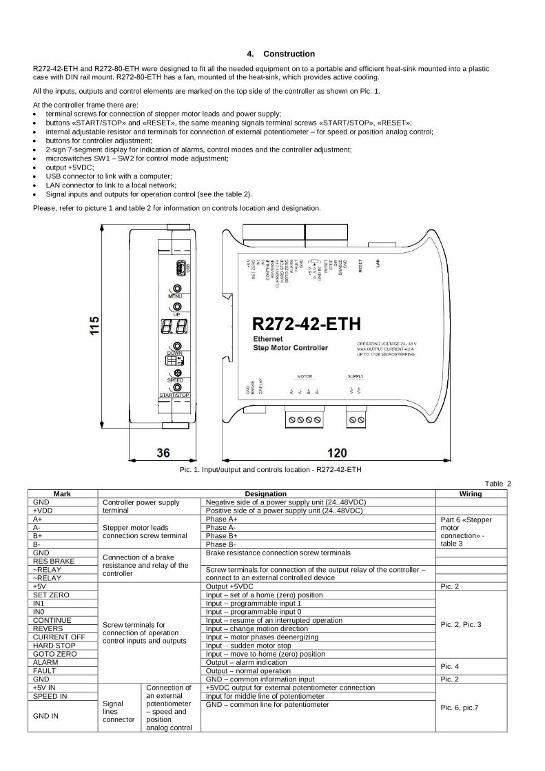
4. ConstructionR272-42-ETH and R272-80-ETH were designed to fit all the needed equipment on to a portable and efficient heat-sink mounted into a plasticcase with DIN rail mount. R272-80-ETH has a fan, mounted of the heat-sink, which provides active cooling.
All the inputs, outputs and control elements are marked on the top side of the controller as shown on Pic. 1.
At the controller frame there are:· terminal screws for connection of stepper motor leads and power supply;· buttons «START/STOP» and «RESET», the same meaning signals terminal screws «START/STOP», «RESET»;· internal adjustable resistor and terminals for connection of external potentiometer – for speed or position analog control;· buttons for controller adjustment;· 2-sign 7-segment display for indication of alarms, control modes and the controller adjustment;· microswitches SW1 – SW2 for control mode adjustment;· output +5VDC;· USB connector to link with a computer;· LAN connector to link to a local network;· Signal inputs and outputs for operation control (see the table 2).
Please, refer to picture 1 and table 2 for information on controls location and designation.
Pic. 1. Input/output and controls location - R272-42-ETH
Table 2Mark Designation Wiring
GND Controller power supplyterminal
Negative side of a power supply unit (24..48VDC)+VDD Positive side of a power supply unit (24..48VDC)A+
Stepper motor leadsconnection screw terminal
Phase А+ Part 6 «Steppermotorconnection» -table 3
A- Phase А-B+ Phase B+B- Phase B-GND Connection of a brake
resistance and relay of thecontroller
Brake resistance connection screw terminalsRES BRAKE~RELAY Screw terminals for connection of the output relay of the controller –
connect to an external controlled device~RELAY+5V
Screw terminals forconnection of operationcontrol inputs and outputs
Output +5VDC Pic. 2SET ZERO Input – set of a home (zero) position
Pic. 2, Pic. 3
IN1 Input – programmable input 1IN0 Input – programmable input 0CONTINUE Input – resume of an interrupted operationREVERS Input – change motion directionCURRENT OFF Input – motor phases deenergizingHARD STOP Input - sudden motor stopGOTO ZERO Input – move to home (zero) positionALARM Output – alarm indication Pic. 4FAULT Output – normal operationGND GND – common information input Pic. 2+5V IN
Signallinesconnector
Connection ofan externalpotentiometer– speed andpositionanalog control
+5VDC output for external potentiometer connection
Pic. 6, pic.7SPEED IN Input for middle line of potentiometer
GND INGND – common line for potentiometer

www.servo-drive.cz [email protected]
RESET Reset Input – reset of the controller Pic. 2, pic. 3STEP
Pulse positioncontrol
Input – STEP (pulse signal) Pic. 5DIR Input – DIR (level signal) Pic. 2, pic. 3ENABLE Input – ENABLE (level signal)GND GND – common input (for STEP signal) Pic. 5RESET Button reset of the controllerLAN Communication connectors Ethernet – local network connectionUSB USB connection to a computerMENU
Menu control buttonsEnter/exit/navigation through the menu of the controller
UP Increase menu parameterDOWN Decrease menu parameterSW1, SW2 Microswitches Control mode settingSPEED Potentiometer Internal adjustable resistor for speed and position analog controlSTART/STOP Button Operation start/stop
5. ConnectionPlease follow this manual carefully for connection and assembly.Please, connect wires only when power is off. Do not attempt to change wiring while the power is ON.Please, provide a reliable contact in connection terminals. During wiring, please, observe the polarity and wire management. Connection
examples are shown on pictures 2-7. Possible connection schemes for motors are given below in table 3.
Connection examples for control inputs and outputs of the controller:
+5V (output 5VDC)
Control inputs:SET_ZEROIN1IN0CONTINUEREVERSCURRENT OFFHARD STOPGOTO ZERORESETDIRENABLE
Controller
GND
1K
Pic. 2. Connection of input lines usinginternal power supply +5VDC
GND
Control inputs:SET_ZEROIN1IN0CONTINUEREVERS
Controller
CURRENT OFFHARD STOPGOTO ZERORESETDIRENABLE
4..5VDC(24VDC)GND
1K
Pic. 3. Connection of input lines using external powersupply (4-5VDC).
Please, connect additional current limitingresistance if use high level signal +24VDC instead of5VDC: 3KOhm for STEP input, 1KOhm for all the restinputs.
GND
Controller
100 Ohm
0V
R+20VDCALARM,
FAULT
GND
Pic. 4. Connection of output lines ALARM andFAULT. Outputs type - optoisolator output, max.voltage: 20VDC, max. current – 100mA
GND
Controller
GND
STEP
Source of pulsesignal4..5VDC (24VDC)
3K
Pic. 5. Connection of STEP signal
+5 IN
Controller
GND IN
SPEED IN
R=3..4К
Pic. 6. Connection of an external potentiometerfor speed or position analog control
Controller
GND IN
SPEED IN
0..5VDC
Pic. 7. Connection example for speed or position controlusing an external source of analog signal 0–5VDC.

www.servo-drive.cz [email protected]
Connection of an external brake (regenerative) resistance
Brake (regenerative) resistor is meant to be used to absorb and dissipate energy, which appears due to deceleration or forced rotation of themotor. The controller is equipped with an internal regenerative resistor for 5W. The power of the resistor is suitable for normal operation of astepper motor SM8680.
In case of forced motor rotation at a speed below 120rpm (10 seconds average value at the desired interval from 0 to infinite), using of anexternal regenerative resistor is not necessary.
In case of forced motor rotation at a speed 120...240 rpm (10 seconds average value at the desired interval from 0 to infinite), it is necessary toconnect an external brake regenerative resistor R=5 Ohm P=100W. The load resistor should be connected to the screw terminals «GND» and«RES BRAKE».
Long duration forced motor rotation at average velocity more than 240 rpm (10 seconds average value at the desired interval from 0 to infinite)is forbidden.
Connection of a stepper motor
The controller provides operation with 2 or 4-phase stepper motors, 4, 6 or 8 wires. Winding connection examples are in the table 3. Connectstepper motor wires to A+, A-, B+ and B- terminals of the controller according to the table 3.
Table 3.
Scheme 1 Scheme 2 Scheme 3 Scheme 48 wires stepmotor connection (4 phases):
Scheme 1 – serial connection;Scheme 2 – parallel connection.
6 wires stepmotor connection (2 phases with midpoint taps):Scheme 3;
4 wires stepmotor connection (2 phases without midpoint taps):Scheme 4.
Connection and assembling
Assembling order is as below:1. Connect the controller to a stepper motor, sensors and power supply according the given schemes and recommendations;2. If necessary, connect an external regenerative resistor;3. If necessary, connect the controller to a computer through the LAN or USB.
6. Controller menuFor the purposes of the controller adjusting the special controller menu is used (buttons MENU, UP and DOWN and 2-sign 7-segment display).Some parameters could also be set through the communication interface (using Ethernet or USB connection).
6.1 Usage of the controller menu
To enter menu press and hold the button MENU till a sound signal (values at the display should start to blink). To change the menu item shortlypress the button MENU again (menu switching is cyclic). To exit the menu press and hold the button MENU till a sound signal (values at the displayshould stop blinking). To change the parameter of a menu item, use the buttons UP (to increase the value) and DOWN (to decrease the value).
Factory reset – simultaneous pushing and holding of UP and DOWN buttons longer than 8 sec till a sound signal.
6.2 Menu items are the next:
· P0 – select a motor control mode: Cu – current mode, Un – voltage mode· P1 – select a motor type for the voltage motor control mode: 1..43 (P0=Un)· P2 – select microstepping mode: 1..16 – for current motor control mode, 1..128 for voltage motor control mode· P3 – select operating current for current motor control mode: 0,1 – 4,2А or 0,1 – 8,0А (P0 = Cu)· P4 – select holding current – as a percentage of an operating current: 25%, 50%, 75%, 99%· P5 – select the number of an executing program P0..P3 which should be executed as the button START/STOP is pushed· P6 – select the analog control mode type: A0/A1 (analog speed control A0 or analog position control A1)· P7 – select acceleration rate: 0..15· P8 – select deceleration rate: 0..15· P9 – select a filter time for inputs IN0, IN1, REVERS, SET_ZERO (to prevent malfunction due to a contact bounce) – 2n ms (n – the menu
parameter value)· PA – turn on/turn off sound signals: ON/OFF· PB – select display brightness: L0..L7

www.servo-drive.cz [email protected]
6.3 Stepper motors list and numbers for the voltage motor control mode (menu item P1, P0 = Un):
Value Max. current perphase, Amp
Resistance perphase, Ohm
Inductance perphase, mH Step angle Motor model
0 - - - - No motor1 1.33 2.1 2.5 1.82 1.33 2.1 4.2 0.93 1.2 3.3 3.4 0.94 1.68 1.65 3.2 1.85 1.68 1.64 3.2 0.96 1.2 3.3 2.8 0.87 1.68 1.65 2.8 1.8 SM42478 1.68 1.65 4.1 0.99 1.2 6 7 1.810 1.2 12.1 36.7 0.911 1.56 1.8 3.6 1.812 1.0 16.7 46.5 1.813 1.5 3.6 6 1.814 1.0 5.7 5.4 1.815 1.0 5.7 8 0.916 2.8 0.7 1.4 1.817 2.8 0.7 2.2 0.918 1.0 6.6 8.6 1.819 2.8 0.83 2.2 1.820 2.8 0.9 3.7 0.921 1.0 7.4 10 1.822 2.0 1.8 2.5 1.823 2.8 0.9 2.5 1.824 1.0 8.6 14 1.825 2.8 1.13 3.6 1.8 SM577626 2.8 1.13 5.6 0.927 2.0 1.2 4.6 1.828 2.0 4.8 18.4 1.829 2.0 1.5 6.8 1.830 2.0 6 7.2 1.831 2.8 0.7 3.9 1.832 2.8 2.8 15.6 1.8
33 4.2 0,375 3.4 1.8 SM8680Parallel connection
34 4.2 1.5 13.6 1.8 SM8680Serial connection
35 4.2 0.45 6 1.8 -36 4.2 1.8 24 1.8 -37 4.2 0,625 8 1.8 -38 4.2 2.5 32 1.8 -39* 6.0 0.6 6.5 1.8 -40* 6.2 0.75 9 1.8 -41* 5.5 0.9 12 1.8 -42* 6.5 0.8 15 1.8 -43* 8 0.67 12 1.8 SM110201
*Values 39 – 43 are applicable for R272-80-ETH controllers only.
7. Operation order1. Make sure the power supply is turned off.2. Make assembly and connection according to section 5.3. Set controller operation parameters: motor control mode (current or voltage), operation current (for current control mode) or motor model (for
voltage control mode), holding current, microstepping mode and other necessary parameters (please, refer to the section 6).
Current control mode – during the motor control the target parameter is a maximum operation current given to a motor phase. If use thiscontrol mode, it is possible to connect any motor to the controller under the condition of a correct current setting (use the menu of thecontroller) in an available range 0.1 – 4.2A (0.1 – 8.0A). The current motor control mode performs better torque and high rotation speed, but itis limited with a maximum microstepping division 1/16;
Voltage control mode – performs smooth motion and provides microstepping division up to 1/128. However, rotation speed and torque are lessin comparison with the current control mode. This control mode is only applicable to the exact list of motor models. The models list resides inthe controller memory (please, refer to the section 6.3).
In case of control through Ethernet or via USB interface, the parameters can be adjusted by command using the controller communicationinterface. Otherwise use the controller menu to adjust the parameters.
The parameters adjusting using the controller menu
· Chose the motor control mode – voltage or current. Enter the menu P0, use buttons UP and DOWN to select chosen control mode: Cu –

www.servo-drive.cz [email protected]
current, Un – voltage.
· In case of current control mode (P0=Cu), enter the menu P3 and select the maximum operation current of the connected motor (please,refer to the motor documentation).
· In case of voltage control mode (P0=Un), enter the menu P1 and select the motor model. List of motor models can be found in thesection 6.3.
· Enter the menu P2 and select required microstepping mode (1..1/16 if current control mode chosen or 1..1/128 if voltage control modechosen).
· Enter the menu P4 and select required holding current – as a percentage of the operation current: 25%, 50%, 75%, 99%.
· If it is intended to use a standalone operation mode according to an executing program from the controller memory, enter the menu P5and select a number of an executing program (it will be executed as the button START/STOP will be pushed).
· If it is intended to use an analog control mode, enter the menu P6 and select A0 for analog speed control or A1 for analog positioncontrol.
· Set suitable values of a motor acceleration and deceleration – enter menu P7 and P8 accordingly.
· Enter the menu P9 and set the debouncing filter value (signal insensitive time) for debouncing inputs.
4. Select a required operation mode using microswitches SW1, SW2 according to the table 4.
Table 4.
Operation modeMark on the
displayMicroswitch
OperationSW1 SW2
Local network Ethernetor USB La ON ON
The operation control is realized by commands according thecommunication protocol of the controller. Ethernet or USB connection isused.
Program executing bF OFF ON The controller executes one of the saved to it’s memory program.
Analog control A0, A1 ON OFF
A0 – analog speed control;A1 – analog position control;For analog control internal or external potentiometers is used, or the signalis given by an external analog source of 0..5VDC.
Driver SD OFF OFF The standard pulse position control using control signals «STEP», «DIR»and «ENABLE».
· If used driver operation mode - standard pulse position control SD, give a sequence of signals «STEP» (pulse), «DIR» (level) and«ENABLE».High level of the signals – 4..5VDC (24VDC*), low level - 0..1VDC.One step (or microstep) executes as front edge of the voltage pulse on the «STEP» input. Direction switches by changing voltage level on the«DIR» input. The motion is enabled if the signal to «ENABLE» input is given. The signals oscillogram is shown on pic.8.
STEP
DIR
ENABLE
0 – 1VDC
0 – 1VDC
0 – 1VDC
4 – 5VDC (24VDC*)
4 – 5VDC (24VDC*)
4 – 5VDC (24VDC*)
> 0,5µs
> 50µs
> 50µs
> 0,5µs
Pic.8 – «STEP», «DIR» and «ENABLE» signals order and duration
*Please, connect additional current limiting resistance if use high level signal +24VDC instead of 5VDC: 3KOhm for STEP input, 1KOhm for all therest inputs.
· If used analog operation mode A0, A1 – control the motor velocity (if chosen menu P6=A0) or turning angle (if chosen menu P6=A1) usinga potentiometer or source of analog signal 0 – 5VDC. The motor motion can be started and stopped by pressing the START/STOP button, or bysignal at the ENABLE input. The motor speed (or turning angle) is regulated by the internal potentiometer "SPEED", by external potentiometer orsource of an analog signal 0-5VDC – which should be connected to the input "SPEED IN". When use one regulation input, another one should beturned off (switch to the zero position).
· In an analog speed control mode A0 - the maximum rotation speed is 2000 rpm for a stepper motor with step angle 1.8° and operation ina full step mode. In case of operation in a microstepping mode, the maximum rotation speed is lower proportional to a microsteppingratio.
· In an analog position control mode A1 - microstepping below 1/16 is not applicable. In case of microstepping ratio 1/16 for a steppermotor with step angle 1.8° - the maximum rotation angle is 270°; in case of microstepping ratio 1/32 – 135°; 1/64 – 67,5°; 1/128 – 33,7°.The maximum momentary target speed is 600 steps/sec.

www.servo-drive.cz [email protected]
· Executing program operation mode bF – The program execution can be started and stopped by pressing the START/STOP button, or bysignal at the ENABLE input. It is possible to choose one of 4 stored in the controller memory programs. The needed program should be selected inthe controller menu P5 - the program number is the menu parameter (please, refer to the section 6).
· When use local network Ethernet (or USB) operation mode LA, operation and motion control is performed by commands – through thelocal network Ethernet or via USB interface. All connection parameters, authorization method and a full command list are given in thecommunication protocol manual.
Designation of the control inputs, which are used in the mentioned operation modes, are given in the section 4 table 2. Signal inputs are activatedby the high voltage level. The motor rotation direction depends on a signal level on the input DIR, rotation direction can be changed to the oppositeby impulse signal at the REVERS input. An emergency stop is implemented when high voltage level appears at the CURRENT OFF input.
8. Ethernet and USB connection
The controller provides 2 communication interfaces –connection via local network Ethernet or USB. In case of connection of the controller to acomputer there is a possibility to adjust controller parameters and control of a stepper motor by commands. Please, refer to a full description of thedata communications protocol in a relevant document. The data communications protocol is open.
Besides the open data communications protocol, we offer a specific software for the controller (OS Windows only). This software SMC-ProgramVer.5 provides both USB and Ethernet connections, it is suitable for the controller adjusting and a motor control.
Please, use a LAN cable for connection to a local network Ethernet (it is a part of delivery). Default LAN connection parameters are next:
MAC address : 0x00 0xf8 0xdc 0x3f 0x00 0x00IP address: 192.168.1.2Port: 5000IP sub-network mask: 255.255.0.0Gateway: 192.168.1.1These parameters can be changed afterwards by commands sent through a USB or Ethernet connection.
Please, use a USB cable for connection to a USB (it is a part of delivery). Special driver (CP210x_VCP) must be installed before the connection. Avirtual COM port appears on a computer after connection of the controller to a computer USB port. The following data communication is performedas per RS-232 interface, parameters are the next:Baud rate - 115200Data bits - 8Parity – noneStop bits - 1
9. SMC-Program software
The software SMC-Program версии Ver.5 is intended for easy and convenient connection of the controller and motor control without learning of adata communications protocol of the controller.
The main application window is shown in the picture 9. The software is shut down and all connections are closed when the main application windowis closed. To start an operation the controller should be connected through the SMC-Program. To connect the controller chose a menu item“Connect new device” in the main window.
Pic. 9. Main window of SMC-Program Pic. 10 – Controller connection window
Please, chose a connection type (USB or Ethernet) and check (change if necessary) the connection parameters in the appeared window (pic.10).The default parameters in the program correspond to default parameters of the controller. If the parameters were changed, new parameters shouldbe set in the correspond fields.

www.servo-drive.cz [email protected]
In a password field the controller safety access code should be entered. The default code is 0x0123456789ABCDEF. This password can bechanged in a window “Change password” (from a main window of the application).
For controller connection press the button “Connect”.
If the connection was done successfully a relevant message will appear in the window. The controller will be available for operation in otherwindows of the application. A list of all connected controllers is available through a menu “List of connected devices” from the main applicationwindow (Pic.11).
Pic.12. Controller parameters
Рic .11. List of connected controllers
As a button “Change” is pressed (available for each ofconnected controllers in the list of connectedcontrollers) a window of controller and motorparameters is appeared (Pic.12). The same windowcan be called from operation windows of the application“Program Load mode” and “Direct Control Mode” (Pic.13 and Pic.14).
Pic.13. Direct Control Mode window
www.servo-drive.cz [email protected]
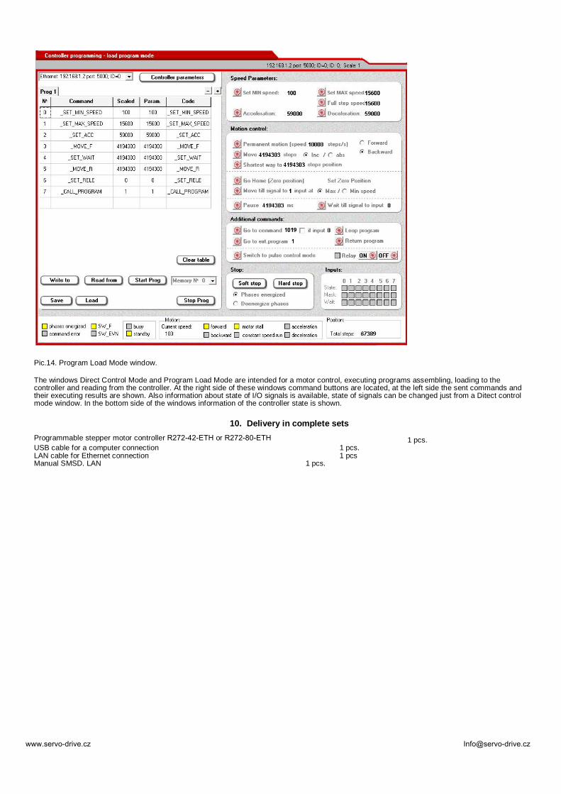
Pic.14. Program Load Mode window.
The windows Direct Control Mode and Program Load Mode are intended for a motor control, executing programs assembling, loading to thecontroller and reading from the controller. At the right side of these windows command buttons are located, at the left side the sent commands andtheir executing results are shown. Also information about state of I/O signals is available, state of signals can be changed just from a Ditect controlmode window. In the bottom side of the windows information of the controller state is shown.
10. Delivery in complete setsProgrammable stepper motor controller R272-42-ETH or R272-80-ETH 1 pcs.USB cable for a computer connection 1 pcs.LAN cable for Ethernet connection 1 pcsManual SMSD. LAN 1 pcs.