service repair manuallz7w.com/audi/mk2ttwiki/pdf/erwin/d3e8007a75e-manual_transmissio… · 2.4...
TRANSCRIPT
Protected by copyright. Copying for private or commercial purposes, in part or in whole, is not permitted unless authorised by AUDI AG. AUDI AG does not guarantee or accept any liability with respect to the correctness of information in this document. Copyright by AUDI AG.
Repair ManualAudi TT 2007 ➤Manual TransmissionEdition 10.2009
Service
Service Department. Technical Information
Protected by copyright. Copying for private or commercial purposes, in part or in whole, is not permitted unless authorised by AUDI AG. AUDI AG does not guarantee or accept any liability with respect to the correctness of information in this document. Copyright by AUDI AG.
List of Workshop Manual Repair GroupsList of Workshop ManualRepair GroupsList of Workshop Manual Repair Groups
Repai r Group00 - General, Technical Data30 - Clutch34 - Controls, Housing35 - Gears, Shafts39 - Final Drive, Differential
Technical information should always be available to the foremen and mechanics, because theircareful and constant adherence to the instructions is essential to ensure vehicle road-worthiness andsafety. In addition, the normal basic safety precautions for working on motor vehicles must, as amatter of course, be observed.
Service
All rights reserved.No reproduction without prior agreement from publisher.
Copyright © 2010 Audi AG, Ingolstadt D3E8007A75E

Protected by copyright. Copying for private or commercial purposes, in part or in whole, is not permitted unless authorised by AUDI AG. AUDI AG does not guarantee or accept any liability with respect to the correctness of information in this document. Copyright by AUDI AG.
Contents
00 - General, Technical Data . . . . . . . . . . . . . . . . . . . . . . . . . . . . . . . . . . . . . . . . . . . . 11 General Information . . . . . . . . . . . . . . . . . . . . . . . . . . . . . . . . . . . . . . . . . . . . . . . . . . . . . . 11.1 Location on Transmission . . . . . . . . . . . . . . . . . . . . . . . . . . . . . . . . . . . . . . . . . . . . . . . . . . 11.2 General Repair Information . . . . . . . . . . . . . . . . . . . . . . . . . . . . . . . . . . . . . . . . . . . . . . . . 21.3 Contact Corrosion . . . . . . . . . . . . . . . . . . . . . . . . . . . . . . . . . . . . . . . . . . . . . . . . . . . . . . . . 21.4 Repair Instructions . . . . . . . . . . . . . . . . . . . . . . . . . . . . . . . . . . . . . . . . . . . . . . . . . . . . . . . . 21.5 Overall Transmission Ratio i, Calculating . . . . . . . . . . . . . . . . . . . . . . . . . . . . . . . . . . . . . . 62 Description and Operation . . . . . . . . . . . . . . . . . . . . . . . . . . . . . . . . . . . . . . . . . . . . . . . . . . 72.1 Powertrain Overview . . . . . . . . . . . . . . . . . . . . . . . . . . . . . . . . . . . . . . . . . . . . . . . . . . . . . . 73 Specifications . . . . . . . . . . . . . . . . . . . . . . . . . . . . . . . . . . . . . . . . . . . . . . . . . . . . . . . . . . . . 93.1 Code Letters, Assembly Allocation, Ratios and Capacities . . . . . . . . . . . . . . . . . . . . . . . . 9
30 - Clutch . . . . . . . . . . . . . . . . . . . . . . . . . . . . . . . . . . . . . . . . . . . . . . . . . . . . . . . . . . 111 General Information . . . . . . . . . . . . . . . . . . . . . . . . . . . . . . . . . . . . . . . . . . . . . . . . . . . . . . 111.1 Determining Clutch Manufacturer . . . . . . . . . . . . . . . . . . . . . . . . . . . . . . . . . . . . . . . . . . . . 111.2 Clutch System, Bleeding . . . . . . . . . . . . . . . . . . . . . . . . . . . . . . . . . . . . . . . . . . . . . . . . . . 121.3 Information Regarding the Removal and Installation of the Clutch Master or Slave Cylinder
. . . . . . . . . . . . . . . . . . . . . . . . . . . . . . . . . . . . . . . . . . . . . . . . . . . . . . . . . . . . . . . . . . . . . . . . 131.4 Clutch Master Cylinder and Clutch Slave Cylinder, Function Test . . . . . . . . . . . . . . . . . . . . 132 Description and Operation . . . . . . . . . . . . . . . . . . . . . . . . . . . . . . . . . . . . . . . . . . . . . . . . . . 152.1 Clutch Mechanism Overview . . . . . . . . . . . . . . . . . . . . . . . . . . . . . . . . . . . . . . . . . . . . . . . . 152.2 Pedal Assembly, Master Cylinder Assembly Overview . . . . . . . . . . . . . . . . . . . . . . . . . . . . 172.3 Hydraulics Assembly Overview . . . . . . . . . . . . . . . . . . . . . . . . . . . . . . . . . . . . . . . . . . . . . . 192.4 Clutch Release Mechanism, Clutch Slave Cylinder Assembly Overview . . . . . . . . . . . . . . 212.5 Sachs Clutch Assembly Overview . . . . . . . . . . . . . . . . . . . . . . . . . . . . . . . . . . . . . . . . . . . . 222.6 LuK Clutch Assembly Overview . . . . . . . . . . . . . . . . . . . . . . . . . . . . . . . . . . . . . . . . . . . . . . 253 Specifications . . . . . . . . . . . . . . . . . . . . . . . . . . . . . . . . . . . . . . . . . . . . . . . . . . . . . . . . . . . . 283.1 Fastener Tightening Specifications . . . . . . . . . . . . . . . . . . . . . . . . . . . . . . . . . . . . . . . . . . 284 Removal and Installation . . . . . . . . . . . . . . . . . . . . . . . . . . . . . . . . . . . . . . . . . . . . . . . . . . 294.1 Hose/Line Assembly or Plastic Line . . . . . . . . . . . . . . . . . . . . . . . . . . . . . . . . . . . . . . . . . . 294.2 Over-Center Spring . . . . . . . . . . . . . . . . . . . . . . . . . . . . . . . . . . . . . . . . . . . . . . . . . . . . . . 304.3 Clutch Pedal . . . . . . . . . . . . . . . . . . . . . . . . . . . . . . . . . . . . . . . . . . . . . . . . . . . . . . . . . . . . 324.4 Mounting Bracket . . . . . . . . . . . . . . . . . . . . . . . . . . . . . . . . . . . . . . . . . . . . . . . . . . . . . . . . 344.5 Clutch Position Sensor . . . . . . . . . . . . . . . . . . . . . . . . . . . . . . . . . . . . . . . . . . . . . . . . . . . . 364.6 Master Cylinder . . . . . . . . . . . . . . . . . . . . . . . . . . . . . . . . . . . . . . . . . . . . . . . . . . . . . . . . . . 374.7 Slave Cylinder with Release Bearing . . . . . . . . . . . . . . . . . . . . . . . . . . . . . . . . . . . . . . . . . . 394.8 Sachs Clutch . . . . . . . . . . . . . . . . . . . . . . . . . . . . . . . . . . . . . . . . . . . . . . . . . . . . . . . . . . . . 404.9 LuK Clutch . . . . . . . . . . . . . . . . . . . . . . . . . . . . . . . . . . . . . . . . . . . . . . . . . . . . . . . . . . . . . . 425 Special Tools . . . . . . . . . . . . . . . . . . . . . . . . . . . . . . . . . . . . . . . . . . . . . . . . . . . . . . . . . . . . 45
34 - Controls, Housing . . . . . . . . . . . . . . . . . . . . . . . . . . . . . . . . . . . . . . . . . . . . . . . . 471 General Information . . . . . . . . . . . . . . . . . . . . . . . . . . . . . . . . . . . . . . . . . . . . . . . . . . . . . . 471.1 Manual Transmission, Checking Gear Oil Level . . . . . . . . . . . . . . . . . . . . . . . . . . . . . . . . 471.2 Gear Oil in Bevel Box, Checking . . . . . . . . . . . . . . . . . . . . . . . . . . . . . . . . . . . . . . . . . . . . 481.3 Gear Oil in Bevel Box, Filling . . . . . . . . . . . . . . . . . . . . . . . . . . . . . . . . . . . . . . . . . . . . . . . . 492 Description and Operation . . . . . . . . . . . . . . . . . . . . . . . . . . . . . . . . . . . . . . . . . . . . . . . . . . 522.1 Selector Mechanism Overview . . . . . . . . . . . . . . . . . . . . . . . . . . . . . . . . . . . . . . . . . . . . . . 522.2 Shift Knob and Covers Assembly Overview . . . . . . . . . . . . . . . . . . . . . . . . . . . . . . . . . . . . 542.3 Shift Lever and Shift Housing for Vehicles to VIN 8J-7-013000 Assembly Overview . . . . 562.4 Shift Lever and Shift Housing for Vehicles from VIN 8J-7-013001 Assembly Overview . . 592.5 Shift Cable and Selector Cable to Model Year 2007 Assembly Overview . . . . . . . . . . . . . . 61
Audi TT 2007 ➤Manual Transmission - Edition 10.2009
Contents i

Protected by copyright. Copying for private or commercial purposes, in part or in whole, is not permitted unless authorised by AUDI AG. AUDI AG does not guarantee or accept any liability with respect to the correctness of information in this document. Copyright by AUDI AG.
2.6 Transmission Shift Lever and Selector Relay Lever to Model Year 2007 AssemblyOverview . . . . . . . . . . . . . . . . . . . . . . . . . . . . . . . . . . . . . . . . . . . . . . . . . . . . . . . . . . . . . . 63
2.7 Shift Cable and Selector Cable from Model Year 2008 Assembly Overview . . . . . . . . . . . . 652.8 Shift Mechanism, Adjusting . . . . . . . . . . . . . . . . . . . . . . . . . . . . . . . . . . . . . . . . . . . . . . . . 692.9 Subframe Mount Assembly Overview . . . . . . . . . . . . . . . . . . . . . . . . . . . . . . . . . . . . . . . . 722.10 Transmission Overview . . . . . . . . . . . . . . . . . . . . . . . . . . . . . . . . . . . . . . . . . . . . . . . . . . . . 752.11 Transmission Assembly Overview . . . . . . . . . . . . . . . . . . . . . . . . . . . . . . . . . . . . . . . . . . . . 762.12 Transmission Housing and Shift Mechanism Assembly Overview . . . . . . . . . . . . . . . . . . . . 772.13 Input Shaft, Output Shafts, Differential, Bevel Box and Selector Rods Assembly Overview
. . . . . . . . . . . . . . . . . . . . . . . . . . . . . . . . . . . . . . . . . . . . . . . . . . . . . . . . . . . . . . . . . . . . . . . . 792.14 Transmission Housing Assembly Overview . . . . . . . . . . . . . . . . . . . . . . . . . . . . . . . . . . . . 812.15 Clutch Housing Assembly Overview . . . . . . . . . . . . . . . . . . . . . . . . . . . . . . . . . . . . . . . . . . 832.16 Shift Mechanism Assembly Overview, Transmission Side . . . . . . . . . . . . . . . . . . . . . . . . . . 852.17 Shift Forks Assembly Overview . . . . . . . . . . . . . . . . . . . . . . . . . . . . . . . . . . . . . . . . . . . . . . 863 Specifications . . . . . . . . . . . . . . . . . . . . . . . . . . . . . . . . . . . . . . . . . . . . . . . . . . . . . . . . . . . . 873.1 Bevel Box Oil Filler Bolt . . . . . . . . . . . . . . . . . . . . . . . . . . . . . . . . . . . . . . . . . . . . . . . . . . . . 873.2 Manual Transmission Oil Filler Plug . . . . . . . . . . . . . . . . . . . . . . . . . . . . . . . . . . . . . . . . . . 873.3 Fastener Tightening Specifications . . . . . . . . . . . . . . . . . . . . . . . . . . . . . . . . . . . . . . . . . . 874 Removal and Installation . . . . . . . . . . . . . . . . . . . . . . . . . . . . . . . . . . . . . . . . . . . . . . . . . . 904.1 Shift Knob with Shift Lever Boot . . . . . . . . . . . . . . . . . . . . . . . . . . . . . . . . . . . . . . . . . . . . . . 904.2 Selector Mechanism . . . . . . . . . . . . . . . . . . . . . . . . . . . . . . . . . . . . . . . . . . . . . . . . . . . . . . 914.3 Shift Cable and Selector Cable . . . . . . . . . . . . . . . . . . . . . . . . . . . . . . . . . . . . . . . . . . . . . . 944.4 Transmission, Removing . . . . . . . . . . . . . . . . . . . . . . . . . . . . . . . . . . . . . . . . . . . . . . . . . . 964.5 Transmission, Transporting . . . . . . . . . . . . . . . . . . . . . . . . . . . . . . . . . . . . . . . . . . . . . . . . 1064.6 Transmission, Securing to Assembly Stand . . . . . . . . . . . . . . . . . . . . . . . . . . . . . . . . . . . . 1074.7 Transmission, Installing . . . . . . . . . . . . . . . . . . . . . . . . . . . . . . . . . . . . . . . . . . . . . . . . . . . . 1074.8 Transmission Mount, Removing . . . . . . . . . . . . . . . . . . . . . . . . . . . . . . . . . . . . . . . . . . . . . . 1134.9 Transmission Mount, installing . . . . . . . . . . . . . . . . . . . . . . . . . . . . . . . . . . . . . . . . . . . . . . 1164.10 Pendulum Support . . . . . . . . . . . . . . . . . . . . . . . . . . . . . . . . . . . . . . . . . . . . . . . . . . . . . . . . 1174.11 Bevel Box, Removing . . . . . . . . . . . . . . . . . . . . . . . . . . . . . . . . . . . . . . . . . . . . . . . . . . . . . . 1184.12 Bevel Box, Installing . . . . . . . . . . . . . . . . . . . . . . . . . . . . . . . . . . . . . . . . . . . . . . . . . . . . . . 1224.13 Input Shaft Seal . . . . . . . . . . . . . . . . . . . . . . . . . . . . . . . . . . . . . . . . . . . . . . . . . . . . . . . . . . 1234.14 Selector Shaft Seal . . . . . . . . . . . . . . . . . . . . . . . . . . . . . . . . . . . . . . . . . . . . . . . . . . . . . . . . 1244.15 Selector Shaft . . . . . . . . . . . . . . . . . . . . . . . . . . . . . . . . . . . . . . . . . . . . . . . . . . . . . . . . . . . . 1265 Disassembly and Assembly . . . . . . . . . . . . . . . . . . . . . . . . . . . . . . . . . . . . . . . . . . . . . . . . 1285.1 Selector Mechanism . . . . . . . . . . . . . . . . . . . . . . . . . . . . . . . . . . . . . . . . . . . . . . . . . . . . . . 1285.2 Transmission without Circlip A for Cap/Input Shaft . . . . . . . . . . . . . . . . . . . . . . . . . . . . . . 1315.3 Transmission with Circlip A for the Cap/Input Shaft . . . . . . . . . . . . . . . . . . . . . . . . . . . . . . 1425.4 Shift Forks . . . . . . . . . . . . . . . . . . . . . . . . . . . . . . . . . . . . . . . . . . . . . . . . . . . . . . . . . . . . . . 1525.5 Transmission Housing . . . . . . . . . . . . . . . . . . . . . . . . . . . . . . . . . . . . . . . . . . . . . . . . . . . . 1525.6 Clutch Housing, Servicing . . . . . . . . . . . . . . . . . . . . . . . . . . . . . . . . . . . . . . . . . . . . . . . . . . 1586 Special Tools . . . . . . . . . . . . . . . . . . . . . . . . . . . . . . . . . . . . . . . . . . . . . . . . . . . . . . . . . . . . 160
35 - Gears, Shafts . . . . . . . . . . . . . . . . . . . . . . . . . . . . . . . . . . . . . . . . . . . . . . . . . . . . 1771 General Information . . . . . . . . . . . . . . . . . . . . . . . . . . . . . . . . . . . . . . . . . . . . . . . . . . . . . . 1771.1 Grooved Ball Bearing Changes . . . . . . . . . . . . . . . . . . . . . . . . . . . . . . . . . . . . . . . . . . . . . . 1772 Description and Operation . . . . . . . . . . . . . . . . . . . . . . . . . . . . . . . . . . . . . . . . . . . . . . . . . . 1792.1 Input Shaft Assembly Overview . . . . . . . . . . . . . . . . . . . . . . . . . . . . . . . . . . . . . . . . . . . . . . 1792.2 Output Shaft for 1st to 4th Gears Assembly Overview . . . . . . . . . . . . . . . . . . . . . . . . . . . . 1812.3 Output Shaft, 1st to 4th Gears, Adjusting . . . . . . . . . . . . . . . . . . . . . . . . . . . . . . . . . . . . . . 1832.4 Output Shaft for 5th/6th Gear/Reverse Gear Assembly Overview . . . . . . . . . . . . . . . . . . . . 1872.5 Output Shaft for 5th/6th Gear and Reverse Gear, Adjusting . . . . . . . . . . . . . . . . . . . . . . . . 1883 Disassembly and Assembly . . . . . . . . . . . . . . . . . . . . . . . . . . . . . . . . . . . . . . . . . . . . . . . . 1923.1 Input Shaft . . . . . . . . . . . . . . . . . . . . . . . . . . . . . . . . . . . . . . . . . . . . . . . . . . . . . . . . . . . . . . 1923.2 Output Shaft, 1st to 4th Gears . . . . . . . . . . . . . . . . . . . . . . . . . . . . . . . . . . . . . . . . . . . . . . 194
Audi TT 2007 ➤Manual Transmission - Edition 10.2009
ii Contents
Protected by copyright. Copying for private or commercial purposes, in part or in whole, is not permitted unless authorised by AUDI AG. AUDI AG does not guarantee or accept any liability with respect to the correctness of information in this document. Copyright by AUDI AG.
3.3 Output Shaft for 5th/6th Gear and Reverse Gear . . . . . . . . . . . . . . . . . . . . . . . . . . . . . . . . 2024 Special Tools . . . . . . . . . . . . . . . . . . . . . . . . . . . . . . . . . . . . . . . . . . . . . . . . . . . . . . . . . . . . 208
39 - Final Drive, Differential . . . . . . . . . . . . . . . . . . . . . . . . . . . . . . . . . . . . . . . . . . . . . . 2191 Description and Operation . . . . . . . . . . . . . . . . . . . . . . . . . . . . . . . . . . . . . . . . . . . . . . . . . . 2191.1 Flange Shaft and Seals on Transmission Assembly Overview . . . . . . . . . . . . . . . . . . . . . . 2191.2 Flange Shaft and Seals on Bevel Box Assembly Overview . . . . . . . . . . . . . . . . . . . . . . . . 2201.3 Differential Assembly Overview . . . . . . . . . . . . . . . . . . . . . . . . . . . . . . . . . . . . . . . . . . . . . . 2221.4 Adjustment Overview . . . . . . . . . . . . . . . . . . . . . . . . . . . . . . . . . . . . . . . . . . . . . . . . . . . . . . 2241.5 Differential, Adjusting . . . . . . . . . . . . . . . . . . . . . . . . . . . . . . . . . . . . . . . . . . . . . . . . . . . . . . 2242 Specifications . . . . . . . . . . . . . . . . . . . . . . . . . . . . . . . . . . . . . . . . . . . . . . . . . . . . . . . . . . . . 2272.1 Fastener Tightening Specifications . . . . . . . . . . . . . . . . . . . . . . . . . . . . . . . . . . . . . . . . . . 2273 Removal and Installation . . . . . . . . . . . . . . . . . . . . . . . . . . . . . . . . . . . . . . . . . . . . . . . . . . 2283.1 Left Flange Shaft . . . . . . . . . . . . . . . . . . . . . . . . . . . . . . . . . . . . . . . . . . . . . . . . . . . . . . . . 2283.2 Left Flange Shaft Seal . . . . . . . . . . . . . . . . . . . . . . . . . . . . . . . . . . . . . . . . . . . . . . . . . . . . 2283.3 Shaft Sealing Ring for Bevel Box with Manual Transmission Installed, Replacing . . . . . . 2293.4 Right Flange Shaft . . . . . . . . . . . . . . . . . . . . . . . . . . . . . . . . . . . . . . . . . . . . . . . . . . . . . . . . 2303.5 Right Flange Shaft Seat on Outer Bevel Box, Replacing . . . . . . . . . . . . . . . . . . . . . . . . . . 2313.6 Right Flange Shaft Needle Bearing . . . . . . . . . . . . . . . . . . . . . . . . . . . . . . . . . . . . . . . . . . 2323.7 Seal between Transmission and Bevel Box . . . . . . . . . . . . . . . . . . . . . . . . . . . . . . . . . . . . 2333.8 Bevel Box Drive Flange Seal . . . . . . . . . . . . . . . . . . . . . . . . . . . . . . . . . . . . . . . . . . . . . . . . 2344 Disassembly and Assembly . . . . . . . . . . . . . . . . . . . . . . . . . . . . . . . . . . . . . . . . . . . . . . . . 2384.1 Differential . . . . . . . . . . . . . . . . . . . . . . . . . . . . . . . . . . . . . . . . . . . . . . . . . . . . . . . . . . . . . . 2385 Special Tools . . . . . . . . . . . . . . . . . . . . . . . . . . . . . . . . . . . . . . . . . . . . . . . . . . . . . . . . . . . . 242
Audi TT 2007 ➤Manual Transmission - Edition 10.2009
Contents iii
Protected by copyright. Copying for private or commercial purposes, in part or in whole, is not permitted unless authorised by AUDI AG. AUDI AG does not guarantee or accept any liability with respect to the correctness of information in this document. Copyright by AUDI AG.
Audi TT 2007 ➤Manual Transmission - Edition 10.2009
iv Contents
Protected by copyright. Copying for private or commercial purposes, in part or in whole, is not permitted unless authorised by AUDI AG. AUDI AG does not guarantee or accept any liability with respect to the correctness of information in this document. Copyright by AUDI AG.
00 – General, Technical Data1 General Information⇒ “1.1 Location on Transmission”, page 1⇒ “1.2 General Repair Information”, page 2⇒ “1.3 Contact Corrosion”, page 2⇒ “1.4 Repair Instructions”, page 2⇒ “1.5 Overall Transmission Ratio i, Calculating”, page 6
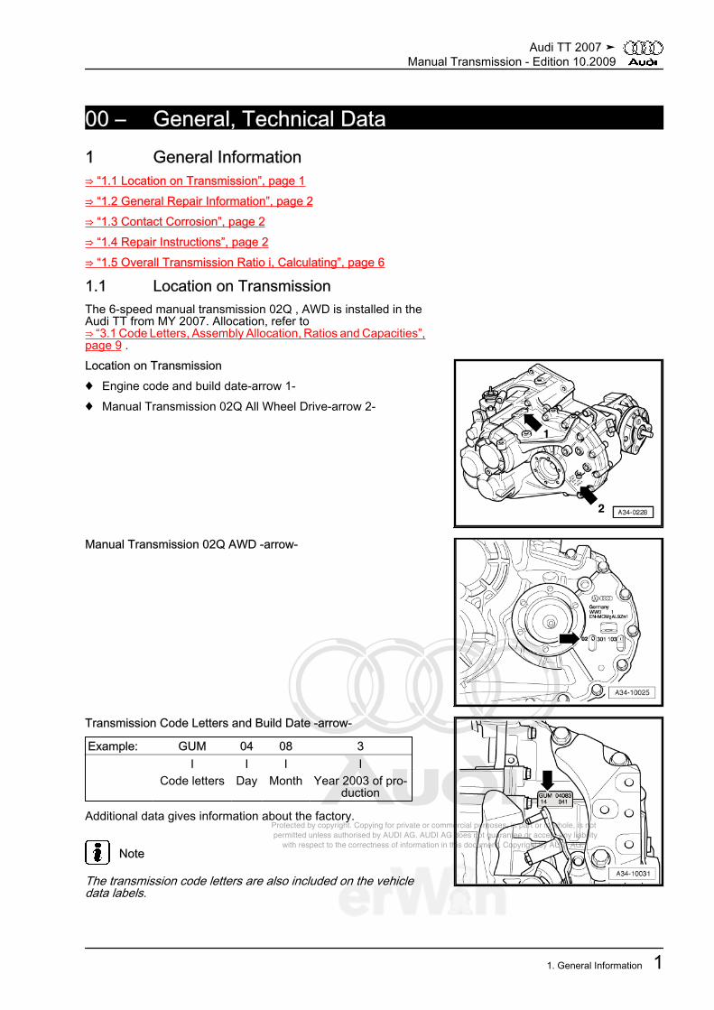
1.1 Location on TransmissionThe 6-speed manual transmission 02Q , AWD is installed in theAudi TT from MY 2007. Allocation, refer to⇒ “3.1 Code Letters, Assembly Allocation, Ratios and Capacities”,page 9 .Location on Transmission♦ Engine code and build date-arrow 1-♦ Manual Transmission 02Q All Wheel Drive-arrow 2-
Manual Transmission 02Q AWD -arrow-
Transmission Code Letters and Build Date -arrow-
Example: GUM 04 08 3 I I I I Code letters Day Month Year 2003 of pro‐
duction
Additional data gives information about the factory.
Note
The transmission code letters are also included on the vehicledata labels.
Audi TT 2007 ➤Manual Transmission - Edition 10.2009
1. General Information 1
Protected by copyright. Copying for private or commercial purposes, in part or in whole, is not permitted unless authorised by AUDI AG. AUDI AG does not guarantee or accept any liability with respect to the correctness of information in this document. Copyright by AUDI AG.
1.2 General Repair InformationThe maximum possible care and cleanliness and proper tools areessential to ensure satisfactory and successful transmission re‐pairs. The usual basic safety precautions also apply when carry‐ing out vehicle repairs.A number of generally applicable instructions for individual repairoperations, which are otherwise mentioned at various points inthe Workshop Manual, are summarized here. It applies to thisrepair manual.
1.3 Contact CorrosionContact corrosion can occur if non-approved fasteners are usedsuch as bolts, nuts, washers, etc.For this reason, only connecting elements with a special surfacecoating are installed.In addition, rubber or plastic parts and adhesive are made of ma‐terials that do not conduct electricity.If you are not sure about the suitability of parts, install new parts.Refer to the electronic parts catalog ETKA.
Note
♦ The transmission housing consists of a magnesium alloy.♦ We only recommend original replacement parts. They have
been checked and are compatible with aluminum.♦ It is recommended to use Audi accessories.
Caution
Warranty does not cover contact corrosion damage.
1.4 Repair InstructionsSpecial Tools and Equipment♦ Complete list of special tools used in this Workshop Manual,
see ServiceNet under Special Tools.Transmission♦ Thoroughly clean all connections and the surrounding area
before disconnecting.♦ When installing the transmission, make sure that the align‐
ment sleeves between the engine and transmission are posi‐tioned correctly.
♦ Allocate bolts and other component using the. Refer to theelectronic parts catalog ETKA.
♦ When installing mounting brackets, as well as other waxedcomponents, the contacts surfaces must be cleaned. Contactsurfaces must be free of grease and wax.
♦ After replacement of the manual transmission with a bevelbox, check the oil level in the manual transmission. Refer to⇒ “1.1 Manual Transmission, Checking Gear Oil Level”, page47 and in the bevel box⇒ “1.2 Gear Oil in Bevel Box, Checking”, page 48 .
♦ Capacities, refer to⇒ “3.1 Code Letters, Assembly Allocation, Ratios and Capaci‐
Audi TT 2007 ➤Manual Transmission - Edition 10.2009
2 Rep. Gr.00 - General, Technical Data
Protected by copyright. Copying for private or commercial purposes, in part or in whole, is not permitted unless authorised by AUDI AG. AUDI AG does not guarantee or accept any liability with respect to the correctness of information in this document. Copyright by AUDI AG.
ties”, page 9 , Specification, refer to the electronic partscatalog ETKA.
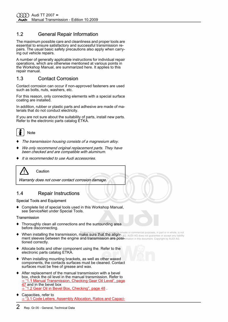
Shaft Seals, Sealing Rings, O-rings, Seals♦ Always replace shaft sealing rings, O-rings, and seals.♦ After removing gaskets and seals, always inspect the contact
surfaces at housing or shaft for burrs resulting from removal,or for other signs of damage.
♦ Before installing the shaft seals, lightly oil the outer circumfer‐ence and fill the space between the sealing lips -arrow- half‐way with sealing grease -G 052 128 A1- .
♦ The open side of the shaft seals point toward the fluid to besealed in.
♦ When pressing in new shaft seal, make sure the sealing lipdoes not run on the same point as the sealing lip of the oldseal (use insertion depth tolerances).
♦ To prevent crushing when installing, lightly lubricate O-ringsbefore inserting.
♦ After replacement of seals, O-rings, and shaft sealing rings,check the oil level in the manual transmission. Refer to⇒ “1.1 Manual Transmission, Checking Gear Oil Level”, page47 or in the bevel box⇒ “1.2 Gear Oil in Bevel Box, Checking”, page 48 .
Sealant♦ Thoroughly clean housing joint surfaces before applying seal‐
ing compounds.♦ Apply the sealing compound -AMV 188 200 03- evenly and not
too thick.♦ Do not allow sealing compound to enter ventilation openings.Fasteners
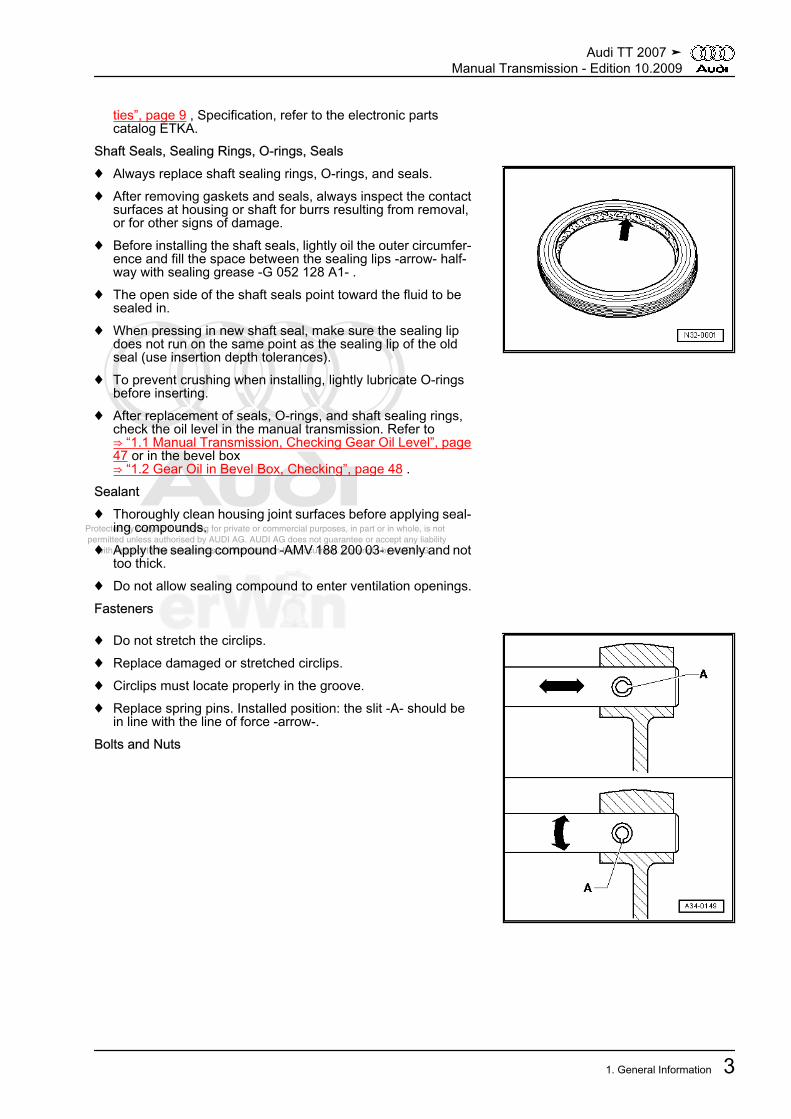
♦ Do not stretch the circlips.♦ Replace damaged or stretched circlips.♦ Circlips must locate properly in the groove.♦ Replace spring pins. Installed position: the slit -A- should be
in line with the line of force -arrow-.Bolts and Nuts
Audi TT 2007 ➤Manual Transmission - Edition 10.2009
1. General Information 3
Protected by copyright. Copying for private or commercial purposes, in part or in whole, is not permitted unless authorised by AUDI AG. AUDI AG does not guarantee or accept any liability with respect to the correctness of information in this document. Copyright by AUDI AG.
♦ Loosen bolts and nuts in reverse of tightening sequence.♦ Tighten and loosen bolts or nuts for securing covers and hous‐
ings without tightening sequence in diagonal sequence instages.
♦ Replace self-locking bolts and nuts.♦ The tightening specifications stated apply to non-oiled nuts
and bolts.♦ Threaded holes into which self-locking bolts or bolts coated
with locking fluid are screwed, must be cleaned (for exampletap). Otherwise there is a risk that the bolts will shear the nexttime they are removed.
♦ Ensure with screwed connections that the contact surfaces aswell as the visible surfaces of nuts and bolts are waxed afterassembly, if necessary.
Mount♦ Install new tapered roller bearing as supplied and do not use
additional oil.♦ Install various bearings (removed tapered roller bearings) into
transmission, lubricated with gear oil.♦ Heat the inner rings of the tapered roller bearings to approxi‐
mately 100 °C (212 °F) with the inductive heat unit -VAS 6414-before installing. Press on to the stop when installing so thatthere is no axial clearance.
♦ Do not interchange the outer or inner races of bearings of thesame size.
♦ Tapered roller bearings installed on a shaft must be replacedas a set and use same make of bearings.
♦ Install needle bearings with lettered side (thicker metal) to‐wards fitting tool.
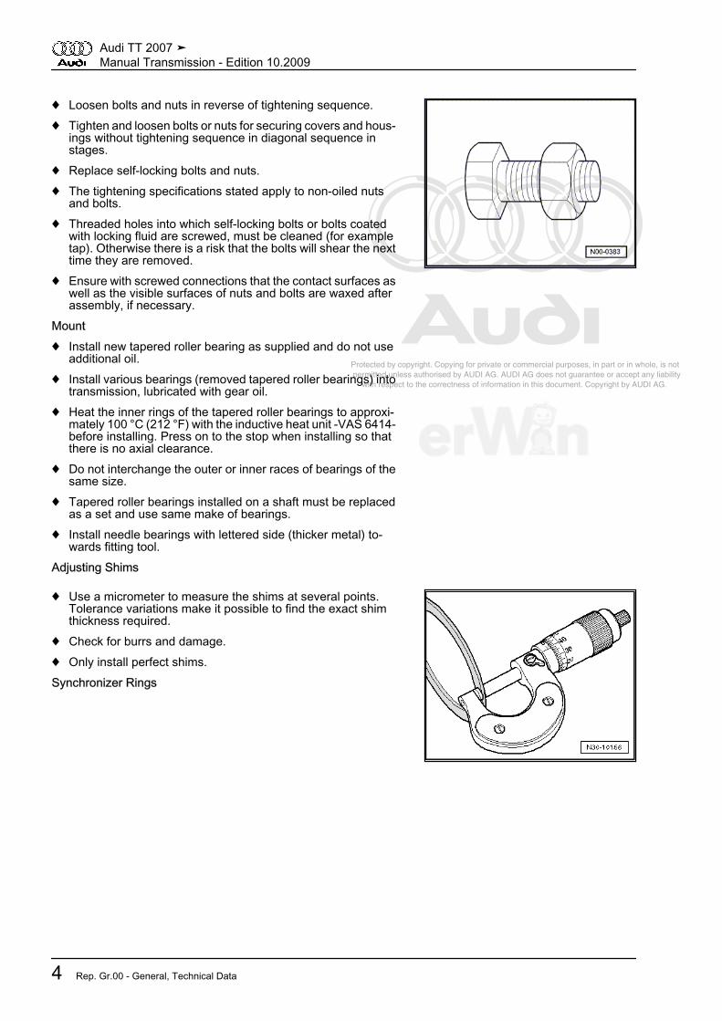
Adjusting Shims
♦ Use a micrometer to measure the shims at several points.Tolerance variations make it possible to find the exact shimthickness required.
♦ Check for burrs and damage.♦ Only install perfect shims.Synchronizer Rings
Audi TT 2007 ➤Manual Transmission - Edition 10.2009
4 Rep. Gr.00 - General, Technical Data
Protected by copyright. Copying for private or commercial purposes, in part or in whole, is not permitted unless authorised by AUDI AG. AUDI AG does not guarantee or accept any liability with respect to the correctness of information in this document. Copyright by AUDI AG.
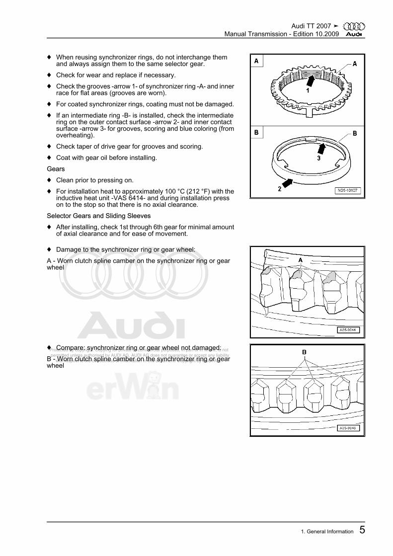
♦ When reusing synchronizer rings, do not interchange themand always assign them to the same selector gear.
♦ Check for wear and replace if necessary.♦ Check the grooves -arrow 1- of synchronizer ring -A- and inner
race for flat areas (grooves are worn).♦ For coated synchronizer rings, coating must not be damaged.♦ If an intermediate ring -B- is installed, check the intermediate
ring on the outer contact surface -arrow 2- and inner contactsurface -arrow 3- for grooves, scoring and blue coloring (fromoverheating).
♦ Check taper of drive gear for grooves and scoring.♦ Coat with gear oil before installing.Gears♦ Clean prior to pressing on.♦ For installation heat to approximately 100 °C (212 °F) with the
inductive heat unit -VAS 6414- and during installation presson to the stop so that there is no axial clearance.
Selector Gears and Sliding Sleeves♦ After installing, check 1st through 6th gear for minimal amount
of axial clearance and for ease of movement.
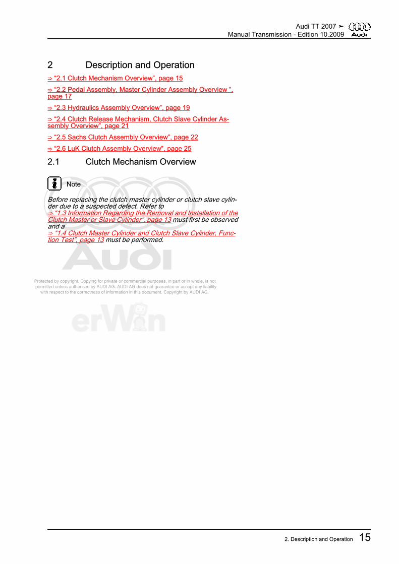
♦ Damage to the synchronizer ring or gear wheel:A - Worn clutch spline camber on the synchronizer ring or gearwheel
♦ Compare: synchronizer ring or gear wheel not damaged:B - Worn clutch spline camber on the synchronizer ring or gearwheel
Audi TT 2007 ➤Manual Transmission - Edition 10.2009
1. General Information 5

Protected by copyright. Copying for private or commercial purposes, in part or in whole, is not permitted unless authorised by AUDI AG. AUDI AG does not guarantee or accept any liability with respect to the correctness of information in this document. Copyright by AUDI AG.
♦ Picture of damage on the locking collar:C - Worn longitudinal inner spline camber and the locking collar
♦ Comparison: locking collar not damaged:D - Undamaged longitudinal inner spline camber and the lockingcollarClutch Mechanism, Clutch♦ If the clutch pedal does not return to the starting position (rest
position) after the recoupling procedure, bleed the clutch sys‐tem (further measures. Refer to⇒ “1.3 Information Regarding the Removal and Installation ofthe Clutch Master or Slave Cylinder”, page 13 ).
♦ Do not tilt clutch pressure plate; loosen and tighten one afteranother in 90° increments.
♦ To reduce odor caused by a burnt clutch, thoroughly clean thetransmission housing around the clutch as well as the engineon the transmission side.
♦ Only use compressed air to blow out the dual-mass flywheel.♦ The clutch pressure plates are corrosion-protected and
greased. With the exception of the friction surface on the clutchplate, do not clean the pressure plate. This will shorten theservice life of the clutch considerably.
♦ The friction surfaces on the pressure plate and on the dualmass flywheel must be cleaned thoroughly (degreased).
1.5 Overall Transmission Ratio i, Calculat‐ing
Example: 6th Gear Final DriveDriving gear ZG1 = 34 ZA1 = 22Driven gear ZG2 = 31 ZA2 = 72
i = ZG2 : ZG1 1)
iG = gear ratio = ZG2 : ZG1 = 31 : 34 = 0.912
iA = axle ratio = ZA2 : ZA1 = 72 : 22 = 3.273
itotal = total ratio = iG x iA = 0.912 x 3.273 = 2.9851) Z1 = No. of teeth drive gear, Z2 = No. of teeth driven gear
Audi TT 2007 ➤Manual Transmission - Edition 10.2009
6 Rep. Gr.00 - General, Technical Data

Protected by copyright. Copying for private or commercial purposes, in part or in whole, is not permitted unless authorised by AUDI AG. AUDI AG does not guarantee or accept any liability with respect to the correctness of information in this document. Copyright by AUDI AG.
2 Description and Operation⇒ “2.1 Powertrain Overview”, page 7
2.1 Powertrain OverviewDesignationArrows point in direction of travel
1 - Engine2 - Clutch3 - Manual Transmission4 - Input Shaft5 - Output Shaft II - 5th/6thGear/Reverse Gear6 - Output Shaft I - 1st to 4thGear7 - Differential8 - Bevel Box9 - Driveshaft10 - Haldex Clutch11 - Rear Final Drive12 - Differential
Gear RatiosArrows point in direction of travel
Audi TT 2007 ➤Manual Transmission - Edition 10.2009
2. Description and Operation 7

Protected by copyright. Copying for private or commercial purposes, in part or in whole, is not permitted unless authorised by AUDI AG. AUDI AG does not guarantee or accept any liability with respect to the correctness of information in this document. Copyright by AUDI AG.
I - 1st GearII - 2nd GearIII - 3rd GearIV - 4th GearV - 5th GearVI - 6th GearR - Reverse GearA - Final DriveW1 - Front Bevel DriveW2 - Rear Bevel Drive
Audi TT 2007 ➤Manual Transmission - Edition 10.2009
8 Rep. Gr.00 - General, Technical Data

Protected by copyright. Copying for private or commercial purposes, in part or in whole, is not permitted unless authorised by AUDI AG. AUDI AG does not guarantee or accept any liability with respect to the correctness of information in this document. Copyright by AUDI AG.
3 Specifications⇒ “3.1 Code Letters, Assembly Allocation, Ratios and Capacities”,page 9
3.1 Code Letters, Assembly Allocation, Ratios and CapacitiesManual Transmission Code Letters JLV JYV KDPManufactured from 04.06 11.06 06.07 to 11.06 05.07 02.08Allocation Model Audi TT from MY 2007 Audi TT from MY
2007Audi TT from MY
2007 Engine 3.2l MPI - 184 kW 3.2l MPI - 184 kW 3.2l MPI - 184 kWGear ratios Final drive I
for 1st to 4thgear
72 : 17 = 4.235 72 : 17 = 4.235 72 : 17 = 4.235
Z2 : Z1 = i Final drive IIfor 5th/6th gear
and reversegear
72 : 22 = 3.273 72 : 22 = 3.273 72 : 22 = 3.273
1st gear 47 : 14 = 3.357 47 : 14 = 3.357 47 : 14 = 3.357 2nd gear 48 : 23 = 2.087 48 : 23 = 2.087 48 : 23 = 2.087 3rd gear 47 : 32 = 1.469 47 : 32 = 1.469 47 : 32 = 1.469 4th gear 37 : 34 = 1.088 37 : 34 = 1.088 37 : 34 = 1.088 5th gear 41 : 37 = 1.108 41 : 37 = 1.108 41 : 37 = 1.108 6th gear 31 : 34 = 0.912 31 : 34 = 0.912 31 : 34 = 0.912 Reverse gear 34 : 23 x 14 : 14 = 3.990 34 : 23 x 14 : 14 =
3.99034 : 23 x 14 : 14 =
3.990itotal in highest gear 2.985 2.985 2.985Capacity in manual transmission 2.3 litersCapacity in bevel box 0.9 litersHydraulic HydraulicPlease obtain the following information from the electronic parts catalog ETKA.♦ Gear oil specification♦ Bevel box axle oil specification♦ Drive axle flanges allocation♦ Clutch allocation♦ Rear final drive allocation
Manual transmission Code letters KNT KZNManufactured from 01.08 12.09 to 12.09 Allocation Model Audi TT from MY 2007 Audi TT from MY 2007 Engine 3.2l MPI - 184 kW 3.2l MPI - 184 kWGear ratios Final drive I
for 1st to 4th gear72 : 17 = 4.235 72 : 17 = 4.235
Audi TT 2007 ➤Manual Transmission - Edition 10.2009
3. Specifications 9

Protected by copyright. Copying for private or commercial purposes, in part or in whole, is not permitted unless authorised by AUDI AG. AUDI AG does not guarantee or accept any liability with respect to the correctness of information in this document. Copyright by AUDI AG.
Manual transmission Code letters KNT KZNZ2 : Z1 = i Final drive II
for 5th/6th gear andreverse gear
72 : 22 = 3.273 72 : 22 = 3.273
1st gear 47 : 14 = 3.357 47 : 14 = 3.357 2nd gear 48 : 23 = 2.087 48 : 23 = 2.087 3rd gear 47 : 32 = 1.469 47 : 32 = 1.469 4th gear 37 : 34 = 1.088 37 : 34 = 1.088 5th gear 41 : 37 = 1.108 41 : 37 = 1.108 6th gear 31 : 34 = 0.912 31 : 34 = 0.912 Reverse gear 34 : 23 x 14 : 14 = 3.990 34 : 23 x 14 : 14 = 3.990itotal in highest gear 2.985 2.985Capacity in manual transmission 2.3 litersCapacity in bevel box 0.9 litersHydraulic HydraulicPlease obtain the following information from the electronic parts catalog ETKA.♦ Gear oil specification♦ Bevel box axle oil specification♦ Drive axle flanges allocation♦ Clutch allocation♦ Rear final drive allocation
Audi TT 2007 ➤Manual Transmission - Edition 10.2009
10 Rep. Gr.00 - General, Technical Data

Protected by copyright. Copying for private or commercial purposes, in part or in whole, is not permitted unless authorised by AUDI AG. AUDI AG does not guarantee or accept any liability with respect to the correctness of information in this document. Copyright by AUDI AG.
30 – Clutch1 General Information⇒ “1.1 Determining Clutch Manufacturer”, page 11⇒ “1.2 Clutch System, Bleeding”, page 12⇒ “1.3 Information Regarding the Removal and Installation of theClutch Master or Slave Cylinder”, page 13⇒ “1.4 Clutch Master Cylinder and Clutch Slave Cylinder, Func‐tion Test”, page 13
1.1 Determining Clutch Manufacturer
Note
A clutch could be installed from either of the manufacturers,Sachs or LuK.
Clutch makes can be differentiated with transmission installed asfollows:– Remove noise insulation in center by loosening fasteners
-1 through 4-.
Some recesses -arrows- are located between engine -A- andtransmission -B- in lower area of engine oil pan.– Through these recesses, inspect the outer contour of the fly‐
wheel.
Audi TT 2007 ➤Manual Transmission - Edition 10.2009
1. General Information 11

Protected by copyright. Copying for private or commercial purposes, in part or in whole, is not permitted unless authorised by AUDI AG. AUDI AG does not guarantee or accept any liability with respect to the correctness of information in this document. Copyright by AUDI AG.
A - Round Outer Contour -arrows- = Clutch Made by SachsAssembly overview - clutch made by Sachs. Refer to⇒ “2.5 Sachs Clutch Assembly Overview”, page 22 .B - Round Outer Contour -arrows 1- and a Peripheral Depression-arrow 2- = Clutch Made by LuKAssembly overview - clutch made by LuK. Refer to⇒ “2.6 LuK Clutch Assembly Overview”, page 25 .
Round Outer Contour -arrows 1- and a Peripheral Depression-arrow 2- = Clutch Made by LuKAssembly overview - clutch made by LuK. Refer to⇒ “2.6 LuK Clutch Assembly Overview”, page 25 .
1.2 Clutch System, Bleeding
Note
♦ After working on the hydraulic clutch mechanism, the systemmust be bled.
♦ During the following procedures, make sure that brake fluiddoes not leak onto the longitudinal member or the transmis‐sion.
♦ Before bleeding, fill the brake fluid reservoir to the max mark‐ing with brake fluid.
Special tools and workshop equipment required♦ Brake Filler/Bleeder Unit -VAS 5234-♦ Brake fluid specifications, refer to ⇒ Brake System; Rep. Gr.
47. ; General InformationProcedure• Tightening specification, refer to
⇒ “2.3 Hydraulics Assembly Overview”, page 19 .– Completely remove the air filter housing. Refer to ⇒ Fuel In‐
jection and Ignition; Rep. Gr. 24 ; Removal and Installation .– Pull the clutch pedal back to the rest position.– Connect the -VAS 5234- to the brake fluid reservoir.
Audi TT 2007 ➤Manual Transmission - Edition 10.2009
12 Rep. Gr.30 - Clutch

Protected by copyright. Copying for private or commercial purposes, in part or in whole, is not permitted unless authorised by AUDI AG. AUDI AG does not guarantee or accept any liability with respect to the correctness of information in this document. Copyright by AUDI AG.
– Remove the protective cap on the vent screw -arrow- andconnect bleeder bottle hose -A-.
– Switch on brake filler/bleeder unit.• Working pressure 2.0 bar positive pressure.– Now open the vent screw approximately 1/4 turn and let 100
cm3 brake fluid drain out.
– With the vent screw open, press the clutch pedal by hand veryquickly 15 to 20 times from one stop to the other (approxi‐mately 2 presses per second).
– Close the vent screw.– Switch the -VAS 5234- off and completely release the pres‐
sure on the bleeder unit.– Now press the clutch pedal slowly 10 times from stop to stop.– Check clutch system function when doing so.– Pull off bleeder hose and set protective cap in place.– Remove the -VAS 5234- from the brake fluid reservoir.– Install the air filter housing. Refer to ⇒ Fuel Injection and Ig‐
nition; Rep. Gr. 24 ; Removal and Installation .
1.3 Information Regarding the Removal andInstallation of the Clutch Master or SlaveCylinder
♦ If the clutch master or slave cylinder is to be replaced as aresult of a suspected defect, it must first be checked for func‐tion. Refer to⇒ “1.4 Clutch Master Cylinder and Clutch Slave Cylinder,Function Test”, page 13 .
♦ If the clutch slave cylinder is removed from the transmissionwith hose/line assembly connector, do not operate (depress)clutch pedal any more. Otherwise, the pistons are pushed outof the clutch slave cylinder and thus damaged.
♦ Carefully actuate the clutch pedal after installing the clutchslave cylinder. If an abnormally difficult pressure point is no‐ticed when depressing the clutch pedal, do not depress theclutch pedal any further. The plunger of the clutch slave cyl‐inder was probably guided past the clutch release lever. Be‐yond a pedal force of approximately 300 N, clutch slavecylinder is destroyed.
1.4 Clutch Master Cylinder and ClutchSlave Cylinder, Function Test
Before replacing master or slave cylinder, you must first carry outthe corresponding tests in the event of the following problems.Noises when actuating the clutch:♦ First check the over-center spring and the clutch pedal switch
for noises.♦ If noises are heard, remove the over-center spring and repeat
the test.♦ Replace affected component.
Audi TT 2007 ➤Manual Transmission - Edition 10.2009
1. General Information 13

Protected by copyright. Copying for private or commercial purposes, in part or in whole, is not permitted unless authorised by AUDI AG. AUDI AG does not guarantee or accept any liability with respect to the correctness of information in this document. Copyright by AUDI AG.
Clutch pedal remains on floor or does not return to rest positionafter recoupling (clutch pedal no longer actuated):♦ Check whether clutch pedal returns completely to rest posi‐
tion, thus freeing bleeder hole in clutch master cylinder.♦ The bleeder hole is integrated into the clutch slave cylinder. It
is not visible from the outside.♦ The clutch hydraulic system can only bleed itself when the
bleeder hole is clear.♦ Explain to the customer that they should not rest their foot on
the clutch pedal. It can interfere with the self-bleeding functionof the clutch system, because the bleeder hole in the clutchslave cylinder can not perform its function.
♦ The following can inhibit the self-bleeding function in the clutchsystem: loose footwell trim or floor mats, a blocked clutch ped‐al switch or drivers who constantly rest their foot on the clutchpedal.
Check the entire hydraulic system for leaks.♦ Check the brake fluid level in the brake fluid reservoir.♦ Visually inspect the clutch master and slave cylinders as well
as hose/line assembly with its connecting points for leaks tooutside.
♦ If you find you leaks, you must replace the affected compo‐nent.
♦ Bleed the clutch system. Refer to⇒ “1.3 Information Regarding the Removal and Installation ofthe Clutch Master or Slave Cylinder”, page 13 .
Pedal force:♦ Approximately 140 N over entire life of clutchHigh pedal force:♦ Pressure plate/clutch plate mechanical defect. Refer to
⇒ “2.5 Sachs Clutch Assembly Overview”, page 22 or⇒ “2.6 LuK Clutch Assembly Overview”, page 25 .
Clutch does not disengage or does not disengage completely:♦ Air in hydraulic system, bleed clutch system. Refer to
⇒ “1.3 Information Regarding the Removal and Installation ofthe Clutch Master or Slave Cylinder”, page 13 or check hy‐draulic system for external and internal leakage
♦ Clutch plate is difficult to move on the drive shaft splines (forexample: due to rust or dirt)
♦ Foreign body in the clutch system♦ Pressure plate/clutch plate mechanical defect. Refer to
⇒ “2.5 Sachs Clutch Assembly Overview”, page 22 or⇒ “2.6 LuK Clutch Assembly Overview”, page 25 .
♦ Incorrect components installed or components missing (forexample intermediate plate or alignment sleeves) during re‐pair work.
Audi TT 2007 ➤Manual Transmission - Edition 10.2009
14 Rep. Gr.30 - Clutch
Protected by copyright. Copying for private or commercial purposes, in part or in whole, is not permitted unless authorised by AUDI AG. AUDI AG does not guarantee or accept any liability with respect to the correctness of information in this document. Copyright by AUDI AG.
2 Description and Operation⇒ “2.1 Clutch Mechanism Overview”, page 15⇒ “2.2 Pedal Assembly, Master Cylinder Assembly Overview ”,page 17⇒ “2.3 Hydraulics Assembly Overview”, page 19⇒ “2.4 Clutch Release Mechanism, Clutch Slave Cylinder As‐sembly Overview”, page 21⇒ “2.5 Sachs Clutch Assembly Overview”, page 22⇒ “2.6 LuK Clutch Assembly Overview”, page 25
2.1 Clutch Mechanism Overview
Note
Before replacing the clutch master cylinder or clutch slave cylin‐der due to a suspected defect. Refer to⇒ “1.3 Information Regarding the Removal and Installation of theClutch Master or Slave Cylinder”, page 13 must first be observedand a⇒ “1.4 Clutch Master Cylinder and Clutch Slave Cylinder, Func‐tion Test”, page 13 must be performed.
Audi TT 2007 ➤Manual Transmission - Edition 10.2009
2. Description and Operation 15

Protected by copyright. Copying for private or commercial purposes, in part or in whole, is not permitted unless authorised by AUDI AG. AUDI AG does not guarantee or accept any liability with respect to the correctness of information in this document. Copyright by AUDI AG.
I -⇒ “2.2 Pedal Assembly, MasterCylinder Assembly Overview ”,page 17⇒ “4.2 Over-Center Spring”,page 30
⇒ “4.3 Clutch Pedal”,page 32
⇒ “4.4 Mounting Bracket”,page 34
⇒ “4.5 Clutch Position Sensor”,page 36
⇒ “4.6 Master Cylinder”,page 37
II -⇒ “2.3 Hydraulics AssemblyOverview”, page 19⇒ “4.1 Hose/Line Assembly orPlastic Line”, page 29
⇒ “1.2 Clutch System, Bleed‐ing”, page 12
III - Hydraulics, RHD , Assem‐bly Overview
Audi TT 2007 ➤Manual Transmission - Edition 10.2009
16 Rep. Gr.30 - Clutch

Protected by copyright. Copying for private or commercial purposes, in part or in whole, is not permitted unless authorised by AUDI AG. AUDI AG does not guarantee or accept any liability with respect to the correctness of information in this document. Copyright by AUDI AG.
2.2 Pedal Assembly, Master Cylinder Assembly Overview
Note
Grease bearing areas and slide surfaces with grease -G 000 450 02- .
1 - Bulkhead❑ With mount for mount‐
ing bracket2 - Gasket
❑ Replace❑ Between the bracket
and bulkhead❑ Self-adhesive❑ Glue on mounting
bracket3 - Bracket
❑ For clutch pedal❑ Removing and instal‐
ling, refer to⇒ “4.4 Mounting Brack‐et”, page 34
4 - Bolt5 - Over-Center Spring
❑ Removing and instal‐ling, refer to⇒ “4.2 Over-CenterSpring”, page 30
6 - Bushing7 - Pivot Pin8 - Clutch Pedal
❑ Removing and instal‐ling, refer to⇒ “4.3 Clutch Pedal”,page 32
❑ In the case of replace‐ment, recut the clutchpedal cap ⇒ page 18
9 - Mounting Clip❑ For the clutch master cylinder actuator rod
10 - Oil Seal❑ Replace❑ Between the clutch master cylinder and bearing bracket
11 - Clutch Master Cylinder❑ Removing and installing, refer to ⇒ “4.6 Master Cylinder”, page 37
12 - Clutch Position Sensor -G476-❑ Removing and installing, refer to ⇒ “4.5 Clutch Position Sensor”, page 36❑ Check in guided fault finding ⇒ Vehicle diagnosis, testing and information system VAS 5051
13 - Retaining Clip❑ To remove and install the hose/line assembly, pull the clip out to the stop
Audi TT 2007 ➤Manual Transmission - Edition 10.2009
2. Description and Operation 17
Protected by copyright. Copying for private or commercial purposes, in part or in whole, is not permitted unless authorised by AUDI AG. AUDI AG does not guarantee or accept any liability with respect to the correctness of information in this document. Copyright by AUDI AG.
14 - Supply Hose❑ To brake fluid reservoir❑ Made of rubber or plastic depending on the version❑ Plastic return hose with additional seals ⇒ page 20
15 -Nut
❑ Replace❑ 20 Nm❑ Self-locking❑ Quantity: 3❑ For the bracket to the bulkhead
16 - Nut❑ Replace❑ 25 Nm❑ Self-locking
17 - End stop❑ For clutch pedal
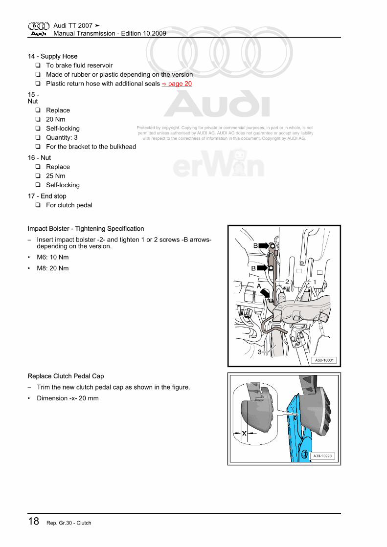
Impact Bolster - Tightening Specification– Insert impact bolster -2- and tighten 1 or 2 screws -B arrows-
depending on the version.• M6: 10 Nm• M8: 20 Nm
Replace Clutch Pedal Cap– Trim the new clutch pedal cap as shown in the figure.• Dimension -x- 20 mm
Audi TT 2007 ➤Manual Transmission - Edition 10.2009
18 Rep. Gr.30 - Clutch

Protected by copyright. Copying for private or commercial purposes, in part or in whole, is not permitted unless authorised by AUDI AG. AUDI AG does not guarantee or accept any liability with respect to the correctness of information in this document. Copyright by AUDI AG.
2.3 Hydraulics Assembly Overview
1 - Brake Fluid Reservoir2 - Spring-Type Clamp
❑ Not equipped on all ve‐hicles
3 - Supply Hose❑ Made of rubber or plas‐
tic depending on theversion
❑ Plastic return hose withadditional seals⇒ page 20
4 - Clutch Master Cylinder❑ Removing and instal‐
ling, refer to⇒ “4.6 Master Cylinder”,page 37
5 - Clip❑ To remove and install
the hose/line assembly,pull the clip out to thestop
6 - Sealing Ring or O-ring❑ Replace damaged seal‐
ing rings or O-rings❑ Pull onto line connection❑ Install with brake fluid❑ Seals/O-rings suitable
for the line connectionmaterial ⇒ page 20
❑ Allocation, refer to theelectronic parts catalogETKA
7 - Mounting Clip❑ To remove and install, disconnect the clutch master cylinder from the clutch pedal. Refer to
⇒ “4.3 Clutch Pedal”, page 328 - Clutch Pedal
❑ Removing and installing, refer to ⇒ “4.3 Clutch Pedal”, page 329 - Nut
❑ For the bracket to the bulkhead❑ Tightening specification -15- ⇒ page 18
10 - Hose/Line Assembly❑ Removing and installing, refer to ⇒ “4.1 Hose/Line Assembly or Plastic Line”, page 29❑ Equipment depends on version❑ Allocation, refer to the electronic parts catalog ETKA
11 - Bracket❑ For hose/line assembly -10-❑ Secured to body❑ Bracket differentiation ⇒ page 21
12 - Plastic Line❑ Removing and installing, refer to ⇒ “4.1 Hose/Line Assembly or Plastic Line”, page 29
Audi TT 2007 ➤Manual Transmission - Edition 10.2009
2. Description and Operation 19
Protected by copyright. Copying for private or commercial purposes, in part or in whole, is not permitted unless authorised by AUDI AG. AUDI AG does not guarantee or accept any liability with respect to the correctness of information in this document. Copyright by AUDI AG.
❑ Equipment depends on version❑ Allocation, refer to the electronic parts catalog ETKA
13 - Bracket❑ For plastic line -12-❑ Secured to body❑ Bracket differentiation ⇒ page 21
14 - Sealing Ring or O-ring❑ Replace damaged sealing rings or O-rings❑ Pull onto line connection❑ Install with brake fluid❑ Seals/O-rings suitable for the line connection material ⇒ page 20❑ Allocation, refer to the electronic parts catalog ETKA
15 - Bleeder16 - Clip
❑ To remove and install hose/line assembly or bleeder, pull out clip until stop17 -Vent Screw
❑ 4.5 Nm❑ Clutch system, bleeding, refer to ⇒ “1.2 Clutch System, Bleeding”, page 12
18 - Dust Cap19 - Clutch Slave Cylinder with Release Bearing
❑ Can only be replaced when transmission is removed20 - Transmission
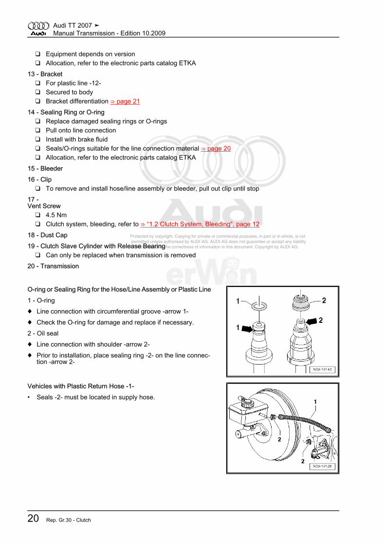
O-ring or Sealing Ring for the Hose/Line Assembly or Plastic Line1 - O-ring♦ Line connection with circumferential groove -arrow 1-♦ Check the O-ring for damage and replace if necessary.2 - Oil seal♦ Line connection with shoulder -arrow 2-♦ Prior to installation, place sealing ring -2- on the line connec‐
tion -arrow 2-
Vehicles with Plastic Return Hose -1-• Seals -2- must be located in supply hose.
Audi TT 2007 ➤Manual Transmission - Edition 10.2009
20 Rep. Gr.30 - Clutch

Protected by copyright. Copying for private or commercial purposes, in part or in whole, is not permitted unless authorised by AUDI AG. AUDI AG does not guarantee or accept any liability with respect to the correctness of information in this document. Copyright by AUDI AG.
Bracket Differentiation
Dimension “a” mm Line Version8 Plastic line6 Hose/line assembly
2.4 Clutch Release Mechanism, Clutch Slave Cylinder Assembly Overview
1 -Bolt
❑ Replace❑ 12 Nm for metal clutch
slave cylinder❑ 15 Nm for plastic clutch
slave cylinder❑ Quantity: 3❑ Carefully tighten diago‐
nally in small stages sothat the clutch slave cyl‐inder bolting tabs do notbreak off
2 - Clutch Slave Cylinder withRelease Bearing
❑ The clutch slave cylin‐der and release bearingare one unit and can on‐ly be replaced together.
❑ Do not wash the bear‐ing, just wipe it off.
❑ If the bearing is noisy,replace it together withthe clutch slave cylinder
❑ Removing and instal‐ling, refer to⇒ “4.7 Slave Cylinderwith Release Bearing”,page 39
3 - O-ring❑ Replace if damaged❑ Pull onto line connection❑ Install with brake fluid
4 - Retaining Clip5 - Vent Screw
❑ Tightening specification -17- ⇒ page 206 - Protective Cap7 - Retaining Clip8 - Hose/line Assembly or Plastic Line
❑ To the clutch slave cylinder
Audi TT 2007 ➤Manual Transmission - Edition 10.2009
2. Description and Operation 21
Protected by copyright. Copying for private or commercial purposes, in part or in whole, is not permitted unless authorised by AUDI AG. AUDI AG does not guarantee or accept any liability with respect to the correctness of information in this document. Copyright by AUDI AG.
❑ Removing and installing, refer to ⇒ “4.1 Hose/Line Assembly or Plastic Line”, page 299 - O-ring
❑ Replace if damaged❑ Pull onto line connection❑ Install with brake fluid
10 - Bleeder❑ Removing and installing, refer to ⇒ “4.7 Slave Cylinder with Release Bearing”, page 39
11 - Shaft Seal❑ For input shaft❑ Removing and installing, refer to ⇒ “4.13 Input Shaft Seal”, page 123
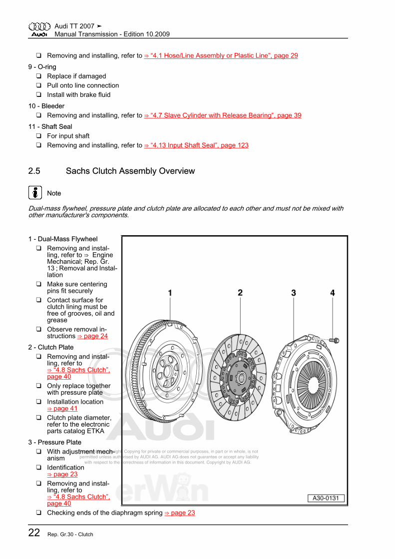
2.5 Sachs Clutch Assembly Overview
Note
Dual-mass flywheel, pressure plate and clutch plate are allocated to each other and must not be mixed withother manufacturer's components.
1 - Dual-Mass Flywheel❑ Removing and instal‐
ling, refer to ⇒ EngineMechanical; Rep. Gr. 13 ; Removal and Instal‐lation
❑ Make sure centeringpins fit securely
❑ Contact surface forclutch lining must befree of grooves, oil andgrease
❑ Observe removal in‐structions ⇒ page 24
2 - Clutch Plate❑ Removing and instal‐
ling, refer to⇒ “4.8 Sachs Clutch”,page 40
❑ Only replace togetherwith pressure plate
❑ Installation location⇒ page 41
❑ Clutch plate diameter,refer to the electronicparts catalog ETKA
3 - Pressure Plate❑ With adjustment mech‐
anism❑ Identification
⇒ page 23❑ Removing and instal‐
ling, refer to⇒ “4.8 Sachs Clutch”,page 40
❑ Checking ends of the diaphragm spring ⇒ page 23
Audi TT 2007 ➤Manual Transmission - Edition 10.2009
22 Rep. Gr.30 - Clutch

Protected by copyright. Copying for private or commercial purposes, in part or in whole, is not permitted unless authorised by AUDI AG. AUDI AG does not guarantee or accept any liability with respect to the correctness of information in this document. Copyright by AUDI AG.
❑ Check the pull-springs and rivet connections ⇒ page 23❑ Check the wire ring or metal ring ⇒ page 24❑ Only replace together with clutch plate❑ Allocation, refer to the electronic parts catalog ETKA❑ Contact surface for clutch lining must be free of grooves, oil and grease
4 -Bolt
❑ M6 - 13 Nm❑ M7 - 20 Nm❑ Loosen and tighten one after another in 90° increments
Identification of Self-Adjusting Clutch (Sachs)Pressure plate with stop (locator) -arrow-.Checking Ends of the Diaphragm Spring
• Wear up to half the thickness of the diaphragm spring-arrows- is permitted.
Checking the Pull-Springs and Rivet ConnectionI - Pull-springs OK
Audi TT 2007 ➤Manual Transmission - Edition 10.2009
2. Description and Operation 23

Protected by copyright. Copying for private or commercial purposes, in part or in whole, is not permitted unless authorised by AUDI AG. AUDI AG does not guarantee or accept any liability with respect to the correctness of information in this document. Copyright by AUDI AG.
• Slight offset in the outer area -arrows A-.II - Pull-springs damaged• The pressure plate must be replaced if the pull-spring is bent
or broken off -arrow B-.
– Make sure the rivet connections -arrows B- fit correctly on allpull-springs -A-.
• Replace any pressure plates that have loose rivet connections-arrow B-.
Check the Wire Ring or Metal Ring– Check the wire ring or metal ring inside the pressure plate for
damage -arrow-.• Replace any pressure plates that have a broken wire ring or
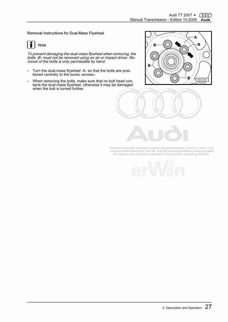
metal ring.Removal Instructions for Dual-Mass Flywheel
Note
To prevent damaging the dual-mass flywheel when removing, thebolts -B- must not be removed using an air or impact driver. Re‐moval of the bolts is only permissible by hand.
– Turn the dual-mass flywheel -A- so that the bolts are posi‐tioned centrally to the bores -arrows-.
– When removing the bolts, make sure that no bolt head con‐tacts the dual-mass flywheel, otherwise it may be damagedwhen the bolt is turned further.
Audi TT 2007 ➤Manual Transmission - Edition 10.2009
24 Rep. Gr.30 - Clutch
Protected by copyright. Copying for private or commercial purposes, in part or in whole, is not permitted unless authorised by AUDI AG. AUDI AG does not guarantee or accept any liability with respect to the correctness of information in this document. Copyright by AUDI AG.
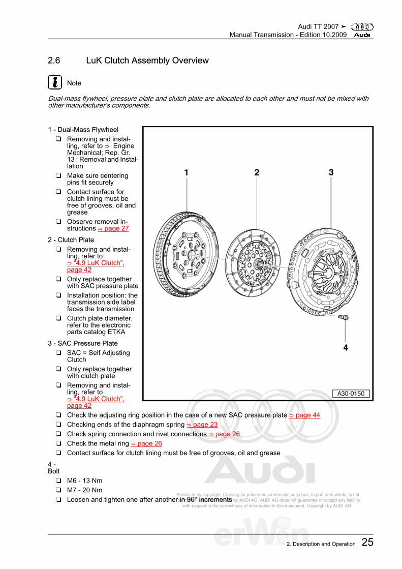
2.6 LuK Clutch Assembly Overview
Note
Dual-mass flywheel, pressure plate and clutch plate are allocated to each other and must not be mixed withother manufacturer's components.
1 - Dual-Mass Flywheel❑ Removing and instal‐
ling, refer to ⇒ EngineMechanical; Rep. Gr. 13 ; Removal and Instal‐lation
❑ Make sure centeringpins fit securely
❑ Contact surface forclutch lining must befree of grooves, oil andgrease
❑ Observe removal in‐structions ⇒ page 27
2 - Clutch Plate❑ Removing and instal‐
ling, refer to⇒ “4.9 LuK Clutch”,page 42
❑ Only replace togetherwith SAC pressure plate
❑ Installation position: thetransmission side labelfaces the transmission
❑ Clutch plate diameter,refer to the electronicparts catalog ETKA
3 - SAC Pressure Plate❑ SAC = Self Adjusting
Clutch❑ Only replace together
with clutch plate❑ Removing and instal‐
ling, refer to⇒ “4.9 LuK Clutch”,page 42
❑ Check the adjusting ring position in the case of a new SAC pressure plate ⇒ page 44❑ Checking ends of the diaphragm spring ⇒ page 23❑ Check spring connection and rivet connections ⇒ page 26❑ Check the metal ring ⇒ page 26❑ Contact surface for clutch lining must be free of grooves, oil and grease
4 -Bolt
❑ M6 - 13 Nm❑ M7 - 20 Nm❑ Loosen and tighten one after another in 90° increments
Audi TT 2007 ➤Manual Transmission - Edition 10.2009
2. Description and Operation 25

Protected by copyright. Copying for private or commercial purposes, in part or in whole, is not permitted unless authorised by AUDI AG. AUDI AG does not guarantee or accept any liability with respect to the correctness of information in this document. Copyright by AUDI AG.
Checking Ends of the Diaphragm Spring• Wear up to half the thickness of the diaphragm spring
-arrows- is permitted.Checking the Pull-Springs and Rivet ConnectionI - Pull-springs OK
• Slight offset in the outer area -arrows A-.II - Pull-springs damaged• The pressure plate must be replaced if the pull-spring is bent
or broken off -arrow B-.
– Make sure the rivet connections -arrows B- fit correctly on allpull-springs -A-.
• Replace any pressure plates that have loose rivet connections-arrow B-.
Checking Metal Ring
– Check the metal ring inside the pressure plate for damage-arrow-.
• Replace any pressure plates that have a broken metal ring.
Audi TT 2007 ➤Manual Transmission - Edition 10.2009
26 Rep. Gr.30 - Clutch
Protected by copyright. Copying for private or commercial purposes, in part or in whole, is not permitted unless authorised by AUDI AG. AUDI AG does not guarantee or accept any liability with respect to the correctness of information in this document. Copyright by AUDI AG.
Removal Instructions for Dual-Mass Flywheel
Note
To prevent damaging the dual-mass flywheel when removing, thebolts -B- must not be removed using an air or impact driver. Re‐moval of the bolts is only permissible by hand.
– Turn the dual-mass flywheel -A- so that the bolts are posi‐tioned centrally to the bores -arrows-.
– When removing the bolts, make sure that no bolt head con‐tacts the dual-mass flywheel, otherwise it may be damagedwhen the bolt is turned further.
Audi TT 2007 ➤Manual Transmission - Edition 10.2009
2. Description and Operation 27

Protected by copyright. Copying for private or commercial purposes, in part or in whole, is not permitted unless authorised by AUDI AG. AUDI AG does not guarantee or accept any liability with respect to the correctness of information in this document. Copyright by AUDI AG.
3 Specifications⇒ “3.1 Fastener Tightening Specifications”, page 28
3.1 Fastener Tightening SpecificationsComponent Bolt Size Nm
Bracket for Clutch Pedal, Nut1,2
20 25Clutch Slave Cylinder, BoltMetal 12Plastic 15Crash Brace to Mounting Bracket/Steer‐ing Column
10
Pressure Plate M6 13 M7 20Vent Screw 4.5• 1 Always replace• 2 For bolt tightening clarification, refer to
⇒ “2.2 Pedal Assembly, Master Cylinder Assembly Overview”, page 17 and see items -15 and 16-
Impact Bolster - Tightening Specification– Insert impact bolster -2- and tighten 1 or 2 bolts -B arrows-
depending on the version.• M6: 10 Nm• M8: 20 Nm
Audi TT 2007 ➤Manual Transmission - Edition 10.2009
28 Rep. Gr.30 - Clutch

Protected by copyright. Copying for private or commercial purposes, in part or in whole, is not permitted unless authorised by AUDI AG. AUDI AG does not guarantee or accept any liability with respect to the correctness of information in this document. Copyright by AUDI AG.
4 Removal and Installation⇒ “4.1 Hose/Line Assembly or Plastic Line”, page 29⇒ “4.2 Over-Center Spring”, page 30⇒ “4.3 Clutch Pedal”, page 32⇒ “4.4 Mounting Bracket”, page 34⇒ “4.5 Clutch Position Sensor”, page 36⇒ “4.6 Master Cylinder”, page 37⇒ “4.7 Slave Cylinder with Release Bearing”, page 39⇒ “4.8 Sachs Clutch”, page 40⇒ “4.9 LuK Clutch”, page 42
4.1 Hose/Line Assembly or Plastic LineSpecial tools and workshop equipment required♦ Hose Clamps Up to 25 mm Diameter. -3094-Removing– Completely remove the air filter housing. Refer to ⇒ Fuel In‐
jection and Ignition; Rep. Gr. 24 ; Removal and Installation .– Clamp off the return hose to the clutch master cylinder with a
-3094- .
Note
♦ While performing the following work, make sure that no brakefluid comes into contact with longitudinal member or withtransmission. If this happens, these areas must be cleanedthoroughly.
♦ Collect any leaking brake fluid with a cloth.
– For removal, use a screwdriver to release securing clip -3- onthe clutch master cylinder.
– Remove hose/line assembly -1- or plastic line with O-ring -2-and detach from the bracket.
Caution
Do not operate the clutch pedal when the hose/line assemblyor plastic line is removed.
Note
Collect any leaking brake fluid with a cloth.
Audi TT 2007 ➤Manual Transmission - Edition 10.2009
4. Removal and Installation 29
Protected by copyright. Copying for private or commercial purposes, in part or in whole, is not permitted unless authorised by AUDI AG. AUDI AG does not guarantee or accept any liability with respect to the correctness of information in this document. Copyright by AUDI AG.
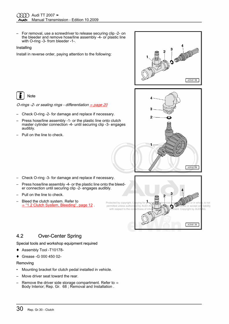
– For removal, use a screwdriver to release securing clip -2- onthe bleeder and remove hose/line assembly -4- or plastic linewith O-ring -3- from bleeder -1-.
InstallingInstall in reverse order, paying attention to the following:
Note
O-rings -2- or sealing rings - differentiation ⇒ page 20
– Check O-ring -2- for damage and replace if necessary.– Press hose/line assembly -1- or the plastic line onto clutch
master cylinder connection -4- until securing clip -3- engagesaudibly.
– Pull on the line to check.
– Check O-ring -3- for damage and replace if necessary.– Press hose/line assembly -4- or the plastic line onto the bleed‐
er connection until securing clip -2- engages audibly.– Pull on the line to check.– Bleed the clutch system. Refer to
⇒ “1.2 Clutch System, Bleeding”, page 12 .
4.2 Over-Center SpringSpecial tools and workshop equipment required♦ Assembly Tool -T10178-♦ Grease -G 000 450 02-Removing• Mounting bracket for clutch pedal installed in vehicle.– Move driver seat toward the rear.– Remove the driver side storage compartment. Refer to ⇒
Body Interior; Rep. Gr. 68 ; Removal and Installation .
Audi TT 2007 ➤Manual Transmission - Edition 10.2009
30 Rep. Gr.30 - Clutch
Protected by copyright. Copying for private or commercial purposes, in part or in whole, is not permitted unless authorised by AUDI AG. AUDI AG does not guarantee or accept any liability with respect to the correctness of information in this document. Copyright by AUDI AG.
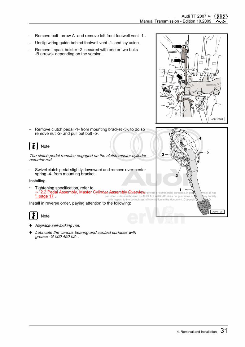
– Remove bolt -arrow A- and remove left front footwell vent -1-.– Unclip wiring guide behind footwell vent -1- and lay aside.– Remove impact bolster -2- secured with one or two bolts
-B arrows- depending on the version.
– Remove clutch pedal -1- from mounting bracket -3-, to do soremove nut -2- and pull out bolt -5-.
Note
The clutch pedal remains engaged on the clutch master cylinderactuator rod.
– Swivel clutch pedal slightly downward and remove over-centerspring -4- from mounting bracket.
Installing• Tightening specification, refer to
⇒ “2.2 Pedal Assembly, Master Cylinder Assembly Overview”, page 17 .
Install in reverse order, paying attention to the following:
Note
♦ Replace self-locking nut.♦ Lubricate the various bearing and contact surfaces with
grease -G 000 450 02- .
Audi TT 2007 ➤Manual Transmission - Edition 10.2009
4. Removal and Installation 31

Protected by copyright. Copying for private or commercial purposes, in part or in whole, is not permitted unless authorised by AUDI AG. AUDI AG does not guarantee or accept any liability with respect to the correctness of information in this document. Copyright by AUDI AG.
– Place over-center spring -2- in the bearing bracket from aboveand hold the end of the spring in the installation position withthe -T10178- .
• The over-center spring mounting cup -arrow- must be vertical.– Insert clutch pedal pressure tab -A- in over-center spring
mounting cup -arrow-.– Press on clutch pedal slightly, push bolt through and tighten
self-locking nut.– Install the impact bolster ⇒ page 18 .– Install the left front footwell vent. Refer to ⇒ Heating, Ventila‐
tion and Air Conditioning; Rep. Gr. 87 ; Removal and Instal‐lation .
– Install the driver side storage compartment. Refer to ⇒ BodyInterior; Rep. Gr. 68 ; Removal and Installation .
4.3 Clutch PedalSpecial tools and workshop equipment required♦ Pliers -T10005-♦ Assembly Tool -T10178-♦ Grease -G 000 450 02-Removing• Mounting bracket for clutch pedal installed in vehicle.– Move driver seat toward the rear.– Remove the driver side storage compartment. Refer to ⇒
Body Interior; Rep. Gr. 68 ; Removal and Installation .
Audi TT 2007 ➤Manual Transmission - Edition 10.2009
32 Rep. Gr.30 - Clutch
Protected by copyright. Copying for private or commercial purposes, in part or in whole, is not permitted unless authorised by AUDI AG. AUDI AG does not guarantee or accept any liability with respect to the correctness of information in this document. Copyright by AUDI AG.
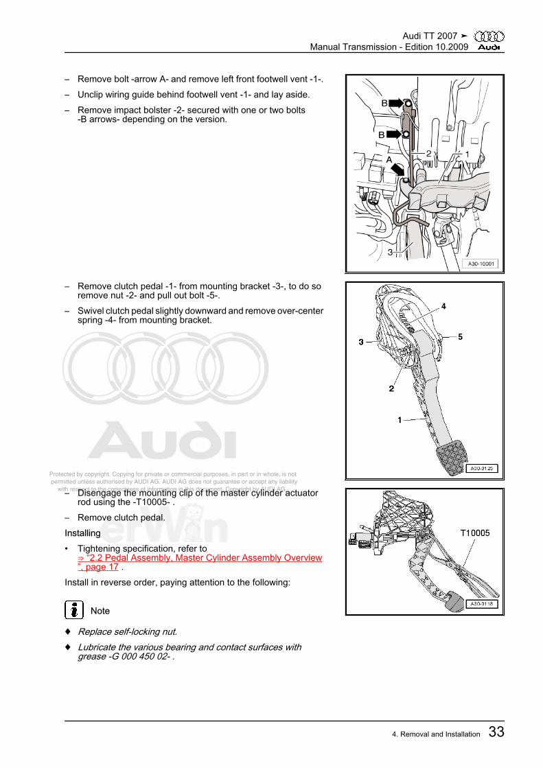
– Remove bolt -arrow A- and remove left front footwell vent -1-.– Unclip wiring guide behind footwell vent -1- and lay aside.– Remove impact bolster -2- secured with one or two bolts
-B arrows- depending on the version.
– Remove clutch pedal -1- from mounting bracket -3-, to do soremove nut -2- and pull out bolt -5-.
– Swivel clutch pedal slightly downward and remove over-centerspring -4- from mounting bracket.
– Disengage the mounting clip of the master cylinder actuatorrod using the -T10005- .
– Remove clutch pedal.Installing• Tightening specification, refer to
⇒ “2.2 Pedal Assembly, Master Cylinder Assembly Overview”, page 17 .
Install in reverse order, paying attention to the following:
Note
♦ Replace self-locking nut.♦ Lubricate the various bearing and contact surfaces with
grease -G 000 450 02- .
Audi TT 2007 ➤Manual Transmission - Edition 10.2009
4. Removal and Installation 33
Protected by copyright. Copying for private or commercial purposes, in part or in whole, is not permitted unless authorised by AUDI AG. AUDI AG does not guarantee or accept any liability with respect to the correctness of information in this document. Copyright by AUDI AG.
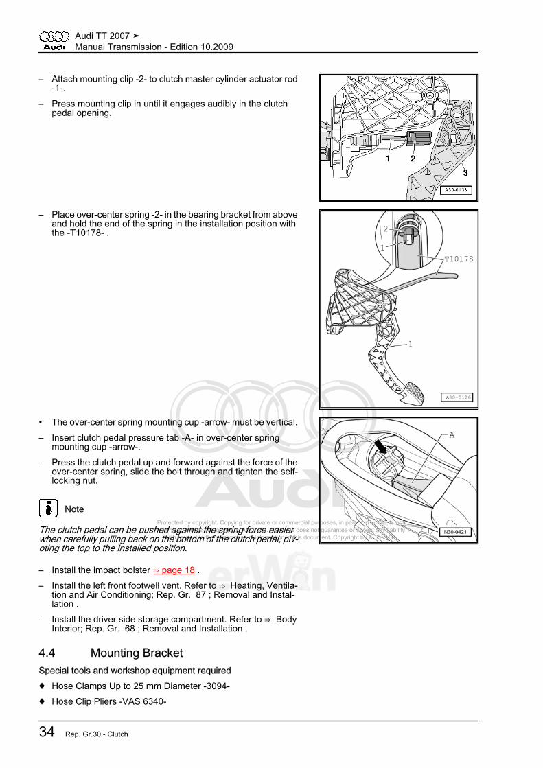
– Attach mounting clip -2- to clutch master cylinder actuator rod-1-.
– Press mounting clip in until it engages audibly in the clutchpedal opening.
– Place over-center spring -2- in the bearing bracket from aboveand hold the end of the spring in the installation position withthe -T10178- .
• The over-center spring mounting cup -arrow- must be vertical.– Insert clutch pedal pressure tab -A- in over-center spring
mounting cup -arrow-.– Press the clutch pedal up and forward against the force of the
over-center spring, slide the bolt through and tighten the self-locking nut.
Note
The clutch pedal can be pushed against the spring force easierwhen carefully pulling back on the bottom of the clutch pedal, piv‐oting the top to the installed position.
– Install the impact bolster ⇒ page 18 .– Install the left front footwell vent. Refer to ⇒ Heating, Ventila‐
tion and Air Conditioning; Rep. Gr. 87 ; Removal and Instal‐lation .
– Install the driver side storage compartment. Refer to ⇒ BodyInterior; Rep. Gr. 68 ; Removal and Installation .
4.4 Mounting BracketSpecial tools and workshop equipment required♦ Hose Clamps Up to 25 mm Diameter -3094-♦ Hose Clip Pliers -VAS 6340-
Audi TT 2007 ➤Manual Transmission - Edition 10.2009
34 Rep. Gr.30 - Clutch
Protected by copyright. Copying for private or commercial purposes, in part or in whole, is not permitted unless authorised by AUDI AG. AUDI AG does not guarantee or accept any liability with respect to the correctness of information in this document. Copyright by AUDI AG.
Removing
Note
While performing the following work, make sure that no brake fluidcomes into contact with longitudinal member or with the trans‐mission. If this happens, these areas must be cleaned thoroughly.
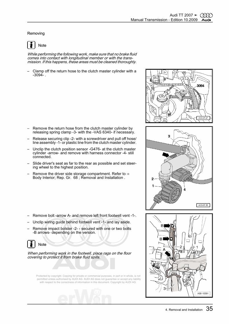
– Clamp off the return hose to the clutch master cylinder with a-3094- .
– Remove the return hose from the clutch master cylinder byreleasing spring clamp -3- with the -VAS 6340- if necessary.
– Release securing clip -2- with a screwdriver and pull off hose/line assembly -1- or plastic line from the clutch master cylinder.
– Unclip the clutch position sensor -G476- at the clutch mastercylinder -arrow- and remove with harness connector -4- stillconnected.
– Slide driver's seat as far to the rear as possible and set steer‐ing wheel to the highest position.
– Remove the driver side storage compartment. Refer to ⇒ Body Interior; Rep. Gr. 68 ; Removal and Installation .
– Remove bolt -arrow A- and remove left front footwell vent -1-.– Unclip wiring guide behind footwell vent -1- and lay aside.– Remove impact bolster -2- - secured with one or two bolts
-B arrows- depending on the version.
Note
When performing work in the footwell, place rags on the floorcovering to protect it from brake fluid spills.
Audi TT 2007 ➤Manual Transmission - Edition 10.2009
4. Removal and Installation 35

Protected by copyright. Copying for private or commercial purposes, in part or in whole, is not permitted unless authorised by AUDI AG. AUDI AG does not guarantee or accept any liability with respect to the correctness of information in this document. Copyright by AUDI AG.
– Remove the nuts -2-.– Remove mounting bracket -1-.Installing• Tightening specification, refer to
⇒ “2.2 Pedal Assembly, Master Cylinder Assembly Overview”, page 17 .
Install in reverse order, paying attention to the following:
Note
♦ Replace self-locking nuts.♦ Secure all hose connections with hose clamps of the same
type as those equipped by the factory. Refer to the electronicparts catalog ETKA.
– Insert mounting bracket -1- and tighten nuts -2-.– Install the hose/line assembly or plastic line. Refer to
⇒ “4.1 Hose/Line Assembly or Plastic Line”, page 29 .– Bleed the clutch system. Refer to
⇒ “1.2 Clutch System, Bleeding”, page 12 .– Install the impact bolster ⇒ page 18 .– Install the left front footwell vent. Refer to ⇒ Heating, Ventila‐
tion and Air Conditioning; Rep. Gr. 87 ; Removal and Instal‐lation .
– Install the driver side storage compartment. Refer to ⇒ BodyInterior; Rep. Gr. 68 ; Removal and Installation .
4.5 Clutch Position SensorRemoving– Disconnect electrical connector -4-.– Unclip the clutch position sensor -G476- at the clutch master
cylinder in direction of the -arrow- and remove it.
Note
Ignore items -1, 2 and 3-.
Installing
Audi TT 2007 ➤Manual Transmission - Edition 10.2009
36 Rep. Gr.30 - Clutch
Protected by copyright. Copying for private or commercial purposes, in part or in whole, is not permitted unless authorised by AUDI AG. AUDI AG does not guarantee or accept any liability with respect to the correctness of information in this document. Copyright by AUDI AG.
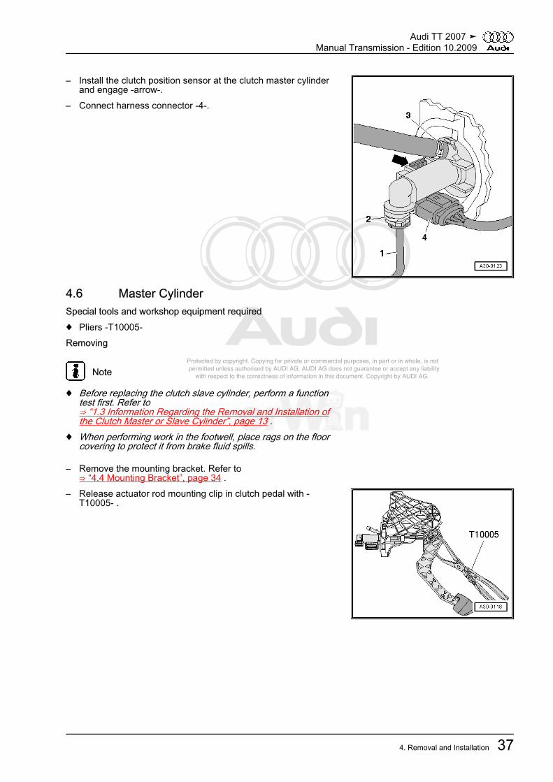
– Install the clutch position sensor at the clutch master cylinderand engage -arrow-.
– Connect harness connector -4-.
4.6 Master CylinderSpecial tools and workshop equipment required♦ Pliers -T10005-Removing
Note
♦ Before replacing the clutch slave cylinder, perform a functiontest first. Refer to⇒ “1.3 Information Regarding the Removal and Installation ofthe Clutch Master or Slave Cylinder”, page 13 .
♦ When performing work in the footwell, place rags on the floorcovering to protect it from brake fluid spills.
– Remove the mounting bracket. Refer to⇒ “4.4 Mounting Bracket”, page 34 .
– Release actuator rod mounting clip in clutch pedal with -T10005- .
Audi TT 2007 ➤Manual Transmission - Edition 10.2009
4. Removal and Installation 37

Protected by copyright. Copying for private or commercial purposes, in part or in whole, is not permitted unless authorised by AUDI AG. AUDI AG does not guarantee or accept any liability with respect to the correctness of information in this document. Copyright by AUDI AG.
– Place a spacer -A- between the clutch pedal and the stop andpress the clutch pedal forward.
• Length of spacer = approximately 40 mm (for example 1/2"socket insert)
– Release retaining clip -B- and pull the clutch master cylinderout of the bearing bracket -arrow 1- and -arrow 2-.
Installing• Move clutch pedal up to stop in rest position.
– Attach mounting clip -2- to clutch master cylinder actuator rod-1-.
– Place a spacer -A- between the clutch pedal and the stop andpress the clutch pedal forward.
• Length of spacer = approximately 40 mm (for example 1/2"socket insert)
– Secure the clutch master cylinder on the bearing bracket-arrow 1- and -arrow 2-.
Audi TT 2007 ➤Manual Transmission - Edition 10.2009
38 Rep. Gr.30 - Clutch
Protected by copyright. Copying for private or commercial purposes, in part or in whole, is not permitted unless authorised by AUDI AG. AUDI AG does not guarantee or accept any liability with respect to the correctness of information in this document. Copyright by AUDI AG.
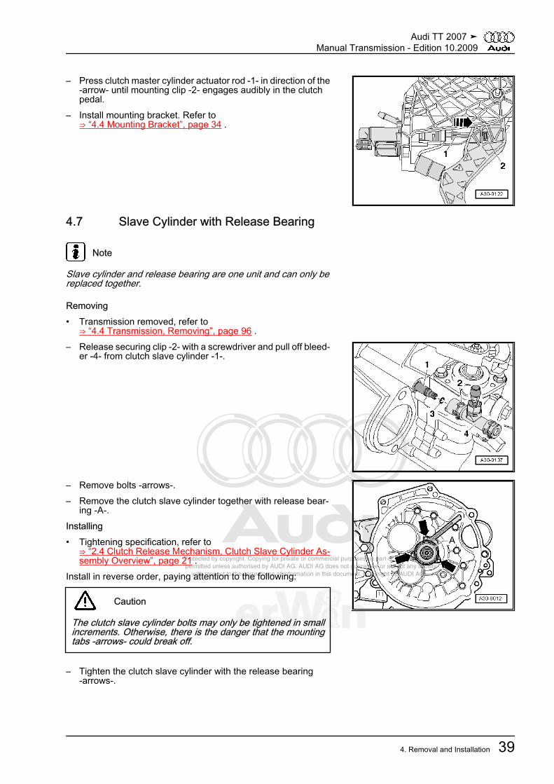
– Press clutch master cylinder actuator rod -1- in direction of the-arrow- until mounting clip -2- engages audibly in the clutchpedal.
– Install mounting bracket. Refer to⇒ “4.4 Mounting Bracket”, page 34 .
4.7 Slave Cylinder with Release Bearing
Note
Slave cylinder and release bearing are one unit and can only bereplaced together.
Removing• Transmission removed, refer to
⇒ “4.4 Transmission, Removing”, page 96 .– Release securing clip -2- with a screwdriver and pull off bleed‐
er -4- from clutch slave cylinder -1-.
– Remove bolts -arrows-.– Remove the clutch slave cylinder together with release bear‐
ing -A-.Installing• Tightening specification, refer to
⇒ “2.4 Clutch Release Mechanism, Clutch Slave Cylinder As‐sembly Overview”, page 21 .
Install in reverse order, paying attention to the following:
Caution
The clutch slave cylinder bolts may only be tightened in smallincrements. Otherwise, there is the danger that the mountingtabs -arrows- could break off.
– Tighten the clutch slave cylinder with the release bearing-arrows-.
Audi TT 2007 ➤Manual Transmission - Edition 10.2009
4. Removal and Installation 39

Protected by copyright. Copying for private or commercial purposes, in part or in whole, is not permitted unless authorised by AUDI AG. AUDI AG does not guarantee or accept any liability with respect to the correctness of information in this document. Copyright by AUDI AG.
– Check O-ring -3- for damage and replace if necessary.– Press bleeder -4- onto clutch slave cylinder connection -1- un‐
til securing clip -2- engages audibly.– Pull on the bleeder to verify.– Bleed the clutch system. Refer to
⇒ “1.2 Clutch System, Bleeding”, page 12 .
4.8 Sachs ClutchSpecial tools and workshop equipment required♦ Flywheel Retainer -3067-♦ Centering Pin -T10097-♦ Grease for clutch disc shaft splines -G 000 100-Removing• Transmission removed, refer to
⇒ “4.4 Transmission, Removing”, page 96 .When removing, loosen the bolts as follows, so that the pressureplate does not distort (causing shuddering on acceleration):– Insert -3067- to loosen bolts.– Loosen all 6 bolts clockwise, one after the other and in steps
of 90° (1/4 turn) until the pressure plate is free.
Audi TT 2007 ➤Manual Transmission - Edition 10.2009
40 Rep. Gr.30 - Clutch
Protected by copyright. Copying for private or commercial purposes, in part or in whole, is not permitted unless authorised by AUDI AG. AUDI AG does not guarantee or accept any liability with respect to the correctness of information in this document. Copyright by AUDI AG.
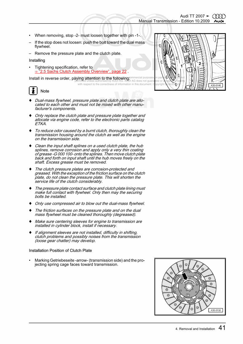
• When removing, stop -2- must loosen together with pin -1-.– If the stop does not loosen: push the bolt toward the dual mass
flywheel.– Remove the pressure plate and the clutch plate.Installing• Tightening specification, refer to
⇒ “2.5 Sachs Clutch Assembly Overview”, page 22 .Install in reverse order, paying attention to the following:
Note
♦ Dual-mass flywheel, pressure plate and clutch plate are allo‐cated to each other and must not be mixed with other manu‐facturer's components.
♦ Only replace the clutch plate and pressure plate together andallocate via engine code, refer to the electronic parts catalogETKA.
♦ To reduce odor caused by a burnt clutch, thoroughly clean thetransmission housing around the clutch as well as the engineon the transmission side.
♦ Clean the input shaft splines on a used clutch plate, the hubsplines, remove corrosion and apply only a very thin coatingof grease -G 000 100- onto the splines. Then move clutch plateback and forth on input shaft until the hub moves freely on theshaft. Excess grease must be removed.
♦ The clutch pressure plates are corrosion-protected andgreased. With the exception of the friction surface on the clutchplate, do not clean the pressure plate. This will shorten theservice life of the clutch considerably.
♦ The pressure plate contact surface and clutch plate lining mustmake full contact with flywheel. Only then may the securingbolts be installed.
♦ Only use compressed air to blow out the dual-mass flywheel.♦ The friction surfaces on the pressure plate and on the dual
mass flywheel must be cleaned thoroughly (degreased).♦ Make sure centering sleeves for engine to transmission are
installed in cylinder block, install if necessary.♦ If alignment sleeves are not installed, difficulty in shifting,
clutch problems and possibly noises from the transmission(loose gear chatter) may develop.
Installation Position of Clutch Plate
• Marking Getriebeseite -arrow- (transmission side) and the pro‐jecting spring cage faces toward transmission.
Audi TT 2007 ➤Manual Transmission - Edition 10.2009
4. Removal and Installation 41

Protected by copyright. Copying for private or commercial purposes, in part or in whole, is not permitted unless authorised by AUDI AG. AUDI AG does not guarantee or accept any liability with respect to the correctness of information in this document. Copyright by AUDI AG.
– Insert -3067- .– Position the pressure plate on the alignment pins.– To center the clutch plate, use the -T10097- .Install the pressure plate as follows so that the pressure platedoes not distort during installation (causing shuddering duringacceleration):
– Make sure that the stop pin (locator) -arrow- can be movedeasily.
– Install all 6 bolts evenly, by hand, until the bolt heads contactthe pressure plate.
– Tighten all 6 bolts clockwise, one after the other and in stepsof 90° (1/4 turn) until the housing contacts the flywheel.
• When doing this, the stop pin -arrow- must lift off from thepressure plate.
– Tighten all 6 bolts clockwise, one after the other to tighteningspecification. Tightening specification -4- ⇒ page 23 .
4.9 LuK ClutchSpecial tools and workshop equipment required♦ Flywheel Retainer -3067-♦ Centering Pin -T10097-♦ Grease for clutch disc shaft splines -G 000 100-Removing• Transmission removed, refer to
⇒ “4.4 Transmission, Removing”, page 96 .
Audi TT 2007 ➤Manual Transmission - Edition 10.2009
42 Rep. Gr.30 - Clutch

Protected by copyright. Copying for private or commercial purposes, in part or in whole, is not permitted unless authorised by AUDI AG. AUDI AG does not guarantee or accept any liability with respect to the correctness of information in this document. Copyright by AUDI AG.
– Insert -3067- to loosen bolts.When removing, loosen the bolts as follows, so that the pressureplate does not distort (causing shuddering on acceleration):– Loosen all 6 bolts clockwise, one after the other and in steps
of 90° (1/4 turn) until the pressure plate is free.
– Remove the pressure plate and the clutch plate.Installing• Tightening specification, refer to
⇒ “2.6 LuK Clutch Assembly Overview”, page 25 .Install in reverse order, paying attention to the following:
Note
♦ Dual-mass flywheel, pressure plate and clutch plate are allo‐cated to each other and must not be mixed with other manu‐facturer's components.
♦ Only replace the clutch plate and pressure plate together andallocate via engine code, refer to the electronic parts catalogETKA.
♦ Check the adjusting ring position in the case of a new pressureplate ⇒ page 44 .
♦ To reduce odor caused by a burnt clutch, thoroughly clean thetransmission housing around the clutch as well as the engineon the transmission side.
♦ Clean the input shaft splines and on a used clutch plate, thehub splines, remove corrosion and apply only a very thin coat‐ing of grease -G 000 100- onto the splines. Then move clutchplate back and forth on input shaft until the hub moves freelyon the shaft. Excess grease must be removed.
♦ The clutch pressure plates are corrosion-protected andgreased. With the exception of the friction surface on the clutchplate, do not clean the pressure plate. This will shorten theservice life of the clutch considerably.
♦ The pressure plate contact surface and clutch plate lining mustmake full contact with flywheel. Only then may the securingbolts be installed.
♦ Only use compressed air to blow out the dual-mass flywheel.♦ The friction surfaces on the pressure plate and on the dual
mass flywheel must be cleaned thoroughly (degreased).♦ Make sure alignment sleeves for engine to transmission are
installed in cylinder block, install if necessary.♦ If alignment sleeves are not installed, difficulty in shifting,
clutch problems and possibly noises from the transmission(loose gear chatter) may develop.
Audi TT 2007 ➤Manual Transmission - Edition 10.2009
4. Removal and Installation 43
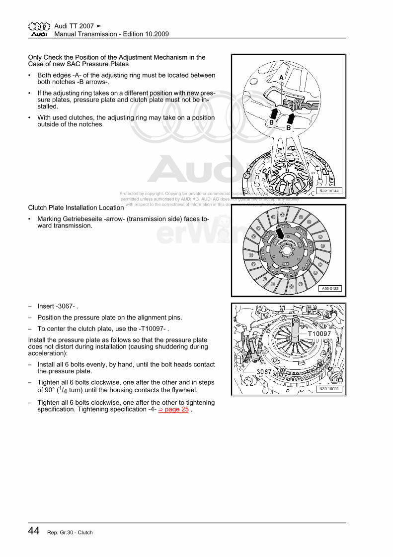
Protected by copyright. Copying for private or commercial purposes, in part or in whole, is not permitted unless authorised by AUDI AG. AUDI AG does not guarantee or accept any liability with respect to the correctness of information in this document. Copyright by AUDI AG.
Only Check the Position of the Adjustment Mechanism in theCase of new SAC Pressure Plates• Both edges -A- of the adjusting ring must be located between
both notches -B arrows-.• If the adjusting ring takes on a different position with new pres‐
sure plates, pressure plate and clutch plate must not be in‐stalled.
• With used clutches, the adjusting ring may take on a positionoutside of the notches.
Clutch Plate Installation Location• Marking Getriebeseite -arrow- (transmission side) faces to‐
ward transmission.
– Insert -3067- .– Position the pressure plate on the alignment pins.– To center the clutch plate, use the -T10097- .Install the pressure plate as follows so that the pressure platedoes not distort during installation (causing shuddering duringacceleration):– Install all 6 bolts evenly, by hand, until the bolt heads contact
the pressure plate.– Tighten all 6 bolts clockwise, one after the other and in steps
of 90° (1/4 turn) until the housing contacts the flywheel.
– Tighten all 6 bolts clockwise, one after the other to tighteningspecification. Tightening specification -4- ⇒ page 25 .
Audi TT 2007 ➤Manual Transmission - Edition 10.2009
44 Rep. Gr.30 - Clutch

Protected by copyright. Copying for private or commercial purposes, in part or in whole, is not permitted unless authorised by AUDI AG. AUDI AG does not guarantee or accept any liability with respect to the correctness of information in this document. Copyright by AUDI AG.
5 Special ToolsSpecial tools and workshop equipment required♦ Brake Filler/Bleeder Unit -VAS 5234-
♦ Hose Clamps Up to 25 mm Diameter. -3094-
♦ Assembly Tool -T10178-
♦ Pliers -T10005-
Audi TT 2007 ➤Manual Transmission - Edition 10.2009
5. Special Tools 45

Protected by copyright. Copying for private or commercial purposes, in part or in whole, is not permitted unless authorised by AUDI AG. AUDI AG does not guarantee or accept any liability with respect to the correctness of information in this document. Copyright by AUDI AG.
♦ Hose Clamps Up to 25 mm Diameter -3094-
♦ Hose Clip Pliers -VAS 6340-
♦ Flywheel Retainer -3067-
♦ Centering Pin -T10097-
Audi TT 2007 ➤Manual Transmission - Edition 10.2009
46 Rep. Gr.30 - Clutch
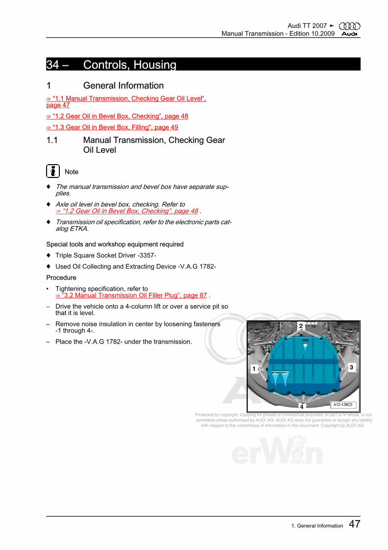
Protected by copyright. Copying for private or commercial purposes, in part or in whole, is not permitted unless authorised by AUDI AG. AUDI AG does not guarantee or accept any liability with respect to the correctness of information in this document. Copyright by AUDI AG.
34 – Controls, Housing1 General Information⇒ “1.1 Manual Transmission, Checking Gear Oil Level”,page 47⇒ “1.2 Gear Oil in Bevel Box, Checking”, page 48⇒ “1.3 Gear Oil in Bevel Box, Filling”, page 49
1.1 Manual Transmission, Checking GearOil Level
Note
♦ The manual transmission and bevel box have separate sup‐plies.
♦ Axle oil level in bevel box, checking. Refer to⇒ “1.2 Gear Oil in Bevel Box, Checking”, page 48 .
♦ Transmission oil specification, refer to the electronic parts cat‐alog ETKA.
Special tools and workshop equipment required♦ Triple Square Socket Driver -3357-♦ Used Oil Collecting and Extracting Device -V.A.G 1782-Procedure• Tightening specification, refer to
⇒ “3.2 Manual Transmission Oil Filler Plug”, page 87 .– Drive the vehicle onto a 4-column lift or over a service pit so
that it is level.– Remove noise insulation in center by loosening fasteners
-1 through 4-.– Place the -V.A.G 1782- under the transmission.
Audi TT 2007 ➤Manual Transmission - Edition 10.2009
1. General Information 47

Protected by copyright. Copying for private or commercial purposes, in part or in whole, is not permitted unless authorised by AUDI AG. AUDI AG does not guarantee or accept any liability with respect to the correctness of information in this document. Copyright by AUDI AG.
– Remove the bolt -arrow- for the oil filler hole in the manualtransmission.
• Target value: the fluid level must reach the lower edge of theoil filler hole.
– Add gear oil if necessary.– Tighten the bolt for the oil filler hole with a new sealing ring.– Install the noise insulation. Refer to ⇒ Body Exterior; Rep. Gr.
66 ; Removal and Installation .
1.2 Gear Oil in Bevel Box, Checking
Note
♦ Bevel box is installed to the side of manual transmission andhas a separate self-contained oil system.
♦ Axle oil specification, refer to the electronic parts catalog ET‐KA.
Special tools and workshop equipment required♦ Used Oil Collecting and Extracting Device -V.A.G 1782-Procedure• Vehicle must be level• Bevel box must be in installation location.• Tightening specification, refer to
⇒ “3.1 Bevel Box Oil Filler Bolt”, page 87 .– Remove noise insulation in center by loosening fasteners
-1 through 4-.– Place the -V.A.G 1782- under the bevel box.
Audi TT 2007 ➤Manual Transmission - Edition 10.2009
48 Rep. Gr.34 - Controls, Housing
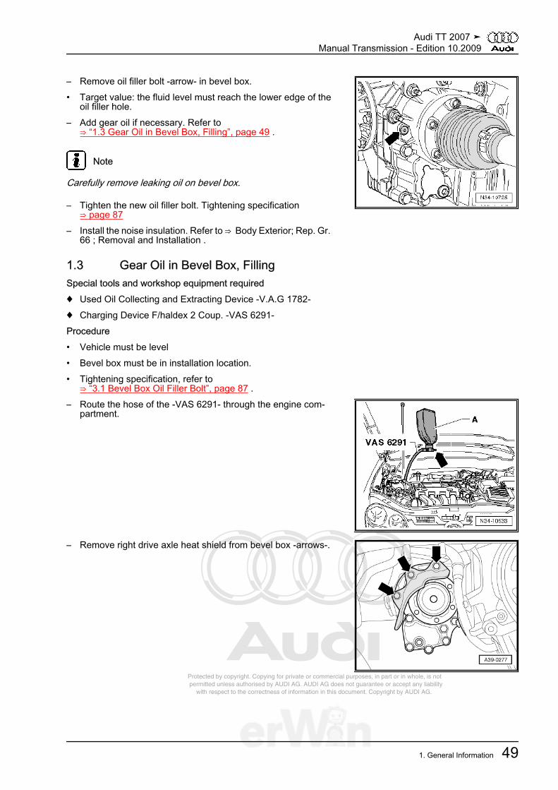
Protected by copyright. Copying for private or commercial purposes, in part or in whole, is not permitted unless authorised by AUDI AG. AUDI AG does not guarantee or accept any liability with respect to the correctness of information in this document. Copyright by AUDI AG.
– Remove oil filler bolt -arrow- in bevel box.• Target value: the fluid level must reach the lower edge of the
oil filler hole.– Add gear oil if necessary. Refer to
⇒ “1.3 Gear Oil in Bevel Box, Filling”, page 49 .
Note
Carefully remove leaking oil on bevel box.
– Tighten the new oil filler bolt. Tightening specification⇒ page 87
– Install the noise insulation. Refer to ⇒ Body Exterior; Rep. Gr. 66 ; Removal and Installation .
1.3 Gear Oil in Bevel Box, FillingSpecial tools and workshop equipment required♦ Used Oil Collecting and Extracting Device -V.A.G 1782-♦ Charging Device F/haldex 2 Coup. -VAS 6291-Procedure• Vehicle must be level• Bevel box must be in installation location.• Tightening specification, refer to
⇒ “3.1 Bevel Box Oil Filler Bolt”, page 87 .– Route the hose of the -VAS 6291- through the engine com‐
partment.
– Remove right drive axle heat shield from bevel box -arrows-.
Audi TT 2007 ➤Manual Transmission - Edition 10.2009
1. General Information 49
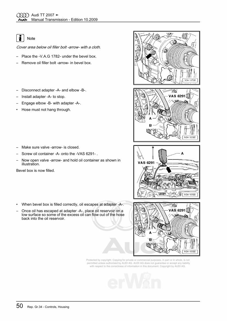
Protected by copyright. Copying for private or commercial purposes, in part or in whole, is not permitted unless authorised by AUDI AG. AUDI AG does not guarantee or accept any liability with respect to the correctness of information in this document. Copyright by AUDI AG.
Note
Cover area below oil filler bolt -arrow- with a cloth.
– Place the -V.A.G 1782- under the bevel box.– Remove oil filler bolt -arrow- in bevel box.
– Disconnect adapter -A- and elbow -B-.– Install adapter -A- to stop.– Engage elbow -B- with adapter -A-.• Hose must not hang through.
– Make sure valve -arrow- is closed.– Screw oil container -A- onto the -VAS 6291- .– Now open valve -arrow- and hold oil container as shown in
illustration.Bevel box is now filled.
• When bevel box is filled correctly, oil escapes at adapter -A-.– Once oil has escaped at adapter -A-, place oil reservoir on a
low surface so some of the excess oil can flow out of the hoseback into the oil reservoir.
Audi TT 2007 ➤Manual Transmission - Edition 10.2009
50 Rep. Gr.34 - Controls, Housing
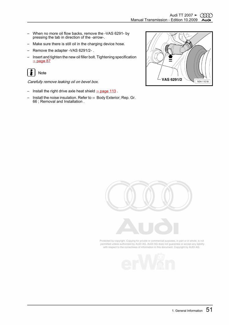
Protected by copyright. Copying for private or commercial purposes, in part or in whole, is not permitted unless authorised by AUDI AG. AUDI AG does not guarantee or accept any liability with respect to the correctness of information in this document. Copyright by AUDI AG.
– When no more oil flow backs, remove the -VAS 6291- bypressing the tab in direction of the -arrow-.
– Make sure there is still oil in the charging device hose.– Remove the adapter -VAS 6291/2- .– Insert and tighten the new oil filler bolt. Tightening specification
⇒ page 87
Note
Carefully remove leaking oil on bevel box.
– Install the right drive axle heat shield ⇒ page 113 .– Install the noise insulation. Refer to ⇒ Body Exterior; Rep. Gr.
66 ; Removal and Installation .
Audi TT 2007 ➤Manual Transmission - Edition 10.2009
1. General Information 51

Protected by copyright. Copying for private or commercial purposes, in part or in whole, is not permitted unless authorised by AUDI AG. AUDI AG does not guarantee or accept any liability with respect to the correctness of information in this document. Copyright by AUDI AG.
2 Description and Operation⇒ “2.1 Selector Mechanism Overview”, page 52⇒ “2.2 Shift Knob and Covers Assembly Overview”, page 54⇒ “2.3 Shift Lever and Shift Housing for Vehicles to VIN8J-7-013000 Assembly Overview”, page 56⇒ “2.4 Shift Lever and Shift Housing for Vehicles from VIN8J-7-013001 Assembly Overview”, page 59⇒ “2.5 Shift Cable and Selector Cable to Model Year 2007 As‐sembly Overview ”, page 61⇒ “2.6 Transmission Shift Lever and Selector Relay Lever toModel Year 2007 Assembly Overview”, page 63⇒ “2.7 Shift Cable and Selector Cable from Model Year 2008 As‐sembly Overview ”, page 65⇒ “2.8 Shift Mechanism, Adjusting”, page 69⇒ “2.9 Subframe Mount Assembly Overview”, page 72⇒ “2.10 Transmission Overview”, page 75⇒ “2.11 Transmission Assembly Overview”, page 76⇒ “2.12 Transmission Housing and Shift Mechanism AssemblyOverview”, page 77⇒ “2.13 Input Shaft, Output Shafts, Differential, Bevel Box andSelector Rods Assembly Overview”, page 79⇒ “2.14 Transmission Housing Assembly Overview”, page 81⇒ “2.15 Clutch Housing Assembly Overview”, page 83⇒ “2.16 Shift Mechanism Assembly Overview, TransmissionSide”, page 85⇒ “2.17 Shift Forks Assembly Overview”, page 86
2.1 Selector Mechanism Overview♦ ⇒ “2.2 Shift Knob and Covers Assembly Overview”,
page 54♦ ⇒ “4.1 Shift Knob with Shift Lever Boot”, page 90♦ ⇒ “2.3 Shift Lever and Shift Housing for Vehicles to VIN
8J-7-013000 Assembly Overview”, page 56♦ ⇒ “2.4 Shift Lever and Shift Housing for Vehicles from VIN
8J-7-013001 Assembly Overview”, page 59♦ ⇒ “5.1 Selector Mechanism”, page 128♦ ⇒ “4.2 Selector Mechanism”, page 91♦ ⇒ “2.5 Shift Cable and Selector Cable to Model Year 2007 As‐
sembly Overview ”, page 61♦ ⇒ “2.6 Transmission Shift Lever and Selector Relay Lever to
Model Year 2007 Assembly Overview”, page 63♦ ⇒ “2.7 Shift Cable and Selector Cable from Model Year 2008
Assembly Overview ”, page 65♦ ⇒ “4.3 Shift Cable and Selector Cable”, page 94♦ ⇒ “2.8 Shift Mechanism, Adjusting”, page 69-Arrow A- Gear Movement-Arrow B- Selection Movement
Audi TT 2007 ➤Manual Transmission - Edition 10.2009
52 Rep. Gr.34 - Controls, Housing

Protected by copyright. Copying for private or commercial purposes, in part or in whole, is not permitted unless authorised by AUDI AG. AUDI AG does not guarantee or accept any liability with respect to the correctness of information in this document. Copyright by AUDI AG.
1 - Shift Cable2 - Selector Cable3 - Heat Shield
❑ Before removing, re‐move the shift mecha‐nism
4 - Selector Relay Lever5 - Transmission Shift Lever
Audi TT 2007 ➤Manual Transmission - Edition 10.2009
2. Description and Operation 53
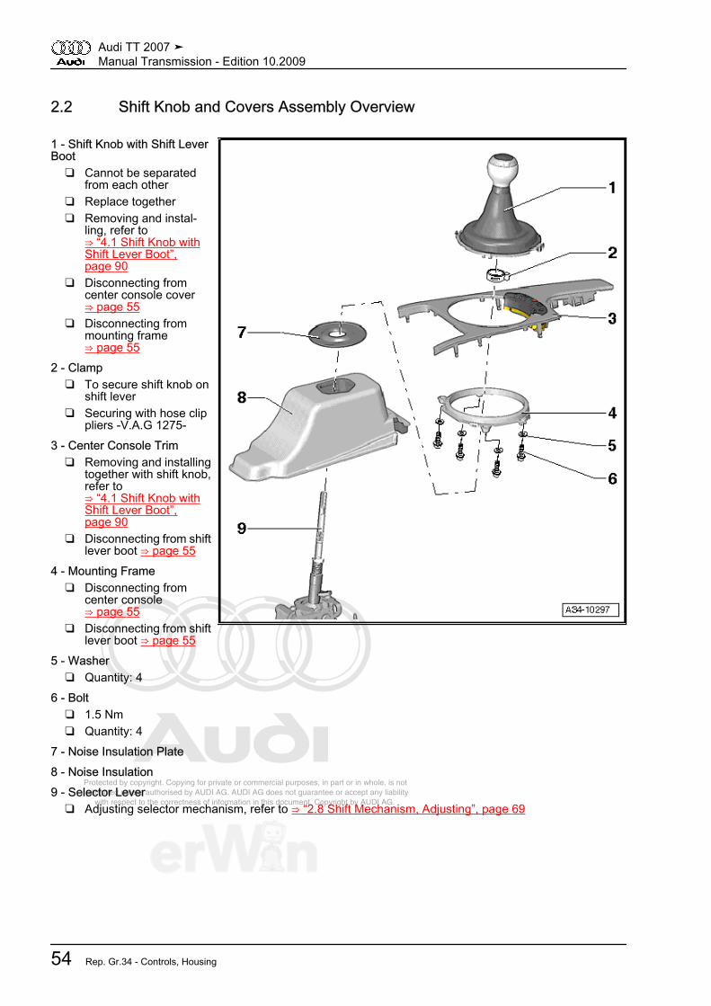
Protected by copyright. Copying for private or commercial purposes, in part or in whole, is not permitted unless authorised by AUDI AG. AUDI AG does not guarantee or accept any liability with respect to the correctness of information in this document. Copyright by AUDI AG.
2.2 Shift Knob and Covers Assembly Overview
1 - Shift Knob with Shift LeverBoot
❑ Cannot be separatedfrom each other
❑ Replace together❑ Removing and instal‐
ling, refer to⇒ “4.1 Shift Knob withShift Lever Boot”,page 90
❑ Disconnecting fromcenter console cover⇒ page 55
❑ Disconnecting frommounting frame⇒ page 55
2 - Clamp❑ To secure shift knob on
shift lever❑ Securing with hose clip
pliers -V.A.G 1275-3 - Center Console Trim
❑ Removing and installingtogether with shift knob,refer to⇒ “4.1 Shift Knob withShift Lever Boot”,page 90
❑ Disconnecting from shiftlever boot ⇒ page 55
4 - Mounting Frame❑ Disconnecting from
center console⇒ page 55
❑ Disconnecting from shiftlever boot ⇒ page 55
5 - Washer❑ Quantity: 4
6 - Bolt❑ 1.5 Nm❑ Quantity: 4
7 - Noise Insulation Plate8 - Noise Insulation9 - Selector Lever
❑ Adjusting selector mechanism, refer to ⇒ “2.8 Shift Mechanism, Adjusting”, page 69
Audi TT 2007 ➤Manual Transmission - Edition 10.2009
54 Rep. Gr.34 - Controls, Housing

Protected by copyright. Copying for private or commercial purposes, in part or in whole, is not permitted unless authorised by AUDI AG. AUDI AG does not guarantee or accept any liability with respect to the correctness of information in this document. Copyright by AUDI AG.
Disconnect the Center Console Trim and Mounting Frame for theShift Lever Boot– Remove bolts -arrows-.– Trim and mounting frame, disconnectingMounting Frame and Shift Lever Boot, Disconnecting
– Carefully release tabs -arrows- and remove mounting frame-1- from shift lever boot -2-.
Audi TT 2007 ➤Manual Transmission - Edition 10.2009
2. Description and Operation 55
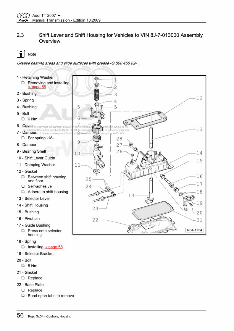
Protected by copyright. Copying for private or commercial purposes, in part or in whole, is not permitted unless authorised by AUDI AG. AUDI AG does not guarantee or accept any liability with respect to the correctness of information in this document. Copyright by AUDI AG.
2.3 Shift Lever and Shift Housing for Vehicles to VIN 8J-7-013000 AssemblyOverview
Note
Grease bearing areas and slide surfaces with grease -G 000 450 02- .
1 - Retaining Washer❑ Removing and installing
⇒ page 582 - Bushing3 - Spring4 - Bushing5 - Bolt
❑ 6 Nm6 - Cover7 - Damper
❑ For spring -18-8 - Damper9 - Bearing Shell10 - Shift Lever Guide11 - Damping Washer12 - Gasket
❑ Between shift housingand floor
❑ Self-adhesive❑ Adhere to shift housing
13 - Selector Lever14 - Shift Housing15 - Bushing16 - Pivot pin17 - Guide Bushing
❑ Press onto selectorhousing
18 - Spring❑ Installing ⇒ page 58
19 - Selector Bracket20 - Bolt
❑ 5 Nm21 - Gasket
❑ Replace22 - Base Plate
❑ Replace❑ Bend open tabs to remove
Audi TT 2007 ➤Manual Transmission - Edition 10.2009
56 Rep. Gr.34 - Controls, Housing
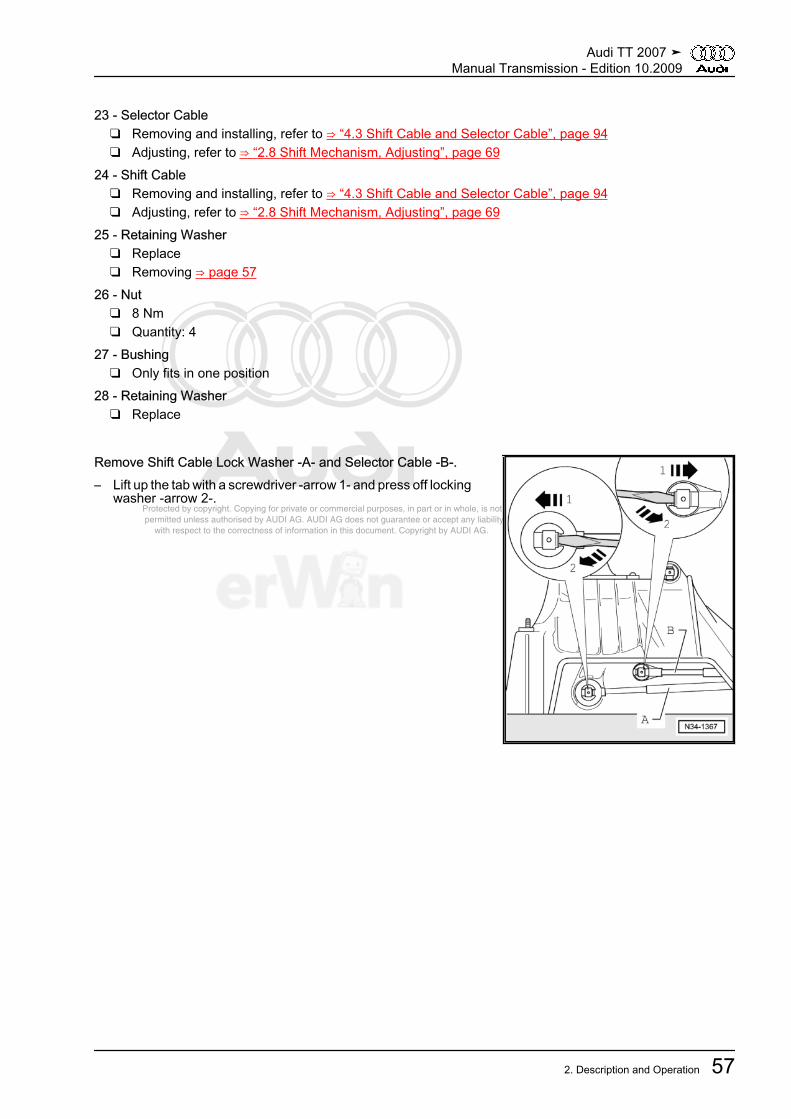
Protected by copyright. Copying for private or commercial purposes, in part or in whole, is not permitted unless authorised by AUDI AG. AUDI AG does not guarantee or accept any liability with respect to the correctness of information in this document. Copyright by AUDI AG.
23 - Selector Cable❑ Removing and installing, refer to ⇒ “4.3 Shift Cable and Selector Cable”, page 94❑ Adjusting, refer to ⇒ “2.8 Shift Mechanism, Adjusting”, page 69
24 - Shift Cable❑ Removing and installing, refer to ⇒ “4.3 Shift Cable and Selector Cable”, page 94❑ Adjusting, refer to ⇒ “2.8 Shift Mechanism, Adjusting”, page 69
25 - Retaining Washer❑ Replace❑ Removing ⇒ page 57
26 - Nut❑ 8 Nm❑ Quantity: 4
27 - Bushing❑ Only fits in one position
28 - Retaining Washer❑ Replace
Remove Shift Cable Lock Washer -A- and Selector Cable -B-.– Lift up the tab with a screwdriver -arrow 1- and press off locking
washer -arrow 2-.
Audi TT 2007 ➤Manual Transmission - Edition 10.2009
2. Description and Operation 57

Protected by copyright. Copying for private or commercial purposes, in part or in whole, is not permitted unless authorised by AUDI AG. AUDI AG does not guarantee or accept any liability with respect to the correctness of information in this document. Copyright by AUDI AG.
Removing and Installing Lock Washer– Hold shift lever -2- in position.– Press spacer bushing -3- in direction of -arrow-.– Remove the circlip -1-.Installing Spring
– Insert the leg -A- of the spring into the guide -1- from above.– Pull the leg -B- of the spring downward and lay it into the guide
from below.
Note
To improve clarity, the selector bracket is removed.
Audi TT 2007 ➤Manual Transmission - Edition 10.2009
58 Rep. Gr.34 - Controls, Housing

Protected by copyright. Copying for private or commercial purposes, in part or in whole, is not permitted unless authorised by AUDI AG. AUDI AG does not guarantee or accept any liability with respect to the correctness of information in this document. Copyright by AUDI AG.
2.4 Shift Lever and Shift Housing for Vehicles from VIN 8J-7-013001 AssemblyOverview
Note
♦ Lubricate mounting areas and slide surfaces with grease -G 000 450 02- .♦ Selector mechanism, disassembling and assembling, refer to ⇒ “5.1 Selector Mechanism”, page 128 .
1 - Base Plate❑ Always replace❑ Bend open tabs to re‐
move2 - Gasket
❑ Replace3 - Selector Lever
❑ Can be removed and in‐stalled with the shift lev‐er guide installed -15-
4 - Damping Washer❑ Slide out of shift lever as
far as stop -arrow-5 - Retaining Clip
❑ Replace❑ Do not damage cables
when removing6 -Selector Cable
❑ Pry off of selector brack‐et
❑ Press onto selectorbracket inside the shiftmechanism
❑ Installation location, re‐fer to⇒ “2.1 Selector Mecha‐nism Overview”,page 52
7 - Bushing8 -Shift Cable
❑ Pry off of shift lever guide❑ Press onto shift lever guide inside the shift mechanism❑ Installation location, refer to ⇒ “2.1 Selector Mechanism Overview”, page 52
9 - Damper10 - Bearing Shell
❑ Replace❑ Is damaged during removal
11 - Bushing12 - Retaining Washer
❑ Removing and installing ⇒ page 58
Audi TT 2007 ➤Manual Transmission - Edition 10.2009
2. Description and Operation 59

Protected by copyright. Copying for private or commercial purposes, in part or in whole, is not permitted unless authorised by AUDI AG. AUDI AG does not guarantee or accept any liability with respect to the correctness of information in this document. Copyright by AUDI AG.
13 - Spring14 - Bushing15 - Shift Lever Guide16 -Nut• M6 - 8 Nm• M8 - 25 Nm
❑ Quantity: 417 - Gasket
❑ Between shift housing and floor❑ Self-adhesive❑ Adhere to shift housing
18 - Shift Housing❑ With spring and selector bracket❑ Spring and selector bracket cannot be removed
Audi TT 2007 ➤Manual Transmission - Edition 10.2009
60 Rep. Gr.34 - Controls, Housing
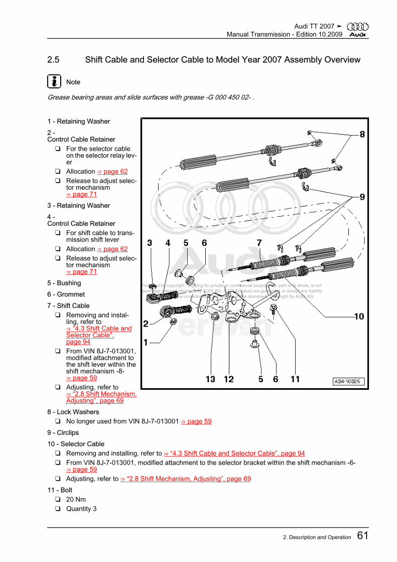
Protected by copyright. Copying for private or commercial purposes, in part or in whole, is not permitted unless authorised by AUDI AG. AUDI AG does not guarantee or accept any liability with respect to the correctness of information in this document. Copyright by AUDI AG.
2.5 Shift Cable and Selector Cable to Model Year 2007 Assembly Overview
Note
Grease bearing areas and slide surfaces with grease -G 000 450 02- .
1 - Retaining Washer2 -Control Cable Retainer
❑ For the selector cableon the selector relay lev‐er
❑ Allocation ⇒ page 62❑ Release to adjust selec‐
tor mechanism⇒ page 71
3 - Retaining Washer4 -Control Cable Retainer
❑ For shift cable to trans‐mission shift lever
❑ Allocation ⇒ page 62❑ Release to adjust selec‐
tor mechanism⇒ page 71
5 - Bushing6 - Grommet7 - Shift Cable
❑ Removing and instal‐ling, refer to⇒ “4.3 Shift Cable andSelector Cable”,page 94
❑ From VIN 8J-7-013001,modified attachment tothe shift lever within theshift mechanism -8-⇒ page 59
❑ Adjusting, refer to⇒ “2.8 Shift Mechanism,Adjusting”, page 69
8 - Lock Washers❑ No longer used from VIN 8J-7-013001 ⇒ page 59
9 - Circlips10 - Selector Cable
❑ Removing and installing, refer to ⇒ “4.3 Shift Cable and Selector Cable”, page 94❑ From VIN 8J-7-013001, modified attachment to the selector bracket within the shift mechanism -6-
⇒ page 59❑ Adjusting, refer to ⇒ “2.8 Shift Mechanism, Adjusting”, page 69
11 - Bolt❑ 20 Nm❑ Quantity 3
Audi TT 2007 ➤Manual Transmission - Edition 10.2009
2. Description and Operation 61
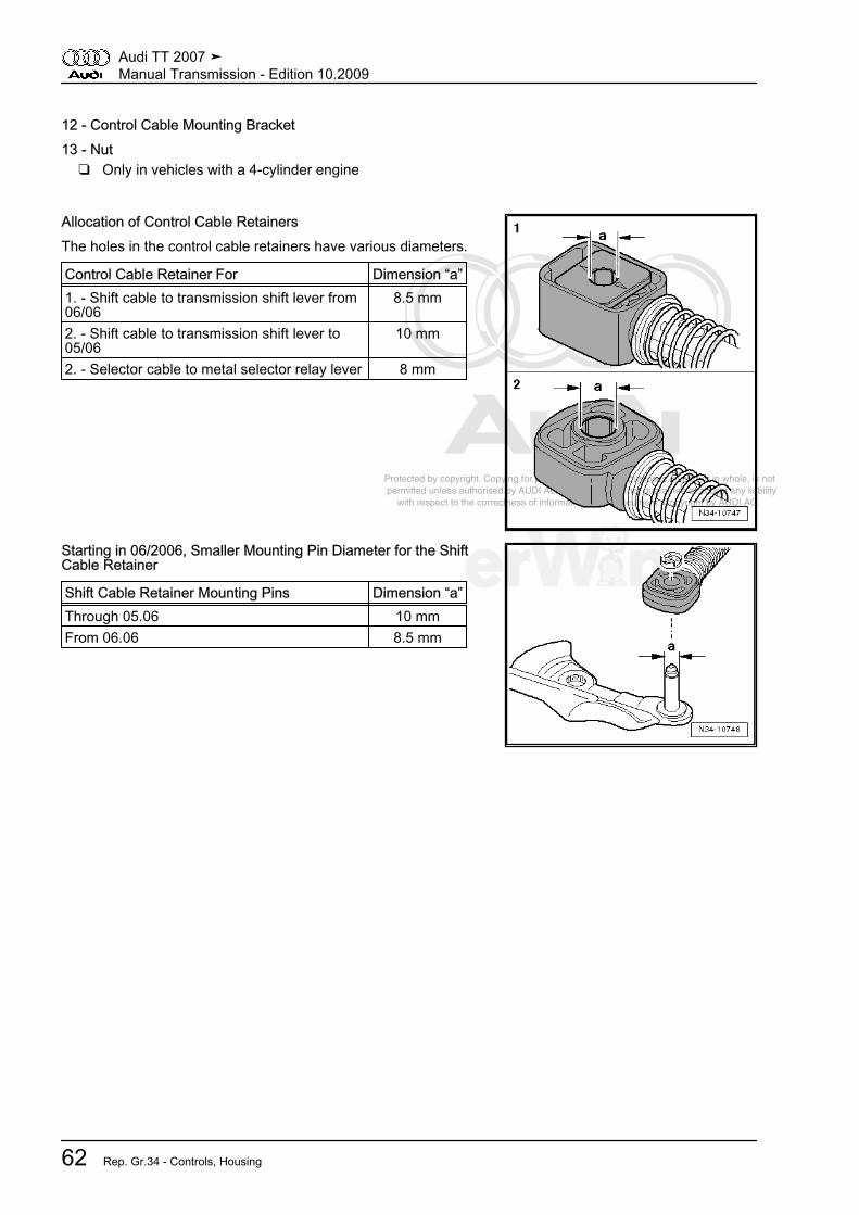
Protected by copyright. Copying for private or commercial purposes, in part or in whole, is not permitted unless authorised by AUDI AG. AUDI AG does not guarantee or accept any liability with respect to the correctness of information in this document. Copyright by AUDI AG.
12 - Control Cable Mounting Bracket13 - Nut
❑ Only in vehicles with a 4-cylinder engine
Allocation of Control Cable RetainersThe holes in the control cable retainers have various diameters.
Control Cable Retainer For Dimension “a”1. - Shift cable to transmission shift lever from06/06
8.5 mm
2. - Shift cable to transmission shift lever to05/06
10 mm
2. - Selector cable to metal selector relay lever 8 mm
Starting in 06/2006, Smaller Mounting Pin Diameter for the ShiftCable Retainer
Shift Cable Retainer Mounting Pins Dimension “a”Through 05.06 10 mmFrom 06.06 8.5 mm
Audi TT 2007 ➤Manual Transmission - Edition 10.2009
62 Rep. Gr.34 - Controls, Housing
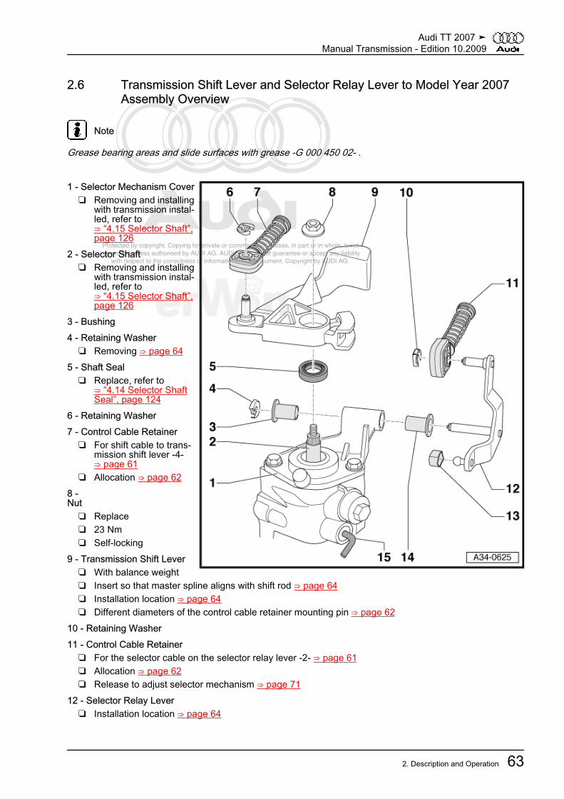
Protected by copyright. Copying for private or commercial purposes, in part or in whole, is not permitted unless authorised by AUDI AG. AUDI AG does not guarantee or accept any liability with respect to the correctness of information in this document. Copyright by AUDI AG.
2.6 Transmission Shift Lever and Selector Relay Lever to Model Year 2007Assembly Overview
Note
Grease bearing areas and slide surfaces with grease -G 000 450 02- .
1 - Selector Mechanism Cover❑ Removing and installing
with transmission instal‐led, refer to⇒ “4.15 Selector Shaft”,page 126
2 - Selector Shaft❑ Removing and installing
with transmission instal‐led, refer to⇒ “4.15 Selector Shaft”,page 126
3 - Bushing4 - Retaining Washer
❑ Removing ⇒ page 645 - Shaft Seal
❑ Replace, refer to⇒ “4.14 Selector ShaftSeal”, page 124
6 - Retaining Washer7 - Control Cable Retainer
❑ For shift cable to trans‐mission shift lever -4-⇒ page 61
❑ Allocation ⇒ page 628 -Nut
❑ Replace❑ 23 Nm❑ Self-locking
9 - Transmission Shift Lever❑ With balance weight❑ Insert so that master spline aligns with shift rod ⇒ page 64❑ Installation location ⇒ page 64❑ Different diameters of the control cable retainer mounting pin ⇒ page 62
10 - Retaining Washer11 - Control Cable Retainer
❑ For the selector cable on the selector relay lever -2- ⇒ page 61❑ Allocation ⇒ page 62❑ Release to adjust selector mechanism ⇒ page 71
12 - Selector Relay Lever❑ Installation location ⇒ page 64
Audi TT 2007 ➤Manual Transmission - Edition 10.2009
2. Description and Operation 63
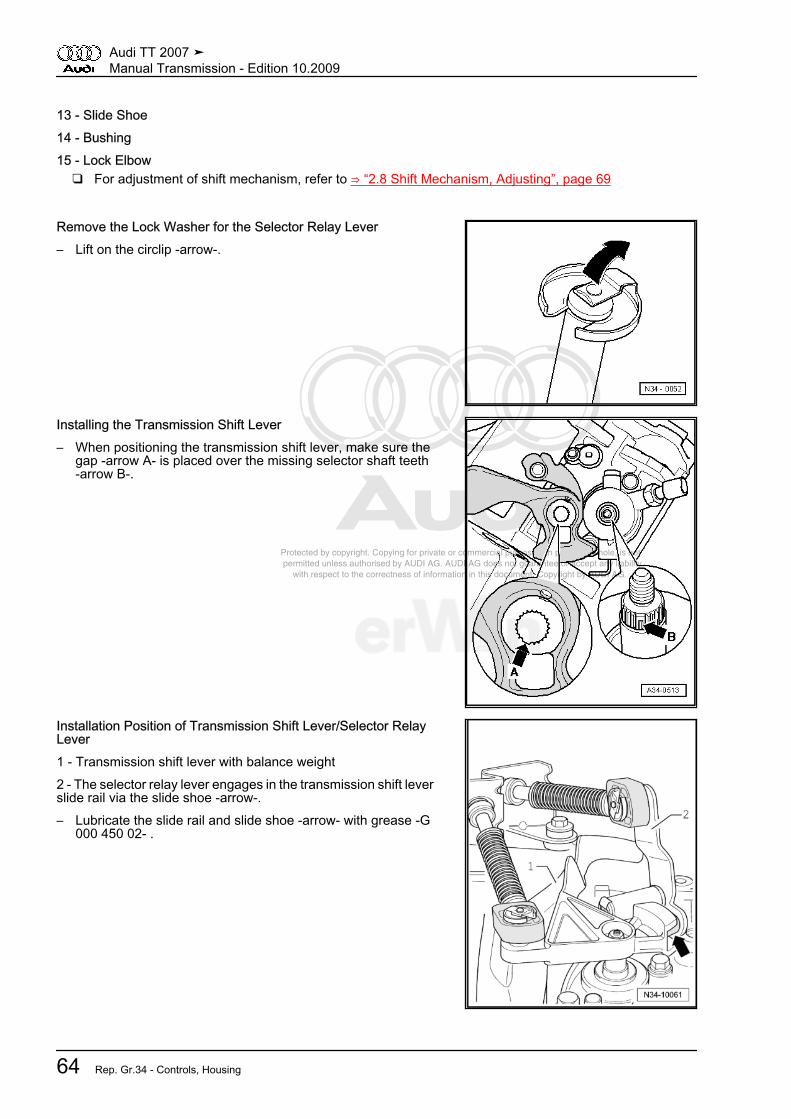
Protected by copyright. Copying for private or commercial purposes, in part or in whole, is not permitted unless authorised by AUDI AG. AUDI AG does not guarantee or accept any liability with respect to the correctness of information in this document. Copyright by AUDI AG.
13 - Slide Shoe14 - Bushing15 - Lock Elbow
❑ For adjustment of shift mechanism, refer to ⇒ “2.8 Shift Mechanism, Adjusting”, page 69
Remove the Lock Washer for the Selector Relay Lever– Lift on the circlip -arrow-.
Installing the Transmission Shift Lever– When positioning the transmission shift lever, make sure the
gap -arrow A- is placed over the missing selector shaft teeth-arrow B-.
Installation Position of Transmission Shift Lever/Selector RelayLever1 - Transmission shift lever with balance weight2 - The selector relay lever engages in the transmission shift leverslide rail via the slide shoe -arrow-.– Lubricate the slide rail and slide shoe -arrow- with grease -G
000 450 02- .
Audi TT 2007 ➤Manual Transmission - Edition 10.2009
64 Rep. Gr.34 - Controls, Housing

Protected by copyright. Copying for private or commercial purposes, in part or in whole, is not permitted unless authorised by AUDI AG. AUDI AG does not guarantee or accept any liability with respect to the correctness of information in this document. Copyright by AUDI AG.
2.7 Shift Cable and Selector Cable from Model Year 2008 Assembly Overview
Note
Grease bearing areas and slide surfaces with grease -G 000 450 02- .
1 - Transmission2 - Clip
❑ Not installed on all ver‐sions
❑ For selector relay leverfrom 8/2008
❑ Remove and secure⇒ page 69
3 - Transmission Shift Lever❑ Inserting ⇒ page 66❑ Installation location
⇒ page 67❑ Adjust shift mechanism
after installation, refer to⇒ “2.8 Shift Mechanism,Adjusting”, page 69
4 - Control Cable Retainer❑ For shift cable to trans‐
mission shift lever❑ Allocation ⇒ page 66❑ Disconnect from the
shift cable ⇒ page 675 - Retaining Washer
❑ Replace❑ Removing ⇒ page 67
6 - Nut❑ Replace❑ 23 Nm❑ Self-locking
7 - Retaining Clip❑ Replace
8 - Shift Cable❑ Remove from the transmission shift lever and attach ⇒ page 67❑ Removing and installing, refer to ⇒ “4.3 Shift Cable and Selector Cable”, page 94❑ Adjusting, refer to ⇒ “2.8 Shift Mechanism, Adjusting”, page 69
9 - Selector Cable❑ Removing and installing, refer to ⇒ “4.3 Shift Cable and Selector Cable”, page 94❑ Adjusting, refer to ⇒ “2.8 Shift Mechanism, Adjusting”, page 69
10 - Shift Housing11 - Circlips
❑ Replace12 - Retaining Clip
❑ Replace
Audi TT 2007 ➤Manual Transmission - Edition 10.2009
2. Description and Operation 65
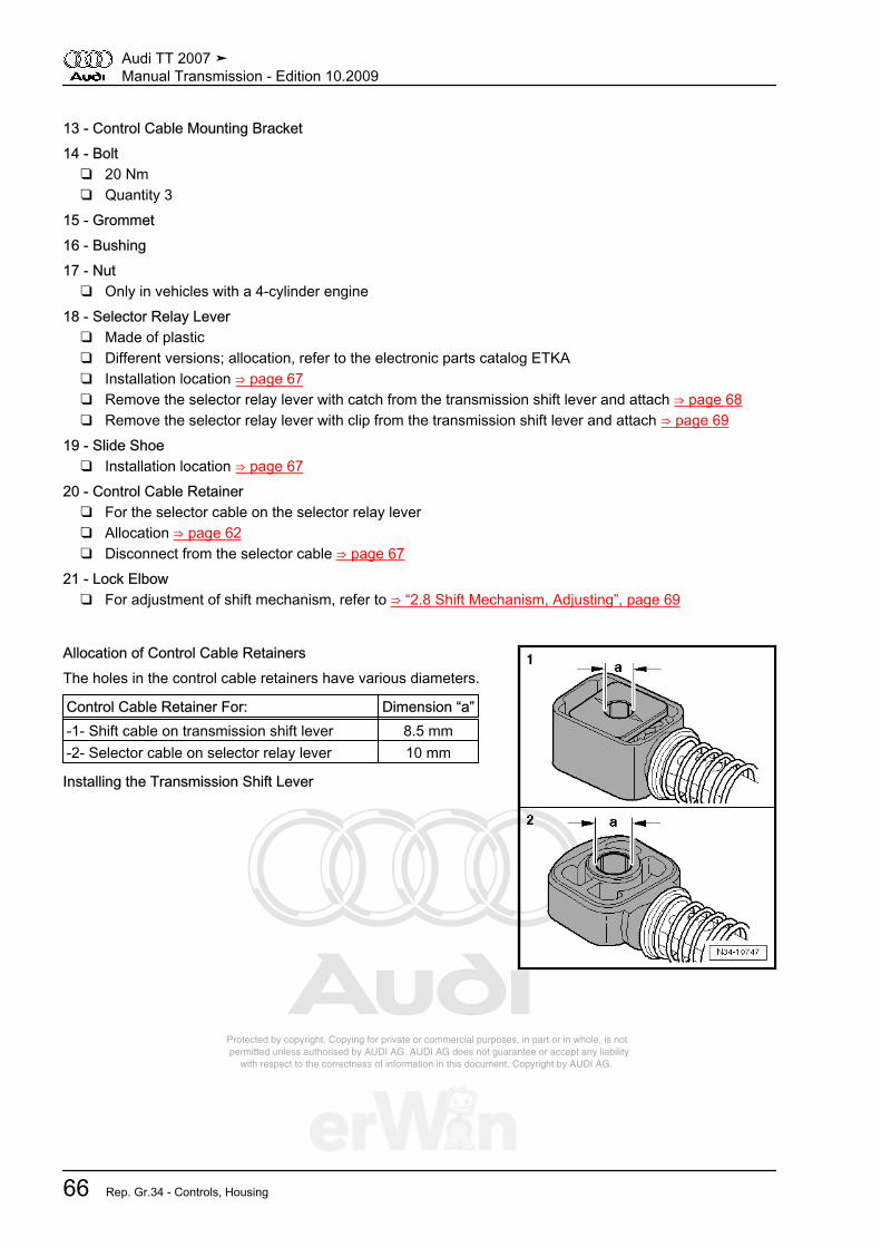
Protected by copyright. Copying for private or commercial purposes, in part or in whole, is not permitted unless authorised by AUDI AG. AUDI AG does not guarantee or accept any liability with respect to the correctness of information in this document. Copyright by AUDI AG.
13 - Control Cable Mounting Bracket14 - Bolt
❑ 20 Nm❑ Quantity 3
15 - Grommet16 - Bushing17 - Nut
❑ Only in vehicles with a 4-cylinder engine18 - Selector Relay Lever
❑ Made of plastic❑ Different versions; allocation, refer to the electronic parts catalog ETKA❑ Installation location ⇒ page 67❑ Remove the selector relay lever with catch from the transmission shift lever and attach ⇒ page 68❑ Remove the selector relay lever with clip from the transmission shift lever and attach ⇒ page 69
19 - Slide Shoe❑ Installation location ⇒ page 67
20 - Control Cable Retainer❑ For the selector cable on the selector relay lever❑ Allocation ⇒ page 62❑ Disconnect from the selector cable ⇒ page 67
21 - Lock Elbow❑ For adjustment of shift mechanism, refer to ⇒ “2.8 Shift Mechanism, Adjusting”, page 69
Allocation of Control Cable RetainersThe holes in the control cable retainers have various diameters.
Control Cable Retainer For: Dimension “a”-1- Shift cable on transmission shift lever 8.5 mm-2- Selector cable on selector relay lever 10 mm
Installing the Transmission Shift Lever
Audi TT 2007 ➤Manual Transmission - Edition 10.2009
66 Rep. Gr.34 - Controls, Housing
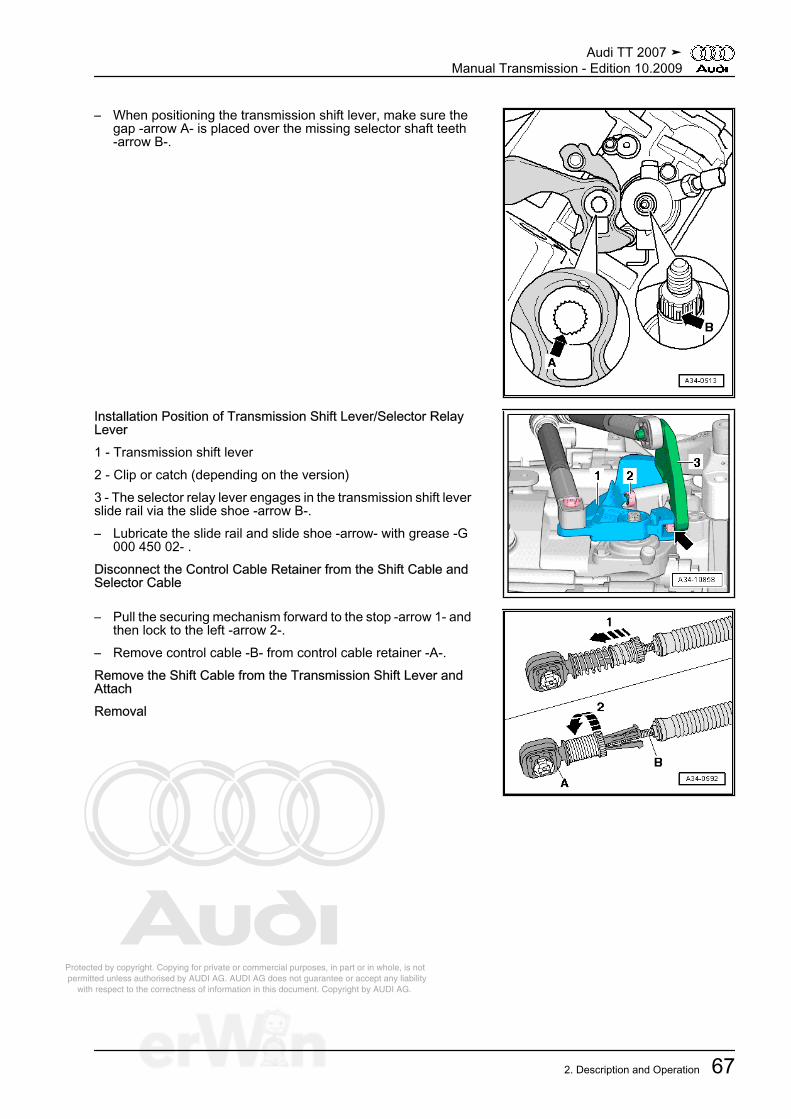
Protected by copyright. Copying for private or commercial purposes, in part or in whole, is not permitted unless authorised by AUDI AG. AUDI AG does not guarantee or accept any liability with respect to the correctness of information in this document. Copyright by AUDI AG.
– When positioning the transmission shift lever, make sure thegap -arrow A- is placed over the missing selector shaft teeth-arrow B-.
Installation Position of Transmission Shift Lever/Selector RelayLever1 - Transmission shift lever2 - Clip or catch (depending on the version)3 - The selector relay lever engages in the transmission shift leverslide rail via the slide shoe -arrow B-.– Lubricate the slide rail and slide shoe -arrow- with grease -G
000 450 02- .Disconnect the Control Cable Retainer from the Shift Cable andSelector Cable
– Pull the securing mechanism forward to the stop -arrow 1- andthen lock to the left -arrow 2-.
– Remove control cable -B- from control cable retainer -A-.Remove the Shift Cable from the Transmission Shift Lever andAttachRemoval
Audi TT 2007 ➤Manual Transmission - Edition 10.2009
2. Description and Operation 67

Protected by copyright. Copying for private or commercial purposes, in part or in whole, is not permitted unless authorised by AUDI AG. AUDI AG does not guarantee or accept any liability with respect to the correctness of information in this document. Copyright by AUDI AG.
– Remove shift cable lock washer -3- from transmission shiftlever -1- by lifting the clip.
– Remove shift cable -2- from the pin -arrow-.Securing
Note
♦ Replace the lock washer for the shift cable.♦ Coat the pin -arrow- with a small amount of grease -G 000 450
02- .
– Press the shift cable onto transmission shift lever -2- and se‐cure with lock washer -1-.
Remove the Selector Relay Lever with Catch from the Transmis‐sion Shift Lever -arrow 1- and AttachRemoval– Press in the catch -arrow 1- to the stop and remove the se‐
lector relay lever together with the control cable retainer. Movethe selector relay lever in the operating direction.
Note
Ignore -arrow 2-.
Securing
Note
To install, grease mounting points and contact surfaces withGrease -G 000 450 02- .
– Press the control cable retainer onto the selector relay lever⇒ page 69
– Insert the selector relay lever together with the control cableretainer to the stop.
• The catch -arrow 1- secures the selector relay lever.• The catch -arrow 2- secures the control cable retainer.• Make sure it engages securely.
Audi TT 2007 ➤Manual Transmission - Edition 10.2009
68 Rep. Gr.34 - Controls, Housing

Protected by copyright. Copying for private or commercial purposes, in part or in whole, is not permitted unless authorised by AUDI AG. AUDI AG does not guarantee or accept any liability with respect to the correctness of information in this document. Copyright by AUDI AG.
Remove the Selector Relay Lever “with Clip” from the Transmis‐sion Shift Lever -arrow 1- and AttachRemoval– Remove the clip -arrow 1-, and remove the selector relay lever
together with the control cable retainer.Securing
Note
Grease bearing areas and slide surfaces with grease -G 000 45002- .
– Insert the selector relay lever together with the control cableretainer to the stop.
– Press on the clip -arrow 1- while ensuring that it engages se‐curely.
Note
Ignore -arrow 2-.
Pry the Selector Cable Retainer Out of the Selector Relay Lever• Selector relay lever removed.– Apply a flat head screwdriver -A- between bushing -B- and the
selector relay lever.Press the Selector Cable Retainer onto the Selector Relay Lever
• Selector relay lever removed.• The cable retainer may only be pressed on at the bushing
-arrow-.• The control cable retainer must move freely on the selector
relay lever.• The control cable retainer must be behind the catch.– Make sure it engages securely.
2.8 Shift Mechanism, AdjustingSpecial tools and workshop equipment required
Audi TT 2007 ➤Manual Transmission - Edition 10.2009
2. Description and Operation 69

Protected by copyright. Copying for private or commercial purposes, in part or in whole, is not permitted unless authorised by AUDI AG. AUDI AG does not guarantee or accept any liability with respect to the correctness of information in this document. Copyright by AUDI AG.
♦ Connecting Pin -T10027 A-Adjustment Requirements• Operating and transfer elements of shift mechanism must be
in proper condition.• Shift mechanism must move freely.• The transmission, clutch and clutch mechanism must be in
proper condition.• Transmission in neutral position.Adjusting– Open the ashtray.– Carefully pry trim from center console -arrows-.– Lift trim up over shift knob.
– Move the shift lever in the neutral position toward the left intothe 1st/2nd gear shift gate.
– Lift the noise insulation plate.– Guide the -T10027A- through hole -A- and into hole -B-.
Note
To improve clarity, the noise insulation is removed in the figure.
– Completely remove the air filter housing. Refer to ⇒ Fuel In‐jection and Ignition; Rep. Gr. 24 ; Removal and Installation .
Audi TT 2007 ➤Manual Transmission - Edition 10.2009
70 Rep. Gr.34 - Controls, Housing

Protected by copyright. Copying for private or commercial purposes, in part or in whole, is not permitted unless authorised by AUDI AG. AUDI AG does not guarantee or accept any liability with respect to the correctness of information in this document. Copyright by AUDI AG.
Release cable retainer -A- for selector and shift cables -B- as fol‐lows:– Push sleeve forward up to the stop -arrow 1-.– Turn sleeve to the right up to the stop -arrow 2- so that it en‐
gages.
Note
The cable -B- must be able to move in the cable retainer.
• Transmission in neutral position.Secure shift rod as follows:
– Press transmission shift lever -1- down in direction of-arrow A-.
– Engage lock elbow -2- by turning slightly in direction of-arrow B- and pressing in direction of -arrow C- at the sametime.
This locks the selector shaft; it can no longer be moved.
– Make sure that the selector and shift cable -B- are insertedfree of tension in the retainer -A-.
– Loosen the sleeve -arrow 1-.– Allow the sleeve to slide to the stop -arrow 2-.The cable is now adjusted.
Audi TT 2007 ➤Manual Transmission - Edition 10.2009
2. Description and Operation 71
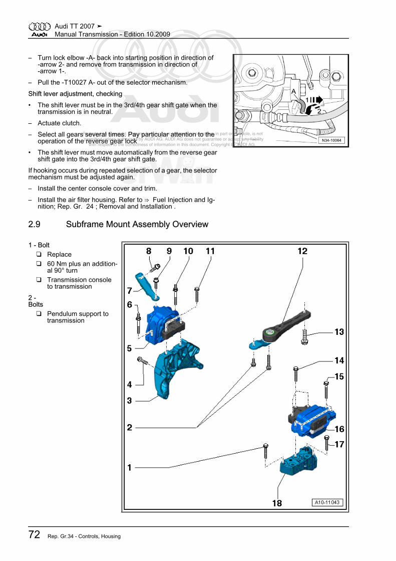
Protected by copyright. Copying for private or commercial purposes, in part or in whole, is not permitted unless authorised by AUDI AG. AUDI AG does not guarantee or accept any liability with respect to the correctness of information in this document. Copyright by AUDI AG.
– Turn lock elbow -A- back into starting position in direction of-arrow 2- and remove from transmission in direction of-arrow 1-.
– Pull the -T10027 A- out of the selector mechanism.Shift lever adjustment, checking• The shift lever must be in the 3rd/4th gear shift gate when the
transmission is in neutral.– Actuate clutch.– Select all gears several times. Pay particular attention to the
operation of the reverse gear lock• The shift lever must move automatically from the reverse gear
shift gate into the 3rd/4th gear shift gate.If hooking occurs during repeated selection of a gear, the selectormechanism must be adjusted again.– Install the center console cover and trim.– Install the air filter housing. Refer to ⇒ Fuel Injection and Ig‐
nition; Rep. Gr. 24 ; Removal and Installation .
2.9 Subframe Mount Assembly Overview
1 - Bolt❑ Replace❑ 60 Nm plus an addition‐
al 90° turn❑ Transmission console
to transmission2 -Bolts
❑ Pendulum support totransmission
Audi TT 2007 ➤Manual Transmission - Edition 10.2009
72 Rep. Gr.34 - Controls, Housing

Protected by copyright. Copying for private or commercial purposes, in part or in whole, is not permitted unless authorised by AUDI AG. AUDI AG does not guarantee or accept any liability with respect to the correctness of information in this document. Copyright by AUDI AG.
Caution♦In the case of 02Q man‐ual transmissions, threa‐ded inserts (HeliCoil) canbe installed in the threadsof the pendulum supportthreaded connection.These threaded insertsare standard as of trans‐mission build date5/28/07.♦Difference ⇒ page 74♦Bolts with strength cate‐gory 10.9 must be usedfor all transmissions withthreaded inserts (Heli‐Coil).♦In the case of transmis‐sions without threadedinserts, bolts withstrength category 8.8 areto be used.♦Bolts with strength cate‐gory 8.8 are listed in the,refer to the electronicparts catalog ETKA toVIN 8J-7-050 000.♦Bolts with strength cate‐gory 10.9 are listed in the,refer to the electronicparts catalog ETKA fromVIN 8J-8-000 001.♦The bolt tightening spec‐ification corresponds tothe strength category.
• Transmission with threaded inserts in connection with bolts of strength category 10.9:❑ 50 Nm plus an additional 90° turn
• Transmission without threaded inserts and bolts with strength category 8.8:❑ Always replace❑ 40 Nm plus an additional 90° turn
3 - Engine Support4 - Bolt
❑ Engine support to engine❑ Tightening specification, refer to ⇒ Engine Mechanical; Rep. Gr. 10 ; Description and Operation
5 - Engine Mount6 - Bolt
❑ Engine mount to body❑ Tightening specification, refer to ⇒ Engine Mechanical; Rep. Gr. 10 ; Description and Operation
7 - Connecting Bar8 - Bolt
❑ Connecting bar to engine❑ Tightening specification, refer to ⇒ Engine Mechanical; Rep. Gr. 10 ; Description and Operation
Audi TT 2007 ➤Manual Transmission - Edition 10.2009
2. Description and Operation 73
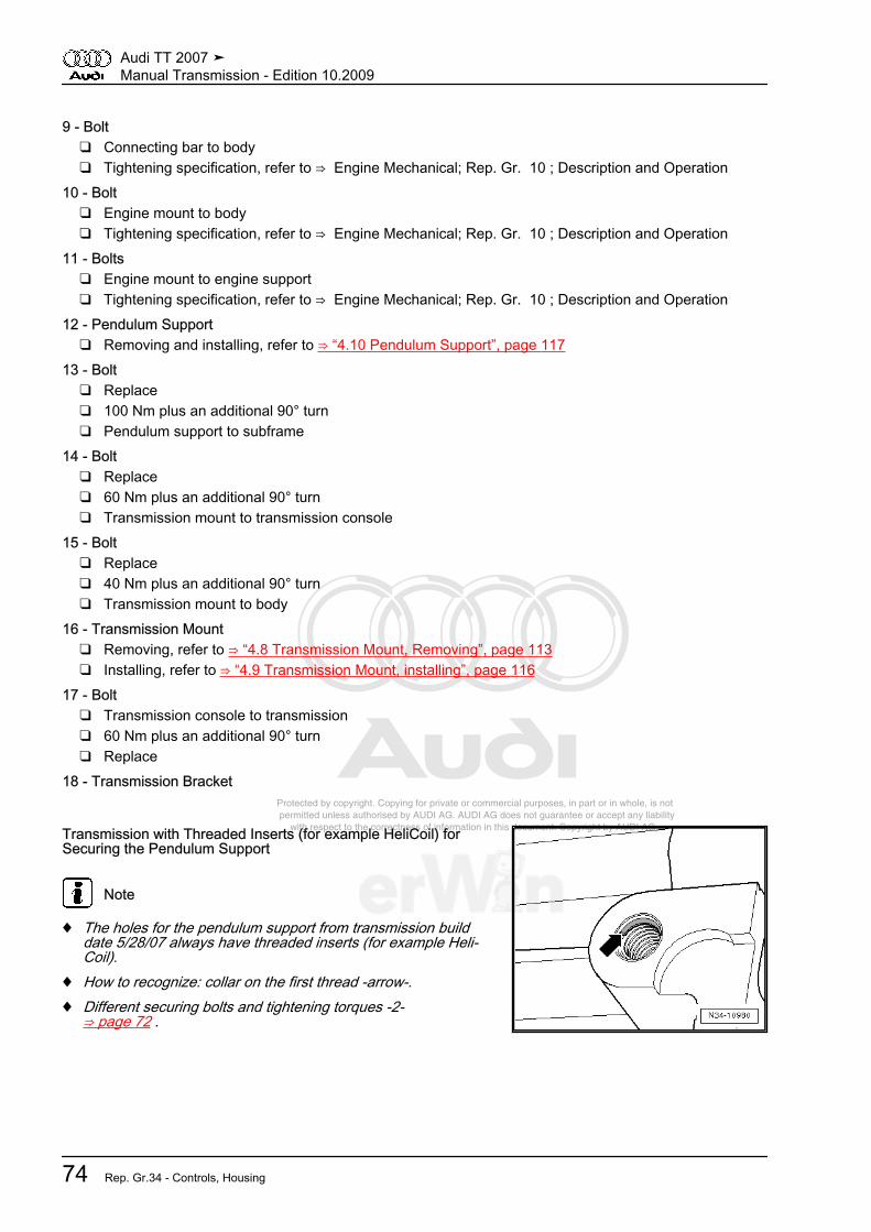
Protected by copyright. Copying for private or commercial purposes, in part or in whole, is not permitted unless authorised by AUDI AG. AUDI AG does not guarantee or accept any liability with respect to the correctness of information in this document. Copyright by AUDI AG.
9 - Bolt❑ Connecting bar to body❑ Tightening specification, refer to ⇒ Engine Mechanical; Rep. Gr. 10 ; Description and Operation
10 - Bolt❑ Engine mount to body❑ Tightening specification, refer to ⇒ Engine Mechanical; Rep. Gr. 10 ; Description and Operation
11 - Bolts❑ Engine mount to engine support❑ Tightening specification, refer to ⇒ Engine Mechanical; Rep. Gr. 10 ; Description and Operation
12 - Pendulum Support❑ Removing and installing, refer to ⇒ “4.10 Pendulum Support”, page 117
13 - Bolt❑ Replace❑ 100 Nm plus an additional 90° turn❑ Pendulum support to subframe
14 - Bolt❑ Replace❑ 60 Nm plus an additional 90° turn❑ Transmission mount to transmission console
15 - Bolt❑ Replace❑ 40 Nm plus an additional 90° turn❑ Transmission mount to body
16 - Transmission Mount❑ Removing, refer to ⇒ “4.8 Transmission Mount, Removing”, page 113❑ Installing, refer to ⇒ “4.9 Transmission Mount, installing”, page 116
17 - Bolt❑ Transmission console to transmission❑ 60 Nm plus an additional 90° turn❑ Replace
18 - Transmission Bracket
Transmission with Threaded Inserts (for example HeliCoil) forSecuring the Pendulum Support
Note
♦ The holes for the pendulum support from transmission builddate 5/28/07 always have threaded inserts (for example Heli‐Coil).
♦ How to recognize: collar on the first thread -arrow-.♦ Different securing bolts and tightening torques -2-
⇒ page 72 .
Audi TT 2007 ➤Manual Transmission - Edition 10.2009
74 Rep. Gr.34 - Controls, Housing

Protected by copyright. Copying for private or commercial purposes, in part or in whole, is not permitted unless authorised by AUDI AG. AUDI AG does not guarantee or accept any liability with respect to the correctness of information in this document. Copyright by AUDI AG.
2.10 Transmission Overview
1 - Clutch Housing2 - Reverse Shaft3 - Output Shaft 5th/6th Gear/Reverse Gear4 - Clutch Slave Cylinder withRelease Bearing5 - Input Shaft6 - Output Shaft, 1st to 4thGears7 - Differential8 - Bevel Box9 - Right Drive Flange10 - Head Bevel Gear with In‐put Shaft11 - Shaft Bevel Gear12 - Output Flange13 - Flange Shaft, Left14 - 2nd Gear Selector Gear15 - 1st Gear Selector Gear16 - 4th Gear Selector Gear17 - 3rd Gear Selector Gear18 - 5th Gear Selector Gear19 - 6th Gear Selector Gear20 - Reverse Gear SelectorGear21 - Transmission Housing
Audi TT 2007 ➤Manual Transmission - Edition 10.2009
2. Description and Operation 75

Protected by copyright. Copying for private or commercial purposes, in part or in whole, is not permitted unless authorised by AUDI AG. AUDI AG does not guarantee or accept any liability with respect to the correctness of information in this document. Copyright by AUDI AG.
2.11 Transmission Assembly Overview
l - Assembly overview - trans‐mission housing and shiftmechanism, refer to⇒ “2.12 Transmission Housingand Shift Mechanism Assem‐bly Overview”, page 77ll - Assembly overview - inputshaft, output shafts, differen‐tial, bevel box and selectorrods, refer to⇒ “2.13 Input Shaft, OutputShafts, Differential, Bevel Boxand Selector Rods AssemblyOverview”, page 79
Input Shaft Cap with Circlip -A-From transmission build date 1/21/08, the input shaft cap is se‐cured with a circlip -A-.⇒ “5.2 Transmission without Circlip A for Cap/Input Shaft”,page 131⇒ “5.3 Transmission with Circlip A for the Cap/Input Shaft”, page142
Audi TT 2007 ➤Manual Transmission - Edition 10.2009
76 Rep. Gr.34 - Controls, Housing

Protected by copyright. Copying for private or commercial purposes, in part or in whole, is not permitted unless authorised by AUDI AG. AUDI AG does not guarantee or accept any liability with respect to the correctness of information in this document. Copyright by AUDI AG.
2.12 Transmission Housing and Shift Mechanism Assembly Overview
1 - Bolt❑ Tightening specification
-7- ⇒ page 2192 - Flange Shaft with Spring
❑ Removing and instal‐ling, refer to⇒ “5.2 Transmissionwithout Circlip A forCap/Input Shaft”,page 131
❑ Assembling, refer to⇒ “1.3 Differential As‐sembly Overview”, page222
3 - Securing Ring❑ For the sealing cap -4-\❑ Installed from transmis‐
sion build date 1/21/084 - Sealing Cap
❑ Secured with circlipfrom transmission builddate 1/21/08
❑ Removing and installingwithout circlip, refer to⇒ “5.2 Transmissionwithout Circlip A forCap/Input Shaft”,page 131
❑ Removing and installingwith circlip, refer to⇒ “5.3 Transmissionwith Circlip A for theCap/Input Shaft”,page 142
❑ Allocate components,refer to the electronicparts catalog ETKA.
5 - Securing Ring❑ For the grooved ball bearing/input shaft -1- ⇒ page 179
6 - Backup Light Switch -F4-❑ 20 Nm
7 - Oil Seal❑ Replace
8 - Bolt for Oil Drain Bore❑ Tightening specification, refer to ⇒ “3.2 Manual Transmission Oil Filler Plug”, page 87
9 - Oil Seal❑ Replace
10 - Locking Bolt❑ 45 Nm❑ For selector shaft
11 -
Audi TT 2007 ➤Manual Transmission - Edition 10.2009
2. Description and Operation 77

Protected by copyright. Copying for private or commercial purposes, in part or in whole, is not permitted unless authorised by AUDI AG. AUDI AG does not guarantee or accept any liability with respect to the correctness of information in this document. Copyright by AUDI AG.
Bolt❑ Replace❑ 15 Nm plus an additional 90° turn❑ With permanent washer❑ Allocation of bolts as replacement parts ⇒ page 78
12 -Bolt
❑ Replace❑ 15 Nm plus an additional 90° turn❑ Without washer❑ Allocation of bolts as replacement parts ⇒ page 78
13 - Selector Mechanism❑ Disassembling and assembling, refer to
⇒ “2.16 Shift Mechanism Assembly Overview, Transmission Side”, page 85❑ Removing with transmission installed, refer to ⇒ “4.15 Selector Shaft”, page 126
14 - Bolt❑ Replace❑ 20 Nm
15 - O-ring❑ Replace
16 - Clutch Housing❑ Servicing, refer to ⇒ “2.15 Clutch Housing Assembly Overview”, page 83
17 - Transmission Housing❑ Servicing, refer to ⇒ “2.14 Transmission Housing Assembly Overview”, page 81
Allocation of Bolts as Replacement PartsA - Bolt with permanent washerB - Bolt without washerC - Bolt with permanent washer
Audi TT 2007 ➤Manual Transmission - Edition 10.2009
78 Rep. Gr.34 - Controls, Housing
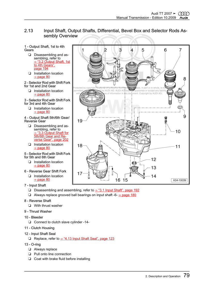
Protected by copyright. Copying for private or commercial purposes, in part or in whole, is not permitted unless authorised by AUDI AG. AUDI AG does not guarantee or accept any liability with respect to the correctness of information in this document. Copyright by AUDI AG.
2.13 Input Shaft, Output Shafts, Differential, Bevel Box and Selector Rods As‐sembly Overview
1 - Output Shaft, 1st to 4thGears
❑ Disassembling and as‐sembling, refer to⇒ “3.2 Output Shaft, 1stto 4th Gears”,page 194
❑ Installation location⇒ page 80
2 - Selector Rod with Shift Forkfor 1st and 2nd Gear
❑ Installation location⇒ page 80
3 - Selector Rod with Shift Forkfor 3rd and 4th Gear
❑ Installation location⇒ page 80
4 - Output Shaft 5th/6th Gear/Reverse Gear
❑ Disassembling and as‐sembling, refer to⇒ “3.3 Output Shaft for5th/6th Gear and Re‐verse Gear”, page 202
❑ Installation location⇒ page 80
5 - Selector Rod with Shift Forkfor 5th and 6th Gear
❑ Installation location⇒ page 80
6 - Reverse Gear Shift Fork❑ Installation location
⇒ page 807 - Input Shaft
❑ Disassembling and assembling, refer to ⇒ “3.1 Input Shaft”, page 192❑ Always replace grooved ball bearings on input shaft -6- ⇒ page 180
8 - Reverse Shaft❑ With thrust washer
9 - Thrust Washer10 - Bleeder
❑ Connect to clutch slave cylinder -14-11 - Clutch Housing12 - Input Shaft Seal
❑ Replace, refer to ⇒ “4.13 Input Shaft Seal”, page 12313 - O-ring
❑ Always replace❑ Pull onto line connection❑ Coat with brake fluid before installing
Audi TT 2007 ➤Manual Transmission - Edition 10.2009
2. Description and Operation 79
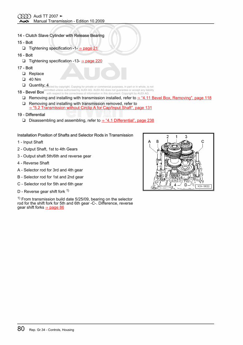
Protected by copyright. Copying for private or commercial purposes, in part or in whole, is not permitted unless authorised by AUDI AG. AUDI AG does not guarantee or accept any liability with respect to the correctness of information in this document. Copyright by AUDI AG.
14 - Clutch Slave Cylinder with Release Bearing15 - Bolt
❑ Tightening specification -1- ⇒ page 2116 - Bolt
❑ Tightening specification -13- ⇒ page 22017 - Bolt
❑ Replace❑ 40 Nm❑ Quantity: 4
18 - Bevel Box❑ Removing and installing with transmission installed, refer to ⇒ “4.11 Bevel Box, Removing”, page 118❑ Removing and installing with transmission removed, refer to
⇒ “5.2 Transmission without Circlip A for Cap/Input Shaft”, page 13119 - Differential
❑ Disassembling and assembling, refer to ⇒ “4.1 Differential”, page 238
Installation Position of Shafts and Selector Rods in Transmission1 - Input Shaft2 - Output Shaft, 1st to 4th Gears3 - Output shaft 5th/6th and reverse gear4 - Reverse ShaftA - Selector rod for 3rd and 4th gearB - Selector rod for 1st and 2nd gearC - Selector rod for 5th and 6th gear
D - Reverse gear shift fork 1)
1) From transmission build date 5/25/09, bearing on the selectorrod for the shift fork for 5th and 6th gear -C-. Difference, reversegear shift forks ⇒ page 86
Audi TT 2007 ➤Manual Transmission - Edition 10.2009
80 Rep. Gr.34 - Controls, Housing
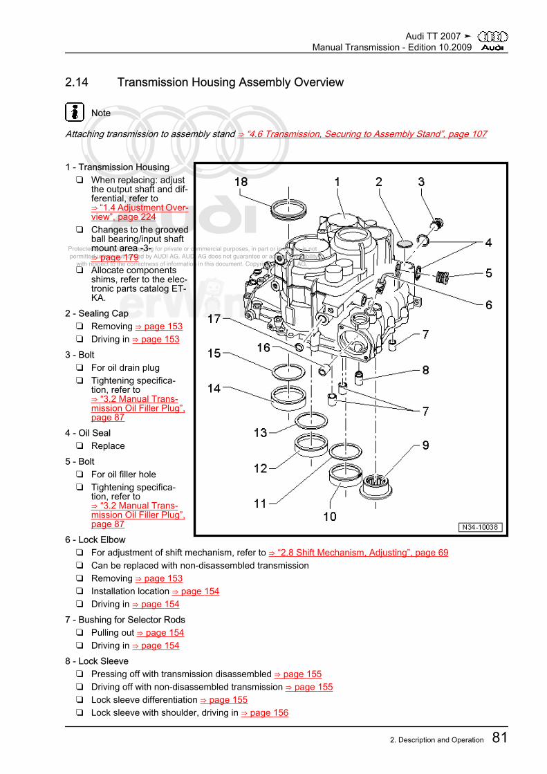
Protected by copyright. Copying for private or commercial purposes, in part or in whole, is not permitted unless authorised by AUDI AG. AUDI AG does not guarantee or accept any liability with respect to the correctness of information in this document. Copyright by AUDI AG.
2.14 Transmission Housing Assembly Overview
Note
Attaching transmission to assembly stand ⇒ “4.6 Transmission, Securing to Assembly Stand”, page 107
1 - Transmission Housing❑ When replacing: adjust
the output shaft and dif‐ferential, refer to⇒ “1.4 Adjustment Over‐view”, page 224
❑ Changes to the groovedball bearing/input shaftmount area -3-⇒ page 179
❑ Allocate componentsshims, refer to the elec‐tronic parts catalog ET‐KA.
2 - Sealing Cap❑ Removing ⇒ page 153❑ Driving in ⇒ page 153
3 - Bolt❑ For oil drain plug❑ Tightening specifica‐
tion, refer to⇒ “3.2 Manual Trans‐mission Oil Filler Plug”,page 87
4 - Oil Seal❑ Replace
5 - Bolt❑ For oil filler hole❑ Tightening specifica‐
tion, refer to⇒ “3.2 Manual Trans‐mission Oil Filler Plug”,page 87
6 - Lock Elbow❑ For adjustment of shift mechanism, refer to ⇒ “2.8 Shift Mechanism, Adjusting”, page 69❑ Can be replaced with non-disassembled transmission❑ Removing ⇒ page 153❑ Installation location ⇒ page 154❑ Driving in ⇒ page 154
7 - Bushing for Selector Rods❑ Pulling out ⇒ page 154❑ Driving in ⇒ page 154
8 - Lock Sleeve❑ Pressing off with transmission disassembled ⇒ page 155❑ Driving off with non-disassembled transmission ⇒ page 155❑ Lock sleeve differentiation ⇒ page 155❑ Lock sleeve with shoulder, driving in ⇒ page 156
Audi TT 2007 ➤Manual Transmission - Edition 10.2009
2. Description and Operation 81

Protected by copyright. Copying for private or commercial purposes, in part or in whole, is not permitted unless authorised by AUDI AG. AUDI AG does not guarantee or accept any liability with respect to the correctness of information in this document. Copyright by AUDI AG.
❑ Lock sleeve without shoulder, driving in ⇒ page 1569 - Needle Bearing for Reverse Shaft
❑ Replace after each disassembly❑ Pulling out ⇒ page 156❑ Installing ⇒ page 156
10 - Taper Roller Bearing Outer Race❑ For output shaft 5th/6th gear/reverse gear❑ Removing and installing, refer to ⇒ “3.3 Output Shaft for 5th/6th Gear and Reverse Gear”, page 202❑ In the event of replacement: adjust the output shaft for 5th/6th gear/reverse gear, refer to
⇒ “2.5 Output Shaft for 5th/6th Gear and Reverse Gear, Adjusting”, page 18811 - Adjustment Shim
❑ For output shaft 5th/6th gear/reverse gear❑ Adjustment overview, refer to ⇒ “1.4 Adjustment Overview”, page 224
12 - Taper Roller Bearing Outer Race❑ For output shaft for 1st to 4th gear❑ Removing and installing, refer to ⇒ “3.2 Output Shaft, 1st to 4th Gears”, page 194❑ In the event of replacement: adjust the output shaft for 1st to 4th gear, refer to
⇒ “2.3 Output Shaft, 1st to 4th Gears, Adjusting”, page 18313 - Adjustment Shim
❑ For output shaft for 1st to 4th gear❑ Adjustment overview, refer to ⇒ “1.4 Adjustment Overview”, page 224
14 - Taper Roller Bearing Outer Race❑ for the differential❑ Removing and installing, refer to ⇒ “1.3 Differential Assembly Overview”, page 222❑ When replacing: adjust the differential, refer to ⇒ “1.4 Adjustment Overview”, page 224
15 - Adjustment Shim❑ For the differential❑ Adjustment overview, refer to ⇒ “1.4 Adjustment Overview”, page 224
16 -Bushing for Selector Shaft
❑ Pulling out ⇒ page 157❑ Driving in ⇒ page 157
17 - Sealing Plug❑ Driving out ⇒ page 157❑ Driving in ⇒ page 157
18 - Left Flange Shaft Seal❑ Replace, refer to ⇒ “3.2 Left Flange Shaft Seal”, page 228
Audi TT 2007 ➤Manual Transmission - Edition 10.2009
82 Rep. Gr.34 - Controls, Housing

Protected by copyright. Copying for private or commercial purposes, in part or in whole, is not permitted unless authorised by AUDI AG. AUDI AG does not guarantee or accept any liability with respect to the correctness of information in this document. Copyright by AUDI AG.
2.15 Clutch Housing Assembly Overview
1 - Bushing for Selector Rods❑ Pulling out ⇒ page 158❑ Driving in ⇒ page 158
2 - Axle for Reverse Gear ShiftFork
❑ Installed to transmissionbuild date 5/24/09⇒ page 84
❑ Axle cannot be removedwith workshop equip‐ment
❑ To transmission builddate 5/24/09: When us‐ing a new clutch hous‐ing, a new axle must bepressed in ⇒ page 159
❑ No longer used as oftransmission build date5/25/09; then bearing ofthe reverse gear shiftfork together with the5th/6th gear shift fork⇒ page 147
❑ Allocation, refer to theelectronic parts catalogETKA
3 - Needle Bearing for ReverseShaft
❑ Replace after each dis‐assembly
❑ Pulling out ⇒ page 159❑ Installing ⇒ page 159
4 - Alignment Bushing❑ Quantity: 2
5 - Clutch Housing❑ When replacing: adjust the output shaft and differential, refer to
⇒ “1.4 Adjustment Overview”, page 2246 - Input Shaft Seal
❑ Replace, refer to ⇒ “4.13 Input Shaft Seal”, page 1237 - Shaft Seal
❑ Between manual transmission and bevel box❑ Replace with transmission installed, refer to
⇒ “3.3 Shaft Sealing Ring for Bevel Box with Manual Transmission Installed, Replacing”, page 229❑ Can be removed using the sleeve -30 - 21- when the transmission is disassembled.❑ Can be driven in to stop on disassembled transmission with thrust piece -T40007-
8 - Adjustment Shim❑ For the differential❑ Installed position: shoulder on inner diameter faces shaft sealing ring -7-
9 - Taper Roller Bearing Outer Race❑ For the differential❑ Removing and installing, refer to ⇒ “1.3 Differential Assembly Overview”, page 222❑ When replacing: adjust the differential, refer to ⇒ “1.5 Differential, Adjusting”, page 224
Audi TT 2007 ➤Manual Transmission - Edition 10.2009
2. Description and Operation 83
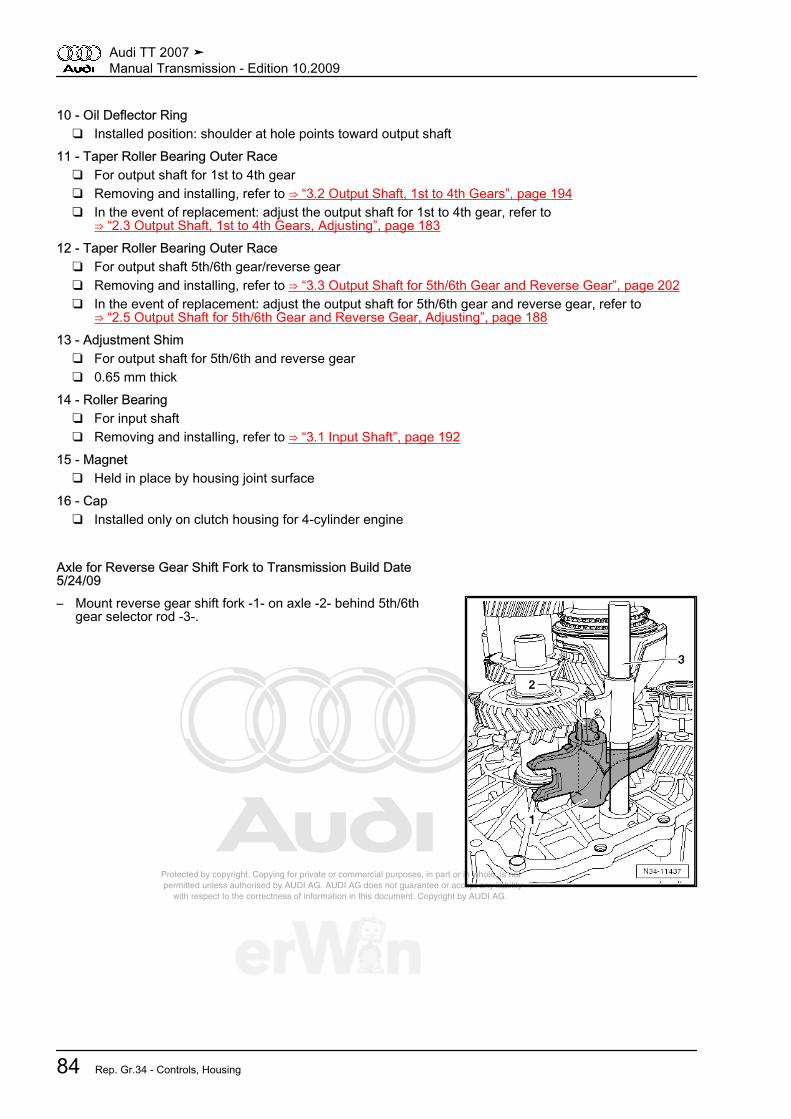
Protected by copyright. Copying for private or commercial purposes, in part or in whole, is not permitted unless authorised by AUDI AG. AUDI AG does not guarantee or accept any liability with respect to the correctness of information in this document. Copyright by AUDI AG.
10 - Oil Deflector Ring❑ Installed position: shoulder at hole points toward output shaft
11 - Taper Roller Bearing Outer Race❑ For output shaft for 1st to 4th gear❑ Removing and installing, refer to ⇒ “3.2 Output Shaft, 1st to 4th Gears”, page 194❑ In the event of replacement: adjust the output shaft for 1st to 4th gear, refer to
⇒ “2.3 Output Shaft, 1st to 4th Gears, Adjusting”, page 18312 - Taper Roller Bearing Outer Race
❑ For output shaft 5th/6th gear/reverse gear❑ Removing and installing, refer to ⇒ “3.3 Output Shaft for 5th/6th Gear and Reverse Gear”, page 202❑ In the event of replacement: adjust the output shaft for 5th/6th gear and reverse gear, refer to
⇒ “2.5 Output Shaft for 5th/6th Gear and Reverse Gear, Adjusting”, page 18813 - Adjustment Shim
❑ For output shaft for 5th/6th and reverse gear❑ 0.65 mm thick
14 - Roller Bearing❑ For input shaft❑ Removing and installing, refer to ⇒ “3.1 Input Shaft”, page 192
15 - Magnet❑ Held in place by housing joint surface
16 - Cap❑ Installed only on clutch housing for 4-cylinder engine
Axle for Reverse Gear Shift Fork to Transmission Build Date5/24/09– Mount reverse gear shift fork -1- on axle -2- behind 5th/6th
gear selector rod -3-.
Audi TT 2007 ➤Manual Transmission - Edition 10.2009
84 Rep. Gr.34 - Controls, Housing

Protected by copyright. Copying for private or commercial purposes, in part or in whole, is not permitted unless authorised by AUDI AG. AUDI AG does not guarantee or accept any liability with respect to the correctness of information in this document. Copyright by AUDI AG.
2.16 Shift Mechanism Assembly Overview, Transmission Side
Note
Grease bearing areas and slide surfaces with grease -G 000 450 02- .
1 - Bushing for Selector Shaft❑ Removing and installing
-16- ⇒ page 822 - Selector Shaft
❑ With shift cover❑ Can be removed and in‐
stalled with transmis‐sion installed
3 - O-ring❑ Replace❑ Insert into surrounding
groove of shift cover❑ Install coated with gear
oil4 - Cap for TransmissionBreather5 - Selector Shaft Seal
❑ Replace, refer to⇒ “4.14 Selector ShaftSeal”, page 124
6 - Bolt❑ Replace❑ 20 Nm
Audi TT 2007 ➤Manual Transmission - Edition 10.2009
2. Description and Operation 85

Protected by copyright. Copying for private or commercial purposes, in part or in whole, is not permitted unless authorised by AUDI AG. AUDI AG does not guarantee or accept any liability with respect to the correctness of information in this document. Copyright by AUDI AG.
2.17 Shift Forks Assembly Overview
1 - Rubber Damper❑ Can be pulled out of se‐
lector rod and insertedby hand
2 - Selector Rod with Shift Forkfor 1st and 2nd Gear3 - Selector Rod with Shift Forkfor 3rd and 4th Gear4 - Selector Rod with Shift Forkfor 5th and 6th Gear
❑ Also serves as the bear‐ing for the reverse gearshift fork as of transmis‐sion build date 5/25/09
5 - Reverse Gear Shift Fork❑ from transmission man‐
ufacture date 06 03 6,ball sleeve -6- has beenomitted
❑ Sliding omission❑ Reverse gear shift fork
is adapted❑ From transmission build
date 5/25/09, bearing onthe selector rod for theshift fork for 5th and 6thgear
❑ Reverse gear shift forkdifferentiation⇒ page 86
❑ Allocation, refer to theelectronic parts catalogETKA
6 - Ball sleeve❑ No longer used as of transmission build date 3/06/06❑ Sliding omission❑ Allocation, refer to the electronic parts catalog ETKA❑ Pulling out ⇒ page 152❑ Installing ⇒ page 152
Reverse Gear Shift Fork Differentiation
Dimension “a”mm
TransmissionManufacture
Date
Reverse GearShift Fork
Mounting
24 Through05 03 6
With ballsleeve
On the axle forthe reverse gear
shift fork⇒ page 8418 From 3/6/06
to 5/24/09Without ball
sleeve15 From 5/25/09 Without ball
sleeveSelector rod
with shift fork for5th and 6th gear
⇒ page 147
Audi TT 2007 ➤Manual Transmission - Edition 10.2009
86 Rep. Gr.34 - Controls, Housing
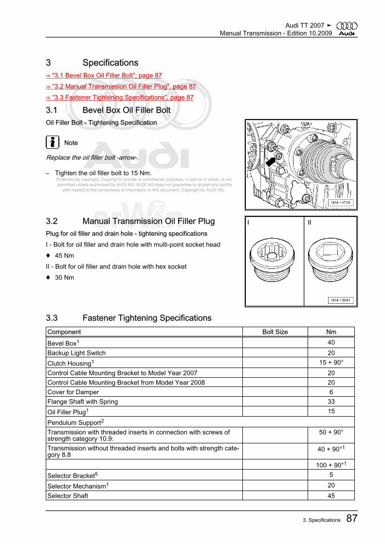
Protected by copyright. Copying for private or commercial purposes, in part or in whole, is not permitted unless authorised by AUDI AG. AUDI AG does not guarantee or accept any liability with respect to the correctness of information in this document. Copyright by AUDI AG.
3 Specifications⇒ “3.1 Bevel Box Oil Filler Bolt”, page 87⇒ “3.2 Manual Transmission Oil Filler Plug”, page 87⇒ “3.3 Fastener Tightening Specifications”, page 87
3.1 Bevel Box Oil Filler BoltOil Filler Bolt - Tightening Specification
Note
Replace the oil filler bolt -arrow-.
– Tighten the oil filler bolt to 15 Nm.
3.2 Manual Transmission Oil Filler PlugPlug for oil filler and drain hole - tightening specificationsI - Bolt for oil filler and drain hole with multi-point socket head♦ 45 NmII - Bolt for oil filler and drain hole with hex socket♦ 30 Nm
3.3 Fastener Tightening SpecificationsComponent Bolt Size Nm
Bevel Box1 40Backup Light Switch 20Clutch Housing1 15 + 90°Control Cable Mounting Bracket to Model Year 2007 20Control Cable Mounting Bracket from Model Year 2008 20Cover for Damper 6Flange Shaft with Spring 33Oil Filler Plug1 15
Pendulum Support2
Transmission with threaded inserts in connection with screws ofstrength category 10.9:
50 + 90°
Transmission without threaded inserts and bolts with strength cate‐gory 8.8
40 + 90°1
100 + 90°1
Selector Bracket5 5
Selector Mechanism1 20Selector Shaft 45
Audi TT 2007 ➤Manual Transmission - Edition 10.2009
3. Specifications 87
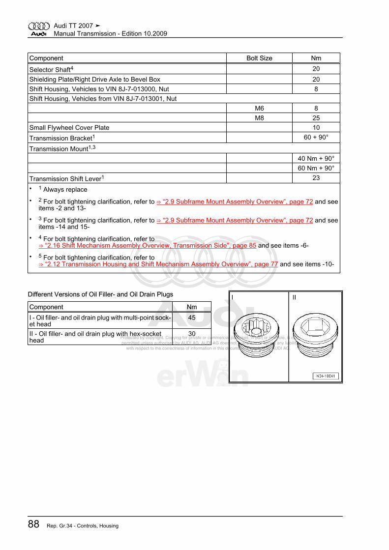
Protected by copyright. Copying for private or commercial purposes, in part or in whole, is not permitted unless authorised by AUDI AG. AUDI AG does not guarantee or accept any liability with respect to the correctness of information in this document. Copyright by AUDI AG.
Component Bolt Size Nm
Selector Shaft4 20Shielding Plate/Right Drive Axle to Bevel Box 20Shift Housing, Vehicles to VIN 8J-7-013000, Nut 8Shift Housing, Vehicles from VIN 8J-7-013001, Nut M6 8 M8 25Small Flywheel Cover Plate 10Transmission Bracket1 60 + 90°
Transmission Mount1,3
40 Nm + 90° 60 Nm + 90°Transmission Shift Lever1 23• 1 Always replace• 2 For bolt tightening clarification, refer to ⇒ “2.9 Subframe Mount Assembly Overview”, page 72 and see
items -2 and 13-• 3 For bolt tightening clarification, refer to ⇒ “2.9 Subframe Mount Assembly Overview”, page 72 and see
items -14 and 15-• 4 For bolt tightening clarification, refer to
⇒ “2.16 Shift Mechanism Assembly Overview, Transmission Side”, page 85 and see items -6-• 5 For bolt tightening clarification, refer to
⇒ “2.12 Transmission Housing and Shift Mechanism Assembly Overview”, page 77 and see items -10-
Different Versions of Oil Filler- and Oil Drain Plugs
Component NmI - Oil filler- and oil drain plug with multi-point sock‐et head
45
II - Oil filler- and oil drain plug with hex-sockethead
30
Audi TT 2007 ➤Manual Transmission - Edition 10.2009
88 Rep. Gr.34 - Controls, Housing

Protected by copyright. Copying for private or commercial purposes, in part or in whole, is not permitted unless authorised by AUDI AG. AUDI AG does not guarantee or accept any liability with respect to the correctness of information in this document. Copyright by AUDI AG.
Manual Transmission Mount on Engine
Item Bolt 1 Nm
1 2),3 3)
M12x55 80
2 4) M12x65 80 M12x55 80
4 4),5 4)5)
M10x50 40
6 3) M12x80 80A Alignment sleeves for centering
• 1) Replace bolts.• 2) Bolt with 8 mm threaded pin• 3) With permanent washer.• 4) Bolted from the engine side into the transmission.• 5) The securing clip must be inserted in the engine oil pan
Bevel Box Bracket -A- Tightening Specification and Sequence
– Tighten bolts in 4 stages as follows:
1. Install bolts -1- and -2- hand tight.
2. Pretighten bolts -1- to 3 Nm.
3. Tighten bolts -2- to 35 Nm.
4. Tighten bolts -1- to 45 Nm.
Right Drive Axle Heat Shield - Tightening Specification– Tighten bolts -arrows- to 25 Nm.
Audi TT 2007 ➤Manual Transmission - Edition 10.2009
3. Specifications 89
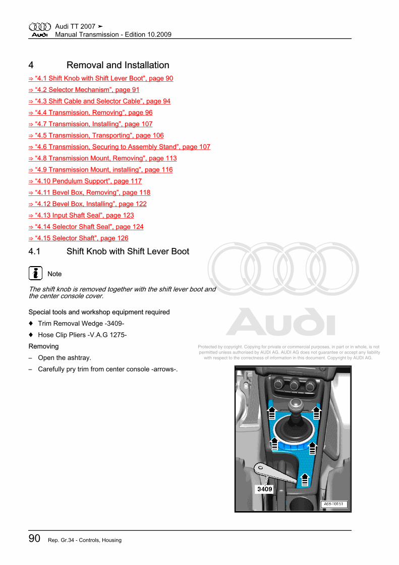
Protected by copyright. Copying for private or commercial purposes, in part or in whole, is not permitted unless authorised by AUDI AG. AUDI AG does not guarantee or accept any liability with respect to the correctness of information in this document. Copyright by AUDI AG.
4 Removal and Installation⇒ “4.1 Shift Knob with Shift Lever Boot”, page 90⇒ “4.2 Selector Mechanism”, page 91⇒ “4.3 Shift Cable and Selector Cable”, page 94⇒ “4.4 Transmission, Removing”, page 96⇒ “4.7 Transmission, Installing”, page 107⇒ “4.5 Transmission, Transporting”, page 106⇒ “4.6 Transmission, Securing to Assembly Stand”, page 107⇒ “4.8 Transmission Mount, Removing”, page 113⇒ “4.9 Transmission Mount, installing”, page 116⇒ “4.10 Pendulum Support”, page 117⇒ “4.11 Bevel Box, Removing”, page 118⇒ “4.12 Bevel Box, Installing”, page 122⇒ “4.13 Input Shaft Seal”, page 123⇒ “4.14 Selector Shaft Seal”, page 124⇒ “4.15 Selector Shaft”, page 126
4.1 Shift Knob with Shift Lever Boot
Note
The shift knob is removed together with the shift lever boot andthe center console cover.
Special tools and workshop equipment required♦ Trim Removal Wedge -3409-♦ Hose Clip Pliers -V.A.G 1275-Removing– Open the ashtray.– Carefully pry trim from center console -arrows-.
Audi TT 2007 ➤Manual Transmission - Edition 10.2009
90 Rep. Gr.34 - Controls, Housing
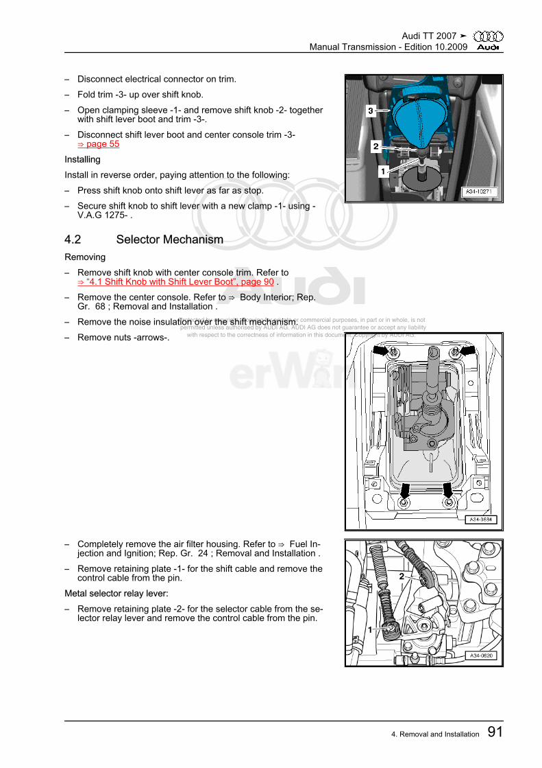
Protected by copyright. Copying for private or commercial purposes, in part or in whole, is not permitted unless authorised by AUDI AG. AUDI AG does not guarantee or accept any liability with respect to the correctness of information in this document. Copyright by AUDI AG.
– Disconnect electrical connector on trim.– Fold trim -3- up over shift knob.– Open clamping sleeve -1- and remove shift knob -2- together
with shift lever boot and trim -3-.– Disconnect shift lever boot and center console trim -3-
⇒ page 55InstallingInstall in reverse order, paying attention to the following:– Press shift knob onto shift lever as far as stop.– Secure shift knob to shift lever with a new clamp -1- using -
V.A.G 1275- .
4.2 Selector MechanismRemoving– Remove shift knob with center console trim. Refer to
⇒ “4.1 Shift Knob with Shift Lever Boot”, page 90 .– Remove the center console. Refer to ⇒ Body Interior; Rep.
Gr. 68 ; Removal and Installation .– Remove the noise insulation over the shift mechanism.– Remove nuts -arrows-.
– Completely remove the air filter housing. Refer to ⇒ Fuel In‐jection and Ignition; Rep. Gr. 24 ; Removal and Installation .
– Remove retaining plate -1- for the shift cable and remove thecontrol cable from the pin.
Metal selector relay lever:– Remove retaining plate -2- for the selector cable from the se‐
lector relay lever and remove the control cable from the pin.
Audi TT 2007 ➤Manual Transmission - Edition 10.2009
4. Removal and Installation 91
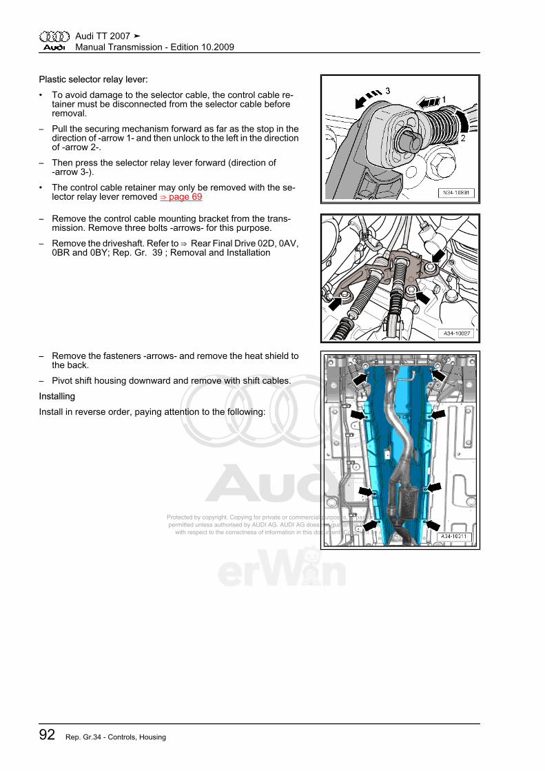
Protected by copyright. Copying for private or commercial purposes, in part or in whole, is not permitted unless authorised by AUDI AG. AUDI AG does not guarantee or accept any liability with respect to the correctness of information in this document. Copyright by AUDI AG.
Plastic selector relay lever:• To avoid damage to the selector cable, the control cable re‐
tainer must be disconnected from the selector cable beforeremoval.
– Pull the securing mechanism forward as far as the stop in thedirection of -arrow 1- and then unlock to the left in the directionof -arrow 2-.
– Then press the selector relay lever forward (direction of-arrow 3-).
• The control cable retainer may only be removed with the se‐lector relay lever removed ⇒ page 69
– Remove the control cable mounting bracket from the trans‐mission. Remove three bolts -arrows- for this purpose.
– Remove the driveshaft. Refer to ⇒ Rear Final Drive 02D, 0AV,0BR and 0BY; Rep. Gr. 39 ; Removal and Installation
– Remove the fasteners -arrows- and remove the heat shield tothe back.
– Pivot shift housing downward and remove with shift cables.InstallingInstall in reverse order, paying attention to the following:
Audi TT 2007 ➤Manual Transmission - Edition 10.2009
92 Rep. Gr.34 - Controls, Housing

Protected by copyright. Copying for private or commercial purposes, in part or in whole, is not permitted unless authorised by AUDI AG. AUDI AG does not guarantee or accept any liability with respect to the correctness of information in this document. Copyright by AUDI AG.
– Insert the shift mechanism and tighten the nuts -arrows-. Tight‐ening specification -16- ⇒ page 60 .
– Route the cables -1- from the shift mechanism -2- to the trans‐mission as follows:
• The cables must run parallel to each other and must not in‐tersect.
• The cables must be routed in the provided recesses in the heatshield -3-.
Note
The enlargement shows the heat shield from above.
A clip -A- holds the cables and heat shield to each other in place.
Audi TT 2007 ➤Manual Transmission - Edition 10.2009
4. Removal and Installation 93
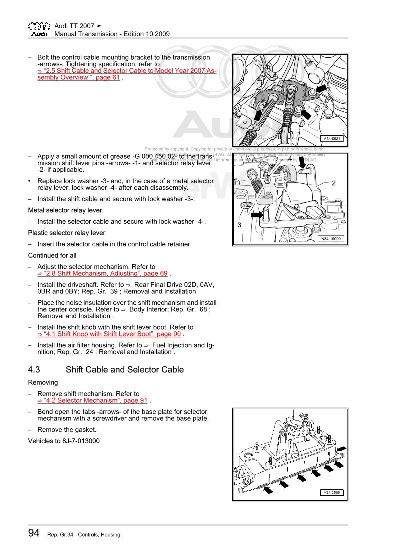
Protected by copyright. Copying for private or commercial purposes, in part or in whole, is not permitted unless authorised by AUDI AG. AUDI AG does not guarantee or accept any liability with respect to the correctness of information in this document. Copyright by AUDI AG.
– Bolt the control cable mounting bracket to the transmission-arrows-. Tightening specification, refer to⇒ “2.5 Shift Cable and Selector Cable to Model Year 2007 As‐sembly Overview ”, page 61 .
– Apply a small amount of grease -G 000 450 02- to the trans‐mission shift lever pins -arrows- -1- and selector relay lever-2- if applicable.
• Replace lock washer -3- and, in the case of a metal selectorrelay lever, lock washer -4- after each disassembly.
– Install the shift cable and secure with lock washer -3-.Metal selector relay lever– Install the selector cable and secure with lock washer -4-.Plastic selector relay lever– Insert the selector cable in the control cable retainer.Continued for all– Adjust the selector mechanism. Refer to
⇒ “2.8 Shift Mechanism, Adjusting”, page 69 .– Install the driveshaft. Refer to ⇒ Rear Final Drive 02D, 0AV,
0BR and 0BY; Rep. Gr. 39 ; Removal and Installation– Place the noise insulation over the shift mechanism and install
the center console. Refer to ⇒ Body Interior; Rep. Gr. 68 ;Removal and Installation .
– Install the shift knob with the shift lever boot. Refer to⇒ “4.1 Shift Knob with Shift Lever Boot”, page 90 .
– Install the air filter housing. Refer to ⇒ Fuel Injection and Ig‐nition; Rep. Gr. 24 ; Removal and Installation .
4.3 Shift Cable and Selector CableRemoving– Remove shift mechanism. Refer to
⇒ “4.2 Selector Mechanism”, page 91 .– Bend open the tabs -arrows- of the base plate for selector
mechanism with a screwdriver and remove the base plate.– Remove the gasket.Vehicles to 8J-7-013000
Audi TT 2007 ➤Manual Transmission - Edition 10.2009
94 Rep. Gr.34 - Controls, Housing

Protected by copyright. Copying for private or commercial purposes, in part or in whole, is not permitted unless authorised by AUDI AG. AUDI AG does not guarantee or accept any liability with respect to the correctness of information in this document. Copyright by AUDI AG.
– Remove lock washers -1- and -4- and remove the control ca‐bles from the pins.
Vehicles from VIN 8J-7-013001– Pry the shift and selector lever off of the pins.All Vehicles– Remove circlips -2 to 3- and remove shift cable and selector
cable from selector mechanism housing.
Release the cable retainer -A- for the selector and shift cables-B- as follows:– Push sleeve forward up to the stop -arrow 1-.– Turn sleeve to the right up to the stop -arrow 2- so that it en‐
gages.– Remove the cable retainers from the cables.
– Pull off the circlips -1- and -2-.– Remove the control cable mounting bracket from the control
cables.InstallingInstall in reverse order, paying attention to the following:
– Secure the shift cable and selector cable to the selector mech‐anism housing with the circlips -1 to 4-.
Vehicles from VIN 8J-7-013001– Press the shift and selector lever onto the pins.All Vehicles
Audi TT 2007 ➤Manual Transmission - Edition 10.2009
4. Removal and Installation 95
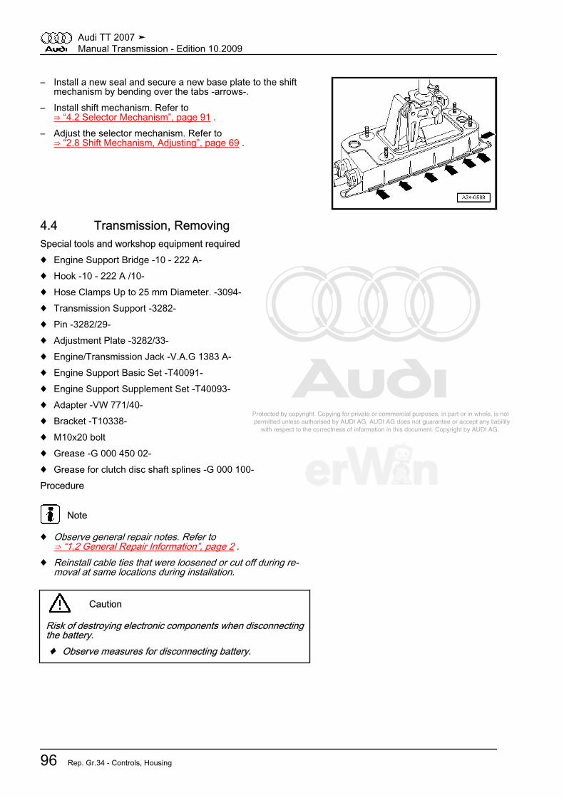
Protected by copyright. Copying for private or commercial purposes, in part or in whole, is not permitted unless authorised by AUDI AG. AUDI AG does not guarantee or accept any liability with respect to the correctness of information in this document. Copyright by AUDI AG.
– Install a new seal and secure a new base plate to the shiftmechanism by bending over the tabs -arrows-.
– Install shift mechanism. Refer to⇒ “4.2 Selector Mechanism”, page 91 .
– Adjust the selector mechanism. Refer to⇒ “2.8 Shift Mechanism, Adjusting”, page 69 .
4.4 Transmission, RemovingSpecial tools and workshop equipment required♦ Engine Support Bridge -10 - 222 A-♦ Hook -10 - 222 A /10-♦ Hose Clamps Up to 25 mm Diameter. -3094-♦ Transmission Support -3282-♦ Pin -3282/29-♦ Adjustment Plate -3282/33-♦ Engine/Transmission Jack -V.A.G 1383 A-♦ Engine Support Basic Set -T40091-♦ Engine Support Supplement Set -T40093-♦ Adapter -VW 771/40-♦ Bracket -T10338-♦ M10x20 bolt♦ Grease -G 000 450 02-♦ Grease for clutch disc shaft splines -G 000 100-Procedure
Note
♦ Observe general repair notes. Refer to⇒ “1.2 General Repair Information”, page 2 .
♦ Reinstall cable ties that were loosened or cut off during re‐moval at same locations during installation.
Caution
Risk of destroying electronic components when disconnectingthe battery.♦ Observe measures for disconnecting battery.
Audi TT 2007 ➤Manual Transmission - Edition 10.2009
96 Rep. Gr.34 - Controls, Housing
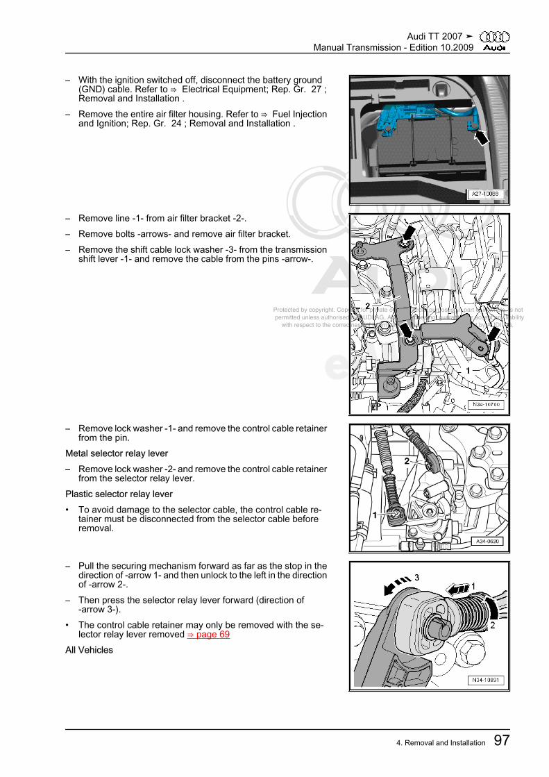
Protected by copyright. Copying for private or commercial purposes, in part or in whole, is not permitted unless authorised by AUDI AG. AUDI AG does not guarantee or accept any liability with respect to the correctness of information in this document. Copyright by AUDI AG.
– With the ignition switched off, disconnect the battery ground(GND) cable. Refer to ⇒ Electrical Equipment; Rep. Gr. 27 ;Removal and Installation .
– Remove the entire air filter housing. Refer to ⇒ Fuel Injectionand Ignition; Rep. Gr. 24 ; Removal and Installation .
– Remove line -1- from air filter bracket -2-.– Remove bolts -arrows- and remove air filter bracket.– Remove the shift cable lock washer -3- from the transmission
shift lever -1- and remove the cable from the pins -arrow-.
– Remove lock washer -1- and remove the control cable retainerfrom the pin.
Metal selector relay lever– Remove lock washer -2- and remove the control cable retainer
from the selector relay lever.Plastic selector relay lever• To avoid damage to the selector cable, the control cable re‐
tainer must be disconnected from the selector cable beforeremoval.
– Pull the securing mechanism forward as far as the stop in thedirection of -arrow 1- and then unlock to the left in the directionof -arrow 2-.
– Then press the selector relay lever forward (direction of-arrow 3-).
• The control cable retainer may only be removed with the se‐lector relay lever removed ⇒ page 69
All Vehicles
Audi TT 2007 ➤Manual Transmission - Edition 10.2009
4. Removal and Installation 97

Protected by copyright. Copying for private or commercial purposes, in part or in whole, is not permitted unless authorised by AUDI AG. AUDI AG does not guarantee or accept any liability with respect to the correctness of information in this document. Copyright by AUDI AG.
– Remove cable mounting bracket from transmission -arrows-and tie it up off to the side with the cables.
– When a plastic line is installed between the clutch master andslave cylinder, clamp off the return line to the clutch mastercylinder with -3094- .
Note
♦ During the following procedures, make sure that brake fluiddoes not leak onto the starter or the transmission. If this hap‐pens, these areas must be cleaned thoroughly.
♦ To prevent dirt from entering, seal open lines and connectionswith clean plugs or protective caps.
– If a hose/line assembly is installed between the clutch masterand slave cylinder, clamp off hose -A- with -3094- .
Note
Pay no attention to -arrow-.
– Pull out the clip -arrow- to the stop.– Remove the plastic line or hose/line assembly -A- from the
bleeder/clutch slave cylinder and seal it off.
Note
Disregard item -B-.
Caution
Clutch pedal must no longer be operated.
Audi TT 2007 ➤Manual Transmission - Edition 10.2009
98 Rep. Gr.34 - Controls, Housing

Protected by copyright. Copying for private or commercial purposes, in part or in whole, is not permitted unless authorised by AUDI AG. AUDI AG does not guarantee or accept any liability with respect to the correctness of information in this document. Copyright by AUDI AG.
– Disconnect electrical harness connector -1- for back-up lightswitch -F4- .
– Remove the ground (GND) cable -2-.– Then remove upper starter mounting bolt under ground (GND)
cable -2-.– Disconnect electrical connector -3-.– Slide cover -4- back.
– Disconnect the electrical wire -arrow- from the starter.
– Remove upper engine/transmission bolts -arrows-.
– Install -T10338- on open threaded hole at left rear of engine.
Audi TT 2007 ➤Manual Transmission - Edition 10.2009
4. Removal and Installation 99

Protected by copyright. Copying for private or commercial purposes, in part or in whole, is not permitted unless authorised by AUDI AG. AUDI AG does not guarantee or accept any liability with respect to the correctness of information in this document. Copyright by AUDI AG.
– Position -10 - 222 A- on bolted fender flange with the followingtool components:
♦ Bracket for engine -10 - 222 A /1- , qty. 2♦ Bracket with spindle and hook -10 - 222 A /10- (spindle faces
toward rear)♦ Spindle -10 - 222 A /11- (spindle faces toward front)♦ Shackle -10 - 222 A /12-♦ Connectors -T40091/3- , qty. 2– Engage -10 - 222 A /11- with -10 - 222 A /12- on right engine
lifting eye.– Engage -10 - 222 A /10- on -T10338- .– Lightly tension the engine/transmission assembly with the
spindles.
– Connect -T40093/3- (qty. 2) with left side -T40093/3-2- or rightside -T40093/3-3- .
– Disconnect ground (GND) cable from left longmember.– Remove left and right connecting bolts for front part of long‐
member.– Install -T40093/3-2- (left) and -T40093/3-3- (right) on the long‐
members with the previously removed bolts -arrow-.
Note
The left side of the vehicle is shown in the illustration.
– Insert -T40091/1- in -T40091/3- and -T40093/3- as shown inillustration.
Audi TT 2007 ➤Manual Transmission - Edition 10.2009
100 Rep. Gr.34 - Controls, Housing

Protected by copyright. Copying for private or commercial purposes, in part or in whole, is not permitted unless authorised by AUDI AG. AUDI AG does not guarantee or accept any liability with respect to the correctness of information in this document. Copyright by AUDI AG.
– Slide -T40093/4- onto square tube.– Slide -T40091/2- with -T40093/5- into both -T40093/4- .
WARNING
Risk of an accident due to loose support bridge parts.♦ Secure -T40091/2- with pins and splints from -T40093/4- .♦ Secure connector and supports with locking bolts.
– Install -10 - 222 A /11- on slide and engine lifting eye.– Tension the engine/transmission assembly by tightening the
3 spindles evenly.– Remove both front wheels.
– Remove noise insulation in center by loosening fasteners-1 through 4-.
– Remove left and right noise insulation -arrows-.
– Remove the noise insulation frame -arrow-. Refer to ⇒ BodyExterior; Rep. Gr. 50 ; Removal and Installation .
Audi TT 2007 ➤Manual Transmission - Edition 10.2009
4. Removal and Installation 101
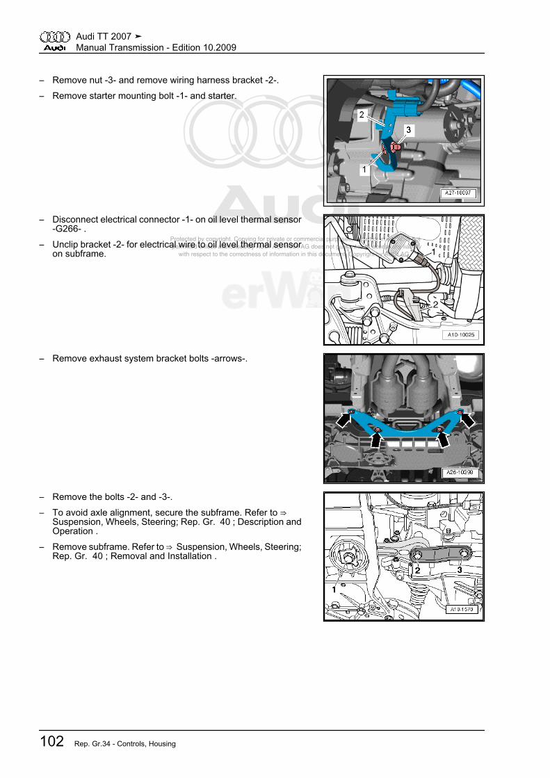
Protected by copyright. Copying for private or commercial purposes, in part or in whole, is not permitted unless authorised by AUDI AG. AUDI AG does not guarantee or accept any liability with respect to the correctness of information in this document. Copyright by AUDI AG.
– Remove nut -3- and remove wiring harness bracket -2-.– Remove starter mounting bolt -1- and starter.
– Disconnect electrical connector -1- on oil level thermal sensor-G266- .
– Unclip bracket -2- for electrical wire to oil level thermal sensoron subframe.
– Remove exhaust system bracket bolts -arrows-.
– Remove the bolts -2- and -3-.– To avoid axle alignment, secure the subframe. Refer to ⇒
Suspension, Wheels, Steering; Rep. Gr. 40 ; Description andOperation .
– Remove subframe. Refer to ⇒ Suspension, Wheels, Steering;Rep. Gr. 40 ; Removal and Installation .
Audi TT 2007 ➤Manual Transmission - Edition 10.2009
102 Rep. Gr.34 - Controls, Housing

Protected by copyright. Copying for private or commercial purposes, in part or in whole, is not permitted unless authorised by AUDI AG. AUDI AG does not guarantee or accept any liability with respect to the correctness of information in this document. Copyright by AUDI AG.
– Remove right drive axle heat shield from bevel box -arrows-.– Remove the left drive axle from transmission flange shaft .– Remove the right drive axle from the bevel box flange shaft .– Raise drive axles and secure with cable ties.
Note
Make sure drive axle protective coating is not damaged.
– Remove the bolts -arrows- and remove the bevel box bracket.– Identify position of flexible disc and bevel box flange to each
other.
– Remove driveshaft flexible disc from bevel box -arrows- whilecounterholding at triangular flange with a lever.
– Press engine/transmission assembly slightly forward (towardfront end) and pull off driveshaft from bevel box.
Caution
Risk of damaging sealing ring -arrow- in driveshaft flange.♦ Press driveshaft horizontally as far back and to the right
side of the vehicle as possible.
Note
If seal is damaged, driveshaft must be replaced.
– Tie driveshaft up.
Audi TT 2007 ➤Manual Transmission - Edition 10.2009
4. Removal and Installation 103
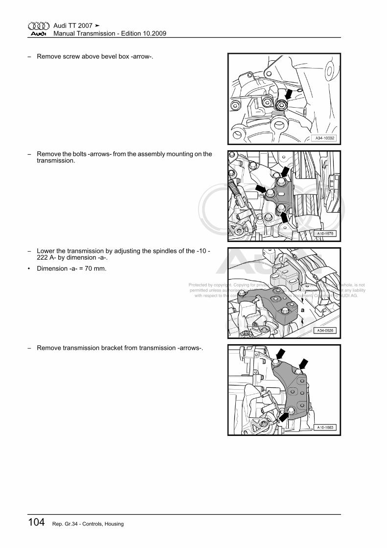
Protected by copyright. Copying for private or commercial purposes, in part or in whole, is not permitted unless authorised by AUDI AG. AUDI AG does not guarantee or accept any liability with respect to the correctness of information in this document. Copyright by AUDI AG.
– Remove screw above bevel box -arrow-.
– Remove the bolts -arrows- from the assembly mounting on thetransmission.
– Lower the transmission by adjusting the spindles of the -10 -222 A- by dimension -a-.
• Dimension -a- = 70 mm.
– Remove transmission bracket from transmission -arrows-.
Audi TT 2007 ➤Manual Transmission - Edition 10.2009
104 Rep. Gr.34 - Controls, Housing
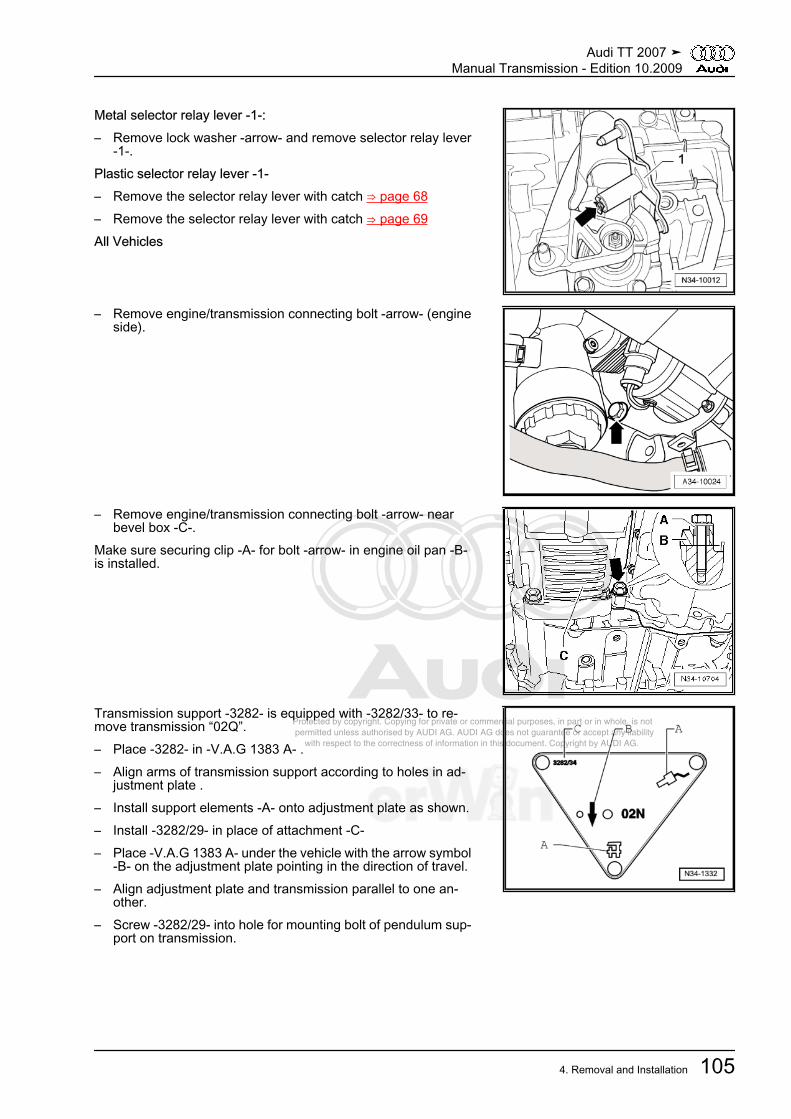
Protected by copyright. Copying for private or commercial purposes, in part or in whole, is not permitted unless authorised by AUDI AG. AUDI AG does not guarantee or accept any liability with respect to the correctness of information in this document. Copyright by AUDI AG.
Metal selector relay lever -1-:– Remove lock washer -arrow- and remove selector relay lever
-1-.Plastic selector relay lever -1-– Remove the selector relay lever with catch ⇒ page 68– Remove the selector relay lever with catch ⇒ page 69All Vehicles
– Remove engine/transmission connecting bolt -arrow- (engineside).
– Remove engine/transmission connecting bolt -arrow- nearbevel box -C-.
Make sure securing clip -A- for bolt -arrow- in engine oil pan -B-is installed.
Transmission support -3282- is equipped with -3282/33- to re‐move transmission “02Q”.– Place -3282- in -V.A.G 1383 A- .– Align arms of transmission support according to holes in ad‐
justment plate .– Install support elements -A- onto adjustment plate as shown.– Install -3282/29- in place of attachment -C-– Place -V.A.G 1383 A- under the vehicle with the arrow symbol
-B- on the adjustment plate pointing in the direction of travel.– Align adjustment plate and transmission parallel to one an‐
other.– Screw -3282/29- into hole for mounting bolt of pendulum sup‐
port on transmission.
Audi TT 2007 ➤Manual Transmission - Edition 10.2009
4. Removal and Installation 105
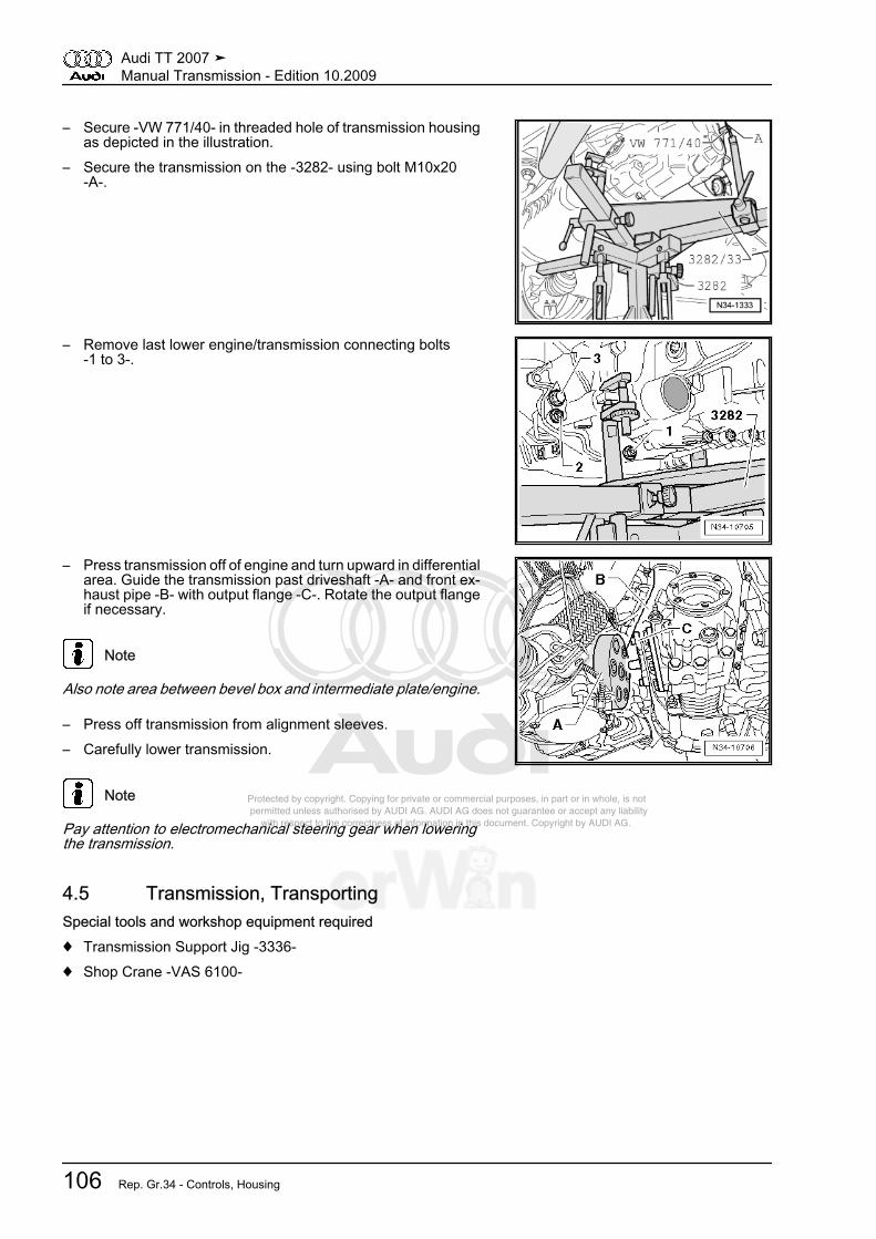
Protected by copyright. Copying for private or commercial purposes, in part or in whole, is not permitted unless authorised by AUDI AG. AUDI AG does not guarantee or accept any liability with respect to the correctness of information in this document. Copyright by AUDI AG.
– Secure -VW 771/40- in threaded hole of transmission housingas depicted in the illustration.
– Secure the transmission on the -3282- using bolt M10x20-A-.
– Remove last lower engine/transmission connecting bolts-1 to 3-.
– Press transmission off of engine and turn upward in differentialarea. Guide the transmission past driveshaft -A- and front ex‐haust pipe -B- with output flange -C-. Rotate the output flangeif necessary.
Note
Also note area between bevel box and intermediate plate/engine.
– Press off transmission from alignment sleeves.– Carefully lower transmission.
Note
Pay attention to electromechanical steering gear when loweringthe transmission.
4.5 Transmission, TransportingSpecial tools and workshop equipment required♦ Transmission Support Jig -3336-♦ Shop Crane -VAS 6100-
Audi TT 2007 ➤Manual Transmission - Edition 10.2009
106 Rep. Gr.34 - Controls, Housing

Protected by copyright. Copying for private or commercial purposes, in part or in whole, is not permitted unless authorised by AUDI AG. AUDI AG does not guarantee or accept any liability with respect to the correctness of information in this document. Copyright by AUDI AG.
Procedure– Secure the -3336- to the clutch housing.– Adjust support arm on sliding piece with locking pin -arrow-.• Number of visible holes = 9.– Lift the transmission with the -VAS 6100- and -3336- .– Set down the transmission, for example in a transport con‐
tainer.
4.6 Transmission, Securing to AssemblyStand
Special tools and workshop equipment required♦ Holding Plate -VW 309-♦ Holding Fixture -VW 313-♦ Transmission Support -VW 353-– Secure transmission to assembly stand with bolts -arrows-.
4.7 Transmission, InstallingInstall in reverse order, paying attention to the following:
Audi TT 2007 ➤Manual Transmission - Edition 10.2009
4. Removal and Installation 107

Protected by copyright. Copying for private or commercial purposes, in part or in whole, is not permitted unless authorised by AUDI AG. AUDI AG does not guarantee or accept any liability with respect to the correctness of information in this document. Copyright by AUDI AG.
Note
♦ When performing repairs, replace self-locking nuts and bolts.♦ Always replace bolts that are secured with additional torque
as well as sealing rings, seals, and O-rings.♦ All cable ties that are opened or cut open during removal must
be replaced in the same positions during installation.♦ Clean input shaft splines and (in case of used clutch plates)
clean hub splines, remove corrosion and apply only a very thincoating of lubricant -G 000 100- on splines. Then move clutchplate back and forth on input shaft until the hub moves freelyon the shaft. Excess grease must be removed.
♦ If the transmission is replaced, modify the transmission shiftlever and selector relay lever.
– All threaded bores, in which self-locking bolts are threaded,must be cleaned of locking fluid residue using a thread tap.
– If there are no alignment sleeves for centering the engine andtransmission in the cylinder block, insert them.
– Make sure that intermediate plate is engaged on sealingflange and has been slid on to alignment sleeves -arrows-.
– Check the centralization of the clutch plate. Refer to⇒ “4.9 LuK Clutch”, page 42 .
– Check the release bearing for wear. Replace the clutch slavecylinder with the release bearing if necessary. Refer to⇒ “2.4 Clutch Release Mechanism, Clutch Slave Cylinder As‐sembly Overview”, page 21 .
– Carefully raise transmission with -3282- .– Align transmission to engine and install.
– Guide the transmission past drive axle -A- and front exhaustpipe -B- with output flange -C-. Rotate the output flange if nec‐essary.
Note
♦ Pay attention to electromechanical steering gear when instal‐ling the transmission.
♦ Pay attention to all lines when installing transmission.
– If applicable, insert bevel box bracket -A-.
Audi TT 2007 ➤Manual Transmission - Edition 10.2009
108 Rep. Gr.34 - Controls, Housing
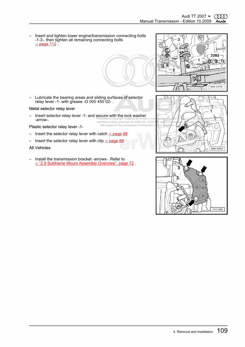
Protected by copyright. Copying for private or commercial purposes, in part or in whole, is not permitted unless authorised by AUDI AG. AUDI AG does not guarantee or accept any liability with respect to the correctness of information in this document. Copyright by AUDI AG.
– Insert and tighten lower engine/transmission connecting bolts-1-3-, then tighten all remaining connecting bolts⇒ page 112 .
– Lubricate the bearing areas and sliding surfaces of selectorrelay lever -1- with grease -G 000 450 02- .
Metal selector relay lever– Insert selector relay lever -1- and secure with the lock washer
-arrow-.Plastic selector relay lever -1-– Insert the selector relay lever with catch ⇒ page 68– Insert the selector relay lever with clip ⇒ page 69All Vehicles
– Install the transmission bracket -arrows-. Refer to⇒ “2.9 Subframe Mount Assembly Overview”, page 72 .
Audi TT 2007 ➤Manual Transmission - Edition 10.2009
4. Removal and Installation 109
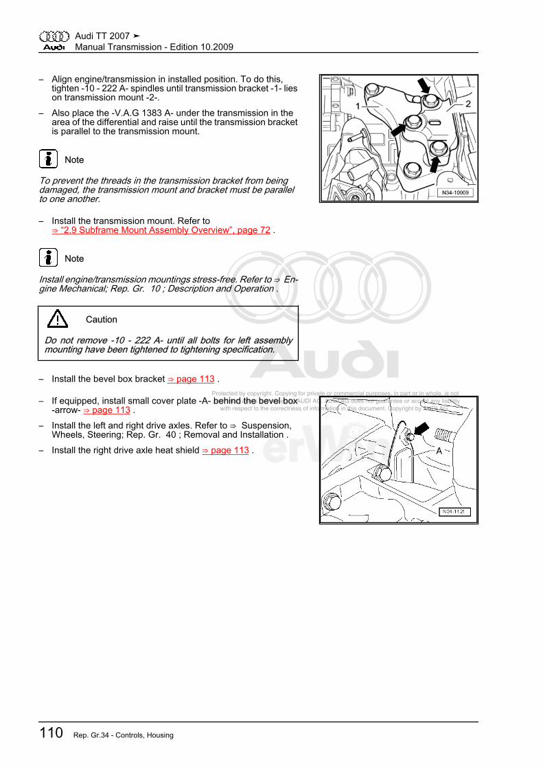
Protected by copyright. Copying for private or commercial purposes, in part or in whole, is not permitted unless authorised by AUDI AG. AUDI AG does not guarantee or accept any liability with respect to the correctness of information in this document. Copyright by AUDI AG.
– Align engine/transmission in installed position. To do this,tighten -10 - 222 A- spindles until transmission bracket -1- lieson transmission mount -2-.
– Also place the -V.A.G 1383 A- under the transmission in thearea of the differential and raise until the transmission bracketis parallel to the transmission mount.
Note
To prevent the threads in the transmission bracket from beingdamaged, the transmission mount and bracket must be parallelto one another.
– Install the transmission mount. Refer to⇒ “2.9 Subframe Mount Assembly Overview”, page 72 .
Note
Install engine/transmission mountings stress-free. Refer to ⇒ En‐gine Mechanical; Rep. Gr. 10 ; Description and Operation .
Caution
Do not remove -10 - 222 A- until all bolts for left assemblymounting have been tightened to tightening specification.
– Install the bevel box bracket ⇒ page 113 .
– If equipped, install small cover plate -A- behind the bevel box-arrow- ⇒ page 113 .
– Install the left and right drive axles. Refer to ⇒ Suspension,Wheels, Steering; Rep. Gr. 40 ; Removal and Installation .
– Install the right drive axle heat shield ⇒ page 113 .
Audi TT 2007 ➤Manual Transmission - Edition 10.2009
110 Rep. Gr.34 - Controls, Housing

Protected by copyright. Copying for private or commercial purposes, in part or in whole, is not permitted unless authorised by AUDI AG. AUDI AG does not guarantee or accept any liability with respect to the correctness of information in this document. Copyright by AUDI AG.
– Press the engine/transmission assembly to the bulkhead whilecarefully guiding the bevel box pin into the flange/driveshaft.
Note
♦ Seal in driveshaft flange must not be damaged when removingand installing transmission. Replace driveshaft if damaged.
♦ Slip the driveshaft horizontally onto the centering pin.
– Secure the driveshaft with the flexible disk on the bevel boxflange -arrows-. Refer to ⇒ Rear Final Drive 02D, 0AV, 0BRand 0BY; Rep. Gr. 39 ; Removal and Installation .
:– Installing the subframe. Refer to ⇒ Suspension, Wheels,
Steering; Rep. Gr. 40 ; Removal and Installation .– Install pendulum support. Refer to
⇒ “2.9 Subframe Mount Assembly Overview”, page 72 .
Note
♦ The holes for the pendulum support on transmissions from05.28.07 have threaded inserts (for example HeliCoil).
♦ How to recognize: collar on the first thread -arrow-.♦ Note the correct mounting bolts and tightening specifications
-2- ⇒ page 72 .
– Installing the steering gear on the subframe. Refer to ⇒ Sus‐pension, Wheels, Steering; Rep. Gr. 48 ; Removal and In‐stallation .
– Install the exhaust system and cross member. Refer to ⇒ En‐gine Mechanical; Rep. Gr. 26 ; Removal and Installation .
– Install the fan shroud. Refer to ⇒ Engine Mechanical; Rep.Gr. 19 ; Removal and Installation .
– Install starter. Refer to ⇒ Electrical Equipment; Rep. Gr. 27 ;Removal and Installation .
– Install the hose/line assembly or plastic line. Refer to⇒ “4.1 Hose/Line Assembly or Plastic Line”, page 29 .
– Bleed the clutch system. Refer to⇒ “1.2 Clutch System, Bleeding”, page 12 .
– Install the control cable mounting bracket on the transmission.Refer to⇒ “2.5 Shift Cable and Selector Cable to Model Year 2007 As‐sembly Overview ”, page 61 .
Audi TT 2007 ➤Manual Transmission - Edition 10.2009
4. Removal and Installation 111
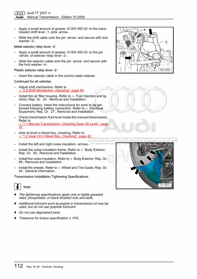
Protected by copyright. Copying for private or commercial purposes, in part or in whole, is not permitted unless authorised by AUDI AG. AUDI AG does not guarantee or accept any liability with respect to the correctness of information in this document. Copyright by AUDI AG.
– Apply a small amount of grease -G 000 450 02- to the trans‐mission shift lever -1- pins -arrow-.
– Slide the shift cable onto the pin -arrow- and secure with lockwasher -3-.
Metal selector relay lever -2-– Apply a small amount of grease -G 000 450 02- to the pin
-arrow- of selector relay lever -2-.– Slide the selector cable onto the pin -arrow- and secure with
the lock washer -4-.Plastic selector relay lever -2-– Insert the selector cable in the control cable retainer.Continued for all vehicles– Adjust shift mechanism. Refer to
⇒ “2.8 Shift Mechanism, Adjusting”, page 69 .– Install the air filter housing. Refer to ⇒ Fuel Injection and Ig‐
nition; Rep. Gr. 24 ; Removal and Installation .– Connect battery. Heed the instructions for work to be per‐
formed following battery connection. Refer to ⇒ ElectricalEquipment; Rep. Gr. 27 ; Removal and Installation .
– Check transmission fluid level inside the manual transmission.Refer to⇒ “1.1 Manual Transmission, Checking Gear Oil Level”, page47 .
– Axle oil level in bevel box, checking. Refer to⇒ “1.2 Gear Oil in Bevel Box, Checking”, page 48 .
– Install the left and right noise insulation -arrows-.– Install the noise insulation frame. Refer to ⇒ Body Exterior;
Rep. Gr. 50 ; Removal and Installation .– Install the noise insulation. Refer to ⇒ Body Exterior; Rep. Gr.
66 ; Removal and Installation .– Install the wheels. Refer to ⇒ Wheel and Tire Guide; Rep. Gr.
44 ; General Information .Transmission Installation Tightening Specifications
Note
♦ The tightening specifications apply only to lightly greased,oiled, phosphated, or black-finished nuts and bolts.
♦ Additional lubricant such as engine or transmission oil may beused, but do not use graphite lubricant.
♦ Do not use degreased parts.♦ Tolerance for torque specification ± 15%.
Audi TT 2007 ➤Manual Transmission - Edition 10.2009
112 Rep. Gr.34 - Controls, Housing
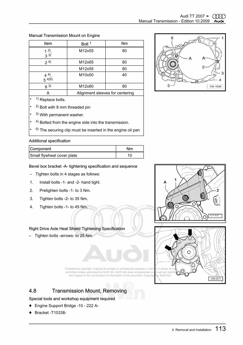
Protected by copyright. Copying for private or commercial purposes, in part or in whole, is not permitted unless authorised by AUDI AG. AUDI AG does not guarantee or accept any liability with respect to the correctness of information in this document. Copyright by AUDI AG.
Manual Transmission Mount on Engine
Item Bolt 1 Nm
1 2),3 3)
M12x55 80
2 4) M12x65 80 M12x55 80
4 4),5 4)5)
M10x50 40
6 3) M12x80 80A Alignment sleeves for centering
• 1) Replace bolts.• 2) Bolt with 8 mm threaded pin• 3) With permanent washer.• 4) Bolted from the engine side into the transmission.• 5) The securing clip must be inserted in the engine oil pan
Additional specification
Component NmSmall flywheel cover plate 10
Bevel box bracket -A- tightening specification and sequence
– Tighten bolts in 4 stages as follows:
1. Install bolts -1- and -2- hand tight.
2. Pretighten bolts -1- to 3 Nm.
3. Tighten bolts -2- to 35 Nm.
4. Tighten bolts -1- to 45 Nm.
Right Drive Axle Heat Shield Tightening Specification– Tighten bolts -arrows- to 25 Nm.
4.8 Transmission Mount, RemovingSpecial tools and workshop equipment required♦ Engine Support Bridge -10 - 222 A-♦ Bracket -T10338-
Audi TT 2007 ➤Manual Transmission - Edition 10.2009
4. Removal and Installation 113
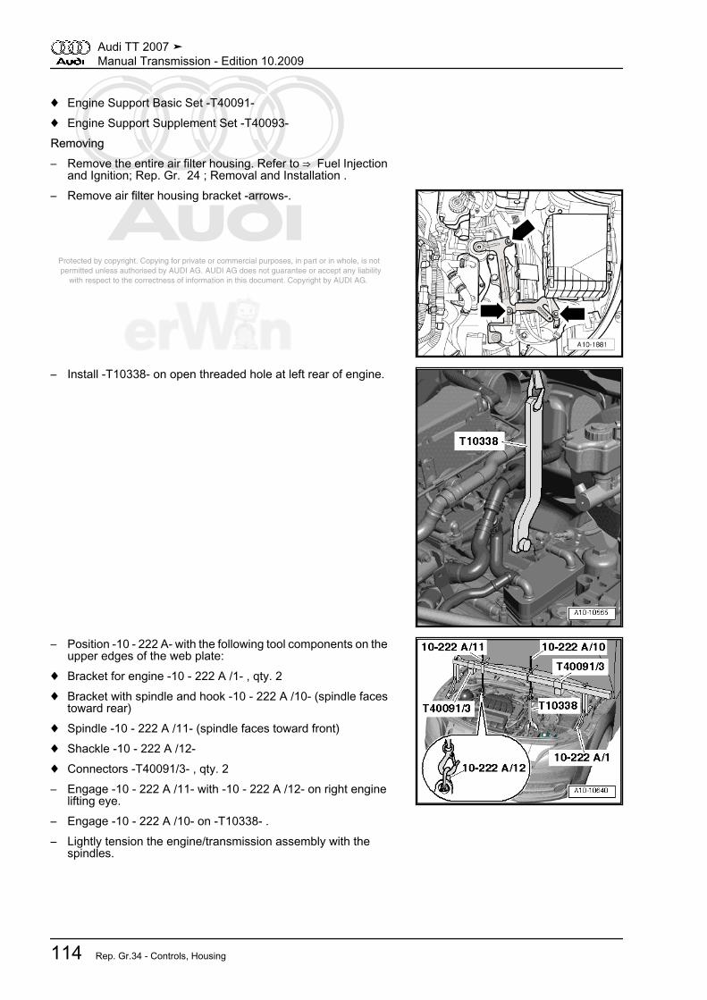
Protected by copyright. Copying for private or commercial purposes, in part or in whole, is not permitted unless authorised by AUDI AG. AUDI AG does not guarantee or accept any liability with respect to the correctness of information in this document. Copyright by AUDI AG.
♦ Engine Support Basic Set -T40091-♦ Engine Support Supplement Set -T40093-Removing– Remove the entire air filter housing. Refer to ⇒ Fuel Injection
and Ignition; Rep. Gr. 24 ; Removal and Installation .– Remove air filter housing bracket -arrows-.
– Install -T10338- on open threaded hole at left rear of engine.
– Position -10 - 222 A- with the following tool components on theupper edges of the web plate:
♦ Bracket for engine -10 - 222 A /1- , qty. 2♦ Bracket with spindle and hook -10 - 222 A /10- (spindle faces
toward rear)♦ Spindle -10 - 222 A /11- (spindle faces toward front)♦ Shackle -10 - 222 A /12-♦ Connectors -T40091/3- , qty. 2– Engage -10 - 222 A /11- with -10 - 222 A /12- on right engine
lifting eye.– Engage -10 - 222 A /10- on -T10338- .– Lightly tension the engine/transmission assembly with the
spindles.
Audi TT 2007 ➤Manual Transmission - Edition 10.2009
114 Rep. Gr.34 - Controls, Housing

Protected by copyright. Copying for private or commercial purposes, in part or in whole, is not permitted unless authorised by AUDI AG. AUDI AG does not guarantee or accept any liability with respect to the correctness of information in this document. Copyright by AUDI AG.
– Install left adapter -T40093/3-2- and right adapter -T40093/3-3- on -T40093/3- .
– Remove ground (GND) wire from left longmember.– Remove left and right connecting bolt for front part of long‐
member.– Install adapters on longmembers with bolts that were removed
earlier -arrow-.
Note
The left side of the vehicle is shown in the illustration.
– Insert square tube -T40091/1- in connector -T40091/3- andsupports -T40093/3- as shown in illustration.
– Slide connector -T40093/4- onto square tube.– Slide supports -T40091/2- with slide -T40093/5- into both con‐
nectors -T40093/4- .
WARNING
Risk of an accident due to loose support bridge parts.♦ Secure -T40091/2- with pins and splints from -T40093/4- .♦ Secure connector and supports with locking screws.
– Install -10 - 222 A /11- on slide and engine lifting eye.– Tension the engine/transmission assembly by tightening the
3 spindles evenly.
Audi TT 2007 ➤Manual Transmission - Edition 10.2009
4. Removal and Installation 115

Protected by copyright. Copying for private or commercial purposes, in part or in whole, is not permitted unless authorised by AUDI AG. AUDI AG does not guarantee or accept any liability with respect to the correctness of information in this document. Copyright by AUDI AG.
– Remove bolts -arrows-.
– Open wiring guide bracket -arrows-.– Cut cable ties -1- and press electrical wires to side.– Unclip wiring guide.
– Remove bolts -1- and remove transmission mount -A-.– Remove -10 - 222 A- from engine.Install the transmission mount. Refer to⇒ “4.9 Transmission Mount, installing”, page 116 .
4.9 Transmission Mount, installingInstalling• Tightening specifications, refer to
⇒ “2.9 Subframe Mount Assembly Overview”, page 72 .Install in reverse order, paying attention to the following:
Audi TT 2007 ➤Manual Transmission - Edition 10.2009
116 Rep. Gr.34 - Controls, Housing
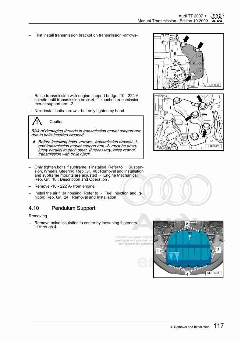
Protected by copyright. Copying for private or commercial purposes, in part or in whole, is not permitted unless authorised by AUDI AG. AUDI AG does not guarantee or accept any liability with respect to the correctness of information in this document. Copyright by AUDI AG.
– First install transmission bracket on transmission -arrows-.
– Raise transmission with engine support bridge -10 - 222 A-spindle until transmission bracket -1- touches transmissionmount support arm -2-.
– Next install bolts -arrows- but only tighten by hand.
Caution
Risk of damaging threads in transmission mount support armdue to bolts inserted crooked.♦ Before installing bolts -arrows-, transmission bracket -1-
and transmission mount support arm -2- must be abso‐lutely parallel to each other. If necessary, raise rear oftransmission with trolley jack.
– Only tighten bolts if subframe is installed. Refer to ⇒ Suspen‐sion, Wheels, Steering; Rep. Gr. 40 ; Removal and Installationand subframe mounts are adjusted ⇒ Engine Mechanical;Rep. Gr. 10 ; Description and Operation .
– Remove -10 - 222 A- from engine.– Install the air filter housing. Refer to ⇒ Fuel Injection and Ig‐
nition; Rep. Gr. 24 ; Removal and Installation .
4.10 Pendulum SupportRemoving– Remove noise insulation in center by loosening fasteners
-1 through 4-.
Audi TT 2007 ➤Manual Transmission - Edition 10.2009
4. Removal and Installation 117

Protected by copyright. Copying for private or commercial purposes, in part or in whole, is not permitted unless authorised by AUDI AG. AUDI AG does not guarantee or accept any liability with respect to the correctness of information in this document. Copyright by AUDI AG.
– Remove bolts -1 through 3- and remove pendulum support.InstallingInstall in reverse order, paying attention to the following:• Tightening specifications, refer to
⇒ “2.9 Subframe Mount Assembly Overview”, page 72 .
Note
♦ The holes for the pendulum support on transmissions from05.28.07 have threaded inserts (for example HeliCoil).
♦ How to recognize: collar on the first thread -arrow-.♦ Note the correct mounting bolts and tightening specifications
⇒ page 72 .
– First tighten pendulum support on transmission -arrow B- and-arrow C- and then on subframe -arrow A-.
4.11 Bevel Box, RemovingSpecial tools and workshop equipment required♦ Socket and Extended Bit -T10107 A- (SW 6 mm)♦ Hex Ball Socket -3247-♦ Bracket -2024 A /1-Removing– Remove front wheels.
Audi TT 2007 ➤Manual Transmission - Edition 10.2009
118 Rep. Gr.34 - Controls, Housing
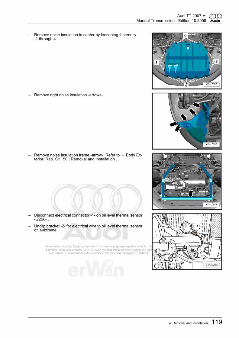
Protected by copyright. Copying for private or commercial purposes, in part or in whole, is not permitted unless authorised by AUDI AG. AUDI AG does not guarantee or accept any liability with respect to the correctness of information in this document. Copyright by AUDI AG.
– Remove noise insulation in center by loosening fasteners-1 through 4-.
– Remove right noise insulation -arrows-.
– Remove noise insulation frame -arrow-. Refer to ⇒ Body Ex‐terior; Rep. Gr. 50 ; Removal and Installation .
– Disconnect electrical connector -1- on oil level thermal sensor-G266- .
– Unclip bracket -2- for electrical wire to oil level thermal sensoron subframe.
Audi TT 2007 ➤Manual Transmission - Edition 10.2009
4. Removal and Installation 119
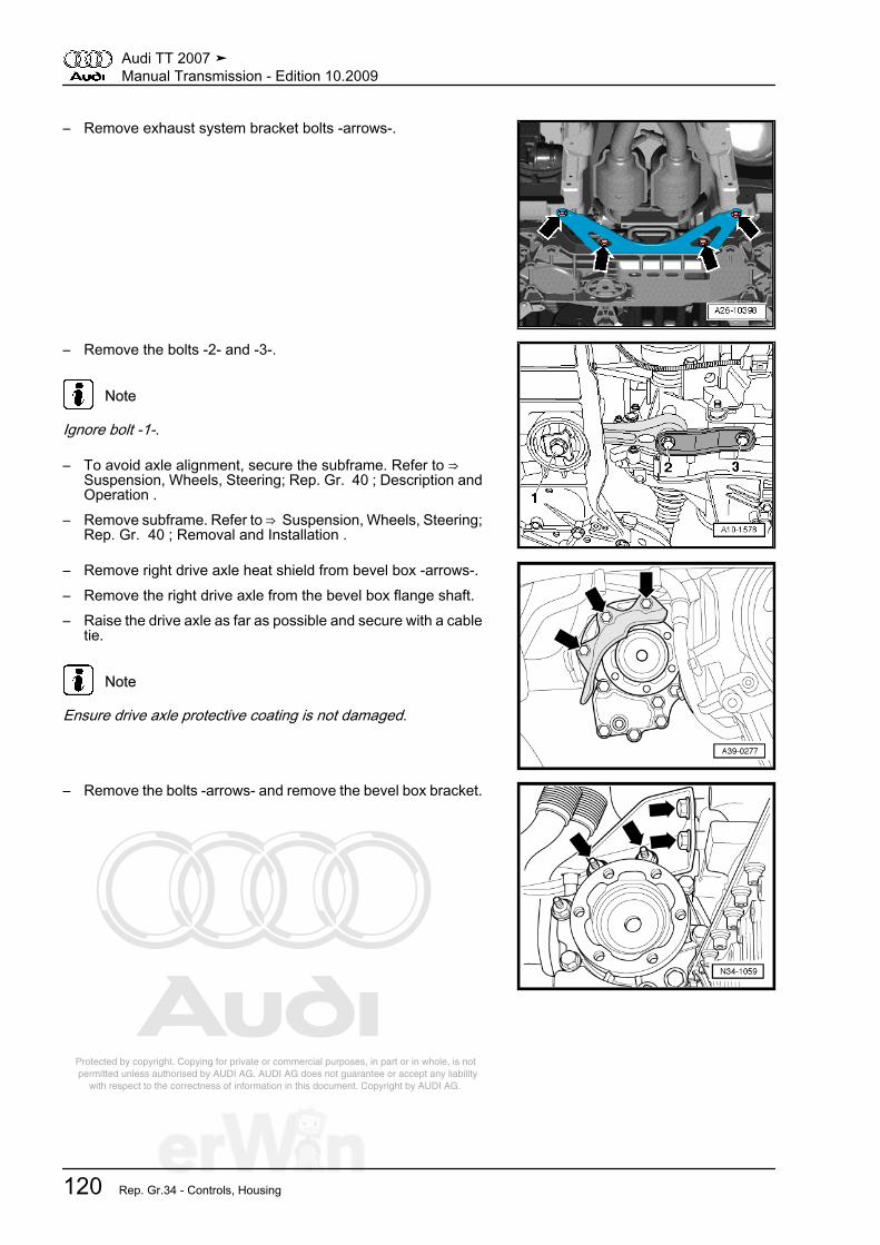
Protected by copyright. Copying for private or commercial purposes, in part or in whole, is not permitted unless authorised by AUDI AG. AUDI AG does not guarantee or accept any liability with respect to the correctness of information in this document. Copyright by AUDI AG.
– Remove exhaust system bracket bolts -arrows-.
– Remove the bolts -2- and -3-.
Note
Ignore bolt -1-.
– To avoid axle alignment, secure the subframe. Refer to ⇒ Suspension, Wheels, Steering; Rep. Gr. 40 ; Description andOperation .
– Remove subframe. Refer to ⇒ Suspension, Wheels, Steering;Rep. Gr. 40 ; Removal and Installation .
– Remove right drive axle heat shield from bevel box -arrows-.– Remove the right drive axle from the bevel box flange shaft.– Raise the drive axle as far as possible and secure with a cable
tie.
Note
Ensure drive axle protective coating is not damaged.
– Remove the bolts -arrows- and remove the bevel box bracket.
Audi TT 2007 ➤Manual Transmission - Edition 10.2009
120 Rep. Gr.34 - Controls, Housing

Protected by copyright. Copying for private or commercial purposes, in part or in whole, is not permitted unless authorised by AUDI AG. AUDI AG does not guarantee or accept any liability with respect to the correctness of information in this document. Copyright by AUDI AG.
– Identify position of flexible disc and bevel box flange to eachother.
– Remove driveshaft flexible disc from bevel box -arrows- whilecounterholding at triangular flange with a lever.
– Press engine/transmission assembly slightly forward (towardfront end) and pull off driveshaft from bevel box.
Caution
Risk of damaging sealing ring -arrow- in driveshaft flange.♦ Press driveshaft horizontally as far back and to the right
side of the vehicle as possible.
Note
If seal is damaged, driveshaft must be replaced.
– Tie driveshaft up.
– Remove the right flange shaft bolt -arrow 1- with the -T10107A- by installing 2 bolts in the flange and counter holding theflange shaft with the assembly lever.
Note
♦ Right flanged shaft remains in bevel box.♦ Ignore -A and B-.
– Remove the bolts for connecting the bevel box to the manualtransmission (qty. 4) -arrows-.
– Remove the bevel box from the transmission together with theright flange shaft.
Install bevel gear transfer case. Refer to⇒ “4.12 Bevel Box, Installing”, page 122 .
Audi TT 2007 ➤Manual Transmission - Edition 10.2009
4. Removal and Installation 121

Protected by copyright. Copying for private or commercial purposes, in part or in whole, is not permitted unless authorised by AUDI AG. AUDI AG does not guarantee or accept any liability with respect to the correctness of information in this document. Copyright by AUDI AG.
4.12 Bevel Box, Installing• Tightening specifications, refer to
⇒ “1.2 Flange Shaft and Seals on Bevel Box Assembly Over‐view”, page 220 .
Install in reverse order, paying attention to the following:
Note
Replace O-rings.
Caution
Risk of damaging sealing ring between transmission and bevelbox.♦ Place bevel box on transmission together with right flange
shaft while turning shaft.
– Slide on bevel box completely on manual transmission, whiledoing this, join splines of input shaft/bevel box centrally withdifferential.
– With proper tooth position and central guiding, bevel box slipsup to stop against manual transmission.
– Tighten bevel box on transmission.
Note
Do not pull bevel box with mounting bolts against manual trans‐mission, otherwise bevel box is canted and mounting eyelets canbreak off.
– Install the bevel box bracket ⇒ page 113 .– Install the right drive axle heat shield ⇒ page 113 .– Install the exhaust system and cross member. Refer to ⇒ En‐
gine Mechanical; Rep. Gr. 26 ; Description and Operation .– Install subframe. Refer to ⇒ Suspension, Wheels, Steering;
Rep. Gr. 40 ; Removal and Installation .– Install the steering gear on the subframe. Refer to ⇒ Suspen‐
sion, Wheels, Steering; Rep. Gr. 48 ; Removal and Installa‐tion .
– Install right drive axle. Refer to ⇒ Suspension, Wheels, Steer‐ing; Rep. Gr. 40 ; Removal and Installation .
Audi TT 2007 ➤Manual Transmission - Edition 10.2009
122 Rep. Gr.34 - Controls, Housing
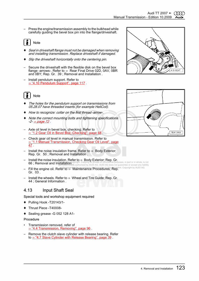
Protected by copyright. Copying for private or commercial purposes, in part or in whole, is not permitted unless authorised by AUDI AG. AUDI AG does not guarantee or accept any liability with respect to the correctness of information in this document. Copyright by AUDI AG.
– Press the engine/transmission assembly to the bulkhead whilecarefully guiding the bevel box pin into the flange/driveshaft.
Note
♦ Seal in driveshaft flange must not be damaged when removingand installing transmission. Replace driveshaft if damaged.
♦ Slip the driveshaft horizontally onto the centering pin.
– Secure the driveshaft with the flexible disk on the bevel boxflange -arrows-. Refer to ⇒ Rear Final Drive 02D, 0AV, 0BRand 0BY; Rep. Gr. 39 ; Removal and Installation .
– Install pendulum support. Refer to⇒ “4.10 Pendulum Support”, page 117 .
Note
♦ The holes for the pendulum support on transmissions from05.28.07 have threaded inserts (for example HeliCoil).
♦ How to recognize: collar on the first thread -arrow-.♦ Note the correct mounting bolts and tightening specifications
-2- ⇒ page 72 .
– Axle oil level in bevel box, checking. Refer to⇒ “1.2 Gear Oil in Bevel Box, Checking”, page 48 .
– Check gear oil level in manual transmission. Refer to⇒ “1.1 Manual Transmission, Checking Gear Oil Level”, page47 .
– Install the noise insulation frame. Refer to ⇒ Body Exterior;Rep. Gr. 50 ; Removal and Installation .
– Install the noise insulation. Refer to ⇒ Body Exterior; Rep. Gr. 66 ; Removal and Installation .
– Fill the engine oil. Refer to ⇒ Maintenance Procedures; Rep.Gr. 03 .
– Install the wheels. Refer to ⇒ Wheel and Tire Guide; Rep. Gr. 44 ; General Information .
4.13 Input Shaft SealSpecial tools and workshop equipment required♦ Pulling Hook -T20143/1-♦ Thrust Piece -T40008-♦ Sealing grease -G 052 128 A1-Procedure• Transmission removed, refer of
⇒ “4.4 Transmission, Removing”, page 96 .– Remove the clutch slave cylinder with release bearing. Refer
to ⇒ “4.7 Slave Cylinder with Release Bearing”, page 39 .
Audi TT 2007 ➤Manual Transmission - Edition 10.2009
4. Removal and Installation 123

Protected by copyright. Copying for private or commercial purposes, in part or in whole, is not permitted unless authorised by AUDI AG. AUDI AG does not guarantee or accept any liability with respect to the correctness of information in this document. Copyright by AUDI AG.
– Pry out the shaft sealing ring for the input shaft using the -T20143/1- .
Note
Do not damage the seal running surface on the input shaft.
– Fill space between sealing lip and dust lip -arrow- halfway withsealing grease -G 052 128 A1- .
– Lightly oil outer circumference of new shaft seal.
– Drive in the shaft sealing ring using the -T40008- until it is flush.– Install the clutch slave cylinder with the release bearing. Refer
to ⇒ “4.7 Slave Cylinder with Release Bearing”, page 39 .
4.14 Selector Shaft SealSpecial tools and workshop equipment required♦ Sleeve -VW 423-♦ Pulling Hook -T20143/1-♦ Sealing grease -G 052 128 A1-Procedure– Completely remove the air filter housing. Refer to ⇒ Fuel In‐
jection and Ignition; Rep. Gr. 24 ; Removal and Installation .
Audi TT 2007 ➤Manual Transmission - Edition 10.2009
124 Rep. Gr.34 - Controls, Housing

Protected by copyright. Copying for private or commercial purposes, in part or in whole, is not permitted unless authorised by AUDI AG. AUDI AG does not guarantee or accept any liability with respect to the correctness of information in this document. Copyright by AUDI AG.
Plastic selector relay lever -1-:– Pull the securing mechanism forward as far as the stop in the
direction of -arrow 1- and then unlock to the left in the directionof -arrow 2-.
– Press the selector relay lever forward in direction of-arrow 3- while pulling the selector cable out of the control ca‐ble retainer.
– Remove the selector relay lever with catch to Model Year 2007⇒ page 64
– Remove the selector relay lever with catch from Model Year2008 ⇒ page 69
Metal selector relay lever– Pull off securing clip -2- and press selector relay lever -3- to
the side and out of the bearing.All Vehicles
Note
If the selector relay lever cannot be removed due to the trans‐mission bracket, remove the selector cable from the selector relaylever. Remove the slide shoe from the transmission shift lever.
– Remove nut -4- and remove transmission shift lever -1-.
– Pry out the shaft sealing ring using the -T20143/1- .– Lightly oil outer circumference of new shaft seal.– Drive in new shaft seal as far as stop without tilting it.
– Fill area between sealing lip and dust lip -arrow- halfway withsealing grease -G 052 128 A1- .
Audi TT 2007 ➤Manual Transmission - Edition 10.2009
4. Removal and Installation 125

Protected by copyright. Copying for private or commercial purposes, in part or in whole, is not permitted unless authorised by AUDI AG. AUDI AG does not guarantee or accept any liability with respect to the correctness of information in this document. Copyright by AUDI AG.
– Drive in the shaft sealing ring using the sleeve -VW 423- .– Install the transmission shift lever and selector relay lever. Re‐
fer to⇒ “2.6 Transmission Shift Lever and Selector Relay Lever toModel Year 2007 Assembly Overview”, page 63 or⇒ “2.7 Shift Cable and Selector Cable from Model Year 2008Assembly Overview ”, page 65 .
Note
The transmission shift lever can only be inserted in one position.
– Install the air filter housing. Refer to ⇒ Fuel Injection and Ig‐nition; Rep. Gr. 24 ; Removal and Installation .
4.15 Selector ShaftRemoving– Completely remove the air filter housing. Refer to ⇒ Fuel In‐
jection and Ignition; Rep. Gr. 24 ; Removal and Installation .Plastic selector relay lever -1-:– Pull the securing mechanism forward as far as the stop in di‐
rection of -arrow 1- and then unlock to the left in direction of-arrow 2-.
– Press the selector relay lever forward in direction of-arrow 3- while pulling the selector cable out of the control ca‐ble retainer.
– Remove the selector relay lever with catch to Model Year 2007⇒ page 64
– Remove the selector relay lever with catch from Model Year2008 ⇒ page 69
Metal selector relay lever
– Pull off lock washer -2- and press selector relay lever -3- to theside and out of the bearing.
All Vehicles
Note
If the selector relay lever cannot be removed due to the trans‐mission bracket, remove the selector cable from the selector relaylever. Remove the slide shoe from the transmission shift lever.
– Remove nut -4- and remove transmission shift lever -1-.
Audi TT 2007 ➤Manual Transmission - Edition 10.2009
126 Rep. Gr.34 - Controls, Housing

Protected by copyright. Copying for private or commercial purposes, in part or in whole, is not permitted unless authorised by AUDI AG. AUDI AG does not guarantee or accept any liability with respect to the correctness of information in this document. Copyright by AUDI AG.
– Move shift shaft to neutral position.
Caution
In the following step, ensure that the selector shaft is not lockedby the lock elbow -arrow-.
– Remove back-up light switch -F4- -1-.– Remove mounting bolt -2-.– Remove the bolts -3-.– Remove selector shaft with shift cover -4- from transmission
housing.Installing• Tightening specification, refer to
⇒ “2.12 Transmission Housing and Shift Mechanism Assem‐bly Overview”, page 77 ,⇒ “2.16 Shift Mechanism Assembly Overview, TransmissionSide”, page 85 .
– Press selector shaft -1- against lock sleeve in direction of-2--arrow- and guide downward with shift finger -3- through shiftforks until stop.
• Shift cover -4- must stand parallel to bolting surface on trans‐mission housing during this.
• Selector shaft must be able to be moved easily in selectormotion (up- and downward).
Note
If shift cover stands at an angle to bolting surface, selector shaftis not inserted in lower bearing.
– Tighten the bolts -3- for the shift cover -4-.– Install lock bolt -2-. Lock elbow -arrow- must not be installed
when doing so.– Install back-up light switch -F4- -1-.– Install the transmission shift lever and selector relay lever. Re‐
fer to⇒ “2.6 Transmission Shift Lever and Selector Relay Lever toModel Year 2007 Assembly Overview”, page 63 or⇒ “2.7 Shift Cable and Selector Cable from Model Year 2008Assembly Overview ”, page 65 .
Note
The transmission shift lever can only be inserted in one position.
– Install the air filter housing. Refer to ⇒ Fuel Injection and Ig‐nition; Rep. Gr. 24 ; Removal and Installation .
Audi TT 2007 ➤Manual Transmission - Edition 10.2009
4. Removal and Installation 127
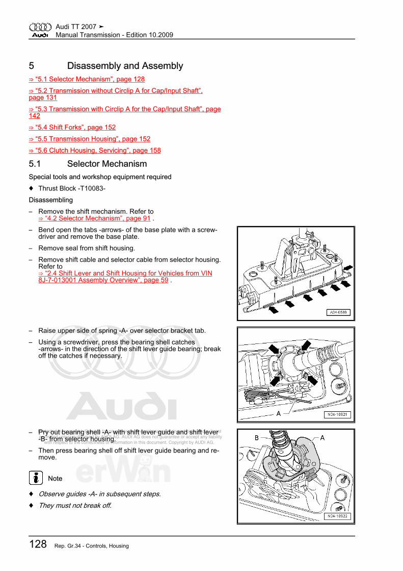
Protected by copyright. Copying for private or commercial purposes, in part or in whole, is not permitted unless authorised by AUDI AG. AUDI AG does not guarantee or accept any liability with respect to the correctness of information in this document. Copyright by AUDI AG.
5 Disassembly and Assembly⇒ “5.1 Selector Mechanism”, page 128⇒ “5.2 Transmission without Circlip A for Cap/Input Shaft”,page 131⇒ “5.3 Transmission with Circlip A for the Cap/Input Shaft”, page142⇒ “5.4 Shift Forks”, page 152⇒ “5.5 Transmission Housing”, page 152⇒ “5.6 Clutch Housing, Servicing”, page 158
5.1 Selector MechanismSpecial tools and workshop equipment required♦ Thrust Block -T10083-Disassembling– Remove the shift mechanism. Refer to
⇒ “4.2 Selector Mechanism”, page 91 .– Bend open the tabs -arrows- of the base plate with a screw‐
driver and remove the base plate.– Remove seal from shift housing.– Remove shift cable and selector cable from selector housing.
Refer to⇒ “2.4 Shift Lever and Shift Housing for Vehicles from VIN8J-7-013001 Assembly Overview”, page 59 .
– Raise upper side of spring -A- over selector bracket tab.– Using a screwdriver, press the bearing shell catches
-arrows- in the direction of the shift lever guide bearing; breakoff the catches if necessary.
– Pry out bearing shell -A- with shift lever guide and shift lever-B- from selector housing.
– Then press bearing shell off shift lever guide bearing and re‐move.
Note
♦ Observe guides -A- in subsequent steps.♦ They must not break off.
Audi TT 2007 ➤Manual Transmission - Edition 10.2009
128 Rep. Gr.34 - Controls, Housing
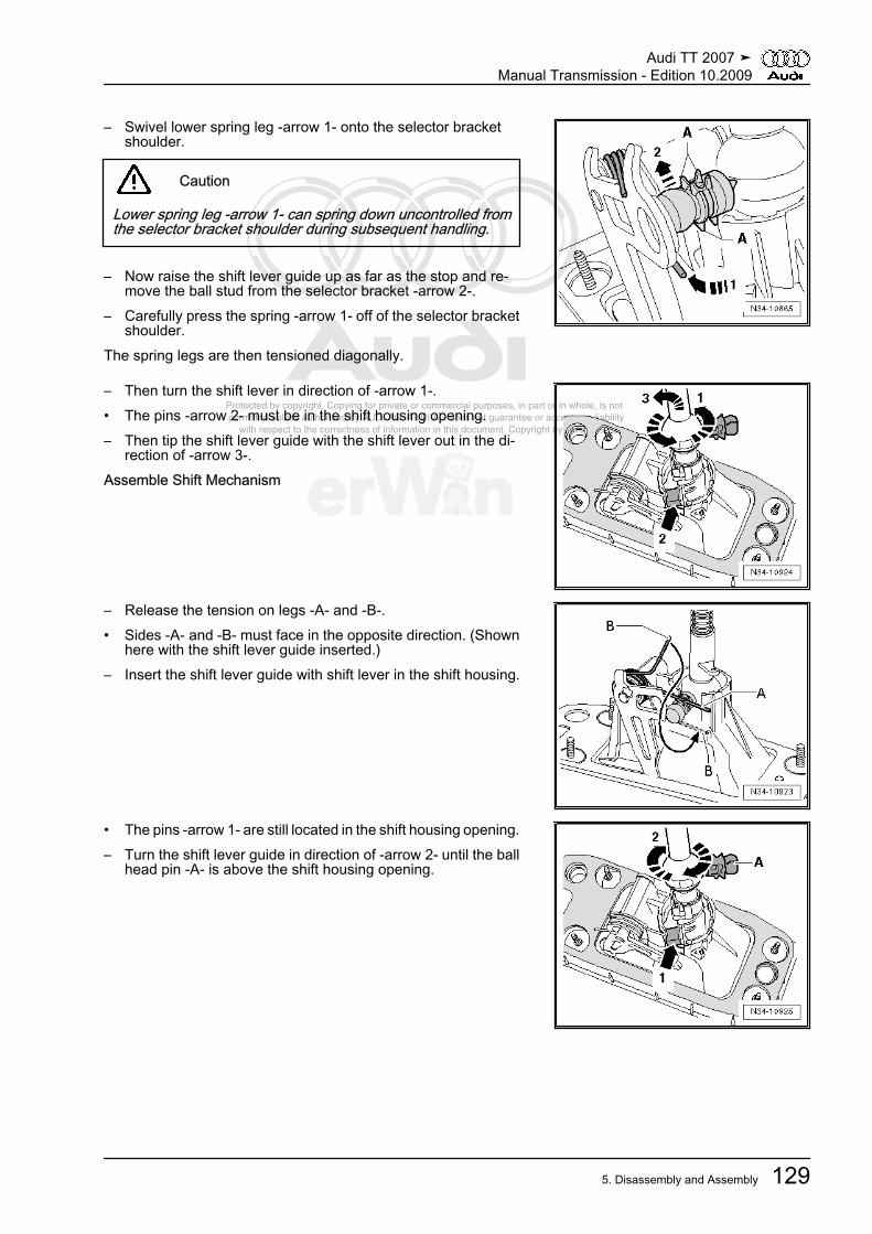
Protected by copyright. Copying for private or commercial purposes, in part or in whole, is not permitted unless authorised by AUDI AG. AUDI AG does not guarantee or accept any liability with respect to the correctness of information in this document. Copyright by AUDI AG.
– Swivel lower spring leg -arrow 1- onto the selector bracketshoulder.
Caution
Lower spring leg -arrow 1- can spring down uncontrolled fromthe selector bracket shoulder during subsequent handling.
– Now raise the shift lever guide up as far as the stop and re‐move the ball stud from the selector bracket -arrow 2-.
– Carefully press the spring -arrow 1- off of the selector bracketshoulder.
The spring legs are then tensioned diagonally.
– Then turn the shift lever in direction of -arrow 1-.• The pins -arrow 2- must be in the shift housing opening.– Then tip the shift lever guide with the shift lever out in the di‐
rection of -arrow 3-.Assemble Shift Mechanism
– Release the tension on legs -A- and -B-.• Sides -A- and -B- must face in the opposite direction. (Shown
here with the shift lever guide inserted.)– Insert the shift lever guide with shift lever in the shift housing.
• The pins -arrow 1- are still located in the shift housing opening.– Turn the shift lever guide in direction of -arrow 2- until the ball
head pin -A- is above the shift housing opening.
Audi TT 2007 ➤Manual Transmission - Edition 10.2009
5. Disassembly and Assembly 129

Protected by copyright. Copying for private or commercial purposes, in part or in whole, is not permitted unless authorised by AUDI AG. AUDI AG does not guarantee or accept any liability with respect to the correctness of information in this document. Copyright by AUDI AG.
– Place the shift housing with the shift lever guide on the -T10083- .
• The shift lever guide rests in the larger recess -arrow- of the -T10083- .
• The shift lever guide must project out of selector housing asfar as stop.
– Insert spring side -A- from above into guide.– Pull spring side -B- down and insert it near the guide (in di‐
rection of ball head).
Note
The selector bracket is only partially shown to provide a betterillustration.
– Carefully remove the shift housing with the shift lever guidefrom the -T10083- .
– Move the selector bracket in direction of -arrow 1- back to thestop.
– Lubricate ball head pins.– Press ball head pins into selector bracket -arrow 2-.• Guides -A- and tabs -B- must not be damaged.
– Place the shift housing with the shift lever guide in the largerdepression -arrow- of the -T10083- .
• The shift lever guide must project out of selector housing asfar as stop.
Audi TT 2007 ➤Manual Transmission - Edition 10.2009
130 Rep. Gr.34 - Controls, Housing
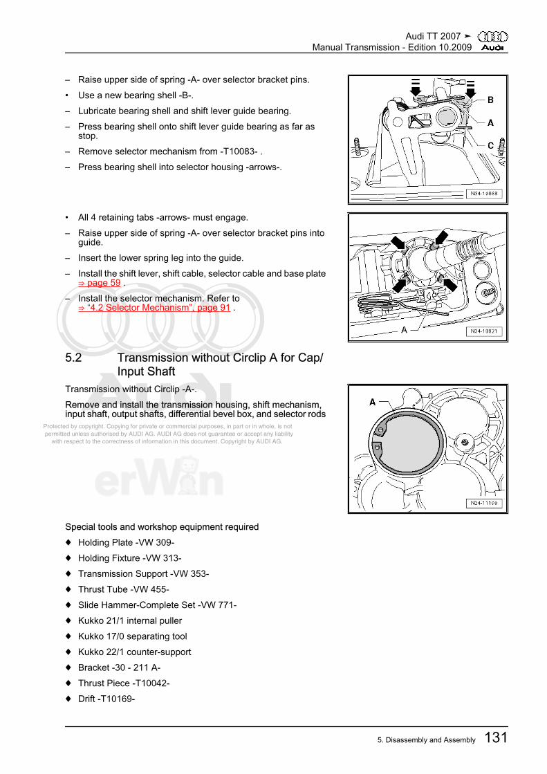
Protected by copyright. Copying for private or commercial purposes, in part or in whole, is not permitted unless authorised by AUDI AG. AUDI AG does not guarantee or accept any liability with respect to the correctness of information in this document. Copyright by AUDI AG.
– Raise upper side of spring -A- over selector bracket pins.• Use a new bearing shell -B-.– Lubricate bearing shell and shift lever guide bearing.– Press bearing shell onto shift lever guide bearing as far as
stop.– Remove selector mechanism from -T10083- .– Press bearing shell into selector housing -arrows-.
• All 4 retaining tabs -arrows- must engage.– Raise upper side of spring -A- over selector bracket pins into
guide.– Insert the lower spring leg into the guide.– Install the shift lever, shift cable, selector cable and base plate
⇒ page 59 .– Install the selector mechanism. Refer to
⇒ “4.2 Selector Mechanism”, page 91 .
5.2 Transmission without Circlip A for Cap/Input Shaft
Transmission without Circlip -A-.Remove and install the transmission housing, shift mechanism,input shaft, output shafts, differential bevel box, and selector rods
Special tools and workshop equipment required♦ Holding Plate -VW 309-♦ Holding Fixture -VW 313-♦ Transmission Support -VW 353-♦ Thrust Tube -VW 455-♦ Slide Hammer-Complete Set -VW 771-♦ Kukko 21/1 internal puller♦ Kukko 17/0 separating tool♦ Kukko 22/1 counter-support♦ Bracket -30 - 211 A-♦ Thrust Piece -T10042-♦ Drift -T10169-
Audi TT 2007 ➤Manual Transmission - Edition 10.2009
5. Disassembly and Assembly 131
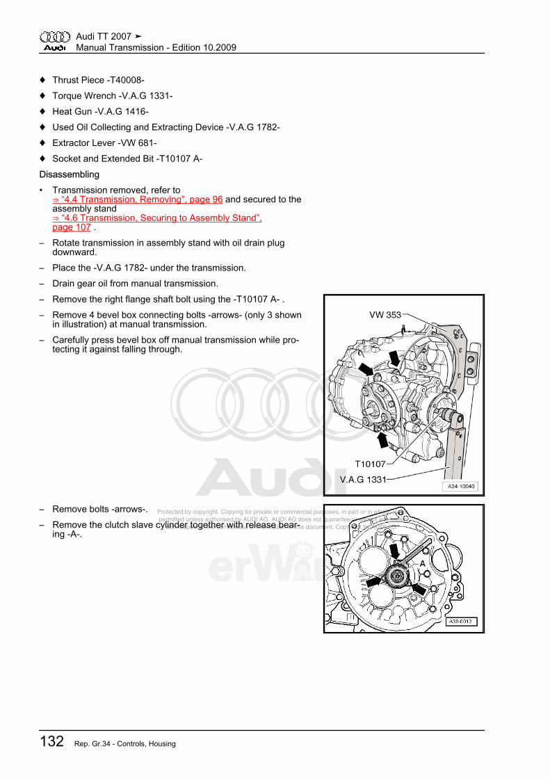
Protected by copyright. Copying for private or commercial purposes, in part or in whole, is not permitted unless authorised by AUDI AG. AUDI AG does not guarantee or accept any liability with respect to the correctness of information in this document. Copyright by AUDI AG.
♦ Thrust Piece -T40008-♦ Torque Wrench -V.A.G 1331-♦ Heat Gun -V.A.G 1416-♦ Used Oil Collecting and Extracting Device -V.A.G 1782-♦ Extractor Lever -VW 681-♦ Socket and Extended Bit -T10107 A-Disassembling• Transmission removed, refer to
⇒ “4.4 Transmission, Removing”, page 96 and secured to theassembly stand⇒ “4.6 Transmission, Securing to Assembly Stand”,page 107 .
– Rotate transmission in assembly stand with oil drain plugdownward.
– Place the -V.A.G 1782- under the transmission.– Drain gear oil from manual transmission.– Remove the right flange shaft bolt using the -T10107 A- .– Remove 4 bevel box connecting bolts -arrows- (only 3 shown
in illustration) at manual transmission.– Carefully press bevel box off manual transmission while pro‐
tecting it against falling through.
– Remove bolts -arrows-.– Remove the clutch slave cylinder together with release bear‐
ing -A-.
Audi TT 2007 ➤Manual Transmission - Edition 10.2009
132 Rep. Gr.34 - Controls, Housing

Protected by copyright. Copying for private or commercial purposes, in part or in whole, is not permitted unless authorised by AUDI AG. AUDI AG does not guarantee or accept any liability with respect to the correctness of information in this document. Copyright by AUDI AG.
– In the following step, ensure that the selector shaft is notlocked by the lock elbow -arrow-.
– Move shift shaft to neutral position.– Remove mounting bolt -2-.– Remove the bolts -3-.– Remove back-up light switch -F4- -1-.– Pull selector shaft -4- off transmission housing.
– Remove the left flange shaft bolt by installing 2 bolts in theflange and counter holding the flange shaft with the assemblylever.
– Remove bolts -B- inside clutch housing for securing clutchhousing to transmission housing.
Note
One bolt -arrow- is located outside of bolting flange.
– Secure the input shaft by inserting the -VW 455- over the inputshaft, onto the clutch housing.
– Then tension separating tool -A-, for example -Kukko 17/0-tightly behind input shaft splines.
• Back side of separating tool must contact pressing sleeve freeof play.
Audi TT 2007 ➤Manual Transmission - Edition 10.2009
5. Disassembly and Assembly 133

Protected by copyright. Copying for private or commercial purposes, in part or in whole, is not permitted unless authorised by AUDI AG. AUDI AG does not guarantee or accept any liability with respect to the correctness of information in this document. Copyright by AUDI AG.
– Knock rubber through in center of cap -C- using a screwdriver.– Remove cap from transmission housing.A - Support , for example -Kukko 22/1-B - Internal puller 8 to 12 mm , for example -Kukko 21/01-
Remove circlip -C- from input shaft grooved ball bearing in thefollowing manner:– Hold one end of circlip in place using screwdriver -A-.– With the 2nd screwdriver -B-, pry the other end of the circlip
out of the groove of the grooved ball bearing -arrow-.– By repositioning the screwdriver -B-, pry the circlip further out.
– If present, remove spacer washer -1- from transmission hous‐ing -2-.
• If the transmission housing is replaced, check whether thespacer washer needs to be reinstalled ⇒ page 137 .
– Remove bolts -A-.
Audi TT 2007 ➤Manual Transmission - Edition 10.2009
134 Rep. Gr.34 - Controls, Housing

Protected by copyright. Copying for private or commercial purposes, in part or in whole, is not permitted unless authorised by AUDI AG. AUDI AG does not guarantee or accept any liability with respect to the correctness of information in this document. Copyright by AUDI AG.
– Screw adapter -VW 771/40- into threaded hole of transmissionhousing.
– Heat the transmission housing using the hot air blower -V.A.G1416- in the area of the bearing seat for the grooved ball bear‐ing/input shaft to approximately 100 °C (212 °F) for approxi‐mately 10 minutes.
– Pull off transmission housing from clutch housing -arrow- us‐ing -VW 771/1- .
Note
If necessary, carefully pry up all around and alternating betweensides on protruding flange taking care not to damage sealing sur‐faces.
– If present, remove spacer washer -1- from grooved ball bear‐ing -2-.
– If the transmission housing is replaced, check whether thespacer washer needs to be reinstalled ⇒ page 137 .
– Remove separating tool -A- and -VW 455- from input shaft.A 2nd technician is required to remove shafts from clutch housing.
Audi TT 2007 ➤Manual Transmission - Edition 10.2009
5. Disassembly and Assembly 135
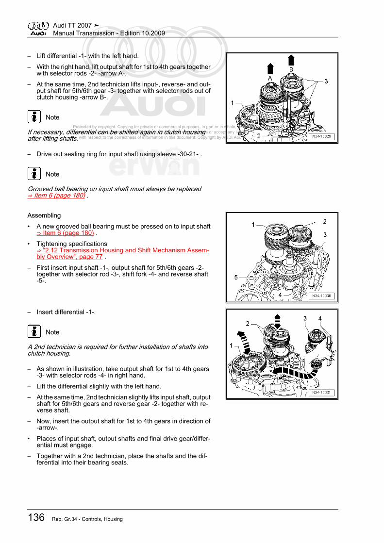
Protected by copyright. Copying for private or commercial purposes, in part or in whole, is not permitted unless authorised by AUDI AG. AUDI AG does not guarantee or accept any liability with respect to the correctness of information in this document. Copyright by AUDI AG.
– Lift differential -1- with the left hand.– With the right hand, lift output shaft for 1st to 4th gears together
with selector rods -2- -arrow A-.– At the same time, 2nd technician lifts input-, reverse- and out‐
put shaft for 5th/6th gear -3- together with selector rods out ofclutch housing -arrow B-.
Note
If necessary, differential can be shifted again in clutch housingafter lifting shafts.
– Drive out sealing ring for input shaft using sleeve -30-21- .
Note
Grooved ball bearing on input shaft must always be replaced⇒ Item 6 (page 180) .
Assembling• A new grooved ball bearing must be pressed on to input shaft
⇒ Item 6 (page 180) .• Tightening specifications
⇒ “2.12 Transmission Housing and Shift Mechanism Assem‐bly Overview”, page 77 .
– First insert input shaft -1-, output shaft for 5th/6th gears -2-together with selector rod -3-, shift fork -4- and reverse shaft-5-.
– Insert differential -1-.
Note
A 2nd technician is required for further installation of shafts intoclutch housing.
– As shown in illustration, take output shaft for 1st to 4th gears-3- with selector rods -4- in right hand.
– Lift the differential slightly with the left hand.– At the same time, 2nd technician slightly lifts input shaft, output
shaft for 5th/6th gears and reverse gear -2- together with re‐verse shaft.
– Now, insert the output shaft for 1st to 4th gears in direction of-arrow-.
• Places of input shaft, output shafts and final drive gear/differ‐ential must engage.
– Together with a 2nd technician, place the shafts and the dif‐ferential into their bearing seats.
Audi TT 2007 ➤Manual Transmission - Edition 10.2009
136 Rep. Gr.34 - Controls, Housing

Protected by copyright. Copying for private or commercial purposes, in part or in whole, is not permitted unless authorised by AUDI AG. AUDI AG does not guarantee or accept any liability with respect to the correctness of information in this document. Copyright by AUDI AG.
– Fasten the bracket -30 - 211 A- for the input shaft to the clutchhousing.
Note
For the sake of illustration, clutch housing is depicted rotated180°.
– Screw in bolt -A- far enough until input shaft rises slightly.
Note
♦ With some transmissions, there are flattened areas -A- on theinput shaft grooved ball bearing and on the bearing mount-B-.
♦ Check the input shaft grooved ball bearing and the transmis‐sion housing.
Input shaft grooved ball bearing and transmission housingWithout flattened areas on grooved ball bearing -A- and bearing
mount -B- ⇒ page 137With flattened areas on grooved ball bearing -A- and bearing
mount -B- ⇒ page 138
From transmission build date 4.10.06 through approximately1.21.08One spacer washer is inserted above and below the input shaftgrooved ball bearing -6- ⇒ page 180 .
Upper spacer wash‐er
Outer circumfer‐ence
78.6 mm
Lower spacer wash‐er
Outer circumfer‐ence
85 mm
Measure the Shoulder above the Grooved Ball Bearing Mount.
Shoulder AboveGrooved Ball Bear‐
ing
Dimension “a” Upper SpacerWasher
Through transmis‐sion build date 09 04
6
10 mm No
From transmissionbuild date 10 04 6
10.7 mm Yes
Audi TT 2007 ➤Manual Transmission - Edition 10.2009
5. Disassembly and Assembly 137
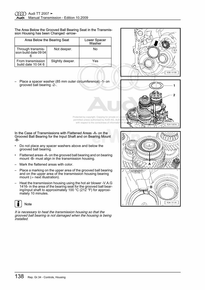
Protected by copyright. Copying for private or commercial purposes, in part or in whole, is not permitted unless authorised by AUDI AG. AUDI AG does not guarantee or accept any liability with respect to the correctness of information in this document. Copyright by AUDI AG.
The Area Below the Grooved Ball Bearing Seat in the Transmis‐sion Housing has been Changed -arrow-
Area Below the Bearing Seat Lower SpacerWasher
Through transmis‐sion build date 09 04
6
Not deeper. No
From transmissionbuild date 10 04 6
Slightly deeper. Yes
– Place a spacer washer (85 mm outer circumference) -1- ongrooved ball bearing -2-.
In the Case of Transmissions with Flattened Areas -A- on theGrooved Ball Bearing for the Input Shaft and on Bearing Mount-B-• Do not place any spacer washers above and below the
grooved ball bearing.• Flattened areas -A- on the grooved ball bearing and on bearing
mount -B- must align in the transmission housing.– Mark the flattened areas with color.– Place a marking on the upper area of the grooved ball bearing
and on the upper area of the transmission housing bearingmount (⇒ next illustration).
– Heat the transmission housing using the hot air blower -V.A.G1416- in the area of the bearing seat for the grooved ball bear‐ing/input shaft to approximately 100 °C (212 °F) for approxi‐mately 10 minutes.
Note
It is necessary to heat the transmission housing so that thegrooved ball bearing is not damaged when the housing is beinginstalled.
Audi TT 2007 ➤Manual Transmission - Edition 10.2009
138 Rep. Gr.34 - Controls, Housing
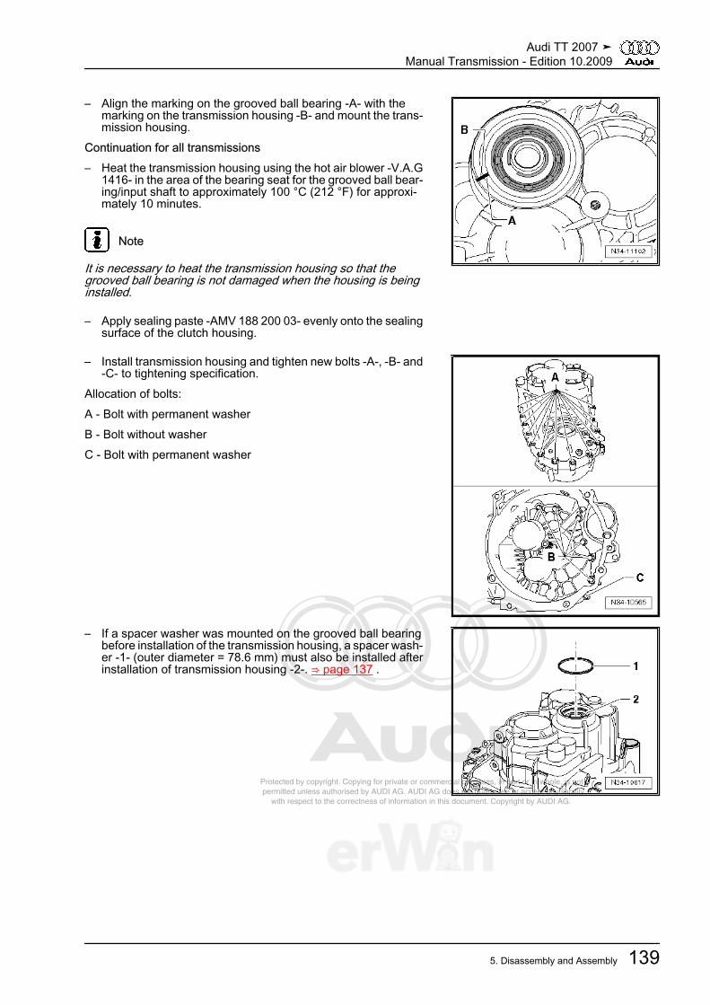
Protected by copyright. Copying for private or commercial purposes, in part or in whole, is not permitted unless authorised by AUDI AG. AUDI AG does not guarantee or accept any liability with respect to the correctness of information in this document. Copyright by AUDI AG.
– Align the marking on the grooved ball bearing -A- with themarking on the transmission housing -B- and mount the trans‐mission housing.
Continuation for all transmissions– Heat the transmission housing using the hot air blower -V.A.G
1416- in the area of the bearing seat for the grooved ball bear‐ing/input shaft to approximately 100 °C (212 °F) for approxi‐mately 10 minutes.
Note
It is necessary to heat the transmission housing so that thegrooved ball bearing is not damaged when the housing is beinginstalled.
– Apply sealing paste -AMV 188 200 03- evenly onto the sealingsurface of the clutch housing.
– Install transmission housing and tighten new bolts -A-, -B- and-C- to tightening specification.
Allocation of bolts:A - Bolt with permanent washerB - Bolt without washerC - Bolt with permanent washer
– If a spacer washer was mounted on the grooved ball bearingbefore installation of the transmission housing, a spacer wash‐er -1- (outer diameter = 78.6 mm) must also be installed afterinstallation of transmission housing -2-. ⇒ page 137 .
Audi TT 2007 ➤Manual Transmission - Edition 10.2009
5. Disassembly and Assembly 139
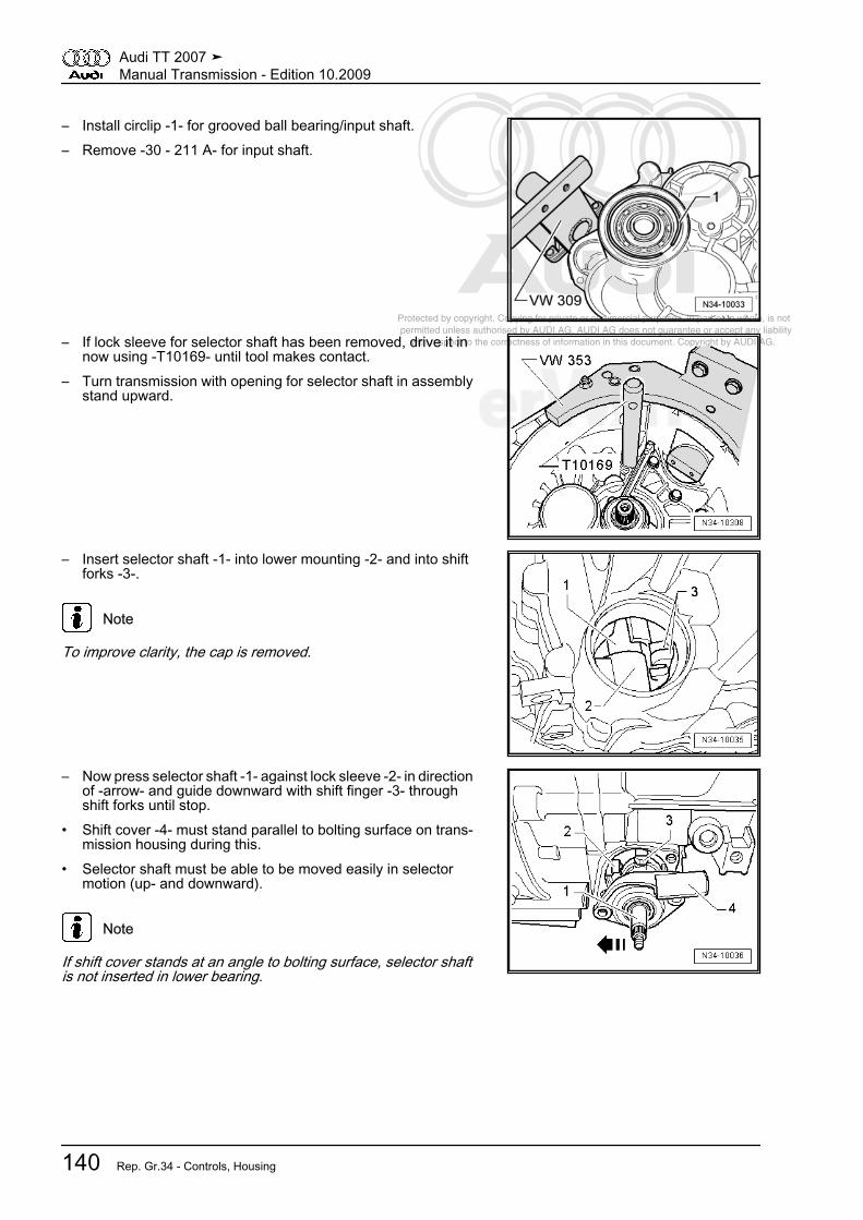
Protected by copyright. Copying for private or commercial purposes, in part or in whole, is not permitted unless authorised by AUDI AG. AUDI AG does not guarantee or accept any liability with respect to the correctness of information in this document. Copyright by AUDI AG.
– Install circlip -1- for grooved ball bearing/input shaft.– Remove -30 - 211 A- for input shaft.
– If lock sleeve for selector shaft has been removed, drive it innow using -T10169- until tool makes contact.
– Turn transmission with opening for selector shaft in assemblystand upward.
– Insert selector shaft -1- into lower mounting -2- and into shiftforks -3-.
Note
To improve clarity, the cap is removed.
– Now press selector shaft -1- against lock sleeve -2- in directionof -arrow- and guide downward with shift finger -3- throughshift forks until stop.
• Shift cover -4- must stand parallel to bolting surface on trans‐mission housing during this.
• Selector shaft must be able to be moved easily in selectormotion (up- and downward).
Note
If shift cover stands at an angle to bolting surface, selector shaftis not inserted in lower bearing.
Audi TT 2007 ➤Manual Transmission - Edition 10.2009
140 Rep. Gr.34 - Controls, Housing

Protected by copyright. Copying for private or commercial purposes, in part or in whole, is not permitted unless authorised by AUDI AG. AUDI AG does not guarantee or accept any liability with respect to the correctness of information in this document. Copyright by AUDI AG.
– Tighten the bolts -3- for the shift cover -4-.– Install lock bolt -2-, lock bolt -arrow- must not be installed when
doing so.– Install back-up light switch -F4- -1-.– Install left flange shaft. Refer to
⇒ “1.1 Flange Shaft and Seals on Transmission AssemblyOverview”, page 219 .
– Drive in the input shaft sealing ring.– Install the clutch slave cylinder with release bearing. Refer to
⇒ “4.7 Slave Cylinder with Release Bearing”, page 39 .– Shift through all gears.
– Drive cap into transmission housing to stop of -T10042-Install bevel box in manual transmission as follows:
Caution
Risk of damaging sealing ring between transmission and bevelbox.♦ Place bevel box on transmission together with right flange
shaft while turning shaft.
– With manual transmission, lubricate differential splines withgrease for clutch disc shaft splines -G 000 100- .
– Slide on bevel box completely on manual transmission, whiledoing this, join splines of input shaft/bevel box centrally withdifferential.
– With proper tooth position and central guiding, bevel box slipsup to stop against manual transmission.
Note
Do not pull bevel box with mounting bolts against manual trans‐mission, otherwise bevel box is canted and mounting eyelets canbreak off.
Audi TT 2007 ➤Manual Transmission - Edition 10.2009
5. Disassembly and Assembly 141
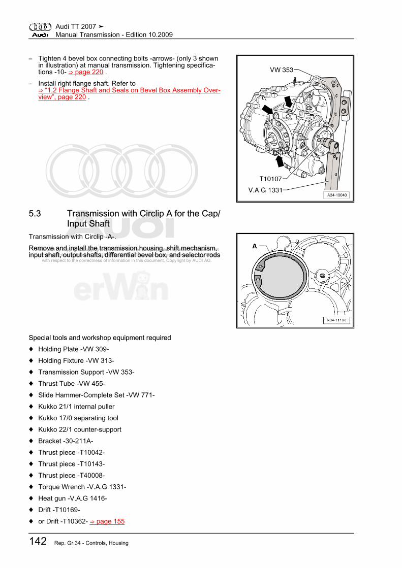
Protected by copyright. Copying for private or commercial purposes, in part or in whole, is not permitted unless authorised by AUDI AG. AUDI AG does not guarantee or accept any liability with respect to the correctness of information in this document. Copyright by AUDI AG.
– Tighten 4 bevel box connecting bolts -arrows- (only 3 shownin illustration) at manual transmission. Tightening specifica‐tions -10- ⇒ page 220 .
– Install right flange shaft. Refer to⇒ “1.2 Flange Shaft and Seals on Bevel Box Assembly Over‐view”, page 220 .
5.3 Transmission with Circlip A for the Cap/Input Shaft
Transmission with Circlip -A-.Remove and install the transmission housing, shift mechanism,input shaft, output shafts, differential bevel box, and selector rods
Special tools and workshop equipment required♦ Holding Plate -VW 309-♦ Holding Fixture -VW 313-♦ Transmission Support -VW 353-♦ Thrust Tube -VW 455-♦ Slide Hammer-Complete Set -VW 771-♦ Kukko 21/1 internal puller♦ Kukko 17/0 separating tool♦ Kukko 22/1 counter-support♦ Bracket -30-211A-♦ Thrust piece -T10042-♦ Thrust piece -T10143-♦ Thrust piece -T40008-♦ Torque Wrench -V.A.G 1331-♦ Heat gun -V.A.G 1416-♦ Drift -T10169-♦ or Drift -T10362- ⇒ page 155
Audi TT 2007 ➤Manual Transmission - Edition 10.2009
142 Rep. Gr.34 - Controls, Housing
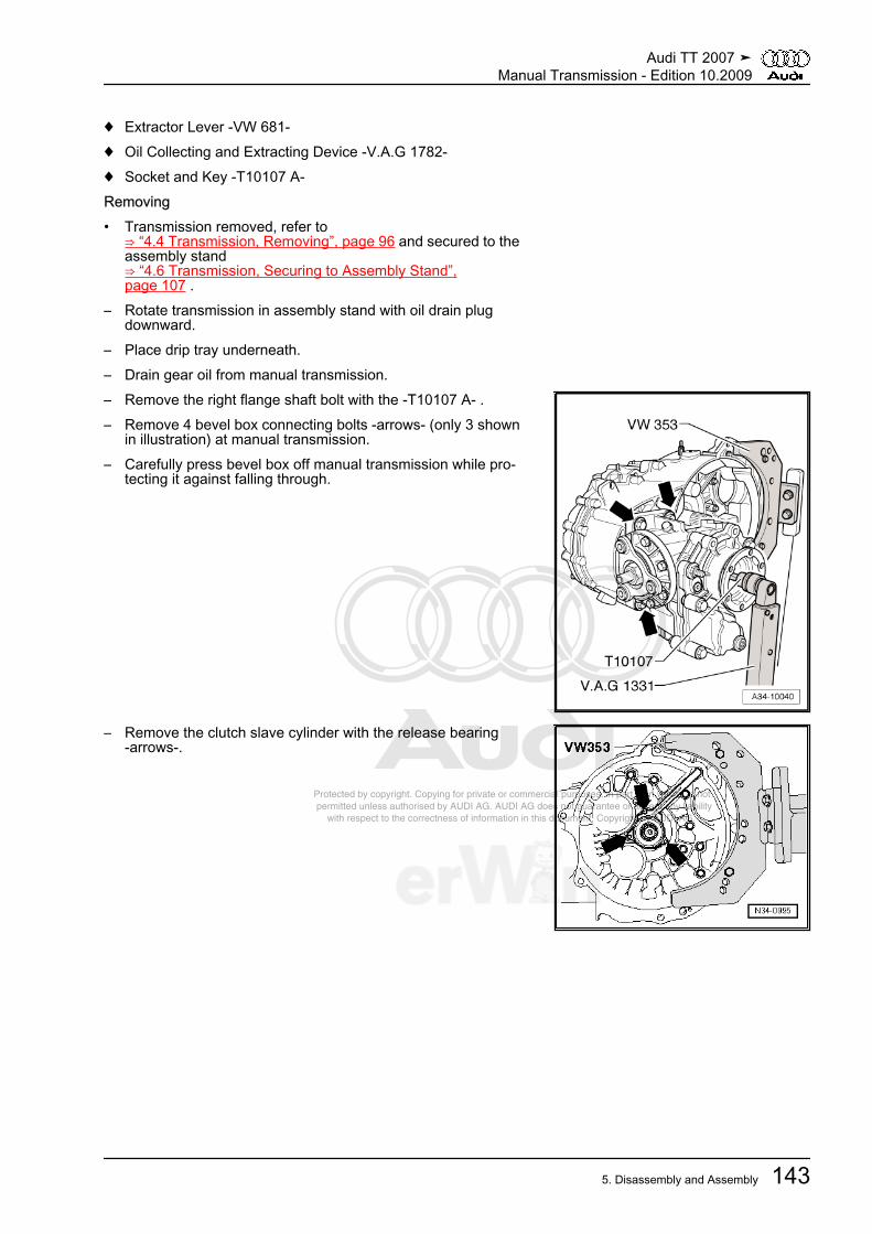
Protected by copyright. Copying for private or commercial purposes, in part or in whole, is not permitted unless authorised by AUDI AG. AUDI AG does not guarantee or accept any liability with respect to the correctness of information in this document. Copyright by AUDI AG.
♦ Extractor Lever -VW 681-♦ Oil Collecting and Extracting Device -V.A.G 1782-♦ Socket and Key -T10107 A-Removing• Transmission removed, refer to
⇒ “4.4 Transmission, Removing”, page 96 and secured to theassembly stand⇒ “4.6 Transmission, Securing to Assembly Stand”,page 107 .
– Rotate transmission in assembly stand with oil drain plugdownward.
– Place drip tray underneath.– Drain gear oil from manual transmission.– Remove the right flange shaft bolt with the -T10107 A- .– Remove 4 bevel box connecting bolts -arrows- (only 3 shown
in illustration) at manual transmission.– Carefully press bevel box off manual transmission while pro‐
tecting it against falling through.
– Remove the clutch slave cylinder with the release bearing-arrows-.
Audi TT 2007 ➤Manual Transmission - Edition 10.2009
5. Disassembly and Assembly 143

Protected by copyright. Copying for private or commercial purposes, in part or in whole, is not permitted unless authorised by AUDI AG. AUDI AG does not guarantee or accept any liability with respect to the correctness of information in this document. Copyright by AUDI AG.
– In the following step, ensure that the selector shaft is notlocked by the lock elbow -arrow-.
– Move shift shaft to neutral position.– Remove mounting bolt -2-.– Remove the bolts -3-.– Remove back-up light switch -F4- -1-.– Pull selector shaft -4- off transmission housing.
– Remove the left flange shaft bolt by installing 2 bolts in theflange and counter holding the flange shaft with the assemblylever.
– Remove bolts -B- inside clutch housing for securing clutchhousing to transmission housing.
Note
One bolt -arrow- is located outside of bolting flange.
– Secure the input shaft by inserting the -VW 455- over the inputshaft, onto the clutch housing.
– Then tension separating tool -A-, for example -Kukko 17/0-tightly behind input shaft splines.
• Back side of separating tool must contact pressing sleeve freeof play.
Audi TT 2007 ➤Manual Transmission - Edition 10.2009
144 Rep. Gr.34 - Controls, Housing
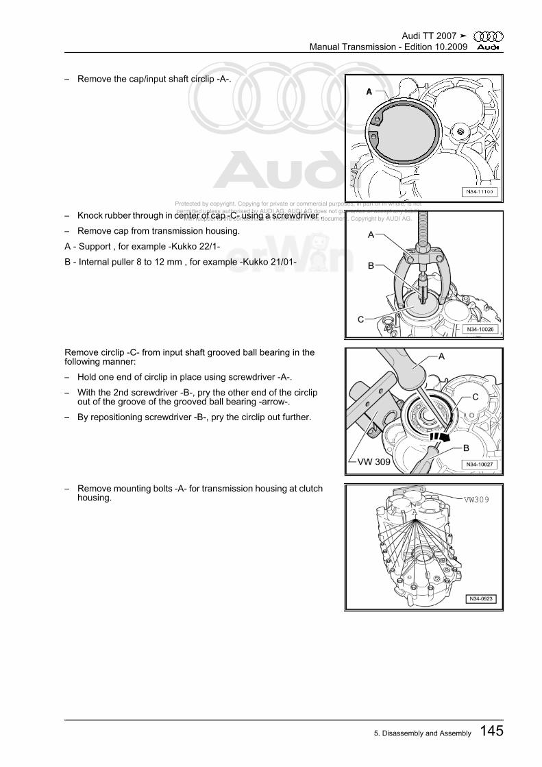
Protected by copyright. Copying for private or commercial purposes, in part or in whole, is not permitted unless authorised by AUDI AG. AUDI AG does not guarantee or accept any liability with respect to the correctness of information in this document. Copyright by AUDI AG.
– Remove the cap/input shaft circlip -A-.
– Knock rubber through in center of cap -C- using a screwdriver .– Remove cap from transmission housing.A - Support , for example -Kukko 22/1-B - Internal puller 8 to 12 mm , for example -Kukko 21/01-
Remove circlip -C- from input shaft grooved ball bearing in thefollowing manner:– Hold one end of circlip in place using screwdriver -A-.– With the 2nd screwdriver -B-, pry the other end of the circlip
out of the groove of the grooved ball bearing -arrow-.– By repositioning screwdriver -B-, pry the circlip out further.
– Remove mounting bolts -A- for transmission housing at clutchhousing.
Audi TT 2007 ➤Manual Transmission - Edition 10.2009
5. Disassembly and Assembly 145
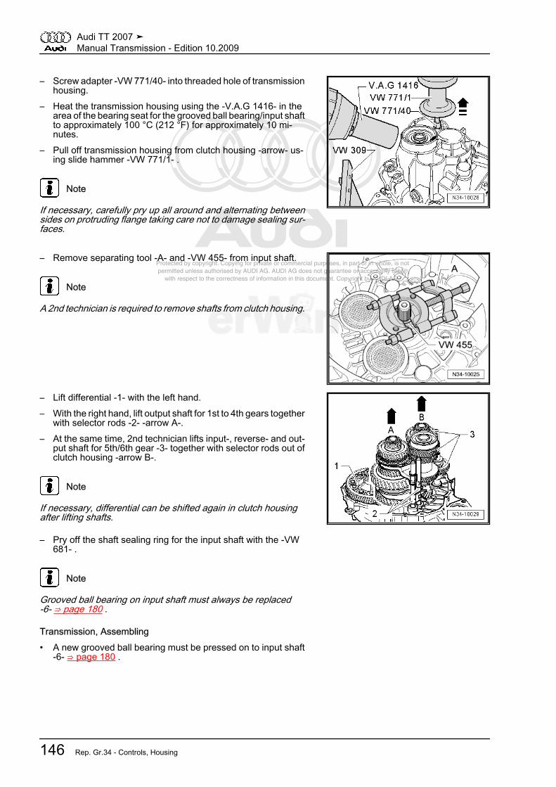
Protected by copyright. Copying for private or commercial purposes, in part or in whole, is not permitted unless authorised by AUDI AG. AUDI AG does not guarantee or accept any liability with respect to the correctness of information in this document. Copyright by AUDI AG.
– Screw adapter -VW 771/40- into threaded hole of transmissionhousing.
– Heat the transmission housing using the -V.A.G 1416- in thearea of the bearing seat for the grooved ball bearing/input shaftto approximately 100 °C (212 °F) for approximately 10 mi‐nutes.
– Pull off transmission housing from clutch housing -arrow- us‐ing slide hammer -VW 771/1- .
Note
If necessary, carefully pry up all around and alternating betweensides on protruding flange taking care not to damage sealing sur‐faces.
– Remove separating tool -A- and -VW 455- from input shaft.
Note
A 2nd technician is required to remove shafts from clutch housing.
– Lift differential -1- with the left hand.– With the right hand, lift output shaft for 1st to 4th gears together
with selector rods -2- -arrow A-.– At the same time, 2nd technician lifts input-, reverse- and out‐
put shaft for 5th/6th gear -3- together with selector rods out ofclutch housing -arrow B-.
Note
If necessary, differential can be shifted again in clutch housingafter lifting shafts.
– Pry off the shaft sealing ring for the input shaft with the -VW681- .
Note
Grooved ball bearing on input shaft must always be replaced-6- ⇒ page 180 .
Transmission, Assembling• A new grooved ball bearing must be pressed on to input shaft
-6- ⇒ page 180 .
Audi TT 2007 ➤Manual Transmission - Edition 10.2009
146 Rep. Gr.34 - Controls, Housing
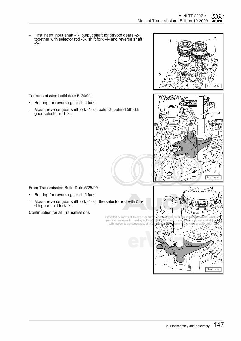
Protected by copyright. Copying for private or commercial purposes, in part or in whole, is not permitted unless authorised by AUDI AG. AUDI AG does not guarantee or accept any liability with respect to the correctness of information in this document. Copyright by AUDI AG.
– First insert input shaft -1-, output shaft for 5th/6th gears -2-together with selector rod -3-, shift fork -4- and reverse shaft-5-.
To transmission build date 5/24/09• Bearing for reverse gear shift fork:– Mount reverse gear shift fork -1- on axle -2- behind 5th/6th
gear selector rod -3-.
From Transmission Build Date 5/25/09• Bearing for reverse gear shift fork:– Mount reverse gear shift fork -1- on the selector rod with 5th/
6th gear shift fork -2-.Continuation for all Transmissions
Audi TT 2007 ➤Manual Transmission - Edition 10.2009
5. Disassembly and Assembly 147

Protected by copyright. Copying for private or commercial purposes, in part or in whole, is not permitted unless authorised by AUDI AG. AUDI AG does not guarantee or accept any liability with respect to the correctness of information in this document. Copyright by AUDI AG.
– Insert differential -1-.
Note
A 2nd technician is required for further installation of shafts intoclutch housing.
– As shown in illustration, take output shaft for 1st to 4th gears-3- with selector rods -4- in right hand.
– Lift differential slightly with the left hand.– At the same time, 2nd technician slightly lifts input shaft, output
shaft for 5th/6th gears and reverse gear -2- together with re‐verse shaft.
– Now, insert the output shaft for 1st to 4th gears in direction of-arrow-.
• Places of input shaft, output shafts and final drive gear/differ‐ential must engage.
– Together with a 2nd technician, place the shafts and the dif‐ferential into their bearing seats.
– Fasten the -30-211A- for the input shaft to the clutch housing.
Note
For the sake of illustration, clutch housing is depicted rotated180°.
– Screw in bolt -A- far enough until input shaft rises slightly.• The grooved ball bearing/input shaft only fits in one position in
the transmission housing.There is a flattened area on the grooved ball bearing and thebearing mount.
• If flattened areas -A- and -B- are present, do not insert anyspacer washers above and below the grooved ball bearing.Refer to ⇒ “1.1 Grooved Ball Bearing Changes”, page 177 .
• Flattened areas -A- on the grooved ball bearing and on bearingmount -B- must align in the transmission housing.
– Mark the flattened areas with color.– Place a marking on the upper area of the grooved ball bearing
and on the upper area of the transmission housing bearingmount (⇒ next illustration).
– Heat the transmission housing using the -V.A.G 1416- in thearea of the bearing seat for the grooved ball bearing/input shaftto approximately 100 °C (212° F) for approximately 10 mi‐nutes.
Audi TT 2007 ➤Manual Transmission - Edition 10.2009
148 Rep. Gr.34 - Controls, Housing
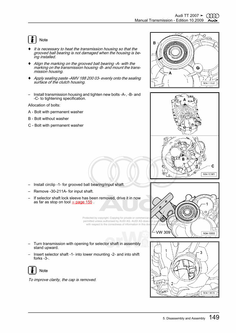
Protected by copyright. Copying for private or commercial purposes, in part or in whole, is not permitted unless authorised by AUDI AG. AUDI AG does not guarantee or accept any liability with respect to the correctness of information in this document. Copyright by AUDI AG.
Note
♦ It is necessary to heat the transmission housing so that thegrooved ball bearing is not damaged when the housing is be‐ing installed.
♦ Align the marking on the grooved ball bearing -A- with themarking on the transmission housing -B- and mount the trans‐mission housing.
♦ Apply sealing paste -AMV 188 200 03- evenly onto the sealingsurface of the clutch housing.
– Install transmission housing and tighten new bolts -A-, -B- and-C- to tightening specification.
Allocation of bolts:A - Bolt with permanent washerB - Bolt without washerC - Bolt with permanent washer
– Install circlip -1- for grooved ball bearing/input shaft.– Remove -30-211A- for input shaft.– If selector shaft lock sleeve has been removed, drive it in now
as far as stop on tool ⇒ page 155 .
– Turn transmission with opening for selector shaft in assemblystand upward.
– Insert selector shaft -1- into lower mounting -2- and into shiftforks -3-.
Note
To improve clarity, the cap is removed.
Audi TT 2007 ➤Manual Transmission - Edition 10.2009
5. Disassembly and Assembly 149

Protected by copyright. Copying for private or commercial purposes, in part or in whole, is not permitted unless authorised by AUDI AG. AUDI AG does not guarantee or accept any liability with respect to the correctness of information in this document. Copyright by AUDI AG.
– Now press selector shaft -1- against lock sleeve -2- directionof -arrow- and guide downward with shift finger -3- throughshift forks until stop.
• Shift cover -4- must stand parallel to bolting surface on trans‐mission housing during this.
• Selector shaft must be able to be moved easily in selectormotion (up- and downward).
Note
If shift cover stands at an angle to bolting surface, selector shaftis not inserted in lower bearing.
– Tighten the bolts -3- for the shift cover -4-.– Install lock bolt -2-, lock elbow -arrow- must not be installed
when doing so.– Install back-up light switch -F4- -1-.
– Install the flange shaft with spring, the thrust washer and ta‐pered ring.
– Drive input shaft seal in flush.– Install the clutch slave cylinder with release bearing. Refer to
⇒ “4.7 Slave Cylinder with Release Bearing”, page 39 .– Shift through all gears.
Audi TT 2007 ➤Manual Transmission - Edition 10.2009
150 Rep. Gr.34 - Controls, Housing

Protected by copyright. Copying for private or commercial purposes, in part or in whole, is not permitted unless authorised by AUDI AG. AUDI AG does not guarantee or accept any liability with respect to the correctness of information in this document. Copyright by AUDI AG.
– Drive the cap into the transmission housing as far as the stop.
– Secure the cap with the circlip -A-.Install bevel box in manual transmission as follows:
Caution
Risk of damaging sealing ring between transmission and bevelbox.♦ Place bevel box on transmission together with right flange
shaft while turning shaft.
– With manual transmission, lubricate differential splines withgrease for clutch disc shaft splines -G 000 100- .
– Slide on bevel box completely on manual transmission, whiledoing this, join splines of input shaft/bevel box centrally withdifferential.
– Bring right drive axle splines and differential bevel gear alsointo alignment, rotate flanged shaft if necessary.
– With proper tooth position and central guiding, bevel box slipsup to stop against manual transmission.
Note
Do not pull bevel box with mounting bolts against manual trans‐mission, otherwise bevel box is canted and mounting eyelets canbreak off.
Audi TT 2007 ➤Manual Transmission - Edition 10.2009
5. Disassembly and Assembly 151

Protected by copyright. Copying for private or commercial purposes, in part or in whole, is not permitted unless authorised by AUDI AG. AUDI AG does not guarantee or accept any liability with respect to the correctness of information in this document. Copyright by AUDI AG.
– Tighten 4 bevel box connecting bolts -arrows- (only 3 shownin illustration) at manual transmission. Tightening specifica‐tions -10- ⇒ page 220 .
– Install right flange shaft. Refer to⇒ “1.2 Flange Shaft and Seals on Bevel Box Assembly Over‐view”, page 220 .
5.4 Shift ForksSpecial tools and workshop equipment required♦ Thrust Plate -VW 402-♦ Punch -VW 411-♦ Sleeve -VW 423-♦ Thrust Pad 16.5/28 mm Dia. -VW 431-♦ -1- Kukko 21/3 internal puller♦ -4- Kukko 22/1 counter-supportPulling Off Ball Sleeve for Reverse Gear Shift ForkA - Internal puller 18 to 23 mm , for example -Kukko 21/3-B - Support , for example -Kukko 22/1-
Pressing In Ball Sleeve for Reverse Gear Shift Fork
5.5 Transmission HousingSpecial tools and workshop equipment required
Audi TT 2007 ➤Manual Transmission - Edition 10.2009
152 Rep. Gr.34 - Controls, Housing

Protected by copyright. Copying for private or commercial purposes, in part or in whole, is not permitted unless authorised by AUDI AG. AUDI AG does not guarantee or accept any liability with respect to the correctness of information in this document. Copyright by AUDI AG.
♦ Guide Pin -VW 436 A-♦ Guide Pin -VW 439-♦ Slide Hammer-Complete Set -VW 771-♦ Holding Fixture -VW 801-♦ Guide Pin -10 - 15-♦ Thrust Pad -3124-♦ Driving Sleeve -VW 244 B-♦ Thrust Plate -VW 401-♦ Thrust Plate -VW 402-♦ Punch -VW 407-♦ Sleeve -VW 416 B-♦ Driver -3264-♦ Subframe Support Assm. Device -3290-♦ Drift -T10168-♦ Drift -T10169-♦ Thrust piece -T10203-♦ Kukko 21/2 Internal puller and Kukko 21/4♦ Kukko 22/2 counter-support♦ Drift -T10362-Removing Cap -A-– Knock rubber through at center of sealing cap using a screw‐
driver -B- and pry out cap in direction of -arrow-.Driving In Sealing Cap
– Drive in sealing cap up to the stop.Removing Lock Elbow for Selector Shaft– Break off the pin in released position.
Audi TT 2007 ➤Manual Transmission - Edition 10.2009
5. Disassembly and Assembly 153

Protected by copyright. Copying for private or commercial purposes, in part or in whole, is not permitted unless authorised by AUDI AG. AUDI AG does not guarantee or accept any liability with respect to the correctness of information in this document. Copyright by AUDI AG.
– Guide a screwdriver -A- into hole -B- of the lock elbow.– Pry out lock elbow -arrow-.Installation Position of Lock Elbow
• The marking on the lock elbow -arrow- must point to clutchslave cylinder connection -1-.
• The angle -a- must be approximately 45°.Drive in the Lock Elbow for the Selector Shaft.
• The lock elbow -arrow- must be released for the driving-inprocedure.
– Drive in the lock elbow to the tool stop.
Pulling Out Bearing Bushing for Selector RodA - Internal puller 14.5 to 18.5 mm , for example -Kukko 21/2-B - Support , for example -Kukko 22/2-Driving In Bushing for Selector Rod
Audi TT 2007 ➤Manual Transmission - Edition 10.2009
154 Rep. Gr.34 - Controls, Housing
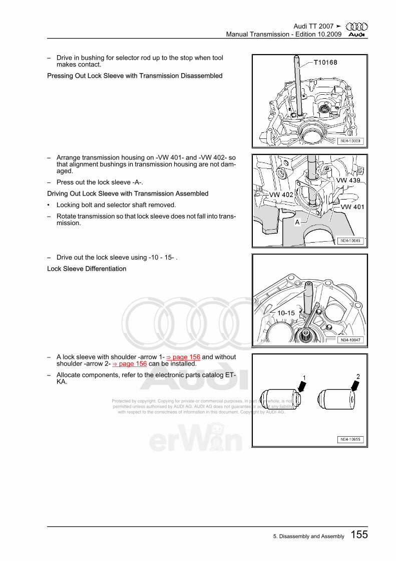
Protected by copyright. Copying for private or commercial purposes, in part or in whole, is not permitted unless authorised by AUDI AG. AUDI AG does not guarantee or accept any liability with respect to the correctness of information in this document. Copyright by AUDI AG.
– Drive in bushing for selector rod up to the stop when toolmakes contact.
Pressing Out Lock Sleeve with Transmission Disassembled
– Arrange transmission housing on -VW 401- and -VW 402- sothat alignment bushings in transmission housing are not dam‐aged.
– Press out the lock sleeve -A-.Driving Out Lock Sleeve with Transmission Assembled• Locking bolt and selector shaft removed.– Rotate transmission so that lock sleeve does not fall into trans‐
mission.
– Drive out the lock sleeve using -10 - 15- .Lock Sleeve Differentiation
– A lock sleeve with shoulder -arrow 1- ⇒ page 156 and withoutshoulder -arrow 2- ⇒ page 156 can be installed.
– Allocate components, refer to the electronic parts catalog ET‐KA.
Audi TT 2007 ➤Manual Transmission - Edition 10.2009
5. Disassembly and Assembly 155
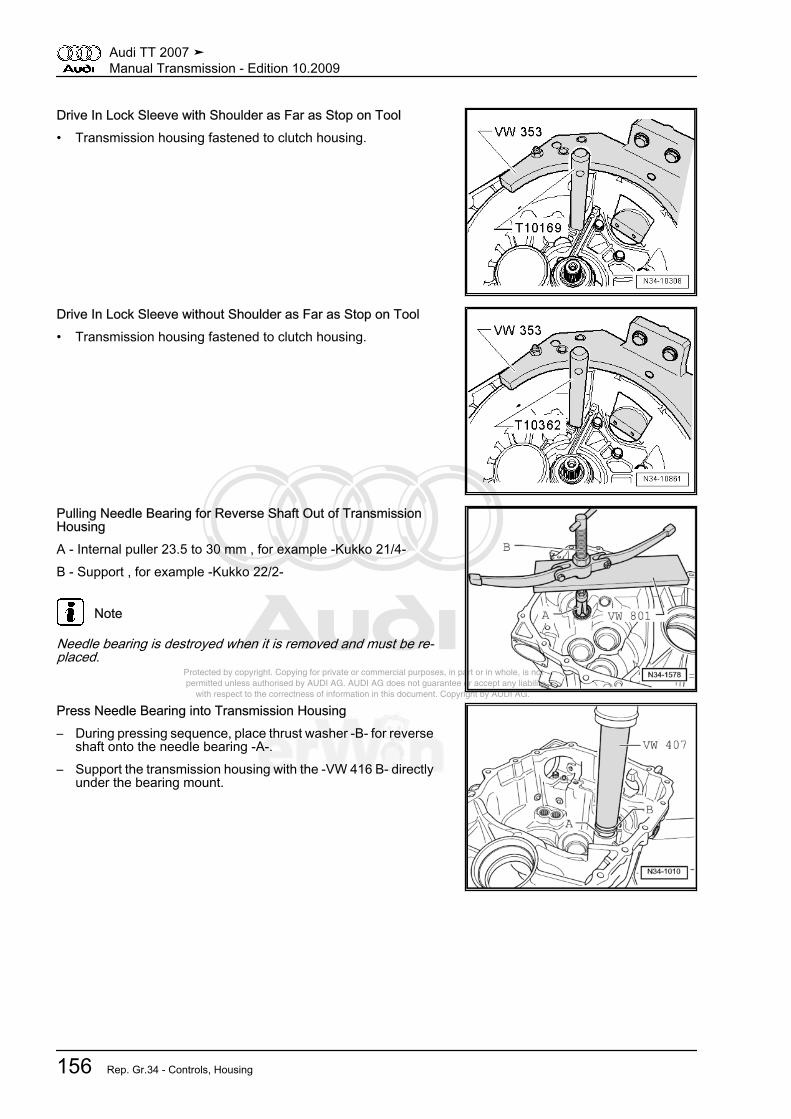
Protected by copyright. Copying for private or commercial purposes, in part or in whole, is not permitted unless authorised by AUDI AG. AUDI AG does not guarantee or accept any liability with respect to the correctness of information in this document. Copyright by AUDI AG.
Drive In Lock Sleeve with Shoulder as Far as Stop on Tool• Transmission housing fastened to clutch housing.
Drive In Lock Sleeve without Shoulder as Far as Stop on Tool• Transmission housing fastened to clutch housing.
Pulling Needle Bearing for Reverse Shaft Out of TransmissionHousingA - Internal puller 23.5 to 30 mm , for example -Kukko 21/4-B - Support , for example -Kukko 22/2-
Note
Needle bearing is destroyed when it is removed and must be re‐placed.
Press Needle Bearing into Transmission Housing– During pressing sequence, place thrust washer -B- for reverse
shaft onto the needle bearing -A-.– Support the transmission housing with the -VW 416 B- directly
under the bearing mount.
Audi TT 2007 ➤Manual Transmission - Edition 10.2009
156 Rep. Gr.34 - Controls, Housing

Protected by copyright. Copying for private or commercial purposes, in part or in whole, is not permitted unless authorised by AUDI AG. AUDI AG does not guarantee or accept any liability with respect to the correctness of information in this document. Copyright by AUDI AG.
Pulling Out Bushing for Selector Shaft– Hold spindle of assembly tool -3290- firmly in place and screw
nut -B-.A - Internal puller 14.5 to 18.5 mm , for example -Kukko 21/2-Driving In Bushing for Selector Shaft
– Drive selector shaft bushing -A- in flush.Driving Out Sealing Plug
– Drive the sealing plug -1- from the inner side of the transmis‐sion housing toward the outside -arrow-.
Driving In Sealing Plug
Audi TT 2007 ➤Manual Transmission - Edition 10.2009
5. Disassembly and Assembly 157

Protected by copyright. Copying for private or commercial purposes, in part or in whole, is not permitted unless authorised by AUDI AG. AUDI AG does not guarantee or accept any liability with respect to the correctness of information in this document. Copyright by AUDI AG.
– Drive in the sealing plug -1- using the -3264- to dimension-a- = approximately 3 mm under the upper edge of housing.
5.6 Clutch Housing, ServicingSpecial tools and workshop equipment required♦ Punch -VW 407-♦ Sleeve -30 - 21-♦ Drift -T10168-♦ Thrust Piece -T40008-♦ -1- Kukko 21/2 Internal puller and Kukko 21/4♦ -4- Kukko support 22/1 and 22/2Pulling Out Bearing Bushing for Selector RodA - Support , for example -Kukko 22/1-B - Internal puller 14.5 to 18.5 mm , for example -Kukko 21/2-Driving In Bushing for Selector Rod
– Drive in bushing up to the stop when tool makes contact
Audi TT 2007 ➤Manual Transmission - Edition 10.2009
158 Rep. Gr.34 - Controls, Housing
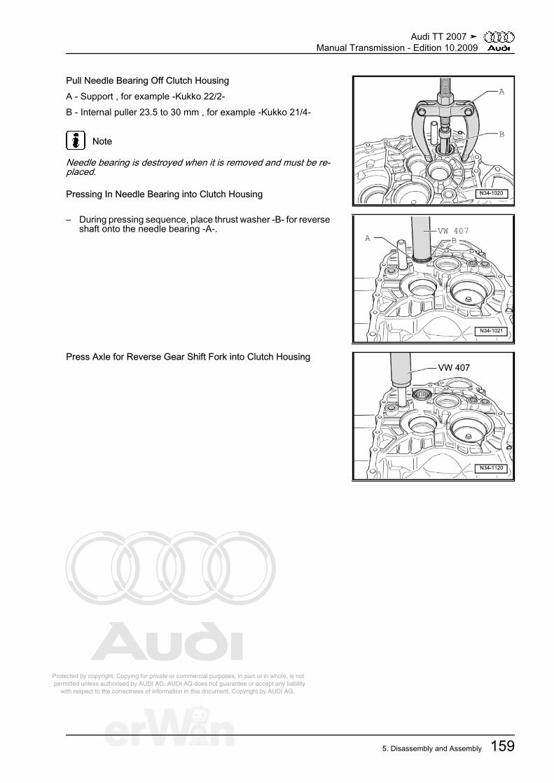
Protected by copyright. Copying for private or commercial purposes, in part or in whole, is not permitted unless authorised by AUDI AG. AUDI AG does not guarantee or accept any liability with respect to the correctness of information in this document. Copyright by AUDI AG.
Pull Needle Bearing Off Clutch HousingA - Support , for example -Kukko 22/2-B - Internal puller 23.5 to 30 mm , for example -Kukko 21/4-
Note
Needle bearing is destroyed when it is removed and must be re‐placed.
Pressing In Needle Bearing into Clutch Housing
– During pressing sequence, place thrust washer -B- for reverseshaft onto the needle bearing -A-.
Press Axle for Reverse Gear Shift Fork into Clutch Housing
Audi TT 2007 ➤Manual Transmission - Edition 10.2009
5. Disassembly and Assembly 159

Protected by copyright. Copying for private or commercial purposes, in part or in whole, is not permitted unless authorised by AUDI AG. AUDI AG does not guarantee or accept any liability with respect to the correctness of information in this document. Copyright by AUDI AG.
6 Special Tools
Special tools and workshopequipment required♦ Guide Pin -VW 436 A-♦ Guide Pin -VW 439-♦ Slide Hammer-Complete
Set -VW 771-♦ Holding Fixture -VW 801-♦ Guide Pin -10 - 15-♦ Thrust Pad -3124-
Audi TT 2007 ➤Manual Transmission - Edition 10.2009
160 Rep. Gr.34 - Controls, Housing
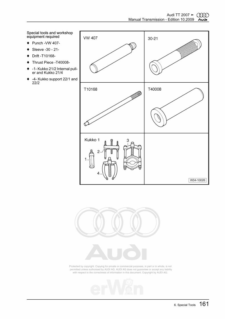
Protected by copyright. Copying for private or commercial purposes, in part or in whole, is not permitted unless authorised by AUDI AG. AUDI AG does not guarantee or accept any liability with respect to the correctness of information in this document. Copyright by AUDI AG.
Special tools and workshopequipment required♦ Punch -VW 407-♦ Sleeve -30 - 21-♦ Drift -T10168-♦ Thrust Piece -T40008-♦ -1- Kukko 21/2 Internal pull‐
er and Kukko 21/4♦ -4- Kukko support 22/1 and
22/2
Audi TT 2007 ➤Manual Transmission - Edition 10.2009
6. Special Tools 161
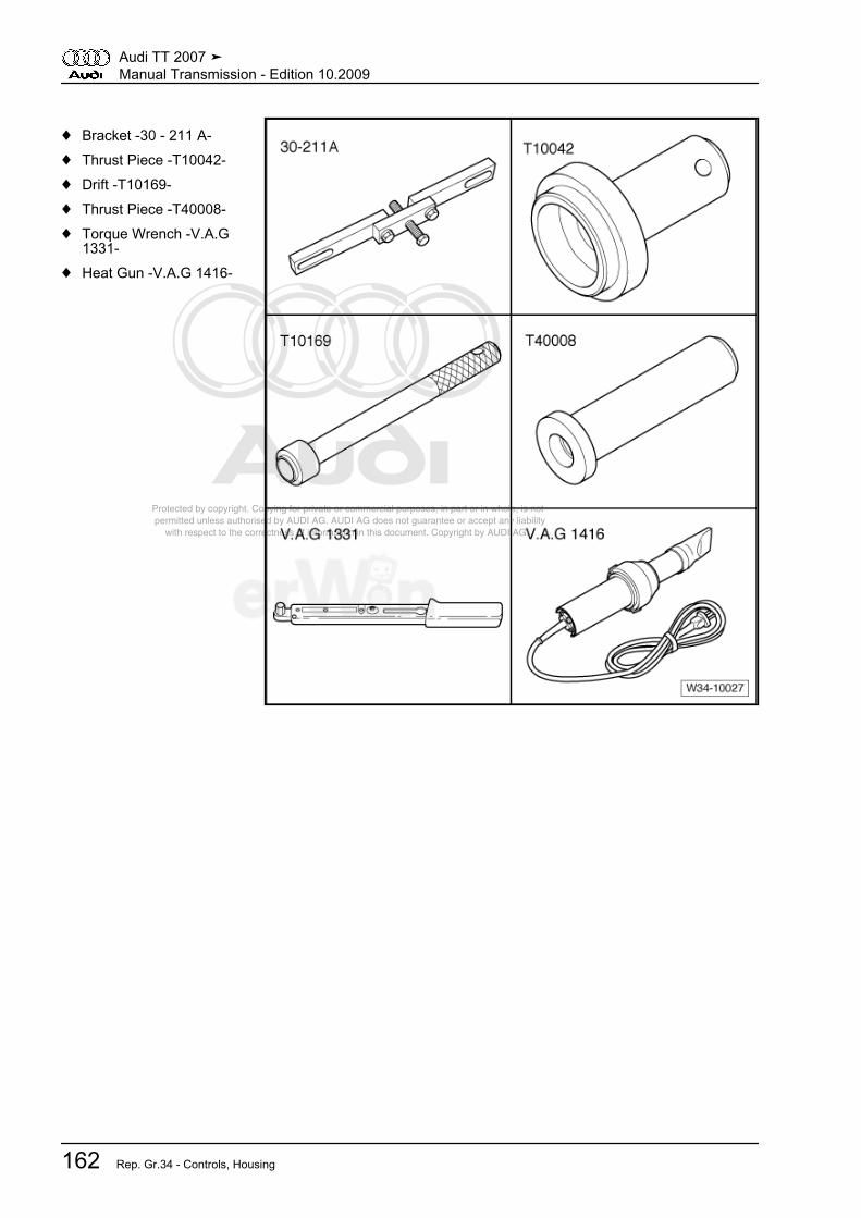
Protected by copyright. Copying for private or commercial purposes, in part or in whole, is not permitted unless authorised by AUDI AG. AUDI AG does not guarantee or accept any liability with respect to the correctness of information in this document. Copyright by AUDI AG.
♦ Bracket -30 - 211 A-♦ Thrust Piece -T10042-♦ Drift -T10169-♦ Thrust Piece -T40008-♦ Torque Wrench -V.A.G
1331-♦ Heat Gun -V.A.G 1416-
Audi TT 2007 ➤Manual Transmission - Edition 10.2009
162 Rep. Gr.34 - Controls, Housing

Protected by copyright. Copying for private or commercial purposes, in part or in whole, is not permitted unless authorised by AUDI AG. AUDI AG does not guarantee or accept any liability with respect to the correctness of information in this document. Copyright by AUDI AG.
Special tools and workshopequipment required♦ Engine Support Bridge -10
- 222 A-♦ Hook -10 - 222 A /10-♦ Hose Clamps Up to 25 mm
Diameter. -3094-♦ Transmission Support
-3282-♦ Pin -3282/29-♦ Adjustment Plate -3282/33-
Audi TT 2007 ➤Manual Transmission - Edition 10.2009
6. Special Tools 163

Protected by copyright. Copying for private or commercial purposes, in part or in whole, is not permitted unless authorised by AUDI AG. AUDI AG does not guarantee or accept any liability with respect to the correctness of information in this document. Copyright by AUDI AG.
♦ Engine/Transmission Jack-V.A.G 1383 A-
♦ Engine Support Basic Set -T40091-
♦ Engine Support Supple‐ment Set -T40093-
Audi TT 2007 ➤Manual Transmission - Edition 10.2009
164 Rep. Gr.34 - Controls, Housing
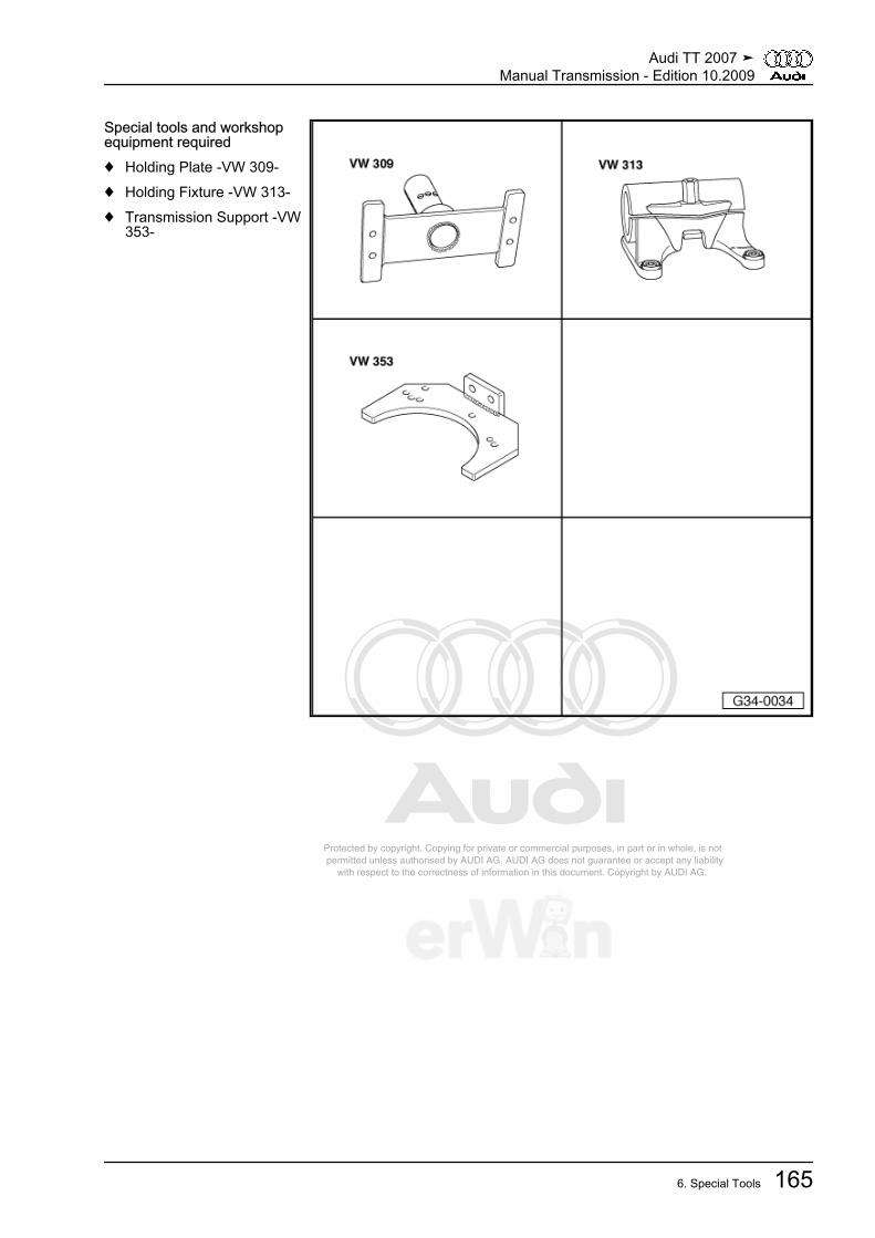
Protected by copyright. Copying for private or commercial purposes, in part or in whole, is not permitted unless authorised by AUDI AG. AUDI AG does not guarantee or accept any liability with respect to the correctness of information in this document. Copyright by AUDI AG.
Special tools and workshopequipment required♦ Holding Plate -VW 309-♦ Holding Fixture -VW 313-♦ Transmission Support -VW
353-
Audi TT 2007 ➤Manual Transmission - Edition 10.2009
6. Special Tools 165
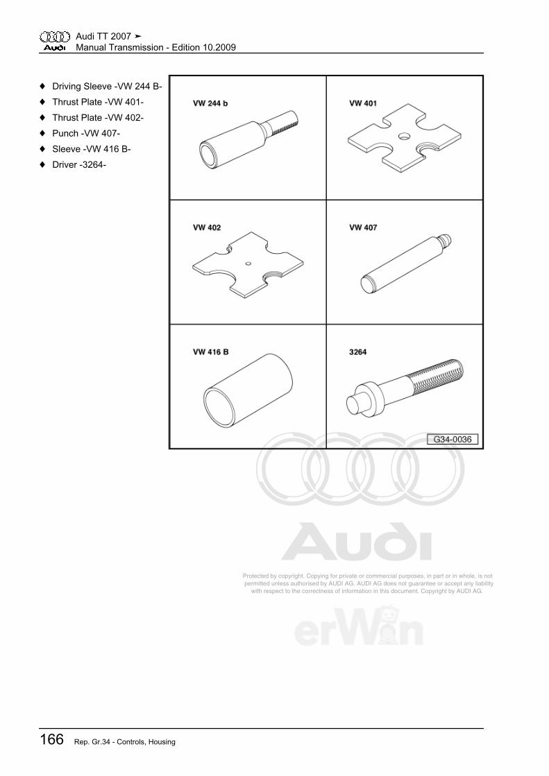
Protected by copyright. Copying for private or commercial purposes, in part or in whole, is not permitted unless authorised by AUDI AG. AUDI AG does not guarantee or accept any liability with respect to the correctness of information in this document. Copyright by AUDI AG.
♦ Driving Sleeve -VW 244 B-♦ Thrust Plate -VW 401-♦ Thrust Plate -VW 402-♦ Punch -VW 407-♦ Sleeve -VW 416 B-♦ Driver -3264-
Audi TT 2007 ➤Manual Transmission - Edition 10.2009
166 Rep. Gr.34 - Controls, Housing
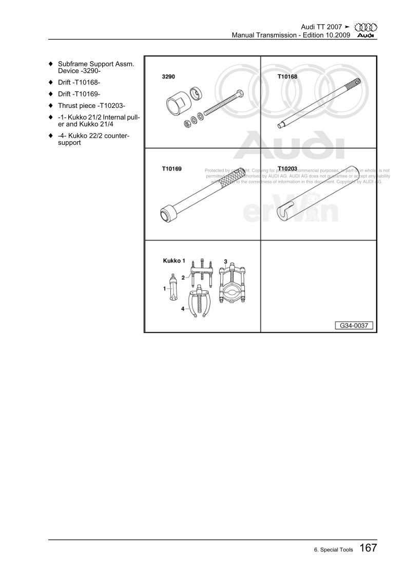
Protected by copyright. Copying for private or commercial purposes, in part or in whole, is not permitted unless authorised by AUDI AG. AUDI AG does not guarantee or accept any liability with respect to the correctness of information in this document. Copyright by AUDI AG.
♦ Subframe Support Assm.Device -3290-
♦ Drift -T10168-♦ Drift -T10169-♦ Thrust piece -T10203-♦ -1- Kukko 21/2 Internal pull‐
er and Kukko 21/4♦ -4- Kukko 22/2 counter-
support
Audi TT 2007 ➤Manual Transmission - Edition 10.2009
6. Special Tools 167
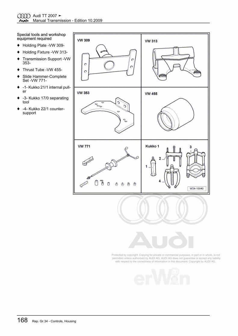
Protected by copyright. Copying for private or commercial purposes, in part or in whole, is not permitted unless authorised by AUDI AG. AUDI AG does not guarantee or accept any liability with respect to the correctness of information in this document. Copyright by AUDI AG.
Special tools and workshopequipment required♦ Holding Plate -VW 309-♦ Holding Fixture -VW 313-♦ Transmission Support -VW
353-♦ Thrust Tube -VW 455-♦ Slide Hammer-Complete
Set -VW 771-♦ -1- Kukko 21/1 internal pull‐
er♦ -3- Kukko 17/0 separating
tool♦ -4- Kukko 22/1 counter-
support
Audi TT 2007 ➤Manual Transmission - Edition 10.2009
168 Rep. Gr.34 - Controls, Housing
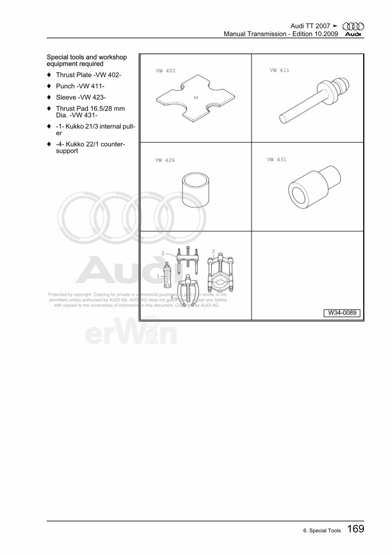
Protected by copyright. Copying for private or commercial purposes, in part or in whole, is not permitted unless authorised by AUDI AG. AUDI AG does not guarantee or accept any liability with respect to the correctness of information in this document. Copyright by AUDI AG.
Special tools and workshopequipment required♦ Thrust Plate -VW 402-♦ Punch -VW 411-♦ Sleeve -VW 423-♦ Thrust Pad 16.5/28 mm
Dia. -VW 431-♦ -1- Kukko 21/3 internal pull‐
er♦ -4- Kukko 22/1 counter-
support
Audi TT 2007 ➤Manual Transmission - Edition 10.2009
6. Special Tools 169

Protected by copyright. Copying for private or commercial purposes, in part or in whole, is not permitted unless authorised by AUDI AG. AUDI AG does not guarantee or accept any liability with respect to the correctness of information in this document. Copyright by AUDI AG.
♦ Bracket -30-211A-♦ Thrust piece -T10042-♦ Thrust piece -T10143-♦ Thrust piece -T40008-♦ Torque Wrench -V.A.G
1331-♦ Heat gun -V.A.G 1416-♦ Drift -T10169-♦ or Drift -T10362-
⇒ page 155
Special tools and workshop equipment required♦ Triple Square Socket Driver -3357-
Audi TT 2007 ➤Manual Transmission - Edition 10.2009
170 Rep. Gr.34 - Controls, Housing
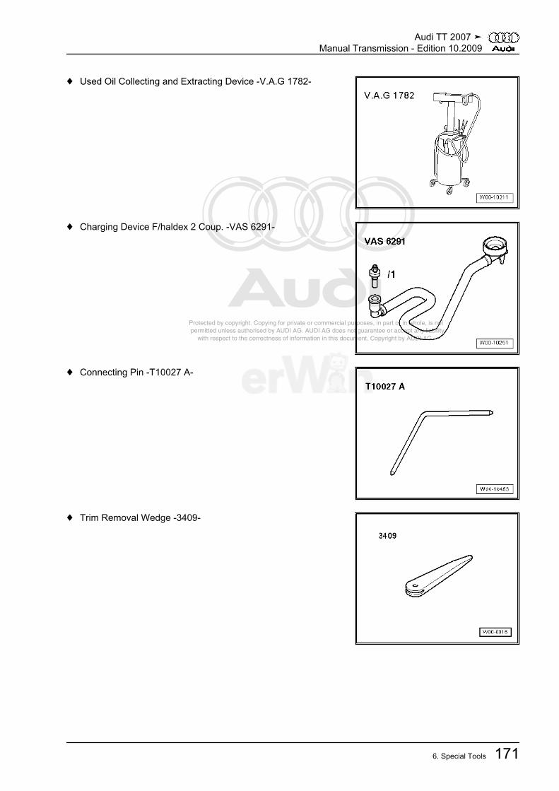
Protected by copyright. Copying for private or commercial purposes, in part or in whole, is not permitted unless authorised by AUDI AG. AUDI AG does not guarantee or accept any liability with respect to the correctness of information in this document. Copyright by AUDI AG.
♦ Used Oil Collecting and Extracting Device -V.A.G 1782-
♦ Charging Device F/haldex 2 Coup. -VAS 6291-
♦ Connecting Pin -T10027 A-
♦ Trim Removal Wedge -3409-
Audi TT 2007 ➤Manual Transmission - Edition 10.2009
6. Special Tools 171
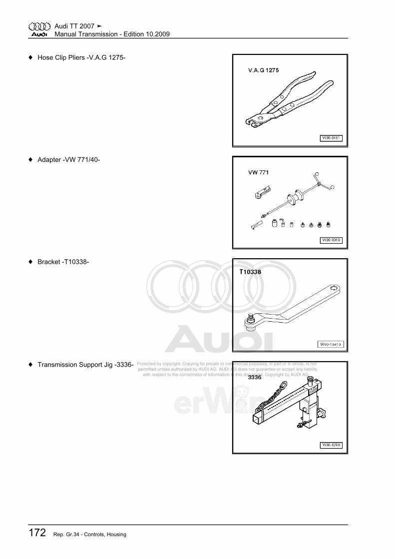
Protected by copyright. Copying for private or commercial purposes, in part or in whole, is not permitted unless authorised by AUDI AG. AUDI AG does not guarantee or accept any liability with respect to the correctness of information in this document. Copyright by AUDI AG.
♦ Hose Clip Pliers -V.A.G 1275-
♦ Adapter -VW 771/40-
♦ Bracket -T10338-
♦ Transmission Support Jig -3336-
Audi TT 2007 ➤Manual Transmission - Edition 10.2009
172 Rep. Gr.34 - Controls, Housing

Protected by copyright. Copying for private or commercial purposes, in part or in whole, is not permitted unless authorised by AUDI AG. AUDI AG does not guarantee or accept any liability with respect to the correctness of information in this document. Copyright by AUDI AG.
♦ Shop Crane -VAS 6100-
♦ Engine Support Basic Set -T40091-
♦ Socket and Extended Bit -T10107 A- (SW 6 mm)
♦ Hex Ball Socket -3247-
Audi TT 2007 ➤Manual Transmission - Edition 10.2009
6. Special Tools 173
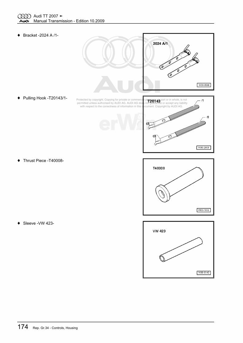
Protected by copyright. Copying for private or commercial purposes, in part or in whole, is not permitted unless authorised by AUDI AG. AUDI AG does not guarantee or accept any liability with respect to the correctness of information in this document. Copyright by AUDI AG.
♦ Bracket -2024 A /1-
♦ Pulling Hook -T20143/1-
♦ Thrust Piece -T40008-
♦ Sleeve -VW 423-
Audi TT 2007 ➤Manual Transmission - Edition 10.2009
174 Rep. Gr.34 - Controls, Housing

Protected by copyright. Copying for private or commercial purposes, in part or in whole, is not permitted unless authorised by AUDI AG. AUDI AG does not guarantee or accept any liability with respect to the correctness of information in this document. Copyright by AUDI AG.
♦ Thrust Block -T10083-
♦ Used Oil Collecting and Extracting Device -V.A.G 1782-
♦ Extractor Lever -VW 681-
♦ Socket and Extended Bit -T10107 A-
Audi TT 2007 ➤Manual Transmission - Edition 10.2009
6. Special Tools 175

Protected by copyright. Copying for private or commercial purposes, in part or in whole, is not permitted unless authorised by AUDI AG. AUDI AG does not guarantee or accept any liability with respect to the correctness of information in this document. Copyright by AUDI AG.
♦ Drift -T10362-
Audi TT 2007 ➤Manual Transmission - Edition 10.2009
176 Rep. Gr.34 - Controls, Housing
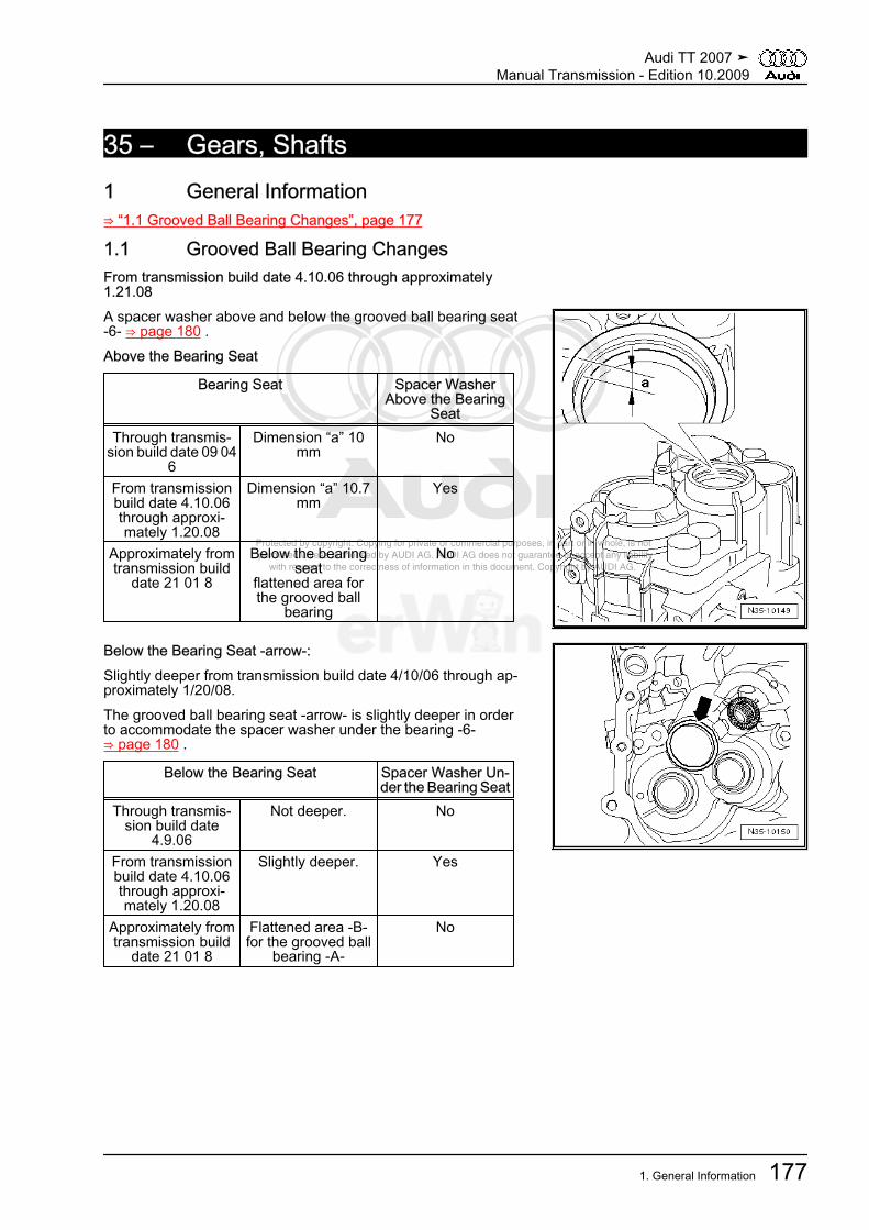
Protected by copyright. Copying for private or commercial purposes, in part or in whole, is not permitted unless authorised by AUDI AG. AUDI AG does not guarantee or accept any liability with respect to the correctness of information in this document. Copyright by AUDI AG.
35 – Gears, Shafts1 General Information⇒ “1.1 Grooved Ball Bearing Changes”, page 177
1.1 Grooved Ball Bearing ChangesFrom transmission build date 4.10.06 through approximately1.21.08A spacer washer above and below the grooved ball bearing seat-6- ⇒ page 180 .Above the Bearing Seat
Bearing Seat Spacer WasherAbove the Bearing
SeatThrough transmis‐
sion build date 09 046
Dimension “a” 10mm
No
From transmissionbuild date 4.10.06through approxi‐mately 1.20.08
Dimension “a” 10.7mm
Yes
Approximately fromtransmission build
date 21 01 8
Below the bearingseat
flattened area forthe grooved ball
bearing
No
Below the Bearing Seat -arrow-:Slightly deeper from transmission build date 4/10/06 through ap‐proximately 1/20/08.The grooved ball bearing seat -arrow- is slightly deeper in orderto accommodate the spacer washer under the bearing -6-⇒ page 180 .
Below the Bearing Seat Spacer Washer Un‐der the Bearing Seat
Through transmis‐sion build date
4.9.06
Not deeper. No
From transmissionbuild date 4.10.06through approxi‐mately 1.20.08
Slightly deeper. Yes
Approximately fromtransmission build
date 21 01 8
Flattened area -B-for the grooved ball
bearing -A-
No
Audi TT 2007 ➤Manual Transmission - Edition 10.2009
1. General Information 177
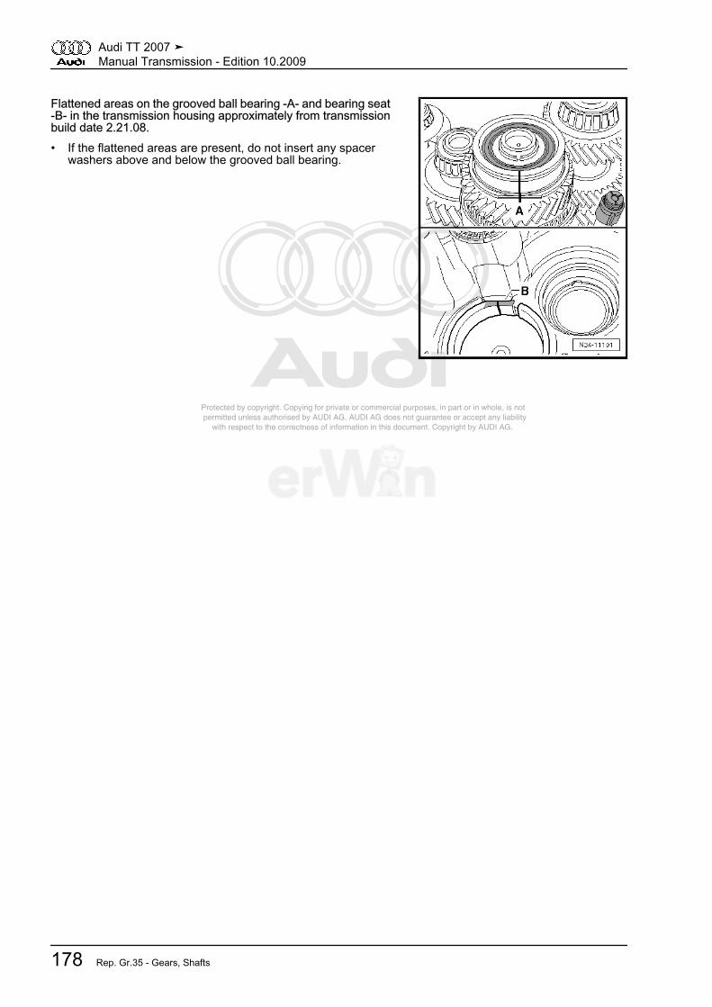
Protected by copyright. Copying for private or commercial purposes, in part or in whole, is not permitted unless authorised by AUDI AG. AUDI AG does not guarantee or accept any liability with respect to the correctness of information in this document. Copyright by AUDI AG.
Flattened areas on the grooved ball bearing -A- and bearing seat-B- in the transmission housing approximately from transmissionbuild date 2.21.08.• If the flattened areas are present, do not insert any spacer
washers above and below the grooved ball bearing.
Audi TT 2007 ➤Manual Transmission - Edition 10.2009
178 Rep. Gr.35 - Gears, Shafts

Protected by copyright. Copying for private or commercial purposes, in part or in whole, is not permitted unless authorised by AUDI AG. AUDI AG does not guarantee or accept any liability with respect to the correctness of information in this document. Copyright by AUDI AG.
2 Description and Operation⇒ “2.1 Input Shaft Assembly Overview”, page 179⇒ “2.2 Output Shaft for 1st to 4th Gears Assembly Overview”,page 181⇒ “2.3 Output Shaft, 1st to 4th Gears, Adjusting”, page 183⇒ “2.4 Output Shaft for 5th/6th Gear/Reverse Gear AssemblyOverview”, page 187⇒ “2.5 Output Shaft for 5th/6th Gear and Reverse Gear, Adjust‐ing”, page 188
2.1 Input Shaft Assembly Overview
Note
♦ Attach transmission to assembly stand. Refer to⇒ “4.6 Transmission, Securing to Assembly Stand”, page 107 .
♦ When installing new gears, consult technical data. Refer to⇒ “3.1 Code Letters, Assembly Allocation, Ratios and Capacities”, page 9 .
♦ Lubricate all bearings with gear oil when inserting on input shaft.
1 -Securing Ring
❑ For the grooved ballbearing/input shaft -6-
❑ Removing and instal‐ling, refer to⇒ “5.2 Transmissionwithout Circlip A forCap/Input Shaft”,page 131
2 - Spacer Washer❑ Outer circumference =
78.6 mm❑ Only insert with the
changed transmissionhousing (from transmis‐sion production date4.10.06 through approx‐imately 1.20.08), refer to⇒ “1.1 Grooved BallBearing Changes”,page 177
❑ Allocation, refer to theelectronic parts catalogETKA
3 -Transmission Housing
❑ Adapted in the groovedball bearing seat area-6- and spacer washers-2- and -4- from trans‐mission build date4/10/06 through approx‐imately 1/20/08, refer to⇒ “1.1 Grooved BallBearing Changes”,
Audi TT 2007 ➤Manual Transmission - Edition 10.2009
2. Description and Operation 179

Protected by copyright. Copying for private or commercial purposes, in part or in whole, is not permitted unless authorised by AUDI AG. AUDI AG does not guarantee or accept any liability with respect to the correctness of information in this document. Copyright by AUDI AG.
page 177 .❑ Flattened areas on grooved ball bearing and bearing seat approximately from transmission build date
1.21.08, refer to ⇒ “1.1 Grooved Ball Bearing Changes”, page 177❑ Allocation, refer to the electronic parts catalog ETKA
4 - Spacer Washer❑ Outer circumference = 85 mm❑ Only insert with the changed transmission housing (from transmission production date 4.10.06 through
approximately 1.20.08), refer to ⇒ “1.1 Grooved Ball Bearing Changes”, page 177❑ Allocation, refer to the electronic parts catalog ETKA
5 - Securing Ring❑ When replacing grooved ball bearing -6- and input shaft -8-, determine again ⇒ page 193
6 -Grooved Ball Bearing
❑ Always replace❑ Pulling off ⇒ page 192❑ Installation location ⇒ page 193❑ Pressing on ⇒ page 193❑ Flattened areas on grooved ball bearing and bearing seat approximately from transmission build date
1.21.08, refer to ⇒ “1.1 Grooved Ball Bearing Changes”, page 1777 - 5th Gear Toothed Wheel
❑ Pressing off ⇒ page 192❑ Installed position: the surrounding groove -arrow- points toward the grooved ball bearing -6-❑ Pressing on ⇒ page 192
8 - Input Shaft❑ With 3rd/4th and 6th gear wheels
9 - Roller Bearing❑ With circlip❑ Pulling out ⇒ page 194❑ Installing ⇒ page 194❑ Installed position: the circlip in bearing points to input shaft
10 - Clutch Housing
Audi TT 2007 ➤Manual Transmission - Edition 10.2009
180 Rep. Gr.35 - Gears, Shafts

Protected by copyright. Copying for private or commercial purposes, in part or in whole, is not permitted unless authorised by AUDI AG. AUDI AG does not guarantee or accept any liability with respect to the correctness of information in this document. Copyright by AUDI AG.
2.2 Output Shaft for 1st to 4th Gears Assembly Overview
Note
♦ Attach transmission to assembly stand. Refer to⇒ “4.6 Transmission, Securing to Assembly Stand”, page 107 .
♦ If output shaft or tapered roller bearings are replaced, an adjustment on output shaft must be performed.Refer to ⇒ “2.3 Output Shaft, 1st to 4th Gears, Adjusting”, page 183 .
♦ When installing new gears or a new output shaft, consult technical data. Refer to⇒ “3.1 Code Letters, Assembly Allocation, Ratios and Capacities”, page 9 .
♦ Always replace both tapered roller bearings together as a set.
1 - Clutch Housing2 - Oil Deflector Ring3 - Dished Washer
❑ Pulling out ⇒ page 195❑ Installing ⇒ page 195
4 - Taper Roller Bearing OuterRace
❑ Pulling out ⇒ page 196❑ Installing ⇒ page 196
5 - Tapered Roller Bearing In‐ner Race
❑ Pressing off⇒ page 197
❑ Pressing on⇒ page 197
6 - Output Shaft❑ For 1st to 4th gear❑ Adjusting, refer to
⇒ “2.3 Output Shaft, 1stto 4th Gears, Adjusting”,page 183
7 - Needle Bearing❑ For 2nd gear
8 - 2nd Gear Selector Gear9 - Synchronizer ring
❑ (Inner race for 2nd gear)❑ Checking for wear
⇒ page 197❑ Check tabs for scoring❑ Installation location
⇒ page 19810 - Outer Race for 2nd Gear
❑ Install on synchronizer ring -9-❑ Replace if grooved or scored❑ Installation location ⇒ page 198
11 - 2nd Gear Synchronizer Ring❑ Checking for wear ⇒ page 198❑ Installation location ⇒ page 198
Audi TT 2007 ➤Manual Transmission - Edition 10.2009
2. Description and Operation 181

Protected by copyright. Copying for private or commercial purposes, in part or in whole, is not permitted unless authorised by AUDI AG. AUDI AG does not guarantee or accept any liability with respect to the correctness of information in this document. Copyright by AUDI AG.
12 - Locking Sleeve with Synchronizer Hub for 1st and 2nd Gears❑ After removing circlip -13-, press off gear wheel for 2nd gear ⇒ page 197 .❑ Disassembling ⇒ page 198❑ Assembling locking collar/synchronizer hub ⇒ page 198❑ Installation location ⇒ page 199❑ Pressing on ⇒ page 199
13 - Securing Ring14 - Synchronizer Ring for 1st Gear
❑ Checking for wear ⇒ page 198❑ Insert so that holes engage in engagement pieces of locking collar -12-
15 - Outer Race for 1st Gear❑ Insert into synchronizer ring -14-, installation position ⇒ page 199❑ Replace if grooved or scored
16 - Synchronizer Ring❑ (Inner race for 1st gear)❑ Checking for wear ⇒ page 197❑ Check tabs for scoring❑ Installation location ⇒ page 200
17 - Needle Bearing❑ For 1st gear
18 - 1st Gear Selector Gear❑ Installation location ⇒ page 200
19 - Thrust Washers❑ For 1st and 4th gear❑ Quantity: 2❑ Insert tab of thrust washer in output shaft hole
20 - Securing Ring❑ Holds thrust washers -19- in position on output shaft
21 - Needle Bearing❑ For 4th gear
22 - 4th Gear Selector Gear23 - 4th Gear Synchronizer Ring
❑ Checking for wear ⇒ page 20124 - Locking Collar with Synchronizer Hub for 3rd and 4th Gear
❑ After removing circlip -25-, pull off gear wheel for 4th gear ⇒ page 196 .❑ Disassembling ⇒ page 198❑ Installation position of locking collar/synchronizer hub ⇒ page 200❑ Assembling operating sleeve/synchronizer hub ⇒ page 198 and ⇒ page 199❑ Pressing on ⇒ page 200
25 - Securing Ring26 - Synchronizer Ring for 3rd Gear
❑ Checking for wear ⇒ page 19827 - Outer Race for 3rd Gear
❑ Insert into synchronizer ring -26-, installation position ⇒ page 199❑ Replace if grooved or scored
Audi TT 2007 ➤Manual Transmission - Edition 10.2009
182 Rep. Gr.35 - Gears, Shafts
Protected by copyright. Copying for private or commercial purposes, in part or in whole, is not permitted unless authorised by AUDI AG. AUDI AG does not guarantee or accept any liability with respect to the correctness of information in this document. Copyright by AUDI AG.
28 - Synchronizer Ring❑ (Inner race for 3rd gear)❑ Checking for wear ⇒ page 197❑ Check tabs for scoring❑ Installation location ⇒ page 200
29 - Needle Bearing❑ For 3rd gear
30 - 3rd Gear Selector Gear❑ Installation location ⇒ page 200
31 - Tapered Roller Bearing Inner Race❑ Pulling off ⇒ page 196❑ Pressing on ⇒ page 201
32 - Securing Ring❑ When replacing tapered roller bearing -31- and output shaft -6-, determine again
33 - Taper Roller Bearing Outer Race❑ Pulling out ⇒ page 201❑ Installing ⇒ page 202
34 - Adjustment Shim❑ Determining thickness, refer to ⇒ “2.3 Output Shaft, 1st to 4th Gears, Adjusting”, page 183
35 - Transmission Housing
2.3 Output Shaft, 1st to 4th Gears, AdjustingIt is necessary to readjust the output shaft when the followingcomponents are replaced:♦ Transmission housing♦ Clutch housing♦ Output Shaft, 1st to 4th Gears♦ Tapered roller bearing for output shaftAdjustment overview, refer to⇒ “1.4 Adjustment Overview”, page 224 .Special tools and workshop equipment required♦ Dial Gauge Holder -VW 387-♦ Punch -VW 407-♦ Thrust Pad Con. 8/65 -VW 433-♦ Installation Arbor -VW 792-♦ Holding Fixture -VW 801-♦ Thrust Plate -2050-♦ Dial gauge -VAS 6080-♦ Kukko 21/7 internal puller♦ Kukko 22/2 counter-supportAdjusting• Attach transmission to assembly stand. Refer to
⇒ “4.6 Transmission, Securing to Assembly Stand”,page 107 .
Audi TT 2007 ➤Manual Transmission - Edition 10.2009
2. Description and Operation 183
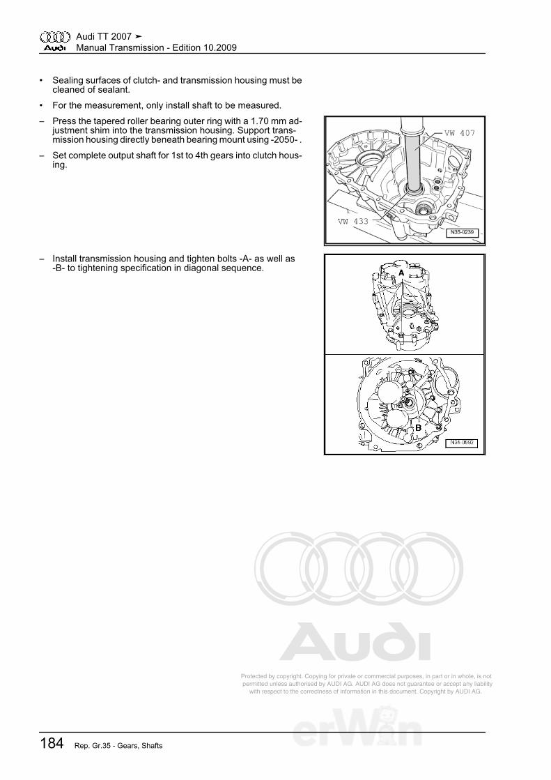
Protected by copyright. Copying for private or commercial purposes, in part or in whole, is not permitted unless authorised by AUDI AG. AUDI AG does not guarantee or accept any liability with respect to the correctness of information in this document. Copyright by AUDI AG.
• Sealing surfaces of clutch- and transmission housing must becleaned of sealant.
• For the measurement, only install shaft to be measured.– Press the tapered roller bearing outer ring with a 1.70 mm ad‐
justment shim into the transmission housing. Support trans‐mission housing directly beneath bearing mount using -2050- .
– Set complete output shaft for 1st to 4th gears into clutch hous‐ing.
– Install transmission housing and tighten bolts -A- as well as-B- to tightening specification in diagonal sequence.
Audi TT 2007 ➤Manual Transmission - Edition 10.2009
184 Rep. Gr.35 - Gears, Shafts
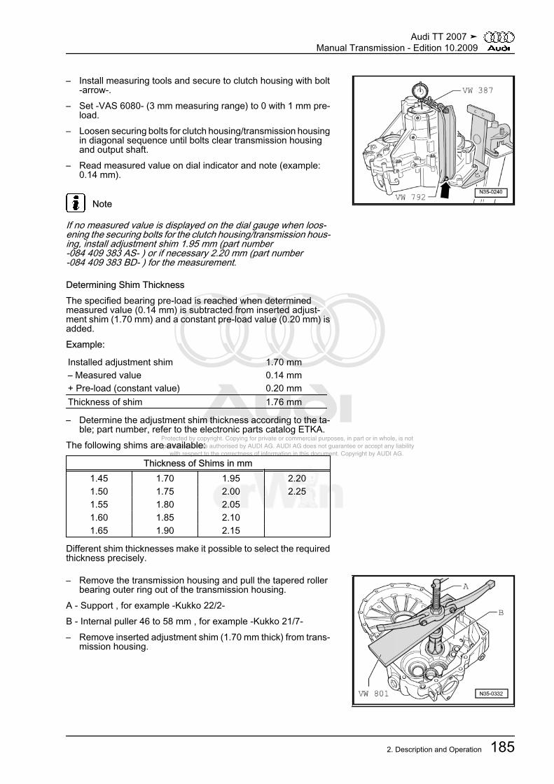
Protected by copyright. Copying for private or commercial purposes, in part or in whole, is not permitted unless authorised by AUDI AG. AUDI AG does not guarantee or accept any liability with respect to the correctness of information in this document. Copyright by AUDI AG.
– Install measuring tools and secure to clutch housing with bolt-arrow-.
– Set -VAS 6080- (3 mm measuring range) to 0 with 1 mm pre‐load.
– Loosen securing bolts for clutch housing/transmission housingin diagonal sequence until bolts clear transmission housingand output shaft.
– Read measured value on dial indicator and note (example:0.14 mm).
Note
If no measured value is displayed on the dial gauge when loos‐ening the securing bolts for the clutch housing/transmission hous‐ing, install adjustment shim 1.95 mm (part number-084 409 383 AS- ) or if necessary 2.20 mm (part number-084 409 383 BD- ) for the measurement.
Determining Shim ThicknessThe specified bearing pre-load is reached when determinedmeasured value (0.14 mm) is subtracted from inserted adjust‐ment shim (1.70 mm) and a constant pre-load value (0.20 mm) isadded.Example:
Installed adjustment shim 1.70 mm– Measured value 0.14 mm+ Pre-load (constant value) 0.20 mmThickness of shim 1.76 mm
– Determine the adjustment shim thickness according to the ta‐ble; part number, refer to the electronic parts catalog ETKA.
The following shims are available:
Thickness of Shims in mm1.45 1.70 1.95 2.201.50 1.75 2.00 2.251.55 1.80 2.05 1.60 1.85 2.10 1.65 1.90 2.15
Different shim thicknesses make it possible to select the requiredthickness precisely.
– Remove the transmission housing and pull the tapered rollerbearing outer ring out of the transmission housing.
A - Support , for example -Kukko 22/2-B - Internal puller 46 to 58 mm , for example -Kukko 21/7-– Remove inserted adjustment shim (1.70 mm thick) from trans‐
mission housing.
Audi TT 2007 ➤Manual Transmission - Edition 10.2009
2. Description and Operation 185
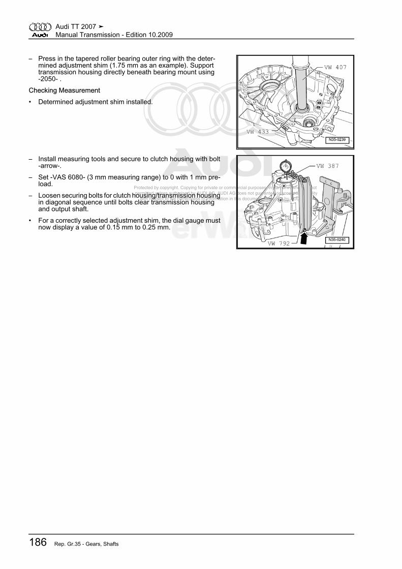
Protected by copyright. Copying for private or commercial purposes, in part or in whole, is not permitted unless authorised by AUDI AG. AUDI AG does not guarantee or accept any liability with respect to the correctness of information in this document. Copyright by AUDI AG.
– Press in the tapered roller bearing outer ring with the deter‐mined adjustment shim (1.75 mm as an example). Supporttransmission housing directly beneath bearing mount using-2050- .
Checking Measurement• Determined adjustment shim installed.
– Install measuring tools and secure to clutch housing with bolt-arrow-.
– Set -VAS 6080- (3 mm measuring range) to 0 with 1 mm pre‐load.
– Loosen securing bolts for clutch housing/transmission housingin diagonal sequence until bolts clear transmission housingand output shaft.
• For a correctly selected adjustment shim, the dial gauge mustnow display a value of 0.15 mm to 0.25 mm.
Audi TT 2007 ➤Manual Transmission - Edition 10.2009
186 Rep. Gr.35 - Gears, Shafts
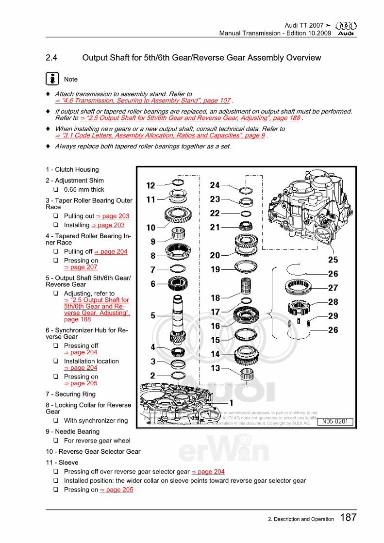
Protected by copyright. Copying for private or commercial purposes, in part or in whole, is not permitted unless authorised by AUDI AG. AUDI AG does not guarantee or accept any liability with respect to the correctness of information in this document. Copyright by AUDI AG.
2.4 Output Shaft for 5th/6th Gear/Reverse Gear Assembly Overview
Note
♦ Attach transmission to assembly stand. Refer to⇒ “4.6 Transmission, Securing to Assembly Stand”, page 107 .
♦ If output shaft or tapered roller bearings are replaced, an adjustment on output shaft must be performed.Refer to ⇒ “2.5 Output Shaft for 5th/6th Gear and Reverse Gear, Adjusting”, page 188 .
♦ When installing new gears or a new output shaft, consult technical data. Refer to⇒ “3.1 Code Letters, Assembly Allocation, Ratios and Capacities”, page 9 .
♦ Always replace both tapered roller bearings together as a set.
1 - Clutch Housing2 - Adjustment Shim
❑ 0.65 mm thick3 - Taper Roller Bearing OuterRace
❑ Pulling out ⇒ page 203❑ Installing ⇒ page 203
4 - Tapered Roller Bearing In‐ner Race
❑ Pulling off ⇒ page 204❑ Pressing on
⇒ page 2075 - Output Shaft 5th/6th Gear/Reverse Gear
❑ Adjusting, refer to⇒ “2.5 Output Shaft for5th/6th Gear and Re‐verse Gear, Adjusting”,page 188
6 - Synchronizer Hub for Re‐verse Gear
❑ Pressing off⇒ page 204
❑ Installation location⇒ page 204
❑ Pressing on⇒ page 205
7 - Securing Ring8 - Locking Collar for ReverseGear
❑ With synchronizer ring9 - Needle Bearing
❑ For reverse gear wheel10 - Reverse Gear Selector Gear11 - Sleeve
❑ Pressing off over reverse gear selector gear ⇒ page 204❑ Installed position: the wider collar on sleeve points toward reverse gear selector gear❑ Pressing on ⇒ page 205
Audi TT 2007 ➤Manual Transmission - Edition 10.2009
2. Description and Operation 187
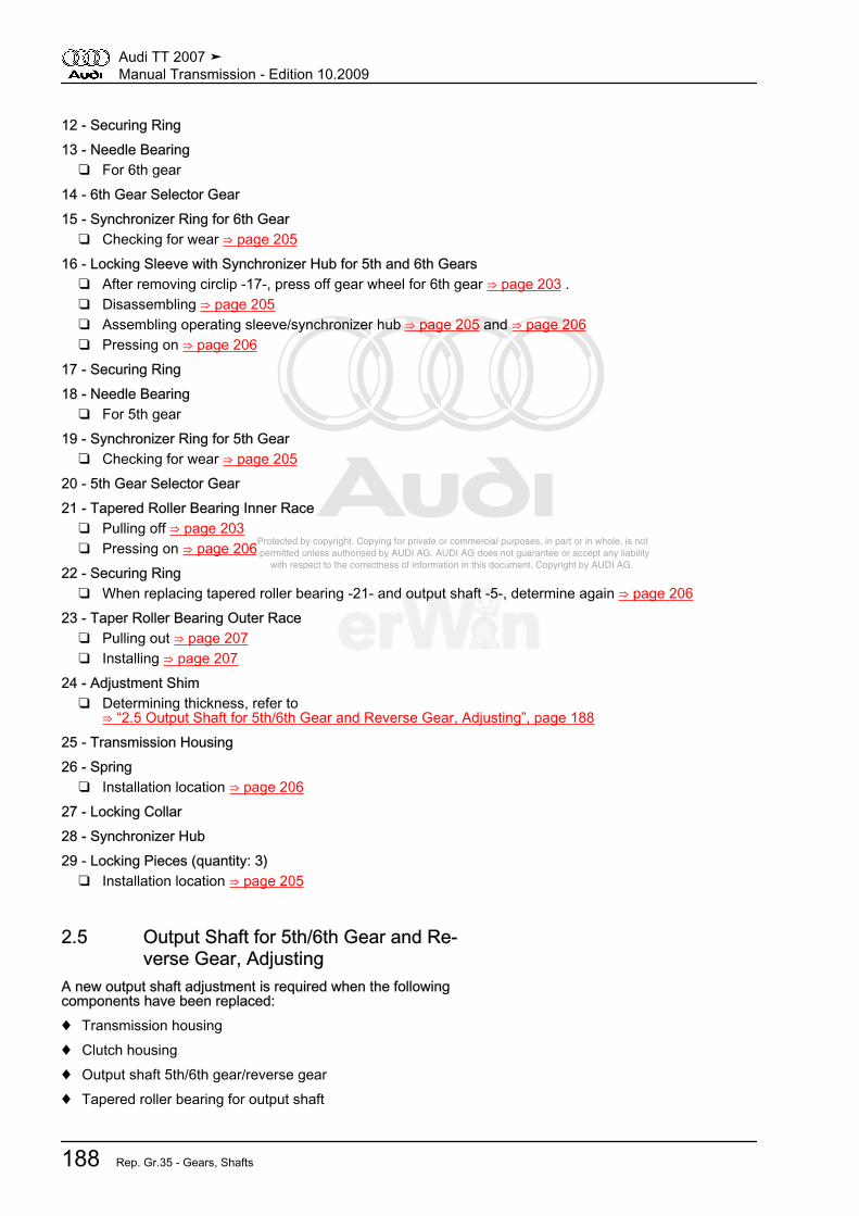
Protected by copyright. Copying for private or commercial purposes, in part or in whole, is not permitted unless authorised by AUDI AG. AUDI AG does not guarantee or accept any liability with respect to the correctness of information in this document. Copyright by AUDI AG.
12 - Securing Ring13 - Needle Bearing
❑ For 6th gear14 - 6th Gear Selector Gear15 - Synchronizer Ring for 6th Gear
❑ Checking for wear ⇒ page 20516 - Locking Sleeve with Synchronizer Hub for 5th and 6th Gears
❑ After removing circlip -17-, press off gear wheel for 6th gear ⇒ page 203 .❑ Disassembling ⇒ page 205❑ Assembling operating sleeve/synchronizer hub ⇒ page 205 and ⇒ page 206❑ Pressing on ⇒ page 206
17 - Securing Ring18 - Needle Bearing
❑ For 5th gear19 - Synchronizer Ring for 5th Gear
❑ Checking for wear ⇒ page 20520 - 5th Gear Selector Gear21 - Tapered Roller Bearing Inner Race
❑ Pulling off ⇒ page 203❑ Pressing on ⇒ page 206
22 - Securing Ring❑ When replacing tapered roller bearing -21- and output shaft -5-, determine again ⇒ page 206
23 - Taper Roller Bearing Outer Race❑ Pulling out ⇒ page 207❑ Installing ⇒ page 207
24 - Adjustment Shim❑ Determining thickness, refer to
⇒ “2.5 Output Shaft for 5th/6th Gear and Reverse Gear, Adjusting”, page 18825 - Transmission Housing26 - Spring
❑ Installation location ⇒ page 20627 - Locking Collar28 - Synchronizer Hub29 - Locking Pieces (quantity: 3)
❑ Installation location ⇒ page 205
2.5 Output Shaft for 5th/6th Gear and Re‐verse Gear, Adjusting
A new output shaft adjustment is required when the followingcomponents have been replaced:♦ Transmission housing♦ Clutch housing♦ Output shaft 5th/6th gear/reverse gear♦ Tapered roller bearing for output shaft
Audi TT 2007 ➤Manual Transmission - Edition 10.2009
188 Rep. Gr.35 - Gears, Shafts

Protected by copyright. Copying for private or commercial purposes, in part or in whole, is not permitted unless authorised by AUDI AG. AUDI AG does not guarantee or accept any liability with respect to the correctness of information in this document. Copyright by AUDI AG.
Adjustment overview, refer to⇒ “1.4 Adjustment Overview”, page 224Special tools and workshop equipment required♦ Dial Gauge Holder -VW 387-♦ Punch -VW 407-♦ Thrust Pad Con. 8/65 -VW 433-♦ Installation Arbor -VW 792-♦ Holding Fixture -VW 801-♦ Thrust Plate -2050-♦ Dial Gauge -VAS 6080-♦ Kukko 21/7 internal puller♦ Kukko 22/2 counter-supportAdjusting• Transmission removed, refer to
⇒ “4.4 Transmission, Removing”, page 96 and secured to theassembly stand⇒ “4.6 Transmission, Securing to Assembly Stand”,page 107 .
• Sealing surfaces of clutch- and transmission housing must becleaned of sealant.
• For the measurement, only install shaft to be measured.– Press the tapered roller bearing outer ring with a 1.70 mm ad‐
justment shim into the transmission housing. Support trans‐mission housing directly beneath bearing mount using -2050- .
– Set the complete output shaft for 5th/6th gear and reverse gearinto the clutch housing.
– Install transmission housing and tighten bolts -A- as well as-B- to tightening specification in diagonal sequence.
Audi TT 2007 ➤Manual Transmission - Edition 10.2009
2. Description and Operation 189

Protected by copyright. Copying for private or commercial purposes, in part or in whole, is not permitted unless authorised by AUDI AG. AUDI AG does not guarantee or accept any liability with respect to the correctness of information in this document. Copyright by AUDI AG.
– Install measuring tools. Insert washers with a total thicknessof 8 mm at securing bolt -arrow- for -VW 792- at clutch housing.
– Set -VAS 6080- (3 mm measuring range) to zero with 1 mmpreload.
– Loosen securing bolts for clutch housing/transmission housingin diagonal sequence until bolts clear transmission housingand output shaft.
– Read measured value on dial indicator and note (example:0.25 mm).
Note
If no measured value is displayed on the dial gauge when loos‐ening the securing bolts for the clutch housing/transmission hous‐ing, install adjustment shim 1.95 mm (part number-084 409 383 AS- ) or if necessary 2.20 mm (part number-084 409 383 BD- ) for the measurement.
Determining Shim ThicknessThe specified bearing pre-load is reached when determinedmeasured value (0.25 mm) is subtracted from inserted adjust‐ment shim (1.70 mm) and a constant pre-load value (0.20 mm) isadded.Example:
Installed adjustment shim 1.70 mm- Measured value 0.25 mm+ Pre-load (constant value) 0.20 mmThickness of shim 1.65 mm
– Determine the adjustment shim thickness according to the ta‐ble; part number , refer to the electronic parts catalog ETKA.
The following shims are available:
Thickness of Shims in mm1.50 1.70 1.90 2.101.55 1.75 1.95 2.151.60 1.80 2.00 2.201.65 1.85 2.05 2.25
Different shim thicknesses make it possible to select the requiredthickness precisely.
– Remove the transmission housing and pull the tapered rollerbearing outer ring out of the transmission housing.
A - Support , for example -Kukko 22/2-B - Internal puller 46...58 mm , for example -Kukko 21/7-– Remove inserted adjustment shim (1.70 mm thick) from trans‐
mission housing.
Audi TT 2007 ➤Manual Transmission - Edition 10.2009
190 Rep. Gr.35 - Gears, Shafts

Protected by copyright. Copying for private or commercial purposes, in part or in whole, is not permitted unless authorised by AUDI AG. AUDI AG does not guarantee or accept any liability with respect to the correctness of information in this document. Copyright by AUDI AG.
– Press in the tapered roller bearing outer ring with the deter‐mined adjustment shim (1.65 mm as an example). Supporttransmission housing directly beneath bearing mount using-2050- .
Checking Measurement• Determined adjustment shim installed.
– Install measuring tools. Insert washers with a total thicknessof 8 mm at securing bolt -arrow- for -VW 792- at clutch housing.
– Set dial gauge -VAS 6080- (3 mm measuring range) to zerowith 1 mm preload.
– Loosen securing bolts for clutch housing/transmission housingin diagonal sequence until bolts clear transmission housingand output shaft.
• For a correctly selected adjustment shim, the dial gauge mustnow display a value of 0.15 mm to 0.25 mm.
Audi TT 2007 ➤Manual Transmission - Edition 10.2009
2. Description and Operation 191
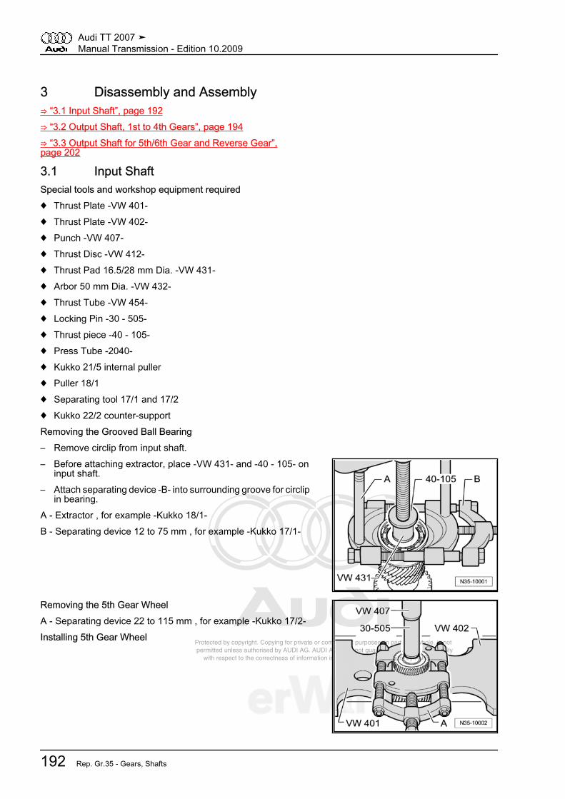
Protected by copyright. Copying for private or commercial purposes, in part or in whole, is not permitted unless authorised by AUDI AG. AUDI AG does not guarantee or accept any liability with respect to the correctness of information in this document. Copyright by AUDI AG.
3 Disassembly and Assembly⇒ “3.1 Input Shaft”, page 192⇒ “3.2 Output Shaft, 1st to 4th Gears”, page 194⇒ “3.3 Output Shaft for 5th/6th Gear and Reverse Gear”,page 202
3.1 Input ShaftSpecial tools and workshop equipment required♦ Thrust Plate -VW 401-♦ Thrust Plate -VW 402-♦ Punch -VW 407-♦ Thrust Disc -VW 412-♦ Thrust Pad 16.5/28 mm Dia. -VW 431-♦ Arbor 50 mm Dia. -VW 432-♦ Thrust Tube -VW 454-♦ Locking Pin -30 - 505-♦ Thrust piece -40 - 105-♦ Press Tube -2040-♦ Kukko 21/5 internal puller♦ Puller 18/1♦ Separating tool 17/1 and 17/2♦ Kukko 22/2 counter-supportRemoving the Grooved Ball Bearing– Remove circlip from input shaft.– Before attaching extractor, place -VW 431- and -40 - 105- on
input shaft.– Attach separating device -B- into surrounding groove for circlip
in bearing.A - Extractor , for example -Kukko 18/1-B - Separating device 12 to 75 mm , for example -Kukko 17/1-
Removing the 5th Gear WheelA - Separating device 22 to 115 mm , for example -Kukko 17/2-Installing 5th Gear Wheel
Audi TT 2007 ➤Manual Transmission - Edition 10.2009
192 Rep. Gr.35 - Gears, Shafts
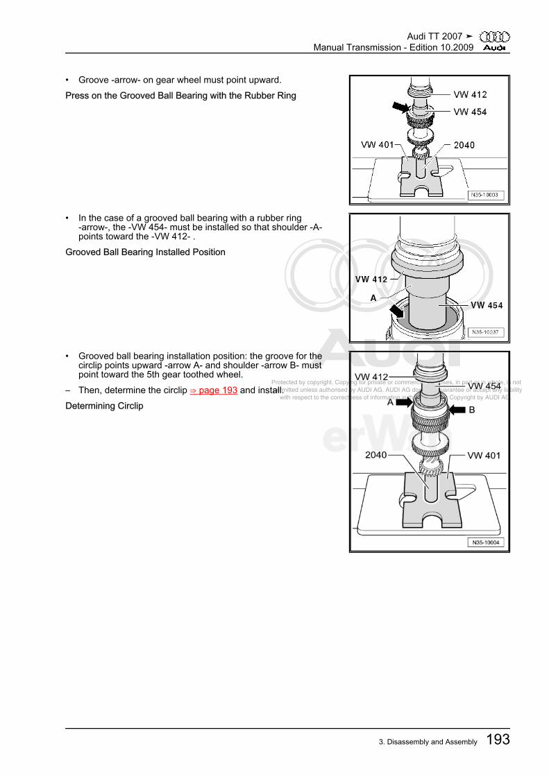
Protected by copyright. Copying for private or commercial purposes, in part or in whole, is not permitted unless authorised by AUDI AG. AUDI AG does not guarantee or accept any liability with respect to the correctness of information in this document. Copyright by AUDI AG.
• Groove -arrow- on gear wheel must point upward.Press on the Grooved Ball Bearing with the Rubber Ring
• In the case of a grooved ball bearing with a rubber ring-arrow-, the -VW 454- must be installed so that shoulder -A-points toward the -VW 412- .
Grooved Ball Bearing Installed Position
• Grooved ball bearing installation position: the groove for thecirclip points upward -arrow A- and shoulder -arrow B- mustpoint toward the 5th gear toothed wheel.
– Then, determine the circlip ⇒ page 193 and install.Determining Circlip
Audi TT 2007 ➤Manual Transmission - Edition 10.2009
3. Disassembly and Assembly 193

Protected by copyright. Copying for private or commercial purposes, in part or in whole, is not permitted unless authorised by AUDI AG. AUDI AG does not guarantee or accept any liability with respect to the correctness of information in this document. Copyright by AUDI AG.
– Insert a 1.86 mm thick circlip -A- into groove of input shaft andpress upward.
– Measure dimension between grooved ball bearing -B- and in‐stalled circlip -A- using a feeler gauge -C-.
– Remove circlip inserted for the measurement.– Determine the circlip according to the table, refer to the elec‐
tronic parts catalog ETKA.The following locking rings are available:
Measured Value(mm)
Locking Ring Thick‐ness (mm)
Axial Play (mm)
0.01 to 0.05 1.86 0.01 to 0.050.05 to 0.07 1.89 0.01 v 0.050.07 to 0.10 1.92 0.01 to 0.050.10 to 0.13 1.95 0.01 to 0.050.13 to 0.16 1.98 0.01 to 0.05
Pulling Cylindrical Roller Bearing off Clutch Housing
– When pulling circlip -arrow- off from roller bearing, compressit using pliers -C-.
A - Support , for example -Kukko 22/2-B - Internal puller 30 to 37 mm , for example -Kukko 21/5-Pressing Cylindrical Roller Bearing into Clutch Housing
– When pressing circlip -arrow- in for roller bearing, compress itusing pliers -A-.
– Remove the pliers before the roller bearing is installed posi‐tion.
• Circlip must engage into groove of clutch housing.
3.2 Output Shaft, 1st to 4th GearsSpecial tools and workshop equipment required♦ Thrust Plate -VW 401-♦ Thrust Plate -VW 402-♦ Punch -VW 407-♦ Punch -VW 408A-♦ THRUST Disc -VW 412-♦ Tube 60 mm Dia. -VW 415A-♦ Holding Plate -VW 309-
Audi TT 2007 ➤Manual Transmission - Edition 10.2009
194 Rep. Gr.35 - Gears, Shafts
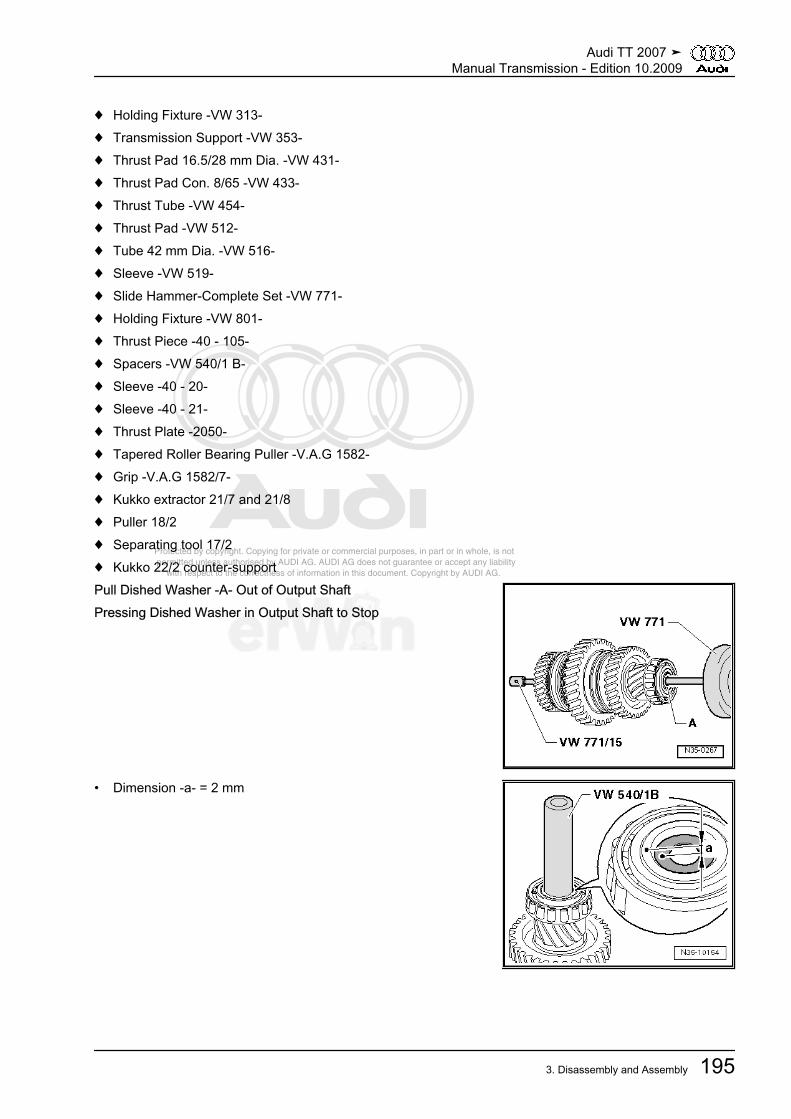
Protected by copyright. Copying for private or commercial purposes, in part or in whole, is not permitted unless authorised by AUDI AG. AUDI AG does not guarantee or accept any liability with respect to the correctness of information in this document. Copyright by AUDI AG.
♦ Holding Fixture -VW 313-♦ Transmission Support -VW 353-♦ Thrust Pad 16.5/28 mm Dia. -VW 431-♦ Thrust Pad Con. 8/65 -VW 433-♦ Thrust Tube -VW 454-♦ Thrust Pad -VW 512-♦ Tube 42 mm Dia. -VW 516-♦ Sleeve -VW 519-♦ Slide Hammer-Complete Set -VW 771-♦ Holding Fixture -VW 801-♦ Thrust Piece -40 - 105-♦ Spacers -VW 540/1 B-♦ Sleeve -40 - 20-♦ Sleeve -40 - 21-♦ Thrust Plate -2050-♦ Tapered Roller Bearing Puller -V.A.G 1582-♦ Grip -V.A.G 1582/7-♦ Kukko extractor 21/7 and 21/8♦ Puller 18/2♦ Separating tool 17/2♦ Kukko 22/2 counter-supportPull Dished Washer -A- Out of Output ShaftPressing Dished Washer in Output Shaft to Stop
• Dimension -a- = 2 mm
Audi TT 2007 ➤Manual Transmission - Edition 10.2009
3. Disassembly and Assembly 195
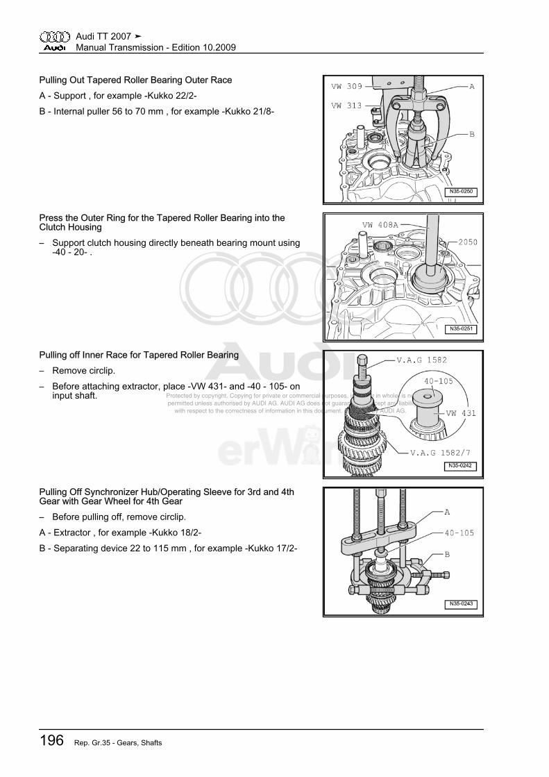
Protected by copyright. Copying for private or commercial purposes, in part or in whole, is not permitted unless authorised by AUDI AG. AUDI AG does not guarantee or accept any liability with respect to the correctness of information in this document. Copyright by AUDI AG.
Pulling Out Tapered Roller Bearing Outer RaceA - Support , for example -Kukko 22/2-B - Internal puller 56 to 70 mm , for example -Kukko 21/8-
Press the Outer Ring for the Tapered Roller Bearing into theClutch Housing– Support clutch housing directly beneath bearing mount using
-40 - 20- .
Pulling off Inner Race for Tapered Roller Bearing– Remove circlip.– Before attaching extractor, place -VW 431- and -40 - 105- on
input shaft.
Pulling Off Synchronizer Hub/Operating Sleeve for 3rd and 4thGear with Gear Wheel for 4th Gear– Before pulling off, remove circlip.A - Extractor , for example -Kukko 18/2-B - Separating device 22 to 115 mm , for example -Kukko 17/2-
Audi TT 2007 ➤Manual Transmission - Edition 10.2009
196 Rep. Gr.35 - Gears, Shafts

Protected by copyright. Copying for private or commercial purposes, in part or in whole, is not permitted unless authorised by AUDI AG. AUDI AG does not guarantee or accept any liability with respect to the correctness of information in this document. Copyright by AUDI AG.
Pressing Off Locking Collar and Synchronizer Hub for 1st and 2ndGears– Remove circlip.– Press off selector gear and locking collar/synchronizer hub all
together.
Pressing Off Inner Race for Tapered Roller BearingA - Separating device 22 to 115 mm , for example -Kukko 17/2-
Pressing on Tapered Roller Bearing Inner Race
Checking Inner Race for 1st gear, 2nd Gear and 3rd Gear forWear– Press inner race onto taper of gear wheel and measure gap
dimension -a- using a feeler gauge.
Gap Dimension-a -
Installed Dimension Wear Limit
1st, 2nd and 3rdgear
0.75 to 1.25 mm 0.3 mm
Audi TT 2007 ➤Manual Transmission - Edition 10.2009
3. Disassembly and Assembly 197

Protected by copyright. Copying for private or commercial purposes, in part or in whole, is not permitted unless authorised by AUDI AG. AUDI AG does not guarantee or accept any liability with respect to the correctness of information in this document. Copyright by AUDI AG.
Checking Synchronizer Rings for 1st, 2nd and 3rd Gears for Wear– Press synchronizer ring, outer race and inner race onto taper
of gear wheel and measure gap dimension -a- using a feelergauge.
Gap Dimension-a -
Installed Dimension Wear Limit
1st, 2nd and 3rdgear
1.2 to 1.8 mm 05 mm
Installed Position of Outer Race, Inner Race and SynchronizerRing, 2nd Gear– Place inner race -A- on the 2 gear wheel.• The bent tabs -arrow 1- face toward outer race -B-.– Install outer race -B-.• The tabs -arrows 2- engage in the gear wheel grooves
-arrows 3-.– Install synchronizer ring -C-.• The grooves -arrows 4- engage in the tabs -arrows 1- of the
inner race -A-.
Disassembling and Assembling Locking Collar and SynchronizerHub for 1st and 2nd Gears as well as 3rd and 4th Gears– Remove the springs to disassemble -1-.1 - Spring2 - Locking piece3 - Locking collar4 - Synchronizer hub– To assemble, slide locking collar over the synchronizer hub.• In 3rd and 4th gear, the wide collar on the synchronizer hub
and the locking collar face in one direction.• Installed position: the narrow recesses in the synchronizer hub
align with the recesses in the locking collar.
Audi TT 2007 ➤Manual Transmission - Edition 10.2009
198 Rep. Gr.35 - Gears, Shafts

Protected by copyright. Copying for private or commercial purposes, in part or in whole, is not permitted unless authorised by AUDI AG. AUDI AG does not guarantee or accept any liability with respect to the correctness of information in this document. Copyright by AUDI AG.
Assembling Locking Collar/Synchronizer Hub for 1st and 2ndGears as well as 3rd and 4th Gears• The locking collar is pushed over the synchronizer hub.– Insert locking pieces and install the springs 120° offset.• Spring must engage with angled end into hollow engaging
piece.
Installation Position of Locking Collar/Synchronizer Hub for 1stand 2nd Gear• The identification groove -arrow 1- and thin collar -arrow 2- of
synchronizer hub point to 1st gear.
Pressing on locking Collar/Synchronizer Hub for 1st and 2nd Gear– Then install circlip.
Installation Position of Outer Ring for 1st and 3rd Gear• Tabs -arrows- point to synchronizer hub/locking collar -A-.
Audi TT 2007 ➤Manual Transmission - Edition 10.2009
3. Disassembly and Assembly 199

Protected by copyright. Copying for private or commercial purposes, in part or in whole, is not permitted unless authorised by AUDI AG. AUDI AG does not guarantee or accept any liability with respect to the correctness of information in this document. Copyright by AUDI AG.
Installed Position of Synchronizer Ring -A- (inner ring for 1st and3rd gear)• Tabs -arrows 1- engage into cut-outs -arrows 2- of synchron‐
izer ring -B-.
Installation Position of Selector Gear for 1st and 3rd Gear• The higher collar -A- points to 2nd and 4th gear -B-. Recesses
in collar -arrows- engage into outer race tabs ⇒ page 199 .
Installation Position of Locking Collar/Synchronizer Hub for 3rdand 4th Gear• Wider collar of synchronizer hub -arrow- points to 3rd gear.
Pressing on Synchronizer Hub with Locking Collar for 3rd and 4thGears– Then install circlip.
Audi TT 2007 ➤Manual Transmission - Edition 10.2009
200 Rep. Gr.35 - Gears, Shafts
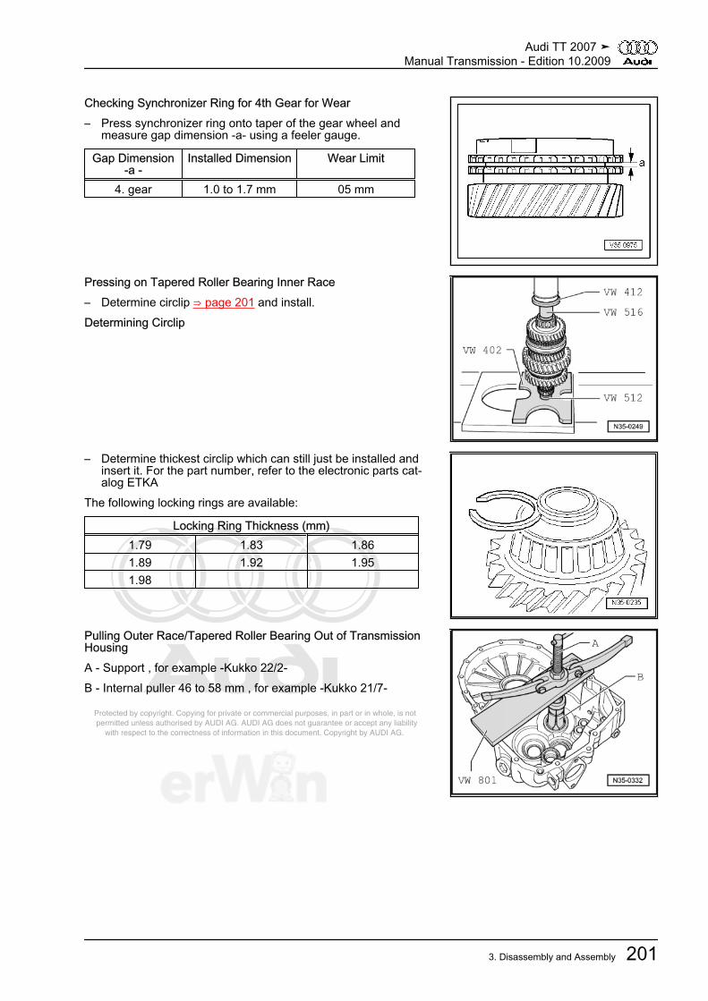
Protected by copyright. Copying for private or commercial purposes, in part or in whole, is not permitted unless authorised by AUDI AG. AUDI AG does not guarantee or accept any liability with respect to the correctness of information in this document. Copyright by AUDI AG.
Checking Synchronizer Ring for 4th Gear for Wear– Press synchronizer ring onto taper of the gear wheel and
measure gap dimension -a- using a feeler gauge.
Gap Dimension-a -
Installed Dimension Wear Limit
4. gear 1.0 to 1.7 mm 05 mm
Pressing on Tapered Roller Bearing Inner Race– Determine circlip ⇒ page 201 and install.Determining Circlip
– Determine thickest circlip which can still just be installed andinsert it. For the part number, refer to the electronic parts cat‐alog ETKA
The following locking rings are available:
Locking Ring Thickness (mm)1.79 1.83 1.861.89 1.92 1.951.98
Pulling Outer Race/Tapered Roller Bearing Out of TransmissionHousingA - Support , for example -Kukko 22/2-B - Internal puller 46 to 58 mm , for example -Kukko 21/7-
Audi TT 2007 ➤Manual Transmission - Edition 10.2009
3. Disassembly and Assembly 201
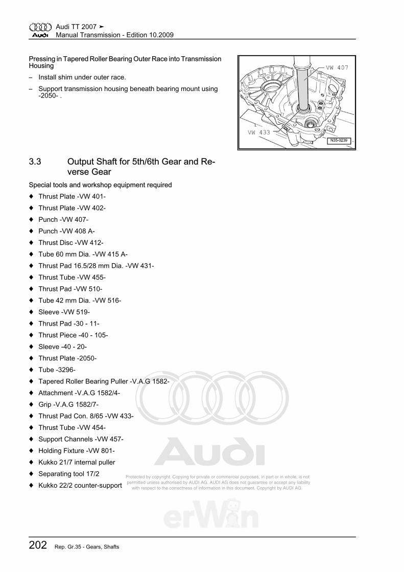
Protected by copyright. Copying for private or commercial purposes, in part or in whole, is not permitted unless authorised by AUDI AG. AUDI AG does not guarantee or accept any liability with respect to the correctness of information in this document. Copyright by AUDI AG.
Pressing in Tapered Roller Bearing Outer Race into TransmissionHousing– Install shim under outer race.– Support transmission housing beneath bearing mount using
-2050- .
3.3 Output Shaft for 5th/6th Gear and Re‐verse Gear
Special tools and workshop equipment required♦ Thrust Plate -VW 401-♦ Thrust Plate -VW 402-♦ Punch -VW 407-♦ Punch -VW 408 A-♦ Thrust Disc -VW 412-♦ Tube 60 mm Dia. -VW 415 A-♦ Thrust Pad 16.5/28 mm Dia. -VW 431-♦ Thrust Tube -VW 455-♦ Thrust Pad -VW 510-♦ Tube 42 mm Dia. -VW 516-♦ Sleeve -VW 519-♦ Thrust Pad -30 - 11-♦ Thrust Piece -40 - 105-♦ Sleeve -40 - 20-♦ Thrust Plate -2050-♦ Tube -3296-♦ Tapered Roller Bearing Puller -V.A.G 1582-♦ Attachment -V.A.G 1582/4-♦ Grip -V.A.G 1582/7-♦ Thrust Pad Con. 8/65 -VW 433-♦ Thrust Tube -VW 454-♦ Support Channels -VW 457-♦ Holding Fixture -VW 801-♦ Kukko 21/7 internal puller♦ Separating tool 17/2♦ Kukko 22/2 counter-support
Audi TT 2007 ➤Manual Transmission - Edition 10.2009
202 Rep. Gr.35 - Gears, Shafts

Protected by copyright. Copying for private or commercial purposes, in part or in whole, is not permitted unless authorised by AUDI AG. AUDI AG does not guarantee or accept any liability with respect to the correctness of information in this document. Copyright by AUDI AG.
Pulling Out Tapered Roller Bearing Outer RaceA - Support , for example -Kukko 22/2-B - Internal puller 46...58 mm , for example -Kukko 21/7-
Note
After pulling off, check the adjustment shim for damage and re‐place if necessary.
Press the Outer Ring for the Tapered Roller Bearing into theClutch Housing– Place the adjustment shim under the outer ring.– Support clutch housing directly beneath bearing mount using
-40 - 20- .
Pulling off Inner Race for Tapered Roller Bearing– Remove circlip.– Before attaching extractor, place -VW 431- and -40 - 105- on
output shaft.
Pressing Off Synchronizer Hub/Locking Collar for 5th and 6thGear with Selector Gear for 6th Gear– Before pressing off, remove circlip.
Audi TT 2007 ➤Manual Transmission - Edition 10.2009
3. Disassembly and Assembly 203

Protected by copyright. Copying for private or commercial purposes, in part or in whole, is not permitted unless authorised by AUDI AG. AUDI AG does not guarantee or accept any liability with respect to the correctness of information in this document. Copyright by AUDI AG.
Pressing Off Sleeve -A- over Reverse Gear Selector Gear– Before pressing off, remove circlip.
Pressing Off Synchronizer Hub for Reverse Gear– Before pressing off, remove circlip.A - Separating device 22 to 115 mm , for example -Kukko 17/2-
Pulling Off Inner Race for Tapered Roller Bearing– Before installing puller, set -30 - 11- onto output shaft.
Installation Position of Synchronizer Hub for Reverse Gear• Stop -arrow A- for reverse gear locking collar points toward
output shaft splines -arrow B-.
Audi TT 2007 ➤Manual Transmission - Edition 10.2009
204 Rep. Gr.35 - Gears, Shafts

Protected by copyright. Copying for private or commercial purposes, in part or in whole, is not permitted unless authorised by AUDI AG. AUDI AG does not guarantee or accept any liability with respect to the correctness of information in this document. Copyright by AUDI AG.
Pressing on Synchronizer Hub for Reverse Gear– Then install circlip.
Press on Sleeve -A-• Installed position: wide collar points toward reverse gear se‐
lector gear.– Then install circlip.
Checking Synchronizer Ring for 5th and 6th Gears for Wear– Press synchronizer ring onto taper of the gear wheel and
measure gap dimension -a- using a feeler gauge.
Gap Dimension-a -
Installed Dimension Wear Limit
5th and 6th gear 1.0 to 1.7 mm 05 mm
Disassembling and Assembling Locking Collar and SynchronizerHub for 5th and 6th Gears– Remove the springs to disassemble -1-.1 - Spring2 - Locking piece3 - Locking collar4 - Synchronizer hub– To assemble, slide locking collar over the synchronizer hub.• Installation position: The narrow locking piece recesses in the
synchronizer hub align with the recesses in the locking collar.
Audi TT 2007 ➤Manual Transmission - Edition 10.2009
3. Disassembly and Assembly 205

Protected by copyright. Copying for private or commercial purposes, in part or in whole, is not permitted unless authorised by AUDI AG. AUDI AG does not guarantee or accept any liability with respect to the correctness of information in this document. Copyright by AUDI AG.
Assembling Locking Collar/Synchronizer Hub for 5th and 6thGears• The locking collar is pushed over the synchronizer hub.– Insert locking pieces and install the springs 120° offset.• Spring must engage with angled end into hollow engaging
piece.
Pressing on Locking Collar/Synchronizer Hub for 5th and 6thGears– Then install circlip.
Pressing on Tapered Roller Bearing Inner Race– Then, determine the circlip ⇒ page 207 and install.
Determining Circlip– Determine the thickest circlip which can still just be installed
and insert it. For the part number, refer to the electronic partscatalog ETKA
The following locking rings are available:
Locking Ring Thickness (mm)1.79 1.83 1.861.89 1.92 1.951.98
Audi TT 2007 ➤Manual Transmission - Edition 10.2009
206 Rep. Gr.35 - Gears, Shafts

Protected by copyright. Copying for private or commercial purposes, in part or in whole, is not permitted unless authorised by AUDI AG. AUDI AG does not guarantee or accept any liability with respect to the correctness of information in this document. Copyright by AUDI AG.
Pressing on Tapered Roller Bearing Inner Race
Pulling Outer Race/Tapered Roller Bearing Out of TransmissionHousingA - Support , for example -Kukko 22/2-B - Internal puller 46...58 mm , for example -Kukko 21/7-
Pressing in Tapered Roller Bearing Outer Race into TransmissionHousing– Support the transmission housing with the -2050- under the
bearing mount.
Audi TT 2007 ➤Manual Transmission - Edition 10.2009
3. Disassembly and Assembly 207

Protected by copyright. Copying for private or commercial purposes, in part or in whole, is not permitted unless authorised by AUDI AG. AUDI AG does not guarantee or accept any liability with respect to the correctness of information in this document. Copyright by AUDI AG.
4 Special Tools
Special tools and workshopequipment required♦ Thrust Plate -VW 401-♦ Thrust Plate -VW 402-♦ Punch -VW 407-♦ Thrust Disc -VW 412-♦ Thrust Pad 16.5/28 mm
Dia. -VW 431-♦ Arbor 50 mm Dia. -VW 432-
Audi TT 2007 ➤Manual Transmission - Edition 10.2009
208 Rep. Gr.35 - Gears, Shafts
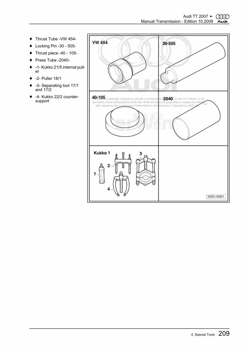
Protected by copyright. Copying for private or commercial purposes, in part or in whole, is not permitted unless authorised by AUDI AG. AUDI AG does not guarantee or accept any liability with respect to the correctness of information in this document. Copyright by AUDI AG.
♦ Thrust Tube -VW 454-♦ Locking Pin -30 - 505-♦ Thrust piece -40 - 105-♦ Press Tube -2040-♦ -1- Kukko 21/5 internal pull‐
er♦ -2- Puller 18/1♦ -3- Separating tool 17/1
and 17/2♦ -4- Kukko 22/2 counter-
support
Audi TT 2007 ➤Manual Transmission - Edition 10.2009
4. Special Tools 209

Protected by copyright. Copying for private or commercial purposes, in part or in whole, is not permitted unless authorised by AUDI AG. AUDI AG does not guarantee or accept any liability with respect to the correctness of information in this document. Copyright by AUDI AG.
Special tools and workshopequipment required♦ Dial Gauge Holder -VW
387-♦ Punch -VW 407-♦ Thrust Pad Con. 8/65 -VW
433-♦ Installation Arbor -VW 792-♦ Holding Fixture -VW 801-♦ Thrust Plate -2050-
Audi TT 2007 ➤Manual Transmission - Edition 10.2009
210 Rep. Gr.35 - Gears, Shafts

Protected by copyright. Copying for private or commercial purposes, in part or in whole, is not permitted unless authorised by AUDI AG. AUDI AG does not guarantee or accept any liability with respect to the correctness of information in this document. Copyright by AUDI AG.
♦ Grip -V.A.G 1582/7-♦ Thrust Pad Con. 8/65 -VW
433-♦ Thrust Tube -VW 454-♦ Support Channels -VW
457-♦ Holding Fixture -VW 801-♦ -1- Kukko 21/7 internal pull‐
er♦ -3- Separating tool 17/2♦ -4- Kukko 22/2 counter-
support
Audi TT 2007 ➤Manual Transmission - Edition 10.2009
4. Special Tools 211

Protected by copyright. Copying for private or commercial purposes, in part or in whole, is not permitted unless authorised by AUDI AG. AUDI AG does not guarantee or accept any liability with respect to the correctness of information in this document. Copyright by AUDI AG.
♦ Spacers -VW 540/1 B-♦ Sleeve -40 - 20-♦ Sleeve -40 - 21-♦ Thrust Plate -2050-♦ Tapered Roller Bearing
Puller -V.A.G 1582-♦ Grip -V.A.G 1582/7-
Audi TT 2007 ➤Manual Transmission - Edition 10.2009
212 Rep. Gr.35 - Gears, Shafts
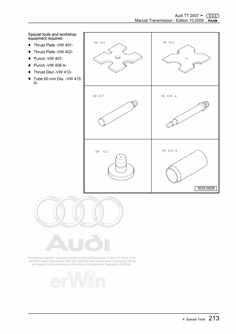
Protected by copyright. Copying for private or commercial purposes, in part or in whole, is not permitted unless authorised by AUDI AG. AUDI AG does not guarantee or accept any liability with respect to the correctness of information in this document. Copyright by AUDI AG.
Special tools and workshopequipment required♦ Thrust Plate -VW 401-♦ Thrust Plate -VW 402-♦ Punch -VW 407-♦ Punch -VW 408 A-♦ Thrust Disc -VW 412-♦ Tube 60 mm Dia. -VW 415
A-
Audi TT 2007 ➤Manual Transmission - Edition 10.2009
4. Special Tools 213
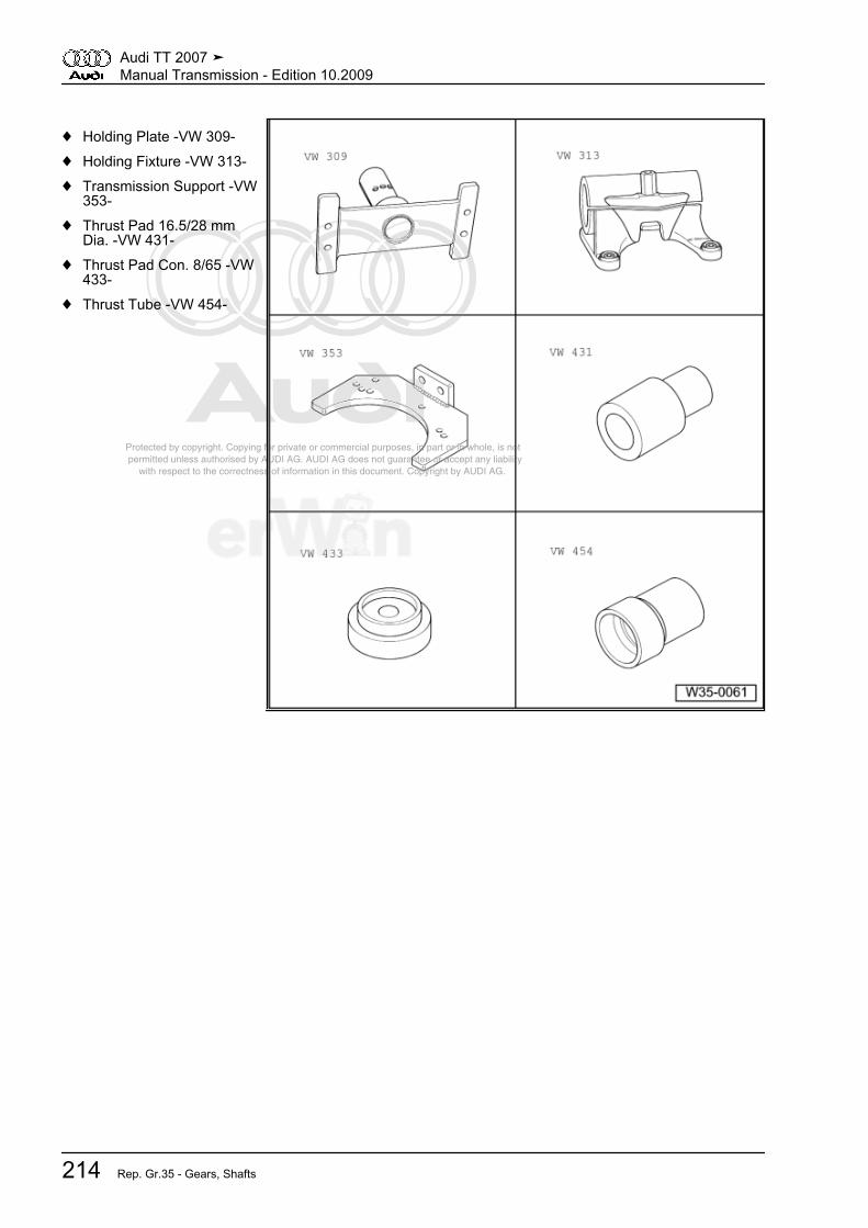
Protected by copyright. Copying for private or commercial purposes, in part or in whole, is not permitted unless authorised by AUDI AG. AUDI AG does not guarantee or accept any liability with respect to the correctness of information in this document. Copyright by AUDI AG.
♦ Holding Plate -VW 309-♦ Holding Fixture -VW 313-♦ Transmission Support -VW
353-♦ Thrust Pad 16.5/28 mm
Dia. -VW 431-♦ Thrust Pad Con. 8/65 -VW
433-♦ Thrust Tube -VW 454-
Audi TT 2007 ➤Manual Transmission - Edition 10.2009
214 Rep. Gr.35 - Gears, Shafts
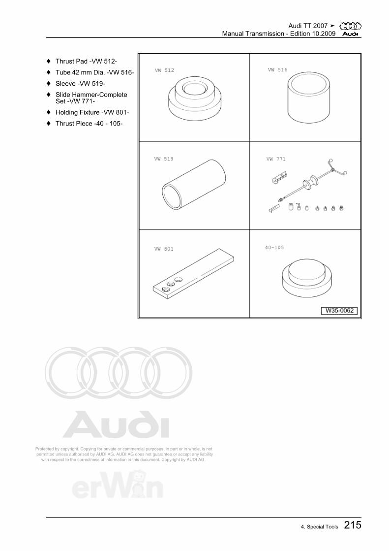
Protected by copyright. Copying for private or commercial purposes, in part or in whole, is not permitted unless authorised by AUDI AG. AUDI AG does not guarantee or accept any liability with respect to the correctness of information in this document. Copyright by AUDI AG.
♦ Thrust Pad -VW 512-♦ Tube 42 mm Dia. -VW 516-♦ Sleeve -VW 519-♦ Slide Hammer-Complete
Set -VW 771-♦ Holding Fixture -VW 801-♦ Thrust Piece -40 - 105-
Audi TT 2007 ➤Manual Transmission - Edition 10.2009
4. Special Tools 215

Protected by copyright. Copying for private or commercial purposes, in part or in whole, is not permitted unless authorised by AUDI AG. AUDI AG does not guarantee or accept any liability with respect to the correctness of information in this document. Copyright by AUDI AG.
♦ Thrust Pad 16.5/28 mmDia. -VW 431-
♦ Thrust Tube -VW 455-♦ Thrust Pad -VW 510-♦ Tube 42 mm Dia. -VW 516-♦ Sleeve -VW 519-♦ Thrust Pad -30 - 11-
Audi TT 2007 ➤Manual Transmission - Edition 10.2009
216 Rep. Gr.35 - Gears, Shafts

Protected by copyright. Copying for private or commercial purposes, in part or in whole, is not permitted unless authorised by AUDI AG. AUDI AG does not guarantee or accept any liability with respect to the correctness of information in this document. Copyright by AUDI AG.
♦ Thrust Piece -40 - 105-♦ Sleeve -40 - 20-♦ Thrust Plate -2050-♦ Tube -3296-♦ Tapered Roller Bearing
Puller -V.A.G 1582-♦ Attachment -V.A.G 1582/4-
Special tools and workshop equipment required♦ Dial gauge -VAS 6080-
Audi TT 2007 ➤Manual Transmission - Edition 10.2009
4. Special Tools 217
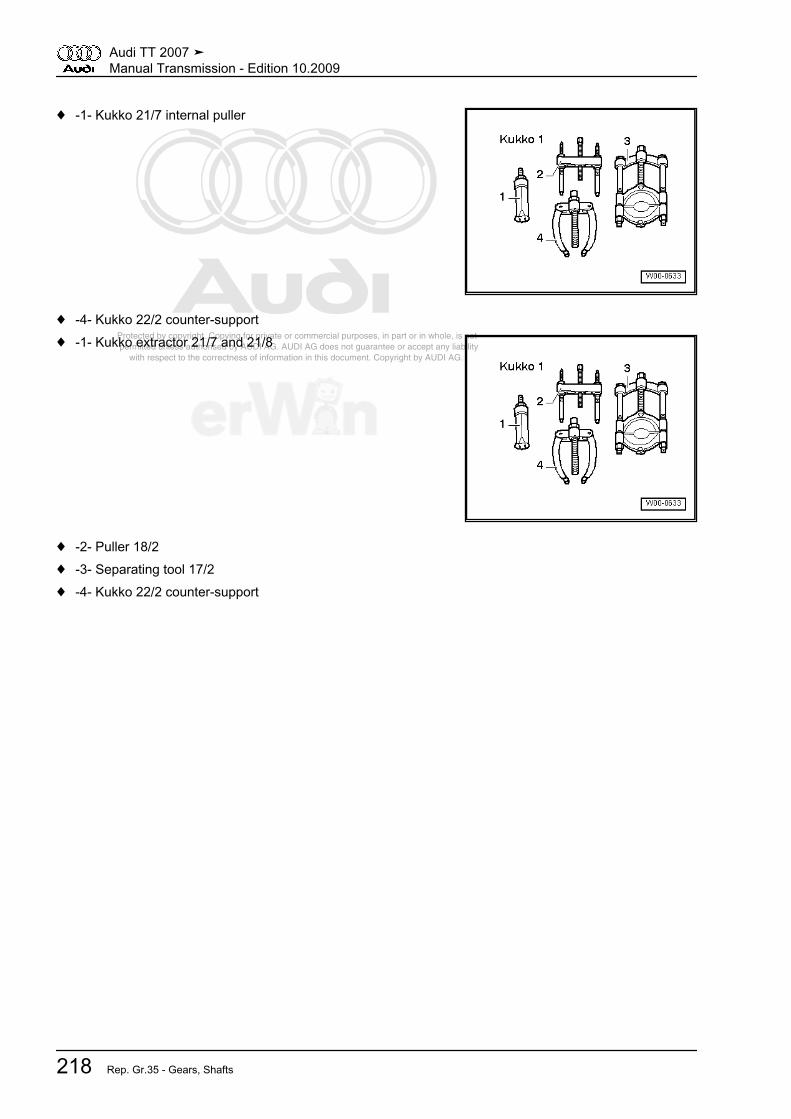
Protected by copyright. Copying for private or commercial purposes, in part or in whole, is not permitted unless authorised by AUDI AG. AUDI AG does not guarantee or accept any liability with respect to the correctness of information in this document. Copyright by AUDI AG.
♦ -1- Kukko 21/7 internal puller
♦ -4- Kukko 22/2 counter-support♦ -1- Kukko extractor 21/7 and 21/8
♦ -2- Puller 18/2♦ -3- Separating tool 17/2♦ -4- Kukko 22/2 counter-support
Audi TT 2007 ➤Manual Transmission - Edition 10.2009
218 Rep. Gr.35 - Gears, Shafts

Protected by copyright. Copying for private or commercial purposes, in part or in whole, is not permitted unless authorised by AUDI AG. AUDI AG does not guarantee or accept any liability with respect to the correctness of information in this document. Copyright by AUDI AG.
39 – Final Drive, Differential1 Description and Operation⇒ “1.1 Flange Shaft and Seals on Transmission Assembly Over‐view”, page 219⇒ “1.2 Flange Shaft and Seals on Bevel Box Assembly Overview”,page 220⇒ “1.3 Differential Assembly Overview”, page 222⇒ “1.4 Adjustment Overview”, page 224⇒ “1.5 Differential, Adjusting”, page 224
1.1 Flange Shaft and Seals on Transmission Assembly Overview
1 - Shaft Seal❑ Between the bevel box
and transmission❑ Replace with transmis‐
sion installed, refer to⇒ “3.3 Shaft SealingRing for Bevel Box withManual TransmissionInstalled, Replacing”,page 229
2 - Selector Shaft Seal❑ Replace, refer to
⇒ “4.14 Selector ShaftSeal”, page 124
3 - Transmission Shift Lever4 - Nut
❑ Tightening specification-8- ⇒ page 63
5 - Left Flange Shaft Seal❑ Replace, refer to
⇒ “3.2 Left Flange ShaftSeal”, page 228
6 - Flange Shaft, Left❑ Removing and instal‐
ling, refer to⇒ “3.1 Left FlangeShaft”, page 228
7 -Bolt
❑ Replace❑ 33 Nm
Audi TT 2007 ➤Manual Transmission - Edition 10.2009
1. Description and Operation 219

Protected by copyright. Copying for private or commercial purposes, in part or in whole, is not permitted unless authorised by AUDI AG. AUDI AG does not guarantee or accept any liability with respect to the correctness of information in this document. Copyright by AUDI AG.
1.2 Flange Shaft and Seals on Bevel Box Assembly Overview
1 - Nut❑ Replace❑ 480 Nm
2 - Bevel Box Output Flange3 - Output Flange Cover Cap
❑ Replace if damaged4 - Shaft Seal
❑ For output flange bevelbox
❑ Replace, refer to⇒ “3.8 Bevel Box DriveFlange Seal”,page 234
5 - Seal on Bevel Box❑ Between the bevel box
and transmission❑ Replace, refer to
⇒ “3.7 Seal betweenTransmission and BevelBox”, page 233
6 - Bevel Box❑ Removing and instal‐
ling, refer to⇒ “4.11 Bevel Box, Re‐moving”, page 118
7 - Drain Plug❑ 60 Nm❑ For the oil drain hole for
the bevel box8 - Shaft Seal
❑ For the right flange shafton the outside of thebevel box
❑ Replace, refer to ⇒ “3.5 Right Flange Shaft Seat on Outer Bevel Box, Replacing”, page 2319 - Drain Plug
❑ For bevel box oil filler hole❑ Tightening specification, refer to ⇒ “3.1 Bevel Box Oil Filler Bolt”, page 87
10 -Bolt
❑ Replace❑ 40 Nm plus an additional 45° turn❑ Quantity: 4❑ Bevel box to transmission
11 - Breather Pipe12 - Ventilation Cap13 -Bolt
❑ Replace❑ 33 Nm
Audi TT 2007 ➤Manual Transmission - Edition 10.2009
220 Rep. Gr.39 - Final Drive, Differential
Protected by copyright. Copying for private or commercial purposes, in part or in whole, is not permitted unless authorised by AUDI AG. AUDI AG does not guarantee or accept any liability with respect to the correctness of information in this document. Copyright by AUDI AG.
14 - Right Drive Flange❑ Removing and installing, refer to ⇒ “3.4 Right Flange Shaft”, page 230
15 - Oil Seal❑ Replace
16 - Needle Bearing (polygon bearing)❑ If the flange shaft is difficult to move when it is removed, this is not a fault❑ Acoustical test only when installed❑ Check for damage, for example for cracks on the out race❑ Replace, refer to ⇒ “3.6 Right Flange Shaft Needle Bearing”, page 232
17 - Needle Bearing (polygon bearing)❑ If the flange shaft is difficult to move when it is removed, this is not a fault❑ Acoustical test only when installed❑ Check for damage, for example for cracks on the out race❑ Replace, refer to ⇒ “3.6 Right Flange Shaft Needle Bearing”, page 232
18 - Securing Ring❑ Replace
Audi TT 2007 ➤Manual Transmission - Edition 10.2009
1. Description and Operation 221

Protected by copyright. Copying for private or commercial purposes, in part or in whole, is not permitted unless authorised by AUDI AG. AUDI AG does not guarantee or accept any liability with respect to the correctness of information in this document. Copyright by AUDI AG.
1.3 Differential Assembly Overview
Note
♦ Attach transmission to assembly stand. Refer to⇒ “4.6 Transmission, Securing to Assembly Stand”, page 107 .
♦ Heat inner race of tapered roller bearing to 100 °C (212 °F) before installing.♦ Always replace both tapered roller bearings together as a set.♦ Adjust differential, refer to ⇒ “1.5 Differential, Adjusting”, page 224 when replacing tapered roller bearing,
differential housing, transmission housing or clutch housing.
1 - Transmission Housing2 - Adjustment Shim
❑ For the differential❑ Determining thickness,
refer to⇒ “1.5 Differential, Ad‐justing”, page 224
3 - Taper Roller Bearing OuterRace
❑ Pulling out ⇒ page 240❑ Installing ⇒ page 240
4 - Tapered Roller Bearing In‐ner Race
❑ Pulling off ⇒ page 239❑ Pressing on
⇒ page 2395 - Differential Housing
❑ With riveted final drivegear
6 - Tapered Roller Bearing In‐ner Race
❑ Pulling off ⇒ page 239❑ Pressing on
⇒ page 2397 - Taper Roller Bearing OuterRace
❑ Pulling out ⇒ page 238❑ Installing ⇒ page 238
8 - Adjustment Shim❑ 0.65 mm thick❑ Installed position: the
shoulder on the inner diameter faces the bevel box -14-9 - Clutch Housing10 - Shaft Seal
❑ For right flange shaft❑ Replace with transmission installed, refer to
⇒ “3.5 Right Flange Shaft Seat on Outer Bevel Box, Replacing”, page 23111 - Bolt
❑ Replace
Audi TT 2007 ➤Manual Transmission - Edition 10.2009
222 Rep. Gr.39 - Final Drive, Differential

Protected by copyright. Copying for private or commercial purposes, in part or in whole, is not permitted unless authorised by AUDI AG. AUDI AG does not guarantee or accept any liability with respect to the correctness of information in this document. Copyright by AUDI AG.
❑ 40 Nm12 - Bolt
❑ Screw together with threaded piece -19- ⇒ page 223❑ Tightening specification -13- ⇒ page 220
13 - Right Drive Flange❑ Removing and installing, refer to ⇒ “3.4 Right Flange Shaft”, page 230
14 - Bevel Box❑ Removing and installing with transmission installed, refer to ⇒ “4.11 Bevel Box, Removing”, page 118❑ Removing and installing with transmission removed, refer to
⇒ “5.2 Transmission without Circlip A for Cap/Input Shaft”, page 13115 - Large Differential Bevel Gear
❑ Installing ⇒ page 24016 - Differential Taper Axle
❑ Removing ⇒ page 240❑ Installing ⇒ page 240
17 - Spring Pin❑ For securing the axle for the differential bevel gear❑ Removing ⇒ page 240❑ Drive new roll pin in flush ⇒ page 241
18 - Small Differential Bevel Gear❑ Removing and installing ⇒ page 240
19 -Threaded Piece
❑ Installing ⇒ page 24020 - Thrust Washer Union
❑ Install coated with gear oil21 - Securing Ring
❑ Holds tapered ring, thrust washer and compression spring in position with flanged shaft removed22 - Tapered Ring
❑ With grooves to engage thrust washer❑ Installed position: ball toward the differential housing
23 - Thrust Washer❑ Installed position: collar towards spring, tab toward tapered ring
24 - Left Flange Shaft Spring❑ installed behind left flange shaft
25 - Flange Shaft, Left❑ Removing and installing, refer to ⇒ “3.1 Left Flange Shaft”, page 228
26 - Shaft Seal❑ For left flange shaft❑ Replace with transmission installed, refer to ⇒ “3.2 Left Flange Shaft Seal”, page 228
Audi TT 2007 ➤Manual Transmission - Edition 10.2009
1. Description and Operation 223

Protected by copyright. Copying for private or commercial purposes, in part or in whole, is not permitted unless authorised by AUDI AG. AUDI AG does not guarantee or accept any liability with respect to the correctness of information in this document. Copyright by AUDI AG.
1.4 Adjustment Overview
Note
When performing repairs on the transmission, readjustment of theoutput shaft for 1st to 4th gears, output shaft for 5th/6th gear andreverse gear or differential is only required if components, whichhave a direct influence on transmission adjustment, have beenreplaced. Refer to the following table to avoid unnecessary ad‐justments:
Parts Replaced: To be Adjusted: Output shaft 1st to
4th gears⇒ “2.3 Output
Shaft, 1st to 4thGears, Adjusting”,
page 183
Output shaft for5th/6th gear and
reverse gear⇒ “2.5 Output
Shaft for 5th/6thGear and ReverseGear, Adjusting”,
page 188
Differential⇒ “1.5 Differential,
Adjusting”,page 224
Transmission housing x x xClutch housing x x xOutput Shaft, 1st to 4th Gears x Output Shaft, 5th, 6th and Reverse Gears x Differential housing xTapered roller bearing for output shaft for 1st to4th gears
x
Tapered roller bearing for output shaft for 5th/6thand reverse gears
x
Differential tapered roller bearing x
1.5 Differential, AdjustingA new differential adjustment is required when the following com‐ponents have been replaced:♦ Transmission housing♦ Clutch housing♦ Differential housing♦ Differential tapered roller bearingList of adjustments, refer to⇒ “1.4 Adjustment Overview”, page 224 .Special tools and workshop equipment required♦ Transmission Support -VW 353-♦ Magnetic Plate 50 mm Dia. -VW 385/17-♦ Dial Gauge Holder -VW 387-♦ Thrust Plate -VW 402-♦ Punch -VW 408 A-♦ Oil Pump Align Plate -3005-♦ Tube -3259-♦ Press Tool -3345-
Audi TT 2007 ➤Manual Transmission - Edition 10.2009
224 Rep. Gr.39 - Final Drive, Differential
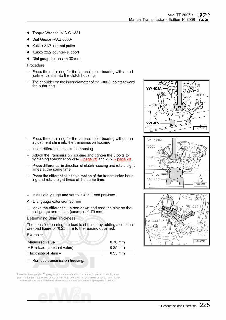
Protected by copyright. Copying for private or commercial purposes, in part or in whole, is not permitted unless authorised by AUDI AG. AUDI AG does not guarantee or accept any liability with respect to the correctness of information in this document. Copyright by AUDI AG.
♦ Torque Wrench -V.A.G 1331-♦ Dial Gauge -VAS 6080-♦ Kukko 21/7 internal puller♦ Kukko 22/2 counter-support♦ Dial gauge extension 30 mmProcedure– Press the outer ring for the tapered roller bearing with an ad‐
justment shim into the clutch housing.• The shoulder on the inner diameter of the -3005- points toward
the outer ring.
– Press the outer ring for the tapered roller bearing without anadjustment shim into the transmission housing.
– Insert differential into clutch housing.– Attach the transmission housing and tighten the 5 bolts to
tightening specification -11- ⇒ page 78 and -12- ⇒ page 78 .– Press differential in direction of clutch housing and rotate eight
times at the same time.– Press the differential in the direction of the transmission hous‐
ing and rotate eight times at the same time.
– Install dial gauge and set to 0 with 1 mm pre-load.A - Dial gauge extension 30 mm– Move the differential up and down and read the play on the
dial gauge and note it (example: 0.70 mm).Determining Shim ThicknessThe specified bearing pre-load is obtained by adding a constantpre-load figure of (0.25 mm) to the reading obtained.Example:
Measured value 0.70 mm+ Pre-load (constant value) 0.25 mmThickness of shim = 0.95 mm
– Remove transmission housing.
Audi TT 2007 ➤Manual Transmission - Edition 10.2009
1. Description and Operation 225
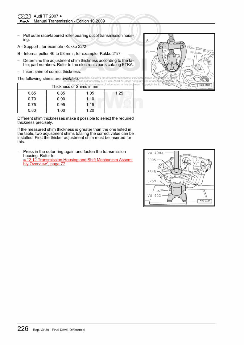
Protected by copyright. Copying for private or commercial purposes, in part or in whole, is not permitted unless authorised by AUDI AG. AUDI AG does not guarantee or accept any liability with respect to the correctness of information in this document. Copyright by AUDI AG.
– Pull outer race/tapered roller bearing out of transmission hous‐ing.
A - Support , for example -Kukko 22/2-B - Internal puller 46 to 58 mm , for example -Kukko 21/7-– Determine the adjustment shim thickness according to the ta‐
ble; part numbers. Refer to the electronic parts catalog ETKA.– Insert shim of correct thickness.The following shims are available:
Thickness of Shims in mm0.65 0.85 1.05 1.250.70 0.90 1.10 0.75 0.95 1.15 0.80 1.00 1.20
Different shim thicknesses make it possible to select the requiredthickness precisely.If the measured shim thickness is greater than the one listed inthe table, two adjustment shims totaling the correct value can beinstalled. First the thicker adjustment shim must be inserted forthis.
– Press in the outer ring again and fasten the transmissionhousing. Refer to⇒ “2.12 Transmission Housing and Shift Mechanism Assem‐bly Overview”, page 77 .
Audi TT 2007 ➤Manual Transmission - Edition 10.2009
226 Rep. Gr.39 - Final Drive, Differential
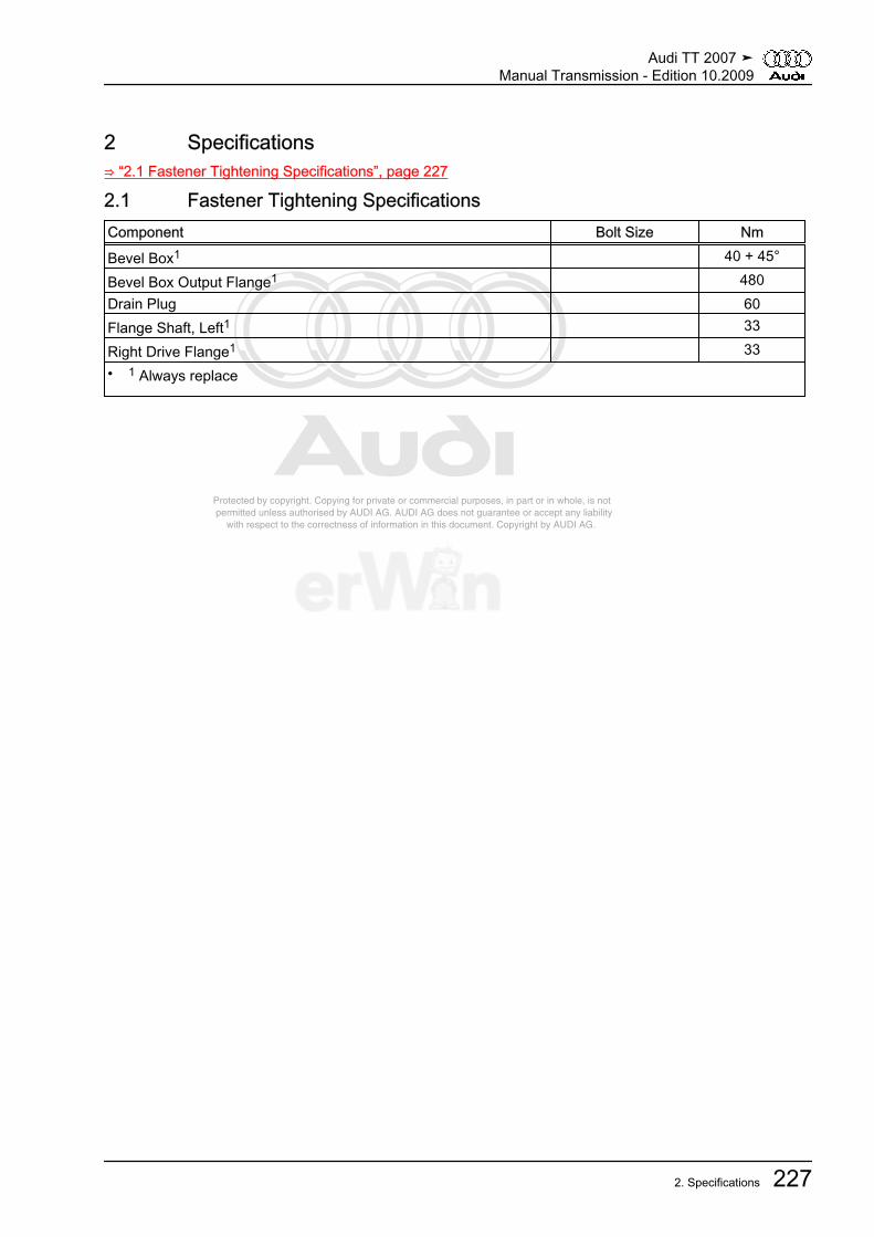
Protected by copyright. Copying for private or commercial purposes, in part or in whole, is not permitted unless authorised by AUDI AG. AUDI AG does not guarantee or accept any liability with respect to the correctness of information in this document. Copyright by AUDI AG.
2 Specifications⇒ “2.1 Fastener Tightening Specifications”, page 227
2.1 Fastener Tightening SpecificationsComponent Bolt Size Nm
Bevel Box1 40 + 45°
Bevel Box Output Flange1 480Drain Plug 60Flange Shaft, Left1 33
Right Drive Flange1 33• 1 Always replace
Audi TT 2007 ➤Manual Transmission - Edition 10.2009
2. Specifications 227

Protected by copyright. Copying for private or commercial purposes, in part or in whole, is not permitted unless authorised by AUDI AG. AUDI AG does not guarantee or accept any liability with respect to the correctness of information in this document. Copyright by AUDI AG.
3 Removal and Installation⇒ “3.1 Left Flange Shaft”, page 228⇒ “3.2 Left Flange Shaft Seal”, page 228⇒ “3.3 Shaft Sealing Ring for Bevel Box with Manual TransmissionInstalled, Replacing”, page 229⇒ “3.4 Right Flange Shaft”, page 230⇒ “3.5 Right Flange Shaft Seat on Outer Bevel Box, Replacing”,page 231⇒ “3.6 Right Flange Shaft Needle Bearing”, page 232⇒ “3.7 Seal between Transmission and Bevel Box”, page 233⇒ “3.8 Bevel Box Drive Flange Seal”, page 234
3.1 Left Flange ShaftSpecial tools and workshop equipment required♦ Oil Collecting and Extracting Device -V.A.G 1782-Removing– Remove left drive axle. Refer to ⇒ Suspension, Wheels,
Steering; Rep. Gr. 40 ; Removal and Installation .– Place -V.A.G 1782- under transmission.– Remove the left flange shaft bolt by installing 2 bolts in the
flange and counter holding the flange shaft with the assemblylever.
– Pull out flange shaft with spring.Installing• Tightening specification, refer to
⇒ “1.1 Flange Shaft and Seals on Transmission AssemblyOverview”, page 219 .
Install in reverse order, paying attention to the following:– Press flange shaft against spring force and tighten.– Install left drive axle. Refer to ⇒ Suspension, Wheels, Steer‐
ing; Rep. Gr. 40 ; Removal and Installation .– Check the transmission oil level in the manual transmission
and fill. Refer to⇒ “1.1 Manual Transmission, Checking Gear Oil Level”, page47 .
3.2 Left Flange Shaft SealSpecial tools and workshop equipment required♦ Thrust Piece -3305-♦ Pulling Hook -T20143/2-♦ Sealing grease -G 052 128 A1-Procedure• Transmission installed.– Remove left drive flange. Refer to
⇒ “3.1 Left Flange Shaft”, page 228 .
Audi TT 2007 ➤Manual Transmission - Edition 10.2009
228 Rep. Gr.39 - Final Drive, Differential

Protected by copyright. Copying for private or commercial purposes, in part or in whole, is not permitted unless authorised by AUDI AG. AUDI AG does not guarantee or accept any liability with respect to the correctness of information in this document. Copyright by AUDI AG.
– Pull out flange shaft seal using -T20143/2- .
– Lightly oil outer circumference of new shaft seal.– Drive in new shaft seal as far as stop without tilting it.
– Fill area between sealing lip and dust lip -arrow- halfway withsealing grease -G 052 128 A1- .
– Install left flange shaft. Refer to⇒ “3.1 Left Flange Shaft”, page 228 .
– Check the transmission oil level in the manual transmissionand fill. Refer to⇒ “1.1 Manual Transmission, Checking Gear Oil Level”, page47 .
3.3 Shaft Sealing Ring for Bevel Box withManual Transmission Installed, Replac‐ing
Special tools and workshop equipment required♦ Oil Collecting and Extracting Device -V.A.G 1782-♦ Pulling Hook -T20143/2-♦ Thrust Piece -T10243-Procedure• The bevel box is removed. Refer to
⇒ “4.11 Bevel Box, Removing”, page 118 .– Place drip tray -VAS 6208- underneath.– Pry the bevel box shaft sealing ring off with the -T20143/2- or
extractor lever -VW 681- .
Audi TT 2007 ➤Manual Transmission - Edition 10.2009
3. Removal and Installation 229
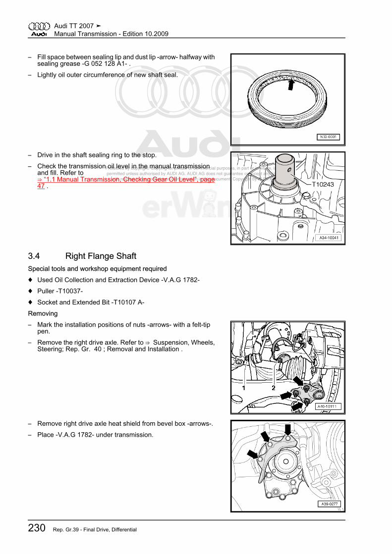
Protected by copyright. Copying for private or commercial purposes, in part or in whole, is not permitted unless authorised by AUDI AG. AUDI AG does not guarantee or accept any liability with respect to the correctness of information in this document. Copyright by AUDI AG.
– Fill space between sealing lip and dust lip -arrow- halfway withsealing grease -G 052 128 A1- .
– Lightly oil outer circumference of new shaft seal.
– Drive in the shaft sealing ring to the stop.– Check the transmission oil level in the manual transmission
and fill. Refer to⇒ “1.1 Manual Transmission, Checking Gear Oil Level”, page47 .
3.4 Right Flange ShaftSpecial tools and workshop equipment required♦ Used Oil Collection and Extraction Device -V.A.G 1782-♦ Puller -T10037-♦ Socket and Extended Bit -T10107 A-Removing– Mark the installation positions of nuts -arrows- with a felt-tip
pen.– Remove the right drive axle. Refer to ⇒ Suspension, Wheels,
Steering; Rep. Gr. 40 ; Removal and Installation .
– Remove right drive axle heat shield from bevel box -arrows-.– Place -V.A.G 1782- under transmission.
Audi TT 2007 ➤Manual Transmission - Edition 10.2009
230 Rep. Gr.39 - Final Drive, Differential

Protected by copyright. Copying for private or commercial purposes, in part or in whole, is not permitted unless authorised by AUDI AG. AUDI AG does not guarantee or accept any liability with respect to the correctness of information in this document. Copyright by AUDI AG.
– Remove right flange shaft bolt -arrow 1- with the -T10107 A-by installing 2 bolts in the flange and counter holding the flangeshaft with the assembly lever.
– Install -T10037- on right flange shaft.– Align -T10037- with knurled nut -T10037- and lower support
-A- parallel to flange.– Pull out flange shaft.Installing• Tightening specification, refer to
⇒ “1.2 Flange Shaft and Seals on Bevel Box Assembly Over‐view”, page 220 .
Install in reverse order, paying attention to the following:– Carefully install the flange shaft, while rotating it at the same
time.– Install flange shaft.– Install the right drive axle heat shield ⇒ page 113 .– Install right drive axle. Refer to ⇒ Suspension, Wheels, Steer‐
ing; Rep. Gr. 40 ; Removal and Installation .– Check the transmission oil level in the manual transmission
and fill. Refer to⇒ “1.1 Manual Transmission, Checking Gear Oil Level”, page47 .
3.5 Right Flange Shaft Seat on Outer BevelBox, Replacing
Special tools and workshop equipment required♦ Thrust Piece -T10049-Procedure• Transmission installed.– Remove right flange shaft. Refer to
⇒ “3.4 Right Flange Shaft”, page 230 .– Pry out the shaft sealing ring for the flange shaft with an as‐
sembly lever.– Lightly oil outer circumference of new shaft seal.
Audi TT 2007 ➤Manual Transmission - Edition 10.2009
3. Removal and Installation 231
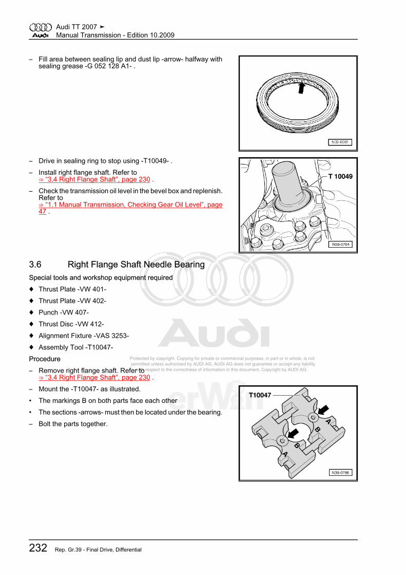
Protected by copyright. Copying for private or commercial purposes, in part or in whole, is not permitted unless authorised by AUDI AG. AUDI AG does not guarantee or accept any liability with respect to the correctness of information in this document. Copyright by AUDI AG.
– Fill area between sealing lip and dust lip -arrow- halfway withsealing grease -G 052 128 A1- .
– Drive in sealing ring to stop using -T10049- .– Install right flange shaft. Refer to
⇒ “3.4 Right Flange Shaft”, page 230 .– Check the transmission oil level in the bevel box and replenish.
Refer to⇒ “1.1 Manual Transmission, Checking Gear Oil Level”, page47 .
3.6 Right Flange Shaft Needle BearingSpecial tools and workshop equipment required♦ Thrust Plate -VW 401-♦ Thrust Plate -VW 402-♦ Punch -VW 407-♦ Thrust Disc -VW 412-♦ Alignment Fixture -VAS 3253-♦ Assembly Tool -T10047-Procedure– Remove right flange shaft. Refer to
⇒ “3.4 Right Flange Shaft”, page 230 .– Mount the -T10047- as illustrated.• The markings B on both parts face each other• The sections -arrows- must then be located under the bearing.– Bolt the parts together.
Audi TT 2007 ➤Manual Transmission - Edition 10.2009
232 Rep. Gr.39 - Final Drive, Differential
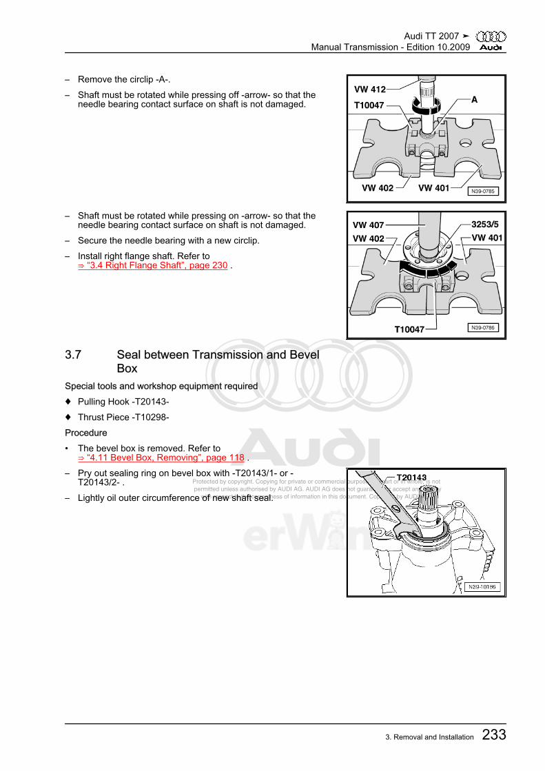
Protected by copyright. Copying for private or commercial purposes, in part or in whole, is not permitted unless authorised by AUDI AG. AUDI AG does not guarantee or accept any liability with respect to the correctness of information in this document. Copyright by AUDI AG.
– Remove the circlip -A-.– Shaft must be rotated while pressing off -arrow- so that the
needle bearing contact surface on shaft is not damaged.
– Shaft must be rotated while pressing on -arrow- so that theneedle bearing contact surface on shaft is not damaged.
– Secure the needle bearing with a new circlip.– Install right flange shaft. Refer to
⇒ “3.4 Right Flange Shaft”, page 230 .
3.7 Seal between Transmission and BevelBox
Special tools and workshop equipment required♦ Pulling Hook -T20143-♦ Thrust Piece -T10298-Procedure• The bevel box is removed. Refer to
⇒ “4.11 Bevel Box, Removing”, page 118 .– Pry out sealing ring on bevel box with -T20143/1- or -
T20143/2- .– Lightly oil outer circumference of new shaft seal.
Audi TT 2007 ➤Manual Transmission - Edition 10.2009
3. Removal and Installation 233
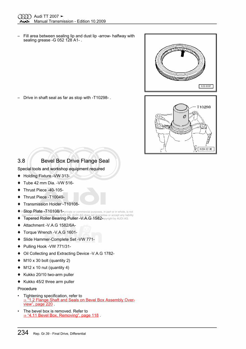
Protected by copyright. Copying for private or commercial purposes, in part or in whole, is not permitted unless authorised by AUDI AG. AUDI AG does not guarantee or accept any liability with respect to the correctness of information in this document. Copyright by AUDI AG.
– Fill area between sealing lip and dust lip -arrow- halfway withsealing grease -G 052 128 A1- .
– Drive in shaft seal as far as stop with -T10298- .
3.8 Bevel Box Drive Flange SealSpecial tools and workshop equipment required♦ Holding Fixture -VW 313-♦ Tube 42 mm Dia. -VW 516-♦ Thrust Piece -40-105-♦ Thrust Piece -T10049-♦ Transmission Holder -T10108-♦ Stop Plate -T10108/1-♦ Tapered Roller Bearing Puller -V.A.G 1582-♦ Attachment -V.A.G 1582/6A-♦ Torque Wrench -V.A.G 1601-♦ Slide Hammer-Complete Set -VW 771-♦ Pulling Hook -VW 771/31-♦ Oil Collecting and Extracting Device -V.A.G 1782-♦ M10 x 30 bolt (quantity 2)♦ M12 x 10 nut (quantity 4)♦ Kukko 20/10 two-arm puller♦ Kukko 45/2 three arm pullerProcedure• Tightening specification, refer to
⇒ “1.2 Flange Shaft and Seals on Bevel Box Assembly Over‐view”, page 220 .
• The bevel box is removed. Refer to⇒ “4.11 Bevel Box, Removing”, page 118 .
Audi TT 2007 ➤Manual Transmission - Edition 10.2009
234 Rep. Gr.39 - Final Drive, Differential
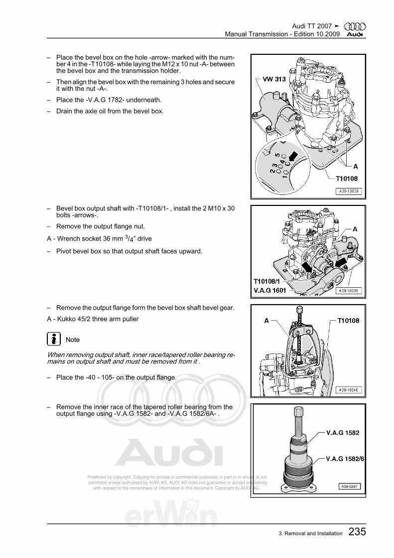
Protected by copyright. Copying for private or commercial purposes, in part or in whole, is not permitted unless authorised by AUDI AG. AUDI AG does not guarantee or accept any liability with respect to the correctness of information in this document. Copyright by AUDI AG.
– Place the bevel box on the hole -arrow- marked with the num‐ber 4 in the -T10108- while laying the M12 x 10 nut -A- betweenthe bevel box and the transmission holder.
– Then align the bevel box with the remaining 3 holes and secureit with the nut -A-.
– Place the -V.A.G 1782- underneath.– Drain the axle oil from the bevel box.
– Bevel box output shaft with -T10108/1- , install the 2 M10 x 30bolts -arrows-.
– Remove the output flange nut.
A - Wrench socket 36 mm 3/4” drive
– Pivot bevel box so that output shaft faces upward.
– Remove the output flange form the bevel box shaft bevel gear.A - Kukko 45/2 three arm puller
Note
When removing output shaft, inner race/tapered roller bearing re‐mains on output shaft and must be removed from it .
– Place the -40 - 105- on the output flange.
– Remove the inner race of the tapered roller bearing from theoutput flange using -V.A.G 1582- and -V.A.G 1582/6A- .
Audi TT 2007 ➤Manual Transmission - Edition 10.2009
3. Removal and Installation 235
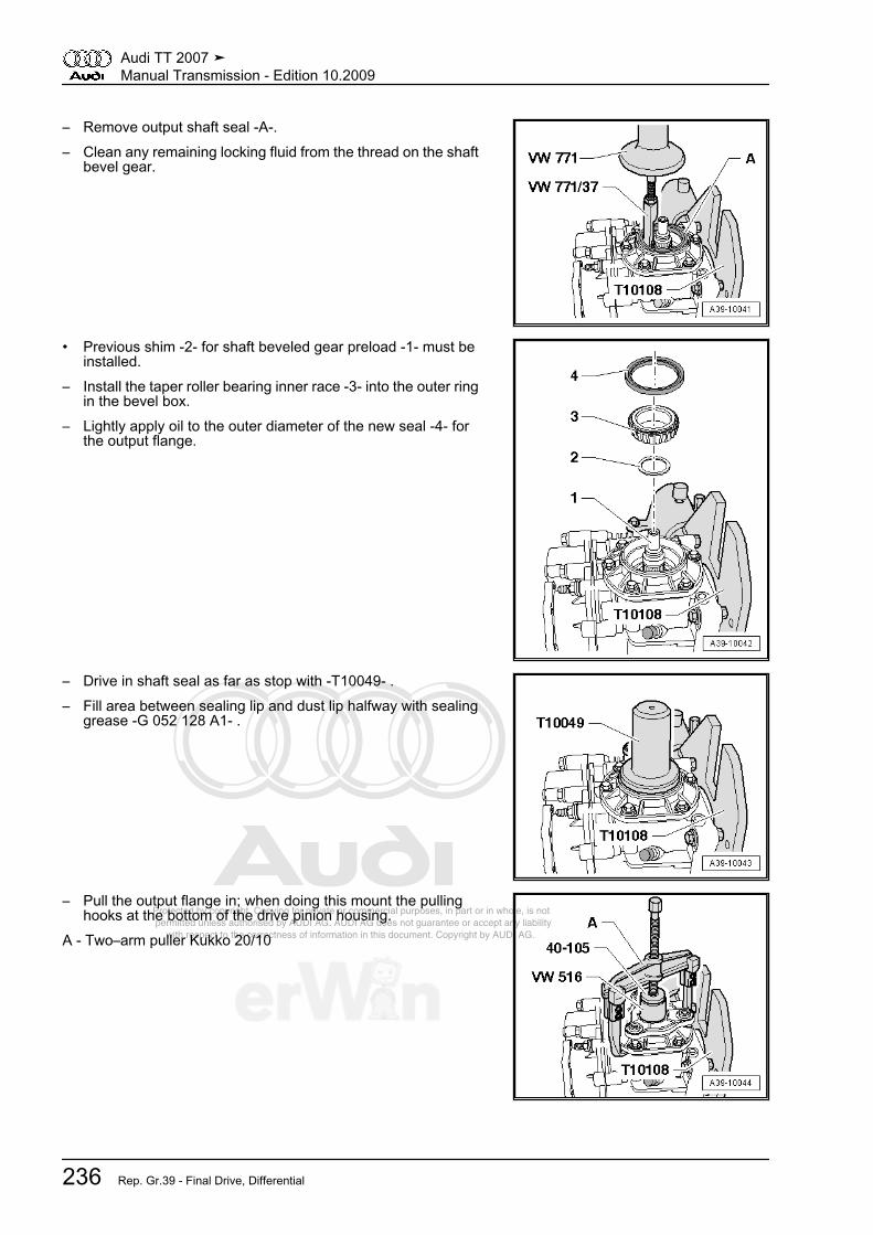
Protected by copyright. Copying for private or commercial purposes, in part or in whole, is not permitted unless authorised by AUDI AG. AUDI AG does not guarantee or accept any liability with respect to the correctness of information in this document. Copyright by AUDI AG.
– Remove output shaft seal -A-.– Clean any remaining locking fluid from the thread on the shaft
bevel gear.
• Previous shim -2- for shaft beveled gear preload -1- must beinstalled.
– Install the taper roller bearing inner race -3- into the outer ringin the bevel box.
– Lightly apply oil to the outer diameter of the new seal -4- forthe output flange.
– Drive in shaft seal as far as stop with -T10049- .– Fill area between sealing lip and dust lip halfway with sealing
grease -G 052 128 A1- .
– Pull the output flange in; when doing this mount the pullinghooks at the bottom of the drive pinion housing.
A - Two–arm puller Kukko 20/10
Audi TT 2007 ➤Manual Transmission - Edition 10.2009
236 Rep. Gr.39 - Final Drive, Differential

Protected by copyright. Copying for private or commercial purposes, in part or in whole, is not permitted unless authorised by AUDI AG. AUDI AG does not guarantee or accept any liability with respect to the correctness of information in this document. Copyright by AUDI AG.
– Coat the new nut for the output flange with locking fluid andthen tighten; locking fluid. Refer to the electronic parts catalogETKA.
– Replenish axle oil after installation of the bevel box. Refer to⇒ “1.3 Gear Oil in Bevel Box, Filling”, page 49 .
Audi TT 2007 ➤Manual Transmission - Edition 10.2009
3. Removal and Installation 237
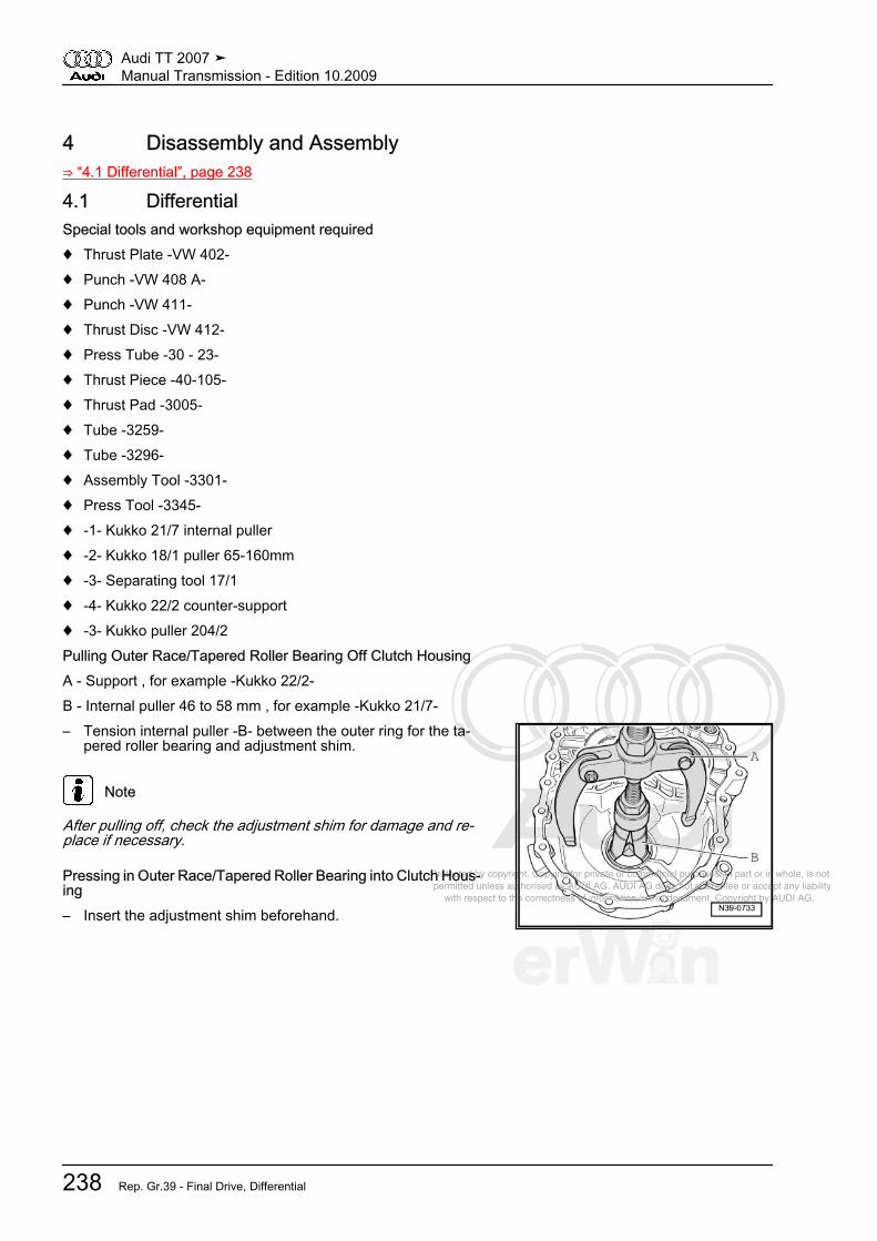
Protected by copyright. Copying for private or commercial purposes, in part or in whole, is not permitted unless authorised by AUDI AG. AUDI AG does not guarantee or accept any liability with respect to the correctness of information in this document. Copyright by AUDI AG.
4 Disassembly and Assembly⇒ “4.1 Differential”, page 238
4.1 DifferentialSpecial tools and workshop equipment required♦ Thrust Plate -VW 402-♦ Punch -VW 408 A-♦ Punch -VW 411-♦ Thrust Disc -VW 412-♦ Press Tube -30 - 23-♦ Thrust Piece -40-105-♦ Thrust Pad -3005-♦ Tube -3259-♦ Tube -3296-♦ Assembly Tool -3301-♦ Press Tool -3345-♦ -1- Kukko 21/7 internal puller♦ -2- Kukko 18/1 puller 65-160mm♦ -3- Separating tool 17/1♦ -4- Kukko 22/2 counter-support♦ -3- Kukko puller 204/2Pulling Outer Race/Tapered Roller Bearing Off Clutch HousingA - Support , for example -Kukko 22/2-B - Internal puller 46 to 58 mm , for example -Kukko 21/7-– Tension internal puller -B- between the outer ring for the ta‐
pered roller bearing and adjustment shim.
Note
After pulling off, check the adjustment shim for damage and re‐place if necessary.
Pressing in Outer Race/Tapered Roller Bearing into Clutch Hous‐ing– Insert the adjustment shim beforehand.
Audi TT 2007 ➤Manual Transmission - Edition 10.2009
238 Rep. Gr.39 - Final Drive, Differential
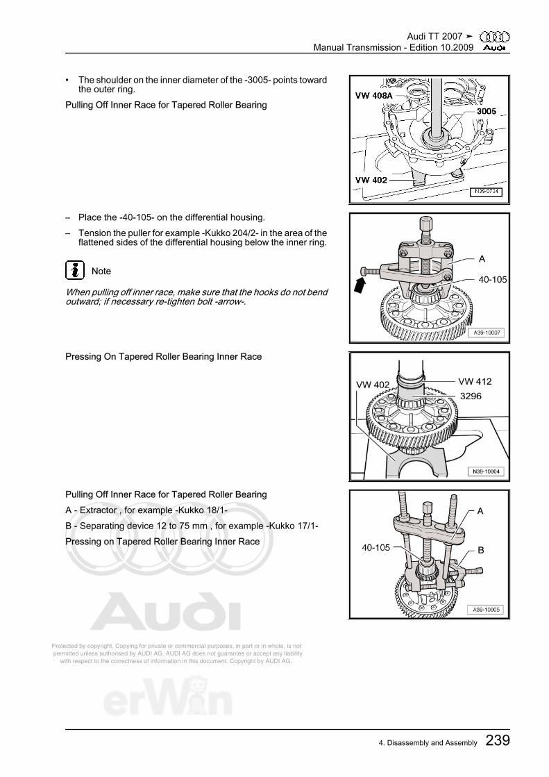
Protected by copyright. Copying for private or commercial purposes, in part or in whole, is not permitted unless authorised by AUDI AG. AUDI AG does not guarantee or accept any liability with respect to the correctness of information in this document. Copyright by AUDI AG.
• The shoulder on the inner diameter of the -3005- points towardthe outer ring.
Pulling Off Inner Race for Tapered Roller Bearing
– Place the -40-105- on the differential housing.– Tension the puller for example -Kukko 204/2- in the area of the
flattened sides of the differential housing below the inner ring.
Note
When pulling off inner race, make sure that the hooks do not bendoutward; if necessary re-tighten bolt -arrow-.
Pressing On Tapered Roller Bearing Inner Race
Pulling Off Inner Race for Tapered Roller BearingA - Extractor , for example -Kukko 18/1-B - Separating device 12 to 75 mm , for example -Kukko 17/1-Pressing on Tapered Roller Bearing Inner Race
Audi TT 2007 ➤Manual Transmission - Edition 10.2009
4. Disassembly and Assembly 239

Protected by copyright. Copying for private or commercial purposes, in part or in whole, is not permitted unless authorised by AUDI AG. AUDI AG does not guarantee or accept any liability with respect to the correctness of information in this document. Copyright by AUDI AG.
– Place the sleeve -3301/3- from the -3301- with the notch-arrow- (larger inner diameter) on the inner race for the taperedroller bearing.
Pulling Outer Race/Tapered Roller Bearing Out of TransmissionHousingA - Support , for example -Kukko 22/2-B - Internal puller 46 to 58 mm , for example -Kukko 21/7-Pressing in Tapered Roller Bearing Outer Race Into TransmissionHousing
– Support transmission housing directly beneath bearing mountusing -3345- .
Removing the Differential Bevel Gear Axle and Spring Pin
– First drive roll pin -1- flush into differential bevel gear axle-2-.
– Place differential with roll pin -arrow- facing toward -30 - 23-below press.
– Then press out differential bevel gear axle.
Note
Remove sheared of parts of roll pin from differential bevel gearaxle if necessary.
Installing the Differential Bevel Gears– Insert thrust washer union with transmission fluid.– Insert both large differential bevel gears and secure (for ex‐
ample with flange shaft).– Insert the small differential planetary gears 180° offset and
pivot them into position.
Audi TT 2007 ➤Manual Transmission - Edition 10.2009
240 Rep. Gr.39 - Final Drive, Differential
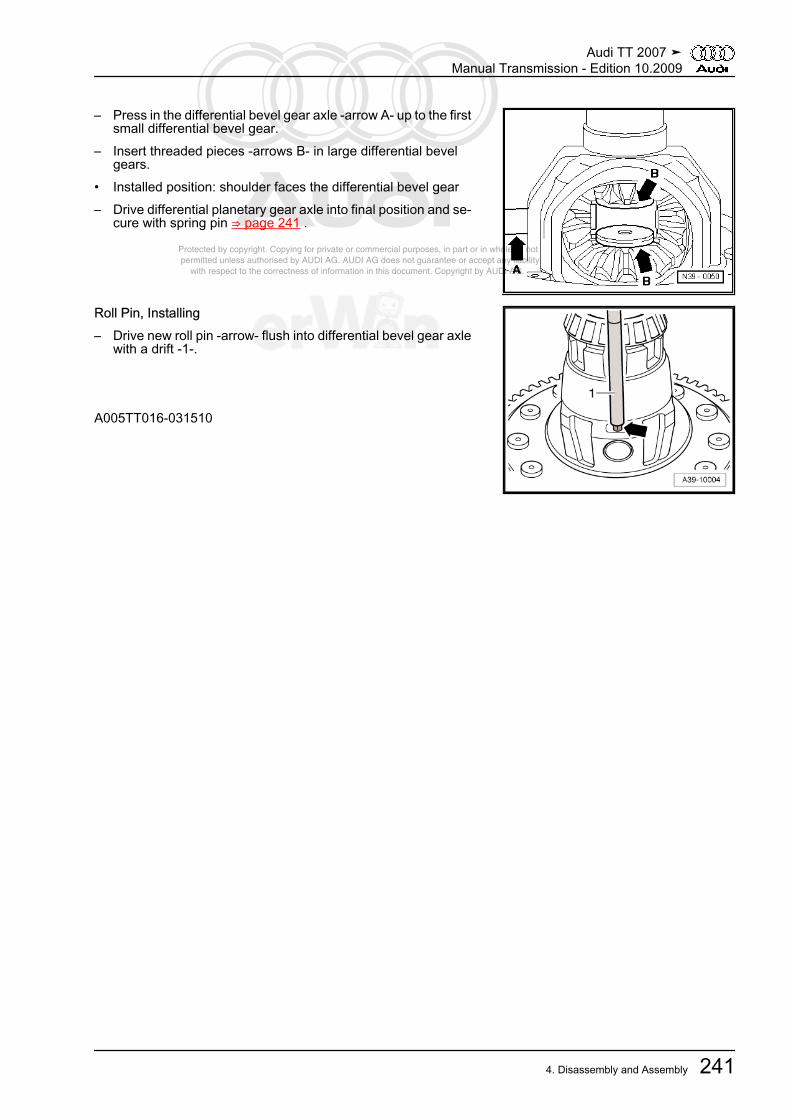
Protected by copyright. Copying for private or commercial purposes, in part or in whole, is not permitted unless authorised by AUDI AG. AUDI AG does not guarantee or accept any liability with respect to the correctness of information in this document. Copyright by AUDI AG.
– Press in the differential bevel gear axle -arrow A- up to the firstsmall differential bevel gear.
– Insert threaded pieces -arrows B- in large differential bevelgears.
• Installed position: shoulder faces the differential bevel gear– Drive differential planetary gear axle into final position and se‐
cure with spring pin ⇒ page 241 .
Roll Pin, Installing– Drive new roll pin -arrow- flush into differential bevel gear axle
with a drift -1-.
A005TT016-031510
Audi TT 2007 ➤Manual Transmission - Edition 10.2009
4. Disassembly and Assembly 241

Protected by copyright. Copying for private or commercial purposes, in part or in whole, is not permitted unless authorised by AUDI AG. AUDI AG does not guarantee or accept any liability with respect to the correctness of information in this document. Copyright by AUDI AG.
5 Special Tools
Special tools and workshopequipment required♦ Thrust Plate -VW 402-♦ Punch -VW 408 A-♦ Punch -VW 411-♦ Thrust Disc -VW 412-♦ Press Tube -30 - 23-♦ Thrust Piece -40-105-
Audi TT 2007 ➤Manual Transmission - Edition 10.2009
242 Rep. Gr.39 - Final Drive, Differential

Protected by copyright. Copying for private or commercial purposes, in part or in whole, is not permitted unless authorised by AUDI AG. AUDI AG does not guarantee or accept any liability with respect to the correctness of information in this document. Copyright by AUDI AG.
♦ Thrust Pad -3005-♦ Tube -3259-♦ Tube -3296-♦ Assembly Tool -3301-♦ Press Tool -3345-♦ -1- Kukko 21/7 internal pull‐
er♦ -2- Kukko 18/1 puller
65-160mm♦ -3- Separating tool 17/1♦ -4- Kukko 22/2 counter-
support
Audi TT 2007 ➤Manual Transmission - Edition 10.2009
5. Special Tools 243

Protected by copyright. Copying for private or commercial purposes, in part or in whole, is not permitted unless authorised by AUDI AG. AUDI AG does not guarantee or accept any liability with respect to the correctness of information in this document. Copyright by AUDI AG.
Special tools and workshopequipment required♦ Oil collecting and extracting
device -V.A.G 1782-♦ Puller -T10037-♦ Socket and Extended Bit -
T10107 A-
Audi TT 2007 ➤Manual Transmission - Edition 10.2009
244 Rep. Gr.39 - Final Drive, Differential
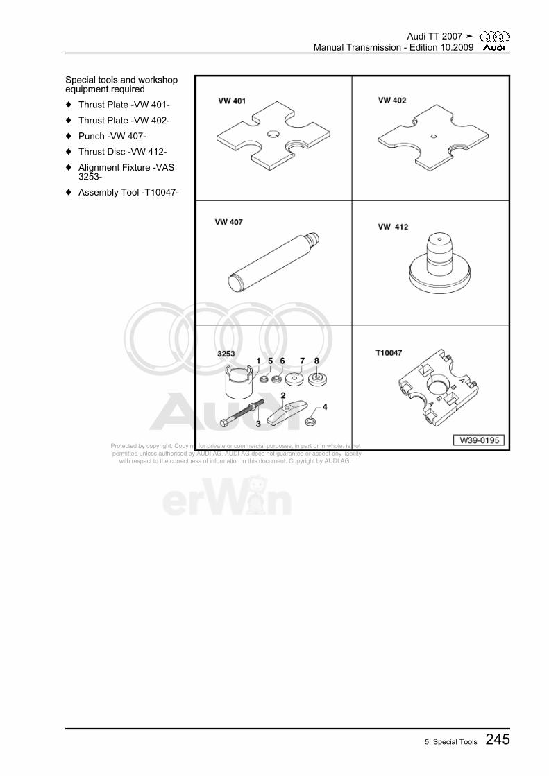
Protected by copyright. Copying for private or commercial purposes, in part or in whole, is not permitted unless authorised by AUDI AG. AUDI AG does not guarantee or accept any liability with respect to the correctness of information in this document. Copyright by AUDI AG.
Special tools and workshopequipment required♦ Thrust Plate -VW 401-♦ Thrust Plate -VW 402-♦ Punch -VW 407-♦ Thrust Disc -VW 412-♦ Alignment Fixture -VAS
3253-♦ Assembly Tool -T10047-
Audi TT 2007 ➤Manual Transmission - Edition 10.2009
5. Special Tools 245

Protected by copyright. Copying for private or commercial purposes, in part or in whole, is not permitted unless authorised by AUDI AG. AUDI AG does not guarantee or accept any liability with respect to the correctness of information in this document. Copyright by AUDI AG.
Special tools and workshopequipment required♦ Transmission Support -
VW 353-♦ Magnetic Plate 50 mm Dia.
-VW 385/17-♦ Dial Gauge Holder -
VW 387-♦ Thrust Plate -VW 402-♦ Punch -VW 408 A-♦ Oil Pump Align Plate -3005-
Audi TT 2007 ➤Manual Transmission - Edition 10.2009
246 Rep. Gr.39 - Final Drive, Differential

Protected by copyright. Copying for private or commercial purposes, in part or in whole, is not permitted unless authorised by AUDI AG. AUDI AG does not guarantee or accept any liability with respect to the correctness of information in this document. Copyright by AUDI AG.
♦ Tube -3259-♦ Press Tool -3345-♦ Torque Wrench -V.A.G
1331-♦ -1- Kukko 21/7 internal pull‐
er♦ -4- Kukko 22/2 counter-
support
Audi TT 2007 ➤Manual Transmission - Edition 10.2009
5. Special Tools 247

Protected by copyright. Copying for private or commercial purposes, in part or in whole, is not permitted unless authorised by AUDI AG. AUDI AG does not guarantee or accept any liability with respect to the correctness of information in this document. Copyright by AUDI AG.
♦ Tapered Roller BearingPuller -V.A.G 1582-
♦ Attachment -V.A.G1582/6A-
♦ Torque Wrench -V.A.G1601-
♦ -1- Kukko 20/10 two-armpuller
♦ Kukko 45/2 three arm puller
Audi TT 2007 ➤Manual Transmission - Edition 10.2009
248 Rep. Gr.39 - Final Drive, Differential

Protected by copyright. Copying for private or commercial purposes, in part or in whole, is not permitted unless authorised by AUDI AG. AUDI AG does not guarantee or accept any liability with respect to the correctness of information in this document. Copyright by AUDI AG.
Special tools and workshopequipment required♦ Holding Fixture -VW 313-♦ Tube 42 mm Dia. -VW 516-♦ Thrust Piece -40-105-♦ Thrust Piece -T10049-♦ Transmission Holder -
T10108-♦ Stop Plate -T10108/1-
Special tools and workshop equipment required♦ Thrust Piece -T10049-
Audi TT 2007 ➤Manual Transmission - Edition 10.2009
5. Special Tools 249

Protected by copyright. Copying for private or commercial purposes, in part or in whole, is not permitted unless authorised by AUDI AG. AUDI AG does not guarantee or accept any liability with respect to the correctness of information in this document. Copyright by AUDI AG.
♦ Thrust Piece -3305-
♦ Thrust Piece -T10243-
♦ Thrust Piece -T10298-
♦ Slide Hammer-Complete Set -VW 771-
Audi TT 2007 ➤Manual Transmission - Edition 10.2009
250 Rep. Gr.39 - Final Drive, Differential
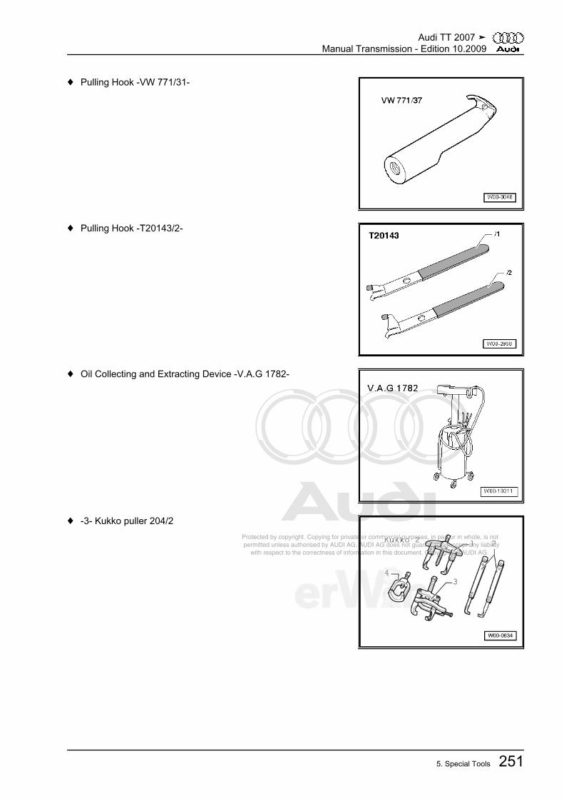
Protected by copyright. Copying for private or commercial purposes, in part or in whole, is not permitted unless authorised by AUDI AG. AUDI AG does not guarantee or accept any liability with respect to the correctness of information in this document. Copyright by AUDI AG.
♦ Pulling Hook -VW 771/31-
♦ Pulling Hook -T20143/2-
♦ Oil Collecting and Extracting Device -V.A.G 1782-
♦ -3- Kukko puller 204/2
Audi TT 2007 ➤Manual Transmission - Edition 10.2009
5. Special Tools 251

Protected by copyright. Copying for private or commercial purposes, in part or in whole, is not permitted unless authorised by AUDI AG. AUDI AG does not guarantee or accept any liability with respect to the correctness of information in this document. Copyright by AUDI AG.
♦ Dial Gauge -VAS 6080-
♦ Dial gauge extension 30 mm
Audi TT 2007 ➤Manual Transmission - Edition 10.2009
252 Rep. Gr.39 - Final Drive, Differential
Protected by copyright. Copying for private or commercial purposes, in part or in whole, is not permitted unless authorised by AUDI AG. AUDI AG does not guarantee or accept any liability with respect to the correctness of information in this document. Copyright by AUDI AG.
Cautions & Warnings
=Page 1 of 3 © 2002 Audi of America, Inc. All rights reserved. Information contained in this document is based on the latest information available at the time of printing and is subject to the copyright and other intellectual property rights of Audi of America, Inc., its affiliated companies and its licensors. All rights are reserved to make changes at any time without notice. No part of this document may be reproduced, stored in a retrieval system, or transmitted in any form or by any means, electronic, mechanical, photocopying, recording, or otherwise, nor may these materials be modified or reposted to other sites, without the prior expressed written permission of the publisher. Version 1.0
Please read these WARNINGS and CAUTIONS before proceeding with maintenance and repair work. You must answer that you have read and you understand these WARNINGS and CAUTIONS before you will be allowed to view this information.
•= If you lack the skills, tools and equipment, or a suitable workshop for any procedure described in this manual, we suggest you leave such repairs to an authorized Audi retailer or other qualified shop. We especially urge you to consult an authorized Audi retailer before beginning repairs on any vehicle that may still be covered wholly or in part by any of the extensive warranties issued by Audi.
•= Disconnect the battery negative terminal (ground strap)whenever you work on the fuel system or the electrical system. Do not smoke or work near heaters or other fire hazards. Keep an approved fire extinguisher handy.
•= Audi is constantly improving its vehicles and sometimes these changes, both in parts and specifications, are made applicable to earlier models. Therefore, part numbers listed in this manual are for reference only. Always check with your authorized Audi retailer parts department for the latest information.
•= Any time the battery has been disconnected on an automatic transmission vehicle, it will be necessary to reestablish Transmission Control Module (TCM) basic settings using the VAG 1551 Scan Tool (ST).
•= Never work under a lifted vehicle unless it is solidly supported on stands designed for the purpose. Do not support a vehicle on cinder blocks, hollow tiles or other props that may crumble under continuous load. Never work under a vehicle that is supported solely by a jack. Never work under the vehicle while the engine is running.
•= For vehicles equipped with an anti-theft radio, be sure of the correct radio activation code before disconnecting the battery or removing the radio. If the wrong code is entered when the power is restored, the radio may lock up and become inoperable, even if the correct code is used in a later attempt.
•= If you are going to work under a vehicle on the ground, make sure that the ground is level. Block the wheels to keep the vehicle from rolling. Disconnect the battery negative terminal (ground strap) to prevent others from starting the vehicle while you are under it.
•= Do not attempt to work on your vehicle if you do not feel well. You increase the danger of injury to yourself and others if you are tired, upset or have taken medicine or any other substances that may impair you or keep you from being fully alert.
•= Never run the engine unless the work area is well ventilated. Carbon monoxide (CO) kills.
•= Always observe good workshop practices. Wear goggles when you operate machine tools or work with acid. Wear goggles, gloves and other protective clothing whenever the job requires working with harmful substances.
•= Tie long hair behind your head. Do not wear a necktie, a scarf, loose clothing, or a necklace when you work near machine tools or running engines. If your hair, clothing, or jewelry were to get caught in the machinery, severe injury could result.

Protected by copyright. Copying for private or commercial purposes, in part or in whole, is not permitted unless authorised by AUDI AG. AUDI AG does not guarantee or accept any liability with respect to the correctness of information in this document. Copyright by AUDI AG.
Cautions & Warnings
=Page 2 of 3 © 2002 Audi of America, Inc. All rights reserved. Information contained in this document is based on the latest information available at the time of printing and is subject to the copyright and other intellectual property rights of Audi of America, Inc., its affiliated companies and its licensors. All rights are reserved to make changes at any time without notice. No part of this document may be reproduced, stored in a retrieval system, or transmitted in any form or by any means, electronic, mechanical, photocopying, recording, or otherwise, nor may these materials be modified or reposted to other sites, without the prior expressed written permission of the publisher. Version 1.0
•= Do not re-use any fasteners that are worn or deformed in normal use. Some fasteners are designed to be used only once and are unreliable and may fail if used a second time. This includes, but is not limited to, nuts, bolts, washers, circlips and cotter pins. Always follow the recommendations in this manual - replace these fasteners with new parts where indicated, and any other time it is deemed necessary by inspection.
•= Illuminate the work area adequately but safely. Use a portable safety light for working inside or under the vehicle. Make sure the bulb is enclosed by a wire cage. The hot filament of an accidentally broken bulb can ignite spilled fuel or oil.
•= Friction materials such as brake pads and clutch discs may contain asbestos fibers. Do not create dust by grinding, sanding, or by cleaning with compressed air. Avoid breathing asbestos fibers and asbestos dust. Breathing asbestos can cause serious diseases such as asbestosis or cancer, and may result in death.
•= Finger rings should be removed so that they cannot cause electrical shorts, get caught in running machinery, or be crushed by heavy parts.
•= Before starting a job, make certain that you have all the necessary tools and parts on hand. Read all the instructions thoroughly, do not attempt shortcuts. Use tools that are appropriate to the work and use only replacement parts meeting Audi specifications. Makeshift tools, parts and procedures will not make good repairs.
•= Catch draining fuel, oil or brake fluid in suitable containers. Do not use empty food or beverage containers that might mislead someone into drinking from them. Store flammable fluids away from fire hazards. Wipe up spills at once, but do not store the oily rags, which can ignite and burn spontaneously.
•= Use pneumatic and electric tools only to loosen threaded parts and fasteners. Never use these tools to tighten fasteners, especially on light alloy parts. Always use a torque wrench to tighten fasteners to the tightening torque listed.
•= Keep sparks, lighted matches, and open flame away from the top of the battery. If escaping hydrogen gas is ignited, it will ignite gas trapped in the cells and cause the battery to explode.
•= Be mindful of the environment and ecology. Before you drain the crankcase, find out the proper way to dispose of the oil. Do not pour oil onto the ground, down a drain, or into a stream, pond, or lake. Consult local ordinances that govern the disposal of wastes.
•= The air-conditioning (A/C) system is filled with a chemical refrigerant that is hazardous. The A/C system should be serviced only by trained automotive service technicians using approved refrigerant recovery/recycling equipment, trained in related safety precautions, and familiar with regulations governing the discharging and disposal of automotive chemical refrigerants.
•= Before doing any electrical welding on vehicles equipped with anti-lock brakes (ABS), disconnect the battery negative terminal (ground strap) and the ABS control module connector.
•= Do not expose any part of the A/C system to high temperatures such as open flame. Excessive heat will increase system pressure and may cause the system to burst.

Protected by copyright. Copying for private or commercial purposes, in part or in whole, is not permitted unless authorised by AUDI AG. AUDI AG does not guarantee or accept any liability with respect to the correctness of information in this document. Copyright by AUDI AG.
Cautions & Warnings
=Page 3 of 3 © 2002 Audi of America, Inc. All rights reserved. Information contained in this document is based on the latest information available at the time of printing and is subject to the copyright and other intellectual property rights of Audi of America, Inc., its affiliated companies and its licensors. All rights are reserved to make changes at any time without notice. No part of this document may be reproduced, stored in a retrieval system, or transmitted in any form or by any means, electronic, mechanical, photocopying, recording, or otherwise, nor may these materials be modified or reposted to other sites, without the prior expressed written permission of the publisher. Version 1.0
•= When boost-charging the battery, first remove the fuses for the Engine Control Module (ECM), the Transmission Control Module (TCM), the ABS control module, and the trip computer. In cases where one or more of these components is not separately fused, disconnect the control module connector(s).
•= Some of the vehicles covered by this manual are equipped with a supplemental restraint system (SRS), that automatically deploys an airbag in the event of a frontal impact. The airbag is operated by an explosive device. Handled improperly or without adequate safeguards, it can be accidentally activated and cause serious personal injury. To guard against personal injury or airbag system failure, only trained Audi Service technicians should test, disassemble or service the airbag system.
•= Do not quick-charge the battery (for boost starting) for longer than one minute, and do not exceed 16.5 volts at the battery with the boosting cables attached. Wait at least one minute before boosting the battery a second time.
•= Never use a test light to conduct electrical tests of the airbag system. The system must only be tested by trained Audi Service technicians using the VAG 1551 Scan Tool (ST) or an approved equivalent. The airbag unit must never be electrically tested while it is not installed in the vehicle.
•= Some aerosol tire inflators are highly flammable. Be extremely cautious when repairing a tire that may have been inflated using an aerosol tire inflator. Keep sparks, open flame or other sources of ignition away from the tire repair area. Inflate and deflate the tire at least four times before breaking the bead from the rim. Completely remove the tire from the rim before attempting any repair.
•= When driving or riding in an airbag-equipped vehicle, never hold test equipment in your hands or lap while the vehicle is in motion. Objects between you and the airbag can increase the risk of injury in an accident.
I have read and I understand these Cautions and Warnings.