service repair manual - lz7w.comlz7w.com/audi/mk2ttwiki/pdf/erwin/d3e8006b7d9-communication.pdf ·...
TRANSCRIPT

Protected by copyright. Copying for private or commercial purposes, in part or in whole, is not permitted unless authorised by AUDI AG. AUDI AG does not guarantee or accept any liability with respect to the correctness of information in this document. Copyright by AUDI AG.
Repair ManualAudi TT 2007 ➤CommunicationEdition 02.2009
Service
Service Department. Technical Information

Protected by copyright. Copying for private or commercial purposes, in part or in whole, is not permitted unless authorised by AUDI AG. AUDI AG does not guarantee or accept any liability with respect to the correctness of information in this document. Copyright by AUDI AG.
List of Workshop Manual Repair GroupsList of Workshop ManualRepair GroupsList of Workshop Manual Repair Groups
Repai r Group91 - Communication
Technical information should always be available to the foremen and mechanics, because theircareful and constant adherence to the instructions is essential to ensure vehicle road-worthiness andsafety. In addition, the normal basic safety precautions for working on motor vehicles must, as amatter of course, be observed.
Service
All rights reserved.No reproduction without prior agreement from publisher.
Copyright © 2010 Audi AG, Ingolstadt D3E8006B7D9

Protected by copyright. Copying for private or commercial purposes, in part or in whole, is not permitted unless authorised by AUDI AG. AUDI AG does not guarantee or accept any liability with respect to the correctness of information in this document. Copyright by AUDI AG.
Contents
91 - Communication . . . . . . . . . . . . . . . . . . . . . . . . . . . . . . . . . . . . . . . . . . . . . . . . . . 11 General Information . . . . . . . . . . . . . . . . . . . . . . . . . . . . . . . . . . . . . . . . . . . . . . . . . . . . . . 11.1 Radio System . . . . . . . . . . . . . . . . . . . . . . . . . . . . . . . . . . . . . . . . . . . . . . . . . . . . . . . . . . . . 11.2 Sound system . . . . . . . . . . . . . . . . . . . . . . . . . . . . . . . . . . . . . . . . . . . . . . . . . . . . . . . . . . . . 21.3 Antenna System, Coupe . . . . . . . . . . . . . . . . . . . . . . . . . . . . . . . . . . . . . . . . . . . . . . . . . . 21.4 Antenna System, Roadster . . . . . . . . . . . . . . . . . . . . . . . . . . . . . . . . . . . . . . . . . . . . . . . . 21.5 Telephone Systems . . . . . . . . . . . . . . . . . . . . . . . . . . . . . . . . . . . . . . . . . . . . . . . . . . . . . . 31.6 RNS-E Navigation System . . . . . . . . . . . . . . . . . . . . . . . . . . . . . . . . . . . . . . . . . . . . . . . . . . 41.7 Navigation System RNS-JP4 . . . . . . . . . . . . . . . . . . . . . . . . . . . . . . . . . . . . . . . . . . . . . . . . 41.8 Navigation System RNS JP5 . . . . . . . . . . . . . . . . . . . . . . . . . . . . . . . . . . . . . . . . . . . . . . . . 41.9 RNS Low Navigation System . . . . . . . . . . . . . . . . . . . . . . . . . . . . . . . . . . . . . . . . . . . . . . . . 41.10 CD Changer . . . . . . . . . . . . . . . . . . . . . . . . . . . . . . . . . . . . . . . . . . . . . . . . . . . . . . . . . . . . 51.11 iPod Baseplate . . . . . . . . . . . . . . . . . . . . . . . . . . . . . . . . . . . . . . . . . . . . . . . . . . . . . . . . . . 51.12 External Audio Source Connection . . . . . . . . . . . . . . . . . . . . . . . . . . . . . . . . . . . . . . . . . . 51.13 Multifunction Steering Wheel . . . . . . . . . . . . . . . . . . . . . . . . . . . . . . . . . . . . . . . . . . . . . . . . 51.14 Steering Column Electronic Systems Control Module . . . . . . . . . . . . . . . . . . . . . . . . . . . . 62 Description and Operation . . . . . . . . . . . . . . . . . . . . . . . . . . . . . . . . . . . . . . . . . . . . . . . . . . 82.1 Radio System . . . . . . . . . . . . . . . . . . . . . . . . . . . . . . . . . . . . . . . . . . . . . . . . . . . . . . . . . . . . 82.2 Sound System . . . . . . . . . . . . . . . . . . . . . . . . . . . . . . . . . . . . . . . . . . . . . . . . . . . . . . . . . . 212.3 Antenna System, Coupe . . . . . . . . . . . . . . . . . . . . . . . . . . . . . . . . . . . . . . . . . . . . . . . . . . 292.4 Antenna System, Roadster . . . . . . . . . . . . . . . . . . . . . . . . . . . . . . . . . . . . . . . . . . . . . . . . 332.5 Telephone System . . . . . . . . . . . . . . . . . . . . . . . . . . . . . . . . . . . . . . . . . . . . . . . . . . . . . . . . 362.6 RNS-E Navigation System . . . . . . . . . . . . . . . . . . . . . . . . . . . . . . . . . . . . . . . . . . . . . . . . . . 452.7 Navigation System RNS-JP4 . . . . . . . . . . . . . . . . . . . . . . . . . . . . . . . . . . . . . . . . . . . . . . . . 552.8 Navigation System RNS JP5 . . . . . . . . . . . . . . . . . . . . . . . . . . . . . . . . . . . . . . . . . . . . . . . . 622.9 RNS low navigation system . . . . . . . . . . . . . . . . . . . . . . . . . . . . . . . . . . . . . . . . . . . . . . . . 702.10 CD Changer Harness Connectors . . . . . . . . . . . . . . . . . . . . . . . . . . . . . . . . . . . . . . . . . . . . 802.11 iPod Baseplate, Connections . . . . . . . . . . . . . . . . . . . . . . . . . . . . . . . . . . . . . . . . . . . . . . . . 812.12 External Audio Source Connection Connectors, AMI . . . . . . . . . . . . . . . . . . . . . . . . . . . . . . 812.13 AUX IN External Audio Source Connection Connectors . . . . . . . . . . . . . . . . . . . . . . . . . . 822.14 Multi-Function Steering Wheel, Overview . . . . . . . . . . . . . . . . . . . . . . . . . . . . . . . . . . . . . . 822.15 Steering Column Switch Module, Overview . . . . . . . . . . . . . . . . . . . . . . . . . . . . . . . . . . . . 832.16 Steering Column Electronic Systems Control Module Connectors . . . . . . . . . . . . . . . . . . 843 Specifications . . . . . . . . . . . . . . . . . . . . . . . . . . . . . . . . . . . . . . . . . . . . . . . . . . . . . . . . . . . . 853.1 Fastener Tightening Specifications . . . . . . . . . . . . . . . . . . . . . . . . . . . . . . . . . . . . . . . . . . 854 Removal and Installation . . . . . . . . . . . . . . . . . . . . . . . . . . . . . . . . . . . . . . . . . . . . . . . . . . 864.1 Radio . . . . . . . . . . . . . . . . . . . . . . . . . . . . . . . . . . . . . . . . . . . . . . . . . . . . . . . . . . . . . . . . . . 864.2 Front Passenger Airbag Disabled Indicator Lamp . . . . . . . . . . . . . . . . . . . . . . . . . . . . . . . . 874.3 Satellite Radio . . . . . . . . . . . . . . . . . . . . . . . . . . . . . . . . . . . . . . . . . . . . . . . . . . . . . . . . . . 884.4 Sound System . . . . . . . . . . . . . . . . . . . . . . . . . . . . . . . . . . . . . . . . . . . . . . . . . . . . . . . . . . 894.5 Antenna System, Coupe . . . . . . . . . . . . . . . . . . . . . . . . . . . . . . . . . . . . . . . . . . . . . . . . . . 954.6 Antenna System, Roadster . . . . . . . . . . . . . . . . . . . . . . . . . . . . . . . . . . . . . . . . . . . . . . . . 1004.7 Telephone Systems . . . . . . . . . . . . . . . . . . . . . . . . . . . . . . . . . . . . . . . . . . . . . . . . . . . . . . 1044.8 Navigation System with CD Drive Control Module . . . . . . . . . . . . . . . . . . . . . . . . . . . . . . . . 1064.9 Radio/Navigation Display Control Module . . . . . . . . . . . . . . . . . . . . . . . . . . . . . . . . . . . . . . 1064.10 CD Changer . . . . . . . . . . . . . . . . . . . . . . . . . . . . . . . . . . . . . . . . . . . . . . . . . . . . . . . . . . . . 1074.11 iPod Baseplate . . . . . . . . . . . . . . . . . . . . . . . . . . . . . . . . . . . . . . . . . . . . . . . . . . . . . . . . . . 1084.12 AMI External Audio Source Connection . . . . . . . . . . . . . . . . . . . . . . . . . . . . . . . . . . . . . . . . 1084.13 AUX IN External Audio Source Connection . . . . . . . . . . . . . . . . . . . . . . . . . . . . . . . . . . . . 1094.14 Multi-function Buttons . . . . . . . . . . . . . . . . . . . . . . . . . . . . . . . . . . . . . . . . . . . . . . . . . . . . . . 1094.15 Tiptronic Switch . . . . . . . . . . . . . . . . . . . . . . . . . . . . . . . . . . . . . . . . . . . . . . . . . . . . . . . . . . 1104.16 Steering Column Electronic Systems Control Module . . . . . . . . . . . . . . . . . . . . . . . . . . . . 111
Audi TT 2007 ➤Communication - Edition 02.2009
Contents i

Protected by copyright. Copying for private or commercial purposes, in part or in whole, is not permitted unless authorised by AUDI AG. AUDI AG does not guarantee or accept any liability with respect to the correctness of information in this document. Copyright by AUDI AG.
5 Special Tools . . . . . . . . . . . . . . . . . . . . . . . . . . . . . . . . . . . . . . . . . . . . . . . . . . . . . . . . . . . . 112
Audi TT 2007 ➤Communication - Edition 02.2009
ii Contents

Protected by copyright. Copying for private or commercial purposes, in part or in whole, is not permitted unless authorised by AUDI AG. AUDI AG does not guarantee or accept any liability with respect to the correctness of information in this document. Copyright by AUDI AG.
91 – Communication1 General Information⇒ “1.1 Radio System”, page 1⇒ “1.2 Sound system”, page 2⇒ “1.3 Antenna System, Coupe”, page 2⇒ “1.4 Antenna System, Roadster”, page 2⇒ “1.5 Telephone Systems”, page 3⇒ “1.6 RNS-E Navigation System”, page 4⇒ “1.7 Navigation System RNS-JP4”, page 4⇒ “1.8 Navigation System RNS JP5”, page 4⇒ “1.9 RNS Low Navigation System”, page 4⇒ “1.10 CD Changer”, page 5⇒ “1.11 iPod Baseplate”, page 5⇒ “1.12 External Audio Source Connection”, page 5⇒ “1.13 Multifunction Steering Wheel”, page 5⇒ “1.14 Steering Column Electronic Systems Control Module”,page 6
1.1 Radio SystemRadio Systems♦ concert♦ symphonySound Systems♦ Standard♦ BOSEGeneral InformationThe radio systems are prepared for satellite radio use or SatelliteRadio is installed.The radio have two tuners with phase diversity and each one hasan antenna connection (AM/FM1 and FM2).Besides switching diversity, phase diversity is the second proce‐dure for reducing reception interference.At least two antennas with amplifier and a radio with two tunersis required.If the signal received is interrupted, both signals are digitalizedand separated in the tuners in the radio so that the disrupted sig‐nals are blocked out as much as possible.If the reception signal is not disrupted, the radio constantly com‐pares which antenna (amplifier) has the strongest reception. Thisis then transferred.In this case, the second tuner checks the frequency band in thebackground for better reception frequencies for the selected sta‐tion. If a better signal is found, this tuner switches to reception andthe other to the background.Satellite radio for SDARS is installed in luggage compartment.
Audi TT 2007 ➤Communication - Edition 02.2009
1. General Information 1

Protected by copyright. Copying for private or commercial purposes, in part or in whole, is not permitted unless authorised by AUDI AG. AUDI AG does not guarantee or accept any liability with respect to the correctness of information in this document. Copyright by AUDI AG.
Communication with other vehicle systems takes place via theInfotainment CAN-Bus and data bus on board diagnostic inter‐face.Symphony transport mode, activating/deactivating, refer to⇒ “2.1.11 Symphony Transport Mode, Activating/Deactivating”,page 20 .Troubleshooting and diagnosis takes place with Guided FaultFinding using vehicle diagnosis, testing and information system -VAS 5051- .Repairs on antenna wires, refer to ⇒ Electrical Equipment Gen‐eral Information; Rep. Gr. 97 ; General Information .Repair to CAN bus lines, refer to ⇒ Electrical Equipment GeneralInformation; Rep. Gr. 97 ; General Information .
1.2 Sound systemThere are three equipment versions.Sound Systems♦ Base♦ Standard♦ BOSEThe individual speakers are installed in the doors, instrumentpanel and rear side trim.
1.3 Antenna System, CoupeThe antenna system includes the antennas inside the rear lid andthe roof antenna.System with phase diversity (radio)♦ Antenna amplifier (AM/FM1/Central Locking System) on the
top of the rear lid on the right side♦ Antenna amplifier 4 (digital audio broadcasting) at the top of
the rear lid on the left side♦ Antenna amplifier 2 (FM2) at the bottom of the rear lid on the
right side♦ Radio, telephone, navigation system antenna (GPS/GSM/Sat‐
ellite) roof antennaSystem with switch diversity (radio/navigation system)♦ Antenna amplifier (AM/FM1/Central Locking System) on the
top of the rear lid on the right side♦ Antenna amplifier 4 (digital audio broadcasting/TV3) at the top
of the rear lid on the left side♦ Antenna amplifier 2 (FM2/high frequency/intermediate fre‐
quency/TV1/TV2) at the bottom of the rear lid on the right side♦ Radio, telephone, navigation system antenna (GPS/GSM/Sat‐
ellite) roof antennaRepairs on antenna wires, refer to ⇒ Electrical Equipment Gen‐eral Information; Rep. Gr. 97 ; General Information .
1.4 Antenna System, RoadsterThe antenna system includes the antennas inside the windshield,the antennas behind the rear lid end piece and mast antenna.
Audi TT 2007 ➤Communication - Edition 02.2009
2 Rep. Gr.91 - Communication

Protected by copyright. Copying for private or commercial purposes, in part or in whole, is not permitted unless authorised by AUDI AG. AUDI AG does not guarantee or accept any liability with respect to the correctness of information in this document. Copyright by AUDI AG.
System with phase diversity (radio)♦ Antenna amplifier (AM/FM1/central locking frequency), left
rear mast antenna base♦ Antenna amplifier 2 (FM2) behind the rear bumper on the right
side♦ Satellite antenna (satellite) on rear lid♦ Navigation system antenna (GPS) behind front interior lamp
on the roof frame♦ Telephone antenna (GPS) behind front interior lamp on the
roof frameSystem with switch diversity (radio/navigation system)♦ Antenna amplifier (AM/FM1/central locking frequency), left
rear mast antenna base♦ Antenna amplifier 2 (FM2/TV1/HF/ZF) behind the rear bumper
on the right side♦ TV antenna 2 (TV2) on the left A-pillar♦ TV antenna 3 (TV3) on the left A-pillar♦ Antenna selection control module (HF/ZF) inside the luggage
compartment on the front separator♦ Satellite antenna (satellite) on rear lid♦ Navigation System Antenna (GPS) behind front interior lamp
on the roof frame♦ Telephone antenna (GPS) behind front interior lamp on the
roof frameThe satellite radio applies only to the USA.Repairs on antenna wires, refer to ⇒ Electrical Equipment Gen‐eral Information; Rep. Gr. 97 ; General Information .
1.5 Telephone SystemsMobile phone prep♦ Telephone transceiver♦ Radio, telephone, navigation system antenna/telephone an‐
tenna (through MY 2008)♦ Telephone baseplate (through MY 2008)♦ Microphone unit in front roof moduleThe telephone transceiver is equipped with a Bluetooth Antenna.Using this, all cellular telephones approved by Audi can be oper‐ated with the Bluetooth interface with the cellular telephone prep‐aration installed in the vehicle.It is not possible to connect other devices via Bluetooth, for ex‐ample headset, laptop, PDA, or similar.Fault finding is performed via Guided Fault Finding, refer to ⇒ Ve‐hicle diagnosis, testing and information system VAS 5051.Repairs on antenna wires, refer to ⇒ Electrical Equipment Gen‐eral Information; Rep. Gr. 97 ; General Information .Repair to CAN bus lines, refer to ⇒ Electrical Equipment GeneralInformation; Rep. Gr. 97 ; General Information .
Audi TT 2007 ➤Communication - Edition 02.2009
1. General Information 3

Protected by copyright. Copying for private or commercial purposes, in part or in whole, is not permitted unless authorised by AUDI AG. AUDI AG does not guarantee or accept any liability with respect to the correctness of information in this document. Copyright by AUDI AG.
1.6 RNS-E Navigation SystemDescriptionThe RNS-E navigation system is an enhancement of the naviga‐tion system II-D. The unit has MMI operation. A DVD is used asthe navigation CD.Screen folds away. DVD drive and two MP3 card readers are lo‐cated behind.Beside the navigation system, the RNS-E include a radio, twoMP3 card readers and a connection for a CD changer/connectionfor an external audio source and the satellite radio . The DVDdrive can play music CDs.Error messages on screen⇒ “2.6.3 Error Messages On Screen”, page 46Fault finding is performed via Guided Fault Finding, refer to ⇒ Ve‐hicle diagnosis, testing and information system VAS 5051.Repairs on antenna wires, refer to ⇒ Electrical Equipment Gen‐eral Information; Rep. Gr. 97 ; General Information .Repair to CAN bus lines, refer to ⇒ Electrical Equipment GeneralInformation; Rep. Gr. 97 ; General Information .
1.7 Navigation System RNS-JP4The JP4 navigation system includes the after market radio/navi‐gation system.All connections necessary for the navigation unit are present inthe vehicle. Sound system and antennas are installed.Only the navigation unit (RNS) is installed in service.Repairs on antenna wires, refer to ⇒ Electrical Equipment Gen‐eral Information; Rep. Gr. 97 ; General Information .Repair to CAN bus lines, refer to ⇒ Electrical Equipment GeneralInformation; Rep. Gr. 97 ; General Information .
1.8 Navigation System RNS JP5The JP5 navigation system includes the after market radio/navi‐gation system.All connections necessary for the navigation unit are present inthe vehicle. The Sound system and the antenna are installed aswell as the connections for the microphone unit (in front roof mod‐ule) and TV card reader.Only the navigation unit (RNS) is installed in service.Repairing antenna wires, refer to ⇒ Electrical Equipment GeneralInformation; Rep. Gr. 97 ; General Information .Repair to CAN bus lines, refer to ⇒ Electrical Equipment GeneralInformation; Rep. Gr. 97 ; General Information .
1.9 RNS Low Navigation SystemDescriptionRNS low is the Low variant of the RNS-E.The unit has MMI operation. A CD is used as the navigation CD.In addition to the navigation system, RNS Low includes a radio/CD player and connection for a CD changer/external audio sourceconnection and a cellular telephone. The CD drive can play musicCDs.
Audi TT 2007 ➤Communication - Edition 02.2009
4 Rep. Gr.91 - Communication

Protected by copyright. Copying for private or commercial purposes, in part or in whole, is not permitted unless authorised by AUDI AG. AUDI AG does not guarantee or accept any liability with respect to the correctness of information in this document. Copyright by AUDI AG.
Fault finding is performed via Guided Fault Finding. Refer to⇒ Vehicle diagnosis, testing and information system VAS 5051.Repairs on antenna wires, refer to ⇒ Electrical Equipment Gen‐eral Information; Rep. Gr. 97 ; General Information .Repair to CAN bus lines, refer to ⇒ Electrical Equipment GeneralInformation; Rep. Gr. 97 ; General Information .
1.10 CD ChangerThe CD changer is installed in the glove compartment as optionalequipment.It is connected via satellite radio.Fault finding is performed using radio Guided Fault Findingin⇒ Vehicle diagnosis, testing and information system VAS 5051.The wiring connection is checked. Malfunction messages result.
1.11 iPod BaseplateThe iPod baseplate is installed in the glove compartment insteadof the CD changer.The iPod baseplate connected directly to the radio just like theCD changer.It is connected via satellite radio.Fault finding is performed using radio Guided Fault Findingin⇒ Vehicle diagnosis, testing and information system VAS 5051.The wiring connection is checked. Malfunction messages result.
1.12 External Audio Source ConnectionThere are several versions of external audio source connections.♦ AMI (Audi Music Interface) installed inside the glove compart‐
ment♦ The AUX IN socket is installed in the center console storage
compartment.Either an AMI or AUX IN socket is installed.Different external audio sources can be connected to the externalaudio source connection :♦ iPod♦ MP3-Player♦ USB StickSuitable adapter cables are needed. Refer to Owner's Manual.Fault finding is performed via Guided Fault Finding. Refer to⇒ Vehicle diagnosis, testing and information system VAS 5051.
1.13 Multifunction Steering WheelDescriptionButtons are integrated in the steering wheel for easier operationof the radio, cellular telephone, navigation and CD changer.With Tiptronic (automatic transmission), additional switches areinstalled.The electronics integrated in the multi-function buttons take oversignal processing from the Tiptronic buttons/switches and trans‐fer signals via the LIN data bus (single wire bus) to the steeringcolumn electronic systems control module. The conversion toCAN BUS (comfort) takes place there.
Audi TT 2007 ➤Communication - Edition 02.2009
1. General Information 5

Protected by copyright. Copying for private or commercial purposes, in part or in whole, is not permitted unless authorised by AUDI AG. AUDI AG does not guarantee or accept any liability with respect to the correctness of information in this document. Copyright by AUDI AG.
The individual button blocks and the Tiptronic switch can be re‐placed separately.Fault finding is performed via Guided Fault Finding. Refer to⇒ Vehicle diagnosis, testing and information system VAS 5051.
1.14 Steering Column Electronic SystemsControl Module
DescriptionThe steering column electronic systems control module is a partof the steering column switch module. The steering column switchmodule consists of:♦ Left and right steering column switch♦ Airbag spiral spring♦ Steering angle sensor♦ Ignition/starter switch♦ Steering column electronic systems control moduleThe steering column electronic systems control module exchang‐es data between vehicle control modules (e.g. vehicle electricalsystem control module) and steering column modules (e.g. steer‐ing column switch) and steering wheel modules (e.g. airbag).In addition, multi-function steering wheel button signals are proc‐ess and relayed via CAN BUS.Fault finding is performed via Guided Fault Finding. Refer to⇒ Ve‐hicle diagnosis, testing and information system VAS 5051.Steering column switch module, removing and installing, refer to⇒ Electrical System; Rep. Gr. 94 ; Description and Operation .Repair to CAN bus lines, refer to ⇒ Electrical Equipment GeneralInformation; Rep. Gr. 97 ; General Information .
Audi TT 2007 ➤Communication - Edition 02.2009
6 Rep. Gr.91 - Communication

Protected by copyright. Copying for private or commercial purposes, in part or in whole, is not permitted unless authorised by AUDI AG. AUDI AG does not guarantee or accept any liability with respect to the correctness of information in this document. Copyright by AUDI AG.
Audi TT 2007 ➤Communication - Edition 02.2009
2. Description and Operation 7

Protected by copyright. Copying for private or commercial purposes, in part or in whole, is not permitted unless authorised by AUDI AG. AUDI AG does not guarantee or accept any liability with respect to the correctness of information in this document. Copyright by AUDI AG.
2 Description and Operation⇒ “2.1 Radio System”, page 8⇒ “2.2 Sound System”, page 21⇒ “2.3 Antenna System, Coupe”, page 29⇒ “2.4 Antenna System, Roadster”, page 33⇒ “2.5 Telephone System”, page 36⇒ “2.6 RNS-E Navigation System”, page 45⇒ “2.7 Navigation System RNS-JP4”, page 55⇒ “2.8 Navigation System RNS JP5”, page 62⇒ “2.9 RNS low navigation system”, page 70⇒ “2.10 CD Changer Harness Connectors ”, page 80⇒ “2.11 iPod Baseplate, Connections”, page 81⇒ “2.12 External Audio Source Connection Connectors, AMI”,page 81⇒ “2.13 AUX IN External Audio Source Connection Connectors”,page 82⇒ “2.14 Multi-Function Steering Wheel, Overview”, page 82⇒ “2.15 Steering Column Switch Module, Overview”, page 83⇒ “2.16 Steering Column Electronic Systems Control ModuleConnectors”, page 84
2.1 Radio System⇒ “2.1.1 Radio System Assembly Overview”, page 8⇒ “2.1.2 Coupe Radio System, Overview”, page 9⇒ “2.1.3 Roadster Radio System, Overview”, page 10⇒ “2.1.4 Radio, Harness Connectors”, page 11⇒ “2.1.5 Satellite Radio Connectors, Through 10/06”, page 13⇒ “2.1.6 Satellite Radio Connectors, From 11/06”, page 14⇒ “2.1.7 Coupe Component Locations, General Overview”, page15⇒ “2.1.8 Roadster Component Locations, General Overview”,page 17⇒ “2.1.9 Radio Preparation”, page 19⇒ “2.1.10 Satellite Radio, Enabling”, page 19⇒ “2.1.11 Symphony Transport Mode, Activating/Deactivating”,page 20
2.1.1 Radio System Assembly Overview1 - CD Changer -R41-2 - Radio Removal Tool -T10057-3 - iPod Baseplate -R192-4 - Front Interior Light -W1-with Microphone Unit (in front
Audi TT 2007 ➤Communication - Edition 02.2009
8 Rep. Gr.91 - Communication

Protected by copyright. Copying for private or commercial purposes, in part or in whole, is not permitted unless authorised by AUDI AG. AUDI AG does not guarantee or accept any liability with respect to the correctness of information in this document. Copyright by AUDI AG.
roof module) -R164-5 - Satellite Radio -R146-6 - External Audio Source Connection -R199-7 - Screw
❑ 1 Nm8 - Radio -R-9 - Radio Removal Tool -T10057-
2.1.2 Coupe Radio System, Overview
1 - Radio, Telephone, Naviga‐tion System Antenna -R52-(Sat/GPS/GSM) Roof Antenna2 - Rear window antennas3 - Antenna Amplifier 2 -R111-On Lower Right Area of RearLid4 - Radio -R- In Upper CenterConsole5 - Sound Systems6 - External Audio Source Con‐nection -R199- In The CenterConsole Storage Compart‐ment7 - CD Changer -R41- / iPodBaseplate -R192- Inside TheGlove Compartment8 - Satellite Radio -R146- In‐side The Luggage Compart‐ment On The Left Side UnderThe Luggage CompartmentFloor Covering9 - Antenna Splitter -R87- In‐side The Luggage Compart‐ment On The Left Side UnderThe Luggage CompartmentFloor Covering (through10.2006)10 - CAN-BUS (Infotainment)11 - Antenna Amplifier -R24-On Upper Right Side Of RearLid
Audi TT 2007 ➤Communication - Edition 02.2009
2. Description and Operation 9

Protected by copyright. Copying for private or commercial purposes, in part or in whole, is not permitted unless authorised by AUDI AG. AUDI AG does not guarantee or accept any liability with respect to the correctness of information in this document. Copyright by AUDI AG.
2.1.3 Roadster Radio System, Overview
1 - Satellite Antenna -R170-(Sat) On Rear Lid2 - Radio Antenna 2 -R93-(FM2) Behind Right Side OfRear Lid3 - Antenna -R11- (AM/FM1)Left Rear Mast Antenna4 - Antenna Amplifier -R24-Left Rear Mast Antenna Base5 - Radio -R- In Upper CenterConsole6 - Sound Systems7 - External Audio Source Con‐nection -R199- In The CenterConsole Storage Compart‐ment8 - CD Changer -R41- / iPodBaseplate -R192- Inside TheGlove Compartment9 - Satellite radio -R146- InsideThe Luggage CompartmentOn The Left Side Under TheLuggage Compartment FloorCovering10 - CAN-BUS (Infotainment)11 - Antenna Amplifier 2 -R111- Behind Right Side OfRear Lid
Audi TT 2007 ➤Communication - Edition 02.2009
10 Rep. Gr.91 - Communication

Protected by copyright. Copying for private or commercial purposes, in part or in whole, is not permitted unless authorised by AUDI AG. AUDI AG does not guarantee or accept any liability with respect to the correctness of information in this document. Copyright by AUDI AG.
2.1.4 Radio, Harness Connectors
1 - Connection Block With FourMulti-Pin Connectors And AFuse For Unit2 - Front Passenger's AirbagDisabled Indicator Lamp -K145-3 - AM/FM1 Connection(White) From Antenna Amplifi‐er -R24-4 - FM2 (white) ConnectionFrom Antenna Amplifier 2 -R111-
Note
Unlisted connector terminals are not assigned.
A - 8-pin Multi-pin Connector (T8b) Brown2 - Right front speaker (+) (only on base sound system)3 - Left front speaker (+) (only on base sound system)6 - Right front speaker (-) (only on base sound system)7 - Left front speaker (-) (only on base sound system)
Audi TT 2007 ➤Communication - Edition 02.2009
2. Description and Operation 11

Protected by copyright. Copying for private or commercial purposes, in part or in whole, is not permitted unless authorised by AUDI AG. AUDI AG does not guarantee or accept any liability with respect to the correctness of information in this document. Copyright by AUDI AG.
B - Multi-pin Connector, 12-pin (T12f) Blue1 - Left LF-In from the external audio source connection2 - Signal ground to CD changer/satellite radio3 - LF-In ground from the external audio source connection4 - Permanent positive to CD changer5 - BOSE coding to ground (only with BOSE)6 - Data out to the CD changer7 - Right LF-In from the external audio source connection8 - Left signal from CD changer/satellite radio9 - Right signal from CD changer/satellite radio10 - Positive switched to CD changer11 - Data in from the CD changer12 - CLK from the CD changer
C - Green 12-pin Multi-pin Connector (T12g)1 - Speed signal (not used)3 - Left front signal to digital sound system control module5 - Left rear signal to digital sound system control module6 - LF (-) from telephone transceiver7 - K diagnostic (not used)8 - Signal ground to digital sound system control module9 - Right front signal to digital sound system control module10 - Audio Pilot in/out (not used)11 - Right rear signal to digital sound system control module12 - LF (+) from telephone transceiver
D - 8-pin Multi-pin Connector (T8a) Black9 - CAN-Bus High (Infotainment)10 - CAN-Bus Low (Infotainment)11 - LF mute12 - Terminal 3113 - Positive switched to digital sound system control module14 - Anti-theft warning system (not used)15 - Terminal 3016 - Permanent positive connected with PIN 15 (anti-theft warningsystem)
Audi TT 2007 ➤Communication - Edition 02.2009
12 Rep. Gr.91 - Communication
Protected by copyright. Copying for private or commercial purposes, in part or in whole, is not permitted unless authorised by AUDI AG. AUDI AG does not guarantee or accept any liability with respect to the correctness of information in this document. Copyright by AUDI AG.
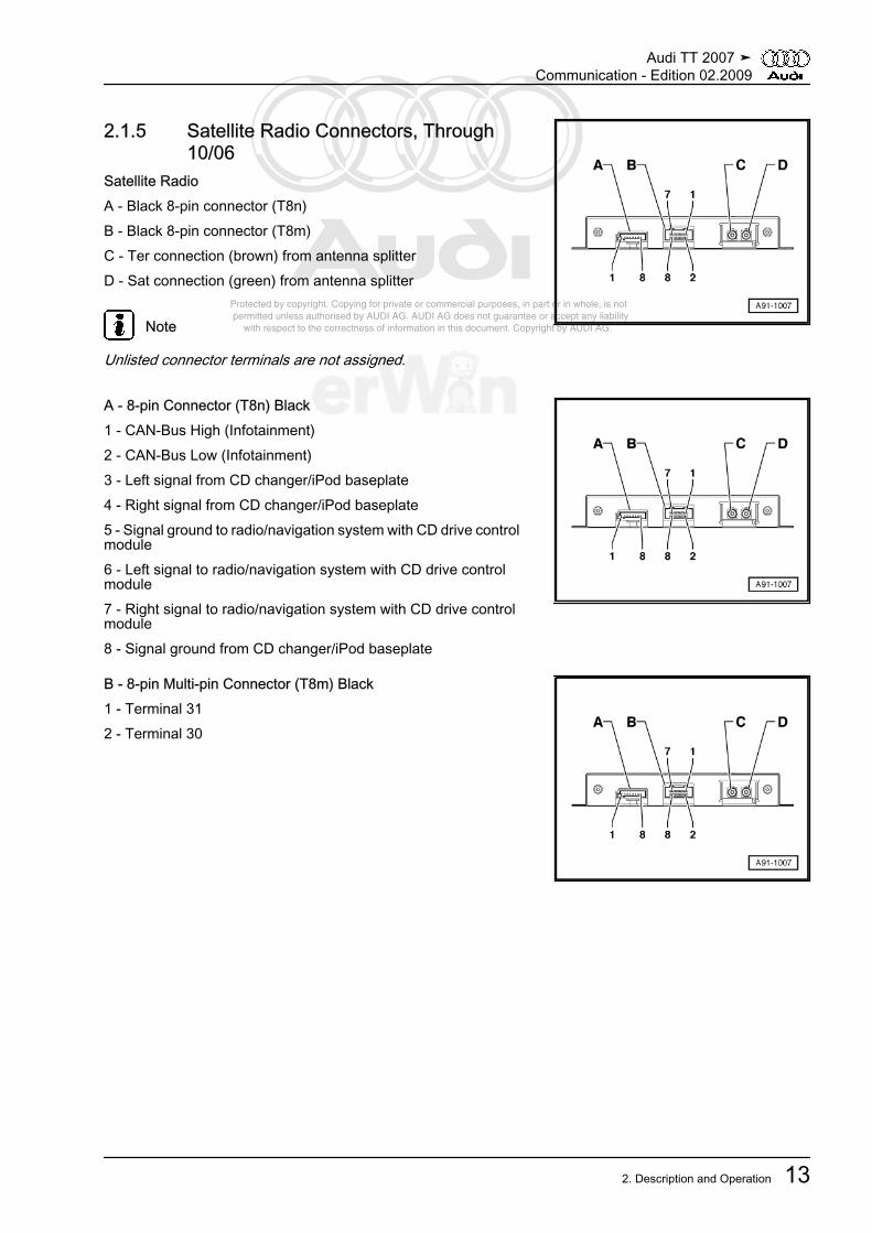
2.1.5 Satellite Radio Connectors, Through10/06
Satellite RadioA - Black 8-pin connector (T8n)B - Black 8-pin connector (T8m)C - Ter connection (brown) from antenna splitterD - Sat connection (green) from antenna splitter
Note
Unlisted connector terminals are not assigned.
A - 8-pin Connector (T8n) Black1 - CAN-Bus High (Infotainment)2 - CAN-Bus Low (Infotainment)3 - Left signal from CD changer/iPod baseplate4 - Right signal from CD changer/iPod baseplate5 - Signal ground to radio/navigation system with CD drive controlmodule6 - Left signal to radio/navigation system with CD drive controlmodule7 - Right signal to radio/navigation system with CD drive controlmodule8 - Signal ground from CD changer/iPod baseplate
B - 8-pin Multi-pin Connector (T8m) Black1 - Terminal 312 - Terminal 30
Audi TT 2007 ➤Communication - Edition 02.2009
2. Description and Operation 13

Protected by copyright. Copying for private or commercial purposes, in part or in whole, is not permitted unless authorised by AUDI AG. AUDI AG does not guarantee or accept any liability with respect to the correctness of information in this document. Copyright by AUDI AG.
2.1.6 Satellite Radio Connectors, From 11/06Satellite RadioA - Black 8-pin connector (T8n)B - Black 8-pin connector (T8m)C - Sat connection (green) from radio, telephone, navigation sys‐tem antenna Coupe- Sat connection (green) on the satellite antenna Roadster
Note
Unlisted connector terminals are not assigned.
A - 8-pin Connector (T8n) Black1 - CAN-Bus High (Infotainment)2 - CAN-Bus Low (Infotainment)3 - Left signal from CD changer/iPod baseplate4 - Right signal from CD changer/iPod baseplate5 - Signal ground to radio/navigation system with CD drive controlmodule6 - Left signal to radio/navigation system with CD drive controlmodule7 - Right signal to radio/navigation system with CD drive controlmodule8 - Signal ground from CD changer/iPod baseplate
B - 8-pin Multi-pin Connector (T8m) Black1 - Terminal 312 - Terminal 30
Audi TT 2007 ➤Communication - Edition 02.2009
14 Rep. Gr.91 - Communication

Protected by copyright. Copying for private or commercial purposes, in part or in whole, is not permitted unless authorised by AUDI AG. AUDI AG does not guarantee or accept any liability with respect to the correctness of information in this document. Copyright by AUDI AG.
2.1.7 Coupe Component Locations, General Overview
1 - Right Front Treble Speaker-R22-
❑ In right of instrumentpanel
❑ Removing and instal‐ling, refer to⇒ “4.4.6 Left Front Tre‐ble Speaker”,page 92
2 - Center Mid/High RangeLoudspeaker -R158-
❑ In front instrument pan‐el, center
❑ Removing and instal‐ling, refer to⇒ “4.4.8 Center Mid/High Range Speaker”,page 93
3 - Microphone Unit In FrontRoof Module -R164-
❑ In front interior light❑ Overview, refer to
⇒ “2.2.6 Front RoofModule MicrophoneUnit Overview”,page 24
❑ Removing and instal‐ling, refer to⇒ “4.4.12 MicrophoneUnit in Front Roof Mod‐ule”, page 94
4 - Antenna Amplifier -R24-❑ On upper right of rear lid❑ Overview, refer to
⇒ “2.3.2 Antennas Over‐view”, page 30
5 - Radio, Telephone, Navigation System Antenna -R52-❑ Overview, refer to ⇒ “2.3.2 Antennas Overview”, page 30
6 - Antenna Amplifier 2 -R111-❑ On lower right of rear lid❑ Overview, refer to ⇒ “2.3.2 Antennas Overview”, page 30
7 - Satellite Radio -R146-❑ Inside the luggage compartment on the left side under the luggage compartment floor covering❑ Connections through 10/06, refer to ⇒ “2.1.5 Satellite Radio Connectors, Through 10/06”, page 13❑ Connections from 11/06, refer to ⇒ “2.1.6 Satellite Radio Connectors, From 11/06”, page 14❑ Removing and installing, activating, refer to ⇒ “4.3 Satellite Radio”, page 88
8 - Digital Sound System Control Module -J525-❑ Behind the luggage compartment left side trim❑ Connectors through MY 2008, refer to
⇒ “2.2.7 Standard Sound System Connectors, Through MY 2008”, page 24❑ Connectors from MY 2009, refer to
⇒ “2.2.8 Standard Sound System Connectors, from MY 2009”, page 25❑ Removing and installing, refer to ⇒ “4.4.1 Digital Sound System Control Module”, page 89
Audi TT 2007 ➤Communication - Edition 02.2009
2. Description and Operation 15

Protected by copyright. Copying for private or commercial purposes, in part or in whole, is not permitted unless authorised by AUDI AG. AUDI AG does not guarantee or accept any liability with respect to the correctness of information in this document. Copyright by AUDI AG.
❑ BOSE connections, refer to ⇒ “2.2.9 BOSE Sound System Connectors”, page 27❑ BOSE, removing and installing, refer to
⇒ “4.4.2 Digital Sound System Control Module (BOSE)”, page 909 - Antenna Splitter -R87-
❑ Through 10/06❑ Inside the luggage compartment on the left side under the luggage compartment floor covering❑ Removing and installing, refer to ⇒ “4.5.6 Antenna Splitter”, page 99
10 - Left Rear Treble Speaker -R14- / Right Rear Treble Speaker -R16-❑ In upper right side trim❑ Removing and installing, refer to ⇒ “4.4.7 Left Rear Treble Speaker”, page 92
11 - Left Rear Mid/Low Range Loudspeaker -R159- / Right Rear Mid/Low Range Loudspeaker -R160-❑ Behind rear side trim❑ Removing and installing, refer to ⇒ “4.4.4 Left Rear Mid/Low Range Loudspeaker, Coupe”, page 91
- Center speaker -R148-❑ Behind the left rear side trim panel❑ Removing and installing, refer to ⇒ “4.4.11 Center Loudspeaker, Roadster”, page 94
12 - Left Front Midrange Speaker -R103- / Right Front Midrange Speaker -R104-❑ In center of doors❑ Removing and installing, refer to ⇒ “4.4.9 Left Front Midrange Speaker”, page 93
13 - Left Front Bass Speaker -R21- / Right Front Bass Speaker -R23-❑ In bottom of doors❑ Removing and installing, refer to ⇒ “4.4.3 Left Front Bass Speaker”, page 90
14 - Left Front Treble Speaker -R20-❑ In left of instrument panel❑ Removing and installing, refer to ⇒ “4.4.6 Left Front Treble Speaker”, page 92
15 - Radio -R-❑ In the top of the center console❑ Connectors. Refer to, refer to ⇒ “2.1.4 Radio, Harness Connectors”, page 11 .❑ Removing and installing, refer to ⇒ “4.1 Radio”, page 86❑ Symphony transport mode, activating/deactivating, refer to
⇒ “2.1.11 Symphony Transport Mode, Activating/Deactivating”, page 2016 - CD Changer -R41-
❑ In the glove compartment❑ Connectors, refer to ⇒ “2.10 CD Changer Harness Connectors ”, page 80 .❑ Removing and installing, refer to ⇒ “4.10 CD Changer”, page 107
- iPod Baseplate -R192-❑ In the glove compartment❑ Connectors, refer to ⇒ “2.11 iPod Baseplate, Connections”, page 81 .❑ Removing and installing, refer to ⇒ “4.11 iPod Baseplate”, page 108
- External audio source connection -R199-❑ Inside the glove compartment / center console❑ Connectors (connection for an external audio source) refer to
⇒ “2.12 External Audio Source Connection Connectors, AMI”, page 81❑ AUX IN Connectors, refer to
⇒ “2.13 AUX IN External Audio Source Connection Connectors”, page 82 .❑ Removing and installing (connection for an external audio source) refer to
⇒ “4.12 AMI External Audio Source Connection”, page 108
Audi TT 2007 ➤Communication - Edition 02.2009
16 Rep. Gr.91 - Communication

Protected by copyright. Copying for private or commercial purposes, in part or in whole, is not permitted unless authorised by AUDI AG. AUDI AG does not guarantee or accept any liability with respect to the correctness of information in this document. Copyright by AUDI AG.
❑ AUX IN, Removing and Installing, refer to⇒ “4.13 AUX IN External Audio Source Connection”, page 109 .
2.1.8 Roadster Component Locations, General Overview
1 - Right Front Treble Speaker-R22-
❑ In right of instrumentpanel
❑ Removing and installing⇒ “4.4.6 Left Front Tre‐ble Speaker”,page 92
2 - Center Mid/High RangeLoudspeaker -R158-
❑ In the center of the in‐strument panel
❑ Removing and instal‐ling, refer to⇒ “4.4.8 Center Mid/High Range Speaker”,page 93
3 - Microphone Unit In FrontRoof Module -R164-
❑ In front interior light❑ Overview, refer to
⇒ “2.2.6 Front RoofModule MicrophoneUnit Overview”,page 24
❑ Removing and instal‐ling, refer to⇒ “4.4.12 MicrophoneUnit in Front Roof Mod‐ule”, page 94
4 - Right Rear Treble Speaker-R16-
❑ In upper right side trim❑ Removing and instal‐
ling, refer to⇒ “4.4.7 Left Rear Tre‐ble Speaker”, page 92
5 - Left Rear Mid/Low Range Loudspeaker -R159- / Right Rear Mid/Low Range Loudspeaker -R160-❑ In left and right rear wall❑ Removing and installing, refer to ⇒ “4.4.5 Left Rear Mid/Low Range Speaker, Roadster”, page 91
6 - Antenna Amplifier 2 -R111-❑ Behind right side of rear lid❑ Overview, refer to ⇒ “2.4.2 Antennas, Overview”, page 34
7 - Satellite Antenna -R170-❑ On rear lid❑ Overview, refer to ⇒ “2.4.2 Antennas, Overview”, page 34
8 - Satellite Radio -R146-❑ Inside the luggage compartment on the left side under the luggage compartment floor covering❑ Connections through 10/06, refer to ⇒ “2.1.5 Satellite Radio Connectors, Through 10/06”, page 13❑ Connections from 11/06, refer to ⇒ “2.1.6 Satellite Radio Connectors, From 11/06”, page 14
Audi TT 2007 ➤Communication - Edition 02.2009
2. Description and Operation 17

Protected by copyright. Copying for private or commercial purposes, in part or in whole, is not permitted unless authorised by AUDI AG. AUDI AG does not guarantee or accept any liability with respect to the correctness of information in this document. Copyright by AUDI AG.
❑ Removing and installing, activating, refer to ⇒ “4.3 Satellite Radio”, page 889 - Digital Sound System Control Module -J525-
❑ Behind the luggage compartment left side trim❑ Connectors through MY 2008, refer to
⇒ “2.2.7 Standard Sound System Connectors, Through MY 2008”, page 24❑ Connectors from MY 2009, refer to
⇒ “2.2.8 Standard Sound System Connectors, from MY 2009”, page 25❑ Removing and installing, refer to ⇒ “4.4.1 Digital Sound System Control Module”, page 89❑ BOSE connections, refer to ⇒ “2.2.9 BOSE Sound System Connectors”, page 27❑ BOSE, removing and installing, refer to
⇒ “4.4.2 Digital Sound System Control Module (BOSE)”, page 9010 - Antenna Amplifier -R24-
❑ left rear mast antenna base❑ Overview, refer to ⇒ “2.4.2 Antennas, Overview”, page 34
11 - Left Rear Treble Speaker -R14-❑ In upper right side trim❑ Removing and installing, refer to ⇒ “4.4.7 Left Rear Treble Speaker”, page 92
12 - Left Front Midrange Speaker -R103- / Right Front Midrange Speaker -R104-❑ In center of doors❑ Removing and installing, refer to ⇒ “4.4.9 Left Front Midrange Speaker”, page 93
13 - Center speaker -R148-❑ In center of rear wall❑ Removing and installing, refer to ⇒ “4.4.11 Center Loudspeaker, Roadster”, page 94
14 - Left Front Bass Speaker -R21- / Right Front Bass Speaker -R23-❑ In bottom of doors❑ Removing and installing, refer to ⇒ “4.4.3 Left Front Bass Speaker”, page 90
15 - Left Front Treble Speaker -R20-❑ In left of instrument panel❑ Removing and installing, refer to ⇒ “4.4.6 Left Front Treble Speaker”, page 92
16 - Radio -R-❑ In the top of the center console❑ Connectors, refer to ⇒ “2.1.4 Radio, Harness Connectors”, page 11 .❑ Removing and installing, refer to ⇒ “4.1 Radio”, page 86❑ symphony transport mode, activating/deactivating, refer to
⇒ “2.1.11 Symphony Transport Mode, Activating/Deactivating”, page 2017 - CD Changer -R41-
❑ In the glove compartment❑ Connectors, refer to ⇒ “2.10 CD Changer Harness Connectors ”, page 80 .❑ Removing and installing, refer to ⇒ “4.10 CD Changer”, page 107
- iPod Baseplate -R192-❑ In the glove compartment❑ Connectors, refer to ⇒ “2.11 iPod Baseplate, Connections”, page 81 .❑ Removing and installing, refer to ⇒ “4.11 iPod Baseplate”, page 108
- External audio source connection -R199-❑ Inside the glove compartment / center console❑ Connectors (connection for an external audio source) refer to
⇒ “2.12 External Audio Source Connection Connectors, AMI”, page 81❑ AUX IN Connectors, refer to
⇒ “2.13 AUX IN External Audio Source Connection Connectors”, page 82 .
Audi TT 2007 ➤Communication - Edition 02.2009
18 Rep. Gr.91 - Communication

Protected by copyright. Copying for private or commercial purposes, in part or in whole, is not permitted unless authorised by AUDI AG. AUDI AG does not guarantee or accept any liability with respect to the correctness of information in this document. Copyright by AUDI AG.
❑ Removing and installing (connection for an external audio source) refer to⇒ “4.12 AMI External Audio Source Connection”, page 108
❑ AUX IN, Removing and Installing, refer to⇒ “4.13 AUX IN External Audio Source Connection”, page 109 .
2.1.9 Radio Preparation1 - Speaker connector (T8d) brown2 - Voltage supply connector (T8c) black3 - Antenna connection (AM/FM1) for the radio4 - Antenna amplifier on upper right side of rear lid (Coupe)- Antenna amplifier left rear mast antenna base (Roadster)5 - Rear window antenna 1 AM/FM1 (Coupe)- Antenna (AM/FM1) mast antenna (Roadster)6 - left front speaker7 - right front speaker
2.1.10 Satellite Radio, EnablingWhen using for first time or when replacing satellite radio tuner, itmust be enabled (activated) by the provider (XM or Sirius).The subscription and application for activation can coincide withsubmission of all necessary data (US postal address, credit cardnumber, radio ID (XM) or SID (Sirius)) to the provider's call center.Only SIRIUS:SIRIUS sends the activation sequence 6 times within the first hourafter apply for the activation. If no successful activation results,another activation sequence must be requested at the SIRIUScall center.Requirements♦ Customer has subscribed to XM or Sirius♦ Satellite radio is installed and connected♦ radio/navigation system with CD drive control module is adap‐
ted/coded accordingly♦ Ignition switched onProcedure– Switch on radio/navigation system with CD drive control mod‐
ule and select satellite radio reception range.– Attempt to receive free channels in XM (e.g. channel 1) or Sir‐
ius band (only channel 184).– Change location.If free channels can be received clearly, the activation informationsent by the provider (XM or Sirius) can also be received clearly.A poor reception situation can prevent a successful activationeven though activation information is being broadcast. In thiscase, vehicle location must be changed (an activation is also pos‐sible while vehicle is moving). There are e.g. workshops, garages,parking buildings, underground garages, fuel filling stations withextensive roofs and all other parking areas with signal shadowsmust be avoided.
Audi TT 2007 ➤Communication - Edition 02.2009
2. Description and Operation 19

Protected by copyright. Copying for private or commercial purposes, in part or in whole, is not permitted unless authorised by AUDI AG. AUDI AG does not guarantee or accept any liability with respect to the correctness of information in this document. Copyright by AUDI AG.
2.1.11 Symphony Transport Mode, Activating/Deactivating
Transport mode must be activated before sending every sym‐phony radio.After activation, the internal CD changer drive is in transport po‐sition.After replacing a symphony, transport mode must be deactivatedafter installation.Transport mode, activatingsymphony is connected and installed.– Press station buttons 3 and 5 and TONE button at the same
time.After about 5 seconds, TRANSPORT appears on the radio dis‐play.Transport mode, deactivatingsymphony is connected and installed.– Press CANCEL button.
TRANSPORT display goes out.Transport mode is deactivated.
Audi TT 2007 ➤Communication - Edition 02.2009
20 Rep. Gr.91 - Communication

Protected by copyright. Copying for private or commercial purposes, in part or in whole, is not permitted unless authorised by AUDI AG. AUDI AG does not guarantee or accept any liability with respect to the correctness of information in this document. Copyright by AUDI AG.
2.2 Sound System⇒ “2.2.1 Coupe, Assembly Overview”, page 21⇒ “2.2.2 Roadster, Assembly Overview”, page 22⇒ “2.2.3 Base Sound System, Overview”, page 23⇒ “2.2.4 Standard Sound System, Overview”, page 23⇒ “2.2.5 BOSE Sound System”, page 24⇒ “2.2.6 Front Roof Module Microphone Unit Overview”,page 24⇒ “2.2.7 Standard Sound System Connectors, Through MY2008”, page 24⇒ “2.2.8 Standard Sound System Connectors, from MY 2009”,page 25⇒ “2.2.9 BOSE Sound System Connectors”, page 27
2.2.1 Coupe, Assembly Overview
1 - Left Front Bass Speaker -R21- / Right Front Bass Speak‐er -R23-2 - Screw
❑ 3.5 Nm3 - Left Front Midrange Speak‐er -R103- / Right Front Mid‐range Speaker -R104-4 - Screw
❑ 2 Nm5 - Screw
❑ 2 Nm6 - Left Rear Mid/Low RangeLoudspeaker -R159- / RightRear Mid/Low Range Loud‐speaker -R160-7 - Clamp8 - Digital Sound System Con‐trol Module -J525-9 - Screw
❑ 3 Nm10 - Nut
❑ 5 Nm11 - Digital Sound SystemControl Module -J525- BOSE12 - Nut
❑ 5 Nm13 - Screw
❑ 3 Nm14 - Nut
❑ 2 Nm
Audi TT 2007 ➤Communication - Edition 02.2009
2. Description and Operation 21

Protected by copyright. Copying for private or commercial purposes, in part or in whole, is not permitted unless authorised by AUDI AG. AUDI AG does not guarantee or accept any liability with respect to the correctness of information in this document. Copyright by AUDI AG.
15 - Screw❑ 2 Nm
16 - Center Speaker -R148-17 - Left Front Treble Speaker -R20- / Right Front Treble Speaker -R22-18 - Instrument panel19 - Screw
❑ 1 Nm20 - Instrument panel21 - Center Mid/High Range Loudspeaker -R158-
2.2.2 Roadster, Assembly Overview
1 - Clamp2 - Digital Sound System Con‐trol Module -J525-3 - Screw
❑ 3 Nm4 - Nut
❑ 5 Nm5 - Digital Sound System Con‐trol Module -J525- BOSE6 - Nut
❑ 5 Nm7 - Screw
❑ 3 Nm8 - Screw
❑ 2 Nm9 - Left Rear Mid/Low RangeLoudspeaker -R159- / RightRear Mid/Low Range Loud‐speaker -R160-10 - Left Front Treble Speaker-R20- / Right Front TrebleSpeaker -R22-11 - Center Mid/High RangeLoudspeaker -R158-12 - Screw
❑ 1 Nm13 - Left Front Bass Speaker -R21- / Right Front Bass Speak‐er -R23-14 - Screw
❑ 3.5 Nm15 - Left Front Midrange Speaker -R103- / Right Front Midrange Speaker -R104-16 - Screw
❑ 2 Nm
Audi TT 2007 ➤Communication - Edition 02.2009
22 Rep. Gr.91 - Communication

Protected by copyright. Copying for private or commercial purposes, in part or in whole, is not permitted unless authorised by AUDI AG. AUDI AG does not guarantee or accept any liability with respect to the correctness of information in this document. Copyright by AUDI AG.
17 - Center speaker -R148-18 - Screw
❑ 2 Nm
2.2.3 Base Sound System, Overview1 - radio in upper center console2 - left front treble speaker/right front treble speaker in left andright front of instrument panel3 - left front bass speaker/right front bass speaker at bottom ofdoors
2.2.4 Standard Sound System, Overview
1 - Digital Sound System Con‐trol Module -J525- behind theluggage compartment left sidetrim2 - Left Front Treble Speaker -R20- / Right Front TrebleSpeaker -R22- in left and rightfront of instrument panel3 - Left Front Bass Speaker -R21- / Right Front Bass Speak‐er -R23- at bottom of doors4 - Left Rear Treble Speaker -R14- / Right Rear TrebleSpeaker -R16- in upper rearside trim5 - Left Rear Mid/Low RangeLoudspeaker -R159- / RightRear Mid/Low Range Loud‐speaker -R160- in rear sidetrim (Coupe)/in rear wall(Roadster)6 - Center Mid/High RangeSpeaker -R158- in center in‐strument panel, front
Audi TT 2007 ➤Communication - Edition 02.2009
2. Description and Operation 23

Protected by copyright. Copying for private or commercial purposes, in part or in whole, is not permitted unless authorised by AUDI AG. AUDI AG does not guarantee or accept any liability with respect to the correctness of information in this document. Copyright by AUDI AG.
2.2.5 BOSE Sound System
1 - Digital Sound System Con‐trol Module -J525- behind theluggage compartment left sidetrim2 - Left Front Treble Speaker -R20- / Right Front TrebleSpeaker -R22- in left and rightfront of instrument panel3 - Left Front Midrange Speak‐er -R103- / Right Front Mid‐range Speaker -R104- indoors, center4 - Left Front Bass Speaker -R21- / Right Front Bass Speak‐er -R23- at bottom of doors5 - Center Mid/High RangeSpeaker -R158- in center in‐strument panel, front6 - Left Rear Treble Speaker -R14- / Right Rear TrebleSpeaker -R16- in upper rearside trim7 - Left Rear Mid/Low RangeLoudspeaker -R159- / RightRear Mid/Low Range Loud‐speaker -R160- in rear sidetrim (Coupe)/in rear wall(Roadster)8 - Center Loudspeaker -R148- behind left rear side trim(Coupe)/in center of rear wall(Roadster)9 - Microphone Unit (in frontroof module) -R164- in FrontInterior Light -W1-
2.2.6 Front Roof Module Microphone UnitOverview
Microphone unit in front roof module -R164-1 - Black 4-pin Multi-pin Harness Connector (T4g)1 - Microphone 1 to telephone transceiver2 - Microphone 1 to Telephone transceiver3 - Microphone 2 to digital sound system control module4 - Microphone 2 to digital sound system control module2 - Microphone 13 - Microphone 2
2.2.7 Standard Sound System Connectors,Through MY 2008
Digital sound system control module
Audi TT 2007 ➤Communication - Edition 02.2009
24 Rep. Gr.91 - Communication

Protected by copyright. Copying for private or commercial purposes, in part or in whole, is not permitted unless authorised by AUDI AG. AUDI AG does not guarantee or accept any liability with respect to the correctness of information in this document. Copyright by AUDI AG.
Note
Unlisted connector terminals are not assigned.
A - Black 32-pin Multi-pin Harness Connector (T32a)1 - Terminal 302 - Terminal 313 - Loudspeaker, left front (-)4 - Loudspeaker, left front (+)6 - Loudspeaker, left rear (+)7 - Loudspeaker, left rear (-)11 - CAN-bus low (Infotainment)12 - CAN-bus high (Infotainment)14 - Positive switched from radio/navigation system with CD drivecontrol module, radio/navigation display control module15 - Loudspeaker, right front (-)16 - Loudspeaker, right front (+)18 - Loudspeaker, right rear (-)19 - Loudspeaker, right rear (+)20 - Center mid/high range speaker (-)21 - Center mid/high range speaker (+)24 - Left rear signal (-) from radio/navigation system with CD drivecontrol module, radio/navigation display control module25 - Left rear signal (+) from radio/navigation system with CD drivecontrol module, radio/navigation display control module26 - Left front signal (-) from radio/navigation system with CD drivecontrol module, radio/navigation display control module27 - Left front signal (+) from radio/navigation system with CDdrive control module, radio/navigation display control module29 - Right rear signal (-) from radio/navigation system with CDdrive control module, radio/navigation display control module30 - Right rear signal (+) from radio/navigation system with CDdrive control module, radio/navigation display control module31 - Right front signal (-) from radio/navigation system with CDdrive control module, radio/navigation display control module32 - Right front signal (+) from radio/navigation system with CDdrive control module, radio/navigation display control module
2.2.8 Standard Sound System Connectors,from MY 2009
Digital sound system control module
Audi TT 2007 ➤Communication - Edition 02.2009
2. Description and Operation 25

Protected by copyright. Copying for private or commercial purposes, in part or in whole, is not permitted unless authorised by AUDI AG. AUDI AG does not guarantee or accept any liability with respect to the correctness of information in this document. Copyright by AUDI AG.
Note
Unlisted connector terminals are not assigned.
A - Black 38-pin Connector (T38)1 - Terminal 312 - Terminal 304 - Loudspeaker, right front (+)5 - Loudspeaker, left front (+)7 - Loudspeaker, right rear (-)8 - Loudspeaker, left rear (+)10 - Center mid/high range speaker (-)16 - Loudspeaker, right front (-)17 - Loudspeaker, left front (-)19 - Loudspeaker, right rear (+)20 - Loudspeaker, left rear (-)22 - Center mid/high range speaker (+)23 - CAN-Bus Low (Infotainment)27 - Left rear signal (-) from radio/navigation system with CD drivecontrol module, radio/navigation display control module28 - Right rear signal (-) from radio/navigation system with CDdrive control module, radio/navigation display control module29 - Left front signal (-) from radio/navigation system with CD drivecontrol module, radio/navigation display control module30 - Right front signal (-) from radio/navigation system with CDdrive control module, radio/navigation display control module31 - CAN-Bus High (Infotainment)34 - Positive switched from radio/navigation system with CD drivecontrol module, radio/navigation display control module35 - Left rear signal (+) from radio/navigation system with CD drivecontrol module, radio/navigation display control module36 - Right rear signal (+) from radio/navigation system with CDdrive control module, radio/navigation display control module37 - Left front signal (+) from radio/navigation system with CDdrive control module, radio/navigation display control module38 - Right front signal (+) from radio/navigation system with CDdrive control module, radio/navigation display control module
Audi TT 2007 ➤Communication - Edition 02.2009
26 Rep. Gr.91 - Communication

Protected by copyright. Copying for private or commercial purposes, in part or in whole, is not permitted unless authorised by AUDI AG. AUDI AG does not guarantee or accept any liability with respect to the correctness of information in this document. Copyright by AUDI AG.
2.2.9 BOSE Sound System ConnectorsDigital sound system control moduleA - Black 18-pin connector (T18a)B - Black 32-pin multi-pin harness connector (T32a)
Note
Unlisted connector terminals are not assigned.
A - Black 18-pin Multi-pin Harness Connector (T18a)3 - Left front signal (+) from radio/navigation system with CD drivecontrol module, radio/navigation display control module4 - Left front signal (-) from radio/navigation system with CD drivecontrol module, radio/navigation display control module5 - Left rear signal (+) from radio/navigation system with CD drivecontrol module, radio/navigation display control module6 - Left rear signal (-) from radio/navigation system with CD drivecontrol module, radio/navigation display control module11 - Right front signal (+) from radio/navigation system with CDdrive control module, radio/navigation display control module12 - Right front signal (-) from radio/navigation system with CDdrive control module, radio/navigation display control module13 - Right rear signal (+) from radio/navigation system with CDdrive control module, radio/navigation display control module14 - Right rear signal (-) from radio/navigation system with CDdrive control module, radio/navigation display control module
Audi TT 2007 ➤Communication - Edition 02.2009
2. Description and Operation 27

Protected by copyright. Copying for private or commercial purposes, in part or in whole, is not permitted unless authorised by AUDI AG. AUDI AG does not guarantee or accept any liability with respect to the correctness of information in this document. Copyright by AUDI AG.
B - Black 32-pin Multi-pin Harness Connector (T32a)1 - Terminal 302 - Terminal 313 - Left front bass speaker (+)4 - Right front bass speaker (+)5 - Center loudspeaker (+)6 - Loudspeaker, right front (+)7 - Loudspeaker, left front (+)8 - Center mid/high range speaker (+)9 - Microphone input (-) from microphone unit (in front roof mod‐ule)10 - Microphone input (+) from microphone unit (in front roof mod‐ule)11 - Loudspeaker, left rear (-)12 - Loudspeaker, left rear (+)13 - Loudspeaker, right rear (-)14 - Loudspeaker, right rear (+)15 - Left Front Bass Speaker (-)16 - Right Front Bass Speaker (-)17 - Center Loudspeaker (-)18 - Loudspeaker, right front (-)19 - Loudspeaker, left front (-)20 - Center Mid/High Range Speaker (-)23 - Microphone input (ground shielding) from microphone unit (infront roof module)27 - CAN-Bus high (Infotainment)29 - Positive switched from radio/navigation system with CD drivecontrol module, radio/navigation display control module32 - CAN-Bus Low (Infotainment)
Audi TT 2007 ➤Communication - Edition 02.2009
28 Rep. Gr.91 - Communication

Protected by copyright. Copying for private or commercial purposes, in part or in whole, is not permitted unless authorised by AUDI AG. AUDI AG does not guarantee or accept any liability with respect to the correctness of information in this document. Copyright by AUDI AG.
2.3 Antenna System, Coupe⇒ “2.3.1 Antenna system Assembly Overview”, page 29⇒ “2.3.2 Antennas Overview”, page 30⇒ “2.3.3 Antenna Amplifier 2 Connections”, page 31⇒ “2.3.4 Antenna Amplifier/Antenna Amplifier 4 connections”,page 31
2.3.1 Antenna system Assembly Overview
1 - Radio, Telephone, Naviga‐tion System Antenna -R52-2 - Nut
❑ 6 Nm3 - Screw
❑ 2 Nm4 - Antenna Amplifier -R24-5 - Nut
❑ 6 Nm6 - Antenna Amplifier 2 -R111-7 - Windshield Antenna Sup‐pression Filter -C18-8 - Nut
❑ 6 Nm9 - Nut
❑ 6 Nm10 - Nut
❑ 6 Nm11 - Antenna Amplifier 4 -R113-12 - Screw
❑ 2 Nm
Audi TT 2007 ➤Communication - Edition 02.2009
2. Description and Operation 29

Protected by copyright. Copying for private or commercial purposes, in part or in whole, is not permitted unless authorised by AUDI AG. AUDI AG does not guarantee or accept any liability with respect to the correctness of information in this document. Copyright by AUDI AG.
2.3.2 Antennas Overview
1 - Radio, Telephone, Naviga‐tion System Antenna -R52-
❑ GPS/GSM❑ Removing and installing
⇒ “4.5.3 Radio, Tele‐phone, Navigation Sys‐tem Antenna”,page 96
❑ Sat/GPS/GSM (USAonly)
❑ Removing and installing⇒ “4.5.4 Radio, Tele‐phone, Navigation Sys‐tem Antenna”,page 97
2 - Antenna Amplifier 4 -R113-❑ Connectors. Refer to
⇒ “2.3.4 Antenna Ampli‐fier/Antenna Amplifier 4connections”,page 31 .
❑ Removing and installing⇒ “4.5.2 Antenna Ampli‐fier and Antenna Ampli‐fier 4”, page 95
3 - Antenna Amplifier -R24-❑ Connectors. Refer to
⇒ “2.3.4 Antenna Ampli‐fier/Antenna Amplifier 4connections”,page 31 .
❑ Removing and installing⇒ “4.5.2 Antenna Ampli‐fier and Antenna Ampli‐fier 4”, page 95
4 - Antenna Amplifier 2 -R111-❑ Connectors. Refer to ⇒ “2.3.3 Antenna Amplifier 2 Connections”, page 31 .❑ Removing and installing ⇒ “4.5.1 Antenna Amplifier 2”, page 95
Audi TT 2007 ➤Communication - Edition 02.2009
30 Rep. Gr.91 - Communication

Protected by copyright. Copying for private or commercial purposes, in part or in whole, is not permitted unless authorised by AUDI AG. AUDI AG does not guarantee or accept any liability with respect to the correctness of information in this document. Copyright by AUDI AG.
2.3.3 Antenna Amplifier 2 Connections
A - FM2/ZF connection (yel‐low) to Radio -R- / NavigationSystem with CD Drive ControlModule -J401- / Radio/Naviga‐tion Display Control Module -J503-B - AM/FM1 connection (black)from the Antenna Amplifier -R24- (only with the radio/navi‐gation system)C - HF connection (white) toNavigation System with CDDrive Control Module -J401- /Radio/Navigation Display UnitControl Module -J503-D - TV1 connection (brown) toTV Tuner -R78-E - TV2 connection (green) toTV Tuner -R78-F - Connection for window an‐tennas1 - FM2/TV1
2 - Ground (GND)
3 - FM3/TV2
2.3.4 Antenna Amplifier/Antenna Amplifier 4connections
Antenna amplifier1 - Central locking and anti-theft alarm system antenna CLS con‐nection (gray)2 - AM/FM2 connection (white) to radio/radio preparation/antennaamplifier 23 - Window antenna connection (1 - FM1, 2 - CLS, 3 - AM)
Audi TT 2007 ➤Communication - Edition 02.2009
2. Description and Operation 31

Protected by copyright. Copying for private or commercial purposes, in part or in whole, is not permitted unless authorised by AUDI AG. AUDI AG does not guarantee or accept any liability with respect to the correctness of information in this document. Copyright by AUDI AG.
Antenna Amplifier 4 -R113-1 - Connection TV3 (green) to TV Tuner2 - DAB connection (black)3 - Window antenna connection (1 - TV/DAB, 2 - DAB, 3 - TV3)
Audi TT 2007 ➤Communication - Edition 02.2009
32 Rep. Gr.91 - Communication

Protected by copyright. Copying for private or commercial purposes, in part or in whole, is not permitted unless authorised by AUDI AG. AUDI AG does not guarantee or accept any liability with respect to the correctness of information in this document. Copyright by AUDI AG.
2.4 Antenna System, Roadster⇒ “2.4.1 Antenna System Assembly Overview”, page 33⇒ “2.4.2 Antennas, Overview”, page 34⇒ “2.4.3 Antenna Amplifier Connections”, page 35⇒ “2.4.4 Antenna Amplifier 2 Connections”, page 35⇒ “2.4.5 Antenna Selection Control Module Connections”,page 35
2.4.1 Antenna System Assembly Overview
1 - Nut (through MY 2007)❑ 2 Nm
2 - TV Antenna 2 -R56-(through MY 2007)3 - Navigation System Antenna-R50- / Telephone Antenna -R65-4 - Screw
❑ 2 Nm5 - Antenna Amplifier 2 -R111-6 - Screw
❑ 2 Nm7 - Radio Antenna 2 -R93-8 - Screw
❑ 2 Nm9 - Antenna Selection ControlModule -J515-10 - Screw
❑ 2 Nm11 - Antenna -R11- Mast An‐tenna12 - Antenna Amplifier -R24-13 - Nut
❑ 4 Nm14 - Grommet15 - Satellite Antenna -R170-16 - Nut
❑ 6 Nm17 - Cover18 - Screw
❑ 4 Nm19 - TV antenna 2 -R56- (from MY 2008)20 - Nut (from MY 2008)
❑ 1.5 Nm
Audi TT 2007 ➤Communication - Edition 02.2009
2. Description and Operation 33

Protected by copyright. Copying for private or commercial purposes, in part or in whole, is not permitted unless authorised by AUDI AG. AUDI AG does not guarantee or accept any liability with respect to the correctness of information in this document. Copyright by AUDI AG.
2.4.2 Antennas, Overview
1 - TV Antenna 2 -R56-❑ Removing and installing
through MY 2007, referto⇒ “4.6.3 TV Antenna 2,through MY 2007”, page101
❑ Removing and installingfrom MY 2008, refer to⇒ “4.6.4 TV Antenna 2,from MY 2008”,page 101
❑ Removing and instal‐ling, USA version, referto⇒ “4.6.8 TV Antenna 2”,page 103
2 - Telephone antenna -R65-❑ Removing and instal‐
ling, refer to⇒ “4.6.6 Navigation Sys‐tem Antenna/Tele‐phone Antenna”,page 102
3 - Navigation System Antenna-R50-
❑ Removing and instal‐ling, refer to⇒ “4.6.6 Navigation Sys‐tem Antenna/Tele‐phone Antenna”,page 102
4 - Antenna Selection ControlModule -J515-
❑ Only with RNS-E withTV
❑ Connectors. Refer to, refer to ⇒ “2.4.5 Antenna Selection Control Module Connections”, page 35 .❑ Removing and installing, refer to ⇒ “4.6.5 Antenna Selection Control Module”, page 102
5 - Antenna Amplifier 2 -R111-❑ Connectors, refer to ⇒ “2.4.4 Antenna Amplifier 2 Connections”, page 35 .❑ Removing and installing, refer to ⇒ “4.6.2 Antenna Amplifier 2”, page 100
6 - Satellite Antenna -R170- (USA only)❑ Removing and installing, refer to ⇒ “4.6.7 Satellite Antenna”, page 103
7 - Antenna Amplifier -R24-❑ Connectors, refer to ⇒ “2.4.3 Antenna Amplifier Connections”, page 35 .❑ Removing and installing, refer to ⇒ “4.6.1 Antenna Amplifier”, page 100
8 - TV Antenna 3 -R57-❑ Removing and installing through MY 2007, refer to
⇒ “4.6.3 TV Antenna 2, through MY 2007”, page 101❑ Removing and installing from MY 2008, refer to ⇒ “4.6.4 TV Antenna 2, from MY 2008”, page 101❑ Removing and installing, USA version, refer to ⇒ “4.6.8 TV Antenna 2”, page 103
Audi TT 2007 ➤Communication - Edition 02.2009
34 Rep. Gr.91 - Communication

Protected by copyright. Copying for private or commercial purposes, in part or in whole, is not permitted unless authorised by AUDI AG. AUDI AG does not guarantee or accept any liability with respect to the correctness of information in this document. Copyright by AUDI AG.
2.4.3 Antenna Amplifier ConnectionsAntenna Amplifier -R24-1 - Grommet with Antenna (AM/FM1) mast antenna2 - DAB connection (black)3 - Central locking and anti-theft alarm system antenna CLS con‐nection (gray)4 - AM/FM1 connection (white) to radio/antenna selection controlmodule/antenna amplifier 2
2.4.4 Antenna Amplifier 2 ConnectionsAntenna Amplifier 2 -R111-1 - Radio Antenna 2 FM2/TV1 rear lid antenna2 - AM/FM1 connection (black) from the antenna amplifier (onlywith the radio/navigation system)3 - IF connection (yellow) from navigation system with CD drivecontrol module, radio/navigation display unit control module (onlyRNS without TV)- Connection TV1 (green) to TV Tuner4 - HF connection (white) to navigation system with CD drive con‐trol module, radio/navigation display unit control module (onlyRNS without TV)- FM2 connection (yellow) to radio, antenna selection controlmodule
2.4.5 Antenna Selection Control Module Con‐nections
Antenna Selection Control Module -J515-1 - AM/FM1 connection (black) from antenna amplifier2 - HF connection (white) to navigation system with CD drive con‐trol module3 - IF connection (yellow) from navigation system with CD Drivecontrol module4 - FM2 connection (yellow) from antenna amplifier 2
Audi TT 2007 ➤Communication - Edition 02.2009
2. Description and Operation 35

Protected by copyright. Copying for private or commercial purposes, in part or in whole, is not permitted unless authorised by AUDI AG. AUDI AG does not guarantee or accept any liability with respect to the correctness of information in this document. Copyright by AUDI AG.
2.5 Telephone System⇒ “2.5.1 Coupe, Assembly Overview”, page 36⇒ “2.5.2 Roadster, Assembly Overview”, page 37⇒ “2.5.3 Cellular Telephone Preparation Preliminary Setup, Over‐view”, page 37⇒ “2.5.4 Cellular Telephone Preparation, Layout”, page 38⇒ “2.5.5 Cellular Telephone Preparation, Connector, PreliminarySetup”, page 39⇒ “2.5.6 Cellular Telephone Preparation Connectors, through MY2008”, page 39⇒ “2.5.7 Cellular Telephone Preparation Connectors, from MY2009”, page 40⇒ “2.5.8 Front Roof Module Microphone Unit Overview”,page 41⇒ “2.5.9 Telephone Transceiver Harness Connectors”,page 41⇒ “2.5.10 Coupe Component Locations, General Overview”, page43⇒ “2.5.11 Roadster Component Locations, General Overview”,page 44
2.5.1 Coupe, Assembly Overview1 - Front Interior Light -W1-with Microphone Unit (in frontroof module) -R164-2 - Radio, Telephone, Naviga‐tion System Antenna -R52-3 - Nut
❑ 6 Nm4 - Not Installed5 - Electronic Box Cover6 - Telephone transceiver -R36-7 - Electronics Box8 - Screw
❑ 2 Nm9 - Base plate10 - Telephone Base plate -R126-
Audi TT 2007 ➤Communication - Edition 02.2009
36 Rep. Gr.91 - Communication
Protected by copyright. Copying for private or commercial purposes, in part or in whole, is not permitted unless authorised by AUDI AG. AUDI AG does not guarantee or accept any liability with respect to the correctness of information in this document. Copyright by AUDI AG.
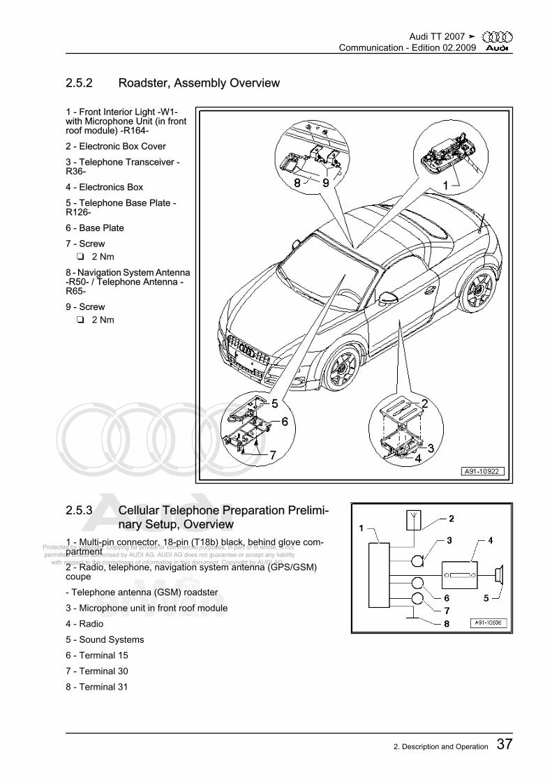
2.5.2 Roadster, Assembly Overview
1 - Front Interior Light -W1-with Microphone Unit (in frontroof module) -R164-2 - Electronic Box Cover3 - Telephone Transceiver -R36-4 - Electronics Box5 - Telephone Base Plate -R126-6 - Base Plate7 - Screw
❑ 2 Nm8 - Navigation System Antenna-R50- / Telephone Antenna -R65-9 - Screw
❑ 2 Nm
2.5.3 Cellular Telephone Preparation Prelimi‐nary Setup, Overview
1 - Multi-pin connector, 18-pin (T18b) black, behind glove com‐partment2 - Radio, telephone, navigation system antenna (GPS/GSM)coupe- Telephone antenna (GSM) roadster3 - Microphone unit in front roof module4 - Radio5 - Sound Systems6 - Terminal 157 - Terminal 308 - Terminal 31
Audi TT 2007 ➤Communication - Edition 02.2009
2. Description and Operation 37

Protected by copyright. Copying for private or commercial purposes, in part or in whole, is not permitted unless authorised by AUDI AG. AUDI AG does not guarantee or accept any liability with respect to the correctness of information in this document. Copyright by AUDI AG.
2.5.4 Cellular Telephone Preparation, Layout
1 - Telephone Baseplate -R126- inside the center con‐sole (through MY 2008)2 - Radio -R- / Navigation Sys‐tem with CD Drive ControlModule -J401- in top of centerconsole3 - Sound Systems4 - Bluetooth Antenna -R152-at Telephone Transceiver -R36-5 - Telephone Transceiver -R36- In Electronics Box UnderLeft Front Seat6 - Microphone Unit (in frontroof module) -R164- in FrontInterior Light -W1-7 - radio, telephone and navi‐gation system antenna -R52-Roof Antenna (Coupe)Through MY 2008- Telephone Antenna -R65-Behind The Front InteriorLamp -W1- (Roadster)Through MY 2008
Audi TT 2007 ➤Communication - Edition 02.2009
38 Rep. Gr.91 - Communication

Protected by copyright. Copying for private or commercial purposes, in part or in whole, is not permitted unless authorised by AUDI AG. AUDI AG does not guarantee or accept any liability with respect to the correctness of information in this document. Copyright by AUDI AG.
2.5.5 Cellular Telephone Preparation, Con‐nector, Preliminary Setup
Note
Unlisted connector terminals are not assigned.
Black 18-pin connector (T18b)1 - Terminal 314 - NF mute to radio/navigation system with CD drive controlmodule, radio/navigation display control module7 - NF (-) to radio/navigation system with CD drive control module,radio/navigation display control module9 - Microphone unit (in front roof module) (-)10 - Terminal 1511 - Terminal 3016 - NF (+) to radio/navigation system with CD drive control mod‐ule, radio/navigation display control module18 - Microphone unit (in front roof module) (+)
2.5.6 Cellular Telephone Preparation Con‐nectors, through MY 2008
Telephone transceiver -R36-A - Bluetooth antenna connection (yellow)B - Black 54-pin multi-pin harness connector (T54)
Note
Unlisted connector terminals are not assigned.
Audi TT 2007 ➤Communication - Edition 02.2009
2. Description and Operation 39

Protected by copyright. Copying for private or commercial purposes, in part or in whole, is not permitted unless authorised by AUDI AG. AUDI AG does not guarantee or accept any liability with respect to the correctness of information in this document. Copyright by AUDI AG.
B - Black 54-pin multi-pin harness connector (T54)1 - Terminal 302 - Terminal 318 - LF (+) out to radio/navigation system with CD drive controlmodule9 - LF (-) out to radio/navigation system with CD drive controlmodule10 - Terminal 31 (screen ground) (not used)11 - Microphone input (+) from microphone unit (in front roof mod‐ule)/navigation system with CD drive control module12 - Microphone input (-) from microphone unit (in front roof mod‐ule)/navigation system with CD drive control module16 - LF mute to Navigation System with CD Drive Control Module17 - CAN-Bus High (Infotainment)18 - CAN-Bus Low (Infotainment)37 - Terminal 30 to telephone baseplate39 - Terminal 31 to telephone baseplate41 - Terminal 30 to telephone baseplate42 - Microphone output (+) to telephone baseplate43 - Microphone output (-) to telephone baseplate44 - Terminal 31 (screen ground)45 - LF (+) from telephone baseplate46 - LF (-) from telephone baseplate47 - SNDREQ signal from telephone baseplate49 - Ser-Tx (+) to telephone baseplate50 - Ser-Tx (-) to telephone baseplate51 - Ser-Rx (+) from telephone baseplate52 - Ser-Rx (-) from telephone baseplate
2.5.7 Cellular Telephone Preparation Con‐nectors, from MY 2009
Telephone transceiver -R36-A - Bluetooth antenna connection (yellow)B - Black 54-pin multi-pin harness connector (T54)
Note
Unlisted connector terminals are not assigned.
Audi TT 2007 ➤Communication - Edition 02.2009
40 Rep. Gr.91 - Communication

Protected by copyright. Copying for private or commercial purposes, in part or in whole, is not permitted unless authorised by AUDI AG. AUDI AG does not guarantee or accept any liability with respect to the correctness of information in this document. Copyright by AUDI AG.
B - Black 54-pin multi-pin harness connector (T54)1 - Terminal 302 - Terminal 318 - LF (+) out to radio/navigation system with CD drive controlmodule9 - LF (-) out to radio/navigation system with CD drive controlmodule10 - Terminal 31 (screen ground) (not used)11 - Microphone input (+) from microphone unit (in front roof mod‐ule)/navigation system with CD drive control module12 - Microphone input (-) from microphone unit (in front roof mod‐ule)/navigation system with CD drive control module16 - LF mute to navigation system with CD drive control module17 - CAN-Bus High (Infotainment)18 - CAN-Bus Low (Infotainment)
2.5.8 Front Roof Module Microphone UnitOverview
Microphone unit in front roof module -R164-1 - Black 4-pin multi-pin harness connector (T4g)1 - Microphone 1 to telephone transceiver2 - Microphone 1 to telephone transceiver3 - Microphone 2 to digital sound system control module4 - Microphone 2 to digital sound system control module2 - Microphone 13 - Microphone 2
2.5.9 Telephone Transceiver Harness Con‐nectors
Telephone transceiver -R36-A - Bluetooth antenna connection (yellow)B - Black 54-pin multi-pin harness connector (T54)
Note
Unlisted connector terminals are not assigned.
Audi TT 2007 ➤Communication - Edition 02.2009
2. Description and Operation 41

Protected by copyright. Copying for private or commercial purposes, in part or in whole, is not permitted unless authorised by AUDI AG. AUDI AG does not guarantee or accept any liability with respect to the correctness of information in this document. Copyright by AUDI AG.
Black 54-pin multi-pin harness connector (T54)1 - Terminal 302 - Terminal 313 - Signal cellular telephone ON to telephone amplifier8 - NF (+) to radio/navigation system with cd drive control module,radio/navigation display control module9 - NF (-) to radio/navigation system with cd drive control module,radio/navigation display control module10 - Terminal 31 (screen ground) (not used)11 - Microphone input (+) from microphone unit (in front roof mod‐ule)/navigation system with cd drive control module12 - Microphone input (-) from microphone unit (in front roof mod‐ule)/navigation system with cd drive control module16 - NF mute, not used17 - CAN-Bus High (Infotainment)18 - CAN-Bus Low (Infotainment)37 - Terminal 30 to telephone baseplate39 - Terminal 31 to telephone baseplate41 - Terminal 30 to telephone baseplate42 - Microphone output (+) to telephone baseplate43 - Microphone output (-) to telephone baseplate44 - Terminal 31 (screen ground)45 - LF (+) from telephone baseplate46 - LF (-) from telephone baseplate47 - SNDREQ signal from telephone baseplate49 - Ser-Tx (+) to telephone baseplate50 - Ser-Tx (-) to telephone baseplate51 - Ser-Rx (+) from telephone baseplate52 - Ser-Rx (-) from telephone baseplate
Audi TT 2007 ➤Communication - Edition 02.2009
42 Rep. Gr.91 - Communication

Protected by copyright. Copying for private or commercial purposes, in part or in whole, is not permitted unless authorised by AUDI AG. AUDI AG does not guarantee or accept any liability with respect to the correctness of information in this document. Copyright by AUDI AG.
2.5.10 Coupe Component Locations, General Overview
1 - CD Changer -R41-❑ In the glove compart‐
ment2 - Center Mid/High RangeLoudspeaker -R158-
❑ In front instrument pan‐el, center
3 - Microphone unit in front roofmodule -R164-
❑ In Front Interior Light -W1-
❑ Overview, refer to⇒ “2.5.8 Front RoofModule MicrophoneUnit Overview”,page 41
❑ Removing and instal‐ling, refer to⇒ “4.7.3 MicrophoneUnit in Front Roof Mod‐ule”, page 105
4 - Radio, Telephone, Naviga‐tion System Antenna -R52-
❑ Through MY 2008❑ Overview, refer to
⇒ “2.3.2 Antennas Over‐view”, page 30
5 - Digital Sound System Con‐trol Module -J525-
❑ Behind the luggagecompartment left sidetrim
6 - Rear Speaker❑ Behind rear side trim
7 - Telephone Transceiver -R36-❑ In electronics box under left front seat❑ Connectors through MY 2008, refer to
⇒ “2.5.6 Cellular Telephone Preparation Connectors, through MY 2008”, page 39❑ Connectors from MY 2009, refer to
⇒ “2.5.7 Cellular Telephone Preparation Connectors, from MY 2009”, page 40❑ Removing and installing, refer to ⇒ “4.7.2 Telephone Transceiver”, page 105
8 - Front Speaker❑ In doors
9 - Telephone Base plate -R126-❑ Through MY 2008❑ In center console❑ Removing and installing, refer to ⇒ “4.7.1 Telephone Baseplate”, page 104
10 - Radio -R-❑ In the top of the center console
Audi TT 2007 ➤Communication - Edition 02.2009
2. Description and Operation 43

Protected by copyright. Copying for private or commercial purposes, in part or in whole, is not permitted unless authorised by AUDI AG. AUDI AG does not guarantee or accept any liability with respect to the correctness of information in this document. Copyright by AUDI AG.
2.5.11 Roadster Component Locations, General Overview
1 - Not Installed2 - CD Changer -R41-
❑ In the glove compart‐ment
3 - Center Mid/High RangeLoudspeaker -R158-
❑ In the center of the in‐strument panel
4 - Telephone Antenna -R65-❑ Through MY 2008❑ Behind front interior light❑ Overview, refer to
⇒ “2.4.2 Antennas,Overview”, page 34
5 - Microphone Unit In FrontRoof Module -R164-
❑ In front interior light❑ Overview, refer to
⇒ “2.5.8 Front RoofModule MicrophoneUnit Overview”,page 41
❑ Removing and instal‐ling, refer to⇒ “4.7.3 MicrophoneUnit in Front Roof Mod‐ule”, page 105
6 - Telephone Transceiver -R36-
❑ In electronics box underleft front seat
❑ Connectors through MY2008, refer to⇒ “2.5.6 Cellular Tele‐phone Preparation Connectors, through MY 2008”, page 39
❑ Connectors from MY 2009, refer to⇒ “2.5.7 Cellular Telephone Preparation Connectors, from MY 2009”, page 40
❑ Removing and installing, refer to ⇒ “4.7.2 Telephone Transceiver”, page 1057 - Front Speaker
❑ In doors8 - Telephone Base plate -R126-
❑ Through MY 2008❑ In center console❑ Removing and installing, refer to ⇒ “4.7.1 Telephone Baseplate”, page 104
9 - Radio -R-❑ In the top of the center console
Audi TT 2007 ➤Communication - Edition 02.2009
44 Rep. Gr.91 - Communication

Protected by copyright. Copying for private or commercial purposes, in part or in whole, is not permitted unless authorised by AUDI AG. AUDI AG does not guarantee or accept any liability with respect to the correctness of information in this document. Copyright by AUDI AG.
2.6 RNS-E Navigation System⇒ “2.6.1 Coupe, Assembly Overview”, page 45⇒ “2.6.2 Roadster, Assembly Overview”, page 46⇒ “2.6.3 Error Messages On Screen”, page 46⇒ “2.6.4 RNS-E, Coupe, Overview”, page 47⇒ “2.6.5 RNS-E, Roadster, Overview”, page 48⇒ “2.6.6 Navigation System with CD Drive Control Module, Har‐ness Connectors ”, page 49⇒ “2.6.7 Coupe Component Locations, General Overview”, page51⇒ “2.6.8 Roadster Component Locations, General Overview”,page 53
2.6.1 Coupe, Assembly Overview
1 - Radio, Telephone, Naviga‐tion System Antenna -R52-2 - Nut
❑ 6 Nm3 - Navigation System with CDDrive Control Module -J401-4 - Radio Removal Tool -T10057-
Audi TT 2007 ➤Communication - Edition 02.2009
2. Description and Operation 45

Protected by copyright. Copying for private or commercial purposes, in part or in whole, is not permitted unless authorised by AUDI AG. AUDI AG does not guarantee or accept any liability with respect to the correctness of information in this document. Copyright by AUDI AG.
2.6.2 Roadster, Assembly Overview
1 - Navigation System Antenna-R50- / Telephone Antenna -R65-2 - Screw
❑ 2 Nm3 - Navigation System With CDDrive Control Module -J401-4 - Radio Removal Tool -T10057-
2.6.3 Error Messages On ScreenIf there is a malfunction in the system, either a fault is saved inthe DTC and/or an error message is given on the navigation sys‐tem with CD drive control module display.The following fault messages can be displayed:Indicator in display:
CD/DVD is unreadablePlease check the CD/DVD
This error message appears:♦ Navigation DVD cannot be read.♦ DVD is faulty.♦ DVD drive is faulty.– See if drive can read a replacement DVD.Same error:– Perform in adaptation channel 41.
Audi TT 2007 ➤Communication - Edition 02.2009
46 Rep. Gr.91 - Communication

Protected by copyright. Copying for private or commercial purposes, in part or in whole, is not permitted unless authorised by AUDI AG. AUDI AG does not guarantee or accept any liability with respect to the correctness of information in this document. Copyright by AUDI AG.
Use the vehicle diagnosis, testing and information system to doso.Indicator in display:
CD/DVD drive defect.Unable to read data.Consult your dealer.
This error message appears:♦ Drive cannot read DVD data.♦ DVD is faulty.♦ DVD drive is faulty.– See if drive can read a replacement DVD.Same error:– Perform in adaptation channel 41.Use the vehicle diagnosis, testing and information system to doso.
2.6.4 RNS-E, Coupe, Overview
1 - Radio, Telephone, Naviga‐tion System Antenna -R52-Roof Antenna2 - Rear Window Antennas3 - Antenna Amplifier -R24- OnUpper Right Side Of Rear Lid4 - Antenna Amplifier 2 -R111-On Lower Right Area Of RearLid5 - Sound Systems6 - Navigation System with CDDrive Control Module -J401- inTop Of Center Console7 - CD Changer -R41- / iPodBaseplate -R192- Inside TheGlove Compartment8 - Satellite Radio -R146- In‐side The Luggage Compart‐ment On The Left Side UnderThe Luggage CompartmentFloor Covering9 - CAN-BUS (Infotainment)10 - External Audio SourceConnection -R199- In TheCenter Console Storage Com‐partment11 - Telephone Transceiver -R36- In Electronics Box UnderLeft Front Seat
Audi TT 2007 ➤Communication - Edition 02.2009
2. Description and Operation 47

Protected by copyright. Copying for private or commercial purposes, in part or in whole, is not permitted unless authorised by AUDI AG. AUDI AG does not guarantee or accept any liability with respect to the correctness of information in this document. Copyright by AUDI AG.
2.6.5 RNS-E, Roadster, Overview
1 - Satellite antenna -R170- OnThe Rear Lid2 - Telephone Antenna -R65-Behind Front Interior Light -W1-3 - Navigation System Antenna-R50- Behind Front InteriorLight -W1-4 - Radio Antenna 2 -R93-(FM2) Behind Right Side OfRear Lid5 - Antenna -R11- (AM/FM1)Left Rear Mast Antenna6 - Antenna Amplifier -R24-Left Rear Mast Antenna Base7 - Antenna Selection ControlModule -J515- In LuggageCompartment Under The Lug‐gage Compartment Floor Cov‐ering In the center8 - Antenna Amplifier 2 -R111-Behind Right Side Of Rear Lid9 - External audio source con‐nection -R199- In The CenterConsole Storage Compart‐ment10 - Navigation System withCD Drive Control Module -J401- In Top Of Center Con‐sole11 - Sound Systems12 - CD Changer -R41- / iPodBaseplate -R192- Inside TheGlove Compartment13 - Satellite radio -R146- Inside The Luggage Compartment On The Left Side Under The Luggage Compart‐ment Floor Covering14 - CAN-BUS (Infotainment)15 - Telephone Transceiver -R36- In Electronics Box Under Left Front Seat
Audi TT 2007 ➤Communication - Edition 02.2009
48 Rep. Gr.91 - Communication

Protected by copyright. Copying for private or commercial purposes, in part or in whole, is not permitted unless authorised by AUDI AG. AUDI AG does not guarantee or accept any liability with respect to the correctness of information in this document. Copyright by AUDI AG.
2.6.6 Navigation System with CD Drive Control Module, Harness Connectors
1 - GPS connection (blue) fromRadio, Telephone, NavigationSystem Antenna -R52- Coupe- GPS connection (blue) fromNavigation System Antenna -R50- Roadster
2 - Connection Block With FourMulti-Pin Connectors And AFuse For Unit3 - Front Passenger's AirbagDisabled Indicator Lamp -K145-4 - IF Connection (White) ToAntenna Amplifier 2 -R111-Coupe- IF Connector (White) To TheAntenna Selection ControlModule -J515- Roadster
5 - HF (white) ConnectionFrom Antenna Amplifier 2 -R111- Coupe- HF Connector (White) FromThe Antenna Selection ControlModule -J515- Roadster
6 - 32-pin Connector (T32b)From The External AudioSource Connection -R199-
Note
Unlisted connector terminals are not assigned.
A - 8-pin multi-pin connector (T8b) brown2 - Right front speaker (+) (not used)3 - Left front speaker (+) (not used)6 - Right front speaker (-) (not used)7 - Left front speaker (-) (not used)
Audi TT 2007 ➤Communication - Edition 02.2009
2. Description and Operation 49

Protected by copyright. Copying for private or commercial purposes, in part or in whole, is not permitted unless authorised by AUDI AG. AUDI AG does not guarantee or accept any liability with respect to the correctness of information in this document. Copyright by AUDI AG.
B - Multi-pin connector, 12-pin (T12f) blue2 - Signal ground to CD changer/satellite radio3 - Speed signal (not used)4 - Permanent positive to CD changer5 - K diagnostic (not used)6 - Data out to the CD changer7 - BOSE coding to ground (only with BOSE)8 - Left signal from CD changer/satellite radio9 - Right signal from CD changer/satellite radio10 - Positive switched to CD changer11 - Data in from the CD changer12 - CLK from the CD changer
C - Green 12-pin multi-pin connector (T12g)2 - Signal from back-up light switch (not used)3 - Left front signal to digital sound system control module5 - Left rear signal to digital sound system control module6 - LF (-) from telephone transceiver8 - Signal ground to digital sound system control module9 - Right front signal to digital sound system control module11 - Right rear signal to digital sound system control module12 - LF (+) from telephone transceiver
D - 8-pin multi-pin connector (T8a) black9 - CAN-Bus High (Infotainment)10 - CAN-Bus Low (Infotainment)11 - NF mute from telephone transciever12 - Terminal 3113 - Positive switched to digital sound system control module14 - Anti-theft warning system (not used)15 - Terminal 3016 - Permanent positive (not used)
6 - 32-pin connector (T32b)6 - Right LF-IN from the external audio source connection21 - LF-IN ground from the external audio source connection22 - Left LF-IN from the external audio source connection
Audi TT 2007 ➤Communication - Edition 02.2009
50 Rep. Gr.91 - Communication

Protected by copyright. Copying for private or commercial purposes, in part or in whole, is not permitted unless authorised by AUDI AG. AUDI AG does not guarantee or accept any liability with respect to the correctness of information in this document. Copyright by AUDI AG.
2.6.7 Coupe Component Locations, General Overview
1 - Right Front Treble Speaker-R22-
❑ In right of instrumentpanel
❑ Removing and instal‐ling, refer to⇒ “4.4.6 Left Front Tre‐ble Speaker”,page 92
2 - CD Changer -R41-❑ In the glove compart‐
ment❑ Connectors, refer to
⇒ “2.10 CD ChangerHarness Connectors ”,page 80 .
❑ Removing and instal‐ling, refer to⇒ “4.10 CD Changer”,page 107
- iPod Baseplate -R192-❑ In the glove compart‐
ment❑ Connectors, refer to
⇒ “2.11 iPod Baseplate,Connections”,page 81 .
❑ Removing and instal‐ling, refer to⇒ “4.11 iPod Base‐plate”, page 108
- External Audio Source Con‐nection -R199-
❑ Inside the glove com‐partment / center con‐sole
❑ Connectors (connection for an external audio source) refer to⇒ “2.12 External Audio Source Connection Connectors, AMI”, page 81
❑ AUX IN Connectors, refer to⇒ “2.13 AUX IN External Audio Source Connection Connectors”, page 82 .
❑ Removing and installing (connection for an external audio source), refer to⇒ “4.12 AMI External Audio Source Connection”, page 108
❑ AUX IN, Removing and Installing, refer to⇒ “4.13 AUX IN External Audio Source Connection”, page 109 .
3 - Center Mid/High Range Loudspeaker -R158-❑ In front instrument panel, center❑ Removing and installing, refer to ⇒ “4.4.8 Center Mid/High Range Speaker”, page 93
4 - Antenna Amplifier -R24-❑ On upper right of rear lid❑ Overview, refer to ⇒ “2.3.2 Antennas Overview”, page 30
5 - Radio, Telephone, Navigation System Antenna -R52-❑ Overview, refer to ⇒ “2.3.2 Antennas Overview”, page 30
Audi TT 2007 ➤Communication - Edition 02.2009
2. Description and Operation 51

Protected by copyright. Copying for private or commercial purposes, in part or in whole, is not permitted unless authorised by AUDI AG. AUDI AG does not guarantee or accept any liability with respect to the correctness of information in this document. Copyright by AUDI AG.
6 - Antenna Amplifier 2 -R111-❑ On lower right of rear lid❑ Overview, refer to ⇒ “2.3.2 Antennas Overview”, page 30
7 - Digital Sound System Control Module -J525-❑ Behind the luggage compartment left side trim❑ Connectors through MY 2008, refer to
⇒ “2.2.7 Standard Sound System Connectors, Through MY 2008”, page 24❑ Connectors from MY 2009, refer to
⇒ “2.2.8 Standard Sound System Connectors, from MY 2009”, page 25❑ Removing and installing, refer to ⇒ “4.4.1 Digital Sound System Control Module”, page 89❑ BOSE connections, refer to ⇒ “2.2.9 BOSE Sound System Connectors”, page 27❑ BOSE, removing and installing, refer to
⇒ “4.4.2 Digital Sound System Control Module (BOSE)”, page 908 - Satellite Radio -R146-
❑ Inside the luggage compartment on the left side under the luggage compartment floor covering❑ Connectors, refer to ⇒ “2.1.5 Satellite Radio Connectors, Through 10/06”, page 13 .❑ Removing and installing, activating, refer to ⇒ “4.3 Satellite Radio”, page 88
9 - Left Rear Treble Speaker -R14- / Right Rear Treble Speaker -R16-❑ In upper right side trim❑ Removing and installing, refer to ⇒ “4.4.7 Left Rear Treble Speaker”, page 92
10 - Left Rear Mid/Low Range Loudspeaker -R159- / Right Rear Mid/Low Range Loudspeaker -R160-❑ Behind rear side trim❑ Removing and installing, refer to ⇒ “4.4.4 Left Rear Mid/Low Range Loudspeaker, Coupe”, page 91
11 - Left Front Midrange Speaker -R103- / Right Front Midrange Speaker -R104-❑ In center of doors❑ Removing and installing, refer to ⇒ “4.4.9 Left Front Midrange Speaker”, page 93
12 - Left Front Bass Speaker -R21- / Right Front Bass Speaker -R23-❑ In bottom of doors❑ Removing and installing, refer to ⇒ “4.4.3 Left Front Bass Speaker”, page 90
13 - Left Front Treble Speaker -R20-❑ In left of instrument panel❑ Removing and installing, refer to ⇒ “4.4.6 Left Front Treble Speaker”, page 92
14 - Navigation System with CD Drive Control Module -J401-❑ In the top of the center console❑ Connectors, refer to
⇒ “2.6.6 Navigation System with CD Drive Control Module, Harness Connectors ”, page 49 .❑ Removing and installing, refer to ⇒ “4.8 Navigation System with CD Drive Control Module”, page 106
Audi TT 2007 ➤Communication - Edition 02.2009
52 Rep. Gr.91 - Communication

Protected by copyright. Copying for private or commercial purposes, in part or in whole, is not permitted unless authorised by AUDI AG. AUDI AG does not guarantee or accept any liability with respect to the correctness of information in this document. Copyright by AUDI AG.
2.6.8 Roadster Component Locations, General Overview
1 - Right Front Treble Speaker-R22-
❑ In right of instrumentpanel
❑ Removing and instal‐ling, refer to⇒ “4.4.6 Left Front Tre‐ble Speaker”,page 92
2 - Center Mid/High RangeLoudspeaker -R158-
❑ In front instrument pan‐el, center
❑ Removing and instal‐ling, refer to⇒ “4.4.8 Center Mid/High Range Speaker”,page 93
3 - Navigation System Antenna-R50-
❑ Behind Front InteriorLight
❑ Overview, refer to⇒ “2.4.2 Antennas,Overview”, page 34
4 - Right Rear Treble Speaker-R16-
❑ In upper right side trim❑ Removing and instal‐
ling, refer to⇒ “4.4.7 Left Rear Tre‐ble Speaker”,page 92
5 - Left Rear Mid/Low RangeLoudspeaker -R159- / RightRear Mid/Low Range Loudspeaker -R160-
❑ In left and right rear wall❑ Removing and installing, refer to ⇒ “4.4.5 Left Rear Mid/Low Range Speaker, Roadster”, page 91
6 - Antenna Selection Control Module -J515-❑ Inside the luggage compartment under the luggage compartment floor covering in the center❑ Overview, refer to ⇒ “2.4.2 Antennas, Overview”, page 34
7 - Antenna Amplifier 2 -R111-❑ Behind right side of rear lid❑ Overview, refer to ⇒ “2.4.2 Antennas, Overview”, page 34
8 - Satellite Antenna -R170-❑ On rear lid❑ Overview , refer to ⇒ “2.4.2 Antennas, Overview”, page 34
9 - Digital Sound System Control Module -J525-❑ Behind the luggage compartment left side trim❑ Connectors through MY 2008, refer to
⇒ “2.2.7 Standard Sound System Connectors, Through MY 2008”, page 24❑ Connectors from MY 2009, refer to
⇒ “2.2.8 Standard Sound System Connectors, from MY 2009”, page 25
Audi TT 2007 ➤Communication - Edition 02.2009
2. Description and Operation 53

Protected by copyright. Copying for private or commercial purposes, in part or in whole, is not permitted unless authorised by AUDI AG. AUDI AG does not guarantee or accept any liability with respect to the correctness of information in this document. Copyright by AUDI AG.
❑ Removing and installing, refer to ⇒ “4.4.1 Digital Sound System Control Module”, page 89❑ BOSE connections, refer to ⇒ “2.2.9 BOSE Sound System Connectors”, page 27❑ BOSE, removing and installing, refer to
⇒ “4.4.2 Digital Sound System Control Module (BOSE)”, page 9010 - Antenna Amplifier -R24-
❑ Left rear mast antenna base❑ Overview, refer to ⇒ “2.4.2 Antennas, Overview”, page 34
11 - Satellite Radio -R146-❑ Inside the luggage compartment on the left side under the luggage compartment floor covering❑ Connectors. Refer to ⇒ “2.1.5 Satellite Radio Connectors, Through 10/06”, page 13 .❑ Removing and installing, activating, refer to ⇒ “4.3 Satellite Radio”, page 88
12 - Left Rear Treble Speaker -R14-❑ In upper right side trim❑ Removing and installing, refer to ⇒ “4.4.7 Left Rear Treble Speaker”, page 92
13 - Center speaker -R148-❑ In center of rear wall❑ Removing and installing, refer to ⇒ “4.4.11 Center Loudspeaker, Roadster”, page 94
14 - Left Front Midrange Speaker -R103- / Right Front Midrange Speaker -R104-❑ In center of doors❑ Removing and installing, refer to ⇒ “4.4.9 Left Front Midrange Speaker”, page 93
15 - Left Front Bass Speaker -R21- / Right Front Bass Speaker -R23-❑ In bottom of doors❑ Removing and installing, refer to ⇒ “4.4.3 Left Front Bass Speaker”, page 90
16 - Left Front Treble Speaker -R20-❑ In left of instrument panel❑ Removing and installing, refer to ⇒ “4.4.6 Left Front Treble Speaker”, page 92
17 - Navigation System with CD Drive Control Module -J401-❑ In the top of the center console❑ Connectors, refer to
⇒ “2.6.6 Navigation System with CD Drive Control Module, Harness Connectors ”, page 49 .❑ Removing and installing, refer to ⇒ “4.8 Navigation System with CD Drive Control Module”, page 106
18 - CD Changer -R41-❑ In the glove compartment❑ Connectors, refer to ⇒ “2.10 CD Changer Harness Connectors ”, page 80 .❑ Removing and installing, refer to ⇒ “4.10 CD Changer”, page 107
- iPod Baseplate -R192-❑ In the glove compartment❑ Connectors, refer to ⇒ “2.11 iPod Baseplate, Connections”, page 81 .❑ Removing and installing, refer to ⇒ “4.11 iPod Baseplate”, page 108
- External audio source connection -R199-❑ Inside the glove compartment / center console❑ Connectors (connection for an external audio source) refer to
⇒ “2.12 External Audio Source Connection Connectors, AMI”, page 81❑ AUX IN Connectors, refer to
⇒ “2.13 AUX IN External Audio Source Connection Connectors”, page 82 .❑ Removing and installing (connection for an external audio source), refer to
⇒ “4.12 AMI External Audio Source Connection”, page 108
Audi TT 2007 ➤Communication - Edition 02.2009
54 Rep. Gr.91 - Communication

Protected by copyright. Copying for private or commercial purposes, in part or in whole, is not permitted unless authorised by AUDI AG. AUDI AG does not guarantee or accept any liability with respect to the correctness of information in this document. Copyright by AUDI AG.
❑ AUX IN, Removing and Installing, refer to⇒ “4.13 AUX IN External Audio Source Connection”, page 109 .
2.7 Navigation System RNS-JP4
2.7.1 JP4 Coupe, Overview
1 - Rear Window Antennas2 - Radio, Telephone, Naviga‐tion System Antenna -R52-(GPS/GSM) Roof Antenna3 - GPS Connection (Blue)From Radio, Telephone, Navi‐gation System Antenna -R52-4 - 12-pin Black Multi-pin Con‐nector (T12h) From DigitalSound System Control Module-J525-5 - Digital Sound System Con‐trol Module -J525- Behind TheLuggage Compartment LeftSide Trim6 - Sound Systems7 - 2-pin Black Multi-pin Volt‐age Supply Connection (T2l)8 - Black 2-pin Multi-pin CANBUS (Infotainment) Connec‐tion (T2m)9 - TV3/TV4 Connection(Green) From Antenna Ampli‐fier 4 -R113-10 - AM/FM1 Connection(White) Antenna Amplifier -R24-11 - TV1/TV2 Connection(Brown) From Antenna Ampli‐fier 2 -R111-12 - Antenna Amplifier 2 -R111- On Lower Right Area OfRear Lid13 - Antenna Amplifier -R24- On Upper Right Side Of Rear Lid14 - Antenna Amplifier 4 -R113- On Upper Left Of Rear Lid
Audi TT 2007 ➤Communication - Edition 02.2009
2. Description and Operation 55

Protected by copyright. Copying for private or commercial purposes, in part or in whole, is not permitted unless authorised by AUDI AG. AUDI AG does not guarantee or accept any liability with respect to the correctness of information in this document. Copyright by AUDI AG.
2.7.2 JP4 Roadster, Overview
1 - Radio Antenna 2 -R93-(FM2/TV1) Behind Right SideOf Rear Lid2 - Antenna (TV2) Right OfWindshield3 - Antenna -R11- (AM/FM1)Left Rear Mast Antenna4 - Antenna (TV3) Left OfWindshield5 - Navigation System Antenna-R50- Behind Front InteriorLight -W1-6 - GPS Connection (Blue)From Navigation System An‐tenna -R50-7 - 12-pin Black Multi-Pin Con‐nector (T12h) From DigitalSound System Control Module-J525-8 - Digital sound system con‐trol module -J525- Behind TheLuggage Compartment LeftSide Trim9 - Sound Systems10 - 2-pin Black Multi-Pin Volt‐age Supply Connection (T2l)11 - Black 2-pin Multi-pin CANBUS (Infotainment) Connec‐tion (T2m)12 - TV1/TV2 Connection(Brown) From Antenna Ampli‐fier 2 -R111- / TV Antenna 2 -R56-13 - AM/FM1 connection (white) from Antenna Amplifier -R24-14 - TV3 Connection (Green) From TV Antenna 3 -R57-15 - TV Antenna 3 -R57- Behind The Left A-Pillar Trim16 - Antenna Amplifier -R24- Left Rear Mast Antenna Base17 - TV Antenna 2 -R56- Behind The Right A-Pillar Trim18 - Antenna Amplifier 2 -R111- Behind Right Side Of Rear Lid
Audi TT 2007 ➤Communication - Edition 02.2009
56 Rep. Gr.91 - Communication

Protected by copyright. Copying for private or commercial purposes, in part or in whole, is not permitted unless authorised by AUDI AG. AUDI AG does not guarantee or accept any liability with respect to the correctness of information in this document. Copyright by AUDI AG.
2.7.3 Sound system Connectors and Connec‐tor Assignments
Note
Unlisted connector terminals are not assigned.
Black 12-pin multi-pin harness connector (T12h)2 - Right rear signal (+) to digital sound system control module3 - Right rear signal (-) to digital sound system control module4 - Positive switched to digital sound system control module5 - Left rear signal (-) to Digital sound system control module6 - Left rear signal (+) to digital sound system control module8 - Right front signal (+) to digital sound system control module9 - Right front signal (-) to digital sound system control module11 - Left front signal (-) to digital sound system control module12 - Left front signal (+) to digital sound system control module
2.7.4 CAN BUS, voltage supply Connectorsand Connector Assignments
Black 2-pin multi-pin connector (T2m)1 - Terminal 302 - Terminal 31
Black 2-pin multi-pin connector (T2l)1 - CAN-Bus High (Infotainment)2 - CAN-Bus Low (Infotainment)
Audi TT 2007 ➤Communication - Edition 02.2009
2. Description and Operation 57

Protected by copyright. Copying for private or commercial purposes, in part or in whole, is not permitted unless authorised by AUDI AG. AUDI AG does not guarantee or accept any liability with respect to the correctness of information in this document. Copyright by AUDI AG.
2.7.5 Antenna Connectors and Connector As‐signments
Connectors1 - GPS connection (blue) from radio, telephone, navigation sys‐tem antenna (Coupe)- - GPS connection (blue) from navigation system antenna (Road‐ster)2 - AM/FM1 connection (white) antenna amplifier3 - TV3/TV4 connection (green) from antenna amplifier 4 (Coupe)- TV3 connection (green) from TV antenna 3 (Roadster)4 - TV1/TV2 connection (brown) antenna amplifier 2 (Coupe)- TV1/TV2 connection (brown) antenna amplifier 2/TV antenna 2(Roadster)
2.7.6 Coupe Component Locations, General Overview
1 - Left Front Treble Speaker -R20-
❑ In right of instrumentpanel
❑ Removing and instal‐ling, refer to⇒ “4.4.6 Left Front Tre‐ble Speaker”,page 92
2 - CD Changer -R41-❑ In the glove compart‐
ment❑ Connectors, refer to
⇒ “2.10 CD ChangerHarness Connectors ”,page 80 .
❑ Removing and instal‐ling, refer to⇒ “4.10 CD Changer”,page 107
- iPod Baseplate -R192-❑ In the glove compart‐
ment❑ Connectors, refer to
⇒ “2.11 iPod Baseplate,Connections”,page 81 .
❑ Removing and instal‐ling, refer to⇒ “4.11 iPod Base‐plate”, page 108
- External audio source con‐nection -R199-
❑ Inside the glove com‐partment / center con‐sole
❑ Connectors (connection for an external audio source), refer to⇒ “2.12 External Audio Source Connection Connectors, AMI”, page 81
Audi TT 2007 ➤Communication - Edition 02.2009
58 Rep. Gr.91 - Communication

Protected by copyright. Copying for private or commercial purposes, in part or in whole, is not permitted unless authorised by AUDI AG. AUDI AG does not guarantee or accept any liability with respect to the correctness of information in this document. Copyright by AUDI AG.
❑ AUX IN Connectors, refer to⇒ “2.13 AUX IN External Audio Source Connection Connectors”, page 82 .
❑ Removing and installing (connection for an external audio source), refer to⇒ “4.12 AMI External Audio Source Connection”, page 108
❑ AUX IN, Removing and Installing, refer to⇒ “4.13 AUX IN External Audio Source Connection”, page 109 .
3 - Center Mid/High Range Loudspeaker -R158-❑ In front instrument panel, center❑ Removing and installing, refer to ⇒ “4.4.8 Center Mid/High Range Speaker”, page 93
4 - Antenna Amplifier -R24-❑ On upper right of rear lid❑ Overview, refer to ⇒ “2.3.2 Antennas Overview”, page 30
5 - Radio, Telephone, Navigation System Antenna -R52-❑ GPS/GSM❑ Overview, refer to ⇒ “2.3.2 Antennas Overview”, page 30
6 - Antenna Amplifier 4 -R113-❑ On upper left of rear lid❑ Overview, refer to ⇒ “2.3.2 Antennas Overview”, page 30
7 - Antenna Amplifier 2 -R111-❑ On lower right of rear lid❑ Overview, refer to ⇒ “2.3.2 Antennas Overview”, page 30
8 - Digital Sound System Control Module -J525-❑ Behind the luggage compartment left side trim❑ Connectors through MY 2008, refer to
⇒ “2.2.7 Standard Sound System Connectors, Through MY 2008”, page 24❑ Connectors from MY 2009, refer to
⇒ “2.2.8 Standard Sound System Connectors, from MY 2009”, page 25❑ Removing and installing, refer to ⇒ “4.4.1 Digital Sound System Control Module”, page 89❑ BOSE connections, refer to ⇒ “2.2.9 BOSE Sound System Connectors”, page 27❑ BOSE, removing and installing, refer to
⇒ “4.4.2 Digital Sound System Control Module (BOSE)”, page 909 - Left Rear Treble Speaker -R14- / Right Rear Treble Speaker -R16-
❑ In upper right side trim❑ Removing and installing, refer to ⇒ “4.4.7 Left Rear Treble Speaker”, page 92
10 - Left Rear Mid/Low Range Loudspeaker -R159- / Right Rear Mid/Low Range Loudspeaker -R160-❑ Behind rear side trim❑ Removing and installing, refer to ⇒ “4.4.4 Left Rear Mid/Low Range Loudspeaker, Coupe”, page 91
11 - Left Front Midrange Speaker -R103- / Right Front Midrange Speaker -R104-❑ In center of doors❑ Removing and installing, refer to ⇒ “4.4.9 Left Front Midrange Speaker”, page 93
12 - Left Front Bass Speaker -R21- / Right Front Bass Speaker -R23-❑ In bottom of doors❑ Removing and installing, refer to ⇒ “4.4.3 Left Front Bass Speaker”, page 90
13 - Right Front Treble Speaker -R22-❑ In left of instrument panel❑ Removing and installing, refer to ⇒ “4.4.6 Left Front Treble Speaker”, page 92
14 - RNS-JP4 Connections/Antenna Connections❑ In the top of the center console❑ Connectors, refer to ⇒ “2.7.5 Antenna Connectors and Connector Assignments”, page 58 .
Audi TT 2007 ➤Communication - Edition 02.2009
2. Description and Operation 59

Protected by copyright. Copying for private or commercial purposes, in part or in whole, is not permitted unless authorised by AUDI AG. AUDI AG does not guarantee or accept any liability with respect to the correctness of information in this document. Copyright by AUDI AG.
2.7.7 Roadster Component Locations, General Overview
1 - Right Front Treble Speaker-R22-
❑ In right of instrumentpanel
❑ Removing and instal‐ling, refer to⇒ “4.4.6 Left Front Tre‐ble Speaker”,page 92
2 - TV Antenna 2 -R56-❑ Behind the A-pillar trim
on the right side❑ Overview, refer to
⇒ “2.4.2 Antennas,Overview”, page 34
3 - Center Mid/High RangeLoudspeaker -R158-
❑ In front instrument pan‐el, center
❑ Removing and instal‐ling, refer to⇒ “4.4.8 Center Mid/High Range Speaker”,page 93
4 - Navigation System Antenna-R50-
❑ Behind Front InteriorLight
❑ Overview, refer to⇒ “2.4.2 Antennas,Overview”, page 34
5 - Microphone unit in front roofmodule -R164-
❑ In Front Interior Light❑ Overview, refer to ⇒ “2.2.6 Front Roof Module Microphone Unit Overview”, page 24❑ Removing and installing, refer to ⇒ “4.4.12 Microphone Unit in Front Roof Module”, page 94
6 - Right Rear Treble Speaker -R16-❑ In upper right side trim❑ Removing and installing, refer to ⇒ “4.4.7 Left Rear Treble Speaker”, page 92
7 - Left Rear Mid/Low Range Loudspeaker -R159- / Right Rear Mid/Low Range Loudspeaker -R160-❑ In rear wall❑ Removing and installing, refer to ⇒ “4.4.5 Left Rear Mid/Low Range Speaker, Roadster”, page 91
8 - Antenna Amplifier 2 -R111-❑ Behind right side of rear lid❑ Overview, refer to ⇒ “2.4.2 Antennas, Overview”, page 34
9 - Antenna Amplifier -R24-❑ Left rear mast antenna base❑ Overview, refer to ⇒ “2.4.2 Antennas, Overview”, page 34
10 - Digital Sound System Control Module -J525-❑ Behind the luggage compartment left side trim
Audi TT 2007 ➤Communication - Edition 02.2009
60 Rep. Gr.91 - Communication

Protected by copyright. Copying for private or commercial purposes, in part or in whole, is not permitted unless authorised by AUDI AG. AUDI AG does not guarantee or accept any liability with respect to the correctness of information in this document. Copyright by AUDI AG.
❑ Connectors through MY 2008, refer to⇒ “2.2.7 Standard Sound System Connectors, Through MY 2008”, page 24
❑ Connectors from MY 2009, refer to⇒ “2.2.8 Standard Sound System Connectors, from MY 2009”, page 25
❑ Removing and installing, refer to ⇒ “4.4.1 Digital Sound System Control Module”, page 89❑ BOSE connections, refer to ⇒ “2.2.9 BOSE Sound System Connectors”, page 27❑ BOSE, removing and installing, refer to
⇒ “4.4.2 Digital Sound System Control Module (BOSE)”, page 9011 - Left Rear Treble Speaker -R14-
❑ In upper right side trim❑ Removing and installing, refer to ⇒ “4.4.3 Left Front Bass Speaker”, page 90
12 - Center Speaker -R148-❑ In center of rear wall❑ Removing and installing, refer to ⇒ “4.4.11 Center Loudspeaker, Roadster”, page 94
13 - Left Front Midrange Speaker -R103- / Right Front Midrange Speaker -R104-❑ In center of doors❑ Removing and installing, refer to ⇒ “4.4.9 Left Front Midrange Speaker”, page 93
14 - Left Front Bass Speaker -R21- / Right Front Bass Speaker -R23-❑ In bottom of doors❑ Removing and installing, refer to ⇒ “4.4.3 Left Front Bass Speaker”, page 90
15 - TV Antenna 3 -R57-❑ Behind the A-pillar trim on the left side❑ Overview, refer to ⇒ “2.4.2 Antennas, Overview”, page 34
16 - Left Front Treble Speaker -R20-❑ In left of instrument panel❑ Removing and installing, refer to ⇒ “4.4.6 Left Front Treble Speaker”, page 92
17 - RNS-JP4 Connections/Antenna Connections❑ In the top of the center console❑ Connectors, refer to ⇒ “2.7.5 Antenna Connectors and Connector Assignments”, page 58 .
18 - CD Changer -R41-❑ In the glove compartment❑ Connectors, refer to ⇒ “2.10 CD Changer Harness Connectors ”, page 80 .❑ Removing and installing, refer to ⇒ “4.10 CD Changer”, page 107
- iPod Baseplate -R192-❑ In the glove compartment❑ Connectors, refer to ⇒ “2.11 iPod Baseplate, Connections”, page 81 .❑ Removing and installing, refer to ⇒ “4.11 iPod Baseplate”, page 108
- External audio source connection -R199-❑ Inside the glove compartment / center console❑ Connectors (connection for an external audio source), refer to
⇒ “2.12 External Audio Source Connection Connectors, AMI”, page 81❑ AUX IN Connectors, refer to
⇒ “2.13 AUX IN External Audio Source Connection Connectors”, page 82 .❑ Removing and installing (connection for an external audio source), refer to
⇒ “4.12 AMI External Audio Source Connection”, page 108❑ AUX IN, Removing and Installing, refer to
⇒ “4.13 AUX IN External Audio Source Connection”, page 109 .
Audi TT 2007 ➤Communication - Edition 02.2009
2. Description and Operation 61
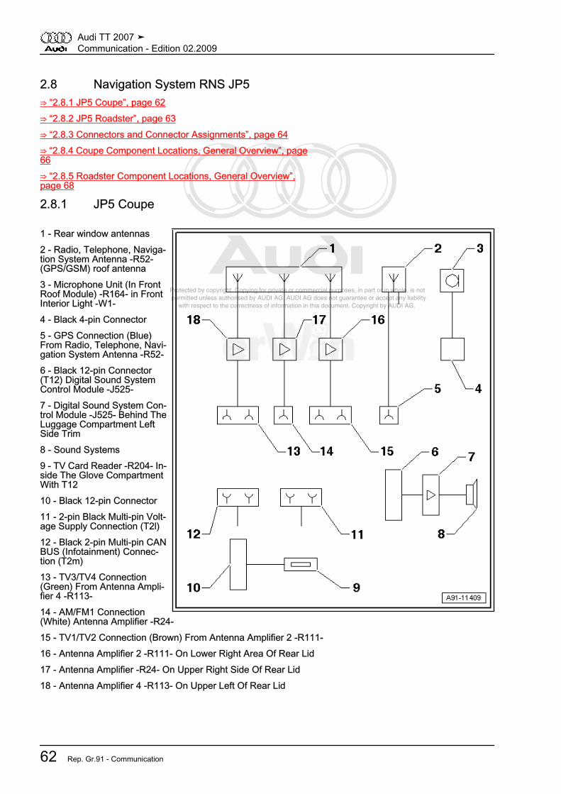
Protected by copyright. Copying for private or commercial purposes, in part or in whole, is not permitted unless authorised by AUDI AG. AUDI AG does not guarantee or accept any liability with respect to the correctness of information in this document. Copyright by AUDI AG.
2.8 Navigation System RNS JP5⇒ “2.8.1 JP5 Coupe”, page 62⇒ “2.8.2 JP5 Roadster”, page 63⇒ “2.8.3 Connectors and Connector Assignments”, page 64⇒ “2.8.4 Coupe Component Locations, General Overview”, page66⇒ “2.8.5 Roadster Component Locations, General Overview”,page 68
2.8.1 JP5 Coupe
1 - Rear window antennas2 - Radio, Telephone, Naviga‐tion System Antenna -R52-(GPS/GSM) roof antenna3 - Microphone Unit (In FrontRoof Module) -R164- in FrontInterior Light -W1-4 - Black 4-pin Connector5 - GPS Connection (Blue)From Radio, Telephone, Navi‐gation System Antenna -R52-6 - Black 12-pin Connector(T12) Digital Sound SystemControl Module -J525-7 - Digital Sound System Con‐trol Module -J525- Behind TheLuggage Compartment LeftSide Trim8 - Sound Systems9 - TV Card Reader -R204- In‐side The Glove CompartmentWith T1210 - Black 12-pin Connector11 - 2-pin Black Multi-pin Volt‐age Supply Connection (T2l)12 - Black 2-pin Multi-pin CANBUS (Infotainment) Connec‐tion (T2m)13 - TV3/TV4 Connection(Green) From Antenna Ampli‐fier 4 -R113-14 - AM/FM1 Connection(White) Antenna Amplifier -R24-15 - TV1/TV2 Connection (Brown) From Antenna Amplifier 2 -R111-16 - Antenna Amplifier 2 -R111- On Lower Right Area Of Rear Lid17 - Antenna Amplifier -R24- On Upper Right Side Of Rear Lid18 - Antenna Amplifier 4 -R113- On Upper Left Of Rear Lid
Audi TT 2007 ➤Communication - Edition 02.2009
62 Rep. Gr.91 - Communication

Protected by copyright. Copying for private or commercial purposes, in part or in whole, is not permitted unless authorised by AUDI AG. AUDI AG does not guarantee or accept any liability with respect to the correctness of information in this document. Copyright by AUDI AG.
2.8.2 JP5 Roadster
1 - FM2/TV 1 Antenna BehindThe Rear Lid End Piece OnThe Right Side2 - TV 1 Antenna On The RightSide Of The Windshield3 - AM/FM1 Rear Mast Anten‐na On The Left Side4 - Antenna TV3 Left Of Wind‐shield5 - Navigation System Antenna-R50- Behind Front InteriorLight -W1-6 - Microphone Unit (in frontroof module) -R164- In FrontInterior Light -W1-7 - Black 4-pin Connector8 - GPS Connection (blue)From Navigation System An‐tenna -R50-9 - Black 12-pin Connector(T12) Digital Sound SystemControl Module -J525-10 - Digital Sound SystemControl Module -J525- BehindThe Luggage CompartmentLeft Side Trim11 - Sound Systems12 - Tv Card Reader -R204-Inside The Glove Compart‐ment With T1213 - Black 12-pin Connector14 - 2-pin Black Multi-pin Volt‐age Supply Connection (T2l)15 - Black 2-pin Multi-pin CAN BUS (Infotainment) Connection (T2m)16 - TV1/TV2 Connection (Brown) From Antenna Amplifier 2 -R111- / TV Antenna 2 -R56-17 - AM/FM1 Connection (White) Antenna Amplifier -R24-18 - TV3 Connection (Green) From TV Antenna 3 -R57-19 - TV Antenna 3 -R57- Behind The Left A-Pillar Trim20 - Antenna Amplifier -R24- Left Rear Mast Antenna Base21 - TV Antenna 2 -R56- Behind The Right A-Pillar Trim22 - Antenna Amplifier 2 -R111- Behind The Rear Lid End Piece On The Right Side
Audi TT 2007 ➤Communication - Edition 02.2009
2. Description and Operation 63

Protected by copyright. Copying for private or commercial purposes, in part or in whole, is not permitted unless authorised by AUDI AG. AUDI AG does not guarantee or accept any liability with respect to the correctness of information in this document. Copyright by AUDI AG.
2.8.3 Connectors and Connector Assign‐ments
Note
Unlisted connector terminals are not assigned.
Sound systemBlack 12-pin multi-pin harness connector (T12h)2 - Right rear signal (+) to Digital Sound System Control Module3 - Right rear signal (-) to Digital Sound System Control Module4 - Positive switched to Digital Sound System Control Module5 - Left rear signal (-) to Digital Sound System Control Module6 - Left rear signal (+) to Digital Sound System Control Module8 - Right front signal (+) to Digital Sound System Control Module9 - Right front signal (-) to Digital Sound System Control Module11 - Left front signal (-) to Digital Sound System Control Module12 - Left front signal (+) to Digital Sound System Control ModuleVoltage supply, CAN Bus, TV card reader
Black 2-pin multi-pin connector (T2m)1 - Terminal 302 - Terminal 31
Black 2-pin multi-pin connector (T2l)1 - CAN-Bus High (Infotainment)2 - CAN-Bus Low (Infotainment)
Audi TT 2007 ➤Communication - Edition 02.2009
64 Rep. Gr.91 - Communication

Protected by copyright. Copying for private or commercial purposes, in part or in whole, is not permitted unless authorised by AUDI AG. AUDI AG does not guarantee or accept any liability with respect to the correctness of information in this document. Copyright by AUDI AG.
Black 12-pin connectorAll pins are connected to the TV card reader.1 - VDDP2 - Ground (GND)3 - VDD4 - CMDVCC5 - CLKDIV26 - CLKDIV17 - OFF8 - Ground (GND)9 - Ground (GND)10 - I/OUC11 - Ground (GND)12 - RSTIN
Black 12-pin connector inside the glove compartmentAll pins are connected to the TV card reader.1 - VDDP2 - Ground (GND)3 - VDD4 - CMDVCC5 - CLKDIV26 - CLKDIV17 - OFF8 - Ground (GND)9 - Ground (GND)10 - I/OUC11 - Ground (GND)12 - RSTIN
Black 4-pin connector1 - Telephone microphone (+):2 - Telephone microphone (-):
Audi TT 2007 ➤Communication - Edition 02.2009
2. Description and Operation 65

Protected by copyright. Copying for private or commercial purposes, in part or in whole, is not permitted unless authorised by AUDI AG. AUDI AG does not guarantee or accept any liability with respect to the correctness of information in this document. Copyright by AUDI AG.
Antennas1 - GPS connection (blue) from radio, telephone, navigation sys‐tem antenna (Coupe)- - GPS connection (blue) from navigation system antenna (Road‐ster)2 - AM/FM1 connection (white) antenna amplifier3 - TV3/TV4 connection (green) from antenna amplifier 4 (Coupe)- TV3/TV 4 connection (green) from TV antenna 3 (Roadster)4 - TV1/TV2 connection (brown) antenna amplifier 2 (Coupe)- TV1/TV2 connection (brown) TV antenna 2 (Roadster)
2.8.4 Coupe Component Locations, General Overview
1 - Right Front Treble Speaker-R22-
❑ In right of instrumentpanel
❑ Removing and instal‐ling, refer to⇒ “4.4.6 Left Front Tre‐ble Speaker”,page 92
2 - CD Changer -R41-❑ In the glove compart‐
ment❑ Connectors, refer to
⇒ “2.10 CD ChangerHarness Connectors ”,page 80 .
❑ Removing and instal‐ling, refer to⇒ “4.10 CD Changer”,page 107
- iPod Baseplate -R192-❑ In the glove compart‐
ment❑ Connectors, refer to
⇒ “2.11 iPod Baseplate,Connections”,page 81 .
❑ Removing and instal‐ling, refer to⇒ “4.11 iPod Base‐plate”, page 108
- External Audio Source Con‐nection -R199-
❑ Inside the glove com‐partment / center con‐sole
❑ Connectors (connection for an external audio source), refer to⇒ “2.12 External Audio Source Connection Connectors, AMI”, page 81
❑ AUX IN Connectors, refer to⇒ “2.13 AUX IN External Audio Source Connection Connectors”, page 82 .
❑ Removing and installing (connection for an external audio source), refer to⇒ “4.12 AMI External Audio Source Connection”, page 108
Audi TT 2007 ➤Communication - Edition 02.2009
66 Rep. Gr.91 - Communication
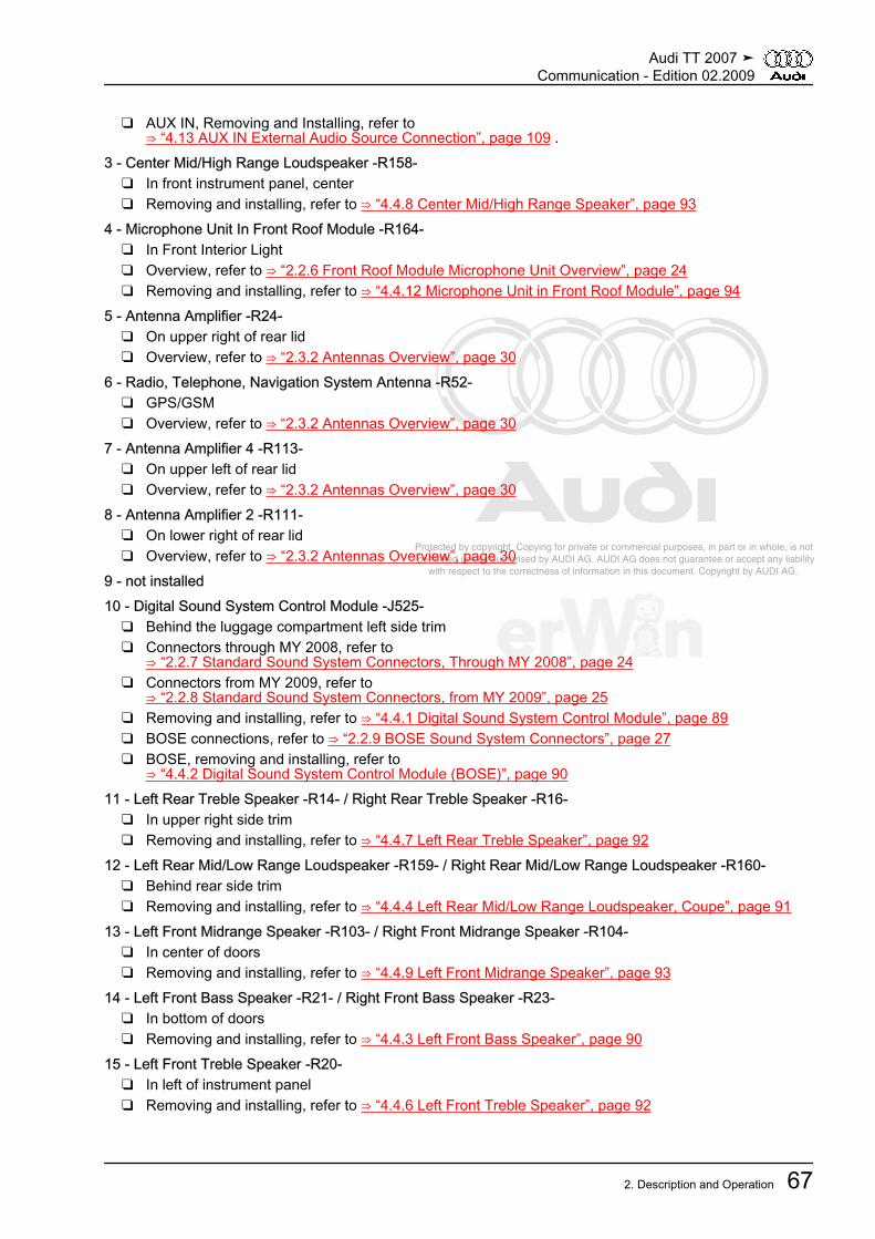
Protected by copyright. Copying for private or commercial purposes, in part or in whole, is not permitted unless authorised by AUDI AG. AUDI AG does not guarantee or accept any liability with respect to the correctness of information in this document. Copyright by AUDI AG.
❑ AUX IN, Removing and Installing, refer to⇒ “4.13 AUX IN External Audio Source Connection”, page 109 .
3 - Center Mid/High Range Loudspeaker -R158-❑ In front instrument panel, center❑ Removing and installing, refer to ⇒ “4.4.8 Center Mid/High Range Speaker”, page 93
4 - Microphone Unit In Front Roof Module -R164-❑ In Front Interior Light❑ Overview, refer to ⇒ “2.2.6 Front Roof Module Microphone Unit Overview”, page 24❑ Removing and installing, refer to ⇒ “4.4.12 Microphone Unit in Front Roof Module”, page 94
5 - Antenna Amplifier -R24-❑ On upper right of rear lid❑ Overview, refer to ⇒ “2.3.2 Antennas Overview”, page 30
6 - Radio, Telephone, Navigation System Antenna -R52-❑ GPS/GSM❑ Overview, refer to ⇒ “2.3.2 Antennas Overview”, page 30
7 - Antenna Amplifier 4 -R113-❑ On upper left of rear lid❑ Overview, refer to ⇒ “2.3.2 Antennas Overview”, page 30
8 - Antenna Amplifier 2 -R111-❑ On lower right of rear lid❑ Overview, refer to ⇒ “2.3.2 Antennas Overview”, page 30
9 - not installed10 - Digital Sound System Control Module -J525-
❑ Behind the luggage compartment left side trim❑ Connectors through MY 2008, refer to
⇒ “2.2.7 Standard Sound System Connectors, Through MY 2008”, page 24❑ Connectors from MY 2009, refer to
⇒ “2.2.8 Standard Sound System Connectors, from MY 2009”, page 25❑ Removing and installing, refer to ⇒ “4.4.1 Digital Sound System Control Module”, page 89❑ BOSE connections, refer to ⇒ “2.2.9 BOSE Sound System Connectors”, page 27❑ BOSE, removing and installing, refer to
⇒ “4.4.2 Digital Sound System Control Module (BOSE)”, page 9011 - Left Rear Treble Speaker -R14- / Right Rear Treble Speaker -R16-
❑ In upper right side trim❑ Removing and installing, refer to ⇒ “4.4.7 Left Rear Treble Speaker”, page 92
12 - Left Rear Mid/Low Range Loudspeaker -R159- / Right Rear Mid/Low Range Loudspeaker -R160-❑ Behind rear side trim❑ Removing and installing, refer to ⇒ “4.4.4 Left Rear Mid/Low Range Loudspeaker, Coupe”, page 91
13 - Left Front Midrange Speaker -R103- / Right Front Midrange Speaker -R104-❑ In center of doors❑ Removing and installing, refer to ⇒ “4.4.9 Left Front Midrange Speaker”, page 93
14 - Left Front Bass Speaker -R21- / Right Front Bass Speaker -R23-❑ In bottom of doors❑ Removing and installing, refer to ⇒ “4.4.3 Left Front Bass Speaker”, page 90
15 - Left Front Treble Speaker -R20-❑ In left of instrument panel❑ Removing and installing, refer to ⇒ “4.4.6 Left Front Treble Speaker”, page 92
Audi TT 2007 ➤Communication - Edition 02.2009
2. Description and Operation 67
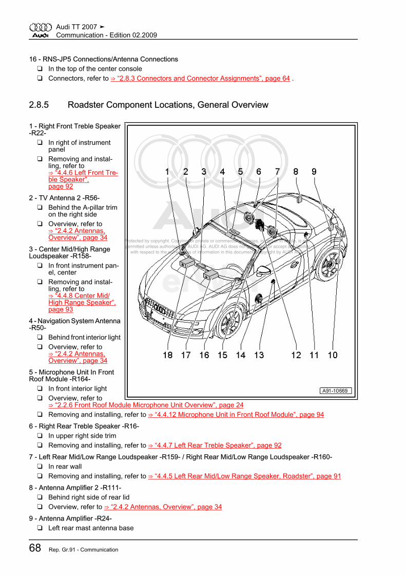
Protected by copyright. Copying for private or commercial purposes, in part or in whole, is not permitted unless authorised by AUDI AG. AUDI AG does not guarantee or accept any liability with respect to the correctness of information in this document. Copyright by AUDI AG.
16 - RNS-JP5 Connections/Antenna Connections❑ In the top of the center console❑ Connectors, refer to ⇒ “2.8.3 Connectors and Connector Assignments”, page 64 .
2.8.5 Roadster Component Locations, General Overview
1 - Right Front Treble Speaker-R22-
❑ In right of instrumentpanel
❑ Removing and instal‐ling, refer to⇒ “4.4.6 Left Front Tre‐ble Speaker”,page 92
2 - TV Antenna 2 -R56-❑ Behind the A-pillar trim
on the right side❑ Overview, refer to
⇒ “2.4.2 Antennas,Overview”, page 34
3 - Center Mid/High RangeLoudspeaker -R158-
❑ In front instrument pan‐el, center
❑ Removing and instal‐ling, refer to⇒ “4.4.8 Center Mid/High Range Speaker”,page 93
4 - Navigation System Antenna-R50-
❑ Behind front interior light❑ Overview, refer to
⇒ “2.4.2 Antennas,Overview”, page 34
5 - Microphone Unit In FrontRoof Module -R164-
❑ In front interior light❑ Overview, refer to
⇒ “2.2.6 Front Roof Module Microphone Unit Overview”, page 24❑ Removing and installing, refer to ⇒ “4.4.12 Microphone Unit in Front Roof Module”, page 94
6 - Right Rear Treble Speaker -R16-❑ In upper right side trim❑ Removing and installing, refer to ⇒ “4.4.7 Left Rear Treble Speaker”, page 92
7 - Left Rear Mid/Low Range Loudspeaker -R159- / Right Rear Mid/Low Range Loudspeaker -R160-❑ In rear wall❑ Removing and installing, refer to ⇒ “4.4.5 Left Rear Mid/Low Range Speaker, Roadster”, page 91
8 - Antenna Amplifier 2 -R111-❑ Behind right side of rear lid❑ Overview, refer to ⇒ “2.4.2 Antennas, Overview”, page 34
9 - Antenna Amplifier -R24-❑ Left rear mast antenna base
Audi TT 2007 ➤Communication - Edition 02.2009
68 Rep. Gr.91 - Communication

Protected by copyright. Copying for private or commercial purposes, in part or in whole, is not permitted unless authorised by AUDI AG. AUDI AG does not guarantee or accept any liability with respect to the correctness of information in this document. Copyright by AUDI AG.
❑ Overview, refer to ⇒ “2.4.2 Antennas, Overview”, page 3410 - Digital Sound System Control Module -J525-
❑ Behind the luggage compartment left side trim❑ Connectors through MY 2008, refer to
⇒ “2.2.7 Standard Sound System Connectors, Through MY 2008”, page 24❑ Connectors from MY 2009, refer to
⇒ “2.2.8 Standard Sound System Connectors, from MY 2009”, page 25❑ Removing and installing, refer to ⇒ “4.4.1 Digital Sound System Control Module”, page 89❑ BOSE connections, refer to ⇒ “2.2.9 BOSE Sound System Connectors”, page 27❑ BOSE, removing and installing, refer to
⇒ “4.4.2 Digital Sound System Control Module (BOSE)”, page 9011 - Left Rear Treble Speaker -R14-
❑ In upper right side trim❑ Removing and installing, refer to ⇒ “4.4.7 Left Rear Treble Speaker”, page 92
12 - Center Speaker -R148-❑ In center of rear wall❑ Removing and installing, refer to ⇒ “4.4.11 Center Loudspeaker, Roadster”, page 94
13 - Left Front Midrange Speaker -R103- / Right Front Midrange Speaker -R104-❑ In center of doors❑ Removing and installing, refer to ⇒ “4.4.9 Left Front Midrange Speaker”, page 93
14 - Left Front Bass Speaker -R21- / Right Front Bass Speaker -R23-❑ In bottom of doors❑ Removing and installing, refer to ⇒ “4.4.3 Left Front Bass Speaker”, page 90
15 - TV Antenna 3 -R57-❑ Behind the A-pillar trim on the left side❑ Overview, refer to ⇒ “2.4.2 Antennas, Overview”, page 34
16 - Left Front Treble Speaker -R20-❑ In left of instrument panel❑ Removing and installing, refer to ⇒ “4.4.6 Left Front Treble Speaker”, page 92
17 - RNS-JP5 Connections/Antenna Connections❑ In the top of the center console❑ Connectors, refer to ⇒ “2.8.3 Connectors and Connector Assignments”, page 64 .
18 - CD Changer -R41-❑ In the glove compartment❑ Connectors, refer to ⇒ “2.10 CD Changer Harness Connectors ”, page 80 .❑ Removing and installing, refer to ⇒ “4.10 CD Changer”, page 107
- iPod Baseplate -R192-❑ Connectors❑ Connectors, refer to ⇒ “2.11 iPod Baseplate, Connections”, page 81 .❑ Removing and installing, refer to ⇒ “4.11 iPod Baseplate”, page 108
- External audio source connection -R199-❑ Inside the glove compartment / center console❑ Connectors (connection for an external audio source), refer to
⇒ “2.12 External Audio Source Connection Connectors, AMI”, page 81❑ AUX IN Connectors, refer to
⇒ “2.13 AUX IN External Audio Source Connection Connectors”, page 82 .❑ Removing and installing (connection for an external audio source), refer to
⇒ “4.12 AMI External Audio Source Connection”, page 108
Audi TT 2007 ➤Communication - Edition 02.2009
2. Description and Operation 69
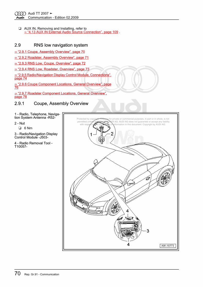
Protected by copyright. Copying for private or commercial purposes, in part or in whole, is not permitted unless authorised by AUDI AG. AUDI AG does not guarantee or accept any liability with respect to the correctness of information in this document. Copyright by AUDI AG.
❑ AUX IN, Removing and Installing, refer to⇒ “4.13 AUX IN External Audio Source Connection”, page 109 .
2.9 RNS low navigation system⇒ “2.9.1 Coupe, Assembly Overview”, page 70⇒ “2.9.2 Roadster, Assembly Overview”, page 71⇒ “2.9.3 RNS Low, Coupe, Overview”, page 72⇒ “2.9.4 RNS Low, Roadster, Overview”, page 73⇒ “2.9.5 Radio/Navigation Display Control Module, Connections”,page 74⇒ “2.9.6 Coupe Component Locations, General Overview”, page76⇒ “2.9.7 Roadster Component Locations, General Overview”,page 78
2.9.1 Coupe, Assembly Overview
1 - Radio, Telephone, Naviga‐tion System Antenna -R52-2 - Nut
❑ 6 Nm3 - Radio/Navigation DisplayControl Module -J503-4 - Radio Removal Tool -T10057-
Audi TT 2007 ➤Communication - Edition 02.2009
70 Rep. Gr.91 - Communication

Protected by copyright. Copying for private or commercial purposes, in part or in whole, is not permitted unless authorised by AUDI AG. AUDI AG does not guarantee or accept any liability with respect to the correctness of information in this document. Copyright by AUDI AG.
2.9.2 Roadster, Assembly Overview
1 - Navigation System Antenna-R50- / Telephone Antenna -R65-2 - Screw
❑ 2 Nm3 - Radio/Navigation DisplayControl Module -J503-4 - Radio Removal Tool -T10057-
Audi TT 2007 ➤Communication - Edition 02.2009
2. Description and Operation 71

Protected by copyright. Copying for private or commercial purposes, in part or in whole, is not permitted unless authorised by AUDI AG. AUDI AG does not guarantee or accept any liability with respect to the correctness of information in this document. Copyright by AUDI AG.
2.9.3 RNS Low, Coupe, Overview
1 - Rear Window Antennas2 - Antenna Amplifier 2 -R111-On Lower Right Area Of RearLid3 - Sound Systems4 - Radio/Navigation DisplayControl Module -J503- In TopOf Center Console5 - CD Changer -R41- / iPodBaseplate -R192- Inside TheGlove Compartment6 - CAN-BUS (Infotainment)7 - External audio source con‐nection -R199- In The CenterConsole Storage Compart‐ment8 - Telephone Transceiver -R36- In Electronics Box UnderLeft Front Seat9 - Antenna Amplifier -R24- OnUpper Right Side Of Rear Lid10 - Radio, Telephone, Navi‐gation System Antenna -R52-Roof Antenna
Audi TT 2007 ➤Communication - Edition 02.2009
72 Rep. Gr.91 - Communication

Protected by copyright. Copying for private or commercial purposes, in part or in whole, is not permitted unless authorised by AUDI AG. AUDI AG does not guarantee or accept any liability with respect to the correctness of information in this document. Copyright by AUDI AG.
2.9.4 RNS Low, Roadster, Overview
1 - Antenna -R11- (AM/FM1)Left Rear Mast Antenna2 - Radio Antenna 2 -R93-(FM2) Behind Right Side OfRear Lid3 - Antenna Amplifier 2 -R111-Behind Right Side Of Rear Lid4 - Sound Systems5 - Radio/Navigation DisplayControl Module -J503- In TopOf Center Console6 - CD Changer -R41- / iPodBaseplate -R192- Inside TheGlove Compartment7 - CAN-BUS (Infotainment)8 - External audio source con‐nection -R199- In The CenterConsole Storage Compart‐ment9 - Telephone Transceiver -R36- In Electronics Box UnderLeft Front Seat10 - Antenna Amplifier -R24-Left Rear Mast Antenna Base11 - Telephone Antenna -R65-Behind Front Interior Light -W1-12 - Navigation System Anten‐na -R50- Behind Front InteriorLight -W1-
Audi TT 2007 ➤Communication - Edition 02.2009
2. Description and Operation 73

Protected by copyright. Copying for private or commercial purposes, in part or in whole, is not permitted unless authorised by AUDI AG. AUDI AG does not guarantee or accept any liability with respect to the correctness of information in this document. Copyright by AUDI AG.
2.9.5 Radio/Navigation Display Control Module, Connections
1 - Connection Block With FourMulti-Pin Connectors And AFuse For Unit2 - Front Passenger's AirbagDisabled Indicator Lamp -K145-3 - GPS Connection (Blue)From Radio, Telephone, Navi‐gation System Antenna -R52-Coupe- GPS Connection (Blue) FromNavigation System Antenna -R50- Roadster
4 - IF Connection (White) ToAntenna Amplifier 2 -R111-5 - HF (white) ConnectionFrom Antenna Amplifier 2 -R111-
Note
Unlisted connector terminals are not assigned.
A - 8-pin multi-pin connector (T8b) brown2 - Right front speaker (+) (not used)3 - Left front speaker (+) (not used)6 - Right front speaker (-) (not used)7 - Left front speaker (-) (not used)
Audi TT 2007 ➤Communication - Edition 02.2009
74 Rep. Gr.91 - Communication

Protected by copyright. Copying for private or commercial purposes, in part or in whole, is not permitted unless authorised by AUDI AG. AUDI AG does not guarantee or accept any liability with respect to the correctness of information in this document. Copyright by AUDI AG.
B - Multi-pin connector, 12-pin (T12f) blue1 - Left LF-In from the external audio source connection2 - Signal ground to CD changer/iPod base plate3 - LF-In ground from the external audio source connection4 - Continuous plus to the CD changer/iPod base plate5 - BOSE coding to ground (only with BOSE)6 - CD data to CD changer/iPod base plate7 - Right LF-In from the external audio source connection8 - Left signal from CD changer/iPod base plate9 - Right signal from CD changer/iPod base plate10 - Positive switched to CD changer/iPod base plate11 - CD data in from the CD changer/iPod base plate12 - CLK from CD changer/iPod base plate
C - Green 12-pin multi-pin connector (T12g)1 - Speed signal (not used)2 - Signal from back-up light switch (not used)3 - Left front signal to digital sound system control module5 - Left rear signal to digital sound system control module6 - LF (-) from telephone transceiver/preliminary setup for cellulartelephone package7 - K diagnostic (not used)8 - Signal ground to digital sound system control module9 - Right front signal to digital sound system control module11 - Right rear signal to digital sound system control module12 - LF (+) from telephone transceiver/preliminary setup for cel‐lular telephone package
D - 8-pin multi-pin connector (T8a) black9 - CAN-Bus High (Infotainment)10 - CAN-Bus Low (Infotainment)11 - NF mute from preliminary setup for cellular telephone prep‐aration12 - Terminal 3113 - Positive switched to digital sound system control module14 - Anti-theft warning system (not used)15 - Terminal 3016 - Permanent positive to PIN 15 (anti-theft protection)
Audi TT 2007 ➤Communication - Edition 02.2009
2. Description and Operation 75

Protected by copyright. Copying for private or commercial purposes, in part or in whole, is not permitted unless authorised by AUDI AG. AUDI AG does not guarantee or accept any liability with respect to the correctness of information in this document. Copyright by AUDI AG.
2.9.6 Coupe Component Locations, General Overview
1 - Left Front Treble Speaker -R20-
❑ In left of instrument pan‐el
❑ Removing and instal‐ling, refer to⇒ “4.4.6 Left Front Tre‐ble Speaker”,page 92
2 - CD Changer -R41-❑ In the glove compart‐
ment❑ Connectors, refer to
⇒ “2.10 CD ChangerHarness Connectors ”,page 80 .
❑ Removing and instal‐ling, refer to⇒ “4.10 CD Changer”,page 107
- iPod Baseplate❑ In the glove compart‐
ment❑ Connectors, refer to
⇒ “2.11 iPod Baseplate,Connections”,page 81 .
❑ Removing and instal‐ling, refer to⇒ “4.11 iPod Base‐plate”, page 108
- External audio source con‐nection
❑ Inside the glove com‐partment / center con‐sole
❑ Connectors (connection for an external audio source) refer to⇒ “2.12 External Audio Source Connection Connectors, AMI”, page 81
❑ AUX IN Connectors, refer to⇒ “2.13 AUX IN External Audio Source Connection Connectors”, page 82 .
❑ Removing and installing (connection for an external audio source), refer to⇒ “4.12 AMI External Audio Source Connection”, page 108
❑ AUX IN, Removing and Installing, refer to⇒ “4.13 AUX IN External Audio Source Connection”, page 109 .
3 - Center Mid/High Range Loudspeaker -R158-❑ In front instrument panel, center❑ Removing and installing, refer to ⇒ “4.4.8 Center Mid/High Range Speaker”, page 93
4 - Microphone Unit In Front Roof Module -R164-❑ In front interior light❑ Overview, refer to ⇒ “2.2.6 Front Roof Module Microphone Unit Overview”, page 24❑ Removing and installing, refer to ⇒ “4.4.12 Microphone Unit in Front Roof Module”, page 94
5 - Antenna Amplifier -R24-❑ On upper right of rear lid
Audi TT 2007 ➤Communication - Edition 02.2009
76 Rep. Gr.91 - Communication

Protected by copyright. Copying for private or commercial purposes, in part or in whole, is not permitted unless authorised by AUDI AG. AUDI AG does not guarantee or accept any liability with respect to the correctness of information in this document. Copyright by AUDI AG.
❑ Overview, refer to ⇒ “2.3.2 Antennas Overview”, page 306 - Radio, Telephone, Navigation System Antenna -R52-
❑ Overview, refer to ⇒ “2.3.2 Antennas Overview”, page 307 - Antenna Amplifier 2 -R111-
❑ On lower right of rear lid❑ Overview, refer to ⇒ “2.3.2 Antennas Overview”, page 30
8 - Digital Sound System Control Module -J525-❑ Behind the luggage compartment left side trim❑ Connectors through MY 2008, refer to
⇒ “2.2.7 Standard Sound System Connectors, Through MY 2008”, page 24❑ Connectors from MY 2009, refer to
⇒ “2.2.8 Standard Sound System Connectors, from MY 2009”, page 25❑ Removing and installing, refer to ⇒ “4.4.1 Digital Sound System Control Module”, page 89❑ BOSE connections, refer to ⇒ “2.2.9 BOSE Sound System Connectors”, page 27❑ BOSE, removing and installing, refer to
⇒ “4.4.2 Digital Sound System Control Module (BOSE)”, page 909 - Left Rear Treble Speaker -R14- / Right Rear Treble Speaker -R16-
❑ In upper right side trim❑ Removing and installing, refer to ⇒ “4.4.7 Left Rear Treble Speaker”, page 92
10 - Left Rear Mid/Low Range Loudspeaker -R159- / Right Rear Mid/Low Range Loudspeaker -R160-❑ Behind rear side trim❑ Removing and installing, refer to ⇒ “4.4.4 Left Rear Mid/Low Range Loudspeaker, Coupe”, page 91
11 - Left Front Midrange Speaker -R103- / Right Front Midrange Speaker -R104-❑ In center of doors❑ Removing and installing, refer to ⇒ “4.4.9 Left Front Midrange Speaker”, page 93
12 - Left Front Bass Speaker -R21- / Right Front Bass Speaker -R23-❑ In bottom of doors❑ Removing and installing, refer to ⇒ “4.4.3 Left Front Bass Speaker”, page 90
13 - Right Front Treble Speaker -R22-❑ In right of instrument panel❑ Removing and installing, refer to ⇒ “4.4.6 Left Front Treble Speaker”, page 92
14 - Radio/Navigation Display Control Module -J503-❑ In the top of the center console❑ Connectors, refer to ⇒ “2.9.5 Radio/Navigation Display Control Module, Connections”, page 74 .❑ Removing and installing, refer to ⇒ “4.9 Radio/Navigation Display Control Module”, page 106
Audi TT 2007 ➤Communication - Edition 02.2009
2. Description and Operation 77

Protected by copyright. Copying for private or commercial purposes, in part or in whole, is not permitted unless authorised by AUDI AG. AUDI AG does not guarantee or accept any liability with respect to the correctness of information in this document. Copyright by AUDI AG.
2.9.7 Roadster Component Locations, General Overview
1 - Right Front Treble Speaker-R22-
❑ In right of instrumentpanel
❑ Removing and instal‐ling, refer to⇒ “4.4.6 Left Front Tre‐ble Speaker”,page 92
2 - Center Mid/High RangeLoudspeaker -R158-
❑ In front instrument pan‐el, center
❑ Removing and instal‐ling, refer to⇒ “4.4.8 Center Mid/High Range Speaker”,page 93
3 - Navigation System Antenna-R50-
❑ Behind front interior light❑ Overview, refer to
⇒ “2.4.2 Antennas,Overview”, page 34
4 - Microphone Unit In FrontRoof Module -R164-
❑ In front interior light❑ Overview, refer to
⇒ “2.2.6 Front RoofModule MicrophoneUnit Overview”,page 24
❑ Removing and instal‐ling, refer to⇒ “4.4.12 MicrophoneUnit in Front Roof Mod‐ule”, page 94
5 - Right Rear Treble Speaker -R16-❑ In upper right side trim❑ Removing and installing, refer to ⇒ “4.4.3 Left Front Bass Speaker”, page 90
6 - Left Rear Mid/Low Range Loudspeaker -R159- / Right Rear Mid/Low Range Loudspeaker -R160-❑ In rear wall❑ Removing and installing, refer to ⇒ “4.4.5 Left Rear Mid/Low Range Speaker, Roadster”, page 91
7 - Antenna Amplifier 2 -R111-❑ Behind right side of rear lid❑ Overview, refer to ⇒ “2.4.2 Antennas, Overview”, page 34
8 - Antenna Amplifier -R24-❑ Left rear mast antenna base❑ Overview, refer to ⇒ “2.4.2 Antennas, Overview”, page 34
9 - Digital Sound System Control Module -J525-❑ Behind the luggage compartment left side trim❑ Connectors through MY 2008, refer to
⇒ “2.2.7 Standard Sound System Connectors, Through MY 2008”, page 24
Audi TT 2007 ➤Communication - Edition 02.2009
78 Rep. Gr.91 - Communication

Protected by copyright. Copying for private or commercial purposes, in part or in whole, is not permitted unless authorised by AUDI AG. AUDI AG does not guarantee or accept any liability with respect to the correctness of information in this document. Copyright by AUDI AG.
❑ Connectors from MY 2009, refer to⇒ “2.2.8 Standard Sound System Connectors, from MY 2009”, page 25
❑ Removing and installing, refer to ⇒ “4.4.1 Digital Sound System Control Module”, page 89❑ BOSE connections, refer to ⇒ “2.2.9 BOSE Sound System Connectors”, page 27❑ BOSE, removing and installing, refer to
⇒ “4.4.2 Digital Sound System Control Module (BOSE)”, page 9010 - Left Rear Treble Speaker -R14-
❑ In upper right side trim❑ Removing and installing, refer to ⇒ “4.4.3 Left Front Bass Speaker”, page 90
11 - Center speaker -R148-❑ In center of rear wall❑ Removing and installing, refer to ⇒ “4.4.11 Center Loudspeaker, Roadster”, page 94
12 - Left Front Midrange Speaker -R103- / Right Front Midrange Speaker -R104-❑ In center of doors❑ Removing and installing, refer to ⇒ “4.4.9 Left Front Midrange Speaker”, page 93
13 - Left Front Bass Speaker -R21- / Right Front Bass Speaker -R23-❑ In bottom of doors❑ Removing and installing, refer to ⇒ “4.4.3 Left Front Bass Speaker”, page 90
14 - Left Front Treble Speaker -R20-❑ In left of instrument panel❑ Removing and installing, refer to ⇒ “4.4.6 Left Front Treble Speaker”, page 92
15 - Radio/Navigation Display Control Module -J503-❑ In the top of the center console❑ Connectors, refer to ⇒ “2.9.5 Radio/Navigation Display Control Module, Connections”, page 74 .❑ Removing and installing, refer to ⇒ “4.8 Navigation System with CD Drive Control Module”, page 106
16 - CD Changer -R41-❑ In the glove compartment❑ Connectors, refer to ⇒ “2.10 CD Changer Harness Connectors ”, page 80 .❑ Removing and installing, refer to ⇒ “4.10 CD Changer”, page 107
- iPod Baseplate❑ In the glove compartment❑ Connectors, refer to ⇒ “2.11 iPod Baseplate, Connections”, page 81 .❑ Removing and installing, refer to ⇒ “4.11 iPod Baseplate”, page 108
- External audio source connection❑ Inside the glove compartment / center console❑ Connectors (connection for an external audio source), refer to
⇒ “2.12 External Audio Source Connection Connectors, AMI”, page 81❑ AUX IN Connectors, refer to
⇒ “2.13 AUX IN External Audio Source Connection Connectors”, page 82 .❑ Removing and installing (connection for an external audio source), refer to
⇒ “4.12 AMI External Audio Source Connection”, page 108❑ AUX IN, Removing and Installing, refer to
⇒ “4.13 AUX IN External Audio Source Connection”, page 109 .
Audi TT 2007 ➤Communication - Edition 02.2009
2. Description and Operation 79

Protected by copyright. Copying for private or commercial purposes, in part or in whole, is not permitted unless authorised by AUDI AG. AUDI AG does not guarantee or accept any liability with respect to the correctness of information in this document. Copyright by AUDI AG.
2.10 CD Changer Harness Connectors
Note
Unlisted connector terminals are not assigned.
Black 12-pin multi-pin harness connector (T12a)1 - CD data out to radio/navigation system with CD drive controlmodule, radio/navigation display control module2 - CLK out to radio/navigation system with CD drive control mod‐ule, radio/navigation display control module3 - Terminal 314 - Data in from radio/navigation system with CD drive controlmodule, radio/navigation display control module6 - Permanent positive from radio/navigation system with CDdrive control module, radio/navigation display control module7 - Right signal to radio/navigation system with CD drive controlmodule, radio/navigation display control module, satellite radio8 - Positive switched from radio/navigation system with CD drivecontrol module, radio/navigation display control module9 - Signal ground from radio/navigation system with CD drivecontrol module, radio/navigation display control module, satelliteradio10 - Left signal to radio/navigation system with CD drive controlmodule, radio/navigation display control module, satellite radio11 - TOC Check Control (not used)12 - Terminal 58 (not used)
Audi TT 2007 ➤Communication - Edition 02.2009
80 Rep. Gr.91 - Communication

Protected by copyright. Copying for private or commercial purposes, in part or in whole, is not permitted unless authorised by AUDI AG. AUDI AG does not guarantee or accept any liability with respect to the correctness of information in this document. Copyright by AUDI AG.
2.11 iPod Baseplate, Connections
Note
Unlisted connector terminals are not assigned.
Black 12-pin multi-pin harness connector (T12a)1 - CD data out to radio/navigation system with CD drive controlmodule, radio/navigation display control module2 - CLK out to radio/navigation system with CD drive control mod‐ule, radio/navigation display control module3 - Terminal 314 - Data in from radio/navigation system with CD drive controlmodule, radio/navigation display control module6 - Permanent positive from radio/navigation system with CDdrive control module, radio/navigation display control module7 - Right signal to radio/navigation system with CD drive controlmodule, radio/navigation display control module, satellite radio8 - Positive switched from radio/navigation system with CD drivecontrol module, radio/navigation display control module9 - Signal ground from radio/navigation system with CD drivecontrol module, radio/navigation display control module, satelliteradio10 - Left signal to radio/navigation system with CD drive controlmodule, radio/navigation display control module, satellite radio11 - TOC Check Control (not used)12 - Terminal 58 (not used)
2.12 External Audio Source Connection Con‐nectors, AMI
Note
Unlisted connector terminals are not assigned.
12-pin connector1 - Terminal 312 - CAN-Bus Low (Infotainment)4 - Right NF to radio/navigation system with CD drive controlmodule, radio/navigation display control module7 - Terminal 308 - CAN-Bus High (Infotainment)9 - Left NF to radio/navigation system with CD drive control mod‐ule, radio/navigation display control module10 - NF ground to radio/navigation system with CD drive controlmodule, radio/navigation display control module
Audi TT 2007 ➤Communication - Edition 02.2009
2. Description and Operation 81

Protected by copyright. Copying for private or commercial purposes, in part or in whole, is not permitted unless authorised by AUDI AG. AUDI AG does not guarantee or accept any liability with respect to the correctness of information in this document. Copyright by AUDI AG.
2.13 AUX IN External Audio Source Connec‐tion Connectors
Note
Unlisted connector terminals are not assigned.
4-pin connectorAll pins are connected to the radio/navigation system with CDdrive control module, radio/navigation display control module.1 - LF ground2 - LF left3 - LF right4 - Terminal 31
2.14 Multi-Function Steering Wheel, Overview
1 - Multifunction SteeringWheel
❑ Multi-function buttons,removing and installing,refer to⇒ “4.14 Multi-functionButtons”, page 109
❑ Tiptronic Switch, remov‐ing and installing, referto⇒ “4.15 TiptronicSwitch”, page 110
2 - Steering Column ElectronicSystems Control Module -J527-
❑ On steering column❑ Connectors, refer to
⇒ “2.16 Steering Col‐umn Electronic SystemsControl Module Con‐nectors”, page 84
❑ Removing and instal‐ling, refer to⇒ “4.16 Steering Col‐umn Electronic SystemsControl Module”,page 111
3 - Telephone transceiver -R36-
❑ In electronics box underleft front seat
4 - CAN-Bus (Comfort)5 - Data Bus On Board Diag‐nostic Interface -J533-
❑ behind left front com‐partment
Audi TT 2007 ➤Communication - Edition 02.2009
82 Rep. Gr.91 - Communication

Protected by copyright. Copying for private or commercial purposes, in part or in whole, is not permitted unless authorised by AUDI AG. AUDI AG does not guarantee or accept any liability with respect to the correctness of information in this document. Copyright by AUDI AG.
6 - CAN-Bus (Infotainment)7 - Radio -R-
❑ In the top of the center console8 - CD Changer -R41-
❑ In the glove compartment9 - CAN-Bus (Powertrain)10 - Engine Control Module -J623-
❑ In plenum chamber11 - CAN-Bus (Instrument Cluster)12 - Instrument Cluster Control Module -J285- (instrument cluster)
❑ In instrument panel13 - LIN Data Bus (Single Wire Bus)
2.15 Steering Column Switch Module, Overview
1 - Airbag Spiral Spring2 - Wiper Switch/On-BoardComputer3 - Steering Angle Sensor -G85-4 - Steering Column ElectronicSystems Control Module -J527-5 - Black Connector (T20b) OnSteering Column ElectronicSystems Control Module -J527-6 - Ignition/Starter Switch -D-7 - Turn Signal Switch/CruiseControl Switch
Audi TT 2007 ➤Communication - Edition 02.2009
2. Description and Operation 83

Protected by copyright. Copying for private or commercial purposes, in part or in whole, is not permitted unless authorised by AUDI AG. AUDI AG does not guarantee or accept any liability with respect to the correctness of information in this document. Copyright by AUDI AG.
2.16 Steering Column Electronic SystemsControl Module Connectors
ConnectorsA - 4-pin multi-pin connector (T4n) yellowB - Black 20-pin multi-pin connector (T20b)
Note
Unlisted connector terminals are not assigned.
B - Black 20-pin multi-pin connector (T20b)11 - CAN-Bus Low (powertrain)12 - CAN-Bus High (powertrain)13 - Cruise control locked OFF to Engine Control Module (ECM)-J623-14 - CAN-Bus High (comfort)15 - CAN-Bus Low (comfort)16 - Parking lock signal from automatic transmission shift gate17 - Terminal 15 to vehicle electrical system control module18 - Terminal 50 to vehicle electrical system control module19 - Terminal 3020 - Terminal 31
Audi TT 2007 ➤Communication - Edition 02.2009
84 Rep. Gr.91 - Communication

Protected by copyright. Copying for private or commercial purposes, in part or in whole, is not permitted unless authorised by AUDI AG. AUDI AG does not guarantee or accept any liability with respect to the correctness of information in this document. Copyright by AUDI AG.
3 Specifications⇒ “3.1 Fastener Tightening Specifications”, page 85
3.1 Fastener Tightening SpecificationsComponent Bolt Size Nm Nut for Antenna Amplifier 21 6
Nut for Center Speaker1 2Nut for Digital Sound System Control Module 5Nut for Digital Sound System Control Module - BOSE 5Nut for Mast Antenna2 4
Nut for Radio, Telephone, Navigation System Antenna1 6Nut for Satellite Antenna 6Nut for Windshield Antenna Suppression Filter 6Screw for Antenna Amplifier 22 2Screw for Antenna Amplifier 4 2Screw for Antenna Selection Control Module Screw for Center Mid/High Range Loudspeaker 1Screw for Center Speaker 2Screw for Digital Sound System Control Module 3Screw for Digital Sound System Control Module - BOSE 3Screw for Left Front Bass Speaker/Right Front Bass Speaker 3.5Screw for External Audio Source Connection 1Screw for Left Front Midrange Speaker/Right Front Midrange Speak‐er
2
Screw for Left Rear Mid/Low Range Loudspeaker & Right Rear Mid/Low Range Loudspeaker
2
Screw for Navigation System / Telephone Antenna2 2Screw for Radio Antenna 2 2Screws for Telephone Base Plate 2 • 1Coupe• 2 Roadster
Audi TT 2007 ➤Communication - Edition 02.2009
3. Specifications 85

Protected by copyright. Copying for private or commercial purposes, in part or in whole, is not permitted unless authorised by AUDI AG. AUDI AG does not guarantee or accept any liability with respect to the correctness of information in this document. Copyright by AUDI AG.
4 Removal and Installation⇒ “4.1 Radio”, page 86⇒ “4.2 Front Passenger Airbag Disabled Indicator Lamp”,page 87⇒ “4.3 Satellite Radio”, page 88⇒ “4.4 Sound System”, page 89⇒ “4.5 Antenna System, Coupe”, page 95⇒ “4.6 Antenna System, Roadster”, page 100⇒ “4.7 Telephone Systems”, page 104⇒ “4.8 Navigation System with CD Drive Control Module”,page 106⇒ “4.9 Radio/Navigation Display Control Module”, page 106⇒ “4.10 CD Changer”, page 107⇒ “4.11 iPod Baseplate”, page 108⇒ “4.12 AMI External Audio Source Connection”, page 108⇒ “4.13 AUX IN External Audio Source Connection”, page 109⇒ “4.14 Multi-function Buttons”, page 109⇒ “4.15 Tiptronic Switch”, page 110⇒ “4.16 Steering Column Electronic Systems Control Module”,page 111
4.1 RadioRequired Special Tools and Equipment♦ Radio Removal Tool -T10057-– If control module is replaced, select Replacement function for
appropriate control module in Guided Fault-Finding routine.Use the Vehicle Diagnosis, Testing and Information System to doso.– Activate transport mode in symphony. Refer to
⇒ “2.1.11 Symphony Transport Mode, Activating/Deactivat‐ing”, page 20 .
– Switch off all electrical consumers.– Remove the key.
Audi TT 2007 ➤Communication - Edition 02.2009
86 Rep. Gr.91 - Communication

Protected by copyright. Copying for private or commercial purposes, in part or in whole, is not permitted unless authorised by AUDI AG. AUDI AG does not guarantee or accept any liability with respect to the correctness of information in this document. Copyright by AUDI AG.
Removing– Insert radio removal tool in release slits on radio until they en‐
gage. Points on grip eyes face outward.– Remove radio from instrument panel with radio removal tool
grip eyes.– Release electrical connectors on radio and remove them.– Remove radio removal tool by pressing locking tabs on radio.– Remove front passenger's airbag disabled indicator lamp. Re‐
fer to⇒ “4.2 Front Passenger Airbag Disabled Indicator Lamp”, page87 .
Installing– Install front passenger's airbag disabled indicator lamp. Refer
to⇒ “4.2 Front Passenger Airbag Disabled Indicator Lamp”, page87 .
– Connect all electrical connectors.– Carefully slide radio into instrument panel and let it engage in
mounting frame.– Deactivate transport mode in symphony. Refer to
⇒ “2.1.11 Symphony Transport Mode, Activating/Deactivat‐ing”, page 20 .
4.2 Front Passenger Airbag Disabled Indi‐cator Lamp
In case of a fault or if radio is replaced, front passenger's airbagdisabled indicator lamp must be removed.– Switch off all electrical consumers.– Remove the key.Removing– Remove radio far enough so rear side can be reached. Refer
to ⇒ “4.1 Radio”, page 86 .– Press retaining springs -arrows- at left and right of front pas‐
senger's airbag disabled indicator lamp -1-.– Press front passenger's airbag disabled indicator lamp -1- in
-direction of arrow- out of radio frame -2-.
Audi TT 2007 ➤Communication - Edition 02.2009
4. Removal and Installation 87

Protected by copyright. Copying for private or commercial purposes, in part or in whole, is not permitted unless authorised by AUDI AG. AUDI AG does not guarantee or accept any liability with respect to the correctness of information in this document. Copyright by AUDI AG.
– Disconnect electrical connector -1- on front passenger's air‐bag disabled indicator lamp -2-.
Installing– Install in reverse order.
4.3 Satellite RadioThe satellite radio is clamped into the left luggage compartmentinsert.– If control module is replaced, select Replacement function for
appropriate control module in Guided Fault-Finding routine.Use the Vehicle Diagnosis, Testing and Information System to doso.– Switch off all electrical consumers.– Remove the key.Removing– Open luggage compartment.– Remove the luggage compartment floor covering.– Tip satellite radio -1- in -direction of arrow- out of luggage
compartment insert.– Disconnect electrical connectors -2-, -3- and -4- on satellite
radio -1-.Installing– Install in reverse order.– Enable satellite radio. Refer to
⇒ “2.1.10 Satellite Radio, Enabling”, page 19 .
Audi TT 2007 ➤Communication - Edition 02.2009
88 Rep. Gr.91 - Communication

Protected by copyright. Copying for private or commercial purposes, in part or in whole, is not permitted unless authorised by AUDI AG. AUDI AG does not guarantee or accept any liability with respect to the correctness of information in this document. Copyright by AUDI AG.
4.4 Sound System⇒ “4.4.1 Digital Sound System Control Module”, page 89⇒ “4.4.2 Digital Sound System Control Module (BOSE)”,page 90⇒ “4.4.3 Left Front Bass Speaker”, page 90⇒ “4.4.4 Left Rear Mid/Low Range Loudspeaker, Coupe”,page 91⇒ “4.4.5 Left Rear Mid/Low Range Speaker, Roadster”,page 91⇒ “4.4.6 Left Front Treble Speaker”, page 92⇒ “4.4.7 Left Rear Treble Speaker”, page 92⇒ “4.4.8 Center Mid/High Range Speaker”, page 93⇒ “4.4.9 Left Front Midrange Speaker”, page 93⇒ “4.4.10 Center Loudspeaker, Coupe”, page 93⇒ “4.4.11 Center Loudspeaker, Roadster”, page 94⇒ “4.4.12 Microphone Unit in Front Roof Module”, page 94
4.4.1 Digital Sound System Control ModuleThe digital sound system control module is located behind the leftluggage compartment trim panel between the tail lamp assemblyand the wheel housing.– Switch off all electrical consumers.– Remove the key.Removing– Remove the left luggage compartment trim panel. Refer to ⇒
Body Interior; Rep. Gr. 70 ; Removal and Installation .– Remove screws -2-.– Tip digital sound system control module -1- out of clamp -3-
on bracket.– Disconnect electrical connector on digital sound system con‐
trol module -1-.Installing– Install in reverse order.
– Make sure that digital sound system control module -1- slidesinto clamp -3- first.
Tightening specifications. Refer to⇒ “2.2.1 Coupe, Assembly Overview”, page 21 .
Audi TT 2007 ➤Communication - Edition 02.2009
4. Removal and Installation 89

Protected by copyright. Copying for private or commercial purposes, in part or in whole, is not permitted unless authorised by AUDI AG. AUDI AG does not guarantee or accept any liability with respect to the correctness of information in this document. Copyright by AUDI AG.
4.4.2 Digital Sound System Control Module(BOSE)
The digital sound system control module is located behind the leftluggage compartment trim panel between the tail lamp assemblyand the wheel housing.– Switch off all electrical consumers.– Remove the key.Removing– Remove the left luggage compartment trim panel. Refer to ⇒
Body Interior; Rep. Gr. 70 ; Removal and Installation .– Loosen nuts -1- and -3- on bracket.The digital sound system control module -2- with bracket is onlyconnected at left rear.– Tip digital sound system control module -2- with bracket into
luggage compartment.
– Disconnect electrical connectors -1- and -2- on digital soundsystem control module.
– Remove bolts -4- and tip digital sound system control moduleout of clamps -3-.
Installing– Install in reverse order.
– Make sure that digital sound system control module slides intoclamp -3- first.
Tightening specifications. Refer to⇒ “2.2.1 Coupe, Assembly Overview”, page 21 .
4.4.3 Left Front Bass SpeakerRemoval and installation of left front bass speaker and right frontbass speaker are the same.– Switch off all electrical consumers.– Remove the key.
Audi TT 2007 ➤Communication - Edition 02.2009
90 Rep. Gr.91 - Communication

Protected by copyright. Copying for private or commercial purposes, in part or in whole, is not permitted unless authorised by AUDI AG. AUDI AG does not guarantee or accept any liability with respect to the correctness of information in this document. Copyright by AUDI AG.
Removing– Remove door trim panel. Refer to ⇒ Body Interior; Rep. Gr.
70 ; Removal and Installation .– Disconnect electrical connector -1- on left front bass speaker
-3-.– Remove screws -2-.– Remove left front bass speaker -3- from door.Installing– Install in reverse order.Tightening specifications. Refer to⇒ “2.2.1 Coupe, Assembly Overview”, page 21 .
4.4.4 Left Rear Mid/Low Range Loudspeaker,Coupe
Removal and installation of left rear mid/low range speaker andright rear mid/low range speaker are identical.– Switch off all electrical consumers.– Remove the key.Removing– Remove side trim. Refer to ⇒ Body Interior; Rep. Gr. 70 ;
Removal and Installation .– Disconnect electrical connector -1- on left rear mid/low range
speaker -2-.– Remove screws -3-.– Remove left rear mid/low range speaker -2- from door.Installing– Install in reverse order.Tightening specifications. Refer to⇒ “2.2.1 Coupe, Assembly Overview”, page 21 .
4.4.5 Left Rear Mid/Low Range Speaker,Roadster
Removal and installation of left rear mid/low range speaker andright rear mid/low range speaker are identical.– Switch off all electrical consumers.– Remove the key.Removing– Remove end panel trim panel. Refer to ⇒ Body Interior; Rep.
Gr. 70 ; Removal and Installation .
Audi TT 2007 ➤Communication - Edition 02.2009
4. Removal and Installation 91

Protected by copyright. Copying for private or commercial purposes, in part or in whole, is not permitted unless authorised by AUDI AG. AUDI AG does not guarantee or accept any liability with respect to the correctness of information in this document. Copyright by AUDI AG.
– Disconnect the connector -3- from the left rear midrangespeaker -1-.
– Remove screws -2-.– Remove left rear mid/low range speaker -1- from rear wall.Installing– Install in reverse order.Tightening specifications. Refer to⇒ “2.2.2 Roadster, Assembly Overview”, page 22 .
4.4.6 Left Front Treble SpeakerRemoval and installation o fleft front treble speaker and right fronttreble speaker is the same.The speakers are clipped into the instrument panel.– Switch off all electrical consumers.– Remove the key.Removing– First unclip speaker trim.– Unclip left front treble speaker -2- from instrument panel -1-.– Disconnect electrical connector -3- on left front treble speaker
-2-.Installing– Install in reverse order.
4.4.7 Left Rear Treble SpeakerRemoval and installation of left rear treble speaker and right reartreble speaker is identical.The speakers are clipped into the side trim.– Switch off all electrical consumers.– Remove the key.Removing– Remove side trim. Refer to ⇒ Body Interior; Rep. Gr. 70 ;
Removal and Installation .
Audi TT 2007 ➤Communication - Edition 02.2009
92 Rep. Gr.91 - Communication

Protected by copyright. Copying for private or commercial purposes, in part or in whole, is not permitted unless authorised by AUDI AG. AUDI AG does not guarantee or accept any liability with respect to the correctness of information in this document. Copyright by AUDI AG.
– Disconnect electrical connector -1- on eft rear treble speaker-2-.
– Release retaining clips -arrows- and remove left rear treblespeaker -2- from side trim -3-.
Installing– Install in reverse order.
4.4.8 Center Mid/High Range Speaker– Switch off all electrical consumers.– Remove the key.Removing– Unclip cover on front center of instrument panel.– Remove screws -2-.– Raise center mid/high range loudspeaker -3- from instrument
panel -1- and disconnect electrical connector.Installing– Install in reverse order.Tightening specifications. Refer to⇒ “2.2.1 Coupe, Assembly Overview”, page 21
4.4.9 Left Front Midrange SpeakerRemoval and installation of left front midrange speaker and rightfront midrange speaker is the same.– Switch off all electrical consumers.– Remove the key.Removing– Remove door trim panel. Refer to ⇒ Body Interior; Rep. Gr.
70 ; Removal and Installation .– Disconnect electrical connector -1- on left front midrange
speaker -3-.– Remove nuts -2-.– Remove left front midrange speaker -3- from side panel.Installing– Install in reverse order.Tightening specifications. Refer to⇒ “2.2.1 Coupe, Assembly Overview”, page 21 .
4.4.10 Center Loudspeaker, Coupe– Switch off all electrical consumers.
Audi TT 2007 ➤Communication - Edition 02.2009
4. Removal and Installation 93

Protected by copyright. Copying for private or commercial purposes, in part or in whole, is not permitted unless authorised by AUDI AG. AUDI AG does not guarantee or accept any liability with respect to the correctness of information in this document. Copyright by AUDI AG.
– Remove the key.Removing– Remove left side trim. Refer to ⇒ Body Interior; Rep. Gr. 70 ;
Removal and Installation .– Disconnect electrical connector on center loudspeaker -1-.– Remove nuts -2-.– Remove bolt -3-.– Remove center loudspeaker -1- from side panel -4-.Installing– Install in reverse order.Tightening specifications. Refer to⇒ “2.2.1 Coupe, Assembly Overview”, page 21 .
4.4.11 Center Loudspeaker, Roadster– Switch off all electrical consumers.– Remove the key.Removing– Remove end panel trim panel. Refer to ⇒ Body Interior; Rep.
Gr. 70 ; Removal and Installation .– Remove screws -2-.– Disconnect electrical connector on center loudspeaker -1-.– Remove center loudspeaker -1- from rear wall.Installing– Install in reverse order.Tightening specifications. Refer to⇒ “2.2.2 Roadster, Assembly Overview”, page 22 .
4.4.12 Microphone Unit in Front Roof ModuleA maximum of two microphones are installed in the front interiorlight. They can only be replaced completely.– Switch off all electrical consumers.– Remove the key.Removing– Remove front interior light. Refer to ⇒ Electrical Equipment;
Rep. Gr. 96 ; Removal and Installation .
Audi TT 2007 ➤Communication - Edition 02.2009
94 Rep. Gr.91 - Communication

Protected by copyright. Copying for private or commercial purposes, in part or in whole, is not permitted unless authorised by AUDI AG. AUDI AG does not guarantee or accept any liability with respect to the correctness of information in this document. Copyright by AUDI AG.
– Disconnect electrical connector -1-.– Pry microphones -2- and -4- out of front interior light -3-
-arrows-.Installing– Install in reverse order.
4.5 Antenna System, Coupe⇒ “4.5.1 Antenna Amplifier 2”, page 95⇒ “4.5.2 Antenna Amplifier and Antenna Amplifier 4”, page 95⇒ “4.5.3 Radio, Telephone, Navigation System Antenna”,page 96⇒ “4.5.4 Radio, Telephone, Navigation System Antenna”,page 97⇒ “4.5.5 Windshield Antenna Suppression Filter”, page 99⇒ “4.5.6 Antenna Splitter”, page 99
4.5.1 Antenna Amplifier 2The antenna amplifier 2 is located on the bottom right of the rearlid.– Switch off all electrical consumers.– Remove the key.Removing– Remove lower rear lid trim. Refer to ⇒ Body Interior; Rep. Gr.
70 ; Removal and Installation .– Disconnect electrical connectors -2-, -4- and -5- on antenna
amplifier 2 -1-.– Remove nuts -3-.– Remove antenna amplifier 2 -1- from rear lid.Installing– Install in reverse order.Tightening specifications. Refer to⇒ “2.3.1 Antenna system Assembly Overview”, page 29 .
4.5.2 Antenna Amplifier and Antenna Amplifi‐er 4
The antenna amplifier and antenna amplifier 4 are located on theupper right and left of the rear lid.Removal and installation of antenna amplifier and antenna am‐plifier 4 is the same.– Switch off all electrical consumers.– Remove the key.
Audi TT 2007 ➤Communication - Edition 02.2009
4. Removal and Installation 95
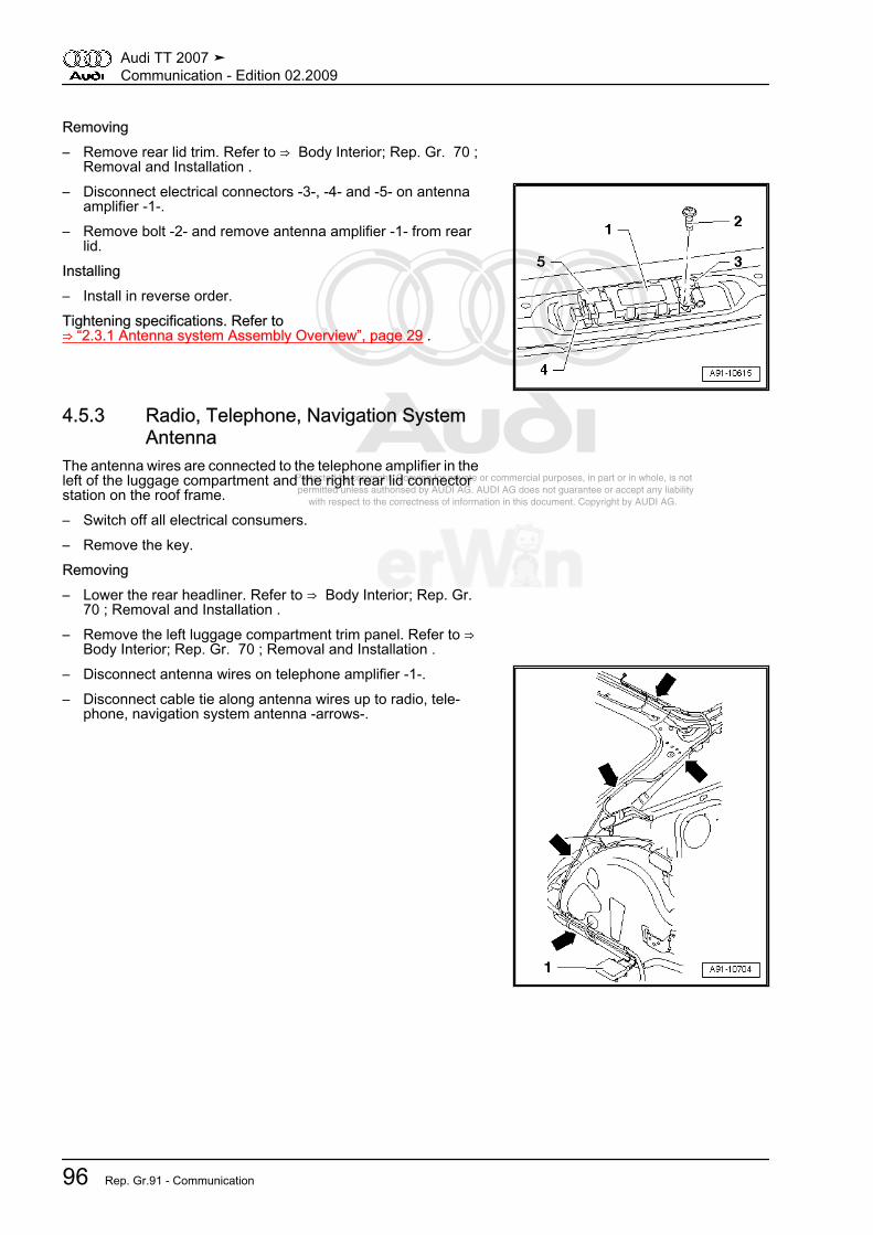
Protected by copyright. Copying for private or commercial purposes, in part or in whole, is not permitted unless authorised by AUDI AG. AUDI AG does not guarantee or accept any liability with respect to the correctness of information in this document. Copyright by AUDI AG.
Removing– Remove rear lid trim. Refer to ⇒ Body Interior; Rep. Gr. 70 ;
Removal and Installation .– Disconnect electrical connectors -3-, -4- and -5- on antenna
amplifier -1-.– Remove bolt -2- and remove antenna amplifier -1- from rear
lid.Installing– Install in reverse order.Tightening specifications. Refer to⇒ “2.3.1 Antenna system Assembly Overview”, page 29 .
4.5.3 Radio, Telephone, Navigation SystemAntenna
The antenna wires are connected to the telephone amplifier in theleft of the luggage compartment and the right rear lid connectorstation on the roof frame.– Switch off all electrical consumers.– Remove the key.Removing– Lower the rear headliner. Refer to ⇒ Body Interior; Rep. Gr.
70 ; Removal and Installation .– Remove the left luggage compartment trim panel. Refer to ⇒
Body Interior; Rep. Gr. 70 ; Removal and Installation .– Disconnect antenna wires on telephone amplifier -1-.– Disconnect cable tie along antenna wires up to radio, tele‐
phone, navigation system antenna -arrows-.
Audi TT 2007 ➤Communication - Edition 02.2009
96 Rep. Gr.91 - Communication

Protected by copyright. Copying for private or commercial purposes, in part or in whole, is not permitted unless authorised by AUDI AG. AUDI AG does not guarantee or accept any liability with respect to the correctness of information in this document. Copyright by AUDI AG.
– Disconnect connector -1- on right side at right rear lid connec‐tor station.
– Disconnect cable ties -arrows- up to radio, telephone, naviga‐tion system antenna -2-.
– Remove nut -3-.– Remove radio, telephone, navigation system antenna -2- up‐
ward from roof.Installing
– Place radio, telephone, navigation system antenna -2- on roofand align it in direction of travel.
– Lay antenna wires in opening on antenna base so nut -3- canbe turned.
The antenna wires must lie in the nut opening -3-.– Align radio, telephone, navigation system antenna -2- in di‐
rection of travel again before tightening the nut -3-.– Perform further installation in reverse order.Tightening specifications. Refer to⇒ “2.3.1 Antenna system Assembly Overview”, page 29 .
4.5.4 Radio, Telephone, Navigation SystemAntenna
The antenna wires are connected to the satellite radio in the leftof the luggage compartment and the right rear lid connector sta‐tion on the roof frame.– Switch off all electrical consumers.– Remove the key.Removing– Lower rear headliner. Refer to ⇒ Body Interior; Rep. Gr. 70 ;
Removal and Installation .– Remove the left luggage compartment trim panel. Refer to ⇒
Body Interior; Rep. Gr. 70 ; Removal and Installation .
Audi TT 2007 ➤Communication - Edition 02.2009
4. Removal and Installation 97

Protected by copyright. Copying for private or commercial purposes, in part or in whole, is not permitted unless authorised by AUDI AG. AUDI AG does not guarantee or accept any liability with respect to the correctness of information in this document. Copyright by AUDI AG.
– Disconnect antenna wire on satellite radio -1-.– Disconnect cable tie along antenna wires up to radio, tele‐
phone, navigation system antenna -arrows-.
– Disconnect electrical connector -1- on right side at right rearlid connector station.
– Disconnect cable ties -arrows- up to radio, telephone, naviga‐tion system antenna -2-.
– Remove nut -3-.– Remove radio, telephone, navigation system antenna -2- up‐
ward from roof.Installing
– Place radio, telephone, navigation system antenna -2- on roofand align it in direction of travel.
– Lay antenna wires in opening on antenna base so nut -3- canbe turned.
The antenna wires must lie in the nut opening -3-.– Align radio, telephone, navigation system antenna -2- in di‐
rection of travel again before tightening the nut -3-.– Perform further installation in reverse order.Tightening specifications. Refer to⇒ “2.3.1 Antenna system Assembly Overview”, page 29 .
Audi TT 2007 ➤Communication - Edition 02.2009
98 Rep. Gr.91 - Communication

Protected by copyright. Copying for private or commercial purposes, in part or in whole, is not permitted unless authorised by AUDI AG. AUDI AG does not guarantee or accept any liability with respect to the correctness of information in this document. Copyright by AUDI AG.
4.5.5 Windshield Antenna Suppression FilterThe windshield antenna suppression filter is located behind theleft side trim between the wheel housing and center loudspeaker.– Switch off all electrical consumers.– Remove the key.Removing– Remove left side trim. Refer to ⇒ Body Interior; Rep. Gr. 70 ;
Removal and Installation .– Remove nuts -3- and -5-.– Remove wire -2- and -6- from threaded pins.– Remove nut -4-.– Remove windshield antenna suppression filter -1- from threa‐
ded pins.Installing– Install in reverse order.Tightening specifications. Refer to⇒ “2.3.1 Antenna system Assembly Overview”, page 29 .
4.5.6 Antenna SplitterThe antenna splitter was installed through 10/06.The antenna splitter is located in the left luggage compartmentinsert under the satellite radio.– Switch off all electrical consumers.– Remove the key.Removing– Open luggage compartment.– Remove the luggage compartment floor covering.– Remove satellite radio from luggage compartment insert and
lay it aside.– Pry antenna splitter -1- out of luggage compartment insert.– Disconnect electrical connectors -2- and -3- on antenna split‐
ter -1-.Installing– Install in reverse order.
Audi TT 2007 ➤Communication - Edition 02.2009
4. Removal and Installation 99

Protected by copyright. Copying for private or commercial purposes, in part or in whole, is not permitted unless authorised by AUDI AG. AUDI AG does not guarantee or accept any liability with respect to the correctness of information in this document. Copyright by AUDI AG.
4.6 Antenna System, Roadster⇒ “4.6.1 Antenna Amplifier”, page 100⇒ “4.6.2 Antenna Amplifier 2”, page 100⇒ “4.6.3 TV Antenna 2, through MY 2007”, page 101⇒ “4.6.4 TV Antenna 2, from MY 2008”, page 101⇒ “4.6.5 Antenna Selection Control Module”, page 102⇒ “4.6.6 Navigation System Antenna/Telephone Antenna”,page 102⇒ “4.6.7 Satellite Antenna”, page 103⇒ “4.6.8 TV Antenna 2”, page 103
4.6.1 Antenna AmplifierThe antenna amplifier is in the base of the left rear mast antenna.– Switch off all electrical consumers.– Remove the key.Removing– Remove the left luggage compartment trim panel. Refer to ⇒
Body Interior; Rep. Gr. 70 ; Removal and Installation .– Remove mast antenna -4-.– Remove grommet -3- upward.– Remove nut -2-.– Remove antenna amplifier -1- inward from fender and discon‐
nect antenna wiring connections.Installing– Install in reverse order.
– When installing grommet -2-, ensure tab -arrow- in the grom‐met is above the groove -arrow- on the antenna amplifier -1-.
Tightening specifications. Refer to⇒ “2.4.1 Antenna System Assembly Overview”, page 33 .
4.6.2 Antenna Amplifier 2The antenna amplifier 2 is located behind the right side of the rearbumper below the right tail lamp.To remove, rear bumper must be removed.– Switch off all electrical consumers.– Remove the key.
Audi TT 2007 ➤Communication - Edition 02.2009
100 Rep. Gr.91 - Communication
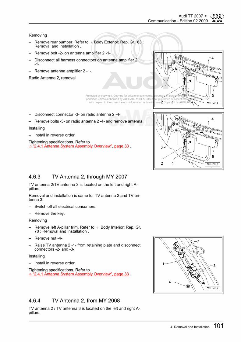
Protected by copyright. Copying for private or commercial purposes, in part or in whole, is not permitted unless authorised by AUDI AG. AUDI AG does not guarantee or accept any liability with respect to the correctness of information in this document. Copyright by AUDI AG.
Removing– Remove rear bumper. Refer to ⇒ Body Exterior; Rep. Gr. 63 ;
Removal and Installation .– Remove bolt -2- on antenna amplifier 2 -1-.– Disconnect all harness connectors on antenna amplifier 2
-1-.– Remove antenna amplifier 2 -1-.Radio Antenna 2, removal
– Disconnect connector -3- on radio antenna 2 -4-.– Remove bolts -5- on radio antenna 2 -4- and remove antenna.Installing– Install in reverse order.Tightening specifications. Refer to⇒ “2.4.1 Antenna System Assembly Overview”, page 33 .
4.6.3 TV Antenna 2, through MY 2007TV antenna 2/TV antenna 3 is located on the left and right A-pillars.Removal and installation is same for TV antenna 2 and TV an‐tenna 3.– Switch off all electrical consumers.– Remove the key.Removing– Remove left A-pillar trim. Refer to ⇒ Body Interior; Rep. Gr.
70 ; Removal and Installation .– Remove nut -4-.– Raise TV antenna 2 -1- from retaining plate and disconnect
connectors -2- and -3-.Installing– Install in reverse order.Tightening specifications. Refer to⇒ “2.4.1 Antenna System Assembly Overview”, page 33 .
4.6.4 TV Antenna 2, from MY 2008TV antenna 2 / TV antenna 3 is located on the left and right A-pillars.
Audi TT 2007 ➤Communication - Edition 02.2009
4. Removal and Installation 101
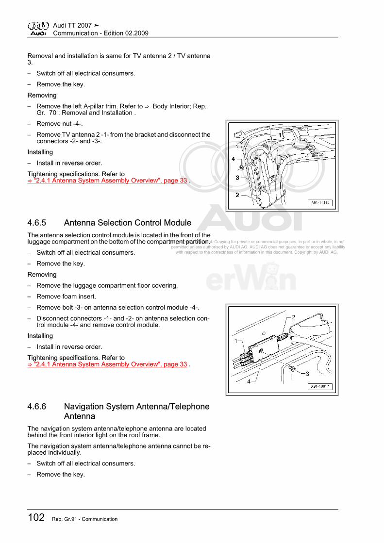
Protected by copyright. Copying for private or commercial purposes, in part or in whole, is not permitted unless authorised by AUDI AG. AUDI AG does not guarantee or accept any liability with respect to the correctness of information in this document. Copyright by AUDI AG.
Removal and installation is same for TV antenna 2 / TV antenna3.– Switch off all electrical consumers.– Remove the key.Removing– Remove the left A-pillar trim. Refer to ⇒ Body Interior; Rep.
Gr. 70 ; Removal and Installation .– Remove nut -4-.– Remove TV antenna 2 -1- from the bracket and disconnect the
connectors -2- and -3-.Installing– Install in reverse order.Tightening specifications. Refer to⇒ “2.4.1 Antenna System Assembly Overview”, page 33 .
4.6.5 Antenna Selection Control ModuleThe antenna selection control module is located in the front of theluggage compartment on the bottom of the compartment partition.– Switch off all electrical consumers.– Remove the key.Removing– Remove the luggage compartment floor covering.– Remove foam insert.– Remove bolt -3- on antenna selection control module -4-.– Disconnect connectors -1- and -2- on antenna selection con‐
trol module -4- and remove control module.Installing– Install in reverse order.Tightening specifications. Refer to⇒ “2.4.1 Antenna System Assembly Overview”, page 33 .
4.6.6 Navigation System Antenna/TelephoneAntenna
The navigation system antenna/telephone antenna are locatedbehind the front interior light on the roof frame.The navigation system antenna/telephone antenna cannot be re‐placed individually.– Switch off all electrical consumers.– Remove the key.
Audi TT 2007 ➤Communication - Edition 02.2009
102 Rep. Gr.91 - Communication
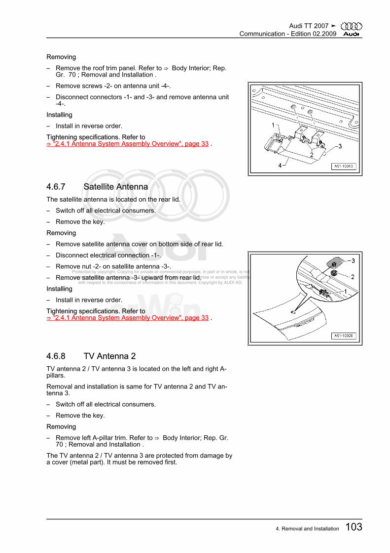
Protected by copyright. Copying for private or commercial purposes, in part or in whole, is not permitted unless authorised by AUDI AG. AUDI AG does not guarantee or accept any liability with respect to the correctness of information in this document. Copyright by AUDI AG.
Removing– Remove the roof trim panel. Refer to ⇒ Body Interior; Rep.
Gr. 70 ; Removal and Installation .– Remove screws -2- on antenna unit -4-.– Disconnect connectors -1- and -3- and remove antenna unit
-4-.Installing– Install in reverse order.Tightening specifications. Refer to⇒ “2.4.1 Antenna System Assembly Overview”, page 33 .
4.6.7 Satellite AntennaThe satellite antenna is located on the rear lid.– Switch off all electrical consumers.– Remove the key.Removing– Remove satellite antenna cover on bottom side of rear lid.– Disconnect electrical connection -1-.– Remove nut -2- on satellite antenna -3-.– Remove satellite antenna -3- upward from rear lid.Installing– Install in reverse order.Tightening specifications. Refer to⇒ “2.4.1 Antenna System Assembly Overview”, page 33 .
4.6.8 TV Antenna 2TV antenna 2 / TV antenna 3 is located on the left and right A-pillars.Removal and installation is same for TV antenna 2 and TV an‐tenna 3.– Switch off all electrical consumers.– Remove the key.Removing– Remove left A-pillar trim. Refer to ⇒ Body Interior; Rep. Gr.
70 ; Removal and Installation .The TV antenna 2 / TV antenna 3 are protected from damage bya cover (metal part). It must be removed first.
Audi TT 2007 ➤Communication - Edition 02.2009
4. Removal and Installation 103

Protected by copyright. Copying for private or commercial purposes, in part or in whole, is not permitted unless authorised by AUDI AG. AUDI AG does not guarantee or accept any liability with respect to the correctness of information in this document. Copyright by AUDI AG.
– Remove screws -1-.– Remove cover -2- from the A-pillar.
– Remove nut -4-.– Raise TV antenna 2 -1- from retaining plate and disconnect
connectors -2- and -3-.Installing– Install in reverse order.Tightening specifications. Refer to⇒ “2.4.1 Antenna System Assembly Overview”, page 33 .
4.7 Telephone Systems⇒ “4.7.1 Telephone Baseplate”, page 104⇒ “4.7.2 Telephone Transceiver”, page 105⇒ “4.7.3 Microphone Unit in Front Roof Module”, page 105
4.7.1 Telephone Baseplate– Switch off all electrical consumers.– Remove the key.Removing– Remove cellular telephone from telephone baseplate and un‐
clip it.– Pry telephone baseplate -1- upward.
Audi TT 2007 ➤Communication - Edition 02.2009
104 Rep. Gr.91 - Communication

Protected by copyright. Copying for private or commercial purposes, in part or in whole, is not permitted unless authorised by AUDI AG. AUDI AG does not guarantee or accept any liability with respect to the correctness of information in this document. Copyright by AUDI AG.
– Remove bolt -4- on bottom side of base plate -3-.– Disconnect electrical connector -2- on telephone baseplate
-1-.– Remove telephone baseplate -1- upward.Installing– Install in reverse order.Tightening specifications. Refer to⇒ “2.5.1 Coupe, Assembly Overview”, page 36 .
4.7.2 Telephone Transceivertelephone transceiver is located in the electronics box under leftfront seat– If control module is replaced, select Replacement function for
appropriate control module in Guided Fault-Finding routine.Use the Vehicle Diagnosis, Testing and Information System to doso.– Switch off all electrical consumers.– Remove the key.Removing– Remove left front seat. Refer to ⇒ Body Interior; Rep. Gr. 72 ;
Removal and Installation .– Cut open the floor covering. Refer to ⇒ Body Interior; Rep.
Gr. 70 ; Removal and Installation .– Unclip cover -1- on electronics box -4- and remove it upward.– Remove bluetooth antenna -3- from telephone transceiver
-2-.– Disconnect electrical connector -5- on telephone transceiver
-2-.– Raise telephone transceiver -2- upward out of electronics box
-4-.Installing– Install in reverse order.– Install a carpet frame. Refer to ⇒ Body Interior; Rep. Gr. 70 ;
Removal and Installation .
4.7.3 Microphone Unit in Front Roof ModuleA maximum of two microphones are installed in the front interiorlight. They can only be replaced completely.– Switch off all electrical consumers.– Remove the key.Removing– Remove front interior light. Refer to ⇒ Electrical Equipment;
Rep. Gr. 96 ; Removal and Installation .
Audi TT 2007 ➤Communication - Edition 02.2009
4. Removal and Installation 105

Protected by copyright. Copying for private or commercial purposes, in part or in whole, is not permitted unless authorised by AUDI AG. AUDI AG does not guarantee or accept any liability with respect to the correctness of information in this document. Copyright by AUDI AG.
– Disconnect electrical connector -1-.– Unclip microphones -2- and -4- from front interior light -3-
-arrows-.Installing– Install in reverse order.
4.8 Navigation System with CD Drive Con‐trol Module
Special tools and workshop equipment required♦ Radio Removal Tool -T10057-– If control module is replaced, select Replacement function for
appropriate control module in Guided Fault-Finding routine.Use the Vehicle Diagnosis, Testing and Information System to doso.– Switch off all electrical consumers.– Remove the key.Removing– Insert radio removal tool into release slots on navigation sys‐
tem with cd drive control module until they engage. Points ongrip eyes face outward.
– Remove the navigation system with cd drive control modulefrom the instrument panel using the grip eyes on the radio re‐moval tool.
– Release electrical connectors on navigation system with cddrive control module and remove it.
– Remove radio removal tool by pressing locking tabs on navi‐gation system with cd drive control module.
– Remove front passenger's airbag disabled indicator lamp. Re‐fer to⇒ “4.2 Front Passenger Airbag Disabled Indicator Lamp”, page87 .
Installing– Install front passenger's airbag disabled indicator lamp. Refer
to⇒ “4.2 Front Passenger Airbag Disabled Indicator Lamp”, page87 .
– Connect all electrical connectors.– Slide navigation system with cd drive control module straight
into instrument panel until it engages in installation frame.
4.9 Radio/Navigation Display Control Mod‐ule
Special tools and workshop equipment required♦ Radio Removal Tool -T10057-
Audi TT 2007 ➤Communication - Edition 02.2009
106 Rep. Gr.91 - Communication

Protected by copyright. Copying for private or commercial purposes, in part or in whole, is not permitted unless authorised by AUDI AG. AUDI AG does not guarantee or accept any liability with respect to the correctness of information in this document. Copyright by AUDI AG.
– If control module is replaced, select Replacement function forappropriate control module in Guided Fault-Finding routine.
Use the Vehicle Diagnosis, Testing and Information System to doso.– Switch off all electrical consumers.– Remove the key.Removing– Place radio removal tool -arrows- in release slits on radio/nav‐
igation display control module until they engage. Points on gripeyes face outward.
– Remove radio/navigation display control module from instru‐ment panel using grip eyes on radio removal tool.
– Release electrical connectors on radio/navigation display con‐trol module and remove it.
– Remove radio removal tool by pressing locking tabs on radio/navigation display control module.
– Remove front passenger's airbag disabled indicator lamp. Re‐fer to⇒ “4.2 Front Passenger Airbag Disabled Indicator Lamp”, page87 .
Installing– Install front passenger's airbag disabled indicator lamp. Refer
to⇒ “4.2 Front Passenger Airbag Disabled Indicator Lamp”, page87 .
– Connect all electrical connectors.– Slide radio/navigation display control module straight into in‐
strument panel until it engages in installation frame.
4.10 CD ChangerRequired Special Tools and Equipment♦ Radio Removal Tool -T10057-– Switch off all electrical consumers.– Remove the key.Removing– Open the glove compartment.– If there is a CD still inside the CD changer, remove it.– Insert two clips on radio removal tool in release slits on CD
changer until they engage. Points on the grip eyelets of toolface outward.
– Remove CD changer from installation frame using grip eyeson radio removal tool.
– Disconnect electrical connector on CD changer.– Remove radio removal tool, push locking tabs on CD changer
to do so.Installing– Connect electrical connector.– Slide CD changer into mounting frame until it engages.
Audi TT 2007 ➤Communication - Edition 02.2009
4. Removal and Installation 107

Protected by copyright. Copying for private or commercial purposes, in part or in whole, is not permitted unless authorised by AUDI AG. AUDI AG does not guarantee or accept any liability with respect to the correctness of information in this document. Copyright by AUDI AG.
4.11 iPod BaseplateRequired Special Tools and Equipment♦ Trim removal wedge -3409-– Switch off all electrical consumers.– Remove the key.Removing– Open the glove compartment.– Remove iPod -1- from iPod baseplate.– Using trim removal wedge, carefully pry iPod baseplate out of
retainer -arrows-.– Remove iPod baseplate from glove compartment and discon‐
nect electrical connector.Installing– Install in reverse order.
4.12 AMI External Audio Source ConnectionThe external audio source connection (AMI) is located inside theglove compartment.Special tools and workshop equipment required♦ Radio Removal Tool -T10057-– Switch off all electrical consumers.– Remove the key.Removing– Open glove compartment.– Insert the two clips of the radio removal tool into the release
slits on the external audio source connection until they en‐gage. Points on the grip eyelets of tool face outward.
– Pull external audio source connection out of mounting frame.– Disconnect all connectors on the external audio source con‐
nection.– Remove the radio removal tool, push locking tabs on external
audio source connection to do so.Remove the internal control unit
Audi TT 2007 ➤Communication - Edition 02.2009
108 Rep. Gr.91 - Communication

Protected by copyright. Copying for private or commercial purposes, in part or in whole, is not permitted unless authorised by AUDI AG. AUDI AG does not guarantee or accept any liability with respect to the correctness of information in this document. Copyright by AUDI AG.
– Remove the screw -2- on back side (2 Nm).– Press the tabs -4- and -5- down and up and remove the control
module -5- back from the frame -1- .Installing– Connect electrical connectors.– Slide the external audio source connection on the mounting
frame until it engages.
4.13 AUX IN External Audio Source Connec‐tion
The external audio source connection (AUX IN) is installed insidethe center console storage compartment.– Switch off all electrical consumers.– Remove the key.Removing– Remove the rear center console. Refer to ⇒ Body Interior;
Rep. Gr. 68 ; Removal and Installation .– Disconnect the connector -1- on the external audio source
connection -2-.– Remove bolt -4-.– Remove the external audio source connection -2- from the
center console -3-.Installing– Install in reverse order.Tightening specifications. Refer to⇒ “2.1.1 Radio System Assembly Overview”, page 8 .
4.14 Multi-function ButtonsRemoving– Remove driver's airbag. Refer to ⇒ Body Interior; Rep. Gr.
69 .– Disconnect harness connector -1- at button -2-.– Slide button -2- out of steering wheel in -direction of arrow-.– Turn the button around.
Audi TT 2007 ➤Communication - Edition 02.2009
4. Removal and Installation 109

Protected by copyright. Copying for private or commercial purposes, in part or in whole, is not permitted unless authorised by AUDI AG. AUDI AG does not guarantee or accept any liability with respect to the correctness of information in this document. Copyright by AUDI AG.
– Disconnect the connector -2- to tiptronic switch from multi‐function button -1- and remove button.
Installing– Install in reverse order.Removal and installation of left multi-function button is identical.
4.15 Tiptronic SwitchRemoving– Remove driver's airbag. Refer to ⇒ Body Interior; Rep. Gr.
69 .– Disconnect trim ring from steering wheel.– Slide multi-function button -2- out of steering wheel in
-direction of arrow-.– Rotate multi-function button.
– Disconnect the connector -2- on the multifunction button -1-.
– Remove the bolts -arrow- (3 Nm) and the Tiptronic switch tothe rear.
Installing– Install in reverse order.Removal and installation of the left switch is identical.
Audi TT 2007 ➤Communication - Edition 02.2009
110 Rep. Gr.91 - Communication

Protected by copyright. Copying for private or commercial purposes, in part or in whole, is not permitted unless authorised by AUDI AG. AUDI AG does not guarantee or accept any liability with respect to the correctness of information in this document. Copyright by AUDI AG.
4.16 Steering Column Electronic SystemsControl Module
– If control module is replaced, select Replacement function forappropriate control module in Guided Fault-Finding routine.
Use the Vehicle Diagnosis, Testing and Information System to doso.Removing– Disconnect battery ground wire. Refer to ⇒ Electrical System;
Rep. Gr. 27 ; Removal and Installation .– Observe airbag system safety precautions. Refer to ⇒ Body
Interior; Rep. Gr. 69 ; General Information .– Remove steering column switch module. Refer to ⇒ Electrical
System; Rep. Gr. 96 ; Description and Operation .– Remove bolt -arrow- (2 Nm) below spiral spring.The steering column electronic systems control module is secureto steering column module with two spring retainers.
– Release springs -1- and -2- with a small screwdriver.– Remove steering column electronic systems control module
downward from steering column module.Installing– Follow the safety precautions for airbag systems. Refer to ⇒
Body Interior; Rep. Gr. 69 ; General Information .– Install in reverse order.– Make sure that all connections have engaged and lines lie in
proper guides.
Audi TT 2007 ➤Communication - Edition 02.2009
4. Removal and Installation 111

Protected by copyright. Copying for private or commercial purposes, in part or in whole, is not permitted unless authorised by AUDI AG. AUDI AG does not guarantee or accept any liability with respect to the correctness of information in this document. Copyright by AUDI AG.
5 Special Tools♦ Radio Removal Tool -T10057-
♦ Trim removal wedge -3409-
Audi TT 2007 ➤Communication - Edition 02.2009
112 Rep. Gr.91 - Communication

Protected by copyright. Copying for private or commercial purposes, in part or in whole, is not permitted unless authorised by AUDI AG. AUDI AG does not guarantee or accept any liability with respect to the correctness of information in this document. Copyright by AUDI AG.
Cautions & Warnings
=Page 1 of 3 © 2002 Audi of America, Inc. All rights reserved. Information contained in this document is based on the latest information available at the time of printing and is subject to the copyright and other intellectual property rights of Audi of America, Inc., its affiliated companies and its licensors. All rights are reserved to make changes at any time without notice. No part of this document may be reproduced, stored in a retrieval system, or transmitted in any form or by any means, electronic, mechanical, photocopying, recording, or otherwise, nor may these materials be modified or reposted to other sites, without the prior expressed written permission of the publisher. Version 1.0
Please read these WARNINGS and CAUTIONS before proceeding with maintenance and repair work. You must answer that you have read and you understand these WARNINGS and CAUTIONS before you will be allowed to view this information.
•= If you lack the skills, tools and equipment, or a suitable workshop for any procedure described in this manual, we suggest you leave such repairs to an authorized Audi retailer or other qualified shop. We especially urge you to consult an authorized Audi retailer before beginning repairs on any vehicle that may still be covered wholly or in part by any of the extensive warranties issued by Audi.
•= Disconnect the battery negative terminal (ground strap)whenever you work on the fuel system or the electrical system. Do not smoke or work near heaters or other fire hazards. Keep an approved fire extinguisher handy.
•= Audi is constantly improving its vehicles and sometimes these changes, both in parts and specifications, are made applicable to earlier models. Therefore, part numbers listed in this manual are for reference only. Always check with your authorized Audi retailer parts department for the latest information.
•= Any time the battery has been disconnected on an automatic transmission vehicle, it will be necessary to reestablish Transmission Control Module (TCM) basic settings using the VAG 1551 Scan Tool (ST).
•= Never work under a lifted vehicle unless it is solidly supported on stands designed for the purpose. Do not support a vehicle on cinder blocks, hollow tiles or other props that may crumble under continuous load. Never work under a vehicle that is supported solely by a jack. Never work under the vehicle while the engine is running.
•= For vehicles equipped with an anti-theft radio, be sure of the correct radio activation code before disconnecting the battery or removing the radio. If the wrong code is entered when the power is restored, the radio may lock up and become inoperable, even if the correct code is used in a later attempt.
•= If you are going to work under a vehicle on the ground, make sure that the ground is level. Block the wheels to keep the vehicle from rolling. Disconnect the battery negative terminal (ground strap) to prevent others from starting the vehicle while you are under it.
•= Do not attempt to work on your vehicle if you do not feel well. You increase the danger of injury to yourself and others if you are tired, upset or have taken medicine or any other substances that may impair you or keep you from being fully alert.
•= Never run the engine unless the work area is well ventilated. Carbon monoxide (CO) kills.
•= Always observe good workshop practices. Wear goggles when you operate machine tools or work with acid. Wear goggles, gloves and other protective clothing whenever the job requires working with harmful substances.
•= Tie long hair behind your head. Do not wear a necktie, a scarf, loose clothing, or a necklace when you work near machine tools or running engines. If your hair, clothing, or jewelry were to get caught in the machinery, severe injury could result.

Protected by copyright. Copying for private or commercial purposes, in part or in whole, is not permitted unless authorised by AUDI AG. AUDI AG does not guarantee or accept any liability with respect to the correctness of information in this document. Copyright by AUDI AG.
Cautions & Warnings
=Page 2 of 3 © 2002 Audi of America, Inc. All rights reserved. Information contained in this document is based on the latest information available at the time of printing and is subject to the copyright and other intellectual property rights of Audi of America, Inc., its affiliated companies and its licensors. All rights are reserved to make changes at any time without notice. No part of this document may be reproduced, stored in a retrieval system, or transmitted in any form or by any means, electronic, mechanical, photocopying, recording, or otherwise, nor may these materials be modified or reposted to other sites, without the prior expressed written permission of the publisher. Version 1.0
•= Do not re-use any fasteners that are worn or deformed in normal use. Some fasteners are designed to be used only once and are unreliable and may fail if used a second time. This includes, but is not limited to, nuts, bolts, washers, circlips and cotter pins. Always follow the recommendations in this manual - replace these fasteners with new parts where indicated, and any other time it is deemed necessary by inspection.
•= Illuminate the work area adequately but safely. Use a portable safety light for working inside or under the vehicle. Make sure the bulb is enclosed by a wire cage. The hot filament of an accidentally broken bulb can ignite spilled fuel or oil.
•= Friction materials such as brake pads and clutch discs may contain asbestos fibers. Do not create dust by grinding, sanding, or by cleaning with compressed air. Avoid breathing asbestos fibers and asbestos dust. Breathing asbestos can cause serious diseases such as asbestosis or cancer, and may result in death.
•= Finger rings should be removed so that they cannot cause electrical shorts, get caught in running machinery, or be crushed by heavy parts.
•= Before starting a job, make certain that you have all the necessary tools and parts on hand. Read all the instructions thoroughly, do not attempt shortcuts. Use tools that are appropriate to the work and use only replacement parts meeting Audi specifications. Makeshift tools, parts and procedures will not make good repairs.
•= Catch draining fuel, oil or brake fluid in suitable containers. Do not use empty food or beverage containers that might mislead someone into drinking from them. Store flammable fluids away from fire hazards. Wipe up spills at once, but do not store the oily rags, which can ignite and burn spontaneously.
•= Use pneumatic and electric tools only to loosen threaded parts and fasteners. Never use these tools to tighten fasteners, especially on light alloy parts. Always use a torque wrench to tighten fasteners to the tightening torque listed.
•= Keep sparks, lighted matches, and open flame away from the top of the battery. If escaping hydrogen gas is ignited, it will ignite gas trapped in the cells and cause the battery to explode.
•= Be mindful of the environment and ecology. Before you drain the crankcase, find out the proper way to dispose of the oil. Do not pour oil onto the ground, down a drain, or into a stream, pond, or lake. Consult local ordinances that govern the disposal of wastes.
•= The air-conditioning (A/C) system is filled with a chemical refrigerant that is hazardous. The A/C system should be serviced only by trained automotive service technicians using approved refrigerant recovery/recycling equipment, trained in related safety precautions, and familiar with regulations governing the discharging and disposal of automotive chemical refrigerants.
•= Before doing any electrical welding on vehicles equipped with anti-lock brakes (ABS), disconnect the battery negative terminal (ground strap) and the ABS control module connector.
•= Do not expose any part of the A/C system to high temperatures such as open flame. Excessive heat will increase system pressure and may cause the system to burst.

Protected by copyright. Copying for private or commercial purposes, in part or in whole, is not permitted unless authorised by AUDI AG. AUDI AG does not guarantee or accept any liability with respect to the correctness of information in this document. Copyright by AUDI AG.
Cautions & Warnings
=Page 3 of 3 © 2002 Audi of America, Inc. All rights reserved. Information contained in this document is based on the latest information available at the time of printing and is subject to the copyright and other intellectual property rights of Audi of America, Inc., its affiliated companies and its licensors. All rights are reserved to make changes at any time without notice. No part of this document may be reproduced, stored in a retrieval system, or transmitted in any form or by any means, electronic, mechanical, photocopying, recording, or otherwise, nor may these materials be modified or reposted to other sites, without the prior expressed written permission of the publisher. Version 1.0
•= When boost-charging the battery, first remove the fuses for the Engine Control Module (ECM), the Transmission Control Module (TCM), the ABS control module, and the trip computer. In cases where one or more of these components is not separately fused, disconnect the control module connector(s).
•= Some of the vehicles covered by this manual are equipped with a supplemental restraint system (SRS), that automatically deploys an airbag in the event of a frontal impact. The airbag is operated by an explosive device. Handled improperly or without adequate safeguards, it can be accidentally activated and cause serious personal injury. To guard against personal injury or airbag system failure, only trained Audi Service technicians should test, disassemble or service the airbag system.
•= Do not quick-charge the battery (for boost starting) for longer than one minute, and do not exceed 16.5 volts at the battery with the boosting cables attached. Wait at least one minute before boosting the battery a second time.
•= Never use a test light to conduct electrical tests of the airbag system. The system must only be tested by trained Audi Service technicians using the VAG 1551 Scan Tool (ST) or an approved equivalent. The airbag unit must never be electrically tested while it is not installed in the vehicle.
•= Some aerosol tire inflators are highly flammable. Be extremely cautious when repairing a tire that may have been inflated using an aerosol tire inflator. Keep sparks, open flame or other sources of ignition away from the tire repair area. Inflate and deflate the tire at least four times before breaking the bead from the rim. Completely remove the tire from the rim before attempting any repair.
•= When driving or riding in an airbag-equipped vehicle, never hold test equipment in your hands or lap while the vehicle is in motion. Objects between you and the airbag can increase the risk of injury in an accident.
I have read and I understand these Cautions and Warnings.