service manual -...
TRANSCRIPT
11111111
White-Westinghouse
ELECTROLUX HOME PRODUCTS NORTH AMERICA
SERVICE MANUAL
Tumble Action Washers
With
Electronic Controls
59953931385995393138599539313859953931385995393138 November2003 November2003 November2003 November2003 November2003
2
ATTENTION!!!This service manual is intended for use by persons having electrical and mechanicaltraining and a level of knowledge of these subjects generally considered acceptable inthe appliance repair trade. Electrolux Home Products cannot be responsible, nor assumeany liability, for injury or damage of any kind arising from the use of this manual.
© 2001 White Consolidated Industries
SAFE SERVICING PRACTICES - ALL APPLIANCES
To avoid personal injury and/or property damage, it is important that Safe ServicingPractices be observed. The following are some limited examples of safe practices:
1. DO NOT attempt a product repair if you have any doubts as to your ability tocomplete it in a safe and satisfactory manner.
2. Before servicing or moving an appliance:
• Remove the power cord from the electrical outlet, trip the circuit breaker to theOFF position, or remove the fuse.
• Turn off the gas supply.• Turn off the water supply.
3. Never interfere with the proper operation of any safety device.
4. USE ONLY REPLACEMENT PARTS CATALOGED FOR THIS APPLIANCE.SUBSTITUTIONS MAY DEFEAT COMPLIANCE WITH SAFETYSTANDARDS SET FOR HOME APPLIANCES.
5. GROUNDING: The standard color coding for safety ground wires is GREEN,or GREEN with YELLOW STRIPES. Ground leads are not to be used as currentcarrying conductors. It is EXTREMELY important that the service technicianreestablish all safety grounds prior to completion of service. Failure to do so willcreate a hazard.
6. Prior to returning the product to service, ensure that:
• All electrical connections are correct and secure• All electrical leads are properly dressed and secured away from sharp
edges, high-temperature components, and moving parts• All non-insulated electrical terminals, connectors, heaters, etc. are
adequately spaced away from all metal parts and panels• All safety grounds (both internal and external) are correctly and securely
connected• All panels are properly and securely reassembled
3
SAFE SERVICING PRACTICES 2QUICK REFERENCE SHEET 6
Serial nameplate location 6Serial number breakdown 6Tech sheet location 6Fault codes 7Function testing 8Component resistance chart 9Water fill height 9Electrical requirements 9Incoming water pressure 9Drain requirements 9Motor 9Operation speeds 10Tub pulley to motor pulley ratio 10Tub capacity 10Auto temp control temperature specifications 10Neutral test point 10
SAMPLE SCHEMATIC 11OPERATION CHART 12SECTION A - INSTALLATION INSTRUCTIONS 14
Full size tumble action washer 14What to do if you smell gas 14Pre-installation requirements 14
Tools required for installation 14Electrical requirements 14
Circuit 14Power supply 14Outlet receptacle 14
Grounding requirements 14Water supply requirements 15Drain requirements 15Rough-in dimensions 16Location of your washer 17
Do not install your washer 17Minimum installation clearances 17
Unpacking 17Installation 18Replacement parts 19
SECTION B - OPERATING INSTRUCTIONS 20Before operating your washer 20Operating steps 20Cycle selection 20
Heavy duty 21Normal wash 21Quick cycle 21Delicates and hand wash 21Silk 21Drain/spin 21
Cycle adjustments 21Wash/rinse water temperature 21Final spin speed 21Water level 21Cycle options 21Heavy soil/stain 22Auto temp 22Extra rinse 22
4
Extra spin 22Washer features 22
Control lock 22Signal 22Delay 22Display 22Error codes 22
Cycle selections 23SECTION C - OWNER’S GUIDE 24
Your safety and the safety of others is very important 24Pedestal 24Important safety instructions 24
Read all instructions before using this washer 24Prevent fire 24Protect Children 24Prevent Injury 25
Washing procedures 26Sort laundry into loads that can be washed together 26Prepare items for washing 26Pretreat stains and heavy soil 27Add laundry load to washer 27Add detergent, bleach and fabic softener to automatic dispenser 27Start the washer 28Remove items when the cycle is completed 29General precautions 29
Stain removal 29Safe stain removal procedures 29Stain removal 30Common washing problems 31Care and cleaning 32
Outside 32Cleaning the dispenser drawer area 32Inside 33
Avoid service checklist 33Winterizing instructions 33Warranty 36
SECTION D - OPERATION 37Membrane 37Control and Display 37Dispenser Drawer Reed Switch 37Door Switch Assembly 37Pressure Switch 38Automatic Dispenser 39Auto Temp System 40Water Inlet Valve 41Drain Pump 42Speed Control 42Motor 43
SECTION E - CONSTRUCTION 44Cabinet 44Front Panel and Door Assembly 44Bellows (Door Boot) 44Outer Tub Assembly 44Spin Basket Assembly 44
SECTION F - TROUBLESHOOTING FLOW CHARTS 45Motor and speed control plug numbers 46Control board connectors 47
5
Washer completely inoperative 48Display does not illuminate 49Washer will not fill 49Washer does not advance through the cycles 50Washer does not drain 50Bleach dispenser does not operate 51Softner dispenser does not operate 51Drive motor does not turn 52Drive motor spins but does not tumble 53Drive motor tumbles but does not spin 53Drive motor tumbles very slowly in any timer position 54Incorrect spin speed for selected setting 54Water fill does not turn off 55Incorrect water level 55Slow water fill 56Warm water temperature above or coldwater temperature below specifiations 56Washer will only fill with cold water in the washcycle, when the warm/cold setting is selected 57Washer will only fill with hot water in the washcycle, when the warm/cold setting is selected 57
SECTION G - TEARDOWN 58Removing the detergent drawer 58Detergent drawer disassembly 58Removing the top panel 59Removing the console 59Removing the control and display 60Removing the reed switch 61Removing the front service panel 61To remove loading door and hinge 62Disassembling the door 62To remove door strike 63Removing the door safety switch 63Removing the bellow or boot 64Reinstalling or replacing the boot 65Removing the water inlet duct 68Removing the detergent dispenser solenoid assembly 68Removing the detergent cavity assembly 68Removing the pressure switch 69Removing the suspension springs 70Removing the automatic temperature control sensor 70Removing the water inlet valve 70Removing the drain pump assembly 70Disassembling the drain pump 71To remove the air bell 71Removing the back service panel 72Removing the speed control board assembly 72Drive belt 73To remove or replace the drive belt 73Removing the drive motor 74Removing the large pulley 74Removing the rear counter weight 75Removing the air shock absorber 75Removing the outer tub 75Removing the spin basket and rear tub half 75Removing the front counter weights 76Removing the spin basket vanes 76
6
QUICK REFERENCE SHEET
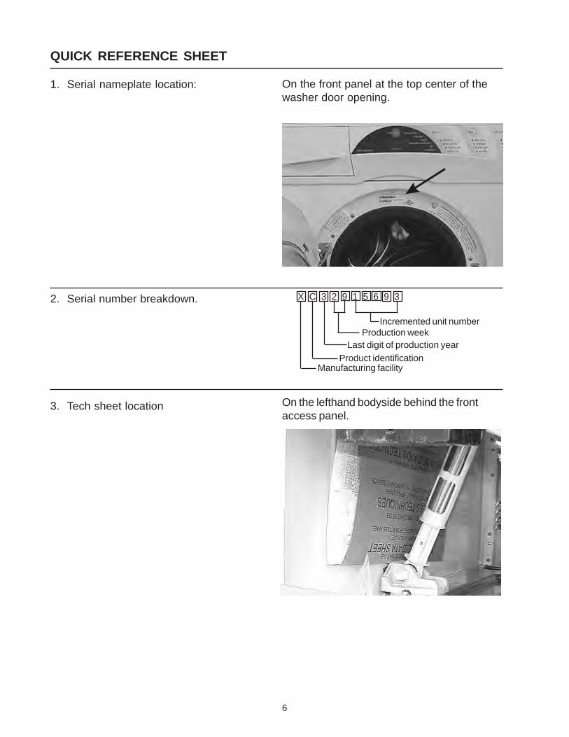
1. Serial nameplate location:
2. Serial number breakdown.
3. Tech sheet location
X C 3 2 9 1 5 6 9 3
Incremented unit numberProduction week
Last digit of production yearProduct identification
Manufacturing facility
On the front panel at the top center of thewasher door opening.
On the lefthand bodyside behind the frontaccess panel.
7
QUICK REFERENCE SHEETFault Codes:
Display shows: F 01
Indicates: An internal fault in the control.
Correction: Touch the Stop/Clear pad. If the dis-play continues to display F1 or if thecode returns when the washer is re-stated, replace the control.
Display shows: F 02
Indicates: A water temperature problem.
Correction: First check to see if the incoming wa-ter hoses are connected properly. If so,disconnect both wires from the watertemperature sensor and measure theresistance of the sensor. If the readingis less than 3K or more than 163K, re-place the sensor. If the reading is be-tween 3K and 163K, reconnect the wiresto the sensor and unplug the small fourpin plug from the control board. Mea-sure the resistance between pins 3 and4 in the plug. If the reading is the sameas the sensor reading, replace the con-trol board. If the meter reading is notthe same as that at the sensor, the wir-ing between the control board and sen-sor is defective.
Display shows: F 03
Indicates: Water level problem caused by eitherno incoming water or the drain pumpnot working.
Correction: Touch the Stop/Clear pad to clear theF 03. Check the drum for water. If thedrum has a normal fill of water, touchthe Drain/Spin pad and press the startpad. If the water does not pump out,remove the front access panel and mea-sure the voltage drop across terminalsof the drain pump. If the meter reads120 VAC, the drain pump is defectiveor the drain hose is plugged. If themeter reads zero, disconnect power,remove the large four pin plug (JX) andthe eight pin plug(J11) from the back ofthe control. Measure the resistance be-tween pin 3 in the four pin plug and pin3 of the eight pin plug. If the meter reads
open, the wires between the controlboard and the drain pump are defec-tive. If the meter reads around 15 Ohms,the control board should be replaced.
If the drum does not have water in it,start the washer in the Normal Cycleand select Warm Wash. If the washerdoes not fill, make sure the faucets areturned on, unplug one of plugs from thewater valve and measure the voltagedrop across the terminals in the plug.If the meter reads 120VAC, the watervalve is defective. If the meter readszero, measure for voltage from each ter-minal in the plug to neutral. If the meterreads zero from each terminal, the pres-sure switch or the wiring to the pres-sure switch is defective. If the meterreads 120VAC from one terminal, thecontrol board or the wiring from the valveto the control board is defective.
If the washer is over filling, check thepressure switch or the tube to the pres-sure switch.
Display shows: F 04
Indicates: The washer is not advancing through itincrements.
Correction: Touch Stop/Clear to clear the F 04. Se-lect and start the washer in the HeavyDuty wash cycle with the Heavy Soil/Stain Option deactivated. If the tubdoes not start turning while filling orwithin 30 seconds after the fill is com-pleted, troubleshoot for a motor will notrun problem. If the motor is running andthe tub is filled, let the washer run for atleast 6 minutes. Measure the voltagebetween pin one of the 8 pin connector(J11) and pin 7 of the 7 pin connector(J6). The voltage should be below 50VAC when the timer advances is off andline voltage when the timer advance ison. If the meter reading does not switchbetween these two reading, the motorspeed control is defective. If the meterreading switches between these tworeading, the electronic control board isdefective.
Display shows: F 05
Indicates: A problem with the key pad.
8
Correction: Disconnect the keypad ribbon from thecontrol and reconnect the ribbon. Tryall keypad switches to see they all func-tion correctly. If they do not, then tryclean the end of the ribbon with a softcotton cloth. Reinstall the ribbon andprogram the washer to operate. If thecode reoccurs, replace the touch pad.
Note: See control removal instructions onhow to disconnect ribbon.
Code: ddo
Indicates: Drawer reed switch is not closed.
Correction: Make sure the drawer is closed. If thedrawer is closed, check that the mag-net in the drawer is in the correct posi-tion. If the magnet is in the correct po-sition, check the reed switch.
Code: dr
Indicates: Door switch is not closed.
Correction: Check that the door is closed and thedoor catch is not broken. If so, replacethe door lock assembly.
QUICK REFERENCE SHEET
Function Testing:
Test programs are built into the control to allow differentfunctions to be activated with out wait for the function tooccur in the cycle.
Membrane test:
To start the test programs, remove power from thewasher. Then reconnect power to the washer and within10 seconds press and hold the temps and the stop padsfor at least 2 seconds, then release. The control is nowin the test function.
1. Starting with the Cycles pad, touch each pad andsee that appropriate LED’s or the appropriatedisplay symbol illuminates.
Note: When Delay pad is touched, the complete display illuminates.
Online test:
To start the test program, remove power from the washer.Then reconnect power to the washer and within 10 sec-onds press and hold the temp and the stop pads for atleast 2 seconds, then release. The control is now in thetest function.
1. Press the stop pad and then the start pad, (H) willappear in the display and the hot water valve circuitis activated.
2. Retouch the start pad and the test will advance tothe cold water test. (C) will appear in the displayand the cold water valve circuit is activated.
3. Retouch the start pad and the test will advance tothe warm water test. (HC) will appear in the displayand both the hot water valve circuit and the coldwater valve circuit are activated.
4. Retouch the start pad and the test will advance tothe bleach dispenser test. (bL) will appear in thedisplay and the bleach solenoid circuit is activated.
5. Retouch the start pad and the test will advance tothe fabric softener test. (FA) will appear in the dis-play and the fabric softener solenoid circuit isactivated.
6. Retouch the start pad and the test will advance andrelease the door solenoid. (dr) will appear in the dis-play and the door can be opened.
7. Retouch the start pad and the test will advance tothe agitation and warm water test. (HC) will appearin the display and the drum will fill with warm waterand agitate.
8. Retouch the start pad and the test will advance tothe final spin test. (FS) will appear in the displayand in about 30 second the washer will go into finalspin.
Press stop pad, then the start pad to repeat the test.To remove the washer from the test mode, disconnectpower from the washer or press and hold the stop andcycles pads for at least 2 seconds, then release.
Demo Mode - For sales demonstration of the board LED’swithout function of the washer, remove power from thewasher. Reconnect power to the washer and within 10seconds, hold the stop/clear pad for at least 6 seconds.To remove the washer from the test mode, disconnectpower from the washer or press and hold the stop andcycles pads for at least 2 seconds, then release.
9
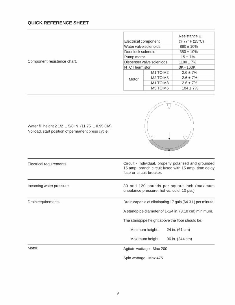
Resistance Ω Electrical component @ 77° F (25°C) Water valve solenoids 880 ± 10% Door lock solenoid 380 ± 10% Pump motor 15 ± 7% Dispenser valve soleniods 1100 ± 7% NTC Thermistor 3K - 163K
M1 TO M2 2.6 ± 7%M2 TO M3 2.6 ± 7%M1 TO M3 2.6 ± 7%M5 TO M6 184 ± 7%
QUICK REFERENCE SHEET
Component resistance chart.
Water fill height 2 1/2 ± 5/8 IN. (11.75 ± 0.95 CM)No load, start position of permanent press cycle.
Electrical requirements.
Incoming water pressure.
Drain requirements.
Motor.
Circuit - Individual, properly polarized and grounded15 amp. branch circuit fused with 15 amp. time delayfuse or circuit breaker.
30 and 120 pounds per square inch (maximumunbalance pressure, hot vs. cold, 10 psi.)
Drain capable of eliminating 17 gals (64.3 L) per minute.
A standpipe diameter of 1-1/4 in. (3.18 cm) minimum.
The standpipe height above the floor should be:
Minimum height: 24 in. (61 cm)
Maximum height: 96 in. (244 cm)
Motor
Agitate wattage - Max 200
Spin wattage - Max 475
10
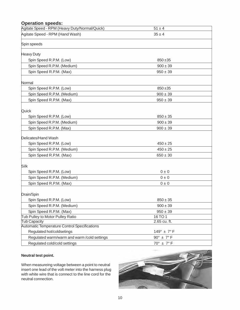
Operation speeds:Agitate Speed - RPM (Heavy Duty/Normal/Quick) 51 ± 4
Agitate Speed - RPM (Hand Wash) 35 ± 4
Spin speeds
Heavy Duty
Spin Speed R.P.M. (Low) 850 ±35
Spin Speed R.P.M. (Medium) 900 ± 39
Spin Speed R.P.M. (Max) 950 ± 39
NormalSpin Speed R.P.M. (Low) 850 ±35
Spin Speed R.P.M. (Medium) 900 ± 39
Spin Speed R.P.M. (Max) 950 ± 39
QuickSpin Speed R.P.M. (Low) 850 ± 35
Spin Speed R.P.M. (Medium) 900 ± 39
Spin Speed R.P.M. (Max) 900 ± 39
Delicates/Hand WashSpin Speed R.P.M. (Low) 450 ± 25
Spin Speed R.P.M. (Medium) 450 ± 25
Spin Speed R.P.M. (Max) 650 ± 30
SilkSpin Speed R.P.M. (Low) 0 ± 0
Spin Speed R.P.M. (Medium) 0 ± 0
Spin Speed R.P.M. (Max) 0 ± 0
Drain/SpinSpin Speed R.P.M. (Low) 850 ± 35
Spin Speed R.P.M. (Medium) 900 ± 39
Spin Speed R.P.M. (Max) 950 ± 39Tub Pulley to Motor Pulley Ratio 16 TO 1Tub Capacity 2.65 cu. ft.Automatic Temperature Control Specifications
Regulated hot/coldsetings 149° ± 7° FRegulated warm/warm and warm /cold settings 90° ± 7° FRegulated cold/cold settings 70° ± 7° F
Neutral test point.
When measureing voltage between a point to neutralinsert one lead of the volt meter into the harness plugwith white wire that is connect to the line cord for theneutral connection.
11
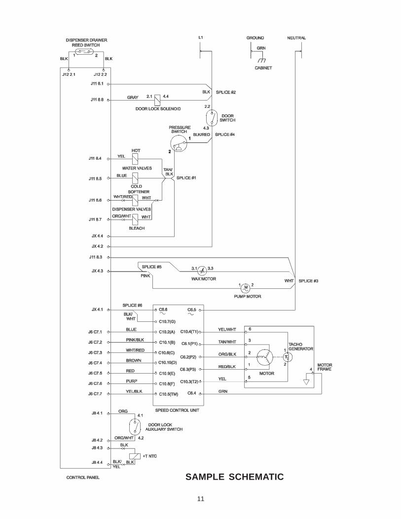
SAMPLE SCHEMATIC
12
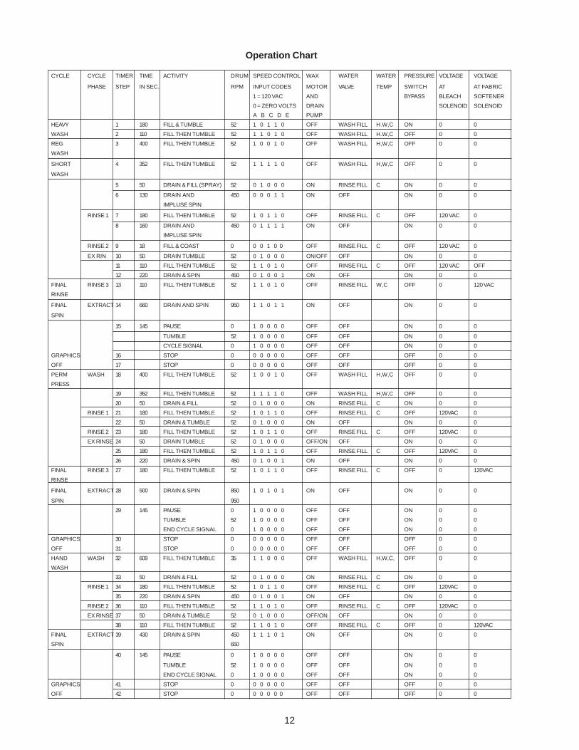
CYCLE CYCLE TIMER TIME ACTIVITY DRUM SPEED CONTROL WAX WATER WATER PRESSURE VOLTAGE VOLTAGE
PHASE STEP IN SEC. RPM INPUT CODES MOTOR VALVE TEMP SWITCH AT AT FABRIC
1 = 120 VAC AND BYPASS BLEACH SOFTENER
0 = ZERO VOLTS DRAIN SOLENOID SOLENOID
A B C D E PUMP
HEAVY 1 180 FILL & TUMBLE 52 1 0 1 1 0 OFF WASH FILL H.W,C ON 0 0
WASH 2 110 FILL THEN TUMBLE 52 1 1 0 1 0 OFF WASH FILL H.W,C OFF 0 0
REG 3 400 FILL THEN TUMBLE 52 1 0 0 1 0 OFF WASH FILL H,W,C OFF 0 0
WASH
SHORT 4 352 FILL THEN TUMBLE 52 1 1 1 1 0 OFF WASH FILL H,W,C OFF 0 0
WASH
5 50 DRAIN & FILL (SPRAY) 52 0 1 0 0 0 ON RINSE FILL C ON 0 0
6 130 DRAIN AND 450 0 0 0 1 1 ON OFF ON 0 0
IMPLUSE SPIN
RINSE 1 7 180 FILL THEN TUMBLE 52 1 0 1 1 0 OFF RINSE FILL C OFF 120 VAC 0
8 160 DRAIN AND 450 0 1 1 1 1 ON OFF ON 0 0
IMPLUSE SPIN
RINSE 2 9 18 FILL & COAST 0 0 0 1 0 0 OFF RINSE FILL C OFF 120 VAC 0
EX RIN 10 50 DRAIN TUMBLE 52 0 1 0 0 0 ON/OFF OFF ON 0 0
11 110 FILL THEN TUMBLE 52 1 1 0 1 0 OFF RINSE FILL C OFF 120 VAC OFF
12 220 DRAIN & SPIN 450 0 1 0 0 1 ON OFF ON 0 0
FINAL RINSE 3 13 110 FILL THEN TUMBLE 52 1 1 0 1 0 OFF RINSE FILL W,C OFF 0 120 VAC
RINSE
FINAL EXTRACT 14 660 DRAIN AND SPIN 950 1 1 0 1 1 ON OFF ON 0 0
SPIN
15 145 PAUSE 0 1 0 0 0 0 OFF OFF ON 0 0
TUMBLE 52 1 0 0 0 0 OFF OFF ON 0 0
CYCLE SIGNAL 0 1 0 0 0 0 OFF OFF ON 0 0
GRAPHICS 16 STOP 0 0 0 0 0 0 OFF OFF OFF 0 0
OFF 17 STOP 0 0 0 0 0 0 OFF OFF OFF 0 0
PERM WASH 18 400 FILL THEN TUMBLE 52 1 0 0 1 0 OFF WASH FILL H,W,C OFF 0 0
PRESS
19 352 FILL THEN TUMBLE 52 1 1 1 1 0 OFF WASH FILL H,W,C OFF 0 0
20 50 DRAIN & FILL 52 0 1 0 0 0 ON RINSE FILL C ON 0 0
RINSE 1 21 180 FILL THEN TUMBLE 52 1 0 1 1 0 OFF RINSE FILL C OFF 120VAC 0
22 50 DRAIN & TUMBLE 52 0 1 0 0 0 ON OFF ON 0 0
RINSE 2 23 180 FILL THEN TUMBLE 52 1 0 1 1 0 OFF RINSE FILL C OFF 120VAC 0
EX RINSE 24 50 DRAIN TUMBLE 52 0 1 0 0 0 OFF/ON OFF ON 0 0
25 180 FILL THEN TUMBLE 52 1 0 1 1 0 OFF RINSE FILL C OFF 120VAC 0
26 220 DRAIN & SPIN 450 0 1 0 0 1 ON OFF ON 0 0
FINAL RINSE 3 27 180 FILL THEN TUMBLE 52 1 0 1 1 0 OFF RINSE FILL C OFF 0 120VAC
RINSE
FINAL EXTRACT 28 500 DRAIN & SPIN 850 1 0 1 0 1 ON OFF ON 0 0
SPIN 950
29 145 PAUSE 0 1 0 0 0 0 OFF OFF ON 0 0
TUMBLE 52 1 0 0 0 0 OFF OFF ON 0 0
END CYCLE SIGNAL 0 1 0 0 0 0 OFF OFF ON 0 0
GRAPHICS 30 STOP 0 0 0 0 0 0 OFF OFF OFF 0 0
OFF 31 STOP 0 0 0 0 0 0 OFF OFF OFF 0 0
HAND WASH 32 609 FILL THEN TUMBLE 35 1 1 0 0 0 OFF WASH FILL H,W,C, OFF 0 0
WASH
33 50 DRAIN & FILL 52 0 1 0 0 0 ON RINSE FILL C ON 0 0
RINSE 1 34 180 FILL THEN TUMBLE 52 1 0 1 1 0 OFF RINSE FILL C OFF 120VAC 0
35 220 DRAIN & SPIN 450 0 1 0 0 1 ON OFF ON 0 0
RINSE 2 36 110 FILL THEN TUMBLE 52 1 1 0 1 0 OFF RINSE FILL C OFF 120VAC 0
EX RINSE 37 50 DRAIN & TUMBLE 52 0 1 0 0 0 OFF/ON OFF ON 0 0
38 110 FILL THEN TUMBLE 52 1 1 0 1 0 OFF RINSE FILL C OFF 0 120VAC
FINAL EXTRACT 39 430 DRAIN & SPIN 450 1 1 1 0 1 ON OFF ON 0 0
SPIN 650
40 145 PAUSE 0 1 0 0 0 0 OFF OFF ON 0 0
TUMBLE 52 1 0 0 0 0 OFF OFF ON 0 0
END CYCLE SIGNAL 0 1 0 0 0 0 OFF OFF ON 0 0
GRAPHICS 41 STOP 0 0 0 0 0 0 OFF OFF OFF 0 0
OFF 42 STOP 0 0 0 0 0 0 OFF OFF OFF 0 0
Operation Chart
13
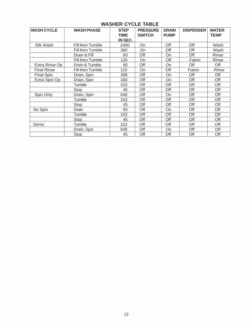
WASHER CYCLE TABLE WASH CYCLE WASH PHASE STEP PRESSURE DRAIN DISPENSER WATER
TIME SWITCH PUMP TEMPIN SEC.
Silk Wash Fill then Tumble 2400 On Off Off WashFill then Tumble 360 On Off Off WashDrain & Fill 60 Off On Off RinseFill then Tumble 120 On Off Fabric Rinse
Extra Rinse Op Drain & Tumble 60 Off On Off Off Final Rinse Fill then Tumble 120 On Off Fabric Rinse Final Spin Drain, Spin 308 Off On Off Off Extra Spin Op Drain, Spin 160 Off On Off Off
Tumble 153 Off Off Off OffStop 45 Off Off Off Off
Spin Only Drain, Spin 648 Off On Off OffTumble 153 Off Off Off OffStop 45 Off Off Off Off
No Spin Drain 60 Off On Off OffTumble 153 Off Off Off OffStop 45 Off Off Off Off
Demo Tumble 153 Off Off Off OffDrain, Spin 648 Off On Off OffStop 45 Off Off Off Off
14
Section A - Installation Instructions
Full Size Tumble Action Washers
Before beginning installation, carefully read theseinstructions. This will simplify the installation andensure the washer is installed correctly and safely.Leave these instructions near the washer afterinstallation for future reference.
NOTE: The electrical service to the washer mustconform with local codes and ordinances and thelatest edition of the National Electrical Code, ANSI/NFPA 70 or in Canada, CSA C22.1 CanadianElectrical Code Part 1.
For your safety the information in thismanual must be followed to minimize the risk of fire orexplosion or to prevent property damage, personalinjury or loss of life.
- Do not store or use gasoline or other flammablevapors and liquid in the vicinity of this or any otherappliance.
- WHAT TO DO IF YOU SMELL GAS
· Do not try to light any appliance.
· Do not touch any electrical switch; do not use anyphone in your building.
· Clear the room, building or area of all occupants.
· Immediately call your gas supplier from aneighbor’s phone. Follow the gas suppliersinstructions.
· If you cannot reach your gas supplier, call the firedepartment.
Installation and service must be performed by aqualified installer, service agency or the gas supplier.
PRE-INSTALLATION REQUIREMENTS
Tools Required for Installation:
1. 1/4 in. nut driver.
2. 3/8 in. socket with ratchet.
3. 3/8 in. open end wrench.
4. 7/16 in. socket with ratchet.
5. 9/16 in. open end wrench.
6. Channel-lock adjustable pliers.
7. Carpenter’s level.
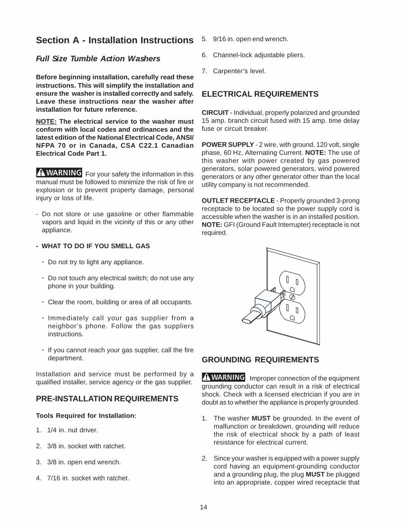
ELECTRICAL REQUIREMENTS
CIRCUIT - Individual, properly polarized and grounded15 amp. branch circuit fused with 15 amp. time delayfuse or circuit breaker.
POWER SUPPLY - 2 wire, with ground, 120 volt, singlephase, 60 Hz, Alternating Current. NOTE: The use ofthis washer with power created by gas poweredgenerators, solar powered generators, wind poweredgenerators or any other generator other than the localutility company is not recommended.
OUTLET RECEPTACLE - Properly grounded 3-prongreceptacle to be located so the power supply cord isaccessible when the washer is in an installed position.NOTE: GFI (Ground Fault Interrupter) receptacle is notrequired.
GROUNDING REQUIREMENTS
Improper connection of the equipmentgrounding conductor can result in a risk of electricalshock. Check with a licensed electrician if you are indoubt as to whether the appliance is properly grounded.
1. The washer MUST be grounded. In the event ofmalfunction or breakdown, grounding will reducethe risk of electrical shock by a path of leastresistance for electrical current.
2. Since your washer is equipped with a power supplycord having an equipment-grounding conductorand a grounding plug, the plug MUST be pluggedinto an appropriate, copper wired receptacle that
15
is properly installed and grounded in accordancewith all local codes and ordinances or in theabsence of local codes, with the National ElectricalCodes, ANSI/NFPA 70 (latest edition). If in doubt,call a licensed electrician. DO NOT cut off or alterthe grounding prong on the power supply cord. Insituations where a two-slot receptacle is present, itis the owner’s responsibility to have a licensedelectrician replace it with a properly groundedthree prong grounding type receptacle.
WATER SUPPLY REQUIREMENTS
Hot and cold water faucets MUST be installed within42 inches (107 cm) of your washer’s water inlet. Thefaucets MUST be 3/4 inch (1.9 cm) garden hose typeso inlet hoses can be connected. Water pressureMUST be between 30 and 120 pounds per square inch(maximum unbalance pressure, hot vs. cold, 10 psi.)Your water department can advise you of your waterpressure. The hot water temperature should be about140 degrees F (60 degrees C).
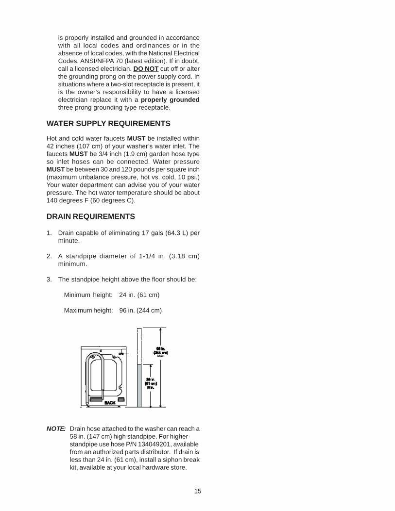
DRAIN REQUIREMENTS
1. Drain capable of eliminating 17 gals (64.3 L) perminute.
2. A standpipe diameter of 1-1/4 in. (3.18 cm)minimum.
3. The standpipe height above the floor should be:
Minimum height: 24 in. (61 cm)
Maximum height: 96 in. (244 cm)
NOTE: Drain hose attached to the washer can reach a58 in. (147 cm) high standpipe. For higherstandpipe use hose P/N 134049201, availablefrom an authorized parts distributor. If drain isless than 24 in. (61 cm), install a siphon breakkit, available at your local hardware store.
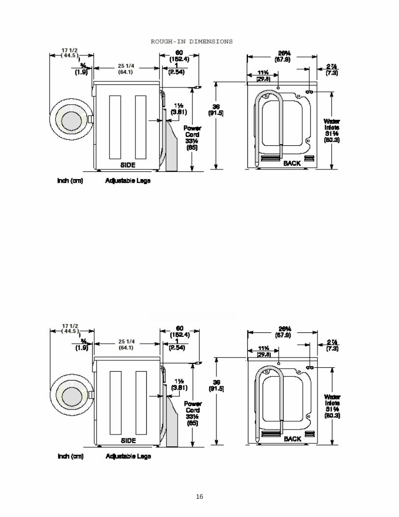
16
17
LOCATION OF YOUR WASHER
DO NOT INSTALL YOUR WASHER:
1. In an area exposed to dripping water or outsideweather conditions. The ambient temperatureshould never be below 60 degrees F (15.6 degreesC) for proper washer operation.
2. In an area where it will come in contact withcurtains or drapes.
3. In an area (garage or garage-type building) wheregasoline of other flammables are kept or stored(including automobiles).
4. On carpet. Floor MUST be solid with a maximumslope of 1/2 in. per foot (1.27 cm per 30.5 cm). Toensure vibration or movement does not occur,reinforcement of the floor may be necessary.
IMPORTANTMINIMUM INSTALLATION CLEARANCES
When installed in alcove or closet: Sides, Rear = 0 in. (0 cm) Top = 0 in. (0 cm)
When installed in closet: Front = 1 in. (2.54 cm)
Closet door ventilation required: 2 louvered openingseach 60 in2 (387 cm2), 3 in. (7.6 cm) from top and bottomof door.
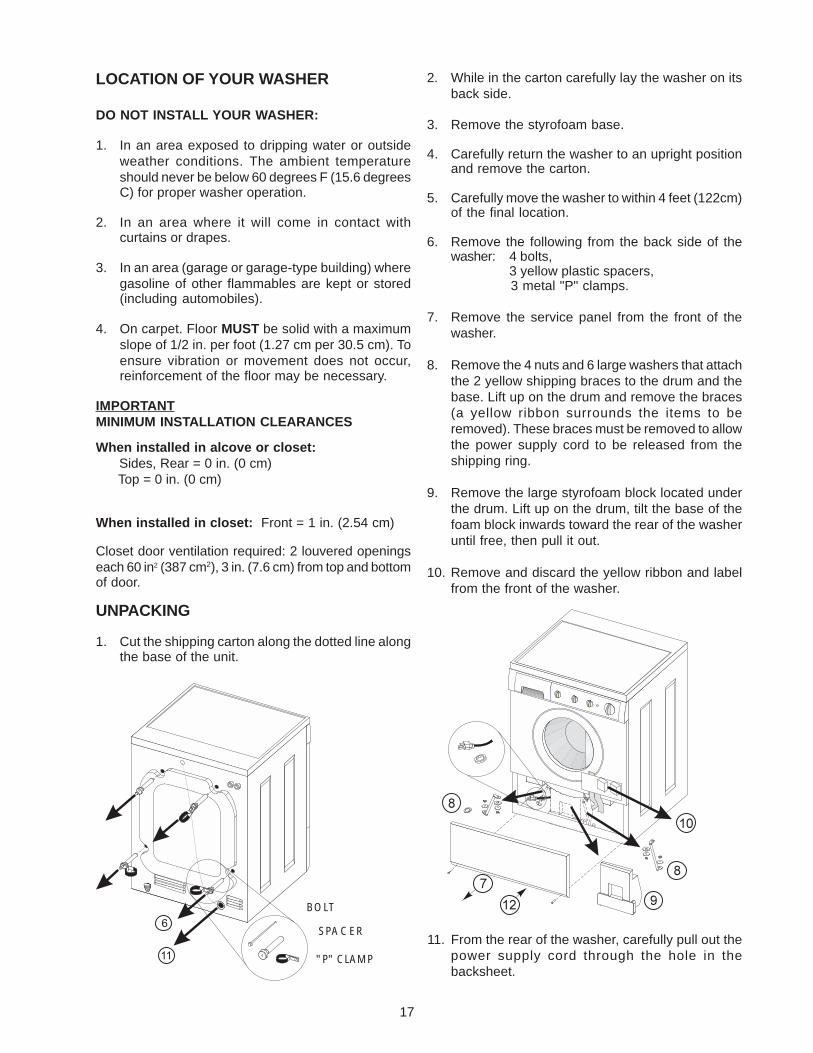
UNPACKING
1. Cut the shipping carton along the dotted line alongthe base of the unit.
2. While in the carton carefully lay the washer on itsback side.
3. Remove the styrofoam base.
4. Carefully return the washer to an upright positionand remove the carton.
5. Carefully move the washer to within 4 feet (122cm)of the final location.
6. Remove the following from the back side of thewasher: 4 bolts,
3 yellow plastic spacers,3 metal "P" clamps.
7. Remove the service panel from the front of thewasher.
8. Remove the 4 nuts and 6 large washers that attachthe 2 yellow shipping braces to the drum and thebase. Lift up on the drum and remove the braces(a yellow ribbon surrounds the items to beremoved). These braces must be removed to allowthe power supply cord to be released from theshipping ring.
9. Remove the large styrofoam block located underthe drum. Lift up on the drum, tilt the base of thefoam block inwards toward the rear of the washeruntil free, then pull it out.
10. Remove and discard the yellow ribbon and labelfrom the front of the washer.
11. From the rear of the washer, carefully pull out thepower supply cord through the hole in thebacksheet.
BOLT
SPACER
"P" CLAMP
18
12. Replace the service panel and screws.
NOTE: If the washer is to be transported at a laterdate, the shipping support hardware mustbe reinstalled to prevent shipping damage.Retain the hardware in the plastic bagprovided.
INSTALLATION
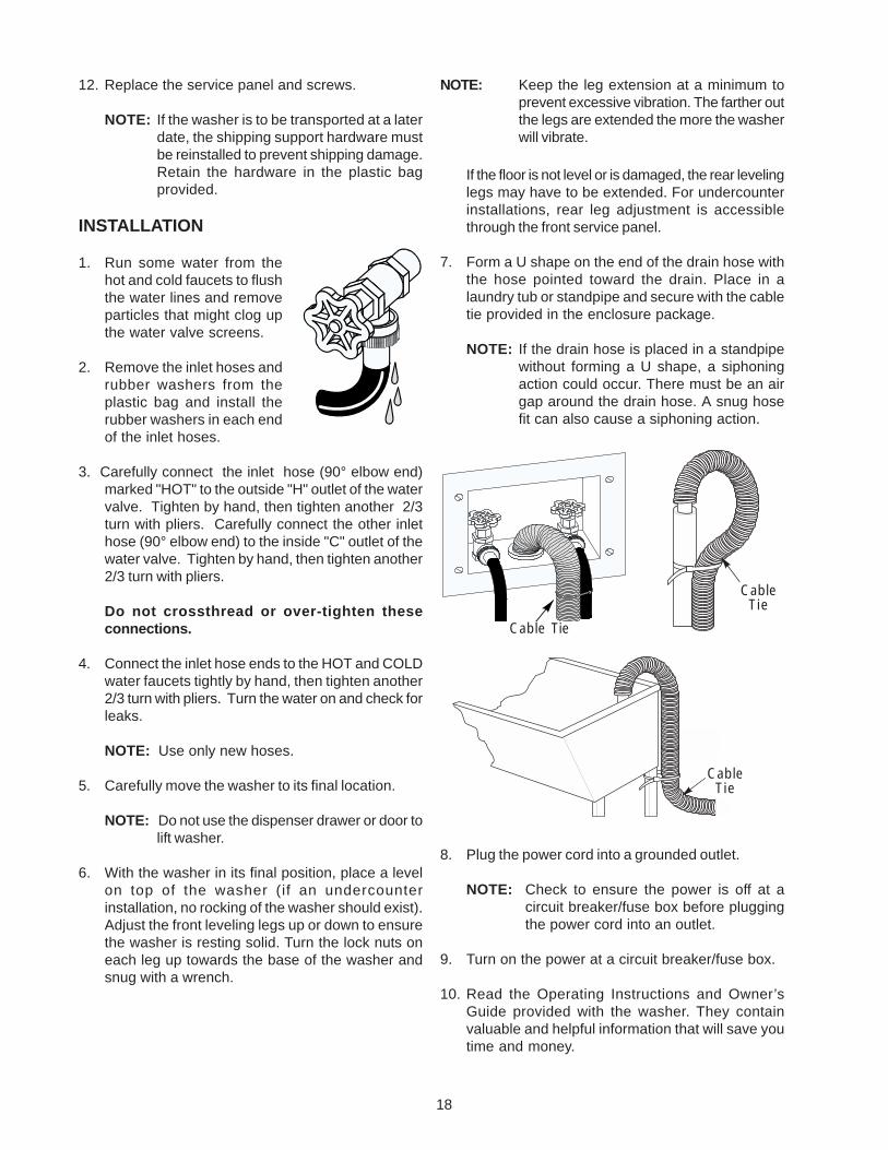
1. Run some water from thehot and cold faucets to flushthe water lines and removeparticles that might clog upthe water valve screens.
2. Remove the inlet hoses andrubber washers from theplastic bag and install therubber washers in each endof the inlet hoses.
3. Carefully connect the inlet hose (90° elbow end)marked "HOT" to the outside "H" outlet of the watervalve. Tighten by hand, then tighten another 2/3turn with pliers. Carefully connect the other inlethose (90° elbow end) to the inside "C" outlet of thewater valve. Tighten by hand, then tighten another2/3 turn with pliers.
Do not crossthread or over-tighten theseconnections.
4. Connect the inlet hose ends to the HOT and COLDwater faucets tightly by hand, then tighten another2/3 turn with pliers. Turn the water on and check forleaks.
NOTE: Use only new hoses.
5. Carefully move the washer to its final location.
NOTE: Do not use the dispenser drawer or door tolift washer.
6. With the washer in its final position, place a levelon top of the washer (if an undercounterinstallation, no rocking of the washer should exist).Adjust the front leveling legs up or down to ensurethe washer is resting solid. Turn the lock nuts oneach leg up towards the base of the washer andsnug with a wrench.
NOTE: Keep the leg extension at a minimum toprevent excessive vibration. The farther outthe legs are extended the more the washerwill vibrate.
If the floor is not level or is damaged, the rear levelinglegs may have to be extended. For undercounterinstallations, rear leg adjustment is accessiblethrough the front service panel.
7. Form a U shape on the end of the drain hose withthe hose pointed toward the drain. Place in alaundry tub or standpipe and secure with the cabletie provided in the enclosure package.
NOTE: If the drain hose is placed in a standpipewithout forming a U shape, a siphoningaction could occur. There must be an airgap around the drain hose. A snug hosefit can also cause a siphoning action.
8. Plug the power cord into a grounded outlet.
NOTE: Check to ensure the power is off at acircuit breaker/fuse box before pluggingthe power cord into an outlet.
9. Turn on the power at a circuit breaker/fuse box.
10. Read the Operating Instructions and Owner’sGuide provided with the washer. They containvaluable and helpful information that will save youtime and money.
Cable Tie
CableTie
CableTie
19
11. Run the washer through a complete cycle. Checkfor water leaks and proper operation.
12. If your washer does not operate, please review the“Avoid Service Checklist” in your Owner’s Guidebefore calling for service.
13. Place these instructions in a location near thewasher for future reference.
NOTE: A wiring diagram is located inside the washeron the service panel.
REPLACEMENT PARTS
If replacements parts are needed for your washer,contact the source where you purchased your washer,call 1-800-944-9044, or visit our website,www.frigidaire.com, for the Frigidaire CompanyAuthorized Parts Distributor nearest you.
Destroy the carton and plastic bags afterthe washer is unpacked. Children might use them forplay. Cartons covered with rugs, bedspreads, or plasticsheets can become airtight chambers causingsuffocation. Place all materials in a garbage containeror make materials inaccessible to children.
The instructions in this manual and allother literature included with this washer are not meantto cover every possible condition and situation thatmay occur. Good safe practice and caution MUST beapplied when installing, operating and maintaining anyappliance.
Maximum benefits and enjoyment are achievedwhen all the Safety and Operating instructions areunderstood and practiced as a routine with yourlaundering tasks.
20
SECTION B - OPERATINGINSTRUCTIONSBefore Operating Your Washer
Read your washer Use and Care Guide. It has importantsafety and warranty information. It also has many sug-gestions for best washing results.
To reduce the risk of fire, electric shockor injury to persons, read the IMPORTANT SAFETYINSTRUCTIONS in your washer Use and Care Guidebefore operating this appliance.
Operating Steps
Read and follow “Washing Procedures” in your Use andCare Guide. It provides detailed information for preparingthe wash load and choosing control settings to ensurebest washing results.
1. Sort laundry into loads that can be washed together.
2. Prepare items for washing.
3. Pretreat stains and heavy soil.
4. Add laundry load to the wash drum.
5. Open the dispenser drawer and add the measuredamount of a high efficiency detergent to thedetergent compartment. If desired, add liquid bleachand fabric softener to the appropriate compartments.They will be dispensed at the proper times. Slowlyclose dispenser drawer. The washer will not operatewith the drawer open.
Note: From time to time you may see water in thebleach and fabric softener compartments. This isa result of the siphoning action and is part of thenormal operation of the washer.
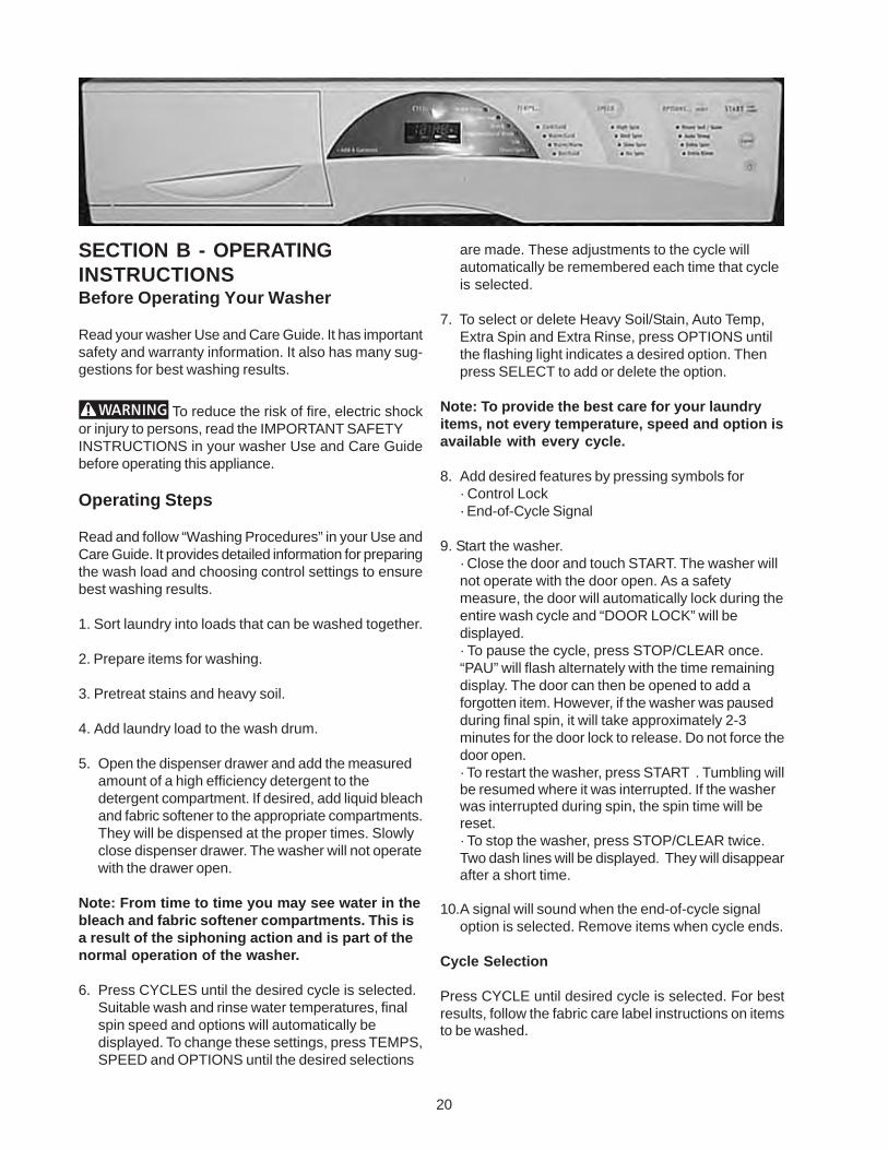
6. Press CYCLES until the desired cycle is selected.Suitable wash and rinse water temperatures, finalspin speed and options will automatically bedisplayed. To change these settings, press TEMPS,SPEED and OPTIONS until the desired selections
are made. These adjustments to the cycle willautomatically be remembered each time that cycleis selected.
7. To select or delete Heavy Soil/Stain, Auto Temp,Extra Spin and Extra Rinse, press OPTIONS untilthe flashing light indicates a desired option. Thenpress SELECT to add or delete the option.
Note: To provide the best care for your laundryitems, not every temperature, speed and option isavailable with every cycle.
8. Add desired features by pressing symbols for· Control Lock· End-of-Cycle Signal
9. Start the washer.· Close the door and touch START. The washer willnot operate with the door open. As a safetymeasure, the door will automatically lock during theentire wash cycle and “DOOR LOCK” will bedisplayed.· To pause the cycle, press STOP/CLEAR once.“PAU” will flash alternately with the time remainingdisplay. The door can then be opened to add aforgotten item. However, if the washer was pausedduring final spin, it will take approximately 2-3minutes for the door lock to release. Do not force thedoor open.· To restart the washer, press START . Tumbling willbe resumed where it was interrupted. If the washerwas interrupted during spin, the spin time will bereset.· To stop the washer, press STOP/CLEAR twice.Two dash lines will be displayed. They will disappearafter a short time.
10.A signal will sound when the end-of-cycle signaloption is selected. Remove items when cycle ends.
Cycle Selection
Press CYCLE until desired cycle is selected. For bestresults, follow the fabric care label instructions on itemsto be washed.
21
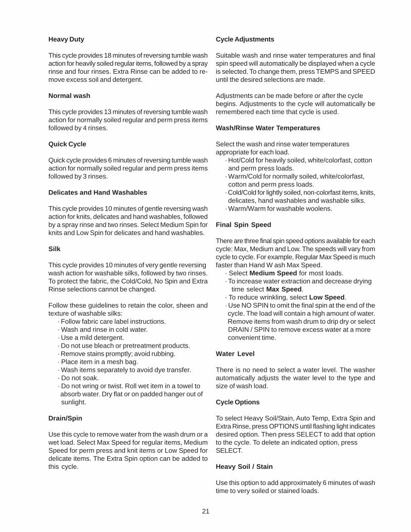
Heavy Duty
This cycle provides 18 minutes of reversing tumble washaction for heavily soiled regular items, followed by a sprayrinse and four rinses. Extra Rinse can be added to re-move excess soil and detergent.
Normal wash
This cycle provides 13 minutes of reversing tumble washaction for normally soiled regular and perm press itemsfollowed by 4 rinses.
Quick Cycle
Quick cycle provides 6 minutes of reversing tumble washaction for normally soiled regular and perm press itemsfollowed by 3 rinses.
Delicates and Hand Washables
This cycle provides 10 minutes of gentle reversing washaction for knits, delicates and hand washables, followedby a spray rinse and two rinses. Select Medium Spin forknits and Low Spin for delicates and hand washables.
Silk
This cycle provides 10 minutes of very gentle reversingwash action for washable silks, followed by two rinses.To protect the fabric, the Cold/Cold, No Spin and ExtraRinse selections cannot be changed.
Follow these guidelines to retain the color, sheen andtexture of washable silks:
· Follow fabric care label instructions.· Wash and rinse in cold water.· Use a mild detergent.· Do not use bleach or pretreatment products.· Remove stains promptly; avoid rubbing.· Place item in a mesh bag.· Wash items separately to avoid dye transfer.· Do not soak.· Do not wring or twist. Roll wet item in a towel to absorb water. Dry flat or on padded hanger out of sunlight.
Drain/Spin
Use this cycle to remove water from the wash drum or awet load. Select Max Speed for regular items, MediumSpeed for perm press and knit items or Low Speed fordelicate items. The Extra Spin option can be added tothis cycle.
Cycle Adjustments
Suitable wash and rinse water temperatures and finalspin speed will automatically be displayed when a cycleis selected. To change them, press TEMPS and SPEEDuntil the desired selections are made.
Adjustments can be made before or after the cyclebegins. Adjustments to the cycle will automatically beremembered each time that cycle is used.
Wash/Rinse Water Temperatures
Select the wash and rinse water temperaturesappropriate for each load.
· Hot/Cold for heavily soiled, white/colorfast, cotton and perm press loads.· Warm/Cold for normally soiled, white/colorfast, cotton and perm press loads.· Cold/Cold for lightly soiled, non-colorfast items, knits, delicates, hand washables and washable silks.· Warm/Warm for washable woolens.
Final Spin Speed
There are three final spin speed options available for eachcycle: Max, Medium and Low. The speeds will vary fromcycle to cycle. For example, Regular Max Speed is muchfaster than Hand W ash Max Speed.
· Select Medium Speed for most loads.· To increase water extraction and decrease drying time select Max Speed.· To reduce wrinkling, select Low Speed.· Use NO SPIN to omit the final spin at the end of the cycle. The load will contain a high amount of water. Remove items from wash drum to drip dry or select DRAIN / SPIN to remove excess water at a more convenient time.
Water Level
There is no need to select a water level. The washerautomatically adjusts the water level to the type andsize of wash load.
Cycle Options
To select Heavy Soil/Stain, Auto Temp, Extra Spin andExtra Rinse, press OPTIONS until flashing light indicatesdesired option. Then press SELECT to add that optionto the cycle. To delete an indicated option, pressSELECT.
Heavy Soil / Stain
Use this option to add approximately 6 minutes of washtime to very soiled or stained loads.

22
Auto Temp
The temperature of hot, warm and cold wash water canbe affected by the water heater setting and seasonallylow ground water temperatures in some geographic ar-eas. Since detergents work best in wash water at a mini-mum of 65° F, select AUTO TEMP to regulate the tem-perature of hot wash a approximately 150° F warm washto approximately 90° F and cold wash to approximately70° F. Rinse water temperatures are not regulated.
Extra Rinse
Use this option when additional rinsing is desired to re-move excess dirt and detergent. It is recommended forheavily soiled loads or if household members have sen-sitive skin. Extra Rinse occurs before the liquid fabricsoftener is dispensed.
Extra Spin
Use this option for several additional minutes of spin atthe selected spin speed. This will increase water extrac-tion and decrease drying time.
Washer Features
Control Lock
To prevent accidental operation of the washer or alter-ation of the cycle settings, press and hold the lock sym-bol until you hear 3 beeps and “LOC” is displayed. Tocancel, press and hold the lock symbol until “LOC” is nolonger displayed.
Signal
A signal will sound at the end of the cycle. Repeatedlypress the signal symbol to select one of three volumelevels or turn off the signal. The selection will be pro-grammed until you change it.
Display
The following will be displayed during the cycle:· Estimated Remaining Cycle Time· Door Lock· Cycle Status ( WASH, RINSE, FINAL SPIN).· Signal volume selected· “LOC” will be displayed briefly when lock symbol is pressed.
Error Codes
If the washer stops and the F01, F03, F04 or F05 errorcode is flashing in the display, press STOP/CLEAR,select a cycle and press START. If the error code ap-pears again, please contact service for assistance.
F01 There may be an internal problem with the washsystem.
F02 There may be a water temperature problem. Besure hot and cold water hoses are properlyconnected before calling service.
F03 Be sure the water is turned on before callingservice. There may be a problem with the pumpor pressure switch.
F04 The washer may have run too long or there maybe a problem with the motor control.
F05 There may be a problem with the keypad.
23
HeavyDuty
53 minutes
X
X
X
X
* Cotton
Perm Press
Delicates
X
X
* X
X
* X
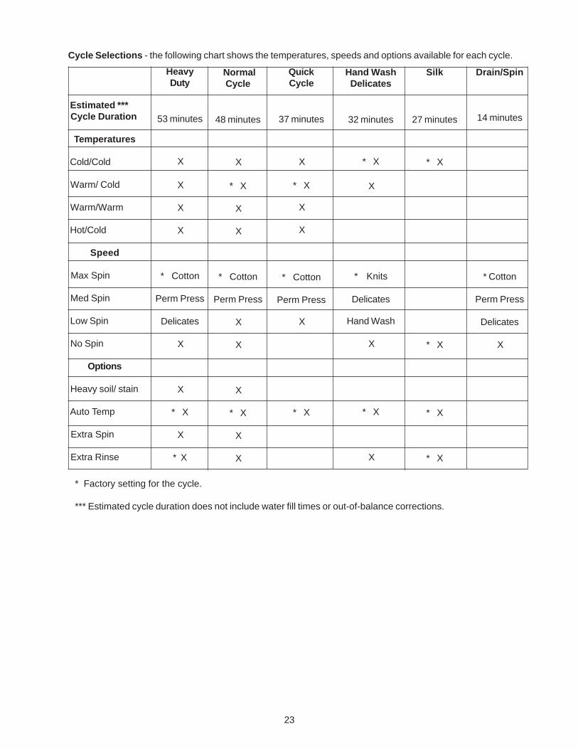
Cycle Selections - the following chart shows the temperatures, speeds and options available for each cycle.
Estimated *** Cycle Duration
Temperatures
Cold/Cold
Warm/ Cold
Warm/Warm
Hot/Cold
Speed
Max Spin
Med Spin
Low Spin
No Spin
Options
Heavy soil/ stain
Auto Temp
Extra Spin
Extra Rinse
NormalCycle
48 minutes
X
* X
X
X
* Cotton
Perm Press
X
X
X
* X
X
X
QuickCycle
37 minutes
X
* X
X
X
* Cotton
Perm Press
X
* X
Hand WashDelicates
32 minutes
* X
X
* Knits
Delicates
Hand Wash
X
* X
X
* Factory setting for the cycle.
*** Estimated cycle duration does not include water fill times or out-of-balance corrections.
Drain/Spin
14 minutes
* Cotton
Perm Press
Delicates
X
Silk
27 minutes
* X
* X
* X
* X
24
This Owner's Guide provides general operatinginstructions for your washer. It also contains informationabout features for several other models. Your washermay not have every feature included here.
Use the washer only as instructed in this Owner's Guideand the Operating Instructions card included with yourwasher.
Your safety and the safety of others is veryimportant.
We have provided many importantsafety messages inthe Use andCare Guide, Operating Instructions, Instal-lation Instructions and on your appliance. Always readand obey all safety messages.
This is the safety alert symbol. This symbol alertsyou to hazards that can kill or hurt you or others. Allsafety messages will be preceded by the safety alertsymbol and the word “DANGER” or “WARNING”. Thesewords mean:
You will be killed or seriously injured ifyou don’t follow instructions.
You can be killed or seriously injured ifyou don’t follow instructions.
All safety messages will identify the hazard, tellyou how to reduce the chance of injury, and tellyou what can happen if the instructions are not fol-lowed.
Pedestal
A pedestal accessory specifically designed for thiswasher may be used when elevating the washer for easeof use. Failure to use accessories certified by themanufacturer could result in personal injury, property dam-age or damage to the washer.
Important Safety Instructions
Read all instructions before using thiswasher.
To reduce the risk of fire, electrical shock,or injury to persons when using this washer, comply withthe basic warnings listed.
Failure to comply with these warnings could result inserious personal injuries.
Prevent Fire
Do not wash items that have beenpreviously cleaned in, soaked in, or spotted with gasoline,cleaning solvents, kerosene, cooking oils, waxes, etc.Do not store these items on or near the washer. Thesesubstances give off vapors or chemical reactions thatcould ignite or explode.
Do not put oily or greasy rags or clothingon top of the washer. These substances give off vaporsthat could ignite the materials.
Do not add gasoline, cleaning solvents,or other flammable or explosive substances to the washwater. These substances give off vapors that could igniteor explode.
Under certain conditions, hydrogen gasmay be produced in a hot water system that has not beenused for 2 weeks or more. HYDROGEN GAS ISEXPLOSIVE. If the hot water system has not been usedfor such a period, before using the washer, turn on all hotwater faucets and let the water flow from each for severalminutes. This will release any accumulated hydrogengas. Hydrogen gas is flammable; do not smoke or usean open flame during this time.
Do not store or use gasoline or otherflammable vapors or liquids in the vicinity of this or anyother appliance.
Failure to comply with these warnings could result infire, explosion, serious bodily injury and/or damage tothe rubber or plastic parts of the washer.
Protect Children
Do not allow children to play on or in thewasher. Close supervision of children is necessary whenthe washer is used near children. As children grow,teach them the proper, safe use of all appliances.
Destroy the carton, plastic bag and otherpacking materials after the washer is unpacked. Childrenmight use them for play. Cartons covered with rugs,bedspreads or plastic sheets can become airtightchambers.
Keep laundry products out of children'sreach. To prevent personal injury, observe all warningson product labels.
SECTION C - OWNER’S GUIDE
25
Before the washer is removed from serviceor discarded, remove the washer door to prevent accidentalentrapment.
Failure to comply with these warnings could result inserious personal injuries.
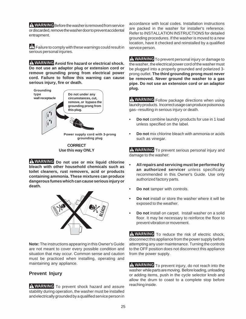
Avoid fire hazard or electrical shock.Do not use an adaptor plug or extension cord orremove grounding prong from electrical powercord. Failure to follow this warning can causeserious injury, fire or death.
CORRECTUse this way ONLY
Do not use or mix liquid chlorinebleach with other household chemicals such astoilet cleaners, rust removers, acid or productscontaining ammonia. These mixtures can producedangerous fumes which can cause serious injury ordeath.
Note: The instructions appearing in this Owner's Guideare not meant to cover every possible condition andsituation that may occur. Common sense and cautionmust be practiced when installing, operating andmaintaining any appliance.
Prevent Injury
To prevent shock hazard and assurestability during operation, the washer must be installedand electrically grounded by a qualified service person in
accordance with local codes. Installation instructionsare packed in the washer for installer's reference.Refer to INSTALLATION INSTRUCTIONS for detailedgrounding procedures. If the washer is moved to a newlocation, have it checked and reinstalled by a qualifiedservice person.
To prevent personal injury or damage tothe washer, the electrical power cord of the washer mustbe plugged into a properly grounded and polarized 3-prong outlet. The third grounding prong must neverbe removed. Never ground the washer to a gaspipe. Do not use an extension cord or an adaptorplug.
Follow package directions when usinglaundry products. Incorrect usage can produce poisonousgas--resulting in serious injury or death.
• Do not combine laundry products for use in 1 loadunless specified on the label.
• Do not mix chlorine bleach with ammonia or acidssuch as vinegar.
To prevent serious personal injury anddamage to the washer:
• All repairs and servicing must be performed byan authorized servicer unless specificallyrecommended in this Owner's Guide. Use onlyauthorized factory parts.
• Do not tamper with controls.
• Do not install or store the washer where it will beexposed to the weather.
• Do not install on carpet. Install washer on a solidfloor. It may be necessary to reinforce the floor toprevent vibration or movement.
To reduce the risk of electric shock,disconnect this appliance from the power supply beforeattempting any user maintenance. Turning the controlsto the OFF position does not disconnect this appliancefrom the power supply.
To prevent injury, do not reach into thewasher while parts are moving. Before loading, unloadingor adding items, push in the cycle selector knob andallow the drum to coast to a complete stop beforereaching inside.
Groundingtypewall receptacle
Power supply cord with 3-pronggrounding plug
Do not under anycircumstances, cut,remove, or bypass thegrounding prong fromthis plug.
26
Failure to comply with these warnings could result inserious personal injuries.
This washer is equipped with an electrical overloadprotector. The motor will stop if it becomes overheated.The washer will automatically restart after a cool downperiod of up to 30 minutes, if the washer has not beenmanually turned off during this time.
SAVE THESE INSTRUCTIONS
Washing Procedures
• Follow the guidelines below for preparing the washload.
• Read the Operating Instructions card for operatingyour specific model.
• Always read and follow fabric care and laundryproduct labels.
To reduce the risk of fire, electrical shock,or injury to persons, read Important Safety Instructions,before operating this washer.
1. Sort laundry into loads that can bewashed together.
Sort items by recommended water temperaturesand wash time.
• Separate white, light, and colorfast items fromdark and noncolorfast items.
• Separate items which shed lint from itemswhich attract lint. Permanent press, synthetic,knit and corduroy items will pick up lint fromtowels, rugs and chenille bedspreads.
• Separate heavily soiled items from lightly soileditems.
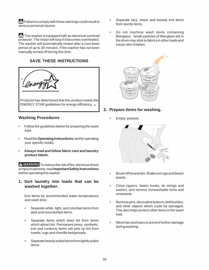
• Separate lacy, sheer and loosely knit itemsfrom sturdy items.
• Do not machine wash items containingfiberglass. Small particles of fiberglass left inthe drum may stick to fabrics in other loads andcause skin irritation.
.
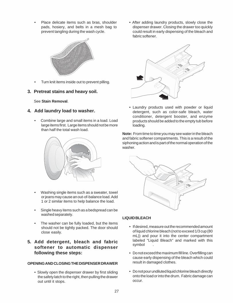
2. Prepare items for washing.
• Empty pockets.
• Brush off lint and dirt. Shake out rugs and beachtowels.
• Close zippers, fasten hooks, tie strings andsashes, and remove nonwashable trims andornaments.
• Remove pins, decorative buttons, belt buckles,and other objects which could be damaged.This also helps protect other items in the washload.
• Mend rips and tears to prevent further damageduring washing.
Products has determined that this product meets the ENERGY STAR guidelines for energy efficiency.
®
®
27
• Place delicate items such as bras, shoulderpads, hosiery, and belts in a mesh bag toprevent tangling during the wash cycle.
• Turn knit items inside out to prevent pilling.
3. Pretreat stains and heavy soil.
See Stain Removal.
4. Add laundry load to washer.
• Combine large and small items in a load. Loadlarge items first. Large items should not be morethan half the total wash load.
• Washing single items such as a sweater, towelor jeans may cause an out-of-balance load. Add1 or 2 similar items to help balance the load.
• Single heavy items such as a bedspread can bewashed separately.
• The washer can be fully loaded, but the itemsshould not be tightly packed. The door shouldclose easily.
5. Add detergent, bleach and fabricsoftener to automatic dispenserfollowing these steps:
OPENING AND CLOSING THE DISPENSER DRAWER
• Slowly open the dispenser drawer by first slidingthe safety latch to the right, then pulling the drawerout until it stops.
• After adding laundry products, slowly close thedispenser drawer. Closing the drawer too quicklycould result in early dispensing of the bleach andfabric softener.
• Laundry products used with powder or liquiddetergent, such as color-safe bleach, waterconditioner, detergent booster, and enzymeproducts should be added to the empty tub beforeloading.
Note: From time to time you may see water in the bleachand fabric softener compartments. This is a result of thesiphoning action and is part of the normal operation of thewasher.
LIQUID BLEACH
• If desired, measure out the recommended amountof liquid chlorine bleach (not to exceed 1/3 cup (80mL)) and pour it into the center compartmentlabeled "Liquid Bleach" and marked with thissymbol .
• Do not exceed the maximum fill line. Overfilling cancause early dispensing of the bleach which couldresult in damaged clothes.
• Do not pour undiluted liquid chlorine bleach directlyonto the load or into the drum. Fabric damage canoccur.
28
• Do not use powdered bleach in the dispenser.
DETERGENT
• Add measured detergent to the detergentcompartment of the dispenser drawer.
• Detergent is flushed from the dispenser at thebeginning of the cycle. Either powdered or liquiddetergent can be used. Note: Liquid detergent willdrain into the washer drum as it is added.
• Low sudsing detergent is recommended for thiswasher. Use the manufacturer's recommendedamount.
• If low sudsing detergent is not available, a reducedamount of regular detergent may be used. Becausereducing the amount of detergent may reducecleaning, it is important to pretreat stains, sortcarefully by color and soil level, and avoidoverloading.
• Detergent usage may need to be adjusted for watertemperature, water hardness, size and soil level ofthe load.
• For best results, avoid oversudsing.
FABRIC SOFTENER
• If desired, pour the recommended amount of fabricsoftener into the compartment labeled "FabricSoftener" and marked with this symbol.
• Dilute concentrated softeners with warm water tothe Fill Line.
• Do not exceed the maximum fill line. Overfilling cancause early dispensing of the fabric softener whichcould result in stained clothes.
• Do not pour fabric softener directly on thewash load.
• Use of a fabric softener dispensing ball is notrecommended in tumble action washers.
6. Select the cycle, temperature and speed settingsoptions and features according to type, size, andsoil level of each load.
(See Operating Instructions for your specific model.)
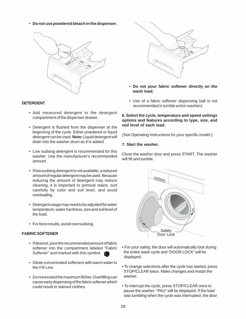
7. Start the washer.
Close the washer door and press START. The washerwill fill and tumble.
• For your safety, the door will automatically lock during the entire wash cycle and “DOOR LOCK” will be displayed.
• To change selections after the cycle has started, press STOP/CLEAR twice. Make changes and restart the washer.
• To interrupt the cycle, press STOP/CLEAR once to pause the washer. “PAU” will be displayed. If the load was tumbling when the cycle was interrupted, the door
29
will open immediately. If the load was spinning, the door will remain locked for 1 - 2 minutes for your safety. DO NOT force open the locked door.
• To restart the washer, press START again. (However, the washer will automatically restart after 5 minutes.
• To stop the washer, press STOP/CLEAR twice. Two dashes will be displayed for approximately thirty seconds.
8. Remove items when the cycle iscompleted.
Place washed items in automatic dryer, line dry, ordry flat as directed by fabric care label. Excesswrinkling, color transfer or odors may develop initems left in the washer after the cycle has ended.
9. General Precautions
• If the dispenser drawer is opened duringoperation, the washer will shut off and thedoor will unlock. “d:do” (dispenser door) will be
displayed. Slowly close the dispenser drawer, and press START tocontinue cycle.
• Do not slam the washer door closed or try toforce the door open when locked (Door Locklight ON). This could result in damage to thewasher.
• DO NOT leave the washer door open. An opendoor could entice children to hang on the door orcrawl inside the washer.
• To avoid damaging the washer and personal injury,DO NOT hang on or lean against the washer door.
• Do not place detergent, bleach or fabric softener
containers on top of the washer. They can damagethe finish or controls.
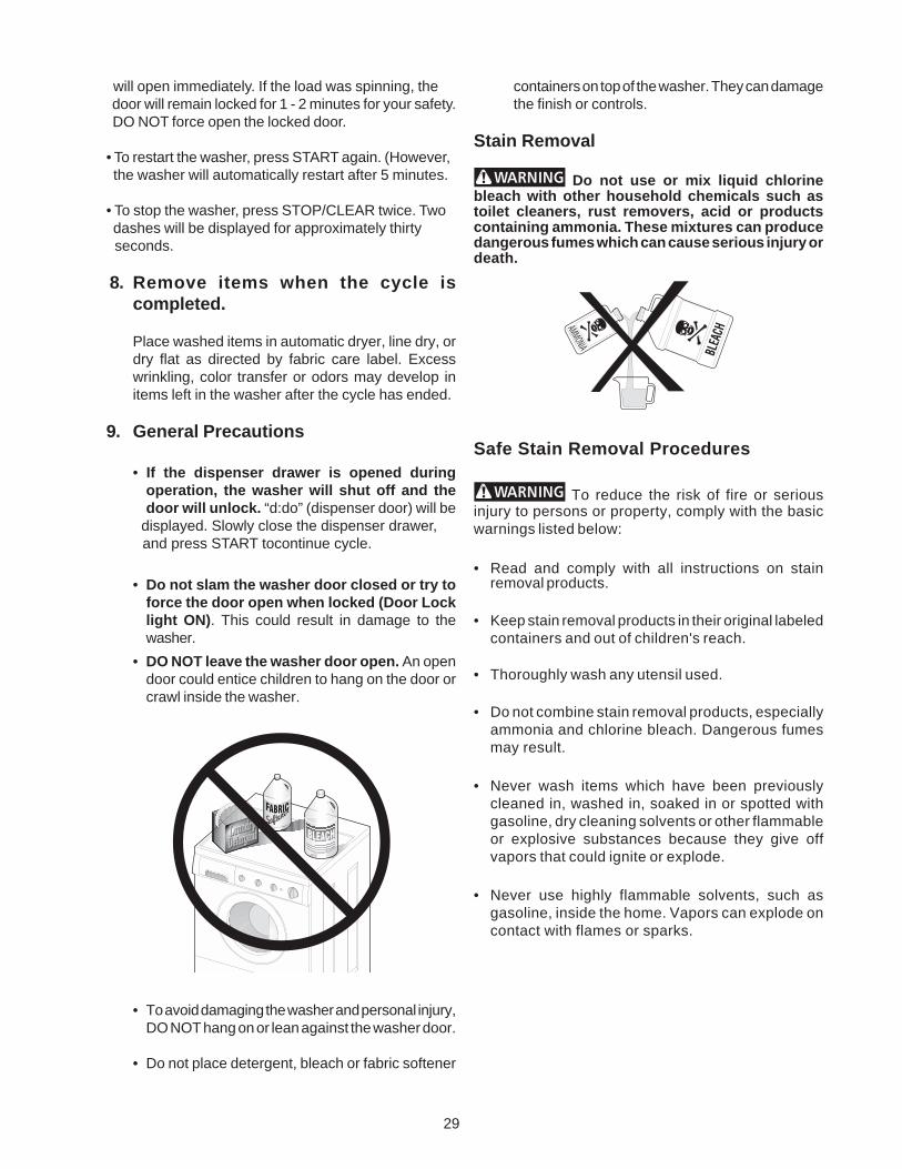
Stain Removal
Do not use or mix liquid chlorinebleach with other household chemicals such astoilet cleaners, rust removers, acid or productscontaining ammonia. These mixtures can producedangerous fumes which can cause serious injury ordeath.
Safe Stain Removal Procedures
To reduce the risk of fire or seriousinjury to persons or property, comply with the basicwarnings listed below:
• Read and comply with all instructions on stainremoval products.
• Keep stain removal products in their original labeledcontainers and out of children's reach.
• Thoroughly wash any utensil used.
• Do not combine stain removal products, especiallyammonia and chlorine bleach. Dangerous fumesmay result.
• Never wash items which have been previouslycleaned in, washed in, soaked in or spotted withgasoline, dry cleaning solvents or other flammableor explosive substances because they give offvapors that could ignite or explode.
• Never use highly flammable solvents, such asgasoline, inside the home. Vapors can explode oncontact with flames or sparks.
30
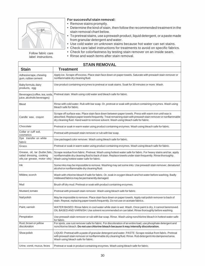
For successful stain removal:• Remove stains promptly.• Determine the kind of stain, then follow the recommended treatment in the
stain removal chart below.• To pretreat stains, use a prewash product, liquid detergent, or a paste made
from granular detergent and water.• Use cold water on unknown stains because hot water can set stains.• Check care label instructions for treatments to avoid on specific fabrics.• Check for colorfastness by testing stain remover on an inside seam.• Rinse and wash items after stain removal.
StainAdhesive tape, chewinggum, rubber cement
Baby formula, dairyproducts, egg
Beverages (coffee, tea, soda,juice, alcoholic beverages)
Blood
Candle wax, crayon
Chocolate
Collar or cuff soil,cosmeticsDye transfer on whitefabric
Grass
Grease, oil, tar (butter,fats,salad dressing, cookingoils,car grease, motor oils)
Ink
Mildew, scorch
Mud
Mustard, tomato
Nail polish
Paint, varnish
Perspiration
Rust, brown or yellowdiscoloration
Shoe polish
Urine, vomit, mucus, feces
TreatmentSTAIN REMOVAL
Follow fabric carelabel instructions.
Apply ice. Scrape off excess. Place stain face down on paper towels. Saturate with prewash stain remover ornonflammable dry cleaning fluid.
Use product containing enzymes to pretreat or soak stains. Soak for 30 minutes or more. Wash.
Pretreat stain. Wash using cold water and bleach safe for fabric.
Rinse with cold water. Rub with bar soap. Or, pretreat or soak with product containing enzymes. Wash usingbleach safe for fabric.
Scrape off surface wax. Place stain face down between paper towels. Press with warm iron until wax isabsorbed. Replace paper towels frequently. Treat remaining stain with prewash stain remover or nonflammabledry cleaning fluid. Hand wash to remove solvent. Wash using bleach safe for fabric.
Pretreat or soak in warm water using product containing enzymes. Wash using bleach safe for fabric.
Pretreat with prewash stain remover or rub with bar soap.
Use packaged color remover. Wash using bleach safe for fabric.
Pretreat or soak in warm water using product containing enzymes. Wash using bleach safe for fabric.
Scrape residue from fabric. Pretreat. Wash using hottest water safe for fabric. For heavy stains and tar, applynonflammable dry cleaning fluid to back of stain. Replace towels under stain frequently. Rinse thoroughly.Wash using hottest water safe for fabric.
Some inks may be impossible to remove. Washing may set some inks. Use prewash stain remover, denaturedalcohol or nonflammable dry cleaning fluid.
Wash with chlorine bleach if safe for fabric. Or, soak in oxygen bleach and hot water before washing. Badlymildewed fabrics may be permanently damaged.
Brush off dry mud. Pretreat or soak with product containing enzymes.
Pretreat with prewash stain remover. Wash using bleach safe for fabric.
May be impossible to remove. Place stain face down on paper towels. Apply nail polish remover to back ofstain. Repeat, replacing paper towels frequently. Do not use on acetate fabrics.
WATER BASED: Rinse fabric in cool water while stain is wet. Wash. Once paint is dry, it cannot beremoved.OIL BASED AND VARNISH: Use solvent recommended on can label. Rinse thoroughly before washing.
Use prewash stain remover or rub with bar soap. Rinse. Wash using nonchlorine bleach in hottest water safefor fabric.For spots, use rust remover safe for fabric. For discoloration of an entire load, use phosphate detergent andnonchlorine bleach. Do not use chlorine bleach because it may intensify discoloration.
LIQUID: Pretreat with a paste of granular detergent and water. PASTE: Scrape residue from fabric. Pretreatwith prewash stain remover or nonflammable dry cleaning fluid. Rinse. Rub detergent into dampened area.Wash using bleach safe for fabric.
Pretreat or soak in product containing enzymes. Wash using bleach safe for fabric.
31
• Avoid overfilling detergent and fabric softener compartments ofdispenser.
• Sort items by soil level and color.• Use correct amount of detergent,hottest water and bleach safe forfabric.
• Use correct amount of detergentand hottest water safe for fabric.
• Do not pour liquid fabric softenerdirectly on fabric. See WashingProcedures on adding softener.
• Never pour chlorine bleachdirectly on fabric.
• Check condition of items beforewashing. See WashingProcedures for preparing, loadingand adding chlorine bleach.
• See Washing Procedures forsorting and preparing the washload.
• Do not overload washer.• Use correct temperature andamount of detergent, water andwash time.
• Use fabric softener in the washerto lubricate fibers.
• When ironing, use spray starchor fabric finish on collars/cuffs.
• Turn items inside out to reduceabrasion.
• Increase water temperature usinghottest water safe for fabric.
• Do not overload washer.• Use liquid detergent or usenonprecipitating water conditionerwith nonphosphate granulardetergent.
• Do not overload washer.• Remove items from washer assoon as cycle is completed.
• Use liquid fabric softener.
• Select correct wash cycle.• Use correct amount of detergent.• Wash synthetics frequently usinghot or warm water.
• Use nonprecipitating watersoftener.
• Before washing, run hot water fora few minutes to clear lines.
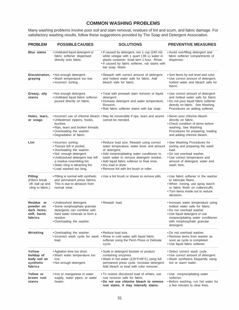
COMMON WASHING PROBLEMS
SOLUTIONSPROBLEM PREVENTIVE MEASURES
• If caused by detergent, mix 1 cup (240 ml)white vinegar with 1 quart (.95 L) water inplastic container. Soak item 1 hour. Rinse.
• If caused by fabric softener, rub stains withbar soap. Wash.
• Rewash with correct amount of detergentand hottest water safe for fabric. Addbleach safe for fabric.
• Treat with prewash stain remover or liquiddetergent.
• Increase detergent and water temperature.Rewash.
• Rub fabric softener stains with bar soap.
• May be irreversible if rips, tears and seamscannot be mended.
• Reduce load size. Rewash using correctwater temperature, water level, and amountof detergent.
• Add nonprecipitating water conditioner towash water to remove detergent residue.
• Add liquid fabric softener to final rinse.• Dry load in dryer.• Remove lint with lint brush or roller.
• Use a lint brush or shaver to remove pills.
• Rewash load.
• Reduce load size.• Rinse in cold water with liquid fabricsoftener using the Perm Press or Delicatecycle.
• Soak in detergent booster or productcontaining enzymes.
• Wash in hot water (120°F/49°C) using fullpermanent press cycle. Increase detergent.Add bleach or treat with color remover.
• To restore discolored load of whites, userust remover safe for fabric.
• Do not use chlorine bleach to removerust stains. It may intensify stains.
POSSIBLE CAUSES
Many washing problems involve poor soil and stain removal, residues of lint and scum, and fabric damage. Forsatisfactory washing results, follow these suggestions provided by The Soap and Detergent Association.
• Undiluted liquid detergent orfabric softener dispenseddirectly onto fabric.
• Not enough detergent.• Wash temperature too low.• Incorrect sorting.
• Not enough detergent.• Undiluted liquid fabric softenerpoured directly on fabric.
• Incorrect use of chlorine bleach.• Unfastened zippers, hooks,buckles.
• Rips, tears and broken threads.• Overloading the washer.• Degradation of fabric.
• Incorrect sorting.• Tissues left in pocket.• Overloading the washer.• Not enough detergent.• Undissolved detergent has lefta residue resembling lint.
• Static cling is attracting lint.• Load washed too long.
• Pilling is normal with syntheticand permanent press fabrics.This is due to abrasion fromnormal wear.
• Undissolved detergent.• Some nonphosphate granulardetergents can combine withhard water minerals to form aresidue.
• Overloading the washer.
• Overloading the washer.• Incorrect wash cycle for washload.
• Agitation time too short.• Wash water temperature toolow.
• Not enough detergent.
• Iron or manganese in watersupply, water pipes, or waterheater.
Blue stains
Discoloration,graying
Greasy, oilystains
Holes, tears,or snags
Lint
Pilling(Fibers break off, ball up and cling to fabric.)
Residue orpowder ondark items;stiff, harshfabrics.
Wrinkling
Yellowbuildup ofbody soil onsyntheticfabrics
Yellow orbrown ruststains
32
CARE AND CLEANING
Outside
• When washing is completed, wipe top and sides ofwasher with a damp cloth. Turn water faucets offto prevent pressure build-up in the hoses.
• As needed, clean the cabinet with mild soap andwater. Never use harsh, gritty or abrasivecleansers. If door or console becomes stained,clean with diluted chlorine bleach [1/2 cup (120 ml)in 1 quart (.95 L) water]. Rinse several times withclear water.
• Remove glue residue from tape or labels with amixture of warm water and mild detergent. Or,touch residue with the sticky side of the tape orlabel.
• Before moving the washer, place a strip ofcardboard or thin fiberboard under the front levelinglegs to prevent floor damage.
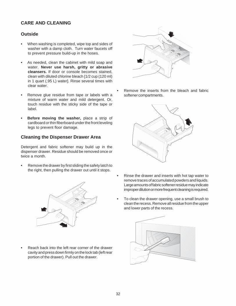
Cleaning the Dispenser Drawer Area
Detergent and fabric softener may build up in thedispenser drawer. Residue should be removed once ortwice a month.
• Remove the drawer by first sliding the safety latch tothe right, then pulling the drawer out until it stops.
• Reach back into the left rear corner of the drawercavity and press down firmly on the lock tab (left rearportion of the drawer). Pull out the drawer.
• Remove the inserts from the bleach and fabricsoftener compartments.
• Rinse the drawer and inserts with hot tap water toremove traces of accumulated powders and liquids.Large amounts of fabric softener residue may indicateimproper dilution or more frequent cleaning is required.
• To clean the drawer opening, use a small brush toclean the recess. Remove all residue from the upperand lower parts of the recess.
33
• Return the bleach and fabric softener inserts to theirproper compartments. Replace the dispenser drawerand run the Prewash cycle without any wash load inthe drum.
Inside
• Remove items from the washer as soon as thecycle ends. Excess wrinkling, color transfer, andodors may develop in items left in the washer.
• Before cleaning the washer interior, unplug theelectrical power cord to avoid electrical shockhazards.
• Dry around the washer door opening, flexible gasket,and door glass. These areas should always beclean to ensure a water tight seal.
• When extremely soiled items have been washed,a dirty residue may remain on the drum. Removethis by wiping the drum with a nonabrasive householdcleanser. Rinse thoroughly with water.
• The plastic drum vanes may become stained fromfabric dye. Clean these parts with a nonabrasivehousehold cleanser. This prevents dye transfer tofuture loads.
Winterizing Instructions
If the washer is stored in an area where freezing canoccur or moved in freezing temperatures, follow thesewinterizing instructions to prevent damage to the washer:
1. Turn off water supply faucets.
2. Disconnect hoses from water supply and drainwater from hoses.
3. Plug electrical cord into a properly groundedelectrical outlet.
4. Add 1 gallon (3.8 L) nontoxic recreational vehicle(RV) antifreeze to empty wash drum. Close door.
5. Set cycle selector knob at a spin setting. Pull outknob and let washer spin for 1 minute to drain outall water. Not all of the RV antifreeze will beexpelled.
6. Push in knob, unplug electrical power cord, drydrum interior, and close door.
7. Remove dispenser drawer. Drain any water incompartments and dry compartments. Replacedrawer.
8. Store washer in an upright position.
9. To remove antifreeze from washer after storage,run empty washer through a complete cycle usingdetergent. Do not add wash load.
High pitch "jet engine" noise.
Rattling and clanking noise.
Squealing sound or hot rubber odor.
Thumping sound.
• A certain amount of motor whine is normal during the spin cycle.
• Foreign objects such as coins or safety pins may be in drum or pump.Stop washer and check drum. If noise continues after washer isrestarted, objects may be in pump. Call your authorized servicer.
• Belt buckles and metal fasteners are hitting wash drum. To preventunnecessary noise and damage to drum, fasten fasteners and turnitems inside out.
• Washer is overloaded. Do not overload washer. Stop washer andreduce load.
• Heavy wash loads may produce a thumping sound. This is usuallynormal. If sound continues, washer is probably out of balance. Stopwasher and redistribute wash load.
Avoid Service Checklist
Before calling for service, review this list. It may save both time and expense. The list includes common concernsthat are not the result of defective workmanship or materials in this washer.
POSSIBLE CAUSE / SOLUTIONOCCURRENCE

34
OCCURRENCE POSSIBLE CAUSE / SOLUTION
• Washer is not resting firmly on floor. Move washer so it rests firmlyon floor. Adjust leveling legs. See INSTALLATION INSTRUCTIONSfor details.
• Shipping bolts and foam block have not been removed duringinstallation. See INSTALLATION INSTRUCTIONS for removingshipping bolts and foam block.
• Wash load unevenly distributed in drum. Stop washer and rearrangewash load.
• Electrical power cord may not be plugged in or connection may beloose. Make sure plug fits tightly in wall outlet.
• House fuse blown, circuit breaker tripped, or a power outage hasoccurred. Reset circuit breaker or replace fuse. Do not increasefuse capacity. If problem is a circuit overload, have it corrected bya qualified electrician. If problem is a power outage, call localelectric company.
• Water supply faucets are not turned on. “F01” is displayed. Turnon water supply faucets.
• Cycle selector is not in correct position. Move indicator clockwiseslightly. Pull out knob.
• Motor is overheated. Washer motor will stop if it becomesoverheated. It will automatically restart after a cool down period ofup to 30 minutes (if washer has not been manually turned off).
• Dispenser drawer is not completely closed. Close dispenserdrawer.
• Washer door is not completely closed. “dr” (door open) is displayedClose door completely.
• Dispenser drawer is not completely closed. “d:do” (dispenserdoor) is displayed. Close dispenser drawer.
• Load is too small. Add 1 or 2 similar items to help balance the load.
• Heavily soiled items. Wipe drum with a nonabrasive householdcleanser, then rinse. Shake or brush excess dirt and sand fromitems before washing.
• This is a result of the siphoning action and is part of the normaloperation of the washer. Water may be removed by removing thedispenser drawer into the empty drum or sink.
• Washer is overloaded. Do not overload washer. See WashingProcedures.
• Load is too small. Add 1 or 2 similar items to help balance the load.• Load is out of balance. Rearrange load to allow proper spinning.• Drain hose is kinked. Straighten drain hose.
• Water supply is not adequate in area. “F01” is displayed. Checkanother faucet in the house. Wait until water supply and pressureincrease.
• Water supply faucets are not completely open. “F01” is displayed.Fully open hot and cold faucets.
• Water is being used elsewhere in the house. Water pressure mustbe at least 30 psi (260 kPa). Avoid running water elsewhere whilewasher is filling.
• Water inlet hoses are kinked. Straighten hoses.
Vibrating noise.
Washer does not start.
Washer won’t spin.
Residue left in tub.
Water collects in bleach and fabricsoftner compartments.
Wash load too wet after spin.
Water does not enter washer or itenters slowly.
35
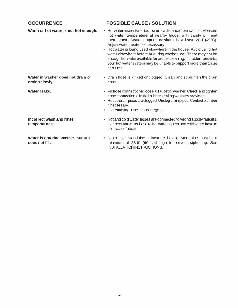
Warm or hot water is not hot enough.
Water in washer does not drain ordrains slowly.
Water leaks.
Incorrect wash and rinsetemperatures.
Water is entering washer, but tubdoes not fill.
• Hot water heater is set too low or is a distance from washer. Measurehot water temperature at nearby faucet with candy or meatthermometer. Water temperature should be at least 120°F (49°C).Adjust water heater as necessary.
• Hot water is being used elsewhere in the house. Avoid using hotwater elsewhere before or during washer use. There may not beenough hot water available for proper cleaning. If problem persists,your hot water system may be unable to support more than 1 useat a time.
• Drain hose is kinked or clogged. Clean and straighten the drainhose.
• Fill hose connection is loose at faucet or washer. Check and tightenhose connections. Install rubber sealing washers provided.
• House drain pipes are clogged. Unclog drain pipes. Contact plumberif necessary.
• Oversudsing. Use less detergent.
• Hot and cold water hoses are connected to wrong supply faucets.Connect hot water hose to hot water faucet and cold water hose tocold water faucet.
• Drain hose standpipe is incorrect height. Standpipe must be aminimum of 23.6" (60 cm) high to prevent siphoning. SeeINSTALLATION INSTRUCTIONS.
OCCURRENCE POSSIBLE CAUSE / SOLUTION
36
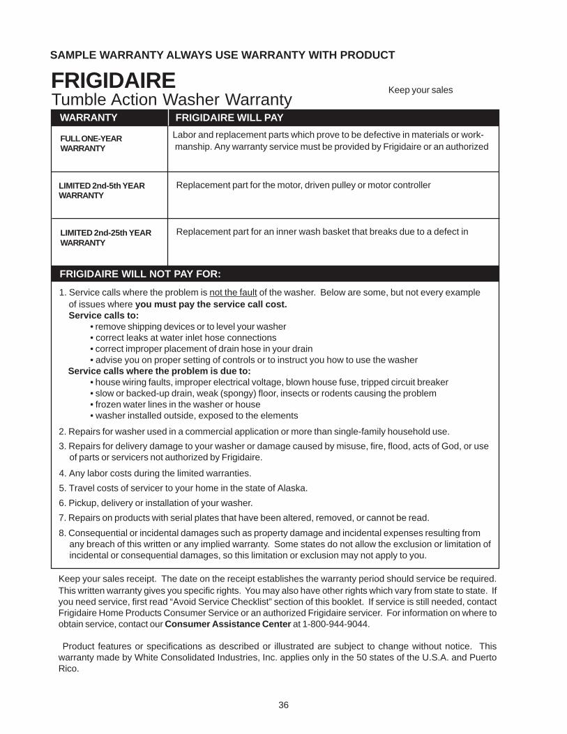
SAMPLE WARRANTY ALWAYS USE WARRANTY WITH PRODUCT
FRIGIDAIRETumble Action Washer Warranty
Keep your sales
FRIGIDAIRE WILL NOT PAY FOR:
Labor and replacement parts which prove to be defective in materials or work-manship. Any warranty service must be provided by Frigidaire or an authorized
WARRANTY
1. Service calls where the problem is not the fault of the washer. Below are some, but not every example of issues where you must pay the service call cost. Service calls to:
• remove shipping devices or to level your washer• correct leaks at water inlet hose connections• correct improper placement of drain hose in your drain• advise you on proper setting of controls or to instruct you how to use the washer
Service calls where the problem is due to:• house wiring faults, improper electrical voltage, blown house fuse, tripped circuit breaker• slow or backed-up drain, weak (spongy) floor, insects or rodents causing the problem• frozen water lines in the washer or house• washer installed outside, exposed to the elements
2. Repairs for washer used in a commercial application or more than single-family household use.
3. Repairs for delivery damage to your washer or damage caused by misuse, fire, flood, acts of God, or useof parts or servicers not authorized by Frigidaire.
4. Any labor costs during the limited warranties.
5. Travel costs of servicer to your home in the state of Alaska.
6. Pickup, delivery or installation of your washer.
7. Repairs on products with serial plates that have been altered, removed, or cannot be read.
8. Consequential or incidental damages such as property damage and incidental expenses resulting fromany breach of this written or any implied warranty. Some states do not allow the exclusion or limitation ofincidental or consequential damages, so this limitation or exclusion may not apply to you.
Keep your sales receipt. The date on the receipt establishes the warranty period should service be required.This written warranty gives you specific rights. You may also have other rights which vary from state to state. Ifyou need service, first read “Avoid Service Checklist” section of this booklet. If service is still needed, contactFrigidaire Home Products Consumer Service or an authorized Frigidaire servicer. For information on where toobtain service, contact our Consumer Assistance Center at 1-800-944-9044.
Product features or specifications as described or illustrated are subject to change without notice. Thiswarranty made by White Consolidated Industries, Inc. applies only in the 50 states of the U.S.A. and PuertoRico.
FULL ONE-YEARWARRANTY
LIMITED 2nd-5th YEARWARRANTY
LIMITED 2nd-25th YEARWARRANTY
Replacement part for the motor, driven pulley or motor controller
Replacement part for an inner wash basket that breaks due to a defect in
FRIGIDAIRE WILL PAY
37
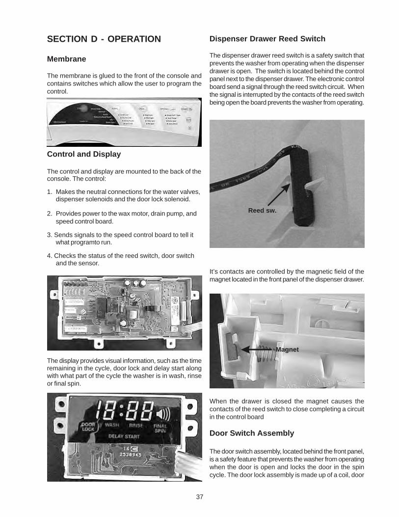
Dispenser Drawer Reed Switch
The dispenser drawer reed switch is a safety switch thatprevents the washer from operating when the dispenserdrawer is open. The switch is located behind the controlpanel next to the dispenser drawer. The electronic controlboard send a signal through the reed switch circuit. Whenthe signal is interrupted by the contacts of the reed switchbeing open the board prevents the washer from operating.
It’s contacts are controlled by the magnetic field of themagnet located in the front panel of the dispenser drawer.
When the drawer is closed the magnet causes thecontacts of the reed switch to close completing a circuitin the control board
Door Switch Assembly
The door switch assembly, located behind the front panel,is a safety feature that prevents the washer from operatingwhen the door is open and locks the door in the spincycle. The door lock assembly is made up of a coil, door
SECTION D - OPERATION
Membrane
The membrane is glued to the front of the console andcontains switches which allow the user to program thecontrol.
Control and Display
The control and display are mounted to the back of theconsole. The control:
1. Makes the neutral connections for the water valves,dispenser solenoids and the door lock solenoid.
2. Provides power to the wax motor, drain pump, andspeed control board.
3. Sends signals to the speed control board to tell itwhat programto run.
4. Checks the status of the reed switch, door switchand the sensor.
The display provides visual information, such as the timeremaining in the cycle, door lock and delay start alongwith what part of the cycle the washer is in wash, rinseor final spin.
Reed sw.
Magnet
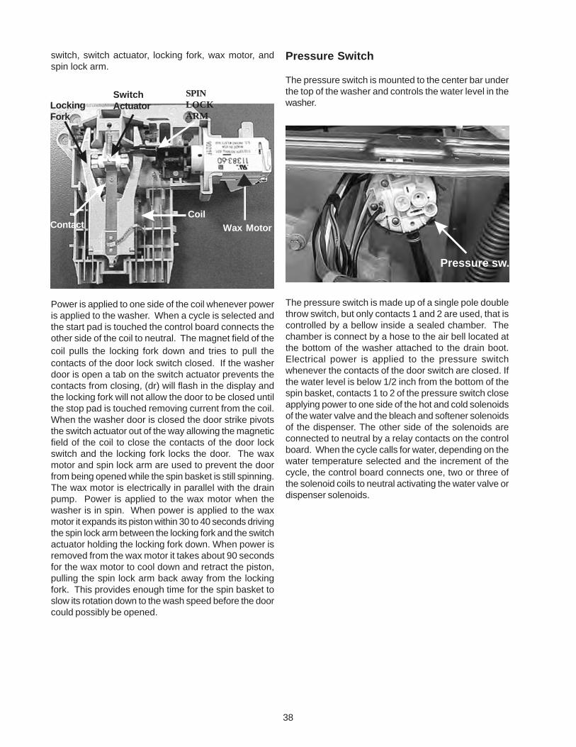
38
Pressure Switch
The pressure switch is mounted to the center bar underthe top of the washer and controls the water level in thewasher.
The pressure switch is made up of a single pole doublethrow switch, but only contacts 1 and 2 are used, that iscontrolled by a bellow inside a sealed chamber. Thechamber is connect by a hose to the air bell located atthe bottom of the washer attached to the drain boot.Electrical power is applied to the pressure switchwhenever the contacts of the door switch are closed. Ifthe water level is below 1/2 inch from the bottom of thespin basket, contacts 1 to 2 of the pressure switch closeapplying power to one side of the hot and cold solenoidsof the water valve and the bleach and softener solenoidsof the dispenser. The other side of the solenoids areconnected to neutral by a relay contacts on the controlboard. When the cycle calls for water, depending on thewater temperature selected and the increment of thecycle, the control board connects one, two or three ofthe solenoid coils to neutral activating the water valve ordispenser solenoids.
switch, switch actuator, locking fork, wax motor, andspin lock arm.
Power is applied to one side of the coil whenever poweris applied to the washer. When a cycle is selected andthe start pad is touched the control board connects theother side of the coil to neutral. The magnet field of thecoil pulls the locking fork down and tries to pull thecontacts of the door lock switch closed. If the washerdoor is open a tab on the switch actuator prevents thecontacts from closing, (dr) will flash in the display andthe locking fork will not allow the door to be closed untilthe stop pad is touched removing current from the coil.When the washer door is closed the door strike pivotsthe switch actuator out of the way allowing the magneticfield of the coil to close the contacts of the door lockswitch and the locking fork locks the door. The waxmotor and spin lock arm are used to prevent the doorfrom being opened while the spin basket is still spinning.The wax motor is electrically in parallel with the drainpump. Power is applied to the wax motor when thewasher is in spin. When power is applied to the waxmotor it expands its piston within 30 to 40 seconds drivingthe spin lock arm between the locking fork and the switchactuator holding the locking fork down. When power isremoved from the wax motor it takes about 90 secondsfor the wax motor to cool down and retract the piston,pulling the spin lock arm back away from the lockingfork. This provides enough time for the spin basket toslow its rotation down to the wash speed before the doorcould possibly be opened.
Contact Wax MotorCoil
SwitchActuator
SPINLOCKARM
LockingFork
Pressure sw.
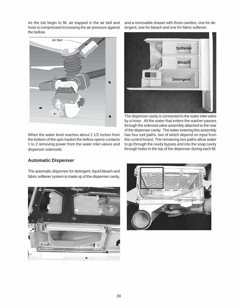
39
As the tub begin to fill, air trapped in the air bell andhose is compressed increasing the air pressure againstthe bellow.
When the water level reaches about 2 1/2 inches fromthe bottom of the spin basket the bellow opens contacts1 to 2 removing power from the water inlet valves anddispenser solenoids.
Automatic Dispenser
The automatic dispenser for detergent, liquid bleach andfabric softener system is made up of the dispenser cavity,
and a removable drawer with three cavities, one for de-tergent, one for bleach and one for fabric softener.
The dispenser cavity is connected to the water inlet valveby a hose. All the water that enters the washer passesthrough the solenoid valve assembly attached to the rearof the dispenser cavity. The water entering this assemblyhas four exit paths, two of which depend on input fromthe control board. The remaining two paths allow waterto go through the cavity bypass and into the soap cavitythrough holes in the top of the dispenser during each fill.
Softener
Bleach
Detergent
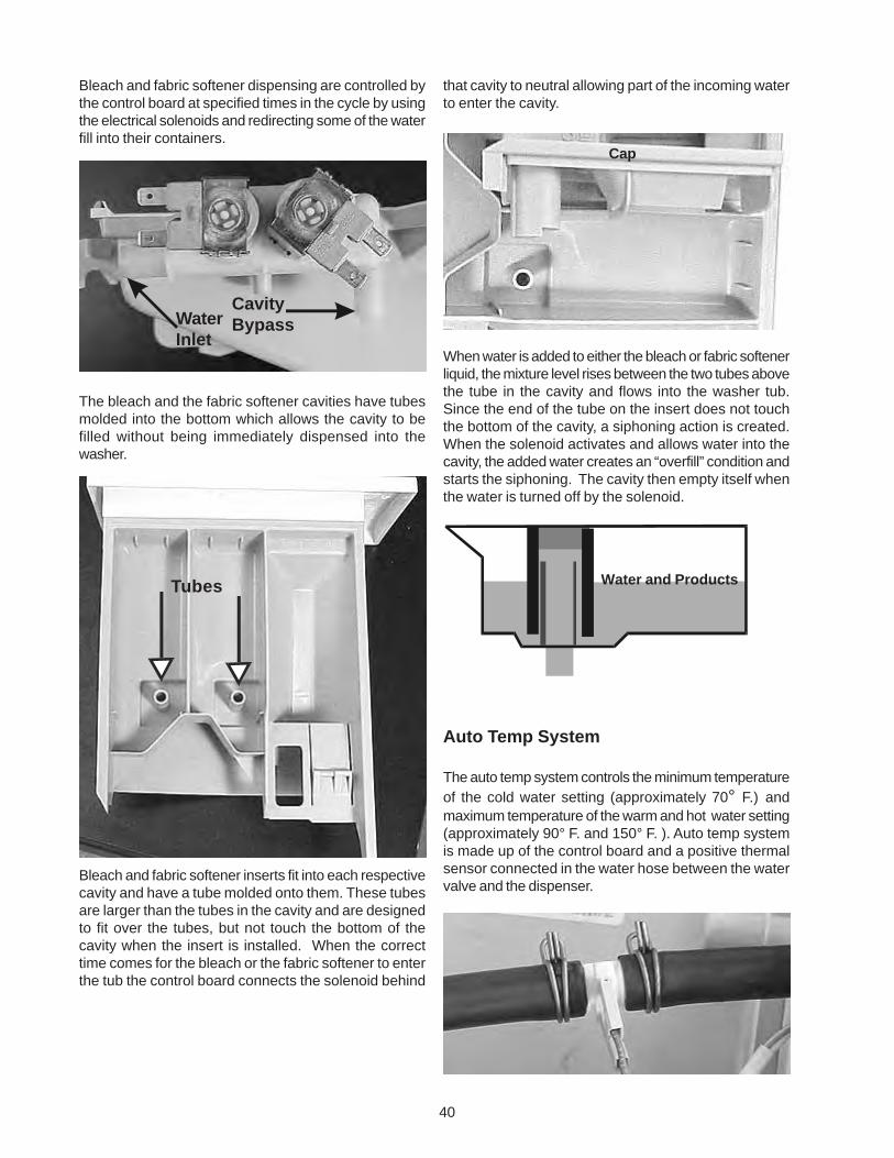
40
that cavity to neutral allowing part of the incoming waterto enter the cavity.
When water is added to either the bleach or fabric softenerliquid, the mixture level rises between the two tubes abovethe tube in the cavity and flows into the washer tub.Since the end of the tube on the insert does not touchthe bottom of the cavity, a siphoning action is created.When the solenoid activates and allows water into thecavity, the added water creates an “overfill” condition andstarts the siphoning. The cavity then empty itself whenthe water is turned off by the solenoid.
Auto Temp System
The auto temp system controls the minimum temperatureof the cold water setting (approximately 70° F.) andmaximum temperature of the warm and hot water setting(approximately 90° F. and 150° F. ). Auto temp systemis made up of the control board and a positive thermalsensor connected in the water hose between the watervalve and the dispenser.
Bleach and fabric softener dispensing are controlled bythe control board at specified times in the cycle by usingthe electrical solenoids and redirecting some of the waterfill into their containers.
The bleach and the fabric softener cavities have tubesmolded into the bottom which allows the cavity to befilled without being immediately dispensed into thewasher.
Bleach and fabric softener inserts fit into each respectivecavity and have a tube molded onto them. These tubesare larger than the tubes in the cavity and are designedto fit over the tubes, but not touch the bottom of thecavity when the insert is installed. When the correcttime comes for the bleach or the fabric softener to enterthe tub the control board connects the solenoid behind
Cap
Water and Products
CavityBypassWater
Inlet
Tubes
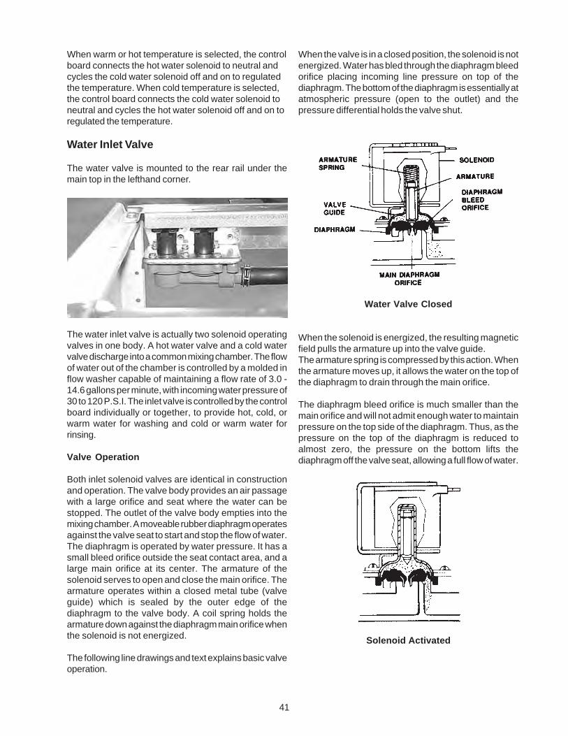
41
When warm or hot temperature is selected, the controlboard connects the hot water solenoid to neutral andcycles the cold water solenoid off and on to regulatedthe temperature. When cold temperature is selected,the control board connects the cold water solenoid toneutral and cycles the hot water solenoid off and on toregulated the temperature.
Water Inlet Valve
The water valve is mounted to the rear rail under themain top in the lefthand corner.
The water inlet valve is actually two solenoid operatingvalves in one body. A hot water valve and a cold watervalve discharge into a common mixing chamber. The flowof water out of the chamber is controlled by a molded inflow washer capable of maintaining a flow rate of 3.0 -14.6 gallons per minute, with incoming water pressure of30 to 120 P.S.I. The inlet valve is controlled by the controlboard individually or together, to provide hot, cold, orwarm water for washing and cold or warm water forrinsing.
Valve Operation
Both inlet solenoid valves are identical in constructionand operation. The valve body provides an air passagewith a large orifice and seat where the water can bestopped. The outlet of the valve body empties into themixing chamber. A moveable rubber diaphragm operatesagainst the valve seat to start and stop the flow of water.The diaphragm is operated by water pressure. It has asmall bleed orifice outside the seat contact area, and alarge main orifice at its center. The armature of thesolenoid serves to open and close the main orifice. Thearmature operates within a closed metal tube (valveguide) which is sealed by the outer edge of thediaphragm to the valve body. A coil spring holds thearmature down against the diaphragm main orifice whenthe solenoid is not energized.
The following line drawings and text explains basic valveoperation.
When the valve is in a closed position, the solenoid is notenergized. Water has bled through the diaphragm bleedorifice placing incoming line pressure on top of thediaphragm. The bottom of the diaphragm is essentially atatmospheric pressure (open to the outlet) and thepressure differential holds the valve shut.
Water Valve Closed
When the solenoid is energized, the resulting magneticfield pulls the armature up into the valve guide.The armature spring is compressed by this action. Whenthe armature moves up, it allows the water on the top ofthe diaphragm to drain through the main orifice.
The diaphragm bleed orifice is much smaller than themain orifice and will not admit enough water to maintainpressure on the top side of the diaphragm. Thus, as thepressure on the top of the diaphragm is reduced toalmost zero, the pressure on the bottom lifts thediaphragm off the valve seat, allowing a full flow of water.
Solenoid Activated
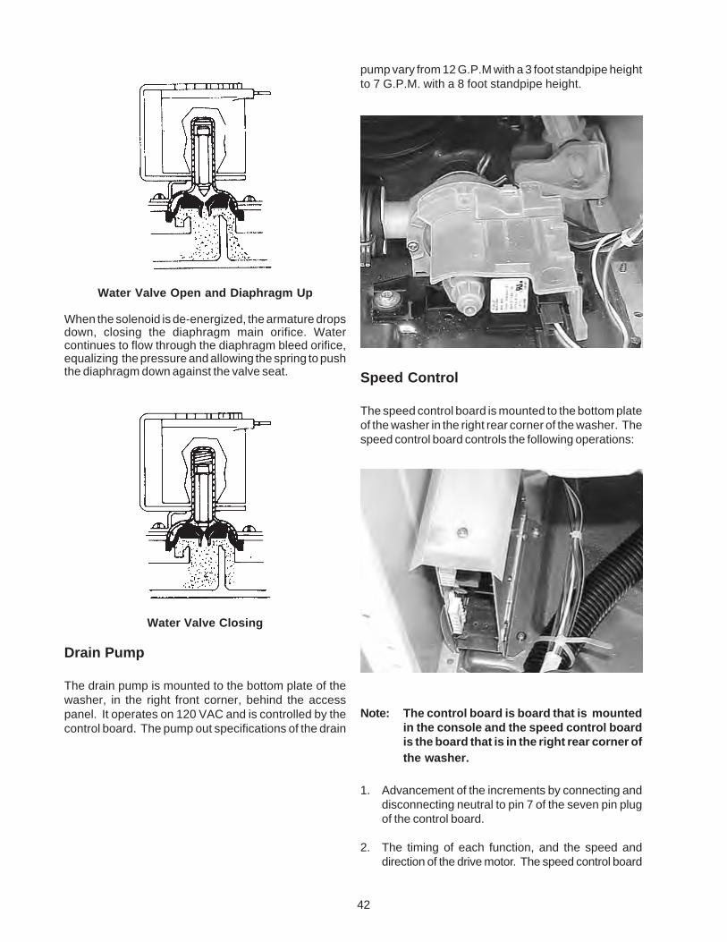
42
pump vary from 12 G.P.M with a 3 foot standpipe heightto 7 G.P.M. with a 8 foot standpipe height.
Speed Control
The speed control board is mounted to the bottom plateof the washer in the right rear corner of the washer. Thespeed control board controls the following operations:
Note: The control board is board that is mountedin the console and the speed control boardis the board that is in the right rear corner ofthe washer.
1. Advancement of the increments by connecting anddisconnecting neutral to pin 7 of the seven pin plugof the control board.
2. The timing of each function, and the speed anddirection of the drive motor. The speed control board
Water Valve Open and Diaphragm Up
When the solenoid is de-energized, the armature dropsdown, closing the diaphragm main orifice. Watercontinues to flow through the diaphragm bleed orifice,equalizing the pressure and allowing the spring to pushthe diaphragm down against the valve seat.
Water Valve Closing
Drain Pump
The drain pump is mounted to the bottom plate of thewasher, in the right front corner, behind the accesspanel. It operates on 120 VAC and is controlled by thecontrol board. The pump out specifications of the drain
sensor
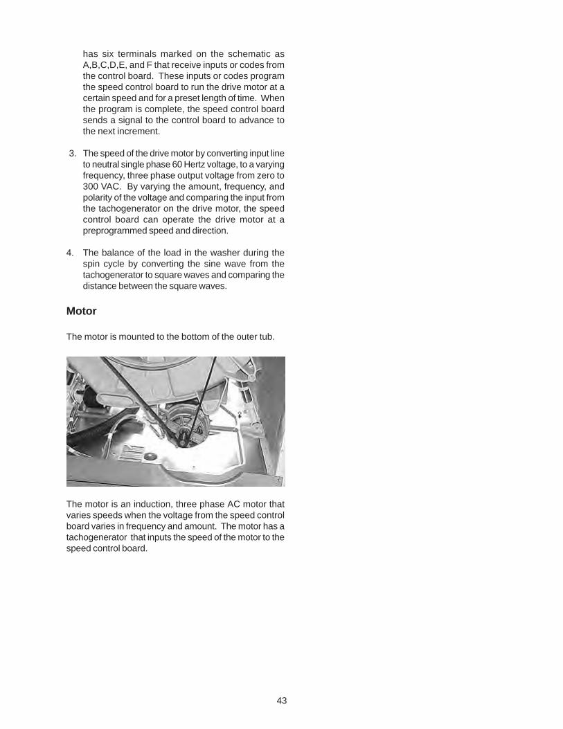
43
has six terminals marked on the schematic asA,B,C,D,E, and F that receive inputs or codes fromthe control board. These inputs or codes programthe speed control board to run the drive motor at acertain speed and for a preset length of time. Whenthe program is complete, the speed control boardsends a signal to the control board to advance tothe next increment.
3. The speed of the drive motor by converting input lineto neutral single phase 60 Hertz voltage, to a varyingfrequency, three phase output voltage from zero to300 VAC. By varying the amount, frequency, andpolarity of the voltage and comparing the input fromthe tachogenerator on the drive motor, the speedcontrol board can operate the drive motor at apreprogrammed speed and direction.
4. The balance of the load in the washer during thespin cycle by converting the sine wave from thetachogenerator to square waves and comparing thedistance between the square waves.
Motor
The motor is mounted to the bottom of the outer tub.
The motor is an induction, three phase AC motor thatvaries speeds when the voltage from the speed controlboard varies in frequency and amount. The motor has atachogenerator that inputs the speed of the motor to thespeed control board.
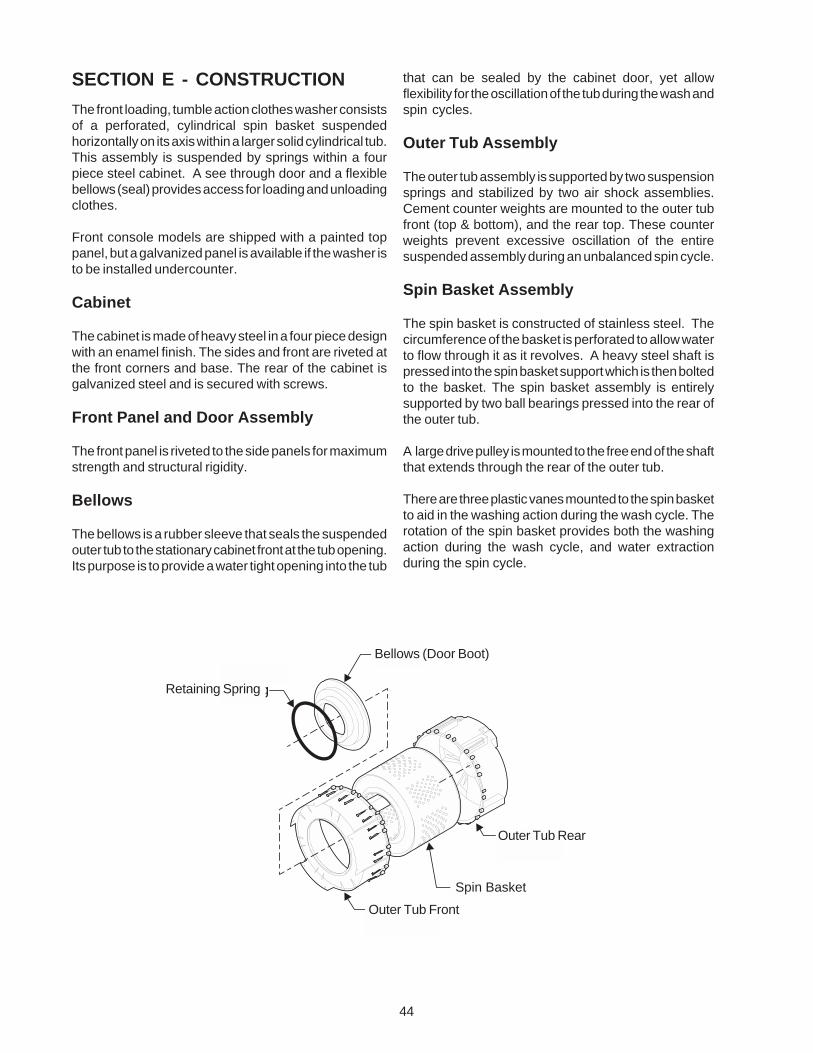
44
The front loading, tumble action clothes washer consistsof a perforated, cylindrical spin basket suspendedhorizontally on its axis within a larger solid cylindrical tub.This assembly is suspended by springs within a fourpiece steel cabinet. A see through door and a flexiblebellows (seal) provides access for loading and unloadingclothes.
Front console models are shipped with a painted toppanel, but a galvanized panel is available if the washer isto be installed undercounter.
Cabinet
The cabinet is made of heavy steel in a four piece designwith an enamel finish. The sides and front are riveted atthe front corners and base. The rear of the cabinet isgalvanized steel and is secured with screws.
Front Panel and Door Assembly
The front panel is riveted to the side panels for maximumstrength and structural rigidity.
Bellows
The bellows is a rubber sleeve that seals the suspendedouter tub to the stationary cabinet front at the tub opening.Its purpose is to provide a water tight opening into the tub
that can be sealed by the cabinet door, yet allowflexibility for the oscillation of the tub during the wash andspin cycles.
Outer Tub Assembly
The outer tub assembly is supported by two suspensionsprings and stabilized by two air shock assemblies.Cement counter weights are mounted to the outer tubfront (top & bottom), and the rear top. These counterweights prevent excessive oscillation of the entiresuspended assembly during an unbalanced spin cycle.
Spin Basket Assembly
The spin basket is constructed of stainless steel. Thecircumference of the basket is perforated to allow waterto flow through it as it revolves. A heavy steel shaft ispressed into the spin basket support which is then boltedto the basket. The spin basket assembly is entirelysupported by two ball bearings pressed into the rear ofthe outer tub.
A large drive pulley is mounted to the free end of the shaftthat extends through the rear of the outer tub.
There are three plastic vanes mounted to the spin basketto aid in the washing action during the wash cycle. Therotation of the spin basket provides both the washingaction during the wash cycle, and water extractionduring the spin cycle.
SECTION E - CONSTRUCTION
Spin Basket
Outer Tub Rear
Outer Tub Front
Bellows (Door Boot)
Retaining Spring
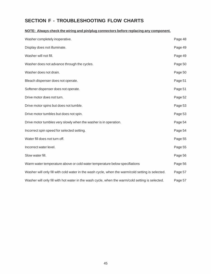
45
SECTION F - TROUBLESHOOTING FLOW CHARTS
NOTE: Always check the wiring and pin/plug connectors before replacing any component.
Washer completely inoperative. Page 48
Display does not illuminate. Page 49
Washer will not fill. Page 49
Washer does not advance through the cycles. Page 50
Washer does not drain. Page 50
Bleach dispenser does not operate. Page 51
Softener dispenser does not operate. Page 51
Drive motor does not turn. Page 52
Drive motor spins but does not tumble. Page 53
Drive motor tumbles but does not spin. Page 53
Drive motor tumbles very slowly when the washer is in operation. Page 54
Incorrect spin speed for selected setting. Page 54
Water fill does not turn off. Page 55
Incorrect water level. Page 55
Slow water fill. Page 56
Warm water temperature above or cold water temperature below specifiations Page 56
Washer will only fill with cold water in the wash cycle, when the warm/cold setting is selected. Page 57
Washer will only fill with hot water in the wash cycle, when the warm/cold setting is selected. Page 57
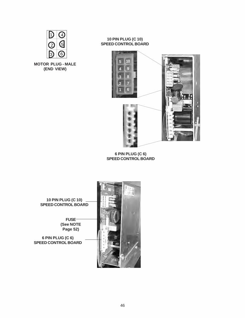
46
MOTOR PLUG - MALE(END VIEW)
41
2
3
5
6
10 PIN PLUG (C 10)SPEED CONTROL BOARD
6 PIN PLUG (C 6)SPEED CONTROL BOARD
5
4
3
2
1
10
9
8
7
6
65
4
321
6 PIN PLUG (C 6)SPEED CONTROL BOARD
10 PIN PLUG (C 10)SPEED CONTROL BOARD
FUSE(See NOTEPage 52)
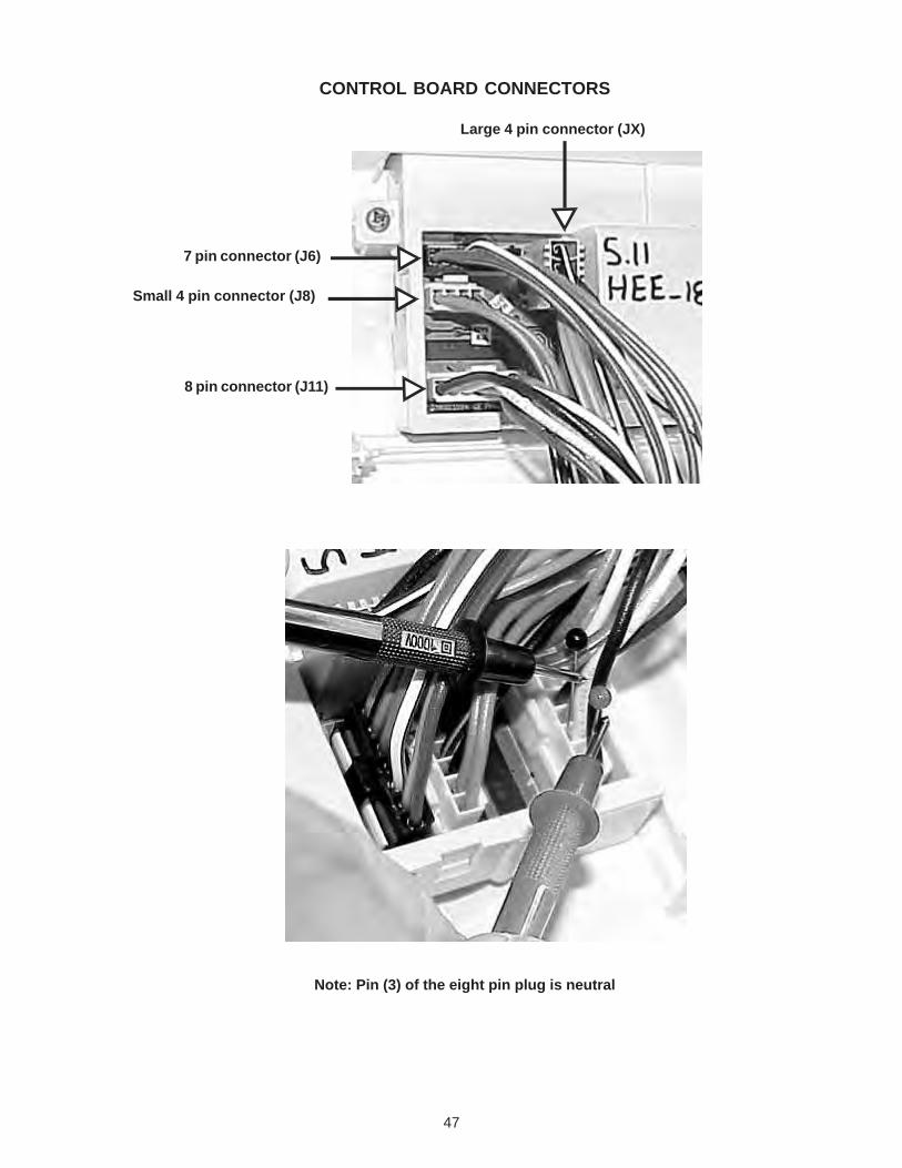
47
CONTROL BOARD CONNECTORS
7 pin connector (J6)
Small 4 pin connector (J8)
8 pin connector (J11)
Large 4 pin connector (JX)
Note: Pin (3) of the eight pin plug is neutral
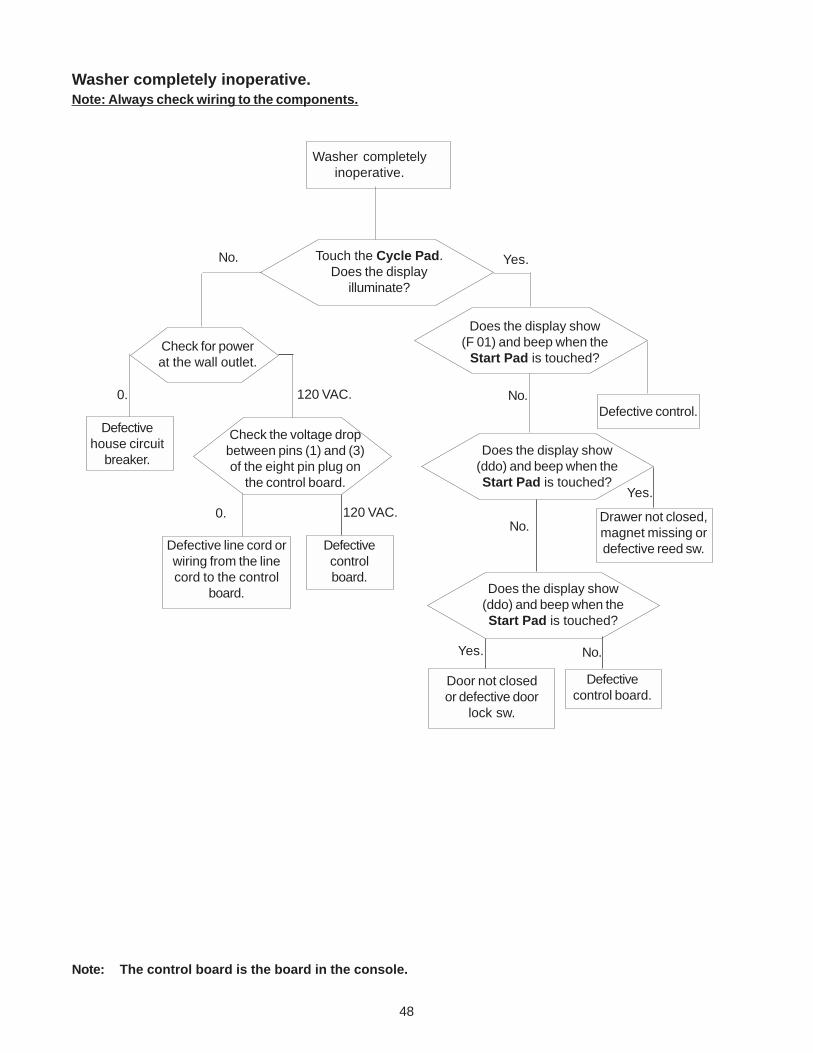
48
Washer completelyinoperative.
Touch the Cycle Pad.Does the display
illuminate?
No. Yes.
Does the display show(ddo) and beep when theStart Pad is touched?
Check for powerat the wall outlet.
120 VAC.
Check the voltage dropbetween pins (1) and (3)of the eight pin plug on
the control board.
Defectivehouse circuit
breaker.
Yes.
Door not closedor defective door
lock sw.
Washer completely inoperative.Note: Always check wiring to the components.
No.
Defective line cord orwiring from the linecord to the control
board.
Defectivecontrolboard.
120 VAC.
Does the display show(F 01) and beep when the
Start Pad is touched?
Drawer not closed,magnet missing ordefective reed sw.
Defectivecontrol board.
Defective control.
No.
Does the display show(ddo) and beep when theStart Pad is touched?
Yes. No.
0.
Note: The control board is the board in the console.
0.
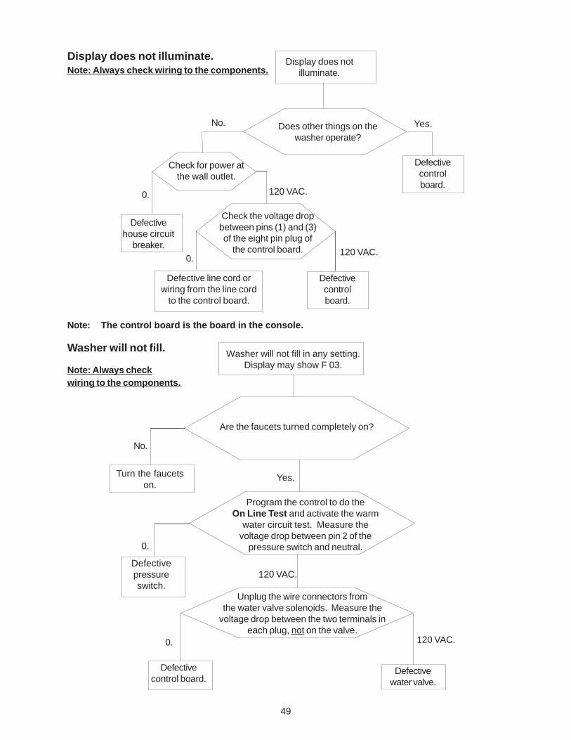
49
Display does notilluminate.
Does other things on thewasher operate?
Yes.
Display does not illuminate.Note: Always check wiring to the components.
Check for power atthe wall outlet.
120 VAC.
Check the voltage dropbetween pins (1) and (3)of the eight pin plug of
the control board.
Defectivehouse circuit
breaker.
Defective line cord orwiring from the line cord
to the control board.
Defectivecontrolboard.
120 VAC.
0.
0.
No.
Defectivecontrolboard.
Note: The control board is the board in the console.
Washer will not fill in any setting.Display may show F 03.
Turn the faucetson.
Are the faucets turned completely on?
No.
Note: Always checkwiring to the components.
Washer will not fill.
Yes.
Program the control to do theOn Line Test and activate the warm
water circuit test. Measure thevoltage drop between pin 2 of the
pressure switch and neutral.0.
Defectivepressureswitch.
Unplug the wire connectors fromthe water valve solenoids. Measure the
voltage drop between the two terminals ineach plug, not on the valve.
120 VAC.
120 VAC.0.
Defectivecontrol board.
Defectivewater valve.
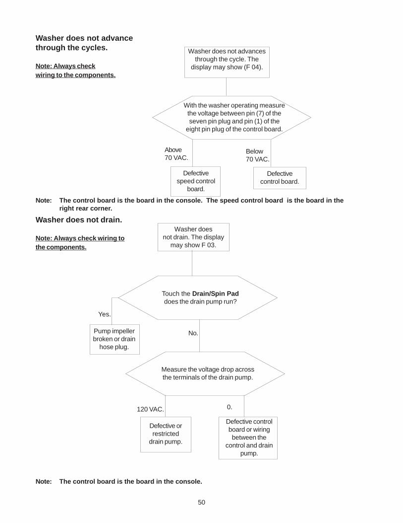
50
Washer does not advancethrough the cycles.
Note: Always checkwiring to the components.
Washer does not advancesthrough the cycle. The
display may show (F 04).
With the washer operating measurethe voltage between pin (7) of theseven pin plug and pin (1) of the
eight pin plug of the control board.
Above70 VAC.
Defectivespeed control
board.
Below70 VAC.
Defectivecontrol board.
Washer doesnot drain. The display
may show F 03.
Touch the Drain/Spin Paddoes the drain pump run?
120 VAC.
Defective orrestricted
drain pump.
Pump impellerbroken or drain
hose plug.
Washer does not drain.
Note: Always check wiring tothe components.
No.
Yes.
Measure the voltage drop acrossthe terminals of the drain pump.
0.
Defective controlboard or wiringbetween the
control and drainpump.
Note: The control board is the board in the console.
Note: The control board is the board in the console. The speed control board is the board in theright rear corner.
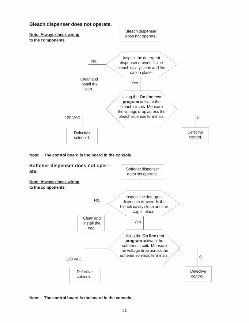
51
Bleach dispenserdoes not operate.
Using the On line testprogram activate the
bleach circuit. Measurethe voltage drop across thebleach solenoid terminals.120 VAC.
Defectivesolenoid.
Defectivecontrol.
0.
Bleach dispenser does not operate.
Note: Always check wiringto the components.
Softener dispenserdoes not operate.
Softener dispenser does not oper-ate.
Note: Always check wiringto the components.
Inspect the detergentdispenser drawer. Is the
bleach cavity clean and thecap in place.
Yes.
No.
Clean andinstall the
cap.
Using the On line testprogram activate the
softener circuit. Measurethe voltage drop across thesoftener solenoid terminals.
120 VAC.
Defectivesolenoid.
Defectivecontrol .
0.
Inspect the detergentdispenser drawer. Is the
bleach cavity clean and thecap in place.
Yes.
No.
Clean andinstall the
cap.
Note: The control board is the board in the console.
Note: The control board is the board in the console.
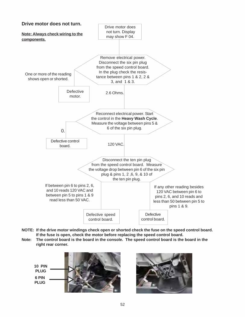
52
Drive motor does not turn.
Note: Always check wiring to thecomponents.
NOTE: If the drive motor windings check open or shorted check the fuse on the speed control board.If the fuse is open, check the motor before replacing the speed control board.
Note: The control board is the board in the console. The speed control board is the board in theright rear corner.
6 PINPLUG
10 PINPLUG
Drive motor does not turn. Displaymay show F 04.
120 VAC.
Defectivemotor.
Defectivecontrol board.
Remove electrical power.Disconnect the six pin plug
from the speed control board.In the plug check the resis-
tance between pins 1 & 2, 2 &3, and 1 & 3.
One or more of the readingshows open or shorted.
2.6 Ohms.
Reconnect electrical power. Startthe control in the Heavy Wash Cycle.Measure the voltage between pins 5 &
6 of the six pin plug.
Defective controlboard.
Disconnect the ten pin plugfrom the speed control board. Measure
the voltage drop between pin 6 of the six pinplug & pins 1, 2 ,6, 9, & 10 of
the ten pin plug.
If between pin 6 to pins 2, 6,and 10 reads 120 VAC andbetween pin 5 to pins 1 & 9
read less than 50 VAC.
Defective speedcontrol board.
If any other reading besides120 VAC between pin 6 to
pins 2, 6, and 10 reads andless than 50 between pin 5 to
pins 1 & 9.
0.
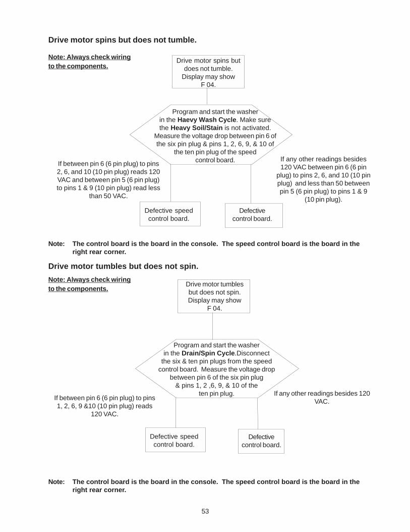
53
Drive motor spins butdoes not tumble.
Display may showF 04.
Defectivecontrol board.
Program and start the washerin the Haevy Wash Cycle. Make surethe Heavy Soil/Stain is not activated.
Measure the voltage drop between pin 6 ofthe six pin plug & pins 1, 2, 6, 9, & 10 of
the ten pin plug of the speedcontrol board.If between pin 6 (6 pin plug) to pins
2, 6, and 10 (10 pin plug) reads 120VAC and between pin 5 (6 pin plug)to pins 1 & 9 (10 pin plug) read less
than 50 VAC.
Defective speedcontrol board.
If any other readings besides120 VAC between pin 6 (6 pin
plug) to pins 2, 6, and 10 (10 pinplug) and less than 50 betweenpin 5 (6 pin plug) to pins 1 & 9
(10 pin plug).
Drive motor spins but does not tumble.
Note: Always check wiringto the components.
Drive motor tumblesbut does not spin.Display may show
F 04.
Defectivecontrol board.
Program and start the washerin the Drain/Spin Cycle.Disconnect
the six & ten pin plugs from the speedcontrol board. Measure the voltage drop
between pin 6 of the six pin plug& pins 1, 2 ,6, 9, & 10 of the
ten pin plug.If between pin 6 (6 pin plug) to pins1, 2, 6, 9 &10 (10 pin plug) reads
120 VAC.
Defective speedcontrol board.
If any other readings besides 120VAC.
Drive motor tumbles but does not spin.
Note: Always check wiringto the components.
Note: The control board is the board in the console. The speed control board is the board in theright rear corner.
Note: The control board is the board in the console. The speed control board is the board in theright rear corner.
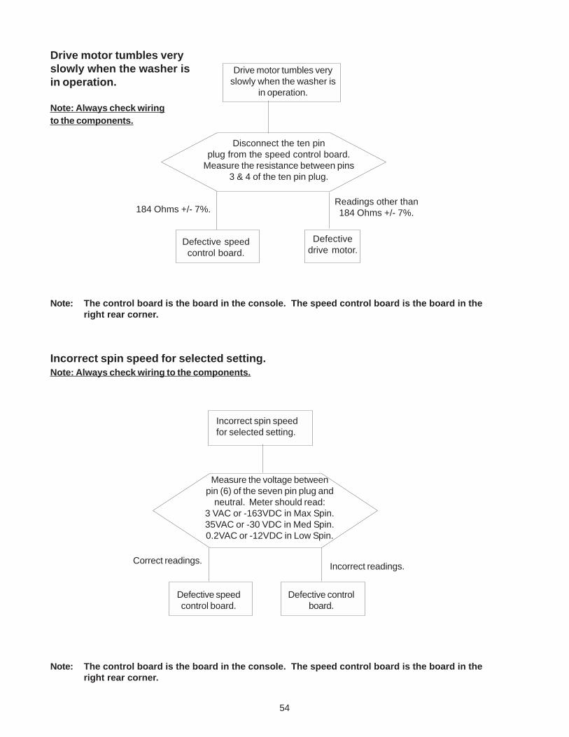
54
Drive motor tumbles veryslowly when the washer is
in operation.
Defectivedrive motor.
Disconnect the ten pinplug from the speed control board.
Measure the resistance between pins3 & 4 of the ten pin plug.
184 Ohms +/- 7%.
Defective speedcontrol board.
Readings other than184 Ohms +/- 7%.
Drive motor tumbles veryslowly when the washer isin operation.
Note: Always check wiringto the components.
Note: The control board is the board in the console. The speed control board is the board in theright rear corner.
Measure the voltage betweenpin (6) of the seven pin plug and
neutral. Meter should read:3 VAC or -163VDC in Max Spin.35VAC or -30 VDC in Med Spin.0.2VAC or -12VDC in Low Spin.
Defective speedcontrol board.
Correct readings.
Incorrect spin speedfor selected setting.
Incorrect readings.
Defective controlboard.
Note: The control board is the board in the console. The speed control board is the board in theright rear corner.
Incorrect spin speed for selected setting.Note: Always check wiring to the components.
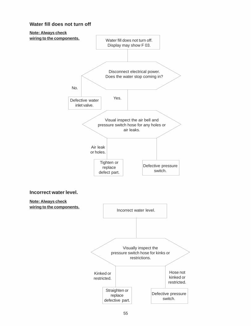
55
Water fill does not turn off
Water fill does not turn off.Display may show F 03.
Tighten orreplace
defect part.
Visual inspect the air bell andpressure switch hose for any holes or
air leaks.
Air leakor holes.
Note: Always checkwiring to the components.
Disconnect electrical power.Does the water stop coming in?
Defective waterinlet valve.
Yes.
Defective pressureswitch.
Incorrect water level.
Straighten orreplace
defective part.
Visually inspect thepressure switch hose for kinks or
restrictions.
Kinked orrestricted.
Note: Always checkwiring to the components.
Defective pressureswitch.
Incorrect water level.
No.
Hose notkinked orrestricted.
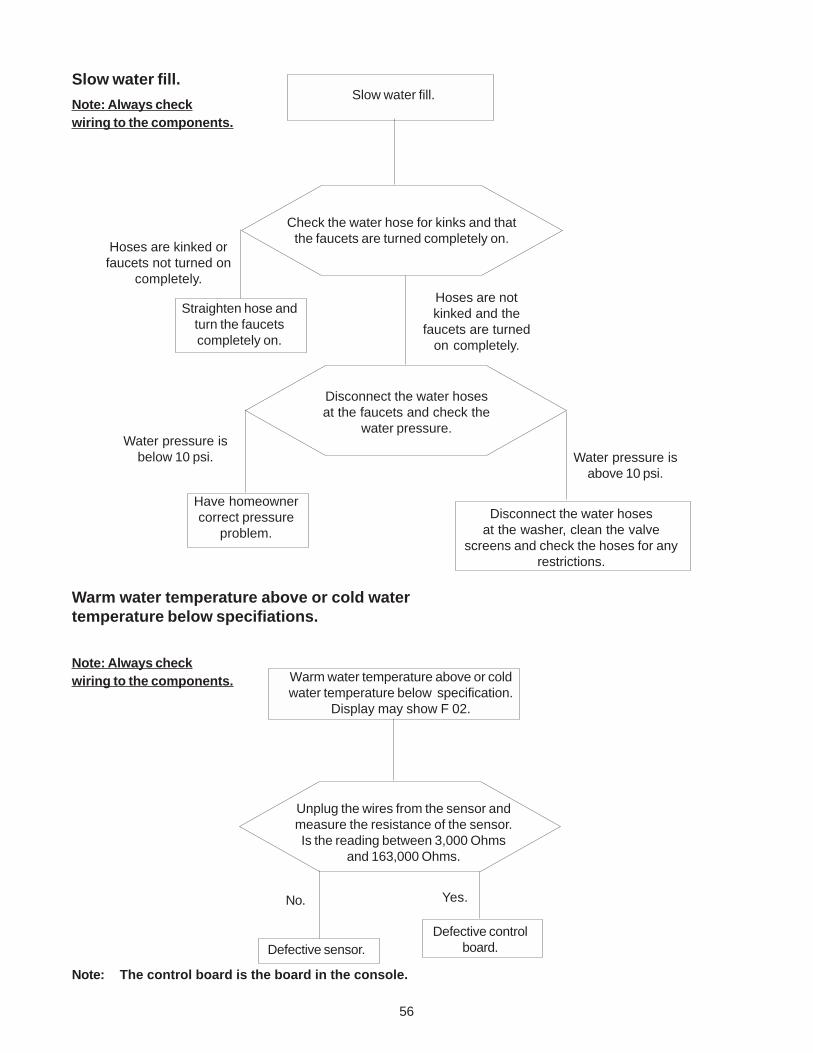
56
Slow water fill.
Straighten hose andturn the faucetscompletely on.
Check the water hose for kinks and thatthe faucets are turned completely on.
Hoses are kinked orfaucets not turned on
completely.
Note: Always checkwiring to the components.
Slow water fill.
Hoses are notkinked and the
faucets are turnedon completely.
Disconnect the water hosesat the faucets and check the
water pressure.Water pressure is
below 10 psi.
Have homeownercorrect pressure
problem.
Disconnect the water hosesat the washer, clean the valve
screens and check the hoses for anyrestrictions.
Water pressure isabove 10 psi.
Defective controlboard.
Unplug the wires from the sensor andmeasure the resistance of the sensor.Is the reading between 3,000 Ohms
and 163,000 Ohms.
Note: Always checkwiring to the components.
Warm water temperature above or cold watertemperature below specifiations.
Defective sensor.
Warm water temperature above or coldwater temperature below specification.
Display may show F 02.
Yes.No.
Note: The control board is the board in the console.
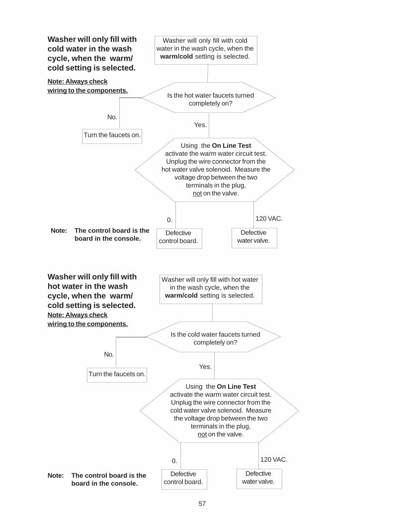
57
Washer will only fill with coldwater in the wash cycle, when the
warm/cold setting is selected.
Note: Always checkwiring to the components.
Washer will only fill withcold water in the washcycle, when the warm/cold setting is selected.
Turn the faucets on.
Is the hot water faucets turnedcompletely on?
No.Yes.
Using the On Line Testactivate the warm water circuit test.Unplug the wire connector from the
hot water valve solenoid. Measure thevoltage drop between the two
terminals in the plug,not on the valve.
120 VAC.0.
Defectivecontrol board.
Defectivewater valve.
Washer will only fill with hot waterin the wash cycle, when the
warm/cold setting is selected.
Turn the faucets on.
Is the cold water faucets turnedcompletely on?
No.
Yes.
Using the On Line Testactivate the warm water circuit test.Unplug the wire connector from thecold water valve solenoid. Measure
the voltage drop between the twoterminals in the plug,
not on the valve.
120 VAC.0.
Defectivecontrol board.
Defectivewater valve.
Washer will only fill withhot water in the washcycle, when the warm/cold setting is selected.Note: Always checkwiring to the components.
Note: The control board is theboard in the console.
Note: The control board is theboard in the console.
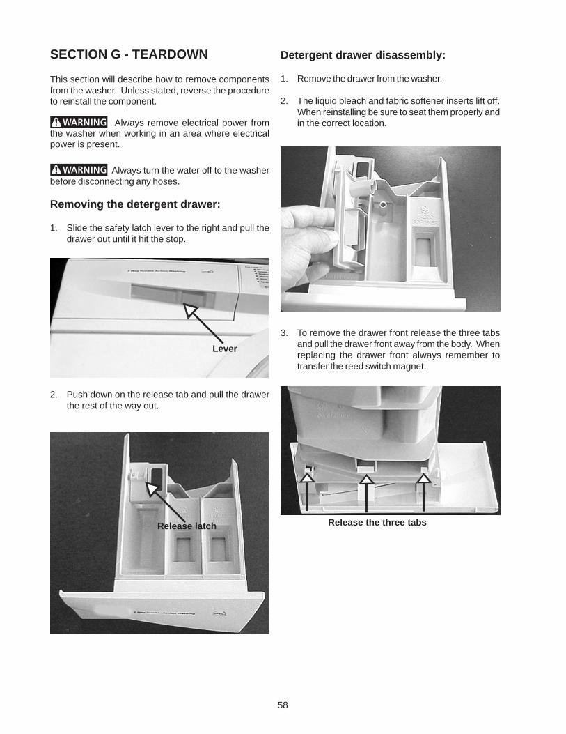
58
Detergent drawer disassembly:
1. Remove the drawer from the washer.
2. The liquid bleach and fabric softener inserts lift off.When reinstalling be sure to seat them properly andin the correct location.
3. To remove the drawer front release the three tabsand pull the drawer front away from the body. Whenreplacing the drawer front always remember totransfer the reed switch magnet.
SECTION G - TEARDOWN
This section will describe how to remove componentsfrom the washer. Unless stated, reverse the procedureto reinstall the component.
Always remove electrical power fromthe washer when working in an area where electricalpower is present.
Always turn the water off to the washerbefore disconnecting any hoses.
Removing the detergent drawer:
1. Slide the safety latch lever to the right and pull thedrawer out until it hit the stop.
2. Push down on the release tab and pull the drawerthe rest of the way out.
Lever
Release latch Release the three tabs
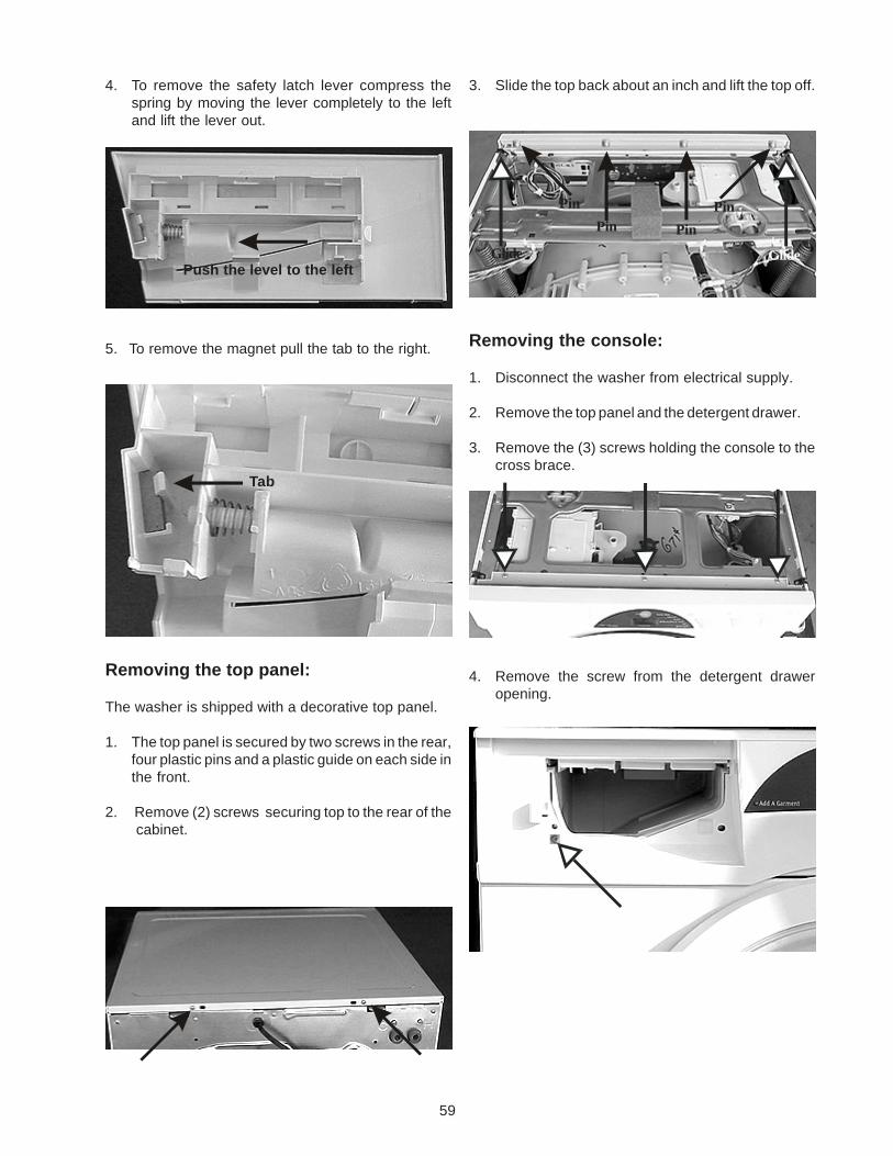
59
3. Slide the top back about an inch and lift the top off.
Removing the console:
1. Disconnect the washer from electrical supply.
2. Remove the top panel and the detergent drawer.
3. Remove the (3) screws holding the console to thecross brace.
4. Remove the screw from the detergent draweropening.
4. To remove the safety latch lever compress thespring by moving the lever completely to the leftand lift the lever out.
5. To remove the magnet pull the tab to the right.
Removing the top panel:
The washer is shipped with a decorative top panel.
1. The top panel is secured by two screws in the rear,four plastic pins and a plastic guide on each side inthe front.
2. Remove (2) screws securing top to the rear of the cabinet.
Push the level to the left
Tab
Pin
Glide Glide
Pin PinPin
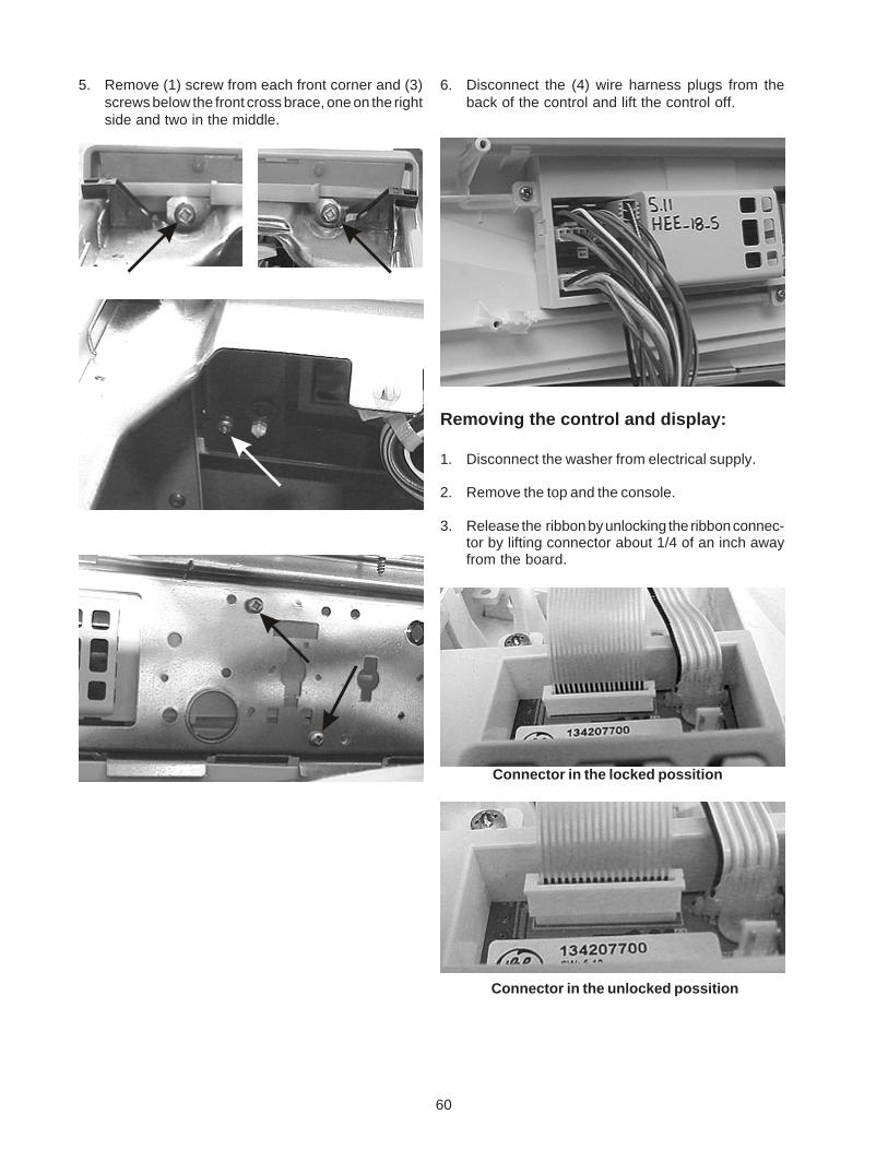
60
6. Disconnect the (4) wire harness plugs from theback of the control and lift the control off.
Removing the control and display:
1. Disconnect the washer from electrical supply.
2. Remove the top and the console.
3. Release the ribbon by unlocking the ribbon connec-tor by lifting connector about 1/4 of an inch awayfrom the board.
5. Remove (1) screw from each front corner and (3)screws below the front cross brace, one on the rightside and two in the middle.
Connector in the locked possition
Connector in the unlocked possition
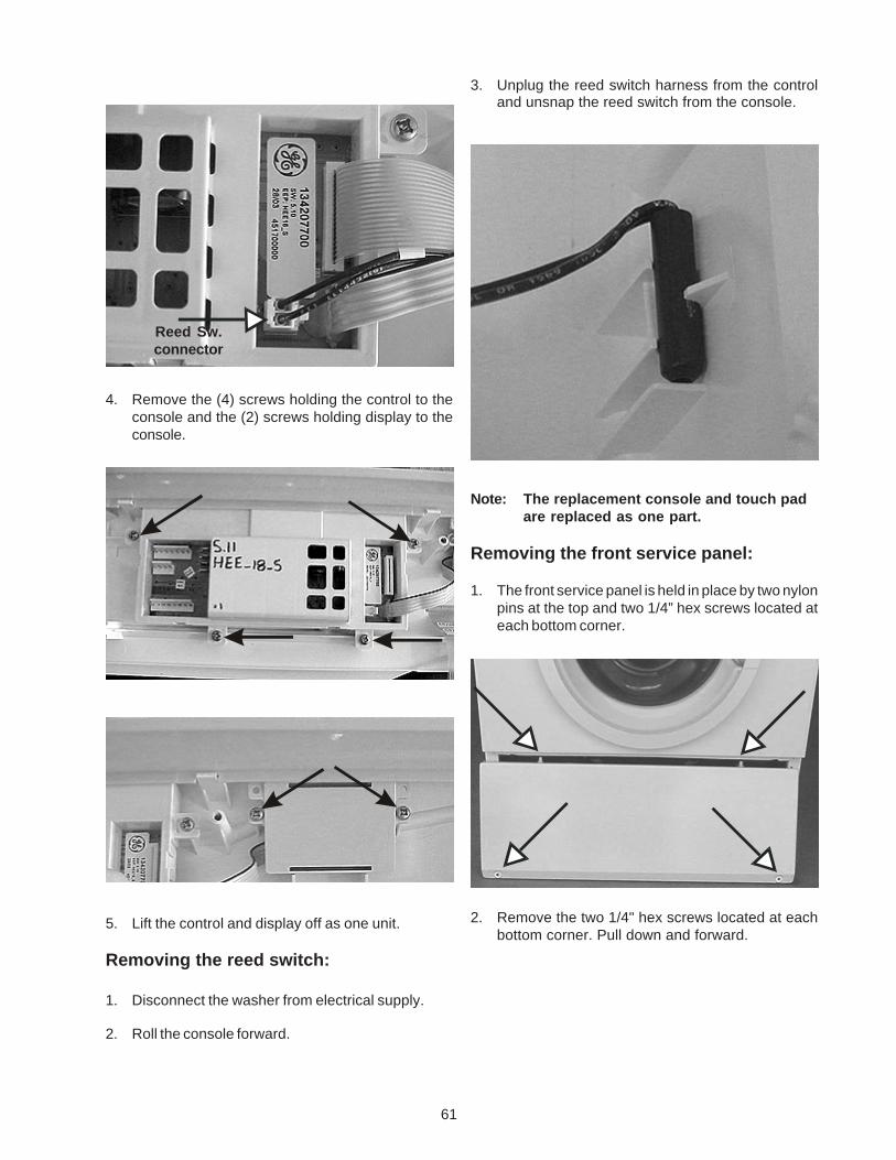
61
3. Unplug the reed switch harness from the controland unsnap the reed switch from the console.
Note: The replacement console and touch padare replaced as one part.
Removing the front service panel:
1. The front service panel is held in place by two nylonpins at the top and two 1/4” hex screws located ateach bottom corner.
2. Remove the two 1/4" hex screws located at eachbottom corner. Pull down and forward.
4. Remove the (4) screws holding the control to theconsole and the (2) screws holding display to theconsole.
5. Lift the control and display off as one unit.
Removing the reed switch:
1. Disconnect the washer from electrical supply.
2. Roll the console forward.
Reed Sw.connector
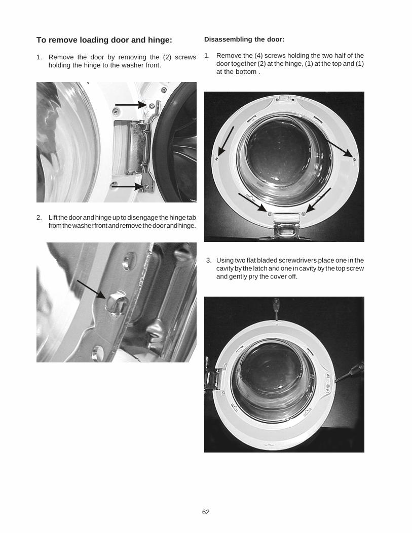
62
To remove loading door and hinge:
1. Remove the door by removing the (2) screwsholding the hinge to the washer front.
2. Lift the door and hinge up to disengage the hinge tabfrom the washer front and remove the door and hinge.
Disassembling the door:
1. Remove the (4) screws holding the two half of thedoor together (2) at the hinge, (1) at the top and (1)at the bottom .
3. Using two flat bladed screwdrivers place one in thecavity by the latch and one in cavity by the top screwand gently pry the cover off.
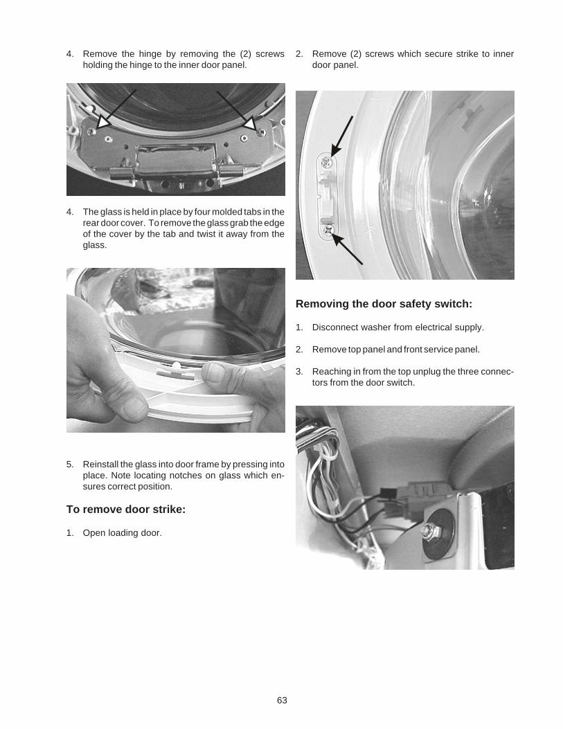
63
2. Remove (2) screws which secure strike to innerdoor panel.
Removing the door safety switch:
1. Disconnect washer from electrical supply.
2. Remove top panel and front service panel.
3. Reaching in from the top unplug the three connec-tors from the door switch.
4. Remove the hinge by removing the (2) screwsholding the hinge to the inner door panel.
4. The glass is held in place by four molded tabs in therear door cover. To remove the glass grab the edgeof the cover by the tab and twist it away from theglass.
5. Reinstall the glass into door frame by pressing intoplace. Note locating notches on glass which en-sures correct position.
To remove door strike:
1. Open loading door.
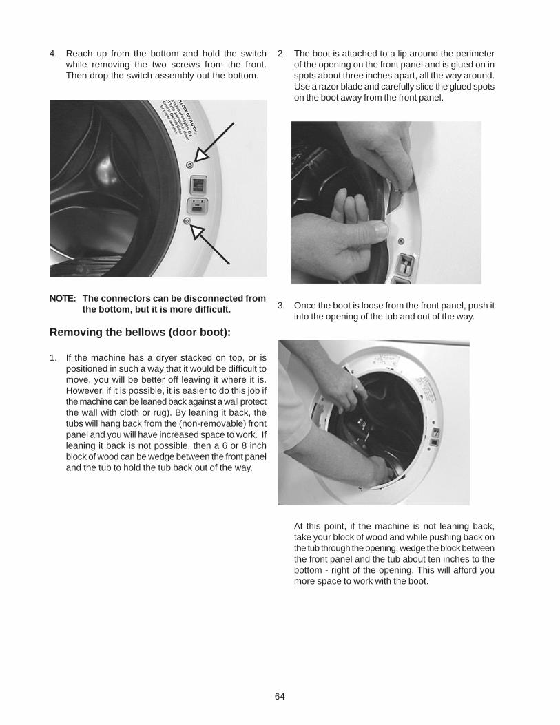
64
4. Reach up from the bottom and hold the switchwhile removing the two screws from the front.Then drop the switch assembly out the bottom.
NOTE: The connectors can be disconnected fromthe bottom, but it is more difficult.
Removing the bellows (door boot):
1. If the machine has a dryer stacked on top, or ispositioned in such a way that it would be difficult tomove, you will be better off leaving it where it is.However, if it is possible, it is easier to do this job ifthe machine can be leaned back against a wall protectthe wall with cloth or rug). By leaning it back, thetubs will hang back from the (non-removable) frontpanel and you will have increased space to work. Ifleaning it back is not possible, then a 6 or 8 inchblock of wood can be wedge between the front paneland the tub to hold the tub back out of the way.
2. The boot is attached to a lip around the perimeterof the opening on the front panel and is glued on inspots about three inches apart, all the way around.Use a razor blade and carefully slice the glued spotson the boot away from the front panel.
3. Once the boot is loose from the front panel, push itinto the opening of the tub and out of the way.
At this point, if the machine is not leaning back,take your block of wood and while pushing back onthe tub through the opening, wedge the block betweenthe front panel and the tub about ten inches to thebottom - right of the opening. This will afford youmore space to work with the boot.
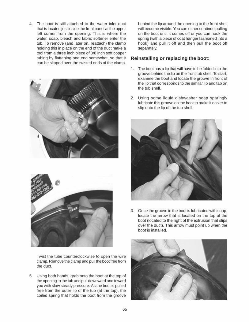
65
4. The boot is still attached to the water inlet ductthat is located just inside the front panel at the upperleft corner from the opening. This is where thewater, soap, bleach and fabric softener enter thetub. To remove (and later on, reattach) the clampholding this in place on the end of the duct make atool from a three inch piece of 3/8 inch soft coppertubing by flattening one end somewhat, so that itcan be slipped over the twisted ends of the clamp.
Twist the tube counterclockwise to open the wireclamp. Remove the clamp and pull the boot free fromthe duct.
5. Using both hands, grab onto the boot at the top ofthe opening to the tub and pull downward and towardyou with slow steady pressure. As the boot is pulledfree from the outer lip of the tub (at the top), thecoiled spring that holds the boot from the groove
behind the lip around the opening to the front shellwill become visible. You can either continue pullingon the boot until it comes off or you can hook thespring (with a piece of coat hanger fashioned into ahook) and pull it off and then pull the boot offseparately.
Reinstalling or replacing the boot:
1. The boot has a lip that will have to be folded into thegroove behind the lip on the front tub shell. To start,examine the boot and locate the groove in front ofthe lip that corresponds to the similar lip and tab onthe tub shell.
2. Using some liquid dishwasher soap sparinglylubricate this groove on the boot to make it easier toslip onto the lip of the tub shell.
3. Once the groove in the boot is lubricated with soap,locate the arrow that is located on the top of theboot (located to the right of the extrusion that slipsover the duct). This arrow must point up when theboot is installed.
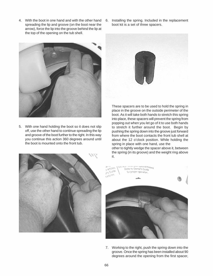
66
4. With the boot in one hand and with the other handspreading the lip and groove (on the boot near thearrow), force the lip into the groove behind the lip atthe top of the opening on the tub shell.
5. With one hand holding the boot so it does not slipoff, use the other hand to continue spreading the lipand groove of the boot further to the right. In this wayyou continue this action 360 degrees around untilthe boot is mounted onto the front tub.
6. Installing the spring. Included in the replacementboot kit is a set of three spacers.
These spacers are to be used to hold the spring inplace in the groove on the outside perimeter of theboot. As it will take both hands to stretch this springinto place, these spacers will prevent the spring frompopping out when you let go of it to use both handsto stretch it further around the boot. Begin bypushing the spring down into the groove just forwardfrom where the boot contacts the front tub shell atabout the 12 o’clock position. While holding thespring in place with one hand, use theother to tightly wedge the spacer above it, betweenthe spring (in its groove) and the weight ring aboveit.
7. Working to the right, push the spring down into thegroove. Once the spring has been installed about 90degrees around the opening from the first spacer,
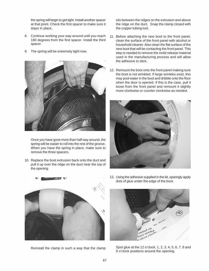
67
the spring will begin to get tight. Install another spacerat that point. Check the first spacer to make sure itstays in place.
8. Continue working your way around until you reach180 degrees from the first spacer. Install the thirdspacer.
9. The spring will be extremely tight now.
Once you have gone more than half way around, thespring will be easier to roll into the rest of the groove.When you have the spring in place, make sure toremove the three spacers.
10. Replace the boot extrusion back onto the duct andpull it up over the ridge on the duct near the top ofthe opening.
Reinstall the clamp in such a way that the clamp
sits between the ridges on the extrusion and abovethe ridge on the duct. Snap the clamp closed withthe copper tubing tool.
11. Before attaching the new boot to the front panel,clean the surface of the front panel with alcohol orhousehold cleaner. Also clean the flat surface of thenew boot that will be contacting the front panel. Thisstep is needed to remove the mold release materialused in the manufacturing process and will allowthe adhesive to stick.
12. Remount the boot onto the front panel making surethe boot is not wrinkled. If large wrinkles exist, thismay pool water in the boot and dribble onto the floorwhen the door is opened. If this is the case, pull itloose from the front panel and remount it slightlymore clockwise or counter clockwise as needed.
13. Using the adhesive supplied in the kit, sparingly applydots of glue under the edge of the boot.
Spot glue at the 12 o’clock, 1, 2, 3, 4, 5, 6, 7, 8 and9 o’clock positions around the opening.
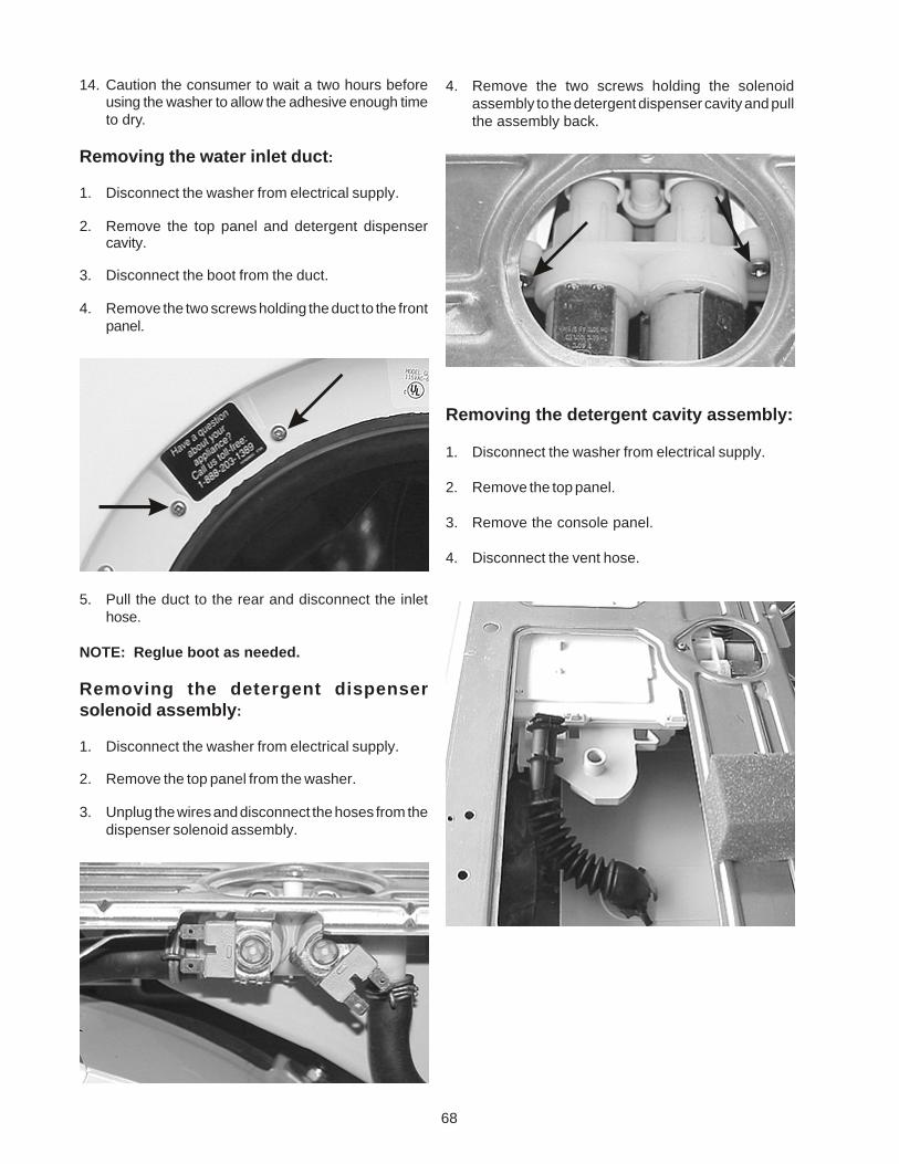
68
14. Caution the consumer to wait a two hours beforeusing the washer to allow the adhesive enough timeto dry.
Removing the water inlet duct:
1. Disconnect the washer from electrical supply.
2. Remove the top panel and detergent dispensercavity.
3. Disconnect the boot from the duct.
4. Remove the two screws holding the duct to the frontpanel.
5. Pull the duct to the rear and disconnect the inlethose.
NOTE: Reglue boot as needed.
Removing the detergent dispensersolenoid assembly:
1. Disconnect the washer from electrical supply.
2. Remove the top panel from the washer.
3. Unplug the wires and disconnect the hoses from thedispenser solenoid assembly.
4. Remove the two screws holding the solenoidassembly to the detergent dispenser cavity and pullthe assembly back.
Removing the detergent cavity assembly:
1. Disconnect the washer from electrical supply.
2. Remove the top panel.
3. Remove the console panel.
4. Disconnect the vent hose.
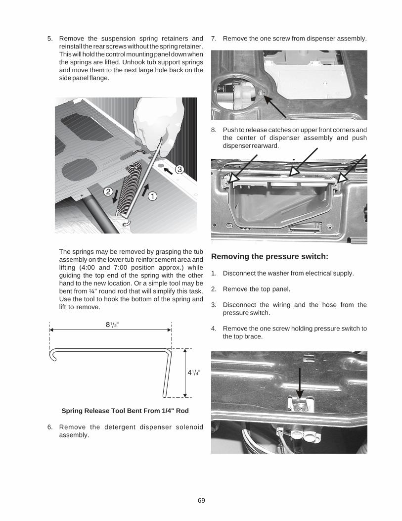
69
7. Remove the one screw from dispenser assembly.
8. Push to release catches on upper front corners andthe center of dispenser assembly and pushdispenser rearward.
Removing the pressure switch:
1. Disconnect the washer from electrical supply.
2. Remove the top panel.
3. Disconnect the wiring and the hose from thepressure switch.
4. Remove the one screw holding pressure switch tothe top brace.
5. Remove the suspension spring retainers andreinstall the rear screws without the spring retainer.This will hold the control mounting panel down whenthe springs are lifted. Unhook tub support springsand move them to the next large hole back on theside panel flange.
The springs may be removed by grasping the tubassembly on the lower tub reinforcement area andlifting (4:00 and 7:00 position approx.) whileguiding the top end of the spring with the otherhand to the new location. Or a simple tool may bebent from ¼" round rod that will simplify this task.Use the tool to hook the bottom of the spring andlift to remove.
Spring Release Tool Bent From 1/4" Rod
6. Remove the detergent dispenser solenoidassembly.
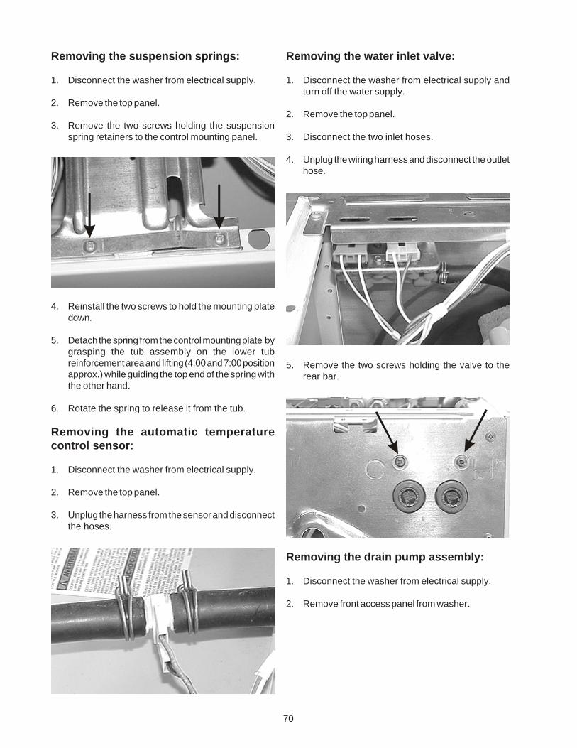
70
Removing the suspension springs:
1. Disconnect the washer from electrical supply.
2. Remove the top panel.
3. Remove the two screws holding the suspensionspring retainers to the control mounting panel.
4. Reinstall the two screws to hold the mounting platedown.
5. Detach the spring from the control mounting plate bygrasping the tub assembly on the lower tubreinforcement area and lifting (4:00 and 7:00 positionapprox.) while guiding the top end of the spring withthe other hand.
6. Rotate the spring to release it from the tub.
Removing the automatic temperaturecontrol sensor:
1. Disconnect the washer from electrical supply.
2. Remove the top panel.
3. Unplug the harness from the sensor and disconnectthe hoses.
Removing the water inlet valve:
1. Disconnect the washer from electrical supply andturn off the water supply.
2. Remove the top panel.
3. Disconnect the two inlet hoses.
4. Unplug the wiring harness and disconnect the outlethose.
5. Remove the two screws holding the valve to therear bar.
Removing the drain pump assembly:
1. Disconnect the washer from electrical supply.
2. Remove front access panel from washer.
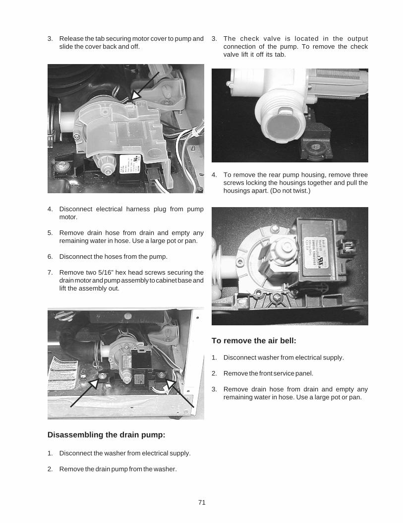
71
3. Release the tab securing motor cover to pump andslide the cover back and off.
4. Disconnect electrical harness plug from pumpmotor.
5. Remove drain hose from drain and empty anyremaining water in hose. Use a large pot or pan.
6. Disconnect the hoses from the pump.
7. Remove two 5/16” hex head screws securing thedrain motor and pump assembly to cabinet base andlift the assembly out.
Disassembling the drain pump:
1. Disconnect the washer from electrical supply.
2. Remove the drain pump from the washer.
3. The check valve is located in the outputconnection of the pump. To remove the checkvalve lift it off its tab.
4. To remove the rear pump housing, remove threescrews locking the housings together and pull thehousings apart. (Do not twist.)
To remove the air bell:
1. Disconnect washer from electrical supply.
2. Remove the front service panel.
3. Remove drain hose from drain and empty anyremaining water in hose. Use a large pot or pan.
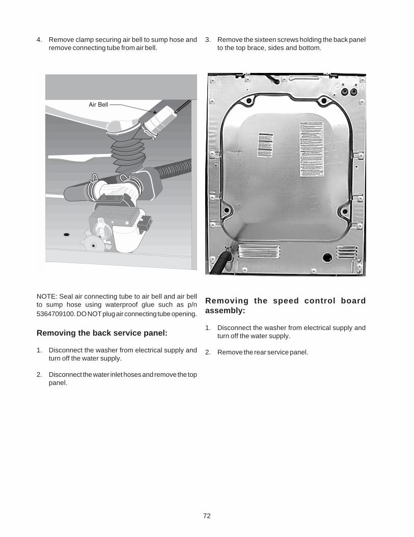
72
4. Remove clamp securing air bell to sump hose andremove connecting tube from air bell.
NOTE: Seal air connecting tube to air bell and air bellto sump hose using waterproof glue such as p/n5364709100. DO NOT plug air connecting tube opening.
Removing the back service panel:
1. Disconnect the washer from electrical supply andturn off the water supply.
2. Disconnect the water inlet hoses and remove the toppanel.
3. Remove the sixteen screws holding the back panelto the top brace, sides and bottom.
Removing the speed control boardassembly:
1. Disconnect the washer from electrical supply andturn off the water supply.
2. Remove the rear service panel.
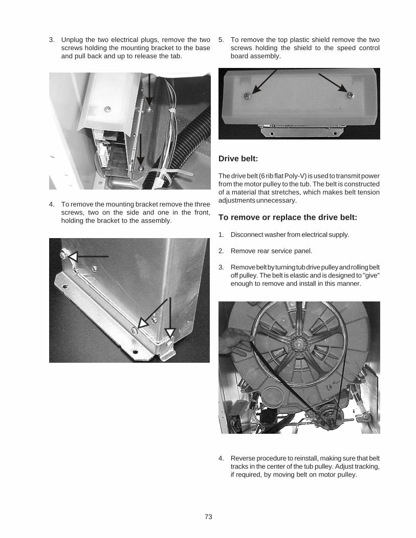
73
3. Unplug the two electrical plugs, remove the twoscrews holding the mounting bracket to the baseand pull back and up to release the tab.
4. To remove the mounting bracket remove the threescrews, two on the side and one in the front,holding the bracket to the assembly.
5. To remove the top plastic shield remove the twoscrews holding the shield to the speed controlboard assembly.
Drive belt:
The drive belt (6 rib flat Poly-V) is used to transmit powerfrom the motor pulley to the tub. The belt is constructedof a material that stretches, which makes belt tensionadjustments unnecessary.
To remove or replace the drive belt:
1. Disconnect washer from electrical supply.
2. Remove rear service panel.
3. Remove belt by turning tub drive pulley and rolling beltoff pulley. The belt is elastic and is designed to "give"enough to remove and install in this manner.
4. Reverse procedure to reinstall, making sure that belttracks in the center of the tub pulley. Adjust tracking,if required, by moving belt on motor pulley.
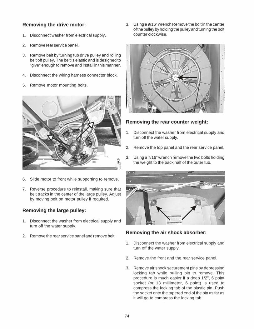
74
Removing the drive motor:
1. Disconnect washer from electrical supply.
2. Remove rear service panel.
3. Remove belt by turning tub drive pulley and rollingbelt off pulley. The belt is elastic and is designed to"give" enough to remove and install in this manner.
4. Disconnect the wiring harness connector block.
5. Remove motor mounting bolts.
6. Slide motor to front while supporting to remove.
7. Reverse procedure to reinstall, making sure thatbelt tracks in the center of the large pulley. Adjustby moving belt on motor pulley if required.
Removing the large pulley:
1. Disconnect the washer from electrical supply andturn off the water supply.
2. Remove the rear service panel and remove belt.
3. Using a 9/16” wrench Remove the bolt in the centerof the pulley by holding the pulley and turning the boltcounter clockwise.
Removing the rear counter weight:
1. Disconnect the washer from electrical supply andturn off the water supply.
2. Remove the top panel and the rear service panel.
3. Using a 7/16” wrench remove the two bolts holdingthe weight to the back half of the outer tub.
Removing the air shock absorber:
1. Disconnect the washer from electrical supply andturn off the water supply.
2. Remove the front and the rear service panel.
3. Remove air shock securement pins by depressinglocking tab while pulling pin to remove. Thisprocedure is much easier if a deep 1/2", 6 pointsocket (or 13 millimeter, 6 point) is used tocompress the locking tab of the plastic pin. Pushthe socket onto the tapered end of the pin as far asit will go to compress the locking tab.
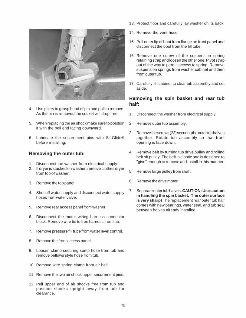
75
4. Use pliers to grasp head of pin and pull to remove.As the pin is removed the socket will drop free.
5. When replacing the air shock make sure to positionit with the bell end facing downward.
6. Lubricate the securement pins with Sil-Glide®before installing.
Removing the outer tub:
1. Disconnect the washer from electrical supply.2. If dryer is stacked on washer, remove clothes dryer
from top of washer.
3. Remove the top panel.
4. Shut off water supply and disconnect water supplyhoses from water valve.
5. Remove rear access panel from washer.
6. Disconnect the motor wiring harness connectorblock. Remove wire tie to free harness from tub.
7. Remove pressure fill tube from water level control.
8. Remove the front access panel.
9. Loosen clamp securing sump hose from tub andremove bellows style hose from tub.
10. Remove wire spring clamp from air bell.
11. Remove the two air shock upper securement pins.
12. Pull upper end of air shocks free from tub andposition shocks upright away from tub forclearance.
13. Protect floor and carefully lay washer on its back.
14. Remove the vent hose
15. Pull outer lip of boot from flange on front panel anddisconnect the boot from the fill tube.
16. Remove one screw of the suspension springretaining strap and loosen the other one. Pivot strapout of the way to permit access to spring. Removesuspension springs from washer cabinet and thenfrom outer tub.
17. Carefully lift cabinet to clear tub assembly and setaside.
Removing the spin basket and rear tubhalf:
1. Disconnect the washer from electrical supply.
2. Remove outer tub assembly.
3. Remove the screws (23) securing the outer tub halvestogether. Rotate tub assembly so that frontopening is face down.
4. Remove belt by turning tub drive pulley and rollingbelt off pulley. The belt is elastic and is designed to"give" enough to remove and install in this manner.
5. Remove large pulley from shaft.
6. Remove the drive motor.
7. Separate outer tub halves. CAUTION: Use cautionin handling the spin basket. The outer surfaceis very sharp! The replacement rear outer tub halfcomes with new bearings, water seal, and tub sealbetween halves already installed.
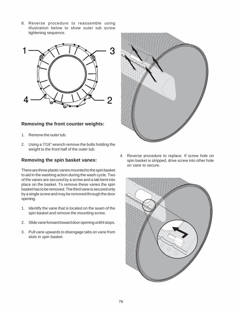
76
8. Reverse procedure to reassemble usingillustration below to show outer tub screwtightening sequence.
Removing the front counter weights:
1. Remove the outer tub.
2. Using a 7/16” wrench remove the bolts holding theweight to the front half of the outer tub.
Removing the spin basket vanes:
There are three plastic vanes mounted to the spin basketto aid in the washing action during the wash cycle. Twoof the vanes are secured by a screw and a tab bent intoplace on the basket. To remove these vanes the spinbasket has to be removed. The third vane is secured onlyby a single screw and may be removed through the dooropening.
1. Identify the vane that is located on the seam of thespin basket and remove the mounting screw.
2. Slide vane forward toward door opening until it stops.
3. Pull vane upwards to disengage tabs on vane fromslots in spin basket.
4. Reverse procedure to replace. If screw hole onspin basket is stripped, drive screw into other holeon vane to secure.

77
NOTES

78
NOTES

79
NOTES

80