maytag gemini™ -...
TRANSCRIPT
MaytagGemini™
RangeService Manual
16010107Issued 10/00

©2000 Maytag Appliances Sales Company16010107 Introduction i
INTRODUCTIONThe manual is printed in a loose format and is divided into sections relating to a generalgroup of components and/or service procedures. Each section is further subdivided todescribe a particular component or service procedure.
The subdividing of the subject matter, plus the loose leaf form, will facilitate the updating ofthe manual as new revised components are added or new models are introduced.
Each page of the manual will be identified in the lower, left and right-hand corners, and asnew or revised pages are published, the manual can easily be updated by following the filinginstructions on the cover letter of the supplement.
This service manual is a valuable tool and care should be taken to keep it up-to-date bypromptly and proper filing of subsequent pages as they are used.
MODELS COVERED IN THIS MANUAL:
MER6770AAWMER6770AABMER6770AAC

©2000 Maytag Appliances Sales Company16010107 Introduction ii

©2000 Maytag Appliances Sales Company16010107 Contents iii
CONTENTSINTRODUCTION............................................................................................................................... iCONTENTS ..................................................................................................................................... iii
SECTION 1. GENERAL INFORMATION .................................................................................... 1-1
SECTION 2. ELECTRICAL COMPONENTS & TESTING ........................................................... 2-1
SECTION 3. COMPONENT ACCESS ......................................................................................... 3-1EXPLODED VIEW ...................................................................................................................... 3-1MAIN TOP .................................................................................................................................. 3-2ELEMENTS ................................................................................................................................. 3-2
Ceran Element ...................................................................................................................... 3-2Bake Element ........................................................................................................................ 3-3Broil Element ........................................................................................................................ 3-3Oven Sensor ......................................................................................................................... 3-3Oven Cavity Components (Electric) ................................................................................... 3-4Convect Fan Motor and Blade (Electric) ............................................................................ 3-5
ELECTRONIC CLOCK AND OVEN CONTROL ......................................................................... 3-6INFINITE SWITCH (Current Sensing) ....................................................................................... 3-6
Signal Lights ......................................................................................................................... 3-7"Hot Surface" Light ............................................................................................................... 3-7Oven Light Replacement ..................................................................................................... 3-7
HI-LIMIT THERMOSTAT............................................................................................................ 3-8OVEN DOOR(S) ......................................................................................................................... 3-8UPPER DOOR ............................................................................................................................ 3-9LOWER DOOR ......................................................................................................................... 3-10
Lower Latch Assembly ...................................................................................................... 3-10LOWER LATCH ASSEMBLY .................................................................................................... 3-11
Oven Door Hinge ............................................................................................................... 3-11LEVELING LEGS ....................................................................................................................... 3-12CONVENIENCE OUTLET (Canadian Models Only) ............................................................... 3-12SPECIFICATIONS ..................................................................................................................... 3-12OVEN RACKS .......................................................................................................................... 3-12RACK POSITIONS ................................................................................................................... 3-13HALF RACK ACCESSORY ...................................................................................................... 3-13
SECTION 4. ELECTRICAL ........................................................................................................... 4-1TOASTING CIRCUIT (Upper Oven Only) ................................................................................. 4-1OVEN CIRCUITS ........................................................................................................................ 4-1SURFACE ELEMENTS - CERAN ............................................................................................... 4-2DUEL ELEMENT ......................................................................................................................... 4-2PROBE, SENSOR / BOTH OVENS ............................................................................................ 4-2HOT SURFACE LIGHTS ............................................................................................................. 4-3SURFACE INICATOR LIGHTS.................................................................................................... 4-3TRANSFORMER, STEPDOWN (12V) ....................................................................................... 4-4

©2000 Maytag Appliances Sales Company16010107 Contents iv
SURFACE ELEMENT SWITCH .................................................................................................. 4-4DUAL ELEMENT SWITCH ......................................................................................................... 4-4ELECTRICAL CONNECTIONS/VOLTAGE ................................................................................. 4-5
SECTION 5. TROUBLESHOOTING ............................................................................................ 5-1GEMINI DOUBLE OVEN CONTROLS ....................................................................................... 5-1FAULT CODES ........................................................................................................................... 5-2RELAY BOARD .......................................................................................................................... 5-3TROUBLESHOOTING GUIDE.................................................................................................... 5-4PARTS LIST ................................................................................................................................ 5-6FAULT IDENTIFICATIONS SUMMARY..................................................................................... 5-7
SECTION 6. WIRING DIAGRAMS.............................................................................................. 6-1

©2000 Maytag Appliances Sales Company16010107 Section 1. General Information 1-1
SECTION 1. GENERAL INFORMATION
Bake: There will be two separate bake keys,one for each oven. When the upper oven ischosen there will be a rapid preheatactivated which turns both elements on. Ifthe lower oven is selected the elements willcycle at the normal rate. The normal ratesfor the bake functions in both ovens are: 6seconds for the broil element, followed by 54seconds for the bake element.
Broil: There will be two separate broil keys,one for each oven. The HI broil functioncontrols the broil element at 100%, the LObroil is controlled at 80% on time of a 60second duty cycle. HI broil will bemaintained to reach a maximumtemperature of 550ºF, LO boil will bemaintained at a maximum of 450ºF.
Toasting: Available in upper oven only.Toasting has a maximum allowable time of10 minutes and maximum temperature of550ºF. Toasting is only available when thelower oven is not in use. If chosen duringlower oven operation the display will scrollan information message regarding use.
Keep Warm: The keep warm functioncontrols only the bake element and isavailable in the upper oven only. Allowabletemperature range is 145 to 190ºF.
Clean: Only one oven is permitted to becleaned at a time. Both ovens will lockduring clean cycle. The clean cycle controlsboth the broil and the bake element, the broilelement is on 100% for the first 40 minutesof the cycle followed by the bake element on100% for the duration of the cycle. The bakeelement is cycled once the cleantemperature of 865º is reached.
Motorized Door Lock: A 3 RPM motor isused on the door lock assemblies, with eachassembly having a locked and unlockedswitch. The motor will only run when aclean cycle is chosen and the door actuatedswitch is in the closed position.

©2000 Maytag Appliances Sales Company16010107 Section 1. General Information 1-2

©2000 Maytag Appliances Sales Company16010107 Section 2. Electrical Components & Testing 2-1
SECTION 2. ELECTRICAL COMPONENTS & TESTING
ELECTRICAL TEST EQUIPMENT
The equipment required to service Maytagproducts depends largely upon the conditionyou encounter. Locating a malfunction willoften require the use of electrical testingequipment such as:
Analog Test Metercan be used to check foropen or closed circuits,measure resistance, ACand DC volts, and tem-perature.
Clamp-On Ammetercan be used to detectshorts. Over-loads on thecircuit breakeror fuse can betraced to eitherthe dryer or circuitbreaker by check-ing the dryercurrent draw.
Description Part Number
Analog Test Meter 20000005
Digital Watt/Amp/Volt/Ohm/Temperature Meter 20000019
Clamp-On Ammeter 20000002
AC Voltage Sensor 20000081
AC Voltage Sensorcan be used to alert you
if AC voltage is present soproper safety precautions can
be observed. The tip of the sensorwill glow bright red, if voltage is be-tween 110-600 volts AC.
Digital Watt/Amp/Volt/Ohm/TemperatureMeterMeasures power (wattage), AC/DC volts, AC/DC amps, temperature (C & F) OHMS resis-tance, continuity and capacitance. Featureslarge LCD display w/backlight and analogbar graph to show tendencies. Includes: ACpower adaptor for measuring wattage andmeter leads.

©2000 Maytag Appliances Sales Company16010107 Section 2. Electrical Components & Testing 2-2

©2000 Maytag Appliances Sales Company16010107 Section 3. Component Description 3-1
SECTION 3. COMPONENT ACCESS
EXPLODED VIEW

©2000 Maytag Appliances Sales Company16010107 Section 3. Component Description 3-2
As a general rule, the appliance shouldALWAYS be disconnected from powersource before servicing appliance orreplacing component parts. Failure todisconnect the power increases thelikelihood that a servicing error or mistakewill result in serious or fatal injuries.
MAIN TOP
To Raise Ceran Cooktop
When cool open the door and remove thetwo screws securing the cook top to theframe. Once the screws are removed raisecook top and slide forward slightly. With thecook top forward disconnect the wireharness and remove the cooktop.
ELEMENTS
Ceran Element Cooktop
Cooking areas are identified by patterns inthe Ceran surface. The elements consist ofcoil(s) contained in the element housing.Power to the element (240 volts) is providedand controlled by an infinite switch. Eachheating element is equipped with atemperature limiter, which prevents heatsurges and ensures that the heatingelements will not overheat. The element andtemperature limiter is available as acomplete unit or individual parts.
When a cooking area is turned ON, the coilelement under the cook top will heat up andglow. The element will cycle on and off tomaintain the heat setting. When the elementcycles on, it is normal to see a red glowthrough the smooth top.
Note: It is normal for the element to cyclewhen set on the high setting.
To Remove Element:
1. Disconnect the appliance from powersource before servicing.
2. Remove the two screws securing themain top to the frame.
3. Lift up slightly and slide the main topforward to access the wire harness.Disconnect the harness.
4. Lift the top off and lay aside securely withunder side up.
5. Remove the screws securing element tomain top.
6. Disconnect wiring to element andreplace element.
7. Reverse procedure to reinstall.
To Remove Glass Top Assembly
1. Disconnect the appliance from powersource before servicing.
2. Remove two (2) screws securing glasstop to frame. The screws are located inthe front left and right corners with thedoor open.
3. Grasp front edge of cooktop and slide outslightly. With the top moved forwarddisconnect the wiring harness.
4. Lift the top off the unit and lay asidesecurely.
5. Reverse the procedure to reinstall.
Ceran Element
• Left front and right rear element wattage:208/240 volts @ 900/1200 watts.Approximately 48Ω.
• Left rear element wattage: 208/240 volts@ 1580/2200 watts. Approximately 27Ω.
• Dual element wattage: 208/240 volts @1580/2200 watts. Approximately 27Ω forthe outer element. 208/240 volts @ 580/750 watts. Approximately 73Ω for theinner element.

©2000 Maytag Appliances Sales Company16010107 Section 3. Component Description 3-3
Bake Element
Element Wattage: 208/240 volts @ 2250/3000watts. Approximately 19Ω
The bake function controls the Bake andBroil heating elements. During a Bake cycle,the Broil element will be on 6 seconds of a60-second duty cycle, and then the Bakeelement will be on the remaining 54seconds. The Bake and Broil elements willbe staged with the exception of the rapidpreheat. In the rapid preheat, available whenthe upper oven is used alone, the bake andbroil elements will be on at 100% untiltemperature is reached. Once temperatureis reached, the elements will cycle asoutlined above.
Note: The Bake element will be the firstelement to turn on at the beginning of anyconventional bake cycle.
To Access Bake Element:
1. Disconnect the appliance from powersource before servicing.
2. Remove lift off door for moreaccessibility.
3. Remove four (4) screws securing bakeelement to back of oven cavity.
4. Gently pull element through cavity walluntil terminals can be accessed.
5. Disconnect wiring.
6. Remove/replace element as necessary.
7. Reverse procedure to reinstall.
Broil Element
The broil function controls only the broilelement. The bake element is inactiveduring a broil cycle. During a broil cycle, thecontrol will monitor the oven temperatureand cycle the broil element on and off toobtain the selected temperature.
To Access Broil Element:
1. Disconnect the appliance from powersource before servicing.
2. Remove lift off door for moreaccessibility.
3. Remove broil support brackets (2) andremove screws securing broil element toback oven.
4. Gently pull element through cavity walluntil terminals can be accessed.
5. Disconnect wiring.
6. Remove/Replace element as necessary.
7. Reverse procedure to reinstall.
Oven Sensor
The oven sensor is located inside the ovencavity, attached to the rear wall of the cavity.As the oven temperature increases, theresistance of the oven sensor increases. Theresistance is measured by the electroniccontrol to determine the oven temperature.
To Access Oven Sensor:
1. Disconnect the appliance from powersource before servicing.
2. Open oven door and remove two (2)screws securing sensor to oven cavity.Gently pull through cavity wall.
3. Disconnect the oven sensor at theconnector blocks and remove/replace asnecessary.
4. Reattach the connector blocks andreassemble.

©2000 Maytag Appliances Sales Company16010107 Section 3. Component Description 3-4
Also shown here are the screws that secure thebake and broil elements.
Oven Cavity Components (Electric)
Open or remove the oven door. Thefollowing components are accessible:
• Racks• Oven Sensor• Broil Element• Convect Fan Cover• Bake Element
Convection Fan (Electric)
Remove six screws (as shown) from theperimeter of the convection fan cover. Thiswill loosen the cover, but it cannot beremoved easily without positioning it toclear the rack guides. Care should be usedwhen moving parts and tools around insidethe oven cavity to avoid marring or chippingthe procelain surfaces.
Three screws (shown) secure the convectionfan mounting plate, remove these, to allowaccess to the motor and connectors.
Bake Element
ConvectFanCover
ConvectFan
Sensor Broil Element
Screws
Screws
Screws
Screws

©2000 Maytag Appliances Sales Company16010107 Section 3. Component Description 3-5
After the convect fan mounting plate isremoved, motor connectors, motor, motormount and insulation is accessible. Motorconnectors are also exposed by removingthe back panel (see range back removal).
The convect fan blade is attached to themotor’s “D” shaft using a hex set screw.The fan blade must be loosened and taken offthe motor shaft before the motor can beremoved. The motor mounting screws arefound on the front side of the convect fanassembly. When reassembling, be sure toreinstall the small piece of insulation under themotor mount. The insulation provides sounddampening and prevents heat loss. Whenreinstalling the convect fan blade, be sure thatthe blade has adequate clearance at all pointsaround the mounting plate. The blade should“stand off” approximately 1/8” with very littleapparent warping.
Note: When reinstalling the convect assembly, be sure tocheck that no loose insulation is visible in the fan areaor anywhere in the oven cavity.
Convect Fan Motor and Blade (Electric)
Motor Connectors
Motor Mount
Motor
Insulation
Mounting Screws
Hex Head Set Screw

©2000 Maytag Appliances Sales Company16010107 Section 3. Component Description 3-6
ELECTRONIC CLOCK AND OVENCONTROL
To Gain Access To Electronic Oven Control
1. Disconnect theappliance frompower sourcebefore servicing.
2. Remove two screwssecuring backguardpanel to the end caps.
3. Remove two (2) screws securingbackguard panel to backguard housing.(Screws located between control paneland main top).
4. Lift backguard panel up, tilt forward, andlay panel on protected surface of maintop for servicing.
5. Remove two (2) screws securing control-mounting plate to backguard.
6. Remove four (4) screws securing controlto control mounting plate.
7. Disconnect wiring and remove/replacecontrol.
8. Reverse procedure to replace.
INFINITE SWITCH (Current Sensing)
This unit is equipped with controls thatprovide an infinite choice of settings fromLOW to HIGH. The control can be set on anyof the numbered settings. To operate, pushin and turn control knob to the desiredsetting.
Note: The infinite switch is a currentsensing switch.
The infinite switch is a rotary switch, whichcontrols the power dissipated by a heatingelement. A heater-bimetal opens and closesthe cycling contacts, which applies and
removes voltage from the heating element.Control is attained by regulating the ratio ofthe time between the opening and closing ofthe contacts. This is usually referred to asinput percentage and is controlled by a cam,which can provide virtually any infinitelyadjustable performance. This performanceis assured when the switch is subjected toelevated ambient temperatures throughautomatic temperature compensation.
The infinite switch stems are color coded foridentification. The silver colored stemcontrols the left front and right rear element,the silver colored stem with a red dotcontrols the left rear, and the brass coloredstem controls the right front element.Amperage is rated at 3-15.5A range +/- 10%.
Note: When replacing the infinite switch,the switch must be matched to the element.
To Access Control:
1. Disconnect the appliance from powersource before servicing.
2. Remove control knobs.
3. Remove two screws from backguardpanel securing panel to housing.
4. Remove two screws securing backguardpanel to end cap.
5. Lift backguard panel up, tilt forward, andlay panel on protected surface on maintop for servicing.
6. Remove two (2) mounting screwssecuring infinite switch to backguardpanel.
7. Disconnect wiring and remove/replacecontrol.
8. Reverse procedure to replace.

©2000 Maytag Appliances Sales Company16010107 Section 3. Component Description 3-7
Signal Lights
Range is equipped with two signal lights toindicate when a surface element is on. Thelight will remain on until the element isturned off. After a cooking operation, besure element and signal light is off.
The signal lights are located on thebackguard panel and may be accessed fromthe backside of the panel when removed.The red indicator lens pop in and out, andthe light slides into a lock position. Reversethe procedure to remove.
“Hot Surface” Light
The Gemini Range is equipped with a HotSurface Light. This red light will turn on toindicate that the cooking area is hot and willremain on until the area has cooled.
The switch is located in the front center ofthe burner box, and may be accessed byremoving the main top.
To Access Hot Surface Light:
1. Disconnect the appliance from powersource before servicing.
2. Open oven door and remove the screwssecuring the main top to the frame.
3. Slide the top forward and disconnect thewire harness.
4. Lift the top off and lay on a protectedsurface with under side up.
5. Release the tabs securing the switch tothe top. Once the tabs are released theswitch can be removed.
6. Reverse procedure to replace.
Oven Light Replacement
The oven light used on the Gemini is a 12volt 10 Watt Halogen bulb. The lightautomatically comes on when the door isopened or activation may occur via the lightpad when the door is closed. The light willnot operate during a clean cycle. The ovenlight will automatically come on one minutebefore the end of a clock controlled cookingoperation.
To Replace Oven Light Bulb:
1. Disconnect power to the range.
2. Open oven door and locate oven light.
3. Remove the lens cover to gain access tobulb.
4. Carefully remove the old bulb by pullingstraight out of ceramic base.
NOTE: To avoid damaging the bulb anddecreasing the life of the bulb, do not touchthe bulb with bare hands or fingers. Holdwith a cloth or paper towel.
5. Push new bulb prongs straight into smallholes of ceramic base.
6. Replace bulb cover by snapping intoplace.
7. Reconnect power to range and resetclock.
Bulb specificationsG4 Type Halogen Bi-Pin 10 w -12V

©2000 Maytag Appliances Sales Company16010107 Section 3. Component Description 3-8
HI-LIMIT THERMOSTAT
The HI-Limit Thermostat is mounted torange main back. The purpose of thisthermostat is to break line voltage to ovencontrol in case of a runaway temperature.Range may be removed from cabinetry forrear serviceability.
Thermostat Replacement
1. Disconnect the appliance from powersource before servicing.
2. Slide unit out of installation.
3. Remove screws securing main backshield and remove shield.
4. Remove two (2) screws securingthermostat to range main back.
5. Disconnect wiring.
6. Replace in reverse order.
OVEN DOOR(S)
Do not place excessive weight on an openoven door or stand on an opened door as, insome cases, it could cause the range to tipover, breakage of the door, or serious injury.
Both the upper and lower oven doors areremovable.
To Remove Lift-Off Door:
Open door to stop position. In stop positiondoor is open approximately 4”. Grasp dooras illustrated. Lift up evenly until door clearsthe hinge arms.
DO NOT USE DOOR HANDLE TO LIFTDOOR.
To Replace:
1. Grasp door at each side.
2. Align slots in the door with the hingearms on the range.
3. Slide the door down onto the hingearms until the door is completely
Contacts normally closedClose Temperature - 250 ± 11ºFOpen Temperature - 300 ± 8ºF
CAUTIONS:
• Do not attempt to open or close dooror operate oven until door is properlyreplaced.
• Hinge arms are spring mounted andwill slam shut if accidentally hit.Never place hand or fingers betweenthe hinges and the front oven frame.You could be injured if hinge snapsback.

©2000 Maytag Appliances Sales Company16010107 Section 3. Component Description 3-9
seated on the hinges. Push down onthe top corners of the door tocompletely seat door on hinges. Doorshould not appear crooked.
NOTE: The oven door on a new rangemay feel “spongy” when it is closed.This is normal and will decrease withuse.
To Disassemble Door:
1. Open door to the stop position and liftdoor off hinges. Remove door and layon protected surface, liner side up.
2. Remove three (3) screws securing thedoorframe to the liner at the bottom.
3. Remove two (2) side screws securingdoorframe to door liner.
4. Remove four (4) screws securing thedoor trim at the top.
5. Slide the doorframe and glass off linerfrom the bottom.
6. Remove four (4) screws securing thedoor handle to the door liner. (Two onthe sides and two in front).
7. Remove two (2) screws securing doorbaffle to liner.
8. Remove four (4) screws securing doorbaffle to window pack. Remove baffle.
9. Remove insulation wrap.
10. Remove four (4) screws securing windowpack to liner. Window pack comes out asan assembly.
11. Door gasket can be replaced withoutdoor being disassembled by pullinggasket out of bottom insert of door. Thegasket is secured with clips inserted intodoor liner.
UPPER DOOR

©2000 Maytag Appliances Sales Company16010107 Section 3. Component Description 3-10
LOWER DOOR
To Replace Lock Assembly
1. Disconnect the appliance from powersource before servicing.
2. Open oven door or remove forconvenience.
3. Remove main top and slide forward.Disconnect wire harness. (See TopRemoval).
4. Lift top off and lay aside securely.
5. Remove two (2) screws securing lockassembly to oven frame in front.
6. Disconnect wiring.
7. Remove two (2) screws securing lockassembly to frame.
8. Slide assembly out.
9. Reverse procedure to reinstall.
Lower Latch Assembly
1. Disconnect the appliance from powersource before servicing.
2. Remove main top assembly as describedpreviously and lay aside securely.

©2000 Maytag Appliances Sales Company16010107 Section 3. Component Description 3-11
3. Remove main top and slide forward.Disconnect wire harness. (See TopRemoval).
LOWER LATCH ASSEMBLY
1. Disconnect the appliance from powersource before servicing.
2. Remove main top as outlinedin main top removal.
3. Remove the screwssecuring the sidepanel at the top andback of frame.
4. Remove the screwssecuring the rearpanel to frame. Remove rear panel.
5. Slide side panel away from the frame atrear and lift out of the slots in front.Remove side panel.
6. Release the bands, securing theinsulation wrap, at the bottom.
7. Slide the insulation wrap back.
Note: This will aid in guiding the latchassembly in and out.
8. Disconnect the wiring from the lockswitches at the rear.
9. Slide the latch assembly out from therear.
To reinstall:
1. Slide latch assembly in from the rear.
2. Guide assembly to front using the sideaccess.
3. Make sure the screw holes of theassembly line up with the screw holes inthe frame.
4. Reinsert the screws.
Note: Make sure the insulation is back inplace when finished. Failure to do so willresult in hot spots and poor bakingcomplaints.
5. Reattach band to the bottom of frame.
6. Reconnect wiring to the lock switches.
7. Reinstall the side panel.
8. Reinstall the rear panel.
9. Reinstall the main top.
Oven Door Hinge
The unit will have to be pulled away from thecabinetry to remove/replace door hinges.
To Access/Replace Oven Door Hinges:
1. Disconnect the appliance from powersource before servicing.
2. Remove main top assembly as describedpreviously and lay aside securely.
3. Remove oven door assembly aspreviously described and lay asidesecurely.
4. Remove the screws securing side panelat the top and back of frame.
5. Remove the screws securing the rearpanel to frame.
6. Slide the side panel away from the frameat rear and lift out of the slots in thefront. Remove panel.
7. Remove two (2) screws securing hinge tofront frame flange.
8. Complete hinge assembly may beremoved.
9. Reverse procedure to reinstall.
©2000 Maytag Appliances Sales Company16010107 Section 3. Component Description 3-12
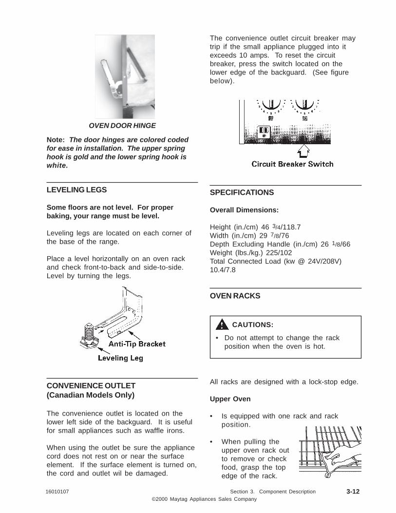
Note: The door hinges are colored codedfor ease in installation. The upper springhook is gold and the lower spring hook iswhite.
LEVELING LEGS
Some floors are not level. For properbaking, your range must be level.
Leveling legs are located on each corner ofthe base of the range.
Place a level horizontally on an oven rackand check front-to-back and side-to-side.Level by turning the legs.
CONVENIENCE OUTLET(Canadian Models Only)
The convenience outlet is located on thelower left side of the backguard. It is usefulfor small appliances such as waffle irons.
When using the outlet be sure the appliancecord does not rest on or near the surfaceelement. If the surface element is turned on,the cord and outlet wil be damaged.
OVEN DOOR HINGE
The convenience outlet circuit breaker maytrip if the small appliance plugged into itexceeds 10 amps. To reset the circuitbreaker, press the switch located on thelower edge of the backguard. (See figurebelow).
SPECIFICATIONS
Overall Dimensions:
Height (in./cm) 46 3/4/118.7Width (in./cm) 29 7/8/76Depth Excluding Handle (in./cm) 26 1/8/66Weight (lbs./kg.) 225/102Total Connected Load (kw @ 24V/208V)10.4/7.8
OVEN RACKS
All racks are designed with a lock-stop edge.
Upper Oven
• Is equipped with one rack and rackposition.
• When pulling theupper oven rack outto remove or checkfood, grasp the topedge of the rack.
CAUTIONS:
• Do not attempt to change the rackposition when the oven is hot.

©2000 Maytag Appliances Sales Company16010107 Section 3. Component Description 3-13
Lower Oven
• Is equipped with two RollerGlide™ racks.
To remove oven racks:
• Pull rack straight out until it stops at thelock-stop position; lift up on the front ofthe rack and pull out.
• For lower oven racks, pull both the rackglide and rack base out together.
To replace oven racks:
• Place rack on the rack support in theoven; tilt the front end up slightly; sliderack back until it clears the lockstopposition; lower front and slide back intothe oven.
RACK POSITIONS
Rack 4: Use for two-rack baking.
Rack 3: Use for most baked goods on acookie sheet or jelly roll pan, layercakes, fruit pies, or frozenconvenience foods, and for mostbroiling.
Rack 2: Use for roasting small cuts of meat,casseroles, baking loaves of bread,bundt cakes or custard pies, andtwo-rack baking.
Rack 1: Use for roasting large cuts of meatand poultry, frozen pies, dessertsouffles or angel food cake, andtwo-rack baking.
Multiple Rack Cooking:
Two Rack: Use rack position 2 and 4, or 1and 4.
HALF RACK ACCESSORY
A half rack, to increase oven capacity, isavailable as an accessory. It fits in the left,upper portion of the oven and providesspace for a vegetable dish when a largeroaster is on the lower rack. Contact yourMaytag dealer for the "HALFRACK"Accessory Kit or call 1-800-688-8408.

©2000 Maytag Appliances Sales Company16010107 Section 3. Component Description 3-14
NOTES
©2000 Maytag Appliances Sales Company16010107 Section 4. Electrical 4-1
SECTION 4. ELECTRICAL
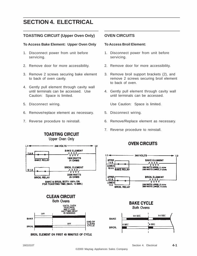
TOASTING CIRCUIT (Upper Oven Only)
To Access Bake Element: Upper Oven Only
1. Disconnect power from unit beforeservicing.
2. Remove door for more accessibility.
3. Remove 2 screws securing bake elementto back of oven cavity.
4. Gently pull element through cavity walluntil terminals can be accessed. UseCaution: Space is limited.
5. Disconnect wiring.
6. Remove/replace element as necessary.
7. Reverse procedure to reinstall.
OVEN CIRCUITS
To Access Broil Element:
1. Disconnect power from unit beforeservicing.
2. Remove door for more accessibility.
3. Remove broil support brackets (2), andremove 2 screws securing broil elementto back of oven.
4. Gently pull element through cavity walluntil terminals can be accessed.
Use Caution: Space is limited.
5. Disconnect wiring.
6. Remove/Replace element as necessary.
7. Reverse procedure to reinstall.

©2000 Maytag Appliances Sales Company16010107 Section 4. Electrical 4-2
SURFACE ELEMENTS - CERAN
Verify there is proper voltage applied to theoven (the range may have blown a fuse orcircuit breaker). A quick check is to see if theother elements heat. If not, check thevoltage at the electrical outlet and check tosee that the power cord is wired correctly.
To Check Surface Element:
1. Disconnect unit from power source
2. Remove main top by removing screwssecuring top to burner box and lay asidesecurely.
3. Visually check the element for evidenceof damage or shorting. Then check theelement for continuity with an ohmmeterconnected to the element terminals.With ohmmeter set at RX1, resistancewill normally be below 28 ohms, largeand 48 ohms, small. If the elementshows no continuity or extremely highresistance, it should be replaced.
4. With power to the unit disconnected, setthe control switch for this element on thehigh setting. With a voltmeter set on 250or 300 volt scale, re-apply power andcheck for voltage at the surface elementterminal block, then check the surfaceelement.
Each heating element is equipped with atemperature limiter which prevents heatsurges and ensures that the heatingelements will not overheat.
The "Hot Surface" light will come onindicating when ceran surface is 150ºF ±50ºF. The Hi-Limit which shuts burner off at1050ºF ± 60ºF.
ELECTRICAL RATINGS: 240VAC 2200W TOTAL750W INNER RING1450 OUTER RING
COLD RESISTANCE: 74.6 Ohms (INNER)±538.6 Ohms (OUTER)±5
LIMITER TYPE:ELECTRICAL RATINGS OF LIMITER CONTACTS
LIMITER CIRCUIT 10 AMP AT 250 VACLIMITER CIRCUIT 7.0 AMPA T 380 VACHOT LIGHT CIRUCIT 1.0 AMP AT 380 VAC
DUEL ELEMENT
The cooking surface is equipped with a dualelement located in the right front position.To operate, push in on the controlknob andturn to the left to control the large element,or push in and turn to the right to control thesmall element.
PROBE, SENSOR / BOTH OVENS
Oven Sensor
The oven sensor is located inside the ovencavity, attached to the rear wall of the cavity.As the oven temperature increases, theresistance of the oven sensor increases. Theresistance is measured by the electroniccontrol to determine the oven temperature.

©2000 Maytag Appliances Sales Company16010107 Section 4. Electrical 4-3
TEM PERATURE RESISTANCE
100 Degrees F 1143 Ohm s
200 Degrees F 1350 Ohm s
300 Degrees F 1553 Ohm s
350 Degrees F 1654 Ohm s
400 Degrees F 1753 Ohms
500 Degrees F 1949 Ohm s
600 Degrees F 2142 Ohm s
700 Degrees F 2331 Ohm s
800 Degrees F 2516 Ohm s
900 Degrees F 2697 Ohm s
1000 Degrees F 2874 Ohm s
HOT SURFACE LIGHTS
Each element has a HOT SURFACE indicatorlight. A light will be illuminated when thematching cooking area is hot. It will remainon, even after the control is turned off, untilthe area has cooled. They are located at thefront center of the cooktop.
SURFACE INDICATOR LIGHTS
There is an indicator light by each pair ofcontrol knobs. When one or both of thesurface control knobs is turned on, the lightwill turn on. The light will turn off when thesurface element(s) is turned off.
To check oven sensor:
1. Access sensor wires as outlined undersensor removal.
2. Set meter to RX1000 Scale.
3. Check for the following:

©2000 Maytag Appliances Sales Company16010107 Section 4. Electrical 4-4
TRANSFORMER, STEPDOWN (12V)
Electrical Ratings:Input Voltage: 120 VoltsOperating Frequency 60 HzOutput Voltage: 7-12 VAC
SURFACE ELEMENT SWITCH
at 10W Load 11.6 ± .2 VACat 20W Load 11.1 ± .3 VAC
DUAL ELEMENT SWITCH

©2000 Maytag Appliances Sales Company16010107 Section 4. Electrical 4-5
ELECTRICAL CONNECTIONS/VOLTAGE
Range Amperage:
The total range wattage is stamped onmodel plate in kilowatts, (kilowatt = 1,000watts) to determine amperage for fuse orcircuit breaker:
• Check incoming voltage at range mainterminal block (pigtail) see illustration.
• Divide voltage into total wattage.
Example: 10. K.W. (stamped on modelplate) X 1,000 = 10,000 watts. Voltage (atterminal block) is 240 VAC. 10,000 ÷ 240= 41.6 (AMPS). This indicates a fuse orcircuit breaker with a rating of slightlyover 41 AMPS would be needed.
The range is connected to an outlet throughan approved range connector (pigtail)fastened securely to the terminal block withproper strain relief at the range and a threeor four pronged plug at the opposite end.
NOTE: For cord (pigtail) replacement, onlya power supply cord kit rated at 240 voltsminimum, 40 amperes, with closed loopterminals and marked for use with rangesshall be used.
With range connected to electricity bymeans of an approved range connector(pigtail) voltmeter reading between L1 andL2 should be approximately 240 VAC.Voltmeter reading between terminalNEUTRAL and terminal LINE 1 should beapproximately 120 VAC. Voltmeter readingbetween NEUTRAL and LINE 2 should beapproximately 120 VAC. Center terminal ofmain terminal block is netural. Range frameis connected to neutral at this point by aground strap and screw.
REMEMBER: MOBILE HOMES AND SOMELOCAL CODES DO NOT PERMITGROUNDING THROUGH NEUTRAL.HENCE, 4-WIRE SERVICE MUST BEPROVIDED FOR SUCH INSTALLATIONS.ALL OTHERS PERMIT 3-WIRE SERVICE, USECOPPER WIRE ONLY. AFTERINSTALLATION, ENSURE TIGHTNESS OFALL ELECTRICAL CONNECTIONS ANDREPLACE ALL COVERS.

©2000 Maytag Appliances Sales Company16010107 Section 4. Electrical 4-6
NOTES

©2000 Maytag Appliances Sales Company16010107 Section 5. Troubleshooting 5-1
SECTION 5. TROUBLESHOOTING
GEMINI DOUBLE OVEN CONROLS
The control is activated via a membrane switch which contains the function pads and 10 keydigi-pad. Data can be entered either by choosing the function and entering a value or bychoosing the function and using the Auto Set pad. Values for the Auto Set pad are listedbelow.
COOKINGFUNCTION
1STPRESSºF / ºC
2NDPRESS
3RDPRESS
4THPRESS
5THPRESS
6THPRESS
7THPRESS
Bake 350/175 375/190 400/205 425/215 450/230 475/245 325/160
Broil HI550/290
LO450/230
Convect* 325/160 350/175 375/190 400/205 425/215 450/230 475/245
Clean Time 3:00 Hrs. 4:00 Hrs. 2:00 Hrs.
Toasting * * 4:00 M in. 4:10 M in. 4:20 M in. 4:30 M in. 4:40 M in. 4:50 M in. 5:00 M in.10:00
Keep Warm 170/75
* If equipped.* * Toasting has a m aximum allowable time of 10 m inutes, available in upper oven only.

©2000 Maytag Appliances Sales Company16010107 Section 5. Troubleshooting 5-2
FAULT CODES
Fault Codes, Displayed in Upper Time Digits:There are three major fault codes that will bedisplayed in the time digits of the upperclock display to the left of the colon. Minorfault codes are displayed in the time digits tothe right of the display colon, these are usedto direct the technician to more specificlocations for diagnosis. Major fault codesare as follows:
F1: Temperature runaway. Membraneswitch shorted. Alarm is continuous, ifcancel key is pressed alarm will stop, if faultstill present alarm will repeat. If membraneswitch is disconnected the alarm will onlysound for 30 seconds and stop.Correction: Test membrane switch and ovensensor, if OK, replace control.
F3: Open or shorted sensor. The cancel keyresets the control and stops the alarm. Iffault is still present it will reactivate thealarm when a cook mode is chosen.Correction: Check sensor and wiring forshorted or open circuit.
F9: Door lock error. Check the status of thedoor lock switches. Unlocked and lockedswitches must be in sequence, unlockedclosed during normal operation and lockedopen. The opposite is true during a clean orlocked state.
Timer Functions: The timer operatesindependently of all other functions. Thereare two timer functions. Timer 1 and Timer2. The countdown time in the upper VFDcan be toggled by pressing the clock andtimer 1 keys.
Off/Cancel: Will cancel any oven operationby pressing the appropriate cancel key forthe respective oven. Cancel will not effectthe timer or clock functions.
*Convection Fan Relay: If equipped, theconvection fan relay will activate the convectfan motor when the oven door is closed. Ina convect mode the relay will shut off theconvect fan when the door is opened.
Oven Temperature Adjust: Baketemperature can be adjusted by pressingBake in either upper or lower oven, enteringa temperature of 550ºF, then hold bake keyfor 3 seconds. Auto set is used to adjust thetemperature either + / - 35ºF in 5º Fincrements(+ / - 21ºC, in 3ºC increments).
Control Lockout: The control can be LockedOut by pressing Setup and then 4. Whenlocked "Control Locked" will be displayed andscroll twice. Press Auto Set to togglebetween Locked and Unlocked. The controllocktout will not lock out the timer, clock,setup options or oven light.
Test Mode: Accessed by holding Cancel andBroil keys down for 3 seconds within 5minutes of power up. The test mode cannotbe accessed if the oven temperature is above400ºF. When test mode is activated all digitswill display "-". To exit the test mode pressCancel or auto exit occurs 16 seconds afterlast key pressed.
KEY PRESSED RELAY or ACTIONACTIVATED
Upper Bake Upper Bake Element
Lower Bake Lower Bake Element
Upper Broil Upper Broil Element
Lower Broil Lower Broil Element
Convection Bake* Convection fan*
Upper Oven Light Upper Oven Light
Lower Oven Light Lower Oven Light
Upper Clean Motorized Door Lock, Upper
Lower Clean Motorized Door Lock, Lower
Stop Time Beeper
Cook Time Display error codes
Clock Display all time digits

16010107 Section 5. Troubleshooting
©2000 Maytag Appliances Sales Company
RELAY BOARD
Relay Board: The relay board will be equipped to operate the following outputs. Some shown canbe optional. The Double Line Break (DLB) is located remotely, off board from the main control.
Engineering Mode: Used to view the actualoven temperature for both ovens at all times,even when an oven function is active. Thismode will also display the current fault code for5 seconds in the time digits. Enter theengineering mode by pressing the Bake Key ofeither oven, enter a bake temperature of 100ºF,then hold Bake down for 3 seconds within 30seconds of initial Bake press. The mode canbe exited by pressing Cancel.
Oven Light: Oven light key toggles the ovenlight on and off. Oven light is deactivatedduring a clean cycle.
Dual Line Break Relay: Canadian ModelsOnly. Relay wil be a 17 amp, 240 VACminimum contact rating. There will also be a5.6 Ohm resistor and a connection to thenormally open contact on Canadian models toallow for "Hi-Pot" testing at the factory.
50/60 Hertz Option: Control automaticallysenses cycle rate of supply line.
Demo Mode: The control can be placed in asales demo mode by pressing Bake and Cancelkeys for 3 seconds. The demo mode can beexited by pressing any key. This mode willactivate the display as if the unit is operatingwithout energizing the heating elements.
RELAY OUTPUTS VOLTAGE(Volts AC)
CURRENT(Amps)
RESISTANCEVALUE
Lower Broil - 3600 Watts 240 15 16 ohms
Lower Bake - 2585 Watts 240 10.8 21 ohms
Convect* 120 0.28 430 ohms
Upper Broil - 2200 Watts 240 9.17 25 ohms
Upper Bake - 1800 Watts 240 9.17 25 ohms
Upper Oven Light 12 0.8 15 ohms
Lower Oven Light 12 0.8 15 ohms
Upper Door Lock 120 0.03 4000 ohms
Lower Door Lock 120 0.03 4000 ohms
Upper Double Line Break 240 17
Lower Double Line Break 240 17
SURFACE ELEMENT VALUES VOLTS WATTS RESISTANCE (ohms)
Left Front/Right Rear 240 1200 46 ohms
Left Rear 240 2200 25 ohms
Right Front/Dual 240 750 inner/1450 outer 74 inner/38 outer
5-3

©2000 Maytag Appliances Sales Company16010107 Section 5. Troubleshooting 5-4
• Check to be sure plug is securely inserted into receptacle.• Check or re-set circuit breaker. Check or replace fuse.• Check power supply.• Check if surface and/or oven controls have been properly set.• Check if oven door is unlocked after a self-clean cycle.• Check if oven is set for a delayed cook or clean program.
NOTE: On Canadian models, the glass-ceramic cooking surface will notoperate during a self-clean cycle.• Check to be sure plug is securely inserted into receptacle.• Check or re-set circuit breaker. Check or replace fuse.• Check power supply.• Check if surface and/or oven controls have been properly set.• Check if oven is set for a delayed oven operation.• Upper oven may be in a toasting operation. Lower oven will operate when the
toasting operation is completed.
1. Tiny screatches or abrasions.• Check to make sure cooktop and pan bottom are clean. Do not slide glass
or metal pans across top. Make sure pan bottom is not rough. Use therecommended cleaning agents.
2. Metal marks.• Do not slide metal pans across top. If metal marks appear, clean when cool
with Cooktop Cleaning Creme.3. Brown streaks and specks.
• Spills not removed promptly. Wiping with soiled cloth or sponge. Panbottom not clean.
4. Areas with a metallic sheen.• Mineral deposits from water and food.
5. Pitting or flaking.• Sugary boilovers that were not removed promptly.
• Check the oven temperature selected. Make sure oven is preheated whenrecipe or directions recommended preheat.
• Check rack positions.• Use correct pan. Dark pans produce dark browning. Shiny pans produce
light browning. See "Cooking Made Simple" booklet for more information onbakeware.
• Check the use of foil in the oven. Never use foil to cover an entire oven rack.Place a small piece of foil on the rack below the pan to catch spillovers.
• Check pan placement. Stagger pans when using two racks. Allow 1-2 inchesbetween pan and oven walls.
• Make sure the oven vent has not been blocked.• Check to make sure range is level.
• Temperatures often vary between a new oven and an old one. As ovens age,the oven temperature often "drifts" and may become hotter or cooler.
NOTE: It is not recommended to adjust the temperature if only one or tworecipes are in question.
Part or all of theappliance does
not work.
Surface or ovenelements fail tooperate or heat
food.
Glass-Ceramicsurface shows
wear.
Baking results arenot what you
expected.
Baking resultsdiffer from
previous oven.
TROUBLESHOOTING GUIDE
Check these points if . . .
○ ○ ○ ○ ○ ○ ○ ○ ○ ○ ○ ○ ○ ○ ○ ○ ○ ○ ○ ○ ○ ○ ○ ○ ○ ○ ○ ○ ○ ○ ○ ○ ○ ○ ○ ○ ○ ○ ○ ○ ○ ○ ○ ○ ○ ○ ○ ○ ○ ○ ○ ○ ○ ○ ○ ○ ○ ○ ○ ○ ○
○ ○ ○ ○ ○ ○ ○ ○ ○ ○ ○ ○ ○ ○ ○ ○ ○ ○ ○ ○ ○ ○ ○ ○ ○ ○ ○ ○ ○ ○ ○ ○ ○ ○ ○ ○ ○ ○ ○ ○ ○ ○ ○ ○ ○ ○ ○ ○ ○ ○ ○ ○ ○ ○ ○ ○ ○ ○ ○ ○ ○
○ ○ ○ ○ ○ ○ ○ ○ ○ ○ ○ ○ ○ ○ ○ ○ ○ ○ ○ ○ ○ ○ ○ ○ ○ ○ ○ ○ ○ ○ ○ ○ ○ ○ ○ ○ ○ ○ ○ ○ ○ ○ ○ ○ ○ ○ ○ ○ ○ ○ ○ ○ ○ ○ ○ ○ ○ ○ ○ ○ ○
○ ○ ○ ○ ○ ○ ○ ○ ○ ○ ○ ○ ○ ○ ○ ○ ○ ○ ○ ○ ○ ○ ○ ○ ○ ○ ○ ○ ○ ○ ○ ○ ○ ○ ○ ○ ○ ○ ○ ○ ○ ○ ○ ○ ○ ○ ○ ○ ○ ○ ○ ○ ○ ○ ○ ○ ○ ○ ○ ○ ○

©2000 Maytag Appliances Sales Company16010107 Section 5. Troubleshooting 5-5
• Check if oven controls have been properly set.• Check oven rack positions.• Broil element was not preheated.• Aluminum foil was incorrectly used. Never line the broiler insert with foil.• Oven door was closed during broiling. Leave the door open to the first stop
position (about 4 inches).
• Food too close to element.• Broiler insert covered with aluminum foil.• Trim excess fat from meat prior to broiling.• A soiled broiler pan was used.
• Check if controls are set properly.• Check to make sure the cycle is not set for a delayed start.• Check if door is closed.
• Longer cleaning time may be needed.• Excessive spillovers, especially sugary and/or acid foods, were not removed
prior to the self-clean cycle.
• Oven interior is still hot. Allow about one hour for the oven to cool after thecompletion of a self-clean cycle. The door can be opened when the LOCindicator word is not displayed.
• Both ovens will lock when either oven is cleaned.
• This is normal when cooking food high in moisture.• Excessive moisture was used when cleaning the window.
• This is normal for a new range and will disappear after a few uses. Initiating aclean cycle will "burn off" the smells more quickly.
• Turning on a ventilation fan will help remove the smoke and/or odor.• Excessive food soils on the oven bottom. Use a self-clean cycle.
• When high moisture foods are cooked in the upper oven, steam may bevisable coming form the vent area. This is normal.
• This is called a fault code. If a fault code appears in the display and beepssound, press the CANCEL pad. If the fault code and beeps continue,disconnect power to the appliance. Wait a few minutes, then reconnectpower. If fault code and beeps still continue, disconnect power to theappliance and call an authorized servicer.
• If the oven is heavily soiled, excessive flare-ups may result in a fault codeduring a clean cycle. Press CANCEL pad and allow the oven to cool for onehour, then reset the clean cycle. If the fault code and beeps still continue,disconnect power to the appliance and call an authorized servicer.
Food is notbroiling
properly.
Oven smokesexcessively during
broiling.
Oven will notself-clean.
Oven did notclean properly.
Oven Door willnot unlock afterself-clean cycle.
Moisturecondensation
collects on ovenwindow.
There is a strongodor or light
smoke when ovenis turned on.
Steam comesfrom vent area.
"F" plus a numberand the message.
TROUBLESHOOTING GUIDE Continued...
Check these points if . . .
○ ○ ○ ○ ○ ○ ○ ○ ○ ○ ○ ○ ○ ○ ○ ○ ○ ○ ○ ○ ○ ○ ○ ○ ○ ○ ○ ○ ○ ○ ○ ○ ○ ○ ○ ○ ○ ○ ○ ○ ○ ○ ○ ○ ○ ○ ○ ○ ○ ○ ○ ○ ○ ○ ○ ○ ○ ○ ○ ○ ○
○ ○ ○ ○ ○ ○ ○ ○ ○ ○ ○ ○ ○ ○ ○ ○ ○ ○ ○ ○ ○ ○ ○ ○ ○ ○ ○ ○ ○ ○ ○ ○ ○ ○ ○ ○ ○ ○ ○ ○ ○ ○ ○ ○ ○ ○ ○ ○ ○ ○ ○ ○ ○ ○ ○ ○ ○ ○ ○ ○ ○
○ ○ ○ ○ ○ ○ ○ ○ ○ ○ ○ ○ ○ ○ ○ ○ ○ ○ ○ ○ ○ ○ ○ ○ ○ ○ ○ ○ ○ ○ ○ ○ ○ ○ ○ ○ ○ ○ ○ ○ ○ ○ ○ ○ ○ ○ ○ ○ ○ ○ ○ ○ ○ ○ ○ ○ ○ ○ ○ ○ ○
○ ○ ○ ○ ○ ○ ○ ○ ○ ○ ○ ○ ○ ○ ○ ○ ○ ○ ○ ○ ○ ○ ○ ○ ○ ○ ○ ○ ○ ○ ○ ○ ○ ○ ○ ○ ○ ○ ○ ○ ○ ○ ○ ○ ○ ○ ○ ○ ○ ○ ○ ○ ○ ○ ○ ○ ○ ○ ○ ○ ○
○ ○ ○ ○ ○ ○ ○ ○ ○ ○ ○ ○ ○ ○ ○ ○ ○ ○ ○ ○ ○ ○ ○ ○ ○ ○ ○ ○ ○ ○ ○ ○ ○ ○ ○ ○ ○ ○ ○ ○ ○ ○ ○ ○ ○ ○ ○ ○ ○ ○ ○ ○ ○ ○ ○ ○ ○ ○ ○ ○ ○
○ ○ ○ ○ ○ ○ ○ ○ ○ ○ ○ ○ ○ ○ ○ ○ ○ ○ ○ ○ ○ ○ ○ ○ ○ ○ ○ ○ ○ ○ ○ ○ ○ ○ ○ ○ ○ ○ ○ ○ ○ ○ ○ ○ ○ ○ ○ ○ ○ ○ ○ ○ ○ ○ ○ ○ ○ ○ ○ ○ ○
○ ○ ○ ○ ○ ○ ○ ○ ○ ○ ○ ○ ○ ○ ○ ○ ○ ○ ○ ○ ○ ○ ○ ○ ○ ○ ○ ○ ○ ○ ○ ○ ○ ○ ○ ○ ○ ○ ○ ○ ○ ○ ○ ○ ○ ○ ○ ○ ○ ○ ○ ○ ○ ○ ○ ○ ○ ○ ○ ○ ○
○ ○ ○ ○ ○ ○ ○ ○ ○ ○ ○ ○ ○ ○ ○ ○ ○ ○ ○ ○ ○ ○ ○ ○ ○ ○ ○ ○ ○ ○ ○ ○ ○ ○ ○ ○ ○ ○ ○ ○ ○ ○ ○ ○ ○ ○ ○ ○ ○ ○ ○ ○ ○ ○ ○ ○ ○ ○ ○ ○ ○

16010107 Section 5. Troubleshooting
©2000 Maytag Appliances Sales Company
REPLACEMENT PARTS
PART NAME PART NUMBER
Main Top Assembly (Black) 74004515
Main Top Assembly (White) 74004516
Hinge, Oven Door (EURO) 74003968
Hinge, Oven Door Upper Gemini 74004523
Switch, Infinite 2600 7403P239-60
Switch, Dual Element 74002144
Element, Broil 3600W/6Pass 74003040
Element, Bake Upper Gemini 74004105
Element, Broil Upper Gemini 74004106
Element, Bake Lower Oven 74004107
Element, Ribbon 1200W 74001011
Element, Ribbon 2200W 74001012
Element, Ceran Dual 74004556
Lamp, Assembly Halogen 74004521
Transformer, Stepdown 12V 74004545
Probe, Sensor/Both Ovens 74003390
Clock, E-Trnc-Elc D/O M/T 74004542
Overlay, Clock Gemini White Maytag 74004544
Overlay, Clock Gemini Black Maytag 74004543
Latch, Door Lock Motor 3RPM Upper 74004528
Latch, Door Lock Motor 3RPM Lower 74004519
PARTS LIST
5-6

16010107 Section 5. Troubleshooting
©2000 Maytag Appliances Sales Company
Fault Suspect Failure Area Correction When Checked
F0-0 No Fault None Anytime
F1-1 Runaway Cook Upper Oven Check the sensor 1050-1100ohms, wiring, control
Every 6 seconds that thecontrol sees the latchunlocked.
F1-2 Runaway Cook Lower Oven Check the sensor 1050-1100ohms, wiring, control
Every 6 seconds that thecontrol sees the latchunlocked
F1-3 Runaway Clean Upper Oven Temperature above 650º F.Check the sensor andcontrol
Every 6 seconds that thecontrol sees the latch locked
F1-4 Runaway Clean Lower Oven Temperature above 650º F.Check the sensor andcontrol
Every 6 seconds that thecontrol sees the latch locked
F1-5 Cancel Keypad Upper Oven Replace Control Every 30 seconds
F1-6 Cancel Keypad Lower Oven Replace Control Every 30 seconds
F1-7 Keypad Disconnected Replace Control Every 30 seconds
F1-8 Keypad Shorted Replace Control Every 30 seconds
F1-9 Slave Replace Control Every 30 seconds
F1-A Latch Switch Upper Oven Check that upper latchswitch is closed
Every 30 seconds
F1-B Latch Switch Lower Oven Check that lower latch switchis closed
Every 30 seconds
F1-C Door Open Upper Oven Check that door positionswitch is closed
Every 30 seconds
F1-D Door Open Lower Oven Check that lower doorposition switch is closed
Every 30 seconds
F1-E EEPROM Replace Control Every 6 seconds
F1-F Jumper Replace Control Every 30 seconds
F1-H EEPROM Read Error Replace Control Anytime
F1-L Sensor Wire Ohm sensor wire end to endto ensure a closed path
Anytime at least one oven isactive
Continued...
FAULT IDENTIFICATION SUMMARY
5-7

©2000 Maytag Appliances Sales Company16010107 Section 5. Troubleshooting 5-8
Fault Suspect Failure Area Correction When Checked
F3-1 Sensor Upper Oven Ohm Sensor (1050-1100ohms) @ room temperature
Every 6 seconds
F3-2 Sensor Lower Oven Ohm Sensor (1050 - 11ohms) @ room temperature
Every 6 seconds
F9-1 Latch Switch Upper OVen Check switches and wiringto latch assembly
Every 60 seconds that thecontrol sees the door locked
F9-2 Unlock Switch Upper Oven Check switches and wiringto latch assembly
Every 60 seconds that thecontrol sees the door locked
F9-3 Lock and Unlock Switch UpperOven
Check switches and wiringto latch assembly
Every 30 seconds
F9-4 Lock Switch Lower Oven Check switches and wiringto latch assembly
Every 60 seconds that thecontrol sees the door locked
F9-5 Unlock Switch Lower Oven Check switches and wiringto latch
Every 60 seconds that thecontrol sees the door locked
F9-6 Lock and Unlock Switch LowerOven
Check switches and wiringto latch assembly
Every 30 seconds

©2000 Maytag Appliances Sales Company16010107 Section 6. Wiring Diagrams 6-1
SECTION 6. WIRING DIAGRAMS
MER6550AA*, MER6550BA* Wiring Diagram

©2000 Maytag Appliances Sales Company16010107 Section 6. Wiring Diagrams 6-2
MER6550AA*, MER6550BA* Schematic Diagram

©2000 Maytag Appliances Sales Company16010107 Section 6. Wiring Diagrams 6-3
MER6550AC, MER6550BC* Wiring Diagram

©2000 Maytag Appliances Sales Company16010107 Section 6. Wiring Diagrams 6-4
MER6550AC*, MER6550BC* Schematic Diagram

©2000 Maytag Appliances Sales Company16010107 Section 6. Wiring Diagrams 6-5
MER6770AA*, MER6771AA*, MER6870AA*, MER6871AA*, Wiring Diagram

©2000 Maytag Appliances Sales Company16010107 Section 6. Wiring Diagrams 6-6
MER6770AA*, MER6771AA*, MER6870AA*, MER6871AA*, Schematic Diagram

©2000 Maytag Appliances Sales Company16010107 Section 6. Wiring Diagrams 6-7
MER6770AC*, MER6870AC* Wiring Diagram

©2000 Maytag Appliances Sales Company16010107 Section 6. Wiring Diagrams 6-8
MER6770AC*, MER6870AC* Schematic Diagram

©2000 Maytag Appliances Sales Company16010107 Section 6. Wiring Diagrams 6-9
MER6772BA*, MER6872BA* Wiring Diagram

©2000 Maytag Appliances Sales Company16010107 Section 6. Wiring Diagrams 6-10
MER6772BA*, MER6872BA* Schematic Diagram

©2000 Maytag Appliances Sales Company16010107 Section 6. Wiring Diagrams 6-11
MER6772BC*, MER6872BC* Wiring Diagram

©2000 Maytag Appliances Sales Company16010107 Section 6. Wiring Diagrams 6-12
MER6772BC*, MER6872BC* Schematic Diagram

Maytag Appliances SalesCompany
Customer Service240 Edwards Street, S.E.Cleveland, Tennessee 37311