service manual - twinslan.nettwinslan.net/~n0nas/manuals/onan/940-0751 onan nh (rv spec j-p)...
TRANSCRIPT
Service Manual
Engine
940-0751 NHC, NHCV Spec E NH (RV) Spec J-P 4-87 Printed in USA

Safety Precautions
It is recommended that you read your engine manual and be- come thoroughly acquainted with your equipment before you start the engine.
LBWAR”GIThis symbol is used throughouf this manual to warn of possible serious personal injuiy.
1-1 This sjmbol refers to possible equip- ment damage.
Fuels, electrical equipment, batteries, exhaust gases and mov- ing parts present potential hazards that could result in serious, personal injury. Take care in following these recommended pro- cedures.
Safety Codes
0 All local, state and federal codes should be consulted and
0 This engine is not designed or intended for use in aircraft.
complied with.
Any such use is at the owner’s sole risk
General
0 Provide appropriate fire extinguishers and install them in convenient locations. Use an extinguisher rated ABC by NFPA.
0 Make sure that all fasteners on the engine are secure and accurately torqued. Keep guards in position over fans, driving belts, etc.
0 If it is necessary to make adjustments while the engine is running, use extreme caution when dose to hot exhausts, moving parts, etc.
Protect Against Moving Parts 0 Do not wear loose clothing in the vicinity of moving parts,
such as PTO shafts, flywheels, blowers, couplings, fans, belts, etc.
0 Keep your hands away from moving parts.
Batteries
0 Before starting work on the engine, disconnect batteries to prevent inadvertent starting of the engine.
0 DO NOTSMOKEwhile servicing batteries. Lead acid bat- teries give off a highly explosive hydrogen gas which can be ignited by flame, electrical arcing or by smoking.
0 Verify battery polarity before connecting battery cables. Connect negative cable last.
Fuel System 0 DO NOT fill fuel tanks while engine is running.
0 DO NOT smoke or use an open flame in the vicinity of the engine or fuel tank. Internal combustion engine fuels are highly flammable.
0 Fuel lines must be of steel piping, adequately secured, and free from leaks. Piping at the engine should be ap- proved flexible line. Do not use copper piping for flexible lines as copper will work harden and become brittle enough to break.
L.
,
0 Be sure all fuel supplies have a positive shutoff valve,
Exhaust System 0 Exhaust products of any internal combustion engine are
toxic and can cause injury, or death if inhaled. All engine applications, especially those within a confined area, should be equipped with an exhaust system to discharge gases to the outside atmosphere.
0 DO NOT use exhaust gases to heat a compartment. 0 Make sure that your exhaust system is free of leaks. En-
sure that exhaust manifolds are secure and are not warped by bolts unevenly torqued.
Exhaust Gas Is Deadly! Exhaust gases contain carbon monoxide, a poisonous gas that might cause unconsciousness and death. It is an odorless and colorless gas formed during combustion of hydrocarbon fuels. Symptoms of carbon monoxide poisoning are:
0 Dizziness 0 Vomiting 0 Headache 0 Muscular Twitching 0 Weakness and Sleepiness
If you experience any of these symptoms, get out into fresh air immediately, shut down the unit and do not use until it has been inspected. The best protection against carbon monoxide inhalation is proper installation and regular, frequent inspections of the com- plete exhaust system. If you notice achange inthe sound orap- pearance of exhaust system, shut the unit down immediately and have it inspected and repaired at once by a competent me- chanic.
Cooling System
Throbbing in Temples
0 Coolants under pressure have a higher boiling point than water. DO NOT open a radiator pressure cap when cool- ant temperature is above 21 2 degrees F (1 00 degrees C) or while engine is running.
Keep The Unit And Surrounding Area Clean
0 Make sure that oily rags are not left on or near the engine. 0 Remove all unnecessary grease and oil from the unit. Ac-
cumulated grease and oil can cause overheating and subsequent engine damage and present a potential fire hazard.
b
5

Table of Contents
TITLE PAGE General Information .................................................... 2 Specifications ......................................................... 3 Dimensions and Clearances ............................................ 4 Assembly Torques and Special Tools .................................... 6 Engine Troubleshooting ................................................ 7 NHC. NHCV Installation Guidelines ..................................... 8 Oil System ........................................................... 12 Fuel System .......................................................... 15 Ignition and Battery Charging ......................................... 28 Starting System ....................................................... 34 Engine Disassembly ................................................... 39 Engine Wiring Diagram ................................................ 59
1

General Information
c
I NTR 0 D U CTI 0 N
This manual dealswith specific mechanical and elec- trical information needed by engine mechanics for troubleshooting, servicing, repairing, or overhauling the engine.
Use the table of contents for a quick reference to the separate engine system sections.
Use the separate Parts Catalogs for parts identifica- tion and for establishing their proper location on assemblies.
The troubleshooting guide is provided as a quick reference for locating and correcting engine trouble.
The illustrations and procedures presented in each section apply to the engines listed on the cover. The flywheel-blower end of the engine is the front end so right and left sides are determined by viewing the engine from the front.
The disassembly section contains major overhaul procedures for step by step removal, disassembly, inspection, repair and assembly of the engine components.
If a major repair or an overhaul is necessary, a compe- tent mechanic should either do the job or supervise and check the work of the mechanic assigned to do the job to ensure that all dimensions, clearances and torque values are within the specified tolerances.
The wiring diagram on the last page of the manual shows how the electrical components are inter- connected.
A parts catalog (available at the dealer level) contains detailed exploded views of each assembly and the individual piece part numbers and their proper names for ordering replacement parts.
Use only Genuine Onan replacement parts to ensure quality and the best possible repair and overhaul results. When ordering parts, always use the com- plete Model and Spec number as well as the Serial number shown on the nameplate.
ENGINE MODEL REFERENCE
Identify your model by referring to the MODEL and SPEC (specification) NO. as shown on the unit nameplate. Always use this number and the engine serial numberwhen making referencetoyourengine.
How to interpret MOD€L and SPEC NO. "if' $ i l l f
1 2 3 4
1. Factory code for general identification purposes. 2. Specific Type: #
S-MANUAL starting MS--ELECTRIC starting
if any.
factory production modifications.
3. Factory code for designated optional equipment,
4. Specification (spec letter) which advances with
1 AWARNING j INCORRECT SERVICE OR REPLACMENT OF PARTS CAN RESULT IN SEVERE PERSONAL INJURY AND/OR EQUIPMENT DAMAGE. SERWCE PERSONNEL MUST BE QUALIFIED TO PERFORM ELECTRICAL AND/OR MECHANICAL SERVICE.
.
2

Specifications
.
This manual contains SI metric equivalents that follow immediately in parentheses after the U.S. customary units of measure.
~
SERIES UNIT OF SPECIFICATION MEASURE NHC NHCV
Number of Cylinders 2 2 Bore in 3.56 3.56
Stroke in 3.0 3.0
Displacement cu in 60 60
Compression Ratio 7.0 to 1 7.0 to 1 Rated Speed (Maximum) RPM 3600 3600 Power at BHP 25 22.5
Rated Speed (kW) (18.6) (16.8) Oil Filter Full Flow Full Flow
(mm) (90.48) (90.48)
(mm) (76) (76)
(cm3) (983) (983)
Oil Capacity Without Qt 3.5 3.5 Filter (litre) (3.3) (3.3)
Filter Change (I itre) (3.8) (3.8)
(viewed from flywheel) Clockwise Clockwise
Oil Capacity With Qt 4.0 4.0
Crankshaft Rotation
Governor Variable Speed Mechanical Valve Clearance (Cold)
Intake in 0.005 0.005 (mm) (0.1 27) (0.1 27)
Exhaust in 0.01 3 0.01 3 (Gasoline Fuel) (mm) (0.330) (0.330)
Exhaust in 0.01 3 0.01 3 (Lpg and Natural Gas) (mm) (0.330) (0.330)
Spark Plug Gap in 0.025 0.025 (mm) (0.64) (0.64)
Breaker Point Gap - Static in 0.016 0.01 6 (Full Separation and Engine Cold) (mm) (0.41) (0.41)
Ignition Timing BTC 20° 20°
Cylinder Compression psi 100 to 120 100 to 120 690 to 827 ( k P 4 690 to 827
3

Dimensions and Clearances All clearances given at room temperature of 7OoF (21OC) . All dimensions in inches (approximate millimetre dimensions in parentheses) unless otherwise specified .
DESCRIPTION
CYLINDER BLOCK Cylinder Bore Honed Diameter ....................................... Maximum Allowable
Taper ............................................................... Out-of-Round .......................................................
Main Bearing Inside Diameter (Without bearing) ..................... Main Bearing Inside Diameter (Installed) .............................. Camshaft Bearing Bore (Bearing installed) ........................... CRANKSHAFT Main Bearing Journal Diameter ....................................... Main Bearing Clearance .......................................... Connecting Rod Journal Diameter ................................... Crankshaft End Play .................................................. CONNECTING ROD Large Bore Diameter (Without bearing installed
and rod bolts properly torqued ..................................... Connecting Rod Side Clearance ...................................... Piston Pin Bushing Bore (Without bearing) ........................... Piston Pin Bushing Bore with Bearing.
(Finished bore) ..................................................... Bearing to Crankshaft Clearance
Nodular iron Rod ................................................... Aluminum Rod ......................................................
CAMS HAFT Bearing Journal Diameter ............................................ Bearing Clearance .................................................... End Play .............................................................. Camshaft Lift ......................................................... PISTON Clearance in Cylinder
Measure 90° to pin 0.10 inch below oil ring Strut Type Spec A-C ............................................. Without Strut Begin Spec D ......................................
Piston Pin Bore ....................................................... Ring Groove Width
Top 1 Compression Ring Spec A-C ................................ Top 1 Compression Ring Begin Spec D ............................ No . 2 Compression Ring Spec A-C .................................
No . 3 Oil Control Ring .............................................. No . 2 Compression Ring Begin Spec D .............................
MINIMUM Inches (mm)
3.5625 (90.49)
2.1 87 (55.55) 2.001 5 (50.84) 1.3760 (34.95)
1.9992 (50.78) 0.0025 (0.064) 1.6252 (41.28) 0.005 (0.13)
MAXIMUM Inches (mm)
3.5635 (90.51)
0.003 (0.08) 0.003 (0.08) 2.1 88 (55.58) 2.0040 (50.90) 1.3770 (34.98)
2.0000 (50.80) 0.0038 (0.097) 1.6260 (41.30) '
0.009 (0.23)
1.7505 (44.46) 1.751 0 (44.48) 0.0020 (0.051) 0.0160 (0.406) 0.8115 (20.61) 0.8125 (20.64)
0.7504 (1 9.06) 0.7508 (1 9.07)
0.0005 (0.013) 0.0028 (0.071) 0.0020 (0.051) 0.0033 (0.084)
1.3740 (34.90) 1.3745 (34.91) 0.0015 (0.038) 0.0030 (0.076) 0.0030 (0.076) 0.0120 (0.305)
0.300 (7.62)
0.001 5 (0.038) 0.0035 (0.089) 0.0070 (0.178) 0.0090 (0.229) 0.7502 (19.055) 0.7506 (19.065)
0.0955 (2.426) 0.0965 (2.451) 0.080 (2.032) 0.081 (2.057) 0.0955 (2.426) 0.0965 (2.451) 0.080 (2.032) 0.081 (2.057) 0.1 88 (4.775) 0.1 89 (4.801)
4

DESCRIPTION MINIMUM MAXIMUM Inches (mm) Inches (mm)
Y
.
PISTON PIN Clearance in Piston .............................................. Clearance in Connecting Rod
Nodular Iron Rod .............................................. Aluminum Rod ................................................
Diameter ........................................................ PISTON RINGS Clearance
Top Groove ................................................... Ring End Gap in Cylinder ........................................ INTAKE VALVE Stem Diameter .................................................. Clearance (Stem to Guide) ....................................... Valve Face Angle ................................................ INTAKE VALVE SEAT Seat Cylinder Head Bore Diameter ................................ Seat Outside Diameter ........................................... Valve Seat Width ................................................ Valve Seat Angle ................................................ EXHAUST VALVE Stem Diameter .................................................. Clearance (Stem to Guide) ....................................... Valve Face Angle ................................................ EXHAUST VALVE SEAT Seat Cylinder Head Bore Diameter ................................ Seat Outside Diameter ........................................... Valve Seat Width ................................................ Valve Seat Angle ................................................ VALVE GUIDE Inside Diameter ................................................. TAPPET Body Diameter .................................................. Bore Diameter ................................................... Clearance in Bore ............................................... VALVE SPRINGS INTAKE AND EXHAUST
Valve Spring Length Valve Spring Free Length (Approx.) ...............................
Valve Open .................................................... Spring Load @ 1.375 inch (Valve Closed) .......................... Spring Load @ 1.125 inch (Valve Open) ...........................
Timing Gear. .................................................... Oil Pump Gear ..................................................
Valve Closed ..................................................
GEAR BACKLASH
0.0001 (0.003) 0.0005 (0.013)
0.00005 (0.001) 0.00055 (0.014) 0.0002 (0.005) 0.0008 (0.020) . 0.7500 (19.05) 0.7502 (19.06)
0.002 (0.051) 0.008 (0.203) 0.010 (0.254) 0.020 (0.508)
0.3425 (8.70) 0.3430 (8.71) 0.0010 (0.025) 0.0025 (0.064)
44"
1.5645 (39.74) 1.5655 (39.76) 1.5690 (39.85) 1.5700 (39.88) 0.031 (0.787) 0.047 (1.194)
45"
0.341 0 (8.661 ) 0.3420 (8.687) 0.0025 (0.064)
440
1.251 0 (31.78) 1.2520 (31.80) 1.2550 (31.88) 1.2560 (31.90) 0.031 (0.787) 0.047 (1.194)
45O
0.344 (8.74) 0.346 (8.79)
0.7475 (1 8.99) 0.7480 (1 9.00) 0.7505 (19.06) 0.7515 (19.09) 0.0015 (0.038) 0.003 (0.076)
1.662 (42.21)
I . 125 (28.58) 1:375 (34.93)
38Ib . (17 kg) 42Ib . (19 kg) 71 Ib (32 kg) 79 Ib (36 kg)
0.002 (0.051) 0.003 (0.076) 0.002 (0.051) 0.005 (0.127)
5

Assembly Torques
The torque values given in Table 1 have been deter- mined for the specific applications. Standard torque values must not be used where those listed in Table 1 apply. The engine assembly torques given here will assure proper tightness without danger of stripping threads. All threads must beclean and lubricated with new engine oil before torquing.
Check all studs, nuts, and capscrews, and tighten as required to keep them from working loose. Refer to the PARTS MANUAL for the location of washers and capscrews.
Y
TABLE 1.
DESCRIPTION
Cylinder Head Nuts (Cold) Asbestos Gasket without
Asbestos Gasket with
Graphoil Gasket without
Graphoil Gasket with
Compression Washers.. .. Compression Washers.. .. Compression Washers.. .. Compression Washers.. ..
TORQUE . SPECIFICATION DESCRIPTION Ft.-Lb. Nm
Rear Bearing Plate.. ......... Connecting Rod Bolt
18-20 (24-27) Iron Rod ................. Aluminum Rod ............
13-1 5 (1 8-20) Flywheel Capscrew .......... Starter Mounting Bracket to
14-1 6 (1 9-22) Oil Base Screws ........... Gear Case Cover ............
11-13 (15-18) Oil Pump.. ................. Other 3/8 Cylinder Block
Nuts ..................... Intake Manifold ............. Exhaust Manifold ............
TORQUE SPECIFICATION Ft.-Lb. Nm 25-28 (34-38)
27-29 (37-39) 14-1 6 (1 9-22) 50-55 (68-75)
25-35 (34-47) 8-10 (11-14) 7-9 (10-12)
18-23 (24-31 ) 20-23 (27-31) 20-23 (27-31 )
Special Tools The following special tools are available from Onan. For further information see TOOL CATALOG 900-0079.
Valve Seat Driver Valve Guide Driver Oil Guide and Driver Combination Bearing Remover (Main and Cam) Combination Bearing Driver (Main and Cam) Flywheel Puller
6

Engine Troubleshooting
.
7

NHC, NHCV Installation Guidelines
VENTILATION The engine must be provided with a supply of fresh air for cooling and for combustion (Figure 1).
Pressure Cooled Engine Position the air inlet opening directly in front of the engine and as close to the engine blower wheel as possible.Theareaoftheinletshould be not lessthan 80 square inches (516 cm'). If louvers or grill work are used, increase thearea to compensate forthe reduced air flow. Provide extra ventilation if the driven load generates heat during operation.
The heated air outlet must allow the heated air to escape freely and prevent recirculation with thecool- ing air. A duct between the compartment air inlet and theengine blower housing may be necessary. Locate the air outlet opposite the intake or at least at a 90 degree angle. The area of the outlet should be at least 15 percent larger than that of the inlet. Allow suffi- cient room on all sides to permit access forservicing.
Open Air Installation For installations where the engine is operated out- side, ventilation will be no problem. However, in pro- tecting theengine from theelements, seethat nothing obstructs the flow of air around the engine.
Vacu-Flo Cooled Engine The vacu-flo equipped engine uses an integral flywheel-centrifugal fan to pull cool air into the engine shroud and over the cooling finsand surfaces of the engine (Figure 1). The heated air is directed through an airtight scroll which encasestheflywheel fan. The scroll may be positioned to discharge heated air in the downward orthe upward left or upward right direction. This is possible because the back section of the scroll (Figure2) has four identical holes shaped to fit over the end of the starter motor. The scroll outlet has a mesh-type screen for safety. .
The ouflef of the vacu-flo scroll @!@%I musf nof be resfricfed or overheaf- ing will result. Engine overhea fing can cause troubles ranging from vapor lock to scored pistons and cylinders.
The area of the air inlet must be at least 300 square inches (19.35 m2). If a filter, grille, or louver is used, the inlet opening must be increased accordingly. The air outlet opening should be located as close to the engine as possible.
PRESSURE COOLED
m PRESSURE COOLED
m
VACU-FLO COOLED
FIGURE 1. AIRFLOW THROUGH ENGINES
Iftheduct length exceeds5feet (1524 mm), increase duct size 30 percent. Use no more than two 90 degree radius-type (not square-type) elbows if it is neces- sary to change air flow direction. When aduct is used between the scroll discharge and the outlet vent, its unobstructed airflow area must be at least as large as the scroll discharge. The cross-sectional area of the duct must be increased if air flow is restricted by ends, long runs, screens, or the exhaust pipe.
b
8

The safety screen used to cover 1 vents must be IN-inch (6.35 mm) mesh, or larger, to permit sufficient air flow and must be commensurate with safefy standards for hazard- ous moving parts to avoid personal contact. Provide a short canvas section between the engine air outlet and the external duct or opening to absorb vibration. If operation in cold weatheris likely, installing a shut- ter in the air outlet is advisable. Cold weather can cause overcooling if air flow is not regulafed.
SCROLL BACKPLATE mi@ FIGURE 2. VACU-FLO SCROLL POSITIONS
EXHAUST Usea length offlexiblestainlesssteel tubing between the engine exhaust outlet and any rigid piping to absorb engine vibration. Shield the line if it passes through a combustible wall or partition. If turns are necessary, use sweeping type (long radius) elbows. Increase one pipe size (from manifold outlet size) for each additional ten feet in length. Locate the outlet away from the air intake.
CARBURETOR AIR INTAKE Proper engine efficiency depends upon a supply of fresh air to the carburetor. Under special conditions, it may be necessary to move the air cleaner off the engine, using a longer connection hoseas necessary. For extremely dusty or dirty conditions, install a spe- cial heavy duty air cleaner.
MOUNTING There are several acceptable methods of mounting the engine. Among factors to be considered are: loca- tion, method of coupling the engine to the load, type of foundation or support, etc. The engine should be mounted on a level surface if possible. Maximum operation angle is 15 degrees sideways, 30 degrees frontto reartilt. Iftheengineistooperateatanangle, be sure to re-mark the oil level indicator to compen- sate for the tilt.
The type of installation can affect the life of the engine, the cost of operation, and the frequency of necessary service. Plan the installation carefully to ensure the best performance.
Because of the great variety of uses and the many variations of the engine, these installation instructions are typical or general in nature. Use the installation recommendation given as a general guide.
EXHAUST SYSTEM Make regular visual and audible inspections of the exhaust system throughout the entire life of the engine. Locate leaks in muffler and piping while the engine is operating. Repair all leaks immediately after they are detected for personnel safety.
Should a vacu-flo engine chronically overheat, the most likely sources of the problem are:
1, Air inlet is obstructed or too small to allow proper
2. Air discharge opening is partially blocked by
3. Recirculation of heated air into fresh air inlet.
Inhalation of exhaust gases can 7) result in serious persona/ jnjuv or death. Inspect exhaust system audibly and visually for leaks daily. Repair any leaks immediately.
ventilation.
external ducts or exhaust systems.
9

CONNECTING THE LOAD The dimensions of various power takeoff shafts are as follows:
~~
SHAFT
STD
DIAMETER LENGTH KEY SIZE
1-711 6 3-1/16 318 (36.51 mml (77.78 mml (9.5 mm)
Rockford Clutch
Gear Reduction
Belt Drive V-belts are preferable to flat belts. Consult a reliable belting supplier for recommendations regarding size of pulleys, number of belts, etc. required. A typical belt drive installation is shown in Figure 3.
1-7/16 3-1/16 318 (36.51 mm) (77.78 mm) (9.5 mm) 1-114 2-314 1 I4
(31.75 mm) (69.85 mm) (6.35 mm)
~KEEPSHAFTS OFENGINE I ?AND LOAD PARALLEL? I I
I
. . . --- _ -
BELT IN
-PULLING LOAD
FIGURE 3. DRIVE BELT INSTALLATION
Comply with the following installation requirements: 1.
2.
3.
4.
5.
The shafts of the engine and the load must be parallel with each other. The pulleys of the engine and the load must be in alignment. Mount the engine pulleys as close to the engine as possible. If the installation permits, belts should run horizontally. Some method of disconnecting the load forstart- ing is recommended. If a clutch is not used, a belt-tightener idler arrangment can be used.
Flexible Coupling If aflexiblecoupling engine-to-load drive is used, the load shaft must be in line and centered with the engine shaft (Figure 4).
Reduction Gear Drive Reduction gear drives are mounted at the factory (when ordered). The method of connecting the load is thesameaswhen connecting directlyto theengine shaft.
I I wf SHAFT- LOAD \
FIGURE 4. FLEXIBLE COUPLING
Drain the gear box after the first 100 hours of opera- tion and refill with fresh lubricant of the recom- mended grade. Repeat this procedure every six months thereafter, or every 100 hours. Use only SAE 50 motor oil or SAE 90 mineral gear oil. Do not use lubricants commonly known as extreme pressure lubricants, hypoid lubricants, etc. Maintain the proper oil level between changes. Over- filling will cause foaming, which can lead to an oil leak due to overheating. Remove the filler plug on top of the case and the oil level plug from the face of the gearcase. Fill thecaseuntiltheoil just beginstoflow from the oil level plug hole. Gear box holds 1/2 pint U.S. measure (.24 litre). Reinstall both plugs.
Clutch Installation A Rockford Clutch can be installed atthe factory or in the field, installation procedures are provided with the clutch.
( F A S T E N UNDER CONVENIENT B O L T O N ENGINE)
FIGURE 5. BATTERY CONNECTIONS
,
10

.
BATTERY CONNECTIONS (Engines with Automotive Type Separate Starter)
Verify battery polarity before connecting battery cables. Connect negative cable last. Connect the 12 volt battery positive cable to the engine start switch terminal. Connect the battery negative cable to the ground point on the engine oil base (Figure 5).
OUT-OF-SERVICE PROTECTION Protect an engine that will be out-of-service for more than 30 days as follows: 1.
2.
3.
4.
5.
6.
Run the engine until it reaches normal operating tern peratu re. Turn off the fuel supply and run the engine until it stops. Drain oil from oil base while the engine is still warm. Refill with fresh crankcase oil and attach a tag stating viscosity used. Remove spark plugs. Pour 1 ounce (2 table- spoons or 28 grams) of rust inhibitor.or SAE #50 oil intothecylinders. Cranktheengineoverafew times. Reinstall spark plugs. Service air cleaner as outlined in MAlNTENANCE section. Clean governor linkage and protect by wrapping with a clean cloth.
7. Plug exhaust outlet to prevent entrance of mois-
8. Wipe entire unit. Coat rustable parts with a light
9. Provide a suitable cover for the entire unit.
ture, dirt, bugs, etc.
film of grease or oil.
10. If battery equipped, disconnect and follow stand- ard battery storage procedure.
1.
2.
3.
4.
5. 6. 7.
IAWARNING I
RETURNING UNIT TO SERVICE Remove cover and all protective wrapping. Re- move plug from exhaust outlet. Check tag on oil base and verify that oil viscosity is still correct for existing ambient temperatures. Clean and check battery. Measure specific grav- ity (1.260 at 77' F [ 2 5 O C]) and verify level to be at split ring. If specific gravity is low, charge until correct value is obtained. If the IeveLis low, add distilled water and charge until specific gravity is correct. Check that fuel filter and fuel lines are secure, with no leaks. Check carburetor; adjust if necessary. Connect battery. Start engine in a well ventilated area. Exhaust smoke when engine is started is normal and is usually caused by the rust inhibitor oil.
EXHAUST GAS IS DEADLY!
Exhaust gases confain carbon monoxide, a poisonous gas that can cause unconsciousness and death. It is an odorless and colorless gas formed during combusfion of hydrocarbon fuels. Symptoms of carbon monoxide poisoning are:
Dizziness Vomiting Headache Muscular Twifching Weakness and Sleepiness Throbbing in Temples
If you experience any of these sympfoms, get out into fresh air immediately, shut down the unif and do not use until if has been inspected.
The best protection against carbon monoxide inhalafion is proper installation and regular, frequent inspections of the complefe exhaust system. If you nofice a change in the sound or appearance of exhaust system, shut the unif down immediately and have if inspected and repaired at once by a competent mechanic.

Oil System
CRANKCASE OIL Refer to engine nameplate or Periodic Maintenance Schedule, located in the Operator's Manual, for oil change interval. If operating in extremely dusty, high ambient, or low ambient conditions change oil more often. Run engine until thoroughly warm before draining oil. Stop the engine, place a pan under the drain outlet and remove the oil drain plug or open the drain valve. After the oil is completely drained, replace the drain plug or close the drain valve. Refill with oil of the correct API classification and appropriate SAE viscosity grade for the temperature conditions. Oil must meet or exceed the API designation SF or SF/CC. Refer to the chart for correct oil viscosity grade.
Crankcase pressure can blow out hof oil and cause serious burns. Do
NOT check oil while the engine is operafing.
Hot crankcase oil can cause burns if laWAR"Gl it is spilled or splashed on skin. Keep iingers and hands clear when removing the oil drain plug and wear protective clothing.
ALWAYS REPLACE TIGHTLY OR OIL
LEAKAGE MAY OCCUR
FULL CAUTION-DO NOT OVERFILL
ADD ONE QUART (0.95 litre)
c-1000
FIGURE 6. CRANKCASE OIL FILL
-1 Do not overfillcrankcase. Excess oil causes higher operating fempera-
tures and may cause foaming.
Oil level should beto the FULLmarkofthedipstick.Start engine and run for a short time to check for oil leaks around the drain plug.
I I I I
I I
60 80 100 0 20 40 0 i o 20 30 40 -20 -10
ERATURE RANGE YOU EXPECT BEFORE NEXT OIL CHANGE
FILTER 7. OILFILTER
OIL FILTER CHANGE . Refer to engine nameplate or Periodic Maintenance Schedule, located in the Operator's Manual, for oil filter change interval. If operating in extremely dusty, high ambient, or low ambient conditions change oil more often. Spin off oil filter element and discard it. Thoroughly clean filter mounting surface and install new element, making sure new gasket is inserted in the element.
b
12

.
Apply a thin film of oil to the gasket. Spin element down by hand until gasket just touches mounting pad and then turn down an additonalV4-1/2 turn. Do not overtighten.
To disassemble, remove breather hose from cap and valve assembly. Remove cap and valve assembly and wash in a suitable solvent. Replace cap and valve if balls do not move freely. Pull baffle out and wash in solvent. To allow free operation of the valve, screens must be positioned as shown in Figure 8.
With oil in crankcase, start engine and check for leaks around filter element. Retighten only as much as necessary to eliminate leaks; do not overtighten.
CRANKCASE BREATHER The crankcase breather prevents pressure from building up in the crankcase. It also prevents oil contamination by removing moisture or gasoline vapors and other harmful blow-by materials from the crankcase. Thesevapors are routed to the carburetor where they are mixed with incoming air and burned in the combustion chamber. Asticky breathervalve can cause leaks, high oil consumption, rough idle, reduced engine power and a rapid formation of sludge and varnish within the engine.
Crankcase Breather Service This engine uses a crankcase breather valve for maintaining crankcase vacuum. If the crankcase be- comes pressurized as evidenced by oil leaks at the seals, clean baffle and valve in a suitable solvent.
Clean or replace crankcase breather baff le periodically. Besure baffle material doesn’t come apartand workinto the manifold.
CAP AND VALVE HOSE CLAMP
PRESSURE LUBRICATION All engines usean oil pumpto provideaconstantflow of oil to theengine parts.TheoiI supply collects in the oil base where it is picked up by the oil pump pick-up cup. A by-pass valve is used to control oil pressure. Drain oil before removing oil base and always use a new gasket when replacing the oil base.
Oil Pump The oil pump (Figure 9) is mounted behind the gear cover and is driven by the crankshaft gear. Inlet pipe and screen assembly are attached directly to the pump body. A discharge passage in pump cover registers with a drilled passage in the crankcase. Parallel passages distribute oil to the front main bearing, rear main bearing, and pressure control bypass valve.
OIL PUMP PICK-UP CUP
OIL PUMP ASSEMBLY
CRANKCASETURNED ON LEFT SIDE
FIGURE 8. CRANKCASE BREATHER FIGURE 9. OIL PUMP ASSEMBLY
13
Circumferential grooves in the main bearings supply oil to connecting rod bearings through drilled pas- sages from each main journal. A drilled passage connects the front main bearing oil supply to the front camshaft bearing; rear cam bearing is splash lubrica- ted. Oil overflow from the bypass valve provides lubrication to the camshaft drive gears.
Normal oil pressure should be 30 psi (207 kPa) or higher when the engine is at normal operating temper- ature. If pressure drops below this value at governed speed, inspect oil system for faulty components.
Check oil pump thoroughly for worn parts. Prime the oil pump with lubeoil before reinstalling. Except for gaskets and pick-up cup, component parts of the pump are not available individually. Install a new pump assembly if any parts are worn.
.
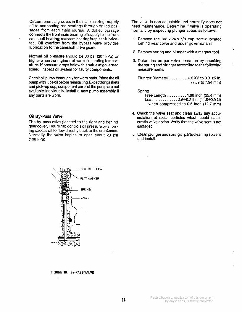
Oil By-Pass Valve The by-pass valve (located to the right and behind gearcover, Figure 10) controls oil pressure byallow- ing excess oil to flow directly back to the crankcase. Normally the valve begins to open about 20 psi (1 38 kPa).
HEX CAP SCREW
FLAT WASHER
SPRING
VALVE
The valve is non-adjustable and normally does not need maintenance. Determine if valve is operating normally by inspecting plunger action as follows:
1. Remove the 3/8 x 24 x 7/8 cap screw located behind gear cover and under governor arm.
2. Remove spring and plunger with a magnet tool. .
3. Determine proper valve operation by checking thespring and plunger according to the following measurements.
. Plunger Diameter.. . . . . . . . . 0.3105 to 0.3125 in.
(7.89 to 7.94 mm)
Spring Free Length.. . . . . . . . . . 1.00 inch (25.4 mm) Load . .. . . .. . . . . . 2.620.2 Ibs. (11.6kO.9 N)
when compressed to 0.5 inch (12.7 mm)
4. Check the valve seat and clean away any accu- mulation of metal particles which could cause erratic valve action. Verify that the valve seat is not damaged.
5. Clean plungerand spring in partscleaning solvent and install.
FIGURE 10. BY-PASS VALVE
14

Fuel System
Carburetor
Sidedraft LUA Nikki
CARBURETOR ADJUSTMENTS The carburetor mixture screws and the float level were set for maximum efficiencyat thefactoryand willseldom require readjustment. If adjustment seems necessary, first be sure the ignition system is working properly and is not the source of the problem.
~
Idle Mixture Main Mixture
1 to 1-112 1-318 to 1-518
1 to 1-1/2 1-1 /4 to 1-1 /2
1-1 /2 NA
If adjustment is needed, refer to Figures 11 and 12 and Table 1 and proceed as follows:
TABLE 1. CARBURETOR ADJUSTMENTS
1. Turn mixture screw(s) in until lightly seated, then back them out the number of turns specified in Table 1.
-1 f oosen packing nut before turn- ing main fuel adjustmenf and
tighfen to a snug fit after adjustment has been made. Hold the adjustment while tighteningpacking nut. Failure to tigbfen the packing nut can result in leaking fuel, creafing a serious fire hazard.
ACAUT~ON Forcing the mixture adjusfment I screws tight wi// damage the needle and seat. Turn in only untillight tension can be felt.
IDLE ADJUSTMENT
SIDEDRAFT CARBURETOR
2. Start the engine and allow it to warm up thoroughly (at least 10 minutes).
3. Move the engine speed control to the slow position.
4. Determine if the engine has a governor low speed adjustment screw (Figure 12).
5. Pull the governor back (Figure 12) so the throttle stop screw is against its stop. Continue to hold the governor arm in this position while completing the adjustments described in steps 6 through 8.
6. If the governor does not have a low speed adjust- ment screw, adjust the throttle stop screw to obtain 1200 rpm. If the governor does have a low speed adjustment screw, adjust the throttle stop screw to obtain 1100 rpm.
7A. Sidedraft and LUA carburetors: Turn the idle adjust- ment screw in until engine speed drops and then out until engine speed drops again. Over a narrow range between these two settings, engine speed will be at its maximum. Setthe idle adjustment screw about 1/8 turn outward from the midpoint of this range.
B. Nikki carburetor: This carburetor has a limited adjustment range between the stops of k 1 /8 turn. Adjust carburetor for highest rpm within this range.
8. Re-adjust the throttle stop screw to obtain the rpm specified in step 6 and release the governor arm.
LUA CARBURETORS
LIMITER CAP- FS-1406-2
NlKKl CARBURETORS
FIGURE 11. MIXTURE ADJUSTMENTS
15

9.
10.
Engines without a governor low speed adjustment screw require no further low speed adjustments. Engines with a governor low speed adjustment screw require the following low speed adjustment: A. Check to see that the governor linkage moves
freely and is not binding. B. Adjust the governor low speed adjustment screw
to obtain 1200 rpm. Check the main mixture adjustment (sidedraft and LUA carburetors only) by rapidly accelerating the engine from idle to full speed. The engine should accelerate evenly and without hesitation. If it does not, turn the main adjustment screw out in 1 / 8 turn increments until the engine accelerates smoothly, but do not turn it out more than 1 /2 turn beyond the original setting.
THRCI~I~STOP~ CARBURETOR
Cii
I\ GOVERNOR CONTROL
LINKAGE
GOVERNOR SPRING GOVERNOR
GOVERNOR LO SPEED ADJUSTMENT [g!$$gvz
STOP SCREW SCREW
FIGURE 12. IDLE SPEED ADJUSTMENT
Float Adjustment An exceedingly high float setting will usually result in an engine that is hard to start when warm. If the setting is too low, the engine may not receive enough fuel under sudden acceleration or load change. Adjust setting as follows: 1. Disconnect throttle control, choke leads, breather
hose, air cleaner inlet hose, and fuel line from carburetor.
2. Remove the four bolts that hold the intake manifold assembly in place and remove the complete carburetor and intake manifold assembly as one unit Then remove carburetor from intake manifold for easier handling when checking float level.
3. Separate the upper body of the carburetor from the fuel bowl section.
4. Measure float level (Figure 13). 5. If the setting is incorrect, remove the float assembly
to adjust. Bend the assembly slightly at the location specified in Figure 13. 71 Attempting adjustments wifh ACAUT'oN the float assembly installed may result in deformation of the inlet needle and seat.
NEEDLE BEND FLOAT AND SEAT TANG HERE
BEND TAB
1/8f1/16 INCH
BOWL ~LANGE GASKET
A91 3rw.
SIDE DRAFT CARBURETORS
U
FLOAT LEVEL ADJUSTMENT WITH FUEL
NlKKl carburetor with limited idle mixture adiustment
BEND FLOAT STRAIGHT TAB HERE WALBRO Ffg::f BEND FLOAT ARM
I HERE TOADJUST
MINIMUM BEND FLOAT ARM FLOAT DROP HERE TO ADJUST
NO FUEL FS-1683
FUEL LEVEL 0.25 INCH
NO FUEL
FLOAT LEVEL ADJUSTMENT LUA CARBURETORS
FIGURE 13. FLOAT LEVEL ADJUSTMENT
FLOAT DROP ADJUSTMENTS
4
FS1524
16

"
CARBURETOR OVERHAUL Carburetion problems that are not corrected by mixture or float adjustments are usually a result of gummed-up fuel passages or worn internal parts. The most effective solution is a carburetor overhaul. In general, overhauling a carburetor consists of dis- assembly, a thorough cleaning, and replacement of worn parts. Carburetor repair kits are available that supply new gaskets and replacements for those parts most subject to wear. General instructions for overhauling a carburetor are given below. Carefully note the position of all parts while removing to assure correct placement when reassemb- ling. Read through all the instructions before beginning for a better understanding of the procedures involved. Carburetor components are shown in Figures 14, 15 and 16.
Ignition of fuel can cause serious laWAR"Gl personal injury or death 6y fire or explosion. Do not permit any flame, cigarefte, or other igniter near the fuel system.
Removal and Disassembly (Except Nikki) 1.
2.
3.
4. 5.
6.
7.
Disconnect all lines, linkages, wires, and attaching nuts or bolts; then remove the carburetor from the engine. (Downdraft carburetors may require removal of the intake manifold to disconnect.) Remove air cleaner adapter, if so equipped, and automatic choking assembly. Remove throttle and choke plate retaining screws, then plates. Pull out throttle and chokeshafts, being careful not to damage the teflon coating applied to some throttle shafts. Remove main and idle mixture screw assemblies. On downdraftcarburetors, remove attaching screws and separate upper and lower carburetor sections. On sidedraft models, unscrew the retaining screw and remove fuel bowl from the upper carburetor body. Carefully note position of float assembly parts then slideout retaining pin and remove the float assembly, any springs or clips, and the needle valve. Unscrew and remove needle valve seat.
Removal and Disassembly (Nikki) 1. Remove air cleaner and hose. 2. Disconnect governor and throttle linkage, choke
control and fuel line from carburetor. 3. Remove the four intake manifold capscrews and lift
complete manifold assembly from engine. Remove carburetor from intake manifold.
4. Remove main jet and idle adjustment needle. 5. Remove attaching screws and separate upper and
lower carburetor sections.
6. Carefully note position of float assembly parts, then
7. Remove needle valve. pull out retaining pin and float assembly.
Cleaning and Repair 1. Soak all metal components not replaced in carbu-
retor cleaner. Do not soak non-metal floats or other non-metal parts. Follow the cleaning manufacturer's recommendations.
2. Clean all carbon from the carburetor bore, especially where the throttle and choke plates seat. Be careful not to plug the idle or main fuel ports.
3. Dry out all passages with low pressure air (35 PSI). Avoid using wire or other objectsfor cleaning which may increase the size of critical passages.
4. Check the condition of the adjustment needle; replace if damaged. Replace float if loaded with fuel or damaged.
5. Check the choke and throttle shafts for excessive play in their bore. This condition may necessitate replacement of the carburetor.
6. Replace old components with new parts.
Reassembly and Installation (Except Nikki) 1. Install needle valve and seat, fuel bowl gasket, and
float assembly. Make sure that all clips and springs are properly placed and that the float moves freely without binding. Check float level and adjust as necessary.
2. Rejoin upper and lower carburetor sections on downdraft carburetors - fuel bowl and upper carburetor body on sidedraft models. The float spring on Zenith sidedraft carburetors rides on the inner face of the fuel bowl. Be sure to catch the end of the spring when reinstalling the bowl (Figure 15).
3. Slide in throttle shaft and install throttle plate, using new screws if furnished in repair kit Before tight- ening the screws, the plate must be centered in the bore. To do so, back off the throttle stop screw as necessary and completely close the throttle lever. Seat the plate by tapping with small screwdriver, then tighten screws. Install the choke shaft and plate in the same manner.
4. install main and idle mixture screw assemblies. Turn in screws until lightly seated and then out the number of turns specified in Table 1. ACAUT~ON Forcing the mixture adjusfmenf
screws tigbt will damage the needle andseat. Turn in only unfilligbt tension can be felt.
5. Reinstall carburetor on engine and connect fuel lines, linkages, and wires.
6. Reset mixture screws according to directions given earlier in this section. Install air cleaner adapter, where used, and air cleaner.
17

Reassembly and Installation (Nikki) t CHOKE PLATE
1.
2.
3.
4.
5.
6.
7.
Install needle valve, main jet, and float assembly. Make sure float pivot pin is properly placed and float moves freely without binding.
Turn carburetor on its side and measure float level (Figure 13). Adjust float level only if necessary. Measure float drop (the distance from the top of carburetor body to top of float). Adjust only if necessary.
Position gasket on lower carburetor section and install upper carburetor section.
Install idle adjustment screw, throttle stop screw, and fixed main jet plug.
Mount carburetor on intake manifold and install assembly on engine.
Mount air cleaner assembly. Connect air intake hose, breather hose, fuel line, vacuum line, and throttle linkage.
Adjust carburetor and governor according to dir- ections given in this section.
IDLE ADJUSTMENT NEEDLE \ P) CHOKE
CHOKE PLATE
!----? ! O THROllLE SHAFT
FLOAT SPRING AND LEVER
gj ; MAINJET ADJUSTMENT
FUEL BOWL <,- 1
FLOAT AXLE
OSITION HOOK UNDER TANG
ON FLOAT
SPRING AFTER INSTALLATION
FIGURE 15. SIDEDRAFT CARBURETOR ASSEMBLY
CHOKE.
FUEL INLET VALVE
ASSEMBLY
THROTTLE SHAFT AND LEVER
ADJUSTMENT
ADJUSTMENT NEEDLE THROTTLE PLATE Q
FIGURE 14. DOWNDRAFT LUA CARBURETOR ASSEMBLY
t 9
FLOAT ASSEMBLY
NEEDLE VALVE
I I / I FIXED
FS-1440-3 FIGURE 16. CARBURETOR ASSEMBLY VY
1 8.
.
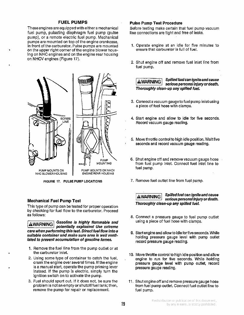
FUEL PUMPS These engines are equipped with either a mechanical fuel pump, pulsating diaphragm fuel pump (pulse pump), or a remote electric fuel pump. Mechanical pumps are mounted on top of the engine crankcase, in front of the carburetor. Pulse pumps are mounted on the upper right corner of the engine blower hous- ing on NHC engines and on the engine rear housing on NHCV engines (Figure 17).
' Pulse Pump Test Procedure Before testing make certain that fuel pump vacuum line connections are tight and free of leaks.
1. Operate engine at an idle for five minutes to ensure that carburetor is full of fuel.
2. Shut engine off and remove fuel inlet line from fuel pump.
PUMP MOUNTS ON NHC BLOWER HOUSING
PUMP MOUNTS ON NHCV ENGINE REAR HOUSING
FIGURE 17. PULSE PUMP LOCATIONS
Mechanical Fuel Pump Test This type of pump can be tested for proper operation by checking for fuel flow to the carburetor. Proceed as follows:
Gasoline is highly flammable and laWARNlNGl potentially explosive! Use extreme care when performing this test. Direct fuel flow into a suitable container and make sure area is well venti- lated to prevenf accumulation of gasoline fumes.
1. Remove the fuel line from the pump outlet or at the carburetor inlet.
2. Using some type of container to catch the fuel, crank the engine over several times. If the engine is a manual start, operate the pump priming lever instead. If the pump is electric, simply turn the ignition switch on to activate the pump.
3. Fuel should spurt out. If it does not, be sure the problem is not an empty orshutoff fuel tank; then, remove the pump for repair or replacement.
Spilled fuelcan ignite and cause k!@@%!l serious personalinjury or death. Thoroughly clean-up any spilled fuel.
3. Connect avacuum gauge tofuel pump inlet using a piece of fuel hose with clamps.
4. Start engine and allow to idle for five seconds. Record vacuum gauge reading.
5. Move throttle control to high idle position. Wait five ; seconds and record vacuum gauge reading.
6. Shut engine off and remove vacuum gauge hose from fuel pump inlet. Connect fuel inlet line to fuel pump.
7. Remove fuel outlet line from fuel pump.
Spilled fuel can ignite and cause serious personalinjury or death.
Thoroughly clean-up any spilled fuel.
8. Connect a pressure gauge to fuel pump outlet using a piece of fuel hose with clamps.
9. Start engine and allow to idle forfive seconds. While holding pressure gauge level with pump outlet record pressure gauge reading.
10. Move throttle control to high idle position and allow engine to run for five seconds. While holding pressure gauge level with pump outlet, record pressure gauge reading.
.
11. Shut engine off and remove pressure gauge hose from fuel pump outlet. Connect fuel outlet line to fuel pump.
19

Repair or replace the fuel pump if test readings are not within the values specified in TABLE 1.
TABLE 1 PULSE PUMP TEST SPECIFICATIONS
Engine Speed
Low Idle
High Idle
Pump Inlet Pump Outlet Vacuum Pressure
(Minimum) (Minimum) 2.6 inches 1.7 psi of mercury 2.6 inches 1.7 psi of mercurv
I I 1
Pulse Pump Repair This section applies only to Facet fuel pump. The Nikki fuel pump is not repairable; replace unit if test readings are not within the values specified in Table 1.
1. Remove the vacuum and fuel lines. Inspect the lines for wear, cracking, and brittleness. Replace as necessary.
2. To insure correct alignment when reassembling, scribe a line across the outer pump parts on each end of the pump (Figure 17).
3. Holding the pump carefully, remove the assembly screws.
4. Carefully pull apartthe pumpsectionsand checkfor worn or damaged parts. Replace with new parts where necessary or install pump repair kit (Fig- ure 18).
ASSEMBLY SCREWS
PUMP COVER GASKET
5. Checkand unclog (if necessary) thesmall diaph- ragm air bleed hole located behind the pump diaphragm in the pump base (Figure 18).
-1 A clogged diaphragm air bleed hole can cause diaphragm wear
and seal damage while inhibiting pump opera- tion.
d
6. Replace gaskets and reassemble pump. Reinstall assembly screws, checking the scribe marks for proper alignment. Reinstall fuel and vacuum lines and clamps.
. Use care when reassembling and reinstalling fhe pump. /m-
proper parts alignmenf or misconnecfed fuel lines can result in reaking fuel, creating a serious fire hazard.
Mechanical Pump Removal and Repair
Removal: 1. Remove the fuel inlet and outlet lines from the
Pump.
2. Remove the two capscrews holding the pump to the engine.
3. Remove the pump, spacer (if used) and gasket from the engine and discard the gasket.
REED VALVE
FIGURE 18. EXPLODED VIEW OF FACET PULSE PUMP
20

Repair: Repair kits are available that provide replacements for those parts of the pump most subject to wear. If the operator chooses to repair the pump rather than install a new one, the use of all parts included in the repair kit is recommended. Proceed as follows:
1. After the pump is removed from the engine, scribealineon theflangesoftheupperand lower pump bodies to assure correct positioning when reassembling.
2. Remove the securing screws and separate the upper and lower pump bodies.
3. Detach the valve cage retainer from the pump upper body. Noting their position, remove the valve and cageassemblies and their gasket sfrom the retainer (Figure 19).
UPPER PUMP BODY
8 R
LOWER SIDE DIAPHRAGM CASK IAPHRAGM RETURN
ROCKER AR
ROCKER ARM LIN
PRIMING LEV
FIGURE 19. MECHANICAL FUEL PUMP - EXPLODED VIEW
4.
5.
tweezers to compress the spring and tip it off the rocker arm catch. When installing the newspring, make sure it is properly placed before remount-
. ing the pump.
6. Clean in solvent all pump parts that will not be replaced and allow to dry.
7. Install the new valve and cage assemblies and their gaskets in the retainer. Be sure the assem- blies are in proper position and fully seated. Rein- stall the retainer and assemblies in the pump upper body.
8. To install the new pump diaphragm, turn the pump lower body upside-down and place the diaphragm and spring in the body. Press the base of the diaphragm up into the body of the pump and turn 1/4 turn.
.
9. Install new rocker arm return spring. Check for proper spring placement.
10. Place the upper and lower bodies of the pump together with the scribe marks aligned. Start the four securing screws, making sure they do not chew into thediaphragm fabric. Leave thescrews 2 or 3 turns loose.
11. Operate the rocker arm several times to flex the new diaphragm fully. While holding the rocker arm fully flexed, tighten the body screws.
-1 Failure to flex fhe rocker arm fully while tighfening fhe pump
bodies together will result in excessive pump pressure and possible engine flooding or pump diaphmgm failure.
Installation: 1. Remove all gasket material from mounting faces
and spacer (if used). Apply oil-resistant sealer to both sides of the gasket(s) and to the threads of the attaching capscrews.
2. Place the gasket (and spacer if used) on the mounting face of the pump. Slide the mounting capscrews through the pump and gasket (and spacer) to prevent thegasketfromslipping out of place.
3. Lightly place the pump in position on the engine, making sure the rocker arm is riding o,n the cam- shaft lobe. Start both capscrews and check for proper gasket placement.
Detach the pump diaphragm by pressing its metal base into the pump body and turning it 1/4 turn.
The rocker arm return spring can normally be removed without removal of the rocker arm from the pump body. Use a small screwdriver or
4. Connect the fuel inlet and outlet lines.
5. Operate the engine and check for leaks. .
21
Electric Fuel Pump All engines used on Onan N series generator sets are equipped with an electric fuel pump. The pump is manufactured by Facet (a division of Bendix Corpo- ration) and carries a Facet nameplate. An internal fuel shutoff valve is a standard feature on this pump. Older versions of this pump carry the Bendix name- plate and do not have an internal fuel shutoff valve. Service proceduresforthe Facet or Bendix pump are the same.
Do not substitute automotive type laWAR”Gl electric fuel pumps for standard Onan supplied electric pumps. The output pressure is much higher and can cause carburetor flooding or fuel leakage, creafing a fire hazard.
Pump Tesf:Test the fuel pump by checking the pump outlet pressure. Use the following procedure. 1.
2.
3.
Remove the fuel line from the pump outlet and install a pressure gauge. Press the START switch and hold it for several seconds until pressure reading is constant. Pressure reading should be 2-1/2 to 3-1/4 psi (17.2 to 22.4 kPa). If the retension is good, the pressure should stay constant or drop off very slowly.
A low pressure reading with little or no pressure drop indicates a weak or broken diaphragm or diaphragm spring, worn linkage,or leaky check valves. If pressure is above maximum, the pump diaphragm is too tight or the diaphragm (or plunger) return spring is too strong. Any of the above conditions are cause for repair or replacement of the pump.
Fuel Pump Repair: Service of the Facet pump is limited to the bottom cover, filter, plunger tube, and plunger assembly. All parts of the electric system are hermetically sealed in a gas atmosphere and are not serviceable. If electrical failure occurs, replace the Pump.
Do not tamper with the seal at the @%@@ cenfer of fhe mounting bracket on the side of the pump as if retains the dry gas which surrounds fhe electrical system. Electrical system components are nof serviceable.
Use the following procedure for servicing the pump: 1. Using a5/8-inch wrench, loosen, the pump cover,
then remove by hand.
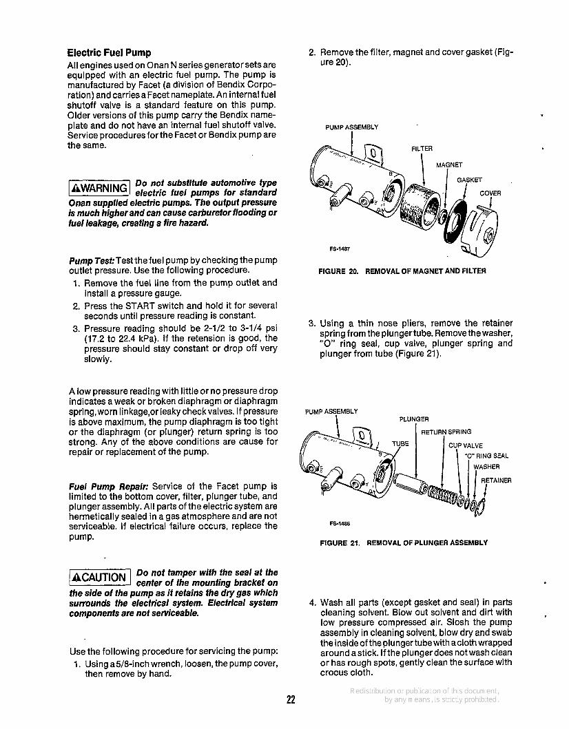
2. Remove the filter, magnet and cover gasket (Fig- ure 20).
PUMP ASSEMBLY I
3.
FS-1487
FIGURE 20. REMOVAL OF MAGNET AND FILTER
Using a thin nose pliers, remove the retainer spring from the plungertube. Remove the washer, “0” ring seal, cup valve, plunger spring and plunger from tube (Figure 21).
PUMP ASSEMBLY PLU N,GER
FS-1486
FIGURE 21. REMOVAL OF PLUNGER ASSEMBLY
4.
22
Wash all parts (except gasket and seal) in parts cleaning solvent. Blow out solvent and dirt with low pressure compressed air. Slosh the pump assembly in cleaning solvent, blow dry and swab the inside of the plunger tube with acloth wrapped around astick. lfthe plungerdoes notwash clean or has rough spots, gently clean the surface with crocus cloth.

Most parts cleaning solvents are flammable and can cause
serious personnel injury if used improperly. Fol- low fhe manufacturer‘s recommendafions when cleaning parts.
5. Insert plunger in tube, buffer spring end first. Check fit by slowly sliding the plunger back and forth in the tube. It should move fully without any tendency tostick. If aclick cannot be heard as the plunger is slid from one end to the other, the internal pump assembly is not functioning prop- erly and the pump should be replaced.
6. Install plunger spring, cup valve, “0” ring seal and washer. Compress the spring and install the retainer with ends in the side holes of the tube.
7. Check cover gasket and replace if deteriorated. Place cover gasket and magnet in the bottom cover and install filter and cover assembly on pump. Twist cover on by hand and tighten securely with a 5/8-inch wrench.
--- . .
Fuel Shutoff Valve (When Used) The external fuel shutoff prevents fuel flow into the carburetor after engine shutdown. It connects elec- trically to the ignition power terminal and energizes during engine cranking and running to allow fuel flow.Thedevicefastens directly to the fuel pump inlet (Figure 22).
USED WITH PUMPSTHAT DO NOT HAVE AN INTERNAL
SHUTOFF VALVE
FS-1485
To test the solenoid, connect a jumper wire from the B+ terminal on the control box to the plus (+) side of the ignition coil. If thesolenoid is good, aclickshould be heard when the wire makes contact.
-1 Twisfing the body of the solenoid . will cause infernal damage. Apply
twisting force with a wrench only at fbe hex nut locafed near fbe fuel inlef.
Fuel Filters Facet/Bendix Fuel pumps incorporate a filter within the casing of the pump (Figure 23). Use a 5/8 inch wrench to twist off the bottom of the pump and remove the filter element. If thefilter is dirty, replace it along with the cover gasket.
GASKET
FIGURE 22. FUEL SOLENOID FIGURE 23. BENDIX AND FACET ELECTRIC PUMP FILTER
23

ELECTRIC CHOKE The choke consists of a bi-metal coil and an electric heating element. The bi-metal coil connects to the choke shaft and holds the choke plate nearly closed when the engine is cold.
As the engine starts, current is supplied to theelectric heating element in the choke cover. Heat from the element causes the bi-metal coil to twist. The twisting action of the coil turns the choke valve shaft and gradually opens the valve. Heat from the element keeps the choke open while the engine is running.
The choke cover gefs very hot dur- ing normal operation and can cause
serious burns if touched. Do nof touch the choke cover while the set is operating.
~
AVERAGE CHOKE SETTING Ambient Temp Choke Opening
58' (14OC) closed 66' (19OC) 114 open 72' (22OC) 1 I 2 open 76' (24OC) 314 open 82' (28OC) open
If the engine starts but runs roughly and blows out black smoke after a minute or two of operation, the choke is set too rich. If the engine starts but sputters or stops before it warms up, the choke is set too lean.
Adjustment Table 2 lists average choke settings. Loosen the two mounting screws and rotate the choke cover until the correct setting is attained. Check the setting by starting the engine and observing its operation. Be sure to retighten the mounting screws after adjustment (Figure 24).
TABLE 2. CHOKE SPECIFICATIONS
BI-METAL COIL n CATCH OUTER END OF COIL IN SLOT
IN COVER TAB
COVER
MOUNTING SCREWS FS 1484
LOOSEN THESE
RICHER MIXTURE
FIGURE 24. ELECTRIC CHOKE ADJUSTMENT
Repair If the choke fails to operate, check to see if the heat- ing element isworking. If it is, thechokecovershould become hot after afew minutes of engine operation. If the cover does not get hot, check for current at the cover terminal. The engine must be running. Trace down any opens or shorts.
Remove the choke cover to inspect the heating ele- ment and coil. See that the element is not burned out or broken. The bi-metal coil must not be damaged, dragging in the housing, or have an improperly directed spiral.
When installing a new coil, maintain the original direction of spiral inward from the fastening screw. Be sure the coil sets squarely in the housing so it will not bind. Coil should not touch inside of choke body.
24

AIR CLEANER
.
If air cleaner becomes too dirty, liGEEi engine wil/ not receive sufficient air to run properly. Symptoms: Loss of power, flooding, hard starting, and overheating.
Engine is equipped with a paper element. If the engine is equipped with polyurethane precleaner it must be removed, cleaned, and oiled every 25 hours of operation, or more often under extremely dusty conditions.
1. To clean precleaner wash in water and detergent (Figure 25). Remove excess water by squeezing like a sponge and allow to dry thoroughly.
2. Distribute two tablespoons of SAE 30 engine oil evenly around the precleaner. Knead into pre- cleaner and wring out excess oil.
3. Depending on conditions in which the engine is operating, the inner paper element should be replaced whenever it becomes excessively dirty or oily.
Neverrun engine with air cleaner ~ACAUTloN 1 removed. Dirt will enter engine and wear out rings causing excessive blow-by.
pp- WING NUT
COVER
POLYURETHANE PRE-CLEANER
PAPER ELEMENT
BASE
1. WASH 2. SQUEEZE DRY 3. COAT WITH OIL 3. INSTALL OVER
PAPER ELEMENT
FIGURE 25. AIR CLEANER ASSEMBLY
25

GOVERNOR ADJUSTMENT Where engine speed is governor controlled, the gov- ernor is set at the factory to allow a nominal engine speed of 2400 rpm at no load operation (unless another speed is specified when the engine is ordered). Proper governor adjustment is one of the most important factors in maintaining the power and speed desired from the engine.
Before making governor adjustment, run the engine in a well ventilated area for about 15 minutes to reach normal operating temperature.
It is difficult to determine if, after long usage, the governor spring has become fatigued. If, after prop- erly making all other adjustments, the regulation is still erratic, install a new spring (Figures 26 and 27).
A tachometer for checking engine speed is required for accurate governor adjustment.
Check the governor arm, linkage, throttle shaft, and !
lever for binding or excessive wear at connecting points. A binding condition at any point will cause the governor to act slowly and regulation will be poor.
Excessive looseness will cause a hunting condition, and regulation will be erratic. Work the arm back and forth several times by hand while the engine idles. If either of these conditions exist, determine the cause and adjust or replace parts as needed.
THIS DISTANCE
DETERMINES SENSlTiVlTY
MORE 4 1 SENSITIVE I
I LESS I SENSITIVE
Procedure 1. Adjust the carburetor main jet for the best fuel
2. Adjust the carburetor idle needle with no load
3. Adjust the length of the governor linkage. 4. Check the governor linkage and throttle shaft for
binding or excessive looseness. 5. Adjust the governor spring tension for nominal
engine speed at no load operation. 6. Check the rpm drop between no load and full load
operation, and adjust the governor sensitivity as needed (should be about 8%).
7. Recheck the speed adjustment. 8. Set the carburetor throttle stop screw.
mixture at full load operation.
connected.
Linkage The engine starts at wide open throttle. The length of the linkageconnecting the governor arm to the throt- tle arm is adjusted by rotating the ball joint housing. Adjust the length so that with theenginestopped and tension on the governor spring, the stop on the car- buretor throttle lever is 1/32 inch (0.794 mm) from the carburetor stop boss. This setting allows immediate control by the governor after starting and synchron- izes travel of the governor arm and the throttle shaft.
THROTTLE ARM CARBURETOR
THROTTLE
JOINT BALL kt
\\
SHAFT
SPRING STING STUD
-GOVERNOR ADJUSTMENT
FIGURE 26. GOVERNOR ADJUSTMENTS
26

DECREASE SPEED
INCREASE SPEED
.
GOVERNO~ ARM
// EXTENSION
t
MAXIMUM DEGREASE SPEED SPEED STOP
$1 &GOVERNOR
L MINIMUM SPEED STOP -
FIGURE 27. VARIABLE SPEED GOVERNORS
Speed Adjustment The speed at which the engine operates is determined by the tension applied to the governor spring. Increasing spring tension increases engine speed. Decreasing spring tension decreases engine speed. The no load speed of the engine should be slightly higher than the speed requirements of the connected load. For example, if the connected load is to turn at 3510 rpm, set the no-load speed of the engine at about 3600 rpm. Check speed with a tachometer.
If aspeed adjustment is needed, turn the speed adjusting nut in to increasethespeed orouttodecreasethespeed (Figure 26).
Sensitivity Adjustment The engine speed drop from no-load to full-load should not be more than 400 rpm. Check the engine speed with no load connected and again after connecting full load. Do not exceed rated rpm at no-load.
The sensitivity of the governor depends upon the position of the arm end of the governor spring. A series of holes in the governor arm provides foradjustment.To increase sensitivity, move the spring toward the gov- ernor shaft. To decrease sensitivity, move the spring toward the linkage end of the governor arm.
If the setting is too sensitive, a hunting condition (alternate increase and decrease in engine speed) will result. If the setting is not sensitive enough, the speed variation between no-load and full-load conditions will be too great Therefore, the correct sensitivity will result in the most stable speed regulation without causing a surge condition.
Always recheck the speed adjustment after a sensitivity adjustment. Increasing sensitivity will cause a slight decrease in speed and will require a slight increase in the governor spring tension.
Variable Speed Governor Adjustment These engines are adapted for use where a wide range of speed settings is desired. The design of the variable speed governors gives an automatic increase in sensi- tivity when the speed is increased and the result is good stability at all speeds.
27
I JNKABE
To adjust the variable speed governors, refer to Figure 27 and the following: 1.
2.
3.
4.
5.
Run the engine and make necessary carburetor adjustments. Adjust the throttle stop screw on the carburetor to allow a recommended minimum idling speed of 1100 rpm. A lower minimum does not assure smooth operation under load. Adjust the tension of the governor spring for minimum speed. For governors having a manual control arm, set lever to minimum speed with no load and adjust the spring tension for about 1500 rpm. For governors having a Bowdin wire remote control knob (NHC engines with mounted engine controls), pull back the knob and slide to the first notch (low speed). Adjust speed to about 1500 rpm (or the desired low speed) at no load by turning the knob as required. Adjust the sensitivity while operating at minimum speed to attain the smoothest no load to full load operation as follows: To decrease sensifivity (allow more speed drop from no-load to full-load operation), move the governor spring outward into a different groove or hole in the extension arm. To increase sensitivity (closer regulation by the governor which permits less speed drop from no- load to full-load operation), move the governor spring inward into a different groove or hole in the extension arm. Apply a full load and shift the variable control to maximum speed-moving the control arm to the right or shifting the control knob and slide to the second notch. For the governor control with the control arm, set the screw in the bracket slot to stop lever travel at the desired maximum full-load speed position. For the control with the control know and slide, increase or decrease speed by turning the knob as required.
Approximately3000 rpm is the recommended maximum full-load speed for continuous operation. The speed must agree with the load requirements.

Ignition and Battery Charging
IGNITION TIMING .016 inch (0.41 mm) by adiusting the socket head Timing is preset atthefactory.Slighttiming changescan be made by adjusting the points.
screw (D) inward or.o&.va;d (Fighe 28). Make sure feeler gauge is clean and free of any grease, oil, or dirt. A .016 inch point gap is equivalent to 20' BTC.
The engine is equipped with an automatic type battery ignition system. Both spark plugs fire simultaneously, thus the need for a distributor is eliminated.
7. Replace breaker box cover, coil wire, spark plugs, and spark plug cables.
-
BREAKER POINTS The timing is adjusted during initial engine assembly and is fixed by the point gap adjustment. To maintain maximum engine efficiency, change the breaker points every 200 hours of operation.
Replacement and Adjustment 1. Remove spark plugs. 2. Remove breaker box cover. Rotate crankshaft
clockwise (facing flywheel) until points are fully open.
3. Remove condenser (screw A) and detach con- denser lead and coil lead screw (screw B). See Figure 28.
4. Remove two Allen screws (C) and lift breaker assembly from engine.
5. Replace condenser and point assembly with new parts and reinstall, using above procedure in reverse order of removal.
6. Adjust point gap by rotating crankshaft clockwise (facing flywheel) by hand until the pointsarefully open. Set the point gap (using flat feeler gauge) at
Continuity Test As a check for proper ignition timing a continuitytest may be performed: 1. Adjust breaker points. 2. Remove air intake hose or cylinder shroud to
expose timing marks (Figure 29). 3. Rotate flywheel clockwise until timing mark is
aligned with the mark corresponding to 20" BTC on top of gearcase cover.
4. Connect an ohmmeter or a continuity test lamp set across the ignition breaker points. Touch one test prod to thecoil lead terminal (screw B Figure 28).
5. Touch theothertest prod toagood ground on the engine.
6. Turn crankshaft against rotation (counterclock- wise) until the points close. Then slowly turn the crankshaft with rotation (clockwise).
7. The lamp should go out (continuity lost) just as the points break, which is where ignition occurs. If timing is early (advanced), the point gap is too large. If timing is late (retarded), the point gap is too small. Adjust point gap accordingly.
n POINTGAP. !I
FIGURE 28. SETTING POINT GAP
28

TIMING MARKS ON BLOWER HOUSING - -
POINTER ON TIMING
FLY W H EEL 8389
TIMING MARKS ON GEAR COVER - VIEW
__.. THRU BLOWER WHEEL
TIMING MARKS 0 GEAR COVER
PRESSURE COOLED REMOVE AIR INTA-KE HOSE20 VlEWTlMlNG MARKS .
TIMING MARK ON FLYWHEEL
VACU FLO ENGINES: REMOVE AIR SHROUD FROM RIGHT CYLINDER TO VIEW TIMING MARKS
IGNITION COIL To test primary and secondary windings within the ignition coil proceed as follows: 1. Use a Sirnpson 260 VOM or equivalent. 2. Place black lead on ground (-)terminal of coil and
red lead to positive (+) terminal. Primary resist- ance should read 3.87-4.73 ohms.
3. Change resistance setting on ohmmeter. Place ohmmeter leads inside of spark plug cable holes (Figure 30). Secondary resistance should read 12,600-15,400 ohms.
4. If any of the above conditions are not met, replace coil. Refer to PARTS CATALOG for correct part number:
FIGURE 30. COILTEST
SPARK’PLUGS Check, and regap spark plugs every 100 hours of operation (Figure 31). Replace spark plugs that show signs of fouling or electrode erosion.
FIGURE 29. TIMING MARK LOCATIONS FIGURE 31. SPARK PLUG GAP
29

BATTERY INSPECTION BATTERY JUMP STARTING Check battery cells with a hydrometer. The specific gravity reading should be approximately 1.260 at 77" F (25OC), Figure 32.
Occasionally, it may be necessary to jump start a weak battery using a charged booster battery to start your engine. If jumpstarting is necessary, the follow- ing procedure is recommended in order to prevent starter damage, battery damage and personal injuries.
RAVITY READING
260 AT 77 F (25 C)
FIGURE 32. SPECIFIC GRAVITY TEST
6
Do not engage starter for periods longer than 30 seconds without
allowing 5 minutes for starter to cool. Starter failure may result if these guidelines are not followed. . 1. Disconnect engine load. 2. Use only a battery of the same voltage (12V) as is
used with your engine. 3. Attach one end of the positive booster cable (red)
to the positive (+) terminal of the booster battery. Attach the other end of the positive cable to the positive (+) terminal of your engine battery.
4. Attach one end of the negative (-) booster cable (black) to negative (-)terminal of booster battery. Attach other end of negative cable to a solid chassis ground on your engine.
Arcing may cause severe per- - sonal injury. Do not allow the If one or more cells are low on water, add distilled water and recharge. Keep the battery case clean and dry. An accumulation of moisture will lead to a more rapid discharge and battery failure.
positive and negative cableends to touch each other because i t will short the battery causing arcing. I
Keep the battery terminals clean and tight. Push the cable terminal down flush with or slightly below the top of the battery post (Figure33). After making con- nections, coat the terminals with a light application of petroleum jelly or grease to retard corrosion.
r BATTERY POST CABLE TERMINAL b
FIGURE 33. BAlTERY CABLE CONNECTION
Poor contact at the battery cable connections is often a source of trouble. Make sure battery cables are in good condition and that contacting surfaces are clean and tightly connected. Do not reverse battery leads. Use recommended battery tools when disconnecting leads to avoid physical damage to battery.
5. Jump starting in any other manner may result in damage to the battery or the electrical system.
6. Turn ignition switch to ON to start engine.
Jump starting a frozen battery can explode and can cause
severe personal injury. Never jump start a frozen battery. To do so may cause the battery to explode. Never expose the battery to an open flame or an electrical spark because a battery discharges highly explosive hydrogen gas.
FLYWHEEL ALTERNATOR The flywheel alternator is a permanent magnet alter- nator and uses asolid-state voltage regulator-rectifier for controlling output.
Three different alternator systems are used with NHC and NHCV engines; 20 amp Synchro system, 15 amp Phelon system, 20 amp Phelon system.
Weak ignition spark ora discharged battery indicates trouble in the charging system. But before testing engine charging system, always check the battery for serviceability.
AWARN~NG Do not smoke while servicing bafter- m ies. Explosive gases are emitted from batteries while charging. Ignition of these gases can cause severe personal injury.
This engine uses a 12 volt, negative ground system. Alternator must be
connected to battery at all times when engine is run- ning. Do not reverse batfery cables.
30

RECTIFIER STATOR ASSY.
I
T O BATTERY
SCREEN BOLT
FLYWHEEL ON PRESSURE COOLE 'ACU-FLO
ENGINE \ FLYWHEEL
ALTERNATORROTOR (PART OF FLYWHEEL ASSY.)
FIGURE 34. 20 AMP SYSTEM
TESTING OR SERVICING
Keep these points in mind when testing or servicing the flywheel alternator:
1. Be sure engine is being run long enough and fast enough to recharge battery after each start Alter- nator output is reduced in direct proportion to engine rpm. Also, power required for accessories reduces power available to recharge battery.
2. Be sure output control plug (connector) is inserted properly. Plug must bottom in receptacle-elim- inates any resistance due to a poor connection. Keep clean and tight.
3. Make sure alternator stator leads are not shorted together.
4. Be sure regulator-rectifier output control has a good ground connection. Mating surface for mount- ing must be clean and fasteners tightened properly.
5. Never reverse the battery leads.
6. Charging system tests require a fully charged battery.
20 Amp Synchro System The 20 amp flywheel alternator systems use a separate regulator and a separate rectifier, Figure 34.
Testing: For testing this system, use a voltmeter- ohmmeter such as a Simpson 270. Various alternator problems with individual test procedures are listed in Table 2.
TABLE 2. TESTING SYNCHRO 20 AMP SYSTEM
TEST
Battery voltage - unit not running
Battery voltage with unit running at 1800 rpm or more
VALUE
AC voltage from stator with plug disconnected and unit running at approximately 1800 rpm
Ohmmeter reading at plug when checking two AC stator leads - unit not running
Resistance values (Ohms) are as follows between wire pairs
1 BLACK I .S - 17 n
1.8- 2.2n I t BLACK
1.3- 1 .5a
12 Volts DC
14.2 - 14.8VDC depending on
charge condition of battery
23 VAC minimum* Black to Black
' - 48 VAC maximum at 3600 rpm.
31

No Output-Stator Assembly: Examine leadwires for loose or broken connections at the regulator and rectifier. Use the Rx l scale on the ohmmeter for detecting opens in the stator. Disconnectthe three wires that come from alternator stator (two black, one red). Connect ohmmeter test leads to red leadwire and ground to check continuity. The ohmmeter reading should be about 2.0 ohms. See Figure 34a for wiring diagram.
Next, connect meter to black leadwires and ground. Approximately0.1 ohm should be read from either black lead to ground. If no continuity exists between ground and black leads, stator assembly should be replaced.
ALTERNATOR STATOR MOUNTED BEHIND BLOWER WHEEL
\n TO TERMINAL CONNECTOR
RECTIFIER ASSEMBLY ASSEMBLY
I -- - FIGURE 34a. 20 AMP SYNCHRO SYSTEM
Checking RectifierAssembly: Examine each of the two diodes for breakdown by connecting ohmmeter (Rxl scale) from one black lead to white lead. Meter should read 10 ohms in proper polarity. A shorted diode would read zero resistance and would cause a short circuit through the lead winding when in operation. An open diode would read infinite in both directions indicating that replacement is necessary.
Testing Regulator Assembly: To check for proper voltage regulation, attach a DC voltmeter to battery and operate engine at about 1800 rpm. Battery voltage will climb to the preset factory setting (14.2 to 14.8 volts).
Some installations may vary due to voltage drop in the length of ammeter harnesses. Other variations may stem from a loose connector in the harness or loose or corroded battery leads. Low voltage readings at the battery mean poor battery connections.
To test regulator, remove connector. Using the Rxl0,OOO scale of your ohmmeter, connect one meter lead to red leadwire and other meter lead to regulator base. No deflection should be noted on the ohmmeter in either polarity. Next, connect meter to black leadwire and base of regulator. Meter will deflect fully in one polarity, with no deflection in the other.
Full Charge- Will Not Regulate: Check for broken leads at connection to regulator plates. To be sure regulator winding operates properly, connect red lead to ground and start engine. A maximum of 4 amperes should be noted. This would indicate stator winding is satisfactory. if so, replace regulator.
No Charge: If alternator does not charge when load is applied to battery, shut off engine and disconnect one red leadwire from regulator terminal. Be sure lead is taped or isolated from conducting engine parts. Once again, start engine. Alternator should charge to full output; if it does not, replace stator assembly.
6
15 Amp Phelon System The Phelon flywheel alternator systems (Figure 35) have as one piece regulator-rectifier assembly. Various alter- nator tests are listed in Table 3.
With the engine running between 1800 to 2600 rpm, observe the panel ammeter (if not already equipped, connect a test ammeter). If no charging is evident, proceed with the Alternator Output Test,
Alternator Output Test ... . . . .
1. With the engine running, check the battery terminal voltage (regulator output) using a DC voltmeter. Voltage output should be within thevaluesspecified in Table 3. If voltage is greater than specified replace regulator-rectifier assembly. If voltage is less than specified, proceed to step 2.
2. Examine all wires for loose, corroded, broken con- nections, short circuits, etc. Check fuses. Repair as needed to assure complete circuits from regulator- rectifier B+ terminal to battery positive (+) terminal and from battery negative (-) terminal to regulator- rectifier case. If battery voltage remains low with engine running, proceed to step 3.
3. Disconnect plug from regulator-rectifier and test the AC voltage at the plug with engine running near 3600 rpm. If AC voltage reads more or less than specified in Table 3, proceed to step 4. If ACvoltage is as specified but DC voltage is low, replace reg ulator-rectifier.
4. Use the Rxl scale on the ohmmeter for detecting opens in the stator (unit not running). Disconnect plug from regulator-rectifier. Connect ohmmeter test leads to wires coming from stator. Refer to Table 3 for resistancespecifications. If resistance is not as specified, replace stator. If stator resistance readings are as specified and windings are not shorted to ground, low AC voltage may be due to loss of magnetism. If so, blower wheel assembly must be replaced. Check for magnetism with steel tool blade. Next, connect one ohmmeter test lead to stator wire, connect the other test lead to gorund. If the ohmmeter reading is low the stator is grounded and must be replaced.
32

TABLE 3. TESTING PHELON SYSTEMS
BASIC TEST
1. Battery
TEST VALUES PROCEDURE 1 SA. SYSTEM 20A. SYSTEM
Battery Voltage - unit not running. 12 VDC 12 VDC
2. Regulator
3. Alternator Stator and Wiring
4. Alternator and Wiring
MOUNTED ON CYLINDER COVER
\ VR1
Battery Voltage after unit is running 3 to 5 minutes.
Ohmmeter reading from stator output - unit not running. Check at plug.
Measure AC open circuit stator voltage with unit running. Measure between two stator leads with 23 VAC minimum plug disconnected and unit 65 VAC maximum 48 VAC maximum running at approximately 3600 rpm.
13.6 to 14.7 VDC 13.6 to 14.7 VDC
0.1 to 0.2 Ohms 0.3 to 0.5 Ohms
28 VAC minimum
MOUNTED BEHIND BLOWER WHEEL
AC B+ AC
FLYWHEEL VOLTAGE REGULATOR
85-1333
TO BATTERY - - AC -AC
15 AMP 20 AMP CAUTION:
REGULATOR MUST BE GROUNDED THROUGH MOUNTING BOLTS 151332
VOLTAGE REGULATOR CONNECTIONS
FIGURE 35. PHELON SYSTEM
33

Starting System
ELECTRIC STARTER The electric starter contains three main assemblies: an electric starting motor; a pinion gear and clutch which engages with the ring gear on the engine fly- wheel during starting; and a solenoid-switch as- sembly which shifts the pinion gear into the engine ring gear and activates the starting motor.
The starter will seldom require service other than possible brush replacement. Before attempting star- ter repair, make sure the electrical system leading to the start solenoid is not the source of the problem. If thestarter bindsorslipsduring cranking, or isexces- sively noisy, the gear lash between the starterand the flywheel ring gear may be incorrect. Information on setting the gear lash is provided at the end of this section.
FIGURE 36. STARTER ASSEMBLIES
STARTER DISASSEMBLY AND REPAIR Starter disassembly and inspection procedures are provided below. Common sources of starter malfunc- tion include worn commutator brushes, worn arma- ture bearings, a stripped pinion gear, or a faulty solenoid-switch.
Removal 1. Disconnect the positive battery cable from the
2. Remove the blower housing from the front of the
3. Holding the starter in place, remove the starter
starter solenoid-switch.
engine.
mounting bolts, then remove the starter.
Disassembly Some differences in configuration exist between the starter used during Spec Aand the starterthat has been used from Spec B to the present (Figure 36). However, disassembly procedures for either are basically the same. Using Figure 37 as a guide, proceed as follows:
I . Remove the field coil strap where it connects to the solenoid-switch.
2. Detach the mounting screws, and remove the solenoid-switch from the starter motor.
3. Remove the starter thru-bolts. Separate the front bracket from the starter housing. The solenoid shift lever and spring components will come loose as the front bracket is removed. The arma- ture may also be removed from the starter hous- ing at this time.
4. Remove the brush holder retaining screws from the back of the rear bracket. Separate the rear bracket from the starter housing and the brush holder.
5. To remove the pinion gear and clutch from the armature shaft, drive the pinion stopper away from the retaining ring it holds in place (Figure 38). Remove the retaining ring and slide the pinion stopper, pinion gear and clutch off of the armature shaft
L
Inspection of Parts Pinion Gear and C/ufch: The pinion gear should rotate smoothly (not necessarily easily) in one direc- tion and not at all in the opposite direction. If the gear isworn or burred, or does not rotate properly, replace the gear and clutch assembly. Also check the teeth on theflywheel ring gearfor signs of excessive wearand replace if necessary.
34

SOLENOID-SWITCH FIELD COIL
842, FRONT BRACKET
FIGURE 37. EXPLODEDWEW OF STARTER (BEGIN SPEC B) ASSEMBLY
PINION STOPPER CYLINDRICAL TOOL
Measure the brush spring tension by placing the brush holder assembly in place over the commutator end of the armature. Hook a spring scale over the spring nearthe brush and take a reading as the spring just leaves the brush. On a new brush, the tension
DRIVE PINION STOPPER AWAY FROM RETAINING RING WITH CYLINDRICAL TOOL ' ES-1022
FIGURE 38. PINION GEAR AND CLUTCH REMOVAL
Brush Inspection: When brushes are worn to the wear limits (Figure 39), replace them. See that the brushes move smoothly in the brushholders.
. - _ .
FIGURE 39. BRUSH WEAR LIMITS
should be 49 to 59 ounces (1390 to 1670 grams). For the Spec A starter, the tension shoud be 29 to 38 ounces (820 to 1075 grams).
Tesfing Armafure for a Short Circuit: Use a growler for locating shorts in the armature. Place armature in growler and hold a thin steel blade (e.g. hacksaw blade) parallel to the core and just above it while slowly rotating armature in growler. A shorted arma- turewill cause the bladetovibrateand be attracted to the core. If armature is shorted, replace with a new one (Figure 40).
.
FIGURE 40. ARMATURE SHORT CIRCUIT TEST
35

Testing Armature for Grounds:Touch armature shaft or core and the end of each commutator bar with a pair of ohmmeter leads (Figure 41). If the ohmmeter reading is low, it indicates a grounded armature. Replace a grounded armature.
Testing Field Coils for Open Circuifs: Place one lead on the connector and the other on a clean spot on the brushholder (Figure 43). A high ohmmeter reading indicates the field coil is open. Check the other three brushholders in the same manner.
COMMUTATOR.
. .
~ -_____ . _ FIGURE 41. ARMATURE GROUND TEST
lnspecfing for an Open Circuit in Armafure:The most
commutator riser bars. Inspect for loose connections on the points where the conductors are joined to the commutator bars.
Testing Field Coils for Grounds: Place one lead on the connector and the other on a clean spot on the frame after unsoldering the shunt field coil wire (Fig- ure42).Alowohmmeter reading indicatesagrounded field either at the connector or in the windings.
likely place to check for an open circuit is at the FIGURE 43. FIELD COIL OPEN CIRCUIT TEST
Testing CommufaforRunouf: Place armature in a test bench and check runout with a dial indicator (Figure 44). When commutator runout exceeds 0.004 inch (0.102 mm), reface the commutator.
.
FIGURE 42. FIELD COIL GROUND TEST FIGURE 44. CHECKING COMMUlTOR RUNOUT
36

Testing Armature Shaff Runout: You can check the armature shaft for runout as shown in Figure 45. A bent armature can often be straightened, but a new armature is required if the shaft is worn.
FIGURE 45. CHECKING ARMATURE SHAFT RUNOUT
CLEANING PARTS 1. Do not immerse parts in cleaning (BCAUTIONI solvent. Immersing the field coil,
yoke assembly, armature, and solenoid will damage fhe insulafion. Wipe these parts with a cloth only. 2. Do nof immerse fhe overrunning clutch in clean- ing solvent- The clutch is prelubricafedat the factory, and solvent will wash lube from clutch. 3. Wash all other parts in solvent and dry.
STARTER ASSEMBLY 1. Lubricate armature shaft with a very light grade
oil. A medium or heavy oil or grease may cause faulty operation in cold weather.
2. Slide the pinion gear and clutch assembly and the pinion stopper onto the armature shaft. Position the retaining ring in its groove on the armature shaft, and secure the pinion stopper over it using a puller such as that shown in Figure 46.
3. Apply a small amount of Lubriplate on the shift lever pivot pin and lever holders (unless the holders are made of nylon, in which case no lub- ricant is needed).
FIGURE 47. SHIFT LEVER INSTALLATION
4. Place the shift lever assembly in position on the armature as shown in Figure 47. Slide the thrust washer onto the end of the armature shaft, and install the armature and shift lever assembly in the front bracket (Figure 48).
FRONT BRACKET I
FIGURE 46. ARMATURE INSTALLATION PINION STOPPER .. , -.
5. Place the shift lever spring and spring holder in the front bracket. Slide the starter housing over the armature and align with the front bracket.
6. Position the brush holder and brushes in place on the commutator end of the armature, pulling the brushes back against spring tension to allow the holder to slide in place.
7. Install the rear bracket making sure the thru-bolt and brush holder screw holes are properly positi- oned. Slide thru-bolts into position and screw in place. Install the brush holder attaching screws.
8. Install thesolenoid-switch, catching the solenoid plunger on the solenoid shift lever. FIGURE 46. INSTALLING PINION GEAR AND CLUTCH
37

INSPECTION AFTER OVERHAUL For no-load test, the starting motor is wired as shown in Figure 49 and run. The value of the meter reading at this condition should be as follows:
Begin Spec B Voltage 10.5 11.5 RPM 5000 3700 Max. Current
Draw (Amp) 53 60
Spec A Only
1.
AMMETER SWITCH
INDICATOR
FIGURE 49. WIRING STARTER FOR NO-LOAD TESTS
The conductor for this test should be large enough in diameter and as short as possible. If anything is wrong in the above test, inspect the following items:
Annealed brush springs Improperly sealed brushes Insufficient armature endplay Shorted, open, or grounded armature Grounded or open field coil Poor electrical connection Dirty commutator
2. To adjust pinion clearance, connect the battery to thestarting motorasshown in Figure50.This will allow the pinion of the starting motor to slide and stop. In this state, measure the clearance between the end of the pinion and pinion stop when the pinion is pushed lightly toward the commutator end. Clearance should be 0.02 to 0.06 inch (0.51 to 1.52 mm). Adjust for proper clearance by removing the solenoid switch attaching screws and select the proper thickness of the fiber packings shown in Figure 51.
FIBER PACKINGS
FIGURE 51. ADJUSTING PINION CLEARANCE
CHECKING GEAR LASH Always check starter-to-flywheel gear lash when reinstalling the starter on the engine. Lash should also be checked if the starter binds or slips during cranking or is excessively noisy. Proceed as follows: 1.
2.
3.
4.
5.
Before installing thestarter, make sure the starter mounting surfaces on the engine base are free of dirt and oil to assure good electrical contact. Install the starter motor and tighten the mounting bolts just enough to hold the starter in place. Remove the spark plugs from the engine to allow free movement of the flywheel. Manually pull the starter pinion gear outward on its shaft so that its teeth mesh fully with those on the flywheel. Measure the amount of free travel (lash) between the pinion gear teeth and the ring gear teeth, as shown in Figure52. Proper lash isO.O20+0.010 in. (0.51+_0.25 mm). Loosen and adjust the starter motor as necessary to obtain the correct setting.
6. Torque down thestarter mounting bolts and rein- stall the engine spark plugs.
FLYWHEEL RING GEAR
0.020 f 0.010'' (0.51 f 0.25 mm) FLYWHEEL GEAR FREE TRAVEL WHE
ENGAGED WITH STARTER G.EqR
STARTING MOTOR PINION GEAR
FIGURE 50. BATTERY CONNECTIONS
38
FIGURE 52. CHECKING STARTER GEAR LASH

Engine Disassembly
DISASSEMBLY/ASSEMBLY When complete engine disassembly is necessary, first remove all ComDleteassemblies. Individual assem-
1. Use the proper bearing driver to install front main bearing after coating it with a light film of oil.
2. Insert rear main bearing in rear bearing plate. blies disassembled and repaired at another time.
as “el pump and carburetor can be 3. Insert crankshaft,rear bearing plate, and crank- shaft gear.
Suggested Disassembly Order 1. Drain crankcase. 2. Disconnect all exhaust lines and electrical lines. 3. Remove engine from its mountings and place on
a suitable bench or work stand. 4. Remove all housings, shrouds, blower housings,
etc. 5. Remove flywheel, using a puller. 6. Remove the gear cover, being careiul to protect
7. Remove the crank gear, using a gear puller and
8. Remove all accessories such as oil filter, starter,
9. Remove breaker point box.
the oil seal from keyway damage.
ring.
intake manifold, fuel lines, spark plugs, etc.
10. Remove oil base, oil pump and cylinder heads. 11. Remove valves, springs, lifters, etc. 12. Remove camshaft and gear assembly. 13. Remove connecting rods and pistons. 14. Remove rear bearing plate, crankshaft, and front
bearing.
4. Install piston and connecting rods.
5. Install camshaft and gear assembly; align crank gear mark with cam gear mark.
6. Install valve assemblies, oil pump, oil base, and cylinder heads.
7. Install breaker point box. 8. Install all accessories such as oil filter, starter,
9. Install gear cover with oil seal and flywheel. fuel lines and spark plugs.
10. Set breaker points to obtain proper timing. 11. Check valve clearance. 12. Install all housings and air cleaner. 13. Fill crankcase with oil.
Operation Start engine and check oil pressure. Run for approxi- mately 15 minutes to bring engine to operating temperature. Check for oil leaks, fuel leaks and exhaust leaks. Adjust carburetor and governor for speed and sensitivity.
Testing Compression The compression tester is used to determine the condition of valves, pistons, piston rings and cylinders. To check compression:
Keep all parts in their respective orders. Keep valve assemblies together. Return rod caps to their respec- tive pistons. Analyze the reasons for parts failure.
1. Run the engine until thoroughly warm. 2. Stop engine and remove spark plugs.
Suggested Assembly Procedure Engine assembly is normally the reverse of the disassembly procedure, observing proper clearances and torques. Use a torque wrench to assure proper tightness. Coat the internal engine parts with oil as they are assembled. After the internal engine parts are assembled, the engine should turn over by hand freely. Use only genuine Onan parts and special tools when reassembling your engine.
3. Remove air cleaner and place throttle and choke in
4. Insert the compression gauge in one spark plug
Refer to SPEClFlCATlONS SECTION for compression pressures. There may be variations due to temperature, atmospheric conditions and altitude. These pressures are for a warm engine at cranking speed (about 300
the wide open position.
hole.
- . rpm).

Tappet Adjustment VALVE SYSTEM The engine is equipped with adjustablevalve tappets. The valve tappet clearance should be checked and adjusted, if necessary, at least every 200 operating hours or when poor engine performance is noticed. Adjust the valve clearance only when engine is at ambient temperature. Proceed as follows:
Aproperlyfunctioning valvesystem isessential forgood engine performance. AI1 engines utilize an L-head type valve design asshown in Figure 53. Accessto thevalve system can beobtained by removing the cylinder heads and thevalvecoverson top oftheengine.Avalvespring '
comm-essor must be used to remove valves from the 1.
2.
3.
4.
5.
6.
7.
8.
Remove ignition key to prevent accidental star- ting. Remove all parts necessary to gain access to valve tappets. Remove spark plugs to ease the task of turning the engine over by hand.
Place a socket wrench on the flywheel capscrew and rotate the crankshaft in a clockwise direction until the left intake valve (viewed from flywheel end) opens and closes. Continue turning the crankshaft until the TC mark on the flywheel is lined up with theTC mark on the gear cover. This should place the left piston (#1) at the top of its compression stroke. Verify that the left intake and exhaust valves are closed and there is no pressure on the valve lifters.
The correct feeler gauge for the valve adjustment (SPECIFICATIONS) should pass freely between valve stem and tappet; a 0.002 inch (0.05 mm) thicker gauge should not (Figure 53).
To correct the valve cleara'nce, use a 7/16-inch open end wrench to turn the adjusting screw to obtain the correct clearance. The screw is self- locking and will stay where it is set. A 9/16-inch (14 mm) open end wrench is required to hold the tappet while turning the adjusting screw.
To adjust valves on the right hand cylinder, turn engine one complete revolution and again line up mark on the flywheel and theTC markon thegear cover. Then follow adjustment procedure given for left hand cylinder.
Replace all parts removed in Step 2. Tighten all screws securely. Torque manifold bolts to spec- ified torque.
. .
NOTE
cylinder block. A valve stem seal is used on the intake valve guides of some engines. This seal must be replaced each time the valve is removed. Placevalves, springs, retainers, and tappets in a rack as they are removed from cylinder block so they can be identified and reinstalled in their original locations. Discard old valve stem seals and replace with new ones during assembly. Use the following procedures to inspect and service the valve system.
I
Inspection Clean carbon from the valves, valve seats, valve guides, and cylinder block.
Valves: Check the valve face for evidence of burning, warpage, out-of-round, and carbon deposits.
Burning and pitting are caused by the valve failing to seat tightly. This condition is often caused by hard carbon particles on the seat. It may also be due to weak valve springs, insufficient tappet clearance, warpage, and misalignment.
VALVE RETAINER> \( ~~
VALVE SPRING, *:*w
'E CI XARANCE
USEASTANDARD A U WRENCH TO ADJUST THE TAI
VALVE ADJUSTING TOMOTIVE TY PE VALVE CLEARANCE 7 / SCREW N 'PETS. H .I
' ' 1 ONLY) SEAL I VT-1005
FIGURE 53. VALVE ASSEMBLY
40

1
Warpage occurs chiefly in the upper stem due to its exposure to intense heat. Out-of-round wear follows when the seat is pounded by a valve whose head is not in line with the stem and guide. If a valve face is burned or warped, or if the stem is worn, install a new valve.
Too much clearance in the intake guide admits air and oil into the combustion chamber, upsetting carburetion, increasing oil consumption, and making heavy carbon deposits. Carbon reduces heat dissi- pation. Clean metal is a good heat conductor' but carbon insulates and retains heat. This increases combustion chamber temperatures which causes warping and burning.
Unburned carbon residue gums valve stems and causes them to stick in the guide. Deposits of hard carbon with sharp points projecting become white hot and cause pre-ignition and pinging.
Refinish valves that are slightly pitted or burned on an accurate valve grinder. If valves are badly pitted or have a thin margin when refacing, replace them.
VT-1020
FIGURE 54. VALVE STEM AND VALVE GUIDE INSPECTION
Sfems And Guides: Always check valve stems and guides for wear (Figure 54). Use a hole gauge to measure the valve guide. When clearance with stem exceeds that specified in DIMENSIONS AND CLEAR- ANCES, replace either valve or guide or both, as may be necessary. Always regrind seatto make concentric with the newly installed guide.
Worn valve stem guides can be replaced from inside the valve chamber (a seal is provided behind the intake valve guides only). The smaller diameter of the tapered valve guides must face toward the valve head. Tappets are also replaceable from the valve chamber after first removing the valve assemblies.
Valve Guide Removal: Before removing valve guides, use an electric drill with a wire brush to remove carbon and otherforeign material from top surfaceof guides. Failure to perform this operation may result in damage to the guide bores. Drive the guides out with a hammer and valve guide driver.
Driving out old guides can damage fhe tappet bores. Be careful not to
sfrike bores wifh driver.
Valve Guide lnsfallafionr Run a small polishing rod covered with crocus cloth through valve guide holes to clean out carbon and otherforeign materials. Place a new gasket on the intake valve guide, and coat the outer edge of each new guide with oil. Place guide, notch-up, in cylinder block and press in until guide stops or protrudes 11/32 inch (8.7 mm) from rocker boxside of block. Asuggested method of installation is shown in Figure 55.
ROD
' NUT
5/16-18 HEX. NUT
\ (2 REQUIRED)
5/16 FLAT WASHER (2 REQUIRED)
-18 THREADED ROD
(Elm) T - 5/8" (16 mm)
vr-1023
FIGURE 55. VALVE GUIDE INSTALLATION
Valve Stem Seals: Do not reuse valve stem seals. Each time the valves are removed from cylinder block, a new seal must be used when valve is reinstalled.
Do not remove valve after seal is insfalled. Valve can be wifhdrawn
only as far as the groove in valve stem. Do not allow valve stem seal fo come in confacf wifh groove orseal damage will result.
41

Valve Spring: Check valve springs for cracks, worn ends, distortion, and tension. If spring ends are worn, check valvespring retainer forwear. Check for spring distortion by placing spring on aflat surface next to a square. Measure height of spring and rotate it against square edge to measure distortion. If distortion exceeds 0.06 inch (1.5 mm) replace spring. Check spring tension at the installed height for both the valve open and closed position using an accurate valve spring tester. Replace any valve spring that is weak, cracked, worn, or distorted.
Valve Rofafors: Positive type valve rotators prolong valve life and decrease valve repairs. When func- tioning properly, the valve is rotated a fraction of a turn each time it opens. While at open position, the valve must rotate freely. There is no easy way to determine if a valve rotator is good or bad. Onan recommends that valve rotators be replaced at each major overhaul or if a build-up of carbon is noted on valve face and valve seat.
Valve Seafs: Inspect valve seat inserts. If seats are loose, cracked or severely pitted, new ones must be installed. Removevalve seat inserts using avalve seat removal tool. If valve seat insert bores in cylinder block are damaged or worn so that a press fit cannot be obtained when installing new standard size valve seat inserts, the bores must be machined for an oversize seat.
USE NEW VALVE SEAT TO ADJUST PULLER DEPTH
PULLER JAWS C-1104
FIGURE 56. VALVE SEAT REMOVAL
Valve Seaf Removal: Remove carbon and combustion deposits from valve seat. Select proper puller size determined by inside diameter of valve seat. On some pullers use a new seat as a guide to adjust puller depth (Figure 56). Puller jaws must expand into cylinder block at the point where bottom of valve seat insert rests on cylinder block (Figure 56). Position puller on valve seat and tighten hex nut. Clamp cylinder block to a solid bench. Attach slide hammer to puller.Tighten hex nut between each blowwith the slide hammer A
USE PROPER TOOL
CHECK THIS SURFACE FOR BURRS BEFORE
SERTING SEAT
FIGURE 57. INSERTING NEW VALVE SEAT
Valve Seaf lnsfallafion: After the old seat has been removed, clean out any carbon or metal burrs from the seat insert recess. Use a valve seat insert driver and hammer to install the insert (Figure 57). Drive the valve seat insert in so that insert enters the recess evenly. Make certain that the valve seat insert rests solidly on the bottom of the recess all the way around its circumference (Figure 57).
t
To assure a tight valve seat fit and eliminate the danger of seat loosening in the bore, valveseat must be staked.
insert valve seat staker into valve seat or guide in cylinder block. Using a lead hammer, strike the staking tool a sharp blow to wedge new valve securely in place. It will be necessary to refinish valve seat inserts before installing valves.
42

TAPPETS Very little wear takes place on tappet diameters or in tappet bores. If the clearance between tappet and bore in cylinder blockexceedsspecifications, replace the tappet.
Inspect the tappet faces which contact camshaft lobes for roughness, scuffing, or concave wear. Replace any worn tappets. If tappets are worn, inspect camshaft for wear.
VALVE FACE AND SEAT GRINDING Some engines are equipped with a premium valve package (aluminized intakevalves). If thealuminized valve face does not clean-up using a wire brush, the valve face may be refinished. This removes the aluminized coating from thevalve face. An aluminized valve that has been refinished will normally have a life expectancy equal to a standard valve. If longer valve life is required, worn or damaged valves should be replaced with new premium valves.
Before installing new valves or previously used valves, inspect valve seats for proper valve seating. If used valves are reinstalled, the valve stems should be cleaned and valve faces ground to their specified angles of 44'. Refinish valve seats to a 45' angle. When refacing valves and seats, remove all evidence of pitting and grooving. If end of valve stem is pitted or worn, true it and clean it up on the refacer wheel. A very light grind is usually enough to square stem and remove any pits or burrs. The valve guide should be thoroughly cleaned. If valve guide is worn, or valve is warped, the necessary parts must be replaced.
By grinding the valve face and seat at slightly different angles, a fine line of contact on face and seat is obtained, eliminating the need to lap the seating surfaces. The one degree difference in angles is defined as the interference angle (Figure 58). The , seat angle is greater than that of the valve face. This assures contact at the maximum diameter on valve seat seating surface.
'
FIGURE 58. VALVE INTERFERENCE ANGLE
VT-1021
43
Refinish valve faces to a44' angle on avalve refacing machine. The first cut from valve face must be a light grinding. Check if there is an unevenness of metal being removed. If only a part of the valve face has been touched, check to see if valve is properlyseated in machine or if valve is warped, worn, or distorted. When cut is even around the whole valve face, keep grinding until complete face is ground clean. Be sure the correct valve face angle is maintained. When valve head is warped, a knife edge will be ground (Figure 59) on part or all of the head due to the large amount of metal that must be completely removed to reface valve. Heavy valve heads are required for strength and good heat dissipation. Knife edges lead to breakage, burning, and pre-ignition due to heat localizing on the edge.
Replace any valve that cannot be entirely refaced while keeping agood valve margin (Figure 59) orthat is warped, worn, or damaged in any way.The amount of grinding necessary to true avalve indicateswhether valve head is worn or warped.
WARPED VALVE WITH KNIFE EDGE KNIFE EDGE
GOODMARGIN I \
i
f I T 1/16 INCH I I (1.6mm) MINIMUM
1-1164
FIGURE 59. VALVE HEAD MARGIN
When new valve seats are installed, or previously used seats reground, refinishing must be done with a valve seat grinder used according to the manufac- turer's directions.
Valve seats should be ground with a 45 degree stone and the width of the seat band should be 1/32 inch to 3/64 inch (0.79 to 1.2 mm) wide. Grind only enough to assure proper seating.
Place each valve in its proper location. Check each valve for a tight seat. Make several marks at regular intervals across the valve face using machinist's bluing. Observe if the marks rub off uniformly when thevalve is rotated part of aturn againsttheseat.The valve seat should contact the valve face evenly at all points. The line of contact should be at the center of the valve face.

FLYWHEEL Removing the flywheel is a relatively simple process, but the following procedure must be followed to avoid damage to the gear case and possible injury to the operator.
1.
2.
3.
Turn the flywheel mounting screw outward about two turns.
-1 Do not remove the screw com- pletely since it acts as a re-
strainer when the flywheel snaps loose. If the flywheel is not held by the screw, the spring action in the wheel will cause if to fly off with great force which can cause injury to the opera tor.
Install a puller on the flywheel.
Turn the puller capscrews in alternately, until the wheel snaps loose on the shaft.
Do not use a screwdriver orsim- ilar fool or pry behind the
flywheel against the gear case. The gear case cover is die-cast material and will break if undue pressure is applied in this manner.
4. Unscrew the pullerfrom the flywheel, removethe flywheel mounting screw and washer, and pull the flywheel off the shaft. Take care not to drop the wheel. A bent or broken fin will destroy the balance. Always use a steel key for mounting the flywheel.
GEAR COVER After removing the mounting screws, tap the gear cover gently with a soft faced hammer to loosen it (Figure 60). Make certain flywheel key is removed from crankshaft before removing gear cover.
1
When installing the gear cover, make sure that the pin in the gear cover engages the nylon lined (smooth) hole in the governor cup. Turn the governor cup so that the nylon lined hole is at the three o’clock posi- tion. Useasmall amount of greasetoassist in holding governor cup in position. The smooth side of the governor yoke must ride against the governor cup. Turn the governor arm and shaft clockwise as far as possible and hold in this position until the gear cover is installed flush against the crankcase. Be careful not to damage the gear cover oil seal.
GOVERNORCUP GOVERNOR ARM
OVERNOR SHP
F OTATE COVE RNOR CUP
FITS INTO THE SHAFT YOKE METAL LINED
HOLE OR PLASTIC BUSHING IN THE CUP
SO TF..4T ROLL PIN‘ GOVERN0 R
A35Va.
,GOVERNOR CUP \ =
IFT
IF FEELER WILL ENTER HOLE I / z ”
B A L L HAS FALLEN OUT
FIGURE 60. GEAR COVER ASSEMBLY
44

4
WHEN GOVERNOR IS PROPERLY
ASSEMBLED THE DIMENSION SHOWN ON DRAWING WILL BE AS INDICATED
CENTER PIN
,
RIGHT WRONG
INSTALLATION OF BALL SPACER G1107
5 BALL GOVERNOR 6 BALL GOVERNOR 8 BALL GOVERNOR
S I 2 3 8 FLYBALL LOCATIONS
FIGURE 61. GOVERNOR CUP DETAILS
GOVERNOR CUP With the gear cover removed, the governor cup can be taken off after removing the snap ring from the camshaft center pin. Catch the flyballs while sliding the cup off (Figure 61).
Replace with a new part any flyball which is grooved or has a flat spot; the ball spacer if its arms are worn or otherwise damaged; the gearispacer assembly if loose on gear hub, and the governor cup if the race surface is grooved or rough. The governor cup must be a free- spinning fit on the camshaft center pin, but without any excessive play.
If replacing the ball spacer, be sure to position it so an arm is lined up with the space on the camshaft gear (if your camshaft gear does not have a space in it, disregard this paragraph). If the ball spacer arm is not lined up with the space in the camshaft gear, a flyball can slip into the space and cause engine racing and governing problems (Figure 61).
When installing the governor cup, tilt the engine so the gear is up, put the flyballs in place (Figure61), and install the cup and snap ring on the center pin.
The camshaft center pin extends out 3/4 inch (19 mm) from the end of the camshaft. This distance provides an in-and-out travel distance of 7/32 inch (5.6 mm) for the governor cup, as illustrated. Hold the cup against the flyballs when measuring. The camshaft center pin
cannot be pulled outward or removed without damage. If the center pin extends out too far, the cup will not hold the flyballs properly. If the distance is less than 7/32“ (5.6 mrn), (the engine will race, especially at no load) remove the center pin and press in a new pin.
TIMING GEARS If replacement of either the crankshaft gear or the camshaft gear becomes necessary, always install both gears new.
The camshaft and gear must be replaced as an assembly. Before removing the camshaft and gear assembly, remove the cylinder head and valve assemblies. Then remove the operating plunger for the breaker points and tappets.
To remove the crankshaft gear, first remove the snap ring and retainer washer, then attach the gear pulling ring using two No. 10-32 screws (Figure 62). Tighten the screws alternately until both are tight. Attach a gear puller to the puller ring and proceed to remove the gear.
Each timing gear is stamped with “ 0 near the edge. The gear teeth must mesh so that these marks exactly coincide when the gears are installed in the engine. When installing the camshaft gear and shaft assembly, be sure that the thrust washer is properly in place behind the camshaft gear. Then install the crankshaft retaining washer and lock ring.
45

HESE MARKS MUST ALIGN WHEN INSTALL- ING TIMING GEARS.
FIGURE 62. TIMING GEAR REMOVAL AND INSTALLATION
PISTONS AND CONNECTING RODS Observe the following procedure when removing pis- tons and connecting rods from the engine. 1. 2.
3.
Drain oil. Remove the cylinder head and oil base pan from the engine. Remove carbon from top of cylinder boreand check for a ridge. Remove ridge (Figure 63) with a ridge reamer before attempting piston removal.
ACAUT~ON Using a ridge reamer to remove carbon can cause damage to
cylinder bore.
5.
push the rod and piston assembly out through the top of the cylinder, using a hammer handle. Avoid scratching the crankpin and cylinder wall when removing the piston and rod.
Mark each piston and rod assembly so they can be returned to their respective cylinders after overhaul. Keep connecting rod beairng caps with their respective rods.
Remove the piston rings from the piston with a piston ring spreader asshown in Figure64. Remove the piston pin retainer and push the piston pin out.
4.
FIGURE 63. REMOVING RIDGE FROM CYLINDER
Forcing fhe pisfon from fhe cylinder before reaming may
cause damage to fhe piston lands and break rings. Turn the crankshaft until the piston is at the bot- tom of its stroke, and remove the connecting rod nuts. Lift the rod bearing cap from the rod, and
I
i
\
/
FIGURE 64. REMOVING PISTON RINGS a
46

Remove dirt and deposits from the piston surfaces with an approved cleaning solvent. Clean the piston ring grooves with a groove cleaner or the end of a piston ring filed to a sharp point (Figure 65). Care must be taken not to remove metal from the groove sides or bottom.
Do not use a caustic cleaning sol- - venf or wire brush for cleaning pisfons. These materials will cause pisfon damage.
FIGURE 65. PISTON GROOVE CLEANING
When cleaning the connecting rods in solvent, in- clude the rod bore. Blow out all passages with com- pressed air.
Engines that have been fitted with 0.005 inch (0.13 mm) oversize pistons at the factory are identified by the letter E after the serial number. Number is stamped on the cylinder block and on the unit nameplate.
Inspection The following text contains inspection procedures concerning pistons and connecting rods. Piston Inspection:
1. Inspect the pistons for fractures at the ring lands, skirts, and pin bosses. Check for wear at the ring lands, using a new ring and feeler gauge as shown in Figure 66. Replace the piston when the side clearance of the top compression ring reaches 0.008 inch (0.20 rnm).
FIGURE 66. CHECKING RING SIDE CLEARANCE
2. Replace pistons showing signs of scuffing, scoring, worn ring lands, fractures, or damage from pre- ignition. Excessive piston wear near the edge of the top ring land indicates pre-ignition.
3. Proper piston tolerances must be maintained for satisfactory operation.
4. Refer to DIMENSIONS AND CLEARANCES to determine where to measure piston to be sure the total clearance follows specifications.
. 0 0 0 0 01
MEASURE CLEARANCE HERE +:
FIGURE 67. MEASURING PISTON CLEARANCE
Connecfing Rod Inspection: 1. Replace connecting rod boltsand nuts with darn-
aged threads. Replace connecting rods with deep nicks, signs of fractures, scored bores or bores out of round more than 0.002 inch.
2. Use a new piston pin to check connecting rod for wear. A push-fit clearance is required and varies from engine to engine. If a new piston pin falls through a dry rod pin bore as a, result of its own weight, replace the rod.
47

Pisfon Rings: 1. Install the piston ring in the cylinder bore. Invert
the piston and push the ring to the end of ring travel, about halfway into the bore. This trues the ring end gap. Check the gap with a feeler gauge (Figure 68).
2. The practice of filing ring ends to increase the end gap is not recommended. If the ring end gap does not meet specifications, check for the cor- rectness of ring and bore sizes. A cylinder bore that isO.001 inch (0.03 mm) undersizewill reduce the end gap 0.003 inch (0.08 mm).
FIGURE 68. POSITIONING OF PISTON RING AND MEASURING OF END GAP
CYLINDER BLOCK
The cylinder block is the main support for all other basic engine parts. Crankshaft and camshaft are supported by the block, assuring alignment of the crankshaft and cylinder bores.
Cleaning After removing pistons, crankshaft, cylinder heads, etc., inspect block for cracks and extreme wear. If block is still serviceable, prepare it for cleaning as follows: 1. Scrapeall old gasket material from block. Remove
oil by-pass to allow cleaning solution to contact inside of oil passages.
2. Remove grease and scale from cylinder block by agitating in a bath of commercial cleaning solu- tion or hot soapy washing solution.
3. Rinse block in clean hot waterto removecleaning solution.
1
Inspection
When rebuilding theengine, thoroughly inspect block for any condition that would make it unfit for further use. This inspection must be made after all parts have been removed and block has been thoroughly cleaned and dried.
1. Make a thorough check for cracks. Minute cracks may be detected by coating the suspected area with a mixture of 25 percent kerosene and 75 percent light motor oil. Wipe the part dry and immediately apply a coating of zinc oxide (white lead) dissolved in wood alcohol. If cracks are present, the whitecoating will become discolored at the defective area. Always replace a cracked cylinder block.
2. Inspect all machined surfaces and threaded holes. Carefully remove any nicks or burrs from ma- chined surfaces. Clean out tapped holes and clean up any damaged threads.
3. Check top of block for flatness with a straight edge and a feeler gauge.
Cyjinder Bore Inspection: Inspect cylinder bores for scuffing, scratches, wear, and scoring. If cylinder bores are scuffed, scratched, scored, or worn, they must be rebored and honed for the next oversize piston.
When the appearance of cylinder bores is good and there are no scuff marks, check cylinder bore for wear or out of roundess as follows:
1. Check cylinder bore for taper, out of round, and wearwith a cylinder bore gauge, telescope gauge or inside micrometer. These measuremets should be taken at four places, top and bottom of piston ring travel, parallel and perpendicular to axis of crankshaft.
2. Record measurements taken at top and bottom of piston travel as follows (Figure 69):
48

.
A. Measure and record as “A’ the cylinder bore diameter (parallel to crankshaft) near the top of cylinder bore where greatest amount of wear occurs.
B. Also measure and record as“B” cylinder bore diameter (parallel to crankshaft) at the bot- tom of piston travel.
C. Measure and record as “C” cylinder bore diameter (perpendicular to crankshaft) near the top of cylinder bore where greatest amount of wear occurs.
D. Also measure and record as“D”cy1inder bore diameter (perpendicular to crankshaft) at the bottom of piston travel.
E. Reading “A’ subtracted from reading “ B and reading “c” subtracted from reading “ D indi- cates cylinder taper.
If cylinder taper exceeds that specified in DlMENSlONS AND CLEARANCES, rebore and hone cylinder to the next oversize.
F. Reading “A” compared to reading “C” and reading “ B compared to reading “D’ indicate whether or not cylinder is out of round. If out of round exceeds that specified in DIMENSIONS AND CLEARANCES, the cylinders must be rebored and honed to the next oversize. A reboring machine is used when going to oversize pistons.
Reboring the Cylinder
Rebore and hone engine whenever cylinder bore is worn, damaged, out of round, or if cylinder taper exceeds specifications. A worn cylinder bore should be resized to the smallest standard oversize diameter at which it will clean up. The final finish and bore diameters should then be obtained by honing.
E%{ AREA
TOP END OF CYLINDER
RING .WEAR AREA
BOTTOM OF-RING TRAVEL
c 1090
FIGURE 69. METHODS OF MEASURING THE DIAMETER OF A CYLINDER BORE
I f boring bar is operatedincorrecfly, if will produce a rough cylinder sur-
face that may not clean up even when honed. Boring should be done only by qualified service personnel who are careful in their work.
After boring to the correct oversize cylinder bore dimension piston and ring clearance should be appropriate. There is no need to adjust or “fit” pistons and rings. When reboring cylinders, take the following pre- cautions: 1. Make sure cutting tool is properly ground before
2. Besure top of engine block is smooth and deposit using it.
free.
49

3. Clean base of boring bar before bar is set up. Deposits under boring bar will cause it to tilt, and the cylinder will be distorted after boring.
4. Makean initial rough cut, followed byafinish cut. Then hone cylinder bore to the specified oversize.
Honing Cylinders (Using Precision Hones)
Refer to hone manufacturer’s recommended grit size to produce specified surface finish of 20 to 40 RMS. Too rough of a finish will wear out the rings and too smooth of a finish can retard piston ring seating.
1. Position block solidly for either vertical or hori- zontal honing. Use either a drill press or heavy- duty drill which operates at approximately 250 to 450 rpm.
2. Follow hone manufacturer’s instructions for the use of oil or lubricant on stones. Do not use lubri- cants with a dry hone.
3. Insert hone in boreand adjust stonestofitsnugly to the narrowest section. When adjusted cor- rectly, the hone should not shake or chatter in cylinder bore, but will drag freely up and down when hone is not running.
4. Connect drill to hone and start drill. Feel out bore for high spots, which cause an increased drag on stones. Move hone up and down in bore with short overlapping strokes about 40 times per minute. Usually bottom of cylinder must be worked out first because it is smaller. As cylinder takes a uniform diameter, move hone up and down all the way through cylinder bore.
5. Check diameter of the cylinder regularly during honing. A dial bore gauge is the easiest method, but a telescoping gauge can be used. Check size at six places in bore; measure twiceat top, middle and bottom at SO-degree angles.
6. Crosshatch formed by the stones should form an included angle of 23 degrees. This can be achieved by moving the rotating hone (250 to450 rpm) up and down in cylinder bore about 40 times per minute.
7. Clean cylinder bores thoroughly with soap, water, and clean rags. A clean white rag should not become soiled on wall after cleaning is complete. Do not use a solvent or gasoline, since they wash oil from the walls but leave metal particles.
8. Dry crankcase and coat it with oil.
Deglazing Cylinder Bores
Deglaze the cylinder bores if there are no scuff marks and no wear or out of round beyond specifications before installing new rings. Deglazing gives a fine finish but does not enlarge cylinder diameter, so the original pistons with new rings may still be used.
The reason for deglazing a cylinder is to provide cavities to hold oil during piston ring break-in. 1. Wipe cylinder bores with a clean cloth which has
been dipped in clean, light engine oil. 6
2. Use a brush type deglazing tool with coated bris- tle tips to produce a crosshatch pattern in the cylinder bore.
3. The deglazing tool should be driven by a slow speed drill. Move deglazing tool up and down in cylinder (10 to 12 complete strokes) rapidly enough to obtain a crosshatch pattern as shown in Figure 70.
PRODUCE CROSS HATCH SCRATCHES FOR FAST RING SEATING
AVOIDTHIS FINISH
01091
FIGURE 70. CROSS HATCHING
Never use gasoline or commer- cial cleaners to clean cylinder
bores after deglazing or honing. These solvents will not remove abrasives from the walls. Abra- sives not removed from engine will rapidly wear rings, cylinder walls, and bearing surfaces of all lubricated parts,
4. Clean cylinder bore thoroughly with soap, water, and clean rags. Continue cleaning until a clean white rag shows no discoloring when wiped through cylinder bore.
50
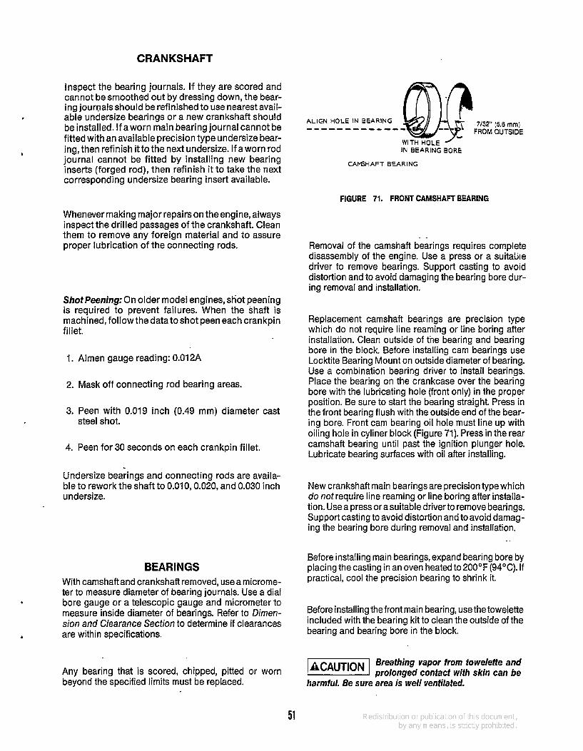
CRANKSHAFT
Inspect the bearing journals. If they are scored and cannot be smoothed out by dressing down, the bear- ing journals should be refinished to use nearest avail- able undersize bearings or a new crankshaft should be installed. If a worn main bearing journal cannot be fitted with an available precision type undersize bear- ing, then refinish it to the next undersize. If a worn rod journal cannot be fitted by installing new bearing inserts (forged rod), then refinish it to take the next corresponding undersize bearing insert available.
Whenever making major repairs on the engine, always inspect the drilled passages of the crankshaft. Clean them to remove any foreign material and to assure proper lubrication of the connecting rods.
Shot Peening: On older model engines, shot peening is required to prevent failures. When the shaft is machined, followthedatatoshot peen each crankpin fillet.
1. Almen gauge reading: 0.01 2A
2. Mask off connecting rod bearing areas.
3. Peen with 0.019 inch (0.49 mm) diameter cast steel shot.
4. Peen for 30 seconds on each crankpin fillet.
Undersize bearings and connecting rods are availa- ble to rework the shaft to 0.010,0.020, and 0.030 inch undersize.
BEARINGS With camshaft and crankshaftremoved, usea microme- ter to measure diameter of bearing journals. Use a dial bore gauge or a telescopic gauge and micrometer to measure inside diameter of bearings. Refer to Dimen- sion and Clearance Section to determine if clearances are within specifications.
Any bearing that is scored, chipped, pitted beyond the specified limits must be replaced.
or worn
7/32" (5.6 mrn) FROM OUTSIDE
ALIGN HOLE IN BEARING ------------ WITH HOLE ' IN BEARING BORE
CAPSHAFT BEARING
FIGURE 71. FRONT CAMSHAFT BEARING
Removal of the camshaft bearings requires complete disassembly of the engine. Use a press or a suitaliie driver to remove bearings. Support casting to avoid distortion and to avoid damaging the bearing bore dur- ing removal and installation.
Replacement camshaft bearings are precision type which do not require line reaming or line boring after installation. Clean outside of the bearing and bearing bore in the block. Before installing cam bearings use Locktite Bearing Mount on outside diameter of bearing. Use a combination bearing driver to install bearings. Place the bearing on the crankcase over the bearing bore with the lubricating hole (front only) in the proper position. Be sure to start the bearing straight. Press in the front bearing flush with the outside end of the bear- ing bore. Front cam bearing oil hole must line up with oiling hole in cyliner block (Figure 71). Press in the rear camshaft bearing until past the ignition plunger hole. Lubricate bearing surfaces with oil after installing.
New crankshaft main bearings are precision type which do not require line reaming or line boring after installa- tion. Use a press or asuitable driver to remove bearings. Support casting to avoid distortion and to avoid damag- ing the bearing bore during removal and installation.
Before installing main bearings, expand bearing bore by placing the casting in an oven heated to 2 O O O F (94°C). If practical, cool the precision bearing to shrink it.
..
Before installing the front main bearing, use the towelette included with the bearing kit to clean the outside of the bearing and bearing bore in the block.
-1 Breathing vapor from towelette and prolonged contact with skin can be
harmful. Be sure area is well ventilated.
51

After allowing three to four minutes for drying, apply the Locktite from the small tube to the mating surfaces of the bearing and the bearing bore. Align the oil holes in the bearing with the oil holes in the bearing bore (Fig- ure 73). The oil passage should be at least half open. Install the bearing flush with the block, using the combi- nation driver. Wipe off any exesss Locktite around the bearing. Allow at least one hour for hardening at room tern peratu re.
REAR BEARING END PLATE
ALIGN BEARING OIL HOLES WITH OIL HOLES IN
BEARING BORE
THRUST WASHER
FIGURE 72. BEARINGS FOR REAR BEARING PLATE
Engines shipped from the factory have separate thrust washers and main bearings for both front and rear of engine. Front bearing replacement part is a one piece bearing (with attached thrust washer) as shown in Figure 73. Do not add an additional thrust washer to this front bearing.
FRONT MAIN BEARING BORE
c
ALIGN BEARING NOTCHES W lTli
LOCK PINS AND MATCH OIL HOLES
849 R e v
REPLACEMENT FRONT MAIN
BEARING
FIGURE 73. FRONT BEARING INSTALLATION
In the rear bearing plate, install the bearing flush to 1 164 inch (0.40 mm) below the end of the bore. Be sure to align the oil holes in the bearing with the oil holes in the bearing bore (Figure 72). The oil passage must be at least half open. Lubricate bearing after installation.
If head of lock pin is damaged, use side cutters or Easy Out tool to remove and install new pin. Oil grooves in thrust washers must face the cranksahft, and washers must be flat (not bent). The two notches on each washer must fit over the two lock pins to prevent riding on the crankshaft (Figure 72).
Lubricate the front main bearing lightly with oil and insert the Crankshaft. With the raar bearing plate gasket in place and the rear plate bearing lubricated, slide the thrust washer (grooves toward crankshaft and plate over the end of the crankshaft. Line up notches of thrust washer with lock pins before tightening end plate or lock pins will be damaged.
A light film of oil on the thrust washer may hold it in place while installing the crankshaft.
&
CRANKSHAFT ENDPLAY After the rear bearing end plate has been tightened, using the torque recommended in Assembly Torques and Special Tools, check the crankshaft endplay as shown in Figure 74. If there istoo much endplay (see Dimensions and Clearances for minimum and max- imum endplay), remove the rear bearing end plate and add ashim (Figure 72) between thethrustwasher and plate. Reinstall the end plate, making sure the thrust washer and shim notches line up with the lock pins. Torque and recheck endplay of the crankshaft.
MEASURE ENDPLAY HERE J (REFER TO DIMENSIONS
AND CLEARANCES)
FIGURE 74. CRANKSHAFT ENDPLAY
,
52

REAR BEARING PLATE
THIS SURFACE SHOULD BE CLEANED OF ALL OLD SEALING COMPOUND BEFORE INSTALLING SEAL
\ DRIVE OR PRESS OIL SEAL TO SHOULDER OF THE PLATE BORE
MOUNTING FACE / OF GEAR COVER
THIS GEAR COVER SURFACE SHOULD BE CLEANED OF ALL OLD SEALING COMPOUND BEFORE INSTALLING SEAL
GEAR COVER OIL SEAL REAR BEARING PLATE OIL SEAL IS-1163
FIGURE 75. GEAR COVER AND REAR BEARING PLATE OIL SEALS
OIL SEALS The bearing plate must be removed to replace the oil seal (Figure 75). Drive the oil seal out from the inside.
3. Install the rings on the pistonsstarting with theoil control ring (Figure 76). Usea piston ring spreader to prevent twisting or excessive expansion of the ring. Compression rings have a dot or the word “top” on one side of the ring to indicate which side faces the top of the piston. Unmarked piston rings can be installed either way. The oil control rinn has an expander; install the expander first
Before installing seals, fill the space between lips with a multi-purpose grease. This will improve sealing.
and then close‘until the expander ends butt. The joint should be 180 degrees from the gap of that ring. When installing the gear cover oil seal, tap the seal
inward until itis.645 inch (16.4 mm)from thefrontofthe gear cover.
When installing the bearing plate oil seal, tap the seal into the bearing plate bore to bottom against the shoulder in the plate bore. Use a seal expander or place a piece of heavy paper around the end of the crankshaft, when replacing the bearing plateto avoid damaging the seal. Remove the paper as soon as the plate is in place.
Engines equipped with some types of reduction gear assemblies do not use the rear oil seal. The reduction gear assembly is oiled directly from the engine crankcase. Refer to the instructions screened on the case of the reduction gear assembly.
PISTON ASSEMBLY 1. Lubricate all parts with engine oil. 2. Position piston on its respective rod and install
the pin.
HEAVIEST COMPRESSION RING IN TOP. GROOVE
COMPRESSION RINGS
OIL CONTROL RING
FIGURE 76. PISTON RINGS
53

INSTALLATION OF PISTON IN CYLINDER
1. Turn the crankshaft to position the number one rod bearing journal at the bottom of its stroke.
2. Lubricate the number one piston assembly and the inside of the cylinder. Compress the rings with a ring compressor as shown in Figure 77.
3. Position the piston and rod assembly in the cylinder block. Oil hole in connecting rod must face camshaft. Rod bolts must be off-set toward outside of block.
4. Tap the piston down into the bore with the handle end of a hammer until the connecting rod is seated on the journal (Figure 77). Install the bearing cap on the rod. Install and tighten the bolts evenly, in steps, to the specified torques.
The bearing cap must be tapped to align it prop- erly with the rest of the connecting rod. Clear- ance varies on the journal if this is not done.
5. Install the remaining piston and rod in the same manner. Crank the engine over by hand to see that all bearings are free.
4
6. Install oil pump pick up tube and cap.
7. Install the oil base with a new gasket.
8. Install the cylinder heads. See Cylinder Headsec- tion for torques and torquing procedure.
9. Replace oil and break in engine.
OIL HOLE
cl-1077
FIGURE 77. INSTALLING PISTON AND CONNECTING ROD
54

I
CYLINDER HEAD GASKET REPLACEMENT
Remove the cylinder heads for lead cleaning and gasket change at least every200 hours, or when poor engine performance is noticed. For engines running on unleaded fuel this interval may be extended to400 hours.
1.
2.
3.
4.
5.
6.
Use a 1/2 inch (13 mm) socket wrench to remove cylinder head bolts. Lift heads off.
Do not torque or remove heads @%!!@I when they are hot. Warpage may occur.The gasket surface must be below 100" F before removal. At temperatures above 100°F, the gasket will become gummy and diffi- cult to remove from the surface of the blockand cylinder head.
After removing heads, clean out all carbon depos- its. Be careful not to damage the outer sealing edges where gaskets fit. The heads are made of aluminum and can be damaged by careless handling.
Use new head gaskets, and clean both the heads and the cylinder block thoroughlywhere the head gaskets rest.
Place a head gasket on the cylinder head, and align the stud holes in the gasket with the stud holes in the cylinder head. While holding the gasket against the cylinder head, carefully install the cylinder head on the engine. Do not attempt to slide the gasket over the studs without the cylinder head behind it or the gasket may tear.
Some engines have two compression washers and one hardened washer on the long cylinder head studs (top 6 studs on each side) as shown in Figure 78. When these washers are used, they must be installed as shown. When properly in- stalled, only the outside edges of the compres- sion washers will be in contact with each other. Install a flat washer and nut on each of the four bottom studs.
Follow the head torque sequence shown in Figure 79.
A. Asbestos head gasket torque procedure: Tighten all nuts to 5 ft-lbs (7 Nm), then 10 ft-lb (14 Nm), then to the torque specified in the ASSEMBLY TORQUES section. Recheck all nuts for correct torque.
-1 Asbestos gaskets contain fibers that when airborne
can be harmful to your health. Use a respi- rator when handling and installing gaskets.
5 5
B. Graphoil head gasket torque procedure: Start outtightening all nutsto5ft-lb(7 Nm),then 10 ft-lb (14 Nm), then to the torque specified in the ASEMBLY TORQUES section. Recheck all nuts for correct torque.
After the head nuts have been tightened once, it will be necessary to tighten each head nut to the specified torque asecond time. Follow thesame sequence shown in Figure 79. Failure to re- torque could result in a blown head gasket.
.HARDENED WASHERS
- HEAD GASKET
6 LONG STUDSIHEAD 4 SHORT STUDS/HEAD
FIGURE 78. CYLINDER HEAD WITH COMPRESSION WASHERS
Too much torque will flatten the compression washersand could
result in engine damage.
7. Recheck torque before engine has run a total of 50 hours.
. - - -
Is
LEFT CYLINDER RIGHT CYLINDER
I FIGURE 79. HEAD BOLT TIGHTENING SEQUENCE

CYLINDER HEAD STUD TEST AND REPLACEMENT PROCEDURE
This cylinder head stud replacement procedure should be used whenever replacing any of the top six studs on a NHC block. The use of a Helicoil is not a recommended repair procedure. If a Helicoil has been used, thecylinder block must be replaced. Gra- phoil head and intake manifold gaskets should also be used when replacing cylinder head studs.
Parts Required Part No. Description 520-091 2 Step stud 11 0-2987 Head gasket 154-221 9 Intake manifold gasket 420-0398 Drilling fixture (Reusable tool)
HEATTREATED
d
HARDENED WASHERS
HEAD GASKET -
6 LONG STUDS (TOP) 4 SHORT STUDS (BOTTOM)
1. Disconnect the spark plug wires and remove the spark plugs and cylinder head air shrouds from TORQUETOP SIX NUTS
TO 12 LB-FT. (COLD) TORQUE BOTTOM FOUR
NUTS TO 15 LB-FT. each cylinder.
2. Remove the nuts and compression washers (do not remove the flatwashers) from the top six studs on each cylinder head (Figure 80). Each stud will have two compression washers and one flatwasher arranged in the sequence shown in Figure 81.
Do not remove the nuts from the bottom four studs before the test procedure is completed.
USE STUDS SHOWN ABOVE LINE FOR SECTION 1 STUD TEST
LEFT CYLINDER RIGHT CYLINDER
NUMBERS INDICATE CORRECT TIGHTENING SEQUENCE FOR
CYLINDER HEAD NUTS
FIGURE 80. CYLINDER HEADS
FIGURE 81. CYLINDER HEAD STUDS
3. Replace the nuts and then test the top six cylinder head studs by tightening (use an accurate torque wrench) each nut to 30 ft-lb (40 Nm) of torque. Make a note of any studs that cannot be tightened to 30 ft-lb of torque.
4. Remove the cylinder-head nuts, flatwashers, cylinder head, and head gasket. Discard the head gasket and remove any studs that could not be torqued to 30 ft-lb (40 Nm) without thread pull out.
5. Examine the gasket surfaces of the block and cylinder head for distortion or irregularities that could cause leakage. Check the head and block for warpage by laying a straight edge over the length of the gasket surface. If a 0.005 inch feeler gauge fits between the straight edge and gasket surface, the part must be replaced or milled flat. A maximum of 0.010 inch may be machined from the cylinder block or head.
1
56

6.
7.
8.
9.
10.
11.
12.
13.
On some engines, it is possible that a groove from the old head gasket fire ring may be impressed into the head and/or block. If this is the case, it is essential that the part be replaced or milled to remove the imperfection. If all of the top six studs accepted 30 ft-lb of torque without pulling out, the new head gasket may be put on without replacement of the studs. If this is the case, skip steps 6 through 12.
Fit the special repair fixture (Onan Tool #420-0398) to the surface of the block. Use the studs shown in Figure 82 and two cylinder head nuts to secure fixture to head of block. Some applications may require that three or four flatwashers be placed over the studs between the block and fixture to space the fixture away from the block. This will be necessary if the fixture does not clear the sheet metal scroll backing plate.
Insert the small size bushing into the fixture over the hole(s) with damaged threads and lock it in place. With the brushing as a guide, drill out the damaged threads using a 27/64 size drill bit. If drilling out the holes on the SIDE of the block, drill through to the fourth fin (see Figure 83). If drilling out the holes at the TOP of the block, it will be necessary to remove the corresponding intake or exhaust manifold. The drill bit should penetrate completely into the port but should not contact the opposite wall of the port (see Figure 83).
Replace the small bushing with the large bushing and lock into place. Using a 1/2-13 tap, carefully form the threads, making sure there are full threads the entire length of the hole.
After all drilling and tapping is completed, remove the special fixture and repeat the same operation - on the other cylinder if necessary.
Remove the ridge around all new holes using a flat file or a 45" chamfer tool. When using a chamfertool, the depth of the chamfer should be 1/32 to 1/16 inch deep.
Apply screw thread retaining compound (Lock- tite 242) to the large end of each new step stud. Install the stepped replacement stud, making sure the entire stepped portion is below the gasket surface.
When putting a stepped stud into the hole that penetrates into the exhaust port, it will be neces- sary to cut approximately 3/16 to 1/4 inch (3 threads) off the stepped portion of the stud. No part of this stud may extend into the exhaust port or it will interfere with the exhaust manifold assembly. Turn engine so that both valves areclosed. Using a flat scraper and/or wire brush, remove all lead and carbon deposits from the top of the piston, valve area, and cylinder head combustion cham- ber.
1 4. Blow out all residual debris and metal chips using low pressure (35 PSI or less) air. If a hole was drilled into either the exhaust or intake port, open the valve on that port and blow it out thoroughly. Replace manifold if removed during the drilling and tapping operations.
FIGURE 83. DRILLING PROCEDURE
57

INTAKE MANIFOLD GASKET REPLACMENT
1. Remove the governor control rod from the gover- nor arm and the breather tube from the air cleaner.
2. Remove all dirt from the area around the intake manifold and cylinder head interface. Remove the four bolts holding down the intake manifold assembly, and move the manifold so that it is possible to work on the gasket area.
3. Remove the intake manifold gasket. On some models, the intake manifold gasket is tied to the exhaust manifold gasket. In these cases, use a cutting tool (chisel) to separate the intake mani- fold section of the gasket. Follow the outline of the exhaust manifold as closely as possible when cutting .
4. Install the new intake manifold gasket, making sure it is properly positioned. Make certain the outline of the gasket follows outline of port. Installing the gasket upside down will allow air leakage. This will cause lean operation and allow entry of dirt which will eventually lead to engine destruction.
5. Reinstall the intake manifold tightening the four hold down bolts to 20 to 23 ft-lb (27-31 Nm) of torque.
6. Reattach the governor control rod and air cleaner breather tube.
71 Do nof reuse anygaskefs which have been damaged by fearing,
erosion, or galling.
58

Wiring Diagrams The wiring diagrams in this section are typical for NHC and NHCV engines with 15-or20-amp flywheel alternators and other options. The separate engine control wiring diagrams shipped with each unit should be used for troubleshooting. The following drawings are included herein:
I 1 I I I 1 i I I I I I I I I I I I I I I
7--.
I --- I I 1 I I I W I
CAUTION ! REGULATOR MUST BE GROUNDED THROUGH YDUNTINC BOLTS
791
VR I MOUNTED BEHIND BLOWER WHEEL
AC B+AC STATOR
I I t
PHELON 15 AMP ALTERNATOR
. MOUNTED WH\W W R WHEEL
-61 SYNCHRO 20 AMP I 1 ALTERNATOR
I I
1 I I
ENGINE CONTROL WIRING DIAGRAM WITH OPTIONS
* WHEN USED
59

- CAUTIDH- REGULATOR MUST BE
MWKTED BLHlW B W E R WHEEL
81 ----
i i S ' I I
WIRING DIAGRAM FOR FLYWHEEL *
ALTERNATOR (PHELON 15 AMP) (622-0386)
REF. DES.
BI BT I
.El & 2
GI J I
S I
s2 TI VR I
DESCRI PTlON I Starter & Solenoid-Engine Battery, 12 V. Spark Plug
Alternator-Flywheel 15 Amp Connector
Switch-Start, Run Off
Breaker & Cap Assembly Ignition Coil (Onan) Regulator-Rectifier Voltage
WIRING DIAGRAM FOR FLYWHEEL ALTERNATOR (SYNCRO 20 AMP)
(622-0382)
REF. DES.
BI BT I CR I El. E2 E3 JI J2 MI
SI 52 53 TI VRI W I GI
DESCRIPTION
Starter & Solenoid - Engine Battery, 12 V. Rectifier Assy. Spark Plug Sender, Oil, Pressure Connector Connector - Faston Meter - Oil Pressure
Switch -S tar t Switch - Ignition Breaker & Cap Assy. Ignition Coil Regulator -Voltage Lead Assy. Alternator - Flywheel 20 h p
60


Cummins Power Generation 1400 73rd Avenue N.E. Minneapolis, MN 55432 763-574-5000 Fax: 763-574-8087
Cummins and Onan are registered trademark of Cummins Inc.