service - twinslantwinslan.net/~n0nas/manuals/onan/974-0250 onan rdje rdjea (spec … · warning...
TRANSCRIPT
Service
Diesel Engines
974-0250 (SPEC A) 10-88 Printed in U.S.A
Safety Precautions
It is recommended that you read your engine manual and become thoroughly acquainted with your equipment be- fore you start the engine.
WARNING This symbolls used throughout this a manual to warn of possible serlous personal injury.
Thls symbol refers to possible equip- ment damage.
Fuels, electrical equipment, batteries, exhaust gases and moving parts present potential hazards that could result in serious, personal injury. Take care in following these recommended procedures.
Safety Codes 0 All local, state and federal codes should be consulted
and complied with.
0 This engine is not designed or intended for use in aircraft. Any such use is at the owner's sole risk.
General 0 Provide appropriate fire extinguishers and install them . in convenient locations. Use an extinguisher rated ABC
by NFPA.
0 Make sure that all fasteners on the engine are secure and accurately torqued. Keep guards in position over fans, driving belts, etc.
If i t is necessary to make adjustments while the engine is running, use extreme caution when close to hot ex- hausts, moving parts, etc. .
Protect Against Moving Parts 0 Do not wear loose clothing in the vicinity of moving
parts, such as PTO shafts, flywheels, blowers, coup- lings, fans, belts, etc.
0 Keep your hands away from moving parts.
Batteries 0 Before starting work on the engine, disconnect batter-
ies to prevent inadvertent starting of the engine.
0 DO NOT SMOKE while servicing batteries, Lead acid batteries give off a highly explosive hydrogen gas which can be ignited by flame, electrical arcing or by smoking.
0 Verify battery polarity before connecting battery cables. Connect negative cable last.
Fuel System 0 DO NOT fill fuel tanks while engine is running.
DO NOT smoke or use an open flame in the vicinity of the engine or fuel tank. Internal combustion engine fuels are highly flammable.
Fuel lines must be of steel piping, adequately secured, and free from leaks. Piping at the engine should be approved flexible line. Do not use copper piping for flexible lines as copper will work harden and become brittle enough to break.
Be sure all fuel supplies have a positive shutoff valve.
.I
Exhaust System Exhaust products of any internal combustion engine are toxic andcan cause injury, or death if inhaled. All engine applications, especially those within a confined area, should be equipped with an exhaust system to discharge gases to the outside atmosphere.
Do not use exhaust gases to heat a compartment.
0 Make sure that your exhaust system is free of leaks. Ensure that exhaust manifolds are secure and are not warped by bolts unevenly torqued.
Exhaust Gas is Deadly! Exhaust gases contain carbon monoxide, a poisonous gas that might cause unconsciousness and death. It is an odorless and colorless gas formed during combustion of hydrocarbon fuels. Symptoms of carbon monoxide poi- soning are: 0 Dizziness Vomiting 0 Headache Muscular Twitching
Weakness and Sleepiness
If you experience any of these symptoms, get out into fresh air immediately, shut down the unit and do not use until it has been inspected.
The best protection against carbon monoxide inhalation is proper installation and regular, frequent inspections of the complete exhaust system. If you notice a change in the sound or appearance of exhaust system, shut the unit down immediately and have it inspected and repaired at once bya competent mechanic.
'Cooling System 0 Coolants under pressure have a higher boiling point
than water. DO NOT open a radiator pressure cap when coolant temperature is above 212°F (lOO°C) or while engine is running.
Throbbing in Temples
Keep the Unit and Surrounding Area Clean Make sure that oily rags are not left on or near the engine.
Remove all unnecessary grease and oil from the unit. Accumulated grease and oil can cause overheating and subsequent engine damage and present a potential fire hazard.
E-4
*
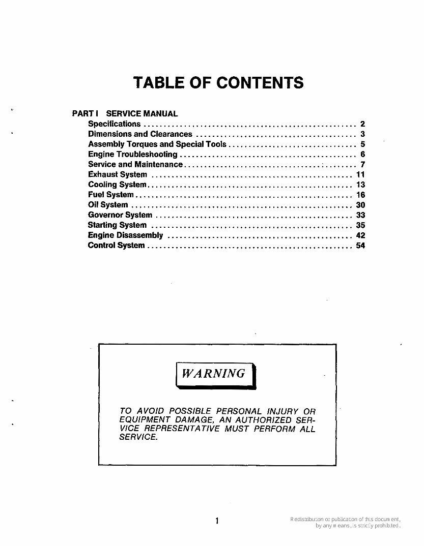
TABLE OF CONTENTS
PART I SERVICE MANUAL Specifications ..................................................... 2 Dimensions and Clearances ........................................ 3 Assembly Torques and Special Tools ................................ 5 Engine Troubleshooting ............................................ 6 Service and Maintenance .................................. ; ........ 7 Exhaust System .................................................. 11 Cooling System ................................................... 13 Fuel System ...................................................... 16
Governor System ................................................. 33 Starting System .................................................. 35 Engine Disassembly .............................................. 42 Control System ................................................... 54
Oilsystem ....................................................... 30
TO AVOID POSSIBLE PERSONAL INJURY OR
VICE REPRESENTATIVE MUST PERFORM ALL S E R VICE . EQUIPMENT DAMAGE. AN AUTHORIZED SER-
1

SPEClFl CATIONS RDJEIRDJEA
Dimensions (inches) Height ........................................................................... 28.71 (729.2 mm) Width ............................................................................ 19.75 (501.6 mm) Length.. ......................................................................... 23.04 (585.2 mm)
............................................................................. 307 Ib. Weight 2 Number of Cylinders (in-line) .......................................................
Displacement (cu in.) ............................................................. 70 inch3 (1.2 litre) Bore 3.5 (88.96 mm) Stroke 3.625 (92.08 mm)
yes
Oil Control.. .................................................................................... 1
Stellite Faced Valves.. ........................................................................... yes Stellite Replaceable Valve Seats .................................................................. Yes Valve Rotator.. ................................................................................... Yes Governor (internal flyball type-externally adjustable) ............................................. Yes Governor Regulation (percent) ..................................................................... 5 Nominal Battery Voltage ........................................................................... 12
SAE Group lH, 6 volt.. ........................................................................ two Amp/Hr SAE 20 hr (minimum). ........................................................ 120 (432 kC)
. Solenoid Shift Starter. yes Injection Pump (American Bosch type) .......................................................... PSU
.............................................................................. 1-2 Primary and Secondary Fuel Filters.. ............................................................. Yes Fuel Pump Lift (feet).. .................................................................... 6 (1.8 m) Oil Pump (gear type) ............................................................................ yes Oil Filter (full flow) ............................................................................... yes Oil Capacity U.S. quarts (includes Filter). ................................................ 3 (2.84 litre) Exhaust Connections (pipe tapped). .................................................. 1-1/2 (38.1 mm)
Shaft Length ......................................................................... 4 (101.6 mm)
Keyway Length.. ...................................................................... 3 (76.2 mm) Keyway Width.. ..................................................................... 3/8 (9.53 mm) Keyway Depth.. .................................................................... 3/16 (4.76 mm)
Compression Ratio ....................................................................... i .... 19.O:l.O
................................................................................. .............................................................................
Main Bearings are Leaded Bronze, Precision Type for Replacement (qty.) ............................ 2-
Compression.. .................................................................................. 3
Connecting Rod Bearings Tri-metal Replaceable .................................................. Piston Rings (chrome plated)
Battery Size
...........................................................................
Injection Order
Power Take-off (inches)
Shaft Diameter .................................................................... 1-314. (44.5 mm)
NOTE: The RDJE and RDJEA are almost identical engines, the differences being that the RDJE is an even firing engine; both pistons move up and down together. The RDJEA is an odd firing engine; one piston moves up while the other moves down. For the above reasons, the crankshafts, injection pumps, camshafts, and associated piece parts are different.
2
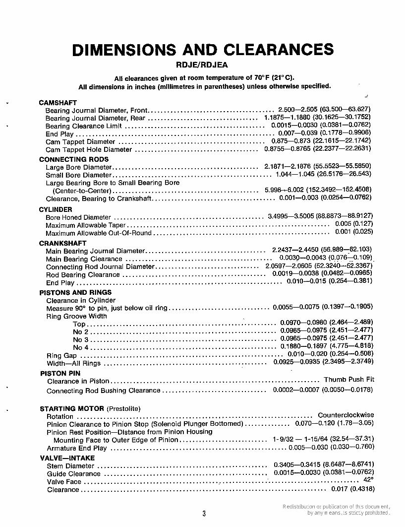
DIMENSIONS AND CLEARANCES RDJWRDJEA
All clearances given at room temperature of 70°F (21°C) . All dimensions in inches (millimetres in parentheses) unless otherwise specified .
d . CAMSHAFT
Bearing Journal Diameter. Front ....................................... 2.500-2.505 (63.500-63.627) Bearing Journal Diameter. Rear .................................. 1.1875-1.1880 (30.1625-30.1752) Bearing Clearance Limit ........................................... 0.0015-0.0030 (0.0381-0.0762) End Play ............................................................. 0.007-0.039 (0.1778-0.9906) Cam Tappet Diameter ............................................. 0.875-0.873 (22.161 5-22.1742) Cam Tappet Hole Diameter ...................................... 0.8755-0.8765 (22.2377-22.2631)
Large Bore Diameter ............................................. 2.1871-2.1876 (55.5523-55.5650) Small Bore Diameter ................................................. 1.044-1.045 (26.51 76-26.543)
(Center-to-Center) ............................................. 5.998-6.002 (152.3492-152.4508) Clearance, Bearing to Crankshaft ...................................... 0.001-0.003 (0.0254-0.0762)
Bore Honed Diameter .............................................. 3.4995-3.5005 (88.8873-88.91 27) Maximum Allowable Taper .............................................................. 0.005 (0.127) Maximum Allowable Out-Of-Round ...................................................... 0.001 (0.025)
Main Bearing Journal Diameter ..................................... 2.2437-2.4450 (56.989-62.103) Main Bearing Clearance ............................................. 0.0030-0.0043 (0.076-0.109) Connecting Rod Journal Diameter ................................ 2.0597-2.0605 (52.3240-52.3367)- Rod Bearing Clearance ............................................ 0.0019-0.0038 (0.0482-0.0965) End Play ............................................................... 0.010-0.015 (0.254-0.381)
CONNECTING RODS
Large Bearing Bore to Small Bearing Bore
CYLINDER
CRANKSHAFT
PISTONS AND RINGS Clearance in Cylinder Measure 90" to pin. just below oil ring ............................... 0.0055-0.0075 (0.1397-0.1905) Ring Groove Width
TOP .......................................................... 0.0970-0.0980 (2.464-2.489) NO 2 ......................................................... 0.0965-0.0975 (2.451-2.477) NO 3 ......................................................... 0.0965-0.0975 (2.451 -2.477) NO 4 ......................................................... 0.1880-0.1897 (4.775-4.81 8)
Wid th-All Rings .................................................. 0.0925-0.0935 (2.3495-2.3749)
Clearance in Piston ................................................................ Thumb Push Fit
Connecting Rod Bushing Clearance ................................ 0.0002-0.0007 (0.0050-0.0178)
.............................................................. Ring Gap 0.010-0.020 (0.254-0.508)
PISTON PIN
STARTING MOTOR (Prestolite) ........................................................................ Rotation Counterclockwise Pinion Clearance to Pinion Stop (Solenoid Plunger Bottomed) .............. 0.070-0.120 (1.78-3.05) Pinion Rest Position-Distance from Pinion Housing
Mounting Face to Outer Edge of Pinion ........................... 1-9/32 - 1-15/64 (32.54-37.31) Armature End Play ...................................................... 0.005-0.030 (0.030-0.760)
Stem Diameter .................................................... 0.3405-0.3415 (8.6487-8.6741) Guide Clearance .................................................. 0.0015-0.0030 (0.0381-0.0762) Valve Face ........................................................ : ............................ 42"
VALVE-INTAKE
........................................................................... Clearance 0.017 (0.4318)
3

VALVE-EXHAUST Stem Diameter .................................................... 0.3405-0.3415 (8.6487-8.6741) Guide Clearance .................................................. 0.0025-0.0045 (0.0635-0.1143) Valve Face .................................................................................... 45' Clearance ........................................................................... 0.017 (0.4318)
Length ............................................................................ 1.7812 (45.2424) Outside Diameter ................................................. 0.469-0.4696 (11.9126-11.9253)
Exhaust ...................................................... 0,344-0.345 (8.7376-8.7630) Intake ........................................................ 0.342-0.343 (8.6868-8.7122)
Cylinder Block Bore Diameter ...................................... 0.467-0.468 (11.8618-11.8872)
Bore Diameter intake ........................................................ 1.361-1.362 (34.570-34.595) Exhaust ....................................................... 1.364-1.365 (34.646-34.671)
Depth (from cylinder head face) .................................... 0.433-0.439 (10.9982-1 1.1506) I nsert-Outside Diameter .......................................... 1.364-1.365 (34.6456-34.671 0) Seat Width ........................................................ 0.0469-0.0625 (1.1912-1.5875) Angle ......................................................................................... 45' Available Oversizes .................................................................. 0.002 (0.0508)
VALVE GUIDE
Inside Diameter (after reaming)
VALVE SEATS
0.005 (0.127) 0.010 (0.254) 0.025 (0.635)
VALVE SPRINGS . *
Load-Valve Open ....................................................... -87-97 Ibs (12.0-13.4 N*) Load-Valve Closed ....................................................... 45-49 ibs (6.2-6.8 N')
N . Base unit . Newtons . Unit of force .
4

ASSEMBLY TORQUES AND SPECIAL TOOLS
The assembly torques given here will assure proper tightness without danger of stripping threads. If a torque wrench is not available, estimate thedegree of tightness necessary for the stud, nut, or screw. Be careful not to strip threads. Use reasonableforceonly and a wrench of normal length.
Specially designed place bolts do not require a lockwasher or gasket. Do not attempt to use a lockwasher with these bolts; it will defeat their purpose. Check all studs, nuts and screws often, and tighten as needed to keep them from working loose.
SPECIAL TOOLS These tools are available from Onan to aid service and repair work. Crankshaft gear pulling ring. ............. .420-0275 Diesel nozzle tester ..................... .420-0184 Diesel pintle nozzle cleaning tool set
(includes injection nozzle centering tool) .................................. 420-0208
Driver, Valve seat ....................... .420-0270 Oil seal guide and driver.. ............... .420-0456 Nozzle centering sleeve ................. .420-0321 Diesel nozzle tester ..................... .420-0322 Combination main and cam
bearing driver ........................ .420-0326 Diesel compression tester ............... .420-0283 Valve spring compressor tool ............ .420-0210 Valve seat remover.. .................... .420-0311 Flywheel puller ......................... .420-0100
TORQUE SPECIFICATIONS F1.-Lb. Nom
Connecting rod bolt ............ 27-29 (37-39) Rocker-Box cover .............. 8-10 ( 1 1-14) Cylinder head bolt. ............. 44-46 (60-62) Exhaust manifold nuts .......... 13-15* (18-20) Flywheel mounting screw ....... 65-70 (88-95) Fuel pump mounting screws .... 15-20 (20-27) Gear case cover ................ 15-20 (20-27)
Injection nozzle mounting
Injection pump mounting screws ....................... 15-16 (20-22)
Intake manifold.. ............... 13-15 (1 8-20) Oil base mounting screws.. ..... 45-50 (61-68) Oil Filter .......... Hand tight plus 1/4 to 1/2 turn Oil pump mounting screws.. .... 15-20 (20-27) Rear bearing plate. ............. 40-45 (54-61)
Glow plug.. .................... 10-15 (18-20)
screws ....................... 20-21 (27-28)
Rocker arm nut.. ............... 4-lo** (5-13) Rocker arm stud.. .............. 55-60 (75-81)
- Exhaust nuts must be tightened evenly. * * - This torque is due to friction between the threads
only and locks the nuts in place. Use the rocker arm nut to adjust valve lash.
5
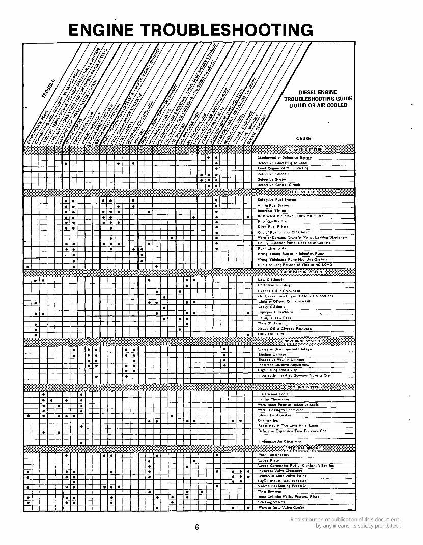
ENGINE TROUBLESHOOTING
6
SERVICE AND MAINTENANCE
PR E-STARTI N G Preparations for the initial and each additional star- ting operation should include careful checks of the oil, fuel, cooling, and electrical systems. The cylinder air housing door should be closed with all airshrouds in place.
Before engine is put in operation, check all com- ponents for mechanical security. If an abnormal condition, defective part, or operating difficulty is detected, repair or service as required. The engine should be kept free of dust, dirt, and spilledoil or fuel. Be sure proper operating procedure is followed.
Crankcase Oil: Use an oil with the API designation CD/SD or CD/SE. However, to reduce oil consump- tion to a normal level in theshortest time possible on a new or rebuilt engine, use CC oil for the first fill only (50 hours). Then use the recommended oil only. Select the correct SAE grade oil by referring to the following:
Above 32" F (0" C) ....................... SAE 30 0" F to 32" F (-18" C to 0°C) ... SAE 1OW or 5W-30 Below 0" F (-18" C) .................. SAE 5W-30
Multigrade oils are recommended for temperatures of 32" F (0" C) and below, but they are not recommend- ed for temperatures above 32" F (0" C). When adding oil between oil changes, it is preferable to use the same brand as various brands of oil may not be compatible when mixed together.
Never remove 011 level Indicator cap with the engine running, because oil will blow out of
the tube causing possible injury.
Recommended Fuel: Although number 2 diesel fuel gives the best economy for most operating con- ditions, number 1 diesel fuel can be used: 1. When ambient temperatures are below 32°F
2. During long periods of light engine load; or, 3. If preferred by user.
(0" C);
Use low sulfur content fuel having a pour point (ability to filter) of at least 10" below the lowest expected temperature. Keep the fuel clean and protected from adverse weather. Leave some room for expansion when filling the fuel tank.
Due to the precise tolerances of diesel injec- tion systems, it is extremely important the fuel
be kept clean. Dirt in the system can cause severe damage to both the injection pump and the injection nozzles.
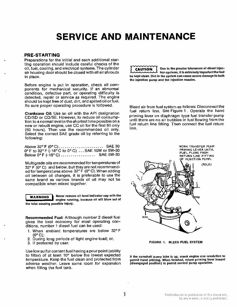
Bleed air from fuel system as follows: Disconnect the fuel return line. See Figure 1 . Operate the hand priming lever on diaphragm type fuel transfer pump until there are no air bubbles in fuel flowing from the fuel return line fitting. Then connect the fuel return line.
'WORK TRANSFER PUMP PRIMING LEVER UNTIL FUEL FLOWS FROM RETURN LINE FITTING OF INlECTlON PUMP.
FIGURE 1. BLEED FUEL SYSTEM
If the camshaft pump lobe is up, crank engine one revolution to permit hand priming. When finished, return priming lever inward (disengaged position) to permit normal pump operation.
7

PRE-HEATING AND STARTING Extremes in starting temperatures may require ad- ditional preheating. If engine fails to startquickly, rest engine several seconds and repeat starting sequence.
CAUTION If engine does not start on first attempt, check fuel system. Limit pre-heating to one minute
periods: longer periods can ruin the heater elements.
.1.
2. 3.
4.
For cold engine starting below 55" F (13" C), depress manifold heater switch for one minute only. Push START-STOP switch to its START position. Release switches after engine starts and reaches speed. Oil pressure should read at least 20 psi (pressure relief valve is not adjustable).
On "standard" model, depress preheat switch for one minute and then push start switch. Both switches must beengaged forstarting.
Do not apply overvoltage to the starting circuit at any time. Overvoltage will destroy
the glow plugs and air heater in 2 to 3 seconds. If it becomes necessary to use an additional source of power to start the set - use a 12 volt battery connected in parallel.
AUTOMATIC STARTING AND STOPPING Optional controls may be used for automatic start and stop, but must provide engine preheating. The automatic control should have a time delay relay to preheat glow plugs and the manifold heater for about 20 seconds before cranking occurs. The time delay relay prevents immediate engagement of the starter in case the load is reapplied before the engine stops.
STOPPING 1. Push fuel solenoid switch to stop position. 2. Release switch when set stops. If stop circuit fails,
close fuel valve.
APPLYING LOAD If practicable, allow engine to warm up before connecting a heavy load. Continuous overloading causes high operating temperatures that can damage the engine. The exhaust system may form carbon deposits during operation at light loads; apply full load occasionally before shut-down to prevent ex- cessive carbon accumulations.
Try to connect the load in steps instead of full load at one time.
EXERCISE Infrequent use results in hard starting. Operate at least 30 minutes each week. Run longer if battery needs charging.
BREAK-IN PROCEDURE The unit should be run in the following sequence: 1. One half hour at 1/2 load. 2. One half hour at 3/4 load. 3. Full load.
Continuous running under one half load during the first few hundred hours usually results in poor piston ring seating, causing higher than normal oil con- sumption and blowby.
Drain and replace the crankcaseoil afterfirat 50 hounof operation; drain while the englne Is stlll hot.
INSPECTION Check for alignment of engine and load. Misalign- ment will cause excessivevibration and bearing wear. Make a visual inspection of the entire installation.
VENTILATION Good ventilation is needed to cool the engine and to support combustion. Avoid recirculation of ven- tilating air. See SPEClFlCATlONS for air flow re- quirements and vent sizes.
Utilizing exhaust heat to warm a room or compartment occupied by people is not
recommended due to possible leakage of exhaust gases.
E X H A U S T G A S E S ARE DEADLY 7 1 POISONOUS!
EXHAUST Pipe exhaust gas outside any enclosure - exhaust gas is poisonous. Exhaust pipes must not terminate near inlet vents. Avoid sharp bends. Use sweeping, large- radius elbows. Use a section of seamless, flexible tubing between the engine and any rigid pipe to restrict vibration. Increase exhaust pipe one size for each additional 10 feet (304.8 cm) in length.
BATTERIES Check the condition of the starting batteries at least every two weeks. See that connections are clean and tight. A light coating of non-conductive grease will retard corrosion at terminals. Keep the electrolyte at the proper level above the plates by adding distilled water. Check specific gravity; recharge if below 1.280.
DUST AND DIRT 1. Keep radiator free of dirt, etc. 2. Service air cleaner as frequently as necessary. 3. Change crankcase oil every 50 operating hours. 4. Keep oil and fuel in dust-tight containers. 5. Keep governor linkage clean.
HIGH ALTITUDE Maximum power will be reduced approximately 4 percent for each 1000 feet (310 m) above sea level, after the first 1000 feet (310 m).
8
LOW TEMPERATURES 1. Use correct SAE No. oil for temperature con-
ditions. Change oil only when engine is warm. If an unexpected temperature drop causes an emergency, move engine to a warm location or apply heated air (never use open flame) external- ly until oil flows freely.
2. Use fresh fuel. Protect against moisture conden- sation.
3. Keep fuel system clean, and batteries in a well charged condition.
4. Partically restrict cool air flow but use care to avoid overheating.
5. Use additional preheat cycles during cold starts. .Do not exceed one minute preheat !cz3 periods; longer periods can ruin the
heater elements.
C A U ~ l ~ ~
in dusty conditions)
100
200
500
600
OUT-OF-SERVICE PROTECTION The natural lubricating qualities of No. 2 diesel fuel should protect a diesel engine for at least 30-days when unit is not in service. To protect an engine that will be out of service for more than 30 days, proceed as follows: 1. Run engine until thoroughly warm; under at least
50 percent load. 2. Shut down engine and drain oil base while still
warm. Refill and attach a warning tag indicating viscosity of oil used.
3. Remove glow plugs. Pour 1-ounce of rust in- hibitor (or SAE #10 oil) into each cylinder. Install
Crank engine by hand only to distribute m oil in cylinder. Starter cranking is too fast: oil or inhibitor fluid will fire if cranked with starter at normal room temperature.
glow plugs.
CAUTION
Check air cleaner.
Clean governor linkage, Change crankcase oil Drain fuel condensation traps in lines and filters, see Note 1
Clean crankcase breather Replace oil filter Check battery condition
Check.start-disconnect circuit Check valve clearances
Change primary filter
4. Service air cleaner per Maintenance Schedule. 5. Clean throttle and governor linkage and protect
6. Plug exhaust outlets to prevent entrance of
7. Clean and wipe entire unit. Coat parts susceptible
8. Disconnect battery and follow standard battery
by wrapping with a clean cloth.
moisture, bugs, dirt, etc.
to rust with a light coat of grease or oil.
storage procedure. 3000 I 5000
Returning a Unit to Service. 1. Remove cover and all protective wrapping.
Remove plug from exhaust outlet. 2. Check warning tag on oil base and vertify that oil
viscosity is still correct for existing ambient temperature.
3. Clean and check battery. Measure specificgravity (1.260 at 77" F [25" C]) and verify level is at split ring. If specific gravity is low, charge until correct value is obtained. If level is low, add distilled water and charge until specific gravity is correct. DO NOT OVERCHARGE.
Change secondary fuel filter
General overhaul (if required) see Note 3
Do not smoke while servicing batteries. Explosive gases are emitted from
batteries in opeation. Ignition of these gases can causesevere personal injury.
4. Check that fuel injectors and fuel lines are secure, correctly torqued.
5. Clean radiator. 6. Connect batteries. 7. Verify that no loads are connected to engine. 8. Start engine.
After engine has started, excessive blue smoke will be exhausted until the rust inhibitor or oil has burned away.
Before commencing any maintenance work on the engine, controls, or associated equlp-
ment, disconnect batteries. Failure to do so could result in damage, serious personal injury In the event of inadvertent starting.
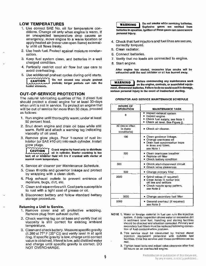
OPERATOR AND SERVICE MAINTENANCE SCHEDULE
I HOURSOF I I I I OPERATION MAINTENANCE TASK I
Inspect exhaust system Inspect engine Check fuel SUPDIV, see Note 1 I Check oil leve1:See Figure 2.
50 (more often I I
2000 Grind valves (if required) Clean holes in rocker box oil line and orifices Check nozzle spray pattern, see Note 2
NOTE 1. Water or foreign material in fuel can ruin the injection system. If daily inspection shows water or excessive dirt in sediment bowl fuel, handling and storing facilities should be checked and situation corrected. Primary and secondary fuel filters must be replaced following correc- tion of fuel contamination problem.
2. This service must be conducted by trained diesel injection equipment personnel with suitable test facilities. Omit this service until these conditions can be met.
3. Tighten head bolts and adjust valve clearance after first 50 hours on an overhauled engine.
9
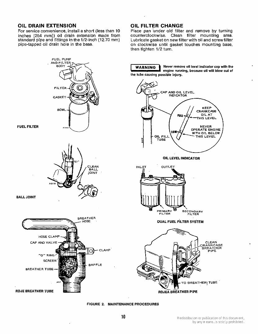
OIL DRAIN EXTENSION For service convenience, install a short (less than 10 inches [254 mm]) oil drain extension made from standard pipe and fittings in the 1/2-inch (12.70 mm) pipe-tapped oil drain hole in the base.
FUEL FILTER
F l lEL PUMP
BALL JOINT
BREATHER \% HOSE
CAP AND VALVE
BREATHER TUBE
RDJE BREATHER TUBE
AMP'
OIL FILTER CHANGE Place pan under old filter and remove by turning counterclockwise. Clean filter mounting area. Lubricate gasket on new filter with oil and screw filter on clockwise until gasket touches mounting base, then tighten 1/2 turn.
Never remove 011 level Indicator cap with the engine running, because oil will blow out of
the tube causing possible Injury.
OIL LEVEL INDICATOR
INLET OUTLET
ONDARY FILTER FILTER
DUAL FUEL FILTER SYSTEM
T O BREATHERJ TUBE
L.2.
RDJEA BREATHER PiPE
FIGURE 2. MAINTENANCE PROCEDURES
10

GENERAL The exhaust system must efficiently expel all engine combustion products and muffle exhaust noises with minimum back pressure. If back pressure is too high, the volumetric efficiency of the engine is reduced, fuel economy drops, exhaust temperature increases, end valve life is shortened.
Back pressure must not exceed 27 inches (686 mm) of water column for the rated load when measured with a manometerat the exhaust manifold, Figure 3.
FIGURE 3. BACK PRESSURE TEST WITH MANOMETER
Exhaust Smoke A light gray or light blue smoke is a result of low ambient temperature and light load. This smoke is unburned fuel (not harmful to the engine) and disappears when more load is applied.
Black smoke indicates overfueling (more fuel than oxygen) and is usually caused by overloading. The smoke or unburned fuel becomes carbon when raised to a high temperature. Carbon contributes to engine damage because it sticks to rings and fuel injection nozzles.
E X H A U S T G A S E S ARE DEADLY -1 POISONOUS!
Vent exhaust gases outside. Use flexible tubing only between the engine exhaust outlet and rigid piping.
WARN~NG On service calls, always inspect exhaust = systems for possible leaks. Report any ex- haust hazards to theowner/operatorand warn them of the potential dangers to life if not repaired.
INSTALLATION TIPS Points to remember when installing an exhaust system are:
Exhaust pipes should be as short as possible with a minimum of fittings. The muffler must be as close to the engine as possible. Mufflers which are too far from the manifold remain cool and collect carbon residue. Pitch exhaust pipe upward from exhaust outlets to avoid entrapment of rawdiesel fumes in muffler at shutdown. Avoid sharp bends by using large radius elbow. Check back pressure with a mercury or water column type manometer. Position the exhaust outlet away from the engine air intake.
Exhaust noise can be suppressed or reduced by: Using a heavy duty exhaust system with a more efficient muffler. Avoiding use of flexible lines. Installing a deflector at the exhaust outlet to direct exhaust toward the ground, but away from the operator. Using a resonator in addition to a muffler.
The importance of exhaust systems (normally supplied by the customer) cannot be over- emphasized. A poor or clogged system causes low power, overheating and engine damage. A poor exhaust system increases back pressure which reduces efficiency.
If the manufacturer tailon his own exhaust system, an Onan applications engineer must
approve the installation for warranty purposes.
11
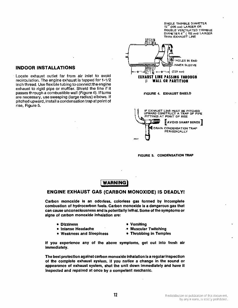
SINGLE THIMBLE DIAMETER 12” (30s mm) LARGER OR DOUBLE VENTILATED THIMBLE DIAMETER 6” ( 152 mm) LARGER
INDOOR INSTALLATIONS
Locate exhaust outlet far from air inlet to avoid recirculation. The engine exhaust is tapped for 1-1/2 inch thread. Use flexible tubing to connect theengine exhaust to rigid pipe or muffler. Shield the line if it passes through a combustible wall (Figure 4). If turns are necessary, use sweeping (large radius) elbows. If pitched upward, install a condensation trap at point of rise, Figure 5.
THANEXHAUS? LINE
S IN END SLEEVE
EXHAUST LINE PASSING THROUGH II WALL OR PARTITION
FIGURE 4. EXHAUST SHIELD
IF EXHAUST LINE MUST BE PITCHED UPWARD CONSTRUCT A TRAP OF PIPE ,. FITTINGS AT POINT OF RISE
DRAIN CONDENSATION TRAP PERIODICALLY
A617
FIGURE 5. CONDENSATION TRAP
\WARNING)
ENGINE EXHAUST GAS (CARBON MONOXIDE) IS DEADLY!
Carbon monoxide is an odorless, colorless gas formed by incomplete combustion of hydrocarbon fuels. Carbon monoxide is a dangerous gas that can cause unconsciousness and is potentially lethal. Some of the symptoms or signs of carbon monoxide inhalation are:
Dizziness Vomiting Intense Headache Weakness and Sleepiness
.. Muscular Twitching Throbbing in Temples
I f you experience any of the above symptoms, get out into fresh air immediately.
The best protection against carbon monoxide inhalation is a regular inspection of the complete exhaust system. I f you notice a change in the sound or appearance of exhaust system, shut the unit down immediately and have it inspected and repaired at once by a competent mechanic.
12

COOLING SYSTEM RADIATOR COOLED SYSTEM On radiator cooled models (Figure 6), the water pump draws cooled water from the radiator through the bottom hose and forces it into the cylinder water jacket at the front of the engine. The water circulates through the cylinder water jacket up through the eylinder heads into the thermostat and flows through the outlet hose into the top of the radiator. It circulates down through the radiator while the fan blows cooling air across the radiator. The water is drawn from the bottom of the radiator by the pump to be recirculated.
WATER PUMP
-- WATER FLOW, ENGINE COOLING
c/"L AIR FLOW, ENGINE VENTILATION LEGEND
FIGURE 6. RADIATOR COOLING SYSTEM
During engine warmup, when the thermostat is closed, the water bypasses the radiator. It flows through a bypass line from the wateroutlet housing to the pump and recirculates through the engine, until
PUGLEY
HOUSING GASKET
FIGURE 7a. WATER PUMP-EXPLODED VIEW
the water reaches normal operating temperature. Recirculation ensures both rapid and even temper- ature increase of all engine parts during warmup. Figure 7a shows an exploded view of the water pump.
Ventilation for radiator cooled models requires an inlet opening for fresh air and an outlet opening for heated air to prevent recirculation of heated air. The openings should be at least the size of the radiator.
An expansion area in the closed cooling system maintains proper coolant level by
preventing overflow and loss of coolant when engine heats up.
The engine water pump is a centrifugal type with a cast impeller. It mounts on the front of the engine cylinder block and is driven by the fan belt from the crankshaft pulley. The inlet to the water pump isfrom the radiator lower hose. The outlet is through the water pump housing into the cylinder water jacket passages.
The water pump requires no lubrication; the bearings are permanently sealed and packed with a life time lubricant. It requires no maintenance other than bearing replacement if they show excessive looseness, or replacement of the seal (impeller) if the pump leaks water.
ANTI-FREEZE AND PRESSURE CAPS Corrosion can shorten an engine's life by plugging up radiator. cores, building up around hot spots near the exhaust valves, and settling in low areas of the block. The corrosive sediment insulates against proper heat transfer and holds heat in. Most of the metals used in cooling systems are susceptible to corrosion damage that causes coolant leaks and the temperature to rise above safe, normal limits. Since pressurized cooling systems run far hotter than the boiling point of water (212°F [lOO"C]) at atmospheric pressure, even greater breakdown of anti-freeze and water solutions result. The average pressure cap (15 pound [103.5 kPa]) raises the boiling point of the engine coolant to 265OF (132" C).
Most anti-freeze manufacturers recommend a minimum 50-50 mixof ethyleneglycol anti-freezeand water for winter and summer in closed water systems with a complete change every year to avoid corrosion and more expensive damage.
Defective pressure caps cause many cooling problems and should be replaced every two years or whenever they malfunction.
13

COOLING SYSTEM MAINTENANCE The cooling system including the block and radiator should be cleaned and flushed at least once a year. This is especially true in cold weather conditions or when preparing unit for extended storage (over 30 days or more)!
The cooling system can work efficiently only when it is clean. Scale and rust in the cooling system slow down heat absorption and restrict water flow.
The thermostat is calibrated to open at 15OoFf2OF. It should be checked also.
An appropriate anti-freeze mixture should be used in colder climates as necessary.
Corrosion inhibitors reduce the formation of rust in a cooling system. Corrosion protection can best be provided in winter by using anti-freeze containing the inhibitor.
Water filters should be used in areas where the water is extremely hard and rust inhibitors cannot protect the cooling system from the formation of rust and scale.
Keep the radiator clean to provide maximum cooling. Remove all dirt, lint, etc. Keep the radiator cap closed during operation.
Check the fan belt tension periodically. For proper operation of the water pump, the fan belt should be tight enough to prevent slipping.
Check the water pump for wear periodically. Loosen the fan belt and move the fan and water pump pulley back and forth. If wear is excessive, replace the bearing.
DRAINING COOLING SYSTEM Whenever draining the cooling system for changing anti-freeze solution or for out-of-service protection when only water is used, be sure to open all drains and hose connections where water could be trapped.
The following drain plugs must be removed to allow complete flushing of the cooling system.
Radiator: One petcock lower right front corner.
Engine Block: One drain plug left front near water pump.
Water Pumps: One drain plug under cover or by loosening cover.
If an optional water jacket tank heater is used it should be drained and flushed also. The lower hose must be disconnected at the tank heater. There is no drain plug.
‘
Further information concerning the location and part numbers for the various drain plugs throughout the unit is shown in the Parts Catalog.
Onan recommends the use of clean ethylene glycol anti-freeze solutions in closed cooling systems dur- ing normal operation and storage periods. Be sure anti-freeze solution will protect the cooling system during the coldest winter weather.
FLUSHING SYSTEM Flush the system at least once a year and more often if operation indicates clogged passages or overheating. To flush the system:
1. Drain the radiator, cylinder block and exhaust manifold.
2. Remove the inlet and outlet hoses between the engine and radiator.
3. Close all drain plugs and attach the flushing gun nozzle to the water outlet, as near the exhaust manifold as practical. Restrict the normal inlet line opening until the system fills with water, then apply air pressure gradually. Repeat the process until the water from the cylinder block flows clean.
4. Remove flushing gun.
5. Reinstall thermostats, hoses and drain plugs and refill the system with the proper coolant.
6. When flushing is completed, check the system thoroughly for any leaks uncovered by the clean- ing operations.
BLEEDING AIR FROM COOLING SYSTEM Air must be bled from the cooling system for proper operation. If your engine is not equipped with a vent plug in the water pump housing, install a 3/8” pipe plug in the top of the housing. Allow engine to cool and bleed as follows:
1. Fill radiator with 50-50 mix of ethyleneglycol anti- freeze and water.
2. Remove plug or sender from water manifold on top of engine to vent trapped air (Figure 7b). Replace plug or sender when water emerges from hole.
14
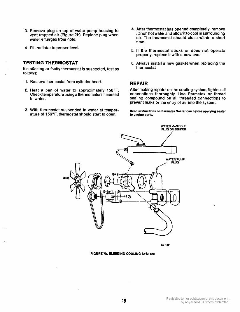
3. Remove plug on top of water pump housing to 4- After thermostat has opened completely, remove vent trapped air (Figure 7b). Replace plug when water emerges from hole.
it from hot water and allow it to cool in surrounding air. The thermostat should close within a short time.
4. Fill radiator to proper level.
TEST1 NG THERMOSTAT If a sticking or faulty thermostat is suspected, test as follows:
1. Remove thermostat from cylinder head.
2. Heat a pan of water to approximately 150°F. Check temperature using a thermometer immersed in water.
3. With thermostat suspended in water at temper- ature of 1 5OoF, thermostat should start to open.
5. If the thermostat sticks or does not operate
6. Always install a new gasket when replacing the
properly, replace it with a new one.
thermostat.
REPAIR After making repairs on the cooling system, tighten all connections thoroughly. Use Permatex or thread sealing compound on all threaded connections to prevent leaks or the entry of air into the system.
Read instructions on Permatex Sealer can before applying sealer to engine parts.
WATER MANIFOLD PLUG OR SENDER
\ WATER PUMP
W cs-1361
FIGURE 7b. BLEEDING COOLING SYSTEM
15

FUEL SYSTEM
KEEP FUEL
CLEAN! 0
DIRTY FUEL I S ONE OF THE MAJOR CAUSES OF ENGINE FAILURI
0 REMEMBER- EVEN A TINY PARTICAL OF DIRT IN
THE INJECTION SYSTEM M A Y STOP YOUR ENGINE!
0
FUEL MANAGEMENT FUEL SYSTEM 1.
2. 3.
4.
5.
Zinc or galvanized tanks should not be used as harmful compounds may form due to reactions with fuel oil impurities. Pitch fuel tanks down away from fuel outlet.
The fuel system (Figure 10) consists of a glass sediment bowl, fuel transfer pump, primary filter, secondary filter, injection pump, injectors, and the connecting fuel lk~es.
Use a drain cock with provisions for draining off water and sediment. A fuel filterand watertrap located on tankoutlet is good practice. Fill tanks on mobile equipment at end of each day to keep condensation at a minimum.
In low temperatures, it is quite common for diesel fuels to become jelly-like. The point at which they cease being a liquid is known as the pour point. This quality should be watched carefully in temperatures of 20°F (-7°C) or lower.
Pour Point' Pour point indicates the suitability of fuel to cold weather operation. Fuel should pour at 10°F (-6°C) below the lowest expected ambient temperature, Figure 8. .
INJECTION GLOW NOZZLE
PLUG . CONNECTION
POINT FOR FUEL RETURN
SECONDARY FUEL FILTER F U E L FILTER
FIGURE 10. FUEL SYSTEM
FIGURE 8. POUR POINT
16

Do not use galvanized lines, fittings, or fuel tanks in underground portions of the fuel
system. Hazardous fuel leaks may be caused by electrolytic corrosion from moisture and chemicals in the soil (galvanism). Some safety ordinances prohibit the use of galvanized materials in fuel systems and the use of threaded cast iron fittings as well.
The fuel system, located on the service side of the engine, uses a transfer pump to deliver fuel from the tank to a high pressure injection pump at about 12 to 14 psi (83-97 kPa). The injection lines deliver fuel to the injectors at high pressure and act as fuel dis- tributors to the injectors. The time interval between individual injectors is varied in the pump by engine speed. From the injection pump, metered fuel is forced through a delivery valve to the injector lines at about 1900 psi (13,110 kPa). When the cylinder air reaches about 1000°F (538°C) on the compression stroke, the injector sprays fuel into the hot com- pressed air where it ignites. The delivery valve in the injection pump and a pintle valve in the injector assists the precision timed injection of fuel into the cylinder. .
Excess fuel is returned to the tank after each injection cycle by a fuel return line from the nozzle. An adapter combines the leak-off fuel with the flow-through fuel from the injection pump. A return line connected at this point returns the combined fuel back to the fuel supply tank.
A diesel engine cannot tolerate dirt in the fuel svstem. It is one of the maior causes of diesel
engine failure. A tiny piece of dirt in the Injection system may stop your unit. When opening any part of the fuel system beyond the secondary fuel filter, place all parts in a pan of clean diesel fuel as they are removed. Before installing new or used parts, flush them thoroughly, and install while still wet.
FILTER SYSTEM The sediment bowl has a fine mesh screen which blocks dirt and water entry into the transfer pump, Figure 10. The dirt and water remain in the sediment bowl which should be removed for cleaning as required. The primary and secondary fuel filters are replaceable spin-on units that clean the fuel of extremely fine particles before it goes to the injection pump.
These filters are mounted on a common casting which bolts to the oil fill tube. Positive filtration is assured because the engine won’t run when either filter is loose or missing.
Average pore size of the second filter is .0005 (0.0127 mm) smaller than the first filter. This means most particles escaping the first filter are trapped in the second filter.
Water in Fuel Filters: Drain water periodically as required from both filters. Replace primary filter every 600 hours and secondary filter every 3000 hours. When replacing filter, tighten screw until gaskets touch base, then tighten screw 1 to 1-1/2 turns.
FUEL TANK AND LINES Where a separate fuel tank is used, install so the vertical distance from bottom of the tank to the fuel pump does not exceed six feet. Auxiliary fuel pumps are available to provide an additional eight-foot lift.
Avoid gravity feed of fuel to the engine. Provide a siphon break if tank is above pump. When sharing a fuel tank, do not connect to an existing line at a point above the fuel supply level.
These diesel engines require a fuel supply line and a separate return line. Install the fuel supply line from tank to the 1/8-inch pipe inlet in the fuel pump. Connect fuel return line to fitting at injection pump. See Figure 10. Use approved flexible fuel lines at the engine to absorb vibration. Be sure there are no air leaks in the suction line.
Install a shut-off valve in the tank for service con- venience.
FUEL TRANSFER PUMP
The fuel transfer pump (Figure l l ) , is a diaphragm and check valve type pump operated by a cam lobe on the engine camshaft. The pump cam follower has a wide surface to prevent wear as it rides on the camshaft lobe. The priming lever is manually operated to prime and bleed the system.
The diaphrgam spring maintains required fuel pressure to the injection pump. Fuel pressure should be 12-14 psi (83-97 kPa) when operating at 1800 rpm.
ROCKER ARM SPRING ... COVER
DIAPHRAGM ASSEMBLY
DIAPHRAGM SPRING
ROCKER ARM
LINK
FIGURE 11. FUEL TRANSFER PUMP
17
Fuel pump pressure may be checked by connecting a pressure gauge and tee at the fuel outlet. A vacuum
the pump has enough capacity to lift fuel about 6 feet (1.83 m). The fuel pump should produce 15 to 18 inches (381 to 457 mm) of vacuum at sea level.
7. Tighten cover screws alternately and securely, then release rocker arm.
test. gauge connected at the fuel inlet will show whether 8. Install pump on the engine and repeat pressure
INJECTION NOZZLES
.1.
2.
3.
4.
5. 6. 7.
Onan diesel engines use hyd raul icall y-operated, pintle-type injection nozzles, Figure 12. They are factory adjusted to open at 1900 to 1950 psi (13,110 to 13.455 kPal. However. after several hundred hours of
Fuel Pump Removal Disassembly Remove Pump inlet and outlet lines. Remove two cap screws holding pump to engine and l i f t it off. Notch the pump cover and body with afileso they can be reassembled in same relative positions and remove six screws holding them together.
operation (he nozzle pressure will decrease to about 1750 psi (12,075 kPa).
Tao bodv with a screwdriver to seDarate two COVER
paits. Ddnot pry them apart; this would damage d ia p h rag m. Remove screws holding valve plate to cover and lift out valve and cage assemblies. Drive out rocker arm hinge pin. Remove rocker arm, spring and link. Lift out diaphragm assembly and diaphragm spring.
Repair: Transfer pump failure is usually due to a leaking diaphragm, valve or valve gasket, Figure 11. A kit is available for replacement of these parts. Because the extent of wear cannot be detected by the eye, replace all parts in the kit. If the diaphragm is broken, or leaks, check for diluted crankcase oil and replace.
Occasionally, failure isdue to a broken orweak spring or wear in the linkage. In this case, replace the worn parts or install a new pump. Obtain replacement parts other than the repair kit from an original equipment parts distributor.
Assembly: 1. When installing a new diaphragm, soak it in fuel
before assembling. Insert diaphragm spring and soaked diaphragm into pump body.
2. Insert link and rocker arm into body and hook it over diaphragm pull rod. Align rocker arm with
-rocker arm pin hole and drive in pin. The priming lever must be in position shown in Figure 11 when installing rocker arm.
3. Compress rocker spring and install between the body and rocker arm.
4. Insert valve cages, gaskets and valve cover plate. Position inlet valve with spring showing and outlet valve with spring in cover recess.
5. Assemble cover to body with notch marks lined up. Install screws, but do not tighten.
6. Push rocker arm in full stroke and hold in this position to flex diaphragm.
PRESSURE A
GASKET^ SPINDLE ASSEMBLY:
ADAPTER - NOZZLE GASKET
NOZZLE SHIELD
SHIELD CASK NOZZLE ASSEMBLY FUEL CUP GASKE
CYLINDER HEAD
- A 0 0
FIGURE 12. NOZZLE ASSEMBLY
COVER 4
SCREW -+ FUEL INLET A
NOZZ LE
PRESSURE ADJUSTING
;ING
JDLE
rDAP'
ASS
TER
4BLY
The diaphragm must be flexed, or it will delivertoo much fuel pressure.
FIGURE 13. INJECTOR NOZZLE HOLDER
18
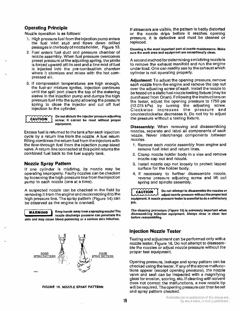
Operating Principle Nozzle operation is as follows: 1. High pressure fuel from theinjection pump enters
the fuel inlet stud and flows down drilled passages in the body of nozzle holder, Figure 13.
2. Fuel enters fuel duct and pressure chamber of nozzle assembly. When fuel pressure overcomes preset pressure of the adjusting spring, the pintle is forced upward off its seat and a fine mist of fuel is injected into the pre-combustion chamber where it atomizes and mixes with the hot com- pressed air.
3. If compression temperatures are high enough, the fuel-air mixture ignites. Injection continues until the spill port clears the top of the metering sleeve in the injection pump and dumps the high pressure fuel into the sump allowing the pressure spring to close the injector and cut off fuel injection to the cylinder.
Do not disturb the injector pressureadjusting screw; it cannot be reset without proper equipment.
Excess fuel is returned to the tankafter each injection cycle by a return line from the nozzle. A fuel return fitting combines the return fuel from the injectors with the flow-through fuel from the injection pump bleed valve. A return line connected at this point returns the combined fuel back to the fuel supply tank.
Nozzle Spray Pattern If one cylinder is misfiring, its nozzle may be operating improperly. Faulty nozzles can be checked by loosening the high pressure line from theinjection pump to each nozzle (one at a time).
If streamers are visible, the pattern is badly distorted or the nozzle drips before it reaches opening pressure, it is defective and must be cleaned or replaced.
Cleaning is the most important part of nozzle maintenance. Make sure the work area and equipment are exceptionally clean.
A second method for determining a misfiring nozzle is to remove the exhaust manifold and run the engine under load. One can readily see by theexhaust which cylinder is not operating properly.
Adjustment: To adjust the opening pressure, remove each nozzle from the engine and remove the cap nut over the adjusting screw of each. Install the nozzle to be tested on astaticfuel nozzletesting fixture (may be purchased from Onan). Following the instructions on the tester, adjust the opening pressure to 1750 psi (12.075 kPa) by turning the adjusting screw. Clockwise increases the pressure and counterclockwise decreases it. Do not try to adjust the pressure without a testing fixture.
Disassembly: When removing and disassembling nozzles, separate and label all components of each nozzle. Never interchange components between nozzles. 1. Remove each nozzle assembly from engine and
remove fuel inlet and return lines. 2. Clamp nozzle holder body in a vise and remove
nozzle cap nut and nozzle. 3. Install nozzle cap nut loosely to protect lapped
surface for the holder body. 4. If necessary to further disassemble nozzle,
reverse pressure adjusting screw and lift out spring and spindle assembly.
Do not attempt to disassemble the nozzles or adjust nozzle pressure without the propertest
equipment. A nozzle pressure tester is essential to do a satisfactory job.
A suspected nozzle can be checked in the field by removing it from theengineand reconnecting itto the high pressure line. The spray pattern (Figure 14) can be observed as the engine is cranked.
7 1 Keep hands away fromaspraying nozzle! The nozzle discharge pressure can penetrate the
skin and may cause blood poisoning or a serious skin infection.
The Cleaning procedure (Figure 15) is extremely important when disassembling injection equipment. Always rinse in clean fuel before reassembling.
Injection Nozzle Tester
Testing and adjustment can be performed only with a nozzle tester, Figure 16. Do not attempt to disassem- ble the nozzles or adjust nozzle pressure without the
POOR proper test equipment. - SPRAY PATTERN
: . . I ?! . , Opening pressure, leakage and spray pattern can be checked using the tester. If any of the above malfunc- tions appear (except opening pressure), the nozzle valve and seat can be inspected with a magnifying glass for erosion, scoring, etc. If cleaning with solvent does not correct the malfunctions, a new nozzle tip will be required. Theopening pressure can then beset and spray pattern checked.
-*.." ,:;. .@''C .697 h.
FIGURE 14. NOZZLE SPRAY PATTERN

1 Use a brass type scrapertool to remove hard carbon deposits from nozzle body valve seat.
5. Clean nozzle valve and polish with tallow and a wooden polishing fixture. Take care to remove all traces of tallow when finished.
2. After scraping the carbon, polish the valve seat by using a round pointed stick dipped in tallow. Polishing should restore seat to its original finish unless it’s scored.
3. Use a special hooked type scraper to clean the nozzle pressure chamber gallery. The hooked end of scraper is inserted into the gallery and then carefully rotated.
6. Examine nozzle valve and body with a magnifying glass. If erosion and scoring conditions are found, renew the valve and body.
7. Use a lapping plate and compound for flat lapping of nozzle parts which depend on a lapped surface for sealing. A figure “8’ motion is used.
CENTERING
4. Small holes i n tip of nozzle body can be cleaned with a fine wire slightly smaller than the size of the hole.
8. I t is essential that the nozzle body is perfectly centered in the cap nut when reassembling nozzle. A centering sleeve, as shown, is used for this purpose.
FIGURE 15. NOZZLE CLEANING
20
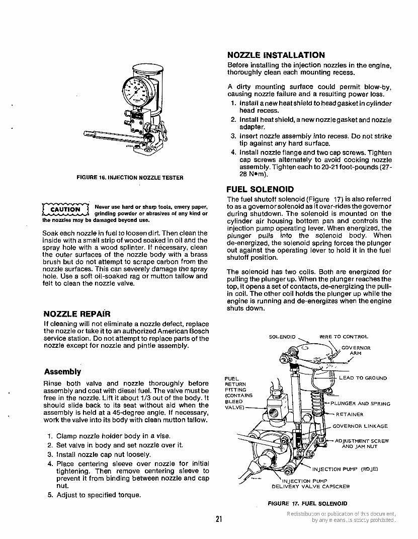
FIGURE 16. INJECTION NOZZLE TESTER
Never use hard or sharp tools, emery paper, grinding powder or abrasives of any kind or
the nozzles may be damaged beyond use.
Soak each nozzle in fuel to loosen dirt. Then clean the inside with a small strip of wood soaked in oil and the spray hole with a wood splinter. I f necessary, clean the outer surfaces of the nozzle body with a brass brush but do not attempt to scrape carbon from the nozzle surfaces. This can severely damage the spray hole. Use a soft oil-soaked rag or mutton tallow and felt to clean the nozzle valve.
NOZZLE REPAIR If cleaning will not eliminate a nozzle defect, replace the nozzle or take it to an authorized American Bosch service station. Do not attempt to replace parts of the nozzle except for nozzle and pintle assembly.
Assembly Rinse both valve and nozzle thoroughly before assembly and coat with diesel fuel. The valve must be free in the nozzle. Lift it about 1/3 out of the body. It should slide back to its seat without aid when the assembly is held at a 45-degree angle. If necessary, work the valve into its body with clean mutton tallow.
1. Clamp nozzle holder body in a vise. 2. Set valve in body and set nozzle over it. 3. Install nozzle cap nut loosely. 4. Place centering sleeve over nozzle for initial
tightening. Then remove centering sleeve to prevent it from binding between nozzle and cap nut.
5. Adjust to specified torque.
NOZZLE 1 NSTALLATI 0 N Before installing the injection nozzles in the engine, thoroughly clean each mounting recess.
A dirty mounting surface could permit blow-by, causing nozzle failure and a resulting power loss. 1. Install a new heat shield to head gasket in cylinder
head recess. 2. Install heat shield, a new nozzlegasket and nozzle
adapter. 3. Insert nozzle assembly into recess. Do not strike
tip against any hard surface. 4. Install nozzle flange and two cap screws. Tighten
cap screws alternately to avoid cocking nozzle assembly. Tighten each to 20-21 foot-pounds (27- 28 Nom).
FUEL SOLENOID The fuel shutoff solenoid (Figure 17) is also referred to as a governorsolenoid as it over-rides thegovernor during shutdown. The solenoid is mounted on the cylinder air housing bottom pan and controls the injection pump operating lever. When energized, the plunger pulls into the solenoid body. When de-energized, the solenoid spring forces the plunger out against the operating lever to hold it in the fuel shutoff position.
The solenoid has two coils. Both are energized for pulling the plunger up. When the plunger reaches the top, it opens a set of contacts, de-energizing the pull- in coil. The other coil holds the plunger up while the engine is running and de-energizes when the engine shuts down.
SOLENOID ~ WIRE TO CONTROL
FUEL D TO GROUND RETURN FITTING
NGER AND SPRING
GOVERNOR LINKAGE
ADJUSTMENT SCREW AND JAM NUT
JECTION PUMP (RDJE)
I N J ECTl ON PUMP DELIVERY VALVE CAPSCREW
FIGURE 17. FUEL SOLENOID
21

To test the solenoid, check plunger operation and current draw with 12-volt input. Current draw with the plunger up should be about 1 amp. If it is much greater, the contacts did not open.
The solenoid plunger should be adjusted so it fully stops injection when in the de-energized position. To adjust the plunger length, screw the hex head cap screw and jam nut on the plunger bottom in or out. If the plunger sticks, remove the solenoid from its mounting plate and clean the plunger and recess in the solenoid.
PREHEATING CIRCUIT This 12 volt battery circuit consists partly of manifold heaters that heat the combustion air at the intake manifold and a glow plug in each cylinder that heats
. the precombustion chamber for engine starting, Figure 18). The manifold heater and glow plugs are wired in parallel and are controlled by a preheat switch on the control box.
GLOW PLUG
MANIFOLD HEATER \
FIGURE 18. GLOW PLUG AND MANIFOLD HEATER
Check each heater by removing its lead, operating the preheat switch, and touching the lead to its terminal. If it sparks, there is continuity and the heater is working. If any componentsof this circuit fail, replace them. Do not attempt repairs on individual com- ponents. If there is still a question, check the compo- nent for heating.
FUEL INJECTION PUMPS Onan diesels are equipped with the model PSU fuel injection pumps.
The fuel injection pumps are constant stroke, lapped plunger type and operated by the engine camshaft. They deliver an accurately measured quantity of fuel under high pressure to the injection nozzles.
A constant bleed-check valve is furnished with all PSU pumps.The bleed valve automatically bleedsoff a restricted amount of fuel, fuel vapors, and small quantities of air to prevent air accumulation in the fuel sump area of the pumps. This valve should open at pressures between 0.9 and 3.0 psi (6.2 and 20.7 Wa).
INJECTION PUMP REPAIR Internal repairs on the PSU injection pumps require special tools and step-by-step procedures for dis- assembly and reassembly.
Replace i n j e c t i o n pumps that troubleshooting procedures prove to be
malfunctioning with new pumps. Do not attempt unauthorized repair procedures on the injection pumps.
Fuel injection pumps must pass stringent quality inspections and tests with precise settings and ad- justments in order to meet Onan’s performance and reliability requirements. Therefore, it must be clearly understood by the owners and by Onan servicemen that tampering or inept repair attempts can cause irrepairable damage to the pumps that will not be covered by the manufacturers warranties or ex- change agreements. Contact an authorized American Bosch Service station or Distributor for expert repair service on the injection pumps.
The repair service should include cleaning, part replacement, static pressure tests for internal and external leaks, internal pump timing, and calibration and adjustment to the manufacturer’s specifications.
PSU INJECTION PUMP The PSU injection pump (Figure 19) is used on Onan 2-cylinder water-cooled diesels.
FIGURE 19. PSU INJECTION PUMP
22

PSU Pump Operation The pump face gear mates with and is rotated by a drivegearon theengine camshaft, Figure20.Theface gear, pilot ring, and the reciprocating plunger in the pump are rotated continually to assure positive fuel distribution. The plunger is reciprocated up and down by a multi-lobed cam on the camshaft which bears against a tappet assembly on the pump.
Pump Cutaway View
The cutaway view in Figure 21 shows the control unit operating lever, metering sleeve, delivery valve, plunger and drilled passages to the plunger and injection lines.
A timing button of very precise thickness transmits motion from the tappet to the plunger and adjusts plunger timing for the fuel pumped to each injector during operation. Plunger reciprocation and rotation are so phased that only one fuel injector is served during the affective portion of each plunger up stroke.
CAM GEAR The high hydraulic pressure developed is required to open the pressure operated fuel injector nozzles which inject the fuel in afine mist into thecombustion chamber. Fuel delivery control, full load, and shutoff are regulated by the up-and-down movement of the fuel metering sleeve. The sleeve is controlled by the operating lever on the outside of the pump. Fuel is injected only during the high velocity portion of each plunger up stroke.
MOUNTING FLANGE
FIGURE 20. INJECTION PUMP TO CAMSHAFT RELATIONSHIP
0 PE L
LEEVE
\ TIMING BUTTON
FIGURE 21. PSU PUMP (CUTAWAY VIEW)
23
When the tappet slips off each lobe of the camshaft, the spring loaded plunger is forced down opening the fuel supply port to the fuel sump. This allows fuel under low pressure from the transfer pump and fuel sump to fill the cavity between the top end of the plunger and the delivery valve. The plunger is then ready for the up stroke.
Metering Sleeve Operation The metering sleeve is positioned by the operating lever of the governor control unit, Figure 22. An eccentric pin on the end of the control shaft engages a slot in the metering sleeve so that a slight rotation of the control shaft causes the sleeve to ride up or down on the plunger. As the camshaft and face gear rotate, the drive key and a vertical slot in the face gear transmit rotation to the plunger. Rotating the plunger aligns the plunger outlet groove with the proper injection line outlet for the injector to be fired on each pump stroke.
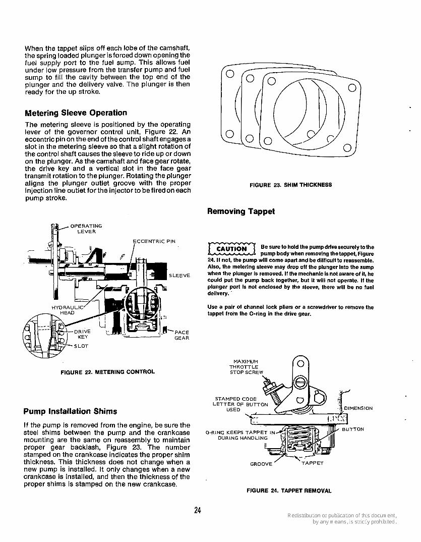
FIGURE 23. SHIM THICKNESS
Removing Tappet
Be sure to hold the pump drive securely to the pump body when removing the tappet, Figure
24. If not, the pump will come apart and be difficult to reassemble. Also, the metering sleeve may drop off the plunger into the sump when the plunger is removed. If the mechanic Is not aware of it, he could put the pump back together, but i t will not operate. I f the plunger port is not enclosed by the sleeve, there will be no fuel delivery. '
SLEEVE
Use a pair of channel lock pliers or a screwdriver to remove the tappet from the O-ring in the drive gear.
MAXIMUM THROTTLE STOP SCREW
STAMPED CODE LETTER OF BUTTON
USED
FIGURE 22. METERING CONTROL
Pump Installation Shims
I f the pump is removed from the engine, be sure the steel shims between the pump and the crankcase mounting are the same on reassembly to maintain proper gear backlash, Figure 23. The number stamped on the crankcase indicates the proper shim thickness. This thickness does not change when a new pump is installed. It only changes when a new crankcase is installed, and then the thickness of the proper shims is stamped on the new crankcase.
TTON O-RING KEEPS TAPPET IN
DURING HANDLING
FIGURE 24. TAPPET REMOVAL
24

TABLE 1. TIMING BUlTONS
1 6 o r S 15 or R 14orP 13 or N 12orM
GROUP 1 I GROUP 2 I CODE I PARTNO. I SI
147-0186 147-0187 147-0188 147-0189 147-0190
I I I Inch ~~
-134 .131 -128 .125 .122
I CODE I PARTNO. I S mm
147-0161
Button 12 or Y is the mid-range of the button sizes used the most. The button dimension is determined by the number or letter stamped on its side, Figure 25.
BUTTON WITH CODE LETTER OR NUMBER STAMPED ON IT.
FIGURE 25. TAPPET BUTTON CODE
TIMING BUTTON CODE The timing button has a code number or letter which corresponds with its dimension in thousands of an inch. See Table 1. Figure 26 shows the timing button and tappet relationship. Only one button is required to provide the correct port closing.
TIMING BUTTON
FIGURE 26. TIMING BUTTON AND TAPPET
3.023 2.946 2.870 2.794 2.718 2.642
PORT CLOSING FORMULA The formula for determining the proper port closing (PC) timing button for a new or replacement pump is as follows:
1. Remove old pump. 2. Determine total pump flange and button
thickness for old pump. a. Write down dimension given on old pump
flange. See Example:
Inches (mm)
Port closing dimension of old pump 1.109 (28.169) Bu!ton thickness of old pump +.lo7 (2.719)
Total 1.216 (30.887)
Port closing dimensions of new pump -1.094 (27.788) Required button thickness of new pump .122 (3.099)
b. Remove old pump timing button. Be careful when removing tappet assembly that the plunger doesn't
drop out of the sleeve, because reassembly is difficult.
c. Obtain dimension of old timing button from Table 1 corresponding with number or letter code on timing button.
d. Add dimension on old pump flange to timing button dimension.
Service Bulletin Engine 34 Is enclosed with each new pump to enable the installer to correctly time the pump to the engine.
PREPARATION FOR PUMP INSTALLATI ON 1. The crankshaft must be set on the compression
stroke for No. 1 cylinder. 2. Look into hole in block where pump mounts to
verify that one intake valve lobe points outward and down 45 degrees.
25

3. See that PC mark on flywheel aligns with timing pointer on gear case cover, Figure 27.
4. Align PC mark on flywheel to timing pointer by rotating crankshaft clockwise in the direction of engine rotation to take out all gear backlash in that direction. INSTALLING PUMP
Another method of aligning the drive gear slot for pump installation uses a straight edge as shown. An experienced person can “eye ball” the slot in the screw hole and place the pump on the engine with proper gear teeth meshing.
.- The flat area just above the pump has a number markedonit which refers to the shim thickness required between the pump and its
’ mounting pad for assuring proper backlash in the gearing. Don’t forget the shims.
With the pump drive gear locked by the 1/8-inch (3.18 mm) brass rod, position the pump in the hole (Figure 29) and firmly apply pressure. The arr0.w on Figure 29 shows the position of the injection pump cam and gear on the camshaft. A slight spring reaction indicates the pump and camshaft gears are meshed. Maintain this pressure, remove brass rod and rotate the crankshaft manually to make sure the gears mesh properly, Figure 30. Install mounting screws and torque to 15-16 ft. Ib. (20-22 Nom).
1 1 1 1 I , , ,
<.c. 9==++==
P.C. (PORT CLOSING)
GEAR COVER p::.::: ’ ’
C’ . FIGURE 27. PORT CLOSING POSITION
POSITIONING PUMP ON ENGINE
Remove the screw shown on the side of the pump, rotate drive gear, and insert a 1 /8-inch (3.1 75 mm) brass rod into the slot in the drive gear to lock the gear for positioning the pump on the engine, Figure 28.
ROTATE FACE GEAR UNTIL BRASS RODS SLlFS INTO PLACE LOCKING
.FIGURE 29. INSTALLING PUMP ON ENGINE
PUMP TAPP
CAM GEAR
FIGURE 28. LOCKING THE DRIVE GEAR FIGURE 30. PSU PUMP INSTALLED
DELIVERY VALVE FU NCTl ON
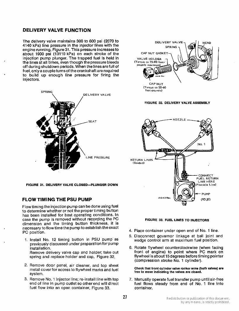
The delivery valve maintains 300 to 600 psi (2070 to 4140 kPa) line pressure in the injector lines with the engine running, Figure 31. This pressure increasesto about 1900 psi (13110 kPa) on each stroke of the injection pump plunger. The trapped fuel is held in the lines at all times, even though the pressure bleeds off during shutdown periods. When the lines are full of fuel, onlyacoupleturnsof thecrankshaft are required to build up enough line pressure for firing the injectors.
SPRING DELIVERY VALVE \ /
.SEAT
.IN€ PRESSURE
DELIVERY VALVE
CAP NUT GASKET
CAP NUT \
(Torque to 55-60 foot-pounds)
FIGURE 32. DELIVERY VALVE ASSEMBLY
RETURN LINES
U E L RETURN LINE HERE
(Flexible Line) FIGURE 31. DELIVERY VALVE CLOSED-PLUNGER DOWN
FLOW TIMING THE PSU PUMP Flow timing the injection pump can bedone using fuel to determine whether or not the proper timing button has been installed for best operating conditions. In case the pump is removed without recording the PC dimension and the timing button thickness, it is necessary to flow time the pump to establish the exact PC position.
1. Install No. 12 timing button in PSU pump as previously discussed under preparation for pump installation. Remove delivery valve cap and holder; take out spring and replace holder and cap, Figure 32.
2. Remove door panel, air cleaner, and top sheet metal cover for access to flywheel marks and fuel system.
3. Remove No. 1 injector line; re-install line with top end of line in pump outlet so other end will direct fuel flow into an open container, Figure 33.
FIGURE 33. FUEL LINES TO INJECTORS
4. Place container under open end of No. 1 line. 5. Disconnect governor linkage at ball joint and
wedge control arm at maximum fuel position.
6. Rotate flywheel counterclockwise (when facing front of engine) to point where PC mark on flywheel is about 15 degrees before timing pointer (compression stroke No. 1 cylinder).
Check that front cyllnder valve rocker arms (both valves) are free to move lndlcatlng the valves are closed.
7. Manually operate fuel transfer pump until air-free fuel flows steady from end of No. 1 line into container.
27
8.
9.
If fuel tank is disconnected, use a separate container of fuel and connect a short hose line between the transfer pumpinlet and the fuel container. The pump has enough suctlon (1 5 to 18 inches [381 to 399 mm] of vacuum) to pull the fuel out of the container.
Continue transfer pump operation while assistant rotates flywheel slowly in clockwise direction.
TIMING BUTTON THICKNESS Injection pump kits a pump and four buttons which will time 90 percent of the engines. The standard thickness button and ring spring are no longer assembled, but are loose in kit.
Stop flywheel rotation at exact point fuel stops flowing from No. 1 lineintocontainer(onedropin 2 to 5 seconds). l-his point is the port closing time of the injection pump plunger regardless of flywheel position, Figure 34.
Pump timing is critical. The injection pump on each engine must be timed to that particular engine by using a timing button of specific thickness. Use the method which applies best to determine the correct new button thickness. Each new pump has its own port closing dimension stamped on it.
FILL PORT (PC)
FIGURE 34. PORT CLOSING
Timing is correct if port closing occurs when the PC mark on the flywheel aligns with the timing pointer. If it doesn't match, timing is either early or late and another timing button is required, Figure 35.
FIGURE 35. PORT CLOSING (PC) MEASUREMENT
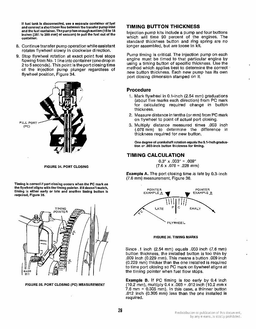
Procedure 1. Mark flywheel in 0.1-inch (2.54 mm) graduations
(about five marks each direction) from PC mark for calculating required change in button thickness.
2. Measure distance in tenths (or mm) from PC mark on flywheel to point of actual port closing.
3. Multiply distance measured times .003 inch (.076 mm) to determine the difference in thickness required for new button.
One degree of crankshaft rotation equals the 0.1-inch gradua- tion or .OO&inch button thickness for timing.
TIMING CALCULATION 0.3' x .003" = .009"
(7.6 x .076 = .228 mm)
Example A. The port closing time is late by 0.3-inch (7.6 mm) measurement, Figure 36.
POINTER POINTER EXAMP LEA
' FLYWHEEL
FIGURE 36. TIMING MARKS
Since .1 inch (2.54 mm) equals .003 inch (7.6 mm) button thickness, the installed button is too thin by .009 inch (0.229 mm). This means a button .009 inch (0.229 mm) thicker than the one installed is required to time port closing so PC mark on flywheel aligns at the timing pointer when fuel flow stops.
Example B. If PC timing is too early by 0.4 inch (10.2 mm), multiply 0.4 x .003 = .012 inch (10.2 mm x '7.6 mm = 0.305 mm). In this case, a thinner button .012 inch (0.305 mm) less than the one installed is required.
28

BLEEDING FUEL SYSTEM Bleed fuel system whenever the filtersare changed or when there is air in the lines.
Procedure: Manually actuate fuel transfer pump until air bubbles are all out and clear fuel flows from the bleed valve automatically, Figure 37.
If the transfer pump cam lobe is on the high side, the priming lever will not operate the pump. Rotate the flywheel one revOh!iOn before operating the priming lever.
BLEED VALVE
FUEL RETURN CONNECT
F U E L LINE ( RDJE)
FIGURE 37. BLEEDING FUEL SYSTEM
29
OIL SYSTEM
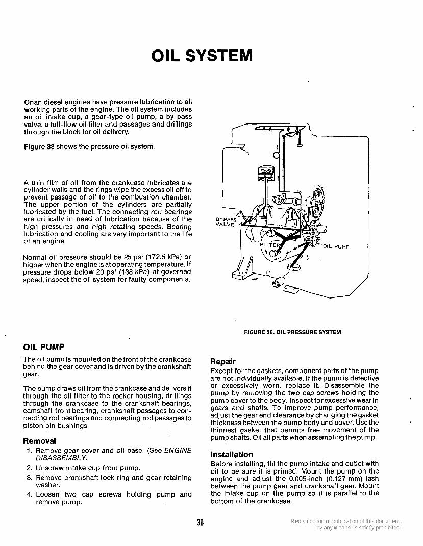
Onan diesel engines have pressure lubrication to all working parts of the engine. The oil system includes an oil intake cup, a gear-type oil pump, a by-pass valve, a full-flow oil filter and passages and drillings through the block for oil delivery.
Figure 38 shows the pressure oil system.
A thin film of oil from the crankcase lubricates the cylinder walls and the rings wipe the excess oil off to prevent passage of oil to the combustion chamber. The upper portion of the cylinders are partially lubricated by the fuel. The connecting rod bearings are critically in need of lubrication because of the high pressures and high rotating speeds. Bearing lubrication and cooling are very important to the life of an engine.
Normal oil pressure should be 25 psi (172.5 kPa) or higher when the engine is at operating temperature. If pressure drops below 20 psi (138 kPa) at governed speed, inspect the oil system for faulty components.
OIL PUMP The oil pump is mounted on the front of the crankcase behind the gear cover and is driven by the crankshaft gear.
The pump drawsoil from thecrankcase anddeliversit through the oil filter to the rocker housing, drillings through the crankcase to the crankshaft bearings, camshaft front bearing, crankshaft passages to con- necting rod bearings and connecting rod passages to piston pin bushings.
Removal 1. Remove gear cover and oil base. (See ENGINE
2. Unscrew intake cup from pump. 3. Remove crankshaft lock ring and gear-retaining
4. Loosen two cap screws holding pump and
DISASSEMBLY.
washer.
remove pump.
FIGURE 38. OIL PRESSURE SYSTEM
Repair Except for the gaskets, component parts of the pump are not individually available. I f the pump is defective or excessively worn, replace it. Disassemble the pump by removing the two cap screws holding the pump cover to the body. Inspect forexcessive wear in gears and shafts. To improve pump performance, adjust the gear end clearance by changing the gasket thickness between the pump body and cover. Usethe thinnest gasket that permits free movement of the pumpshafts. Oil all parts when assembling the pump.
Installation Before installing, fi l l the pump intake and outlet with oil to be sure it is primed. Mount the pump on the engine and adjust the 0.005-inch (0.127 mm) lash between the pump gear and crankshaft gear. Mount the intake cup on the pump so it is parallel to the bottom of the crankcase.
30

BYPASS VALVE
REAR BEARING B> PLATE --L
OIL BYPASS
I OIL BYPASS
FIGURE 39. BYPASS VALVE
N O T E I -USE A ff70 D R I L L (.OB) (.71 d FOR CLEANING AREA 1.
N O T E 2 - USE A #56 D R I L L (-046) ( 1 - 17 t t d FOR CLEANING AREA 2.
W FLUSH ROCKER BOX OIL LINE WITH F U E L AND CLEAN HOLES
WITH F I N E WIRE.
Located on the outside of the rear bearing plate, the bypass valve (Figure 39) controls oil pressure by allowing excess oil to flow directly back to the crankcase. Normally thevalve begins to open at about 25 psi (172.5 kPa). It is non-adjustable, and normally needs no maintenance.
To determine if high oil pressure is caused by the plunger sticking closed, or low oil pressure by the plunger sticking open, clean and inspect the valve.
To remove the valve, unscrew the recessed plug in the rear bearing plate and lift out the spring and plunger assembly. Determine proper valve operation by checking the spring and plunger against the given values:
Plunger Diameter.. . . . . 0.3365 inch to 0.3380 inch Spring (8.5471 to 8.5852 mm)
Free Length.. .. . . .. . 2-5/16 inches, + 1/16 inch (74.613, + 1.588 mrn)
2.225 Ib. at 1-3/16 inches (compressed) at (30.163 mm) (compressed) (1.01 kg)
A L L Z-CYLINDER DIESEL MODELS
FIGURE 40. CLEANING ROCKER BOX OIL LINE AND RESTRICTION ORIFICES
31

‘CRANKCASE BREATHERS OIL LINES At overhaul time the rocker box oil line should be flushed with fuel, and a fine wire used to clean the small holes, Figure 40. Clean standpipe breather on four cylinder engines.
Clean out all other oil lines and drillings with com- pressed air whenever the engine is disassembled or overhauled. Reach the oil gauge passage by remov- ing the oil filter mounting plate.
External oil lines, the rocker box oil line, and the internal oil line to the rear bearing are replaceable, if damaged.
Restriction orifices are placed in the external oil lines to regulate thequantity of oil delivered to theinjection pump gearing and tappet and to the rocker arm and valve train areas. Two orifices are located in the Tee fitting at the injection pump and one orifice is located in the inlet fitting to each cylinder head.
To prevent injection pump or valve train Ex3 damage from lack of lubrication, ensure that ail restriction orifices are kept open. Cleaning can be done using a fine wire or drill bit and compressed air.
CAUT,ON
.028 inch size at heads (0.71 mm)
.046 inch size at Tee (1.17 mm) . .
OIL FILTER (Full Flow) .. .
The oil filter is mounted on the filter plate at the left side of crankcase, Figure 41. It requires replacement every 500 hours of normal operation. Removefilter by turning counterclockwise using afilter wrench. Install’ new filter finger-tight plus 1/4 to 1/2 turn.
FIGURE 41. FULL FLOW OIL FILTER
The RDJE crankcase breather has a valve assembly that compensates for the pulses created by both pistons moving up and down at the same time. The ball check valves close as the pistons move up and are forced open as the pistons move down, thus, venting crankcase pulse pressure and fumes to thecarburetor intake hose. The only maintenance required is to clean the check valve assembly and replace the baffle material periodically. Remove the hose clamp, breather hose, and cap clamp to release the breather cap and valve assembly, Figure 42. Wash the cap, valve assembly, and baffle material in a suitable solvent and reinstall.
The RDJEA crankcase is vented by a breather pipe installed in the intake manifold, under the valve cover. A breather hose between the crankcase and the valve cover vents the crankcase pressure and fumes to the intake manifold. Since one piston moves up while the other moves down, pulse pressure is minimal; it is equalized by the pistons moving in opposite directions. - - BREATHER
HOSE
HOSE CLAMP \
VALVE 7
“0” RING ’ SCREEN
/
CAP AND
/ A
- CLAMP
BAFFLE
FIGURE 42. CRANKCASE BREATHER
OIL DRAIN EXTENSION For service convenience, install a short (less than 10 inches [254 mm]) oil drain extension made from standard pipe and fittings in the l /Pinch (12.70 mm) pipe-tapped oil drain hole in the base.
32

The purpose of the engine governor is to maintain a constant engine speed during changes in power demands. A governor responds to changes in power demands by varying the throttle position. A constant- speed governor is standard on industrial engines.
GOVERNORS The constant-speed governor (Figure 43) maintains engine speed up to 2400-rpm. The speed-sensing device is a ball and cup mechanism on the camshaft gear. A yoke, resting on the cup, is connected to the governor arm which, in turn, is connected to the throttle lever. Any change in engine speed is transmitted from the cup to the yoke, and on to the throttle.
Maintenance: The linkage must be ableto move freely through its entiretravel. Periodically lubricate the ball joints with graphite or light non-gumming oil. Also inspect the linkage for binding, excessive slack, and wear.
Testing and Repaie Removing the gear cover for access to the governor cup and other internal gover- nor parts is covered in the ENGINE DISASSEMBLY section. External service and repair is limited to testing spring tension and checking ball joints.
To test spring rates, use aspring-type scale. Compare the measured rates with those in Table 2.
TABLE 2. GOVERNOR SPRING DATA
Tension on the governor spring determines the speed at which the engine is governed. A stud screwed into the spring is used to vary the number of effective coils for getting the desired sensitivity-the speed drop from no load to full load.
Engine Governor Spring No Load Active
Constant 150-0846 1-3f8 13-m
1 ;: 1 Type 1 Number I Length I Coils I (34.925 mm)
8435 DECREASE SENSITIVITY
FIGURE 43. GOVERNOR ASSEMBLY AND ADJUSTMENTS
33
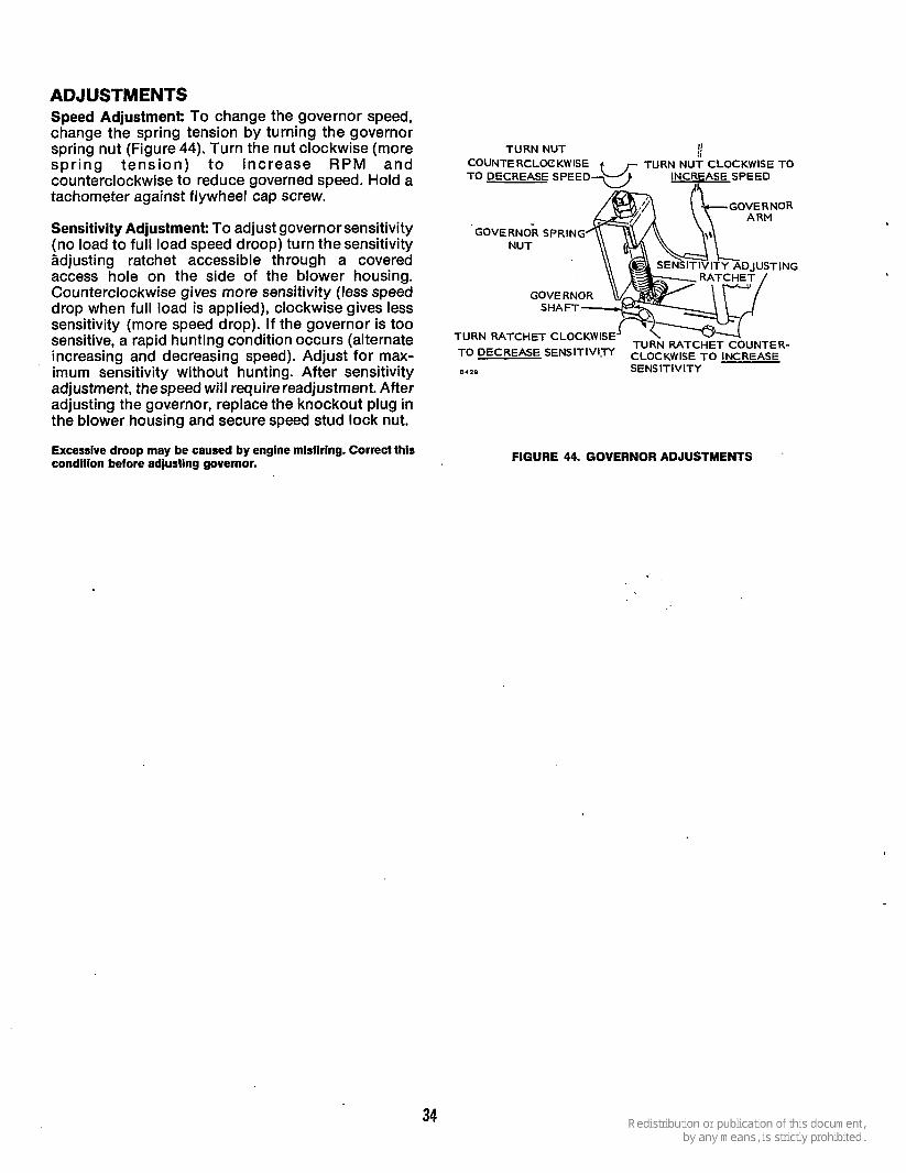
ADJUSTMENTS Speed Adjustment: To change the governor speed, change the spring tension by turning the governor
spr ing tens ion) t o increase RPM and COUNTERCLOCKWISE
tachometer against flywheel cap screw.
spring nut (Figure 44). Turn the nut clockwise (more
counterclockwise to reduce governed speed. Hold a
TURN NUT
TO DECREASE SPEED
Sensitivity Adjustment: To adjust governor sensitivity (no load to full load speed droop) turn the sensitivity
GOVERNOR SPRING NUT
Sdjusting ratchet accessible through a covered access hole on the side of the blower housing.
sensitivity (more speed drop). If the governor is too
Counterclockwise gives more sensitivity (less speed drop when full load is applied), clockwise gives less
sensitive, a rapid hunting condition occurs (alternate increasing and decreasing speed). Adjust for max- imum sensitivity without hunting. After sensitivity 8 4 1 9 SENS ITlVlTY
GOVE SHA
TURN RATCHET CLoCKWISE TO DECREASE SENslTIv1.V
TURN RATCHET COUNTER- CLOCKWISE TO INCREASE
adjustment, the speed will require readjustment. After adjusting the governor, replace the knockout plug in the blower housing and secure speed stud lock nut.
Excessive droop may be caused by engine mlsflrlng. Correct this condition before adjustlng governor. FIGURE 44. GOVERNOR ADJUSTMENTS
34
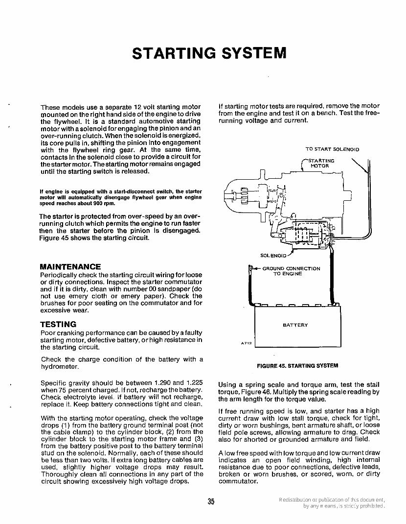
STARTING SYSTEM
These models use a separate 12 volt starting motor mounted on the right hand side of the engine to drive the flywheel. It is a standard automotive starting motor with a solenoid for engaging the pinion and an over-running clutch. When the solenoid is energized, its core pulls in, shifting the pinion into engagement with the flywheel ring gear. At the same time, contacts in the solenoid close to provide a circuit for the starter motor. The starting motor remains engaged until the starting switch is released.
If engine is equipped with a start-disconnect switch, the starter motor will automatically disengage flywheel gear when engine speed reaches about 900 rpm.
The starter is protected from over-speed by an over- running clutch which permits the engine to run faster then the starter before the pinion is disengaged. Figure 45 shows the starting circuit.
MAINTENANCE Periodically check the starting circuit wiring for loose or dirty connections. Inspect the starter commutator and if it is dirty, clean with number 00 sandpaper (do not use emery cloth or emery paper). Check the brushes for poor seating on the commutator and for excessive wear.
TESTING Poor cranking performance can be caused bya faulty starting motor, defective battery, or high resistance in the starting circuit.
Check the charge condition of the battery with a hydrometer.
Specific gravity should be between 1.290 and 1.225 when 75 percent charged. If not, recharge the battery. Check electrolyte level. If battery will not recharge, replace it. Keep battery connections tight and clean.
With the starting motor operating, check the voltage drops (1) from the battery ground terminal post (not the cable clamp) to the cylinder block, (2) from the cylinder block to the starting motor frame and (3) from the battery positive post to the battery terminal stud on the solenoid. Normally, each of these should be less than two volts. If extra long battery cables are used, slightly higher voltage drops may result. Thoroughly clean all connections in any part of the circuit showing excessively high voltage drops.
I f starting motor tests are required, remove the motor from the engine and test it on a bench. Test the free- running voltage and current.
T O START SOLENOID
GROUND CONNECTION TO ENGINE
n n n n n
FIGURE 45. STARTING SYSTEM
Using a spring scale and torque arm, test the stall torque, Figure 46. Multiply the spring scale reading by the arm length for the torque value.
If free running speed is low, and starter has a high current draw with low stall torque, check for tight, dirty or worn bushings, bent armature shaft, or loose field pole screws, allowing armature to drag. Check also for shorted or grounded armature and field.
A lowfreespeed with lowtorqueand low currentdraw indicates an open field winding, high internal resistance due to poor connections, defective leads, broken or worn brushes, or scored, worn, or dirty commutator.
35
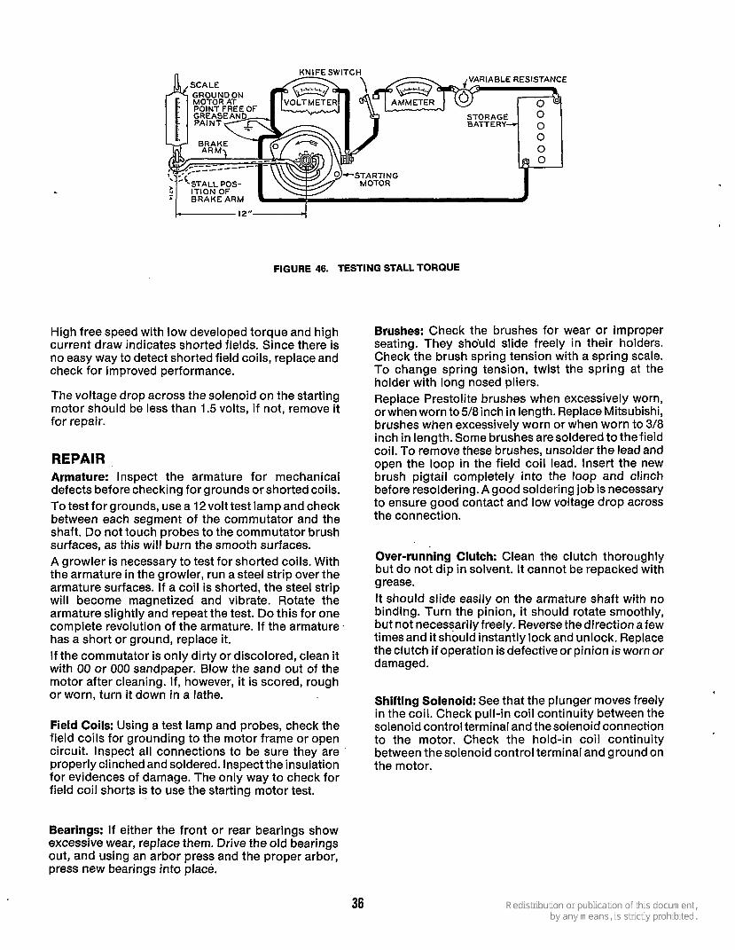
VARIABLE RESISTANCE
STALL POS-
BRAKE ARM
I---- 12"-4
FIGURE 46. TESTING STALL TORQUE
High free speed with low developed torque and high current draw indicates shorted fields. Since there is no easy way to detect shorted field coils, replace and check for improved performance.
The voltage drop across the solenoid on the starting motor should be less than 1.5 volts, if not, remove it for repair.
REPAIR Armature: Inspect the armature for mechanical defects before checking for grounds or shorted coils. To test for grounds, use a l2volt test lamp and check between each segment of the commutator and the shaft. Do not touch probes to the commutator brush surfaces, as this will burn the smooth surfaces. A growler is necessary to test for shorted coils. With the armature in the growler, run a steel strip over the armature surfaces. If a coil is shorted, the steel strip will become magnetized and vibrate. Rotate the armature slightly and repeat the test. Do this for one complete revolution of the armature. If the armature has a short or ground, replace it. If the commutator is only dirty or discolored, clean it with 00 or 000 sandpaper. Blow the sand out of the motor after cleaning. If, however, it is scored, rough or worn, turn it down in a lathe.
Field Coils: Using a test lamp and probes, check the field coils for grounding to the motor frame or open circuit. Inspect all connections to be sure they are properly clinched and soldered. Inspect the insulation for evidences of damage. The only way to check for field coil shorts is to use the starting motor test.
Brushes: Check the brushes for wear or improper seating. They should slide freely in their holders. Check the brush spring tension with a spring scale. To change spring tension, twist the spring at the holder with long nosed pliers. Replace Prestolite brushes when excessively worn, orwhen worn to 5/8inch in length. Replace Mitsubishi, brushes when excessively worn or when worn to 3/8 inch in length. Some brushes aresoldered to the field coil. To remove these brushes, unsolder the lead and open the loop in the field coil lead. Insert the new brush pigtail completely into the loop and clinch before resoldering. A good soldering job is necessary to ensure good contact and low voltage drop across the connection.
Over-running Clutch: Clean the clutch thoroughly but do not dip in solvent. It cannot be repacked with grease. It should slide easily on the armature shaft with no binding. Turn the pinion, it should rotate smoothly, but not necessarily freely. Reverse the direction a few times and it should instantly lock and unlock. Replace the clutch if operation is defective or pinion is worn or damaged.
Shifting Solenoid: See that the plunger moves freely in the coil. Check pull-in coil continuity between the solenoid control terminal and the solenoid connection to the motor. Check the hold-in coil continuity between thesolenoid control terminal and ground on the motor.
Bearings: If either the front or rear bearings show excessive wear, replace them. Drive the old bearings out, and using an arbor press and the proper arbor, press new bearings into place.
36
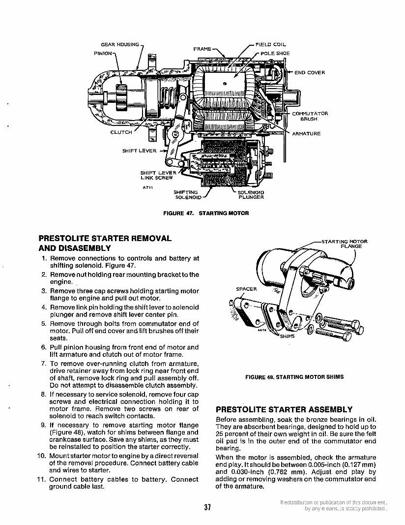
SHIFTING 1 SOLENOID SOLENOID PLUNGER
FIGURE 47. STARTING MOTOR
PRESTOLITE STARTER REMOVAL AND DISASEMBLY 1.
2.
3.
4.
5.
6.
7.
8.
9.
IO.
11.
Remove connections to controls and battery at shifting solenoid. Figure 47. Remove nut holding rear mounting bracket to the engine. Remove three cap screws holding starting motor flange to engine and pull out motor. Remove link pin holding theshift lever tosolenoid plunger and remove shift lever center pin. Remove through bolts from commutator end of motor. Pull off end cover and lift brushes off their seats. Pull pinion housing from front end of motor and lift armature and clutch out of motor frame. To remove over-running clutch from armature, drive retainer away from lock ring near front end of shaft, remove lock ring and pull assembly off. Do not attempt to disassemble clutch assembly. If necessary to service solenoid, remove four cap screws and electrical connection holding it to motor frame. Remove two screws on rear of solenoid to reach switch contacts. If necessary to remove starting motor flange (Figure 48), watch for shims between flange and crankcase surface. Save any shims, as they must be reinstalled to position the starter correctly. Mount starter motor to engine by a direct reversal of the removal procedure. Connect battery cable and wires to starter. Connect battery cables to battery. Connect ground cable last.
37
-STARTING MOTOR
FIGURE 48. STARTING MOTOR SHIMS
PRESTOLITE STARTER ASSEMBLY Before assembling, soak the bronze bearings in oil. They are absorbent bearings, designed to hold up to 25 percent of their own weight in oil. Be sure the felt oil pad is in the outer end of the commutator end bearing. When the motor is assembled, check the armature end play. ltshould be between 0.005-inch (0.127 mm) and 0.030-inch (0.762 mm). Adjust end play by adding or removing washers on the commutator end of the armature.

Before installing, check the pinion clearance. Proper clearance is important to ensure starter engagement. Press on solenoid core to shift the pinion into full mesh and measure the clearance between pinion and pinion stop, Figure 49. This should be between 0.07- inch and 0.12-inch (3.05 mm) (as near to 0.070-inch [1.78 mm] as possible.) Adjust the link screw on the end of the solenoid plunger for proper clearance.
PUSH PLUNGE
ENGINE TO MAKE THIS MEASUREMENT
FIGURE 49. PINION CLEARANCE
MlTSUBlSHl STARTER REMOVAL AND INSTALLATION
1. Remove both battery cables from battery. Dis-
2. Disconnect battery cable and electrical lead wires
3. Remove capscrews and flat washers that attach
4. Remove starter. 5. Mount starter motor to engine by a direct reversal
of the removal procedure. Connect battery cable and wires to starter.
6. Connect battery cables to battery. Connect ground cable last.
MlTSUBlSHl STARTER DISASSEMBLY
connect ground cable first.
from starter.
starter to mounting bracket.
1. Remove “M” terminal nut and wire lead from solenoid.
2. Remove the two solenoid mounting screws and remove solenoid.
3. Remove the two through bolts and brush holder retaining screws. Remove rear bracket (Figure 49a).
THROUGH BOLTS e
ES-1186
FIGURE 49a. REMOVING REAR BRACKET
4. Remove frame assembly, and brush holderassem- bly while pulling the brushes upward. Then re- move armature assembly.
5. Remove cover assembly, (snap ring and washer) from the pinion shaft (Figure 49b).
ES-1195
SNAP RING
FIGURE 49b. REMOVING SNAP RING AND WASHER
6. Remove capscrew that secures center bracket to front bracket. Remove the center bracket; several washers used to adjust pinion shaft end play can now be removed (Figure 49c).
FRONT CENTER BRACKET BRACKET
T WASHERS - CAPSCREW --
- ES-1187
FIGURE 49c. REMOVING CENTER BRACKET
38

7. Remove gear, spring set and lever assembly from front bracket. Note direction in which the lever assembly is installed.
8. Push pinion gear and stopper down and remove retainjng ring. Remove stopper, pinion gear, spring, and pinion shaft assembly.
9- Inspect ball bearings. If they are rough or noisy when rotated replace them. The front bearing is not replaceable and must be replaced with the bracket.
SOLENOID FIBER I TERMINAL "M"
THROUGH
(RETAINING RING)
I BRUSH
HOLDER /
FRAME ASSEMBLY ASSEMBLY
MlTSUBlSHl STARTER ASSEMBLY
XES1255
FIGURE 49d. MlTSUBlSHl STARTER
For assembly reverse the disassembly procedure, but note the following items. See Figure 49d.
Whenever starter motor is disassembled apply grease to each of the following points. (Recommended grade; Multemp PS No. 2.)
Armature shaft gear Reduction gear Ball bearing (Both ends of armature Stopper on pinion shaft Sleeve bearing Pinion gear Sliding portion of lever
Pinion Shaft End Play Adjustment Adjust end play so that it is 0.1 to 0.8 mm (.0039 to .0315 inch) with theadjusting washers placed between center bracket and reduction gear (Figure 49e).
PINION SHAFT OVERRUNNING CLUTCH
\ PINION GEAR I SNAP RING
ES-1191
FIGURE 49e. ADJUSTING PINION SHAFT END PLAY
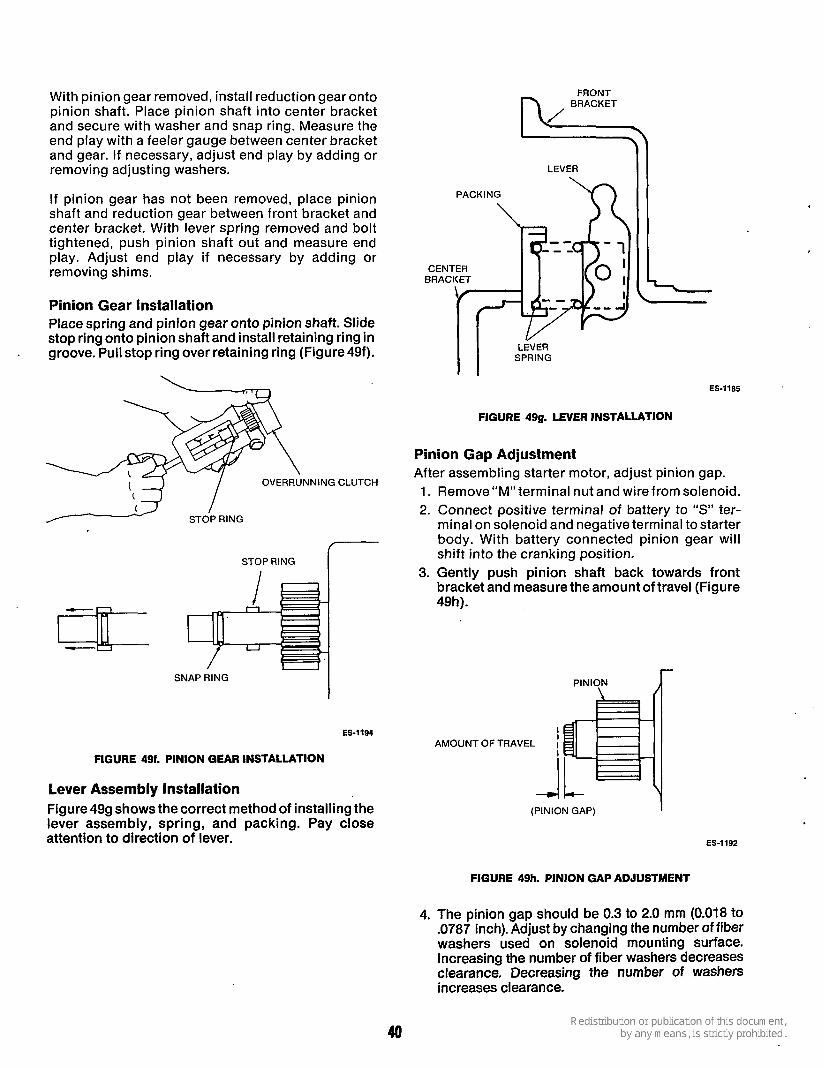
With pinion gear removed, install reduction gear onto pinion shaft. Place pinion shaft into center bracket and secure with washer and snap ring. Measure the end play with a feeler gauge between center bracket and gear. If necessary, adjust end play by adding or removing adjusting washers.
If pinion gear has not been removed, place pinion shaft and reduction gear between front bracket and center bracket. With lever spring removed and bolt tightened, push pinion shaft out and measure end play. Adjust end play if necessary by adding or removing shims.
Pinion Gear Installation Place spring and pinion gear onto pinion shaft. Slide stop ring onto pinion shaft and install retaining ring in groove. Pull stop ring over retaining ring (Figure49f).
- 2 STOP / RING
STOP RING r
I SNAP RING
ES-1194
FIGURE 491. PINION GEAR INSTALLATION
Lever Assembly Installation Figure 499 shows the correct method of installing the lever assembly, spring, and packing. Pay close attention to direction of lever.
PACKING
LEVER I
CENTER BRACKET
LEVER SPRING I I
ES-1185
FIGURE 49g. LEVER INSTALLATION
Pinion Gap Adjustment After assembling starter motor, adjust pinion gap. 1. Remove “M” terminal nut and wire from solenoid. 2. Connect positive terminal of battery to “S” ter-
minal on solenoid and negative terminal to starter body. With battery connected pinion gear will shift into the cranking position.
3. Gently push pinion shaft back towards front bracket and measure the amount of travel (Figure 49h).
PINION \
I AMOUNT OF TRAVEL I
r
Y (PINION GAP) I
ES-1192
FIGURE 49h. PINION GAP ADJUSTMENT
4. The pinion gap should be 0.3 to 2.0 mm (0.018 to .0787 inch). Adjust by changing the number of fiber washers used on solenoid mounting surface. Increasing the number of fiber washers decreases clearance. Decreasing the number of washers increases clearance.
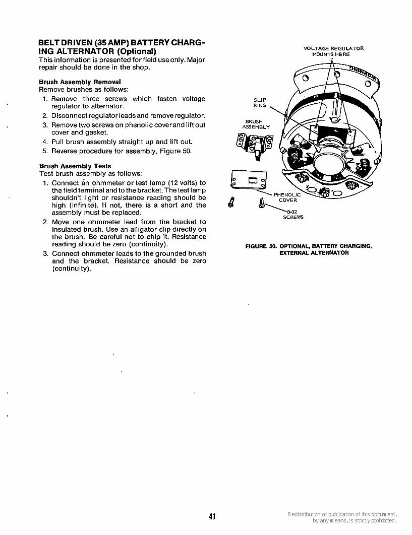
BELT DRIVEN (35 AMP) BATTERY CHARG- ING ALTERNATOR (Optional) This information is presented for field use only. Major repair should be done in the shop.
Brush Assembly Removal Remove brushes as follows: 1. Remove three screws which fasten voltage
2. Disconnect regulator leads and remove regulator. 3. Remove two screws on phenolic coverand lift out
4. Pull brush assembly straight up and lift out. 5. Reverse procedure for assembly, Figure 50.
regulator to alternator.
cover and gasket.
Brush Assembly Tests Test brush assembly as follows: 1. Connect an ohmmeter or test lamp (12 volts) to
the field terminal and to the bracket. The test lamp shouldn't light or resistance reading should be high (infinite). If not, there is a short and the assembly must be replaced.
2. Move one ohmmeter lead from the bracket to insulated brush. Use an alligator clip directly on the brush. Be careful not to chip it. Resistance reading should be zero (continuity).
3. Connect ohmmeter leads to the grounded brush and the bracket. Resistance should be zero (con ti nu i ty) .
VOLTAGE REGULATOR MOUNTS HERE
FIGURE 50. OPTIONAL, BATTERY CHARGING, EXTERNAL ALTERNATOR
41
ENGINE REBUILDING When engine disassembly is necessary, remove com- plete assemblies (tear down individual components like fuel pump, breaker mechanism, etc., as bench jobs). Use special tools available. Disassembly: 1. Common sense will dictate proper order of dis-
assembly. As disassembly progresses, the order may be changed, as will become self-evident.
a. Radiator, water pump. b. Flywheel-using puller or pry-bar method. c. Gear Cover-protect oil seal from keyway
d. Crank Gear-use puller and gear puller ring. e. Loosen accessories such as fuel pumps and oil
f. Starter motor.
2. A suggested procedure would be as follows:
damage.
filter.
g. Drain oil - discard oil removed. h. Cylinder head. i. Valves, springs, rocker arms. j. Camshaft and gear, rear bearing plate, oil
k. Piston, connecting rod bearings. I . Crankshaft. rn. Try to analyze reasons for any parts failure and
necessity of the repair. n. Cleanliness and neat, orderly work area makes
job easier to do. 0. Use proper meters and gauges. Observe if
cy1 i nder req u i res boring , cranks haft needs grinding, or if other major shop work is necessary.
pump.
Assembly (Use Genuine Onan Parts): 1.
2.
3.
Engine assembly procedure is normally the reverse of disassembly - observing proper clearances of bearings, connecting rod, proper fitting and sizing of piston, rings, etc. Follow proper recommended procedure for fit of valves, adjusting clearances, and torque of all special items. Use a torque wrench to assure proper tightness without danger of stripping threads. As each internal engine part is assembled, use crank (or wrench) to rotate crankshaft, making certain it turns freely. If tightness is noted after any operation you then know your last step is responsible.
4. As each internal engine part is assembled, coat it heavily with oil (same grade used in crankcase). During first few critical moments of operation, the engine will depend on this lubrication.
5. X f e r y o u have infernalengi'ne pzrfs EiGembTed, the engine should crank freely. If reasonable care and attention has been given, the engine will operate efficiently.
6. At this point, i t is a matter of mechanically adding outside accessory items to the block assembly. Order of assembly is reverse of disassembly.
7. When engine is complete, install controls. Check the tagged wires. Using wiring diagram to con- nect leads to control, and from control to engine. All wires are marked for correct identification. If the unit is to work properly, wires must be connected correctly.
8, The engine is now ready for testing. Follow suggestions given on Testing and Adjusting Engines. Before final test and adjustments, run the engine about 15 minutes under light load to reach normal operating temperature.
ASSEMBLY SUGGESTIONS (Things to keep in mind during engine assembly)
1. See Onan Tool Catalog (900-0019) - many items require a special tool for correct installation. Some of these tools are: a. Oil seal driver and guide, bearing driver. b. Valve spring compressor, valve lock replacer,
valve guide driver, and valve seat remover. c. Gear puller and gear puller rings. d. Piston ring spreader and compressor. e. Flywheel puller, pry bar, armature puller. f. Torque wrench, plastigauge (for correct bear-
g. Load test panel, armature growler, gas
2. Wet holes in crankcase (holes through crankcase) -always use copper (gasket) washers.
3. Nuts, bolts and screws that do not require exact torque should be tightened snugly, then 1/4extra turn.
4. Select proper length of any screw or bolt and position in hole. Make sure they do not bottom.
5. Gasket kits sometimes cover more than one engine. Therefore, select gasket of correct size and shape for part being used. Always use new gaskets.
ing clearance).
pressure gauge (or manometer).
42

6. When disassembling engine, mike bearing plate gasket thickness. Then select proper shim thickness for correct end play.
Shims establish end play. Only one thickness gasket is included in kit.
7. When assembling crankshaft, make sure bearing thrust washers are in proper position supported by bearing stop pins. Use cup grease to hold in - place.
8. When adjusting valve lash, tap rocker arm so it is
9. Crank gears are easier to remove and install if
straight when checking with feeler gauge.
heated a slight amount.
Do not overheat or temper may be lost and shaft may expand.
10. See FUEL SYSTEM section for correct engine time for specific model.
11. Allow some gear lash (approximately 0.005-inch) in oil pump. Do not install gears tightly against each other!
TESTING AND ADJUSTING ENGINES Preparation Check the following: 1. Put proper oil in crankcase. 2. Service air cleaner. 3. Connect fuel line. 4. Connect load. 5. Connect fully charged battery. 6. Check ventilation for proper cooling.
OPERATION 1. Start engine. 2. Check o.il pressure. 3. Run unit 15 minutes to bring up to operating
temperature. '
4. Check for oil leaks, loose electrical connections, tight fuel lines and tight exhaust connections.
ADJUSTMENTS Adjust governor for speed and sensitivity.
IMPORTANT: For complete customer satisfaction, repaint unit (Onan Green, spray can 525-0137, or Onan White, spray can 525- 0216) and apply instructions from Kit 98-11OOC or Marine Kit 98- 1807.
CYLINDER HEADS, VALVES Each cast iron cylinder head assembly has alloy hard en ed-f aced valves, re1 ease-ty pe rotato rs , al I oy hardened inserts, guides, rocker arms, injection nozzles and glow plugs. The push rods run through
' shields.
Maintenance: Check the valve clearances at regular intervals (see SERVICE AND MAINTENANCE section). In addition, clean the combustion chambers and valve seats at regular intervals.
VALVE CLEARANCE ADJUSTMENTS The valves are adjusted cold. Afterthecooling period, adjust No. 1 cylinder first and the rest in the firing order.
RDJE Engines To adjust valve clearance, on RDJE engines, proceed as follows: 1. Rotate flywheel clockwise until cylinder number
is up on acompression strokeand theTC markon the flywheel lines up with the timing pointer on the gear cover, then turn 10-45" past TC to be sure lifter moves off ramp of cam. Adjust both valves, intake and exhaust, to 0.017 inch (0.43 mm).
In this position, both valves will be closed and the rocker arms are free to move slightly indicating maximum clearance.
EXHAUST VALVES I\ 0.017" (0.43 rnm)
AOJUST VALVE CLEARANCE HE
VALVE SEAT
FIGURE 51. SETTING VALVE CLEARANCES
43
2.
3. 4.
* Using a feeler gauge, check clearance between rocker arm and valve (see Figure 51). Increase or reduce clearance until proper gap is established; adjust with lock nut which secures rocker arm to cylinder head.
Repeat Step 1 for number 2 cylinder. Repeat Step 2 for number 2 cylinder.
Compression readings will deviate considerably from the above readings because of differences in crank- ing speed, altitude and ambient temperature con- ditions. Therefore the specification is given only as a guide. The best indication of leakage is the pressure difference between cylinders or a compression in- crease when oil is added to the cylinder.
Disassembly: RDJEA Engines To adjust valve clearance on RDJEA engines, proceed as follows: 1. Rotate flywheel clockwise until cylinder number 1
is up on a compression stroke and the TC mark on the flywheel lines up with the timing pointer on the gear cover, then turn 10 to 45" past TC to be sure lifter moves off ramp of cam. Adjust bbth valves, intake and exhaust, to 0.017 inch (0.43 mm).
In this position, both valves will be closed and the rocker arm is free to move slightly indicating maximum clearance.
2. Using a feeler gauge. check clearance between rocker arm and valve (see Figure 51). Increase or reduce clearance until proper gap is established; adjust with lock nut which secures rocker arm to cylinder head, Figure 51.
3. To adjust valve clearance for number 2 cylinder, turn flywheel in aclockwisedirection 180degrees (1/2 revolution) from position used in Step 1. The flywheel position should be between 10 degrees and 45 degrees past the bottom center (BC).
4. After timing number 2 cylinder, adjust valve clearance according to Step 2.
Testing: The cylinder compression test can be used to deter- mine the condition of valves, pistons, piston rings and cylinders.
To check compression, run the engine until thoroughly warm. Stop engine and remove all injec- tion nozzles. Insert the compression gauge in one nozzle hole. Crank the engine and note the reading. To check for piston blow-by, squirt a small amount of SAE 50 oil into the cylinder and repeat the check. An increase in compression with oil in the cylinder indicates piston blow-by.
Keep rocker arms, rocker arm nuts, push rods and tappetsin order, so they go back in the same valve train position.
1. Remove rocker box cover, fuel nozzles and connecting oil lines to cylinder heads.
2. Remove intake and exhaust manifold. 3. Remove cap screws holding each cylinder head
to cylinder block. 4. Remove each head. If it sticks, rap it sharply with a
soft hammer. Do not use a pry. 5. Remove rocker arms and push rods. 6. Using avalve spring compressor, disassemble the
valve assemblies.
Repair: Thoroughly clean all components of the cylinder head assemblies. Remove all the carbon deposits from the intake and exhaust ports and clean all gasket surfaces.
Valves: Remove all carbon and check each valve for burning, pitting, or a warped stem. Refinish valves that are slightly pitted or burned on an accurate valve grinder. Refinish intake valves to a 42 degree angle and exhaust valves to a 45 degree angle. If they are badly pitted or have a thin edge when refacing, replace them.
Check refinished valves for a tight seat to the valve seat with an air-pressure-type, testing tool or by applying Prussian Blue on the valve face and rotating it against the seat.
Valve Guides: Check valve guide to valve clearance. See the DIMENSIONS AND CLEARANCES section. If the proper clearances cannot be obtained by replac- ing the valves, replace the valve guides. Drive the old valve guides into the valve chambers. Drive new guides in until they protrude 11/32 inch (8.731 mm) from the rocker box side of the head. Ream the new valve guide to obtain the proper clearance.
Valve Seats: If thevalve seats are pitted, refinish them. Using conventional seat-grinding equipment, reface
Compression of a standard new engine cranking at each seat to a45degreeangleand aseatwidthof 3/64 about 300 rpm is about 350-4OOpsi (2415 to inch to 1/16 inch (1.191 to 1.588 mm) You should be 2760 kPa). Compression should be fairly uniform, able to reface each seat several times before it normally with less than 10 psi (69 kPa) difference becomes necessary to replace it. between the highest and lowest cylinder, taken at the same cranking rpm. Excessively high readings in- If the valve seats are loose or cannot be refaced, dicate carboned combustion chambers. replace them.
44
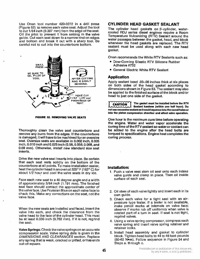
Use Onan tool number 420-0272 in a drill press (Figure 52) to remove each valve seat. Adjust the tool to cut 1/64 inch (0.397 mm) from the edge of theseat. Oil the pilot to prevent it from seizing in the valve guide. Cut each seat down to a narrow rind on edges and bottom and break it out with a sharp tool. Be careful not to cut into the counterbore bottom.
DRILL PRESS
BE SURE TO OIL PILOT OF
TOOL AFTER CUTTING RIND IS EASILY
REMOVED. I MAKE CUT
FROM EDGE OF
FIGURE 52. REMOVING VALVE SEATS
Thoroughly clean the valve seat counterbore and remove any burrs from the edges. If the counterbore is damaged, it will have to be machined for an oversize seat. Oversize seats are available in 0.002 inch, 0.005 inch, 0.010 inch and 0.025 inch (0.58,0.056,0.068, and 0.09 mm). Otherwise, install new standard size seat inserts.
Drive the new valve seat inserts into place. Be certain that each seat rests solidly on the bottom of the counterbore at all points. To make installation easier, heatthecylinderhead in anovenat325'F (162"C)for about 1/2 hour and cool the valve seats in dry ice.
Face each new seat to a 45 degree angle and a width of approximately 3/64 inch (1.191 mm). The finished seat face should contact the approximate center of thevalve face. Use Prussian Blueon each valve face to check this. Make any corrections on the seat, notlhe valve face.
When the new seats are installed and faced, insertthe valve into each, and check the clearance from the valve head to the face of the cylinder head. This must be at least 0.030 inch (0.762 mm). I f it is not, regrind the seat.
Valve Springs: Check thevalvesprings on an accurate compression scale. Valve spring data is given in the DIMENSIONS AND CLEARANCES section. Replace any spring that is weak, cracked orpitted, orhas ends ou t-of-square.
CYLINDER HEAD GASKET SEALANT The cylinder head gaskets on 2-,cylinder, water- cooled RDJ series diesel engines require a Room Temperature Vulcanizing (RTV) Sealant around the water passages between the gasket, head, and block whenever the head gaskets are replaced. The RTV sealant must be used along with each new head gasket.
Onan recommends the White RTV Sealants such as: Dow-Corning Silastic RTV Silicone Rubber
General Electric White RTV Sealant Adhesive #732
Application Apply sealant bead .03-.06 inches thick at six places on both sides of the head gasket according to dimensions shown in Figure 53. The sealant may also be applied to the finished surfaceof the block and/or head to just one side of the gasket.
The gasket must be installed before the RTV K Z x Sealant hardens (within one half hour). Do not useexcessivesealantas it couldsqueezeinto thecored holesor into the piston compression chamber and affect valve operation.
One hour is the minimum cure time before operating the engine. Water and water vapor accelerate the curing time of the RTV sealant so wateror coolant can be added to the engine after the head bolts are torqued to specifications. Engine heat completes the curing process.
Installation: 1. Push a valve seat stem oil seal onto each intake
valve guide and clamp in place. Then oil inside surface of each seal.
2. Oil stem of each valve lightly and insert each in its own guide.
3. Check each valve for a tight seat with an air- pressure type tester. If a tester is not available, make pencil marks at intervals on valve face; observe if marks rub off uniformly when valve is rotated part of a turn in seat. If seat is not tight, regrind valves.
4. Using a valve spring compressor, compress each valve spring and insert valve spring retainer and retainer locks.
5. Install head assembly and gasket to cylinder block. Tighten head bolts to 44 to 46 foot-pounds (60-62 Nom). Follow sequence in Figure 54 and Steps a. through c.
45

P 4 PLACES, BOTH SIDES SEE NOTE I P
DASHED LINES INDICATE CORED HOLES, RTV BEAD MUST BE OUTSIDE THIS AREA
FIGURE 53. HEAD GASKET-RTV SEALANT APPLICATION
d. Tighten cylinder head bolts in same sequence to 44-46 foot-pounds (60-62 Nom).
e. After 60 seconds, retighten cylinder head bolts in sequence to 44-46 foot-pounds (60-62 Nom). This step compensates for the com- press of the cylinder gasket.
6. Install intake manifold, nozzles, glow plugs and
7. Install valve stem cap. 8. Install push rods, rocker arms and rocker arm
9. Set valve clearance. See Figure 51.
oil lines. .
nuts.
CAUT,ON After the first 50 hours of operation, Exz3 retighten the cylinder head bolts and check valve clearance or the head gaskets may be blown out.
FIGURE 54. HEAD BOLT TORQUE SEQUENCE
Use Never-Seez, Fel-Pro C5-A or equivalent thread lubricant when installing cylinder head bolts. INTERNAL DISASSEMBLY a. Tighten cylinder head bolts finger-tight. If engine disassembly is necessary, observe the
following order (Le. Flywheel, Gear Cover.. .). As b. Install exhaust manifold. c. Tighten
disassembly progresses, the order may be changed somewhat as will be self-evident. The engine assembly procedure is the reverse of disassembly. Any special assembly instructions for a particular group are included in the applicable section, When reassembling, check each section for these special assembly instructions or procedures.
head bolts in sequence shown in Figure 54 to 25-30 foot-pounds (34- 41 Nom).
46

FLYWHEEL The flywheel is a tapered fit on the crankshaft. Improvise a puller, using at least a 7/16-inch bar (11.113 mm), and drill two 7/16-inch (11.113 mm) holes 2-7/8 inches (73.025 mm) between centers. Loosen the flywheel mounting screw a few turns. Place bar against the flywheel screw and attach bar, using two 3/8-16 thread screws in the holes provided in flywheel. Alternately tighten the screws until flywheel is free.
FLYWHEEL REPLACEMENT Replacement flywheels are supplied without the timing markings because each flywheel must befitted to its engine. The only accurate method of determing the top dead center (TDC) and port closing points is to measure the piston travel. This is a critical measurement and should be attempted only with accurate, dependable equipment.
With the flywheel mounted, remove the head and install a depth gauge over the front piston. Rotate the flywheel to find the TDC position on the compression stroke and mark this point on the flywheel. Next, turn the flywheel counterclockwise until the piston drops exactly 0.128 inch (3.25 mm). Mark both TDC and piston drop to PC point on the flywheel.
Ring Gear: To remove the ring gear, i f damaged, saw part way through, then break it using acold chisel and heavy hammer.
To install a new ring gear, place it in an oven heated to 380" F - 400" F (192" to 204" C) for 30 to 40 minutes.
Do not heat with a torch or ring gear may be warped.
When heated properly, the ring will fall into place on the flywheel. If it does not go on all the way by itself, drive it into place with a hammer. Do itfastand do not damage the gear teeth. The ring will contract rapidly and may shrink to the flywheel before it is in place. If this occurs, a new ring gear may be required.
GEAR COVER To remove the gear cover, detach the uppergovernor ball joint. Remove thegovernorspeed-adjustment nut and governor spring bracket.
Remove the screws holding the gear cover to the crankcase. To loosen the gear cover, tap it with a soft hammer.
Governor Shaft The governor shaft is supported by two sets of needle bearings. To remove the shaft, remove the yoke and pull the shaft from the gear cover. If the shaft is binding, clean the bearings. If loose, replace the bearings. To remove the larger bearing, drive both bearing and oil seal out from the outside of the gear cover. Remove the smaller bearing with an Easy-Out or similar tool. Press new bearings and oil seal into place. See Figure 55.
GOVERNOR
GOVERNOR ARM
. GOVERNOR SHAFT YOKE
(Smooth side toward cup)
FITS INTO
GOVERNOR CUP BE SURE THAT OIL
PASSAGES ARE OPEN I 8343
IF FEELER W I L L ENTER HOLE 112" ,
B A L L HAS FALLEN OUT
FIGURE 55. GEAR COVER ASSEMBLY
47
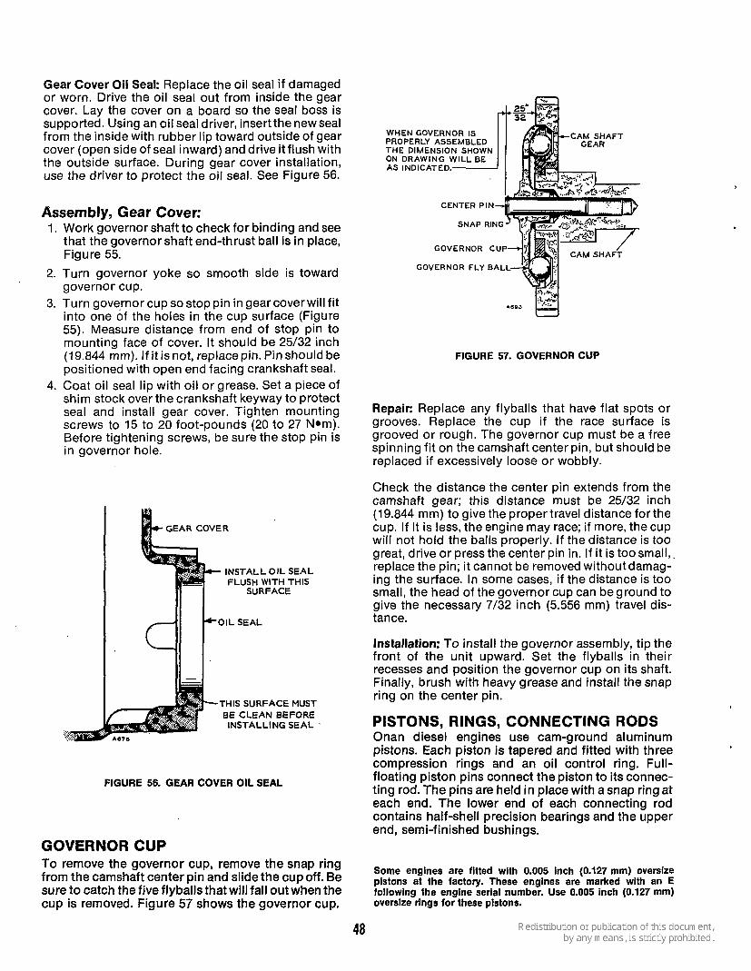
Gear Cover Oil Seal: Replace the oil seal if damaged or worn. Drive the oil seal out from inside the gear cover. Lay the cover on a board so the seal boss is supported. Using an oil seal driver, insertthe new seal from the inside with rubber lip toward outside of gear cover (open side of seal inward) and drive it flush with the outside surface. During gear cover installation, use the driver to protect the oil seal. See Figure 56.
Assembly, Gear Cover: 1. Work governor shaft to check for binding and see
that the governor shaft end-thrust ball is in place, Figure 55.
2. Turn governor yoke so smooth side is toward governor cup.
3. Turn gove,rnor cup so stop pin in gear cover will fit into one of the holes in the cup surface (Figure 55). Measure distance from end of stop pin to mounting face of cover. It should be 25/32 inch (19.844 mm). If it isnot, replace pin. Pin should be positioned with open end facing crankshaft seal.
4. Coat oil seal lip with oil or grease. Set a piece of shim stock over the crankshaft keyway to protect seal and install gear cover. Tighten mounting screws to 15 to 20 foot-pounds (20 to 27 Nom). Before tightening screws, be sure the stop pin is in governor hole.
GEAR COVER
INSTALL OIL SEAL FLUSH WITH THIS
SURFACE
'1 F O I L S E A L
.. ,... THIS SURFACE MUST '.::$> k..fl BE CLEAN BEFORE
INSTALLING SEAL '
FIGURE 56. GEAR COVER OIL SEAL
GOVERNOR CUP To remove the governor cup, remove the snap ring from the camshaft center pin and slide the cupoff. Be sure to catch the five flyballs that will fall out when the cup is removed. Figure 57 shows the governor cup.
WHEN GOVERNOR IS CAM SHAFT
CENTER PIN
GOVERNOR CUP
GOVERNOR FLY BAL
FIGURE 57. GOVERNOR CUP
Repair: Replace any flyballs that have flat spots or grooves. Replace the cup if the race surface is grooved or rough. The governor cup must be a free spinning fit on the camshaft center pin, but should be replaced if excessively loose or wobbly.
Check the distance the center pin extends from the camshaft gear; this distance must be 25/32 inch (19.844 mm) to give the propertravel distance for the cup. If it is less, the engine may race; if more, the cup will not hold the balls properly. If the distance is too great, drive or press the center pin in. If it is too small, replace the pin; it cannot be removed withoutdamag- ing the surface. In some cases, if the distance is too small, the head of the governor cup can be ground to give the necessary 7/32 inch (5.556 mm) travel dis- tance.
Installation: To install the governor assembly, tip the front of the unit upward. Set the flyballs in their recesses and position the governor cup on its shaft. Finally, brush with heavy grease and install the snap ring on the center pin.
PISTONS, RINGS, CONNECTING RODS Onan diesel engines use cam-ground aluminum pistons. Each piston is tapered and fitted with three compression rings and an oil control ring. Full- floating piston pins connect the piston to its connec- ting rod. The pins are held in place with a snap ring at each end. The lower end of each connecting rod contains half-shell precision bearings and the upper end , semi -f i n ish ed bushings.
Some engines are fitted with 0.005 inch (0.127 mm) oversize plstons at the factory. These engines are marked with an E following the engine serial number. Use 0.005 inch (0.127 mm) oversize rings for these pistons.
48
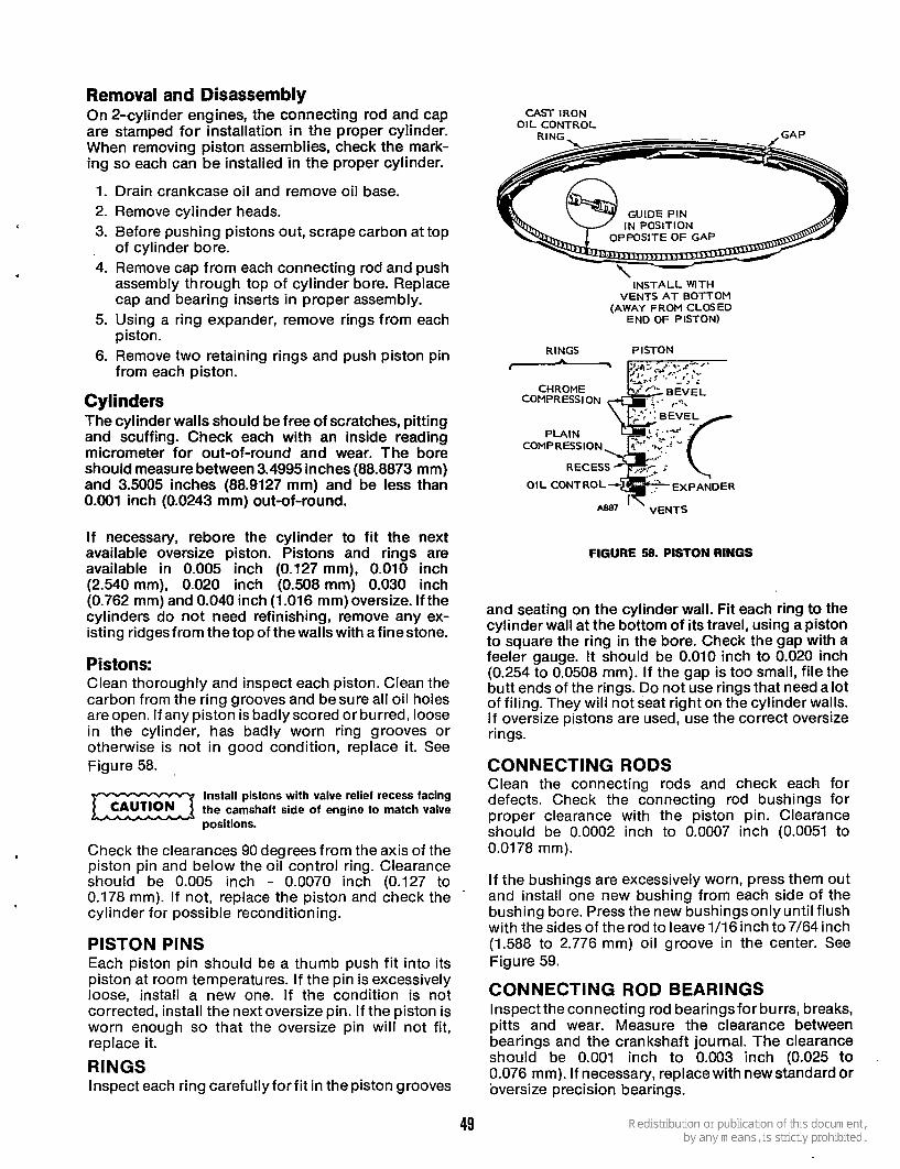
'
Removal and Disassembly On 2-cylinder engines, the connecting rod and cap are stamped for installation in the proper cylinder. When removing piston assemblies, check the mark- ing so each can be installed in the proper cylinder.
1. Drain crankcase oil and remove oil base. 2. Remove cylinder heads. 3. Before pushing pistons out, scrape carbon at top , of cylinder bore. 4. Remove cap from each connecting rod and push
assembly through top of cylinder bore. Replace cap and bearing inserts in proper assembly.
5. Using a ring expander, remove rings from each pis ton.
6. Remove two retaining rings and push piston pin from each piston.
Cylinders The cylinder walls should be free of scratches, pitting and scuffing. Check each with an inside reading micrometer for out-of-round and wear. The bore should measure between 3.4995 inches (88.8873 mm) and 3.5005 inches (88.9127 mm) and be less than 0.001 inch (0.0243 mm) out-of-round.
If necessary, rebore the cylinder to fit the next available oversize piston. Pistons and rings are available in 0.005 inch (0.127 mm), 0.010 inch (2.540 mm), 0.020 inch (0.508 mm) 0.030 inch (0.762 mm) and 0.040 inch (1.016 mm) oversize. If the cylinders do not need refinishing, remove any ex- isting ridges from the top of the walls with a finestone.
Pistons: Clean thoroughly and inspect each piston. Clean the carbon from the ring grooves and besure all oil holes are open. If any piston is badly scored or burred, loose in the cylinder, has badly worn ring grooves or otherwise is not in good condition, replace it. See Figure 58.
m positions.
Check the clearances 90 degrees from the axis of the piston pin and below the oil control ring. Clearance should be 0.005 inch - 0.0070 inch (0.127 to 0.178 mm). If not, replace the piston and check the
'
cylinder for possible reconditioning.
PISTON PINS Each piston pin should be a thumb push fit into its piston at room temperatures. If the pin is excessively loose, install a new one. If the condition is not corrected, install the next oversize pin. If the piston is worn enough so that the oversize pin will not fit, replace it.
RINGS Inspect each ring carefullyforfit in the piston grooves
Install pistons with valve relief recess facing the camshaft side of engine to match valve CAUTION
~ . -
IN POSITION
CAST IRON O I L CONTROL
INSTALL WlTH VENTS A T BOTTOM
(AWAY FROM CLOSED END OF PISTON)
RINGS PISTON
CHROME B E V E L COMPRESSION
RECESS -1
AB87 ' ' VENTS
FIGURE 58. PISTON RINGS
and seating on the cylinder wall. Fit each ring to the cylinder wall at the bottom of its travel, using a piston to square the ring in the bore. Check the gap with a feeler gauge. It should be 0.010 inch to 0.020 inch (0.254 to 0.0508 mm). If the gap is too small, file the butt ends of the rings. Do not use rings that need a lot of filing. They will not seat right on the cylinder walls. I f oversize pistons are used, use the correct oversize rings.
CONNECTING RODS Clean the connecting rods and check each for defects. Check the connecting rod bushings for proper clearance with the piston pin. Clearance should be 0.0002 inch to 0.0007 inch (0.0051 to 0.0178 mm).
If the bushings are excessively worn, press them out and install one new bushing from each side of the bushing bore. Press the new bushings only until flush with the sides of the rod to leave 1/16 inch to 7/64 inch (1.588 to 2.776 mm) oil groove in the center. See Figure 59.
CONNECTING ROD BEARINGS Inspect the connecting rod bearingsfor burrs, breaks, pitts and wear. Measure the clearance between bearings and the crankshaft journal. The clearance should be 0.001 inch to 0.003 inch (0.025 to 0.076 mm). If necessary, replace with new standard or oversize precision bearings.
49
CONNECTING ROD
BUSHING ENDS M BE FLUSH WITH S O F ROD TO PER 1/16”01L GROOVE BETWEEN BUSHINGS
I I Iiil
F ’RECISION TYPE BEARING
’ MEASURE CLEP DIRECTION INDl
ARROW
A881 R e v .
rR IC
LANCE :ATED
3SS-S ECTl ON
IN BY
FIGURE ‘59. CONNECTING ROD BUSHINGS
ASSEMBLY AND INSTALLATION 1.
2.
3.
4.
5.
6. 7.
8. 9.
Install connecting rods on each piston with pins and retaining rings. If new bushings were in- stalled, check to see that ends are flush with connecting rod to provide for oil recess in center. Install all rings on each piston. Tapered-type rings will be marked top or identified in some other manner. Place this mark toward closed end of piston. Space ring gaps 1/4 of way around piston from one another. No gap should be in line with the piston pin. Position a bearing half in each connecting rod. Be sure there is no dirt under bearing. This could cause high spots and early bearing failure. Oil cylinder walls. Install each piston in proper cylinder using a suitable installer. Each assembly should be installed with stamp on piston facing same direction as when removed. Position each connecting rod on crankshaft, oil the journal, and install its rod cap with bearing half. When installing rod cap, position so raised witness mark on forging matches mark on con- necting rod. See Figure 60. Tighten cap screws to specified torque. Crank engine over by hand to see that all bearings are free. Install oil base with a new gasket. Install cylinder heads using proper bolt tighten- ing sequence.
10. Replace oil.
CAMSHAFT The camshaft is a one-piece machine casting, driven through gears by the crankshaft. It rides on sleeve bearings pressed into the crankcase.
In addition to providing a means of opening and closing the valves, the camshaft operates the injec- tion pump and fuel transfer pump.
FIGURE 60. CONNECTING ROD CAP
Removal: 1. Remove rocker arms and push rods from valve
chambers. 2. Remove injection pump and fuel transfer pump
from engine. 3. Remove crankshaft gear retaining washer by
removing lock ring on crankshaft. 4. Lay engine on its side to avoid dropping tappets
and remove camshaft assembly as a group. If. necessary, pry it out with a screwdriver between camshaft gear and crankcase.
5. Remove valve tappets. These can be removed only from the camshaft end of the push rod holes.
Repair: If a lobe has become slightly scored, dress it smooth with afinestone. If the camshaft is badly worn or scored, replace it. After installing a new camshaft, retime the injection pump to the engine.
Camshaft Gear: This gear is a pressed fit on the camshaft and drives it at 1/2 the crankshaft speed.To remove the gear, use a hollow tool or pipe that will fit inside the gear bore and over the center pin. Press the camshaft out of the gear bore. Be careful not to damage the center pin.
Camshaft Bearings: Thecamshaft bearings should be replaced if the clearance to the camshaft is greater than specified, the bearings show cracks, breaks, burrs , excessive wear, or other defects. The camshaft-to-bearing clearance should be 0.001 2 inch to 0.0037 inch (0.0304 to 0.0938 mm). To check the rear bearing, remove the expansion plug at the rear of the crankcase.
50
PRESS BEARING FLUSH WITH
BOn-OM OF RECESS
REAR EARING
BEARING
.9-3 1/32 2 1/16
FIGURE 61. CAMSHAFT BEARINGS
ANKSHAFT WASHER
FIGURE 62. CAMSHAFT ENDPLAY
2-1/4 x 20 PULLER
PRESS BEARING FLUSH WITH
FRONT CRANK- CASE SURFACE
- ALIGN O I L HOLES
FRONT 8 EA RI N G
Press new bearings into place, Figure 61. Press the rear bearing flush with the bottom of the expansion plug recess. Press the front bearing in flush with the crankcase front surface so the oil passages are aligned. Do not attempt to ream the bearings as they are a precision type. Afterthe rear bearing is installed, insert a new expansion plug in the recess, using sealing compound, and expand it into place with sharp blows at its center.
Installation, Camshaft Assembly: 1. Install key and press camshaft gear on camshaft
until it. bottoms on flange with no clearance. 2. Install governor components. 3. Slide thrust washer onto shaft. Measure camshaft
end play: i t should be 0.007 inch to 0.039 inch (0.178 to 0.991 mm). See Figure 62.
4. Lay engine on its side or end and insert push rod tappets.
5. Install camshaft assembly in engine. Align timing marks on camshaft gear and crankshaft gear. See Figure 63.
6. Replace push rods and fuel transfer pump. 7. When engine is reassembled, install injection
pump following the steps for Injection Pump Installation in the FUEL SYSTEM section. This step is critical.
CRANKSHAFT Onan diesel engines use a counter-balanced, ductile iron crankshaft. To increasetheshaftfatigue durabili- ty, all crankpin fillets are shot-peened during manufacture.
FIGURE 63. TIMING MARKS
51

FIGURE 64. REMOVING CAMSHAFT GEAR
Removal 1.
2.
3. 4. 5. 6.
Remove lock ring and retaining washer in front of crankshaft gear. Pull off crankshaft gear. It has 2-1/4-20 UNC tapped holesfor attaching agear pulling ring. Use care not to damage teeth if the gear is to be reused. See Figure 64. Remove oil pan, pistons and connecting rods. Remove bearing cap from center main bearing. Remove rear bearing plate from crankcase. Remove crankshaft through rear opening in crankcase. Catch upper half of center main bearing support as it slides off its mounting surface.
Inspection: Clean the crankshaft and blow out all oil passages. Check journals for out-of-round, taper, grooving or ridges. Pay particular attention to ridges orgrooveson eitherside of theoil holeareas. Unusual conditions here often point to previous neglect of oil changes. .
If journal dimensions are not within limits, or the journals are scored, regrind the crankshaft.
Crankshaft Grinding: Crankshaft grinding requires a trained, experienced operator working with precision equipment. Procedures which may besatisfactory for some spark-ignition engines may well be unsatisfac- tory for diesel applications, resulting in expensive failures. Onan emphasizes that if facilities or trained personnel are not available, the crankshaft may be sent to the factory.
Special procedures must be observed when rework- ing diesel crankshafts. In addition to machining, the crankshaft must be shot-peened and super-finished. Failure to shot-peen the crankpin fillets is likely to cause early failure. When the shaft is machined, follow this data and Figure 65 to shotpeen each crank pin fillet.
3/16’’ (4.763 mrn) ~ \ H E s ~ T O B E S H O T - S U R F A C E S P E E N A
II I L!z&ZZ~J.% , T O E E M A S K E D - ._. . - 1 I T H I S A R E A D U R I N G S H O T - P E E N I N U
O P E R A T I O N
U
FIGURE 65. SHOT-PEENING THE CRANKSHAFT
1. Almen gauge reading 0.012-A (0.305). 2. Peen with 0.019 inch (0.482 mm) diameter cast
3. Peen for 30 seconds on each crankpin fillet. 4. Mask off connecting rod bearing areas.
steel shot.
Undersize bearings and connecting rodsare available to rework the shaft to 0.010inch (0.254 mm), 0.020 inch (0.508 mm), and 0.030 inch (0.762 mm) under- size.
Main Bearings: Replace main bearings if clearances are greater than limits or if the bearings are worn, grooved, or broken.
Precision replacement inserts and thrust washers are available for all main bearings. Do not ream the bearings.
Align the oil holes and press the new bearings into the front and rear housings.
Rear Oil Seal: The rear oil seal is in the rear bearing plate. If damaged, drive it out from the inside of the plate. Using the oil seal installing tool, install a new seal with the rubber lip facing outward (open side of seal inward). See Figure 66. Drive the new seal flush with the rear surface of the bearing plate. Leave the seal installer on during bearing plate installation to protect the oil seal.
Installation: After each installation step, check the crankshaft to be sure it is not frozen into place.
1. Press front and rear main bearings into place, align bearing and bearing housing oil holes. Do not attempt to drive a bearing into a cold block or rear bearing plate.
2. Install thrust washers and locking pins. 3. Oil bearing surfaces and install crankshaft from
rear of crankcase through rear bearing plate hole.
52

4. Mount and secure rear bearing plate. 5. Heat timing gear on an electric burner or oven to
about 350" F (175°C). Install key on crankshaft, then drivegear into place. Install retaining washer and lock ring.
CRANKCASE If the crankcase requires replacement, a new set of injection pump shims will be furnished with the new crankcase. These must be used and, in addition, the injection pump must be retimed to the engine.
6- Check crankshaft end play. Use enough rear bearing plate shims and gaskets to provide 0.010 inch (0*254 mm) to 0'015 inch (0*381 mm) end 'lay' If gaskets Of more than 0'01 inch
steel shim Of proper thickness and a thin gasket on each side of shim. This avoids excessive gasket compression and maintains bolt torque.
BREAK-IN PERIOD Whenever new rings or pistons are installed or the cylinder refinished, the engine must be run-in before regular operation can be resumed. Run theengine for
load, and 2 to 3 hours at 2/3 load. Regular operation can then be Avoid light load operation during the following several hours for best ring
(0.381 mm) total thickness are required, use a 15 to 20 minutes at no load, about 30 minutes at 1/3
7. Install piston assemblies. seating to prevent oil consumption.
USH DE
THRUST WASHER
ALIGN OIL HOLES
MAIN BEARING LIP FACING MUST BE FLUSH WITH
FIGURE 66. MAIN BEARING INSTALLATION
53

CONTROL SYSTEM
Due to the widevariety of uses to which these engines are adapted, operating controls are not supplied with the engines. In most cases, the engines are used for prime power to operate other manufacturers equip- ment. Installation nearly always differs. Therefore, the manufacturer or fabricator generally provides a control for the complete unit.
MAINTENANCE Periodically check all connections and contacts in the control system to be sure they are tight and clean.
PRE-HEAT SWITCH I A* SI I
SWITCH
I
NO. 12 W I R E
GLOW PLUGS
FUEL SOLENOID
* s2
FUEL SOLENOID SWITCH I
WIRING DIAGRAM
STARTER
81 ---- *I
+CUSTOMER SUPPLIED
,
SCHEMATIC
TYPICAL STANDARD ENGINE
54


Onan Corporation 1400 73rd Avenue N. E. Minneapolis, MN 55432
Telex: 275477 Fax: 61 2-574-8087 Onan is a registered trademark of Onan Corporation
61 2-574-5000