service manual - yugora.ruyugora.ru/uploads/eh65_service_manual.pdf · - 2 - 2. performance 2-1...
TRANSCRIPT
SERVICEMANUALEH65Model
PUB-ES1113Rev. 8/98
Engine

EH65 '98 - 8
© Copyright 1998 Robin America, Inc.940 Lively Blvd. � Wood Dale, IL 60191 � Phone: 630-350-8200 � Fax: 630-350-8212e-mail: [email protected] • www.robinamerica.com

CONTENTS
Section Title Page
1. SPECIFICATIONS ....................................................................................................... 1
2. PERFORMANCE ........................................................................................................ 22-1 MAXIMUM OUTPUT ......................................................................................................... 2
2-2 CONTINUOUS RATED OUTPUT ..................................................................................... 2
2-3 MAXIMUM TORQUE ........................................................................................................ 2
2-4 PERFORMANCE CURVES .............................................................................................. 3
3. FEATURES.................................................................................................................. 6
4. GENERAL DESCRIPTION OF ENGINE COMPONENTS .......................................... 74-1 CYLINDER AND CRANKCASE ........................................................................................ 7
4-2 MAIN BEARING COVER .................................................................................................. 7
4-3 CRANKSHAFT .................................................................................................................. 7
4-4 CONNECTING ROD AND PISTON .................................................................................. 8
4-5 PISTON RINGS ................................................................................................................ 8
4-6 CAMSHAFT ...................................................................................................................... 8
4-7 CYLINDER HEAD ............................................................................................................. 9
4-8 VALVE ARRANGEMENT .................................................................................................. 9
4-9 GOVERNOR SYSTEM ..................................................................................................... 9
4-10 COOLING SYSTEM ...................................................................................................... 10
4-11 LUBRICATION SYSTEM............................................................................................... 10
4-12 IGNITION SYSTEM ...................................................................................................... 10
4-13 CHARGING SYSTEM ................................................................................................... 10
4-14 CARBURETOR .............................................................................................................. 11
4-15 AIR CLEANER ............................................................................................................... 11
4-16 FUEL PUMP................................................................................................................... 11
4-17 SECTIONAL VIEW OF ENGINE ................................................................................... 12
5. DISASSEMBLY AND REASSEMBLY ....................................................................... 145-1 PREPARATIONS AND SUGGESTIONS ......................................................................... 14
5-2 SPECIAL TOOLS ............................................................................................................ 14
5-3 DISASSEMBLY PROCEDURES..................................................................................... 15
5-4 REASSEMBLY PROCEDURES...................................................................................... 30
5-5 BREAK-IN OPERATION ................................................................................................. 43
6. MAGNETO ................................................................................................................ 446-1 OPERATION AND FUNCTION ....................................................................................... 44

Section Title Page
7. LUBRICATION SYSTEM ......................................................................................... 467-1 OPERATION AND FUNCTION .......................................................................................46
8. CARBURETOR ........................................................................................................ 47
8-1 OPERATION AND FUNCTION .......................................................................................47
8-2 COMPORNENT PARTS .................................................................................................49
9. ELECTRIC STARTER .............................................................................................. 509-1 OPERATION AND FUNCTION .......................................................................................50
9-2 COMPORNENT PARTS .................................................................................................51
10. TROUBLESHOOTING ........................................................................................... 5210-1. NO ENGINE OPERATION ...........................................................................................52
10-2. STARTING DIFFICULTIES .........................................................................................53
10-3. INSUFFICIENT OUTPUT.............................................................................................54
10-4. OVERHEAT..................................................................................................................54
10-5. ROUGH IDLING ...........................................................................................................55
10-6. HIGH ENGINE OIL CONSUMPTION...........................................................................55
10-7. HIGH FUEL CONSUMPTION ......................................................................................56
10-8. DETONATION ..............................................................................................................56
10-9. ENGINE MISFIRE ........................................................................................................57
11. INSTALLATION ..................................................................................................... 5811-1 INSTALLING..................................................................................................................58
11-2 VENTILATION ...............................................................................................................58
11-3 EXHAUST GAS DISCHARGE ......................................................................................58
11-4 POWER TRANSMISSION TO DRIVEN MACHINES ....................................................58
12. SERVICE DATA...................................................................................................... 5912-1 CLEARANCE DATA AND LIMITS .................................................................................59
12-2 TORQUE SPECIFICATIONS ........................................................................................65
12-3 OIL GRADE CHART .....................................................................................................66
13. MAINTENANCE AND STORAGE.......................................................................... 6713-1 DAILY MAINTENANCE .................................................................................................67
13-2 PERIODIC MAINTENANCE SCHEDULE .....................................................................67
13-3 ENGINE STORAGE ......................................................................................................69
- 1 -
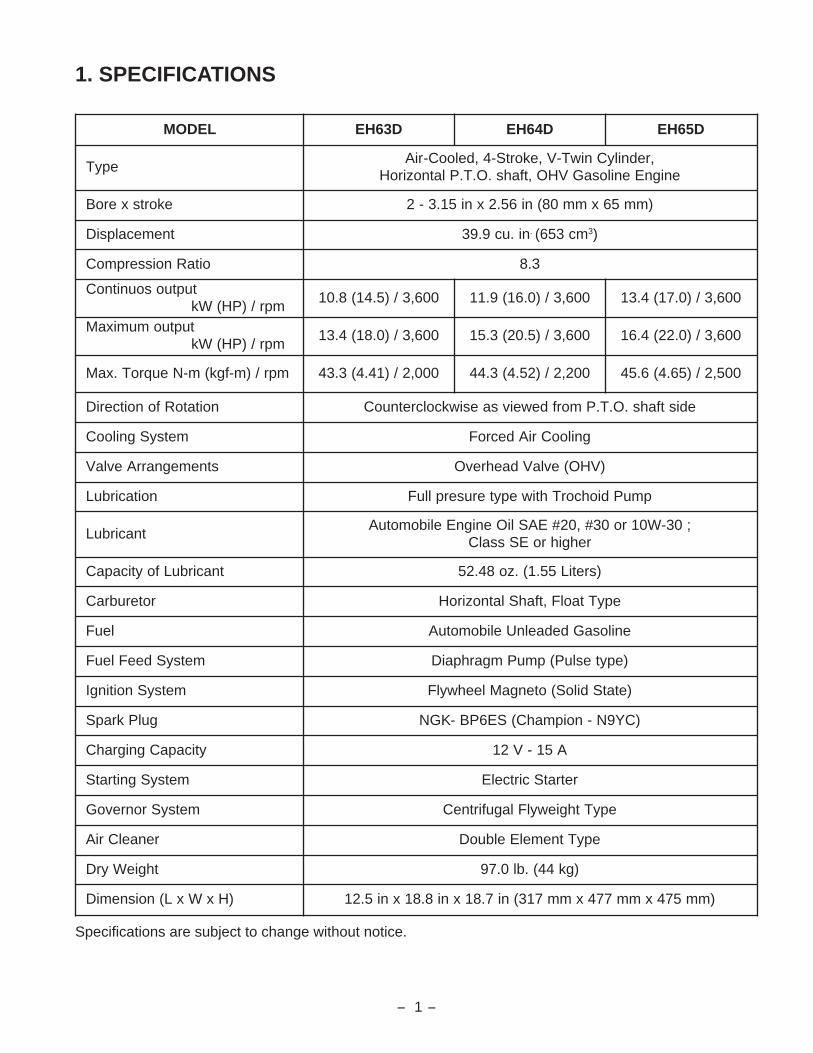
1. SPECIFICATIONS
Specifications are subject to change without notice.
LEDOM D36HE D46HE D56HE
epyT,rednilyCniwT-V,ekortS-4,delooC-riA
enignEenilosaGVHO,tfahs.O.T.PlatnoziroH
ekortsxeroB )mm56xmm08(ni65.2xni51.3-2
tnemecalpsiD ni.uc9.93 . mc356( 3)
oitaRnoisserpmoC 3.8
tuptuosounitnoCmpr/)PH(Wk
006,3/)5.41(8.01 006,3/)0.61(9.11 006,3/)0.71(4.31
tuptuomumixaMmpr/)PH(Wk
006,3/)0.81(4.31 006,3/)5.02(3.51 006,3/)0.22(4.61
mpr/)m-fgk(m-NeuqroT.xaM 000,2/)14.4(3.34 002,2/)25.4(3.44 005,2/)56.4(6.54
noitatoRfonoitceriD edistfahs.O.T.PmorfdeweivsaesiwkcolcretnuoC
metsySgnilooC gnilooCriAdecroF
stnemegnarrAevlaV )VHO(evlaVdaehrevO
noitacirbuL pmuPdiohcorThtiwepyteruserplluF
tnacirbuL;03-W01ro03#,02#EASliOenignEelibomotuA
rehgihroESssalC
tnacirbuLfoyticapaC )sretiL55.1(.zo84.25
roterubraC epyTtaolF,tfahSlatnoziroH
leuF enilosaGdedaelnUelibomotuA
metsySdeeFleuF )epytesluP(pmuPmgarhpaiD
metsySnoitingI )etatSdiloS(otengaMleehwylF
gulPkrapS )CY9N-noipmahC(SE6PB-KGN
yticapaCgnigrahC A51-V21
metsySgnitratS retratScirtcelE
metsySronrevoG epyTthgiewylFlagufirtneC
renaelCriA epyTtnemelEelbuoD
thgieWyrD )gk44(.bl0.79
)HxWxL(noisnemiD )mm574xmm774xmm713(ni7.81xni8.81xni5.21

- 2 -
2. PERFORMANCE
2-1 MAXIMUM OUTPUT
The maximum output is the output of an engine with its throttle valve fully opened under the condition thatall the moving parts are properly worn in after the initial break-in period.
A new engine may not produce full maximum output while its moving parts are still not broken-in.
NOTE :Power curves shown in the following charts are made in conformity to SAE internal combustion enginestandard test code J1349
2-2 CONTINUOUS RATED OUTPUT
The continuous rated output is the output of an engine at optimum governed speed which is most favor-able from the view point of engine's life and fuel consumption.
When the engine is installed on a certain equipment, it is recommended that the continuous outputrequired from the engine be kept below this continuous rated output.
2-3 MAXIMUM TORQUE
The maximum torque is the torque at the output shaft when the engine is producing maximum output atcertain revolution.

- 3 -
2-4 PERFORMANCE CURVES
EH63D
2000 2400 2800 3200 3600
5(6.7)
10(13.4)
15(20.1)
REVOLUTION r.p.m
HO
RS
EP
OW
ER
kW(HP)
TO
RQ
UE
N-m(kgf-m)
45 (4.59)
35 (3.57)
CONTINUOUSRATED HP
RECOMMENDEDHORSEPOWER RANGE
MAXIMUM TORQUE
MAXIMUM HORSEPOWER

- 4 -
EH64D
2000 2400 2800 3200 3600
5(6.7)
10(13.4)
15(20.1)
REVOLUTION r.p.m
HO
RS
EP
OW
ER
kW(HP)
TO
RQ
UE
N-m(kgf-m)
45 (4.59)
35 (3.57)
CONTINUOUSRATED HP
RECOMMENDEDHORSEPOWER RANGE
MAXIMUM TORQUE
MAXIMUM HORSEPOWER

- 5 -
EH65D
2000 2400 2800 3200 3600
5(6.7)
10(13.4)
15(20.1)
REVOLUTION r.p.m
HO
RS
EP
OW
ER
kW(HP)
TO
RQ
UE
N-m(kgf-m)
45 (4.59)
35 (3.57)
CONTINUOUSRATED HP
RECOMMENDEDHORSEPOWER RANGE
MAXIMUM TORQUE
MAXIMUM HORSEPOWER

- 6 -
3. FEATURES
The overhead valve arrangement is adopted for ensuring high power, low fuel consumption and low oilconsumption.
The adoption of twin-cylinder in the angle of 90 degree (V arrangement) and crankcase in one piece,plastic blower housing etc. offers a compactness and light weight, making the arrangements for installingthe engine much easier into many kinds of power equipments.
The forged steel crankshaft and high loading capacity ball bearing offer high durability, and full pressurelubrication system with trochoid type oil pump and large capacity air cleaner with dual elements enhancethe reliability.
The effective combustion chamber shape and the precisely tuned intake and exhaust valve systemenhance the low exhaust emission and ensure the engine characteristics of high torque at low speed.
The carburetor with fuel cut valve, 12V-15A alternator and pulse type fuel pump are employed as stan-dard features so that the engine can be utilized for many usage.
- 7 -
4. GENERAL DESCRIPTION OF ENGINE COMPONENTS
ROBIN EH63D/ 64D/ 65D series engine is air-cooled, 4-stroke, twin-cylinder, OHV arrangement gaso-line engine. The twin-cylinder is located in the angle of 90 degree; #1 cylinder is in the RH side and #2cylinder in LH side as viewed from flywheel (cooling fan) side.
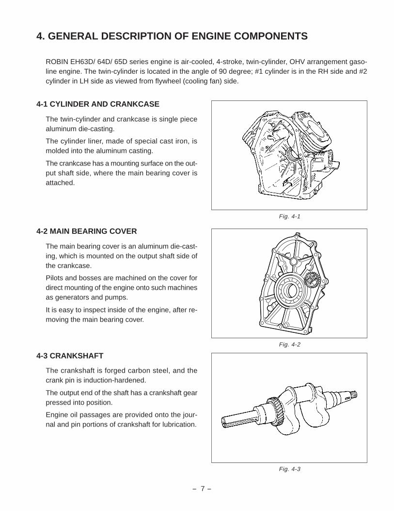
4-1 CYLINDER AND CRANKCASE
The twin-cylinder and crankcase is single piecealuminum die-casting.
The cylinder liner, made of special cast iron, ismolded into the aluminum casting.
The crankcase has a mounting surface on the out-put shaft side, where the main bearing cover isattached.
4-2 MAIN BEARING COVER
The main bearing cover is an aluminum die-cast-ing, which is mounted on the output shaft side ofthe crankcase.
Pilots and bosses are machined on the cover fordirect mounting of the engine onto such machinesas generators and pumps.
It is easy to inspect inside of the engine, after re-moving the main bearing cover.
4-3 CRANKSHAFT
The crankshaft is forged carbon steel, and thecrank pin is induction-hardened.
The output end of the shaft has a crankshaft gearpressed into position.
Engine oil passages are provided onto the jour-nal and pin portions of crankshaft for lubrication.
Fig. 4-1
Fig. 4-2
Fig. 4-3

- 8 -
4-4 CONNECTING ROD AND PISTON
The connecting rod is forged aluminum alloy, andits large and small ends function as bearings.
The piston is an aluminum alloy casting, and car-ries two compression rings and one oil ring.
4-5 PISTON RINGS
The piston rings are made of special cast iron.
The profile of the top ring is barrel face and the second ring has a tapered face.
The oil ring is designed for better sealing and less oil consumption, in combination with 3 pieces.
4-6 CAMSHAFT
The camshaft is made of special cast iron andcamshaft gears are casted together in one piece.
Each 2 cam robs are provided for intake and ex-haust valves correspondingly.
Both sides of the shaft fit into the plane bearingson the crankcase and main bearing cover.
Fig. 4-4
Fig. 4-5
Fig. 4-6
TOP RING
SECOND RING
OIL RING
1
2
3
BARREL
TAPER
COMBINATIONRING
1
2
3

- 9 -
4-7 CYLINDER HEAD
The cylinder head is an aluminum die-castingwhich utilizes semi-spherical type combustionchamber for the high combustion efficiency.
4-8 VALVE ARRANGEMENT
The intake valve is located on flywheel side of thecylinder head.
The cooling fins and passages design lead cool-ing air to the exhaust valve area for the optimumcooling.
Hard alloy valve seats are molded in the cylinderhead and stellite is fused to the exhaust valve face.
4-9 GOVERNOR SYSTEM
The governor is a centrifugal flyweight type whichensures constant operation at the selected speedagainst load variations.
The governor gear with governor weights is in-stalled inside of main bearing cover and drivenby the crankshaft.
Fig. 4-7
Fig. 4-8
Fig. 4-9
GOVERNORGEAR
INTAKE VALVE EXHAUST VALVE

- 10 -
4-10 COOLING SYSTEM
The large fins on the flywheel provide sufficientcooling air capacity for cylinder and cylinder head.
The cylinder baffle helps the cooling air flow effi-ciently.
4-11 LUBRICATION SYSTEM
The engine is furnished with full pressure lubrica-tion system.
The trochoid type oil pump is driven by crankshaftand delivers pressurized engine oil through thefull-flow type oil filter to the journal and pin por-tions of crankshaft and camshaft.
4-12 IGNITION SYSTEM
The ignition system is a transistor controlled mag-neto ignition system which consists of a flywheeland an ignition coil with a built-in transistor installedonto the crankcase.
4-13 CHARGING SYSTEM
Multipolar charging coil is provided inside of fly-wheel. Charging capacity is 12V-15A.
Fig. 4-10
Fig. 4-11
FLYWHEEL
IGNITION COIL
- 11 -
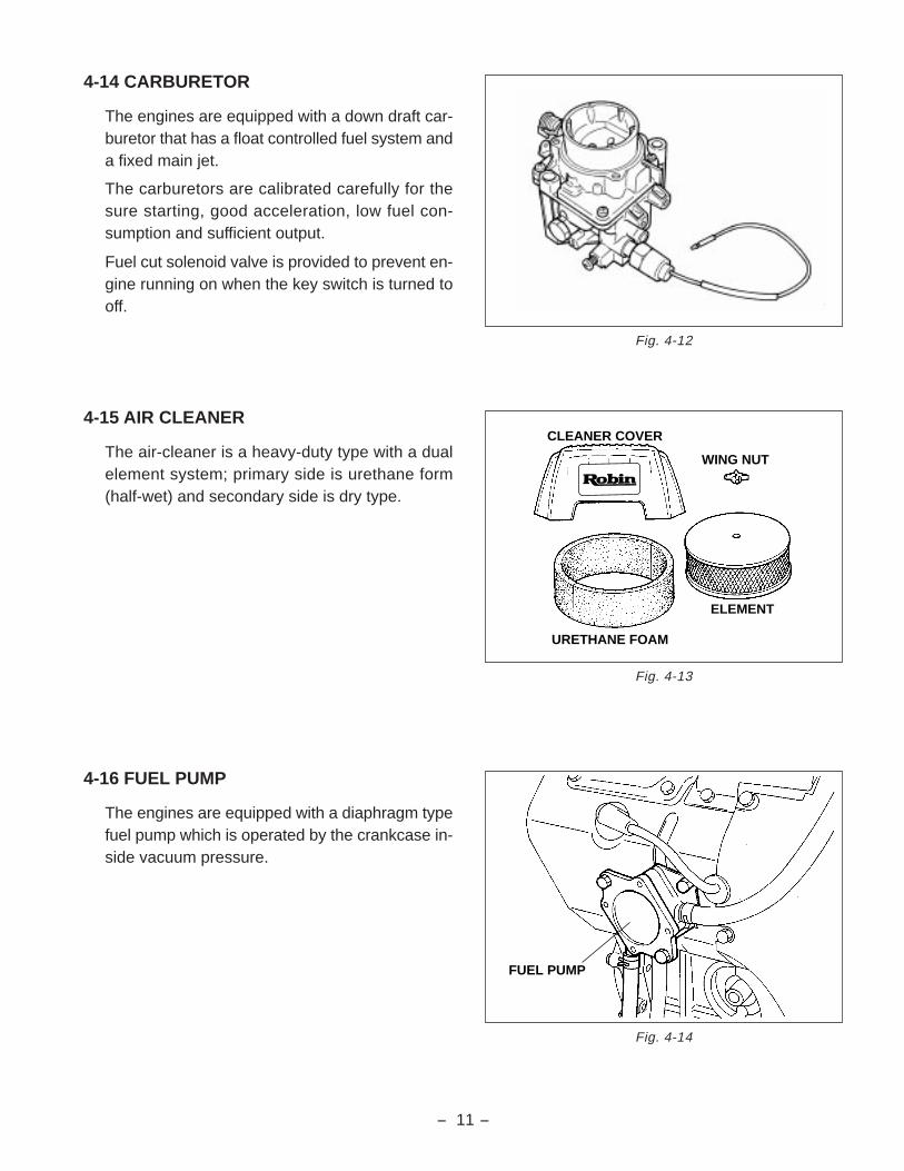
4-14 CARBURETOR
The engines are equipped with a down draft car-buretor that has a float controlled fuel system anda fixed main jet.
The carburetors are calibrated carefully for thesure starting, good acceleration, low fuel con-sumption and sufficient output.
Fuel cut solenoid valve is provided to prevent en-gine running on when the key switch is turned tooff.
4-15 AIR CLEANER
The air-cleaner is a heavy-duty type with a dualelement system; primary side is urethane form(half-wet) and secondary side is dry type.
4-16 FUEL PUMP
The engines are equipped with a diaphragm typefuel pump which is operated by the crankcase in-side vacuum pressure.
Fig. 4-12
Fig. 4-13
Fig. 4-14
URETHANE FOAM
ELEMENT
WING NUT
CLEANER COVER
FUEL PUMP

- 12 -
4-17 SECTIONAL VIEW OF ENGINE
Fig. 4-15
CARBURETOR
OIL PUMP
IGNITION COIL
FLYWHEEL
INTAKE MANIFOLD
OIL PUMP FILTER
MAIN BEARING COVER
P.T.O.SHAFT

- 13 -
Fig. 4-16
AIR CLEANER
GOVERNOR LEVER
ROCKER ARM
CRANKCASE CRANKSHAFT CONNECTING ROD
PISTON PIN
OIL PRESSURESWITCH
PISTON
OIL FILTER
FUEL PUMP
PISTON RING
CAMSHAFTPUSH ROD
INTAKE ANDEXHAUST VALVES
TAPPET
GOVERNOR GEAR
ELECTRIC STARTER
SPARK PLUG

- 14 -
5. DISASSEMBLY AND REASSEMBLY
5-1 PREPARATIONS AND SUGGESTIONS
When disassembling the engine, memorize the locations of individual parts so that they can be reas-sembled correctly. If you are uncertain of identifying some parts, it is suggested that tags be attached tothem.
Have boxes ready to keep disassembled parts by group.
To prevent losing and misplacing, temporarily assemble each group of disassembled parts.
Carefully handle disassembled parts, and clean them with washing oil if necessary.
Use the correct tools in the correct way.
5-2 SPECIAL TOOLS
No Special Tool is needed for disassembling and reassembling the engine.
For pulling off the flywheel, universal type puller being popular in the market place as shown in theillustration is needed.
FLYWHEEL PULLER
Fig. 5-1

- 15 -
5-3 DISASSEMBLY PROCEDURES
Fig. 5-2
petS evomerotstraP serudecorpdnaskrameR srenetsaF
1niardlioenignE sgulpgnivomeryblioenigneniarD
.esacknarcfoedishtobnodetacol
STEP 1
OIL LEVEL GAUGE
GASKET
OIL DRAIN PLUG(ON BOTH SIDE)
OIL FILLER CAP
GASKET

- 16 -
petS evomerotstraP serudecorpdnaskrameR srenetsaF
2stnemelednarevocrenaelcriA 1#morfepiprehtaerbevomeR
.daehrednilyc;mm11x23-01
.scp3
3 esabrenaelcriA
Fig. 5-4
Fig. 5-3
BREATHERPIPE
WING NUT
STEP 2
STEP 3
CLEANERCOVER
CLEANERELEMENT
CLEANER BASE
FLANGE BOLT(Inch) : 3 pcs.

- 17 -
petS evomerotstraP serudecorpdnaskrameR srenetsaF
4 gnisuohrewolB .scp8;21x6M
5 knildnarevellortnockcohC 6M
Fig. 5-5
CHOKECONTROL ROD
RETURNSPRING
WAVEDWASHER
LINK PIVOT
CHOKECONTROLLINK
CHOKEKNOB
CLAMP
M5 TAPPINGSCREW : 1 pce.
BLOWER HOUSING
M6 FLANGEBOLT : 8 pcs
STEP 4
STEP 5
- 18 -
petS evomerotstraP serudecorpdnaskrameR srenetsaF
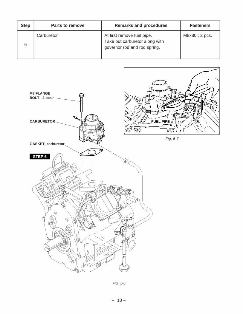
6
roterubraC .epipleufevomertsriftAhtiwgnolaroterubractuoekaT
.gnirpsdordnadorronrevog
.scp2;08x8M
Fig. 5-7
Fig. 5-6
FUEL PIPE
STEP 6
M8 FLANGE BOLT : 2 pcs.
CARBURETOR
GASKET, carburetor

- 19 -
Fig. 5-8
petS evomerotstraP serudecorpdnaskrameR srenetsaF
7dnarevelronrevoGrevellortnocdeepS
;revelronrevoG.reveltuoekatdnatlobevomeR
;revellortnocdeepSgnirpsronrevoG.1
tunkcolfleS.2etalppotS.3
rehsawgnirpS.4revellortnocdeepS.5
scp3;21X6Mtunkcol-fles6M
8 tinutekcarblortnocdeepS M scp3;21X6
STOP PLATE
SPRING WASHER
SPEED CONTROLLEVER
M6 FLANGEBOLT : 3 pcs.
M6 SELF LOCKNUT : 1 pce.
FRICTIONWASHER
FRICTIONWASHER
BRACKET UNIT,speed control
STEP 8
STEP 7
GOVERNORSPRING
GOVERNORROD
RODSPRING
GOVERNORLEVER
M6 BOLT AND WASHER : 1 pce.
M6 NUT : 1 pce.

- 20 -
TO STOP DIODE
STEP 9
STEP 10
SPARKPLUG CAP
PLUGTERMINAL
IGNITIONCOIL
M6 BOLT AND WASHERASSY : 2 pcs.
IGNITIONCOIL
PLUGTERMINAL
SPARKPLUG CAP
M6 BOLT AND WASHERASSY : 2 pcs.
M6 FLANGEBOLT : 2 pcs.
HOSECLAMP
HOSECLAMP
PULSEPIPE
BRACKET,fuel pump
FUEL PIPE
FUEL PUMPand FUEL
FILTER ASSY
M6 FLANGEBOLT : 2 pcs.
Fig. 5-9
Fig. 5-10
IGNITION COIL
FIXING BANDS
petS evomerotstraP serudecorpdnaskrameR srenetsaF
9 pmupleuF .tsriftaepipaesulpevomeR scp2;21x6M
01
liocnoitingI .pacgulptuoekaT.1.liocnoitingievomeR.2
.sdnabgnixiferiwpotstuotuC.3noitingimorfseriwpotstcennocsiD.4
.lioc
M &tlob03x6.scp4;rehsaw

- 21 -
petS evomerotstraP serudecorpdnaskrameR srenetsaF
11selffabrednilyC)4#&3#,2#,1#(
21X6M
Fig. 5-11
CYLINDER BAFFLE #1
STEP 11
M6 FLANGEBOLT : 3 pcs.
CYLINDER BAFFLE #3
M6 FLANGEBOLT : 2 pcs.
CYLINDER BAFFLE #4
M6 FLANGEBOLT : 3 pcs.
CYLINDER BAFFLE #2M6 FLANGEBOLT : 3 pcs.

- 22 -
petS evomerotstraP serudecorpdnaskrameR srenetsaF
21 dlofinamekatnI;tunegnalf8M
.scp4
31gulpkrapS SE6RPBroSE6PB:KGN
)CY9NRroCY9N:NOIPMAHCro(
Fig. 5-12
INTAKE MANIFOLD
STEP 12
STEP 13
STEP 13
SPARK PLUG
SPARK PLUG
M8 FLANGENUT : 2 pcs.
GASKET, muffler
GASKET, muffler
M8 FLANGENUT : 2 pcs.

- 23 -
petS evomerotstraP serudecorpdnaskrameR srenetsaF
41 revocrekcoR .scp4;21x6M
51dorhsuPdnadaehrednilyC
tfahsmrarekcoR.1mrarekcoR.2
dnamrarekcorgnivomernehWtaleehwylftsujdadnanrut,tfahs
"1"otdecaf"T"gnikramehthtiwCDT.daehrednilychcaeno"2"ro
noitisoplanigirofognikramehttuPdnamrarekcor,dorhsuphcaeotno
.ylbmessaerrofevlav
.scp8;56x01M
scp2;21X6M
Fig. 5-13
ROCKERSHAFT
ROCKERCOVER
PUSHROD
ROCKERARM
M8 NUT : 2 pcs.
ADJUSTINGSCREW
GASKET,rocker cover
CYLINDERHEAD 1
M6 FLANGEBOLT : 4 pcs.
M10 FLANGEBOLT : 4 pcs.
GASKET 1
STEP 14
GASKET 2
CYLINDERHEAD 2
M10 FLANGEBOLT : 4 pcs.
GASKET,rocker cover
M6 FLANGEBOLT : 4 pcs.
ROCKERARM
PUSHROD
M8 NUT : 2 pcs.
ADJUSTINGSCREW
ROCKERCOVER
ROCKERSHAFT
LIFT HOOK
STEP 15
STEP 15
STEP 14
LIFT HOOK

- 24 -
Fig. 5-14
Fig. 5-15
petS evomerotstraP serudecorpdnaskrameR srenetsaF
61sevlavtsuahxe&ekatnI
revocrehtaerBetalprehtaerB
SPRINGRETAINER
COLLET-VALVE
VALVESPRING
WASHER
SPRINGRETAINER
COLLET-VALVE
VALVESPRING
WASHER
STEP 16
EXHAUSTVALVE
INTAKEVALVE
GASKET
BREATHER
GASKET, breather
BREATHERCOVER
M6 FLANGEBOLT : 2 pcs.

- 25 -
M18 NUT : 1 pce.
SPRING WASHER
WASHER
RING GEAR
FLYWHEEL
STEP 17
STEP 18
CHARGE COIL
M5 BOLT ANDWASHER : 4 pcs.
Fig. 5-17
Fig. 5-16
Fig. 5-18 Fig. 5-19
petS evomerotstraP serudecorpdnaskrameR srenetsaF
71leehwylF dnatfahsknarcmorfyekevomeR
.rellupgnisuybleehwylftuollupneht,rehsaw,tun81M
rehsawgnirps
81 liocegrahC .scp4;02x5M

- 26 -
Fig. 5-21
Fig. 5-20
GOVERNORSLEEEVE
GOVERNOR GEAR
GOVERNORGEAR SHAFT
WASHER : 2 pcs.
GASKET
MAIN BEARING COVER
M8 FLANGEBOLT : 10 pcs.
STEP 19
THRUST BEARING
petS evomerotstraP serudecorpdnaskrameR srenetsaF
91
evocgniraebniaM .tfahsOTPmorfyektuoekaTepatlynivylophtiwtfahsOTPpaR
evoorgyekyblaeslioegamadotton.egde
.scp01;44x8M
- 27 -
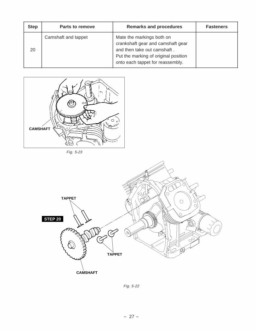
Fig. 5-23
CAMSHAFT
Fig. 5-22
STEP 20
TAPPET
TAPPET
CAMSHAFT
petS evomerotstraP serudecorpdnaskrameR srenetsaF
02
teppatdnatfahsmaC nohtobsgnikramehtetaMraegtfahsmacdnaraegtfahsknarc
.tfahsmactuoekatnehtdnanoitisoplanigirofognikramehttuP
.ylbmessaerrofteppathcaeotno

- 28 -
Fig. 5-24
petS evomerotstraP serudecorpdnaskrameR srenetsaF
12
dorgnitcennoCdnanotsiPpilcnipnotsiP*
nipnotsiP*sgnirnotsiP*
.stlobdorgnitcennocevomeR.1.pacdorgnitcennoctuoekaT.2
sdrawpudorgnitcennocehthsuP.3.notsiphtiwgnolatuoekatdna
noitisoplanigirofognikramehttuPnotsip,pilc,gnir,notsiphcaeotno
rofpacdnadorgnitcennoc,nip.ylbmessaer
.scp4;8M
22 tfahsknarC
CONNECTING ROD
PISTON
PISTONRING SET
PISTON PIN
CLIP
CLIP
CLIPCONNECTINGROD CAP
M8 CONNECTINGROD BOLT : 2 pcs.
PISTON PIN
CLIP
CONNECTINGROD
PISTONRING SET
CONNECTINGROD CAP
M8 CONNECTINGROD BOLT : 2 pcs.
STEP 21
STEP 21
STEP 22 CRANKSHAFT
SPACER

- 29 -
Fig. 5-25
petS evomerotstraP serudecorpdnaskrameR srenetsaF
32
esacknarCpmupliO*
retlifliO*hctiwserusserpliO*
retlifpmupliO*llab&gnirpsfeilerliO*
retratscirtcelE*tfahsrevelronrevoG*
scp2;56x8M
11x23-01
STEP 23
OIL FILTER
OIL PRESSURESWITCHSTEEL BALL
OIL PUMP FILTER
SPRING, relief valve
GASKET, aluminum
PLUG, oil relief
10-32 FLANGEBOLT (Inch) : 1 pce.
GOVERNOR LEVERSHAFT
ELECTRICSTARTER
M8 FLANGEBOLT : 2 pcs.
WASHER
SNAP PINBRACKET,magnetic switch
M6 FLANGEBOLT : 4 pcs.
OIL PUMP COVER
O RING
INNERROTOR
OUTERROTER

- 30 -
5-4 REASSEMBLY PROCEDURES
5-4-1 PRECAUTIONS FOR REASSEMBLY
1) Clean parts thoroughly before reassembly.
Pay most attention to cleanliness of piston, cylinder, crankshaft, connecting rod and bearings.
2) Scrape off all carbon deposits from cylinder head, piston top and piston ring grooves.
3) Check lip of oil seals. Replace oil seal if the lip is damaged. Apply oil to the lip before reassembly.
4) Replace all the gaskets with new ones.
5) Replace keys, pins, bolts, nuts, etc., if necessary.
6) Torque bolts and nuts to specification referring to the "TORQUE SPECIFICATIONS".
7) Apply oil to rotating and sliding portions.
8) Check and adjust clearances and end plays where specified in this manual.
5-4-2 Pre-assembly
A. CRANKCASE
(1) Fix oil pump filter in position.
(2) Insert ball and spring into the oil relief valve hole and tighten plug to the specified torque.
(3) Fit governor lever shaft with clip.
(4) Tighten oil drain plugs on both side of crankcase.
Tightening Torque : 11.8 - 14.7 N-m (150 - 250 kg-cm, 10.9 - 18.1 ft-lb.)
Fig. 5-26
OIL FILTER
STEEL BALL
OIL PUMP FILTER
SPRING, relief valve
GASKET, aluminum
PLUG, oil relief
10-32 FLANGEBOLT (Inch) : 1 pce.
GOVERNOR LEVERSHAFT
WASHER
SNAP PIN
OIL DRAIN PLUG(ON BOTH SIDE)
GASKET
OIL DRAIN PLUG
GASKET
- 31 -
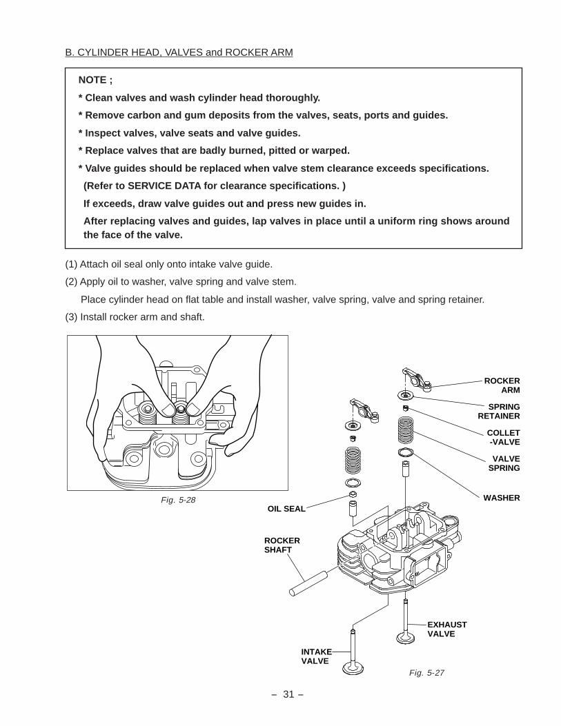
B. CYLINDER HEAD, VALVES and ROCKER ARM
(1) Attach oil seal only onto intake valve guide.
(2) Apply oil to washer, valve spring and valve stem.
Place cylinder head on flat table and install washer, valve spring, valve and spring retainer.
(3) Install rocker arm and shaft.
NOTE ;
* Clean valves and wash cylinder head thoroughly.
* Remove carbon and gum deposits from the valves, seats, ports and guides.
* Inspect valves, valve seats and valve guides.
* Replace valves that are badly burned, pitted or warped.
* Valve guides should be replaced when valve stem clearance exceeds specifications.
(Refer to SERVICE DATA for clearance specifications. )
If exceeds, draw valve guides out and press new guides in.
After replacing valves and guides, lap valves in place until a uniform ring shows aroundthe face of the valve.
Fig. 5-27
Fig. 5-28OIL SEAL
SPRINGRETAINER
ROCKERARM
COLLET-VALVE
VALVESPRING
WASHER
ROCKERSHAFT
EXHAUSTVALVE
INTAKEVALVE

- 32 -
Fig. 5-30
C. PISTON and CONNECTING ROD
(1) Install oil ring first, then second ring and top ring. Spread ring only far enough to slip over piston andinto correct groove. Use care not to distort ring.
(2) Apply enough oil to small end of connecting rod and piston pin, and fix connecting rod to piston withpiston pin.
(3) Use clips on the both side of the piston pin to secure piston pin in position.
D. Main bearing cover and governor gear
(1) Insert washer into governor gear shaft.
(2) Insert governor gear along with sleeve intogovernor gear shaft.
TOP RING
SECOND RING
OIL RING
1
2
3
BARREL
TAPER
COMBINATIONRING
1
2
3
Fig. 5-29
NOTE ;
* Install second ring with punched mark beside the gap on the top side.
* Top ring can be fit either way.
* As for oil ring, rails should be placed on and below the expander.
MAIN BEARING COVER
GOVERNORSLEEEVE
GOVERNOR GEAR
GOVERNORGEAR SHAFT
WASHER : 2 pcs.
THRUST BEARING

- 33 -
Fig. 5-31
Note:
Apply enough oil to bearing portion ofcrankcase. For easy installation, putcrankcase on box or wood blocks.
Fig. 5-33
Note:
* The "1" mark of the connecting rod for#1 cylinder and "2" mark for #2 cylin-der should be faced to the flywheel sidewhen assembled.
* Apply enough oil to piston rings, con-necting rod bearings (large end) andcylinder bore before assembly.
* Set gaps of piston rings as shown inthe illustration.
Fig. 5-32
CRANKSHAFT
CONNECTING ROD
PISTON RING COMPRESSOR
MARK "1"
1
ALIGNMENT MARKS
Tightening Torque : 22.1 - 27.0 N-m(225 - 275 kg-cm)(16.3 - 19.9 ft-lb.)
5-4-3 Re-assembly
1) CRANKSHAFT
Install crankshaft onto crankcase.
2) PISTON and CONNECTING ROD
(1) Install piston and connecting rod assembly intocylinder by using a piston ring compressor tohold piston rings.
(2) Temporary fit key and flywheel and turn crank-shaft to BTDC (bottom dead center). Lightlytap the top of piston until large end of the rodmeet the pin portion of crankshaft.
(3) Set connecting rod cap to connecting rod withthe alignment marks mated and the clinchingportion clinched. Tighten bolts to the speci-fied torque.
(4) Check for free movement of piston and con-necting rod by turning crankshaft slowly.
SECOND RING
OIL RING
TOP RING


- 35 -
5) MAIN BEARING COVER
(1) Put a oil seal guide onto PTO shaft portion to avoid damaging the main bearing cover oil seal.
(2) Place gasket onto the mating surface of crankcase.
(3) Lubricate oil seal lip potion and bearing surfaces, and install main bearing cover.
Tighten bolts evenly to the specified torque.
6) OIL PUMP and COVER
(1) Apply oil to inner and outer rotors of oil pumpand attach them in position.
(2) Set O-ring in position.
(3) Install oil pump cover with the allow markingupwards.
7) CYLINDER HEAD
(1) Place new head gasket onto crankcase.
(2) Install #1 and #2 cylinder heads. Tighten bolts evenly in steps to the specified torque;
8) PUSH ROD
(1) Rotate crankshaft to the position in the no lifted condition of tappet.
(2) Be sure to loose the rocker arm adjust screw.
NOTE ;
* Before installing main bearing cover, be sure to check the installation of governor levershaft and oil pump filter in the crankcase in position.
* Tap cover with a soft hammer until tacthing the crankcase mating surface, engagingwith governor gear and camshaft gear properly.
* Rotate crankshaft slowly to check for smooth operation and side clearance.
NOTE ;
Be sure to check dwell pin, and replace with new one if damaged.
Fig. 5-37
O-RING
INNER ROTOR
OUTER ROTOR
" "MARKING
OIL PUMP COVER
Tightening Torque : 16.7 - 18.6 N-m (170 - 190 kg-cm, 12.3 - 13.7 ft-lb.)
Tightening Torque : 33.3 - 41.2 N-m (340 - 420 kg-cm, 24.6 - 30.4 ft-lb.)

- 36 -
(3) Insert push rods into the concave portion of tappet and set the other end to the concave portion ofrocker arm adjust screw with valve spring depressed.
(4) Temporally tighten adjust screw.
9) VALVE CLEARANCE ADJUSTMENT
NOTE : Temporally fit the flywheel in position for easy operation.
(1) Rotate crankshaft clockwise to the TDC (top dead center) of compression stroke by matching themark "T" of flywheel with the mark "1" of #1 cylinder head.
(2) Loosen lock nut on rocker arm and turn adjusting screw to adjust the clearance between rocker armand valve stem end, and then tighten lock nut to the specified torque.
Valve Clearance : 0.085 - 0.115 mm (Cold condition)
(3) Adjust valve clearance of #2 cylinder side inthe same manner.
(4) Rotate crankshaft several times and be sureto check valve clearance again. Adjust valveclearance if necessary.
Fig. 5-38
Fig. 5-39
THICKNESSGAUGE
#1 CYLINDER#2 CYLINDER
MARK "1"MARK "2"
MARK "T"
FLYWHEEL
Tightening Torque : 9.8 - 13.7 N-m(100 - 140 kg-cm)(7.2 - 10.1 ft-lb.)

- 37 -
10) ROCKER COVER
Install rocker cover with new gasket.
11) BREATHER PIPE and COVER
Attach breather plate (breather valve) and breathercover to crankcase using proper gaskets.
Put breather plate in such position as its reedvalve opens outside.
12) SPARK PLUG
Install spark plug to each cylinder head.
Spark plug : NGK - BP6ES or BPR6ES (CHAMPION - N9YC or RN9YC)
13) CHARGE COIL
Install charge coil with the wiring located at 2-o’clock position.
Fig. 5-40
GASKET
BREATHER
GASKET, breather
BREATHERCOVER
M6 FLANGEBOLT : 2 pcs.
Note:
Never tighten the bolts over the speci-fied torque, or gasket is damaged andcut. Replace gaskets with new ones ifthey are torn or damaged.
Tightening Torque :
New plug - 11.8 - 14.7 N-m (120 - 150 kg-cm, 8.7 - 10.8 ft-lb.)
Current plug - 22.5 - 26.5 N-m (230 - 270 kg-m, 16.6 - 19.5 ft-lb.)
Fig. 5-41
CHARGE COIL
ELECTRIC STARTER
BLACKET
PULLING M8 FLANGE BOLT : 2 pcs.
Tightening Torque : 2.9 - 4.9 N-m(30 - 50 kg-cm)(2.2 - 3.6 ft-lb.)
Tightening Torque : 1.5 - 3.4 N-m (15 - 35 kg-cm)(1.1 - 2.5 ft-lb.)
Tightening Torque : 2.9 - 4.9 N-m (30 - 50 kg-cm, 2.2 - 3.6 ft-lb.)

- 38 -
14) STARTER MOTOR
Install starter motor.
15) CYLINDER BAFFLE
Attach cylinder baffle #1, #2, #3 and #4.
16) INTAKE MANIFOLD
Set gasket (stainless steel) onto both #1 and #2cylinder head and install intake manifold.
17) FLYWHEEL
(1) Put woodruff key in the keyway of crankshaft.
(2) Wipe off oil and grease thoroughly fromtapered portion of crankshaft and flywheelcenter hole.
(3) Install flywheel to crankshaft and tightenflywheel nut with spring washer and washer.
18) IGNITION COIL
Temporally fit ignition coil to crankcase.
Adjust air gap between ignition coil and flywheelusing a thickness gauge and tighten bolts.
Connect wiring from stop diode to the primaryterminal of ignition coil.
Fig. 5-42
INTAKE MANIFOLD
M8 FLANGE NUT : 2 pcs.
GASKET, muffler
GASKET, muffler
M8 FLANGENUT : 2 pcs.
Fig. 5-43
Tightening Torque : 16.7 - 18.6 N-m (170 - 190 kg-cm)(12.3 - 13.7 ft-lb.)
Tightening Torque : 16.7 - 18.6 N-m (170 - 190 kg-cm)(12.3 - 13.7 ft-lb.)
Tightening Torque : 83.3 - 93.1 N-m (850 - 950 kg-cm)(61.5 - 68.7 ft-lb.)
Ignition coil air gap : 0.3 - 0.5 mm (0.012 - 0.020 in.)
THICKNESS GAUGE IGNITION COIL
WIRE
STOPDIODE
Tightening Torque : 6.9 - 8.8 N-m (70 - 90 kg-cm)(5.1 - 6.5 ft-lb.)

- 39 -
19) CARBURETOR
Set gasket onto intake manifold and install carburetor.
20) GOVERNOR LEVER
Attach governor rod and rod spring betweengovernor lever and carburetor throttle lever, andinsert the governor lever to governor lever shaft.Tighten locking bolt temporarily.
Fig. 5-44
GOVERNORLEVER
GOVERNOR SHAFT
ROD SPRING
GOVERNOR ROD THROTTLE LEVER
Tightening Torque : 16.7 - 18.6 N-m (170 - 190 kg-cm)(12.3 - 13.7 ft-lb.)

- 40 -
21) SPEED CONTROL LEVER
Install speed control bracket onto intake manifold.Attach return spring, spacer, friction washer, wing nut, etc. to speed control lever as shown in theillustration.Attach governor spring between governor lever and speed control lever. Attach chock control linkbetween carburetor chock lever and chock control lever.
Fig. 5-45
GOVERNOR GEAR
GOVERNOR SPRING
ADJUSTING SCREWSPEED CONTROL LEVER
GOVERNOR LEVER
CARBURETOR
GOVERNOR ROD
FULL OPENFULL CLOSE
A
B
LOCK NUT
HIGH SPEED
LOW SPEED
5
4
3
2
1

- 41 -
22) ADJUST GOVERNOR SYSTEM
(1) Push speed control lever all the way to thehigh speed position and fix it by tightening nut.
(2) Check that governor lever is pulled by gover-nor spring and carburetor throttle valve is fullyopen.
(3) Turn governor shaft counterclockwise all theway and tighten lock bolt to secure the leveron the shaft.
23) BLOWER HOUSING
Attach blower housing to crankcase.
24) FUEL PUMP
Install fuel pump onto #2 cylinder baffle. Connectfuel pipe between carburetor and fuel pump.
25) AIR CLEANER
(1) Connect breather pipe to air cleaner base.
(2) Fit air cleaner base onto carburetor.
(3) Connect breather pipe to #1 cylinder head.
(4) Set air cleaner element along with urethaneform onto base.
(5) Install air cleaner cover with knob.
Fig. 5-46
GOVERNOR LEVERGOVERNOR SHAFT
Fig. 5-47
FUEL PUMP
AIR CLEANER BASE
Fig. 5-48
- 42 -
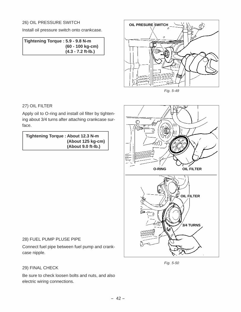
26) OIL PRESSURE SWITCH
Install oil pressure switch onto crankcase.
27) OIL FILTER
Apply oil to O-ring and install oil filter by tighten-ing about 3/4 turns after attaching crankcase sur-face.
28) FUEL PUMP PLUSE PIPE
Connect fuel pipe between fuel pump and crank-case nipple.
29) FINAL CHECK
Be sure to check loosen bolts and nuts, and alsoelectric wiring connections.
Fig. 5-49
Fig. 5-50
OIL PRESURE SWITCH
OIL FILTERO-RING
3/4 TURNS
OIL FILTER
Tightening Torque : About 12.3 N-m (About 125 kg-cm)(About 9.0 ft-lb.)
Tightening Torque : 5.9 - 9.8 N-m (60 - 100 kg-cm)(4.3 - 7.2 ft-lb.)
- 43 -
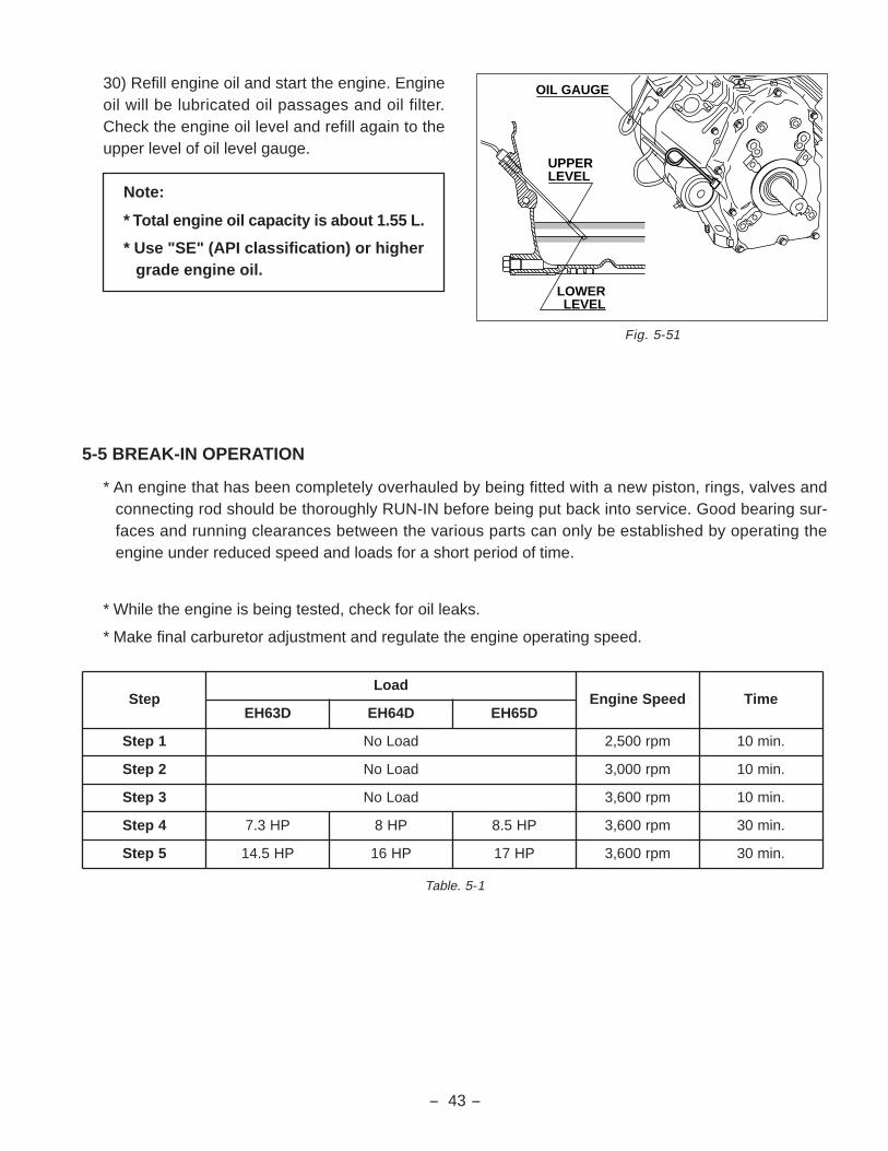
30) Refill engine oil and start the engine. Engineoil will be lubricated oil passages and oil filter.Check the engine oil level and refill again to theupper level of oil level gauge.
5-5 BREAK-IN OPERATION
* An engine that has been completely overhauled by being fitted with a new piston, rings, valves andconnecting rod should be thoroughly RUN-IN before being put back into service. Good bearing sur-faces and running clearances between the various parts can only be established by operating theengine under reduced speed and loads for a short period of time.
* While the engine is being tested, check for oil leaks.
* Make final carburetor adjustment and regulate the engine operating speed.
petSdaoL
deepSenignE emiTD36HE D46HE D56HE
1petS daoLoN mpr005,2 .nim01
2petS daoLoN mpr000,3 .nim01
3petS daoLoN mpr006,3 .nim01
4petS PH3.7 PH8 PH5.8 mpr006,3 .nim03
5petS PH5.41 PH61 PH71 mpr006,3 .nim03
Table. 5-1
Note:
* Total engine oil capacity is about 1.55 L.
* Use "SE" (API classification) or highergrade engine oil.
Fig. 5-51
UPPERLEVEL
LOWERLEVEL
OIL GAUGE

- 44 -
6. MAGNETO
6-1 OPERATION AND FUNCTION
The ignition system is pointless flywheel magneto with automatic advancing characteristic.
Being different from the breaker point type ignition system, this system is completely free from suchtroubles as starting-up failure owing to dirty, burnt or corroded point surface.
The electronic automatic advancing ensures extremely easy starts and stable high performance at oper-ating speed by advancing the ignition timing to the most suitable point.
* BASIC THEORY
(1) Revolution of the flywheel generates electricity on the primary side of the ignition coil, and the basecurrent I1 flows to the power transistor. Current I1 turns the power transistor "ON" and the electriccurrent I2 flows.
Low SpeedIgnitionTiming
Control Circuit
I3
I4
Sig
nal
Tra
nsi
sto
r A
AutomaticAdvancing
ControlCircuit
I5
I6
Sig
nal
Tra
nsi
sto
r B
I1Res
iste
r
I2
Po
wer
Tra
nsi
sto
r
Sec
on
dar
y C
oil
Pri
mar
y C
oil
Sp
ark
plu
g
500 1000 2000 3000 (r.p.m.)
ENGINE REVOLUTION
IGN
ITIO
N T
IMIN
G STEP ADVANCING
ELECTRONIC ADVANCING FLYWHEELMAGNETO SYSTEM(B.T.D.C.)
Fig. 6-1 (b)
Fig. 6-1 (a)

- 45 -
(2) At lower engine revolution, when the flywheel reached the ignition point the low speed ignition timingcontrol circuit operates to run the base current I3 to turn the signal transistor A "ON" allowing thecurrent /1 to bypass as current I4.
At this moment the power transistor turns "OFF" and the current I2 is abruptly shut resulting in thehigh voltage generated in the secondary coil which produces sparks at the spark plug.
(3) At higher engine revolution, the advancing control circuit operates at the ignition timing to run thebase current I5 to turn the signal transistor B "ON" allowing the current I1 to bypass as current I6.
At this moment the power transistor turns "OFF" and the current I2 is abruptly shut resulting in thehigh voltage generated in the secondary coil which produces sparks at the spark plug.
The operating timing of the advancing control circuit advances in accordance with the increase ofengine speed resulting in the advancing of ignition timing.
* WIRING DIAGRAM
Connect key switch, magnetic switch and battery with wirings of proper gauge as shown by the dottedlines in the wiring diagram.
Fig. 6-2
OFF
ON
START
G M B L S
KEY SWITCH
STOPDIODE
S BM
G L
MAGNETICSWITCH
CARBURETOR
DIODERECTIFIER
IGNITIONCOIL
RED
LA406GREEN
BATTERY12V-30AH
+ -
KEYSWITCH
CHARGECOIL
BLACK BLACK
LA106LA406
RED
BLACK
BLACK
LA406ELECTRICSTARTER
BLUE
BROWNTO TACH./HOUR METER
WHITE
OIL PRES.SWITCH
GR
AY
LA
MP
YELLOW
BLUE

- 46 -
7. LUBRICATION SYSTEM
7-1 OPERATION AND FUNCTION
* Full lubrication system is adopted, in combination with large-size torchoid oil pump and cartridge typeoil filter.
* The large-size trochoid type oil pump is driven directly by crankshaft, and delivers pressurized engineoil to the journal and pin portions of crankshaft, camshaft etc.
* The engine oil in the oil pan is fed trough the oil pump filter into oil pump and the engine oil pressure isadjusted by the relief valve after discharging from oil pump. Through the cartridge type oil filter, theengine oil is provided onto the rotating portions such as journal and pin portion of crankshaft andcamshaft. The splashed engine oil is provided to the cylinder, piston, cylinder head valve system.
* The by-pass valve is incorporated into the cartridge type oil filter. In case that the oil filter element isclogged, the engine oil is fed through the by-pass valve into the crankcase oil passage.
Fig. 7-1
OIL PUMP
OIL PUMP FILTER
CRANKSHAFT
OIL FILTER
RELIEF VALVE
CAMSHAFT

- 47 -
8. CARBURETOR
8-1 OPERATION AND FUNCTION
AIR
AIR
VE
NT
HO
LE
CH
OK
E V
AL
VE
PIL
OT
AIR
JE
T
MA
IN A
IR J
ET
FL
OA
T
NE
ED
LE
VA
LV
E
FU
EL
INL
ET
PIP
E
FU
EL
MA
IN N
OZ
ZL
E
TH
RO
TT
LE
VA
LV
E
BY
-PA
SS
PIL
OT
OU
TL
ET
MIX
TU
RE
TA
MP
ER
CA
P
EM
UL
SIO
N T
UB
E
FU
EL
CU
T V
AL
VE
MA
IN J
ET
PIL
OT
JE
T
Fig. 8-1
- 48 -
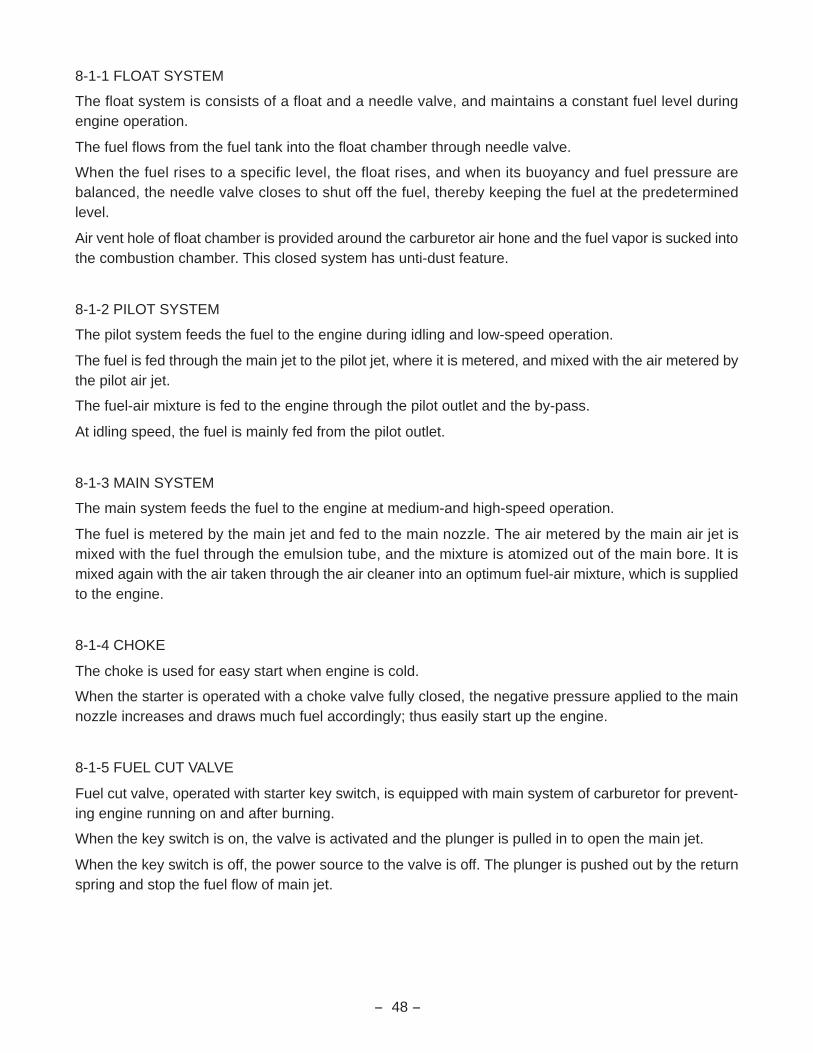
8-1-1 FLOAT SYSTEM
The float system is consists of a float and a needle valve, and maintains a constant fuel level duringengine operation.
The fuel flows from the fuel tank into the float chamber through needle valve.
When the fuel rises to a specific level, the float rises, and when its buoyancy and fuel pressure arebalanced, the needle valve closes to shut off the fuel, thereby keeping the fuel at the predeterminedlevel.
Air vent hole of float chamber is provided around the carburetor air hone and the fuel vapor is sucked intothe combustion chamber. This closed system has unti-dust feature.
8-1-2 PILOT SYSTEM
The pilot system feeds the fuel to the engine during idling and low-speed operation.
The fuel is fed through the main jet to the pilot jet, where it is metered, and mixed with the air metered bythe pilot air jet.
The fuel-air mixture is fed to the engine through the pilot outlet and the by-pass.
At idling speed, the fuel is mainly fed from the pilot outlet.
8-1-3 MAIN SYSTEM
The main system feeds the fuel to the engine at medium-and high-speed operation.
The fuel is metered by the main jet and fed to the main nozzle. The air metered by the main air jet ismixed with the fuel through the emulsion tube, and the mixture is atomized out of the main bore. It ismixed again with the air taken through the air cleaner into an optimum fuel-air mixture, which is suppliedto the engine.
8-1-4 CHOKE
The choke is used for easy start when engine is cold.
When the starter is operated with a choke valve fully closed, the negative pressure applied to the mainnozzle increases and draws much fuel accordingly; thus easily start up the engine.
8-1-5 FUEL CUT VALVE
Fuel cut valve, operated with starter key switch, is equipped with main system of carburetor for prevent-ing engine running on and after burning.
When the key switch is on, the valve is activated and the plunger is pulled in to open the main jet.
When the key switch is off, the power source to the valve is off. The plunger is pushed out by the returnspring and stop the fuel flow of main jet.

- 49 -
8-2 COMPORNENT PARTS
Fig. 8-2
1. BODY, lower
2. GASKET, body upper
3. BODY, upper
4. LEVER ASSY, choke
5. SPRING, choke
6. SHAFT ASSY, choke
7. CHOKE VALVE
8. VALVE, float
9. FLOAT ASSY
10. FLOAT PIN
11. MAIN JET
12. SOLENOID VALVE ASS’Y
13. JET, slow
14. NEEDLE, idle adjust
15. THROTTLE SHAFT ASS’Y
16. THROTTLE VALVE
17. EXPANSION PLUG
18. PLUG
19. O-RING
20. PLUG, anti tamper
19
34
5
6
7
2
12
11
13
18
1720
9
8
10
14
16
15
1

- 51 -
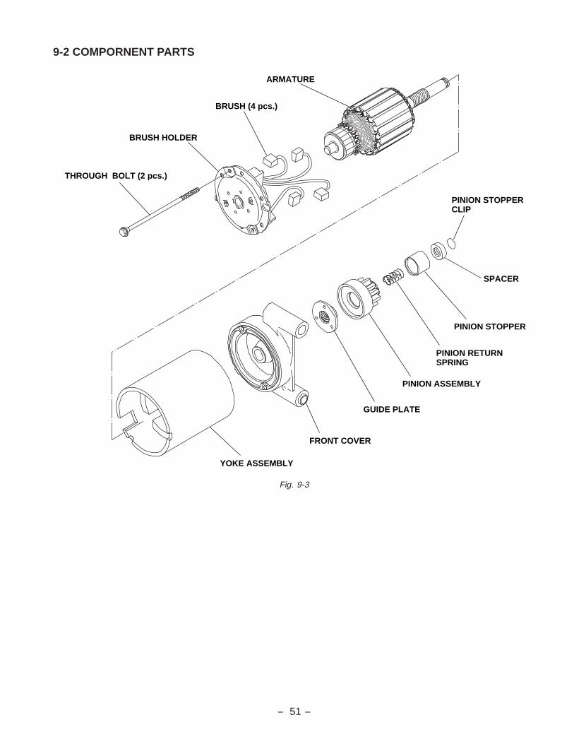
9-2 COMPORNENT PARTS
Fig. 9-3
THROUGH BOLT (2 pcs.)
BRUSH HOLDER
ARMATURE
BRUSH (4 pcs.)
YOKE ASSEMBLY
FRONT COVER
PINION ASSEMBLY
PINION RETURN SPRING
PINION STOPPER
PINION STOPPERCLIP
SPACER
GUIDE PLATE
- 52 -
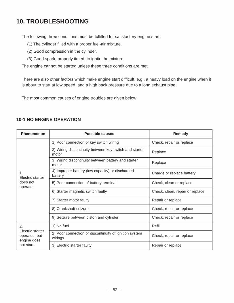
10. TROUBLESHOOTING
The following three conditions must be fulfilled for satisfactory engine start.
(1) The cylinder filled with a proper fuel-air mixture.
(2) Good compression in the cylinder.
(3) Good spark, properly timed, to ignite the mixture.
The engine cannot be started unless these three conditions are met.
There are also other factors which make engine start difficult, e.g., a heavy load on the engine when itis about to start at low speed, and a high back pressure due to a long exhaust pipe.
The most common causes of engine troubles are given below:
10-1 NO ENGINE OPERATION
nonemonehP sesuacelbissoP ydemeR
.1retratscirtcelE
tonseod.etarepo
gniriwhctiwsyekfonoitcennocrooP)1 ecalperroriaper,kcehC
retratsdnahctiwsyekneewtebytiunitnocsidgniriW)2rotom
ecalpeR
retratsdnayrettabneewtebytiunitnocsidgniriW)3rotom
ecalpeR
degrahcsidro)yticapacwol(yrettabreporpmI)4yrettab
yrettabecalperroegrahC
lanimretyrettabfonoitcennocrooP)5 ecalperronaelc,kcehC
ytluafhctiwscitengamretratS)6 ecalperroriaper,naelc,kcehC
ytluafrotomretratS)7 ecalperroriapeR
eruziestfahsknarC)8 ecalperroriaper,kcehC
rednilycdnanotsipneewteberuzieS)9 ecalperroriaper,kcehC
.2retratscirtcelE
tub,setareposeodenigne
.tratston
leufoN)1 llifeR
metsysnoitingifoytiunitnocsidronoitcennocrooP)2sgniriw
ecalperroriaper,kcehC
ytluafretratscirtcelE)3 ecalperroriapeR

- 53 -
10-2 STARTING DIFFICULTIES
nonemonehP sesuacelbissoP ydemeR
enignewoL.1tadeeps
gnitrats
degrahcsidyrettaB)1 yrettabegrahC
rotomretratsdnayrettabneewtebnoitcennocrooP)2 riaperronaelC
dnuorgdnayrettabneewtebnoitcennocrooP)3 riaperronaelC
ytluafretratscirtcelE)4 ecalperroriapeR
lioenignereporpmI)5dednemmocerhtiwecalpeR
lioenigne
noitingI.2metsys
noitcnuflam
gulpkrapSpaggulpkrapsreporpmI*
noitalusnioN*stisopednobraC*
tsujdAecalpeR
naelC
liocnoitingIytiunitnocsidronoitalusnioN*
edocnoitingifoytiunitnocsidronoitcennocrooP*ecalpeR
ecalperroriapeR
leehwylfdnaliocnoitingineewtebpagriareporpmI tsujdA
metsysleuF.3noitcnuflam
knatleufnileufoN)1 llifeR
deggolcpmupleuF)2 naelC
dehcniprodeggolcesohleuF)3 ecalperronaelC
senilleufotnigniximriA)4gnitcennoctsujdadnakcehC
noitrop
noitartlifniretawroenilosagreporpmI)5 ecalpeR
roterubraC)6wolfrevO*
degamadrodeggolC*evlavelttorhtfonoitareporeporpmI*
tsujdAnaelcdnaylbmessasiD
tsujdadnakcehC
gniriwevlavtucleuffonoitcennocrooP)7 riaperdnakcehC
erocenignE.4stnenopmoc
noitcnuflam
stlobdaehrednilycfogninethgittneiciffusnI)1 nethgiterdnakcehC
rednilycro/dnagnirnotsip,notsipforaeW)2 ecalperroriapeR
taesdnaevlavfotcatnocreporpmI)3 riapeR
eruziesevlaV)4 riapeR
ecnaraelcevlavreporpmI)5 tsujdA
egakaelteksagdlofinamekatnI)6rostlobdlofinamekatninethgiteR
teksagecalper
egakaelteksagroterubraC)7rostlobroterubracnethgiteR
teksagecalper
gulpkrapsfogninethgittneiciffusnI)8 nethgiteR

- 54 -
10-4. OVERHEAT
nonemonehP sesuacelbissoP ydemeR
woL.1noisserpmoc
gulpkrapsnesooL)1 teksagecalperronethgiteR
egakaelteksagdaehrednilyC)2 teksagecalperronethgiteR
raewroeruzies)s(gnirnotsiP)3 ecalpeR
raewrednilycronotsiP)4 ecalperroriapeR
tcatnoctaesdnaevlavtcerrocnI)5 ecalperroriapeR
eruziesmetsevlaV)6 ecalperroriapeR
ecnaraelcevlavreporpmI)7 tsujdA
noitingI.2metsys
noitcnuflam
ytluafgulpkrapS)1 ecalpeR
ytluafliocnoitingI)2 ecalpeR
leehwylfdnaliocnoitingineewtebpagriareporpmI)3 tsujdA
noitazitengamedotengaM)4 ecalpeR
metsysleuF.3noitcnuflam
deggolcroterubraC)1 naelcdnaylbmessasiD
noitarepopmupleufreporpmI)2 naelcdnaylbmessasiD
deggolcesohleufroreniartsleuF)3 ecalperronaelC
senilleufotnigniximriA)4gnitcennoctsujdadnakcehC
noitrop
noitartlifniretawroenilosagreporpmI)5 ecalpeR
ekatniwoL.4emulovria
deggolcrenaelcriA)1 ecalperronaelC
ytluafevlavelttorhT)2 ecalperroriapeR
nonemonehP sesuacelbissoP ydemeR
gnitaehrevO
elffabrednilycrotelnitadetcurtsbowolfriagnilooC)1noitrop
naelC
lioenignereporpmI)2 ecalpeR
erutximleuf/rianaeL)3 roterubractsujdadnakcehC
metsystsuahxefoerusserpkcabevissecxE)4 ecalperronaelc,kcehC
daol-revO)5 daoldetarotegnahC
10-3. INSUFFICIENT OUTPUT

- 55 -
10-5. ROUGH IDLING
10-6. HIGH ENGINE OIL CONSUMPTION
nonemonehP sesuacelbissoP ydemeR
roterubraC.1deepsgnildiwoL)1 tsujdA
deggolcegassapmetsyswolsroterubraC)2 naelcdnakcehC
ekatnI.2metsys
ekatniriafonoitropgnitcennocmorfgniximriA)1metsys
teksagecalperronethgit,kcehC
rednilyC.3daeh
)yb-wolb(ytluafteksagdaehrednilyC)1 ecalpeR
metsysevlaV.4
ecnaraelcevlavreporpmI)1 tsujdA
taesevlavmorfegakaeL)2 tcatnoctaesevlavtsujdA
ediugdnametsevlavneewtebecnaraelcevissecxE)3 ecalpeR
noitingI.5metsys
krapsnoitingikaeW)1 gulpkrapsecalperdnakcehC
nonemonehP sesuacelbissoP ydemeR
egakaelliO.1
gulpniardnesooL)1 nethgiT
degamadteksaggulpniarD)2 ecalpeR
gnittifretlifliotcerrocnI)3 riapeR
stlobrevocgniraebniamnesooL)4 nethgiT
degamadteksagrevocgniraebniaM)5 ecalpeR
degamadlaesliotfahsknarC)6 ecalpeR
noitulidliO.2
ytluafgnirlionotsiP)1 ecalpeR
tcatnocrooproraew,eruziessgnirnotsiP)2 ecalpeR
rednilycdnanotsipforaewevissecxE)3 ecalpeR
metsevlavforaewevissecxE)4 ecalpeR
levelliohgiH)5 levelliotsujdA
ytluafrehtaerB)6 ecalperroriapeR

- 56 -
10-7. HIGH FUEL CONSUMPTION
10-8. DETONATION
nonemonehP sesuacelbissoP ydemeR
metsysleuF.1
tejniamezis-revO)1 ecalpeR
taolfnilevelleufhgihro/dnaytluafevlaveldeeN)2rebmahc
ecalperrotsujdA
.yllufnepotonseodevlavkcohC)3 ecalperroriapeR
erocenignE.2stnenopmoc
noisserpmocwoL)1 riaperrokcehC
gniloocrevO)2ro/dnadaoltsujdadnakcehC
deepsenigne
nonemonehP sesuacelbissoP ydemeR
noitingI.1metsys
noitcnuflam
sgniriwmetsysnoitingifonoitcennocrooP)1 ylreporptcennocdnakcehC
gulpkrapsdegamadroreporpmI)2 ecalperronaelC
metsysleuF.2noitcnuflam
erutximleuf/riahcirronaeL)1 ecalperrotsujda,naelC
degamadroterubraC)2 naelcdnaylbmessasiD
degamadrodeggolcsenilleuF)3 ecalperronaelC
ekatniriafonoitropgnitcennocmorfgniximriA)4metsys
ecalperroylreporptcennoCteksag
rednilyC.3daeh
rebmahcnoitsubmocnitisopednobraC)1 naelcdnaevomeR
)yb-wolb(ytluafteksagdaehrednilyC)2 ecalpeR
metsysevlaV.4
ecnaraelcevlavreporpmI)1 tsujdA
noitaroiretedtaehevlaV)2 ecalpeR
noitaroiretedgnirpsevlaV)3 ecalpeR
gnimitevlavreporpmI)4 tsujdA

- 57 -
10-9. ENGINE MISFIRE
nonemonehP sesuacelbissoP ydemeR
noitingI.1metsys
edortceledegamadropaggulpkrapsrepprpmI)1 ecalperrotsujda,naelC
ytluafliocnoitingi)2 ecalpeR
sgniriwmetsysnoitingidegamaD)3 ecalpeR
sgniriwmetsysnoitingifonoitcennocrooP)4 ylreporptcennocdnakcehC
metsysleuF.2
erutximleuf/riahcirronaeL)1 riaperdnaylbmessasiD
deggolcroterubraC)2 riaperdnaylbmessasiD
roterubracfotnemtsujdagnildireporpmI)3 tsujdA
noitartlifniretawroenilosagreporpmI)4 ecalpeR
erocenignE.3stnenopmoc
evlavreporpmironoitaroiretedtaehevlaV)1tnemtsujda
ecalperrotsujdA
noitaroiretedgnirpsevlaV)2 ecalpeR
noisserpmocwoL)3 ecalperrotsujda,kcehC

- 58 -
11. INSTALLATION
Engine life, ease of maintenance and inspection, frequency of checks and repairs, and operating cost all depend onthe way in which the engine is installed. Review the following instructions carefully for installing the engine.
11-1 INSTALLING
When mounting the engine, carefully examine its position, the method of connecting it to a machine, the foundation,and the method of supporting the engine.
When determining its mounting position, in particular, make sure that gasoline and oil can easily be supplied andchecked, the spark plug can easily be checked, the air cleaner can easily be serviced, and that the oil can easily bedischarged.
11-2 VENTILATION
Fresh air is necessary for cooling the engine and burning the fuel.
In the case the engine is operated under a hood or in a small room, temperature rise in the engine room can causevapor lock, oil deterioration, increased oil consumption, loss of power, piston seizure, shorter engine life, etc.,making it impossible to operate the engine properly. It is necessary, therefore, to provide a duct or baffle to guidecooling air to the engine to prevent recirculation of he hot air used for engine cooling, and temperature rise of themachine.
Keep the engine room temperature below 50 °C even in the hottest period of the year.
11-3 EXHAUST GAS DISCHARGE
Exhaust gas is noxious. When operating the engine indoors, be sure to discharge the exhaust gas outdoors. If along exhaust pipe is used in such a case, the internal resistance increases causing loss of engine power. Thus pipeinside diameter must be increased in proportion to exhaust pipe length.
Exhaust pipe : Less than 3 m long --- pipe inside diameter 30 mm
Less than 5m long --- pipe inside diameter 33 mm.
11-4 POWER TRANSMISSION TO DRIVEN MACHINES
11-4-1 BELT DRIVE
Take the following notes into consideration.
* V-belts are preferable to flat belts.
* The driving shaft of the engine must be parallel to the driven shaft of the machine.
* The driving pulley of the engine must be in line with the driven pulley of the machine.
* Install the engine pulley as close to the engine as possible.
* If possible, span the belt horizontally.
* Disengage the load when starting the engine.
If no clutch is used, use a belt tension pulley or the like.
11-4-2 FLEXIBLE COUPLING
When using a flexible coupling, run out and misalignment between the driven shaft and engine shaft must beminimized. Run out and misalignment tolerance are specified by the coupling manufacturer.

- 59 -
12. SERVICE DATA
12-1 CLEARANCE DATA AND LIMITS
METID56/D46/D36HE
DTS timiL
DAEHREDNILYCssentalF*
htdiwtcatnoctaesevlaV*
.aidedisniediugevlaV*
sselro50.0)sselro200.0(
1.0)400.0(
.XE.NI0.1-7.0
)930.0-820.0(0.2
)970.0(
350.6-530.6)3832.0-6732.0(
51.6)242.0(
Unit : mm (in)

- 60 -
16 m
m
Unit : mm (in)
METID56/D46/D36HE
DTS timiL
REDNILYC.aidedisnI*
.gniroberretfassenidnuoR*
.gniroberretfayticirdnilyC*
DTS910.08-000.08
)4051.3-6941.3(
nehwderobereboTneewtebecnereffideht
fo.nimdna.xamotdehcaerretemaid
.)400.0(1.0
ts1gnirober
962.08-052.08)061.3-951.3(
ottiD
ts2gnirober
915.08-005.08)071.3-961.3(
------------
10.0)400.0(
------------
510.0)6000.0(
------------
NOTSIP)noitceridtsurhtnitrikstA(ezisnotsiP*
DTS889.97-869.97)941.3-841.3(
878.97)541.3(
s/ots1832.08-812.08)951.3-851.3(
821.08)551.3(
s/odn2884.08-864.08)961.3-861.3(
873.08)461.3(
- 61 -
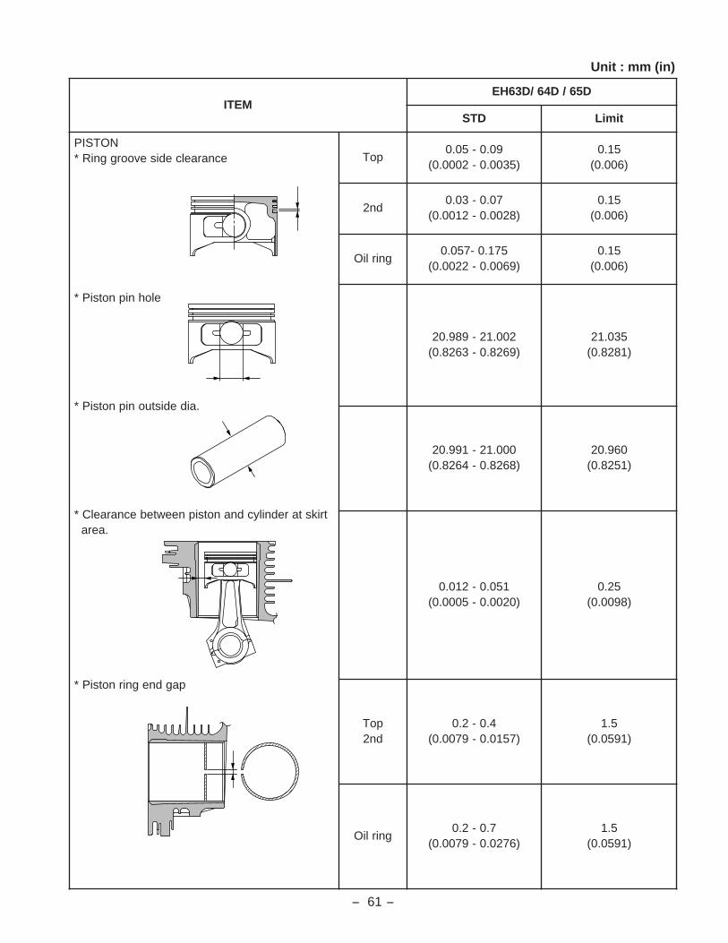
Unit : mm (in)
METID56/D46/D36HE
DTS timiL
NOTSIPecnaraelcedisevoorggniR*
elohnipnotsiP*
.aidedistuonipnotsiP*
trikstarednilycdnanotsipneewtebecnaraelC*.aera
pagdnegnirnotsiP*
poT90.0-50.0
)5300.0-2000.0(51.0
)600.0(
dn270.0-30.0
)8200.0-2100.0(51.0
)600.0(
gnirliO571.0-750.0
)9600.0-2200.0(51.0
)600.0(
200.12-989.02)9628.0-3628.0(
530.12)1828.0(
000.12-199.02)8628.0-4628.0(
069.02)1528.0(
150.0-210.0)0200.0-5000.0(
52.0)8900.0(
poTdn2
4.0-2.0)7510.0-9700.0(
5.1)1950.0(
gnirliO7.0-2.0
)6720.0-9700.0(5.1
)1950.0(
��������
- 63 -
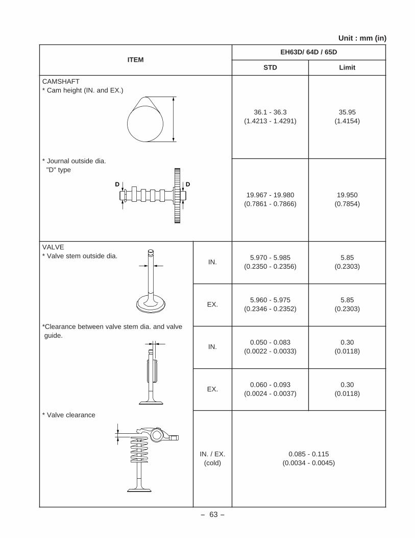
Unit : mm (in)
METID56/D46/D36HE
DTS timiL
TFAHSMAC).XEdna.NI(thgiehmaC*
.aidedistuolanruoJ*epyt"D"
3.63-1.63)1924.1-3124.1(
59.53)4514.1(
089.91-769.91)6687.0-1687.0(
059.91)4587.0(
EVLAV.aidedistuometsevlaV*
evlavdna.aidmetsevlavneewtebecnaraelC*.ediug
ecnaraelcevlaV*
.NI589.5-079.5
)6532.0-0532.0(58.5
)3032.0(
.XE579.5-069.5
)2532.0-6432.0(58.5
)3032.0(
.NI380.0-050.0
)3300.0-2200.0(03.0
)8110.0(
.XE390.0-060.0
)7300.0-4200.0(03.0
)8110.0(
.XE/.NI)dloc(
511.0-580.0)5400.0-4300.0(
D D

- 64 -
Unit : mm (in)
METID56/D46/D36HE
DTS timiL
TEPPAT.aidedistuometS*
.aidedisniediuG*
ecnaraelcediugteppaT*
579.8-069.8)3353.0-8253.0(
39.8)6153.0(
510.9-00.9)9453.0-3453.0(
80.9)5753.0(
550.0-520.0)2200.0-0100.0(
51.0)9500.0(
MRAREKCOR.aidedistuotfahsrekcoR*
.aidelohmrarekcoR*
ecnaraelctfahsmrarekcoR*
499.11-689.11)2274.0-9174.0(
29.11)3964.0(
420.21-600.21)4374.0-7274.0(
70.21)2574.0(
830.0-210.0)5100.0-5000.0(
51.0)9500.0(
HTGNELEERFGNIRPSEVLAV
5.93)1555.1(
------------


- 66 -
12-3 OIL GRADE CHART
Use oil classified as SE or higher.
Multi-grade oil tends to increase its consumption at high ambient temperature.
5W
10W
20W
#20
#30
#40
10W-30
10W-40
Singlegrade
Multi-grade
Specified Lubricant
Quality
Comparison between oil viscosity and temparature
- 20- 4
- 1014
032
1050
2068
3086
40 °C104 °F

- 67 -
13. MAINTENANCE AND STORAGE
13-1 DAILY MAINTENANCE
Every day before operating engine, check the following items;
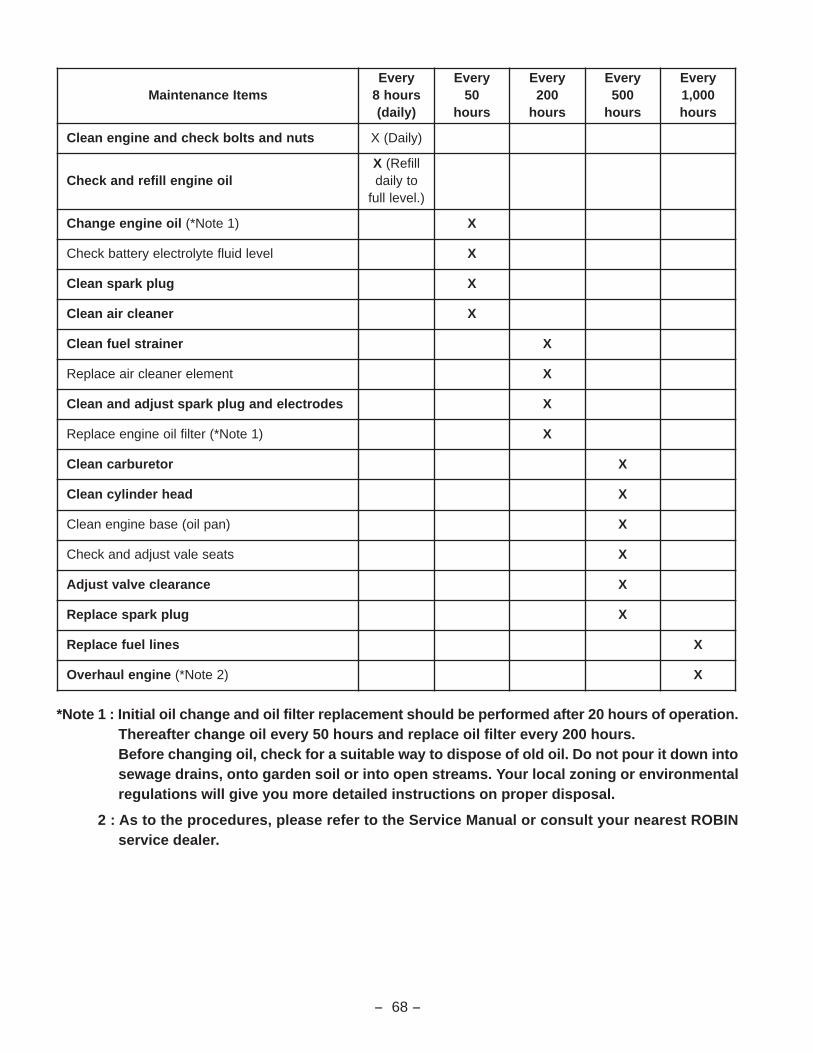
13-2 PERIODIC MAINTENANCE SCHEDULE
Periodic maintenance is vital to safe and efficient operation of engine.
Check the table below for periodic maintenance intervals.
It is also necessary to conduct the maintenance and adjustments on the emission-related parts listedbelow to keep the emission control system effective;
(1) Carburetor and internal parts (2) Choke system
(3) Fuel strainer (4) Air cleaner elements
(5) Intake pipe (6) Spark plug
(7) Magneto (8) Fuel hoses, clamps and sealing gaskets
The following maintenance schedule is based on the normal engine operation.
Should the engine be operated in extremely dusty condition or in heavier loading condition, the mainte-nance interval must be shortened depending on the contamination of oil, clogging of filter elements, wearof parts, and so on.
SMETIECNANETNIAM SKRAMER
.enignemorfffahcdnatsudyawanaelC)1 .tsudotevitisnesyllaicepsesiegaknilronrevoG
,ynafI.metsysleufmorfegakaelleufkcehC)2.strapyrassecenecalperrosrenetsafnethgiter
finethgiterdnaerawdrahesoolroftcepsnI)3.yrassecen
nitluserdnaffoemocyamstundnastlobesooL.straprehtofoegakaerb
.levelllufotddadnalevelliokcehC)4
- 68 -
*Note 1 : Initial oil change and oil filter replacement should be performed after 20 hours of operation.Thereafter change oil every 50 hours and replace oil filter every 200 hours.Before changing oil, check for a suitable way to dispose of old oil. Do not pour it down intosewage drains, onto garden soil or into open streams. Your local zoning or environmentalregulations will give you more detailed instructions on proper disposal.
2 : As to the procedures, please refer to the Service Manual or consult your nearest ROBINservice dealer.
smetIecnanetniaMyrevEsruoh8)yliad(
yrevE05
sruoh
yrevE002sruoh
yrevE005sruoh
yrevE000,1sruoh
stundnastlobkcehcdnaenignenaelC )yliaD(X
lioenignelliferdnakcehCX llifeR(
otyliad).levellluf
lioenigneegnahC )1etoN*( X
leveldiulfetylortceleyrettabkcehC X
gulpkrapsnaelC X
renaelcrianaelC X
reniartsleufnaelC X
tnemelerenaelcriaecalpeR X
sedortcelednagulpkrapstsujdadnanaelC X
)1etoN*(retliflioenigneecalpeR X
roterubracnaelC X
daehrednilycnaelC X
)naplio(esabenignenaelC X
staeselavtsujdadnakcehC X
ecnaraelcevlavtsujdA X
gulpkrapsecalpeR X
senilleufecalpeR X
enigneluahrevO )2etoN*( X

- 69 -
13-3 ENGINE STORAGE
(1) Change the engine oil and perform the daily maintenance items above mentioned.
(2) Drain fuel from carburetor float chamber.
(3) To prevent rust in the cylinder bore, apply oil through the spark plug hole and turn the crankshaftseveral turns by hand. Reinstall the plug.
(4) Turn the crankshaft by hand and leave it where the resistance is the heaviest.
(5) Clean outside of the engine with oiled cloth.
(6) Put a plastic cover or the like over the engine and store the engine in dry place.

PRINTED IN THE USA