service instructions “p-a” or “p-b ... - oilgear f1u controls for “pvg” 100/130 (f1u...
TRANSCRIPT
Bulletin 947556 THE OILGEAR COMPANY 1
SERVICE INSTRUCTIONS “P-A” OR “P-B” ELECTRONIC PRESSURE COMPENSATOR, SERIES F1U CONTROLS
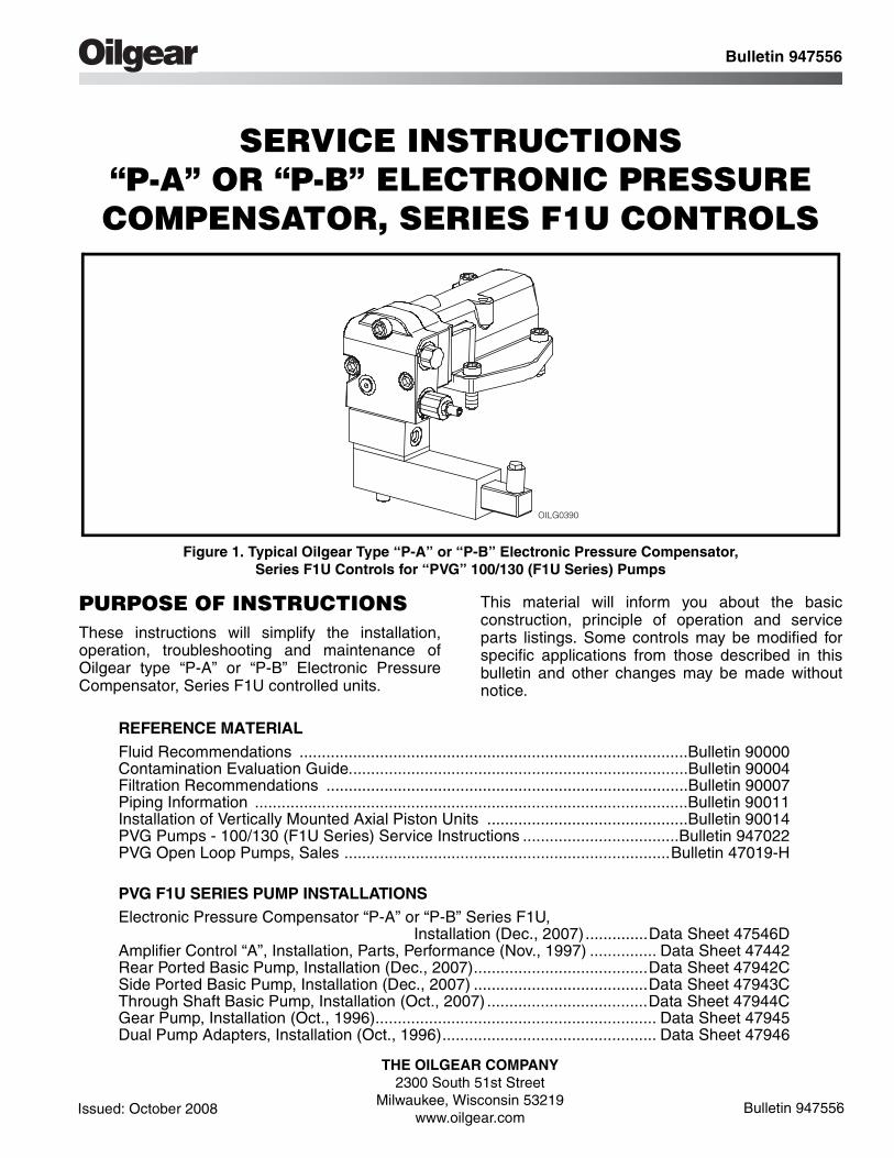
Figure 1. Typical Oilgear Type “P-A” or “P-B” Electronic Pressure Compensator, Series F1U Controls for “PVG” 100/130 (F1U Series) Pumps
PURPOSE OF INSTRUCTIONSThese instructions will simplify the installation,operation, troubleshooting and maintenance ofOilgear type “P-A” or “P-B” Electronic PressureCompensator, Series F1U controlled units.
This material will inform you about the basicconstruction, principle of operation and serviceparts listings. Some controls may be modified forspecific applications from those described in thisbulletin and other changes may be made withoutnotice.
REFERENCE MATERIALFluid Recommendations .......................................................................................Bulletin 90000Contamination Evaluation Guide............................................................................Bulletin 90004Filtration Recommendations .................................................................................Bulletin 90007Piping Information .................................................................................................Bulletin 90011Installation of Vertically Mounted Axial Piston Units .............................................Bulletin 90014PVG Pumps - 100/130 (F1U Series) Service Instructions ...................................Bulletin 947022PVG Open Loop Pumps, Sales .........................................................................Bulletin 47019-H
PVG F1U SERIES PUMP INSTALLATIONSElectronic Pressure Compensator “P-A” or “P-B” Series F1U,
Installation (Dec., 2007)..............Data Sheet 47546DAmplifier Control “A”, Installation, Parts, Performance (Nov., 1997) ............... Data Sheet 47442Rear Ported Basic Pump, Installation (Dec., 2007).......................................Data Sheet 47942CSide Ported Basic Pump, Installation (Dec., 2007) .......................................Data Sheet 47943CThrough Shaft Basic Pump, Installation (Oct., 2007) ....................................Data Sheet 47944CGear Pump, Installation (Oct., 1996)............................................................... Data Sheet 47945Dual Pump Adapters, Installation (Oct., 1996)................................................ Data Sheet 47946
OILG0390
Bulletin 947556
Issued: October 2008
THE OILGEAR COMPANY2300 South 51st Street
Milwaukee, Wisconsin 53219www.oilgear.com
Bulletin 947556
2 THE OILGEAR COMPANY Bulletin 947556
Read and understand this entire instruction sheetbefore repairing or adjusting your Oilgear product.
Those who use and maintain this equipment mustbe thoroughly trained and familiar with the product.If incorrectly used or maintained, this product andits equipment can cause severe injury.
SAFETY SYMBOLSThe following signal words are used in thisinstruction sheet to identify areas of concern whereyour safety may be involved. Carefully read the textand observe any instructions provided to ensureyour safety.
THIS SIGNAL WORD INDICATES AN IMMI-NENTLY HAZARDOUS SITUATION WHICH,IF NOT AVOIDED, WILL RESULT IN DEATHOR SERIOUS INJURY.
This signal word indicates a potentiallyhazardous situation which, if not avoided,could result in death or serious injury.
This signal word indicates that a potentiallyhazardous situation exists which, if notavoided, may result in damage toequipment or minor personal injury.
While not directly relevant to the topic beingdiscussed, the NOTE is used to emphasizeinformation provided, or provide additionalinformation which may be of benefit.
This service information is designed forthe maintenance of your Oilgear product.It contains the information on the correctprocedures determined by Oilgear for thesafe manner of servicing. Always keepthis instruction sheet in a location where itis readily available for the persons whouse and maintain the product. Additionalcopies of this instruction sheet areavailable through Oilgear. Contact us at414-327-1700 or visit our website:www.oilgear.com. Please contact us if youhave any questions regarding theinformation in this instruction bulletin.
The cleanliness of working on this pumpcontrol or the hydraulic system is extremelyimportant to the safety and reliability of thepump and the system. Always make surethe fittings are clean on the outside beforeremoving them from their connections, arecapped and plugged when removed, andare placed in a clean rag or container untilthey are reinstalled.
Some service operations may requirespecial tools or equipment. If you requireinformation on these items, please contactOilgear before attempting these repairsand service operations.
Read, understand and follow the safetyguidelines, dangers and warningscontained in this instruction sheet topromote reliable operation and preventserious personal injury.
DO NOT attempt to service this machineryin an environment where safety regulationsare not established and in place.
DO NOT operate the hydraulic system if aleak is present. Serious injury may result.
Hydraulic systems operate under very highpressure. Hydraulic fluid escaping from apressurized system can penetrateunprotected body tissue. DO NOT inspectfor hydraulic leaks with bare hands or otherexposed body parts. As a minimum, wearleather gloves prior to inspecting for leaksand use cardboard or wood. If leaks arepresent, relieve pressure and allow systemto cool prior to servicing. If injured byescaping hydraulic oil, contact a physicianimmediately. Serious complications mayarise if not treated immediately. If you havequestions regarding inspecting forhydraulic leaks, please contact Oilgearprior to servicing.
DANGER! !
! WARNING
CAUTION
NOTE
! WARNING
NOTE
! WARNING
! WARNING
! WARNING
! WARNING
! WARNING
Safety First
© 2008 THE OILGEAR COMPANY - ALL RIGHTS RESERVED
Bulletin 947556 THE OILGEAR COMPANY 3
Hydraulic hoses and tubing must beinspected on a daily basis for leaks, cuts,abrasions, damage and improperclearance along any mounting frame forhidden damage before the unit is put intoservice. Replace damaged hoses or hosesyou suspect are damaged before thesystem is returned to service! Hoses mustbe replaced every 2 years. Failure toproperly inspect and maintain the systemmay result in serious injury.
Hydraulic systems are hot. DO NOTTOUCH! Serious personal injury mayresult from hot oil. When you havecompleted working on the hydraulicsystem, thoroughly clean any spilled oilfrom the equipment. Do not spill anyhydraulic fluids on the ground. Clean anyhydraulic fluids from your skin as soon asyou have completed maintenance andrepairs. Dispose of used oil and systemfilters as required by law.
Use hoses, fittings and adapters with thecorrect SAE rating when replacing hosesto prevent possible serious injury. Alwaysreplace hoses, fittings and adapters withreplacements that have a proper, suitable,working pressure rating. Replacementhoses must be of the correct length andmust comply with the hose manufacturer’sand Oilgear’s installation guidelines andrecommendations.
Hydraulic hoses have the SAE ratingsmarked on the hose to assist you inselecting the correct hose. The samemanufacturer must supply any replacementhydraulic hoses and fitting assemblies. Asan example: Brand “X” hose and brand “Y”fitting will not normally be compatible. No“Twist” is allowed in the hydraulic hoses.“Twist” may result in premature hosefailure. This can cause serious injury.Please contact Oilgear for assistance whenrequired.
Hydraulic cylinders can be holding afunction in a certain position when thepump is off. An example of this is afunction being held in the lift or partial liftposition by the cylinders. If a hydraulicline is removed or the hydraulic circuits orcontrols are being worked on, gravity mayallow the function being held in position todrop. All workers and personnel mustremain clear of these areas when workingon or operating the hydraulic system.Block and secure all devices andfunctions which apply before beginningwork or operation. Failure to comply withthis can result in serious injury or death.
Any hydraulic pipe which is replaced mustconform to SAE J1065 specifications. Ifincorrect hydraulic pipe is installed, thehydraulic system may fail, causingserious injury. Damaged or leakingfittings, pipes or hoses must be replacedbefore the system is returned to service.
DO NOT heat hydraulic pipe. The carboncontent of this steel tube is such that ifheated for bending, and either water or airquenched, the pipe may lose its ductilityand thereby be subject to failure underhigh pressure conditions. Serious injurycan result. Damaged or leaking pipes mustbe replaced before the system is returnedto service. Please contact Oilgear if yourequire assistance or have questions.
All hydraulic pressure must be relievedfrom the hydraulic system prior to removingany components from the system. Torelieve the hydraulic pressure from thehydraulic system, turn off the motor andoperate the control panel with the key in theON position. Failure to comply can result inserious injury. If you have any questionsconcerning relieving the hydraulic pressurefrom the system, please contact Oilgear.
! WARNING
! WARNING
! WARNING
! WARNING
! WARNING
! WARNING
! WARNING
! WARNING
Safety First
4 THE OILGEAR COMPANY Bulletin 947556
Hydraulic components can be heavy. Usecaution while lifting these components.Serious personal injury can be avoidedwith proper handling of the components.
Please contact Oilgear if you requireassistance. When performing hydraulictest procedures, use the proper hydraulicgauges. Installing an incorrect test gaugecould result in serious injury if the gaugefails. Use properly rated hydraulic hosesto allow the test gauge to be read awayfrom moving parts and functions.
Increasing hydraulic pressure beyond therecommendations may result in seriousdamage to the pump and system orserious personal injury, and may void theOilgear Warranty. If you have questionsconcerning hydraulic pressures or testingprocedures, please contact Oilgear beforeattempting the test procedures or makingadjustments.
An Oilgear pump or pump control mustnot be modified in any way withoutauthorization from Oilgear. Modificationsmay not comply with safety standards,including ANSI safety standards, and mayresult in serious personal injury. Pleasecontact Oilgear if you require assistance.
DO NOT enter under hydraulic-supportedequipment unless it is fully supported orblocked. Failure to follow this procedurecan result in serious injury or death.
Any Oilgear pump safety decals must bereplaced anytime they are damaged,missing or cannot be read clearly. Failureto have proper decals in place can resultin serious injury or death. (If you requiresafety decals, please contact Oilgear forreplacement safety decals, at no charge.)
Be sure everyone is clear of the areaaround the hydraulic system beforeoperating after servicing. Remain attentiveat all times when operating to check yourwork until you are completely sure it issafe to return to service. Failure to heedthis warning may result in seriouspersonal injury or death.
Wear the proper protective clothing whenoperating, servicing or maintaining thehydraulic system or the Oilgear pump. Wearthe correct protective gear, safety glasses,gloves and safety shoes. Serious injury canresult without proper protective gear.
Make sure to keep hands, feet and otherparts of your body clear of revolving ormoving parts. Failure to comply can causeserious injury.
DO NOT wear watches, rings or jewelrywhile working with electrical and mechani-cal equipment. These items can be hazard-ous and can cause serious and painfulinjuries if they come into contact with elec-trical wires, moving parts or hydraulicequipment.
! WARNING
! WARNING
! WARNING
! WARNING
! WARNING
! WARNING
! WARNING
! WARNING
! WARNING
! WARNING
Safety First
Bulletin 947556 THE OILGEAR COMPANY 5
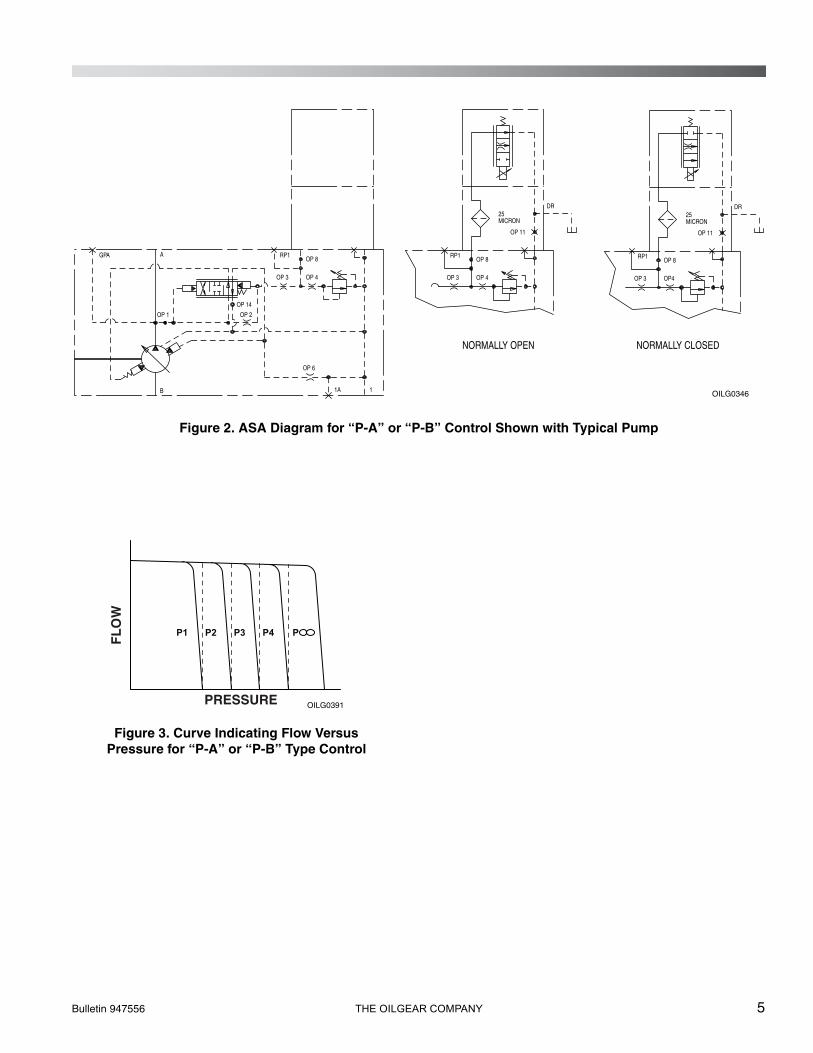
Figure 2. ASA Diagram for “P-A” or “P-B” Control Shown with Typical Pump
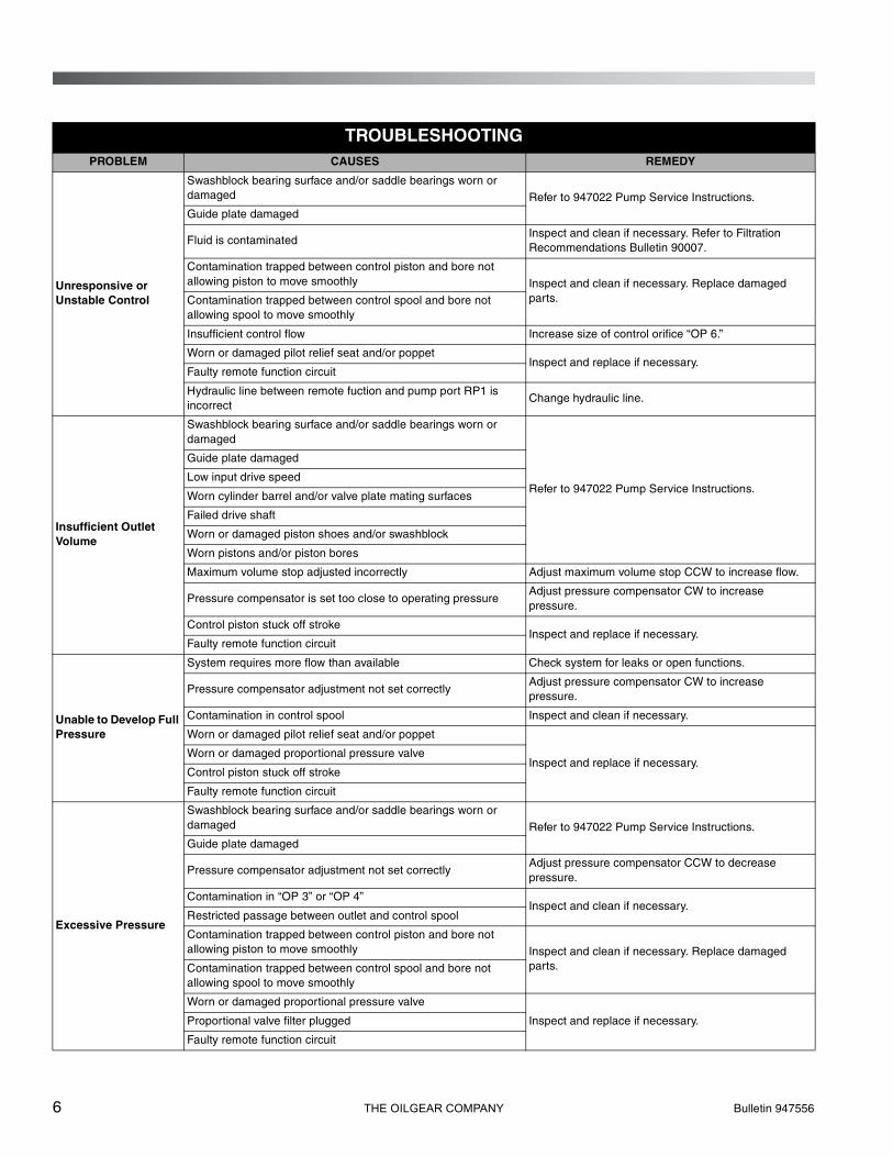
Figure 3. Curve Indicating Flow Versus Pressure for “P-A” or “P-B” Type Control
A
1B
GPA
OP 1 OP 2
OP 6
OP 3 OP 4
OP 8RP1
1A
OP 14
OP 11
DR25MICRON
OP 3 OP 4
OP 8RP1
OP 11
DR25MICRON
OP 3 OP4
OP 8RP1
NORMALLY OPEN NORMALLY CLOSED
OILG0346
P4 P P3P2P1
FL
OW
PRESSURE OILG0391
6 THE OILGEAR COMPANY Bulletin 947556
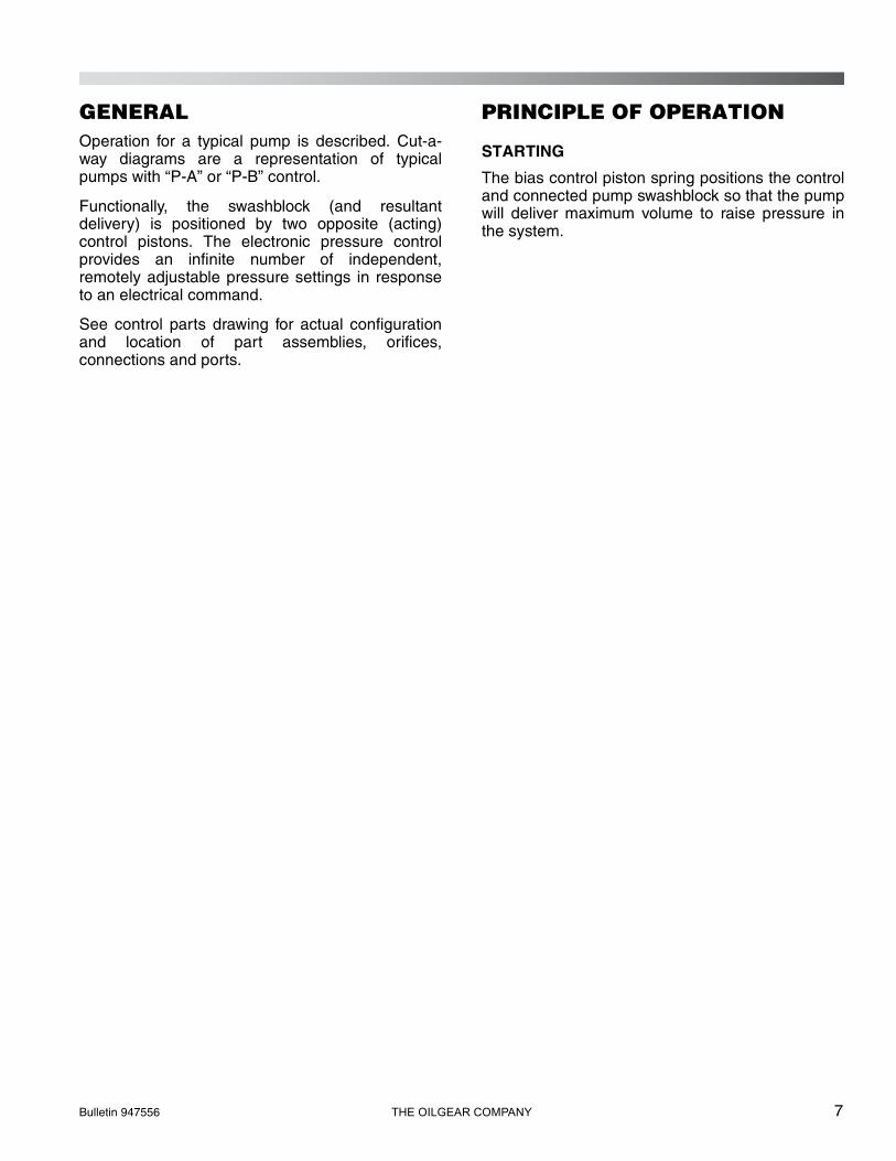
TROUBLESHOOTINGPROBLEM CAUSES REMEDY
Unresponsive or Unstable Control
Swashblock bearing surface and/or saddle bearings worn or damaged Refer to 947022 Pump Service Instructions.Guide plate damaged
Fluid is contaminatedInspect and clean if necessary. Refer to Filtration Recommendations Bulletin 90007.
Contamination trapped between control piston and bore not allowing piston to move smoothly Inspect and clean if necessary. Replace damaged
parts.Contamination trapped between control spool and bore not allowing spool to move smoothly
Insufficient control flow Increase size of control orifice “OP 6.”
Worn or damaged pilot relief seat and/or poppetInspect and replace if necessary.
Faulty remote function circuit
Hydraulic line between remote fuction and pump port RP1 is incorrect
Change hydraulic line.
Insufficient Outlet Volume
Swashblock bearing surface and/or saddle bearings worn or damaged
Refer to 947022 Pump Service Instructions.
Guide plate damaged
Low input drive speed
Worn cylinder barrel and/or valve plate mating surfaces
Failed drive shaft
Worn or damaged piston shoes and/or swashblock
Worn pistons and/or piston bores
Maximum volume stop adjusted incorrectly Adjust maximum volume stop CCW to increase flow.
Pressure compensator is set too close to operating pressureAdjust pressure compensator CW to increase pressure.
Control piston stuck off strokeInspect and replace if necessary.
Faulty remote function circuit
Unable to Develop Full Pressure
System requires more flow than available Check system for leaks or open functions.
Pressure compensator adjustment not set correctlyAdjust pressure compensator CW to increase pressure.
Contamination in control spool Inspect and clean if necessary.
Worn or damaged pilot relief seat and/or poppet
Inspect and replace if necessary.Worn or damaged proportional pressure valve
Control piston stuck off stroke
Faulty remote function circuit
Excessive Pressure
Swashblock bearing surface and/or saddle bearings worn or damaged Refer to 947022 Pump Service Instructions.
Guide plate damaged
Pressure compensator adjustment not set correctlyAdjust pressure compensator CCW to decrease pressure.
Contamination in “OP 3” or “OP 4”Inspect and clean if necessary.
Restricted passage between outlet and control spool
Contamination trapped between control piston and bore not allowing piston to move smoothly Inspect and clean if necessary. Replace damaged
parts.Contamination trapped between control spool and bore not allowing spool to move smoothly
Worn or damaged proportional pressure valve
Inspect and replace if necessary.Proportional valve filter plugged
Faulty remote function circuit
Bulletin 947556 THE OILGEAR COMPANY 7
GENERALOperation for a typical pump is described. Cut-a-way diagrams are a representation of typicalpumps with “P-A” or “P-B” control.
Functionally, the swashblock (and resultantdelivery) is positioned by two opposite (acting)control pistons. The electronic pressure controlprovides an infinite number of independent,remotely adjustable pressure settings in responseto an electrical command.
See control parts drawing for actual configurationand location of part assemblies, orifices,connections and ports.
PRINCIPLE OF OPERATION
STARTING
The bias control piston spring positions the controland connected pump swashblock so that the pumpwill deliver maximum volume to raise pressure inthe system.
8 THE OILGEAR COMPANY Bulletin 947556
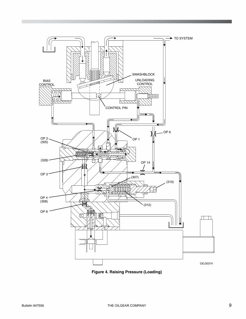
RAISING PRESSURE (LOADING)
Pump delivery (and resultant pressure) is fed backto the control through Port “OP 1”. The pressurecompensating spool (305) is held in position by apilot control valve spring (328). Flow (and resultantpressure) is transmitted through the pressurecompensating spool (305) to the area behind thebias control piston and through orifice Port “OP 2.”
Pressure acting on either end of the pilot controlvalve is equal. The spool is balanced and held inthe open position by the pilot control valve spring(328). Flow (and resultant pressure) is alsotransmitted through Port “OP 3” and Port “OP 4” tothe adjustable control relief (unloading) valve (310),as well as Port “OP 8” to the electronic pressurecompensator, which blocks further flow in thecontrol (and pressure transmittal).
Bulletin 947556 THE OILGEAR COMPANY 9
Figure 4. Raising Pressure (Loading)
UNLOADINGCONTROL
BIASCONTROL
CONTROL PIN
SWASHBLOCK
OILG0374
OP 1OP 2(305)
(328)
OP 4(308)
OP 8
OP 3
OP 14
OP 6
TO SYSTEM
(310)
(307)
(312)
10 THE OILGEAR COMPANY Bulletin 947556
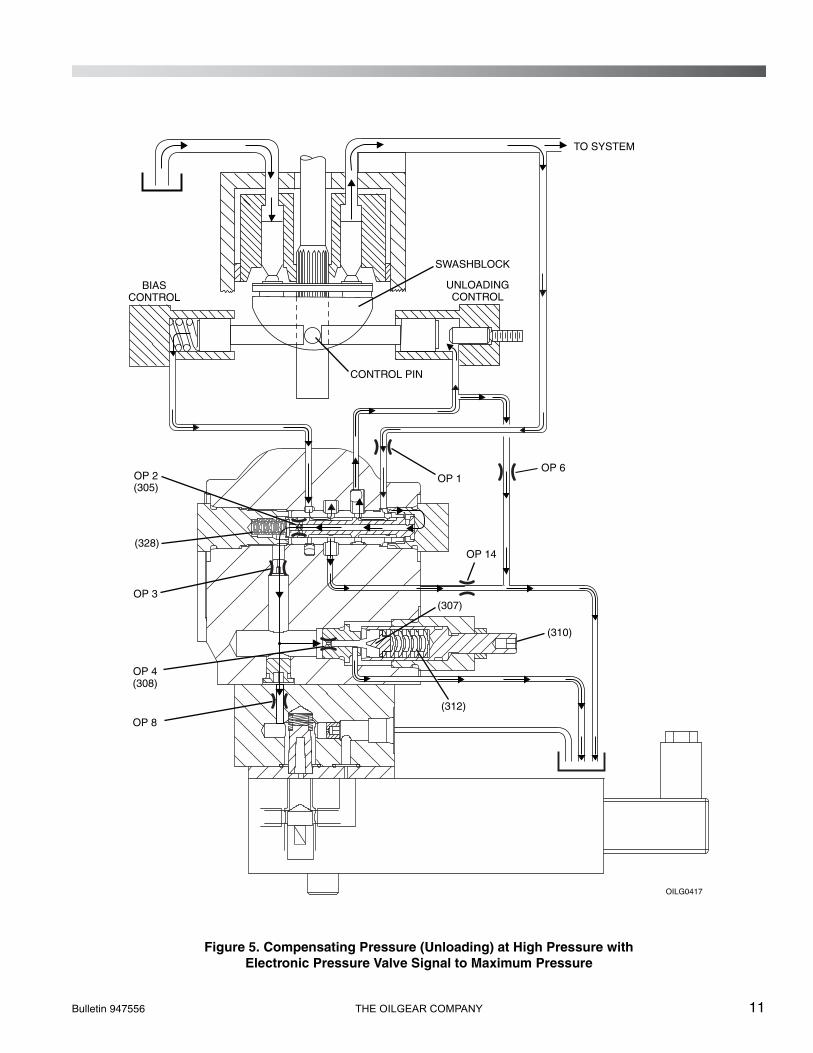
COMPENSATING PRESSURE (UNLOADING) AT HIGH PRESSURE WITH ELECTRONIC PRESSURE VALVE SIGNAL TO MAXIMUM PRESSURE
When pressure on the relief valve poppet (307)exceeds the presetting of the relief valve screw(310): Set by turning the valve screw in or out,which sets the force of the relief valve spring (312).The relief valve poppet (307) moves off seat (308)and allows flow through the valve, and throughdrain line to pump case and case drain. Pressure isno longer acting on the spring end of the pressurecompensating spool (305).
Flow through “OP 2” reduces pressure on thespring end of the pressure compensating spool(305). There is still pressure on the other end of thepressure compensating spool. This differentialpressure forces the pressure compensating spool(305) to shift and compress the control valve spring(328). The pressure compensating spool nowallows pump delivery (and resultant pressure) toflow to the unloading control piston. The pressurecompensating spool simultaneously drains the fluidfrom behind the bias control piston.
The control piston now moves the control pin andshifts the swashblock to a position towards neutral,where the pump delivers sufficient volume tomaintain system pressure as regulated by thecontrol relief valve (310).
HOLDING PRESSURE
If the system pressure drops below presetcompensating pressure, the relief valve poppet(307) seats and forces on the pressurecompensating spool (305) are balanced, the pilotcontrol valve spring (328) returns the spool to theoriginal position (Figure 4), swashblock positionshifts, and the pump increases delivery until therelief valve screw (310) preset pressure is reachedagain.
Bulletin 947556 THE OILGEAR COMPANY 11
Figure 5. Compensating Pressure (Unloading) at High Pressure withElectronic Pressure Valve Signal to Maximum Pressure
UNLOADINGCONTROL
BIASCONTROL
CONTROL PIN
SWASHBLOCK
OILG0417
OP 2(305)
(310)
(307)
(312)
(328)
OP 4(308)
OP 8
OP 1
OP 3
OP 14
OP 6
TO SYSTEM
12 THE OILGEAR COMPANY Bulletin 947556
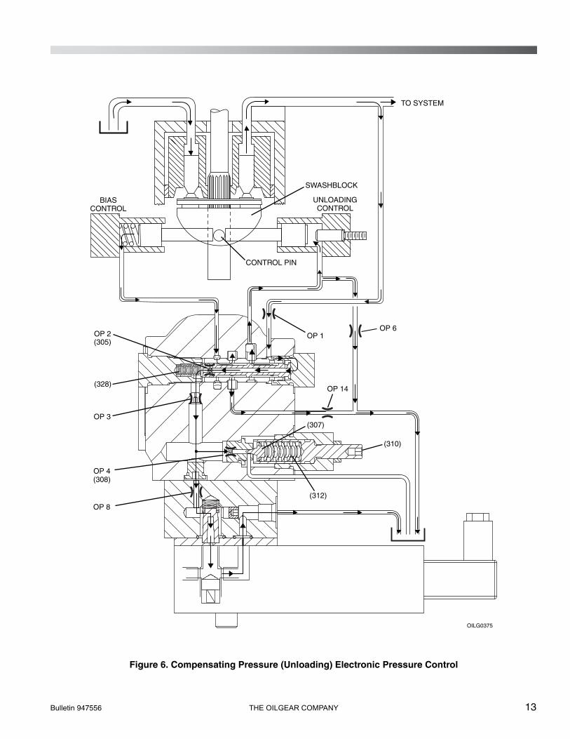
COMPENSATING PRESSURE (UNLOADING) ELECTRONIC PRESSURE CONTROL
The electronic signal to pressure control isproportional to the pressure setting. Whenpressure on the pressure control valve exceeds theelectronic control signal, the valve passes flowthrough drain line to pump case and case drain.Pressure is reduced on the spring end of thepressure compensating spool (305).
Flow through “OP 2” reduces pressure on thespring end of the pressure compensating spool(305). There is still full pressure on the other end ofthe pressure compensating spool. This differentialpressure forces the pressure compensating spool(305) to shift and compress the control valve spring(328). The pressure compensating spool nowallows pump delivery (and resultant pressure) toflow to the unloading control piston. The pressurecompensating spool simultaneously drains the fluidfrom behind the bias control piston.
The control piston now moves the control pin andshifts the swashblock to a position towards neutral,where the pump delivers sufficient volume tomaintain system pressure as regulated by theelectronic pressure control valve.
HOLDING PRESSURE
If the system pressure drops below the electronicsignal to the control valve, pilot flow to the drain isblocked and force on the pressure compensatingspool (305) is balanced, the pilot control valvespring (328) returns the spool to the originalposition (Figure 4), swashblock position shifts, andthe pump increases delivery until the electronicsignal pressure is reached again.
Bulletin 947556 THE OILGEAR COMPANY 13
Figure 6. Compensating Pressure (Unloading) Electronic Pressure Control
UNLOADINGCONTROL
BIASCONTROL
CONTROL PIN
SWASHBLOCK
OILG0375
OP 2(305)
(310)
(307)
(312)
(328)
OP 4(308)
OP 8
OP 1
OP 3
OP 14
OP 6
TO SYSTEM
14 THE OILGEAR COMPANY Bulletin 947556
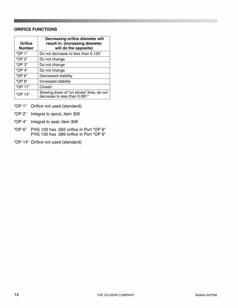
ORIFICE FUNCTIONS
“OP 1” Orifice not used (standard)
“OP 2” Integral to spool, item 305
“OP 4” Integral to seat, item 308
“OP 6” PVG 100 has .062 orifice in Port “OP 6”PVG 130 has .089 orifice in Port “OP 6”
“OP 14” Orifice not used (standard)
OrificeNumber
Decreasing orifice diameter will result in: (increasing diameter
will do the opposite)“OP 1” Do not decrease to less than 0.125''“OP 2” Do not change“OP 3” Do not change“OP 4” Do not change“OP 6” Decreased stability“OP 8” Increased stability“OP 11” Closed
“OP 14” Slowing down of “on stroke” time, do not decrease to less than 0.081"
Bulletin 947556 THE OILGEAR COMPANY 15
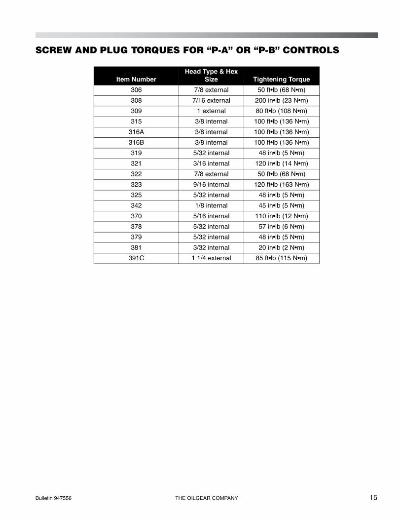
SCREW AND PLUG TORQUES FOR “P-A” OR “P-B” CONTROLS
Item NumberHead Type & Hex
Size Tightening Torque
306 7/8 external 50 ft•lb (68 N•m)
308 7/16 external 200 in•lb (23 N•m)
309 1 external 80 ft•lb (108 N•m)
315 3/8 internal 100 ft•lb (136 N•m)
316A 3/8 internal 100 ft•lb (136 N•m)
316B 3/8 internal 100 ft•lb (136 N•m)
319 5/32 internal 48 in•lb (5 N•m)
321 3/16 internal 120 in•lb (14 N•m)
322 7/8 external 50 ft•lb (68 N•m)
323 9/16 internal 120 ft•lb (163 N•m)
325 5/32 internal 48 in•lb (5 N•m)
342 1/8 internal 45 in•lb (5 N•m)
370 5/16 internal 110 in•lb (12 N•m)
378 5/32 internal 57 in•lb (6 N•m)
379 5/32 internal 48 in•lb (5 N•m)
381 3/32 internal 20 in•lb (2 N•m)
391C 1 1/4 external 85 ft•lb (115 N•m)
16 THE OILGEAR COMPANY Bulletin 947556
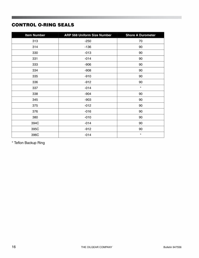
CONTROL O-RING SEALS
* Teflon Backup Ring
Item Number ARP 568 Uniform Size Number Shore A Durometer
313 -250 70
314 -136 90
330 -013 90
331 -014 90
333 -906 90
334 -908 90
335 -910 90
336 -912 90
337 -014 *
338 -904 90
345 -903 90
375 -012 90
376 -016 90
380 -010 90
394C -014 90
395C -912 90
396C -014 *
Bulletin 947556 THE OILGEAR COMPANY 17
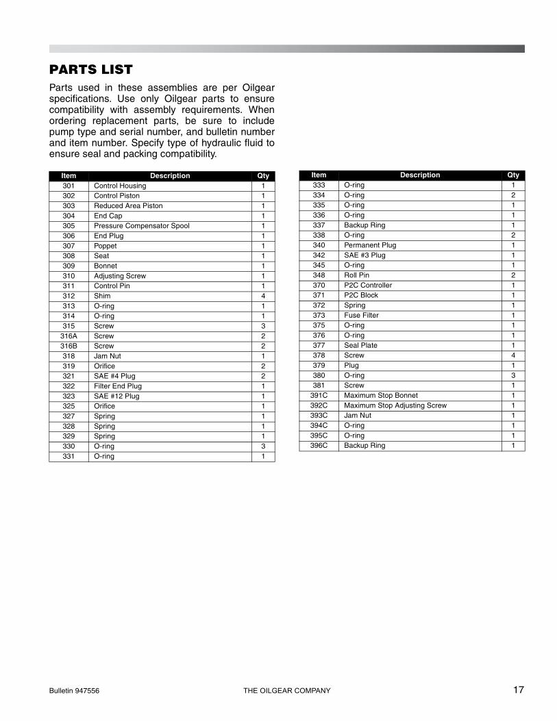
PARTS LISTParts used in these assemblies are per Oilgearspecifications. Use only Oilgear parts to ensurecompatibility with assembly requirements. Whenordering replacement parts, be sure to includepump type and serial number, and bulletin numberand item number. Specify type of hydraulic fluid toensure seal and packing compatibility.
Item Description Qty301 Control Housing 1302 Control Piston 1303 Reduced Area Piston 1304 End Cap 1305 Pressure Compensator Spool 1306 End Plug 1307 Poppet 1308 Seat 1309 Bonnet 1310 Adjusting Screw 1311 Control Pin 1312 Shim 4313 O-ring 1314 O-ring 1315 Screw 3
316A Screw 2316B Screw 2318 Jam Nut 1319 Orifice 2321 SAE #4 Plug 2322 Filter End Plug 1323 SAE #12 Plug 1325 Orifice 1327 Spring 1328 Spring 1329 Spring 1330 O-ring 3331 O-ring 1
Item Description Qty333 O-ring 1334 O-ring 2335 O-ring 1336 O-ring 1337 Backup Ring 1338 O-ring 2340 Permanent Plug 1342 SAE #3 Plug 1345 O-ring 1348 Roll Pin 2370 P2C Controller 1371 P2C Block 1372 Spring 1373 Fuse Filter 1375 O-ring 1376 O-ring 1377 Seal Plate 1378 Screw 4379 Plug 1380 O-ring 3381 Screw 1
391C Maximum Stop Bonnet 1392C Maximum Stop Adjusting Screw 1393C Jam Nut 1394C O-ring 1395C O-ring 1396C Backup Ring 1
18 THE OILGEAR COMPANY Bulletin 947556
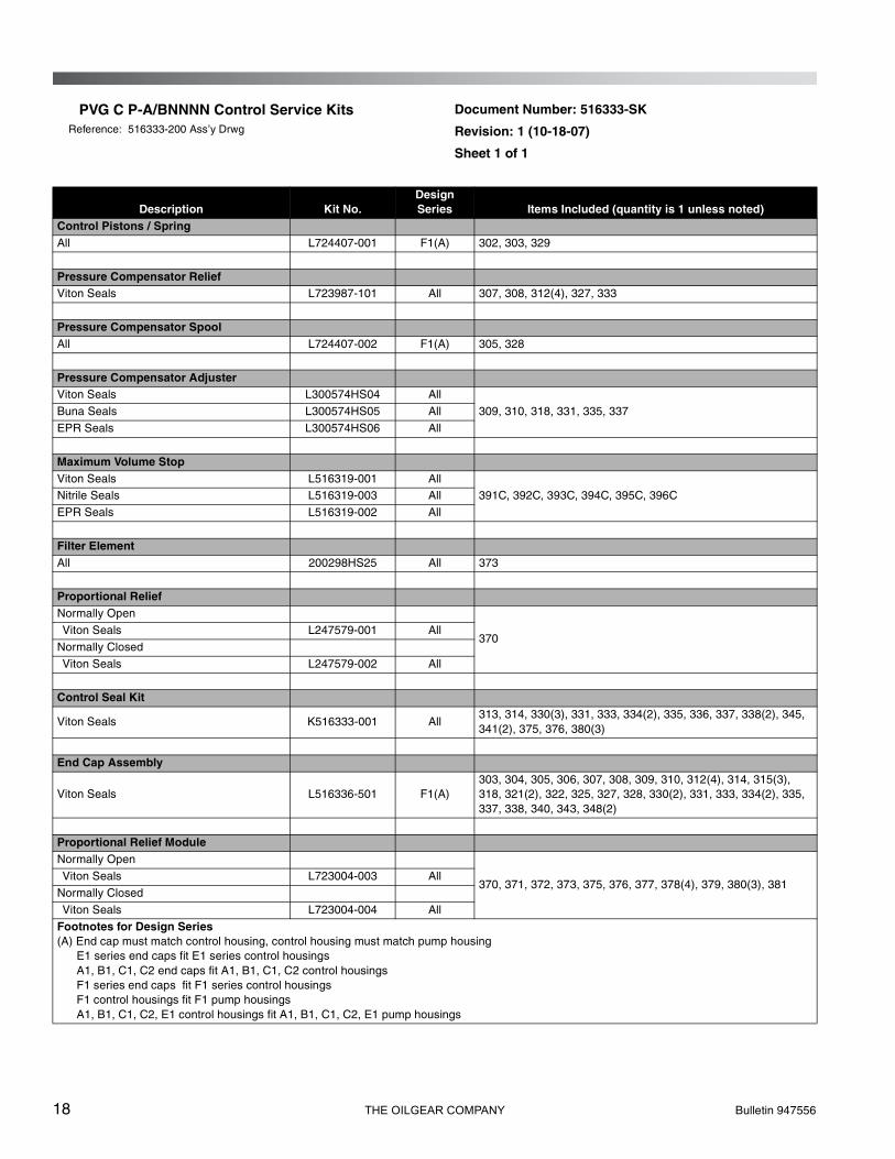
PVG C P-A/BNNNN Control Service KitsReference: 516333-200 Ass’y Drwg
Document Number: 516333-SK
Revision: 1 (10-18-07)
Sheet 1 of 1
Description Kit No.Design Series Items Included (quantity is 1 unless noted)
Control Pistons / SpringAll L724407-001 F1(A) 302, 303, 329
Pressure Compensator ReliefViton Seals L723987-101 All 307, 308, 312(4), 327, 333
Pressure Compensator SpoolAll L724407-002 F1(A) 305, 328
Pressure Compensator AdjusterViton Seals L300574HS04 All
309, 310, 318, 331, 335, 337Buna Seals L300574HS05 All
EPR Seals L300574HS06 All
Maximum Volume StopViton Seals L516319-001 All
391C, 392C, 393C, 394C, 395C, 396CNitrile Seals L516319-003 All
EPR Seals L516319-002 All
Filter ElementAll 200298HS25 All 373
Proportional ReliefNormally Open
370Viton Seals L247579-001 All
Normally Closed
Viton Seals L247579-002 All
Control Seal Kit
Viton Seals K516333-001 All313, 314, 330(3), 331, 333, 334(2), 335, 336, 337, 338(2), 345, 341(2), 375, 376, 380(3)
End Cap Assembly
Viton Seals L516336-501 F1(A)303, 304, 305, 306, 307, 308, 309, 310, 312(4), 314, 315(3), 318, 321(2), 322, 325, 327, 328, 330(2), 331, 333, 334(2), 335, 337, 338, 340, 343, 348(2)
Proportional Relief ModuleNormally Open
370, 371, 372, 373, 375, 376, 377, 378(4), 379, 380(3), 381Viton Seals L723004-003 All
Normally Closed
Viton Seals L723004-004 All
Footnotes for Design Series(A) End cap must match control housing, control housing must match pump housing E1 series end caps fit E1 series control housings A1, B1, C1, C2 end caps fit A1, B1, C1, C2 control housings F1 series end caps fit F1 series control housings F1 control housings fit F1 pump housings A1, B1, C1, C2, E1 control housings fit A1, B1, C1, C2, E1 pump housings
Bulletin 947556 THE OILGEAR COMPANY 19
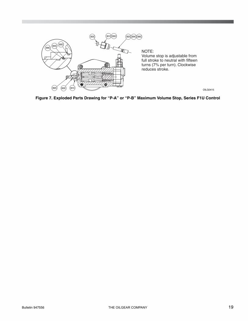
Figure 7. Exploded Parts Drawing for “P-A” or “P-B” Maximum Volume Stop, Series F1U Control
391C392C 393C
393C 391C 395C 392C 394C 396C
NOTE: Volume stop is adjustable from full stroke to neutral with fifteen turns (7% per turn). Clockwise reduces stroke.
396C395C
394C
OILG0415
20 THE OILGEAR COMPANY Bulletin 947556
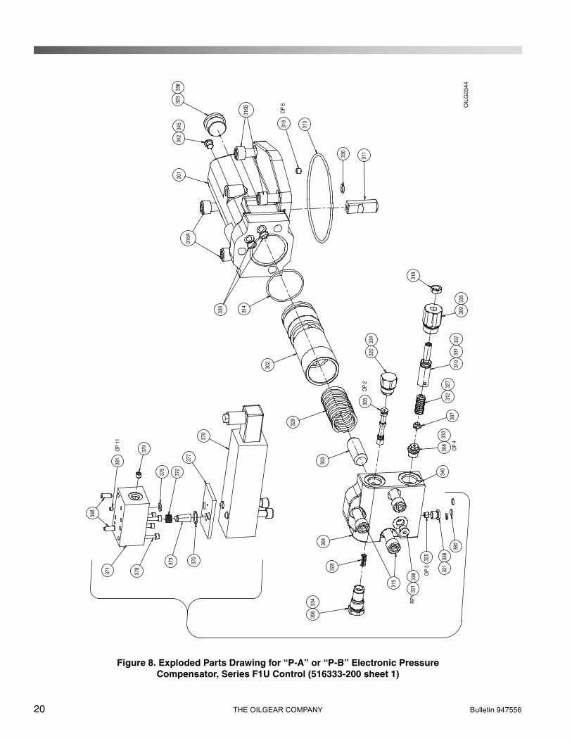
Figure 8. Exploded Parts Drawing for “P-A” or “P-B” Electronic PressureCompensator, Series F1U Control (516333-200 sheet 1)
OP
6
OP
2
OP
3
OP
4
RP1
OP
11
328
314
315
325
311
330
305
319
330
303
329
302
307
318
371
376
378
370
373
380
340
348
301
304
316A
316B
372
313
377
375
379
381
310
321
321
338
338
306
334
308
333
327
312
337
331
309
335
334
322
336
342
345
323
OIL
G03
44
Bulletin 947556 THE OILGEAR COMPANY 21
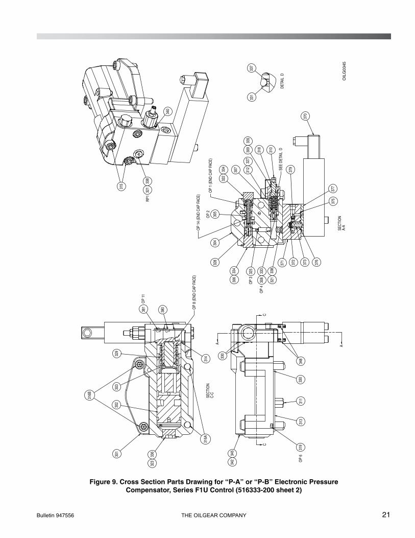
Figure 9. Cross Section Parts Drawing for “P-A” or “P-B” Electronic PressureCompensator, Series F1U Control (516333-200 sheet 2)
CC
A
A
331
301
337
OP
8 (E
ND C
AP F
ACE)
OP
3
OP
4
OP
2
RP1
319
330
OP
634
833
031
131
3
380
381
31432
930
330
2
OP
11
316B
316A
340
315
307
318
310
379
372
373
304
OP
1 (E
ND C
AP F
ACE)
305
328
370
325
371
OP
14 (E
ND C
AP F
ACE)
376
375
377
342
345
308
333
321
338
306
334
SECT
ION
C-
C
323
SECT
ION
A-
A
SEE
DETA
IL D
322
334
312
327
309
335
DETA
IL D
321
338
336
OIL
G03
45
22 THE OILGEAR COMPANY Bulletin 947556
NOTES____________________________________________________________________________________
____________________________________________________________________________________
____________________________________________________________________________________
____________________________________________________________________________________
____________________________________________________________________________________
____________________________________________________________________________________
____________________________________________________________________________________
____________________________________________________________________________________
____________________________________________________________________________________
____________________________________________________________________________________
____________________________________________________________________________________
____________________________________________________________________________________
____________________________________________________________________________________
____________________________________________________________________________________
____________________________________________________________________________________
____________________________________________________________________________________
____________________________________________________________________________________
____________________________________________________________________________________
____________________________________________________________________________________
____________________________________________________________________________________
____________________________________________________________________________________
____________________________________________________________________________________
____________________________________________________________________________________
____________________________________________________________________________________
____________________________________________________________________________________
____________________________________________________________________________________
Bulletin 947556 THE OILGEAR COMPANY 23
NOTES____________________________________________________________________________________
____________________________________________________________________________________
____________________________________________________________________________________
____________________________________________________________________________________
____________________________________________________________________________________
____________________________________________________________________________________
____________________________________________________________________________________
____________________________________________________________________________________
____________________________________________________________________________________
____________________________________________________________________________________
____________________________________________________________________________________
____________________________________________________________________________________
____________________________________________________________________________________
____________________________________________________________________________________
____________________________________________________________________________________
____________________________________________________________________________________
____________________________________________________________________________________
____________________________________________________________________________________
____________________________________________________________________________________
____________________________________________________________________________________
____________________________________________________________________________________
____________________________________________________________________________________
____________________________________________________________________________________
____________________________________________________________________________________
____________________________________________________________________________________
____________________________________________________________________________________
24 THE OILGEAR COMPANY Bulletin 947556
AFTER SALES SERVICESAt Oilgear we build products to last. It is the natureof this type of machinery to require propermaintenance regardless of the care we put intomanufacturing. Oilgear has several serviceprograms in place to help you.
STAY-ON-STREAM SERVICE
By signing up for Oilgear’s Stay-On-Streamprogram, you can prepare for problems before theyhappen. Certain field tests such as fluid testing,slip testing and electronic profile recordingcomparisons can be performed by our field servicepeople or your own factory trained personnel.These tests can indicate problems before theybecome “down-time” difficulties.
SERVICE SCHOOLS
Oilgear conducts training to train your maintenancepersonnel. “General” hydraulic or electronictraining is conducted at our Milwaukee, Wisconsinplant on a regular basis. “Custom” training,specifically addressing your particular hydraulicand electro-hydraulic equipment, can be conductedat your facilities.
SPARE PARTS AVAILABILITY
Prepare for your future needs by stocking Oilgearoriginal factory parts. Having the correct parts andnecessary skills “in-plant” enables you to minimize“down-time.” Oilgear has developed parts kits tocover likely future needs. Oilgear Field ServiceTechnicians are also ready to assist you and yourmaintenance people in troubleshooting andrepairing equipment.
Issued: October 2008
THE OILGEAR COMPANY2300 South 51st Street
Milwaukee, Wisconsin 53219www.oilgear.com