oilgear type “pvg” pumps 150 (series a1) … 947034 the oilgear company 1 oilgear type “pvg”...
TRANSCRIPT
Bulletin 947034 THE OILGEAR COMPANY 1
OILGEAR TYPE “PVG” PUMPS 150 (SERIES A1)
SERVICE INSTRUCTIONS
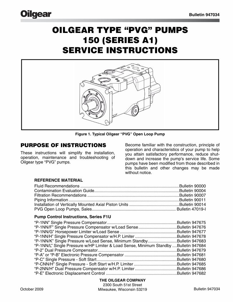
Figure 1. Typical Oilgear “PVG” Open Loop Pump
PURPOSE OF INSTRUCTIONSThese instructions will simplify the installation,operation, maintenance and troubleshooting ofOilgear type “PVG” pumps.
Become familiar with the construction, principle ofoperation and characteristics of your pump to helpyou attain satisfactory performance, reduce shut-down and increase the pump's service life. Somepumps have been modified from those described inthis bulletin and other changes may be madewithout notice.
REFERENCE MATERIALFluid Recommendations .....................................................................................Bulletin 90000Contamination Evaluation Guide.........................................................................Bulletin 90004Filtration Recommendations ...............................................................................Bulletin 90007Piping Information ...............................................................................................Bulletin 90011Installation of Vertically Mounted Axial Piston Units ...........................................Bulletin 90014PVG Open Loop Pumps, Sales........................................................................ Bulletin 47019-I
Pump Control Instructions, Series F1U“P-1NN” Single Pressure Compensator ............................................................Bulletin 947675“P-1NN/F” Single Pressure Compensator w/Load Sense.................................Bulletin 947676“P-1NN/G” Horsepower Limiter w/Load Sense .................................................Bulletin 947677“P-1NN/H” Single Pressure Compensator w/H.P. Limiter ....................................Bulletin 947678“P-1NN/K” Single Pressure w/Load Sense, Minimum Standby.........................Bulletin 947683“P-1NN/L” Single Pressure w/HP Limiter & Load Sense, Minimum Standby ....Bulletin 947684“P-2” Dual Pressure Compensator....................................................................Bulletin 947679“P-A” or “P-B” Electronic Pressure Compensator .............................................Bulletin 947681“P-C” Single Pressure - Soft Start.....................................................................Bulletin 947680“P-CNN/H” Single Pressure - Soft Start w/H.P. Limiter .....................................Bulletin 947685“P-2NN/H” Dual Pressure Compensator w/H.P. Limiter ....................................Bulletin 947686“P-E” Electronic Displacement Control .............................................................Bulletin 947682
Bulletin 947034
October 2009
THE OILGEAR COMPANY2300 South 51st Street
Milwaukee, Wisconsin 53219 Bulletin 947034

2 THE OILGEAR COMPANY Bulletin 947034
Read and understand this entire instruction sheetbefore repairing or adjusting your Oilgear product.
Those who use and maintain this equipment mustbe thoroughly trained and familiar with the product.If incorrectly used or maintained, this product andits equipment can cause severe injury.
SAFETY SYMBOLSThe following signal words are used in thisinstruction sheet to identify areas of concern whereyour safety may be involved. Carefully read the textand observe any instructions provided to ensureyour safety.
THIS SIGNAL WORD INDICATES ANIMMINENTLY HAZARDOUS SITUATIONWHICH, IF NOT AVOIDED, WILL RESULT INDEATH OR SERIOUS INJURY.
This signal word indicates a potentiallyhazardous situation which, if not avoided,could result in death or serious injury.
This signal word indicates that a potentiallyhazardous situation exists which, if notavoided, may result in damage toequipment or minor personal injury.
While not directly relevant to the topic beingdiscussed, the NOTE is used to emphasizeinformation provided, or provide additionalinformation which may be of benefit.
This service information is designed forthe maintenance of your Oilgear product.It contains the information on the correctprocedures determined by Oilgear for thesafe manner of servicing. Always keepthis instruction sheet in a location where itis readily available for the persons whouse and maintain the product. Additionalcopies of this instruction sheet areavailable through the Oilgear Company.Or visit our website: www.oilgear.com.Please contact us if you have anyquestions regarding the information inthis instruction bulletin.
The cleanliness of working on this pump orthe hydraulic system is extremelyimportant to the safety and reliability of thepump and the system. Always make surethe fittings are clean on the outside beforeremoving them from their connections, arecapped and plugged when removed andplaced in a clean rag or container until theyare reinstalled.
Some service operations may requirespecial tools or equipment. If you requireinformation on these items, please contactOilgear before attempting these repairsand service operations.
Read, understand, and follow the safetyguidelines, dangers, and warningscontained in this instruction sheet topromote reliable operation and preventserious personal injury.
DO NOT attempt to service this machineryin an environment where safety regulationsare not established and in place.
DO NOT operate the hydraulic system if aleak is present. Serious injury may result.
Hydraulic systems operate under very highpressure. Hydraulic fluid escaping from apressurized system can penetrateunprotected body tissue. DO NOT inspectfor hydraulic leaks with bare hands or otherexposed body parts. As a minimum, wearleather gloves prior to inspecting for leaksand use cardboard or wood. If leaks arepresent, relieve pressure and allow systemto cool prior to servicing. If injured byescaping hydraulic oil, contact a physicianimmediately. Serious complications mayarise if not treated immediately. If you havequestions regarding inspecting forhydraulic leaks, please contact Oilgearprior to servicing.
DANGER! !
! WARNING
CAUTION
NOTE
! WARNING
NOTE
! WARNING
! WARNING
! WARNING
! WARNING
! WARNING
Safety First
© 2009 THE OILGEAR COMPANY - ALL RIGHTS RESERVED

Bulletin 947034 THE OILGEAR COMPANY 3
Hydraulic hoses and tubing must beinspected on a daily basis for leaks, cuts,abrasions, damage and improperclearance along any mounting frame forhidden damage before the unit is put intoservice. Replace damaged hoses or hosesyou suspect are damaged before thesystem is returned to service! Hoses mustbe replaced every two years. Failure toproperly inspect and maintain the systemmay result in serious injury.
Hydraulic systems are hot. DO NOTTOUCH! Serious personal injury mayresult from hot oil. When you havecompleted working on the hydraulicsystem, thoroughly clean any spilled oilfrom the equipment. Do not spill anyhydraulic fluids on the ground. Clean anyhydraulic fluids from your skin as soon asyou have completed maintenance andrepairs. Dispose of used oil and systemfilters as required by law.
Use correct hoses, fittings, and adapterswith the correct SAE rating whenreplacing hoses to prevent possibleserious injury. Always replace hoses,fittings, and adapters with replacementsthat have a proper, suitable, workingpressure rating. Replacement hoses mustbe of the correct length and must complywith the hose manufacturer’s andOilgear’s installation guidelines andrecommendations.
Hydraulic hoses have the SAE ratingsmarked on the hose to assist you inselecting the correct hose. The samemanufacturer must supply any replacementhydraulic hoses and fitting assemblies. Asan example: Brand “X” hose and brand “Y”fitting will not normally be compatible. No“Twist” is allowed in the hydraulic hoses.“Twist” may result in premature hosefailure. This can cause serious injury.Please contact Oilgear for assistance whenrequired.
Hydraulic cylinders can be holding afunction in a certain position when thepump is OFF. An example of this is afunction being held in the lift or partial liftposition by the cylinders. If a hydraulicline is removed or the hydraulic circuits orcontrols are being worked on, gravity mayallow the function being held in position todrop. All workers and personnel mustremain clear of these areas when workingon or operating the hydraulic system.Block and secure all devices andfunctions which apply before beginningwork or operation. Failure to comply withthis can result in serious injury or death.
Any hydraulic pipe which is replaced mustconform to SAE J1065 specifications. Ifincorrect hydraulic pipe is installed, thehydraulic system may fail, causingserious injury. Damaged or leakingfittings, pipes or hoses must be replacedbefore the system is returned to service.
DO NOT heat hydraulic pipe. The carboncontent of this steel tube is such that ifheated for bending, and either water or airquenched, the pipe may lose its ductilityand thereby be subject to failure underhigh pressure conditions. Serious injurycan result. Damaged or leaking pipes mustbe replaced before the system is returnedto service. Please contact Oilgear if yourequire assistance or have questions.
All hydraulic pressure must be relievedfrom the hydraulic system prior to removingany components from the system. Torelieve the hydraulic pressure from thehydraulic system, turn off the motor andoperate the control panel with the key in theON position. Failure to comply can result inserious injury. If you have any questionsconcerning relieving the hydraulic pressurefrom the system, please contact Oilgear.
! WARNING
! WARNING
! WARNING
! WARNING
! WARNING
! WARNING
! WARNING
! WARNING
Safety First

4 THE OILGEAR COMPANY Bulletin 947034
Hydraulic components can be heavy. Usecaution while lifting these components.Serious personal injury can be avoidedwith proper handling of the components.
Please contact Oilgear if you requireassistance, when performing hydraulictest procedures, use the proper hydraulicgauges. Installing an incorrect test gaugecould result in serious injury if the gaugefails. Use properly rated hydraulic hosesto allow the test gauge to be read awayfrom moving parts and functions.
Increasing hydraulic pressure beyond therecommendations may result in seriousdamage to the pump and system orserious personal injury and may void theOilgear Warranty. If you have questionsconcerning hydraulic pressures or testingprocedures, please contact Oilgear beforeattempting the test procedures or makingadjustments.
An Oilgear pump must not be modified inany way without authorization fromOilgear. Modifications may not complywith safety standards, including ANSIsafety standards, and may result inserious personal injury. Please contactOilgear if you require assistance.
DO NOT enter under hydraulic supportedequipment unless they are fully supportedor blocked. Failure to follow this procedurecan result in serious injury or death.
Any Oilgear pump safety decals must bereplaced anytime they are damaged,missing, or cannot be read clearly. Failureto have proper decals in place can resultin serious injury or death. (If you requiresafety decals, please contact Oilgear forreplacement safety decals, at no charge.)
Be sure everyone is clear of the areaaround the hydraulic system beforeoperating after servicing. Remain attentiveat all times when operating to check yourwork until you are completely sure it issafe to return to service. Failure to heedthis warning may result in seriouspersonal injury or death.
Wear the proper protective clothing whenoperating, servicing or maintaining thehydraulic system or the Oilgear pump. Wearthe correct protective gear, safety glasses,gloves, and safety shoes. Serious injurycan result without proper protective gear.
Make sure to keep hands and feet andother parts of your body clear of revolvingor moving parts. Failure to comply cancause serious injury.
DO NOT wear watches, rings, or jewelrywhile working with electrical andmechanical equipment. These items canbe hazardous and can cause serious andpainful injuries if they come into contactwith electrical wires, moving parts, orhydraulic equipment.
! WARNING
! WARNING
! WARNING
! WARNING
! WARNING
! WARNING
! WARNING
! WARNING
! WARNING
! WARNING
Safety First
Bulletin 947034 THE OILGEAR COMPANY 5
PREPARATION AND INSTALLATION
MOUNTING
Pump Without Reservoir - The pump can bemounted in any position. But, the recommendedmounting position is with the drive shaft on ahorizontal plane and the case drain port 1 on thetop side. Secure the pump to a rigid mountingsurface. Refer to the referenced Oilgear PipingInformation Bulletin 90011.
Pump With Reservoir - These pumps are usuallyfully piped and equipped. It may be necessary toconnect to a super-charge circuit when used.Mount reservoir on level foundation with thereservoir bottom at least six inches above floorlevel to facilitate fluid changes.
PIPING AND FITTINGS
Refer to the referenced Oilgear Piping InformationBulletin 90011 and individual circuit diagram beforeconnecting the pump to the system. Inlet velocitymust not exceed 5 fps (1,5 mps). Inlet should beunrestricted and have a minimum of fittings.
DO NOT use an inlet strainer.
Arrange line from “case drain” so the case remainsfull of fluid (non-siphoning). Case pressure must beless than 25 psi (1,7 bar). For higher casepressures, special shaft seals are required; contactour Customer Service. Each drain line must be aseparate line, unrestricted, full sized andconnected directly to the reservoir below the lowestfluid level. Make provisions for opening this linewithout draining (siphoning) reservoir.
Running the pump in NEUTRAL position(zero delivery) for extended periodswithout a supercharge circuit can damagethe pump. The system and pump must beprotected against overloads by separatehigh pressure relief valves. Install bleedvalve(s) at the highest point(s) in system.
POWER
Power is required in proportion to volume andpressure used. Motor size recommendations forspecific applications can be obtained from TheOilgear Company. Standard low starting torquemotors are suitable for most applications.
DO NOT start or stop unit under loadunless system is approved by Oilgear. Itmay be necessary to provide deliverybypass in some circuits.
DRIVE
Verify rotation direction plate on the pump's housing.Clockwise pumps must be driven clockwise andcounterclockwise pumps must be drivencounterclockwise. Use direct drive coupling. Sizeand install coupling per manufacturer's instructions.
DO NOT drive the coupling onto the pumpdrive shaft. If it is too tight, it may benecessary to heat coupling for installation.Refer to manufacturer's instructions.
Misalignment of pump shaft to driver's shaft shouldnot exceed 0.005 inches (0,13 mm) Total IndicatorReadout (TIR) in any plane.
NOTE
! WARNING
CAUTION
CAUTION
Service Instructions
6 THE OILGEAR COMPANY Bulletin 947034
FILTRATION
Keep the fluid clean at all times to ensure long lifefrom your hydraulic system. Refer to the referencedOilgear Filtration Recommendations bulletin 90007and Oilgear Contamination Evaluation GuideBulletin 90004. Oilgear recommends use of a filterin the pressure or return line. Replace filterelement(s) when the filter condition indicatorreaches change area at normal fluid temperature.Drain and thoroughly clean filter case. Usereplacement element(s) of same beta 10 ratio(normally a ratio of 4 with hydraulic oils).
FLUID COOLING
When the pump is operated continuously at therated pressure or frequently at peak load, auxiliary cooling of the fluid may be necessary. Fluidtemperature should not exceed limits specified inthe referenced Oilgear Fluid RecommendationsBulletin 90000.
AIR BREATHER
On most installations, an air breather is mountedon top of fluid reservoir. It is important for thebreather to be the adequate size to allow air flow inand out of reservoir as fluid level changes. Keepthe breather case filled to the “fluid level” mark.About once every six months, remove cover, washscreen in solvent and allow screen to dry, cleanand refill case to level mark and install screen.Refer to the manufacturer's recommendations.
FLUID, FILLING AND STARTING RECOMMENDATIONS
Refer to instruction plate on the unit, reservoir,machine and/or reference, Fluid Recommendationsbulletin. Fire resistant fluids and phosphate esterfluids can be used in accordance with fluidmanufacturer's recommendations.
1. Pump all fluid into reservoir through a clean(beta 10 ratio of 4 or more) filter. Fill reservoirto, but not above, “high level” mark on the sightgauge.
2. Remove case drain line and fill pump casewith hydraulic fluid.
3. Turn drive shaft a few times by hand with aspanner wrench to make sure parts rotate.Torque to turn drive shaft should be 9 to 24 ft•lb(12 to 32 N•m).
With pump under “no load” or with pump control atNEUTRAL:
4. Turn drive unit ON and OFF several timesbefore allowing pump to reach full speed. Thesystem can usually be filled by running thepump and operating the control.
5. The fluid level in the reservoir should decrease.Stop the pump. DO NOT allow the fluid level togo beyond the “low level.” If the level reaches“low level” mark, add fluid and repeat step.
With differential (cylinder) systems, the fluidmust not be above “high level” when theram is retracted or below “low level” whenextended. Bleed air from the system byloosening connections or opening petcocksat the highest point in the system. Closeconnections or petcocks tightly when solidstream of fluid appears.
CONSTRUCTION
See Figure 3.
1. A drive shaft (301) runs through the center lineof pump housing (001) and valve plate (401)with the pump cylinder barrel (101) splined to it.
2. A bearing (306) supports the outboard end ofthe drive shaft and a bushing supports theinboard end. (The bushing is part of valve plate assembly.)
3. The pump cylinder barrel is carried in apolymerous (journal type) cylinder bearing(202).
4. The valve plate (401) has two crescent shapedports.
5. The pumping piston/shoe assemblies (102) inthe cylinder barrel are held against aswashblock (201) by a shoe retainer (104).
6. The shoe retainer is held in position by thefulcrum ball (103) which is forced outward bythe shoe retainer spring (105).
7. The spring acts against the pump cylinderbarrel, forcing it against the valve plate whilealso forcing the piston shoes against theswashblock.
8. The semi-cylindrical shaped swashblock limitsthe piston stroke and can be swiveled in arcshaped saddle bearings (204).
9. The swashblock is swiveled by a control(included in referenced material). Refer toPRINCIPLE OF OPERATION.
NOTE

Bulletin 947034 THE OILGEAR COMPANY 7
PRINCIPLE OF OPERATIONThe illustrations show the pump driven counter-clockwise (left hand) from the top (plan) view.
Figure 2. Cut-away of a Typical “PVG” Pump
Position B, Pump During Full Delivery From PORT B - Figure 3
Rotating the drive shaft (301) counter-clockwiseturns the splined cylinder, which contains thepumping pistons (102). When the cylinder rotates,the pistons move in and out within their bores asthe shoes ride against the angled (C) swashblock(201).
As the cylinder rotates, the individual piston boresare connected, alternately, to the crescent shapedport A and port B in the valve plate. Whileconnected to the suction port A, each piston movesoutward (OUT), drawing fluid from port A into thepiston bore until its outermost stroke (D) isreached. At this point, the piston bore passes fromport A to port B.
While rotating across the crescent port B, eachpiston moves across the angled swashblock faceand then each piston is forced inward (IN). Eachpiston then displaces fluid through the crescent toport B until its innermost stroke (D) is reached. Atthis point, the piston bore passes from the A to theB crescent again and the cycle is repeated.
Figure 3. Position B, Pump During Full Delivery From Port B
A
AC
IN
OUT
A B
301
306
001 201103
104 102101 401
202 D SECTION A-A
8 THE OILGEAR COMPANY Bulletin 947034
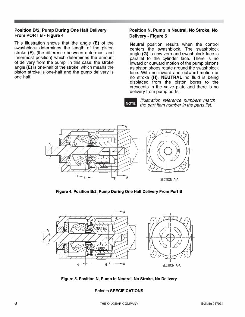
Position B/2, Pump During One Half Delivery From PORT B - Figure 4
This illustration shows that the angle (E) of theswashblock determines the length of the pistonstroke (F), (the difference between outermost andinnermost position) which determines the amountof delivery from the pump. In this case, the strokeangle (E) is one-half of the stroke, which means thepiston stroke is one-half and the pump delivery isone-half.
Position N, Pump In Neutral, No Stroke, No Delivery - Figure 5
Neutral position results when the controlcenters the swashblock. The swashblockangle (G) is now zero and swashblock face isparallel to the cylinder face. There is noinward or outward motion of the pump pistonsas piston shoes rotate around the swashblockface. With no inward and outward motion orno stroke (H), NEUTRAL no fluid is beingdisplaced from the piston bores to thecrescents in the valve plate and there is nodelivery from pump ports.
Illustration reference numbers match the part item number in the parts list.
Figure 4. Position B/2, Pump During One Half Delivery From Port B
Figure 5. Position N, Pump In Neutral, No Stroke, No Delivery
Refer to SPECIFICATIONS
NOTE
A
AE F
IN
OUT
A B
SECTION A-A
A
AG
A B
NEUTRAL
NEUTRAL
H SECTION A-A

Bulletin 947034 THE OILGEAR COMPANY 9
SPECIFICATIONS
Refer to reference material, pump controlmaterial and individual application circuitfor exceptions.
Case pressure should be less than 25 psi (1,7 bar). For higher case pressure, consult factory.
Table 1. Nominal Performance Data with 150-300 SSU viscosity fluids.
All dimensions (without controls) are approximate. For detailed dimensions, contact your Oilgear Representative.* Weight with "P" Control and non-thru shaft valve plate.
Table 2. Nominal Dimensions without controls.
Refer to installation drawings for more detailed dimensions and port configurations.
NOTE
Unit
THEORETICALMAXIMUM
DISPLACEMENT
RATED CONTINUOUS
PRESSURE
PEAKPRESSURE
FLOW RATE at1800 rpm rated
continuous pressureand 14,7 psia (bar abs)
inlet condition
MAXIMUMSPEED
POWER INPUT at rated
continuous pressure & 1800 rpm
in 3/rev ml/rev psi bar psi bar gpm l/mi rpm hp kw
PVG 150 9.16 150,0 5000 344,8 5800 400,0 63.0 238,5 2400 215 160,4
UnitLength Width Height Weight
Face Mountinginches mm inches mm inches mm lbs. kg
PVG 150 14.2 360,7 7.9 200,7 8.1 205,7 171* 78 SAE “D” 4 bolt
10 THE OILGEAR COMPANY Bulletin 947034
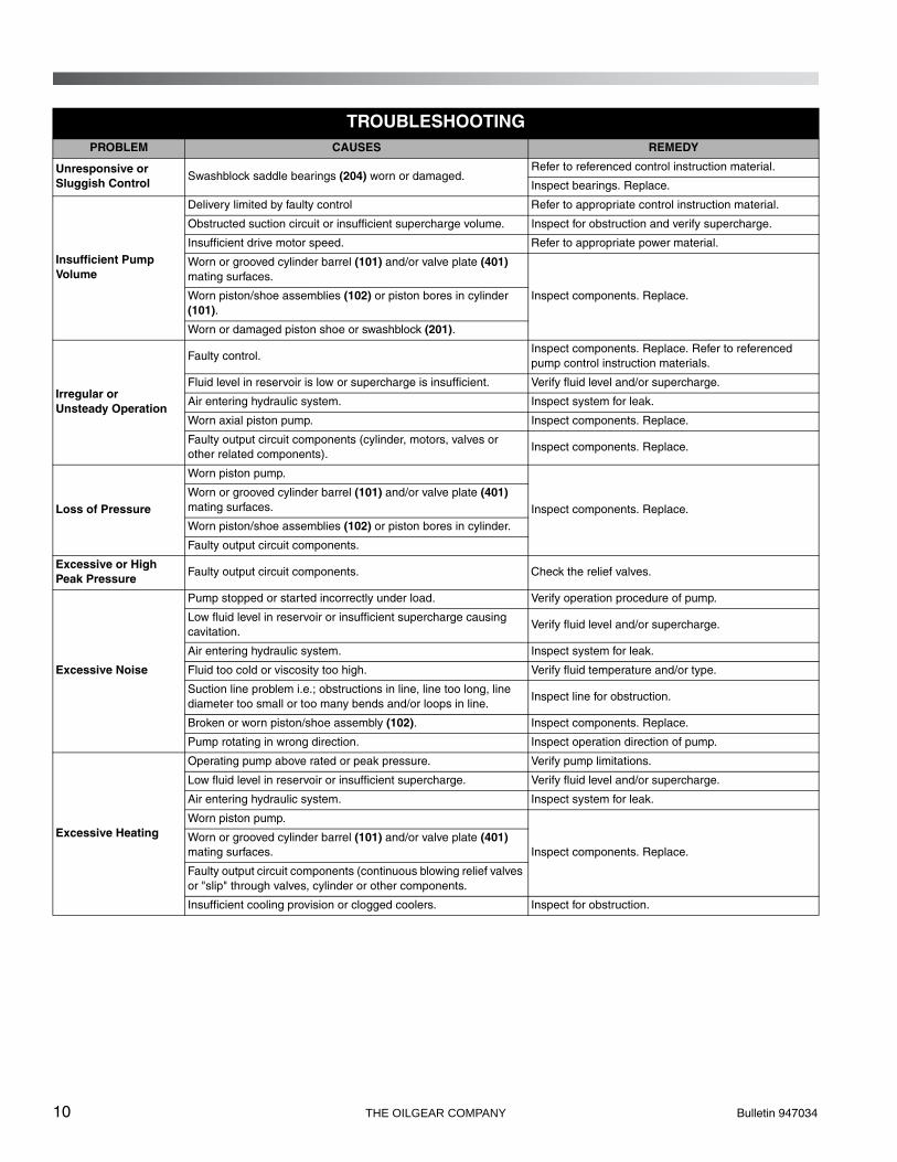
TROUBLESHOOTINGPROBLEM CAUSES REMEDY
Unresponsive or Sluggish Control
Swashblock saddle bearings (204) worn or damaged.Refer to referenced control instruction material.
Inspect bearings. Replace.
Insufficient PumpVolume
Delivery limited by faulty control Refer to appropriate control instruction material.
Obstructed suction circuit or insufficient supercharge volume. Inspect for obstruction and verify supercharge.
Insufficient drive motor speed. Refer to appropriate power material.
Worn or grooved cylinder barrel (101) and/or valve plate (401) mating surfaces.
Inspect components. Replace.Worn piston/shoe assemblies (102) or piston bores in cylinder (101).
Worn or damaged piston shoe or swashblock (201).
Irregular orUnsteady Operation
Faulty control.Inspect components. Replace. Refer to referenced pump control instruction materials.
Fluid level in reservoir is low or supercharge is insufficient. Verify fluid level and/or supercharge.
Air entering hydraulic system. Inspect system for leak.
Worn axial piston pump. Inspect components. Replace.
Faulty output circuit components (cylinder, motors, valves or other related components).
Inspect components. Replace.
Loss of Pressure
Worn piston pump.
Inspect components. Replace.Worn or grooved cylinder barrel (101) and/or valve plate (401) mating surfaces.
Worn piston/shoe assemblies (102) or piston bores in cylinder.
Faulty output circuit components.
Excessive or High Peak Pressure
Faulty output circuit components. Check the relief valves.
Excessive Noise
Pump stopped or started incorrectly under load. Verify operation procedure of pump.
Low fluid level in reservoir or insufficient supercharge causing cavitation.
Verify fluid level and/or supercharge.
Air entering hydraulic system. Inspect system for leak.
Fluid too cold or viscosity too high. Verify fluid temperature and/or type.
Suction line problem i.e.; obstructions in line, line too long, line diameter too small or too many bends and/or loops in line.
Inspect line for obstruction.
Broken or worn piston/shoe assembly (102). Inspect components. Replace.
Pump rotating in wrong direction. Inspect operation direction of pump.
Excessive Heating
Operating pump above rated or peak pressure. Verify pump limitations.
Low fluid level in reservoir or insufficient supercharge. Verify fluid level and/or supercharge.
Air entering hydraulic system. Inspect system for leak.
Worn piston pump.
Inspect components. Replace.Worn or grooved cylinder barrel (101) and/or valve plate (401) mating surfaces.
Faulty output circuit components (continuous blowing relief valves or "slip" through valves, cylinder or other components.
Insufficient cooling provision or clogged coolers. Inspect for obstruction.

Bulletin 947034 THE OILGEAR COMPANY 11
TESTING AND ADJUSTING
Shut the pump OFF and release pressurefrom the system before disassemblingcomponents. Failure to comply with theseinstructions could result in personal injuryor death. Blocking the pressure linebetween the pump and the system (orpump) high pressure relief valve will resultin damage and could result in seriouspersonal injury.
PISTON PUMP
To check for a worn piston pump, make a leakmeasurement test from the case drain while thepump is under pressure. After the unit is warm,either install a flow meter in the drain line or havethe flow from the drain line directed into a largecontainer or reservoir. The pump case must remainfull of fluid during this test.
DO NOT run a pump on stroke against ablocked output unless it is protected by ahigh pressure relief valve and then run nolonger than necessary to check slip. Limitdischarge to prevent dropping reservoirfluid below low level.
With an accurate high pressure gauge in thepressure line, start the pump and stall (or block)output device to raise system pressure tomaximum (as set by system relief valve). Read themeasurement on the flow meter or time andmeasure the case drain flow to fill a known sizecontainer and calculate the flow rate.
Additional leakage indicates wear, butdoes not become critical until it impairsperformance.
DISASSEMBLY
The cleanliness of working on this pump orthe hydraulic system is extremely importantto the safety and reliability of the pump andthe system.
When disassembling or assembling thepump, choose a clean, dry, dust and sandfree area where no traces of abrasiveparticles are in the air which can damagethe pump and system. DO NOT work nearwelding, sandblasting, grinding benches orsimilar conditions.
Always make sure the fittings are clean onthe outside before removing them fromtheir connections. Make sure they arecapped and plugged when removed. Placethem on a clean surface and in a clean ragor container until they are reinstalled.When cleaning parts which have beendisassembled, it is important to useCLEAN cleaning solvents and parts areallowed to dry. All tools and gauges shouldbe clean prior to working with the systemand use new, CLEAN lint free rags tohandle and dry parts.
DO NOT attempt to remove or install anycomponents or assembly while the pumpand system is running. Always stop thepump, shut OFF the power and releasepressure from the system before servicingor testing. Be sure provisions have beenmade so the case drain line can bedisconnected from the unit withoutcausing the line to drain (siphon) thereservoir.
(continued)
! WARNING
CAUTION
NOTE
NOTE
! WARNING
12 THE OILGEAR COMPANY Bulletin 947034
DISASSEMBLY (Continued)
1. Disconnect case drain line from port 1 or 1A.
2. Drain pump case through the remaining (port 1or 1A) on the bottom of case. If plugs areinaccessible, it may be necessary to removethe pump from the mounting and drive motorbefore draining it.
3. After removing the pump from the mountingand before disassembly, cap or plug all portsand clean the outside of unit thoroughly toprevent dust from entering the system. SeeFigures 8 and 9.
Depending on what part or parts are to beinspected, it may not be necessary tocompletely take apart all assemblies.
CONTROL GROUP
Refer to the reference material for the informationwhich applies to the control your pump is equippedwith. Some force is required to remove the controlhousing.
1. Remove socket head cap screws.
2. Lift the control group assembly, with control pin,straight up from the top of the pump assembly.The control pin may or may not remain in theswashblock (201).
3. Remove control O-rings from the pumphousing.
VALVE PLATE GROUP
If another pump is coupled to thru-shaft pumps, itwill be necessary to remove coupling half beforeremoving valve plate.
1. Block the pump on a bench with the drive shaftfacing down.
2. Remove the valve plate (401) by removing foursocket head cap screws (403) and lifting itstraight up.
3. Remove valve plate O-ring (1013) and (1261).
NOTE

Bulletin 947034 THE OILGEAR COMPANY 13
ROTATING GROUP
The rotating group is heavy. Be careful notto damage cylinder wear surface whichmates against the valve plate, bearingdiameters or piston shoes. Use properlifting techniques and assistance fromothers to prevent personal injury.
1. Place the pump in a horizontal position.
2. Remove the rotating group slowly by pulling thecylinder barrel (101) from the housing.
3. Identify (number) each pump piston shoeassembly (102) and its respective bore in thecylinder barrel (101) and shoe retainer (104) foreasy reassembly.
4. See Figure 6. Lift out shoe retainer (104) withpistons (102) and remove the fulcrum ball (103)and shoe retainer springs (105).
Figure 6. Rotating Group Disassembly
5. Remove plugs (205) and pull the hydrodynamicbearing (202) from the housing.
DRIVE SHAFT GROUP
1. Remove the drive key (303), if used and thedrive shaft bearing retainer ring (305).
2. Grasp outboard end of drive shaft (301) andpull it out of the pump housing.
3. Remove the shaft seal retainer (302) and shaftseal (007) if necessary.
SWASHBLOCK GROUP
Reach inside the case and remove the swashblock(201) and saddle bearings (204A and 204B).
INSPECTIONClean all parts thoroughly and allow them to dry.Inspect all seals and O-rings for hardening,cracking or deterioration. Replace if necessary or ifyou suspect damage. Check all locating pins fordamage and springs for cracking or signs of wear.
Wear proper protective gear when usingsolvents or compressed air, servicing ormaintaining the hydraulic system or theOilgear pump. Wear correct protectivegear, safety glasses, gloves, and safetyshoes. Serious injury can result withoutproper protective gear.
CONTROL GROUP
Refer to the reference material on pump controls.Be sure to carefully check the control pin for cracksand/or signs of fatigue. Check fit of the pin in theswashblock. It should be a slip-fit without side-play.Replace if necessary or if you suspect damage.
! WARNING
101
103105
104
102
! WARNING
14 THE OILGEAR COMPANY Bulletin 947034
VALVE PLATE GROUP
Inspect the valveplate (401) surface which mateswith the cylinder barrel (101) for excessive wear.Remove minor defects by lightly stoning thesurface with a hard stone which is flat to within0.001 inches (0,03 mm).
Be sure to stone lightly. Any excessivestoning will remove the hardened surface.If wear or damage is extensive, replace thevalve plate.
ROTATING GROUP
Inspect cylinder barrel (101) piston bores and theface which mate with the valve plate for wear.Remove minor defects on the face by lightlystoning or lapping the surface.
Inspect the cylinder bearing (202) for damage andreplace if necessary. Check all piston and shoeassemblies (102) to be sure they ride properly onthe swashblock.
Be sure to stone lightly. Any excessivestoning will remove the hardened surface.If wear or damage is extensive and defectscannot be removed, replace the cylinderbarrel.
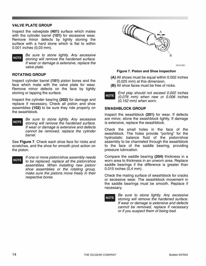
See Figure 7. Check each shoe face for nicks andscratches, and the shoe for smooth pivot action onthe piston.
If one or more piston/shoe assembly needsto be replaced, replace all the piston/shoeassemblies. When installing new piston/shoe assemblies or the rotating group,make sure the pistons move freely in theirrespective bores.
Figure 7. Piston and Shoe Inspection
(A) All shoes must be equal within 0.002 inches(0,025 mm) at this dimension.
(B) All shoe faces must be free of nicks.
End play should not exceed 0.002 inches(0,076 mm) when new or 0.006 inches(0,152 mm) when worn.
SWASHBLOCK GROUP
Inspect the swashblock (201) for wear. If defectsare minor, stone the swashblock lightly. If damageis extensive, replace the swashblock.
Check the small holes in the face of theswashblock. The holes provide “porting” for thehydrostatic balance fluid of the piston/shoeassembly to be channeled through the swashblockto the face of the saddle bearing, providingpressure lubrication.
Compare the saddle bearing (204) thickness in aworn area to thickness in an unworn area. Replacesaddle bearings if the difference is greater than0.015 inches (0,4 mm).
Check the mating surface of swashblock for cracksor excessive wear. The swashblock movement inthe saddle bearings must be smooth. Replace ifnecessary.
Be sure to stone lightly. Any excessivestoning will remove the hardened surface.If wear or damage is extensive and defectscannot be removed, replace if necessaryor if you suspect them of being bad.
NOTE
NOTE
NOTE
B
A
OILG-0005
NOTE
NOTE
Bulletin 947034 THE OILGEAR COMPANY 15
DRIVE SHAFT GROUP
Check:
• the shaft seal (007) for deterioration orcracks. Replace if necessary (press-out).
• the shaft bearing (306) for galling, pitting,binding or roughness.
• the rear shaft bushing in valve plate.
• the shaft and its splines for wear. Replaceany parts necessary.
ASSEMBLYSee Figures 8 and 9. Follow the disassemblyprocedures in reverse for re-assembling the pump.
During assembly, install new seals and O-rings.Apply a thin film of CLEAN grease or hydraulic fluidto sealing components to ease assembly. If a newrotating group is used, lubricate thoroughly withCLEAN hydraulic fluid. Apply fluid generously to allwear surfaces.
SWASHBLOCK GROUP
If removed,
1. Press shaft seal (007) into the saddle (216).
2. Align hole in bottom of saddle (216) with pin(217) in housing. Install saddle in housing andfasten with eight (8) screws (225).
3. Place housing on a bench with the mountingflange side down.
4. Grease the back side of each saddle bearing(204A and 204B) and install on the appropriateside of the saddle (216).
5. The swashblock is inserted from the valve plateend. Insert swashblock (201) into the pumphousing. Once in place, be sure the swashblockswivels in the saddle bearings. With newbearings, swiveling may be stiff and not alwayssmooth.
6. The bearing (202) should be positioned withthe half moon mill cut positioned towards thecontrol face. The bearing should fit into placewith a little difficulty and be square to the axisof the pump.
7. Tap bearing into place if necessary usingextreme care not to damage the bearing.
8. Assemble plugs (205) with O-rings (1906) intocase.
DRIVE SHAFT GROUP
1. Place the housing on its side with the axishorizontal.
2. Install the seal retainer (302).
3. Lubricate the shaft seal (007) and shaft.
4. Insert the drive shaft (301) and bearingassembly into the housing.
5. Lock in place with the drive shaft bearingretainer ring (305).
ROTATING GROUP
See Figure 6.
1. Place the cylinder barrel (101), wear surfacedown, on a clean cloth.
2. Place the nine (9) shoe retainer springs (105)in the spring pockets of the barrel with thefulcrum ball (103) on top of it.
3. Insert the identified pistons (102) into theircorresponding identified holes of the shoeretainer (104). As a unit, fit the pistons into theircorresponding, identified bores in the cylinderbarrel. DO NOT FORCE. When parts arealigned properly, the pistons will fit smoothly.

16 THE OILGEAR COMPANY Bulletin 947034
The rotating group weight is heavy. Becareful not to damage cylinder wearsurface which mates against the valveplate, bearing diameters or piston shoes.Use proper lifting techniques andassistance from others to preventpersonal injury.
The rotating group can now be carefully installedover the end of the drive shaft (301) and into thepump housing (001).
When installing the rotating group, supportthe weight of the cylinder barrel (101), ascylinder spline is passed over the tailshaft,to avoid scratching or damage.
4. Push cylinder forward until the cylinder splinereaches the drive shaft spline and rotateslightly to engage shaft splines. Continue toslide cylinder forward until it encounters thecylinder bearing (202). Lifting the rear of theshaft slightly helps the cylinder (101) and thecylinder bearing (202) engagement. Continuepushing the cylinder forward until the pistonshoes contact the swashblock. The back of thecylinder should protrude approximately 0.25inches (6 mm) from the back of the pumphousing.
VALVE PLATE GROUP
1. Place the pump housing on a bench with theopen end facing up.
2. Install new O-rings (1013) and (1261) on thehousing.
3. Assemble the valve plate (401) onto thehousing (001) making sure the screw holes arealigned.
4. Hand-tighten the hex head cap screw (403)closest to O-ring (1013) first, then alternatelytighten the other cap screws. On thru-shaftunits connected to another pump or device,install coupling (501).
Refer to PREPARATION and INSTALLATIONwhen pump is ready to be returned to service.
! WARNING
NOTE

Bulletin 947034 THE OILGEAR COMPANY 17
Table 3. PVG Pump Torques
PVGPump
Fastener or Plug
DescriptionHead
Type/SizeTightening Torque
150
205 Hydrobearing Retaining Plug 1/4" Internal Hex 200 in•lb (23 N•m)225 1/4-20 SCHS x 1.5" lg 3/16" Internal Hex 120 in•lb (14 N•m)403 3/4-10 SHCS x 2.5" lg 5/8" Internal Hex 244 ft•lb (330 N•m)
503
3/8-16 HHCS x 1" lg 9/16" External Hex 183 in•lb (20 N•m)1/2-13 HHCS x 1.25" lg 3/4" External Hex 37 ft•lb (50 N•m)5/8-11 HHCS x 1.5" lg 15/16" External Hex 74 ft•lb (100 N•m)3/4-10 HHCS x 2.25" lg 1-1/8" External Hex 132 ft•lb (179 N•m)
5073/8-16 SHCS x 63" lg 5/16" Internal Hex 45 ft•lb (61 N•m)1/2-13 SHCS x 1.5" lg 3/8" Internal Hex 100 ft•lb (136 N•m)
601 SAE #2 Plug 1/8" Internal Hex 45 in•lb (5 N•m)602 SAE #3 Plug 1/8" Internal Hex 45 ft•lb (61 N•m)609 SAE #16 Plug 5/8" Internal Hex 135 ft•lb (183 N•m)
PVG150 D-Frame Pumps
18 THE OILGEAR COMPANY Bulletin 947034
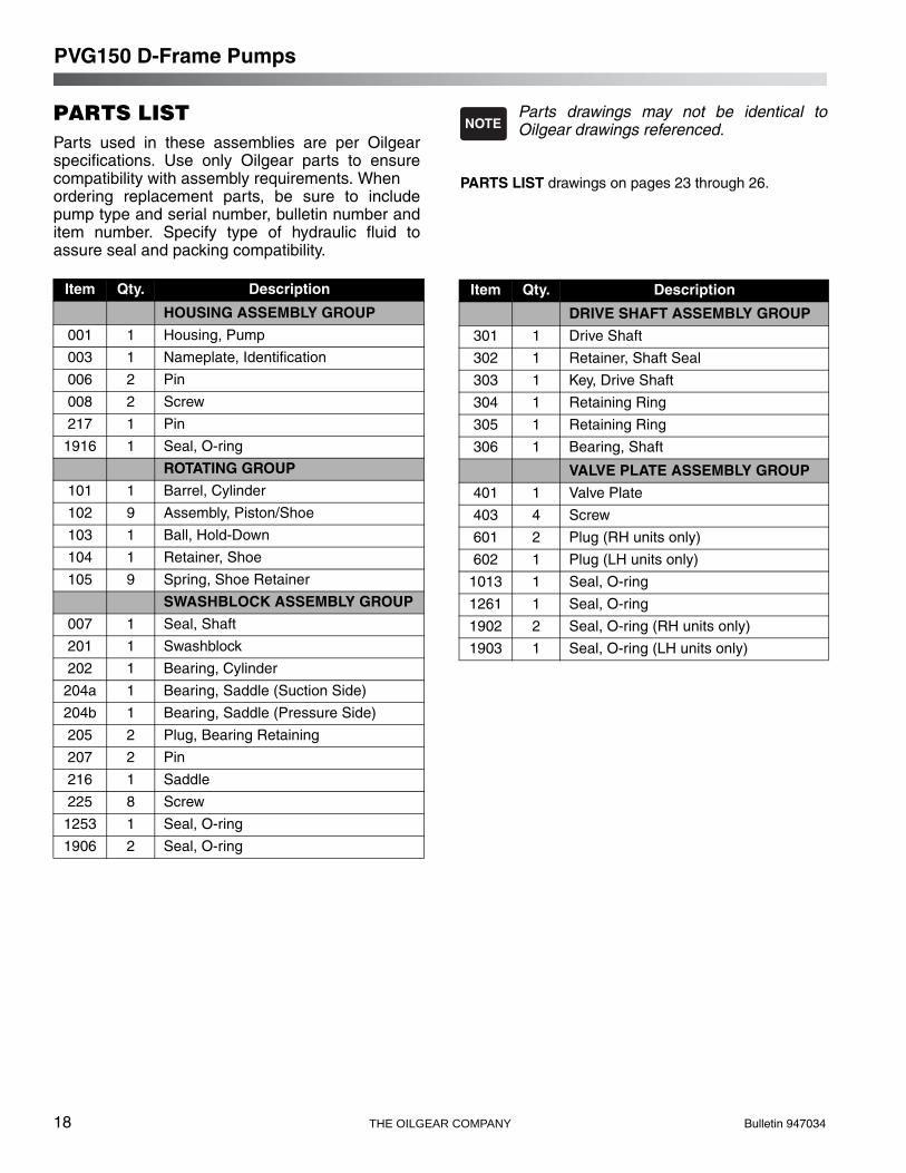
PARTS LISTParts used in these assemblies are per Oilgearspecifications. Use only Oilgear parts to ensurecompatibility with assembly requirements. When ordering replacement parts, be sure to includepump type and serial number, bulletin number anditem number. Specify type of hydraulic fluid toassure seal and packing compatibility.
Parts drawings may not be identical toOilgear drawings referenced.
PARTS LIST drawings on pages 23 through 26.
NOTE
Item Qty. Description
HOUSING ASSEMBLY GROUP
001 1 Housing, Pump
003 1 Nameplate, Identification
006 2 Pin
008 2 Screw
217 1 Pin
1916 1 Seal, O-ring
ROTATING GROUP
101 1 Barrel, Cylinder
102 9 Assembly, Piston/Shoe
103 1 Ball, Hold-Down
104 1 Retainer, Shoe
105 9 Spring, Shoe Retainer
SWASHBLOCK ASSEMBLY GROUP
007 1 Seal, Shaft
201 1 Swashblock
202 1 Bearing, Cylinder
204a 1 Bearing, Saddle (Suction Side)
204b 1 Bearing, Saddle (Pressure Side)
205 2 Plug, Bearing Retaining
207 2 Pin
216 1 Saddle
225 8 Screw
1253 1 Seal, O-ring
1906 2 Seal, O-ring
Item Qty. Description
DRIVE SHAFT ASSEMBLY GROUP
301 1 Drive Shaft
302 1 Retainer, Shaft Seal
303 1 Key, Drive Shaft
304 1 Retaining Ring
305 1 Retaining Ring
306 1 Bearing, Shaft
VALVE PLATE ASSEMBLY GROUP
401 1 Valve Plate
403 4 Screw
601 2 Plug (RH units only)
602 1 Plug (LH units only)
1013 1 Seal, O-ring
1261 1 Seal, O-ring
1902 2 Seal, O-ring (RH units only)
1903 1 Seal, O-ring (LH units only)
PVG150 D-Frame Pumps
Bulletin 947034 THE OILGEAR COMPANY 19
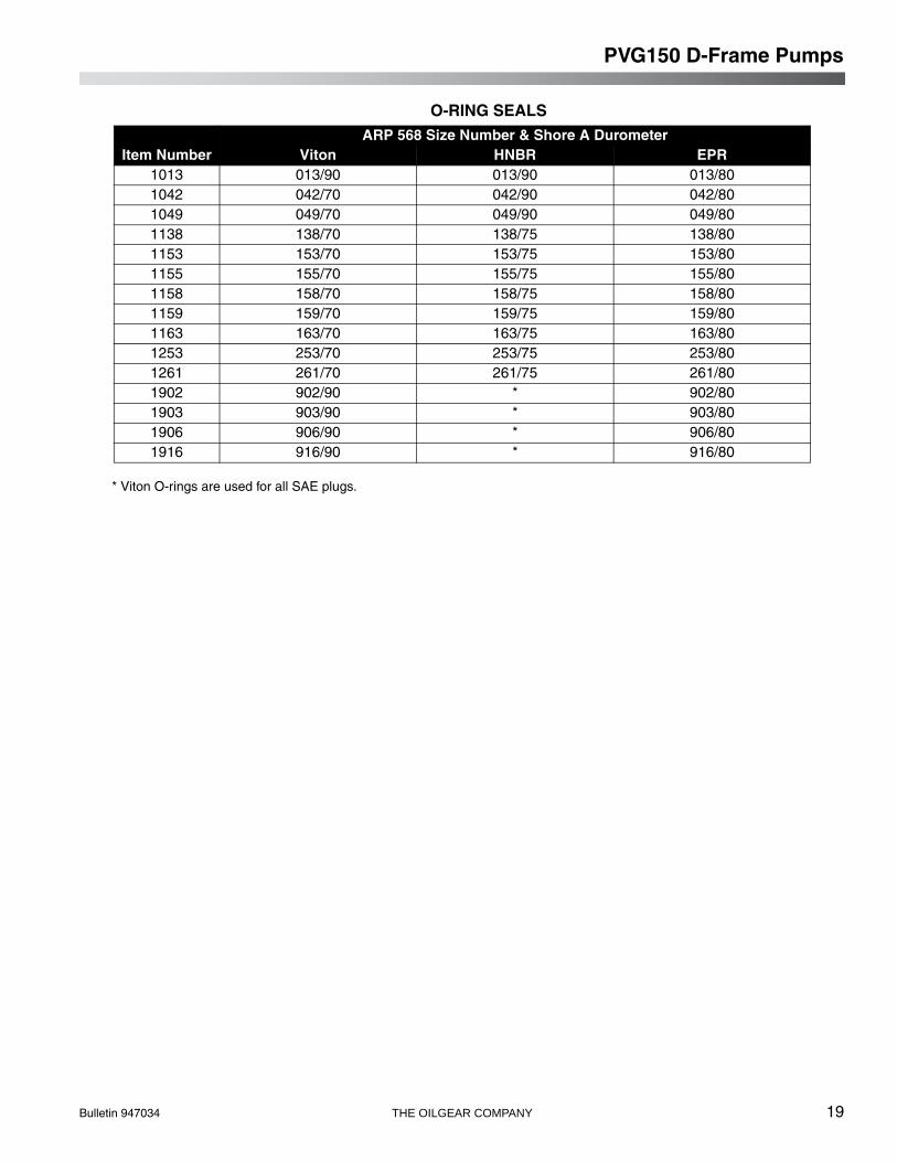
O-RING SEALS
* Viton O-rings are used for all SAE plugs.
Item NumberARP 568 Size Number & Shore A Durometer
Viton HNBR EPR1013 013/90 013/90 013/801042 042/70 042/90 042/801049 049/70 049/90 049/801138 138/70 138/75 138/801153 153/70 153/75 153/801155 155/70 155/75 155/801158 158/70 158/75 158/801159 159/70 159/75 159/801163 163/70 163/75 163/801253 253/70 253/75 253/801261 261/70 261/75 261/801902 902/90 * 902/801903 903/90 * 903/801906 906/90 * 906/801916 916/90 * 916/80
PVG150 D-Frame Pumps
20 THE OILGEAR COMPANY Bulletin 947034
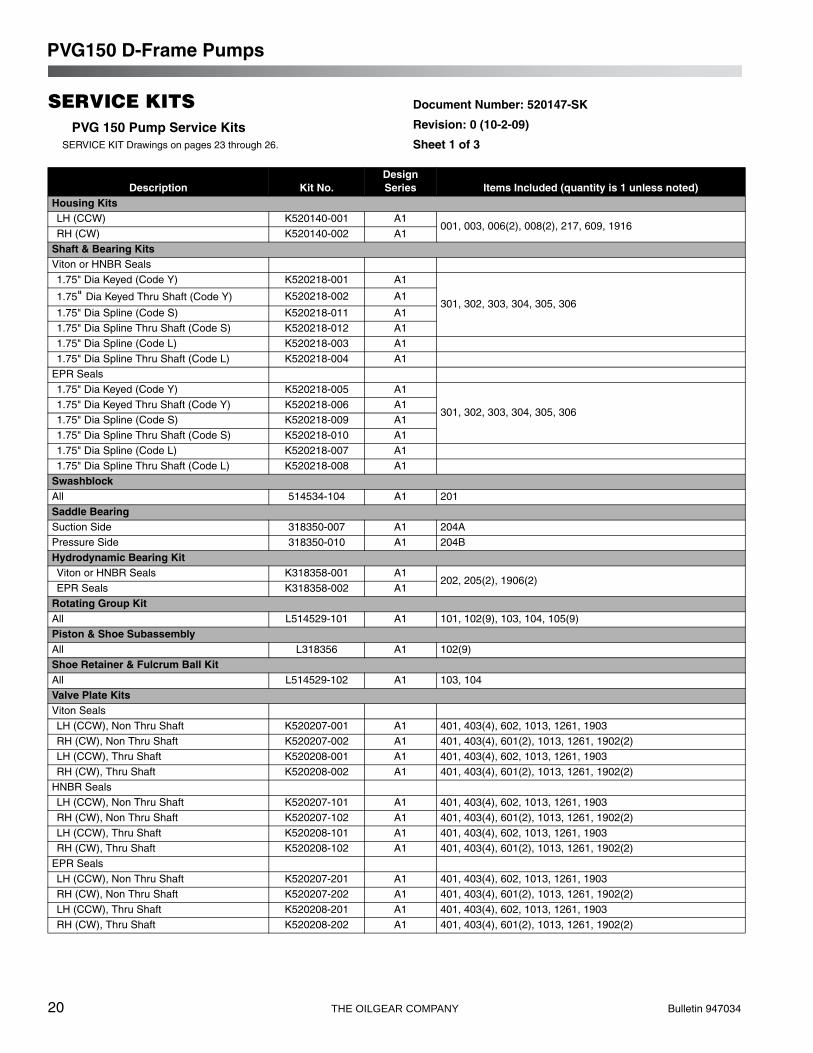
SERVICE KITSPVG 150 Pump Service Kits
SERVICE KIT Drawings on pages 23 through 26.
Document Number: 520147-SK
Revision: 0 (10-2-09)
Sheet 1 of 3
Description Kit No.Design Series Items Included (quantity is 1 unless noted)
Housing KitsLH (CCW) K520140-001 A1
001, 003, 006(2), 008(2), 217, 609, 1916RH (CW) K520140-002 A1
Shaft & Bearing KitsViton or HNBR Seals1.75" Dia Keyed (Code Y) K520218-001 A1
301, 302, 303, 304, 305, 3061.75" Dia Keyed Thru Shaft (Code Y) K520218-002 A1
1.75" Dia Spline (Code S) K520218-011 A11.75" Dia Spline Thru Shaft (Code S) K520218-012 A11.75" Dia Spline (Code L) K520218-003 A11.75" Dia Spline Thru Shaft (Code L) K520218-004 A1
EPR Seals1.75" Dia Keyed (Code Y) K520218-005 A1
301, 302, 303, 304, 305, 3061.75" Dia Keyed Thru Shaft (Code Y) K520218-006 A11.75" Dia Spline (Code S) K520218-009 A11.75" Dia Spline Thru Shaft (Code S) K520218-010 A11.75" Dia Spline (Code L) K520218-007 A11.75" Dia Spline Thru Shaft (Code L) K520218-008 A1
Swashblock All 514534-104 A1 201Saddle BearingSuction Side 318350-007 A1 204APressure Side 318350-010 A1 204BHydrodynamic Bearing KitViton or HNBR Seals K318358-001 A1
202, 205(2), 1906(2)EPR Seals K318358-002 A1
Rotating Group KitAll L514529-101 A1 101, 102(9), 103, 104, 105(9)Piston & Shoe SubassemblyAll L318356 A1 102(9)Shoe Retainer & Fulcrum Ball KitAll L514529-102 A1 103, 104Valve Plate KitsViton SealsLH (CCW), Non Thru Shaft K520207-001 A1 401, 403(4), 602, 1013, 1261, 1903RH (CW), Non Thru Shaft K520207-002 A1 401, 403(4), 601(2), 1013, 1261, 1902(2)LH (CCW), Thru Shaft K520208-001 A1 401, 403(4), 602, 1013, 1261, 1903RH (CW), Thru Shaft K520208-002 A1 401, 403(4), 601(2), 1013, 1261, 1902(2)
HNBR SealsLH (CCW), Non Thru Shaft K520207-101 A1 401, 403(4), 602, 1013, 1261, 1903RH (CW), Non Thru Shaft K520207-102 A1 401, 403(4), 601(2), 1013, 1261, 1902(2)LH (CCW), Thru Shaft K520208-101 A1 401, 403(4), 602, 1013, 1261, 1903RH (CW), Thru Shaft K520208-102 A1 401, 403(4), 601(2), 1013, 1261, 1902(2)
EPR SealsLH (CCW), Non Thru Shaft K520207-201 A1 401, 403(4), 602, 1013, 1261, 1903RH (CW), Non Thru Shaft K520207-202 A1 401, 403(4), 601(2), 1013, 1261, 1902(2)LH (CCW), Thru Shaft K520208-201 A1 401, 403(4), 602, 1013, 1261, 1903RH (CW), Thru Shaft K520208-202 A1 401, 403(4), 601(2), 1013, 1261, 1902(2)
PVG150 D-Frame Pumps

Bulletin 947034 THE OILGEAR COMPANY 21
PVG 150 Pump Service KitsSERVICE KIT Drawings on pages 23 through 26.
Document Number: 520147-SK
Revision: 0 (10-2-09)
Sheet 2 of 3
Description Kit No.Design Series Items Included (quantity is 1 unless noted)
Basic Seal KitsViton Seals K516175-D01 A1
007, 1013, 1902(2), 1903, 1906(2), 1253, 1261, 1916HNBR Seals K516175-D11 A1EPR Seals K516175-D21 A1
Seal Kits for OptionsStandard Cover PlateViton Seals 238270-138 A1
1138HNBR Seals 252194-138 A1EPR Seals 242080-138 A1
SAE C 2-Bolt AdapterViton Seals 238270-049 A1
1049HNBR Seals 252305-049 A1EPR Seals 242080-049 A1
SAE C 4-Bolt AdapterViton Seals L250667-025 A1
1049, 1159HNBR Seals L250667-026 A1EPR Seals L250667-027 A1
SAE B 2-Bolt AdapterViton Seals L250667-017 A1
1155, 1158HNBR Seals L250667-029 A1EPR Seals L250667-018 A1
SAE B 4-Bolt AdapterViton Seals L250667-022 A1
1049, 1155HNBR Seals L250667-023 A1EPR Seals L250667-024 A1
SAE A AdapterViton Seals L250667-014 A1
1042, 1153HNBR Seals L250667-028 A1EPR Seals L250667-015 A1
Shaft SealsViton Seals 249823 A1
007HNBR Seals 249823-002 A1EPR Seals 251281 A1
Cover Plate KitsViton Seals K319076-101 A1
507(4), 508, 1138HNBR Seals K319076-201 A1EPR Seals K319076-301 A1
SAE A 2-Bolt Coupling & Adapter KitsViton Seals K319076-102 A1
501, 502, 503(2), 504(2), 507(4), 1042, 1153HNBR Seals K319076-202 A1EPR Seals K319076-302 A1
SAE B 2-Bolt Coupling & Adapter KitsViton Seals K319076-103 A1
501, 502, 503(2), 504(2), 1155, 1158HNBR Seals K319076-203 A1EPR Seals K319076-303 A1
PVG150 D-Frame Pumps
22 THE OILGEAR COMPANY Bulletin 947034
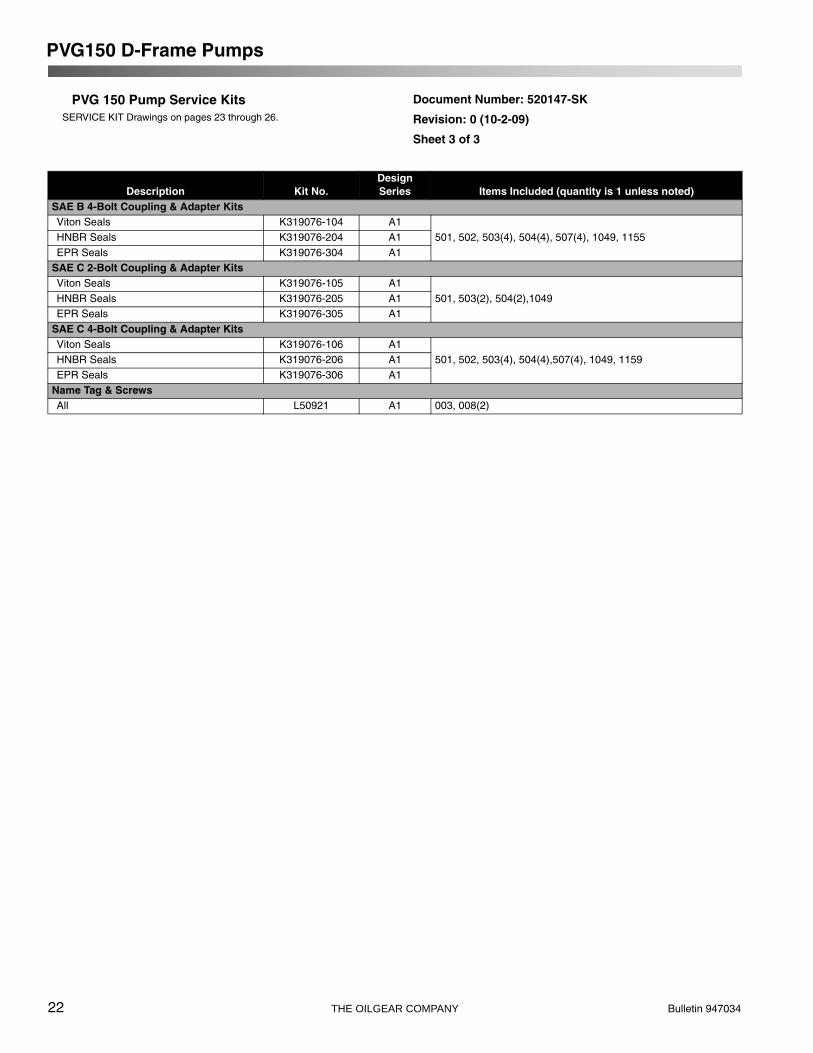
PVG 150 Pump Service KitsSERVICE KIT Drawings on pages 23 through 26.
Document Number: 520147-SK
Revision: 0 (10-2-09)
Sheet 3 of 3
Description Kit No.Design Series Items Included (quantity is 1 unless noted)
SAE B 4-Bolt Coupling & Adapter KitsViton Seals K319076-104 A1
501, 502, 503(4), 504(4), 507(4), 1049, 1155HNBR Seals K319076-204 A1EPR Seals K319076-304 A1
SAE C 2-Bolt Coupling & Adapter KitsViton Seals K319076-105 A1
501, 503(2), 504(2),1049HNBR Seals K319076-205 A1EPR Seals K319076-305 A1
SAE C 4-Bolt Coupling & Adapter KitsViton Seals K319076-106 A1
501, 502, 503(4), 504(4),507(4), 1049, 1159HNBR Seals K319076-206 A1EPR Seals K319076-306 A1
Name Tag & ScrewsAll L50921 A1 003, 008(2)
PVG150 D-Frame Pumps
Bulletin 947034 THE OILGEAR COMPANY 23
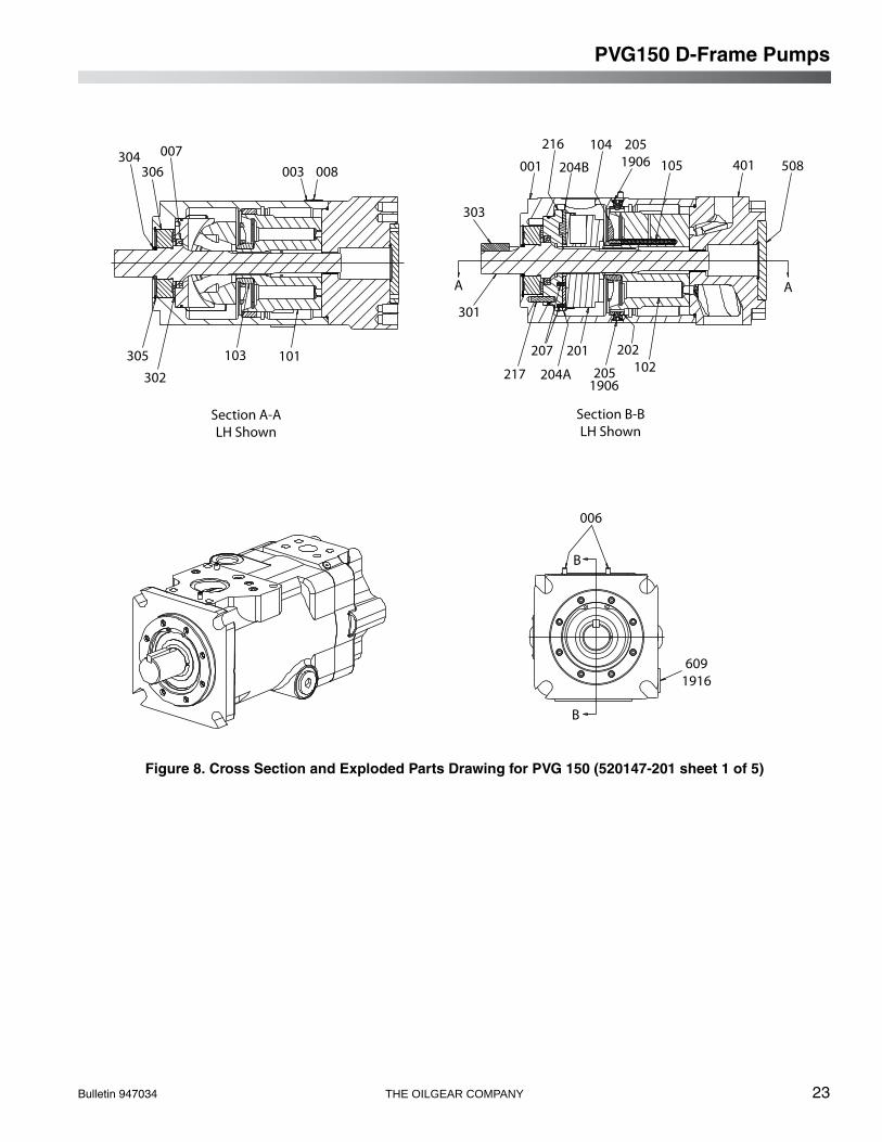
Figure 8. Cross Section and Exploded Parts Drawing for PVG 150 (520147-201 sheet 1 of 5)
304306
007
305
302
103 101
Section A-ALH Shown
003 008
Section B-BLH Shown
001
216
204B
104 2051906 105 401 508
AA
303
301
217
207
204A 2051906
201 202102
006
6091916
B
B
PVG150 D-Frame Pumps
24 THE OILGEAR COMPANY Bulletin 947034
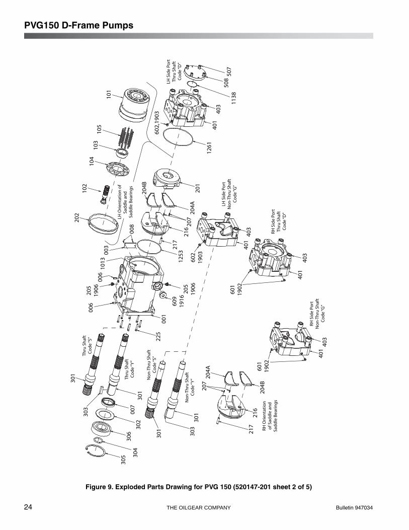
Figure 9. Exploded Parts Drawing for PVG 150 (520147-201 sheet 2 of 5)
305 30
430
6
302
007
301
303
301
Thru
Sha
ftCo
de “S
”
Thru
Sha
ftCo
de “Y
”
Non
-Thr
u Sh
aft
Code
“S”
Non
-Thr
u Sh
aft
Code
“Y”
301
303
301
207
204A
217
216
204B
601
1902
RH O
rient
atio
nof
Sad
dle
and
Sadd
le B
earin
gs
RH S
ide
Port
Non
-Thr
u Sh
aft
Code
“G”
401
403
RH S
ide
Port
Thru
Sha
ftCo
de “D
”
601
1902
401
403
401
403
LH S
ide
Port
Non
-Thr
u Sh
aft
Code
“G”
602
1903
201
204A
207
216
217
1253
225
001
609
1916
205
1906
006
205
1906
006
1013
003
202
102
104
103
105
LH O
rient
atio
n of
Sadd
le a
nd
Sadd
le B
earin
gs
204B
008
101
602,
1903
LH S
ide
Port
Thru
Sha
ftCo
de “D
”
1261
401
403 11
3850
850
7
PVG150 D-Frame Pumps

Bulletin 947034 THE OILGEAR COMPANY 25
Figure 10. Exploded Parts Drawing for PVG 150 (520147-201 sheet 3 of 5)
301
(REF
)
1138
508
507
Cove
r Pla
te
301
(REF
)50
1
1153
502
SAE
A A
dapt
er(2
-Bol
t)
301
(REF
)50
1
1158
502
SAE
B Ad
apte
r (2-
Bolt)
1155
504
503
SAE
B Ad
apte
r (4-
Bolt)
502
1049
507
1155
504
503
507
1042
504
503
301
(REF
)50
1
PVG150 D-Frame Pumps

26 THE OILGEAR COMPANY Bulletin 947034
Figure 11. Cross Section and Exploded Parts Drawing for PVG 150 (520147-201 sheet 4 of 5)
301
(REF
)50
1
301
(REF
)50
1
1049
504
503
SAE
C Ad
apte
r (2-
Bolt) 10
4950
250
711
6350
4
SAE
D A
dapt
er (4
-Bol
t)
50310
4950
250
711
5950
450
3
SAE
C Ad
apte
r (4-
Bolt)
301
(REF
)50
1
PVG150 D-Frame Pumps

Bulletin 947034 THE OILGEAR COMPANY 27
NOTES

Bulletin 947034 THE OILGEAR COMPANY 28
AFTER SALES SERVICESAt Oilgear we build products to last. It is the natureof this type of machinery to require propermaintenance regardless of the care we put intomanufacturing. Oilgear has several serviceprograms in place to help you.
STAY-ON-STREAM SERVICE
By signing up for Oilgear's Stay-On-Streamprogram, you can prepare for problems before theyhappen. Certain field tests such as fluid testing,slip testing and electronic profile recordingcomparisons can be performed by our field servicepeople or your own factory trained personnel.These tests can indicate problems before theybecome “down-time” difficulties.
SERVICE SCHOOLS
Oilgear conducts training to train your maintenancepersonnel. “General” hydraulic or electronictraining is conducted at our Milwaukee, Wisconsinplant on a regular basis. “Custom” training,specifically addressing your particular hydraulicand electro-hydraulic equipment can be conductedat your facilities.
SPARE PARTS AVAILABILITY
Prepare for your future needs by stocking Oilgearoriginal factory parts. Having the correct parts andnecessary skills “in-plant” enables you to minimize“down-time.” Oilgear has developed parts kits tocover likely future needs. Oilgear Field ServiceTechnicians are also ready to assist you and yourmaintenance people in troubleshooting andrepairing equipment.
THE OILGEAR COMPANY2300 South 51st Street
Milwaukee, Wisconsin 53219 Bulletin 947034Issued: October 2009