service and operating instructions for actuator type a...
TRANSCRIPT
Contents
Important 2
Function and design 2
Storage, handling and lifting 2
Air connection markings 2
Assembling the clamp ring 2
Accessories 2
Mount the actuator on the valve 3
Dismounting the actuator from the valve 3
Pullers 3
Adjusting the end position 4
Tightening torque, tie-rods 5
Service and maintenance 5
Sealing and repair kits 5
Replacing the sealing kit 6 - 7
Replacing the repair kit 8
Spare parts drawings 9 - 11
Technical specifications 12
Service and Operating Instructions Mi-503 ENActuator Types A-DA and A-SC/SO Edition: 2006-01
Safety InformationTo avoid injury, disconnect the actuator from its power source before servicing the valve or actuator.
DO NOT place fi ngers, hands or arms either inside the valve or at the sealing surface when the power source is connected to the actuator.
2
Fig. 2
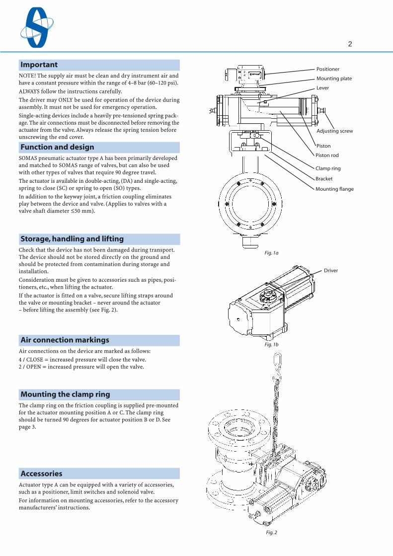
ImportantNOTE! The supply air must be clean and dry instrument air and have a constant pressure within the range of 4–8 bar (60–120 psi).ALWAYS follow the instructions carefully.The driver may ONLY be used for operation of the device during assembly. It must not be used for emergency operation.Single-acting devices include a heavily pre-tensioned spring pack-age. The air connections must be disconnected before removing the actuator from the valve. Always release the spring tension before unscrewing the end cover.
Function and designSOMAS pneumatic actuator type A has been primarily developed and matched to SOMAS range of valves, but can also be used with other types of valves that require 90 degree travel.The actuator is available in double-acting, (DA) and single-acting, spring to close (SC) or spring to open (SO) types.In addition to the keyway joint, a friction coupling eliminates play between the device and valve. (Applies to valves with a valve shaft diameter ≤50 mm).
Storage, handling and liftingCheck that the device has not been damaged during transport. The device should not be stored directly on the ground and should be protected from contamination during storage and installation.Consideration must be given to accessories such as pipes, posi-tioners, etc., when lifting the actuator.If the actuator is fitted on a valve, secure lifting straps around the valve or mounting bracket – never around the actuator – before lifting the assembly (see Fig. 2).
Fig. 1a
Air connection markingsAir connections on the device are marked as follows: 4 / CLOSE = increased pressure will close the valve.2 / OPEN = increased pressure will open the valve.
Mounting the clamp ringThe clamp ring on the friction coupling is supplied pre-mounted for the actuator mounting position A or C. The clamp ring should be turned 90 degrees for actuator position B or D. See page 3.
AccessoriesActuator type A can be equipped with a variety of accessories, such as a positioner, limit switches and solenoid valve. For information on mounting accessories, refer to the accessory manufacturers’ instructions.
Fig. 1b
Positioner
Mounting plate
Lever
Adjusting screw
Piston
Piston rod
Clamp ring
Bracket
Mounting flange
Driver

3
A11 A13 A21 A22 A23 A24 A31 A32
34786 34786 34786 34786 34786 34786 34787 34787
A33 A34 A41 A42 A43 A44 A51 A52
34787 34787 34788 34788 34788 34788 34788 34788
Fig. 3
Mounting the actuator on the valveActuator type A is mounted on the valve using an intermediate bracket. The standard position for both the valve and the actuator is the closed position.In the bottom of the actuator housing there is an ISO5211-com-pliant interface with threaded holes. The actuator can be mounted in four different positions (see Fig.3). Position A is the standard. Other positions can be chosen depending on the installation requirements. 1. Check that the keyway in the actuator’s lever and the valve-
shaft and key are undamaged. 2. Check the position of the valve and the actuator to make sure that the valve will operate in the correct quadrant. 3. Fit the bracket on the actuator. 4. Place the actuator in the actual mounting position and tap the actuator into place with plastic or rubber mallet to ensure a tight fit. 5. Secure the bracket to the valve’s mounting flange by tight- ening the screws. 6. Make sure that the clamp rings yellow marking follows key on the valve shaft. Untighten the clamp ring before mounting in new position. Tighten the clamp ring screws (C).
For information on ball valve actuator assembly, refer to Service and Operating Instructions Mi-706 EN.After assembly is complete, the end position adjustments should be made. Refer to the “Adjusting the end position” instructions on page 4, for further information.
Dismounting the actuator from the valveIn order to avoid damaging the seat(s) and ball/ball segment/disc a puller should be used when dismantling the actuator from the valve.The pullers are available directly from SOMAS, by specifyingthe part numbers provided in the table below. 1. Loosen the clamp ring screws (C). 2. Dismantle accessories such as positioners, limit switch boxes and the driver (A) by loosening the screws (B). 3. Unscrew the actuator and bracket from the valve by removing the screws (D). 4. Dismantle the actuator from the valve shaft with help of a puller (see Fig. 4). NOTE! Be careful, not to drop the actuator. 5. Lift of the actuator and unscrew the puller.
Fig. 4
PullersActuator size DA, SC, SO
Part No.
Actuator size DA, SC, SO
Part No.
Fig. 3a

4
Adjusting the end positionThe actuator’s travel is limited in the closed and open positions by adjustment screws. In closed position, the adjustment screw allows for adjustment of ±5°. In open position, the adjustment screw is used to limit the stroke of the valve. The degree of limitation in open position depends on the valve type (see Fig. 5a and 5b).
Closed position adjustmentFor ball valves: 1. Loosen the locking nut and unscrew the closed position adjusting screw a few turns. 2. Ensure that the keyway connection on the valve shaft is turned 90º from the flow direction of the valve. If it is necessary to correct the closed position, use supply air pressure to turn the ball. The air connections are marked “4 / CLOSE” respectively “2 / OPEN” to indicate moving direction. 3. At correct position, screw in the adjusting screw, seal with sealing tape and lock with the nut.For ball segment valves type KVT/KVTW/KVTF: 1. Loosen the locking nut and unscrew the closed position adjusting screw a few turns. 2. Make sure that the ball segment is centered on the seat by looking into the valve via the outlet flange. If it is necessary to correct the closed position, use supply air pressure to turn the segment. The air connections are marked “4 / CLOSE” respectively “2 / OPEN” to indicate moving direction. 3. At correct position, screw in the adjusting screw, seal with sealing tape and lock with the nut.For ball segment valves type KVX/KVXW/KVXF and butterfly valves: 1. Loosen the locking nut and unscrew the closed position adjusting screw a few turns. 2. Fit a filter regulator on the air supply line and reduce the supply pressure to about 3 bars (2 bars for low-pressure actuators). Close the valve by using the reduced air pressure. Make sure that the segment or disc will reach the seat. 3. Screw in the adjusting screw, seal with thread sealing tape and lock with the nut.For a butterfly valve, to check the tightness of the seal between the disc and seat, the valve should first be fitted between flanges or other pressure-testing equipment. A simple method to test the tightness of the seal bet-ween the disc and seat is to use a strip of normal writing paper approx. 2 to 3 cm wide. Insert the strip between the seat ring and the edge of the disc and close the valve. The adjusting screw is correctly adjusted when the surface pressure is so hard that the paper strip tends to break. For placement of the paper strip, see Fig. 5c.
Open position adjustmentFor ball segment valves:In on/off applications the valve should be operated at 90° and in control applications the valve should be operated at between 75° and 90°. 1. Check the function of the valve and the opening angle. 2. Loosen the adjusting screw a few turns. 3. Open the valve. 4. Screw the adjusting screw gently against the stop. 5. Seal with thread sealing tape and lock with the nut.For butterfly valves:As an on/off valve the valve should open to 80° for maximum capacity. As a control valve the valve should open to between 60° and 80°. 1. Check the function of the valve and the opening angle. 2. Loosen the adjusting screw a few turns. 3. Open the valve to the required position. 4. Screw in the adjusting screw. 5. Seal with thread sealing tape and lock with the nut.
Fig. 5b
Fig. 6
For ball valves:The valve should be operated at 90° in both on/off and control applications. 1. Check the function of the valve and the opening angle. 2. Loosen the adjusting screw a few turns. 3. Open the valve fully using a wrench or air pressure. 4. Screw the adjusting screw gently against the stop. 5. Seal with thread sealing tape and lock with the nut.
Adjusting screwOpen position
Adjusting screw Closed position
Type A-DAA-11, A-21, etc.One cylinder
Type A-DAA-11, A-21, etc.Two cylinders
Type A-DA
Type A-DA
Type A-DA
Type A-DA
Fig. 5a

5
A11-DA A13-DA A21-DA A22-DA A23-DA A24-DA A31-DA A32-DA
35584 35585 35586 35587 35588 35589 35590 35591
35607 35608 35609 35610 35611 35612 35613 35614
A33-DA A34-DA A41-DA A42-DA A43-DA A44-DA A51-DA A52-DA
35592 35593 35594 35595 35596 35597 35598 35599
35615 35616 35617 35618 35619 35620 35621 35622
A11-DA A13-DA A21-DA A22-DA A23-DA A24-DA A31-DA A32-DA
35630 35631 35632 35633 35634 35635 35636 35637
35653 35654 35655 35656 35657 35658 35659 35660
A33-DA A34-DA A41-DA A42-DA A43-DA A44-DA A51-DA A52-DA
35638 35639 35640 35641 35642 35643 35644 35645
35661 35662 35663 35664 35665 35666 35667 35668
A13-SC/SO A23-SC/SO A24-SC/SO A33-SC/SO A34-SC/SO A43-SC/SO A44-SC/SO
35600 35601 35602 35603 35604 35605 35606
35623 35624 35625 35626 35627 35628 35629
A13-SC/SO A23-SC/SO A24-SC/SO A33-SC/SO A34-SC/SO A43-SC/SO A44-SC/SO
35646 35647 35648 35649 35650 35651 35652
35669 35670 35671 35672 35673 35674 35675
Tightening torque: tie-rods and nutsThe table 1 (to the right) shows the maximum permitted tightening torques for tightening tie-rods and nuts when the actuator has been dismantled.
Service and maintenanceSOMAS actuator type A is in principle maintenance free, provided that it is supplied with dry and clean instrument air at the correct pressure. Spare parts are available in the form of sealing kits and repair kits. The sealing kit contains a number of seals necessary for a standard overhaul of the cylinder section. The repair kit contains all of the sealing components, bushings and bearings required to restore the actuator to its original condition. Order numbers for respective kits and actuator sizes can be found in table below.
Kit components are shown in the drawings on pages 9 through 11.
Actuator size
Sealing kit
Repair kit
Actuator size
Sealing kit
Repair kit
Actuator size
Sealing kit
Repair kit
Actuator size
Sealing kit
Repair kit
Double-acting actuator, type A-DA, High-temperature design
Actuator size
Sealing kit
Repair kit
Single-acting actuator, type A-SC/SO
Actuator size
Sealing kit
Repair kit
Single-acting actuator, type A-SC/SO, High-temperature design
Sealing and repair kits
Double-acting actuator, type A-DA
Thread Max. torque
Table 1
Table 2
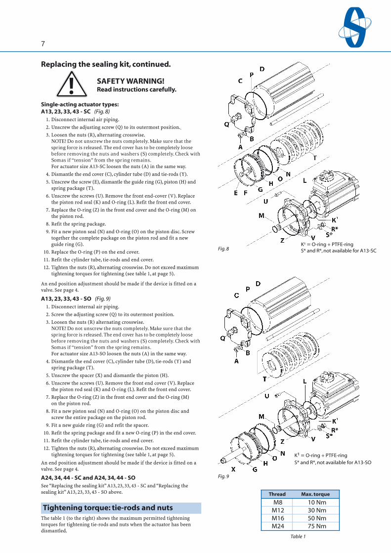
M8 10 Nm M12 30 Nm M16 50 Nm M24 75 Nm

6
Replacing the sealing kitDouble-acting actuator types:A11, 21, 31, 41, 51 - DA (Fig. 8) 1. Disconnect internal air piping. 2. Unscrew the nuts (A). Remove the washers (B) and the end cover (C). 3. Dismantle the cylinder tube (D). 4. Dismantle the screw (E), washer (F), guide ring (G) and piston (H). 5. Loosen the screws (I) and dismantle the seal retainer (J). 6. Replace the piston rod seal (K) and refit the seal retainer. 7. Replace the O-ring (L) in the housing end cover and the O-ring (M) on the piston rod. 8. Fit a new piston seal (N) and a new O-ring (O) on the piston disc (H). Screw together the complete package on the piston rod and fit a new guide ring (G). 9. Replace the O-ring (P) on the end cover. Refit the cylinder tube and end cover.A13, 23, 33, 43 - DA (Fig. 7) 1. Disconnect internal air piping. 2. Unscrew the nuts (A). Remove the washers (B) and the end cover (C). 3. Loosen the nuts (R). Dismantle the washers (S) the cylinder tube (D) and the tie-rods (Y). 4. Unscrew the screw (E). Dismantle the washer (F) and piston (H). 5. Unscrew the screws (U) and remove front end cover (V). 6. Replace the piston rod seal (K) and O-ring (L). 7. Refit the front end cover. 8. Replace the O-ring (Z) in the front end cover and the O-ring (M) on the piston rod. 9. Fit a new piston seal (N) and new O-ring (O) on the piston rod. 10. Screw together the complete package on the piston rod and fit a new guide ring (G). 11. Replace the new O-ring (P) in the end cover. 12. Refit the cylinder tube, tie-rods and end cover.
A22, 32, 42, 52 - DASee “Replacing the sealing kit” A11, 21, 31, 41, 51 - DA above.
A24, 34, 44 - DASee “Replacing the sealing kit” A11, 21, 31, 41, 51 - DA and “Replacing the sealing kit” A13, 23, 33, 43 - DA above.
Fig. 6
Fig. 7
K¹ = O-ring + PTFE-ring
K¹ = O-ring + PTFE-ring
S* and R*, not available for A13-DA
!
7
M8 10 Nm M12 30 Nm M16 50 Nm M24 75 Nm
Single-acting actuator types:A13, 23, 33, 43 - SC (Fig. 8) 1. Disconnect internal air piping. 2. Unscrew the adjusting screw (Q) to its outermost position. 3. Loosen the nuts (R), alternating crosswise. NOTE! Do not unscrew the nuts completely. Make sure that the spring force is released. The end cover has to be completely loose before removing the nuts and washers (S) completely. Check with Somas if “tension” from the spring remains. For actuator size A13-SC loosen the nuts (A) in the same way. 4. Dismantle the end cover (C), cylinder tube (D) and tie-rods (Y). 5. Unscrew the screw (E), dismantle the guide ring (G), piston (H) and spring package (T). 6. Unscrew the screws (U). Remove the front end-cover (V). Replace the piston rod seal (K) and O-ring (L). Refit the front end cover. 7. Replace the O-ring (Z) in the front end cover and the O-ring (M) on the piston rod. 8. Refit the spring package. 9. Fit a new piston seal (N) and O-ring (O) on the piston disc. Screw together the complete package on the piston rod and fit a new guide ring (G). 10. Replace the O-ring (P) on the end cover. 11. Refit the cylinder tube, tie-rods and end cover. 12. Tighten the nuts (R), alternating crosswise. Do not exceed maximum tightening torques for tightening (see table 1, at page 5).
An end position adjustment should be made if the device is fitted on a valve. See page 4.
A13, 23, 33, 43 - SO (Fig. 9) 1. Disconnect internal air piping. 2. Screw the adjusting screw (Q) to its outermost position. 3. Loosen the nuts (R) alternating crosswise. NOTE! Do not unscrew the nuts completely. Make sure that the spring force is released. The end cover has to be completely loose before removing the nuts and washers (S) completely. Check with Somas if “tension” from the spring remains. For actuator size A13-SO loosen the nuts (A) in the same way. 4. Dismantle the end cover (C), cylinder tube (D), tie-rods (Y) and spring package (T). 5. Unscrew the spacer (X) and dismantle the piston (H). 6. Unscrew the screws (U). Remove the front end cover (V). Replace the piston rod seal (K) and O-ring (L). Refit the front end cover. 7. Replace the O-ring (Z) in the front end cover and the O-ring (M) on the piston rod. 8. Fit a new piston seal (N) and O-ring (O) on the piston disc and screw the entire package on the piston rod. 9. Fit a new guide ring (G) and refit the spacer. 10. Refit the spring package and fit a new O-ring (P) in the end cover. 11. Refit the cylinder tube, tie-rods and end cover. 12. Tighten the nuts (R), alternating crosswise. Do not exceed maximum tightening torques for tightening (see table 1, at page 5).
An end position adjustment should be made if the device is fitted on a valve. See page 4.
A24, 34, 44 - SC and A24, 34, 44 - SOSee “Replacing the sealing kit” A13, 23, 33, 43 - SC and “Replacing the sealing kit” A13, 23, 33, 43 - SO above.
Fig. 8K¹ = O-ring + PTFE-ringS* and R*, not available for A13-SC
K¹ = O-ring + PTFE-ringS* and R*, not available for A13-SO
Fig. 9
Replacing the sealing kit, continued.
SAFETY WARNING! Read instructions carefully.
Tightening torque: tie-rods and nutsThe table 1 (to the right) shows the maximum permitted tightening torques for tightening tie-rods and nuts when the actuator has been dismantled.
Thread Max. torque
Table 1

8
Replacing the repair kit 1. Dismantle the actuator from the valve. 2. Dismantle the driver (B) by loosening the screws (A). If your actuator includes a positioner, dismantle the positioner/switch box and mounting block first. 3. Loosen the screws (C) and dismantle the cover (D). 4. Dismantle the screw (E) and lift up the pivot pin (F). 5. Twist the upper link arm (G) off of the lever and pull it out from the piston rod together with the swivel bolt (H). 6. Move the piston rod so that the whole lever can be lifted out of the housing and dismantle the lower link arm (L) from the lever. 7. Fit new bushings (I) in the cover (D) respective bottom of the housing. 8. Fit new O-rings (J) and new bushings (K) on the lever. 9. Fit the new lower link arm (L) with pivot pin (M) on the lever.Lock with the screw (N). NOTE! The position of the washers (see Fig. 11). 10. Fit the new pin bolt (H) and washer on the new upper link arm (G) and lock with locking ring (O). 11. Refit the lever in the actuator housing. 12. Align the piston rod and lower link arm with each other and insert the pin bolt through the piston rod. 13. Secure the upper link arm on the lever by inserting the pivot pin (F). NOTE! The right position for the washers is demon-strated in the drawing, see Fig. 11). Lock with screw (E). 14. Fit a new seal (P) and refit the cover and the driver.See “Replacing the sealing kit” on pages 6 and 7 to replace other parts in the repair kit. Note that when replacing the piston rod seal, the bushing in the housing end cover should be replaced. The bushing is included in the repair kit but not in the sealing kit.
Fig. 11
Fig. 10
Lever
Washer
Upper Linkarm
Washer
Washer
Washer
Swiwel bolt
Lower linkarm

9
It
em
N
o.
Des
crip
tio
n
1 Sc
rew
2
Dri
ver
5
Cov
er (f
rom
act
uat
or s
ize
3)
6
a Sc
rew
(fro
m a
ctu
ato
r siz
e 3)
6b
N
ut (
fro
m a
ctu
ato
r siz
e 3)
8
Cov
er
9 Sc
rew
10
G
aske
t
11
Bear
ing
12
O
-rin
g
13
Leve
r
14
Bush
ing
15
Lo
ckin
g ri
ng
16
W
ash
er
17
Swiv
el b
olt
18
Pi
vot p
in
19
Scre
w
20
Lin
k ar
m
It
em
N
o.
Des
crip
tio
n
21
Cla
mp
rin
g
22
Sc
rew
23
A
dju
stin
g s
crew
Nu
t
24
Ad
just
ing
Scr
ew
N
ut
25
Sc
rew
26
W
ash
er
27
End
cov
er
28
Gas
ket
29
H
ou
sin
g
31
Bear
ing
32
Pi
sto
n ro
d s
eal,
cpl.
33
Se
alin
g b
rack
et
34
Scre
w
35
O-r
ing
36
Ti
e ro
d
37
Cyl
ind
er tu
be
It
em
N
o.
Des
crip
tio
n
38
Pist
on
rod
39
O
-rin
g
40
Pist
on
sea
l
41
O-r
ing
42
Pi
sto
n
43
Gu
ide
rin
g
44
Was
her
45
Sc
rew
46
En
d c
over
47
W
ash
er
48
Nu
t
49
O-r
ing
50
Sc
rew
Seal
ing
kit (
A-D
A)
Item
No.
10,
28,
32,
35,
39,
40,
41
and
43.
Rep
air
kit (
A-D
A)
Item
No.
10,
11,
12,
14,
15,
16,
17,
18, 2
0, 2
8, 3
1, 3
2, 3
5, 3
9, 4
0, 4
1 an
d 4
3.
Actuator type DA

10
Seal
ing
kit (
A-S
C)
Item
No.
10,
28,
32,
35,
39,
40,
41
and
43.
Rep
air
kit (
A-S
C)
Item
No.
10,
11,
12,
14,
15,
16,
17,
18, 2
0, 2
8, 3
1, 3
2, 3
5, 3
9, 4
0, 4
1 an
d 4
3.
It
em
N
o.
Des
crip
tio
n
1 Sc
rew
2
Dri
ver
5
Cov
er (f
rom
act
uat
or s
ize
3)
6
a Sc
rew
(fro
m a
ctu
ato
r siz
e 3)
6b
N
ut (
fro
m a
ctu
ato
r siz
e 3)
8
Cov
er
9 Sc
rew
10
G
aske
t
11
Bear
ing
12
O
-rin
g
13
Leve
r
14
Bush
ing
15
Lo
ckin
g ri
ng
16
W
ash
er
17
Swiv
el b
olt
18
Pi
vot p
in
19
Scre
w
20
Lin
k ar
m
21
Cla
mp
rin
g (D
≤50
)
22
Scre
w
23
Ad
just
ing
scr
ew
N
ut
24
A
dju
stin
g s
crew
Nu
t
25
Scre
w
26
Was
her
27
En
d c
over
28
G
aske
t
29
Ho
usi
ng
It
em.
N
o.
Des
crip
tio
n
31
Bear
ing
32
Pi
sto
n ro
d s
eal,
cpl.
34
Sc
rew
35
O
-rin
g
36
Tie
rod
37
C
ylin
der
tub
e
38
Pist
on
rod
39
O
-rin
g
40
Pist
on
sea
l
41
O-r
ing
42
Pi
sto
n
43
Gu
ide
rin
g
44
Was
her
45
Sc
rew
46
En
d c
over
47
W
ash
er
48
Nu
t
49
O-r
ing
50
Sc
rew
52
Sp
rin
g k
it
53
Spac
er, e
nd
po
siti
on
Actuator type A-SC

11Se
alin
g ki
t (A
-SO
)
Item
No.
10,
28,
32,
35,
39,
40,
41
and
43.
Rep
air
kit (
A-S
O)
Item
No.
10,
11,
12,
14,
15,
16,
17,
18, 2
0, 2
8, 3
1, 3
2, 3
5, 3
9, 4
0, 4
1 an
d 4
3.
It
em
N
o.
Des
crip
tio
n
1 Sc
rew
2
Dri
ver
5
Cov
er (f
rom
act
uat
or s
ize
3)
6
a Sc
rew
(fro
m a
ctu
ato
r siz
e 3)
6b
N
ut (
fro
m a
ctu
ato
r siz
e 3)
8
Cov
er
9 Sc
rew
10
G
aske
t
11
Bear
ing
12
O
-rin
g
13
Leve
r
14
Bush
ing
15
Lo
ckin
g ri
ng
16
W
ash
er
17
Swiv
el b
olt
18
Pi
vot p
in
19
Scre
w
20
Lin
k ar
m
21
Cla
mp
rin
g
22
Sc
rew
23
A
dju
stin
g s
crew
Nu
t
24
Ad
just
ing
scr
ew
N
ut
25
Sc
rew
26
W
ash
er
27
End
cov
er
28
Gas
ket
29
H
ou
sin
g
It
em
N
o.
Des
crip
tio
n
31
Bear
ing
32
Pi
sto
n ro
d s
eal,
cpl.
34
Sc
rew
35
O
-rin
g
36
Tie
rod
37
C
ylin
der
tub
e
38
Pist
on
rod
39
O
-rin
g
40
Pist
on
sea
l
41
O-r
ing
42
Pi
sto
n
43
Gu
ide
rin
g
44
Was
her
45
Sc
rew
46
En
d c
over
47
W
ash
er
48
Nu
t
49
O-r
ing
50
Sc
rew
52
Sp
rin
g k
it
53
Spac
er, e
nd
po
siti
on
Actuator type A-SO

www.somas.se
12
A 32 – DA – 050 – F14 – H
SOMAS reserves the right to make changes to these instructions and specifications without prior notice.
Type designation, actuator type A
Representative
P.O. Box 107, SE-661 23 SÄFFLE, SWEDENPHONE: +46 533 167 00FAX: +46 533 141 36E-mail: [email protected]
Option E = ATEX design H = High temperature design HM = Hand operated LC = Locking device (closed position) V = Larger air connections X = Special design
Mounting pattern for valve attachment (according to ISO 5211)
Shaft diameter
Function: DA = Double-acting actuator SC = Single-acting actuator (spring to close) SO = Single-acting actuator (spring to open) SCL = Single-acting actuator (spring to close), low air supply design SOL = Single-acting actuator (spring to open), low air supply design
Actuator size according to the selection table
Actuator type
Material specification
Housing, cover, End cover: Aluminium (Duasolid painted)
Cylinder: Aluminium (Duasolid painted)
Tie rod: EN 1.4305
Piston seal: Carbon filled PTFE- + O-ring made of cold-resistant nitrile rubber
Screws/nuts: Stainless steel
Connection: Plastic tubing (standard)(between actuator Stainless steel tubing (option)and accessories)
Technical specificationSupply air: Dry and clean instrument air
Air supply: 4 - 8 bar
Rotary motion: Max 95° adjustable travel stops
Ambient – 40° to + 90° C (standard)temperature: (+ 120° C Option O-ring made of Viton)
Art
. No.
367
53