spring brake actuator catalog - rvautopark.com vehicle technology l00092 rev. 12/04 spring brake...
TRANSCRIPT

I n n o v a t i v e V e h i c l eT e c h n o l o g y
L00092Rev. 12/04
Spring Brake Actuator Catalog
Life Seal Gold Seal Midland 3030
Maxibrake Wedge Service

03-AC
TU
ATO
RS
ACTUATORS
PURPOSE OF THIS SECTION
This section is designed as a reference for Haldex Commercial Vehicle Systems air brake system components and accessories. Products described include all pertinent information needed to replace anOEM installed component or to help design an original installation.
DESIGN FLEXIBILITY
The products presented in this section are described by function and usage. Technical data and mountingconfigurations are also provided. Throughout this section, reference is made to numerous specific OEMapplications. This section is not, however, intended to be a mutually exclusive listing of all part numbersand designs available. Should the need for a design not presented occur, contact your HaldexCommercial Vehicle Systems Sales Representative for additional information.
WARRANTY INFORMATION
Proper service and repair are important to the safe, reliable operation of any motor vehicle. To preventpersonal injury and/or vehicle damage, careful and cautious service procedures recommended by thevehicle manufacturer should be followed by anyone servicing a motor vehicle. For details on warranty ofHaldex Commercial Vehicle Systems air brake system components and accessories, refer to L20221Aftermarket Warranty Policy. For warranty returns, use L90005 Warranty Adjustment Form.
ORDERING PROCEDUREU.S. Customers Contact: Canada Customers Contact:
Phone: 800-643-2374 Phone: 800-267-9247
Fax: 800-533-1941 Fax: 519-826-9497
Mail: Commercial Vehicle Systems Mail: Haldex LimitedNorth American Sales Division Canadian Distribution CentreAttn: Customer Service Department Attn: Customer Service Department10930 N. Pomona Avenue 525 Southgate Drive, Unit 1Kansas City, MO 64153-1297 Guelph, Ontario N1G 3W6
IMPORTANT NOTICE
The data listed herein is correct to the best of Haldex Brake Systems knowledge and belief, having beencompiled from reliable and official sources of information. However, HALDEX COMMERCIAL VEHICLESYSTEMS CANNOT ASSUME ANY RESPONSIBILITY for possible error or misapplication of the product.Final determination of the suitability of the products for the use contemplated by the Buyer is the sole responsibility of the Buyer. Haldex Brake Systems shall have no responsibility in connection with this suitability. It is not our intention to imply that any of the components in this catalog in connection with anengine make or model are made by any engine manufacturer.
Copyright 2004 by Haldex Commercial Vehicle Systems
North American Sales Division10707 N.W. Airworld Drive
Kansas City, MO 64153-1215
All rights reserved.Materials may only be reproduced with written permission of Haldex.
FOREWORD
03 - A

03-A
CT
UA
TOR
S
ACTUATORSTABLE OF CONTENTS
DESCRIPTIONPAGE
NUMBER
03 - B
SPRING BRAKE MODEL LISTINGS ..................................................................................................03-2HOW TO IDENTIFY HALDEX ANCHORLOK SPRING BRAKES .....................................................03-4HOW TO ORDER .................................................................................................................................03-6TECHNICAL DATA
GOLD SEAL COMBINATION / PIGGYBACK BRAKES................................................................03-8LIFE SEAL COMBINATION / PIGGYBACK BRAKES...................................................................03-9SERVICE CHAMBER BRAKES..............................................................................................03-10CLAMP STYLE COMBINATION / PIGGYBACK BRAKES..........................................................03-11WEDGE SERVICE CHAMBER COMBINATION / PIGGYBACK BRAKES.............................03-12MIDLAND STYLE COMBINATION / PIGGYBACK BRAKES .....................................................03-13ACTUATOR PRODUCT LINE COMPONENTS...........................................................................03-14SERVICE DIAPHRAGM PERFORMANCE CURVES.................................................................03-17SPRING FORCE CURVES..........................................................................................................03-21
SERVICE COMPONENTSWEDGE BRAKES.........................................................................................................................03-24S-CAM BRAKES (REMOTE UNIT)..............................................................................................03-25
MAXIBRAKE® SPRING BRAKESMAXIBRAKE® I (Service Sizes 20", 24", 30", 36")......................................................................03-26MAXIBRAKE® H-SERIES (Air/Hydr. Spring-Set Parking Brake) .................................................03-27MAXIBRAKE® HR-SERIES (Air/Hydraulic Pull-Type) ................................................................03-28MAXIBRAKE® 50-SERIES (Service Size 50") ..........................................................................03-29MAXIBRAKE® 50-SERIES (B Model Service Chamber) ............................................................03-30MAXIBRAKE® CAMTITE SERIES (Service Sizes 24", 30" and 36") ..........................................03-31MAXIBRAKE® R-SERIES (Air/Hydraulic Pull-Type)...................................................................03-32MAXIBRAKE® R-SERIES (Air/Hydraulic Push-Type).................................................................03-33
INSTALLATION AND SERVICE INSTRUCTIONSGENERAL SAFETY PRECAUTIONS..........................................................................................03-34RECOMMENDED PREVENTATIVE MAINTENANCE ................................................................03-37GOLD SEAL / MIDLAND MECHANICAL RELEASE OF SPRING BRAKE................................03-38LIFE SEAL / MIDLAND MECHANICAL RELEASE OF SPRING BRAKE ..................................03-41COMBINATION SPRING BRAKE INSTALLATION INSTRUCTIONS .....................................03-42PIGGYBACK INSTALLATION INSTRUCTIONS .....................................................................03-47ROTATING MOUNTING BOLTS, CLAMPS AND/OR INLET PORTS.....................................03-49SERVICE DIAPHRAGM REPLACEMENT..............................................................................03-50
DISARMING PROCEDURESPIGGYBACK AND COMBINATION SERVICE / SPRING BRAKES .........................................03-51
ORANGE ALERT STROKE INDICATOR OPERATION ...............................................................03-52DETERMINING WARRANTY STATUS / INTERPRET DATE CODES.............................................03-53CORRECTIVE ACTION FORM..........................................................................................................03-54

03-AC
TU
ATO
RS
03 - 1
ACTUATORS
IMPORTANT:Used without the safety alert symbol, is used as a reminder of an instruction where the concerns dealwith product integrity and have to do with installation, operation, maintenance or service and care ofthe product. It is intended to show that vehicle breakdown and/or expensive repair could result if theinstruction is not followed.
WARNING:Is used with an instruction for the purpose of showing that a safe practice must be adhered to or thatan unsafe practice must be avoided, and that if proper precautions are not taken, personal injury couldresult.
DANGER:Indicates a potentially hazardous situation which, if not avoided, may result in serious injury ordeath.
NOTE:Is used as a reminder of an instruction where the concern deals with product integrity and has to do with installation, operation, maintenance or service and care of the product.
Throughout this manual, you will notice the terms “NOTE”, “IMPORTANT”, “WARNING”, and “DANGER”followed by important product information. So that you may better understand the manual, those terms aredefined below. The warns of the possibility of personal injury or death.
TERMS

MODEL PART NUMBERS LP2430 LP3030
LP2430L LP3030L
03-A
CT
UA
TOR
S
03 - 2
ACTUATORS
GOLD SEAL MODELS
MODEL PART NUMBERS GC2024 GC2424 GC2430 GC3030 GC3036 GC3636
GC2424L GC2430L GC3030L GC3036L
GC2430XL
MODEL PART NUMBERS GP1624 GP2430 GP3030
GP2024 GP2430L GP3036
GP2424 GP2430XL GP3636
GP2424L GP3036L GP3030L
FEATURES:• Fully Threaded Push Rod• Orange Alert Stroke Indicator• Piloting Diaphragm• Piloting Dust Shield• Epoxy Powder Coated Spring &
Housing• Zinc Plated Spring Chamber -
permanently attached for safety• 4 Year Unlimited Mileage Warranty
SEALED COMBINATION (GC) SEALED PIGGYBACK (GP)
LIFE SEAL MODELS
MODEL PART NUMBERS LC2430 LC2430L LC3030 LC3030L
SEALED PIGGYBACK (LP)
FEATURES:• Emergency Spring Chamber is completely
sealed• Integral Caging Tool• Guided Pressure Plate/Compression
Spring Design• Zinc Plated Spring Chamber - permanently
attached for safety• 6 year Unlimited Mileage Brake Warranty
LIFE SEAL AND GOLD SEAL MODEL STROKE LENGTHS
SEALED COMBINATION (LC)
GOLD SEAL MODELS
MODEL PART NUMBERS STROKE (in) STROKE (mm)
GP1624 2.25 in 57 mm
GC2024 2.25 in 57 mm
GC2424 2.25 in 57 mm
GC2424L 2.50 in 64 mm
GC2430 2.25 in 57 mm
GC2430L 2.50 in 64 mm
GC2430XL 3.00 in 76 mm
GC3030 2.50 in 64 mm
GC3030L 3.00 in 76 mm
GC3036 2.50 in 64 mm
GC3036L 3.00 in 76 mm
GC3636 3.00 in 76 mm
LIFE SEAL MODELS
MODEL PART NUMBERS STROKE (in) STROKE (mm)
LC2430 2.50 in 64 mm
LC2430L 3.00 in 76 mm
LC3030 2.50 in 64 mm
LC3030L 3.00 in 76 mm
SPRING BRAKE MODELS

03-AC
TU
ATO
RS
03 - 3
ACTUATORS
MODEL PART NUMBERS CC2024 CC2424 CC2430 CC3030
MODEL PART NUMBERS CP1624 CP2024 CP2424 CP2430CP3030
CLAMP MODELSCLAMP COMBINATION (C)
FEATURES:• Fully Threaded
Push Rod• Orange Alert Stroke
Indicator• Piloting Dust Shield• Piloting Diaphragm
WEDGE MODELS
CLAMP PIGGYBACK (P)
FEATURES:• Epoxy Powder
Coated Spring & Spring Chamber
• Piloting Diaphragm• Welded Safety
Hooks• 2 Year Unlimited
Mileage Warranty
MODEL PART NUMBERS SC9 SC12 SC16 SC16L SC20 SC20LSC24 SC24L SC24XL SC30 SC30L SC36R30*R30-1 w/o cable*
* Remote mounted units, see page 24.
FEATURES:• Fully Threaded
Push Rod• Orange Alert
Stroke Indicator• Piloting Dust
Shield• 3 Year Unlimited
Mileage Warranty
CLAMP SERVICE (S)
FEATURES:• Available in Multiple
Tube Lengths for Bendix or Rockwell Wedge Brakes
• Epoxy Powder Coated Spring
• Corrosion Resistant A-360 Aluminum
MODEL PART NUMBERS 0912SB 0916SB 1212SB 1216SB
CLAMP COMBINATION (SB) CLAMP PIGGYBACK (PB)
FEATURES:• Epoxy Powder
Coated Spring• Corrosion
Resistant A-360 Aluminum
• Safety Hooks on Spring Chamber
• 2 Year Unlimited Mileage Warranty
MODEL PART NUMBERS 0912PB 0916PB 1212PB 1216PB
CLAMP SERVICE CHAMBER (SD)
MODEL PART NUMBERS 09SD 12SD
FEATURES:• Available in Multiple
Tube Lengths for Bendix or Rockwell Wedge Brakes
• Zinc Plated, Epoxy Powder Coat andAluminum A-360 Corrosion Protection
• 2 Year Unlimited Mileage Warranty
SERVICE AND WEDGE BRAKE MODEL STROKE LENGTHSWEDGE BRAKE MODELS
MODEL PART NUMBERS STROKE (in) STROKE (mm)
09SD 1.75 in 44 mm
12SD 1.75 in 44 mm
0912SB 1.75 in 44 mm
0916SB 1.75 in 44 mm
1212SB 1.75 in 44 mm
1216SB 1.75 in 44 mm
SERVICE BRAKE MODELS
MODEL PART NUMBERS STROKE (in) STROKE (mm)
SC9 1.75 in 44 mm
SC12 1.75 in 44 mm
SC16 2.25 in 57 mm
SC16L 2.50 in 64 mm
SC20 2.25 in 57 mm
SC20L 2.50 in 64 mm
SC24 2.25 in 57 mm
SC24L 2.50 in 64 mm
SC24XL 3.00 in 76 mm
SC30 2.50 in 64 mm
SC30L 3.00 in. 76 mm
SC36 3.00 in. 76 mm
CLAMP AND WEDGE BRAKE MODELS
• Epoxy Powder Coated Spring, Housing & Spring Chamber
• Welded Safety Hooks• 2 Year Unlimited Mileage Warranty
• Safety Hooks on Spring Chamber• 2 Year Unlimited Mileage Warranty
03-A
CT
UA
TOR
S
03 - 4
ACTUATORS
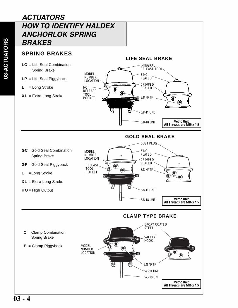
LC = Life Seal Combination Spring Brake
LP = Life Seal Piggyback
L = Long Stroke
XL = Extra Long Stroke
SPRING BRAKES
GOLD SEAL BRAKE
CLAMP TYPE BRAKE
LIFE SEAL BRAKE
5/8-11 UNC
3/8 NPTF
MODELNUMBERLOCATION
5/8-18 UNF
CRIMPEDSEALED
C = Clamp CombinationSpring Brake
P = Clamp Piggyback
GC = Gold Seal Combination Spring Brake
GP = Gold Seal Piggyback
L = Long Stroke
XL = Extra Long Stroke
HO= High Output
Metric Unit:All Threads are M16 x 1.5
INTEGRALRELEASE TOOLZINC PLATED
NORELEASETOOLPOCKET
5/8-11 UNC
3/8 NPTF
MODELNUMBERLOCATION
5/8-18 UNF
CRIMPEDSEALED
Metric Unit:All Threads are M16 x 1.5
DUST PLUG
ZINC PLATED
5/8-11 UNC
3/8 NPTF
MODELNUMBERLOCATION
5/8-18 UNF
SAFETYHOOK
Metric Unit:All Threads are M16 x 1.5
EPOXY COATEDSTEEL
RELEASETOOLPOCKET
HOW TO IDENTIFY HALDEXANCHORLOK SPRING BRAKES

03-AC
TU
ATO
RS
03 - 5
ACTUATORSHOW TO IDENTIFY HALDEXANCHORLOK SPRING BRAKES
Measure "Y" dimension (tubelength) from the end of the tube to the flat in the housing.
5/8-11 UNC
CAST ALUMINUM
3/8 NPTF
3/8 NPTF
MODEL NUMBERLOCATION
MODEL NUMBERLOCATION
CAST ALUMINUM
3/8 NPTFMODELNUMBER LOCATION
5/8-18 UNFMetric Unit:
All Threads are M16 x 1.5
Tube Threads:All Threads are 1 3/4-12
Tube Threads:All Threads are 1 3/4-12
Tube Threads:All Threads are 1 3/4-12
EPOXY COATEDSTEEL
SERVICE BRAKESS = Clamp Service Brake
L = Long Stroke
R = Remote Mount
SB = Wedge Clamp Combination Spring Brake
PB = Wedge Clamp Piggyback
WEDGE CLAMP BRAKES
SD = Wedge Clamp Service ChamberWEDGE SERVICE BRAKES
PUSHRODS
BENDIX ROCKWELL
PUSHRODS
BENDIX ROCKWELL
WEDGE BRAKE TUBE LENGTH MEASUREMENT
For ordering information and available tube lengths - see page 7.
TUBE LENGTHMEASUREMENT
TUBE LENGTHMEASUREMENT
Nomenclature TablePrefix Suffix
SC Service Chamber GPGold Seal Piggyback K Piggyback Kit XHD Extra Heavy DutyCC Clamp Style Combination LC Life Seal Combination L Long Stroke Q 3/4” Push RodCP Clamp Style Piggyback LP Life Seal Piggyback XL Extra Long Stroke Pxx Package xx SizeMC Midland Combination CS Clevis, Stamped B Dust Boot or BulkMP Midland Piggyback CF Clevis, Forged M MetricGC Gold Seal Combination HD Heavy Duty HO High Output

03-A
CT
UA
TOR
S
03 - 6
ACTUATORS
Life
Sea
l
Life
Sea
lPi
ggyb
ack
Rem
ote
See pages 8-12 for selected Haldex Anchorlok Model Part Numbers.Referring to Table I above, the following is astep-by-step example of how to determine aHaldex Anchorlok Brake Model Type.
S-CAM / AIR DISC BRAKES
TABLE I
9 1.75 44 12 1.75 44 16 2.25 57 16 2.50 64 20 2.25 57 20 2.50 64 24 2.25 57 24 2.50 64 24 3.00 76 30 2.50 64 30 3.00 76 36 3.00 76
1624 2.25 57 2024 2.25 57 2030 3.00 76 2424 2.25 57 2424 2.50 64 2430 2.50 64 2430 3.00 76 3030 2.50 64 3030 3.00 76 3036 2.50 64 3036 3.00 76 3636 3.00 76
HOW TO ORDER
Size / Type
Mode
l
inch mm
Avail
able
Stro
ke
Serv
ice
Clam
p St
yle
Clam
p St
ylePi
ggyb
ack
Gold
Sea
l
Gold
Sea
lPi
ggyb
ack
Midl
and
3/4” P
ush
Rod
Optio
n
Heav
y Dut
yRe
turn
Spr
ing
Optio
n
Metri
c Thr
ead
Optio
n
S R LC LP C P GC GP MAxxxxxxxxxx xxx
x xx x x x
x xx x x x
x xx x x xx x x xx x x x x x xx x x x
x xx xx x
xxx
x xx xx x
xxxxx
x xx
x x xx xx xx xx x
x = Available
OPTION CODE DEFINITIONS:
1 This is the desired style (refer to page 2 for descriptions). This information is required. The example is a LifeSeal combination unit.
2 This is the size of the unit in square inches of effective area. 2 digits are used for a service only chamber. 4 digits are used for combination service and emergency units. This information is required. In this example 24is the service side square inch area and 30 is the emergency side.
3 This feature is optional where indicated. Please refer to the Technical Data Section for further information onLong Stroke (L) or Extra Long Stroke (XL) units.
4 Optional feature, HD designates Heavy Duty Return Spring and/or Heavy Duty Housing Assembly. Notapplicable on GP and P Units.
5 Optional feature, HO designates High Output main compression spring.6 “M” denotes Metric push rod, mounting studs and air inlet port threads. All of which are M16 x 1.5 - 6g.
Spring brakes may have a combination of both standard and metric threads.
EXAMPLE: LC 24 30 - L - HD - HO -M1 2 3 4 5 6

03-AC
TU
ATO
RS
03 - 7
ACTUATORS
HOW TO ORDER
1 2 3 4TUBE LENGTHS
(LISTED TUBE LENGTHS ARE AVAILABLE FOUNDATION BRAKE STYLESB PB SD FOR ALL WEDGE BRAKES) B (BENDIX) R (ROCKWELL)
09 X 2.25" 6.00"
0912 X X 3.00" 7.00"
0916 X X 3.50" 7.88"
12 X 4.00" 9.38"
1212 X X 4.50" 10.20"
1216 X X 5.00" 14.50"
X = Available
WEDGE BRAKES
CODE DEFINITIONS:1 This is the size of the unit in square inches of effective area. 2 digits are used for a service only
chamber. 4 digits indicate a combination service/spring brake with the first 2 digits indicating the service side size and the last 2 digits indicating the emergency side size.
2 This is the desired style (refer to page 3 for description). 3 Tube length (SB & SD only). All lengths listed are available for all sizes listed. 3 or 4 digits are
required, based on desired length. Drop the decimal point. Example is 3.00” (refer to page 5 for `how to measure tube).
4 R = Rockwell, B = Bendix, type foundation brakes. This information is required on SB & SD units only.
SPRING BRAKE AVAILABLE OPTIONS:HEAVY DUTY RETURN SPRING - TABLE I Item 4, Option Code 5
The heavy duty return spring is a high output spring (100 lb.) used primarily with Kelsey-Hayes (Gunite), Bendix and BFGoodrich disc brakes. It is standard on 36S and 3636GC.
3/4" PUSH ROD - TABLE I Item 3, Option Code 43/4 -12 UNF threaded push rod. Longer push rods are also available at additional cost. Consult Haldex Anchorlokapplications engineering for additional information.
DUST BOOT ASSEMBLY - Available separately, recommended for applications involving high amounts of potential environmental contaminants.
METRIC THREADS - TABLE I Item 5, Option Code 6Push rod, mounting studs and air inlet port threads are all M16 x 1.5 - 6 g. Spring brakes may have a combinationof both standard and metric threads.
HIGH OUTPUT COMPRESSION SPRING - Available on select models to increase spring force output.
EXAMPLE:1216 - SB - 300 - R1 2 3 4
Referring to Table II above, thefollowing is a step-by-step exampleof how to determine an HaldexAnchorlok Wedge Brake Model Type.
WED
GE C
LAMP
COMB
INAT
ION
WED
GE C
LAMP
PIGG
YBAC
K
WED
GE C
LAMP
SERV
ICE
MODELTYPE
B=BENDIX
R=ROCKWELL
See pages 8-12 for selected Haldex Anchorlok Model Part Numbers.
TABLE II

03-A
CT
UA
TOR
S
03 - 8
ACTUATORS
Model AvailableSize / Stroke Service SpringType inch mm C.U.IN. C.U.IN.
1624 2.25 57 NA 72.5 2024 2.25 57 53.0 72.5 2030 3.00 76 92.0 116.4 2424 2.25 57 63.0 72.5 2424 2.50 64 69.5 86.9 2430 2.50 64 69.5 103.5 2430 3.00 76 92.0 116.4 3030 2.50 64 87.5 97.0 3030 3.00 76 92.0 116.4 3036 2.50 64 87.5 145.0 3036 3.00 76 109.0 167.0 3636 3.00 76 128.0 145.0
inch mm inch mm inch mm inch mm inch mm inch mm
NA NA 6.3 160 5.9 150 7.5 191 NA NA NA NA8.5 216 6.3 160 5.9 150 7.5 191 8.9 226 6.5 165 9.6 244 7.8 198 6.3 160 8.3 211 9.4 239 7.1 180 8.5 216 6.3 160 5.9 150 7.5 191 9.6 244 7.1 180 8.9 226 5.4 137 5.4 137 7.4 188 9.2 234 7.1 180 9.0 229 6.7 170 6.3 160 8.4 213 9.3 236 7.1 180 9.6 244 7.8 198 6.6 168 8.3 211 9.4 239 7.1 180 9.0 229 6.7 170 6.3 160 8.3 211 9.2 234 7.8 198 9.5 241 7.2 183 6.3 160 8.3 211 10.2 259 7.8 198 9.6 244 7.3 185 7.2 183 9.2 234 9.7 246 7.8 198 10.9 277 8.5 216 7.2 183 8.2 208 9.1 231 7.8 198 10.4 264 8.0 203 7.2 183 9.4 239 11.2 284 8.7 221
A B C D E F
lbs kg lbs kg
10.0 4.5 NA NA10.3 4.7 17.0 7.7 18.9 8.6 21.9 9.9 10.5 4.8 17.5 7.9 11.0 5.0 18.0 8.2 12.1 5.5 19.9 9.0 18.9 8.6 21.9 9.9 11.8 5.4 19.6 8.9 12.3 5.6 20.6 9.3 15.7 7.1 26.0 11.8 15.7 7.1 26.0 11.8 16.4 7.4 26.0 11.8
Mass Mass Piggyback Combination
GOLD SEAL COMBINATION /PIGGYBACK BRAKES
Gold Seal (GC - Combination, GP - Piggyback)
Stud Spacing (G): 4.75" - 121 mm Push Rod Thread: 5/8 x 18 UNFStud Type: 5/8 x 11 UNC Grade 5 Air Port Threads: 3/8 x 18 NPTFStud Length: 1.50" - 38 mm
Model T (PA) SI (SCA)Size / Qty per Port Service Type inch mm Combination Piggyback Pack J (inches) K (inches) Angle ** Clamp Angle**
1624 2.25 57 NA GP1624 2 NA NA NA NA2024 2.25 57 GC2024 GP2024 2 9.68 NA 90 ° 0 °2424 2.25 57 GC2424 GP2424 2 9.65 NA 90 ° 0 °2424 2.50 64 GC2424L GP2424L 2 9.50 NA 90 ° 0 °2430 2.50 64 GC2430L GP2430L 2 9.50 NA 90 ° 0 °2430 3.00 76 GC2430XL GP2430XL 1 8.60 NA 90 ° 0 °3030 2.50 64 GC3030 GP3030 2 10.00 NA 90 ° 0 °
GC3030R NA 1 14.00 NA 90 ° 0 °GC3030P40 GP3030P40 40 10.00 NA 90 ° 0 °
3030 3.00 76 GC3030L GP3030L 2 10.00 NA 90 ° 0 °GC3030LR NA 1 14.00 NA 90 ° 0 °GC3030LP40 GP3030LP40 40 10.00 NA 90 ° 0 °
3036 2.50 64 GC3036 GP3036 2 9.44 NA 90 ° 0 °3036 3.00 76 GC3036L GP3036L 2 9.00 NA 90 ° 0 °3636 3.00 76 GC3636 GP3636 2 10.00 NA 90 ° 0 °
With Clevis, Stamped (CS)
3030 2.50 64 GC3030CS NA 1 10.00 11.25 90 ° 0 °GC3030CSP40 NA 40 10.00 11.25 90 ° 0 °
With Clevis, Forged (CF)
3030 2.50 64 GC3030CF NA 1 10.00 11.25 90 ° 0 °GC3030CFP40 NA 40 10.00 11.25 90 ° 0 °
With Clevis, Forged (CF) and Push Rod Dust Boot (B)
3030 2.50 64 GC3030CFB NA 1 10.00 11.25 90 ° 0 °GC3030CFBP40 NA 40 10.00 11.25 90 ° 0 °
Gold Seal Piggyback Kits (K) (Piggyback, Diaphragm and Clamp Assembly)
3030 2.50 64 NA GP3030K 1 NA NA NA NANA GP3030KP40 40 NA NA NA NA
3030 3.00 76 NA GP3030LK 1 NA NA NA NANA GP3030LKP40 40 NA NA NA NA
AvailableStroke
AftermarketPart Number Push Rod Length**
C
J-Face of the stud housing to the tip of the service push rodK-Face of the stud housing to the center of the main clevis pinA-Length of the chamber from face of the stud housing to the end of spring housingB-Length of piggyback center body to end of spring housingC-Dimension at spring housing
BA
JK
G
** Applies to combination assemblies only.
ED
D-Dimension at Rolled SealE-Dimension at Service Clamp BandF-Dimension of Service DiaphragmNote: Angles are measured counter-clockwise with the studs inthe vertical position and viewed fromthe spring housing
F
SERVICE DIAPHRAGMT SI

03-AC
TU
ATO
RS
03 - 9
ACTUATORS
Model AvailableSize / Stroke Service SpringType inch mm C.U.IN. C.U.IN.
2430 2.50 64 69.5 97.0 2430 3.00 76 116.4 100.0 3030 2.50 64 90.5 97.0 3030 3.00 76 116.4 100.0
inch mm inch mm inch mm inch mm inch mm inch mm
9.6 244 7.2 183 6.6 168 8.3 211 9.2 234 7.1 180 9.8 249 7.4 188 6.6 168 8.3 211 9.2 234 7.1 180 8.9 226 6.7 170 6.6 168 8.3 211 9.2 234 7.8 198 9.8 249 7.2 183 6.6 168 8.3 211 9.2 234 7.8 198
A B C D E F
lbs kg lbs kg
12.1 5.5 19.5 8.8 12.5 5.7 20.9 9.5 12.9 5.9 20.7 9.4 13.1 5.9 21.7 9.8
Mass Mass Piggyback Combination
LIFE SEAL COMBINATION /PIGGYBACK BRAKES
Stud Spacing (G): 4.75" - 121 mm Push Rod Thread: 5/8 x 18 UNFStud Type: 5/8 x 11 UNC Grade 5 Air Port Threads: 3/8 x 18 NPTFStud Length: 1.50" - 38 mm
Life Seal (LC - Combination, LP - Piggyback)Model T (PA) SI (SCA)Size / Qty per Port Service Type inch mm Combination Piggyback Pack J (inches) K (inches) Angle ** Clamp Angle**
2430 2.50 64 LC2430 LP2430 1 9.50 NA 90 ° 0 °2430 3.00 76 LC2430L LP2430L 1 8.62 NA 90 ° 0 °3030 2.50 64 LC3030 LP3030 1 10.00 NA 90 ° 0 °
LC3030R NA 1 14.00 NA 90 ° 0 °LC3030P40 LP3030P40 40 10.00 NA 90 ° 0 °
3030 3.00 76 LC3030L LP3030L 1 10.00 NA 90 ° 0 °LC3030LR NA 1 14.00 NA 90 ° 0 °LC3030LP40 LP3030LP40 40 10.00 NA 90 ° 0 °
Life Seal Piggyback Kits (K) (Piggyback, Diaphragm and Clamp Assembly)
3030 2.50 64 NA LP3030K 1 NA NA NA NANA LP3030KP40 40 NA NA NA NA
3030 3.00 76 NA LP3030LK 1 NA NA NA NANA LP3030LKP40 40 NA NA NA NA
AvailableStroke
AftermarketPart Number Push Rod Length**
J-Face of the stud housing to the tip of the service push rodK-Face of the stud housing to the center of the main clevis pinA-Length of the chamber from face of the stud housing to the end of spring housingB-Length of piggyback center body to end of spring housingC-Dimension at spring housing
** Applies to combination assemblies only.
C
BA
JK
G
ED
D-Dimension at Rolled SealE-Dimension at Service Clamp BandF-Dimension of Service DiaphragmNote: Angles are measured counter-clockwise with the studs inthe vertical position and viewed fromthe spring housing
F
SERVICEDIAPHRAGM
T SI

03-A
CT
UA
TOR
S
03 - 10
ACTUATORS
Model AvailableSize / Stroke Service SpringType inch mm C.U.IN. C.U.IN.
9 1.75 44 16.0 NA12 1.75 44 24.0 NA16 2.25 57 39.0 NA16 2.50 64 52.3 NA20 2.25 57 51.3 NA20 2.50 64 61.0 NA24 2.25 57 67.0 NA24 2.50 64 69.5 NA24 3.00 76 85.0 NA30 2.50 64 87.6 NA30 3.00 76 92.0 NA36 3.00 76 136.4 NA
R30 2.50 64 82.0 NA
inch mm inch mm inch mm inch mm inch mm inch mm
4.4 112 NA NA 4.0 102 NA NA 5.6 142 5.5 140 3.7 94 NA NA 4.0 102 NA NA 7.7 196 5.5 140 4.6 117 NA NA 4.6 117 NA NA 8.3 211 6.2 157 4.7 119 NA NA 6.5 165 NA NA 6.5 165 6.3 160 4.0 102 NA NA 7.0 178 NA NA 8.9 226 6.5 165 4.7 119 NA NA 6.9 175 NA NA 6.9 175 6.6 168 4.3 109 NA NA 7.5 191 NA NA 9.3 236 7.1 180 4.4 112 NA NA 7.5 191 NA NA 9.3 236 7.1 180 4.7 119 NA NA 7.4 188 NA NA 7.4 188 7.0 178 4.2 107 NA NA 8.2 208 NA NA 9.3 236 7.8 198 4.1 104 NA NA 8.2 208 NA NA 9.8 249 7.8 198 4.8 122 NA NA 9.3 236 NA NA 10.8 274 8.7 221 4.9 124 NA NA 8.2 208 NA NA 8.3 211 7.8 198
A B C D E F
lbs kg lbs kg
NA NA 4.4 2.0 NA NA 5.2 2.4 NA NA 5.7 2.6 NA NA 6.8 3.1 NA NA 8.0 3.6 NA NA 7.0 3.2 NA NA 8.5 3.9 NA NA 8.5 3.9 NA NA 9.1 4.1 NA NA 9.5 4.3 NA NA 8.7 3.9 NA NA 13.0 5.9 NA NA 12.5 5.7
Mass Mass Piggyback Combination
Type 9, 12 and 16 2.25" StrokeStud Spacing (G): 3.00" - 76 mm Push Rod Thread: 1/2 x 20 UNFStud Type: 7/16 x 14 UNC Grade 5 Air Port Threads: 3/8 x 18 NPTFStud Length: 1.12" - 28 mm
All othersStud Spacing (G): 4.75" - 121 mm Push Rod Thread: 5/8 x 18 UNFStud Type: 5/8 x 11 UNC Grade 5 Air Port Threads: 3/8 x 18 NPTFStud Length: 1.50" - 38 mm
Service Chamber (SC - Combination SP - Piggyback)Model T (PA) SI (SCA)Size / Qty per Port Service Type inch mm Pack J (inches) K (inches) Angle Clamp Angle
09 1.75 44 SC09 2 10.43 NA 0 ° 135 °12 1.75 44 SC12 2 10.41 NA 90 ° 45 °16 2.25 57 SC16 2 9.52 NA 90 ° 45 °16 2.50 64 SC16L 1 10.00 NA 0 ° 0 °20 2.25 57 SC20 2 10.15 NA 90 ° 45 °20 2.50 64 SC20L 1 10.00 NA 0 ° 0 °24 2.25 57 SC24 2 10.23 NA 90 ° 45 °24 2.50 64 SC24L 2 9.47 NA 90 ° 45 °24 3.00 76 SC24XL 1 10.00 NA 0 ° 0 °30 2.50 64 SC30 2 10.34 NA 90 ° 0 °30 3.00 76 SC30L 1 10.00 NA 0 ° 0 °36 3.00 76 SC36 2 8.00 NA 90 ° 0 °
R30 2.50 64 R30 1 NA 90 ° 0 °
AvailableStroke Aftermarket
Part NumberPush Rod Length
SERVICE CHAMBER BRAKES
C
AJ
K
G
E
SERVICEDIAPHRAGM
F
J-Face of the stud housing to the tip of the service push rodK-Face of the stud housing to the center of the main clevis pinA-Length of the chamber from face of the stud housing to the end of spring housingB-Length of piggyback center body to end of spring housingC-Dimension at spring housing
D-Dimension at Rolled SealE-Dimension at Service Clamp BandF-Dimension of Service DiaphragmNote: Angles are measured counter-clockwise with the studs inthe vertical position and viewed fromthe pressure housing
T
SI

03-AC
TU
ATO
RS
03 - 11
ACTUATORSCLAMP STYLE COMBINATION /PIGGYBACK BRAKES
Model AvailableSize / Stroke Service SpringType inch mm C.U.IN. C.U.IN.
1624 2.25 57 NA 78.9 2024 2.25 57 53.0 78.9 2424 2.25 57 63.0 78.9 2430 2.50 64 63.0 99.3 3030 2.50 64 87.5 103.0
inch mm inch mm inch mm inch mm inch mm inch mm
NA NA 6.3 160 6.0 152 NA NA 9.4 239 NA NA8.5 216 6.3 160 6.0 152 NA NA 9.4 239 6.5/7.1 165/180 8.6 218 6.3 160 6.0 152 NA NA 9.4 239 7.1 180 8.6 218 6.3 160 6.3 160 NA NA 10.2 259 7.1/7.9 180/201 8.9 226 6.8 173 6.3 160 NA NA 10.2 259 7.9 201
A B C D E F*
lbs kg lbs kg
10.5 4.8 NA NA10.6 4.8 17.4 7.9 10.5 4.8 17.9 8.1 11.5 5.2 17.5 7.9 13.2 6.0 20.9 9.5
Mass Mass Piggyback Combination
Stud Spacing (G): 4.75" - 121 mm Push Rod Thread: 5/8 x 18 UNFStud Type: 5/8 x 11 UNC Grade 5 Air Port Threads: 3/8 x 18 NPTFStud Length: 1.50" - 38 mm
Clamp Style (CC - Combination CP - Piggyback)Model T (PA) SI (SCA)Size / Qty per Port Service Type inch mm Combination Piggyback Pack J (inches) K (inches) Angle** Clamp Angle**
1624 2.25 57 NA CP1624 2 NA NA NA NA2024 2.25 57 CC2024 CP2024 2 9.68 NA 90 ° 0 °2424 2.25 57 CC2424 CP2424 2 9.65 NA 90 ° 0 °2430 2.25 57 CC2430 CP2430 2 9.44 NA 90 ° 0 °3030 2.50 64 CC3030 CP3030 2 9.44 NA 90 ° 0 °
AvailableStroke
AftermarketPart Number
Push Rod Length**
*The first dimension is for Service Side and the second dimension is for the Emergency Side
** Applies to combination assemblies only.
C
BA
JK
G
ED
SERVICEDIAPHRAGM
F
J-Face of the stud housing to the tip of the service push rodK-Face of the stud housing to the center of the main clevis pinA-Length of the chamber from face of the stud housing to the end of spring housingB-Length of piggyback center body to end of spring housingC-Dimension at spring housing
D-Dimension at Rolled SealE-Dimension at Emergency Clamp BandF-Dimension of Service DiaphragmNote: Angles are measured counter-clockwise with the studs in thevertical position and viewed from thespring housing
T
SI

03-A
CT
UA
TOR
S
03 - 12
ACTUATORSWEDGE SERVICE CHAMBERCOMBINATION / PIGGYBACKBRAKES
Model AvailableSize / Stroke Service SpringType inch mm C.U.IN. C.U.IN.
0912 0.75 19 25.0 26.5 1212 1.75 44 28.8 28.1 0916 1.75 44 25.9 39.6 1216 1.75 44 31.0 38.8
inch mm inch mm inch mm inch mm inch mm inch mm
6.4 163 4.9 124 4.8 122 NA NA 7.8 198 5.1/5.5 130/140 6.3 160 5.0 127 4.8 122 NA NA 7.8 198 5.5 140 7.1 180 5.7 145 5.7 145 NA NA 8.4 213 5.1/6.1 130/155 7.0 178 5.7 145 5.7 145 NA NA 8.4 213 5.5/6.1 140/155
A B C D E F*
lbs kg lbs kg
5.9 2.7 13.0 5.9 6.0 2.7 14.0 6.4 8.0 3.6 13.0 5.9 9.0 4.1 17.0 7.7
Mass Mass Piggyback Combination
Model AvailableSize / Stroke Service SpringType inch mm C.U.IN. C.U.IN.
09 1.75 44 22.5 NA12 1.75 44 28.6 NA
inch mm inch mm inch mm inch mm inch mm inch mm
2.6 66 NA NA 3.3 84 NA NA 7.0 178 5.0 127 2.6 66 NA NA 4.0 102 NA NA 7.6 193 5.5 140
A B C D E F*
lbs kg lbs kg
NA NA 3.0 1.4 NA NA 4.2 1.9
Mass Mass Piggyback Combination
*The first dimension is for Service Side and the second dimension is for the Emergency Side
Wedge Double Diaphragm
SERVICEDIAPHRAGM
C
A
E F
B
Wedge Service Chambers
*The first dimension is for Service Side and the second dimension is for the Emergency Side
D-Dimension at Rolled SealE-Dimension at Service Clamp BandF-Dimension of Service DiaphragmNote: Angles are measured counter-clockwise with the studs inthe vertical position and viewed fromthe spring housing
J-Face of the stud housing to the tip of the service push rodK-Face of the stud housing to the center of the main clevis pinA-Length of the chamber from face of the stud housing to the end of spring housingB-Length of piggyback center body to end of spring housingC-Dimension at spring housing

03-AC
TU
ATO
RS
03 - 13
ACTUATORSMIDLAND STYLE COMBINATION/ PIGGYBACK BRAKES
Model AvailableSize / Stroke Service SpringType inch mm C.U.IN. C.U.IN.
3030 2.50 64 87.5 97.0
inch mm inch mm inch mm inch mm inch mm inch mm
9.0 229 6.7 170 6.3 160 8.3 211 9.2 234 7.8 198
A B C D E F
lbs kg lbs kg
11.8 5.4 19.6 8.9
Mass Mass Piggyback Combination
Midland (MC - Combination, MP - Piggyback)Model T (PA) SI (SCA)Size / Qty per Port Service Type inch mm Combination Piggyback Pack J (inches) K (inches) Angle** Clamp Angle**
3030 2.50 64 MC3030B MP3030B 45 9.36 NA 90 ° 0 °
With Clevis, Stamped (CS)
3030 2.50 64 MC3030CSB MP3030B 45 9.36 10.66 90 ° 0 °
Midland Piggyback Kits (K) (Piggyback, Diaphragm and Clamp Assembly)
3030 2.50 64 NA MP3030KB 45 NA NA NA NA
AvailableStroke
AftermarketPart Number Push Rod Length**
Stud Spacing (G): 4.75" - 121 mm Push Rod Thread: 5/8 x 18 UNFStud Type: 5/8 x 11 UNC Grade 5 Air Port Threads: 3/8 x 18 NPTFStud Length: 1.50" - 38 mm
** Applies to combination assemblies only.
C
BA
JK
G
ED
D-Dimension at Rolled SealE-Dimension at Service Clamp BandF-Dimension of Service DiaphragmNote: Angles are measured counter-clockwise with the studs inthe vertical position and viewed fromthe spring housing
F
SERVICEDIAPHRAGM
J-Face of the stud housing to the tip of the service push rodK-Face of the stud housing to the center of the main clevis pinA-Length of the chamber from face of the stud housing to the end of spring housingB-Length of piggyback center body to end of spring housingC-Dimension at spring housing
TSI

03-A
CT
UA
TOR
S
03 - 14
ACTUATORSACTUATOR PRODUCT LINE COMPONENTS
Stroke Stroke New AM Pkg. Qty.Type (in) (mm) Part No. Description/Notes 1 Per Bag
9 n/a n/a CB09 T-09 Clamp Band Kit 10 bags/box 12 n/a n/a CB12 T-12 Clamp Band Kit 10 bags/box16 n/a n/a CB16 T-16 Clamp Band Kit 10 bags/box16 2.50 64 CB16LS2 T-16 Clamp Band Kit, 1 Pc., Black Finish 10 bags/box20 n/a n/a CB20 T-20 Clamp Band Kit 10 bags/box20 n/a n/a CB20S1 T-20 Clamp Band Kit, Black Finish 10 bags/box24 n/a n/a CB24 T-24 Clamp Band Kit 10 bags/box24 n/a n/a CB24S1 T-24 Clamp Band Kit, Black Finish 10 bags/box30 n/a n/a CB30 T-30 Clamp Band Kit 10 bags/box30 n/a n/a CB30S1 T-30 Clamp Band Kit, Black Finish 10 bags/box36 n/a n/a CB36S1 T-36 Clamp Band Kit, Black Finish 10 bags/box
Clamp Band - CB
Stroke Stroke New AM Pkg. Qty.Type (in) (mm) Part No. Description/Notes 1 Per Bag
9 1.75 44 DP09 T-09 Diaphragm 10 bags/box 12 1.75 44 DP12 T-12 Diaphragm 10 bags/box16 2.25 57 DP16 T-16 Diaphragm 10 bags/box16 2.50 64 DP16L T-16L Diaphragm 10 bags/box20 2.25 57 DP20 T-20 Diaphragm 10 bags/box20 2.50 64 DP20L T-20L Diaphragm 10 bags/box24 2.25/2.50 57/64 DP24L T-24 and T-24L Diaphragm 10 bags/box24 3.00 76 DP24XL T-24XL Diaphragm 10 bags/box30 2.50 64 DP30 T-30 Diaphragm 10 bags/box30 3.00 76 DP30L T-30L Diaphragm 10 bags/box36 3.00 76 DP36 T-36 Diaphragm 10 bags/box
Diaphragm - DP
Stroke Stroke New AM Pkg. Qty.Type (in) (mm) Part No. Description/Notes 1 Per Bag
30 2.50 64 PH30 T-30 Pressure Housing 1 bag/box
Service Pressure Housing - PH
Length Length New AM Pkg. Qty.Type Rod Assy. Thread Part No. Description/Notes 1 Per Bag
20 13.50 10.50 PR20 T-20 Service Push Rod 5/8-18 UNF 1 bag/box24 14.00 11.15 PR24 T-24 Service Push Rod 5/8-18 UNF 1 bag/box24 12.50 8.60 PR24M T-24M Service Push Rod M16X1.5 1 bag/box30 17.75 14.75 PR30 T-30 Service Push Rod 5/8-18 UNF 1 bag/box30 12.62 8.90 PR30M T-30M Service Push Rod M16X1.5 1 bag/box30 24.00 21.00 PR30S1 T-30 Service Push Rod 3/4-14 UNF 1 bag/box36 18.00 14.25 PR36 T-36 Service Push Rod 5/8-18 UNF 1 bag/box36 21.50 18.25 PR36S1 T-36 Service Push Rod 3/4-14 UNF 1 bag/box
Service Push Rod - PR

03-AC
TU
ATO
RS
03 - 15
ACTUATORS
Stroke Stroke New AM Pkg. Qty.Type (in) (mm) Part No. Description/Notes 1 Per Bag
24 2.50 64 SBH24L Spring Brake Service Housing 1 bag/box9 Gauge with 40 mm HoleStuds: 5/8 x 11 UNC
24 3.00 76 SBH24XL Spring Brake Service Housing 1 bag/box9 Gauge with 40 mm HoleStuds: 5/8 x 11 UNC
30 2.50 64 SBH30 Spring Brake Service Housing 1 bag/box9 Gauge with 40 mm HoleStuds: 5/8 x 11 UNC
30 3.00 76 SBH30L Spring Brake Service Housing 1 bag/box9 Gauge with 40 mm HoleStuds: 5/8 x 11 UNC
Spring Brake Service Housing - SBH
Stroke Stroke New AM Pkg. Qty.Type (in) (mm) Part No. Description/Notes 1 Per Bag
n/a n/a n/a RS5 Return Spring for Midland and current 1 bag/boxT-30 and G(L)C3030 2.5” Models
n/a n/a n/a RS6 Return Spring for Anchorlok and 1 bag/boxDDSB except 3636 and RS5
n/a n/a n/a RS7 Return Spring for Type 3636 1 bag/box
Service Return Spring - RS
Stroke Stroke New AM Pkg. Qty.Type (in) (mm) Part No. Description/Notes 1 Per Bag
n/a n/a n/a DS1 Dust Shield - 5/8” Push Rod 10 bags/box1” (25.4mm) Hole
n/a n/a n/a DS2 Dust Shield - 3/4” Push Rod 10 bags/box1” (25.4mm) Hole
n/a n/a n/a DS3 Dust Shield - Blue - 5/8” Push Rod 10 bags/box1.58” (40mm) Hole
n/a n/a n/a DS4 Dust Shield - Blue - 3/4” Push Rod 10 bags/box1.58” (40mm) Hole
n/a n/a n/a RT1 Release Tool - All DDSB except xx36 10 bags/boxn/a n/a n/a RT2 Release Tool - For 3036 and 3636 10 bags/boxn/a n/a n/a RT3 Release Tool - For Remote Chambers 10 bags/box
n/a n/a n/a RTP1 Release Tool Plug - Gold Seal and 10 bags/boxClamp Style except xx36
n/a n/a n/a RTP2 Release Tool Plug - Midland Style 10 bags/boxn/a n/a n/a RTP3 Release Tool Plug - Gold Seal 3036 10 bags/box
and 3636
n/a n/a n/a BA1 Boot Assembly for 5/8” Push Rod 10 bags/box
OTHER - Dust Shield - DS, Release Tool - RT,Release Tool Plug - RTP, Boot Assembly - BA
ACTUATOR PRODUCT LINE COMPONENTS

03-A
CT
UA
TOR
S
03 - 16
ACTUATORS
Stroke Stroke New AM Pkg. Qty.Type (in) (mm) Part No. Description/Notes 1 Per Bag
n/a n/a n/a CF1 Clevis Forged - 0.5 Pin 1/2-20 UNF 10 bags/boxn/a n/a n/a CF2 Clevis Forged - 0.5 Pin 5/8-18 UNF 10 bags/box
n/a n/a n/a CF3 Clevis Forged - 5/8 Pin 5/8-18 UNF 10 bags/boxn/a n/a n/a CF4 Clevis Forged - 1/2 Pin 3/4-16 UNF 10 bags/boxn/a n/a n/a CF5 Clevis Forged - 14MM Pin M16X1.5 10 bags/boxn/a n/a n/a CF6 Clevis Forged - 1/2 and 1/4 Pin 10 bags/box
1.38 5/8-18 UNFn/a n/a n/a CF7 Clevis Forged - 1/2 and 1/4 Pin 10 bags/box
1.25 5/8-18 UNFn/a n/a n/a CF8 Clevis Forged - 1/2 and 1/4 Pin 10 bags/box
1.25 1/2-20 UNFn/a n/a n/a CF9 Clevis Forged - Remote 10 bags/box
n/a n/a n/a CS2 Clevis Stamped - 0.5 Pin 5/8-18 UNF 10 bags/box
Clevis Forged - CF, Clevis Stamped - CS
Stroke Stroke New AM Pkg. Qty.Type (in) (mm) Part No. Description/Notes 1 Per Bag
n/a n/a n/a CP1 Clevis Pin - 1/2” 10 bags/boxn/a n/a n/a CP2 Clevis Pin - 5/8” 10 bags/box
n/a n/a n/a PP1 Pipe Plug Fitting 10 bags/box
n/a n/a n/a HW1 Mounting Hardware Kit 10 bags/boxLock Washer and Std Nut 7/16” - 14
n/a n/a n/a HW2 Mounting Hardware Kit 10 bags/boxLock Washer and Std Nut 5/8” - 11
n/a n/a n/a HW3 Mounting Hardware Kit 10 bags/boxFlat Washer and Locking Nut 5/8” - 11
n/a n/a n/a HW4 Mounting Hardware Kit 10 bags/box1/2 - 20 Jam Nut
n/a n/a n/a HW5 Mounting Hardware Kit 10 bags/box5/8 - 18 Jam Nut
n/a n/a n/a HW6 Mounting Hardware Kit 10 bags/boxM16X1.5 Jam Nut
n/a n/a n/a HW7 Mounting Hardware Kit 10 bags/box3/4 - 16 Jam Nut
n/a n/a n/a HW8 Mounting Hardware Kit 10 bags/box3/8 - 24 Clamp Band Nut and Bolt
OTHER - Clevis Pin - CP, Pipe Plug - PP, MountingHardware Kit - HW
ACTUATOR PRODUCT LINE COMPONENTS

03-AC
TU
ATO
RS
03 - 17
ACTUATORSSERVICE DIAPHRAGM PERFORMANCE CURVES
MODELSS12
1500
1000
500
0
6kN
4kN
2kN
10 20 30 40 50 60 70
MINIM
UM EFFECTIVE FORCE
(KILO-NEWTONS)
STROKE (mm)
MIN
IMUM
EFF
ECTI
VE F
ORCE
(LBS
)
STROKE (INCH) MIN. FULL STROKE
0 0.5 1.0 1.5 2.0 2.5 3.0
@ 100 PSIG@ 80 PSIG@ 60 PSIG@ 40 PSIG@ 20 PSIG
6.90 B AR5.52 B AR4.14 B AR2.76 B AR1.38 B AR
2500
2000
1500
1000
500
0
10kN
8kN
6kN
4kN
2kN
10 20 30 40 50 60 70
MINIM
UM EFFECTIVE FORCE (KILO-NEW
TONS)
STROKE (mm)
MIN
IMUM
EFF
ECTI
VE F
ORCE
(LBS
)
STROKE (INCH) MIN. FULL STROKE
0 0.5 1.0 1.5 2.0 2.5 3.0
@ 100 PSIG
@ 80 PSIG
@ 60 PSIG
@ 40 PSIG
@ 20 PSIG
6.90 B AR
5.52 B AR
4.14 B AR
2.76 B AR
1.38 B AR
2500
2000
1500
1000
500
0
10kN
8kN
6kN
4kN
2kN
10 20 30 40 50 60 70
MINIM
UM EFFECTIVE FORCE (KILO-NEW
TONS)
STROKE (mm)
MIN
IMUM
EFF
ECTI
VE F
ORCE
(LBS
)
STROKE (INCH) RATED FULL STROKE
0 0.5 1.0 1.5 2.0 2.5 3.0
@ 80 PSIG
@ 60 PSIG
@ 40 PSIG
@ 20 PSIG
6.9 B AR
5.5 B AR
4.1 B AR
2.8 B AR
1.4 B AR
@ 100 PSIG
MODELSGC2030XL
MODELS S20,GC2024
2500
2000
1500
1000
500
0
10kN
8kN
6kN
4kN
2kN
10 20 30 40 50 60 70
MINIM
UM EFFECTIVE FORCE (KILO-NEW
TONS)
STROKE (mm)
MIN
IMUM
EFF
ECTI
VE F
ORCE
(LBS
)
STROKE (INCH) MIN. FULL STROKE
0 0.5 1.0 1.5 2.0 2.5 3.0
@ 100 PSIG
@ 80 PSIG
@ 60 PSIG
@ 40 PSIG
@ 20 PSIG
6.90 B AR
5.52 B AR
4.14 B AR
2.76 B AR
1.38 B AR
MODELSS16
NOTE: SERVICE AND SPRING BRAKE FORCECURVES ARE STATED AS MINIMUM VALUES.

03-A
CT
UA
TOR
S
03 - 18
ACTUATORSSERVICE DIAPHRAGM PERFORMANCE CURVES
MODELS
S24,GC2424,GC2430
MODELS S24L,GC2424L,GC2430L,LC2430L
MODELSGC2430XL(EUROBRAKE)LC2430XL
2500
2000
1500
1000
500
0
10kN
8kN
6kN
4kN
2kN
10 20 30 40 50 60 70
MINIM
UM EFFECTIVE FORCE (KILO-NEW
TONS)
STROKE (mm)
MIN
IMUM
EFF
ECTI
VE F
ORCE
(LBS
)
STROKE (INCH) MIN. FULL STROKE
0 0.5 1.0 1.5 2.0 2.5 3.0
@ 100 PSIG
@ 80 PSIG
@ 60 PSIG
@ 40 PSIG
@ 20 PSIG
6.90 B AR
5.52 B AR
4.14 B AR
2.76 B AR
1.38 B AR
2500
2000
1500
1000
500
0
10kN
8kN
6kN
4kN
2kN
10 20 30 40 50 60 70
MINIM
UM EFFECTIVE FORCE (KILO-NEW
TONS)
STROKE (mm)
MIN
IMUM
EFF
ECTI
VE F
ORCE
(LBS
)
STROKE (INCH) RATED FULL STROKE
0 0.5 1.0 1.5 2.0 2.5 3.0
@ 80 PSIG
@ 60 PSIG
@ 40 PSIG
@ 20 PSIG
6.90 B AR
5.52 B AR
4.14 B AR
2.76 B AR
1.38 B AR
@ 100 PSIG
3000
2500
2000
1500
1000
500
0
12kN
10kN
8kN
6kN
4kN
2kN
10 20 30 40 50 60 70
MINIM
UM EFFECTIVE FORCE (KILO-NEW
TONS)
STROKE (mm)
MIN
IMUM
EFF
ECTI
VE F
ORCE
(LBS
)
STROKE (INCH) MIN. FULL STROKE
0 0.5 1.0 1.5 2.0 2.5 3.0
@ 100 PSIG
@ 80 PSIG
@ 60 PSIG
@ 40 PSIG
@ 20 PSIG
6.90 B AR
5.52 B AR
4.14 B AR
2.76 B AR
1.38 B AR

03-AC
TU
ATO
RS
03 - 19
ACTUATORSSERVICE DIAPHRAGM PERFORMANCE CURVES
MODELS S30,GC3030,LC3030,GC3030HO,GC3036
3500
3000
2500
2000
1500
1000
500
0
16kN
14kN
12kN
10kN
8kN
6kN
4kN
2kN
10 20 30 40 50 60 70
MINIM
UM EFFECTIVE FORCE (KILO-NEW
TONS)
STROKE (mm)
MIN
IMUM
EFF
ECTI
VE F
ORCE
(LBS
)
STROKE (INCH) MIN. FULLSTROKE
0 0.5 1.0 1.5 2.0 2.5 3.0
@ 100 PSIG
@ 80 PSIG
@ 60 PSIG
@ 40 PSIG
@ 20 PSIG
6.90 B AR
5.52 B AR
4.14 B AR
2.76 B AR
1.38 B AR
MODELS S30L,GC3030LLC3030LGC3036L
3000
2500
2000
1500
1000
500
0
12kN
10kN
8kN
6kN
4kN
2kN
10 20 30 40 50 60 70M
INIMUM
EFFECTIVE FORCE (KILO-NEWTONS)
STROKE (mm)
MIN
IMUM
EFF
ECTI
VE F
ORCE
(LBS
)
STROKE (INCH) MIN. FULL STROKE
0 0.5 1.0 1.5 2.0 2.5 3.0
@ 100 PSIG
@ 80 PSIG
@ 60 PSIG
@ 40 PSIG
@ 20 PSIG
6.90 B AR
5.52 B AR
4.14 B AR
2.76 B AR
1.38 B AR

03-A
CT
UA
TOR
S
03 - 20
ACTUATORSSERVICE DIAPHRAGM PERFORMANCE CURVES
MODELS S36,GC3636
WEDGE BRAKEMODELS 09 SD,0912,0916
WEDGE BRAKEMODELS
12 SD,1212,1216
1500
1000
500
0
6kN
4kN
2kN
10 20 30 40 50 60 70
MINIM
UM EFFECTIVE FORCE
(KILO-NEWTONS)
STROKE (mm)
MIN
IMUM
EFF
ECTI
VE F
ORCE
(LBS
)
STROKE (INCH) MIN. FULL STROKE
0 0.5 1.0 1.5 2.0 2.5 3.0
@ 100 PSIG@ 80 PSIG@ 60 PSIG@ 40 PSIG@ 20 PSIG
6.90 B AR5.52 B AR4.14 B AR2.76 B AR1.38 B AR
1500
1000
500
0
6kN
4kN
2kN
10 20 30 40 50 60 70
MINIM
UM EFFECTIVE FORCE
(KILO-NEWTONS)
STROKE (mm)
MIN
IMUM
EFF
ECTI
VE F
ORCE
(LBS
)
STROKE (INCH) MIN. FULL STROKE
0 0.5 1.0 1.5 2.0 2.5 3.0
@ 100 PSIG
@ 80 PSIG
@ 60 PSIG
@ 40 PSIG
@ 20 PSIG
6.90 B AR
5.52 B AR
4.14 B AR
2.76 B AR
1.38 B AR
4000
3500
3000
2500
2000
1500
1000
500
0
16kN
14kN
12kN
10kN
8kN
6kN
4kN
2kN
10 20 30 40 50 60 70
MINIM
UM EFFECTIVE FORCE (KILO-NEW
TONS)
STROKE (mm)
MIN
IMUM
EFF
ECTI
VE F
ORCE
(LBS
)
STROKE (INCH) MIN. FULLSTROKE
0 0.5 1.0 1.5 2.0 2.5 3.0
@ 100 PSIG
@ 80 PSIG
@ 60 PSIG
@ 40 PSIG
@ 20 PSIG
6.90 B AR
5.52 B AR
4.14 B AR
2.76 B AR
1.38 B AR

03-AC
TU
ATO
RS
03 - 21
ACTUATORS
SPRING FORCE CURVES
MODELS1624,2024,2424
MODELS2424 L
MODELS2430,3030,2430 L
2500
2000
1500
1000
500
0
0 0.5 1.0 1.5 2.0 2.5 3.0
10kN
8kN
6kN
4kN
2kN
10 20 30 40 50 60 70
MINIM
UM S
PRING FORCE (KILO-NEWTONS)
STROKE (mm)MINIMUMSPRING
FORCE (LBS)
STROKE (INCH) MIN. FULL STROKE
100 PSIG(6.90 B AR)
80 PSIG(5.52 B AR)
60 PSIG(4.14 B AR)
40 PSIG(2.76 B AR)
20 PSIG(1.38 B AR)
0
HOLD-OFFAIR PRESSURE
AIR PRESSURETOLERANCE 10%+
SPRING FORCEHOLD-OFF AIR PRESSURE
2500
2000
1500
1000
500
0
10kN
8kN
6kN
4kN
2kN
10 20 30 40 50 60 70
MINIM
UM S
PRING FORCE (KILO-NEWTONS)
STROKE (mm)MINIMUMSPRING
FORCE (LBS)
STROKE (INCH) MIN. FULLSTROKE -2430 L, 3030
AIR PRESSURETOLERANCE 10%+
SPRING FORCEHOLD-OFF AIR PRESSURE
0 0.5 1.0 1.5 2.0 2.5 3.0
100 PSIG(6.90 B AR)
80 PSIG(5.52 B AR)
60 PSIG(4.14 B AR)
40 PSIG(2.76 B AR)
20 PSIG(1.38 B AR)
0
HOLD-OFFAIR PRESSURE
MIN. FULLSTROKE -2430
2500
2000
1500
1000
500
0
10kN
8kN
6kN
4kN
2kN
10 20 30 40 50 60 70
MINIM
UM S
PRING FORCE (KILO-NEWTONS)
STROKE (mm)MINIMUMSPRING
FORCE (LBS)
STROKE (INCH) MIN. FULL STROKEAIR PRESSURETOLERANCE 10%+
SPRING FORCEHOLD-OFF AIR PRESSURE
0 0.5 1.0 1.5 2.0 2.5 3.0
100 PSIG(6.90 B AR)
80 PSIG(5.52 B AR)
60 PSIG(4.14 B AR)
40 PSIG(2.76 B AR)
20 PSIG(1.38 B AR)
0
HOLD-OFFAIR PRESSURE

03-A
CT
UA
TOR
S
03 - 22
ACTUATORS
SPRING FORCE CURVES
2500
2000
1500
1000
500
0
10kN
8kN
6kN
4kN
2kN
10 20 30 40 50 60 70M
INIMUM
SPRING FORCE (KILO-NEW
TONS)
STROKE (mm)MINIMUMSPRING
FORCE (LBS)
STROKE (INCH) MIN. FULL STROKEAIR PRESSURETOLERANCE 10%+
SPRING FORCEHOLD-OFF AIR PRESSURE
0 0.5 1.0 1.5 2.0 2.5 3.0
100 PSIG(6.90 B AR)
80 PSIG(5.52 B AR)
60 PSIG(4.14 B AR)
40 PSIG(2.76 B AR)
20 PSIG(1.38 B AR)
0
HOLD-OFFAIR PRESSURE
MODELS2030 XL,2430 XL,3030 L
MODELS3036,3636
2500
2000
1500
1000
500
0
10kN
8kN
6kN
4kN
2kN
10 20 30 40 50 60 70
MINIM
UM S
PRING FORCE (KILO-NEWTONS)
STROKE (mm)MINIMUMSPRING
FORCE (LBS)
STROKE (INCH)
MIN. FULLSTROKE -3636AIR PRESSURE
TOLERANCE 10%+
SPRING FORCEHOLD-OFF AIR PRESSURE
MIN. FULL STROKE - 3036
0 0.5 1.0 1.5 2.0 2.5 3.0
100 PSIG(6.90 B AR)
80 PSIG(5.52 B AR)
60 PSIG(4.14 B AR)
40 PSIG(2.76 B AR)
20 PSIG(1.38 B AR)
0
HOLD-OFFAIR PRESSURE

03-AC
TU
ATO
RS
03 - 23
ACTUATORS
SPRING FORCE CURVES
WEDGE BRAKEMODELS0912,1212
WEDGE BRAKEMODELS0916,1216
MODELSR-30(REMOTE)
2500
2000
1500
1000
500
0
0 0.5 1.0 1.5 2.0 2.5 3.0
10kN
8kN
6kN
4kN
2kN
10 20 30 40 50 60 70
MINIM
UM S
PRING FORCE (KILO-NEWTONS)
STROKE (mm)MINIMUMSPRING
FORCE (LBS)
STROKE (INCH) MIN. FULL STROKEAIR PRESSURETOLERANCE 10%+
SPRING FORCEHOLD-OFF AIR PRESSURE
100 PSIG(6.90 B AR)
80 PSIG(5.52 B AR)
60 PSIG(4.14 B AR)
40 PSIG(2.76 B AR)
20 PSIG(1.38 B AR)
0
HOLD-OFFAIR PRESSURE
2500
2000
1500
1000
500
0
10kN
8kN
6kN
4kN
2kN
10 20 30 40 50 60 70
MINIM
UM S
PRING FORCE (KILO-NEWTONS)
STROKE (mm)MINIMUMSPRING
FORCE (LBS)
STROKE (INCH) MIN. FULL STROKEAIR PRESSURETOLERANCE 10%+
SPRING FORCEHOLD-OFF AIR PRESSURE
0 0.5 1.0 1.5 2.0 2.5 3.0
100 PSIG(6.90 B AR)
80 PSIG(5.52 B AR)
60 PSIG(4.14 B AR)
40 PSIG(2.76 B AR)
20 PSIG(1.38 B AR)
0
HOLD-OFFAIR PRESSURE
2500
2000
1500
1000
500
0
0 0.5 1.0 1.5 2.0 2.5 3.0
10kN
8kN
6kN
4kN
2kN
10 20 30 40 50 60 70
MINIM
UM S
PRING FORCE (KILO-NEWTONS)
STROKE (mm)MINIMUMSPRING
FORCE (LBS)
STROKE (INCH) MIN. FULL STROKEAIR PRESSURETOLERANCE 10%+
SPRING FORCEHOLD-OFF AIR PRESSURE
100 PSIG(6.90 B AR)
80 PSIG(5.52 B AR)
60 PSIG(4.14 B AR)
40 PSIG(2.76 B AR)
20 PSIG(1.38 B AR)
0
HOLD-OFFAIR PRESSURE

SPRING BRAKE - SERVICE SIDE AND SERVICE CHAMBER COMPONENTS
Pressure Cap
Clamp Band Assembly Diaphragm Push Rod Dust Boot Housing NutCarriage Bolt and
Nut
ITEM DESCRIPTION QTY. WHERE USED PART NO.
18. PRESSURE CAP 1 9SD 0956001
12SD 1256001
19. CLAMP BAND ASSEMBLY 1 9SD, 0912, 0916 0964003(SERVICE) 12SD,1212,1216 1264003
20. CARRIAGE BOLT 2 ALL 9999143AND NUT ASSY.
21. DIAPHRAGM 1 9SD, 0912, 0916 0962001(SERVICE) 12SD,1212,1216 1262001
22. DUST BOOT 1 ALL 9999131
23. HOUSING ASSY. REPLACEMENT KIT 1 TYPE 9 - ALL TUBE LENGTHS See chart belowIncludes: Push Rod, Dust Boot, TYPE 12 - ALL TUBE LENGTHS See chart belowHousing and Nut, Diaphragm
24. NUT 1 ALL 9999130
TYPE 09 TYPE 12TUBE LENGTH* BENDIX ROCKWELL BENDIX ROCKWELLW/ 2.25" TUBE 0984001 0985001 1284003 1285007W/ 3.00" TUBE 0984002 0985003 1284005 1285010W/ 3.50" TUBE 0984003 0985008 1284006 1285011W/ 4.00" TUBE 0984004 0985013 1284007 1285012W/ 4.50" TUBE 0984006 0985004 1284008 1285014W/ 5.00" TUBE 0984005 0985005 1284009 1285015W/ 6.00" TUBE 0984007 0985006 1284010 1285017W/ 7.00" TUBE 0984008 0985007 1284012 1285018W/ 7.88" TUBE 0984009 0985009 1284013 1285019W/ 9.38" TUBE 0984010 0985010 1284014 1285022W/ 10.20" TUBE 0984011 0985011 1284015 1285002W/ 14.50" TUBE 0984012 0985012 1284002 1285005
18 19 20
21 22
23
24
WEDGE BRAKE HOUSING ASSY. REPLACEMENT KITS
*See page 5 for tube length measurement procedure
03-A
CT
UA
TOR
S
03 - 24
WEDGE BRAKES
SERVICE COMPONENTS

03-AC
TU
ATO
RS
03 - 25
SERVICE COMPONENTS
ITEM DESCRIPTION QTY. WHERE USED OLD PART NO. NEW PART NO.
26. PRESSURE CAP 1 R-30 1126M040-2 3056001
27. CLAMP BAND ASSEMBLY 1 R-30 1126M005-CA 3064004
28. CARRIAGE BOLT 2 ALL 3/8-16 9999143AND NUT ASSEMBLY
29. DIAPHRAGM 1 R-30 1126M009 3062003
30. CHAMBER ASSEMBLY NOT SERVICED SEPARATELY
31. WASHER 2 LOCK-use w/ STD NUT 11M046 9999069 FLAT-use w/ LOCK NUT 11M066 9999093FLAT- HEAVY DUTY - use w/LOCK NUT 1128M042 9999142
32. NUT 2 5/8"-STD - use w/ LOCK WASHER 11M067 99990945/8"-STD METRIC - use w/ LOCK WASHER 11M067-4 99990965/8"-LOCK - use w/ FLAT WASHER 11M067-1 99990955/8"-LOCK METRIC - use w/ FLAT WASHER 11M067-5 9999997
33. RELEASE NUT ASSEMBLY 1 R-30 1130MR05 3099006
34. CLEVIS ASSEMBLY 1 R-30 11MO18-1/2 9999044
35. CLEVIS PIN 1 1/2" PIN 11M061 9999087
36. CABLE ASSEMBLY 1 R-30 1130MR06 3099008
37. VENT HOLE PLUG OPT. UP TO 6 ALL 11M003-WP 9999028
Pressure Cap
Carriage Bolt and Nut
31 32
Clamp BandAssembly
Diaphragm CompressionSpring
PushRod
Stud Ring
ChamberWasher
Nut
Release NutAssembly
ClevisAssembly
Clevis Pin
Cable Assembly
37
VentHolePlug
26 27 28 29 30 33 34 35 36
S-CAM BRAKES (Remote Unit)

03-A
CT
UA
TOR
S
03 - 26
MAXIBRAKE®I SPRING BRAKES
• All steel housings provide strength, durability and extracorrosion resistance.
• Aluminum piston and nylon bearings provide maximumguidance stability that diffuses lateral and twistingmotion.
• Steel alloy springs are epoxy coated to protect againstrust and corrosion.
• Deeper spring cavities and optional spring force outputs offer uniform output and longer service life.
• Unit cannot be released manually, making it inoperative. This insures the vehicle cannot be moved until the air supply is at a safe level.
MA15770 KSM2050KC800NN Type 20, #50 Spring, Univ. 8" Push RodMA15772 KSM2075KC800NN Type 20, #75 Spring, Univ. 8" Push Rod MA15773 KSM2450KC800NN Type 24, #50 Spring, Univ. 8" Push Rod MA15775 KSM2475KC800NN Type 24, #75 Spring, Univ. 8" Push Rod MA15777 KSM3075KC800NN Type 30, #75 Spring, Univ. 8" Push RodMA15779 KSM3675KC800NN Type 36, #75 Spring, Univ. 8" Push Rod
ServiceNo. DescriptionOEM.
No.
TYPE 36SERVICE NO.
TYPE 30SERVICE NO.
TYPE 24SERVICE NO.
TYPE 20SERVICE NO.
REPLACEMENTPART
02500
2000
1500
1000
500Fo
rce
(lbs)
11121
8890
6672
4448
2224
Forc
e (N
)
57.250.838.125.412.7Stroke (mm)
0.50 2.01.51.0 2.225
Stroke (in)
= #75 Spring
= #50 Spring
SERVICE SIZES 20", 24", 30", 36"
MAXIBRAKE® I - SINGLE PACKS - 1 PER BOX MAXIBRAKE® I
Spring ChamberPerformance
Steel Pressure Plate M4040992 M4040754 M4036174 M4040757Clamp Band Kit M4031060 M4031061 M4031062 M4031063Diaphragm M4031540 M4031251 M4031165 M4031252Push Rod - 1.75" Projection --- --- ---- M4036067Push Rod - 8.00" Projection M4040134 M4036060 M4036066 M4036068Spring Retainer M4031047 M4031047 M4031047 M4031047Push Rod Retainer Spring M4031046 M4031046 M4301046 M4031046Spring Support M4040475 M4031017 M4031017 M4031017#50 Spring (Maximum Release Pressure M4031295 M4031295 M4031295 M403129555 PSI, Minimum Hold-Off Pressure 49 PSI)#75 Spring (Maximum Release Pressure87 PSI, Minimum Hold-Off Pressure 82 PSI) M4031002 M4031002 M4031002 M4031002Felt Wiper Ring M4031173 M4031173 M4031173 M4031173Cap Screw --- M4031041 M4031041 M4031041Cylinder Assembly 3/8" NPT M4040527 M4040530 M4040533 M4040596Cylinder Assembly Universal --- M4041173 M4041175 M4041177Flange Nut M4031340 M4031340 M4031340 M4031340O-Ring (Small) M4031044 M4031044 M4031044 M4031044Nylon Bushing M4031161 M4031161 M4031161 M4031161Jam Nut M4031134 M4031134 M4031134 M4031134Drain Hole Plug --- M4031076 M4031076 M4031076Aluminum Piston Repair Kit M4040025 M4040025 M4040025 M4040025Boot Kit M4031333 M4031333 M4031333 M4031333Piston Bearing FOR STEEL PISTON ONLY M4041367 M4041367 M4041367 M4041367Maintenance Kit - For Alumimum Piston Only M4041406 M4041406 M4041406 M4041406Maintenance Kit - For both Steel and Alumimum RN21AD RN21AD RN21AD RN21ADPistons. Services One Unit.Maintenance Kit - For both Steel and Alumimum RN21AE RN21AE RN21AE RN21AEPistons. Services Two Unit.

03-AC
TU
ATO
RS
03 - 27
MAXIBRAKE®H-SERIES SPRING BRAKESAIR/HYDRAULIC SPRING-SETPARKING BRAKE
02500
2000
1500
1000
500
Forc
e (lb
s)
11121
8890
6672
4448
2224
Forc
e (N
)57.250.838.125.412.7
Stroke (mm)
0.50 2.01.51.0 2.225
Stroke (in)
MAXIBRAKE®H-SERIES
Spring ChamberPerformance
• All steel housings provide strength, durability and extracorrosion resistance.
• Steel piston and nylon bearings provide maximumguidance stability that diffuses lateral and twistingmotion.
• Steel alloy springs are epoxy coated to protect against rust and corrosion.
• Deeper spring cavities and optional spring force outputs offer uniform output and longer service life.
• The Maxibrake® H-Series Air and Hydraulic Spring-SetParking Brake release mechanisms are housed insidethe unit making them readily available for use.
ServiceNo. DescriptionOEM
No.
MAXIBRAKE® H-SERIES - SINGLE PACKS - 1 PER BOX
= Hydraulic Unit (KSH101E)
= Air Unit(KSH202C)
REPLACEMENTPART
SERVICENO.
Bleeder Valve and Adapter Kit MQ5200180Cap Screw M4631656Cylinder Assembly M5200143Jam Nut M5200108Service Parts Kit M5200092(Release Bolt, Pin, Slotted Nut, Filter)Hydraulic Service Kit M5200090(O-Ring 5" x 4 1/2" x 1/4", O-Ring 1 1/2" x 1 5/16" x 3/32",O-Ring 1 5/16" x 1" x 5/32", O-Ring 1 13/16" x 1 5/8" x 3/32",Piston Bearing, Insert, Piston Bearing Compressor, Filter, TR-3 Lubricant) Hydraulic Service Kit M5200078(Same as Above [M5200090], Plus Release Bolt, Pin, Slotted Nut)Air Service Kit M5200201(O-Ring 5" x 4 1/2" x 1/4", O-Ring 1 1/2" x 1 5/16" x 3/32",O-Ring 1 1/4" x 1" x 1/8", O-Ring 1 13/16" x 1 5/8" x 3/32",Piston Bearing, Insert, Piston Bearing Compressor, Filter, Lubricant)Air Service Kit (Same as Above [M5200201], Plus Release Bolt, M5200200 Pin, Slotted Nut)Air Service Kit M5200173(Same as Above [M5200200]–Excluding TR-3 Lubricant)Fluid Inlet Fitting KSH5200099
MA15500 KSH101E Hydraulic Spring-Set Parking BrakeComplete
MA15502 KSH101F Hydraulic Spring-Set Parking BrakeWith Fluid Inlet Elbow
MA15504 KSH202C Air Spring-Set Parking BrakeWith 3/8" NPT Air Inlet

03-A
CT
UA
TOR
S
03 - 28
MAXIBRAKE® HR-SERIES SPRING BRAKES
MAXIBRAKE® HR-SERIES - SINGLE PACKS - 1 PER BOX
• All steel housings provide strength, durability and extracorrosion resistance.
• Steel piston and nylon bearings provide maximumguidance stability that diffuses lateral and twistingmotion.
• Steel alloy springs are epoxy coated to protect against rust and corrosion.
• Deeper spring cavities and optional spring force outputs offer uniform output and longer service life.
• Unit cannot be released manually, making it inoperative. This insures the vehicle cannot be moved until the air hydraulic supply is at a safe level.
ServiceNo. 2000
1600
1200
800
400Fo
rce
(lbs)
8896
7117
5338
3558
1779
Forc
e (N
)
50.8Stroke (mm)
0Stroke (in)
MAXIBRAKE®HR-SERIES
Spring ChamberPerformance
Dust Boot Kit MQ15707
Service Kit - Air MQ15708
Service Kit - Hydraulic MQ15709
OEM.No. Description
AIR/HYDRAULIC - PULL TYPE
REPLACEMENTPART
SERVICENO.
= Spring 01
= Spring 02
= Spring 03
= Spring 04
38.112.7 25.40
2.01.51.00.5
------ KSHR2PT01A625NN HR-Pull Type - Air (1400 lbs.)------ KSHR2PT02A625NN HR-Pull Type - Air (1100 lbs.)------ KSHR2PT03A625NN HR-Pull Type - Air (600 lbs.)------ KSHR2PT04A625NN HR-Pull Type - Air (850 lbs.)------ KSHR2PT01H625NN HR-Pull Type - Hydr (1400 lbs.)------ KSHR2PT02H625NN HR-Pull Type - Hydr (1100 lbs.)------ KSHR2PT03H625NN HR-Pull Type - Hydr (600 lbs.)
MA15509 KSHR2PT04H625NN HR-Pull Type - Hydr (850 lbs.)

03-AC
TU
ATO
RS
03 - 29
MAXIBRAKE® 50-SERIES SPRING BRAKES
SERVICE SIZE 50"• All steel housings provide strength, durability and extra
corrosion resistance.• Nylon piston and push rod bearings prevent metal-to-
metal contact.• Packing cup type service brake piston seals provide
positive seal throughout articulating action.• Dual pistons (service and spring chamber) insures
that pressure bearing surface remains constant.
0
Forc
e (lb
s)
Forc
e (N
)Stroke (mm)
0Stroke (in)
76.225.4 50.80
4.03.02.01.0
MAXIBRAKE®50-SERIES
Spring ChamberPerformance
1000
2000
3000
5000
4000
0
4448
8896
13,344
22,240
17,792
101.6
= Nominal Heavy Spring With Booster
= Nominal HeavySpring Only
MAXIBRAKE® 50-SERIES - SINGLE PACKS - 1 PER BOXService
No.OEM.No. Description
MA15690 KSC50HBBC-175NN 1.75" Push Rod
MA15691 KSC50HBBC-800NN 8.00" Push Rod
Emergency Cylinder Assembly M5040580Cap Screw M5040472Spring Locator M5040378Booster Spring M5040390Heavy Spring M5040388Service Piston Bearing (1) M5040367Emergency Piston Bearing (2) M5040563Packing Cup M5040368Emergency Piston Assembly Kit M5040516Large Seal M5040538Bulkhead M5040370Nylon Bushing M5040372Snap Ring M5040373Self-Tapping Screw M5040495Service Packing Retainer M5040493Service Piston Assembly M5040513Return Spring M5040364Return Spring Locator M5040377Service Cylinder Assembly M5040567Service Filter M5040402Filter Retaining Ring M5040536Jam Nut M5040391
Yoke Kit M5040392Boot Kit M5040486Instruction Washer M4740161
Universal Maintenance Kit: RN21AF
SERVICENO.
REPLACEMENTPART
REPLACEMENTPART
2-Packing Cups, 2-Piston Bearings, 2-Large Seals,Small Seal, Snap Ring, Nylon Bushing, ReturnSpring Locator, Sealing Compound, TR-3 Lubricant,Filter, Service Filter, Cylinder Drain Valve, Plug,Boot Strap, 5-Cap Screws, Emer. & Svc. PackingRetainer,9-Self-Tapping Screws, Plug, BreatherPlug, 2-Pan Head Self-Tapping Screws, End CapCover, Svc. & Parts Bulletin W/Supplement
Release Bolt Kit: M5040585Release Bolt, Release Washer, Instruction Washer
Note: 1. Emergency Piston Bearing prior to 5/00.2. Emergency Piston Bearing 5/00 to present.
SERVICENO.

03-A
CT
UA
TOR
S
03 - 30
MAXIBRAKE® 50-SERIES SERVICE CHAMBERS
• Output is constant.• Black epoxy coated finish allows for extra corrosion
resistance.• Heavy duty steel and ductile construction for
added strength.• Standard mounting with heavy duty 3/4" mounting
studs.
B MODEL SERVICE CHAMBER
REPLACEMENTPART
REPLACEMENTPART
MAXIBRAKE® B MODEL SVC. CHAMBER-SINGLE PACKS-1/BOXService OEM.
No. No. DescriptionMA15703 - 4" Stroke Air W/8.00" Push Rod, W/Yoke & Boot
Clamp Band Assembly M4031063O-Ring M5040557Piston Bearing M5040563Spring M5040555Spring Locator M5040377Mounting Plate Assembly M5040561Filter M5040402Boot Assembly M5040524Jam Nut M5040391Hardened Washer M5040409Yoke Kit M5040392
Maintenance Kit: M50405661 - Piston Bearing2 - O-Rings1 - Lubricant1 - Spring Locator1 - Filter1 - Boot Strap1 - Boot Adapter
SERVICENO.
SERVICENO.

03-AC
TU
ATO
RS
03 - 31
MAXIBRAKE® CAMTITE SERIES SPRING BRAKES
SERVICE SIZES 24", 30", 36"• All steel housings provide strength, durability and extra
corrosion resistance.• Steel piston and nylon bearings provide maximum
guidance stability that diffuses lateral and twistingmotion.
• Steel alloy springs are epoxy coated to protect against rust and corrosion.
• Deeper spring cavities and optional spring force outputs offer uniform output and longer service life.
• Booster Spring may be combined with medium andheavy spring for additional ranges of force outputs.
03000
2250
1500
750
0
Forc
e (lb
s)
13345
10008
6672
3336
0
Forc
e (N
)57.250.838.125.412.7
Stroke (mm)
0.50 2.01.51.0 2.25
Stroke (in)
MAXIBRAKE®CAMTITESERIES
Spring ChamberPerformance
= Heavy Spring W/Booster= Med. Spring W/Booster= Heavy Spring= Med. Spring= Booster
MAXIBRAKE® CAMTITE SERIES-SINGLE PACKS-1/BOXService
No.OEM.No.
Description
MA15551 KSC24HBC-800NN Type 24, 8" Push Rod, Heavy SpringMA15553 KSC24HBBC-800NN Type 24, 8" Push Rod, Heavy Spring W/Booster MA15555 KSC24MBC-800NN Type 24, 8" Push Rod, Medium Spring MA15557 KSC24MBBC-800NN Type 24, 8" Push Rod, Medium Spring W/BoosterMA15559 KSC30HBC-800NN Type 30, 8" Push Rod, Heavy SpringMA15561 KSC30HBBC-800NN Type 30, 8" Push Rod, Heavy Spring W/BoosterMA15563 KSC30MBC-800NN Type 30, 8" Push Rod, Medium SpringMA15565 KSC30MBBC-800NN Type 30, 8" Push Rod, Medium Spring W/BoosterMA15567 KSC36HBC-800NN Type 36, 8" Push Rod, Heavy SpringMA15569 KSC36HBBC-800NN Type 36, 8" Push Rod, Heavy Spring W/BoosterMA15573 KSC36MBBC-800NN Type 36, 8" Push Rod, Medium Spring W/Booster
- KSC30MBBCS45625 Type 30, 8" Push Rod, Medium Spring
Self-Tapping Screw M4740012 M4740012 M4740012Snap Plug M4731975 M4731975 M4731975Stop Washer M4731974 M4731974 M4731974Release Bolt M4731970 M4731970 M4740105Cylinder M4740420 M4740420 M4740432Cap Screw M4631656 M4631656 M4631656Filter M4731971 M4731971 M4731971Spring Locator M4740191 M4740191 M4740191Booster Spring (Maximum Release Pressure 33 PSIG, M4740112 M4740112 M4740112Minimum Hold-Off Pressure 28 PSIG)Medium Spring (Maximum Release Pressure 56 PSIG, M4731921 M4731921 M4731921Minimum Hold-Off Pressure 51 PSIG)Heavy Spring (Maximum Release Pressure 68 PSIG, M4731922 M4731922 M4731922Minimum Hold-Off Pressure 63 PSIG)Felt Wiper Ring M4731805 M4731805 M4731805Piston Seat Ring M4731799 M4731799 M4731799Piston Assembly M4740421 M4740421 M4740421Bulkhead With 3/8" NPT Air Inlets M4740299 M4740309 M4740313Nylon Bushing M4731745 M4731745 M4731745Retainer Ring M4731804 M4731804 M4731804Follower M4731785 M4731785 M4731785Machine Screw M4736161 M4736161 M4736161Clamp Band Kit M4031061 M4031062 M4031063Diaphragm M4031251 M4031165 M4031252Push Rod Assembly (8.00" Projection) M4736034 M4731986 M4740102Return Spring KN36404 KN36404 KN36404Non-Pressure Housing Assembly (5/8 - 18 UNF) M4740563 M4940329 M4740098Boot And Retainer Kit M4940273 M4940273 M4940273Instruction Washer M4740161 M4740161 M4740161Maintenance Kit M4740157 M4740157 M4740157
REPLACEMENTPART
TYPE 24SERVICE NO.
TYPE 30SERVICE NO.
TYPE 36SERVICE NO.

03-A
CT
UA
TOR
S
03 - 32
MA15651 KSMR0PT50-800NN 1.38" Stroke, #50 Spring, 8" Push Rod- KSMR0PT75-800NN 1.38" Stroke, #75 Spring, 8" Push Rod
MA15655 KSMR1PT50-800NN 2.25" Stroke, #50 Spring, 8" Push RodMA15657 KSMR1PT75-800NN 2.25" Stroke, #75 Spring, 8" Push RodMA15659 KSMR2PT50-800NN 2.62" Stroke, #50 Spring, 8" Push RodMA15661 KSMR2PT75-800NN 2.62" Stroke, #75 Spring, 8" Push RodMA15663 KSMR3PT50-800NN 3.00" Stroke, #50 Spring, 8" Push RodMA15665 KSMR3PT75-800NN 3.00" Stroke, #75 Spring, 8" Push Rod
• All steel housings provide strength, durability and extra corrosion resistance.
• Steel piston and nylon bearings provide maximum guidance stability that diffuses lateral and twisting motion.
• Steel alloy springs are epoxy coated to protect against rust and corrosion.
• Deeper spring cavities and optional spring force outputs offer uniform output and longer service life.
• Unit cannot be released manually, making it inoperative. This insures the vehicle cannot be moved until the air supply is at a safe level.
• Maximum hydraulic pressure - 125 PSI.
AIR APPLICATION- PULL TYPE
MAXIBRAKE® R-SERIES SPRING BRAKES
MAXIBRAKE®R-SERIES
Spring ChamberPerformance
REPLACEMENTPART
MAXIBRAKE® R-SERIES SINGLE PACKS - 1 PER BOXDescription
R0PT1.38" Stroke
SERVICE NO.
R3PT3.00" Stroke
SERVICE NO.
R2PT2.62" Stroke
SERVICE NO.
R1PT2.25" Stroke
SERVICE NO.
= #75 Spring
= #50 Spring0
500
1500
1000
2000
2500 11121
8890
6672
4448
2224
00 0.5 2.01.51.0 2.5 3.0
Forc
e (lb
s)
Forc
e (N
)
Stroke (in)
0 63.550.838.125.412.7 76.2Stroke (mm)
OEM.No.
ServiceNo.
For Hydraulic Pull Type Application - Special Order.
Cylinder Assembly (Air) KSM4040894 M4040899 M4040772 M4040900Cylinder Assembly (Hydraulic) M4041300 M4041302 ---- ----Cap Screw M4031041 M4031041 M4031041 M4031041Plug Cylinder M4031076 M4031076 M4031076 M4031076Piston Assembly (Includes Push M4040893 M4040893 M4040893 M4040893 Rod - Standard 8.00" Projection)O-Ring (Hydraulic Unit Requires 2) M4031045 M4031045 M4031045 M4031045Felt Wiper Ring (For Air Unit Only) M4031173 M4031173 M4031173 M4031173#50 Spring M4031295 M4031295 M4031295 M4031295Maximum Release Pressure 55 PSIMinimum Hold-Off Pressure 49 PSI #75 Spring M4031002 M4031002 M4031002 M4031002Maximum Release Pressure 87 PSIMinimum Hold-Off Pressure 82 PSI Steel Stud Mounting Plate M4041502 M4041502 M4041502 M4041502

03-AC
TU
ATO
RS
03 - 33
MAXIBRAKE® R-SERIES SPRING BRAKES
AIR APPLICATION - PUSH TYPE
• Same features and benefits as R-Series Pull Type Brake.• Unit cannot be released manually, making it inoperative. This insures
the vehicle cannot be moved until the air supply is at a safe level.• Maximum hydraulic pressure - 125 PSI.
MAXIBRAKE®R-SERIES
Spring ChamberPerformance
= #75 Spring
= #50 Spring0
500
1500
1000
2000
2500 11121
8890
6672
4448
2224
00 0.5 2.01.51.0 2.5 3.0
Forc
e (lb
s)
Forc
e (N
)
Stroke (in)
0 63.550.838.125.412.7 76.2Stroke (mm)
MA15601 KSMR0PH50-800NN 1.38" Stroke, #50 Spring, 8" Push RodMA15603 KSMR0PH75-800NN 1.38" Stroke, #75 Spring, 8" Push RodMA15605 KSMR0PHS75-800NN 1.38" Stroke, #75 Spring, 8" Push RodMA15607 KSMR1PH50-800NN 2.25" Stroke, #50 Spring, 8" Push RodMA15609 KSMR1PH75-800NN 2.25" Stroke, #75 Spring, 8" Push RodMA15610 KSMR1PHS50-800NN 2.25" Stroke, #60 Spring, 8" Push RodMA15612 KSMR1PHS75-800NN 2.25" Stroke, #75 Spring, 8" Push RodMA15614 KSMR2PH50-800NN 2.62" Stroke, #50 Spring, 8" Push RodMA15616 KSMR2PH75-800NN 2.62" Stroke, #75 Spring, 8" Push RodMA15617 KSMR2PHS50-800NN 2.62" Stroke, #50 Spring, 8" Push RodMA15619 KSMR2PHS75-800NN 2.62" Stroke, #75 Spring, 8" Push RodMA15621 KSMR3PH50-800NN 3.00" Stroke, #50 Spring, 8" Push RodMA15623 KSMR3PH75-800NN 3.00" Stroke, #75 Spring, 8" Push RodMA15624 KSMR3PHS50-800NN 3.00" Stroke, #50 Spring, 8" Push Rod
MAXIBRAKE® R-SERIES SINGLE PACKS - 1 PER BOXDescription
OEM.No.
ServiceNo.
REPLACEMENTPART
Cylinder Assembly (Air) M4031043 M4031090 M4031089 M4031090Cap Screw M4031041 M4031041 M4031041 M4031041Piston Assembly M4031742 M4031743 M4031744 M4031743 Plug Cylinder M4031076 M4031076 M4031076 M4031076Small O-Ring (Hydraulic Unit Requires 2) M4031044 M4031044 M4031044 M4031044 Large O-Ring (Hydraulic Unit Requires 2) M4031045 M4031045 M4031045 M4031045Felt Wiper Ring (For Air Unit Only) M4031173 M4031173 M4031173 M4031173#50 Spring M4031295 M4031295 M4031295 M4031295#75 Spring M4031002 M4031002 M4031002 M4031002Spring Support M4031070 M4031070 M4031070 M4031070Nylon Bushing M4031161 M4031161 M4031161 M4031161Stud Mounting Plate M4041502 M4041502 M4041502 M4041502Jam Nut M4031134 M4031134 M4031134 M4031134Flange Nut M4031340 M4031340 M4031340 M4031340Push Rod Assembly (Includes PushRod - Standard 8.00" Projection) M4040719 M4040718 M4040717 M4040796Yoke And Pin Kit (1/2" Diameter) KN36470 KN36470 KN36470 KN36470Dust Boot Kit M4031334 M4031334 M4031334 M4031334
R1PH2.25" Stroke
SERVICE NO.
R2PHS2.62" Stroke
SERVICE NO.
R3PH3.00" Stroke
SERVICE NO.
R2PH2.62" Stroke
SERVICE NO.
For Hydraulic Push Type Application - Special Order.

03-A
CT
UA
TOR
S
03 - 34
• If spring brake shows structural damage DO NOT cage thespring and DO NOT attempt to service it. Replace the completeunit. To prevent severe personal injury when removing anuncaged spring brake from a vehicle, cut the service push rodmaking sure to relieve all force on it. After cutting the push rod,remove the spring brake from the vehicle, then disarm thespring brake using a suitable safety chamber (See Page 48 -Figure 36).
• Never strike any part of the spring brake with a hammer or anyother heavy object; structural damage may result.
• Do not drop spring brake, as compression spring may forcefully release.
• If air pressure is used to aid in the caging process, do nottighten the release tool more than finger tight. The air pressuremust always be exhausted after the spring has beenmechanically caged prior to any disassembly.
• On all Haldex Gold Seal & Life Seal Spring Brakes, theemergency diaphragm cannot be replaced. Replace thecomplete piggyback. (Follow instructions listed under“Mechanical Release” on Page 35 for Gold Seal brakes. Page38 for Life Seal brakes. And “Piggyback InstallationInstructions” on Pages 44 and 45).
Continued on next page
FIG 1 - Gold Seal Spring Brake
PERMANENTLYSEALED CHAMBER
CAUTION:DO NOT ATTEMPTTO DISASSEMBLE
TETHEREDDUST PLUG
PERMANENTLYSEALED CHAMBER
CAUTION:DO NOT ATTEMPTTO DISASSEMBLE
FIG 2 - Life Seal Spring Brake
INTEGRAL RELEASETOOL -NO SIDE POCKET
DANGER: A spring brake contains a very powerful compression spring. Failure to comply with all of the followinginstructions may result in forceful release of the piggyback orspring chamber and its contents which could CAUSE DEATH,SEVERE PERSONAL INJURY AND/OR PROPERTY DAMAGE.
IMPORTANT: ALWAYS BLOCK WHEELS to prevent vehiclerollaway when performing any brake maintenance.
DANGER: Haldex Anchorlok DOES NOT recommend therebuilding of any of its air brake actuator products. Nor doesHaldex Anchorlok recommend the use of rebuilt HaldexAnchorlok air brake actuators.
IMPORTANT: It is recommended that a new service brakediaphragm be used when installing a new piggyback. DONOT use a piloted diaphragm on the service side (a piloted“protrusion” diaphragm is designed to be used in theemergency spring chamber only). Use of a piloted diaphragmresults in a reduction of stroke length.
POCKETFORRELEASETOOL
DOUBLE DIAPHRAGM SPRING BRAKEGENERAL SAFETY PRECAUTIONS

03-AC
TU
ATO
RS
03 - 35
DOUBLE DIAPHRAGM SPRING BRAKEGENERAL SAFETY PRECAUTIONS (Cont’d)
FIG 3 - Gold Seal & Life Seal 3.0" (76 mm) Stroke Spring Brake
SQUARE SHAPEBOSSES ON AIRPORTS IDENTIFYBRAKES WITH3.0" (76 mm)STROKE
WARNING: NEVER interchange 3.0" (76 mm) stroke actuator components with 2.25" (57 mm) or 2.5" (64 mm) stroke components. Performance and stroke may be seriously affected.
WARNING: NEVER interchange spring brake manufacturerscomponents. Performance and stroke may be seriously affected. Although spring brake manufacturers components looksimilar, they should never be interchanged.
• Haldex manufactures a complete line of 3.0" (76 mm) stroke brakeactuators. In some cases these are referred to as “Long Stroke”(L). In other cases they are referred to as “Extra Long Stroke” (XL).To avoid confusion, please refer to Table 1 below.
TABLE 1 STROKE MODELS2.5" (64 MM) STROKE MODELS 3.0" (76 MM) STROKE MODELS
COMBINATION PIGGYBACK COMBINATION PIGGYBACK
GC2424L GP2424 L GC2430XL GP2430XLGC2430L GP2430L LC2430XL LP2430XLLC2430L LP2430L GC3030L GP3030LGC3030 GP3030 LC3030L LP3030LGC3036 GP3036GC3030 LP3030
• When servicing 3.0” stroke actuators, it is imperative that strict attention is paid to the components. These air brake actuators havepush rod stroke capabilities in excess of the standard 2.25" (57 mm)* or 2.5" (64 mm) design. The serviceable components forthese actuators are unique. They include the following: *2.5” stroke T-24 diaphragm may be used in 2.25” stroke T-24 service brake applications.
1) Service Diaphragm 2) Service Housing 3) Service Pushrod4) Complete Piggyback
• These components are uniquely identified as “Long Stroke”, “LS”, or “3.0" (76 mm) Stroke” on each component. The unique square bosses on the air inlet ports on the aluminum center body easily identify the spring brake as 3.0" (76 mm) stroke(Figure 3).
• To aid in the identification of Long Stroke brakes being used on vehicles, Haldex has decals available (Figure 3A). These decalscan easily be attached to the side of the vehicle.Labels can be purchased from your local Haldex Distributor.
ALUMINUM CENTER BODY

03-A
CT
UA
TOR
S
03 - 36
5.50"
3.00"
FIG 3A - Long Stroke Brake Alert Decal
DOUBLE DIAPHRAGM SPRING BRAKEGENERAL SAFETY PRECAUTIONS (Cont’d)
L80033
L80034

03-AC
TU
ATO
RS
03 - 37
DOUBLE DIAPHRAGM SPRING BRAKERECOMMENDED PREVENTATIVEMAINTENANCE
• Preventative maintenance for Haldex Gold Seal and Life Seal combination spring brake models is recommended every threemonths or every 25,000 miles (40,000 km).
IMPORTANT: ALWAYS BLOCK WHEELS to prevent vehicle rollaway when performing any brake maintenance.
1. Check the conditions of the foundation brakes, including drums, shoes and linings, rollers, bushings, etc.
2. Check for structural damage of the spring brake, brake adjuster and s-cam. Replace if necessary.
3a.Gold Seal Models:Apply the parking brake. Remove the dust plug from the rear of the spring housing and physically inspect the condition of the parking spring. If the parking spring is broken, replace the spring brake with either a new piggyback unit or an entire unit. Please refer to Pages 44 and 45 for specific piggyback installation instructions or to Pages 39 thru 43 for combination installation instructions.
IMPORTANT: ALWAYS replace dust plug after inspection.
3b. Life Seal Models:Mechanically release the parking brake and follow the procedure listed on Page 38.
4. Apply the Service Brakes. Check the air lines and fittings for leaks. Check for proper torque according to Table 4, Page 41.
5. After allowing the brake drum to cool to room temperature, check for the correct spring brake stroke and verify properinstallation. Proper installation can be verified by following the instructions listed on Page 43.

03-A
CT
UA
TOR
S
03 - 38
RELEASE TOOL
SERVICECLAMPASSEMBLY
ROUNDDUSTPLUG
RELEASETOOLHOLE
SERVICEPUSH ROD
SERVICEHOUSING
SIDE POCKET
FIG 4
DANGER: Read Pages 35-37 carefully. Do not attempt to mechanically release (cage) the spring on a spring brake if itshows structural damage. Caging the spring or disassembly of the chamber may result in the forceful release of thespring chamber and its contents which could CAUSE DEATH, SEVERE PERSONAL INJURY AND/OR PROPERTYDAMAGE. Remove complete spring brake and replace with new unit.
DANGER: DISARM spring chamber before discarding old brake. To disarm, use a suitable Safety Chamber (see Page48). Failure to disarm assembly prior to disposal may, in time, result in spontaneous release of the spring chamber andits contents, which could CAUSE DEATH, SEVERE PERSONAL INJURY AND/OR PROPERTY DAMAGE.
IMPORTANT: ALWAYS BLOCK WHEELS to prevent vehicle rollaway when performing any brake maintenance.
DOUBLE DIAPHRAGM SPRING BRAKE
FIG 5
RELEASE TOOL- 1/4 TURN CLOCKWISE
RELEASETOOL
WASHERAND NUT
A B
RELEASE TOOL HOLE
TO CAGE PARK BRAKE COMPRESSION SPRING (RELEASE PARK BRAKE)
1. Remove dust plug from release tool hole in center of spring housing (Figure 4).
2. Remove release tool assembly from side pocket of center body (Figure 4).
3. Insert release tool through key hole in chamber into the spring piston (Figure 5 Arrow A).
4. Turn release tool 1/4 turn clockwise (Figure 5 Arrow B).
5. Pull on release tool to ensure stud crosspin is properly seated in the spring piston. 6. Assemble release tool washer and nut on release tool, finger tighten only (Figure 5).
Continued on next page
GOLD SEAL - MECHANICALRELEASE OF SPRING BRAKE

03-AC
TU
ATO
RS
03 - 39
DOUBLE DIAPHRAGM SPRING BRAKEGOLD SEAL - MECHANICAL RELEASE OF SPRING BRAKE (Cont’d)
7. a). Turn release tool nut clockwise with hand wrench (DO NOT USE HIGH SPEED AND/OR POWER DRIVEN IMPACTWRENCH) and make certain push rod is retracting (Figure 6).
7. b). This procedure will be made much easier if air pressure (100-120 PSIG; 6.6-8.0 BAR) is used to collapse the compressionspring before turning the release tool nut with a hand wrench. Proper caging will be complete when a slight resistance is feltafter turning the release tool nut. Release the air pressure after caging prior to any disassembly.
DANGER: The below listed instructions only apply when spring brake is not pressurized. If air pressure is used to compress the spring, do not tighten release tool more than finger tight. Torquing the release tool nut while the spring brakeis pressurized can cause spring piston damage resulting in sudden release of the spring which could CAUSE DEATH,SEVERE PERSONAL INJURY AND/OR PROPERTY DAMAGE. Air pressure must be released after caging, prior to any disassembly.
IMPORTANT: Do not over torque release tool assembly. Over torquing release tool can cause spring piston damage.
NOTE: If dimension of release tool (X dimension) length is less than the minimum measurement, then spring brake unit must be replaced.
IMPORTANT: To insure the parking spring is fully caged, the release tool length (X dimension) (Figure 6) should measure as shown in Table 2.
Continued on next page
inch mm inch mm 1624 2.25 57 2.9 74 2024 2.25 57 2.9 74 2424 2.25 57 2.9 74 2424 2.50 64 2.9 74 2430 2.25 57 2.9 74 2430 2.50 64 2.9 74 2430 3.00 76 3.4 86 3030 2.50 64 2.9 74 3030 3.00 76 3.4 86 3036 2.50 64 3.6 91 3036 3.00 76 2.4 61 3636 3.00 76 3.6 91
Table 2Stroke X-MinimumModel
RETRACTINGPUSH ROD
X
HANDWRENCH
ONLY
TORQUE TO 35 FT. LBS.CLOCKWISE
SEE TABLE 2
FIG 6

03-A
CT
UA
TOR
S
03 - 40
DOUBLE DIAPHRAGM SPRING BRAKE
TO UNCAGE PARK BRAKE COMPRESSION SPRING (APPLY PARK BRAKE)
1. Turn release stud nut counter clockwise with hand wrench (DO NOT USE HIGH SPEED OR POWER DRIVEN IMPACTWRENCH). This procedure will be made much easier if air pressure (100-120 PSIG; 6.6-8.0 BAR) is used to collapse thespring (Figure 7).
2. Remove release tool nut and washer.3. Push release tool in, turn 1/4 turn counter clockwise and remove.4. Place release tool in pocket with T-head down and washer and nut up (this allows the washer to protect the pocket from
corrosive elements while allowing the pocket to drain around the T-head (Figure 8).5. Torque the nut to 5-8 ft. lb. (6.8-10.8 Nm).6. Install dust plug in release tool hole. Insert the plug into the hole in the housing and push firmly until the plug is securely in
place.7. Lift edge of tether plug to be sure the plug is firmly in place.
FIG 7
HANDWRENCH
ONLY
TURN RELEASETOOL NUTCOUNTERCLOCKWISE
RELEASE TOOL
SERVICECLAMPASSEMBLY
ROUND DUST PLUG
RELEASETOOLHOLE
SERVICEPUSH ROD
SERVICEHOUSING
SEALED TYPEPIGGYBACK
SIDE POCKET
FIG 8
IMPORTANT: Always re-install tethered dust plug in release tool key hole. Failure to do so will result in corrosion andforeign particle ingestion through the hole which will void the warranty. Do not use excessive force when installing theplug. Excessive force may damage the plug and make it unusable.
Replacement tether plugs can be purchased from your local Haldex Distributor.
GOLD SEAL - MECHANICALRELEASE OF SPRING BRAKE(Cont’d)

03-AC
TU
ATO
RS
03 - 41
DOUBLE DIAPHRAGM SPRING BRAKELIFE SEAL - MECHANICALRELEASE OF SPRING BRAKE
FIG 11
RETRACTINGPUSH ROD
HANDWRENCH
ONLY
INTEGRAL RELEASETOOL
TO CAGE PARKING SPRING (RELEASE PARKBRAKE)
XSEE TABLE 3
TABLE 3CHAMBER TYPE STROKE X - MINIMUM X - MAXIMUM
30 2 1/2" (64 mm) 2.40" (61 mm) 2.56" (65 mm)
30LS 3" (76 mm) 2.90" (74 mm) 3.06" (78 mm)
NOTE: If dimension of release tool (X dimension) length is less thanthe minimum measurement, the spring brake unit must be replaced.
RELEASE TOOL NUT"TORQUE VALUE"STAMPED ONHOUSING
TORQUE TO 55 FT. LBS.(74 Nm)CLOCKWISE
APPLIEDOR
“UNCAGED”POSITION
FIG 12
DANGER: The below listed instructions only apply whenspring brake is not pressurized. If air pressure is used to compress the spring, do not tighten release tool more than finger tight. Torquing the release tool nut while the springbrake is pressurized can cause spring plate damage result-ing in sudden release of the spring which could CAUSEDEATH, SEVERE PERSONAL INJURY AND/OR PROPERTYDAMAGE. Air pressure must be released after caging, prior toany disassembly.
DANGER: DISARM spring chamber before discarding oldbrake. To disarm, use a suitable Safety Chamber (see Page50). Failure to disarm assembly prior to disposal may, intime, result in spontaneous release of the spring chamberand its contents, which COULD CAUSE DEATH, PERSONALINJURY AND/OR PROPERTY DAMAGE.
1. a). Turn release tool nut counter clockwise with hand wrench(DO NOT USE HIGH SPEED AND/OR POWER DRIVENIMPACT WRENCH) and make certain push rod is retracting(Figure 11).
1. b). This procedure will be made much easier if air pressure(100-120 PSIG; 6.6-8.0 BAR) is used to collapse the parking spring before turning the release tool nut with ahand wrench. Proper caging will be complete when a slightresistance is felt after turning the release tool nut. Releasethe air pressure after caging prior to any disassembly.
IMPORTANT: Do not over torque release tool assembly.Over torquing release tool can cause pressure platedamage. Life Seal S-Cam type 55 ft. lb. (74Nm) Maximum,Counter Clockwise.
TO UNCAGE PARKING SPRING (APPLY PARKBRAKE)1. Turn release tool nut clockwise with hand wrench (DO NOT
USE HIGH SPEED OR POWER DRIVEN IMPACT WRENCH).This procedure will be made much easier if air pressure (100-120 PSIG; 6.6-8.0 BAR) is used to collapse the spring.
2. Turn release tool nut until contact is made with the springhousing. Torque to 55 ft. lb. (74 Nm). Torque value is stampedon housing (Figure 12).
MIS
HANDLING
DISPOSAL
MAY
RES
ULTFROM
NO
.110372BEFORE
INJU
RYO
RDEATH
DIS
AR
MUSING
PART
TORQUE TO50-60
FT-LBS
DISASSEMBLYO
FSE
RV
ICE
CLAMPBAN
D
STUDROTA
TIO
N
TO RELEASEBR
AK
E
CAGEBRAKEPR
IOR
TO
IMPORTANT: ALWAYS BLOCK WHEELS to prevent vehicle rollaway when performing any brake maintenance.
IMPORTANT: To ensure the parking spring is fully caged, therelease tool length (X dimension) (Figure 11) shouldmeasure as shown in Table 3.

03-A
CT
UA
TOR
S
03 - 42
NOTE: In an effort to maximize the life of Haldex spring brakes, Haldex recommends the following brake mounting guidelineswhen installing Haldex spring brakes on your vehicle(s).
CUT PUSH ROD TO CORRECT INSTALLATION LENGTH
INSTALLATION PREPARATIONIMPORTANT: Spring brake must be caged prior to performing installation procedures. If brake is not caged, follow stepson Pages 35-37 for safety instructions and mechanical release of spring brake.
NOTE: Units are furnished with a universal fully threaded push rod and must be cut to the correct length.
IMPORTANT: Before installing a new combination spring brake, it is necessary to determine the correct service push rodlength to ensure proper alignment for efficient operation of the spring brake.
NOTE: If spring brake unit being replaced is not available to take measurements from, follow the procedures listed under Step 5, Page 40.
1. Remove worn or non-functional spring brake unit from vehicle:Determine manufacturer and model of unit to be replaced. Refer to that manufacturer's service manual for caging and removalinstructions.
2. Make sure the parking spring of the removed actuator is fully released (parking spring caged) and the service brake push rodis fully retracted to zero stroke position (i.e. brake fully released).
3. Measure and record the “J” and “K” dimensions from unit to be replaced (Figure 13).“J” dimension = The dimension from mounting face of actuator to end of push rod.“K” dimension = The dimension from mounting face of actuator to centerline of clevis pin.
4. Take measured “J” dimension (Figure 13) from the removed unit and mark push rod of new unit to be cut.
Continued on next page
IMPORTANT: Place blocks under wheels to prevent vehicle rollaway before removing spring brake actuators.
DOUBLE DIAPHRAGM SPRING BRAKE
3/16" (4.8mm)MAXIMUM PROTRUSION TOENSURE NO INTERFERENCEWITH BRAKE ADJUSTER
FIG 14
PUSH ROD BRAKE ADJUSTER
FIG 13
J
K
COMBINATION SPRING BRAKEINSTALLATION INSTRUCTIONS

03-AC
TU
ATO
RS
03 - 43
COMBINATION SPRING BRAKEINSTALLATION INSTRUCTIONS(Cont’d)
NOTE: Step 5 lists the procedures to determine correct push rod length when the spring brake being replaced is not available. Moveahead to Step 6 if correct push rod length is already determined.
5. To determine the correct push rod length of the brake to be installed, measure the “B” dimension as shown (Figure 15) andsubtract the setup stroke as listed in Table 5 (Page 43). With the spring brake fully caged: “B” minus Setup Stroke = Push RodLength including Clevis. (Figure 16)
NOTE: Setup stroke is only to establish push rod length. (See Step 6 on Page 42).
EXAMPLE:For a typical Type 30 spring brake, if “B” (Figure 15) = 5.0 inches, setup stroke = 1 1/2 inches (Table 5, Page 43). The push rod lengthfrom mounting face to centerline of main clevis pin should measure: 5 minus 1 1/2 = 3 1/2 in. with the spring brake caged. (Figure 16)
6. Before marking push rod to be cut on new unit, be sure the spring brake is caged and the push rod is fully retracted to the zerostroke position. Refer to mechanical release instructions: Pages 35-37 for Gold Seal brakes. Page 38 for Life Seal brakes.
NOTE: When determining the push rod cut-off length, the length of the threaded rod protruding between the clevis legs must notexceed 3/16" (4.8 mm) to ensure no interference with the operation of the brake adjuster (Figure 14).
7. Thread clevis jam nut past the mark on push rod. Align edge of nut with mark to use as a guide for cutting. Use a sharp hack-sawand cut push rod on the mark.
8. After cutting rod, thread jam nut off to clean up threads.
FIG 15 FIG 16
90°
SET-UPSTROKE(TABLE 5,Page 43)
CLOF PUSHROD
CL OF BRAKEADJUSTER PARALLELTO MOUNTING SURFACE
MOUNTING SURFACE
PUSH RODLENGTH TO
CENTERLINEOF CLEVIS PIN
CORRECTWHEN BRAKES ARE
NOT APPLIED[PARKING OR 60 PSIG
(4 BAR) SERVICE]90°
BB
CLOF PUSHROD
CORRECTWHEN BRAKES ARE
APPLIED[PARKING OR 60 PSIG
(4 BAR) SERVICE]
APPLIEDBRAKE
DOUBLE DIAPHRAGM SPRING BRAKE

03-A
CT
UA
TOR
S
03 - 44
DOUBLE DIAPHRAGM SPRING BRAKE
Continued on next page
FIG 17BE CERTAIN THATMOUNTING BRACKETSURFACE IS FREE OFDEBRIS, BURRS, CRACKSAND IS FLAT WITHIN1/64" (.4 mm).
ALWAYS MOUNT THE BRAKE CHAMBER DIRECTLY TO THE BRACKET - DONOT INSERT SPACERS, WASHERS OR SHIMSBETWEEN MOUNTING BRACKET AND BRAKEHOUSING.
FIG 18 5/8" (M16) BOLTS,WASHERS AND NUTS.
.25" (6 mm) STEEL PLATE 7" X 7" (178 mm x 178 mm) (CONTACT AXLE/BRACKET MANUFACTURER FOR YOURAPPLICATION).
MOUNTING SPRING BRAKE TOMOUNTING BRACKETWhen attaching spring brakes to mounting bracketsthe following checks and instructions should beperformed:
1. Mounting brackets must be inspected to assure thatbracket surface is free from debris, burrs, cracks, weldspatter and is flat within 1/64" (.4 mm) (Figure 17).
2. Attach spring brake directly to mounting bracket onaxle. Fasten with mounting hardware (Figure 17).Torque to specifications listed in Table 4 below.
TABLE 4 INSTALLATION TORQUE VALUESTORQUE
Mounting Hardware 130-150 lb. ft. (177-203 Nm)Jam Nut 15-25 lb. ft. (20-34 Nm)Port Plug or Reducer 15-20 lb. ft. (20-27 Nm)Air Fittings 25-30 lb. ft. (34-40 Nm)LIFE SEAL - Release Tool Nut 55 lb. ft. (74 Nm)GOLD SEAL - Release Tool Nut 25-35 lb. ft. (34-47 Nm)GOLD SEAL - Release Tool Nut
(in side pocket) 5-8 lb. ft. (7-11 Nm)Carriage Bolt Nuts (for clamps) 20-30 lb. ft. (27-40 Nm)
TORQUE SPECIFICATIONSLISTED IN TABLE 4 BELOW.
NOTE: In some cases it may be necessary to rotate air portsand/or clamp bands for proper clearance and installation on vehicle. (See Page 46 for rotation instructions.)
REINFORCEMENT PLATEATTACHMENT GUIDELINESWhen attaching a reinforcement plate to the brake mountingbracket face the following guidelines must be followed:1. Attach .25" (6 mm) steel plate 7" x 7" (178 mm x 178 mm)
square, to brake mounting bracket face. Secure with (2) 5/8"or M16 bolts, washers and nuts, and torque to 50 ft. lb. (67.5Nm) (Figure 18).
2. Weld reinforcement plate to brake mounting bracket (See Figure19) for suggested weldment locations. For exact location andweld size, refer to axle manufacturer’s guidelines. Allow welds tocool and remove bolts (Figure 19, Page 42).
3. Attach spring brake directly to new reinforcement plate. Fastenwith mounting hardware (Figure 20, Page 42). Torque to specifications listed in Table 4 below.
CAGED SPRING BRAKE.
IMPORTANT: Always mount brake chamber directly to bracket, ifa reinforcement plate is necessary, follow the guidelines for plateattachment below. DO NOT insert spacers, washers or shimsbetween mounting bracket and brake housing. (Figure 17)Consult the bracket manufacturer for your application todetermine if a reinforcement plate is necessary.
DO NOT mount spring brake in a vertical position. The springbrake must be mounted within 45 degrees of horizontal (Figure 18A).
45°
45°
BRAKE CHAMBERMOUNTING RANGEMUST BE WITHIN 45°OF HORIZONTAL.
1.63"(41.4 mm)
3.0"(76 mm)
6.2" (159 mm)
FIG 17A
CROSS HATCHED AREA SHOWS MINIMUMCONTACT SUPPORT AREA REQUIRED FORBRAKE CHAMBER MOUNTING.
IMPORTANT: When mounting a spring brake to a horizontal axle bracket, as shown in Figure 17, the bracket must meet the minimum contact area (Figure 17A).
When the spring brake mounting bracket requires the studs to bein the vertical position (rotated 90Þ from horizontal), the contact area can be slightly less than the minimum contact area forhorizontal mount.
BRAKE CHAMBERMOUNTING BRACKET.
FIG 18A
COMBINATION SPRING BRAKEINSTALLATION INSTRUCTIONS(Cont’d)

03-AC
TU
ATO
RS
03 - 45
Continued on next page
DOUBLE DIAPHRAGM SPRING BRAKECOMBINATION SPRING BRAKEINSTALLATION INSTRUCTIONS(Cont’d)
FIG 23
90°CLOF PUSHROD
MOUNTING BRACKETSURFACE
90° BRAKE ADJUSTER TOPUSH ROD ANGLE MUSTBE MAINTAINED
FIG 21 AIR LINES
COTTER PIN
CLEVIS PIN
CAGED SPRING BRAKE.
ATTACH CLEVIS AND AIR LINES1. Thread jam nut back onto the push rod a sufficient length to
allow assembly of the clevis.2. Thread clevis onto the push rod. Clevis from removed unit may
be reused provided clevis pin hole is not worn. Adjust clevis tothe same “K” dimension as measured from the removed unit(Figure 13, Page 39).
3. Hold clevis to prevent it from turning and tighten jam nutagainst clevis to torque specifications. (See Table 4, Page 41for Installation Torque Values). The clevis must be adjusted sothat it has full thread engagement on the push rod (from flushto 3/16" (4.8 mm) protrusion). (Figure 14, Page 39).
4. Connect the service and emergency air line to the proper airports. Torque to specifications listed in Table 4, Page 43.
5. Connect clevis to the brake adjuster using clevis and cotterpins, and uncage the spring brake. Refer to uncagingprocedures: Pages 35-37 for Gold Seal brakes. Page 38 for Life Seal brakes.
CORRECTWHEN BRAKES ARE
APPLIED[PARKING OR
60 PSIG (4 BAR) SERVICE]
FIG 22
SET-UPSTROKE(TABLE 5,PAGE 43)
CORRECTWHEN BRAKES ARE
NOT APPLIED[PARKING BRAKE CAGED
AND 0 PSIG (0 BAR) SERVICE]
CLOF PUSHROD
max.
REINFORCEMENTPLATE WELDLOCATIONS (CONTACTAXLE/BRACKETMANUFACTURER FORYOUR APPLICATION).
REMOVE BOLTS AFTERWELDS HAVE COOLED.
FIG 20
BE CERTAIN TO KEEPWELD AND WELDSPATTER AWAY FROMPLATE FACE SURFACE.
TORQUE SPEC LISTED IN TABLE 4, Page 41.
IMPORTANT: If push rod is not long enough to reach brakeadjuster mounting hole, DO NOT physically pull push rodout to reach mounting hole.6. Adjust the brake adjuster to the listed setup stroke (See
Table 5, Page 43). (Figure 22)CAGED SPRING BRAKE.
CAGED SPRING BRAKE
ALWAYS MOUNT THE BRAKE SERVICE HOUSINGDIRECTLY TO THE BRACKET - DO NOT INSERTSPACERS, WASHERS OR SHIMS BETWEENMOUNTING BRACKET AND BRAKE HOUSING.
CL OF BRAKE ADJUSTER PARALLELTO MOUNTING SURFACE
90°
FIG 19

03-A
CT
UA
TOR
S
03 - 46
DOUBLE DIAPHRAGM SPRING BRAKECOMBINATION SPRING BRAKEINSTALLATION INSTRUCTIONS(Cont’d)
INCORRECTWHEN BRAKES ARE
APPLIED[PARKING OR 60 PSI
(4 BAR) SERVICE]
FIG 24 FIG 25
CLOF PUSH ROD
MOUNTINGSURFACE
INCORRECTWHEN BRAKES ARE
APPLIED[PARKING OR 60 PSI
(4 BAR) SERVICE]
CLOF PUSHROD
90°
MORETHAN90°
MOREOR
LESSTHAN90°
LESSTHAN90°
2. If the setup results in the condition depicted in Figure 24 or Figure 25, the spring brake is misaligned and must be corrected byone or more of the following:Figure 24 a.) shorten push rod, b.) align spring brake on mounting bracket, c.) mount clevis in proper brake adjuster hole.Figure 25 a.) lengthen push rod, b.) align spring brake on mounting bracket, c.) mount clevis in proper brake adjuster hole.If misalignment cannot be corrected, consult with foundation brake manufacturer for verification of correct mounting bracket position.
3. Once the spring brake and push rod are set properly (Figure 23, Page 42), release the brakes and follow vehicle manufacturer’sinstructions for brake adjustment.
IMPORTANT: Incorrect push rod brake adjuster setup will result in improper brake operation.
IMPORTANT: After installation, check for proper parking spring operation, service brake operation and brake adjustment.
MOREOR
LESSTHAN
VERIFY PROPER INSTALLATION1. With the brake applied, the following conditions must occur: a.) push rod 90° to the centerline of brake adjuster; b.) push rod 90°
to the mounting face of the spring brake. (Figure 23, Page 42).
9 1.75 44 1.38 35 1.00 25 12 1.75 44 1.38 35 1.00 25 16 2.25 57 1.75 44 1.38 35 16 2.50 64 2.00 51 1.50 38 20 2.25 57 1.75 44 1.38 35 20 2.50 64 2.00 51 1.50 38 20 3.00 76 2.50 64 1.75 44 24 2.25 57 1.75 44 1.38 35 24 2.50 64 2.00 51 1.50 38 24 3.00 76 2.50 64 1.75 44 30 2.50 64 2.00 51 1.50 38 30 3.00 76 2.50 64 1.75 44 36 3.00 76 2.25 57 1.75 44
Table 5Stroke Values
Recommended Stroke Range Set-up StrokeService Side Available Stroke Minimum Maximum Applied Brake * **Size / Type inch mm inch mm inch mm inch mm
Should beas short astroke aspossiblewithoutbrake dragging.
* Stroke length measured by applying parking brake or 60 PSIG (4 Bar) service brake application** Typical setup stroke values
NOTICE: For special applications consult vehicle, brake or brake adjuster manufacturers.

03-AC
TU
ATO
RS
03 - 47
DOUBLE DIAPHRAGM SPRING BRAKEPIGGYBACK INSTALLATIONINSTRUCTIONS
2. If vehicle air pressure was used to aid in the caging process, exhaust the air pressure.3. To prevent sudden release of service housing assembly and to facilitate rotation of air ports or mounting studs, the service push
rod should be prevented from retracting by clamping the service push rod in place with vise grip pliers as shown (Figure 28a/b).4. Disconnect the airlines from the air ports on the adapter.5. Remove service clamp assembly (Figure 28a/b).
FIG 28a
WARNING: Failure to comply with all instructions for mechanical release may result in the forceful release of the springwhich COULD CAUSE DEATH, SEVERE PERSONAL INJURY AND/OR PROPERTY DAMAGE.
TO REMOVE PIGGYBACK FROM SERVICE HOUSING1. Refer to mechanical release instructions: Pages 35-37 for Gold Seal brakes. Page 38 for Life Seal brakes.
IMPORTANT: DO NOT bend the clamp assembly when removing.
TO INSTALL PIGGYBACK ON SERVICE HOUSING1. If piggyback is not caged, follow steps on Pages 35-37 for Gold Seal brakes. Page 38 for Life Seal brakes.
WARNING: Failure to comply with all instructions for mechanical release may result in the forceful release of the springwhich could CAUSE DEATH, SEVERE PERSONAL INJURY AND/OR PROPERTY DAMAGE.
2. Before installing piggyback on existing non-pressure housing, inspect the clamp assembly, the service return spring, the service push rod and non-pressure housing. If any structural damage is noted, replace with new parts.
3. Wipe the surface of the service push rod clean of any oil, grease or dirt. Check to see that the bottom most vent holes in the housing are not plugged.
VISE GRIPPLIERS
ONE PIECE SERVICE CLAMPASSEMBLY
CAGEDSPRINGPARKING
SERVICEPUSH ROD
Continued on next page
TWO-PIECE SERVICE CLAMPASSEMBLY
FIG 28b

03-A
CT
UA
TOR
S
03 - 48
DOUBLE DIAPHRAGM SPRING BRAKE
FIG 29
VISE GRIPPLIERS
EMERGENCYAIR PORT
CAGEDPARKINGSPRING
SERVICEHOUSING
SERVICEDIAPHRAGM
SERVICEAIR PORT
CENTERBODY
4. Place the new service diaphragm in adapter (as shown) and center the housing over the diaphragm and adapter lip (Figure 29).5. Ensure that diaphragm is properly seated between the adapter and housing lip and that the air ports are in the desired positions.
When reinstalling the one-piece service clamp assembly (Figure 28a), torque the carriage nut to specifications listed in Table 4,Page 41. When reinstalling the two-piece service clamp assembly (Figure 28b), tighten each nut equally, alternating every otherturn. Torque each carriage nut to specifications listed in Table 4, Page 41. DO NOT strike clamp or unit with a hammer.
6. Check carriage bolts and clamp assembly for proper seating around the adapter and housing lip, and remove vise grip pliers previously clamped around the service push rod to prevent it from retracting.
7. Reconnect the air lines to the air ports on the adapter, making sure to connect the proper lines to the service and emergencyports (Figure 29). Torque to specifications listed in Table 4, Page 41.
8. Apply a maximum of 120 PSIG (8 BAR) air to the service port and check diaphragm seal for leakage by applying a water and soapsolution to the service clamp area. (No leakage allowed).
9. Uncage parking spring. Refer to uncaging instructions: Pages 35-37 for Gold Seal brakes. Page 38 for Life Seal brakes.
IMPORTANT: It is recommended that a new service brake diaphragm be used when installing a new piggyback. DO NOTuse a piloted diaphragm on the service side (a piloted “protrusion” diaphragm is designed to be used in the emergencyspring chamber only). Use of a piloted diaphragm results in a reduction of stroke length.
SERVICECLAMPASSEMBLY
PIGGYBACK INSTALLATIONINSTRUCTIONS (Cont’d)
IMPORTANT: After reassembly, check for proper emergency and service brake operation. For brake adjustment, follow vehicle manufacturer’s instructions.

03-AC
TU
ATO
RS
03 - 49
DOUBLE DIAPHRAGM SPRING BRAKEROTATING MOUNTING BOLTS,CLAMPS AND/OR AIR INLETPORTS
SERVICEHOUSING
SERVICE CLAMPASSEMBLY
CENTERBODY
CAGED PARKINGSPRING
FIG 33
TO ROTATE SERVICE HOUSING MOUNTING STUDS1. For Mechanical Release of Spring Brake see Pages 35-37 for Gold Seal brakes. Page 38 for Life Seal brakes.
FIG 32a
VISE GRIPPLIERS
SERVICEPUSH ROD
ONE PIECESERVICE CLAMPASSEMBLY
SERVICEHOUSING
CAGEDPARKINGSPRING
DANGER: Failure to comply with all instructions for mechanical release may result in the forceful release of thespring which could CAUSE DEATH, SEVERE PERSONAL INJURY AND/OR PROPERTY DAMAGE.2. If vehicle air pressure was used to aid in the caging process, exhaust the air pressure.3. To prevent sudden release of service housing assembly and to facilitate rotation of air ports or mounting studs, the service push
rod should be prevented from retracting by clamping the service push rod in place with vise grip pliers as shown (Figure 32a/b).4. Remove service clamp/carriage bolt and rotate service housing (Figure 32a/b) or center body (Figure 33) to desired position.5. Ensure that diaphragm is properly seated between the center body and housing lip and that the air ports are in the desired
positions. When reinstalling the one-piece service clamp assembly (Figure 32a), torque the carriage nut to specifications listed inTable 4, Page 41. When reinstalling the two-piece service clamp assembly (Figure 32b), tighten each nut equally, alternatingevery other turn. Torque each carriage nut to specifications listed in Table 4, Page 41. DO NOT strike clamp or unit with ahammer.
6. Check carriage bolts and clamp assembly for proper seating around the center body and housing lip, and remove vise grip plierspreviously clamped around the service push rod to prevent it from retracting.
7. Apply a maximum of 120 PSIG (8 BAR) air pressure to the service port and check seal for leakage by applying a water and soapsolution to the service clamp area (No leakage is allowed).
8. Uncage parking spring. Refer to uncaging instructions: Pages 35-37 for Gold Seal brakes. Page 38 for Life Seal brakes.
WARNING: After reassembly, check forproper emergency and service brake operation.For brake adjustment, follow vehicle manufacturer’s instructions.
TWO-PIECE SERVICE CLAMPASSEMBLY
FIG 32b

03-A
CT
UA
TOR
S
03 - 50
DOUBLE DIAPHRAGM SPRING BRAKE
1. For Mechanical Release of Spring Brake see Pages 35-37 for Gold Seal brakes. Page 38 for Life Seal brakes.
FIG 34a
VISE GRIPPLIERS
SERVICEPUSH ROD
SERVICE DIAPHRAGM(FLAT SURFACE WITH NO PROTRUSIONS)
CENTER BODY
FIG 35
ONE PIECESERVICE CLAMPASSEMBLY
CAGED PARKINGSPRING
CAGED PARKINGSPRING
IMPORTANT: It is recommended that a new service brake diaphragm be used when installing a new piggyback. DO NOTuse a piloted diaphragm on the service side (a piloted “protrusion” diaphragm is designed to be used in the emergencyspring chamber only). Use of a piloted diaphragm results in a reduction of stroke length.
8. Ensure that diaphragm is properly seated between the center body and housing lip and that the air ports are in the desiredpositions. When reinstalling the one-piece service clamp assembly (Figure 34a), torque the carriage nut to specifications listed inTable 4, Page 41. When reinstalling the two-piece service clamp assembly (Figure 34b), tighten each nut equally, alternatingevery other turn. Torque each carriage nut to specifications listed in Table 4, Page 41. DO NOT strike clamp or unit with ahammer.
9. Check carriage bolts and clamp assembly for proper seating around the center body and housing lip, and remove vise grip plierspreviously clamped around the service push rod to prevent it from retracting.
10. Apply a maximum of 120 PSIG (8 BAR) air pressure to the service port and check diaphragm seal for leakage by applying a waterand soap solution to the service clamp area (No leakage is allowed).
11. Uncage parking spring (See instructions on Pages 35-37 for Gold Seal brakes. Page 38 for Life Seal brakes.).
IMPORTANT: After reassembly, check forproper emergency and service brakeoperation. If installed on vehicle, checkbrake adjustment by following vehiclemanufacturer’s instructions.
DANGER: Failure to comply with all instructions for mechanical release may result in the forceful release of the spring which could CAUSE DEATH, SEVERE PERSONAL INJURY AND/OR PROPERTY DAMAGE.
2. If vehicle air pressure was used to aid in the caging process, exhaust the air pressure.3. To prevent sudden release of the piggyback or service push rod assembly and to facilitate the installation of the new diaphragm,
the service push rod should be prevented from retracting by clamping the service push rod in place with vise grip pliers asshown (Figure 34a/b).
4. Remove service clamp assembly and discard old diaphragm.5. Inspect the service clamp assembly, the center body wall and lip, the housing, the service return spring and service push rod. If
any structural damage is noted, replace with new part.6. Wipe the surface push rod plate clean of any oil, grease or dirt.7. Place the new service diaphragm in center body and center the housing over the diaphragm and center body (Figure 35).
TWO-PIECE SERVICE CLAMPASSEMBLY
FIG 34b
SERVICE DIAPHRAGM REPLACEMENT

03-AC
TU
ATO
RS
03 - 51
DOUBLE DIAPHRAGM SPRING BRAKEDISARMING PROCEDURES:PIGGYBACK AND COMBINATIONSERVICE/SPRING BRAKES
NOTE: A detailed drawing of the Safety Chamber is available free-of-charge upon request. Contact Haldex Anchorlok EngineeringDepartment at 800-643-2374. (Drawing #110372)
1. Remove the caged Piggyback or Combination Service/Spring Brake from vehicle, after removal uncage the parking spring. 2. Open the lid of the Safety Chamber and place the uncaged Piggyback or Combination Service/Spring Brake inside the chamber,
close lid and lock hinges in place with bolts as shown (Figure 36). NOTE: Service push rod may need to be cut in order to fit a Combination Service/Spring Brake into the Safety Chamber (Figure 36).
3. While wearing safety glasses, use an acetylene cutting torch and cut a 3" (76 mm) diameter hole (Figure 37) out of the Spring Brakechamber wall through one of the openings in the Safety Chamber (Figure 36).
4. Once the compression spring is exposed, use the acetylene cutting torch to cut the exposed spring in one or more places until thecompression spring pieces can be moved around inside the Spring Brake chamber with a long screwdriver or similar tool throughthe disarming chamber openings.
5. Once the compression spring pieces can be moved around inside the Spring Brake, the disarming process is complete and thepiggyback can be removed from the Safety Chamber after it has cooled down. The unit can be submersed in water to cool it quickly.
FIG 36
SAFETYCHAMBER
FIG 37
CUT 3" (76 mm) DIAMETER HOLE HERE
UNIT UNCAGED
SAFETY CHAMBER OPENINGS
WARNING: Cutting of the Spring Brake Chamber with an acetylene torch can result in harmful fumes. Do not breathethese fumes. All cutting should be done outside or in a well ventilated area. After cutting the chamber, submerse it inwater to cool. If the disarmed unit is not cooled, it will emit additional fumes and it could start a fire if stored near combustible material.
DANGER: A Piggyback or Combination Service/Spring Brake must be disarmed before disposal, or forceful release ofthe compression spring may occur in the future without warning.

03-A
CT
UA
TOR
S
03 - 52
DOUBLE DIAPHRAGM SPRING BRAKE
IMPORTANT: All Haldex brake chambers are equipped with astroke indicator which meets October 1994 FMVSS-121requirements. Please read the following information carefullyand familiarize yourself with the operation of this feature. THREADED PORTION
OF SERVICE PUSH ROD
PUSH ROD DISC
STROKE INDICATOR(ORANGE BAND)
SPRING BRAKE FULLY RETRACTED
LEADING EDGE OFSTROKE INDICATOR
MOUNTING FACEOF SERVICEHOUSING
FIG 38
FIG 39
NOTE: LIFE SEAL VIEWSSHOWN TO REPRESENTSEALED BRAKE MODELS.
IMPORTANT: When disassembly of the Haldex Spring Brakeis required, consult the Haldex Anchorlok “Instructions forMechanical Release and Diaphragm Replacement.” (SeePages 35-37 for Gold Seal brakes. Page 38 for Life Seal brakes.)
IMPORTANT: Depending on the location and type of mountingbracket used, it may be difficult to observe the stroke indicator’sprotrusion once the spring brake or service chamber has beenmounted to the vehicle.
At the point where the leading edge of the stroke indicator is levelwith the mounting face of the service housing, as shown (Figure 39),the combination spring brake or service chamber has only 20% ofavailable stroke remaining. (See Table 6 below).When the stroke indicator becomes visible, maintenance isrequired. The brake may need adjustment, or it may requirecomponent replacement.
IMPORTANT: A stroke indicator is not intended to be used as the only indicator of when to adjust the brakes on a vehicle. For brake adjustment, follow vehicle manufacturer’sinstructions.
WHAT IS A STROKE INDICATOR?An Haldex Orange Alert stroke indicator is an orange knurled bandlocated on the service push rod. This band is permanentlyembossed on the push rod and painted (Figure 38).The orange band (stroke indicator) is normally inside the brakechamber (Figure 38) and will only start to protrude outside of themounting face of the service housing when the spring brake orservice chamber has only 20% of stroke remaining (Figure 39).
HOW TO USE A STROKE INDICATOR
Size / Type inch mm inch mm9 1.75 44 1.38 35
12 1.75 44 1.38 35 16 2.25 57 1.75 44 16 2.50 64 2.00 51 20 2.25 57 1.75 44 20 2.50 64 2.00 51 20 3.00 76 2.50 64 24 2.25 57 1.75 44 24 2.50 64 2.00 51 24 3.00 76 2.50 64 30 2.50 64 2.00 51 30 3.00 76 2.50 64 36 3.00 76 2.25 57
Table 6Recommended Brake Re-Adjustment Stroke
Service Side Available Stroke Re-Adjust Stroke
ORANGE ALERT STROKEINDICATOR OPERATION

03-AC
TU
ATO
RS
03 - 53
DOUBLE DIAPHRAGM SPRING BRAKEDETERMINING WARRANTYSTATUS
Actuator Date Code ChangeFor standardization and consistency, Haldex is modifying the date code format on allbrake actuators produced after November 1, 2004. The date code will remain in the same location on all actuators.
The new date codes can be interpreted using the following information:Day of Year Shift Year Location
DDD S YY LDays running of the year A = First Shift Two Digit Year A = Apodaca
B = Second Shift (Monterrey), MexicoC = Third Shift K = Iola, Kansas
For example, a date code of 307A04A would translate to Tuesday, November 2, 2004,First Shift, Apodaca (Monterrey), Mexico.
Date codes on actuators built in Apodaca (Monterrey), Mexico (formerly Anchorlok)between June 1, 1990 and October 31, 2004, can be interpreted using the following information.
Market Day of Year Year Run No.O DDD YY XX
O = OEM Days running of the year Two Digit Year Production run D = Distributor
Date codes on actuators built in Iola, Kansas (formerly Midland) prior to November 1,2004 can be interpreted using the following information.
Day of Year Shift Year LocationDDD S Y L
Days running of the year A = First Shift Single Digit Year K = Iola, KansasB = Second ShiftC = Third Shift
If you have questions about this date code change or other Haldex Actuator technicalissues, please contact your local Haldex Sales Professional.

ACTUATORS
03-A
CT
UA
TOR
S
03 - 54
CORRECTIVE ACTION FORM
Haldex trys to make certain the information published in our catalogs is as accurate as possible. We will appreciate any comments and/or help in identifyingany errors that you may find. Please indicate your comments below and forwardto the Marketing Department, via fax or mail as indicated.
FAX: Product Management/Marketing Department(816) 880-9766
MAIL: Commercial Vehicle SystemsNorth American Sales DivisionAttn: Product Management/Marketing Department10707 N.W. Airworld DriveKansas City, MO 64153-1215
PAGE PART DESCRIPTION OFNUMBER NUMBER CORRECTIVE ACTION

Commercial Vehicle Systems
North American Sales DivisionHaldex Brake Products Corporation
10707 N.W. Airworld DriveKansas City, MO 64153-1215
Phone: (816) 891-2470Fax: (816) 801-4198
North American Sales DivisionHaldex Limited
525 Southgate Drive, Unit 1Guelph, Ontario CANADA N1G 3W6
Phone: (519) 826-7723Fax: (519) 826-9497
www.haldex.com · www.hbsna.com
Rev. 12/04 40M ART L00092