service - allied systems · perform a visual inspection according to aws d1.1, ... prequalified:...
TRANSCRIPT

SERVICEBULLETIN
21433 SW Oregon Street Sherwood, Oregon 97140-9799 USA • Tel 503.625.2560 • Fax 503.625.7980
BULLETIN NO.: CSB0051
MODEL(S): K80-65
DATE: August 23, 2017
PAGE: 1 of 14
REVISED:
ATTENTION: CHIEF ENGINEER
SUBJECT: WELD INSPECTION & REPAIR REQUIRED ON THE MAIN BOOM.
BACKGROUND: A potential weld nonconformance has been identified on the main boom weldment of the Knuckleboom crane, model K80-65.
The units affected are serial number: 1974, 1975, 1993, 2020, 2034, 2036, 2088, 2193, 2194, and 2213. The identified welds on these units must be inspected immediately and repaired, if necessary. Additionally, each unit must add a reinforcement kit (ASC P/N: 83383).
To provide a valid shipping address for the reinforcement kit, or for any other questions, please contact:
Allied Systems CompanyService Department(503) [email protected]
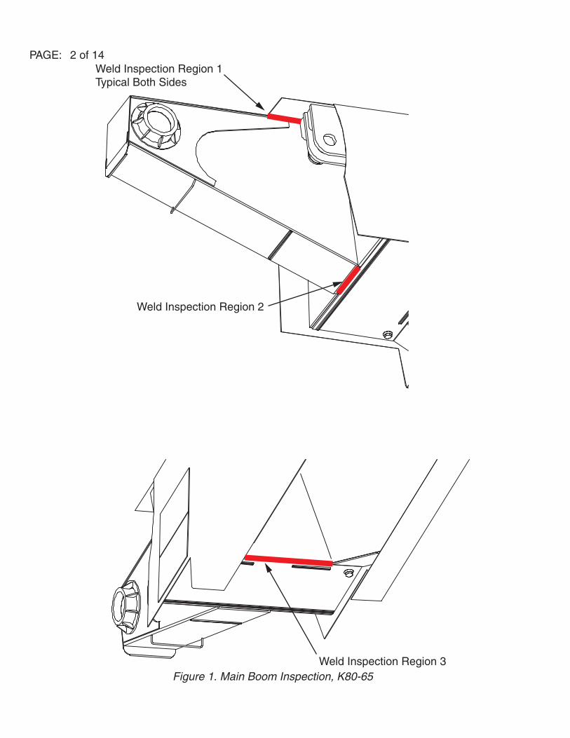
CORRECTIVE ACTION:Perform an NDT on the weld surfaces identified in Figure 1, per the inspection procedure outlined below.
INSPECTION PROCEDURE:
1. Remove the paint and clean the weld surface of all dirt, oil, grease, or debris.
2. Perform a visual inspection according to AWS D1.1, Section 6.9.
3. Perform a dye penetrant inspection according to AWS D1.1, Section 6.10 (ASTM E165).
4. The examination results will determine the repair procedure.
a. If no defects in the weld surface are identified, immediately install the reinforcement kit according to the reinforcement kit installation procedure below.
b. If defects in the weld surfaces are identified, the welds must first be repaired according to the weld repair procedure, before moving on to the reinforcement kit installation procedure.
Allied Systems Co. reserves the right to make changes to new equipment without incurring the obligation to make such changes to equipment previously manufactured.Form 81-76 A Printed in USA
Marine CraneE. A Division of Allied Systems Company
PAGE: 2 of 14
Figure 1. Main Boom Inspection, K80-65
Weld Inspection Region 1Typical Both Sides
Weld Inspection Region 2
Weld Inspection Region 3

PAGE: 3 of 14WELD REPAIR PROCEDURE:
Preparation
The inside of the boom is filled with Cortec VPCI-368M corrosion inhibitor. This material is thinned out with mineral spirits.
Potential Hazards
Flammability - refer to the information regarding Cortec VpCI-368M and the mineral spirits below.
Structural Considerations
• Structural Support – the crane is blocked up at the jib.
• Boom Alignment - the boom alignment should not be affected by this repair.
• Additional stresses due to the method of boom support during welding - the boom cylinders are configured as single acting rams so the weight of the booms are the only forces on the boom.
Cortec VpCI-368M Information
• Technical service engineer contact number: 1-651-407-2730
• Ignition Temperature = 410°F
• Material can be removed using an alkaline cleaner such as Simple Green®, or dish soap mixed with hot water. Use the cleaner in a power washer or steam cleaner to get the best results.
• Requires proper ventilation during welding to remove vapors.
• Clean thoroughly 1-2 feet away from the weld.
• If it’s a liquid, then it is mostly mineral spirits and will be more flammable.
• The product is organic and will simply decompose.
Position and Support the Crane for Repair
Position the crane as shown in Figures 2 & 3. The jib boom tip must be supported at all times, while the repairs are underway.

PAGE: 4 of 14
Figure 2. Boom Repair Position

PAGE: 5 of 14
Figure 3. Boom Repair PositionWeld Repair Procedure – Step 1
A. Protect the cab and glass with weld blankets and plywood over the top glass. Protect the hoses and cylinders with weld blankets during cutting, welding, and grinding operations. With personnel in a man-basket, use a mag drill to drill a vent hole in the vertical plate, on center, and 36” from the base plate, as shown in Figure 4. The coating inside is flammable, but not explosive. Use cutting fluid to keep the temperature down below the combustion temperatures of the coatings inside. The material is ½” thickness, ASTM A-514. This hole will be used to purge flammable vapors from the cavity. Choose a hole size appropriate for the pipe bung and plug that will be welded into it. The hole can be up to 3” in diameter.
B. Next, use an inert gas to purge the flammable vapors from the cavity. There should be a pipe bung located on the bottom surface of this section of the boom and the new hole in the top of the boom. Put gas in one hole to fill the void with inert gas and to purge the flammable vapors out the other hole.
C. With the cavity purged, use a cutting torch to create an access hole in the boom, as shown in Figures 4 & 5. The plate that is removed will weigh ~36 lbs. The area will be well ventilated, but personnel must be mindful of fumes in the area and modify the plan if the ventilation is not adequate.
D. If the Jib latch is removed during this step, save for later so it can be reinstalled.

PAGE: 6 of 14
Figure 4. Access Hole Drawing
Figure 5. Access Hole Location

PAGE: 7 of 14
Weld Repair Procedure – Step 2
Use a steam cleaner with Simple Green®, dish soap or some other alkaline cleaner to remove the Cortec VpCI-368M coating within 1-2 feet of the weld area. This will include not only the crack area but also around the new access hole and the new hole for the pipe bung. Use a shop vacuum to remove as much of the moisture as possible once the area is clean.
Weld Repair Procedure – Step 3
Use a drill or die grinder to create round features on the ends of the cracked area to keep the crack from propagating, as shown in Figure 6. Use a grinder to completely remove the cracked weld.
Figure 6. Remove Cracked Weld
Weld Repair Procedure – Step 4
Prepare the crack area for the new weld by cleaning the crack area once again, to remove any additional Cortec VpCI-368M coating and to finalize the weld preparation.
Weld Repair Procedure – Step 5
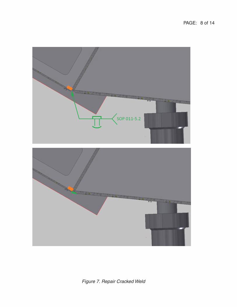
Weld the crack, according to Allied SOP 011-5.2 in Appendix A, as shown in Figure 7. Wait 48 hours, then NDT the area according to steps 1 through 3 of the above inspection procedure.
Weld Repair Procedure – Step 6
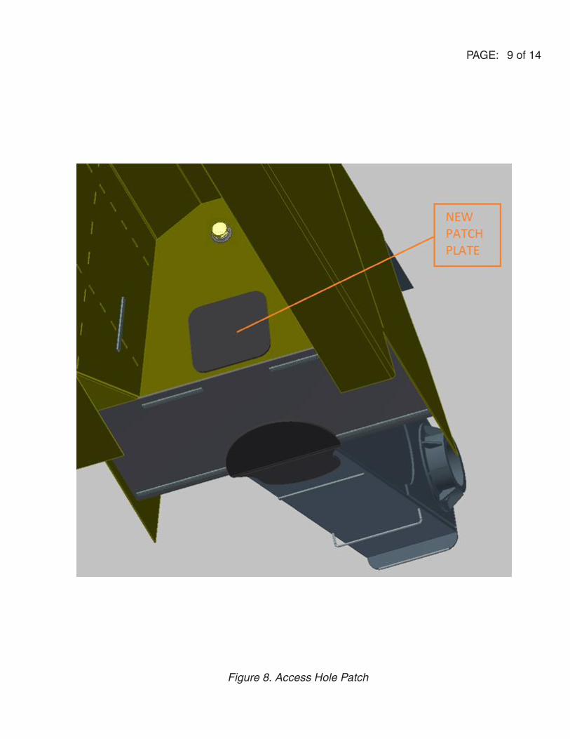
Re-coat the inside of the boom around the repaired crack with Cortec VpCI-368M, then patch the area where the new access hole was cut, as shown in Figure 8. Join using a 1/2” fillet weld all around, following Allied SOP 011-15.1, found in Appendix A. The material is ASTM A-514 TO ASTM A-514. The plate weighs ~45 lbs. Weld a pipe bung into the vent hole and plug.
PAGE: 8 of 14
Figure 7. Repair Cracked Weld
PAGE: 9 of 14
Figure 8. Access Hole Patch
PAGE: 10 of 14
REINFORCEMENT KIT INSTALLATION PROCEDURE
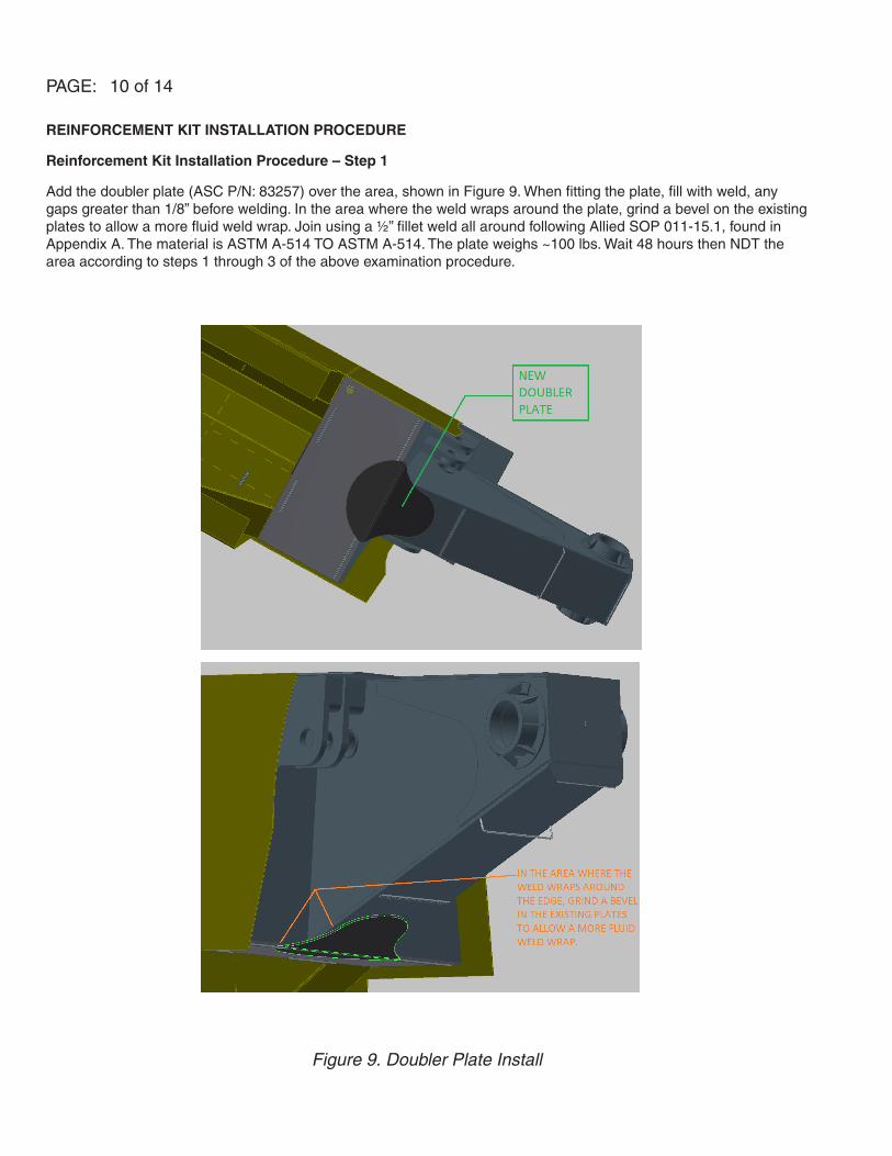
Reinforcement Kit Installation Procedure – Step 1
Add the doubler plate (ASC P/N: 83257) over the area, shown in Figure 9. When fitting the plate, fill with weld, any gaps greater than 1/8” before welding. In the area where the weld wraps around the plate, grind a bevel on the existing plates to allow a more fluid weld wrap. Join using a ½” fillet weld all around following Allied SOP 011-15.1, found in Appendix A. The material is ASTM A-514 TO ASTM A-514. The plate weighs ~100 lbs. Wait 48 hours then NDT the area according to steps 1 through 3 of the above examination procedure.
Figure 9. Doubler Plate Install

PAGE: 11 of 14
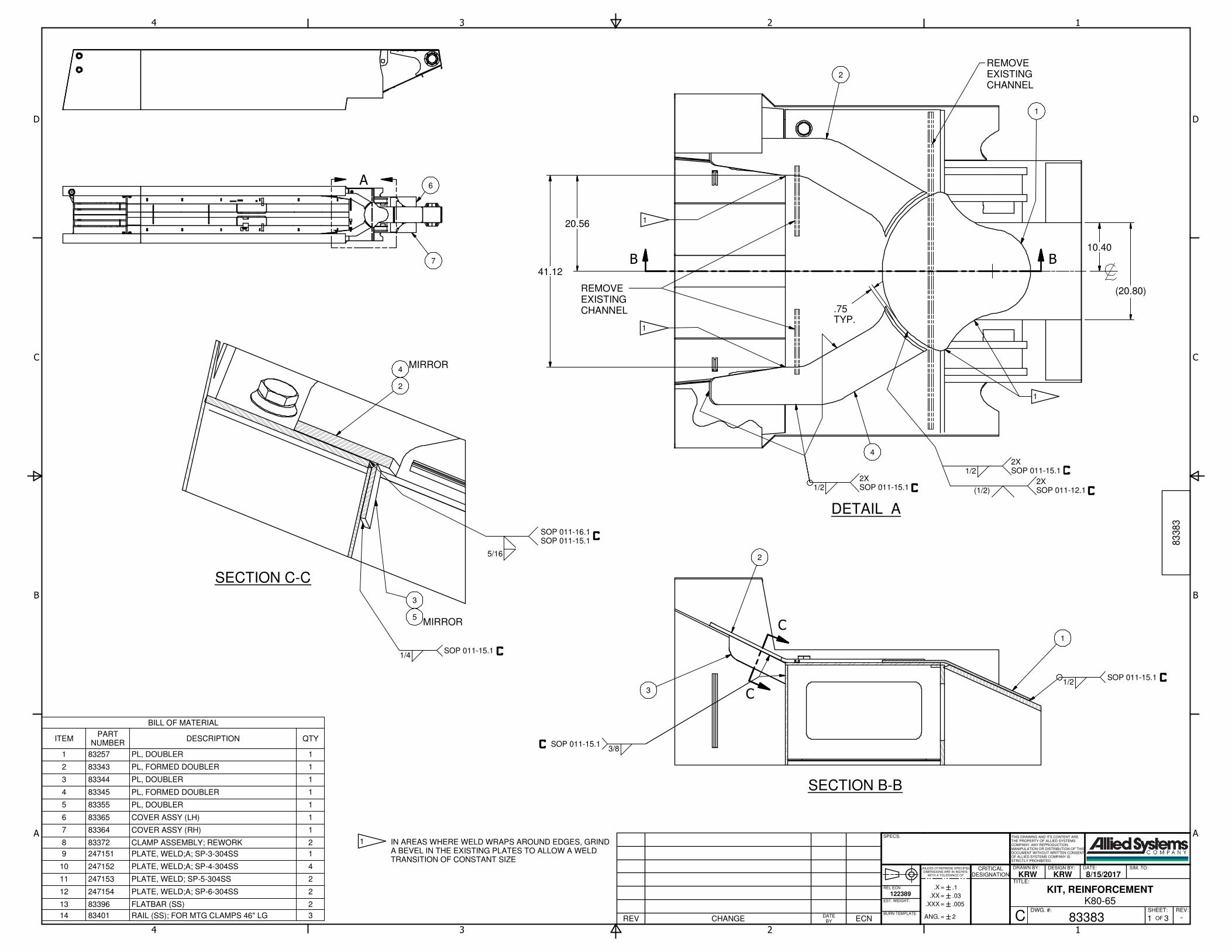
Reinforcement Kit Installation Procedure – Step 2
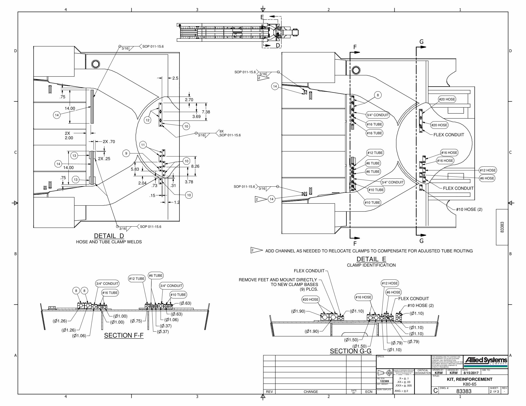
Refer to Figure 10 and follow the Reinforcement Kit drawing, ASC P/N: 83383, found in Appendix B, for the application of the reinforcement plates (ASC P/N: 83343 & 83345). This drawing also provides instructions for adding clamps back to the underside of the boom. In this reinforcement kit, some of these clamps and clamp mountings have been changed to allow the plumbing to route around the new reinforcement plates while still maintaining clearance between the underside of the boom and the top of the cab.
Figure 10. Reinforcement Plate Install
PAGE: 12 of 14
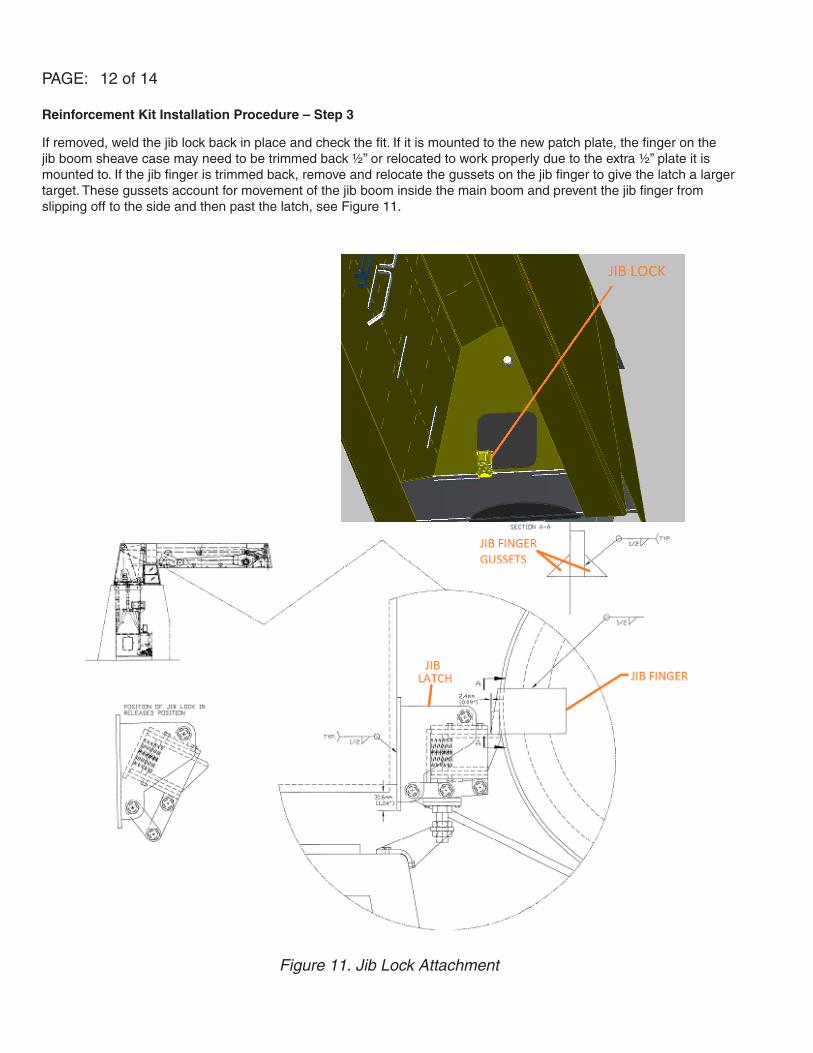
Reinforcement Kit Installation Procedure – Step 3
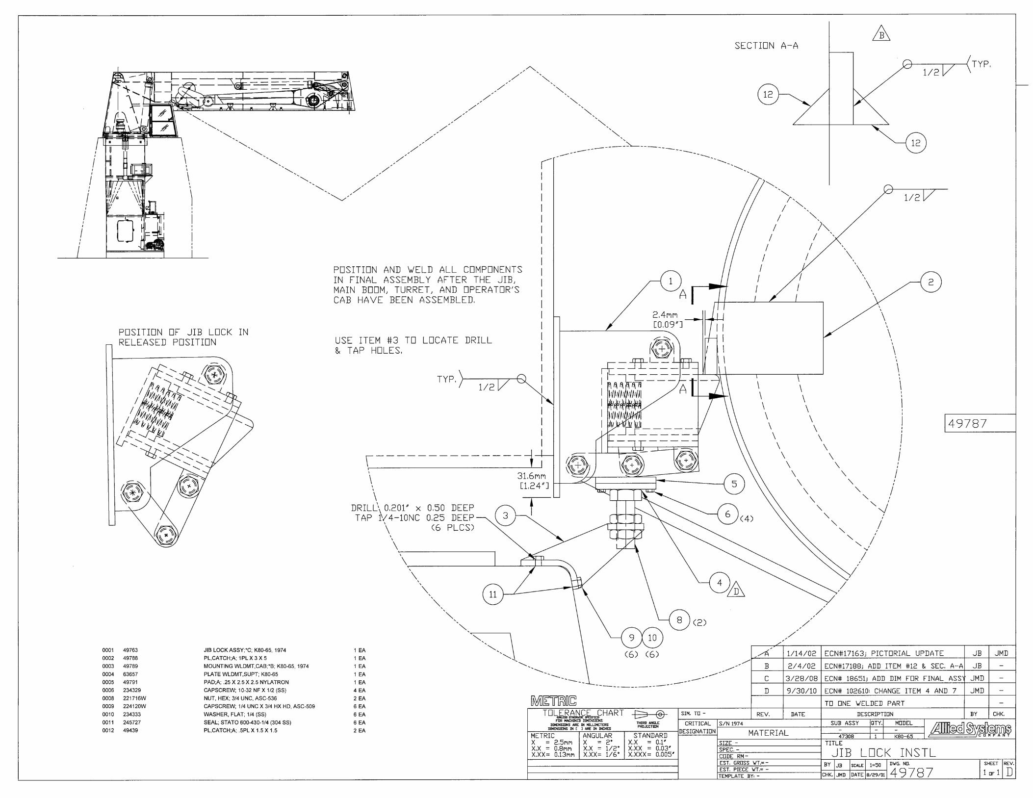
If removed, weld the jib lock back in place and check the fit. If it is mounted to the new patch plate, the finger on the jib boom sheave case may need to be trimmed back ½” or relocated to work properly due to the extra ½” plate it is mounted to. If the jib finger is trimmed back, remove and relocate the gussets on the jib finger to give the latch a larger target. These gussets account for movement of the jib boom inside the main boom and prevent the jib finger from slipping off to the side and then past the latch, see Figure 11.
Figure 11. Jib Lock Attachment
PAGE: 13 of 14
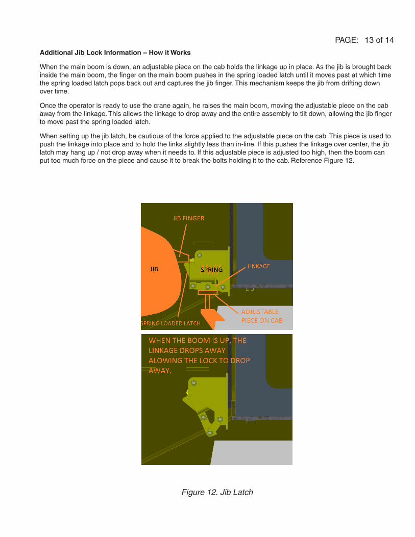
Additional Jib Lock Information – How it Works
When the main boom is down, an adjustable piece on the cab holds the linkage up in place. As the jib is brought back inside the main boom, the finger on the main boom pushes in the spring loaded latch until it moves past at which time the spring loaded latch pops back out and captures the jib finger. This mechanism keeps the jib from drifting down over time.
Once the operator is ready to use the crane again, he raises the main boom, moving the adjustable piece on the cab away from the linkage. This allows the linkage to drop away and the entire assembly to tilt down, allowing the jib finger to move past the spring loaded latch.
When setting up the jib latch, be cautious of the force applied to the adjustable piece on the cab. This piece is used to push the linkage into place and to hold the links slightly less than in-line. If this pushes the linkage over center, the jib latch may hang up / not drop away when it needs to. If this adjustable piece is adjusted too high, then the boom can put too much force on the piece and cause it to break the bolts holding it to the cab. Reference Figure 12.
Figure 12. Jib Latch

PAGE: 14 of 14
PAGE INTENTIONALLY BLANK

CSB005108-23-2017
Marine Crane Appendix A
Allied SOP 011-5.2

CSB0051 08-23-2017
INTENTIONALLY LEFT BLANK

Uncontrolled Document when Printed
689-96027-14e & 689-96027-14d
JOINT DESIGN USED Joint Detail: CJP square groove butt joint (Crane Boom)
Prequalified:
Single
Double Weld
Backing Material:
Back Gouging (Method):
Root Opening:
Root Face Dimension:
Groove Angle:
Radius (J-U):
Position (Groove):
Position (Fillet):
Vertical Progression: Up Down T = Thickness of material which cannot exceed 1/2"
Rmax = 2T -1/16"
FILLER METALS Rmin = T
AWS Specification:
AWS Classification: PREHEAT
TECHNIQUE
Stringer or Weave Bead:
Multi-pass or Single Pass (per side):
Contact Tube or Work Distance:
Peening:
Interpass Cleaning:
SHIELDING * Temperature to be checked 3" on each side of weld joint.
Flux: Gas:
Composistion: 0689106-46a 0689106-46b
Electrode-Flux (Class): Flow Rate:
Cas Cup Size:
TUNGSTEN ELECTRODE (GTAW if Applicable) POST WELD HEAT TREATEMENT
Size: Temperature:
Type: Time:
Weld Zone Average: 25 Ft Lbs @ -40
Charpy Test Record:
Heat Zone Average:
ENGINEERING SOP (WPS)Square Groove Butt Joint (Crane Boom)
Type &
Polarity
73 Ft Lbs @ -40
Amps
Current
220-260 28-30 16-201-n FCAW E71T-1 .052" DCEP
Note
Relevant Quality Manual Section(s) (if applicable):
40-50 CFH
#6
CO2
100%
Min./Max. Preheat and Interpass Temperatures*
Travel
Speed (IPM)Volts
N.A.
A5.20
E71T-1CJ/T-12CJ
Stringer 1/4"
N.A.
N.A.
Revision:
B. Tanner
Class Diam.
Pass or
Weld
Layer(s)
Process
Filler Metals
011-5.2
5
4/26/2011
SOP No.:
B. Tanner, B. NourseApproved by:
Revised by:
Revised Date:
Fillet Thickness:
Supporting PQR:
WELDING PROCEDURE
Multi-pass
1/2" to 1"
None
Weld slag removed
N.A.
Flat
Thickness of thickest part at point
of welding
Up to and including 1/2" 50 400
Min.
Temp °F
Max.
Temp °F
A514 to A514, A572 or A36 (Group II)
1/2" Maximum
Greater than 24"
Unlimited
Material Spec.:
Material Thickness:
Diameter (pipe):
Groove Thickness:
Crane Boom
T thru 2T -1/16"
6.2.2, API-2C Section 15.1, and API-2C Section 15.2
9/1/2000Implementations date:
Form 60-132, 8/09

CSB005108-23-2017
Marine Crane Appendix B
Reinforcement Kit & Jib Latch Install Drawings

CSB0051 08-23-2017
INTENTIONALLY LEFT BLANK
DETAIL A
SECTION B-B
SECTION C-C
1
1
2
2
3
3
4
4
A A
B B
C C
D D
A
B B
C
C
BILL OF MATERIAL
QTYDESCRIPTIONPART
NUMBERITEM
1PL, DOUBLER832571
1PL, FORMED DOUBLER833432
1PL, DOUBLER833443
1PL, FORMED DOUBLER833454
1PL, DOUBLER833555
1COVER ASSY (LH)833656
1COVER ASSY (RH)833647
2CLAMP ASSEMBLY; REWORK833728
1PLATE, WELD;A; SP-3-304SS2471519
4PLATE, WELD;A; SP-4-304SS24715210
2PLATE, WELD; SP-5-304SS24715311
2PLATE, WELD;A; SP-6-304SS24715412
2FLATBAR (SS)8339613
3RAIL (SS); FOR MTG CLAMPS 46" LG8340114
THIS DRAWING AND ITS CONTENT ARE THE PROPERTY OF ALLIED SYSTEMS COMPANY. ANY REPRODUCTION, MANIPULATION OR DISTRIBUTION OF THISDOCUMENT WITHOUT WRITTEN CONSENT OF ALLIED SYSTEMS COMPANY IS STRICTLY PROHIBITED.
DRAWN BY: DESIGN BY: DATE:
TITLE:
DWG. #: SHEET: REV:
CRITICALDESIGNATION
`=.XX
`=
`=
ANG.
.XXX
.X
UNLESS OTHERWISE SPECIFIEDDIMENSIONS ARE IN INCHES;
WITH A TOLERANCE OF
SPECS.
EST. WEIGHT:
BURN TEMPLATE
83
38
3
C OF1 3 -83383
KRW KRW 8/15/2017
KIT, REINFORCEMENT
K80-65
2̀
.1
.03
.005
SIM. TO:
=REV CHANGE ECNDATE
BY
REL ECN
122389
REMOVEEXISTINGCHANNEL
1
31/2
SOP 011-15.1
(1/2)2XSOP 011-12.1
1/22XSOP 011-15.1
2
1
4
REMOVEEXISTINGCHANNEL
2
4
1/4SOP 011-15.1
2
3
5
1
1
1
7
6
IN AREAS WHERE WELD WRAPS AROUND EDGES, GRIND A BEVEL IN THE EXISTING PLATES TO ALLOW A WELD TRANSITION OF CONSTANT SIZE
1
3/8SOP 011-15.1
MIRROR
MIRROR
(20.80)
10.40
41.12
20.56
1/22XSOP 011-15.1
.75TYP.
5/16
SOP 011-16.1SOP 011-15.1
DETAIL DHOSE AND TUBE CLAMP WELDS
DETAIL ECLAMP IDENTIFICATION
SECTION G-G
SECTION F-F
1
1
2
2
3
3
4
4
A A
B B
C C
D D
THIS DRAWING AND ITS CONTENT ARE THE PROPERTY OF ALLIED SYSTEMS COMPANY. ANY REPRODUCTION, MANIPULATION OR DISTRIBUTION OF THISDOCUMENT WITHOUT WRITTEN CONSENT OF ALLIED SYSTEMS COMPANY IS STRICTLY PROHIBITED.
DRAWN BY: DESIGN BY: DATE:
TITLE:
DWG. #: SHEET: REV:
CRITICALDESIGNATION
`=.XX
`=
`=
ANG.
.XXX
.X
UNLESS OTHERWISE SPECIFIEDDIMENSIONS ARE IN INCHES;
WITH A TOLERANCE OF
SPECS.
EST. WEIGHT:
BURN TEMPLATE
83
38
3
C OF2 3 -83383
KRW KRW 8/15/2017
KIT, REINFORCEMENT
K80-65
2̀
.1
.03
.005
SIM. TO:
=REV CHANGE ECNDATE
BY
REL ECN
122389
D
E
G
G
F
F
11
9
10
2.5
1.2
14
1414.00
14.00
12
10
.31.732.04 3.78
8.26
.15
2.70
3.697.38
8
3/4" CONDUIT
#16 TUBE
#16 TUBE
#12 TUBE
#6 TUBE
#6 TUBE
3/4" CONDUIT
#10 TUBE
#10 TUBE
8 8
3/4" CONDUIT
#16 TUBE
#12 TUBE#6 TUBE
3/4" CONDUIT
#10 TUBE
#20 HOSE#16 HOSE
#6 HOSE
(n1.90) (n1.10)
(n1.50)
14
14
ADD CHANNEL AS NEEDED TO RELOCATE CLAMPS TO COMPENSATE FOR ADJUSTED TUBE ROUTING2
2
23/16
SOP 011-15.6
13
13
2.002X
.75
.75
.252X
.702X
3/16SOP 011-15.6
3/16SOP 011-15.6
3/169XSOP 011-15.6
3/16SOP 011-15.6
REMOVE FEET AND MOUNT DIRECTLY TO NEW CLAMP BASES
(9) PLCS.
5.83
10
(n1.26)
(n1.26)
(n1.06)
(n1.00)
(n1.00)(n.75)
(n.37)
(n.37)
(n1.06)
(n.63)
(n.63)
(n1.50)(n1.10)
(n1.10)
(n1.10)
(n1.10)
(n.79) (n.79)
(n1.90)
#12 HOSE
FLEX CONDUIT
FLEX CONDUIT
#10 HOSE (2)
#10 HOSE (2)
FLEX CONDUIT
FLEX CONDUIT
#6 HOSE
#12 HOSE
#16 HOSE
#16 HOSE
#20 HOSE
#20 HOSE

1
1
2
2
3
3
4
4
A A
B B
C C
D D
THIS DRAWING AND ITS CONTENT ARE THE PROPERTY OF ALLIED SYSTEMS COMPANY. ANY REPRODUCTION, MANIPULATION OR DISTRIBUTION OF THISDOCUMENT WITHOUT WRITTEN CONSENT OF ALLIED SYSTEMS COMPANY IS STRICTLY PROHIBITED.
DRAWN BY: DESIGN BY: DATE:
TITLE:
DWG. #: SHEET: REV:
CRITICALDESIGNATION
`=.XX
`=
`=
ANG.
.XXX
.X
UNLESS OTHERWISE SPECIFIEDDIMENSIONS ARE IN INCHES;
WITH A TOLERANCE OF
SPECS.
EST. WEIGHT:
BURN TEMPLATE
83
38
3
C OF3 3 -83383
KRW KRW 8/15/2017
KIT, REINFORCEMENT
K80-65
2̀
.1
.03
.005
SIM. TO:
=REV CHANGE ECNDATE
BY
REL ECN
122389
6
7
(3/8)2XSOP 011-16.1
3/82XSOP 011-15.1
MAXIMUM GAP1/4"
MAXIMUM GAP1/4"
MAXIMUM OFFSET BETWEENCOVER PLATES AND TOP OF BOOM1/4"
COVER PLATE
GUSSET
8.5
8.5
3/8" X 45° CHAMFERFOR BEVEL WELD PREP
USE COVER AND GUSSET ASSEMBLY TO LOCATE PARTSTACK IN PLACE AND REMOVE COVER PLATES TO FINISH WELD
3
3