prequalified connections for special and intermediate steel
TRANSCRIPT
ANSI/AISC 358-05An American National Standard
Prequalified Connections for Special and Intermediate
Steel Moment Frames for Seismic Applications
December 13, 2005
Approved by the AISC Connection Prequalification Review Panel and issued by the AISC Board of Directors
AMERICAN INSTITUTE OF STEEL CONSTRUCTION, INC.One East Wacker Drive, Suite 700
Chicago, Illinois 60601-1802
AISC_Prequalified_1 1/27/07 7:02 AM Page i
ii
Prequalified Connections for Special and Intermediate Steel Moment Frames for Seismic ApplicationsAMERICAN INSTITUTE OF STEEL CONSTRUCTION, INC.
Copyright © 2006
by
American Institute of Steel Construction, Inc.
All rights reserved. This book or any part thereof must not be reproduced in any form without the written permission of the publisher.
The AISC logo is a registered trademark of AISC and is used under license.
The information presented in this publication has been prepared in accordance withrecognized engineering principles and is for general information only. While it is be-lieved to be accurate, this information should not be used or relied upon for any spe-cific application without competent professional examination and verification of itsaccuracy, suitability, and applicability by a licensed professional engineer, designer, orarchitect. The publication of the material contained herein is not intended as a repre-sentation or warranty, on the part of the American Institute of Steel Construction orof any other person named herein, that this information is suitable for any general or par-ticular use or of freedom from infringement of any patent or patents. Anyone making useof this information assumes all liability arising from such use.
Caution must be exercised when relying upon other specifications and codes developedby other bodies and incorporated by reference herein since such material may be mod-ified or amended from time to time subsequent to the printing of this edition. TheInstitute bears no responsibility for such material other than to refer to it and incorpo-rate it by reference at the time of the initial publication of this edition.
Printed in the United States of America
Second Printing October 2006
6.2–
AISC_Prequalified_1 1/27/07 7:02 AM Page ii
iii
Prequalified Connections for Special and Intermediate Steel Moment Frames for Seismic ApplicationsAMERICAN INSTITUTE OF STEEL CONSTRUCTION, INC.
CONNECTION PREQUALIFICATION REVIEW PANEL
Committee MembersRonald O. Hamburger, Chairman Robert LyonsKevin Moore, Vice-Chairman Brett ManningChristopher M. Hewitt, Secretary Michael MayesFred Breismeister Duane MillerNathan Charlton Thomas M. MurrayTheodore Droessler Lawrence NovakMichael Engelhardt Thomas SabolLinda Hanagan Robert ShawPatrick Hassett Christos TokasKeith Landwehr Behnam (Ben) Yousefi
Corresponding MembersCynthia Duncan Carol PivonkaLanny Flynn Thomas SchlaflyRoberto Leon Emmett SumnerJames Malley Chia-Ming UangHank Martin
6.2–
AISC_Prequalified_1 1/27/07 7:02 AM Page iii

6.2– iv
Prequalified Connections for Special and Intermediate Steel Moment Frames for Seismic ApplicationsAMERICAN INSTITUTE OF STEEL CONSTRUCTION, INC.
AISC_Prequalified_1 1/27/07 7:02 AM Page iv
v
Prequalified Connections for Special and Intermediate Steel Moment Frames for Seismic ApplicationsAMERICAN INSTITUTE OF STEEL CONSTRUCTION, INC.
TABLE OF CONTENTS
SYMBOLS . . . . . . . . . . . . . . . . . . . . . . . . . . . . . . . . . . . . . . . . . . . . . . . . . . . . . . . . . . 6.2–1
GLOSSARY . . . . . . . . . . . . . . . . . . . . . . . . . . . . . . . . . . . . . . . . . . . . . . . . . . . . . . . . . 6.2–3
CHAPTER 1 GENERAL . . . . . . . . . . . . . . . . . . . . . . . . . . . . . . . . . . . . . . . . . . . . . . 6.2–4
1.1 Scope . . . . . . . . . . . . . . . . . . . . . . . . . . . . . . . . . . . . . . . . . . . . . . . . . . 6.2–4
1.2 References . . . . . . . . . . . . . . . . . . . . . . . . . . . . . . . . . . . . . . . . . . . . . . 6.2–4
1.3 General . . . . . . . . . . . . . . . . . . . . . . . . . . . . . . . . . . . . . . . . . . . . . . . . . 6.2–4
CHAPTER 2 DESIGN REQUIREMENTS . . . . . . . . . . . . . . . . . . . . . . . . . . . . . . . 6.2–5
2.1 Special and Intermediate Moment Frame Connection Types . . . . . . . 6.2–5
2.2 Connection Stiffness . . . . . . . . . . . . . . . . . . . . . . . . . . . . . . . . . . . . . . 6.2–5
2.3 Members . . . . . . . . . . . . . . . . . . . . . . . . . . . . . . . . . . . . . . . . . . . . . . . . 6.2–5
2.3.1 Rolled Wide-Flange Members . . . . . . . . . . . . . . . . . . . . . . . . . . . . . . . 6.2–5
2.3.2 Built-up Members . . . . . . . . . . . . . . . . . . . . . . . . . . . . . . . . . . . . . . . . 6.2–5
2.3.2a Beams . . . . . . . . . . . . . . . . . . . . . . . . . . . . . . . . . . . . . . . . . . . . . . . . . . 6.2–6
2.3.2b Columns . . . . . . . . . . . . . . . . . . . . . . . . . . . . . . . . . . . . . . . . . . . . . . . . 6.2–6
1. I-Shaped Welded Columns . . . . . . . . . . . . . . . . . . . . . . . . . . . . . . . 6.2–6
2. Boxed Wide-Flange Columns . . . . . . . . . . . . . . . . . . . . . . . . . . . . . 6.2–6
3. Built-up Box Columns . . . . . . . . . . . . . . . . . . . . . . . . . . . . . . . . . . 6.2–6
4. Flanged Cruciform Columns . . . . . . . . . . . . . . . . . . . . . . . . . . . . . . 6.2–7
2.4 Connection Design Parameters . . . . . . . . . . . . . . . . . . . . . . . . . . . . . . 6.2–7
2.4.1 Load Combinations and Resistance Factors . . . . . . . . . . . . . . . . . . . . . 6.2–7
2.4.2 Plastic Hinge Location . . . . . . . . . . . . . . . . . . . . . . . . . . . . . . . . . . . . . 6.2–7
2.4.3 Probable Maximum Moment at Plastic Hinge . . . . . . . . . . . . . . . . . . . 6.2–8
2.4.4 Beam Flange Continuity Plates . . . . . . . . . . . . . . . . . . . . . . . . . . . . . . 6.2–8
2.4.4a Continuity Plate Thickness . . . . . . . . . . . . . . . . . . . . . . . . . . . . . . . . . . 6.2–9
2.4.4b Continuity Plate to Column Attachment . . . . . . . . . . . . . . . . . . . . . . . 6.2–9
2.5 Panel Zones . . . . . . . . . . . . . . . . . . . . . . . . . . . . . . . . . . . . . . . . . . . . 6.2–10
2.6 Protected Zone . . . . . . . . . . . . . . . . . . . . . . . . . . . . . . . . . . . . . . . . . . 6.2–10
CHAPTER 3 WELDING REQUIREMENTS . . . . . . . . . . . . . . . . . . . . . . . . . . . . 6.2–11
3.1 Filler Metals . . . . . . . . . . . . . . . . . . . . . . . . . . . . . . . . . . . . . . . . . . . . 6.2–11
3.2 Welding Procedures . . . . . . . . . . . . . . . . . . . . . . . . . . . . . . . . . . . . . . 6.2–11
6.2–
AISC_Prequalified_1 1/27/07 7:02 AM Page v
vi TABLE OF CONTENTS
Prequalified Connections for Special and Intermediate Steel Moment Frames for Seismic ApplicationsAMERICAN INSTITUTE OF STEEL CONSTRUCTION, INC.
3.3 Backing at Beam to Column and Continuity Plate to Column Joints . . . . . . . . . . . . . . . . . . . . . . . . . . . . . . . . . . . . . . . . 6.2–11
3.3.1 Steel Backing at Continuity Plates . . . . . . . . . . . . . . . . . . . . . . . . . . . 6.2–11
3.3.2 Steel Backing at Beam Bottom Flange . . . . . . . . . . . . . . . . . . . . . . . 6.2–11
3.3.3 Steel Backing at Beam Top Flange . . . . . . . . . . . . . . . . . . . . . . . . . . 6.2–11
3.3.4 Prohibited Welds at Steel Backing . . . . . . . . . . . . . . . . . . . . . . . . . . . 6.2–12
3.3.5 Non-Fusible Backing at Beam Flange-to-Column Joints . . . . . . . . . 6.2–12
3.4 Details and Treatment of Weld Tabs . . . . . . . . . . . . . . . . . . . . . . . . . 6.2–12
3.5 Tack Welds . . . . . . . . . . . . . . . . . . . . . . . . . . . . . . . . . . . . . . . . . . . . . 6.2–13
3.6 Continuity Plates . . . . . . . . . . . . . . . . . . . . . . . . . . . . . . . . . . . . . . . . 6.2–13
3.7 Quality Control and Quality Assurance . . . . . . . . . . . . . . . . . . . . . . . 6.2–13
CHAPTER 4 BOLTING REQUIREMENTS . . . . . . . . . . . . . . . . . . . . . . . . . . . . 6.2–14
4.1 Fastener Assemblies . . . . . . . . . . . . . . . . . . . . . . . . . . . . . . . . . . . . . . 6.2–14
4.2 Installation Requirements . . . . . . . . . . . . . . . . . . . . . . . . . . . . . . . . . . 6.2–14
4.3 Quality Control and Quality Assurance . . . . . . . . . . . . . . . . . . . . . . . 6.2–14
CHAPTER 5 REDUCED BEAM SECTION (RBS) MOMENT CONNECTION . . . . . . . . . . . . . . . . . . . . . . . . . . . . . . . 6.2–15
5.1 General . . . . . . . . . . . . . . . . . . . . . . . . . . . . . . . . . . . . . . . . . . . . . . . . 6.2–15
5.2 Systems . . . . . . . . . . . . . . . . . . . . . . . . . . . . . . . . . . . . . . . . . . . . . . . 6.2–15
5.3 Prequalification Limits . . . . . . . . . . . . . . . . . . . . . . . . . . . . . . . . . . . . 6.2–15
5.3.1 Beam Limitations . . . . . . . . . . . . . . . . . . . . . . . . . . . . . . . . . . . . . . . . 6.2–16
5.3.2 Column Limitations . . . . . . . . . . . . . . . . . . . . . . . . . . . . . . . . . . . . . . 6.2–17
5.4 Beam-Column Relationship Limitations . . . . . . . . . . . . . . . . . . . . . . 6.2–17
5.5 Beam Flange to Column Flange Weld Limitations . . . . . . . . . . . . . . 6.2–18
5.6 Beam Web to Column Connection Limitations . . . . . . . . . . . . . . . . . 6.2–18
5.7 Fabrication of Flange Cuts . . . . . . . . . . . . . . . . . . . . . . . . . . . . . . . . . 6.2–19
5.8 Design Procedure . . . . . . . . . . . . . . . . . . . . . . . . . . . . . . . . . . . . . . . . 6.2–19
CHAPTER 6 BOLTED UNSTIFFENED AND STIFFENED EXTENDED END-PLATE MOMENT CONNECTIONS . . . . . . . . . . . . . . . . . . 6.2–23
6.1 General . . . . . . . . . . . . . . . . . . . . . . . . . . . . . . . . . . . . . . . . . . . . . . . . 6.2–23
6.2 Systems . . . . . . . . . . . . . . . . . . . . . . . . . . . . . . . . . . . . . . . . . . . . . . . 6.2–23
6.3 Prequalification Limits . . . . . . . . . . . . . . . . . . . . . . . . . . . . . . . . . . . . 6.2–24
6.4 Beam Limitations . . . . . . . . . . . . . . . . . . . . . . . . . . . . . . . . . . . . . . . . 6.2–24
6.5 Column Limitations . . . . . . . . . . . . . . . . . . . . . . . . . . . . . . . . . . . . . . 6.2–25
6.6 Beam-Column Relationship Limitations . . . . . . . . . . . . . . . . . . . . . . 6.2–26
6.2–
AISC_Prequalified_1 1/27/07 7:02 AM Page vi

vii
Prequalified Connections for Special and Intermediate Steel Moment Frames for Seismic ApplicationsAMERICAN INSTITUTE OF STEEL CONSTRUCTION, INC.
6.7 Continuity Plates . . . . . . . . . . . . . . . . . . . . . . . . . . . . . . . . . . . . . . . . 6.2–26
6.8 Bolts . . . . . . . . . . . . . . . . . . . . . . . . . . . . . . . . . . . . . . . . . . . . . . . . . . 6.2–26
6.9 Connection Detailing . . . . . . . . . . . . . . . . . . . . . . . . . . . . . . . . . . . . . 6.2–27
6.9.1 Gage . . . . . . . . . . . . . . . . . . . . . . . . . . . . . . . . . . . . . . . . . . . . . . . . . . 6.2–30
6.9.2 Pitch and Row Spacing . . . . . . . . . . . . . . . . . . . . . . . . . . . . . . . . . . . 6.2–30
6.9.3 End-Plate Width . . . . . . . . . . . . . . . . . . . . . . . . . . . . . . . . . . . . . . . . . 6.2–30
6.9.4 End-Plate Stiffener . . . . . . . . . . . . . . . . . . . . . . . . . . . . . . . . . . . . . . . 6.2–30
6.9.5 Finger Shims . . . . . . . . . . . . . . . . . . . . . . . . . . . . . . . . . . . . . . . . . . . 6.2–32
6.9.6 Composite Slab Detailing for IMF . . . . . . . . . . . . . . . . . . . . . . . . . . . 6.2–32
6.9.7 Welding Details . . . . . . . . . . . . . . . . . . . . . . . . . . . . . . . . . . . . . . . . . 6.2–33
6.10 Design Procedure . . . . . . . . . . . . . . . . . . . . . . . . . . . . . . . . . . . . . . . . 6.2–33
TABLE OF CONTENTS 6.2–
COMMENTARY . . . . . . . . . . . . . . . . . . . . . . . . . . . . . . . . . . . . . . . . . . . . . . . . . . . . 6.2–47
C1. GENERAL . . . . . . . . . . . . . . . . . . . . . . . . . . . . . . . . . . . . . . . . . . . . . . . . . . . . . 6.2–48
C1.1 Scope . . . . . . . . . . . . . . . . . . . . . . . . . . . . . . . . . . . . . . . . . . . . . . . . . 6.2–48
C1.2 References . . . . . . . . . . . . . . . . . . . . . . . . . . . . . . . . . . . . . . . . . . . . . 6.2–49
C1.3 General . . . . . . . . . . . . . . . . . . . . . . . . . . . . . . . . . . . . . . . . . . . . . . . . 6.2–49
C2. DESIGN REQUIREMENTS . . . . . . . . . . . . . . . . . . . . . . . . . . . . . . . . . . . . . . 6.2–50C2.1 Special and Intermediate Moment Frame Connection Types . . . . . . 6.2–50C2.3 Members . . . . . . . . . . . . . . . . . . . . . . . . . . . . . . . . . . . . . . . . . . . . . . . 6.2–50C2.3.2 Built-up Members . . . . . . . . . . . . . . . . . . . . . . . . . . . . . . . . . . . . . . . 6.2–50C2.3.2b Columns . . . . . . . . . . . . . . . . . . . . . . . . . . . . . . . . . . . . . . . . . . . . . . . 6.2–50
(2) Boxed Wide-Flange Columns . . . . . . . . . . . . . . . . . . . . . . . . . . . . 6.2–52(4) Flanged Cruciform Columns . . . . . . . . . . . . . . . . . . . . . . . . . . . . 6.2–52
C2.4 Connection Design Parameters . . . . . . . . . . . . . . . . . . . . . . . . . . . . . 6.2–52C2.4.1 Load Combinations and Resistance Factors . . . . . . . . . . . . . . . . . . . . 6.2–52C2.4.2 Plastic Hinge Location . . . . . . . . . . . . . . . . . . . . . . . . . . . . . . . . . . . . 6.2–52C2.4.3 Probable Maximum Moment at Plastic Hinge . . . . . . . . . . . . . . . . . . 6.2–53C2.4.4 Beam Flange Continuity Plates . . . . . . . . . . . . . . . . . . . . . . . . . . . . . 6.2–53C2.4.4b Continuity Plate to Column Attachment . . . . . . . . . . . . . . . . . . . . . . 6.2–54
C3. WELDING REQUIREMENTS . . . . . . . . . . . . . . . . . . . . . . . . . . . . . . . . . . . . 6.2–55
C3.3 Backing at Beam-to-Column and Continuity-Plate-to-Column Joints . 6.2–55
C3.3.1 Steel Backing at Continuity Plates . . . . . . . . . . . . . . . . . . . . . . . . . . . 6.2–55
C3.3.2 Steel Backing at Beam Bottom Flange . . . . . . . . . . . . . . . . . . . . . . . 6.2–55
C3.3.3 Steel Backing at Beam Top Flange . . . . . . . . . . . . . . . . . . . . . . . . . . 6.2–55
C3.3.4 Prohibited Welds at Steel Backing . . . . . . . . . . . . . . . . . . . . . . . . . . . 6.2–56
C3.3.5 Non-fusible Backing at Beam Flange-to-Column Joints . . . . . . . . . . 6.2–56
C3.4 Details and Treatment of Weld Tabs . . . . . . . . . . . . . . . . . . . . . . . . . 6.2–56
AISC_Prequalified_1 1/27/07 7:02 AM Page vii
6.2–viii TABLE OF CONTENTS
Prequalified Connections for Special and Intermediate Steel Moment Frames for Seismic ApplicationsAMERICAN INSTITUTE OF STEEL CONSTRUCTION, INC.
C3.5 Tack Welds . . . . . . . . . . . . . . . . . . . . . . . . . . . . . . . . . . . . . . . . . . . . . 6.2–57
C3.6 Continuity Plates . . . . . . . . . . . . . . . . . . . . . . . . . . . . . . . . . . . . . . . . 6.2–57
C3.7 Quality Control and Quality Assurance . . . . . . . . . . . . . . . . . . . . . . . 6.2–58
C4. BOLTING REQUIREMENTS . . . . . . . . . . . . . . . . . . . . . . . . . . . . . . . . . . . . . 6.2–60
C4.1 Fastener Assemblies . . . . . . . . . . . . . . . . . . . . . . . . . . . . . . . . . . . . . . 6.2–60
C4.2 Installation Requirements . . . . . . . . . . . . . . . . . . . . . . . . . . . . . . . . . . 6.2–60
C4.3 Quality Control and Quality Assurance . . . . . . . . . . . . . . . . . . . . . . . 6.2–60
C5. REDUCED BEAM SECTION (RBS) MOMENT CONNECTION . . . . . . . 6.2–61
C5.1 General . . . . . . . . . . . . . . . . . . . . . . . . . . . . . . . . . . . . . . . . . . . . . . . . 6.2–61
C5.2 Systems . . . . . . . . . . . . . . . . . . . . . . . . . . . . . . . . . . . . . . . . . . . . . . . 6.2–62
C5.3 Prequalification Limits . . . . . . . . . . . . . . . . . . . . . . . . . . . . . . . . . . . . 6.2–62
C5.3.1 Beam Limitations . . . . . . . . . . . . . . . . . . . . . . . . . . . . . . . . . . . . . . . . 6.2–62
C5.3.2 Column Limitations . . . . . . . . . . . . . . . . . . . . . . . . . . . . . . . . . . . . . . 6.2–63
C5.4 Beam-Column Relationship Limitations . . . . . . . . . . . . . . . . . . . . . . 6.2–65
C5.5 Beam Flange-to-Column Flange Weld Limitations . . . . . . . . . . . . . . 6.2–65
C5.6 Beam Web-to-Column Connection Limitations . . . . . . . . . . . . . . . . . 6.2–65
C5.7 Fabrication of Flange Cuts . . . . . . . . . . . . . . . . . . . . . . . . . . . . . . . . . 6.2–66
C5.8 Design Procedure . . . . . . . . . . . . . . . . . . . . . . . . . . . . . . . . . . . . . . . . 6.2–66
C6. BOLTED UNSTIFFENED AND STIFFENDED EXTENDED END-PLATE MOMENT CONNECTIONS . . . . . . . . . . . . . . . . . . . . . . . . . . 6.2–69
C6.1 General . . . . . . . . . . . . . . . . . . . . . . . . . . . . . . . . . . . . . . . . . . . . . . . . 6.2–69
C6.2 Systems . . . . . . . . . . . . . . . . . . . . . . . . . . . . . . . . . . . . . . . . . . . . . . . 6.2–69
C6.3 Prequalification Limits . . . . . . . . . . . . . . . . . . . . . . . . . . . . . . . . . . . . 6.2–70
C6.4 Beam Limitations . . . . . . . . . . . . . . . . . . . . . . . . . . . . . . . . . . . . . . . . 6.2–70
C6.5 Column Limitations . . . . . . . . . . . . . . . . . . . . . . . . . . . . . . . . . . . . . . 6.2–70
C6.6 Beam-Column Relationship Limitations . . . . . . . . . . . . . . . . . . . . . . 6.2–70
C6.7 Continuity Plates . . . . . . . . . . . . . . . . . . . . . . . . . . . . . . . . . . . . . . . . 6.2–70
C6.8 Bolts . . . . . . . . . . . . . . . . . . . . . . . . . . . . . . . . . . . . . . . . . . . . . . . . . . 6.2–71
C6.9 Connection Detailing . . . . . . . . . . . . . . . . . . . . . . . . . . . . . . . . . . . . . 6.2–71
C6.10 Design Procedure . . . . . . . . . . . . . . . . . . . . . . . . . . . . . . . . . . . . . . . . 6.2–72
REFERENCES . . . . . . . . . . . . . . . . . . . . . . . . . . . . . . . . . . . . . . . . . . . . . . . . . . . . . 6.2–73
ALL CONNECTIONS . . . . . . . . . . . . . . . . . . . . . . . . . . . . . . . . . . . . . . . . . . . . . . . 6.2–73
REDUCED BEAM SECTION (RBS) MOMENT CONNECTION . . . . . . . . . . . 6.2–74
BOLTED UNSTIFFENED AND STIFFENED EXTENDED END-PLATE MOMENT CONNECTIONS . . . . . . . . . . . . . . . . . . . . . . . . . . . . . . 6.2–76
AISC_Prequalified_1 1/27/07 7:02 AM Page viii
1
Prequalified Connections for Special and Intermediate Steel Moment Frames for Seismic ApplicationsAMERICAN INSTITUTE OF STEEL CONSTRUCTION, INC.
SYMBOLS
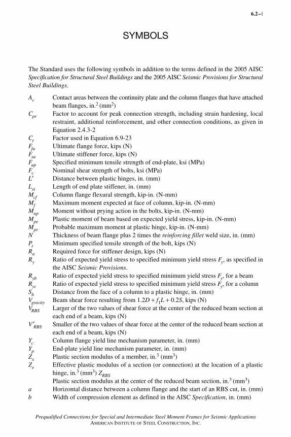
The Standard uses the following symbols in addition to the terms defined in the 2005 AISCSpecification for Structural Steel Buildings and the 2005 AISC Seismic Provisions for StructuralSteel Buildings.
Ac Contact areas between the continuity plate and the column flanges that have attachedbeam flanges, in.2 (mm2)
Cpr Factor to account for peak connection strength, including strain hardening, localrestraint, additional reinforcement, and other connection conditions, as given inEquation 2.4.3-2
Ct Factor used in Equation 6.9-23Ffu Ultimate flange force, kips (N)Fsu Ultimate stiffener force, kips (N)Fup Specified minimum tensile strength of end-plate, ksi (MPa)Fv Nominal shear strength of bolts, ksi (MPa)L′ Distance between plastic hinges, in. (mm)Lst Length of end plate stiffener, in. (mm)Mcf Column flange flexural strength, kip-in. (N-mm)Mf Maximum moment expected at face of column, kip-in. (N-mm)Mnp Moment without prying action in the bolts, kip-in. (N-mm)Mpe Plastic moment of beam based on expected yield stress, kip-in. (N-mm)Mpr Probable maximum moment at plastic hinge, kip-in. (N-mm)N Thickness of beam flange plus 2 times the reinforcing fillet weld size, in. (mm)Pt Minimum specified tensile strength of the bolt, kips (N)Rn Required force for stiffener design, kips (N)Ry Ratio of expected yield stress to specified minimum yield stress Fy, as specified in
the AISC Seismic Provisions.Ryb Ratio of expected yield stress to specified minimum yield stress Fy, for a beamRyc Ratio of expected yield stress to specified minimum yield stress Fy, for a columnSh Distance from the face of a column to a plastic hinge, in. (mm)Vgravity Beam shear force resulting from 1.2D + f1L + 0.2S, kips (N)VRBS Larger of the two values of shear force at the center of the reduced beam section at
each end of a beam, kips (N)V ′RBS Smaller of the two values of shear force at the center of the reduced beam section at
each end of a beam, kips (N)Yc Column flange yield line mechanism parameter, in. (mm)Yp End-plate yield line mechanism parameter, in. (mm) Zx Plastic section modulus of a member, in.3 (mm3) Ze Effective plastic modulus of a section (or connection) at the location of a plastic
hinge, in.3 (mm3) ZRBSPlastic section modulus at the center of the reduced beam section, in.3 (mm3)
a Horizontal distance between a column flange and the start of an RBS cut, in. (mm)b Width of compression element as defined in the AISC Specification, in. (mm)
6.2–
AISC_Prequalified_1 1/27/07 7:02 AM Page 1
2 SYMBOLS
Prequalified Connections for Special and Intermediate Steel Moment Frames for Seismic ApplicationsAMERICAN INSTITUTE OF STEEL CONSTRUCTION, INC.
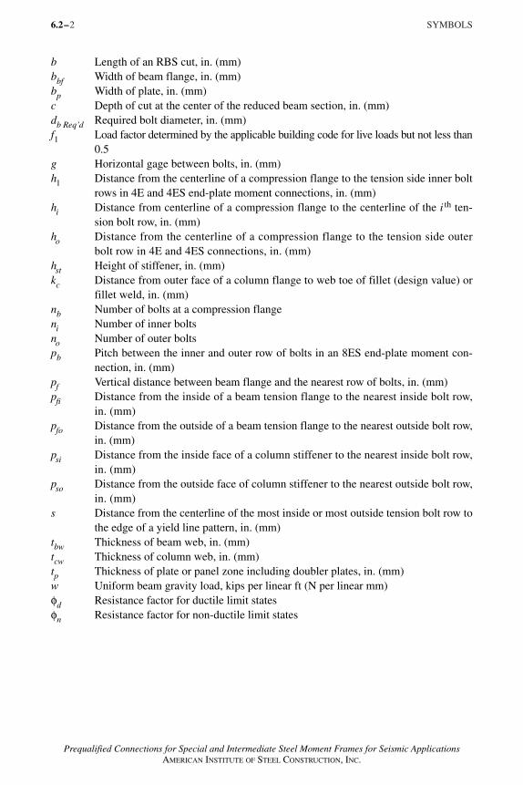
b Length of an RBS cut, in. (mm)bbf Width of beam flange, in. (mm)bp Width of plate, in. (mm)c Depth of cut at the center of the reduced beam section, in. (mm)db Req’d Required bolt diameter, in. (mm)f1 Load factor determined by the applicable building code for live loads but not less than
0.5g Horizontal gage between bolts, in. (mm)h1 Distance from the centerline of a compression flange to the tension side inner bolt
rows in 4E and 4ES end-plate moment connections, in. (mm)hi Distance from centerline of a compression flange to the centerline of the i th ten-
sion bolt row, in. (mm)ho Distance from the centerline of a compression flange to the tension side outer
bolt row in 4E and 4ES connections, in. (mm)hst Height of stiffener, in. (mm)kc Distance from outer face of a column flange to web toe of fillet (design value) or
fillet weld, in. (mm)nb Number of bolts at a compression flangeni Number of inner boltsno Number of outer boltspb Pitch between the inner and outer row of bolts in an 8ES end-plate moment con-
nection, in. (mm)pf Vertical distance between beam flange and the nearest row of bolts, in. (mm)pfi Distance from the inside of a beam tension flange to the nearest inside bolt row,
in. (mm)pfo Distance from the outside of a beam tension flange to the nearest outside bolt row,
in. (mm)psi Distance from the inside face of a column stiffener to the nearest inside bolt row,
in. (mm)pso Distance from the outside face of column stiffener to the nearest outside bolt row,
in. (mm)s Distance from the centerline of the most inside or most outside tension bolt row to
the edge of a yield line pattern, in. (mm)tbw Thickness of beam web, in. (mm)tcw Thickness of column web, in. (mm)tp Thickness of plate or panel zone including doubler plates, in. (mm)w Uniform beam gravity load, kips per linear ft (N per linear mm)φd Resistance factor for ductile limit statesφn Resistance factor for non-ductile limit states
6.2–
AISC_Prequalified_1 1/27/07 7:02 AM Page 2
3
Prequalified Connections for Special and Intermediate Steel Moment Frames for Seismic ApplicationsAMERICAN INSTITUTE OF STEEL CONSTRUCTION, INC.
GLOSSARY
The Standard uses the following terms in addition to the terms defined in the 2005 AISCSpecification for Structural Steel Buildings and the 2005 AISC Seismic Provisions for StructuralSteel Buildings. Glossary terms are italicized where they appear in the text.
Air carbon arc cutting. Process of cutting steel by the heat from an electric arc appliedsimultaneously with an air jet.
Backing. Piece of metal or other material, placed at the weld root to facilitate placement ofthe root pass.
Backgouge. Process of removing by grinding or air carbon arc cutting all or a portion of theroot pass of a complete joint penetration groove weld, from the reverse side of a jointfrom which a root was originally placed.
Complete joint penetration (CJP) groove weld. Groove weld in which weld metal extendsthrough the joint thickness.
Concrete structural slab. Reinforced concrete slab or concrete fill on steel deck with a totalthickness of 3 in. (75 mm) or greater and a concrete compressive strength in excess of2000 psi (14 MPa).
Non-fusible backing. Backing material that will not fuse with the base metals during thewelding process.
Plastic hinge location. Location in a beam column assembly where inelastic energy dissi-pation is assumed to occur through the development of plastic flexural straining.
Probable maximum moment at plastic hinge. Expected moment developed at a plastic hingelocation along a member, considering the probable (mean) value of the material strengthfor the specified steel and effects of strain hardening.
Reinforcing fillet. Fillet weld applied to a groove welded “tee-joint” to obtain a contour toreduce stress concentrations associated with joint geometry.
Root. Portion of a multi-pass weld deposited in the first pass of welding.
Thermal cutting. Group of cutting processes that severs or removes metal by localizedmelting, burning, or vaporizing of the workpiece.
Weld tab. Piece of metal affixed to the end of a welded joint to facilitate the initiation andtermination of weld passes outside the structural joint.
6.2–
AISC_Prequalified_1 1/27/07 7:02 AM Page 3
4
Prequalified Connections for Special and Intermediate Steel Moment Frames for Seismic ApplicationsAMERICAN INSTITUTE OF STEEL CONSTRUCTION, INC.
CHAPTER 1
GENERAL
1.1 ScopeThis Standard specifies design, detailing, fabrication and quality criteria forconnections that are prequalified in accordance with the AISC Seismic Provisionsfor Structural Steel Buildings (herein referred to as the AISC Seismic Provisions)for use with special moment frames (SMF) and intermediate moment frames(IMF). The connections contained in this Standard are prequalified to meet therequirements in the AISC Seismic Provisions only when designed and con-structed in accordance with the requirements of this Standard. Nothing in thisStandard shall preclude the use of connection types contained herein outsidethe indicated limitations, or the use of other connection types, when satisfactoryevidence of qualification in accordance with Appendix S of the AISC SeismicProvisions is presented to the authority having jurisdiction.
1.2 ReferencesThe following standards form a part of this Standard to the extent that theyare referenced and applicable:
2005 AISC Seismic Provisions for Structural Steel Buildings2004 AWS D1.1 Structural Welding Code – Steel (herein referred to as AWS
D1.1)2004 RCSC Specification for Structural Joints using ASTM A325 or A490 Bolts
(herein referred to as the RCSC Specification)2005 AISC Specification for Structural Steel Buildings (herein referred to as
the AISC Specification)
1.3 GeneralAll design, materials, and workmanship shall conform to the requirements ofthe AISC Seismic Provisions, and this Standard. The connections contained in thisStandard shall be designed according to the Load and Resistance Factor Design(LRFD) provisions. Connections designed according to this Standard are per-mitted to be used in structures designed according to the LRFD or AllowableStrength Design (ASD) provisions of the AISC Seismic Provisions.
6.2–
AISC_Prequalified_1 1/27/07 7:02 AM Page 4
5
Prequalified Connections for Special and Intermediate Steel Moment Frames for Seismic ApplicationsAMERICAN INSTITUTE OF STEEL CONSTRUCTION, INC.
CHAPTER 2
DESIGN REQUIREMENTS
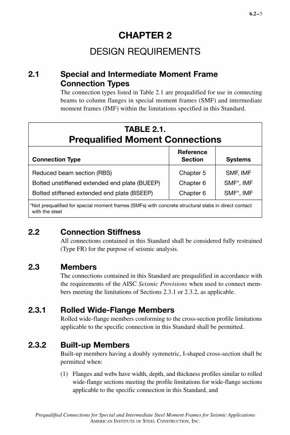
2.1 Special and Intermediate Moment Frame Connection TypesThe connection types listed in Table 2.1 are prequalified for use in connectingbeams to column flanges in special moment frames (SMF) and intermediatemoment frames (IMF) within the limitations specified in this Standard.
TABLE 2.1.Prequalified Moment Connections
ReferenceConnection Type Section Systems
Reduced beam section (RBS) Chapter 5 SMF, IMF
Bolted unstiffened extended end plate (BUEEP) Chapter 6 SMF*, IMF
Bolted stiffened extended end plate (BSEEP) Chapter 6 SMF*, IMF
*Not prequalified for special moment frames (SMFs) with concrete structural slabs in direct contactwith the steel
2.2 Connection Stiffness All connections contained in this Standard shall be considered fully restrained(Type FR) for the purpose of seismic analysis.
2.3 MembersThe connections contained in this Standard are prequalified in accordance withthe requirements of the AISC Seismic Provisions when used to connect mem-bers meeting the limitations of Sections 2.3.1 or 2.3.2, as applicable.
2.3.1 Rolled Wide-Flange MembersRolled wide-flange members conforming to the cross-section profile limitationsapplicable to the specific connection in this Standard shall be permitted.
2.3.2 Built-up MembersBuilt-up members having a doubly symmetric, I-shaped cross-section shall bepermitted when:
(1) Flanges and webs have width, depth, and thickness profiles similar to rolledwide-flange sections meeting the profile limitations for wide-flange sectionsapplicable to the specific connection in this Standard, and
6.2–
AISC_Prequalified_1 1/27/07 7:02 AM Page 5
6 CHAPTER 2. DESIGN REQUIREMENTS
Prequalified Connections for Special and Intermediate Steel Moment Frames for Seismic ApplicationsAMERICAN INSTITUTE OF STEEL CONSTRUCTION, INC.
(2) Webs are continuously connected to flanges in accordance with the re-quirements of Sections 2.3.2a or 2.3.2b, as applicable.
2.3.2a BeamsWithin a zone extending from the beam end to a distance not less than one beamdepth beyond the plastic hinge location, Sh, unless specifically indicated in thisStandard the web and flanges shall be connected using complete joint penetration(CJP) groove welds with a pair of reinforcing fillet welds. The minimum size of thesefillet welds shall be the lesser of 5/16 in. (8 mm) or the thickness of the beam web.
Exception: This provision shall not apply where individual connection pre-qualifications specify other requirements.
2.3.2b ColumnsBuilt-up columns shall conform to the provisions of subsections (1) through(4), as applicable. Built-up columns shall satisfy the requirements of AISCSpecification Section E6 except as modified in this Section. Transfer of allinternal forces and stresses between elements of the built-up column shall bethrough welds.
1. I-Shaped Welded ColumnsThe elements of built-up I-shaped columns shall conform to the requirementsof the AISC Seismic Provisions.
Within a zone extending from 12 in. (300 mm) above the upper beam flange to12 in. (300 mm) below the lower beam flange, unless specifically indicated inthis Standard, the column webs and flanges shall be connected using CJP groovewelds with a pair of reinforcing fillet welds. The minimum size of fillet weldsshall be the lesser of 5/16 in. (8 mm) or the thickness of the column web.
2. Boxed Wide-Flange ColumnsThe wide-flange shape of a boxed wide-flange column shall conform to therequirements of the AISC Seismic Provisions.
The width-to-thickness ratio (b/t) of plates used as flanges shall not exceed0.6�Es /Fy� , where b shall be taken as not less than the clear distance betweenplates.
The width-to-thickness ratio (h/tw) of plates used only as webs shall conformto the provisions of Table I–8–1 of the AISC Seismic Provisions.
Within a zone extending from 12 in. (300 mm) above the upper beam flange to12 in. (300 mm) below the lower beam flange, flange and web plates of boxedwide-flange columns shall be joined by CJP groove welds. Outside this zone,plate elements shall be continuously connected by fillet or groove welds.
3. Built-up Box ColumnsThe width-to-thickness ratio (b/t) of plates used as flanges shall not exceed0.6�Es /Fy� , where b shall be taken as not less than the clear distance betweenweb plates.
6.2–
AISC_Prequalified_1 1/27/07 7:02 AM Page 6
7
Prequalified Connections for Special and Intermediate Steel Moment Frames for Seismic ApplicationsAMERICAN INSTITUTE OF STEEL CONSTRUCTION, INC.
The width-to-thickness ratio (h/tw ) of plates used only as webs shall con-form to the requirements of the AISC Seismic Provisions.
Within a zone extending from 12 in. (300 mm) above the upper beam flangeto 12 in. (300 mm) below the lower beam flange, flange and web platesof box columns shall be joined by CJP groove welds. Outside this zone, boxcolumn web and flange plates shall be continuously connected by filletwelds or groove welds.
4. Flanged Cruciform ColumnsThe elements of flanged cruciform columns, whether fabricated from rolledshapes or built up from plates, shall meet the requirements of the AISC SeismicProvisions.
User Note: For flanged cruciform columns, the provisions of AISCSpecification Section E6 must be considered.
Within a zone extending from 12 in. (300 mm) above the upper beam flangeto 12 in. (300 mm) below the lower beam flange, the web of the tee-shapedsections shall be welded to the web of the continuous I-shaped section withCJP groove welds with a pair of reinforcing fillet welds. The minimum sizeof fillet welds shall be the lesser of 5/16 in. (300 mm) or the thickness ofthe column web. Continuity plates shall conform to the requirements forwide-flange columns.
2.4 Connection Design Parameters
2.4.1 Load Combinations and Resistance FactorsWhere available strengths are calculated in accordance with the AISC Specification,the resistance factors specified therein shall apply. When available strengths arecalculated in accordance with this Standard, the resistance factors φd and φn shallbe used as specified in the applicable section of this Standard. The values of φdand φn shall be taken as:
(a) For ductile limit states:
φd = 1.00
(b) For non-ductile limit states:
φn = 0.90
2.4.2 Plastic Hinge LocationThe distance of the plastic hinge from the face of the column, Sh, shall betaken in accordance with the requirements for the individual connection asspecified herein.
CHAPTER 2. DESIGN REQUIREMENTS 6.2–
AISC_Prequalified_1 1/27/07 7:02 AM Page 7

8 CHAPTER 2. DESIGN REQUIREMENTS
Prequalified Connections for Special and Intermediate Steel Moment Frames for Seismic ApplicationsAMERICAN INSTITUTE OF STEEL CONSTRUCTION, INC.
2.4.3 Probable Maximum Moment at Plastic HingeThe probable maximum moment at the location of the plastic hinge shall betaken as:
Mpr = Cpr RyFyZe (2.4.3-1)
whereMpr = probable maximum moment at plastic hinge, kip-in. (N-mm)
Ry = ratio of the expected yield stress to the specified minimum yieldstress Fy; see AISC Seismic Provisions
Ze = effective plastic modulus of the section (or connection) at the locationof the plastic hinge, in.3 (mm3)
Cpr = factor to account for the peak connection strength, including strainhardening, local restraint, additional reinforcement, and other connection conditions. Unless otherwise specifically indicated in thisStandard, the value of Cpr shall be:
(2.4.3-2)
whereFy = specified minimum yield stress of the type of steel to be used in the
yielding element, ksi (MPa)
Fu = specified minimum tensile strength of the type of steel to be used in theyielding element, ksi (MPa)
2.4.4 Beam Flange Continuity PlatesContinuity plates shall be provided.
Exceptions:
(1) For bolted end-plate connections, the provisions of Section 6 shall apply.
(2) When the beam flange connects to the flange of a wide-flange or built-upI-shaped column having a thickness that satisfies Equations 2.4.4-1 and2.4.4-2, continuity plates need not be provided:
(2.4.4-1)
(2.4.4-2)
wheretcf = minimum required thickness of column flange when no continuity
plates are provided, in. (mm)
6.2–
CF +F
Fpry u
y
= ≤2
1 2.
t b tF R
F Rcf bf bfyb yb
yc yc
≥ 0 4 1 8. .
tb
cfbf≥6
AISC_Prequalified_1 1/27/07 7:02 AM Page 8
9
Prequalified Connections for Special and Intermediate Steel Moment Frames for Seismic ApplicationsAMERICAN INSTITUTE OF STEEL CONSTRUCTION, INC.
bbf = beam flange width, in. (mm)
tbf = beam flange thickness, in. (mm)
Fyb = specified minimum yield stress of the beam flange, ksi (MPa)
Fyc = specified minimum yield stress of the column flange, ksi (MPa)
Ryb = ratio of the expected yield stress of the beam material to the specified minimum yield stress, per the AISC Seismic Provisions
Ryc = ratio of the expected yield stress of the column material to the specifiedminimum yield stress, per the AISC Seismic Provisions
(3) When the beam flange connects to the flange of the I-shape in a boxedwide-flange column having a thickness that satisfies Equations 2.4.4-3and 2.4.4-4, continuity plates need not be provided.
(2.4.4-3)
(2.4.4-4)
2.4.4a Continuity Plate ThicknessWhere continuity plates are required, the thickness of the plates shall be determinedas follows:
(a) For one-sided (exterior) connections, continuity plate thickness shall be atleast one-half of the thickness of the beam flange.
(b) For two-sided (interior) connections, the continuity plate thickness shall beat least equal to the thicker of the two beam flanges on either side of thecolumn.
Continuity plates shall also conform to the requirements of Section J10 of the AISCSpecification.
2.4.4b Continuity Plate to Column AttachmentContinuity plates, if provided, shall be welded to column flanges using CJPgroove welds.
Continuity plates shall be welded to column webs using groove welds or filletwelds. The required strength of the sum of the welded joints of the continuityplates to the column web shall be the smallest of the following:
(a) The sum of the design strengths in tension of the contact areas of the continuityplates to the column flanges that have attached beam flanges.
(b) The design strength in shear of the contact area of the plate with the columnweb.
CHAPTER 2. DESIGN REQUIREMENTS 6.2–
tb
cff≥
12
tb
bb
b
cfbf
cfcf
bf≥ − −
0 4 14
1.2
..8b tF R
F Rb f bfyb yb
yc yc
AISC_Prequalified_1 1/27/07 7:02 AM Page 9
10 CHAPTER 2. DESIGN REQUIREMENTS
Prequalified Connections for Special and Intermediate Steel Moment Frames for Seismic ApplicationsAMERICAN INSTITUTE OF STEEL CONSTRUCTION, INC.
(c) The design strength in shear of the column panel zone.
(d) The sum of the expected yield strengths of the beam flanges transmittingforce to the continuity plates.
2.5 Panel ZonesPanel zones shall conform to the minimum requirements for SMF or IMF, asapplicable, in Section 9.3 or Section 10.3 of the AISC Seismic Provisions.References to matching of tested connections shall not apply.
2.6 Protected ZoneThe protected zone shall be as defined for each prequalified connection. Theprotected zone shall meet the requirements of Section 7.4 of the AISC SeismicProvisions, except as indicated in this Standard. Unless otherwise specificallyindicated in this Standard, the protected zone of the beam shall be defined asthe area from the face of the column flange to one-half of the beam depth beyondthe theoretical hinge point. Bolt holes in beam webs, when detailed in accordancewith the individual connection provisions of this Standard, shall be permitted.
6.2–
AISC_Prequalified_1 1/27/07 7:02 AM Page 10
11
Prequalified Connections for Special and Intermediate Steel Moment Frames for Seismic ApplicationsAMERICAN INSTITUTE OF STEEL CONSTRUCTION, INC.
CHAPTER 3
WELDING REQUIREMENTS
3.1 Filler MetalsFiller metals shall conform to the requirements of Section 7.3 and Appendix Wof the AISC Seismic Provisions.
3.2 Welding Procedures Welding procedures shall be in accordance with Section 7.3 and Appendix Wof the AISC Seismic Provisions.
3.3 Backing at Beam to Column and Continuity Plate toColumn Joints
3.3.1 Steel Backing at Continuity PlatesSteel backing used at continuity plate to column welds need not be removed. Atcolumn flanges, steel backing left in place shall be attached to the columnflange using a continuous 5/16-in. (8-mm) fillet weld on the edge below theCJP groove weld.
When backing is removed, following the removal of backing, the root pass shallbe backgouged to sound weld metal and backwelded with a reinforcing fillet.The reinforcing fillet shall be continuous with a minimum size of 5/16 in. (8 mm).
3.3.2 Steel Backing at Beam Bottom FlangeWhere steel backing is used with CJP groove welds between the bottom beamflange and the column, the backing shall be removed.
Following the removal of backing, the root pass shall be backgouged to soundweld metal and backwelded with a reinforcing fillet. The size of the reinforcingfillet leg adjacent to the column shall be a minimum of 5/16 in. (8 mm), and thereinforcing fillet leg adjacent to the beam flange shall be such that the fillet toeis located on the beam flange base metal.
Exception: If the base metal and weld root are ground smooth after removal ofbacking, the reinforcing fillet adjacent to the beam flange need not extend tobase metal.
3.3.3 Steel Backing at Beam Top FlangeWhere steel backing is used with CJP groove welds between the top beam flangeand the column, and the backing is not removed, the backing shall be attached tothe column by a continuous 5/16-in. (8-mm) fillet weld on the edge below theCJP groove weld.
6.2–
AISC_Prequalified_1 1/27/07 7:02 AM Page 11
12 CHAPTER 3. WELDING REQUIREMENTS
Prequalified Connections for Special and Intermediate Steel Moment Frames for Seismic ApplicationsAMERICAN INSTITUTE OF STEEL CONSTRUCTION, INC.
3.3.4 Prohibited Welds at Steel BackingBacking at beam flange-to-column flange joints shall not be welded to theunderside of the beam flange, nor shall tack welds be permitted at this location.If fillet welds or tack welds are placed between the backing and the beam flangein error, they shall be repaired as follows:
(1) The weld shall be removed such that the fillet weld or tack weld no longerattaches the backing to the beam flange.
(2) The surface of the beam flange shall be ground flush and shall be free ofdefects.
(3) Any gouges or notches shall be repaired. Repair welding shall be done withE7018 SMAW electrodes or other filler metals meeting the requirementsof Section 3.1 for demand critical welds. A special welding procedure spec-ification (WPS) is required for this repair. Following welding, the repairweld shall be ground smooth.
3.3.5 Non-Fusible Backing at Beam Flange-to-ColumnJointsWhere non-fusible backing is used with CJP groove welds between the beamflanges and the column, the backing shall be removed, the root backgouged tosound weld metal and backwelded with a reinforcing fillet. The size of the rein-forcing fillet leg adjacent to the column shall be a minimum of 5/16 in. (8 mm) andthe reinforcing fillet leg adjacent to the beam flange shall be such that the fillettoe is located on the beam flange base metal.
Exception: If the base metal and weld root is ground smooth after removal ofbacking, the reinforcing fillet adjacent to the beam flange need not extend tobase metal.
3.4 Details and Treatment of Weld TabsWhere used, weld tabs shall be removed to within 1/8 in. (3 mm) of the basemetal surface and the end of the weld finished, except at continuity plates whereremoval to within 1/4 in. (6 mm) of the plate edge shall be permitted. Removal shallbe by air carbon arc cutting (CAC-A), grinding, chipping, or thermal cutting. Theprocess shall be controlled to minimize errant gouging. The edges where weld tabshave been removed shall be finished to a surface roughness of 500 microinches(13 micron) or better. The contour of the weld end shall provide a smooth tran-sition to adjacent surfaces, free of notches, gouges and sharp corners. Welddefects greater than 1/16-in. (1.6-mm) deep shall be excavated and repaired bywelding in accordance with an applicable WPS. Other weld defects shall beremoved by grinding, faired to a slope not greater than 1:5.
6.2–
AISC_Prequalified_1 1/27/07 7:02 AM Page 12
13
Prequalified Connections for Special and Intermediate Steel Moment Frames for Seismic ApplicationsAMERICAN INSTITUTE OF STEEL CONSTRUCTION, INC.
3.5 Tack WeldsIn the protected zone, tack welds attaching backing and weld tabs shall be placedwhere they will be incorporated into a final weld.
3.6 Continuity Plates Along the web, the corner clip shall be detailed so that the clip extends a dis-tance of at least 11/2 in. (38 mm) beyond the published “k” detail dimension forthe rolled shape. Along the flange, the plate shall be clipped to avoid interfer-ence with the radius of the rolled shape and shall be detailed so that the clip doesnot exceed a distance of 1/2 in. (12 mm) beyond the published “k1” detail di-mension. The clip shall be detailed to facilitate suitable weld terminations forboth the flange weld and the web weld. When a curved clip is used, it shall havea minimum radius of 1/2 in. (12 mm).
At the end of the weld adjacent to the column web/flange juncture, weld tabsfor continuity plates shall not be used, except when permitted by the engineer ofrecord. Unless specified to be removed by the engineer of record, weld tabs shallnot be removed when used in this location.
Where continuity plate welds are made without weld tabs near the column filletradius, weld layers shall be permitted to be transitioned at an angle of 0° to 45°measured from the vertical plane. The effective length of the weld shall be definedas that portion of the weld having full size. Non-destructive testing (NDT) shallnot be required on the tapered or transition portion of the weld not having full size.
3.7 Quality Control and Quality AssuranceQuality control and quality assurance shall be in accordance with Appendix Q ofthe AISC Seismic Provisions.
CHAPTER 3. WELDING REQUIREMENTS 6.2–
AISC_Prequalified_1 1/27/07 7:02 AM Page 13
14
Prequalified Connections for Special and Intermediate Steel Moment Frames for Seismic ApplicationsAMERICAN INSTITUTE OF STEEL CONSTRUCTION, INC.
CHAPTER 4
BOLTING REQUIREMENTS
4.1 Fastener AssembliesBolts shall be pretensioned high-strength bolts conforming to ASTM A325 orA490. Twist-off type tension control bolt assemblies of equivalent mechanicalproperties and chemical composition may be substituted for A325 and A490fastener assemblies.
4.2 Installation RequirementsInstallation requirements shall be in accordance with AISC Seismic Provisionsand the RCSC Specification, except as otherwise specifically indicated in thisStandard.
4.3 Quality Control and Quality AssuranceQuality control and quality assurance shall be in accordance with Appendix Q ofthe AISC Seismic Provisions.
6.2–
AISC_Prequalified_1 1/27/07 7:02 AM Page 14
15
Prequalified Connections for Special and Intermediate Steel Moment Frames for Seismic ApplicationsAMERICAN INSTITUTE OF STEEL CONSTRUCTION, INC.
CHAPTER 5
REDUCED BEAM SECTION (RBS) MOMENT CONNECTION
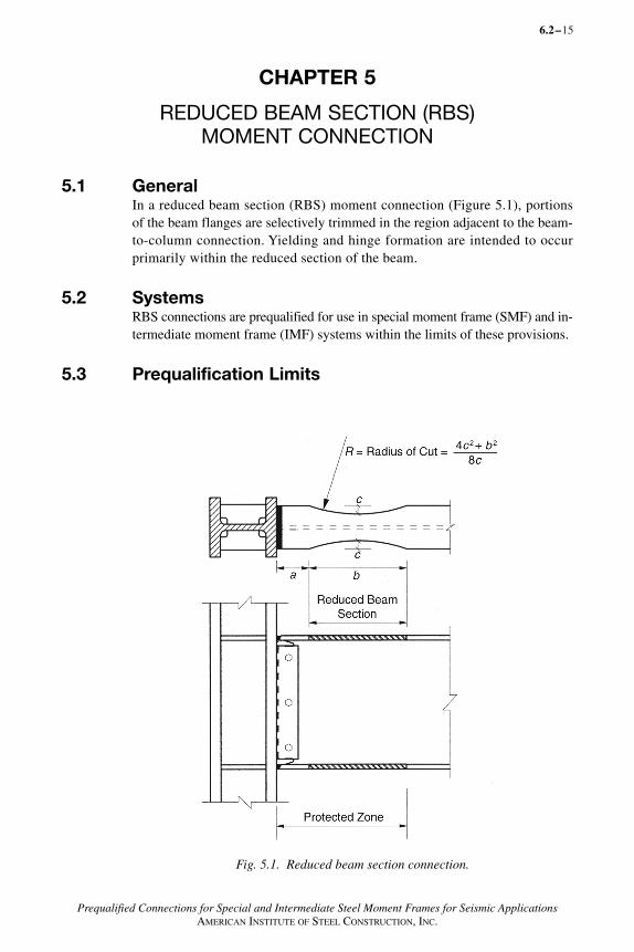
5.1 GeneralIn a reduced beam section (RBS) moment connection (Figure 5.1), portionsof the beam flanges are selectively trimmed in the region adjacent to the beam-to-column connection. Yielding and hinge formation are intended to occurprimarily within the reduced section of the beam.
5.2 SystemsRBS connections are prequalified for use in special moment frame (SMF) and in-termediate moment frame (IMF) systems within the limits of these provisions.
5.3 Prequalification Limits
6.2–
Fig. 5.1. Reduced beam section connection.
AISC_Prequalified_1 1/27/07 7:02 AM Page 15
16 CHAPTER 5. REDUCED BEAM SECTION (RBS) MOMENT CONNECTION
Prequalified Connections for Special and Intermediate Steel Moment Frames for Seismic ApplicationsAMERICAN INSTITUTE OF STEEL CONSTRUCTION, INC.
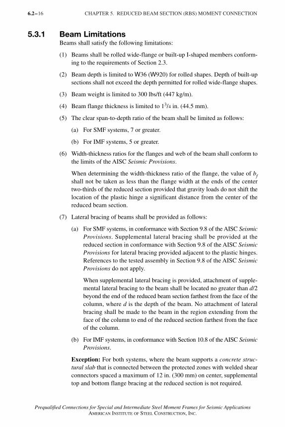
5.3.1 Beam LimitationsBeams shall satisfy the following limitations:
(1) Beams shall be rolled wide-flange or built-up I-shaped members conform-ing to the requirements of Section 2.3.
(2) Beam depth is limited to W36 (W920) for rolled shapes. Depth of built-upsections shall not exceed the depth permitted for rolled wide-flange shapes.
(3) Beam weight is limited to 300 lbs/ft (447 kg/m).
(4) Beam flange thickness is limited to 13/4 in. (44.5 mm).
(5) The clear span-to-depth ratio of the beam shall be limited as follows:
(a) For SMF systems, 7 or greater.
(b) For IMF systems, 5 or greater.
(6) Width-thickness ratios for the flanges and web of the beam shall conform tothe limits of the AISC Seismic Provisions.
When determining the width-thickness ratio of the flange, the value of bfshall not be taken as less than the flange width at the ends of the centertwo-thirds of the reduced section provided that gravity loads do not shift thelocation of the plastic hinge a significant distance from the center of thereduced beam section.
(7) Lateral bracing of beams shall be provided as follows:
(a) For SMF systems, in conformance with Section 9.8 of the AISC SeismicProvisions. Supplemental lateral bracing shall be provided at thereduced section in conformance with Section 9.8 of the AISC SeismicProvisions for lateral bracing provided adjacent to the plastic hinges.References to the tested assembly in Section 9.8 of the AISC SeismicProvisions do not apply.
When supplemental lateral bracing is provided, attachment of supple-mental lateral bracing to the beam shall be located no greater than d/2beyond the end of the reduced beam section farthest from the face of thecolumn, where d is the depth of the beam. No attachment of lateralbracing shall be made to the beam in the region extending from theface of the column to end of the reduced section farthest from the faceof the column.
(b) For IMF systems, in conformance with Section 10.8 of the AISC SeismicProvisions.
Exception: For both systems, where the beam supports a concrete struc-tural slab that is connected between the protected zones with welded shearconnectors spaced a maximum of 12 in. (300 mm) on center, supplementaltop and bottom flange bracing at the reduced section is not required.
6.2–
AISC_Prequalified_1 1/27/07 7:02 AM Page 16
17
Prequalified Connections for Special and Intermediate Steel Moment Frames for Seismic ApplicationsAMERICAN INSTITUTE OF STEEL CONSTRUCTION, INC.
(8) The protected zone consists of the portion of beam between the face of thecolumn and the end of the reduced beam section cut farthest from the faceof the column.
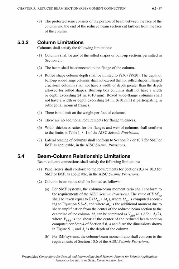
5.3.2 Column LimitationsColumns shall satisfy the following limitations:
(1) Columns shall be any of the rolled shapes or built-up sections permitted inSection 2.3.
(2) The beam shall be connected to the flange of the column.
(3) Rolled shape column depth shall be limited to W36 (W920). The depth ofbuilt-up wide-flange columns shall not exceed that for rolled shapes. Flangedcruciform columns shall not have a width or depth greater than the depthallowed for rolled shapes. Built-up box columns shall not have a widthor depth exceeding 24 in. (610 mm). Boxed wide-flange columns shallnot have a width or depth exceeding 24 in. (610 mm) if participating inorthogonal moment frames.
(4) There is no limit on the weight per foot of columns.
(5) There are no additional requirements for flange thickness.
(6) Width-thickness ratios for the flanges and web of columns shall conformto the limits in Table I–8–1 of the AISC Seismic Provisions.
(7) Lateral bracing of columns shall conform to Section 9.7 or 10.7 for SMF orIMF, as applicable, in the AISC Seismic Provisions.
5.4 Beam-Column Relationship LimitationsBeam-column connections shall satisfy the following limitations:
(1) Panel zones shall conform to the requirements for Sections 9.3 or 10.3 forSMF or IMF, as applicable, in the AISC Seismic Provisions.
(2) Column-beam ratios shall be limited as follows:
(a) For SMF systems, the column-beam moment ratio shall conform tothe requirements of the AISC Seismic Provisions. The value of Σ M*
pbshall be taken equal to Σ (Mpr + Mv), where Mpr is computed accord-ing to Equation 5.8–5, and where Mv is the additional moment due toshear amplification from the center of the reduced beam section to thecenterline of the column. Mv can be computed as VRBS (a + b/2 + dc/2),where VRBS is the shear at the center of the reduced beam sectioncomputed per Step 4 of Section 5.8, a and b are the dimensions shownin Figure 5.1, and dc is the depth of the column.
(b) For IMF systems, the column-beam moment ratio shall conform to therequirements of Section 10.6 of the AISC Seismic Provisions.
CHAPTER 5. REDUCED BEAM SECTION (RBS) MOMENT CONNECTION 6.2–
AISC_Prequalified_1 1/27/07 7:02 AM Page 17
18 CHAPTER 5. REDUCED BEAM SECTION (RBS) MOMENT CONNECTION
Prequalified Connections for Special and Intermediate Steel Moment Frames for Seismic ApplicationsAMERICAN INSTITUTE OF STEEL CONSTRUCTION, INC.
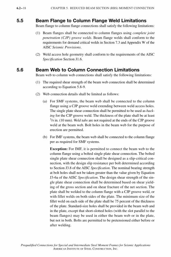
5.5 Beam Flange to Column Flange Weld LimitationsBeam flange to column flange connections shall satisfy the following limitations:
(1) Beam flanges shall be connected to column flanges using complete jointpenetration (CJP) groove welds. Beam flange welds shall conform to therequirements for demand critical welds in Section 7.3 and Appendix W of theAISC Seismic Provisions.
(2) Weld access hole geometry shall conform to the requirements of the AISCSpecification Section J1.6.
5.6 Beam Web to Column Connection LimitationsBeam web to column web connections shall satisfy the following limitations:
(1) The required shear strength of the beam web connection shall be determinedaccording to Equation 5.8-9.
(2) Web connection details shall be limited as follows:
(a) For SMF systems, the beam web shall be connected to the columnflange using a CJP groove weld extending between weld access holes.The single plate shear connection shall be permitted to be used as back-ing for the CJP groove weld. The thickness of the plate shall be at least3/8 in. (10 mm). Weld tabs are not required at the ends of the CJP grooveweld at the beam web. Bolt holes in the beam web for the purpose oferection are permitted.
(b) For IMF systems, the beam web shall be connected to the column flangeper as required for SMF systems.
Exception: For IMF, it is permitted to connect the beam web to thecolumn flange using a bolted single plate shear connection. The boltedsingle plate shear connection shall be designed as a slip-critical con-nection, with the design slip resistance per bolt determined accordingto Section J3.8 of the AISC Specification. The nominal bearing strengthat bolt holes shall not be taken greater than the value given by EquationJ3-6a of the AISC Specification. The design shear strength of the sin-gle plate shear connection shall be determined based on shear yield-ing of the gross section and on shear fracture of the net section. Theplate shall be welded to the column flange with a CJP groove weld, orwith fillet welds on both sides of the plate. The minimum size of thefillet weld on each side of the plate shall be 75 percent of the thicknessof the plate. Standard-size holes shall be provided in the beam web andin the plate, except that short-slotted holes (with the slot parallel to thebeam flanges) may be used in either the beam web or in the plate,but not in both. Bolts are permitted to be pretensioned either before orafter welding.
6.2–
AISC_Prequalified_1 1/27/07 7:02 AM Page 18
Prequalified Connections for Special and Intermediate Steel Moment Frames for Seismic ApplicationsAMERICAN INSTITUTE OF STEEL CONSTRUCTION, INC.
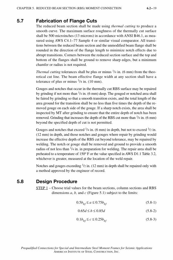
5.7 Fabrication of Flange CutsThe reduced beam section shall be made using thermal cutting to produce asmooth curve. The maximum surface roughness of the thermally cut surfaceshall be 500 microinches (13 microns) in accordance with ANSI B46.1, as mea-sured using AWS C4.1–77 Sample 4 or similar visual comparator. All transi-tions between the reduced beam section and the unmodified beam flange shall berounded in the direction of the flange length to minimize notch effects due toabrupt transitions. Corners between the reduced section surface and the top andbottom of the flanges shall be ground to remove sharp edges, but a minimumchamfer or radius is not required.
Thermal cutting tolerances shall be plus or minus 1/4 in. (6 mm) from the theo-retical cut line. The beam effective flange width at any section shall have atolerance of plus or minus 3/8 in. (10 mm).
Gouges and notches that occur in the thermally cut RBS surface may be repairedby grinding if not more than 1/4 in. (6 mm) deep. The gouged or notched area shallbe faired by grinding so that a smooth transition exists, and the total length of thearea ground for the transition shall be no less than five times the depth of the re-moved gouge on each side of the gouge. If a sharp notch exists, the area shall beinspected by MT after grinding to ensure that the entire depth of notch has beenremoved. Grinding that increases the depth of the RBS cut more than 1/4 in. (6 mm)beyond the specified depth of cut is not permitted.
Gouges and notches that exceed 1/4 in. (6 mm) in depth, but not to exceed 1/2 in.(12 mm) in depth, and those notches and gouges where repair by grinding wouldincrease the effective depth of the RBS cut beyond tolerance, may be repaired bywelding. The notch or gouge shall be removed and ground to provide a smoothradius of not less than 1/4 in. in preparation for welding. The repair area shall bepreheated to a temperature of 150o F or the value specified in AWS D1.1 Table 3.2,whichever is greater, measured at the location of the weld repair.
Notches and gouges exceeding 1/2 in. (12 mm) in depth shall be repaired only witha method approved by the engineer of record.
5.8 Design ProcedureSTEP 1 – Choose trial values for the beam sections, column sections and RBS
dimensions a, b, and c (Figure 5.1) subject to the limits:
0.5bbf ≤ a ≤ 0.75bbf (5.8-1)
0.65d ≤ b ≤ 0.85d (5.8-2)
0.1bbf ≤ c ≤ 0.25bbf (5.8-3)
CHAPTER 5. REDUCED BEAM SECTION (RBS) MOMENT CONNECTION 6.2– 19
AISC_Prequalified_1 1/27/07 7:02 AM Page 19
20 CHAPTER 5. REDUCED BEAM SECTION (RBS) MOMENT CONNECTION
Prequalified Connections for Special and Intermediate Steel Moment Frames for Seismic ApplicationsAMERICAN INSTITUTE OF STEEL CONSTRUCTION, INC.
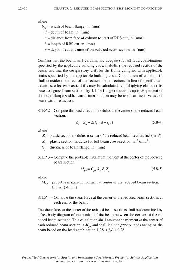
wherebbf = width of beam flange, in. (mm)
d = depth of beam, in. (mm)
a = distance from face of column to start of RBS cut, in. (mm)
b = length of RBS cut, in. (mm)
c = depth of cut at center of the reduced beam section, in. (mm)
Confirm that the beams and columns are adequate for all load combinationsspecified by the applicable building code, including the reduced section of thebeam, and that the design story drift for the frame complies with applicablelimits specified by the applicable building code. Calculation of elastic driftshall consider the effect of the reduced beam section. In lieu of specific cal-culations, effective elastic drifts may be calculated by multiplying elastic driftsbased on gross beam sections by 1.1 for flange reductions up to 50 percent ofthe beam flange width. Linear interpolation may be used for lesser values ofbeam width reduction.
STEP 2 – Compute the plastic section modulus at the center of the reduced beamsection:
Ze = Zx − 2ctbf (d − tbf ) (5.8-4)
whereZe = plastic section modulus at center of the reduced beam section, in.3 (mm3)
Zx = plastic section modulus for full beam cross-section, in.3 (mm3)
tbf = thickness of beam flange, in. (mm)
STEP 3 – Compute the probable maximum moment at the center of the reducedbeam section:
Mpr = Cpr Ry Fy Ze (5.8-5)
whereMpr = probable maximum moment at center of the reduced beam section,
kip-in. (N-mm)
STEP 4 – Compute the shear force at the center of the reduced beam sections ateach end of the beam.
The shear force at the center of the reduced beam sections shall be determined bya free body diagram of the portion of the beam between the centers of the re-duced beam sections. This calculation shall assume the moment at the center ofeach reduced beam section is Mpr and shall include gravity loads acting on thebeam based on the load combination 1.2D + f1L + 0.2S
6.2–
AISC_Prequalified_1 1/27/07 7:02 AM Page 20
21
Prequalified Connections for Special and Intermediate Steel Moment Frames for Seismic ApplicationsAMERICAN INSTITUTE OF STEEL CONSTRUCTION, INC.
wheref1 = load factor determined by the applicable building code for live loads,
but not less than 0.5
STEP 5 – Compute the probable maximum moment at the face of the column.
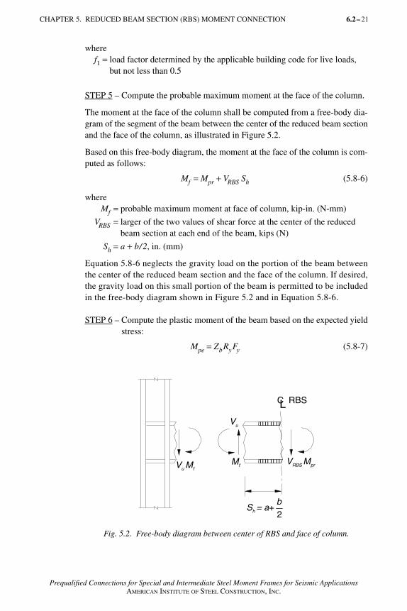
The moment at the face of the column shall be computed from a free-body dia-gram of the segment of the beam between the center of the reduced beam sectionand the face of the column, as illustrated in Figure 5.2.
Based on this free-body diagram, the moment at the face of the column is com-puted as follows:
Mf = Mpr + VRBS Sh (5.8-6)
whereMf = probable maximum moment at face of column, kip-in. (N-mm)
VRBS = larger of the two values of shear force at the center of the reducedbeam section at each end of the beam, kips (N)
Sh = a + b/2, in. (mm)
Equation 5.8-6 neglects the gravity load on the portion of the beam betweenthe center of the reduced beam section and the face of the column. If desired,the gravity load on this small portion of the beam is permitted to be includedin the free-body diagram shown in Figure 5.2 and in Equation 5.8-6.
STEP 6 – Compute the plastic moment of the beam based on the expected yieldstress:
Mpe = ZbRyFy (5.8-7)
CHAPTER 5. REDUCED BEAM SECTION (RBS) MOMENT CONNECTION 6.2–
LC RBS
Mf VRBS Mpr
Sh = a+2b
Vu
Vu Mf
Fig. 5.2. Free-body diagram between center of RBS and face of column.
AISC_Prequalified_1 1/27/07 7:02 AM Page 21
22 CHAPTER 5. REDUCED BEAM SECTION (RBS) MOMENT CONNECTION
Prequalified Connections for Special and Intermediate Steel Moment Frames for Seismic ApplicationsAMERICAN INSTITUTE OF STEEL CONSTRUCTION, INC.
whereMpe = plastic moment of beam based on expected yield stress, kip-in.
(N-mm)
STEP 7 – Check that Mf does not exceed φd Mpe, as follows:
Mf ≤ φd Mpe (5.8-8)
If Equation 5.8-8 is not satisfied, increase the value of c and/or decrease thevalues of a and b, and repeat Steps 2 through 7.
STEP 8 – Determine the required shear strength Vu of beam and beam web-to-column connection from:
(5.8-9)
whereVu = required shear strength of beam and beam web-to-column
connection, kips (N)
L′ = distance between the centers of the reduced beam sections,in. (mm)
Vgravity = beam shear force resulting from 1.2D + f1L + 0.2S, kips (N)
f1 = load factor determined by the applicable building code for liveloads, but not less than 0.5
Check design shear strength of beam according to Chapter G of the AISCSpecification.
STEP 9 – Design the beam web-to-column connection according to Section 5.6.
STEP 10 – Check continuity plate requirements according to Chapter 2.
STEP 11 – Check column panel zone according to Section 5.4.
STEP 12 – Check column-beam moment ratio according to Section 5.4.
6.2–
VM
LVu
prgravity=
′+
2
AISC_Prequalified_1 1/27/07 7:02 AM Page 22
23
Prequalified Connections for Special and Intermediate Steel Moment Frames for Seismic ApplicationsAMERICAN INSTITUTE OF STEEL CONSTRUCTION, INC.
CHAPTER 6
BOLTED UNSTIFFENED AND STIFFENED EXTENDEDEND-PLATE MOMENT CONNECTIONS
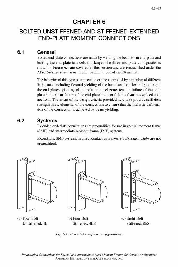
6.1 GeneralBolted end-plate connections are made by welding the beam to an end-plate andbolting the end-plate to a column flange. The three end-plate configurationsshown in Figure 6.1 are covered in this section and are prequalified under theAISC Seismic Provisions within the limitations of this Standard.
The behavior of this type of connection can be controlled by a number of differentlimit states including flexural yielding of the beam section, flexural yielding ofthe end-plates, yielding of the column panel zone, tension failure of the end-plate bolts, shear failure of the end-plate bolts, or failure of various welded con-nections. The intent of the design criteria provided here is to provide sufficientstrength in the elements of the connections to ensure that the inelastic deforma-tion of the connection is achieved by beam yielding.
6.2 SystemsExtended end-plate connections are prequalified for use in special moment frame(SMF) and intermediate moment frame (IMF) systems.
Exception: SMF systems in direct contact with concrete structural slabs are notprequalified.
6.2–
Fig. 6.1. Extended end-plate configurations.
(b) Four-Bolt Stiffened, 4ES
(a) Four-Bolt Unstiffened, 4E
(c) Eight-Bolt Stiffened, 8ES
AISC_Prequalified_1 1/27/07 7:02 AM Page 23
6.2–
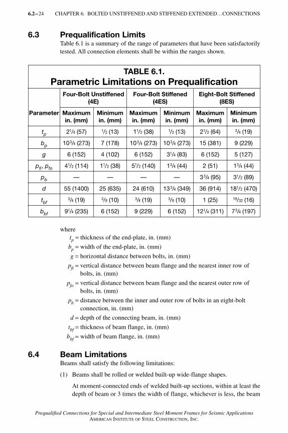
6.3 Prequalification LimitsTable 6.1 is a summary of the range of parameters that have been satisfactorilytested. All connection elements shall be within the ranges shown.
wheretp = thickness of the end-plate, in. (mm)
bp = width of the end-plate, in. (mm)
g = horizontal distance between bolts, in. (mm)
pfi = vertical distance between beam flange and the nearest inner row ofbolts, in. (mm)
pfo = vertical distance between beam flange and the nearest outer row ofbolts, in. (mm)
pb = distance between the inner and outer row of bolts in an eight-bolt connection, in. (mm)
d = depth of the connecting beam, in. (mm)
tbf = thickness of beam flange, in. (mm)
bbf = width of beam flange, in. (mm)
6.4 Beam LimitationsBeams shall satisfy the following limitations:
(1) Beams shall be rolled or welded built-up wide-flange shapes.
At moment-connected ends of welded built-up sections, within at least thedepth of beam or 3 times the width of flange, whichever is less, the beam
24 CHAPTER 6. BOLTED UNSTIFFENED AND STIFFENED EXTENDED…CONNECTIONS
Prequalified Connections for Special and Intermediate Steel Moment Frames for Seismic ApplicationsAMERICAN INSTITUTE OF STEEL CONSTRUCTION, INC.
TABLE 6.1.Parametric Limitations on Prequalification
Four-Bolt Unstiffened Four-Bolt Stiffened Eight-Bolt Stiffened(4E) (4ES) (8ES)
Parameter Maximum Minimum Maximum Minimum Maximum Minimumin. (mm) in. (mm) in. (mm) in. (mm) in. (mm) in. (mm)
tp 21/4 (57) 1/2 (13) 11/2 (38) 1/2 (13) 21/2 (64) 3/4 (19)
bp 103/4 (273) 7 (178) 103/4 (273) 103/4 (273) 15 (381) 9 (229)
g 6 (152) 4 (102) 6 (152) 31/4 (83) 6 (152) 5 (127)
pfi, pfo 41/2 (114) 11/2 (38) 51/2 (140) 13/4 (44) 2 (51) 13/4 (44)
pb — — — — 33/4 (95) 31/2 (89)
d 55 (1400) 25 (635) 24 (610) 133/4 (349) 36 (914) 181/2 (470)
tbf3/4 (19) 3/8 (10) 3/4 (19) 3/8 (10) 1 (25) 19/32 (16)
bbf 91/4 (235) 6 (152) 9 (229) 6 (152) 121/4 (311) 73/4 (197)
AISC_Prequalified_1 1/27/07 7:02 AM Page 24
25
Prequalified Connections for Special and Intermediate Steel Moment Frames for Seismic ApplicationsAMERICAN INSTITUTE OF STEEL CONSTRUCTION, INC.
web and flanges shall be connected using either a CJP groove weld or apair of fillet welds each having a size 3/4 times the beam web thicknessbut not less than 1/4 in. (6 mm). For the remainder of the beam, the weld sizeshall not be less than that required to accomplish shear transfer from the webto the flanges.
(2) Beam depth, d, is limited to values shown in Table 6.1.
(3) There is no limit on the weight per foot of beams.
(4) Beam flange thickness is limited to the values shown in Table 6.1.
(5) The clear span-to-depth ratio of the beam shall be limited as follows:
(a) For SMF systems, 7 or greater.
(b) For IMF systems, 5 or greater.
(6) Width–thickness ratios for the flanges and web of the beam shall conform tothe limits of the AISC Seismic Provisions.
(7) Lateral bracing of beams shall be provided as follows:
(a) For SMF systems, in conformance with Section 9.8 of the AISC SeismicProvisions.
(b) For IMF systems, in conformance with Section 10.8 of the AISC SeismicProvisions.
(8) The protected zone shall be determined as follows:
(a) For unstiffened extended end-plate connections: the portion of beambetween the face of the column and a distance equal to the depth ofthe beam or 3 times the width of flange from the face of the column,whichever is less.
(b) For stiffened extended end-plate connections: the portion of beam be-tween the face of the column and a distance equal to the location ofthe end of the stiffener plus one-half the depth of the beam or 3 timesthe width of the beam flange, whichever is less.
6.5 Column LimitationsColumns shall satisfy the following limitations:
(1) The end-plate shall be connected to the flange of the column.
(2) The column depth shall be limited to the beam depth or shallower.
(3) There is no limit on the weight per foot of columns.
(4) There are no additional requirements for flange thickness.
(5) Width–thickness ratios for the flanges and web of the column shall conformto the limits in Table I–8–1 of the AISC Seismic Provisions.
CHAPTER 6. BOLTED UNSTIFFENED AND STIFFENED EXTENDED…CONNECTIONS 6.2–
AISC_Prequalified_1 1/27/07 7:02 AM Page 25
26 CHAPTER 6. BOLTED UNSTIFFENED AND STIFFENED EXTENDED…CONNECTIONS
Prequalified Connections for Special and Intermediate Steel Moment Frames for Seismic ApplicationsAMERICAN INSTITUTE OF STEEL CONSTRUCTION, INC.
6.6 Beam-Column Relationship LimitationsBeam-to-column connections shall satisfy the following limitations:
(1) Panel zones shall conform to the requirements of Sections 9.3 or 10.3 forSMF or IMF, as applicable, in the AISC Seismic Provisions.
(2) The column-beam moment ratio shall conform to the requirements for SMFor IMF, as applicable, in the AISC Seismic Provisions.
6.7 Continuity PlatesContinuity plates shall satisfy the following limitations:
(1) The need for continuity plates shall be determined in accordance withSection 6.10.
(2) When provided, continuity plates shall conform to the requirements ofSection 6.10.
(3) Continuity plates shall be attached to columns by welds in accordance withSection 2.4.4b and Section 3.6.
Exception: Continuity plates less than or equal to 3/8 in. (10 mm) shall bepermitted to be welded to column flanges using double-sided fillet welds. Therequired strength of the fillet weld shall not be less than Fy Ac, where Ac is definedas the contact areas between the continuity plate and the column flanges thathave attached beam flanges and Fy is defined as the specified minimum yieldstress of the continuity plate.
6.8 BoltsBolts shall conform to the requirements of Section 4.
6.2–
AISC_Prequalified_1 1/27/07 7:02 AM Page 26
27
Prequalified Connections for Special and Intermediate Steel Moment Frames for Seismic ApplicationsAMERICAN INSTITUTE OF STEEL CONSTRUCTION, INC.
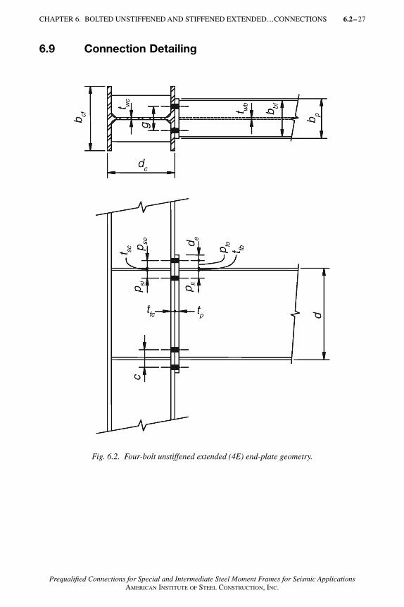
6.9 Connection Detailing
CHAPTER 6. BOLTED UNSTIFFENED AND STIFFENED EXTENDED…CONNECTIONS 6.2–
Fig. 6.2. Four-bolt unstiffened extended (4E) end-plate geometry.
AISC_Prequalified_1 1/27/07 7:02 AM Page 27
6.2–28 CHAPTER 6. BOLTED UNSTIFFENED AND STIFFENED EXTENDED…CONNECTIONS
Prequalified Connections for Special and Intermediate Steel Moment Frames for Seismic ApplicationsAMERICAN INSTITUTE OF STEEL CONSTRUCTION, INC.
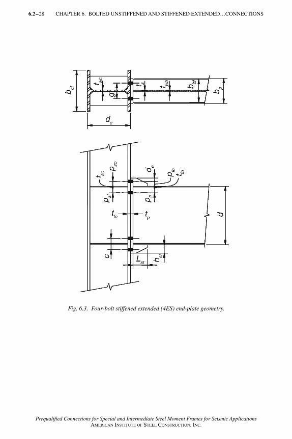
Fig. 6.3. Four-bolt stiffened extended (4ES) end-plate geometry.
AISC_Prequalified_1 1/27/07 7:02 AM Page 28
CHAPTER 6. BOLTED UNSTIFFENED AND STIFFENED EXTENDED…CONNECTIONS 6.2– 29
Prequalified Connections for Special and Intermediate Steel Moment Frames for Seismic ApplicationsAMERICAN INSTITUTE OF STEEL CONSTRUCTION, INC.
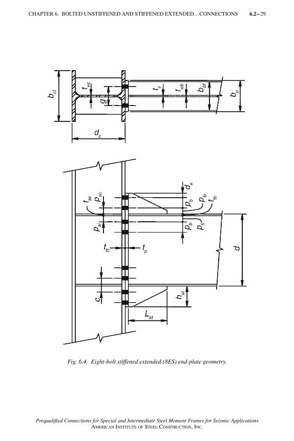
Fig. 6.4. Eight-bolt stiffened extended (8ES) end-plate geometry.
AISC_Prequalified_1 1/27/07 7:02 AM Page 29
30 CHAPTER 6. BOLTED UNSTIFFENED AND STIFFENED EXTENDED…CONNECTIONS
Prequalified Connections for Special and Intermediate Steel Moment Frames for Seismic ApplicationsAMERICAN INSTITUTE OF STEEL CONSTRUCTION, INC.
6.9.1 GageThe gage, g, is as defined in Figures 6.2 through 6.4. The maximum gage dimen-sion is limited to the width of the connected beam flange.
6.9.2 Pitch and Row SpacingThe minimum pitch distance is the bolt diameter plus 1/2 in. (12 mm) for bolts upto 1-in. (25-mm) diameter, and the bolt diameter plus 3/4 in. (19 mm) for largerdiameter bolts. The pitch distance, pfi and pfo, is the distance from the face ofthe beam flange to the centerline of the nearer bolt row, as shown in Figures 6.2through 6.4.
The spacing, pb, is as defined in Figure 6.4. The spacing of the bolt rows shall beat least 22/3 times the bolt diameter.
User Note: A distance of 3 times the bolt diameter is preferred. The distanceshall be sufficient to provide clearance for any welds in the region.
6.9.3 End-Plate WidthThe width of the end-plate shall be greater than or equal to the connected beamflange width. The effective end-plate width shall not be taken as greater than theconnected beam flange plus 1 in. (25 mm).
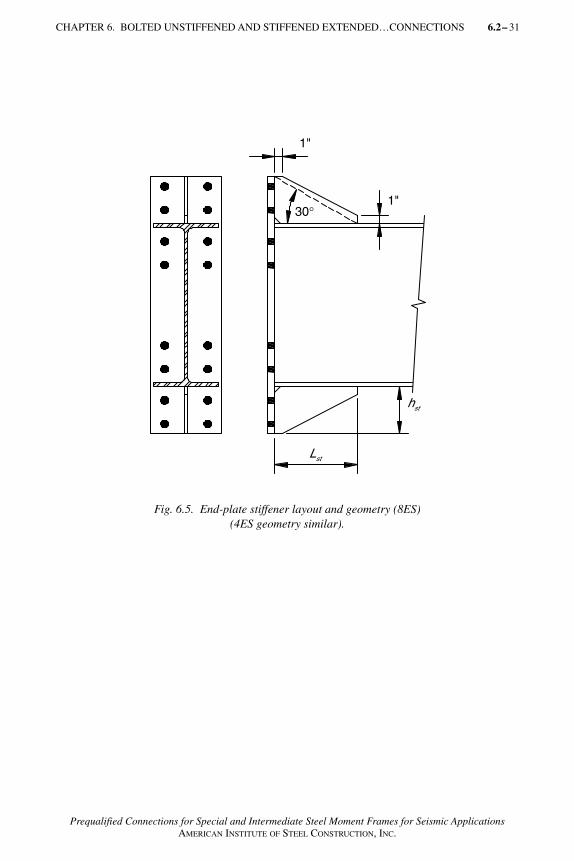
6.9.4 End-Plate StiffenerThe two extended stiffened end-plate connections, Figures 6.1(b) and (c), requirea gusset plate welded between the connected beam flange and the end-plate. Theminimum stiffener length shall be:
(6.9-1)
where hst is the height of the end-plate from the outside face of the beam flangeto the end of the end-plate (see Figure 6.5).
The stiffener plates shall be terminated at the beam flange and at the end of theend-plate with landings approximately 1 in. (25 mm) long. The stiffener shallbe clipped where it meets the beam flange and end-plate to provide clearancebetween the stiffener and the beam flange weld.
When the beam and end-plate stiffeners have the same material strengths, thethickness of the stiffeners shall be greater than or equal to the beam web thick-ness. If the beam and end-plate stiffener have different material strengths, thethickness of the stiffener shall be greater than the ratio of the beam-to-stiffenerplate material yield stress times the beam web thickness.
6.2–
Lh
stst=
tan30�
AISC_Prequalified_1 1/27/07 7:02 AM Page 30
CHAPTER 6. BOLTED UNSTIFFENED AND STIFFENED EXTENDED…CONNECTIONS 6.2– 31
Prequalified Connections for Special and Intermediate Steel Moment Frames for Seismic ApplicationsAMERICAN INSTITUTE OF STEEL CONSTRUCTION, INC.
Fig. 6.5. End-plate stiffener layout and geometry (8ES)(4ES geometry similar).
AISC_Prequalified_1 1/27/07 7:02 AM Page 31
32 CHAPTER 6. BOLTED UNSTIFFENED AND STIFFENED EXTENDED…CONNECTIONS
Prequalified Connections for Special and Intermediate Steel Moment Frames for Seismic ApplicationsAMERICAN INSTITUTE OF STEEL CONSTRUCTION, INC.
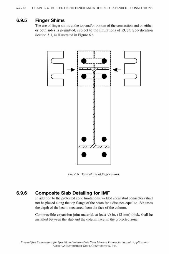
6.9.5 Finger ShimsThe use of finger shims at the top and/or bottom of the connection and on eitheror both sides is permitted, subject to the limitations of RCSC SpecificationSection 5.1, as illustrated in Figure 6.6.
6.2–
Fig. 6.6. Typical use of finger shims.
6.9.6 Composite Slab Detailing for IMFIn addition to the protected zone limitations, welded shear stud connectors shallnot be placed along the top flange of the beam for a distance equal to 11/2 timesthe depth of the beam, measured from the face of the column.
Compressible expansion joint material, at least 1/2-in. (12-mm) thick, shall beinstalled between the slab and the column face, in the protected zone.
AISC_Prequalified_1 1/27/07 7:02 AM Page 32
33
Prequalified Connections for Special and Intermediate Steel Moment Frames for Seismic ApplicationsAMERICAN INSTITUTE OF STEEL CONSTRUCTION, INC.
6.9.7 Welding DetailsWelding of the beam to the end-plate shall conform to the following limitations:
(1) Weld access holes shall not be used.
(2) The beam web to end-plate joint shall be made using either fillet welds orcomplete joint penetration (CJP) groove welds. When used, the fillet weldsshall be sized to develop the full strength of the beam web in tension fromthe inside face of the flange to 6 in. (150 mm) beyond the bolt row farthestfrom the beam flange.
(3) The beam flange to end-plate joint shall be made using a CJP groove weldwithout backing. The CJP groove weld shall be made such that the root ofthe weld is on the beam web side of the flange. The inside face of the flangeshall have a 5/16-in. (8-mm) fillet weld. These welds shall be demand critical.
(4) Backgouging of the root is not required in the flange directly above andbelow the beam web for a length equal to 1.5k1. A full-depth PJP grooveweld shall be permitted at this location.
(5) When used, all end-plate stiffener joints shall be made using CJP groovewelds.
Exception: When the stiffener is 3/8-in. (10-mm) thick or less, it shall bepermitted to use fillet welds that develop the strength of the stiffener.
6.10 Design ProcedureConnection geometry is shown in Figures 6.2, 6.3, and 6.4 for the 4E, 4ES, and8ES connections, respectively.
End-Plate and Bolt Design
(1) Determine the sizes of the connected members (beams and column) andcompute the moment at the face of the column, Mf .
Mf = Mpe + VuSh (6.9-2)
whereMpe = Cpr RyFyZx (6.9-3)
Vu = 2Mpe /L ′ + Vgravity
Sh = distance from the face of the column to the plastic hinge,in. (mm)
= the lesser of d/2 or 3bbf for unstiffened connection (4E) (6.9-4)
= Lst + tp (6.9-5)
Ry = the ratio of the expected yield stress to the specifiedminimum yield stress, from the AISC Seismic Provisions
CHAPTER 6. BOLTED UNSTIFFENED AND STIFFENED EXTENDED…CONNECTIONS 6.2–
AISC_Prequalified_1 1/27/07 7:02 AM Page 33
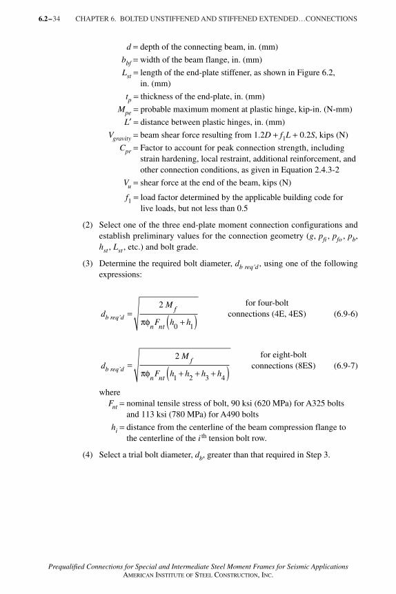
34 CHAPTER 6. BOLTED UNSTIFFENED AND STIFFENED EXTENDED…CONNECTIONS
Prequalified Connections for Special and Intermediate Steel Moment Frames for Seismic ApplicationsAMERICAN INSTITUTE OF STEEL CONSTRUCTION, INC.
d = depth of the connecting beam, in. (mm)
bbf = width of the beam flange, in. (mm)
Lst = length of the end-plate stiffener, as shown in Figure 6.2,in. (mm)
tp = thickness of the end-plate, in. (mm)
Mpe = probable maximum moment at plastic hinge, kip-in. (N-mm)
L′ = distance between plastic hinges, in. (mm)
Vgravity = beam shear force resulting from 1.2D + f1L + 0.2S, kips (N)
Cpr = Factor to account for peak connection strength, includingstrain hardening, local restraint, additional reinforcement, andother connection conditions, as given in Equation 2.4.3-2
Vu = shear force at the end of the beam, kips (N)
f1 = load factor determined by the applicable building code forlive loads, but not less than 0.5
(2) Select one of the three end-plate moment connection configurations andestablish preliminary values for the connection geometry (g, pfi , pfo , pb,hst , Lst , etc.) and bolt grade.
(3) Determine the required bolt diameter, db req’d , using one of the followingexpressions:
for four-bolt connections (4E, 4ES) (6.9-6)
for eight-bolt connections (8ES) (6.9-7)
whereFnt = nominal tensile stress of bolt, 90 ksi (620 MPa) for A325 bolts
and 113 ksi (780 MPa) for A490 bolts
hi = distance from the centerline of the beam compression flange tothe centerline of the i th tension bolt row.
(4) Select a trial bolt diameter, db, greater than that required in Step 3.
6.2–
=+( )
2
0 1
M
F h h
f
n ntπφ
=+ + +( )
2
1 2 3 4
M
F h h h h
f
n ntπφ
db req’d
db req’d
AISC_Prequalified_1 1/27/07 7:02 AM Page 34
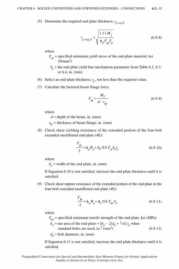
CHAPTER 6. BOLTED UNSTIFFENED AND STIFFENED EXTENDED…CONNECTIONS 6.2– 35
Prequalified Connections for Special and Intermediate Steel Moment Frames for Seismic ApplicationsAMERICAN INSTITUTE OF STEEL CONSTRUCTION, INC.
(5) Determine the required end-plate thickness, tp req’d.
(6.9-8)
whereFyp = specified minimum yield stress of the end-plate material, ksi
(N/mm2)
Yp = the end-plate yield line mechanism parameter from Table 6.2, 6.3,or 6.4, in. (mm)
(6) Select an end-plate thickness, tp , not less than the required value.
(7) Calculate the factored beam flange force.
(6.9-9)
whered = depth of the beam, in. (mm)
tbf = thickness of beam flange, in. (mm)
(8) Check shear yielding resistance of the extended portion of the four-boltextended unstiffened end-plate (4E):
(6.9-10)
wherebp = width of the end-plate, in. (mm)
If Equation 6.10 is not satisfied, increase the end-plate thickness until it issatisfied.
(9) Check shear rupture resistance of the extended portion of the end-plate in thefour-bolt extended unstiffened end-plate (4E):
(6.9-11)
whereFup = specified minimum tensile strength of the end-plate, ksi (MPa)
An = net area of the end-plate = [bp − 2(db + 1/8)] tp when standard holes are used, in.2 (mm2) (6.9-12)
db = bolt diameter, in. (mm)
If Equation 6.11 is not satisfied, increase the end-plate thickness until it issatisfied.
tM
F Yp req’df
d yp p
=1 11.
φ
FM
d tfubf
f=−
FR
fud n2
< φ = φd 0.6 Fypbptp
= φn 0.6 FupAn
FR
fun n2
< φ
AISC_Prequalified_1 1/27/07 7:02 AM Page 35
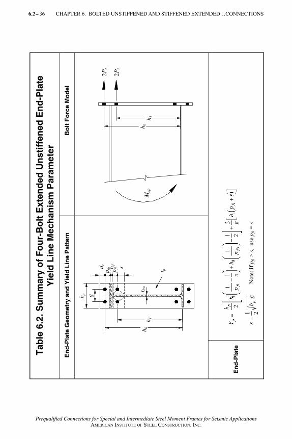
6.2– 36 CHAPTER 6. BOLTED UNSTIFFENED AND STIFFENED EXTENDED…CONNECTIONS
Prequalified Connections for Special and Intermediate Steel Moment Frames for Seismic ApplicationsAMERICAN INSTITUTE OF STEEL CONSTRUCTION, INC.
Tab
le 6
.2. S
um
mar
y o
f F
ou
r-B
olt
Ext
end
ed U
nst
iffe
ned
En
d-P
late
Y
ield
Lin
e M
ech
anis
m P
aram
eter
En
d-P
late
Geo
met
ry a
nd
Yie
ld L
ine
Pat
tern
B
olt
Fo
rce
Mo
del
En
d-P
late
gb
sp
21
N
ote
: If
pfi >
s, u
se p
fi =
s
h1
h0
gbp
t bw
t p
st bf
de
2P
t
2P
t
Mnp
h1
h0
pfo pfi
AISC_Prequalified_1 1/27/07 7:02 AM Page 36

CHAPTER 6. BOLTED UNSTIFFENED AND STIFFENED EXTENDED…CONNECTIONS 6.2– 37
Prequalified Connections for Special and Intermediate Steel Moment Frames for Seismic ApplicationsAMERICAN INSTITUTE OF STEEL CONSTRUCTION, INC.
Tab
le 6
.3. S
um
mar
y o
f F
ou
r-B
olt
Ext
end
ed S
tiff
ened
En
d-P
late
Y
ield
Lin
e M
ech
anis
m P
aram
eter
En
d-P
late
Geo
met
ry a
nd
Yie
ld L
ine
Pat
tern
Bo
lt F
orc
e M
od
el
Cas
e 1
(de
< s
)
Cas
e 2
(de
> s
)
En
d-
Pla
te
gb
sp
21 N
ote
: If
pfi >
s,
use
pfi =
s
Mn
p
2P
t
2P
t
h0
h1
t p
g
t cw
bp
st bf
pfi
pfo
de
h0
h1
t p
bp
t bw
g
pfo pfi
ss
h1
h0
t bf
Cas
e 1
de
s
Cas
e 2
de
> s
AISC_Prequalified_1 1/27/07 7:02 AM Page 37
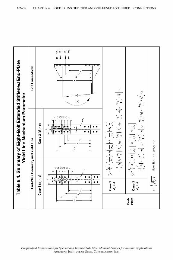
6.2–38 CHAPTER 6. BOLTED UNSTIFFENED AND STIFFENED EXTENDED…CONNECTIONS
Prequalified Connections for Special and Intermediate Steel Moment Frames for Seismic ApplicationsAMERICAN INSTITUTE OF STEEL CONSTRUCTION, INC.
AISC_Prequalified_1 1/27/07 7:02 AM Page 38
CHAPTER 6. BOLTED UNSTIFFENED AND STIFFENED EXTENDED…CONNECTIONS 6.2– 39
Prequalified Connections for Special and Intermediate Steel Moment Frames for Seismic ApplicationsAMERICAN INSTITUTE OF STEEL CONSTRUCTION, INC.
(10) If using either the four-bolt extended stiffened end-plate (4ES) or eight-bolt extended stiffened end-plate (8ES) connection, select the end-platestiffener thickness and design the stiffener-to-beam flange and stiffener-to-end-plate welds.
(6.9-13)
wheretbw = thickness of the beam web, in. (mm)
Fyb = specified minimum yield stress of beam material, ksi (MPa)
Fys = specified minimum yield stress of stiffener material, ksi (MPa)
The stiffener geometry shall conform to the requirements of Section 6.9.4.In addition, to prevent local buckling of the stiffener plate, the followingwidth-to-thickness criterion shall be satisfied.
(6.9-14)
wherehst = the height of the stiffener, in. (mm)
The stiffener-to-beam flange and stiffener-to-end-plate welds shall be de-signed to develop the stiffener plate in shear at the beam flange and in ten-sion at the end-plate. Either fillet or complete joint penetration (CJP) groovewelds are suitable for the weld of the stiffener plate to the beam flange. If thestiffener plate thickness is greater than 3/8 in., CJP groove welds shall beused for the stiffener-to-end-plate weld. Otherwise, double-sided fillet weldsare permitted to be used.
(11) The bolt shear rupture strength of the connection is provided by the bolts atone (compression) flange; thus
Vu < φnRn = φn(nb)Fv Ab (6.9-15)
wherenb = number of bolts at the compression flange, four for 4ES, and
eight for 8ES connections
Fv = nominal shear stress of bolts from Table J3.2 of the AISCSpecification, ksi (N/mm2)
Ab = nominal gross area of bolt, in.2 (mm2)
(6.9-16)
tF
Fbwyb
ys
=
h
t
E
Fst
s ys
0.56<
VM
LVu
pegravity=
′+
2
ts,min
AISC_Prequalified_1 1/27/07 7:02 AM Page 39
40 CHAPTER 6. BOLTED UNSTIFFENED AND STIFFENED EXTENDED…CONNECTIONS
Prequalified Connections for Special and Intermediate Steel Moment Frames for Seismic ApplicationsAMERICAN INSTITUTE OF STEEL CONSTRUCTION, INC.
(12) Check bolt-bearing/tear-out failure of the end-plate and column flange:
Vu < φnRn = φn(ni)rni + φn(no)rno (6.9-17)
whereni = number of inner bolts (two for 4E and 4ES, and four for 8ES
connections)
no = number of outer bolts (two for 4E and 4ES, and four for 8ES connections)
rni = 1.2 LctFu < 2.4 dbtFu for each inner bolt (6.9-18)
rno = 1.2 LctFu < 2.4 dbtFu for each outer bolt (6.9-19)
Lc = clear distance, in the direction of force, between the edge of thehole and the edge of the adjacent hole or edge of the material,in. (mm)
t = end-plate or column flange thickness, in. (mm)
Fu = specified minimum tensile strength of end-plate or column flangematerial, ksi (N/mm2)
db = diameter of the bolt, in. (mm)
(13) Design the flange to end-plate and web to end-plate welds using the require-ments of Section 6.9.7.
Column Side Design
(14) Check the column flange for flexural yielding
(6.9-20)
whereFyc = specified minimum yield stress of column flange material,
ksi (N/mm2)
Yc = unstiffened column flange yield line mechanism parameter fromTable 6.5 or Table 6.6, in. (mm)
tcf = column flange thickness, in. (mm)
If Equation 6.20 is not satisfied, increase the column size or add webstiffeners (continuity plates).
If stiffeners are added, Equation 6.20 must be checked using Yc for thestiffened column flange from Tables 6.5 and 6.6.
(15) If stiffeners are required for column flange flexural yielding, determine therequired stiffener force.
The column flange flexural design strength is
φdMcf = φdFycYct2cf (6.9-21)
6.2–
tM
F Ytcf req’d
f
d yc ccf= <
1 11.
φ
AISC_Prequalified_1 1/27/07 7:02 AM Page 40
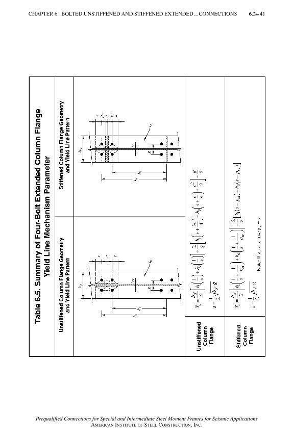
CHAPTER 6. BOLTED UNSTIFFENED AND STIFFENED EXTENDED…CONNECTIONS 6.2– 41
Prequalified Connections for Special and Intermediate Steel Moment Frames for Seismic ApplicationsAMERICAN INSTITUTE OF STEEL CONSTRUCTION, INC.
AISC_Prequalified_1 1/27/07 7:02 AM Page 41
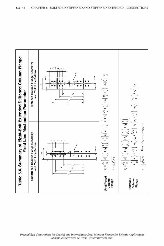
6.2–42 CHAPTER 6. BOLTED UNSTIFFENED AND STIFFENED EXTENDED…CONNECTIONS
Prequalified Connections for Special and Intermediate Steel Moment Frames for Seismic ApplicationsAMERICAN INSTITUTE OF STEEL CONSTRUCTION, INC.
AISC_Prequalified_1 1/27/07 7:02 AM Page 42

CHAPTER 6. BOLTED UNSTIFFENED AND STIFFENED EXTENDED…CONNECTIONS 6.2– 43
Prequalified Connections for Special and Intermediate Steel Moment Frames for Seismic ApplicationsAMERICAN INSTITUTE OF STEEL CONSTRUCTION, INC.
whereYc = unstiffened column yield line mechanism parameter from Table 6.5
or 6.6, in. (mm).
Therefore, the equivalent column flange design force is
(6.9-22)
Using φdRn, the required force for stiffener design is determined in Step 19.
(16) Check the local column web yielding strength of the unstiffened columnweb at the beam flanges.
Strength requirement: φdRn ≥ Ffu (6.9-23)
Rn = Ct �6kc + tbf + 2tp� Fyctcw (6.9-24)
whereCt = 0.5 if the distance from the column top to the top face of the beam
flange is less than the depth of the column
= 1.0 otherwise
kc = distance from outer face of the column flange to web toe of fillet(design value) or fillet weld, in. (mm)
tp = end-plate thickness, in. (mm)
Fyc = specified yield stress of the column web material, ksi (MPa)
tcw = column web thickness, in. (mm)
tbf = thickness of beam flange, in. (mm)
If the strength requirement (φdRn ≥ Ffu) is not satisfied, then column webcontinuity plates are required.
(17) Check the unstiffened column web buckling strength at the beam com-pression flange.
Strength requirement:
φRn ≥ Ffu (6.9-25)
where φ = 0.75
(a) When Ffu is applied a distance greater than or equal to dc/2 from the endof the column
(6.9-26)
φφ
d nd cf
bf
RM
d t=
−( )
Rt EF
hncw yc
=24 3
AISC_Prequalified_1 1/27/07 7:02 AM Page 43
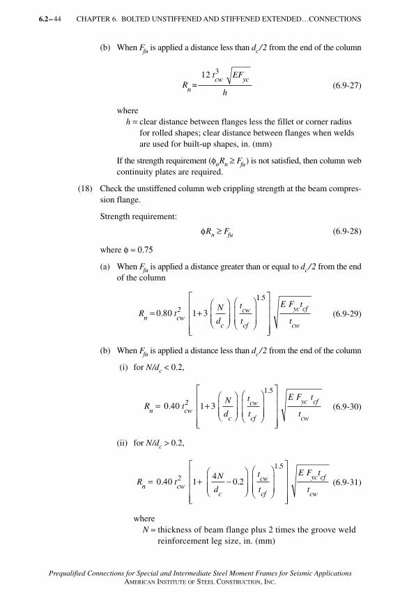
6.2– 44 CHAPTER 6. BOLTED UNSTIFFENED AND STIFFENED EXTENDED…CONNECTIONS
Prequalified Connections for Special and Intermediate Steel Moment Frames for Seismic ApplicationsAMERICAN INSTITUTE OF STEEL CONSTRUCTION, INC.
(b) When Ffu is applied a distance less than dc/2 from the end of the column
(6.9-27)
whereh = clear distance between flanges less the fillet or corner radius
for rolled shapes; clear distance between flanges when weldsare used for built-up shapes, in. (mm)
If the strength requirement (φnRn ≥ Ffu) is not satisfied, then column webcontinuity plates are required.
(18) Check the unstiffened column web crippling strength at the beam compres-sion flange.
Strength requirement:
φRn ≥ Ffu (6.9-28)
where φ = 0.75
(a) When Ffu is applied a distance greater than or equal to dc/2 from the endof the column
(6.9-29)
(b) When Ffu is applied a distance less than dc/2 from the end of the column
(i) for N/dc < 0.2,
(6.9-30)
(ii) for N/dc > 0.2,
(6.9-31)
whereN = thickness of beam flange plus 2 times the groove weld
reinforcement leg size, in. (mm)
Rt EF
hncw yc
=12 3
R tN
d
t
tn cw2
c
cw
cf
= +
0.80 1 3
11 5.
E F t
t
yc cf
cw
R tN
d
t
tn cw2
c
cw
cf
= +
0.40 1 3
1 5.E F t
t
yc cf
cw
R tN
d
t
tn cw2
c
cw
cf
= + −
0.40 1
40 2.
1 5.E F t
t
yc cf
cw
AISC_Prequalified_1 1/27/07 7:02 AM Page 44
CHAPTER 6. BOLTED UNSTIFFENED AND STIFFENED EXTENDED…CONNECTIONS 6.2– 45
Prequalified Connections for Special and Intermediate Steel Moment Frames for Seismic ApplicationsAMERICAN INSTITUTE OF STEEL CONSTRUCTION, INC.
dc = overall depth of the column, in. (mm)
If the strength requirement (φnRn ≥ Ffu) is not satisfied, then columnweb continuity plates are required.
(19) If stiffener plates are required for any of the column side limit states, therequired strength is
Fsu = Ffu − min φRn (6.9-32)
wheremin φRn = the minimum design strength value from Steps 15 (column
flange bending), 16 (column web yielding), 17 (column webbuckling), and 18 (column web crippling)
The design of the continuity plates shall also conform to section J10.8 ofthe AISC Specification, and the welds shall be designed in accordance withSection 6.7.3.
(20) Check the panel zone in accordance with Section 6.6.1.
AISC_Prequalified_1 1/27/07 7:02 AM Page 45

6.2– 46
Prequalified Connections for Special and Intermediate Steel Moment Frames for Seismic ApplicationsAMERICAN INSTITUTE OF STEEL CONSTRUCTION, INC.
AISC_Prequalified_1 1/27/07 7:02 AM Page 46
6.2–47
COMMENTARY on thePrequalified Connections forSpecial and Intermediate Steel Moment Frames for Seismic Applications
Prequalified Connections for Special and Intermediate Steel Moment Frames for Seismic Applications
December 13, 2005
Prequalified Connections for Special and Intermediate Steel Moment Frames for Seismic ApplicationsAMERICAN INSTITUTE OF STEEL CONSTRUCTION, INC.
AISC_Commentary_final 12/4/06 4:21 PM Page 47
6.2–48
Prequalified Connections for Special and Intermediate Steel Moment Frames for Seismic ApplicationsAMERICAN INSTITUTE OF STEEL CONSTRUCTION, INC.
C1. GENERAL
C1.1 ScopeSpecial moment frames (SMF) and intermediate moment frames (IMF) designedin accordance with the AISC Seismic Provisions are designed with the expecta-tion that they will experience substantial inelastic deformations when subjectedto design-level earthquake ground shaking, generally concentrated at the moment-resisting beam-to-column connections. In the 1994 Northridge earth-quake, a number of steel moment frame buildings were found to have experiencedbrittle fractures that initiated at the welded beam flange to column flange jointsof moment connections. These brittle fractures were unexpected and were quitedifferent from the anticipated behavior of ductile yielding of the beams in so-called zones of plastic hinging. Where they occurred, these brittle fracturesprevented the formation of ductile plastic hinge zones and resulted in framebehavior substantially different from that upon which the design requirementsfor these systems were based.
Following this discovery, the Federal Emergency Management Agency (FEMA)provided funding to a coalition of universities and professional associations,known as the SAC Joint Venture. Over a period of six years, the SAC JointVenture, with participation from AISC, AISI, AWS and other industry groups,conducted extensive research into the causes of the damage that had occurredin the Northridge earthquake and effective means of reducing the possibility ofsuch damage in future earthquakes.
Numerous issues were identified in the SAC studies as contributing causes ofthese brittle fractures. This Standard specifically addresses the following fourcauses that were identified in the SAC study:
(1) Connection geometries that resulted in large stress concentrations in regionsof high triaxiality and limited ability to yield;
(2) Use of weld filler metals with low inherent notch toughness and limitedductility;
(3) High variability in the yield strengths of beams and columns resulting inunanticipated zones of weakness in connection assemblies; and
(4) Welding practice and workmanship that fell outside the acceptable para-meters under the AWS D1.1 Structural Welding Code.
A more complete listing of the causes of damage sustained in the Northridgeearthquake may be found in a series of publications (FEMA 350, 2000; FEMA351, 2000; FEMA 352, 2000; FEMA 353, 2000b; FEMA 355C, 2000; FEMA355D, 2000) published by the SAC Joint Venture that presented recommendationsfor design and construction of moment resisting frames designed to experiencesubstantial inelastic deformation during design ground shaking. These recom-mendations included changes to material specifications for base metals and weld-ing filler metals, improved quality assurance procedures during construction and
AISC_Commentary_final 12/4/06 4:21 PM Page 48
COMMENTARY 6.2–49
Prequalified Connections for Special and Intermediate Steel Moment Frames for Seismic ApplicationsAMERICAN INSTITUTE OF STEEL CONSTRUCTION, INC.
the use of connection geometries that had been demonstrated by testing andanalysis to be capable of resisting appropriate levels of inelastic deformationwithout fracture. Most of these recommendations have been incorporated intothe AISC Seismic Provisions as well as a pending AWS seismic supplement to theAWS D1.1 Structural Welding Code.
Following the recommendations of the SAC Joint Venture, the AISC SeismicProvisions require that moment connections used in special or intermediate steelmoment frames be demonstrated by testing to be capable of providing the nec-essary ductility. Two means of demonstration are acceptable. One means con-sists of project-specific testing in which a limited number of full-scale specimens,representing the connections to be used in a structure, are constructed and testedin accordance with a protocol prescribed in Appendix S of the AISC SeismicProvisions. Recognizing that it is costly and time consuming to perform suchtests, the AISC Seismic Provisions also provide for prequalification of connectionsconsisting of a rigorous program of testing, analytical evaluation and review byan independent body, the connection prequalification review panel (CPRP).Connections contained in this Standard have met the criteria for prequalifica-tion when applied to framing that complies with the limitations contained hereinand when designed and detailed in accordance with this Standard.
C1.2 ReferencesReferences for this Standard are listed in the Bibliography, found at the end of theCommentary.
C1.3 GeneralConnections that are prequalified under this Standard are intended to withstandinelastic deformation through controlled yielding in specific behavioral modes.In order to obtain connections that will behave in the indicated manner, proper de-termination of the strength of the connection in various limit states is necessary.The capacity formulations contained in the LRFD method are consistent withthis approach.
AISC_Commentary_final 12/4/06 4:21 PM Page 49
6.2–50
Prequalified Connections for Special and Intermediate Steel Moment Frames for Seismic ApplicationsAMERICAN INSTITUTE OF STEEL CONSTRUCTION, INC.
C2. DESIGN REQUIREMENTS
C2.1 Special and Intermediate Moment FrameConnection TypesLimitations included in this Standard for various prequalified connections include specification of permissible materials specifications for base metals,mechanical properties for weld filler metals, member shape and profile, and connection geometry, detailing and workmanship. These limitations are basedon conditions, demonstrated by testing and analytical evaluation, for which reliableconnection behavior can be attained. It is possible that these connections canprovide reliable behavior outside these limitations; however, this has not beendemonstrated. When any condition of base metal, mechanical properties, weld fillermetals, member shape and profile, connection geometry, detailing or workman-ship falls outside the limitations specified herein, project-specific qualificationtesting should be performed to demonstrate the acceptability of connectionbehavior under these conditions.
C2.3 Members
C2.3.2 Built-up MembersThe behavior of built-up I-shaped members has been extensively tested in boltedend-plate connections and has been demonstrated to be capable of developingthe necessary inelastic deformations. These members have not generally beentested in other prequalified connections; however, the conditions of inelastic de-formation imposed on the built-up shapes in these other connection types aresimilar to those tested for the bolted end-plate connections.
C2.3.2b ColumnsFour built-up column cross-section shapes are covered by this Standard. These areillustrated in Figure C–2.1 and include
(1) I-shaped welded columns that resemble standard rolled wide-flange shapesin cross-section shape and profile.
(2) Cruciform W-shape columns, fabricated by splitting a wide-flange sectionin half and welding the webs on either side of the web of an unsplit wide-flange section at its mid-depth to form a cruciform shape, each outstandingleg of which terminates in a rectangular flange.
(3) Box columns, fabricated by welding four plates together to form a closed box-shaped cross section.
(4) Boxed W-shape columns constructed by adding side plates to the sides of anI-shaped cross section.
The preponderance of connection tests reviewed as the basis for prequalifica-tions contained in this Standard consisted of rolled wide-flange beams connected
AISC_Commentary_final 12/4/06 4:21 PM Page 50
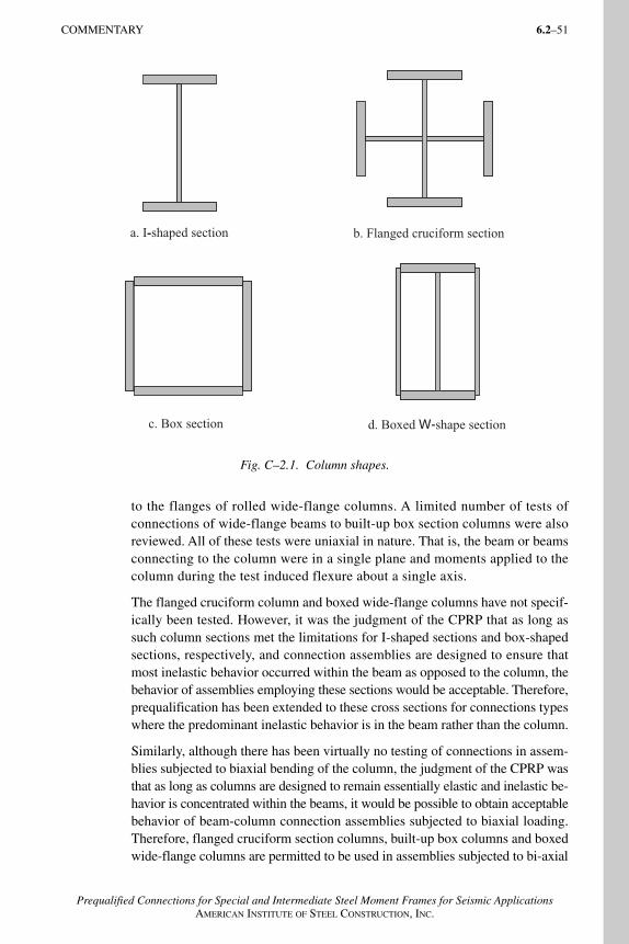
COMMENTARY 6.2–51
Prequalified Connections for Special and Intermediate Steel Moment Frames for Seismic ApplicationsAMERICAN INSTITUTE OF STEEL CONSTRUCTION, INC.
to the flanges of rolled wide-flange columns. A limited number of tests ofconnections of wide-flange beams to built-up box section columns were alsoreviewed. All of these tests were uniaxial in nature. That is, the beam or beamsconnecting to the column were in a single plane and moments applied to thecolumn during the test induced flexure about a single axis.
The flanged cruciform column and boxed wide-flange columns have not specif-ically been tested. However, it was the judgment of the CPRP that as long assuch column sections met the limitations for I-shaped sections and box-shaped sections, respectively, and connection assemblies are designed to ensure thatmost inelastic behavior occurred within the beam as opposed to the column, thebehavior of assemblies employing these sections would be acceptable. Therefore,prequalification has been extended to these cross sections for connections typeswhere the predominant inelastic behavior is in the beam rather than the column.
Similarly, although there has been virtually no testing of connections in assem-blies subjected to biaxial bending of the column, the judgment of the CPRP wasthat as long as columns are designed to remain essentially elastic and inelastic be-havior is concentrated within the beams, it would be possible to obtain acceptablebehavior of beam-column connection assemblies subjected to biaxial loading.Therefore, flanged cruciform section columns, built-up box columns and boxedwide-flange columns are permitted to be used in assemblies subjected to bi-axial
a. I-shaped section
c. Box section
- b. Flanged cruciform section
d. Boxed W-shape section
Fig. C–2.1. Column shapes.
AISC_Commentary_final 12/4/06 4:21 PM Page 51
6.2–52 COMMENTARY
Prequalified Connections for Special and Intermediate Steel Moment Frames for Seismic ApplicationsAMERICAN INSTITUTE OF STEEL CONSTRUCTION, INC.
loading for those connections types where inelastic behavior is concentrated inthe beam, rather than in the column.
Limited testing of connections of wide-flange beams to the webs of I-shapedcolumns had been conducted prior to the Northridge earthquake by Popov,Engelhardt and others. This testing demonstrated that these “minor-axis” con-nections were incapable of developing reliable inelastic behavior even at a timewhen major axis connections were thought capable of developing acceptable be-havior. No significant testing of such minor axis connections following theNorthridge earthquake has been conducted. Consequently, such connections arenot prequalified under this Standard.
(2) Boxed Wide-Flange Columns
Testing of connection assemblies comprising boxed wide-flange columns has notspecifically been conducted. However, the behavior of columns of this cross-section type is believed to be bounded by the behavior of standard wide-flangesection columns and that of box section columns, both of which have been tested.
(4) Flanged Cruciform Columns
Testing of connection assemblies comprised of cruciform wide-flange columnshas not specifically been conducted. However, the behavior of columns of thiscross-section type is believed to be similar to the behavior of standard wide-flange section columns that have been extensively tested.
C2.4 Connection Design Parameters
C2.4.1 Load Combinations and Resistance Factors
A significant factor considered in the formulation of resistance factors is thedesirability or undesirability of various limit states. Limit states that are con-sidered brittle and subject to sudden catastrophic failure are typically assignedlower resistance factors than those that exhibit relatively benign yielding failure.Since, for the prequalified connections, design demand is determined based onconservative estimates of the material strength of weak elements of the con-nection assembly, and materials, workmanship and quality assurance are morerigorously controlled than for other structural elements, resistance factors havebeen set somewhat higher than those traditionally used. It is believed thatthese resistance factors, when used in combination with the design, fabrication,erection and quality-assurance requirements contained in the Standard, willprovide reliable service in the prequalified connections.
C2.4.2 Plastic Hinge Location
This Standard specifies the location of the plastic hinge for each prequalified con-nection type. In reality, inelastic deformation of connection assemblies is gener-
AISC_Commentary_final 12/4/06 4:21 PM Page 52
COMMENTARY 6.2–53
Prequalified Connections for Special and Intermediate Steel Moment Frames for Seismic ApplicationsAMERICAN INSTITUTE OF STEEL CONSTRUCTION, INC.
ally distributed to some extent throughout the connection assembly. The plastichinge locations specified herein are based on observed behavior during connectionassembly tests and indicate the locations of most anticipated inelastic deformationin connection assemblies conforming to the particular prequalified type.
C2.4.3 Probable Maximum Moment at Plastic HingeThe probable plastic moment at the plastic hinge is intended to be a conservativeestimate of the maximum moment likely to be developed by the connection undercyclic inelastic response. It includes consideration of likely material overstrengthand strain hardening.
C2.4.4 Beam Flange Continuity PlatesBeam flange continuity plates serve several purposes in moment connections.They help to distribute beam flange forces to the column web, they stiffen the col-umn web to prevent local crippling under the concentrated beam-flange forces andthey minimize stress concentrations that can occur in the joint between beamflange and column due to non-uniform stiffness of the attached elements.
When the beam flange connects to the flange of a wide-flange, built-up I-shapeor cruciform W-shaped column in which the column extends above and below thebeam and the column flange thickness satisfies Equations 2.4.4-1 and 2.4.4-2, con-tinuity plates are not required as beam-flange forces can be adequately trans-ferred to the column webs without the stiffening effects and secondary load pathsprovided by these plates. However, these equations have been developed basedon consideration of the behavior of columns in lower stories of buildings, wherethe column extends a considerable distance above the top flange of the connectedbeam. Equations 2.4.4-1 and 2.4.4-2 do not apply in the top story of a building,where the column terminates at approximately the level of the top flange of thebeam. In such cases beam-flange continuity plates or column cap plates, havinga thickness not less than that of the connected beam flange, should be provided.Figure C–2.2 presents a detail for such a connection, where the beam flange iswelded directly to the cap plate and the cap plate is welded to the column so asto deliver the beam-flange forces to the column web.
Alternatively, if the column projects sufficiently above the beam top flange,Equations 2.4.4-1 and 2.4.4.-2 can be considered valid. Although comprehen-sive research to establish the necessary distance the column must extend abovethe beam for this purpose has not been performed, it may be sufficient if the col-umn is extended a distance not less than dc/2 or bf / 2, whichever is less, above thetop beam flange.
For boxed wide-flange section columns in which the beams are connected to theflange of the I-shaped section, Equations 2.4.4-3 and 2.4.4-4 have been developedto provide a similar stiffness of column flange as that provided by Equations2.4.4-1 and 2.4.4-2 for unboxed sections. As with Equations 2.4.4-1 and 2.4.4-2,Equations 2.4.4-3 and 2.4.4-4 are not strictly valid for the case of a moment
AISC_Commentary_final 12/4/06 4:21 PM Page 53
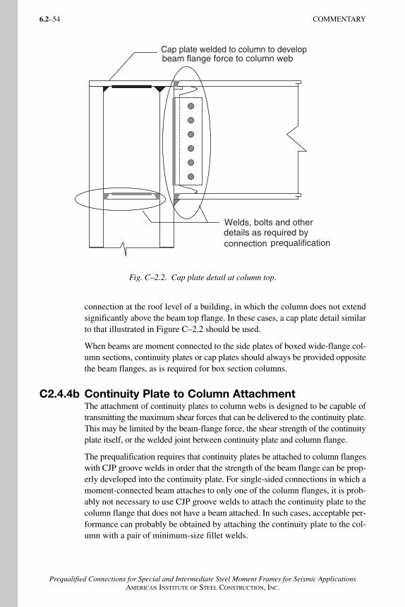
6.2–54 COMMENTARY
Prequalified Connections for Special and Intermediate Steel Moment Frames for Seismic ApplicationsAMERICAN INSTITUTE OF STEEL CONSTRUCTION, INC.
connection at the roof level of a building, in which the column does not extendsignificantly above the beam top flange. In these cases, a cap plate detail similarto that illustrated in Figure C–2.2 should be used.
When beams are moment connected to the side plates of boxed wide-flange col-umn sections, continuity plates or cap plates should always be provided oppositethe beam flanges, as is required for box section columns.
C2.4.4b Continuity Plate to Column AttachmentThe attachment of continuity plates to column webs is designed to be capable oftransmitting the maximum shear forces that can be delivered to the continuity plate.This may be limited by the beam-flange force, the shear strength of the continuityplate itself, or the welded joint between continuity plate and column flange.
The prequalification requires that continuity plates be attached to column flangeswith CJP groove welds in order that the strength of the beam flange can be prop-erly developed into the continuity plate. For single-sided connections in which amoment-connected beam attaches to only one of the column flanges, it is prob-ably not necessary to use CJP groove welds to attach the continuity plate to thecolumn flange that does not have a beam attached. In such cases, acceptable per-formance can probably be obtained by attaching the continuity plate to the col-umn with a pair of minimum-size fillet welds.
Fig. C–2.2. Cap plate detail at column top.
Welds, bolts and other details as required by connection prequalification
Cap plate welded to column to developbeam flange force to column web
AISC_Commentary_final 12/4/06 4:21 PM Page 54
6.2–55
Prequalified Connections for Special and Intermediate Steel Moment Frames for Seismic ApplicationsAMERICAN INSTITUTE OF STEEL CONSTRUCTION, INC.
C3. WELDING REQUIREMENTS
C3.3 Backing at Beam-to-Column and Continuity-Plate-to-Column JointsAt the root of groove welds between beam flanges or continuity plates to columnflanges, the inherent lack of fusion plane between the left-in-place steel backingand the column flange creates a stress concentration and notch effect, even whenthe weld has uniform and sound fusion at the root. When ultrasonic testing isperformed, this left-in-place backing may mask significant flaws that may existat the weld root. These flaws may create a more severe notch condition than thatcaused by the backing itself (Chi and others, 1997).
C3.3.1 Steel Backing at Continuity PlatesThe stress and strain level at the groove weld between continuity plate and col-umn flange is considerably different than that at the beam flange-to-columnflange connection; therefore it is not necessary to remove the backing. The additionof the fillet weld beneath the backing makes the inherent notch at the interface aninternal notch, rather than an external notch, reducing the notch effect. Whenbacking is removed, the reinforcing fillet weld reduces the stress concentrationat the right-angle intersection of the continuity plate and the column flange.
C3.3.2 Steel Backing at Beam Bottom FlangeThe removal of backing, whether fusible or non-fusible, followed by backgoug-ing to sound weld metal, is performed so that potential root defects within thewelded joint are detected and eliminated, and the stress concentration at the weldroot is eliminated.
The influence of left-in-place steel backing is more severe on the bottom flange,as compared to the top flange, because at the bottom flange, the stress concen-tration from the backing occurs at the point of maximum applied and secondarytensile stresses in the groove weld, at the weld root, and at the outer fiber of thebeam flange.
A reinforcing fillet weld with a 5/16-in. (8-mm) leg on the column flange helps toreduce the stress concentration at the right-angle intersection of the beam flangeand column flange, and is placed at the location of maximum stress. The filletweld’s horizontal leg may need to be larger than 5/16 in. (8 mm) to completelycover the weld root area, eliminating the potential for multiple weld toes at the rootthat serve as small stress concentrations and potential fracture initiation points.When grinding the weld root and base metal area, previously deposited weld toeregions and their associated fracture initiation sites are removed, and the horizontalleg of the fillet weld need not be extended to base metal when this is done.
C3.3.3 Steel Backing at Beam Top FlangeBecause of differences in the stress and strain conditions at the top and bottomflange connections, the stress/strain concentration and notch effect created by
AISC_Commentary_final 12/4/06 4:21 PM Page 55

6.2–56 COMMENTARY
Prequalified Connections for Special and Intermediate Steel Moment Frames for Seismic ApplicationsAMERICAN INSTITUTE OF STEEL CONSTRUCTION, INC.
the backing/column interface at the top flange is at a lower level, compared to thatat the bottom flange. Therefore, backing removal is not required. The addition ofthe reinforcing fillet weld makes the inherent notch at the interface an internalnotch, rather than an external notch, further reducing the effect. Because backingremoval, backgouging, and backwelding would be performed through an accesshole beneath the top flange, these operations should be avoided whenever possible.
C3.3.4 Prohibited Welds at Steel Backing
Tack welds for beam flange-to-column connections should be made within theweld groove. Tack welds or fillet welds to the underside of beam at the backingwould direct stress into the backing itself, increasing the notch effect at thebacking/column flange interface. In addition, the weld toe of the tack weld orfillet weld on the beam flange would act as a stress concentration and a potentialfracture initiation site.
Proper removal of these welds is necessary to remove the stress concentration andpotential fracture initiation site. Any repair of gouges and notches by filling withweld metal must be made using filler metals with the required notch toughness.
C3.3.5 Non-fusible Backing at Beam Flange-to-ColumnJointsAfter backing is removed, backgouging to sound metal removes potential rootflaws within the welded joint. A reinforcing fillet weld with a 5/16-in. (8-mm)leg on the column flange helps reduce the stress concentration at the right-angleintersection of the beam flange and column flange.
The fillet weld’s horizontal leg may need to be larger than 5/16 in. (8 mm) tocompletely cover the weld root area, eliminating the potential for multipleweld toes at the root that serve as small stress concentrations and potentialfracture initiation points. When grinding the weld root and base metal area,previously deposited weld toe regions and their associated fracture initiation sitesare removed, therefore the horizontal leg of the fillet weld need not be ex-tended to base metal.
C3.4 Details and Treatment of Weld Tabs
Weld tabs are used to provide a location for initiation and termination of weldsoutside the final weld location, improving the quality of the final weld. The re-moval of weld tabs is performed to remove the weld discontinuities and defectsthat may be present at these start and stop locations. Because weld tabs are locatedat the ends of welds, any remaining weld defects at the weld-end removal areasmay act as external notches and fracture initiation sites and are therefore re-moved. A smooth transition is needed between base metal and weld to minimizestress concentrations.
AISC_Commentary_final 12/4/06 4:21 PM Page 56
COMMENTARY 6.2–57
Prequalified Connections for Special and Intermediate Steel Moment Frames for Seismic ApplicationsAMERICAN INSTITUTE OF STEEL CONSTRUCTION, INC.
C3.5 Tack WeldsTack welds outside weld joints may create unintended load paths and may createstress concentrations that become crack initiation sites when highly strained. Byplacing tack welds within the joint, the potential for surface notches and hardheat affected zones (HAZs) is minimized. When placed within the joint, the HAZof a tack weld is tempered by the subsequent passes for the final weld.
Tack welds for beam flange-to-column connections are preferably made in theweld groove. Tack welds of backing to the underside of beam flanges would beunacceptable, and any tack welds between weld backing and beam flanges are tobe removed in accordance with Section 3.3.4. Steel backing may be welded to thecolumn under the beam flange, where a reinforcing fillet is typically placed.
When tack welds for the attachment of weld tabs are placed within the weldjoint, they become part of the final weld.
C3.6 Continuity PlatesThe rotary straightening process used by steel rolling mills to straighten rolled sec-tions cold works the webs of these shapes in and near the “k-area.” This coldworking can result in an increase in hardness, yield strength, ultimate tensilestrength, and yield-to-tensile ratio; and a decrease in notch toughness. In someinstances, CVN toughness has been recorded to be less than 2 ft-lbs at 70° F [3 J at 20° C] (Barsom and Korvink, 1998). These changes do not negatively influence the in-service behavior of uncracked shapes. However, the potentialfor post-fabrication k-area base metal cracking exists in highly restrained jointsat the weld terminations for column continuity plates, web doublers and thermalcut coped beams.
When the minimum clip dimensions are used along the member web, the avail-able continuity plate length must be considered in the design and detailing ofthe welds to the web. For fillet welds, the fillet weld should be held back one totwo weld sizes from each clip. For groove welds, weld tabs should not be used inthe k-area that could cause base metal fracture from the combination of weldshrinkage, the stress concentration/notch effect at the weld end, and the lownotch-toughness web material.
When the maximum clip dimensions are used along the member flange, thewidth, hence the capacity, of the continuity plate is not reduced substantially.Care must be used in making quality weld terminations near the member radius,as the use of common weld tabs is difficult. If used, their removal in this regionmay damage the base metal, necessitating difficult repairs. The use of cascadedends within the weld groove may be used within the dimensional limits stated.Because of the incomplete filling of the groove, the unusual configuration of theweld, and the relatively low level of demand placed upon the weld at this loca-tion, NDT of cascaded weld ends in groove welds at this location need not andshould not be performed.
AISC_Commentary_final 12/4/06 4:21 PM Page 57
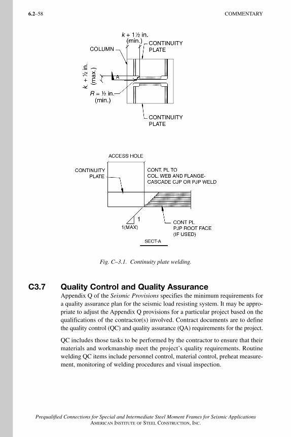
6.2–58 COMMENTARY
Prequalified Connections for Special and Intermediate Steel Moment Frames for Seismic ApplicationsAMERICAN INSTITUTE OF STEEL CONSTRUCTION, INC.
C3.7 Quality Control and Quality AssuranceAppendix Q of the Seismic Provisions specifies the minimum requirements fora quality assurance plan for the seismic load resisting system. It may be appro-priate to adjust the Appendix Q provisions for a particular project based on thequalifications of the contractor(s) involved. Contract documents are to definethe quality control (QC) and quality assurance (QA) requirements for the project.
QC includes those tasks to be performed by the contractor to ensure that theirmaterials and workmanship meet the project’s quality requirements. Routinewelding QC items include personnel control, material control, preheat measure-ment, monitoring of welding procedures and visual inspection.
Fig. C–3.1. Continuity plate welding.
AISC_Commentary_final 12/4/06 4:21 PM Page 58
COMMENTARY 6.2–59
Prequalified Connections for Special and Intermediate Steel Moment Frames for Seismic ApplicationsAMERICAN INSTITUTE OF STEEL CONSTRUCTION, INC.
QA includes those tasks to be performed by an agency or firm other than thecontractor. QA includes monitoring of the performance of the contractor inimplementing the contractor’s QC program, ensuring that designated QCfunctions are performed properly by the contractor on a routine basis. QA mayalso include specific inspection tasks that are included in the contractor’s QCplan, and may include nondestructive testing of completed joints.
AISC_Commentary_final 12/4/06 4:21 PM Page 59
6.2–60
Prequalified Connections for Special and Intermediate Steel Moment Frames for Seismic ApplicationsAMERICAN INSTITUTE OF STEEL CONSTRUCTION, INC.
C4. BOLTING REQUIREMENTS
C4.1 Fastener AssembliesASTM F1852 twist-off type tension-control fastener assemblies are appropriatesubstitutes for ASTM A325 bolts. At the time of publication of AISC 358, anASTM standard for twist-off type tension-control fastener assemblies with astrength equivalent to that of ASTM A490 bolts had not yet been adopted, butwas in development. Such assemblies are commonly produced and used, and areaddressed by the RCSC Specification.
C4.2 Installation RequirementsSection 7.2 of the Seismic Provisions designates all bolted joints to be pretensionedjoints, with the additional requirement that the joint’s faying surfaces meetClass A conditions for slip-critical joints. Some connection types designate thebolted joint to be designed as slip-critical, and others waive the faying surfacerequirements of the Seismic Provisions.
C4.3 Quality Control and Quality AssuranceSee Section C3.7.
AISC_Commentary_final 12/4/06 4:21 PM Page 60
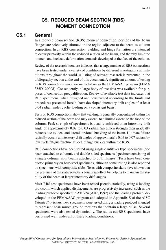
6.2–61
Prequalified Connections for Special and Intermediate Steel Moment Frames for Seismic ApplicationsAMERICAN INSTITUTE OF STEEL CONSTRUCTION, INC.
C5. REDUCED BEAM SECTION (RBS) MOMENT CONNECTION
C5.1 GeneralIn a reduced beam section (RBS) moment connection, portions of the beamflanges are selectively trimmed in the region adjacent to the beam-to-columnconnection. In an RBS connection, yielding and hinge formation are intendedto occur primarily within the reduced section of the beam, and thereby limit themoment and inelastic deformation demands developed at the face of the column.
Review of the research literature indicates that a large number of RBS connectionshave been tested under a variety of conditions by different investigators at insti-tutions throughout the world. A listing of relevant research is presented in thebibliography section at the end of this document. A significant amount of testingon RBS connections was also conducted under the FEMA/SAC program (FEMA355D, 2000d). Consequently, a large body of test data was available for pur-poses of connection prequalification. Review of available test data indicates thatRBS specimens, when designed and constructed according to the limits andprocedures presented herein, have developed interstory drift angles of at least0.04 radian under cyclic loading on a consistent basis.
Tests on RBS connections show that yielding is generally concentrated within thereduced section of the beam and may extend, to a limited extent, to the face of thecolumn. Peak strength of specimens is usually achieved at an interstory driftangle of approximately 0.02 to 0.03 radian. Specimen strength then graduallyreduces due to local and lateral torsional buckling of the beam. Ultimate failuretypically occurs at interstory drift angles of approximately 0.05 to 0.07 radian, bylow cycle fatigue fracture at local flange buckles within the RBS.
RBS connections have been tested using single-cantilever type specimens (onebeam attached to column), and double-sided specimens (specimen consisting ofa single column, with beams attached to both flanges). Tests have been con-ducted primarily on bare-steel specimens, although some testing is also reportedon specimens with composite slabs. Tests with composite slabs have shown thatthe presence of the slab provides a beneficial effect by helping to maintain the sta-bility of the beam at larger interstory drift angles.
Most RBS test specimens have been tested pseudo-statically, using a loadingprotocol in which applied displacements are progressively increased, such as theloading protocol specified in ATC-24 (ATC, 1992) and the loading protocol de-veloped in the FEMA/SAC program and adopted in Appendix S of the AISCSeismic Provisions. Two specimens were tested using a loading protocol intendedto represent near-source ground motions that contain a large pulse. Severalspecimens were also tested dynamically. The radius-cut RBS specimens haveperformed well under all of these loading conditions.
AISC_Commentary_final 12/4/06 4:21 PM Page 61
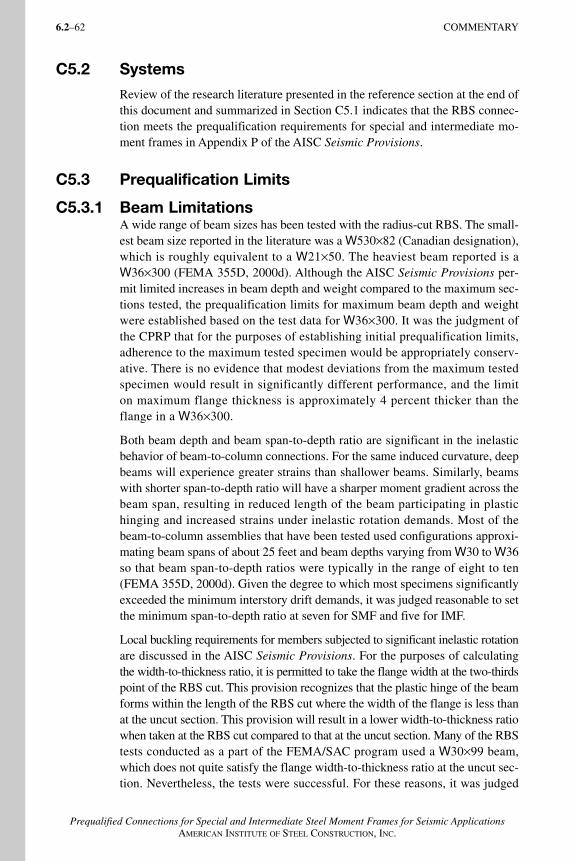
6.2–62 COMMENTARY
Prequalified Connections for Special and Intermediate Steel Moment Frames for Seismic ApplicationsAMERICAN INSTITUTE OF STEEL CONSTRUCTION, INC.
C5.2 Systems
Review of the research literature presented in the reference section at the end ofthis document and summarized in Section C5.1 indicates that the RBS connec-tion meets the prequalification requirements for special and intermediate mo-ment frames in Appendix P of the AISC Seismic Provisions.
C5.3 Prequalification Limits
C5.3.1 Beam LimitationsA wide range of beam sizes has been tested with the radius-cut RBS. The small-est beam size reported in the literature was a W530×82 (Canadian designation),which is roughly equivalent to a W21×50. The heaviest beam reported is aW36×300 (FEMA 355D, 2000d). Although the AISC Seismic Provisions per-mit limited increases in beam depth and weight compared to the maximum sec-tions tested, the prequalification limits for maximum beam depth and weightwere established based on the test data for W36×300. It was the judgment ofthe CPRP that for the purposes of establishing initial prequalification limits,adherence to the maximum tested specimen would be appropriately conserv-ative. There is no evidence that modest deviations from the maximum testedspecimen would result in significantly different performance, and the limiton maximum flange thickness is approximately 4 percent thicker than theflange in a W36×300.
Both beam depth and beam span-to-depth ratio are significant in the inelasticbehavior of beam-to-column connections. For the same induced curvature, deepbeams will experience greater strains than shallower beams. Similarly, beamswith shorter span-to-depth ratio will have a sharper moment gradient across thebeam span, resulting in reduced length of the beam participating in plastic hinging and increased strains under inelastic rotation demands. Most of the beam-to-column assemblies that have been tested used configurations approxi-mating beam spans of about 25 feet and beam depths varying from W30 to W36so that beam span-to-depth ratios were typically in the range of eight to ten(FEMA 355D, 2000d). Given the degree to which most specimens significantlyexceeded the minimum interstory drift demands, it was judged reasonable to setthe minimum span-to-depth ratio at seven for SMF and five for IMF.
Local buckling requirements for members subjected to significant inelastic rotationare discussed in the AISC Seismic Provisions. For the purposes of calculatingthe width-to-thickness ratio, it is permitted to take the flange width at the two-thirdspoint of the RBS cut. This provision recognizes that the plastic hinge of the beamforms within the length of the RBS cut where the width of the flange is less thanat the uncut section. This provision will result in a lower width-to-thickness ratiowhen taken at the RBS cut compared to that at the uncut section. Many of the RBStests conducted as a part of the FEMA/SAC program used a W30×99 beam,which does not quite satisfy the flange width-to-thickness ratio at the uncut sec-tion. Nevertheless, the tests were successful. For these reasons, it was judged
AISC_Commentary_final 12/4/06 4:21 PM Page 62
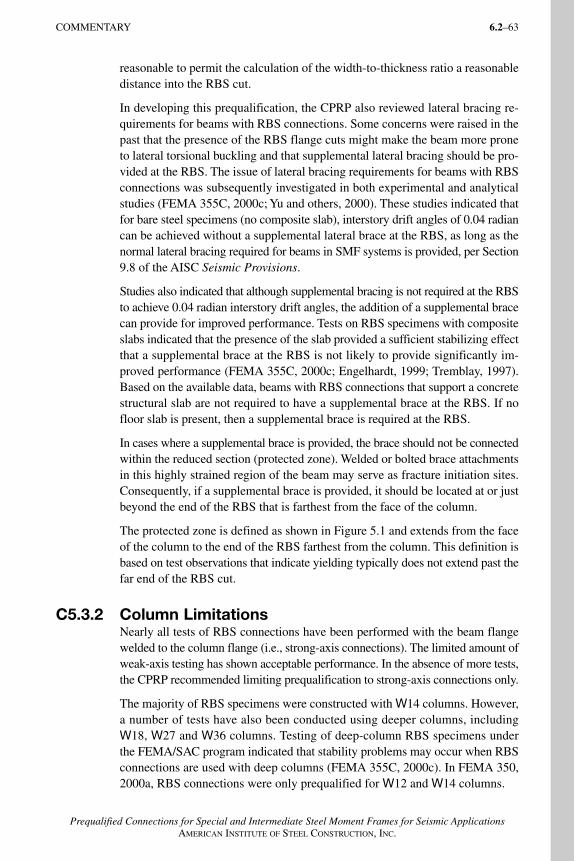
COMMENTARY 6.2–63
Prequalified Connections for Special and Intermediate Steel Moment Frames for Seismic ApplicationsAMERICAN INSTITUTE OF STEEL CONSTRUCTION, INC.
reasonable to permit the calculation of the width-to-thickness ratio a reasonabledistance into the RBS cut.
In developing this prequalification, the CPRP also reviewed lateral bracing re-quirements for beams with RBS connections. Some concerns were raised in thepast that the presence of the RBS flange cuts might make the beam more proneto lateral torsional buckling and that supplemental lateral bracing should be pro-vided at the RBS. The issue of lateral bracing requirements for beams with RBSconnections was subsequently investigated in both experimental and analyticalstudies (FEMA 355C, 2000c; Yu and others, 2000). These studies indicated thatfor bare steel specimens (no composite slab), interstory drift angles of 0.04 radiancan be achieved without a supplemental lateral brace at the RBS, as long as thenormal lateral bracing required for beams in SMF systems is provided, per Section9.8 of the AISC Seismic Provisions.
Studies also indicated that although supplemental bracing is not required at the RBSto achieve 0.04 radian interstory drift angles, the addition of a supplemental bracecan provide for improved performance. Tests on RBS specimens with compositeslabs indicated that the presence of the slab provided a sufficient stabilizing effectthat a supplemental brace at the RBS is not likely to provide significantly im-proved performance (FEMA 355C, 2000c; Engelhardt, 1999; Tremblay, 1997).Based on the available data, beams with RBS connections that support a concretestructural slab are not required to have a supplemental brace at the RBS. If nofloor slab is present, then a supplemental brace is required at the RBS.
In cases where a supplemental brace is provided, the brace should not be connectedwithin the reduced section (protected zone). Welded or bolted brace attachmentsin this highly strained region of the beam may serve as fracture initiation sites.Consequently, if a supplemental brace is provided, it should be located at or justbeyond the end of the RBS that is farthest from the face of the column.
The protected zone is defined as shown in Figure 5.1 and extends from the faceof the column to the end of the RBS farthest from the column. This definition isbased on test observations that indicate yielding typically does not extend past thefar end of the RBS cut.
C5.3.2 Column LimitationsNearly all tests of RBS connections have been performed with the beam flangewelded to the column flange (i.e., strong-axis connections). The limited amount ofweak-axis testing has shown acceptable performance. In the absence of more tests,the CPRP recommended limiting prequalification to strong-axis connections only.
The majority of RBS specimens were constructed with W14 columns. However,a number of tests have also been conducted using deeper columns, includingW18, W27 and W36 columns. Testing of deep-column RBS specimens underthe FEMA/SAC program indicated that stability problems may occur when RBSconnections are used with deep columns (FEMA 355C, 2000c). In FEMA 350,2000a, RBS connections were only prequalified for W12 and W14 columns.
AISC_Commentary_final 12/4/06 4:21 PM Page 63
6.2–64 COMMENTARY
Prequalified Connections for Special and Intermediate Steel Moment Frames for Seismic ApplicationsAMERICAN INSTITUTE OF STEEL CONSTRUCTION, INC.
The specimens in the FEMA/SAC tests conducted showed a considerable amountof column twisting (Gilton and others, 2000). However, two of the three spec-imens tested achieved 0.04-radian rotation, albeit with considerable strengthdegradation. The third specimen just fell short of 0.04-radian rotation and failedby fracture of the column web near the k-area. Subsequent study attributed thisfracture to column twisting.
Subsequent to the FEMA/SAC tests, an analytical study (Shen, 2002) concludedthat boundary conditions used in these tests may not be representative of whatwould be found in an actual building. Consequently, the large-column twisting(and presumably resultant k-area column fracture) seen in the FEMA/SAC testswould not be expected in real buildings. The study also concluded that deepcolumns should not behave substantially different from W14 columns and thatno special bracing is needed when a slab is present. This was followed by a moreextensive analytical and large-scale experimental investigation on RBS connectionswith columns up to W36 in depth (Ricles and others, 2004). This investigationshowed that good performance can be achieved with deep columns when a com-posite slab is present or when adequate lateral bracing is provided for the beamand/or column in the absence of a slab. Based on a review of this recent research,the prequalification of RBS connections is extended herein to include W36 columns.
The behavior of RBS connections with cruciform columns is expected to be sim-ilar to that of a rolled wide-flange column because the beam flange frames intothe column flange, the principal panel zone is oriented parallel to that of thebeam and the web of the cut wide-flange column is to be welded with a CJPgroove weld to the continuous web one foot above and below the depth of theframe girder. Given these similarities and the lack of evidence suggesting be-havioral limit states different from those associated with rolled wide-flangeshape, the Committee determined to limit cruciform column depths to those im-posed on wide-flange shapes.
Successful tests have also been conducted on RBS connections with built-upbox columns. The largest box column for which test data was available was 24 in.by 24 in. Consequently, RBS connections have been prequalified for use withbuilt-up box columns up to 24 in. Limits on the width-thickness ratios for thewalls of built-up box columns are specified in Section 2.3.2b(3) and were chosento reasonably match the box columns that have been tested.
The use of box columns participating in orthogonal moment frames, that is, withRBS connections provided on orthogonal beams, is also prequalified. Althoughno data were available for test specimens with orthogonal beams, it was the judg-ment of the committee that this condition should provide ostensibly the sameperformance as single-plane connections, since the RBS does not rely on panelzone yielding for good performance, and the column is expected to remain es-sentially elastic for the case of orthogonal connections.
Based on successful tests on wide-flange columns and on built-up box columns,it was the judgment of the Committee that boxed wide-flange columns would
AISC_Commentary_final 12/4/06 4:21 PM Page 64
COMMENTARY 6.2–65
Prequalified Connections for Special and Intermediate Steel Moment Frames for Seismic ApplicationsAMERICAN INSTITUTE OF STEEL CONSTRUCTION, INC.
also be expected to provide acceptable performance. Consequently, RBS con-nections are prequalified for use with boxed wide-flange columns. When mo-ment connections are made only to the flanges of the wide-flange portion of theboxed wide-flange, the column may be up to W36 in depth. When the boxedwide-flange column participates in orthogonal moment frames, then neither thedepth nor the width of the column is allowed to exceed 24 in. (600 mm), apply-ing the same limits as for built-up boxes.
C5.4 Beam-Column Relationship LimitationsColumn panel zone strength provided on RBS test specimens has varied over awide range. This includes specimens with very strong panel zones (no yieldingin panel zone), specimens with very weak panel zones (essentially all yielding inpanel zone and no yielding in beam), and specimens where yielding has beenshared between the panel zone and the beam. Good performance has been achievedfor all levels of panel zone strength, including panel zones that are substantiallyweaker than permitted in Section 9.3a of the AISC Seismic Provisions (FEMA355C, 2000c). However, there are concerns that very weak panel zones may pro-mote fracture in the vicinity of the beam-flange groove welds due to “kinking”of the column flanges at the boundaries of the panel zone. Consequently, theminimum panel zone strength specified in Section 9.3a of the AISC SeismicProvisions is required for prequalified RBS connections.
C5.5 Beam Flange-to-Column Flange Weld LimitationsComplete joint penetration groove welds joining the beam flanges to the col-umn flanges provided on the majority of RBS test specimens have been made bythe self-shielded flux cored arc welding process (FCAW-S) using electrodes witha minimum specified CVN toughness. Three different electrode designationshave commonly been used in these tests: E71T-8, E70TG-K2, and E70T-6.Further, for most specimens, the bottom flange backing was removed and a re-inforcing fillet added, top flange backing was fillet welded to the column, and weldtabs were removed at both the top and bottom flanges.
Test specimens have employed a range of weld access-hole geometries, and results suggest that connection performance is not highly sensitive to the weld access-hole geometry. Consequently, prequalified RBS connections do not require specific access-hole geometry. However, as a minimum, access holesmust conform to the requirements of Figure C-J1.2 of the AISC Specification.Although not required, the access-hole geometry shown in Figure 11-1 of theAISC Seismic Provisions may result in improved reliability of the connection.
C5.6 Beam Web-to-Column Connection LimitationsTwo types of web connection details have been used for radius-cut RBS testspecimens: a welded and a bolted detail. In the welded detail, the beam web iswelded directly to the column flange using a complete joint penetration grooveweld. For the bolted detail, pretensioned high-strength bolts are used. Specimens
AISC_Commentary_final 12/4/06 4:21 PM Page 65
6.2–66 COMMENTARY
Prequalified Connections for Special and Intermediate Steel Moment Frames for Seismic ApplicationsAMERICAN INSTITUTE OF STEEL CONSTRUCTION, INC.
with both types of web connections have achieved at least 0.04-radian interstorydrift angles, and consequently both types of web connection details were per-mitted for RBS connections in (FEMA 350, 2000a).
Previous test data (Engelhardt and others, 2000) indicate that beyond an interstorydrift angle of 0.04 radian, specimens with bolted web connections show a higherincidence of fracture occurring near the beam-flange groove welds, as comparedto specimens with welded web connections. Thus, while satisfactory perfor-mance is possible with a bolted web connection, previous test data indicate thata welded web is beneficial in reducing the vulnerability of RBS connections tofracture at the beam-flange groove welds.
Subsequent to the SAC/FEMA testing on RBS connections, a test program(Lee and others, 2004) was conducted which directly compared RBS connec-tions that were nominally identical, except for the web connection detail. TheRBS specimens with welded web connections achieved 0.04-radian interstorydrift angle, whereas as RBS specimens with bolted web connections failed toachieve 0.04 radian.
Thus, while past successful tests have been conducted on RBS connections withbolted web connections, recent data has provided contradictory evidence, sug-gesting bolted web connections may not be suitable for RBS connections whenused for SMF applications. Until further data is available, it was the judgment ofthe CPRP to require a welded web connection for RBS connections prequali-fied for use in SMF. For IMF applications, bolted web connections are acceptable.
C5.7 Fabrication of Flange CutsVarious shapes of flange cutouts are possible for RBS connections, including aconstant cut, a tapered cut, and a radius cut. Experimental work has includedsuccessful tests on all of these types of RBS cuts. The radius cut avoids abruptchanges of cross section, reducing the chances of a premature fracture occurringwithin the reduced section. Further, the majority of tests reported in the literatureused radius-cut RBS sections. Consequently, only the radius-cut RBS shape isprequalified.
An issue in the fabrication of RBS connections is the required surface finish andsmoothness of the RBS flange cuts. No research data was found that specificallyaddressed this issue. Consequently, finish requirements for RBS cuts were cho-sen based on judgment and are consistent with those specified in (FEMA 350,2000a).
C5.8 Design ProcedureDimensions of the RBS cuts for the test specimens reported in the literature varyover a fairly small range. The distance from the face of the column to the start ofthe RBS cut (designated as “a” in Figure 5.1) ranged from 50 to 75 percent of thebeam-flange width. The length of the cuts (designated as “b” in Figure 5.1) hasvaried from approximately 75 to 85 percent of the beam depth. The amount of
AISC_Commentary_final 12/4/06 4:21 PM Page 66
COMMENTARY 6.2–67
Prequalified Connections for Special and Intermediate Steel Moment Frames for Seismic ApplicationsAMERICAN INSTITUTE OF STEEL CONSTRUCTION, INC.
flange width removed at the minimum section of the RBS has varied from about38 to 55 percent. Flange removal for prequalified RBS connections is limited,based on judgment, to a maximum of 50 percent, to avoid excessive loss ofstrength or stiffness.
The design procedure presented herein for prequalified RBS connections issimilar to that presented in FEMA 350, 2000a. The overall basis for sizing theRBS cut in this design procedure is to limit the maximum beam moment thatcan develop at the face of the column to the beam’s actual plastic moment(based on expected yield stress) when the minimum section of the RBS is fullyyielded and strain hardened. Test data indicate that connecting the beam at theface of the column in accordance with the requirements herein allows the con-nection to resist this level of moment while minimizing the chance of fracture atthe beam-flange groove welds.
Step 4 of the design procedure requires computation of the shear force at thecenter of the RBS cut. This shear force is a function of the gravity load on the beamand the plastic moment capacity of the RBS. An example calculation is shown inFigure C–5.1 for the case of a beam with a uniformly distributed gravity load.
For gravity load conditions other than a uniform load, the appropriate adjust-ment should be made to the free-body diagram in Figure C–5.1 and to EquationsC–5.8-1 and C–5.8-2.
Equations C–5.8-1 and C–5.8-2 assume that plastic hinges will form at the RBSat each end of the beam. If the gravity load on the beam is very large, the plastichinge at one end of the beam may move toward the interior portion of the beamspan. If this is the case, the free-body diagram in Figure C–5.1 should be mod-ified to extend between the actual plastic hinge locations. To determine whetherEquations C–5.8-1 and C–5.8-2 are valid, draw the moment diagram for thesegment of the beam shown in Figure C–5.1(b), that is, for the segment of thebeam between the centers of the RBS cuts. If the maximum moment occursat the ends of the span, then Equations C–5.8-1 and C–5.8-2 are valid. If themaximum moment occurs within the span and exceeds Mpe of the beam (seeEquation 5-8), then the modification described above will be needed.
VM
L
wLRBS
pr=′
+ ′2
2
′ =′
− ′V
M
L
wLRBS
pr2
2
(C-5.8-1)
(C-5.8-2)
AISC_Commentary_final 12/4/06 4:21 PM Page 67
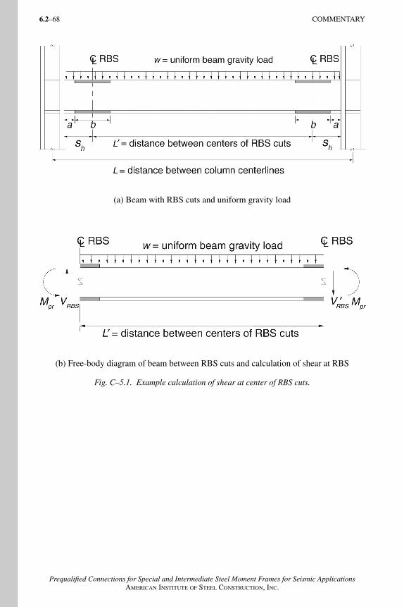
6.2–68 COMMENTARY
Prequalified Connections for Special and Intermediate Steel Moment Frames for Seismic ApplicationsAMERICAN INSTITUTE OF STEEL CONSTRUCTION, INC.
(a) Beam with RBS cuts and uniform gravity load
(b) Free-body diagram of beam between RBS cuts and calculation of shear at RBS
Fig. C–5.1. Example calculation of shear at center of RBS cuts.
AISC_Commentary_final 12/4/06 4:21 PM Page 68
6.2–69
Prequalified Connections for Special and Intermediate Steel Moment Frames for Seismic ApplicationsAMERICAN INSTITUTE OF STEEL CONSTRUCTION, INC.
C6. BOLTED UNSTIFFENED AND STIFFENED EXTENDEDEND-PLATE MOMENT CONNECTIONS
C6.1 GeneralThe three extended end-plate moment configurations currently addressed in thischapter are the most commonly used end-plate connection configurations in steelmoment frames. AISC Design Guide No. 4, 2nd Edition (Murray and Sumner,2003) provides background, design procedures, and complete design examples forthe three configurations. The Guide was developed before this Standard waswritten, and there are small differences between the design procedures in theGuide and in Section C6.10. The primary difference is the resistance factor, φ-factor, values. The Standard supersedes the Design Guide in all instances.
Prequalification test results for the three extended end-plate moment connec-tions are found in FEMA, 1997; Meng, 1996; Meng and Murray, 1997; Ryanand Murray, 1999; Sumner and others, 2000a; Sumner and others, 2000b; Sumnerand Murray, 2001; Sumner and Murray, 2002. Results of similar testing but notused for prequalification are found in Adey and others, 1997; Adey and others,1998; Adey and others, 2000; Castellani and others, 1998; Coons, 1999; Ghobarahand others, 1990; Ghobarah and others, 1992; Johnstone and Walpole, 1981;Korol and others, 1990; Popov and Tsai, 1989; Tsai and Popov, 1990.
The intent of the design procedure in Section 6.10 is to provide an end-plate mo-ment connection with sufficient strength to develop the strength of the connectedflexural member. The connection does not provide any contribution to inelasticrotation. All inelastic deformation for an end-plate connection is achieved bybeam yielding and/or column panel zone deformation.
The design procedure in Section 6.10 is based on Borgsmiller and Murray, 1995,and is similar to the “thick plate” procedure in AISC Design Guide No. 16 (Murrayand Shoemaker, 2002). The procedure is basically the same as that in FEMA 350,2000a, but with much clarification. Applicable provisions in FEMA 353, 2000bare incorporated into the procedure as well.
C6.2 Systems
The three extended end-plate moment connections in Figure 6.1 are prequali-fied for use in IMF and SMF systems, except in SMF systems where the beam isin direct contact with concrete structural slabs. The exception applies only whenshear studs are used to attach the concrete slab to the connected beam and is be-cause of the lack of test data to date. All of the prequalification testing has beenperformed with bare steel specimens, except for one test reported in Sumner andMurray, 2000. In this test, headed studs were installed from near the end-platemoment connection to the end of the beam, and the concrete was in contactwith the column flanges and web. The lower bolts failed prematurely by tensionrupture because of the increase in the distance from the neutral axis due to thepresence of the composite slab.
AISC_Commentary_final 12/4/06 4:21 PM Page 69
6.2–70 COMMENTARY
Prequalified Connections for Special and Intermediate Steel Moment Frames for Seismic ApplicationsAMERICAN INSTITUTE OF STEEL CONSTRUCTION, INC.
C6.3 Prequalification LimitsThe parametric limitations in Table 6.1 were determined from reported test datain the prequalification references. Only connections that are within these limitsare prequalified.
Beams may be either hot-rolled or built-up. If built-up sections are used, theweb-to-flange weld may be a one-sided fillet weld, except within the beam,depth, or three times the flange width of the face of the end-plate. Within thislength, fillet welds on both sides are required of a size at least 1/4 in. (6 mm)for constructability or 0.75 times the beam-flange web thickness to develop theweb material, whichever is greater. Complete joint penetration (CJP) groovewelds may be used in lieu of fillet welds.
For tapered members, the depth of the beam at the connection is used to determinethe limiting span-to-depth ratio.
C6.4 Beam LimitationsThe beam size limitations in Table 6.1 are directly related to connection testing.Since many of the tested beam sections were built-up members, the limitationsare in cross-section dimensions instead of rolled-beam designations as usedin Section 5 for RBS. There is no evidence that modest deviations from thesedimensions will result in significantly difference performance.
Similar to RBS testing, most of the tested beam-column assemblies had config-urations approximating beam span-to-depth ratios in the range of eight to ten.However, it was judged reasonable to set the minimum span-to-depth ratio atseven for SMF and five for IMF.
The protected zone, the distance from the face of the end-plate for unstiffened, orfrom the end of the stiffener for stiffened, which is specified as the smaller of thebeam depth and three times the flange width, is based on test observations.
C6.5 Column Limitations Extended moment end-plate connections may be used only with rolled or built-up I-shaped sections and must be flange connected. There are no other specificcolumn requirements for extended end-plate moment connections.
C6.6 Beam-Column Relationship LimitationsThere are no specific beam-to-column relationship limitations for extended end-plate moment connections.
C6.7 Continuity PlatesContinuity plate design must conform to the requirements of Section 2.4.4. Thedesign procedure in Section 6.10 contains provisions specific to end-plate momentconnections, and the procedure is discussed generally in AISC Design GuideNo. 13 (Carter, 1999).
AISC_Commentary_final 12/4/06 4:21 PM Page 70

COMMENTARY 6.2–71
Prequalified Connections for Special and Intermediate Steel Moment Frames for Seismic ApplicationsAMERICAN INSTITUTE OF STEEL CONSTRUCTION, INC.
C6.8 BoltsPrequalification tests have been conducted with both pretensioned ASTM A325and A490 bolts. Bolt length should be such that at least two complete threadsare between the unthreaded portion of the shank and the face of the nut after thebolt is pretensioned. Slip-critical connection provisions are not required for end-plate moment connections.
C6.9 Connection DetailingMaximum gage, that is, the horizontal distance between outer bolt columns, is lim-ited to the width of the beam flange to ensure a stiff load path. Monotonic testshave shown that the stiffness and strength of an end-plate moment connection aredecreased when the bolt gage is wider than the beam flange.
Inner bolt pitch, the distance between the face of the beam flange and the first rowof inside or outside bolts, must be sufficient to allow bolt tightening. The mini-mum pitch values specified have been found to be satisfactory. An increase inpitch distance can significantly increase the required end-plate thickness.
The end-plate can be wider than the beam flange, but the width used in design cal-culations is limited to the beam flange width plus 1 in. (25 mm). This limitationis based on unpublished results of monotonic tests of end-plate connections.
The requirements for the length of beam-flange-to-end-plate stiffeners are es-tablished to ensure a smooth load path. The 30° angle is the same as used fordetermining the Whitmore section width in other types of connections. The re-quired 1-in. (25-mm) land is needed to ensure the quality of the vertical and hor-izontal weld terminations.
Tests have shown that the use of finger shims between the end-plate and the col-umn flange do not affect the performance of the connection (Sumner and others,2000a).
Design procedures are not available for connections of beams with composite ac-tion at an end-plate moment connection. Therefore, careful composite slab de-tailing is necessary to prevent composite action, which may increase tension forcesin the lower bolts. Welded stud shear connectors are not permitted within 11/2
times the beam depth, and compressible material is required between the con-crete slab and the column face (Sumner and Murray, 2002; Yang and others, 2003).
Cyclic testing has shown that use of weld access holes can cause premature frac-ture of the beam flange at end-plate moment connections (Meng and Murray,1997). Short to long weld access holes were investigated with similar results.Therefore, weld access holes are not permitted for end-plate moment connections.
Strain gage measurements have shown that the web plate material in the vicinityof the inside tension bolts generally reaches the yield strain (Murray and Kukreti,1988). Consequently, it is required that the web-to-end-plate weld(s) in the vicin-ity of the inside bolts be sufficient to develop the strength of the beam web.
AISC_Commentary_final 12/4/06 4:21 PM Page 71
6.2–72 COMMENTARY
Prequalified Connections for Special and Intermediate Steel Moment Frames for Seismic ApplicationsAMERICAN INSTITUTE OF STEEL CONSTRUCTION, INC.
The beam-flange-to-end-plate and stiffener weld requirements equal or exceed thewelding that was used to prequalify the three extended end-plate moment con-nections. Since weld access holes are not permitted, the beam-flange-to-end-plate weld at the beam web is necessarily a partial-joint-penetration (PJP) grooveweld. The prequalification testing has shown that these conditions are not detri-mental to the performance of the connection.
C6.10 Design Procedure
The design procedure in this section, with some modification, was used to designthe prequalification test specimens. The procedure is very similar to that in theAISC Design Guide No. 4, 2nd Edition (Murray and Sumner, 2003) except that dif-ferent resistance factors are used. Example calculations are found in the DesignGuide. Column stiffening example calculations are also found in the AISC DesignGuide No. 13 (Carter, 1999).
AISC_Commentary_final 12/4/06 4:21 PM Page 72
6.2–73
Prequalified Connections for Special and Intermediate Steel Moment Frames for Seismic ApplicationsAMERICAN INSTITUTE OF STEEL CONSTRUCTION, INC.
REFERENCES
The following references have been reviewed as a basis for the prequalification of the con-nections described in this Standard. Although some references are not specifically cited inthis Standard, they have been reviewed by the AISC Connection Prequalification ReviewPanel and are listed here to provide an archival record of the basis for this Standard in ac-cordance with the requirements of Appendix P of the AISC Seismic Provisions.
ALL CONNECTIONS
AISC (2005a), AISC/ANSI 360-05, Specification for Structural Steel Buildings, AmericanInstitute of Steel Construction, Inc., Chicago, IL.
AISC (2005b), AISC/ANSI 341-05, Seismic Provisions for Structural Steel Buildings, AmericanInstitute of Steel Construction, Inc., Chicago, IL.
ATC (1992), Guidelines for Cyclic Seismic Testing of Components of Steel Structures, ATC-24,Applied Technology Council, Redwood City, CA.
AWS (2004), AWS/ANSI D1.1, Structural Welding Code — Steel, American Welding Society,Miami, FL.
Barsom, J. and Korvink, S. (1998), “Effects of Strain Hardenening and Strain Aging onthe K-Region of Structural Shapes,” Report No. SAC/BD-98/02, SAC Joint Venture,Sacramento, CA.
Carter, C.J. (1999), “Stiffening of Wide-Flange Columns at Moment Connections: Wind andSeismic Applications,” AISC Design Guide No. 13, American Institute of Steel Construction,Chicago, IL.
Castellani, A., Castiglioni, C.A., Chesi, C., and Plumier, A. (1998), “A European ResearchProgram on the Cyclic Behaviour of Welded Beam to Column Connections,” Proceedingsof the NEHRP Conference and Workshop on Research on the Northridge, CaliforniaEarthquake of January 17, 1994, Vol. III-B, pp. 510–517, National Earthquake HazardsReduction Program, Washington, DC.
Chi, W.M., Deierlein, G. and Ingraffea, A. (1997), “Finite Element Fracture MechanicsInvestigation of Welded Beam-Column Connections,” Report No. SAC/BD-97/05, SAC JointVenture, Sacramento, CA.
FEMA 302 (1997), NEHRP Recommended Provisions for Seismic Regulations for NewBuildings and Other Structures, FEMA 302, Part 1 — Provisions, Federal EmergencyManagement Agency, Washington, DC.
FEMA 350 (2000), Recommended Seismic Design Criteria for New Steel Moment-FrameBuildings, Federal Emergency Management Agency, Washington, DC.
AISC_Commentary_final 12/4/06 4:21 PM Page 73
6.2–74 REFERENCES
Prequalified Connections for Special and Intermediate Steel Moment Frames for Seismic ApplicationsAMERICAN INSTITUTE OF STEEL CONSTRUCTION, INC.
FEMA 351 (2000), Recommended Seismic Evaluation and Upgrade Criteria for ExistingWelded Steel Moment-Frame Buildings, Federal Emergency Management Agency,Washington, DC.
FEMA 352 (2000), Recommended Post-Earthquake Evaluation and Repair Criteria forWelded Steel Moment-Frame Buildings, Federal Emergency Management Agency,Washington, DC.
FEMA 353 (2000), Recommended Specifications and Quality Assurance Guidelines for SteelMoment-Frame Construction for Seismic Applications, Federal Emergency ManagementAgency, Washington, DC.
FEMA 355C (2000), State of the Art Report on Systems Performance of Steel Moment FramesSubject to Earthquake Ground Shaking, prepared by the SAC Joint Venture for the FederalEmergency Management Agency, Washington, DC.
FEMA 355D (2000), State of the Art Report on Connection Performance, prepared by theSAC Joint Venture for the Federal Emergency Management Agency, Washington, DC.
Lee, C.H., Kim, J.H., Jeon, S.W., and Kim, J.H. (2004), “Influence of Panel Zone Strength andBeam Web Connection Method on Seismic Performance of Reduced Beam Section SteelMoment Connections,” Proceedings of the CTBUH 2004 Seoul Conference — Tall Buildingsfor Historical Cities, Council on Tall Buildings and Urban Habitat, Bethlehem, PA.
Popov, E. and Tsai, K.C. (1989), “Performance of Large Seismic Steel Moment Connectionsunder Cyclic Loads,” Engineering Journal, Vol. 12, pp. 51–60, American Institute of SteelConstruction, Inc., Chicago, IL.
Ricles, J.M., Zhang, X., Lu, L.W., and Fisher, J. (2004), “Development of Seismic Guidelinesfor Deep Column Steel Moment Connections,” ATLSS Report No. 04-13, Lehigh University,Bethlehem, PA.
RSSC (2004), Specification for Structural Joints Using ASTM A325 and A490 Bolts, ResearchCouncil on Structural Connections, Chicago, IL.
REDUCED BEAM SECTION (RBS) MOMENT CONNECTION
Chambers, J.J., Almudhafer, S. and Stenger, F. (2003), “Effect of Reduced Beam SectionFrames Elements on Stiffness of Moment Frames,” Journal of Structural Engineering,Vol. 129, No. 3, American Society of Civil Engineers, Reston, VA.
Chen, S.J. and Chao, Y.C. (2001), “Effect of Composite Action on Seismic Performance of SteelMoment Connections with Reduced Beam Sections,” Journal of Constructional SteelResearch, Vol. 57, Elsevier Science Publishers, London, England.
Chen, S.J., Yeh, C.H. and Chu, J.M. (1996), “Ductile Steel Beam-to-Column Connectionsfor Seismic Resistance,” Journal of Structural Engineering, Vol. 122, No. 11,pp. 1292–1299, American Society of Civil Engineers, Reston, VA.
AISC_Commentary_final 12/4/06 4:21 PM Page 74
REFERENCES 6.2–75
Prequalified Connections for Special and Intermediate Steel Moment Frames for Seismic ApplicationsAMERICAN INSTITUTE OF STEEL CONSTRUCTION, INC.
Engelhardt, M.D. (1999), “The 1999 T.R. Higgins Lecture: Design of Reduced Beam SectionMoment Connections,” Proceedings 1999 North American Steel Construction Conference,Toronto, Canada, pp. 1–1 to 1–29, American Institute of Steel Construction, Inc., Chicago, IL.
Engelhardt, M.D., Fry, G., Jones, S., Venti, M. and Holliday, S. (2000), “Behavior and Designof Radius-Cut Reduced Beam Section Connections,” Report No. SAC/BD-00/17, SACJoint Venture, Sacramento, CA.
Engelhardt, M.D., Winneberger, T., Zekany, A.J. and Potyraj, T.J. (1998), “ExperimentalInvestigation of Dogbone Moment Connections,” Engineering Journal, Vol. 35, No. 4,pp. 128–139, American Institute of Steel Construction, Inc., Chicago, IL.
FEMA (1997), NEHRP Recommended Provisions for Seismic Regulations for New Buildingsand Other Structures, Part 1 — Provisions, Federal Emergency Management Agency,Washington, DC.
FEMA (2000e), State of the Art Report on Past Performance of Steel Moment-Frame Buildingsin Earthquakes, prepared by the SAC Joint Venture for the Federal Emergency ManagementAgency, Washington, DC.
Gilton, C., Chi, B. and Uang, C.M. (2000), “Cyclic Response of RBS Moment Connections:Weak Axis Configuration and Deep Column Effects,” Report No. SAC/BD-00/23, SAC JointVenture, Sacramento, CA.
Grubbs, K.V., “The Effect of the Dogbone Connection on the Elastic Stiffness of Steel MomentFrames” (1997). M.S. Thesis, Department of Civil Engineering, The University of Texasat Austin.
Iwankiw, N.R. and Carter, C. (1996), “The Dogbone: A New Idea to Chew On,” ModernSteel Construction, April 1996, American Institute for Steel Construction, Inc, Chicago, IL.
Moore, K.S., Malley, J.O. and Engelhardt, M.D. (1996), “Design of Reduced Beam Section(RBS) Moment Connections,” Steel Tips, Structural Steel Education Council, Moraga, CA.
Okahashi, Y. (2003), “Reduced Beam Section Connection without Continuity Plates,” M.S.Thesis, Department of Civil and Environmental Engineeering, University of Utah.
Plumier, A. (1990), “New Idea for Safe Structures in Seismic Zones,” IABSE Symposium —Mixed Structures Including New Materials, Brussels, Belgium.
Plumier, A. (1997), “The Dogbone: Back to the Future,” Engineering Journal, AmericanInstitute of Steel Construction, Inc., Chicago, IL.
Popov, E.P., Yang, T.S. and Chang, S.P. (1998), “Design of Steel MRF Connections Before andAfter 1994 Northridge Earthquake,” International Conference on Advances in SteelStructures, Hong Kong, December 11–14, 1996. Also in: Engineering Structures, Vol. 20,No. 12, pp.1030–1038, Elsevier Science Publishers, London, England.
Shen, J., Kitjasateanphun, T. and Srivanich, W. (2000), “Seismic Performance of Steel MomentFrames with Reduced Beam Sections,” Journal of Constructional Steel Research, Vol. 22,Elsevier Science Publishers, London, England.
AISC_Commentary_final 12/4/06 4:21 PM Page 75

6.2–76 REFERENCES
Prequalified Connections for Special and Intermediate Steel Moment Frames for Seismic ApplicationsAMERICAN INSTITUTE OF STEEL CONSTRUCTION, INC.
Shen, J., Astaneh-Asl, A. and McCallen, D.B. (2002), “Use of Deep Columns in Special SteelMoment Frames,” Steel Tips, Structural Steel Education Council, Moraga, CA.
Suita, K., Tamura, T., Morita, S., Nakashima, M. and Engelhardt, M.D. (1999), “PlasticRotation Capacity of Steel Beam-to-Column Connections Using a Reduced Beam Sectionand No Weld Access Hole Design — Full Scale Tests for Improved Steel Beam-to-ColumnSubassemblies — Part 1,” Structural Journal, Architectural Institute of Japan, No. 526,pp. 177–184, December 1999 (in Japanese).
Tremblay, R., Tchebotarev, N. and Filiatrault, A. (1997), “Seismic Performance of RBSConnections for Steel Moment Resisting Frames: Influence of Loading Rate and FloorSlab,” Proceedings, Stessa ’97, Kyoto, Japan.
Tsai, K.C., Chen, W.Z. and Lin, K.C. (1999), “Steel Reduced Beam Section to Weak Panel ZoneMoment Connections,” Proceedings: Workshop on Design Technologies of Earthquake-Resistant Moment-Resisting Connections in Steel Buildings, May 17–18, 1999, Taipei,Taiwan (in Chinese).
Uang, C.M. and Fan, C.C. (1999) “Cyclic Instability of Steel Moment Connections withReduced Beam Section,” Report No. SAC/BD-99/19, SAC Joint Venture, Sacramento, CA.
Uang, C.M. and Richards, P. (2002), “Cyclic Testing of Steel Moment Connections for EastTower of Hoag Memorial Hospital Presbyterian,” Third Progress Report, University ofCalifornia, San Diego, CA.
Yu, Q.S., Gilton, C. and Uang, C.M. (2000), “Cyclic Response of RBS Moment Connections:Loading Sequence and Lateral Bracing Effects,” Report No. SAC/BD-00/22, SAC JointVenture, Sacramento, CA, 2000.
Zekioglu, A., Mozaffarian, H., Chang, K.L., Uang, C.M. and Noel, S. (1997), “Designingafter Northridge,” Modern Steel Construction, American Institute of Steel Construction, Inc.,Chicago, IL.
Zekioglu, A., Mozaffarian, H. and Uang, C.M. (1997), “Moment Frame ConnectionDevelopment and Testing for the City of Hope National Medical Center,” Building toLast — Proceedings of Structures Congress XV, ASCE, Portland, American Society of CivilEngineers, Reston, VA.
BOLTED UNSTIFFENED AND STIFFENED EXTENDED END-PLATE MOMENT
CONNECTIONS
Abel, M.S. and Murray, T.M. (1992a), “Multiple Row, Extended Unstiffened End-PlateConnection Tests,” Research Report CE/VPI-ST-92/04, Department of Civil Engineering,Virginia Polytechnic Institute and State University, Blacksburg, VA.
Abel, M.S. and Murray, T.M. (1992b), “Analytical and Experimental Investigation of theExtended Unstiffened Moment End-Plate Connection with Four Bolts at the Beam Tension
AISC_Commentary_final 12/4/06 4:21 PM Page 76
REFERENCES 6.2–77
Prequalified Connections for Special and Intermediate Steel Moment Frames for Seismic ApplicationsAMERICAN INSTITUTE OF STEEL CONSTRUCTION, INC.
Flange,” Research Report CE/VPI-ST-93/08, Department of Civil Engineering, VirginiaPolytechnic Institute and State University, Blacksburg, VA.
Adey, B.T., Grondin, G.Y. and Cheng, J.J.R. (1997), “Extended End Plate Moment Connectionsunder Cyclic Loading,” Structural Engineering Report No. 216, Department of Civil andEnvironmental Engineering, University of Alberta, Alberta, Canada.
Adey, B.T., Grondin, G.Y. and Cheng, J.J.R. (1998), “Extended End Plate Moment Connectionsunder Cyclic Loading,” Journal of Constructional Steel Research, Vol. 46, pp. 1–3, ElsevierScience Publishers, London, England.
Adey, B.T., Grondin, G.Y. and Cheng, J.J.R. (2000), “Cyclic Loading of End Plate MomentConnections,” Canadian Journal of Civil Engineering, Vol. 27, No. 4, pp. 683–701, NationalResearch Council of Canada.
Agerskov, H. (1976), “High Strength Bolted Connections Subject to Prying” Journal of theStructural Division, Vol. 102, No. ST1, pp. 161–175, American Society of Civil Engineers,Reston, VA.
Agerskov, H. (1977), “Analysis of Bolted Connections Subject to Prying.” Journal of theStructural Division, Vol. 103, No. ST11, pp. 2145–2163, American Society of CivilEngineers, Reston, VA.
Ahuja, V. (1982), “Analysis of Stiffened End-Plate Connections Using Finite Element Method,”M.S. Thesis, School of Civil Engineering and Environmental Science, University ofOklahoma, Norman, OK.
Bahaari, M.R. and Sherbourne, A.N. (1993), “Modeling of Extended End-plate BoltedConnections.” Proceedings of the National Steel Structures Congress, pp. 731–736,American Institute of Steel Construction, Inc., Chicago, IL.
Bjorhovde, R., Brozzetti, J. and Colson, A. (1987) “Classification of Connections,” Connectionsin Steel Structures — Behaviour, Strength and Design, pp. 388–391, Elsevier SciencePublishers, London, England.
Bjorhovde, R., Colson, A. and Brozzetti, J. (1990), “Classification System for Beam-to-ColumnConnections,” Journal of Structural Engineering, Vol. 116, No. 11, pp. 3059–3076,American Society of Civil Engineers, Reston, VA.
Borgsmiller, J.T. and Murray, T.M. (1995), “Simplified Method for the Design of Moment End-Plate Connections,” Research Report CE/VPI-ST-95/19, Department of Civil Engineering,Virginia Polytechnic Institute and State University, Blacksburg, VA.
Bursi, O.S. and Leonelli, L. (1994), “A Finite Element Model for the Rotational Behavior ofEnd Plate Steel Connections,” SSRC Proceedings 1994 Annual Task Group TechnicalSession, pp. 162–175, Lehigh University, Bethlehem, PA.
Coons, R.G. (1999), “Seismic Design and Database of End Plate and T-stub Connections,” M.S.Thesis, University of Washington, Seattle, WA.
Disque, R.O. (1962), “End-Plate Connections,” National Engineering Conference Proceedings,1962, pp. 30–37, American Institute of Steel Construction, Inc., Chicago, IL.
AISC_Commentary_final 12/4/06 4:21 PM Page 77
6.2–78 REFERENCES
Prequalified Connections for Special and Intermediate Steel Moment Frames for Seismic ApplicationsAMERICAN INSTITUTE OF STEEL CONSTRUCTION, INC.
Douty, R.T. and McGuire, S. (1965), “High Strength Bolted Moment Connections,” Journalof the Structural Division, Vol. 91, No. ST2, pp. 101–126, American Society of CivilEngineers, Reston, VA.
Fleischman, R.B., Chasten, C.P., Lu, L-W and Driscoll, G.C. (1991), “Top-and-Seat AngleConnections and End-Plate Connections: Snug vs. Fully Pretensioned Bolts,” EngineeringJournal, Vol. 28, pp. 18–28, American Institute of Steel Construction, Inc., Chicago, IL.
Ghassemieh, M. (1983), “Inelastic Finite Element Analysis of Stiffened End-Plate MomentConnections,” M.S. Thesis, School of Civil Engineering and Environmental Science,University of Oklahoma, Norman, OK.
Ghobarah, A., Korol, R.M. and Osman, A. (1992), “Cyclic Behavior of Extended End-PlateJoints,” Journal of Structural Engineering, Vol. 118, No. 5, pp. 1333–1353, AmericanSociety of Civil Engineers, Reston, VA,.
Ghobarah, A., Osman, A. and Korol, R.M. (1990), “Behaviour of Extended End-PlateConnections under Cyclic Loading,” Engineering Structures, Vol. 12, pp. 15–26, ElsevierScience Publishers, London, England.
Granstrom, A. (1980), “Bolted End-Plate Connections,” Stalbyggnads Institute SBI Report 86.3,pp. 5–12.
Griffiths, J.D. (1984), “End-Plate Moment Connections — Their Use and Misuse,”Engineering Journal, Vol. 21, pp. 32–34, American Institute of Steel Construction, Inc.,Chicago, IL.
Hasan, R., Kishi, N. and Chen, W.F. (1997), “Evaluation of Rigidity of Extended End-PlateConnections,” Journal of Structural Engineering, Vol. 123, No. 12, pp. 1595–1602, AmericanSociety of Civil Engineers, Reston, VA.
Hendrick, D., Kukreti, A. and Murray, T. (1984), “Analytical and Experimental Investigationof Stiffened Flush End-Plate Connections with Four Bolts at the Tension Flange,” ResearchReport FSEL/MBMA 84-02, Fears Structural Engineering Laboratory, University ofOklahoma, Norman, OK.
Hendrick, D., Kukreti, A. and Murray, T. (1985), “Unification of Flush End-Plate DesignProcedures,” Research Report FSEL/MBMA 85-01, Fears Structural EngineeringLaboratory, University of Oklahoma, Norman, OK.
Johnstone, N.D. and Walpole, W.R. (1981), “Bolted End-Plate Beam-to-Column ConnectionsUnder Earthquake Type Loading,” Report 81-7, Department of Civil Engineering, Universityof Canterbury, Christchurch, New Zealand.
Kato, B. and McGuire, W.F. (1973), “Analysis of T-Stub Flange-to-Column Connections,”Journal of the Structural Division, Vol. 99 No. ST5, pp. 865–888, American Society ofCivil Engineers, Reston, VA.
Kennedy, N.A., Vinnakota, S. and Sherbourne, A.N. (1981), “The Split-Tee Analogy in BoltedSplices and Beam-Column Connections,” Proceedings of the International Conferenceon Joints in Structural Steelwork, pp. 2.138–2.157.
AISC_Commentary_final 12/4/06 4:21 PM Page 78
REFERENCES 6.2–79
Prequalified Connections for Special and Intermediate Steel Moment Frames for Seismic ApplicationsAMERICAN INSTITUTE OF STEEL CONSTRUCTION, INC.
Kline, D. Rojiani, K., and Murray, T. (1989), “Performance of Snug Tight Bolts in MomentEnd-Plate Connections,” MBMA Research Report, Department of Civil Engineering,Virginia Polytechnic Institute and State University, Blacksburg, VA. Revised July 1995.
Korol, R.M., Ghobarah, A. and Osman, A. (1990), “Extended End-Plate Connections UnderCyclic Loading: Behaviour and Design,” Journal of Constructional Steel Research, Vol. 16,No. 4, pp. 253–279, Elsevier Science Publishers, London, England.
Krishnamurthy, N. (1978), “A Fresh Look at Bolted End-Plate Behavior and Design,”Engineering Journal, Vol. 15, pp. 39–49, American Institute of Steel Construction, Inc.,Chicago, IL.
Krishnamurthy, N. and Graddy, D. (1976), “Correlation between 2- and 3-Dimensional FiniteElement Analysis of Steel Bolted End Plate Connections,” Computers and Structures,Vol. 6, No. 4/5, pp. 381–389.
Kukreti, A.R., Ghassemieh, M. and Murray, T.M. (1990), “Behavior and Design of Large-Capacity Moment End-Plates,” Journal of Structural Engineering, Vol. 116, No. 3,pp. 809–828, American Society of Civil Engineers, Reston, VA.
Kukreti, A.R., Murray, T.M. and Abolmaali, A. (1987), “End-Plate Connection Moment-Rotation Relationship,” Journal of Constructional Steel Research., Vol. 8, pp. 137–157,Elsevier Science Publishers, London, England.
Mann, A.P. and Morris, L.J. (1979), “Limit Design of Extended End-Plate Connections,”Journal of the Structural Division, ASCE, Vol. 105, No. ST3, pp. 511–526, AmericanSociety of Civil Engineers, Reston, VA.
Meng, R.L. (1996), “Design of Moment End-Plate Connections for Seismic Loading,” DoctoralDissertation, Virginia Polytechnic Institute and State University, Blacksburg, VA.
Meng, R.L. and Murray, T.M. (1997), “Seismic Performance of Bolted End-Plate Moment Connections,” Proceedings of the 1997 National Steel Construction Conference,pp. 30–1 to 30–14, American Institute of Steel Construction, Inc., Chicago, IL.
Morrison, S.J., Astaneh-Asl, A. and Murray, T. (1985), “Analytical and ExperimentalInvestigation of the Extended Stiffened Moment End-Plate Connection with Four Boltsat the Beam Tension Flange,” Research Report FSEL/MBMA 85-05, Fears StructuralEngineering Laboratory, University of Oklahoma, Norman, OK.
Morrison, S.J., Astaneh-Asl, A. and Murray, T. (1986), “Analytical and ExperimentalInvestigation of the Multiple Row Extended 1/3 Moment End-Plate Connection with EightBolts at the Beam Tension Flange,” Research Report FSEL/MBMA 86-01, Fears StructuralEngineering Laboratory, University of Oklahoma, Norman, OK.
Murray, T.M. (1986), “Stability of Gable Frame Panel Zone Plates,” Proceedings of theStructural Stability Research Council Annual Technical Session, pp. 317–325, StructuralStability Research Council, Bethlehem, PA.
Murray, T.M. (1988), “Recent Developments for the Design of Moment End-Plate Connections,”Journal of Constructional Steel Research, Vol. 10, pp. 133–162, Elsevier Science Publishers,London, England.
AISC_Commentary_final 12/4/06 4:21 PM Page 79
6.2–80 REFERENCES
Prequalified Connections for Special and Intermediate Steel Moment Frames for Seismic ApplicationsAMERICAN INSTITUTE OF STEEL CONSTRUCTION, INC.
Murray, T.M. (1990), “Extended End-Plate Moment Connections,” AISC Design GuideNo. 4, American Institute of Steel Construction, Chicago, IL.
Murray, T.M., Kline, D.P. and Rojiani, K.B. (1992), “Use of Snug-Tightened Bolts in End-PlateConnections,” Connections in Steel Structures II: Behavior, Strength and Design, Editedby R. Bjorhovde and others, pp. 27–34, American Institute of Steel Construction, Chicago,IL.
Murray, T.M. and Kukreti, A.R. (1988), “Design of 8-Bolt Stiffened Moment End Plates,”Engineering Journal, Second Quarter, pp. 45–52, American Institute of Steel Construction,Chicago, IL.
Murray, T.M. and Shoemaker, W.L. (2002), “Flush and Extended Multiple Row Moment EndPlate Connections,” Design Guide No. 16, American Institute of Steel Construction, Inc.,Chicago, IL.
Murray, T.M. and Sumner, E.A. (2003), “Extended End-Plate Moment Connectiosn Seismicand Wind Applications, Second Edition,” AISC Design Guide No. 4, American Institute ofSteel Construction, Chicago, IL.
Nair, R., Birkemoe, P. and Munse, W. (1974), “High Strength Bolts Subject to Tension andPrying.” Journal of the Structural Division, Vol. 100, No. ST2, pp. 351–372, AmericanSociety of Civil Engineers, Reston, VA.
Packer, J. and Morris, L. (1977), “A Limit State Design Method for the Tension Region ofBolted Beam-Column Connections,” The Structural Engineer, Vol. 55, No. 10, pp. 446–458.
Ryan, J.C. and Murray, T.M. (1999), Evaluation of the Inelastic Rotation Capability ofExtended End-Plate Moment Connections, Research Report No. CE/VPI-ST-99/13, sub-mitted to Metal Building Manufacturers Association, Cleveland, OH and American Instituteof Steel Construction, Chicago, IL, September.
Salmon, C. and Johnson, J. (1980), Steel Structures, Design and Behavior, 2nd Ed., Harper &Row, New York, NY.
SEI (1984), “Multiple Row, Extended End-Plate Connection Tests,” Research Report, StructuralEngineers, Inc., Norman, OK.
Srouji, R., Kukreti, A.R. and Murray, T.M. (1983a), “Strength of Two Tension Bolt FlushEnd-Plate Connections,” Research Report FSEL/MBMA 83-03, Fears Structural EngineeringLaboratory, University of Oklahoma, Norman, OK.
Srouji, R., Kukreti, A.R. and Murray, T.M. (1983b), “Yield-Line Analysis of End-PlateConnections With Bolt Force Predictions,” Research Report FSEL/MBMA 83-05, FearsStructural Engineering Laboratory, University of Oklahoma, Norman, OK.
Sumner, E.A., Mays, T.W. and Murray, T.M. (2000a), Cyclic Testing of Bolted Moment End-Plate Connections, Research Report No. CE/VPI-ST-00/03, SAC Report No. SAC/BD-00/21, submitted to the SAC Joint Venture.
Sumner, E.A., Mays, T.W. and Murray, T.M. (2000b), “End-Plate Moment Connections: TestResults and Finite Element Method Validation,” Connections in Steel Structures IV,
AISC_Commentary_final 12/4/06 4:21 PM Page 80
REFERENCES 6.2–81
Prequalified Connections for Special and Intermediate Steel Moment Frames for Seismic ApplicationsAMERICAN INSTITUTE OF STEEL CONSTRUCTION, INC.
Proceedings of the Fourth International Workshop, pp. 82–93, American Institute of SteelConstruction, Chicago, IL.
Sumner, E.A. and Murray, T.M. (2001), Experimental Investigation of the MRE 1/2 End-Plate Moment Connection, Research Report No. CE/VPI-ST-01/14, submitted to MetalBuilding Manufacturers Association, Cleveland, OH.
Sumner, E.A. and Murray, T.M. (2002), “Behavior of Extended End-Plate Moment ConnectionsSubject to Cyclic Loading,” Journal of Structural Engineering, Vol. 128, No. 4, pp. 501–508,American Society of Civil Engineers, Reston, VA.
Tsai, K.C. and Popov, E.P. (1990), “Cyclic Behavior of End-Plate Moment Connections,”Journal of Structural Engineering, ASCE, Vol. 116, No. 11, pp. 2917–2930, AmericanSociety of Civil Engineers, Reston, VA.
Yang, H., Tagawa, Y. and Nishiyama, I. (2003). “Elasto-Plastic Behavior of ‘New CompositeBeam System’,” Steel Structures, Vol. 3, pp. 45–52.
Young, J. and Murray, T.M. (1996), “Experimental Investigation of Positive Bending MomentStrength of Rigid Knee Connections,” Research Report No. CE/VPI-ST 9617, Departmentof Civil Engineering, Virginia Polytechnic Institute and State University, Blacksburg, VA.
AISC_Commentary_final 12/4/06 4:21 PM Page 81

6.2–82
Prequalified Connections for Special and Intermediate Steel Moment Frames for Seismic ApplicationsAMERICAN INSTITUTE OF STEEL CONSTRUCTION, INC.
AISC_Commentary_final 12/4/06 4:21 PM Page 82