sensors and actuators b: chemical 234 : 1-7 (2016)
TRANSCRIPT

UPV/EHU ADDI: The Basque Country Institutional Repository https://addi.ehu.es/
Article:
On-demand generation and removal of alginate biocompatible microvalves for flow control in microfluidics
J. Sáez, J. Etxebarria, M. Antoñana-Díez, F. Benito-López
Sensors and Actuators B: Chemical 234 : 1-7 (2016)
This work is made available online in accordance with publisher policies.
To see the final version of this work please visit the publisher’s website. Access to the published online version may require a subscription.
Link to publisher’s version: http://dx.doi.org/10.1016/j.snb.2016.04.140
Copyright statement: © 2016 Elsevier Ltd. Full-text reproduced in
accordance with the publisher’s self-archiving policy. This manuscript version is made available under the CC-BY-NC-ND 4.0
license http://creativecommons.org/licenses/by-nc-nd/4.0

ON-DEMAND GENERATION AND REMOVAL OF ALGINATE
BIOCOMPATIBLE MICROVALVES FOR FLOW CONTROL IN MICROFLUIDICS
J. Saez1, J. Etxebarria
2, M. Antonana-Diez
2, F. Benito-Lopez
1,3*
1Microfluidics UPV/EHU Cluster, Analytical Chemistry Department, University of the
Basque Country UPV/EHU, Vitoria-Gazteiz, SPAIN
2IK4-Ikerlan, SPAIN
3Insight: Centre for Data Analytics, National Centre for Sensor Research, Dublin City
University, Dublin, Ireland
This paper describes for the first time the use of alginate hydrogels as miniaturised
microvalves in microfluidic devices. These biocompatible and biodegradable
microvalves are in situ generated, on demand, allowing for microfluidic flow control.
The microfluidic devices were fabricated using the origami technique with a single
sheet of cyclic olefin polymer folded into several layers followed by
thermocompression bonding. The hydrogels can be dehydrated at mild temperatures, 37
ºC, to slightly open the microvalve and chemically erased using an
ethylenediaminetetraacetic acid disodium salt dehydrated (EDTA) solution, to
completely open the channel, ensuring the reusability of the whole device.
1. INTRODUCTION
Lab on a Chip (LOC) it is a multidisciplinary area of science that covers chemistry,
physics, engineering and biotechnology, claiming the miniaturisation of devices for
fluidic handling and detection. The driving force behind miniaturisation is to enhance
performance gained by down-scaling analytical systems, and to integrate multiple
components into a single device.1
LOC devices offer many advantages compared to other traditional analytical
platforms; for instance, the reduced dimensions of microfluidic components allow for
the manipulation of small volumes of fluids which lead to less reagent consumption,
reduced costs and less waste generation. Temperature can be controlled and changed
quickly due to the low thermal mass and large surface to volume ratio of microfluidics,
which facilitates heat transfer. Moreover, the ability to couple multiple channels
together, allows for easy handling of high throughput multicomponent devices and leads

to decreased analysis times.2 Their reduced dimensions allow for the creation of
portable devices for in situ testing and the potential integration of multiple components
for sampling, fluid handling, detection and reporting of the results in a single run as per
the Micro Total Analysis System concept.
The current state-of-the-art for microfluidic devices is based on flow systems that
employ traditional pumping, valving and mixing components. These systems are
generally expensive, difficult to integrate in a microfluidic device and, most of the
times, can only be controlled from external sources, as for example solenoid valves3, 4
Nevertheless, recent research focus has been upon improving these microfluidic
components, and the resulting novel valve concepts such as "Quake" PDMS micro-
valves,5 "Doormat" valves
6 and check valves
7 among others, are now emerging. These
valves have been proven to be effective and more cost effective than conventional
valves but still need to be designed within the microfluidic device. The ability for on-
demand in situ generation, and subsequent removal after use, of valves has not been
reported yet and as such a goal is to develop novel flow systems that are cheaper and
easier to fabricate based upon types of microvalves.
A very interesting concept for microvalve integration in microfluidic devices is the
use of smart materials for fluid handling and control.8 In particular, hydrogels are
networks of polymer chains that are highly water absorbent and that posses a substantial
degree of flexibility. The ability of hydrogels to absorb water arises from hydrophilic
functional groups attached to the polymeric backbone, while their resistance to be
dissolved comes from the addition of crosslinkers between the polymer chains of the
hydrogel.9 Due to their dynamic nature, they can be identified as stimuli-responsive
materials able to undergo volumetric changes in response to physical and chemical
changes in their local environment.10
In particular, calcium alginate is a water-insoluble hydrogel formed from linear
copolymers of anionic polysaccharide (water soluble) and calcium cations that can
chelate carboxylate groups and produce crosslinkages between polysaccharide chains.
The gelling properties of alginate depend strongly upon its monomeric composition,
block structure, molecular size and concentration of polymer and calcium ions.11
This
polymer is one of the most used biomaterial in science due to its biocompatibility and
biodegradability.12
Alginates are extremely versatile biopolymers since they have been used in a variety
of technical applications as biomedical13
and pharmaceutical14
and extensively used in

the food industry because it is a powerful thickening, stabilising, and gel-forming agent.
Incomprehensibly, in microfluidic applications, alginates are rarely used, primordially
for reagent storage in chips and for the fabrication of microcapsules in drug delivery
systems.15
Recent advances in microtechnology for biomedical applications, resulting in
products appearing on the market,16
have increased the necessity to integrate stimuli
responsive materials with biocompatible capabilities within microfluidic devices
making gels obtained from natural polymers are good candidates.17
In particular the use
of smart materials as actuators, with innocuous chemical characteristics, will create
opportunities for the next generation of novel microfluidic devices for biological
applications.
This study demonstrates, for the first time, the use of calcium alginate hydrogels as
miniaturised valves in microfluidic devices, as innovative alternatives to conventional
hydrogel microvalves. These biocompatible and biodegradable microvalves can be
generated on demand and in situ to introduce microfluidic flow control. Since calcium
alginate is dehydratated at room temperature (syneresis process), it can be thermally
actuated at mild temperatures, slightly unblocking the channel and, in turn, restoring the
flow rate, allowing to chemically erase the microvalve from the main channel simply
using an ethylenediaminetetraacetic acid disodium salt dehydrated (EDTA) solution,
and so ensuring the reusability of the whole device.
2. EXPERIMENTAL
2.1 Materials
Sodium alginate was purchased by Sigma-Aldrich (St Louis, MO, USA). Calcium
chloride dehydratated (Sigma-Aldrich) was used to prepare calcium alginate hydrogel.
Ethylenediaminetetraacetic acid disodium salt (EDTA) was purchased by Merck
(Darmstadt, Germany) and was used for chemically erase the calcium alginate hydrogel.
All the solutions were prepared using deonised (DI) water from a Milli-Q water
purification system (Millipore, Milford, MA).
Isopropyl alcohol (IPA) was purchased by Panreac Química S.L.U. (Spain). Rolls of
100 µm thick of COP films (ZeonorFilm®) were obtained from Zeon Chemicals
(Düsseldorf, Germany). This material was chosen because of its good properties such as
biocompatibility, acids and basis attack resistant and transparency.
Accura Amethyst was purchased from (3D Systems) for the fabrication of the luers
by stereolitography technique (Viper SLA systems, 3DSystems) and were coupled to
the device with screws.
The microfluidic device flows were controlled using a WPI SP120PZ syringe pump
(Shangai, China). Alternatively, solutions were injected with a Harvard Apparatus
model 11 elite syringe pump (Holliston, MA, USA). A MFCSTM
-EZ pressure driven
flow controller (Fluigent, Paris, France) was used for the controlled injection of
solutions. A SLG-0075 flow sensor (Sensirion CMOSens©
, Switzerland) was connected
for the monitoring of solutions inside the microfluidic device.
2.2 Chip Fabrication
Microfluidic devices were designed and fabricated by the Origami technique18
by
rapid prototyping using the FC-8000-60 cutting plotter from Graphtec (Irvine, CA). The
3D design was sliced into several 2D layers, which were cut with the cutting plotter,
assembled and then bonded by thermocompression.19
Stereolithography 3D-printed interconnections for fluidic handling were in house
fabricated and coupled to the device with screws [www.microliquid.com]. These
interconnections are coupled to syringes type ICO+3, 1 mL (Novico Medica, Barcelona,
Spain) and/or to male PMMA luers (Chipshop, Jena, Germany) and Tygon 0.8 x 2.4
mm tubes (Colmer Palmer,Vernon Hills, USA).
2.3 Hydrogel preparation
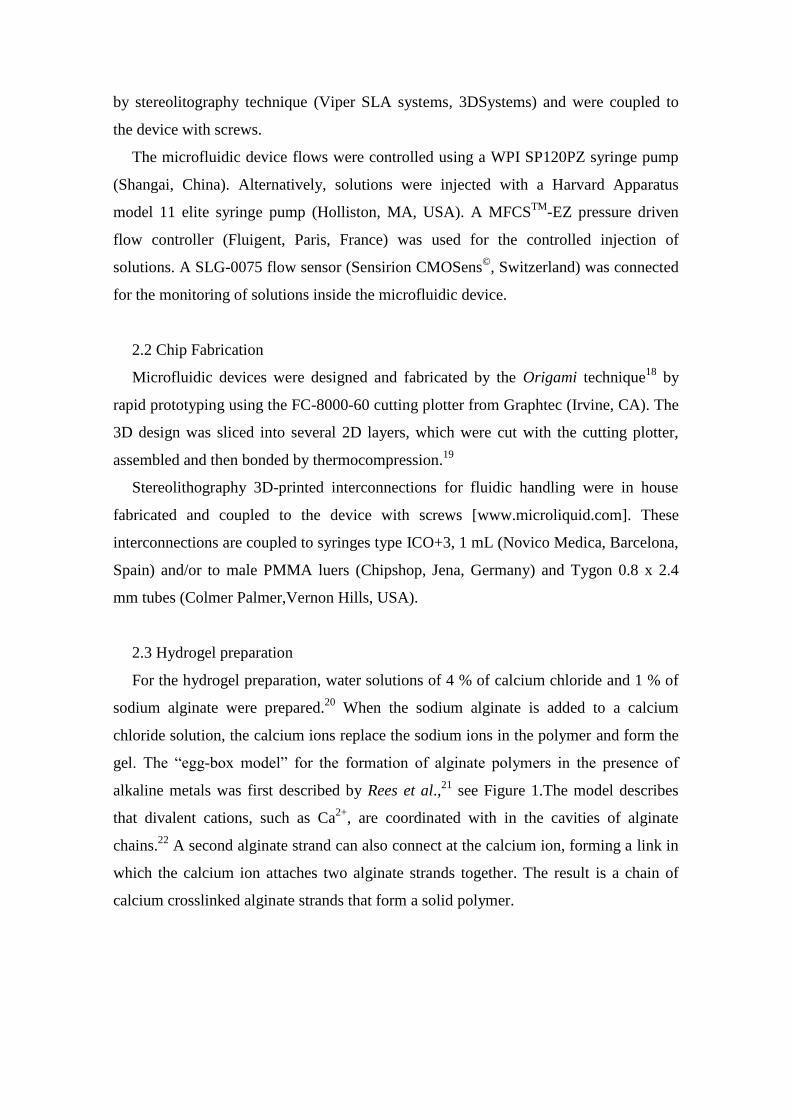
For the hydrogel preparation, water solutions of 4 % of calcium chloride and 1 % of
sodium alginate were prepared.20
When the sodium alginate is added to a calcium
chloride solution, the calcium ions replace the sodium ions in the polymer and form the
gel. The “egg-box model” for the formation of alginate polymers in the presence of
alkaline metals was first described by Rees et al.,21
see Figure 1.The model describes
that divalent cations, such as Ca2+
, are coordinated with in the cavities of alginate
chains.22
A second alginate strand can also connect at the calcium ion, forming a link in
which the calcium ion attaches two alginate strands together. The result is a chain of
calcium crosslinked alginate strands that form a solid polymer.
Figure 1: Schematic of the calcium alginate polymer formation and EDTA erase (left)
and chemical structure of the calcium alginate formation (right).
In order to perform this reaction within the microfluidic device and generate a
functional microvalve, in a controlled manner, calcium alginate beads were first
synthesised on bench. For this, a syringe was filled with the sodium alginate solution
and few drops of the liquid (500 µL) were added to a calcium chloride solution bath,
allowing polymerisation. The reaction was then stopped by putting the beads into a
water bath.
3. RESULTS AND DISCUSSION
3.1 Chip Fabrication
In order to first prove the concept of valve generation, the first generation prototype
microfluidic device (Prototype 1) was designed with a simple T-shape configuration
containing seven 100 µm thick COP layers, with a main channel stream of 1 mm width
and a perpendicular channel of 500 µm for microvalve generation. A more sophisticated
second generation microfluidic design (prototype 2) was later fabricated in order to
independently control the injection of the CaCl2, EDTA and alginate solutions into the
main channel stream. This second generation was fabricated including an additional set
of layers of COP, where the EDTA microchannel is placed with a V-shape (1 mm
width, 200 µm height) above the generated microvalve in order to independently control
the gel microvalve removal. COP was used in order to guarantee the biocompatibility of
the whole device
Figure 2 (A) shows an unfolded Origami prototype 1 sliced in seven layers of COP
and (C) prototype 2 sliced in nine layers of COP. The microfluidic devices contain the

inlets/outlet, the main channel and the perpendicular channel in prototype 1 and an
additional V-shape channel in prototype 2. Figure 2 (B and D) presents the prototype 1
and prototype 2 respectively, after thermocompression with the stereolithography
interconnections coupled with screws. This type of interconnector guarantees no
leakage during the experiment up to 1 bar of pressure and has the possibility of being
connected directly to syringe or to commercially available fittings coupled to a tubing
and then to the syringe.
Figure 2: Prototype 1 schematic design of the microfluidic device (A), unfolded origami
sheets (B) and completed device following thermocompression of the origami layers
with inlets/oultets (C). Prototype 2 schematic design of the microfluidic device
including additional V-shaped EDTA channel (D), unfolded origami sheets (E) and
completed device after thermocompression of the origami layers with inlets/oultets (F).
3.2 Hydrogel characterisation
Two approaches were followed to characterise the optimised conditions for calcium
alginate microvalve generation and removal in the microfluidic device. Firstly, the
percent weight/volume (% w/v) for each sodium alginate/water and calcium chloride
solutions was optimised on bench. Secondly, the flow rate of each solution into their
corresponding channels was investigated.
For the characterisation of the optimum % w/v per solution, several proportions of
sodium alginate were tested. 0.6%, 1%, 2% and 4% w/v of sodium alginate solution
were tested in order to select the most adequate solution to be employed in the
microfluidic device. It was found that 1 % w/v sodium alginate ensures rapid,
homogeneous polymerisation and low viscosity to facilitate the flow of alginate solution

into the microfluidic device. The CaCl2 concentration was optimised by selecting the
concentration of CaCl2 which shows the best performance with respect to the structural
resistance of the formed calcium alginate polymer (ɳ). This result was obtained for 4 %
w/v calcium chloride solution, obtaining the same results as the work previously
described by Blandino et al. 11
Using this percentage, the structural resistance
(robustness) of calcium alginate polymers is uniform. It was observed that ɳ tends to
decrease when more concentrated solutions were used. This reduction in n value is
known to be due to the increase in diffusional resistance that Ca2+
ions suffer in their
flux through a thicker membrane (n, decreases with increasing diffusional resistance)
and similar behaviour was reported by Yamagiwa et al.15
In order to chemically erase the microvalve an aqueous solution of 0.5 M water
EDTA was found to successfully dissolve the polymer.
3.3 Alginate microvalve in situ generation
The prototype 1 device was connected to the pressure driven flow controller that
controls the pressure and flow of calcium chloride solution independently from sodium
alginate solution into the microfluidic device. As highlighted in the experimental
section the microvalves were in situ fabricated using 1 % w/v sodium alginate and 4 %
w/v CaCl2 solution.
For the fabrication of the microvalve, the CaCl2 solution was flowed (Figure 3-1)
through the main microchannel using the pressure driven flow controlled at 60 µL min-1
through the 1 mm diameter channel while the alginate solution coming from the
perpendicular channel reaches the T-intersection section of the microchannel (~ 1500
µm length, Volume: 1.05 L) after a small air plug (~ 200 µm length) as a manually
controlled fast flow pulse using a syringe, Figure 3-2 and 3-3. Figure 3-3 presents an in
situ generated microvalve in the main microchannel and in the top right figure an
alginate bead fabricated outside the microfluidic device for comparison. It is appreciated
in Figure 3-3 that both generated alginate polymers (on-chip and bench) present similar
physical configurations with no appreciable fabrication damages or cracks. In the
intersection, the calcium cations of the CaCl2 solution penetrate by diffusion into the
sodium alginate solution plug and start polymerising the alginate, resulting in hydrogel
formation. By introducing the alginate into the calcium solution, anisotropic
polymerised particles with broad size distributions are formed at first due to differences

in the diffusion rate of calcium throughout the alginate.23
The amount of sodium
alginate solution and the shape of the generated microvalve in the microfluidic device
are controlled by the speed of the alginate plug. It should be noted here that it is quite
difficult to control the shape of the microvalve since the hydropobicity of the COP
microchannel is not enough to prevent the alginate solution expanding throughout the
main microchannel, see the shape of the microvalve in Figure 3-3. Nevertheless, the
generated alginate plug is sufficient to ensure a physical barrier to close the main
microchannel and act as a microvalve. A well defined microvalve could be generated by
mechanically controlling the sodium alginate solution plug.
Figure 3: Time lapse images illustrating alginate microvalve formation: (1) CaCl2
solution injected into main channel, (2) Alginate solution added through feed channel
and (3) Calcium alginate bead formation upon reaction of two solutions. (3) inset is a
calcium alginate bead generated outside of microfluidic channel for comparison to in-
situ bead produced for valving applications.
3.4 Alginate microvalve characterisation
Figure 4 (a) shows the flow profile within the microfluidic channel during in situ
microvalve formation. The flow sensor was placed after the microfluidic device and the
CaCl2 solution flowed through the main channel (ON configuration) at 3 µL min-1
in
order to be able to observe the formation of the microvalve. The flow in the main
channel decreased to almost 0 µL min-1
when the microvalve is fully formed and the
channel is blocked (OFF configuration). The microvalve formation time was 40 ± 7 s, n
= 4 for this particular microfluidic configuration.
Although the experimental conditions of both the on-bench and in situ microvalves
formation are not entirely equivalent, the formation time of the in situ microvalves
correlates well with the formation of a calcium alginate beads on bench. On bench, the
calcium alginate starts polymerising instantly at the surface of the sodium alginate bead,
upon addition of CaCl2, maintaining the shape of the bead. As time progresses, the
alginate drop becomes firmer with time while in contact with the CaCl2 solution. The
core of the sodium alginate bead/microvalve is initially “unreactive” but over time the
ion exchange moves towards the centre from the surface and forms a complete calcium
alginate structure, as described by Kim.24
The fluctuations in the flow rate, with a maximum of approximately 0.20 µL min-1
,
could be attributed to fluctuations of the flow due to reorganisation of the alginate
polymer during formation or accommodation of the generated polymer to the channel
configurations. The reason why the flow signal does not reach 0 µL min-1
may be
attributed to:
(1) the alginate polymer porosity; this can be reduced by increasing the immersion time
of alginate in the calcium solution and/or decreasing the ratio between mannuronic units
and guannuronic units (M/G) in the sodium alginate. Calcium alginate films with
higher concentration of G were proven to have significantly lower water vapour
permeabilities (WVP) compared to films with higher concentration of M. It was
reported that the immersion time and the M/G ratio of sodium alginate are therefore the
key steps for producing calcium alginate films with low WVP and so less porosity.25
(2) inadequate assembly of the alginate microvalve with the microchannel walls. In
order to minimise this effect, other T-junction configurations with a more circular or
oval shape could be fabricated to better accommodate the generated microvalve.
In order to characterise the pressure resistance of the microvalve, microvalve failure
pressure experiments were carried out. The flow sensor was located before the
prototype 1 device and a 60 µL min-1
flow of CaCl2 was set into the main microchannel
meanwhile a controlled pulse flow of sodium alginate was applied into the
perpendicular microchannel, see experimental. At the T-junction the polymerisation of
the calcium alginate took place resulting in the formation of the microvalve. Once the
CaCl2 flow decreased to virtually 0 µL min-1
the microchannel is its blocked (OFF)
configuration. In this particular experiment the microvalve formation appears negative
due to the large fluctuation generated in the flow sensor signal when the alginate
solution is injected into the main channel. Failure pressure experiments were then
carried out then by applying incremental pressures to the microvalve, through the main
channel, when the microvalve is OFF. The failure pressure value of the microvalve was

tested for 0.02, 0.05, 0.1, and 1 bar and it was observed that some of the microvalves
could hold up to 1 bar of pressure. However the observed fluctuations in the flow signal
after applying 1 bar of pressure imply that the microvalve is not stable at this pressure
for an extended period of time.
Figure 4: (a) Flow profile of prototype 1 device in the main channel of the microfluidic
device during alginate microvalve fabrication (flow sensor placed at the outlet of the
microfluidic device). (b) Flow profile in the main channel during alginate microvalve
fabrication (flow sensor placed at the inlet of the microfluidic device). Inset: microvalve
pressure failure experiments, carried out with the same microvalve.
A)
B)

3.5 Alginate microvalve actuation
As calcium alginate exhibits the phenomenon of syneresis the polymer can therefore
be actuated by temperature. Syneresis is the spontaneous release of bound water with
contraction of the hydrogel volume. Therefore the blocking action generated by the
microvalve in the microchannel can be partially reverted at a mild temperatures, 37 ºC,
as illustrated in Figure 5 with demonstrator beads on bench and in situ within a
microfluidic device. Although this actuation is not reversible, the microvalve is able to
shrink up to 20 % of its initial volume, allowing for the liquid to flow again.
This syneresis effect of the microvalve facilitates noncontact operation and therefore
independent manipulation of liquids flow in multiple microfluidic channels within an
integrated microfluidic manifold simply by positioning heaters below the microvalves.
It is clear that such dehydration of the hydrogel microvalves has the potential to greatly
improve fabrication processes. Moreover, this thermal process could be used to allow
for the injection, through the main microchannel, of an EDTA solution to completely
erase the alginate microvalve when the microvalve completely blocks the microchannel
when using very simple microfluidic configurations such as that represented by
protototype 1.

Figure 5: Dehydration of an alginate bead on bench and chip, respectively.
3.5 Removal of the alginate microvalve
The stability of calcium alginate hydrogel depends on the stability of calcium
complexes within the hydrogel.26
Thus, chelating agents that strongly bind calcium such
as sodium citrate and EDTA quickly solubilise the polymer.
Figure 6 presents the flow profile in the main microchannel when a microvalve was
generated and subsequently erased with EDTA. A CaCl2 solution was inserted into the
prototype 2 at 500 nL min-1
meanwhile the alginate was inserted as a fast pulse
perpendicularly. At the T-junction polymerisation of the microvalve takes place,
blocking the channel and producing a decrease in the flow to virtually 0 µL min-1
(Figure 6, picture 1). Following this, the addition of the EDTA chelate complex (500 nL
min-1
), coming from the channel set on top of the main channel (V-shape) removes the
calcium ions from the alginate polymer and erases the microvalve from the main
microchannel increasing then the flow rate (Figure 7, picture 2). It is important to note
here that for this microfluidic configuration (prototype 2) it is not necessary to heat the
microvalve, since the EDTA channel sits on top of the main channel. Both channels are
connected through a small orifice that gets blocked when microvalve forms.
Figure 6: Flow profile in the prototype 2 main microchannel during alginate microvalve
generation and removal by EDTA (flow sensor placed at the outlet of the microfluidic

device). 1) CaCl2 solution injection at 500 nL min-1
. 2) Sodium alginate solution pulse
injection. 3) Generated calcium alginate microvalve (OFF) (picture 1). 4) EDTA
solution injection and removal of the microvalve from the main microchannel (ON)
(picture 2).
It was found out that 60 ± 5 µL (n = 3) of EDTA solution it is sufficient to
completely erase the calcium alginate microvalve from the channel thus restoring the
main microfluidic microchannel for subsequent operations. The time needed to remove
the valve was approx. 120 s (depending on the size of the generated microvalve). The
result is a fast process that is comparable to the actuation mechanism observed by others
when using conventional hydrogel microvalves in microfluidic devices (e.g.
photoswitchables (60 s)27
or thermoresponsive (120 s)18
to open).
In the near future, a way of controlling the dimensions of the calcium alginate
microvalves will be investigated. It is believed that this preliminary investigation opens
up the use of calcium alginate materials as microvalves for many applications, such as
POC devices that require biocompatible and biodegradable components.
4. CONCLUSIONS
This contribution demonstrates the potential for alginate polymers to be used as
building block materials for the fabrication of in situ microvalves within microfluidic
devices with an ON/OFF actuation capability. Alginate has proven to efficiently act as
actionable microvalve at mild temperatures allowing for flow control due to its
syneresis effect. Moreover, by carefully adjusting the microfluidic channel
configuration alginate microvalves can be easily erased with EDTA solution, ensuring
the reusability of the whole device.
Alginate is biodegradable, therefore is an attractive material for microfluidic
applications related to the health and food industry. Moreover these calcium alginate
microvalves are low cost to produce in terms of materials, and the in situ fabrication
opens the possibility of creating large arrays of microvalves in complex microfluidic
structures.
5. ACKNOWLEDGEMENTS
Fernando Benito-Lopez acknowledges the Ramón y Cajal Programme (Ministerio de
Economía y Competitividad), Spain. This project has received funding from the
European Union´s Seventh Framework Programme (FP7) for Research, Technological

Development and Demonstration under grant agreement no. 604241. Authors are
grateful to IK4-IKERLAN for letting them to use its facilities for the fabrication of the
microfluidic devices and to Prof. Marian Martinez de Pancorbo for let us use her
laboratory facilities at UPV/EHU.
6. REFERENCES
1 S. Haeberle and R. Zengerle, Lab Chip, 2007, 7, 1094-1110.
2 C. A. Baker, C. T. Duong, A. Grimley and M. G. Roper, Bioanalysis, 2009, 1, 967-975.
3 A. Fonseca, I. M. Raimundo Jr, J. J. Rohwedder, R. S. Lima and M. C. Araujo, Anal. Bioanal Chem., 2010, 396, 715-723.
4 A. Milani, P. J. Statham, M. C. Mowlem and D. P. Connelly, Talanta, 2015, 136, 15-22.
5 G. Pasirayi, S. M. Scott, M. Islam, L. O'Hare, S. Bateson and Z. Ali, Talanta, 2014, 129, 491-498.
6 M. Rothbauer, D. Wartmann, V. Charwat and P. Ertl, Biotechnol. Adv.,2015, 33, 948-961 .
7 W. Al-Faqheri, F. Ibrahim, T. H. G. Thio, M. M. Aeinehvand, H. Arof and M. Madou, Sens. Actuators, A, 2015, 222, 245-254.
8 http://www.intechopen.com/books/advances-in-microfluidics/smart-microfluidics-the-role-of-stimuli-responsivepolymers-in-microfluidic-devices.
9 E. M. Ahmed, J. Adv. Res., 2015, 6, 105-121.
10 D. T. Eddington and D. J. Beebe, Adv. Drug Deliv. Rev., 2004, 56, 199-210.
11 A. Blandino, M. Macías and D. Cantero, J. Biosci. Bioeng., 1999, 88, 686-689.
12 J. Sun and H. Tan, Materials, 2013, 6, 1285-1309.
13 K. Y. Lee and D. J. Mooney, Prog. Polym. Sci., 2012, 37, 106-126.
14 A. Dalmoro, A. A. Barba, G. Lamberti, M. Grassi and M. d'Amore, Adv. Polym. Technol., 2012, 31, 219-230.
15 Y. Yajima, M. Yamada, E. Yamada, M. Iwase and M. Seki, Biomicrofluidics, 2014, 8, 024115-024115-11.
16 E. Ghafar-Zadeh, Sensors (Basel), 2015, 15, 3236-3261.

17 V. Zamora-Mora, D. Velasco, R. Hernández, C. Mijangos and E. Kumacheva, Carbohydr. Polym., 2014, 111, 348-355.
18 F. Benito-Lopez, M. Antonana-Diez, V. F. Curto, D. Diamond and V. Castro-Lopez, Lab Chip,2014, 14, 3530-3538.
19 C. L. Cassano, A. J. Simon, W. Liu, C. Fredrickson and Z. H. Fan, Lab Chip, 2015, 15, 62-66.
20 S. K. Bajpai and S. Sharma, React Funct Polym, 2004, 59, 129-140.
21 C. W. McCleary, D. A. Rees, J. W. B. Samuel and I. W. Steele, Carbohydr. Res., 1967, 5, 492-495.
22 L. Li, Y. Fang, R. Vreeker, I. Appelqvist and E. Mendes, Biomacromolecules, 2007, 8, 464-468.
23 I. Fernández Farrés and I. T. Norton, Food Hydrocoll., 2014, 40, 76-84.
24 H. Kim, Korean J. Chem. Eng., 1990, 7, 1-6.
25 G. I. Olivas and G. V. Barbosa-Cánovas, LWT - Food Sci. and Technol., 2008, 41, 359-366.
26 M. Kobaslija and D. T. McQuade, Biomacromolecules, 2006, 7, 2357-2361.
27 J. ter Schiphorst, S. Coleman, J.E. Stumpel, A. Ben Azouz, D. Diamond, A.P.H.J. Schenning, Chem. Mater., 2015, 27 , 5925-5931 .