seminar 51 - gshps using co
TRANSCRIPT

Laboratory Performance of a Prototype CO2 Ground-Source Air
Conditioner (GSAC)
Jan. 16, 2019
Harrison Skye, PhD
National Institute of Standards and Technology
Seminar 51 - GSHPs using CO2

• Describe the benefit of using CO2 as refrigerant in DX-GSHP systems.
• List some important parameters for designing CO2 DX-GSHP systems.
• For the prototype CO2 GSAC, discuss the variation of capacity, efficiency, with entering liquid temperature (ELT).
• Compare the efficiency and capacity of the prototype CO2 GSAC with the R410A GSHP.
Session Learning Objectives
this presentation

Paul Kalinowski
Dennis Nasuta
William Hoffman
Cara Martin
Acknowledgements
Optimized Thermal Systems
Wei Wu
Vance Payne
Piotr Domanski
John Wamsley
Art Ellison
NIST

• Using CO2 as a refrigerant
• Description of prototype CO2 GSAC
• Test facility & protocol (ISO 13256-1)
• Test results
• Comparison with a R410A GSHP
• Conclusions
Outline/Agenda

Using CO2 as a refrigerant
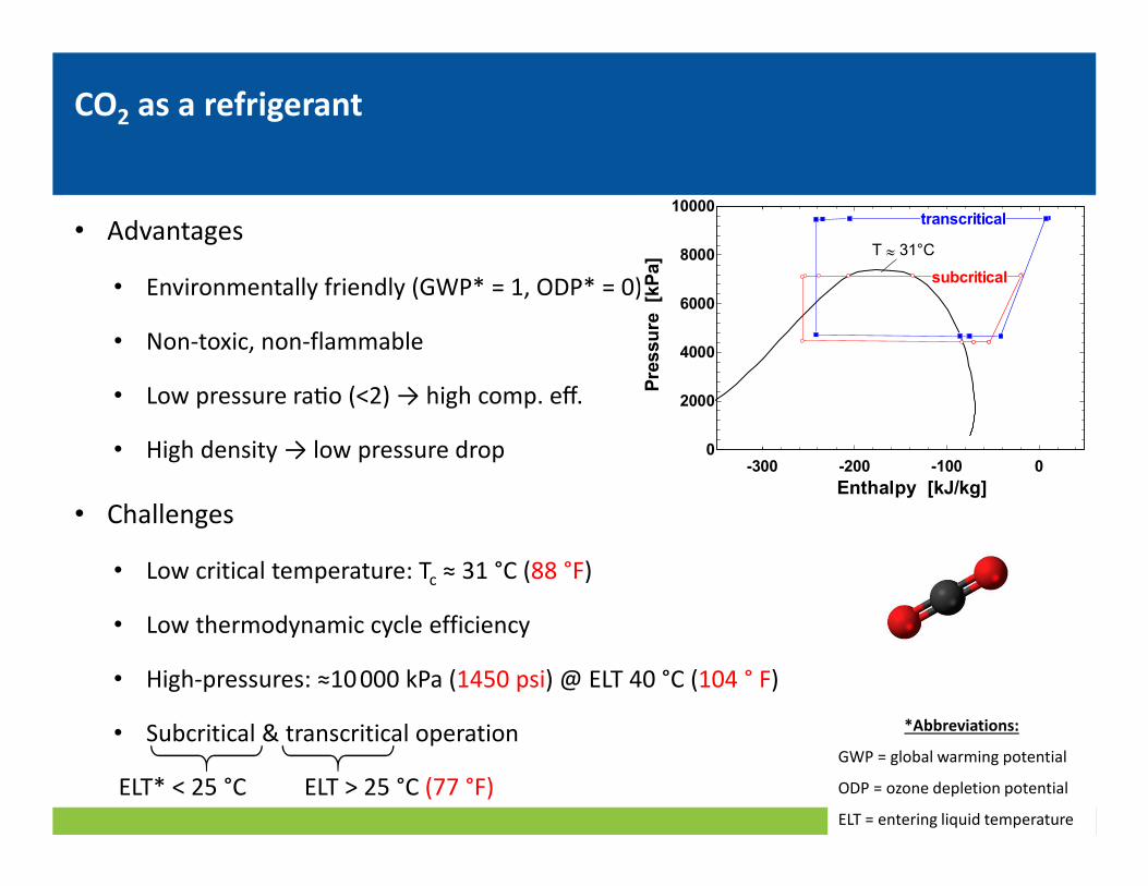
• Advantages
• Environmentally friendly (GWP* = 1, ODP* = 0)
• Non-toxic, non-flammable
• Low pressure ra@o (<2) → high comp. eff.
• High density → low pressure drop
• Challenges
• Low critical temperature: Tc ≈ 31 °C (88 °F)
• Low thermodynamic cycle efficiency
• High-pressures: ≈10 000 kPa (1450 psi) @ ELT 40 °C (104 ° F)
• Subcritical & transcritical operation
CO2 as a refrigerant
ELT* < 25 °C ELT > 25 °C (77 °F)
-300 -200 -100 00
2000
4000
6000
8000
10000
Enthalpy [kJ/kg]
Pre
ssu
re [k
Pa]
subcritical
transcritical
T ≈ 31°C
*Abbreviations:
GWP = global warming potential
ODP = ozone depletion potential
ELT = entering liquid temperature

Prototype CO2 GSAC

• Residential liquid-to-air GSAC
• Capacity: 5 to 7 kW (1.5 to 2 ton)
• Vapor-compression cycle with liquid-line /
suction-line heat exchanger (LLSL-HX)
• Cooling only
• Plate heat exchangers
• Condenser / gas cooler
• LLSL-HX
• Fin-tube evaporator
• Reciprocating compressor (semi-hermetic)
Prototype CO2 GSAC

Prototype CO2 GSAC
• MAWP - High side: 12000 kPa (1740 psi), Low side: 7000 kPa (1015 psi)
• Component specifications available in forthcoming NIST Technical Note [1]
*Abbreviations:
EEV = electronic expansion valve
RTD = resistance temperature detector
*
*

Test facility & protocol

• System tested inside an environmental chamber
• Measured capacity (latent/sensible), electricity, COP
• Controlled airflow, drybulb, dewpoint, liquid flow, entering liq. temp (ELT)
Test facility

Test facility - measurements

• ISO 13256-1: Standard for water-source heat pumps [2]
• Ground loop antifreeze: water/ethanol/isopropanol (70/25/5 %)
Test protocol
Standard Part-load Maximum Minimum
Drybulb, °C (°F) 27 (81) 32 (90) 21 (70)
Dewpoint, °C (°F) 14.7 (59) 19.2 (67) 11 (52)
Airflow, L/s (ft3/min) 342 (725)
Static pressure, Pa (in H2O) 58 (0.25)
Liquid flow, L/min (gal/min) 17 (4.5)
Entering liq. Temp., °C (°F) 25 (77) 20 (68) 39 (102) 10 (50)
Test Conditions

• ‘Extended’ tests - additional liquid temperatures
Test protocol
ELT-1 ELT-2 ELT-3 ELT-4 ELT-5
Drybulb, °C (°F) 27 (81)
Dewpoint, °C (°F) 14.7 (59)
Airflow, L/s (ft3/min) 308 (650)
Static pressure, Pa (in H2O) 58 (0.25)
Liquid flow, L/min (gal/min) 21 (5.5)
Entering liq. Temp., °C (°F) 10 (50) 15 (59) 30 (86) 35 (95) 36.8 (98)
Test Conditions

Test results

5 10 15 20 25 30 35 400.6
0.7
0.8
0.9
1
ELT [°C]
Ad
juste
d s
en
sib
le h
eat
rati
o,
SH
Ra
dj
standard
part-load
maximumELT-1
& min ELT-2
ELT-3
ELT-5
ELT-4
Error bars: k = 2 (95 % CI)
5 10 15 20 25 30 35 404000
5000
6000
7000
8000
9000
ELT [°C]
Ad
juste
d c
ap
acit
y
[W]
standard
minimum
part-load
maximum
total (Qtotal,adj)
sensible (Qsens,adj)
Error bars: k = 2 (95 % CI)
Test results - Capacity & Sensible Heat Ratio
subcritical transcritical
2.5 ton
(50 °F) (104 °F)
1.5 ton
Error bars: k=2 (95 % confidence)
• Capacity and SHR include adjustments to fan & pump power, per ISO 13256-1
Ca
pa
city
[W
]
Se
nsi
ble
he
at
rati
o
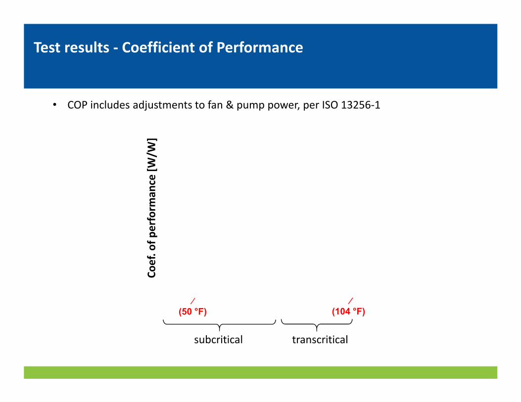
Test results - Coefficient of Performance
subcritical transcritical
(50 °F) (104 °F)
• COP includes adjustments to fan & pump power, per ISO 13256-1
Co
ef.
of
pe
rfo
rma
nce
[W
/W]

5 10 15 20 25 30 35 402
3
4
5
6
7
8
ELT [°C]
CO
Pa
dj [
-]
standard
minimum
part-load
maximum
ELT-1
ELT-2
ELT-3
ELT-5
ELT-4
Error bars: k = 2 (95 % CI)
Test results - Coefficient of Performance
subcritical transcritical
(50 °F) (104 °F)
• COP includes adjustments to fan & pump power, per ISO 13256-1
Co
ef.
of
pe
rfo
rma
nce
[W
/W]

Test results - Pressure
subcritical transcritical
1450 psi
600 psi
(50 °F) (104 °F)
1070 psi
5 10 15 20 25 30 35 404000
5000
6000
7000
8000
9000
10000
ELT [°C]
Pre
ssu
re
[kP
a]
standard
part-load
max
ELT-1 &
minimum
ELT-2
ELT-3
ELT-5
ELT-4
critical pressure
(7377 kPa)
transcritical
subcritical
compressor discharge
compressor suction
Error bars: k = 2 (95 % CI)

0 1 2 3 4 5 60.3
0.4
0.5
0.6
0.7
Compressor pressure ratio, P1/P13 [-]
To
tal
eff
icie
ncy, η
tota
l [
-]
standard
part-load
ELT-1
ELT-2
ELT-3
ELT-5
ELT-4
manufacturer: transcritical
manufacturer: subcritical
CO2 GSAC Tests
Error bars: k = 2 (95 % CI)
• Compressor efficiency ηtotal = mref · Δhisen/Welec [3]
Test results - Compressor Efficiency
Co
mp
ress
or
tota
l e
ffic
ien
cy, η
tota
l
Compressor pressure ratio, Pdis/Psuc

Comparison with R410A GSHP

• Compared CO2 GSAC with a R410A GSHP
• R410A GSHP
• Similar size: 7000 W (2 ton)
• Commercially available
• Entry-level price (low cost)
• Data from manufacturer’s website [4]
Comparison with R410A GSHP

5 10 15 20 25 30 35 400.6
0.7
0.8
0.9
1
ELT [°C]
Ad
juste
d s
en
sib
le h
eat
rati
o,
SH
Ra
dj
[-]
standard
part-load
ELT-1ELT-2
ELT-3
ELT-5
ELT-4
CO2 GSAC
R410A GSHP
max
Error bars: k = 2 (95 % CI)
5 10 15 20 25 30 35 404000
5000
6000
7000
8000
9000
ELT [°C]
Ad
juste
d c
ap
acit
y
[W]
total (Qtotal,adj)
sensible (Qsens,adj)
CO2 GSAC
R410A GSHP
Error bars: k = 2 (95 % CI)
• CO2 GSAC had lower capacity w/ ELT > 20 °C (68 °F)
• CO2 GSAC had higher SHR
Comparison with R410A GSHP
(50 °F) (104 °F)
2.5 ton
1.5 ton
Ca
pa
city
[W
]
Se
nsi
ble
he
at
rati
o

5 10 15 20 25 30 35 402
3
4
5
6
7
8
ELT [°C]
CO
Pa
dj [
-]
standard
part-load
ELT-1
ELT-2
ELT-3
ELT-5ELT-4
CO2 GSAC
R410A GSHPmin (CO2 only)
max
Error bars: k = 2 (95 % CI)
• CO2 system had lower COP w/ ELT > 20 °C (68 °F)
Comparison with R410A GSHP
(50 °F) (104 °F)
Co
ef.
of
pe
rfo
rma
nce
[W
/W]

Conclusions & future work

Conclusions
• Tested prototype CO2 GSAC in cooling, ISO 13256-1
• Measurements: capacity, COP, SHR, pressures, compressor efficiency
• Transcritical cycle when ELT > 25 °C (77 °F)
• CO2 GSHP vs. R410A GSHP
• CO2 GSAC had lower capacity & COP with ELT > 20 °C (68 °F)
• CO2 GSAC had higher SHR
• Additional work required to make CO2 system competitive

Future work
• Increase CO2 GSAC efficiency
• Ejector
• Compressor design (leverage low pressure ratio)
• Heat exchanger design (leverage low pressure drop)
• CO2 system in heating mode

Bibliography
[1] Skye, H.M., Wu, W., “Laboratory Tests of a Prototype Carbon Dioxide Ground-Source Air Conditioner”, NIST Technical note, expected publication 2019.
[2] ISO, “ISO 13256-1:1998 Standard for Water-source heat pumps -- Testing and rating for performance -- Part 1: Water-to-air and brine-to-air heat pumps.” International Standards Organization, 1998.
[3] ASHRAE Handbook: HVAC Systems and Equipment. Amer. Soc. Heating, Ref. Air-Conditioning Eng. Inc., p. 38.3, 2016.
[4] Waterfurnace, “Waterfurnace Specifications Catalog: 3-Series 300A11.” 2018.


End