semi-robotic 6 degree of freedom positioning for - biomed central
TRANSCRIPT

Wilbert et al. Radiation Oncology 2010, 5:42http://www.ro-journal.com/content/5/1/42
Open AccessR E S E A R C H
ResearchSemi-robotic 6 degree of freedom positioning for intracranial high precision radiotherapy; first phantom and clinical resultsJürgen Wilbert†, Matthias Guckenberger, Bülent Polat, Otto Sauer, Michael Vogele, Michael Flentje and Reinhart A Sweeney*†
AbstractBackground: To introduce a novel method of patient positioning for high precision intracranial radiotherapy.
Methods: An infrared(IR)-array, reproducibly attached to the patient via a vacuum-mouthpiece(vMP) and connected to the table via a 6 degree-of-freedom(DoF) mechanical arm serves as positioning and fixation system. After IR-based manual prepositioning to rough treatment position and fixation of the mechanical arm, a cone-beam CT(CBCT) is performed. A robotic 6 DoF treatment couch (HexaPOD™) then automatically corrects all remaining translations and rotations. This absolute position of infrared markers at the first fraction acts as reference for the following fractions where patients are manually prepositioned to within ± 2 mm and ± 2° of this IR reference position prior to final HexaPOD-based correction; consequently CBCT imaging is only required once at the first treatment fraction.
The preclinical feasibility and attainable repositioning accuracy of this method was evaluated on a phantom andhuman volunteers as was the clinical efficacy on 7 pilot study patients.
Results: Phantom and volunteer manual IR-based prepositioning to within ± 2 mm and ± 2° in 6DoF was possible within a mean(± SD) of 90 ± 31 and 56 ± 22 seconds respectively. Mean phantom translational and rotational precision after 6 DoF corrections by the HexaPOD was 0.2 ± 0.2 mm and 0.7 ± 0.8° respectively. For the actual patient collective, the mean 3D vector for inter-treatment repositioning accuracy (n = 102) was 1.6 ± 0.8 mm while intra-fraction movement (n = 110) was 0.6 ± 0.4 mm.
Conclusions: This novel semi-automatic 6DoF IR-based system has been shown to compare favourably with existing non-invasive intracranial repeat fixation systems with respect to handling, reproducibility and, more importantly, intra-fraction rigidity. Some advantages are full cranial positioning flexibility for single and fractionated IGRT treatments and possibly increased patient comfort.
BackgroundIn the last decade, there have been major technologicaladvances, of note cone-beam CT (CBCT) [1-3], 3D fluo-roscopy [4-6] and 6 degrees of freedom (DoF) treatmentcouches [7-10], all commercially available and in clinicaluse. These have made not only submillimeter but alsosub-degree positioning possible, allowing reduction ofsafety margins and also giving clinicians the confidence to
perform even radiosurgical procedures without invasivefixation, using for example thermoplastic masks [11,12].Without IGRT, such masks allow repositioning accuracyof about ± 2 mm (SD) and about ± 2° [13,14]. The IGRTprocess relativises this inaccuracy somewhat, however,image acquisition and position correction, even with6DoF remote couches takes time and judging from ourexperiences, the required corrections exceed the capabili-ties of the HexaPOD to correct remotely on average everythird fraction (unpublished data, RS, MG). In such cases,manual pre-corrections need to be performed with thebase couch. Large rotational corrections can in turnthemselves induce translational anatomical changes
* Correspondence: [email protected] Department of Radiation Oncology, University Hospital Würzburg, Josef-Schneider-Str. 11, 97080 Würzburg, Germany† Contributed equallyFull list of author information is available at the end of the article
BioMed Central© 2010 Wilbert et al; licensee BioMed Central Ltd. This is an Open Access article distributed under the terms of the Creative CommonsAttribution License (http://creativecommons.org/licenses/by/2.0), which permits unrestricted use, distribution, and reproduction inany medium, provided the original work is properly cited.

Wilbert et al. Radiation Oncology 2010, 5:42http://www.ro-journal.com/content/5/1/42
Page 2 of 11
inside a thermoplastic mask [15] which may be critical, soeven with IGRT and 6DoF couches, repositioning accu-racy is still important; less is always better, especially forrotational errors. Some may argue that rotational errorsare not an issue, but especially for larger irregular vol-umes or multiple tumors treated simultaneously [16]ignoring rotations may reduce coverage or increase organat risk exposure. Finally, intra-fractional patient motion,especially for radiosurgical procedures is of utmostimportance and not negligible in thermoplastic masks[17,18].
In this work, we describe the system, pre-clinical andpilot-patient results of a novel concept, combining 4 wellknown and clinically proven systems to maximize theirindividual high potential, namely the vacuum mouthpiece(vMP), 6 DoF couch, CBCT, infrared(IR). The novelty isthe manual IR-based prepositioning of the head to within± 2 mm and ± 2° before allowing a robotic, 6DoF treat-ment couch to complete the remaining required rotationsand translations to within the system accuracy of 0.1 mmand 0.1°. We thus hypothesize previously unattainedaccuracy in all 6 DoF with high reliability and speed,while possibly being more flexible and patient friendlythan other repeat fixation aides. This can be achievedwith minimal radiation dose to the patient, as ionizingverification could in principle be necessary only onceduring the entire course of fractionated radiotherapy.
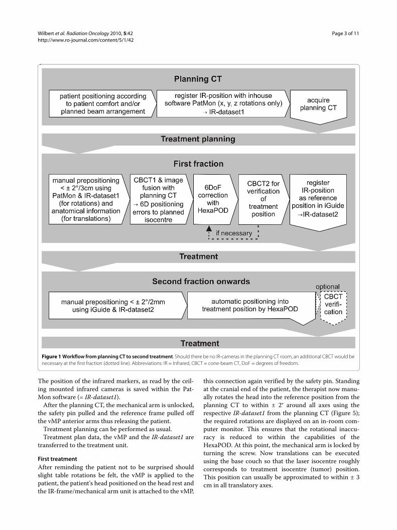
Proposed clinical procedure (Figure 1)The position of the cranium is defined in the planning
CT. In contrast to all current fixation systems, this posi-tion is not predefined or limited by some rigid (non-)invasive structure of sorts (e.g. mask systems, stereotacticrings systems). The initial reference structure is the 3Dvolume of the head itself. At first treatment, CBCT andimage fusion is used for verification of the correct patientposition and this geometric position of the cranium issaved via an IR frame, which is connected to the vMP.From the second fraction onwards, positioning occursonly according to this isocentre-specific IR-position. Amore detailed description is given in the following sec-tion.
MaterialsInfrared array- based reproducible positioning and fixationThe central element and the only patient specific hard-ware is the vMP(Medical Intelligence GmbH, Schwab-münchen, Germany). Its production has been previouslydescribed[19,20]. In short, an individual dental/upperpalate impression with a small vacuum area against theupper palate is made using a quickly hardening vinyl-poly-siloxane material. Production takes 5-10 minutes.Using a vacuum pump, air can be evacuated through theunderside of the mouthpiece from this vacuum-area.
allowing objectively consistent connection of the vMP tothe patient's upper dentition. The connection of the vMPto the treatment table is achieved via a mechanical armwhich allows full 6 DoF movement until locked by turn-ing a screw (ATLAS MultifunctionalARM™, MedicalIntelligence GmbH, Schwabmünchen, Germany). Thismechanical arm is attached to a base-plate which itself isattached to the treatment table with one self-centeringclamp. A reference frame with an array of four infraredmarkers is rigidly attached to the mechanical arm (Figure2). Once the patient is positioned on the treatment tablewith vMP in place and vacuum verified, this mechanicalarm-reference frame unit is reproducibly clamped ontothe anterior arms of the vMP (Figure 3).
No individualized headrest is required; a standardheadrest serves well for strictly supine position. However,for rotated positioning of the head, a flat pillow (Figure 2)or an individualized vacuum cushion is recommended.Ideally, the headrest or cushion is not fixated to the base-plate. This "floating" headrest allows the repositioningprocess to rely solely on the vMP/IR-frame connection,maximizing the concept of tensionless fixation.
All other materials (CBCT, ceiling mounted infraredcameras and 6 DoF treatment couch (HexaPOD withiGuide-Software (Version 1.0), Medical IntelligenceGmbH, Schwabmünchen Germany)) are commerciallyavailable in the scope of the Access Linac (Elekta, Craw-ley, UK). Ideally, an identical infrared camera (Polaris,NDI) is mounted in the planning CT room so that the ini-tial patient position can be transferred to the treatmentroom. In-house software ("PatMon" [10]) was used forthis purpose in this study. The room coordinates aredefined as x (left-right), y (cranio-caudal) and z (anterior-posterior) with respect to a supine patient on the treat-ment couch (Figure 4).
MethodsPlanning CTThe patient lies down comfortably on the table in a stan-dard head mould and inserts the vMP. Correct seat of thevMP is verified when the manometer on the vacuumpump shows values in the range of -0.3 to -0.6 mbar. Thenthe IR-reference array, rigidly connected to the mechani-cal arm on the base plate (Figure 2), is attached to thevMP anterior arms. A safety pin, which ensures repro-ducibility of the connection IR-frame to vMP, must beapplied (Figure 3).
No special attention is required to align the head tolasers, nor is there a need for reference markings.
The head is then manually positioned as required, thenfixated by tightening the screw on the mechanical arm.Patients can be positioned with any pitch, roll or yawrotation of the head offering additional degrees of free-dom for treatment planning or improved patient comfort.
Wilbert et al. Radiation Oncology 2010, 5:42http://www.ro-journal.com/content/5/1/42
Page 3 of 11
The position of the infrared markers, as read by the ceil-ing mounted infrared cameras is saved within the Pat-Mon software (= IR-dataset1).
After the planning CT, the mechanical arm is unlocked,the safety pin pulled and the reference frame pulled offthe vMP anterior arms thus releasing the patient.
Treatment planning can be performed as usual.Treatment plan data, the vMP and the IR-dataset1 are
transferred to the treatment unit.
First treatmentAfter reminding the patient not to be surprised shouldslight table rotations be felt, the vMP is applied to thepatient, the patient's head positioned on the head rest andthe IR-frame/mechanical arm unit is attached to the vMP,
this connection again verified by the safety pin. Standingat the cranial end of the patient, the therapist now manu-ally rotates the head into the reference position from theplanning CT to within ± 2° around all axes using therespective IR-dataset1 from the planning CT (Figure 5);the required rotations are displayed on an in-room com-puter monitor. This ensures that the rotational inaccu-racy is reduced to within the capabilities of theHexaPOD. At this point, the mechanical arm is locked byturning the screw. Now translations can be executedusing the base couch so that the laser isocentre roughlycorresponds to treatment isocentre (tumor) position.This position can usually be approximated to within ± 3cm in all translatory axes.
Figure 1 Workflow from planning CT to second treatment. Should there be no IR-cameras in the planning CT room, an additional CBCT would be necessary at the first fraction (dotted line). Abbreviations: IR = Infrared, CBCT = cone-beam CT, DoF = degrees of freedom.
Wilbert et al. Radiation Oncology 2010, 5:42http://www.ro-journal.com/content/5/1/42
Page 4 of 11
A CBCT is performed; the volume data set is matchedto the planning CT images using the automatic grey valuealgorithm. The alignment clipbox is generally defined toencompass the entire skull. The resulting required trans-lational and rotational positioning shifts to align to isoce-ntre in 6 DoF are corrected remotely with the HexaPODitself; should the required corrections however exceedHexaPOD capability, then rough approximation with thebase couch must precede the HexaPOD movement.
We recommend repeating the CBCT as verificationprior to treatment as this patient and isocentre specific IRposition stored within iGuide will be the reference posi-tion for all following fractions (= IR-dataset2).
After treatment, the mechanical arm is unlocked; thevMP is removed, rinsed with water and stored in a patientspecific box for the next treatment.
From second treatment onwardsThe patient is pre-positioned to within ± 2 mm and ± 2°manually as described, however this time using the IR-
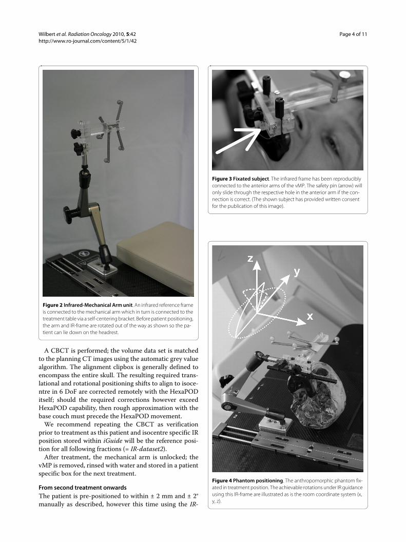
Figure 2 Infrared-Mechanical Arm unit. An infrared reference frame is connected to the mechanical arm which in turn is connected to the treatment table via a self-centering bracket. Before patient positioning, the arm and IR-frame are rotated out of the way as shown so the pa-tient can lie down on the headrest.
Figure 3 Fixated subject. The infrared frame has been reproducibly connected to the anterior arms of the vMP. The safety pin (arrow) will only slide through the respective hole in the anterior arm if the con-nection is correct. (The shown subject has provided written consent for the publication of this image).
Figure 4 Phantom positioning. The anthropomorphic phantom fix-ated in treatment position. The achievable rotations under IR guidance using this IR-frame are illustrated as is the room coordinate system (x, y, z).
Wilbert et al. Radiation Oncology 2010, 5:42http://www.ro-journal.com/content/5/1/42
Page 5 of 11
dataset2 reference position from the first treatment.Attention must always be paid to verifying correct vMPposition (audible hiss should the vacuum against theupper palate break, and visible on the manometer gauge)prior to and during this manual prepositioning. Afteragain locking the mechanical arm, the HexaPOD shouldautomatically complete the rest of the IR- based position-ing to submillimetric and tenth degree precision.
Phantom Study1.) Attainable repositioning accuracy of the reference frame onto the vMPThis system critically depends on the repositioning accu-racy of the IR-reference frame onto the mouthpiece,tested by repositioning the mechanical arm/IR-frameunit onto the anterior arms of the vMP 20 times. ThevMP remained rigidly attached to a cranial anthropomor-phic phantom which itself was screwed against the base-plate (Figure 4). The 6 DoF infrared deviations from thebaseline position were noted.
2.) Range of rotations detectable by the IR systemOne of the inherent advantages of this method is that, atleast theoretically, the head can be fixated in a tilted posi-tion, ± 90° around the x, y and z axis. This freedom ishowever limited not only by anatomy, but also by the IR-frame geometry. To determine the actual registrationrange of the IR-frame by the cameras, the phantom wasrotated from a supine (0°) position around all axes andthe maximally registered angle was noted.
3.) Attainable phantom resultsThe entire clinical procedure as described above wastested using the abovementioned phantom, at this pointhowever not fixated against the base plate. The vMPhowever remained rigidly attached to the phantom; Plan-ning CT slice thickness was 2 mm. Three users (one radi-ation therapist, one physicist and one physician, all naiveto 6DoF manual prepositioning) each positioned thephantom 10 times, totaling 30 repositionings, includingthe initial position according to the planning CT infraredinformation (IR-dataset1).
To determine the feasibility of the manual preposition-ing according to infrared information, the time frombeginning the manual pre-positioning to reaching therequired ± 2° and ± 2 mm was noted.
After CBCT1 and image registration to the planningCT using the clipbox surrounding the skull and the "greyvalue" algorithm, the required translatory and rotationalcorrections were noted. The duration of the ensuingHexaPOD correction of these values was also measured.After another CBCT(2) and image registration to plan-ning CT dataset, the final deviations from isocentre werenoted, again in 6 DoF.
4.) Subject studyTo evaluate the manual prepositioning process onhumans, an individual vMP was made for 5 informed andconsenting adult volunteers. Time was measured fromthe beginning of the manual positioning process (lowestbase table level, vMP inserted but mechanical arm loose,head turned about 30° to one side), up to when the sub-jects were positioned under infrared guidance to within ±2 mm and ± 2° of an initially saved supine baseline infra-red-position. This was repeated 5 times each by 5 differ-ent "therapists" (n = 30), all with little to no experience inmanual 6 DoF, IR-based positioning.
5.) Pilot studyBetween March and July 2008, 7 patients scheduled forfractionated intracranial radiotherapy at our departmentwere included in this study on a prospective protocolafter providing written informed consent. All weretreated according to the described method, with a CBCTperformed after positioning according to IR (CBCT1)and after each fraction (CBCT2). An additional verifica-
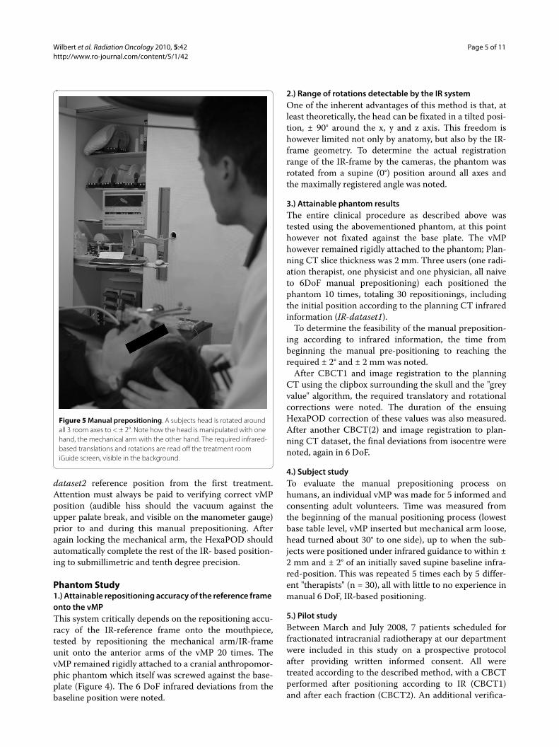
Figure 5 Manual prepositioning. A subjects head is rotated around all 3 room axes to < ± 2°. Note how the head is manipulated with one hand, the mechanical arm with the other hand. The required infrared-based translations and rotations are read off the treatment room iGuide screen, visible in the background.

Wilbert et al. Radiation Oncology 2010, 5:42http://www.ro-journal.com/content/5/1/42
Page 6 of 11
tion CBCT (CBCT1v) was made after the HexaPOD cor-rections at first treatment prior to saving that IR positionas reference for the following fractions. Thus, the CBCT1values showed the accuracy of the entire semi-automaticIR-based repositioning process (manual prepositioning +HexaPOD corrections). Intra-fraction movement wascalculated by subtraction of the CBCT1 values fromCBCT2 values.
To determine positioning- and intra-fraction duration,the time was measured from when the patient entered thetreatment room up to the beginning of CBCT1 andCBCT2 acquisitions, respectively.
Deviations are reported as described by van Herk [21];for each patient, the mean (systematic error) and stan-dard deviation (SD; random error) of all deviations dur-ing treatment were calculated. The group mean error (M)is defined as the average of all systematic errors; Σ isdefined as the SD of the systematic errors. The root-mean-square of the random errors was calculated as σ.Deviations in all 3 translational and rotational axes werecalculated separately as was the length of the 3D transla-tional vector. Safety margins for compensation of rigidsetup errors and intra-fraction errors were calculatedusing the formula 2.5Σ + 0.7σ.
Results1.) Attainable repositioning accuracy of the reference frame onto the vMPRepositioning the IR frame 20 times showed a standarddeviation of frame position of ≤ 0.1 mm and ≤ 0.1° aroundall axes. No translation or deviation was > ± 0.1 mm ordegree, demonstrating that repositioning accuracy of theIR frame onto the vMP is possible to at least the resolu-tion of the IR system itself (Table 1).
2.) Range of rotations detectable by the IR systemUsing the 4-Arm infrared-array as seen on Figures 3, 4and 5, only rotations around the z axis could be measuredaround 360°. Detection of rotations around the x axis waslimited to -19° (chin away from chest) and +90° (chintowards chest). Detection of rotations around the y-axiswas limited to about ± 40°.
3.) Attainable phantom resultsPrepositioning the phantom manually to within ± 2°according to IR parameters (n = 30) took 91 ± 31 seconds(mean ± SD). This manual prepositioning was performedto within a root mean square error of 1.8 ± 2.5 mm and0.58 ± 0.46° respectively.
Correction of these values by the HexaPOD took 21 ±4.1 seconds (mean ± SD).
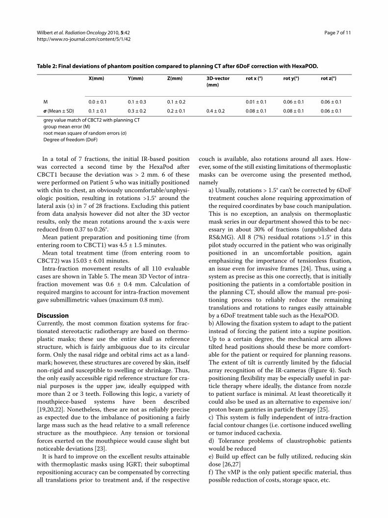
Table 2 shows the final positioning (deviation ofCBCT2 to planning CT) in the individual directions oraxes. Averaged over all translations (xyz) and rotations, aroot mean square error of 0.2 ± 0.2 mm and 0.07 ± 0.08°was reached respectively. The mean 3D vector was 0.4 ±0.2 mm.
4.) Subject studyRepositioning humans to within ± 2 mm and ± 2° (n = 30)took 56 ± 22 seconds (mean ± SD). Interuser variance wassmall. However, a steep learning curve was obvious(mean initial positioning time was 182 seconds (range 92-243 seconds). Also, it was found that manual preposition-ing is best performed by guiding the head with one handwhile simultaneously guiding the mechanical arm closeto the mouthpiece with the other hand (Figure 5).
5.) Pilot Patient StudySpecific patient information is listed in Table 3. In total,110 complete datasets of 117 fractions (94%) were avail-able for evaluation (229 CBCT datasets). All 110 fractionscould be evaluated for intra-fraction errors. Due to thedifferent procedure at the initial fraction, only 102 inter-fraction displacements were included in the analysis.
7 fractions (6%) could not be evaluated due to CBCTdowntime, during which verification was done by orthog-onal portal images.
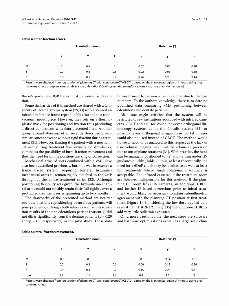
Individual translational and rotational deviations areshown in Table 4.
The 3D displacement vector after IR based semi-robotic patient positioning was 1.6 ± 0.8 mm (mean ±SD) and the maximum 3D Vector was 3.8 mm. Marginsranging from 1.7 mm in AP to 2.3 mm in lateral directionwere calculated for compensation of these setup errors.
Table 1: Infrared frame repositioning results.
X(mm) Y(mm) Z(mm) rot x (°) rot y (°) rot z (°)
SD 0.04 0.01 0.05 0.028 0.022 0.015
max 0.1 0.05 0.1 0.1 0.05 0.05
Standard deviation (SD) and maximum repositioning deviations when repeatedly connecting the frame to a fixated mouthpiece on the phantom.
Wilbert et al. Radiation Oncology 2010, 5:42http://www.ro-journal.com/content/5/1/42
Page 7 of 11
In a total of 7 fractions, the initial IR-based positionwas corrected a second time by the HexaPod afterCBCT1 because the deviation was > 2 mm. 6 of thesewere performed on Patient 5 who was initially positionedwith chin to chest, an obviously uncomfortable/unphysi-ologic position, resulting in rotations >1.5° around thelateral axis (x) in 7 of 28 fractions. Excluding this patientfrom data analysis however did not alter the 3D vectorresults, only the mean rotations around the x-axis werereduced from 0.37 to 0.26°.
Mean patient preparation and positioning time (fromentering room to CBCT1) was 4.5 ± 1.5 minutes.
Mean total treatment time (from entering room toCBCT2) was 15.03 ± 6.01 minutes.
Intra-fraction movement results of all 110 evaluablecases are shown in Table 5. The mean 3D Vector of intra-fraction movement was 0.6 ± 0.4 mm. Calculation ofrequired margins to account for intra-fraction movementgave submillimetric values (maximum 0.8 mm).
DiscussionCurrently, the most common fixation systems for frac-tionated stereotactic radiotherapy are based on thermo-plastic masks; these use the entire skull as referencestructure, which is fairly ambiguous due to its circularform. Only the nasal ridge and orbital rims act as a land-mark; however, these structures are covered by skin, itselfnon-rigid and susceptible to swelling or shrinkage. Thus,the only easily accessible rigid reference structure for cra-nial purposes is the upper jaw, ideally equipped withmore than 2 or 3 teeth. Following this logic, a variety ofmouthpiece-based systems have been described[19,20,22]. Nonetheless, these are not as reliably preciseas expected due to the imbalance of positioning a fairlylarge mass such as the head relative to a small referencestructure as the mouthpiece. Any tension or torsionalforces exerted on the mouthpiece would cause slight butnoticeable deviations [23].
It is hard to improve on the excellent results attainablewith thermoplastic masks using IGRT; their suboptimalrepositioning accuracy can be compensated by correctingall translations prior to treatment and, if the respective
couch is available, also rotations around all axes. How-ever, some of the still existing limitations of thermoplasticmasks can be overcome using the presented method,namely
a) Usually, rotations > 1.5° can't be corrected by 6DoFtreatment couches alone requiring approximation ofthe required coordinates by base couch manipulation.This is no exception, an analysis on thermoplasticmask series in our department showed this to be nec-essary in about 30% of fractions (unpublished dataRS&MG). All 8 (7%) residual rotations >1.5° in thispilot study occurred in the patient who was originallypositioned in an uncomfortable position, againemphasizing the importance of tensionless fixation,an issue even for invasive frames [24]. Thus, using asystem as precise as this one correctly, that is initiallypositioning the patients in a comfortable position inthe planning CT, should allow the manual pre-posi-tioning process to reliably reduce the remainingtranslations and rotations to ranges easily attainableby a 6DoF treatment table such as the HexaPOD.b) Allowing the fixation system to adapt to the patientinstead of forcing the patient into a supine position.Up to a certain degree, the mechanical arm allowstilted head positions should these be more comfort-able for the patient or required for planning reasons.The extent of tilt is currently limited by the fiducialarray recognition of the IR-cameras (Figure 4). Suchpositioning flexibility may be especially useful in par-ticle therapy where ideally, the distance from nozzleto patient surface is minimal. At least theoretically itcould also be used as an alternative to expensive ion/proton beam gantries in particle therapy [25].c) This system is fully independent of intra-fractionfacial contour changes (i.e. cortisone induced swellingor tumor induced cachexia.d) Tolerance problems of claustrophobic patientswould be reducede) Build up effect can be fully utilized, reducing skindose [26,27]f ) The vMP is the only patient specific material, thuspossible reduction of costs, storage space, etc.
Table 2: Final deviations of phantom position compared to planning CT after 6DoF correction with HexaPOD.
X(mm) Y(mm) Z(mm) 3D-vector (mm)
rot x (°) rot y(°) rot z(°)
M 0.0 ± 0.1 0.1 ± 0.3 0.1 ± 0.2 0.01 ± 0.1 0.06 ± 0.1 0.06 ± 0.1
σ (Mean ± SD) 0.1 ± 0.1 0.3 ± 0.2 0.2 ± 0.1 0.4 ± 0.2 0.08 ± 0.1 0.08 ± 0.1 0.06 ± 0.1
grey value match of CBCT2 with planning CTgroup mean error (M)root mean square of random errors (σ)Degree of freedom (DoF)

Wilbert et al. Radiation Oncology 2010, 5:42http://www.ro-journal.com/content/5/1/42
Page 8 of 11
In the pre-clinical aspect of this study, we have shownthat manual prepositioning to within ± 2° and ±2 mm in 6DoF according to infrared information can be performedeven by first time users. Prepositioning human subjectstook no longer than the phantom skull. With little prac-tice, manual prepositioning is possible in well under oneminute, the remaining corrections by the HexaPOD take≤ 20 seconds. Thus, high precision 6 DoF positioning wasexpected be reliably possible in less than 2 minutes onactual patients; although the time for the actual manualpre-positioning could not be measured consistently dueto logistic reasons, the expected time frame was basicallyconfirmed in the pilot patient phase, where the meanduration of patient entering the treatment room to startof CBCT1 was 4.5 ± 1.5 minutes. The entire treatmentsession could on average be completed within the allo-cated 15 minute timeslot (mean 15.03 ± 6.01 minutes).
Combined semi-robotic repositioning accuracy in thephantom study showed a mean deviation to planning CTof 0.2 ± 0.2 mm and 0.07 ± 0.08° over all translations (xyz)and rotations respectively, close to the minimal systeminaccuracies of the IR/image fusion systems themselves.These extraordinary results could however not be trans-ferred to the clinical setting on patients. One possiblereason is that the vMP itself was not removed betweenthe phantom repositionings as it was from the patients.However, the repositioning of the vMP itself has beenshown to be in the order of 0.1 mm on subjects[28] and isthus believed to be of lesser influence. The main reasonsfor this discrepancy must be the influence of tension in
the repositioning process, which seems to remain anissue even with use of vacuum technology. Possibly, opti-mization of mouthpiece impression material and vMPcasting will further improve these results in the future.Nonetheless, the clinical repositioning accuracy resultsshown in Table 4 and Table 5 still compare favourably toall available intracranial inter- and intra-fraction dataattained by volume imaging of sorts (Additional file 1,Table S1).
Comparing these data to invasive frames is no easymatter. In general however, the mechanical accuracy ofinvasive frames is quite often overestimated and not nec-essarily submillimetric as exhaustively shown already byMaciunas et al. in 1994 [24]. A more recent and clinicalpaper comparing stereotactic invasive frame-based toimage guided radiosurgery using kV imaging showedimage guidance to be superior to reliance on stereotacticcoordinates, possibly caused by mechanical inaccuracyand flex of the stereotactic frame[12].
We are not aware of pre existing results using thedescribed method; van Santfort et al. however used thesame vMP in comparing a BrainLab Mask system withand without this vMP using stereoscopic fluoroscopyimaging [6]. The best results were obtained with the vMP,quite similar to the inter- and intra-fraction results of thisstudy (Additional file 1, Table S1). The authors concludethat fixation according to vMP alone is inferior to thecombined method by comparing their data to historicvMP-based data. However such comparisons between
Table 3: Pilot Patient data.
Age K.S. BMI (kg/m2) Diagnosis Dental Status
Fx. treated % Fx. imaged before
treatment
% Fx. imaged
after treatment
CBCT2 repeat due
to > 1.5 mm/° error
1 58 80 29 Brain metastasis breast cancer
full 13 69 69 1
2 55 80 23 Brain metastasis SCLC
full 13 100 100 0
3 42 80 25 Brain metastasis breast cancer
full 10 90 90 0
4 46 70 20 Brain metastasis breast cancer
no teeth 10 100 100 0
5 * 69 90 27 Pituitary adenoma
3 teeth 29 97 100 7
6+ 65 80 26 Glioblastoma full 31 97 97 2
7 46 70 30 Clival metastasis NSCLC
full 11 100 83 0
* positioned chin to chest; + painful occipital scar thus oblique positionK.S. = Karnofsky ScoreFx. = Fractionsmin. = minutes
Wilbert et al. Radiation Oncology 2010, 5:42http://www.ro-journal.com/content/5/1/42
Page 9 of 11
the mV-portal and IGRT eras must be viewed with cau-tion.
Some similarities of this method are shared with a Uni-versity of Florida groups system [29,30] who also used aninfrared reference frame reproducibly attached to a (non-vacuum) mouthpiece. However, they rely on a thermo-plastic mask for positioning and fixation thus precludinga direct comparison with data presented here. Anothergroup around Wiersma et al. recently described a verysimilar concept except without rigid fixation during treat-ment [31]. However, fixating the patient with a mechani-cal arm during treatment has virtually no drawbacks,eliminates the possibility of intra-fraction movement andthus the need for online position-tracking or correction.
Mechanical arms of sorts combined with a vMP havealso been described previously, but, this was in essence aframe based system, requiring bilateral hydraulic-mechanical arms to remain rigidly attached to the vMPthroughout the entire treatment series [32]. Althoughpositioning flexibility was given, the hydraulic-mechani-cal arms could not reliably retain their full rigidity over aprotracted treatment series spanning up to two months.
The drawbacks of the presented method are not yetobvious. Possibly, repositioning edentulous patients willpose problems, although both inter- as well as intra-frac-tion results of the one edentulous patient (patient 4) didnot differ significantly from the dentate patients (p = 0.29and p = 0.1 respectively) in the pilot study. These data
however need to be viewed with caution due to the lownumbers. To the authors knowledge, there is to date nopublished data comparing vMP positioning betweenedentulous and dentate patients.
Also, one might criticize that the system will berestricted to few institutions equipped with infrared cam-eras, CBCT and a 6 DoF couch; however, orthogonal flu-oroscopy systems as in the Novalis system [33] orpossibly even orthogonal megavoltage portal imagescould also be used instead of CBCT. The method wouldhowever need to be analysed to this respect as the lack oftrue volume imaging may limit the attainable precisiondue to out of plane rotations [34]. With practice, the headcan be manually positioned to <2° and <2 mm under IR-guidance quickly (Table 2), thus, at least theoretically, theneed for a 6DoF couch may be facultative as well, at leastfor treatments where small rotational inaccuracy isacceptable. The infrared cameras in the treatment roomare however indispensible for this method. If the plan-ning CT room lacks IR- cameras, an additional CBCTand further IR-based corrections prior to initial treat-ment would likely be necessary to attain submillimetricagreement with the planning CT position at first treat-ment (Figure 1). Considering the low dose applied by acranial CBCT (0.9-1.2 mGy) [35] the additional CBCTsadd very little radiation exposure.
On a more cautions note, the next steps are softwareand hardware optimizations as well as a large scale clini-
Table 4: Inter-fraction errors.
Translations (mm) Rotations (°)
X Y Z x y z
M 0 0.6 0 0.02 0.06 0.18
Σ 0.7 0.8 0.5 0.02 0.06 0.18
σ 0.8 0.1 0.7 0.26 0.28 0.44
Results were obtained from registration of planning CT-with cone-beam CT (CBCT1), based on the cranium as region of interest, using grey value matching. group mean error(M), standard deviation(SD) of systematic errors(Σ), root-mean-square of random errors(σ)
Table 5: Intra- fraction movement.
Translations (mm) Rotations (°)
X Y Z x y z
M -0.1 0 0 0 -0.06 -0.15
Σ 0.2 0.2 0.1 0.09 0.15 0.24
σ 0.4 0.4 0.2 0.15 0.23 0.31
max 1.8 1.1 1.4 0.8 1.1 2
Results were obtained from registration of planning CT-with cone-beam CT (CBCT2), based on the cranium as region of interest, using grey value matching.

Wilbert et al. Radiation Oncology 2010, 5:42http://www.ro-journal.com/content/5/1/42
Page 10 of 11
cal study, currently in preparation; we expect the resultsto improve with increasing experience and user-friendli-ness of hard and software; currently, the recognition ofthe described infrared frame is not a clinically releasedoption of iGuide which was not specifically designed forthis functionality, so storing the patient- and isocentre-specific infrared frame position relative to room coordi-nates still needs to be simplified and visualization of therequired corrections should also be improved.
In addition, combining vacuum mouthpiece and infra-red frame into one rigid cast would probably not onlyincrease precision but also simplify, expedite and increasethe reliability of the process.
Once more data and experience is gathered, we expectthat daily 3D imaging using ionizing radiation could bereduced to a typical once-weekly rate for all but the high-est precisional requirements or hypofractionated series,as the indirect infrared information allowed excellentrepositioning accuracy (mean 3D vector:1.6 ± 0.8 mm). Inthis case safety margins of 2 mm would be requiredaccording to the van Herk formula. If image guided 6 DoFcorrections are performed prior to each treatment, thesafety margins, namely those for intra-fraction move-ment, are submillimetric.
ConclusionsInfrared-based manual 6 DoF prepositioning with robotic6D correction of remaining translations and rotations hasbeen shown to be a fairly simple and effective method in aclinical setting as well. Although the hypothesized sub-millimetric accuracy was not reached in the clinical set-ting, these initial results compare favourably with the bestrepeat positioning systems available.
Additional material
Competing interestsJW, RS, and MG have received travel reimbursements from Elekta, Crawley UKor Medical Intelligence. MV was co-founder of Medical Intelligence and waswith the company between 1995 and 2007. Medical Intelligence was boughtby Elekta in 2005. Since 2007 he has had no financial relations whatsoever witheither Elekta or Medical Intelligence. None of the other authors have actual orpotential conflicts of interest.
Authors' contributionsJW contributed to study conception, coordination, data acquisition and analy-sis, MG contributed to coordination, patient treatment and data acquisition, BPcontributed to patient treatment and data analysis, OS contributed to coordi-nation, patient treatment and treatment planning, MV was involved in studyconception, MF treated patients and contributed to conception and organiza-tion, RS contributed to conception, treated patients, data analysis and draftedmanuscript. All authors revised the manuscript critically and gave finalapproval.
AcknowledgementsThe authors wish to express their sincere gratitude to Mr. Gerald Büchold for the hardware modifications of the reference frame adaptor, Joachim Goebel MD and Kurt Baier MSc for their assistance and constructive discussions as well as Iris Guenther for assistance in data collection (all University Würzburg, Department of Radiation Therapy).
Author DetailsDepartment of Radiation Oncology, University Hospital Würzburg, Josef-Schneider-Str. 11, 97080 Würzburg, Germany
References1. Groh BA, Siewerdsen JH, Drake DG, Wong JW, Jaffray DA: A performance
comparison of flat-panel imager-based MV and kV cone-beam CT. Med Phys 2002, 29:967-975.
2. Thilmann C, Nill S, Tucking T, Hoss A, Hesse B, Dietrich L, Bendl R, Rhein B, Haering P, Thieke C, et al.: Correction of patient positioning errors based on in-line cone beam CTs: clinical implementation and first experiences. Radiat Oncol 2006, 1:16.
3. Polat B, Guenther I, Wilbert J, Goebel J, Sweeney RA, Flentje M, Guckenberger M: Intra-fractional uncertainties in image-guided intensity-modulated radiotherapy (IMRT) of prostate cancer. Strahlenther Onkol 2008, 184:668-673.
4. Linthout N, Verellen D, Tournel K, Storme G: Six dimensional analysis with daily stereoscopic x-ray imaging of intrafraction patient motion in head and neck treatments using five points fixation masks. Med Phys 2006, 33:504-513.
5. Yan H, Yin FF, Kim JH: A phantom study on the positioning accuracy of the Novalis Body system. Med Phys 2003, 30:3052-3060.
6. van Santvoort J, Wiggenraad R, Bos P: Positioning accuracy in stereotactic radiotherapy using a mask system with added vacuum mouth piece and stereoscopic X-ray positioning. Int J Radiat Oncol Biol Phys 2008, 72:261-267.
7. D'Souza WD, McAvoy TJ: An analysis of the treatment couch and control system dynamics for respiration-induced motion compensation. Med Phys 2006, 33:4701-4079.
8. Guckenberger M, Meyer J, Wilbert J, Baier K, Sauer O, Flentje M: Precision of image-guided radiotherapy (IGRT) in six degrees of freedom and limitations in clinical practice. Strahlenther Onkol 2007, 183:307-313.
9. Wilbert J, Meyer J, Baier K, Guckenberger M, Herrmann C, Hess R, Janka C, Ma L, Mersebach T, Richter A, et al.: Tumor tracking and motion compensation with an adaptive tumor tracking system (ATTS): system description and prototype testing. Med Phys 2008, 35:3911-3921.
10. Meyer J, Wilbert J, Baier K, Guckenberger M, Richter A, Sauer O, Flentje M: Positioning accuracy of cone-beam computed tomography in combination with a HexaPOD robot treatment table. Int J Radiat Oncol Biol Phys 2007, 67:1220-1228.
11. Breneman JC, Steinmetz R, Smith A, Lamba M, Warnick RE: Frameless image-guided intracranial stereotactic radiosurgery: clinical outcomes for brain metastases. Int J Radiat Oncol Biol Phys 2009, 74:702-706.
12. Lamba M, Breneman JC, Warnick RE: Evaluation of image-guided positioning for frameless intracranial radiosurgery. Int J Radiat Oncol Biol Phys 2009, 74:913-919.
13. Boda-Heggemann J, Walter C, Rahn A, Wertz H, Loeb I, Lohr F, Wenz F: Repositioning accuracy of two different mask systems-3D revisited: comparison using true 3D/3D matching with cone-beam CT. Int J Radiat Oncol Biol Phys 2006, 66:1568-1575.
14. Polat B, Wilbert J, Baier K, Flentje M, Guckenberger M: Nonrigid patient setup errors in the head-and-neck region. Strahlenther Onkol 2007, 183:506-511.
15. Guckenberger M, Meyer J, Wilbert J, Baier K, Sauer O, Flentje M: Precision of image-guided radiotherapy (IGRT) in six degrees of freedom and limitations in clinical practice. Strahlenther Onkol 2007, 183:307-313.
16. Sterzing F, Welzel T, Sroka-Perez G, Schubert K, Debus J, Herfarth KK: Reirradiation of multiple brain metastases with helical tomotherapy. A multifocal simultaneous integrated boost for eight or more lesions. Strahlenther Onkol 2009, 185:89-93.
Additional file 1 Table S1: Inter- and Intra-fraction errors as analysed in IGRT for various repeat-fixation systems[36-39].
Received: 23 February 2010 Accepted: 26 May 2010 Published: 26 May 2010This article is available from: http://www.ro-journal.com/content/5/1/42© 2010 Wilbert et al; licensee BioMed Central Ltd. This is an Open Access article distributed under the terms of the Creative Commons Attribution License (http://creativecommons.org/licenses/by/2.0), which permits unrestricted use, distribution, and reproduction in any medium, provided the original work is properly cited.Radiation Oncology 2010, 5:42
Wilbert et al. Radiation Oncology 2010, 5:42http://www.ro-journal.com/content/5/1/42
Page 11 of 11
17. Murphy MJ, Chang SD, Gibbs IC, Le QT, Hai J, Kim D, Martin DP, Adler JR Jr: Patterns of patient movement during frameless image-guided radiosurgery. Int J Radiat Oncol Biol Phys 2003, 55:1400-1408.
18. Hoogeman MS, Nuyttens JJ, Levendag PC, Heijmen BJ: Time dependence of intrafraction patient motion assessed by repeat stereoscopic imaging. Int J Radiat Oncol Biol Phys 2008, 70:609-618.
19. Sweeney RA, Bale R, Auberger T, Vogele M, Foerster S, Nevinny-Stickel M, Lukas P: A simple and non-invasive vacuum mouthpiece-based head fixation system for high precision radiotherapy. Strahlenther Onkol 2001, 177:43-47.
20. Olch AJ, Lavey RS: Reproducibility and treatment planning advantages of a carbon fiber relocatable head fixation system. Radiother Oncol 2002, 65:165-168.
21. van Herk M: Errors and margins in radiotherapy. Semin Radiat Oncol 2004, 14:52-64.
22. Kooy HM, Dunbar SF, Tarbell NJ, Mannarino E, Ferarro N, Shusterman S, Bellerive M, Finn L, McDonough CV, Loeffler JS: Adaptation and verification of the relocatable Gill-Thomas-Cosman frame in stereotactic radiotherapy. Int J Radiat Oncol Biol Phys 1994, 30:685-691.
23. Burtscher J, Sweeney R, Bale R, Eisner W, Twerdy K: Neuroendoscopy based on computer assisted adjustment of the endoscope holder in the laboratory. Minim Invasive Neurosurg 2003, 46:208-214.
24. Maciunas RJ, Galloway RL Jr, Latimer JW: The application accuracy of stereotactic frames. Neurosurgery 1994, 35:682-694.
25. Jakel O, Debus J: Selection of beam angles for radiotherapy of skull base tumours using charged particles. Phys Med Biol 2000, 45:1229-1241.
26. Mellenberg DE: Dose behind various immobilization and beam-modifying devices. Int J Radiat Oncol Biol Phys 1995, 32:1193-1197.
27. Carl J, Vestergaard A: Skin damage probabilities using fixation materials in high-energy photon beams. Radiother Oncol 2000, 55:191-198.
28. Martin A, Bale RJ, Vogele M, Gunkel AR, Thumfart WF, Freysinger W: Vogele-Bale-Hohner mouthpiece: registration device for frameless stereotactic surgery. Radiology 1998, 208:261-265.
29. Meeks SL, Bova FJ, Friedman WA, Buatti JM, Moore RD, Mendenhall WM: IRLED-based patient localization for linac radiosurgery. Int J Radiat Oncol Biol Phys 1998, 41:433-439.
30. Furuse M, Aoki T, Takagi T, Takahashi JA, Ishikawa M: Frameless stereotactic radiosurgery with a bite-plate: our experience with brain metastases. Minim Invasive Neurosurg 2008, 51:333-335.
31. Wiersma RD, Wen Z, Sadinski M, Farrey K, Yenice KM: Development of a frameless stereotactic radiosurgery system based on real-time 6D position monitoring and adaptive head motion compensation. Phys Med Biol 55:389-401.
32. Sweeney R, Bale R, Vogele M, Nevinny-Stickel M, Bluhm A, Auer T, Hessenberger G, Lukas P: Repositioning accuracy: comparison of a noninvasive head holder with thermoplastic mask for fractionated radiotherapy and a case report. Int J Radiat Oncol Biol Phys 1998, 41:475-483.
33. Fahrig A, Ganslandt O, Lambrecht U, Grabenbauer G, Kleinert G, Sauer R, Hamm K: Hypofractionated stereotactic radiotherapy for brain metastases--results from three different dose concepts. Strahlenther Onkol 2007, 183:625-630.
34. Gilhuijs KG, Drukker K, Touw A, Ven PJ van de, van Herk M: Interactive three dimensional inspection of patient setup in radiation therapy using digital portal images and computed tomography data. Int J Radiat Oncol Biol Phys 1996, 34:873-885.
35. Amer A, Marchant T, Sykes J, Czajka J, Moore C: Imaging doses from the Elekta Synergy X-ray cone beam CT system. Br J Radiol 2007, 80:476-482.
36. Willner J, Flentje M, Bratengeier K: CT simulation in stereotactic brain radiotherapy--analysis of isocenter reproducibility with mask fixation. Radiother Oncol 1997, 45:83-88.
37. Masi L, Casamassima F, Polli C, Menichelli C, Bonucci I, Cavedon C: Cone beam CT image guidance for intracranial stereotactic treatments: comparison with a frame guided set-up. Int J Radiat Oncol Biol Phys 2008, 71:926-933.
38. Fuss M, Salter BJ, Cheek D, Sadeghi A, Hevezi JM, Herman TS: Repositioning accuracy of a commercially available thermoplastic mask system. Radiother Oncol 2004, 71:339-345.
39. Salter BJ, Fuss M, Vollmer DG, Sadeghi A, Bogaev CA, Cheek DA, Herman TS, Hevezi JM: The TALON removable head frame system for
stereotactic radiosurgery/radiotherapy: measurement of the repositioning accuracy. Int J Radiat Oncol Biol Phys 2001, 51:555-562.
doi: 10.1186/1748-717X-5-42Cite this article as: Wilbert et al., Semi-robotic 6 degree of freedom position-ing for intracranial high precision radiotherapy; first phantom and clinical results Radiation Oncology 2010, 5:42