self-priming pumps model 2620 series
TRANSCRIPT
Mo
de
l 26
20
-Se
ries
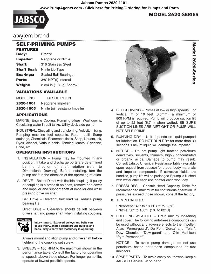
SELF-PRIMING PUMPSFEATURESBody: Bronze
Impeller: Neoprene or Nitrile
Shaft: 316 Stainless Steel
Shaft Seal: Nitrile Lip Type
Bearings: Sealed Ball Bearings
Ports: 3/8" NPT(f) Internal
Weight: 2-3/4 lb (1.3 kg) Approx.
VARIATIONS AVAILABLE
MODEL NO. DESCRIPTION
2620-1001 Neoprene Impeller
2620-1003 Nitrile (oil resistant) Impeller
APPLICATIONSMARINE: Engine Cooling, Pumping bilges, Washdowns,Circulating water in bait tanks, Utility dock side pump.
INDUSTRIAL: Circulating and transferring, Ve loc i ty-mixing,Pumping machine tool cool ants, Return spill, Sumpdrainage, Chemicals, Phar ma ceu ti cals, Soap, Liquors, Ink,Dyes, Alcohol, Various acids, Tanning liquors, Glyc er ine,Brine, etc.
OPERATING INSTRUCTIONS1. INSTALLATION – Pump may be mounted in any
position. Intake and discharge ports are de ter minedby the direction of shaft rotation (refer toDimensional Drawing). Before in stall ing, turn thepump shaft in the direction of the operating ro ta tion.
2. DRIVE – Belt or Direct with flexible coupling. If pulleyor coupling is a press fit on shaft, remove end coverand impeller and support shaft at impeller end whilepressing drive on shaft.
Belt Drive – Overtight belt load will reduce pumpbearing life.
Direct Drive – Clearance should be left be tweendrive shaft and pump shaft when in stall ing cou pling.
Always mount and align pump and drive shaft beforetightening the coupling set screw.
3. SPEEDS – 100 RPM to the maximum shown in theperformance table. Consult the factory for operationat speeds above those shown. For longer pump life,operate at lowest pos si ble speeds.
4. SELF-PRIMING – Primes at low or high speeds. Forvertical lift of 10 feet (3.0mm), a minimum of 800 RPM is required. Pump will produce suction liftof up to 22 feet (6.7m) when wetted. BE SURE SUCTION LINES ARE AIRTIGHT OR PUMP WILLNOT SELF-PRIME.
5. RUNNING DRY – Unit depends on liquid pumpedfor lubrication. DO NOT RUN DRY for more than 30seconds. Lack of liquid will damage the impeller.
6. NOTICE – Do not pump light fraction pe tro leumderivatives, solvents, thinners, highly concentratedor organic acids. Damage to pump may result.Consult Jabsco Chem i cal Resistance Table (availableupon request from Jabsco) for proper body materialsand impeller compounds. If corrosive fluids are handled, pump life will be prolonged if pump is flushedwith water after each use or after each work day.
7. PRESSURES – Consult Head Capacity Table forrecommended maximum for continuous operation. Ifpres sures exceed those shown, consult the factory.
8. TEMPERATURES
• Neoprene: 45° to 180°F (7° to 82°C)• Nitrile: 50° to 180°F (10° to 82°C)
9. FREEZING WEATHER – Drain unit by looseningend cover. The following anti-freeze compounds canbe used without any adverse effects to the impeller:Atlas “Perma-guard”, Du Pont “Zerex” and “Telar”,Dow Chemical “Dow-guard” and Olin Mathison“Pyro Per ma nent”.
NOTICE – To avoid pump damage, do not use petroleum based anti-freeze compounds or rustinhibitors.
10. SPARE PARTS – To avoid costly shutdowns, keep aJABSCO Service Kit on hand.
Injury hazard. Exposed pulleys and belts can cause injury . Install shield around pulleys and belts. Stay clear while machinery is operating.
W ARNING !
MODEL 2620-SERIESwww.PumpAgents.com - Click here for Pricing/Ordering for Pumps and Parts
Jabsco Pumps 2620-1101

SERVICE INSTRUCTIONSDISASSEMBLY
1. Remove end cover screws, end cover and O-ring.
2. Remove impeller by grasping hub with water pumppliers.
3. Loosen cam screw and remove cam (clean offsealant).
4. Remove pulley or coupling and key from shaft.
5. Remove retaining ring which secures bear ing/shaftassembly to pump body.
6. From impeller end of pump, press bearing and shaftassembly out of bearing bore. Remove slinger fromshaft.
7. From drive end of pump, press the seal out of theseal bore.
8. If bearings or shaft need to be replaced, care ful lyinsert two equal size slot screw driv ers be tween bearings 180° apart. Si mul ta neous ly twist screwdrivers in opposite di rec tions to separate bearings. Continue to push bearings off of shaft taking care not to dam age bearings or scratch shaft.
9. Remove snap ring that positions the bear ings on theshaft.
NOTE: Inspect all parts for wear or damage andreplace where necessary.
ASSEMBLY
1. Install bearing positioning snap ring on shaft.
2. Press bearings (one from each end of shaft) ontoshaft and against positioning snap ring. Slide slingeronto impeller end of the shaft and position againstraised shoulder near bearings.
3. Press seal (with lip pointing toward impeller bore)into seal bore in pump body. Lubricate seal lip with asmall amount of grease.
4. Align impeller end of shaft with the seal and pressshaft/bearing assembly into the bearing bore (pushon bearing outer race). Install bearing retaining ringin retaining ring groove.
5. Apply a thin layer of sealant to screw threads andtop of cam and install in body. Secure with camscrew.
6. Lubricate impeller bore with light coat of water pumpgrease and start impeller into bore with a rotarymotion, until impeller screw engages slot in shaft,then push into bore.
7. Install O-ring and end cover. Secure with end coverscrews.
Capacities reduced by approximately 10% using Nitrile impeller at higher speeds and higher pres sures.
NOTE: Progressively longer life may be ex pect ed as operating pressures and speeds are reduced. Factory ApplicationEngineering assistance suggested for operation in light shaded area and recommended for heavy shaded area.Capacitor type motor recommended. Table shows approximate Head-Flow for new pump in U.S. gallons per minuteand liters per minute.
HEAD CAPACITY TABLEModel 2620-1001
Total Head 500 RPM 1160 RPM 1750 RPM 2100 RPM 2450 RPM 3000 RPM 3600 RPM
Head in Feet PSI GPM GPM GPM GPM GPM GPM GPM (Meters) (kg/sq cm) (LPM) HP (LPM) HP (LPM) HP (LPM) HP (LPM) HP (LPM) HP (LPM) HP
10 4.3 1.6 1/12 3.5 1/6 5.8 1/4 6.7 1/3 7.5 1/3 9.4 1/2 11.3 3/4 (3.0) (0.3) (6.0) (13.3) (22.0) (25.4) (28.4) (35.6) (42.8)
20 8.7 1.0 1/12 2.6 1/6 5.0 1/4 5.8 1/3 6.6 1/3 8.4 1/2 10.4 3/4 (6.1) (0.6) (3.8) (9.8) (18.9) (22.0) (25.0) (31.8) (39.4)
30 13.0 –– –– –– –– 3.8 1/4 4.6 1/3 5.3 1/3 7.2 1/2 9.1 3/4 (9.1) (0.9) –– –– –– –– (14.4) (17.4) (20.0) (27.3) (34.4) 40 17.3 –– –– –– –– –– –– –– –– –– –– 5.6 1/2 7.7 3/4 (12.2) (1.2) –– –– –– –– –– –– –– –– –– –– (21.0) (29.2)
50 21.6 –– –– –– –– –– –– –– –– –– –– –– –– –– –– (15.2) (1.5) –– –– –– –– –– –– –– –– –– –– –– –– –– ––
www.PumpAgents.com - Click here for Pricing/Ordering for Pumps and PartsJabsco Pumps 2620-1101
51
23
4 6 5
7
10
13 8 11 9 12 8
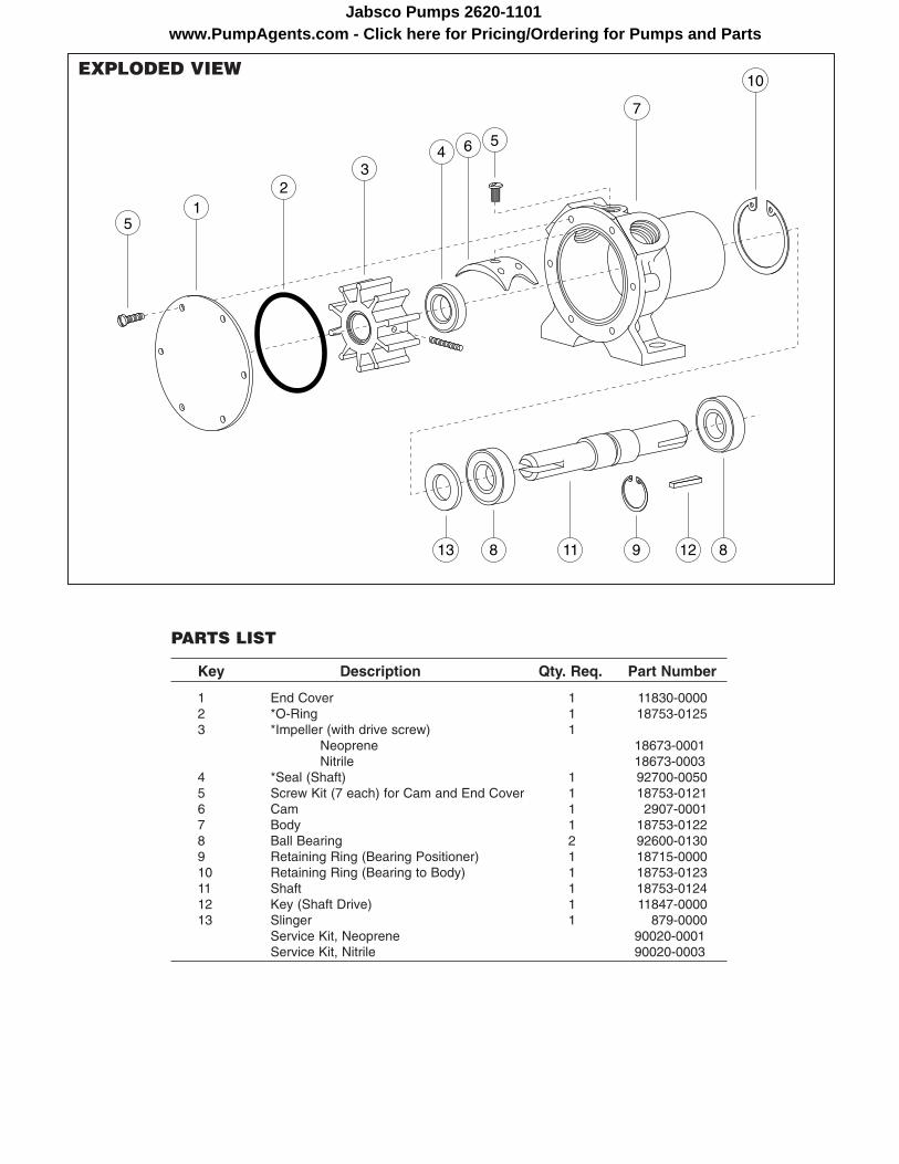
EXPLODED VIEW
PARTS LIST
Key Description Qty. Req. Part Number
1 End Cover 1 11830-0000 2 *O-Ring 1 18753-0125 3 *Impeller (with drive screw) 1 Neoprene 18673-0001 Nitrile 18673-0003 4 *Seal (Shaft) 1 92700-0050 5 Screw Kit (7 each) for Cam and End Cover 1 18753-0121 6 Cam 1 2907-0001 7 Body 1 18753-0122 8 Ball Bearing 2 92600-0130 9 Retaining Ring (Bearing Positioner) 1 18715-0000 10 Retaining Ring (Bearing to Body) 1 18753-0123 11 Shaft 1 18753-0124 12 Key (Shaft Drive) 1 11847-0000 13 Slinger 1 879-0000 Service Kit, Neoprene 90020-0001 Service Kit, Nitrile 90020-0003
www.PumpAgents.com - Click here for Pricing/Ordering for Pumps and PartsJabsco Pumps 2620-1101

A. LIMITED WARRANTY:Jabsco warrants that at the time of shipment, the products manufactured by Jabsco and sold hereunder shall be in conformity with applicable written specifications and descriptionsreferred to or set forth herein, free from defects in material andworkmanship, merchantable, and suitable for a particular purpose, provided such is implied by State law under the circumstances of this sale.
B. WARRANTY ADJUSTMENT:1. Jabsco agrees to repair or furnish a replacement for, but not to
remove or install, any product or component thereof which, withinone (1) year from date of purchase, shall upon test and examination by Jabsco prove defective within the above warranty.Receipt verifying purchase date is required to obtain adjustment.
2. Buyer shall notify Jabsco of any defect within this warranty nolater than ninety (90) days after the defect is discovered.
3. No product will be accepted for return or replacement without theprior written authorization of Jabsco. Upon such authorization,and in accordance with instructions from Jabsco, the product willbe returned to Jabsco, shipping charges prepaid by Buyer.Products returned to Jabsco will be addressed as follows:
JABSCO1485 Dale Way
Costa Mesa, California 92626-3998
Or to such alternate locations as may be designated on the product, its container, or this sheet.
Repair or replacement made under this warranty will be shipped prepaid to Buyer.
C. EXCLUSIONS FROM WARRANTY AND LIMITATION OF LIABILITY:
1. The foregoing warranty is limited solely as set forth herein andapplies only for the period designated above.
2. ITT SHALL NOT BE LIABLE FOR ANY LOSS, DAMAGE, SPECIAL OR CONSEQUENTIAL DAMAGE OF ANY KIND,WHETHER BASED UPON WARRANTY, CONTRACT, NEGLIGENCE, OR STRICT LIABILITY ARISING IN CONNECTION WITH THE SALE, USE, OR REPAIR OF THEPRODUCT.
3. THE MAXIMUM LIABILITY OF ITT IN CONNECTION WITH THISWARRANTY SHALL NOT IN ANY CASE EXCEED THE CONTRACT PRICE FOR THE PRODUCT CLAIMED TO BEDEFECTIVE OR UNSUITABLE.
4. This warranty does not extend to any product manufactured byJabsco which has been subjected to misuse, neglect, accident,improper installation, or use in violation of instructions furnishedby Jabsco.
5. This warranty does not extend to or apply to any unit which hasbeen repaired or altered at any place other than Jabsco’s factory,or by persons not expressly approved by Jabsco, nor to any unitthe serial number, model number, or identification of which hasbeen removed, defaced or changed.
6. Components manufactured by any supplier other than Jabscoshall bear only that warranty made by the manufacturer of thatproduct.
7. This warranty applies to products defined as “consumer products”by the Consumer Product Warranties Act as from time to timeamended.
D. CONSUMER RIGHTS:This warranty gives you specific legal rights, and you may haveother rights which vary from state to state. Some states do notallow exclusion or limitation of damages.
STANDARD WARRANTY: If the products manufactured and soldhereunder are not Consumer Products, the warranty extended toBuyer shall be as set forth in subparagraphs (A), (B), and (C), EXCEPTTHAT ALL EXPRESS OR IMPLIED WARRANTIES OR MERCHANTABILITY OR SUITABILITY FOR ANY PARTICULAR PURPOSE ARE EXCLUDED.
ONE YEAR LIMITED WARRANTY
DIMENSIONAL DRAWINGInches (Millimeters)
Jabsco is a trademark of Xylem Inc. or one of its subsidiaries. © 2012 Xylem, Inc. 43000-0495 Rev 4/12
www.xylemflowcontrol.comJabsco, 1 Kondelin Road, Cape Ann Industrial Park, Gloucester, MA 01930Tel: +1 978 281 0440 Fax: +1 978 283 2619
Jabsco, Bingley Road, Hoddesdon, Hertfordshire, EN11 0BUTel: +44 (0) 1992 450 145 Fax: +44 (0) 1992 467 132
NHK Jabsco Co Ltd, 3-21-10, Shin - Yokohama Kohoku-ku, Yokohama 222Tel: +81 (0) 45 475 8906 Fax: +81 (0) 45 475 8908
Jabsco GmbH, Oststraße 28, 22844 NorderstedtTel: +49 (0) 40 53 53 73 0 Fax: +49 (0) 49 53 53 73 11
Jabsco Italia, s.r.l., Via Tommaseo, 6, 20059 Vimercate, MilanoTel: +39 039 685 2323 Fax: +39 039 666 307
USA
UK
JAPAN
GERMANY
ITALY
www.PumpAgents.com - Click here for Pricing/Ordering for Pumps and PartsJabsco Pumps 2620-1101