selection guidelines for surface mount …banelec.online.fr/fab/evox rifa/film capacitors -...
TRANSCRIPT
9
TERMS AND DEFINITIONS
Rated capacitance (CR)
The rated capacitance of a capacitor is the value which is indicated upon it. The capacitance is measured at 1 kHz and +23°C.
Rated voltage (UR)
The rated voltage is the maximum direct voltage or the maximum RMS alternating voltage which may be applied continuously to the terminals of the capacitor at any temperature within the rated temperature range.
Rated temperature
The rated temperature is the maximum ambient temperature at which the rated voltage can be continuously applied.
Climatic category
The climatic category states thetemperature range and the humidity class. For example 40/085/56 stands for –40°C to +85°C; 56 states that the steady state humidity test should take 56 days.
Tangent of the loss angle
(Dissipation factor, tan )
The tangent of the loss angle is the power loss of the capacitor divided by the reactive power of the capacitor at a sinusoidal voltage of specified frequency. The tangent of loss angle is given in percent (Eg 0.01 tan =1%).The dissipation factor is of interest especially when the capacitor is operated on AC. The dielectric loss causes heating of the capacitor which under unfavourable circumstances may lead to a destructive breakdown. This will not happen if the
capacitor is used within specified limits.The ability to withstand short duration thermal and voltage overload is greater for small capacitors than for large ones.
Insulation resistance
The values given in the catalogue indicate the insulation resistance after one minute of electrification at +23°C with the following voltages: 100 VDC for capacitors rated at 100 to 500 VDC and 500 VDC for capacitors rated at 500 VDC. Insulation resistance is temperature dependent and is approximately halved for each 7 °C of temperature rise.Multilayer construction provides insulation resistance higher than that of single-layer types.
Pulse operation
Capacitors loaded with pulses with fast rise or fall times (high dU/dt) will be exposed to high current pulses. In order not to overload the internal connections the current must be limited. The current limits for a specific type are dependent upon:• Amplitude and form of the pulse• Rated voltage of the capacitor• Capacitance• Geometrical configuration of the winding
dU/dt = UR/(R x C)
UR
= Rated voltageR = Discharge resistorC = Rated capacitance
At repeated pulse operation, self-heating, ambient temperature and cooling set the
load limit.Pulse current limits are commonly expressed in the form of maximum permitted dU/dt in volts per microsecond. The figures stated in the type specifications refer to an unlimited number of pulses charging or discharging from rated voltage U
R.
Passive flammability
The ability of a capacitor to burn with a flame as a consequence of the application of an external source of heat.
Resonance frequency
The resonance frequency of a capacitor is reached when
L = 1/ C
= 2 f (f = frequency)L = inductance caused by the winding and the length of the leadsC = the capacitance at f.
Dielectric absorption (DA)
Dielectric absorption describes the dielectric material’s properties to ”remember” the applied voltage. One method to define DA is:The capacitor is to be charged for one hour at rated voltage DC (U
R) then
discharged thr ough a resistor of 5 ohms for 10 seconds. The discharge resistor must then be disconnected and the recovery voltage U
r measured 15
minutes after disconnection. The dielectric absorption is defined by:DA = (U
r/U
R) x 100%
GENERAL INFORMATION
SELECTION GUIDELINES FOR SURFACE MOUNT CAPACITORS
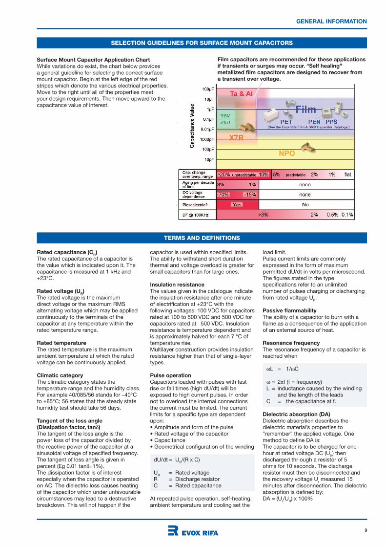
Surface Mount Capacitor Application Chart
While variations do exist, the chart below provides a general guideline for selecting the correct surface mount capacitor. Begin at the left edge of the red stripes which denote the various electrical properties. Move to the right until all of the properties meet your design requirements. Then move upward to the capacitance value of interest.
Film capacitors are recommended for these applications
if transients or surges may occur. “Self healing”
metallized film capacitors are designed to recover from
a transient over voltage.

10
Capacitor type
Rated voltage
in DC Volts
Capacitance
tolerance
G = ± 2 %J = ± 5 %K = ± 10 %Available tolerances vary by series. See the individual tables for each series.
where Y = year, Z = month.
Year Code Year Code Year Code Month Code Month Code
THE MANUFACTURING CODE Y Z, ACCORDING TO IEC 60062
1990 A1991 B1992 C1993 D1994 E1995 F1996 H
1997 J1998 K1999 L2000 M2001 N2002 P2003 R
2004 S2005 T2006 U2007 V2008 W2009 X2010 Y
Jan 1Febr 2March 3April 4May 5June 6
July 7Aug 8Sept 9Oct ONov NDec D
GENERAL TECHNICAL INFORMATION
HOW TO ORDER SMD CAPACITORS
The Evox Rifa article code includes all the information needed to specify the product characteristics and type of packing. This article code construction applies for the following products in this catalogue: MMC, SMC, GMC, GPC, SPC, GMW, SMW, MDC and MDS.
MMC 5.7 273 K 50 A31 TR16
Capacitor type
The first letter specifies the dielectric material:M = Polyester (PET)P = Polypropylene (PP)G = Polyethylene naphthalate (PEN)S = Polyphenylene sulphide (PPS)
The second letter indicates the electrode construction:M = Metallized filmF = Metal foil
Capacitance
tolerance
M = ± 20 %K = ± 10 %J = ± 5 %X = ± 3.5 %H = ± 2.5 %G = ± 2 %F = ± 1 %
Chip length in mm
Packaging
BULK 1) Loose capacitors in a boxTUBE 1) Tube packaging of DIL capacitorsTR12 1) Horizontally taped SMD capacitors,
L*) = 5.7 and 7.3 mmTR16 1) Horizontally taped SMD capacitors,
L*) = 10.2 mmTR24 1) Horizontally taped SMD capacitors,
L*) = 12.7 and 16.5 mmTV24 2) Vertically taped SMD capacitors,
L*) = 10.2 and 12.7 mmTV44 2) Vertically taped SMD capacitors,
L*) = 16.5 mm
1) Quantity/package according to article table2) Quantity per package according to table on page 11.*) See figure on page 20.
The Evox Rifa Film Chip article code includes all the information needed to specify the product characteristics and type of packing. This article code construction applies for the following products in this catalogue: ERS_PUA, ERS_HUX, ERS_HUC, ERS_WUX,
ERS_WUC, ERS_WUC_V.
ERS 0805 HUX 103 J 16 5 V
Rated capacitance
Expressed in picofarads. Three digit code where the first two digits indicate the two most significant digits of the capacitance value in pF. The third digit is the number of following zeroes. Example:101 = 100 pF = 0.1 nF = 0.0001µF103 = 10000 pF = 10 nF = 0.01 µF104 = 100000 pF = 100 nF = 0.1 µF
Dielectric
PUA = OrganicHUC = PPSHUX = PPSWUC= PENWUX = PEN
Taping
5 = 8 mm9 = 12 mmV = 16 mmZ = 24 mmTaping codes denote the width of the tape, a function of the capacitor size. Obtain the correct taping code from the table of tape and reel dimensions, page 49.
Capacitor size code
See size codes on page 11.
Suffix
Special codeUse suffix ”V” to distinguish type WUC-V from type WUC. Other suffixes may be applied to denote customized capacitors.
Rated voltage
in DC Volts
Rated capacitance
Expressed in picofarads. Three digit code where the first two digits indicate the two most significant digits of the capacitance value in pF. The third digit is the number of following zeroes. 103 = 10000 pF = 10 nF = 0.01 F104 = 100000 pF = 100 nF = 0.1 F106 =10000000 pF = 10000 nF = 10 FWhen three significant digits are needed to express the capacitance value, a four digit code is used. The last digit gives the amount of numbers after the two most significant digits. Example:4582 = 4580 pF = 4.58 nF = 0.00458 F1464 = 146000 pF = 146 nF = 0.146 F
Size code
06030805etc.

11
GENERAL TECHNICAL INFORMATION
SIZE CODES OF SMD CAPACITORS
SIZE CODES OF DIL CAPACITORS
The size code in the article code determines the size of the component and the packing quantities.
Size code Box dimensions in mm 0.2 Leads Quantity per package Packaging code
in Article Code B H L p per side Tube Reel Tube Reel
A52 12.2 6.05 11.0 10.0 3 43 TUBE
A53 12.7 9.0 14.0 10.0 3 or 4 34 200 TUBE TR32
A54 12.2 6.05 13.5 10.0 3 or 4 35 TUBE
A55 12.2 6.05 16.5 10.0 3, 4 or 5 28 TUBE
A57 12.7 9.0 23.0 10.0 7 or 8 21 TUBE
A58 12.7 11.0 23.0 10.0 7 or 8 21 TUBE
B53 16.5 6.05 11.0 15.0 3 43 TUBE
B55 16.5 6.05 12.2 15.0 3 or 4 39 TUBE
A size code has been added to the Evox Rifa SMD capacitors. The size code determines the size of the component and the packing quantities. The size codes are as follows:
Encapsulated SMD capacitors MMC, SMC, GMC, GPC, SPC
Size code Box dimensions in mm 0.2 Quantity per package Packaging code
in Article Code B H L p Bulk Reel Reel, Bulk Reel Reel,
vertical taping vertical taping
A31 9.1 5.5 10.2 10.2 1000 800 500 BULK TR16 TV24
B31 11.5 6.5 12.7 12.7 1000 600 400 BULK TR24 TV24
C31 15.0 7.0 16.5 16.5 800 500 200 BULK TR24 TV44
J31 5.0 2.5 5.7 5.7 2000 3100 BULK TR12
J33 5.0 3.0 5.7 5.7 2000 2400 BULK TR12
J35 5.0 4.0 5.7 5.7 2000 2100 BULK TR12
K31 6.0 2.5 7.3 7.3 2000 3100 BULK TR12
K33 6.0 3.0 7.3 7.3 2000 2500 BULK TR12
K35 6.0 3.5 7.3 7.3 2000 2300 BULK TR12
K37 6.0 4.5 7.3 7.3 1000 1700 BULK TR12
Naked SMD capacitors SMW, GMW
Size code Dimensions in mm Quantity per package Packaging code
in Article Code B 0.4 Hmax
L 0.4 p Bulk Reel Bulk Reel
J91 5.0 2.0 5.7 5.7 2000 3100 BULK TR12
J93 5.0 3.0 5.7 5.7 2000 2400 BULK TR12
J95 5.0 4.0 5.7 5.7 2000 2100 BULK TR12
K91 6.0 2.0 7.3 7.3 2000 3100 BULK TR12
K93 6.0 2.7 7.3 7.3 2000 2500 BULK TR12
K95 6.0 3.2 7.3 7.3 2000 2300 BULK TR12
K97 6.0 4.2 7.3 7.3 1000 1700 BULK TR12
Film chip capacitors ERS
Size Dimensions in mm Reel Packaging
code B H L packing qty code
0603 0.8 0.7 1.6 4000 5
0805 1.25 0.9 2.0 3000 5
0805 1.25 1.1 2.0 3000 5
1206 1.6 0.8 3.2 3000 5
1206 1.6 1.1 3.2 3000 5
1206 1.6 1.4 3.2 2000 5
1206 1.6 1.5 3.2 2000 5
1210 2.5 1.1 3.2 2000 5
1210 2.5 2.1 3.2 2000 5
1812 3.3 1.4 4.8 3000 9
1812 3.3 2.0 4.8 3000 9
1812 3.3 2.4 4.8 2000 9
1812 3.3 2.8 4.8 2000 9
Size Dimensions in mm Reel Packaging
code B H L packing qty code
2216 4.1 1.8 6.0 3000 9
2216 4.1 2.0 6.0 3000 9
2216 4.1 2.4 6.0 2000 9
2216 4.1 3.2 6.0 2000 9
2220 5.0 6.0 1500 9
2820 5.0 7.1 1500 9
2825 6.3 7.1 1000 v
3022 5.5 7.7 1000 v
3925 6.3 9.8 1000 v
12
PROPERTIES OF DIELECTRICS
GENERAL INFORMATION
POLYESTER
(Polyethylene Terephthalate, PET)
Metallized and Film/foil
High dielectric constant and high dielectric strength provides good volumetric efficiency for metallized polyester film capacitors. Metallized polyester film has excellent self-healing properties. Typical applications: Bypassing, coupling, filtering.
POLYESTER
(Polyethylene Naphthalate, PEN)
Metallized
High temperature Polyester. Relatively high dielectric constant and dielectric strength, and availability of thin films, provide good volymeric efficiency for metallized construction. High melting point allowes SMD constructions and service in high ambient temperatures. General purpose capacitor.
POLYPROPYLENE (PP) *)
Metallized and Film/foil
Very low losses, low dielectric absorption, high dielectric strength, very high insulation resistance, and negative temperature coefficient.Typical applications: Stable oscillators and filters. Sample & hold circuits, pulse handling circuits, AC applications and mains filtering.
POLYCARBONATE (PC) **)
Metallized and Film/foil
Very low temperature dependency, wide operating temperature range, good long term stability, and low losses.Typical applications: Timers and filters. Applications in high ambient temperatures.
POLYPHENYLENE SULPHIDE (PPS)
Metallized
Low losses, wide operating temperature range, low temperature coefficient, good stability.Typical applications: Timers and filters. Automotive and other applications in high ambient temperatures. Available in SMD constructions.
PAPER
Metallized
High dielectric constant. Excellent self-healing properties and transient handling capability. High ionisation level due to impregnated dielectric material. Outstanding reliability in mains connected and other low frequency applications.
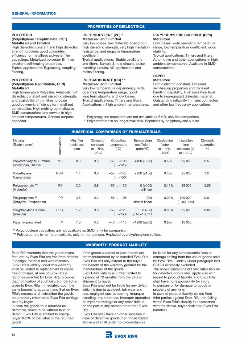
NUMERICAL COMPARISON OF FILM MATERIALS
Material Min. film Dielectric Operating Temperature Dissipation Insulation Dielectric
(Trade names) thickness constant temperature coefficient factor time absorption
(µm) at 1 kHz, (°C) (ppm/°C) at 1 kHz, constant (s) %
+23°C +23°C at +23°C
Polyester (Mylar, Lumirror, PET 0.9 3.3 –55 ... +100 +400 (±200) 0.5% 25 000 0.5
Hostaphan, Diafoil) (... +125)
Polyethylene PEN 1.4 3.0 –55 ... +125 +200 (±150) 0.4% 25 000 1.2
Naphthalate (... +150)
Polycarbonate **) PC 2.0 2.8 –55 ... +125 0 (±100) 0.15% 25 000 0.06
(Makrofol) nonlinear
Polypropylene *) PP 3.5 2.2 –55 ... +105 –200 0.03% 100 000 0.01
(Torayfan, Trespaphan) almost linear (–100, +50)
Polyphenylene sulfide PPS 1.2 3.0 –55 ... +125 0 (–50) 0.06% 25 000 0.05
(Torelina) (... +150) up to +100 °C
Paper Impregnated P 7.0 5.5 –40 ... +115 +1200 (±200) 0.8% 15 000
*) Polypropylene capacitors are not available as SMD, only for comparison. **) Polycarbonate is no more available, only for comparison. Replaced by polyphenylene sulfide.
Ab
bre
via
tio
n
WARRANTY, PRODUCT LIABILITY
Evox Rifa warrants that the goods manu-factured by Evox Rifa are free from defects in design, material and workmanship.Evox Rifa’s liability under this warranty shall be limited to replacement or repair free of charge, at one of Evox Rifa’s factories selected by Evox Rifa, provided that notification of such failure or defect is given to Evox Rifa immediately upon the same becoming apparent and that on Evox Rifa’s request and instruction the goods are promptly returned to Evox Rifa carriage paid by buyer.In case the goods thus returned as defective, prove to be without fault or defect, Evox Rifa is entitled to charge buyer 100% of the value of the returned goods.
If the goods supplied or part thereof are not manufactured by or branded Evox Rifa, Evox Rifa will only extend to the buyer the benefit of the warranty granted by the manufacturer of the goods. Evox Rifa’s liability is further limited to a period of 12 months from the date of shipment to buyer. Evox Rifa shall not be liable for any defect which is due to accident, fair wear and tear, negligent use, tampering, improper handling, improper use, improper operation or improper storage or any other default on the part of any person other than Evox Rifa.Evox Rifa shall have no other liabilities in case of defective goods than those stated above and shall under no circumstances
be liable for any consequential loss or damage arising from the use of goods sold by Evox Rifa. Liability under paragraph 823 BGB is expressly excluded.The above limitations of Evox Rifa’s liability for defective goods shall apply also with regard to product liability, and Evox Rifa shall have no responsibility for injury to persons or for damage to goods or property of any kind. In case of product liability claims from third parties against Evox Rifa, not falling within Evox Rifa’s liability in accordance with the above, buyer shall hold Evox Rifa harmless.
*) Polypropylene capacitors are not available as SMD, only for comparison. **) Polycarbonate is no longer available. Replaced by polyphenylene sulfide.
13
PROPERTIES OF DIELECTRICS
GENERAL INFORMATION
CAPACITOR EQUIVALENT DIAGRAM
C = nominal value of the capacitorL = inductance (leads, metallization, winding)ESR = equivalent series resistance (leads, metallization, metal spraying)IR = insulation resistance (properties of the dielectric material)
C = capacitance change (depending on changes in temperature, DC voltage and/or frequency)PR = dielectric polarization resistanceC
da= dielectric absorption
M F
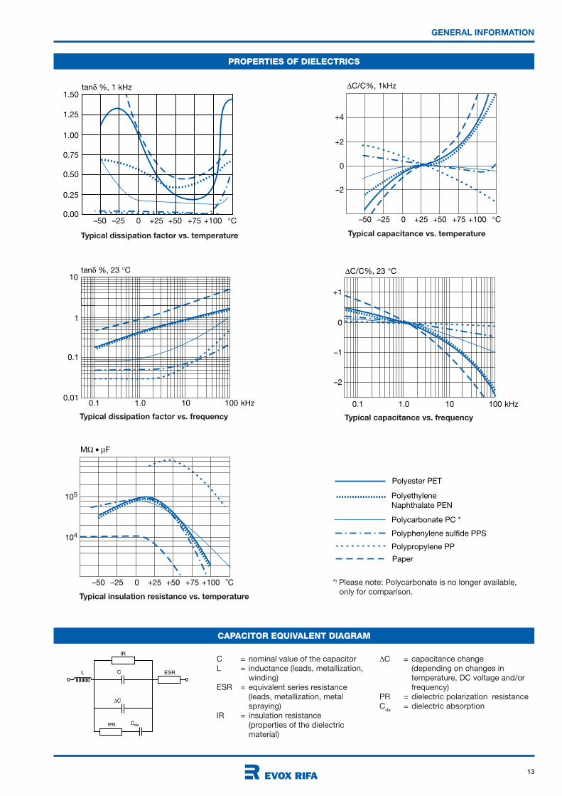
Polyester PET
Polycarbonate PC *
Polyphenylene sulfide PPS
Polypropylene PP
105
104
–50 –25 0 +25 +50 +75 +100 ˚C
PolyethyleneNaphthalate PEN
Paper
tan %, 1 kHz
1.00
1.25
1.50
–50 –25 0 +25 +50 +75 +100 C
0.75
0.50
0.25
0.00
C/C%, 1kHz
+4
–50 –25 0 +25 +50 +75 +100 C
+2
0
–2
tan %, 23 C
1
0.1 1.0 10 100 kHz
0.1
0.01
10C/C%, 23 C
+1
0.1 1.0 10 100 kHz
0
–1
–2
Typical dissipation factor vs. temperature Typical capacitance vs. temperature
Typical dissipation factor vs. frequency Typical capacitance vs. frequency
Typical insulation resistance vs. temperature
C
Cda
C
PR
IR
ESRL
*) Please note: Polycarbonate is no longer available, only for comparison.
14
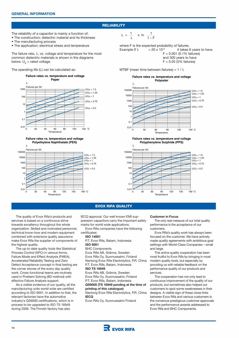
RELIABILITY
GENERAL INFORMATION
The reliability of a capacitor is mainly a function of:• The construction; dielectric material and its thickness• The manufacturing process• The application; electrical stress and temperature
The failure rate, , vs. voltage and temperature for the most common dielectric materials is shown in the diagrams below. U
R = rated voltage.
The operating life (L) can be calculated as:
1000Failures per Gh
Temperature
100
10
1
0.1
0.01C120100806040200
U/UR = 1.5
U/UR = 1.25
U/UR = 1
U/UR = 0.75
U/UR = 0.5
Failure rates vs. temperature and voltage
Paper
10000
100000Failures per Gh
Temperature
1000
100
10
1
0.1
0.01C1501209060300
U/UR = 1.5
U/UR = 1.25
U/UR = 1
U/UR = 0.75
U/UR = 0.5
Failure rates vs. temperature and voltage
Polyester
10000
100000Failures per Gh
Temperature
1000
100
10
1
0.1
0.01C1801501209060300
U/UR = 1.5
U/UR = 1.25U/UR = 1
U/UR = 0.75
U/UR = 0.5
Failure rates vs. temperature and voltage
Polyethylene Naphthalate (PEN)
L =1
x ln1
1 – F
10000
100000Failures per Gh
Temperature
1000
100
10
1
0.1
0.01C1801501209060300
U/UR = 1.5
U/UR = 1.25U/UR = 1
U/UR = 0.75
U/UR = 0.5
Failure rates vs. temperature and voltage
Polyphenylene Sulphide (PPS)
where F is the expected probability of failures.Example:If = 20 x 10–9 it takes 6 years to have F = 0.001 (0.1% failures) and 300 years to have F = 0.05 (5% failures)
MTBF (mean time between failures) = 1 /
EVOX RIFA QUALITY
The quality of Evox Rifa’s products and
services is based on a continuous strive
towards excellency throughout the whole
organization. Skilled and motivated personnel,
technical know-how and modern equipment
combined with extensive quality assurance
make Evox Rifa the supplier of components of
the highest quality.
The up-to date quality tools like Statistical
Process Control (SPC) in various forms,
Failure Mode and Effect Analysis (FMEA),
Accelerated Reliability Testing and Zero
Defect Acceptance concept in final testing are
the corner stones of the every day quality
work. Cross-functional teams are routinely
used in Problem Solving (8D method) with
effective Failure Analysis support.
As a visible evidence of our quality, all the
manufacturing units world wide are certified
according to ISO 9001. In addition to that, the
relevant factories have the automotive
industry’s QS9000 certifications, which is in
process to be upgraded to ISO TS 16949
during 2006. The Finnish factory has also
IECQ approval. Our well known EMI sup-
pression capacitors carry the important safety
marks for world wide applications.
Evox Rifa companies have the following
certificates:
ISO 14001
P.T. Evox Rifa, Batam, Indonesia
ISO 9001
BHC Components
Evox Rifa AB, Gränna, Sweden
Evox Rifa Oy, Suomussalmi, Finland
Nantong Evox Rifa Electrolytics, P.R. China
P.T. Evox Rifa, Batam, Indonesia
ISO TS 16949
Evox Rifa AB, Gränna, Sweden
Evox Rifa Oy, Suomussalmi, Finland
P.T. Evox Rifa, Batam, Indonesia
QS9000 (TS 16949 pending at the time of
printing of this catalogue)
Nantong Evox Rifa Electrolytics, P.R. China
IECQ
Evox Rifa Oy, Suomussalmi Finland
Customer in Focus
The only real measure of our total quality
performance is the acceptance of our
customers.
Evox Rifa’s quality work has always been
focused on the customer. We have actively
made quality agreements with ambitious goal
settings with World-Class Companies – small
and large.
This active quality cooperation has been
most fruitful to Evox Rifa by bringing in most
modern quality tools, but especially by
providing us with reliable feedback on the
performance quality of our products and
services.
The cooperation has not only lead to
continuous improvement of the quality of our
products, but sometimes also helped our
customers to spot some weaknesses in their
designs. A visible sign of these close links
between Evox Rifa and various customers is
the numerous prestigious customer approvals
and the performance awards addressed to
Evox Rifa and BHC Components.

15
WASHING AND DRYING
Evox Rifa recommends not to wash the naked SMD capacitors. If washing is requested, it should be made gently, according to the following instructions:
Statement on Washing of NakedWound SMD Capacitors:
Because the “naked” wound SMD capacitors do not have any encapsulation and the protection of the active element is made with extra deactivated turns of the same dielectric film, which forms the capacitor, the components of flux and/or washing detergent left over on the element at the time of washing may be activated and invade inside the capacitor. This may cause adverse effects.If washing is used, use flux and solder paste with halogen content of 0.1wt.% or less. The internal evaporated electrodes may deteriorate due to activated halogens, if the concentration is high.The ultrasonic agitation is not recommended during washing, because it can cause the washing agents to penetrate the outer layers of the capacitor element.When using a washing method , where water with detergent or the rinsing water is sprayed on to the substrate at high pressure, the protective film around the element surface may peel off slightly due to the water pressure. This is mainly a visual failure, and should not influence the
VACUUM PACKAGING
Some of the SMD and DIL capacitors are
vacuum packaged. The reels are then
packaged in vacuum, according to EIA 583
standard ”Packaging Material Standards for
Moisture Sensitive Items”.
The vacuum package contains a desiccant, which can absorb 20% relative humidity (RH) at +20 °C. Therefore, the recommended maximum storage time is 12 months at the temperature lower than
GENERAL INFORMATION
PRODUCT SPECIFICATION
All descriptions, drawings and other particulars (including dimensions, materials and performance data) given by Evox Rifa are as accurate as possible but, being given for general information, are not binding on Evox Rifa unless specifically agreed in writing. All dimensions and materials are, unless otherwise stated, subject to reasonable variations resulting from the raw material available or arising in the ordinary course of manufacture. Any performance data are based upon Evox Rifa’s experience and are such as Evox Rifa normally expects to achieve.
ENVIRONMENTAL COMMITMENT
The SMD capacitors don’t contain any
substances which have been listed in
the restriction of hazardous substances
Directive 2002/95/EC (RoHS).
As an environmentally conscious company, Evox Rifa (including BHC Components) is working continuously with improvements concerning the environ-mental effects of both our capacitors and the production of them.
In Europe (RoHS Directive) and in some other geographical areas like China, legis-lation has been put on place to prevent the use of some hazardous materials, like Lead (Pb), in electronic equipment. All products
in this catalogue are produced to help our customer’s obligations to guarantee their products to fulfil these legislative require-ments. The Evox Rifa SMD capacitors have always been designed without using any RoHS restricted materials.
Evox Rifa will follow closely any changes in legislation world wide, and makes any necessary changes in its products, whenever needed.
A symbol is used on the packaging labels for RoHS compatible capacitors. See pictures to the right.
Because of customer requirements there may appear additional markings like LF =
Lead Free or LFW = Lead Free Wires on the label.
RoHS
Compliant
RoHS CompliantExamples of RoHS Compliance
markings on packaging labels
performance of the capacitors.The capacitors have to be dried after water washing so that no detergent is left over. If drying is insufficient, and the detergent is left over on the element surface, the insulation resistance may be reduced.The following solvents are suitable for washing of the “naked” SMD capacitors:• Ethanol• Isopropanol• n-propanol
Even when suitable solvents are used, a reversible change of the electrical characteristics may occur in uncoated capacitors immediately after washing.If testing of the boards with these capacitors is performed immediately after washing, it is recommended that the capacitors are dried (e.g. 4 hours at 70 °C) before being subjected to electrical testing.
Washing of Film Chip Capacitors:
1. No clean solderinga. Please use a recommended flux.
i. Low residue flux ULF-500VS ii. Inactivated flux AM-173.2. Washing
a. Recommended detergent i. Alcohol derivative (IPA isopropyl alcohol) ii. Halogenated hydrocarbon (AK-225AES)
b. Recommended washing method i. Immersion washing room temperature, within 5 minutes ii. Steam washing less than 50ºC, within 5 minutes iii. Ultrasonic washing less than 50ºC, within 5 minutes
c. Note: i. Ensure capacitor surface temperature is below 60ºC if the washing is immediately after soldering process. ii. Cleaner shall contain halogen with less than 0.1wt%, because in case of cleaning after assembly, halogen in flux will dissolved into cleaner. iii. Consult our engineering section when further information for cleaning solvent, condition is required.
+40 °C RH less than 90 %.When the package is opened, it should be used within 168 hours at the temperature lower than +30 °C RH less than 60 % according to JEDEC J-STD-020C (July 2004), Sensitivity level 3.If the circumstances for storage and usage differ from these recommendations, please consult Evox Rifa.

18
SMD FILM CAPACITORS
GENERAL TECHNICAL INFORMATION
MARKING OF SMD CAPACITORS
Tolerance
Capacitance marked
acc. to EIA standard
Rated voltage
Type
Manufacturing year
Testing month
103 HZ S K D
103H Z M
Chip length 5.7 mm Chip length 7.3 mm
The rated voltage is expressed with letter codes:
Z 50 VDC H 250 VDC
C 63 VDC K 400 VDC
D 100 VDC M 630 VDC
F 160 VDC P 1000 VDC
W 12 00 VDC
The nominal capacitance value is given with 3 digits EIA-code,
Examples: 103 = 10000 pF = 10 nF = 0.01 µF
The capacitance tolerance is expressed with letter codes:
M ± 20 % H ± 2.5 %
K ± 10 % G ± 2 %
J ± 5 % F ± 1 %
The capacitor type codes are as follows:
M MMC P GPC
S SMC, SMW D SPC
G GMC, GMW
The manufacturing year and the testing month are expressed
according to IEC 60062, see table on page 10.
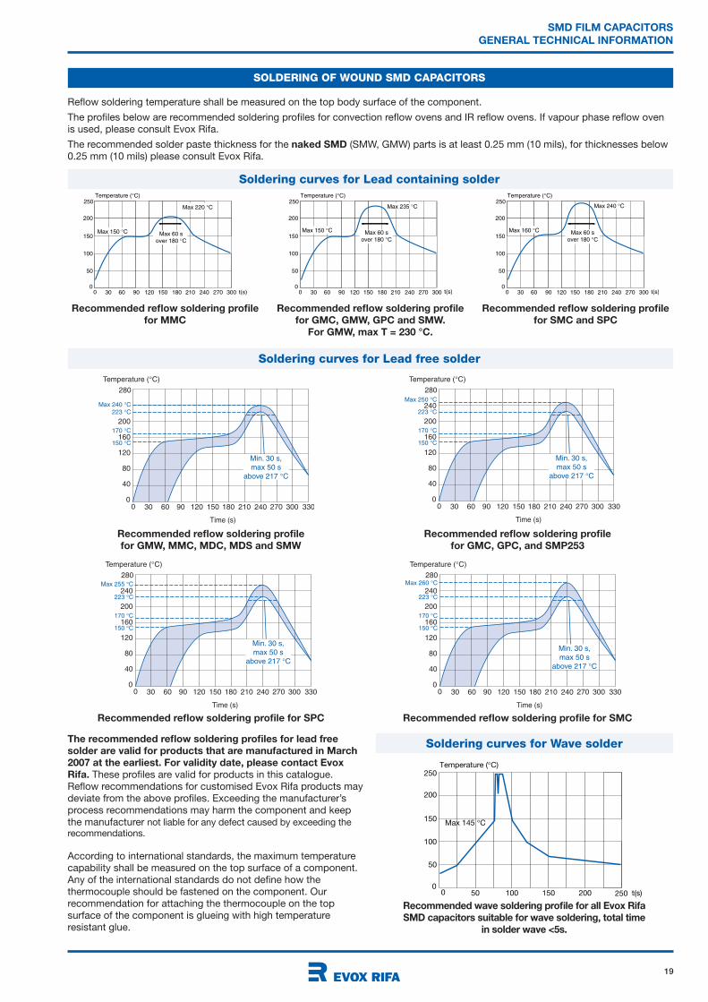
SOLDERING OF WOUND SMD CAPACITORS
The recommended soldering land dimensions are:
W
X X
A
Ah = horizontal mounting
Av = vertical mounting
L Case size W Ah Av X
mm Horizontal Vertical mils mm mils mm mils mm mils mm
5.7 2220 - J31, J91 60 1.5 200 5.1 118.58 3.0
5.7 2220 - J33, J93 60 1.5 200 5.1 118.58 3.0
5.7 2220 - J35, J95 60 1.5 200 5.1 118.58 3.0
7.3 2824 - K31, K91 60 1.5 240 6.1 148.11 3.8
7.3 2824 - K33, K93 60 1.5 240 6.1 148.11 3.8
7.3 2824 - K35, K95 60 1.5 240 6.1 148.11 3.8
7.3 2824 - K37, K97 60 1.5 240 6.1 148.11 3.8
10.2 4036 - A31 4022 - A31V 80 2.0 360 9.1 220 5.6 217.15 5.5
12.7 5045 - B31 5026 - B31V 100 2.5 455 11.6 260 6.6 276.4 7.0
16.5 6560 - C31 6528 - C31V 120 3.0 590 15.0 280 7.1 355.3 9.0
Land dimensions for PCB design are available in PADS format.
Please see our website www.evoxrifa.com
19
SMD FILM CAPACITORS
GENERAL TECHNICAL INFORMATION
Recommended reflow soldering profile
for GMW, MMC, MDC, MDS and SMW
Recommended reflow soldering profile
for GMC, GPC, and SMP253
Recommended reflow soldering profile for SPC
Temperature ( C)
200
25050 100 t(s)150 200
150
100
50
250
00
Max 145 C
Recommended wave soldering profile for all Evox Rifa
SMD capacitors suitable for wave soldering, total time
in solder wave <5s.
SOLDERING OF WOUND SMD CAPACITORS
Temperature ( C)
200
30 60 90 120 150 180 210
160
120
40
80
240 270 3303000
280
0
Time (s)
150 C
170 C
223 C
Max 240 C
Min. 30 s,
max 50 s
above 217 C
Temperature ( C)
200
240
30 60 90 120 150 180 210
160
120
40
80
240 270 3303000
280
0
Time (s)
150 C
170 C
223 C
Max 250 C
Min. 30 s,
max 50 s
above 217 C
Temperature ( C)
200
240
30 60 90 120 150 180 210
160
120
40
80
240 270 3303000
280
0
Time (s)
150 C
170 C
223 C
Max 255 C
Min. 30 s,
max 50 s
above 217 C
Temperature ( C)
200
240
30 60 90 120 150 180 210
160
120
40
80
240 270 3303000
280
0
Time (s)
150 C
170 C
223 C
Max 260 C
Min. 30 s,
max 50 s
above 217 C
Recommended reflow soldering profile for SMC
The recommended reflow soldering profiles for lead free
solder are valid for products that are manufactured in March
2007 at the earliest. For validity date, please contact Evox
Rifa. These profiles are valid for products in this catalogue.
Reflow recommendations for customised Evox Rifa products may
deviate from the above profiles. Exceeding the manufacturer’s
process recommendations may harm the component and keep
the manufacturer not liable for any defect caused by exceeding the recommendations.
According to international standards, the maximum temperature
capability shall be measured on the top surface of a component.
Any of the international standards do not define how the
thermocouple should be fastened on the component. Our
recommendation for attaching the thermocouple on the top
surface of the component is glueing with high temperature
resistant glue.
Reflow soldering temperature shall be measured on the top body surface of the component.
The profiles below are recommended soldering profiles for convection reflow ovens and IR reflow ovens. If vapour phase reflow oven
is used, please consult Evox Rifa.
The recommended solder paste thickness for the naked SMD (SMW, GMW) parts is at least 0.25 mm (10 mils), for thicknesses below
0.25 mm (10 mils) please consult Evox Rifa.
Temperature ( C)
200
30 60 90 120 150 180 210 t(s)
150
100
50
240 270 3000
250
0
Max 150 C
Max 220 C
Max 60 s
over 180 C
Recommended reflow soldering profile
for MMC
Temperature ( C)
200
30 60 90 120 150 180 210 t(s)
150
100
50
240 270 3000
250
0
Max 150 C
Max 235 C
Max 60 s
over 180 C
Recommended reflow soldering profile
for GMC, GMW, GPC and SMW.
For GMW, max T = 230 °C.
Temperature ( C)
200
30 60 90 120 150 180 210 t(s)
150
100
50
240 270 3000
250
0
Max 160 C
Max 240 C
Max 60 s
over 180 C
Recommended reflow soldering profile
for SMC and SPC
Soldering curves for Wave solder
Soldering curves for Lead containing solder
Soldering curves for Lead free solder
20
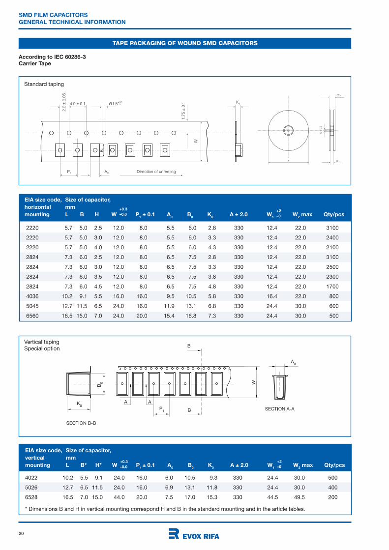
4022 10.2 5.5 9.1 24.0 16.0 6.0 10.5 9.3 330 24.4 30.0 500
5026 12.7 6.5 11.5 24.0 16.0 6.9 13.1 11.8 330 24.4 30.0 400
6528 16.5 7.0 15.0 44.0 20.0 7.5 17.0 15.3 330 44.5 49.5 200
* Dimensions B and H in vertical mounting correspond H and B in the standard mounting and in the article tables.
SMD FILM CAPACITORS
GENERAL TECHNICAL INFORMATION
TAPE PACKAGING OF WOUND SMD CAPACITORS
1
According to IEC 60286-3
Carrier Tape
2220 5.7 5.0 2.5 12.0 8.0 5.5 6.0 2.8 330 12.4 22.0 3100
2220 5.7 5.0 3.0 12.0 8.0 5.5 6.0 3.3 330 12.4 22.0 2400
2220 5.7 5.0 4.0 12.0 8.0 5.5 6.0 4.3 330 12.4 22.0 2100
2824 7.3 6.0 2.5 12.0 8.0 6.5 7.5 2.8 330 12.4 22.0 3100
2824 7.3 6.0 3.0 12.0 8.0 6.5 7.5 3.3 330 12.4 22.0 2500
2824 7.3 6.0 3.5 12.0 8.0 6.5 7.5 3.8 330 12.4 22.0 2300
2824 7.3 6.0 4.5 12.0 8.0 6.5 7.5 4.8 330 12.4 22.0 1700
4036 10.2 9.1 5.5 16.0 16.0 9.5 10.5 5.8 330 16.4 22.0 800
5045 12.7 11.5 6.5 24.0 16.0 11.9 13.1 6.8 330 24.4 30.0 600
6560 16.5 15.0 7.0 24.0 20.0 15.4 16.8 7.3 330 24.4 30.0 500
Standard taping
Vertical taping
Special option
EIA size code, Size of capacitor,
horizontal mm
mounting L B H W P1
± 0.1 A0 B
0 K
0A ± 2.0 W
1 W
2max Qty/pcs
+2
–0
+0.3
–0.0
+2
–0
+0.3
–0.0
EIA size code, Size of capacitor,
vertical mm
mounting L B* H* W P1± 0.1 A
0 B
0 K
0A ± 2.0 W
1 W
2max Qty/pcs

21
RoHSCompliant
Rated voltage UR, VDC 50 63 100 250 400
Rated voltage UR, VAC 30 40 63 160 200
Capacitance range, nF 1 - 1 - 1 - 1 - 1 -
15000 4700 3300 1000 470
Capacitance tolerance ± 10%, ±5%; other tolerances on request.
Category
temperature range -55°C to +100°C
Rated temperature +85°C
Voltage derating The rated voltage is decreased with 1.25%/°C from +85°C.
Climatic category 55/100/56
Test voltage 1.6 x UR, 60s
Insulation resistance Minimum value between terminals
Measured at +20°C according to IEC 60384-19
C 0.33 µF C > 0.33 µF
UR
100 V 10 000 M 3000 s
UR >100 V 30 000 M 10 000 s
Dissipation factor Max values at +23°C
C 100nF 100nF < C 1µF 1µF C 10µF C > 10µF
1 kHz 0.8% 0.8% 0.8% 0.8%
10 kHz 1.2% 1.2% 1.5% 3.0%
100 kHz 2.5% 3.0%
Pulse rise time The capacitors can withstand an unlimited number of pulses
with a dU/dt according to article table. For voltages (U) lower
than the rated voltage (UR), the specified dU/dt can be
multiplied by UR/U.
MMC• Metallized polyester (PET) SMD
• According to IEC 60384-19
TYPICAL APPLICATIONS CONSTRUCTION
TECHNICAL DATA
RECOMMENDED SOLDERING
CONDITIONS
Bypassing, signal coupling. General
purpose for highest reliability.
Polyester (PET) film capacitor for
surface mounting. Encapsulation in
self-extinguishing material meeting the
requirements of UL 94V-0.
C/C%
-25 0 25 50 75 100 125 C
5
-50 -5
0
10tan x 10
-3
-50 -25 0 25 50 75 100 C
10
-550
5
15
Typical capacitance vs
temperature at 1 kHz
Typical dissipation factor vs
temperature at 1 kHz
Reflow soldering on the top body
surface of the component
Preheating temperature should be less
than 170°C. The time above 217°C should
be less than 50 s. The peak temperature
must not exceed 240°C.
Temperature ( C)
200
30 60 90 120 150 180 210
160
120
40
80
240 270 3303000
280
0
Time (s)
150 C
170 C
223 C
Max 240 C
Min. 30 s,
max 50 s
above 217 C
Recommended reflow soldering profile
for products manufactured in March
2007 at the earliest. For detailed
information see page 19.
B
L
H
0.5
0.5
Components may be vertically mounted
for decreased footprint. See page 20.
MARKING
• Rated capacitance
• Capacitance tolerance code
• Rated voltage code
• Capacitor type M for MMC
• Manufacturing date code according to
IEC 60062 (year, month)
See also page 18.
ORDERING INFORMATION
See article table and page 10 for options and article code construction.
22
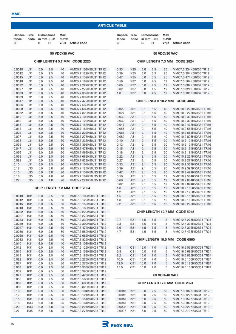
50 VDC/30 VAC
CHIP LENGTH 5.7 MM CODE 2220
0.0010 J31 5.0 2.5 40 MMC5.7 102K50J31 TR12
0.0012 J31 5.0 2.5 40 MMC5.7 122K50J31 TR12
0.0015 J31 5.0 2.5 40 MMC5.7 152K50J31 TR12
0.0018 J31 5.0 2.5 40 MMC5.7 182K50J31 TR12
0.0022 J31 5.0 2.5 40 MMC5.7 222K50J31 TR12
0.0027 J31 5.0 2.5 40 MMC5.7 272K50J31 TR12
0.0033 J31 5.0 2.5 40 MMC5.7 332K50J31 TR12
0.0039 J31 5.0 2.5 40 MMC5.7 392K50J31 TR12
0.0047 J31 5.0 2.5 40 MMC5.7 472K50J31 TR12
0.0056 J31 5.0 2.5 40 MMC5.7 562K50J31 TR12
0.0068 J31 5.0 2.5 40 MMC5.7 682K50J31 TR12
0.0082 J31 5.0 2.5 40 MMC5.7 822K50J31 TR12
0.010 J31 5.0 2.5 40 MMC5.7 103K50J31 TR12
0.012 J31 5.0 2.5 40 MMC5.7 123K50J31 TR12
0.015 J31 5.0 2.5 30 MMC5.7 153K50J31 TR12
0.018 J31 5.0 2.5 30 MMC5.7 183K50J31 TR12
0.022 J31 5.0 2.5 30 MMC5.7 223K50J31 TR12
0.027 J31 5.0 2.5 30 MMC5.7 273K50J31 TR12
0.033 J31 5.0 2.5 30 MMC5.7 333K50J31 TR12
0.039 J31 5.0 2.5 30 MMC5.7 393K50J31 TR12
0.047 J31 5.0 2.5 30 MMC5.7 473K50J31 TR12
0.056 J31 5.0 2.5 30 MMC5.7 563K50J31 TR12
0.068 J31 5.0 2.5 20 MMC5.7 683K50J31 TR12
0.082 J31 5.0 2.5 20 MMC5.7 823K50J31 TR12
0.10 J31 5.0 2.5 20 MMC5.7 104K50J31 TR12
0.12 J33 5.0 3.0 20 MMC5.7 124K50J33 TR12
0.15 J33 5.0 3.0 20 MMC5.7 154K50J33 TR12
0.18 J35 5.0 4.0 20 MMC5.7 184K50J35 TR12
0.22 J35 5.0 4.0 20 MMC5.7 224K50J35 TR12
CHIP LENGTH 7.3 MM CODE 2824
0.0010 K31 6.0 2.5 50 MMC7.3 102K50K31 TR12
0.0012 K31 6.0 2.5 50 MMC7.3 122K50K31 TR12
0.0015 K31 6.0 2.5 50 MMC7.3 152K50K31 TR12
0.0018 K31 6.0 2.5 50 MMC7.3 182K50K31 TR12
0.0022 K31 6.0 2.5 50 MMC7.3 222K50K31 TR12
0.0027 K31 6.0 2.5 50 MMC7.3 272K50K31 TR12
0.0033 K31 6.0 2.5 50 MMC7.3 332K50K31 TR12
0.0039 K31 6.0 2.5 50 MMC7.3 392K50K31 TR12
0.0047 K31 6.0 2.5 50 MMC7.3 472K50K31 TR12
0.0056 K31 6.0 2.5 50 MMC7.3 562K50K31 TR12
0.0068 K31 6.0 2.5 40 MMC7.3 682K50K31 TR12
0.0082 K31 6.0 2.5 40 MMC7.3 822K50K31 TR12
0.010 K31 6.0 2.5 40 MMC7.3 103K50K31 TR12
0.012 K31 6.0 2.5 40 MMC7.3 123K50K31 TR12
0.015 K31 6.0 2.5 40 MMC7.3 153K50K31 TR12
0.018 K31 6.0 2.5 40 MMC7.3 183K50K31 TR12
0.022 K31 6.0 2.5 30 MMC7.3 223K50K31 TR12
0.027 K31 6.0 2.5 30 MMC7.3 273K50K31 TR12
0.033 K31 6.0 2.5 30 MMC7.3 333K50K31 TR12
0.039 K31 6.0 2.5 30 MMC7.3 393K50K31 TR12
0.047 K31 6.0 2.5 30 MMC7.3 473K50K31 TR12
0.056 K31 6.0 2.5 30 MMC7.3 563K50K31 TR12
0.068 K31 6.0 2.5 30 MMC7.3 683K50K31 TR12
0.082 K31 6.0 2.5 30 MMC7.3 823K50K31 TR12
0.10 K31 6.0 2.5 30 MMC7.3 104K50K31 TR12
0.12 K31 6.0 2.5 30 MMC7.3 124K50K31 TR12
0.15 K31 6.0 2.5 25 MMC7.3 154K50K31 TR12
0.18 K33 6.0 3.0 25 MMC7.3 184K50K33 TR12
0.22 K33 6.0 3.0 25 MMC7.3 224K50K33 TR12
0.27 K35 6.0 3.5 25 MMC7.3 274K50K35 TR12
MMC
ARTICLE TABLE
Capaci- Size Dimensions Max
tance code in mm ±0.2 dU/dt
µF B H V/µs Article code
Capaci- Size Dimensions Max
tance code in mm ±0.2 dU/dt
µF B H V/µs Article code
50 VDC/30 VAC
CHIP LENGTH 7.3 MM CODE 2824
0.33 K35 6.0 3.5 25 MMC7.3 334K50K35 TR12
0.39 K35 6.0 3.5 25 MMC7.3 394K50K35 TR12
0.47 K35 6.0 3.5 25 MMC7.3 474K50K35 TR12
0.56 K37 6.0 4.5 12 MMC7.3 564K50K37 TR12
0.68 K37 6.0 4.5 12 MMC7.3 684K50K37 TR12
0.82 K37 6.0 4.5 12 MMC7.3 824K50K37 TR12
1.0 K37 6.0 4.5 12 MMC7.3 105K50K37 TR12
CHIP LENGTH 10.2 MM CODE 4036
0.022 A31 9.1 5.5 40 MMC10.2 223K50A31 TR16
0.027 A31 9.1 5.5 40 MMC10.2 273K50A31 TR16
0.033 A31 9.1 5.5 40 MMC10.2 333K50A31 TR16
0.039 A31 9.1 5.5 40 MMC10.2 393K50A31 TR16
0.047 A31 9.1 5.5 40 MMC10.2 473K50A31 TR16
0.056 A31 9.1 5.5 40 MMC10.2 563K50A31 TR16
0.068 A31 9.1 5.5 40 MMC10.2 683K50A31 TR16
0.082 A31 9.1 5.5 40 MMC10.2 823K50A31 TR16
0.10 A31 9.1 5.5 30 MMC10.2 104K50A31 TR16
0.12 A31 9.1 5.5 30 MMC10.2 124K50A31 TR16
0.15 A31 9.1 5.5 30 MMC10.2 154K50A31 TR16
0.18 A31 9.1 5.5 20 MMC10.2 184K50A31 TR16
0.22 A31 9.1 5.5 20 MMC10.2 224K50A31 TR16
0.27 A31 9.1 5.5 20 MMC10.2 274K50A31 TR16
0.33 A31 9.1 5.5 20 MMC10.2 334K50A31 TR16
0.39 A31 9.1 5.5 20 MMC10.2 394K50A31 TR16
0.47 A31 9.1 5.5 20 MMC10.2 474K50A31 TR16
0.56 A31 9.1 5.5 12 MMC10.2 564K50A31 TR16
0.68 A31 9.1 5.5 12 MMC10.2 684K50A31 TR16
0.82 A31 9.1 5.5 12 MMC10.2 824K50A31 TR16
1.0 A31 9.1 5.5 12 MMC10.2 105K50A31 TR16
1.2 A31 9.1 5.5 12 MMC10.2 125K50A31 TR16
1.5 A31 9.1 5.5 12 MMC10.2 155K50A31 TR16
1.8 A31 9.1 5.5 12 MMC10.2 185K50A31 TR16
2.2 A31 9.1 5.5 12 MMC10.2 225K50A31 TR16
CHIP LENGTH 12.7 MM CODE 5045
2.7 B31 11.5 6.5 8 MMC12.7 275K50B31 TR24
3.3 B31 11.5 6.5 8 MMC12.7 335K50B31 TR24
3.9 B31 11.5 6.5 8 MMC12.7 395K50B31 TR24
4.7 B31 11.5 6.5 8 MMC12.7 475K50B31 TR24
CHIP LENGTH 16.5 MM CODE 6560
5.6 C31 15.0 7.0 5 MMC16.5 565K50C31 TR24
6.8 C31 15.0 7.0 5 MMC16.5 685K50C31 TR24
8.2 C31 15.0 7.0 5 MMC16.5 825K50C31 TR24
10.0 C31 15.0 7.0 5 MMC16.5 106K50C31 TR24
12.0 C31 15.0 7.0 5 MMC16.5 126K50C31 TR24
15.0 C31 15.0 7.0 5 MMC16.5 156K50C31 TR24
63 VDC/40 VAC
CHIP LENGTH 7.3 MM CODE 2824
0.0010 K31 6.0 2.5 50 MMC7.3 102K63K31 TR12
0.0012 K31 6.0 2.5 50 MMC7.3 122K63K31 TR12
0.0015 K31 6.0 2.5 50 MMC7.3 152K63K31 TR12
0.0018 K31 6.0 2.5 50 MMC7.3 182K63K31 TR12
0.0022 K31 6.0 2.5 50 MMC7.3 222K63K31 TR12
0.0027 K31 6.0 2.5 50 MMC7.3 272K63K31 TR12

23
MMC
ARTICLE TABLE
63 VDC/40 VAC
CHIP LENGTH 7.3 MM CODE 2824
0.0033 K31 6.0 2.5 50 MMC7.3 332K63K31 TR12
0.0039 K31 6.0 2.5 50 MMC7.3 392K63K31 TR12
0.0047 K31 6.0 2.5 50 MMC7.3 472K63K31 TR12
0.0056 K31 6.0 2.5 50 MMC7.3 562K63K31 TR12
0.0068 K31 6.0 2.5 40 MMC7.3 682K63K31 TR12
0.0082 K31 6.0 2.5 40 MMC7.3 822K63K31 TR12
0.010 K31 6.0 2.5 40 MMC7.3 103K63K31 TR12
0.012 K31 6.0 2.5 40 MMC7.3 123K63K31 TR12
0.015 K31 6.0 2.5 40 MMC7.3 153K63K31 TR12
0.018 K31 6.0 2.5 40 MMC7.3 183K63K31 TR12
0.022 K31 6.0 2.5 30 MMC7.3 223K63K31 TR12
0.027 K31 6.0 2.5 30 MMC7.3 273K63K31 TR12
0.033 K31 6.0 2.5 30 MMC7.3 333K63K31 TR12
0.039 K31 6.0 2.5 30 MMC7.3 393K63K31 TR12
0.047 K31 6.0 2.5 30 MMC7.3 473K63K31 TR12
0.056 K31 6.0 2.5 30 MMC7.3 563K63K31 TR12
0.068 K31 6.0 2.5 30 MMC7.3 683K63K31 TR12
0.082 K31 6.0 2.5 30 MMC7.3 823K63K31 TR12
0.10 K31 6.0 2.5 30 MMC7.3 104K63K31 TR12
0.12 K31 6.0 2.5 30 MMC7.3 124K63K31 TR12
0.15 K31 6.0 2.5 30 MMC7.3 154K63K31 TR12
0.18 K33 6.0 3.0 25 MMC7.3 184K63K33 TR12
0.22 K33 6.0 3.0 25 MMC7.3 224K63K33 TR12
0.27 K35 6.0 3.5 25 MMC7.3 274K63K35 TR12
0.33 K35 6.0 3.5 25 MMC7.3 334K63K35 TR12
0.39 K35 6.0 3.5 25 MMC7.3 394K63K35 TR12
0.47 K35 6.0 3.5 25 MMC7.3 474K63K35 TR12
CHIP LENGTH 10.2 MM CODE 4036
0.022 A31 9.1 5.5 40 MMC10.2 223K63A31 TR16
0.027 A31 9.1 5.5 40 MMC10.2 273K63A31 TR16
0.033 A31 9.1 5.5 40 MMC10.2 333K63A31 TR16
0.039 A31 9.1 5.5 40 MMC10.2 393K63A31 TR16
0.047 A31 9.1 5.5 40 MMC10.2 473K63A31 TR16
0.056 A31 9.1 5.5 40 MMC10.2 563K63A31 TR16
0.068 A31 9.1 5.5 40 MMC10.2 683K63A31 TR16
0.082 A31 9.1 5.5 40 MMC10.2 823K63A31 TR16
0.10 A31 9.1 5.5 30 MMC10.2 104K63A31 TR16
0.12 A31 9.1 5.5 30 MMC10.2 124K63A31 TR16
0.15 A31 9.1 5.5 30 MMC10.2 154K63A31 TR16
0.18 A31 9.1 5.5 20 MMC10.2 184K63A31 TR16
0.22 A31 9.1 5.5 20 MMC10.2 224K63A31 TR16
0.27 A31 9.1 5.5 20 MMC10.2 274K63A31 TR16
0.33 A31 9.1 5.5 20 MMC10.2 334K63A31 TR16
0.39 A31 9.1 5.5 20 MMC10.2 394K63A31 TR16
0.47 A31 9.1 5.5 20 MMC10.2 474K63A31 TR16
0.56 A31 9.1 5.5 12 MMC10.2 564K63A31 TR16
0.68 A31 9.1 5.5 12 MMC10.2 684K63A31 TR16
0.82 A31 9.1 5.5 12 MMC10.2 824K63A31 TR16
1.0 A31 9.1 5.5 12 MMC10.2 105K63A31 TR16
1.2 A31 9.1 5.5 12 MMC10.2 125K63A31 TR16
1.5 A31 9.1 5.5 12 MMC10.2 155K63A31 TR16
CHIP LENGTH 12.7 MM CODE 5045
1.8 B31 11.5 6.5 8 MMC12.7 185K63B31 TR24
2.2 B31 11.5 6.5 8 MMC12.7 225K63B31 TR24
2.7 B31 11.5 6.5 8 MMC12.7 275K63B31 TR24
3.3 B31 11.5 6.5 8 MMC12.7 335K63B31 TR24
Capaci- Size Dimensions Max
tance code in mm ±0.2 dU/dt
µF B H V/µs Article code
Capaci- Size Dimensions Max
tance code in mm ±0.2 dU/dt
µF B H V/µs Article code
63 VDC/40 VAC
CHIP LENGTH 16.5 MM CODE 6560
3.9 C31 15.0 7.0 5 MMC16.5 395K63C31 TR24
4.7 C31 15.0 7.0 5 MMC16.5 475K63C31 TR24
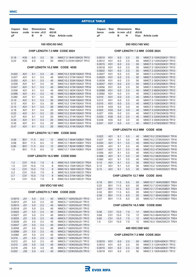
100 VDC/63 VAC
CHIP LENGTH 5.7 MM CODE 2220
0.0010 J31 5.0 2.5 40 MMC5.7 102K100J31 TR12
0.0012 J31 5.0 2.5 40 MMC5.7 122K100J31 TR12
0.0015 J31 5.0 2.5 40 MMC5.7 152K100J31 TR12
0.0018 J31 5.0 2.5 40 MMC5.7 182K100J31 TR12
0.0022 J31 5.0 2.5 40 MMC5.7 222K100J31 TR12
0.0027 J31 5.0 2.5 40 MMC5.7 272K100J31 TR12
0.0033 J31 5.0 2.5 40 MMC5.7 332K100J31 TR12
0.0039 J31 5.0 2.5 40 MMC5.7 392K100J31 TR12
0.0047 J31 5.0 2.5 40 MMC5.7 472K100J31 TR12
0.0056 J31 5.0 2.5 40 MMC5.7 562K100J31 TR12
0.0068 J31 5.0 2.5 40 MMC5.7 682K100J31 TR12
0.0082 J31 5.0 2.5 40 MMC5.7 822K100J31 TR12
0.010 J31 5.0 2.5 40 MMC5.7 103K100J31 TR12
0.012 J31 5.0 2.5 40 MMC5.7 123K100J31 TR12
0.015 J31 5.0 2.5 30 MMC5.7 153K100J31 TR12
0.018 J31 5.0 2.5 30 MMC5.7 183K100J31 TR12
0.022 J31 5.0 2.5 30 MMC5.7 223K100J31 TR12
0.027 J31 5.0 2.5 30 MMC5.7 273K100J31 TR12
0.033 J31 5.0 2.5 30 MMC5.7 333K100J31 TR12
0.039 J31 5.0 2.5 30 MMC5.7 393K100J31 TR12
0.047 J31 5.0 2.5 30 MMC5.7 473K100J31 TR12
0.056 J33 5.0 3.0 30 MMC5.7 563K100J33 TR12
0.068 J33 5.0 3.0 30 MMC5.7 683K100J33 TR12
0.082 J35 5.0 4.0 30 MMC5.7 823K100J35 TR12
0.10 J35 5.0 4.0 30 MMC5.7 104K100J35 TR12
CHIP LENGTH 7.3 MM CODE 2824
0.0010 K31 6.0 2.5 50 MMC7.3 102K100K31 TR12
0.0012 K31 6.0 2.5 50 MMC7.3 122K100K31 TR12
0.0015 K31 6.0 2.5 50 MMC7.3 152K100K31 TR12
0.0018 K31 6.0 2.5 50 MMC7.3 182K100K31 TR12
0.0022 K31 6.0 2.5 50 MMC7.3 222K100K31 TR12
0.0027 K31 6.0 2.5 50 MMC7.3 272K100K31 TR12
0.0033 K31 6.0 2.5 50 MMC7.3 332K100K31 TR12
0.0039 K31 6.0 2.5 50 MMC7.3 392K100K31 TR12
0.0047 K31 6.0 2.5 50 MMC7.3 472K100K31 TR12
0.0056 K31 6.0 2.5 50 MMC7.3 562K100K31 TR12
0.0068 K31 6.0 2.5 40 MMC7.3 682K100K31 TR12
0.0082 K31 6.0 2.5 40 MMC7.3 822K100K31 TR12
0.010 K31 6.0 2.5 40 MMC7.3 103K100K31 TR12
0.012 K31 6.0 2.5 40 MMC7.3 123K100K31 TR12
0.015 K31 6.0 2.5 40 MMC7.3 153K100K31 TR12
0.018 K31 6.0 2.5 40 MMC7.3 183K100K31 TR12
0.022 K31 6.0 2.5 30 MMC7.3 223K100K31 TR12
0.027 K31 6.0 2.5 30 MMC7.3 273K100K31 TR12
0.033 K31 6.0 2.5 30 MMC7.3 333K100K31 TR12
0.039 K31 6.0 2.5 30 MMC7.3 393K100K31 TR12
0.047 K31 6.0 2.5 30 MMC7.3 473K100K31 TR12
0.056 K31 6.0 2.5 30 MMC7.3 563K100K31 TR12
0.068 K31 6.0 2.5 30 MMC7.3 683K100K31 TR12
0.082 K31 6.0 2.5 30 MMC7.3 823K100K31 TR12
0.10 K31 6.0 2.5 30 MMC7.3 104K100K31 TR12
0.12 K33 6.0 3.0 30 MMC7.3 124K100K33 TR12
0.15 K35 6.0 3.5 30 MMC7.3 154K100K35 TR12
24
MMC
ARTICLE TABLE
100 VDC/63 VAC
CHIP LENGTH 7.3 MM CODE 2824
0.18 K35 6.0 3.5 30 MMC7.3 184K100K35 TR12
0.22 K35 6.0 4.5 30 MMC7.3 224K100K37 TR12
CHIP LENGTH 10.2 MM CODE 4036
0.022 A31 9.1 5.5 40 MMC10.2 223K100A31 TR16
0.027 A31 9.1 5.5 40 MMC10.2 273K100A31 TR16
0.033 A31 9.1 5.5 40 MMC10.2 333K100A31 TR16
0.039 A31 9.1 5.5 40 MMC10.2 393K100A31 TR16
0.047 A31 9.1 5.5 40 MMC10.2 473K100A31 TR16
0.056 A31 9.1 5.5 40 MMC10.2 563K100A31 TR16
0.068 A31 9.1 5.5 40 MMC10.2 683K100A31 TR16
0.082 A31 9.1 5.5 40 MMC10.2 823K100A31 TR16
0.10 A31 9.1 5.5 30 MMC10.2 104K100A31 TR16
0.12 A31 9.1 5.5 30 MMC10.2 124K100A31 TR16
0.15 A31 9.1 5.5 30 MMC10.2 154K100A31 TR16
0.18 A31 9.1 5.5 20 MMC10.2 184K100A31 TR16
0.22 A31 9.1 5.5 20 MMC10.2 224K100A31 TR16
0.27 A31 9.1 5.5 20 MMC10.2 274K100A31 TR16
0.33 A31 9.1 5.5 20 MMC10.2 334K100A31 TR16
0.39 A31 9.1 5.5 20 MMC10.2 394K100A31 TR16
0.47 A31 9.1 5.5 20 MMC10.2 474K100A31 TR16
CHIP LENGTH 12.7 MM CODE 5045
0.56 B31 11.5 6.5 12 MMC12.7 564K100B31 TR24
0.68 B31 11.5 6.5 12 MMC12.7 684K100B31 TR24
0.82 B31 11.5 6.5 12 MMC12.7 824K100B31 TR24
1.0 B31 11.5 6.5 12 MMC12.7 105K100B31 TR24
CHIP LENGTH 16.5 MM CODE 6560
1.2 C31 15.0 7.0 8 MMC16.5 125K100C31 TR24
1.5 C31 15.0 7.0 8 MMC16.5 155K100C31 TR24
1.8 C31 15.0 7.0 8 MMC16.5 185K100C31 TR24
2.2 C31 15.0 7.0 8 MMC16.5 225K100C31 TR24
2.7 C31 15.0 7.0 8 MMC16.5 275K100C31 TR24
3.3 C31 15.0 7.0 8 MMC16.5 335K100C31 TR24
250 VDC/160 VAC
CHIP LENGTH 5.7 MM CODE 2220
0.0010 J31 5.0 2.5 40 MMC5.7 102K250J31 TR12
0.0012 J31 5.0 2.5 40 MMC5.7 122K250J31 TR12
0.0015 J31 5.0 2.5 40 MMC5.7 152K250J31 TR12
0.0018 J31 5.0 2.5 40 MMC5.7 182K250J31 TR12
0.0022 J31 5.0 2.5 40 MMC5.7 222K250J31 TR12
0.0027 J31 5.0 2.5 40 MMC5.7 272K250J31 TR12
0.0033 J31 5.0 2.5 40 MMC5.7 332K250J31 TR12
0.0039 J31 5.0 2.5 40 MMC5.7 392K250J31 TR12
0.0047 J31 5.0 2.5 40 MMC5.7 472K250J31 TR12
0.0056 J31 5.0 2.5 40 MMC5.7 562K250J31 TR12
0.0068 J31 5.0 2.5 40 MMC5.7 682K250J31 TR12
0.0082 J31 5.0 2.5 40 MMC5.7 822K250J31 TR12
0.010 J31 5.0 2.5 40 MMC5.7 103K250J31 TR12
0.012 J31 5.0 2.5 40 MMC5.7 123K250J31 TR12
0.015 J33 5.0 3.0 40 MMC5.7 153K250J33 TR12
0.018 J35 5.0 4.0 40 MMC5.7 183K250J35 TR12
0.022 J35 5.0 4.0 40 MMC5.7 223K250J35 TR12
Capaci- Size Dimensions Max
tance code in mm ±0.2 dU/dt
µF B H V/µs Article code
Capaci- Size Dimensions Max
tance code in mm ±0.2 dU/dt
µF B H V/µs Article code
250 VDC/160 VAC
CHIP LENGTH 7.3 MM CODE 2824
0.0010 K31 6.0 2.5 50 MMC7.3 102K250K31 TR12
0.0012 K31 6.0 2.5 50 MMC7.3 122K250K31 TR12
0.0015 K31 6.0 2.5 50 MMC7.3 152K250K31 TR12
0.0018 K31 6.0 2.5 50 MMC7.3 182K250K31 TR12
0.0022 K31 6.0 2.5 50 MMC7.3 222K250K31 TR12
0.0027 K31 6.0 2.5 50 MMC7.3 272K250K31 TR12
0.0033 K31 6.0 2.5 50 MMC7.3 332K250K31 TR12
0.0039 K31 6.0 2.5 50 MMC7.3 392K250K31 TR12
0.0047 K31 6.0 2.5 50 MMC7.3 472K250K31 TR12
0.0056 K31 6.0 2.5 50 MMC7.3 562K250K31 TR12
0.0068 K31 6.0 2.5 40 MMC7.3 682K250K31 TR12
0.0082 K31 6.0 2.5 40 MMC7.3 822K250K31 TR12
0.010 K31 6.0 2.5 40 MMC7.3 103K250K31 TR12
0.012 K31 6.0 2.5 40 MMC7.3 123K250K31 TR12
0.015 K31 6.0 2.5 40 MMC7.3 153K250K31 TR12
0.018 K33 6.0 3.0 40 MMC7.3 183K250K33 TR12
0.022 K33 6.0 3.0 40 MMC7.3 223K250K33 TR12
0.027 K35 6.0 3.5 40 MMC7.3 273K250K35 TR12
0.033 K35 6.0 3.5 40 MMC7.3 333K250K35 TR12
0.039 K35 6.0 3.5 40 MMC7.3 393K250K35 TR12
0.047 K37 6.0 4.5 40 MMC7.3 473K250K37 TR12
CHIP LENGTH 10.2 MM CODE 4036
0.022 A31 9.1 5.5 40 MMC10.2 223K250A31 TR16
0.027 A31 9.1 5.5 40 MMC10.2 273K250A31 TR16
0.033 A31 9.1 5.5 40 MMC10.2 333K250A31 TR16
0.039 A31 9.1 5.5 40 MMC10.2 393K250A31 TR16
0.047 A31 9.1 5.5 40 MMC10.2 473K250A31 TR16
0.056 A31 9.1 5.5 40 MMC10.2 563K250A31 TR16
0.068 A31 9.1 5.5 40 MMC10.2 683K250A31 TR16
0.082 A31 9.1 5.5 40 MMC10.2 823K250A31 TR16
0.10 A31 9.1 5.5 30 MMC10.2 104K250A31 TR16
0.12 A31 9.1 5.5 30 MMC10.2 124K250A31 TR16
0.15 A31 9.1 5.5 30 MMC10.2 154K250A31 TR16
CHIP LENGTH 12.7 MM CODE 5045
0.18 B31 11.5 6.5 20 MMC12.7 184K250B31 TR24
0.22 B31 11.5 6.5 20 MMC12.7 224K250B31 TR24
0.27 B31 11.5 6.5 20 MMC12.7 274K250B31 TR24
0.33 B31 11.5 6.5 20 MMC12.7 334K250B31 TR24
0.39 B31 11.5 6.5 20 MMC12.7 394K250B31 TR24
0.47 B31 11.5 6.5 20 MMC12.7 474K250B31 TR24
CHIP LENGTH 16.5 MM CODE 6560
0.56 C31 15.0 7.0 12 MMC16.5 564K250C31 TR24
0.68 C31 15.0 7.0 12 MMC16.5 684K250C31 TR24
0.82 C31 15.0 7.0 12 MMC16.5 824K250C31 TR24
1.0 C31 15.0 7.0 12 MMC16.5 105K250C31 TR24
400 VDC/200 VAC
CHIP LENGTH 7.3 MM CODE 2824
0.0010 K31 6.0 2.5 50 MMC7.3 102K400K31 TR12
0.0012 K31 6.0 2.5 50 MMC7.3 122K400K31 TR12
0.0015 K31 6.0 2.5 50 MMC7.3 152K400K31 TR12
0.0018 K31 6.0 2.5 50 MMC7.3 182K400K31 TR12

25
MMC
ARTICLE TABLE
Capaci- Size Dimensions Max
tance code in mm ±0.2 dU/dt
µF B H V/µs Article code
Capaci- Size Dimensions Max
tance code in mm ±0.2 dU/dt
µF B H V/µs Article code
400 VDC/200 VAC
CHIP LENGTH 7.3 MM CODE 2824
0.0022 K31 6.0 2.5 50 MMC7.3 222K400K31 TR12
0.0027 K31 6.0 2.5 50 MMC7.3 272K400K31 TR12
0.0033 K31 6.0 2.5 50 MMC7.3 332K400K31 TR12
0.0039 K31 6.0 2.5 50 MMC7.3 392K400K31 TR12
0.0047 K31 6.0 2.5 50 MMC7.3 472K400K31 TR12
0.0056 K33 6.0 3.0 50 MMC7.3 562K400K33 TR12
0.0068 K33 6.0 3.0 50 MMC7.3 682K400K33 TR12
0.0082 K33 6.0 3.0 50 MMC7.3 822K400K33 TR12
0.010 K35 6.0 3.5 50 MMC7.3 103K400K35 TR12
0.012 K35 6.0 3.5 50 MMC7.3 123K400K35 TR12
0.015 K37 6.0 4.5 50 MMC7.3 153K400K37 TR12
CHIP LENGTH 10.2 MM CODE 4036
0.022 A31 9.1 5.5 40 MMC10.2 223K400A31 TR16
0.027 A31 9.1 5.5 40 MMC10.2 273K400A31 TR16
0.033 A31 9.1 5.5 40 MMC10.2 333K400A31 TR16
0.039 A31 9.1 5.5 40 MMC10.2 393K400A31 TR16
0.047 A31 9.1 5.5 40 MMC10.2 473K400A31 TR16
0.056 A31 9.1 5.5 40 MMC10.2 563K400A31 TR16
0.068 A31 9.1 5.5 40 MMC10.2 683K400A31 TR16
400 VDC/200 VAC
CHIP LENGTH 12.7 MM CODE 5045
0.082 B31 11.5 6.5 30 MMC12.7 823K400B31 TR24
0.10 B31 11.5 6.5 30 MMC12.7 104K400B31 TR24
0.12 B31 11.5 6.5 30 MMC12.7 124K400B31 TR24
0.15 B31 11.5 6.5 30 MMC12.7 154K400B31 TR24
CHIP LENGTH 16.5 MM CODE 6560
0.18 C31 15.0 7.0 20 MMC16.5 184K400C31 TR24
0.22 C31 15.0 7.0 20 MMC16.5 224K400C31 TR24
0.27 C31 15.0 7.0 20 MMC16.5 274K400C31 TR24
0.33 C31 15.0 7.0 20 MMC16.5 334K400C31 TR24
0.39 C31 15.0 7.0 20 MMC16.5 394K400C31 TR24
0.47 C31 15.0 7.0 20 MMC16.5 474K400C31 TR24
26
RoHSCompliant
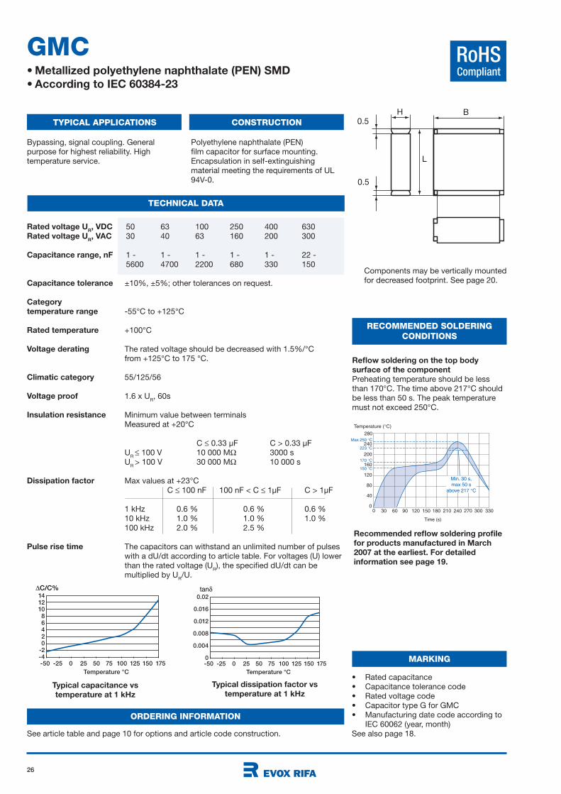
GMC• Metallized polyethylene naphthalate (PEN) SMD
• According to IEC 60384-23
TYPICAL APPLICATIONS CONSTRUCTION
TECHNICAL DATA
RECOMMENDED SOLDERING
CONDITIONS
Bypassing, signal coupling. General
purpose for highest reliability. High
temperature service.
Polyethylene naphthalate (PEN)
film capacitor for surface mounting.
Encapsulation in self-extinguishing
material meeting the requirements of UL
94V-0.
Typical capacitance vs
temperature at 1 kHz
Typical dissipation factor vs
temperature at 1 kHz
Reflow soldering on the top body
surface of the component
Preheating temperature should be less
than 170°C. The time above 217°C should
be less than 50 s. The peak temperature
must not exceed 250°C.
Recommended reflow soldering profile
for products manufactured in March
2007 at the earliest. For detailed
information see page 19.
B
L
H
0.5
0.5
-50 -25 0 25 50 75 100 125 150 175
Temperature °C
14121086420
-2-4
∆C/C%
-50 -25 0 25 50 75 100 125 150 175
Temperature °C
0.02
0.016
0.012
0.008
0.004
0
tan
Temperature ( C)
200
240
30 60 90 120 150 180 210
160
120
40
80
240 270 3303000
280
0
Time (s)
150 C
170 C
223 C
Max 250 C
Min. 30 s,
max 50 s
above 217 C
50 63 100 250 400 630
30 40 63 160 200 300
1 - 1 - 1 - 1 - 1 - 22 -
5600 4700 2200 680 330 150
±10%, ±5%; other tolerances on request.
-55°C to +125°C
+100°C
The rated voltage should be decreased with 1.5%/°C
from +125°C to 175 °C.
55/125/56
1.6 x UR, 60s
Minimum value between terminals
Measured at +20°C
C 0.33 µF C > 0.33 µF
UR
100 V 10 000 M 3000 s
UR
> 100 V 30 000 M 10 000 s
Max values at +23°C
C 100 nF 100 nF < C 1µF C > 1µF
1 kHz 0.6 % 0.6 % 0.6 %
10 kHz 1.0 % 1.0 % 1.0 %
100 kHz 2.0 % 2.5 %
The capacitors can withstand an unlimited number of pulses
with a dU/dt according to article table. For voltages (U) lower
than the rated voltage (UR), the specified dU/dt can be
multiplied by UR/U.
Components may be vertically mounted
for decreased footprint. See page 20.
Rated voltage UR, VDC
Rated voltage UR, VAC
Capacitance range, nF
Capacitance tolerance
Category
temperature range
Rated temperature
Voltage derating
Climatic category
Voltage proof
Insulation resistance
Dissipation factor
Pulse rise time
• Rated capacitance
• Capacitance tolerance code
• Rated voltage code
• Capacitor type G for GMC
• Manufacturing date code according to
IEC 60062 (year, month)
See also page 18.
MARKING
ORDERING INFORMATION
See article table and page 10 for options and article code construction.
27
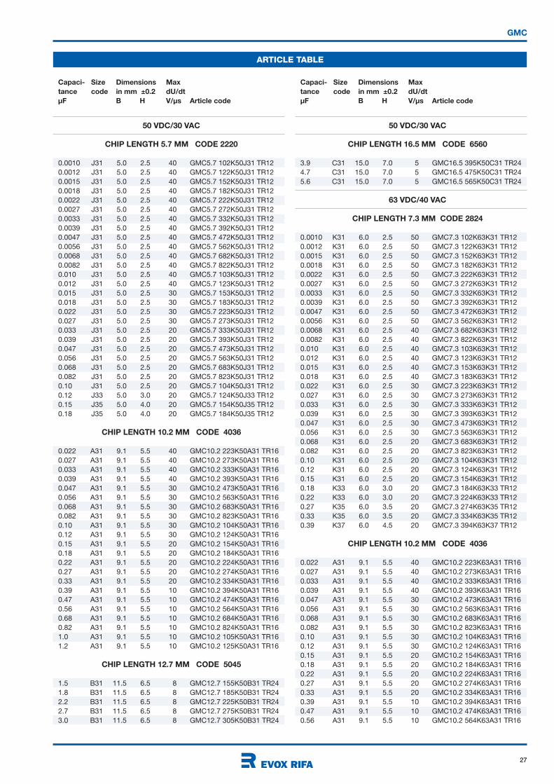
GMC
ARTICLE TABLE
Capaci- Size Dimensions Max
tance code in mm ±0.2 dU/dt
µF B H V/µs Article code
Capaci- Size Dimensions Max
tance code in mm ±0.2 dU/dt
µF B H V/µs Article code
50 VDC/30 VAC
CHIP LENGTH 5.7 MM CODE 2220
0.0010 J31 5.0 2.5 40 GMC5.7 102K50J31 TR12
0.0012 J31 5.0 2.5 40 GMC5.7 122K50J31 TR12
0.0015 J31 5.0 2.5 40 GMC5.7 152K50J31 TR12
0.0018 J31 5.0 2.5 40 GMC5.7 182K50J31 TR12
0.0022 J31 5.0 2.5 40 GMC5.7 222K50J31 TR12
0.0027 J31 5.0 2.5 40 GMC5.7 272K50J31 TR12
0.0033 J31 5.0 2.5 40 GMC5.7 332K50J31 TR12
0.0039 J31 5.0 2.5 40 GMC5.7 392K50J31 TR12
0.0047 J31 5.0 2.5 40 GMC5.7 472K50J31 TR12
0.0056 J31 5.0 2.5 40 GMC5.7 562K50J31 TR12
0.0068 J31 5.0 2.5 40 GMC5.7 682K50J31 TR12
0.0082 J31 5.0 2.5 40 GMC5.7 822K50J31 TR12
0.010 J31 5.0 2.5 40 GMC5.7 103K50J31 TR12
0.012 J31 5.0 2.5 40 GMC5.7 123K50J31 TR12
0.015 J31 5.0 2.5 30 GMC5.7 153K50J31 TR12
0.018 J31 5.0 2.5 30 GMC5.7 183K50J31 TR12
0.022 J31 5.0 2.5 30 GMC5.7 223K50J31 TR12
0.027 J31 5.0 2.5 30 GMC5.7 273K50J31 TR12
0.033 J31 5.0 2.5 20 GMC5.7 333K50J31 TR12
0.039 J31 5.0 2.5 20 GMC5.7 393K50J31 TR12
0.047 J31 5.0 2.5 20 GMC5.7 473K50J31 TR12
0.056 J31 5.0 2.5 20 GMC5.7 563K50J31 TR12
0.068 J31 5.0 2.5 20 GMC5.7 683K50J31 TR12
0.082 J31 5.0 2.5 20 GMC5.7 823K50J31 TR12
0.10 J31 5.0 2.5 20 GMC5.7 104K50J31 TR12
0.12 J33 5.0 3.0 20 GMC5.7 124K50J33 TR12
0.15 J35 5.0 4.0 20 GMC5.7 154K50J35 TR12
0.18 J35 5.0 4.0 20 GMC5.7 184K50J35 TR12
CHIP LENGTH 10.2 MM CODE 4036
0.022 A31 9.1 5.5 40 GMC10.2 223K50A31 TR16
0.027 A31 9.1 5.5 40 GMC10.2 273K50A31 TR16
0.033 A31 9.1 5.5 40 GMC10.2 333K50A31 TR16
0.039 A31 9.1 5.5 40 GMC10.2 393K50A31 TR16
0.047 A31 9.1 5.5 30 GMC10.2 473K50A31 TR16
0.056 A31 9.1 5.5 30 GMC10.2 563K50A31 TR16
0.068 A31 9.1 5.5 30 GMC10.2 683K50A31 TR16
0.082 A31 9.1 5.5 30 GMC10.2 823K50A31 TR16
0.10 A31 9.1 5.5 30 GMC10.2 104K50A31 TR16
0.12 A31 9.1 5.5 30 GMC10.2 124K50A31 TR16
0.15 A31 9.1 5.5 20 GMC10.2 154K50A31 TR16
0.18 A31 9.1 5.5 20 GMC10.2 184K50A31 TR16
0.22 A31 9.1 5.5 20 GMC10.2 224K50A31 TR16
0.27 A31 9.1 5.5 20 GMC10.2 274K50A31 TR16
0.33 A31 9.1 5.5 20 GMC10.2 334K50A31 TR16
0.39 A31 9.1 5.5 10 GMC10.2 394K50A31 TR16
0.47 A31 9.1 5.5 10 GMC10.2 474K50A31 TR16
0.56 A31 9.1 5.5 10 GMC10.2 564K50A31 TR16
0.68 A31 9.1 5.5 10 GMC10.2 684K50A31 TR16
0.82 A31 9.1 5.5 10 GMC10.2 824K50A31 TR16
1.0 A31 9.1 5.5 10 GMC10.2 105K50A31 TR16
1.2 A31 9.1 5.5 10 GMC10.2 125K50A31 TR16
CHIP LENGTH 12.7 MM CODE 5045
1.5 B31 11.5 6.5 8 GMC12.7 155K50B31 TR24
1.8 B31 11.5 6.5 8 GMC12.7 185K50B31 TR24
2.2 B31 11.5 6.5 8 GMC12.7 225K50B31 TR24
2.7 B31 11.5 6.5 8 GMC12.7 275K50B31 TR24
3.0 B31 11.5 6.5 8 GMC12.7 305K50B31 TR24
50 VDC/30 VAC
CHIP LENGTH 16.5 MM CODE 6560
3.9 C31 15.0 7.0 5 GMC16.5 395K50C31 TR24
4.7 C31 15.0 7.0 5 GMC16.5 475K50C31 TR24
5.6 C31 15.0 7.0 5 GMC16.5 565K50C31 TR24
63 VDC/40 VAC
CHIP LENGTH 7.3 MM CODE 2824
0.0010 K31 6.0 2.5 50 GMC7.3 102K63K31 TR12
0.0012 K31 6.0 2.5 50 GMC7.3 122K63K31 TR12
0.0015 K31 6.0 2.5 50 GMC7.3 152K63K31 TR12
0.0018 K31 6.0 2.5 50 GMC7.3 182K63K31 TR12
0.0022 K31 6.0 2.5 50 GMC7.3 222K63K31 TR12
0.0027 K31 6.0 2.5 50 GMC7.3 272K63K31 TR12
0.0033 K31 6.0 2.5 50 GMC7.3 332K63K31 TR12
0.0039 K31 6.0 2.5 50 GMC7.3 392K63K31 TR12
0.0047 K31 6.0 2.5 50 GMC7.3 472K63K31 TR12
0.0056 K31 6.0 2.5 50 GMC7.3 562K63K31 TR12
0.0068 K31 6.0 2.5 40 GMC7.3 682K63K31 TR12
0.0082 K31 6.0 2.5 40 GMC7.3 822K63K31 TR12
0.010 K31 6.0 2.5 40 GMC7.3 103K63K31 TR12
0.012 K31 6.0 2.5 40 GMC7.3 123K63K31 TR12
0.015 K31 6.0 2.5 40 GMC7.3 153K63K31 TR12
0.018 K31 6.0 2.5 40 GMC7.3 183K63K31 TR12
0.022 K31 6.0 2.5 30 GMC7.3 223K63K31 TR12
0.027 K31 6.0 2.5 30 GMC7.3 273K63K31 TR12
0.033 K31 6.0 2.5 30 GMC7.3 333K63K31 TR12
0.039 K31 6.0 2.5 30 GMC7.3 393K63K31 TR12
0.047 K31 6.0 2.5 30 GMC7.3 473K63K31 TR12
0.056 K31 6.0 2.5 30 GMC7.3 563K63K31 TR12
0.068 K31 6.0 2.5 20 GMC7.3 683K63K31 TR12
0.082 K31 6.0 2.5 20 GMC7.3 823K63K31 TR12
0.10 K31 6.0 2.5 20 GMC7.3 104K63K31 TR12
0.12 K31 6.0 2.5 20 GMC7.3 124K63K31 TR12
0.15 K31 6.0 2.5 20 GMC7.3 154K63K31 TR12
0.18 K33 6.0 3.0 20 GMC7.3 184K63K33 TR12
0.22 K33 6.0 3.0 20 GMC7.3 224K63K33 TR12
0.27 K35 6.0 3.5 20 GMC7.3 274K63K35 TR12
0.33 K35 6.0 3.5 20 GMC7.3 334K63K35 TR12
0.39 K37 6.0 4.5 20 GMC7.3 394K63K37 TR12
CHIP LENGTH 10.2 MM CODE 4036
0.022 A31 9.1 5.5 40 GMC10.2 223K63A31 TR16
0.027 A31 9.1 5.5 40 GMC10.2 273K63A31 TR16
0.033 A31 9.1 5.5 40 GMC10.2 333K63A31 TR16
0.039 A31 9.1 5.5 40 GMC10.2 393K63A31 TR16
0.047 A31 9.1 5.5 30 GMC10.2 473K63A31 TR16
0.056 A31 9.1 5.5 30 GMC10.2 563K63A31 TR16
0.068 A31 9.1 5.5 30 GMC10.2 683K63A31 TR16
0.082 A31 9.1 5.5 30 GMC10.2 823K63A31 TR16
0.10 A31 9.1 5.5 30 GMC10.2 104K63A31 TR16
0.12 A31 9.1 5.5 30 GMC10.2 124K63A31 TR16
0.15 A31 9.1 5.5 20 GMC10.2 154K63A31 TR16
0.18 A31 9.1 5.5 20 GMC10.2 184K63A31 TR16
0.22 A31 9.1 5.5 20 GMC10.2 224K63A31 TR16
0.27 A31 9.1 5.5 20 GMC10.2 274K63A31 TR16
0.33 A31 9.1 5.5 20 GMC10.2 334K63A31 TR16
0.39 A31 9.1 5.5 10 GMC10.2 394K63A31 TR16
0.47 A31 9.1 5.5 10 GMC10.2 474K63A31 TR16
0.56 A31 9.1 5.5 10 GMC10.2 564K63A31 TR16
28
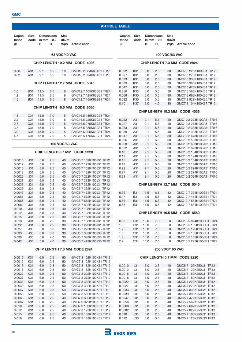
GMC
ARTICLE TABLE
Capaci- Size Dimensions Max
tance code in mm ±0.2 dU/dt
µF B H V/µs Article code
Capaci- Size Dimensions Max
tance code in mm ±0.2 dU/dt
µF B H V/µs Article code
63 VDC/40 VAC
CHIP LENGTH 10.2 MM CODE 4036
0.68 A31 9.1 5.5 10 GMC10.2 684K63A31 TR16
0.82 A31 9.1 5.5 10 GMC10.2 824K63A31 TR16
CHIP LENGTH 12.7 MM CODE 5045
1.0 B31 11.5 6.5 8 GMC12.7 105K63B31 TR24
1.2 B31 11.5 6.5 8 GMC12.7 125K63B31 TR24
1.5 B31 11.5 6.5 8 GMC12.7 155K63B31 TR24
CHIP LENGTH 16.5 MM CODE 6560
1.8 C31 15.0 7.0 5 GMC16.5 185K63C31 TR24
2.2 C31 15.0 7.0 5 GMC16.5 225K63C31 TR24
2.7 C31 15.0 7.0 5 GMC16.5 275K63C31 TR24
3.3 C31 15.0 7.0 5 GMC16.5 335K63C31 TR24
3.9 C31 15.0 7.0 5 GMC16.5 395K63C31 TR24
4.7 C31 15.0 7.0 5 GMC16.5 475K63C31 TR24
100 VDC/63 VAC
CHIP LENGTH 5.7 MM CODE 2220
0.0010 J31 5.0 2.5 40 GMC5.7 102K100J31 TR12
0.0012 J31 5.0 2.5 40 GMC5.7 122K100J31 TR12
0.0015 J31 5.0 2.5 40 GMC5.7 152K100J31 TR12
0.0018 J31 5.0 2.5 40 GMC5.7 182K100J31 TR12
0.0022 J31 5.0 2.5 40 GMC5.7 222K100J31 TR12
0.0027 J31 5.0 2.5 40 GMC5.7 272K100J31 TR12
0.0033 J31 5.0 2.5 40 GMC5.7 332K100J31 TR12
0.0039 J31 5.0 2.5 40 GMC5.7 392K100J31 TR12
0.0047 J31 5.0 2.5 40 GMC5.7 472K100J31 TR12
0.0056 J31 5.0 2.5 40 GMC5.7 562K100J31 TR12
0.0068 J31 5.0 2.5 40 GMC5.7 682K100J31 TR12
0.0082 J31 5.0 2.5 40 GMC5.7 822K100J31 TR12
0.010 J31 5.0 2.5 40 GMC5.7 103K100J31 TR12
0.012 J31 5.0 2.5 40 GMC5.7 123K100J31 TR12
0.015 J31 5.0 2.5 30 GMC5.7 153K100J31 TR12
0.018 J31 5.0 2.5 30 GMC5.7 183K100J31 TR12
0.022 J31 5.0 2.5 30 GMC5.7 223K100J31 TR12
0.027 J33 5.0 3.0 30 GMC5.7 273K100J33 TR12
0.033 J33 5.0 3.0 30 GMC5.7 333K100J33 TR12
0.039 J35 5.0 4.0 30 GMC5.7 393K100J35 TR12
0.047 J35 5.0 4.0 30 GMC5.7 473K100J35 TR12
CHIP LENGTH 7.3 MM CODE 2824
0.0010 K31 6.0 2.5 50 GMC7.3 102K100K31 TR12
0.0012 K31 6.0 2.5 50 GMC7.3 122K100K31 TR12
0.0015 K31 6.0 2.5 50 GMC7.3 152K100K31 TR12
0.0018 K31 6.0 2.5 50 GMC7.3 182K100K31 TR12
0.0022 K31 6.0 2.5 50 GMC7.3 222K100K31 TR12
0.0027 K31 6.0 2.5 50 GMC7.3 272K100K31 TR12
0.0033 K31 6.0 2.5 50 GMC7.3 332K100K31 TR12
0.0039 K31 6.0 2.5 50 GMC7.3 392K100K31 TR12
0.0047 K31 6.0 2.5 50 GMC7.3 472K100K31 TR12
0.0056 K31 6.0 2.5 50 GMC7.3 562K100K31 TR12
0.0068 K31 6.0 2.5 40 GMC7.3 682K100K31 TR12
0.0082 K31 6.0 2.5 40 GMC7.3 822K100K31 TR12
0.010 K31 6.0 2.5 40 GMC7.3 103K100K31 TR12
0.012 K31 6.0 2.5 40 GMC7.3 123K100K31 TR12
0.015 K31 6.0 2.5 40 GMC7.3 153K100K31 TR12
0.018 K31 6.0 2.5 40 GMC7.3 183K100K31 TR12
100 VDC/63 VAC
CHIP LENGTH 7.3 MM CODE 2824
0.022 K31 6.0 2.5 30 GMC7.3 223K100K31 TR12
0.027 K31 6.0 2.5 30 GMC7.3 273K100K31 TR12
0.033 K31 6.0 2.5 30 GMC7.3 333K100K31 TR12
0.039 K31 6.0 2.5 30 GMC7.3 393K100K31 TR12
0.047 K31 6.0 2.5 30 GMC7.3 473K100K31 TR12
0.056 K33 6.0 3.0 30 GMC7.3 563K100K33 TR12
0.068 K35 6.0 3.5 30 GMC7.3 683K100K35 TR12
0.082 K35 6.0 3.5 30 GMC7.3 823K100K35 TR12
0.10 K37 6.0 4.5 30 GMC7.3 104K100K37 TR12
CHIP LENGTH 10.2 MM CODE 4036
0.022 A31 9.1 5.5 40 GMC10.2 223K100A31 TR16
0.027 A31 9.1 5.5 40 GMC10.2 273K100A31 TR16
0.033 A31 9.1 5.5 40 GMC10.2 333K100A31 TR16
0.039 A31 9.1 5.5 40 GMC10.2 393K100A31 TR16
0.047 A31 9.1 5.5 30 GMC10.2 473K100A31 TR16
0.056 A31 9.1 5.5 30 GMC10.2 563K100A31 TR16
0.068 A31 9.1 5.5 30 GMC10.2 683K100A31 TR16
0.082 A31 9.1 5.5 30 GMC10.2 823K100A31 TR16
0.10 A31 9.1 5.5 30 GMC10.2 104K100A31 TR16
0.12 A31 9.1 5.5 30 GMC10.2 124K100A31 TR16
0.15 A31 9.1 5.5 20 GMC10.2 154K100A31 TR16
0.18 A31 9.1 5.5 20 GMC10.2 184K100A31 TR16
0.22 A31 9.1 5.5 20 GMC10.2 224K100A31 TR16
0.27 A31 9.1 5.5 20 GMC10.2 274K100A31 TR16
0.33 A31 9.1 5.5 20 GMC10.2 334K100A31 TR16
CHIP LENGTH 12.7 MM CODE 5045
0.39 B31 11.5 6.5 12 GMC12.7 394K100B31 TR24
0.47 B31 11.5 6.5 12 GMC12.7 474K100B31 TR24
0.56 B31 11.5 6.5 12 GMC12.7 564K100B31 TR24
0.68 B31 11.5 6.5 12 GMC12.7 684K100B31 TR24
CHIP LENGTH 16.5 MM CODE 6560
0.82 C31 15.0 7.0 8 GMC16.5 824K100C31 TR24
1.0 C31 15.0 7.0 8 GMC16.5 105K100C31 TR24
1.2 C31 15.0 7.0 8 GMC16.5 125K100C31 TR24
1.5 C31 15.0 7.0 8 GMC16.5 155K100C31 TR24
1.8 C31 15.0 7.0 8 GMC16.5 185K100C31 TR24
2.2 C31 15.0 7.0 8 GMC16.5 225K100C31 TR24
250 VDC/160 VAC
CHIP LENGTH 5.7 MM CODE 2220
0.0010 J31 5.0 2.5 40 GMC5.7 102K250J31 TR12
0.0012 J31 5.0 2.5 40 GMC5.7 122K250J31 TR12
0.0015 J31 5.0 2.5 40 GMC5.7 152K250J31 TR12
0.0018 J31 5.0 2.5 40 GMC5.7 182K250J31 TR12
0.0022 J31 5.0 2.5 40 GMC5.7 222K250J31 TR12
0.0027 J31 5.0 2.5 40 GMC5.7 272K250J31 TR12
0.0033 J31 5.0 2.5 40 GMC5.7 332K250J31 TR12
0.0039 J31 5.0 2.5 40 GMC5.7 392K250J31 TR12
0.0047 J31 5.0 2.5 40 GMC5.7 472K250J31 TR12
0.0056 J31 5.0 2.5 40 GMC5.7 562K250J31 TR12
0.0068 J31 5.0 2.5 40 GMC5.7 682K250J31 TR12
0.0082 J31 5.0 2.5 40 GMC5.7 822K250J31 TR12
0.010 J31 5.0 2.5 40 GMC5.7 103K250J31 TR12
0.012 J33 5.0 3.0 40 GMC5.7 123K250J33 TR12
29
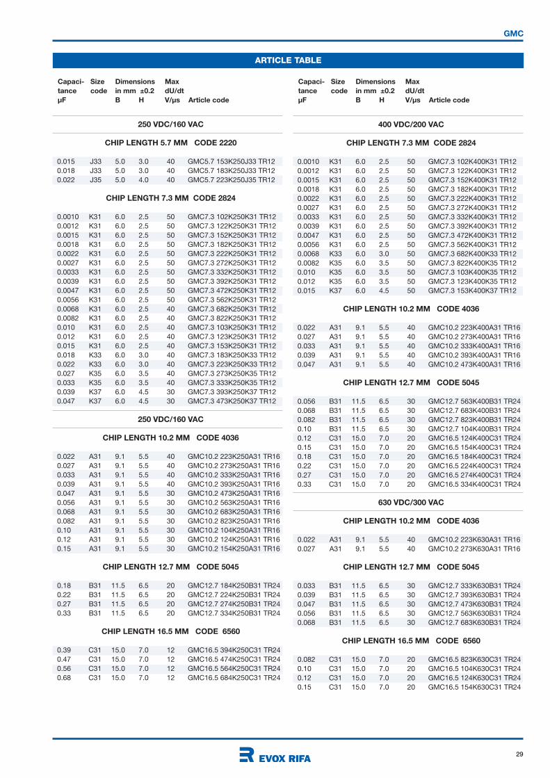
GMC
ARTICLE TABLE
Capaci- Size Dimensions Max
tance code in mm ±0.2 dU/dt
µF B H V/µs Article code
Capaci- Size Dimensions Max
tance code in mm ±0.2 dU/dt
µF B H V/µs Article code
250 VDC/160 VAC
CHIP LENGTH 5.7 MM CODE 2220
0.015 J33 5.0 3.0 40 GMC5.7 153K250J33 TR12
0.018 J33 5.0 3.0 40 GMC5.7 183K250J33 TR12
0.022 J35 5.0 4.0 40 GMC5.7 223K250J35 TR12
CHIP LENGTH 7.3 MM CODE 2824
0.0010 K31 6.0 2.5 50 GMC7.3 102K250K31 TR12
0.0012 K31 6.0 2.5 50 GMC7.3 122K250K31 TR12
0.0015 K31 6.0 2.5 50 GMC7.3 152K250K31 TR12
0.0018 K31 6.0 2.5 50 GMC7.3 182K250K31 TR12
0.0022 K31 6.0 2.5 50 GMC7.3 222K250K31 TR12
0.0027 K31 6.0 2.5 50 GMC7.3 272K250K31 TR12
0.0033 K31 6.0 2.5 50 GMC7.3 332K250K31 TR12
0.0039 K31 6.0 2.5 50 GMC7.3 392K250K31 TR12
0.0047 K31 6.0 2.5 50 GMC7.3 472K250K31 TR12
0.0056 K31 6.0 2.5 50 GMC7.3 562K250K31 TR12
0.0068 K31 6.0 2.5 40 GMC7.3 682K250K31 TR12
0.0082 K31 6.0 2.5 40 GMC7.3 822K250K31 TR12
0.010 K31 6.0 2.5 40 GMC7.3 103K250K31 TR12
0.012 K31 6.0 2.5 40 GMC7.3 123K250K31 TR12
0.015 K31 6.0 2.5 40 GMC7.3 153K250K31 TR12
0.018 K33 6.0 3.0 40 GMC7.3 183K250K33 TR12
0.022 K33 6.0 3.0 40 GMC7.3 223K250K33 TR12
0.027 K35 6.0 3.5 40 GMC7.3 273K250K35 TR12
0.033 K35 6.0 3.5 40 GMC7.3 333K250K35 TR12
0.039 K37 6.0 4.5 30 GMC7.3 393K250K37 TR12
0.047 K37 6.0 4.5 30 GMC7.3 473K250K37 TR12
250 VDC/160 VAC
CHIP LENGTH 10.2 MM CODE 4036
0.022 A31 9.1 5.5 40 GMC10.2 223K250A31 TR16
0.027 A31 9.1 5.5 40 GMC10.2 273K250A31 TR16
0.033 A31 9.1 5.5 40 GMC10.2 333K250A31 TR16
0.039 A31 9.1 5.5 40 GMC10.2 393K250A31 TR16
0.047 A31 9.1 5.5 30 GMC10.2 473K250A31 TR16
0.056 A31 9.1 5.5 30 GMC10.2 563K250A31 TR16
0.068 A31 9.1 5.5 30 GMC10.2 683K250A31 TR16
0.082 A31 9.1 5.5 30 GMC10.2 823K250A31 TR16
0.10 A31 9.1 5.5 30 GMC10.2 104K250A31 TR16
0.12 A31 9.1 5.5 30 GMC10.2 124K250A31 TR16
0.15 A31 9.1 5.5 30 GMC10.2 154K250A31 TR16
CHIP LENGTH 12.7 MM CODE 5045
0.18 B31 11.5 6.5 20 GMC12.7 184K250B31 TR24
0.22 B31 11.5 6.5 20 GMC12.7 224K250B31 TR24
0.27 B31 11.5 6.5 20 GMC12.7 274K250B31 TR24
0.33 B31 11.5 6.5 20 GMC12.7 334K250B31 TR24
CHIP LENGTH 16.5 MM CODE 6560
0.39 C31 15.0 7.0 12 GMC16.5 394K250C31 TR24
0.47 C31 15.0 7.0 12 GMC16.5 474K250C31 TR24
0.56 C31 15.0 7.0 12 GMC16.5 564K250C31 TR24
0.68 C31 15.0 7.0 12 GMC16.5 684K250C31 TR24
400 VDC/200 VAC
CHIP LENGTH 7.3 MM CODE 2824
0.0010 K31 6.0 2.5 50 GMC7.3 102K400K31 TR12
0.0012 K31 6.0 2.5 50 GMC7.3 122K400K31 TR12
0.0015 K31 6.0 2.5 50 GMC7.3 152K400K31 TR12
0.0018 K31 6.0 2.5 50 GMC7.3 182K400K31 TR12
0.0022 K31 6.0 2.5 50 GMC7.3 222K400K31 TR12
0.0027 K31 6.0 2.5 50 GMC7.3 272K400K31 TR12
0.0033 K31 6.0 2.5 50 GMC7.3 332K400K31 TR12
0.0039 K31 6.0 2.5 50 GMC7.3 392K400K31 TR12
0.0047 K31 6.0 2.5 50 GMC7.3 472K400K31 TR12
0.0056 K31 6.0 2.5 50 GMC7.3 562K400K31 TR12
0.0068 K33 6.0 3.0 50 GMC7.3 682K400K33 TR12
0.0082 K35 6.0 3.5 50 GMC7.3 822K400K35 TR12
0.010 K35 6.0 3.5 50 GMC7.3 103K400K35 TR12
0.012 K35 6.0 3.5 50 GMC7.3 123K400K35 TR12
0.015 K37 6.0 4.5 50 GMC7.3 153K400K37 TR12
CHIP LENGTH 10.2 MM CODE 4036
0.022 A31 9.1 5.5 40 GMC10.2 223K400A31 TR16
0.027 A31 9.1 5.5 40 GMC10.2 273K400A31 TR16
0.033 A31 9.1 5.5 40 GMC10.2 333K400A31 TR16
0.039 A31 9.1 5.5 40 GMC10.2 393K400A31 TR16
0.047 A31 9.1 5.5 40 GMC10.2 473K400A31 TR16
CHIP LENGTH 12.7 MM CODE 5045
0.056 B31 11.5 6.5 30 GMC12.7 563K400B31 TR24
0.068 B31 11.5 6.5 30 GMC12.7 683K400B31 TR24
0.082 B31 11.5 6.5 30 GMC12.7 823K400B31 TR24
0.10 B31 11.5 6.5 30 GMC12.7 104K400B31 TR24
0.12 C31 15.0 7.0 20 GMC16.5 124K400C31 TR24
0.15 C31 15.0 7.0 20 GMC16.5 154K400C31 TR24
0.18 C31 15.0 7.0 20 GMC16.5 184K400C31 TR24
0.22 C31 15.0 7.0 20 GMC16.5 224K400C31 TR24
0.27 C31 15.0 7.0 20 GMC16.5 274K400C31 TR24
0.33 C31 15.0 7.0 20 GMC16.5 334K400C31 TR24
630 VDC/300 VAC
CHIP LENGTH 10.2 MM CODE 4036
0.022 A31 9.1 5.5 40 GMC10.2 223K630A31 TR16
0.027 A31 9.1 5.5 40 GMC10.2 273K630A31 TR16
CHIP LENGTH 12.7 MM CODE 5045
0.033 B31 11.5 6.5 30 GMC12.7 333K630B31 TR24
0.039 B31 11.5 6.5 30 GMC12.7 393K630B31 TR24
0.047 B31 11.5 6.5 30 GMC12.7 473K630B31 TR24
0.056 B31 11.5 6.5 30 GMC12.7 563K630B31 TR24
0.068 B31 11.5 6.5 30 GMC12.7 683K630B31 TR24
CHIP LENGTH 16.5 MM CODE 6560
0.082 C31 15.0 7.0 20 GMC16.5 823K630C31 TR24
0.10 C31 15.0 7.0 20 GMC16.5 104K630C31 TR24
0.12 C31 15.0 7.0 20 GMC16.5 124K630C31 TR24
0.15 C31 15.0 7.0 20 GMC16.5 154K630C31 TR24

30
RoHSCompliant
63 100 250 400 630
40 63 160 200 220
1 - 1 - 1 - 1 - 1 -
470 220 68 15 6.8
±20%, ±10% standard; ±5% on request.
-55°C to +125°C
+100°C
The rated voltage should be decreased with 1.5%/°C
from +125°C to 175 °C.
55/125/21
1.6 x UR, 60s
Minimum value between terminals
Measured at +20°C
C 0.47 µF
UR
100 V 10 000 M
UR
> 100 V 30 000 M
Max values at +23°C
C 100 nF 100 nF < C 470 nF
1 kHz 0.6 % 0.6 %
10 kHz 1.0 % 1.0 %
100 kHz 2.0 % 2.5 %
The capacitors can withstand an unlimited number of pulses
with a dU/dt according to article table. For voltages (U) lower
than the rated voltage (UR), the specified dU/dt can be
multiplied by UR/U.
GMW• Metallized polyethylene naphthalate (PEN) SMD
• Miniature size naked capacitor
• Low profile
• Wound construction
• According to IEC 60384-23
TYPICAL APPLICATIONS CONSTRUCTION
TECHNICAL DATA
Rated voltage UR, VDC
Rated voltage UR, VAC
Capacitance range, nF
Capacitance tolerance
Category
temperature range
Rated temperature
Voltage derating
Climatic category
Voltage proof
Insulation resistance
Dissipation factor
Pulse rise time
Bypassing, signal coupling. General
purpose for highest reliability. High
temperature service.
Polyethylene naphthalate (PEN) film
capacitor for surface mounting.
Typical capacitance vs
temperature at 1 kHz
Typical dissipation factor vs
temperature at 1 kHz
B
B
H
L
3D view
-50 -25 0 25 50 75 100 125 150 175
Temperature °C
14121086420
-2-4
∆C/C%
-50 -25 0 25 50 75 100 125 150 175
Temperature °C
0.02
0.016
0.012
0.008
0.004
0
tan
RECOMMENDED SOLDERING
CONDITIONS
Reflow soldering on the top body
surface of the component
Preheating temperature should be less
than 170°C. The time above 217°C should
be less than 50 s. The peak temperature
must not exceed 240°C.
Recommended reflow soldering profile
for products manufactured in March
2007 at the earliest. For detailed
information see page 19.
Temperature ( C)
200
30 60 90 120 150 180 210
160
120
40
80
240 270 3303000
280
0
Time (s)
150 C
170 C
223 C
Max 240 C
Min. 30 s,
max 50 s
above 217 C
Temperature ( C)
200
25050 100 t(s)150 200
150
100
50
250
300
00
Max 130 C
90 C
250 C, 2s + 3s max
Recommended
preheat
Recommended
max preheat
Recommended wave soldering profile
Electrode temperature, Wave soldering
The recommended preheating temperature
is 90 °C, max 130 °C. The peak temperature
250°C may be applied for 2 + 3 s max. Evox
Rifa recommends wave soldering for GMW
parts with up to H = 2 mm.
• Rated capacitance
• Capacitance tolerance code
• Rated voltage code
• Capacitor type G for GMW
• Manufacturing date code according to
IEC 60062 (year, month)
ORDERING INFORMATION
See article table and page 10 for options and article code construction.
MARKING
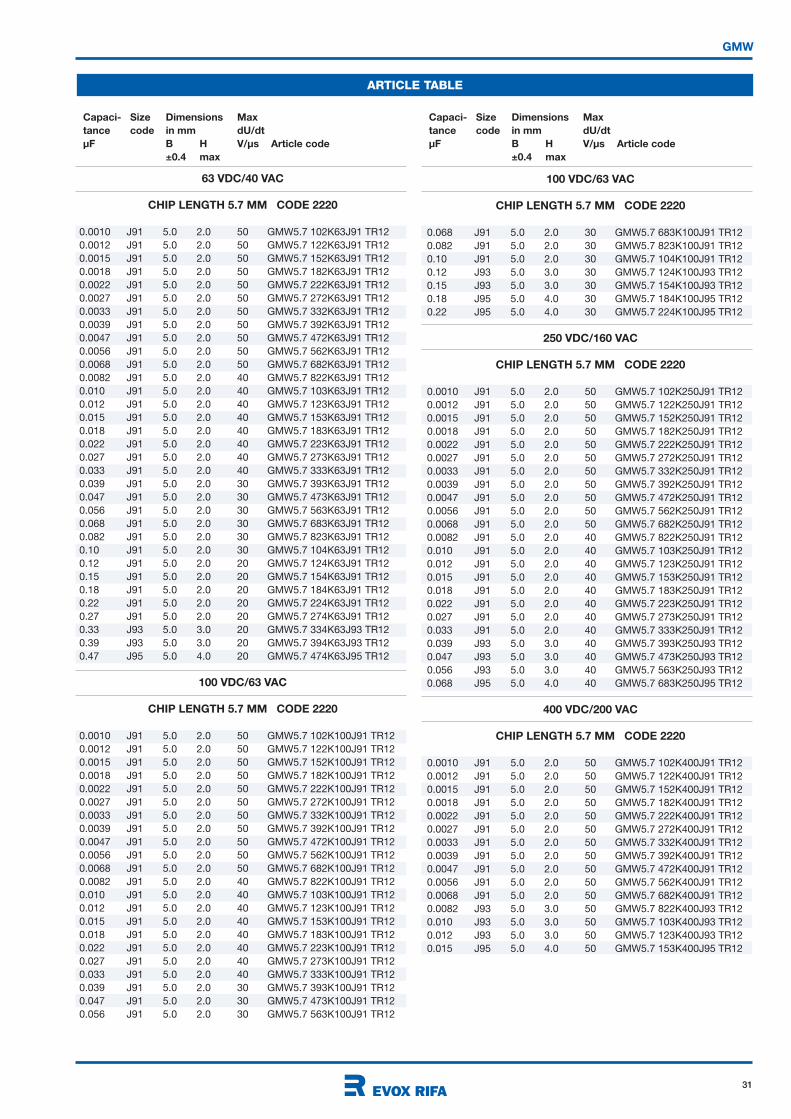
31
GMW
ARTICLE TABLE
63 VDC/40 VAC
CHIP LENGTH 5.7 MM CODE 2220
0.0010 J91 5.0 2.0 50 GMW5.7 102K63J91 TR12
0.0012 J91 5.0 2.0 50 GMW5.7 122K63J91 TR12
0.0015 J91 5.0 2.0 50 GMW5.7 152K63J91 TR12
0.0018 J91 5.0 2.0 50 GMW5.7 182K63J91 TR12
0.0022 J91 5.0 2.0 50 GMW5.7 222K63J91 TR12
0.0027 J91 5.0 2.0 50 GMW5.7 272K63J91 TR12
0.0033 J91 5.0 2.0 50 GMW5.7 332K63J91 TR12
0.0039 J91 5.0 2.0 50 GMW5.7 392K63J91 TR12
0.0047 J91 5.0 2.0 50 GMW5.7 472K63J91 TR12
0.0056 J91 5.0 2.0 50 GMW5.7 562K63J91 TR12
0.0068 J91 5.0 2.0 50 GMW5.7 682K63J91 TR12
0.0082 J91 5.0 2.0 40 GMW5.7 822K63J91 TR12
0.010 J91 5.0 2.0 40 GMW5.7 103K63J91 TR12
0.012 J91 5.0 2.0 40 GMW5.7 123K63J91 TR12
0.015 J91 5.0 2.0 40 GMW5.7 153K63J91 TR12
0.018 J91 5.0 2.0 40 GMW5.7 183K63J91 TR12
0.022 J91 5.0 2.0 40 GMW5.7 223K63J91 TR12
0.027 J91 5.0 2.0 40 GMW5.7 273K63J91 TR12
0.033 J91 5.0 2.0 40 GMW5.7 333K63J91 TR12
0.039 J91 5.0 2.0 30 GMW5.7 393K63J91 TR12
0.047 J91 5.0 2.0 30 GMW5.7 473K63J91 TR12
0.056 J91 5.0 2.0 30 GMW5.7 563K63J91 TR12
0.068 J91 5.0 2.0 30 GMW5.7 683K63J91 TR12
0.082 J91 5.0 2.0 30 GMW5.7 823K63J91 TR12
0.10 J91 5.0 2.0 30 GMW5.7 104K63J91 TR12
0.12 J91 5.0 2.0 20 GMW5.7 124K63J91 TR12
0.15 J91 5.0 2.0 20 GMW5.7 154K63J91 TR12
0.18 J91 5.0 2.0 20 GMW5.7 184K63J91 TR12
0.22 J91 5.0 2.0 20 GMW5.7 224K63J91 TR12
0.27 J91 5.0 2.0 20 GMW5.7 274K63J91 TR12
0.33 J93 5.0 3.0 20 GMW5.7 334K63J93 TR12
0.39 J93 5.0 3.0 20 GMW5.7 394K63J93 TR12
0.47 J95 5.0 4.0 20 GMW5.7 474K63J95 TR12
100 VDC/63 VAC
CHIP LENGTH 5.7 MM CODE 2220
0.0010 J91 5.0 2.0 50 GMW5.7 102K100J91 TR12
0.0012 J91 5.0 2.0 50 GMW5.7 122K100J91 TR12
0.0015 J91 5.0 2.0 50 GMW5.7 152K100J91 TR12
0.0018 J91 5.0 2.0 50 GMW5.7 182K100J91 TR12
0.0022 J91 5.0 2.0 50 GMW5.7 222K100J91 TR12
0.0027 J91 5.0 2.0 50 GMW5.7 272K100J91 TR12
0.0033 J91 5.0 2.0 50 GMW5.7 332K100J91 TR12
0.0039 J91 5.0 2.0 50 GMW5.7 392K100J91 TR12
0.0047 J91 5.0 2.0 50 GMW5.7 472K100J91 TR12
0.0056 J91 5.0 2.0 50 GMW5.7 562K100J91 TR12
0.0068 J91 5.0 2.0 50 GMW5.7 682K100J91 TR12
0.0082 J91 5.0 2.0 40 GMW5.7 822K100J91 TR12
0.010 J91 5.0 2.0 40 GMW5.7 103K100J91 TR12
0.012 J91 5.0 2.0 40 GMW5.7 123K100J91 TR12
0.015 J91 5.0 2.0 40 GMW5.7 153K100J91 TR12
0.018 J91 5.0 2.0 40 GMW5.7 183K100J91 TR12
0.022 J91 5.0 2.0 40 GMW5.7 223K100J91 TR12
0.027 J91 5.0 2.0 40 GMW5.7 273K100J91 TR12
0.033 J91 5.0 2.0 40 GMW5.7 333K100J91 TR12
0.039 J91 5.0 2.0 30 GMW5.7 393K100J91 TR12
0.047 J91 5.0 2.0 30 GMW5.7 473K100J91 TR12
0.056 J91 5.0 2.0 30 GMW5.7 563K100J91 TR12
Capaci- Size Dimensions Max
tance code in mm dU/dt
µF B H V/µs Article code
±0.4 max
Capaci- Size Dimensions Max
tance code in mm dU/dt
µF B H V/µs Article code
±0.4 max
100 VDC/63 VAC
CHIP LENGTH 5.7 MM CODE 2220
0.068 J91 5.0 2.0 30 GMW5.7 683K100J91 TR12
0.082 J91 5.0 2.0 30 GMW5.7 823K100J91 TR12
0.10 J91 5.0 2.0 30 GMW5.7 104K100J91 TR12
0.12 J93 5.0 3.0 30 GMW5.7 124K100J93 TR12
0.15 J93 5.0 3.0 30 GMW5.7 154K100J93 TR12
0.18 J95 5.0 4.0 30 GMW5.7 184K100J95 TR12
0.22 J95 5.0 4.0 30 GMW5.7 224K100J95 TR12
250 VDC/160 VAC
CHIP LENGTH 5.7 MM CODE 2220
0.0010 J91 5.0 2.0 50 GMW5.7 102K250J91 TR12
0.0012 J91 5.0 2.0 50 GMW5.7 122K250J91 TR12
0.0015 J91 5.0 2.0 50 GMW5.7 152K250J91 TR12
0.0018 J91 5.0 2.0 50 GMW5.7 182K250J91 TR12
0.0022 J91 5.0 2.0 50 GMW5.7 222K250J91 TR12
0.0027 J91 5.0 2.0 50 GMW5.7 272K250J91 TR12
0.0033 J91 5.0 2.0 50 GMW5.7 332K250J91 TR12
0.0039 J91 5.0 2.0 50 GMW5.7 392K250J91 TR12
0.0047 J91 5.0 2.0 50 GMW5.7 472K250J91 TR12
0.0056 J91 5.0 2.0 50 GMW5.7 562K250J91 TR12
0.0068 J91 5.0 2.0 50 GMW5.7 682K250J91 TR12
0.0082 J91 5.0 2.0 40 GMW5.7 822K250J91 TR12
0.010 J91 5.0 2.0 40 GMW5.7 103K250J91 TR12
0.012 J91 5.0 2.0 40 GMW5.7 123K250J91 TR12
0.015 J91 5.0 2.0 40 GMW5.7 153K250J91 TR12
0.018 J91 5.0 2.0 40 GMW5.7 183K250J91 TR12
0.022 J91 5.0 2.0 40 GMW5.7 223K250J91 TR12
0.027 J91 5.0 2.0 40 GMW5.7 273K250J91 TR12
0.033 J91 5.0 2.0 40 GMW5.7 333K250J91 TR12
0.039 J93 5.0 3.0 40 GMW5.7 393K250J93 TR12
0.047 J93 5.0 3.0 40 GMW5.7 473K250J93 TR12
0.056 J93 5.0 3.0 40 GMW5.7 563K250J93 TR12
0.068 J95 5.0 4.0 40 GMW5.7 683K250J95 TR12
400 VDC/200 VAC
CHIP LENGTH 5.7 MM CODE 2220
0.0010 J91 5.0 2.0 50 GMW5.7 102K400J91 TR12
0.0012 J91 5.0 2.0 50 GMW5.7 122K400J91 TR12
0.0015 J91 5.0 2.0 50 GMW5.7 152K400J91 TR12
0.0018 J91 5.0 2.0 50 GMW5.7 182K400J91 TR12
0.0022 J91 5.0 2.0 50 GMW5.7 222K400J91 TR12
0.0027 J91 5.0 2.0 50 GMW5.7 272K400J91 TR12
0.0033 J91 5.0 2.0 50 GMW5.7 332K400J91 TR12
0.0039 J91 5.0 2.0 50 GMW5.7 392K400J91 TR12
0.0047 J91 5.0 2.0 50 GMW5.7 472K400J91 TR12
0.0056 J91 5.0 2.0 50 GMW5.7 562K400J91 TR12
0.0068 J91 5.0 2.0 50 GMW5.7 682K400J91 TR12
0.0082 J93 5.0 3.0 50 GMW5.7 822K400J93 TR12
0.010 J93 5.0 3.0 50 GMW5.7 103K400J93 TR12
0.012 J93 5.0 3.0 50 GMW5.7 123K400J93 TR12
0.015 J95 5.0 4.0 50 GMW5.7 153K400J95 TR12

32
GMW
ARTICLE TABLE
630 VDC/220 VAC
CHIP LENGTH 5.7 MM CODE 2220
0.0010 J91 5.0 2.0 50 GMW5.7 102K630J91 TR12
0.0012 J91 5.0 2.0 50 GMW5.7 122K630J91 TR12
0.0015 J91 5.0 2.0 50 GMW5.7 152K630J91 TR12
0.0018 J91 5.0 2.0 50 GMW5.7 182K630J91 TR12
0.0022 J91 5.0 2.0 50 GMW5.7 222K630J91 TR12
0.0027 J91 5.0 2.0 50 GMW5.7 272K630J91 TR12
0.0033 J93 5.0 3.0 50 GMW5.7 332K630J93 TR12
0.0039 J93 5.0 3.0 50 GMW5.7 392K630J93 TR12
0.0047 J95 5.0 4.0 50 GMW5.7 472K630J95 TR12
0.0056 J95 5.0 4.0 50 GMW5.7 562K630J95 TR12
0.0068 J95 5.0 4.0 50 GMW5.7 682K630J95 TR12
ARTICLE TABLE
Capaci- Size Dimensions Max
tance code in mm dU/dt
µF B H V/µs Article code
±0.4 max
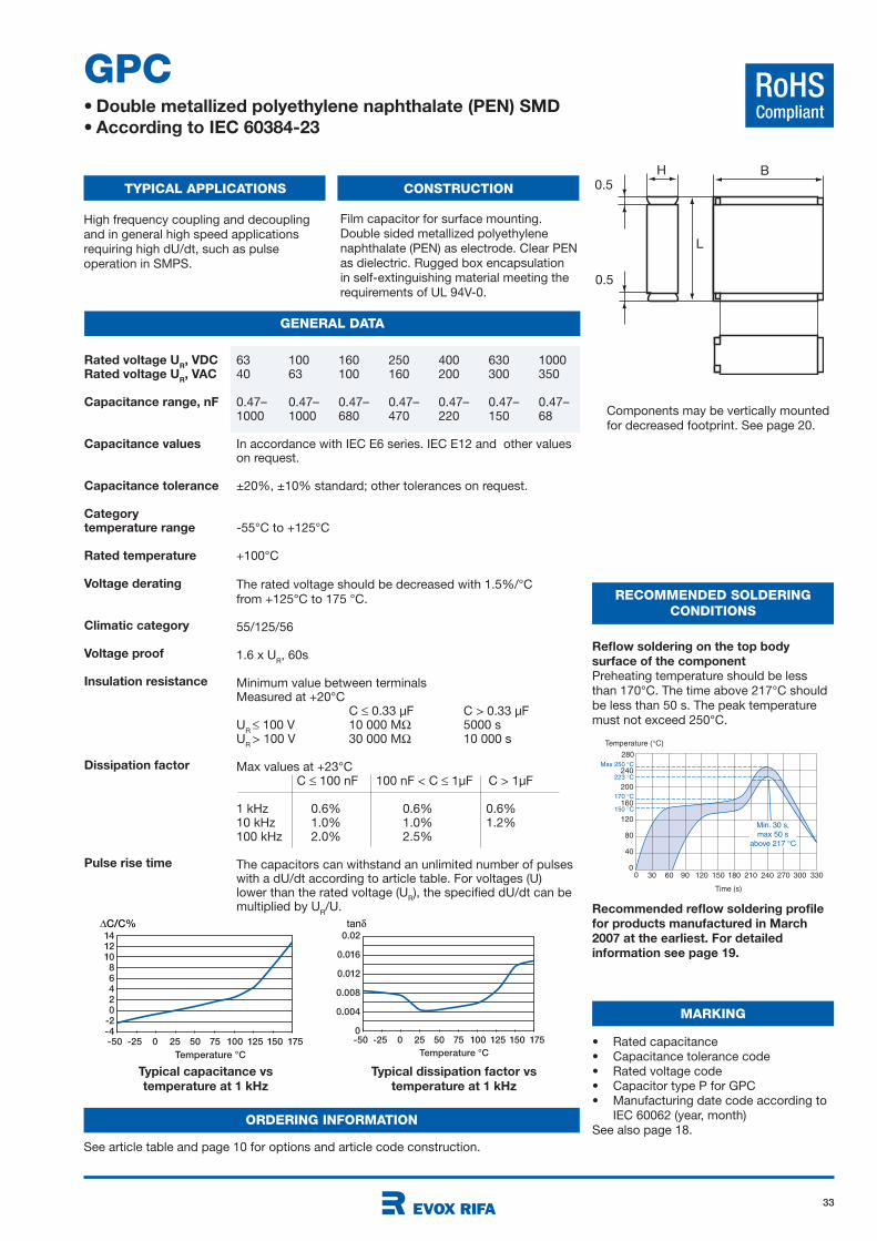
33
RoHSCompliant
GPC• Double metallized polyethylene naphthalate (PEN) SMD
• According to IEC 60384-23
TYPICAL APPLICATIONS CONSTRUCTION
GENERAL DATA
RECOMMENDED SOLDERING
CONDITIONS
High frequency coupling and decoupling
and in general high speed applications
requiring high dU/dt, such as pulse
operation in SMPS.
Film capacitor for surface mounting.
Double sided metallized polyethylene
naphthalate (PEN) as electrode. Clear PEN
as dielectric. Rugged box encapsulation
in self-extinguishing material meeting the
requirements of UL 94V-0.
Reflow soldering on the top body
surface of the component
Preheating temperature should be less
than 170°C. The time above 217°C should
be less than 50 s. The peak temperature
must not exceed 250°C.
63 100 160 250 400 630 100040 63 100 160 200 300 350
0.47– 0.47– 0.47– 0.47– 0.47– 0.47– 0.47–1000 1000 680 470 220 150 68
In accordance with IEC E6 series. IEC E12 and other values on request.
±20%, ±10% standard; other tolerances on request.
-55°C to +125°C
+100°C
The rated voltage should be decreased with 1.5%/°C
from +125°C to 175 °C.
55/125/56
1.6 x UR, 60s
Minimum value between terminalsMeasured at +20°C
C 0.33 µF C > 0.33 µFU
R 100 V 10 000 M 5000 s
UR
> 100 V 30 000 M 10 000 s
Max values at +23°C C 100 nF 100 nF < C 1µF C > 1µF
1 kHz 0.6% 0.6% 0.6%10 kHz 1.0% 1.0% 1.2%100 kHz 2.0% 2.5%
The capacitors can withstand an unlimited number of pulseswith a dU/dt according to article table. For voltages (U) lower than the rated voltage (U
R), the specified dU/dt can be
multiplied by UR/U.
Rated voltage UR, VDC
Rated voltage UR, VAC
Capacitance range, nF
Capacitance values
Capacitance tolerance
Categorytemperature range
Rated temperature
Voltage derating
Climatic category
Voltage proof
Insulation resistance
Dissipation factor
Pulse rise time
-50 -25 0 25 50 75 100 125 150 175
Temperature °C
14121086420
-2-4
∆C/C%
-50 -25 0 25 50 75 100 125 150 175
Temperature °C
0.02
0.016
0.012
0.008
0.004
0
tan
Temperature ( C)
200
240
30 60 90 120 150 180 210
160
120
40
80
240 270 3303000
280
0
Time (s)
150 C
170 C
223 C
Max 250 C
Min. 30 s,
max 50 s
above 217 C
Typical capacitance vs
temperature at 1 kHz
Typical dissipation factor vs
temperature at 1 kHz
Recommended reflow soldering profile
for products manufactured in March
2007 at the earliest. For detailed
information see page 19.
B
L
H
0.5
0.5
Components may be vertically mounted
for decreased footprint. See page 20.
ORDERING INFORMATION
See article table and page 10 for options and article code construction.
MARKING
• Rated capacitance
• Capacitance tolerance code
• Rated voltage code
• Capacitor type P for GPC
• Manufacturing date code according to
IEC 60062 (year, month)
See also page 18.
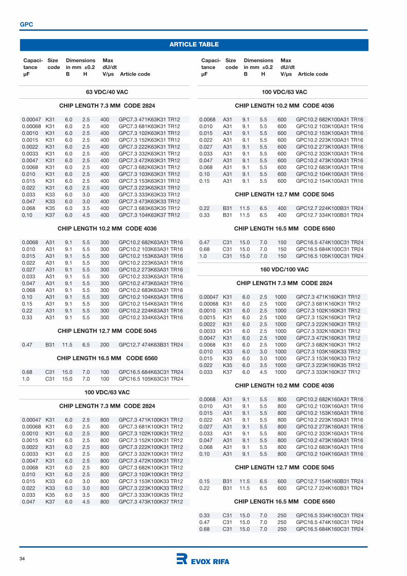
34
Capaci- Size Dimensions Max
tance code in mm ±0.2 dU/dt
µF B H V/µs Article code
Capaci- Size Dimensions Max
tance code in mm ±0.2 dU/dt
µF B H V/µs Article code
100 VDC/63 VAC
CHIP LENGTH 10.2 MM CODE 4036
0.0068 A31 9.1 5.5 600 GPC10.2 682K100A31 TR16
0.010 A31 9.1 5.5 600 GPC10.2 103K100A31 TR16
0.015 A31 9.1 5.5 600 GPC10.2 153K100A31 TR16
0.022 A31 9.1 5.5 600 GPC10.2 223K100A31 TR16
0.027 A31 9.1 5.5 600 GPC10.2 273K100A31 TR16
0.033 A31 9.1 5.5 600 GPC10.2 333K100A31 TR16
0.047 A31 9.1 5.5 600 GPC10.2 473K100A31 TR16
0.068 A31 9.1 5.5 600 GPC10.2 683K100A31 TR16
0.10 A31 9.1 5.5 600 GPC10.2 104K100A31 TR16
0.15 A31 9.1 5.5 600 GPC10.2 154K100A31 TR16
CHIP LENGTH 12.7 MM CODE 5045
0.22 B31 11.5 6.5 400 GPC12.7 224K100B31 TR24
0.33 B31 11.5 6.5 400 GPC12.7 334K100B31 TR24
CHIP LENGTH 16.5 MM CODE 6560
0.47 C31 15.0 7.0 150 GPC16.5 474K100C31 TR24
0.68 C31 15.0 7.0 150 GPC16.5 684K100C31 TR24
1.0 C31 15.0 7.0 150 GPC16.5 105K100C31 TR24
160 VDC/100 VAC
CHIP LENGTH 7.3 MM CODE 2824
0.00047 K31 6.0 2.5 1000 GPC7.3 471K160K31 TR12
0.00068 K31 6.0 2.5 1000 GPC7.3 681K160K31 TR12
0.0010 K31 6.0 2.5 1000 GPC7.3 102K160K31 TR12
0.0015 K31 6.0 2.5 1000 GPC7.3 152K160K31 TR12
0.0022 K31 6.0 2.5 1000 GPC7.3 222K160K31 TR12
0.0033 K31 6.0 2.5 1000 GPC7.3 332K160K31 TR12
0.0047 K31 6.0 2.5 1000 GPC7.3 472K160K31 TR12
0.0068 K31 6.0 2.5 1000 GPC7.3 682K160K31 TR12
0.010 K33 6.0 3.0 1000 GPC7.3 103K160K33 TR12
0.015 K33 6.0 3.0 1000 GPC7.3 153K160K33 TR12
0.022 K35 6.0 3.5 1000 GPC7.3 223K160K35 TR12
0.033 K37 6.0 4.5 1000 GPC7.3 333K160K37 TR12
CHIP LENGTH 10.2 MM CODE 4036
0.0068 A31 9.1 5.5 800 GPC10.2 682K160A31 TR16
0.010 A31 9.1 5.5 800 GPC10.2 103K160A31 TR16
0.015 A31 9.1 5.5 800 GPC10.2 153K160A31 TR16
0.022 A31 9.1 5.5 800 GPC10.2 223K160A31 TR16
0.027 A31 9.1 5.5 800 GPC10.2 273K160A31 TR16
0.033 A31 9.1 5.5 800 GPC10.2 333K160A31 TR16
0.047 A31 9.1 5.5 800 GPC10.2 473K160A31 TR16
0.068 A31 9.1 5.5 800 GPC10.2 683K160A31 TR16
0.10 A31 9.1 5.5 800 GPC10.2 104K160A31 TR16
CHIP LENGTH 12.7 MM CODE 5045
0.15 B31 11.5 6.5 600 GPC12.7 154K160B31 TR24
0.22 B31 11.5 6.5 600 GPC12.7 224K160B31 TR24
CHIP LENGTH 16.5 MM CODE 6560
0.33 C31 15.0 7.0 250 GPC16.5 334K160C31 TR24
0.47 C31 15.0 7.0 250 GPC16.5 474K160C31 TR24
0.68 C31 15.0 7.0 250 GPC16.5 684K160C31 TR24
GPC
ARTICLE TABLE
63 VDC/40 VAC
CHIP LENGTH 7.3 MM CODE 2824
0.00047 K31 6.0 2.5 400 GPC7.3 471K63K31 TR12
0.00068 K31 6.0 2.5 400 GPC7.3 681K63K31 TR12
0.0010 K31 6.0 2.5 400 GPC7.3 102K63K31 TR12
0.0015 K31 6.0 2.5 400 GPC7.3 152K63K31 TR12
0.0022 K31 6.0 2.5 400 GPC7.3 222K63K31 TR12
0.0033 K31 6.0 2.5 400 GPC7.3 332K63K31 TR12
0.0047 K31 6.0 2.5 400 GPC7.3 472K63K31 TR12
0.0068 K31 6.0 2.5 400 GPC7.3 682K63K31 TR12
0.010 K31 6.0 2.5 400 GPC7.3 103K63K31 TR12
0.015 K31 6.0 2.5 400 GPC7.3 153K63K31 TR12
0.022 K31 6.0 2.5 400 GPC7.3 223K63K31 TR12
0.033 K33 6.0 3.0 400 GPC7.3 333K63K33 TR12
0.047 K33 6.0 3.0 400 GPC7.3 473K63K33 TR12
0.068 K35 6.0 3.5 400 GPC7.3 683K63K35 TR12
0.10 K37 6.0 4.5 400 GPC7.3 104K63K37 TR12
CHIP LENGTH 10.2 MM CODE 4036
0.0068 A31 9.1 5.5 300 GPC10.2 682K63A31 TR16
0.010 A31 9.1 5.5 300 GPC10.2 103K63A31 TR16
0.015 A31 9.1 5.5 300 GPC10.2 153K63A31 TR16
0.022 A31 9.1 5.5 300 GPC10.2 223K63A31 TR16
0.027 A31 9.1 5.5 300 GPC10.2 273K63A31 TR16
0.033 A31 9.1 5.5 300 GPC10.2 333K63A31 TR16
0.047 A31 9.1 5.5 300 GPC10.2 473K63A31 TR16
0.068 A31 9.1 5.5 300 GPC10.2 683K63A31 TR16
0.10 A31 9.1 5.5 300 GPC10.2 104K63A31 TR16
0.15 A31 9.1 5.5 300 GPC10.2 154K63A31 TR16
0.22 A31 9.1 5.5 300 GPC10.2 224K63A31 TR16
0.33 A31 9.1 5.5 300 GPC10.2 334K63A31 TR16
CHIP LENGTH 12.7 MM CODE 5045
0.47 B31 11.5 6.5 200 GPC12.7 474K63B31 TR24
CHIP LENGTH 16.5 MM CODE 6560
0.68 C31 15.0 7.0 100 GPC16.5 684K63C31 TR24
1.0 C31 15.0 7.0 100 GPC16.5 105K63C31 TR24
100 VDC/63 VAC
CHIP LENGTH 7.3 MM CODE 2824
0.00047 K31 6.0 2.5 800 GPC7.3 471K100K31 TR12
0.00068 K31 6.0 2.5 800 GPC7.3 681K100K31 TR12
0.0010 K31 6.0 2.5 800 GPC7.3 102K100K31 TR12
0.0015 K31 6.0 2.5 800 GPC7.3 152K100K31 TR12
0.0022 K31 6.0 2.5 800 GPC7.3 222K100K31 TR12
0.0033 K31 6.0 2.5 800 GPC7.3 332K100K31 TR12
0.0047 K31 6.0 2.5 800 GPC7.3 472K100K31 TR12
0.0068 K31 6.0 2.5 800 GPC7.3 682K100K31 TR12
0.010 K31 6.0 2.5 800 GPC7.3 103K100K31 TR12
0.015 K33 6.0 3.0 800 GPC7.3 153K100K33 TR12
0.022 K33 6.0 3.0 800 GPC7.3 223K100K33 TR12
0.033 K35 6.0 3.5 800 GPC7.3 333K100K35 TR12
0.047 K37 6.0 4.5 800 GPC7.3 473K100K37 TR12
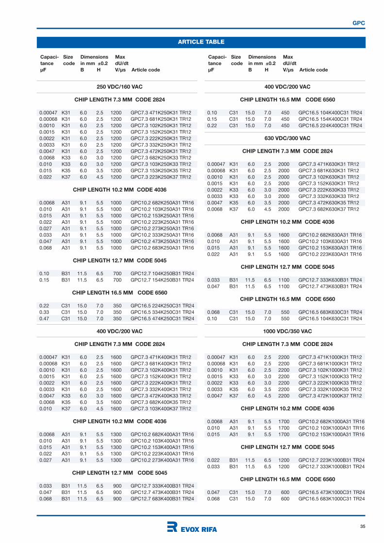
35
Capaci- Size Dimensions Max
tance code in mm ±0.2 dU/dt
µF B H V/µs Article code
Capaci- Size Dimensions Max
tance code in mm ±0.2 dU/dt
µF B H V/µs Article code
GPC
ARTICLE TABLE
400 VDC/200 VAC
CHIP LENGTH 16.5 MM CODE 6560
0.10 C31 15.0 7.0 450 GPC16.5 104K400C31 TR24
0.15 C31 15.0 7.0 450 GPC16.5 154K400C31 TR24
0.22 C31 15.0 7.0 450 GPC16.5 224K400C31 TR24
630 VDC/300 VAC
CHIP LENGTH 7.3 MM CODE 2824
0.00047 K31 6.0 2.5 2000 GPC7.3 471K630K31 TR12
0.00068 K31 6.0 2.5 2000 GPC7.3 681K630K31 TR12
0.0010 K31 6.0 2.5 2000 GPC7.3 102K630K31 TR12
0.0015 K31 6.0 2.5 2000 GPC7.3 152K630K31 TR12
0.0022 K33 6.0 3.0 2000 GPC7.3 222K630K33 TR12
0.0033 K33 6.0 3.0 2000 GPC7.3 332K630K33 TR12
0.0047 K35 6.0 3.5 2000 GPC7.3 472K630K35 TR12
0.0068 K37 6.0 4.5 2000 GPC7.3 682K630K37 TR12
CHIP LENGTH 10.2 MM CODE 4036
0.0068 A31 9.1 5.5 1600 GPC10.2 682K630A31 TR16
0.010 A31 9.1 5.5 1600 GPC10.2 103K630A31 TR16
0.015 A31 9.1 5.5 1600 GPC10.2 153K630A31 TR16
0.022 A31 9.1 5.5 1600 GPC10.2 223K630A31 TR16
CHIP LENGTH 12.7 MM CODE 5045
0.033 B31 11.5 6.5 1100 GPC12.7 333K630B31 TR24
0.047 B31 11.5 6.5 1100 GPC12.7 473K630B31 TR24
CHIP LENGTH 16.5 MM CODE 6560
0.068 C31 15.0 7.0 550 GPC16.5 683K630C31 TR24
0.10 C31 15.0 7.0 550 GPC16.5 104K630C31 TR24
1000 VDC/350 VAC
CHIP LENGTH 7.3 MM CODE 2824
0.00047 K31 6.0 2.5 2200 GPC7.3 471K1000K31 TR12
0.00068 K31 6.0 2.5 2200 GPC7.3 681K1000K31 TR12
0.0010 K31 6.0 2.5 2200 GPC7.3 102K1000K31 TR12
0.0015 K33 6.0 3.0 2200 GPC7.3 152K1000K33 TR12
0.0022 K33 6.0 3.0 2200 GPC7.3 222K1000K33 TR12
0.0033 K35 6.0 3.5 2200 GPC7.3 332K1000K35 TR12
0.0047 K37 6.0 4.5 2200 GPC7.3 472K1000K37 TR12
CHIP LENGTH 10.2 MM CODE 4036
0.0068 A31 9.1 5.5 1700 GPC10.2 682K1000A31 TR16
0.010 A31 9.1 5.5 1700 GPC10.2 103K1000A31 TR16
0.015 A31 9.1 5.5 1700 GPC10.2 153K1000A31 TR16
CHIP LENGTH 12.7 MM CODE 5045
0.022 B31 11.5 6.5 1200 GPC12.7 223K1000B31 TR24
0.033 B31 11.5 6.5 1200 GPC12.7 333K1000B31 TR24
CHIP LENGTH 16.5 MM CODE 6560
0.047 C31 15.0 7.0 600 GPC16.5 473K1000C31 TR24
0.068 C31 15.0 7.0 600 GPC16.5 683K1000C31 TR24
250 VDC/160 VAC
CHIP LENGTH 7.3 MM CODE 2824
0.00047 K31 6.0 2.5 1200 GPC7.3 471K250K31 TR12
0.00068 K31 6.0 2.5 1200 GPC7.3 681K250K31 TR12
0.0010 K31 6.0 2.5 1200 GPC7.3 102K250K31 TR12
0.0015 K31 6.0 2.5 1200 GPC7.3 152K250K31 TR12
0.0022 K31 6.0 2.5 1200 GPC7.3 222K250K31 TR12
0.0033 K31 6.0 2.5 1200 GPC7.3 332K250K31 TR12
0.0047 K31 6.0 2.5 1200 GPC7.3 472K250K31 TR12
0.0068 K33 6.0 3.0 1200 GPC7.3 682K250K33 TR12
0.010 K33 6.0 3.0 1200 GPC7.3 103K250K33 TR12
0.015 K35 6.0 3.5 1200 GPC7.3 153K250K35 TR12
0.022 K37 6.0 4.5 1200 GPC7.3 223K250K37 TR12
CHIP LENGTH 10.2 MM CODE 4036
0.0068 A31 9.1 5.5 1000 GPC10.2 682K250A31 TR16
0.010 A31 9.1 5.5 1000 GPC10.2 103K250A31 TR16
0.015 A31 9.1 5.5 1000 GPC10.2 153K250A31 TR16
0.022 A31 9.1 5.5 1000 GPC10.2 223K250A31 TR16
0.027 A31 9.1 5.5 1000 GPC10.2 273K250A31 TR16
0.033 A31 9.1 5.5 1000 GPC10.2 333K250A31 TR16
0.047 A31 9.1 5.5 1000 GPC10.2 473K250A31 TR16
0.068 A31 9.1 5.5 1000 GPC10.2 683K250A31 TR16
CHIP LENGTH 12.7 MM CODE 5045
0.10 B31 11.5 6.5 700 GPC12.7 104K250B31 TR24
0.15 B31 11.5 6.5 700 GPC12.7 154K250B31 TR24
CHIP LENGTH 16.5 MM CODE 6560
0.22 C31 15.0 7.0 350 GPC16.5 224K250C31 TR24
0.33 C31 15.0 7.0 350 GPC16.5 334K250C31 TR24
0.47 C31 15.0 7.0 350 GPC16.5 474K250C31 TR24
400 VDC/200 VAC
CHIP LENGTH 7.3 MM CODE 2824
0.00047 K31 6.0 2.5 1600 GPC7.3 471K400K31 TR12
0.00068 K31 6.0 2.5 1600 GPC7.3 681K400K31 TR12
0.0010 K31 6.0 2.5 1600 GPC7.3 102K400K31 TR12
0.0015 K31 6.0 2.5 1600 GPC7.3 152K400K31 TR12
0.0022 K31 6.0 2.5 1600 GPC7.3 222K400K31 TR12
0.0033 K31 6.0 2.5 1600 GPC7.3 332K400K31 TR12
0.0047 K33 6.0 3.0 1600 GPC7.3 472K400K33 TR12
0.0068 K35 6.0 3.5 1600 GPC7.3 682K400K35 TR12
0.010 K37 6.0 4.5 1600 GPC7.3 103K400K37 TR12
CHIP LENGTH 10.2 MM CODE 4036
0.0068 A31 9.1 5.5 1300 GPC10.2 682K400A31 TR16
0.010 A31 9.1 5.5 1300 GPC10.2 103K400A31 TR16
0.015 A31 9.1 5.5 1300 GPC10.2 153K400A31 TR16
0.022 A31 9.1 5.5 1300 GPC10.2 223K400A31 TR16
0.027 A31 9.1 5.5 1300 GPC10.2 273K400A31 TR16
CHIP LENGTH 12.7 MM CODE 5045
0.033 B31 11.5 6.5 900 GPC12.7 333K400B31 TR24
0.047 B31 11.5 6.5 900 GPC12.7 473K400B31 TR24
0.068 B31 11.5 6.5 900 GPC12.7 683K400B31 TR24

36
RoHSCompliant
SMC• Metallized polyphenylene sulphide (PPS) SMD
• According to IEC 60384-20
TYPICAL APPLICATIONS CONSTRUCTION
TECHNICAL DATA
RECOMMENDED SOLDERING
CONDITIONS
Timing, filtering. Memory capacitor. High
stability and accuracy. High temperature
use.
Polyphenylene sulphide (PPS) film
capacitor for surface mounting.
Encapsulation in self-extinguishing
material meeting the requirements of UL
94V-0.
Typical capacitance vs
temperature at 1 kHz
Typical dissipation factor vs
temperature at 1 kHz
Reflow soldering on the top body
surface of the component
Preheating temperature should be less
than 170°C. The time above 217°C should
be less than 50 s. The peak temperature
must not exceed 260°C.
Recommended reflow soldering profile
for products manufactured in March
2007 at the earliest. For detailed
information see page 19.
B
L
H
0.5
0.5
-50 -25 0 25 50 75 100 125 150 175
Temperature °C
5
4
3
2
1
0
-1
∆C/C%
-50 -25 0 25 50 75 100 125 150 175
Temperature °C
0.001
0.0008
0.0006
0.0004
0.0002
0
tan
Temperature ( C)
200
240
30 60 90 120 150 180 210
160
120
40
80
240 270 3303000
280
0
Time (s)
150 C
170 C
223 C
Max 260 C
Min. 30 s,
max 50 s
above 217 C
50 100 250 400
30 63 160 200
1 - 1 - 1 - 1 -
3300 1500 470 220
±5%, ±2.5%, ±2% other tolerances on request.
-55°C to +125°C
+100°C
The rated voltage should be decreased with 1.5%/°C
from +125°C to 175 °C.
55/125/56
1.6 x UR, 60s
Minimum value between terminals
Measured at +20°C according to IEC 60384-20.
C 0.33µF C > 0.33µF
UR
100 V 15 000 M 5 000 s
UR > 100 V 30 000 M 10 000 s
Max values at +23°C
C 100nF 100nF < C 1µF C > 1µF
1 kHz 0.15 % 0.15 % 0.15 %
10 kHz 0.25 % 0.25 % 0.30 %
100 kHz 0.50 % 0.60 %
The capacitors can withstand an unlimited number of
pulses with a dU/dt according to article table. For
voltages (U) lower than the rated voltage (UR), the
specified dU/dt can be multiplied by UR/U.
Rated voltage UR, VDC
Rated voltage UR, VAC
Capacitance range, nF
Capacitance tolerance
Category
temperature range
Rated temperature
Voltage derating
Climatic category
Voltage proof
Insulation resistance
Dissipation factor
Pulse rise time
Components may be vertically mounted
for decreased footprint. See page 20.
MARKING
• Rated capacitance
• Capacitance tolerance code
• Rated voltage code
• Capacitor type S for SMC
• Manufacturing date code according to
IEC 60062 (year, month)
See also page 18.
ORDERING INFORMATION
See article table and page 10 for options and article code construction.

37
SMC
ARTICLE TABLE
Capaci- Size Dimensions Max
tance code in mm ±0.2 dU/dt
µF B H V/µs Article code
Capaci- Size Dimensions Max
tance code in mm ±0.2 dU/dt
µF B H V/µs Article code
50 VDC/30 VAC
CHIP LENGTH 5.7 MM CODE 2220
0.0010 J31 5.0 2.5 20 SMC5.7 102J50J31 TR12
0.0012 J31 5.0 2.5 20 SMC5.7 122J50J31 TR12
0.0015 J31 5.0 2.5 20 SMC5.7 152J50J31 TR12
0.0018 J31 5.0 2.5 20 SMC5.7 182J50J31 TR12
0.0022 J31 5.0 2.5 20 SMC5.7 222J50J31 TR12
0.0027 J31 5.0 2.5 20 SMC5.7 272J50J31 TR12
0.0033 J31 5.0 2.5 20 SMC5.7 332J50J31 TR12
0.0039 J31 5.0 2.5 20 SMC5.7 392J50J31 TR12
0.0047 J31 5.0 2.5 20 SMC5.7 472J50J31 TR12
0.0056 J31 5.0 2.5 20 SMC5.7 562J50J31 TR12
0.0068 J31 5.0 2.5 20 SMC5.7 682J50J31 TR12
0.0082 J31 5.0 2.5 20 SMC5.7 822J50J31 TR12
0.010 J31 5.0 2.5 20 SMC5.7 103J50J31 TR12
0.012 J31 5.0 2.5 20 SMC5.7 123J50J31 TR12
0.015 J31 5.0 2.5 15 SMC5.7 153J50J31 TR12
0.018 J31 5.0 2.5 15 SMC5.7 183J50J31 TR12
0.022 J31 5.0 2.5 15 SMC5.7 223J50J31 TR12
0.027 J31 5.0 2.5 15 SMC5.7 273J50J31 TR12
0.033 J31 5.0 2.5 15 SMC5.7 333J50J31 TR12
0.039 J33 5.0 3.0 6 SMC5.7 393J50J33 TR12
0.047 J33 5.0 3.0 6 SMC5.7 473J50J33 TR12
0.056 J35 5.0 4.0 6 SMC5.7 563J50J35 TR12
0.068 J35 5.0 4.0 6 SMC5.7 683J50J35 TR12
0.082 J35 5.0 4.0 6 SMC5.7 823J50J35 TR12
0.10 J35 5.0 4.0 6 SMC5.7 104J50J35 TR12
CHIP LENGTH 7.3 MM CODE 2824
0.0010 K31 6.0 2.5 20 SMC7.3 102J50K31 TR12
0.0012 K31 6.0 2.5 20 SMC7.3 122J50K31 TR12
0.0015 K31 6.0 2.5 20 SMC7.3 152J50K31 TR12
0.0018 K31 6.0 2.5 20 SMC7.3 182J50K31 TR12
0.0022 K31 6.0 2.5 20 SMC7.3 222J50K31 TR12
0.0027 K31 6.0 2.5 20 SMC7.3 272J50K31 TR12
0.0033 K31 6.0 2.5 20 SMC7.3 332J50K31 TR12
0.0039 K31 6.0 2.5 20 SMC7.3 392J50K31 TR12
0.0047 K31 6.0 2.5 20 SMC7.3 472J50K31 TR12
0.0056 K31 6.0 2.5 20 SMC7.3 562J50K31 TR12
0.0068 K31 6.0 2.5 20 SMC7.3 682J50K31 TR12
0.0082 K31 6.0 2.5 20 SMC7.3 822J50K31 TR12
0.010 K31 6.0 2.5 20 SMC7.3 103J50K31 TR12
0.012 K31 6.0 2.5 20 SMC7.3 123J50K31 TR12
0.015 K31 6.0 2.5 20 SMC7.3 153J50K31 TR12
0.018 K31 6.0 2.5 20 SMC7.3 183J50K31 TR12
0.022 K31 6.0 2.5 20 SMC7.3 223J50K31 TR12
0.027 K31 6.0 2.5 20 SMC7.3 273J50K31 TR12
0.033 K31 6.0 2.5 15 SMC7.3 333J50K31 TR12
0.039 K31 6.0 2.5 15 SMC7.3 393J50K31 TR12
0.047 K31 6.0 2.5 15 SMC7.3 473J50K31 TR12
0.056 K31 6.0 2.5 15 SMC7.3 563J50K31 TR12
0.068 K31 6.0 2.5 15 SMC7.3 683J50K31 TR12
0.082 K33 6.0 3.0 6 SMC7.3 823J50K33 TR12
0.10 K33 6.0 3.0 6 SMC7.3 104J50K33 TR12
0.12 K35 6.0 3.5 6 SMC7.3 124J50K35 TR12
0.15 K35 6.0 3.5 6 SMC7.3 154J50K35 TR12
0.18 K35 6.0 3.5 6 SMC7.3 184J50K35 TR12
0.22 K37 6.0 4.5 6 SMC7.3 224J50K37 TR12
50 VDC/30 VAC
CHIP LENGTH 10.2 MM CODE 4036
0.010 A31 9.1 5.5 4 SMC10.2 103J50A31 TR16
0.012 A31 9.1 5.5 4 SMC10.2 123J50A31 TR16
0.015 A31 9.1 5.5 4 SMC10.2 153J50A31 TR16
0.018 A31 9.1 5.5 4 SMC10.2 183J50A31 TR16
0.022 A31 9.1 5.5 4 SMC10.2 223J50A31 TR16
0.027 A31 9.1 5.5 4 SMC10.2 273J50A31 TR16
0.033 A31 9.1 5.5 4 SMC10.2 333J50A31 TR16
0.039 A31 9.1 5.5 4 SMC10.2 393J50A31 TR16
0.047 A31 9.1 5.5 4 SMC10.2 473J50A31 TR16
0.056 A31 9.1 5.5 4 SMC10.2 563J50A31 TR16
0.068 A31 9.1 5.5 4 SMC10.2 683J50A31 TR16
0.082 A31 9.1 5.5 4 SMC10.2 823J50A31 TR16
0.10 A31 9.1 5.5 4 SMC10.2 104J50A31 TR16
0.12 A31 9.1 5.5 4 SMC10.2 124J50A31 TR16
0.15 A31 9.1 5.5 4 SMC10.2 154J50A31 TR16
0.18 A31 9.1 5.5 4 SMC10.2 184J50A31 TR16
0.22 A31 9.1 5.5 4 SMC10.2 224J50A31 TR16
0.27 A31 9.1 5.5 4 SMC10.2 274J50A31 TR16
0.33 A31 9.1 5.5 4 SMC10.2 334J50A31 TR16
0.39 A31 9.1 5.5 4 SMC10.2 394J50A31 TR16
0.47 A31 9.1 5.5 4 SMC10.2 474J50A31 TR16
0.56 A31 9.1 5.5 4 SMC10.2 564J50A31 TR16
0.68 A31 9.1 5.5 4 SMC10.2 684J50A31 TR16
0.82 A31 9.1 5.5 4 SMC10.2 824J50A31 TR16
CHIP LENGTH 12.7 MM CODE 5045
1.0 B31 11.5 6.5 3 SMC12.7 105J50B31 TR24
1.2 B31 11.5 6.5 3 SMC12.7 125J50B31 TR24
1.5 B31 11.5 6.5 3 SMC12.7 155J50B31 TR24
1.8 B31 11.5 6.5 3 SMC12.7 185J50B31 TR24
CHIP LENGTH 16.5 MM CODE 6560
2.2 C31 15.0 7.0 2 SMC16.5 225J50C31 TR24
2.7 C31 15.0 7.0 2 SMC16.5 275J50C31 TR24
3.3 C31 15.0 7.0 2 SMC16.5 335J50C31 TR24
100 VDC/63 VAC
CHIP LENGTH 5.7 MM CODE 2220
0.0010 J31 5.0 2.5 20 SMC5.7 102J100J31 TR12
0.0012 J31 5.0 2.5 20 SMC5.7 122J100J31 TR12
0.0015 J31 5.0 2.5 20 SMC5.7 152J100J31 TR12
0.0018 J31 5.0 2.5 20 SMC5.7 182J100J31 TR12
0.0022 J31 5.0 2.5 20 SMC5.7 222J100J31 TR12
0.0027 J31 5.0 2.5 20 SMC5.7 272J100J31 TR12
0.0033 J31 5.0 2.5 20 SMC5.7 332J100J31 TR12
0.0039 J31 5.0 2.5 20 SMC5.7 392J100J31 TR12
0.0047 J31 5.0 2.5 20 SMC5.7 472J100J31 TR12
0.0056 J31 5.0 2.5 20 SMC5.7 562J100J31 TR12
0.0068 J31 5.0 2.5 20 SMC5.7 682J100J31 TR12
0.0082 J31 5.0 2.5 20 SMC5.7 822J100J31 TR12
0.010 J31 5.0 2.5 20 SMC5.7 103J100J31 TR12
0.012 J31 5.0 2.5 20 SMC5.7 123J100J31 TR12
0.015 J31 5.0 2.5 15 SMC5.7 153J100J31 TR12
0.018 J33 5.0 3.0 15 SMC5.7 183J100J33 TR12
0.022 J33 5.0 3.0 15 SMC5.7 223J100J33 TR12
0.027 J35 5.0 4.0 15 SMC5.7 273J100J35 TR12
0.033 J35 5.0 4.0 15 SMC5.7 333J100J35 TR12
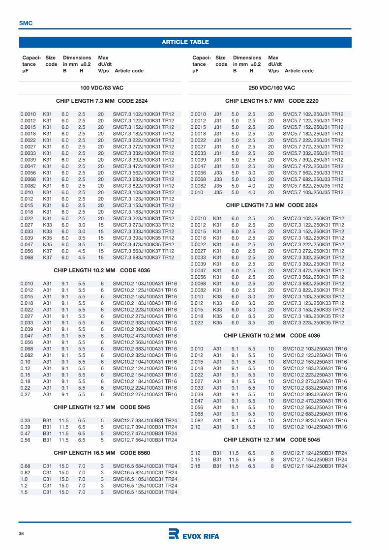
38
SMC
ARTICLE TABLE
Capaci- Size Dimensions Max
tance code in mm ±0.2 dU/dt
µF B H V/µs Article code
Capaci- Size Dimensions Max
tance code in mm ±0.2 dU/dt
µF B H V/µs Article code
100 VDC/63 VAC
CHIP LENGTH 7.3 MM CODE 2824
0.0010 K31 6.0 2.5 20 SMC7.3 102J100K31 TR12
0.0012 K31 6.0 2.5 20 SMC7.3 122J100K31 TR12
0.0015 K31 6.0 2.5 20 SMC7.3 152J100K31 TR12
0.0018 K31 6.0 2.5 20 SMC7.3 182J100K31 TR12
0.0022 K31 6.0 2.5 20 SMC7.3 222J100K31 TR12
0.0027 K31 6.0 2.5 20 SMC7.3 272J100K31 TR12
0.0033 K31 6.0 2.5 20 SMC7.3 332J100K31 TR12
0.0039 K31 6.0 2.5 20 SMC7.3 392J100K31 TR12
0.0047 K31 6.0 2.5 20 SMC7.3 472J100K31 TR12
0.0056 K31 6.0 2.5 20 SMC7.3 562J100K31 TR12
0.0068 K31 6.0 2.5 20 SMC7.3 682J100K31 TR12
0.0082 K31 6.0 2.5 20 SMC7.3 822J100K31 TR12
0.010 K31 6.0 2.5 20 SMC7.3 103J100K31 TR12
0.012 K31 6.0 2.5 20 SMC7.3 123J100K31 TR12
0.015 K31 6.0 2.5 20 SMC7.3 153J100K31 TR12
0.018 K31 6.0 2.5 20 SMC7.3 183J100K31 TR12
0.022 K31 6.0 2.5 20 SMC7.3 223J100K31 TR12
0.027 K33 6.0 3.0 15 SMC7.3 273J100K33 TR12
0.033 K33 6.0 3.0 15 SMC7.3 333J100K33 TR12
0.039 K35 6.0 3.5 15 SMC7.3 393J100K35 TR12
0.047 K35 6.0 3.5 15 SMC7.3 473J100K35 TR12
0.056 K37 6.0 4.5 15 SMC7.3 563J100K37 TR12
0.068 K37 6.0 4.5 15 SMC7.3 683J100K37 TR12
CHIP LENGTH 10.2 MM CODE 4036
0.010 A31 9.1 5.5 6 SMC10.2 103J100A31 TR16
0.012 A31 9.1 5.5 6 SMC10.2 123J100A31 TR16
0.015 A31 9.1 5.5 6 SMC10.2 153J100A31 TR16
0.018 A31 9.1 5.5 6 SMC10.2 183J100A31 TR16
0.022 A31 9.1 5.5 6 SMC10.2 223J100A31 TR16
0.027 A31 9.1 5.5 6 SMC10.2 273J100A31 TR16
0.033 A31 9.1 5.5 6 SMC10.2 333J100A31 TR16
0.039 A31 9.1 5.5 6 SMC10.2 393J100A31 TR16
0.047 A31 9.1 5.5 6 SMC10.2 473J100A31 TR16
0.056 A31 9.1 5.5 6 SMC10.2 563J100A31 TR16
0.068 A31 9.1 5.5 6 SMC10.2 683J100A31 TR16
0.082 A31 9.1 5.5 6 SMC10.2 823J100A31 TR16
0.10 A31 9.1 5.5 6 SMC10.2 104J100A31 TR16
0.12 A31 9.1 5.5 6 SMC10.2 124J100A31 TR16
0.15 A31 9.1 5.5 6 SMC10.2 154J100A31 TR16
0.18 A31 9.1 5.5 6 SMC10.2 184J100A31 TR16
0.22 A31 9.1 5.5 6 SMC10.2 224J100A31 TR16
0.27 A31 9.1 5.5 6 SMC10.2 274J100A31 TR16
CHIP LENGTH 12.7 MM CODE 5045
0.33 B31 11.5 6.5 5 SMC12.7 334J100B31 TR24
0.39 B31 11.5 6.5 5 SMC12.7 394J100B31 TR24
0.47 B31 11.5 6.5 5 SMC12.7 474J100B31 TR24
0.56 B31 11.5 6.5 5 SMC12.7 564J100B31 TR24
CHIP LENGTH 16.5 MM CODE 6560
0.68 C31 15.0 7.0 3 SMC16.5 684J100C31 TR24
0.82 C31 15.0 7.0 3 SMC16.5 824J100C31 TR24
1.0 C31 15.0 7.0 3 SMC16.5 105J100C31 TR24
1.2 C31 15.0 7.0 3 SMC16.5 125J100C31 TR24
1.5 C31 15.0 7.0 3 SMC16.5 155J100C31 TR24
250 VDC/160 VAC
CHIP LENGTH 5.7 MM CODE 2220
0.0010 J31 5.0 2.5 20 SMC5.7 102J250J31 TR12
0.0012 J31 5.0 2.5 20 SMC5.7 122J250J31 TR12
0.0015 J31 5.0 2.5 20 SMC5.7 152J250J31 TR12
0.0018 J31 5.0 2.5 20 SMC5.7 182J250J31 TR12
0.0022 J31 5.0 2.5 20 SMC5.7 222J250J31 TR12
0.0027 J31 5.0 2.5 20 SMC5.7 272J250J31 TR12
0.0033 J31 5.0 2.5 20 SMC5.7 332J250J31 TR12
0.0039 J31 5.0 2.5 20 SMC5.7 392J250J31 TR12
0.0047 J31 5.0 2.5 20 SMC5.7 472J250J31 TR12
0.0056 J33 5.0 3.0 20 SMC5.7 562J250J33 TR12
0.0068 J33 5.0 3.0 20 SMC5.7 682J250J33 TR12
0.0082 J35 5.0 4.0 20 SMC5.7 822J250J35 TR12
0.010 J35 5.0 4.0 20 SMC5.7 103J250J35 TR12
CHIP LENGTH 7.3 MM CODE 2824
0.0010 K31 6.0 2.5 20 SMC7.3 102J250K31 TR12
0.0012 K31 6.0 2.5 20 SMC7.3 122J250K31 TR12
0.0015 K31 6.0 2.5 20 SMC7.3 152J250K31 TR12
0.0018 K31 6.0 2.5 20 SMC7.3 182J250K31 TR12
0.0022 K31 6.0 2.5 20 SMC7.3 222J250K31 TR12
0.0027 K31 6.0 2.5 20 SMC7.3 272J250K31 TR12
0.0033 K31 6.0 2.5 20 SMC7.3 332J250K31 TR12
0.0039 K31 6.0 2.5 20 SMC7.3 392J250K31 TR12
0.0047 K31 6.0 2.5 20 SMC7.3 472J250K31 TR12
0.0056 K31 6.0 2.5 20 SMC7.3 562J250K31 TR12
0.0068 K31 6.0 2.5 20 SMC7.3 682J250K31 TR12
0.0082 K31 6.0 2.5 20 SMC7.3 822J250K31 TR12
0.010 K33 6.0 3.0 20 SMC7.3 103J250K33 TR12
0.012 K33 6.0 3.0 20 SMC7.3 123J250K33 TR12
0.015 K33 6.0 3.0 20 SMC7.3 153J250K33 TR12
0.018 K35 6.0 3.5 20 SMC7.3 183J250K35 TR12
0.022 K35 6.0 3.5 20 SMC7.3 223J250K35 TR12
CHIP LENGTH 10.2 MM CODE 4036
0.010 A31 9.1 5.5 10 SMC10.2 103J250A31 TR16
0.012 A31 9.1 5.5 10 SMC10.2 123J250A31 TR16
0.015 A31 9.1 5.5 10 SMC10.2 153J250A31 TR16
0.018 A31 9.1 5.5 10 SMC10.2 183J250A31 TR16
0.022 A31 9.1 5.5 10 SMC10.2 223J250A31 TR16
0.027 A31 9.1 5.5 10 SMC10.2 273J250A31 TR16
0.033 A31 9.1 5.5 10 SMC10.2 333J250A31 TR16
0.039 A31 9.1 5.5 10 SMC10.2 393J250A31 TR16
0.047 A31 9.1 5.5 10 SMC10.2 473J250A31 TR16
0.056 A31 9.1 5.5 10 SMC10.2 563J250A31 TR16
0.068 A31 9.1 5.5 10 SMC10.2 683J250A31 TR16
0.082 A31 9.1 5.5 10 SMC10.2 823J250A31 TR16
0.10 A31 9.1 5.5 10 SMC10.2 104J250A31 TR16
CHIP LENGTH 12.7 MM CODE 5045
0.12 B31 11.5 6.5 8 SMC12.7 124J250B31 TR24
0.15 B31 11.5 6.5 8 SMC12.7 154J250B31 TR24
0.18 B31 11.5 6.5 8 SMC12.7 184J250B31 TR24
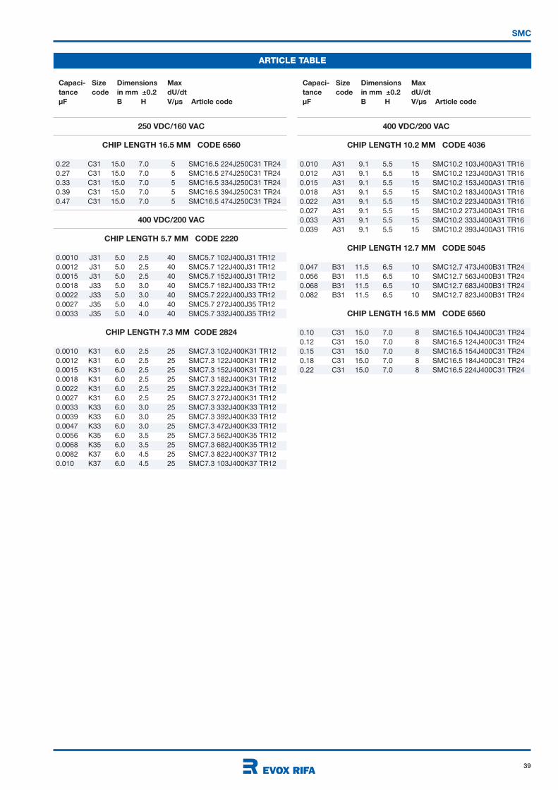
39
SMC
ARTICLE TABLE
Capaci- Size Dimensions Max
tance code in mm ±0.2 dU/dt
µF B H V/µs Article code
Capaci- Size Dimensions Max
tance code in mm ±0.2 dU/dt
µF B H V/µs Article code
250 VDC/160 VAC
CHIP LENGTH 16.5 MM CODE 6560
0.22 C31 15.0 7.0 5 SMC16.5 224J250C31 TR24
0.27 C31 15.0 7.0 5 SMC16.5 274J250C31 TR24
0.33 C31 15.0 7.0 5 SMC16.5 334J250C31 TR24
0.39 C31 15.0 7.0 5 SMC16.5 394J250C31 TR24
0.47 C31 15.0 7.0 5 SMC16.5 474J250C31 TR24
400 VDC/200 VAC
CHIP LENGTH 5.7 MM CODE 2220
0.0010 J31 5.0 2.5 40 SMC5.7 102J400J31 TR12
0.0012 J31 5.0 2.5 40 SMC5.7 122J400J31 TR12
0.0015 J31 5.0 2.5 40 SMC5.7 152J400J31 TR12
0.0018 J33 5.0 3.0 40 SMC5.7 182J400J33 TR12
0.0022 J33 5.0 3.0 40 SMC5.7 222J400J33 TR12
0.0027 J35 5.0 4.0 40 SMC5.7 272J400J35 TR12
0.0033 J35 5.0 4.0 40 SMC5.7 332J400J35 TR12
CHIP LENGTH 7.3 MM CODE 2824
0.0010 K31 6.0 2.5 25 SMC7.3 102J400K31 TR12
0.0012 K31 6.0 2.5 25 SMC7.3 122J400K31 TR12
0.0015 K31 6.0 2.5 25 SMC7.3 152J400K31 TR12
0.0018 K31 6.0 2.5 25 SMC7.3 182J400K31 TR12
0.0022 K31 6.0 2.5 25 SMC7.3 222J400K31 TR12
0.0027 K31 6.0 2.5 25 SMC7.3 272J400K31 TR12
0.0033 K33 6.0 3.0 25 SMC7.3 332J400K33 TR12
0.0039 K33 6.0 3.0 25 SMC7.3 392J400K33 TR12
0.0047 K33 6.0 3.0 25 SMC7.3 472J400K33 TR12
0.0056 K35 6.0 3.5 25 SMC7.3 562J400K35 TR12
0.0068 K35 6.0 3.5 25 SMC7.3 682J400K35 TR12
0.0082 K37 6.0 4.5 25 SMC7.3 822J400K37 TR12
0.010 K37 6.0 4.5 25 SMC7.3 103J400K37 TR12
400 VDC/200 VAC
CHIP LENGTH 10.2 MM CODE 4036
0.010 A31 9.1 5.5 15 SMC10.2 103J400A31 TR16
0.012 A31 9.1 5.5 15 SMC10.2 123J400A31 TR16
0.015 A31 9.1 5.5 15 SMC10.2 153J400A31 TR16
0.018 A31 9.1 5.5 15 SMC10.2 183J400A31 TR16
0.022 A31 9.1 5.5 15 SMC10.2 223J400A31 TR16
0.027 A31 9.1 5.5 15 SMC10.2 273J400A31 TR16
0.033 A31 9.1 5.5 15 SMC10.2 333J400A31 TR16
0.039 A31 9.1 5.5 15 SMC10.2 393J400A31 TR16
CHIP LENGTH 12.7 MM CODE 5045
0.047 B31 11.5 6.5 10 SMC12.7 473J400B31 TR24
0.056 B31 11.5 6.5 10 SMC12.7 563J400B31 TR24
0.068 B31 11.5 6.5 10 SMC12.7 683J400B31 TR24
0.082 B31 11.5 6.5 10 SMC12.7 823J400B31 TR24
CHIP LENGTH 16.5 MM CODE 6560
0.10 C31 15.0 7.0 8 SMC16.5 104J400C31 TR24
0.12 C31 15.0 7.0 8 SMC16.5 124J400C31 TR24
0.15 C31 15.0 7.0 8 SMC16.5 154J400C31 TR24
0.18 C31 15.0 7.0 8 SMC16.5 184J400C31 TR24
0.22 C31 15.0 7.0 8 SMC16.5 224J400C31 TR24
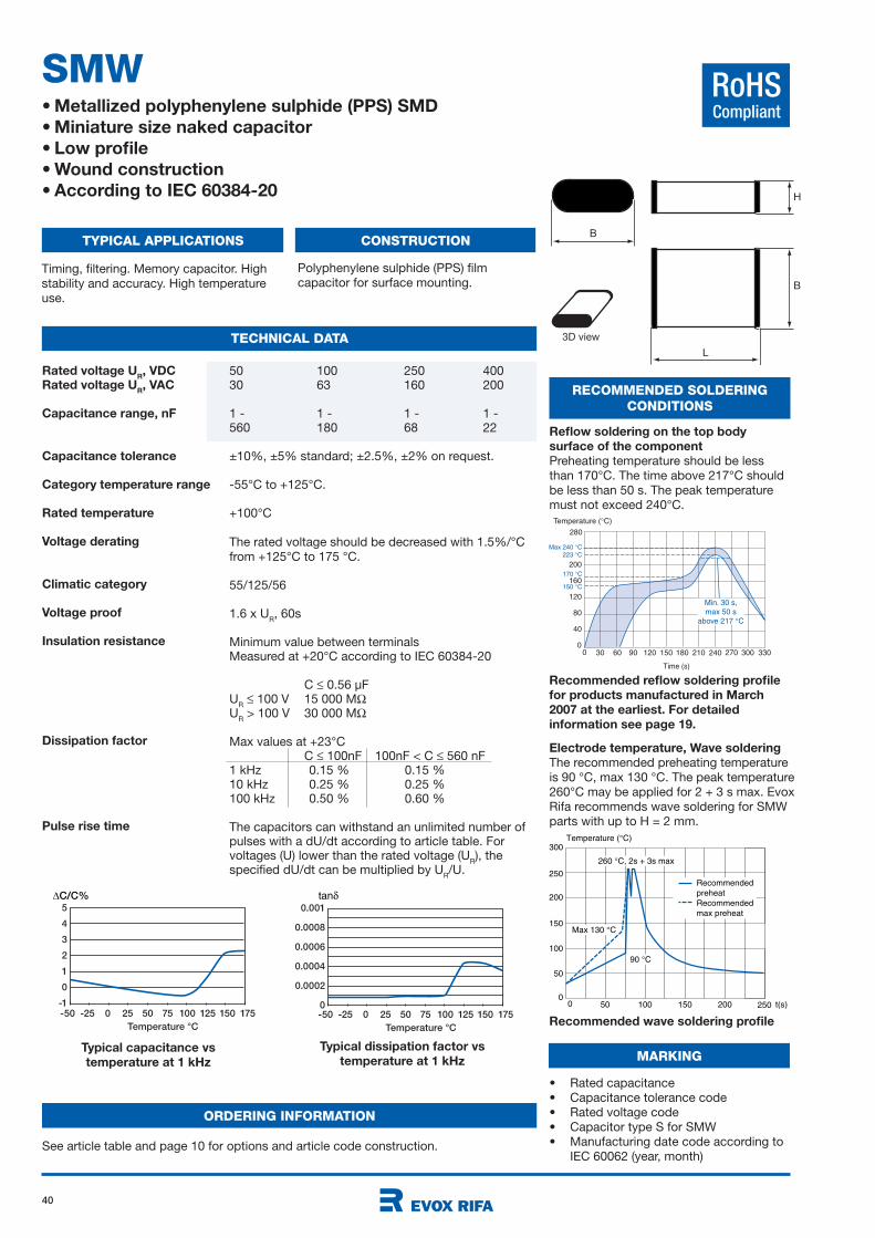
40
RoHSCompliant
Typical capacitance vs
temperature at 1 kHz
Typical dissipation factor vs
temperature at 1 kHz
-50 -25 0 25 50 75 100 125 150 175
Temperature °C
5
4
3
2
1
0
-1
∆C/C%
-50 -25 0 25 50 75 100 125 150 175
Temperature °C
0.001
0.0008
0.0006
0.0004
0.0002
0
tan
SMW• Metallized polyphenylene sulphide (PPS) SMD
• Miniature size naked capacitor
• Low profile
• Wound construction
• According to IEC 60384-20
TYPICAL APPLICATIONS CONSTRUCTION
TECHNICAL DATA
Timing, filtering. Memory capacitor. High
stability and accuracy. High temperature
use.
Polyphenylene sulphide (PPS) film
capacitor for surface mounting.
B
B
H
L
3D view
50 100 250 40030 63 160 200
1 - 1 - 1 - 1 -560 180 68 22
±10%, ±5% standard; ±2.5%, ±2% on request.
-55°C to +125°C.
+100°C
The rated voltage should be decreased with 1.5%/°C
from +125°C to 175 °C.
55/125/56
1.6 x UR, 60s
Minimum value between terminalsMeasured at +20°C according to IEC 60384-20
C 0.56 µFU
R 100 V 15 000 M
UR > 100 V 30 000 M
Max values at +23°CC 100nF 100nF < C 560 nF
1 kHz 0.15 % 0.15 %10 kHz 0.25 % 0.25 %100 kHz 0.50 % 0.60 %
The capacitors can withstand an unlimited number of pulses with a dU/dt according to article table. For voltages (U) lower than the rated voltage (U
R), the
specified dU/dt can be multiplied by UR/U.
Rated voltage UR, VDC
Rated voltage UR, VAC
Capacitance range, nF
Capacitance tolerance
Category temperature range
Rated temperature
Voltage derating
Climatic category
Voltage proof
Insulation resistance
Dissipation factor
Pulse rise time
RECOMMENDED SOLDERING
CONDITIONS
Reflow soldering on the top body
surface of the component
Preheating temperature should be less
than 170°C. The time above 217°C should
be less than 50 s. The peak temperature
must not exceed 240°C.
Recommended reflow soldering profile
for products manufactured in March
2007 at the earliest. For detailed
information see page 19.
Temperature ( C)
200
30 60 90 120 150 180 210
160
120
40
80
240 270 3303000
280
0
Time (s)
150 C
170 C
223 C
Max 240 C
Min. 30 s,
max 50 s
above 217 C
Temperature ( C)
200
25050 100 t(s)150 200
150
100
50
250
300
00
Max 130 C
90 C
260 C, 2s + 3s max
Recommended
preheat
Recommended
max preheat
Recommended wave soldering profile
MARKING
• Rated capacitance
• Capacitance tolerance code
• Rated voltage code
• Capacitor type S for SMW
• Manufacturing date code according to
IEC 60062 (year, month)
Electrode temperature, Wave soldering
The recommended preheating temperature
is 90 °C, max 130 °C. The peak temperature
260°C may be applied for 2 + 3 s max. Evox
Rifa recommends wave soldering for SMW
parts with up to H = 2 mm.
ORDERING INFORMATION
See article table and page 10 for options and article code construction.
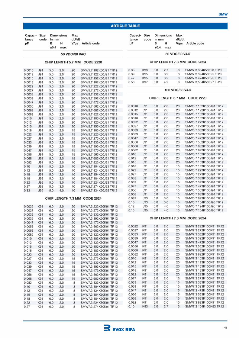
41
SMW
ARTICLE TABLE
Capaci- Size Dimensions Max
tance code in mm dU/dt
µF B H V/µs Article code
±0.4 max
Capaci- Size Dimensions Max
tance code in mm dU/dt
µF B H V/µs Article code
±0.4 max
50 VDC/30 VAC
CHIP LENGTH 5.7 MM CODE 2220
0.0010 J91 5.0 2.0 20 SMW5.7 102K50J91 TR12
0.0012 J91 5.0 2.0 20 SMW5.7 122K50J91 TR12
0.0015 J91 5.0 2.0 20 SMW5.7 152K50J91 TR12
0.0018 J91 5.0 2.0 20 SMW5.7 182K50J91 TR12
0.0022 J91 5.0 2.0 20 SMW5.7 222K50J91 TR12
0.0027 J91 5.0 2.0 20 SMW5.7 272K50J91 TR12
0.0033 J91 5.0 2.0 20 SMW5.7 332K50J91 TR12
0.0039 J91 5.0 2.0 20 SMW5.7 392K50J91 TR12
0.0047 J91 5.0 2.0 20 SMW5.7 472K50J91 TR12
0.0056 J91 5.0 2.0 20 SMW5.7 562K50J91 TR12
0.0068 J91 5.0 2.0 20 SMW5.7 682K50J91 TR12
0.0082 J91 5.0 2.0 20 SMW5.7 822K50J91 TR12
0.010 J91 5.0 2.0 20 SMW5.7 103K50J91 TR12
0.012 J91 5.0 2.0 20 SMW5.7 123K50J91 TR12
0.015 J91 5.0 2.0 20 SMW5.7 153K50J91 TR12
0.018 J91 5.0 2.0 15 SMW5.7 183K50J91 TR12
0.022 J91 5.0 2.0 15 SMW5.7 223K50J91 TR12
0.027 J91 5.0 2.0 15 SMW5.7 273K50J91 TR12
0.033 J91 5.0 2.0 15 SMW5.7 333K50J91 TR12
0.039 J91 5.0 2.0 15 SMW5.7 393K50J91 TR12
0.047 J91 5.0 2.0 15 SMW5.7 473K50J91 TR12
0.056 J91 5.0 2.0 15 SMW5.7 563K50J91 TR12
0.068 J91 5.0 2.0 15 SMW5.7 683K50J91 TR12
0.082 J91 5.0 2.0 10 SMW5.7 823K50J91 TR12
0.10 J91 5.0 2.0 10 SMW5.7 104K50J91 TR12
0.12 J91 5.0 2.0 10 SMW5.7 124K50J91 TR12
0.15 J91 5.0 2.0 10 SMW5.7 154K50J91 TR12
0.18 J93 5.0 3.0 10 SMW5.7 184K50J93 TR12
0.22 J93 5.0 3.0 10 SMW5.7 224K50J93 TR12
0.27 J93 5.0 3.0 10 SMW5.7 274K50J93 TR12
0.33 J95 5.0 4.0 10 SMW5.7 334K50J95 TR12
CHIP LENGTH 7.3 MM CODE 2824
0.0022 K91 6.0 2.0 20 SMW7.3 222K50K91 TR12
0.0027 K91 6.0 2.0 20 SMW7.3 272K50K91 TR12
0.0033 K91 6.0 2.0 20 SMW7.3 332K50K91 TR12
0.0039 K91 6.0 2.0 20 SMW7.3 392K50K91 TR12
0.0047 K91 6.0 2.0 20 SMW7.3 472K50K91 TR12
0.0056 K91 6.0 2.0 20 SMW7.3 562K50K91 TR12
0.0068 K91 6.0 2.0 20 SMW7.3 682K50K91 TR12
0.0082 K91 6.0 2.0 20 SMW7.3 822K50K91 TR12
0.010 K91 6.0 2.0 20 SMW7.3 103K50K91 TR12
0.012 K91 6.0 2.0 20 SMW7.3 123K50K91 TR12
0.015 K91 6.0 2.0 20 SMW7.3 153K50K91 TR12
0.018 K91 6.0 2.0 20 SMW7.3 183K50K91 TR12
0.022 K91 6.0 2.0 20 SMW7.3 223K50K91 TR12
0.027 K91 6.0 2.0 15 SMW7.3 273K50K91 TR12
0.033 K91 6.0 2.0 15 SMW7.3 333K50K91 TR12
0.039 K91 6.0 2.0 15 SMW7.3 393K50K91 TR12
0.047 K91 6.0 2.0 15 SMW7.3 473K50K91 TR12
0.056 K91 6.0 2.0 15 SMW7.3 563K50K91 TR12
0.068 K91 6.0 2.0 15 SMW7.3 683K50K91 TR12
0.082 K91 6.0 2.0 8 SMW7.3 823K50K91 TR12
0.10 K91 6.0 2.0 8 SMW7.3 104K50K91 TR12
0.12 K91 6.0 2.0 8 SMW7.3 124K50K91 TR12
0.15 K91 6.0 2.0 8 SMW7.3 154K50K91 TR12
0.18 K91 6.0 2.0 8 SMW7.3 184K50K91 TR12
0.22 K91 6.0 2.0 8 SMW7.3 224K50K91 TR12
0.27 K91 6.0 2.0 8 SMW7.3 274K50K91 TR12
50 VDC/30 VAC
CHIP LENGTH 7.3 MM CODE 2824
0.33 K93 6.0 2.7 8 SMW7.3 334K50K93 TR12
0.39 K95 6.0 3.2 8 SMW7.3 394K50K95 TR12
0.47 K95 6.0 3.2 8 SMW7.3 474K50K95 TR12
0.56 K97 6.0 4.2 8 SMW7.3 564K50K97 TR12
100 VDC/63 VAC
CHIP LENGTH 5.7 MM CODE 2220
0.0010 J91 5.0 2.0 20 SMW5.7 102K100J91 TR12
0.0012 J91 5.0 2.0 20 SMW5.7 122K100J91 TR12
0.0015 J91 5.0 2.0 20 SMW5.7 152K100J91 TR12
0.0018 J91 5.0 2.0 20 SMW5.7 182K100J91 TR12
0.0022 J91 5.0 2.0 20 SMW5.7 222K100J91 TR12
0.0027 J91 5.0 2.0 20 SMW5.7 272K100J91 TR12
0.0033 J91 5.0 2.0 20 SMW5.7 332K100J91 TR12
0.0039 J91 5.0 2.0 20 SMW5.7 392K100J91 TR12
0.0047 J91 5.0 2.0 20 SMW5.7 472K100J91 TR12
0.0056 J91 5.0 2.0 20 SMW5.7 562K100J91 TR12
0.0068 J91 5.0 2.0 20 SMW5.7 682K100J91 TR12
0.0082 J91 5.0 2.0 20 SMW5.7 822K100J91 TR12
0.010 J91 5.0 2.0 20 SMW5.7 103K100J91 TR12
0.012 J91 5.0 2.0 20 SMW5.7 123K100J91 TR12
0.015 J91 5.0 2.0 20 SMW5.7 153K100J91 TR12
0.018 J91 5.0 2.0 15 SMW5.7 183K100J91 TR12
0.022 J91 5.0 2.0 15 SMW5.7 223K100J91 TR12
0.027 J91 5.0 2.0 15 SMW5.7 273K100J91 TR12
0.033 J91 5.0 2.0 15 SMW5.7 333K100J91 TR12
0.039 J91 5.0 2.0 15 SMW5.7 393K100J91 TR12
0.047 J91 5.0 2.0 15 SMW5.7 473K100J91 TR12
0.056 J91 5.0 2.0 15 SMW5.7 563K100J91 TR12
0.068 J91 5.0 2.0 15 SMW5.7 683K100J91 TR12
0.082 J93 5.0 3.0 15 SMW5.7 823K100J93 TR12
0.10 J93 5.0 3.0 15 SMW5.7 104K100J93 TR12
0.12 J95 5.0 4.0 15 SMW5.7 124K100J95 TR12
0.15 J95 5.0 4.0 15 SMW5.7 154K100J95 TR12
CHIP LENGTH 7.3 MM CODE 2824
0.0022 K91 6.0 2.0 20 SMW7.3 222K100K91 TR12
0.0027 K91 6.0 2.0 20 SMW7.3 272K100K91 TR12
0.0033 K91 6.0 2.0 20 SMW7.3 332K100K91 TR12
0.0039 K91 6.0 2.0 20 SMW7.3 392K100K91 TR12
0.0047 K91 6.0 2.0 20 SMW7.3 472K100K91 TR12
0.0056 K91 6.0 2.0 20 SMW7.3 562K100K91 TR12
0.0068 K91 6.0 2.0 20 SMW7.3 682K100K91 TR12
0.0082 K91 6.0 2.0 20 SMW7.3 822K100K91 TR12
0.010 K91 6.0 2.0 20 SMW7.3 103K100K91 TR12
0.012 K91 6.0 2.0 20 SMW7.3 123K100K91 TR12
0.015 K91 6.0 2.0 20 SMW7.3 153K100K91 TR12
0.018 K91 6.0 2.0 20 SMW7.3 183K100K91 TR12
0.022 K91 6.0 2.0 20 SMW7.3 223K100K91 TR12
0.027 K91 6.0 2.0 15 SMW7.3 273K100K91 TR12
0.033 K91 6.0 2.0 15 SMW7.3 333K100K91 TR12
0.039 K91 6.0 2.0 15 SMW7.3 393K100K91 TR12
0.047 K91 6.0 2.0 15 SMW7.3 473K100K91 TR12
0.056 K91 6.0 2.0 15 SMW7.3 563K100K91 TR12
0.068 K91 6.0 2.0 15 SMW7.3 683K100K91 TR12
0.082 K91 6.0 2.0 15 SMW7.3 823K100K91 TR12
0.10 K93 6.0 2.7 15 SMW7.3 104K100K93 TR12

42
Capaci- Size Dimensions Max
tance code in mm dU/dt
µF B H V/µs Article code
±0.4 max
Capaci- Size Dimensions Max
tance code in mm dU/dt
µF B H V/µs Article code
±0.4 max
ARTICLE TABLE
400 VDC/200 VAC
CHIP LENGTH 5.7 MM CODE 2220
0.0010 J91 5.0 2.0 20 SMW5.7 102K400J91 TR12
0.0012 J91 5.0 2.0 20 SMW5.7 122K400J91 TR12
0.0015 J91 5.0 2.0 20 SMW5.7 152K400J91 TR12
0.0018 J91 5.0 2.0 20 SMW5.7 182K400J91 TR12
0.0022 J91 5.0 2.0 20 SMW5.7 222K400J91 TR12
0.0027 J91 5.0 2.0 20 SMW5.7 272K400J91 TR12
0.0033 J91 5.0 2.0 20 SMW5.7 332K400J91 TR12
0.0039 J91 5.0 2.0 20 SMW5.7 392K400J91 TR12
0.0047 J91 5.0 2.0 20 SMW5.7 472K400J91 TR12
0.0056 J93 5.0 3.0 20 SMW5.7 562K400J93 TR12
0.0068 J93 5.0 3.0 20 SMW5.7 682K400J93 TR12
0.0082 J93 5.0 3.0 20 SMW5.7 822K400J93 TR12
0.010 J93 5.0 3.0 20 SMW5.7 103K400J93 TR12
0.012 J95 5.0 4.0 20 SMW5.7 123K400J95 TR12
0.015 J95 5.0 4.0 20 SMW5.7 153K400J95 TR12
CHIP LENGTH 7.3 MM CODE 2824
0.0022 K91 6.0 2.0 20 SMW7.3 222K400K91 TR12
0.0027 K91 6.0 2.0 20 SMW7.3 272K400K91 TR12
0.0033 K91 6.0 2.0 20 SMW7.3 332K400K91 TR12
0.0039 K91 6.0 2.0 20 SMW7.3 392K400K91 TR12
0.0047 K91 6.0 2.0 20 SMW7.3 472K400K91 TR12
0.0056 K91 6.0 2.0 20 SMW7.3 562K400K91 TR12
0.0068 K91 6.0 2.0 20 SMW7.3 682K400K91 TR12
0.0082 K91 6.0 2.0 20 SMW7.3 822K400K91 TR12
0.010 K91 6.0 2.0 20 SMW7.3 103K400K91 TR12
0.012 K93 6.0 2.7 20 SMW7.3 123K400K93 TR12
0.015 K93 6.0 2.7 20 SMW7.3 153K400K93 TR12
0.018 K95 6.0 3.2 20 SMW7.3 183K400K95 TR12
0.022 K95 6.0 3.2 20 SMW7.3 223K400K95 TR12
100 VDC/63 VAC
CHIP LENGTH 7.3 MM CODE 2824
0.12 K93 6.0 2.7 15 SMW7.3 124K100K93 TR12
0.15 K95 6.0 3.2 15 SMW7.3 154K100K95 TR12
0.18 K97 6.0 4.2 15 SMW7.3 184K100K97 TR12
250 VDC/160 VAC
CHIP LENGTH 5.7 MM CODE 2220
0.0010 J91 5.0 2.0 20 SMW5.7 102K250J91 TR12
0.0012 J91 5.0 2.0 20 SMW5.7 122K250J91 TR12
0.0015 J91 5.0 2.0 20 SMW5.7 152K250J91 TR12
0.0018 J91 5.0 2.0 20 SMW5.7 182K250J91 TR12
0.0022 J91 5.0 2.0 20 SMW5.7 222K250J91 TR12
0.0027 J91 5.0 2.0 20 SMW5.7 272K250J91 TR12
0.0033 J91 5.0 2.0 20 SMW5.7 332K250J91 TR12
0.0039 J91 5.0 2.0 20 SMW5.7 392K250J91 TR12
0.0047 J91 5.0 2.0 20 SMW5.7 472K250J91 TR12
0.0056 J91 5.0 2.0 20 SMW5.7 562K250J91 TR12
0.0068 J91 5.0 2.0 20 SMW5.7 682K250J91 TR12
0.0082 J91 5.0 2.0 20 SMW5.7 822K250J91 TR12
0.010 J91 5.0 2.0 20 SMW5.7 103K250J91 TR12
0.012 J91 5.0 2.0 20 SMW5.7 123K250J91 TR12
0.015 J91 5.0 2.0 20 SMW5.7 153K250J91 TR12
0.018 J93 5.0 3.0 20 SMW5.7 183K250J93 TR12
0.022 J93 5.0 3.0 20 SMW5.7 223K250J93 TR12
0.027 J93 5.0 3.0 20 SMW5.7 273K250J93 TR12
0.033 J95 5.0 4.0 20 SMW5.7 333K250J95 TR12
CHIP LENGTH 7.3 MM CODE 2824
0.0022 K91 6.0 2.0 20 SMW7.3 222K250K91 TR12
0.0027 K91 6.0 2.0 20 SMW7.3 272K250K91 TR12
0.0033 K91 6.0 2.0 20 SMW7.3 332K250K91 TR12
0.0039 K91 6.0 2.0 20 SMW7.3 392K250K91 TR12
0.0047 K91 6.0 2.0 20 SMW7.3 472K250K91 TR12
0.0056 K91 6.0 2.0 20 SMW7.3 562K250K91 TR12
0.0068 K91 6.0 2.0 20 SMW7.3 682K250K91 TR12
0.0082 K91 6.0 2.0 20 SMW7.3 822K250K91 TR12
0.010 K91 6.0 2.0 20 SMW7.3 103K250K91 TR12
0.012 K91 6.0 2.0 20 SMW7.3 123K250K91 TR12
0.015 K91 6.0 2.0 20 SMW7.3 153K250K91 TR12
0.018 K91 6.0 2.0 20 SMW7.3 183K250K91 TR12
0.022 K91 6.0 2.0 20 SMW7.3 223K250K91 TR12
0.027 K91 6.0 2.0 15 SMW7.3 273K250K91 TR12
0.033 K93 6.0 2.7 15 SMW7.3 333K250K93 TR12
0.039 K93 6.0 2.7 15 SMW7.3 393K250K93 TR12
0.047 K95 6.0 3.2 15 SMW7.3 473K250K95 TR12
0.056 K97 6.0 4.2 15 SMW7.3 563K250K97 TR12
0.068 K97 6.0 4.2 15 SMW7.3 683K250K97 TR12
SMW
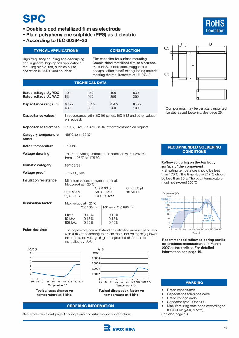
43
RoHSCompliant
SPC• Double sided metallized film as electrode
• Plain polyphenylene sulphide (PPS) as dielectric
• According to IEC 60384-20
TYPICAL APPLICATIONS CONSTRUCTION
TECHNICAL DATA
RECOMMENDED SOLDERING
CONDITIONS
High frequency coupling and decoupling
and in general high speed applications
requiring high dU/dt, such as pulse
operation in SMPS and snubber.
Film capacitor for surface mounting.
Double sided metallized film as electrode.
Plain PPS as dielectric. Rugged box
encapsulation in self-extinguishing material
meeting the requirements of UL 94V-0.
Typical capacitance vs
temperature at 1 kHz
Typical dissipation factor vs
temperature at 1 kHz
Reflow soldering on the top body
surface of the component
Preheating temperature should be less
than 170°C. The time above 217°C should
be less than 50 s. The peak temperature
must not exceed 255°C.
Recommended reflow soldering profile
for products manufactured in March
2007 at the earliest. For detailed
information see page 19.
B
L
H
0.5
0.5
-50 -25 0 25 50 75 100 125 150 175
Temperature °C
5
4
3
2
1
0
-1
∆C/C%
-50 -25 0 25 50 75 100 125 150 175
Temperature °C
0.001
0.0008
0.0006
0.0004
0.0002
0
tan
Temperature ( C)
200
240
30 60 90 120 150 180 210
160
120
40
80
240 270 3303000
280
0
Time (s)
150 C
170 C
223 C
Max 255 C
Min. 30 s,
max 50 s
above 217 C
100 250 400 63063 160 250 350
0.47- 0.47- 0.47- 0.47-680 330 150 100
In accordance with IEC E6 series. IEC E12 and other values on request.
±10%, ±5%, ±2.5%, ±2%, other tolerances on request.
-55°C to +125°C
+100°C
The rated voltage should be decreased with 1.5%/°C
from +125°C to 175 °C.
55/125/56
1.6 x UR, 60s
Minimum values between terminals Measured at +20°C
C 0.33 µF C > 0.33 µFU
R 100 V 50 000 M 16 500 s
UR
> 100 V 100 000 M
Max values at +23°C C 100 nF 100 nF < C 680 nF
1 kHz 0.10% 0.10%10 kHz 0.15% 0.15%100 kHz 0.20% 0.40%
The capacitors can withstand an unlimited number of pulses with a dU/dt according to article table. For voltages (U) lower than the rated voltage (U
R), the specified dU/dt can be
multiplied by UR/U.
Rated voltage UR, VDC
Rated voltage UR, VAC
Capacitance range, nF
Capacitance values
Capacitance tolerance
Category temperaturerange
Rated temperature
Voltage derating
Climatic category
Voltage proof
Insulation resistance
Dissipation factor
Pulse rise time
Components may be vertically mounted
for decreased footprint. See page 20.
MARKING
• Rated capacitance
• Capacitance tolerance code
• Rated voltage code
• Capacitor type D for SPC
• Manufacturing date code according to
IEC 60062 (year, month)
See also page 18.
ORDERING INFORMATION
See article table and page 10 for options and article code construction.
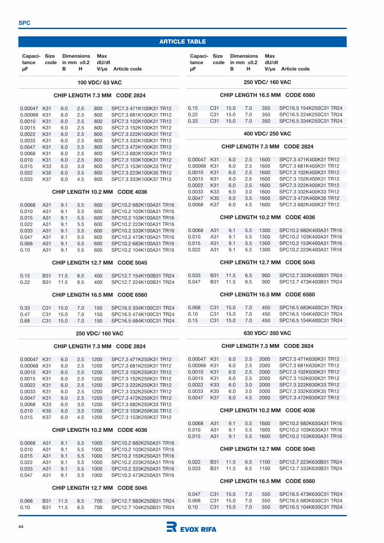
44
SPC
ARTICLE TABLE
Capaci- Size Dimensions Max
tance code in mm ±0.2 dU/dt
µF B H V/µs Article code
Capaci- Size Dimensions Max
tance code in mm ±0.2 dU/dt
µF B H V/µs Article code
100 VDC/ 63 VAC
CHIP LENGTH 7.3 MM CODE 2824
0.00047 K31 6.0 2.5 800 SPC7.3 471K100K31 TR12
0.00068 K31 6.0 2.5 800 SPC7.3 681K100K31 TR12
0.0010 K31 6.0 2.5 800 SPC7.3 102K100K31 TR12
0.0015 K31 6.0 2.5 800 SPC7.3 152K100K31 TR12
0.0022 K31 6.0 2.5 800 SPC7.3 222K100K31 TR12
0.0033 K31 6.0 2.5 800 SPC7.3 332K100K31 TR12
0.0047 K31 6.0 2.5 800 SPC7.3 472K100K31 TR12
0.0068 K31 6.0 2.5 800 SPC7.3 682K100K31 TR12
0.010 K31 6.0 2.5 800 SPC7.3 103K100K31 TR12
0.015 K33 6.0 3.0 800 SPC7.3 153K100K33 TR12
0.022 K35 6.0 3.5 800 SPC7.3 223K100K35 TR12
0.033 K37 6.0 4.5 800 SPC7.3 333K100K37 TR12
CHIP LENGTH 10.2 MM CODE 4036
0.0068 A31 9.1 5.5 600 SPC10.2 682K100A31 TR16
0.010 A31 9.1 5.5 600 SPC10.2 103K100A31 TR16
0.015 A31 9.1 5.5 600 SPC10.2 153K100A31 TR16
0.022 A31 9.1 5.5 600 SPC10.2 223K100A31 TR16
0.033 A31 9.1 5.5 600 SPC10.2 333K100A31 TR16
0.047 A31 9.1 5.5 600 SPC10.2 473K100A31 TR16
0.068 A31 9.1 5.5 600 SPC10.2 683K100A31 TR16
0.10 A31 9.1 5.5 600 SPC10.2 104K100A31 TR16
CHIP LENGTH 12.7 MM CODE 5045
0.15 B31 11.5 6.5 400 SPC12.7 154K100B31 TR24
0.22 B31 11.5 6.5 400 SPC12.7 224K100B31 TR24
CHIP LENGTH 16.5 MM CODE 6560
0.33 C31 15.0 7.0 150 SPC16.5 334K100C31 TR24
0.47 C31 15.0 7.0 150 SPC16.5 474K100C31 TR24
0.68 C31 15.0 7.0 150 SPC16.5 684K100C31 TR24
250 VDC/ 160 VAC
CHIP LENGTH 7.3 MM CODE 2824
0.00047 K31 6.0 2.5 1200 SPC7.3 471K250K31 TR12
0.00068 K31 6.0 2.5 1200 SPC7.3 681K250K31 TR12
0.0010 K31 6.0 2.5 1200 SPC7.3 102K250K31 TR12
0.0015 K31 6.0 2.5 1200 SPC7.3 152K250K31 TR12
0.0022 K31 6.0 2.5 1200 SPC7.3 222K250K31 TR12
0.0033 K31 6.0 2.5 1200 SPC7.3 332K250K31 TR12
0.0047 K31 6.0 2.5 1200 SPC7.3 472K250K31 TR12
0.0068 K33 6.0 3.0 1200 SPC7.3 682K250K33 TR12
0.010 K35 6.0 3.5 1200 SPC7.3 103K250K35 TR12
0.015 K37 6.0 4.5 1200 SPC7.3 153K250K37 TR12
CHIP LENGTH 10.2 MM CODE 4036
0.0068 A31 9.1 5.5 1000 SPC10.2 682K250A31 TR16
0.010 A31 9.1 5.5 1000 SPC10.2 103K250A31 TR16
0.015 A31 9.1 5.5 1000 SPC10.2 153K250A31 TR16
0.022 A31 9.1 5.5 1000 SPC10.2 223K250A31 TR16
0.033 A31 9.1 5.5 1000 SPC10.2 333K250A31 TR16
0.047 A31 9.1 5.5 1000 SPC10.2 473K250A31 TR16
CHIP LENGTH 12.7 MM CODE 5045
0.068 B31 11.5 6.5 700 SPC12.7 683K250B31 TR24
0.10 B31 11.5 6.5 700 SPC12.7 104K250B31 TR24
250 VDC/ 160 VAC
CHIP LENGTH 16.5 MM CODE 6560
0.15 C31 15.0 7.0 350 SPC16.5 154K250C31 TR24
0.22 C31 15.0 7.0 350 SPC16.5 224K250C31 TR24
0.33 C31 15.0 7.0 350 SPC16.5 334K250C31 TR24
400 VDC/ 250 VAC
CHIP LENGTH 7.3 MM CODE 2824
0.00047 K31 6.0 2.5 1600 SPC7.3 471K400K31 TR12
0.00068 K31 6.0 2.5 1600 SPC7.3 681K400K31 TR12
0.0010 K31 6.0 2.5 1600 SPC7.3 102K400K31 TR12
0.0015 K31 6.0 2.5 1600 SPC7.3 152K400K31 TR12
0.0022 K31 6.0 2.5 1600 SPC7.3 222K400K31 TR12
0.0033 K33 6.0 3.0 1600 SPC7.3 332K400K33 TR12
0.0047 K35 6.0 3.5 1600 SPC7.3 472K400K35 TR12
0.0068 K37 6.0 4.5 1600 SPC7.3 682K400K37 TR12
CHIP LENGTH 10.2 MM CODE 4036
0.0068 A31 9.1 5.5 1300 SPC10.2 682K400A31 TR16
0.010 A31 9.1 5.5 1300 SPC10.2 103K400A31 TR16
0.015 A31 9.1 5.5 1300 SPC10.2 153K400A31 TR16
0.022 A31 9.1 5.5 1300 SPC10.2 223K400A31 TR16
CHIP LENGTH 12.7 MM CODE 5045
0.033 B31 11.5 6.5 900 SPC12.7 333K400B31 TR24
0.047 B31 11.5 6.5 900 SPC12.7 473K400B31 TR24
CHIP LENGTH 16.5 MM CODE 6560
0.068 C31 15.0 7.0 450 SPC16.5 683K400C31 TR24
0.10 C31 15.0 7.0 450 SPC16.5 104K400C31 TR24
0.15 C31 15.0 7.0 450 SPC16.5 154K400C31 TR24
630 VDC/ 350 VAC
CHIP LENGTH 7.3 MM CODE 2824
0.00047 K31 6.0 2.5 2000 SPC7.3 471K630K31 TR12
0.00068 K31 6.0 2.5 2000 SPC7.3 681K630K31 TR12
0.0010 K31 6.0 2.5 2000 SPC7.3 102K630K31 TR12
0.0015 K31 6.0 2.5 2000 SPC7.3 152K630K31 TR12
0.0022 K33 6.0 3.0 2000 SPC7.3 222K630K33 TR12
0.0033 K35 6.0 3.5 2000 SPC7.3 332K630K35 TR12
0.0047 K37 6.0 4.5 2000 SPC7.3 472K630K37 TR12
CHIP LENGTH 10.2 MM CODE 4036
0.0068 A31 9.1 5.5 1600 SPC10.2 682K630A31 TR16
0.010 A31 9.1 5.5 1600 SPC10.2 103K630A31 TR16
0.015 A31 9.1 5.5 1600 SPC10.2 153K630A31 TR16
CHIP LENGTH 12.7 MM CODE 5045
0.022 B31 11.5 6.5 1100 SPC12.7 223K630B31 TR24
0.033 B31 11.5 6.5 1100 SPC12.7 333K630B31 TR24
CHIP LENGTH 16.5 MM CODE 6560
0.047 C31 15.0 7.0 550 SPC16.5 473K630C31 TR24
0.068 C31 15.0 7.0 550 SPC16.5 683K630C31 TR24
0.10 C31 15.0 7.0 550 SPC16.5 104K630C31 TR24
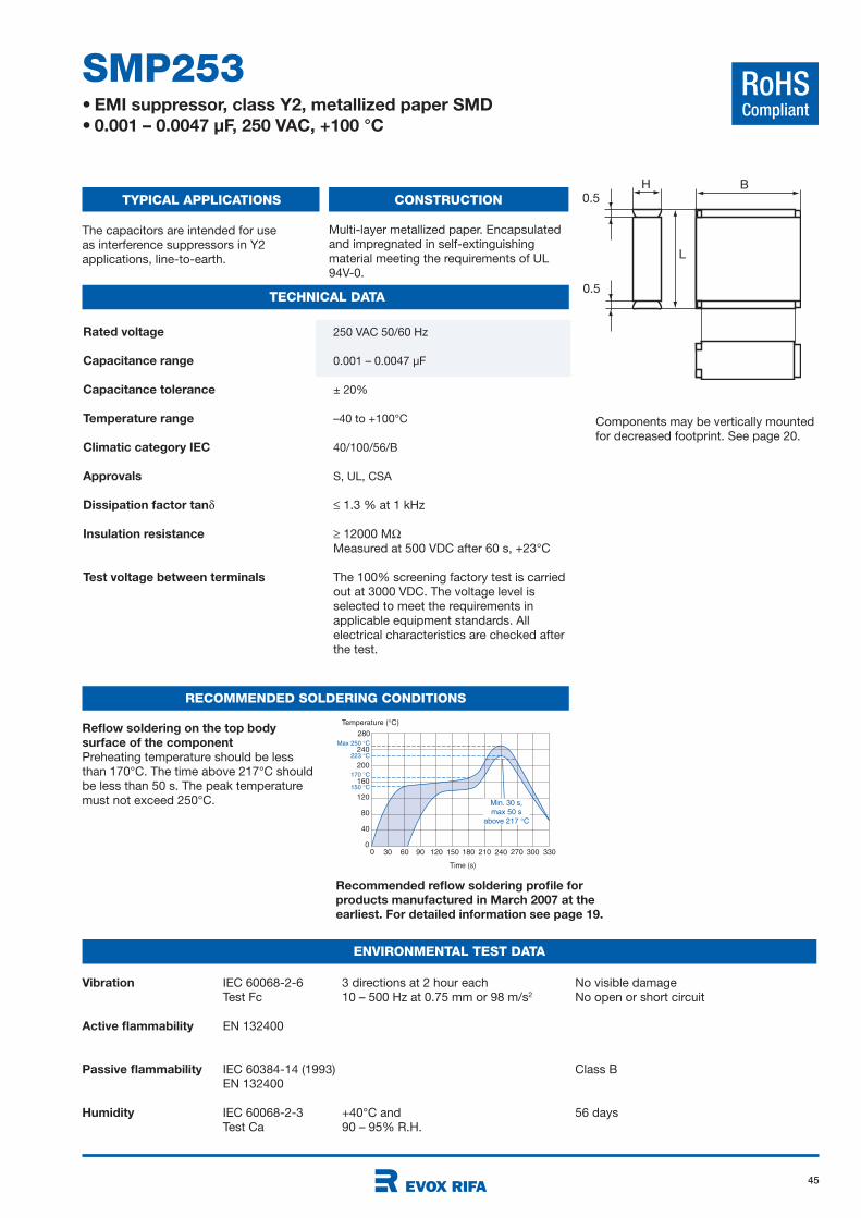
45
RoHSCompliant
250 VAC 50/60 Hz
0.001 – 0.0047 µF
± 20%
–40 to +100°C
40/100/56/B
S, UL, CSA
1.3 % at 1 kHz
12000 M
Measured at 500 VDC after 60 s, +23°C
The 100% screening factory test is carried
out at 3000 VDC. The voltage level is
selected to meet the requirements in
applicable equipment standards. All
electrical characteristics are checked after
the test.
SMP253• EMI suppressor, class Y2, metallized paper SMD
• 0.001 – 0.0047 µF, 250 VAC, +100 °C
TYPICAL APPLICATIONS CONSTRUCTION
TECHNICAL DATA
The capacitors are intended for use
as interference suppressors in Y2
applications, line-to-earth.
Multi-layer metallized paper. Encapsulated
and impregnated in self-extinguishing
material meeting the requirements of UL
94V-0.
Rated voltage
Capacitance range
Capacitance tolerance
Temperature range
Climatic category IEC
Approvals
Dissipation factor tan
Insulation resistance
Test voltage between terminals
Vibration IEC 60068-2-6 3 directions at 2 hour each No visible damage
Test Fc 10 – 500 Hz at 0.75 mm or 98 m/s2 No open or short circuit
Active flammability EN 132400
Passive flammability IEC 60384-14 (1993) Class B
EN 132400
Humidity IEC 60068-2-3 +40°C and 56 days
Test Ca 90 – 95% R.H.
ENVIRONMENTAL TEST DATA
RECOMMENDED SOLDERING CONDITIONS
Reflow soldering on the top body
surface of the component
Preheating temperature should be less
than 170°C. The time above 217°C should
be less than 50 s. The peak temperature
must not exceed 250°C.
Recommended reflow soldering profile for
products manufactured in March 2007 at the
earliest. For detailed information see page 19.
B
L
H
0.5
0.5
Components may be vertically mounted
for decreased footprint. See page 20.
Temperature ( C)
200
240
30 60 90 120 150 180 210
160
120
40
80
240 270 3303000
280
0
Time (s)
150 C
170 C
223 C
Max 250 C
Min. 30 s,
max 50 s
above 217 C
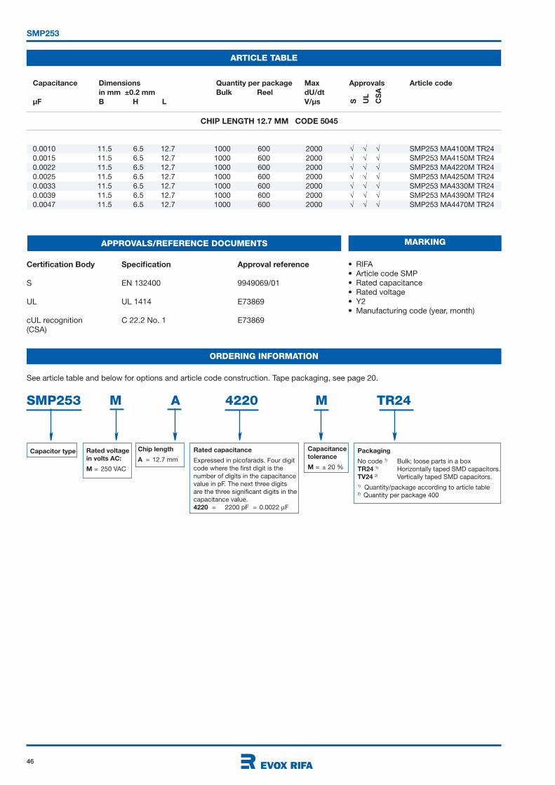
46
SMP253
ARTICLE TABLE
0.0010 11.5 6.5 12.7 1000 600 2000 SMP253 MA4100M TR24
0.0015 11.5 6.5 12.7 1000 600 2000 SMP253 MA4150M TR24
0.0022 11.5 6.5 12.7 1000 600 2000 SMP253 MA4220M TR24
0.0025 11.5 6.5 12.7 1000 600 2000 SMP253 MA4250M TR24
0.0033 11.5 6.5 12.7 1000 600 2000 SMP253 MA4330M TR24
0.0039 11.5 6.5 12.7 1000 600 2000 SMP253 MA4390M TR24
0.0047 11.5 6.5 12.7 1000 600 2000 SMP253 MA4470M TR24
Capacitance Dimensions Quantity per package Max Approvals Article code
in mm ±0.2 mm Bulk Reel dU/dt
µF B H L V/µs S UL
CS
A
ORDERING INFORMATION
MARKING
• RIFA
• Article code SMP
• Rated capacitance
• Rated voltage
• Y2
• Manufacturing code (year, month)
APPROVALS/REFERENCE DOCUMENTS
Certification Body Specification Approval reference
S EN 132400 9949069/01
UL UL 1414 E73869
cUL recognition C 22.2 No. 1 E73869
(CSA)
See article table and below for options and article code construction. Tape packaging, see page 20.
CHIP LENGTH 12.7 MM CODE 5045
Chip length
A = 12.7 mm
Capacitor type Packaging
No code 1) Bulk; loose parts in a box
TR24 1) Horizontally taped SMD capacitors.
TV24 2) Vertically taped SMD capacitors.
1) Quantity/package according to article table2) Quantity per package 400
Rated voltage
in volts AC:
M = 250 VAC
Capacitance
tolerance
M = ± 20 %
Rated capacitance
Expressed in picofarads. Four digit
code where the first digit is the
number of digits in the capacitance
value in pF. The next three digits
are the three significant digits in the
capacitance value.
4220 = 2200 pF = 0.0022 F
SMP253 M A 4220 M TR24
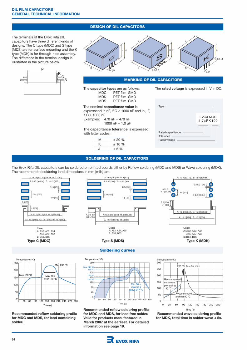
64
DIL FILM CAPACITORS
GENERAL TECHNICAL INFORMATION
DESIGN OF DIL CAPACITORS
The Evox Rifa DIL capacitors can be soldered on printed boards either by Reflow soldering (MDC and MDS) or Wave soldering (MDK).
The recommended soldering land dimensions in mm [mils] are:
Temperature ( C)
200
30 60 90 120 150 180 210
160
120
40
80
240 270 3303000
280
0
Time (s)
150 C
170 C
223 C
Max 240 C
Min. 30 s,
max 50 s
above 217 C
Recommended reflow soldering profile
for MDC and MDS, for lead free solder.
Valid for products manufactured in
March 2007 at the earliest. For detailed
information see page 19.
Type C (MDC) Type S (MDS) Type K (MDK)
1.5 [59]
1.5 [59]
2.54 [100]
Case:
A: A52, A53, A54
A55, A57, A58
B: B53, B55
A: 9.15 [360.24] / B: 14.15 [557.1]
0.25 [10]
1.0 [40]
A: 10.0 [393.7] / B: 15.0 [590.55]
A1: 12.2 [480], A2: 12.7 [500] / B: 16.5 [650]
A: 13.15 [517.72] / B: 18.15 [714.57]
1.5 to 3.2
[59 to126]
2.54 [100]
Case:
A: A52, A54, A55
B: B53, B55
A: 9.15 [360] / B: 14.15 [560]
0.25 [10]
1.0 [40]
A: 10.0 [393.7] / B: 15.0 [590.55]
A: 12.2 [480] / B: 16.5 [650]
A: 18.6 [730] / B: 22.9 [900]
1.5B
H h1
L
1.5-3.2B
H h1
L
B
H
3.2 +1
L
2.54p
KC
S
The terminals of the Evox Rifa DIL
capacitors have three different kinds of
designs. The C type (MDC) and S type
(MDS) are for surface mounting and the K
type (MDK) is for through-hole assembly.
The difference in the terminal design is
illustrated in the picture below.
SOLDERING OF DIL CAPACITORS
0
50
100
150
200
250
300
0 30 60 90 120 150 180 210 240
Time (s)
Recommendedpreheat 90 C
Temperature ( C)
250 C, 2s + 3s max
Recommendedmaximumpreheating130 C
Recommended wave soldering profile
for MDK, total time in solder wave < 5s.
3.2 [126]
+1 [40]
2.54 [100]
min
0.7 [27.56]
Case:
A: A52, A53, A54
A55, A57, A58
B: B53, B55
A: 10.0 [393.7] / B: 15.0 [590.55]
0.54 [21.26]
2.0 [78.74]
A: 10.0 [393.7] / B: 15.0 [590.55]
A: 12.2 [480] / B: 16.5 [650]
MARKING OF DIL CAPACITORS
Type
Rated capacitance
Tolerance
Rated voltage
EVOX MDC4.7 F K 100
The capacitor types are as follows:
MDC PET film SMD
MDK PET film SMD
MDS PET film SMD
The nominal capacitance value is
expressend in nF, if C < 1000 nF and in F,
if C 1000 nF
Examples: 470 nF = 470 nF
1000 nF = 1.0 µF
The capacitance tolerance is expressed
with letter codes:
M ± 20 %
K ± 10 %
J ± 5 %
The rated voltage is expressed in V in DC.
Temperature ( C)
200
30 60 90 120 150 180 210
150
100
50
240 270 3000
250
0
Max 150 C
Max 230 C
Max 60 s
over 180 C
Time (s)
Recommended reflow soldering profile
for MDC and MDS, for lead containing
solder.
Soldering curves
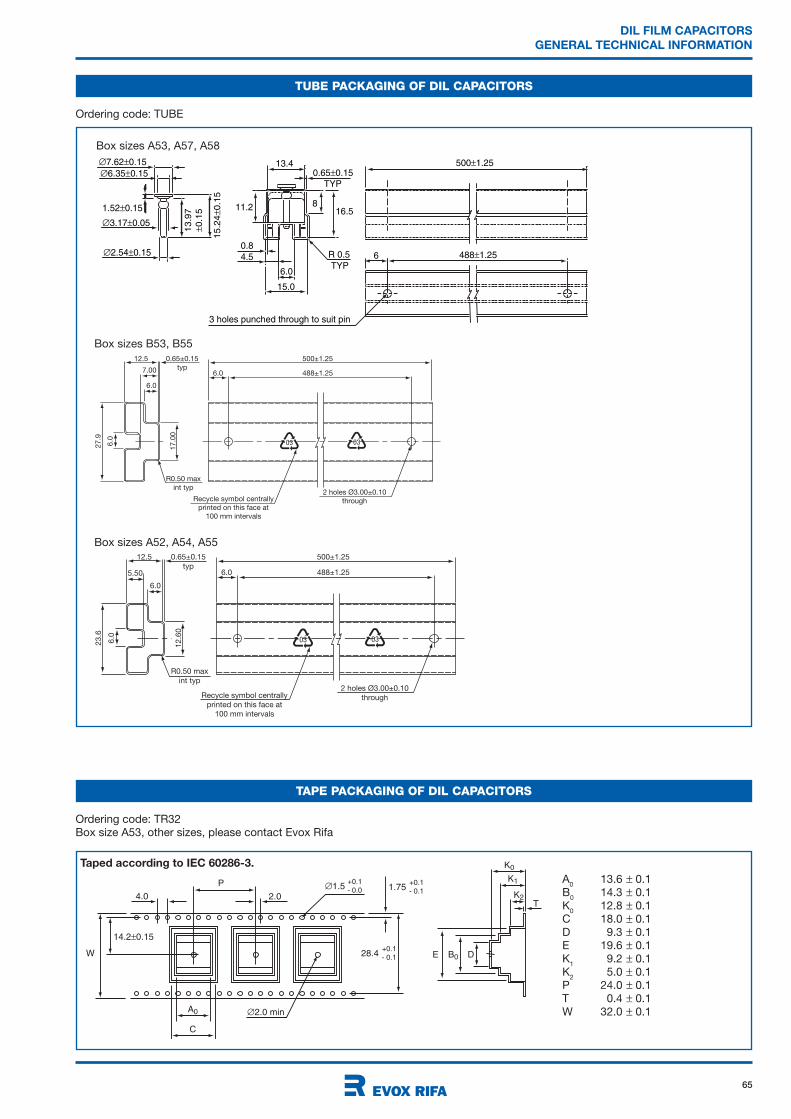
65
DIL FILM CAPACITORS
GENERAL TECHNICAL INFORMATION
TAPE PACKAGING OF DIL CAPACITORS
14.2 0.15
4.01.5
2.0 min
P
2.0
A0
C
W
+0.1- 0.0 1.75
+0.1- 0.1
28.4+0.1- 0.1 B0
K0
K1
K2T
E D
Ordering code: TR32
Box size A53, other sizes, please contact Evox Rifa
A0
13.6 0.1
B0
14.3 0.1
K0
12.8 0.1
C 18.0 0.1
D 9.3 0.1
E 19.6 0.1
K1
9.2 0.1
K2
5.0 0.1
P 24.0 0.1
T 0.4 0.1
W 32.0 0.1
TUBE PACKAGING OF DIL CAPACITORS
Ordering code: TUBE
13.4
R 0.50.8
4.5TYP
TYP
15.0
3 holes punched through to suit pin
6.0
0.65 0.15
488 1.25
1.52 0.15
3.17 0.05
2.54 0.15
6.35 0.15
7.62 0.15
15.2
40.1
5
13.9
7
0.1
5
500 1.25
8
6
16.511.2
03 03
12.5
27.9
6.0
17.0
0
0.65±0.15
typ
500±1.25
488±1.256.0
R0.50 max
int typ
7.00
6.0
2 holes Ø3.00±0.10
throughRecycle symbol centrally
printed on this face at
100 mm intervals
03 03
12.5
23.6
6.0
12.6
0
0.65±0.15
typ
500±1.25
488±1.256.0
R0.50 max
int typ2 holes Ø3.00±0.10
throughRecycle symbol centrally
printed on this face at
100 mm intervals
5.50
6.0
Taped according to IEC 60286-3.
Box sizes A53, A57, A58
Box sizes B53, B55
Box sizes A52, A54, A55
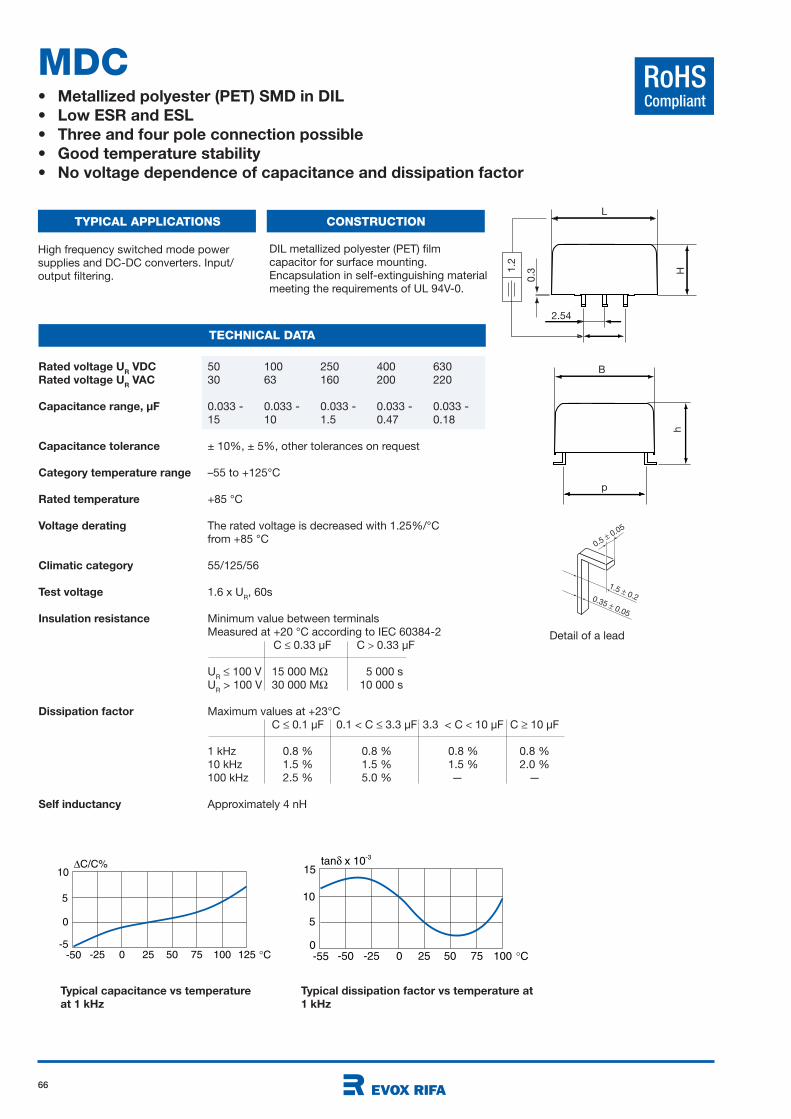
66
RoHSCompliant
tan x 10-3
-50 -25 0 25 50 75 100 C
10
-550
5
15
Rated voltage UR VDC 50 100 250 400 630
Rated voltage UR VAC 30 63 160 200 220
Capacitance range, µF 0.033 - 0.033 - 0.033 - 0.033 - 0.033 -
15 10 1.5 0.47 0.18
Capacitance tolerance ± 10%, ± 5%, other tolerances on request
Category temperature range –55 to +125°C
Rated temperature +85 °C
Voltage derating The rated voltage is decreased with 1.25%/°C
from +85 °C
Climatic category 55/125/56
Test voltage 1.6 x UR, 60s
Insulation resistance Minimum value between terminals
Measured at +20 °C according to IEC 60384-2
C 0.33 µF C 0.33 µF
UR
100 V 15 000 M 5 000 s
UR > 100 V 30 000 M 10 000 s
Dissipation factor Maximum values at +23°C
C 0.1 µF 0.1 < C 3.3 µF 3.3 < C 10 µF C 10 µF
1 kHz 0.8 % 0.8 % 0.8 % 0.8 %
10 kHz 1.5 % 1.5 % 1.5 % 2.0 %
100 kHz 2.5 % 5.0 % —kk —
Self inductancy Approximately 4 nH
MDC• Metallized polyester (PET) SMD in DIL
• Low ESR and ESL
• Three and four pole connection possible
• Good temperature stability
• No voltage dependence of capacitance and dissipation factor
TYPICAL APPLICATIONS CONSTRUCTION
TECHNICAL DATA
High frequency switched mode power
supplies and DC-DC converters. Input/
output filtering.
DIL metallized polyester (PET) film
capacitor for surface mounting.
Encapsulation in self-extinguishing material
meeting the requirements of UL 94V-0.
L
H
B
p
h
2.54
1.2
0.3
0.35 0.05
1.5 0.2
0.5 0.05
Detail of a lead
Typical capacitance vs temperature
at 1 kHz
Typical dissipation factor vs temperature at
1 kHz
C/C%
-25 0 25 50 75 100 125 C
5
-50 -5
0
10
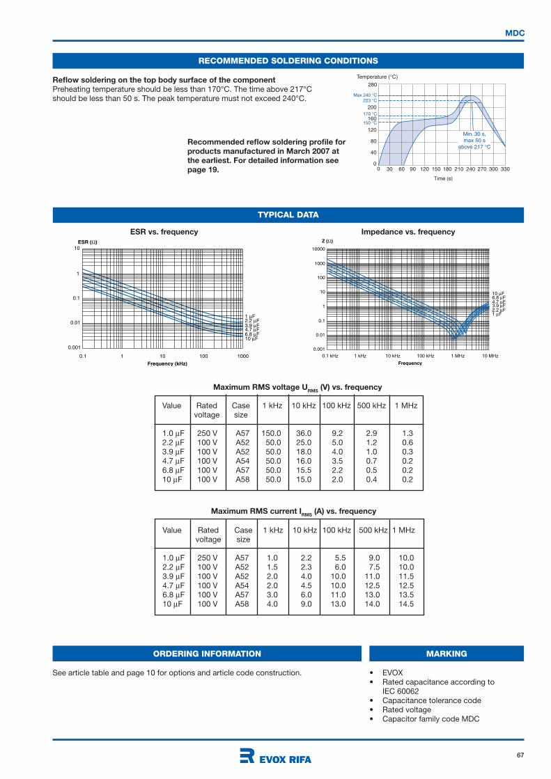
67
RECOMMENDED SOLDERING CONDITIONS
Reflow soldering on the top body surface of the component
Preheating temperature should be less than 170°C. The time above 217°C
should be less than 50 s. The peak temperature must not exceed 240°C.
Recommended reflow soldering profile for
products manufactured in March 2007 at
the earliest. For detailed information see
page 19.
Temperature ( C)
200
30 60 90 120 150 180 210
160
120
40
80
240 270 3303000
280
0
Time (s)
150 C
170 C
223 C
Max 240 C
Min. 30 s,
max 50 s
above 217 C
MDC
TYPICAL DATA
10ESR ( )
Frequency (kHz)
1
0.1
0.1 1 10 100
1 F2.2 F3.9 F4.7 F6.8 F10 F
1000
0.01
0.001
10000
Z ( )
1000
100
10
1
0.1
0.01
0.001
0.1 kHz 1 kHz 10 kHz 100 kHz 1 MHz 10 MHz
Frequency
10 F6.8 F4.7 F3.9 F2.2 F1 F
ESR vs. frequency Impedance vs. frequency
MARKING
• EVOX
• Rated capacitance according to
IEC 60062
• Capacitance tolerance code
• Rated voltage
• Capacitor family code MDC
ORDERING INFORMATION
See article table and page 10 for options and article code construction.
Maximum RMS current IRMS
(A) vs. frequency
Value Rated Case 1 kHz 10 kHz 100 kHz 500 kHz 1 MHz
voltage size
1.0 F 250 V A57 1.0 2.2 5.5 9.0 10.0
2.2 F 100 V A52 1.5 2.3 6.0 7.5 10.0
3.9 F 100 V A52 2.0 4.0 10.0 11.0 11.5
4.7 F 100 V A54 2.0 4.5 10.0 12.5 12.5
6.8 F 100 V A57 3.0 6.0 11.0 13.0 13.5
10 F 100 V A58 4.0 9.0 13.0 14.0 14.5
Maximum RMS voltage URMS
(V) vs. frequency
Value Rated Case 1 kHz 10 kHz 100 kHz 500 kHz 1 MHz
voltage size
1.0 F 250 V A57 150.0 36.0 9.2 2.9 1.3
2.2 F 100 V A52 50.0 25.0 5.0 1.2 0.6
3.9 F 100 V A52 50.0 18.0 4.0 1.0 0.3
4.7 F 100 V A54 50.0 16.0 3.5 0.7 0.2
6.8 F 100 V A57 50.0 15.5 2.2 0.5 0.2
10 F 100 V A58 50.0 15.0 2.0 0.4 0.2

68
MDC
ARTICLE TABLE
50 VDC/30 VAC
LEAD SPACING 10 MM
0.033 12.2 6.05 11.0 7.75 390 MDC10 333K50A52P3 TUBE
0.039 12.2 6.05 11.0 7.75 330 MDC10 393K50A52P3 TUBE
0.047 12.2 6.05 11.0 7.75 270 MDC10 473K50A52P3 TUBE
0.056 12.2 6.05 11.0 7.75 230 MDC10 563K50A52P3 TUBE
0.068 12.2 6.05 11.0 7.75 190 MDC10 683K50A52P3 TUBE
0.082 12.2 6.05 11.0 7.75 160 MDC10 823K50A52P3 TUBE
0.10 12.2 6.05 11.0 7.75 130 MDC10 104K50A52P3 TUBE
0.12 12.2 6.05 11.0 7.75 110 MDC10 124K50A52P3 TUBE
0.15 12.2 6.05 11.0 7.75 85 MDC10 154K50A52P3 TUBE
0.18 12.2 6.05 11.0 7.75 70 MDC10 184K50A52P3 TUBE
0.22 12.2 6.05 11.0 7.75 58 MDC10 224K50A52P3 TUBE
0.27 12.2 6.05 11.0 7.75 47 MDC10 274K50A52P3 TUBE
0.33 12.2 6.05 11.0 7.75 39 MDC10 334K50A52P3 TUBE
0.39 12.2 6.05 11.0 7.75 33 MDC10 394K50A52P3 TUBE
0.47 12.2 6.05 11.0 7.75 30 MDC10 474K50A52P3 TUBE
0.56 12.2 6.05 11.0 7.75 26 MDC10 564K50A52P3 TUBE
0.68 12.2 6.05 11.0 7.75 21 MDC10 684K50A52P3 TUBE
0.82 12.2 6.05 11.0 7.75 18 MDC10 824K50A52P3 TUBE
1.0 12.2 6.05 11.0 7.75 15 MDC10 105K50A52P3 TUBE
1.2 12.2 6.05 11.0 7.75 14 MDC10 125K50A52P3 TUBE
1.5 12.2 6.05 11.0 7.75 13 MDC10 155K50A52P3 TUBE
1.8 12.2 6.05 11.0 7.75 12 MDC10 185K50A52P3 TUBE
2.2 12.2 6.05 11.0 7.75 11 MDC10 225K50A52P3 TUBE
2.7 12.2 6.05 11.0 7.75 10 MDC10 275K50A52P3 TUBE
3.3 12.2 6.05 11.0 7.75 8 MDC10 335K50A52P3 TUBE
3.9 12.2 6.05 11.0 7.75 7 MDC10 395K50A52P3 TUBE
4.7 12.2 6.05 11.0 7.75 6 MDC10 475K50A52P3 TUBE
5.6 12.2 6.05 13.5 7.75 5 MDC10 565K50A54Px TUBE
6.8 12.2 6.05 16.5 7.75 5 MDC10 685K50A55Pz TUBE
8.2 12.7 9.0 23.0 10.7 4 MDC10 825K50A57Py TUBE
10 12.7 9.0 23.0 10.7 3 MDC10 106K50A57Py TUBE
12 12.7 11.0 23.0 12.5 3 MDC10 126K50A58Py TUBE
15 12.7 11.0 23.0 12.5 3 MDC10 156K50A58Py TUBE
LEAD SPACING 15 MM
0.033 16.5 6.05 11.0 7.75 390 MDC15 333K50B53P3 TUBE
0.039 16.5 6.05 11.0 7.75 330 MDC15 393K50B53P3 TUBE
0.047 16.5 6.05 11.0 7.75 270 MDC15 473K50B53P3 TUBE
0.056 16.5 6.05 11.0 7.75 230 MDC15 563K50B53P3 TUBE
0.068 16.5 6.05 11.0 7.75 190 MDC15 683K50B53P3 TUBE
0.082 16.5 6.05 11.0 7.75 160 MDC15 823K50B53P3 TUBE
0.10 16.5 6.05 11.0 7.75 130 MDC15 104K50B53P3 TUBE
0.12 16.5 6.05 11.0 7.75 110 MDC15 124K50B53P3 TUBE
0.15 16.5 6.05 11.0 7.75 85 MDC15 154K50B53P3 TUBE
0.18 16.5 6.05 11.0 7.75 70 MDC15 184K50B53P3 TUBE
0.22 16.5 6.05 11.0 7.75 58 MDC15 224K50B53P3 TUBE
0.27 16.5 6.05 11.0 7.75 47 MDC15 274K50B53P3 TUBE
0.33 16.5 6.05 11.0 7.75 39 MDC15 334K50B53P3 TUBE
0.39 16.5 6.05 11.0 7.75 39 MDC15 394K50B53P3 TUBE
0.47 16.5 6.05 11.0 7.75 30 MDC15 474K50B53P3 TUBE
0.56 16.5 6.05 11.0 7.75 26 MDC15 564K50B53P3 TUBE
0.68 16.5 6.05 11.0 7.75 21 MDC15 684K50B53P3 TUBE
0.82 16.5 6.05 11.0 7.75 18 MDC15 824K50B53P3 TUBE
1.0 16.5 6.05 11.0 7.75 15 MDC15 105K50B53P3 TUBE
1.2 16.5 6.05 11.0 7.75 15 MDC15 125K50B53P3 TUBE
1.5 16.5 6.05 11.0 7.75 13 MDC15 155K50B53P3 TUBE
1.8 16.5 6.05 11.0 7.75 13 MDC15 185K50B53P3 TUBE
2.2 16.5 6.05 11.0 7.75 11 MDC15 225K50B53P3 TUBE
2.7 16.5 6.05 11.0 7.75 11 MDC15 275K50B53P3 TUBE
3.3 16.5 6.05 11.0 7.75 8 MDC15 335K50B53P3 TUBE
Capaci- Dimensions in mm ESR Article code
tance B H L h1 500kHz
µF ±0.2 ±0.2 ±0.2 m
50 VDC/30 VAC
LEAD SPACING 15 MM
3.9 16.5 6.05 11.0 7.75 8 MDC15 395K50B53P3 TUBE
4.7 16.5 6.05 11.0 7.75 6 MDC15 475K50B53P3 TUBE
5.6 16.5 6.05 11.0 7.75 5 MDC15 565K50B53P3 TUBE
6.8 16.5 6.05 11.0 7.75 5 MDC15 685K50B53P3 TUBE
100 VDC/63 VAC
LEAD SPACING 10 MM
0.033 12.2 6.05 11.0 7.75 390 MDC10 333K100A52P3 TUBE
0.039 12.2 6.05 11.0 7.75 330 MDC10 393K100A52P3 TUBE
0.047 12.2 6.05 11.0 7.75 270 MDC10 473K100A52P3 TUBE
0.056 12.2 6.05 11.0 7.75 230 MDC10 563K100A52P3 TUBE
0.068 12.2 6.05 11.0 7.75 190 MDC10 683K100A52P3 TUBE
0.082 12.2 6.05 11.0 7.75 160 MDC10 823K100A52P3 TUBE
0.10 12.2 6.05 11.0 7.75 130 MDC10 104K100A52P3 TUBE
0.12 12.2 6.05 11.0 7.75 110 MDC10 124K100A52P3 TUBE
0.15 12.2 6.05 11.0 7.75 85 MDC10 154K100A52P3 TUBE
0.18 12.2 6.05 11.0 7.75 70 MDC10 184K100A52P3 TUBE
0.22 12.2 6.05 11.0 7.75 58 MDC10 224K100A52P3 TUBE
0.27 12.2 6.05 11.0 7.75 47 MDC10 274K100A52P3 TUBE
0.33 12.2 6.05 11.0 7.75 39 MDC10 334K100A52P3 TUBE
0.39 12.2 6.05 11.0 7.75 33 MDC10 394K100A52P3 TUBE
0.47 12.2 6.05 11.0 7.75 30 MDC10 474K100A52P3 TUBE
0.56 12.2 6.05 11.0 7.75 26 MDC10 564K100A52P3 TUBE
0.68 12.2 6.05 11.0 7.75 21 MDC10 684K100A52P3 TUBE
0.82 12.2 6.05 11.0 7.75 18 MDC10 824K100A52P3 TUBE
1.0 12.2 6.05 11.0 7.75 15 MDC10 105K100A52P3 TUBE
1.2 12.2 6.05 11.0 7.75 14 MDC10 125K100A52P3 TUBE
1.5 12.2 6.05 11.0 7.75 13 MDC10 155K100A52P3 TUBE
1.8 12.2 6.05 11.0 7.75 12 MDC10 185K100A52P3 TUBE
2.2 12.2 6.05 11.0 7.75 11 MDC10 225K100A52P3 TUBE
2.7 12.2 6.05 11.0 7.75 10 MDC10 275K100A52P3 TUBE *
3.3 12.2 6.05 11.0 7.75 8 MDC10 335K100A52P3 TUBE *
3.9 12.2 6.05 11.0 7.75 7 MDC10 395K100A52P3 TUBE *
4.7 12.2 6.05 13.5 7.75 6 MDC10 475K100A54Px TUBE *
4.7 12.7 9.0 14.0 10.5 6 MDC10 475K100A53Px TR32 *
5.6 12.2 6.05 16.5 7.75 5 MDC10 565K100A55Pz TUBE *
6.8 12.7 9.0 23.0 10.7 5 MDC10 685K100A57Py TUBE
8.2 12.7 11.0 23.0 12.5 4 MDC10 825K100A58Py TUBE
10 12.7 11.0 23.0 12.5 3 MDC10 106K100A58Py TUBE
LEAD SPACING 15 MM
0.033 16.5 6.05 11.0 7.75 390 MDC15 333K100B53P3 TUBE
0.039 16.5 6.05 11.0 7.75 330 MDC15 393K100B53P3 TUBE
0.047 16.5 6.05 11.0 7.75 270 MDC15 473K100B53P3 TUBE
0.056 16.5 6.05 11.0 7.75 230 MDC15 563K100B53P3 TUBE
0.068 16.5 6.05 11.0 7.75 190 MDC15 683K100B53P3 TUBE
0.082 16.5 6.05 11.0 7.75 160 MDC15 823K100B53P3 TUBE
0.10 16.5 6.05 11.0 7.75 130 MDC15 104K100B53P3 TUBE
0.12 16.5 6.05 11.0 7.75 110 MDC15 124K100B53P3 TUBE
0.15 16.5 6.05 11.0 7.75 85 MDC15 154K100B53P3 TUBE
0.18 16.5 6.05 11.0 7.75 70 MDC15 184K100B53P3 TUBE
0.22 16.5 6.05 11.0 7.75 58 MDC15 224K100B53P3 TUBE
0.27 16.5 6.05 11.0 7.75 47 MDC15 274K100B53P3 TUBE
0.33 16.5 6.05 11.0 7.75 39 MDC15 334K100B53P3 TUBE
0.39 16.5 6.05 11.0 7.75 39 MDC15 394K100B53P3 TUBE
0.47 16.5 6.05 11.0 7.75 30 MDC15 474K100B53P3 TUBE
0.56 16.5 6.05 11.0 7.75 26 MDC15 564K100B53P3 TUBE
* 100 VDC/35 VAC
Capaci- Dimensions in mm ESR Article code
tance B H L h1 500kHz
µF ±0.2 ±0.2 ±0.2 m

69
MDC
ARTICLE TABLE
Capaci- Dimensions in mm ESR Article code
tance B H L h1 500kHz
µF ±0.2 ±0.2 ±0.2 m
Capaci- Dimensions in mm ESR Article code
tance B H L h1 500kHz
µF ±0.2 ±0.2 ±0.2 m
100 VDC/63 VAC
LEAD SPACING 15 MM
0.68 16.5 6.05 11.0 7.75 21 MDC15 684K100B53P3 TUBE
0.82 16.5 6.05 11.0 7.75 18 MDC15 824K100B53P3 TUBE
1.0 16.5 6.05 11.0 7.75 15 MDC15 105K100B53P3 TUBE
1.2 16.5 6.05 11.0 7.75 15 MDC15 125K100B53P3 TUBE
1.5 16.5 6.05 11.0 7.75 13 MDC15 155K100B53P3 TUBE
1.8 16.5 6.05 11.0 7.75 13 MDC15 185K100B53P3 TUBE
2.2 16.5 6.05 11.0 7.75 11 MDC15 225K100B53P3 TUBE
2.7 16.5 6.05 11.0 7.75 11 MDC15 275K100B53P3 TUBE
3.3 16.5 6.05 11.0 7.75 8 MDC15 335K100B53P3 TUBE
3.9 16.5 6.05 11.0 7.75 8 MDC15 395K100B53P3 TUBE
4.7 16.5 6.05 11.0 7.75 6 MDC15 475K100B53P3 TUBE *
5.6 16.5 6.05 12.2 7.75 5 MDC15 565K100B55Px TUBE
250 VDC/160 VAC
LEAD SPACING 10 MM
0.033 12.2 6.05 11.0 7.75 390 MDC10 333K250A52P3 TUBE
0.039 12.2 6.05 11.0 7.75 330 MDC10 393K250A52P3 TUBE
0.047 12.2 6.05 11.0 7.75 270 MDC10 473K250A52P3 TUBE
0.056 12.2 6.05 11.0 7.75 230 MDC10 563K250A52P3 TUBE
0.068 12.2 6.05 11.0 7.75 190 MDC10 683K250A52P3 TUBE
0.082 12.2 6.05 11.0 7.75 160 MDC10 823K250A52P3 TUBE
0.10 12.2 6.05 11.0 7.75 130 MDC10 104K250A52P3 TUBE
0.12 12.2 6.05 11.0 7.75 130 MDC10 124K250A52P3 TUBE
0.15 12.2 6.05 11.0 7.75 130 MDC10 154K250A52P3 TUBE
0.18 12.2 6.05 11.0 7.75 70 MDC10 184K250A52P3 TUBE
0.22 12.2 6.05 11.0 7.75 58 MDC10 224K250A52P3 TUBE
0.27 12.2 6.05 11.0 7.75 47 MDC10 274K250A52P3 TUBE
0.33 12.2 6.05 11.0 7.75 39 MDC10 334K250A52P3 TUBE
0.39 12.2 6.05 11.0 7.75 33 MDC10 394K250A52P3 TUBE
0.47 12.2 6.05 11.0 7.75 30 MDC10 474K250A52P3 TUBE
0.56 12.2 6.05 13.5 7.75 26 MDC10 564K250A54Px TUBE
0.68 12.2 6.05 16.5 7.75 21 MDC10 684K250A55Pz TUBE
0.82 12.7 9.0 23.0 10.7 18 MDC10 824K250A57Py TUBE
1.0 12.7 9.0 23.0 10.7 15 MDC10 105K250A57Py TUBE
1.2 12.7 11.0 23.0 12.5 14 MDC10 125K250A58Py TUBE
1.5 12.7 11.0 23.0 12.5 13 MDC10 155K250A58Py TUBE
LEAD SPACING 15 MM
0.033 16.5 6.05 11.0 7.75 390 MDC15 333K250B53P3 TUBE
0.039 16.5 6.05 11.0 7.75 330 MDC15 393K250B53P3 TUBE
0.047 16.5 6.05 11.0 7.75 270 MDC15 473K250B53P3 TUBE
0.056 16.5 6.05 11.0 7.75 230 MDC15 563K250B53P3 TUBE
0.068 16.5 6.05 11.0 7.75 190 MDC15 683K250B53P3 TUBE
0.082 16.5 6.05 11.0 7.75 160 MDC15 823K250B53P3 TUBE
0.10 16.5 6.05 11.0 7.75 130 MDC15 104K250B53P3 TUBE
0.12 16.5 6.05 11.0 7.75 110 MDC15 124K250B53P3 TUBE
0.15 16.5 6.05 11.0 7.75 85 MDC15 154K250B53P3 TUBE
0.18 16.5 6.05 11.0 7.75 70 MDC15 184K250B53P3 TUBE
0.22 16.5 6.05 11.0 7.75 58 MDC15 224K250B53P3 TUBE
0.27 16.5 6.05 11.0 7.75 47 MDC15 274K250B53P3 TUBE
0.33 16.5 6.05 11.0 7.75 39 MDC15 334K250B53P3 TUBE
0.39 16.5 6.05 11.0 7.75 39 MDC15 394K250B53P3 TUBE
0.47 16.5 6.05 11.0 7.75 30 MDC15 474K250B53P3 TUBE
0.56 16.5 6.05 11.0 7.75 26 MDC15 564K250B53P3 TUBE
0.68 16.5 6.05 11.0 7.75 21 MDC15 684K250B53P3 TUBE
* 100 VDC/35 VAC
400 VDC/200 VAC
LEAD SPACING 10 MM
0.033 12.2 6.05 11.0 7.75 390 MDC10 333K400A52P3 TUBE
0.039 12.2 6.05 11.0 7.75 330 MDC10 393K400A52P3 TUBE
0.047 12.2 6.05 11.0 7.75 270 MDC10 473K400A52P3 TUBE
0.056 12.2 6.05 11.0 7.75 230 MDC10 563K400A52P3 TUBE
0.068 12.2 6.05 11.0 7.75 190 MDC10 683K400A52P3 TUBE
0.082 12.2 6.05 11.0 7.75 160 MDC10 823K400A52P3 TUBE
0.10 12.2 6.05 11.0 7.75 130 MDC10 104K400A52P3 TUBE
0.12 12.2 6.05 11.0 7.75 110 MDC10 124K400A52P3 TUBE
0.15 12.2 6.05 11.0 7.75 85 MDC10 154K400A52P3 TUBE
0.18 12.2 6.05 11.0 7.75 70 MDC10 184K400A52P3 TUBE
0.22 12.7 9.0 23.0 10.7 58 MDC10 224K400A57Py TUBE
0.27 12.7 9.0 23.0 10.7 47 MDC10 274K400A57Py TUBE
0.33 12.7 9.0 23.0 10.7 39 MDC10 334K400A57Py TUBE
0.39 12.7 11.0 23.0 12.5 33 MDC10 394K400A58Py TUBE
0.47 12.7 11.0 23.0 12.5 30 MDC10 474K400A58Py TUBE
LEAD SPACING 15 MM
0.033 16.5 6.05 11.0 7.75 390 MDC15 333K400B53P3 TUBE
0.039 16.5 6.05 11.0 7.75 330 MDC15 393K400B53P3 TUBE
0.047 16.5 6.05 11.0 7.75 270 MDC15 473K400B53P3 TUBE
0.056 16.5 6.05 11.0 7.75 230 MDC15 563K400B53P3 TUBE
0.068 16.5 6.05 11.0 7.75 190 MDC15 683K400B53P3 TUBE
0.082 16.5 6.05 11.0 7.75 160 MDC15 823K400B53P3 TUBE
0.10 16.5 6.05 11.0 7.75 130 MDC15 104K400B53P3 TUBE
0.12 16.5 6.05 11.0 7.75 110 MDC15 124K400B53P3 TUBE
0.15 16.5 6.05 11.0 7.75 85 MDC15 154K400B53P3 TUBE
0.18 16.5 6.05 11.0 7.75 70 MDC15 184K400B53P3 TUBE
0.22 16.5 6.05 11.0 7.75 58 MDC15 224K400B53P3 TUBE
0.27 16.5 6.05 11.0 7.75 47 MDC15 274K400B53P3 TUBE
0.33 16.5 6.05 12.2 7.75 39 MDC15 334K400B55Px TUBE
630 VDC/220 VAC
LEAD SPACING 10 MM
0.033 12.2 6.05 11.0 7.75 390 MDC10 333K630A52P3 TUBE
0.039 12.2 6.05 11.0 7.75 330 MDC10 393K630A52P3 TUBE
0.047 12.2 6.05 11.0 7.75 270 MDC10 473K630A52P3 TUBE
0.056 12.2 6.05 11.0 7.75 230 MDC10 563K630A52P3 TUBE
0.068 12.2 6.05 13.5 7.75 190 MDC10 683K630A54Px TUBE
0.082 12.7 11.0 23.0 12.5 160 MDC10 823K630A58Py TUBE
0.10 12.7 11.0 23.0 12.5 130 MDC10 104K630A58Py TUBE
0.12 12.7 11.0 23.0 12.5 110 MDC10 124K630A58Py TUBE
0.15 12.7 11.0 23.0 12.5 85 MDC10 154K630A58Py TUBE
0.18 12.7 11.0 23.0 12.5 70 MDC10 184K630A58Py TUBE
LEAD SPACING 15 MM
0.033 16.5 6.05 11.0 7.75 390 MDC15 333K630B53P3 TUBE
0.039 16.5 6.05 11.0 7.75 330 MDC15 393K630B53P3 TUBE
0.047 16.5 6.05 11.0 7.75 270 MDC15 473K630B53P3 TUBE
0.056 16.5 6.05 11.0 7.75 230 MDC15 563K630B53P3 TUBE
0.068 16.5 6.05 11.0 7.75 190 MDC15 683K630B53P3 TUBE
0.082 16.5 6.05 11.0 7.75 160 MDC15 823K630B53P3 TUBE
0.10 16.5 6.05 11.0 7.75 130 MDC15 104K630B53P3 TUBE
x = Number of leads per side, 3 or 4
z = Number of leads per side, 3, 4 or 5
y = Number of leads per side, 7 or 8
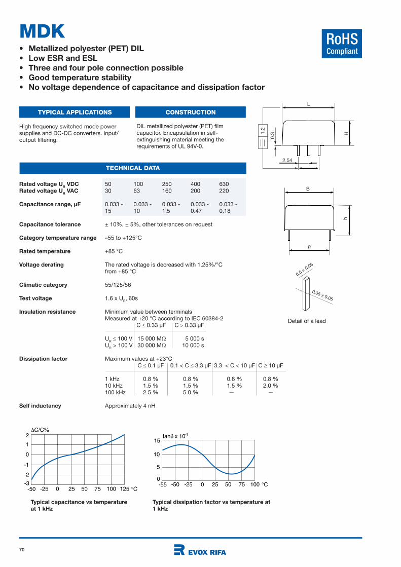
70
RoHSCompliant
Rated voltage UR VDC 50 100 250 400 630
Rated voltage UR VAC 30 63 160 200 220
Capacitance range, µF 0.033 - 0.033 - 0.033 - 0.033 - 0.033 -
15 10 1.5 0.47 0.18
Capacitance tolerance ± 10%, ± 5%, other tolerances on request
Category temperature range –55 to +125°C
Rated temperature +85 °C
Voltage derating The rated voltage is decreased with 1.25%/°C
from +85 °C
Climatic category 55/125/56
Test voltage 1.6 x UR, 60s
Insulation resistance Minimum value between terminals
Measured at +20 °C according to IEC 60384-2
C 0.33 µF C 0.33 µF
UR
100 V 15 000 M 5 000 s
UR > 100 V 30 000 M 10 000 s
Dissipation factor Maximum values at +23°C
C 0.1 µF 0.1 < C 3.3 µF 3.3 < C 10 µF C 10 µF
1 kHz 0.8 % 0.8 % 0.8 % 0.8 %
10 kHz 1.5 % 1.5 % 1.5 % 2.0 %
100 kHz 2.5 % 5.0 % —kk —
Self inductancy Approximately 4 nH
MDK• Metallized polyester (PET) DIL
• Low ESR and ESL
• Three and four pole connection possible
• Good temperature stability
• No voltage dependence of capacitance and dissipation factor
TYPICAL APPLICATIONS CONSTRUCTION
TECHNICAL DATA
High frequency switched mode power
supplies and DC-DC converters. Input/
output filtering.
DIL metallized polyester (PET) film
capacitor. Encapsulation in self-
extinguishing material meeting the
requirements of UL 94V-0.
L
H
B
p
h
2.54
1.2
0.3
0.35 0.05
0.5 0.05
Detail of a lead
Typical capacitance vs temperature
at 1 kHz
Typical dissipation factor vs temperature at
1 kHz
C/C%
-25 0 25 50 75 100 125 C
0
-2
-50-3
2
-1
1
tan x 10-3
-50 -25 0 25 50 75 100 C
10
-550
5
15
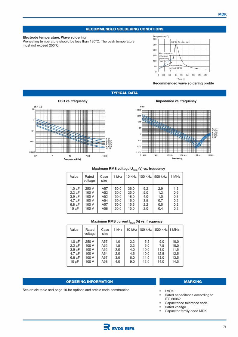
71
0
50
100
150
200
250
300
0 30 60 90 120 150 180 210 240
Time (s)
Recommendedpreheat 90 C
Temperature ( C)
250 C, 2s + 3s max
Recommendedmaximumpreheating130 C
RECOMMENDED SOLDERING CONDITIONS
Electrode temperature, Wave soldering
Preheating temperature should be less than 130°C. The peak temperature
must not exceed 250°C.
Recommended wave soldering profile
MDK
TYPICAL DATA
10ESR ( )
Frequency (kHz)
1
0.1
0.1 1 10 100
1 F2.2 F3.9 F4.7 F6.8 F10 F
1000
0.01
0.001
10000
Z ( )
1000
100
10
1
0.1
0.01
0.001
0.1 kHz 1 kHz 10 kHz 100 kHz 1 MHz 10 MHz
Frequency
10 F6.8 F4.7 F3.9 F2.2 F1 F
ESR vs. frequency Impedance vs. frequency
• EVOX
• Rated capacitance according to
IEC 60062
• Capacitance tolerance code
• Rated voltage
• Capacitor family code MDK
MARKINGORDERING INFORMATION
See article table and page 10 for options and article code construction.
Maximum RMS current IRMS
(A) vs. frequency
Value Rated Case 1 kHz 10 kHz 100 kHz 500 kHz 1 MHz
voltage size
1.0 F 250 V A57 1.0 2.2 5.5 9.0 10.0
2.2 F 100 V A52 1.5 2.3 6.0 7.5 10.0
3.9 F 100 V A52 2.0 4.0 10.0 11.0 11.5
4.7 F 100 V A54 2.0 4.5 10.0 12.5 12.5
6.8 F 100 V A57 3.0 6.0 11.0 13.0 13.5
10 F 100 V A58 4.0 9.0 13.0 14.0 14.5
Maximum RMS voltage URMS
(V) vs. frequency
Value Rated Case 1 kHz 10 kHz 100 kHz 500 kHz 1 MHz
voltage size
1.0 F 250 V A57 150.0 36.0 9.2 2.9 1.3
2.2 F 100 V A52 50.0 25.0 5.0 1.2 0.6
3.9 F 100 V A52 50.0 18.0 4.0 1.0 0.3
4.7 F 100 V A54 50.0 16.0 3.5 0.7 0.2
6.8 F 100 V A57 50.0 15.5 2.2 0.5 0.2
10 F 100 V A58 50.0 15.0 2.0 0.4 0.2

72
MDK
ARTICLE TABLE
50 VDC/30 VAC
LEAD SPACING 10 MM
0.033 12.2 6.05 11.0 6.25 390 MDK10 333K50A52P3 TUBE
0.039 12.2 6.05 11.0 6.25 330 MDK10 393K50A52P3 TUBE
0.047 12.2 6.05 11.0 6.25 270 MDK10 473K50A52P3 TUBE
0.056 12.2 6.05 11.0 6.25 230 MDK10 563K50A52P3 TUBE
0.068 12.2 6.05 11.0 6.25 190 MDK10 683K50A52P3 TUBE
0.082 12.2 6.05 11.0 6.25 160 MDK10 823K50A52P3 TUBE
0.10 12.2 6.05 11.0 6.25 130 MDK10 104K50A52P3 TUBE
0.12 12.2 6.05 11.0 6.25 110 MDK10 124K50A52P3 TUBE
0.15 12.2 6.05 11.0 6.25 85 MDK10 154K50A52P3 TUBE
0.18 12.2 6.05 11.0 6.25 70 MDK10 184K50A52P3 TUBE
0.22 12.2 6.05 11.0 6.25 58 MDK10 224K50A52P3 TUBE
0.27 12.2 6.05 11.0 6.25 47 MDK10 274K50A52P3 TUBE
0.33 12.2 6.05 11.0 6.25 39 MDK10 334K50A52P3 TUBE
0.39 12.2 6.05 11.0 6.25 33 MDK10 394K50A52P3 TUBE
0.47 12.2 6.05 11.0 6.25 30 MDK10 474K50A52P3 TUBE
0.56 12.2 6.05 11.0 6.25 26 MDK10 564K50A52P3 TUBE
0.68 12.2 6.05 11.0 6.25 21 MDK10 684K50A52P3 TUBE
0.82 12.2 6.05 11.0 6.25 18 MDK10 824K50A52P3 TUBE
1.0 12.2 6.05 11.0 6.25 15 MDK10 105K50A52P3 TUBE
1.2 12.2 6.05 11.0 6.25 14 MDK10 125K50A52P3 TUBE
1.5 12.2 6.05 11.0 6.25 13 MDK10 155K50A52P3 TUBE
1.8 12.2 6.05 11.0 6.25 12 MDK10 185K50A52P3 TUBE
2.2 12.2 6.05 11.0 6.25 11 MDK10 225K50A52P3 TUBE
2.7 12.2 6.05 11.0 6.25 10 MDK10 275K50A52P3 TUBE
3.3 12.2 6.05 11.0 6.25 8 MDK10 335K50A52P3 TUBE
3.9 12.2 6.05 11.0 6.25 7 MDK10 395K50A52P3 TUBE
4.7 12.2 6.05 11.0 6.25 6 MDK10 475K50A52P3 TUBE
5.6 12.2 6.05 13.5 6.25 5 MDK10 565K50A54Px TUBE
6.8 12.2 6.05 16.5 6.25 5 MDK10 685K50A55Pz TUBE
8.2 12.7 9.0 23.0 10.7 4 MDK10 825K50A57Py TUBE
10 12.7 9.0 23.0 10.7 3 MDK10 106K50A57Py TUBE
12 12.7 11.0 23.0 12.5 3 MDK10 126K50A58Py TUBE
15 12.7 11.0 23.0 12.5 3 MDK10 156K50A58Py TUBE
LEAD SPACING 15 MM
0.033 16.5 6.05 11.0 6.25 390 MDK15 333K50B53P3 TUBE
0.039 16.5 6.05 11.0 6.25 330 MDK15 393K50B53P3 TUBE
0.047 16.5 6.05 11.0 6.25 270 MDK15 473K50B53P3 TUBE
0.056 16.5 6.05 11.0 6.25 230 MDK15 563K50B53P3 TUBE
0.068 16.5 6.05 11.0 6.25 190 MDK15 683K50B53P3 TUBE
0.082 16.5 6.05 11.0 6.25 160 MDK15 823K50B53P3 TUBE
0.10 16.5 6.05 11.0 6.25 130 MDK15 104K50B53P3 TUBE
0.12 16.5 6.05 11.0 6.25 110 MDK15 124K50B53P3 TUBE
0.15 16.5 6.05 11.0 6.25 85 MDK15 154K50B53P3 TUBE
0.18 16.5 6.05 11.0 6.25 70 MDK15 184K50B53P3 TUBE
0.22 16.5 6.05 11.0 6.25 58 MDK15 224K50B53P3 TUBE
0.27 16.5 6.05 11.0 6.25 47 MDK15 274K50B53P3 TUBE
0.33 16.5 6.05 11.0 6.25 39 MDK15 334K50B53P3 TUBE
0.39 16.5 6.05 11.0 6.25 39 MDK15 394K50B53P3 TUBE
0.47 16.5 6.05 11.0 6.25 30 MDK15 474K50B53P3 TUBE
0.56 16.5 6.05 11.0 6.25 26 MDK15 564K50B53P3 TUBE
0.68 16.5 6.05 11.0 6.25 21 MDK15 684K50B53P3 TUBE
0.82 16.5 6.05 11.0 6.25 18 MDK15 824K50B53P3 TUBE
1.0 16.5 6.05 11.0 6.25 15 MDK15 105K50B53P3 TUBE
1.2 16.5 6.05 11.0 6.25 15 MDK15 125K50B53P3 TUBE
1.5 16.5 6.05 11.0 6.25 13 MDK15 155K50B53P3 TUBE
1.8 16.5 6.05 11.0 6.25 13 MDK15 185K50B53P3 TUBE
2.2 16.5 6.05 11.0 6.25 11 MDK15 225K50B53P3 TUBE
2.7 16.5 6.05 11.0 6.25 11 MDK15 275K50B53P3 TUBE
3.3 16.5 6.05 11.0 6.25 8 MDK15 335K50B53P3 TUBE
Capaci- Dimensions in mm ESR Article code
tance B H L h 500kHz
µF ±0.2 ±0.2 ±0.2 m
50 VDC/30 VAC
LEAD SPACING 15 MM
3.9 16.5 6.05 11.0 6.25 8 MDK15 395K50B53P3 TUBE
4.7 16.5 6.05 11.0 6.25 6 MDK15 475K50B53P3 TUBE
5.6 16.5 6.05 11.0 6.25 5 MDK15 565K50B53P3 TUBE
6.8 16.5 6.05 11.0 6.25 5 MDK15 685K50B53P3 TUBE
100 VDC/63 VAC
LEAD SPACING 10 MM
0.033 12.2 6.05 11.0 6.25 390 MDK10 333K100A52P3 TUBE
0.039 12.2 6.05 11.0 6.25 330 MDK10 393K100A52P3 TUBE
0.047 12.2 6.05 11.0 6.25 270 MDK10 473K100A52P3 TUBE
0.056 12.2 6.05 11.0 6.25 230 MDK10 563K100A52P3 TUBE
0.068 12.2 6.05 11.0 6.25 190 MDK10 683K100A52P3 TUBE
0.082 12.2 6.05 11.0 6.25 160 MDK10 823K100A52P3 TUBE
0.10 12.2 6.05 11.0 6.25 130 MDK10 104K100A52P3 TUBE
0.12 12.2 6.05 11.0 6.25 110 MDK10 124K100A52P3 TUBE
0.15 12.2 6.05 11.0 6.25 85 MDK10 154K100A52P3 TUBE
0.18 12.2 6.05 11.0 6.25 70 MDK10 184K100A52P3 TUBE
0.22 12.2 6.05 11.0 6.25 58 MDK10 224K100A52P3 TUBE
0.27 12.2 6.05 11.0 6.25 47 MDK10 274K100A52P3 TUBE
0.33 12.2 6.05 11.0 6.25 39 MDK10 334K100A52P3 TUBE
0.39 12.2 6.05 11.0 6.25 33 MDK10 394K100A52P3 TUBE
0.47 12.2 6.05 11.0 6.25 30 MDK10 474K100A52P3 TUBE
0.56 12.2 6.05 11.0 6.25 26 MDK10 564K100A52P3 TUBE
0.68 12.2 6.05 11.0 6.25 21 MDK10 684K100A52P3 TUBE
0.82 12.2 6.05 11.0 6.25 18 MDK10 824K100A52P3 TUBE
1.0 12.2 6.05 11.0 6.25 15 MDK10 105K100A52P3 TUBE
1.2 12.2 6.05 11.0 6.25 14 MDK10 125K100A52P3 TUBE
1.5 12.2 6.05 11.0 6.25 13 MDK10 155K100A52P3 TUBE
1.8 12.2 6.05 11.0 6.25 12 MDK10 185K100A52P3 TUBE
2.2 12.2 6.05 11.0 6.25 11 MDK10 225K100A52P3 TUBE
2.7 12.2 6.05 11.0 6.25 10 MDK10 275K100A52P3 TUBE *
3.3 12.2 6.05 11.0 6.25 8 MDK10 335K100A52P3 TUBE *
3.9 12.2 6.05 11.0 6.25 7 MDK10 395K100A52P3 TUBE *
4.7 12.2 6.05 13.5 6.25 6 MDK10 475K100A54Px TUBE *
4.7 12.7 9.0 14.0 10.5 6 MDK10 475K100A53Px TR32 *
5.6 12.2 6.05 16.5 6.25 5 MDK10 565K100A55Pz TUBE *
6.8 12.7 9.0 23.0 10.7 5 MDK10 685K100A57Py TUBE
8.2 12.7 11.0 23.0 12.5 4 MDK10 825K100A58Py TUBE
10 12.7 11.0 23.0 12.5 3 MDK10 106K100A58Py TUBE
LEAD SPACING 15 MM
0.033 16.5 6.05 11.0 6.25 390 MDK15 333K100B53P3 TUBE
0.039 16.5 6.05 11.0 6.25 330 MDK15 393K100B53P3 TUBE
0.047 16.5 6.05 11.0 6.25 270 MDK15 473K100B53P3 TUBE
0.056 16.5 6.05 11.0 6.25 230 MDK15 563K100B53P3 TUBE
0.068 16.5 6.05 11.0 6.25 190 MDK15 683K100B53P3 TUBE
0.082 16.5 6.05 11.0 6.25 160 MDK15 823K100B53P3 TUBE
0.10 16.5 6.05 11.0 6.25 130 MDK15 104K100B53P3 TUBE
0.12 16.5 6.05 11.0 6.25 110 MDK15 124K100B53P3 TUBE
0.15 16.5 6.05 11.0 6.25 85 MDK15 154K100B53P3 TUBE
0.18 16.5 6.05 11.0 6.25 70 MDK15 184K100B53P3 TUBE
0.22 16.5 6.05 11.0 6.25 58 MDK15 224K100B53P3 TUBE
0.27 16.5 6.05 11.0 6.25 47 MDK15 274K100B53P3 TUBE
0.33 16.5 6.05 11.0 6.25 39 MDK15 334K100B53P3 TUBE
0.39 16.5 6.05 11.0 6.25 39 MDK15 394K100B53P3 TUBE
0.47 16.5 6.05 11.0 6.25 30 MDK15 474K100B53P3 TUBE
0.56 16.5 6.05 11.0 6.25 26 MDK15 564K100B53P3 TUBE
* 100 VDC/35 VAC
Capaci- Dimensions in mm ESR Article code
tance B H L h 500kHz
µF ±0.2 ±0.2 ±0.2 m
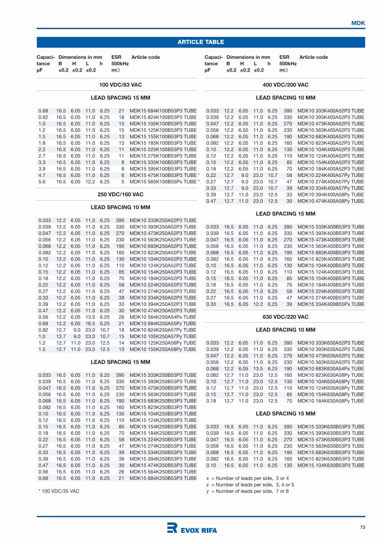
73
MDK
ARTICLE TABLE
Capaci- Dimensions in mm ESR Article code
tance B H L h 500kHz
µF ±0.2 ±0.2 ±0.2 m
Capaci- Dimensions in mm ESR Article code
tance B H L h 500kHz
µF ±0.2 ±0.2 ±0.2 m
100 VDC/63 VAC
LEAD SPACING 15 MM
0.68 16.5 6.05 11.0 6.25 21 MDK15 684K100B53P3 TUBE
0.82 16.5 6.05 11.0 6.25 18 MDK15 824K100B53P3 TUBE
1.0 16.5 6.05 11.0 6.25 15 MDK15 105K100B53P3 TUBE
1.2 16.5 6.05 11.0 6.25 15 MDK15 125K100B53P3 TUBE
1.5 16.5 6.05 11.0 6.25 13 MDK15 155K100B53P3 TUBE
1.8 16.5 6.05 11.0 6.25 13 MDK15 185K100B53P3 TUBE
2.2 16.5 6.05 11.0 6.25 11 MDK15 225K100B53P3 TUBE
2.7 16.5 6.05 11.0 6.25 11 MDK15 275K100B53P3 TUBE
3.3 16.5 6.05 11.0 6.25 8 MDK15 335K100B53P3 TUBE
3.9 16.5 6.05 11.0 6.25 8 MDK15 395K100B53P3 TUBE
4.7 16.5 6.05 11.0 6.25 6 MDK15 475K100B53P3 TUBE *
5.6 16.5 6.05 12.2 6.25 5 MDK15 565K100B55Px TUBE *
250 VDC/160 VAC
LEAD SPACING 10 MM
0.033 12.2 6.05 11.0 6.25 390 MDK10 333K250A52P3 TUBE
0.039 12.2 6.05 11.0 6.25 330 MDK10 393K250A52P3 TUBE
0.047 12.2 6.05 11.0 6.25 270 MDK10 473K250A52P3 TUBE
0.056 12.2 6.05 11.0 6.25 230 MDK10 563K250A52P3 TUBE
0.068 12.2 6.05 11.0 6.25 190 MDK10 683K250A52P3 TUBE
0.082 12.2 6.05 11.0 6.25 160 MDK10 823K250A52P3 TUBE
0.10 12.2 6.05 11.0 6.25 130 MDK10 104K250A52P3 TUBE
0.12 12.2 6.05 11.0 6.25 110 MDK10 124K250A52P3 TUBE
0.15 12.2 6.05 11.0 6.25 85 MDK10 154K250A52P3 TUBE
0.18 12.2 6.05 11.0 6.25 70 MDK10 184K250A52P3 TUBE
0.22 12.2 6.05 11.0 6.25 58 MDK10 224K250A52P3 TUBE
0.27 12.2 6.05 11.0 6.25 47 MDK10 274K250A52P3 TUBE
0.33 12.2 6.05 11.0 6.25 39 MDK10 334K250A52P3 TUBE
0.39 12.2 6.05 11.0 6.25 33 MDK10 394K250A52P3 TUBE
0.47 12.2 6.05 11.0 6.25 30 MDK10 474K250A52P3 TUBE
0.56 12.2 6.05 13.5 6.25 26 MDK10 564K250A54Px TUBE
0.68 12.2 6.05 16.5 6.25 21 MDK10 684K250A55Pz TUBE
0.82 12.7 9.0 23.0 10.7 18 MDK10 824K250A57Py TUBE
1.0 12.7 9.0 23.0 10.7 15 MDK10 105K250A57Py TUBE
1.2 12.7 11.0 23.0 12.5 14 MDK10 125K250A58Py TUBE
1.5 12.7 11.0 23.0 12.5 13 MDK10 155K250A58Py TUBE
LEAD SPACING 15 MM
0.033 16.5 6.05 11.0 6.25 390 MDK15 333K250B53P3 TUBE
0.039 16.5 6.05 11.0 6.25 330 MDK15 393K250B53P3 TUBE
0.047 16.5 6.05 11.0 6.25 270 MDK15 473K250B53P3 TUBE
0.056 16.5 6.05 11.0 6.25 230 MDK15 563K250B53P3 TUBE
0.068 16.5 6.05 11.0 6.25 190 MDK15 683K250B53P3 TUBE
0.082 16.5 6.05 11.0 6.25 160 MDK15 823K250B53P3 TUBE
0.10 16.5 6.05 11.0 6.25 130 MDK15 104K250B53P3 TUBE
0.12 16.5 6.05 11.0 6.25 110 MDK15 124K250B53P3 TUBE
0.15 16.5 6.05 11.0 6.25 85 MDK15 154K250B53P3 TUBE
0.18 16.5 6.05 11.0 6.25 70 MDK15 184K250B53P3 TUBE
0.22 16.5 6.05 11.0 6.25 58 MDK15 224K250B53P3 TUBE
0.27 16.5 6.05 11.0 6.25 47 MDK15 274K250B53P3 TUBE
0.33 16.5 6.05 11.0 6.25 39 MDK15 334K250B53P3 TUBE
0.39 16.5 6.05 11.0 6.25 39 MDK15 394K250B53P3 TUBE
0.47 16.5 6.05 11.0 6.25 30 MDK15 474K250B53P3 TUBE
0.56 16.5 6.05 11.0 6.25 26 MDK15 564K250B53P3 TUBE
0.68 16.5 6.05 11.0 6.25 21 MDK15 684K250B53P3 TUBE
* 100 VDC/35 VAC
400 VDC/200 VAC
LEAD SPACING 10 MM
0.033 12.2 6.05 11.0 6.25 390 MDK10 333K400A52P3 TUBE
0.039 12.2 6.05 11.0 6.25 330 MDK10 393K400A52P3 TUBE
0.047 12.2 6.05 11.0 6.25 270 MDK10 473K400A52P3 TUBE
0.056 12.2 6.05 11.0 6.25 230 MDK10 563K400A52P3 TUBE
0.068 12.2 6.05 11.0 6.25 190 MDK10 683K400A52P3 TUBE
0.082 12.2 6.05 11.0 6.25 160 MDK10 823K400A52P3 TUBE
0.10 12.2 6.05 11.0 6.25 130 MDK10 104K400A52P3 TUBE
0.12 12.2 6.05 11.0 6.25 110 MDK10 124K400A52P3 TUBE
0.15 12.2 6.05 11.0 6.25 85 MDK10 154K400A52P3 TUBE
0.18 12.2 6.05 11.0 6.25 70 MDK10 184K400A52P3 TUBE
0.22 12.7 9.0 23.0 10.7 58 MDK10 224K400A57Py TUBE
0.27 12.7 9.0 23.0 10.7 47 MDK10 274K400A57Py TUBE
0.33 12.7 9.0 23.0 10.7 39 MDK10 334K400A57Py TUBE
0.39 12.7 11.0 23.0 12.5 33 MDK10 394K400A58Py TUBE
0.47 12.7 11.0 23.0 12.5 30 MDK10 474K400A58Py TUBE
LEAD SPACING 15 MM
0.033 16.5 6.05 11.0 6.25 390 MDK15 333K400B53P3 TUBE
0.039 16.5 6.05 11.0 6.25 330 MDK15 393K400B53P3 TUBE
0.047 16.5 6.05 11.0 6.25 270 MDK15 473K400B53P3 TUBE
0.056 16.5 6.05 11.0 6.25 230 MDK15 563K400B53P3 TUBE
0.068 16.5 6.05 11.0 6.25 190 MDK15 683K400B53P3 TUBE
0.082 16.5 6.05 11.0 6.25 160 MDK15 823K400B53P3 TUBE
0.10 16.5 6.05 11.0 6.25 130 MDK15 104K400B53P3 TUBE
0.12 16.5 6.05 11.0 6.25 110 MDK15 124K400B53P3 TUBE
0.15 16.5 6.05 11.0 6.25 85 MDK15 154K400B53P3 TUBE
0.18 16.5 6.05 11.0 6.25 70 MDK15 184K400B53P3 TUBE
0.22 16.5 6.05 11.0 6.25 58 MDK15 224K400B53P3 TUBE
0.27 16.5 6.05 11.0 6.25 47 MDK15 274K400B53P3 TUBE
0.33 16.5 6.05 12.2 6.25 39 MDK15 334K400B55Px TUBE
630 VDC/220 VAC
LEAD SPACING 10 MM
0.033 12.2 6.05 11.0 6.25 390 MDK10 333K630A52P3 TUBE
0.039 12.2 6.05 11.0 6.25 330 MDK10 393K630A52P3 TUBE
0.047 12.2 6.05 11.0 6.25 270 MDK10 473K630A52P3 TUBE
0.056 12.2 6.05 11.0 6.25 230 MDK10 563K630A52P3 TUBE
0.068 12.2 6.05 13.5 6.25 190 MDK10 683K630A54Px TUBE
0.082 12.7 11.0 23.0 12.5 160 MDK10 823K630A58Py TUBE
0.10 12.7 11.0 23.0 12.5 130 MDK10 104K630A58Py TUBE
0.12 12.7 11.0 23.0 12.5 110 MDK10 124K630A58Py TUBE
0.15 12.7 11.0 23.0 12.5 85 MDK10 154K630A58Py TUBE
0.18 12.7 11.0 23.0 12.5 70 MDK10 184K630A58Py TUBE
LEAD SPACING 15 MM
0.033 16.5 6.05 11.0 6.25 390 MDK15 333K630B53P3 TUBE
0.039 16.5 6.05 11.0 6.25 330 MDK15 393K630B53P3 TUBE
0.047 16.5 6.05 11.0 6.25 270 MDK15 473K630B53P3 TUBE
0.056 16.5 6.05 11.0 6.25 230 MDK15 563K630B53P3 TUBE
0.068 16.5 6.05 11.0 6.25 190 MDK15 683K630B53P3 TUBE
0.082 16.5 6.05 11.0 6.25 160 MDK15 823K630B53P3 TUBE
0.10 16.5 6.05 11.0 6.25 130 MDK15 104K630B53P3 TUBE
x = Number of leads per side, 3 or 4
z = Number of leads per side, 3, 4 or 5
y = Number of leads per side, 7 or 8

74
RoHSCompliant
Rated voltage UR VDC 50 100 250 400 630
Rated voltage UR VAC 30 63 160 200 220
Capacitance range, µF 0.033 - 0.033 - 0.033 - 0.033 - 0.033 -
6.8 5.6 0.68 0.33 0.10
Capacitance tolerance ± 10%, ± 5%, other tolerances on request
Category temperature range –55 to +125°C
Rated temperature +85 °C
Voltage derating The rated voltage is decreased with 1.25%/°C
from +85 °C
Climatic category 55/125/56
Test voltage 1.6 x UR, 60s
Insulation resistance Minimum value between terminals
Measured at +20 °C according to IEC 60384-2
C 0.33 µF C 0.33 µF
UR
100 V 15 000 M 5 000 s
UR > 100 V 30 000 M 10 000 s
Dissipation factor Maximum values at +23°C
C 0.1 µF 0.1 < C 3.3 µF 3.3 < C 10 µF C 10 µF
1 kHz 0.8 % 0.8 % 0.8 % 0.8 %
10 kHz 1.5 % 1.5 % 1.5 % 2.0 %
100 kHz 2.5 % 5.0 % —kk —
Self inductancy Approximately 4 nH
MDS• Metallized polyester (PET) DIL
• Low ESR and ESL
• Three and four pole connection possible
• Good temperature stability
• No voltage dependence of capacitance and dissipation factor
TYPICAL APPLICATIONS CONSTRUCTION
TECHNICAL DATA
High frequency switched mode power
supplies and DC-DC converters. Input/
output filtering.
DIL metallized polyester (PET) film
capacitor. Encapsulation in self-
extinguishing material meeting the
requirements of UL 94V-0.
L
H
B
p
h
2.54
1.2
0.3
0.35 0.051.5 to 3.2
0.5 0.05
Detail of a lead
Typical capacitance vs temperature
at 1 kHz
Typical dissipation factor vs temperature at
1 kHz
tan x 10-3
-50 -25 0 25 50 75 100
10
-550
5
15
C/C%
-25 0 25 50 75 100 125
5
-50 -5
0
10

75
Temperature ( C)
200
30 60 90 120 150 180 210
160
120
40
80
240 270 3303000
280
0
Time (s)
150 C
170 C
223 C
Max 240 C
Min. 30 s,
max 50 s
above 217 C
RECOMMENDED SOLDERING CONDITIONS
Reflow soldering on the top body surface of the component
Preheating temperature should be less than 170°C. The time above 217°C
should be less than 50 s. The peak temperature must not exceed 240°C.
Recommended reflow soldering profile for
products manufactured in March 2007 at
the earliest. For detailed information see
page 19.
MDS
TYPICAL DATA
10ESR ( )
Frequency (kHz)
1
0.1
0.1 1 10 100
1 F2.2 F3.9 F4.7 F6.8 F10 F
1000
0.01
0.001
10000
Z ( )
1000
100
10
1
0.1
0.01
0.001
0.1 kHz 1 kHz 10 kHz 100 kHz 1 MHz 10 MHz
Frequency
10 F6.8 F4.7 F3.9 F2.2 F1 F
ESR vs. frequency Impedance vs. frequency
• EVOX
• Rated capacitance according to
IEC 60062
• Capacitance tolerance code
• Rated voltage
• Capacitor family code MDS
MARKINGORDERING INFORMATION
See article table and page 10 for options and article code construction.
Maximum RMS current IRMS
(A) vs. frequency
Value Rated Case 1 kHz 10 kHz 100 kHz 500 kHz 1 MHz
voltage size
1.0 F 250 V A57 1.0 2.2 5.5 9.0 10.0
2.2 F 100 V A52 1.5 2.3 6.0 7.5 10.0
3.9 F 100 V A52 2.0 4.0 10.0 11.0 11.5
4.7 F 100 V A54 2.0 4.5 10.0 12.5 12.5
6.8 F 100 V A57 3.0 6.0 11.0 13.0 13.5
10 F 100 V A58 4.0 9.0 13.0 14.0 14.5
Maximum RMS voltage URMS
(V) vs. frequency
Value Rated Case 1 kHz 10 kHz 100 kHz 500 kHz 1 MHz
voltage size
1.0 F 250 V A57 150.0 36.0 9.2 2.9 1.3
2.2 F 100 V A52 50.0 25.0 5.0 1.2 0.6
3.9 F 100 V A52 50.0 18.0 4.0 1.0 0.3
4.7 F 100 V A54 50.0 16.0 3.5 0.7 0.2
6.8 F 100 V A57 50.0 15.5 2.2 0.5 0.2
10 F 100 V A58 50.0 15.0 2.0 0.4 0.2
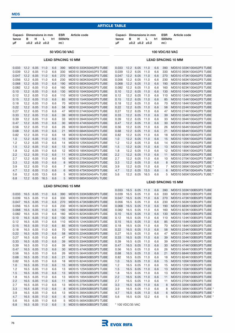
76
MDS
ARTICLE TABLE
50 VDC/30 VAC
LEAD SPACING 10 MM
0.033 12.2 6.05 11.0 6.6 390 MDS10 333K50A52P3 TUBE
0.039 12.2 6.05 11.0 6.6 330 MDS10 393K50A52P3 TUBE
0.047 12.2 6.05 11.0 6.6 270 MDS10 473K50A52P3 TUBE
0.056 12.2 6.05 11.0 6.6 230 MDS10 563K50A52P3 TUBE
0.068 12.2 6.05 11.0 6.6 190 MDS10 683K50A52P3 TUBE
0.082 12.2 6.05 11.0 6.6 160 MDS10 823K50A52P3 TUBE
0.10 12.2 6.05 11.0 6.6 130 MDS10 104K50A52P3 TUBE
0.12 12.2 6.05 11.0 6.6 110 MDS10 124K50A52P3 TUBE
0.15 12.2 6.05 11.0 6.6 85 MDS10 154K50A52P3 TUBE
0.18 12.2 6.05 11.0 6.6 70 MDS10 184K50A52P3 TUBE
0.22 12.2 6.05 11.0 6.6 58 MDS10 224K50A52P3 TUBE
0.27 12.2 6.05 11.0 6.6 47 MDS10 274K50A52P3 TUBE
0.33 12.2 6.05 11.0 6.6 39 MDS10 334K50A52P3 TUBE
0.39 12.2 6.05 11.0 6.6 33 MDS10 394K50A52P3 TUBE
0.47 12.2 6.05 11.0 6.6 30 MDS10 474K50A52P3 TUBE
0.56 12.2 6.05 11.0 6.6 26 MDS10 564K50A52P3 TUBE
0.68 12.2 6.05 11.0 6.6 21 MDS10 684K50A52P3 TUBE
0.82 12.2 6.05 11.0 6.6 18 MDS10 824K50A52P3 TUBE
1.0 12.2 6.05 11.0 6.6 15 MDS10 105K50A52P3 TUBE
1.2 12.2 6.05 11.0 6.6 14 MDS10 125K50A52P3 TUBE
1.5 12.2 6.05 11.0 6.6 13 MDS10 155K50A52P3 TUBE
1.8 12.2 6.05 11.0 6.6 12 MDS10 185K50A52P3 TUBE
2.2 12.2 6.05 11.0 6.6 11 MDS10 225K50A52P3 TUBE
2.7 12.2 6.05 11.0 6.6 10 MDS10 275K50A52P3 TUBE
3.3 12.2 6.05 11.0 6.6 8 MDS10 335K50A52P3 TUBE
3.9 12.2 6.05 11.0 6.6 7 MDS10 395K50A52P3 TUBE
4.7 12.2 6.05 11.0 6.6 6 MDS10 475K50A52P3 TUBE
5.6 12.2 6.05 13.5 6.6 5 MDS10 565K50A54Px TUBE
6.8 12.2 6.05 16.5 6.6 5 MDS10 685K50A55Pz TUBE
LEAD SPACING 15 MM
0.033 16.5 6.05 11.0 6.6 390 MDS15 333K50B53P3 TUBE
0.039 16.5 6.05 11.0 6.6 330 MDS15 393K50B53P3 TUBE
0.047 16.5 6.05 11.0 6.6 270 MDS15 473K50B53P3 TUBE
0.056 16.5 6.05 11.0 6.6 230 MDS15 563K50B53P3 TUBE
0.068 16.5 6.05 11.0 6.6 190 MDS15 683K50B53P3 TUBE
0.082 16.5 6.05 11.0 6.6 160 MDS15 823K50B53P3 TUBE
0.10 16.5 6.05 11.0 6.6 130 MDS15 104K50B53P3 TUBE
0.12 16.5 6.05 11.0 6.6 110 MDS15 124K50B53P3 TUBE
0.15 16.5 6.05 11.0 6.6 85 MDS15 154K50B53P3 TUBE
0.18 16.5 6.05 11.0 6.6 70 MDS15 184K50B53P3 TUBE
0.22 16.5 6.05 11.0 6.6 58 MDS15 224K50B53P3 TUBE
0.27 16.5 6.05 11.0 6.6 47 MDS15 274K50B53P3 TUBE
0.33 16.5 6.05 11.0 6.6 39 MDS15 334K50B53P3 TUBE
0.39 16.5 6.05 11.0 6.6 39 MDS15 394K50B53P3 TUBE
0.47 16.5 6.05 11.0 6.6 30 MDS15 474K50B53P3 TUBE
0.56 16.5 6.05 11.0 6.6 26 MDS15 564K50B53P3 TUBE
0.68 16.5 6.05 11.0 6.6 21 MDS15 684K50B53P3 TUBE
0.82 16.5 6.05 11.0 6.6 18 MDS15 824K50B53P3 TUBE
1.0 16.5 6.05 11.0 6.6 15 MDS15 105K50B53P3 TUBE
1.2 16.5 6.05 11.0 6.6 13 MDS15 125K50B53P3 TUBE
1.5 16.5 6.05 11.0 6.6 13 MDS15 155K50B53P3 TUBE
1.8 16.5 6.05 11.0 6.6 13 MDS15 185K50B53P3 TUBE
2.2 16.5 6.05 11.0 6.6 11 MDS15 225K50B53P3 TUBE
2.7 16.5 6.05 11.0 6.6 13 MDS15 275K50B53P3 TUBE
3.3 16.5 6.05 11.0 6.6 8 MDS15 335K50B53P3 TUBE
3.9 16.5 6.05 11.0 6.6 13 MDS15 395K50B53P3 TUBE
4.7 16.5 6.05 11.0 6.6 6 MDS15 475K50B53P3 TUBE
5.6 16.5 6.05 11.0 6.6 5 MDS15 565K50B53P3 TUBE
6.8 16.5 6.05 11.0 6.6 5 MDS15 685K50B53P3 TUBE
100 VDC/63 VAC
LEAD SPACING 10 MM
0.033 12.2 6.05 11.0 6.6 390 MDS10 333K100A52P3 TUBE
0.039 12.2 6.05 11.0 6.6 330 MDS10 393K100A52P3 TUBE
0.047 12.2 6.05 11.0 6.6 270 MDS10 473K100A52P3 TUBE
0.056 12.2 6.05 11.0 6.6 230 MDS10 563K100A52P3 TUBE
0.068 12.2 6.05 11.0 6.6 190 MDS10 683K100A52P3 TUBE
0.082 12.2 6.05 11.0 6.6 160 MDS10 823K100A52P3 TUBE
0.10 12.2 6.05 11.0 6.6 130 MDS10 104K100A52P3 TUBE
0.12 12.2 6.05 11.0 6.6 110 MDS10 124K100A52P3 TUBE
0.15 12.2 6.05 11.0 6.6 85 MDS10 154K100A52P3 TUBE
0.18 12.2 6.05 11.0 6.6 70 MDS10 184K100A52P3 TUBE
0.22 12.2 6.05 11.0 6.6 58 MDS10 224K100A52P3 TUBE
0.27 12.2 6.05 11.0 6.6 47 MDS10 274K100A52P3 TUBE
0.33 12.2 6.05 11.0 6.6 39 MDS10 334K100A52P3 TUBE
0.39 12.2 6.05 11.0 6.6 33 MDS10 394K100A52P3 TUBE
0.47 12.2 6.05 11.0 6.6 30 MDS10 474K100A52P3 TUBE
0.56 12.2 6.05 11.0 6.6 26 MDS10 564K100A52P3 TUBE
0.68 12.2 6.05 11.0 6.6 21 MDS10 684K100A52P3 TUBE
0.82 12.2 6.05 11.0 6.6 18 MDS10 824K100A52P3 TUBE
1.0 12.2 6.05 11.0 6.6 15 MDS10 105K100A52P3 TUBE
1.2 12.2 6.05 11.0 6.6 14 MDS10 125K100A52P3 TUBE
1.5 12.2 6.05 11.0 6.6 13 MDS10 155K100A52P3 TUBE
1.8 12.2 6.05 11.0 6.6 12 MDS10 185K100A52P3 TUBE
2.2 12.2 6.05 11.0 6.6 11 MDS10 225K100A52P3 TUBE
2.7 12.2 6.05 11.0 6.6 10 MDS10 275K100A52P3 TUBE *
3.3 12.2 6.05 11.0 6.6 8 MDS10 335K100A52P3 TUBE *
3.9 12.2 6.05 11.0 6.6 7 MDS10 395K100A52P3 TUBE *
4.7 12.2 6.05 13.5 6.6 6 MDS10 475K100A54Px TUBE *
5.6 12.2 6.05 16.5 6.6 5 MDS10 565K100A55Pz TUBE *
LEAD SPACING 15 MM
0.033 16.5 6.05 11.0 6.6 390 MDS15 333K100B53P3 TUBE
0.039 16.5 6.05 11.0 6.6 330 MDS15 393K100B53P3 TUBE
0.047 16.5 6.05 11.0 6.6 270 MDS15 473K100B53P3 TUBE
0.056 16.5 6.05 11.0 6.6 230 MDS15 563K100B53P3 TUBE
0.068 16.5 6.05 11.0 6.6 190 MDS15 683K100B53P3 TUBE
0.082 16.5 6.05 11.0 6.6 160 MDS15 823K100B53P3 TUBE
0.10 16.5 6.05 11.0 6.6 130 MDS15 104K100B53P3 TUBE
0.12 16.5 6.05 11.0 6.6 110 MDS15 124K100B53P3 TUBE
0.15 16.5 6.05 11.0 6.6 85 MDS15 154K100B53P3 TUBE
0.18 16.5 6.05 11.0 6.6 70 MDS15 184K100B53P3 TUBE
0.22 16.5 6.05 11.0 6.6 58 MDS15 224K100B53P3 TUBE
0.27 16.5 6.05 11.0 6.6 47 MDS15 274K100B53P3 TUBE
0.33 16.5 6.05 11.0 6.6 39 MDS15 334K100B53P3 TUBE
0.39 16.5 6.05 11.0 6.6 39 MDS15 394K100B53P3 TUBE
0.47 16.5 6.05 11.0 6.6 30 MDS15 474K100B53P3 TUBE
0.56 16.5 6.05 11.0 6.6 26 MDS15 564K100B53P3 TUBE
0.68 16.5 6.05 11.0 6.6 21 MDS15 684K100B53P3 TUBE
0.82 16.5 6.05 11.0 6.6 18 MDS15 824K100B53P3 TUBE
1.0 16.5 6.05 11.0 6.6 15 MDS15 105K100B53P3 TUBE
1.2 16.5 6.05 11.0 6.6 15 MDS15 125K100B53P3 TUBE
1.5 16.5 6.05 11.0 6.6 13 MDS15 155K100B53P3 TUBE
1.8 16.5 6.05 11.0 6.6 13 MDS15 185K100B53P3 TUBE
2.2 16.5 6.05 11.0 6.6 11 MDS15 225K100B53P3 TUBE
2.7 16.5 6.05 11.0 6.6 11 MDS15 275K100B53P3 TUBE
3.3 16.5 6.05 11.0 6.6 8 MDS15 335K100B53P3 TUBE
3.9 16.5 6.05 11.0 6.6 8 MDS15 395K100B53P3 TUBE *
4.7 16.5 6.05 11.0 6.6 6 MDS15 475K100B53P3 TUBE *
5.6 16.5 6.05 12.2 6.6 5 MDS15 565K100B55Px TUBE *
* 100 VDC/35 VAC
Capaci- Dimensions in mm ESR Article code
tance B H L h1 500kHz
µF ±0.2 ±0.2 ±0.2 m
Capaci- Dimensions in mm ESR Article code
tance B H L h1 500kHz
µF ±0.2 ±0.2 ±0.2 m
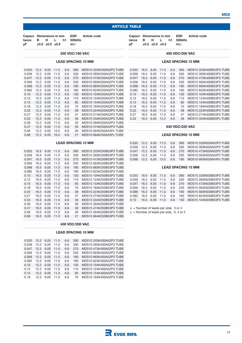
77
MDS
ARTICLE TABLE
Capaci- Dimensions in mm ESR Article code
tance B H L h1 500kHz
µF ±0.2 ±0.2 ±0.2 m
Capaci- Dimensions in mm ESR Article code
tance B H L h1 500kHz
µF ±0.2 ±0.2 ±0.2 m
250 VDC/160 VAC
LEAD SPACING 10 MM
0.033 12.2 6.05 11.0 6.6 390 MDS10 333K250A52P3 TUBE
0.039 12.2 6.05 11.0 6.6 330 MDS10 393K250A52P3 TUBE
0.047 12.2 6.05 11.0 6.6 270 MDS10 473K250A52P3 TUBE
0.056 12.2 6.05 11.0 6.6 230 MDS10 563K250A52P3 TUBE
0.068 12.2 6.05 11.0 6.6 190 MDS10 683K250A52P3 TUBE
0.082 12.2 6.05 11.0 6.6 160 MDS10 823K250A52P3 TUBE
0.10 12.2 6.05 11.0 6.6 130 MDS10 104K250A52P3 TUBE
0.12 12.2 6.05 11.0 6.6 110 MDS10 124K250A52P3 TUBE
0.15 12.2 6.05 11.0 6.6 85 MDS10 154K250A52P3 TUBE
0.18 12.2 6.05 11.0 6.6 70 MDS10 184K250A52P3 TUBE
0.22 12.2 6.05 11.0 6.6 58 MDS10 224K250A52P3 TUBE
0.27 12.2 6.05 11.0 6.6 47 MDS10 274K250A52P3 TUBE
0.33 12.2 6.05 11.0 6.6 39 MDS10 334K250A52P3 TUBE
0.39 12.2 6.05 11.0 6.6 33 MDS10 394K250A52P3 TUBE
0.47 12.2 6.05 11.0 6.6 30 MDS10 474K250A52P3 TUBE
0.56 12.2 6.05 13.5 6.6 26 MDS10 564K250A54Px TUBE
0.68 12.2 6.05 16.5 6.6 21 MDS10 684K250A55Pz TUBE
LEAD SPACING 15 MM
0.033 16.5 6.05 11.0 6.6 390 MDS15 333K250B53P3 TUBE
0.039 16.5 6.05 11.0 6.6 330 MDS15 393K250B53P3 TUBE
0.047 16.5 6.05 11.0 6.6 270 MDS15 473K250B53P3 TUBE
0.056 16.5 6.05 11.0 6.6 230 MDS15 563K250B53P3 TUBE
0.068 16.5 6.05 11.0 6.6 190 MDS15 683K250B53P3 TUBE
0.082 16.5 6.05 11.0 6.6 160 MDS15 823K250B53P3 TUBE
0.10 16.5 6.05 11.0 6.6 130 MDS15 104K250B53P3 TUBE
0.12 16.5 6.05 11.0 6.6 110 MDS15 124K250B53P3 TUBE
0.15 16.5 6.05 11.0 6.6 85 MDS15 154K250B53P3 TUBE
0.18 16.5 6.05 11.0 6.6 70 MDS15 184K250B53P3 TUBE
0.22 16.5 6.05 11.0 6.6 58 MDS15 224K250B53P3 TUBE
0.27 16.5 6.05 11.0 6.6 47 MDS15 274K250B53P3 TUBE
0.33 16.5 6.05 11.0 6.6 39 MDS15 334K250B53P3 TUBE
0.39 16.5 6.05 11.0 6.6 39 MDS15 394K250B53P3 TUBE
0.47 16.5 6.05 11.0 6.6 30 MDS15 474K250B53P3 TUBE
0.56 16.5 6.05 11.0 6.6 26 MDS15 564K250B53P3 TUBE
0.68 16.5 6.05 11.0 6.6 21 MDS15 684K250B53P3 TUBE
400 VDC/200 VAC
LEAD SPACING 10 MM
0.033 12.2 6.05 11.0 6.6 390 MDS10 333K400A52P3 TUBE
0.039 12.2 6.05 11.0 6.6 330 MDS10 393K400A52P3 TUBE
0.047 12.2 6.05 11.0 6.6 270 MDS10 473K400A52P3 TUBE
0.056 12.2 6.05 11.0 6.6 230 MDS10 563K400A52P3 TUBE
0.068 12.2 6.05 11.0 6.6 190 MDS10 683K400A52P3 TUBE
0.082 12.2 6.05 11.0 6.6 160 MDS10 823K400A52P3 TUBE
0.10 12.2 6.05 11.0 6.6 130 MDS10 104K400A52P3 TUBE
0.12 12.2 6.05 11.0 6.6 110 MDS10 124K400A52P3 TUBE
0.15 12.2 6.05 11.0 6.6 85 MDS10 154K400A52P3 TUBE
0.18 12.2 6.05 11.0 6.6 70 MDS10 184K400A52P3 TUBE
400 VDC/200 VAC
LEAD SPACING 15 MM
0.033 16.5 6.05 11.0 6.6 390 MDS15 333K400B53P3 TUBE
0.039 16.5 6.05 11.0 6.6 330 MDS15 393K400B53P3 TUBE
0.047 16.5 6.05 11.0 6.6 270 MDS15 473K400B53P3 TUBE
0.056 16.5 6.05 11.0 6.6 230 MDS15 563K400B53P3 TUBE
0.068 16.5 6.05 11.0 6.6 190 MDS15 683K400B53P3 TUBE
0.082 16.5 6.05 11.0 6.6 160 MDS15 823K400B53P3 TUBE
0.10 16.5 6.05 11.0 6.6 130 MDS15 104K400B53P3 TUBE
0.12 16.5 6.05 11.0 6.6 110 MDS15 124K400B53P3 TUBE
0.15 16.5 6.05 11.0 6.6 85 MDS15 154K400B53P3 TUBE
0.18 16.5 6.05 11.0 6.6 70 MDS15 184K400B53P3 TUBE
0.22 16.5 6.05 11.0 6.6 58 MDS15 224K400B53P3 TUBE
0.27 16.5 6.05 11.0 6.6 47 MDS15 274K400B53P3 TUBE
0.33 16.5 6.05 12.2 6.6 39 MDS15 334K400B55Px TUBE
630 VDC/220 VAC
LEAD SPACING 10 MM
0.033 12.2 6.05 11.0 6.6 390 MDS10 333K630A52P3 TUBE
0.039 12.2 6.05 11.0 6.6 330 MDS10 393K630A52P3 TUBE
0.047 12.2 6.05 11.0 6.6 270 MDS10 473K630A52P3 TUBE
0.056 12.2 6.05 11.0 6.6 230 MDS10 563K630A52P3 TUBE
0.068 12.2 6.05 13.5 6.6 190 MDS10 683K630A54Px TUBE
LEAD SPACING 15 MM
0.033 16.5 6.05 11.0 6.6 390 MDS15 333K630B53P3 TUBE
0.039 16.5 6.05 11.0 6.6 330 MDS15 393K630B53P3 TUBE
0.047 16.5 6.05 11.0 6.6 270 MDS15 473K630B53P3 TUBE
0.056 16.5 6.05 11.0 6.6 230 MDS15 563K630B53P3 TUBE
0.068 16.5 6.05 11.0 6.6 190 MDS15 683K630B53P3 TUBE
0.082 16.5 6.05 11.0 6.6 160 MDS15 823K630B53P3 TUBE
0.10 16.5 6.05 11.0 6.6 130 MDS15 104K630B53P3 TUBE
x = Number of leads per side, 3 or 4
z = Number of leads per side, 3, 4 or 5