selection and analysis of material for boiler pipes in a...
TRANSCRIPT

Procedia Engineering 149 ( 2016 ) 216 – 223
1877-7058 © 2016 The Authors. Published by Elsevier Ltd. This is an open access article under the CC BY-NC-ND license (http://creativecommons.org/licenses/by-nc-nd/4.0/).Peer-review under responsibility of the organizing committee of ICMEM 2016doi: 10.1016/j.proeng.2016.06.659
ScienceDirectAvailable online at www.sciencedirect.com
* Corresponding author. Tel.:+381-64-276-39-81. E-mail address: [email protected]
International Conference on Manufacturing Engineering and Materials, ICMEM 2016, 6-10 June 2016, Nový Smokovec, Slovakia
Selection and analysis of material for boiler pipes in a steam plant
Vukić Lazića, Dušan Arsića,*, Ružica R. Nikolića,b, Dragan Rakića, Srbislav Aleksandrovića, Milan Djordjevića, Branislav Hadzimab
a Faculty of Engineering University of Kragujevac, Sestre Janjić 6, 34000 Kragujevac, Serbia b Research Center, University of Žilina, Univerzitna 8215/1, Žilina 010 26, Slovakia.
Abstract
The problems of a material selection for making the boiler pipes in a responsible steam plant and the technology for their welding are considered in this paper. The boiler is screened, complex, radiating energetic plant, with the natural water circulation in the hanging steel structure. Based on the legal regulations, the mandatory periodic reparation of the most important components is performed. This is why the check of mechanical properties, for the used and new materials for eventual replacement and building-in was done, as well as the check of the prescribed reparation procedures. The components that were in exploitation were checked, since their properties change with time. Checking consisted of testing the tensile material properties at room and elevated temperatures, measurements of hardness and analysis of materials' microstructures. Besides the experimental tests, the numerical modeling and analysis of the workload of the fluid transporting pipes was conducted. In that way it was established which material is optimal for manufacturing the boiler pipes. © 2016 The Authors. Published by Elsevier B.V. Peer-review under responsibility of the organizing committee of ICMEM 2016.
Keywords: Screened steam boiler; low-carbon structural steel; seamless pipes; mechanical properties; welding.
1. Introduction
Metal materials are generally used for manufacturing the boiler components, mainly the carbon and alloyed steels. The largest number of subassemblies and assemblies of the boiler are made by various welding procedures. The manufactured parts are exposed to influence of time, what could cause degradation of some of material characteristics, so their reliability must be checked [1, 2]. According to the place of mounting, components are divided into those exposed to water or steam pressure and to high temperatures. In addition, certain components are subjected to various kinds of external loadings and chemical influences, what has additional negative effect on integrity of the structure. It is not infrequent that materials can have flaws like cracks or non-metallic inclusions, due to what the exploitation characteristics of the structure are significantly reduced [3].
Results of theoretical, experimental and numerical investigations, whose objectives were to verify various properties of the most loaded components (both existing ones and the newly made), at room and elevated temperatures, are presented in this paper. In addition, the technology of pipes joining by gas welding was checked, since the considered boiler pipes are joined by welding.
Similar boiler installations were subject of research of numerous authors. Milović et al. [4] presented estimate of integrity of the pressure vessels made of the low-alloyed steel. The integrity estimate was done by experimental measurements of the J-integral at the working temperature of – 40 °C. Then they performed the numerical simulation whose results were in agreement
© 2016 The Authors. Published by Elsevier Ltd. This is an open access article under the CC BY-NC-ND license (http://creativecommons.org/licenses/by-nc-nd/4.0/).Peer-review under responsibility of the organizing committee of ICMEM 2016

217 Vukić Lazić et al. / Procedia Engineering 149 ( 2016 ) 216 – 223
Nomenclature
Rm – Tensile strength Rp0.2 – Yield stress Rp0.2min – Minimal yield stress A5 – Elongation BM – Base metal HAZ – Heat affected zone WM – Weld metal E – Elasticity modulus
– Poisson's ratio – Linear thermal expansion coefficient M100000 – Permanent time strength
l0 – Specimen measurement length a – Wall thickness b – Sample width
with experimental ones. Jovičić et al. in [5] have shown that the reservoir for storage of liquids is prone to appearance of cracks in the welded joints. The subject of the research was to point to possibilities for revitalization of the damaged plants by eliminating the flaws and re-welding. In welded structures the flaws can frequently appear during the manufacturing process, what was shown by Balać et al. in [6]. They performed the numerical investigation of behavior of a pressure vessel, to whose shell two connectors were welded. In that way, the critical point on the structure for appearance of the fatigue crack was successfully determined by application of the Finite Element Method. The similar procedure was applied by Žmindak et al. in [7] for numerical analysis of the radial crack and the crack on the Y-joint on the pipe for fluid transport. Katavic et al. [8] have presented an analysis of damages on the boiler's pipes as well as procedures for elimination or reparation of those damages. The problem that they noticed appears at the back screen of the boiler's combustion chamber of a boiler, in the area attacked by the burner's flame. An evaluation of the quality of a reservoir after reparation of cracks was presented in Bakić et al. [9], what testifies about importance of the structural operation safety after revitalization. The authors were in fact dealing with criteria, which are defined by the corresponding ISO and EN standards that the repaired plant should satisfy. Dimić et al. [10] have analyzed influence of flaws in the welded joint on integrity of pipes subjected to internal pressure. They first identified the flaws – the lack of penetration – by the ultrasound testing and then examined their influence on the structure's reliability by the FEM modeling. It was concluded that the present flaw does not decisively influence the reliability of a structure; however, the fracture could result from the crack that appeared at the outside of the pipe. The similar pipes were investigated by Rakin et al. in [11] where, also both by measurement and numerical analysis, was established that the existing crack is not immanently dangerous, but here further propagation above the critical value, could lead to fracture. Szubka et al. [12] have also analyzed potential causes of the steam line failure. The failure was predicted by the probability sampling method. The certain parts of the plant were subjected to estimate of the residual life by this method and it turned out that this way of the structure's integrity estimate was quite reliable. Applying the similar procedure, Pilch et al. [13, 14] have shown that corrosion could be a cause of damages, besides other causes already cited here. They monitored the influence of corrosion on reduction of the pipe wall's thickness and created a model, which should help in estimates of the pipe's residual life. Kalaba et al. in [15] have shown that the failure could be predicted, besides by experimental and numerical methods, also by the statistical methods and mathematical models. They were monitoring the downtimes during an 11 year period and then established a mathematical-statistical model, which could serve as a basis for monitoring other plants, as well. Unlike the previous researchers, Bassi et al. [16] and Bošnjak et al. [17] have dealt with analysis of materials for manufacturing the mentioned installations, related to carrying capacity of certain devices, material degradation and analysis of initiation and growth of cracks, as well as their influence of the structural reliability, can be successfully solved. Besides analysis of failures due to flaws like cracks, one always has to keep in mind material characteristics at room and elevated temperatures [18-20]. As potential causes of failures of the similar plants, one can also consider material brittleness developed with exploitation time and pipes' corrosion, what was investigated by Novotny et al. [21]. But when cracks occur there are some possibilities and concepts of pipes repairing analyzed by Mician et al. [22].
All those detailed and expensive investigations were aimed at increasing the working life, reliability and safety of this very responsible installation.
2. Description of the screened steam boiler
All experimental, theoretical and numerical investigations were performed on the screened boiler TE-523, thus it is necessary first to explain the function of the boiler installation and conditions in which certain components are operating.
The boiler is a steam vent device with natural water circulation; it is a hanging structure, thus the total load is transferred to the boiler foundation via the columns of the steel structure. The combustion chamber of the boiler is densely screened so the good burning of coal is enabled even at the lower boiler loads. The combustion chamber circuit is designed with the unheated

218 Vukić Lazić et al. / Procedia Engineering 149 ( 2016 ) 216 – 223
inclined pipes what provides for the natural circulation. The grid for afterburning of the unburned coal particles is placed at the combustion chamber bottom, and beneath it is placed the wet slag remover. The pipes' net is placed at the end of the combustion chamber and the steam super heater is behind it. The temperature regulation of the superheated steam is done automatically via the three-way valve for mixing and surface steam cooler placed within the drum. In the channel of the additionally heated surfaces are placed one set of the pre-evaporator, two sets of the steel pipe water heater and the three-part vertical air heater made of steel pipes through which the combustion gases stream vertically, while the air is streaming around the pipes transversely. The hot gases are collected at the top of the combustion chamber and, together with a part of the hot air and cold gases, are directed into the recirculation channels in the mills for coal drying. The coal is brought into the mills from the bunker via the coal feeder. The two fan mills are placed at the front side of the boiler for coal grinding and drying, as well as for the transportation of the coal dust. The ground and dried coal is being sent to coal dust burners pneumatically, where the burners' spears are placed coaxially, as well as the burning oil, which serves for igniting the pulverized coal and for maintaining the flame at the lowest loads.
Fresh air is taken from under the ceiling of the boiler room and sent into the air heaters by the fan. The hot air is distributed to the hot recirculation channels, burners of the coal dust and oil and to the after burning grid.
The supporting structure of the boiler was built of the standard steel profiles and thin sheets, which are supporting all the parts of the boiler. The boiler is equipped with all the necessary fine and robust structures, as well as with the respective galleries and stairs for unrestricted access and managing.
The basic characteristics of the screened boiler are steam production (80 t/h), pressure at the super-heater exit (38 bar), steam temperature (450 ºC), feeding water temperature (130 ºC), boiler's heating surface (5667 m2) and efficiency ratio (84%).
3. Materials for boilers manufacturing and their properties
3.1 Basic materials for manufacturing the boiler's components
Metals materials are used for manufacturing the boilers, most of all the steel. According to the place of mounting, one distinguishes between components subjected to water and steam pressure and to high temperatures, parts subjected to various external loadings and parts subjected to chemical influences.
The mentioned components can be loaded by tension, compression, bending, shear, but the most frequently they are subjected to combined loads. During the long-term exploitation and months-long continuous operation of the boiler, properties of certain parts could be changed. Those changes must be taken into considerations particularly during the design and sizing of components subjected to pressure and elevated temperatures.
Carbon steels are used when the working temperature of the plant is lower than 250 °C; molybdenum-alloyed steels are used for operating temperatures between 250 °C and 350 °C, while for the components exposed to temperatures between 350 °C and 500 °C it is recommended to use the multi-alloyed steels (chromium and molybdenum, chromium nickel and molybdenum). Alloying of steels with those elements increases the strength and thermal stability of material, but it worsens their weldability.
For the water-heated pipes, recommended materials are St. 35.8 and St. 45.8. The low-alloyed Cr-Mo steel is used for the steam super-heaters (T > 540 ºC). If the working temperature of the pipe's wall or the chamber exceeds 570 ºC, one then must use highly alloyed steels Cr-Ni or Cr-Ni-Mo austenitic steels (with very low carbon content).
3.2 Seamless steel pipes
Those are pipes where the mechanical properties at elevated temperatures are guaranteed, primarily the yield stress; they are aimed for mounting into the boiler installations, or some other pressure vessels and pipelines, for operating at high temperatures (maximum 580 ºC).
There are three quality categories of these pipes, with respect to the area of application: I – for transfer of fluids under pressure up to 32 bar at temperatures about 400 ºC; II – for transfer of fluids under pressure of 32-80 bar at temperatures of 400-450 ºC; III – for transfer of fluids under pressure above 80 bar at temperatures above 450 ºC. If the designed working conditions, pressure and temperature fall into two different categories, the higher of the two quality
categories, which corresponds to the stricter requirements, should be selected. Quality of steels, which are applied for manufacturing of the seamless pipes, operating at elevated temperatures, are defined
by standard EN 10216-2:2014 (P235GH, P245GH, 16 Mo 3, 13 CrMo4-5 and 14 CrMo4-5 ). Carbon steels P235GH and P245GH can be used for manufacturing the pipes of all the three quality categories, while the alloyed steels 16 Mo 3, 13 CrMo4-5 and 14 CrMo4-5 are used for manufacturing the pipes of the category III, exclusively. The yield stress is the most important mechanical property for this type of pipes, which is guaranteed by the manufacturer, but it has to be specially emphasized in the order that the value must be presented in specification at delivery [4].
Weldability of steels for seamless pipes is good and the mechanical properties are guaranteed at elevated temperatures. However, for the CrMo4-5 steel and pipe's wall thicknesses above 10 mm and for the 14 CrMo4-5 steel and pipe's wall thicknesses above 5 mm, the preheating must be applied at 200-300 ºC. Besides the weldability, some other technological

219 Vukić Lazić et al. / Procedia Engineering 149 ( 2016 ) 216 – 223
properties are guaranteed, like: ability of retorting, flattening, widening and stretching, what is additionally required for certain categories of the steel's quality. During the accepting of the steel pipes, depending on the type, besides checking of the surface quality and dimensions, additional mechanical, radiographic and technological tests could be done.
4. Experimental investigations
Regardless of the high degree of materials' testing methods development, one should emphasize that there is no universal testing method, applicable to all the individual cases. Each method has advantages, disadvantages and restrictions; therefore, for giving the reliable estimate on some base metal’s or the welded joint’s property, it is necessary to perform investigations by several different methods.
Within the experimental research the following tests were done: tensile test at room and elevated temperatures, hardness measurement and microstructures estimate of the characteristic zones of the welded joint.
4.1. Tension test at room and elevated temperatures
The base metal was steel P235GH defined by standard EN 10216-2 [23], which belongs into a group of carbon steels with guaranteed mechanical properties at elevated temperature. The DIN 17175 standard notation of this steel is St. 35.8. The chemical composition and mechanical properties of this steel are given in Tables 1 and 2, respectively. The seamless pipes, made of this steel, had dimensions Ø38.2 × 3.2 mm.
Table 1. Chemical composition of the tested steel P235GH
Chemical element content, %
C Si Mn Pmax Smax
< 0.17 0.10-0.35 ≥ 0.40 0.050 0.050
Table 2. Some mechanical properties of the tested steel P235GH
Tensile strength Rm, MPa Elongation A5, % Temperature, ºC 20 200 250 300 350 400 450 500
350-450 25 Minimal yield stress, Rp0.2min, MPa 240 196 167 147 128 108 88 -
The verification of the yield stress at elevated temperatures is not done during the delivery of the boiler pipes since it is
guaranteed based on the manufacturer's tests. If one would want such a test to be performed and stated in the certificate, it should be emphasized in the order. For temperatures above 500 ºC the value of the yield stress is not necessary, since the requirement is for either the tensile strength or the stress, which causes plastic strain of 1 % after 100 000 working hours.
The tensile tests were done according to standard ISO 6892-2:2011 [24]. The tests at the room temperature consisted of determination of the tensile strength, yield stress and elongation, while at elevated temperatures only the tensile strength and the yield stress were determined.
For the pipes of the larger diameter (> Ø 30 mm) and the smaller thickness, the proportional sample was prepared, taken from the pipes wall, of sizes l0 = 11.2 ba , mm, (a – wall thickness, mm; b – sample width, mm), Fig. 1.
Fig. 1. Sample sizes and place from where the sample was taken
220 Vukić Lazić et al. / Procedia Engineering 149 ( 2016 ) 216 – 223
The properties of the materials resistance and deformability, at room and elevated temperatures, were tested on provided samples; 15 samples were made of the P235GH steel and for 5 samples there was no mark on steel type (in the further text they are referred to as "old samples"). Tests were performed on the universal testing machine with the tension rate of 25 mm/min. Results of tests are presented in Table 3.
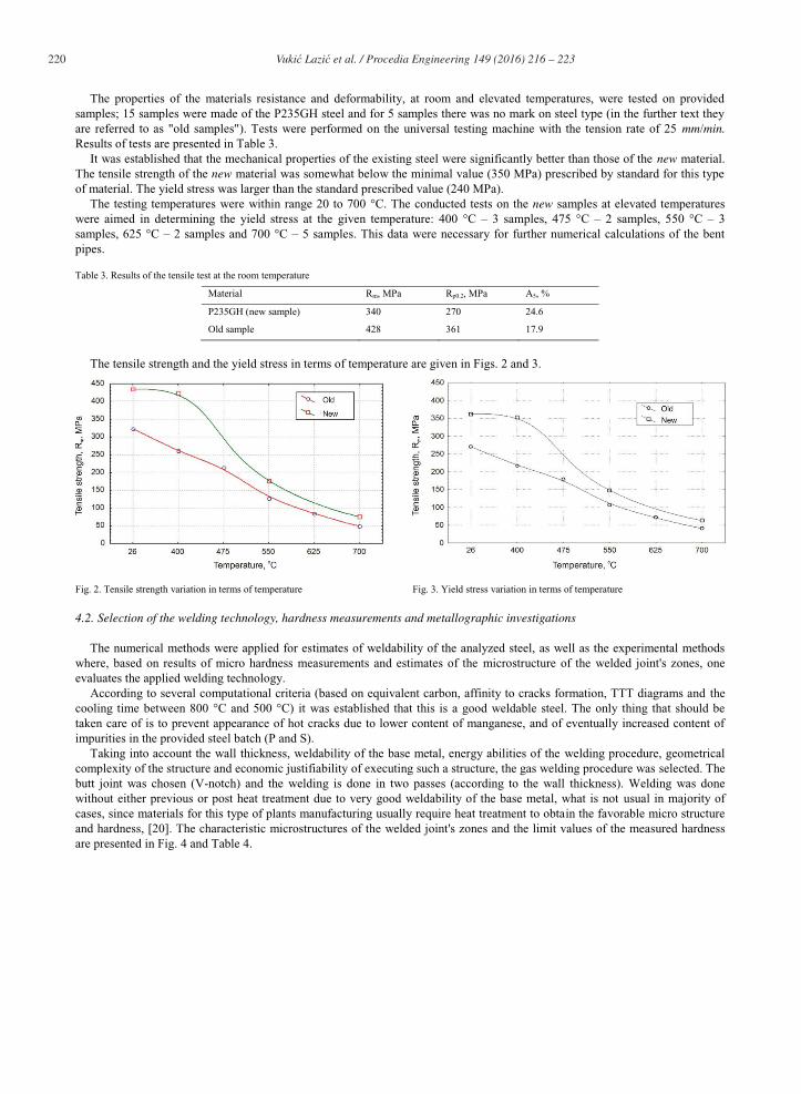
It was established that the mechanical properties of the existing steel were significantly better than those of the new material. The tensile strength of the new material was somewhat below the minimal value (350 MPa) prescribed by standard for this type of material. The yield stress was larger than the standard prescribed value (240 MPa).
The testing temperatures were within range 20 to 700 °C. The conducted tests on the new samples at elevated temperatures were aimed in determining the yield stress at the given temperature: 400 °C – 3 samples, 475 °C – 2 samples, 550 °C – 3 samples, 625 °C – 2 samples and 700 °C – 5 samples. This data were necessary for further numerical calculations of the bent pipes.
Table 3. Results of the tensile test at the room temperature
Material Rm, MPa Rp0.2, MPa A5, %
P235GH (new sample) 340 270 24.6
Old sample 428 361 17.9
The tensile strength and the yield stress in terms of temperature are given in Figs. 2 and 3.
Fig. 2. Tensile strength variation in terms of temperature Fig. 3. Yield stress variation in terms of temperature
4.2. Selection of the welding technology, hardness measurements and metallographic investigations
The numerical methods were applied for estimates of weldability of the analyzed steel, as well as the experimental methods where, based on results of micro hardness measurements and estimates of the microstructure of the welded joint's zones, one evaluates the applied welding technology.
According to several computational criteria (based on equivalent carbon, affinity to cracks formation, TTT diagrams and the cooling time between 800 °C and 500 °C) it was established that this is a good weldable steel. The only thing that should be taken care of is to prevent appearance of hot cracks due to lower content of manganese, and of eventually increased content of impurities in the provided steel batch (P and S).
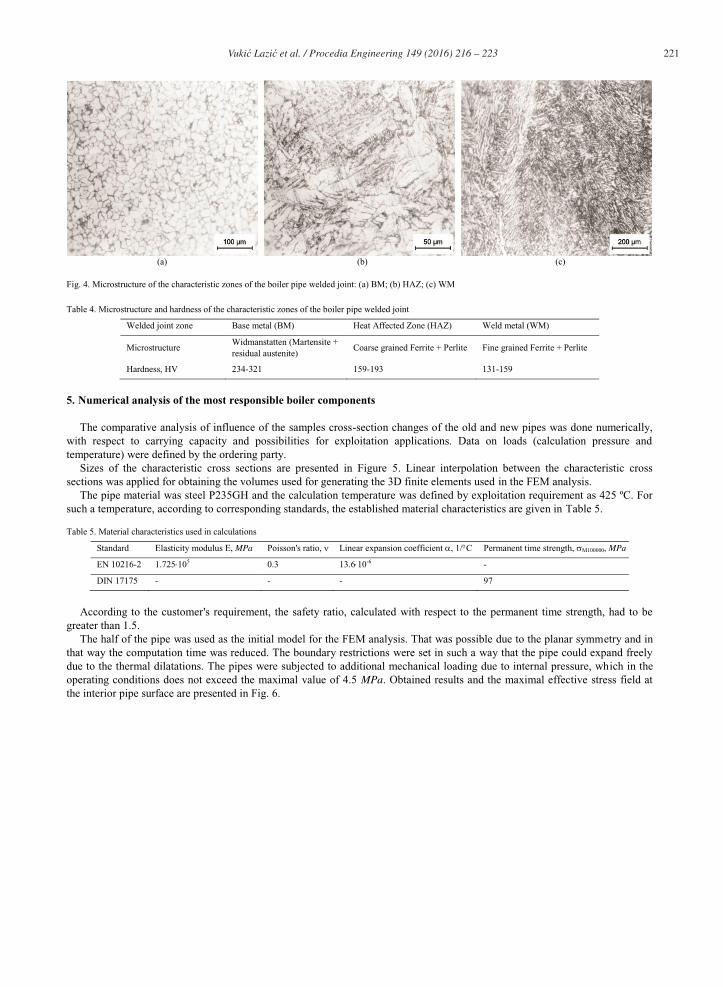
Taking into account the wall thickness, weldability of the base metal, energy abilities of the welding procedure, geometrical complexity of the structure and economic justifiability of executing such a structure, the gas welding procedure was selected. The butt joint was chosen (V-notch) and the welding is done in two passes (according to the wall thickness). Welding was done without either previous or post heat treatment due to very good weldability of the base metal, what is not usual in majority of cases, since materials for this type of plants manufacturing usually require heat treatment to obtain the favorable micro structure and hardness, [20]. The characteristic microstructures of the welded joint's zones and the limit values of the measured hardness are presented in Fig. 4 and Table 4.
221 Vukić Lazić et al. / Procedia Engineering 149 ( 2016 ) 216 – 223
(a) (b) (c)
Fig. 4. Microstructure of the characteristic zones of the boiler pipe welded joint: (a) BM; (b) HAZ; (c) WM
Table 4. Microstructure and hardness of the characteristic zones of the boiler pipe welded joint
Welded joint zone Base metal (BM) Heat Affected Zone (HAZ) Weld metal (WM)
Microstructure Widmanstatten (Martensite + residual austenite)
Coarse grained Ferrite + Perlite Fine grained Ferrite + Perlite
Hardness, HV 234-321 159-193 131-159
5. Numerical analysis of the most responsible boiler components
The comparative analysis of influence of the samples cross-section changes of the old and new pipes was done numerically, with respect to carrying capacity and possibilities for exploitation applications. Data on loads (calculation pressure and temperature) were defined by the ordering party.
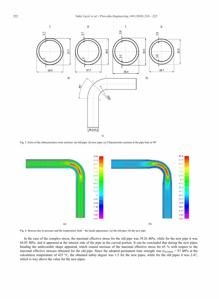
Sizes of the characteristic cross sections are presented in Figure 5. Linear interpolation between the characteristic cross sections was applied for obtaining the volumes used for generating the 3D finite elements used in the FEM analysis.
The pipe material was steel P235GH and the calculation temperature was defined by exploitation requirement as 425 ºC. For such a temperature, according to corresponding standards, the established material characteristics are given in Table 5.
Table 5. Material characteristics used in calculations
Standard Elasticity modulus E, MPa Poisson's ratio, Linear expansion coefficient , 1/ C Permanent time strength, M100000, MPa
EN 10216-2 1.725 105 0.3 13.6 10-6 -
DIN 17175 - - - 97
According to the customer's requirement, the safety ratio, calculated with respect to the permanent time strength, had to be greater than 1.5.
The half of the pipe was used as the initial model for the FEM analysis. That was possible due to the planar symmetry and in that way the computation time was reduced. The boundary restrictions were set in such a way that the pipe could expand freely due to the thermal dilatations. The pipes were subjected to additional mechanical loading due to internal pressure, which in the operating conditions does not exceed the maximal value of 4.5 MPa. Obtained results and the maximal effective stress field at the interior pipe surface are presented in Fig. 6.
222 Vukić Lazić et al. / Procedia Engineering 149 ( 2016 ) 216 – 223
Fig. 5. Sizes of the characteristics cross sections: (a) old pipe; (b) new pipe; (c) Characteristic sections at the pipe bent at 90°
(a) (b)
Fig. 6. Stresses due to pressure and the temperature field – the inside appearance: (a) the old pipe; (b) the new pipe
In the case of the complex stress, the maximal effective stress for the old pipe was 39.26 MPa, while for the new pipe it was 64.85 MPa, and it appeared at the interior side of the pipe in the curved portion. It can be concluded that during the new pipes bending the unfavorable shape appeared, which caused increase of the maximal effective stress for 65 % with respect to the maximal effective stresses obtained for the old pipe. Since the adopted permanent time strength was M100000 = 97 MPa at the calculation temperature of 425 C, the obtained safety degree was 1.5 for the new pipes, while for the old pipes it was 2.47, which is way above the value for the new pipes.
223 Vukić Lazić et al. / Procedia Engineering 149 ( 2016 ) 216 – 223
6. Conclusions
The conducted experimental and numerical calculations were done to monitor behavior of the old and the new material of the steam boiler pipes. Based on that, the following conclusions could be drawn: Tensile tests have shown that the yield stress decreases at elevated temperatures, while at the operating temperature of 425 C
it had the satisfactory value. The prescribed technology has enabled obtaining of the favorable microstructure without presence of martensite of other
brittle phases, which potentially could later cause a failure. By weldability estimates and performed weldings it was established that the P235GH steel possesses good weldability.
The old pipes' material had somewhat higher strength than the new one (about 90 MPa), but that did not influence the integrity of pipes, since even that smaller strength had satisfied the prescribed requirements.
During the pipes manufacturing, one must strictly pay attention to bending of pipes, since the improperly bent radius could cause the stress concentration what was established by numerical analysis. The investigation has also shown that, in this case, the numerical analysis is very reliable.
Finally, obtained results have also shown that the new pipe material P235GH, though of somewhat worse mechanical properties than the old one, could be used for manufacturing the boiler pipes and for mounting during the boiler reparation.
It was established that the safety coefficient of 1.5 was quite enough for reliable operation of this plant and that savings were realized due to difference in prices between the old and the newly applied material, which was also easier to procure.
Acknowledgements
This research was partially financially supported by European regional development fund and Slovak state budget by the project "Research Centre of the University of Žilina" - ITMS 26220220183 and by the Ministry of Education, Science and Technological Development of Republic of Serbia through grants: ON174004, TR32036, TR35024 and TR33015.
References
[1] Sedmak S, Radaković Z, Milović Lj, Svetel I. Significance and applicability of structural integrity assessment. Structural Integrity and Life 2012;12(1):3-30.
[2] Horváth L, Douda J, Horváth J, Svobodová M. Degradation of Czechoslovak creep resistant steels after 50 years of service. Materials Engineering 2014; 21 (2):80-87.
[3] Arsić D, Lazić V, Aleksandrović S, Nikolić R, Marinković P, Djordjević M, Ratković N. Theoretical-experimental fracture analysis of a responsible machine part. Structural Integrity and Life 2014;14(2):141-146.
[4] Milović Lj, Milošević-Mitić V, Radaković Z, Andjelić N, Petrovski B. Assessment of pressure vessel load capacity in the presence of cracks. Structural Integrity and Life 2013;13(1):9-16.
[5] Jovičić M, Algool MMA, Tatić U, Popović O, Lukić U, Burzić M. Storage tank integrity assessment after the removal of weld cracks. Structural Integrity and Life 2014;14(1):35-38.
[6] Balać M, Grbović A, Petrović A. Numerical predictions of crack growth a pressure vessel with welded nozzles. Structural Integrity and Life 2015;15(1):55-61.
[7] Žmindak M, Meško J, Pelagić Z, Zrak A. Finite element analysis of crack growth in pipelines. Manufacturing Technology 2014;14(1):116-122 [8] Katavić B, Jegdić B. Analysis of damages on water boiler shield pipes. Welding and welded structures 2007;4:123-130. [9] Bakić R, Milović Lj, Jovičić R, Sedmak S. Quality assurance of storage tanks after in-service cracks repairs. Structural Integrity and Life 2013;13(1):63-74. [10] Dimić I, Arsić M, Medjo B, Stefanović A, Grabulov V, Rakin M. Effect of welded joint imperfection on the integrity of pipe elbows subjected to internal
pressure. Technical Gazette 2013;20(2):285-290. [11] Rakin M, Medjo B, Arsić M, Šarkočević Ž, Ivanović I, Sedmak A. API J55 steel casing pipe with an initial surface crack under internal pressure –
determination of fracture parameters. Advances in fracture and damage mechanics X 2012;488-489:577-580. [12] Szybka J, Broniec B, Pilch R. Forecasting the failure of a thermal pipeline on the basis of risk assessment and exploitation analysis. Eksploatacja i
Niezawodnosc - Maintenance and Reliability 2011;13(4):5-10. [13] Pilch R, Szybka J, Broniec Z. Determining of hot water-pipe exploitation time on the basis of limiting states. Eksploatacja i Niezawodnosc – Maintenance
and Reliability 2012;14(3):203-207. [14] Pilch R, Szybka J, Tuszyńska A. Application of factoring and time-space simulation methods for assessment of the reliability of water-pipe networks.
Eksploatacja i Niezawodnosc – Maintenance and Reliability 2014;16(2):253-258. [15] Kalaba D, Djordjević M, Ivanović V. Determining the reliability functions of the boiler tubing system in power plant "Nikola Tesla Block A4". Structural
Integrity and Life 2015;15(3):167-171. [16] Bassi F, Foletti S, Lo Conte A. Creep fatigue crack growth and fracture mechanisms of T/P91 power plant steel. Materials at High Temperatures
2015;32(3):250-255. [17] Bošnjak S, Arsić M, Savićević S, Milojević G, Arsić D. Fracture analysis of the pulley of a bucket wheel boom hoist system. Eksploatacja i Niezawodnosc
– Maintenance and Reliability 2016;18(2):155-163. [18] Lazić V, Aleksandrović S, Arsić D, Sedmak A, Ilić A, Ivanović L, Djordjević M. The influence of temperature on mechanical properties of the base
material and welded joint made of steel S690QL. Metalurgija 2016;55(2):213-216. [19] Német M, Mihaliková M, Girman V. Static and dynamic tensile characteristics of DP 600 steel sheets. Materials engineering 2014;21(1):30-35. [20] Novotny J, Honzíkova J, Pilous V, Stransky K. Properties of welded joints in power plant. Manufacturing Technology 2015;15(6):1028-1032. [21] Beneš L, Kolegar T, Tojmar M, Majrich P. Influence of preheating and heat treatment after welding according to the EN 13445 and ASME code on the
hardness level of welded joints for the pressure vessel plates. Manufacturing Technology 2014;14(4):511-516. [22] Mician M., Patek M., Sladek G. Concept of repairing branch pipes on high-pressure pipelines by using split sleeve. Manufacturing technology,
2014;14(3):60-66. [23] EN 10216-2:2014: Seamless steel tubes for pressure purposes - Technical delivery conditions - Part 2: Non-alloy and alloy steel tubes with specified
elevated temperature properties. [24] ISO 6892-2:2011: Part 2 - Metallic materials - Tensile testing at elevated temperatures.