seismic retrofit of reinforced concrete frame...
TRANSCRIPT

Research ArticleSeismic Retrofit of Reinforced ConcreteFrame Buildings with Hysteretic Bracing Systems:Design Procedure and Behaviour Factor
Antonio Di Cesare and Felice Carlo Ponzo
School of Engineering, University of Basilicata, Viale dell’Ateneo Lucano 10, 85100 Potenza, Italy
Correspondence should be addressed to Antonio Di Cesare; [email protected]
Received 17 November 2016; Accepted 23 January 2017; Published 23 March 2017
Academic Editor: Ovidiu Vasile
Copyright © 2017 Antonio Di Cesare and Felice Carlo Ponzo. This is an open access article distributed under the CreativeCommons Attribution License, which permits unrestricted use, distribution, and reproduction in any medium, provided theoriginal work is properly cited.
This paper presents a design procedure to evaluate the mechanical characteristics of hysteretic Energy Dissipation Bracing (EDB)systems for seismic retrofitting of existing reinforced concrete framed buildings.The proposed procedure, aiming at controlling themaximum interstorey drifts, imposes a maximum top displacement as function of the seismic demand and, if needed, regularizesthe stiffness and strength of the building along its elevation. In order to explain the application of the proposed procedure andits capacity to involve most of the devices in the energy dissipation with similar level of ductility demand, a simple benchmarkstructure has been studied and nonlinear dynamic analyses have been performed. A further goal of this work is to propose asimplified approach for designing dissipating systems based on linear analysis with the application of a suitable behaviour factor, inorder to achieve a widespread adoption of the passive control techniques. At this goal, the increasing of the structural performancesdue to the addition of an EDB system designed with the above-mentioned procedure has been estimated considering one thousandcase studies designed with different combinations of the main design parameters. An analytical formulation of the behaviour factorfor braced buildings has been proposed.
1. Introduction
The capacity of the structural systems to withstand seismicactions beyond the elastic range, by exploiting the intrinsicstructural ductility, generally permits their design for seismicforces smaller than those corresponding to a linear elasticresponse. While attempting to minimise the effects of theseismic action, the use of a ductile behaviour often causesthe development of excessive displacements that might leadto excessive structural and nonstructural damage [1].
In recent years, several innovative low-damage strategiesfor controlling the seismic response of buildings have beendeveloped and put into practice. One of these considers theadoption of passive control approach, consisting in the use ofEnergy Dissipative Bracing (EDB) systems inserted into thestructural frame. These systems are characterized by specialdevices able to dissipate large amounts of energy during aseismic event and significantly reduce the interstorey drifts of
the braced structures [2–6]. The number of real applicationsof these techniques on new and existing buildings is rapidlyincreasing, mainly due to their effectiveness in reducingseismic effects, as demonstrated in the past studies carried outalso by [7–11]. However, extensive studies are still required inorder to providemore reliable analysis methods and practicaldesign criteria, as the adoption of equivalent linear analysis[12–15].
Several seismic codes adopt simplified linear and nonlin-ear analysis methods for the design and seismic assessmentof structures with supplemental dampers [16–20]. Elasticmethods currently implemented in seismic codes take intoaccount the nonlinear behaviour of conventional buildingstructures using a behaviour factor 𝑞.The 𝑞 factor is an empir-ical quantity adopted to reduce the seismic force providedby the elastic response spectrum, allowing for performinglinear elastic analysis for design of buildings. This approachfocuses on determining the reduction factor starting from
HindawiShock and VibrationVolume 2017, Article ID 2639361, 20 pageshttps://doi.org/10.1155/2017/2639361
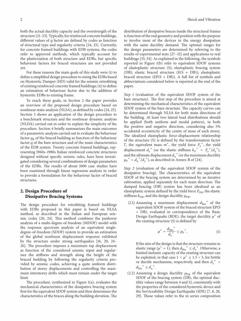
2 Shock and Vibration
both the actual ductility capacity and the overstrength of thestructure [21–23]. Typically, for reinforced concrete buildings,different values of 𝑞 factor are defined by codes as functionof structural type and regularity criteria [24, 25]. Currently,for concrete framed buildings with EDB systems, the codesrefer to approved methods, which typically account forthe plasticization of both structure and EDBs, but specificbehaviour factors for braced structures are not providedyet.
For these reasons the main goals of this study were (i) todefine a simplified design procedure to sizing the EDBs basedon Hysteretic Damper (HD) valid for the seismic retrofittingof existing reinforced concrete framed buildings; (ii) to definean estimation of behaviour factor due to the addition ofhysteretic EDBs to existing frame.
To reach these goals, in Section 2 the paper providesan overview of the proposed design procedure based onnonlinear static analysis (NLSA), as defined by codes [24, 25].Section 3 shows an application of the design procedure toa benchmark structure and the nonlinear dynamic analysis(NLDA) carried out in order to explain the simplicity of theprocedure. Section 4 briefly summarizes the main outcomesof a parametric analysis carried out to evaluate the behaviourfactor 𝑞B of the braced building as function of the behaviourfactor 𝑞 of the bare structure and of the main characteristicsof the EDB system. Twenty concrete framed buildings, rep-resenting 1960s–1980s Italian reinforced concrete structuresdesigned without specific seismic rules, have been investi-gated considering several combinations of design parametersof the EDBs. The results of about 1000 case studies havebeen examined through linear regression analysis in orderto provide a formulation for the behaviour factor of bracedstructures.
2. Design Procedure ofDissipative Bracing Systems
The design procedure for retrofitting framed buildingswith EDBs proposed in this paper is based on NLSAmethod, as described in the Italian and European seis-mic codes [20, 24]. This method combines the pushoveranalysis of a multi-degree-of-freedom (MDOF) model withthe response spectrum analysis of an equivalent single-degree-of-freedom (SDOF) system to provide an estimationof the global nonlinear displacement response exhibitedby the structure under strong earthquakes [16, 20, 24–26]. The procedure imposes a maximum top displacementas function of the considered seismic input and regular-izes the stiffness and strength along the height of thebraced building by following the regularity criteria pro-vided by seismic codes, achieving a quite uniform distri-bution of storey displacements and controlling the maxi-mum interstorey drifts which must remain under the targetlimit.
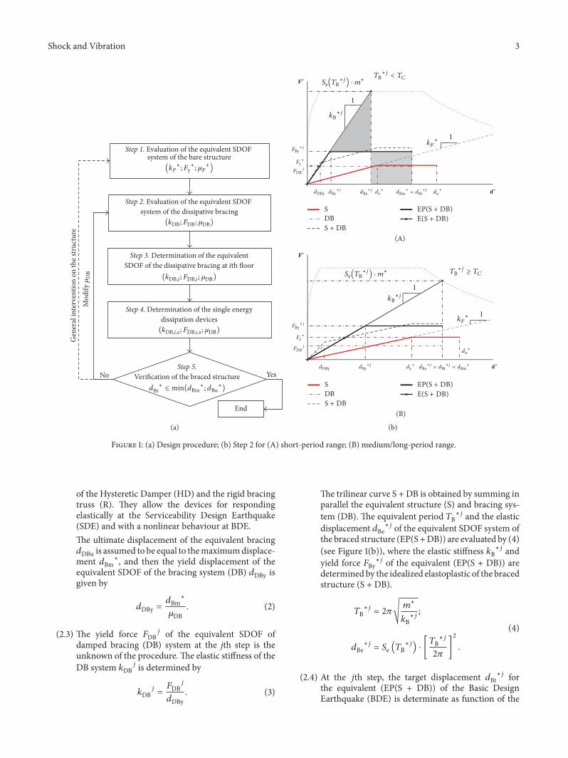
The procedure, synthesized in Figure 1(a), evaluates themechanical characteristics of the dissipative bracing systemfirst for the equivalent SDOF system and then determines thecharacteristics of the braces along the building elevation.The
distribution of dissipative braces inside the structural framesis function of the real geometry and positionwith the purposeto involve most of the devices in the energy dissipationwith the same ductility demand. The optimal ranges forthe design parameters are determined by referring to theresults of experimental tests [27–32] and applications to realbuildings [33, 34]. As explained in the following, the symbolsreported in Figure 1(b) refer to equivalent SDOF systemsof elastoplastic structure (S); elastoplastic bracing system(DB); elastic braced structure (E(S + DB)); elastoplasticbraced structure (EP(S + DB)). A full list of symbols andabbreviations considered below is reported at the end of thepaper.
Step 1 (evaluation of the equivalent SDOF system of thebare structure). The first step of the procedure is aimed atdetermining the mechanical characteristics of the equivalentSDOF system of the bare structure. The capacity curves canbe determined through NLSA for both main directions ofthe building. At least two lateral load distributions shouldbe applied (both uniform and modal pattern), in boththe positive and negative direction, considering also 5%accidental eccentricity of the centre of mass of each storey.The idealized elastoplastic force-displacement relationshipof the structure (S) is defined by the transformation factorΓ, the equivalent mass 𝑚∗, the yield force 𝐹y∗, the yielddisplacement 𝑑y∗ (or the elastic stiffness 𝑘𝐹∗ = 𝐹y∗/𝑑y∗),and the ultimate displacement𝑑u∗ (or themaximumductility𝜇𝐹∗ = 𝑑u∗/𝑑y∗), as described in Annex-B of [24].
Step 2 (evaluation of the equivalent SDOF system of thedissipative bracing). The characteristics of the equivalentSDOF of the bracing system are determined by an iterativesubroutine, applied separately for each main direction. Thedamped bracing (DB) system has been idealized as anelastoplastic system defined by the yield force 𝐹DB, the elasticstiffness 𝑘DB, and the design ductility 𝜇DB.(2.1) Assuming a maximum displacement 𝑑Bm∗ of the
equivalent SDOF system of the braced structure EP(S+ DB), evaluated in correspondence of the BasicDesign Earthquake (BDE), the target ductility 𝜇∗ ofthe existing structure (S) is defined by
𝜇∗ = 𝑑Bm∗𝑑y∗ ≤ 𝜇𝐹∗. (1)
If the aim of the design is that the structure remains inelastic range (𝜇∗ = 1), then 𝑑Bm∗ ≤ 𝑑y∗. Otherwise, alimited inelastic capacity of the existing structure canbe exploited, in that case 1 < 𝜇∗ ≤ 1.5 ÷ 3, for brittleor ductile mechanism, respectively, and then 𝑑y∗ <𝑑Bm∗ ≤ 𝑑u∗.
(2.2) Assuming a design ductility 𝜇DB of the equivalentSDOF of the bracing system (DB), the optimal duc-tility values range between 4 and 12, consistently withthe properties of the considered hysteretic device andthe Serviceability Design Earthquake (SDE) [7, 8, 28,29]. Those values refer to the in series composition
Shock and Vibration 3
Step 1. Evaluation of the equivalent SDOF system of the bare structure
Step 2. Evaluation of the equivalent SDOF system of the dissipative bracing
Step 3. Determination of the equivalent
Step 5.Verification of the braced structureNo
Gen
eral
inte
rven
tion
on th
e str
uctu
re
End
Step 4. Determination of the single energydissipation devices
Yes
Mod
ify�휇DB
(kDB; FDB; �휇DB)
(kDB,i,s; FDB,i,s; �휇DB)
SDOF of the dissipative bracing at ith floor(kDB,i ; FDB,i ; �휇DB)
(kF∗; Fy∗; �휇F
∗)
dBt∗ ≤ min(dBm
∗; dBu∗)
(a)
1
1
1
1
(A)
(B)
TB∗j < TC
Se(TB∗j) · m∗
Se(TB∗j) · m∗
kB∗j
kB∗j
�퐅∗
�퐅∗
FBy∗j
FBy∗j
Fy∗
Fy∗
FDBj
FDBj
kF∗
kF∗
dDBy
dDBy
dBy∗j dBe
∗j dy∗
dy∗
dBm∗ = dBt
∗j du∗
du∗
�퐝∗
�퐝∗
TB∗j ≥ TC
SDB
EP(S + DB)
SDB
EP(S + DB)
S + DB
E(S + DB)
dBe∗j = dBt
∗j = dBm∗dBy
∗j
S + DB
E(S + DB)
(b)
Figure 1: (a) Design procedure; (b) Step 2 for (A) short-period range; (B) medium/long-period range.
of the Hysteretic Damper (HD) and the rigid bracingtruss (R). They allow the devices for respondingelastically at the Serviceability Design Earthquake(SDE) and with a nonlinear behaviour at BDE.The ultimate displacement of the equivalent bracing𝑑DBu is assumed to be equal to themaximumdisplace-ment 𝑑Bm∗, and then the yield displacement of theequivalent SDOF of the bracing system (DB) 𝑑DBy isgiven by
𝑑DBy = 𝑑Bm∗𝜇DB . (2)
(2.3) The yield force 𝐹DB𝑗 of the equivalent SDOF ofdamped bracing (DB) system at the jth step is theunknown of the procedure.The elastic stiffness of theDB system 𝑘DB𝑗 is determined by
𝑘DB𝑗 = 𝐹DB𝑗𝑑DBy . (3)
The trilinear curve S + DB is obtained by summing inparallel the equivalent structure (S) and bracing sys-tem (DB). The equivalent period 𝑇B∗𝑗 and the elasticdisplacement 𝑑Be∗𝑗 of the equivalent SDOF system ofthe braced structure (EP(S +DB)) are evaluated by (4)(see Figure 1(b)), where the elastic stiffness 𝑘B∗𝑗 andyield force 𝐹By∗𝑗 of the equivalent (EP(S + DB)) aredetermined by the idealized elastoplastic of the bracedstructure (S + DB).
𝑇B∗𝑗 = 2𝜋√ 𝑚∗𝑘B∗𝑗 ;
𝑑Be∗𝑗 = 𝑆e (𝑇B∗𝑗) ⋅ [𝑇B∗𝑗2𝜋 ]2 .(4)
(2.4) At the 𝑗th step, the target displacement 𝑑Bt∗𝑗 forthe equivalent (EP(S + DB)) of the Basic DesignEarthquake (BDE) is determinate as function of the
4 Shock and Vibration
period of the braced structure 𝑇B∗𝑗 and 𝑇𝐶 theupper limit of the period of the constant spectralacceleration branch [24, 25], as follows:
(1) If 𝑇B∗𝑗 < 𝑇𝐶 short-period range, then 𝑑Bt∗𝑗is determined from the equal energy criteriabetween the elastic (E(S +DB)) and elastoplasticSDOF of the braced structure (EP(S + DB)).Then, 𝑑Bt∗𝑗 can be expressed as the equality ofthe area underlying the elastic and elastoplasticoscillator curves; see Figure 1(b)(A).Generally, the target displacement evaluated byequal energy criteria results more conservativethan the displacement evaluated by NLSA [24,25]; see Step 5.This conservative design assump-tion is due to the stiffening effect of bracing intothe structural frames.
(2) If 𝑇B∗𝑗 ≥ 𝑇𝐶 medium/long-period range, then𝑑Bt∗𝑗 is determined from the equal displacementcriteria between the elastic (E(S + DB)) andelastoplastic (EP(S + DB)) oscillators of thebraced structure; that is, 𝑑Bt∗𝑗 = 𝑑Be∗𝑗; seeFigure 1(b)(B).
If the target displacement 𝑑Bt∗𝑗 is much different fromthe maximum displacement 𝑑Bm∗, bigger than an imposedtolerance value |𝑑Bt∗𝑗 − 𝑑Bm∗| > 𝜀, the iterative subroutineis applied. An updated value of the yielding force 𝐹DB𝑗+1 ofthe equivalent DB system is evaluated and Substeps (2.3) and(2.4) are repeated. Usually the procedure converges in a fewiterations.
Step 3 (determination of the characteristics of the equiv-alent dissipative bracing at storey 𝑖). The characteristicsof the equivalent SDOF dissipating system, determined inthe previous step, are distributed along the height of thebuilding achieving the substantial satisfaction of the criteriaof regularization in elevation for the braced structure, asdefined by [25]. The distribution maximizes the efficiency ofthe bracing system and no single floor will exhibit excessiveinterstorey displacements.This should always be avoided in aregular building, as being connected to damage of structuraland nonstructural elements and to the activation of weak orsoft storey mechanism.
The stiffness 𝑘BD,𝑖 of the equivalent bracing of the storey𝑖 is determined hypothesizing that the ratio between thestiffness at each storey of the bare frame 𝑘𝐹,𝑖 and that of therelative bracing 𝑘DB,𝑖 is proportional to the ratio 𝑟𝑘 betweenthe elastic stiffness of the equivalent bare structure 𝑘𝐹∗ andthe elastic stiffness of the bracing systems 𝑘DB, as shownby (5). The stiffness of the storey 𝑖 of the original structure𝑘𝐹,𝑖 can be calculated from the interstorey displacementΔ𝑠𝑖 generated by linear static analysis (LSA) applying adistribution of horizontal seismic forces 𝐹𝑖 to each storey.
𝑘DB,𝑖 = 𝑟𝑘 ⋅ 𝑘𝐹,𝑖;
𝑟𝑘 = 𝑘DB𝑘𝐹∗ ;
𝑘𝐹,𝑖 = 1Δ𝑠𝑖 ⋅𝑛𝑝∑𝑖
𝐹𝑖.(5)
In the case of irregular distribution in elevation of thestiffness of the retrofitted building at the end of the designprocedure, the contribution of the bracing system in terms ofstiffness has to be modified with the aim of regularizing thebraced structure. To this end, reference is made to the criteriafor regularity in elevation of the building set out in the codes[24, 25]. The stiffness of equivalent bracing 𝑘DB,𝑖 at the storey𝑖 can be modified following the iterative procedure, valid forbuilding having a number of storeys 𝑛s ≥ 2, as reported in thefollowing.
For 𝑖 = 𝑛s, . . . , 2if Δ𝑘tot,𝑖𝑗 > 0.3, 𝑘DB,𝑖𝑗 = 𝑚𝑘 ⋅ 𝑘tot,𝑖−1𝑗−1 − 𝑘𝐹,𝑖if Δ𝑘tot,𝑖𝑗 < −0.1, 𝑘DB,𝑖−1𝑗 = 𝑘tot,𝑖𝑗−1𝑀𝑘 − 𝑘𝐹,𝑖−1if − 0.1 ≤ Δ𝑘tot,𝑖𝑗 ≤ 0.3,
𝑘DB,𝑖𝑗 = 𝑘DB,𝑖𝑗−1, 𝑘DB,𝑖−1𝑗 = 𝑘DB,𝑖−1𝑗−1,
(6)
where Δ𝑘tot,𝑖 = (𝑘tot,𝑖−1 − 𝑘tot,𝑖)/𝑘tot,𝑖−1 is the variation of thestiffness of the reinforced structure at the 𝑖th storey respectlower floor; 𝑘tot,𝑖 = 𝑘𝐹,𝑖 + 𝑘DB,𝑖 is the stiffness of the 𝑖th storeyof the braced structure;𝑚𝑘 and𝑀𝑘 are the stiffness correctionfactors to be taken in the following range of values 0.7 ≤ 𝑚𝑘 <1 and 1.1 ≥ 𝑀𝑘 > 1; 𝑗 = 1, . . . , 𝑛s is the step of iteration.
In the same way, the yield force 𝐹DB,𝑖 of the equivalentbracing at the ith storey is determined in the hypothesisthat the ratio between the yield force at each floor of thebare frame 𝐹y,𝑖 and that of relative bracing 𝐹DB,𝑖 is dis-tributed proportionally to the ratio 𝑟𝐹 between the strength ofequivalent bare structure 𝐹y∗ and the strength of equivalentbracing 𝐹DB systems (see (7)). The yield force 𝐹y,𝑖 of the 𝑖thstorey of the bare structure can be calculated in a simplifiedmanner starting from the displacements at the elastic limits𝑑y,𝑖 determined by redistributing the displacement at elasticlimit of the original structure 𝑑y∗ as a function of the ratiobetween the interstorey displacement Δ𝑠𝑖 and the total elasticdisplacement 𝑠TOT calculated by means of LSA.
𝐹DB,𝑖 = 𝑟𝐹 ⋅ 𝐹y,𝑖;𝑟𝐹 = 𝐹DB𝐹y∗ ;𝐹y,𝑖 = 𝑘𝐹,𝑖 ⋅ 𝑑y,𝑖;𝑑y,𝑖 = Δ𝑠𝑖𝑠TOT ⋅ 𝑑y∗.
(7)
When the ratio among the actual storey resistance of thebare frame and the resistance required by the analysis of

Shock and Vibration 5
the reinforced building varies nonproportionally (more than20%) between adjacent storeys, the yield force 𝐹DB,𝑖 of storey𝑖 of equivalent bracing system could be modified followingthe iterative procedure, valid for building having a number ofstoreys 𝑛s ≥ 3, reported in the following.
For 𝑖 = 2, . . . , 𝑛s − 1if Δ𝜌𝑖𝑗 < 0.8,
𝐹DB,𝑖𝑗 = 𝑚𝐹 ⋅ (𝐹y,𝑖−1 + 𝐹DB,𝑖−1𝑗−1) ⋅ 𝑉Ed,𝑖𝑉Ed,𝑖−1− 𝐹y,𝑖
if Δ𝜌𝑖𝑗 > 1.2,𝐹DB,𝑖𝑗 = 𝑀𝐹 ⋅ (𝐹y,𝑖−1 + 𝐹DB,𝑖−1𝑗−1) ⋅ 𝑉Ed,𝑖𝑉Ed,𝑖−1
− 𝐹y,𝑖if 0.8 ≤ Δ𝜌𝑖𝑗 ≤ 1.2, 𝐹DB,𝑖𝑗 = 𝐹DB,𝑖𝑗−1,
(8)
where Δ𝜌𝑖 = (𝜌𝑖/𝜌𝑖−1) is the variation of the ratio 𝜌 at the 𝑖thfloor respect lower floor; 𝜌𝑖 = (𝐹y,𝑖+𝐹DB,𝑖/𝑉Ed,𝑖) > 1 is the ratiobetween storey resistance of the bare frame and resistancerequired by the analysis of the reinforced structure at the 𝑖thfloor;𝑉Ed,𝑖 is the design shear force of storey 𝑖 required bythe analysis of the reinforced structure;𝑚𝐹 and 𝑀𝐹 are thestrength correction factors to be taken in the following rangeof values 0.8 ≤ 𝑚𝐹 < 1 and 1.2 ≥ 𝑀𝐹 > 1, from small tolarge irregularities in elevation of the original structure; 𝑗 =1, . . . , 𝑛s is the step of iteration.
In framed buildings, the stiffness and strength variationsshould not vary disproportionately between adjacent storeys.In the design of the dissipative bracing system, the correctionsfactors have been adopted in order to reduce the irregularitiesin elevation of the original structure and to contain thevariation of stiffness and strength of the braced structure inthe following range of values −10% < Δ𝑘tot,𝑖 < 30% and−20% < Δ𝜌𝑖 < 20%, respectively.
Step 4 (determination of the single energy dissipationdevice). The characteristics of the single dissipating brace(𝑘DB,𝑖,𝑠, 𝐹DB,𝑖,𝑠, 𝜇DB) are finally defined starting from theequivalent dissipative bracing system of 𝑖th storey, as functionof the number and slope of the braces [20], as in the following:
𝑘DB,𝑖,𝑠 = 𝑘DB,𝑖𝑛DB,𝑖 ⋅1
cos2𝜙𝑠 ;𝐹DB,𝑖,𝑠 = 𝐹DB,𝑖𝑛DB,𝑖 ⋅
1cos𝜙𝑠 ,
(9)
where 𝑛DB,𝑖 is the number of damped braces in the floor;𝜙𝑠 isthe angle between the single brace and the horizontal.
The preliminary design of the bracing elements is basedon the yielding forces of the dissipative damper. Increasedreliability is required for the dissipative bracing system. Thisshall be affected by applying a magnification factor 𝛾𝑥 =1.2 on the yielding forces of each dissipative damper unitto avoiding either any buckling phenomena for compressioncondition or yielding in tension under the Maximum Con-sidered Earthquake (MCE) loading, as defined by codes [24].
The stiffness and ductility characteristics of the singleHysteretic Damper (HD) depend on the stiffness 𝑘R,𝑖,𝑠 of thesingle rigid bracing truss (R) at the storey 𝑖, as defined in
𝐹DB,𝑖,𝑠 = 𝐹HD,𝑖,𝑠;𝐾DB,𝑖,𝑠 = 𝑘HD,𝑖,𝑠 ⋅ 𝑘R,𝑖,𝑠𝑘HD,𝑖,𝑠 + 𝑘R,𝑖,𝑠 ;𝜇DB = 𝑘HD,𝑖,𝑠 + 𝑘R,𝑖,𝑠 ⋅ 𝜇HD𝑘HD,𝑖,𝑠 + 𝑘R,𝑖,𝑠 ,
(10)
where 𝑘HD,𝑖,𝑠, 𝐹HD,𝑖,𝑠 𝜇HD are the stiffness, the yield force, andthe ductility of each Hysteretic Damper (HD).
Typically, the ductility of devices 𝜇HD based on steelyielding can reach values greater than 20, displaying stablebehaviour for an adequate number of cycles [35]. In orderto dissipate a good amount of energy reaching adequatevalues of ductility demanded to dissipating devices, therigid support will be chosen considering a stiffness ratio𝑘R,𝑖,𝑠/𝑘HD,𝑖,𝑠 ≥ 2.Step 5 (verification of the braced structure). The designprocedure ends with the verification of the braced structurefor the BDE. NLSA have been performed considering theMDOFmodel, which includes the nonlinear behaviour of thedissipative brace elements.The iterative procedure stops if thetarget displacement 𝑑Bt∗ of the braced structure, modifiedconsidering a transformation factor ΓB and the equivalentmass𝑚B
∗, satisfies the condition of
𝑑Bt∗ ≤ min (𝑑Bm∗; 𝑑Bu∗) , (11)
where
𝑑Bt∗ = 𝑑Be∗𝑞B∗ [1 + (𝑞B∗ − 1) ⋅ 𝑇𝐶𝑇B∗ ] ≥ 𝑑Be∗if 𝑇B∗ < 𝑇𝐶
𝑑Bt∗ = 𝑑Be∗ if 𝑇B∗ ≥ 𝑇𝐶.(12)
𝑞B∗ = 𝑆e(𝑇B∗)⋅𝑚B∗/𝐹By∗ is the ratio between the acceleration
in the braced structure with unlimited elastic behaviour andwith limited strength [24, 25]; 𝑑By∗, 𝑑Bu∗ are the yield andthe ultimate displacements of the braced structure; 𝜇∗B =min(𝑑Bm∗; 𝑑Bu∗)/𝑑By∗ is the ductile capacity of the bracedstructure.
If (11) is not satisfied, the iterative procedure of Step 2is applied increasing the design ductility of the dissipativebracing 𝜇DB in Substep (2.2) and/or assuming a maximumdisplacement equal to the target displacement 𝑑Bt∗ deter-mined in Step 5, instead of 𝑑Bm∗ assumed in Substep (2.1).
Moreover, in case of verification not satisfied, specificintervention to the structural elements (beams, columns,and/or beam to column joints) could be required in orderto increase the capacity of the bare frame and the procedurerestart from Step 1.
It is worth noting that the application of the NLSA isallowed in the hypothesis that the requirements laid out in

6 Shock and Vibration
4.00
4.00
4.00 4.00 4.00
Y
X
(a) (b)
0.0
0.2
0.4
0.6
0.8
1.0
S e(a
/g)
1.0 2.00.0 4.03.0
T (sec)
MCEBDE
SDEFDE
(c)
Figure 2: Benchmark structure: (a) plan view and (b) numerical model; (c) elastic response spectra.
Table 1: Details of cross section of the main structural elements.
Element Cross section Longitudinal rebar Transversal rebarcm × cm 1st floor 2nd–4th floor End of elem. Middle of elem.
Column 30 × 30 4𝜙16 + 2𝜙14 4𝜙16 𝜙6/15 𝜙6/151st–4th floor
End MiddleTop Bottom Top Bottom
Beam 30 × 50 4𝜙14 2𝜙14 2𝜙14 4𝜙14 𝜙6/15 𝜙6/20
the codes for the use of this analysis method are respected(regularity criteria). As shown in the following, a correctpositioning of the dissipating braces usually determines theachievement of regularity conditions. Otherwise, it should benecessary to perform a nonlinear dynamic analysis for thesafety verification of the braced structure (Step 5).
3. Application of the Design Procedure
This section shows an example of application of the designprocedure to a simple benchmark structure retrofitted withhysteretic EDBs. The example considers two different con-figurations of dissipative bracing shapes, namely, diagonal Dand inverted V, comparing the design performances with theresults of NLDA.
3.1. Benchmark Structure. The benchmark structure consid-ered in this simple example is a four-storey (𝑛𝑠 = 4) re-inforced concrete framed building, with a rectangular plan,as showed in Figure 2(a).The structure represents an existingbuilding located in the city of Potenza (Italy), classifiedas medium/high seismic area. The structure is founded ona soil type B and a topographic factor T1 [25] has beenconsidered to evaluate the PGA (0.25 g for the Basic DesignEarthquake (BDE)). The structure consists of three framesalong the longitudinal direction (𝑋) and four frames intransverse direction (𝑌). The interstorey height ℎ𝑖 of allstoreys is 3.0m. The cross sections of the main structural
elements are described in Table 1. Structural elements havebeen designed by assuming the mechanical characteristicsof materials coherently with a concrete type 𝑅𝑐𝑘 25 andreinforcing steel FeB38k.
The benchmark structure has been modelled by usingnonlinear finite element program CDS-Opensees [36].Beams and columns have been modelled with elastic frameelements having nonlinear elastoplastic hinges concentratedat the ends.The hinges behaviour is based on the Takeda hys-teretic model for the beams, for the columns it is axial load-dependent.The ultimate rotation depends on the amount andquality of the reinforcement rebar. The numerical models ofthe benchmark structure are shown in Figure 2(b).The elasticresponse spectra at different limit states for equivalent viscousdamping ratio 𝜉 = 5% are shown in Figure 2(c): FrequentDesign Earthquake (FDE); Serviceability Design Earthquake(SDE); Basic Design Earthquake (BDE); Maximum Consid-ered Earthquake (MCE).
The main characteristics of each storey of the barestructure, obtained by using LSA, are reported for both maindirections in Table 2 in terms of seismic mass 𝑚𝑖, elasticstiffness 𝑘𝐹,𝑖, yield force 𝐹y,𝑖, and first normalized modaldisplacement 𝑢𝑖. It is possible to observe that the bare framessatisfy the criteria of structural regularity (stiffness and massvariation).
3.2. Design of the Hysteretic EDB Systems. The benchmarkstructure has been retrofitted by means of hysteretic EDB

Shock and Vibration 7
Table 2: Main characteristics of each storey of the bare structure.
StoreyInterstoreyheight ℎ𝑖
(m)
Seismic mass𝑚𝑖(t)
Direction𝑋 Direction 𝑌𝐹y,𝑖(kN)
𝑘𝐹,𝑖(kN/mm)
Δ𝑘𝐹,𝑖% 𝑢𝑖 𝐹y,𝑖
(kN)𝑘𝐹,𝑖
(kN/mm)Δ𝑘𝐹,𝑖% 𝑢𝑖
1st 3.1 115 325 44 20 0.31 360 49 18 0.312nd 6.2 115 287 35 0 0.64 317 40 3 0.643rd 9.3 115 206 35 6 0.88 228 39 8 0.884th 12.4 86 95 33 1.00 105 36 1.00
Table 3: Main properties of equivalent bare structure and equivalent braced system.
DirectionStep 1 Step 2𝑚∗
(t)𝑇∗(sec)
𝑆e(𝑇∗)(a/g)
𝐹y∗(kN)
𝑘𝐹∗(kN/mm) 𝜇𝐹∗ 𝑑Bm
∗
(mm)𝜇∗ 𝜇DB 𝐹DB
(kN)𝑘DB
(kN/mm)𝑋 296 0.92 0.31 324 14 1.9 36 1.5 4 357 39𝑌 296 0.87 0.33 360 15 1.8 37 1.5 4 320 34
(a) (b)
Figure 3: Numerical models of the braced structure, configuration: (a) inverted V and (b) diagonal D.
systems considering both inverted V (Figure 3(a)) and diago-nal D (Figure 3(b)) configurations, suitably designed by usingthe design procedure described above.
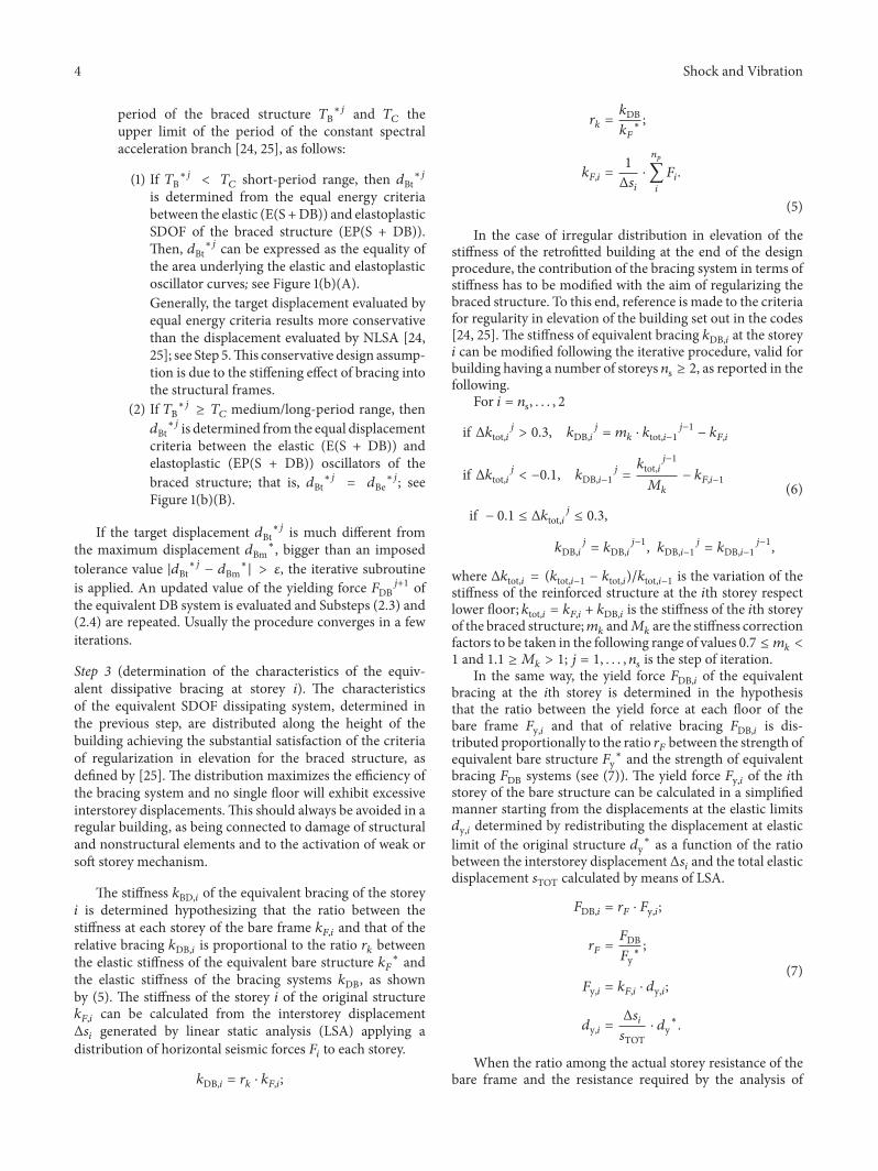
The idealized SDOF systems of the bare structure (with-out retrofit) evaluated at the Step 1 are reported in Table 3for both main directions (see also Figure 2(c)). The capacitycurves of the bare structure are shown in Figures 4(a) and4(c).
With the aim to limit the maximum interstorey drift ofthe braced structure at 0.5% under the BDE, a maximumdisplacement 𝑑Bm∗ was established at Step 2, correspondingto a structure ductility equal to 𝜇∗ = 1.5, as considered byItalian code [25] for existing buildings. The design ductilityof the equivalent dissipative bracing system was assumed𝜇DB = 4. The characteristics of the equivalent SDOF of theDB systems are reported in Table 3.
The stiffness 𝑘DB,𝑖 and the yield force 𝐹DB,𝑖 of theequivalent bracing systems at storey 𝑖 evaluated at Step 3are reported in Table 4. Moreover, Table 4 shows the
stiffness 𝑘HD,𝑖,𝑠 and yield force 𝐹HD,𝑖,𝑠 of the single HystereticDamper HD obtained at Step 4. The HDs were evaluatedassuming a ductility capacity of the dissipating devices(𝜇HD = 20) and a rigid steel bracing trusses (𝑘R,𝑖,𝑠/𝑘HD,𝑖,𝑠 ≈2).
The Step 5 has been applied separately for both maindirections considering the numerical models of the bench-mark structure equipped with both configurations of non-linear dissipative bracing configurations (D and invertedV) as shown in Figures 4(b) and 4(d). The finite elementsoftware considered in this study uses specific elements tosimulate the elastoplastic behaviour of the dissipative bracingsystems.
Diagrams of Figure 4 clearly show the effectiveness of theretrofitting technique in reducing the target displacement ofthe centre of mass of the top floor. The values of the overallductile capacity 𝜇B∗ of the braced structure obtained with theconsidered intervention are equal to 2.8 and 2.5 in direction𝑋 and 𝑌, respectively.
8 Shock and Vibration
Bare structureBraced structure (D)Braced structure (V)
. X
0.05 0.100.00d (m)
0
500
1000
F(k
N)
Dir
(a)
Bare structureBraced structure (D)Braced structure (V)
TB∗
T∗
�휇B∗
�휇∗
dBt∗
. X
0.05 0.100.00SDe (m)
0.0
0.3
0.6
S e(a
/g)
Dir
(b)
Bare structureBraced structure (D)Braced structure (V)
. Y
0
500
1000
F(k
N)
0.05 0.100.00d (m)
Dir
(c)
Bare structureBraced structure (D)Braced structure (V)
TB∗
T∗
�휇B∗
�휇∗
dBt∗
Dir. Y
0.0
0.3
0.6S e
(a/g
)
0.05 0.100.00SDe (m)
(d)
Figure 4: Comparison between pushover curves of the building with and without seismic retrofit: (a) direction 𝑋 and (c) direction 𝑌;verification of upgraded structure using NTC08: (b) direction𝑋 and (d) direction 𝑌.
Table 4: Characteristics of the dissipative braces.
Direction Storey
Step 3 Step 4𝐹DB,𝑖(kN)
𝑘DB,𝑖(kN/mm)
Configuration inverted V Configuration DRigidtruss
𝐹HD,𝑖,𝑠(kN)
𝑘HD,𝑖,𝑠(kN/mm)
Rigidtruss
𝐹HD,𝑖,𝑠(kN)
𝑘HD,𝑖,𝑠(kN/mm)
𝑋1st 358 130 HE 180A 165 165 HE 140A 115 802nd 316 103 HE 160A 150 125 HE 120A 100 603rd 227 101 HE 160A 100 120 HE 120A 70 604th 104 98 HE 140A 50 130 HE 120A 40 60
𝑌1st 320 111 HE 180A 150 130 HE 120A 100 602nd 282 91 HE 160A 130 110 HE 100A 90 453rd 203 89 HE 160A 100 100 HE 100A 65 454th 94 81 HE 140A 50 100 Tube 114.3x5 30 40

Shock and Vibration 9
0.0
0.2
0.4
0.6
0.8
1.0S e
(a/g
)
1.00 2.000.00 0.50 1.50
T (sec)
BDEAcc_1Acc_2Acc_3
Acc_4Acc_5Acc_6Acc_7
(a)
0.0
0.2
0.4
0.6
0.8
1.0
S e(a
/g)
1.00 2.000.00 0.50 1.50
T (sec)
BDEAcc_8Acc_9Acc_10
Acc_11Acc_12Acc_13Acc_14
(b)
Figure 5: Sets of 7 accelerograms considered for the analysis in (a) direction𝑋 and (b) direction 𝑌.
3.3. Results of Nonlinear Dynamic Analyses. In order to es-timate the maximum displacement of the braced structure(Step 5), bidirectional NLDA have been carried out consid-ering a set of 7 artificial spectrum-compatible accelerogramsmatching, on average, the spectrum at the BDE adopted inthe design procedure (see Figure 5).The 30 sec accelerogramshave been generated by CDS-Opensees [36].They are charac-terized by a stationary part of 20 sec. In the range of periodsbetween 0.15 and 2 seconds [25] no value of the mean 5%viscous damping ratio, calculated from all time histories, isless than 90% of the corresponding value of the 5% viscousdamping ratio of response spectrum.
The seismic response of the braced building has beenevaluated by means of NLDA carried out with CDS-Opensees, applying the accelerograms simultaneously in bothdirections.
Figure 6 shows the numerical results in terms of storeyacceleration, interstorey drifts, and force-displacement cyclicbehaviours of the HDs at all storeys. The diagrams refer toboth bracing configurations (D and inverted V) subjected toearthquakes no. 1 and 8.
Time histories of drifts exhibit maximum value lessthan 0.4%, which is comparable with the target drift (0.5%)considered in the design procedure. Moreover, both configu-rations D and inverted V of bracing systems show analogousresponses in terms of interstorey drifts and floor acceleration.The cyclic behaviour of devices, shown in Figure 6, highlightsthe activation of the energy dissipation braces at all storeys ofthe model with similar values of ductility demand (of about3.5).
The NLDA averaged results in terms of maximum inter-storey drifts of the benchmark structure, obtained consid-ering all acceleration profiles, with and without EDB, arecompared in Figure 7.Drift is commonly considered themainparameter to evaluate the performance of framed structuresand the effectiveness of the retrofitting technique. As clearly
shown by Figure 7, the seismic response of the structuredrastically decreases in amplitude when the EDBs are used;in fact a reduction of the maximum drift at all storeys of thebraced model, corresponding to about 2-3 times with respectto that of the bare frame, has been observed. Referring to thediagrams of Figure 7 it should be highlighted that the valuesof the maximum interstorey drift could occur not at the sametime step of the analysis.
In Figure 8 the capacity curves of the reinforced structuresobtained by NLSA are compared with the results of NLDA.The curves have been generated for both principal directionsusing both uniform (mass) and modal (mode) distributionsof horizontal forces 𝐹𝑖 at each storey. The output of NLDA,carried out considering all accelerograms, is expressed interms of maximum top displacement versus the correspon-dent base shear. Figure 8 shows a good agreement betweenthemean value of themaximum displacements of theMDOFsystem and the maximum displacement (𝑑Bm∗ ⋅ ΓB) of thecontrol node, coinciding with the centre of mass of the topfloor, considered in the design procedure.
4. Estimation of Behaviour Factor ofBraced Buildings
It is worth noting that NLDA are not always simple toapply, especially for existing buildings, for several reasons:(i) difficulties in correctlymodelling the actual characteristicsof cyclic load-deformation of structural members (geometryand material uncertainties, cumulative damage, fatigue); (ii)the need to define a set of ground motions that wouldproperly represent the seismic input at a given constructionsite; (iii) the longer computational time and other hindrances(complexity and accuracy).
For conventional reinforced concrete buildings the codesconsider also the possibility of using linear analysis, in which

10 Shock and Vibration
Direction X1st storey 2nd storey 3rd storey 4rd storey
Direction Y
−5.0
−2.5
0.0
2.5
5.0
(m/s
ec2)
−0.4
−0.2
0.0
0.2
0.4
Drift
(%)
−15 −5−10 5 10 150(mm)
−200
−100
0
100
200
(kN
)
−5.0
−2.5
0.0
2.5
5.0
(m/s
ec2)
5 10 15 20 25 300t (sec)
−0.4
−0.2
0.0
0.2
0.4
5 10 15 20 25 300t (sec)
−0.4
−0.2
0.0
0.2
0.4
5 10 15 20 25 300t (sec)
−0.4
−0.2
0.0
0.2
0.4
−0.4
−0.2
0.0
0.2
0.4
Drift
(%)
5 10 15 20 25 300t (sec)
−0.4
−0.2
0.0
0.2
0.4
5 10 15 20 25 300t (sec)
−0.4
−0.2
0.0
0.2
0.4
5 10 15 20 25 300t (sec)
−0.4
−0.2
0.0
0.2
0.4
With retrofit DWith retrofit V
With retrofit DWith retrofit V
With retrofit DWith retrofit V
With retrofit DWith retrofit V
−15 −5−10 5 10 150(mm)
−200
−100
0
100
200
(kN
)
−15 −5−10 5 10 150(mm)
−200
−100
0
100
200
(kN
)−15 −5−10 5 10 150
(mm)−200
−100
0
100
200
(kN
)
−15 −5−10 5 10 150(mm)
−200
−100
0
100
200
(kN
)
−15 −5−10 5 10 150(mm)
−200
−100
0
100
200
(kN
)
−15 −5−10 5 10 150(mm)
−200
−100
0
100
200
(kN
)
−15 −5−10 5 10 150(mm)
−200
−100
0
100
200
(kN
)
5 10 15 20 25 300t (sec)
5 10 15 20 25 300t (sec)
5 10 15 20 25 300t (sec)
5 10 15 20 25 300t (sec)
−5.0
−2.5
0.0
2.5
5.0
5 10 15 20 25 300t (sec)
−5.0
−2.5
0.0
2.5
5.0
5 10 15 20 25 300t (sec)
−5.0
−2.5
0.0
2.5
5.0
5 10 15 20 25 300t (sec)
5 10 15 20 25 300t (sec)
−5.0
−2.5
0.0
2.5
5.0
5 10 15 20 25 300t (sec)
−5.0
−2.5
0.0
2.5
5.0
5 10 15 20 25 300t (sec)
−5.0
−2.5
0.0
2.5
5.0
Figure 6: Comparison of NLDA results considering earthquakes number 1 and number 8 for both directions of drift, acceleration, andforce-displacement of the elastoplastic braces on both configurations of EDB (D and inverted V).

Shock and Vibration 11
Acc 1–8 Acc 2–9 Acc 3–10 Acc 4–11 Acc 5–12 Acc 6–13 Acc 7–14
With retrofit_V Dir YWith retrofit_V Dir X
With retrofit_D Dir YWith retrofit_D Dir X
Without retrofit Dir YWithout retrofit Dir X
1
2
3
4
Stor
ey
1
2
3
4
1
2
3
4
1
2
3
4
1
2
3
4
1
2
3
4
1
2
3
4
0.70 1.400.00Drift (%)
0.70 1.400.00Drift (%)
0.70 1.400.00Drift (%)
0.70 1.400.00Drift (%)
0.70 1.400.00Drift (%)
0.70 1.400.00Drift (%)
0.70 1.400.00Drift (%)
Figure 7: Maximum drifts obtained by NLDA on model with and w/o damped bracing systems.
Dir. YDir. X
0.04 0.080.00d (m)
0
500
1000
F(k
N)
0.04 0.080.00d (m)
0
500
1000
F(k
N)
With retrofit_D modeWith retrofit_D massWith retrofit_D (1–8)With retrofit_D (2–9)With retrofit_D (3–10)
With retrofit_D (4–11)With retrofit_D (5–12)With retrofit_D (6–13)With retrofit_D (7–14)With retrofit_D mean
With retrofit_V modeWith retrofit_V massWith retrofit_V (1–8)With retrofit_V (2–9)With retrofit_V (3–10)
With retrofit_V (4–11)With retrofit_V (5–12)With retrofit_V (6–13)With retrofit_V (7–14)With retrofit_V mean
Figure 8: Comparison between the results of NLSA and the maximum top displacements versus base shears by NLDA.
the seismic demand (elastic spectrum) is suitably reduced bya behaviour factor 𝑞 [37], defined by codes [24, 25], as follows:
𝑞 = 𝑞0 ⋅ 𝐾𝑤 ≥ 1.5, (13)where 𝑞0 is the basic value of the behaviour factor 𝑞, depend-ing on structural type and on the ratio 𝛼u/𝛼1 between thecollapse load multiplier (𝛼u) and the multiplier for flexuralyield (𝛼1); 𝐾𝑤 is the factor reflecting the regular criteria inelevation of the building. It should reduce the behaviourfactor 𝑞 by 20% for building which is not regular in elevation.
Following the guidance provided by the codes, NLSAmaybe applied in order to estimate the behaviour factor 𝑞 [38, 39],as follows:
𝑞 = 1 + (𝜇𝑑 − 1) ⋅ 𝑇1𝑇C if 𝑇1 < 𝑇𝐶𝑞 = 𝜇𝑑 if 𝑇1 ≥ 𝑇𝐶,
(14)
where 𝑇1 is the fundamental period of the building; 𝜇𝑑 is thedisplacement ductility factor.
Several NLSA have been carried out considering all casestudies in order to propose an analytical formulation of thebehaviour factor 𝑞B valid for braced buildings.The study aimsto estimate a correction factor 𝐶 to increase the behaviourfactor of the bare building 𝑞 (see (15)).The values of 𝑞(𝑇∗, 𝜇∗)and 𝑞B(𝑇B∗, 𝜇B∗) are evaluated by considering in (14) thevalues of 𝑇∗ and 𝜇∗ of the bare structure estimated by Step 1of the design procedure and the values of 𝑇B∗ and 𝜇B∗ of thebraced structure evaluated by Step 5 of the design procedure.
𝐶 = 𝑞B (𝑇B∗, 𝜇B∗)𝑞 (𝑇∗, 𝜇∗) . (15)
4.1. Case Studies. Twenty buildings representing the1960s–1980s standard Italian constructions, designed for
12 Shock and Vibration
1_3s 2_3s 3_3s 4_3s
(a)
4_4s 4_5s 4_6s 4_8s
(b)
Figure 9: Numerical model of the bare structures: (a) 3 storey structural types and (b) different number of storeys of structural type 4.
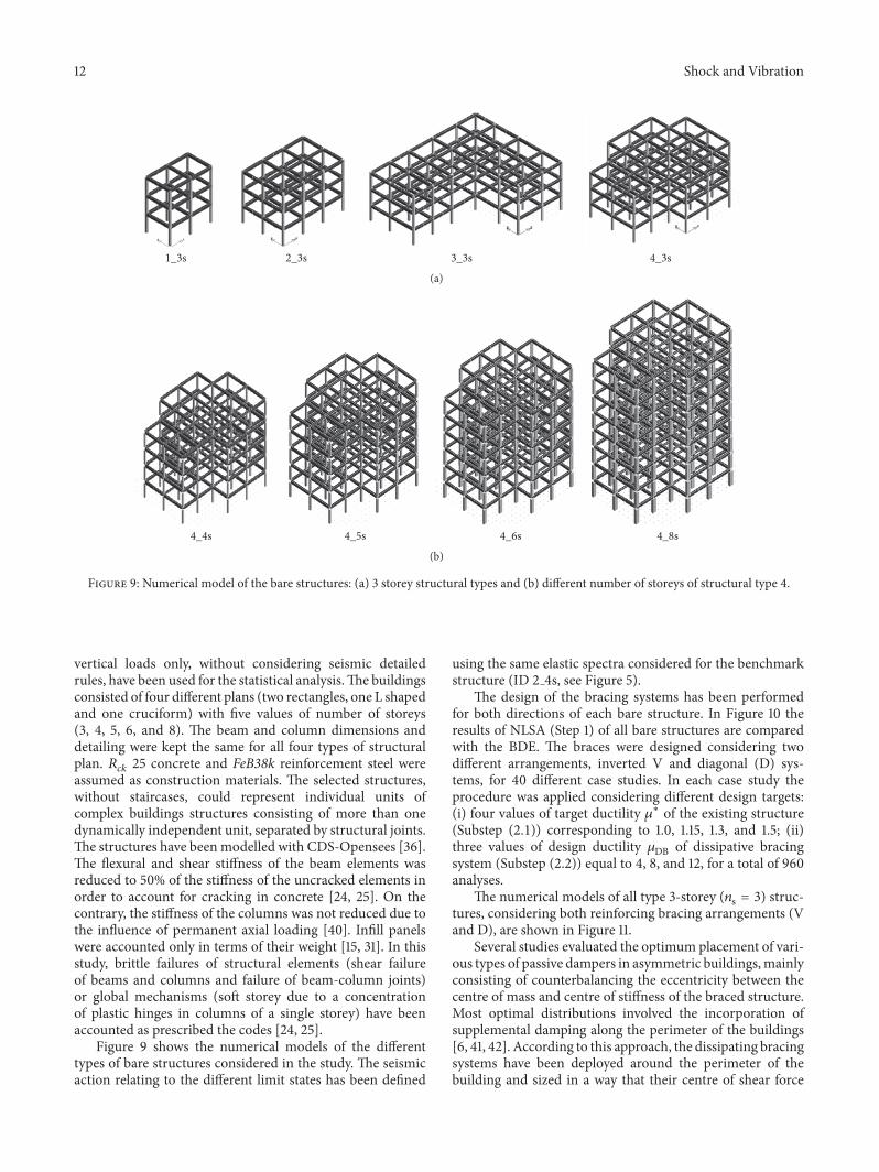
vertical loads only, without considering seismic detailedrules, have been used for the statistical analysis.The buildingsconsisted of four different plans (two rectangles, one L shapedand one cruciform) with five values of number of storeys(3, 4, 5, 6, and 8). The beam and column dimensions anddetailing were kept the same for all four types of structuralplan. 𝑅𝑐𝑘 25 concrete and FeB38k reinforcement steel wereassumed as construction materials. The selected structures,without staircases, could represent individual units ofcomplex buildings structures consisting of more than onedynamically independent unit, separated by structural joints.The structures have beenmodelled with CDS-Opensees [36].The flexural and shear stiffness of the beam elements wasreduced to 50% of the stiffness of the uncracked elements inorder to account for cracking in concrete [24, 25]. On thecontrary, the stiffness of the columns was not reduced due tothe influence of permanent axial loading [40]. Infill panelswere accounted only in terms of their weight [15, 31]. In thisstudy, brittle failures of structural elements (shear failureof beams and columns and failure of beam-column joints)or global mechanisms (soft storey due to a concentrationof plastic hinges in columns of a single storey) have beenaccounted as prescribed the codes [24, 25].
Figure 9 shows the numerical models of the differenttypes of bare structures considered in the study. The seismicaction relating to the different limit states has been defined
using the same elastic spectra considered for the benchmarkstructure (ID 2 4s, see Figure 5).
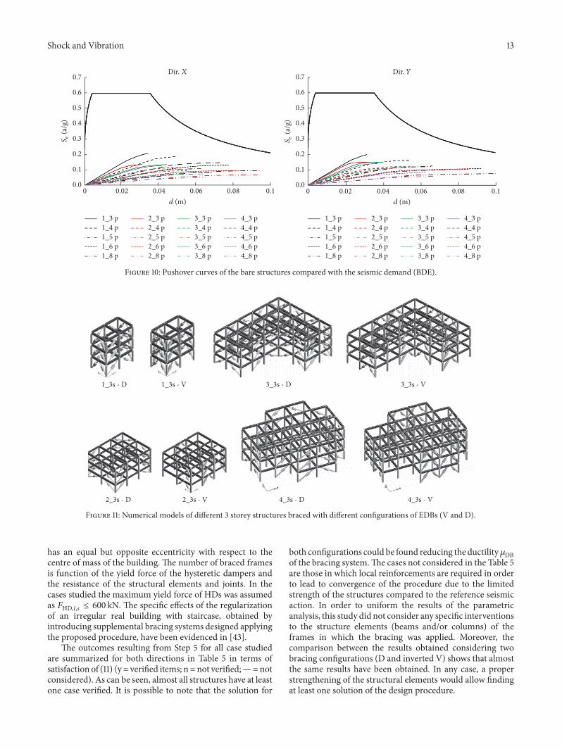
The design of the bracing systems has been performedfor both directions of each bare structure. In Figure 10 theresults of NLSA (Step 1) of all bare structures are comparedwith the BDE. The braces were designed considering twodifferent arrangements, inverted V and diagonal (D) sys-tems, for 40 different case studies. In each case study theprocedure was applied considering different design targets:(i) four values of target ductility 𝜇∗ of the existing structure(Substep (2.1)) corresponding to 1.0, 1.15, 1.3, and 1.5; (ii)three values of design ductility 𝜇DB of dissipative bracingsystem (Substep (2.2)) equal to 4, 8, and 12, for a total of 960analyses.
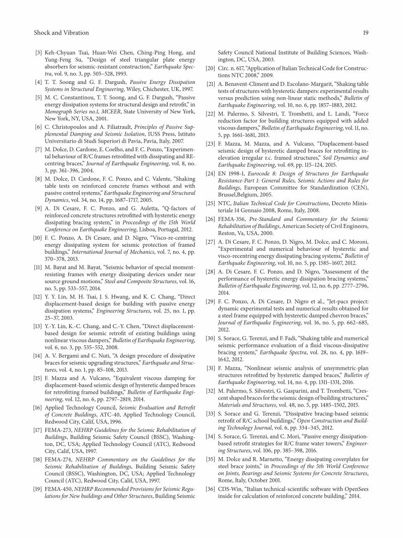
The numerical models of all type 3-storey (𝑛s = 3) struc-tures, considering both reinforcing bracing arrangements (Vand D), are shown in Figure 11.
Several studies evaluated the optimum placement of vari-ous types of passive dampers in asymmetric buildings,mainlyconsisting of counterbalancing the eccentricity between thecentre of mass and centre of stiffness of the braced structure.Most optimal distributions involved the incorporation ofsupplemental damping along the perimeter of the buildings[6, 41, 42]. According to this approach, the dissipating bracingsystems have been deployed around the perimeter of thebuilding and sized in a way that their centre of shear force
Shock and Vibration 13
0 0.10.06 0.080.040.02
d (m)
0.0
0.1
0.2
0.3
0.4
0.5
0.6
0.7
0.0
0.1
0.2
0.3
0.4
0.5
0.6
0.7
S e(a
/g)
0 0.10.06 0.080.040.02
d (m)
1_3 p1_4 p1_5 p1_6 p1_8 p
2_3 p2_4 p2_5 p2_6 p2_8 p
3_3 p3_4 p3_5 p3_6 p3_8 p
4_3 p4_4 p4_5 p4_6 p4_8 p
1_3 p1_4 p1_5 p1_6 p1_8 p
2_3 p2_4 p2_5 p2_6 p2_8 p
3_3 p3_4 p3_5 p3_6 p3_8 p
4_3 p4_4 p4_5 p4_6 p4_8 p
Dir. X Dir. YS e
(a/g
)
Figure 10: Pushover curves of the bare structures compared with the seismic demand (BDE).
1_3s - D 1_3s - V 3_3s - D 3_3s - V
2_3s - D 2_3s - V 4_3s - D 4_3s - V
Figure 11: Numerical models of different 3 storey structures braced with different configurations of EDBs (V and D).
has an equal but opposite eccentricity with respect to thecentre of mass of the building. The number of braced framesis function of the yield force of the hysteretic dampers andthe resistance of the structural elements and joints. In thecases studied the maximum yield force of HDs was assumedas 𝐹HD,𝑖,𝑠 ≤ 600 kN. The specific effects of the regularizationof an irregular real building with staircase, obtained byintroducing supplemental bracing systems designed applyingthe proposed procedure, have been evidenced in [43].
The outcomes resulting from Step 5 for all case studiedare summarized for both directions in Table 5 in terms ofsatisfaction of (11) (y = verified items; n =not verified;—=notconsidered). As can be seen, almost all structures have at leastone case verified. It is possible to note that the solution for
both configurations could be found reducing the ductility𝜇DBof the bracing system.The cases not considered in the Table 5are those in which local reinforcements are required in orderto lead to convergence of the procedure due to the limitedstrength of the structures compared to the reference seismicaction. In order to uniform the results of the parametricanalysis, this study did not consider any specific interventionsto the structure elements (beams and/or columns) of theframes in which the bracing was applied. Moreover, thecomparison between the results obtained considering twobracing configurations (D and inverted V) shows that almostthe same results have been obtained. In any case, a properstrengthening of the structural elements would allow findingat least one solution of the design procedure.

14 Shock and Vibration
Table 5: Results of analysis on reinforced structures designed considering all cases Dir.𝑋/Dir. 𝑌.Number of
levels 3 4 5 6 8
ID1 1 3s 1 4s 1 5s 1 6s 1 8s𝜇∗ 1 1.15 1.3 1.5 1 1.15 1.3 1.5 1 1.15 1.3 1.5 1 1.15 1.3 1.5 1 1.15 1.3 1.5
V 𝜇DB4 n/y n/y n/— —/— n/y y/y y/y y/y n/y n/y n/y y/y y/y y/y y/y y/y y/y y/y y/y y/y8 n/y n/y n/— —/— n/n y/n y/n y/n n/n n/n n/n n/n n/n y/n y/n n/n n/n n/n n/n n/n12 n/n n/n n/— —/— y/n n/n n/n n/n n/n n/n n/n n/n n/n n/n n/n n/n n/n n/n n/n n/n
D 𝜇DB4 n/— n/— n/— —/— n/— y/— y/— y/— n/— n/— n/— y/— y/— y/— y/— y/— y/— y/— y/— y/—8 n/— n/— n/— —/— y/— n/— y/— n/— n/— n/— n/— n/— n/— n/— n/— n/— n/— n/— n/— n/—12 n/— n/— n/— —/— y/— n/— n/— n/— n/— n/— n/— n/— n/— n/— n/— n/— n/— n/— n/— n/—
ID2 2 3s 2 4s 2 5s 2 6s 2 8s𝜇∗ 1 1.15 1.3 1.5 1 1.15 1.3 1.5 1 1.15 1.3 1.5 1 1.15 1.3 1.5 1 1.15 1.3 1.5
V 𝜇DB4 n/y n/y n/y y/y n/y n/y y/y y/y n/y y/y y/y y/y y/y y/n y/y y/n y/y y/y y/y y/y8 n/y n/n n/n y/n y/n y/n y/n y/y y/y y/y y/y y/y n/n n/n n/n n/n n/n y/n n/n n/n12 n/n n/n n/n n/n n/n y/n y/n y/n y/n y/n y/y y/n n/n n/n n/n n/n n/n n/n n/n n/n
D 𝜇DB4 n/y n/y y/y y/y n/y n/y n/y y/y n/y n/y y/y y/y y/y y/y y/y y/y y/y y/y y/y y/y8 n/n n/n y/y y/y y/n y/n y/n y/y n/n y/y y/y y/y n/n n/n n/n n/n y/n n/n n/n n/n12 n/n n/n n/n n/n y/n y/n y/n y/n y/n y/n y/n y/n n/n n/n n/n n/n n/n n/n n/n n/n
ID3 3 3s 3 4s 3 5s 3 6s 3 8s𝜇∗ 1 1.15 1.3 1.5 1 1.15 1.3 1.5 1 1.15 1.3 1.5 1 1.15 1.3 1.5 1 1.15 1.3 1.5
V 𝜇DB4 n/y n/y n/y y/y n/y y/y y/y y/y n/y y/n y/n n/y —/— —/— —/— —/— —/— —/— —/— —/—8 n/y n/n y/n y/n y/n y/n y/n n/y n/n y/n y/n y/n —/— —/— —/— —/— —/— —/— —/— —/—12 y/n n/n n/n n/n n/n n/n n/n n/n n/— n/— n/— y/n —/— —/— —/— —/— —/— —/— —/— —/—
D 𝜇DB4 n/y n/y n/y y/y n/y n/y y/y y/y n/n y/n y/n y/n —/— —/— —/— —/— —/— —/— —/— —/—8 n/n n/n n/y y/y y/n y/n y/n n/y y/n y/n y/n y/n —/— —/— —/— —/— —/— —/— —/— —/—12 n/n n/n n/n n/n y/n y/n y/n n/n y/— y/— y/— y/n —/— —/— —/— —/— —/— —/— —/— —/—
ID4 4 3s 4 4s 4 5s 4 6s 4 8s𝜇∗ 1 1.15 1.3 1.5 1 1.15 1.3 1.5 1 1.15 1.3 1.5 1 1.15 1.3 1.5 1 1.15 1.3 1.5
V 𝜇DB4 n/y n/y n/y y/y n/y n/y y/y y/y n/y n/y y/y y/y n/n y/n y/y y/y y/y y/y y/y y/y8 n/n n/n n/n y/y y/n y/n n/n n/n n/n n/n y/n y/n n/n n/n n/n n/n —/— —/— n/n n/n12 y/n n/n n/n n/n n/n n/n n/n n/n n/n n/n n/n n/n —/— —/n n/n n/n —/— —/— —/— —/—
D 𝜇DB4 n/y n/y n/y n/y n/y n/y y/y y/y n/y n/y y/y y/y n/y y/y y/y y/y y/y y/y y/y y/y8 n/y n/y n/y y/y n/n n/n n/n n/n n/n y/n y/y y/y n/n n/n n/n n/n —/— n/y y/y y/y12 n/n n/n n/n n/n n/n n/n n/n n/n n/n n/n y/n y/n n/n n/n n/n n/n —/— —/— —/— —/—
4.2. Influence of the Design Parameters. The correction factor𝐶 of (15) has been evaluated for all cases, being verified ornot, as shown in Figures 12 and 13. After that, a correlationbetween 𝐶 and the main structural parameters was sought,namely, 𝜇∗, 𝑇B∗/𝑇∗, 𝐹DB/𝐹y∗, 𝑛s, and 𝜇DB.
The outcomes of Figures 12 and 13 lead to the followingconsiderations about the correction factor 𝐶:
(i) it grows with the reduction of the ratio between thebilinear equivalent period of the braced structure 𝑇B∗and that of the bare structure 𝑇∗ (in the range of 0.2÷0.9);
(ii) it grows with the growth of the ratio between the yieldforce 𝐹DB of the equivalent dissipative bracing systemand the yield force𝐹y∗ of the equivalent bare structure(in the range of 0.2 ÷ 1.4);
(iii) there is no correlation with the value of number ofstoreys 𝑛s, almost for considered range (3 ÷ 8 story);
(iv) it seems almost independent from the value of designductility 𝜇DB of equivalent bracing system (in therange of 4 ÷ 12);
(v) it grows with decreasing of the target ductility 𝜇∗ ofthe bare structure (in the range of 1 ÷ 1.5);
(vi) it ranges from 1 to 4 for all combinations of the maindesign parameters.
4.3. Estimation of the Behaviour Factor. Based on the out-comes showed in the previous paragraph and with the aimof proposing a formulation to calculate the correction factor𝐶cal, a multiparameter linear regression analysis has been

Shock and Vibration 15
Dir. X Dir. Y
ns ns
�휇DB
0.3 0.4 0.5 0.6 0.7 0.8 0.90.2
TB∗/T∗
0
1
2
3
4
5
C
0.3 0.4 0.5 0.6 0.7 0.8 0.90.2
TB∗/T∗
0
1
2
3
4
5
C
0
1
2
3
4
5
C
10.6 0.80.4 1.2 1.40.2
FDB/Fy∗
0
1
2
3
4
5
C
10.6 0.80.4 1.2 1.40.2
FDB/Fy∗
0
1
2
3
4
5
C
0
1
2
3
4
5
C
3 4 5 6 7 8 92
ns
3 4 5 6 7 8 92
ns
1D-�휇∗1
2D-�휇∗1
3D-�휇∗1
4D-�휇∗1
1V-�휇∗1
2V-�휇∗1
3V-�휇∗1
4V-�휇∗1
1D-�휇∗1.15
2D-�휇∗1.15
3D-�휇∗1.15
4D-�휇∗1.15
1V-�휇∗1.15
2V-�휇∗1.15
3V-�휇∗1.15
4V-�휇∗1.15
1D-�휇∗1.3
2D-�휇∗1.33D-�휇∗1.34D-�휇∗1.3
1V-�휇∗1.32V-�휇∗1.33V-�휇∗1.34V-�휇∗1.3
1D-�휇∗1.52D-�휇∗1.53D-�휇∗1.54D-�휇∗1.5
1V-�휇∗1.52V-�휇∗1.53V-�휇∗1.54V-�휇∗1.5
3
4
5
6
8
ns ns1D-�휇∗1
2D-�휇∗1
3D-�휇∗1
4D-�휇∗1
1V-�휇∗1
2V-�휇∗1
3V-�휇∗1
4V-�휇∗1
1D-�휇∗1.15
2D-�휇∗1.15
3D-�휇∗1.15
4D-�휇∗1.15
1V-�휇∗1.15
2V-�휇∗1.15
3V-�휇∗1.15
4V-�휇∗1.15
1D-�휇∗1.3
2D-�휇∗1.33D-�휇∗1.34D-�휇∗1.3
1V-�휇∗1.32V-�휇∗1.33V-�휇∗1.34V-�휇∗1.3
1D-�휇∗1.52D-�휇∗1.53D-�휇∗1.54D-�휇∗1.5
1V-�휇∗1.52V-�휇∗1.53V-�휇∗1.54V-�휇∗1.5
3
4
5
6
8
1D-�휇∗1
2D-�휇∗1
3D-�휇∗1
4D-�휇∗1
1V-�휇∗1
2V-�휇∗1
3V-�휇∗1
4V-�휇∗1
1D-�휇∗1.15
2D-�휇∗1.15
3D-�휇∗1.15
4D-�휇∗1.15
1V-�휇∗1.15
2V-�휇∗1.15
3V-�휇∗1.15
4V-�휇∗1.15
1D-�휇∗1.3
2D-�휇∗1.33D-�휇∗1.34D-�휇∗1.3
1V-�휇∗1.32V-�휇∗1.33V-�휇∗1.34V-�휇∗1.3
1D-�휇∗1.52D-�휇∗1.53D-�휇∗1.54D-�휇∗1.5
1V-�휇∗1.52V-�휇∗1.53V-�휇∗1.54V-�휇∗1.5
4
8
12
Figure 12: Continued.

16 Shock and Vibration
0
1
2
3
4
5
C
4 5 6 7 8 93 11 12 1310
�휇DB
0
1
2
3
4
5
C
4 5 6 7 8 93 11 12 1310
�휇DB
ns ns1D-�휇∗1
2D-�휇∗1
3D-�휇∗1
4D-�휇∗1
1V-�휇∗1
2V-�휇∗1
3V-�휇∗1
4V-�휇∗1
1D-�휇∗1.15
2D-�휇∗1.15
3D-�휇∗1.15
4D-�휇∗1.15
1V-�휇∗1.15
2V-�휇∗1.15
3V-�휇∗1.15
4V-�휇∗1.15
1D-�휇∗1.3
2D-�휇∗1.33D-�휇∗1.34D-�휇∗1.3
1V-�휇∗1.32V-�휇∗1.33V-�휇∗1.34V-�휇∗1.3
1D-�휇∗1.52D-�휇∗1.53D-�휇∗1.54D-�휇∗1.5
1V-�휇∗1.52V-�휇∗1.53V-�휇∗1.54V-�휇∗1.5
3
4
5
6
8
Figure 12: Correlation between 𝐶 and the ductility demand on the bracing 𝜇DB, the number of storeys 𝑛s, the ratio between periods 𝑇B∗/𝑇∗,
and the ratio between resistances 𝐹DB/𝐹y∗.Dir. X Dir. Y
ns ns1D-�휇DB122D-�휇DB123D-�휇DB124D-�휇DB12
1V-�휇DB122V-�휇DB123V-�휇DB124V-�휇DB12
1D-�휇DB82D-�휇DB83D-�휇DB84D-�휇DB8
1V-�휇DB82V-�휇DB83V-�휇DB84V-�휇DB8
1D-�휇DB42D-�휇DB43D-�휇DB44D-�휇DB4
1V-�휇DB42V-�휇DB43V-�휇DB44V-�휇DB4
3
4
5
6
8
0
1
2
C
3
4
5
0
1
2
3
4
5
C
1.05 1.15 1.25 1.35 1.45 1.550.95
�휇∗
1.05 1.15 1.25 1.35 1.45 1.550.95
�휇∗
Figure 13: Correlation between 𝐶 and design structural ductility 𝜇∗.performed considering the five above-mentioned structuralparameters (see (16)).The values of the linear regression coef-ficients, which obtain the best fitting correlation 𝑟2 between𝐶, have been evaluated by applying the design procedureand the correction factor 𝐶cal has been calculated throughlinear regression analysis (reported in Table 6 as regres-sion (a)). The linear regression analysis carried out on theresults of all case studies produced the diagrams showed inFigure 14.
𝐶cal = 𝑚1 ⋅ 𝜇∗ + 𝑚2 ⋅ 𝑇B∗𝑇∗ + 𝑚3 ⋅ 𝐹DB𝐹y∗ + 𝑚4 ⋅ 𝑛s + 𝑚5⋅ 𝜇DB,
(16)
where 𝑚1, . . . , 𝑚5 are the linear regression coefficients of theconsidered parameters.
As indicated by Table 6 and Figure 14(a), the coefficientsm4 andm5 are negligible in determining the correction factor𝐶. The lateral bar of each diagram shows the weight ofthe single parameters. A similar fitting correlation r2 canbe found by considering only the three main parametersassociated with m1, m2, and m3, named regression (b) (seeTable 6 and Figure 14).
5. Conclusions
Fast sizing and verifications of the performance of EBDscould simplify the adoption of this particular strategy for

Shock and Vibration 17
0.0
1.0
2.0
3.0
4.0
5.0
C
3.0 4.0 5.01.0 2.00.0
Ccal
0%
20%
40%
60%
80%
100%
0%
20%
40%
60%
80%
100%
3.0 4.0 5.01.0 2.00.0
Ccal
0.0
1.0
2.0
3.0
4.0
5.0
C
�휇∗
�휇DB
ns
TB∗/T∗
FDB/Fy∗
Reg. (b)D
ir.X
Dir.
Y
0.0
1.0
2.0
3.0
4.0
5.0
C
3.0 4.0 5.01.0 2.00.0
Ccal
0.0
1.0
2.0
3.0
4.0
5.0
C
3.0 4.0 5.01.0 2.00.0
Ccal
0%
20%
40%
60%
80%
100%
0%
20%
40%
60%
80%
100%
�휇∗
�휇DB
ns
TB∗/T∗
FDB/Fy∗
Reg. (a)
(b) (a)
Figure 14: Regression analysis between the correction factors 𝐶 and 𝐶cal with the weight of the design parameters.
Table 6: Linear regression coefficients.
Dir. Regression 𝑚1 𝑚2 𝑚3 𝑚4 𝑚5 𝑟2𝑋 (a) −0.98 1.28 2.43 0.01 0.05 0.97
(b) −0.78 1.40 2.54 — — 0.97
𝑌 (a) −0.87 1.57 2.33 0.02 0.02 0.97(b) −0.79 1.45 2.32 — — 0.97
structural retrofitting of existing buildings. Contemporarilythe use of more simple linear analysis could allow for anincreasing of the applications to real existing buildings. Thedesign procedure proposed in this paper to evaluate themechanical characteristics of the hysteretic EDBs showedtheir effectiveness in achieving the performance objective.The application of the procedure to a simple benchmarkstructure also confirmed a good agreement between numeri-cal response obtained by NLSA and NLDA.
The outcomes of statistical analyses performed on about1000 case studies have highlighted the efficiency of the designprocedure in providing at least one solution satisfying theverification in most of cases studied. Only few of consideredcases require specific local reinforcement to the structureelements despite the fact that the bracing is applied.
A correction factor 𝐶 representing the increasing ofthe behaviour factor of the braced building compared to
that of the bare structure has been estimated. The analysesperformed on all cases studies have shown that the correctionfactor 𝐶 varies from 1 to 4, depending on the combinationsof the three main design parameters: the target ductility𝜇∗ of the bare structure; the ratio between the equivalentperiod of the braced structure and the period of the barestructure 𝑇B∗/𝑇∗; the ratio between the yield force of theequivalent dissipative bracing system and the yield force ofthe equivalent bare structure 𝐹DB/𝐹y∗.
Finally, it can be observed that in order to avoid theoverloading of the structural elements (beams, columns, andjoints) it is recommended that the target ductility of the barestructure should be 1 < 𝜇∗ < 1.5; the strength of the bracingsystem should not be too high with respect to the yield forceof the bare structure𝐹BD/𝐹y∗ < 1.3; the stiffness of the bracedstructure should not be too high with respect to the stiffnessof the original structure 𝑇B∗/𝑇∗ > 0.3.

18 Shock and Vibration
Symbols and Abbreviations
Seismic Analysis
MDOF: Multi-degree-of-freedomSDOF: Single-degree-of-freedomS: Elastoplastic SDOF of bare structureDB: Elastoplastic SDOF of dissipative bracingS + DB: Trilinear curve of the braced structureE(S + DB): Equivalent elastic system of S + DBEP(S + DB): Equivalent elastoplastic system of S + DBLSA: Linear static analysisNLDA: Nonlinear dynamic analysisNLSA: Nonlinear static analysisFDE: Frequent Design EarthquakeSDE: Serviceability Design EarthquakeBDE: Basic Design EarthquakeMCE: Maximum Considered Earthquake𝑇𝐶: Upper limit of the period of the constant
spectral acceleration branch𝜉: Viscous damping ratioT1: Topographic factorPGA: Peak ground acceleration.
Bare Structure (S)
𝑛s: Number of storeys𝑇1: Fundamental period of vibration of a building𝑚𝑖: Mass of storey 𝑖ℎ𝑖: Interstorey height of storey 𝑖𝑠𝑖: Displacement of storey 𝑖 from LSAΔ𝑠𝑖: Interstorey displacement from LSA𝑠TOT: Maximum top displacement form LSA𝐹𝑖: Horizontal seismic force at storey 𝑖Γ: Transformation factor of S𝑚∗: Equivalent mass of S𝑇∗: Equivalent period of S𝐹y∗: Yield force of S𝑑y∗: Yield displacement of S𝑘𝐹∗: Elastic stiffness of S𝑑u∗: Ultimate displacement of S𝜇𝐹∗: Maximum ductility of S𝜇∗: Target ductility of S𝐹y,𝑖: Yield force of storey 𝑖 of S𝑑y,𝑖: Yield displacement of storey 𝑖 of S𝑘𝐹,𝑖: Elastic stiffness of storey 𝑖 of S𝑢𝑖: Normalized modal displacement of storey 𝑖 of S𝑞: Behaviour factor of the bare structure𝑞0: Basic value of the behaviour factor 𝑞Dissipative Bracing (DB) System
EDB: Energy Dissipation Bracing𝐹DB: Yield force of DB𝑑DBy: Yield displacement of DB𝑘DB: Elastic stiffness of DB𝑑DBu: Ultimate displacement of DB𝜇DB: Design ductility of DB𝑘DB,𝑖: Elastic stiffness of storey 𝑖 of DB𝐹DB,𝑖: Yield force of storey 𝑖 of DB.
Braced Structure (EP(S + DB))
ΓB: Transformation factor of EP(S + DB)𝑚B∗: Equivalent mass of EP(S + DB)𝑇B∗: Equivalent period of EP(S + DB)𝑘B∗: Elastic stiffness of EP(S + DB)𝑘tot,𝑖: Total stiffness of storey 𝑖 of S + DB𝐹By∗: Yield force of the EP(S + DB)𝑑By∗: Yield displacement of the braced structure𝑑Bu∗: Ultimate displacement of the braced structure𝜇B∗: Ductile capacity of the braced structure𝑑Be∗: Elastic displacement of E(S + DB) at BDE𝑑Bm∗: Maximum displacement of EP(S + DB) at BDE𝑑Bt∗: Target displacement of EP(S + DB)𝑉Ed,𝑖: Design shear force of storey 𝑖 required by LSA𝑚𝑘,𝑀𝑘: Stiffness correction factors𝑚𝐹,𝑀𝐹: Strength correction factors𝑞B: Behaviour factor of the braced structure𝐶: Correction coefficient of the behaviour factor 𝑞.
Dissipative Braces
HD: Hysteretic DamperR: Rigid bracing truss𝑘DB,𝑖,𝑠: Stiffness of the single BD of storey 𝑖𝐹DB,𝑖,𝑠,: Yield strength of the single DB of storey 𝑖𝑛DB,𝑖: Number of DBs of storey 𝑖𝜙𝑠: Angle between the brace and the horizontal𝑘HD,𝑖,𝑠: Elastic stiffness of single HD of storey 𝑖𝐹HD,𝑖,𝑠: Yield force of single HD of storey 𝑖𝜇HD: Design ductility of single HD of storey 𝑖𝑘R,𝑖,𝑠: Elastic stiffness of the single R of storey 𝑖.Conflicts of Interest
The authors declare that there are no conflicts of interestregarding the publication of this paper.
Acknowledgments
This studywas funded by the ItalianDepartment of Civil Pro-tection within the RELUIS 2010–2013, RELUIS 2014 projects,and MIUR within the PRIN 2012 project. The authors wouldlike to acknowledge STS Software for supplying finite elementprogram.Thework performed byGianlucaAuletta, Ph.D., forthe numerical modelling is also acknowledged.
References
[1] A. Di Cesare, F. C. Ponzo, M. Vona et al., “Identification of thestructural model and analysis of the global seismic behaviourof a RC damaged building,” Soil Dynamics and EarthquakeEngineering, vol. 65, pp. 131–141, 2014.
[2] V. Ciampi, “Development of passive energy dissipation tech-niques for buildings,” in Proceedings of the Post-SMIRT Con-ference Seminar on Seismic Isolation, Energy Dissipation andControl of Vibrations of Structures, pp. 495–510, Capri, Italy,1993.
Shock and Vibration 19
[3] Keh-Chyuan Tsai, Huan-Wei Chen, Ching-Ping Hong, andYung-Feng Su, “Design of steel triangular plate energyabsorbers for seismic-resistant construction,” Earthquake Spec-tra, vol. 9, no. 3, pp. 505–528, 1993.
[4] T. T. Soong and G. F. Dargush, Passive Energy DissipationSystems in Structural Engineering, Wiley, Chichester, UK, 1997.
[5] M. C. Constantinou, T. T. Soong, and G. F. Dargush, “Passiveenergy dissipation systems for structural design and retrofit,” inMonograph Series no.1, MCEER, State University of New York,New York, NY, USA, 2001.
[6] C. Christopoulos and A. Filiatrault, Principles of Passive Sup-plemental Damping and Seismic Isolation, IUSS Press, IstitutoUniversitario di Studi Superiori di Pavia, Pavia, Italy, 2007.
[7] M. Dolce, D. Cardone, E. Coelho, and F. C. Ponzo, “Experimen-tal behaviour of R/C frames retrofitted with dissipating and RE-centring braces,” Journal of Earthquake Engineering, vol. 8, no.3, pp. 361–396, 2004.
[8] M. Dolce, D. Cardone, F. C. Ponzo, and C. Valente, “Shakingtable tests on reinforced concrete frames without and withpassive control systems,” Earthquake Engineering and StructuralDynamics, vol. 34, no. 14, pp. 1687–1717, 2005.
[9] A. Di Cesare, F. C. Ponzo, and G. Auletta, “Q-factors ofreinforced concrete structures retrofitted with hysteretic energydissipating bracing system,” in Proceedings of the 15th WorldConference on Earthquake Engineering, Lisboa, Portugal, 2012.
[10] F. C. Ponzo, A. Di Cesare, and D. Nigro, “Visco-re-centringenergy dissipating system for seismic protection of framedbuildings,” International Journal of Mechanics, vol. 7, no. 4, pp.370–378, 2013.
[11] M. Bayat and M. Bayat, “Seismic behavior of special moment-resisting frames with energy dissipating devices under nearsource ground motions,” Steel and Composite Structures, vol. 16,no. 5, pp. 533–557, 2014.
[12] Y. Y. Lin, M. H. Tsai, J. S. Hwang, and K. C. Chang, “Directdisplacement-based design for building with passive energydissipation systems,” Engineering Structures, vol. 25, no. 1, pp.25–37, 2003.
[13] Y.-Y. Lin, K.-C. Chang, and C.-Y. Chen, “Direct displacement-based design for seismic retrofit of existing buildings usingnonlinear viscous dampers,”Bulletin of Earthquake Engineering,vol. 6, no. 3, pp. 535–552, 2008.
[14] A. V. Bergami and C. Nuti, “A design procedure of dissipativebraces for seismic upgrading structures,” Earthquake and Struc-tures, vol. 4, no. 1, pp. 85–108, 2013.
[15] F. Mazza and A. Vulcano, “Equivalent viscous damping fordisplacement-based seismic design of hysteretic damped bracesfor retrofitting framed buildings,” Bulletin of Earthquake Engi-neering, vol. 12, no. 6, pp. 2797–2819, 2014.
[16] Applied Technology Council, Seismic Evaluation and Retrofitof Concrete Buildings, ATC-40, Applied Technology Council,Redwood City, Calif, USA, 1996.
[17] FEMA-273, NEHRP Guidelines for the Seismic Rehabilitation ofBuildings, Building Seismic Safety Council (BSSC), Washing-ton, DC, USA; Applied Technology Council (ATC), RedwoodCity, Calif, USA, 1997.
[18] FEMA-274, NEHRP Commentary on the Guidelines for theSeismic Rehabilitation of Buildings, Building Seismic SafetyCouncil (BSSC), Washington, DC, USA; Applied TechnologyCouncil (ATC), Redwood City, Calif, USA, 1997.
[19] FEMA-450,NEHRP Recommended Provisions for Seismic Regu-lations for New buildings and Other Structures, Building Seismic
Safety Council National Institute of Building Sciences, Wash-ington, DC, USA, 2003.
[20] Circ. n. 617, “Application of ItalianTechnical Code forConstruc-tions NTC 2008,” 2009.
[21] A. Benavent-Climent andD. Escolano-Margarit, “Shaking tabletests of structures with hysteretic dampers: experimental resultsversus prediction using non-linear static methods,” Bulletin ofEarthquake Engineering, vol. 10, no. 6, pp. 1857–1883, 2012.
[22] M. Palermo, S. Silvestri, T. Trombetti, and L. Landi, “Forcereduction factor for building structures equipped with addedviscous dampers,”Bulletin of Earthquake Engineering, vol. 11, no.5, pp. 1661–1681, 2013.
[23] F. Mazza, M. Mazza, and A. Vulcano, “Displacement-basedseismic design of hysteretic damped braces for retrofitting in-elevation irregular r.c. framed structures,” Soil Dynamics andEarthquake Engineering, vol. 69, pp. 115–124, 2015.
[24] EN 1998-1, Eurocode 8: Design of Structures for EarthquakeResistance-Part 1: General Rules, Seismic Actions and Rules forBuildings, European Committee for Standardization (CEN),Brussel,Belgium, 2005.
[25] NTC, Italian Technical Code for Constructions, Decreto Minis-teriale 14 Gennaio 2008, Rome, Italy, 2008.
[26] FEMA-356, Pre-Standard and Commentary for the SeismicRehabilitation of Buildings, American Society of Civil Engineers,Reston, Va, USA, 2000.
[27] A. Di Cesare, F. C. Ponzo, D. Nigro, M. Dolce, and C. Moroni,“Experimental and numerical behaviour of hysteretic andvisco-recentring energy dissipating bracing systems,” Bulletin ofEarthquake Engineering, vol. 10, no. 5, pp. 1585–1607, 2012.
[28] A. Di Cesare, F. C. Ponzo, and D. Nigro, “Assessment of theperformance of hysteretic energy dissipation bracing systems,”Bulletin of Earthquake Engineering, vol. 12, no. 6, pp. 2777–2796,2014.
[29] F. C. Ponzo, A. Di Cesare, D. Nigro et al., “Jet-pacs project:dynamic experimental tests and numerical results obtained fora steel frame equipped with hysteretic damped chevron braces,”Journal of Earthquake Engineering, vol. 16, no. 5, pp. 662–685,2012.
[30] S. Sorace, G. Terenzi, and F. Fadi, “Shaking table and numericalseismic performance evaluation of a fluid viscous-dissipativebracing system,” Earthquake Spectra, vol. 28, no. 4, pp. 1619–1642, 2012.
[31] F. Mazza, “Nonlinear seismic analysis of unsymmetric-planstructures retrofitted by hysteretic damped braces,” Bulletin ofEarthquake Engineering, vol. 14, no. 4, pp. 1311–1331, 2016.
[32] M. Palermo, S. Silvestri, G. Gasparini, and T. Trombetti, “Cres-cent shaped braces for the seismic design of building structures,”Materials and Structures, vol. 48, no. 5, pp. 1485–1502, 2015.
[33] S. Sorace and G. Terenzi, “Dissipative bracing-based seismicretrofit of R/C school buildings,” Open Construction and Build-ing Technology Journal, vol. 6, pp. 334–345, 2012.
[34] S. Sorace, G. Terenzi, and C. Mori, “Passive energy dissipation-based retrofit strategies for R/C frame water towers,” Engineer-ing Structures, vol. 106, pp. 385–398, 2016.
[35] M. Dolce and R. Marnetto, “Energy dissipating coverplates forsteel brace joints,” in Proceedings of the 5th World Conferenceon Joints, Bearings and Seismic Systems for Concrete Structures,Rome, Italy, October 2001.
[36] CDS-Win, “Italian technical-scientific software with OpenSeesinside for calculation of reinforced concrete building,” 2014.
20 Shock and Vibration
[37] N. M. Newmark andW. J. Hall, Earthquake Spectra and Design,EERI Monograph Series, EERI, Berkley, Calif, USA, 1982.
[38] P. Fajfar and H. Krawinkler, Nonlinear Seismic Analysis andDesign of Reinforced Concrete Buildings, Elsevier, London, UK,1992.
[39] E. Miranda and V. V. Bertero, “Evaluation of strength reductionfactors for earthquake−resistant design,” Earthquake Spectra,vol. 10, no. 2, pp. 357–379, 1994.
[40] T. Paulay and M. J. N. Priestley, Seismic Design of ReinforcedConcrete andMasonry Buildings, JohnWiley & Sons, New York,NY, USA, 1992.
[41] I. Takewaki, S. Yoshitomi, K. Uetani, and M. Tsuji, “Non-monotonic optimal damper placement via steepest directionsearch,” Earthquake Engineering and Structural Dynamics, vol.28, no. 6, pp. 655–670, 1999.
[42] O. Lavan and R. Levy, “Optimal peripheral drift control of3D irregular framed structures using supplemental viscousdampers,” Journal of Earthquake Engineering, vol. 10, no. 6, pp.903–923, 2006.
[43] F. C. Ponzo, A. Di Cesare, G. Arleo, and P. Totaro, “Protezionesismica di edifici esistenti con controventi dissipativi di tipoisteretico: aspetti progettuali ed esecutivi.,” Progettazione Sis-mica, vol. 1, pp. 37–60, 2010.

International Journal of
AerospaceEngineeringHindawi Publishing Corporationhttp://www.hindawi.com Volume 2014
RoboticsJournal of
Hindawi Publishing Corporationhttp://www.hindawi.com Volume 2014
Hindawi Publishing Corporationhttp://www.hindawi.com Volume 2014
Active and Passive Electronic Components
Control Scienceand Engineering
Journal of
Hindawi Publishing Corporationhttp://www.hindawi.com Volume 2014
International Journal of
RotatingMachinery
Hindawi Publishing Corporationhttp://www.hindawi.com Volume 2014
Hindawi Publishing Corporation http://www.hindawi.com
Journal ofEngineeringVolume 2014
Submit your manuscripts athttps://www.hindawi.com
VLSI Design
Hindawi Publishing Corporationhttp://www.hindawi.com Volume 2014
Hindawi Publishing Corporationhttp://www.hindawi.com Volume 2014
Shock and Vibration
Hindawi Publishing Corporationhttp://www.hindawi.com Volume 2014
Civil EngineeringAdvances in
Acoustics and VibrationAdvances in
Hindawi Publishing Corporationhttp://www.hindawi.com Volume 2014
Hindawi Publishing Corporationhttp://www.hindawi.com Volume 2014
Electrical and Computer Engineering
Journal of
Advances inOptoElectronics
Hindawi Publishing Corporation http://www.hindawi.com
Volume 2014
The Scientific World JournalHindawi Publishing Corporation http://www.hindawi.com Volume 2014
SensorsJournal of
Hindawi Publishing Corporationhttp://www.hindawi.com Volume 2014
Modelling & Simulation in EngineeringHindawi Publishing Corporation http://www.hindawi.com Volume 2014
Hindawi Publishing Corporationhttp://www.hindawi.com Volume 2014
Chemical EngineeringInternational Journal of Antennas and
Propagation
International Journal of
Hindawi Publishing Corporationhttp://www.hindawi.com Volume 2014
Hindawi Publishing Corporationhttp://www.hindawi.com Volume 2014
Navigation and Observation
International Journal of
Hindawi Publishing Corporationhttp://www.hindawi.com Volume 2014
DistributedSensor Networks
International Journal of