seismic performance of concrete frame structures ... · reinforced with superelastic shape memory...
TRANSCRIPT

Smart Structures and Systems, Vol. 5, No. 5 (2009) 565-585 565
Seismic performance of concrete frame structures reinforced with superelastic shape memory alloys
M. Shahria Alam, Moncef Nehdi* and Maged A. Youssef
Department of Civil and Environmental Engineering, The University of Western Ontario
London, Ontario, N6A 5B9, Canada
(Received March 25, 2008, Accepted June 29, 2009)
Abstract. Superelastic Shape Memory Alloys (SMAs) are gaining acceptance for use as reinforcing bars inconcrete structures. The seismic behaviour of concrete frames reinforced with SMAs is being assessed in thisstudy. Two eight-storey concrete frames, one of which is reinforced with regular steel and the other with SMAs atthe plastic hinge regions of beams and regular steel elsewhere, are designed and analyzed using 10 differentground motion records. Both frames are located in the highly seismic region of Western Canada and are designedand detailed according to current seismic design standards. The validation of a finite element (FE) program thatwas conducted previously at the element level is extended to the structure level in this paper using the results of ashake table test of a three-storey moment resisting steel RC frame. The ten accelerograms that are chosen foranalyzing the designed RC frames are scaled based on the spectral ordinate at the fundamental periods of theframes. The behaviour of both frames under scaled seismic excitations is compared in terms of maximum inter-storey drift, top-storey drift, inter-storey residual drift, and residual top-storey drift. The results show that SMA-RC frames are able to recover most of its post-yield deformation, even after a strong earthquake.
Keywords: concrete frame; shape memory alloy; superelasticity; finite element analysis; residual drift; seismicdamage.
1. Introduction
Seismic hazards and their associated damage can be substantial. Many earthquake events have caused
devastation including permanent damage and failure of many buildings and structures. Conventional
reinforced concrete (RC) structures are mostly designed for safety conditions, where the earthquake
energy is mainly dissipated through yielding of reinforcement and its inelastic deformation. Structures
are allowed to undergo severe damage – this means saving lives at the expense of structures incurring
excessive economic losses. More recently the vision has been broadened where owners as well as designers
no longer accept to surrender their constructions. The seismic design of structures has evolved towards
a performance-based approach in which there is need for new structural members and systems that
possess enhanced deformation capacity and ductility, higher damage tolerance, and recovered and/or
reduced permanent deformations.
Shape Memory Alloys (SMAs) are unique materials that have the ability to undergo large deformation and
return to a predetermined shape upon unloading or by heating. The distinct and unique properties of
SMAs have been used in a wide variety of applications in different fields and industries such as
*Corresponding Author, E-mail: [email protected]

566 M. Shahria Alam, Moncef Nehdi and Maged A. Youssef
aviation, medical equipment and implants. SMAs are gradually gaining recognition and finding new
applications in various engineering fields. Recent experimental and numerical investigations have also
demonstrated numerous possibilities of utilizing SMAs in civil engineering structures to protect
buildings and bridges against earthquakes (Dolce, et al. 2004, Salichs, et al. 2001 and Wilde, et al. 2000).
Ocel, et al. (2004) used SMAs in steel beam-column connections, which displayed repeatable and
stable hysteretic behavior. An analytical investigation was carried out by Shahin, et al. (1997) where
SMA tendons were used as active bracing members of building models. Numerical simulation
illustrated that the use of these tendons reduced the relative displacement between the base and floor of
the model. SMA devices composed of sixty superelastic SMA wires were utilized for the rehabilitation
of the Trignano S. Giorgio Church in Italy, which was seriously damaged by an earthquake (Indirli, et
al. 2001). The performance of the rehabilitation scheme was positively verified after the tower was
shaken by another earthquake. No forms of distress or damage were noticed after the shock. Tamai, et
al. (2003) tested the possibility of using SMA rods for anchoring steel columns of a building structure.
The seismic resisting mechanism of the column base with SMA anchorage was investigated under
reversed cyclic loading on cantilevers. The test results revealed that SMA anchorage has the ability to
improve the restoring force characteristics of the column base and to prevent plastic deformation and
damage in the column. DesRoches and Delemont (2002) evaluated the effectiveness of SMA restrainers
through an analytical study of a multi-span simply supported bridge subjected to a set of ground motion
records. The results show that SMA restrainers were capable of reducing relative hinge displacements
much more effectively than conventional steel restrainers.
Clark, et al. (1995) conducted experimental and analytical research on energy dissipation devices
using SMAs. Two different types of reduced-scale dampers using prestressed SMA wires were tested
under in-plane cyclic loading. The test showed good hysteresis with a little reduction in the yield stress.
The function of this SMA device was analytically studied by fitting it in a six storey, steel frame where
the results showed good performance in reducing the displacement response of the structure under
earthquake excitation. Salichs, et al. (2001) conducted a feasibility study on using SMA diagonal bracing
wires as passive devices for vibration suppression of a one-storey building model. SMA superelastic
hysteresis lowered the peak lateral drift compared with that for steel bracing having similar stiffness.
McCormick and DesRoches (2003) made an analytical evaluation of the effectiveness of using large
diameter superelastic SMA bars as bracing members. The reduction in the inter-storey drift and column
rotation of an RC frame achieved by using SMA bracing members was more than that achieved by
using steel bracing. Auricchio, et al. (2006) conducted numerical simulations and compared the seismic
responses of a three- and a six-storey steel frame building equipped with traditional steel bracings and
superelastic SMA bracings. Their results showed that buildings with SMA bracings performed better
than steel braced buildings in terms of inter-storey and residual drift. Zhu and Zhang (2007) performed
a similar study where superelastic nitinol-based reusable hysteretic damping braces were used in steel
frame structures. Nonlinear time history analyses confirmed that such braces can outperform conventional
buckling restrained braced frames in terms of residual drift.
Since SMA is a costly material, it was not until very recently that it found its way as reinforcing bars
in RC structures. Only very limited research work reported the use of SMA rebars as reinforcement in
RC structures subjected to cyclic loading. For instance, Saiidi and Wang (2006) used SMA rods in the
plastic hinge area of RC columns and evaluated the seismic performance of such columns using a shake
table. The results showed that SMA RC columns were able to recover nearly all of their post-yield
deformation, thus requiring minimal repair. Youssef, et al. (2008) and Nehdi, et al. (2007) utilized
superelastic SMA in the plastic hinge area of beam-column joint specimens and conducted experimental

Seismic performance of concrete frame structures reinforced with superelastic shape memory alloys 567
investigation to assess their performance under reversed cyclic loading. Alam, et al. (2007 and 2008)
conducted numerical investigation on SMA RC elements. Their results showed that SMA RC beam-
column joints are advantageous over steel-RC beam-column joints because of their recentering
capability even after large inelastic displacements.
Although existing literature provides a number of analytical and experimental studies on the use of
SMAs in several components of RC building structures, little research has been carried out on the use
of SMA as reinforcement in full RC frame structures. Thus, this paper focuses on the use of superelastic
SMA rebars in the plastic hinge areas of beam-column joints and regular steel in other parts of a full-
scale RC building. Nonlinear finite element (FE) analysis has been implemented to investigate and
compare the performances of a SMA RC building and a regular steel RC building under a number of
seismic loads. The FE program (SeismoStruct) has been first validated at the element level for SMA
RC element, then with the shake table test results of a three-storey RC frame. Static nonlinear pushover
analyses were performed for both types of frames to determine their capacity, investigate their failure
mechanism, and compare their residual drift and recentering capability. Then time history analyses were
performed for both types of frames to determine the characteristic differences in terms of inter-storey
drift, inter-storey residual drift, top-storey drifts, and top-storey residual drift.
2. Superelasticity of SMA and its modelling
Super-Elasticity (SE) is a distinct property that makes SMA a smart material. A superelastic SMA can
restore its initial shape spontaneously, even from its inelastic range, upon unloading. Among various
composites, Ni-Ti has been found to be the most appropriate SMA for structural applications because of
its large recoverable strain, superelasticity and exceptionally good resistance to corrosion. In this paper,
unless otherwise stated, SMAs are mainly referred to Ni-Ti SMA (commonly known as Nitinol).
A typical stress-strain curve of austenite SMA under cyclic axial force is presented in Fig. 1. When an
SMA specimen is subjected to a cycle of axial deformation within its superelastic strain range, it
dissipates a certain amount of energy without permanent deformation. This results from the phase
transformation from austenite to martensite during loading and the reverse transformation during
unloading ensuing a net release of energy. SMA with SE has an advantage over other common metals/
alloys in the sense that besides dissipating a considerable amount of energy under repeated load cycles,
it has a negligible residual strain.
Fig. 1 Typical stress-strain diagram of superelastic SMA under cyclic axial load

568 M. Shahria Alam, Moncef Nehdi and Maged A. Youssef
2.1. Modelling SMAs
Since most civil engineering applications of SMA are related to the use of bars and wires, one-
dimensional phenomenological models are often considered suitable. Several researchers have proposed
uniaxial phenomenological models for SMA. Based on their works, the superelastic behaviour of SMA
has been incorporated in a number of finite element packages, e.g. ANSYS 10.0 (2005), and Seismostruct
(http://www.seismosoft.com/SeismoStruct/index.htm). Fig. 2 shows the 1D-superelastic model (Auricchio,
et al. 1997) used in FE packages (SeismoStruct and ANSYS 2005) where SMA has been subjected to
multiple stress cycles at a constant temperature and undergoes stress induced austenite-martensite
transformation. The parameters used to define the material model are fy (austenite to martensite starting
stress); fP1 (austenite to martensite finishing stress); fT1 (martensite to austenite starting stress); fT2(martensite to austenite finishing stress); superelastic plateau strain length or maximum residual strain,
εl; and modulus of elasticity, Ea.
3. Finite element program and its validation
In the present study, forty inelastic dynamic time-history analyses have been performed to predict the
seismic performances of RC frame structures and its elements using a FE program (SeismoStruct). The fibre
modelling approach has been employed to clearly represent the distribution of material nonlinearity
along the length and cross-sectional area of the member. 3D beam-column elements have been used for
modelling the beam and column where the sectional stress-strain state of the elements is obtained
through the integration of the nonlinear uniaxial stress-strain response of the individual fibres in which
the section has been subdivided. Concrete and steel have been represented using the model of Martinez-
Rueda and Elnashai (1997), and a bilinear kinematic strain hardening model, respectively. SMA has
been modelled according to the model of Auricchio and Sacco (1997). Fig. 2 shows the 1D-superelastic
Fig. 2 1D-Superelastic model of SMA incorporated in FE Packages [(SeismoStruct and ANSYS 2005) withpermission]

Seismic performance of concrete frame structures reinforced with superelastic shape memory alloys 569
model used in the FE program where SMA has been subjected to multiple stress cycles at a constant
temperature and has undergone stress induced transformation. The parameters used to define the
material model were discussed in the previous section.
3.1. Validation of program
This section describes the validation of the FE program (SeismoStruct) with test results.
3.1.1. Case 1: SMA-RC Elements
The FE program was validated (Alam, et al. 2008) with test results of an SMA-RC beam-column
joint tested under reversed cyclic loading (Youssef, et al. 2008) and SMA-RC column under dynamic
loading (Saiidi and Wang 2006). The beam-column joint was reinforced with superelastic SMA at the
plastic hinge region of the beam, along with regular steel in the remaining portion of the joint and was
designed and detailed according to Canadian standards (2004, 2005). A FE mesh was developed for the
joint specimen where the geometry and material properties were taken from the experimental data
(Youssef, et al. 2008). The predicted results from the FE analysis were compared to the corresponding
experimental results in terms of moment-rotation, load-displacement and energy dissipation capacities.
The quarter-scale spiral RC column simulates an RC bridge pier and was designed, constructed and
tested using a shake table (Saiidi and Wang 2006). SMA rebars were placed at the plastic hinge region
and connected to the steel rebars with mechanical threaded couplers. An inelastic dynamic FE analysis
was performed to predict the performance of the bridge pier. The analysis results were compared in
terms of base shear-tip displacement hysteresis (Fig. 3), energy dissipation and displacement ductility.
For the column and the joint, the numerical results indicate that the FE program can simulate the
behaviour of SMA-RC elements with reasonable accuracy (Alam, et al. 2008).
3.1.2. Case 2: Steel-RC Frame
This section summarizes the validation of the FE program for dynamic analyses of RC frame
structures. Bracci, et al. (1992) tested a three storey 1/3 reduced scale gravity load designed RC frame
structure under the 1952 Taft earthquake (N21E component) where the time-history of the ground
Fig. 3 Base shear versus tip-displacement for SMA-steel-RC bridge pier (a) experimental result (Saiidi andWang 2006) with permission, and (b) numerical result
570 M. Shahria Alam, Moncef Nehdi and Maged A. Youssef
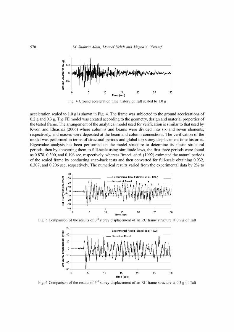
acceleration scaled to 1.0 g is shown in Fig. 4. The frame was subjected to the ground accelerations of
0.2 g and 0.3 g. The FE model was created according to the geometry, design and material properties of
the tested frame. The arrangement of the analytical model used for verification is similar to that used by
Kwon and Elnashai (2006) where columns and beams were divided into six and seven elements,
respectively, and masses were deposited at the beam and column connections. The verification of the
model was performed in terms of structural periods and global top storey displacement time histories.
Eigenvalue analysis has been performed on the model structure to determine its elastic structural
periods, then by converting them to full-scale using similitude laws, the first three periods were found
as 0.878, 0.300, and 0.196 sec, respectively, whereas Bracci, et al. (1992) estimated the natural periods
of the scaled frame by conducting snap-back tests and then converted for full-scale obtaining 0.932,
0.307, and 0.206 sec, respectively. The numerical results varied from the experimental data by 2% to
Fig. 4 Ground acceleration time history of Taft scaled to 1.0 g
Fig. 5 Comparison of the results of 3rd storey displacement of an RC frame structure at 0.2 g of Taft
Fig. 6 Comparison of the results of 3rd storey displacement of an RC frame structure at 0.3 g of Taft

Seismic performance of concrete frame structures reinforced with superelastic shape memory alloys 571
6%, which could be due to the presence of minor cracks in the test specimen.
Figs. 5 and 6 illustrate the comparisons of the 3rd storey displacement of the scaled specimen under
shake table tests at ground excitations with PGA of 0.2 g and 0.3 g respectively, and dynamic analyses
of the scaled model under the same excitations. At 0.2 g excitation, the numerically evaluated maximum
top-storey drift varied from the experimental results by 1.5% and 5.5% in the forward and reverse
direction, respectively. In the case of 0.3 g, the forward and reverse maximum top-storey drift values
varied from the experimental results by 1.7% and 1.2%, respectively. Both numerical results show good
agreement with the experimental results.
4. RC frame characteristics and modelling
An eight-storey RC moment resisting frame has been selected in this study since it has been observed
that medium rise RC buildings are particularly susceptible to damage during earthquakes (Bariola
1992). The building has been designed and detailed in accordance with Canadian standards (2004)
assuming that it is located in the seismic western part of Canada on firm ground with un-drained shear
strength of more than 100 kPa. The elevation and plan of the building are shown in Fig. 7. The design
PGA is 0.54 g and the moment frames are designed assuming a moderate level of ductility.
Two types of RC frames have been considered in this study. One is reinforced with regular steel bars
(Frame-1), while the other is reinforced with SMA at the plastic hinge region of the beam and regular
steel in the remaining portion of the frame (Frame-2). The material properties are presented in Table 1.
The detailed design of Frame-1 and Frame-2 is given in Figs. 8 and 9. The beams and columns have
been designed with the maximum moment and shear forces developed during the analysis of the building
considering all possible combinations of load cases. The size of longitudinal rebars and spacing of the
transverse reinforcement for the joint conform to current code requirements (Canadian standards 2004,
National Building Code of Canada 2005). The geometry, longitudinal and transverse reinforcement
Fig. 7 Eight-storey frame building located in the western part of Canada (dimensions in metre)

572 M. Shahria Alam, Moncef Nehdi and Maged A. Youssef
arrangements of the columns are similar for both frames. In the case of beams, Frame-1 and Frame-2
are similar in terms of geometry, and transverse reinforcement and its arrangement. Frame-2 has SMA
as longitudinal reinforcement at the plastic hinge region of its beams. SMA RC sections are designed in
a similar fashion to that of steel RC sections. However, the area of SMA rebar in a beam is chosen such
that the SMA section has a slightly lower moment carrying capacity compared to that of an adjacent
steel RC section, and yielding does not initiate in the steel rebar. The length of the plastic hinge of a
typical beam (Paulay and Priestley 1992) is calculated as 420 mm from the face of the column in the
case of 20 mm rebars and 365 mm for 15 mm rebars. Mechanical couplers are assumed to connect
Table 1 Material properties used in the FE program
Material Property Value
Concrete
Compressive strength (MPa) 30.0
Strain at peak stress (%) 0.2
Tensile strength (MPa) 3.0
15 mm and 20 mm Steel
Yield strength (MPa) 500.0
Strain hardening parameter (Post yield stiffness/initial stiffness) 0.015
Modulus of elasticity, ES (MPa) 200000
10 mm Steel Yield strength (MPa) 430
15 mm and 20 mm SMA(Refer to Fig. 2)
Modulus of elasticity, ESMA (MPa) 68200
fy (MPa) 480
fP1 (MPa) 540
fT1 (MPa) 260
fT2 (MPa) 120
εl (%) 6.2
Fig. 8 Reinforcement details of columns and beams (dimensions in mm)
Fig. 9 Reinforcement details of SMA RC beam

Seismic performance of concrete frame structures reinforced with superelastic shape memory alloys 573
SMA with regular steel rebar in Frame-2 as recommended by Youssef, et al. (2008). The arrangement
of couplers in a typical SMA RC Beam is shown in Fig. 9.
The frames have been modelled using the same approach described earlier in the FE analysis section.
Shear failure of the frame elements before attaining flexural yielding is excluded as the frame members
conform to current seismic codes, and thus have adequate capacity in shear. Yielding of steel and SMA
rebar are assumed to take place at a tensile strain of 0.0025 and 0.00704, respectively. MacGregor and
Wight (2005) suggested that the crushing strain varies from 0.0025 to 0.006 for unconfined concrete.
Paulay and Priestley (1992) found that it ranges between 0.015 and 0.05 for confined concrete. In the
present analysis, crushing of confined concrete was assumed to take place at a concrete compressive
strain of 0.015.
An ensemble of earthquake records has been compiled to analyze RC frame structures under seismic
excitation where all ground acceleration records were scaled to have PGA values of 0.54 g and 0.80 g.
No source of damping other than hysteretic has been taken into account.
5. Pushover analysis
Inelastic pushover analyses were performed for both frames in order to investigate their failure
mechanism and determine their limit states. The vertical distribution of lateral load was triangular
analogous to that of the design load. The analysis started with force control up to the peak load, and
then the analysis progressed with displacement control.
Fig. 10 Base shear versus top-storey drift of (a) steel RC frame, and (b) SMA RC frame
Fig. 11 Inter-storey drift distribution at collapse: (a) steel RC frame and (b) SMA RC frame

574 M. Shahria Alam, Moncef Nehdi and Maged A. Youssef
Figs. 10(a) and (b) show the pushover curves for steel (Frame-1) and SMA RC frames (Frame-2)
where the lateral capacities are 1.18 and 1.06 times the design base shear, respectively. Figs. 11(a) and
(b) show the distribution of inter-storey drift at collapse over different floor levels for Frame-1 and
Frame-2, respectively. In both cases, the maximum inter-storey drift was observed in the fourth storey,
which is used to define the global damage levels. Figs. 12(a) and (b) show the relationship between
base shear and inter-storey drift of the fourth floor for Frames 1 and 2, respectively. Frame-1 remained
elastic without cracking up to an inter-storey drift of 0.18%, whereas Frame-2 remained elastic up to
0.14% inter-storey drift. The global limit states of the two frames were obtained by tracking the local
damage of individual members. Before concrete cracks, steel and SMA RC frames exhibit similar
stiffness. Once concrete cracks, the SMA rebars become effective in resisting forces. Since SMA has
lower stiffness, there is a marked some reduction in the overall frame stiffness (Fig. 12b). But the
stiffness is regained when the steel RC columns start resisting the force. Because of this reduced
stiffness, the frame will dissipate a smaller amount of energy, which will also increase the frame response.
The sequence of yielding of rebar and crushing of concrete in beams and columns are illustrated in
Fig. 13 for both frames. In the case of Frame-1, for drifts up to 1%, yielding of steel rebar took place in
the first three floors at the plastic hinge region of beams with the sequence represented by numbers (1 to
21) in Fig. 13(a). This 1% drift may be defined as the point of global yielding. Since no column yielded
up to this stage of loading, it can be considered as a minor state of damage of the frame. With the
progress of pushover loading, damage was observed in the columns through yielding of rebar. For
storey drifts between 1% and 2%, the sequence of damage is represented by numbers from 22 to 29 in
Fig. 13(a), where the frame is considered to be at a moderate stage of damage (Fig. 12(a)). The frame
was subjected to extensive damage where the drift reached beyond 2%. The fourth floor reached its
maximum capacity at an inter-storey drift of 3%, which is considered as its collapse limit. This value
matches those suggested or observed by Broderick and Elnashai (1994), Kappos (1997) and Elfeki and
Youssef (2007). At this stage of loading (3% drift) two columns were found to reach the crushing limit
as shown in Fig. 13(a). The damage limit states proposed by Hassanein (1997) in terms of inter-storey
drift also matches the limits obtained from the pushover analysis.
Fig. 12 Base shear versus inter-storey drift of (a) steel RC frame, and (b) SMA RC frame

Seismic performance of concrete frame structures reinforced with superelastic shape memory alloys 575
In the case of Frame-2, minor damage was observed up to an inter-storey drift of 1.35%, where
yielding of SMA rebar took place in the first three floors at the plastic hinge region of the beams. The
sequence of SMA yielding up to 1.35% drift is illustrated in Fig. 13(b) represented by numbers 1 to 19. As
the loading progressed, steel rebars in several columns reached their yield point. The progress of damage
in terms of yielding of rebar and crushing of concrete was observed and compared for both frames. It was
found that the level of damage experienced by Frame-1 at a storey drift of 2% was equivalent to that of
Frame-2 at a storey drift of 2.25%. In Frame-2, for storey drifts between 1.35% and 2.25%, the sequence
of damage is represented by numbers 20 to 30 in Fig. 13(b), where the frame is considered to be at a
moderate stage of damage. The frame started experiencing extensive damage once the inter-storey drift
reached 2.25%. At an inter-storey drift of more than 3%, concrete in two columns reached its crushing
strain. The fourth floor reached its capacity at an inter-storey drift of 3.27%, which is defined as its
collapse limit. Frame-2 experienced relatively larger drift compared to that of Frame-1 at an equivalent
level of damage. This is mainly due to the lower stiffness of SMA-RC beams in Frame-2 compared to
steel-RC beams in Frame-1 since SMA has a lower modulus of elasticity compared to that of steel.
6. Seismic response
Eigenvalue analyses were performed for both frames to determine their fundamental horizontal
periods of vibration, which was found as 1.027, 0.361, and 0.211 sec for Frame-1, and 1.038, 0.365 and
0.213 sec for Frame-2, respectively.
6.1. Selection of earthquake records
Fig. 13 Sequence of local damages in individual members of (a) steel RC frame, and (b) SMA RC frame
576 M. Shahria Alam, Moncef Nehdi and Maged A. Youssef
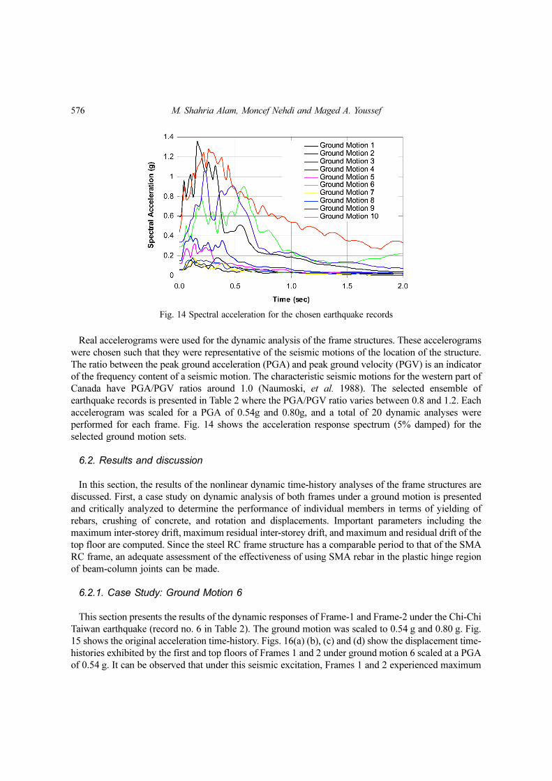
Real accelerograms were used for the dynamic analysis of the frame structures. These accelerograms
were chosen such that they were representative of the seismic motions of the location of the structure.
The ratio between the peak ground acceleration (PGA) and peak ground velocity (PGV) is an indicator
of the frequency content of a seismic motion. The characteristic seismic motions for the western part of
Canada have PGA/PGV ratios around 1.0 (Naumoski, et al. 1988). The selected ensemble of
earthquake records is presented in Table 2 where the PGA/PGV ratio varies between 0.8 and 1.2. Each
accelerogram was scaled for a PGA of 0.54g and 0.80g, and a total of 20 dynamic analyses were
performed for each frame. Fig. 14 shows the acceleration response spectrum (5% damped) for the
selected ground motion sets.
6.2. Results and discussion
In this section, the results of the nonlinear dynamic time-history analyses of the frame structures are
discussed. First, a case study on dynamic analysis of both frames under a ground motion is presented
and critically analyzed to determine the performance of individual members in terms of yielding of
rebars, crushing of concrete, and rotation and displacements. Important parameters including the
maximum inter-storey drift, maximum residual inter-storey drift, and maximum and residual drift of the
top floor are computed. Since the steel RC frame structure has a comparable period to that of the SMA
RC frame, an adequate assessment of the effectiveness of using SMA rebar in the plastic hinge region
of beam-column joints can be made.
6.2.1. Case Study: Ground Motion 6
This section presents the results of the dynamic responses of Frame-1 and Frame-2 under the Chi-Chi
Taiwan earthquake (record no. 6 in Table 2). The ground motion was scaled to 0.54 g and 0.80 g. Fig.
15 shows the original acceleration time-history. Figs. 16(a) (b), (c) and (d) show the displacement time-
histories exhibited by the first and top floors of Frames 1 and 2 under ground motion 6 scaled at a PGA
of 0.54 g. It can be observed that under this seismic excitation, Frames 1 and 2 experienced maximum
Fig. 14 Spectral acceleration for the chosen earthquake records

Seismic performance of concrete frame structures reinforced with superelastic shape memory alloys 577
top-storey drift (MTSD) of 284 mm and 758 mm, respectively. Although the maximum top-storey drift
for Frame-2 was higher compared to that of Frame-1, the characteristic difference between the frames
was found in the top-storey residual drift (TSRD) as depicted in Fig. 16. Frame-1 experienced about
Fig. 15 Ground motion record no. 6
Table 2 Ensemble of ground motion records.
Record Earthquake Station Data SourceMagni-
tude (M)PGA(g)
PGA
PGV(sec-1)
1 Chi-Chi, Taiwan 1999/09/20CHICHI/TTN042-Nhttp://peer.berkeley.edu
(PEER Strong Ground Motion Database 2007)
7.6 0.059 1.00
2 Hollister 1961/04/09 1028 Hollister City Hall
http://nsmp.wr.usgs.gov(Digitized Strong-Motion Accel-erograms of North and Central American Earthquakes 2007)
5.5 0.051 1.09
3 Loma Prieta 1989/10/18 16 LGPChttp://emerald.ucsc.edu(UCSC Seismographic
Station 2007)
6.9 0.605 1.19
4 Loma Prieta 1989/10/18 57217 Coyote Lake Dam (SW Abut)
http://peer.berkeley.edu(PEER Strong Ground Motion
Database 2007)
6.9 0.151 0.93
5 Loma Prieta 1989/10/18 57064 Fremont- Mission San Jose
http://peer.berkeley.edu(PEER Strong Ground Motion
Database 2007)
6.9 0.124 1.08
6 Chi-Chi, Taiwan 1999/09/21 Unknownwww.seismosoft.com
(Strong Motion Database 2007)7.6 0.810 1.13
7 Chi-Chi, Taiwan 1999/09/20 CHY019http://www.cwb.gov.tw
(Chi-Chi Earthquake 2007)7.6 0.052 0.83
8 Chi-Chi, Taiwan 1999/09/20 CHY019http://www.cwb.gov.tw
(Chi-Chi Earthquake 2007)7.6 0.064 1.00
9 Chi-Chi, Taiwan 1999/09/20 CHY006http://www.cwb.gov.tw
(Chi-Chi Earthquake 2007)7.6 0.345 0.81
10 Artificial -Campos-Costa and Pinto
(Campos-Costa and Pinto 1999)– 0.425 0.98

578 M. Shahria Alam, Moncef Nehdi and Maged A. Youssef
113 mm residual top-storey displacement, whereas Frame-2 experienced only 26 mm.
The seismic responses of both frames were also examined at a PGA of 0.80g for ground motion 6.
Figs. 16(e) and (f) show the displacement time-histories exhibited by the first floor of Frames 1 and 2,
respectively, and Figs. 16(g) and (h) show the displacement time-history of the top floor of Frame-1 and
2, respectively. It was observed that under this seismic excitation, Frames 1 and 2 experienced MTSD
Fig. 16 Storey drift time histories of first and top floor of Frames 1 and 2 due to ground motion record 6 scaledfor a PGA of 0.54g (a, b, c and d) and 0.80g (e, f, g and h)
Seismic performance of concrete frame structures reinforced with superelastic shape memory alloys 579
of 673 mm and 808 mm, respectively. Although the maximum top-storey displacement for Frame-2
was comparable to that of Frame-1, disparity was found in the TSRD as depicted in Fig. 16 where
Frame-1 experienced about 465 mm residual top-storey displacement, whereas Frame-2 experienced
only 32 mm. In both cases, Frame-2 performed better than Frame-1 in limiting the residual drift by
utilizing the recentering capability of super-elastic SMA rebars. For both excitations, Frame-1 had
maximum inter-storey drift (MISD) and maximum inter-storey residual drift (MISRD) at its 1st floor,
whereas MISD and MISRD occurred at the 2nd floor of Frame-2.
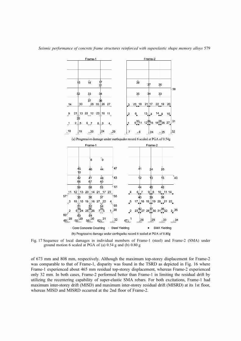
Fig. 17 Sequence of local damages in individual members of Frame-1 (steel) and Frame-2 (SMA) underground motion 6 scaled at PGA of (a) 0.54 g and (b) 0.80 g

580 M. Shahria Alam, Moncef Nehdi and Maged A. Youssef
The progress of plastic hinge formation and crushing of concrete in both frames under earthquake
record no. 6 was investigated for both excitations. The sequence of local damage in individual members
of both frames at scaled excitations (PGA of 0.54 g and 0.8 g) are presented in Fig. 17. At a PGA of
0.54 g, no concrete crushing occurred in any of the member of the frames, whereas at a PGA of 0.80 g,
concrete crushing occurred in four columns of Frame-1 and one column in Frame-2. In the case of
Frame-1, a PGA of 0.54g resulted in forming 15 plastic hinges in columns and 22 in beams. In the case
of Frame-2, 16 plastic hinges formed in columns and 23 in beams for the same excitation. At higher
seismic load (PGA of 0.80g), plastic hinges formed in 39 locations of columns and 24 locations of
beams for Frame-1, whereas Frame-2 suffered 22 plastic hinges in columns and 24 in beams. Thus, at
PGA of 0.54 g both frames suffered comparable damages, whereas at higher seismic load (PGA of
0.80g) the SMA-RC frame experienced less damage compared to steel-RC frame in terms of plastic
hinge formation and concrete crushing.
At a PGA of 0.54 g, the first plastic hinge was formed at the first floor for both frames as shown in
Fig. 17(a). The rotation of the beams at the location of the first plastic hinge for both frames is presented in
Fig. 18. The steel-RC frame was subjected to higher rotation compared to that of the SMA-RC frame. It
also suffered higher residual rotation of 0.0117 rad compared to 0.0009 rad for the SMA-RC frame.
SMA-RC joints could regain almost all of its residual rotation and go back to its original form.
Fig. 18 Beam rotation history at the location of first plastic hinge of Frame-1 and Frame-2 under groundmotion record 6 at PGA of 0.54 g
Fig. 19 Stress-strain of bottom rebar at the location of first plastic hinge under ground motion record 6 scaledat a PGA of 0.54 g: (a) steel RC frame and (b) SMA RC frame
Seismic performance of concrete frame structures reinforced with superelastic shape memory alloys 581
Conversely, steel-RC joints suffered large residual rotation after the earthquake. This shows that SMA-
RC joints can be effective and serviceable even after large earthquakes.
Figs. 19(a) and (b) display the stress-strain curves obtained from the bottom steel and SMA rebars in
the beam at the first plastic hinge location of the steel-RC frame and the SMA-RC frame. The steel
rebar at the joint was subjected to extensive deformation beyond its yield strain, which resulted in 2.1%
residual strain as shown in Fig. 19(a). Under the same seismic excitation, the stress in the SMA rebar
was within the super-elastic strain range and produced flag shaped hysteresis. Thus, it regained its
inelastic strain even after large displacements. However, the steel-RC frame joint could dissipate a
higher amount of energy compared to that for the SMA-RC frame because of the large hysteretic loop
exhibited by steel. On the other hand, advantages of using SMA can be appreciated in its ability of
reducing earthquake induced large residual displacements and rotations of RC frame members as
shown in Figs. 18 and 19.
6.2.2. Steel-RC Frame versus SMA-RC Frame
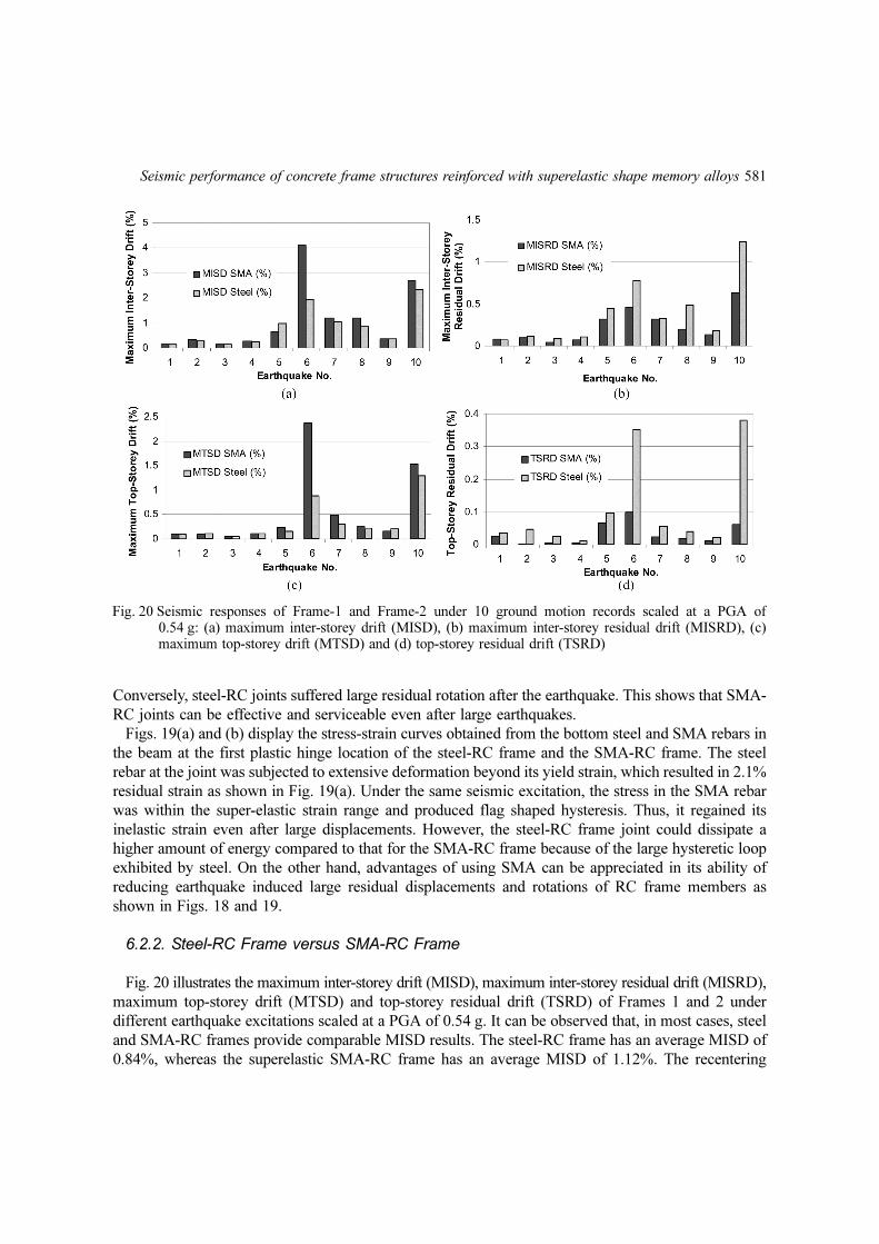
Fig. 20 illustrates the maximum inter-storey drift (MISD), maximum inter-storey residual drift (MISRD),
maximum top-storey drift (MTSD) and top-storey residual drift (TSRD) of Frames 1 and 2 under
different earthquake excitations scaled at a PGA of 0.54 g. It can be observed that, in most cases, steel
and SMA-RC frames provide comparable MISD results. The steel-RC frame has an average MISD of
0.84%, whereas the superelastic SMA-RC frame has an average MISD of 1.12%. The recentering
Fig. 20 Seismic responses of Frame-1 and Frame-2 under 10 ground motion records scaled at a PGA of0.54 g: (a) maximum inter-storey drift (MISD), (b) maximum inter-storey residual drift (MISRD), (c)maximum top-storey drift (MTSD) and (d) top-storey residual drift (TSRD)

582 M. Shahria Alam, Moncef Nehdi and Maged A. Youssef
capability of SMA-RC frames has been found to be much higher compared to that of steel-RC frames
in terms of MISRD (Fig. 20(b)). The average MISRD was 0.24% for the SMA-RC frame and 0.39%
for the steel-RC frame. However, the advantage of using SMA becomes more evident when the frames
are subjected to higher seismic loads. At a PGA of 0.80g, the average MISD was 1.43% and 1.47% for
the steel and SMA-RC frame, respectively as shown in Fig. 21(a). At the same excitation, steel-RC
frame suffered 3.2 times the average of MISRD of SMA-RC frame as depicted in Fig. 21(b). It should
be noted that the maximum strain levels in the SMA rebars were within the superelastic strain range.
The SMA-RC frame experienced higher maximum tip displacement compared to that of steel-RC
frame at PGA of 0.54 g as shown in Fig. 20(c). The average maximum drift of the top floor for the
steel-RC frame was 0.34%, whereas for the SMA-RC frame it was 0.54%. However, both frames
performed in a similar fashion as far as the maximum tip displacement is concerned at PGA of 0.80 g as
shown in Fig. 21(c). The steel-RC frame experienced an average of 0.57% MTSD, whereas the SMA-
RC frame had an average of 0.72% MTSD. The steel-RC frame suffered 0.11% (Fig. 20(d)) and 0.25%
(Fig. 21(d)) TSRD at PGA of 0.54 g and 0.80 g, respectively, whereas the SMA-RC frame suffered
only 0.03% and 0.05% TSRD at PGA of 0.54 g and 0.80 g, respectively. For the residual drift of the top
floor, the results demonstrate that the SMA-RC frame had a much better performance compared to that
of the steel-RC frame. The superelastic property of SMA ensures structural recentering as the SMA
bars try to bring the structure back to its original position upon stress removal. On the other hand, steel
experienced permanent deformation once yielding took place, which caused the steel-RC frame to
suffer higher residual drift than that of the SMA-RC frame.
Only one of the results of the SMA-RC frame showed higher MISRD compared to that of the steel-
Fig. 21 Seismic responses of Frame-1 and Frame-2 under 10 ground motion records scaled at a PGA of0.80 g: (a) maximum inter-storey drift (MISD), (b) maximum inter-storey residual drift (MISRD), (c)maximum top-storey drift (MTSD) and (d) top-storey residual drift (TSRD)

Seismic performance of concrete frame structures reinforced with superelastic shape memory alloys 583
RC frame (ground motion 9 scaled at 0.8 g). In most cases the SMA-RC frame experienced higher
MISD and top-storey drift compared to that of the steel-RC frame. Consequently, columns of the SMA-
RC frame were also subjected to higher deformations than that of the steel-RC frame, which might have
caused some of the columns of the SMA-RC frame to deform excessively, and frames not to recenter.
In such cases, superelastic SMA-RC columns might be an option to counteract this measure. However,
there is a possibility of developing increased top-storey drift because of the low modulus of elasticity of
SMA, which makes the columns less stiff compared to similar steel-RC columns. This aspect is,
however, beyond the scope of this paper. Further studies need to be conducted to address this issue in
the near future.
7. Conclusions
This paper examines a novel approach to reduce the seismic vulnerability of RC frame structures by
utilizing a smart material, shape memory alloy, in beam-column joints. The specific objective of this
study is to investigate the dynamic performance of an eight-storey RC frame building reinforced with
steel and SMA in its beam-column joints. The building is located in the highly seismic zone of western
Canada and has been designed according to CSA standards (A 23.3-04) in two ways: one with only
regular steel rebar (Frame-1) and the other with superelastic SMA rebar (Frame-2) at the plastic hinge
regions of the beam-column joints. Both frames have been analyzed under selected and scaled seismic
loading using a finite element program, and their performances have been compared. Before analyzing
the frames, the FE program was validated using experimental results for RC frames with regular steel
and joints reinforced with SMA-steel coupled reinforcement at its plastic hinge location. The numerical
results indicate that the FE program can predict the seismic performance of RC frames with reasonable
accuracy.
From pushover analyses, the load carrying capacity was found as 1.18 and 1.06 times the design base
shear for Frames 1 and 2, respectively. Maximum inter-storey drift was obtained at the fourth floor during
collapse for both frames. Frames 1 and 2 were elastic up to an inter-storey drift of 0.18% and 0.14%
and reached their maximum lateral capacities at an inter-storey drift of 3.0% and 3.3%, respectively.
The seismic performances of Frame-1 and 2 have been compared in terms of MISD, MISRD, MTSD
and TSRD. The results show that although the SMA-RC frame provides comparable results to that of
the steel-RC frame as far as MISD and MTSD are concerned, its main advantage lies in its ability of
reducing inter-storey and top-storey residual drifts. At the design PGA of 0.54 g, all results show that
the steel RC frame is subjected to higher residual drift (both inter-storey and top-storey residual drift)
compared to that of the SMA RC frame. In the case of 0.8 g, which is much higher than the design load,
only one record shows that the steel RC frame is subjected to slightly smaller maximum inter-storey
residual drift compared to that of the SMA RC frame. However, all the top-storey residual drift values
were much larger for the steel RC frame compared to that of the SMA RC frame. SMA-RC joints
exhibited better performance compared to that of steel-RC joints in terms of residual drift and rotations.
In the case of steel RC frames, steel rebars experience permanent deformation, which will cause
difficult and costly rehabilitation work. On the other hand, in the case of SMA RC frames, SMA rebar
undergoes large inelastic strain due to a larger storey-drift, however, this inelastic strain is potentially
recovered leaving negligible permanent deformation. Thus, the rehabilitation of SMA RC frames is
expected to be easier and less costly compared to that of steel RC frames. Steel-RC joints dissipated
relatively higher amounts of energy compared to that of SMA-RC joints because of its large hysteretic

584 M. Shahria Alam, Moncef Nehdi and Maged A. Youssef
loops. However, the SMA-RC joints performed better in terms of recovering post-elastic rotations. The
unique feature of such SMA-RC joints makes it very attractive in highly seismic regions where it is not
only able to dissipate energy, but also remain functional even after strong earthquakes.
Excessive residual displacements have been identified as one of the major causes that make the
rehabilitation of damaged buildings and bridges difficult and costly after an earthquake. SMAs are
unique materials that can recover most of its large inelastic deformations. If SMA can be used as
reinforcement in beam-column joints, it can initiate a major progress in seismic design whereby the
repair cost may be substantially reduced and the structure may remain serviceable even after a severe
earthquake.
References
Alam, M.S., Youssef, M.A. and Nehdi, M. (2008), “Analytical prediction of the seismic behaviour of superelasticshape memory alloy reinforced concrete elements”, Eng. Struct., 30(12), 3399-3411.
Alam, M.S., Youssef, M.A. and Nehdi, M. (2007), “Seismic behaviour of concrete beam-column joints reinforcedwith superelastic shape memory alloys”, 9th Canadian Conf. on Earthquake Engineering, June, ON, Canada2007, Paper no. 1125, 10 p.
ANSYS, Inc. (2005), Version 10.0, Southpoint, Canonsburg, PA, USA.Auricchio, F. and Sacco, E. (1997), “Superelastic shape-memory-alloy beam model”, J. Intel. Mat. Syst. Str., 8(6),
489-501.Auricchio, F., Fugazza, D. and DesRoches, R. (2006), “Earthquake performance of steel frames with Nitinol
braces”, J. Earthq. Eng., 10(SPEC), 45-66.Auricchio, F., Taylor, R.L. and Lubliner, J. (1997), “Shape-memory alloys: macromodelling and numerical
simulations of the superelastic behaviour”, Comput. Methods Appl. M., 146(3-4), 281-312.Bariola, J. (1992), “Drift response of medium-rise reinforced concrete buildings during earthquakes”, ACI Struct.
J., 89(4), 384-390.Bracci, J.M., Reinhorn, A.M. and Mander, J.B. (1992), “Seismic resistance of reinforced concrete frame
structures designed only for gravity loads:part I—design and properties of a one-third scale model structure”,Technical report NCEER-92-0027.
Broderick, B.M. and Elnashai, A.S. (1994), “Seismic resistance of composite beam-columns in multi-storeystructures, Part 2: Analytical model and discussion of results”, J. Constr. Steel Res., 30(3), 231-258.
Campos-Costa, A. and Pinto, A.V. (1999), European seismic hazards scenarios – An approach to the definitionof input motion for testing and reliability assessment of Civil Engineering structures, JRC Special publicationNo.X.99.XX 1999, Joint Research Centre, Ispra, Italy.
Chi-Chi Earthquake (2007), http://www.cwb.gov.tw/V5e/index.htm, January 2007.Clark, P.W., Aiken, I.D., Kelly, J.M., Higashino, M. and Krumme, R. (1995), “Experimental and analytical studies
of shape-memory alloy dampers for structural control”, Proc. of SPIE, 2445, 241-251.Canadian Standards Association (2004), Design of Concrete Structures, CSA A23.3-04, Rexdale, Ontario, Canada,
240p.DesRoches, R. and Delemont, M. (2002), “Seismic retrofit of simply supported bridges using shape memory
alloys”, Eng. Struct., 24, 325-332.Digitized Strong-Motion Accelerograms of North and Central American Earthquakes (2007), http://nsmp.wr.usgs.
gov/data_sets/ncae.html, January 2007.Dolce, M., Cardone, D., Marnetto, R., Mucciarelli, M., Nigro, D., Ponzo, F.C. and Santarsiero, G. (2004), “Experimental
static and dynamic response of a real RC frame upgraded with SMA re-centering and dissipating braces”,Proc. of the 13th World Conf. on Earthquake Engineering, Canada, Paper no. 2878.
Elfeki, M.A. and Youssef, M.A. (2007), “Effect of the vertical earthquake component on the seismic response ofreinforced concrete moment frames”, 9th Canadian Conf. on Earthquake Engineering, June 2007, ON, Canada,Paper no. 1129, 10 p.

Seismic performance of concrete frame structures reinforced with superelastic shape memory alloys 585
Hassanein, A. (1997), “Reliability Assessment of Rehabilitated Buildings of Moderate Height”, M.Sc. Thesis,McMaster University, Hamilton, Ontario, Canada.
Indirli, M., Castellano, M.G., Clemente, P. and Martelli, A. (2001), “Demo-application of shape memory alloydevices: The rehabilitation of the S. Giorgio Church Bell-Tower”, The Proc. of SPIE, 4330, 262-272.
Kappos, A.J. (1997), “A comparative assessment of R/C structures designed to the 1995 Eurocode 8 and the1985 CEB seismic code”, Struct. Des. Tall Build., 6(1), 59-83.
Kwon, O.S. and Elnashai, A. (2006), “The effect of material and ground motion uncertainty on the seismicvulnerability curves of RC structure”, Eng. Struct., 28(2), 289-303.
MacGregor, J.G. and Wight, J.K. (2005), Reinforced Concrete Mechanics and Design, fourth edition.Martinez-Rueda, J.E. and Elnashai, A.S. (1997), “Confined concrete model under cyclic load”, Mater. Struct.30(197), 139-147.
McCormick, J. and DesRoches, R. (2003), “Seismic response using smart bracing elements”, The Proc. of theExtreme Loading Conf., Toronto, Canada, August.
National Building Code of Canada (2005), National Research Council, Canada.Naumoski, N., Tso, W.K. and Heidebrecht, A.C. (1988), “A selection of representative strong motion earthquake
records having different A/V ratios”, EERG Report 88-01, Earthquake Engineering Research Group, Dept. ofCivil Engg., McMaster University, Hamilton, ON Canada.
Nehdi, M., Alam, M.S. and Youssef, M.A. (2007), “Seismic behaviour of repaired beam-column joints reinforcedwith superelastic shape memory alloys”, ACI Struct. J., in review.
Ocel, J., DesRoches, R., Leon, R.T., Hess, W.G., Krumme, R., Hayes, J.R. and Sweeney, S. (2004), “Steel beam-column connections using shape memory alloys”, J. Struct. Eng. ASCE, 130(5), 732-740.
Paulay, T. and Priestley, M.J.N. (1992), Seismic Design of Reinforced Concrete and Masonry Buildings, New York:J. Wiley.
PEER Strong Ground Motion Database (2007), http://peer.berkeley.edu/svbin, January 2007.Saiidi, M.S. and Wang, H. (2006), “Exploratory study of seismic response of concrete columns with shape memory
alloys reinforcement”, ACI Struct. J., 103, 435-442.Salichs, J., Hou, Z. and Noori, M. (2001), “Vibration suppression of structures using passive shape memory alloy
energy dissipation devices”, J. Intel. Mat. Syst. Str., 12, 671-680.SeismoStruct, http://www.seismosoft.com/SeismoStruct/index.htm.Shahin, A.R., Meckl, P.H. and Jones, J.D. (1997), “Modeling of SMA tendons for active control of structures”,
J. Intel. Mat. Syst. Str., 8, 51-70.Strong Motion Databases (2007), www.seismosoft.com, January 2007.Tamai, H., Miura, K., Kitagawa, Y. and Fukuta, T. (2003), “Application of SMA Rod to Exposed-type Column
Base in Smart Structural System”, the Proc. of SPIE, 5057, 169-177.UCSC Seismographic Station (2007), http://emerald.ucsc.edu, January 2007.Wilde, K., Gardoni, P. and Fujino, Y. (2000), “Base isolation system with shape memory alloy device for
elevated highway bridges”, Eng. Struct., 22, 222-229.Youssef, M.A., Alam, M.S. and Nehdi, M. (2008), “Experimental investigation on the seismic behaviour of
beam-column joints reinforced with superelastic shape memory alloys”, J. Earthq. Eng., accepted January.Zhu, S. and Zhang, Y. (2007), “Seismic behaviour of self-centring braced frame buildings with reusable hysteretic
damping brace”, Earthq. Eng. Struct. D., 36, 1329-1346.
CC