seismic refraction survey · 2019-11-20 · seismic refraction survey . srsne site . southington,...
TRANSCRIPT

HAGER-RICHTERGEOSCIENCE, INC
SEISMIC REFRACTION SURVEYSOLVENTS RECOVERY SERVICE
OF NEW ENGLAND, INC. SITESOUTHINGTON, CONNECTICUT
US-EPA Contract No. 68-W8-0117Subcontract No. S92-117-024
Prepared for:
HALLIBURTON NUS Environmental Corporation187 Ballardvale Street - Suite A100Wilmington, Massachusetts 01887
Prepared by:
Hager-Richter Geoscience, Inc.8 Industrial Way - DIGSalem, New Hampshire 03079
File 92D27June, 1992

HAGER-RICHTER GEOSCIENCE. INC.
Seismic Refraction Survey SRSNE Site Southington, Connecticut File 92D27 June. 1992
0. EXECUTIVE SUMMARY
Hager-Richter Geoscience, Inc. conducted a seismic refraction survey at the Solvents Recovery Service of New England, Inc. (SRSNE) Site, Southington, Connecticut for HALLIBURTON NUS Environmental Corporation in June, 1992. The geophysical survey was conducted under Subcontract No. S92-117-024 from HALLIBURTON NUS and is part of a Remedial Design Investigation by HALLIBURTON NUS for the US-EPA Region I.
The SRSNE Site is an inactive solvents recycling facility located in a suburban light industrial area. The objectives of the seismic refraction survey were to characterize the depth of bedrock in the general neighborhood of the Site and to determine the presence and location of any buried bedrock valley.
The seismic refraction survey consisted of six profiles with a total profile length of 8740 feet, not including 960 feet of overlapped spreads. The locations of the profiles were specified by HALLIBURTON NUS. Most of the seismic refraction lines were located along roadways north, east, and south of the SRSNE operations area, and included parts of Lazy Lane, Queen Street, Flanders Street, and Curtiss Street.
The results of the seismic refraction survey may be summarized as follows:
1. Bedrock depths range from 13 to 122 feet below the ground surface. The elevation of bedrock varies between 186 and 45 feet.
2. The bedrock surface is distinctly higher west of the railroad tracks and the SRSNE Operations area. In the northern half of the survey area, the bedrock surface slopes easterly to the Quinnipiac River and undulates gently between the river and Queen Street. In the southern half of the survey area, the bedrock surface slopes southeasterly, with a steeper slope west of the railroad tracks, and a very gentle slope east of the railroad tracks. There is some indication that the bedrock surface rises towards the eastern limits of the survey area, but a distinct bedrock valley cannot be defined on the basis of the present data set.

Seismic Refraction Survey SRSNE Site Southington, Connecticut File 92D27 June, 1992
TABLE OF CONTENTS
0. Executive Summary
1. Introduction
2. Equipment and Procedures2.1 General2.2 Site Specific
3. Results and Discussion3.1 General3.2 Data Quality3.3 Interpretation of Velocities3.4 Bedrock Topography
4. Conclusions
TABLES
1. Summary of Seismic Refraction Results 2. Comparison of Depths of Bedrock for Intersecting and
Overlapped Segments of Seismic Lines
FIGURES
1. Site location 2. Seismic Line 1 3. Seismic Line 2A 4. Seismic Line 2B 5. Seismic Line 3 6. Seismic Lines 4A and 4B 7. Seismic Line 5 8. Seismic Line 6
PLATES
1. Site Plan 2. Bedrock Topography
HAGER-RICHTER GEOSCIENCE, INC
i
1
2 2 3
5 5 5 6 6 7

HAGER-RICHTER GEOSCIENCE, INC
Seismic Refraction Survey SRSNE Site Southington, Connecticut File 92D27 June. 1992
1. INTRODUCTION
Hager-Richter Geoscience, Inc. conducteda seismic refraction survey at the Solvents Recovery Service of New England, Inc. (SRSNE) Site, Southington, Connecticut for HALLIBURTON NUS Environmental Corporation (HNUS) of Wilmington, Massachusetts. The geophysical survey was conducted under Subcontract No. S92-117-024 from HNUS and is part of Phase 3 of a Remedial Investigation/Feasibility Study by HNUS for US-EPA Region I under Prime Contract No. 68-W8-0117.
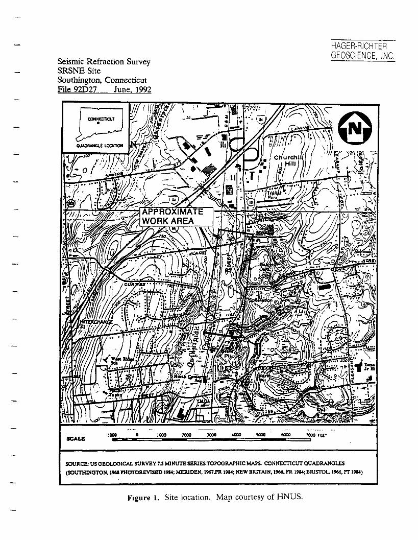
The SRSNE Site is located on the south side of Lazy Lane in a suburban light industrial area of Southington (Figure 1). SRSNE reportedly operated an industrial solvents processing facility at the Site until March, 1991. The 2Vi acre Operations Area is surrounded by a chain link fence. East of the SRSNE Operations Area are an open field, the Quinnipiac River, and a commercial district along Queen Street (Conn. Route 10), a busy two-lane highway. The areas to the north and west of the Site are suburban and semi-rural residential areas.
The seismic refraction survey was conducted in the general neighborhood of the SRSNE plant, along public roadways and on vacant land owned either by SRSNE or the Town of Southington. The general locations for the seismic lines were selected by HNUS. Plate 1 shows the area included in the geophysical survey and the locations of the seismic refraction lines.
The objectives of the seismic refraction survey were to determine the depth of bedrock in the vicinity of the Site and to determine the presence and location of any buried bedrock valley. Boring logs and the results of a 1990 seismic refraction survey conducted by others' in the field located between the SRSNE plant and the Quinnipiac River indicated that bedrock deepens between the SRSNE Operations Area and the Quinnipiac River. HNUS was interested in determining whether a bedrock valley is present in the vicinity of the river. Bedrock in the area is reported to be arkose of the New Haven Formation locally intruded by diabase dikes.
Hager-Richter personnel were on Site June 22 - 26, 1992. Jeffrey Reid and Jonathon
Western Geophysical Corp., Seismic Refraction Survey, Solvents Recovery Service of New England Site, October, 1990.
- 1

HAGER-RICHTER GEOSCIENCE, INC
Seismic Refraction Survey SRSNE Site Southington, Connecticut File 92D27 June. 1992
Puliafico of Hager-Richter conducted the field work. Mr. Liyang Chu of HNUS coordinated the field activities. All work was conducted under Level D personal protection. Data analysis and interpretation were completed at the Hager-Richter offices. Original data and field notes reside in the Hager-Richter files and will be retained for a minimum of ten years as required in the contract.
2. EQUIPMENT AND PROCEDURES
2.1 General
2.J.I Field Work. We used a 24-channel Bison Model 9024 Digital Instantaneous Floating Point Stacking Seismograph to perform the seismic refraction survey. The Model 9024 is a "state of the art" microprocessor controlled instrument that records data digitally and on paper seismograms. The stored data were transferred to floppy disk and the hard disk of a laptop computer at the end of each field day.
The seismograph was coupled to two 12-element seismic spread cables for a total of 24 geophones. A geophone spacing sufficient to record arrivals from bedrock was selected.
Seismic energy was provided by either a 12-lb sledge hammer striking a steel base plate or a Betsy seisgun. The Betsy seisgun uses a shotgun blank buried to a depth of about 2 feet as the seismic source and is not classified as a weapon or explosive under Federal regulations. The number of stacks per shot point is variable, and the quality of the stacked seismic signal for each shot point was verified in the field with the paper record. Five shot points were used for each 24-geophone spread ~ one shot off each end of the cable, one shot at each end of the cable, and one at the 13th geophone. This configuration provides reversed profiles. Shot points (and geophone locations, if necessary) were flagged in the field.
2.1.2 Data Analysis. The seismic data were analyzed using the Generalized Reciprocal Method (GRM) of seismic refraction interpretation. GRM has several advantages over other seismic refraction interpretation methods such as the Time-Intercept or Crossover-Distance methods. GRM allows for some variation in the surface topography as well as lateral variation in the seismic velocity of the upper layers. The method uses a principle of migration whereby the refractor need only be planar over a short distance, thus allowing the
- 2

HAGER-RICHTER GEOSCIENCE, INC.
Seismic Refraction Survey SRSNE Site Southington, Connecticut File 92D27 June. 1992
calculation of depth to an undulating interface. In addition, GRM is relatively insensitive to dip angles as high as 20°, unlike most other methods that can be sensitive to dips as low as 5°. GRM also allows for the calculation of depth below each geophone instead of below only the shot points as in the Time-Intercept and Crossover Distance methods. The commercially available software that we use for data analysis contains several internal tests for data consistency.
The results are used to construct an interpreted velocity profile of the subsurface for each seismic line. The velocities of seismic waves are strong functions of the types of geologic material through which they pass. One can thus infer the general subsurface stratigraphy from the velocities exhibited.
A widespread misconception about the seismic refraction method is that one cannot detect layers of lower velocity material underlying higher velocity material, a common situation in stratified sediments. If present and undetected, the lower velocity layers can cause large errors in the thickness calculated for the various layers. However, the GRM technique provides for the detection of such low velocity layers and, more importantly, provides correct depths to refracting horizons below any low velocity layers that may be present. The elevation, thickness, and velocity of the hidden layer itself cannot be determined. Typical uncertainties in depths determined seismically are 15% or 2 feet, whichever is larger.
2.2 Site Specific
The procedures used for the seismic refraction survey at the SRSNE Site meet or exceed the contract technical specifications. The locations of the seismic lines (designated Seismic Lines 1 - 6 and shown on Plate 1) conform closely with the locations proposed by HNUS, but were modified where site conditions required. For example, four of the seven spreads for Seismic Line 2 were located on the west side of Queen Street instead of the east side, because there was not room to work safely along the east side of the road as had been proposed. One seismic spread located under the high voltage power line easement that crosses Queen Street was aborted because the 60 Hertz electromagnetic fields associated with the power line obliterated the seismic signals, even after > 100 stacked hammer strikes. In several places, space constraints required overlapping seismic spreads. The field work along Queen Street was begun in the early morning hours (4:30 am) to obtain data before the traffic became heavy.
- 3

HAGER-RICHTER GEQSCIENCE, INC
Seismic Refraction Survey SRSNE Site Southington, Connecticut File 92D27 June. 1992
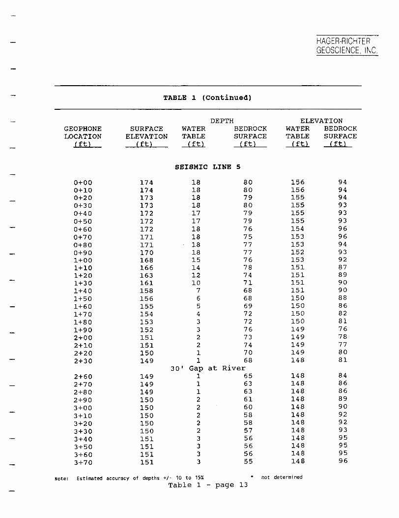
Seismic spread cables with a 20-foot geophone spacing were used for all lines except Seismic Line 5. Space limitations required a break in Seismic Line 5 at the Quinnipiac River, and cables with a 10-foot geophone spacing were used. Thus, the seismic spreads were 460 feet long, except for the two spreads on Seismic Line 5 where each spread was 230 feet long.
A sledge hammer was used as the seismic source for the lines along Lazy Lane (Seismic Line 1), Queen Street (Seismic Line 2), Flanders Street (Seismic Line 3), and Curtiss Street (Seismic Line 4). Up to 130 hammer strikes (stacks) were required for the spreads along Queen Street. The Betsy seisgun was used with 8-gauge shotgun blanks as a seismic source for the lines located in the field (Seismic Lines 5 and 6) and for shot points located near the River on Seismic Line 1. Five shot points were used per 24-channel spread. Offset shots varying between 60 and 150 feet were made from the ends of the spreads to obtain bedrock arrivals from all geophones.
Elevations of geophones and shot points used for the reduction of the seismic refraction data were obtained from topographic maps with 2-foot contour intervals provided by HALLIBURTON NUS. Their accuracy is estimated to be about 1 foot. The ends of the seismic lines were marked in the field with spray paint and driven nails for later survey by HNUS.
- 4

HAGER-RICHTER
Seismic Refraction Survey GEOSCIENCE, I N C .
SRSNE Site Southington, Connecticut File 92D27 June. 1992
3. RESULTS AND DISCUSSION
3.1 General
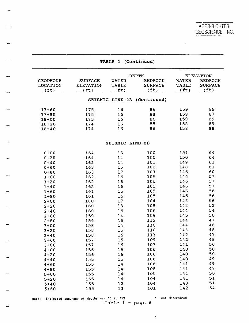
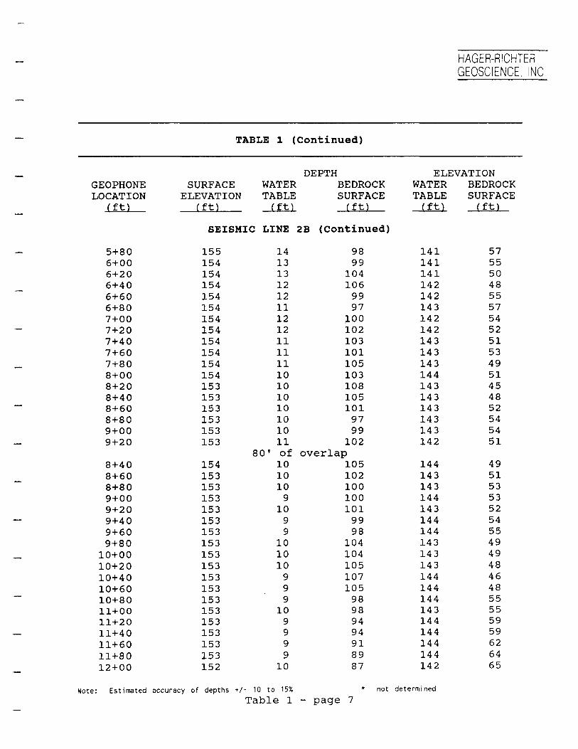
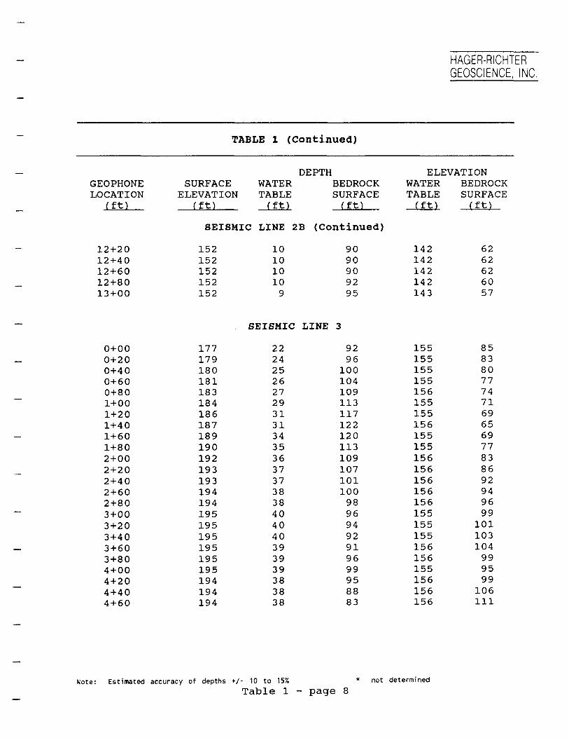
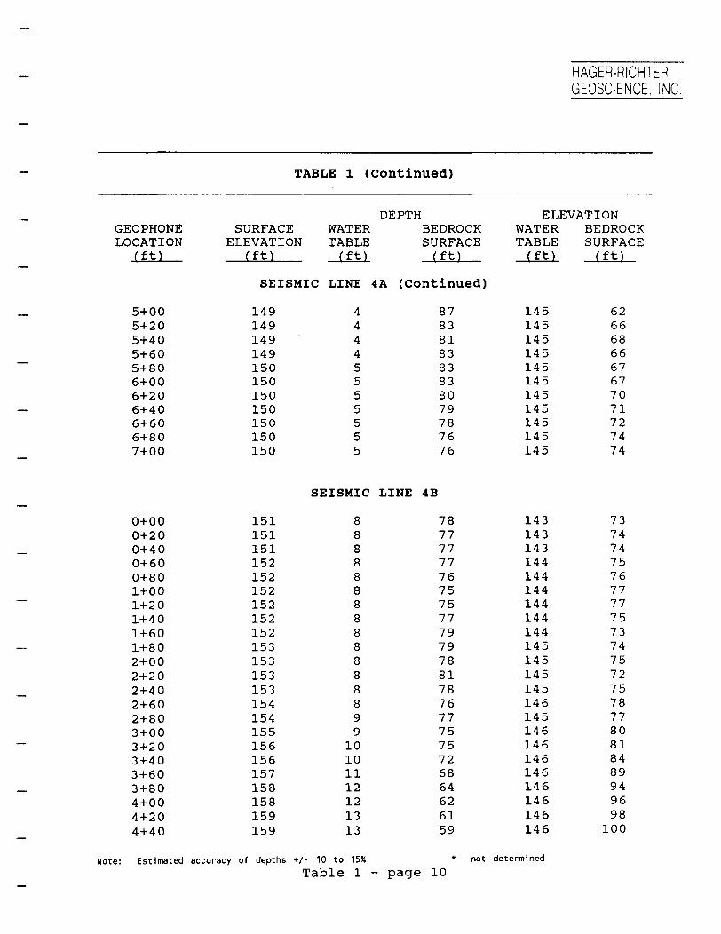
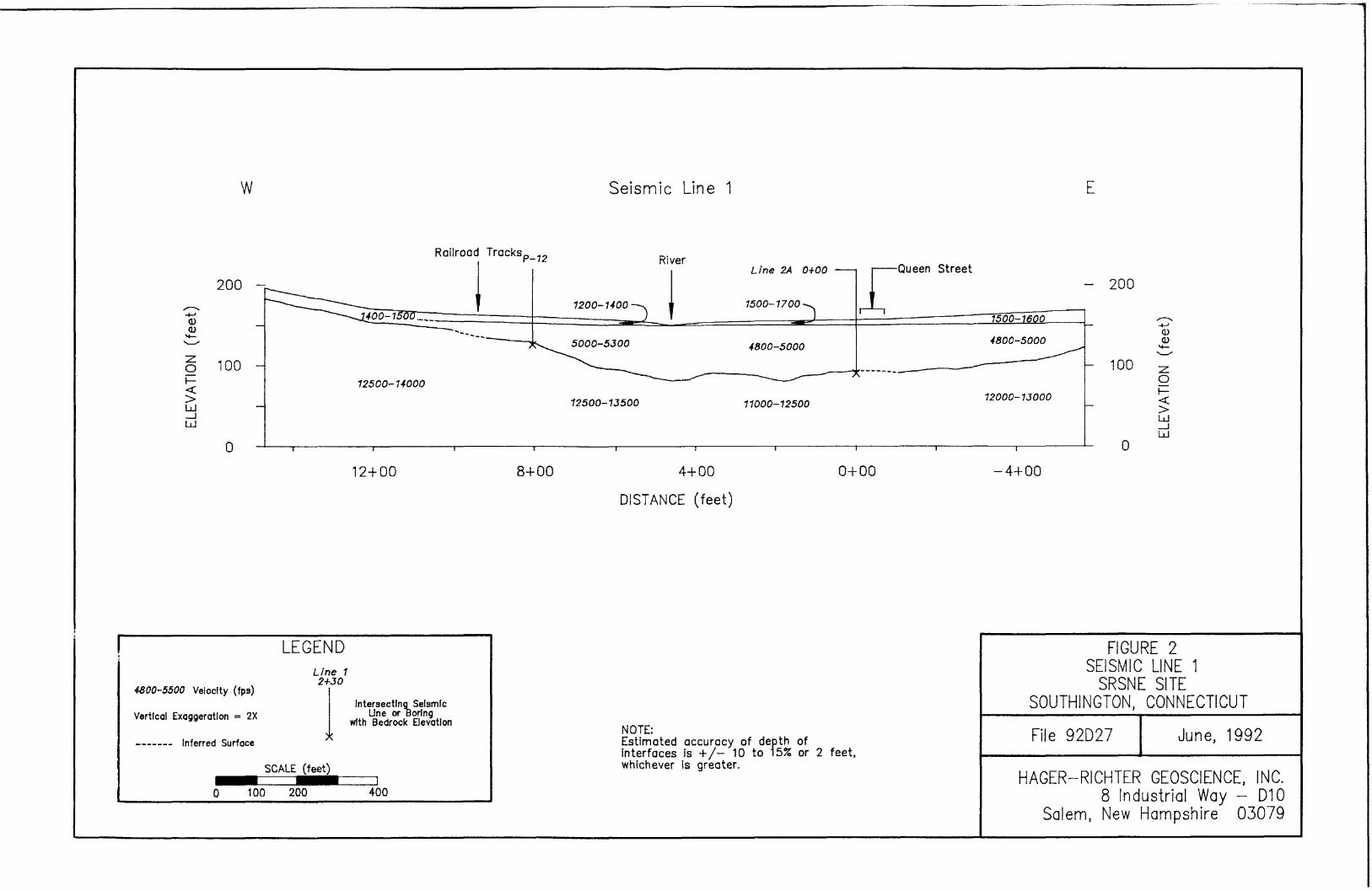
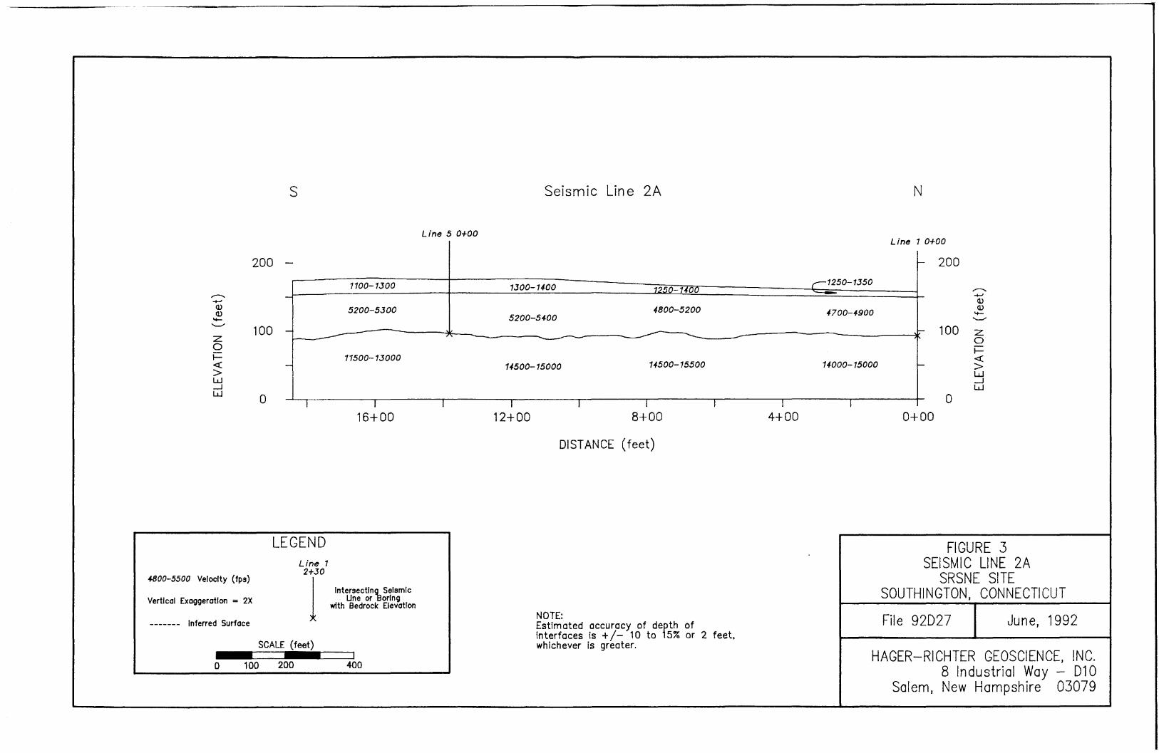
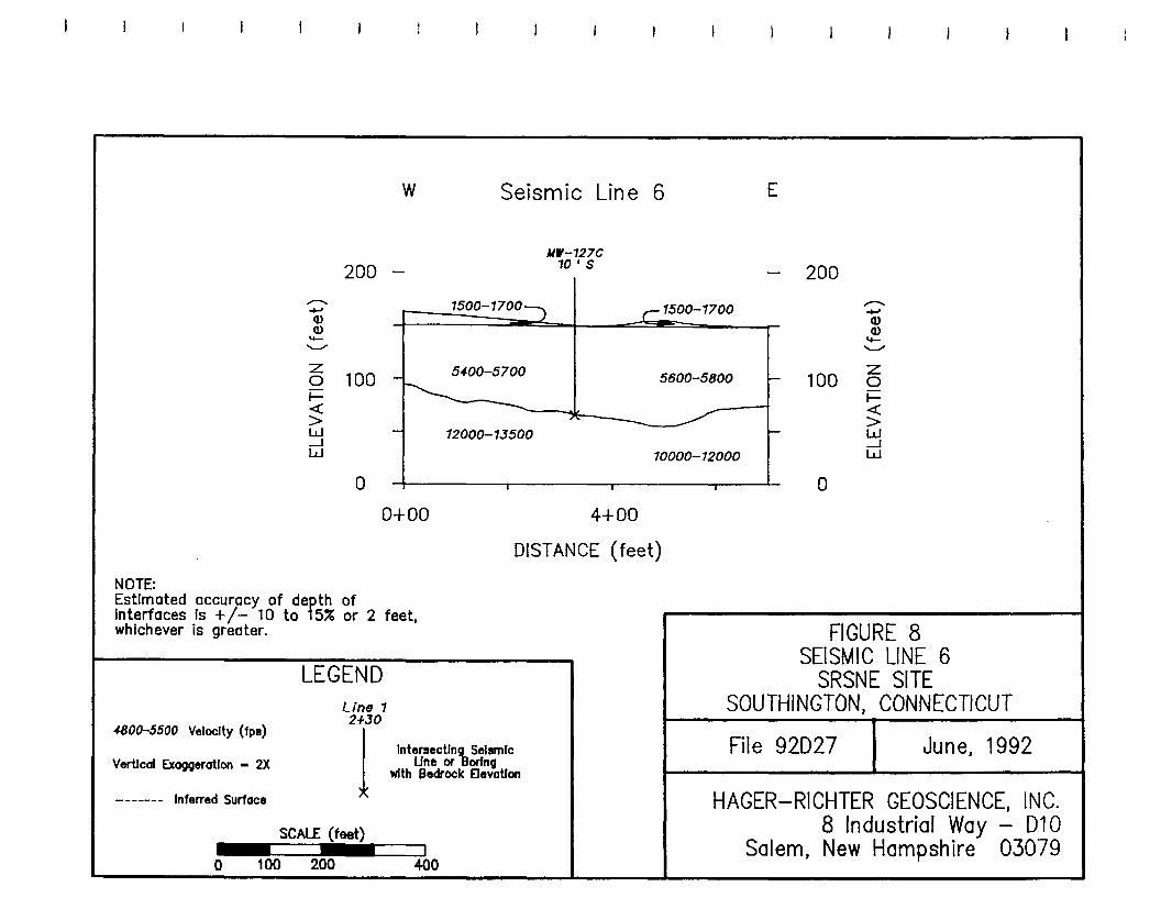
The locations of the six seismic refraction lines are shown on Plate 1. The seismic refraction survey consisted of 22 spreads, for a total length of 8740 feet, not including 960 feet of overlap on various spreads. The results of the seismic refraction survey are summarized in profile form in Figures 2 - 8 and are listed in Table 1. For ease of presentation, we separate Seismic Line 2 and Seismic Line 4 into "A" and "B" segments at gaps in the lines.
3.2 Data Quality
The quality of the seismic data for the SRSNE Site varies between fair and excellent. The data quality for spreads along Queen Street (Seismic Line 2), a very busy two-lane highway, and Flanders Street (Seismic Line 3) is generally only fair due to the "noise" from traffic. The data quality for spreads along Lazy Lane (Seismic Line 1), its easterly extension (also Seismic Line 1) along a private driveway into an apartment complex on the east side of Queen Street, and most of Curtiss Street (Seismic Line 4) is fair to good. The data quality for the lines in the field between the SRSNE Operations Area and Queen Street (Seismic Lines 5 and 6) is good to excellent.
The quality of the data can be evaluated by comparing bedrock depths determined seismically with those determined from boring logs. The internal consistency of the data can be checked by comparing depths obtained independently for the same location from overlapping seismic spreads and intersecting seismic spreads.
Only three bedrock wells are located near the seismic refraction lines for this survey. Well P-12 (depth of bedrock 30 feet) is located near 8+00 on Seismic Line 1 (depth of bedrock 32 feet). Well MW-121A (depth of bedrock 55 feet) is located near 3 + 70 on Seismic Line 5 (depth of bedrock 55 feet). And well MW-127C (depth of bedrock 89 feet) is located at about 3+30 on Seismic Line 6 (depth of bedrock 84 feet). The bedrock depths determined by seismic refraction thus correlate fairly well with the available boring data.
In Table 2, we compare the depths of bedrock determined for overlapped segments of the seismic lines and intersecting seismic lines. In the present survey, Seismic Line 2 contains 80 feet (5 geophones) of overlap, Seismic Line 4 contains 660 feet (35 geophones)
- 5

HAGER-RICHTER GEOSCIENCE, INC
Seismic Refraction Survey SRSNE Site Southington, Connecticut File 92D27 June. 1992
of overlap, and Seismic Line 6 contains 220 feet (12 geophones) of overlap. The difference in bedrock depths is 0 to 3 feet, and we conclude that the data for overlapped segments and intersecting seismic refraction lines are internally consistent.
3.3 Interpretation of Velocities
Materials with three distinct ranges in seismic velocities were detected in the seismic survey. The uppermost material, with velocities of 1100 - 1700 fps, is interpreted to be unsaturated sediments. An intermediate layer, with velocities of 4700 - 5600 fps, is interpreted to as saturated sediments. The deepest layer is interpreted to be competent bedrock, and exhibits velocities ranging from 10000 to 15500 fps.
The velocity range for bedrock might indicate variations in the degree of weathering, the abundance of fractures, or the presence of diabase dikes in the arkose. Seismic velocities, however, are bulk measurements and variations in velocity reflect broad changes in properties that cannot be interpreted on a fine scale.
3.4 Bedrock Topography
Bedrock depths determined in this survey vary between 13 and 122 feet below ground surface. The elevation of bedrock determined in this survey varies between 186 and 45 feet.
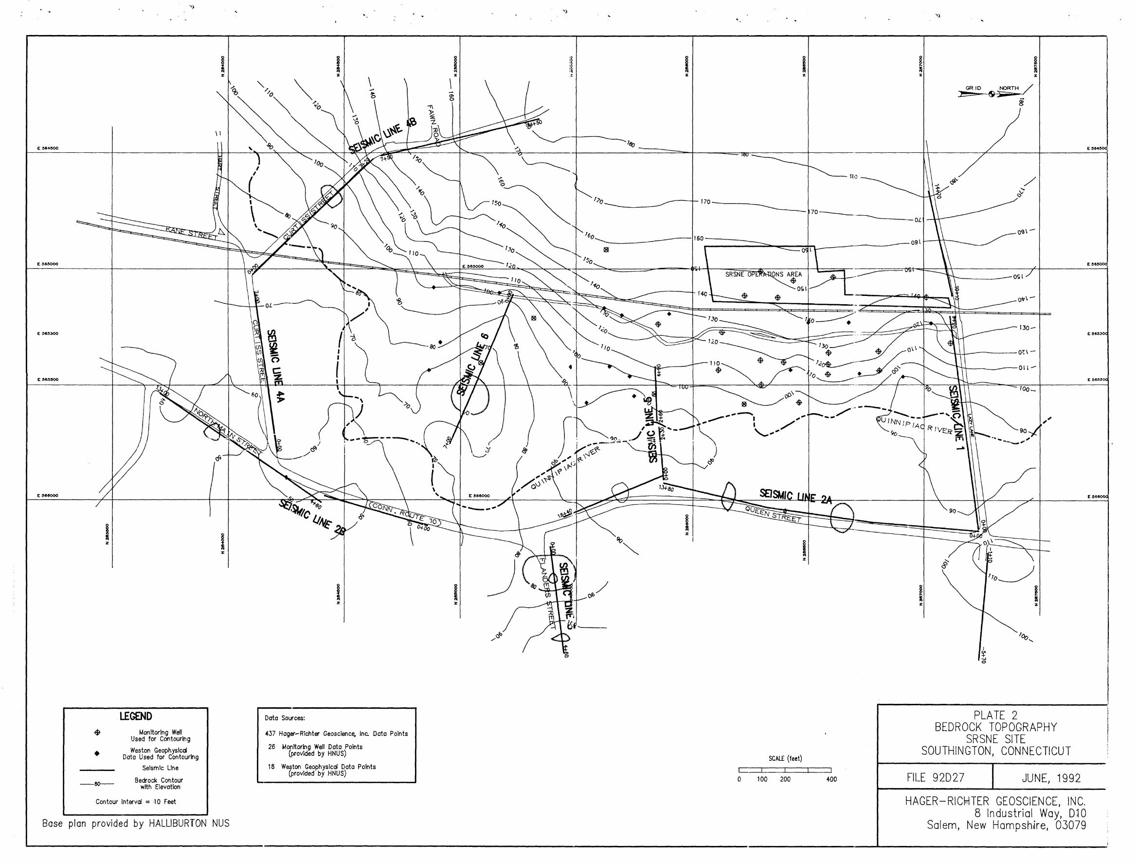
Plate 2 is a contour map of bedrock topography for the survey area. The data used in preparing Plate 2 include the results of the present seismic refraction survey, boring logs provided by HNUS, and the results of a previous seismic refraction survey2.
Bedrock is distinctly higher to the west of the railroad tracks and the SRSNE Operations Area (Seismic Line 1 and Seismic Line 4B), where the surface elevation is likewise higher. In the northern half of the survey area, the bedrock surface slopes easterly toward the Quinnipiac River from an elevation of > 180 feet to about 90 feet, but between the river and Queen Street, the bedrock surface appears to undulate gently at elevations near 90 (±10) feet.
In the southern half of the survey area, the bedrock surface slopes southeasterly from an elevation of > 180 feet to an elevation of about 80 feet near the railroad tracks, east of
Elevation data posted on the bedrock topographic map contained in Weston Geophysical Corp.'s report cited earlier.
- 6
HAGER-RICHTER GEOSCIENCE, INC.
Seismic Refraction Survey SRSNE Site Southington, Connecticut File 92D27 June. 1992
which it appears to slope very gently toward the southeast, perhaps along a former flow direction for the Quinnipiac River. Elevations of bedrock in the southeastern part of the survey area vary between about 80 feet and 50 feet. The lowest bedrock elevations determined occur along Seismic Line 2B near 2+80, 3+40 4+80, 8+20 and 10+40. The seismic refraction data for Seismic Line 3 and the easternmost spread of Seismic Line 1 indicate that the elevation of bedrock rises toward the east. However, the present set of elevation data is too limited in geographic extent to define clearly an eastern flank of a bedrock valley.
4. CONCLUSIONS
Based on the results of the seismic refraction survey at the Solvents Recovery Service of New England, Inc. Site, we conclude that:
1. Bedrock depths range from 13 to 122 feet in depth below the ground surface. The elevation of bedrock varies between 186 and 45 feet.
2. The bedrock surface is distinctly higher west of the railroad tracks and the SRSNE Operations area. In the northern half of the survey area, the bedrock surface slopes easterly to the Qunnipiac River and undulates gently between the river and Queens Street. In the southern half of the survey area, the bedrock surface slopes southeasterly, with a steeper slope west of the railroad tracks, and a very gentle slope east of the railroad tracks. There is some indication that the bedrock surface rises towards the eastern limits of the survey area, but a distinct bedrock valley cannot be defined on the basis of the present data set.
- 7
HAGER-RICHTER GEOSCIENCE, INC.
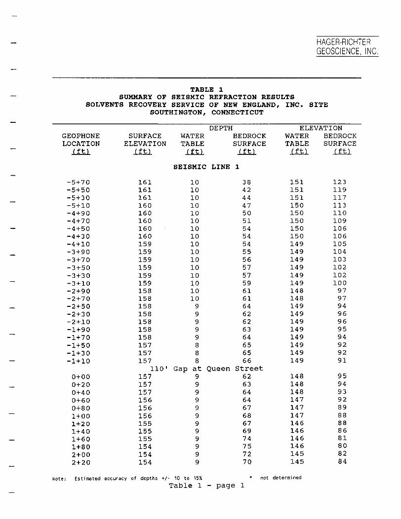
TABLE 1 SUMMARY OF SEISMIC REFRACTION RESULTS
SOLVENTS RECOVERY SERVICE OF NEW ENGLAND, INC. SITE SOUTHINGTON, CONNECTICUT
DEPTH ELEVATION GEOPHONE SURFACE WATER BEDROCK WATER BEDROCK LOCATION ELEVATION TABLE SURFACE TABLE SURFACE
(ft) (ft) (ft) (ft) (ft) (ft)
SEISMIC LINE 1
-5-H70 161 10 38 151 123 -5+50 161 10 42 151 119 -5+30 161 10 44 151 117 -5+10 160 10 47 150 113 -4 + 90 160 10 50 150 110 -4 + 70 160 10 51 150 109 -4 + 50 160 10 54 150 106 -4+ 30 160 10 54 150 106 -4 + 10 159 10 54 149 105 •3+90 159 10 55 149 104 -3+70 159 10 56 149 103 -3+50 159 10 57 149 102 -3+ 30 159 10 57 149 102 -3 + 10 159 10 59 149 100 -2+90 158 10 61 148 97 -2 + 70 158 10 61 148 97 -2 + 50 158 9 64 149 94 -2 + 30 158 9 62 149 96 -2 + 10 158 9 62 149 96 -1+90 158 9 63 149 95 -1+70 158 9 64 149 94 -1+50 157 8 65 149 92 -1+30 157 8 65 149 92 -1+10 157 8 66 149 91
110' Gap at Queen Street 0+00 157 9 62 148 95 0+20 157 9 63 148 94 0+40 157 9 64 148 93 0+60 156 9 64 147 92 0+80 156 9 67 147 89 1+00 156 9 68 147 88 1+20 155 9 67 146 88 1+40 155 9 69 146 86 1+60 155 9 74 146 81 1+80 154 9 75 146 80 2+00 154 9 72 145 82 2+20 154 9 70 145 84
Note: Estimated accuracy of depths +/ 10 to 15% not determined Table 1 - page 1

HAGER-RICHTER GEOSCIENCE, INC
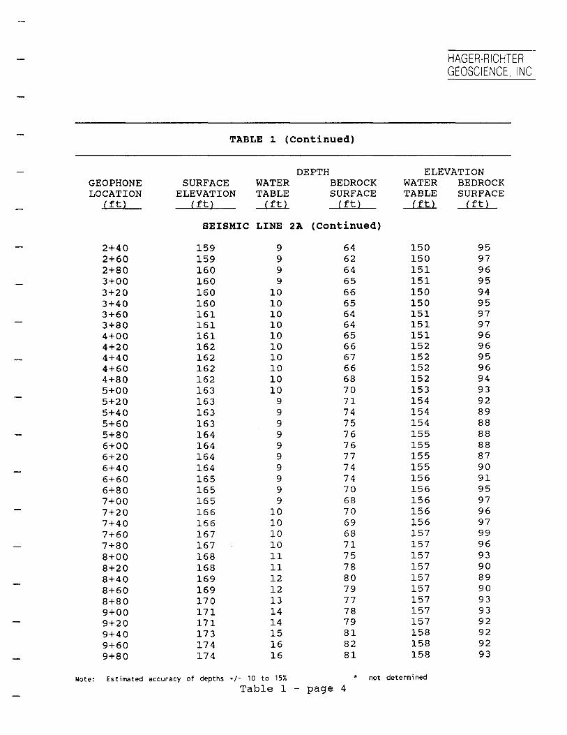
TABLE 1 (Continued)
DEPTH ELEVATION GEOPHONE SURFACE WATER BEDROCK WATER BEDROCK LOCATION ELEVATION TABLE SURFACE TABLE SURFACE
(ft) (ft) 'ft) (ft) (ft) (ft)
SEISMIC LINE 1 (Continued)
2+40 154 9 67 145 87 2+60 154 9 65 145 89 2+80 154 9 65 145 89 3+00 154 9 64 145 90 3+20 154 9 64 145 90 3+40 154 9 64 145 90 3+60 154 9 63 145 91 3+80 154 8 65 146 89 4+00 152 7 66 145 86 4+20 151 5 70 146 81 4+40 151 5 69 146 82 4+60 150 6 69 144 81 4+80 151 7 68 144 83 5+00 153 7 69 146 84 5+20 154 7 67 147 87 5+40 155 7 66 148 89 5+60 155 7 64 148 91 5+80 156 7 62 149 94 6+00 157 7 62 150 95 6+20 157 8 61 149 96 6+40 158 8 61 150 97 6+60 158 8 59 150 99 6+80 159 8 54 151 105 7+00 159 8 49 151 110 7 + 20 160 8 47 152 113 7+40 160 8 44 152 116 7+60 160 8 40 152 120 7+80 160 8 37 152 123 8 + 00 161 8 32 153 129 8+20 161 8 31 153 130 8+40 161 8 31 153 130 8 + 60 161 8 30 153 131 8 + 80 162 8 30 154 132 9 + 00 162 8 29 154 133 9+20 162 8 28 154 134
90' Gap at RR tracks 10+10 164 * 19 * 145
* * 147 10+30 165 18
Note: Estimated accuracy of depths +/- 10 to 15% * not determined
Table 1 - page

HAGER-RICHTER GEOSCIENCE, INC
TABLE 1 (Continued)
DEPTH ELEVATION GEOPHONE SURFACE WATER BEDROCK WATER BEDROCK LOCATION ELEVATION TABLE SURFACE TABLE SURFACE
(ft) (ft) (ft) (ft) (ft) (ft)
SEISMIC LINE 1 (Continued)
10+50 165 * 18 * 147 17 * 149 *10+70 166
10+90 11+10 11+30 11+50 11+70 11+90 12+10
167 168 168 169 170 170 171
* * * *
* *
*
18 17 17 17 16 17 17 16
* * * * * * * *
149 151 151 152 154 153 154 157 12+30 173 *
12+ 50 175 * 15 * 160 12+70 177 * 15 * 162
*12+90 179 * 15 164 13+10 181 * 14 * 167 13+ 30 183 * 14 * 169
*13+50 185 * 15 170 13+70 186 * 14 * 172 13+90 188 * 15 * 173
*14+ 10 190 * 14 176 14+ 30 192 * 13 * 179 14+50 194 * 13 * 181 14+70 196 * 13 * 183
SEISMIC LINE 2A
0+00 158 8 64 149 93 0+20 157 8 64 149 93 0+40 157 8 64 149 93 0+60 157 8 64 149 93 0+80 158 8 65 150 93 1+00 158 8 65 150 93 1+20 158 8 67 150 91 1+40 158 8 66 150 92 1+60 158 9 67 149 91 1+80 159 9 66 150 93 2+00 159 9 66 150 93 2+20 159 9 66 150 93
Note: Estimated accuracy of depths +/- 10 to 15% not determined
Table 1 - page
HAGER-RICHTER GEOSCIENCE, INC
TABLE 1 (Continued)
DEPTH ELEVATION GEOPHONE SURFACE WATER BEDROCK WATER BEDROCK LOCATION ELEVATION TABLE SURFACE TABLE SURFACE
(ft) (ft) (ft) (ft) 'ft) (ft)
SEISMIC LINE 2A (Continued)
2+40 159 9 64 150 95 2+60 159 9 62 150 97 2+80 160 9 64 151 96 3+ 00 160 9 65 151 95 3+20 160 10 66 150 94 3+40 160 10 65 150 95 3+60 161 10 64 151 97 3+80 161 10 64 151 97 4+00 161 10 65 151 96 4+20 162 10 66 152 96 4+40 162 10 67 152 95 4+60 162 10 66 152 96 4 + 80 162 10 68 152 94 5+00 163 10 70 153 93 5+20 163 9 71 154 92 5+40 163 9 74 154 89 5+60 163 9 75 154 88 5+80 164 9 76 155 88 6+00 164 9 76 155 88 6+20 164 9 77 155 87 6+40 164 9 74 155 90 6+60 165 9 74 156 91 6+80 165 9 70 156 95 7 + 00 165 9 68 156 97 7 + 20 166 10 70 156 96 7 + 40 166 10 69 156 97 7 + 60 167 10 68 157 99 7+80 167 10 71 157 96 8+00 168 11 75 157 93 8+20 168 11 78 157 90 8+40 169 12 80 157 89 8+60 169 12 79 157 90 8+80 170 13 77 157 93 9 + 00 171 14 78 157 93 9+20 171 14 79 157 92 9+40 173 15 81 158 92 9+60 174 16 82 158 92 9+80 174 16 81 158 93
Note: Estimated accuracy of depths +/- 10 to 15% * not determined Table 1 - page
HAGER-RICHTER GEOSCIENCE, INC
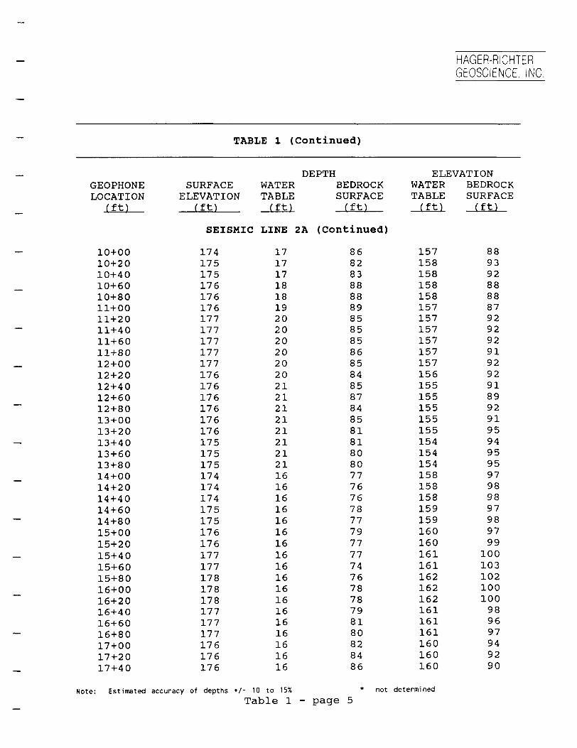
TABLE 1 (Continued)
DEPTH ELEVATION GEOPHONE SURFACE WATER BEDROCK WATER BEDROCK LOCATION ELEVATION TABLE SURFACE TABLE SURFACE
(ft) (ft) 'ft! (ft) (ft) fft)
SEISMIC LINE 2A (Continued)
10+00 174 17 86 157 88 10+20 175 17 82 158 93 10+40 175 17 83 158 92 10+60 176 18 88 158 88 10+80 176 18 88 158 88 11+00 176 19 89 157 87 11+20 177 20 85 157 92 11+40 177 20 85 157 92 11+60 177 20 85 157 92 11+80 177 20 86 157 91 12+00 177 20 85 157 92 12+20 176 20 84 156 92 12+40 176 21 85 155 91 12+60 176 21 87 155 89 12+80 176 21 84 155 92 13+00 176 21 85 155 91 13+20 176 21 81 155 95 13+40 175 21 81 154 94 13+60 175 21 80 154 95 13+80 175 21 80 154 95 14+ 00 174 16 77 158 97 14+20 174 16 76 158 98 14+40 174 16 76 158 98 14+ 60 175 16 78 159 97 14+80 175 16 77 159 98 15+00 176 16 79 160 97 15+20 176 16 77 160 99 15+40 177 16 77 161 100 15+60 177 16 74 161 103 15+80 178 16 76 162 102 16+00 178 16 78 162 100 16+20 178 16 78 162 100 16+40 177 16 79 161 98 16+60 177 16 81 161 96 16+80 177 16 80 161 97
17+ 00 176 16 82 160 94 17+20 176 16 84 160 92 17+40 176 16 86 160 90
Note: Estimated accuracy of depths +/- 10 to 15% * not determined Table 1 - page 5
HAGER-RICHTER GEOSCIENCE, INC.
TABLE 1 (Continued)
DEPTH ELEVATION GEOPHONE SURFACE WATER BEDROCK WATER BEDROCK LOCATION ELEVATION TABLE SURFACE TABLE SURFACE
(ft) (ft) rtj (ft) (ft) (ft)
SEISMIC LINE 2A (Continued)
17+60 175 16 86 159 89 17+80 175 16 88 159 87 18+00 175 16 86 159 89 18+20 174 16 85 158 89 18+40 174 16 86 158 88
SEISMIC LINE 2B
0+00 164 13 100 151 64 0+20 164 14 100 150 64 0+40 163 14 101 149 62 0+60 163 15 102 148 61 0+80 163 17 103 146 60 1+00 162 16 105 146 57 1+20 162 16 105 146 57 1+40 162 16 105 146 57 1+60 161 15 105 146 56 1+80 161 16 105 145 56 2+ 00 160 17 104 143 56 2+20 160 18 108 142 52 2+40 160 16 106 144 54 2+60 159 14 109 145 50 2+80 159 15 112 144 47 3+ 00 158 14 110 144 48 3+ 20 158 15 110 143 48 3+40 158 16 111 142 47 3+60 157 15 109 142 48 3+80 157 16 107 141 50 4+00 156 16 106 140 50 4+20 156 16 106 140 50 4+40 155 15 106 140 49 4+ 60 155 14 106 141 49 4+80 155 14 108 141 47 5+00 155 14 105 141 50 5+20 155 14 104 141 51 5+40 155 12 104 143 51 5+60 155 13 101 142 54
Note: Estimated accuracy of depths +/- 10 to 15% not determined Table 1 - page 6
HAGER-RICHTER GEOSCIENCE, INC
TABLE 1 (Continued)
DEPTH ELEVATION GEOPHONE SURFACE WATER BEDROCK WATER BEDROCK LOCATION ELEVATION TABLE SURFACE TABLE SURFACE
(ft) (ft) (ft] (ft) (ft) (ft)
SEISMIC LINE 2B (Continued)
5+80 155 14 98 141 57 6+00 154 13 99 141 55 6+20 154 13 104 141 50 6+40 154 12 106 142 48 6+60 154 12 99 142 55 6+80 154 11 97 143 57 7+00 154 12 100 142 54 7+20 154 12 102 142 52 7+40 154 11 103 143 51 7+60 154 11 101 143 53 7+80 154 11 105 143 49 8+00 154 10 103 144 51 8+20 153 10 108 143 45 8+40 153 10 105 143 48 8+60 153 10 101 143 52 8+80 153 10 97 143 54 9+00 153 10 99 143 54 9+20 153 11 102 142 51
80' Of overlap 8+40 154 10 105 144 49 8+60 153 10 102 143 51 8+80 153 10 100 143 53 9+00 153 9 100 144 53 9+20 153 10 101 143 52 9+40 153 9 99 144 54 9+60 153 9 98 144 55 9+80 153 10 104 143 49 10+00 153 10 104 143 49 10+20 153 10 105 143 48 10+40 153 9 107 144 46 10+60 153 9 105 144 48 10+80 153 9 98 144 55 11+00 153 10 98 143 55 11+20 153 9 94 144 59 11+40 153 9 94 144 59 11+60 153 9 91 144 62 11+80 153 9 89 144 64 12+ 00 152 10 87 142 65
Note: Estimated accuracy of depths +/- 10 to 15% * not determined Table 1 - page 7
HAGER-RICHTER GEOSCIENCE, INC.
TABLE 1 (Continued)
DEPTH ELEVATION GEOPHONE SURFACE WATER BEDROCK WATER BEDROCK LOCATION ELEVATION TABLE SURFACE TABLE SURFACE
(ft) (ft) 'ft] (ft) (ft) (ft)
SEISMIC LINE 2B (Continued)
12+20 152 10 90 142 62 12+40 152 10 90 142 62 12+ 60 152 10 90 142 62 12+ 80 152 10 92 142 60 13+00 152 9 95 143 57
SEISMIC LINE 3
0+00 177 22 92 155 85 0+20 179 24 96 155 83 0+40 180 25 100 155 80 0+60 181 26 104 155 77 0+80 183 27 109 156 74 1+00 184 29 113 155 71 1+20 186 31 117 155 69 1+40 187 31 122 156 65 1+60 189 34 120 155 69 1+80 190 35 113 155 77 2+ 00 192 36 109 156 83 2+ 20 193 37 107 156 86 2+40 193 37 101 156 92 2+ 60 194 38 100 156 94 2+ 80 194 38 98 156 96 3+00 195 40 96 155 99 3+20 195 40 94 155 101 3+40 195 40 92 155 103 3+ 60 195 39 91 156 104 3+80 195 39 96 156 99 4+00 195 39 99 155 95 4+20 194 38 95 156 99 4+40 194 38 88 156 106 4 + 60 194 38 83 156 111
Note: Estimated accuracy of depths +/• 10 to 15% not determined Table 1 - page 8

HAGER-RICHTER GEOSCIENCE, INC.
TABLE 1 (Continued)
DEPTH ELEVATION GEOPHONE SURFACE WATER BEDROCK WATER BEDROCK LOCATION ELEVATION TABLE SURFACE TABLE SURFACE
(ft) (ft) 'ft! (ft) (ft) (ft)
SEISMIC LINE 4A
0+00 152 6 88 146 64 0+20 152 6 88 146 64 0+40 152 6 88 146 64 0+60 152 6 88 146 64 0+80 151 6 88 145 63 1+00 151 6 88 145 63 1+20 151 6 88 145 63 1+40 151 6 88 145 63 1+60 151 6 87 145 64 1+80 151 6 87 145 64 2+00 150 5 88 145 62 2+20 150 5 89 145 61 2+40 150 5 91 145 59 2+ 60 150 5 93 145 57 2+80 150 5 90 145 60 3+ 00 150 5 89 145 61 3+20 150 5 89 145 61 3+40 150 5 88 145 62 3+60 150 5 87 145 63 3+80 149 4 86 145 63 4 + 00 149 4 88 145 61 4 + 20 149 4 87 145 62 4 + 40 149 4 86 145 63 4 + 60 149 4 85 145 64
220 of overlap 2+ 40 150 5 89 145 61 2+ 60 150 5 90 145 60 2+80 150 5 88 145 62 3+00 150 5 87 145 63 3+ 20 150 5 88 145 62 3+40 150 5 90 145 60 3+ 60 150 5 85 145 65 3+80 149 4 84 145 65 4+ 00 149 4 86 145 63 4 + 20 149 4 86 145 63
4+40 149 4 87 145 62
4+60 149 4 86 145 63 4+80 149 4 86 145 63
Note: Estimated accuracy of depths +/- 10 to 15% * not determined Table 1 - page 9
HAGER-RICHTER GEOSCIENCE, INC.
TABLE 1 (Continued)
DEPTH ELEVATION GEOPHONE SURFACE WATER BEDROCK WATER BEDROCK LOCATION ELEVATION TABLE SURFACE TABLE SURFACE
(ft) (ft) 'ft] (ft) (ft) (ft)
SEISMIC LINE 4A (Continued)
5+00 149 4 8877 145 62 54-20 149 4 8833 145 66 54-40 149 4 8811 145 68 54-60 149 4 8833 145 66 54-80 150 5 8833 145 67 64-00 150 5 8833 145 67 64-20 150 5 8800 145 70 64-40 150 5 7799 145 71 64-60 150 5 7788 145 72 64-80 150 5 7766 145 74 74-00 150 5 7766 145 74
SEISMIC LINE 4B
04-00 151 8 7788 143 73 04-20 151 8 7777 143 74 04-40 151 8 7777 143 74 04-60 152 8 7777 144 75 04-80 152 8 7766 144 76 14-00 152 8 7755 144 77 1+20 152 8 7755 144 77 1+40 152 8 7777 144 75 1+60 152 8 7799 144 73 1+80 153 8 7799 145 74 2+00 153 8 7788 145 75 2+20 153 8 8811 145 72 2+40 153 8 7788 145 75 2+60 154 8 7766 146 78 2+80 154 9 7777 145 77 3+00 155 9 7755 146 80 3+20 156 10 7755 146 81 3+40 156 10 7722 146 84 3+60 157 11 6688 146 89 3+80 158 12 6644 146 94 4+00 158 12 6622 146 96 4+20 159 13 6611 146 98 4+40 159 13 5599 146 100
Note: Estimated accuracy of depths +/- 10 to 15% * not determined
Table 1 - page 10

HAGER-RICHTER GEOSCIENCE, INC.
TABLE 1 (Continued)
DEPTH ELEVATION GEOPHONE LOCATION
(ft)
4 + 60
2+ 60 2+ 80 3+00 3+20 3+40 3+ 60 3+80 4+00 4+20 4+40 4+60 4+80 5+00 5+20 5+40 5+60 5+80 6+00 6+20 6+40 6+60 6+80 7+00 7+20
7+50 7+70 7+90 8+10 8+30 8 + 50 8 + 70 8 + 90 9 + 10 9+30 9+50
SURFACE WATER BEDROCK ELEVATION TABLE SURFACE
(ft) 'ftl (ft)
SEISMIC LINE 4B (Continued)
160 14 59 200' of overlap
153 10 75 154 10 75 154 10 75 155 10 74 156 11 73 156 11 69 157 11 64 158 11 64 158 12 61 159 12 61 159 12 61 160 12 60 161 12 58 161 12 56 162 12 55 162 12 57 163 11 57 164 11 57 164 11 59 165 11 56 165 11 53 166 11 47 166 11 45 167 12 35
30" gap between spreads168 * 32 169 * 30 169 * 28 170 * 26 171 * 24 171 * 23 172 * 21 173 * 19 173 * 22 174 * 22 174 * 22
WATERTABLE
ft)
146
143 144 144 145 145 145 146 147 146 147 147 148 149 149 150 150 152 153 153 154 154 155 155 155
* * * * * * * * * * *
BEDROCK SURFACE (ft)
1C
78 79 79 81 83 87 93 94 97 98 98 100 103 105 107 105 106 107 105 109 112 119 121 132
136 139 141 144 147 148 151 154 151 152 152
Note: Estimated accuracy of depths +/- 10 to 15% * not determined Table 1 - page 11

HAGER-RICHTER GEOSCIENCE, INC.
TABLE 1 (Continued)
DEPTH ELEVATION GEOPHONE SURFACE WATER BEDROCK WATER BEDROCK LOCATION ELEVATION TABLE SURFACE TABLE SURFACE
(ft) (ft) •ft: (ft) (ft) (ft)
SEISMIC LINE 4B (Continued)
* *9+70 175 22 153 *** * *
21 * 155 19 * 158 19 * 159 21 * 158 20 * 160
9+90 176 10+10 177 10+30 178 10+50 179 10+70 180
* * * * * * * of
20 * 161 19 * 163 20 * 163 18 * 166 18 * 167 21 * 165 23 * 164
overlap
10+90 11+10 11+30 11+50 11+70 11+90 12+ 10
181 182 183 184 185 186 187
220 * 20 * 155 9 + 90 175
10+10 10+30 10+50 10+70 10+90 11+10 11+30 11+50 11+70 11+90 12+ 10 12+ 30 12+50 12+70 12+90 13+ 10 13+30 13+50 13+70 13+90 14+10 14+30 14+50
176 177 178 179 181 182 183 184 185 186 187 188 190 191 192 194 195 196 198 199 200 202 203
* * * * * * * * * * * * * * * * * * * * * * *
18 19 20 19 19 20 19 19 19 21 23 27 26 25 24 24 24 22 21 20 19 18 17
* * * * * * * * * * * * * * * * * * * * * * *
158 158 158 160 162 162 164 165 166 165 164 161 164 166 168 170 171 174 177 179 181 184 186
Note: Estimated accuracy of depths +/- 10 to 15% * not determined Table 1 - page 12
HAGER-RICHTER GEOSCIENCE, INC.
TABLE 1 (Continued)
DEPTH ELEVATION GEOPHONE SURFACE WATER BEDROCK WATERLOCATION ELEVATION TABLE SURFACE TABLE
(ft) (ft) (ft) (ft) (ft)
SEISMIC LINE 5
0+00 174 18 80 156 0+10 174 18 80 156 0+20 173 18 79 155 0+30 173 18 80 155 0+40 172 17 79 155 0+50 172 17 79 155 0+60 172 18 76 154 0+70 171 18 75 153 0+80 171 18 77 153 0+90 170 18 77 152 1+00 168 15 76 153 1+10 166 14 78 151 1+20 163 12 74 151 1+30 161 10 71 151 1+40 158 7 68 151 1 + 50 156 6 68 150 1+60 155 5 69 150 1+70 154 4 72 150 1+80 153 3 72 150 1+90 152 3 76 149 2+00 151 2 73 149 2+ 10 151 2 74 149 2+ 20 150 1 70 149 2+ 30 149 1 68 148
30' Gap at River 2+60 149 1 65 148 2+70 149 1 63 148 2+80 149 1 63 148 2+90 150 2 61 148 3 + 00 150 2 60 148 3 + 10 150 2 58 148 3 + 20 150 2 58 148 3 + 30 150 2 57 148 3+40 151 3 56 148 3 + 50 151 3 56 148 3 + 60 151 3 56 148
148 3+70 151 3 55
Note: Estimated accuracy of depths +/- 10 to 15% not determined Table 1 - page 13
BEDROCK SURFACE (ft)
94 94 94 93 93 93 96 96 94 93 92 87 89 90 90 88 86 82 81 76 78 77 80 81
84 86 86 89 90 92 92 93 95 95 95 96

HAGER-RICHTER GEOSCIENCE, INC
TABLE 1 (Continued)
DEPTH ELEVATION GEOPHONE SURFACE WATER BEDROCK WATER BEDROCK LOCATION ELEVATION TABLE SURFACE TABLE SURFACE
(ft) (ft) 'ftl (ft) (ft) (ft)
SEISMIC LINE 5 (Continued)
3+80 151 3 58 148 93 3+90 151 3 56 148 95 4+00 151 3 56 148 95 4+10 151 3 55 148 96 4+20 151 3 55 148 96 4+30 151 3 53 148 98 4+40 151 3 48 148 103 4+50 151 3 45 148 106 4+60 151 3 44 148 107 4+70 151 3 41 148 110 4+80 151 3 42 148 109 4+90 151 3 39 148 112
SEISMIC LINE 6
0+00 163 12 6699 151 94 0+20 162 11 6699 151 93 0+40 161 10 7744 151 87 0+60 161 9 7777 152 84 0+80 160 8 7777 152 83 1+00 159 8 8811 151 78 1+20 158 7 8822 151 76 1+40 158 6 7799 152 79 1+60 157 6 7788 151 79 1+80 156 5 8800 151 76 2+00 155 5 8800 150 75 2+20 154 4 8811 150 73 2+40 154 4 8855 150 69 2+60 153 3 8855 150 68 2+80 152 3 8833 149 69 3+00 151 2 8822 149 69 3+20 150 2 8844 148 66 3+40 148 1 8844 147 64 3+60 149 1 8844 148 65 3+80 149 1 8877 148 62 4+00 150 2 8888 148 62
147 584+20 150 3 9922
Note: Estimated accuracy of depths +/- 10 to 15% not determined
Table 1 - page 14

HAGER-RICHTER GEOSCIENCE, INC
TABLE 1 (Continued)
DEPTH GEOPHONE SURFACE WATER BEDROCK LOCATION ELEVATION TABLE SURFACE
(ft) (ft) (ft) (ft)
SEISMIC LINE 6 (Continued)
4 + 40 152 5 95 4+ 60 154 5 98
220' of overlap 2+ 40 153 7 84 2+60 152 6 86 2+80 152 5 84 3+ 00 151 4 83 3+20 150 2 85 3+40 148 1 86 3+60 149 1 87 3+80 149 1 89 4+00 150 2 90 4+20 150 3 94 4+40 152 4 97 4+60 154 5 100 4+80 154 5 100 5+00 155 5 101 5+20 154 4 100 5+40 152 4 95 5+60 151 3 91 5+80 150 1 85 6+00 150 1 79 6+20 149 1 78 6+40 149 1 77 6+60 149 1 76 6+80 148 1 75 7 + 00 148 1 74
ELEVATION WATER TABLE (ft)
147 149
146 146 147 147 148 147 148 148 148 147 148 149 149 150 150 148 148 149 149 148 148 148 147 147
BEDROCK SURFACE (ft)
57 56
69 66 68 68 65 62 62 60 60 56 55 54 54 54 54 57 60 65 71 71 72 73 73 74
Note: Estimated accuracy of depths +/- 10 to 15% * not determined
Table 1 - page 15

HAGER-RICHTER GEOSCIENCE, INC.
TABLE 2 COMPARISON OF DEPTHS OF BEDROCK
FOR INTERSECTING AND OVERLAPPED SEGMENTS OF SEISMIC LINES SOLVENTS RECOVERY SERVICE OF NEW ENGLAND, INC. SITE
OVERLAP LOCATION
(ft)
0+00/0+00
13+80/0+00
8+40 8+60 8+80 9+00 9+20
2+40 2+60 2+80 3+00 3+20 3+40 3+ 60 3+80 4+00 4+20 4+40 4+60
2+60 2+80 3+ 00 3+20 3+40
SOUTHINGTON, CONNECTICUT
BEDROCK DEPTHS DIFFERENCE (ft) (ft) (ft) (%)
SEISMIC LINE I/SEISMIC LINE 2A
62 64 1
SEISMIC LINE 2A/SEISMIC LINE 5
80 80 0
SEISMIC LINE 2B
105 101 97 99 102
105 102 100 100 101
0 1 3 1 1
0 1 3 1 1
SEISMIC LINE 4A
91 93 90 89 89 88 87 86 88 87 86 85
89 90 88 87 88 90 85 84 86 86 87 86
2 3 2 2 1 2 2 2 1 1 1 1
2 3 2 2 1 2 2 2 1 1 1 1
SEISMIC LINE 4B
76 77 75 75 72
75 75 75 74 73
1 1 0 1 1
1 1 0 1 1
Table 2 - page 1

HAGER-RICHTER GEOSCIENCE, INC.
TABLE 2 (Continued)
OVERLAP LOCATION BEDROCK DEPTHS DIFFERENCE
(ft) (ft) (ft) (ft) f%)
3+ 60 68 69 1 2 3+80 64 64 0 0 4+00 62 64 2 3 4+20 61 61 0 0 4+40 59 61 2 3 4 + 60 59 61 2 3
SEISMIC LINE 4B
9 + 90 21 20 10+10 19 18 10+30 19 19 10+50 21 20 10+70 20 19 10+90 20 19 11+10 19 20 11+30 20 19 11+50 18 19 11+70 18 19 11+90 21 21 12+ 10 23 23
SEISMIC LINE 6
560555556600
11 01111111 0 0
2+40 85 84 1 1 2+ 60 85 86 1 1 2+80 83 84 1 1 3+ 00 82 83 1 1 3+20 84 85 1 1 3+40 84 86 2 2 3+ 60 84 87 3 4 3+80 87 89 2 2 4+00 88 90 2 2 4+20 92 94 2 2 4+40 95 97 2 2 4+60 98 100 2 2
Table 2 - page 2
HAGER-RICHTER GEOSCIENCE, INC.
Seismic Refraction Survey SRSNE Site Southington, Connecticut File 92D27 June. 1992
--*-i:
APPROXIMATE WORK AREA
• i
eto1" i/fij /:•'.!?" j> i [i.:?^rfclmy/j* i 'i
:ooo 1000 7000 3000 *000 1000 6000 TOGO SCALE
SOURCE: US GEOLOGICAL SURVEY 7.5 MINUTE SERIES TOPOGRAPHIC MAPS. CONNECTICUT QUADRANGLES
(SOUTHINGTON. 1961 PHOTOREVISED 19*4; MERIDEN. 1967 JR 19«4; NEW BRITAIN, 1966. PR 19*4; BRISTOL. 1966. FT 19S4)
Figure 1. Site location. Map courtesy of HNUS.
CD
OC
sl ro
o
LU
O
I—
O
O
-c
LU
OT
G
O —
O.5
Q
N
OI1V
A313
LU ^
3
E
O
co
O
C£
0
,-s0
°
O)
CM
5ra
C
M
LU
a
CHC
M
E
en _o>
Cxi
oLU
G
O
OO
0
CO
0
(U
O
O
<u O
CM
*0 O
•o o
^
°0
O
i . o
0) O
0)
eO
o
01
+
o
UJ
T
3
W
i _
<U
0)
0)
- O
>
O o
<U
O
LU Eli-g
co
CO
0^
-2
^
Q
2L
J.E
3s
o
o
00
I:
O
O
CM
Q
Ld
1
LU
oc/i X
CM
OO
o
OO
CM
o
T
3 o
0) V
o>
NO
I1VA
313 O
l
o
>o? o o
C ^5
c5
C
M
—I
O
~i LL j
3
—>
T—
rD ^
0
<r ^
O
J i=
o>"
u
0<
0
c
TC
M
LU
13
>•) CO
U
JZ
-=
§
C/ D
.2 Q
. ro
LU 1 —
2:
C
u
J .£ E
^ 60 o
1 1 1 —:
f •}
CD co
o rv
—' i . , ^-^
(}39J)
NO
I1VA
313 n
IE
—) .-i:
„
Q J
c $
0o
^> r^
C
D
t~ ~
CD
o
0
Ll_
/•
.-. Q
— i
|^
-n
—- "^
0
„
o
CM
'
•* f
r\ f*** 1
fr~>
CJ.)
C>J
c_ LU
_
_
f— •,
—
O
00
Z
g
QO
-^
°
1 y
i ^
E1
x ^
O
5^
0.c
)
Q;
Li j °
3
00
o
,—
c
00
LJ-<
C
o
3o
o
oo
"0
00>
s
—
11
o 1
o
o
o"O
1 o
<N
K
0
T
T1 r
O
_ O
\ -*- 1
0)
1 0)
CM
bo
0 o
••_
1 OM
%o
o
RIr
>oT
i 1
Jd
&?
O
o
o
'*"'Q
LT3 _
oo
<
S03
o
«|T
-•*
CM
^-°
C
T
^°
*~ oo
o
°2
L: <D
*•- >\
<u c~
• i!
o
oi
UJ
3^£
O
o "•" en
•p
—
t—
"0
W
L_ 00
«
g «
CO Q
. .
O O
O> CD
<jJ Et-g
O
o
1
§00
O
O "O
T-^S
>*•
"*" /
§ Z
LU
.E *
11
1 O
0
o0
o
o
o
O
»-
S-! <o
—
~
<N
o
o
-f. o
\
^
"**"
.c
0 |
E 0,
3
o0
§o
O0
o
(/> O
UJ
•n 0
r.
«o Y
--i B
/*l
^^
C
i _ 0
53 5
o
0o
CD
^O
o
o
lf-\ o
^
^
«
fc5m
°
\ ^
5
\ ~
'5
Q
"~o
\I Z
C
4-A
^
LU ^
$
(f)
\1
|
O
^o
11
1 LU
uu
°
00
1
^
00
0
0
in
<N
0
V
w
g
o
Q.
Q
^
0
^(}9
9J)
NO
I1VA
313 o
-S
-o
o
O
O
4)
"37 ™
fc~
on
2
—
C
0
UJ
"O? s
O
"C

OJ
0)
UJ
O
0I—
DQ
O
CN
UJ
-c
O
w
GO -=
sit
O
CO
O
o
Ql-g
31
LU
C
5:
/\ _
U)
tr\
— ^
' C
N
Q
O)
Osl
i -g
o
00
NO
I1VA
313
oO
o
O
CM
o
o
oo
oo
>o o
o
<u o
o
<D
V)
CM C
M
"o o
o
o
+
« o
00
C\l
^1 <D
0)
0
0>
o
o
<0 o
1^2 en LU
t~
T> tn i_ I
O
O
oo
5 8 5
oo
. O
O
<U
E
"O
o
oQ
00
oo
§V)
±§ I
o
O
O
CN
»•=
Vc/>fcQ
?fe
o
OO
O
O
C^cn
CN
* I
NO
I1VA
313
.«= + "
$
O
o
CO
a €
»
§1 1
T)
i o
Q
§
r

NO
I1VA
313
88
CM
CD C
LJ
O
O
CO
NO
I1VA
313
CM
CD
U
J
oo
f—
CD" U
J o
O
o
CD
co
oLU
^^S
=JIE
C
^0U
J
o^lc
o^"
CU 11
CO
Ql i
oo CN
O
CO
CM
E
Ien
CU
O
CO
Ji I
£r»
«
£
OC>l
-X
1- fe
o o
O
|oI C
M
oj•o
o
O i +
J
i*w3
4.
»
(J T
o>
*-» o
1 XS
O „
Eo
,J3 tn :>
cr>
JO
T3 01 i _
0) 0) OJ o
*J O
>
II
00
0)
§> "S
-ti-c:u
j.E *

CN
cn
NO
LLVA
313 o
CD
G
O
^
O^
S
2
oO
<u
oO
0
CC
M
o
O
&?--§O
.— °
UJ J±;
£LU
O
•**" c?)
o
CD
cn
o
O
Of
=3 T"
fK -o
LU
C ^
r I—
—
QJ o
g
oo
z
0
CN
K
Q
ct: c
7
CN
§
CO
C
O
§
§
<U CD
o
CO
<c
LU
mO
OO
O
ncn
§o
00
"CD
o
(O
Q
I o
o
o
oo
o
IO
§
o
<U 0)
o
S C
N
CN
o
o
"o
o
o
(0•O
o
"OQ
01 I "a
3 C
T
o
"O
t/1 L<U
CD <U
*J O
>
O
O
O
QJ O
w E
t-g
zul.E i
<u
UJ
o
O
O
+
a
o
1:
C
i _ O
^
30
0
O
a
-s o
a
o
c-i-LU
CN
o
OOLU
<N
o
00
O
xO
CM
"X
"°
p a>
a> t
Oi
4> o
o
o>o
»:
£
oo
CN
"
"5
NO
IIVA
313

KD
C
D
LU
ID
O
Cm
LU
13
0
-
Q
ujjs
E
O
CO
O
Lu
S^g
C£
..in
NO
LLVA
313 CO
r--
go
o
Csl
00
Q
CN
l o
0
0
CD
rv
*>
0ID
03
O
LU
C
O
«
c
<D
o
8 5
00
I 50
e >_ ' O
O
3
3 O
! O
O
0
<N 0}0)
= iN
OI1V
A313
~"
*
QC
M
-<
O O
LU
.cfc?•tim
LU
O
K
o
T£•
^
0
8
o
^>
g
W
CJ ''
O1
"5
5
•" O
"
O
°—
jm 5
fe
fc
>
o> «
•o w »_
0) W
fl)
-M O
>
.. o o «uj E -
•§S5
CN
^ Q
O
ID
O
O
Z O
d> c:
CD
^
co-=
w
°'C
UJ^: E c
-
O
co o
NO
I1VA
313
UJ_
c ^
00
o
o
CN
CN Q
C
sl rxI
c
c: 1
1 O
d -S
O
0
CO
o
N
00
CD
<D O
<1)
O
U
O
MO
^o
CO CO
'<D
Q
1 0-1 S£ «
Is!
O
O
O +
-•?
oO
O
»*>
o
O
CN o
LU
O
NO
I1VA
313
0}•o
00
e
>s
r0 I
CM
IO
, I I
0+
0)
o „
1§
O.S
2.W
1§
J>
T3 01 i_
s 1
0) <U
0) •4-J
O
>
o
O
O
QJ <o
§

* o
GR ID ^
NORTH -
CN
CL >
-X
C
L < CD
O
C
L
o o o LU
CO GO
ID
o o o o c/)o 0
00
o GO
S^ T
|\
LU
>^
°
2L
^ £ >
LU _
-i
LU
Z 3 o
c£ —
> bd C O
c u
E _CD O
GO
3O I O
L LU
O
<
o CO
o o o o eg
o o
CO
•4-* C
O
a. D
"5 Q
CO
ci c
_c CO
0 Q
. to
c O
0
0 -4-»
§ a. 0 a GO
0
(0
eosc
a. 0 a T
il ^
X
eosc
OX
Til
^X
0 SSZ
>s
2>>» &
.a K
•+*
•n K
%
£2
CD <J)
'i in 1
0 > 0 ^
0
ger
it u
^ !5
ger
§ a. 1^
co 0
S *
M
r
m
00 O
m
CN
O
•*
CO
2:
o> 0
£ I
Well curing
yslcd ontour
?
tour ion
BUR
o>§ H°
Z3 S
° 1
£0
5 5=5 0
0 «
1
a
Monitor ed for
ston Gc Used f(
Seisml
edrock with El
0 TII >>
Lu
co -3?
n CD
>
_Q
cd :D
3=5
hi a
O
Q
3
ded
0 >
c 0
^ ♦
< a 1 > 0
CL
c 0 a.
CO
o C
D
-
=
-
"
-
=
—
—
--