seismic performance of dissipative devices martin williams university of oxford japan-europe...
TRANSCRIPT

Seismic Performance ofDissipative Devices
Martin WilliamsUniversity of Oxford
Japan-Europe Workshop on Seismic RiskBristol, July 2004

Japan-Europe Workshop on Seismic Risk, Bristol, July 2004
Outline
• Introduction to knee bracing
• Optimisation of the knee element design:
– Full-scale experiments on knee elements
– Finite element modelling
• Seismic design and analysis of knee braced frames
• Conclusions and future work
Acknowledgements: Tony Blakeborough, Denis Clément, Neil Woodward

Japan-Europe Workshop on Seismic Risk, Bristol, July 2004
Introduction to knee braced frames
Cross brace
Knee element
Seismic energy dissipated through yielding/hysteresis of knee elements

Japan-Europe Workshop on Seismic Risk, Bristol, July 2004
Knee bracing
Knee element requirements:• Early yield• Large energy dissipation – shear vs flexure• Stable under large non-linear excursions – web buckling• Easily replaceable – no damage to ends • Pursued via testing and FE analysis• Focus on standard section types
Flexural hinge:
Shear yield in web:

Japan-Europe Workshop on Seismic Risk, Bristol, July 2004
Knee element designs
• Column sections provide high lateral stability
• Different stiffener patterns explored to prevent plastic web buckling
• Perforation of webs explored as a way of giving a designer greater flexibility over choice of shear yield load

Japan-Europe Workshop on Seismic Risk, Bristol, July 2004
Test set-up
Load cell
Actuators
Kneeelement
Universal load cell
Test frame
Cable extensiondisplacementtransducers

Japan-Europe Workshop on Seismic Risk, Bristol, July 2004
Loading regimes
Slow cyclic: Real-time loading:
u
t
Apply measured forces tonumerical substructure
External loads(eg. earthquake)
PHYSICAL SUBSTRUCTURE
Measure forces and actualdisplacements of test specimen
NUMERICAL SUBSTRUCTURE
Calculatedisplacementsat interfacebetweenphysical andnumericalsubstructures
Command actuators to applyinterface displacements to
physical substructure
Japan-Europe Workshop on Seismic Risk, Bristol, July 2004
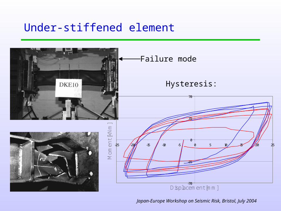
Under-stiffened element
Displacement [mm]
Mom
ent [
kNm
]
-70
-35
0
35
70
-25 -20 -15 -10 -5 0 5 10 15 20 25
Failure mode
Hysteresis:

Japan-Europe Workshop on Seismic Risk, Bristol, July 2004
Well-stiffened section
Displacement [mm]
For
ce [k
N]
-700
-350
0
350
700
-30 -20 -10 0 10 20 30
Displacement [mm]
Mom
ent [
kNm
]
-80
-40
0
40
80
-25 -20 -15 -10 -5 0 5 10 15 20 25
Failure mode:
Hysteresis
Japan-Europe Workshop on Seismic Risk, Bristol, July 2004
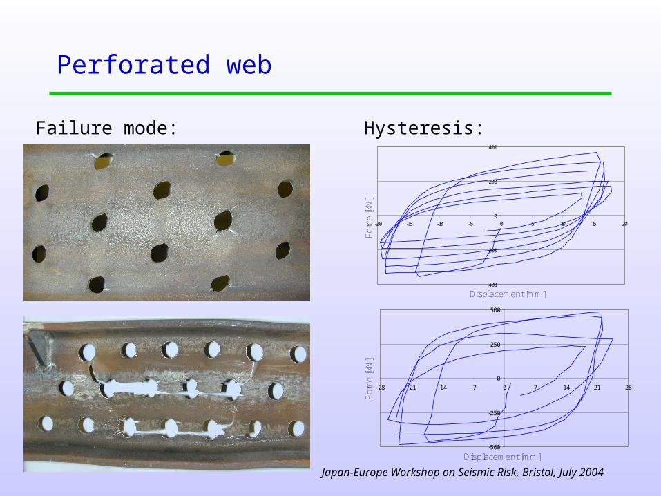
Perforated web
Displacement [mm]
For
ce [k
N]
-500
-250
0
250
500
-28 -21 -14 -7 0 7 14 21 28
Displacement [mm]
For
ce [k
N]
-400
-200
0
200
400
-20 -15 -10 -5 0 5 10 15 20
Failure mode: Hysteresis:

Japan-Europe Workshop on Seismic Risk, Bristol, July 2004
Thermal monitoring system
Plastic strain distributions during tests could be deduced from measurements of the knee element temperature
Thermal imaging system:
Typical images:

Japan-Europe Workshop on Seismic Risk, Bristol, July 2004
Thermal analysis results
Amplitude = 20 mm 30 mm
Energy:
Plastic strain:
Von Mises stress:

Japan-Europe Workshop on Seismic Risk, Bristol, July 2004
Summary of experimental findings
• Full scale cyclic loading gives responses representative of a real earthquake
• Yielding in shear is optimal
• UC sections are are less prone to lateral instabilities
• To prevent buckling, web stiffeners are required at a spacing approximately equal to the section depth
• At a realistic design deflection the load on a knee element is approximately 1.7 times the yield load
• Perforating the web was unsuccessful
• Thermal imaging is an effective method for identifying the energy dissipation areas and tracking the spread of yielding

Japan-Europe Workshop on Seismic Risk, Bristol, July 2004
FE analysis of knee elements using ABAQUS
Cyclic analysis with three different hardening laws:
Cyclic + thermal analysis – comparison of temperature rise in one half-cycle with test:
Japan-Europe Workshop on Seismic Risk, Bristol, July 2004
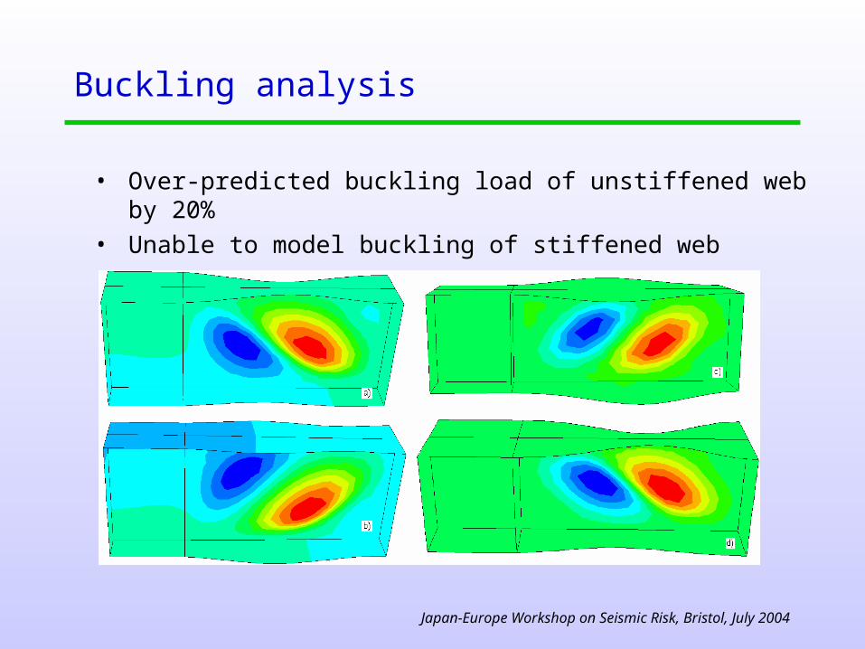
Buckling analysis
• Over-predicted buckling load of unstiffened web by 20%• Unable to model buckling of stiffened web

Japan-Europe Workshop on Seismic Risk, Bristol, July 2004
Summary of FE results
• An accurate hardening law is essential for realistic cyclic analysis
• Thermal analysis showed reasonable agreement with thermal imaging results
• It was not possible to build a model that agreed with all aspects of behaviour - shear forces, axial forces, moments and thermal dissipations
• Buckling analysis overestimated the critical load by 20% for an unstiffened knee element and was unable to predict the failure mode for knee elements with stiffeners

Japan-Europe Workshop on Seismic Risk, Bristol, July 2004
Design of a knee braced frame
Facade 1 Facade 2
Brace
Kneeelement
Pin
5-storey building designed to EC8, for earthquake with peak ground acceleration 0.35g

Japan-Europe Workshop on Seismic Risk, Bristol, July 2004
Design using pushover analysis
• Designed using EC8 pushover approach• Also FEMA 356 approach, ATC 40 capacity spectrum method• Key difference is idealisation of pushover curve:
(a) Modal pattern
0
500
1000
1500
0 50 100 150d* (mm)
F*
(kN
)
(b) Uniform pattern
0
500
1000
1500
0 50 100 150
d* (mm)
F*
(kN
)
Pushover
EC8
FEMA356

Japan-Europe Workshop on Seismic Risk, Bristol, July 2004
Comparison with time-history analysis
(a) EC 8
0
1
2
3
4
5
0 0.5 1
Storey drift (%)
Sto
rey
(b) FEMA 356
0
1
2
3
4
5
0 0.5 1
Storey drift (%)
Sto
rey
(c) ATC 40
0
1
2
3
4
5
0 0.5 1
Storey drift (%)
Sto
rey
Mean Mean +/- st. dev.
Uniform Modal
Time history analysis:
Pushover analysis:

Japan-Europe Workshop on Seismic Risk, Bristol, July 2004
Summary of results
• Pushover analysis shows that frames possess high ductility and post-yield stiffness
• Knee elements begin to yield at just 0.08g but remain stable up to 0.56g
• EC8 approach appears highly conservative for this type of structure, ATC40 approach unsafe

Japan-Europe Workshop on Seismic Risk, Bristol, July 2004
Conclusions
• Stable dissipative behaviour can be achieved using standard sections, appropriately reinforced
• Large increases in knee element load occur after initial yield
• Yielding and energy dissipation in experiments can be tracked using thermal imaging
• Accurate FE modelling of all aspects of knee element behaviour did not prove possible – web buckling was particularly problematic
• Design methods based on pushover analysis may be suitable for frames incorporating dissipative elements, but some further development of these approaches is desirable

Japan-Europe Workshop on Seismic Risk, Bristol, July 2004
Current/future work
• Testing of other dissipators, e.g. Jarret, Hyde devices• Real-time substructure testing• Further design and analysis studies using ten-storey frames,
different dissipators