seismic collapse evaluation of steel moment resisting ... · seismic collapse evaluation of steel...
TRANSCRIPT
1
Seismic collapse evaluation of steel moment resisting frames with superelastic viscous damper
Baikuntha Silwal1, Osman E. Ozbulut1*, Robert J. Michael2
1Department of Civil and Environmental Engineering, University of Virginia, Charlottesville, Virginia, USA
2Department of Mechanical Engineering, Gannon University, Erie, Pennsylvania, USA
ABSTRACT This study investigates the seismic collapse resistance of steel moment resisting frames
equipped with superelastic viscous dampers (SVD) through incremental dynamic analysis (IDA). The SVD is a hybrid passive control device that strategically combines a viscoelastic device and shape memory alloy cables in parallel. The hybrid device exhibits improved re-centering and energy dissipating capabilities compared to only viscoelastic or only SMA-based devices. First, the design and mechanical behavior of SVDs are described. A nine-story steel frame building is selected for the numerical analyses. The building is first designed as a conventional special moment resisting frame (SMRF) to meet the strength and stiffness requirements of the design codes. Then, a reduced strength version of the fully code compliant frame is developed and upgraded with either SVDs or buckling restrained brace (BRB) system. Analytical models of the steel building for each configuration are developed to simulate global frame behavior by considering both geometric nonlinearities and cyclic strength and stiffness deterioration of structural steel components under dynamic loads. Incremental dynamic analysis is employed to assess the seismic resistance of steel frame structures up to collapse using 44 ground motion records. A sensitivity analysis is also performed to evaluate the influence of SVD design parameters on the seismic response of the frame. The results indicate that the steel frame designed with SVDs has the largest median collapse capacity and minimal residual drifts under various seismic hazard levels. Keywords: Shape memory alloys, passive control, viscoelastic damper, collapse assessment, earthquakes, steel structures
1. Introduction
Conventional seismic design approaches rely on the ability of structures to dissipate the input earthquake energy through inelastic deformations in designed regions of the steel frames, implying substantial structural damage and potential residual drifts after a major earthquake [1]. Peak response quantities such as peak story drifts and peak floor acceleration are typically considered to evaluate performance of different structural systems under seismic loads. However, several studies have shown that residual drifts, which occur due to the nonlinear
* Corresponding author. Tel.: +1 434-924-7230; fax: +1 434-982-2951 Email address: [email protected] (O. E. Ozbulut).
2
behavior of yielding components of a structural system, can have an important role in defining the performance of a structure after a seismic event and in evaluation of potential damage [2-3]. McCormick et al. [4] studied the effects of residual drifts on occupants and concluded that residual drifts greater than 0.5% in buildings may suggest a complete loss of the structure from an economic point of view. In another study, Erochko et al. [5] examined the residual drift response of special moment resisting frames (SMRFs) and buckling restrained braced frames (BRBFs). It was found that both types of building systems experience significant residual drifts, with values between 0.8-1.5% for the SMRFs and 0.8-2.0% for the BRBFs under design-based excitations. Ramirez and Miranda [6] found that considering residual drifts in building earthquake loss estimation significantly increases the expected economic losses. By reducing residual drifts of a structure subjected to a seismic event, structural engineers can maximize post-event functionality, reduce the cost to repair the structures, and increase the public safety. To enhance the seismic performance of structural systems, structural systems that can provide stable energy dissipation with full self-centering capabilities are desirable. These systems, known as self-centering or re-centering, exhibit flag-shaped hysteric response with the ability to return to small or zero deformation after each cycle. The self-centering system can control structural damages while minimizing residual drifts. A wide variety of self-centering systems have been developed over the past two decades including post-tensioned systems, rocking wall systems, and self-centering brace systems [7-12]. An extensive review of self-centering systems can be found in [13].
Shape memory alloys (SMAs) are a class of smart materials that exhibit unique properties such as excellent re-centering ability, high corrosion and fatigue resistance, and good energy dissipation capacity. These distinct properties of SMA have broadly attracted the attention of researchers to develop SMA-based seismic control systems [14]. A number of studies investigated the use of SMAs in developing an effective energy dissipation device with self-centering capabilities [15-20]. However, the previous studies indicate that superelastic SMA wires or bars employed as the sole damping device can provide only limited quantity of equivalent viscous damping under dynamic loading [21-22]. Therefore, several researchers have explored ways to add supplemental energy dissipation capabilities to SMA-based control devices [23-26]. Recently, Silwal et al. [27] proposed an SMA-based passive seismic control device, named as superelastic viscous damper (SVD), and conducted experimental and numerical studies to evaluate its effectiveness in mitigating response of steel frames. The SVD combines SMA cables and a viscoelastic element in parallel for improved re-centering and energy dissipating capabilities and is an attractive alternative control device in both performance and design efficiency.
This study evaluates the collapse assessment of steel moment resisting frames upgraded with SVDs. In what follows, a description of the SVDs is provided first. Then, a nine-story steel building is designed as conventional special moment resisting frame (SMRF) to meet the current seismic design requirements. The same building is designed with SVDs to achieve a performance similar to that of conventional SMRF. For comparison purposes, the steel building is also designed with buckling restrained braces (BRB). Incremental dynamic analyses are conducted using 44 ground motion records to assess the collapse resistance of each frame. The results are analyzed in terms of peak interstory drift, peak floor absolute acceleration, and peak residual drifts. Finally, the influence of SVD design parameters on the overall performance of the steel frames designed with SVDs is also investigated.
3
2. Superelastic viscous damper
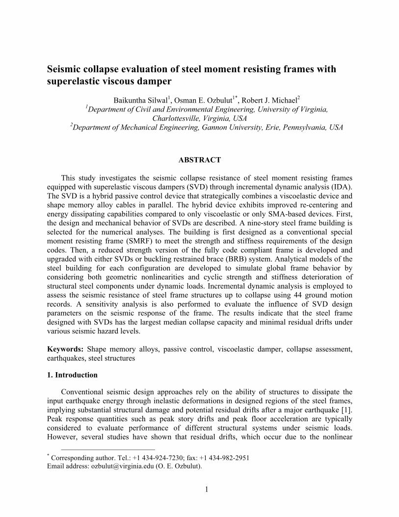
The superelastic viscous damper (SVD) is a hybrid passive control device that strategically combines a viscoelastic device and shape memory alloys in parallel. Fig. 1(a) illustrates the 3D renderings of the SVD. In the SVD, the SMA elements are primarily employed to achieve re-centering capability while a viscoelastic component is used to dissipate input seismic energy by virtue of a high damped (HD) butyl compound. The module comprises two high damped elastomer compounds, sandwiched between and bonded to three identical steel plates and installed SMA elements. Each SMA element forms a continuous loop; wrapping the loops around the outer two plates improves compactness and efficiency. Whether the device itself moves left or right, the configuration ensures that the SMA elements will remain under tension. Along the top and bottom of the device, the wires are threaded through guides, which ensure that the wires remain parallel to the direction of shear deformation in the elastomer layers.
(a)
(b)
(c)
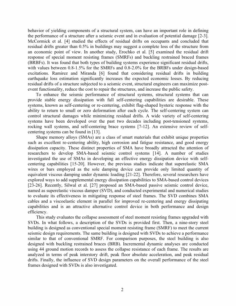
Fig. 1. (a) 3D renderings of SVD, (b) design parameters for SVD and (c) force-displacement curve of SVD
Shape memory alloy cables have been recently developed as a new class of structural
elements that exhibit adaptive functionality and leverage excellent mechanical properties of small SMA wires into large-size structural tension elements. They have relatively large tensile
−100 −50 0 50 100
−300
−200
−100
0
100
200
300
Displacement (mm)
Forc
e (k
N)
−300
−200
−100
0
100
200
300
−100 −50 0 50 100
4
stiffness and strength, yet they are compliant in bending and torsion, making them easy to handle. They also provide significant cost savings compared to the same size monolithic SMA bars [28]. Thus, the hybrid damper utilizes SMA cables as its re-centering SMA elements.
The viscoelastic component of the SVD utilizes an elastomer specifically compounded to produce maximum damping at minimum stiffness. The base polymer used in the elastomer compound is butyl rubber (IIR), a copolymer of isobutylene with a small amount of isoprene to provide cure sites. Butyl is known for its high elongation, very low gas permeability and high damping [29]. Due to its inherently high damping, butyl is often used in vibration isolator applications where resonance must be controlled [30-31]. The HD butyl compounds developed and used in this study are highly loaded which means that the % rubber hydrocarbon (rhc) is lower than traditional industrial butyls. Since there is less elastomer, the damping tends to go up because carbon black and oil, the typical materials used to lower the rhc, generally have higher damping than the elastomer alone. In addition, these compounds utilize a grade of carbon black that builds hardness slowly so more carbon black is necessary to achieve stiffness. The additional carbon black increases damping even further. Thus, the HD butyl is an ideal elastomer that can be used for the SVD. Both the HD butyl and SMA cables were experimentally characterized by the authors in previous studies [27-28].
In this study, the dimension of each elastomer compound of the SVD is selected to be 406×406×50 mm. Each SVD employs a total of 8 SMA cables with a diameter of 8 mm and a length of 1210 mm. With the selected parameters, the SVD has a design displacement of 100 mm and a maximum force capacity of 300 kN. The equivalent viscous damping ratio of a single damper is about 10%. The dimensions and typical force-deformation curve of the SVD are shown in Fig. 1(b) and (c).
3. Building design and modeling
3. 1. Steel special moment resisting frame
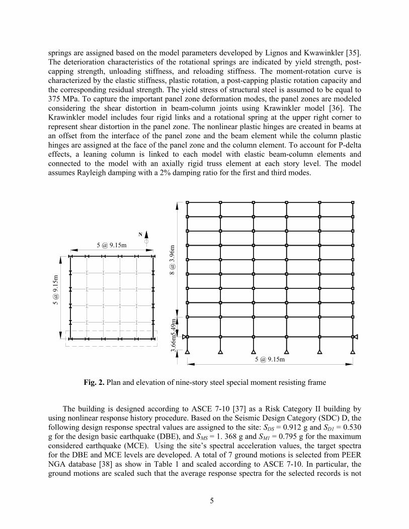
A nine-story steel building [32] is selected from the SAC steel project for numerical analyses. The selected building includes a basement level in addition to the nine stories above the ground level and was originally designed as an office building located on a stiff-soil site (Site Class D) in Seattle, Washington. A floor plan and elevation of the nine-story building are shown in Fig. 2. The building has five bays at 9.15 m (30 feet) in each direction. The story height is 3.96 m (13 feet) at each floor except the first floor, which has a height of 5.49 m (18 feet) and the basement, which has a height of 3.65 m (12 feet). The lateral load resisting system in both directions consists of two special moment-resisting frames on the perimeter of the building. This study analyzes one of the moment frames in the E-W direction. The seismic masses are assigned as 1.01×10⁶ kg for floor level 2, 9.89×10⁵ kg for floor levels 3-9, and 1.07×10⁶ kg for roof level. All the columns are assumed to be pinned at the base. The exterior columns at the ground level are also restrained laterally.
The numerical model of the nine-story steel frame building is developed in 2D using nonlinear seismic analysis program OpenSees [33]. Based on the concentrated plasticity concept, the beam and column elements are modeled with elastic beam column elements connected by zero-length inelastic plastic hinges employing the modified Ibarra-Krawinkler deterioration model [34]. The modified Ibarra-Krawinkler deterioration model considers bilinear hysteric response behavior. The cyclic deterioration model parameters of the zero-length rotational
5
springs are assigned based on the model parameters developed by Lignos and Kwawinkler [35]. The deterioration characteristics of the rotational springs are indicated by yield strength, post-capping strength, unloading stiffness, and reloading stiffness. The moment-rotation curve is characterized by the elastic stiffness, plastic rotation, a post-capping plastic rotation capacity and the corresponding residual strength. The yield stress of structural steel is assumed to be equal to 375 MPa. To capture the important panel zone deformation modes, the panel zones are modeled considering the shear distortion in beam-column joints using Krawinkler model [36]. The Krawinkler model includes four rigid links and a rotational spring at the upper right corner to represent shear distortion in the panel zone. The nonlinear plastic hinges are created in beams at an offset from the interface of the panel zone and the beam element while the column plastic hinges are assigned at the face of the panel zone and the column element. To account for P-delta effects, a leaning column is linked to each model with elastic beam-column elements and connected to the model with an axially rigid truss element at each story level. The model assumes Rayleigh damping with a 2% damping ratio for the first and third modes.
5 @
9.1
5m
N
5 @ 9.15m
5 @ 9.15m
5.49
m8
@ 3
.96m
3.66
m
Fig. 2. Plan and elevation of nine-story steel special moment resisting frame
The building is designed according to ASCE 7-10 [37] as a Risk Category II building by
using nonlinear response history procedure. Based on the Seismic Design Category (SDC) D, the following design response spectral values are assigned to the site: SDS = 0.912 g and SD1 = 0.530 g for the design basic earthquake (DBE), and SMS = 1. 368 g and SM1 = 0.795 g for the maximum considered earthquake (MCE). Using the site’s spectral acceleration values, the target spectra for the DBE and MCE levels are developed. A total of 7 ground motions is selected from PEER NGA database [38] as show in Table 1 and scaled according to ASCE 7-10. In particular, the ground motions are scaled such that the average response spectra for the selected records is not
6
less than the target response spectrum for periods ranging between 0.2 and 1.5 times the building fundamental period. The steel members of the nine-story building are selected in accordance with the strength requirements of ANSI/AISC 360-10 [39] under the load combinations provided in ASCE 7-10. The building is also designed to comply with the drift requirements of ASCE 7-10. Since a nonlinear response history is adopted for the design, the allowable story drift is increased by 25% and determined from ASCE 7-10 for Risk Category II buildings as 2.5% under DBE level and as 3.75% under MCE level. The selected column and beam sections for the nine-story frame are shown in Table 2. The building satisfies the drift requirements under both DBE and MCE levels as will be illustrated below. The first mode period of the special moment resisting frame is 2.36 sec.
Table 1. Seven ground motion records used in the design
No. Earthquake Station Name Magnitude (Mw)
Distance (km)
Peak Ground Acceleration (g)
1 San Fernando (1971) LA-Hollywood 6.6 22.8 0.19 2 Imperial Valley-06 (1979) Elcentro array 6.5 12.6 0.37 3 Loma Prieta (1989) Gilroy Array 6.9 12.2 0.37 4 Superstition Hills-02 (1987) El Centro Imp. 6.5 18.2 0.26 5 Northridge (1994) Canyon Country 6.7 12.4 0.40 6 Duzce, Turkey (1999) Duzce 7.1 12.0 0.81 7 Kocaeli, Turkey (1999) Bolu 7.5 15.4 0.36
3. 2. Steel moment frame with SVDs
In order to design the nine-story frame with damping systems, a reduced strength version of the fully code compliant frame is developed first. In particular, the beam and column member sizes are reduced such that the steel frame satisfies the strength requirements of the design codes but does not meet the drift limits. In this more flexible frame, the added dampers will carry a larger portion of the seismic loads and will be mainly responsible to control the story drifts. Table 2 provides the selected member sizes for the reduced strength frame. The reduced strength steel frame is first upgraded with SVDs to comply with the story drift requirements of ASCE 7-10. In particular, the steel frame with SVDs is designed using the nonlinear response history procedure and following the seismic design requirements for structures with damping systems described in Chapter 18 of ASCE 7-10.
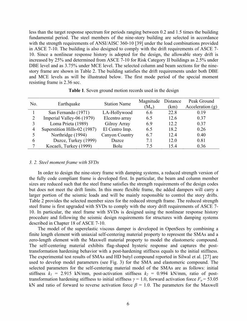
The model of the superelastic viscous damper is developed in OpenSees by combining a finite length element with uniaxial self-centering material property to represent the SMAs and a zero-length element with the Maxwell material property to model the elastomeric compound. The self-centering material exhibits flag-shaped hysteric response and captures the post-transformation hardening behavior with a post-hardening stiffness equals to the initial stiffness. The experimental test results of SMAs and HD butyl compound reported in Silwal et al. [27] are used to develop model parameters (see Fig. 3) for the SMA and elastomeric compound. The selected parameters for the self-centering material model of the SMAs are as follows: initial stiffness k1 = 2.915 kN/mm, post-activation stiffness k2 = 0.994 kN/mm, ratio of post-transformation hardening stiffness to initial stiffness γ = 1.0, forward activation force Fa = 53.05 kN and ratio of forward to reverse activation force b = 1.0. The parameters for the Maxwell
7
model is selected as follows: elastic spring coefficient K = 1.43 kN/mm, viscous damping coefficient C = 1.00 kN-s/mm, nonlinear exponent coefficient α = 0.8.
Table 2. Members of steel moment resisting frames
SMRF SMRF with SVD and BRB
Story Exterior Columns
Interior Columns Girders Exterior
Columns Interior
Columns Girders
1 W24x279 W24x279 W21x201 W18x311 W18x311 W21x201 2 W24x279 W24x279 W21x201 W18x311 W18x311 W21x201 3 W24x279 W24x279 W21x201 W18x258 W18x258 W21x166 4 W24x279 W24x279 W21x201 W18x258 W18x258 W21x166 5 W18x311 W18x311 W21x182 W18x192 W18x211 W21x132 6 W18x311 W18x311 W21x182 W18x192 W18x211 W21x132 7 W18x234 W18x234 W18x192 W18x130 W18x143 W18x106 8 W18x234 W18x234 W18x192 W18x130 W18x143 W18x106 9 W18x192 W18x192 W18x175 W18x86 W18x86 W18x65 R W18x192 W18x192 W18x175 W18x86 W18x86 W18x65
Fig. 3. Parameters used to model SMA cables and butyl rubber in OpenSees
The SVDs are installed at the second and fourth bay of each story level using a chevron brace configuration shown in Fig. 4. From the nonlinear time history analyses, the number of dampers for each story is selected to be 10 to meet the drift requirements. The fundamental period of the frame with the installed SVDs is 2.26 sec.
Displacement
Forc
e
Displacement
Forc
e
γk1
Fak1
k2
Cα
Damping coefficient
Exponent
K
β

8
Fig. 4. Superelastic viscous dampers installed into steel frame
3. 3. Steel moment frame with BRBs
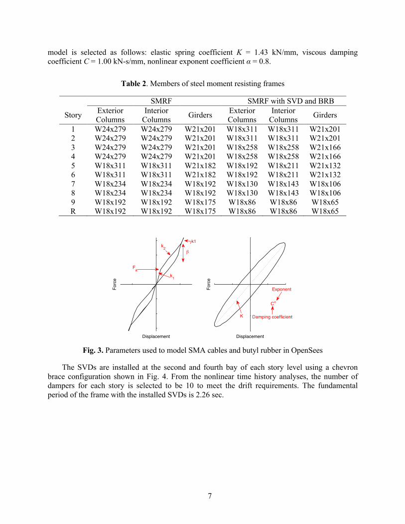
The reduced strength frame discussed above is also upgraded with the buckling restrained braces (BRBs) to meet the story drift requirements according to ASCE 7-10. BRB is a structural component that exhibits a ductile load-deformation behavior under both tension and compression and a high-energy absorption capacity. A typical BRB consists of a central core designed to yield in tension and compression, buckling-restrained elastic transition zone, and unrestrained elastic end zone as shown in Fig. 5(a). Buckling-restraining mechanism is typically composed of mortar and steel tube casing. The area of the central core section is lower than that of the transition and end zones to provide a controlled yielding to the core segment. Here, the BRB elements are modeled in OpenSees using an inelastic corotTruss element that resists only axial force and deformation. To represent the overall hysteric behavior of a BRB that includes a variable cross-sectional area along the length of the brace, a simple model with a constant cross-sectional area is assigned for the entire length of the truss element. In the model, the elastic stiffness and the yield strengths are adjusted to consider the effect of the BRB area variation to the response of the brace. The elastic stiffness of the BRB is modified as described in Oxborrow [40] to represent the equivalent stiffness and, the yield strength of the BRB is adjusted as discussed in Coy [41] to match the hysteric response with experimental results. The material behavior for the BRB is represented using a steel02 material, which is a bilinear hysteric model that considers a uniaxial Giuffre-Menegotto-Pinto material behavior with isotropic strain hardening.
9
Fig. 5. (a) Components of buckling restrained brace and (b) BRB installed to steel frame
The nonlinear response history analysis procedure is adopted to design the BRB frame using the 7 ground motion records given in Table 1. The BRBs with the same capacity are installed in second and forth bay of each story using a diagonal brace configuration as shown in Fig. 5(b). The yield stress of the BRB used in the design is 260 MPa and the yield force capacity of the BRB is 405 kN. The first mode period of the nine-story frame upgraded with BRBs is 2.12 sec.
The mean story drifts for the SMRF, the steel frame with SVDs and the steel frame with BRBs under 7 design ground motions are provided in Table 3 for the DBE and MCE levels. Note that each frame is designed such that the peak intersory drift obtained from nonlinear response history procedure meets the code drift requirements without aiming to achieve any higher seismic performance objective. For each steel frame, it can be seen that the mean story drift response under DBE level earthquakes is similar while the SMRF has the lowest drift response under MCE level ground motions.
Table 3. Mean story drifts under 7 design ground motions at DBE and MCE level
Frame DBE MCE Design Limit Design Limit
SMRF 2.43% 2.5% 3.23% 3.75% SVD 2.40% 2.5% 3.44% 3.75% BRB 2.42% 2.5% 3.34% 3.75%
4. Performance assessment
4. 1. Ground motion records
A set of 22 far-field ground motion pairs used in the FEMA P695 methodology [42] is employed in this study for extensive nonlinear time history analyses. The set represents strong ground motions with PGA > 0.2 g and PGV > 15 cm/s that range in event magnitude from M6.5 to M7.6 and from stiff soils (site Class D) and very stiff soil sites (site Class C). The ground motions are normalized to eliminate unwarranted variability between records. The acceleration
10
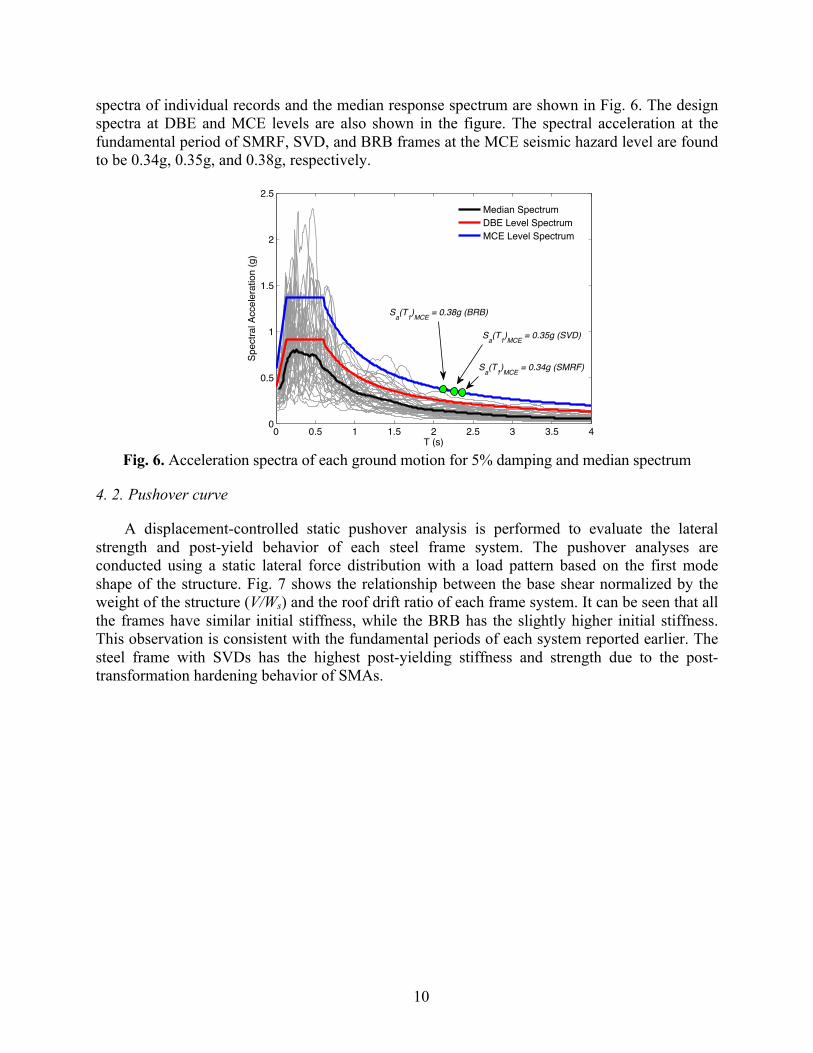
spectra of individual records and the median response spectrum are shown in Fig. 6. The design spectra at DBE and MCE levels are also shown in the figure. The spectral acceleration at the fundamental period of SMRF, SVD, and BRB frames at the MCE seismic hazard level are found to be 0.34g, 0.35g, and 0.38g, respectively.
Fig. 6. Acceleration spectra of each ground motion for 5% damping and median spectrum
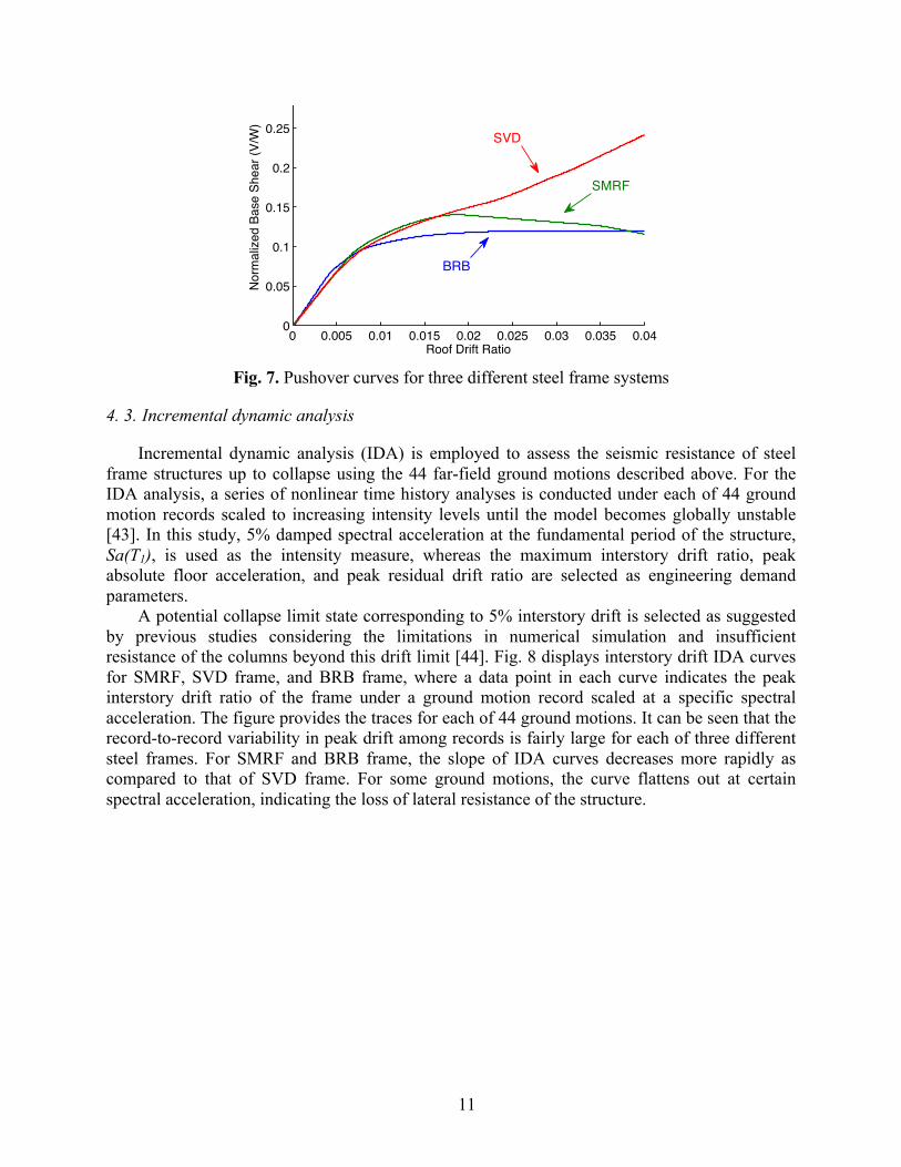
4. 2. Pushover curve
A displacement-controlled static pushover analysis is performed to evaluate the lateral strength and post-yield behavior of each steel frame system. The pushover analyses are conducted using a static lateral force distribution with a load pattern based on the first mode shape of the structure. Fig. 7 shows the relationship between the base shear normalized by the weight of the structure (V/Ws) and the roof drift ratio of each frame system. It can be seen that all the frames have similar initial stiffness, while the BRB has the slightly higher initial stiffness. This observation is consistent with the fundamental periods of each system reported earlier. The steel frame with SVDs has the highest post-yielding stiffness and strength due to the post-transformation hardening behavior of SMAs.
0 0.5 1 1.5 2 2.5 3 3.5 40
0.5
1
1.5
2
2.5
T (s)
Spec
tral A
ccel
erat
ion
(g)
Median SpectrumDBE Level SpectrumMCE Level Spectrum
Sa(T1)MCE = 0.35g (SVD)
Sa(T1)MCE = 0.38g (BRB)
Sa(T1)MCE = 0.34g (SMRF)
11
Fig. 7. Pushover curves for three different steel frame systems
4. 3. Incremental dynamic analysis
Incremental dynamic analysis (IDA) is employed to assess the seismic resistance of steel frame structures up to collapse using the 44 far-field ground motions described above. For the IDA analysis, a series of nonlinear time history analyses is conducted under each of 44 ground motion records scaled to increasing intensity levels until the model becomes globally unstable [43]. In this study, 5% damped spectral acceleration at the fundamental period of the structure, Sa(T1), is used as the intensity measure, whereas the maximum interstory drift ratio, peak absolute floor acceleration, and peak residual drift ratio are selected as engineering demand parameters.
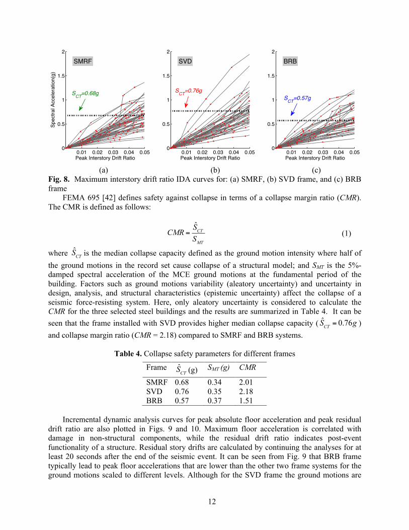
A potential collapse limit state corresponding to 5% interstory drift is selected as suggested by previous studies considering the limitations in numerical simulation and insufficient resistance of the columns beyond this drift limit [44]. Fig. 8 displays interstory drift IDA curves for SMRF, SVD frame, and BRB frame, where a data point in each curve indicates the peak interstory drift ratio of the frame under a ground motion record scaled at a specific spectral acceleration. The figure provides the traces for each of 44 ground motions. It can be seen that the record-to-record variability in peak drift among records is fairly large for each of three different steel frames. For SMRF and BRB frame, the slope of IDA curves decreases more rapidly as compared to that of SVD frame. For some ground motions, the curve flattens out at certain spectral acceleration, indicating the loss of lateral resistance of the structure.
0 0.005 0.01 0.015 0.02 0.025 0.03 0.035 0.040
0.05
0.1
0.15
0.2
0.25
Roof Drift Ratio
Nor
mal
ized
Bas
e Sh
ear (
V/W
)
SMRF
BRB
SVD
12
(a) (b) (c)
Fig. 8. Maximum interstory drift ratio IDA curves for: (a) SMRF, (b) SVD frame, and (c) BRB frame
FEMA 695 [42] defines safety against collapse in terms of a collapse margin ratio (CMR). The CMR is defined as follows:
CMR =SCTSMT
(1)
where is the median collapse capacity defined as the ground motion intensity where half of the ground motions in the record set cause collapse of a structural model; and SMT is the 5%-damped spectral acceleration of the MCE ground motions at the fundamental period of the building. Factors such as ground motions variability (aleatory uncertainty) and uncertainty in design, analysis, and structural characteristics (epistemic uncertainty) affect the collapse of a seismic force-resisting system. Here, only aleatory uncertainty is considered to calculate the CMR for the three selected steel buildings and the results are summarized in Table 4. It can be seen that the frame installed with SVD provides higher median collapse capacity ( SCT = 0.76g ) and collapse margin ratio (CMR = 2.18) compared to SMRF and BRB systems.
Table 4. Collapse safety parameters for different frames
Frame (g) SMT (g) CMR
SMRF 0.68 0.34 2.01 SVD 0.76 0.35 2.18 BRB 0.57 0.37 1.51
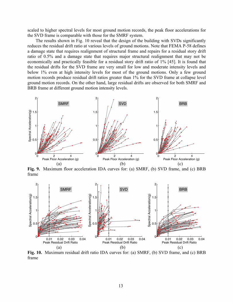
Incremental dynamic analysis curves for peak absolute floor acceleration and peak residual
drift ratio are also plotted in Figs. 9 and 10. Maximum floor acceleration is correlated with damage in non-structural components, while the residual drift ratio indicates post-event functionality of a structure. Residual story drifts are calculated by continuing the analyses for at least 20 seconds after the end of the seismic event. It can be seen from Fig. 9 that BRB frame typically lead to peak floor accelerations that are lower than the other two frame systems for the ground motions scaled to different levels. Although for the SVD frame the ground motions are
0.01 0.02 0.03 0.04 0.050
0.5
1
1.5
2
Peak Interstory Drift Ratio
Spec
tral A
ccel
erat
ion(
g)SMRFSMRFSMRFSMRFSMRFSMRFSMRFSMRFSMRFSMRFSMRFSMRFSMRFSMRFSMRFSMRFSMRFSMRFSMRFSMRFSMRFSMRFSMRFSMRFSMRFSMRFSMRFSMRFSMRFSMRFSMRFSMRFSMRFSMRFSMRFSMRFSMRFSMRFSMRFSMRFSMRFSMRFSMRFSMRF
0.01 0.02 0.03 0.04 0.050
0.5
1
1.5
2
Peak Interstory Drift Ratio
SVDSVDSVDSVDSVDSVDSVDSVDSVDSVDSVDSVDSVDSVDSVDSVDSVDSVDSVDSVDSVDSVDSVDSVDSVDSVDSVDSVDSVDSVDSVDSVDSVDSVDSVDSVDSVDSVDSVDSVDSVDSVDSVDSVD
0.01 0.02 0.03 0.04 0.050
0.5
1
1.5
2
Peak Interstory Drift Ratio
BRBBRBBRBBRBBRBBRBBRBBRBBRBBRBBRBBRBBRBBRBBRBBRBBRBBRBBRBBRBBRBBRBBRBBRBBRBBRBBRBBRBBRBBRBBRBBRBBRBBRBBRBBRBBRBBRBBRBBRBBRBBRBBRBBRB
SCT=0.76gSCT=0.57g
SCT=0.68g
SCT
SCT
13
scaled to higher spectral levels for most ground motion records, the peak floor accelerations for the SVD frame is comparable with those for the SMRF system.
The results shown in Fig. 10 reveal that the design of the building with SVDs significantly reduces the residual drift ratio at various levels of ground motions. Note that FEMA P-58 defines a damage state that requires realignment of structural frame and repairs for a residual story drift ratio of 0.5% and a damage state that requires major structural realignment that may not be economically and practically feasible for a residual story drift ratio of 1% [45]. It is found that the residual drifts for the SVD frame are very small for low and moderate intensity levels and below 1% even at high intensity levels for most of the ground motions. Only a few ground motion records produce residual drift ratios greater than 1% for the SVD frame at collapse level ground motion records. On the other hand, large residual drifts are observed for both SMRF and BRB frame at different ground motion intensity levels.
(a) (b) (c)
Fig. 9. Maximum floor acceleration IDA curves for: (a) SMRF, (b) SVD frame, and (c) BRB frame
(a) (b) (c)
Fig. 10. Maximum residual drift ratio IDA curves for: (a) SMRF, (b) SVD frame, and (c) BRB frame
0 2 40
0.5
1
1.5
2
Peak Floor Acceleration (g)
Spec
tral A
ccel
erat
ion(
g)
SMRFSMRFSMRFSMRFSMRFSMRFSMRFSMRFSMRFSMRFSMRFSMRFSMRFSMRFSMRFSMRFSMRFSMRFSMRFSMRFSMRFSMRFSMRFSMRFSMRFSMRFSMRFSMRFSMRFSMRFSMRFSMRFSMRFSMRFSMRFSMRFSMRFSMRFSMRFSMRFSMRFSMRFSMRFSMRF
0 2 40
0.5
1
1.5
2
Peak Floor Acceleration (g)
SVDSVDSVDSVDSVDSVDSVDSVDSVDSVDSVDSVDSVDSVDSVDSVDSVDSVDSVDSVDSVDSVDSVDSVDSVDSVDSVDSVDSVDSVDSVDSVDSVDSVDSVDSVDSVDSVDSVDSVDSVDSVDSVDSVD
0 2 40
0.5
1
1.5
2
Peak Floor Acceleration (g)
BRBBRBBRBBRBBRBBRBBRBBRBBRBBRBBRBBRBBRBBRBBRBBRBBRBBRBBRBBRBBRBBRBBRBBRBBRBBRBBRBBRBBRBBRBBRBBRBBRBBRBBRBBRBBRBBRBBRBBRBBRBBRBBRBBRB
0.01 0.02 0.03 0.040
0.5
1
1.5
2
Peak Residual Drift Ratio
Spec
tral A
ccel
erat
ion(
g)
SMRFSMRFSMRFSMRFSMRFSMRFSMRFSMRFSMRFSMRFSMRFSMRFSMRFSMRFSMRFSMRFSMRFSMRFSMRFSMRFSMRFSMRFSMRFSMRFSMRFSMRFSMRFSMRFSMRFSMRFSMRFSMRFSMRFSMRFSMRFSMRFSMRFSMRFSMRFSMRFSMRFSMRFSMRFSMRF
0.01 0.02 0.03 0.040
0.5
1
1.5
2
Peak Residual Drift Ratio
Spec
tral A
ccel
erat
ion(
g)
SVDSVDSVDSVDSVDSVDSVDSVDSVDSVDSVDSVDSVDSVDSVDSVDSVDSVDSVDSVDSVDSVDSVDSVDSVDSVDSVDSVDSVDSVDSVDSVDSVDSVDSVDSVDSVDSVDSVDSVDSVDSVDSVDSVD
0.01 0.02 0.03 0.040
0.5
1
1.5
2
Peak Residual Drift Ratio
Spec
tral A
ccel
erat
ion(
g)
BRBBRBBRBBRBBRBBRBBRBBRBBRBBRBBRBBRBBRBBRBBRBBRBBRBBRBBRBBRBBRBBRBBRBBRBBRBBRBBRBBRBBRBBRBBRBBRBBRBBRBBRBBRBBRBBRBBRBBRBBRBBRBBRBBRB
14
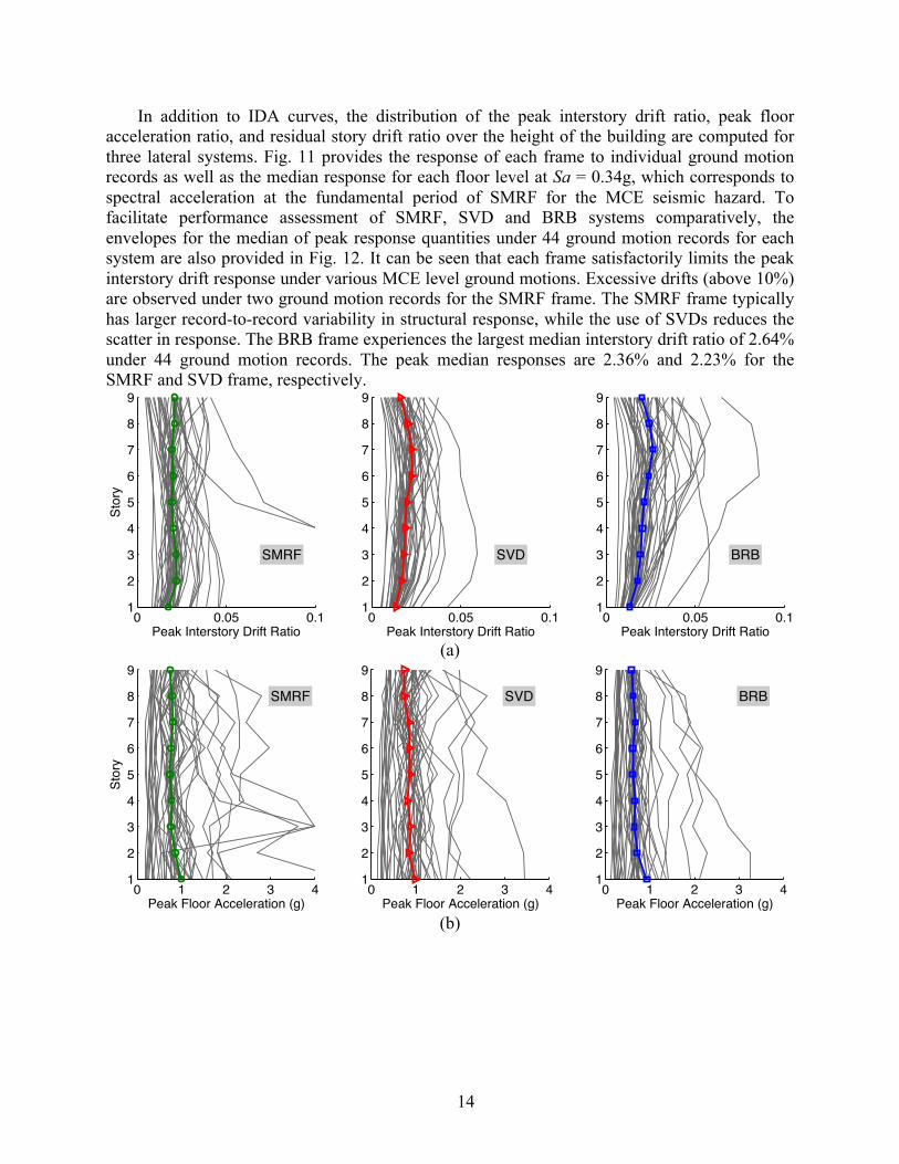
In addition to IDA curves, the distribution of the peak interstory drift ratio, peak floor acceleration ratio, and residual story drift ratio over the height of the building are computed for three lateral systems. Fig. 11 provides the response of each frame to individual ground motion records as well as the median response for each floor level at Sa = 0.34g, which corresponds to spectral acceleration at the fundamental period of SMRF for the MCE seismic hazard. To facilitate performance assessment of SMRF, SVD and BRB systems comparatively, the envelopes for the median of peak response quantities under 44 ground motion records for each system are also provided in Fig. 12. It can be seen that each frame satisfactorily limits the peak interstory drift response under various MCE level ground motions. Excessive drifts (above 10%) are observed under two ground motion records for the SMRF frame. The SMRF frame typically has larger record-to-record variability in structural response, while the use of SVDs reduces the scatter in response. The BRB frame experiences the largest median interstory drift ratio of 2.64% under 44 ground motion records. The peak median responses are 2.36% and 2.23% for the SMRF and SVD frame, respectively.
(a)
(b)
0 0.05 0.11
2
3
4
5
6
7
8
9
Peak Interstory Drift Ratio
Stor
y
SMRF
0 0.05 0.11
2
3
4
5
6
7
8
9
Peak Interstory Drift Ratio
SVD
0 0.05 0.11
2
3
4
5
6
7
8
9
Peak Interstory Drift Ratio
BRB
0 1 2 3 41
2
3
4
5
6
7
8
9
Peak Floor Acceleration (g)
Stor
y
SMRF
0 1 2 3 41
2
3
4
5
6
7
8
9
Peak Floor Acceleration (g)
SVD
0 1 2 3 41
2
3
4
5
6
7
8
9
Peak Floor Acceleration (g)
BRB
15
(c)
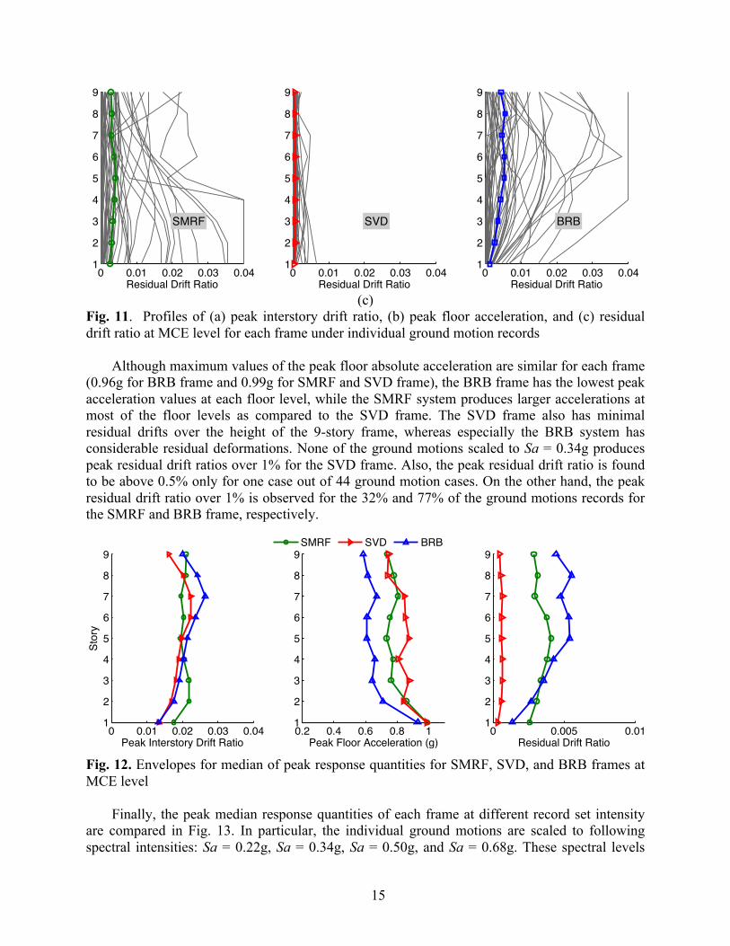
Fig. 11. Profiles of (a) peak interstory drift ratio, (b) peak floor acceleration, and (c) residual drift ratio at MCE level for each frame under individual ground motion records
Although maximum values of the peak floor absolute acceleration are similar for each frame
(0.96g for BRB frame and 0.99g for SMRF and SVD frame), the BRB frame has the lowest peak acceleration values at each floor level, while the SMRF system produces larger accelerations at most of the floor levels as compared to the SVD frame. The SVD frame also has minimal residual drifts over the height of the 9-story frame, whereas especially the BRB system has considerable residual deformations. None of the ground motions scaled to Sa = 0.34g produces peak residual drift ratios over 1% for the SVD frame. Also, the peak residual drift ratio is found to be above 0.5% only for one case out of 44 ground motion cases. On the other hand, the peak residual drift ratio over 1% is observed for the 32% and 77% of the ground motions records for the SMRF and BRB frame, respectively.
Fig. 12. Envelopes for median of peak response quantities for SMRF, SVD, and BRB frames at MCE level
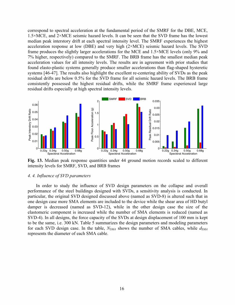
Finally, the peak median response quantities of each frame at different record set intensity
are compared in Fig. 13. In particular, the individual ground motions are scaled to following spectral intensities: Sa = 0.22g, Sa = 0.34g, Sa = 0.50g, and Sa = 0.68g. These spectral levels
0 0.01 0.02 0.03 0.041
2
3
4
5
6
7
8
9
SMRF
Residual Drift Ratio0 0.01 0.02 0.03 0.04
1
2
3
4
5
6
7
8
9
Residual Drift Ratio
SVD
0 0.01 0.02 0.03 0.041
2
3
4
5
6
7
8
9
BRB
Residual Drift Ratio
0 0.01 0.02 0.03 0.041
2
3
4
5
6
7
8
9
Peak Interstory Drift Ratio
Stor
y
SMRF SVD BRB
0.2 0.4 0.6 0.8 11
2
3
4
5
6
7
8
9
Peak Floor Acceleration (g)0 0.005 0.01
1
2
3
4
5
6
7
8
9
Residual Drift Ratio
16
correspond to spectral acceleration at the fundamental period of the SMRF for the DBE, MCE, 1.5×MCE, and 2×MCE seismic hazard levels. It can be seen that the SVD frame has the lowest median peak interstory drift at each spectral intensity level. The SMRF experiences the highest acceleration response at low (DBE) and very high (2×MCE) seismic hazard levels. The SVD frame produces the slightly larger accelerations for the MCE and 1.5×MCE levels (only 9% and 7% higher, respectively) compared to the SMRF. The BRB frame has the smallest median peak acceleration values for all intensity levels. The results are in agreement with prior studies that found elasto-plastic systems generally produce smaller accelerations than flag-shaped hysteretic systems [46-47]. The results also highlight the excellent re-centering ability of SVDs as the peak residual drifts are below 0.5% for the SVD frame for all seismic hazard levels. The BRB frame consistently possessed the highest residual drifts, while the SMRF frame experienced large residual drifts especially at high spectral intensity levels.
Fig. 13. Median peak response quantities under 44 ground motion records scaled to different intensity levels for SMRF, SVD, and BRB frames
4. 4. Influence of SVD parameters
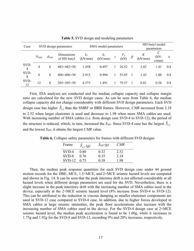
In order to study the influence of SVD design parameters on the collapse and overall performance of the steel buildings designed with SVDs, a sensitivity analysis is conducted. In particular, the original SVD designed discussed above (named as SVD-8) is altered such that in one design case more SMA elements are included to the device while the shear area of HD butyl damper is decreased (named as SVD-12), while in the other design case the size of the elastomeric component is increased while the number of SMA elements is reduced (named as SVD-4). In all designs, the force capacity of the SVDs at design displacement of 100 mm is kept to be the same, i.e. 300 kN. Table 5 summarizes the design parameters and modeling parameters for each SVD design case. In the table, NSMA shows the number of SMA cables, while dSMA represents the diameter of each SMA cable.
0.22g 0.34g 0.50g 0.68g0
0.01
0.02
0.03
0.04
0.05
0.06
Specteral Acceleration
Peak
Inte
rsto
ry D
rift R
atio
0.22g 0.34g 0.50g 0.68g0
0.005
0.01
0.015
0.02
0.025
0.03
0.035
Specteral AccelerationPe
ak R
esid
ual D
rift R
atio
SMRF SVD BRB
0.22g 0.34g 0.50g 0.68g0
0.5
1
1.5
2
Specteral Acceleration
Peak
Flo
or A
ccel
erat
ion
(g)
17
Table 5. SVD design and modeling parameters
Case SVD design parameters SMA model parameters HD butyl model parameters
NSMA dSMA Dimensions of HD butyl
k1
(kN/mm) k2
(kN/mm) γ Fa (kN) b K
(kN/mm)
C (kN-
s/mm) α
SVD-4 4 8 482×482×50 1.458 0.497 1 26.52 1 2.02 1.41 0.8
SVD-8 8 8 406×406×50 2.915 0.994 1 53.05 1 1.43 1.00 0.8
SVD-12 12 8 305×305×50 4.373 1.491 1 79.57 1 0.81 0.56 0.8
First, IDA analyses are conducted and the median collapse capacity and collapse margin
ratio are calculated for the new SVD design cases. As can be seen from Table 6, the median collapse capacity did not change considerably with different SVD design parameters. Each SVD design case has higher than the SMRF or BRB frames. However, CMR increased from 2.18 to 2.52 when larger elastomer is used and decrease to 1.98 when more SMA cables are used. With increasing number of SMA cables (i.e. from design case SVD-4 to SVD-12), the period of the structure is reduced, which, in turn, increased the SMT. Since SVD-4 case has the largest and the lowest SMT, it attains the largest CMR value.
Table 6. Collapse safety parameters for frames with different SVD designs
Frame (g) SMT (g) CMR
SVD-4 0.80 0.32 2.52 SVD-8 0.76 0.35 2.18 SVD-12 0.75 0.38 1.98
Then, the median peak response quantities for each SVD design case under 44 ground
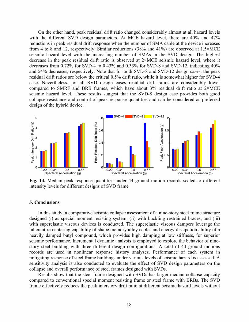
motion records for the DBE, MCE, 1.5×MCE, and 2×MCE seismic hazard levels are computed and shown in Fig. 14. It can be seen that the peak interstoy drift is not affected considerably at all hazard levels when different design parameters are used for the SVD. Nevertheless, there is a slight increase in the peak interstory drift with the increasing number of SMA cables used in the device, especially at the 2×MCE seismic hazard level (8% increase from SVD-4 to SVD-12). This can be attributed to the reduction in viscous damping as smaller elastomer components are used in SVD-12 case compared to SVD-4 case. In addition, due to higher forces developed in SMA cables at large seismic intensities, the peak floor accelerations also increase with the increasing number of SMA cables used in the device. For the SVD-4 design case at 2×MCE seismic hazard level, the median peak acceleration is found to be 1.60g, while it increases to 1.75g and 1.92g for the SVD-8 and SVD-12, recording 9% and 20% increases, respectively.
SCT
SCT
SCT
18
On the other hand, peak residual drift ratio changed considerably almost at all hazard levels with the different SVD design parameters. At MCE hazard level, there are 40% and 47% reductions in peak residual drift response when the number of SMA cable at the device increases from 4 to 8 and 12, respectively. Similar reductions (38% and 41%) are observed at 1.5×MCE seismic hazard level with the increasing number of SMAs in the SVD design. The highest decrease in the peak residual drift ratio is observed at 2×MCE seismic hazard level, where it decreases from 0.72% for SVD-4 to 0.43% and 0.33% for SVD-8 and SVD-12, indicating 40% and 54% decreases, respectively. Note that for both SVD-8 and SVD-12 design cases, the peak residual drift ratios are below the critical 0.5% drift ratio, while it is somewhat higher for SVD-4 case. Nevertheless, for all SVD design cases residual drift ratios are considerably lower compared to SMRF and BRB frames, which have about 3% residual drift ratio at 2×MCE seismic hazard level. These results suggest that the SVD-8 design case provides both good collapse resistance and control of peak response quantities and can be considered as preferred design of the hybrid device.
Fig. 14. Median peak response quantities under 44 ground motion records scaled to different intensity levels for different designs of SVD frame
5. Conclusions
In this study, a comparative seismic collapse assessment of a nine-story steel frame structure designed (i) as special moment resisting system, (ii) with buckling restrained braces, and (iii) with superelastic viscous devices is conducted. The superelastic viscous dampers leverage the inherent re-centering capability of shape memory alloy cables and energy dissipation ability of a heavily damped butyl compound, which provides high damping at low stiffness, for superior seismic performance. Incremental dynamic analysis is employed to explore the behavior of nine-story steel building with three different design configurations. A total of 44 ground motions records are used in nonlinear response history analyses. Performance of each system in mitigating response of steel frame buildings under various levels of seismic hazard is assessed. A sensitivity analysis is also conducted to evaluate the effect of SVD design parameters on the collapse and overall performance of steel frames designed with SVDs.
Results show that the steel frame designed with SVDs has larger median collapse capacity compared to conventional special moment resisting frame or steel frame with BRBs. The SVD frame effectively reduces the peak interstory drift ratio at different seismic hazard levels without
0.22 0.34 0.5 0.670
1
2
3
4
5
Specteral Acceleration (g)
Peak
Inte
rsto
ry D
rift R
atio
(%)
0.22 0.34 0.5 0.670
0.2
0.4
0.6
0.8
Specteral Acceleration (g)
Peak
Res
idua
l Drif
t Rat
io (%
)
SVD−4 SVD−8 SVD−12
0.22 0.34 0.5 0.670
0.5
1
1.5
2
Specteral Acceleration (g)
Peak
Flo
or A
ccel
erat
ion
(g)
19
a considerable increase in the acceleration response. The SVD frame also produces minimal residual drifts even at very high seismic hazard levels. The significantly lower residual drifts observed in the SVD frame indicates that the repair costs of the steel frame buildings with SVD will be less than that of the conventional SMRF and steel frames with BRBs after a seismic event. The results of sensitivity analysis indicate that using larger viscoelastic component but fewer SMA cables in the design of SVD device improves the collapse resistance. However, it considerably increases peak residual drifts at different seismic hazard levels. Using a more balanced ratio between SMA and viscoelastic components in the SVD design can provide a satisfactory seismic performance. Overall, the results show the potential of SVDs as a passive seismic control device in improving collapse resistance of steel frame buildings and eliminating the damage under various seismic hazard levels.
20
References
[1] ANSI/AISC 341-10. Seismic Provisions for Structural Steel Buildings. American Institute of Steel Construction (AISC): Chicago, Illinois, 2010.
[2] Uma SM, Pampanin S, Christopoulos C. Development of probabilistic framework for performance-based seismic assessment of structures considering residual deformations. J Earthq Eng 2010; 14(7): 1092–1111.
[3] Bojórquez E, Ruiz-García J. Residual drift demands in moment-resisting steel frames subjected to narrow-band earthquake ground motions. Earthq Eng Struct Dyn. 2013; 42(11): 1583-98.
[4] McCormick J, Aburano H, Ikenaga M, Nakashima M. Permissible residual deformation levels for building structures considering both safety and human elements. Proc. 14th World Conf. Earthquake Engineering Seismological Press of China, Beijing, Paper ID 05-06-0071, 2008.
[5] Erochko J, Christopoulos C, Tremblay R, Choi H. Residual drift response of SMRFs and BRB frames in steel buildings designed according to ASCE 7-05. J Struct Eng 2011; 137: 589–99.
[6] Ramirez CM, Miranda E. Significance of residual drifts in building earthquake loss estimation. Earthq Eng Struct Dyn. 2012 Sep 1; 41(11): 1477-93.
[7] El-Sheikh M, Sause R, Pessiki S, Lu L. Seismic behavior and design of unbonded post-tensioned precast concrete frames. PCI J 1999; 44(3): 54–71.
[8] Ricles JM, Sause R, Garlock MM, Zhao C. Posttensioned seismic-resistant connections for steel frames. J Struct Eng 2001; 127(2): 113–21.
[9] Christopoulos C, Filiatrault A, Uang CM, Folz B. Posttensioned energy dissipating connections for moment-resisting steel frames. J Struct Eng 2002; 128(9): 1111–20.
[10] Perez FJ, Sause R, Pessiki S. Analytical and experimental lateral load behavior of unbonded posttensioned precast concrete walls. J Struct Eng 2007; 133(11): 1531–40.
[11] Eatherton M, Hajjar J, Deierlein G, Ma X, Krawinkler H. Hybrid simulation testing of a controlled rocking steel braced frame system. In: Proceedings, 9th US national and 10th Canadian conference on earthquake engineering. Toronto, Ontario, Canada; 2010.
[12] Christopoulos C, Tremblay R, Kim HJ, Lacerte M. Self-centering energy dissipative bracing system for the seismic resistance of structures: development and validation. J Struct Eng 2008; 134(1): 96–107.
[13] Chancellor NB, Eatherton MR, Roke DA, Akbaş T. Self-centering seismic lateral force resisting systems: High performance structures for the city of tomorrow. Buildings. 2014 Sep 18; 4(3): 520-48.
[14] Ozbulut OE, Hurlebaus S, DesRoches R. Seismic response control using shape memory alloys: A Review. J Intell Mater Syst Struct 2011; 22: 1531-1549
[15] Qian H, Li H, Song G, Guo W. Recentering Shape Memory Alloy Passive Damper for Structural Vibration Control. Math Probl Eng, 2013.
[16] Araki, Y, Endo T, Omori T, Sutou Y, Koetaka Y, Kainuma R, Ishida K 2011. Potential of superelastic Cu–Al–Mn alloy bars for seismic applications. Earthq Eng Struct Dyn 2011; 40(1): 107-115.
[17] Araki Y, Maekawa N, Shrestha KC, Yamakawa M, Koetaka Y, Omori T, Kainuma R. Feasibility of tension braces using Cu–Al–Mn superelastic alloy bars. Struct Control Health Monit. 2014 Oct 1; 21(10): 1304-15.
21
[18] Ozbulut OE, Mir C, Moroni MO, Sarrazin M, Roschke PN. A fuzzy model of superelastic shape memory alloys for vibration control in civil engineering applications. Smart Mater Struct. 2007 May 4; 16(3): 818.
[19] Parulekar YM, Reddy GR, Vaze KK, Guha S, Gupta C, Muthumani K, Sreekala R. Seismic response attenuation of structures using shape memory alloy dampers. Struct Control Health Monit. 2012 Feb 1; 19(1): 102-19.
[20] Motahari SA, Ghassemieh M, Abolmaali SA. Implementation of shape memory alloy dampers for passive control of structures subjected to seismic excitations. J Constr Steel Res. 2007 Dec 31; 63(12): 1570-9.
[21] Desroches R, McCormick J, Delemont MA. Cyclic properties of superelastic shape memory alloy wires and bars, J Struct Eng 2004; 130(1): 38–46.
[22] Ozbulut OE, Hurlebaus S. Neuro-fuzzy modeling of temperature-and strain-rate-dependent behavior of NiTi shape memory alloys for seismic applications. J Intell Mater Syst Struct 2010 May 1; 21(8): 837-49.
[23] Zhu S, Zhang Y. Seismic behaviour of self-centering braced frame buildings with reusable hysteretic damping brace. Earthq Eng Struct Dyn 2007; 36: 1329-46.
[24] Shook DA, Roschke PN, Ozbulut OE. Superelastic semi-active damping of a base-isolated structure. Struct Control Health Monit 2008 Aug 1; 15(5): 746-68.
[25] Yang CSW, DesRoches R, Leon RT. Design and analysis of braced frames with shape memory alloy and energy-absorbing hybrid devices. Eng Struct 2010; 32: 408–507.
[26] Ozbulut OE, Hurlebaus S. Re-centering variable friction device for vibration control of structures subjected to near-field earthquakes. Mech Syst Signal Process 2011; 25:2849-2862.
[27] Silwal B, Michael RJ, Osman OE. A superelastic viscous damper for enhanced seismic performance of steel moment frames. Eng Struct 2015; 105: 152-164.
[28] Ozbulut, O.E., Daghash, S. and Sherif, M.M., 2015. Shape Memory Alloy Cables for Structural Applications. J Mater Civ Eng, p.04015176.
[29] Del Vecchio RJ, Fundamentals of Rubber Technology, Rubber Division, American Chemical Society, 2003.
[30] Alan A. Gent, Engineering with Rubber, Hanser Publishing, Oxford University Press, NY, 1992.
[31] Michael RJ, Courtwright JA, Ferro EB, Filiatrault A, Higgins PS, Wanitkorkul A. Development of a New Base Isolation System for Seismic Isolation of Steel Pallet Storage Racks, Proceedings, 9th US National and 10th Canadian Conference on Earthquake Engineering (9USN10CEE), 10 pp, Toronto, Ontario, Canada, July 26, 2010.
[32] State of the art report on systems performance of steel moment frames subject to earthquake ground shaking. SAC Joint Venture, 2000.
[33] OpenSees. The Open System for Earthquake Engineering Simulation. http://opensees.berkeley.edu Pacific Earthquake Engineering Research Center (PEER); 2014.
[34] Ibarra LF, Medina RA, Krawinkler H. Hysteretic models that incorporate strength and stiffness deterioration. Int J Earthq Eng Struct Dyn 2005; 34(12): 1489-1511.
[35] Lignos DG, Krawinkler H. A Database in Support of Modeling of Component Deterioration for Collapse Prediction of Steel Frame Structures. Proc. ASCE Structures Congress, Long Beach, California, May 18-20; 2007.
22
[36] Gupta A, Krawinkler H. Seismic Demands for Performance Evaluation of Steel Moment Resisting Frame Structures. Technical Report 132, The John A. Blume Earthquake Engineering Research Center, Department of Civil Engineering, Stanford University, Stanford, CA, 1999.
[37] ASCE. Minimum Design Loads for Buildings and Other Structures. ASCE 7-10, American Society of Civil Engineers, Reston, Virginia 2010.
[38] PEER NGA database. The Pacific Earthquake Engineering Research Center. http://ngawest2.berkeley.edu Pacific Earthquake Engineering Research Center (PEER); 2014.
[39] AISC Committee. Specification for Structural Steel Buildings (ANSI/AISC 360-10). American Institute of Steel Construction, Chicago-Illinois (2010).
[40] Oxborrow G. Optimized Distribution of Strength in Buckling-Restrained Braced Frames in Tall Buildings. MS Thesis, Provo, UT: Brigham Young University, 2009.
[41] Coy BB. Buckling-restrained brace connection design and testing. Master's Thesis. Provo, UT: Brigham Young University, 2007.
[42] Federal Emergency Management Agency (FEMA). FEMA P695. Quantification of Building Seismic Performance Factors. (2009).
[43] Vamvatsikos D, Cornell CA. Incremental dynamic analysis. Earthq Eng Struct Dyn 2002; 31(3): 491-514.
[44] Hsiao PC, Lehman DE, Roeder CW. Evaluation of the response modification coefficient and collapse potential of special concentrically braced frames. Earthq Eng Struct Dyn 2013; 42(10): 1547-1564.
[45] FEMA P-58. Seismic Performance Assessment of Buildings. Federal Emergency Management Agency, 2012. �
[46] Gavridou S, Melek M, Wallace JW. Conventional and unbonded post-tensioned lateral force resisting systems–a comparative assessment of expected performance and losses. Proc. 10th National Conf. in Earthquake Eng. 2014.
[47] Christopoulos C, Filiatrault A. Seismic response of self-centering hysteretic SDOF systems. Earthq Eng Struct Dyn 2002; 31: 1131-1150. �