section e engine - rroc · on chassis nos. b-297-cd, b-347-cd and all subsequent cars no ... ensine...
TRANSCRIPT
h L , 3 D i L B E N T L E Y M A R K V1
ENGINE OIL FILLER CAP WASER.
Owing t o the repor ted l o s s of o i l f i l l e r cap v~ashers iq se rv ice , i t is considered advisable t h a t t h i s washer be permanently f ixed in i t s recess .
This modification is now being incorporated on all c a r s p r i o r t o del ivery , bu t a c e r t a i n number of ca r s were delivered before t h e a l t e r a t i o n took place aid i t i s necessary t h a t these ca r s should receive a t t en t ion .
The process consis ts of s t i ck ing the rubber washer i n t o the cap us ing P ~ s t i k No.772, care being taken t h a t surfaces are clean and f r e s from o i l before a a e s i v e i s applied.
It i s a simple matter to v e r i f y whether any p a r t i c u l a r car hrs been modified, a s a washer which has not been s tuck dovm i s e a s i l y removaSle from i ts cap, and % t a i l e r s should take the necessary ac t ion when c a r s come in f o r ser : i c i rg .
W i l l all Reta i l e r s kindly inform t h i s Service Depot Concexmizg ca r s on which they carry out t h i s a l t e r a t i o n .

r. . I . E r \ T ~ E Y h a i t
FQR INFORWLTIOK. CBNCZIS I3BkJ dated 4.1 ,Yc.
RGPLACXENT OF TAPPETS.
T h i s Bulletin supercedes Bulletin B&3 dated 4.1.54. which should be destroyed*
It has been found tha t a greater running clearance i s desirable with the two windaw type tappet now being supplied f o r replacement purposes. This tappet, having two windows l e s s than t h t ea r l i e r type, i s more r ig id , has a greater bearing s u f a c e and i s s l igh t ly heavier, a l l fac tors which may cause the tappet temporarily t o s t i ck i n the bore when the lubricating o i l i s cold.
F i t t i ng i n accordance with previous instructions may lead t o t h i s wert ightness which i s evidenced by considerable valve gear noise when l i gh t ly r e w i n g a cold engine, The noise i s not unlike tha t of slack pistons, It w i l l occur only when tappets have recently been replaced i n service and should not be confused with tappet noise due t o wear a f t e r considerable mileage.
Briefly, the new instruct ion is t o f i t t a p y t s one s ize amaller than i s found by ' f e e l f i t ' a s previously recanmended, The fill procedure i s detailed i n the following paragraphs,
2. 'COLOUR CODING OF TkP7ETS.
A range of tappets is available allowing selective f i t t i n g i n steps of ,00025" on the diameter as s e t out below. The tappets are colour coded a s indicated and do not bear separate par t numbers. Replacement orders should be by colour only. Both i n l e t and exhaust tappets are coloured similarly.
Tappet Diameter Colour
1.18675 t o 1.1870 Blue 1.1870 t o 1.18725 Green 1.18725 t o 1.1875 X O ~ ~ O W 1.1875 to1.18775 . Black 1.18775 t o 1.1880 Black and Yellcm 1.1880 t o 1.18825 . Green and Yellow
Retai lers are advised tha t a s e t of six of these l a t e s t type tappets should be held f o r gauging purposes. Any of the ea r l i e r four window type now held i n stock should be used up on repairs and not held as gauges i n order t o avoid confusion when re-ordering due t o previous colour code changes,
3 T-T SELECTION ANI) FITTING.
Tappets a n selectively f i t t e d and should be a close clearance f i t i n t h e i r bores. k master s e t of six should be used f o r gauging purposes.
(i ) Carefully wipe clean the tappet bore. Select a tappet f ran the se t of gauges that w i l l just s l i de down the bore without lubricant with the f inger pressing l igh t ly on the top.
( i i ) Select a new t a p ~ e t from stock tha t i s one size l e s s than the gauge tappet c Tkus if a 'yellcw' gauge tappet i s found t o give the r e q u r e d f e e l f i t a 'green' tappet should be selected f o r f i t t i n g t o the bore. Repeat fbr a l l the tappet bons.
( i i i ) Wash and wipe clean the new tappets without remwing the 'Parkerising' from the bottun face, This surface, a s well a s being rustproaf, is of value during mming in. Etch the apprupriate number f r an l t o 6 on the top of each tappet t o correspond with i t s bore, i n l e t or exhaust, canmencing f r an the f ront of the engine,
( i v ) F i t the t a p p t s t o the bores smearing the sides and bo t tm face with Gargoyle grease 234 or Mobilgrease 2 S S These greases have a high f i lm strength and w i l l a s s i s t i n obtaining e good bedding surface during running in. They may be obtained i n s m a l l quanti t ies frcm the manufacturers,
Whenever the cylinder head i s removed f o r decarbonising the tappets should be checked f o r p i t t i ng on the bottan face. P i t t e d tappets should be renewed. Serviceable tap?ets should be replace a i n their ariginal bore S.
J E R V I C E . . - -. -. - - . . -- - - . - . - -- t i c . Bl3-48.
. . . . . . . . . . . . . . . . . . . . . . . . . . . . . . . . . . . . . . . . . . . . . . . .
... . . . . . . . . . . . . . . . . . . . . . . . . . . . . . . . . . . . . . . . . . . . . . . . . . . . .- . .
. . - . . . . .
. . . -- .
CATEGORY 2
STICKIrJG OF THROTTLE CONTROIS.
This mcdification is introduced i n order t o prevent the p o s s i b i l i t y of corpla ints of s t i ck ing t h r o t t l e controls, due t o se izure cf the lower t h r o t t l e countershaft mounted i n the frame. Br ief ly , the ac t ion t o be taken consis ts of increasing the diametrical clearance between t h e countershaft and i t s bearings by reaming the bushes t c .320f' + .002" dia . o r i n the event of a reamer of t h i s s i z e being unobtainable, by reducing the diameter of the s h a f t by approximately .00!tw t o .3Q6" dia. by c a r e f u l l y po l i sh ing with emery cloth.
On chass is nos. B-297-CD, B-347-CD and a l l subsequent cars no ac t ion is required as the bcres of the countershaft bushes a re .320t' + ,002'' diameter, giving the required clearance of .008" t o ,012".
PROCEDURE.
( i ) Remove the R.H. f ront and r e a r undersheets t o ga in access to the cmnte r shaf t .
( i i ) Remove the l eve r from the outermost end of the counter- s h a f t , t ha t is, remove the l e v e r from the end of the countershaft which i s s i t u a t e d ins ide the box sec t ion of the frame. This operation requires some ingenuity owing t o the comparative i n a c c e s s i b i l i t y of t h i s end of the shaft .
( i i i ) Disconnect the control rod from the lever Dn the inner end of the counfershaft , then, t c provide withdrawal clearance fo r tne c x n t e r s h a f t , prcp the clutch pedal in the disengaged pos i t ion with the a i d of a p iece of wood of s u i t a b l e length, and then remove t h e countershaft.
(iv) Ream the bushes t o .320N + .002" dia. It may be necessary t o remove the flywheel lower ccver i n order t~ obta in the necessary working clearance ts ca r ry out the reaming operation.
I f a su i t ab le reamer is not avai lable , the countershaft should be reduced i n diameter by appr~x imate ly .004" t o .306" - .002" d i a . by careful ly pol ishing with emery c l o t h The reduced diameter should be loca l i sed t c the two areas in cm$a:ct with the bushes.
Cont irlued
(4 Re-assemble the countershaft to its bracket a f t e r cleaning and lubricat ing the bushes. Check tha t the shaf t possesses end play, the exact amount is not important as long as some ia present.
h i ) As a means of iden t i f ica t ion t o show that this modification has been carried out, the l e t t e r "R" should be stamped on the chassis frame just beneath the rearmost nut of the countershaft bracket.
W i l l a l l Retai lers p l e r se n o t i e t h i s Service Stat ion of the chassis numbers of cars on which the modification is carried out.

TIGHTENING DOWN !LW& CY13NDlB H U D .
FOR INFtRMATICN :
, Further t o Paragraph 2 of Service Bullet in BB-42, it is not now reaomended that a break back or torque loaded spanner should be used since there is a danger of s t retching the cylinder head holding down studs a t a tension of 280-lbs/ins. on the 5/16" diameter studs. It should be part icular ly noted therefore that the only re l iab le and s a t i s f a c t o ~ y method of tightening down the cylinder heads i s under the control of a sk i l led f i t t e r using a box spanner with a f ixed length of tornnly bar. The recommended t q bar length i s 6", and the nuts should be tightened down evenly working from the centre u n t i l by experienoed 'feel" the nuts are as t i g h t as i s wise having regard t o the e l a s t i c i t y of the studs.
It may also be noted fo r information, that u n t i l recently 5/16" studs with standard 5/16" nuts were used. In order t o improve the t ens i l e properties of the studs, a special heat treatment operation was introduced. It w i l l a l so be found that l a t e r cars h a v e m m 2lated nuts, and a s t h i s has the e f f ec t of reducing the thread f r i c t i on , extra care i s necessary i n tightening down.
Present production cars are now f i t t e d with 3" diameter studs and nuts. These w i l l stand a greater degree of tension i n tightening down.
The ohief points a r i s ing out of these instructions a r e a s f o l l m :-
l. Klingerite gaskets where available, my be used up.
2 . F'uture deliveries of gaskets w i l l be copper asbestos.
3. It is advisable t o use a joint ing oampound along the exhaust s ide of the C & A gaskets.
4. Care must be taken i n tightening down the 5/16" holding down studs. Dc not use an excessive length of touqy bar and tighten dawn uniformly keeping within the e l a s t i o l i m i t or' the stud.
5. Latest engines have 8" diameter nuts and s t u b .
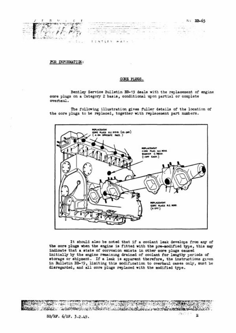
Bentley Service Bullet in BB-19 deals w i t h the replaoement of engine oore plugs on a Categoxy 2 basis , conditional upon p a r t i a l o r complete overhaul.
The following i l l u s t r a t i on gives Puller de ta i l s of t he location of t h e core plugs t o be replaced, together with replacement part numbers.
MMLYOn C CWCI I.L.9OI6. (IQ OW) aw or~orm m.)
M?LAccuWt C W nK LC.WI6. WUWCI t.7as49.
llOWYDn U l c CWGl L C sow.
It should also be noted t ha t i f a coolant leak develops from ary of the oore plug8 when the engine is f i t t e d with the pro-modified type, t h i s m q indioate tha t a e t a t e of corrosion ex is t s in other oore plugs caused i n i t i a l l y by t h e engine remaining drained of coolant f o r length periods of storage or shipment. I f a leak is apparent t hen fo re , the instruct ions glven in Bulletin BB-19, l imiting t h i s modifictat ion t o overhaul caaes only, must be disregarded, and a l l core plugs replaced with the modified type.
When the modification detailed in Bentley Service Bullet in BSI9 is effected, an aluminium allqy crankcase core plug, additional t o t ho;. e i l l u s t r a t ed i n Service Bulletin BB-63, must be replaced bx the modified type.
This core plug is positioned under the ooolant pump mounting adaptor and i n order t o f a c i l i t a t e replacement, the coolant pump and adaptor must be removed.
The replacement core plug i s the type specified f o r the arankcase s ide (RE.9016) and must be f i t t e d w i t h an aluminium washer (~.75549.) The amended list of pa r t s necessary t o incorporate t h i s modification i s a s follows:-
a. 901 6 Core Plug 2 Mf G. 75549 Washer RE. 9018 Core Plug 10 Off RE. 9019 Coreplug
M O D E L B E N T L E Y M A R K V I
FOR ~ R K A T I O N :
ENSINE TUNE-UP.
The recamended operations necessary fo r a tune-up of the engine.
Clean the sparking plugs and r e s e t the gaps t o .025" ( .635 6). 2. IGNITION SY STE&l DISTRIBUTOR:
Remove, clean and r e se t the gaps of the contact breakers of the dis- t r i bu to r as follows : - ( i ) Remwe the rotor arm from the top of the spindle.
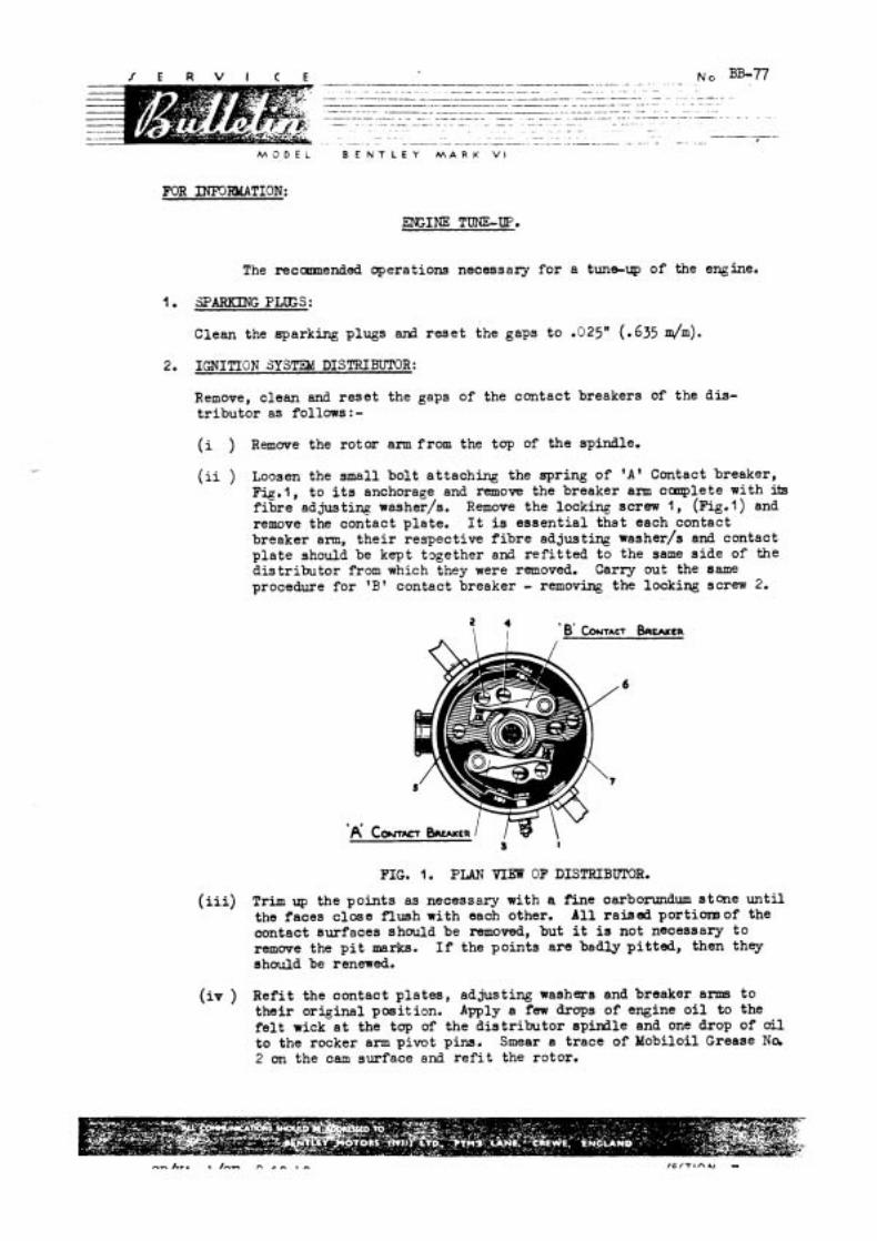
( i i ) Loosen the small bol t at taching the apring of ' A ' Contact breaker, Fi.g.1, t o i ts anchorage and remove the breaker arm c q l e t e with its f i b r e adjusting washer/s. Remove the locking screw l , ( ~ i ~ . l ) and remove the contact plate. It is e s sen t i a l that each contact breaker arm, t h e i r respective f i b r e adjusting washer/s and contact p l a t e should be kept t ~ g e t h e r and r e f i t t e d t o the same s i de of the d i s t r i bu to r from which they were removed. Carry out the same procedure fo r 'B' contact breaker - removing the locking screw 2.
FIG. l. PLAN VIEN OF DISTRIBUMR.
( i i i ) Trim up the po in t s as necessary with a Fine oarbonmdum stone un t i l the faces c lose f lush with each other. A11 ra ised portion3 of the contact surfaces should be removed, but i t is not necessary t o remwe the p i t marks. I f the points a r e bad lyp i t t ed , then they should be renewed.
( i v ) Ref i t the contact p la tes , adjusting washers and breaker anus t o t he i r or iginal posit ion. Apply a few drops of engine o i l to the f e l t wick a t the tap of the d i s t r i bu to r sp i rd le and one drop of o i l t o the rocker arm pivot pins. Smear a trace of Mobiloil Grease Na 2 on the cam surface and r e f i t the rotor.

/ E R V l < E .- .
N c. BB-77 .,.* - -. . . . . . ~ ..- . .
.--.--p------. . - --------.-.p----. . . - - - --
- -----.--p - - .- -- -- . - - - - -- p - --- - -- - .~ - .. . - - - . - -- - - .. -
. . ----- - - . . ---
. .~ . -- - -- . ~ . . - . . . .. - - - - -. . ~. . - --.- - ----p-. - .
M G r i i B E N T L E Y M A R K V i
Note: Should i t be found necessary t o f i t one or two p a i r s of new w q t a c t breakers, c a r e must be taken t o ensure t h a t the contact faces of the points c lose f lush with each other. I t is usual ly found t h a t t h i s is obtained by r e f i t t i n g the o r i g i n a l f i b r e ad- jus t ing washers, but i f t t is does not su f f i ce , an add i t iona l washer R-3975 ( th in ) or R-3977 ( tn ick) can be f i t t e d o r one removed a s found cecessary.
(v ) Turn the engine u n t i l the f i b r e heel of ' A t contact breaker arm i s on a lobe of the cam to give maximum opening, loosen the contact p i e t e lccking screw, 1 , and turn the adjusting screw 3, t o obtain the cor rec t gap between the polnts i.e. . 0 a " (0.508 h), and then r e t i g n t e n the locking screw ( l ) . Check that the s e t t i n g of the gap has not been disturbed by the t ightening of the locking screw. Carry out the same procedure for B' contact breaker a m by loosening the locklng screw 2, and turning the ad jus t ing screw 4.
3. CIEANING TXE CARBURETTORS:
(i ) With the i g n i t i m switched c f f , remove the p e t r o l feed pipe f r a n each of the ca rbure t to r f l o ~ t chamber covers. Take out and clear. the small gauze f l l t e r located i n each of the covers.
(ii ) Remove the f l o a t chamber covers, l i f t out the f l o a t s and wipe out the b o t t m of the f l o a t chambers.
( i i i ) R e f i t the covers, and replace the small f i l t e r s wi th the open end outwards. I f necessary, f i t four new C & A washers ( p a r t No. EB.4580) t o the banjo joints of the p e t r o l feed pipe connections.
( i v ) Remwe the a i r valve assembly from each carburet tor ; f i r s t unscrew the knurled cap Prw the top of each air velve cyl inder and ca re fu l ly remove the pl-anger (at tached t o the cap). Next remove the cyl inder , then l i f t out the p is ton, taking g r e a t care not t o bend or damage i ts needle valve or t o t r ans fe r t h e pistons. Wipe the p is ton, cyl inder and guide with a p iece of clean c l o t h dipped i n pet rol . I f the p i s ton i s f o u d t o be "gummyH, it is penniss ib le t o clean i t with metal po l i sh with the exception of the l a r g e diameter grooved por t ion of the piston. On replacement, r e f i l l the o i l damper reservoir with a v i scos i ty S. A. E. 10 o i l , any of the following may be used:-
P r i c e ' s Wake f i e l d 'S Vacuum She l l Ess olube
Motorine U. C. L Wakefield O i l i t Mobil Handy O i l Donax A. 1 . Esso Shock Absorber Light.
4. F r n STRAINER:
Remove and c lean the f i l t e r gauzes of the f i e 1 s t r a i n e r located on the cross-member i n f ron t of the main . ank. Drain and clean the s t r a i n . r sump. I f necessary, f i t a new cork jo int washer ( p a r t N .F-891 95) t o the c w e r .

M 3 C E L B E N T L E Y M A R K V I
- 3 -
After a t tent :on t o the c o n k ' breakers ns described in paragraph :, it is essent ial tha t the igni t ion timing should be r6 timed. Proceed as follows : - (i ) Sta r t up the en@ne and allow it to run f o r a few minutes and the.
remove the sparking plugs t o r - l i eve the corn? -essions.
( i i ) Slacken the nut of the cover of the flywheel marking inspection hole and ease back the cover. The c w e r is si tuated on the l e f t - hand s lde of the clutch casing adjacent to the s t a r t e r motor. Note: Qnng t o the f a c t tha t a friction-danp-d spring d n v e is used f o r dr iving the v d v e gear and the b s t n b u t o r , and that the s t a r t i ng hnndl: operates t o turn the cranksha. t through the nediw of t h i s sprir,g drive, i t is essent ia l thnt the crankshaft i s rotated f o r t ining purposes m m the flyv.hee1 end as described below. Also the s t a r t i ~ g hancile hould not hive been use6 a t a l l since the engine was L t runnine, and s~iould not be used again c n t i l the Igni t ion timine kas been reset.
( i i i ) To enable the cronkshaf to be turned f o r timing purposes, jack up -he l e f t - I d rear road wheel, e n p p top gear and release the handbrake. Note: A method of determining precisely when the contact points break, i s t o connect one lead -f a 12 vol t inspection lamp ( or a 12 vo l t buzzer ) t o the contact reaker terminal on the s ide of the 4is t r ibutor ancl the other lead to the d is t r ibu tor body (earth). To v i e w the flywheel marking, a small mirror nill be necessary.
With the dis t r ibutor c w e r removed, turn the crankshaft in its norndl direct ion of r tat ion by means of the r ea r L.H. h e e l u n k l the dis t r ibutor rotor appoaches the Noel. cylinder f i r i n r position (approfimtely I 1-0'. lock on the dis t r ibutor) , continue to turn slowly u n t i l the I.O. (1nlet Opens) m n r b g on the flywheel reg is te rs with the pointer. The 1.0. marking i s k0 past the ICN/T.D.C. marfine. Note: Normally, wi th the use of hi& octane fuels (~0 .1 spirit) the contact points of the d is t r ibu tor are s e t t o break on the IW/T.D.C. marking, but owin t o the present use of low octane fue ls i n cer tain countries, t is now recommended that the contact points are s e t t o break on the 1.0. marking of the flywheel, 1.e. 2' l a t e r i n order to prevent engine detonation.
(v ) Connect t h e leads of a l 2 vo l t inspection lamp (or buzzer) t o the distrit to r as previously described and 6 t h the igni t ion OK.
v i ) S l a c 2n the screw of the dis z i b u t o r head clamp, and holding the ro tor i n its f u l l v retarded position (anti-clockwise), ro ta te the complete dis t r ibutor body u n t l l the points of 'A' contacts jus' break, i.e. inciicated by the l i & t i n g of t he inspection lamp. Tlghten the screw of t h e distributor head clamp, t a k i n g care not t o wer- t i&ten t o such an extent thnt the &str ibutor d n v e bush is distorted.
(v i i ) Turn the crankshaf t tkrou~i- , two r evc lu t ions and check t h e break of the p o i n t s againsz; t ke I. C. marking or, t h e flywheel. If necessary, re-ad jus t and re-check.
Htiving s s t the timing of No.1 cy l inde r on 'A' s e t of con tac t s , i t w i l l now be necessary to check the t i m i r g of No.6 c y i l n d e r con t ro l l ed by 'B ' contacts .
(v i i i ) Turn t h e crankshaf t s c tha t No.6 p i s t o n is approaching T.D. C. and the d i s t r i b u t o r r c t c r approaching the firing pos i t i o r , fcjr t h a t cy l inde r ( a p ~ r o x i m a t e l ~ 5-0 ' c lock) ; continue t o t u r n slowly unti l the I. 0. mariting 3n the flywheel r e g i s t e r s w i th t h e poin ter .
(ix ) Slacken t h e screws 5 and 6 Fig.1. and wi th the a i d cf t h e in spec t ion lamp ( o r buzzer ) , a d j u s ~ the break of 'B' con tac t p o i n t s by r o t a t i n g the a d j u s t i n g screw . Ret ighten t h e s crews 5 and 6.
(X ) Turn the engine through tw: r ev : i ' ~ t ions .rd check the break of ' E ' contac t po in t s aga ins t t he 1 .2 . marking on the flywheel. I f necessary. re-ad jus t a:d re-check an2 then switch o f f the i g n i t i c n . The contac t breeker a r m w i l l now have been spc 'nronised .
6. INLET VALVE R?CmR CLE4R.4NZE - T- AWUST:
Befcre cmnencinp ' - c ad jus t a rocker c learance , i t shou2d be ascer ta ined t h a t t na t p a r t i ?.liar tappet 1s on tne base of tk,e carr. i .e . not on the can contour, w i 4 i h 1s bes t Scne by turn in^ t h e crankshsf t by hand u n t i l the va;ve has op-.ne3 and c l % e d , acd then cranking h a l f a r e v ~ l j ~ t i o n beyon? tP.is p g i n t . The i tandarc c l ea rance f o r the i n l e t rockers is .006" ( , l 5 2 m/m) witk the e x i n e cold. I f , a f t e r t h i s s e t t i n g , the inlcst tappet mechanisn c h c u i c p r w e t c be a l i t t l e noisy , then the c learances may b e s e t t o .336" with the engine hot.
The c9 r rec t clears: e f o r the exhaust tappets is .312" (.3"5 m/m) with the er.gine co!d. These should need no a t t - q t l 9 n between de- carbonis lng per i 06s gf the en; lne.
7. ADJUSTME;l?T OF TXE CARBURETT'RS; (blixture Control and Slow Running).
I f a f t e r carrying out the above mentioned opera t ions , and cpon running t h e engine u n t i l i t ? . t t a in s i ts normal runriing temperature, i t is found t h a t the s l m running is uneven, i t w i l l be necessary t o e d j u s t t he ca rbu re t to r s as described be l -W: -
NOTE: - There a r e only t w . a d ~ u s t m e n b on tne S.U. Ca rbure t to r i .e . the j e t a d j u s t i n g nut (4 Fig.2) f o r the mixture, and the i d l e a d j u s t i n g screw (3) f o r the i d l i n g speed.
J E R V I C E N c. BB-77 . -- .............. - . . . . . - - - -. -- . .. ........... .. . .-.. .... - --p p
-. - -.---.p ~p - - - - - - - p -- - -- - -.
p - - . -. . - - - - - . - - -- - -.-----W - - -p---- - - - -. - - - - - - . . ..........-
. . . . . . . . . . . . . . - - ...............-.-...----.-.. ................. .... ---..-p--. ..... .--..-. .p---
.. ......-...... .- - - - - . - - . - - - -. -- - p -- -- - - M O D E L B E N T L E Y M A R K V I
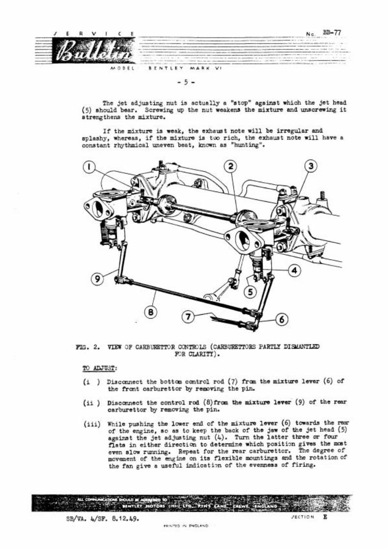
The jet adjusting nut is actual ly a "atoptt against which the je t head ( 5 ) should bear. Screwing up the nut weakens the mixture ana unscrewing i t s treng them the mixture.
I f the mixture is weak, the exheust note w i l l be i r regular and splashy, whereas, i f the mixture is too rich, the exhaust note w i l l have a constant rhythmical uneven beat, known as "hunting".
FIG. 2. VIEW OF CARBURETTOR CC~NTROLS ( C ~ U K E T T O R S PAR^ DISWANTI;ED rnR CLARITY).
TO ADJUST:
( i ) Disconnect the bottau control rod (7) frau the mixture lever (6) of the front carburettor by relrroving the pin.
( i i ) Disconnect the control rod ( 8 ) f ~ a n the mixture lever' (9) of the rear carburettor by removing the pin.
( i i i ) While pushing the lower end of the mixtum lever (6) towards the rear of the engine, ao as to keep the back of the jaw of the je t head (5) against the je t adjusting nut (4). Turn the l a t t e r three or four f la ta in e i ther direction to determine which p o s i t i m gives the moet even slow running. Repeat fo r the rear carburettor. The degree of movement of the engine on its f lexible mountings and the ro t a t ion of the fan give a useful i n d i c a t i ~ n of the evenness of f i r ing.

M j B E L B E N T L E Y M A R K V I
( i y - ) With the mixture conti 1 iever on the s t e e r i n g wheel i r ~ the pos i t ion marked ''R?xin pus: tha lower end of t h e mixture l eve r (6) of the f r an t c a - t u r e t t r t waim the r e a r of the engine and while l i g h t y p ..lug t h . bottcm control rcd (7) tcw-irds the mixture l e v r offer -.p the jaw of the rod t o t h e l L v e . and check whether t:e p i n holes a re i n l i n e wi th each ethe-., l f not , adjus t the jaw :I the rlsd urit:- they l i n e up. F i t the control p i n ~ n d secure with a i ew s p l i t pin.
(v ) Again push the m i ~ t u r e l eve r I ) towards the r e a r , a d o f f e r up the jaw of' the corit~o: rod ,8) t o the mixture l eve r (9) of t h e r e a r carburettor, l l n e IQ I . n ho es as found necessary. F l t the control p i n and c e c r e wi 'h a new s p l i t pin.
(vi ) With the hand th:-b t t l e l e ~ ~ e r on the S teer ing wheel p l a .ed t the bottom of i t s range. adjus t , lf found necessary, tha t h r o t t l e s top adjusting scr'h (3 ) of he f ron t carburet tor u n t i l the correct id l ing s p -ed has been 0-~ta ined.
If a f t e r the ad jus tm~nt of t h carburet tors as described above, i t is s t iil found tha t the slow runnlnp 1s uneven, then proceed t J
synchronise the tbr.rott!es as -01. u,vs.--
.. Unscrew the o i l e r caps and remove the hydraulic dampers f r u n both carburet tors .
2. Thoroughly warm up the engine and ad jus t the f ront ca rbure t to r t h r o t t l e s top screw t o give a f a s .die (about 503-603 R P . L ' s u f f i c i e n t t o l i f t the cuction pls tons s l igh t ly .
3 With a penc i l , depress the p i s ton of the f ront carburet tor a d l i s t e n t o the a i r n c l s e or "hiss"
4. Repeat t h e operation with the rear carburettor.
5. If the h i s s is not the same f o r bL th carburet tors , s lacken the pinch b o l t ( 2 ) of t e in te r - th ro t l e linkage and a d j u s t t h l t h r o t t l e s t o p screw of the c a r b u r , t o r which does not prod ce the cor rec t amount of hiss, u n t l i both carburet tors sound the same.
6 . When synchronised, clamp up the pinch b o l t (2).
7. .Unscrew the r e a r t h r o t t l e stop screw u n t i l i t no l o ~ g e r makes contact with the stop.
8. Using the t h r o t t l e s top screw of t h e f r m t carburet tor 0x131. adjus t the slow running t o give a tick-over of approximately 500 W '
9. Make a f i n a l check of the synchronisatim.
10. Replace the o i l e r caps and hydraulic dampers.
SB/VA ~ /sF . 8.1 2.49. PQI+,-F> Ir; ENGLAND
M O D E L B E N T L E Y M A R K V I
CANCELS BB-91 dated 12.6.52. a d BB-1 61 dated 22.1 2.52.
FOR INFOR!ATIOfJ
VALVE TIfCDTG
This Bullet in s e t s out the l a t e s t instructions f o r valve timing m d cancels Bulletins BB-91 of 12 .6~52 and BB-l 61 of 22.12.52, which should be destroyed.
Basically, owing t o the poss ib i l i ty of camshafts and flywheels having been replaced i n senrice, valve t ining should be carried out i n accordance with the camshaft f i t t e d and not necessarily i n accordance with the markings on the flywheel f i t t e d .
The folloming camshafts have been f i t t e d t o the Bentley b r k VI sngLae on produation.
Chassis Nos: B-= t o E501 -CD Camslmf t RE. 51 57.
Chassis Nos: B-2-RA and onwards Cnnshaft RE. 6885.
Camshaft FtE.6885 i s the sha f t available as a rmlacement and, where f i t t e d t o replace camshaft RE.5157, the le t te l ; '6' should be - stamped on the top left-hand s ide wnll of -tile aluminium wheelcase tin in^ case) f o r recoppition purposes. Weclcases of e n m e s reconditioned by the bndon Service Stat ion a re already being stanped i n this m y where the l a t e r shaft has been substituted. .
It wi l l be appreciated that , as the camshaft par t number is e n p v e d on the end of the shaft near the flywheel, an external mark is essent ial for recognition where the or iginal shaft IELS been replaced, s o that valve timing may be checked without u n n e c e s s q stripping.
Where a l e camshaft has not been replaced, it may be recognised f r o m the Chassis Number.
It is advised f o r infornation t h a t a th i rd camshaft RJ3.19517 w i l l shortly be introduced on production but t h i s shaft d i f f e r s from RE .6885 only i n the method of retaining ffie camsl-raft gear. Ei@t setscrews are used i n place of four studs.
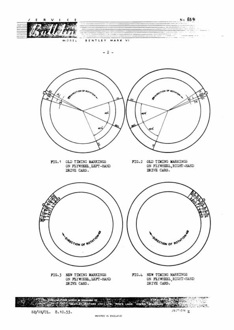
Early type flywheels a re marked as shown in Fig. 1 and 2. Later type flywheels and replacement flywheels, w i l l be marked as shown i n Pig. 3, It will be noted tha t t h e T.D.C. mark only is shown w i t h a d d i t i o d markings a t f ive d e g e e in te rva ls from 5' t o 20' on e i ther s ide of the T.D.C. mark designated EARLY and LATE.
M O D E L
.- -- .- . N S . . . g094 . .. -. -~ --h.-- - - -. -. . . . . .. - -- . - -. - .- . -- -- - -- - - . - - - -p--
- .- -- p-- v - - - -. . - . -----.p - - . -- - -. - . - .- .- . - -. . - . . - . . - ....- ~
. -- . --. - - -
- . - -
B E N T L E Y M A R K V I
F I G . 1 OLD TIXING MARKINGS P I G . 2 OLD TIMING MARKINGS ON fiYWHEEL,LEFT-KAND ON FLYWKEEL,RIGHT-HAND DRNE CARS. m m CARS.
FIG.^ NEW TIMING MARKINGS PIG.& NEW TIMING MARKINGS ON FLYMIEE;L, LEFT-HAND ON FLYWIEEL, RIGIIT-IiAND m m CARS. m 1 V E CARS.
M O D E L ' B E N T L E Y M A R K V1
3, VALVE TIh17JG DATA
(i ) Enpines f i t t e d with Canshaft RE,5157.
T imin~ Ykrk
Old Flywheel NW F l y h e e l Ibarldngs Liarkings
I d e t opens so A.T.D.C. with ,030" valve clearance 1.0. 3 9 LATE
(2 on flprfieel represents 1 O )
( i i ) EnF.ines f i t t e d with Canshaft IiE.6885 o r RE.19517
T imin~ Y m k
Old Flyvheel New Flywheel
M e t opens a t T.D.C. w i t h ,030" valve clearance IGN/T.D.C. T.D.C.
The t ining w i t h canshaft RE. 68-95 has been al tered t o i n l e t opens a t T.D.C. t o give increased torque and engines should be t iccd t o &e new sett in^, wdienever retiming is necessary.
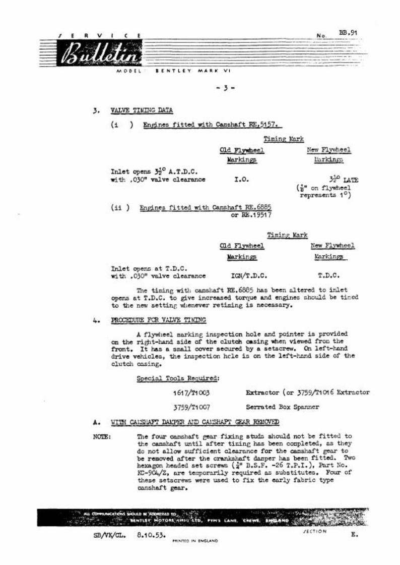
A flywheel marking inspection hole an2 pointer is provided on the ri&t-hand s ide af the clutch casing when viewed froo the front , It has a sxnall cover secured by a setscrew. On left-hand drive vehicles, the inspection hcle is on the left-kmd side of the clutch casing.
Special Tools Recluired:
1 61 7/ !~ 0 ~ 3 Extractor ( o r j759/T1016 Fktrzctor
3759/T1007 S e m t e d Box Spanner
NCTE: Tile four canshaft gear f ix ing studs should not be f i t t e d t o the canshaft u n t i l a f t e r t i r i i n ~ has been conpleted, as they do not allow suf f ic ien t clearance fo r the canshnft gear t o be removed a f t e r the crankshnft donper has been f i t t ed . TWO hexagon headed s e t screws ( p B.S.F. -26 T.P.I.), Part No. ~ - 9 0 4 / Z , a r e t e i j p o r d y required os subst i tutes , Four of these setscrews were used t o f i x the ear ly f ab r i c type cnnshaf t gem.
SB/vx/CL. 0.1 0.53. PCINTCD IN ENGLAND

M O D E L
N G m.91 -- - - - -. - . . - - - - - . - - - -- - - - - - - -- - - - - - -
--- -- - - - p - - - -
---p------
--- - -- - - - - - -- - - . - - -- - - -- - - - B E N T L E Y M A R K V1
(i ) Screw t h e two setscrews i n t o the hub of t h e camshaft and r o t a t e the s h a f t with a l e v e r i n i t s running d i rec t ion u n t i l t h e i n l e t valve of No.6 cyl inaer commences t o open. No.1 p i s ton w i l l then be on i t s f i r i n g stroke. Se t and lock the i n l e t valve clearance on No. l cyl inder t o exact ly .030n clearance ( .762 mm).
( i i ) Again t u r n the camshaft i n i t s running di rec t ion u n t i l the i n l e t valve of No.1 cyl inder jus t commences t o open, a s ascer ta ined by the 'n ip ' on the push rod which should be jus t turnable.
With the camshaft s e t i n pos i t ion , the procedure d i f f e r s according t o t h e type of crankshaft damper f i t t e d . The ea r ly o r we-Bench' type, was f i t t e d f r a n Chassis Nos. B-2-AK t o B-126-DA inclus ive and the l a t e r 'Bench' type f r a n Chassis No. B-128-DA and onwards. The two dampers may be dist inguished by the f a c t t h a t the 'Pre-Bench' type has twelve s tuds (D, Fig.5) f i t t e d t o the rim of the r e a r damper wheel, whereas the 'Bench' type has s i x b o l t s (E, Fig.6).
With the 'Pre-Bench' T.ype Damper.
( i i i ) Remove the bottom cover f r o m the c lu tch casing and t u r n t h e crankshaft f ran the flywheel u n t i l the appropriate timing mark on the flywheel l i n e s up with t h e timing pointer .
( i v ) With t h e th rus t plunger and spring i n posi t ion, f i t t he camshaft gear t o the camshaft. F i t the locking p l a t e and secure with the two temporary setscrews.
(v ) Offer up the r e a r ha l f of the damper, assembled a s shown i n Fig.5, t o the crankshaft nose, and a l i g n t h e th ree key- ways i n the bore of
FIT TWPORARY DlSTWCE PIECES AND MWS ON TWO
the damper hub with the keys i n the FIG.5 SECTION - 'REAR HAW' OF 'Pm- crankshaft nose. PENCH' TYPE CRANKSHAFT W E X
(SPRING TYPE)
SB/VK/CL 8.10.53 PRINTED IN ENGLAND
M O D E L : B E N T L E Y M A R K V I
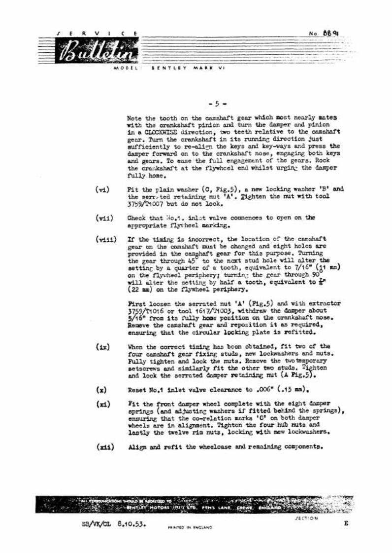
Note the tooth on the camshaft gear which most nearly mates w i t h the crankshaft pinion and turn the damper 4 pinion i n a CLEXWISE direction, two tee th r e l a t i ve t o the camshaft gear. Turn the crankshnft i n i t s running d3rection just sufficiently t o re-alis the keys and key-ways and press the damper fol.ward on to the crankshaft nose, engaging both keys and gears. To ease the full engagement of the gears. Rock the c1'81Ikshaft a t the flywheel end -1st u r g i w the damper fully home.
(v i ) Fit the pla in washer (C, ~ i ~ . 5 ) , a new locking washer 'B' and the serr t ted retaining nut 'A', W t e n the nut with t o o l 3739/~1007 but do not lock,
(v i i ) Check that 7.lo.l . i n l e t valve comences t o open on the apprapriate flysrheel mnrking.
( v i i i ) If the tim3n.g is incorrect, the location of the camshaft gear on the camshaft must be changed and eight holes a re provided in the c a q h a f t gear f o r this purpose. Turning the gear through 45 t o the ncxt stud hole will a l t e r the se t t ing by a quarter of a tooth, equivalent t o 7/16" (&I m) on the f l p h e e l periphezy; turning the gear through 90 w i l l a l t e r the sett- by half a tooth, equivalent t o &" (22 mm) on the flywheel periphery.
First loosen the serrated nut 'A' (mg.5) and with extractor 37 3/~1016 or tool 161 7/Tl003, withdraw the damper about 5 p 16" from its fu l l y home posi t ion on the crankshaft nose. Remove the camshaft gear and reposition i t as required, ensuring that the circular 10cking pla te is ref i t ted.
(ix) When the correct tidq has been obtained, f i t two of the four camshdt gear f ixing studs, new lochashers and nuts. N l y tighten and lock the nuts. Remove the brokrnporary setscrews and similarly f i t the other two studs. T' hten and lock the serrated Qmper r e t d n i n g nut (A Pier3.
(X) Reset No.1 i n l e t valve clearance t o .006" ( . l5 mm),
(xi) F i t the f ront damper wheel complete with the eig!!t dnmper sprlngs (and adjusting washers i f f i t t e d b&bd the springs), e m r h g that the CO-relation marks '0' on both damper wheels are in alignment. Tighten the four hub nuts and l a s t l y the twelve r i m nuts, locking wlth new lockwashers.
(rii) Align and r e f i t the wheelcase ancl rema5nln& componente.
/ECT!ON
SB/V&~L 8.10.53. PRINTED IN ENGLAND E
M O D E L ' B E N T L E Y M A R K V I
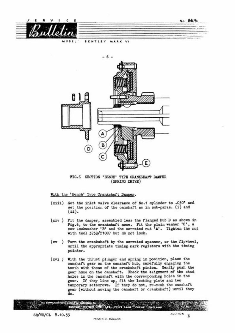
FIG.6 SECTION 'BENCH' TYPE CRANKSHAFT Z;UU6PER (SPRING WNE)
With the 'Bencht Type Crankshaft Damper.
( x i i i ) Set the i n l e t valve clearance of No.1 cylinder t o .03OW and s e t the position of the camshaft as i n sub-paras. (i) and ( i i ) .
(xiv ) F i t the damper, assembled l e s s the f langed hub D a s shown in Fig.6, t o the crankshaft nose. F i t the p la in washer 'C' , a n e w lockwasher 'B1 and the serrated nut * A t . Tighten the nut with too l 3759/~1007 but do not lock.
(m ) Turn the crankshaft by the serrated spanner, or the flywheel, u n t i l the appropriate timing mark reg is te rs with the timing pointer.
(xvi ) With the thrust plunger and spring i n position, place the camshaft gear on the camshaft hub, carefully engaging the tee th with those of the crankshaft pinion. Gently push the gear hane on the camshaft. Check the al igment of the stud holes i n the camshaft with the correcponding holes i n the gear. If they l i n e up, f i t the locking plate and two tamporary setscrews. I f they do not, re-mesh the camshaft gear (without moving the camshaft or crankshaft) u n t i l they do.
S B / ~ C L 8.10.53 PRINTED IN ENGLAND
M O D E L : B E N T L E Y M A R K V I
( h i ) Check the timing, i f necessary repositioning the camshaft gear; f i t the camshaft gear f i A n studs md -set the valve clearance .s i n sub-paras. P v i i ) , ( v i i i ) , (ix) and (X ) abwe. It is not necessary t o withdraw the 'Bench type damper 5/16" t o remove the camshaft gear.
(xxLii) R e f i t the flan@ hub 'D', E g . 6 t o the damper, ensuring that the co-relation marks '0 ' on the front damper wheel and the hub are in a l i m e n t .
First tiefiten and lock the six r i m nuts of the damper wheels and then tighten and lock the four hub nuts.
(b) Align and =fit the wheelcase and remaining components.
I f the crankshaft damper only has been removed, the procedure f o r timing is the same f o r both dampers.
( i ) W i t h No.1 piston on i t s f i r i n g stroke, s e t the No,l i n l e t valve clearance t o emc t ly .030n ( -762 mm) and turn the camshaft u n t i l No.1 i n l e t valve just commences to open as ascertained by the 'nip' on the push-rod w h i c h should be just turnable.
( i i ) Turn the crankshaf't f r o m the flywheel un t i l the appropriate timing mark on the flywheel l ines up w i t h the timing pointer.
( i i i ) Offer up the rear half of the 'F%-Bench' type damper assembled as in Fig.5, or the 'knch ' type damper l e s s the flan@ hub as in Eg.6, t o the &shaft nose, and al ign the three keyways in the bore of the damper hub with the keys i n the crankshaft nose. Note the tooth on the camshaft gur which m a s t nearly mates w i t h tile cxmkd~af t pinion, and hum the cizmper and pinion in a CLOCEFI:SE direction two teeth re la t ive t o the camshaft gem* !ham the cranksfudt in its running direction just suff icient ly t o re-aligi the keys and keyways and press the damper forward on t o the c x a n k b f t nose, engaging both keys and gears. To ease f u l l en~ggcnent of the gears, rock the crank- shaft at the flywheel end w h i l s t urging the damper m y home.
( i v ) Fit and tiefiten the serrated damper retaining nut wi th its p la in and lock msi:ers, and check t h e timing of No.1 i n l e t valve commencing t o open against the appropriate flywheel marking.
(v) If incorrect, remove the damper w i t h the extractor arui re-mesh tlle gears u n t i l correct timing hns been obtained.
( v i ) Lock the serrated retair6ng nut, reassemble the damper and a l ign and r e f i t the trrfieelcase.
( v i i ) Reset the clearance of No.1 i n l e t valve to .006" ( -15 m),
M 3 D t L B E N T L E Y M A R K V I
FOR INFORbLATIOTi:
This Bu l le t in supersedes Bul le t in No.BB-92 ( sec t ion E) reference S~/G~.29.3.50, and a l so cancels BB-l 37 ( s e c t i o n E) reference ~ i l / L ~ . l / ~ ~ . 2 2 . 1 1 . 5 1 . The contents of t h i s Bu l le t in cover the following:-
a ) Stendaril oversize cyl inder bore diameters and c o r r e s p o ~ replacement p is tons ( ~ a r o . 1 ) .
b) F i t t i n g a s e t of shor t l i n e r s ( t ~ t I?ig.2) t o a 3.500" dia. bore engine on which t h e upper por t ion of t h e bores were previously "Flash Chromed" (~sl.a.2).
c ) Boring a cyl inder block t o a standard overs ize d i m e t e r on which shor t l i n e r s were o r i g i n a l l y incorporated ( ~ a r a . 3 ) .
d) F i t t i n g twin cylinder bore l i n e r s t o a 3.500" dia. bore engine when one o r more of the bores a re deeply scored ( ~ a r a . 4 ) .
e ) F i t t i n g t w i n cylinder bore l i n e r s t o a 3.625" dia. bore engine when one o r more of t h e bores a r e deeply scored (~ara.5).
Originally, the cyl inders of the 3.500" dia. bore engine were "Flash Chromed" t o a th ickness of .00075" = .02 m/m(.OM 5" on bore dia. 1 f o r a d is tance of 2.250" (57.15 m/m) from t h e t o p of t h e bores. "Flash Chrorning" comaenced a t Chassis No .B-?-M up t o Chassis 1Jo.B-142-DA, although c e r t a i n engines i n t h i s range of cors have s ince been f i t t e d with shor t "Bricrome" l i n e r s . Conaencing at Chassis N0.B-l@,-DA and onwards, shor t "flricrome" l i n e r s a r e f i t t e d .
The f o l l o w h g items, 'a ' , ' b t , ' c ' , 'at and ' e t should be noted p r i o r t o reboring and f i n a l l y honing the cyl inders and ' f t a f t e r these operations have been ca r r i ed out.
a ) The recornended grades f o r the honing s tones , together with the spindle speed a r e as follows:-
( i Rough Carborundum C-180 - N - K I r ' o r e q u i v a l e n t . [ii 1 Fine Carborundum C-320 - N - %I? o r equivalent. iii Spindle speed. 180 R.P.M.
The recommended l u b r i c a n t when honing, i s Vaclar Cutt ing Oil.
b ) A Tunesten Cerbide t ipped c u t t e r should be used f o r boring; o p e r a t i w a t about 250 R.P.M., no lubr ican t i s required. The radius on the t i p of the c u t t e r should not be l e s s than .020" (. 5 m/m) ancl not exceed .025" ( .63 m/m).
----p p-- ............ No. . . . - . . . - . . . . . . . . . . . .-.... - . . . . . . . . . . - . . . - - - - . - -- -- -. - . --p - --p - -- -- - - - . - .- - -
..... -----.v-- .... ..........--......-. ... .
.----.-p--...--.-.-..-.-- . . . . . . . - . - . . . . . . . . . . . . . . . . . - - - -
. - . -- ........ . . . . . . . . . . . . . . . . . . . . . - - . . . . . . . . . . . . . . . . . . . . . . . . .
M 3 D E L B E N T L E Y M A R K V I
- 2 -
c ) Deper.Eing upon t h e type of eqyipment avai lable , i t may be necesstry t o remove the cyl inder head hol6ing d0v.n studs, in which case, they must be r e f i t t e d p r i o r t o t h e f i n a l h o n i q operatior., because small 1 o d " h i g h spots" occur i n the upper end 01 t h e cyl inder bores hen ti&teriing docn the studs, v;fiich ciisappear during f i n a l honing. The s tuds vary i n length, therefore h e note should be taken before renoving t h e c 01' t h c posi t ion which they occupy on t h e crankcase upper face.
d) The coolant Funp support bracket (secured by f i v e n u t s ) mst 'ce l e f t bol ted t o the cyiir-der block.
e) The canshaft must be removed and the crankcase cleaned t o prevent adhesion of svarf and dust.
f ) F r i o r t o r e f i t t . i n t t h e ca~z.'lzft, i t $..S of the UTMOST ILiFORTJiCE that the crarkcase should be thoroubhly v;ask.ed and clear'ed and the var icsa oilr:ajre, d r i l l e d o i l passages and the o i l g a l l e r y b1ov.n out ~ 5 t h paraff in arid eir under pressure. It r e i l l be necessary t o remove the tv:o ccre plugb frof. the f r o n t u ,d r e a r end 6f t h e o i l ga l l e ry , ( s i t u a t e d on the f r o n t an8 r e a r ezd face of' the crankcase). The o i l ga l l e ry or. 2.ii.side of e n a n e ia i r i t e ~ r a l ~ 5 t h the crankcase; running from er,& t o er.6,
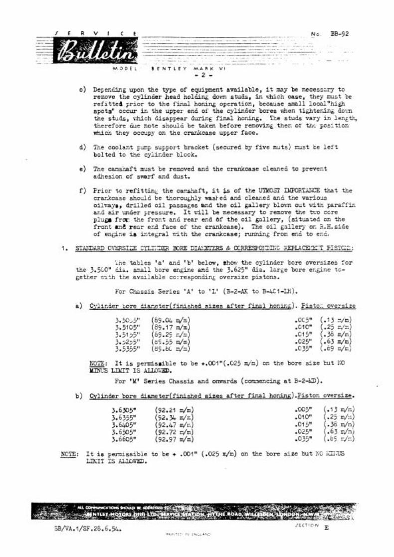
i h e t ab les ' a ' and 'b ' below, &or: the cylinder kcre oversizes f'or the 3.5CO" ua. s.?all bore engine and the 3.625" dia. l a rge bore er.&ine tc- ~ e t k e r n t h the ava i l ab le co:.responding oversize pistons.
For Chassis S e r i e s ' A ' t o 'L' (E-2-AK t o B-XI-U).
a ) Cylin5er t o r e Ciar.eter(finished s i z e s a f t e r f i n a l honiri&). Fisto:-. oversize
WTE: It i s p e d s g i b l e t o be +.001"(.02j m/m) on the bore s i z e but KO m3 LXIT IS UYCID.
For 'M' Se r i e s Chassis and onmar& (commencing a t B-2-D).
b ) Cylinder bore iiiameter(finished s i z e s a f t e r f i n a l honin&) .l?iston oversize.
NOTE: It i s perrnissibie t o be + .001" (-025 m/m) on the bore s i z e bu t KO iLGLTS L E I T IS A.LLG\"IED.

M 3 D E L B E N T L E Y M A R K V I
- 3 -
2. TO F?T A SFT OF SHOIiT "ERICROME" LINERS TO A 3.500" DU.BORE D7GINE ON WHICH THE UPPER FORTION OF THE BORFS WERE PREVIOUSLY "FLASH O M E D " :
Note: Should one o r more of the cylinder bores be found to be deeply - .cored then oonsideration should be given to f i t t i n g twin l l n w s . (see ~ara.i+j.
(l ) To a s s i s t in obtaining the reqyhed interference of .0025" to .0035" (.06 to .09 m/m)between the l i n e r and the cylinder counterbore, 'A' Fig. l , the l i n e r RE-6017, is oolour coded(graded)in the bore a s follows:-
a ) Those marked with blue paint, have an external diameter of 3.628" t o 3.6285" (92.15 t o 92.16 dm).
b) Those marked with yellow paint, have an external diameter of 3.6285" to 3,629" (92.16 t o 92.17 dm).
( i i ) Set up the crankcase cn a boring machine, taking a w e that the cylinder bore is CONCENTRIC w i t h the boring cutter, a t a
FIG.1. SECTION - c a 7 L m m l S I i O ~ G CO-RE. position about 2.500" (63.5 m/m) dawn the
aylinder bore. Next, adjust the boring out ter so t ha t the fFrs t cu t is heavy enough t o get underneath the original chranium plating and counterbore the cylinder to a depth of 2.245" to 2.250" (57.02 to 57.15 dm). See 'B' Fig.1.
( i i i ) Re-adjust the cu t te r and cmtinue the counterboring t o a depth as above and t o a diameter that w i U allow a l i n e r t o have an inter ferance fit of .0025" t o .0035". The number of eecondn~y cuts w i l l of course, depend upon the depth of the initial cut, but i t i s reconmended that these a r e kept to a m h b u m .
The bottom face, ' C' Fig.1, of the counterbore must be machined perfect ly true. Any s l i g h t discrepancy on this end nil1 cause a gap on one par t of the *buttw joint.
( i v ) Repeat f o r the remaining bores.
(v ) Before pressing in the l i ne r s , ensure tha t the radiua, 'D' Fig.1, is smaller than the chamfer ('F' F'ig.2) an the lower end of the l iners , so that there will be no interference a t the but t joints when the l i n e r s a re pressed f u l l y home.
M O D E L B E N T L E Y M A R K V i
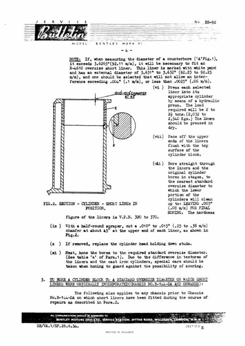
NOTE: I f , h e n measuring the diameter of a counterbore ( ' ~ 'F ig . l ) , i t exceeds 3.6265n(92.11 m/m), i t w i l l be necessary to f i t an R4610 oversiee short liner. This l i n e r is marked with white pint and has an external diameter of 3.631" to 3.632" (92.23 t o 92.25 d m ) , and one should be selected that w i l l not allow an in t e r - ference exceeding .004" (.l nJm), or l e s s than .0025" (.06 dm) .
(vi ) Press each selected
FIG.2. SECTION - CXLRDER - SHOkT LINEH DJ POSITION.
figure of the liners is V.P.N. 320 t o
l i n e r i n to i t s appropriate cylinder by means of a hydraulic press. The load required w i l l be 2 t o 2$ tons. (2,032 to 2,560 ~ g s . ) The liners should be pressed in dry*
Face off the upper ends of the l i ne r s f lush with the top surface of the cylinder block.
Bore s t ra ight through the l i n e r s and the original cylinder bores in stages, to the nearest standard oversize diameter to which the lower portion of the cylinders rill clean up to: LEAVING .003" (.08 m/m) FOR FINAL HOhiING. The hardness
(h ) Kith a half-round sgraper, cut a .OIOn t o .015" (.25 t o .38 d m ) chamfer at about C5 a t the upper end of each l i ne r , a s shown in Fig.2.
(X ) If removed, replace the cylinder head holding down studs.
(rd ) N u t , hone the bores t o the required standard oversize diameter. (See table 'a ' of Para.1). Due to the difference i n textures of the liners and the cas t i ron cylinders, special care should be taken when honing t o guard against the poss ib i l i ty of scollrrg.
3 m3.E A c X L W E R BLOCK W A S T ~ ~ OVERSIZE D W T E R ON W d C H SHOXT LlNiRS VlTERE ORIGINALLY D~coBOIWTED(CHASSIS N0.B-144-DA AND OIWARDS):
The followdng a l so applies t o any chassis pr ior t o Chassis N0.B-144-RA on which short l i n e r s have been f i t t e d d h g the course of repair8 as described in Para.2,
M O D E L B E N T L E Y M A R K V I
- 5 -
( i ) S e t up t h e crankcase on a b o r i a machine, taking care t h a t the cyl inder bore is COIICEFI'RIC w i t h the boring c u t t e r at a posi t ion about .167" = 4.7 m / m (unworn por t ion of bore) dovm t h e cylinder and machine s t r a i g h t through t i e l i n e r s nnd t h e cyl inder bores i n s tages t o t h e nearest stand& oversize diameter t o which t h e cyl inders w i l l c lezn up to ; LZAVING .003" (.B m/m) FOR FINAL HONING. For stendard oversize diameters, r e f e r t o t ab le 'a8 o r 'b' of Pwe.1.
KWE: Honing ins tead of boring may be ca r r i ed out f o r t h e removd of - metal up to .OIOn (.25 m/m) on diameter, but beyond t h i s point, it w i l l be preferable t o bore and then f i n a l l y hone. I
( i i ) Wit!: a h a l f , - r o d scraper, cut a .M 0" t o .M 5" (.25 t o .38 m/m) c h m f e r at about 45 a t t h e upper end of each l i n e r a s shown i n Fig.2.
(iii) If remove&, replace the cyl inder head holding down studs.
( i v ) Next hone the bores t o the required standard oversize diameter.
TO FIT I"iSlf.1 CYLINDER BOPS LINERS TO A 3.500" DIA. BORE EPU'GIIE: - Generd: The following scheme cons i s t s of f i t t i n g twin l i n e r s when one o r more of the bores a r e deeply scored. A long c e s t i r o n l i n e r RE-9922 i s f i t t e d t o t h e loner por t ion of t h e bore and a shor t "aricrome" l i n e r (RE-9921) t o the upper portion, a f t e r which, the cylinder/s can be rebored to t h e same diacleter as the reaaining bores and a new p i s ton / s f i t t e d . This scheme may a l s o be used, if a f t e r boring a cyl inder block t o the maximum standard over- s i z e diameter of 3.5355" t o 3.5365" (89.8 t o 89.82 m/m), one o r more of the bores have not cleened up. Twin liners should then be f i t t e d t o all the cylinders; and they should be bored and f i n a l l y honed t o the standard d iaae te r of 3.5005" t o 3.5015" (86.~1 t o 88.93 dm). This scheme i s applicable t o Chassis 1io.B-2-AK and up t o Chassis 1io.B-401-LH.
I f shor t l i n e r s ('E' ~ i ~ . 2 ) have not been incorporated (on chass i s p r io r t o B-I~~-D;X), it will be necessary t o counterbore t h e unaffected (un- scored) cyliniiers at t h e i r upper end and fit a shor t Bricrome l i n e r , E-6017; i r respec t ive t o f i t t i n g twin l i n e r s t o one o r more of t h e bores.
If shor t l i n e r s a r e a l ready incoqmrated, the liner must be removed before f i t t i n g twin l ine rs . To determine i f shor t l i n e r s have been f i t t e d t o an engine, note top of cyl inder bores; t h e r e i s a di f ference in colour and grain between the s t e e l l i n e r and the c a s t i r o n block.
Machining & F i t t i n g Procedure:-
Where shor t l i n e r s have not been incorporated, proceed a s follows f o r bores which do not r e ~ u i r e twin l iners : -
(i ) Refer t o sub-para.(i) of Para.2 concerning t h e external diameter and interference f i t of the shor t l i n e r s , RE-6017.
( i i ) Carry out the operations is described i n sub-paras.(ii) t o ( v i i i ) inclus ive , of Per2.2.
P R . V T E 0 Ih E N G L A N D

M O D E L B E N T L E Y M A K K V l
- 6 -
( i i i ) I f ehort Uners are already incorporated, proceed as follows to rsmove a l i n e r from a ecored bore:-
a) Set up the crankcase on a boring =dune, taking care that the cylinder bore i s CONChTRIC with the boring cu t te r a t a position about -187" = 4.7 m/m (unworn portion of bore) down the cylinder.
b) %re out the short liner i n stages, ' u n t i l i t has a w a l l thickness cf not more than .O%" (-38 dm). Tfus operation must be careful ly carr ied out -h order t h a t the boring cu t t e r does not contact the cylinder count r rb~re . A s a guide when boring, i t should be borne in mind that the external diameter of the l l n e r ( in position) is 3.625" (92.07 m/m) l. e. the same diameter as the c ~ u n t e r b c n *A' Fig. l . From the upper face of the cylinder blcck, the l i ne r should be bored t o a depth of 2.250" to 2.255" (57.15 t o 57.27 dm).
c) With a sharp suitable halid tool, carefully break away the upper end of the l i n e r f ram the cylinder w a l l an3 remove the remaining portion.
( i v ) To a s s i s t in obtaining the requires intereferenae of ,0025'' t o .0035" (.06 t o -09 m/n) betweer, tne cylinder and the l iners , the short and long l i n e r s (RE-9921 and RZ-9322) are colour coded (graded) in t h e i r b 3 r ~ s as follows: -
a) Those marked with blue paint have an external diameter of 3.6%" to 3.6385" (92.40 to 9 2 . w )
SHORT LINER b) Those marked with yellow paint have an external diameter of 3.6385" t o 3.639" ( 9 2 . ~ to 92.43dm)
(v ) Apart from the l i n e r dimensions given above, the long l i n e r s should be measured a t six di f fe ren t diametrical points; take tne mean of these measurements f o r the external diameter. Select a sui table short l iner t o match ~5th the obteined measuremerit. It is not necessary t o s imilar ly measure a short l i n e r ; r e f e r to the colour
FIG-3. SECTIdl - m - TWIN IJlWLS XI4 coding.
POSITI~II (3 500'' DIA. BORE ENGINE).
M O D E L B E N T L E Y M A R K V I
- 7 -
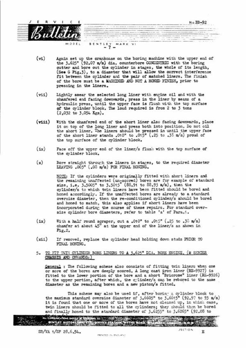
vi) Again s e t U the crankcase on the boring machine with the upper end of the 3.625" f92.07 d m ) dia. counterbore COXXNTRIC with the boring out ta r and bore out the cylinder in stages, the whole of i ts length, (see G Fig.3), t o a diameter that w i l l allow the correct interference f i t between the cylinder and the pair of matched l iners . The f in i sh of the bore must be a MACMNED AND NBT A HONED FITiISH, pr ior t o pressing in the Ilners.
( v i i ) Lightly smear the selected long l i n e r with engine o i l and n i t h the chamfered end facing dowrrwards, press in the l i n e r by meam of a hydraulic press, u n t i l the upper face i s flush ~ ~ 5 t h the top surface of' the cylinder block. The load required is from 2 to 3 tons (2,032 to 3,054 %S).
(U) With the chamfered end of the short l i n e r also facing domrmmds , place it on top of the long Uner and press both in to position. Do not o i l the short l iner . The l iners should be pressed in u n t i l the upper face of the short l i n e r stands .OIOn t o .015" (-25 to .3e dm) proud of the top surface of the cylinder block.
(ix) Face off the upper end of the l iner/s f lush with the top surface of the cylinder block.
(X> Bore s t ra ight throwh the l i n e r s i n s t w e s , to the required diameter L E A m T G .OO3" ( -03 m/m) FOR FINAL HONING.
NOTE: I f the cylinders were or iginal ly f i t t e d with short l i ne r s d the remaining unaffected (un-pcond) bores are for example of standard s i z c , i.e. 3.5005" t o 3.5015 (88.91 t o 88.93 h), then the cylinder/s t o which ts7in l i ne r s have been f i t t e d should be bored and honed accordingly. I f the unaffected bores are alrea&y to a standard oversize diameter, then the re-conditioned q l inde r / s should be bored and honed t o match, t h i s a l so applies i f short l i ne r s have been incorporated &=in;: the course of these repairs. For stanc3ard over- s i ze cylinder bore diameters, re fe r to table 'a' of Pars.?.
(h) With a W round scraper, cu t a .OIOn t o .015" (-25 to -36 dm) chamfer at about 45' a t the upper end of the l iner/s a s shown in Fig.2.
( x i i ) I f removed, replace the cylinder head holding dovm studs PRlCIR TO FINAL HONING.
5. TO FIT Til17i CYLINDiD BORE IDERS TO A 3.625" DIA. BORF: ENGIRXE . (M SDCES CHASSIS AtQ OM'iARDS: )
B n e r d : The fo1lmrh.g scheme also consists of f i t t i n g b , i n l i ne r s wfien one o r more of the bores are deeply scored. A long cast i ron l i ne r (RE-9927) i s f i t t e d t o the lmrrer portion of the bore and a short "~ricrome" l i n e r (E-9926) t o the upper portion, &ter which, the c;.linder/s can be rebored to the same ,
diameter as the remaining bores and a new piston/s f i t t ed .
This scheme may a lso be used i f , after'borin: 2 cylinder block t o the maximum standard oversize diancter of 3.6605" t o 3.6615" (92.97 to 93 m/m) i t is found t h a t one o r more of the bores have not clean=& up, i n vdlich case, twin liners should be f i t t e d to a l l the cylinders; they should then bc bored and f ina l ly honed t o the standard diameter of 3 -6255" to 3.6265" (92.08 to
M O D E L B E K T L E Y M A R K V1
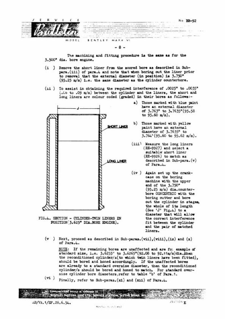
The machining and f i t tang prooedure ie the sune as for the 3.500' dia. bore angane.
(i ) Remove the ahort l ine r fran the soored bore as desoribed in Sub- para. ( i i i ) of paro.4 and note that when boring out the l iner prior to removal that the external diuneter (in position) is 3.750" (95.25 dm) i.e, the same diameter as the cylinder oounterbore.
(ai ) To ass is t in obtaining the requind interference of .0025" to .0035" (.Gb t o .O9 d m ) between the cylinder and the liners, the short and long l iners are colour coded (graded) in their bores as follows:-
a) Those marked w i t h blue p i n t have an external diameter of 3.763" to 3-7635"(95.58 to 95.60 dm).
b) Those marked wi th yellow paint have an external diameter of 3.7635" to 3.764'.(95.60 t o 95.62 d m ) .
(iii) Measure the long l iners (RE-9927) and select a suifable' short l iner
(RE-9926) to match as described in Sub-para. (v) of Parp.4.
( i v ) Again se t up the crank- case on the boring machine with the upper end of the 3.750" (95.25 dm) dia. counter- bore CONCENTRIC with the boring cutter and bore out the cylinder in stag* the whole of its length (see 'S' Fig.&) to a
FIG.4. SECTION - LINERS IN POSITION.: 3.625" D=. BORE ENGINE).
diameter thpt w i l l P1J.m the correct interference f i t between the cylinder and the pair of matched liners.
(v ) Next, proceed as described in sub-pa.ras. (a), ( v i i i ) , (h) and ( X ) of Fara.4.
NOTE: If the remaining bores are unaffected and are fol wcnmple cf - standard size, i.e. 3.6255" to 3.6265" (92.08 to 92.1 lm/rn)dia.,then the reconditioned cylinder/s(to which twin l iners have been f i t ted) , should be bored and honed accordulgly. If the unaffected bores are already to a. standard oversize diameter, then the reconditioned cylinder/s should be bored and honed to mptch. For standard over- size cylinder bore diarneters,refer t o table 'b' of Para.1.
(Vi ) Finally, refer to Sub-parao. (xi) and (rri) of Pua.4.
M O D E L : B E N T L E Y M A R K V I
FOR I r m m T I O B .
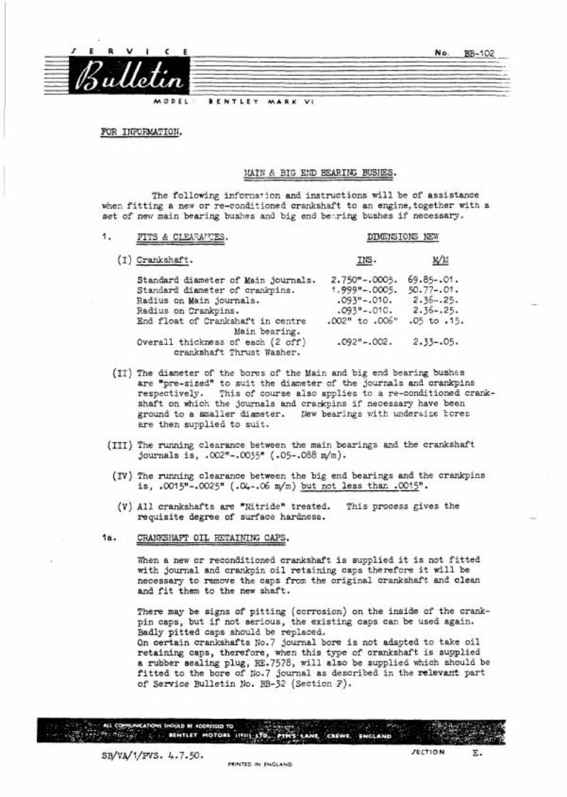
1.IAIh' R BIG END BEARING BUSIES.
The following infornat ion and ins t ruc t ions w i l l be of a s s i s t ance when f i t t i n g a new o r re-concbtioned crankshaft t o an engine,together with a s e t of new main bearing bushes and b ig end ber.ring bushes i f necessary.
( I ) Crankshaf't . INS. P&
Standard diameter of Main journals. 2.750"-.0005. 69.85-.01. Staqdard diameter of crankpins. 7.999"--0005. 9.77-.01. Radius on Main journals. .0931t-.010. 2.36-.25. Radius on Crankpins. .09311-.010. 2.36--25. End f l o a t of Crankshaft i n cen t re .002" t o ,006" .05 t o .15.
Eliain bearing. Overal l thickness of each (2 o f f ) .092"-.002. 2.33-.05.
crankshaft Thrust Washer.
(11) The diameter of the bores of the Main and b ig end bearing bushes are "pre-sized" t o s u i t the diameter of the journals and crankpins respect ively . This of course a l s o appl ies t o a re-conditioned crank- s h a f t on which the journals and crardcpins i f necessary have been ground t o a smaller diameter. I k w bearings with undersize bores are then s u ~ p l i e d t o s u i t .
(111) The running clearance between the main bearings and the crankshaft journals is, .002n-.0035n ( .05-.088 m/m) .
(D) The runnine clearance between the big end bearings and the crankpins is , .001 5"-.0025It ( .04-. 06 din) but not l e s s thaR . W O .
( V ) A l l crankshafts are "Bitride" t rea ted. This process ~ i v e s the r e q u i s i t e degree of surface hardness.
l a . CRAIESIIAET OIL RETAINI~G CAPS.
'fien a nevr o r reconditioned crankshaft i s supplied it i s not f i t t e d with journal and crankpin o i l r e t a in ing caps therefore it w i l l be necessary t o remove the caps from the o r i g i n a l crankshaft and c lean and f i t them t o the new s h a f t . There may be s igns of p i t t i n g (corrosion) on t h e ins ide of t h e crank- p i n caps, but i f not ser ious , the ex i s t ing caps can be used again. Badly p i t t e d caps should be replaced. On c e r t a i n crankshafts 110.7 journal bore i s not adapted t o take o i l r e t a i n i n g caps, therefore, when t h i s tme of crankshaft i s supplied a rubber seal ing plug, RE. 7578, w i l l a l s o be supplied which should be f i t t e d t o the bore of IJo.7 journal a s described i n the re levan t p a r t of Service Bul le t in No. BB-32 ( sec t ion 3').
sB/vA/~/PVS. 4.7.50. PRINTED IN ENGLAND

M O D E L : B E N T L E Y M A R K V I
When a crankshaft i s supplied on which No.7 journal bore is adapted t o take o i l re ta ining caps, these caps and a s tud w i l l a lso be supplied and should be f i t t e d t o the shaf t .
It w i l l be necessary when t ransferr ing the caps f r a n the or ig ina l crankshaft t o the new one t o f i t new aluminium washers t o the studs t o prevent the poss ib i l i ty of o i l leakage.
Additional necessary par t S.
12. RE. 6976 A l u m i n i u m ,;;asher - Crankpin Stud. l j. KB. 1076 A l u m i n i u m Flasher [2;;$'?1iA.) - Journal Stud. 6. WL.4602 S p l i t P in (.062" dia.) - Crankpin Stud. 7. K.4602 Split P in ( .062" dia. ) - Journal Stud.
2. W N BEARING BUSIfES. (Copper, lead-indium l ined s t e e l she l l s )
The main bearing bushes are of the "Thin Wall Precisionn type. They a r e so accurately made t ha t no hand f i t t i n g i s required i n way. The circumferential length or "Shut Heightw i s held t o very f i n e l i m i t s ( t h i s a lso applies t o the big end bearing bushes) so tha t when the housing caps of the crankcase are pul led down t o t h e i r correct posi t ion, the bearing w i l l have suf f ic ien t pressure exerted on i t t o make it conform exactly with the housing; being f l ex ib l e i t w i l l take up the exact shape of it and obtain the maximum sugport. It w i l l be obvious from t h e above tha t the following points should be observed:-
a ) Do not f i l e o r touch the joint faces of the bearing she l l s , o r , touch the bores with a scraper. An in te rna l micrometer should not be used on the bores.
b ) Do not f i l e o r touch the joint faces of t he housings and bearing caps.
3 WASIIDTG AND CI;EAIJiNG DISkWE'LED PARTS.
NOTE:- It i s of the utmost importance t ha t a l l disnantl-ed p a r t s should be thoroughly cleaned pr io r t o f i t t i n e n e w bearings.
( I ) In order tha t the crankcase can be thoroughly cleaned and the various oil~vays, d r i l l e d o i l passages and the o i l gal lery blown out with paraff in and a i r under pressure, it w i l l be necessary t o remove the camshaft and the two core plugs frm the f ron t and r ea r end of the o i l gal lery, i.e. , f r ~ n the f ron t and r e a r end face of the crankcase. The o i l gal lery (on R.H. Side of engine) i s in tegra l with the crank- case running f r m end t o end of it.
(11) Clean and blow out a l l external o i l pipes.
(111) I n addition t o the above it w i l l be necessary t o dismantle and clean out the o i l pump, the o i l r e l i e f valve un i t and the By-Pass F i l t e r , f i t t i n g a new element t o the l a t t e r . Also clean t h e wire screen of
SB/VA/I/PVS. 4.7.50 PRINTED IN ENGLAND

M O D E L B E N T L E Y M A R K V I
t h e 051 pump intake s t r a i n e r .
TO REMOVE ATID REFIT TIE C W I f A F T .
(I) With the exhaust valves , i n l e t and exhaust tappets removed from the crankcase f i r s t mark the pos i t ion of the camshaft driving gear i n r e l a t i o n t o the camshaft by sc r ib ing a l i n e on t h e hub of the g e m , then removing t h e screws o r nu t s securing the gear t o the camshaf't a ~ d scr ib ing a corresponding l i n e on the camshaft.
(IT) Remove the th ree 4" (B.s.F.) nu t s securing the camshaft th rus t p l a t e t o the crankcase and ca re fu l ly withdraw the camshaft. ' The camshaft must be supported during i ts removal t o prevent damaging the Babbit t l i n e d s t e e l bearings i n the crankcase.
EJOTE: I f t h e camshaft dr iv ing gear i s of the Fabroi l type t h i s should be discarded arid replaced by an Aluminium gear. I n such cese i t v r i l l a l s o be necessary t o change t h e crankshaft p in ion a s t h i s i s a mated gear and i s supplied a s a p a i r with the Aluminium gear.
(111) Af te r cleaning the crankcase r e f i t the camshaft t o t h e crankcase and t h e dr iv ing gea r t o t h e camshaft. P a r t s required, 7 New ~ ~ . 7 1 0 6 Lockwashers f o r locking the nu t s of the t h r u s t p l a t e and the hexagon headed n u t s of the gear.
(N) Place a neK aluminium washer (~.75427) on t o each core plug, smear p lugs and washers with a jo int ing compound and r e f i t t o the o i l g a l l e r y .
N;)TE: The core plugs espec ia l ly the r e a r one should be r e f i t t e d t o the - crankcase p r i o r t o p lac ing t h e crankshaft and flywheel i n posi t ion.
5 TO FIT A NEVl SET OF MAIN BEARING BUSIES.
A s e t of Main bearings comprise the following: -
Main bearing - Front - Top. Main bearing - Front - Bot tm. Main bearing - Intermediate - Top. Main bearing - Intermediate - Bottm. Main bearing - Centre - Top. Main bear ing - Centre - Bottom. Main bearing - Rear - Top. Main bearing - Rear Bottom. Thrust Yiasher - To?. Thrust Washer - Botton.
l o f f . l of f . 4 o f f . 4 o f f . l o f f . l o f f . 1 of f . l o f f . 2 o f f . 2 o f f .
( I ) All main bearings should be numbered (etched) i n pa i r s , i .e . , t h e t o p and bottom half of a bearing should bear the same number. The numbers, 1 t o 7, commencing from the f r o n t 6f the englne, should be e tched on t h e lug of the s t e e l she l l . If ax etching apparatus i s not avai lable then use a sharp pointed scr iber . 'Uhen carrying
SB/VA/I/WS. 4.7.50 /ECTION E. PRINTED IN ENGLAND
M O D E L : B E N T L E Y M A R K V I
out the above, care must be taken not t o damage the bearings in any way.
(11) A l l top main bearing halves have two o i l passage holes d r i l l ed in each half, which should correctly reg is te r with the corresponding o i l passages d r i l l ed in the crankcase bearing housing. It w i l l be noticed however, upon assembling the top halves that the o i l passage hole in No.6 housing is d r i l l ed s l igh t ly off centre, t h i s being a feature of design. No attempt should be made to elongate the corresponding hole in the top half of the bearing. It w i l l a lso be observed that No.1,3,5 and 7 housings have two o i l passage holes d r i l l e d in each housing, whereas Nos .2,4 & 6 housings have only one o i l passage hole. The f o r t h i s is, there are no cam- shaft bearing bus!~;i f i t t ed t n Vos. 2 ,& & 6 camshaft bearing housings therefore no o i l feed i s required.
(111) Lightly smear the back of each top half main bearing with engine o i l and place them in the i r corresponding housings in the crankcase. Repeat f o r the bottom halves and place them in the i r corresponding caps.
NCrPE:- All bearin& surPaces must be perf'ectly clean and all bearings and bearing &aces should be f ree ly lubricated with engine o i l . The f l a t faces of the main bearing caps should be l i gh t ly smeared w i t h grease.
(N) With the balance weights of No.3 & 4 crankpins in a horizontal position, gently lower the crankshaft and flywheel into position taking care t o avoid damagbg the bearings.
(V) The next operation is to f i t the crankshaft thrust washers to No.4 bearing housing and cap and check the end f loa t of the crankshaft. It i s recommended that a new s e t of thrust washers are f i t t ed .
Proceed as follows: - a) Etch the l e t t e r "X" on the s t e e l side of a top and bottom
half thrust washer near the cut. This washer should be f i t t e d to the side of the housing and cap ( ~ 0 . 4 ) nearest the f ront of the engine, This is advisable in case the thrust washers have t o be removed fo r any purpose; they can then be replaced in the i r or iginal positions.
b) Oil the th rus t washers and s l i de the two top halves i n to the recess on each s ide of the bearing housing. The Babbitt (white-metal) grooved s ide of the thrust washers must be f i t t e d against the crank face, i.e. the Babbitt l ined surface must face the crankshaft thrust face.
c) Likewise, place the two bottom halves of the thrust washers on each side of t he bearing cap ascertaining that the tab of each washer correctly locates ic the s l o t s of the bearing W.
~~/vA/l/PVS.4.7.50. PRINTED IN ENGLAND
M O D E L : B E N T L E Y M A R K vl
d) P i t the bearing cap in pos i t ion , place two new lockwashers, KB-7108, on t o the s tuds and progressively t igh ten the n u t s with a box spanner and check the crankshaft f o r freedom. The recommended t o w b a r length i s 6" ( l 5 2 m / m ) and t h i s should be cen t ra l ly placed ir, the spanner.
KCEE: When t ightening the main bearing cap do not slacken back a nut t o accommodate a lockwasher continue t o tighten.
e ) Fix a d i a l type ind ica to r t o the f r o n t of the crankcase, l e v e r the crankshaft t o and f r o and note the amount of end f l o a t , which should be .002"-.006" ( .05-.l5 m/m) . In the unlikeljr event of the end f l o a t being l e s s than .002" i t would 35 neczssary t o reduce the two washers ( four halves) an equal amounJU ar~d t o the amount required by having the s t e e s l d e s -ue-c surr'ace ground and re-etching the washers as necessary. M t ~ r grinding, the four halves should be of e@ thickness. It i s important that no grinding dust shoula be allowed t o f i n d i t s way onto the Babbi t t l ined faczz , ETP:- -h-uld tnerefore be examined with a m+gnifying f l a s s before r e f i t t i n g . The overa l l thickness of a new th rus t washcr is .092It-2 (2.33--05 d m ) .
f ) After the end f l o a t of the crankshaft has been checked, assemble and regressively t ighten dowr. the remaining bearing caps ppiacLlg a new locknrasher, KB.7108 under each nut) i n thy following order:-
After t ightening dovm a bearing cap check the crankshaft f o r freedom. When all the caps have Deen tightened down it si-~ould be possible t o h. the crankshaft (by hand) g u i t e e a s i l x with t ne flywheel.
NOTE: I n the unlikely event of a new bearing being found t o be too t i g h t , preventing f r e e ro ta t ion of the crankshaft, then the only a l t e r n a t i v e i s t o replace the bearing.
g) The nuts of the m a i n bearing caps should be locked a f t e r the o i l pressure t e s t s have been ca r r i ed out ( see paragraph 8 , sub-paragraph IV) . The f i t t i n g of new o i l s e a l s t o No.7 main bearing cap should a l s o be carr ied out a f t e r the o i l t e s t s . ( ~ e e paragraph 9).
6 . BIG EM) BEARING BUSHES (copper, lead-indium l ined s t e e l she l l s ) .
The big end bearing bushes a r e a l s o of the "Tkin W a l l Frecision" type and l i k e the m a i n bearings they a r e so accurately made tha t
SB/V~/I/€TS. 4.7.50. PRINTED IN ENGLAND
M O D E L B E N T L E Y M A R K V I
no hand f i t t i n g i s required in any way. The following points should therefore a l so be observed:-
a) Do not f i l e o r touch the joint faces of the bearing shells or , touch the bores with a scraper. An internal micrometer should not be used on the bores.
b) Do not f i l e o r touch the joint faces of the connecting rods and caps.
F'IT A SET OF BIG END BEARING BUSHES..
(I) A l l top and bottom bearing halves (12 of f ) are ident ical with one another. Each having a .125l1 (3.17 m/m) dia. hole d r i l l ed in it. The o i l hole in the half bearing t o be f i t t e d to a conn. rod, as d i s t i nc t from the cap of the rod, should reg is te r correctly with the corresponding o i l hole dri1)ed in the rod, through which o i l passes to lubricate the small end bush.
(11) The bearing bushes should be numbered (etched) i n pa i r s (1 t o 6) i.e., the top and bottom of a bearing should bear the same number. They should be etched on the lug of the s t e e l she l l on each half of the bearing.
(111) Smear with engine o i l the back of each top and bottom half of bearing and place them in t h e i r corresponding rods and caps.
(TV) The following points should be borne in mind during the assembling of the connecting rods (complete with pistons) t o the engine.
a ) On the large majority of engines a small hole i s d r i l l ed in the s ide of the connecting rods which a l l ows a f ine swrt of o i l t o be projected on to the walls of the cylinders t o a s s i s t lubrication of the bores. When re- assembling the rods to the engine these "squirt holes" must face the thrust side of the engine, i.e., not the camshaft side.
b) I f s p l i t skirt pistons are used, the s p l i t must face the camshaft side of the engine.
c) The markings (NOS.) on the connecting rods should be on the camshaft s ide of the engine.
W i t h the pistons in place on the connecting m& space the rings so that the end gaps are approximately l No apart. Position the crankcase so t h a t the cylinders are horizontal. The pistons should be placed in the cylinders and the connecting rods assembled t o the crankpins in the following order: -
NO. i & 6. NO. 2 c3 5. & No. 3 Be 4.
PRINTED IN FYGLAND

M O D E L : B E N T L E Y M A R K V I
(VI) Place No.1 crankpin half way down i ts stroke. Using a piston r ing clip, l igh t ly tap No.1 piston in to i t s bore with the a id of a mall hamer shaft . Pul l the rod tovrards the crankpin andkota te the crankshaft u n t i l No.1 crankpin i s a t the bottun of i t s stroke and pu l l the rod (benring) on t o the crankpin.
(VII) Place the two bol ts i n position on the rod making sure that the 11-15: on the bol t s enter and correct ly locate i n the recess provided on the rod.
(VI11) fit the cap (with Nos. on cap and rod corresponding with each other) and progressively tighten the nuts with a box spanner u n t i l t he s p l i t pin holes are i n l ine. The recamended tommy bar length i s 6" (152 m/m) and t h i s should be central ly placed i n the spanner.
NOTE: Do not slacken back a nut t o acccmmodate a s p l i t pin, i .e. , t ighten up u n t i l pin hole reg is te rs witn next castel la t ion on nut.
(IX) Check the rod fo r freedom of end f l o a t on the crankpin and gudgeon pin.
(X) Refi t the remaining rods i n a similar manner but do not secure the nuts with s p l i t pins u n t i l the o i l t e s t s have been carr ied out.
OIL TESTS.
(I) It w i l l be necessary t o connect t o the crankcase a source of o i l s u ~ p l y (hand operated gear type pump, f o r example) and a reservoir n i t h a re l iab le pressure gauge i n c i rcu i t . To carry out the o i l t e s t s proceed as follo~vs: -
a ) Blank off o i l r e l i e f valve passages situated externally on right-hand side of crankcase, by means of a sui table blanking plate and joint , u t i l i s ing the three studs which secure the o i l r e l i e f valve uni t t o the crankcase.
b) ,On ear ly type crankcases, the right-hand side of the prigine car r ies trio tapped bosses which lead in to the o i l gallery. With an aluminium washer and a bolt .375" dia. (B.S.F.) 20.F.P.I. - RII, blank off the tapped boss (hole) s i tuated midway along the o i l gallery. The bol t should have a length of .5mn (12.7 m / m ) t o .625" (15.8 m / m ) beneath the head and f u l l y threaded. (Before blanking off see paragraph (d) below. ).
c ) With an aluminium washer and a bolt .4375" dia. (B.s.F. ), 18.T.P.I. - R.H. blank off the other tapped boss s i tuated towards the rear of t h e o i l gallery. This bolt should also have a length of .5mn-.625" beneath the head and f u l l y threaded.
SB/VA/I/PVS. 4.7.50 PRINTED IN ENGLAND
M O D E L ' B E N T L E T M A R K V I
On l a t e r type crankcases the boss towards the rear of the o i l gallery i s not used, the external o i l feed pipe being deleted. An internal high pressure o i l j e t i s used to spray o i l d i rec t on to the d is t r ibu tor drive gears from the o i l gallery. The j e t i s 5.375'' (1 36.5 m/m) long and is removable, being screwed into position through the tapped boss midway along the o i l gallery. It i s advisable t o leave the je t in position but if absolutely necessary it can be removed by use of a sui table screwdriver. It can be cleaned in place by f i r s t passing the end of a piece of wire about 10" (254 m/m) long throu h the .0468" ( I .I 7 m/m) diameter o r i f i ce at its inner end f the inner end is not vis ible) and subsequently blowing out the in t e r io r of the j e t with paraff in and air under pressure through the boss midway along the o i l gallery, During the o i l t e s t s a f a i r amount of o i l should escape from i t and flow down the s ide of the crankcase. Blank off the
boss (midway along the o i l gallery) as described in
e) B l a n k off the four o i l feed holes in the f ront end of the crankshaft by means of two sui table Jubilee c l ips and two s t r i p s of rubber.
f ) Yake a sui table adaptor ( fo r connecting up the external o i l supply) and at tach it to the o i l pump pipe connection flange, (inside the crankcase) by means of the two existing setscrews and connect up the o i l supply.
g) Using o i l t o correct specification ( s . A . E . ~ ) ra i se and main- tain o i l pressure a t 20-25 lb s per sq.&. Turn the cmnk&af't slowly and ascertain tha t there are no o i l leakages past 8.w of the o i l retaining caps and t he i r studs as f i t t e d to the bores of the journals and crankpins.
(11) Bearing leak should not be excessive, but i t should be confirmed that o i l reaches all main journals, b ig ends and gudgeon pins.
(111) If' the connecting rods. are provided with a s m a l l squirt hole on the s ide of the rod as mentioned in paragraph 7, a check should be made, while slawly turning the crankshaft, that a squi r t of o i l emerges from each rod twice during a revolution of the crankshaft. While maintaining the o i l pressure and continuing the slow turning of the crankshaft a lso turn the camshaft slowly u n t i l a f r ee flow of o i l emerges from the o i l hole d r i l l ed a t the f m n t end. Also ascertain that the camshaft rear bearing cover and the f ront and rear end plugs of the o i l gal lery are o i l t ight . A l l leaks should be corrected.
(U) After the completion of the o i l t e s t s , lock the 14 nuts of the main bearing caps and secure the nuts of the corn. rod bo l t s with l 2 new
SB/VA/I/PVS. 4.7.50- P R I Y ~ I D I N ENGLAND
M O D E L B E N T L E Y M A R K V I
s p l i t pins, ~.84689, bending the legs of the pins around the nuts.
TO FIT NEW OIL SEALS TO ME REAR MAIN BEARING CAP.
The next operation i s to f i t two new c i rcu lar o i l seals , KE.7144, t o the r ea r main bearing cap and crankcase (having previously removed the or iginal ones). These seals a r e made of White Pine and are provide& with a square head f o r tapping in purposes. Tap the new seals i n to position as f a r as they w i l l go i.e. u n t i l they make contact with the upper face of the bearing cap housing of the crankcase. Neatly cut off the heads w i t h a sharp knife f lush with the crankcase facing. They should be a l i g h t drive f i t .
9:- Before replacing the crankcase lower half a f i n a l check should be made that all necessary par t s have been correctly locked. This also applies before replacing the wheelcase.
10. M REFIT CRA.NKCASE LOWER HALF.
The following i s the correct procedure:-
a) Place the crankcase lower half in position and assemble all setscrews finger t igh t then nip up one setscrew on each s ide of the lower half a t the front end.
b) Place the wheelcase in position and nip up all nuts and setscrew^.
c ) Progressively tighten up all lower half setscrews and repeat f o r the wheelcase. After the road test/s have been carried out all the setscrews of the lower half should be checked f o r being tight.
Will all Retailers kindly inform the London Service Station whenever the Main or Big End Bearings have been replaced.
SB/VA/~/PVS. 4.7.50. PRINTFD IN ENGLAND

M C O E L B E N T L E Y M A R K V I
FOR INFORMATION
ALUhIIfrn CAbdSIiAET DWNI?R, GEAR.
Reta i l e r s are advised t h a t the mate r i a l of the camshaft driving gear has been a l t e r e d from Fabroi l t o aluminium and the l a t t e r should be used f o r a l l replacement S.
W i l l R e t a i l e r s kindly note t h a t whenever an engine i s being over- hauled o r whenever the r a d i a t o r o r engine f r o n t i s dismantled f o r o t h e r reasons t h i s opportunity is t o be taken t o change the camshaft driving gear. With t h i s i n view we a r e arranging t o send s m a l l s tocks of t h e necessaq. p a r t s t o a l l Overseas Re ta i l e r s .
I n add i t ion t o changing the camshaft dr iv ing gear it w i l l a l s o be necessary t o replace the crankshaft pinion i n view of the f a c t tha t t h e gears a r e pai red t o obta in the cor rec t amount of backlash.
The gears are pa i red on a r i g t o g ive a backlash of .002" - .Own ( .05 - . lCh/m) but when f i t t e d to an engine t h e backlash may be found t o be .m" ( . l 5 qm). This should not cause any d i s a b i l i t y . Af ter f i t t i n g an aluminium gear, the l e t t e r ' A t should be stamped on t h r top nearside (L.II. Side) wal l of t h e aluminium wheelcase (timing case) where it w i l l be e a s i l y v i s i b l e on l i f t i n g the bonnet.
The o r i g i n a l crankshaft p in ion should be re turned t o the London Service S ta t ion a s soon a s possible f o r re-grinding and re-pairing t o a ne-;; aluminium camshaf't drivirig gear.
W i l l a l l R e t a i l e r s please no t i fy the London Service S ta t ion of the chass is number of the c a r , whenever they incorporate t h i s a l t e ra t ion .
l . PARTS FEQUIF;ED.
The following p a r t s and inc iden ta l p a r t s w i l l be required when the Spring Drive f i t t e d t o t h e engine i s of the "Wraithn type ( i . e . "Pre- Benchn t ~ e ) . See page 2 of Sub-Sectior! BE-9, of t h e Torkshop Manuel.
a ) P a r t No. T i t l e . No. off .
Camshaft Driving Gear. 1. Crankshaft Pinion. 1. Camshaft Driving Gear. l*> Crankshaf't Pinion. l*>
(Alternatives t o m.12120 & RE.146.)
Driving Pin. 2. Countersunk Screws - Pinion Assy. 2. Locking P l a t e - Gear. 1. Studs - Gear . G . 1Juts - Studs. 4. 1,ocki.rashers - 1Jut S. 4-

M O D E L B E N T L E Y M A R K V t
b) Incidenta l P a r t s required due t o dismantling t h e Spring Drive.
E. 54566. Lockviasher - Damper Wheel. 12. KB.7106. Lockwasher - Pinion t o Dog. 4. EF. 3228. Lockwasher - Crankshaft Nut. 1 . Evl.935. F r i c t ion 'ti'asher (cot ton Duck). 2. When replacement
i s necessary.
RE.6341. J o i n t , Wheelcase t o crankcase. 1 . RE. 3589. Rubber Hose - Radiator Pipes. 2.
AA. PARTS REQUIRED.
The f o l l o ~ i n g p a r t s and incidenta l p a r t s w i l l be required vrhen the Spring Drive f i t t e d t o the engine i s of the "Bench" t l ~ e . (See page 2 of Sub-Section B - 9 ) .
a) P a r t 110. T i t l e . 110. o f f .
RE.12120. Camshaft Driving Gear. iiE.3938a. Crankshaft Pinion. R.4420. Camshaft Driving Gear. 2.4419. Crankshaft Pi-nion. FcE.7?72. Locking P l a t e - Gear. KE.752/2. Studs - Gear. K.b3?0/Z. Huts - Studs. KB.7106. Lockwashers - Nut S.
1 . 1 . 1 . ) kl ter r ia t ives t o 1. ) iE.12120 & H3.3938a. 1 . 4 4 4.
b) Incidenta l P a r t s required due t o removal of the Spring Drive.
RE. 3947. Lockvrasher - Damper \Yheel. 6. EB. 3228. Lockwasher - Crankshaft Cut. 1 . IB.7106. Lochrasher - Pinion Studs. 4 EVi. 935. F r i c t ion Washer (Cotton Duck). 2. When replacement
i s necessary. m .6341 . J o i n t , Wheelcase t o crankcase. 1. FS.3589. Rubber Hose - Radiator Pipes. 2.
ITote: - A f u l l description of the "Wraithn ("Pre: Bench" Type) and the "Bench" t p e Spring Drive i s given i n Sub-Section E - 9 , of the Workshop Manual, inoluding t h e f i t t i n g of new Cotton Duck f r i c t i o n washers and s e t t i n g the damper poundage ( s l ipp ing load).
2. TO REI.tlOVE TfE RAIIIATOR,WIIEEICASE AND TlIE SPRING IHZIVE.
(i) Refer t o paragraphs 4 Ec 5 of Sub-Section RE-9. I f the Spring. Drive i s of the "Bench" type then r e f e r t o paragra?hs, "1% 1 5 concerning the removal of t h e Wheelcase and t h e removal of the Spring Drive from the crankshaft .
(ii) After removal of the outer and inner r a d i a l dr iv ing springs from the f r i c t i o n drum and the driver, dog of the Spring Drive i t will

M O D E L : B E N T L E Y M A R K V 1
be necessary where a "Wraithu type Spring Ikive i s f i t t e d t o dismantle the crankehaft pinion assembly and f i t the new pinion as described i n the following paragraph.
3. TO DISMAM'm THE CRANKSHAFT PINION BSSEMBI;P OF A 'WRAITH" TYPE SPRING Ixrm m FIT THE NEW CRBNKSHBFT PINION.
(i) Ranme the two ( 2 B A . ) oountersunk screws Srm the crankshaft pinion assembly. With a f l a t ended s t ee l punch .l 50" (3.8 m/m) dia; drive out t he two driving pins ( 3 . Fig.1). These pins are a t ight drive f i t . With an aluminium Wt n m w e the crankshaf't pinion (4) f m the driven dog ( l ). These two par t s have a taper of l i n 200.
1. Driven Dog.
2. Distance Piece.
3. Driving Pin (2 off) .
b. Crankshaft Pinion.
FIG.1. Scrap Seation - Crankshaft Pinion Assembly.
("Wraith" type Spring Drive).
(11) Prom a piece of S i lver Steel rod ,250" ( 6 .l+ m/m) dia., make two dummy eligning pins about 3.OOOW (76 m/m) long f o r lining up the driving pin holes in the driven dog, distance piece and the orankehaft pinion pr ior t o f i t t i n g the new driving pins ( ~ ~ . l 6 3 ) . Trg these dumqy pins i n the two driving pin holes i n the new pinion which have a depth of .U5" (10.79 m/m) i f found t o be t ight reduoe Qne end of each dummy pin u n t i l they are a l ight p u a h f i t i n the pinion. With a l l p a r t s f r e e from arqyburrs, place the distance piece ( 2 ) and the new prankshaft pinion-on t o the driven dog. The chamfer on the distance piece should mate with the radius on the driven dog a s ~Eown i n Fig.1.
M O D E L B E N T L E Y M A R K V I
Line up the driving p i n holes and i n s e r t the dummy aligning p ins i n t o t h e driven dog, dis+.an-e plece and pinion and press or t a p the ?inion f u l l y on t o the driven dog. Screw i n the t:;io ccunter- sunk screvrs (IC.2819) and f u l l y t ighten. Remove one dummy p i n and pass a .250" dia . . p a r a l l e l reamer down the driving p in hole i n order t o ream the hole i n the new pinion. Remove s;;rarf and dr ive i n a new driving p in which must be a t i g h t drive f i t . Repeat f o r the o ther hole. Pean over metal of driven do2 t o secure the ins.
(iii) Place t h e crankshaft pinion on t o the crankshaft. Attach a d i a l t y ~ e ind ica to r t o the f ront end of the crankcase and check the crankshaft pinion f o r backlash i n four places.
Note:- In the unlikely event of being unable t o obta in the correct backlash then the only a l t e r n a t i v e m u l d be t o try another s e t of gears.
5. TO A S S h I B E T I E SPFtIIJG DRIVE 07; T f E B3i:CIi &VD CIiECK T I E D W R POUNDAGZ.
(i) A t t h i s stage it w i l l be necessary. t o assemble t h e spring dr ive ( l e s s the outer and inner r a d i a l driving spr ings) on the bench and check the damper p o u n ~ g e ; f i t t i n g tvro new Cotton Duck f r i c t i o n washers should i t be found necessary and r e - f i t t l n g the inner ar,d outer r a d i a l d r i v i ~ l g springs.
6 . TO REFIT TIE "FLWQ IIAWw O F RE S P R I N G J B i V E ("YiWiITi!" TYPE) MD CIiECK T I E VALVE TIblI l iG.
Refer t o paragraph 9 , of Sub-section BE-? of the iYorkshop Manual.
7. TO ALIGN APID R E F I T T I E YffELCASZ AND T I E REMAII;I?J(: D I S A T P L E D PARTS ("i'mAiTlI" TITE SPRIIJG DRIVE).
Refer t o paragraph 10, of Sub-Section BE-9, of the Viorkshop MarLaal.
8. TO R E F I T TIC3 SPRING DRIVE ("BZIJCI!" T W E ) AND C I E C K TITE VALVE TIMING.
Refer t o paragraph 19, of Sub-Section BE-9. of the Workshop Manual.
9. M ALIGN AM) R E F I T TIE3 WISELCASE A I D T I E RBJ.AINiIJG D i S I ; ~ V L D PARTS. ( "BEI!CII" TIPE SPRIIJG CWIVE ) . Refer t o paragraph 20, of Sub-Section BZ-9, of the Workshop Manual.
NOTE: - A s s tuds have been f i t t e d t o the canshaft i n p lace of the o r i g i n a l setscrews i t w i l l be necessary when carrying out the valve timing, ( i . e . , when a l t e r i n g the pos i t ion of the camshaft driving gear, r o t a t i o n a l l y , i n r e l a t i o n t o the camshaft) t o remove the spring dr ive .
After timing the engine and f i n a l l y t ightening u- the four nuts securing the ca ishaf t dr iv ing gear t o the caashaft do
M O D E L B E N T L E Y M A R K V1
NOT omit t o bend back the tabs of the lockwashers. Also pr ior t o re - f i t t ing the wheelcase check that a l l other necessary pa r t s have been correctly locked.
.2- : i : . % : \ : L E ' N t a t
FOR INFORMATION:
ALuIKtNmd calmwT DRIVING CaMR
With ref ereme to Senrice Bulletin No, BB-103 (section E) , it shocld be noted that chassis nmbers bearing the suffix le t ters , ILK, U, BH, BG, CF, CD, DA, m, EY, EW, Fir, FU, andGT, have beenf i t t edwi th a Fabroil camshaft driving gear unless the wheelcase has been stamped with the l e t t e r ' A t as described in Bulletin No. BB-103, ¬ing that an aluminium geer has been f i t t ed ,
Carmencing a5 chassis No' B-2-HR (series H) and onwzu-ds an a.luuinium camshaft driving gear is f i t ted .
NOTE: - Where Retailers have f i t t e d an aluminium gear to a car, p r i o r
to the issue of Bulletin No. BB-103, w i l l they please arrange, &ere possible, to stamp the wheelcase with the l e t t e r ' A ' a t the first cpportunity.

M 3 D E L 6 E N T L E Y M A R K V i
FOR IXFORMATION:
Concerning Service Wllletin Nos : BB-1 03 and BB-l O3a, we wish to koint out that the name "Fabroil" has been loosely applied to the original camshaft driving gear, t h i s name, should not have been used, being the registered trade mark of a par t icular manufacturer, and the gears were not a product of t h i s manufacturer.
W i l l Retai lers and other persors interested, kindly r e f e r to these gears a s fabric and not "Fabroil".
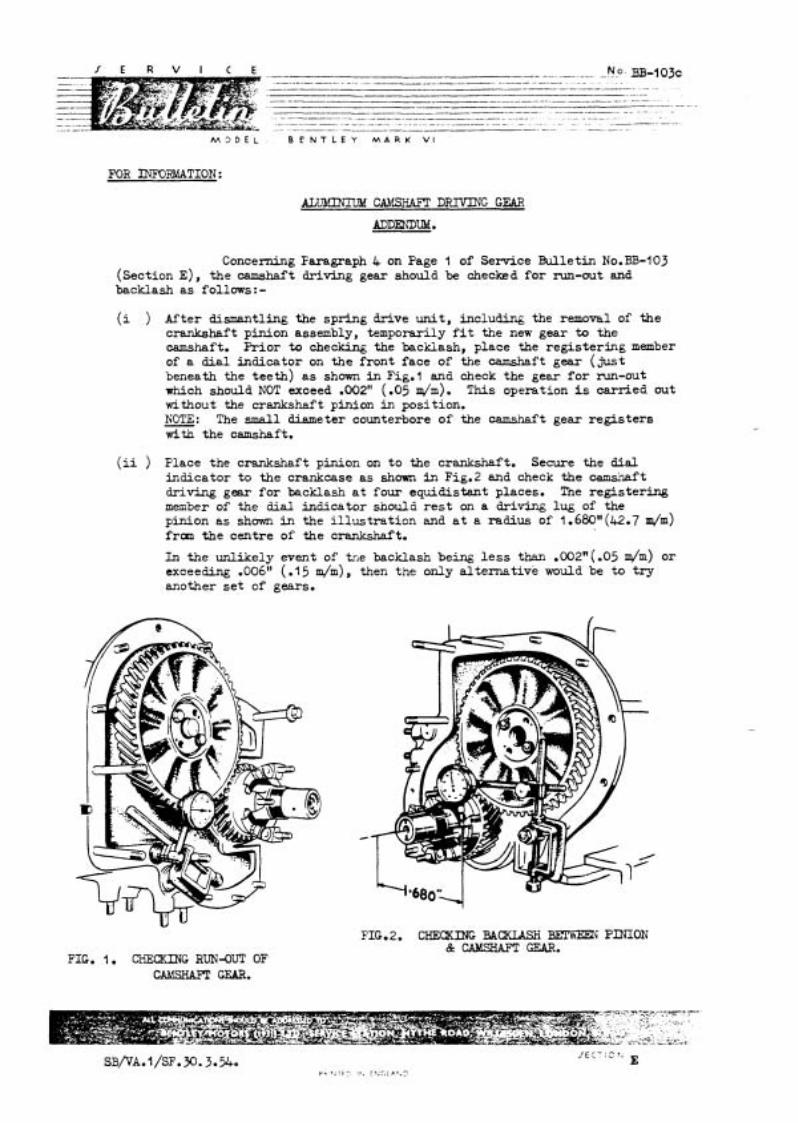
M 3 D E L B E N T L E Y M A R K V I
FOR r n R M A T I O N :
m m c m s m DRIVING GEAR
Concerning Faragraph 4 on Page I of Service Bulletin No.BB-I03 (section E) , the camshaft driving gear should be checked fo r run-out and backlash as f o l l m s : - (i ) After dismantling the spring drive un i t , including the removal of the
crankshaft pinion assembly, temporarily f i t the new gear to the camshaft. Pr ior to checking the backlash, place the regis ter ing member of a d i a l indicator on the front face of the camshaft gear ( j u s t beneath the teeth) a s shown in Fig. l and check the gear f o r m - o u t which should NOT exceed .002" (.05 6). T h i s operation i s carried out without the crankshaft p h i o n i n position. KOTE: The s m a l l diameter counterbore of the camshaft gear reg is te rs with the camshaft.
(ii ) Place the crankshaft pinion on t o the crankshaft. Secure the dial indicator t o the crankcase as shown in Fig.2 and check the camshaft driving gear fo r backlash a t four equidistant places. The registering member of the dial indicator should r e s t on a driving lug of the pinion as shown i n the i l l u s t r a t i on and a t a radius of 1.680"(42.7 m/m) fran the centre of the crankshaft.
Ln the unlikely event of trie backlash being l e s s than .002"(.05 d m ) or exceeding .00611 ( .l 5 h), then the only al ternat ive would be to t r y another s e t of gears.
FIG. 1. CHECKING RUN&U!C OF
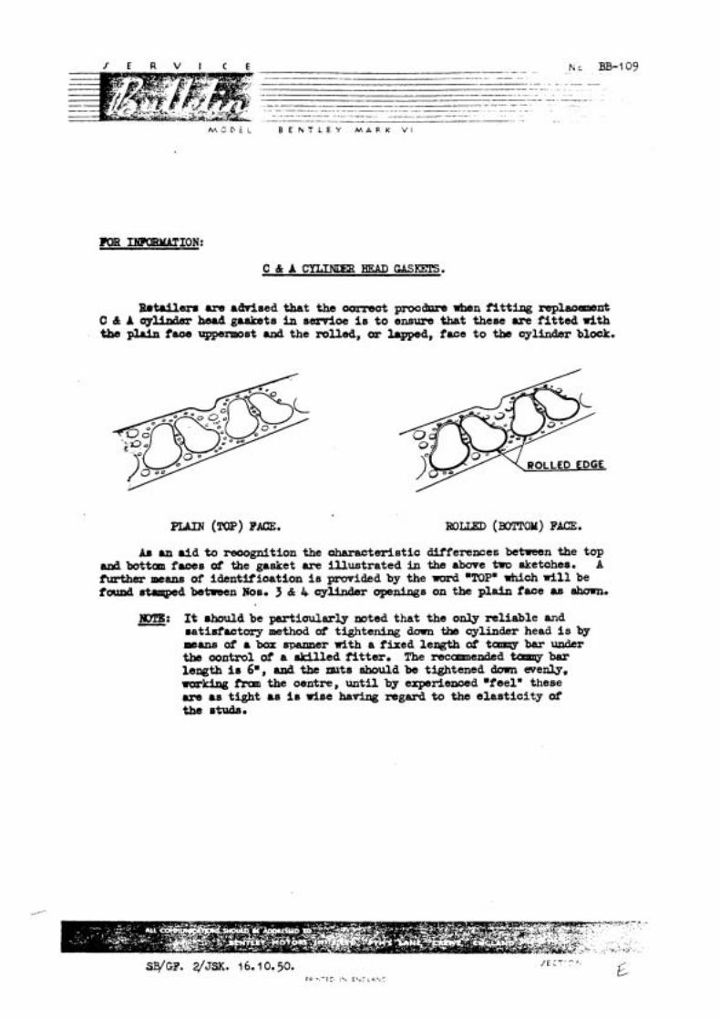
- . . -- .- . . K BB- - - - - - -- - - - -. -- - - - .-- . . -. p-- - - - - . -. - - -
--p ~
--P- -- p .- - -- - -- -. . - . - . - . . -- - -- - - - - - - - -. - - . ---p-------.-----------. - - - ...
- - .. . - - . - . - - . . - .. . . - . - - - . - . . . . - - - -. - . -- - - -. - .
--..---W .- . -- - . . - -.
M S P E L B E N T L E Y M A R K V1
Retailera a m a w s e d that the oomeut pxmdrua when f i t t ing r e p l m n t C d A oylbdm head gaskets k? asrrrioe i s t o ensure that these are f i t t ed with tbs plrin fam \qrpsrmost and the mlled, or lapped, face t o the cylinder block.
PLAIN (!W) FACE. ROLLED (XW20M) FACE.
84 an aid to ~ g n i t i o n the oharacteristia diiferences between the top and bottan f u x s of the gasket are i l lustrated in the above two aketuhes. A ftmther of identification i s provided by the word 'TOP" which w i l l be found &aqed between Ms. 3 8: 4 c y W r openings on the plain face as damn.
E: It should be partiaularly mted t h a t the only reliable and satisfactory method of tightening dam tb cylinder head i s by mancl of a box spanner with a fixed length of tamqy bar under the oonkcol of a skilled f i t t e r . The rscunnended tamy bar length i s 6., a& the lruts should be tightened down evenly, w&cbg tKm the cmntre, unti l by experienced .feelw these a m as tight as is r i se haw regard to the elast ici ty of the otuds.
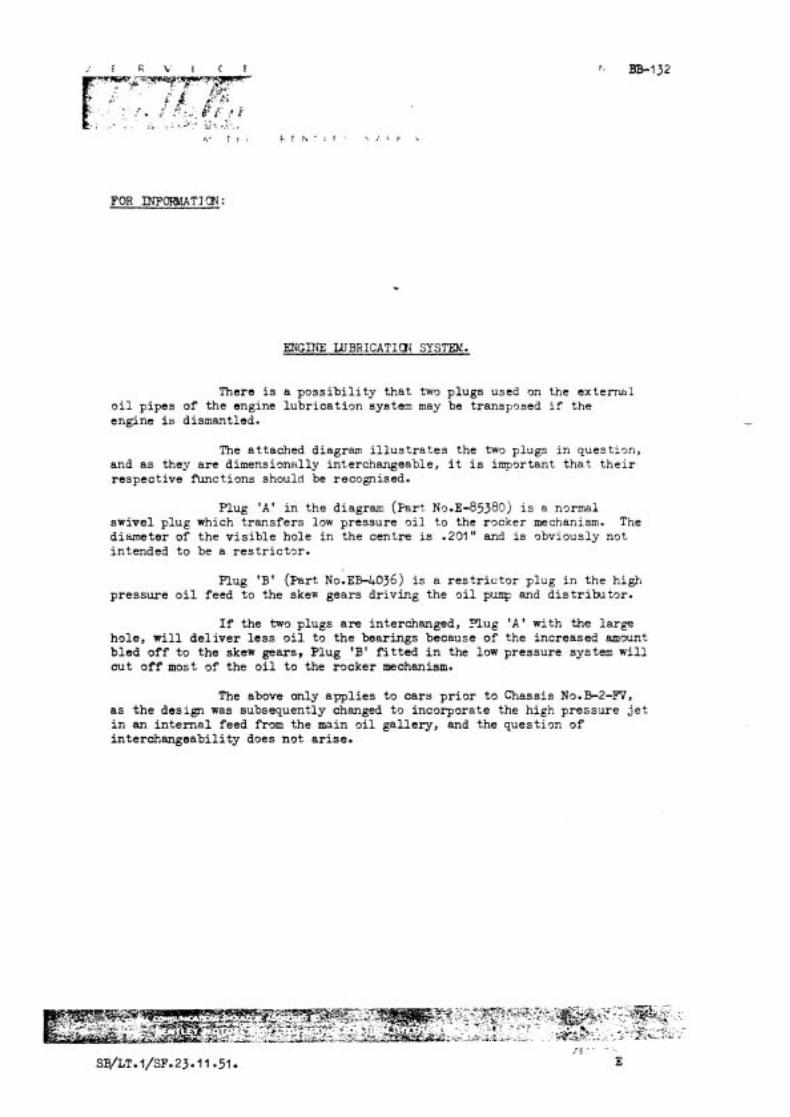
FOR INFOWIATIQN:
ENGINE WBRICATICN SYSTEM.
There is a p o s s i b i l i t y tha t two plugs used on the e x t e m l o i l pipes of the engine lubr ica t ion system may be transp9sed i f the engine is dismantled.
The at tached diagram i l l u s t r a t e s the tws plugs i n q u e s t i ~ n , and a s they a re d imens ion~l ly interchangeable, i t is important t h a t t h e i r respective functions should be recognised.
Plug 'A' i n the diagram (pa r t No.~-85380) is a n o r m 1 swivel plug which t r ans fe r s low pressure o i l t o the rocker mechanism. The diameter of the v i s i b l e hole i n the centre is .20l8 ' and is obviously not intended t o be a r e s t r i c t o r .
Plug 'B' (par t N O . E B - L + O ~ ~ ) is a r e s t r i c t o r p lug i n the high pressure o i l feed t o the skew gears driving the o i l pump and d i s t r i b u t o r .
I f the two plugs a r e interchanged, Plug ' A ' with the large hole, w i l l d e l i v e r l e s s o i l to the bearings because of the increased amount b led o f f t o the skew gears, Plug 'B' f i t t e d i n the low pressure system w i l l cut o f f most of the o i l t o the rocker mechanism.
The above only app l i e s t o ca r s p r i o r t o Chassis No.B-2-m, a s t h e design was subsequently changed t o incorporate the high pressure j e t i n an i n t e r n a l feed from the main o i l ga l lery , and the question of in terchangeabi l i ty does not a r i se .
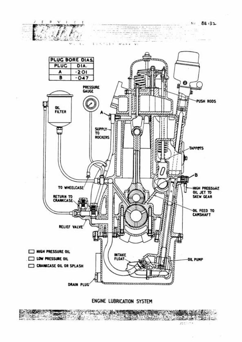
PLUG BORE OiA
0 0 4 7
O HIGH PRESSURE OIL
. r PRESSURE OIL
0 mmcAsE OIL OR SPLASH
ENGINE LUBRICATION SYSTEM

M 3 D E L B E N T L E Y M A R K V I
FOR r n F M A T I O N & ACTICN:
m FIJO'VV ENGINE OIL FILTERS.
A f u l l flow o i l f i l t e r is f i t t e d t o a l l engines from Chassis No.E2-MD onwards, and i t is of the UTM9ST IMFORTANCE THAT THE -T SHOULD E REKEWED AT PERIODS CIF 5,000 MILE'S RUNNWG.
I f the element becomes clogged, a f i l t e r by-pass device comes i n t o operation t o ensure the continued supply of o i l , but i n t h i s case there is no f i l t r a t i o n and f'urther running may harm the engine.
W i l l Re ta i l e r s p lease ensure t h a t they have adequate s tocks of elements and tha t t h i s operation is always included i n t h e Schedules A and B a t 5,000 and 10,000 miles.
An appropriate i n s e r t has been pleced in Owners Handbooks, b u t your co-operation is requested i n advising owners i n your t e r r i t o r y , who have f u l l flow f i l t e r s f i t t e d , o f the necess i ty f o r t h i s pe r iod ic maintenance.
M J D E L B E N T L E Y M A R K V I
FOR YNFORMATICN & ACTICN:
RENEWAL QF FILTER CARTRIDSE:
When renewing the ca r t r idge i n f u l l flow , w i l f i l t e r s , the conta iner should be f i l l e d with engine o i l t o a depth of l " a b w e the c i r c u l a r groove on the type with the six bo l t f i x i n g and 2" abwe the groove on the cen t re bo l t type, before r e f i t t i n g .
I f the container i s replaced empty, the re w i l l be a c e r t a i n time l a g before o i l pressure is regis tered on res ta r t ing , while t h e container i s f i l l i n g up. This delay in the supply of o i l t o the engine may have a detrimental e f f e c t on the u l t ima te l i f e of bearings.
ACCESSIBILITY :
Q-I right-hand dr ive cars , access t o the f i l t e r is e a s i e r i f the carburet tor intake branch is remmed.

M L ' D E L B E N T L E Y M A R K V1
FOR momTION: mu now ENGINE OIL FILTER.
GENERAL: Full flow f i l t r a t i o n was introduced on Chassis N0.B-2ddD.
The scheme dispensed with the ,Ey-Pass f i l t e r and embodied a Vokes Type E-30 f i l t e r interposed in the o i l delivery l i ne between the o i l pump and the crankcase o i l gal lery which feeds the main bearings.
The crankcase cast ing was a l te red for th i s purpose, the ve r t i ca l passage t o the gallery being diverted to the lower or if ice of a new "external" facing approximately 3" ( 7 6 4 l m ) above the o i l r e l i e f valve unit; the upper o r i f i ce i n th i s facing c o ~ i c a t i n g with the gallery. The pipes leading t o ard from the Vokes f i l t e r , and also the o i l pressure gauge pipe, are connected to an adaptor mounted on the facing. Fig.3 i l l u s t r a t e s the external layout, but depicts a Vokes E 6 2 f'ilter(centre bol t l i d fixing)which is now used instead of the E-30 type (six bolt l i d fixing).
I n order to meet requests fo r the in s t a l l a t i on of full flow f i l t r a t i o n on cars prior to B-2dD, two separate schemes a re described l a t e r in t h i s Bulletin.
SCHEME 'A' conforms to the layout shown i n Fig.3, and i s re la t ive ly si-mple .in ins ta l la t ion , being confined to external a l te ra t ion only. It can be applied to engines, the crankcaee of which have the adaptor facing referred to abwe. Generally speaking, t h i s modifioation to the crankcase was f i r s t introduced a t the commencement of 'H' se r ies t o provide a m e a n s of employing fill flow f i l t r a t i o n on uni t t e s t , and i n anticipation of the scheme becoming standardisal l a t e r . Crankcasesof t h i s type may be recognised by reference t o Figs. 1 & 2, which show special adaptors used i n conjunotion with the original Ely-Pass Fi l ters .
SCHEME 'B' i s applioable where the adaptor facing is non-existent, and other means of diverting the main o i l supply are neoessary, involving crankcase d r i l l i n g and internal a l te ra t ion of oilways. For t h i s reason, the work is best undertaken with the engine out of the chassis, on the grounds of both accessi- b i l i t y and cleanliness.
THE RRdWAIr OF WARP FROM THE SYSTEM FOLLOWING MODl3'ICATION CANNOT BE WO GREATLY STRESSED.
FIG.1 -ADAPTOR-OIL FEED(EARLIER m) FIG. 2 .MOR-OIL PEED(LATER TYPE)
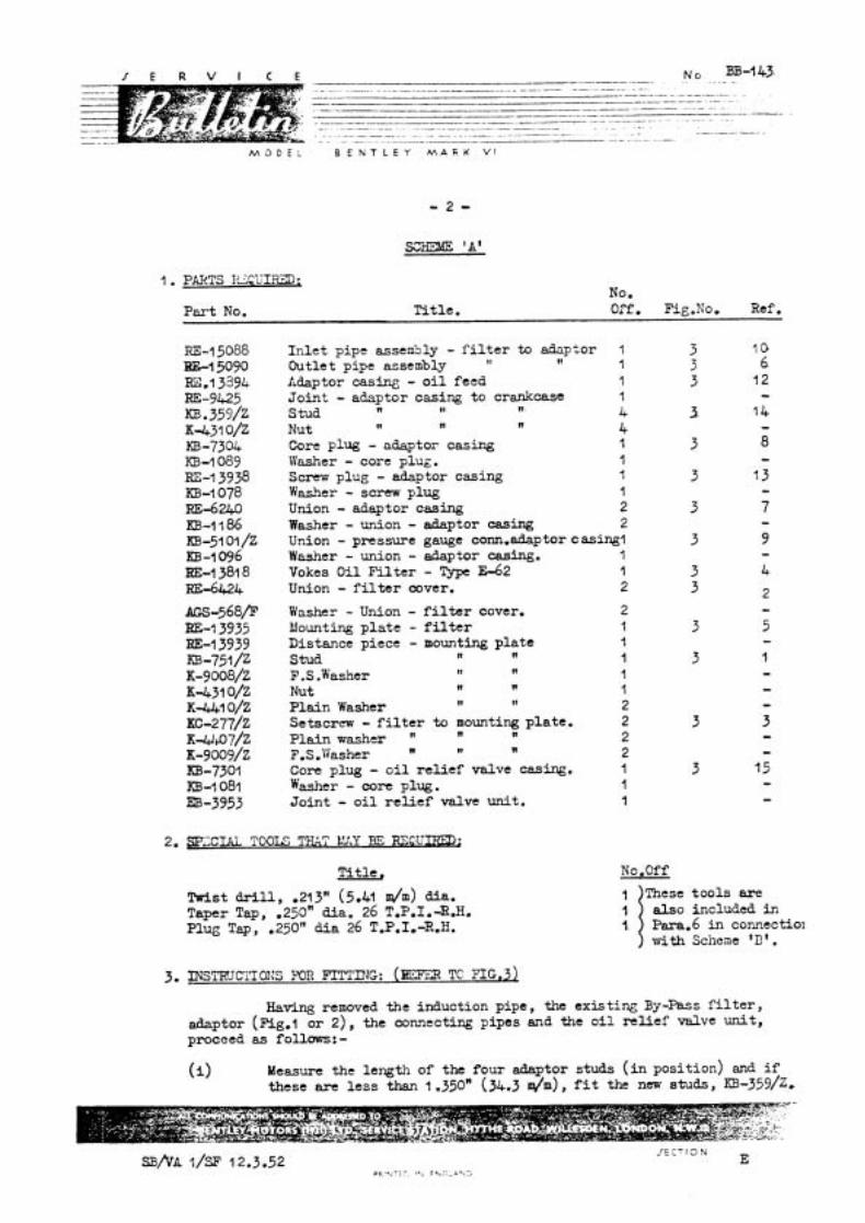
M 3 D E L B E N T L E Y h ? A K K V '
1 . PARTS I ' Z C U I r n ; No.
Ti t le . Orf. Fig.No. Ref. P a t No.
RE-1 5088 B-l 5090 m.13394 RE-9425 m3.359/z 94-31 0/Z KB-7304 KB-I 089 m-I 3938 KB-1078 RE-6240 KB-4 I 86 m-51 01 /z KE-1096 HE-1 381 8 RE-6424
AGS-568/F BE-1 3935 m-1 3939 KB-751 /Z ~ - 9 0 0 8 / ~ K--431 O/Z K* o/z ~c-277/2 K-W~O?/Z K - ~ O O ~ / Z KB-7301 m-I 081 m-3953
I n l e t pipe assen3ly - f i l t e r to adaptor 1 Outlet pipe assembly 11 11 l Adaptor casing - o i l feed 1 Jo in t - adaptor casing to crankcase l Stud n II n 4 Nut n n n 4 Core plug - adaptor casing l Washer - core plug. 1 Screw plug - adaptor casing 1 Washer - screw plug l Union - adaptor casing 2 Washer - union - adaptor casing 2 Union - pressure gauge conn.adaptor C asingl Washer - union - adaptor casing. 1 Yokes O i l F i l t e r - Type E-62 l Union - f i l t e r cover. 2
Washer - Union - f i l t e r cover. Mounting p l a t e - f i l t e r Distance piece - mounting p la te Stud n n
F. S .Washer II n
Nut n n
Plain Washer 11 l1
S e t sc rm - f i l t e r t o mounting plate . Plain washer n n F.S .Washer n 11
n . ~
Core plug - o i l r e l i e f valve casing. Washer - core plug. Jo in t - o i l r e l i e f valve unit.
!Pi t l e , ~ w i s t drill, ,213" (5.41 dm) &a. Taper Tap, .250n dia. 26 T.P.I.-R.H. Plug Tap, .2501' d i a 26 T.P.1.-R.H.
INSTRUCTIOI?S FOR FITTING: (= TC PIG.^)
No .Off
These too ls are also included i n Para.6 i n comect io~ with Scilese 'B ' .
Having removed the induction pipe, the existing By-Pass f i l t e r , adaptor (Rig.1 o r 2) , the connecting pipes and the o i l relief valve u n i t , proceed as follows: - (i> Measure the length of the four adaptor studs ( i n position) and i f
these are l e s s than 1 .350H (36.3 h), f i t the new studs, ~ ~ - 3 5 9 / ~ .

.. - -- .- - - - - - - - - -. . . . - - -. -. - - . - --p - .- --- . - . - - - -. .. - - -
. p--.- - - .~ .. - -- ~- - -
- .-.-.-..------------U-----. .- - - -- ... - - p . -- .. - - ~-
-- -. - - -- - . .~~ - - .
- . . .. . - . ... ---- - - - . . .. .- -- - . - .- - - .- . F - - .. - . .-.-.--..-------p p --- . . . . . - -- -
B E N T L E Y M A R K V I
( i i ) Remwe the union from the o i l r e l i e f valve un i t , and with a su i t ab le p i n spanner, f i t the c c r e plug(l 5)and j o i n t washer. Ref i t the u n i t t o the crankcase inc17ding a new joint , EE-3953.
(iii) F i t t h e following p a r t s t o the adaptor casing(12). The two unions ( 7 ) , the core plug ( 8 ) , the union(9), and the screw plug(13), to- gether with t h e i r j o i n t washers. F i t the adaptor and i ts j o i n t t o the crankcase.
( i v ) Observe whether the crankcase f r o n t lug, ' A ' I?ig.8(situated a t t ap of cyl inder block on R.Ii.side of crankcase, ) has been machined back ani tapped t o take s tud (1). If not, proceed as follows:-
a) F i l e back the face of the l u g u n t i l the f i l t e r mounting p la te (5 ) when offered up t o the crankcase l i e s FLAT agains t t h i s lug and the two lower studded lugs.
b ) With the f i l t e r mounting p l a t e i n pos i t ion , c e n t r a l i s e i t s two lower holes with t h e ex i s t ing s tuds on t h e crankcase and temporarily secure in posit ion. Using t h e mountin l a t e as a template, nark o f f the l u g and drill a .213"(5.41n$mPdia. hole t o a depth of .450"(11 .A2 m/m) and tap .250" dia . 26 T.P.1.-R.H. Remove t h e momting p l a t e and fit the s tud(1) K B - ~ ~ I / z . This makes the 3rd f i x i n g point f o r the f i l t e r mounting pla te . NOTE: I f the lug referred t o above has been machined back, then - it w i l l be necessary t o f i t t h e c i r c u l a r d is tanoe piece,R.E-13939, t o the s tud in terposing it between the mounting p l a t e and the lug when carrying out the next operations (v).
C . 3 F7X)NT I?LEVATION - PULL F'LOCi O I L FILTER.
-- -p-..-..-- No: .. 33-..1&3 . - -- -- - -
---.U- p - - - - - -. . -. -. - .
M O D E L B E N T L E Y M A R K V I
F i t the two unions (2 ) and jo in t washers t o the f i l t e r . Attach the f i l t e r t o the mounting p l a t e (;), by means of' the trvo se t - screws ( 3 ) , s p r i q and p l a i n washers and f i t the asstmbiy to the crankcase.
With a syringe, i n j e c t a recommended S.A.E.20 e n ~ l n e o i l i n t o the f i l t e r througl~ EACH of the two unions u n t i l i t i s f u l l , then connect tllc i n l e t and o u t l e t o i l p ipes (10 Cc 6) to th:: t r a n s f e r block and f i l t e r .
( v i i ) Connect the e x i s t i q f l e x i b l e o i l feed pipe, l 1 , (from pressure gauge) t o the adaptor.
( v i i i ) Af te r the i n s t a l l a t i o n of the F u l l F ~ O Y I o i l f i l t e r , tnc f i l t e r systcn must be primed vvith en@ne o i l as fo1 lms : -
a ) Before s t a r t i n g up tnc e n ~ i n e , unscrex the union nut of the i n l e t o i l pipe (10) from the union on the f i l t e r , an- with a s y r i n ~ e , f i l l y prime the pipe and then prime the o i l f i l t e r . Reconnect the uqion nut.
b) E'k'hen s t a r t i n g U;, the engine, a l l o x i t t o i d l e u n t i l pressure shows on the o i l gauge.
c ) Vhen e n ~ i n e i s warmed up, check all connections f o r o i l leaks ,
( i ) The fol loviny l e d l e t s w i l l be sent uncier separzte cover which must be inse r t ed i n the Owner's Hnndbook t o advise h i m of the change and the necessary a l t e r a t i o n s f o r maintenance which t h i s modification has involved,
Leaf'let SB/3/51. ( ~ l i s h Leaflet 3/4/51. ( ~ n ~ l i s h
Leaf le t ~!/3/51. Leefle t =/U51 .
W i l l R e t a i l e r s p lease not* the b n d o n Senrice Sta t ion of t h e chass i s number of the c a r whenever they f i t a Full Flmi O i l F i l t e r , e i t h e r t o Scheme 'A' o r 'B'.
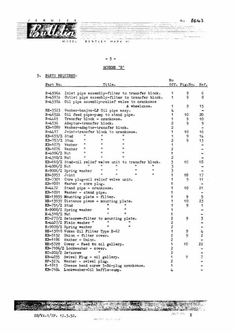
I E R V I C E K G . ~ 6gri+3 .- . . -. .. . . . . - - - .. .- . - - -- . -- . . . . . . - . - -. .- - . - .
-.------.-.------p--.-..p----.-.-.----.---- ..-- -- .--.. - -
--.p-.-...- ---..--p--.-. - - .- - . . - - . -. - . . . -
.- -.~ -. ... - . . . . - . ~~ . -
- - - ~ .. -. --.-. .. - -- -- . . ~.
M 3 D E L B E K T L E Y M A R K V I
5. PmTS REQUImD: No
Part No. Ti t le . Off.
R-4596A In l e t pipe assembly-filter t o t ransfer block. l R-4597A Outlet pipe assembly-filter t o transfer block. l R4598A O i l pipe as sembly-relief valve to crankcase
& wheelcase. 1 RJ3-3523 Yiasher-banjos-LP O i l pipe assy. 4 R-4652A O i l feed pipe-pump t o stand pipe. l R 4 6 9 Transfer block - crankcase. 1 R-4536 Adaptor-transfer block. 2 ICB.1089 Washer-adap t o r t r a n s f e r block. 2 R 4 9 7 Joint-transfer block t o crankcase. l K0-65?/~ Stud t1 t I 11 I ~ ~ - 7 5 7 / z StIifi " 11 11 2 KB-l075 Washer " 11 11 l KB-1076 Washer " II II 2 ~-4.006/~ Nut to t I 11 l K431 O/Z Nut II II t t 2 -~o/z Stud-oil r e l i e f valve unit t o transfer block. 3 K-4006/~ N u t 11 11 11 t t
11 3 K-9006/~ Spring washer " I t t t t t 3 EB-3953 Joint I t I t I 1 t I l lU3-7301 Core plug-oil r e l i e f valve unit. l KB-l081 Washer - core plug. 1 R 4 7 2 Stand pipe - crankcase. 1 KB-l091 Washer - stand pipe. 1 RE-13935 Mounting p l a t e - f i l t e r . 1 RE-13939 Distance piece - mounting plate. l KB-751/~ Stud n I t 1 K-9008/~ Spring washer et 11 1 K-431 O/Z Nut (I 11 1 KC-277/~ Setscrew-filter t o mounting plate. 2 X-4407/2 Plain washer I$ I) 2 K-9009/~ Spring washer II n 2 RE-13818 Vokes O i l F i l t e r Type E-62 1 KB-5132 Union - f i l t e r cover. 2 KB.1186 \Sasher - Union. 2 RE-5720 Cwer - Feed t o o i l gallery. l KB-7106 Z Lockwasher - cover. y/ 2 KC-20 Z Setscrew 11 2 EB-4035 Swivel Plug - o i l gallery. l RF-3274 Washer - swivel plug. 2 K-l81 3 Cheese head screw 3-BA-plug crankcase. l KB-7104 L~ckwasher-Oil baf fle-sump. 4
Fig.Ne. Ref.
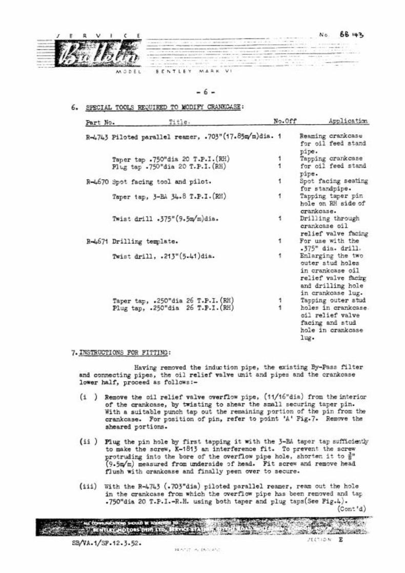
6. SPECIAL TOOLS FQ34UIRED TO MODIFY CRWKMSE:
Par t No. T i t l e . No.Off Application
R-4743 P i lo ted p a r a l l e l reamer, .703" (l 7.85dm)dia. 1
Taper tap .750Ndia 20 T.P.I. (RH) 1 Plug tap .750I1dia 20 T.P.I. (RH) l
R-1-670 Spot facing too l and p i l o t . 1
Taper tap, 3-RA 34.8 T.P.I. (RH) 1
Twist drill .375" (9.5dm)dia. l
R-4-671 D r i l l i n g template.
Twist drill, .213"(5.41)dia.
Taper tap, .250"dia 26 T.P.I. Plug tap, .250t'dia 26 T.P.I.
Reaming crankcase fo r o i l feed stand pipe Tapping crankcase for o i l feed stand pipe. Spot facing seating fo r standpipe. Tapping taper p in hole on RH s i d e of crankcase. D r i l l i n g through crankcase o i l r e l i e f valve facing For use with the .375" dia. d r i l l , Enlarging the two outer s tud holes i n crankcase o i l r e l i e f valve and d r i l l i n g hole i n crankcase lug. Tapping outer stud holes i n crankcase. o i l r e l i e f valve facing and s tud hole i n crankcase lug*
7. I?LCX"RUCTIONS FOR FITTING:
Having removed t h e i n d x t i o n pipe, t h e ex i s t ing By-Pass f i l t e r and connecting pipes, the o i l r e l i e f valve uni t and pipes and the crankcase lower ha l f , proceed a s follows:-
( i ) Remove the o i l r e l i e f valve overflow pipe, (l 1/16"dia) from the in ter ior of the crankcase, by twis t ing t o shear the smll securing taper pin. With a s u i t a b l e punch t a p out the remaining por t ion of the p i n from the crankcase. For pos i t ion of pin, r e f e r t o po in t 'A' Fig.7. Remcnre the sheared port ions.
( i i ) Plug the p i n hole by f i r s t tapping i t with t h e 3-BA taper t ap sui%cimt& t o make the screw, K-l813 an in ter ference fit. To prevent the screw protruding i n t o the bore of t h e overflow p ipe hole, short,en i t t o 2" (9.5dm) measured from underside of head. F i t screw and remove head f l u s h with crankcase and f i n a l l y peen Qver t o secure.
( i i i ) With the R-4743 (.70jWdia) p i lo ted p a r a l l e l reamer, ream out the hole i n the crankcase from which the crverflow p ipe h3s been removed and tap .75OR'dia 20 T.P.1.-R.H. using both taper and plug taps(see ~ i ~ . 4 ) .
( ~ o n t 'd)
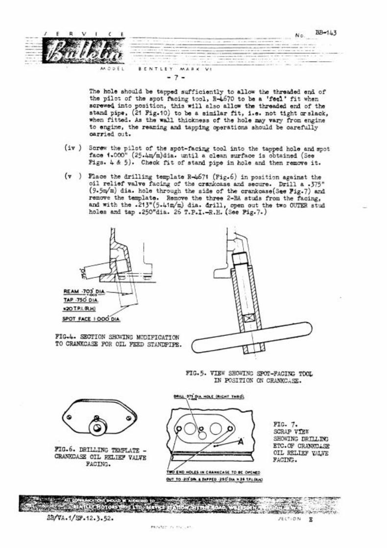
M 3 D E L B E N T L E Y M A R K V I
- 7 -
The hole should be tapped suf f ic ien t ly to allow the threaded end of the p i lo t of the spot facing tool, R4670 t o be a 'feel ' f i t when screwed into position, t h i s w i l l a l so allow the threaded end of the stand pipe, (21 ~ i g . 1 0 ) t o be a similar fit, i.e. not t ight arslack, when f i t ted. A s the w a l l thickness of the hole may vary f'rorn engine t o engine, the reaming and tapping operations should be oarefully a r r i e d ol~t.
( i v ) Screw the p i l o t of the spot-faciw tool in to the tapped hole and spot face 1.000" (25.Wm)dia. un t i l a clean surface i s obtained (see Figs. 4 & 5). Check fit of stand pipe i n hole and then remove it.
(v ) Place the d r i l l i ng template ~4.671 (I?iE.6) i n position against the o i l r e l i e f valve facing of the crankoase and secure. D r i l l a .375" (9.5dm) dia. hole through the side of the crankcase(~ae ~ i g . 7 ) and remove the template. Remwe the three 2-BA studs from the facing, and with the .213"(5.41m/mS dia. d r i l l , open out the two OUTER stud holes and tap .250ndia. 26 T.P.1.-R.H. (see ~ i ~ * 7 - )
TAP .75d DIA.
s2OTP.I. (R.W
!SPOT FACE 1,006 DIA.
FIG41 SECTION SHO'KtNG MODIFICATION TO CRANKCASE FYlR OIL =D STANDPIPE.
FIG.5. V I E W SHOWING SPOT-FACING T a IN FQSITIOK ON CRANKCASE.
FIG.6. DRILLDTG TE~PUTE - CRANKCASE OIL RELIEF VALVE
FACING.
FIG. 7. SCRAP VBW SHOWING DRIUING ETC. OF' CWJICCkSE OIL RELIEF FACING.
&'END HOLES IN CRANKCASE TO BE OPENED
OUT TO .ztf D*. TAPPED .zso.ou r 26 T.P.L(W
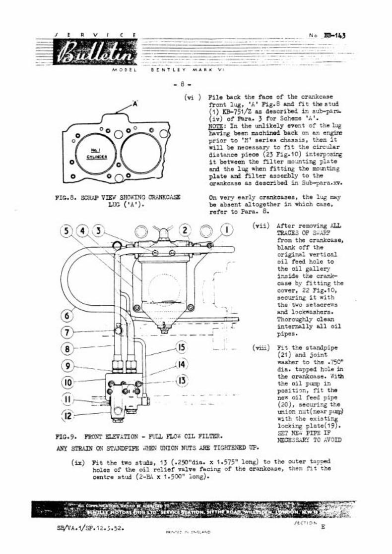
I C E l N o ..BB-l&3 . - - - - -. - - - .. . . . . . . . _ _ .. . . . -~ - -. -
(vi ) Fi l e back the face of the crankcase front lug, 'X' Fig.8 and f i t the stud ( l ) KB-751/~ as described in sub-para. ( i v ) of Para. 3 for Scheme 'A '. NOTE: I n the unlikely event of the lug - having been machined back on an e w pr ior t o 'H' se r ies chassis, then it w i l l be necessary t o f i t the circular distance piece (23 ~ i g . 10) interpgsbg it between the f i l t e r mo;mting plate and the lug when f i t t i n g the molmting p la te and f i l t e r assembly t o the crankcase as described in Sub-para.xv.
FIG. 8. SCRAP VEZW S H D h ' G CRANKCASE On very ear ly crankcases, the lug may LUG ( ' A ' ) . be absent altogether i n which chse,
refer to Para. 8.
( v i i )
( v i i i )
FIG. 9. FRONT EZEVXTION - m no'ti OIL FILTER.
ANY STRAIN ON STANDPIPE irTZN UNION NUTS AP3 TIGHTENED UP.
After removing AIL TRkCES OF Sf';;LRF from the crankcase, blank off the original ver ti c& o i l feed hole to the o i l gallexy inside the crank- case by f i t t i n g the cover, 22 Fig.10, securing i t with the two setscrews and lockwashers. Thoroughly clean internal ly all o i l pipes.
F i t the standpipe (21 ) and joint washer t o the .7501' dia. tapped hole in the crankcase. iVith the o i l p q in pos i t im , f i t the new o i l feed pipe (20), securing the union nut (near p ~ ) with the ex i s t i locking p l a t e ( l 3 . SET NEii P E 3 IF NECESSARY TO AVOID
(ix) F i t the two studs, l J (.29"dia. X 1.575" long) t o the outer tapped holes of the o i l r e l i e f valve facing of the crankcase, then ? i t the centre stud (2-BA X 1.500" iong).

M 2 C k L B E K T L E Y M A R K V i
- 9 -
(X ) F i t the three studs, 18 (2-BA X 7.600" long) t o the t ransfer block ( l 0 fig.^), a l so the two adaptors (9) and joint washers. Place the block complete with i ts Vellumoid joint R-4497, on t o the crankcase. hQTE: As the jbint is - similar t o the joint (EB-3953) for the o i l r e l i e f valve uni t ex- cept for a -375" (9.5i.aJfn) diameter hole i n the former, i t i s inportant the the CORRECT joint is f i t t ed . Plaae an aluminium washer only on t o each of the three studs and seoure. (NO OTFER WmRS ABE REJJIRED).
( x i ) Remove the union from the o i l r e l i e f valve un i t and f i t the core plug (1 1 ) and joint washer. Place the un i t and the Vellumoid joint (EE-3953) on to the t ransfer block. iiihile tightening up the three nuts to secure, check . --.-.L <L . - . - -- -. - - . - .
' -- -. - . -_ 3 tha t the end of the centre stud (14) or nuts
F1G.101 EYD ELEVATION - FULL F L D W O n FILTER. securing the t ransfer block t o the crankcase do not foul the casing
( x i i )
of the o i l r e l i e f valve unit . The uni t is in- verted for f i t t i n g m&r t h i s arrangement as shown i n Fig. 9.
Remove the exis t ing two- way feed swivel plug from the tapped boss s i tuated midway along the o i l gal lery on RA
FIG. 11. C W A S E LO'tI,'ER HALF'. s ide of engine. Place the banjo connection of the exis t ing f lexible
o i l feed pipe (tb pressure gauge) and joint washers on t o the nex one-way feed swivel plug, EB.@35 E O - ~ screw i t in to the boss.
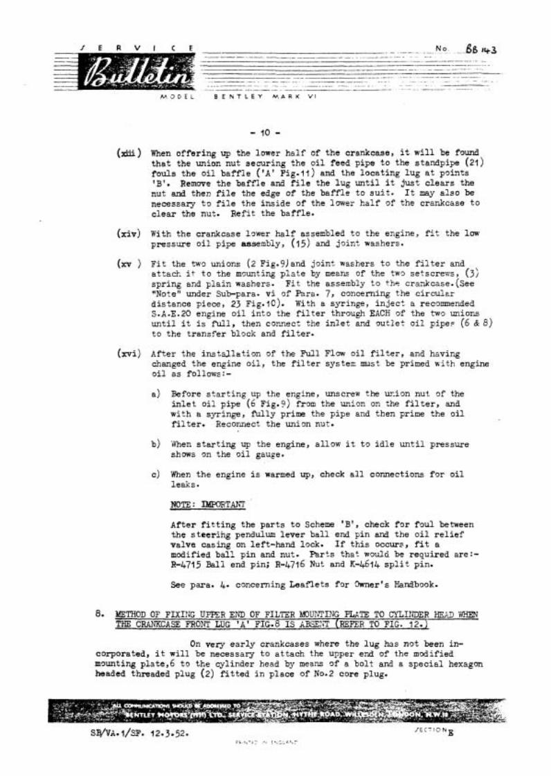
. - NO. -..g0 143 . . . . . . -- - .- . - - - W - - - - - -- .- -- . - .. -- ....
-p-- -- ..... ...-........- - p---. - - -p-.
.... . - . - . . ........ ---p -----p-..--- -- . . . . . . . . . . . . . . . . .
. ---.--.- . . . . . . . --- . . . . . . . . . . -.-..-----.-..-.-.----...-.-----.--p- .. . - .
M O D E L B E N T L E Y M A R K V I
(16%) When of fe r ing up the lower ha l f of the crankcase, it w i l l be found t h a t the union nut securing the o i l feed pipe t o the standpipe (21) fou l s the o i l b a f f l e ( ' A ' Fig-11) and the loca t ing lug a t points ' B ' Remwe the b a f f l e and f i l e the lug u n t i l i t jus t c l e a r s the nut and then f i l e the edge of the b a f f l e t o s u i t . It may a l s o be necessary t o f i l e the ins ide of the l m e r ha l f of the crankcase t o c l e a r the nut. Ref i t the ba f f l e .
(xiv) With the crankcase lgwer h a l f assembled t o the engine, f i t the low pressure o i l pipe assembly, (15) and jo in t washers.
(xv ) F i t the two unions (2 Fig.9) and jo int washers t o the f i l t e r and attack, i t t o the mounting p l a t e by means of the two setscrews, (3) spr ing and p l a i n washers. F i t the assembly t o t he crankcase. (see "Note" under Sub-para. v i of Para. 7, concerning the c i r c u l ~ r d is tance piece, 23 ~ i g . 10). With a syringe, i n j e c t a recommended S.A.E.20 engine o i l i n t o the f i l t e r through EACH of the two unions u n t i l i t is f u l l , then connect the i n l e t and ou t l e t o i l pipes (6 & 8) t o the t r ans fe r block and f i l t e r .
(xvi) After the i n s t a l l a t i o n of the Ful l Flow o i l f i l t e r , and having changed the engine o i l , the f i l t e r systen: must be primed with engine o i l a s follows:-
a) Before s t a r t i n g up the engine, unscrew the x i o n nut of the i n l e t o i l pipe ( 6 Fig.?) from the union on the f i l t e r , and wi th a syringe, f i l l y prime the pipe and then prime the o i l f i l t e r . Reconnect the union nut.
b) iYhen s t a r t i n g up the engine, allow i t t o i d l e u n t i l pressure shows on the o i l gauge.
c) When the engine i s warmed up, check a l l connections f o r o i l leaks.
NOTE: IMWRTfiT
After f i t t i n g the p a r t s t o Scheme 'B' , check f o r f o u l between the s t e e r i n g pendulum lever b a l l end pin and the o i l r e l i e f valve casing on left-hand lock. If t h i s occurs, f i t a modified b a l l p in and nut. PBrts tha t would be required are:- R-4715 Ball end pin; R-4716 Nut and K-46f4 s p l i t pin.
See para. 4. concerning Leaf le ts fo r h e r ' s Handbook.
8. blETHOD OF FIXIIJG UPPER END OF FILTER blOU?PTING PLKTE TO CYLINDER H?UD WHEN THE CRANKCASE FRONT LUG 'A ' FIG.8 IS kBSE??T (REFER TO FIG. 12.)
On very e a r l y crankcases where the l u g has no t been in- corporated, i t w i l l be necessary t o a t t ach the upper end of the m d i f i e d mounting p la te ,6 t o the cylinder head by means of a bo l t and a spec ia l hexagon headed threaded plug (2) f i t t e d i n place of No.2 core plug.

M , 1 D k . B E N T L E Y M A R K V I
FIG* I 2. METHOD OF FIXING FILTER IsKUNTING ~ T E TO CYLIM;IER HE3.D.
PARTS REQUIRED:
Par t No. Title. No.Off Fig.No. Ref.
D1092 Washer - plug l 1 2 RE-9015 Plug - cylinder head. l It
RE-13939 Distance piece - plug. l (additional) " K C - ~ O ~ / Z Bolt - mounting plate. l n
K-9008/~ Spring washer - bolt . l II
R-4747 Mounting p l a t e - f i l t e r . 1 )I
NOTE: When the above pa r t s are required, the following parts which figure in Pars. 5 f o r Scheme 'B' w i l l not be needed.
Part No. Title. No.Off.
RB-13935 Mounting p l a t e - f i i t e r . l
=751/~ Stud. n l
E R V I E No. BB.143~ . . - - --- - - - - -
M O D E L B E N T L E Y M A R K V I
mu FLOW ENGINE O I L FILTER.
Concerning Scheme 'B' of Service Bul le t in ~ o . ~ B = 1 4 ~ ( ~ e c t i o n E ) , i t has been brought t o our no t i ce that in one or two instances the ex te rna l i n l e t and ou t l e t o i l feed pipes, (6 & 8 ~ i g . 9 ' of Bul le t in ~ 0 . ~ ~ 1 4 3 ) t o and from the Fu l l Flow F i l t e r have been reversed when f i t t i n g t o the t r a n s f e r block (10). This arrangement causes the f i l t e r element t o col lapse and block the o i l flow-
To obviate t h i s , we have re-designed the two o i l pipes on which add i t iona l bends have been incorporated t o make it impossible f o r the p ipes t o be incorrect ly f i t t e d , but u n t i l the ex i s t ing stocks a r e used up, care must be taken t o see t h a t the pipes a r e cor rec t ly connected. To a s s i s t in t h i s , we have marked the pipes a t the t r ans fe r block end, "Frontn and "Rear" and they should be f i t t e d accordingly.
It w i l l be observed upon reference t o Fig. 9, t h a t the lower end of the i n l e t o i l pipe ( 6 ) is connected t o the right-hand s i d e of the t r a n s f e r block and the o u t l e t o i l pipe (8) t o the left-hand s ide -

M O D E L B E N T L E Y M A R K V I
For C a t e ~ o r y 2 Action
MODDICAT I O N
Aluninium Core Plugs S' Bore Engine
On c e r t a i n g" bore engines two aluminium a l loy core plugs were f i t t e d on the l e f t hand s i d e of the crankcase above the tappet covers a s shown a t A Fig.1.
The aluminium plugs have proved subject t o corrosion i n service and a r e t o be replaced with oadmiunplated s t e e l core plugs and aluminium washers a s a re t rospect ive modification. R e t a i l e r s a r e asked t o ca r ry out replacement on a l l ai 'fected ca r s i n t h e i r area when they a re next being serviced.
A FIG. l LOCATION OF CORE PLUGS
Chassis Numbers Affected
Bentley Mk. V 1
B.2 YID t o B.169 SP inc lus ive
B.187 SP t o B.201 SP inc lus ive
B.207 SP and B.255 SP
Bentley Continental
BC-l -A t o BC-14-B inclus ive except BC-1 7-8
J E C T I O N
SB/VK/CL 1.10.53 P R I N T E D IN F h C L A N D E

I E R V I C E
M O D E L
. -- . . rlJ 0 _. -~ac145 ..-.---p--. --..----.-p---- ~ -- - -
-p- -- - - - - -. - - - - - - ------p - ---p - .-. . - - -- -. . - - . - -- p - p - - - .. -. - - . . .- -. - - - -. -- .- -- -. .- . - - - . - - - . . - - . -- - - - - . - . - . . .- . - -- . - - -- . -. - . . -. . . - - - - . . - - - - . - - . . - .. -. .
. ... -..-- ~ - - -- .- - . - . . - - . .. ---- - - - .-. -. -- --p - -. . . W .. . . - . .
B E N T L E Y M A R K V I
Tools Required:
Core plug spanner B.4956 Tap 5" X 20 T.P.I. second.
RE. 20740 Care plug water jacket 2 off (Rephcea XB. 7301 ) E.27488 Washer, aluminium 2 off
Special arrangements rre being made t o despatch & s e t of tools and a supply of core plugs to Retailers affected.
Procedure :
The spanner supplied enables the care plugs t o be replaced without removing the exhaust manifold.
( i ) Drain the cylinder block.
(ii ) Remwe the aluminium core plugs, clean the threads w i t h the tap provided and fit the s tee l plugs and aluminium washers.
( i i i ) Refil l the cooling system.
A time of 2 hours is Pllorred and charges should be submitted on Guarantee Forms in the usual way.
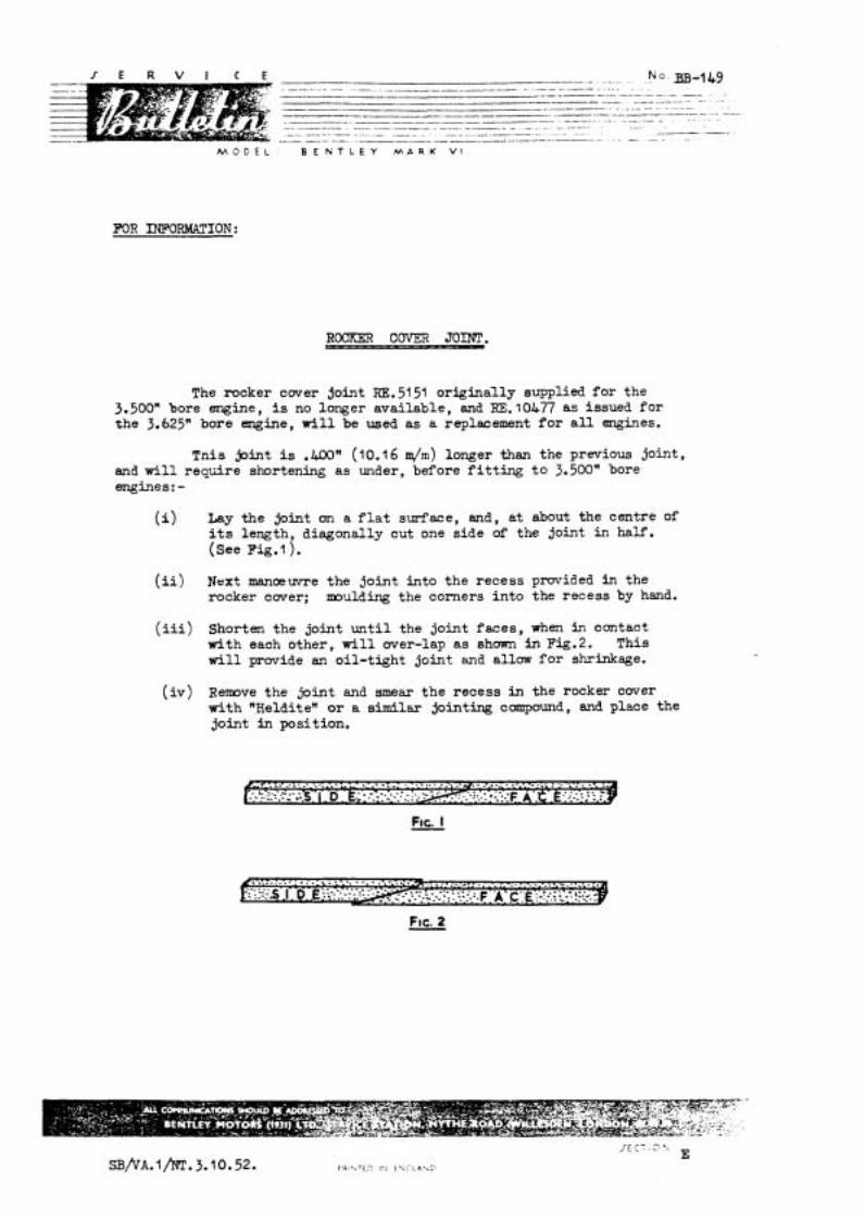
M O D E L B E N T L E Y M A R K V I
FOR INFORWLTION:
The rocker c w e r joint RE. 51 51 or iginal ly supplied fo r the 3.500" bore engine, is no longer available, and RE. 10477 as issued fo r the 3.625" bore engine, w i l l be used as a replacement f o r a l l engines.
Tnis joint is .400" (10.1 6 m/m) longer than the previous joint, and w i l l r e q ~ r e shortening a s under, before f i t t i n g t o 3.500" bore engines: -
(i) Lay the joint on a f l a t surf'ace, and, a t about the centre of i ts length, diagonally cut one side of the joint in half. ( see Fig.1).
( i i ) Next IIIanQwre the joint into the recess provided i n the rocker cwer ; moulding the corners i n to the recess by hand.
(iii) Shorten the joint u n t i l the joint faces , when i n contact with each other, w i l l wer-lap a s shown i n Fig.2. This w i l l prwide an oi l - t ight joint and allow f o r shrinkage.
( i v ) Remve the joint and smear t he recess in the rocker cover with "Heldite" or a similar joint- compound, and place the joint i n position.
hc. I -
M O D E L B E N T L E Y M A R K V I
The re-introduction of Premium grade fue l s i n the United Kingdom invi tes many enquiries from Owners a s t o the effect of these fue ls i n t he i r cars , and the following advice should therefore be noted on t h i s subject.
l . A s the ca lo r i f i c value of most grades of motor f u e l is approximately the same, no increase i n power can be expected when operating a t the same compression r a t i o and igni t ion timing.
2. The benefit of ?ranim grade fue ls l i e s i n the increased anti-knock value which eliminates pinking which would occur on Pool petrol , and allows the use of increased ignition advance and/or higher canpression r a t i o s t o be employed, with a resul t ing increase i n power.
3 It follows tha t i n order t o obtain any appreciable improvement, i n performance with Premium grade fue ls , i t i s rrecessary t o re-set the igni t ion txning t o the optimum se t t ing i f the engine is a t present de-tuned t o avoid pinking on Pool petrol . The optimum igni t ion set t ing on the Bentley engine is 2' E.T.b.C. It is . most important that before attempting t o re-set the timing, the contact breaker points should be carefully cleaned and adjusted, and the timing should be se to accurately by reference t o the f l p h e e l marking (l represents 9" on the flywheel). Any attempt t o advance the igni t ion t o pinking point on Premiun fue l s w i l l almost cer ta inly resu l t i n loss of power.
4 A fur ther small improvement i n performance can be obtained by ra i s ing the canpression r a t i o f r an 6.25 t o 6.62 : l on the large bore engine. This can be achieved by f i t t i n g a s t e e l gasket ( .025" compressed thickness, Par t No. E16.16320) i n place of the present C & A gasket ( .055' canpreeaed thickness). Thinner gaskets are not available f o r the L& l i t r e engine. Custaners nfio viah t o have the higher canpresaion r a t i o , should be warnsd that ease increase i n engine roughness might be noticeable.
5 No change i n j e t needles o r carburation is necessary.
6 . We do not recamend any par t icu la r Brand of petrol. The customer makes hia m choice.
M O D E L B E N T L E Y M A R K V i
FOR INFORMATION: CANCELS: BB. 169
CYLINDER HEAD AND GASKETS
This Bulletin cancels our Bulletin BB. 169, reference SB/VK/SL l /NT, which should be destroyed.
The r e tu rn of high grade fuels t o the home market has made possible the introduction of a new cylinder head (RE. 19451) giving a higher compression r a t io and this Bulletin gives details of the Chassis Numbers to which i t i s fitted.
THE BENTLEY 'R' TYPE:
The new cylinder head has been fitted to the following chassis : -
B-11-TO B-1 9-TO B-15-TO B-49-TO to B-87-TO B-17-TO (inclusive)
and i s being fitted a s standard production f rom B-93-TO onwards.
This cylinder head i s fitted with a copper and asbestos gasket (RE. 14764) and gives a compression ra t io of 6.75: 1 compared with 6 .4 : 1 with the fo rmer cylinder head (RE. 10429).
The two cylinder heads can easi ly be distinguished a s the par t number i s cast on the top of the left-hand s ide .
THE BENTLEY CONTINENTAL SPORTS SALOON -- - The new cylinder head (RE. 19451) i s a l so being fitted to
the Bentley Continental f rom Chassis Number BC-4-C onwards.
It i s fitted with a s teel gasket (RE 16320) and gives a compression ra t io of 7 . 2 0 ~ 1 .
E a r l i e r chassis a r e fitted with a smal le r capacity cylinder head (RE. 16876) and a copper and asbestos gasket (RE. 14764).
CAUTION: -
In no circumstances must the steel gasket (RE. 16320) be fitted to the Bentley Continental with the small capacity cylinder head RE. 16876 o r t o the Bentley 'Rf Type with the new cylinder head R E . 19451 a s detonation a t high speeds and distortion of the cylinder head may resu l t

M O D E L ' B E N T L E Y M A R K V I
FOW I N r n T I C N
OVERSrZE PISTONS.
Although the Schedule of Spare P a r t s gives a range of oversize p is tons from 0.005" t o 0.045" i n s t eps of 0.005" overs izes , i t has been decided t o d e l e t e ce r t a in of these , and in f'uture, only the following oversize p i s tons w 5 l l be available:-
0.005Il (0.4 3 m/m) oversize p is ton.
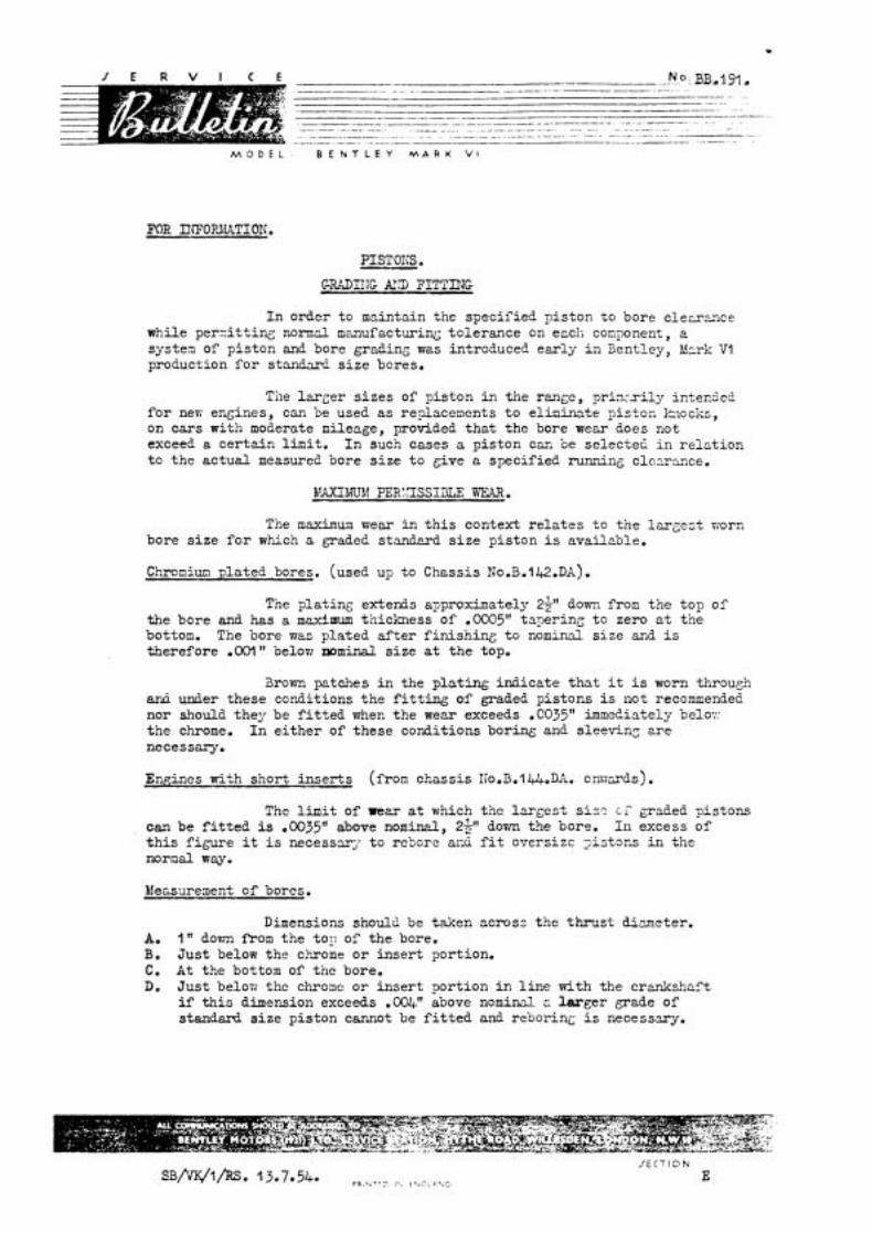
M O D E L B E N T L E Y M A R K VI
PIST OIL5 . C - M I I J G &!D ?ITTIT?G
I n order t o maintain the spec i f i ed p i s ton t o bore clerrzrice while pe r - i t t ing normal m,uufacturini; to le rance on erch component, a systen o f p i s ton and bore grading wes introduced e a r l y i n Bentley, Mcrk V1 production f o r s t m W s i z e bores.
Tile l a r g e r s i z e s of p i s ton i n t h e r a g e , p r in r r i l j r i n t e d e i ! f o r ner; engines, c m be used as r e g a c e n e n t s t o el iminate p i s t o c k ~ o c k s , on cars with moderate mileage, provided t h a t the bore wear does not exceed a c e r t a i n l imi t . I n such cases a p i s ton can be se lec ted i n r e l a t i o n t o t h e a c t u a l measured bore s i z e t o give a speci f ied running clc-rsnce.
The maximum wear in t h i s context r e l a t e s t o t h e 1a - ses t riorn bore s i z e f o r which a graded standrrd s i z e p i s ton i s availcble.
Chroniun p la ted bores. (used up t o Chessis NO.B.I~~.DA).
The p la t ing extends approximately 2 9 down from t h e top of the bore and has a m e x i m u m thickness of ,0005" taper ing t o zero r t t h e bottom. The bore was pla ted a f t e r f i n i s h i n g t o nomind s i z e 2nd is therefore .W" belon nominal s i z e a t t h e top.
3rovm patches i n the p l a t i n g ind ica te t h a t it i s worn through artli under these conditions t h e f i t t i n g of graded p i s tons i s not recommended nor should they be f i t t e d when t h e we= exceeds .@035" immeLiately belo:: t h e chrome. I n e i t h e r of these condit ions boring and sleeving e r e necessary.
Enaines with shor t i n s e r t s (from chass is IIo.B.lLJ+.DA. cnvm-ds).
The limit of reer at which the l m g e s t s i s ? c; graded pis tons can be f i t t e d i s .003511 above nomind, 2 9 dovm the bore. I n excess of t h i s f i g u r e it i s necessary t o rebcre acir f i t oversizc > i s tons in the nornal way.
Measureaent of bores.
Dimensions should be taken across t h e t h r u s t d i m e t e r . A. 1 dovm from t h e to11 of the bore. B. J u s t below the chrome o r i n s e r t portion. C. A t the bottom of the bore. D. J u s t belon i;hc chrome o r i n s e r t por t ion i n l i n e with the c r d s h a f t
i f t h i s dimension exceeds .004" above n o m i d r. l a r g e r grade of standard s i z e p i s ton cannot be f i t t e d and r e b o r i n ~ i s necesszry.
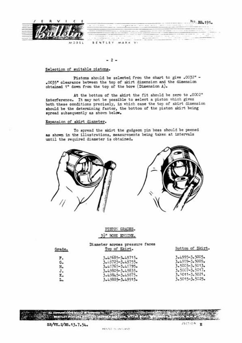
- - - - . " ; 0 . L J 3 & ~ 9 . 1 * - . . . .. -. - - --. . ... ~ - - -- --.-.p---- ----..--p---.-.---.-.....- ~ ~- - - p --p - . . . . .-.--.---p-.-- ~-
---W--- ~ . ... .
- -- - - - .. .. . - . ~ ~ - ~ --- -
~ ~ . . . . . - . .. - . . - - . . - - .. . - -- - . -- .- -. . .. . . . . -. . -- . . - - . . -. . . .-
B E N T L E Y M A R K V 1
Selection of su i tab le is tons.
Pistons should be selected from the chart t o give .OO32" - .0035" clearance between t he top of sk i r t dimension and t h e dimensim obtained 1 " down from the top of the bore (~ imens ion A).
A t the bottom of the skirt the f i t should be zero t o .0032" interference. It may not be possible t o s e l ec t a piston rrhich gives both these conditions precisely, i n which case t he top of s k i r t dimension should be the determining factor , the bottom of the pis ton s k i r t being spread subsequently as shovrn below.
Expansion of skirt diameter.
To spread the Bkirt the gudgeon pin boss should be peened aa shown in the i l l u s t r a t i ons , measurements being taken a t in tervals u n t i l t h e required diameter is obtained.
PISTOT: GFJLES.
34" BORE ENGINE.
Grade. Diameter acmas pressure faces
Top of Skir t . Bottom of Skirt .
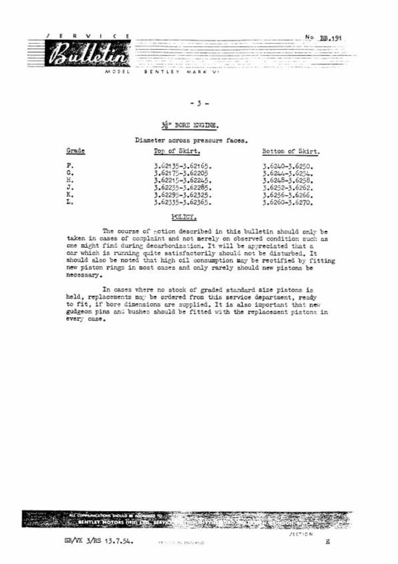
M 3 D E L B E N T L E Y M A R K V1
S)' BORE EXGINE.
Dinmeter across pressure faces.
Grade Top of Sk i r t . Bottom of S k i r t .
The course of 2ction described i n this b u l l e t i n should only be taken i n cases of co.xplzint and not merely on observed condition such as one m i ~ h t f in5 during decarbonization. It w i l l be ap.p-sreciated t h a t a c m vzhich i s running p i t e s a t i s f a c t o r i l y shoulE not be disturbed. It should a lso be noted tha t hign o i l consumption rnv be r e c t i f i e d by f i t t i n g new p i s ton r ings in most cases and only r a r e l y should new pis tons be n e c c s s q ,
I n cases r;hcre no stock of graded s t ~ ? d a r d s ize pis tons i s held, replncements m% be ordered from t h i s service department, ready t o f i t , i f bore dimensions a r e supplied. It i s a l so inpor tant t h a t nm-; gudgeon p ins an2 bushes should be f i t t e d w i t h the replacement p i s tons i n ever,- case,
M O D E L : B E N T L E Y M A R K V I
FOR INKRMATION
~ . 6 2 m FIXW FILTERS.
Cases have occured of the f i l t e r casing being fractured by over-tightening of the centre bolt .
When re-tightening a f t e r cleaning and re-f i t t ing a new "Klement" , the centre bol t should be nipped up gently using a 6" spanner to an approximate load of 5 lb - Ft which is all that i s required to make a leak proof joint. On t e s t , it has been found tha t a load of X ) - 25 l b s - Ft w i l l f racture the f i l t e r head.
PRINTE3 IN ENGLAND
M O D E L : B E N T L E Y M A R K V I
FOR rnBXTION:
FUL;L-mt'i OIL F'ILTER SERVICDTG
On 3ent ley "R" t j ~ e c a r s f l t t e d vrith t h e l c t e s t b t an CAd ( ~ o n t m e n t a l ) d e n i s t k ~ systm., ~t hcs been found tha t t h e ?l evlous method of l i f t i n g out t h e detached f i l t e r elenent m d bowl, ?as t the dynamo, 1s no longer poss ible , due t o the ?os l t ioning of the heater plpes
The following method 1s now recommended, Disconnect t h e a i r pipe from the rnatrlx under tile L+, and z l s o f r o m the blower motor on t h e dash. Disconnect the win3screen washer reservoir and remove t h e "bot t le" . Loosen t h e s t r a p holdmg t h e alr pxpe and vnthdravr pipe.
The f l l t e r b w l can now b e withdrawn without d i f f i cu l ty .
JECTION SB/VK.I/SF. 5.10.54. E
PRINTED IN ENGLAND
M C J b E L B E N T L E Y M A R K V I
TOP DECARBONI SATIOK bK!E".LAL.
When the ea r l i e r engines a re reconditioned a t the Works, E'ull-Flmr F i l t e r equipment i s invariably installed. A t the saae time, minor modifications affect ing the scale of decarbonisation material, may be embohed. A s i t is not practicable t o keep record of these retrospective modifications, Retai lers are asked to bear in mind the follacing points v'hen ordervlg decarbonisation material.
a ) There the rocker cover breather has been f i t t ed , a replacement washer, KB-l092 mil l be required.
b) Where aluminium tappet doors have been f i t t e d , washers RE-54-27, 2-0ffS w i l l be required in place of E13-U59 2-0f f.
c) The corrugated hose, RE-16218, may be f i t t e d to any chassis f i t t e d ~ 5 t h the deep-type radiator, and the exls t ing three-plcce lower connection discarded.
d) The presence of a Full-Flow F i l t e r w i l l be recognised immediately, and i n such cases, the By-pass F i l t e r v;ill not be required.
Upon reference to the schedules, the material required f o r a part icular chassis may be readily ascertained.
Appendix "A" re fe rs t o B-VI: cars and Appendix "Bn t o *R1 type and Continental .
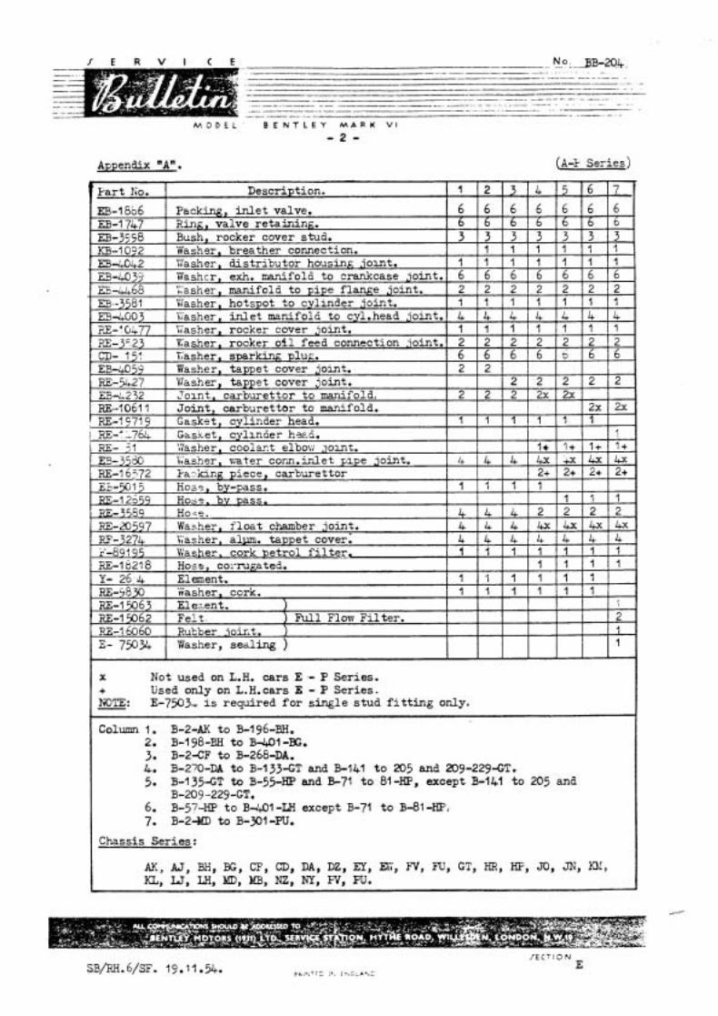
Appendix "A".
M O D E L ' B E N T L E Y M A R K V I
- 2 -
( 84 s e r i e s )
h - 5 8 ~ RE-15063 RE-15062
. m - 1 6 0 6 0 2- 750%
X Not used on L.H. c a r s E .- P Ser ies . + Used only on L.H.cars E - P Ser ies . KOTE: E-7503, i s required f o r s i n g l e s t u d f i t t i n g only<
Column 1. B-2-AK t o B-1 96-BH. 2. B-198-EH t o B-401-BG, 3 B-2-CF t o B-268-DA. 4. B-270-RA t o B-I33-GT and B-lbl t o 205 and 209-229-GT. 5. B-1 35-GT to B-55-HP and E 7 1 t o 81 -HP, except B-141 t o 205 and
B-209-229-GT. 6. B-57-HP t o B-401-LIi except B-71 t o B-81-HP, 7. B-2dbD t o B - 9 1 -PU,
Chassis S e r i e s :
AK, A J , BHP BG, CF, CD, DA, DZ, EY, EL', FV, m, GT, HR, HF, JO, JN, n!, KL,LJ ,LH,MD,MB,NZ,NY,PV,W.
washer, cork. El e;r.ent. 1 F e l t . ) N l Florr T i l t e r . Rukber joir,t. 1 Washer, sea l ing )
I
2 1 l
-
' 1 1 1 1 1 1
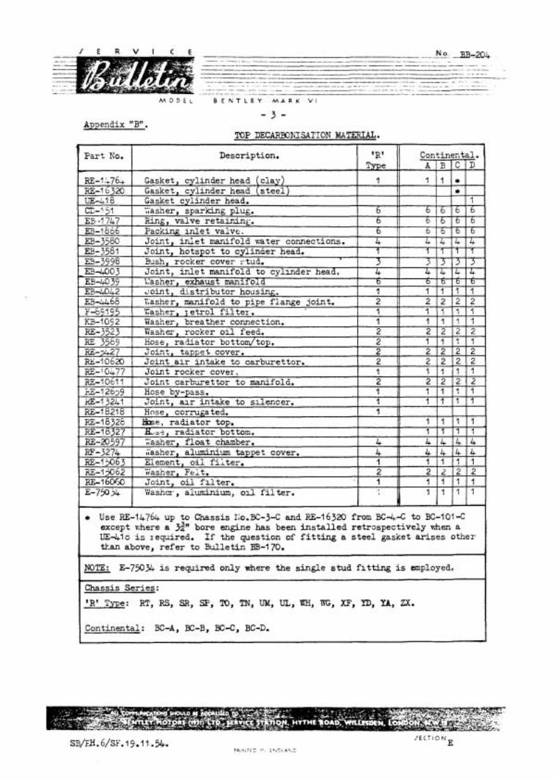
/ E R V I C E __.... NO: 3 - 2 0 4 -- . ~ . . -
-. -. - .- -- p - P - - -- W - - -- - - . . - - . - - ---F--- P- -- -. . . - .- . - .- - . .
F-. - - -.-p- .- -- -- -. -. -- -- - - - - - - . - - -. -. - - .-..---...-.--...-.-----.-p--.----.-..--- ~ - - - - - - - - . . . . . . . . . . . .
. -- - . -- - - . -. -. --.. . - . - - -. - -. . - - - . - -. . . - . . - . - - - -- - - - . - . . ..-. - - ..--p --- -. -A - - .. - . . -.
M O D E L B E K T L E Y M A R K V I
- 3 - A~aendix "B".
'R' Type: RT, RS, SR, SF', TO, TN, UM, UL, WH, X, XF, YD, U, ZX.
Continental: BC-A, BC-B, BC-C, BC-D,
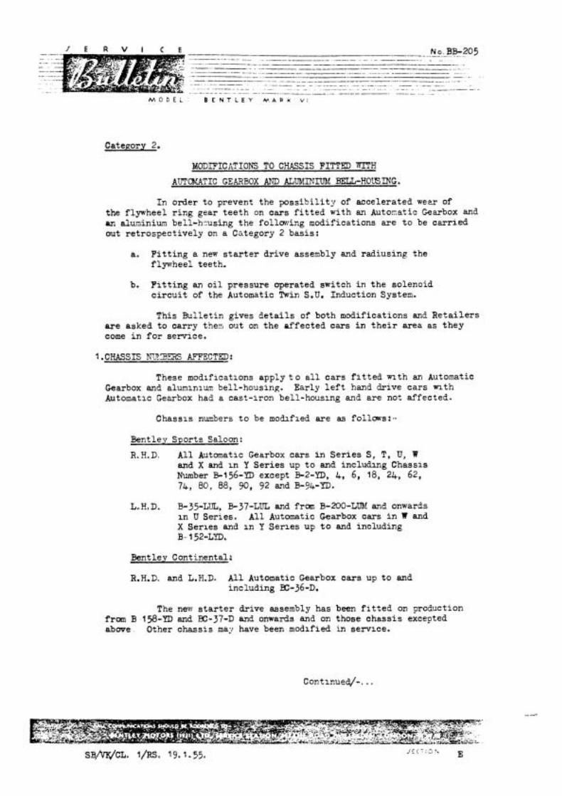
No. BB-205 -- -- .- . . -. . - .. .. - - - -- - -.----p----- - -- . - - - .- --...---------p-.. -
-- - -.. -p .. . .- p -- - -. - . -- -----..W--- - - --.---..----p-. - .-
-----.A. ----.--W--- .. .- - .
. ..-. - - . . -. ... . .- . ~ .~ - - - . .- . - - - - .- -. - - ---- - - - ~- ... -
M O D E L B E N T L E Y W A P K v i
MODIFICATIONS TO CHASSIS FITTED VITH
AUTOKATIC GEARBOX AND ALUMINlXld BELL-HOB ING.
In order t o prevent the p o s s i b i l i t y of accelera ted weer of the flywheel r i n g gear t e e t h on ca r s f i t t e d with an Automatic Gearbox and an aluminium bell-hzusing the follmiing modifications are t o be ca r r i ed out r e t rospec t ive ly on a Cstegory 2 basis :
a. F i t t i n g a new s t a r t e r dr ive assembly and radiusing the f lyvrheel teeth.
b. F i t t i n g an o i l pressure operated switch i n t h e solenoid c i r c u i t of the Automatic Twin S.U. Induction System.
This Bu l le t in gives d e t a i l s of both modifications and R e t a i l e r s a r e asked t o carry the5 out on t h e a f fec ted cars i n t h e i r area a s t h e y come i n f o r service.
I .CHASSIS hv3m AFFECTED:
These modlflcatlons apply t o a l l c a r s f i t t e d n t h an Automatic Gearbox and alumlnluv bell-housing. Early l e f t hand drive c a r s n t h Automatlc Gearbox had a cast- lron bell-houslng and a r e not a f fec ted-
Chassls numbers t o be mobfled a r e as fo1laws:-
Bentley Spor ts Saloon:
R,H.D. A l l Automatlc Gearbox cars i n S e r i e s S, T, U, W and X and I n Y S e r i e s up t o and i n c l u b g Chassls Number B-156-YD except B-2-M), 4, 6 , 18, 24, 62, 74, 80, 88, 90, 92 and B-94-YD.
L.H,D. B-35-LUL, B-37-LUL and f r m B-200-LUM and onwards i n U Ser ies , A l l Automatic Gearbox cars i n W and X Ser les and i n Y Se r l es up t o and including B- 152-LYDC
Bentley Continental:
R.H.D. and L.H.D. A l l Automatic Gearbox c a r s up t o and including EC-36-D.
The nevr s t a r t e r drive assembly has been f i t t e d on production f r m B 158-YD and E-37-D and onwards and on those chass i s excepted a b w e . Other chass is may have been modified in servlce.
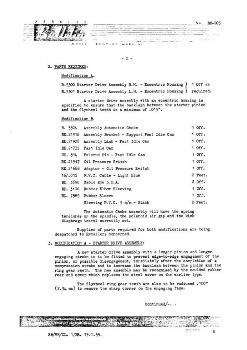
2. PARTS REQUIRED :
Modification A.
R. 5300 S t a r t e r Drive Assembly R,H. - Eccentric Housing
R.5301 S t a r t e r Drive Assembly L.H. - Eccentric Housing
A s t a r t e r drive assembly with an eccentr ic housing is speci f ied t o ensure tha t t h e backlash between t h e s t a r t e r pinion and the flywheel t e e t h i s a minimum of .015".
Nodif i ca t ion B.
R. 5 9 4
RE. 21 918
RE. 21 908
RE.21735
UE. 514
RE.21917
RE. 21 688
16/.012
RD. 36% RD. 3106
RD. 7589
Asserably Automatic Choke
Assembly Bracket - Support Fast I d l e Cam
Assembly Link - Fas t I d l e Cam
Fas t I d l e Cam
Fulcrum P i n - Fast I d l e Cam
O i l Pressure Switch
Adaptor - O i l Pressure Switch
P,V, C, Cable - Light Blue
Cable Eye 3.B.A.
Rubber Elbow Sleeving
Rubber Sleeve
Sleeving P.V,C. 5 q l m - ~ h c k
l Off.
l Off.
l Off.
1 Off.
1 Off.
l Off.
l Off.
2 Feet.
2 Off.
l off.
1 Off.
2 Feet.
The Automatic Choke Assembly w i l l have the s?ring tens ioner on the spindle, the solenoid air gap and t h e kick diaphragm t r a v e l co r rec t ly se t .
Suppl ies of p a r t s required f o r both modifications a r e being despatched t o R e t a i l e r s concerned,
3. MODIFICATION A - STARTER DRrVE ASSR3LY:
A ner.1 s t a r t e r d r i v e assembly wi th a longer pinion and longer engaging stroke is t c be f i t t e d to prevent edge-to-edge engagement of t h e pinion, o r possible disengagement, i m ~ e d i a t e l y a f t e r t h e com?letion of a compression stroke and t o increase t h e backlash between t h e pinion and t h e r i n g gear ree th . The new assembly may be recognised by t h e moulded rubber rear end c w e r which rep laces the s t e e l cover on the e a r l i e r type,
The flywheel r ing gear t e e t h a re a l s o t o be radiused .100" (2.54 m) t o remove the sharp corner on the engaging face.
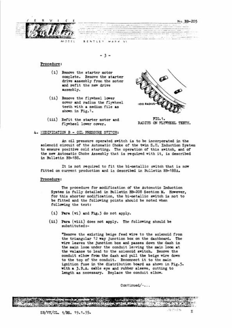
- - - - -- - - - N O . - BB-205 - -. . . . . . . . . . . . . . . . . . . . . .
-. - .. -.- . ---- -- -- ............. --p - . - - - - - - - - -.
......... ........... -. ... .- . - ... - ............. - - ... ........ -- - -- - - -- - .- - .......... ................ .-
. -.............................. ...........- . . . . . . . . . .................... - . . - ~ .. - -- -
.............. . . . .
Procedure :
( i ) Remwe the s t a r t e r motor complete. Remove the s t a r t e r drive assembly from the motor ond r e f i t the new drive assembly.
( i i ) Remove the flywheel lower ower and radius the flywheel teeth with a medium f i l e as shown i n Fig. l.
( i i i ) Refit the s t a r t e r motor and flywheel lower cwer.
PIG. 1. RADIUS ON F L M E L TEETH.
4. ?.:ODIFICA!rION B - OIL PRESSURE SrnCH:
An o i l pressure operated switch is t o be incorporated in the solenoid c i r cu i t of the Automatic Choke of the twin S.U. Induction System to ensure positive cold s tar t ing. The operation of t h i s switch, and of the new Automatic Choke Assembly that i s required with it, is described in Bullet in BB-188.
It is not required t o f i t the bi-metallic switch that i s now f i t t e d on current production and i s described in E3ulleti.n BB-188A.
Procedure:
The procedure for modification of the Automatic Induction Syetem i s f u l l y detailed in Bulletin BB-208 Section M. However, f o r this shor te r modification, the bi-metallic switch is not t o be f i t t e d and the following points should be noted when following the tex t :
(i) Fara (H) and Fig.3 do not apply.
(ii) Para ( v i i i ) does not apply. The following should be substituted:-
"Remwe the existing beige feed wire t o the solenoid from the t r iangular 12 way junction box on the dashboard. The w i r e leaves the m o t i o n box and passes down the dash i n the main loom under the conduit leeving the main loom a t the valance t o lead t o the solenoid switch. Renwe the conduit elbow fran the dash and pul l the beige wire down t o the top of the conduit. Reconnect i t t o the main igni t ion fuse in the dis t r ibut ion board as shown i n Fig.5. with a 3. B.A. oable eye and rubber sleeve, cutting t o length as necessary. Replace the conduit elbow.

(iii) Fig. 5. Delete t h e b i - m e t a l l i c switch and consider the beige cable as one length.
5. CHARGES:
A time of 6 hours i s allowed f o r both modifications and oharges should be submitted on a Guarantee Form i n the usual way.

h'. L' C t : H f h - ' , F ' h ' A F K V I
W U S T VALVE SPRIIGS.
S'' BOKE: ENGINES.
Qn S" bore engines, coamencing a t Chassis NO. B-2-MD, and BC-l-A (Continental) the undermentioned exhaust valve springs and bottcm washers wem f i t t e d : -
RE.J9Y+, Spring, (approximate f r e e length a e n new is 2.040") RE. 976, Bottom washer.
Subsequently the above w e r e superseded by an improved spring of constant ra te and lower s t ress : -
( RE-15959, Spring (appmximate f r e e length when new is 1.860") ( RE.15960, Bottom washer.
Whenever i t i s necessary t o renew one o r mare of the ea r l i e r type springs, RE.3954, a complete se t of the improved type springs, FiE.15959 should be f i t t e d TO- with the bottom washers, RE.15960.
Apart from the difference in the f ree length of the two types of springs, ident if icat icn as t o which type of spring is f i t t e d t o a part icular engine, may be determined upon reference t o the bottom washer (see Fig.1 and Fig.2) from which i t w i l l be observed that the base of the l a t e r type i s not recessed.
I n a l l cases the top washer, RE.975 i s retained.
Fig.1 - Section Fig.2 - Section RE-976 - Washer RE-1 596GWasher

I E R V I C E
M 3 D E L B E N T L E Y M A R K V I
FOR U6'C)RItlATIOIJ.
With reference t o Service Bulletin ai3-20k it i s advised that the scale of material laid down for .B" tppe Chassie is aloo applicable t o ZY Series Chatsir.
K i l l Retailers please note that the Schedules se t out in Sel-vice Bulletin BE-201, supersede a l l previous issues which should be destroyed.
s ~ J S L m 29.6.55. PPINTED IN ENGLAND
M O D E L . B E N T L E Y M A R K V I
DnwLEx PIsTrn RINGS.
It has been the practise of the Loadon S e r v i a Station fo r solretime now to f i t Wellworthy Duaflex O i l Control Rings to engines where heavy o i l consumption has been reported.
bs this type of ring has proved very satisfactory, it has now been decided to discontinue the use of the standard Slotted Oil Control Ring, and all oversize pistons will now be supplied with a Duaflex O i l Control Ring.
There are still a few Bentley Mark VI p bore cars in Service with chromium plated bores (a t upper end), urd as the n d Duaflex Ring is not suitable f o r f i t t i n g to such engines the Duaflex Gold Line Ring mus t be us ed. The Part Number of this r ing is RH-41 1 .
A ccmplete list 09 Duaflex Bings, vhich art to supersede the original scraper ring are given overleaf.
It w i l l be noted that one s ize Duaflwr Ring is suitable fo r a s d range of oversize bores. The actual s ize is as follows :-
Stpndard r ing is suitable f o r : - Standard to .019" ~ / s i z e bores. ,020" o/size l ing is suitable for :- ,020" o/size to ,039" o/size bores. ,040" o/size r ing is suitable for :- ,040" o/size to ,059" o/size bores.
The sizes quoted above . re those to which the respective, rings a m capable of expanding i.e. .019" in each a s e .
The ring s p s a re prc-sized and must therefare not be altered.
TO BSSELBLE TO A PISTCBJ
IJS: h existing pistons .l1 grooves and o i l drain holes must be thorou@ly clean ard f ree from arbon.
( i ) P l a a the expander in the first, and then SPIRAL the rails on one by one, tpldng arre t o arrange the gaps a l l round the pistons, The top r a i l w i l l need a l i t t l e pressure t o enter the groove, as the assembled r ing is s l i@t ly wider than the groove.
(ii) Check that the asstmbled ring, li@tly oiled, can be mwed round in the pave.
( i i i ) Oil w i t h l igh t o i l and install w i t h f i t t i n g clamp,
NOIIE: The three side rails are identical may therefore be instal led ei ther way round. The assembled order on a piston is :-
Expander, two side rails uppennost, centre spring and one side r a i l a t bottom.
~/PR. 15.5.56. PRINTFD Ih ENGLAND
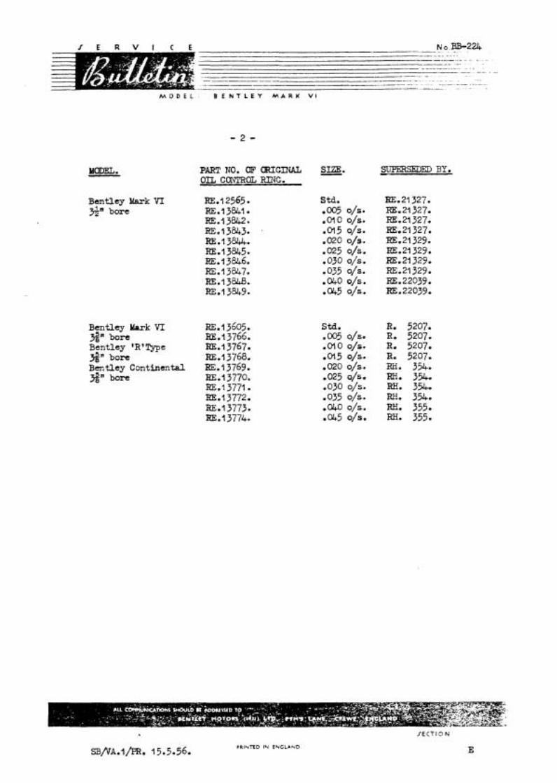
M O D E L B E N T L E Y M A R K V I
PART NO. CIE' OWIGINAL OIL CONTROL Rl3G.
Bentley Mark V I RE01 2565 2" bore RE.? 3841.
RE.13842. RE.? 3843. RE.? 3844. RE.13845- m.13846. m.13847. RE.13848. RE.? 3849.
Bentley Mark VI RE.^ 3605. S" bore RE.? 3766. Bentley 'R'Type RE.13767. S" bore RE.13768. Bentley Continental BE.13769. S" bore RE.13770.
RE.? 3771. BE.? 3772. =*l 3773. RE.? 37749
Std. 0005 o/s. *olo o/s. 0015 o/s. .020 o/s. -025 o/s. .030 o/s. -035 o/s. .WO o/s. 0045 o/s.
SUPERSEDED BY.
KE.21327. RE.21327. KE.21327. m021 327. RE.21329. KE.21329. KE.21329. RE. 21 329. RE. 22039 RE. 22039.
sta. R. 5207. .005o/s. R. 5207. .o l00 /~ . R. 5207. .ol5 o/s. R. 5207. .02oo/s. m. 354. .0250/~. RH. 354. .030 o/s. RH. 354, ,035 o/s. m. 354. . ~ O o / s . m. 355. .W5 o/s. RH. 355.
SB/'VA.~/PR. 15.5.56. PRINTED IN ENGLAND
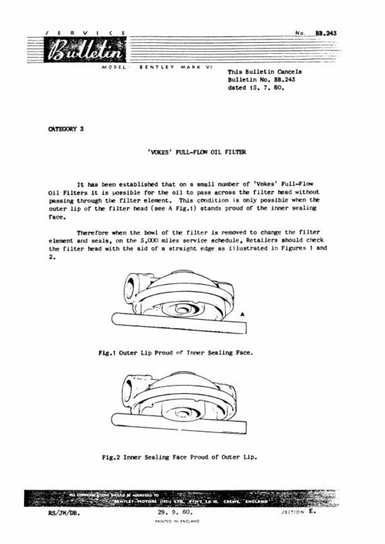
M O D E L : B E N T L E Y M A R K V I This B u l l e t i n Cancels B u l l e t i n No. BB.243 d a t e d 15. 7. 60.
'WKES ' N L L - F m OIL FILTER
I t has been e s t a b l i s h e d t h a t on a sma l l nurnber of 'Vokes' F u l l - F l w O i l F i l t e r s it i s p o s s i b l e f o r t h e o i l t o pass a c r o s s t h e f i l t e r head without pass ing through t i l e f i l t e r e lement . Th i s cond i t i on j s only pos s ib l e when the o u t e r l i p o f t h e f i l t e r head ( s e e A Fig.1) s t a n d s proud of t h e i n n e r s e a l i n g face .
Therefore when t h e bowl of t h e f i l t e r i s removed t o change t h e f i l te r element and s e a l s , on t h e 5,000 miles s e r v i c e schedule , R e t a i l e r s should check t h e f i l t e r head w i t h t h e a i d of a s t r a i g h t edge a s i l l u s t r a t e d i n F igu re s 1 and 2.
-1 Fig.1 Oute r L ip Proud nf Tnner S e a l i n g Face.
--
Fig.2 I n n e r Sea l i ng Face Proud o f Outer Lip.
29. 9. 60. PRINTED IN ENGLAND
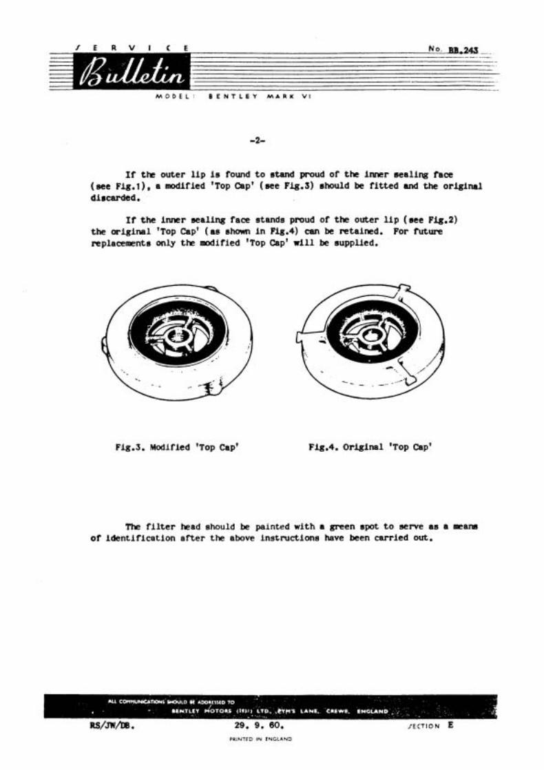
M O D E L : B E N T L E Y M A R K V I
If the outer l i p is found t o stand proud of the inner seal ing face (see Flg.1) , a modified 'Top Cap' ( see Fig.3) should be f i t t e d and the or iginal discarded.
It t h e inner seal ing face stands proud of the outer l i p ( s ee Fj.g.2) the or ig ina l 'Top Cap' ( a s shown i n Fig.4) can be retained. For Mure replacements only the modified 'Top Cap' w i l l be supplied.
F-ig.3. Modified 'Top Cap' Fig.4. Original 'Top Cap'
The f i l t e r head should be painted with a green spot t o serve as a meam of iden t i f i ca t ion a f t e r the above inst ruct ions have been carried out.
PRINTED IN ENGLAND