section vii engine - jholst.netjholst.net/58-service-manual/engine.pdf · section vii engine...
TRANSCRIPT
CHRYSLER SERVICE MANUAL ENGINE—1
Section VII
ENGINE
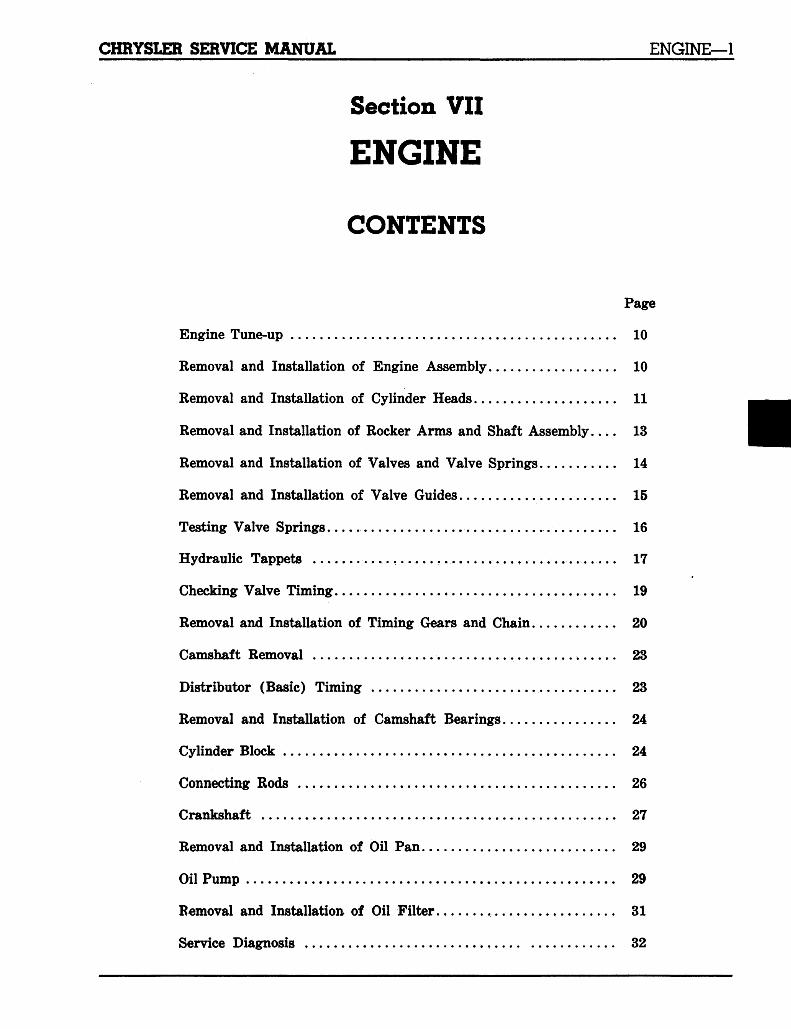
CONTENTS
Page
Engine Tune-up 10
Removal and Installation of Engine Assembly 10
Removal and Installation of Cylinder Heads 11
Removal and Installation of Rocker Arms and Shaft Assembly 13
Removal and Installation of Valves and Valve Springs 14
Removal and Installation of Valve Guides 15
Testing Valve Springs. . . . . . 16
Hydraulic Tappets 17
Checking Valve Timing... > 19
Removal and Installation of Timing Gears and Chain 20
Camshaft Removal 23
Distributor (Basic) Timing 23
Removal and Installation of Camshaft Bearings 24
Cylinder Block 24
Connecting Rods 26
Crankshaft 27
Removal and Installation of Oil Pan 29
Oil Pump 29
Removal and Installation of Oil Filter . 31
Service Diagnosis 32
2—ENGINE CHRYSLER SERVICE MANUAL
Section VII
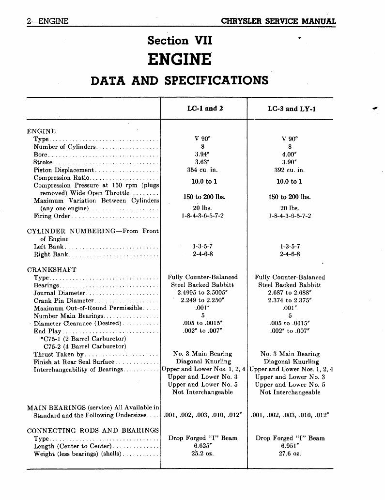
ENGINEDATA AND SPECIFICATIONS
LC-l and 2 LC-3 and LY-1
ENGINETypeNumber of Cylinders :BoreStrokePiston DisplacementCompression RatioCompression Pressure at 150 rpm (plugs
removed) Wide Open ThrottleMaximum Variation Between Cylinders
(any one engine)Firing Order
CYLINDER NUMBERING—From Frontof Engine
Left BankRight Bank
CRANKSHAFTTypeBearingsJournal DiameterCrank Pin DiameterMaximum Out-of-Round PermissibleNumber Main BearingsDiameter Clearance (Desired)End Play
•C75-1 (2 Barrel Carburetor)C75-2 (4 Barrel Carburetor)
Thrust Taken byFinish at Rear Seal SurfaceInterchangeability of Bearings
MAIN BEARINGS (service) All Available inStandard and the Following Undersizes....
CONNECTING RODS AND BEARINGSTypeLength (Center to Center)Weight (less bearings) (shells)
V90°8
3.94"3.63"
354 cu. in.
10.0 to 1
150 to 200 lbs.
20 lbs.l_8-4-3-6-5-7-2
1-3-5-72-4-6-8
Fully Counter-BalancedSteel Backed Babbitt
2.4995 to 2.5005"2.249 to 2.250"
.001"5
.005 to .0015".002" to .007"
No. 3 Main BearingDiagonal Knurling
Upper and Lower Nos. 1, 2, 4Upper and Lower No. 3Upper and Lower No. 5
Not Interchangeable
.001, .002, .003, .010, .012'
Drop Forged " I " Beam6.625"
25.2 oz.
V90°8
4.00"3.90"
392 cu. in.
10.0 to 1
150 to 200 lbs.
20 lbs.1-8-4-3-6-5-7-2
1-3-5-72-4-6-8
Fully Counter-BalancedSteel Backed Babbitt
2.687 to 2.688"2.374 to 2.375"
.001"5
.005 to .0015".002" to .007"
No. 3 Main BearingDiagonal Knurling
Upper and Lower Nos. 1, 2,Upper and Lower No. 3Upper and Lower No. 5
Not Interchangeable
.001, .002, .003, .010, .012"
Drop Forged " I " Beam6.951"
27.6 oz.
CHRYSLER SERVICE MANUAL ENGINE-3
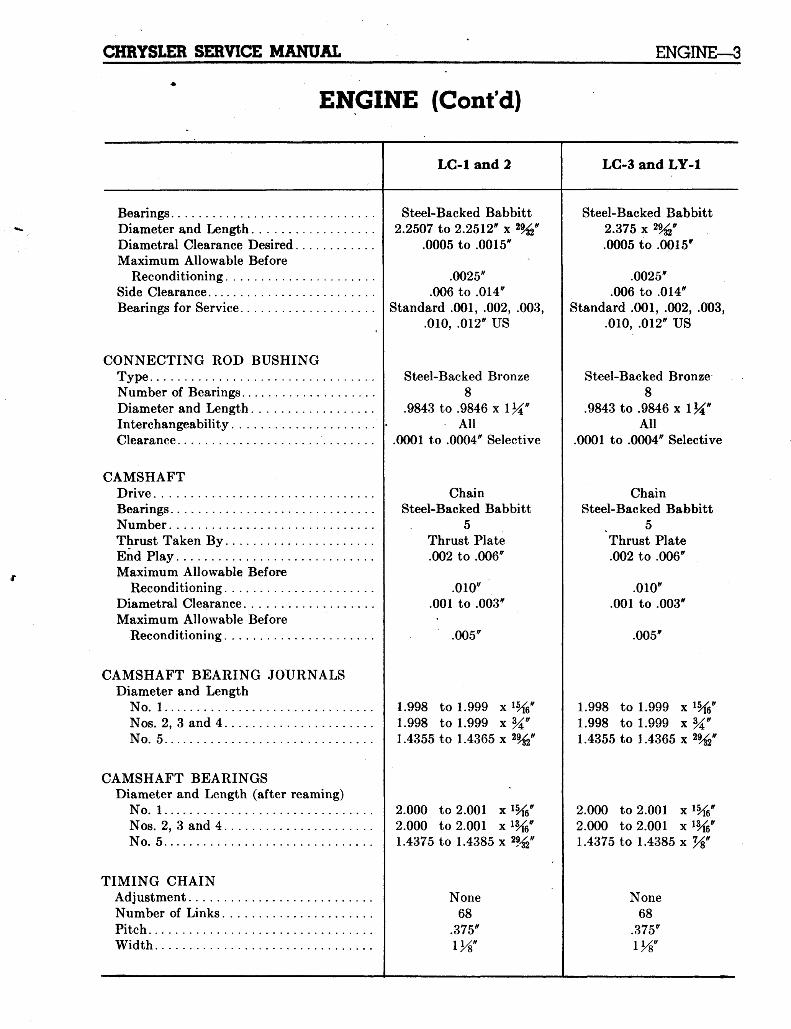
ENGINE (Cont'd)
LC-1 and 2 LC-3 and LY-1
BearingsDiameter and LengthDiametral Clearance DesiredMaximum Allowable Before
Reconditioning. . .Side ClearanceBearings for Service
CONNECTING ROD BUSHINGTypeNumber of BearingsDiameter and LengthInterchangeabilityClearance
CAMSHAFTDriveBearingsNumberThrust Taken ByEnd PlayMaximum Allowable Before
ReconditioningDiametral ClearanceMaximum Allowable Before
Reconditioning
CAMSHAFT BEARING JOURNALSDiameter and Length
No. 1Nos. 2, 3 and 4No. 5
CAMSHAFT BEARINGSDiameter and Length (after reaming)
No. 1Nos. 2, 3 and 4No. 5
TIMING CHAINAdjustmentNumber of LinksPitchWidth
Steel-Backed Babbitt2.2507 to 2.2512" x 2%"
.0005 to .0015"
.0025;/
.006 to .014'Standard .001, .002, .003,
.010, .012" US
Steel-Backed Bronze8
.9843 to .9846 x l^"All
.0001 to .0004" Selective
ChainSteel-Backed Babbitt
5Thrust Plate.002 to .006"
.010".001 to .003"
.005"
1.998 to 1.999 x %"1.998 to 1.999 x %"1.4355 to 1.4365x2%
Steel-Backed Babbitt2.375 x 2%".0005 to .0015"
.0025".006 to .014"
Standard .001, .002, .003,.010, .012" US
Steel-Backed Bronze8
.9843 to .9846 x \\i"All
.0001 to .0004" Selective
ChainSteel-Backed Babbitt
5Thrust Plate.002 to .006"
.010".001 to .003"
.005"
1.998 to 1.999 x1.998 to 1.999 x1.4355 to 1.4365 x
2.0002.0001.4375
to 2.001 x 1%to 2.001 x%"to 1.4385 x 2%"
None68
.375"
2.0002.0001.4375
to 2.001 xto 2.001 xto 1.4385 x
None68
.375"
4—ENGINE CHRYSLER SERVICE MANUAL
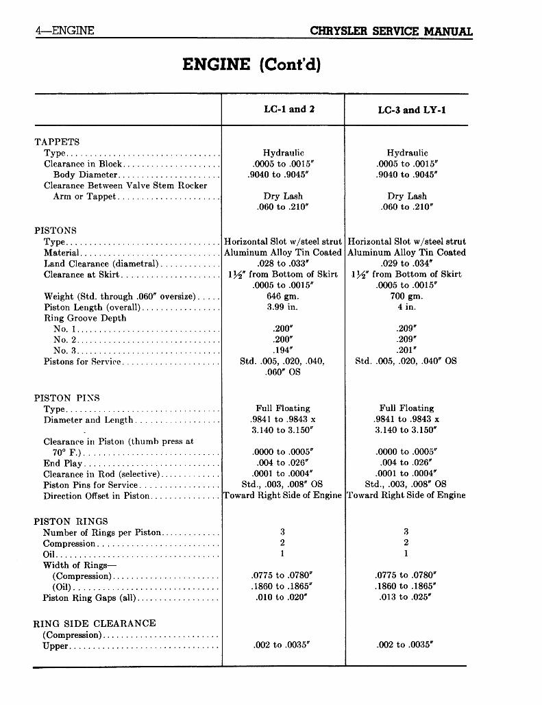
ENGINE (Cont'd)
LG-1 and 2 LC-3 and LY-1
TAPPETSTypeClearance in Block
Body DiameterClearance Between Valve Stem Rocker
Arm or Tappet
PISTONSTypeMaterialLand Clearance (diametral)Clearance at Skirt
Weight (Std. through .060" oversize)Piston Length (overall)Ring Groove Depth
No. 1No. 2No. 3
Pistons for Service
PISTON PINSTypeDiameter and Length
Clearance in Piston (thumb press at70° F.)
End PlayClearance in Rod (selective)Piston Pins for ServiceDirection Offset in Piston
PISTON RINGSNumber of Rings per Piston.CompressionOilWidth of Rings—
(Compression)(Oil)
Piston Ring Gaps (all)
RING SIDE CLEARANCE(Compression)Upper
Hydraulic.0005 to .0015"
.9040 to .9045"
Dry Lash.060 to .210"
Horizontal Slot w/steel strutAluminum Alloy Tin Coated
.028 to .033"from Bottom of Skirt.0005 to .0015"
646 gm.3.99 in.
.200"
.200"
.194"Std. .005, .020, .040,
.060" OS
Full Floating.9841 to .9843 x3.140 to 3.150"
.0000 to .0005".004 to .026"
.0001 to .0004"Std., .003, .008" OS
Toward Right Side of Engine
321
.0775 to .0780"
.1860 to .1865".010 to .020"
.002 to .0035'
Hydraulic.0005 to .0015".9040 to .9045"
Dry Lash.060 to .210"
Horizontal Slot w/steel strutAluminum Alloy Tin Coated
.029 to .034*\y<i' from Bottom of Skirt
.0005 to .0015"700 gm.
4 in.
.209"
.209"
.201"Std. .005, .020, .040" OS
Full Floating.9841 to .9843 x3.140 to 3.150"
.0000 to .0005".004 to .026"
.0001 to .0004"Std., .003, .008" OS
Toward Right Side of Engine
321
.0775 to .0780"
.1860 to .1865".013 to .025"
.002 to .0035"
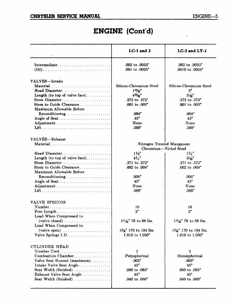
CHRYSLER SERVICE MANUAL ENGINE—5
ENGINE (Cont'd)
LG-l and 2 LG-3 and LY-1
Intermediate(Oil)
VALVES—IntakeMaterialHead DiameterLength (to top of valve face)..Stem DiameterStem to Guide ClearanceMaximum Allowable Before
ReconditioningAngle of SeatAdjustmentLift
VALVES—ExhaustMaterial
Head DiameterLength (to top of valve face)..Stem DiameterStem to Guide ClearanceMaximum Allowable Before
ReconditioningAngle of SeatAdjustmentLift
VALVE SPRINGSNumberFree LengthLoad When Compressed to
(valve closed)Load When Compressed to
(valve open)Valve Springs I.D
CYLINDER HEADNumber UsedCombustion ChamberValve Seat Runout (maximum)Intake Valve Seat AngleSeat Width (finished)Exhaust Valve Seat Angle . . . .Seat Width (finished)
.002 to .0035"
.001 to .0025"
Silicon-Chromium Steel
.002 to .0035".0010 to .0025"
Silicon-Chromium Steel2"
4*%".372 to .373".001 to .003"
.004"45°
None.388"
.372 to .373"
.001 to .003"
.004"45°
None.388"
Nitrogen Treated ManganeseChromium—Nickel Steel
.371 to .372"
.002 to .004"
.006"45°
None.388"
162"
1%"78 to 88 lbs.
" 170 to 184 lbs.1.010 to 1.030"
Polyspherical.002"45°
.060 to .085"45°
.040 to .060"
Hemispherical.003"45°
.060 to .085"45°
.040 to .060"
.371 to .372"
.002 to .004"
.006"45°
None.388"
162"
78 to 88 lbs.
170 to 184 lbs.1.010 to 1.030"
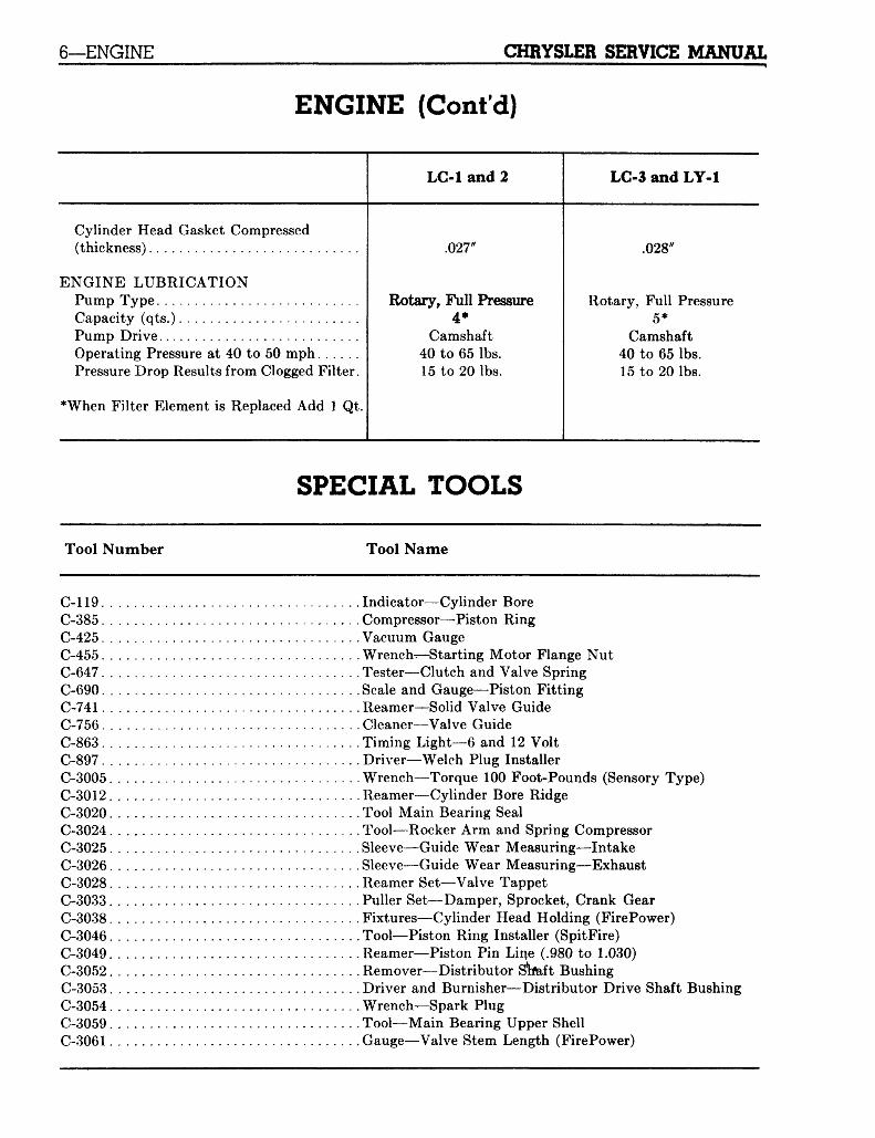
6—ENGINE CHRYSLER SERVICE MANUAL
ENGINE (Cont'd)
LG-l and 2 LC-3 and LY-1
Cylinder Head Gasket Compressed(thickness)
ENGINE LUBRICATIONPump TypeCapacity (qts.)Pump DriveOperating Pressure at 40 to 50 mphPressure Drop Results from Clogged Filter.
•When Filter Element is Replaced Add 1 Qt.
.027'
Rotary, Full Pressure4*
Camshaft40 to 65 lbs.15 to 20 lbs.
.028'
Rotary, Full Pressure5*
Camshaft40 to 65 lbs.15 to 20 lbs.
SPECIAL TOOLS
Tool Number Tool Name
C-119.C-385.C-425.C-455.C-647.C-690.C-741.C-756.C-863.C-897.C-3005C-3012C-3020C-3024C-3025C-3026C-3028C-3033C-3038C-3046C-3049C-3052C-3053C-3054C-3059C-3061
Indicator—Cylinder BoreCompressor—Piston RingVacuum GaugeWrench—Starting Motor Flange NutTester—Clutch and Valve SpringScale and Gauge—Piston FittingReamer—Solid Valve GuideCleaner—Valve GuideTiming Light—6 and 12 VoltDriver—Welch Plug InstallerWrench—Torque 100 Foot-Pounds (Sensory Type)Reamer—Cylinder Bore RidgeTool Main Bearing SealTool—Rocker Arm and Spring CompressorSleeve—Guide Wear Measuring—IntakeSleeve—Guide Wear Measuring—ExhaustReamer Set—Valve TappetPuller Set—Damper, Sprocket, Crank GearFixtures—Cylinder Head Holding (FirePower)Tool—Piston Ring Installer (SpitFire)Reamer—Piston Pin Line (.980 to 1.030)Remover—Distributor SWft BushingDriver and Burnisher—Distributor Drive Shaft BushingWrench—Spark PlugTool—Main Bearing Upper ShellGauge—Valve Stem Length (FirePower)
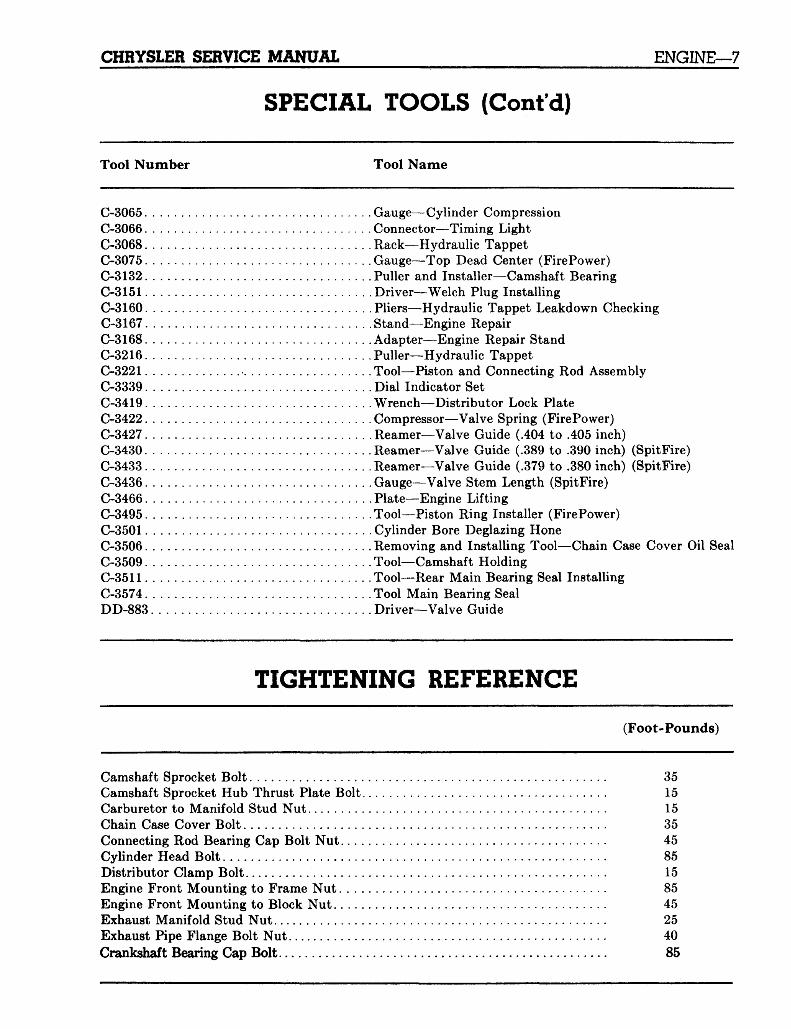
CHRYSLER SERVICE MANUAL ENGINE—7
SPECIAL TOOLS (Cont'd)
Tool Number Tool Name
C-3065 Gauge—Cylinder CompressionC-3066 Connector—Timing LightC-3068 Rack—Hydraulic TappetC-3075 Gauge—Top Dead Center (FirePower)C-3132 Puller and Installer—Camshaft BearingC-3151 Driver—Welch Plug InstallingC-3160 Pliers—Hydraulic Tappet Leakdown CheckingC-3167 Stand—Engine RepairC-3168 Adapter—Engine Repair StandC-3216 Puller—Hydraulic TappetC-3221 Tool—Piston and Connecting Rod AssemblyC-3339 Dial Indicator SetC-3419 Wrench—Distributor Lock PlateC-3422 Compressor—Valve Spring (FirePower)C-3427 Reamer—Valve Guide (.404 to .405 inch)C-3430 Reamer—Valve Guide (.389 to .390 inch) (SpitFire)C-3433 Reamer—Valve Guide (.379 to .380 inch) (SpitFire)C-3436 Gauge—Valve Stem Length (SpitFire)C-3466 Plate—Engine LiftingC-3495 Tool—Piston Ring Installer (FirePower)C-3501 Cylinder Bore Deglazing HoneC-3506 Removing and Installing Tool—Chain Case Cover Oil SealC-3509 Tool—Camshaft HoldingC-3511 Tool—Rear Main Bearing Seal InstallingC-3574 Tool Main Bearing SealDD-883 Driver—Valve Guide
TIGHTENING REFERENCE
(Foot-Pounds)
Camshaft Sprocket Bolt 35Camshaft Sprocket Hub Thrust Plate Bolt 15Carburetor to Manifold Stud Nut 15Chain Case Cover Bolt 35Connecting Rod Bearing Cap Bolt Nut 45Cylinder Head Bolt 85Distributor Clamp Bolt 15Engine Front Mounting to Frame Nut 85Engine Front Mounting to Block Nut 45Exhaust Manifold Stud Nut 25Exhaust Pipe Flange Bolt Nut 40Crankshaft Bearing Cap Bolt 85
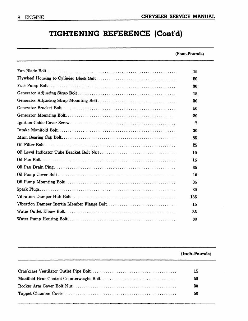
8—ENGINE CHRYSLER SERVICE MANUAL
TIGHTENING REFERENCE (Cont'd)
(Foot-Pounds)
Fan Blade Bolt 15
Flywheel Housing to Cylinder Block Bolt 50
Fuel Pump Bolt 30
Generator Adjusting Strap Bolt 15
Generator Adjiasfcmg Strap Mounting Bolt 30
Generator Bracket Bolt 50
Generator Mounting Bolt 20
Ignition Cable Cover Screw 7
Intake Manifold Bolt 30
Main Bearing Cap Bolt 86
Oil Filter Bolt 25
Oil Level Indicator Tube Bracket Bolt Nut 10
Oil Pan Bolt 15
Oil Pan Drain Plug 35
Oil Pump Cover Bolt 10
Oil Pump Mounting Bolt 35
Spark Plugs 30
Vibration Damper Hub Bolt 135
Vibration Damper Inertia Member Flange Bolt 15
Water Outlet Elbow Bolt 35
Water Pump Housing Bolt 30
(Inch-Pounds)
Crankcase Ventilator Outlet Pipe Bolt 15
Manifold Heat Control Counterweight Bolt 50
Rocker Arm Cover Bolt Nut 30
Tappet Chamber Cover 50
CHRYSLER SERVICE MANUAL ENGINE—9
57x82 A
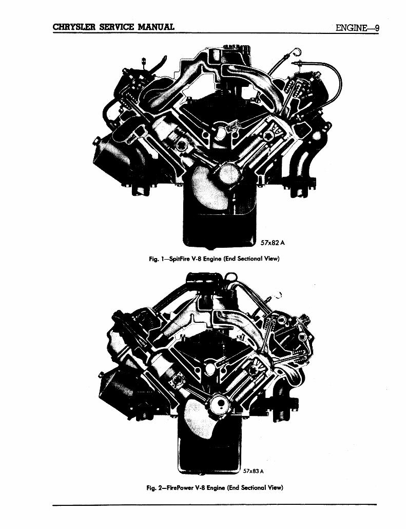
Fig. 1-SpitFire V-8 Engine (End Sectional View)
o
57x83A
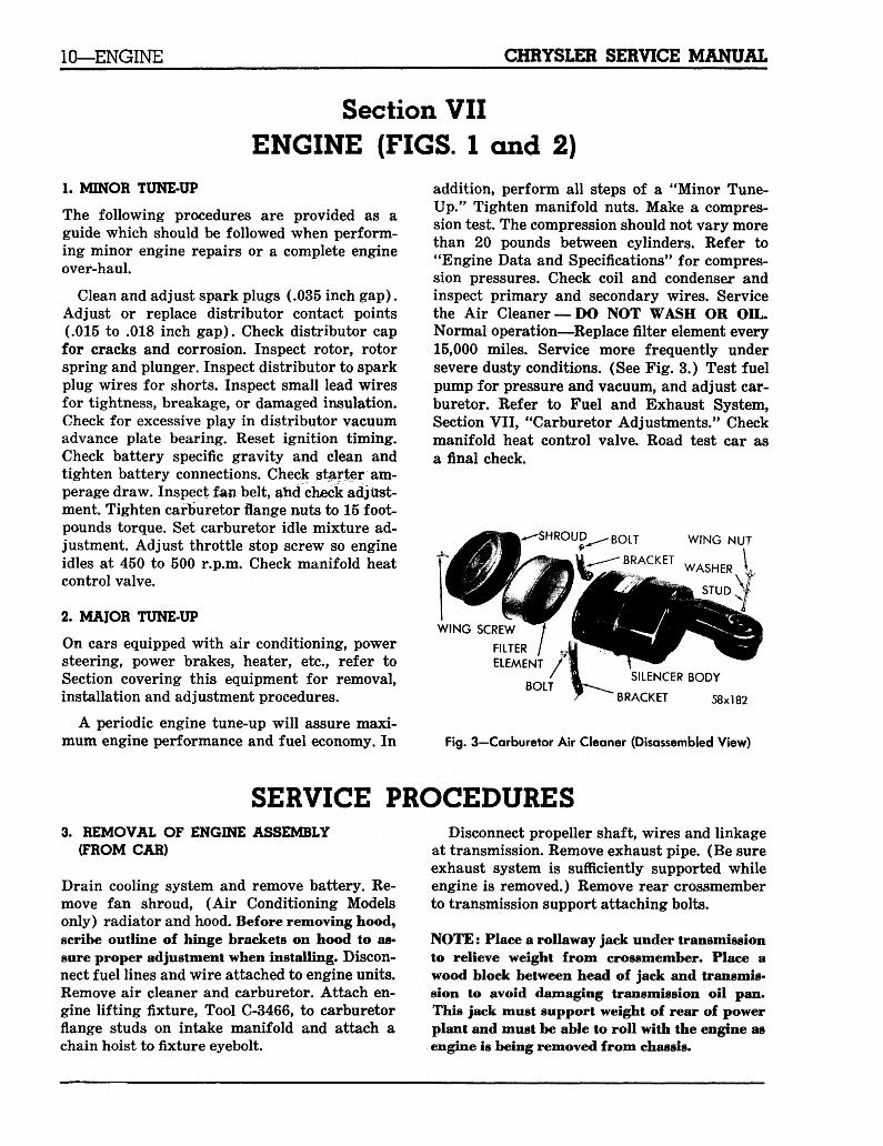
Fig. 2-F'rrePower V-8 Engine (End Sectional View)
10—ENGINE SERVICE MANUAL
Section VIIENGINE (FIGS. 1 and 2)
1. MINOR TUNE-UP
The following procedures are provided as aguide which should be followed when perform-ing minor engine repairs or a complete engineover-haul.
Clean and adjust spark plugs (.035 inch gap).Adjust or replace distributor contact points(.015 to .018 inch gap). Check distributor capfor cracks and corrosion. Inspect rotor, rotorspring and plunger. Inspect distributor to sparkplug wires for shorts. Inspect small lead wiresfor tightness, breakage, or damaged insulation.Check for excessive play in distributor vacuumadvance plate bearing. Reset ignition timing.Check battery specific gravity and clean andtighten battery connections. Check starter am-perage draw. Inspect fan belt, and check adjust-ment. Tighten carburetor flange nuts to 15 foot-pounds torque. Set carburetor idle mixture ad-justment. Adjust throttle stop screw so engineidles at 450 to 500 r.p.m. Check manifold heatcontrol valve.
2. MAJOR TUNE-UP
On cars equipped with air conditioning, powersteering, power brakes, heater, etc., refer toSection covering this equipment for removal,installation and adjustment procedures.
A periodic engine tune-up will assure maxi-mum engine performance and fuel economy. In
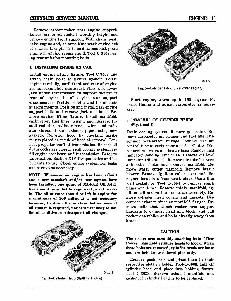
addition, perform all steps of a "Minor Tune-Up." Tighten manifold nuts. Make a compres-sion test. The compression should not vary morethan 20 pounds between cylinders. Refer to"Engine Data and Specifications" for compres-sion pressures. Check coil and condenser andinspect primary and secondary wires. Servicethe Air Cleaner —DO NOT WASH OR OIL.Normal operation—Replace filter element every15,000 miles. Service more frequently undersevere dusty conditions. (See Fig. 3.) Test fuelpump for pressure and vacuum, and adjust car-buretor. Refer to Fuel and Exhaust System,Section VII, "Carburetor Adjustments." Checkmanifold heat control valve. Road test car asa final check.
'SHROUD BOLT WING NUT
WASHER
WING SCREWFILTERELEMENT /
BOLTSILENCER BODY
BRACKET 58x182
Fig. 3—Carburetor Air Cleaner (Disassembled View)
SERVICE PROCEDURES3. REMOVAL OF ENGINE ASSEMBLY
(FROM CAR)
Drain cooling system and remove battery. Re-move fan shroud, (Air Conditioning Modelsonly) radiator and hood. Before removing hood,scribe outline of hinge brackets on hood to as-sure proper adjustment when installing. Discon-nect fuel lines and wire attached to engine units.Remove air cleaner and carburetor. Attach en-gine lifting fixture, Tool C-3466, to carburetorflange studs on intake manifold and attach achain hoist to fixture eyebolt.
Disconnect propeller shaft, wires and linkageat transmission. Remove exhaust pipe. (Be sureexhaust system is sufficiently supported whileengine is removed.) Remove rear crossmemberto transmission support attaching bolts.
NOTE: Place a rollaway jack under transmissionto relieve weight from crossmember. Place awood block between head of jack and transmis-sion to avoid damaging transmission oil pan.This jack must support weight of rear of powerplant and must be able to roll with the engine asengine is being removed from chassis.
CHRYSLER SERVICE MANUAL ENGINE—11
Remove crossmember rear engine support.Lower car to convenient working height andremove engine front support. With chain, hoist,raise engine and, at same time work engine outof chassis. If engine is to be disassembled, placeengine in engine repair stand, Tool C-3167, us-ing transmission mounting bolts.
4. INSTALLING ENGINE ON CAR)
Install engine lifting fixture, Tool C-3466 andattach chain hoist to fixture eyebolt. Lowerengine carefully, until front and rear of engineare approximately positioned. Place a rollawayjack under transmission to support weight ofrear of engine. Install engine rear supportcrossmember. Position engine and install nutsat front mounts. Position and install rear enginesupport bolts and remove jack and hoist. Re-move engine lifting fixture. Install manifold,carburetor, fuel lines, wiring and linkage. In-stall radiator, radiator hoses, wires and radi-ator shroud. Install exhaust pipes> using newgaskets. Reinstall hood by checking scribemarks placed on inside of hood at removal. Con-nect propeller shaft at transmission. Be sure alldrain cocks are closed; refill cooling system, re-fill engine crankcase and transmission. Refer toLubrication, Section XIV for quantities and lu-bricants to use. Check entire system for leaksand correct as necessary.
NOTE: Whenever an engine has been rebuiltand a new camshaft and/or new tappets havebeen installed, one quart of MOPAR Oil Addi-tive should be added to engine oil to aid break-in. The oil mixture should be left in engine fora minimum of 500 miles. It is not necessaryhowever, to drain the mixture before normaloil change is required, nor is it necessary to usethe oil additive at subsequent oil changes.
57x219
Fig. 4-Cylinder Head (SpitFire Engine)
57x221
Fig. 5-Cylinder Head (FirePower Engine)
Start engine, warm up to 160 degrees F.,check timing and adjust carburetor as neces-sary.
5. REMOVAL OF CYLINDER HEADS(Fig. 4 and 5)
Drain cooling system. Remove generator. Re-move carburetor air cleaner and fuel line. Dis-connect accelerator linkage. Remove vacuumcontrol tube at carburetor and distributor. Dis-connect coil wires and heater hose. Remove heatindicator sending unit wire. Remove oil levelindicator (dip stick). Remove air tube betweenautomatic choke and exhaust manifold. Re-move water outlet manifold. Remove heaterblower. Remove ignition cable cover and dis-engage insulators from spark plugs. Use a thinwall socket, or Tool C-3054 to remove sparkplugs and tubes. Remove intake manifold, ig-nition coil and carburetor as an assembly. Re-move cylinder head covers and gaskets. Dis-connect exhaust pipes at manifold flanges. Re-move bolts that attach rocker arm supportbrackets to cylinder head and block, and pullrocker assemblies and bolts directly away fromheads.
CAUTION
The rocker arm assembly attaching bolts (Fire-Power ) also hold cylinder heads to block. Whenthese bolts are removed, cylinder heads are looseand are held by two dowel pins only.
Remove push rods and place them in theirrespective slots in holder Tool-C-3068. Lift offcylinder head and place into holding fixtureTool C-3038. Remove exhaust manifold andgasket, if cylinder head is to be replaced.
12—ENGINE CHRYSLER SERVICE MANUAL
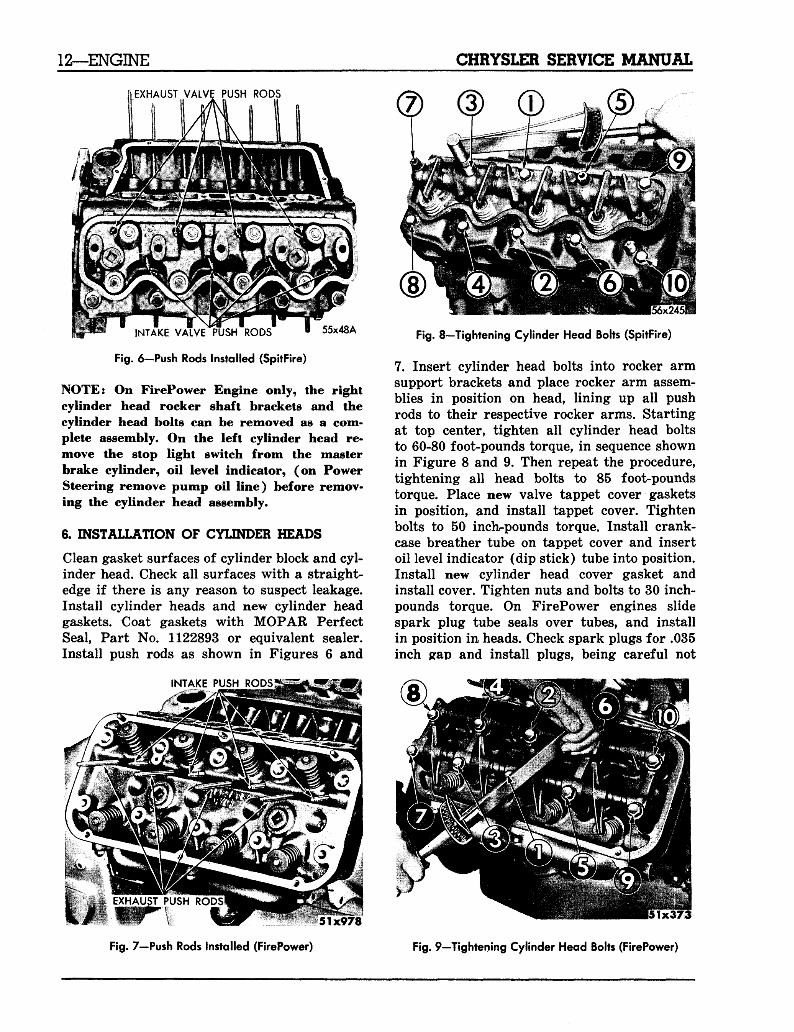
EXHAUST VALVE PUSH RODS
INTAKE VALVE PUSH RODS • 55x48A
Fig. 6-Push Rods Installed (SpitFire)
NOTE: On FirePower Engine only, the rightcylinder head rocker shaft brackets and thecylinder head bolts can be removed as a com-plete assembly. On the left cylinder head re-move the stop light switch from the masterbrake cylinder, oil level indicator, (on PowerSteering remove pump oil line) before remov-ing the cylinder head assembly.
6. INSTALLATION OF CYLINDER HEADS
Clean gasket surfaces of cylinder block and cyl-inder head. Check all surfaces with a straight-edge if there is any reason to suspect leakage.Install cylinder heads and new cylinder headgaskets. Coat gaskets with MOPAR PerfectSeal, Part No. 1122893 or equivalent sealer.Install push rods as shown in Figures 6 and
INTAKE PUSH RODS'
Fig. 8—Tightening Cylinder Head Bolts (SpitFire)
7. Insert cylinder head bolts into rocker armsupport brackets and place rocker arm assem-blies in position on head, lining up all pushrods to their respective rocker arms. Startingat top center, tighten all cylinder head boltsto 60-80 foot-pounds torque, in sequence shownin Figure 8 and 9. Then repeat the procedure,tightening all head bolts to 85 foot-poundstorque. Place new valve tappet cover gasketsin position, and install tappet cover. Tightenbolts to 50 inch-pounds torque. Install crank-case breather tube on tappet cover and insertoil level indicator (dip stick) tube into position.Install new cylinder head cover gasket andinstall cover. Tighten nuts and bolts to 30 inch-pounds torque. On FirePower engines slidespark plug tube seals over tubes, and installin position in heads. Check spark plugs for .035inch gap and install plugs, being careful not
51x978
Fig. 7—Push Rods Installed (FirePower) Fig. 9—Tightening Cylinder Head Bolts (FirePower)
CHRYSLER SERVICE MANUAL ENGINE—13
GENERATOR ADJUSTINGSTRAP BOLT
PUMP ADJUSTING BOLT
57x21«A
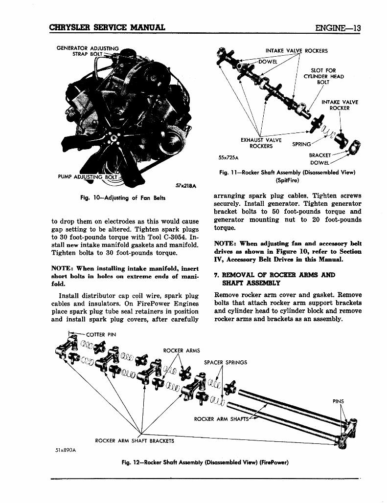
Fig. 1 0 - A d justing of Fan Belts
to drop them on electrodes as this would causegap setting to be altered. Tighten spark plugsto 30 foot-pounds torque with Tool C-3054. In-stall new intake manifold gaskets and manifold.Tighten bolts to 30 foot-pounds torque.
NOTE: When installing intake manifold, insertshort bolts in holes on extreme ends of mani-fold.
Install distributor cap coil wire, spark plugcables and insulators. On FirePower Enginesplace spark plug tube seal retainers in positionand install spark plug covers, after carefully
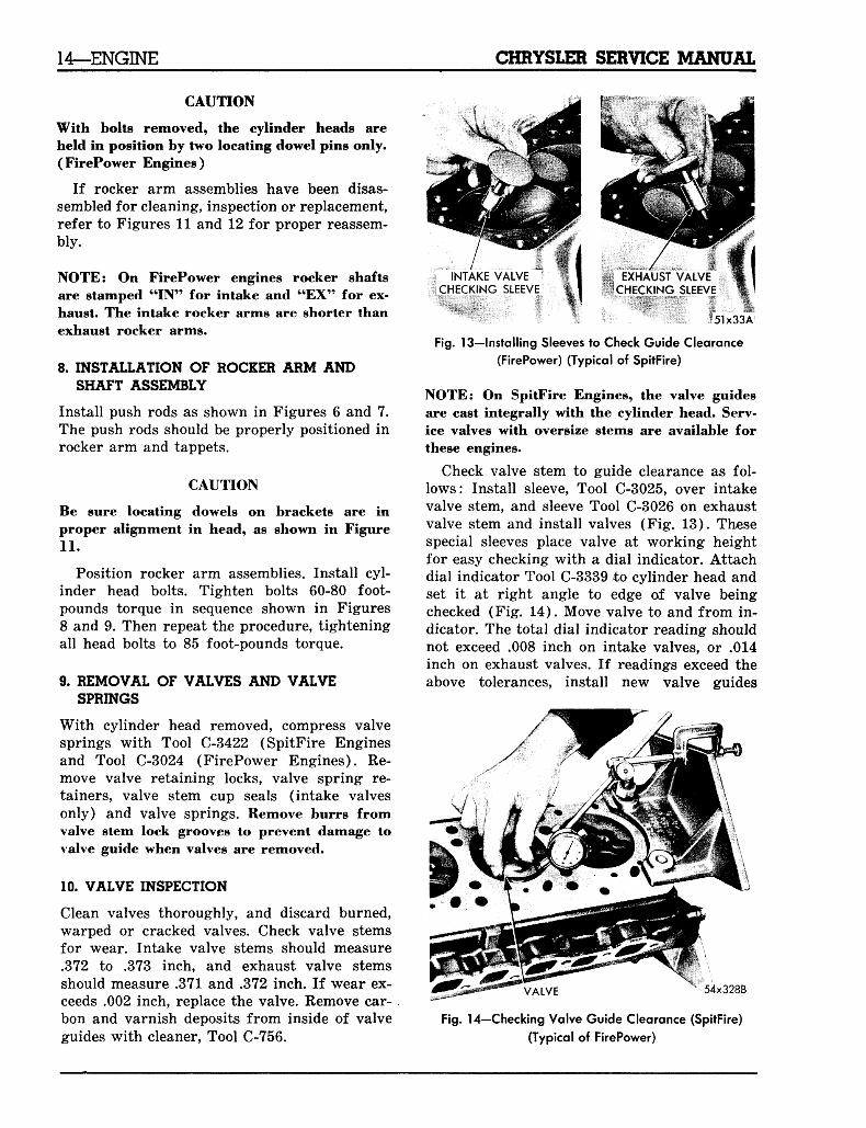
INTAKE VALVE ROCKERS
•DOWEL
SLOT FORCYLINDER HEAD
BOLT
INTAKE VALVEROCKER
EXHAUST VALVEROCKERS
55x725A BRACKET
DOWEL
Fig. 11—Rocker Shaft Assembly (Disassembled View)
(SpitFire)
arranging spark plug cables. Tighten screwssecurely. Install generator. Tighten generatorbracket bolts to 50 foot-pounds torque andgenerator mounting nut to 20 foot-poundstorque.
NOTE: When adjusting fan and accessory beltdrives as shown in Figure 10, refer to SectionFV, Accessory Belt Drives in this Manual.
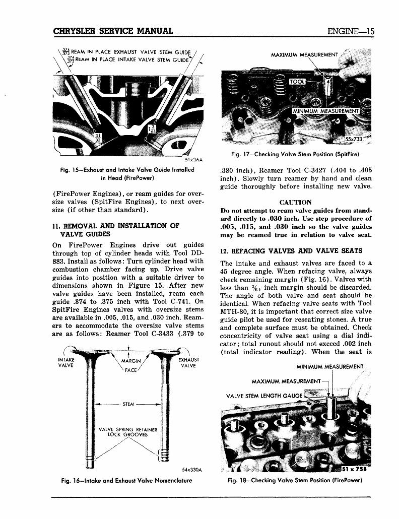
7. REMOVAL OF ROCKER ARMS ANDSHAFT ASSEMBLY
Remove rocker arm cover and gasket. Removebolts that attach rocker arm support bracketsand cylinder head to cylinder block and removerocker arms and brackets as an assembly.
COTTER PIN
ROCKER ARMS
SPACER SPRINGS
PINS
ROCKER ARM SHAFT BRACKETS
5U890A
Fig. 12-Rocker Shaft Assembly (Disassembled View) (FirePower)
14—ENGINE CHRYSLER SERVICE MANUAL
CAUTION
With bolts removed, the cylinder heads areheld in position by two locating dowel pins only.(FirePower Engines)
If rocker arm assemblies have been disas-sembled for cleaning, inspection or replacement,refer to Figures 11 and 12 for proper reassem-bly.
NOTE: On FirePower engines rocker shaftsare stamped "IN" for intake and "EX" for ex-haust. The intake rocker arms are shorter thanexhaust rocker arms.
8. INSTALLATION OF ROCKER ARM ANDSHAFT ASSEMBLY
Install push rods as shown in Figures 6 and 7.The push rods should be properly positioned inrocker arm and tappets.
CAUTION
Be sure locating dowels on brackets are inproper alignment in head, as shown in Figure11.
Position rocker arm assemblies. Install cyl-inder head bolts. Tighten bolts 60-80 foot-pounds torque in sequence shown in Figures8 and 9. Then repeat the procedure, tighteningall head bolts to 85 foot-pounds torque.
9. REMOVAL OF VALVES AND VALVESPRINGS
With cylinder head removed, compress valvesprings with Tool C-3422 (SpitFire Enginesand Tool C-3024 (FirePower Engines). Re-move valve retaining locks, valve spring re-tainers, valve stem cup seals (intake valvesonly) and valve springs. Remove burrs fromvalve stem lock grooves to prevent damage tovalve guide when valves are removed.
10. VALVE INSPECTION
Clean valves thoroughly, and discard burned,warped or cracked valves. Check valve stemsfor wear. Intake valve stems should measure.372 to .373 inch, and exhaust valve stemsshould measure .371 and .372 inch. If wear ex-ceeds .002 inch, replace the valve. Remove car-bon and varnish deposits from inside of valveguides with cleaner, Tool C-756.
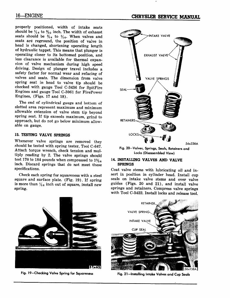
INTAKE VALVECHECKING SLEEVE
• EXHAUST VALVECHECKING SLEEVE
'5U33A
Fig. 13—Installing Sleeves to Check Guide Clearance
(FirePower) (Typical of SpitFire)
NOTE: On SpitFire Engines, the valve guidesare cast integrally with the cylinder head. Serv-ice valves with oversize stems are available forthese engines.
Check valve stem to guide clearance as fol-lows: Install sleeve, Tool C-3025, over intakevalve stem, and sleeve Tool C-3026 on exhaustvalve stem and install valves (Fig. 13). Thesespecial sleeves place valve at working heightfor easy checking with a dial indicator. Attachdial indicator Tool C-3339 to cylinder head andset it at right angle to edge of valve beingchecked (Fig. 14). Move valve to and from in-dicator. The total dial indicator reading shouldnot exceed .008 inch on intake valves, or .014inch on exhaust valves. If readings exceed theabove tolerances, install new valve guides
54x3288
Fig. 14—Checking Valve Guide Clearance (SpitFire)
(Typical of FirePower)
CHRYSLER SERVICE MANUAL ENGINE—15
REAM IN PLACE EXHAUST VAIVE STEM GUIDE /"RfcAM IN PLACE INTAKE VALVE STEM G U I D E V
MAXIMUM MEASUREMENT
51x36A
Fig. 15—Exhaust and Intake Valve Guide Installed
in Head (FirePower)
(FirePower Engines), or ream guides for over-size valves (SpitFire Engines), to next over-size (if other than standard).
11. REMOVAL AND INSTALLATION OFVALVE GUIDES
On FirePower Engines drive out guidesthrough top of cylinder heads with Tool DD-883. Install as follows: Turn cylinder head withcombustion chamber facing up. Drive valveguides into position with a suitable driver todimensions shown in Figure 15. After newvalve guides have been installed, ream eachguide .374 to .375 inch with Tool C-741. OnSpitFire Engines valves with oversize stemsare available in .005, .015, and .030 inch. Ream-ers to accommodate the oversize valve stemsare as follows: Reamer Tool C-3433 (.379 to
INTAKEVALVE
\MARGINXFACE-
EXHAUSTVALVE
STEM
VALVE SPRING RETAINER .'LOCK GROOViS
MINIMUM MEASUREMENT
55x733 "*
Fig. 17—Checking Valve Stem Position (SpitFire)
.380 inch), Reamer Tool C-3427 (.404 to .405inch). Slowly turn reamer by hand and cleanguide thoroughly before installing new valve.
CAUTIONDo not attempt to ream valve guides from stand-ard directly to .030 inch. Use step procedure of.005, .015, and .030 inch so the valve guidesmay he reamed true in relation to valve seat.
12. REFACING VALVES AND VALVE SEATS
The intake and exhaust valves are faced to a45 degree angle. When refacing valve, alwayscheck remaining margin (Fig. 16). Valves withless than %4 inch margin should be discarded.The angle of both valve and seat should beidentical. When refacing valve seats with ToolMTH-80, it is important that correct size valveguide pilot be used for reseating stones. A trueand complete surface must be obtained. Checkconcentricity of valve seat using a dial indi-cator ; total runout should not exceed .002 inch(total indicator reading). When the seat is
MINIMUM MEASUREMENT
MAXIMUM MEASUREMENT
VALVE STEM LENGTH GAUGE
EMENT—i
cyT. il*
54x330A
Fig. 16—Intake and Exhaust Valve Nomenclature
1x758
Fig. 18—Checking Valve Stem Position (FirePower)
16—ENGINE CHRYSLER SERVICE MANUAL
properly positioned, width of intake seatsshould be y16 to %2 inch. The width of exhaustseats should be %4 to y16. When valves andseats are reground, the position of valve inhead is changed, shortening operating lengthof hydraulic tappet. This means that plunger isoperating closer to its bottomed position, andless clearance is available for thermal expan-sion of valve mechanism during high speeddriving. Design of plunger travel includes asafety factor for normal wear and refacing ofvalves and seats. The dimension from valvespring seat in head to valve tip should bechecked with gauge Tool C-3436 for SpitFireEngines and gauge Tool C-3061 for FirePowerEngines, (Figs. 17 and 18).
The end of cylindrical gauge and bottom ofslotted area represent maximum and minimumallowable extension of valve stem tip beyondspring seat. If tip exceeds maximum, grind toapproach, but do not go below minimum allow-able on gauge.
13. TESTING VALVE SPRINGS
Whenever valve springs are removed theyshould be tested with spring tester, Tool C-647.Attach torque wrench, check tension and mul-tiply reading by 2. The valve springs shouldtest 170 to 184 pounds when compressed to 1%6inch. Discard springs that do not meet thesespecifications.
Check each spring for squareness with a steelsquare and surface plate. (Fig. 19). If springis more than y1Q inch out of square, install newspring.
SEAL
RETAINERS
LOCKS
w 54x336A
Fig. 20—Valves, Springs, Seals, Retainers and
Locks (Disassembled View)
14. INSTALLING VALVES AND VALVESPRINGS
Coat valve stems with lubricating oil and in-sert in position in cylinder head. Install cupseals on intake valve stems and over valveguides (Figs. 20 and 21), and install valvesprings and retainers. Compress valve springswith Tool C-3422. Install locks and release tool.
RETAINER
VALVE SPRING
INTAKE VALVE
CUP SEAL
Fig. 19-Checking Valve Spring for Squareness Fig. 21-lnstalling Intake Valves and Cup Seals
CHRYSLER SERVICE MANUAL ENGINE—17
NOTE: If valves and/or seats are reground,check the installed height of springs. Make suremeasurement is taken from full depth of coun-terbore in cylinder head to bottom surface ofspring retainer. (If spacers are installed meas-ure from top of spacer). If height is greaterthan 1 11/16 inches, install a 1/16 inch spacer(Part No. 1400482) in head counterbore tobring spring height back to normal 1 5/8 to1 11/16 inch.
15. HYDRAULIC TAPPETS
a. Preliminary to Checking Hydraulic Tappets
Before disassembling any part of engine tocheck for tappet noise, check oil pressure atgauge and oil level in oil pan. The pressureshould be between 40 to 65 pounds at 2,000r.p.m. The oil level in pan should never beabove "full" mark on dip stick, nor below "addoil" mark. Either of two conditions could beresponsible for noisy tappets.
Oil Level Too High—If oil level is above"full" mark on dip stick, it is possible the con-necting rods can dip into oil when engine isrunning and create foaming. This foam is fedto the hydraulic tappets by the oil pump, caus-ing them to go flat and allowing valves to seatnoisily.
Oil Level Too Low—Low oil level may allow
pump to take in air which, when fed to tappets,causes them to lose length and allows valves toseat noisily. Any leaks on intake side of pumpthrough which air can be drawn will create thesame tappet action. When tappet noise is dueto aeration, it may be intermittent or constant,and usually more than one tappet will be noisy.When oil level leaks have been corrected, theengine should run at fast idle for sufficient timeto allow all of air inside of tappets to be workedout.
b. Tappet Noises
To determine source of tappet noise, run en-gine at idle with cylinder head covers removed.Feel each valve spring to detect the noisytappet.
NOTE: Worn valve guides or cocked springsare sometimes mistaken for noisy tappets. Ifsuch is the case, noise may be dampened by ap-plying side thrust on valve spring. Inspect rock-
er arm push rod sockets and push rod ends forwear. If noise is not appreciably reduced, it canbe assumed the noise is in the tappet.
Valve tappet noise can be separated into twotypes, light noise and heavy noise. A light noiseis usually caused by excessive leakdown aroundthe unit plunger, or by plunger partially stick-ing in cylinder. A heavy noise is caused eitherby a tappet check valve not seating, or by for-eign particles becoming wedged between plung-er and tappet body, causing plunger to stickin down position. This heavy noise will be fur-ther evidenced by clearance between valve stemand rocker arm as valve closes. In either in-stance, the unit assembly should be removedfor inspection and cleaning.
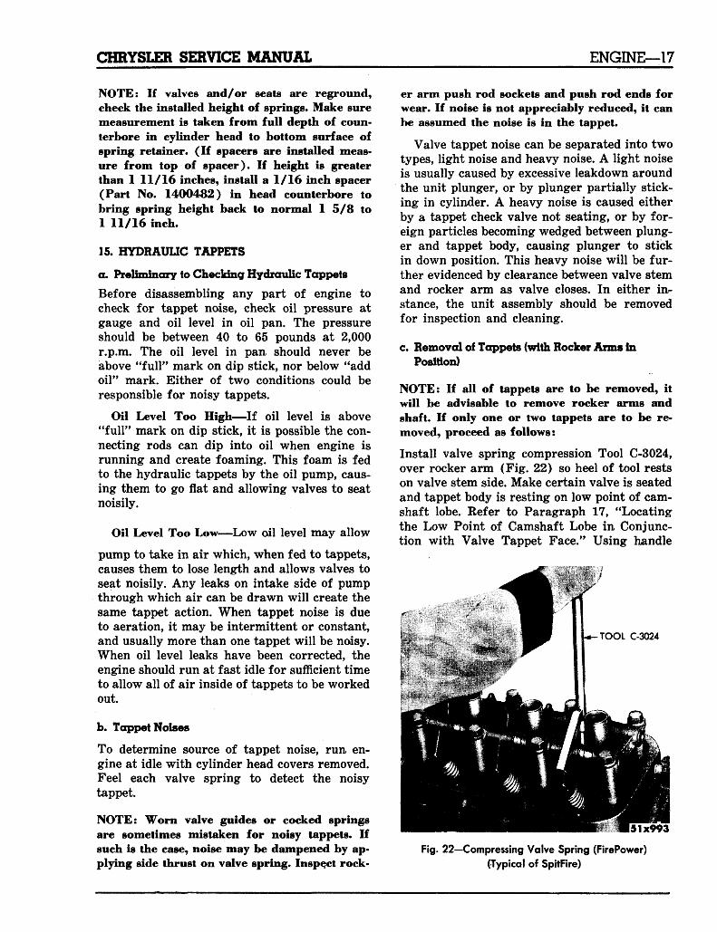
c. Removal of Tappets (with Rocker Anns InPosition)
NOTE: If all of tappets are to be removed, itwill be advisable to remove rocker arms andshaft. If only one or two tappets are to be re-moved, proceed as follows:
Install valve spring compression Tool C-3024,over rocker arm (Fig. 22) so heel of tool restson valve stem side. Make certain valve is seatedand tappet body is resting on low point of cam-shaft lobe. Refer to Paragraph 17, "Locatingthe Low Point of Camshaft Lobe in Conjunc-tion with Valve Tappet Face." Using handle
TOOL C-3024
Fig. 22—Compressing Valve Spring (FirePower)
(Typical of SpitFire)
18—ENGINE CHRYSLER SERVICE MANUAL
PLUNGER RETAINING SPRING CLIP
PLUNGER CAP
TAPPET PLUNGER
FLAT VALVE
CLEANKEROSENE
VALVE SPRING-
VALVE RETAINER-
PLUNGER SPRING'
TAPPET BODY
52x389B
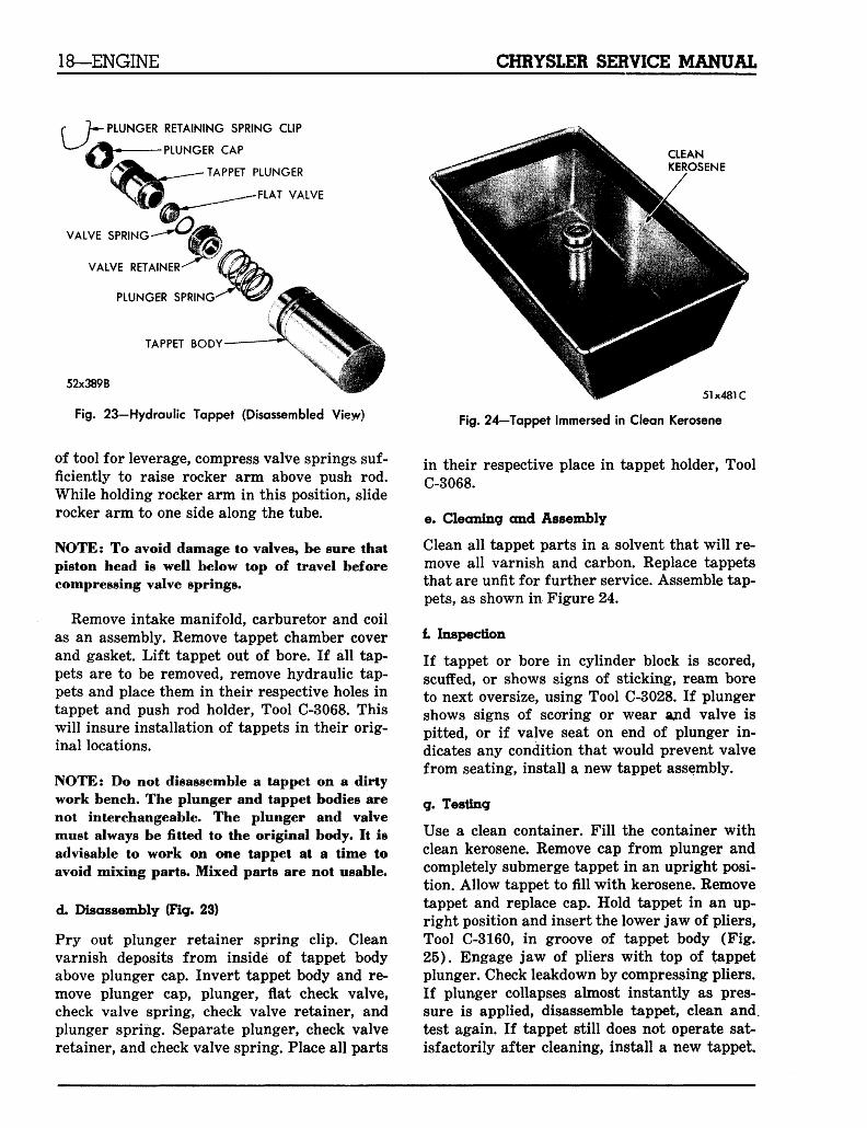
Fig. 23—Hydraulic Tappet (Disassembled Vieyv)
of tool for leverage, compress valve springs suf-ficiently to raise rocker arm above push rod.While holding rocker arm in this position, sliderocker arm to one side along the tube.
NOTE: To avoid damage to valves, be sure thatpiston head is well below top of travel beforecompressing valve springs.
Remove intake manifold, carburetor and coilas an assembly. Remove tappet chamber coverand gasket. Lift tappet out of bore. If all tap-pets are to be removed, remove hydraulic tap-pets and place them in their respective holes intappet and push rod holder, Tool C-3068. Thiswill insure installation of tappets in their orig-inal locations.
NOTE: Do not disassemble a tappet on a dirtywork bench. The plunger and tappet bodies arenot interchangeable. The plunger and valvemust always be fitted to the original body. It isadvisable to work on one tappet at a time toavoid mixing parts. Mixed parts are not usable.
d. Disassembly (Fig. 23)
Pry out plunger retainer spring clip. Cleanvarnish deposits from inside of tappet bodyabove plunger cap. Invert tappet body and re-move plunger cap, plunger, flat check valve,check valve spring, check valve retainer, andplunger spring. Separate plunger, check valveretainer, and check valve spring. Place all parts
51x481C
Fig. 24—Tappet Immersed in Clean Kerosene
in their respective place in tappet holder, ToolC-3068.
e. Cleaning and Assembly
Clean all tappet parts in a solvent that will re-move all varnish and carbon. Replace tappetsthat are unfit for further service. Assemble tap-pets, as shown in Figure 24.
i Inspection
If tappet or bore in cylinder block is scored,scuffed, or shows signs of sticking, ream boreto next oversize, using Tool C-3028. If plungershows signs of scoring or wear ajnd valve ispitted, or if valve seat on end of plunger in-dicates any condition that would prevent valvefrom seating, install a new tappet assembly.
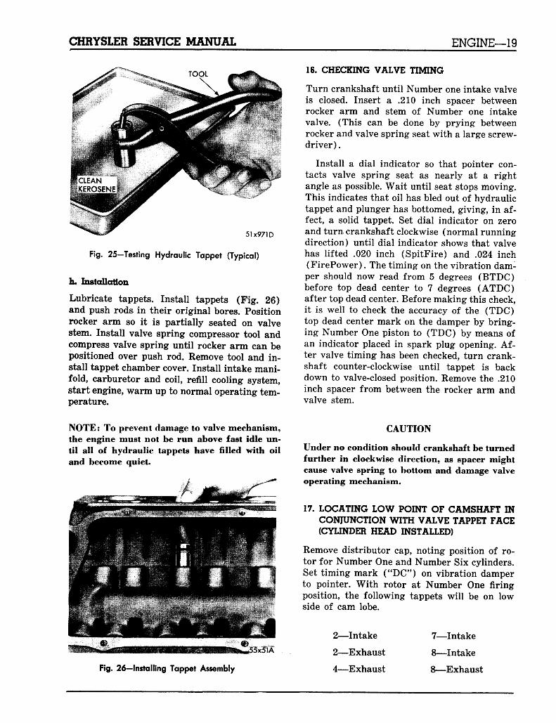
g. Testing
Use a clean container. Fill the container withclean kerosene. Remove cap from plunger andcompletely submerge tappet in an upright posi-tion. Allow tappet to fill with kerosene. Removetappet and replace cap. Hold tappet in an up-right position and insert the lower jaw of pliers,Tool C-3160, in groove of tappet body (Fig.25). Engage jaw of pliers with top of tappetplunger. Check leakdown by compressing pliers.If plunger collapses almost instantly as pres-sure is applied, disassemble tappet, clean and.test again. If tappet still does not operate sat-isfactorily after cleaning, install a new tappet.
CHRYSLER SERVICE MANUAL ENGINE—19
51x971D
Fig. 25—Testing Hydraulic Tappet (Typical)
h. Installation
Lubricate tappets. Install tappets (Fig. 26)and push rods in their original bores. Positionrocker arm so it is partially seated on valvestem. Install valve spring compressor tool andcompress valve spring until rocker arm can bepositioned over push rod. Remove tool and in-stall tappet chamber cover. Install intake mani-fold, carburetor and coil, refill cooling system,start engine, warm up to normal operating tem-perature.
16. CHECKING VALVE TIMING
Turn crankshaft until Number one intake valveis closed. Insert a .210 inch spacer betweenrocker arm and stem of Number one intakevalve. (This can be done by prying betweenrocker and valve spring seat with a large screw-driver).
Install a dial indicator so that pointer con-tacts valve spring seat as nearly at a rightangle as possible. Wait until seat stops moving.This indicates that oil has bled out of hydraulictappet and plunger has bottomed, giving, in af-fect, a solid tappet. Set dial indicator on zeroand turn crankshaft clockwise (normal runningdirection) until dial indicator shows that valvehas lifted .020 inch (SpitFire) and .024 inch(FirePower). The timing on the vibration dam-per should now read from 5 degrees (BTDC)before top dead center to 7 degrees (ATDC)after top dead center. Before making this check,it is well to check the accuracy of the (TDC)top dead center mark on the damper by bring-ing Number One piston to (TDC) by means ofan indicator placed in spark plug opening. Af-ter valve timing has been checked, turn crank-shaft counter-clockwise until tappet is backdown to valve-closed position. Remove the .210inch spacer from between the rocker arm andvalve stem.
NOTE: To prevent damage to valve mechanism,the engine must not be run above fast idle un-til all of hydraulic tappets have filled with oiland become quiet.
x51A
CAUTION
Under no condition should crankshaft be turnedfurther in clockwise direction, as spacer mightcause valve spring to bottom and damage valveoperating mechanism.
17. LOCATING LOW POINT OF CAMSHAFT INCONJUNCTION WITH VALVE TAPPET FACE(CYLINDER HEAD INSTALLED)
Remove distributor cap, noting position of ro-tor for Number One and Number Six cylinders.Set timing mark ("DC") on vibration damperto pointer. With rotor at Number One firingposition, the following tappets will be on lowside of cam lobe.
Fig. 26-lnstalling Tappet Assembly
2—Intake
2—Exhaust
4—Exhaust
7—Intake
8—Intake
8—Exhaust
20—ENGINE CHRYSLER SERVICE MANUAL
NOTE? To remove Number One intake and ex-haust tappet, rotate the crankshaft *4 turnclockwise from above position.
With rotor at Number Six firing position, thefollowing tappets will be on low side of camlobe:
SPROCKET
3—Intake
3—Exhaust
4—Intake
5—Intake
5—Exhaust
7—Exhaust
NOTE: To remove Number Six intake and ex-haust tappet, rotate crankshaft \i turn clock-wise from above position.
18. REMOVAL OF TIMING GEARS AND CHAIN
Remove radiator and water pump assembly.Remove bolt and flatwasher holding vibrationdamper on crankshaft. Remove two of the dam-per bolts, install Tool C-3033, and pull damperassembly off end of crankshaft.
Remove chain cover and gasket. Slide crank-shaft oil slinger off end of crankshaft. Removefuel pump eccentric attaching bolt, cup washerand eccentric. Remove timing chain, withcrankshaft and camshaft sprockets. Remove thecamshaft and crankshaft gear keys from theirrespective slots.
CRANKSHAFTSPROCKET
RETAINER WASHER M flff . B 56x556 A
Fig. 28—Installing Fuel Pump Eccentric
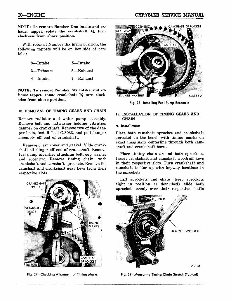
19. INSTALLATION OF TIMING GEARS ANDCHAIN
a. Installation
Place both camshaft sprocket and crankshaftsprocket on the bench with timing marks onexact imaginary centerline through both cam-shaft and crankshaft bores.
Place timing chain around both sprockets.Insert crankshaft and camshaft woodruff keysin their respective slots. Turn crankshaft andcamshaft to line up with keyway locations inthe sprockets.
Lift sprockets and chain (keep sprocketstight in position as described) slide bothsprockets evenly over their respective shafts
TORQUE WRENCH
Fig. 27—Checking Alignment of Timing Marks
56x130
Fig. 29—Measuring Timing Chain Stretch (Typical)
CHRYSLER SERVICE MANUAL ENGINE—21
(see Fig. 29), "Camshaft Installation". Usestraight edge to check alignment of timingmarks (Fig. 27.)
Slide fuel pump eccentric over camshaftagainst sprocket (Fig. 28). Be sure slot in ec-centric lines up with protruding camshaftsprocket key. Install cup washer and bolt andtighten 35 foot-pounds torque.
b. Checking Timing Chain for Stretch
Place a scale next to timing chain so that anymovement of chain may be measured. Place atorque wrench and socket over camshaft gearattaching bolt and apply torque in direction ofcrankshaft rotation to take up slack; 30 foot-pounds torque (with cylinder heads installed)and 15 foot-pounds torque (heads removed).Holding scale with dimensional reading evenwith edge of a chain link, apply torque in re-verse direction 25 foot-pounds (with cylinderheads installed) and 15 foot-pounds (headsremoved), and note the amount of chain rota-tion (Fig. 29). Install new timing chain, if itsmovement is greater than %6 inch.
NOTE: With a torque applied to camshaft gearbolt, the crankshaft should not move. If thereis any movement, however, the crankshaftshould be blocked to prevent rotation.
If chain is satisfactory, slide crankshaft oilslinger over shaft and up against gear (flangeaway from gear.)
20. TIMING CHAIN CASE COVER OIL SEALREPLACEMENT
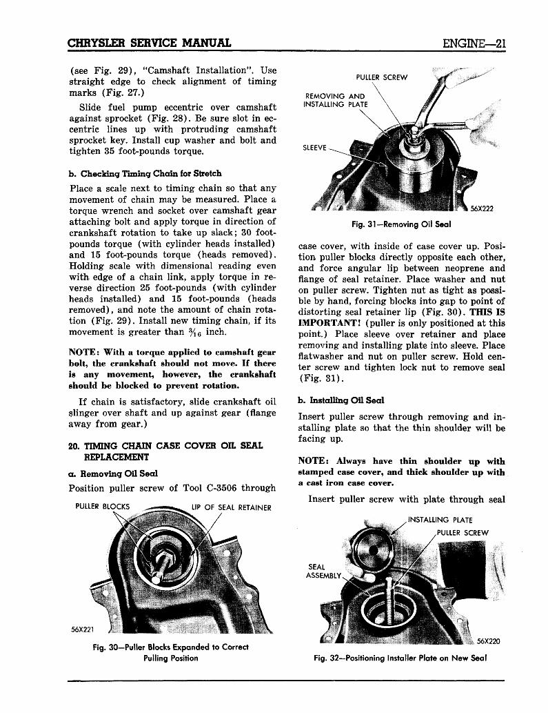
a. Removing Oil Seal
Position puller screw of Tool C-3506 through
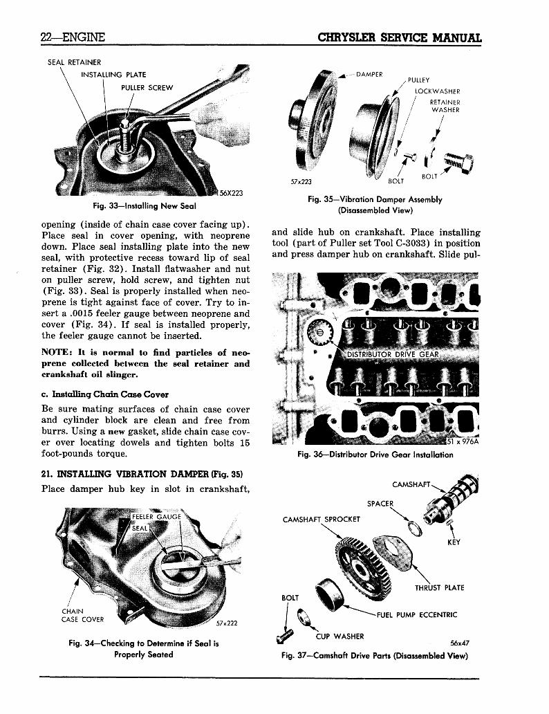
PULLER BLOCKS . ^ , — i ^ UP OF SEAL RETAINER
PULLER SCREW
56X221
REMOVING ANDINSTALLING PLATE
SLEEVE
56X222
Fig. 31—Removing Oil Seal
case cover, with inside of case cover up. Posi-tion puller blocks directly opposite each other,and force angular lip between neoprene andflange of seal retainer. Place washer and nuton puller screw. Tighten nut as tight as possi-ble by hand, forcing blocks into gap to point ofdistorting seal retainer lip (Fig. 30). THIS ISIMPORTANT! (puller is only positioned at thispoint.) Place sleeve over retainer and placeremoving and installing plate into sleeve. Placeflatwasher and nut on puller screw. Hold cen-ter screw and tighten lock nut to remove seal(Fig. 31).
b. Installing Oil Seal
Insert puller screw through removing and in-stalling plate so that the thin shoulder will befacing up.
NOTE: Always have thin shoulder up withstamped case cover, and thick shoulder up witha cast iron case cover.
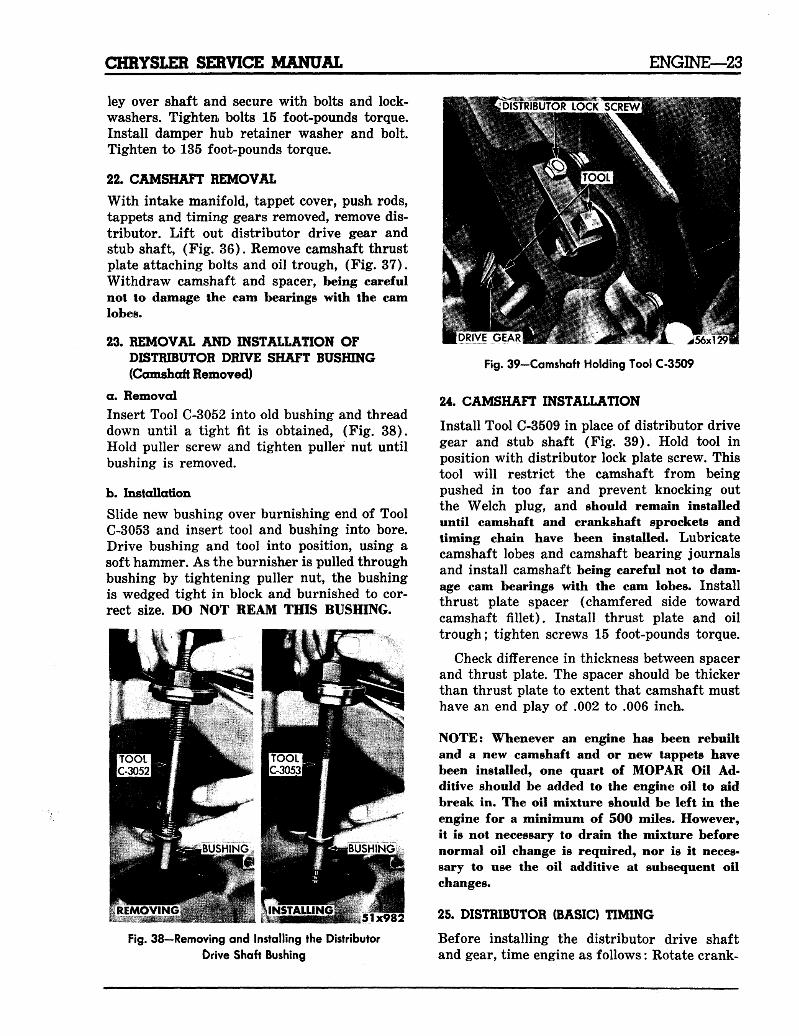
Insert puller screw with plate through seal
INSTALLING PLATE
PULLER SCREW
SEALASSEMBLY^ ':
Fig. 30—Puller Blocks Expanded to CorrectPulling Position
t m - r -- *: - >?- •.. : « n n R i t « . 56x220
Fig. 32—Positioning Installer Plate on New Seal
22—ENGINE CHRYSLER SERVICE MANUAL
SEAL RETAINER
INSTALLING PLATE
PULLER SCREW
56X223
Fig. 33-lnstalling New Seal
opening (inside of chain case cover facing up).Place seal in cover opening, with neoprenedown. Place seal installing plate into the newseal, with protective recess toward lip of sealretainer (Fig. 32). Install flatwasher and nuton puller screw, hold screw, and tighten nut(Fig. 33). Seal is properly installed when neo-prene is tight against face of cover. Try to in-sert a .0015 feeler gauge between neoprene andcover (Fig. 34). If seal is installed properly,the feeler gauge cannot be inserted.
NOTE: It is normal to find particles of neo-prene collected between the seal retainer andcrankshaft oil slinger.
c. Installing Chain Case Cover
Be sure mating surfaces of chain case coverand cylinder block are clean and free fromburrs. Using a new gasket, slide chain case cov-er over locating dowels and tighten bolts 15foot-pounds torque.
21. INSTALLING VIBRATION DAMPER (Fig. 35)
Place damper hub key in slot in crankshaft,
CHAINCASE COVER 57x222
Fig. 34—Checking to Determine if Seal is
Properly Seated
DAMPER, PULLEY
p LOCKWASHER
/ RETAINER// WASHER
/
57x223 BO(T
Fig. 35—Vibration Damper Assembly
(Disassembled View)
and slide hub on crankshaft. Place installingtool (part of Puller set Tool C-3033) in positionand press damper hub on crankshaft. Slide pul-
DISTRIBUTOR DRIVE GEAR
x976A
Fig. 36—Distributor Drive Gear Installation
CAMSHAFT,
SPACER
CAMSHAFT SPROCKET
BOLT
THRUST PLATE
FUEL PUMP ECCENTRIC
CUP WASHER56x47
Fig. 37—Camshaft Drive Parts (Disassembled View)
CHRYSLER SERVICE MANUAL ENGINE—23
ley over shaft and secure with bolts and lock-washers. Tighten, bolts 15 foot-pounds torque.Install damper hub retainer washer and bolt.Tighten to 135 foot-pounds torque.
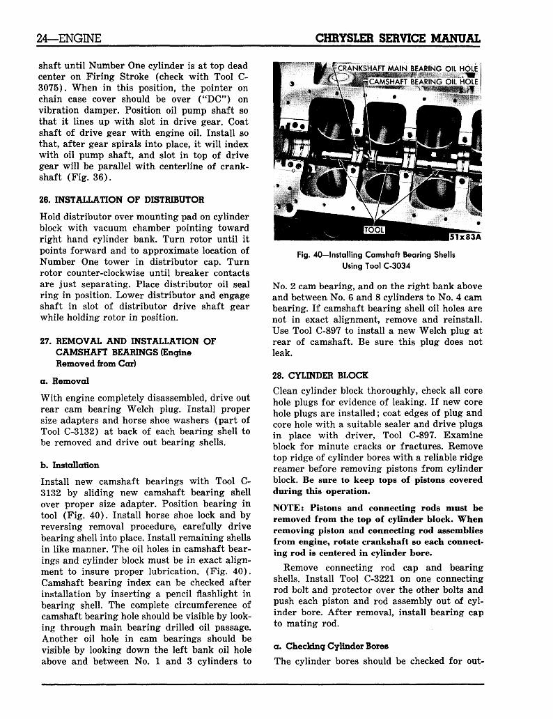
22. CAMSHAFT REMOVAL
With intake manifold, tappet cover, push rods,tappets and timing gears removed, remove dis-tributor. Lift out distributor drive gear andstub shaft, (Fig. 36). Remove camshaft thrustplate attaching bolts and oil trough, (Fig. 37).Withdraw camshaft and spacer, being carefulnot to damage the cam bearings with the camlobes.
23. REMOVAL AND INSTALLATION OFDISTRIBUTOR DRIVE SHAFT BUSHING(Camshaft Removed)
a. RemovalInsert Tool C-3052 into old bushing and threaddown until a tight fit is obtained, (Fig. 38).Hold puller screw and tighten puller nut untilbushing is removed.
b. InstallationSlide new bushing over burnishing end of ToolC-3053 and insert tool and bushing into bore.Drive bushing and tool into position, using asoft hammer. As the burnisher is pulled throughbushing by tightening puller nut, the bushingis wedged tight in block and burnished to cor-rect size. DO NOT REAM THIS BUSHING.
DIITRIBUTOR LOCK SCREW
Fig. 38—Removing and Installing the DistributorDrive Shaft Bushing
[DRIVE GEAR WO? « . ^BT % W * J L ^56X1!
Fig. 39-Camshaft Holding Tool C-3509
24. CAMSHAFT INSTALLATION
Install Tool C-3509 in place of distributor drivegear and stub shaft (Fig. 39). Hold tool inposition with distributor lock plate screw. Thistool will restrict the camshaft from beingpushed in too far and prevent knocking outthe Welch plug, and should remain installeduntil camshaft and crankshaft sprockets andtiming chain have been installed. Lubricatecamshaft lobes and camshaft bearing journalsand install camshaft being careful not to dam-age cam bearings with the cam lobes. Installthrust plate spacer (chamfered side towardcamshaft fillet). Install thrust plate and oiltrough; tighten screws 15 foot-pounds torque.
Check difference in thickness between spacerand thrust plate. The spacer should be thickerthan thrust plate to extent that camshaft musthave an end play of .002 to .006 inch.
NOTE: Whenever an engine has been rebuiltand a new camshaft and or new tappets havebeen installed, one quart of MOPAR Oil Ad-ditive should be added to the engine oil to aidbreak in. The oil mixture should be left in theengine for a minimum of 500 miles. However,it is not necessary to drain the mixture beforenormal oil change is required, nor is it neces-sary to use the oil additive at subsequent oilchanges.
25. DISTRIBUTOR (BASIC) TIMING
Before installing the distributor drive shaftand gear, time engine as follows: Rotate crank-
24—ENGINE CHRYSLER SERVICE MANUAL
shaft until Number One cylinder is at top deadcenter on Firing Stroke (check with Tool C-3075). When in this position, the pointer onchain case cover should be over ("DC") onvibration damper. Position oil pump shaft sothat it lines up with slot in drive gear. Coatshaft of drive gear with engine oil. Install sothat, after gear spirals into place, it will indexwith oil pump shaft, and slot in top of drivegear will be parallel with center line of crank-shaft (Fig. 36).
26. INSTALLATION OF DISTRIBUTOR
Hold distributor over mounting pad on cylinderblock with vacuum chamber pointing towardright hand cylinder bank. Turn rotor until itpoints forward and to approximate location ofNumber One tower in distributor cap. Turnrotor counter-clockwise until breaker contactsare just separating. Place distributor oil sealring in position. Lower distributor and engageshaft in slot of distributor drive shaft gearwhile holding rotor in position.
27. REMOVAL AND INSTALLATION OFCAMSHAFT BEARINGS (EngineRemoved from Car)
a. Removal
With engine completely disassembled, drive outrear cam bearing Welch plug. Install propersize adapters and horse shoe washers (part ofTool C-3132) at back of each bearing shell tobe removed and drive out bearing shells.
b. Installation
Install new camshaft bearings with Tool C-3132 by sliding new camshaft bearing shellover proper size adapter. Position bearing intool (Fig. 40). Install horse shoe lock and byreversing removal procedure* carefully drivebearing shell into place. Install remaining shellsin like manner. The oil holes in camshaft bear-ings and cylinder block must be in exact align-ment to insure proper lubrication. (Fig. 40).Camshaft bearing index can be checked afterinstallation by inserting a pencil flashlight inbearing shell. The complete circumference ofcamshaft bearing hole should be visible by look-ing through main bearing drilled oil passage.Another oil hole in cam bearings should bevisible by looking down the left bank oil holeabove and between No. 1 and 3 cylinders to
CRANKSHAFT MAIN BEARING OIL HOLE
CAMSHAFT BEARING OIL HOLE
Fig. 40—Installing Camshaft Bearing Shells
Using Tool C-3034
No. 2 cam bearing, and on the right bank aboveand between No. 6 and 8 cylinders to No. 4 cambearing. If camshaft bearing shell oil holes arenot in exact alignment, remove and reinstall.Use Tool C-897 to install a new Welch plug atrear of camshaft. Be sure this plug does notleak.
28. CYLINDER BLOCK
Clean cylinder block thoroughly, check all corehole plugs for evidence of leaking. If new corehole plugs are installed; coat edges of plug andcore hole with a suitable sealer and drive plugsin place with driver, Tool C-897. Examineblock for minute cracks or fractures. Removetop ridge of cylinder bores with a reliable ridgereamer before removing pistons from cylinderblock. Be sure lo keep tops of pistons coveredduring this operation.
NOTE: Pistons and connecting rods must beremoved from the top of cylinder block. Whenremoving piston and connecting rod assembliesfrom engine, rotate crankshaft so each connect-ing rod is centered in cylinder bore.
Remove connecting rod cap and bearingshells. Install Tool C-3221 on one connectingrod bolt and protector over the other bolts andpush each piston and rod assembly out of cyl-inder bore. After removal, install bearing capto mating rod.
a. Checking Cylinder Bores
The cylinder bores should be checked for out-
CHRYSLER SERVICE MANUAL ENGINE—25
of-round and taper with Tool CM-119. If cyl-inder bores show more than .005 inch out-of-round or a taper of more than .010 inch, thecylinder block should be rebored and new pis-tons and rings fitted.
b. Honing Cylinder Bores
To remove light scoring, scuffing, or scratchesfrom cylinder walls, use honing Tool C-823.The crankshaft, bearings and internal partsshould be protected during honing and boringoperations. Usually one or two "passes" witha hone will clean up a bore and still maintainrequired limits. If cylinder bores are found tobe satisfactory in respect to taper and out-of-round and new rings are to be installed, usecylinder surfacing hone Tool C-3501 with 280grit stones for deglazing bores. This will facili-tate in the break-in of new rings.
CAUTION
Be sure all abrasives are removed from engineparts after honing. It is recommended that asolution of soap and water be used with a brushand then thoroughly dried. If this is impossibleuse SAE No. 10 oil and CLEAN rags. When thebore can be wiped with a clean white rag andbe withdrawn clean, the bore is clean.
c. Cylinder Walls
Cylinder walls which are badly scored, scuffed,scratched, or worn beyond specified limitsshould be rebored. Whatever type of boringequipment is used, boring operation should beclosely co-ordinated with the fitting of pistonsand rings, in order that specifications may bemaintained.
SPRING SCALE (TOOL)
INVERTED PISTON
57x225
Fig. 42—Checking Ring Gap in Cylinder Bore (FirePower)
(Typical of SpitFire)
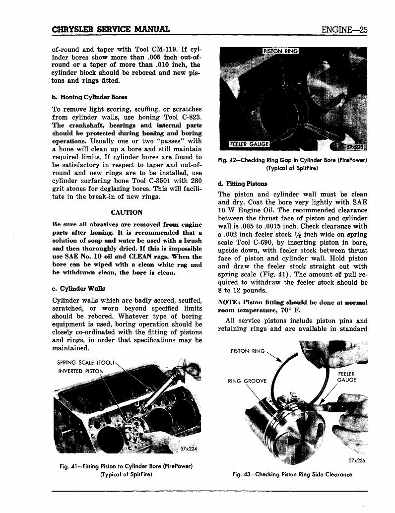
d. Fitting Pistons
The piston and cylinder wall must be cleanand dry. Coat the bore very lightly with SAE10 W Engine Oil. The recommended clearancebetween the thrust face of piston and cylinderwall is .005 to .0015 inch. Check clearance witha .002 inch feeler stock y% inch wide on springscale Tool C-690, by inserting piston in bore,upside down, with feeler stock between thrustface of piston and cylinder wall. Hold pistonand draw the feeler stock straight out withspring scale (Fig. 41). The amount of pull re-quired to withdraw the feeler stock should be8 to 12 pounds.
NOTE: Piston fitting should be done at normalroom temperature, 70° F.
All service pistons include piston pins andretaining rings and are available in standard
PISTON RING
RING GROOVE
57x224
Fig. 41—Fitting Piston to Cylinder Bore (FirePower)
(Typical of SpitFire)
57x226
Fig. 43—Checking Piston Ring Side Clearance
26—ENGINE CHRYSLER SERVICE MANUAL
51x60
Fig. 44—Fitting Piston Pins in Connecting Rod
and the following oversizes, .005, .020, .040and .060 inch, (C-75 only).
e. Fitting Rings
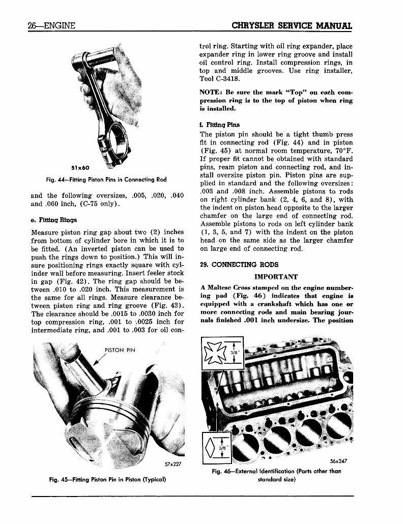
Measure piston ring gap about two (2) inchesfrom bottom of cylinder bore in which it is tobe fitted. (An inverted piston can be used topush the rings down to position.) This will in-sure positioning rings exactly square with cyl-inder wall before measuring. Insert feeler stockin gap (Fig. 42). The ring gap should be be-tween .010 to .020 inch. This measurement isthe same for all rings. Measure clearance be-tween piston ring and ring groove (Fig. 43).The clearance should be .0015 to .0030 inch fortop compression ring, .001 to .0025 inch forintermediate ring, and .001 to .003 for oil con-
PISTON PIN
57x227
trol ring. Starting with oil ring expander, placeexpander ring in lower ring groove and installoil control ring. Install compression rings, intop and middle grooves. Use ring installer,Tool C-3418.
NOTE: Be sure the mark "Top" on each com-pression ring is to the top of piston when ringis installed.
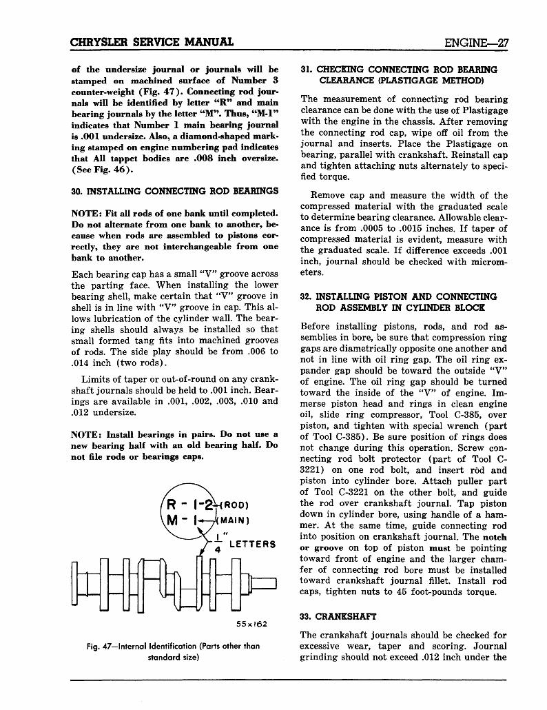
f. Fitting PinsThe piston pin should be a tight thumb pressfit in connecting rod (Fig. 44) and in piston(Fig. 45) at normal room temperature, 70°F.If proper fit cannot be obtained with standardpins, ream piston and connecting rod, and in-stall oversize piston pin. Piston pins are sup-plied in standard and the following oversizes:.003 and .008 inch. Assemble pistons to rodson right cylinder bank (2, 4, 6, and 8), withthe indent on piston head opposite to the largerchamfer on the large end of connecting rod.Assemble pistons to rods on left cylinder bank(1, 3, 5, and 7) with the indent on the pistonhead on the same side as the larger chamferon large end of connecting rod.
29. CONNECTING RODS
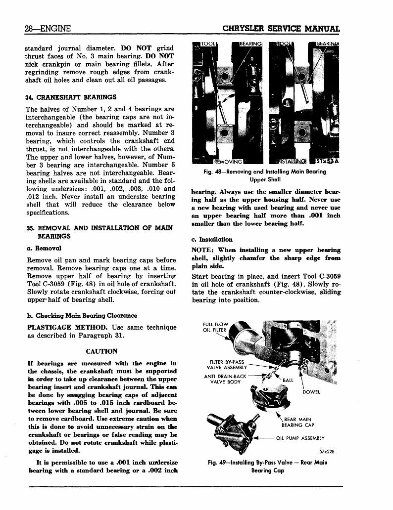
IMPORTANTA Maltese Cross stamped on the engine number-ing pad (Fig. 46) indicates that engine isequipped with a crankshaft which has one ormore connecting rods and main bearing jour-nals finished .001 inch undersize. The position
3/8"
3/8 Kfflfc56x247
Fig. 45-Fitting Piston Pin in Piston (Typical)
Fig. 46—External Identification (Parts other than
standard size)
CHRYSLER SERVICE MANUAL ENGINE—27
of the undersize journal or journals will bestamped on machined surface of Number 3counter-weight (Fig. 47) . Connecting rod jour-nals will be identified by letter "R" and mainbearing journals by the letter "M". Thus, "M-l"indicates that Number 1 main bearing journalis .001 undersize. Also, a diamond-shaped mark-ing stamped on engine numbering pad indicatesthat All tappet bodies are .008 inch oversize.(See Fig. 46) .
30. INSTALLING CONNECTING ROD BEARINGS
NOTE: Fit all rods of one bank until completed.Do not alternate from one bank to another, be-cause when rods are assembled to pistons cor-rectly, they are not interchangeable from onebank to another.
Each bearing cap has a small "V" groove acrossthe parting face. When installing the lowerbearing shell, make certain that "V" groove inshell is in line with "V" groove in cap. This al-lows lubrication of the cylinder wall. The bear-ing shells should always be installed so thatsmall formed tang fits into machined groovesof rods. The side play should be from .006 to.014 inch (two rods).
Limits of taper or out-of-round on any crank-shaft journals should be held to .001 inch. Bear-ings are available in .001, .002, .003, .010 and.012 undersize.
NOTE: Install bearings in pairs. Do not use anew bearing half with an old bearing half. Donot file rods or bearings caps.
55x162
Fig. 47—Internal Identification (Parts other thanstandard size)
31. CHECKING CONNECTING ROD BEARINGCLEARANCE (PLASTIGAGE METHOD)
The measurement of connecting rod bearingclearance can be done with the use of Plastigagewith the engine in the chassis. After removingthe connecting rod cap, wipe off oil from thejournal and inserts. Place the Plastigage onbearing, parallel with crankshaft. Reinstall capand tighten attaching nuts alternately to speci-fied torque.
Remove cap and measure the width of thecompressed material with the graduated scaleto determine bearing clearance. Allowable clear-ance is from .0005 to .0015 inches. If taper ofcompressed material is evident, measure withthe graduated scale. If difference exceeds .001inch, journal should be checked with microm-eters.
32. INSTALLING PISTON AND CONNECTINGROD ASSEMBLY IN CYLINDER BLOCK
Before installing pistons, rods, and rod as-semblies in bore, be sure that compression ringgaps are diametrically opposite one another andnot in line with oil ring gap. The oil ring ex-pander gap should be toward the outside "V"of engine. The oil ring gap should be turnedtoward the inside of the "V" of engine. Im-merse piston head and rings in clean engineoil, slide ring compressor, Tool C-385, overpiston, and tighten with special wrench (partof Tool C-385). Be sure position of rings doesnot change during this operation. Screw con-necting rod bolt protector (part of Tool C-3221) on one rod bolt, and insert rod andpiston into cylinder bore. Attach puller partof Tool C-3221 on the other bolt, and guidethe rod over crankshaft journal. Tap pistondown in cylinder bore, using handle of a ham-mer. At the same time, guide connecting rodinto position on crankshaft journal. The notchor groove on top of piston must be pointingtoward front of engine and the larger cham-fer of connecting rod bore must be installedtoward crankshaft journal fillet. Install rodcaps, tighten nuts to 45 foot-pounds torque.
33. CRANKSHAFT
The crankshaft journals should be checked forexcessive wear, taper and scoring. Journalgrinding should not exceed .012 inch under the
28—ENGINE CHRYSLER SERVICE MANUAL
standard journal diameter. DO NOT grindthrust faces of No. 3 main bearing. DO NOTnick crankpin or main bearing fillets. Afterregrinding remove rough edges from crank-shaft oil holes and clean out all oil passages.
34. CRANKSHAFT BEARINGS
The halves of Number 1, 2 and 4 bearings areinterchangeable (the bearing caps are not in-terchangeable) and should be marked at re-moval to insure correct reassembly. Number 3bearing, which controls the crankshaft endthrust, is not interchangeable with the others.The upper and lower halves, however, of Num-ber 3 bearing are interchangeable. Number 5bearing halves are not interchangeable. Bear-ing shells are available in standard and the fol-lowing undersizes: .001, .002, ,003, .010 and.012 inch. Never install an undersize bearingshell that will reduce the clearance belowspecifications.
35. REMOVAL AND INSTALLATION OF MAINBEARINGS
a. Removal
Remove oil pan and mark bearing caps beforeremoval. Remove bearing caps one at a time.Remove upper half of bearing by insertingTool C-3059 (Fig. 48) in oil hole of crankshaft.Slowly rotate crankshaft clockwise, forcing outupper half of bearing shell.
b. Checking Main Bearing Clearance
PLASTIGAGE METHOD. Use same techniqueas described in Paragraph 31.
CAUTION
If bearings are measured with the engine inthe chassis, the crankshaft must be supportedin order to take up clearance between the upperbearing insert and crankshaft journal. This canbe done by snugging bearing caps of adjacentbearings with .005 to .015 inch cardboard be-tween lower bearing shell and journal. Be sureto remove cardboard. Use extreme caution whenthis is done to avoid unnecessary strain on thecrankshaft or bearings or false reading may beobtained. Do not rotate crankshaft while plasti-gage is installed.
It is permissible to use a .001 inch unfdersizebearing with a standard bearing or a .002 inch
REMOVING!
Fig. 48—Removing and Installing Main Bearing
Upper Shell
bearing. Always use the smaller diameter bear-ing half as the upper housing half. Never usea new bearing with used bearing and never usean upper bearing half more than .001 inchsmaller than the lower bearing half.
c. Installation
NOTE: When installing a new upper bearingshell, slightly chamfer the sharp edge fromplain side.
Start bearing in place, and insert Tool C-3059in oil hole of crankshaft (Fig. 48). Slowly ro-tate the crankshaft counter-clockwise, slidingbearing into position.
FULL FLOWOIL FILTER
FILTER BY-PASSVALVE ASSEMBLY
ANTI DRAIN-BACKVALVE BODY
REAR MAINBEARING CAP
OIL PUMP ASSEMBLY
57x228
Fig. 49—Installing By-Pass Valve — Rear Main
Bearing Cap
CHRYSLER SERVICE MANUAL ENGINE—29
After all bearings have been fitted, tightenNumber 3 (center) main bearing first, andwork alternately to both ends. Tighten all capsto 85 foot-pounds torque.
NOTE: Before installing rear main bearing cap,position hollow dowel in cylinder block bore.See Fig. 49.
Crankshaft end play should be .002 to .007inch.
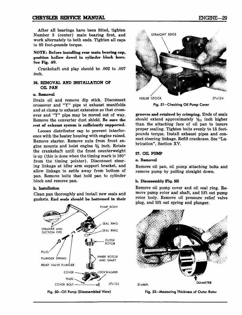
36. REMOVAL AND INSTALLATION OFOIL PAN
a. RemovalDrain oil and remove dip stick. Disconnectcrossover and "Y" pipe at exhaust manifoldsand at clamp to exhaust extension so that cross-over and "Y" pipe may be moved out of way.Remove the converter dust shield. Be sure therest of exhaust system is sufficiently supported.
Loosen distributor cap to prevent interfer-ence with the heater housing with engine raised.Remove starter. Remove nuts from front en-gine mounts and hoist engine % inch. Rotatethe crankshaft until the front counterweightis up (this is done when the timing mark is 180°from the timing pointer). Disconnect steer-ing linkage at idler arm support bracket, andallow linkage to settle away from bottom ofpan. Remove bolts that hold pan to cylinderblock and remove pan.
b. InstallationClean pan thoroughly and install new seals andgaskets. End seals should be bottomed in their
PUMP BODY
SEAL RING
SEAL RING
OUTERROTOR
INNER ROTORAND SHAFT
LOCKWASHER
57x123
STRAIGHT EDGE
STRAINER ANDSUCTION PIPE
PLUG
PLUNGER SPRING
RELIEF VALVE PLUNGER
COVER
PLUG
COVER BOLT
FEELER STOCK 57x124
Fig. 51—Checking Oil Pump Cover
grooves and retained by crimping. Ends of sealsshould extend approximately %2 inch higherthan the attaching face of oil pan to insureproper sealing. Tighten bolts evenly to 15 foot-pounds torque. Install exhaust pipes and con-nect steering linkage. Refill crankcase. See "Lu-brication", Section XV.
37. OIL PUMP
a. Removed
Remove oil pan, oil pump attaching bolts andremove pump by pulling straight down.
b. Disassembly (Fig. 50)
Remove oil pump cover and oil seal ring. Re-move pump rotor and shaft, and lift out pumprotor body. Remove oil pressure relief valveplug, and lift out spring and plunger.
41
Fig. 50-Oil Pump (Disassembled View)
ci *AA DIAMETER
Fig. 52—Measuring Thickness of Outer Rotor
30—ENGINE CHRYSLER SERVICE MANUAL
PUMP BODY
51x67
Fig. 53—Measuring Thickness of Pump Rotor
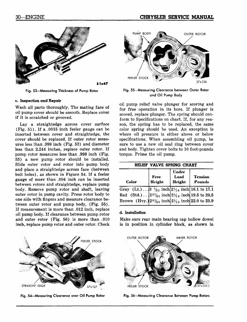
c. Inspection and RepairWash all parts thoroughly. The mating face ofoil pump cover should be smooth. Replace coverif it is scratched or grooved.
Lay a straightedge across cover surface(Fig. 51). If a .0015 inch feeler gauge can beinserted between cover and straightedge, thecover should be replaced. If outer rotor meas-ures less than .998 inch (Fig. 52) and diameterless than 2.244 inches, replace outer rotor. Ifpump rotor measures less than .998 inch (Fig.53) a new pump rotor should be installed.Slide outer rotor and rotor into pump bodyand place a straightedge across face (betweenbolt holes), as shown in Figure 54. If a feelergauge of more than .004 inch can be insertedbetween rotors and straightedge, replace pumpbody. Remove pump rotor and shaft, leavingouter rotor in pump cavity. Press rotor body toone side with fingers and measure clearance be-tween outer rotor and pump body, (Fig. 55).If measurement is more than .012 inch, replaceoil pump body. If clearance between pump rotorand outer rotor (Fig. 56) is more than .010inch, replace pump rotor and outer rotor. Check
OUTER ROTOR
FEELER STOCK •57x126
Fig. 55—Measuring Clearance between Outer Rotorand Oil Pump Body
oil pump relief valve plunger for scoring andfor free operation in its bore. If plunger isscored, replace plunger. The spring should con-form to Specifications on chart. If, for any rea-son, the spring has to be replaced, the samecolor spring should be used. An exception iswhere oil pressure is either above or belowspecifications. When assembling oil pump, besure to use a new oil seal ring between coverand body. Tighten cover bolts to 10 foot-poundstorque. Prime the oil pump.
RELIEF VALVE SPRING CHART
Color
Gray (Lt.). .Red (Std.)..Brown (Hvy.
FreeHeight
3 y32 inch227/32 inch
)23i/32inch
UnderLoad
Height
2% 6 inch2y16 inch2y16 inch
TensionPounds
16.1 to 17.119.5 to 20.522.0 to 23.9
d. InstallationMake sure rear main bearing cap hollow dowelis in position in cylinder block, as shown in
FEELER STOCKOUTER ROTOR INNER ROTOR
STRAIGHT EDGE < < V K r 57X)27
Fig. 54—Measuring Clearance over Oil Pump Rotor
FEELER STOCK w # 57x125 »
Fig. 56—Measuring Clearance Between Pump Rotors
CHRYSLER SERVICE MANUAL ENGINE—31
FILTER SHELL
SHELL GASKET
FILTER ELEMENT-(CARTRIDGE)
MOUNTING BOLT
•LOCKWASHER
OIL FILTER BASE
/ to/MOUNTING GASKET
ha:/^~ y 51x715A
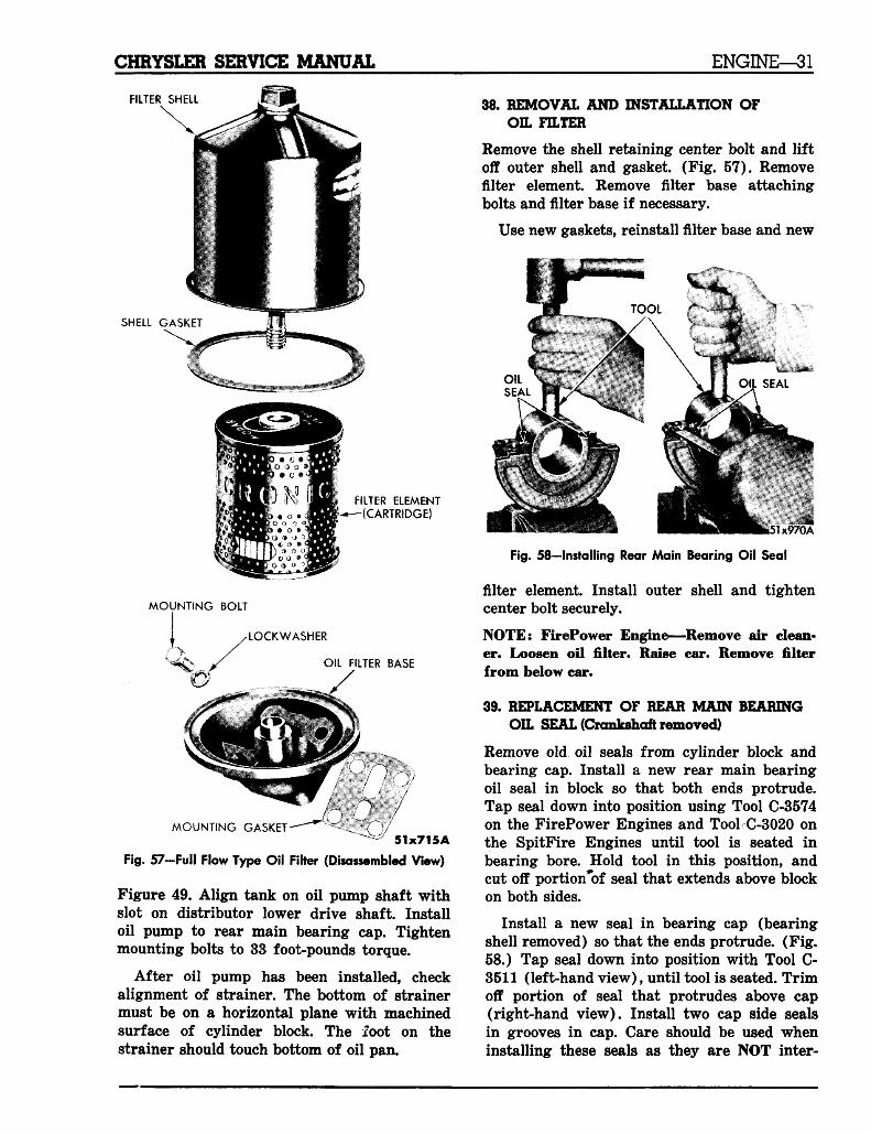
Fig. 57-Full Flow Type Oil Filter (Disassembled View)
Figure 49. Align tank on oil pump shaft withslot on distributor lower drive shaft. Installoil pump to rear main bearing cap. Tightenmounting bolts to 33 foot-pounds torque.
After oil pump has been installed, checkalignment of strainer. The bottom of strainermust be on a horizontal plane with machinedsurface of cylinder block. The foot on thestrainer should touch bottom of oil pan.
38. REMOVAL AND INSTALLATION OFOIL FILTER
Remove the shell retaining center bolt and liftoff outer shell and gasket. (Fig. 57). Removefilter element. Remove filter base attachingbolts and filter base if necessary.
Use new gaskets, reinstall filter base and new
\
Fig. 58-lnstalling Rear Main Bearing Oil Seal
filter element. Install outer shell and tightencenter bolt securely.
NOTE: FirePower Engine—Remove air clean-er. Loosen oil filter. Raise car. Remove filterfrom below car.
39. REPLACEMENT OF REAR MAIN BEARINGOIL SEAL (Crankshaft removed)
Remove old oil seals from cylinder block andbearing cap. Install a new rear main bearingoil seal in block so that both ends protrude.Tap seal down into position using Tool C-3574on the FirePower Engines and Tool C-3020 onthe SpitFire Engines until tool is seated inbearing bore. Hold tool in this position, andcut off portion*bf seal that extends above blockon both sides.
Install a new seal in bearing cap (bearingshell removed) so that the ends protrude. (Fig.58.) Tap seal down into position with Tool C-3511 (left-hand view), until tool is seated. Trimoff portion of seal that protrudes above cap(right-hand view). Install two cap side sealsin grooves in cap. Care should be used wheninstalling these seals as they are NOT inter-
32—ENGINE CHRYSLER SERVICE MANUAL
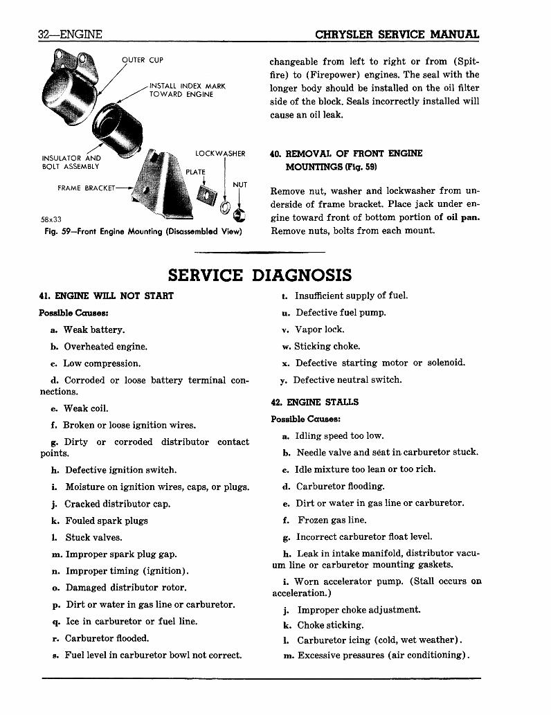
OUTER CUP
INSTALL INDEX MARKTOWARD ENGINE
INSULATOR ANDBOLT ASSEMBLY
FRAME BRACKET
LOCKWASHER
PLATE
NUT
58x33
Fig. 59—Front Engine Mounting (Disassembled View)
changeable from left to right or from (Spit-fire) to (Firepower) engines. The seal with thelonger body should be installed on the oil filterside of the block. Seals incorrectly installed willcause an oil leak.
40. REMOVAL OF FRONT ENGINEMOUNTINGS (Fig. 59)
Remove nut, washer and lockwasher from un-derside of frame bracket. Place jack under en-gine toward front of bottom portion of oil pan.Remove nuts, bolts from each mount.
SERVICE41. ENGINE WILL NOT START
Possible Causes:
a. Weak battery.
b. Overheated engine.
c. Low compression.
d. Corroded or loose battery terminal con-nections.
e. Weak coil.
f. Broken or loose ignition wires.
g. Dirty or corroded distributor contactpoints.
h. Defective ignition switch.
i. Moisture on ignition wires, caps, or plugs.
j . Cracked distributor cap.
k. Fouled spark plugs
1. Stuck valves.
m. Improper spark plug gap.
n. Improper timing (ignition).
o. Damaged distributor rotor.
p. Dirt or water in gas line or carburetor.
q. Ice in carburetor or fuel line.
r. Carburetor flooded.
s. Fuel level in carburetor bowl not correct.
DIAGNOSISt. Insufficient supply of fuel.
u. Defective fuel pump.
v. Vapor lock.
w. Sticking choke.
x. Defective starting motor or solenoid.
y. Defective neutral switch.
42. ENGINE STALLS
Possible Causes:
a. Idling speed too low.
b. Needle valve and seat in carburetor stuck.
c. Idle mixture too lean or too rich.
d. Carburetor flooding.
e. Dirt or water in gas line or carburetor.
f. Frozen gas line.
g. Incorrect carburetor float level.
h. Leak in intake manifold, distributor vacu-um line or carburetor mounting gaskets.
i. Worn accelerator pump. (Stall occurs onacceleration.)
j . Improper choke adjustment.
k. Choke sticking.
1. Carburetor icing (cold, wet weather).
m. Excessive pressures (air conditioning).
CHRYSLER SERVICE MANUAL ENGINE—33
n. Loose ignition wires.
p. Weak battery.
q. Loose ignition switch connection.
r. Spark plugs/ dirty, damp, or gaps incor-rectly set.
s. Distributor advance not operating.
t. Defective coil or condenser.
u. Distributor points dirty, burned, or incor-rectly spaced.
v. Exhaust system restricted.
w. Trailing edge of rotor worn.
x. Leaks in ignition wiring.
y. Incorrect valve tappet clearance. (C-300)
z. Burned valves.
aa. Low compression.
bb. Engine overheating.
cc. Use of winter fuels in hot weather.
43. ENGINE HAS NO POWER
Possible Causes:
a. Torque converter stator assembled in re-verse.
b. Incorrect ignition timing.
c. Weak coil or condenser.
d. Stiff accelerator linkage.
e. Trailing edge of rotor worn.
f. Defective mechanical or vacuum advance(distributor).
g. Hydraulic tappet pump up (high speed).
h. Excessive play in distributor shaft.
i. Weak spring in contact points.
j . Distributor cam worn.
k. Spark plugs dirty or gap incorrectly set.
1. Insufficient point dwell.
m. Fouled spark plugs.
n. Low grade fuel.
o. Weak valve springs.
p. Carburetor in poor condition.
q. Valves sticking when hot.
r. Dirt or water in gas line or carburetor.
s. Ice in gas line or carburetor.
t. Improper carburetor float level.
u. Worn camshaft lobes.
v. Defective fuel pump.
w. Pistons or pins fit tight.
x. Valve timing incorrect.
y. Too rich or lean fuel mixture.
z. Incorrect valve tappet clearance (C-300).
aa. Blown cylinder head gasket.
bb. Low compression.
cc. Flow control valve not operating (PowerSteering).
dd. Burned, warped, or pitted valves.
ee. Spark plug breakdown under load.
ff. Plugged, restricted, or damaged muffleror tail pipe.
gg. Brakes dragging.
hh. Tight wheel bearings.
ii. Clutch slipping. (If so equipped.)
jj. Engine overheating.
kk. Detonation.
11. Stuck transmission regulate r valve.mm. Improper ignition or battery ground.
44. ENGINE "LOPES" OR MISSES (AT IDLE)
Possible Causes:
a. Air leak between intake manifold and
heads due to retaining bolts bottoming or dam-aged gasket.
b. Incorrect carburetor idle adjustment.
c. Dirt or water in gas line or carburetor.
d. Dirty jets or plugged passages in carbu-retor.
e. Incorrect valve tappet clearance. (C-300).
f. Burned, warped, or pitted valves.
g. Incorrect ignition timing.
h. Leaks in ignition wiring.
34—ENGINE CHRYSLER SERVICE MANUAL
i. Blown head gasket.
j . Air leak at carburetor mounting gasket.
k. Worn lobes on the camshaft.
1. Moisture on ignition wires, cap, or plugs.
m. Worn timing chain.
n. Defective spark advance mechanism.
©. Sticking valves.
p. Excessive play in distributor shaft.
q. Distributor cam worn.
r. Inoperative choke.
s. Spark plugs damp, dirty, or the gaps settoo close.
t. Overheated engine.
u. Weak battery.
v. Uneven compression.
w. Low grade of fuel. (Winter fuel used insummer.)
x. Flooding carburetor.
y. Carburetor icing (cold, damp weather).
45. ENGINE MISSES WHILE IDLING
Possible Causes:
a. Spark plugs dirty, damp, or gap incor-rectly set.
b. Broken or loose ignition wires.
c. Burned or pitted contact points, or pointsset with insufficient gap.
d. Coil or condenser defective.
e. Weak battery.
*- Distributor cap cracked.
g. Trailing edge of rotor worn.
h. Moisture on ignition wires, cap, or plugs.
i. Excessive play in distributor shaft.
j . Distributor sha,f t cam worn.
k. Burned, warped, or pitted valves.
1. Incorrect valve tappet clearance. (C-300.)
m. Incorrect carburetor idle adjustment.
n. Improper carburetor float level.
o. Low compression.
46. ENGINE MISSES AT HIGH SPEED
Possible Causes:
a. Dirt or water in gas line or carburetor.
b. Dirty jets in carburetor, especially theeconomizer jet.
c. Weak coil or condenser.
d. Incorrect ignition timing.
e. Distributor points dirty or incorrectlyspaced.
f. Trailing edge of rotor worn.
g. Loose ignition wiring.
h. Excessive play in distributor shaft.
i. Spark plugs fouled, damp, or dirty, or thegaps set too wide.
j . Insufficient point dwell.
k. Insufficient spring tension on points.
1. Normal hydraulic tappet pump up.
m. Worn camshaft lobes.
n. Weak valve springs.
0. Abnormal resistance in spark plugs.
p. Distributor cam lobe worn.
q. Engine overheating.
r. Low grade fuel.
s. Badly worn diaphragm in fuel pump.
t. Detonation or pre-ignition.
u. Frozen heat control valve.
47. EXTERNAL OIL LEAKAGE
Possible Causes:
a. Outside oil lines.
b. Timing chain case cover oil seal.
c. Rear main bearing oil seal.
d. Oil pan gaskets.
e. Oil pan drain plug.
f. Oil filter gasket.
g. Clogged rear camshaft bearing drain hole.
h. Tappet cover gaskets.
1. Fuel pump gasket.
CHRYSLER SERVICE MANUAL ENGINE—35
j . Timing chain cover gasket.
48. OIL PUMPING PAST PISTON RINGS
Possible Causes:
a. Oil level too high, (a) Dip stick not enter-ing oil pan far enough, (b) Dip stick incorrectlymarked.
b Loose main or connecting rod bearings.
NOTE: Excessive bearing clearance will causethe cylinder walls to be flooded with oil.
c. Too light oil for the type of service andconditions.
d. Excessively hot operating temperatures.
e. Piston ring gaps not staggered or incor-rect size rings used.
f. Incorrect set of piston rings or rings but-of-round.
g. Cylinder head improperly torqued, caus-ing a distortion of the cylinder bores for whichthe piston rings cannot compensate.
h. Rings fitted too tight in piston.
i. Oil rings carboned up or return grooves inpiston clogged.
j . Insufficient piston ring tension.
NOTE: Common condition after engine hasoverheated.
k. Compression rings installed upside-down.
1. Excessive oil pressure or broken pistonrings.
m. Burned piston.
NOTE: This condition can be brought about byexcessive detonation and pre-ignition.
n. Scored cylinder walls or piston rings.
o. Excessively worn rings or cylinder walls.
NOTE: This condition can be traced to one ormore of the following:
(1) Normal wear.
(2) Failure to keep air cleaners, carburetor,and crankcase filler cap installed and serv-iced.
(3) Failure to service the oil filter.
(4) Careless filling of the oil pan by allowingdirt or foreign material to fall in.
(5) Failure to clean cylinder walls properlyafter reboring or honing.
(6) Failure to prevent grindings and stonedust from getting on cylinder walls or im-proper cleaning of valve ports after grind-ing seats.
(7) Use of rings with heavier wall tension thannecessary.
(8) Excessive speeding of a cold engine. In ad-dition to the foregoing, many engines areoverhauled for excessive use of oil or smok-ing without any degree of success becausethe actual cause may be due to any one ormore of the following.
(9) Excessive clearance between valve guideand valve stem.
(10) Diaphragm of fuel pump porous.
(11) External oil leaks.
(12) Internal oil leak into cooling system.
49. OIL PUMPING AT VALVE GUIDES
Possible Causes:
a. Worn valve stems or guides.
b. Intake valve stem guide in inverted posi-
tion. (FirePower engine.)c. Intake valve seals damaged or missing.
50. HIGH OIL CONSUMPTION DUE TOLUBRICATING OIL
Possible Causes:
a. Oil level too high.
b. Contaminated oil.
c. Poor grade of oil.
d. Thin, diluted oil.
e. Oil pressure too high.
f. Sludge in engine.
51. HIGH OIL CONSUMPTION-MISCELLANEOUS
Possible Causes:
36—ENGINE CHRYSLER SERVICE MANUAL
a. Overheated engine.
b. Sustained high speeds.
c. Misadjusted breather cap, causing exces-sive crankcase ventilation.
Certain mechanical conditions can affect en-gine oil pressure readings. In order to aid indetermining the cause, the following conditionsand possible causes are listed.
52. NO OIL PRESSURE WHEN ENGINE ISFIRST STARTED
Possible Causes:
a. Oil from the oil galleries and oil filter hasdrained back into the oil pan when the enginewas shut off.
b. Frozen or partially clogged oil gauge line.
53. NO OIL PRESSURE AT IDLE
Possible Causes:
a. Oil gauge not registering properly, dueto higher than normal pressure required to startgauge registering.
b. Excessive oil pump rotor end clearance.
c. Stuck oil pump relief valve.
d. Loose main and connecting rod bearings.
e. Loose camshaft bearings.
f. Plugs in ends of rocker shafts. Loose ormissing.
g. Internal oil passage leakage.
h. Oil pump body cover seal ring blown outor missing.
i. Oil pump body cover seal ring replacedwith common gasket.
54. NO OIL PRESSURE ON FAST STARTSOR RAPID ACCELERATION
Possible Causes:
a. Low oil level in oil pan.
b. Oil pump suction tube not aligned, or bent,causing the oil strainer to extend above the oilsurface in the pan.
c. The foot on the oil strainer should touchthe bottom of the oil pan.
d. Oil pump rotor pin sheared.
e. Expansion plug missing in oil pump cover.
f. Oil filter and oil filter by-pass plugged.
g. Air leak in oil pump suction tube.
h. Oil pump strainer plugged.
i. Oil pump relief valve stuck open.
j . Internal oil passage leak.
55. BROKEN VALVES
Possible Causes:
a. Weak valve springs.
b. Worn valve guides.
c. Excessive tappet clearance. (C-300)
d. Cocked springs or retainers.
e. Out-of-round valve seats.
f. Defective valve forgings.
g. Excessive engine speeds.
h. Detonation or pre-ignition.
56. BURNED OR STICKING VALVES
Possible Causes:
a. Close tappet clearance. (C-300).
b. Weak valve springs.
c. Gum formations on stem or guide.
d. Eccentric valve face.
e. Deposits on valve seats.
f. Incorrect valve seat width.
g. Improper valve guide clearance.
h. Warped valves.
i. Improper block cooling.
j . Exhaust back pressure.
k. Improper spark timing.
1. Out-of-round valve seat.
57. NOISY VALVES
Possible Causes:
a. Incorrect tappet clearance. (C-300).
b. Worn tappets or adjusting screws (C-300).
CHRYSLER SERVICE MANUAL ENGINE—37
c. Wear in cam lobes.
d. Worn valve guides.
e. Excessive run-out of valve seat or valveface.
NOTE: When replacing valve guides, be sure thecounterbore in guide is up for exhaust anddown for intake.
58. BROKEN VALVE SPRINGS
Possible Causes:
a. Valve flutter at high speed.
b. Improper crankcase ventilation.
c. Worn timing chain.
d. Cold engine operation due to defectivethermostat.
e. Rust, due to improper storage.
f. Coolant leaking into crankcase.
59. VALVE DEPOSITS
Possible Causes:
a. Quality of fuel.
b. Quality of lubricating oil.
c. Valve stem wear.
d. Improper cooling of block.
e. Sludged engine.
f. Worn valve guides.
g. Improper lubrication of valve stem.
h. Excessive engine idling.
i. Rich carburetor setting.
When diagnosing the cause of valve failure,it must be remembered that a valve can onlytransfer its heat through the valve seats andguides, to the cooling system. There is only onebasic cause for valve failure and that is theinability of a valve to dissipate its heat into thecooling system as rapidly as necessary.
The following information is presented as anaid in diagnosing valve failure and also to helpin preventing a recurrence.
60. CONDITIONS WHICH CAN CAUSE BOTHINTAKE AND EXHAUST VALVE FAILURE
a. Deposits on the upper part of the valvestems which prevents full seating of the valves.
b. Sludge deposits on the end of the valvesand springs cause the valves to stick. These de-posits are caused by poor maintenance of theengine oil or filter, low engine operating tem-peratures due to an inoperative thermostat, orshort intermittent engine operation. The lattercondition does not allow the engine to reachoperating temperature to evaporate the conden-sation in the crankcase. Extremely slow drivingof the vehicle does not induce sufficient crank-case ventilation to remove condensation.
c. Insufficient tappet clearance or operatingclearance between tappet plunger and bottomof tappet body (hydraulic tappets).
On hydraulic tappets, this condition is usuallycaused by excessive valve face and seat regrind-ing which allows the valve stems to extend toofar out of the guides.
Sufficient clearance is very important andwill insure complete closing of the valves whenthe engine is hot.
d. Valves or seats that are not ground con-centric with the valve guide. This can be due toworn refacing equipment. Valve-to-seat contactshould be checked with a film of Prussian blue.
e. Improper valve seat width. Reconditionvalve faces and seats as directed in Paragraph12.
f. Valve and valve seat not refaced to a 45degree angle, due to worn or inaccurate equip-ment.
g. Excessively refaced valves. The distancebetween the top edge of the valve face and thetop of the valve must not be less than %4 inch.Discard any valve that does not meet specifi-cations.
h. Incorrect valve timing.
i. Excessive valve guide wear. Worn guideswill not provide proper cooling and permit oilto be sucked into the intake ports causing acarbon formation which could lead to valvesticking.
38—ENGINE CHRYSLER SERVICE MANUAL
j . Restrictions in the cooling passages aroundthe valve seats caused by excessive scale andrust deposits. This is the result of not using arust inhibitor in the cooling system.
k. Engine overheating to such a degree thatthere is insufficient coolant remaining in theengine to dissipate the valve heat.
61. CONDITIONS WHICH CAN CAUSE INTAKEVALVE FAILURE
a. Sticking valves. This condition can bebrought about by heavy carbon and/or a var-nish deposit on the valve stems and heads. Gumforms as a result of the exposure of gasolineto air for an extended period. In some caseswhere gum and varnish have deposited on thevalve stem, valve sticking has occurred whilethe engine was hot and operating under power.A good idle might be obtained while such anengine was relatively cool.
Cars which have been improperly preparedfor extended storage or have been using fuelfrom bulk storage that is used very little—suchas on a farm or ranch during the winter months—are susceptible to this type of valve sticking.
Heavy carbon deposits can result from shorttrip operation.
Rust. This condition results from prolongedstorage without proper preparation.
b. Valve dishing and valve face grooving areusually the result of overheating. Overheatingcan be aggravated by, or attributed to, pre-igni-tion or detonation.
62. CONDITIONS WHICH CAN CAUSEEXHAUST VALVE FAILURE
a. Back-pressure due to restrictions in theexhaust system which prevent rapid expulsionof the hot gases.
b. Excessively lean fuel-air mixtures.
c. Carburetion (improper size jets.)
d. Air leaking into the intake manifold.
e. Air leak at carburetor mounting or throt-tle body gaskets.
f. Air leaks in vacuum line for booster brakesor other vacuum-operated accessories.
g. Improper ignition timing.
h. Detonation or pre-ignition.
i. Overloading engine by pulling heavy housetrailers, luggage trailers, or boat trailers.
k. Low grade fuel.
1. Heat control valve stuck in the closed posi-tion.
As a matter of interest, broken or crackedexhaust valve seats, as well as cylinder headswith cracks radiating out from an exhaustvalve port, can be traced to prolonged operationwith burned or leaking exhaust valves.
63. PISTON RING NOISE
Possible Causes:
a. Broken ring.
b. Top ring striking cylinder ridge.
c. Broken ring lands.
d. Excessive side clearance in groove.
64. PISTON NOISE
Possible Causes:
a. Piston pin fits too tight or too loose.
b. Excessive piston-to-bore clearance.
c. Carbon accumulation in head.
d. Collapsed piston skirt.
e. Insufficient clearance at top ring land.
f. Broken piston skirt, or ring land.
g. Misaligned connecting rods.
65. CONNECTING ROD NOISE
Possible Causes:
a. Low oil pressure.
b. Insufficient oil supply.
c. Thin or diluted oil.
d. Misaligned rods.
e. Excessive bearing clearance.
f. Eccentric or out-of-round crank pin jour-nal.
CHRYSLER SERVICE MANUAL ENGINE—39
66. MAIN BEARING NOISE
Possible Causes:
a. Low oil pressure.
b. Insufficient oil supply.
c. Thin or diluted oil.
d. Loose vibration damper or torque con-verter.
e. Excessive bearing clearance.
f. Excessive end play.
g. Eccentric or out-of-round journals.
h. Sprung crankshaft.
i. Excessive belt tension.
67. BROKEN PISTON RINGS
Possible Causes:
a. Wrong type or size.
b. Detonation.
c. Undersize pistons.
d. Pre-ignition.
e. Ring striking top ridge.
f. Worn ring grooves.
g. Rings assembled improperly.
h. Broken ring lands.
i. Insufficient gap clearance.
j . Excessive side clearance in groove.
kc Uneven cylinder walls (particularly dueto a previous ring breakage in same cylinder).
68. BROKEN PISTONS
Possible Causes:
a. Undersize pistons.
b. Eccentric or tapered cylinders.
c. Misaligned connecting rod.
d. Engine overheating.
e. Water or fuel leakage into combustionchamber.
f. Detonation or pre-ignition.
69. DETONATION
Detonation, pre-ignition, and after-running areabnormal types of combustion. Normal combus-tion starts at the spark plug and the flame ex-pands to the extremes of the combustion cham-ber. During the short period of combustion, ahigh pressure is produced which pushes downon the piston to develop engine power.
Detonation occurs after the spark plug fires,when some of the fuel-air mixture in the com-bustion chamber is ignited by spontaneous com-bustion before the flame reaches it. The mixtureis burned much more rapidly than during nor-mal combustion. Thus, detonation produces ex-cessive temperatures and pressures. Detonationis most easily recognized by a pinging soundduring acceleration or continuous wide openthrottle operation, such as climbing a steephill.
A detonation complaint is usually concernedwith the noise that is produced. Although amild case of detonation will not damage an en-gine, excessive detonation may result in enginefailure caused by the excessive temperaturesand pressures. Detonation can cause broken pis-ton rings, broken and burned piston ring lands,blown cylinder head gaskets, and short bearinglife.
Detonation is caused primarily by the follow-ing:
a. Advanced spark timing.
b. Combustion chamber deposits.
c. Low octane fuels.
d. Excessively high coolant or air tempera-tures.
When correcting a detonation complaint thefirst thing to check is the spark timing as di-rected in Paragraph 73. If detonation persistsat the proper timing, the distributor should beremoved and checked to see if it conforms tospark advance specifications. The spark ad-vance mechanism should be repaired if neces-sary. Further investigation depends on the typeof operation. If the vehicle is used primarily forlight duty, the detonation probably results fromexcessive combustion chamber deposits. Theseshould be removed.
40—ENGINE CHRYSLER SERVICE MANUAL
70. PRE-IGNITION
Pre-ignition is the burning of the air-fuel mix-ture before the spark plug fires. The mixture isignited by a hot spot in the combustion cham-ber. Since this is equivalent to advancing thespark, it results in higher temperatures andpressures in the combustion chamber than thoseproduced during normal combustion.
Sometimes, pre-ignition produces a pingingsound which is louder than detonation. If pre-ignition occurs early on the compression stroke,it is not audible. If it occurs before the intakevalve closes, the engine will backfire throughthe air cleaner.
In many cases, it is difficult to distinguish be-tween audible pre-ignition and detonation; infact, they may occur simultaneously. Audiblepre-ignition may be isolated from detonation byaccelerating the vehicle at wide open throttle(not above 2000 rpm) until the loud pingingis heard and then turning off the ignition. If theengine continues to fire, it is pre-ignition; if itceases to fire, the engine is detonating. Removethe foot from accelerator pedal before turningon the ignition again.
Often, inaudible pre-ignition is difficult to dis-tinguish during operation, but it can be recog-nized by the failures it can produce, as notedbelow. If the engine back-fires through the aircleaner during wide open throttle operation, acolder set of plugs should be installed. If theback-firing ceases, it was probably caused bypre-ignition. If the engine continues to back-fire, it is caused by other factors, such as faultyignition, incorrect carburetor mixture, incor-rect valve timing, or a worn camshaft.
Inaudible pre-ignition cannot be recognizeduntil a piston or valve failure occurs. It is gen-erally caused by a hot spark plug, or advancedignition timing. Check spark plug type and setignition timing as described below. ALWAYSUSE SPECIFIED SPARK PLUGS.
71. HOT STARTING NOISE
A form of audible pre-ignition sometimes oc-curs when a hot engine is started. Usually, thenoise is limited to two or three sharp rapswhich are heard just as the engine begins tofire. This condition does not cause damage tothe engine and is common with high compres-
sion engines. It cannot be eliminated by retard-ing ignition timing or changing spark plugs.Slow cranking speed may accompany the hotstarting noise.
72. AFTER-RUNNING
After-running is a compression ignition of theengine at very slow speeds after the ignition hasbeen turned off.
This condition is a source of irritation to theowner but it does not cause engine failure.After-running is primarily caused by one ormore of the following factors:
a. Fast idle speed.
b. High coolant temperatures.
c. Combustion chamber deposits.
After-running js generally caused by fast idlespeed or cutting the ignition before the enginethrottles down to idle. The idle speed should beproperly adjusted and the owner questioned asto whether he has the habit of pumping the ac-celerator pedal before turning off the ignition.If this does not correct the complaint, the ve-hicle should be checked for overheating.
If the vehicle has been used primarily forlight duty operation, some highway operationwill remove combustion chamber deposits whichmay eliminate the complaint.
This complaint cannot be corrected with coldspark plugs.
73. IGNITION TIMING
Due to normal variations between engines intheir fuel requirements, high altitude operation(which results in a richer fuel mixture that re-duces the octane requirements of the engine),and the variations in octane ratings of the fuelsbeing marketed, the established ignition timingsetting of 6 degrees BTDC for the V-8 enginesshould be considered a basic or starting pointwhen tuning an engine. As a result of the con-ditions mentioned, a variation of plus or minus6 degrees from the starting setting is per-missible.
CAUTION
The advancing of timing in excess of 6 degreesof the basic setting is not recommended, as in-
CHRYSLER SERVICE MANUAL ENGINE—41
audible pre-ignition could be encountered undersome operating conditions at high speeds.
When tuning an engine to obtain maximumperformance, economy, and smooth operation,and to take advantage of variations in octanerequirements, it is desirable to make the finalignition timing during actual road test. Shouldthe final timing be made during the road test, itis suggested the following procedures be fol-lowed :
a. Set the ignition timing at 6 degreesBTDC.
b. Drive the vehicle until normal operatingtemperature has been reached.
c. While in high gear, decelerate the car to20 mph or just before the transmission down-shifts; then, with a wide open throttle, accel-erate to about 40 mph. Without downshiftingto second gear.
d. During this wide open throttle operation,if a slight unobjectionable pinging or detona-tion is heard that disappears as the car ap-proaches 40 mph, the timing can be consideredto be the best setting; however, if the pingingor detonation is objectionable, the timing shouldbe retarded 1 degree at a time until the propersetting has been reached.
74. TAPPET STARTING NOISE
This is a condition where the tappets are noisyupon starting and remain so for approximately5 or 10 minutes, or until the engine has reachednormal operating temperature.
Possible Causes:
a. Engine oil drain-back.
If the anti-drain back valve leaks, the oildrains out of the oil galleries and drilled pass-ages into the oil pan. This occurs when the en-gine is not operating. Upon starting, it is neces-sary that the oil pump refill the system and, atthe same time, force the air that entered thesystem out of the engine through the tappets.Until the oil system has been refilled and all theair bled out, noisy tappets may be experienced.
b. Filter change.
This may cause the same condition as above,and for the same reasons. Air trapped in thelubricating system may require a minimum of
20 to 30 minutes to bleed out. When changingan oil filter element, there is always a possi-bility that air may be trapped in the cover ofthe filter and not work out through the tappetsuntil some time later, after the tappets haveoriginally quieted.
c. Tappet varnish.
The problem of tappet varnish will not neces-sarily hinder the tappets since they are de-signed to allow the varnish to build up in areasthat do not affect their operation. There is, how-ever, a condition in which a varnish-coated tap-pet can possibly cause trouble; this is when avalve has been replaced. A new valve can effec-tively change the length of the valve mechanismand thereby allow the tappet plunger to operatein a new position in the body which may havea varnish build-up and result in the plungersticking.
d. Anti-freeze.
Starting noise can also be caused by a gummydeposit, which results from leakage of anti-freeze or glycol into the engine oil. When cold,this deposit will be hard, but when hot, it be-comes soft and gummy. This is another reasonexcessive tappet noise can be experienced whenstarting and gradually disappear as the gummysubstance softens and allows the plungers toassume their normal operating positions. If thisdeposit is permitted to remain, it can eventuallycause scuffing of the hydraulic tappet plunger.
e. Normal tappet leakdown.
This condition occurs on all engines and isdue to the normal leakdown of the tappets thatremain under valve spring pressure when theengine is shut off. The expulsion of air and theduration for quieting these particular tappetsis dependent on the clearance to which the tap-pet plunger body has been fitted. The closer thefit, the longer the noise will persist.
75. ALL TAPPETS NOISY
In cases where all 16 tappets are noisy, it isgenerally safe to assume that the noise is notthe fault of the tappets, but of the oil supply,which is inadequate, or into which air has beeninduced. No advantage can be gained by install-ing 16 new tappets unless they are found to bestuck due to an anti-freeze leak. In this case itis imperative that the leak be corrected to pre-vent reoccurrence.
42—ENGINE CHRYSLER SERVICE MANUAL
Possible Causes:
a. Drain plug out of oil pan.
The loss of the drain plug from the oil panwill result in the loss of oil and oil pumppressure.
b. Plug out of the oil pump cover.
A plug out of the oil pump cover will permitthe majority of oil from the pump to escapeback into the oil pan. This usually shows up asfluctuation or low oil pressure on the gauge.
c. Oil strainer improperly located in pan.
When this occurs, tappet noise may occur short-ly after a turn, stop, or fast acceleration. Thiscondition may also be detected by close obser-vation of the oil pressure gauge.
d. Low oil level.
Low oil level permits the oil strainer to be-come uncovered while accelerating, stopping, orturning. Air will be pumped into the lubricationsystem when this happens.
e. Plugged oil screen.
A plugged oil screen is generally due to in-adequate oil and/or filter change periods forthe type of operation.
f. Oil pump relief valve stuck.
When this condition occurs, it usually permitspressure to be normal at higher speeds whilefalling below normal at low engine speeds or atidle. Normal oil pressure for a warm engine atidle is considered to be 12 psi or more at 500rpm.
g. A major oil pressure drop is generallycaused by excessive bearing clearance, etc.,which permits excessive leakage of hot engineoil and reduces the pressure of oil delivered tothe tappets below the minimum required forquiet and proper operation of the tappet.
h. Oil foaming.
This is a condition where a large quantity ofair bubbles are trapped in the oil, producing acondition of foaming or sudsing (aeration).Since air unlike oil, is compressible, tappet noiseor loss of valve lift will result when the aeratedoil enters the tappet.
i. Excessive oil supply.
When the oil level is too high in the oil pan,the crankshaft and connecting rods dip into theoil and churn it, causing an aerated condition.
j . Low oil supply.
This condition permits the reuse of a smallquantity of oil which does not have sufficienttime to cool and rid itself of the normal air in-duced into the oil.
k. Air entering the oil pump.
This condition can be caused by an improp-erly located oil screen, a leak in the suction tube,loose oil pump cover, etc. In all cases, air willbe drawn into the oil pump and induced intothe oil.
1. Plug out of oil pump cover.
A plug that is loose or missing out of the oilpump cover will cause excessive by-passing andaeration of the oil.
m. Prolonged use of engine oil.
Where operating conditions are such that themajority of driving is slow or short and inter-mittent, not permitting the engine to warm upto operating temperature, it is possible for nor-mal condensation to build up in the crankcaseto a point where it will cause the oil to foam.
n. Water from the cooling system leakinginto the engine oil.
Water from the cooling system leaking intoengine oil will cause excessive oil foaming.
o. Glycol in the engine oil.
When glycol leaks into the engine lubricationsystem it has a tendency to form a gummy sub-stance which deposits on the engine parts. Thissubstance will normally affect the operation ofthe hydraulic tappets, first by causing sticking,and then gradually causing the tappets to scuffand become increasingly noisy until they reacha point where the plungers will stick completely.This is the only condition which may requirethe replacement of all 16 tappets. However, un-less the leak is corrected, it will repeat itself.
76. ONE OR MORE TAPPETS NOISY
Possible Causes:
a. Excessive dry lash.
The term of dry lash refers to the clearance
CHRYSLER SERVICE MANUAL ENGINE-43
between the valve stem and rocker arm whenthe tappet is on the heel of the cam lobe andthe plunger is bottomed in the tappet body. Thenormal clearance is .060 to .210 inch, and anylash exceeding .210 inch could cause a tappetto be noisy. A condition of excessive dry lashusually indicates wear.
To determine if proper dry lash is the prob-lem, insert a Vs inch (.125) feeler between therocker arm and the valve stem; then, start theengine. If the noise has disappeared it is quitepossible it was caused by a worn rocker arm orpush rod.
b. Broken valve spring.
c. Sticking rocker arm.
This could be the result of any condition thatprevents free movement of the rocker arm onthe rocker shaft.
d. Worn rocker arm.
This condition is usually due to lack of hard-ness of the rocker arm or push rod end, and canbe detected by the dry lash test as describedabove.
e. Face of rocker arm not true.
When this condition is present, it will benoted that the rocker arm is making contact onthe edge of the valve stem. This can cause avalve cocking condition and result in the valvestem to ride heavy or bind in the guide.
f. Push rods worn, bent, or interfering (inhead).
A worn push rod can be identified by a wornspot on one end. This can be caused by insuffi-cient lubrication. Check holes in arm and rockershaft.
When installing a new rocker arm, be surethe lubricating oil holes are open.
Worn, bent, or interfering push rods can bedetected by the dry lash test, as described above.
A bent push rod is generally caused by mis-handling and can result in the cylinder head orincreased dry lash.
The push rod interference in the cylinderhead can be caused by inadequate clearance inthe push rod passages through the cylinderheads. If this condition is found, it is only ne-
cessary to relieve the ends of the hole at thetop and bottom.
g. Tight tappet.
While rare, this condition occurs where thetappet or the tappet bore is of incorrect size,bell-mouthed, or out-of-round, causing the tap-pet to stick in its bore. A condition of thisnature is indicated by heavy wear or scuffmarks on portions of the side of the tappetbody. Unless the tappet bores in the cylinderblock are cleaned up, the same condition willoccur with a replacement tappet. To check bore,slide a new tappet in and out. If the tappetsticks, ream bore to next oversize and installnew oversize tappet.
h. Stuck hydraulic tappet plungers.
This condition is where a tappet plunger isstuck in the tappet body and is unable to com-pensate for changes in the valve train clearance.Extended engine operation at high speed withthis condition existing, could cause valve break-age. Three basic causes for this condition are:Dirt or metal chips; glycol in the lubricatingoil; and, the mismatching of parts in assemblyafter cleaning.
Varnish build-up around the top of the tap-pet above the operating range of the plungeris a normal condition, therefore, it should notbe confused with a stuck tappet in which theplunger will normally be found stuck below theoperating range.
i. Valve stem varnish.
Occasionally, this condition may occur wherea heavy deposit of varnish has adhered to thevalve stem and restricts the movement of thevalve in the guide.
j . Faulty tappets.
This is caused by conditions that may be in-herent in the individual tappets, such as bentvalve washers, omitted valve washers, tightplunger caps, improperly fitted retainer, badflat valve or valve seat, a plugged or missingoil hole in the tappet body or plunger, or aloose plunger to body fit that causes a fast leak-down under spring pressure. (The latter usu-ally shows up at idle when the oil is hot.)
Since the hydraulic tappet is not reparable,only those determined to be faulty should be
44—ENGINE CHRYSLER SERVICE MANUAL
replaced. The replacement of any tappets otherthan the individual ones causing the condition,would serve no purpose.
k. Worn valve guide.
Tappet noise can also be caused by a guidethat is worn .015 inch or more, or by a valvethat is bent to a point where it will actuallyhang up in the guide. Valves can be bent in thefield when attempting to compress a valvespring on an engine with the piston up or nearTDC, or by failing to use the proper headholding fixtures, Tool C-3209, when the headshave been removed for repairs.
1. Tappet oil feed hole plugged or restricted.
In many cases where a tappet has been re-moved for being noisy, it has been found thatthe oil feed hole in the tappet or the cylinderblock was restricted or plugged. This conditionis due to varnish, sludge, dirt, or other foreignmaterials. Again this condition can be attributedto infrequent filter element or oil change. Be-fore installing any tappet, it is a good policyto run a drill rod or drill into the feed hole tomake sure it is open. Be sure no burr is leftin the tappet bore after opening with rod.
m. Worn tappet or camshaft lobe.
There have been instances where scoringstarts between the cam lobe and the face ofthe tappet, in the same manner as any otherbearing surface. When this condition occurs, itcan result in damage not only to the face of thetappet, but to the camshaft lobe as well. It willproduce tappet noise and a lack of engine per-formance.
This condition can be determined by measur-ing the lift of the valve. The lift can be meas-ured by bottoming the tappet in the same wayas checking for valve timing, by inserting ashim of sufficient size to take up the dry lash.The lift of the valve can then be measured witha dial indicator and compared with other valvesshimmed in the same manner. The normal valvelift should be approximately .360 inch. Since
wear of up to .030 inch is permissible, the mile-age of the engine, as well as the comparisoncheck with other cylinders, should be taken intoconsideration before a decision is reached toreplace the camshaft. When tappets and/orcamshaft replacement is necessary due to ex-cessive wear, a very thorough cleaning of thelubricating system should be performed, or elsethe particles of worn metal that have depositedout of the oil will cause a reocurrence of thesame trouble.
77. INTERMITTENT TAPPET NOISE
Possible Causes:
a. Aerated or foaming oil.
This is a condition where a large quantity ofair bubbles are trapped in the oil, producing acondition of foaming or sudsing (aeration).Since air, unlike oil, is compressible, tappetnoise or loss of valve lift will result when theaerated oil enters the tappet.
b. Defective tappets.
Although these defects cannot be corrected inthe field, and therefore require replacement ofthe individual tappet, the following is presentedto point out possible defects:
c. Extremely wide seat on the lapped seat ofthe tappet plunger.
d. Insufficient check valve travel to compen-sate for various speeds.
e. Out-of-round tappet plunger.
78. TAPPET CLEANING
When cleaning tappets (if needed) at the timeof engine overhaul or valve grind, it should bedone in accordance with the procedure de-scribed in this section. Extreme precautionsmust be taken to be sure that all work be donein clean surroundings and using clean materi-als. If the cleanliness precautions are not ob-served, it is more than likely the effort will bewasted and noisy or stuck tappets can be ex-pected.