section 8, lecture 1, supplemental effect of pressure
TRANSCRIPT
MAE 5420 - Compressible Fluid Flow 1
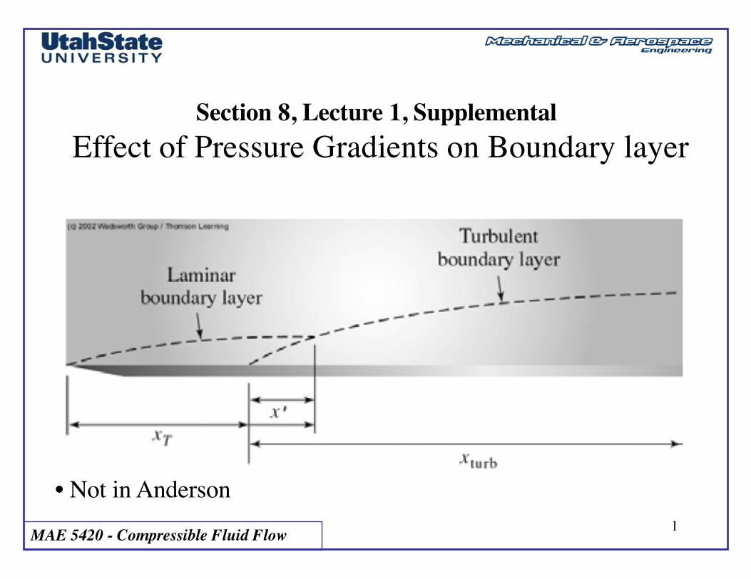
Section 8, Lecture 1, SupplementalEffect of Pressure Gradients on Boundary layer
• Not in Anderson

MAE 5420 - Compressible Fluid Flow 2
Displacement and Momentum Thickness
• Fluid sticks to wall .. Creating boundary layer• Local thickness is a function of downstream distance• Local effects (at each x)
-- External streamlines are displaced (displacement thickness, d*)-- Momentum is list to friction (momentum thickness, Q)
MAE 5420 - Compressible Fluid Flow 3
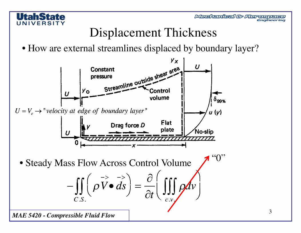
Displacement Thickness• How are external streamlines displaced by boundary layer?
• Steady Mass Flow Across Control Volume “0”
MAE 5420 - Compressible Fluid Flow 4
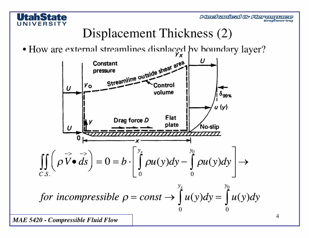
Displacement Thickness (2)• How are external streamlines displaced by boundary layer?
MAE 5420 - Compressible Fluid Flow 5
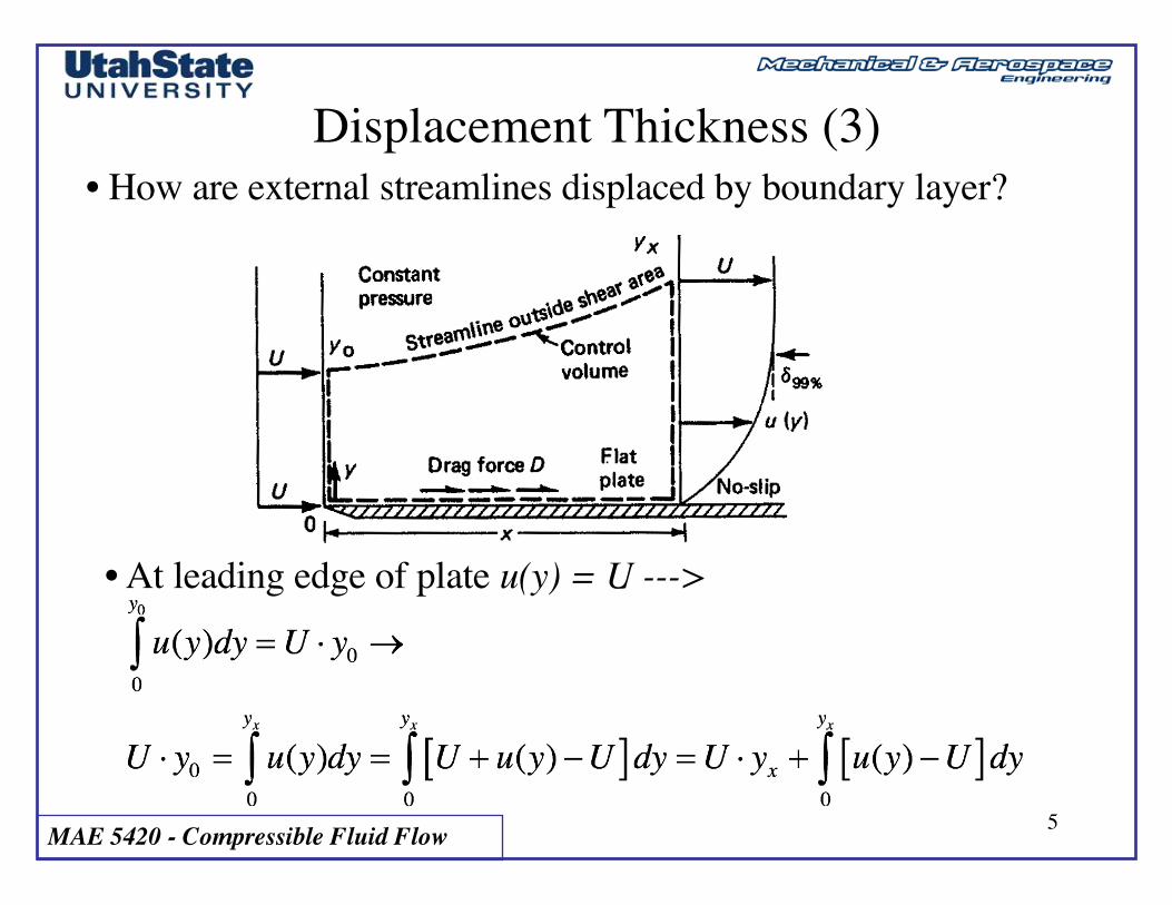
Displacement Thickness (3)• How are external streamlines displaced by boundary layer?
• At leading edge of plate u(y) = U --->
MAE 5420 - Compressible Fluid Flow 6
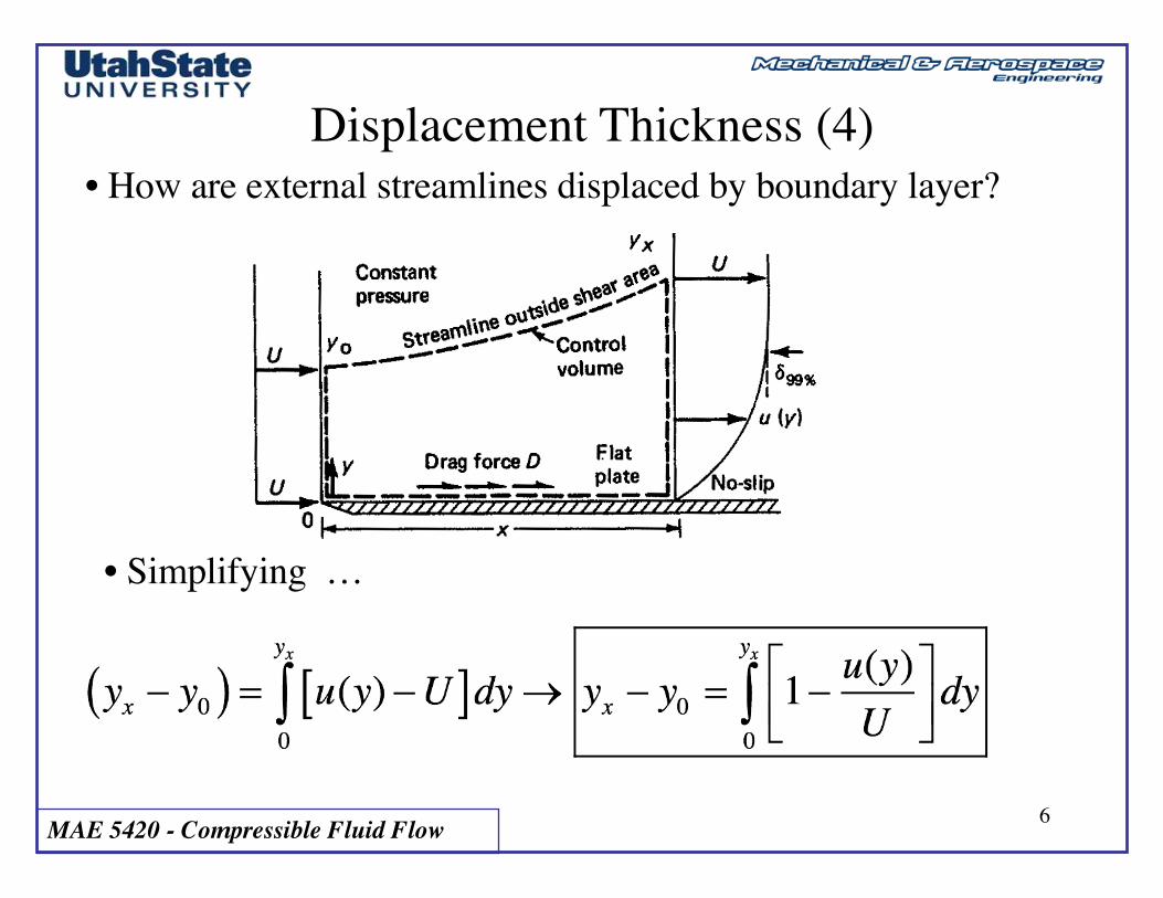
Displacement Thickness (4)• How are external streamlines displaced by boundary layer?
• Simplifying …
MAE 5420 - Compressible Fluid Flow 7
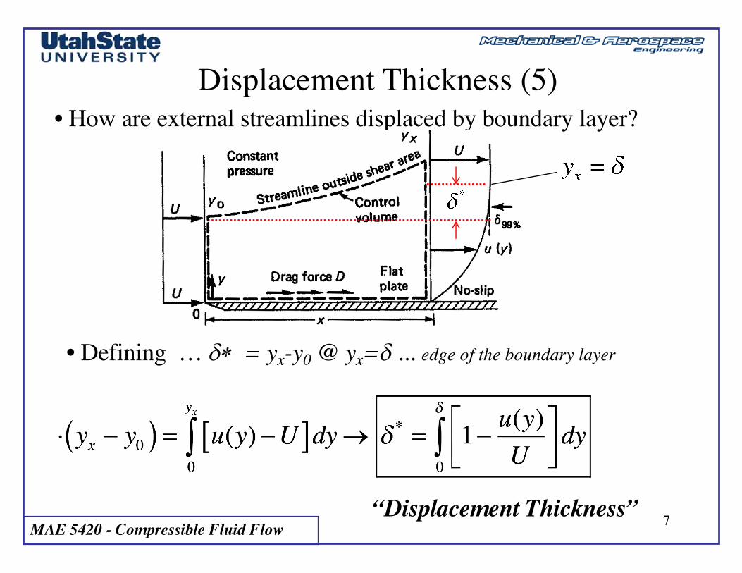
Displacement Thickness (5)• How are external streamlines displaced by boundary layer?
• Defining … d* = yx-y0 @ yx=d ... edge of the boundary layer
“Displacement Thickness”
MAE 5420 - Compressible Fluid Flow 8
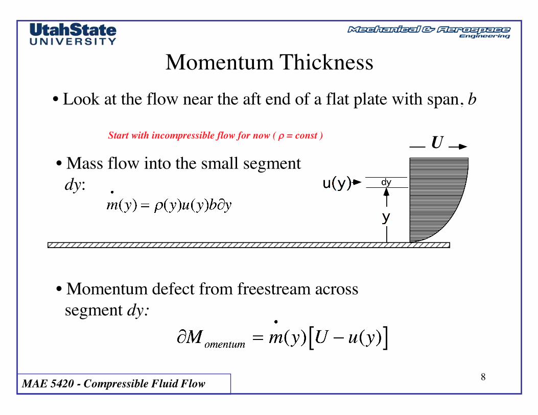
Momentum Thickness• Look at the flow near the aft end of a flat plate with span, b
• Mass flow into the small segment dy:
• Momentum defect from freestream across segment dy:
eStart with incompressible flow for now ( r = const ) U
MAE 5420 - Compressible Fluid Flow 9
Momentum Thickness (2)
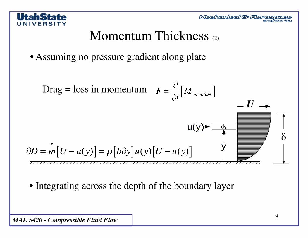
• Assuming no pressure gradient along plate
Drag = loss in momentum
d
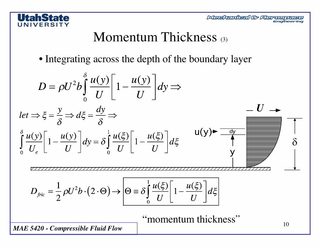
• Integrating across the depth of the boundary layer
U
MAE 5420 - Compressible Fluid Flow 10
Momentum Thickness (3)
d
• Integrating across the depth of the boundary layer
“momentum thickness”
U

MAE 5420 - Compressible Fluid Flow 11
Displacement and Momentum Thickness (2)• Displacement Thickness …
-- How far external streamlines are displaced by local boundary layer (d*)
• Momentum Thickness …-- Momentum Loss in Boundary Layer from front of plate to local station, x (Q)
MAE 5420 - Compressible Fluid Flow 12
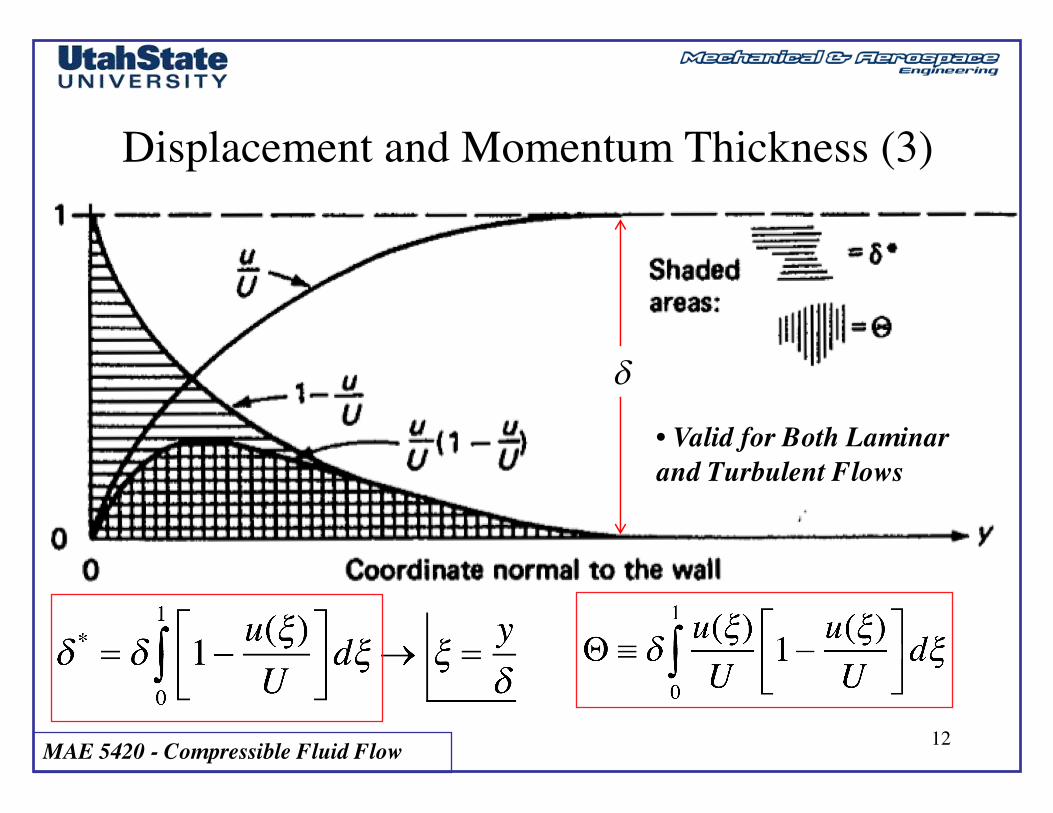
Displacement and Momentum Thickness (3)
d
• Valid for Both Laminar and Turbulent Flows
MAE 5420 - Compressible Fluid Flow 13
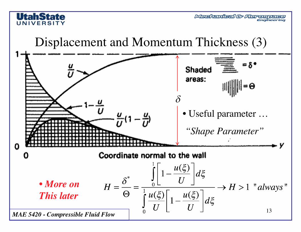
Displacement and Momentum Thickness (3)
d• Useful parameter …
“Shape Parameter”

MAE 5420 - Compressible Fluid Flow 14
Local Skin Friction Coefficient andTotal Skin-Drag Coefficient
• Per Earlier Discussion
• Start with Wall Shear Stress
“dynamic viscosity”dx
“incremental drag /unit surface area”
U

MAE 5420 - Compressible Fluid Flow 15
Local Skin Friction Coefficient andTotal Skin-Drag Coefficient (2)
•From Earlier derivation of momentum thickness
dx
“equate and collect”
U
MAE 5420 - Compressible Fluid Flow 16
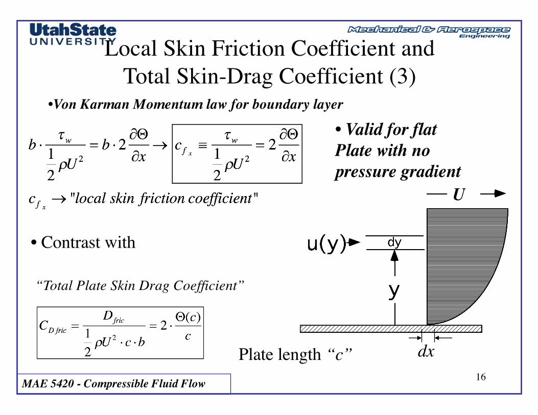
Local Skin Friction Coefficient andTotal Skin-Drag Coefficient (3)
•Von Karman Momentum law for boundary layer
dx
• Valid for flatPlate with no pressure gradient
• Contrast with
“Total Plate Skin Drag Coefficient”
Plate length “c”
U
MAE 5420 - Compressible Fluid Flow 17
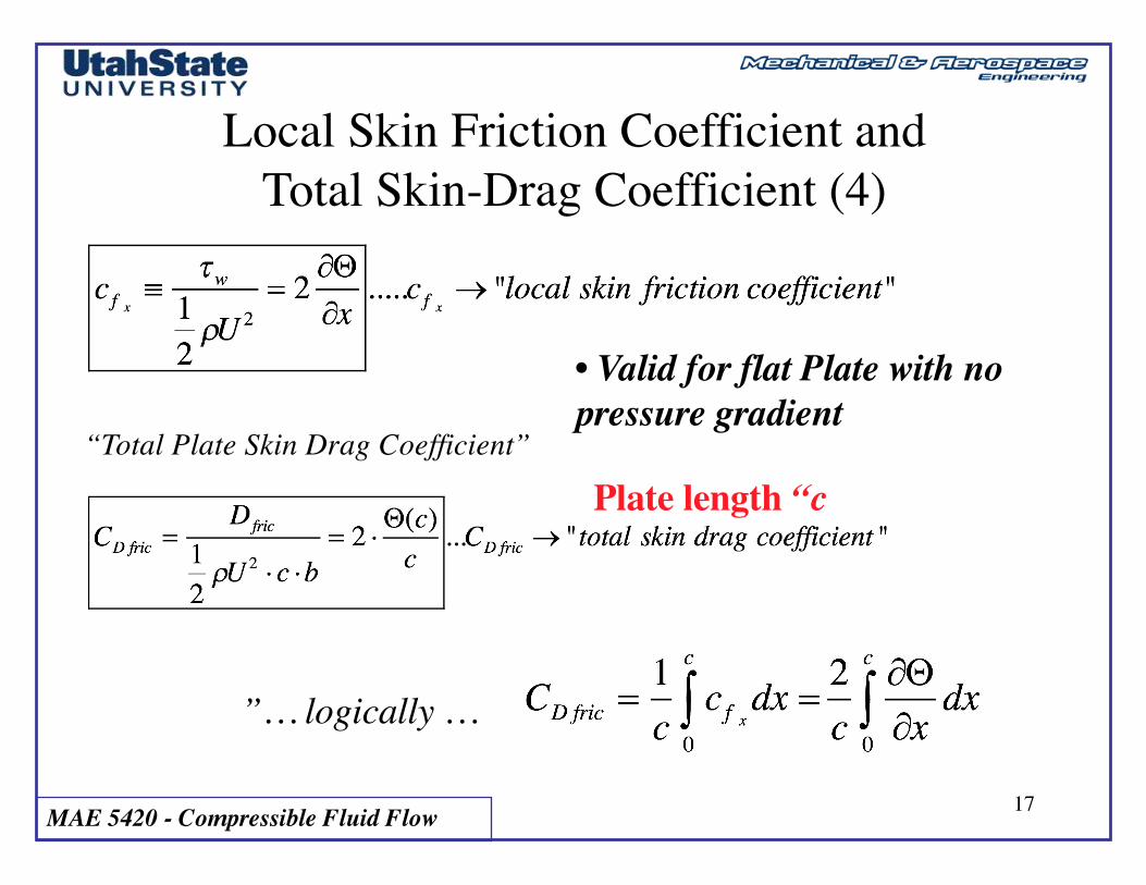
Local Skin Friction Coefficient andTotal Skin-Drag Coefficient (4)
• Valid for flat Plate with no pressure gradient
“Total Plate Skin Drag Coefficient”
Plate length “c
”… logically …
MAE 5420 - Compressible Fluid Flow 18
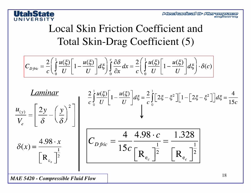
Local Skin Friction Coefficient andTotal Skin-Drag Coefficient (5)
Laminar
MAE 5420 - Compressible Fluid Flow 19
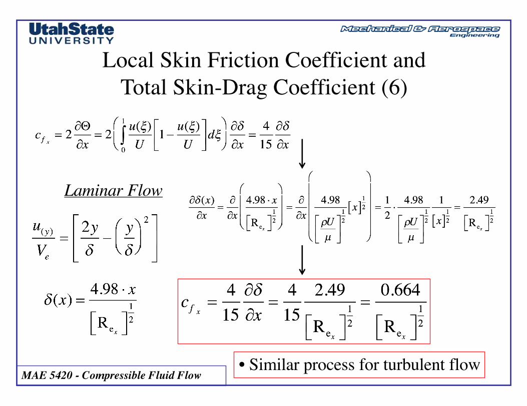
Local Skin Friction Coefficient andTotal Skin-Drag Coefficient (6)
Laminar Flow
• Similar process for turbulent flow
MAE 5420 - Compressible Fluid Flow 20
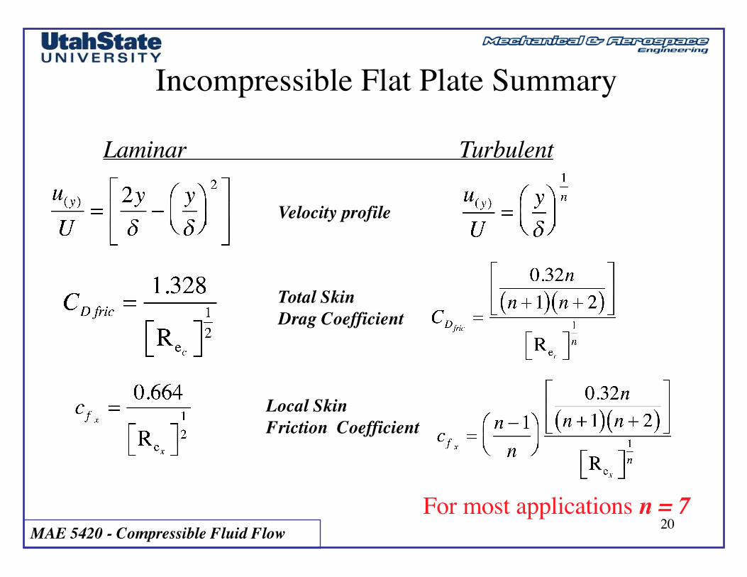
Incompressible Flat Plate Summary
Laminar Turbulent
Velocity profile
Total Skin Drag Coefficient
Local SkinFriction Coefficient
For most applications n = 7
MAE 5420 - Compressible Fluid Flow 21
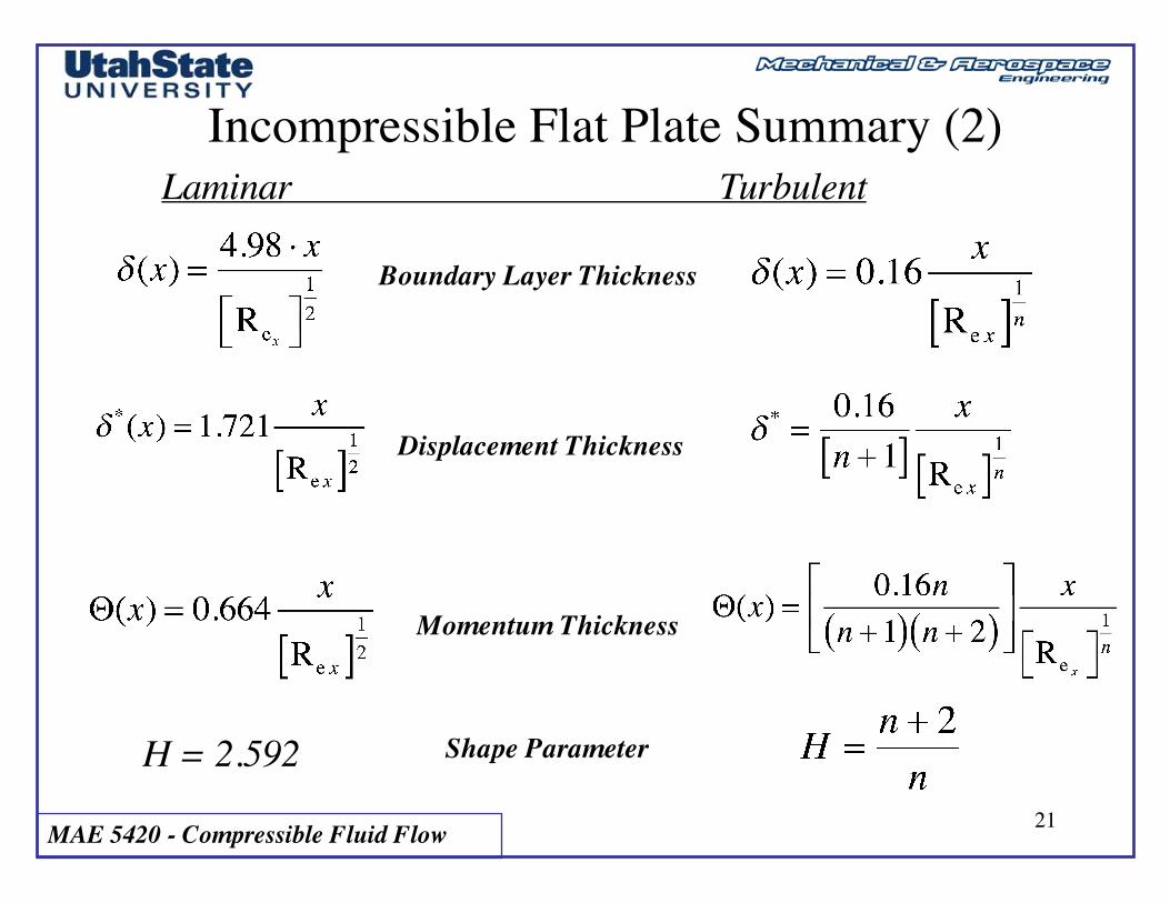
Incompressible Flat Plate Summary (2)Laminar Turbulent
Boundary Layer Thickness
Displacement Thickness
Momentum Thickness
H = 2.592 Shape Parameter
MAE 5420 - Compressible Fluid Flow 22
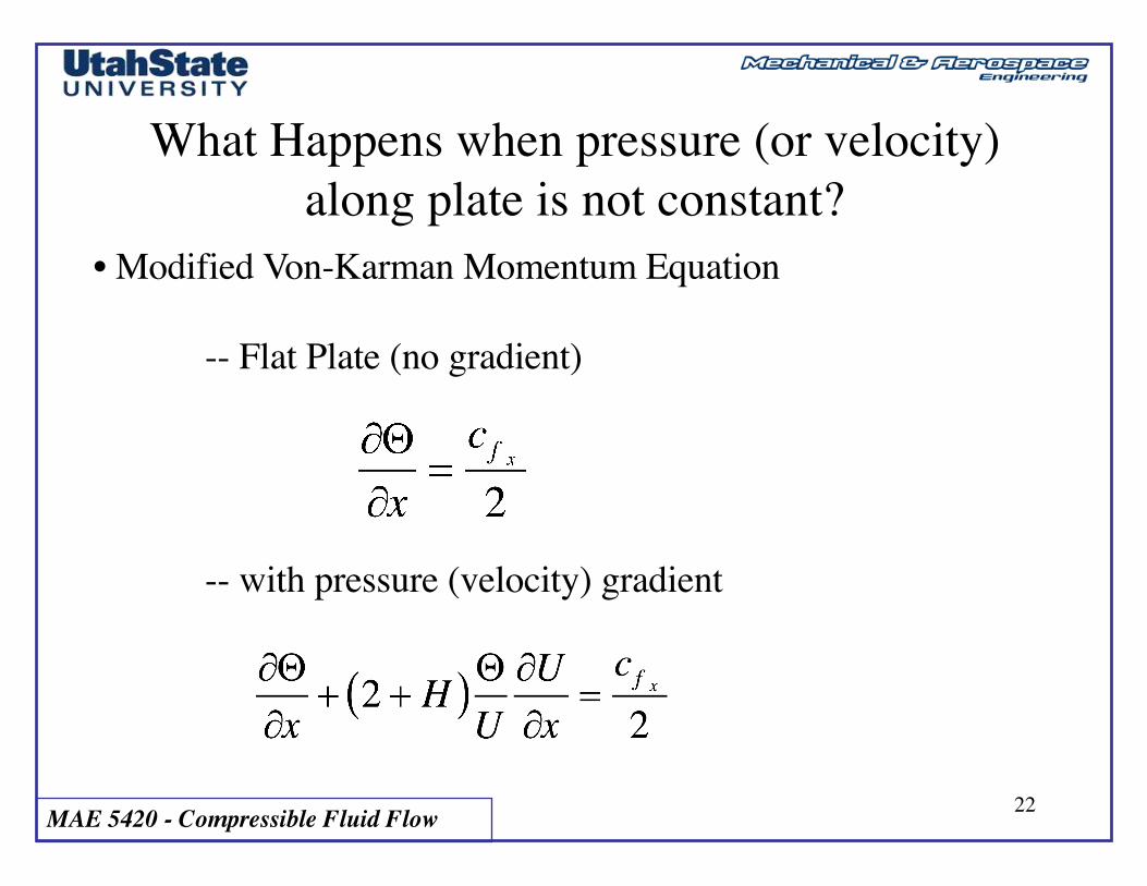
What Happens when pressure (or velocity) along plate is not constant?
• Modified Von-Karman Momentum Equation
-- Flat Plate (no gradient)
-- with pressure (velocity) gradient
MAE 5420 - Compressible Fluid Flow 23
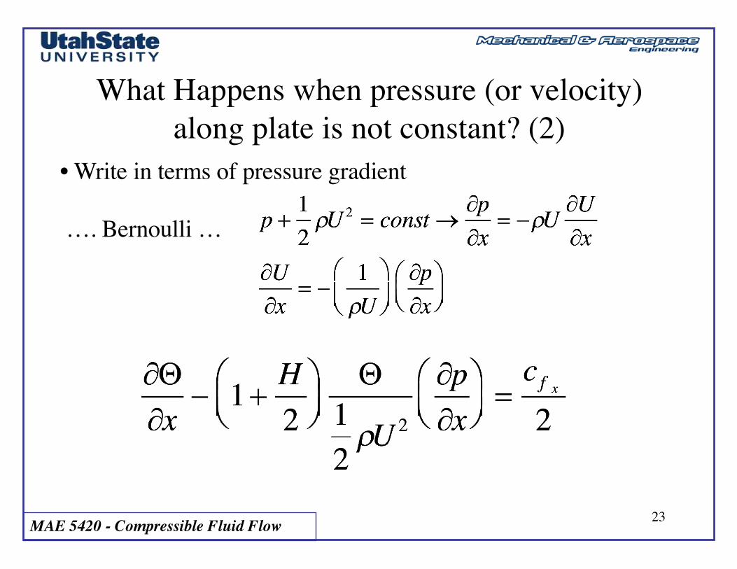
What Happens when pressure (or velocity) along plate is not constant? (2)
• Write in terms of pressure gradient
…. Bernoulli …
MAE 5420 - Compressible Fluid Flow 24
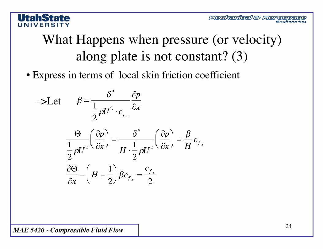
What Happens when pressure (or velocity) along plate is not constant? (3)
• Express in terms of local skin friction coefficient
-->Let
MAE 5420 - Compressible Fluid Flow 25
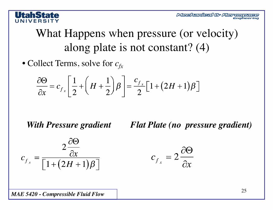
What Happens when pressure (or velocity) along plate is not constant? (4)
• Collect Terms, solve for cfx
With Pressure gradient Flat Plate (no pressure gradient)
MAE 5420 - Compressible Fluid Flow 26
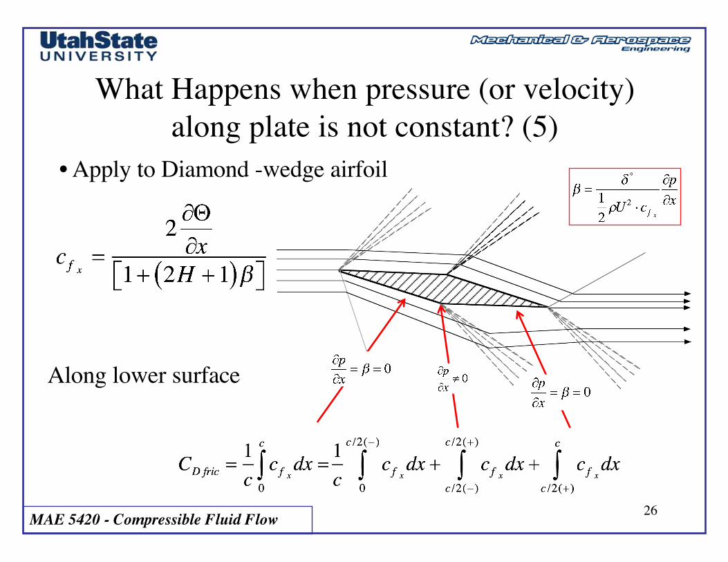
What Happens when pressure (or velocity) along plate is not constant? (5)
• Apply to Diamond -wedge airfoil
Along lower surface
MAE 5420 - Compressible Fluid Flow 27
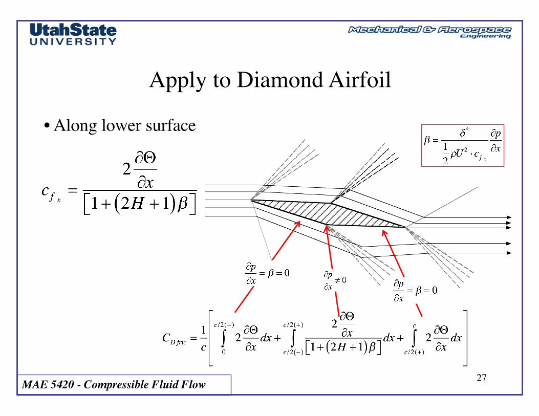
Apply to Diamond Airfoil
• Along lower surface
MAE 5420 - Compressible Fluid Flow 28
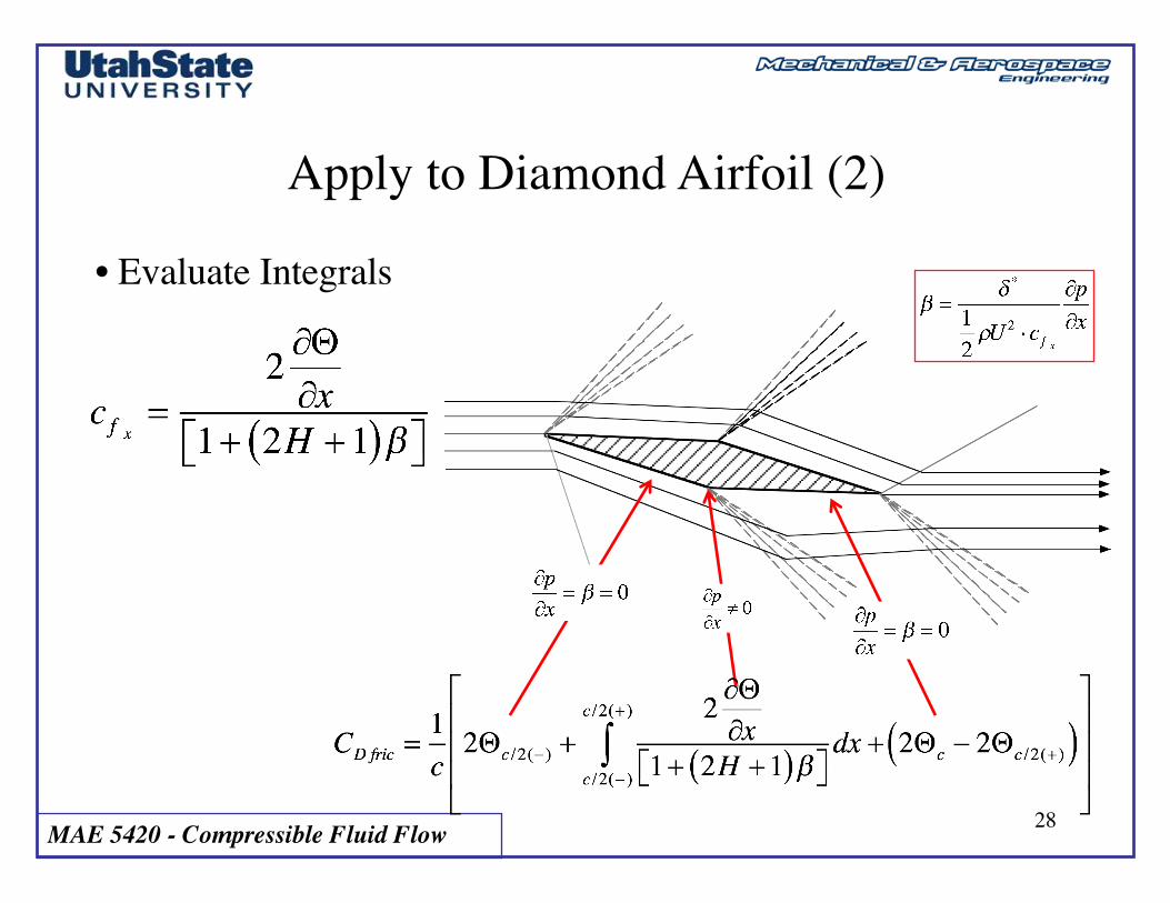
Apply to Diamond Airfoil (2)
• Evaluate Integrals
MAE 5420 - Compressible Fluid Flow 29
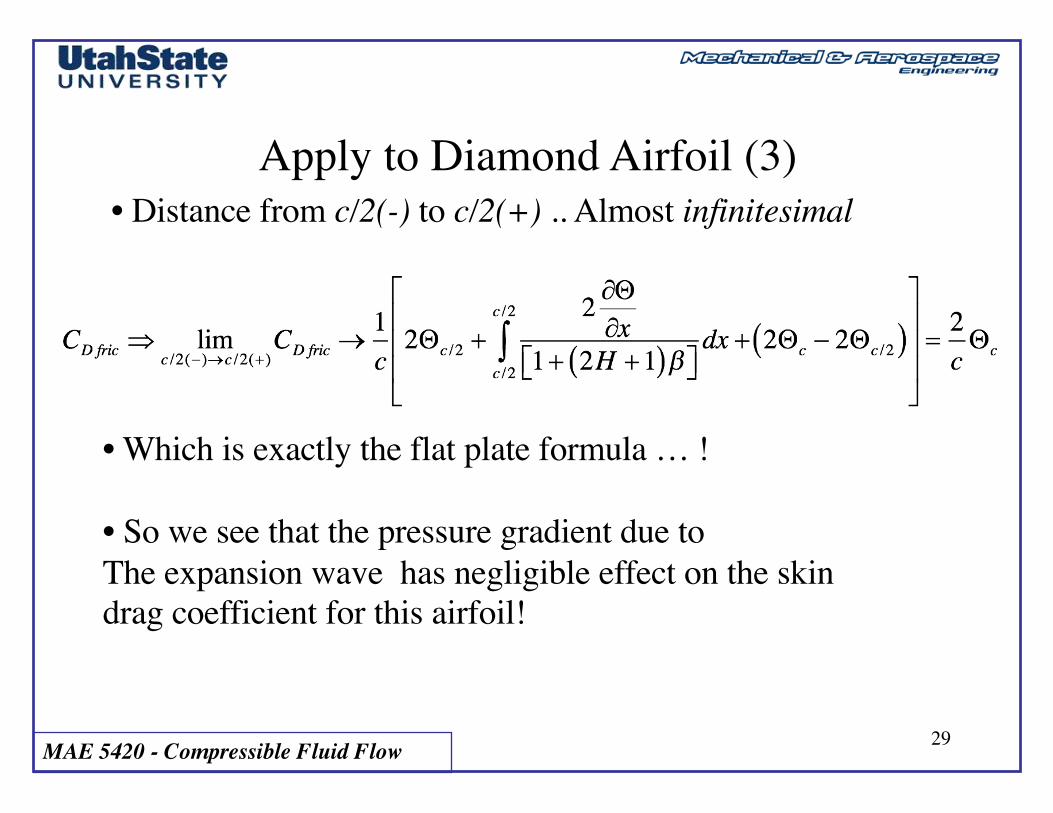
Apply to Diamond Airfoil (3)• Distance from c/2(-) to c/2(+) .. Almost infinitesimal
• Which is exactly the flat plate formula … !
• So we see that the pressure gradient due to The expansion wave has negligible effect on the skin drag coefficient for this airfoil!
MAE 5420 - Compressible Fluid Flow 30
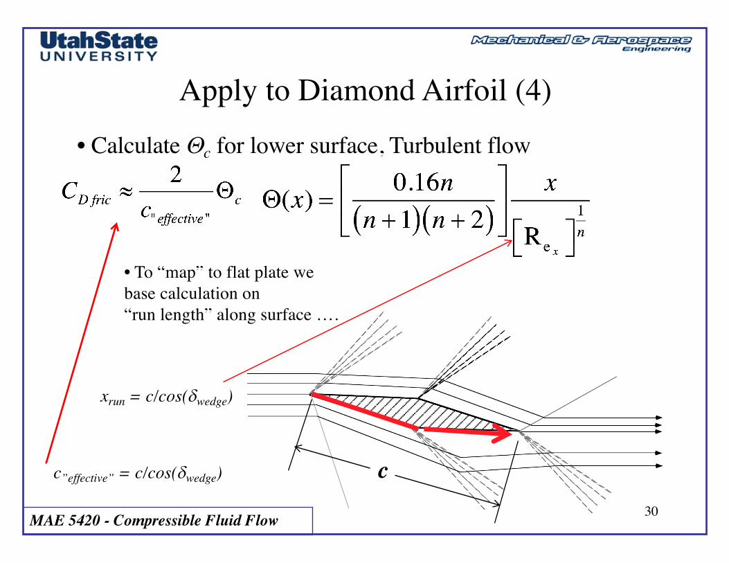
Apply to Diamond Airfoil (4)• Calculate Qc for lower surface, Turbulent flow
• To “map” to flat plate we base calculation on “run length” along surface ….
xrun = c/cos(dwedge)
cc”effective” = c/cos(dwedge)
MAE 5420 - Compressible Fluid Flow 31
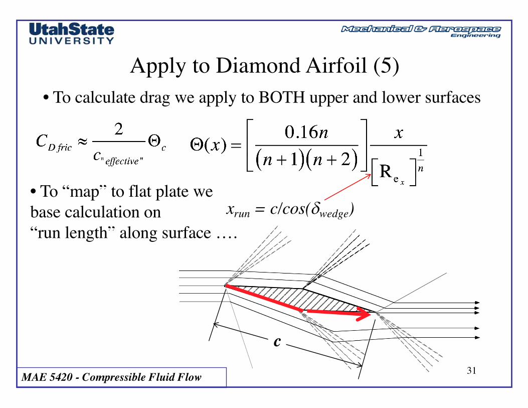
Apply to Diamond Airfoil (5)• To calculate drag we apply to BOTH upper and lower surfaces
• To “map” to flat plate we base calculation on “run length” along surface ….
xrun = c/cos(dwedge)
c
MAE 5420 - Compressible Fluid Flow 32
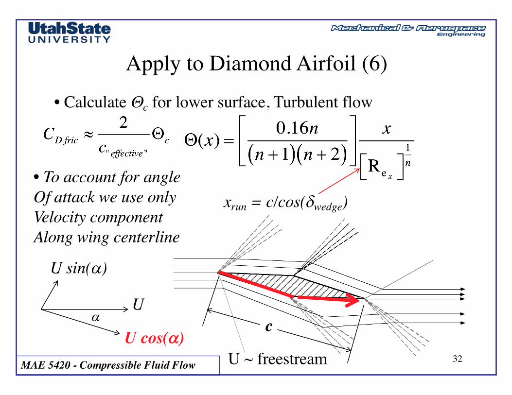
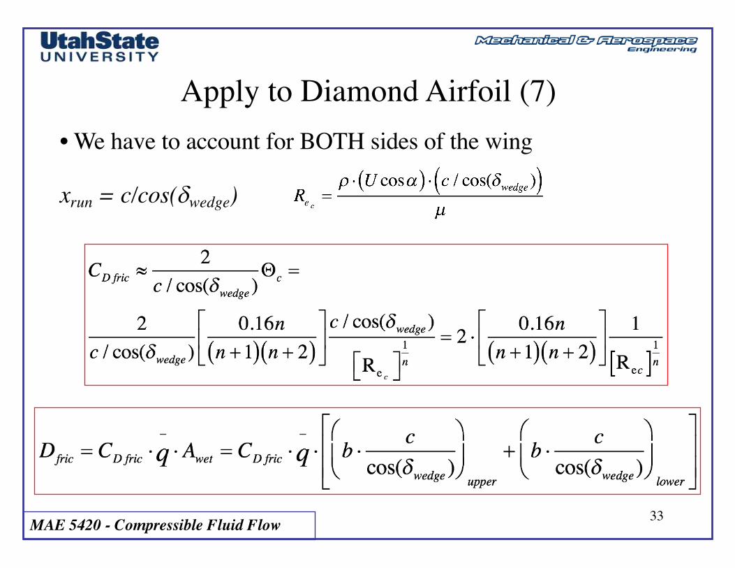
Apply to Diamond Airfoil (6)• Calculate Qc for lower surface, Turbulent flow
• To account for angleOf attack we use onlyVelocity component Along wing centerline
xrun = c/cos(dwedge)
caU
U cos(a)
U sin(a)
U ~ freestream
MAE 5420 - Compressible Fluid Flow 33
Apply to Diamond Airfoil (7)• We have to account for BOTH sides of the wing
xrun = c/cos(dwedge)

MAE 5420 - Compressible Fluid Flow 34
Apply to Diamond Airfoil (8)• Normalize by planform area (b x c)
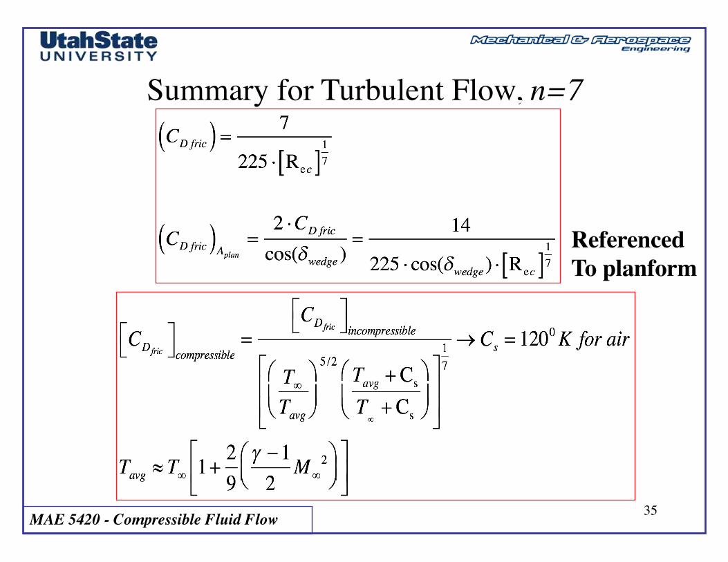
• Apply compressibility correction
MAE 5420 - Compressible Fluid Flow 35
Summary for Turbulent Flow, n=7
ReferencedTo planform