section 2 2.0 traffic signal design guidelines · pdf file2.0 traffic signal design guidelines...
TRANSCRIPT

LATEST REVISION: JANUARY 1, 2016 2-1
SECTION 2
2.0 TRAFFIC SIGNAL DESIGN GUIDELINES
2.1 SIGNAL DESIGN ELEMENTS Any traffic signal proposed for installation on City streets shall meet the minimum criteria as outlined in the Manual on Uniform Traffic Control Devices (MUTCD) and the Alabama Department of Transportation (ALDOT) Traffic Signal Design Guide & Timing Manual, latest editions. Additionally, traffic signals proposed for installation on City streets may only be considered at locations where their spacing from existing signals would not deteriorate roadway capacity along the street. A request for traffic signalization shall address the minimum criteria for installation as well as the roadway capacity impacts created by signal spacing. A development may be responsible for all or part of any right-of-way, design, hardware, and construction costs of a traffic signal if it is determined that the signal is warranted by the traffic generated from the development. The procedures for traffic signal installation shall be in accordance with criteria established by the MUTCD and ALDOT, as applicable. 2.1.1 Signal Heads All signal lenses shall be DIALIGHT (or approved equal) twelve (12) inch LED balls with a quick disconnect feature utilizing a fork terminal end for termination purposes. The LED lenses shall be wired to a terminal block located in the yellow lens housing. The LED lenses shall be installed in a yellow aluminum signal head housing with yellow aluminum tunnel visors. Back plates are typically not required on City signals unless a visibility problem exists. Back plates are required by ALDOT on all State routes. All mounting hardware for mast arm traffic signals shall be black Pelco articulating cable mount brackets. All mounting hardware for span wire traffic signals shall be aluminum tri-stud hanger assemblies. Signal head placement shall adhere to the standards set forth in the MUTCD, latest edition. A minimum of two (2) signal faces shall be provided for the major movement on each approach, even if the major movement is a turning movement. If the signal faces provided on the mast arm or span wire are more than one hundred eighty (180) feet beyond the stop line, a supplemental near side signal face shall be installed as required by the MUTCD. Where dual left turn lanes are provided, a separate left turn face shall be provided for each lane. Lateral positioning of signal heads shall be in accordance with the guidelines established in the latest edition of the MUTCD. Adjacent signal faces on the same mast arm or span wire shall be placed no closer than eight (8) feet apart. The placement of the signal head over the roadway shall be such as to provide a minimum seventeen (17) foot vertical clearance from the bottom of the signal head to the roadway. 2.1.2 Signal Supports All signals supports shall be decorative mast arms unless approved by the City Engineer. All mast arm signal poles shall be smooth, round poles with an arched mast arm and a powder coated gloss black (P-33) finish. Poles are to be assembled with the ornamental pole base and

2. TRAFFIC SIGNAL DESIGN GUIDELINES
LATEST REVISION: JANUARY 1, 2016 2-2
ornamental pole top per the City standards. The factory finish on the ornamental ball on pole top shall be gloss black on all assemblies. Strain poles and mast arm poles should be located as far as practical off the edge of roadway while staying within the right-of-way. Additionally, the poles shall be located to maximize the separation between the foundation and existing utilities. The location of strain poles and mast arm poles shall be in compliance with the AASHTO Roadside Design Guide and ALDOT standards, and approved by the City Engineer. 2.1.3 Cabinet and Controller Equipment The standard controller to be used at all signalized intersections shall be an Eagle or approved equal 16-phase, NEMA-compatible controller that meets current ALDOT standards and specifications. Controller cabinets shall be 16-phase powder coated gloss black ground mounted cabinets with railroad preemption and remote traffic signal override cord, unless otherwise approved by the City Engineer. The controller cabinet shall be so oriented that the traffic personnel will be facing the intersection while looking in the cabinet. Controller cabinets should be located as far as practical off the edge of the roadway and in the same intersection quadrant as the power source. Cabinet shall have integrated UPS cabinet unless approved by Traffic Engineer. All cabinet components and controller shall be capable of operation with flashing yellow arrow sequencing. 2.1.4 CommunicationsSignal interconnect provides communication between two (2) or more individual traffic signals to provide coordination of signals. The different types of communication include hardwire, twisted pair, closed-loop and radio. Other types of communication may be considered and approved at the discretion of the City Engineer. When an intersection with existing communications equipment is modified or upgraded, the existing communication equipment shall be reinstalled in the newly completed signalized intersection and fully functional unless new communication equipment is specified in the project plans and documents.
2.1.4.1 Extension of Existing System If a new signal is to be added to an existing hardwire connection, a local controller with adequate cabinet space for an interconnect panel must be designated as the system supervisor. If the signal modifications are significant, the replacement of the hardwire systems with a more advanced interconnect system may be necessary.
To connect a new signal with an existing twisted pair connection, a local controller must be designated as the system supervisor and communications boards must be installed in each controller.
If a new signal is to be added to an existing closed-loop system or if an existing communication system is being upgraded to a closed-loop system, all controllers must be of the same make or all controllers must be upgraded.

2. TRAFFIC SIGNAL DESIGN GUIDELINES
LATEST REVISION: JANUARY 1, 2016 2-3
2.1.4.2 New System Implementation Closed-loop systems and radio interconnect systems are most common for new installations. Radio signals require a clear line of sight between antennas and transmissions may be disrupted by rolling terrain, dense tree canopies and/or tall building structures. A closed-loop twisted pair interconnect system may be installed underground.
2.1.5 Signal Wiring, Conduit and Junction Boxes All signal head wiring is required to be seven (7) conductor stranded, regardless of signal head (3-, 4- or 5- section heads).Wiring from cabinet to signal heads should have no joins. Terminations are to be made in signal heads and cabinets only. Any changes to an existing intersection with solid wiring will require complete re-wire of all components using stranded cable. At existing span wire intersections, removal of existing lashing may be required when new wire is added. Adding new wire over existing lashed wire shall not be permitted unless old lashing is removed. Lashing shall be aluminum lashing tape only. A minimum of two (2) – 2” conduit are required for signal cable from the controller cabinet under roadways. Two (2) – 2” conduit is also required for signal cable and loop returns, once the run has crossed the roadway. All above ground conduit is required to be rigid metallic, while PVC Schedule 40 conduit is the standard for trenched underground conduit and continuous run HDPE conduit is the standard for underground bored conduit. Traffic rated junction boxes of a minimum size of 17”x 30” and minimum Tier 15 rating are required for all installations throughout the City, regardless of location within the right-of-way. Junction box lids shall have “traffic” molded into the lid. Any joints within underground junction boxes shall be water-tight connectors and approved by the Traffic Engineer. 2.1.6 Power Supply The electrical power source for the controller cabinet shall be underground. It shall be designated on signal plans in the same quadrant as the signal controller. The power source should be verified by the engineer in the field with a representative of the power company before the power source is located on the plans. The service disconnect shall be constructed in accordance with the standard detail shown in Appendix H Any charges imposed by the utility company for service shall be paid by the project contractor or signal contractor. An uninterruptible power system (UPS) (battery back-up system Clary SP 1250LX or approved equal) is required for all intersections. The entire UPS system and batteries shall be housed in the traffic signal controller cabinet with integrated UPS cabinet. When added to an existing cabinet without space for the UPS, the UPS and batteries shall be housed in a 336S cabinet. The UPS shall use the OP72C battery. Aesthetics should be considered when designing the location and style of the power service supply and disconnect to maintain the standard established by the decorative black poles. 2.1.7 Vehicle Detection The type of vehicle detector used depends upon the type of information needed by the controller to operate efficiently at its location with respect to the roadway. There are two (2) types of inductive loop detectors, as well as video detection, which are acceptable for use

2. TRAFFIC SIGNAL DESIGN GUIDELINES
LATEST REVISION: JANUARY 1, 2016 2-4
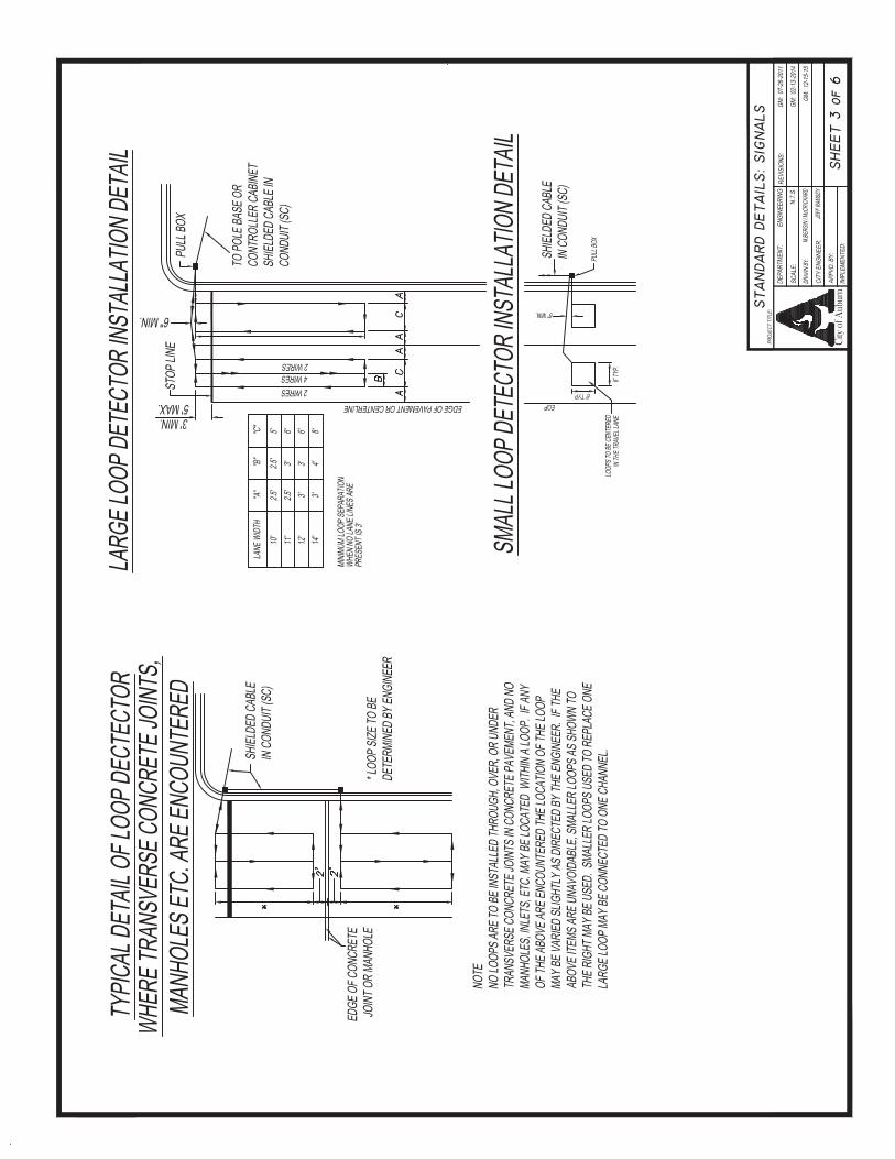
within the City. The type of detection used at each intersection shall be approved by the City Engineer. Video detection shall be required at all new or improved intersections. Other types of detection may be considered and approved at the discretion of the City Engineer. All detection, regardless of type, shall be capable of obtaining and providing volume data via the mesh network and shall detect and respond to the presence of bicycles. The inductive loop detects vehicles by sensing a change of inductance in the loop caused by the passage or presence of a vehicle over the loop. This type of detection is made up of three (3) components: a loop of wire sawcut into the roadway surface, a lead-in (home run) cable and an amplifier unit in the controller cabinet. It is capable of both passage and presence detection. All loops sawcut into the road way shall have individual homerun cables and individual curb side cut outs. Loops shall be installed and tested in accordance with ALDOT Standard Specification 730(p). Testing results for each loop shall be provided to the Traffic Engineer for approval. Video detection utilizes video cameras and an image processor to detect the presence of a vehicle to determine when to activate a particular phase.
2.1.7.1 Stop Line Detection Stop line detection, as the name implies, are inductive loops located at or near the stop line on an intersection approach to detect the presence of stopped vehicles and operate in the presence (non-locking memory) mode of detection. Stop line detection is typically used on low speed [twenty-five (25) mph or less] and side street approaches. They are typically used in through lanes on minor approaches (at a minimum), in left turn lanes on both major and minor approaches and across bicycle lanes. When used with a delay, stop line detectors can screen out right turns made on red, or left turns clipping opposing lanes, thus preventing false calls. The standard size loop is six (6) feet by forty (40) feet regardless of lane widths. At large radius intersections, wider loops may be used. The width of the loop in a curbside lane can increase significantly when it is located ten (10) feet back from a cross street and the intersection has large curb radii. 2.1.7.2 Advanced Detection Advanced detection are inductive loops that can be used with volume density controllers and are located some distance in advance of the approach stop line. The advanced loop is six (6) feet by six (6) feet and located in the through lanes of the major street where speeds are thirty (30) mph or greater. These loops operate in a passage or pulse mode and detect vehicles as they pass a specific point. Advanced loop detection can provide the controller with information on vehicles approaching the intersection, and in the case of a volume density controller, can count the number of vehicles on the approach that are waiting with a red signal indication. The location of these loops is based on the safe stopping distance of approaching vehicles which varies according to the approach speed.

2. TRAFFIC SIGNAL DESIGN GUIDELINES
LATEST REVISION: JANUARY 1, 2016 2-5
TABLE 2.1 Advanced Detector Location
Approach Speed Loop Setback
30 mph 140’ 35 mph 185’ 40 mph 230’ 45 mph 285’ 50 mph 340’ 55 mph 405’
Source: ITE Manual of Traffic Signal Design, 2nd Edition
2.1.7.3 Video Detection Video detection can operate in both presence and passage mode, similar to stop line and advanced detection. Detection zones are designated in the image processor to detect the presence of a vehicle and a bicycle and send a call to the controller. Video detection is often used in place of stop line detection, but can also be used for advanced detection (may require cameras downstream of the intersection). If the intersection cameras cannot detect advancing vehicles because of the topography and additional downstream cameras are not feasible, advanced loops may be necessary. The latest model color Ieteris camera and VRack (mounting rack) are required at all intersections operating with a video detection system. Cameras are to be mounted on a mast arm on the far side of the intersection. Proper mounting height is necessary, and varies by location, to ensure the cameras have an acceptable field of vision. ALDOT recommends mounting heights from thirty (30) to forty-two (42) feet. Engineering judgment is required to determine the ultimate mounting location. All cameras and mounting hardware for video detection shall be black cable mount brackets.
2.1.7.4 Wireless Detection Wireless detection shall be compatible with and interchangeable with the existing wireless systems provided by Sensys Networks. 2.1.8 Railroad Pre-Emption The MUTCD states that railroad pre-emption shall be provided whenever the distance between a rail crossing and traffic signal is two hundred (200) feet or less. Additional warrants include:
Analysis that indicates vehicle queues from a traffic signal have the potential to extend into or past the rail crossing, and
Analysis that indicates vehicle queues caused by a passing train have the potential to extend into the signalized intersection and obstruct traffic flow.
The maximum [ninety-five (95%) percent] queue is recommended to be used when determining whether the queue will extend into the track area [within eight (8) feet of the nearest rail]. Refer to ALDOT’s Traffic Signal Design Guide & Timing Manual for the standard pre-emption sequence and guidelines for computing the minimum interval times.

2. TRAFFIC SIGNAL DESIGN GUIDELINES
LATEST REVISION: JANUARY 1, 2016 2-6
2.1.9 Intersection Signage This section presents only the most commonly required signing associated with traffic signals. Guidance for additional signing may be found in the MUTCD, latest edition. Spanwire/Mast arm mounted sign arrangements shall be installed in conformance with the MUTCD, latest edition. Where overhead signs are installed, they shall have a minimum of seventeen (17) foot vertical clearance over the roadway. Examples of these signs include:
1. Left Turn Signal Signs R10-10, R10-12, 2. Lane Control Signs R3-5 through R3-6a, 3. Turn Prohibition Signs R3-1, R3-2, R3-4, R10-5, R10-11a, 4. Street Name Signs D3-1.
Ground mounted signs to be used at or in advance of signalized intersections shall be installed in conformance with the MUTCD, latest edition. Examples of these signs include:
1. Turn Lane Supplemental Sign R3-7, 2. Signal Ahead Sign W3-3, 3. Street Name Signs D3-2.
Street name signs shall be LED internally edge lit illuminated signs with high intensity prismatic white letter on the standard City of Auburn blue background. They shall be equipped with flip front faces for field maintenance. Frames shall be gloss black in color. All mounting hardware for illuminated signs shall be black under-hang brackets for use with two-sided signs. Each individual sign shall be fused at the base of the pole and individually photocell controlled unless otherwise approved by the Traffic Engineer. Traffic control signs used at signalized intersections in the City shall be high intensity prismatic and of the size specified in the MUTCD. The unit measurement for these signs as shown in signal plans shall be in square feet of sign face. 2.1.10 Pedestrian Signal Pedestrian signals shall be LED countdown signal heads (Lumination PS7-CFF1-01A-18), with a “walking person” indication and a “flashing/steady upraised hand”. Audible devices shall also be installed to provide standard information about the status of the signal cycle to pedestrians with disabilities. Pedestrian signal housing shall have a gloss black finish. All mounting hardware for pedestrian signal heads shall be black clam-shell brackets drilled and tapped to the pole. Pedestrian push buttons shall be provided on their own individual poles on the appropriate approach with an audible push button for each crossing direction. Pedestrian push button poles shall be installed in accordance with the standard detail shown in Appendix H. Pedestrian push buttons shall be POLERA Navigator (or approved equal) compliant with Public Rights-of-Way Accessibility Guidelines’ (PROWAG) issued by the United States Access Board. Each push button is to be supplemented by sign R10-3i, which includes the street name of the street to be crossed with an arrow pointing in the direction of the crossing. The street name shall also be identified in Braille. Audible push button programming shall be implemented in accordance with the latest edition of the MUTCD including all individual
2. TRAFFIC SIGNAL DESIGN GUIDELINES
LATEST REVISION: JANUARY 1, 2016 2-7
street names and messages. Standard Polera settings for volume and tones may be obtained from the Traffic Engineering Department. The pedestrian signal phase is a special sequence actuated by pedestrian push buttons to allow pedestrians to safely cross a street.
2.1.10.1 WarrantsA pedestrian signal phase with pedestrian signal heads shall be installed when any of the following occur:
1. When Signal Warrant 4, “Pedestrian Volume” is fulfilled, 2. When Signal Warrant 5, “School Crossing” is fulfilled, 3. Where there is an established school crossing at the proposed signal location, 4. Where pedestrians are present and multiphase signal operations (lead-lag left
turns, split phasing, etc.) are used that could confuse the pedestrians, 5. Where a sidewalk approaches the intersection on opposite sides of the
intersection and on the same side of the street. 6. As required by the City Engineer.
2.1.10.2 SequenceThe most commonly used sequence is to move pedestrians concurrent with parallel vehicular traffic. Care must be taken however not to move pedestrians during the display of a conflicting left turn or right turn arrow for the parallel vehicular traffic. The exclusive movement sequence moves pedestrians on a phase totally separate from any vehicular phase. When used, pedestrians cross all approaches simultaneously. This sequence should only be used where both pedestrian volumes and conflicting vehicular turning movement volumes are high.
2.1.10.3 TimingWalk timing provides the time necessary for a pedestrian to leave the curb to cross the street. Its minimum setting ranges from three (3) to seven (7) seconds. Pedestrian clearance time shall be calculated utilizing the latest edition of the MUTCD. It is calculated using the equation:
PC = W / VP
Where: PC = Pedestrian Clearance (sec) W = Width of street (ft) VP = Pedestrian walking speed (see MUTCD latest edition)
A portion of the pedestrian clearance interval can be timed simultaneously with the yellow and all red intervals of the concurrent vehicular phase.
2.1.11 Intersection Lighting A twelve (12) foot luminaire arm with a Phillips Roadstar 130 130W98LED4K (or approved equal) cobra head fixture shall be installed on all traffic signal poles at the intersections. Luminaire assembly shall be painted with a gloss black finish and include an equivalent to a

2. TRAFFIC SIGNAL DESIGN GUIDELINES
LATEST REVISION: JANUARY 1, 2016 2-8
two hundred fifty (250) watt high pressure sodium fixture. Each fixture shall be individually fused at the base of the pole.

2. TRAFFIC SIGNAL DESIGN GUIDELINES
LATEST REVISION: JANUARY 1, 2016 2-9
2.2 SIGNAL TIMING Traffic signal timings shall be developed in accordance with the criteria established by the MUTCD, Federal Highway Administration (FHWA) Traffic Signal Timing Manual and the ALDOT Traffic Signal Design Guide & Timing Manual, latest editions. The engineer should consult with the City Traffic Engineer to determine whether a traffic signal will operate as actuated. Fixed time signals are often used in the downtown area and on low volume roads. Actuated signals with a fixed cycle length are more commonly used. 2.2.1 Cycle Lengths Signal cycle length is the total time required to complete one (1) sequence of signal phases and generally should be as short as possible. Table 2.2 “Typical Cycle Length Ranges” contains guidelines regarding typical cycle length ranges. Cycle lengths should be calculated for the A.M. peak hour, the P.M. peak hour and off peak periods, as a minimum. If the cycle lengths vary by more than ten (10) seconds, each period should operate on a different cycle length. Signal timing software should be utilized to determine optimum cycle lengths. TABLE 2.2 Typical Cycle Length Ranges
Traffic Volumes Typical Cycle Length Range
Low 50 – 90 sec. Moderate/High 90 – 130 sec.
Congested 130 – 180 sec. Source: ALDOT Traffic Signal Design Guide and Timing Manual, November 2007 2.2.2 Actuated Timing Parameters The following timing parameters are for stop line detection of an actuated signal: minimum green, vehicle extension (passage time), maximum green (I and II), yellow all red, walk and pedestrian clearance. The following timing parameters are for advanced detection of a volume density signal controller. These features are typically used for approach speeds thirty (30) mph or greater and provide a variable (minimum) green as well as a variable “gap” feature. The timing parameters are: minimum initial (minimum green), added initial, initial gap (passage time), time before reduction, time to reduce, minimum gap, maximum green (I and II), yellow, all red, walk and pedestrian clearance. 2.2.3 Signal Timing Plans A signal timing plan is the combination of cycle length, phasing, splits (green + clearance for each phase) and offsets (for coordinated systems) and should be included with traffic signal plans.

2. TRAFFIC SIGNAL DESIGN GUIDELINES
LATEST REVISION: JANUARY 1, 2016 2-10
2.3 PLANS PRODUCTION A Traffic Signal Plans Submittal Checklist has been provided in Appendix F to facilitate a more efficient plan review process for the designer and the review team. The checklist must be submitted with every set of plans for traffic signal improvements or new signal installations. The various signal plan sheets, their format and contents are described in this section. At a minimum, all plan sheets shall have a title block containing the intersection or corridor name, a scale, the design date and the design firm information, including the initials of the designer. The title sheet shall be stamped, signed, and dated by the engineer of record that supervised the design and plans production. 2.3.1 Traffic Signal Notes This sheet contains, as the name implies, notes of general nature that apply to all the signalized intersections in the plans. It generally includes items from the ALDOT Standard Specifications for Highway Construction (latest edition) for which emphasis is intended for the contractor. The most frequently used notes are shown in Appendix G. 2.3.2 Signal Plan Signal plan sheets shall illustrate the basic intersection geometry, channelization, driveways, ditches, right-of-way, the location of underground and aerial utilities, utility poles, pavement markings, construction stationing (if available), and the power source for the controller cabinet. The following information concerning the timing, phasing and installation of the signal is also required on the signal plan sheet.
2.3.2.1 Installation Notes This set of notes applies to the signal installation at a particular intersection only. It should not repeat notes covered in the signal general notes section. Items typically covered in these notes include but are not limited to:
Signal Controller/Cabinet – Specifies installation and type Electrical Service – Specifies installation Junction Boxes – Specifies installation and type Signal detectors – Specifies installation References – Refers to the signal General Notes and the signal timing and operations sheets for additional information Speed Limits – Posted speed limits on all intersection approaches Flashing Operations – Yellow to major street, red to minor street.
2.3.2.2 Signal Head Displays This diagram shows the signal indication arrangement for each head on the signal plan. It also specifies the signal indication lens size twelve (12) inches and signal head housing color (yellow).

2. TRAFFIC SIGNAL DESIGN GUIDELINES
LATEST REVISION: JANUARY 1, 2016 2-11
2.3.2.3 Signage Displays This diagram shows the sign type, MUTCD designation and size for each sign called for on the signal plans. If a non-standard sign, such as a street name sign, is called for, its size, color and legend must be specified.
2.3.2.4 Pre-Emption Phasing Diagram If emergency or railroad pre-emption is included in the signal design, a pre-emption phasing diagram is needed to show all the phasing sequences possible when the signal is pre-empted. The phase in which normal operations is to resume after pre-emption is to be designated. Normally pre-emption is limited to major roadways and not side streets. Exceptions would be if there was a fire/EMS station or hospital located on the side street.
2.3.2.5 Signal Sequence Chart This table contains all the timing parameters applicable for the type of signal specified in the plans. The timing is shown for each signal phase in addition to its recall status.
2.3.2.6 Conflict Monitor Chart The conflict monitor chart contains the permissible or safe phase combinations to be hardwired into the conflict monitor. Any combination not wired into the circuit board will trip the conflict monitor and place the signal into flash mode.
2.3.2.7 Wiring Diagram and Table The wiring diagram shows the wiring required to accommodate the signal heads, detectors, signal controllers and power source for the signal installation shown on the signal plan. For clarity purposes, the combination of conductors required in each different section of the wiring diagram may be designated with a letter code corresponding to a wiring combination shown in the wiring table.
The wiring table is a chart that describes the various conductor combinations as designated by the letter code on the wiring diagram. The wiring code should include all runs both aerial and underground. It also specifies the conduit size needed for each particular combination of conductors run underground.
2.3.2.8 Materials List This chart shall list the components of the signal equipment that are covered under the 730 “Furnishing and Installing Traffic Control Unit” pay item. Computed quantities are not necessary as they are part of a lump sum pay item. The following items, as applicable, should be listed in a box on the plan sheet:
3/8” messenger cable 1/4” tether wire #14 signal cable Power source (specify 120V or 240V) Miscellaneous hardware Span mounted signs with hardware (ex. R10-12, R10-10, etc.) Backplates with hardware Weatherheads Pedestrian signal displays
2. TRAFFIC SIGNAL DESIGN GUIDELINES
LATEST REVISION: JANUARY 1, 2016 2-12
Pedestrian pushbutton assemblies.
2.3.3 Details and Standard Drawings The traffic signal plans shall also include all standard details, drawings and specifications as applicable to the signal design. This includes, but it not limited to the City’s Standard Decorative Pole Assembly and the applicable ALDOT Traffic Signal Operating Plan. Typical details, drawings and specifications are provided in Appendix H of this Manual. 2.3.4 Communication Plan A communication or interconnect plan shall be required if a traffic signal is being coordinated with other signal installations, via hardwire, radio, fiber optic or other. The plan shall illustrate required equipment such as master controllers, and the placement of communication cable, either underground or aerial, and tabulate all related interconnect quantities. The communication plan sheet shall indicate all signal and/or utility poles to which communication cable will be attached. In the case of radio coordination, the plan shall illustrate all necessary antennae, master controllers or other required equipment.

2. TRAFFIC SIGNAL DESIGN GUIDELINES
LATEST REVISION: JANUARY 1, 2016 2-13
2.4 CONSTRUCTION A certified Traffic Signal Technician shall have active involvement with all work required for the installation and operational testing of electrical materials and equipment (conduit, boxes, conductors, etc.). All installations shall comply with the regulations of the National Electrical Code and the National Electrical Safety Code, latest editions, and with the service rules of the electric service provider. Prior to beginning work, contractors shall provide at least 48 hours notification to the Traffic Engineering Department. In the case of a signal upgrade, existing equipment that is not in operation at the project site shall be returned to the Public Works Department. 2.4.1 Materials Submittal Equipment shop drawings and manuals must be submitted to the City for approval before materials are ordered. All materials furnished for use shall conform to the requirements given in the ALDOT Standard Specifications for Highway Construction, latest edition. Materials shall also comply with requirements that may be given on the plans. Concrete for foundations shall comply with the requirements for Class A, Type 2a concrete. Reinforcing steel shall meet the requirements for steel reinforcement and shall be Grade 60 (400) billet steel. Minimum design wind speed shall be based on ALDOT standards. All materials and equipment furnished shall be new, except when the plans specifically provide for the re-use of existing equipment. 2.4.2 Test Requirements Before the installation of a traffic control systems, the contractor shall perform a pre-installation test. This test shall include the bench testing of all controllers, signals, detectors, etc., under signal load conditions for fourteen (14) consecutive days. The contractor shall secure an acceptable site, approved by the engineer, for the bench test and shall perform all work required in the performance of the test. The contractor shall notify the engineer of the date that the test is to begin a minimum of seven (7) days before that date. None of the equipment shall be installed on the project until the bench test has been completed and the contractor has submitted a letter to the engineer certifying that the equipment performed satisfactorily during the test. The engineer may shorten the length of time required for the bench testing. There will be no direct payment to the contractor for the cost of the pre-installation test including the cost of a suitable test site and the setting up of equipment for the test. 2.4.3 Inspection Some materials and equipment required to be furnished will be standard production type products. Acceptance will be made by the engineer based on selected confirmation tests, the manufacturer's certification of the materials and equipment, and visual inspection at the job site. The manufacturer shall make available to the City Engineer test data and material samples from the production runs for use in evaluation of these items. Approved devices are shown on ALDOT’s Approved Traffic Control Devices and Materials list.

2. TRAFFIC SIGNAL DESIGN GUIDELINES
LATEST REVISION: JANUARY 1, 2016 2-14
Concrete pole foundations shall be inspected by the Traffic Engineering Division before and after concrete is poured. Upon completion of the project, the contractor shall schedule a full operations traffic signal inspection with the Traffic Engineering Department. Results of the inspection shall be provided to the contractor in the form of a punch list. All items on the punch list must be satisfactorily addressed prior to releasing payment. Contractor shall give at least one day’s notification for inspections. 2.4.4 CloseoutAfter all equipment has been installed and the operational check has been instigated, the contractor shall submit a set of plans showing in detail all changes on construction from the original plan details with special notation given to conduit location and elevation and schematic circuit diagrams. Operation manuals and as-built wiring diagrams shall be furnished for all equipment and accessories required in the controller cabinet. These manuals and wiring diagrams shall be mounted to the cabinet in an appropriate manner.

APPENDIX F. Traffic Signal Plans Submittal Checklist

This page intentionally left blank.

Updated 06/22/2009
Check N/A Comments
These are the basic sheets we expect to see in a set of plans. Some sheets may be combined on certain projects, or have different names (for example, storm water profiles shown on the street plan & profile sheets).
** Traffic Signal Notes Sheet** Signal Plan Sheets** Installation Notes ** Standard Details and Drawings Sheets** Coordination Plan Sheets
Galvanized Steel PolesPowder Coat Gloss Black finishSmooth Pole (not fluted)Smooth, Arched Mast ArmGloss Black Decorative Top includedGloss Black Decorative Base includedBlack Ball on Decorative top
Auburn Spec Cabinet (not ALDOT)Painted BlackUPS included8-Phase NEMA Compatible Controller includedGround Mounted CabinetInterconnect Components specifiedPreemption Requirements specified
Underground Service designedFuture Service Corner/Disconnect Location shownVerified with ALPCoShow existing topography with clearly labeled contours lines
Yellow, Aluminum, 12inch signal headsGelcore ELD specified
Black, Aluminum headsLEDCountdown styleAudible pedestrian buttons
Overhead Blue Street Name Signs specifiedOverhead Turn Signs specifiedOverhead Lane Control Signs requiredSignal Ahead Signs required
Black, 250 W HPS over each stop barCut-off style Cobra Head Fixutre12' Luminaire Arm
Traffic Signal Notes SheetSignal Plan Sheets intersection geometry shown utilities shown pavement markings shown right of way shownInstallation Notes Specified for the following: controller/cabinet specs
Sign
al H
Pede
stria
n Si
gnal
Sign
age
Lum
inar
ies
ns-P
lans
-Pla
ns
Pedestrian Signals
Plans
Signage
Luminaries
Signal Support
Cabinet
Power Supply
Signal Heads
Sign
al S
uppo
rt -
Sign
al S
uppo
rtC
abin
etPo
wer
sup
ply
- Po
CCity of Auburn Traffic Signal PlansSSubmittal Checklist
This checklist must be submitted with every set of plans for traffic signals improvements. All items on the checklist shall be addressed. If the item is not applicable to this project check the box next to the item labeled "N/A", and provide comment. Items preceded by an asterisk (** ) are required for the submittal to be considered complete. If one of these items is missing from the submittal without a valid explanation, the entire submittal will be rejected. Note that this checklist is not intended to be all-inclusive, and fulfillment of this checklist does not alleviate the obligation of the designer to meet all City of Auburn code, regulations, ordinances, and specifications. The purpose of this checklist is to facilitate a more efficient plan review process for the designer and the review team.
DescriptionRequired Plan Sheets
Page 1 of 2

Updated 06/22/2009
Description Check N/A CommentsPl
ans-
Plan
s-Pl
ans-
Plan
s-Pl
ans-
Plan
s-Pl
ans-
Plan
s-Pl
an electrical servicejunction boxesdetectionreferencesspeed limitsflash pattern
Signal Head Display shownDetection shown (cameras on mast arms)Signage Display shownPre-emption phasing diagram shown
signal sequence chart includedconflict monitor chart includedwiring diagram and table includedmaterials list includedtiming plan provided
Standard Details and Drawings SheetsCoordination Plan Sheets
Construction
Con
stru
ctio
n
Materials Submittals included for the following:pole designpole foundation designscabinet and controller equipmentsignal heads and mounting hardwarepedestrian heads and mounting hardwaretesting reports
SIGNED:(engineer of record)
ENGINEER'S SEAL:
Page 2 of 2

APPENDIX G. Traffic Signal Notes

This page intentionally left blank.

APPENDIX G. Traffic Signal NotesPavement markings shown are for illustrative purposes unless otherwise noted.
Controller shall be capable of running pedestrian phases.
Mast arm pole shall be galvanized steel, smooth, round poles (not fluted) with an arched mast arm and a powder coated gloss black (P33) finish.
The contractor shall not order the traffic signal material until the shop drawings and design calculations have been reviewed by the City of Auburn and written approval granted.
Poles shall include ornamental pole base and top as per City of Auburn standard.
Ball at top of crown shall be black.
The traffic signal pole assembly includes the pole structure, mast arm, decorative pole base, decorative pole top, luminaire arm and assembly, and miscellaneous hardware incidentals for a complete mast arm pole installation.
Cost of mast arm installation shall include all miscellaneous items, such as washers, bolts and all incidental items to have a complete installation.
Signal heads shall have a minimum clearance of 17’ from the bottom of the signal head to the roadway.
Signal heads shall be yellow.
Signal heads shall be 12” LED’s.
Luminaire assembly shall be gloss black Phillips Roadstar 130W98LED4K or approved equal.
Pedestrian signal housing shall be gloss black.
Pedestrian signals shall be led countdown signal heads (Lumination PS7-CFF1-01A-18).
Pedestrian pole shall be Holophane Wadsworth Aluminum Sitelink pole (or approved equal) with a powder coated gloss black finish.
Pedestrian signal head clamshell bracket shall be bolted to the pole, not banded.
Uninterruptable power systems (battery back-up systems Clary SP 1000SN+) using the OP72C battery are required for all intersections. The entire ups system and batteries shall be housed in the standard City of Auburn traffic signal controller cabinet unless otherwise approved.

This page intentionally left blank.

APPENDIX H. Traffic Signal Details and Specifications

This page intentionally left blank.

CO
UN
TDO
WN
TYP
ELE
D
WH
ITE
RIN
GR
RE
DC
EN
TER
GYR
SU
PP
LEM
EN
TAL
RE
D IN
DIC
ATI
ON
GG
Y
RR
GYY
RR
GGY
Y
R GY
G


Ø17.0"
1'-6.8"
12'-0"
Ø17.0"
14'-5.5"
Pole - Wadsworth Aluminum Pole[WDA 12 L4E 17 P07 ABG BK]Prefix: Wadsworth Aluminum PoleHeight: 12 Feet (Actual Height: 12'-0")Shaft Style: SiteLink 4.5 inch Fluted,
.156 wallBase: 17 inch Round BaseTenon: 3 X 3 TenonPole Mounting: Anchor bolts,
galvanized steelFinish: Powder Coat Black Paint Finish,
unless otherwise noted during DRTBreakaway Kit: NoneBreakaway Kit Finish: NoneBase EPA: 1.62Base Weight: 41Anchor Bolt: AB-31-4
Fixture - Granville II LED (GVD)[GVD 80 4K AS S B 3 N N U]Prefix: GranVille II LED (GVD)Source & Wattage: 80W 400mA DriverColor Temperature: 4000 Series CCTVoltage: Auto-Sensing Voltage (120-277)Housing: SimpleFinish: BlackOptics: Asymmetric Type IIITrim: No TrimFinial: No FinialTrim and/or Finial Finish:
No Trim and Clear or No FinialDimming Drive: NoneCovers: NoneFinish for Cover: NoneNEMA Label: NonePhotocontrol Receptacle: NoneDimming: NonePhotocontrol: NoneDimming: NonePhotocontrol: NoneROAM Dimming Contro: NonePrewired Leads: NonePhotocontrol Kits: NonePhotocontrol Kit Finish: NoneDecorative Band: NoneHouse Side Shields: NonePost Capital: NoneLuminaire EPA: 1.88Luminaire Weight: 59
NOTES:1. The lighting post shall be all aluminum, one-piece construction,
with a classic tapered and fluted base design.2. The base and fluted tapered cast shaft shall be heavy wall, cast
aluminum produced from certified ASTM 356.1 Ingot per ASTMB-179-95a or ASTM B26-95.
3. The straight shafts shall be extruded from aluminum, ASTM 6061ally.
4. The tapered shaft shall be extruded from aluminum, ASTM 6063alloy, spun to a tapered shape.
5. Material heat treated to a T6 temper.


Clary Corporation
150 E Huntington Drive Monrovia, Ca 91016
Tel: 800.442.5279 • Fax:626.305.0254
• www.clary.com
P/N 520-113481
08/04/06-VVer. 1.4
SP Series Specifications
InputVol tage 120 VAC +12%, -29%
(wi thout bat ter y d ischarge)Frequency 48 to 62 HzOutputVol tage 120 VAC +3%Frequency 50 or 60 HzRat ing: SP 1000 SR/SN 1,250 VA/875 Wat ts
SP 1250 SR/SN PLUS 1,250 VA/875 Wat ts1
SP 2000SR/SN/U 2,000 VA/1400 Wat tsCrest Factor Rat io @50% Load Up to 4 .8:1(Non- l inear Load and @75% Load Up to 3 .2:1< 5% THD) Typica l @100% Load Up to 2.4:1Tota l Har monicDis tor t ion (THD) 4.0% Max.Dynamic Response ±4% for 100% Step Load Change
0.5 ms Recover y T imeOver load 110% for 10 sec;
200% for .05 secUPS Protect ion Input and Output Shor t Ci rcu i t ;
Input and Output Over load;Excess ive Bat ter y Discharge
Operat ing Temp. -40oC to +74oC (-40F to+165oF)Humid i ty 0% to 95% Non-condensingAl t i tude Sea Level to 10,000 f t (some
derating of temp. w/altitude > 6,000 ft)
Input Hardwired to PIMOutputs Hardwired to PIM, w/single 15 Amp
Receptacle on back of UPSCabinet NEMA, 332 or CBO-123 Cabinet
Style Configurations Avai lable ;NEMA 3R Type I I and Type I I IOpt ional
Consul t Factor y for o ther Custom opt ions
ENVIRONMENTAL
MECHANICAL
ELECTRICALStandard Features Power Factor Corrected Input ;
Fu l ly Regenerat ive;True On-Line Continuous Power ;Low Distor tion Sinewave Output;Designed for Non- l inear Loads;Extended Brownout Protect ion;EIA/RS232 Data In ter face
Speci f icat ions Meets FCC Class A, IEEE 587/ANSI C62.41, IEC 555 @ 120 VAC and NEMA Stds
MTBF Inver ter : > 100,000 hrs System w/Bypass: 150,000 hrs Calculated from Component Spec
Typica l Recharge 48-72 hrs (more t ime requiredTime to 85% wi th extended bat ter y opt ion) Capaci ty @ Less than 20 hrs wi th opt ional 100% Load Fast Bat ter y Charger
Ramping LEDs Bat ter y Level ; Load LevelSingle LEDs AC In; Inver ter On; Low Bat ter y
and Summary Alarm; Alarm SilenceContro l Panel Power On; Cold Star t; Test; Alarm
Silence; Event Counter (w/Reset);Hour Meter ; Bat ter y Disconnect
Audible A lar ms Uti l i ty Interrupt; Inver ter Fai lure;Over load; Low Battery; Self Test
Ser ia l In ter face for Full Interactive Remote ComputerEIA 232. Opt ional Moni tor ing and Contro l o f Most NTCIP and TCP/ IP Features Including Load Controlv ia Standard RJ45 (requi res opt ional moni tor ing Connector sof tware) ; NTCIP and TCP/ IP
ReadyContact Closures Open Col lector for Remote ( "D" connector ) Annunciat ion of Power Up,
Power Down, On Bat ter y, LowBat ter y and Alar ms
Speci f icat ions subject to change wi thout pr ior not ice.
DESIGN
CONTROLS AND INDICATORS
Made in the USA
Input Output Backup Time Unit Weight RackmountModel VA Watts Current (A) Current (A) 100% / 50% Load (lbs) H x W x D (in)
SP1000SN/SR2
1,250 875 8.8 10.4 1.5 hrs. / 3.25 hrs. 20 3.50 x 19.0 x 13.0 (2U)
SP1250SN/SR Plus1, 2
1,250 875 8.8 10.4 1.5 hrs. / 3.25 hrs. 20 3.50 x 19.0 x 13.0 (2U)
SP2000SN/SR2
2,000 1400 18.0 20.0 15.0 min. / 35.0 min. 30 5.25 x 19.0 x 17.0 (3U)
SP1250U 1,250 875 8.8 10.4 1.5 hrs. / 3.25 hrs. 20 3.50 x 19.0 x 13.0 (2U)
SP2000U 2,000 1400 18.0 20.0 15.0 min / 35.0 min 30 5.25 x 19.0 x 17.0 (3U)
CUSTOM Options
Note 1 Supports 1400 watt peak load for 10 seconds or less, intended for yellow incandescent applications.Note 2 Requires Clary PIM30C, G, R, or GR for traffic applications.
Uninterruptible Power for Traffic Signal Applications - 1000, 1250 and 2000VA

This page intentionally left blank.

RX11 LED Signal Modules
Mechanical Outline Dimensions in inches. (mm) indicates metric equivalent
Design ComplianceTest Type Compliance
Luminous Intensity ITE VTCSH-STD Part 2 - July 1998
Chromaticity ITE VTCSH-STD Part 2 - July 1998
Moisture Resistance NEMA STD 250 Type 4 - 1991
Mechanical Vibration MIL-STD-883 Method 2007
Electronic Noise FCC Title 47 Sub. B Sec 151
Transient Voltage Protection ITE VTCSH-STD Part 2 - July 1998
Controller Compatibility NEMA TS-2-1992
Wiring National Electric Code
Operating Specifications Parameter Rating
Operating Temperature Range -40 to + 74°C (-40 to +165°F)
Operating Voltage Range 80 to 135 V (60Hz AC)
Power Factor (PF) > 90 %
Total Harmonic Distortion (THD) < 20 %
Voltage Turn-off (VTO) 45 V
Lens & Shell Material UV Stabilized Polycarbonate
Wiring 16 AWG, Color Coded with Strain Relief
Product InformationModel Size AC Power Wavelength Maintained
Number (in) Voltage (W) (nm) Intensity (Cd)
Nominal Nominal Dominant Minimum2
DR4-RTFB-20A 8 120V – 60 Hz 5 626 133
DR4-YTFB-20A 8 120V – 60 Hz 13 589 2673
DR4-GTFB-20A 8 120V – 60 Hz 6 508 267
DR4-GCFB-20A 8 120V – 60 Hz 6 508 267
DR6-RTFB-20A4 12 120V – 60 Hz 10 626 339
DR6-YTFB-20A 12 120V – 60 Hz 22 589 6783
DR6-GTFB-20A 12 120V – 60 Hz 12 508 678
DR6-GCFB-20A 12 120V – 60 Hz 12 508 678Standard product equipped with spade connectors.2 Measured at +2.5°H -2.5°V, Ta = 25°C.3 Actual intensity less than ITE VTCSH-STD Part 2 - July 1998.4 May exceed maximum intensity of ITE VTCSH-STD Part 2 - July 1998.
1 Class A
2.4"(62)
8.2"(210)7.6"(194)
1.4"(35)
6.3"(161)
1.8"(45) 0.3"
(8)
Options :- Q : Quick Connect- S : Medium Base Socket- F : In-line Fuse
2.4"(62)11.8"
(300)
11.0"(280)
1.9"(47)
9.6"(244)
0.3" (8)
1.3"(32)
Distributed by:
6180 Halle Drive · Valley View, Ohio 44125-4635, · USAP: 216.606.6555 F: 216.606.6599 www.led.com [email protected]
Lumination, LLC is a subsidiary of the General Electric Company. The GE brand and logo are trademarks of the General Electric Company. © 2008 Lumination, LLC. Information provided is subject to change without notice. All values are design or typical values when measured under laboratory conditions.
TRAF115-R100108
For customer service & technical support, contact:1-888-MY-GE-LED (1.888.694.3533)
Nominal Nominal Dominant Minimum2

This page intentionally left blank.

LED Array Pedestrian Countdown Signals16 X 18 inch module
Mechanical Outline Dimensions in inches. (mm) indicates metric equivalent
2 Full MUTCD Compliance Standard product shipped with spade connectors.Test Conditions: Ta = 25°C Options: Q – Quick Connect, MB – For GTE Winkomatic (16 7/8” x 16 1/4”) Housing,MC – For Econolite (18” x 15 5/8”) Housing.
3.2"(80)
17.2"(480)
16.0"(407)
9.0"(227)
13.2"(336)
2.4"(60)
16x18
Operating Specifications Parameter Rating
Operating Temperature Range -40 to +74°C (-40 to +165°F)
Operating Voltage Range 80 to 135 V (60Hz AC)
Power Factor (PF) > 90 %
Total Harmonic Distortion (THD) < 20 %
Voltage Turn-Off (VTO) 45 V
Lens & Shell Material UV Stabilized Polycarbonate
Wiring 16 AWG, Color Coded with Strain Relief
Hand: Portland Orange LED Color Person: Lunar White Countdown: Portland Orange
1 Class A
Design Compliance Test type Compliance
ITE Pedestrian Traffic Control Signal Indication - Part 2: Light Emitting Diode Luminous intensity (LED) Pedestrian Traffic Signal Modules Section 4.1.1 (applies to: Hand & Person only)
Chromaticity ITE PTCSI-STD - Part 2
Moisture Resistance NEMA STD 250 Type 4 – 1991
Mechanical Vibration MIL-STD-883 Method 2007
Electronic Noise FCC Title 47 Sec 15 Sub. B1
Transient Voltage Protection ITE PTCSI-STD - Part 2
Controller Compatibility NEMA TS-2-1992
Wiring National Electric Code
Distributed by:
Figure A
Product Information Model Number Operating Configuration Symbol AC Voltage Power (W) Figure Cycle Hand Person Countdown Nominal Hand Person Countdown
PS7-CFF1-01A-182 Clearance Overlay/ Full Full 2 Rows/ 120V – 60Hz 9 8 5 A Countdown 9'' high
PS7-CFL1-01A Overlay Overlay Full Full – 120V – 60Hz 9 8 – B
Figure B

This page intentionally left blank.