geotechnical design memorandum traffic signal …
TRANSCRIPT

GEOTECHNICAL DESIGN MEMORANDUM TRAFFIC SIGNAL FOUNDATIONS INTERSECTION OF ROUTE 1 AND WALKER STREET KITTERY, MAINE MAINEDOT WIN 12752.00 PREPARED FOR: Vanasse Hangen Brustlin, Inc. Bedford, New Hampshire PREPARED BY: Isabel V. (Be) Schonewald, P.E. Schonewald Engineering Associates, Inc. (SchonewaldEA) 129 Middle Road Cumberland, Maine 04021 [email protected] November 1, 2011 SchonewaldEA Project No. 11-010


Vanasse Hangen Brustlin, Inc. November 1, 2011 Project No. 11-010
Page 2
The remaining two borings, B-2 and B-4, located in the southwest and northeast corners of the intersection, respectively, were completed using cased drive and wash techniques and rock core was obtained. In all four borings, Standard Penetration Tests (SPTs) were completed and split-spoon soil samples obtained near the ground surface and at five-foot intervals to the bottom of each boring. Soft soils (e.g., Presumpscot clay) were not encountered. Groundwater level was measured in the auger borings upon completion of the test boring and removal of the augers. The boreholes were backfilled with drill cuttings and manufactured stone backfill; asphalt pavement disturbed by the work was patched. SUBSURFACE CONDITIONS Soil conditions observed in the test borings consisted of the following strata from the ground surface downward: GRANULAR FILL MATERIAL Approximately 2.8 to 4.0 feet of good quality granular fill material
was encountered beneath surficial loam or asphalt in all of the test borings. The granular fill material typically consisted of dense, gravelly sand with about 5 to 15 percent silt;
MISCELLANEOUS URBAN FILL Up to approximately 5.5 feet of loose to medium dense, typically fine to medium sand with varying amounts of gravel and silt, with lesser amounts of apparent cinders and crushed brick was encountered in test borings B-3 and B-4 on the easterly side of the intersection; and
GLACIAL TILL Glacial till consisting of medium dense to very dense, sand and gravel with about 10 to 20 percent silt was encountered in all of the test borings above refusal (rock).
Bedrock: Refusal was encountered at between 10.3 and 21.1 feet BGS in the test borings. In the auger borings, refusal was presumed to be on rock. In the cased borings, rock core was obtained. Rock core was classified as a hard, fresh to slightly weathered, fine-grained metasandstone containing some apparent brecciated zones, which is consistent with bedrock geological maps of the area. The shallow refusals are consistent with observed rock outcrop in the vicinity of the intersection and reports of shallow bedrock encountered during spread footing construction for a building under construction in the southeast corner of the intersection. Rock quality, based upon RQDs ranging from 0 to 47 percent, would be considered very poor to poor. Groundwater was observed to be at about 8 to 13 feet BGS in test borings B-1 and B-3, respectively, at the time of drilling. GEOTECHNICAL ENGINEERING EVALUATION Frost Depth: Methodology set forth in MaineDOT’s Bridge Design Guide dated August 2003 (MaineDOT BDG) was used to determine the depth of frost penetration for the project site. The design freezing index of the site was taken as 1250 degree-days. Near-surface soils underlying the project site consist of granular material that was observed to be moist. Based upon Table 5.1 in the MaineDOT BDG, the frost depth would be about 4.5 feet. This is consistent with local geotechnical engineering practice. Traffic Signal Mast Pole Foundations: The soils underlying the project site are suitable for supporting the proposed traffic signal mast poles on drilled shafts. Rock anchors might be required due to the thin overburden soils. Site soils are also suitable to support the mast poles on shallow spread footings. However, space is limited due to numerous buried utilities. As such, the use of shallow spread footings is not discussed further. In accordance with Table 3.3 in MaineDOT’s BDG and local practice, the structural design of the foundations should be based on the following site-specific soil parameters:
MISCELLANEOUS URBAN FILL: drained friction angle (Φ’) equal to 28 degrees; saturated unit weight (γsat) equal to 0.110 kcf; and interface friction angle between soil and cast-in-place concrete (δ) equal to 19 degrees.

Vanasse Hangen Brustlin, Inc. November 1, 2011 Project No. 11-010
Page 3
GRANULAR FILL AND GLACIAL TILL: drained friction angle (Φ’) equal to 34 degrees; saturated unit weight (γsat) equal to 0.120 kcf; and interface friction angle between soil and cast-in-place concrete (δ) equal to 22 degrees.
For the design of rock anchors, it should be assumed that the upper portion of the bedrock underlying the project site is of very poor to poor quality based upon drilling behavior, low RQDs determined by coring rock, and visual examination of the rock core retrieved. If rock anchors are utilized, pull-out tests should be completed during construction. GEOTECHNICAL RECOMMENDATIONS FOR DESIGN AND CONSTRUCTION The following geotechnical recommendations are provided for the design and construction of the traffic signal foundations specifically and intersection improvements in general. Design of drilled shafts for supporting proposed traffic signal mast poles: The soils underlying the project site are suitable for supporting the proposed traffic signal mast poles on drilled shafts. The design of drilled shafts should be in accordance with Section 13 of the AASHTO Standard Specifications for Structural Supports for Highway Signs, Luminaires, and Traffic Signals, Fifth Edition, dated 2009 (Traffic Signal Spec) together with Section 4.6 of the AASHTO Standard Specifications for Highway Bridges [ASD methodology] (Bridge Spec) and using site-specific subsurface data and project-specific structural loads. The design should consider both geotechnical lateral capacity and geotechnical axial capacity, though likely the lateral capacity will control. Brom’s method may be used to develop approximate shaft dimensions including embedment depth. In Brom’s method a factor of safety of 2.5 to 3.0 should be utilized. A more rigorous analysis, such as L-PILE or COM624, should be used to evaluate lateral capacity and predict deflection of the shaft. The structural design should confirm that the predicted deflections are acceptable. The lateral soil resistance in the upper 4.5 feet of the shaft, equivalent to the frost depth at the site, should be neglected for all soil types, including cohesionless soils such as those encountered at the project site. Geotechnical axial capacity should be checked utilizing procedures set forth in the Bridge Spec. Both side and tip resistance may be considered. A factor of safety of at least 2.5 should be achieved. For the design of rock anchors, it should be assumed that the bedrock underlying the project site is of poor quality and would have a relatively low RQD, indicative of fractured rock near the rock surface. If rock anchors are utilized, pull-out tests should be completed on all anchors during construction. Drilled shafts should be uncased (concrete cast against soil) below the frost zone. Backfill used to repair disturbed areas around the drilled shafts should be a good quality granular material and grading adjacent to the shafts should direct surface water runoff away from the structure. Site-specific soil parameters for use in designing traffic signal mast pole foundations: In accordance with Table 3.3 in MaineDOT’s BDG and local practice, the structural design of the foundations should be based on the following site-specific soil parameters:
MISCELLANEOUS URBAN FILL: drained friction angle (Φ’) equal to 28 degrees; saturated unit weight (γsat) equal to 0.110 kcf; and interface friction angle between soil and cast-in-place concrete (δ) equal to 19 degrees. GLACIAL TILL: drained friction angle (Φ’) equal to 34 degrees; saturated unit weight (γsat) equal to 0.120 kcf; and interface friction angle between soil and cast-in-place concrete (δ) equal to 22 degrees. An SPT N-value equal to 30 should be used for the purpose of determining unit tip resistance (qT) in accordance with Section 4.6.5.1.4 of the Bridge Spec.

Vanasse Hangen Brustlin, Inc. November 1, 2011 Project No. 11-010
Page 4
The highest anticipated groundwater level should be used in the analyses. Contractor’s foundation design submittal: The contractor’s foundation designer shall prepare detailed site-specific design calculations that demonstrate the adequacy of the foundations. Design calculations that consist of computer program generated output shall be supplemented with at least one hand calculation with graphics demonstrating the design methodology used. MATHCAD-generated calculations are acceptable as hand calculations as long as they are thoroughly documented and annotated. Design calculations shall provide thorough documentation of the sources of equations used, as well as soil and material properties. Design calculations shall only include those foundation elements proposed for the specific project. Subgrade preparation and earthwork for new travel-way construction: To limit the disturbance of the subgrade soils, care should be exercised to excavate existing soils to expose suitable subgrade soils consisting of suitable compacted granular borrow or undisturbed inorganic native soil. Unsuitable subgrade soils, including cobbles and boulders in excess of 6 inches, should be overexcavated and replaced using suitable granular borrow. The subgrade soils should be proofrolled using a self-propelled static roller. Loose or yielding areas should be overexcavated and replaced using suitable granular borrow. Care should be exercised in matching the new (full-depth construction) into the existing road section. To limit future maintenance issues, the prepared subgrade for the new travel-way should blend into similarly prepared and constructed elements of the existing road section. Excavated existing granular materials shall not be reused as aggregate subbase or base. It may be reused to fill below the top of subgrade elevation, given the gradation of the material is similar to gradation of the surrounding subgrade materials Suitable aggregate subbase and base course materials should be placed and compacted to the lines and grades shown on the drawings and in accordance with MaineDOT Standard Specifications. Surface water and groundwater should be controlled to allow fill placement to be completed in the dry. SchonewaldEA appreciates the opportunity to work with VHB on the improvements to the intersection of Route 1 and Walker Street in Kittery, Maine. If you have any questions regarding this design memorandum or the attachments, please call me at your convenience. Attachments: Figure 1: Test Boring Location Plan A: Limitations B: Subsurface Exploration Logs

FIGURE
TEST BORING LOCATION PLAN

B 2
B-1
21.1’B-2 (RC)13.6’
-
21.1 12.8’
O.:
11-0
10
NO
V 2
011
IVS
B-3
10.3’ 8.0’
B-4
PR
OJE
CT
NO
DA
TE
:
DR
AW
N B
Y:
T.
WA
LK
ER
S
(RC)11.2’
-
ON
PLA
NN
D W
ALK
ER
ST.
E 52.0
0
ST
.
OR
ING
LO
CA
TIO
OF
RO
UT
E 1
AN
KIT
TE
RY,
MA
INE
eDO
T W
IN 1
275
TE
ST
BO
INT
ER
SE
CT
ION
KM
ain
BORING PLAN LEGEND
TEST BORING
I.D.B-1
BORING PLAN NOTES
1. BASE PLAN WAS DEVELOPED FROM SHEET 6 OF THE PDR-LEVEL DRAWINGS PROVIDED BY VHB.
2. LOCATIONS OF THE TEST BORINGS WERE DETERMINED IN THE FIELD BY TAPING FROM PROMINENT SITE FEATURES AND SHOULD BE CONSIDERED APPROXIMATE
Figure No.:
1
I
ROCK CORE OBTAINEDDEPTH TO REFUSAL/ TOP OF ROCKDEPTH TO OBSERVED GROUNDWATER
RC15.0’ 9.0’
CONSIDERED APPROXIMATE.
3. TEST BORINGS WERE COMPLETED BY MAINE TEST BORINGS ON OCT. 16, 2011 AND WERE OBSERVED AND LOGGED BY SchonewaldEA. DETAILED DESCRIPTIONS OF THE MATERIALS ENCOUNTERED ARE PROVIDED ON THE BORING LOGS.

ATTACHMENT A
LIMITATIONS
Attachment A-1
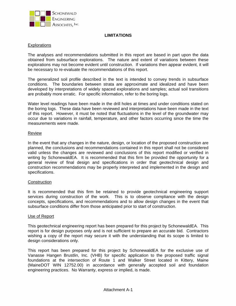
LIMITATIONS
Explorations The analyses and recommendations submitted in this report are based in part upon the data obtained from subsurface explorations. The nature and extent of variations between these explorations may not become evident until construction. If variations then appear evident, it will be necessary to re-evaluate the recommendations of this report. The generalized soil profile described in the text is intended to convey trends in subsurface conditions. The boundaries between strata are approximate and idealized and have been developed by interpretations of widely spaced explorations and samples; actual soil transitions are probably more erratic. For specific information, refer to the boring logs. Water level readings have been made in the drill holes at times and under conditions stated on the boring logs. These data have been reviewed and interpretations have been made in the text of this report. However, it must be noted that fluctuations in the level of the groundwater may occur due to variations in rainfall, temperature, and other factors occurring since the time the measurements were made. Review In the event that any changes in the nature, design, or location of the proposed construction are planned, the conclusions and recommendations contained in this report shall not be considered valid unless the changes are reviewed and conclusions of this report modified or verified in writing by SchonewaldEA. It is recommended that this firm be provided the opportunity for a general review of final design and specifications in order that geotechnical design and construction recommendations may be properly interpreted and implemented in the design and specifications. Construction It is recommended that this firm be retained to provide geotechnical engineering support services during construction of the work. This is to observe compliance with the design concepts, specifications, and recommendations and to allow design changes in the event that subsurface conditions differ from those anticipated prior to start of construction. Use of Report This geotechnical engineering report has been prepared for this project by SchonewaldEA. This report is for design purposes only and is not sufficient to prepare an accurate bid. Contractors wishing a copy of the report may secure it with the understanding that its scope is limited to design considerations only. This report has been prepared for this project by SchonewaldEA for the exclusive use of Vanasse Hangen Brustlin, Inc. (VHB) for specific application to the proposed traffic signal foundations at the intersection of Route 1 and Walker Street located in Kittery, Maine (MaineDOT WIN 12752.00) in accordance with generally accepted soil and foundation engineering practices. No Warranty, express or implied, is made.

ATTACHMENT B
SUBSURFACE EXPLORATION LOGS
Boring No.Page
File No.Check
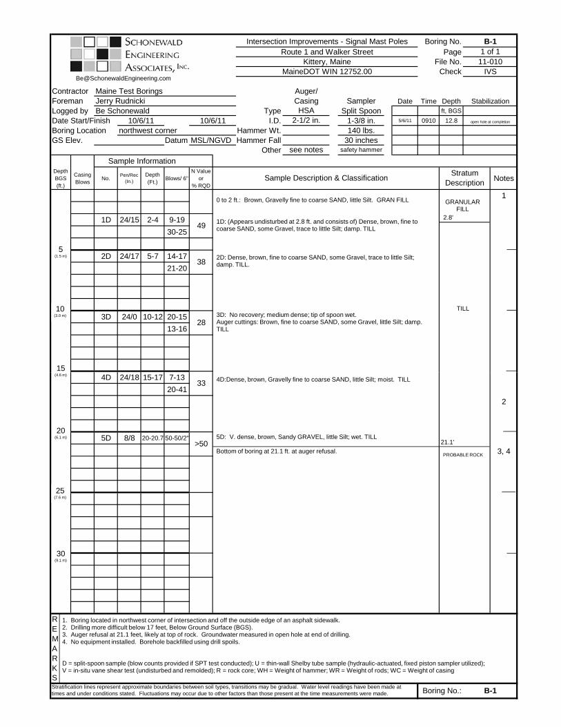
Contractor Maine Test Borings Auger/Foreman Jerry Rudnicki Casing Sampler Date Time Depth
Logged by Be Schonewald Type Split Spoon ft, BGS
Date Start/Finish 10/6/11 10/6/11 I.D. 1-3/8 in. 5/6/11 0910 12.8
Boring Location northwest corner Hammer Wt. 140 lbs.GS Elev. Datum MSL/NGVD Hammer Fall 30 inches
OtherSample Information
Depth BGS (ft.)
Casing Blows
No.Pen/Rec
(In.)Depth (Ft.)
Blows/ 6"N Value
or% RQD
Notes
1
1D 24/15 2-4 9-19
30-25
2D 24/17 5-7 14-17
21-20
3D 24/0 10-12 20-15
13-1628
38
see notes safety hammer
Sample Description & ClassificationStratum
Description
49
IVS
HSA2-1/2 in.
MaineDOT WIN 12752.00
open hole at completion
Stabilization
Intersection Improvements - Signal Mast Poles B-1Route 1 and Walker Street 1 of 1
Kittery, Maine 11-010
5(1.5 m)
10(3.0 m)
15
0 to 2 ft.: Brown, Gravelly fine to coarse SAND, little Silt. GRAN FILL
1D: (Appears undisturbed at 2.8 ft. and consists of) Dense, brown, fine to coarse SAND, some Gravel, trace to little Silt; damp. TILL
2D: Dense, brown, fine to coarse SAND, some Gravel, trace to little Silt; damp. TILL.
3D: No recovery; medium dense; tip of spoon wet.Auger cuttings: Brown, fine to coarse SAND, some Gravel, little Silt; damp. TILL
TILL
GRANULAR FILL
2.8'
4D 24/18 15-17 7-13
20-41
2
5D 8/8 20-20.7 50-50/2"
3, 4
REMARKSStratification lines represent approximate boundaries between soil types, transitions may be gradual. Water level readings have been made at times and under conditions stated. Fluctuations may occur due to other factors than those present at the time measurements were made.
>50
33
Boring No.: B-1
1. Boring located in northwest corner of intersection and off the outside edge of an asphalt sidewalk.2. Drilling more difficult below 17 feet, Below Ground Surface (BGS).3. Auger refusal at 21.1 feet, likely at top of rock. Groundwater measured in open hole at end of drilling.4. No equipment installed. Borehole backfilled using drill spoils.
D = split-spoon sample (blow counts provided if SPT test conducted); U = thin-wall Shelby tube sample (hydraulic-actuated, fixed piston sampler utilized); V = in-situ vane shear test (undisturbed and remolded); R = rock core; WH = Weight of hammer; WR = Weight of rods; WC = Weight of casing
(4.6 m)
20(6.1 m)
30(9.1 m)
25(7.6 m)
4D:Dense, brown, Gravelly fine to coarse SAND, little Silt; moist. TILL
5D: V. dense, brown, Sandy GRAVEL, little Silt; wet. TILL
Bottom of boring at 21.1 ft. at auger refusal.PROBABLE ROCK
21.1'

Boring No.Page
File No.Check
Contractor Maine Test Borings Auger/Foreman Jerry Rudnicki Casing Sampler Date Time Depth
Logged by Be Schonewald Type Split Spoon ft, BGS
Date Start/Finish 10/6/11 10/6/11 I.D. 1-3/8 in.Boring Location southwest corner Hammer Wt. 140 lbs.GS Elev. Datum MSL/NGVD Hammer Fall 30 inches
OtherSample Information
Depth BGS (ft.)
Casing Blows
No.Pen/Rec
(In.)Depth (Ft.)
Blows/ 6"N Value
or% RQD
Notes
1
1D 24/14 2-4 19-17
27-27
2D 24/13 5-7 35-15
10-11
3D 24/1 10-12 11-11
8-8
R1 9/7 13.6-14.3 0%
R2 51/46 14.3-18.6
19
25
NQ2 core safety hammer
Sample Description & ClassificationStratum
Description
44
3 in.
MaineDOT WIN 12752.00 IVS
StabilizationNW
Intersection Improvements - Signal Mast Poles B-2Route 1 and Walker Street 1 of 1
Kittery, Maine 11-010
5(1.5 m)
10(3.0 m)
15
0 to 0.4 ft: ASPHALT 0.4 to 2 ft.: Brown, Gravelly fine to coarse SAND, little Silt. GRAN FILL
1D: (Appears undisturbed at 2.8 ft. and consists of) Dense, brown, Sandy GRAVEL, trace to little Silt; damp. TILL
2D: M. dense, brown, Sandy GRAVEL, trace to little Silt; damp. TILL.
3D: Poor recovery; medium dense; possibly pushing rock ahead of spoon. TILL
R1 and R2: Light gray, fine grained, hard, fresh to slightly weathered, META-SANDSTONE. Some cross-bedding (calcereous felspathic) veins and possible breciated zones. No distinct foliation or jointing. R1 consists of gravel-sized pieces of rock (RQD=0"/9"=0%). R2 somewhat more intact (RQD=8"/51"=16%) Core times:
TILL
GRANULAR FILL
ASPHALT
2.8'
0.4'
13.6'
2, 3
REMARKSStratification lines represent approximate boundaries between soil types, transitions may be gradual. Water level readings have been made at times and under conditions stated. Fluctuations may occur due to other factors than those present at the time measurements were made. Boring No.: B-2
16%
1. Boring located in southwest corner of intersection in Route 1 southbound travelway.2. Boring terminated at 18.6 feet, approximately 5 feet into rock.3. No equipment installed. Borehole backfilled using drill spoils and manufactured sand and gravel; pavement patched.
D = split-spoon sample (blow counts provided if SPT test conducted); U = thin-wall Shelby tube sample (hydraulic-actuated, fixed piston sampler utilized); V = in-situ vane shear test (undisturbed and remolded); R = rock core; WH = Weight of hammer; WR = Weight of rods; WC = Weight of casing
(4.6 m)
20(6.1 m)
30(9.1 m)
25(7.6 m)
(RQD=8 /51 =16%). Core times:13.6 to 14.6 ft. 4:15 min/ft14.6 to 15.6 ft. 3:4515.6 to 16.6 ft. 4:1516.6 to 17.6 ft. 4:5517.6 to 18.6 ft. 4:45
Bottom of boring at 18.6 ft.
KITTERY FM(META-
SANDSTONE)

Boring No.Page
File No.Check
Contractor Maine Test Borings Auger/Foreman Jerry Rudnicki Casing Sampler Date Time Depth
Logged by Be Schonewald Type Split Spoon ft, BGS
Date Start/Finish 10/6/11 10/6/11 I.D. 1-3/8 in. 5/6/11 1330 8.0
Boring Location southeast corner Hammer Wt. 140 lbs.GS Elev. Datum MSL/NGVD Hammer Fall 30 inches
OtherSample Information
Depth BGS (ft.)
Casing Blows
No.Pen/Rec
(In.)Depth (Ft.)
Blows/ 6"N Value
or% RQD
Notes
1
1D 24/18 2-4 14-19
14-9
2D 24/15 5-7 2-2
3-5
2
3D 1/0 10-10.1 50/1" 3, 4
5
see notes safety hammer
Sample Description & ClassificationStratum
Description
33
2-1/2 in. open hole at completion
MaineDOT WIN 12752.00 IVS
StabilizationHSA
Intersection Improvements - Signal Mast Poles B-3Route 1 and Walker Street 1 of 1
Kittery, Maine 11-010
5(1.5 m)
10(3.0 m)
15
0 to 2 ft.: Brown, fine to medium SAND, some Gravel, trace Silt. GRAN FILL
2.0 to 3.5 ft.: Dense, brown, fine to medium SAND, some Gravel,trace Silt; damp. GRAN FILL
1D: 3.5 to 4.0 ft.: Black-brown, fine to medium SAND, little Silt, trace Gravel, with cinders and crushed brick; damp. MISC URBAN FILL
2D: Red-brown, fine to medium SAND, trace Silt; damp. Changing at 6.1 ft. to dark grayish brown, fine to coarse SAND, little Silt, with crushed brick; moist. MISC URBAN FILL Undisturbed till in tip of spoon.
3D: No recovery; spoon wet; auger cuttings consist of pieces ground rock.
Bottom of boring at 10.3 ft. at auger refusal.
MISC URBAN FILL
TILL
GRANULAR FILL
PROBABLE ROCK
3.5'
10.3'
7.0'
REMARKSStratification lines represent approximate boundaries between soil types, transitions may be gradual. Water level readings have been made at times and under conditions stated. Fluctuations may occur due to other factors than those present at the time measurements were made. Boring No.: B-3
1. Boring located in southeast corner of intersection in grass island.2. Drilling more difficult below 9.4 feet, Below Ground Surface (BGS).3. Auger refusal at 10.3 feet, likely at top of rock. Groundwater measured in open hole at end of drilling.4. No equipment installed. Borehole backfilled using drill spoils.
D = split-spoon sample (blow counts provided if SPT test conducted); U = thin-wall Shelby tube sample (hydraulic-actuated, fixed piston sampler utilized); V = in-situ vane shear test (undisturbed and remolded); R = rock core; WH = Weight of hammer; WR = Weight of rods; WC = Weight of casing
(4.6 m)
20(6.1 m)
30(9.1 m)
25(7.6 m)

Boring No.Page
File No.Check
Contractor Maine Test Borings Auger/Foreman Jerry Rudnicki Casing Sampler Date Time Depth
Logged by Be Schonewald Type Split Spoon ft, BGS
Date Start/Finish 10/6/11 10/6/11 I.D. 1-3/8 in.Boring Location northeast corner Hammer Wt. 140 lbs.GS Elev. Datum MSL/NGVD Hammer Fall 30 inches
OtherSample Information
Depth BGS (ft.)
Casing Blows
No.Pen/Rec
(In.)Depth (Ft.)
Blows/ 6"N Value
or% RQD
Notes
1
1D 24/13 2-4 4-9
23-26
2D 24/14 5-7 23-17
12-11
3D 13/1 10-11.1 >104
R1 25/22 11.2-13.3
R2 19/19 13.3-14.9
2, 347%
0%
29
NQ2 core safety hammer
Sample Description & ClassificationStratum
Description
32
3 in.
MaineDOT WIN 12752.00 IVS
StabilizationNW
Intersection Improvements - Signal Mast Poles B-4Route 1 and Walker Street 1 of 1
Kittery, Maine 11-010
5(1.5 m)
10(3.0 m)
15
0 to 2 ft.: Brown, fine to medium SAND, some Gravel, trace Silt. GRAN FILL
1D: Dense, brown, fine to medium SAND, little to some Gravel, trace to little Silt. GRAN FILL
2D: M. dense, reddish brown, fine to medium SAND, little to some fine Gravel, trace Silt, with minor amounts cinders; damp. MISC URBAN FILL.
3D: Poor recovery consisting of pieces ground rock.R1 and R2: Light gray, fine grained, hard, fresh to slightly weathered, META-SANDSTONE. Some cross-bedding (calcereous felspathic) veins and possible breciated zones consisting of gravel-sized pieces of rock with mud. No distinct foliation or jointing. (R1 RQD=0"/25"=0%; R2 RQD=9"/19"=47%). Core times:11.2 to 12.2 ft. 3:35 min/ft12.2 to 13.2 ft. 2:5013.2 to 14.2 ft. 3:10Bottom of boring at 14 9 ft
MISC URBAN FILL
TILL
GRANULAR FILL
4.0'±
8.5'±
11.2'
KITTERY FM(META-
SANDSTONE)
44-5450/1"
REMARKSStratification lines represent approximate boundaries between soil types, transitions may be gradual. Water level readings have been made at times and under conditions stated. Fluctuations may occur due to other factors than those present at the time measurements were made. Boring No.: B-4
1. Boring located in northeast corner of intersection in grass island.2. Boring terminated at 14.9 feet, approximately 3.7 feet into rock.3. No equipment installed. Borehole backfilled using drill spoils and manufactured sand and gravel.
D = split-spoon sample (blow counts provided if SPT test conducted); U = thin-wall Shelby tube sample (hydraulic-actuated, fixed piston sampler utilized); V = in-situ vane shear test (undisturbed and remolded); R = rock core; WH = Weight of hammer; WR = Weight of rods; WC = Weight of casing
(4.6 m)
20(6.1 m)
30(9.1 m)
25(7.6 m)
Bottom of boring at 14.9 ft.