section 1 highway maintenance guidelines table of · pdf filehighway maintenance guidelines...
TRANSCRIPT

HHIIGGHHWWAAYY MMAAIINNTTEENNAANNCCEE GGUUIIDDEELLIINNEESS AANNDD LLEEVVEELL OOFF SSEERRVVIICCEE MMAANNUUAALL
June 14, 2000 ( i )
SSEECCTTIIOONN 11 –– HHIIGGHHWWAAYY MMAAIINNTTEENNAANNCCEE GGUUIIDDEELLIINNEESS
TTAABBLLEE OOFF CCOONNTTEENNTTSS
INTRODUCTION .......................................................................................................................................................1
GUIDING PRINCIPLES .................................................................................................................................................2 RESOURCE ALLOCATION STRATEGY .........................................................................................................................2 RESPONSIBILITIES SUMMARY ....................................................................................................................................3 MUNICIPAL LIAISON..................................................................................................................................................6
1.0 WINTER MAINTENANCE .............................................................................................................................7
1.1 PREPARATION FOR WINTER..............................................................................................................................7 1.2 GUIDELINES .....................................................................................................................................................7 1.3 STRATEGIES .....................................................................................................................................................9
1.3.1 Snow Clearing – Paved Roads...............................................................................................................9 1.3.2 Ice Control Operations – Paved Roads ...............................................................................................10 1.3.3 Snow And Ice Control – Gravel Roads ................................................................................................13
1.4 SNOWFENCE...................................................................................................................................................14
2.0 SURFACE MAINTENANCE – PAVEMENT...............................................................................................15
2.1 PAVEMENT REPAIR – GUIDELINES .................................................................................................................15 2.2 PAVEMENT REPAIR – STRATEGIES .................................................................................................................15 2.3 CRACKSEALING .............................................................................................................................................16
2.3.1 Guidelines ............................................................................................................................................16 2.3.2 Strategies .............................................................................................................................................17
3.0 SURFACE MAINTENANCE - GRAVEL.....................................................................................................18
3.1 GUIDELINES ...................................................................................................................................................18 3.2 ROADWAY SURFACE MAINTENANCE .............................................................................................................18 3.3 SHOULDER MAINTENANCE.............................................................................................................................19 3.4 SURFACE REGRAVELLING ..............................................................................................................................19 3.5 DUST CONTROL .............................................................................................................................................20
4.0 RIGHT-OF-WAY MAINTENANCE.............................................................................................................21
4.1 RAILWAY CROSSING MAINTENANCE .............................................................................................................21 4.2 DELINEATORS ................................................................................................................................................21 4.3 GUARDRAIL ...................................................................................................................................................21 4.4 MOWING ........................................................................................................................................................22
4.4.1 Burning ................................................................................................................................................23 4.5 HAY PERMITS.................................................................................................................................................23 4.6 WEED CONTROL ............................................................................................................................................23 4.7 BRUSH CONTROL ...........................................................................................................................................24 4.8 LITTER CLEAN UP..........................................................................................................................................24 4.9 DRAINAGE SYSTEMS ......................................................................................................................................25
4.9.1 Culverts................................................................................................................................................25 4.9.2 Ditches .................................................................................................................................................26 4.9.3 Beaver Dams........................................................................................................................................26 4.9.4 Storm Sewer .........................................................................................................................................27 4.9.5 Curb and Gutter...................................................................................................................................27 4.9.6 Sidewalk...............................................................................................................................................27
5.0 TRAFFIC CONTROL DEVICES ..................................................................................................................28
5.1 SIGNING .........................................................................................................................................................28
HHIIGGHHWWAAYY MMAAIINNTTEENNAANNCCEE GGUUIIDDEELLIINNEESS AANNDD LLEEVVEELL OOFF SSEERRVVIICCEE MMAANNUUAALL
June 14, 2000 ( ii )
5.1.1 Standards .............................................................................................................................................28 5.1.2 Inventory Information ..........................................................................................................................28 5.1.3 Maintenance ........................................................................................................................................28 5.1.4 Responsibility.......................................................................................................................................29
5.2 TRAFFIC SIGNALS ..........................................................................................................................................29 5.3 PEDESTRIAN SIGNALS ....................................................................................................................................30 5.4 EMERGENCY VEHICLE ACCESS SIGNALS .......................................................................................................30 5.5 LINE PAINTING...............................................................................................................................................31 5.6 MESSAGE PAINTING.......................................................................................................................................31
5.6.1 Stop Bar Painting At Intersections ......................................................................................................31 5.6.2 Pedestrian Crosswalk Marking............................................................................................................31
5.7 REMOVAL OF NON-CONFORMING SIGNS ........................................................................................................32
6.0 ROADWAY ILLUMINATION ......................................................................................................................34
7.0 SPRING CLEANUP ........................................................................................................................................35
7.1 WASHING BRIDGES ........................................................................................................................................35 7.2 SWEEPING ......................................................................................................................................................35
7.2.1 Sweeping/Cleaning Raised Medians....................................................................................................36
8.0 LIVESTOCK GUARDS ..................................................................................................................................37
HHIIGGHHWWAAYY MMAAIINNTTEENNAANNCCEE GGUUIIDDEELLIINNEESS AANNDD LLEEVVEELL OOFF SSEERRVVIICCEE MMAANNUUAALL
June 14, 2000 ( iii )
SSEECCTTIIOONN 22 –– BBRRIIDDGGEE MMAAIINNTTEENNAANNCCEE GGUUIIDDEELLIINNEESS
TTAABBLLEE OOFF CCOONNTTEENNTTSS
INTRODUCTION .....................................................................................................................................................38
BACKGROUND .........................................................................................................................................................38
1.0 TIMBER STRIPDECK MAINTENANCE....................................................................................................39
2.0 REPAIR TIMBER BRIDGERAILS, POSTS AND FLEXBEAM RAILS..................................................39
3.0 INSTALL/REPAIR FLEXBEAM ON BRIDGE APPROACHES ..............................................................39
4.0 INSTALLATION OF LOAD POSTING SIGNS ..........................................................................................40
5.0 INSTALLATION/REPLACEMENT OF HAZARD MARKERS ...............................................................40
6.0 ROAD CLOSURE ASSOCIATED WITH BRIDGES..................................................................................40
7.0 SMALL AREA CONCRETE PATCHING ...................................................................................................40
8.0 BANDING SPLIT PILES................................................................................................................................41
9.0 REPAIR OF BRIDGE ABUTMENT WASHOUTS .....................................................................................41
10.0 HIGH BACKWALL ABUTMENT – REPAIR OF BACKWALL SCOUR ..........................................41
11.0 PLACING STRUTS ON STANDARDS BRIDGES.................................................................................42
12.0 RESTORATION OF BRIDGE HEADSLOPES.......................................................................................42
13.0 BRIDGE WASHING ..................................................................................................................................43
14.0 SITE CLEANUP .........................................................................................................................................43
15.0 REMOVE BEAVER DAM.........................................................................................................................43
16.0 TIMBER STRUTTING OF METAL CULVERTS..................................................................................44
17.0 MAINTENANCE OF BRIDGE STRUCTURES ON LOCAL ROADS ................................................44
17.1 ISSUE.........................................................................................................................................................44 17.2 BACKGROUND ...........................................................................................................................................44
18.0 MAINTENANCE OF BRIDGE STRUCTURES ON PROVINCIAL HIGHWAY SYSTEM .............45
18.1 BACKGROUND ...........................................................................................................................................45 18.2 RECOMMENDED GUIDELINES ....................................................................................................................45

HHIIGGHHWWAAYY MMAAIINNTTEENNAANNCCEE GGUUIIDDEELLIINNEESS AANNDD LLEEVVEELL OOFF SSEERRVVIICCEE MMAANNUUAALL
June 14, 2000 (1)
INTRODUCTION The province will assume full direction, management, and control of the Secondary Highway network by September 2001. These secondary highways will be re-designated as provincial highways and included as part of the new Provincial Highway system. In recognition of the many and varied needs of the expanded network, this manual will: 9 Provide users with information regarding maintenance standards and levels of service being
provided on the new provincial highway network. 9 Outline the department’s responsibilities related to the delivery of maintenance activities on
Alberta’s provincial highways. 9 Ensure uniformity and consistency of the maintenance service levels provided across the
province. This manual is not intended to replace or modify the contents of the department’s existing maintenance contracts. If a conflict or ambiguity exists between this manual and the contract, the user should contact the department for clarification. Users should note that this manual, by itself, does not provide a complete record of all processes and procedures related to the delivery of maintenance activities. Other department manuals, which must be considered, are as follows: 9 Contract Administration Manual - Highway and Bridge Maintenance 9 Highway Maintenance Specifications 9 Bridge Maintenance Standards 9 Alberta Highway Pavement Marking Guide 9 Traffic Accommodation in Work Zones Manual 9 Manual of Uniform Traffic Control Devices for Canada 9 Alberta Highway Geometric Design Guide Any omissions, obvious errors, or recommendations for future updates should be forwarded to the Director, Maintenance, Specification and Traffic Engineering of the department’s Technical Standards Branch.

HHIIGGHHWWAAYY MMAAIINNTTEENNAANNCCEE GGUUIIDDEELLIINNEESS AANNDD LLEEVVEELL OOFF SSEERRVVIICCEE MMAANNUUAALL
June 14, 2000 (2)
GUIDING PRINCIPLES To maintain a rational, equitable and appropriate level of service for the new provincial highway network, the following guiding principles are established: 9 All highways in Alberta shall serve Albertans with the same basic integrity and functionality,
regardless of their current network designation. The new expanded provincial highway network shall serve as a reliable, dependable core transportation network, across Alberta.
9 Resource allocation decisions are to be made on the basis of priority and need, regardless of
their history and previous standing in the network. 9 Open and clear communications between the department and all of the effected municipal
jurisdictions is necessary. Obtaining municipal input and maintaining “open” lines of communication will enable the department to responsibly address any “special requirements or situations” that may currently exist. (See Municipal Liaison)
9 While it remains the government policy not to contract directly to another level of
government, Alberta Infrastructure will not interfere with the private sector maintenance contractors in terms of the most effective delivery of the highway maintenance.
9 Regardless of the traffic volumes, all highways within the provincial highway network will
have minimum standards for service and serve as part of a reliable, dependable transportation system.
RESOURCE ALLOCATION STRATEGY To ensure the guiding principles are met, the following should be done: 9 All highways (secondary and primary) shall have winter resources allocated to them, on the
basis of greatest need and overall benefit to the public safety. 9 Non-winter resource allocation decisions are to be made wherever required within the
system, on the basis of the greatest cost/benefit. 9 Traditional maintenance practices will be respected if the practices are consistent with wise
and economic application of resources, for that particular type of roadway. 9 Throughout the entire expanded network, sufficient snow removal equipment will be
provided and distributed to ensure the ability of the equipment to respond to all areas of the network. See Table 1, “Winter Level of Service Guidelines for Highways”.
9 Towns and Villages represent a different situation than most of the length of the rural
highway network. Traffic volumes are commonly higher within the urban municipality and frequently important intersections may exist, within the urban municipality. Depending on the situation, special attention may be required and must be identified to the Contractor.
HHIIGGHHWWAAYY MMAAIINNTTEENNAANNCCEE GGUUIIDDEELLIINNEESS AANNDD LLEEVVEELL OOFF SSEERRVVIICCEE MMAANNUUAALL
June 14, 2000 (3)
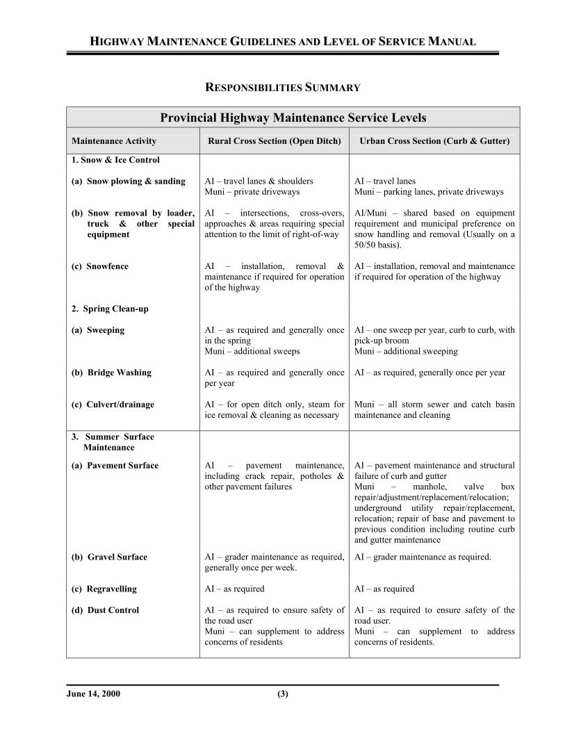
RESPONSIBILITIES SUMMARY
Provincial Highway Maintenance Service Levels
Maintenance Activity Rural Cross Section (Open Ditch) Urban Cross Section (Curb & Gutter)
1. Snow & Ice Control
(a) Snow plowing & sanding AI – travel lanes & shoulders Muni – private driveways
AI – travel lanes Muni – parking lanes, private driveways
(b) Snow removal by loader, truck & other special equipment
AI – intersections, cross-overs, approaches & areas requiring special attention to the limit of right-of-way
AI/Muni – shared based on equipment requirement and municipal preference on snow handling and removal (Usually on a 50/50 basis).
(c) Snowfence AI – installation, removal & maintenance if required for operation of the highway
AI – installation, removal and maintenance if required for operation of the highway
2. Spring Clean-up
(a) Sweeping AI – as required and generally once in the spring Muni – additional sweeps
AI – one sweep per year, curb to curb, with pick-up broom Muni – additional sweeping
(b) Bridge Washing AI – as required and generally once per year
AI – as required, generally once per year
(c) Culvert/drainage AI – for open ditch only, steam for ice removal & cleaning as necessary
Muni – all storm sewer and catch basin maintenance and cleaning
3. Summer Surface Maintenance
(a) Pavement Surface AI – pavement maintenance, including crack repair, potholes & other pavement failures
AI – pavement maintenance and structural failure of curb and gutter Muni – manhole, valve box repair/adjustment/replacement/relocation; underground utility repair/replacement, relocation; repair of base and pavement to previous condition including routine curb and gutter maintenance
(b) Gravel Surface AI – grader maintenance as required, generally once per week.
AI – grader maintenance as required.
(c) Regravelling AI – as required AI – as required
(d) Dust Control AI – as required to ensure safety of the road user Muni – can supplement to address concerns of residents
AI – as required to ensure safety of the road user. Muni – can supplement to address concerns of residents.

HHIIGGHHWWAAYY MMAAIINNTTEENNAANNCCEE GGUUIIDDEELLIINNEESS AANNDD LLEEVVEELL OOFF SSEERRVVIICCEE MMAANNUUAALL
June 14, 2000 (4)
Provincial Highway Maintenance Service Levels
Maintenance Activity Rural Cross Section (Open Ditch) Urban Cross Section (Curb & Gutter)
(e) Line Painting (centre, shoulder and lane lines)
AI – all line painting maintained in good condition
AI – centre line, shoulder line, lane line maintained in good condition Muni – all parking markings
(f) Message Painting including stop bars, pedestrian cross walks
AI – maintain in good condition AI – (except parking control) maintain in good condition Muni – parking control and painting of curbs
4. Right-of-Way Maintenance
(a) Vegetation Control AI – weed control, brushing and mowing normally two shoulder cuts per year, and full right-of-way once per year only on high volume traffic highways. Generally full right-of-way cuts once every three years for brush control. Muni – can supplement mowing at their own cost
AI – weed control in cooperation with Muni Muni – mowing boulevards and raised medians
(b) Hay Permits AI – will issue hay permits where practice is appropriate
Not applicable
(c) Sidewalk, bike paths, walkways, etc.
Muni – maintenance, repair, replacement and cleaning.
Muni – maintenance, repair, replacement and cleaning
(d) Street scapes, special landscaping, decorative lighting or other special features
Muni – supply, install, maintain, operate with prior approval by AI
Muni – supply, install, maintain, operate with prior approval by AI
5. Drainage (a) Culverts/bridges, storm
sewers
AI – culverts and bridge maintenance and repairs
AI – bridge and culvert maintenance repair and (initial capital cost on storm sewer based on highway share) Muni – ongoing operation and maintenance of storm sewer infrastructure including catch basins
(b) Geotechnical subdrain
AI – maintain if installed to serve the needs of the highway
AI – maintain if installed to serve the needs of the highway

HHIIGGHHWWAAYY MMAAIINNTTEENNAANNCCEE GGUUIIDDEELLIINNEESS AANNDD LLEEVVEELL OOFF SSEERRVVIICCEE MMAANNUUAALL
June 14, 2000 (5)
6. Traffic Control
(a) Traffic/Pedestrian Signals/Flashing Beacons
AI – installation, maintenance and operation if warrants are met Muni – may be permitted to install & maintain if warrants are not met
AI – will install, maintain and operate if meets warrants Muni – may be permitted to install and maintain if warrants are not met
(b) Emergency Vehicle Access Signals
Muni – installing, operating and maintenance of all devices
Muni – installation, operation and maintenance of all devices
(c) Delineation Posts & Guardrail
AI – supply, install and maintain all within right-of-way
AI – supply, install and maintain all within right-of-way
(d) Speed Limits AI – establishes, province enforces speed limits unless delegated to the Muni.
AI – establishes, province to enforces speed limits unless delegated to the Muni
(e) Parking AI – will enforce parking restrictions, province provide authority to municipalities, where appropriate
AI – province to provide authority to the Municipalities
7. Illumination (1)
(a) AI System (meets warrants)
AI – install, operate and maintain
AI – install, operate and maintain
(2) (b) Municipal System (meets
warrants)
AI – install Muni – operation and maintenance
AI – install Muni – operation and maintenance
(c) Municipal System Sentry Lighting (meets warrants)
AI – install Muni – operation and maintenance
AI – install Muni – operation and maintenance
8. SIGNS
(a) Regulatory AI – supply, install and maintain within right-of-way Muni – install if special mounting requested by Muni
AI – supply, install and maintain within right-of-way Muni – install if special mounting requested by Muni
(b) Guide/Destination AI – supply, install and maintain Muni – install if special mounting requested by Muni
AI – supply, install and maintain Muni – install if special mounting requested by Muni
(c) Parking Other Facility Signs
Muni – supply, install and maintain Muni – supply, install and maintain
AI: Alberta Infrastructure Muni: Municipalities (Towns, Villages & Hamlets) Note 1 An Alberta Infrastructure (AI) system is one where the primary purpose of highway lighting is strictly for traffic reasons. These locations generally relate to interchanges and at highway intersections where traffic warrants are met. Note 2 A municipal system is one where the primary purpose is to provide a safe environment for community activities including pedestrian traffic, commercial business, and diverse roadway users activity.
HHIIGGHHWWAAYY MMAAIINNTTEENNAANNCCEE GGUUIIDDEELLIINNEESS AANNDD LLEEVVEELL OOFF SSEERRVVIICCEE MMAANNUUAALL
June 14, 2000 (6)
MUNICIPAL LIAISON Alberta Infrastructure will maintain “open and close” communications with local municipal officials. The focus of these meetings will be to address problems or issues that may arise related to the maintenance and operations of the new provincial highway network. The Operations Manager will establish an “open invitation” policy for meetings and provide municipalities with a regular opportunity to “book an appointment” whenever necessary. It is desirable that each municipal jurisdiction provides the name of their representative that will commonly work with the Maintenance Contractor and other department staff, on highway maintenance issues. This should assist in a common interface between the parties and reduce any confusion that may occur. Public communications is also important. The department’s Operations Manager together with the maintenance contractor will implement a system to facilitate effective two-way communications with the public. This may include mail-outs, newspaper ads, publicized phone numbers, highway signs, etc.
SSEECCTTIIOONN 11 –– HHIIGGHHWWAAYY MMAAIINNTTEENNAANNCCEE GGUUIIDDEELLIINNEESS
June 14, 2000 (7)
1.0 WINTER MAINTENANCE
1.1 PREPARATION FOR WINTER The department will estimate the next winter’s requirement of calcium chloride, sodium chloride (salt) and sand in the spring of each year, including amounts necessary for freeze proofing winter sand stockpiles. Freeze proofed winter sand must be stockpiled at appropriate locations before winter. Inventories of salt, calcium chloride and sand must be monitored throughout the winter season to ensure adequate supplies are available. All equipment must be in place before the onset of winter with sufficient number of trained staff. All sanding units must be calibrated to ensure that sand and deicing chemicals can be applied at the proper rates. Positive communications with the RCMP and the AMA must be established to ensure accurate road condition information is released to the public. It is important that all parties accurately and properly advise the public when highway conditions have deteriorated below “good winter driving condition”.
1.2 GUIDELINES
Snow removal and ice control operations differ throughout the province due to influences of terrain, precipitation, temperature, wind and chinooks, etc. Regardless of these influences, the department and the contractor shall ensure that the minimum level of service is maintained. Alberta Infrastructure will not provide snow removal services for the purpose of driveway clearing. The information provided in Table 1, Winter Level of Service (Rural Highways), illustrate the minimum acceptable levels of service for snow clearing within rural and urban locations. The department’s past experience with winter operations on the Provincial Highway System has indicated that the actual service level delivered exceeds the minimum levels by quite a substantial margin. Appropriate equipment and manpower should be available to provide the level of service as indicated in Table 1 for each highway classification.

SSEECCTTIIOONN 11 –– HHIIGGHHWWAAYY MMAAIINNTTEENNAANNCCEE GGUUIIDDEELLIINNEESS
June 14, 2000 (8)
Table 1 – Winter Level of Service (Rural Highways)
Class of Highway
Traffic Volume (AADT)
Maximum Reaction Time•
(hrs)
Maximum Time to Good
Winter Driving Conditions••
(hrs)
Typical reaction Time
(hrs)
A > 15,000 2 6 1 B 7,000 – 15,000 4 6 1 C 5,000 – 7,000 4 8 2 D 2,000 – 5,000 4 8 2 E 1,000 – 2,000 6 12 3 F 500 – 1,000 8 12 3 G 100 – 500 12 18 4 H < 100 16 24 5
• Maximum time allowable for equipment to have commenced work from the time
of a 3cm accumulation. This value represents the maximum time that will be required to respond after an average winter storm. Normally, equipment will begin work during most storm events and as a result most roads are cleared faster than the maximum time indicated.
•• Good winter driving conditions exist when snow and ice have been removed from
the driving lanes and excessive loose snow has been removed from the shoulders and centreline of highway. Short sections of ice and packed snow are acceptable and can be expected within the driving lanes between the wheel paths, as well as on centreline.
An average winter snowstorm is defined as one in which snowfall amounts range between 3 and 8 centimetres, the air temperature is lower than -10°C, the wind velocity is less than 15 kilometres per hour and the road surface is frozen. EXEMPTIONS TO THE ABOVE TABLE - Predefined “hotspots” will require a quicker response time. Hotspots are locations that have been identified as special feature areas within the maintenance contract.
A specified percentage of the plow-truck fleet must be available for dispatching well within the maximum reaction time, with the remainder available for dispatch before the end of the maximum time. The impact of salt on the environment is a growing concern on a global scale. The department’s operations are being scrutinized to ensure the use of salt is minimized and contamination is eliminated. The importance of eliminating salt contamination of the environment is critical to the operation and adequate preventative measures should be followed. The TAC Salt Management Guide has more information about proper salt use and storage.
SSEECCTTIIOONN 11 –– HHIIGGHHWWAAYY MMAAIINNTTEENNAANNCCEE GGUUIIDDEELLIINNEESS
June 14, 2000 (9)
In general, winter response for snow/ice control within urban cross-sections will follow the same guidelines as rural highways. Traffic volumes within Towns, Villages and Summer Villages are generally known and should be considered in the determination of “LOS”. Where traffic volumes and situations dictate, these urban areas will be defined as a “hot spot” within the department’s maintenance contract. Department and contractor staff will work closely with municipal officials to monitor delivered service levels at ‘hot spots’ both inside and immediately outside communities. Refer to “Responsibility Summary” for more information on snow clearing operations within an urban cross-section.
1.3 STRATEGIES
1.3.1 SNOW CLEARING – PAVED ROADS
Snowplowing of paved highways should commence before snow becomes packed by traffic, or when snow accumulations exceed 3 centimetres. To assist in providing timely response during changing winter conditions, maintenance staff must keep informed of weather forecasts. News of advancing storms should be communicated to neighboring maintenance areas. The basic strategy for snow removal and ice control is: first - remove as much snow or ice as possible with suitable plowing equipment and second - treat any remaining snow or ice with sand, salt, or a salt/sand combination to achieve good winter driving conditions within the required time frames. Plowing and deicing activities will continue, as weather and operational conditions permit, with the aim of eventually achieving bare pavement. Snowplows should pull over at reasonable intervals, usually about 5 to 8 kilometres when it is safe to do so, to allow traffic the opportunity to pass. When traffic is heavy, or rearward visibility is obscured, this interval should be shortened. Pulling over helps reduce any frustration experienced by motorists following the snowplow. Safety is the prime concern, and pulling over is a balance between minimizing inconvenience to the public and bringing the highway to “good winter driving conditions” in the shortest period possible. When plowing overpass structures, the operator must make sure snow is not plowed off the overpass while there are vehicles on the roadway below. Excessive accumulations of snow on overpass structures may have to be loaded onto trucks and hauled away.

SSEECCTTIIOONN 11 –– HHIIGGHHWWAAYY MMAAIINNTTEENNAANNCCEE GGUUIIDDEELLIINNEESS
June 14, 2000 (10)
Steep hills, curves, important intersections, and other areas known to create difficulties for traffic, should be attended to first. Priority should be given to higher volume highways to provide the best service to the greatest number of motorists. When roadway surface temperatures are too low for the use of salt, calcium chloride, other deicing chemicals and sand should be applied to maintain the best possible winter driving conditions. After the surface temperature of the roadway rises, applications of deicing chemical will remove snow and ice accumulations more quickly. Road surface temperature is often different from air temperatures, and application rates should be chosen based on road temperature, not air temperature. Once good winter driving conditions have been achieved along all routes, “cleanup” activities, including the plowing of shoulders, cross-overs, approaches, etc., can be started if snow and ice deposits are significant enough to be considered a hazard to traffic. Highways are to be kept open to traffic as long as conditions permit. If visibility is reduced to below 75 metres, or when, in the opinion of the equipment operator and area foreman, it is too hazardous to continue snowplowing, the equipment should be removed from the roadway to a safe location. Snowplowing should be resumed as soon as visibility improves sufficiently to allow operation at an acceptable level of safety. Occasionally, severe storms require that temporary highway closures be implemented. Each Operations Manager has been delegated the authority under the Public Highways Traffic Act to close highways. The public must be advised of all road closures in a timely manner. The local media should be made aware of all temporary road closures. Where available, changeable message signs and highway advisory radio systems should be used to inform the travelling public of road closures and/or poor driving conditions. It is important to ensure that news of the road re-opening is transmitted to the public promptly.
1.3.2 ICE CONTROL OPERATIONS – PAVED ROADS
Under many conditions, the application of proper amounts of deicing chemicals onto the roadway will help to remove packed snow, ice or frost, thereby improving traction and driving conditions. Salt (sodium chloride) and calcium chloride are the primary deicing agents used. Deicing chemicals should only be used on ice, frost or snow, which cannot be removed by snowplowing.

SSEECCTTIIOONN 11 –– HHIIGGHHWWAAYY MMAAIINNTTEENNAANNCCEE GGUUIIDDEELLIINNEESS
June 14, 2000 (11)
The application rate of salt varies considerably, depending on the surface condition being treated and the current and forecasted weather conditions. Experience and judgement must be used when determining application rates. Only the amount of salt necessary to do the job must be used. The proper use of deicing chemicals represents a cost efficient and effective use of resources. Timing of the application of salt is critical, especially when conditions for its use are marginal. There is little heat available from the sun in December and January and, ideally, salt is applied just as the surface begins to warm. This will help ensure that the salt is on the roadway surface during the warmest part of the day. Following these practices will maximize the effectiveness of salt in removing snow and ice. Use of salt when the temperature of the road surface is below –10 degrees Celsius is not justifiable. Salt loses its effectiveness rapidly under this temperature, and excessive amounts are necessary to achieve melting action. Under such conditions, straight sand or sand pre-wetted with a liquid deicing chemical should be applied to maintain the best possible driving conditions. When conditions are favorable, salt or a liquid deicer applied early in the storm will prevent the bond from forming between the pavement and packed snow. Much less salt is required to prevent the bond from forming than to melt packed snow after the snowfall has ended. Time is of the essence when chemical applications are involved. Often snow, sleet and freezing rain are created by rapidly advancing cold air. Temperatures can drop dramatically in a matter of hours. Any necessary chemicals must be applied quickly to allow as much time as possible for them to work. If timing of snow plowing and chemical applications are right, the highway will “freeze dry”. At low temperatures too much diluted brine on the roadway will freeze to ice. Table 2 provides guidelines for adjusting salt application rates under varying conditions.

SSEECCTTIIOONN 11 –– HHIIGGHHWWAAYY MMAAIINNTTEENNAANNCCEE GGUUIIDDEELLIINNEESS
June 14, 2000 (12)
Table 2 – Salt Application Guidelines
Rates kg of Salt per 2 lane km
Conditions (Road and Weather)
Factors Affecting Salt Application Rate
50 • temperature near 0° Celsius • light amounts of
snow/ice/frost
INCREASE RATE WHEN • temperatures are lower or
falling • road surface is cold • increased amounts of
snow/ice/frost • traffic flow is light and won’t
help break up ice 125 • temperature near -6° Celsius
• moderate amounts of snow/ice
225 • Temperature near -10° Celsius
• Thicker ice/snow • For temperatures below –10°
salt has limited effectiveness and straight sand should be used.
Decrease Rate When: • temperature surface is rising • road surface is warm • the sun is warming the road
surface • there are lesser amounts of
snow/ice • traffic volume is higher and
will help break up ice
Note: This table refers to the amounts of salt in a sand/salt mixture. At near-freezing temperatures, brine from the salt will be tracked by traffic several hundred metres beyond the area treated, so that intermittent applications of salt may give the same effect as a lighter, continuous application.
For example: If spreading a 50–50 mix of sand and salt at the suggested salt
application of 50kg per 2 lane kilometre, the total amount of 50-50 material being spread on the road would be 100 kg per 2 lane kilometre.
Caution: DO NOT USE SALT (SODIUM CHLORIDE) OR CALCIUM
(CALCIUM CHLORIDE) OR OTHER CORROSIVE CHEMICALS ON AIRPORT RUNWAYS, TAXIWAYS AND APRONS AS SERIOUS DAMAGE CAN OCCUR TO SPECIALIZED METALLIC COMPONENTS ON AIRCRAFT.

SSEECCTTIIOONN 11 –– HHIIGGHHWWAAYY MMAAIINNTTEENNAANNCCEE GGUUIIDDEELLIINNEESS
June 14, 2000 (13)
Sanding will improve traction and provide better winter driving conditions when temperatures are too low for the effective application of ice control chemicals. Typical sand application rates for providing traction are 1000 kg/2 lane km for heavy sanding, 500 - 700 kg/2 lane km for normal sanding, and 300 - 500 kg/2 lane km for reapplication of sand or light sanding. When temperatures are near –20 degrees Celsius, calcium chloride or other pre-wetting agents may be added to help imbed the sand particles into the ice surface. Adding 0.5 to 1.5 percent by weight of calcium chloride will promote this effect. The addition of too much calcium chloride will cause tracking and create icing. If snow is blowing across the highway without sticking, sand should not be applied unless the highway is dangerously slippery, as the sand will cause the snow to stick, aggravating drifting and icing problems. Ice Blading can be carried out when deicing chemicals are not effective and involve removal or roughening of ice and packed snow from the paved roadway surface with the aim of achieving good winter driving conditions. Under no circumstances will carbide tipped removable tooth blades (i.e. System 2000 ice blades) be used on paved surfaces. Ice blading on seal coated roads is not recommended, and should only be done with extreme caution. When snow accumulations at the edge of the paved surface exceed 30 centimetres, or when snow at the side of the road causes drifting, winging should be considered.
1.3.3 SNOW AND ICE CONTROL – GRAVEL ROADS
Plowing of gravel surface roadways should be commenced before snow accumulations reach 10-15 cm on the roadway. However, if drifting conditions prevail, plowing operations may be commenced sooner. In general, winter maintenance schedules are determined by weather conditions. Priority should be given to school bus routes and high traffic volume routes. Overall, priorities should be determined using local information. During the first snow fall, it is desirable to mix snow into the loose gravel to stabilize the surface material when it freezes. This minimizes future gravel loss from snow plowing. Ice blading may become necessary if the roadway becomes slippery due to compacted snow or ice. Ice blading roughens the surface for improved traction. Care must be taken to minimize gravel loss. Winging of snow into the ditch will be necessary before plowed snow accumulates to a depth of 30 cm along the shoulder edge.

SSEECCTTIIOONN 11 –– HHIIGGHHWWAAYY MMAAIINNTTEENNAANNCCEE GGUUIIDDEELLIINNEESS
June 14, 2000 (14)
1.4 SNOWFENCE
Snowfence should be placed in areas where snow drifting is prevalent to reduce snow accumulation on the roadway and to improve visibility. The location of the snowfence will be determined by local conditions and past experience. The Public Highways Development Act (Section 49) makes provisions for snowfence to be erected on private property without the necessity to pay rent or to provide other compensation. Good public relations require that the landowner be contacted prior to entry onto private property. Consent should be obtained from the landowner or lessee, and documented prior to commencing installations. Wherever the right-of-way is of sufficient width, installation of snowfence on private property should be avoided. Alberta Infrastructure and the maintenance contractor should work with the municipality to coordinate installation and removal in towns and villages. Fences should be checked and repaired periodically throughout the winter. Snowfencing should be installed after farming operations have been completed and prior to winter. Snowfence should be located 25-40 metres from the centerline of the roadway. Typically, the drift formed by the snowfence will extend for a distance of approximately 10 times its height. The snowfence should be removed early in the spring to avoid conflicts with the landowner’s operations. All debris must be removed from the property and properly disposed of (wire, lath, etc.). Permanent snow fence structures may be cost effective in some locations, and should be designed and installed in accordance with SHRP H-381 Design Guidelines for Control of Blowing and Drifting Snow.
SSEECCTTIIOONN 11 –– HHIIGGHHWWAAYY MMAAIINNTTEENNAANNCCEE GGUUIIDDEELLIINNEESS
June 14, 2000 (15)
2.0 SURFACE MAINTENANCE – PAVEMENT
2.1 PAVEMENT REPAIR – GUIDELINES All highway surfaces must be kept in a condition suitable for safe travel at the posted speed limit. Keeping the surface of all roads in a safe condition is the number one priority maintenance item. Regular inspections of all paved road surfaces will be carried out by both department staff and the maintenance contractor. These inspections will ensure that all areas of pavement failure have been promptly identified, signed and repaired. Breaks or distortions that occur on the pavement’s surface can pose a hazard to traffic; these areas must be identified and attended to immediately. Until the necessary repair work is done, warning signs must be placed on each side of break or distortion area. The hazard must be monitored until repaired. The permanent repair of all serious pavement break areas and distortions must be completed as quickly as possible. In addition to the daily/weekly routine inspections, all pavements on the Provincial highway network will be subjected to a detailed Surface Condition Rating (SCR) every two years. As part of this process, all types and severity of pavement distresses will be identified for the purpose of programming proactive and in some cases reactive treatments. Transverse cracking, surface oxidization, general hairline cracking, pavement joint separation and roller cracks, are examples of distresses which if left unattended, will eventually develop into more serious pavement failures. The department and the Contractor will work together to identify these areas for proactive maintenance planning. Pavement Distresses that would require treatment would include: • Pot Holes • Subgrade Failures • Alligator Cracking • Settlements/Distortions (i.e. culvert dips)
• Wheelpath Cracking • Spalling and Raveling • Depressed Transverse Cracking • Rutting
2.2 PAVEMENT REPAIR – STRATEGIES
The department will work closely with the Maintenance Contractor to determine the appropriate pavement repair strategies. The department will have the ultimate responsibility to determine what type of repair will be undertaken.

SSEECCTTIIOONN 11 –– HHIIGGHHWWAAYY MMAAIINNTTEENNAANNCCEE GGUUIIDDEELLIINNEESS
June 14, 2000 (16)
Examples of pavement repair strategies include: • Selective and full surface seals (i.e. chip seals and sand slurry seals); These are useful
methods for repairing aggregate loss which may have occurred as the result of the progressive deterioration of segregated areas. While it will not fix underlying failures in the asphalt structure, sealing the surface may prolong the life of the pavement.
• Deep patching is used when base and pavement repair is required (i.e. structural failures). Skin patching can be used to address raveling, rutting, and depressions or distortions.
• Rout and seal, spray patch, mill and fill, treatments can be used to repair various types of cracking and transverse cracking.
A repair strategy will be selected based on the final result desired. For example, if a road segment is scheduled for major rehabilitation in the following year, the department may opt to select a lower cost repair as opposed to a higher cost repair that would have better long-term performance. In this example long term performance of the repair would not be a factor due to the fact that the segment will receive an overlay in the following year. There are also different methods of completing the same type of repair. For example, there are two methods of providing skin patching, with a grader or with a paver. Both of these repair methods have advantages and disadvantages. Based on the desired results, the department and the Contractor will work together to determine the appropriate method for patching. Driver safety will continue to be the primary focus of the department when selecting any treatment strategy.
2.3 CRACKSEALING
2.3.1 GUIDELINES
Cracksealing is a pavement preservation activity that is to be carried out on an “as required” basis. The department will determine which roadways within their network are to be crack-sealed each year. The purpose of cracksealing is to prevent moisture from penetrating the base and subgrade thereby weakening the roadway structure. It also prevents material spalling from the edges of the cracks.
SSEECCTTIIOONN 11 –– HHIIGGHHWWAAYY MMAAIINNTTEENNAANNCCEE GGUUIIDDEELLIINNEESS
June 14, 2000 (17)
Cracks, that are wide enough to accept crackfiller (usually wider than 5mm), should be sealed as early as possible once the frost is out of the base layer. Under certain conditions some sections of highways may not require annual crackfilling (e.g. well drained subgrades). The earlier this function can be completed, the more successful it will be in minimizing moisture penetration from spring rainfalls. Cracksealing should be completed prior to June 30, although rout and seal work may be scheduled after this date.
2.3.2 STRATEGIES
The intent of the cracksealing is to ensure that the crack is sealed. A crack does not need to be completely full to be considered sealed. It is not uncommon for the material to sag or settle in the crack and not look filled after a period of time. Various asphaltic materials are acceptable for cracksealing. The usual materials used in Alberta are cold pour, catalytic cracksealer, hot pour and various types of hot pour rubberized cracksealers. In order to provide for proper accommodation of traffic, cracksealing must be carried out on one lane at a time with signs and properly attired flagpersons directing traffic. Signing must be in accordance with the appropriate signing diagram in the Traffic Accommodation in Work Zones manual. A blotting agent may be required where traffic cannot be kept out of the work zone (i.e. intersections) before the crackfilling material dries.
SSEECCTTIIOONN 11 –– HHIIGGHHWWAAYY MMAAIINNTTEENNAANNCCEE GGUUIIDDEELLIINNEESS
June 14, 2000 (18)
3.0 SURFACE MAINTENANCE - GRAVEL
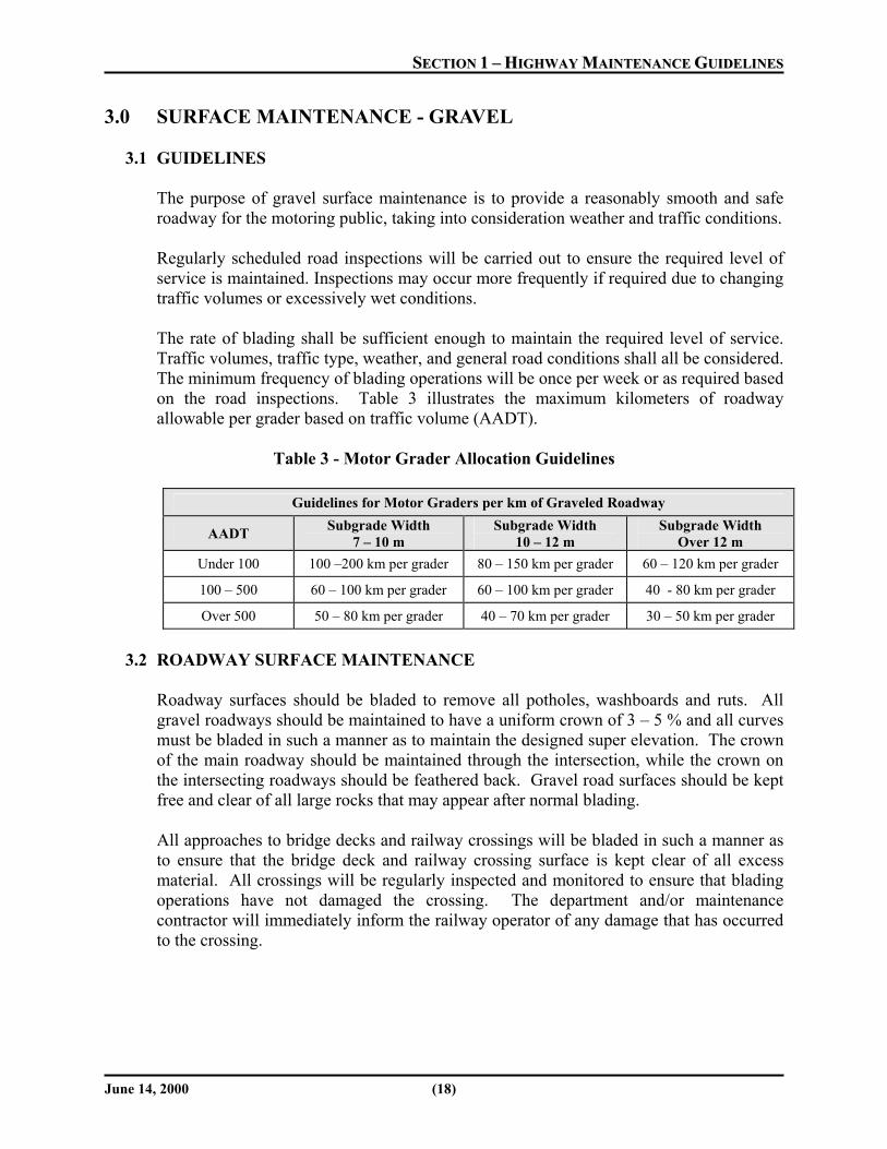
3.1 GUIDELINES The purpose of gravel surface maintenance is to provide a reasonably smooth and safe roadway for the motoring public, taking into consideration weather and traffic conditions. Regularly scheduled road inspections will be carried out to ensure the required level of service is maintained. Inspections may occur more frequently if required due to changing traffic volumes or excessively wet conditions. The rate of blading shall be sufficient enough to maintain the required level of service. Traffic volumes, traffic type, weather, and general road conditions shall all be considered. The minimum frequency of blading operations will be once per week or as required based on the road inspections. Table 3 illustrates the maximum kilometers of roadway allowable per grader based on traffic volume (AADT).
Table 3 - Motor Grader Allocation Guidelines
Guidelines for Motor Graders per km of Graveled Roadway
AADT Subgrade Width 7 – 10 m
Subgrade Width 10 – 12 m
Subgrade Width Over 12 m
Under 100 100 –200 km per grader 80 – 150 km per grader 60 – 120 km per grader
100 – 500 60 – 100 km per grader 60 – 100 km per grader 40 - 80 km per grader
Over 500 50 – 80 km per grader 40 – 70 km per grader 30 – 50 km per grader
3.2 ROADWAY SURFACE MAINTENANCE
Roadway surfaces should be bladed to remove all potholes, washboards and ruts. All gravel roadways should be maintained to have a uniform crown of 3 – 5 % and all curves must be bladed in such a manner as to maintain the designed super elevation. The crown of the main roadway should be maintained through the intersection, while the crown on the intersecting roadways should be feathered back. Gravel road surfaces should be kept free and clear of all large rocks that may appear after normal blading. All approaches to bridge decks and railway crossings will be bladed in such a manner as to ensure that the bridge deck and railway crossing surface is kept clear of all excess material. All crossings will be regularly inspected and monitored to ensure that blading operations have not damaged the crossing. The department and/or maintenance contractor will immediately inform the railway operator of any damage that has occurred to the crossing.

SSEECCTTIIOONN 11 –– HHIIGGHHWWAAYY MMAAIINNTTEENNAANNCCEE GGUUIIDDEELLIINNEESS
June 14, 2000 (19)
3.3 SHOULDER MAINTENANCE
Shoulder maintenance (pulling of shoulders) will be done on all gravel roadways on an as required basis. Roadways should be inspected regularly to determine whether pulling shoulders is required. Shoulder maintenance will be required when, the shoulders of the roadway push out, the crown rate of the roadway becomes flatter than 1%, or the cross-section is wider than designed and not properly draining. Typically, shoulder maintenance will be required prior to the commencement of regravelling operations.
3.4 SURFACE REGRAVELLING
The excessive loss of gravel from a roadway results in loss of traction, a reduction in strength, rutting, and deterioration of the roadway surface and side slopes. Gravelled roadways require regravelling, on average, once every three years. In the late fall of each year the department will inspect all gravel roads for the purpose of condition rating. Part of the condition rating process will be to determine which roadways will require regravelling in the following year. A roadway will be considered for regravelling when it exhibits any of the following characteristics: • Excessive loss of surface gravel • Numerous bald or shiny spots • Clay balls on the shoulders after blading • Excessive rutting Ultimately, the condition, type, width, and traffic volume of a roadway will dictate the application rate of gravel. The department staff will work closely with the maintenance contractor to determine the optimal application rate for each roadway. The recommended rates of application are shown in Table 4.
Table 4 – Regravelling Application Rates
AADT Tonnes/km > 500 400 - 800 < 500 400 - 500
Prior to regravelling operations, the roadway should be reshaped to the proper crown rate and width. If required, it may be necessary to “pull shoulders” (refer to sections 3.2 and 3.3). On roadways with an Average Annual Daily Traffic (AADT) higher than 50, the gravel should be spread all the way out to the shoulders, on roadways with an AADT less then 50, the gravel should be spread out to within one metre from the shoulders.

SSEECCTTIIOONN 11 –– HHIIGGHHWWAAYY MMAAIINNTTEENNAANNCCEE GGUUIIDDEELLIINNEESS
June 14, 2000 (20)
Windrowed, or unspread gravel, will not be left on the roadway overnight. In an emergency, windrowed or unspread material may be left overnight with adequate warning devices. Where applicable, the maintenance contractor will consult the local road authorities prior to the commencement of hauling on roads under their jurisdiction. The contractor will be required to regularly maintain haul roads to keep them in a reasonably smooth and safe condition for the general motoring public. If required, dust control materials will be provided in front of residences, at intersections, hills and curves. Haul roads will be inspected/checked at least twice per day to ensure that maintenance and dust control operations are effective.
3.5 DUST CONTROL
The department will use dust control to minimize safety hazards caused by severe dust conditions on gravel roadways. Department staff will work with the maintenance contractor to identify all roadway segments that will require dust control. Dust abatement material may be applied to selected roadways, intersections, on curves, hills, in hamlets, and other public places. The application of dust control materials is usually initiated late in the spring. Prior to the application of dust abatement material, the department will identify the sections of roadway that need to be bladed and/or regravelled. Alberta Infrastructure will provide dust control "as-required", based on safety criteria. Many municipalities provide dust abatement services on a cost recovery basis for local ratepayers. Municipalities have the option to supplement the department's dust control coverage as they see fit. The department and maintenance contractors will work closely with the municipalities to ensure that all efforts are properly coordinated. Materials used for dust abatement can include: • Flake Calcium Chloride • Liquid Chemical Products • Petroleum Products The department recommends the application rates shown in Table 5. Local conditions may justify pre-approval of other applications rates.
Table 5 – Dust Abatement Application Rates
Type Kg/m2 Flake calcium chloride .75 Liquid calcium chloride .75 – 1.25 Lignosulphates .75 – 1.25 (50% dilution) Petroleum based products Suppliers recommended rates Water As required
SSEECCTTIIOONN 11 –– HHIIGGHHWWAAYY MMAAIINNTTEENNAANNCCEE GGUUIIDDEELLIINNEESS
June 14, 2000 (21)
4.0 RIGHT-OF-WAY MAINTENANCE
4.1 RAILWAY CROSSING MAINTENANCE
Crossing maintenance is required to ensure a safe crossing for the motoring public and the railway operator. All railway crossings should be inspected weekly and immediately following the completion of any maintenance activity that has been carried out in close proximity to the crossing. Visual checks should be performed more frequently on those crossings that are known to be problematic. All crossings will be kept clear of all debris, gravel, snow and ice, resulting from roadway maintenance activities. When roadway maintenance affects the operation of the railway, the railway operator must be notified prior to the commencement of the work. All crossings should be signed in accordance with Alberta Infrastructure standards. The railway operator should be immediately notified of conditions which may interfere with the safe operation of the crossing. Loose planking or rail damage should be reported to the railway operator as soon as possible.
4.2 DELINEATORS
Delineators, sometimes referred to as guide posts, are installed to assist the motorists during periods of limited visibility. Delineators are used; • at changes in road alignment, • at changes in roadway width, • for marking roadside hazards, • as a guide for turning movements, • in advance of a guardrail end treatment that is turned away from the highway. Delineators shall be located in accordance with the warrants described in the Design Guide for Traffic Barriers Section of the Traffic Control Standards Manual. Delineators are not warning devices, and appropriate warning signs must be used to advise motorists of hazards.
4.3 GUARDRAIL
Guardrail is a longitudinal roadside barrier that is intended to contain or redirect a vehicle that may inadvertently attempt to leave the roadway. Typically guardrail is used to protect vehicles from three major hazards: roadside obstacles, permanent bodies of water, and steep slopes or high embankments. Proper maintenance of guardrail is critical to safe operations. Improperly installed/maintained guardrail can actually be more of a hazard than the feature they guard.

SSEECCTTIIOONN 11 –– HHIIGGHHWWAAYY MMAAIINNTTEENNAANNCCEE GGUUIIDDEELLIINNEESS
June 14, 2000 (22)
The department will inspect all guardrails annually to ensure proper and effective operations; guardrail that is prone to damage should be inspected more frequently. The department will identify all substandard guardrail and will work closely with the maintenance contractor each year to develop a guardrail replacement/repair/maintenance program based on the needs of the network. If guardrail causes a snow drifting hazard that is more severe than the original hazard the guardrail was intended to protect against, the installation should be reevaluated. The department will maintain an accurate database of all guardrail currently installed along Alberta’s provincial highways. The department and Maintenance Contractor will work together to ensure that all guardrail information contained in the department’s Infrastructure Management System (IMS) is kept current and up-to-date. Inventory information will contain detailed item descriptions as well as installation and condition information. Standards related to guardrail design and installation can be found in the Traffic Control Standards Manual and the Highway Geometric Design Guide.
4.4 MOWING
Vegetation along the right-of-way will be mowed for the following reasons: • eliminate obstructions to sight distance on curves. • control weed and brush growth. • reduce snow drifting on the roadway. • provide for unobstructed drainage. • reduce the fire hazard in some areas. • improve road aesthetics. • eliminate obstruction to signs. • increase the visibility of large animals on the right-of-way. All high traffic volume highways will receive one shoulder cut in the late spring and an additional full right-of-way cut. All other provincial highways in Alberta will receive up to 2 shoulder cuts per year (as required) and a full right-of-way cut once every 3 years or as warranted for brush control purposes. The first shoulder cut will be 4.5 metres in width and should be completed during the early summer months. The second shoulder cut or full cut may be warranted in the late fall, depending on re-growth. Where required, trimming around all appurtenances located adjacent to the highway will be carried out during the second cut. In urban areas the mowing of boulevards and raised medians will be the responsibility of the municipality.

SSEECCTTIIOONN 11 –– HHIIGGHHWWAAYY MMAAIINNTTEENNAANNCCEE GGUUIIDDEELLIINNEESS
June 14, 2000 (23)
The department will discuss their area’s mowing plans and arrangements with local municipal officials. Where possible, the department will try to coordinate their operations with that of the municipalities. 4.4.1 BURNING
Burning grass or debris within the right-of-way is not desirable, as it can create several problems. It is, therefore, the policy of the department that burning in the highway ditches is not done at any time. Besides the problem of containing fires within the right-of-way, there is the possibility of a change in wind direction, resulting in smoke on the travelled portion of the highway, creating poor visibility. Alberta Environment is also concerned with the destruction of cover for small birds, leaving them exposed to predators and destroying their nesting area.
4.5 HAY PERMITS
Hay permits are issued in many areas of the province to allow landowners to cut hay from the highway right-of-ways. Adjacent landowners are given the first opportunity to apply for these hay permits. Hay permits are subject to certain conditions: • Adjacent landowner must apply for permit prior to June 15th. After June 15th permits
will be handled on a “first come, first serve” basis. (Dates may be adjusted across the province for local conditions).
• Cutting must be commenced prior to the date noted in the hay permit. • Maintenance of the right-of-way (i.e. mowing and weed control) may be done in
areas that have hay permits. Hay permits may not be issued for particular locations as part of a weed control program.
• Baled hay is to be placed as far from the highway driving surface as reasonably possible, as bales pose a potential hazard for a vehicle leaving the roadway.
• Baled hay will not be allowed to remain in the right-of-way longer than two weeks. Owners who have not removed their bales promptly in the past may be denied new permits.
Hay permit applications can be made at any Alberta Infrastructure office.
4.6 WEED CONTROL
Alberta Infrastructure places a high priority on weed control within all highway right-of-ways. The department will work closely with the Agricultural Service Board to determine the weed spraying requirements along each roadway within their area of responsibility. Once a weed control program has been developed, the department, Agricultural Fieldman, and Maintenance Contractor should meet to review the program.

SSEECCTTIIOONN 11 –– HHIIGGHHWWAAYY MMAAIINNTTEENNAANNCCEE GGUUIIDDEELLIINNEESS
June 14, 2000 (24)
By maintaining close communications, all parties will be able to ensure that new weed issues are being dealt with quickly and that overall weed control is being provided in a timely and effective manner.
4.7 BRUSH CONTROL
Alberta Infrastructure will remove brush along all provincial highways where necessary in order to; • improve sight distance at intersections and curves, • restore proper drainage in ditches, • reduce snow drifting problems, • and allow for dissipation of dust clouds, created by traffic on gravel roads. Brush control is best performed before the vegetation reaches 2m in height or before sight distance becomes impaired. Brush control requirements should be reviewed and prioritized on an annual basis. A brush control program should be developed by early fall of each year. After brush control operations have been completed, all cuttings larger than 10cm in diameter or longer than 50cm should be removed and properly disposed of. Mechanical brushing may produce debris small enough to leave in the right-of-way.
4.8 LITTER CLEAN UP Good housekeeping and, consequently, neat appearance of our highways, can create a favorable impression of our province to our own citizens, as well as, travellers and tourists from other provinces or states. Therefore, it is important to keep a clean right-of-way. A clean right-of-way is also important in preventing damage to equipment and tires during mowing operations. Alberta Infrastructure currently operates two separate programs dedicated to the cleaning up of waste materials along Alberta’s provincial highways in addition to the routine litter cleanup done as part of the highway maintenance contract. Shortly after the snow has melted in the spring, all highway right-of-ways should receive a major clean up to remove winter accumulation of debris and rubbish. The bulk of this clean up can be accomplished during the annual spring Highway Clean Up Campaign, held on the first Saturday of May (with the second Saturday as the alternate date, in the event of inclement weather). This government-sponsored program involves non-profit groups (4-H, Junior Forest Warden, and others) where each club volunteers to clean part of the right-of-way. Besides paying the clubs on a kilometre basis, the department provides advertising, vests, decals and garbage bags. Department will also arrange to pick up and dispose of the garbage bags. This is a very successful program.

SSEECCTTIIOONN 11 –– HHIIGGHHWWAAYY MMAAIINNTTEENNAANNCCEE GGUUIIDDEELLIINNEESS
June 14, 2000 (25)
The second program, Caring for Alberta’s Highway Program, provides an opportunity for any individual or group to participate in highway clean up activities by allowing them the chance to “adopt” a section of provincial highway. Participating groups or individuals volunteer to remove litter along their adopted section of highway. In return, Alberta Infrastructure will erect a sign identifying the adopting group, provide necessary safety equipment and training, provide litter bags, and dispose of the collected litter. In order to keep the highway right-of-way looking presentable, regular clean up of articles large enough to be seen from the highway is necessary throughout the season. In an effort to encourage the highway users to help keep the highway clean, litter barrels should be placed along the highway at regular intervals, with the necessary advance signing. These barrels should be placed on a widened section of highway whenever possible, in order that vehicles stopping to deposit litter can park well clear of the driving lanes. Regular garbage pickup from these sites must be carried out as required. During the warmer weather in July and August, pickup should occur at least twice a week, regardless of whether or not the containers are full, to avoid excessive odor from decaying material.
4.9 DRAINAGE SYSTEMS
As flowing water can be one of the greatest natural destructive forces affecting a road, it is very important that all structures and other features of the drainage system are well designed and properly maintained. In order to maintain a roadway in optimum condition, water must be kept from saturating the subgrade and also from eroding the roadway. Drainage systems include the following components:
• Ditches • Culverts • Ditch Blocks • Curbs/Gutters • Down Drains • Subsurface Drains • Bridges
Each spring, the department will update and prioritize the culvert maintenance program. This program will describe any drainage system deficiencies and identify what corrective action needs to be taken.
4.9.1 CULVERTS
The department will maintain an accurate inventory database of all culverts, which exist on the new provincial highway network. Inventory information will contain detailed item descriptions as well as installation and condition information. All culverts will be inspected regularly to ensure proper and effective operations.
SSEECCTTIIOONN 11 –– HHIIGGHHWWAAYY MMAAIINNTTEENNAANNCCEE GGUUIIDDEELLIINNEESS
June 14, 2000 (26)
Culvert installations play an important role in the effective operations of our provincial highway network. Culvert installations provide relief for natural drainage channels and also prevent the undue accumulation and retention of water on and adjacent to the roadway. Properly installed and maintained culverts will protect the roadway against storm and subsurface water damage. The capacity of culverts can be reduced dramatically when damaged or blocked by silt, debris, or ice. Each year, the department will work closely with the maintenance contractor to develop a culvert replacement/repair/maintenance program based on the needs of the network. Culverts prone to freezing, should be inspected in the early spring. Culverts that become plugged with ice during spring runoff should be steamed open as soon as is practical. The repair, replacement, and maintenance of all culverts located within the provincial highway right-of-way, will be the responsibility of Alberta Infrastructure. Maintenance of culverts will include silt removal and spring steaming on an as required basis.
4.9.2 DITCHES
Ditches that become “silted in” or blocked can alter the natural drainage patterns thus causing flooding. Periodic maintenance of ditches may be required to ensure that drainage ditches are functional and that they are capable of carrying their design flows. All ditches, especially those with heavy flows and those subject to flooding or erosion, should be inspected each spring or during peak flow periods to ensure proper operation.
4.9.3 BEAVER DAMS
Beaver may build dams in or near culverts located under, or adjacent to roadways. Dams can cause flooding, in some cases this flooding will cause damage to adjacent roadways. Beavers that build problem dams should be removed from the area. Dams should be removed or breached if flooding problems are anticipated. Dams located in culverts should always be removed. Adjacent landowners should be informed about dam removal to minimize the risk of flooding or erosion on private property as backed up water is released. Removal of dams and the inspection of problem prone areas should be carried out continuously throughout the summer. Follow up inspections should be made prior to freeze up.
SSEECCTTIIOONN 11 –– HHIIGGHHWWAAYY MMAAIINNTTEENNAANNCCEE GGUUIIDDEELLIINNEESS
June 14, 2000 (27)
Culverts that are prone to problems should be protected through the installation of an approved beaver control device.
4.9.4 STORM SEWER
Often Alberta Infrastructure will have invested heavily in the capital cost of storm sewer construction. Commonly, storm sewers are installed at the time of major reconstruction of the provincial highways through urban areas. Normally, the installation of storm sewers is cost shared with the municipality under the department’s Street Improvement Program (SIP). Once installed, the on-going operation and maintenance of storm sewer facilities, including catch basins will remain the responsibility of the municipality.
4.9.5 CURB AND GUTTER
At the time of pavement rehabilitation, replacement of worn or broken curb and gutter will be undertaken by Alberta Infrastructure. Should a section of curb and/or gutter structurally fail, whereby repair/replacement is required for either safety or drainage reasons, Alberta Infrastructure will undertake such work. Cosmetic repair/treatments for visual appearance will remain the responsibility of the municipality. Routine maintenance of curb and gutter will be the responsibility of the municipality and done in conjunction with maintenance of sidewalk or boulevard.
4.9.6 SIDEWALK
The maintenance of all sidewalks located within urban cross-sections will be the responsibility of the local municipal jurisdiction.
SSEECCTTIIOONN 11 –– HHIIGGHHWWAAYY MMAAIINNTTEENNAANNCCEE GGUUIIDDEELLIINNEESS
June 14, 2000 (28)
5.0 TRAFFIC CONTROL DEVICES
5.1 SIGNING
5.1.1 STANDARDS
Signs are used to inform motorists of traffic regulations, warn of changes in the roadway characteristics or hazards, and to provide directional/distance information that is necessary to motorists. The Alberta Highway Signing Manual, Traffic Control Standards Manual and the Uniform Traffic Control Devices for Canada Manual, provide standards and guidelines for the application of signing along Alberta’s highways. • The department’s Traffic Control Standards Manual contains the Alberta
standards for sign positioning and layout, including height and setback.
• The Uniform Traffic Control Devices for Canada Manual deals with sign characteristics and application.
• The Alberta Highway Signing Manual contains standards and policies related to the installation of business signing on Alberta’s highways.
5.1.2 INVENTORY INFORMATION
The department will maintain an accurate database of all signs currently installed along Alberta’s provincial highways. The department and the Maintenance Contractor will work together to ensure that all sign information contained in the department’s Infrastructure Management System (IMS) is kept current and up-to-date.
5.1.3 MAINTENANCE
All highways should be checked on a regular basis to ensure that all signs are properly in place, functional and conform to established standards. In addition to daytime inspections, night inspections should be carried out regularly to ensure that signs are reflective and legible during hours of darkness. Lighting which has been installed on overhead sign structures should be inspected regularly to ensure that all fixtures are operational. Signs larger than 3m2 should be placed on breakaway bases to minimize the potential for injury and vehicle damage if struck by vehicles leaving the roadway. Shear bolts should be checked periodically for proper torque so that the breakaway feature will function as intended.

SSEECCTTIIOONN 11 –– HHIIGGHHWWAAYY MMAAIINNTTEENNAANNCCEE GGUUIIDDEELLIINNEESS
June 14, 2000 (29)
5.1.4 RESPONSIBILITY
Regulatory and Warning Signs • All regulatory and warning signs within the right-of-way will be maintained
by Alberta Infrastructure, unless other arrangements have been made.
• In Urban areas where a municipality has requested a “special mounting” for visual or aesthetic purposes, the installation of these signs will remain the responsibility of the municipality. In these cases, the department will supply the sign, for the municipality to install.
Guide Signs • All guide or destination signing on Alberta’s provincial highways will be the
responsibility of Alberta Infrastructure.
Parking and Other Facility Signs • All parking and other type of information / bylaw information will remain the
responsibility of the municipality.
5.2 TRAFFIC SIGNALS
The function of a traffic control signal is to safely assign the right-of-way between the conflicting flows of traffic at an intersection. Standards related to the installations and operation of traffic control signals can be found in the Manual of Uniform Traffic Control Devices for Canada. Alberta Infrastructure will install and operate all traffic control signals located on the provincial highway network (refer to Table 6). The department should work closely with local municipalities to ensure that signals function properly. If required, the department will ensure that repair and routine maintenance are being completed in a timely fashion.
SSEECCTTIIOONN 11 –– HHIIGGHHWWAAYY MMAAIINNTTEENNAANNCCEE GGUUIIDDEELLIINNEESS
June 14, 2000 (30)
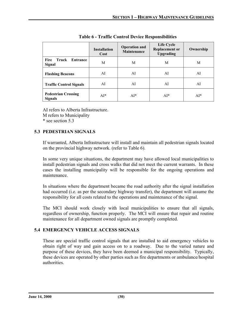
Table 6 - Traffic Control Device Responsibilities
Installation
Cost
Operation and Maintenance
Life Cycle Replacement or
Upgrading
Ownership
Fire Truck Entrance Signal M M M M
Flashing Beacons AI AI AI AI
Traffic Control Signals AI AI AI AI
Pedestrian Crossing Signals
AI* AI* AI* AI*
AI refers to Alberta Infrastructure. M refers to Municipality * see section 5.3
5.3 PEDESTRIAN SIGNALS
If warranted, Alberta Infrastructure will install and maintain all pedestrian signals located on the provincial highway network. (refer to Table 6). In some very unique situations, the department may have allowed local municipalities to install pedestrian signals and cross walks that did not meet the current warrants. In these cases the installing municipality will be responsible for the ongoing operations and maintenance. In situations where the department became the road authority after the signal installation had occurred (i.e. as per the secondary highway transfer), the department will assume the responsibility for all costs related to the operations and maintenance of the signal. The MCI should work closely with local municipalities to ensure that all signals, regardless of ownership, function properly. The MCI will ensure that repair and routine maintenance for all department owned signals are promptly completed.
5.4 EMERGENCY VEHICLE ACCESS SIGNALS
These are special traffic control signals that are installed to aid emergency vehicles to obtain right of way and gain access on to a roadway. Due to the varied nature and purpose of these devices, they have been deemed a municipal responsibility. Typically, these devices are operated by other parties such as fire departments or ambulance/hospital authorities.

SSEECCTTIIOONN 11 –– HHIIGGHHWWAAYY MMAAIINNTTEENNAANNCCEE GGUUIIDDEELLIINNEESS
June 14, 2000 (31)
5.5 LINE PAINTING
Line painting is a traffic control device that is used to define traffic lanes and assist in the control, warning and guidance of the road user. Alberta Infrastructure will follow the standards for line painting as defined in the Alberta Highway Pavement Marking Guide. Alberta Infrastructure is responsible for all line painting on provincial highways with the exception of parking lines. The marking of parking lines within an urban area will be a municipal responsibility. All line painting shall be maintained in good condition. Typically, line painting is carried out on an annual basis throughout the province. In the past, Alberta Infrastructure has found it necessary to paint: • Centre lines every year • One shoulder line each year, alternating sides annually • Other lines every year or every other year • On high traffic volume highways, all lines every year
5.6 MESSAGE PAINTING
Alberta Infrastructure is responsible for all pavement messages located on the Provincial Highway System. Any messages located within the urban cross section of a provincial highway that is related to parking, or painting of curbs will be the responsibility of the municipality. All message painting shall be maintained in good condition and should be placed in accordance with the standards as defined in the Alberta Highway Pavement Marking Guide.
5.6.1 STOP BAR PAINTING AT INTERSECTIONS
Alberta Infrastructure will maintain intersection stop bars, within the right-of-way. All stop bars shall be maintained in good condition.
5.6.2 PEDESTRIAN CROSSWALK MARKING
Alberta Infrastructure will install and maintain all crosswalks as required by warrant. All crosswalks shall be maintained in good condition.
SSEECCTTIIOONN 11 –– HHIIGGHHWWAAYY MMAAIINNTTEENNAANNCCEE GGUUIIDDEELLIINNEESS
June 14, 2000 (32)
5.7 REMOVAL OF NON-CONFORMING SIGNS The removal of non-conforming signs, from time to time is necessary, as privately owned signs are erected on or adjacent to the highway right-of-way without a permit from the department. The origin of these signs is varied, but it usually is the result of some group or commercial business wishing to promote or advertise goods and services that are available. Many of the signs are placed on private property on the assumption that prosecution under the Public Highway Development Act and Regulations is not possible because they are located on privately owned land. This is untrue, as the jurisdiction of the Act extends for 300 metres from the right-of-way and 800 meters from all highway intersections. The initial step, in having a possible non-conforming sign removed, is to determine whether or not the sign conforms to the Department’s signing policy or the Public Highways Development Act and Regulations. Thus, these two documents are to be reviewed thoroughly. The details of any sign, suspected of being non-conforming, should be reviewed with the Operations Manager before processing. Once it is determined that a sign does not conform, the following course of action is suggested: (a) Signs within Corporate Limits of Hamlets, Villages, Towns and Cities and
Outside the Highway Right-of-Way
Management of all signing outside the highway right-of-way is under the control and management of the local municipality. Through an administration decision in the early 1980s, the Department decided that the signing regulations and permitting process required under the Public Development Act would not be applied to signs located outside of the highway right-of-way within the highway development control zone through cites, towns, villages and hamlets, and as such devolved the signing responsibility to the municipalities. Only under exceptional circumstances, would the department enforce the legislation, under the Public Highways Development Act and Regulations, on signs within urban municipalities.
(b) Signs within the Highway Right-of-Way Generally, only signs erected by the department, or signs receiving permission
from the department, can be located within the right-of-way. Thus, any other signs can be considered to be non-conforming, and steps should be taken to force their removal. These steps are as follows:
(1) Determine the name, address and telephone number of the sign owner. (2) Advise the sign owner, in writing, that the sign is placed incorrectly on
government property and should be removed. Allow the owner up to seven days to comply. Once the grace period has expired, the department should arrange for its removal.

SSEECCTTIIOONN 11 –– HHIIGGHHWWAAYY MMAAIINNTTEENNAANNCCEE GGUUIIDDEELLIINNEESS
June 14, 2000 (33)
(3) If the sign is interfering with traffic, or is particularly objectionable, the sign owner should be notified by telephone to remove the sign immediately.
(4) All non-conforming signs removed should be stored at the nearest maintenance yard and given back to the owner, if he or she wishes to pick them up.
(c) Signs Located Outside of Communities and Outside the Highway Right-of-
Way The initial step is to determine the extent to which a particular sign violates the
signing policy. Minor violations, such as slightly larger than allowed, poorly placed, or other minor irregularities, may be insufficient grounds to commence with a total removal notice. In many cases, the sign owner will be willing to correct the deficiencies to bring the sign within the policy.
After determining that a non-conforming sign must be removed, both the
landowner and the sign owner must be informed as to the department’s policy and asked to remove the sign. Verbal contact shall be followed by written correspondence. A two week period shall be allowed for the sign’s removal. After the two week period, if unsuccessful, additional correspondence shall be prepared and forwarded by the District Operations Manager and the Regional Director.
After three unsuccessful written requests to remove the sign, a Ministerial Notice
should be prepared and forwarded to the Assistant Deputy Minister, Transportation and Civil Engineering Division, for furtherance. A draft of the Ministerial Notice must include the following documents:
(1) Copies of all previous correspondence, with the landowner and the sign
owner (2) A copy of the title search on the land, where the sign is located. (3) A mosaic, showing sign location. (4) A recent colour photograph of the sign. (5) Draft Ministerial Notice to both sign owner and landowner. (6) Any additional information relating to the sign.
If the Ministerial Notice is unsuccessful, a complaint should be laid with the local RCMP detachment, after approval to do so is obtained from the Minister. The Crown prosecutor will determine whether criminal charges are warranted, and proceed accordingly. If convicted, the sign owner, in addition to being fined is usually instructed to remove the offending sign.

SSEECCTTIIOONN 11 –– HHIIGGHHWWAAYY MMAAIINNTTEENNAANNCCEE GGUUIIDDEELLIINNEESS
June 14, 2000 (34)
6.0 ROADWAY ILLUMINATION Table 7 shown below outlines the responsibility for illumination and traffic signal systems. This generally represents current practice on the Provincial Highway System. Not all illumination systems on the Provincial Highway System are currently administered in this fashion. The existing arrangements will remain in force until urban development occurs or upgrades are required to the illumination system.
Table 7 - Illumination Responsibility
Installation
Cost
Operation and Maintenance
Life Cycle Replacement or
Upgrading
Ownership
AI Systems AI AI AI AI
Municipal Systems Ltg. Warranted AI 1,2 M3 AI AI4
Municipal Systems Sentry Ltg. Warranted AI M AI AI5
Municipal Lighting No warrant M6 M M AI7
All Existing Municipal Systems “Non-Invested”
Not Applicable M U8 U9
1 Except where developer/municipality/industrial development initiates the need to install or modify a system. 2 AI will pay the installation costs provided that Program funding is available. 3 The department was paying for operating costs of some Municipal Systems installed on primary highways before
cost sharing was implemented. 4 a) AI should own the facility since it is within our right-of-way. b) AI ownership will prohibit the possibility for anyone to make changes or modifications without our prior
knowledge. c) AI ownership will ensure that existing cost sharing agreements remain in place and cannot be shut-off once
installed. 5 Same as 6. 6 Municipality will be permitted to install a system if and only if the installation meets department requirements and
standards. 7 Same as 6. 8 U refers to Utility Company. 9 Possible buydown by AI in future if ownership or control by AI is desired.

SSEECCTTIIOONN 11 –– HHIIGGHHWWAAYY MMAAIINNTTEENNAANNCCEE GGUUIIDDEELLIINNEESS
June 14, 2000 (35)
7.0 SPRING CLEANUP
7.1 WASHING BRIDGES
Carried out on an annual basis, this process involves the removal, containment and disposal of all dirt, debris and deleterious material and washing of the bridge structure to remove all ice control (salt) materials. All bridge surfaces shall be swept prior to washing to minimize the amount of material washed into the watercourse. Deck surfaces, sidewalks, gutters, drainage structures, expansion and deck joints, are to be cleaned of all dirt and debris and flushed with water to remove any remaining chemicals and winter abrasives. This includes railing and truss members to a height of three metres above the deck surface and bridge approaches and all bridge elements for a distance of ten metres.
7.2 SWEEPING
In rural areas, scheduled sweeping is undertaken once in spring by Alberta Infrastructure, normally at intersections where there is accumulation of winter sanding material. Sweeping is usually carried out at intersections with turning bays, bridge decks, or along raised median. At other times of the year, sweeping is done as required to remove debris from the road surface (i.e. trucks turning onto the road from a muddy field). Sweeping and cleaning paved surfaced is undertaken to: • Remove sand and debris from the pavement surface to avoid damage to vehicles. • Remove sand and debris from areas scheduled for line and message painting. • Prevent debris from entering drainage inlets. • Reduce potential for skidding by increasing traction. • Remove sand and debris from the pavement surface prior to crack filling or tacking. • Clean up spills and vehicle accident debris. • Remove loose chips from pavement surface. In urban cross-section, if required, Alberta Infrastructure will sweep from curb to curb once, generally in the spring. Sweeping is usually done with a “pick up broom”. This will remove residual sand remaining from winter sanding operations. Municipal authorities are encouraged to provide input into scheduling and details of sweeping activities. Municipal staff are asked to provide 30 days prior notice if they require a specific sweeping completion date. Sweeping will be carried out prior to line painting and message painting so the majority of the loose material is removed prior to any painting being performed. Sweeping is often carried out in conjunction with bridge washing, see 7.1.
SSEECCTTIIOONN 11 –– HHIIGGHHWWAAYY MMAAIINNTTEENNAANNCCEE GGUUIIDDEELLIINNEESS
June 14, 2000 (36)
7.2.1 SWEEPING/CLEANING RAISED MEDIANS
Raised medians are usually cleaned in conjunction with scheduled sweeping.

SSEECCTTIIOONN 11 –– HHIIGGHHWWAAYY MMAAIINNTTEENNAANNCCEE GGUUIIDDEELLIINNEESS
June 14, 2000 (37)
8.0 LIVESTOCK GUARDS Livestock guards are used to prevent domestic and wild animals from entering the roadway. Most livestock guards are installed on approaches to highways; however, there are a small number located on the main highway. The department will maintain and inspect all livestock guards located on the Provincial Highway System. The department shall inspect the guards to ensure that the guard is carrying out its intended function of preventing domestic and wild animals from entering roadway. Accumulated debris must be removed before it causes water drainage problems or builds to a height that it renders the guard ineffective. Repairs to guard and associated fencing are done as required.

SSEECCTTIIOONN 22 –– BBRRIIDDGGEE MMAAIINNTTEENNAANNCCEE GGUUIIDDEELLIINNEESS
June 14, 2000 (38)
BBRRIIDDGGEE MMAAIINNTTEENNAANNCCEE GGUUIIDDEELLIINNEESS INTRODUCTION BACKGROUND The average age of bridges and culverts on the provincial public roadway system is about 27 years. Given that the required average life of standard bridges is about 40 years and about 50 years for major bridges and culverts, it is important that these structures be properly maintained to ensure that they reach their full design life. The estimated current value of the provincial bridge system is over 2 billion dollars. If even 1 percent of system requires premature replacement, the cost to the province is enormous. This section describes maintenance activities that may be required based on the periodic inspection of bridges and culverts, as defined by the Alberta Infrastructure’s (AI) Bridge Inspection and Maintenance system (BIM). It specifically deals with bridge maintenance activities that local maintenance contractor can reasonable be expected to undertake. Additional definitions of what these activities include are given in AI’s Guidelines for Bridge Operations (GAP), in Section GAP-02. More detailed information on specialized bridge work is available from Alberta Infrastructure’s Bridge Group. This section provides a performance standard for each maintenance activity to be undertaken. It should be recognized that modifications to these suggestions might be necessary to accommodate site specific concerns and events. This section provides general, common sense repair techniques for commonly found defects in bridge materials. The areas covered include timber, repair, signing, guardrail/bridge rail repair, small area concrete patching, culvert strutting and repair of washouts at bridge abutments. The purpose of the Manual is to provide guidelines for: 9 Planning and scheduling bridge maintenance, arising from deficiencies identified during
bridge inspection. 9 Planning the performance standards to provide information on typical manpower and
equipment requirements. 9 Performance standards also provide descriptions of general procedures for undertaking the
work.

SSEECCTTIIOONN 22 –– BBRRIIDDGGEE MMAAIINNTTEENNAANNCCEE GGUUIIDDEELLIINNEESS
June 14, 2000 (39)
1.0 TIMBER STRIPDECK MAINTENANCE Timber stripdeck is used as the wearing surface for most timber stringer bridges and steel truss, as well as some steel girder bridges. The stripdeck may be either untreated or CCA treated 3 x 10 or 3 x 12 timbers. The stripdeck may be damaged due to rot penetration, particularly at the cut ends, or wear due to vehicular traffic. The average life of untreated timber stripdeck is dependent on the type and volume of traffic, grade and finish of the lumber, weather conditions, subdeck condition, and type of fastener, but is usually in the order of seven years. In cases where damage is limited to small areas, it is economical to repair these areas and extend the time before total replacement of the stripdeck is necessary. The wheel lines are often the areas of most wear and may become a safety concern if the deterioration is severe. Any damage should be reported to the AI Regional Bridge Group as soon as possible. Hazard markers may be required if repairs cannot be completed within a day or two. It is preferable to carry out stripdeck patching or replacement when the surface is dry and free of gravel, snow and ice. Fall is generally the preferred season for stripdeck replacement, however, traffic safety may dictate when maintenance should be done. In some cases, it is less disruptive to the road users and safer to do one side of the bridge at a time. For low traffic volume roads and smaller bridges, it may be acceptable to allow traffic to travel on the subdeck during stripdeck replacement. For two lane bridges, traffic can be accommodated by replacing half the stripdeck at a time and permitting one lane traffic to continue over the bridge. 2.0 REPAIR TIMBER BRIDGERAILS, POSTS AND FLEXBEAM RAILS Bridgerails are a safety feature required to protect the public from the hazards associated with falling from the bridge deck. There are a wide variety of bridgerails, dependent primarily on the type of structure and the standards at the time of construction. Typical bridgerails include timber plank, w-beam, steel lattice, vertical bar rail, tube rail and concrete parapet. Damage or deterioration may present a hazard to traffic that warrants signing, repair or replacement of the bridgerails. All repairs associated with steel tube and concrete railing and posts shall be referred to the Regional Bridge office. Repairs to rail should be scheduled for high visibility hours and times where disruption to the travelling public is projected to be minimal. Work should be performed on one side of the bridge at a time. 3.0 INSTALL/REPAIR FLEXBEAM ON BRIDGE APPROACHES Flexbeam guardrail on bridge approaches is a required safety feature which protects the travelling public from the hazard associated with a vehicle leaving the road adjacent to bridge structures. The approach flexbeam is generally attached to the bridgerail, which may require one of several types of transition sections. The end of the flexbeam that is away from the bridge is normally a turned down section. Flexbeam should be installed and/or repaired in accordance with current departmental standards.
SSEECCTTIIOONN 22 –– BBRRIIDDGGEE MMAAIINNTTEENNAANNCCEE GGUUIIDDEELLIINNEESS
June 14, 2000 (40)
Installation or repair of bridge approach flexbeam should be done as soon as possible in order to maximize the safety of the travelling public. When repairs cannot be done immediately, appropriate hazard warning must be installed. 4.0 INSTALLATION OF LOAD POSTING SIGNS By analysis of the design capacity of the bridge and its elements, a bridge may not be capable of carrying legal loads. Bridges in poor condition may require reduction of the loads that can safely cross the bridge. All bridges that cannot operate at legal highway loading shall be posted to their appropriate capacity in order to protect the users and the bridge. In most installations with new signing, a total of six signs will be required. 5.0 INSTALLATION/REPLACEMENT OF HAZARD MARKERS Hazard markers are alternating diagonal striped signs, installed to advise motorists of potentially dangerous roadside obstacles, such as the ends and edges of bridges and the protruding ends of culverts. Hazard markers are generally installed immediately in advance of the hazard, and the diagonal stripes point downward towards the roadway. In the case of standard bridges, the hazard markers are attached to the bridge ends. In some cases, special post brackets are used to allow easy removal and replacement, where necessary, to accommodate wide loads. Missing or damaged hazard markers should be repaired or replaced as soon as possible, in order to maintain safety for the travelling public. 6.0 ROAD CLOSURE ASSOCIATED WITH BRIDGES Closure of a bridge to public traffic may be required in emergency situations or during extensive repairs and/or bridge replacement. In general, emergency closure is associated with high risk of collapse or extreme danger to the public. Structures that are in imminent danger of collapse, or that are dangerous to the user, should be closed immediately. In most cases, this type of closure is not pre-planned and the Local Road Authority maintenance personnel will likely be the first to identify this requirement. It is important that all staff be trained to decisively respond to this type of safety situation and that a plan of action including designated response teams be organized. In cases where road closure is forecast on the basis of major repairs and/or replacement of the bridge, it is appropriate that such closures be properly planned and coordinated with staff from the Regional Bridge Office and the Bridge Engineering Branch. It is desirable to schedule closures such that inconvenience to the public is minimized. Notice of closure should be published in local newspapers or aired on local radio stations. 7.0 SMALL AREA CONCRETE PATCHING Minor patching repair of concrete girders and concrete bridge elements is an economical way to effectively delay rapid deterioration of the element. In general, this type of repair can be used for surface type damages and non-structural repairs.

SSEECCTTIIOONN 22 –– BBRRIIDDGGEE MMAAIINNTTEENNAANNCCEE GGUUIIDDEELLIINNEESS
June 14, 2000 (41)
The nature of the patching required will dictate when the repair should be done. Most patching materials are sensitive to moisture and temperature. Cold weather is generally the poorest time to attempt a repair in an unprotected environment. Hot weather can also be a problem for some patching materials. Timing of the repair will depend on location, volume of traffic, etc. 8.0 BANDING SPLIT PILES The backfill behind the abutments exerts horizontal pressure against the backwall. If there is not a structural member to resist this force, then the backwall will migrate inwards, pushing the piles. The result will be either the pile splitting at the drift and/or the cap rolling inwards. Both produce an unstable structure. Banding a split pile is a means of preventing the pile from getting worse. Notify the office if over half of the pile is pushed past the cap. An effective long-term solution to movement of the pile or cap is the use of struts, backwall clamps, or spill through abutments. This job is best performed where access under the bridge is available, during low flows or in winter. Performing the work after a dry spell will increase the likelihood that the timber is not wet prior to working on the bridge. 9.0 REPAIR OF BRIDGE ABUTMENT WASHOUTS In cases of high flow conditions in a stream, or instances where there is poor alignment of the stream with respect to a bridge crossing, either the headslope or the approach road itself may be washed out or damaged due to overtopping or undermining. In the event of such an occurrence, the first consideration and action to be undertaken is to preserve the safety of the travelling public. Temporary road closures, as well as other precautionary measures, may be required. The urgency and scope of repairs will be determined by the extent of damage and the importance of the road, based on consideration of factors such as type and volume of traffic, emergency access requirements and Local Road Authority priorities. 10.0 HIGH BACKWALL ABUTMENT – REPAIR OF BACKWALL SCOUR If left unattended, scour behind a backwall can result in holes appearing in the approach road and/or failure of the bridge. The failure will likely occur with little or no warning during high stream flow.
SSEECCTTIIOONN 22 –– BBRRIIDDGGEE MMAAIINNTTEENNAANNCCEE GGUUIIDDEELLIINNEESS
June 14, 2000 (42)
Factors that can contribute to backwall scour are: • Poor alignment of the bridge abutment and the stream bed • High localized stream velocities • Erodible stream bed and/or backwall material • Initial backwall planks set too high In the event of backwall scour occurring, the first consideration and action to be undertaken is to preserve the safety of the travelling public. Temporary road closures, as well as other precautionary measures, may be required. The urgency and scope of repairs will be determined by the extent of damage and the importance of the road, based on consideration of factors such as type and volume of traffic, emergency access requirements and Local Road Authority priorities. 11.0 PLACING STRUTS ON STANDARDS BRIDGES The backfill behind the abutments exerts horizontal pressure against the backwall. If there is not a structural member to resist this force, then the backwall will migrate inwards, pushing the piles. The result will be either the pile splitting at the drift or the caprolling inwards. Both produce an unstable structure. Standard bridges have three means of handling this force: backwall U-clamps around each pile, spill through abutments where the backwall height (or pressure) is not significant, or as describe here, timber struts between piles. This job is best performed during periods where access under the bridge is available. This occurs either during low flows, or in winter when the ice is thick. 12.0 RESTORATION OF BRIDGE HEADSLOPES Many bridge crossings are located in river valleys having wide floodplains relative to the width of the main watercourse channel. It is generally impractical and uneconomical to span the entire width of the valley or, in some cases, the total main channel with bridge superstructure. In such cases, fill embankments are used on the bridge approaches to shorten the length of structure required. The portion of fill spilling towards the channel beneath the ends of the bridge is known as a headslope. The slope of the headslope is generally in the range of 2 horizontal to 1 vertical. Since these headslopes are exposed to the concentrated flow of the channel, as well as from drainage of the road approaches and the bridgedeck, they are vulnerable to erosion and scour damage. In some cases, the headslopes will be armored with systems such as riprap and concrete, which are also subject to damage. The extent of repair required will vary depending on site conditions. Restoration of headslopes and their protective systems is best done when low flow conditions prevail in the watercourse. In general, it is difficult to use motorized equipment when the ground and headslopes are in a wet condition. In emergency situations, it may be possible to end dump heavy rock riprap as a temporary deflector to protect a failing headslope or protection system.
SSEECCTTIIOONN 22 –– BBRRIIDDGGEE MMAAIINNTTEENNAANNCCEE GGUUIIDDEELLIINNEESS
June 14, 2000 (43)
In some cases, concerns about disturbances to the stream bed may affect scheduling the repair. The maintenance contractor is responsible to contact the appropriate provincial or federal environmental agency to obtain all permits and clearances. 13.0 BRIDGE WASHING Salt accumulation on bridge decks is the leading cause of rapid deterioration of concrete bridge elements. Once salt is transported internally through the concrete, it causes corrosion of the reinforcing structural steel encased in the concrete and, ultimately, leads to spalling of the concrete. Gravel and sand accumulations tend to contain salt and moisture, which provide another source of contaminants, as well as potential abrasion damage to concrete surfaces. Washing concrete decks and other surfaces at least once a year is a cost-effective way to reduce this type of damage. It is advantageous to wash the bridge decks in the spring, after the danger of freezing temperatures has passed. Removal of gravel and sand, as well as opening of clogged drains, can be done from spring to fall, but is best coordinated with washing. (also see Section 7.1) 14.0 SITE CLEANUP Most maintenance activities will result in site disturbance and/or waste products. It is environmentally and aesthetically unacceptable to leave sites in a disturbed condition, or to improperly dispose of waste, after maintenance activities are completed. Site cleanup and waste disposal must be considered in the scheduling of any maintenance projects; weather and traffic conditions are the prime considerations. 15.0 REMOVE BEAVER DAM The presence of a beaver dam in close proximity to a bridge or culvert opening can significantly reduce the hydraulic capacity of the structure. The resulting damage can range from washout of the crossing to flooding of upstream properties. Removal of the beaver dam can also damage the structure, if improperly done. Beaver dams are more easily removed in low water conditions. Water depth upstream of the beaver dam should be determined for safety purposes before attempting removal. (also see Section 4.9.3)

SSEECCTTIIOONN 22 –– BBRRIIDDGGEE MMAAIINNTTEENNAANNCCEE GGUUIIDDEELLIINNEESS
June 14, 2000 (44)
16.0 TIMBER STRUTTING OF METAL CULVERTS Metal culverts are prone to problems associated with improper installation and movement or deterioration of the structural backfill surrounding the pipe. In many cases, the pipe geometry will deform and/or or cracking of the seams or plate may occur. In order to prevent collapse of culverts that are severely deformed, struts are used as a temporary repair. The use of timber struts is generally limited to immediate type repairs, where adequacy of opening is not severely impacted, and drift is not a problem. Strutting is generally used for structures with equivalent diameters between 1500mm and 4000mm. Strutting is more easily achieved in low or no flow conditions and, therefore, fall and winter conditions generally make for easier installation. In some cases, where risk of collapse is great, dewatering, cleaning out, and water control may be necessary. In situations where the amount of fill over the culvert is less than 1800mm, consideration should be given to limiting traffic over the structure while it is under repair. In no case should a repair be attempted on a severely deformed culvert under low fill without the supervision of qualified bridge staff. 17.0 MAINTENANCE OF BRIDGE STRUCTURES ON LOCAL ROADS
17.1 ISSUE
There are now written guidelines regarding the assistance that the department provides to the Local Road Authorities for maintenance of bridge structures. This has caused some confusion and inconsistency regarding the assistance provided to the LRA’s for maintenance of bridges on local roads and secondary highways still under municipal control.
17.2 BACKGROUND
The Municipal Government Act and the Public Highways Development Act provide the legislation under which a Municipal Road Authority and Alberta Infrastructure operate, concerning the maintenance of bridge structures on local roads. Like the roads on which they are located, the bridge structures are under the control and management of the Municipality (some irrigation bridges are exceptions). Although bridge structures are the Municipality’s responsibility, the Department provides technical and/or financial assistance to help the Municipality meet its responsibility to the extent that budgets approved by legislature allow. The Department undertakes, on behalf of the Municipality, work on those bridge structures that are considered beyond the normal capability of the Municipality. The Department will provide the following services relating to inspection and maintenance of bridge structures within the Municipality’s jurisdiction:
(1) Manage the Bridge Inspection and Maintenance System (BIM).
Inspection forms will be provided, as required, and all data will be entered into the system for the local road authority.

SSEECCTTIIOONN 22 –– BBRRIIDDGGEE MMAAIINNTTEENNAANNCCEE GGUUIIDDEELLIINNEESS
June 14, 2000 (45)
(2) Train the bridge inspectors, as required, to ensure the Municipalities have the information and knowledge required to do the routine inspection of their bridges.
(3) Inspect all major bridges for the Municipality as specified in the BIM
System. Inspect standard bridges where the Municipality requires specialized engineering expertise by way of an inspection.
(4) Repair bridges and culverts outside the normal capabilities of the
Municipality.
18.0 MAINTENANCE OF BRIDGE STRUCTURES ON PROVINCIAL HIGHWAY SYSTEM
18.1 BACKGROUND
Alberta Infrastructure is the responsible road authority for all provincial highways, with the Operations Manager having responsibility for the operation and maintenance of the roadway. Maintenance staff has always performed some routine maintenance activities, with respect to bridges, e.g. snow removal from bridge decks, installation and repair of bridge signing, emergency repairs, or erection and maintenance of barriers until repairs can be made. Contractors have carried out other maintenance activities, such as washing bridge decks, and repair of bank and headslope erosion. Any culvert with diametre 1500mm and larger, and all bridges are considered ‘bridge structures’.
18.2 RECOMMENDED GUIDELINES
On provincial highways, the department’s maintenance contractor will undertake routine bridge maintenance activities as requested by the MCI. The following is a list of activities that should be carried out regularly. (1) Monitor structure on a regular basis and notify the Regional Bridge
Engineer of any problems at bridge site (e.g. accident damage, deck joint problems, high water, ice jams, abnormal alignment, etc.).
(2) The MCI should accompany the Bridge Inspector, if available, on regular
BIM inspections. (3) The maintenance contractor ensure the safety of the traffic by carrying out
emergency repairs, or by providing traffic control and/or alternate traffic accommodation, until the Regional Bridge Engineer can assess the situation.
(4) The MCI shall ensure that bridge structures are properly signed in
accordance with current department standards.

SSEECCTTIIOONN 22 –– BBRRIIDDGGEE MMAAIINNTTEENNAANNCCEE GGUUIIDDEELLIINNEESS
June 14, 2000 (46)
(5) Bridge washing, the contractor shall clean bridge components, such as the decks, drains, curbs, railing, signs, abutment seats, and pier tops (de-icing salts should be removed as soon as practical).
(6) Patch and crack fill ACP wearing surfaces. (7) Repair bank, headslope erosion, and scour holes, including replacement of
rock riprap. Funding assistance will be considered for significant expenditure.
(8) Maintain bridge drainage (trough drains at end of bridge, deck drains,
etc.). (9) Minor repair of timber decks. (10) Remove drift, beaver dams, or other debris, which may impede the flow at
bridges and culverts. (11) Repair timber and flexbeam railing (not steel posts) and make temporary
repairs to other types of bridge railing. (12) Repair or replace approach railing. (13) Maintain reflectors and hazard markers on bridgerails. (14) Repair approach bumps at bridge ends to reduce impact on structure. (15) Paint over graffiti on bridge structures. For approval of paint material and
assistance with access problems, contact Regional Bridge Engineer. (16) Minor repair to struts in culverts. (17) Provide flagmen/traffic control, if available, for short-term repairs or
inspections. Other routine bridge maintenance activities, which are outside the normal capabilities of the maintenance contractor will be carried out under direction of the regional bridge staff and will be funded from the bridge maintenance budget.

SSEECCTTIIOONN 22 –– BBRRIIDDGGEE MMAAIINNTTEENNAANNCCEE GGUUIIDDEELLIINNEESS
June 14, 2000 (47)
Abutment A substructure element that supports the end of the superstructure. Approach Road The section of road located within 1 km of each end of the bridge or culvert. Backwall A portion of the abutment located above the elevation of the abutment seat. Bearing A superstructure component that transmits loads to the substructure, usually natural rubber or neoprene. Bearing Plate Steel plate, located between top of timber pile and underside of timber cap. Used to improve quality of contact surfaces, helps reduce change of timber piles splitting. Bridgerail A railing attached to the bridge structure which helps prevent traffic from going over the edge of the bridge. Camber A gradual crest curve along the longitudinal axis of the culvert bed. Collar A stiffening beam constructed around the beveled end of a steel culvert. Concrete End Treatment Comprise of cutoff wall, collar and headwall. CSP Corrugated steel pipe – galvanized sheet steel formed to finished shape by the fabricator.
Cutoff Wall Vertical wall at the end of the culvert, starting at the invert and extending below the culvert. Debris/Drift Material transported by the stream. Deck A portion of the superstructure that receives live loads due to vehicular traffic. Deck Top The surface on which the wearing surface is bonded. If no wearing surface exists the deck top is in direct contact with the wheels of the vehicle. Deep-Beam Bridgerail Can only be used on roadways of 9.0 m or less. Comprises double layer steel flexbeam. Layers are lapped “shingle fashion” and the exposed edges must point away from the approaching traffic. Erosion General removal of material from the stream banks and bed, by flowing water. Gap Guidelines and procedures. Girder A main flexural member, which receives live loads. Plant cast in a factory and constructed of either precast reinforced concrete, or precast prestressed concrete. Hazard Marker Warning signs at bridge approach, used to delineate curb and bridgerail. Yellow board with black diagonal lines, lines slope toward the road.
SSEECCTTIIOONN 22 –– BBRRIIDDGGEE MMAAIINNTTEENNAANNCCEE GGUUIIDDEELLIINNEESS
June 14, 2000 (48)
Headwall Vertical wall located over the crown of the culvert, usually attached to the roof. Height of Cover Vertical distance between the roadway surface and the crown of the culvert. Height of Fill Vertical distance between the roadway surface and the centerline invert of the culvert. Low Level Crossing Bridge crossing at which it is considered acceptable for flood waters to flow for short periods of time, during flood events. Pier A substructure type located between the abutments on multi-span bridges and supports the superstructure. Pile Vertical or near vertical load bearing member, which transmits live and dead loads to the surrounding soil. Driven or drilled into the ground and constructed of treated timber, steel H-pipe, or pipe pile filled with concrete. Piping Hydraulic gradient, within the backfill material surrounding the culvert. Usually, the result of inadequate clay seals and/or blockage of the culvert, causing a hydraulic head. Results in the removal of fine granular particles from the structural backfill. If left unchecked, will likely to failure of the culvert. Riprap Usually heavy rocks of different sizes, placed to prevent erosion/scour.
Road Authority The organization or person, who by legislation or delegation, is responsible for control and management of the roadway and/or bridge. Scour Localized erosion caused by flowing water an, as a result of constrictions or obstructions. Sheeting Timber planks (sometimes called sheathing) spiked and bolted to pier or backwall piles and cap, to form a wall. Used as, an alternative to, sway bracing on piers, and to retain road fill on abutment backwalls. SPCSP Structural Plate Corrugated Steep Pipe – hot rolled sheets or plate, hot-dipped galvanized, curved to radius, assembled and bolted together to form a pipe. Standard Bridge A bridge structure is classified as standard, if it is built according to Standard Plans (drawings). Stringer Treated timber flexural member that supports the deck. Same function as a girder but usually used when referring to timber. Stripdeck Deck wearing surface consisting of timber (usually untreated timber) running parallel to the roadway. Strut A secondary member that resists compressive stresses.

SSEECCTTIIOONN 22 –– BBRRIIDDGGEE MMAAIINNTTEENNAANNCCEE GGUUIIDDEELLIINNEESS
June 14, 2000 (49)
Subcap Used beneath the main cap and enables economic lengths of timber to be use din cap construction. Special subcaps with sloped tops are used when the roadway requires a crown. Subdeck Usually refers to a layer of treated timber planks, located between the timber wearing surface, and stringers or beams. Substructure All components below the bearings, i.e. caps, pile, bracing, wingwalls, etc. Superstructure All components, including the bearings, that are located above the pier and abutments caps, i.e. bearings, girders or stringers, deck, bridgerail, etc. Sway Bracing Diagonal timber members, bolted to the individual pier piles. Used to resist transverse horizontal forces. Also helps stiffen the bridge pier. Timber Struts Used as an alternative to anchor piles to help prevent high backwall abutments from moving inwards. Wearing Surface The surface that is in direct contact with the wheels of the vehicle. Wingwall A portion of the abutment, located on each side of the backwall, used to retain the approach fill.