secondary organic aerosol formation from gasoline vehicle emissions in a new mobile
TRANSCRIPT

Atmos. Chem. Phys., 13, 9141–9158, 2013www.atmos-chem-phys.net/13/9141/2013/doi:10.5194/acp-13-9141-2013© Author(s) 2013. CC Attribution 3.0 License.
EGU Journal Logos (RGB)
Advances in Geosciences
Open A
ccess
Natural Hazards and Earth System
Sciences
Open A
ccess
Annales Geophysicae
Open A
ccessNonlinear Processes
in Geophysics
Open A
ccess
Atmospheric Chemistry
and PhysicsO
pen Access
Atmospheric Chemistry
and Physics
Open A
ccess
Discussions
Atmospheric Measurement
Techniques
Open A
ccess
Atmospheric Measurement
Techniques
Open A
ccess
Discussions
Biogeosciences
Open A
ccess
Open A
ccess
BiogeosciencesDiscussions
Climate of the Past
Open A
ccess
Open A
ccess
Climate of the Past
Discussions
Earth System Dynamics
Open A
ccess
Open A
ccess
Earth System Dynamics
Discussions
GeoscientificInstrumentation
Methods andData Systems
Open A
ccess
GeoscientificInstrumentation
Methods andData Systems
Open A
ccess
Discussions
GeoscientificModel Development
Open A
ccess
Open A
ccess
GeoscientificModel Development
Discussions
Hydrology and Earth System
Sciences
Open A
ccess
Hydrology and Earth System
Sciences
Open A
ccess
Discussions
Ocean Science
Open A
ccess
Open A
ccess
Ocean ScienceDiscussions
Solid Earth
Open A
ccess
Open A
ccess
Solid EarthDiscussions
The Cryosphere
Open A
ccess
Open A
ccess
The CryosphereDiscussions
Natural Hazards and Earth System
Sciences
Open A
ccess
Discussions
Secondary organic aerosol formation from gasoline vehicleemissions in a new mobile environmental reaction chamber
S. M. Platt1, I. El Haddad1, A. A. Zardini 2, M. Clairotte 2, C. Astorga2, R. Wolf1, J. G. Slowik1, B. Temime-Roussel3,N. Marchand3, I. Jezek4, L. Drinovec4, G. Mocnik4, O. Mohler5, R. Richter1, P. Barmet1, F. Bianchi1,U. Baltensperger1, and A. S. H. Prevot1
1Laboratory of Atmospheric Chemistry, Paul Scherrer Institute (PSI), Villigen, 5232, Switzerland2Institute for Energy and Transport, Sustainable Transport Unit, European Commission Joint Research Centre,21027 Ispra, Italy3Aix-Marseille Universite, CNRS, LCE FRE 3416, 13331, Marseille, France4Aerosol d.o.o., 100 Ljubljana, Slovenia5Institute for Meteorology and Climate Research, Karlsruhe Institute of Technology, 76021 Karlsruhe, Germany
Correspondence to:A. S. H. Prevot ([email protected])
Received: 21 September 2012 – Published in Atmos. Chem. Phys. Discuss.: 26 October 2012Revised: 8 July 2013 – Accepted: 11 July 2013 – Published: 16 September 2013
Abstract. We present a new mobile environmental reac-tion chamber for the simulation of the atmospheric agingof different emission sources without limitation from theinstruments or facilities available at any single site. Pho-tochemistry is simulated using a set of 40 UV lights (to-tal power 4 KW). Characterisation of the emission spec-trum of these lights shows that atmospheric aging ofemissions may be simulated over a range of tempera-tures (−7 to 25◦C). A photolysis rate of NO2, JNO2, of(8.0± 0.7)× 10−3 s−1 was determined at 25◦C. We demon-strate the utility of this new system by presenting resultson the aging (OH = 12× 106 cm−3 h) of emissions from amodern (Euro 5) gasoline car operated during a driving cy-cle (New European Driving Cycle, NEDC) on a chassis dy-namometer in a vehicle test cell. Emissions from the entireNEDC were sampled and aged in the chamber. Total or-ganic aerosol (OA; primary organic aerosol (POA) emission+ secondary organic aerosol (SOA) formation) was (369.8–397.5)10−3 g kg−1 fuel, or (13.2–15.4)× 10−3 g km−1, afteraging, with aged OA/POA in the range 9–15. A thoroughinvestigation of the composition of the gas phase emissionssuggests that the observed SOA is from previously uncon-sidered precursors and processes. This large enhancement inparticulate matter mass from gasoline vehicle aerosol emis-sions due to SOA formation, if it occurs across a wider rangeof gasoline vehicles, would have significant implications for
our understanding of the contribution of on-road gasoline ve-hicles to ambient aerosols.
1 Introduction
Airborne particulate matter (PM) damages health (Dockeryet al., 1993; Dockery and Pope, 1994) and affects climate(IPCC, 2007). A significant fraction of the total ambientaerosol mass is secondary organic aerosol (SOA), formedvia the reactions of precursors (Hallquist et al., 2009). Theseprecursors comprise gas phase volatile organic compounds(VOCs) or condensed phase matter which partitions at leastto some extent to the gas phase (Donahue et al., 2006; Robin-son et al., 2007). Therefore any source of VOCs or primary,directly emitted, organic aerosol (POA) may be associatedwith the production of SOA. In this context vehicular ex-haust is an important source of primary PM and VOCs, par-ticularly in urban areas where the health implications of pol-lutants are greater due to higher population density (EEA,2006). Unfortunately, little or no information on SOA for-mation from vehicle emissions exists in the literature. Fur-thermore, how SOA production varies by vehicle type (e.g.diesel or gasoline, vehicle legislative standard etc.) and thusthe relative contribution of different vehicle classes to ambi-ent PM, remains poorly constrained. For example, top-downestimations of SOA production from vehicle exhaust haveyielded contradictory results. Recent ambient aerosol mass
Published by Copernicus Publications on behalf of the European Geosciences Union.

9142 S. M. Platt et al.: Secondary organic aerosol formation from gasoline vehicle emissions
Table 1.Overview of instrumentation used to study the aging of emissions in the mobile smog chamber.
Measured parameter Instrument Manufacturer Lower limit/range
Size resolved non-refractory par-ticulate matter (mainly organics(OA), nitrates, sulfates, ammo-nium, chloride)
High-resolution time-of-flightaerosol mass spectrometer (HR-ToF-AMS) with high pressurelens
Aerodyne < 1 µg m−3/DP 0.1–2.5 µm
Number-weighted aerosol sizedistribution
Scanning mobility particle sizer(SMPS)
Home built, with TSI longDMA, TSI 3022 CPC
0.01 cm−3, DP 15–850 nm
Black carbon (BC) Aethalometer AE33 (beta) Aerosol d.o.o. 30 ng m−3
10 ng m−3 > 100 ng m−3
Particle number Condensation particle counterCPC 3776
TSI 4 nm,0.01–107 particles cm−3
NO + NOy (trace level) NOx monitor 42C Thermo Environmental 0–200 ppbNO+NOy NOx monitor 9841A Monitor Labs 0–2000 ppb
O3 UV photometric O3 analysermodel 49C
Monitor Labs 0.05–1.0 ppm
CO2 + CO+ CH4 + H2O Picarro Cavity Ring-Down Spec-trometer G2401
Picarro 0–1000 ppm (CO2)0–5 ppm (CO)0–20 ppm (CH4)0–7 % (H2O)
Total hydrocarbon (THC) THC monitor APHA-370 Horiba 0.02–100 ppmC
Trace volatile organiccompounds (VOCs)
Proton time-of-flight mass spec-trometer (PTR-ToF-MS)
Ionicon Analytik 10 ppt–1 ppm
Relative humidity andtemperature
Dew point hygrometer SC-05 Rotronic RH 0–100 %,−40–100◦C
Temperature Thermocouple type K Messelemente 0–1200◦C
spectrometer measurements in the Los Angeles Basin con-cluded that secondary organic aerosol (SOA) from gasolinevehicle emissions can dominate background urban organicaerosol (Bahreini et al., 2012). Conversely, another recentstudy has suggested, using raw diesel fuel combined withtunnel measurements, that diesel vehicles produce more SOAthan gasoline vehicles (Gentner et al., 2012). Bottom-up es-timations of SOA production from real tailpipe vehicularemissions are therefore needed.
Environmental reaction chambers orsmog chambersare ofconsiderable utility in the study of SOA formation (Hallquistet al., 2009, and references therein). However, the generationof realistic emissions from many combustion sources (in-cluding vehicle engines) under controlled, highly repeatable,conditions typically requires specialist testing facilities (e.g.chassis dynamometers) not generally accessible to large, sta-tionary, smog chambers. For ambient studies a further limi-tation is that only air in the immediate vicinity of the smogchamber may be sampled. Here, we present the new PaulScherrer Institute (PSI) mobile smog chamber constructed toovercome these limitations. Some features of this chamberare similar to those of the mobile chamber used by CarnegieMellon University (CMU), see, e.g. Presto et al. (2011). Wedemonstrate the utility of the mobile smog chamber by in-
vestigating and quantifying SOA formation from a modern(Euro 5) gasoline light-duty vehicle from the New EuropeanDriving Cycle (NEDC, see, e.g. Barlow et al., 2009) on achassis dynamometer. These experiments required the trans-port to, installation, and operation of the chamber at a sec-ond facility, the European Commission Joint Research Cen-tre (JRC), Italy.
2 Materials and methods
2.1 Mobile smog chamber and integrated systems
The mobile chamber set-up during the gasoline vehicle emis-sions aging experiments is illustrated in Fig. 1, which alsohighlights the modular design of the mobile smog chamber.Instrumentation used in this study is listed in Table 1. The de-sign offers significant flexibility in terms of installation andoperation at host facilities. For example during the gasolinevehicle emissions aging experiments, the chamber and sam-pling system was placed inside a testing cell with the vehi-cle, while the instruments and injection system were operatedfrom outside of the cell. This allowed access to instrumenta-tion during testing as well as a precise control of the chamber
Atmos. Chem. Phys., 13, 9141–9158, 2013 www.atmos-chem-phys.net/13/9141/2013/

S. M. Platt et al.: Secondary organic aerosol formation from gasoline vehicle emissions 9143
UV Lights
~12 m3
T1
T2
T3/ RH
Inside VELA test cellExhaust
Gas Phase Instruments
Aerosol Instruments
Pump
Pure AirGenerator
Injection System
Heated Ejector Diluter~150°C
Exhaust
VELA Instrumentation
Emission Sampling
Injection System
Instrumentation
Smog chamber+UV lights
FanTest Vehicle
Dynamometer
Fig. 1. Schematic (not to scale) of the mobile chamber as set upduring experiments on a Euro 5 gasoline light-duty vehicle at thevehicle emissions laboratory (VELA) of the European CommissionJoint Research Centre (JRC), Ispra, Italy. Highlighted are differentsections of the set-up. Green: emissions sampling is performed us-ing a modified Dekati ejector equipped with a pressurized air heater.Purple: the smog chamber, an approximately 12.5 m3 (when full),nominally 9 m3 (2.5 m× 1.8 m× 1.9 m, L× W × H), 125 µm thickcollapsible Teflon bag (suspended from a mobile aluminium frame(2.3 m× 2 m× 2.5 m, L× W × H) with a battery of 40 100 W UVlights. Orange: injection system and pure air generator. Blue: in-strumentation, which was located outside of the test cell. Gas phaseinstruments are connected to the chamber via Teflon tubing, whilesteel or copper tubing is used to connect aerosol instruments.
temperature. Photographs illustrating this set-up are shown inFig. S1, in the Supplement.
The mobile smog chamber (Fig. 1, purple) is anapproximately 12 m3 (when full), nominally 9 m3
(2.5 m× 1.8 m× 1.9 m, L× W × H), 125 µm thick col-lapsible Teflon bag (DuPont Teflon fluorocarbon film (FEP),type 500A, Foiltec GmbH, Germany) suspended from amobile aluminium frame (2.3 m× 2 m× 2.5 m, L× W × H)with a battery of 40× 100 W UV lights (Cleo Performancesolarium lamps, Phillips).
Controlling concentrations of gas phase species (e.g. NOx)inside smog chambers is necessary in order to simulate atmo-spheric processes, see Sect. 2.3.2. Therefore, as illustratedin Fig. 2, the chamber is connected to an injection system,allowing the input of gases or liquids under controlled con-ditions. The injection system consists of a pure air genera-
0-150 L min-1
0-50 L min-1VOC
InjectionBypass
HONOSource
To Dekati
0-10 L min-1 0-0.2 L min-1
Air Purifier
O3 generator
Humidifier
Key:
Steel/TeflonLines
HeatedLines
Mass FlowController
TwoWay
valve
ThreeWay
ValveCompressor Rotameter
GasBottle
To Chamber
Fig. 2.Schematic (not to scale) of the primary component injectionsystem of the mobile chamber. Pure air may be injected directly intothe chamber through the main injection line, an insulated 12mm(outer diameter) stainless steel tube which can be heated up to amaximum of 150◦C (red hatching, “To Chamber”). All or part ofthe pure air stream may be diverted through different sections ofthe primary injection system using a series of two- and three-wayvalves.
tor (Atlas Copco SF 1 oil-free scroll compressor with 270 Lcontainer, Atlas Copco AG, Switzerland) with an air puri-fier (AADCO 250 series, AADCO Instruments, Inc., USA)coupled to an injection system. Pure air can be injected di-rectly into the chamber through the main injection line, anextendable, insulated 12 mm stainless steel tube, which canbe heated up to 150◦C (Fig. 2, red hatching, “To Chamber”).The maximum operational flow rate from the pure air gen-eration system is 120 L min−1. Since the Teflon bag is notfixed onto the frame, but rather suspended from rollers, thevolume of the chamber may be adjusted by filling with pureair or withdrawing air through a pump. Rapid cleaning of thechamber is therefore possible by sequentially reducing thebag volume to around 1 m3 and flushing with O3 and humid-ified, pure air, see Sect. 2.3.2.
All or part of the pure air stream may be diverted throughdifferent sections of the injection system using a series oftwo- and three-way valves. The ratio of direct air into themain line to air through the injection system is controlled
www.atmos-chem-phys.net/13/9141/2013/ Atmos. Chem. Phys., 13, 9141–9158, 2013

9144 S. M. Platt et al.: Secondary organic aerosol formation from gasoline vehicle emissions
using rotameters. Gaseous components, e.g. NO, NO2, orpropene (C3H6), are injected from gas bottles through one oftwo mass flow controllers: a low flow at 1–1000 mL min−1 ora high flow at 1–10 L min−1. Air inside the chamber can behumidified by diverting part of the pure air at∼20 L min−1
through a glass flask containing heated MilliQ water. Toprevent condensation, heated (∼80◦C) stainless steel tubing(red hatching, Fig. 2) is used after the flask and the humidi-fied stream is re-combined with dry air in the main line, alsoheated to∼80◦C. O3 is generated by passing pure air over aUV light source housed inside a stainless steel cylinder. Us-ing this system O3 concentrations in the range of ppb–ppmcan be generated inside the chamber. Liquid volatile organiccompounds (VOCs) can be injected through a septum into themain injection line. Nitrous acid (HONO), used as a sourceof OH radicals, may be injected into the chamber using thecontinuous HONO generation system described by Taira andKanda (1990). Briefly, constant flows of sodium nitrite andsulfuric acid, regulated by a programmable peristaltic pump(REGLO Digital MS-4/8, IDEX Health & Science GmbH,Germany), are reacted in a custom-built glass vessel to pro-duce HONO. Pure air passes through the vessel to purge theHONO and then through a polytetrafluoroethylene (PTFE)filter before injection into the chamber. Waste chemical solu-tion is removed from the vessel by the peristaltic pump.
Emissions sampling into the chamber is performed usinga modified ejector dilutor (DI-1000, Dekati Ltd, Finland),equipped with a pressurized air heater (DH-1723, Dekati Ltd,Finland). The Dekati is placed inside a stainless steel hous-ing, which can be heated up to 200◦C, to reduce VOC andparticle losses. The sampling lines are constructed from sep-arable 2 m segments of insulated 12 mm silica steel tubing(outer diameter), also heatable up to 150◦C. Using separa-ble segments allows the distance between the chamber andemissions source to be varied as required, providing maxi-mum flexibility in terms of installation at different facilities.Sampling lines to the instrumentation are of variable lengthand constructed from stainless steel or copper for aerosolsampling, and Teflon for gas phase sampling. Temperatureprobes are placed at the top and the bottom surface of thebag (Fig. 1, T1 and T2). Relative humidity (RH) and a thirdtemperature reading, are measured in the sampling lines di-rectly adjacent to the chamber (Fig. 1, RH/T3).
Data from the gas phase instruments (NOx, CO2, total hy-drocarbon (THC), O3, Table 1 and Sect. 2.4) and the RHsensor are recorded and saved in real time using a data ac-quisition (DAQ) system (NI 9201 8 channel analogue inputmodule and cDAQ-9178 8 slot USB chassis, National Instru-ments). Temperature at T1 and T2 is also recorded using thesame DAQ system (NI 9214 16 channel module for high ac-curacy thermocouple measurements, National Instruments).
2.2 Light characterisation experiments
Actinometry experiments to determine the photolysis rateof NO2 (JNO2) were performed to characterise the smogchamber lighting. Thus, 80 ppbv of nitrogen monoxide (NO,1000 ppmv, 5.0, in N2, Carbagas) was injected into the cham-ber followed by injection of ozone (O3). After allowing sev-eral minutes for equilibration, the lights were switched on.NOx and O3 concentrations were monitored throughout (seeSect. 2.4.2 for details on smog chamber instrumentation).
The spectrum of the lights was measured using a photome-ter (USB2000 UVVIS, Ocean Optics, Inc., USA). The effectof varying temperature on light emission, and accordinglyphotochemistry, was determined by placing a small numberof UV lights inside a refrigeration unit and measuring thespectrum over the range−7 to 25◦C.
2.3 Gasoline exhaust aging experiments
We report the results of two emission aging experiments per-formed at the Vehicle Emission Laboratory (VELA) of theEuropean Commission Joint Research Centre (JRC), on ex-haust emissions from one EURO 5 gasoline light-duty vehi-cle (GLDV). The experiments were conducted on 13 Octo-ber 2011 (Exp. 1) and 14 October 2011 (Exp. 2). The emis-sions were studied after injection into the smog chamber anddirectly at the tail pipe. The emission measurements fromthe smog chamber also allowed an assessment of the perfor-mance of the smog chamber during typical operating condi-tions, including wall losses, leak rates and sampling efficien-cies, see Sect. 3.1.
2.3.1 Vehicle Emission Laboratory testing procedure
Emission tests were performed on a chassis dynamometer(two 48′′ roller benches, Maha GmbH) climatic test cell (tem-perature range−10 to 35◦C) equipped with a constant vol-ume sampler (CVS) with a critical flow venturi (Horiba, Ger-many).The temperature inside the test cell was 22◦C duringthe experiments. The GLDV is equipped with a three-way-catalyst and stop-start system; technical details for this vehi-cle are summarised in Table S1.
Emissions were generated during the New European Driv-ing Cycle (Fig. 3, grey) used for type approval of light-dutyvehicles in Europe. The test started after a mandatory mini-mum ambient temperature (22◦C) soaking time of 6 h and ismade up of a first urban phase of 780 s followed by an extra-urban phase of 400 s, following EU Regulation 692/2008(EC, 2008), as highlighted in Fig. 3. Regulated emissions(THC, NMHC, CO, NOx, and PM) were sampled from theCVS and measured offline onto heated filters (Heated Par-ticulate Filter Module, Horiba HFU-4770) in accordancewith Directive 70/220/EEC (EEC, 1970), and its follow-ing amendments by means of non-dispersive infrared (reg-ulated CO and unregulated CO2), chemiluminiscence (NOx)
Atmos. Chem. Phys., 13, 9141–9158, 2013 www.atmos-chem-phys.net/13/9141/2013/

S. M. Platt et al.: Secondary organic aerosol formation from gasoline vehicle emissions 9145
Table 2. Initial and adjusted parameters inside the mobile smog chamber for the gasoline light-duty vehicle aging experiments. Addition ofpropene after 2 h during Exp. 1 and before lights-on for Exp. 2 resulted in adjusted VOC/ NOx ratios of around 6.
Experiment # Date Initial conditions (before lights-on and addition of propene) Adjusted THC Adjusted(ppmv) VOC/NOx
RH % T (◦C) Ozone (ppbv) THC (ppmv) NOx (ppmv)
1 13.10.2011 50 25.1 < 10 1.5 0.53 3.2 6.12 14.10.2011 64 23.6 < 10 1.4 0.41 2.3 5.6
and flame ionisation detector (THC) (Horiba MEXA 7400HTRLE). In addition, a time-resolved (1 Hz) tailpipe emis-sion characterisation was performed with the same methodsdescribed above (for CO, THC, NOx and CO2) and witha high-resolution Fourier transform infrared spectrometer(HR-FTIR, MKS MultiGas analyser 2030, Wilmington, MA,USA) used to monitor alkanes and alkenes (e.g. methane,ethylene and toluene), nitrogen species (NOx and ammonia),and oxygenated compounds such as formaldehyde, acetalde-hyde, and ethanol (see Clairotte et al., 2011, for details). Fi-nally, gaseous emissions were sampled from the CVS andanalysed offline by dedicated gas chromatography (Agilent,model 6890 with dual column and FID), allowing measure-ment of gas phase species such as alkanes, alkenes and aro-matic hydrocarbons. Prior to and immediately after each test,the CVS is flushed for 30 minutes with dilution air. Particlenumber, as well as total hydrocarbon measurements, CO, andCO2 are all below detection at the start of any test.
2.3.2 Smog chamber experimental procedure
Prior to all experiments the mobile chamber is cleaned by re-ducing its volume to∼1 m3 and flushing first with O3 andhumidified air, illuminating the chamber with UV light fora period of around 1 h and then flushing with pure dry airfor several hours, typically overnight. At the start of each ex-periment, the bag was filled to approximately two thirds fullwith humidified air (i.e. leaving a volume free for sample in-jection during several minutes). Emissions from the NEDCwere then sampled directly at the vehicle tailpipe and in-jected into the chamber using the Dekati ejector dilutor. TheDekati and sampling lines were heated to 150◦C. Table 2shows the initial conditions inside the smog chamber, afterexhaust injection.
Subsequent to exhaust injection, the chamber was filledto close to maximum volume with pure air, ensuring morerapid mixing of the sample and allowing longer experimenttimes (since sampling from the chamber involves reducingits volume). An ambient relevant 30 to 15 µg m−3 of primaryaerosol (sum of black carbon and primary organic) was in-jected into the chamber in experiments 1 and 2, respectively.
A period of several minutes was allowed for the equilibra-tion inside the chamber and for characterisation of the pri-mary emissions. Then, 1 µL (∼20 ppbv) of nine-times deuter-
0
2 0 0 0
4 0 0 0
6 0 0 0
8 0 0 0
1 0 0 0 0
1 2 0 0 0
1 4 0 0 0
0 2 0 0 4 0 0 6 0 0 8 0 0 1 0 0 00
2 0
4 0
6 0
8 0
1 0 0
1 2 0 e x t r a u r b a n d r i v i n g c y c l e
C OT H C
A c t u a l s p e e d S c h e d u l e d s p e e d C O T H C N O x
Spee
d (km
/h)
T i m e ( s )
N O xu r b a n d r i v i n g c y c l e
ppm
N E D C d r i v i n g c y c l e 2 0 1 1 1 0 1 4 ( 2 2 C T a i l p i p e e m i s s i o n s )
0
2 0 0
4 0 0
6 0 0
8 0 0
1 0 0 0
1 2 0 0
1 4 0 0
ppm
Fig. 3. Vehicle speed during the New European Driving Cycle(NEDC, grey, left axis) and average exhaust concentrations of theregulated compounds carbon monoxide (CO, black) and total hy-drocarbon (THC, blue), both on the first right axis, and oxides ofnitrogen (NOx, orange) on the second right axis for Exp. 2 duringthe driving cycle. The NEDC is split into two phases representingurban driving and a second phase representing extra-urban driving.
ated butanol (butanol-D9, 98 % Aldritch) was injected toquantify OH exposure during the experiment (Barmet et al.,2012). Briefly, butanol-D9 is used as a unique OH tracer, andmeasuring its decay, here with the PTR-ToF-MS, yields timeresolved OH concentrations.
Gasoline engines emit significant NOx (Fig. 3, orange). Inthe lower troposphere most NOx is present as NO2, therefore,ozone was injected to oxidise most NO to nitrogen diox-ide (NO2) prior to switching on the lights. Note that onlyenough ozone was added to convert the NO, and that an ex-cess was not present before lights-on. Furthermore, propene(1000 ppm, 5.0, Carbagas) was added after two hours oflights-on for Exp. 1 and before lights-on for Exp. 2. to ad-just the VOC/NOx ratio to, in the case of these experiments,approximately 6:1 (see Table 2). The oxidation of propene isnot likely to produce SOA (due to the high volatility of its ox-idation products) and has previously been used to adjust theVOC/NOx ratio during smog chamber experiments (Odum etal., 1996; Chirico et al., 2010). Previous studies have shownthat propene can reduce SOA yields of aromatic hydrocar-bons during smog chamber experiments by up to 15 % by
www.atmos-chem-phys.net/13/9141/2013/ Atmos. Chem. Phys., 13, 9141–9158, 2013

9146 S. M. Platt et al.: Secondary organic aerosol formation from gasoline vehicle emissions
140
120
100
80
60
40
20
0Ave
rage
tailp
ipe
conc
entr
atio
n/ T
otal
em
issi
on (
%)
CO2NO
N2O NH3H2O CO
Form
aldeh
yde
Prope
ne
Ethen
e
Met
hane
Ethan
e
Acetyl
ene
THC
Fig. 4. CO2 normalised concentrations of gas phase species mea-sured at the tailpipe (i.e. concentration of the constant flow in-jected into the smog chamber) vs. total mass emitted (i.e. account-ing for variable exhaust flow as a function of time), measured us-ing FTIR. Normalised concentrations are within 20 % for most gasphase species, suggesting that sampling a constant flow from thevehicle exhaust yields samples with chemical composition close tothose of the total emissions.
acting as an OH scavenger (Song et al., 2007), though thiseffect is quantified using the butanol-D9 tracer. Furthermore,propene addition resulted in a significant increase in OH rad-ical production, as shown in Fig. S2. The addition of ozoneand propene served therefore to shorten experiment times,while adjusting the conditions in the chamber to match moreclosely those of the ambient atmosphere.
After adjusting the gases in the chamber and after allowingtime for instrument readings of the injected gases to stabilise,the UV lights were switched on to initiate photochemistry.Aging of the emissions and associated SOA production weremeasured during a period of∼4 h.
The procedure described here can be adapted for the studyof other emissions, e.g. from ship engines, wood combustionetc. Adjustment of the VOC/NOx ratio, if at all necessary,may in other studies also be achieved by the addition of NOx,in cases where the NOx concentration is low in the chamber.
For this study the emissions were sampled directly at thetailpipe of the vehicle, thereby avoiding potential particlelosses in the CVS. The CVS operates with a dynamic dilu-tion system, ensuring that the total flow through the systemis constant, even as exhaust flow rate varies during a drivingcycle. This offers significant advantages in terms of quantifi-cation, and indeed is required for legislative testing, but islikely to incur losses of semi-volatile species as the systemis not heated even at relatively low dilution. In this study, forexample, the dilution in the CVS varied between 2 and 200,while the average dilution during the whole NEDC for bothexperiments was 37, less than the dilution inside the cham-ber during both experiments (average dilution factor 100).The most significant disadvantage with sampling directly at
the tailpipe is that while exhaust flow is variable, the sampledflow is constant. A different fraction of the complete exhaustis sampled as the flow rate varies. In theory this could lead toa sampled composition different from that which is emitted.However, Fig. 4 shows that the relative composition of thetotal VOC emission is very close, within 20 %, to that of theaverage tailpipe VOC emission (measured at the tailpipe us-ing the FTIR). That is, tailpipe sampling offers the advantageof minimising losses while allowing quantification of emis-sions. For the results presented below, it is assumed that thecomposition of VOC sampled at the tailpipe is the same asthat sampled at the CVS (e.g. from GC-FID analysis).
2.4 Instrumentation
Table 1 reports a non-exhaustive list of instrumentation typi-cal of that available for measurements from the mobile cham-ber. These allow the characterisation and quantification ofparticle and gas phase species.
2.4.1 Particle phase measurements
Time-resolved online measurements of particle compo-sition were performed using a high-resolution time-of-flight aerosol mass spectrometer (HR-ToF-AMS) and anaethalometer (Model AE33 prototype). A detailed descrip-tion of the working principles of the HR-ToF-AMS and as-sociated data analysis may be found in DeCarlo et al. (2006).The instrument provides quantitative size-resolved massspectra of non-refractory PM1 components, empirically de-fined as vaporisable species over a 1 s time interval, at 600◦Cand 10−7 torr. These include organic aerosol (OA) and am-monium nitrate and sulfate (NH+4 , NO−
3 and SO2−
4 ). Datafrom the high-resolution time-of-flight aerosol mass spec-trometer are analysed using high-resolution analysis fittingprocedures.
Black carbon (BC) concentrations and aerosol opticalabsorption spectra were measured using an aethalometer(Model AE33 prototype). This new aethalometer incorpo-rates two simultaneous parallel sampling channels from thesame inlet stream collected at different rates of accumula-tion, resulting in different loading of the filter with collectedaerosols on the two respective spots. Loading effects can thenbe extrapolated to zero loading allowing online “loading ef-fect” compensation for all wavelengths used for the measure-ment.
An important consideration in the quantitative analysisof AMS data is the collection efficiency (CE), related toparticle bounce. Correcting scanning mobility particle sizer(SMPS) data from the chamber for density, based on theparticle chemical composition measured by the HR-ToF-AMS and subtracting black carbon (BC) as measured bythe aethalometer, provides a second measurement of the to-tal non-refractory PM mass (i.e. those species quantified inthe HR-ToF-AMS). This was used to correct for CE, which
Atmos. Chem. Phys., 13, 9141–9158, 2013 www.atmos-chem-phys.net/13/9141/2013/

S. M. Platt et al.: Secondary organic aerosol formation from gasoline vehicle emissions 9147
was between 0.5–1.0 throughout both experiments, consis-tent with recent laboratory and ambient measurements of CE(Middlebrook et al., 2012; Matthew et al., 2008). Note thaterror is possible in the quantification of the primary parti-cles, which have a relatively high content of BC characterisedby a non-uniform shape, since the SMPS relies on mobil-ity diameter. An overestimation of total primary emissionscould be expected where black carbon content is large. How-ever gravimetric analysis of primary emissions yielded simi-lar primary emission factors (EFs), suggesting only minimalerror in this case (see Sect. 3.3.2 and Fig. S3). Heavily SOA-coated particles are assumed to be spherical and thereforenot to introduce error in the CE calculation. Data presentedbelow are all corrected for CE.
The HR-ToF-AMS used for these experiments wasequipped with a newly developed high pressure lens, whichhas a lower size limit of 100 nm for 100 % transmission,and can sample aerosol larger than 2.5 µm (Williams et al.,2013). Figure S5 shows volume distributions for fresh andaged aerosol during Exp. 2. The volume distribution growssignificantly over the experiment. As shown, the primary vol-ume distribution is centred at around 250 nm, while most sec-ondary particles are in the range 350–700 nm. By using thelarge lens, around 40 nm are cut from the lower edge of thevolume distribution (< 10 % of the mass), while no part ofthe higher edge is cut. The standard lens would cut a smallportion at both sides of the primary aerosol volume distribu-tion. For the secondary aerosol the standard lens would cuta small portion of the larger particles, while none are cut bythe large lens. Therefore, while both lenses could reasonablybe used to measure the aging of aerosol from this vehicle, thehigh pressure lens is slightly better suited.
2.4.2 Gas phase measurements
A suite of gas phase instruments was used here and is typ-ically available for studies using the mobile smog chamber.Reactive gases such as O3 and NOx are monitored through-out every experiment, while emphasis has been placed on themeasurement of combustion products, e.g. CO2, CO, CH4and THC (Table 1), allowing establishment of the carbonmass balance of the emissions. NOx is monitored using in-strumentation which measures directly NO as well as all ni-trogen oxides (NOy), with NOy assumed to be almost exclu-sively NO2 during most experiments.
A proton transfer reaction time-of-flight mass spectrom-eter (PTR-ToF-MS, Ionicon Analytik) was used to measureconcentrations of VOCs inside the chamber, including that ofbutanol-D9. The instrument performances have already beendescribed in detail previously (Jordan et al., 2009; Graus etal., 2010). The high mass resolution of the PTR-ToF-MS(m/1m ranging from 3200 to 4500 betweenm/z 21 andm/z 149) combined with an accuracy below 20 ppm allowsseparation and formula assignment of most of the ions com-prising the mass spectra of both primary and secondary ve-
hicle emissions. Based on a 2 min integration time, typicallimits of detection determined as the 3σ uncertainty mea-sured with a Pt catalyst heated at 350◦C were below 10 ppt.Data analysis was carried out using ToF Viewer 1.4.3. ToF-to-mass assignment was performed using hydronium ion iso-tope (H18
3 O+, 21.022) and protonated acetone (C3H7O+,59.049). Peak fitting and integration was performed usingGaussian functions.
3 Results
3.1 Mobile chamber characterisation
The suite of tests conducted (see Sect. 2.2) and emissionsexperiments (see Sect. 2.3) allowed us a detailed characteri-sation of the mobile chamber.
3.1.1 Chamber blank and leak rate
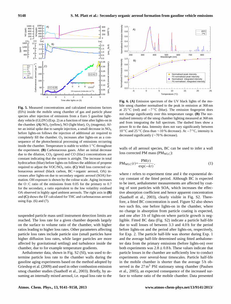
Figure 5 illustrates an example of results from the secondemissions experiment, showing time series and concentra-tions of several gas phase species as well as organic aerosolconcentrations measured from the smog chamber and thetemperature inside the chamber. In the empty chamber, be-fore sample injection, measured particle number concentra-tion is always below the CPC detection limit (< 0.1 cm−3),whereas the CO2 concentration is around 35 ppmv. By mea-suring the increase in CO2 and CH4 due to diffusion ofexternal air into the empty chamber, an average leak rateof 0.08 % h−1 (i.e. ∼9 L h−1) was calculated. These resultsshow that the chamber has minimal contaminants and thatleaks are minor over the course of a typical experiment last-ing 5–6 h (see CO2, green trace, Fig. 5b).
Two blank experiments were performed, where the cham-ber was filled with either pure air, or a mix of pure air andambient air sampled through the heated sampling system andthe lights were switched on. In both experiments< 1 µg m−3
of aerosol was formed.
3.1.2 Temperature control
Since the chamber is not housed in an enclosure, the temper-ature inside the bag is that of the ambient. For the gasolineaging experiments the ventilation inside the VELA was suffi-cient to maintain a stable temperature to within 1◦C, despitethe heat generated by the UV lights (see Fig. 5a, grey). Thetemperature gradient was< 1◦C as measured using sensorsT1 and T2 (Fig. 1).
3.1.3 Particle loss rates
During smog chamber experiments particles are lost tothe walls through deposition following diffusion and grav-itational settling. These losses limit the maximum dura-tion of smog chamber experiments by continually removing
www.atmos-chem-phys.net/13/9141/2013/ Atmos. Chem. Phys., 13, 9141–9158, 2013
9148 S. M. Platt et al.: Secondary organic aerosol formation from gasoline vehicle emissions
1600
1200
800
400
CO2
543210-1
Time after lights on (h)
3.0
2.0
1.0
0.0
THC12
8
4
0
CO
2.0
1.5
1.0
0.5
0.0
THC
1000800600400200
0N
Ox(
ppb)
600
400
200
0
O3 (ppb)
200
150
100
50
0
Car
bona
ceou
s ae
roso
l (µg
m-3
)
0.35
0.30
0.25
0.20
0.15
0.10
0.05
0.00
Carbonaceous aerosol (g kg
-1 fuel)
1000800600400200
0
NO
(pp
b)
NOx NO O3
CO2
THC CO OA+BC
(ppm
)
(g kg-1 fuel)
12x106840
OH exposure (molecules cm-3
h)
O:C=0.05
O:C=0.7
A)
B)
C)
Fig. 5. Measured concentrations and calculated emissions factors(EFs) inside the mobile smog chamber of gas and particle phasespecies after injection of emissions from a Euro 5 gasoline light-duty vehicle (GLDV) (Exp. 2) as a function of time after lights-on inthe chamber.(A) NOx (yellow), NO (light blue), O3 (magenta). Af-ter an initial spike due to sample injection, a small decrease in NOxbefore lights-on follows the injection of additional air required tocompletely fill the chamber. O3 increases after lights-on as a con-sequence of the photochemical processing of emissions occurringinside the chamber. Temperature is stable to within 1◦C throughoutthe experiment.(B) Carbonaceous gases. After an initial decreasedue to the dilution, CO2 (green) and CO (lilac) concentrations areconstant indicating that the system is airtight. The increase in totalhydrocarbon (blue) before lights-on follows the addition of propenerequired to adjust the VOC/NOx ratio. (C) Wall loss corrected car-bonaceous aerosol (black carbon, BC + organic aerosol, OA) in-creases after lights-on due to secondary organic aerosol (SOA) for-mation. OH exposure is shown by the colour scale. Aging increasesthe O : C ratio of the emissions from 0.05 for the primary to 0.7for the secondary, a ratio equivalent to the low volatility oxidisedOA observed in highly aged ambient aerosols. The right axis in(B)and(C) shows the EF calculated for THC and carbonaceous aerosolusing Eqs. (6) and (7).
suspended particle mass until instrument detection limits arereached. The loss rate for a given chamber depends largelyon the surface to volume ratio of the chamber, with higherratios leading to higher loss rates. Other parameters affectingparticle loss rates include particle size (small particles havehigher diffusion loss rates, while larger particles are moreaffected by gravitational settling) and turbulence inside thechamber, due to for example temperature gradients.
Aethalometer data, shown in Fig. S2 (SI), was used to de-termine particle loss rate to the chamber walls during thegasoline aging experiments based on the method adopted byGrieshop et al. (2009) and used in other combustion emissionsmog chamber studies (Saathoff et al., 2003). Briefly, by as-suming an internally mixed aerosol, i.e. equal loss rate to the
1.0
0.8
0.6
0.4
0.2
0.0
Nor
mal
ised
Em
issi
on In
tens
ity
800700600500400300200Wavelength (nm)
1.0
0.8
0.6
0.4
0.2
0.0 Nor
mal
ised
Em
issi
on In
tens
ity
2520151050-5
Temperature (°C)
Normalised peak intensity Fit normalised peak intensity Normalised integrated intensity Fit normalised integrated intensity
25ºC -7ºC
A)
B)
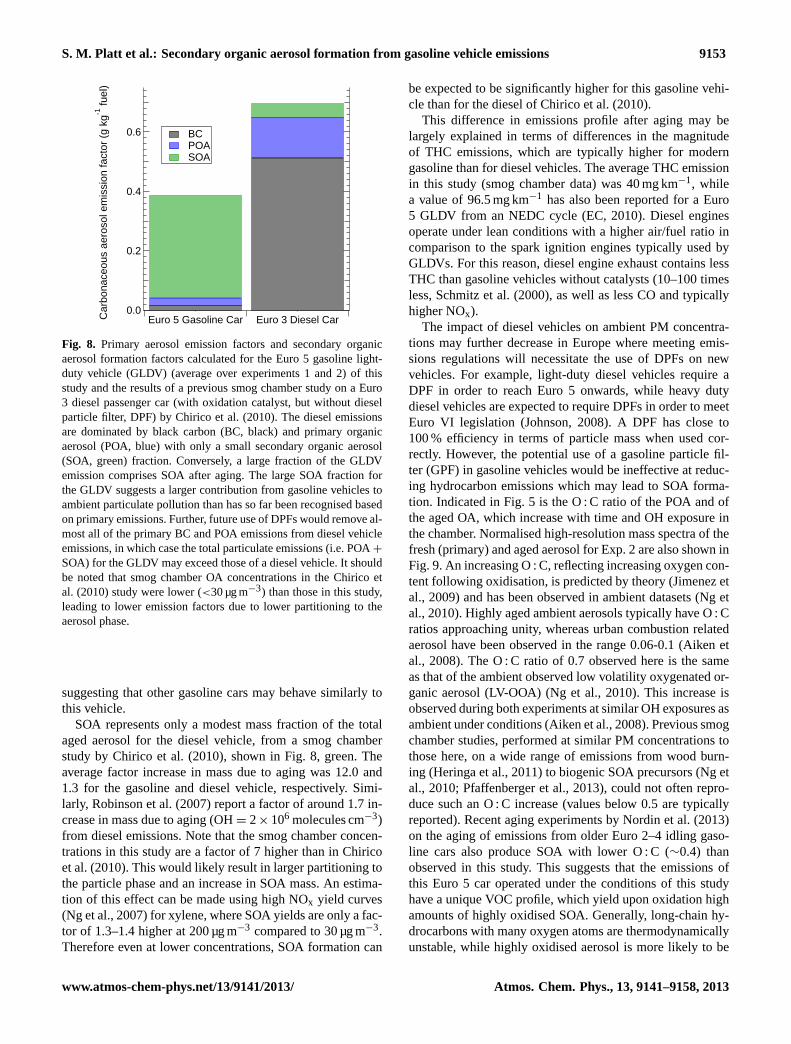
Fig. 6. (A) Emission spectrum of the UV black lights of the mo-bile smog chamber normalised to the peak in emission at 368 nmat 25◦C (red) and−7◦C (blue). The emission fingerprint doesnot change significantly over this temperature range.(B) The nor-malised intensity of the smog chamber lighting measured at 368 nmand from integrating the full spectrum. The dashed lines show apower fit to the data. Intensity does not vary significantly between10◦C and 25◦C (less than∼10 % decrease). At−7◦C, intensity isdecreased significantly (∼70 % decrease).
walls of all aerosol species, BC can be used to infer a wallloss corrected PM mass (PMWLC):
PMWLC(t)=PM(t)
exp(−kt), (1)
wheret refers to experiment time andk the exponential de-cay constant of the fitted period. Although BC is expectedto be inert, aethalometer measurements are affected by coat-ing of soot particles with SOA, which increases the effec-tive absorption coefficient and hence apparent concentration(Saathoff et al., 2003), clearly visible in Fig. S2. There-fore, a fitted BC concentration is used. Figure S2 also showstwo such fits, one before lights-on in the chamber, whereno change in absorption from particle coating is expected,and one after 3 h of lights-on where particle growth is neg-ligible. Fitted BC data (Fig. S2) indicate a particle half-lifedue to wall losses of between 3.3 and 4.0 h for the periodbefore lights-on and the period after lights-on, respectively,for Exp. 2. The particle half-life was shorter during Exp. 1and the average half-life determined using fitted aethalome-ter data from the primary emissions (before lights-on) overboth experiments was 2.8± 0.8 h. These values indicate thatparticle losses in the chamber are sufficiently low to conductexperiments over several-hour timescales. Particle half-lifein the mobile chamber is shorter than the average 5 h ob-served in the 27 m3 PSI stationary smog chamber (Paulsenet al., 2005), an expected consequence of the increased sur-face to volume ratio of the mobile chamber. Data presented
Atmos. Chem. Phys., 13, 9141–9158, 2013 www.atmos-chem-phys.net/13/9141/2013/

S. M. Platt et al.: Secondary organic aerosol formation from gasoline vehicle emissions 9149
here are all corrected for wall losses. The pre-UV exposurefit before lights-on was chosen to correct for losses as the fitafter lights is more likely to be influenced by coating. Sig-nificant influences due to turbulence during aging as a resultof heating from the lights are not expected as only a smallchange in temperature after UV light exposure was observedand a longer half-life is observed during lights-on (Fig. S2).
3.1.4 Actinometry
Figure 6a shows the light spectrum at 25◦C (red) and−7◦C(blue) of the UV lights of the mobile smog chamber nor-malised to the peak intensity. The peak in emission is at368 nm and is in a narrow window between 310 and 430 nm.The emission fingerprint as a function of wavelength andtemperature (I (λ,T )), of the smog chamber lighting over-laps with the absorption cross section (σ(λ,T )) for the pho-tolysis of many important atmospheric trace gases includingthe OH radical sources O3, HONO, and HCHO, as well asNO2 (Carter, 1995). Therefore although emission intensitymay be higher than sunlight over the spectral region at whichUV lights emit and much of the solar spectrum is not repre-sented, UV lights are a good substitute for ambient sunlightin smog chambers (Carter, 1995). An advantage of UV lightsover other light sources, such as for example xenon arc lights,is that they do not produce significant heat. Consequently UVblack lights are used in many environmental reaction cham-bers.
The photolysis rate of NO2 (JNO2) can be calculated usingthe photostationary steady-state relation:
[O3]=JNO2[NO2]
k[NO], (2)
where the concentrations of O3, NO2 and NO as well asthe rate constantk between O3 and NO are known (Sein-feld and Pandis, 2006), in this case from smog chamber mea-surements. NOx was measured with both Thermo and Mon-itor Labs NOx analysers (Table 1), and an averageJNO2 of(8.0± 0.7)× 10−3 s−1 was calculated from Eq. (2), after acorrection of 5 % to account for formation of NO2 in the(dark) sampling lines.
JNO2 as a function of wavelength and temperature withina given windowλ2− λ1 is given by
JNO2(λ,T ) =
λ2∫λ1
ϕNO2(λ,T ) · σNO2(λ,T ) · I (λ,T )dλ, (3)
where (λ,T ) is the quantum yield of NO2 photolysis as afunction of wavelength and temperature (Seinfeld and Pan-dis, 2006). Thus, whileI (λ,T ) in Fig. 6a is given by thelight photometer in arbitrary units only, absolute values forthe photolysis rates of a compoundi(Ji) can be inferred from
JNO2:
Ji = JNO2 ·
∫ λ2λ1 ϕi(λ,T ) · σi(λ,T ) · I (λ,T )dλ∫ λ2
λ1 ϕNO2(λ,T ) · σNO2(λ,T ) · I (λ,T )dλ. (4)
Inferred photolysis rates at 25◦C from Eq. (4) are given forseveral compounds in Table 5, where International Union ofPure and Applied Chemistry (IUPAC) recommended valuesof ϕ(λ,T ) andσ(λ,T ) (Atkinson et al., 2004, 2006) wereused in Eq. (4). The predicted photolysis rates show that thelighting system of the mobile smog chamber can be expectedto be particularly effective in generating OH radicals fromHONO when in the presence of NOx, and to a lesser extentfrom O3 and formaldehyde.
Figure 6 also shows that the emission fingerprint is largelyunchanged over the given temperature range. Theoretical rateconstants at−7◦C, shown in Table 5, were also determinedusing Eq. (4). Methodology for the calculation ofφ−7◦C(λ)
andσ−7◦C(λ) for each compound is given in the Supplement.ForI −7◦C(λ), measured values (Fig. 6a, blue) were used. Ta-ble 5 also shows the ratio of gas phase photolysis ratesJi at−7◦C and 25◦C, Ji,−7◦C/Ji,25◦C . The ratio is in the range0.30–0.41, while the ratio in emission intensity at these tem-peratures,I−7◦C(λ)/I−25◦C(λ), is 0.28 (Fig. 6b). Therefore,the decrease in photolysis rates can be largely explained interms of the decrease in emission intensity of the UV lights.A power fit (dashed lines Fig. 3b) of the measured intensityat different temperatures can therefore be used to predict therelative gas phase photolysis rate of speciesi as a function oftemperature (Jrel,i(T )):
Jrel,i(T ) = Ji(25◦C) ·
(−0.064·
(1.080
1+ exp(−2.466− (T /6.218)
)). (5)
Equation (5) suggests that although significant loss of inten-sity occurs at low temperatures, the lighting in the mobilechamber will still initiate photochemistry. The mobile cham-ber can thus be utilised for aerosol aging studies even at zeroor sub-zero temperatures. Under such conditions the HONOinjection system described in Sect. 2.1 could be used to com-pensate for the loss in intensity by providing an additionalOH source. As Fig. 6 illustrates the mobile chamber may beoperated down to∼10◦C without large loss in light intensity.
For the gasoline aging experiments the OH exposure waszero before the lights were switched on. The integrated expo-sure at the end of each experiment, after UV light exposureand aging, was around 12× 106 molecules cm−3 h (colourscale, Fig. 5). Assuming a global annual mean concentrationof 106 OH molecules cm−3 (Prinn et al., 2001), this corre-sponds to 12 h in the atmosphere, thereby demonstrating thatthe lighting of the chamber generates sufficient OH to studyatmospheric processes occurring over relevant timescales.
While this study shows that the mobile chamber lightingcan be used to simulate atmospheric photochemistry over arange of temperatures, uncertainties remain. The photolysisrates of some compounds, notably ketones and aldehydes,
www.atmos-chem-phys.net/13/9141/2013/ Atmos. Chem. Phys., 13, 9141–9158, 2013

9150 S. M. Platt et al.: Secondary organic aerosol formation from gasoline vehicle emissions
may be enhanced compared to ambient conditions when us-ing UV lights (Carter, 1995). Furthermore, oxidised SOAmass can be lost under UV black lights when OH concen-tration decreases from 107 to 106 molecules cm−3 s−1 (Don-ahue et al., 2012). This suggests that photolysis and otherOA processing pathways initiated by the UV lights competewith the photooxidation pathways responsible for SOA for-mation. That is, the relative importance of SOA decay (due tophotolysis pathways) compared to SOA production via OHoxidation is increased when OH concentration is lowered.
This is consistent with the photolysis rates in Table 5.For example, usingkOH = 1.1× 10⁻¹¹ cm3 molecule−1 s−1
for glyoxal and OH = 106 cm−3, photolysis would accountfor ∼40 % of glyoxal decay in the smog chamber. AtOH = 107 cm−3 this drops to∼6 %. Such effects could the-oretically lead to an underestimation of the SOA productionfor the gasoline vehicle in this study relative to ambient con-ditions. However, the UV light and sunlight spectra overlap,thus the relative importance of the SOA formation/SOA pro-cessing (likely photolysis) pathways will depend both on rel-ative light intensity and OH concentrations, each highly vari-able in smog chambers and the ambient atmosphere.
3.2 Gasoline exhaust aging experiments
Figure 5 shows the concentrations measured with respectto time for several gas phase species as well as organicaerosol concentrations measured from the smog chamberduring Exp. 2. Using this data, emission factors for a pollu-tantP per mass of combusted fuel (EFMASS), shown on theright axis for aerosol and hydrocarbon emissions as a func-tion of time in Fig. 5, were calculated based on a carbon massbalance approach (adapted from Phuleria et al., 2006):
EFMASS =
(1P
1CCO2 + 1CCO+ 1CHC + 1COC+ 1CBC
)· Wc, (6)
whereC denotes carbon mass from CO2, CO, gas phase hy-drocarbon (HC), particle phase organic carbon (OC), fromhigh-resolution AMS analysis (Aiken et al., 2008) and blackcarbon (BC).WC is the fuel carbon mass fraction, 0.859, forthe gasoline used. All values are determined from the changein concentration (1) observed in the smog chamber beforeand after sample injection or aging.
An emission factor per km (EFKM ) can then be calculatedbased on fuel economy:
EFKM = EFMASS · e · ρ, (7)
where e is the fuel economy, 5.27 and 5.22 L 100 km−1
for Exp. 1 and 2, respectively, andρ is the fuel density,0.759 kg L−1 for the gasoline fuel used. Vehicle test cell (e.g.ambient temperature, humidity) and vehicle parameters (oiland catalyst temperatures) are presented in Table S3. Notethat a period of several hours (> 5) is required for oil tem-perature to cool to initial temperature after the driving cy-cle. This highlights the importance of the “soaking time”(Sect. 2.3.1) in performing repeatable driving cycles.
3.2.1 Primary emissions
EFs for Exp. 1 and 2, determined from smog chamber datausing Eqs. (6) and (7) for the Euro 5 GLDV regulated com-pounds, CO, HC, non-methane hydrocarbons (NMHC) andNOx, from the primary emissions as well as the Euro 5 limitvalues, are shown in Table 3. HC and NMHC are reported inunits of carbon mass, i.e. g C kg−1 fuel.
Exhaust VOCs measured using Fourier transform infrared(FTIR) spectroscopy and gas chromatography flame ioni-sation detection (GC-FID) are given in Table S4. Figure 7shows exhaust VOCs measured at the CVS using GC-FID inaddition to normalised methane and formaldehyde measuredat the tailpipe and condensed phase material measured in thesmog chamber. Data are presented as a carbon mass balancefor fresh and aged emissions, as well as for raw gasoline(from data shown also in Table S2). An estimate of the agedgas phase (Fig. 7, aged emissions, red) is made by subtractingthe aged secondary organic carbon from the initial VOC. Theaged gas therefore incorporates gas phase reaction productsincluding CO and CO2. Note that a considerable fraction oflighter hydrocarbons are produced, and that the aromatic hy-drocarbon fraction (∼10 %) is somewhat reduced comparedto the raw fuel used (29 %), indicating that raw fuel is not agood proxy for vehicular emitted hydrocarbon, at least not inthis case. The large unidentified fraction of the hydrocarbonemission may include smaller oxygenated compounds, e.g.ethanol, longer chain and branched alkanes and measurementuncertainty. Most of this THC emission (> 90 %) occurs atthe start of the driving cycle (see Fig. 3), when the catalyst iscold, as is to be expected based from previous studies show-ing the importance of the cold start, e.g. Weilenmann et al.(2009).
As shown from the CVS data in Table 3, the GLDV in thisstudy complies with Euro 5 regulations. Furthermore, emis-sion of regulated compounds is close to those previously ob-served from a Euro 5 GLDV during the NEDC cycle (EC,2010, and Internal Communication, Joint Research Centre)as well as from a Euro 4 GLDV tested during different driv-ing cycles (Chirico et al., 2013).
Table 4 shows EFs for carbonaceous aerosol from theGLDV. Black carbon (BC) emission factors were calcu-lated using aethalometer data, presented in Fig. S2. ValuesEFMASS = 20.0× 10⁻³ and 11.2× 10⁻³ g BC kg−1 were ob-tained for Exp. 1 and 2, respectively. A higher value, EFMASSof 52.5× 10⁻³ g BC kg−1 fuel, is used in the emission inven-tory of Bond et al. (2004), for regions, e.g. United States andEurope, where relatively stringent emissions controls werein place as of 2004. This is consistent with the adoption ofemissions controls and newer engine technology subsequentto 2004, e.g. Euro 4 in 2005 and Euro 5 in 2008. As expected,BC emissions for the GLDV were much lower than those ob-served for a diesel light-duty vehicle (Chirico et al., 2010),Fig. 8, black. TheAngstrom exponent (α), a standardisedparameter describing the decrease in light absorbance with
Atmos. Chem. Phys., 13, 9141–9158, 2013 www.atmos-chem-phys.net/13/9141/2013/

S. M. Platt et al.: Secondary organic aerosol formation from gasoline vehicle emissions 9151
Table 3.Emission factors for regulated compounds calculated for a Euro 5 gasoline light-duty vehicle from smog chamber data and VELA(CVS) data, averaged over two experiments, and Euro 5 limit values for gasoline light-duty vehicles. For smog chamber data, the range ofobserved values, lowest–highest, is given.
CO THC NMHC NOx
From smog chamber data
EFMASS (g kg−1 fuel) 12.69–13.87 0.91–1.06 0.77–0.86 0.72–1.06EFKM (g km−1) 0.50–0.55 0.036–0.042 0.030–0.034 0.028–0.041
From CVS data
EFMASS (g kg−1 fuel) 18.84± 0.68 1.75± 0.21 1.75± 0.21 0.89± 0.14EFKM (g km−1) 0.741± 0.03 0.069± 0.009 0.069± 0.009 0.035± 0.005
Euro 5 limit values for GLDVs
EFKM (g km−1) 1.000 0.100 0.068 0.060
Table 4.Range of emission factors for carbonaceous aerosol and secondary organic aerosol formation for a Euro 5 gasoline light-duty vehiclecalculated from smog chamber data and particulate matter (PM) from VELA (CVS) data. The range of observed values is given.
Emission factor (EF) Black carbon(BC)× 10−3
Primary organicaerosol (POA)× 10−3
Total primary(BC+POA)× 10−3
Secondary organicaerosol formation(SOA) × 10−3
From smog chamber data
EFMASS (g kg−1 fuel) 11.2–20.0 24.5± 19.7 25.8–40.5 344–347EFKM (g km−1) 1.2–1.7 0.4–1.4 1.0–2.2 12.2-13.2
From CVS data
EFKM (g km−1) NA NA 1.1–1.7 NA
respect to wavelength for BC, and a useful tool for sourceapportionment (Sandradewi et al., 2008) is also shown inFig. S2 for Exp. 2. The initial value of 1.2 was obtained foraerosols from the gasoline car, which is higher than valuesreported for diesel cars (Sandradewi, 2008, and referencestherein). A slow reduction ofα during the experiment wasobserved, except immediately after the UV light switch-on,where a transient increase ofα is observed. These changescould be caused by an increase of coating thickness due tocondensation or evaporation, and oxidation of the adsorbedspecies.
As Fig. 8 shows, POA emissions from the GLDV are lowerthan those previously reported for a Euro 3 diesel vehicleequipped with an oxidation catalyst, but no diesel particlefilter (DPF) (Chirico et al., 2010). An alternative, gravimet-ric measurement of primary PM measured from the CVS isalso reported in Table 4. PM emission factors are close to thecombined OA+BC taken from the chamber (see Fig. S3),suggesting that there are only small errors in the reportedprimary emission factors. Small variation in the methodolo-gies likely results from a number of factors including, butnot limited to, (i) adsorption artefacts on the filters, (ii) ef-fects due to lower-than-smog chamber dilution in the CVS,
(iii) error in the aethalometer estimation of BC, and (iv) er-ror in the SMPS measurement due to differences in effectiveand mobility diameters. A high-resolution AMS mass spec-trum of the POA from Exp. 2 is presented in Fig. 9. POAemissions are highly hydrocarbon like, containing very fewoxidised fragments.
Measurements of the average THC concentration in theraw exhaust vs. those in the chamber could be also used toquantify VOC losses in the sampling system of the mobilechamber. Chirico et al. (2010) suggest that SOA formationis unaffected by sampling line temperature over the rangeof 80–150◦C, since an aerosol sample will respond dynam-ically to changes in temperature and concentration. That is,upon entering the smog chamber, emitted particles will par-tition as though in the atmosphere, regardless of temperatureand concentration in the sampling system itself. However,SOA formation may also be influenced by the loss of gaseousprecursors in the emission sampling lines. Assuming no lossof inert CO2 in the system, the fraction of THC lost in thesampling lines can be estimated:
THC lost= 1−
(1THCChamber/THCExhaust
1CO2Exhaust/CO2Exhaust
), (8)
www.atmos-chem-phys.net/13/9141/2013/ Atmos. Chem. Phys., 13, 9141–9158, 2013

9152 S. M. Platt et al.: Secondary organic aerosol formation from gasoline vehicle emissions
Table 5.Predicted gas phase photolysis rates of selected compounds in the mobile smog chamber at 25◦C and−7◦C.
Compound Reaction Ji Ratio(10−5 s−1) Ji,−7◦C /Ji,25◦C
25◦C −7◦C
Nitrogen dioxide NO2> NO+O(3P) 797 259 0.32Ozone O3> O(1D) 43.1 17.8 0.41Nitrous acid HONO> OH+NO 214 68.4 0.32Nitrate NO3> NO + O2 0.00 0.00 –
NO3> NO2+O(3P) 444 135 0.30
Formaldehyde HCHO>HCO+H 1.50 0.53 0.36
HCHO> CO+H2 3.74 1.35 0.36Acetaldehyde CH3CHO>products 0.11 – –Methyl hydroperoxide. CH3OOH>products 0.43 – –Glyoxal (CHO)2>products 0.71 – –Methyl vinyl ketone CH3C(O)CH=CH2> products 0.34 – –Acetone CH3C(O)CH3> products 0.01 – –Methyl nitrate CH3ONO2> products 0.29 – –Peroxy acetyl nitrate (PAN) CH3C(O)OONO2> products 0.04 – –
100
80
60
40
20
0
% C
Fresh emissions Aged emissions Raw gasoline
Aged gases Aged OC C1 C2 C3 C4 C5 C6 C7 C8 POA Aromatic Other Black carbon
Fig. 7.Composition of fresh and smog chamber aged exhaust emis-sions (CO2 normalised) from a Euro 5 gasoline light-duty vehicle(Exp. 2), and raw gasoline fuel. Data are presented as a carbon massbalance. The following species were included: C1: methane andformaldehyde; C2: ethane, acetylene and ethane; C3: propane andpropene; C4: isobutane, n-butane, trans-2-butene, 1-butene, cis-2-butene, and 1,3-butadiene; C5: 2-methylbutane, n-pentane, trans-2-pentene, 1-pentene, and isoprene; C6: 2-methylpentane and hexane;C7: n-heptane; C8: 2,2,4-trimethylpentane and n-octane.
where1THCChamberand1CO2Chamberdenotes the changein THC and CO2 concentration measured in the smog cham-ber, respectively, andTHCExhaustandCO2Exhaustare the av-erage exhaust concentrations of THC and CO2 measured us-ing the FTIR. Note that these average concentrations used forEq. 8 are taken directly from the tailpipe, not the from CVSdata which are reported as emission factors. CO2 in Eq. (8)
can also be replaced with other tracers, such as NO, also mea-sured from both smog chamber and using VELA instrumen-tation. Using this methodology an average THC loss of 20 %was determined, with both NO and CO2 as tracers giving thesame result. This calculated loss encompasses instrument er-ror (two different instruments were used for each gas, onesampling from the chamber and one from the CVS), lossesin instrument sampling lines, the effect of different measure-ment location (CVS in the VELA vs. smog chamber), lossesto the chamber walls as well as losses in the exhaust sam-pling lines. Such losses appear minor, although dependingon which individual VOCs, i.e. whether SOA precursors arelost, and to what extent, a small underestimation of SOA pro-duction is possible.
3.2.2 Secondary organic aerosol formation and aging
Aging of the GLDV emissions resulted in significantSOA formation (Fig. 8) during both experiments, around340× 10−3 g kg−1 fuel (Table 3). Thus for this gasoline carSOA is the dominant fraction (9–15 times higher than thePOA) of emitted or formed aerosol pollution after a relativelyshort time in the ambient atmosphere. This is consistent withrecent results on idling emissions from older gasoline vehi-cle emissions reported by Nordin et al. (2013). Furthermore,this SOA was formed after an OH exposure equivalent to ap-proximately 12 h of ambient aging (assuming a 24 h ambientmean OH concentration of 106 cm−3), indicating that SOAformation occurs rapidly in the atmosphere. This result isconsistent with a recent ambient study which concludes thatgasoline SOA is the largest source of vehicular carbonaceousPM in the Los Angeles basin (Bahreini et al., 2012), again
Atmos. Chem. Phys., 13, 9141–9158, 2013 www.atmos-chem-phys.net/13/9141/2013/
S. M. Platt et al.: Secondary organic aerosol formation from gasoline vehicle emissions 9153
0.6
0.4
0.2
0.0Car
bona
ceou
s ae
roso
l em
issi
on fa
ctor
(g
kg-1
fuel
)
Euro 5 Gasoline Car Euro 3 Diesel Car
BC POA SOA
Fig. 8. Primary aerosol emission factors and secondary organicaerosol formation factors calculated for the Euro 5 gasoline light-duty vehicle (GLDV) (average over experiments 1 and 2) of thisstudy and the results of a previous smog chamber study on a Euro3 diesel passenger car (with oxidation catalyst, but without dieselparticle filter, DPF) by Chirico et al. (2010). The diesel emissionsare dominated by black carbon (BC, black) and primary organicaerosol (POA, blue) with only a small secondary organic aerosol(SOA, green) fraction. Conversely, a large fraction of the GLDVemission comprises SOA after aging. The large SOA fraction forthe GLDV suggests a larger contribution from gasoline vehicles toambient particulate pollution than has so far been recognised basedon primary emissions. Further, future use of DPFs would remove al-most all of the primary BC and POA emissions from diesel vehicleemissions, in which case the total particulate emissions (i.e. POA+
SOA) for the GLDV may exceed those of a diesel vehicle. It shouldbe noted that smog chamber OA concentrations in the Chirico etal. (2010) study were lower (<30 µg m−3) than those in this study,leading to lower emission factors due to lower partitioning to theaerosol phase.
suggesting that other gasoline cars may behave similarly tothis vehicle.
SOA represents only a modest mass fraction of the totalaged aerosol for the diesel vehicle, from a smog chamberstudy by Chirico et al. (2010), shown in Fig. 8, green. Theaverage factor increase in mass due to aging was 12.0 and1.3 for the gasoline and diesel vehicle, respectively. Simi-larly, Robinson et al. (2007) report a factor of around 1.7 in-crease in mass due to aging (OH= 2× 10⁶ molecules cm−3)from diesel emissions. Note that the smog chamber concen-trations in this study are a factor of 7 higher than in Chiricoet al. (2010). This would likely result in larger partitioning tothe particle phase and an increase in SOA mass. An estima-tion of this effect can be made using high NOx yield curves(Ng et al., 2007) for xylene, where SOA yields are only a fac-tor of 1.3–1.4 higher at 200 µg m−3 compared to 30 µg m−3.Therefore even at lower concentrations, SOA formation can
be expected to be significantly higher for this gasoline vehi-cle than for the diesel of Chirico et al. (2010).
This difference in emissions profile after aging may belargely explained in terms of differences in the magnitudeof THC emissions, which are typically higher for moderngasoline than for diesel vehicles. The average THC emissionin this study (smog chamber data) was 40 mg km−1, whilea value of 96.5 mg km−1 has also been reported for a Euro5 GLDV from an NEDC cycle (EC, 2010). Diesel enginesoperate under lean conditions with a higher air/fuel ratio incomparison to the spark ignition engines typically used byGLDVs. For this reason, diesel engine exhaust contains lessTHC than gasoline vehicles without catalysts (10–100 timesless, Schmitz et al. (2000), as well as less CO and typicallyhigher NOx).
The impact of diesel vehicles on ambient PM concentra-tions may further decrease in Europe where meeting emis-sions regulations will necessitate the use of DPFs on newvehicles. For example, light-duty diesel vehicles require aDPF in order to reach Euro 5 onwards, while heavy dutydiesel vehicles are expected to require DPFs in order to meetEuro VI legislation (Johnson, 2008). A DPF has close to100 % efficiency in terms of particle mass when used cor-rectly. However, the potential use of a gasoline particle fil-ter (GPF) in gasoline vehicles would be ineffective at reduc-ing hydrocarbon emissions which may lead to SOA forma-tion. Indicated in Fig. 5 is the O : C ratio of the POA and ofthe aged OA, which increase with time and OH exposure inthe chamber. Normalised high-resolution mass spectra of thefresh (primary) and aged aerosol for Exp. 2 are also shown inFig. 9. An increasing O : C, reflecting increasing oxygen con-tent following oxidisation, is predicted by theory (Jimenez etal., 2009) and has been observed in ambient datasets (Ng etal., 2010). Highly aged ambient aerosols typically have O : Cratios approaching unity, whereas urban combustion relatedaerosol have been observed in the range 0.06-0.1 (Aiken etal., 2008). The O : C ratio of 0.7 observed here is the sameas that of the ambient observed low volatility oxygenated or-ganic aerosol (LV-OOA) (Ng et al., 2010). This increase isobserved during both experiments at similar OH exposures asambient under conditions (Aiken et al., 2008). Previous smogchamber studies, performed at similar PM concentrations tothose here, on a wide range of emissions from wood burn-ing (Heringa et al., 2011) to biogenic SOA precursors (Ng etal., 2010; Pfaffenberger et al., 2013), could not often repro-duce such an O : C increase (values below 0.5 are typicallyreported). Recent aging experiments by Nordin et al. (2013)on the aging of emissions from older Euro 2–4 idling gaso-line cars also produce SOA with lower O : C (∼0.4) thanobserved in this study. This suggests that the emissions ofthis Euro 5 car operated under the conditions of this studyhave a unique VOC profile, which yield upon oxidation highamounts of highly oxidised SOA. Generally, long-chain hy-drocarbons with many oxygen atoms are thermodynamicallyunstable, while highly oxidised aerosol is more likely to be
www.atmos-chem-phys.net/13/9141/2013/ Atmos. Chem. Phys., 13, 9141–9158, 2013

9154 S. M. Platt et al.: Secondary organic aerosol formation from gasoline vehicle emissions
0.20
0.15
0.10
0.05
0.00
frac
tio
n/O
rg
12010080604020m/z
Cx CH CHO1 CHOgt1 HO
0.20
0.15
0.10
0.05
0.00
frac
tio
n/O
rg
12010080604020m/z
Cx CH CHO1 CHOgt1 HO
OH=0·106 cm-3h OH=12·106 cm-3h
Fig. 9. High-resolution aerosol mass spectra measured at the mobile smog chamber of fresh primary and aged emission at an OH exposureof 12× 106 cm−3 h from a gasoline light-duty vehicle.
produced in fewer generations from smaller precursor hydro-carbons (Kroll et al., 2011). Therefore, this suggests that theremarkably high O : C ratio here results from the oxidationand condensation of smaller, unknown SOA precursor hy-drocarbons or processes.
3.2.3 Secondary organic aerosol yields
A SOA yieldY is defined as
Y =1OA
1VOC, (9)
where1OA is the aerosol produced for a given change inreactive hydrocarbon concentration1VOC. Unfortunately,information on how much of initial hydrocarbon emissionhas reacted inside the smog chamber to produce SOA dur-ing this study is not available; the THC analyser does notdiscriminate between the initial VOC and gas phase reactionproducts. However, Fig. 7 indicates that despite significantSOA production, only around 5 % of emitted VOC and par-ticle phase carbon condenses to the particle phase. That is,a large SOA yield is not required in order to account for theSOA production observed from this vehicle.
An estimated maximum SOA production (1OApredicted)from light aromatic hydrocarbons in the emissions (benzene,toluene, C2-benzenes, C3-benzenes or naphthalene) can bedetermined using
1OApredicted=∑
i
(1i × Yi), (10)
where1i is the change in concentration of an aromatic hy-drocarboni, measured from the smog chamber using PTR-ToF-MS, and Yi is the low NOx SOA yield of aromatici.SOA yields for benzene, toluene, andm-xylene (∼0.3) aretaken from Ng et al. (2007). The low NOx SOA yield form-xylene is used for all C2 and C3 benzenes, while the SOAyield for naphthalene (0.73) is taken from Chan et al. (2009).Low NOx yields are used since these are higher than high
200
150
100
50
043210
Time after lights on (h)
200
150
100
50
0
Con
cent
ratio
n (µ
g m
-3)
Observed SOA Predicted toluene SOA Predicted C2-benzene SOA Predicted C3-benzene SOA Predicted C4-benzene SOA Predicted naphthalene SOA
A)
B)
Fig. 10.Observed secondary organic aerosol (SOA) formation, wallloss corrected, green, in the mobile smog chamber during aging ofemissions from a Euro 5 gasoline light-duty vehicle and predictedSOA formation based on measurement of aromatic hydrocarbon de-cay for Exp. 1(A) and Exp. 2(B). Low NOx yields are used topredict SOA from the aromatics in order to provide an upper limit.Only a small fraction of observed SOA is explained by the oxidationof aromatic hydrocarbons.
NOx yields, thereby allowing a maximum estimation. Fig. 10shows that, using this methodology1OApredicted accountsfor < 20 % of the observed SOA production. Candidate non-aromatic (unknown) precursors may include smaller, highlyoxygenated hydrocarbons, as suggested by the high O : Cratio of the aged OA (see Sect. 3.2.2, above). Odum etal. (1997) assume that the composition of gasoline vehicleexhaust matches that of raw gasoline and suggest that SOAformation from gasoline vehicle emissions may be accountedfor by aromatic oxidation. However, Fig. 7 shows that al-though there would be enough aromatic hydrocarbons in theraw fuel to produce the SOA observed here while only requir-ing modest SOA yields, the VOC composition of the exhaust
Atmos. Chem. Phys., 13, 9141–9158, 2013 www.atmos-chem-phys.net/13/9141/2013/

S. M. Platt et al.: Secondary organic aerosol formation from gasoline vehicle emissions 9155
is significantly different to that of raw gasoline. Strikingly,the total carbon content of the aged OA is actually higherthan the total carbon emitted as light aromatic hydrocarbons.This demonstrates that, at least in the case of this vehicle,aromatics in raw gasoline cannot be used to account forSOA production. This result is consistent with previous vehi-cle emission aging studies (Robinson et al., 2007; Grieshopet al., 2009). However, these results contradict Nordin etal. (2013), who suggest that around 60 % of SOA may beexplained by aromatic oxidation. This may be a consequenceof the different methodology employed,; Nordin et al. (2013)used older test vehicles which were operated under engineidling and relatively low temperature (ambient, outdoor).This suggests an influence of driving conditions on SOA for-mation. To understand and quantify SOA formation from ve-hicles, emissions generated under controlled, repeatable, andas realistic as possible conditions may be required.
4 Conclusions
We have shown that the new Paul Scherrer Institute mobileenvironmental reaction chamber can be of considerable util-ity in atmospheric science. Due to the flexible design of thechamber, a wide range of emissions aging or ambient studiesare possible with a single facility. We have characterised themobile smog chamber and demonstrated its utility and po-tential with results from measurements at a specialised test-ing facility, the European Commission Joint Research Centre(JRC).
We have demonstrated that a modern gasoline car can pro-duce significantly higher secondary aerosol than the emittedprimary (up to 15 times). This is consistent with very recentemission and ambient studies (Bahreini et al., 2012; Nordinet al., 2013) and has not previously been observed for tailpipeemissions from diesel vehicles. Furthermore, gasoline vehi-cle SOA appears in this case to be highly oxygenated, formedfrom unknown precursors or mechanisms.
So far no experimental data, other than those here, havebeen published on SOA formation from gasoline vehicles op-erated the under controlled, repeatable conditions offered bya dedicated vehicle testing facility. Ultimately however, morework is needed to study real tailpipe emissions from morevehicles than the single car presented in this study, espe-cially as SOA formation under experimental conditions maybe highly variable, varying with background OA concentra-tion and VOC/NOx levels.
Furthermore, given that real tailpipe emissions can be sig-nificantly different to raw gasoline, and that emissions likelyvary according to driving conditions, future studies shouldaim to replicate real-world driving as closely as possible inorder to better estimate and understand SOA formation fromvehicles.
Supplementary material related to this article isavailable online at:http://www.atmos-chem-phys.net/13/9141/2013/acp-13-9141-2013-supplement.pdf.
Acknowledgements.This work was supported by the Swiss Fed-eral Office for the Environment (FOEN), the Federal Roads Office(FEDRO), the Swiss National Science Foundation (SNSF) for SAP-MAV (No. 20002113016) and Ambizione (NF-BBB-A), and TheFrench Environment and Energy Management Agency (ADEME,Grant number 1162C00O2), EUROSTARS grant E!4825 FC Aethand JR-KROP grant 3211-11-000519. Operation part-financed bythe European Union, European Social Fund.
The VELA staff is acknowledged for its skilful technical assistance,in particular Franz Muehlberger, Urbano Manfredi, and Philippe LeLijours.
We appreciate the insights into the details of the Carnegie Mellonmobile chamber and would like to thank the whole group of AllenRobinson and especially Albert Presto.
Edited by: N. M. Donahue
References
Aiken, A. C., DeCarlo, P. F., Kroll, J. H., Worsnop, D. R., Huff-man, J. A., Docherty, K. S., Ulbrich, I. M., Mohr, C., Kimmel,J. R., Sueper, D., Sun, J. Y., Zhang, Q., Trimborn, A., North-way, M. J., Ziemann, P. J., Canagaratna, M., Onasch, T. B., Al-farra, M. R., Prevot, A. S. H., Dommen, J., Duplissy, J., Metzger,A., Baltensperger, U., and Jimenez, J. L.: O/C and OM/OC ra-tios of primary, secondary, and ambient organic aerosols withhigh-resolution time-of-flight aerosol mass spectrometry, Envi-ron. Sci. Technol., 42, 4478–4485, 2008.
Atkinson, R., Baulch, D. L., Cox, R. A., Crowley, J. N., Hamp-son, R. F., Hynes, R. G., Jenkin, M. E., Rossi, M. J., and Troe, J.:Evaluated kinetic and photochemical data for atmospheric chem-istry: Volume I – gas phase reactions of Ox, HOx, NOxand SOxspecies, Atmos. Chem. Phys., 4, 1461–1738, doi:10.5194/acp-4-1461-2004, 2004.
Atkinson, R., Baulch, D. L., Cox, R. A., Crowley, J. N., Hampson,R. F., Hynes, R. G., Jenkin, M. E., Rossi, M. J., Troe, J., and oth-ers: Evaluated kinetic and photochemical data for atmosphericchemistry: Volume II: gas phase reactions of organic species, At-mospheric Chemistry and Physics, 6, 3625-4055, 2006.
Bahreini, R., Middlebrook, A. M., de Gouw, J. A., Warneke, C.,Trainer, M., Brock, C. A., Stark, H., Brown, S. S., Dube, W.P., Gilman, J. B., and others: Gasoline emissions dominate overdiesel in formation of secondary organic aerosol mass, Geophys.Res. Lett., 39, L06805, doi:10.1029/2011GL050718, 2012.
Barlow, T. J., Latham, S., McCrae, P. G., and Boulter, P. G.: Areference book of driving cycles for use in the measurementof road vehicle emissions (2009), United Kingdom TransportResearch Laboratory (TRL),http://www.trl.co.uk/onlinestore/reportspublications/trlreports/cattraffic and the environment/reporta referencebook of driving cyclesfor usein themeasurementof roadvehicleemissions.htm, (last access:2 May 2012), 2009.
www.atmos-chem-phys.net/13/9141/2013/ Atmos. Chem. Phys., 13, 9141–9158, 2013

9156 S. M. Platt et al.: Secondary organic aerosol formation from gasoline vehicle emissions
Barmet, P., Dommen, J., DeCarlo, P. F., Tritscher, T., Praplan, A. P.,Platt, S. M., Prevot, A. S. H., Donahue, N. M., and Baltensperger,U.: OH clock determination by proton transfer reaction massspectrometry at an environmental chamber, Atmos. Meas. Tech.,5, 647–656, doi:10.5194/amt-5-647-2012, 2012.
Bond, T. C., Streets, D. G., Yarber, K. F., Nelson, S. M., Woo, J. H.,and Klimont, Z.: A technology-based global inventory of blackand organic carbon emissions from combustion, J. Geophys. Res.Lett., 109, D14203, doi:10.1029/2003JD003697, 2004.
Carter, W. P. L.: National Renewable Energy Laboratory (US),Environmental chamber studies of atmospheric reactivities ofvolatile organic compounds: Effects of varying chamber and lightsource, Statewide Air Pollution Research Center, 1995.
Chan, A. W. H., Kautzman, K. E., Chhabra, P. S., Surratt, J. D.,Chan, M. N., Crounse, J. D., Kurten, A., Wennberg, P. O.,Flagan, R. C., and Seinfeld, J. H.: Secondary organic aerosolformation from photooxidation of naphthalene and alkylnaph-thalenes: implications for oxidation of intermediate volatility or-ganic compounds (IVOCs), Atmos. Chem. Phys., 9, 3049–3060,doi:10.5194/acp-9-3049-2009, 2009.
Chirico, R., DeCarlo, P. F., Heringa, M. F., Tritscher, T., Richter,R., Prevot, A. S. H., Dommen, J., Weingartner, E., Wehrle, G.,Gysel, M., Laborde, M., and Baltensperger, U.: Impact of af-tertreatment devices on primary emissions and secondary or-ganic aerosol formation potential from in-use diesel vehicles: re-sults from smog chamber experiments, Atmos. Chem. Phys., 10,11545–11563, doi:10.5194/acp-10-11545-2010, 2010.
Chirico, R., Clairotte, M., Adam, T. W., Giechaskiel, B., Heringa,M. F., Elasser, M., Martini, G., Manfredi, U., DeCarlo, P. F.,Streibel, T., Sklorz, M., Zimmermann, R. A., C., Baltensperger,U., and Prevot, A. S. H.: Chassis dynamometer measurementsof organic mass, black carbon, particle number, and regulatedand unregulated gas emissions from scooters and light and heavyduty vehicles, in preparation, 2013.
Clairotte, M., Adam, T. W., Chirico, R., Giechaskiel, B., Manfredi,U., Elsasser, M., Sklorz, M., DeCarlo, P. F., Heringa, M. F., Zim-mermann, R., Martini, G., krasenbrink, A., Vicet, A., Tournie,E., Prevot, A. S. H., and Astorga, C.: Online Characterizationof Regulated and Unregulated Gaseous and Particulate ExhaustEmission from Two-Stroke Mopeds: A Chemometric Approach,Anal. Chim. Acta, 44, 505–512, 2011.
DeCarlo, P. F., Kimmel, J. R., Trimborn, A., Northway, M. J., Jayne,J. T., Aiken, A. C., Gonin, M., Fuhrer, K., Horvath, T., Docherty,K. S., Worsnop, D. R., and Jimenez, J. L.: Field-deployable,high-resolution, time-of-flight aerosol mass spectrometer, Anal.Chem., 78, 8281–8289, 2006.
Dockery, D. W. and Pope, C. A.: Acute respiratory effects of partic-ulate air pollution, Ann. Rev. Pub. Health, 15, 107–132, 1994.
Dockery, D. W., Pope, C. A., Xu, X., Spengler, J. D., Ware, J. H.,Fay, M. E., Ferris Jr, B. G., and Speizer, F. E.: An associationbetween air pollution and mortality in six US cities, New Engl.J. Med., 329, 1753–1759, 1993.
Donahue, N. M., Robinson, A. L., Stanier, C. O., and Pandis,S. N.: Coupled partitioning, dilution, and chemical aging ofsemivolatile organics, Environ. Sci. Technol., 40, 2635–2643,2006.
Donahue, N. M., Henry, K. M., Mentel, T. F., Kiendler-Scharr, A.,Spindler, C., Bohn, B., Brauers, T., Dorn, H. P., Fuchs, H., Till-mann, R., Wahner, A., Saathoff, H., Naumann, K.-H., Moehler,
O., Leisner, T., Mueller, L., Reinnig, M.-C., Hoffmann, T., Salo,K., Hallquist, M., Frosch, M., Bilde, M., Tritscher, T., Barmet,P., Praplan, A. P., DeCarlo, P. F., Dommen, J., Prevot, A. S. H.,and Baltensperger, U.: Aging of Secondary Organic Aerosol viaGas-Phase OH Radical Reactions, Proc. Natl. Acad. Sci. USA,109, 13503–13508, 2012.
EEA: EMEP/ CORINAIR Emission Inventory Guidebook,European Environment Agency,http://reports.ee.europa.eu/EMEPCORINAIR4(last access: 2 May 2012), Technical Report11/2006, 2006.
EC: European Commission Regulation No 692/2008 of 18 July2008 implementing and amending Regulation (EC) No 715/2007of the European Parliament and of the Council on type-approvalof motor vehicles with respect to emissions from light passengerand commercial vehicles (Euro 5 and Euro 6) and on access tovehicle repair and maintenance information., Official Journal ofthe European Communities, L199, 2008.
EC: Regulated emissions of a Euro 5 passenger car mea-sured over different driving cycles, European CommissionJoint Research Centre (JRC) Institute for Environment andSustainability, http://www.unece.org/fileadmin/DAM/trans/doc/2010/wp29grpe/WLTP-DHC-04-03e.pdf(last access: 9 July2012), 2010.
EEC: The Council of the European Communities. Council Directive70/220/EEC of 20 March 1970 on the approximation of the lawsof the Member States relating to measures to be taken againstair pollution by gases from positive-ignition engines of motorvehicles, Official Journal of the European Communities, L076,1–22, 1970.
Gentner, D. R., Isaacman, G., Worton, D. R., Chan, A. W. H., Dall-mann, T. R., Davis, L., Liu, S., Day, D. A., Russell, L. M., Wil-son, K. R., and others: Elucidating secondary organic aerosolfrom diesel and gasoline vehicles through detailed characteriza-tion of organic carbon emissions, Proc. Natl. Acad. Sci., 109,18318–18323, 2012.
Graus, M., Muller, M., and Hansel, A.: High Resolution PTR-TOF:Quantification and Formula Confirmation of VOC in Real Time,J. Am. Soc. Mass Spectrom., 1037–1044, 2010.
Grieshop, A. P., Logue, J. M., Donahue, N. M., and Robinson, A.L.: Laboratory investigation of photochemical oxidation of or-ganic aerosol from wood fires 1: measurement and simulation oforganic aerosol evolution, Atmos. Chem. Phys., 9, 1263–1277,doi:10.5194/acp-9-1263-2009, 2009.
Hallquist, M., Wenger, J. C., Baltensperger, U., Rudich, Y., Simp-son, D., Claeys, M., Dommen, J., Donahue, N. M., George,C., Goldstein, A. H., Hamilton, J. F., Herrmann, H., Hoff-mann, T., Iinuma, Y., Jang, M., Jenkin, M. E., Jimenez, J. L.,Kiendler-Scharr, A., Maenhaut, W., McFiggans, G., Mentel, Th.F., Monod, A., Prevot, A. S. H., Seinfeld, J. H., Surratt, J. D.,Szmigielski, R., and Wildt, J.: The formation, properties and im-pact of secondary organic aerosol: current and emerging issues,Atmos. Chem. Phys., 9, 5155–5236, doi:10.5194/acp-9-5155-2009, 2009.
Heringa, M. F., DeCarlo, P. F., Chirico, R., Tritscher, T., Dommen,J., Weingartner, E., Richter, R., Wehrle, G., Prevot, A. S. H.,and Baltensperger, U.: Investigations of primary and secondaryparticulate matter of different wood combustion appliances witha high-resolution time-of-flight aerosol mass spectrometer, At-mos. Chem. Phys., 11, 5945–5957, doi:10.5194/acp-11-5945-
Atmos. Chem. Phys., 13, 9141–9158, 2013 www.atmos-chem-phys.net/13/9141/2013/

S. M. Platt et al.: Secondary organic aerosol formation from gasoline vehicle emissions 9157
2011, 2011.IPCC: Contribution of Working Group I to the Fourth Assessment
Report of the Intergovernmental Panel on Climate Change, ISBN978-0-521-88009-1, Cambridge University Press, 2007.
Jimenez, J. L., Canagaratna, M. R., Donahue, N. M., Prevot, A. S.H., Zhang, Q., Kroll, J. H., DeCarlo, P. F., Allan, J. D., Coe,H., Ng, N. L., Aiken, A. C., Docherty, K. S., Ulbrich, I. M.,Grieshop, A. P., Robinson, A. L., Duplissy, J., Smith, J. D.,Wilson, K. R., Lanz, V. A., Hueglin, C., Sun, Y. L., Tian, J.,Laaksonen, A., Raatikainen, T., Rautiainen, J., Vaattovaara, P.,Ehn, M., Kulmala, M., Tomlinson, J. M., Collins, D. R., Cu-bison, M. J., Dunlea, E. J., Huffman, J. A., Onasch, T. B., Al-farra, M. R., Williams, P. I., Bower, K., Kondo, Y., Schnei-der, J., Drewnick, F., Borrmann, S., Weimer, S., Demerjian, K.,Salcedo, D., Cottrell, L., Griffin, R., Takami, A., Miyoshi, T.,Hatakeyama, S., Shimono, A., Sun, J. Y., Zhang, Y. M., Dzepina,K., Kimmel, J. R., Sueper, D., Jayne, J. T., Herndon, S. C., Trim-born, A. M., Williams, L. R., Wood, E. C., Middlebrook, A. M.,Kolb, C. E., Baltensperger, U., and Worsnop, D. R.: Evolutionof organic aerosols in the atmosphere, Science, 326, 1525–1529,doi:10.1126/science.1180353, 2009.
Johnson, T. V.: Diesel emission control in review, SAE InternationalJournal of Fuels and Lubricants, 1, 68–81, 2008.
Jordan, A., Haidacher, S., Hanel, G., Hartungen, E., L., M., See-hauser, H., Schottkowsky, R., Sulzer, P., and Mark, T. D.: A highresolution and high sensitivity proton-transfer-reaction time-of-flight mass spectrometer (PTR-TOF-MS), Int. J. Mass Spec-trom., 122–128, 2009.
Kroll, J. H., Donahue, N. M., Jimenez, J. L., Kessler, S. H., Cana-garatna, M. R., Wilson, K. R., Altieri, K. E., Mazzoleni, L. R.,Wozniak, A. S., Bluhm, H., Mysak, E. R., Smith, J. D., Kolb,C. E., and Worsnop, D.: Carbon oxidation state as a metric fordescribing the chemistry of atmospheric organic aerosol, NatureChem., 3, 133–139, 2011.
Matthew, B. M., Middlebrook, A. M., and Onasch, T. B.: Collec-tion efficiencies in an Aerodyne Aerosol Mass Spectrometer asa function of particle phase for laboratory generated aerosols,Aerosol Sci. Technol., 42, 884–898, 2008.
Middlebrook, A. M., Bahreini, R., Jimenez, J. L., and Canagaratna,M. R.: Evaluation of composition-dependent collection efficien-cies for the Aerodyne aerosol mass spectrometer using field data,Aerosol Sci. Technol., 46, 258–271, 2012.
Ng, N. L., Kroll, J. H., Chan, A. W. H., Chhabra, P. S., Flagan,R. C., and Seinfeld, J. H.: Secondary organic aerosol formationfrom m-xylene, toluene, and benzene, Atmos. Chem. Phys., 7,3909–3922, doi:10.5194/acp-7-3909-2007, 2007.
Ng, N. L., Canagaratna, M. R., Zhang, Q., Jimenez, J. L., Tian,J., Ulbrich, I. M., Kroll, J. H., Docherty, K. S., Chhabra, P.S., Bahreini, R., Murphy, S. M., Seinfeld, J. H., Hildebrandt,L., Donahue, N. M., DeCarlo, P. F., Lanz, V. A., Prevot, A. S.H., Dinar, E., Rudich, Y., and Worsnop, D. R.: Organic aerosolcomponents observed in Northern Hemispheric datasets fromAerosol Mass Spectrometry, Atmos. Chem. Phys., 10, 4625–4641, doi:10.5194/acp-10-4625-2010, 2010.
Nordin, E. Z., Eriksson, A. C., Roldin, P., Nilsson, P. T., Carlsson,J. E., Kajos, M. K., Hellen, H., Wittbom, C., Rissler, J., Londahl,J., Swietlicki, E., Svenningsson, B., Bohgard, M., Kulmala, M.,Hallquist, M., and Pagels, J. H.: Secondary organic aerosol for-mation from idling gasoline passenger vehicle emissions investi-
gated in a smog chamber, Atmos. Chem. Phys., 13, 6101–6116,doi:10.5194/acp-13-6101-2013, 2013.
Odum, J. R., Hoffmann, T., Bowman, F., Collins, D., Flagan, R.C., and Seinfeld, J. H.: Gas/particle partitioning and secondaryorganic aerosol yields, Environ. Sci. Technol., 30, 2580–2585,1996.
Odum, J. R., Jungkamp, T. P. W., Griffin, R. J., Forstner, H. J. L.,Flagan, R. C., and Seinfeld, J. H.: Aromatics, reformulated gaso-line, and atmospheric organic aerosol formation, Environ. Sci.Technol., 31, 1890–1897, 1997.
Paulsen, D., Dommen, J., Kalberer, M., Prevot, A. S. H., Richter,R., Sax, M., Steinbacher, M., Weingartner, E., and Baltensperger,U.: Secondary Organic Aerosol Formation by Irradiation of 1, 3,5-Trimethylbenzene-NO x-H2O in a New Reaction Chamber forAtmospheric Chemistry and Physics, Environ. Sci. Technol., 39,2668–2678, 2005.
Pfaffenberger, L., Barmet, P., Slowik, J. G., Praplan, A. P., Dom-men, J., Prevot, A. S. H., and Baltensperger, U.: The link betweenorganic aerosol mass loading and degree of oxygenation: an ?-pinene photooxidation study, Atmos. Chem. Phys., 13, 6493–6506, doi:10.5194/acp-13-6493-2013, 2013.
Phuleria, H. C., Geller, M. D., Philip, M., and Sioutas, C.: Size-resolved emissions of organic tracers from light-and heavy-dutyvehicles measured in a California roadway tunnel, Environ. Sci.Technol., 40, 4109–4118, 2006.
Presto, A. A., Nguyen, N. T., Ranjan, M., Reeder, A. J., Lipsky,E. M., Hennigan, C. J., Miracolo, M. A., Riemer, D. D., andRobinson, A. L.: Fine particle and organic vapor emissions fromstaged tests of an in-use aircraft engine, Atmos. Environ., 45,3603–3612, 2011.
Prinn, R. G., Huang, J., Weiss, R. F., Cunnold, D. M., Fraser, P.J., Simmonds, P. G., McCulloch, A., Harth, C., Salameh, P.,O’Doherty, S., and others: Evidence for substantial variations ofatmospheric hydroxyl radicals in the past two decades, Science,292, 1882–1888, 2001.
Robinson, A. L., Donahue, N. M., Shrivastava, M. K., Weitkamp,E. A., Sage, A. M., Grieshop, A. P., Lane, T. E., Pierce, J. R.,and Pandis, S. N.: Rethinking organic aerosols: Semivolatileemissions and photochemical aging, Science, 315, 1259–1262,doi:10.1126/science.1133061, 2007.
Saathoff, H., Naumann, K. H., Schnaiter, M., Schock, W., Mohler,O., Schurath, U., Weingartner, E., Gysel, M., and Baltensperger,U.: Coating of soot and (NH4) 2SO4 particles by ozonolysisproducts of [alpha]-pinene, J. Aerosol Sci., 34, 1297–1321, 2003.
Sandradewi, J., Prevot, A. S. H., Weingartner, E., Schmidhauser,R., Gysel, M., and Baltensperger, U.: A study of wood burningand traffic aerosols in an Alpine valley using a multi-wavelengthAethalometer, Atmos. Environ., 42, 101–112, 2008.
Schmitz, T., Hassel, D., and Weber, F.-J.: Determination of VOC-components in the exhaust of gasoline and diesel passenger cars,Atmos. Environ., 34, 4639–4647, 2000.
Seinfeld, J. H. and Pandis, S. N.: Atmospheric Chemistry andPhysics, edited by: Seinfeld, J. H., and Pandis, S. N., Wiley,p. 196, New York, 2006.
Song, C., Na, K., Warren, B., Malloy, Q., and Cocker, D. R.: Im-pact of propene on secondary organic aerosol formation from m-xylene, Environ. Sci. Technol., 41, 6990–6995, 2007.
Taira, M. and Kanda, Y.: Continuous generation system for low-concentration gaseous nitrous acid, Anal. Chem., 62, 630–633,
www.atmos-chem-phys.net/13/9141/2013/ Atmos. Chem. Phys., 13, 9141–9158, 2013

9158 S. M. Platt et al.: Secondary organic aerosol formation from gasoline vehicle emissions
1990.Weilenmann, M., Favez, J.-Y., and Alvarez, R.: Cold-start emissions
of modern passenger cars at different low ambient temperaturesand their evolution over vehicle legislation categories, Atmos.Environ., 43, 2419–2429, 2009.
Williams, L. R., Gonzalez, L. A., Peck, J., Trimborn, D., McIn-nis, J., Farrar, M. R., Moore, K. D., Jayne, J. T., Robinson, W.A., Lewis, D. K., Onasch, T. B., Canagaratna, M. R., Trim-born, A., Timko, M. T., Magoon, G., Deng, R., Tang, D., de laRosa Blanco, E., Prevot, A. S. H., Smith, K. A., and Worsnop,D. R.: Characterization of an aerodynamic lens for transmittingparticles>1 micrometer in diameter into the Aerodyne aerosolmass spectrometer, Atmos. Meas. Tech. Discuss., 6, 5033–5063,doi:10.5194/amtd-6-5033-2013, 2013.
Atmos. Chem. Phys., 13, 9141–9158, 2013 www.atmos-chem-phys.net/13/9141/2013/