sec dps
DESCRIPTION
cover Saudi electrical requirmenetsTRANSCRIPT

7/18/2019 SEC DPS
http://slidepdf.com/reader/full/sec-dps 1/541
Kingdom Of Saudi Arabia
King Abdulaziz International Airport Development
TENDER NO.: J-1X-421-PF-0
Exhibit “ D” – Special Specifications
Part – “D2”
Divisions 21 & 22
31 December, 2009G 14 Muharram, 1431H
7/18/2019 SEC DPS
http://slidepdf.com/reader/full/sec-dps 2/541
Tender Document No. J-1X-421-PF-014 Muharram, 1431H Exhibit "D" – Special Specifications, Part – D231 December, 2009G Sheet 1 of 2
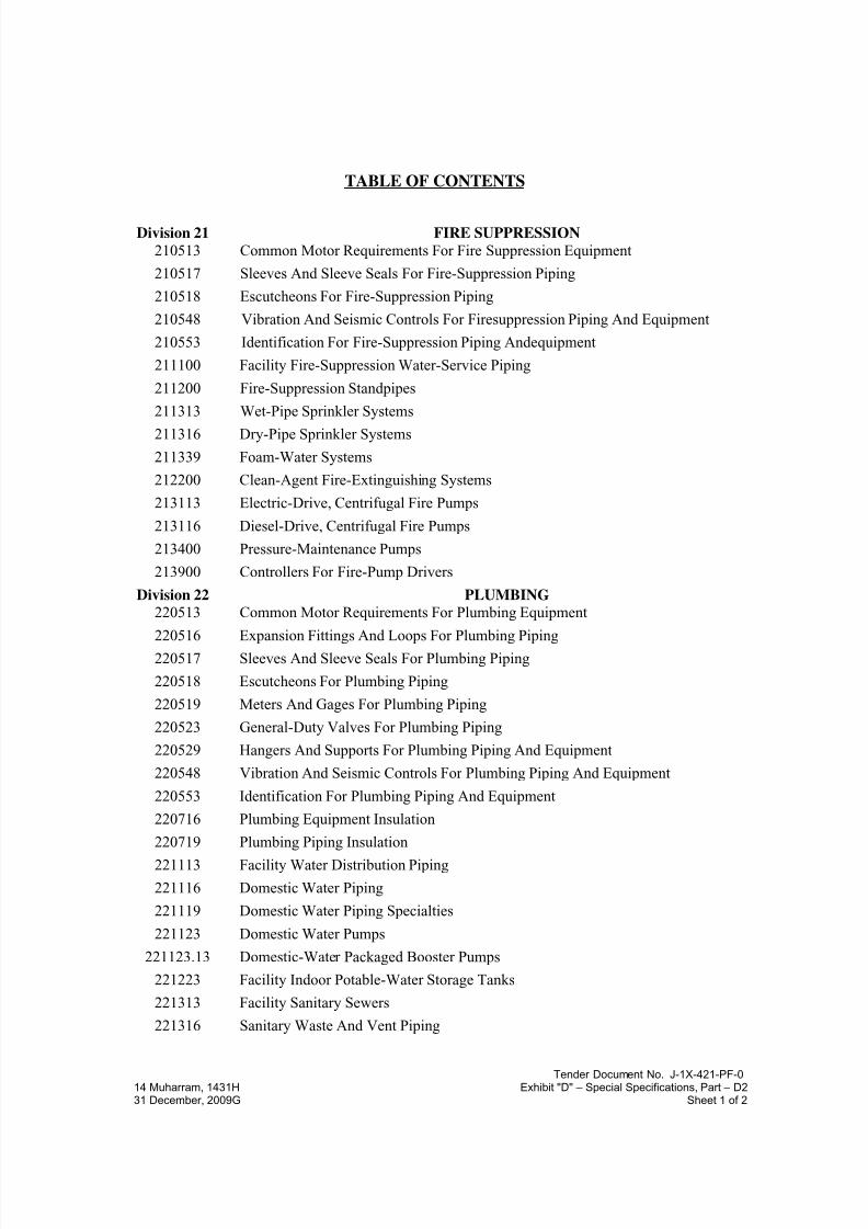
TABLE OF CONTENTS
Division 21 FIRE SUPPRESSION
210513 Common Motor Requirements For Fire Suppression Equipment
210517 Sleeves And Sleeve Seals For Fire-Suppression Piping
210518 Escutcheons For Fire-Suppression Piping
210548 Vibration And Seismic Controls For Firesuppression Piping And Equipment
210553 Identification For Fire-Suppression Piping Andequipment
211100 Facility Fire-Suppression Water-Service Piping
211200 Fire-Suppression Standpipes
211313 Wet-Pipe Sprinkler Systems
211316 Dry-Pipe Sprinkler Systems
211339 Foam-Water Systems
212200 Clean-Agent Fire-Extinguishing Systems
213113 Electric-Drive, Centrifugal Fire Pumps
213116 Diesel-Drive, Centrifugal Fire Pumps
213400 Pressure-Maintenance Pumps
213900 Controllers For Fire-Pump Drivers
Division 22 PLUMBING
220513 Common Motor Requirements For Plumbing Equipment
220516 Expansion Fittings And Loops For Plumbing Piping220517 Sleeves And Sleeve Seals For Plumbing Piping
220518 Escutcheons For Plumbing Piping
220519 Meters And Gages For Plumbing Piping
220523 General-Duty Valves For Plumbing Piping
220529 Hangers And Supports For Plumbing Piping And Equipment
220548 Vibration And Seismic Controls For Plumbing Piping And Equipment
220553 Identification For Plumbing Piping And Equipment
220716 Plumbing Equipment Insulation
220719 Plumbing Piping Insulation
221113 Facility Water Distribution Piping
221116 Domestic Water Piping
221119 Domestic Water Piping Specialties
221123 Domestic Water Pumps
221123.13 Domestic-Water Packaged Booster Pumps
221223 Facility Indoor Potable-Water Storage Tanks
221313 Facility Sanitary Sewers
221316 Sanitary Waste And Vent Piping

7/18/2019 SEC DPS
http://slidepdf.com/reader/full/sec-dps 3/541
Tender Document No. J-1X-421-PF-014 Muharram, 1431H Exhibit "D" – Special Specifications, Part – D231 December, 2009G Sheet 2 of 2
221319 Sanitary Waste Piping Specialties
221329 Sanitary Sewerage Pumps
221413 Facility Storm Drainage Piping221423 Storm Drainage Piping Specialties
221429 Sump Pumps
221513 General-Service Compressed-Air Piping
221519 General-Service Packaged Air Compressors And Receivers
223100 Domestic Water Softeners
223200 Domestic Water Filtration Equipment
223300 Electric, Domestic-Water Heaters
223500 Domestic-Water Heat Exchangers
224000 Plumbing Fixtures
224700 Refrigerated Drinking Fountains
224800 Decorative Fountain
7/18/2019 SEC DPS
http://slidepdf.com/reader/full/sec-dps 4/541
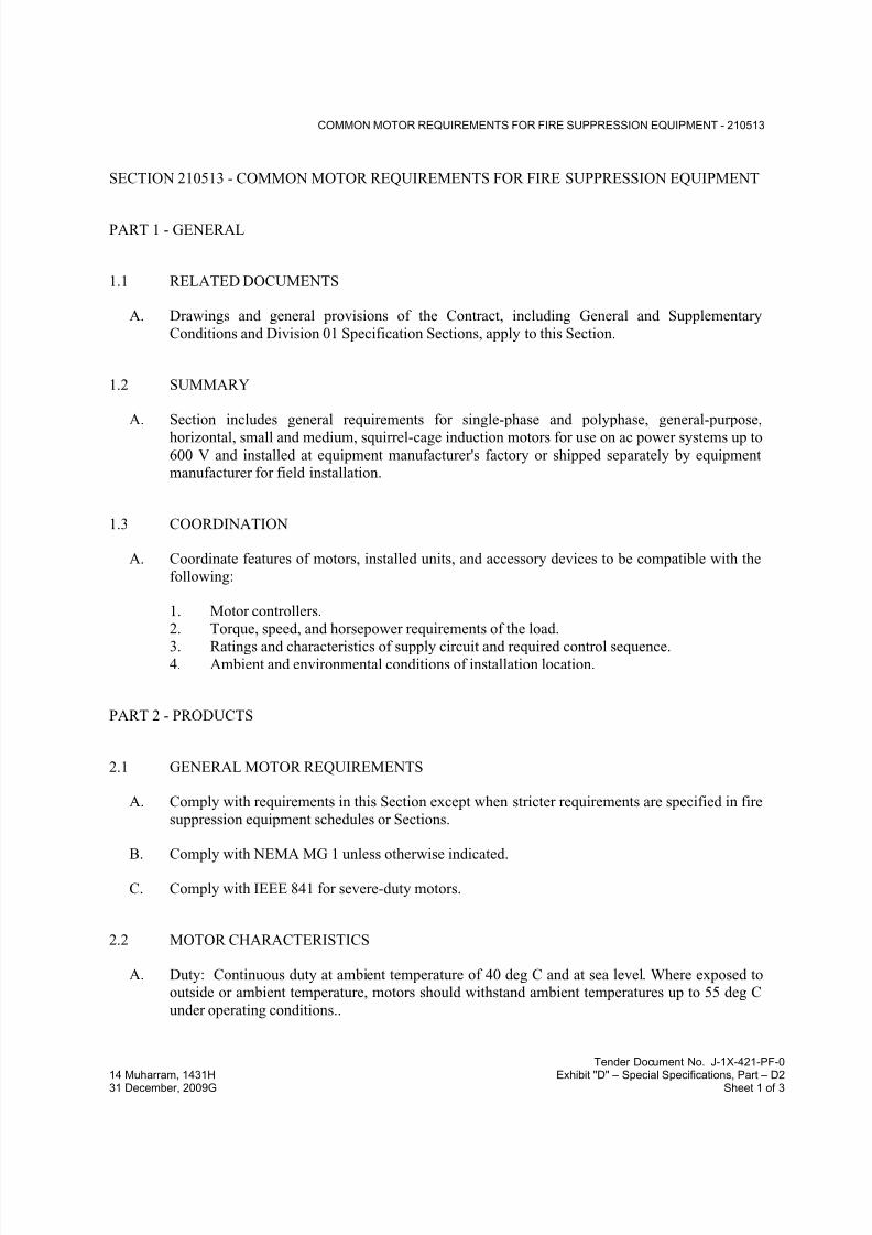
COMMON MOTOR REQUIREMENTS FOR FIRE SUPPRESSION EQUIPMENT - 210513
Tender Document No. J-1X-421-PF-0
14 Muharram, 1431H Exhibit "D" – Special Specifications, Part – D231 December, 2009G Sheet 1 of 3
SECTION 210513 - COMMON MOTOR REQUIREMENTS FOR FIRE SUPPRESSION EQUIPMENT
PART 1 - GENERAL
1.1 RELATED DOCUMENTS
A. Drawings and general provisions of the Contract, including General and Supplementary
Conditions and Division 01 Specification Sections, apply to this Section.
1.2 SUMMARY
A. Section includes general requirements for single-phase and polyphase, general-purpose,
horizontal, small and medium, squirrel-cage induction motors for use on ac power systems up to
600 V and installed at equipment manufacturer's factory or shipped separately by equipmentmanufacturer for field installation.
1.3 COORDINATION
A. Coordinate features of motors, installed units, and accessory devices to be compatible with the
following:
1. Motor controllers.
2. Torque, speed, and horsepower requirements of the load.
3. Ratings and characteristics of supply circuit and required control sequence.4. Ambient and environmental conditions of installation location.
PART 2 - PRODUCTS
2.1 GENERAL MOTOR REQUIREMENTS
A. Comply with requirements in this Section except when stricter requirements are specified in fire
suppression equipment schedules or Sections.
B. Comply with NEMA MG 1 unless otherwise indicated.
C. Comply with IEEE 841 for severe-duty motors.
2.2 MOTOR CHARACTERISTICS
A. Duty: Continuous duty at ambient temperature of 40 deg C and at sea level. Where exposed tooutside or ambient temperature, motors should withstand ambient temperatures up to 55 deg C
under operating conditions..

7/18/2019 SEC DPS
http://slidepdf.com/reader/full/sec-dps 5/541
COMMON MOTOR REQUIREMENTS FOR FIRE SUPPRESSION EQUIPMENT - 210513
Tender Document No. J-1X-421-PF-0
14 Muharram, 1431H Exhibit "D" – Special Specifications, Part – D231 December, 2009G Sheet 2 of 3
B. Capacity and Torque Characteristics: Sufficient to start, accelerate, and operate connected loads
at designated speeds, at installed altitude and environment, with indicated operating sequence,
and without exceeding nameplate ratings or considering service factor.
2.3 POLYPHASE MOTORS
A. Description: NEMA MG 1, Design B, medium induction motor.
B. Efficiency: Energy efficient, as defined in NEMA MG 1.
C. Service Factor: 1.15.
D. Multispeed Motors: Variable torque.
1. For motors with 2:1 speed ratio, consequent pole, single winding.2. For motors with other than 2:1 speed ratio, separate winding for each speed.
E. Multispeed Motors: Separate winding for each speed.
F. Rotor: Random-wound, squirrel cage.
G. Bearings: Regreasable, shielded, antifriction ball bearings suitable for radial and thrust loading.
H. Temperature Rise: Match insulation rating.
I. Insulation: Class F.
J. Code Letter Designation:
1. Motors 15 HP and Larger: NEMA starting Code F or Code G.
2. Motors Smaller than 15 HP: Manufacturer's standard starting characteristic.
K. Enclosure Material: Cast iron for motor frame sizes 324T and larger; rolled steel for motor
frame sizes smaller than 324T.
2.4 POLYPHASE MOTORS WITH ADDITIONAL REQUIREMENTS
A. Motors Used with Reduced-Voltage and Multispeed Controllers: Match wiring connection
requirements for controller with required motor leads. Provide terminals in motor terminal box,suited to control method.
B. Motors Used with Variable Frequency Controllers: Ratings, characteristics, and features
coordinated with and approved by controller manufacturer.
1. Windings: Copper magnet wire with moisture-resistant insulation varnish, designed and
tested to resist transient spikes, high frequencies, and short time rise pulses produced by
pulse-width modulated inverters.
2. Energy- and Premium-Efficient Motors: Class B temperature rise; Class F insulation.
3. Inverter-Duty Motors: Class F temperature rise; Class H insulation.
7/18/2019 SEC DPS
http://slidepdf.com/reader/full/sec-dps 6/541
COMMON MOTOR REQUIREMENTS FOR FIRE SUPPRESSION EQUIPMENT - 210513
Tender Document No. J-1X-421-PF-0
14 Muharram, 1431H Exhibit "D" – Special Specifications, Part – D231 December, 2009G Sheet 3 of 3
4. Thermal Protection: Comply with NEMA MG 1 requirements for thermally protected
motors.
C. Severe-Duty Motors: Comply with IEEE 841, with 1.15 minimum service factor.
2.5 SINGLE-PHASE MOTORS
A. Motors larger than 1/20 hp shall be one of the following, to suit starting torque and
requirements of specific motor application:
1. Permanent-split capacitor.
2. Split phase.
3. Capacitor start, inductor run.
4. Capacitor start, capacitor run.
B. Multispeed Motors: Variable-torque, permanent-split-capacitor type.
C. Bearings: Prelubricated, antifriction ball bearings or sleeve bearings suitable for radial and
thrust loading.
D. Motors 1/20 HP and Smaller: Shaded-pole type.
E. Thermal Protection: Internal protection to automatically open power supply circuit to motor
when winding temperature exceeds a safe value calibrated to temperature rating of motor
insulation. Thermal-protection device shall automatically reset when motor temperature returns
to normal range.
PART 3 - EXECUTION (Not Applicable)
END OF SECTION 210513
7/18/2019 SEC DPS
http://slidepdf.com/reader/full/sec-dps 7/541
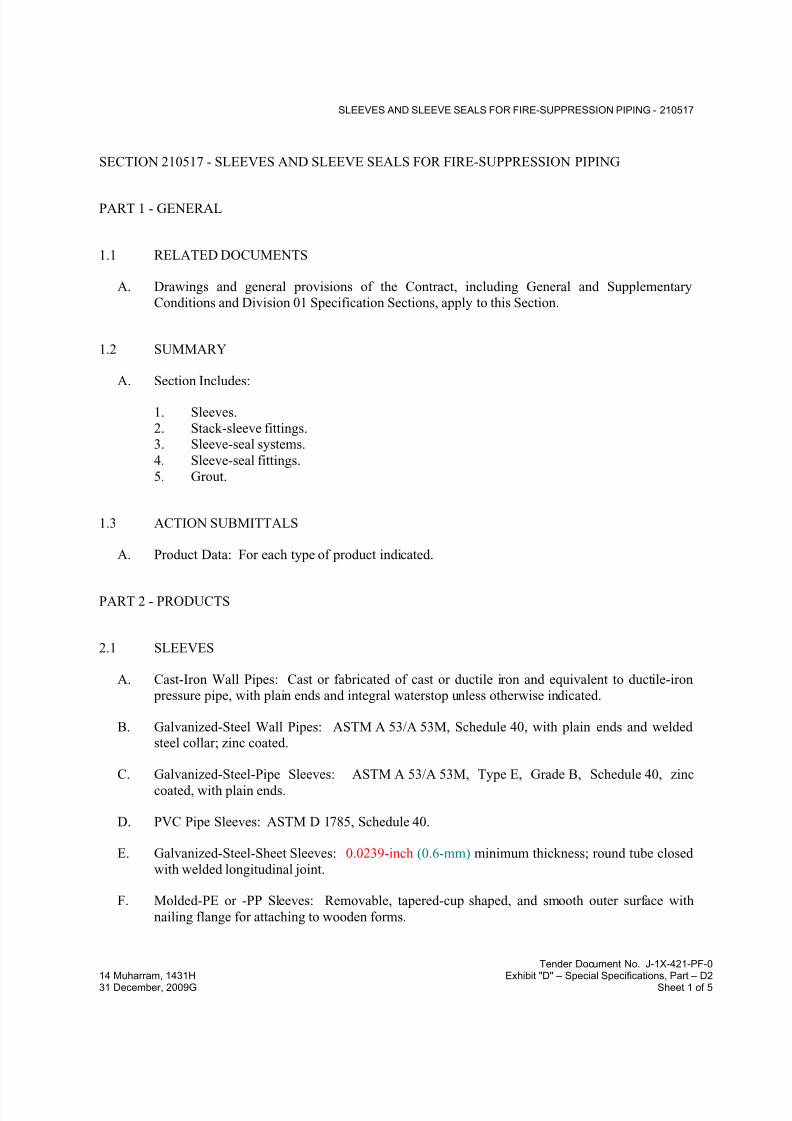
SLEEVES AND SLEEVE SEALS FOR FIRE-SUPPRESSION PIPING - 210517
Tender Document No. J-1X-421-PF-0
14 Muharram, 1431H Exhibit "D" – Special Specifications, Part – D231 December, 2009G Sheet 1 of 5
SECTION 210517 - SLEEVES AND SLEEVE SEALS FOR FIRE-SUPPRESSION PIPING
PART 1 - GENERAL
1.1 RELATED DOCUMENTS
A. Drawings and general provisions of the Contract, including General and Supplementary
Conditions and Division 01 Specification Sections, apply to this Section.
1.2 SUMMARY
A. Section Includes:
1. Sleeves.
2. Stack-sleeve fittings.3. Sleeve-seal systems.
4. Sleeve-seal fittings.
5. Grout.
1.3 ACTION SUBMITTALS
A. Product Data: For each type of product indicated.
PART 2 - PRODUCTS
2.1 SLEEVES
A. Cast-Iron Wall Pipes: Cast or fabricated of cast or ductile iron and equivalent to ductile-iron
pressure pipe, with plain ends and integral waterstop unless otherwise indicated.
B. Galvanized-Steel Wall Pipes: ASTM A 53/A 53M, Schedule 40, with plain ends and weldedsteel collar; zinc coated.
C. Galvanized-Steel-Pipe Sleeves: ASTM A 53/A 53M, Type E, Grade B, Schedule 40, zinccoated, with plain ends.
D. PVC Pipe Sleeves: ASTM D 1785, Schedule 40.
E. Galvanized-Steel-Sheet Sleeves: 0.0239-inch (0.6-mm) minimum thickness; round tube closed
with welded longitudinal joint.
F. Molded-PE or -PP Sleeves: Removable, tapered-cup shaped, and smooth outer surface with
nailing flange for attaching to wooden forms.

7/18/2019 SEC DPS
http://slidepdf.com/reader/full/sec-dps 8/541
SLEEVES AND SLEEVE SEALS FOR FIRE-SUPPRESSION PIPING - 210517
Tender Document No. J-1X-421-PF-0
14 Muharram, 1431H Exhibit "D" – Special Specifications, Part – D231 December, 2009G Sheet 2 of 5
G. Molded-PVC Sleeves: With nailing flange for attaching to wooden forms.
2.2 STACK-SLEEVE FITTINGS
A. Description: Manufactured, cast-iron sleeve with integral clamping flange. Include clamping
ring, bolts, and nuts for membrane flashing.
1. Underdeck Clamp: Clamping ring with setscrews.
2.3 SLEEVE-SEAL SYSTEMS
A. Description: Modular sealing-element unit, designed for field assembly, for filling annular
space between piping and sleeve.
1. Sealing Elements: EPDM-rubber interlocking links shaped to fit surface of pipe.
2. Pressure Plates: Carbon steel
3. Connecting Bolts and Nuts: Carbon steel with corrosion-resistant coating of length
required to secure pressure plates to sealing elements.
2.4 SLEEVE-SEAL FITTINGS
A. Description: Manufactured plastic, sleeve-type, waterstop assembly made for imbedding in
concrete slab or wall. Unit has plastic or rubber waterstop collar with center opening to match
piping OD.
2.5 GROUT
A. Standard: ASTM C 1107/C 1107M, Grade B, post-hardening and volume-adjusting, dry,
hydraulic-cement grout.
B. Characteristics: Nonshrink; recommended for interior and exterior applications.
C. Design Mix: 5000-psi (34.5-MPa), 28-day compressive strength.
D. Packaging: Premixed and factory packaged.
PART 3 - EXECUTION
3.1 SLEEVE INSTALLATION
A. Install sleeves for piping passing through penetrations in floors, partitions, roofs, and walls.
B. For sleeves that will have sleeve-seal system installed, select sleeves of size large enough to
provide 1-inch (25-mm)annular clear space between piping and concrete slabs and walls.
7/18/2019 SEC DPS
http://slidepdf.com/reader/full/sec-dps 9/541
SLEEVES AND SLEEVE SEALS FOR FIRE-SUPPRESSION PIPING - 210517
Tender Document No. J-1X-421-PF-0
14 Muharram, 1431H Exhibit "D" – Special Specifications, Part – D231 December, 2009G Sheet 3 of 5
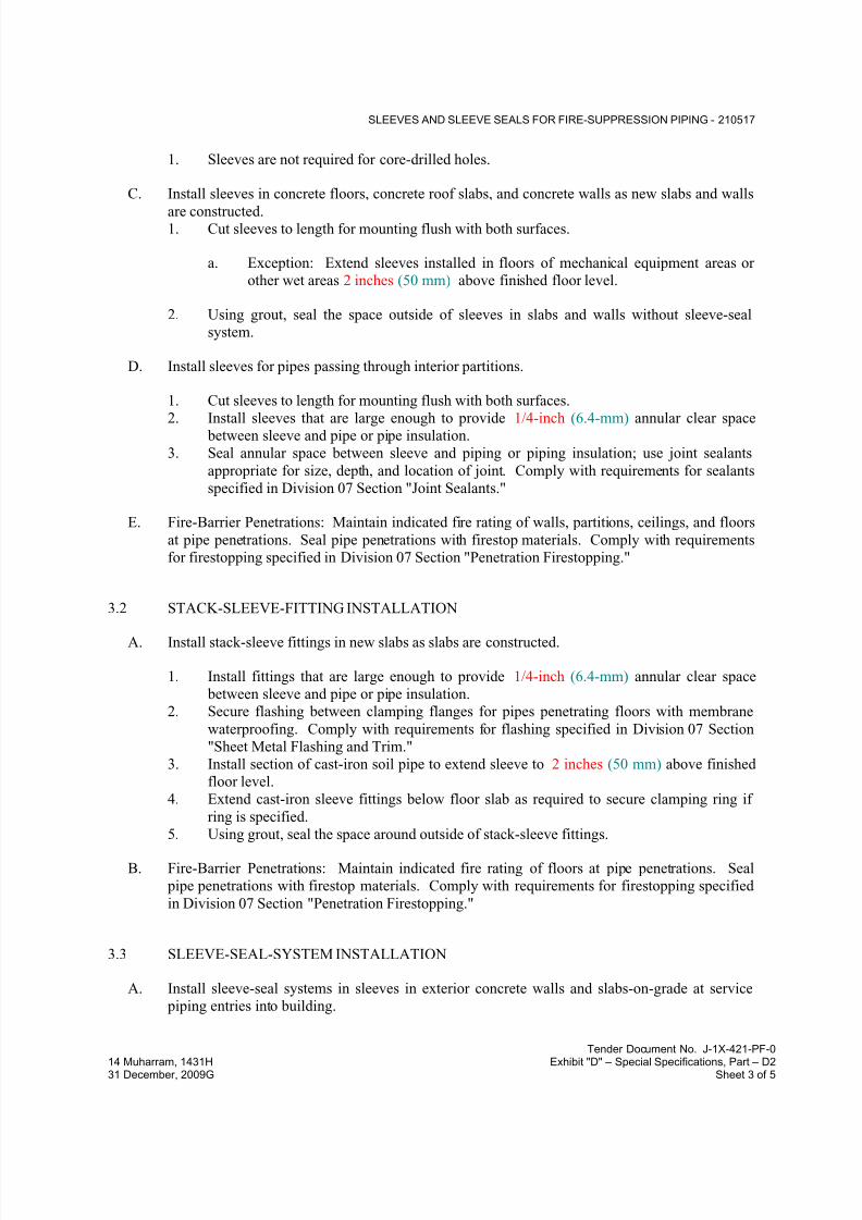
1. Sleeves are not required for core-drilled holes.
C. Install sleeves in concrete floors, concrete roof slabs, and concrete walls as new slabs and walls
are constructed.1. Cut sleeves to length for mounting flush with both surfaces.
a. Exception: Extend sleeves installed in floors of mechanical equipment areas or
other wet areas 2 inches (50 mm) above finished floor level.
2. Using grout, seal the space outside of sleeves in slabs and walls without sleeve-seal
system.
D. Install sleeves for pipes passing through interior partitions.
1. Cut sleeves to length for mounting flush with both surfaces.
2. Install sleeves that are large enough to provide 1/4-inch (6.4-mm) annular clear space between sleeve and pipe or pipe insulation.
3. Seal annular space between sleeve and piping or piping insulation; use joint sealants
appropriate for size, depth, and location of joint. Comply with requirements for sealants
specified in Division 07 Section "Joint Sealants."
E. Fire-Barrier Penetrations: Maintain indicated fire rating of walls, partitions, ceilings, and floors
at pipe penetrations. Seal pipe penetrations with firestop materials. Comply with requirements
for firestopping specified in Division 07 Section "Penetration Firestopping."
3.2 STACK-SLEEVE-FITTING INSTALLATION
A. Install stack-sleeve fittings in new slabs as slabs are constructed.
1. Install fittings that are large enough to provide 1/4-inch (6.4-mm) annular clear space
between sleeve and pipe or pipe insulation.
2. Secure flashing between clamping flanges for pipes penetrating floors with membrane
waterproofing. Comply with requirements for flashing specified in Division 07 Section
"Sheet Metal Flashing and Trim."
3. Install section of cast-iron soil pipe to extend sleeve to 2 inches (50 mm) above finished
floor level.
4. Extend cast-iron sleeve fittings below floor slab as required to secure clamping ring if
ring is specified.
5. Using grout, seal the space around outside of stack-sleeve fittings.
B. Fire-Barrier Penetrations: Maintain indicated fire rating of floors at pipe penetrations. Seal
pipe penetrations with firestop materials. Comply with requirements for firestopping specified
in Division 07 Section "Penetration Firestopping."
3.3 SLEEVE-SEAL-SYSTEM INSTALLATION
A. Install sleeve-seal systems in sleeves in exterior concrete walls and slabs-on-grade at service
piping entries into building.

7/18/2019 SEC DPS
http://slidepdf.com/reader/full/sec-dps 10/541
SLEEVES AND SLEEVE SEALS FOR FIRE-SUPPRESSION PIPING - 210517
Tender Document No. J-1X-421-PF-0
14 Muharram, 1431H Exhibit "D" – Special Specifications, Part – D231 December, 2009G Sheet 4 of 5
B. Select type, size, and number of sealing elements required for piping material and size and for
sleeve ID or hole size. Position piping in center of sleeve. Center piping in penetration,
assemble sleeve-seal system components, and install in annular space between piping and
sleeve. Tighten bolts against pressure plates that cause sealing elements to expand and make awatertight seal.
3.4 SLEEVE-SEAL-FITTING INSTALLATION
A. Install sleeve-seal fittings in new walls and slabs as they are constructed.
B. Assemble fitting components of length to be flush with both surfaces of concrete slabs and
walls. Position waterstop flange to be centered in concrete slab or wall.
C. Secure nailing flanges to concrete forms.
D. Using grout, seal the space around outside of sleeve-seal fittings.
3.5 SLEEVE AND SLEEVE-SEAL SCHEDULE
A. Use sleeves and sleeve seals for the following piping-penetration applications:
1. Exterior Concrete Walls above Grade:
a. Piping Smaller Than NPS 6 (DN 150): Galvanized-steel-pipe sleeves .
b. Piping NPS 6 (DN 150) and Larger: Galvanized-steel-pipe sleeves.
2. Exterior Concrete Walls below Grade:
a. Piping Smaller Than NPS 6 (DN 150): Galvanized-steel wall sleeves with sleeve-
seal system.
1) Select sleeve size to allow for 1-inch (25-mm) annular clear space between
piping and sleeve for installing sleeve-seal system.
b. Piping NPS 6 (DN 150) and Larger: Galvanized-steel wall sleeves with sleeve-
seal system.
1) Select sleeve size to allow for 1-inch (25-mm) annular clear space between
piping and sleeve for installing sleeve-seal system.
3. Concrete Slabs-on-Grade:
a. Piping Smaller than NPS 6 (DN 150): Galvanized-steel wall sleeves with sleeve-
seal system.
1) Select sleeve size to allow for 1-inch (25-mm) annular clear space between
piping and sleeve for installing sleeve-seal system.

7/18/2019 SEC DPS
http://slidepdf.com/reader/full/sec-dps 11/541
SLEEVES AND SLEEVE SEALS FOR FIRE-SUPPRESSION PIPING - 210517
Tender Document No. J-1X-421-PF-0
14 Muharram, 1431H Exhibit "D" – Special Specifications, Part – D231 December, 2009G Sheet 5 of 5
b. Piping [ NPS 6 (DN 150)] and Larger: Galvanized-steel wall sleeves with sleeve-
seal system.
1) Select sleeve size to allow for 1-inch (25-mm) annular clear space between piping and sleeve for installing sleeve-seal system.
4. Concrete Slabs above Grade:
a. Piping Smaller than NPS 6 (DN 150): Galvanized-steel-pipe sleeves.
b. Piping NPS 6 (DN 150) and Larger: Galvanized-steel-pipe sleeves .
5. Interior Partitions:
a. Piping Smaller than NPS 6 (DN 150): Galvanized-steel-pipe sleeves.
b. Piping NPS 6 (DN 150) and Larger: Galvanized-steel-sheet sleeves.
END OF SECTION 210517

7/18/2019 SEC DPS
http://slidepdf.com/reader/full/sec-dps 12/541
ESCUTCHEONS FOR FIRE-SUPPRESSION PIPING - 210518
Tender Document No. J-1X-421-PF-0
14 Muharram, 1431H Exhibit "D" – Special Specifications, Part – D231 December, 2009G Sheet 1 of 2
SECTION 210518 - ESCUTCHEONS FOR FIRE-SUPPRESSION PIPING
PART 1 - GENERAL
1.1 RELATED DOCUMENTS
A. Drawings and general provisions of the Contract, including General and Supplementary
Conditions and Division 01 Specification Sections, apply to this Section.
1.2 SUMMARY
A. Section Includes:
1. Escutcheons.
2. Floor plates.
1.3 ACTION SUBMITTALS
A. Product Data: For each type of product indicated.
PART 2 - PRODUCTS
2.1 ESCUTCHEONS
A. One-Piece, Cast-Brass Type: With polished, chrome-plated and rough-brass finish and setscrew
fastener.
B. One-Piece, Deep-Pattern Type: Deep-drawn, box-shaped brass with chrome-plated finish and
spring-clip fasteners.
C. One-Piece, Stamped-Steel Type: With chrome-plated finish and spring-clip fasteners.
D. Split-Casting Brass Type: With polished, chrome-plated and rough-brass finish and with
concealed hinge and setscrew.
E. Split-Plate, Stamped-Steel Type: With chrome-plated finish, concealed hinge, and spring-clip
fasteners.
2.2 FLOOR PLATES
A. One-Piece Floor Plates: Cast-iron flange with holes for fasteners.
B. Split-Casting Floor Plates: Cast brass with concealed hinge.

7/18/2019 SEC DPS
http://slidepdf.com/reader/full/sec-dps 13/541
ESCUTCHEONS FOR FIRE-SUPPRESSION PIPING - 210518
Tender Document No. J-1X-421-PF-0
14 Muharram, 1431H Exhibit "D" – Special Specifications, Part – D231 December, 2009G Sheet 2 of 2
PART 3 - EXECUTION
3.1 INSTALLATION
A. Install escutcheons for piping penetrations of walls, ceilings, and finished floors.
B. Install escutcheons with ID to closely fit around pipe, tube, and insulation of piping and with
OD that completely covers opening.
1. Escutcheons for New Piping:
a. Piping with Fitting or Sleeve Protruding from Wall: One-piece, deep-pattern type.
b. Chrome-Plated Piping: One-piece, cast-brass or split-casting brass type with
polished, chrome-plated finish.
c. Insulated Piping: One-piece, stamped-steel typeor split-plate, stamped-steel typewith concealed hinge.
d. Bare Piping at Wall and Floor Penetrations in Finished Spaces: One-piece, cast-
brass or split-casting brass type with polished, chrome-plated finish.
e. Bare Piping at Wall and Floor Penetrations in Finished Spaces: One-piece,
stamped-steel typeor split-plate, stamped-steel type with concealed hinge.
f. Bare Piping at Ceiling Penetrations in Finished Spaces: One-piece, cast-brass or
split-casting brass type with polished, chrome-plated finish.
g. Bare Piping at Ceiling Penetrations in Finished Spaces: One-piece, stamped-steel
type or split-plate, stamped-steel type with concealed hinge.
h. Bare Piping in Unfinished Service Spaces: One-piece, cast-brass or split-casting
brass type with polished, chrome-plated finish.
i. Bare Piping in Unfinished Service Spaces: One-piece, stamped-steel type or split- plate, stamped-steel type with concealed hinge.
j. Bare Piping in Equipment Rooms: One-piece, cast-brass or split-casting brass type
with rough-brass finish.
C. Bare Piping in Equipment Rooms: One-piece, stamped-steel type or split-plate, stamped-steel
type with concealed hinge
D. Install floor plates for piping penetrations of equipment-room floors.
E. Install floor plates with ID to closely fit around pipe, tube, and insulation of piping and with OD
that completely covers opening.
1. New Piping: One-piece, floor-plate type.
3.2 FIELD QUALITY CONTROL
A. Replace broken and damaged escutcheons and floor plates using new materials.
END OF SECTION 210518

7/18/2019 SEC DPS
http://slidepdf.com/reader/full/sec-dps 14/541
VIBRATION AND SEISMIC CONTROLS FOR FIRE-SUPPRESSION PIPING AND EQUIPMENT - 210548
Tender Document No. J-1X-421-PF-0
14 Muharram, 1431H Exhibit "D" – Special Specifications, Part – D231 December, 2009G Sheet 1 of 7
SECTION 210548 - VIBRATION AND SEISMIC CONTROLS FOR FIRE-SUPPRESSION PIPING
AND EQUIPMENT
PART 1 - GENERAL
1.1 RELATED DOCUMENTS
A. Drawings and general provisions of the Contract, including General and Supplementary
Conditions and Division 01 Specification Sections, apply to this Section.
1.2 SUMMARY
A. This Section includes the following:
1. Isolation pads.
2. Isolation mounts.
3. Restrained elastomeric isolation mounts.
4. Restraining braces.
1.3 DEFINITIONS
A. IBC: International Building Code.
B. ICC-ES: ICC-Evaluation Service.
C. OSHPD: Office of Statewide Health Planning and Development for the State of California.
1.4 PERFORMANCE REQUIREMENTS
A. Seismic-Restraint Loading:
1. Site Class as Defined in the UBC 1997, Zone 2A.
2. Assigned Seismic Use Group or Building Category as Defined per structural
requirements.
a. Component Importance Factor: 1.0.
b. Component Response Modification Factor: 1.5.
c. Component Amplification Factor: 1.0.
1.5 ACTION SUBMITTALS
A. Product Data: For the following:

7/18/2019 SEC DPS
http://slidepdf.com/reader/full/sec-dps 15/541
VIBRATION AND SEISMIC CONTROLS FOR FIRE-SUPPRESSION PIPING AND EQUIPMENT - 210548
Tender Document No. J-1X-421-PF-0
14 Muharram, 1431H Exhibit "D" – Special Specifications, Part – D231 December, 2009G Sheet 2 of 7
1. Include rated load, rated deflection, and overload capacity for each vibration isolation
device.
2. Illustrate and indicate style, material, strength, fastening provision, and finish for each
type and size of seismic-restraint component used.
a. Tabulate types and sizes of seismic restraints, complete with report numbers and
rated strength in tension and shear as evaluated by an evaluation service member
of ICC-ES
b. Annotate to indicate application of each product submitted and compliance with
requirements.
B. Delegated-Design Submittal: For vibration isolation and seismic-restraint details indicated to
comply with performance requirements and design criteria, including analysis data signed and
sealed by the qualified professional engineer responsible for their preparation.
1. Design Calculations: Calculate static and dynamic loading due to equipment weight andoperation, seismic forces required to select vibration isolators, seismic restraints, and for
designing vibration isolation bases.
2. Seismic-Restraint Details:
a. Design Analysis: To support selection and arrangement of seismic restraints.
Include calculations of combined tensile and shear loads.
b. Details: Indicate fabrication and arrangement. Detail attachments of restraints to
the restrained items and to the structure. Show attachment locations, methods, and
spacings. Identify components, list their strengths, and indicate directions and
values of forces transmitted to the structure during seismic events. Indicate
association with vibration isolation devices.
c. Preapproval and Evaluation Documentation: By an evaluation service member ofICC-ES, showing maximum ratings of restraint items and the basis for approval
(tests or calculations).
1.6 INFORMATIONAL SUBMITTALS
A. Qualification Data: For professional engineer.
B. Welding certificates.
1.7 QUALITY ASSURANCE
A. Testing Agency Qualifications: An independent agency, with the experience and capability to
conduct the testing indicated, that is a nationally recognized testing laboratory (NRTL) as
defined by OSHA in 29 CFR 1910.7, and that is acceptable to authorities having jurisdiction.
B. Comply with seismic-restraint requirements in the IBC and NFPA 13 unless requirements in
this Section are more stringent.
C. Welding: Qualify procedures and personnel according to AWS D1.1/D1.1M, "StructuralWelding Code - Steel."
7/18/2019 SEC DPS
http://slidepdf.com/reader/full/sec-dps 16/541
VIBRATION AND SEISMIC CONTROLS FOR FIRE-SUPPRESSION PIPING AND EQUIPMENT - 210548
Tender Document No. J-1X-421-PF-0
14 Muharram, 1431H Exhibit "D" – Special Specifications, Part – D231 December, 2009G Sheet 3 of 7
D. Seismic-restraint devices shall have horizontal and vertical load testing and analysis and shall
bear anchorage preapproval OPA number from OSHPD, preapproval by ICC-ES, or
preapproval by another agency acceptable to authorities having jurisdiction, showing maximum
seismic-restraint ratings. Ratings based on independent testing are preferred to ratings based oncalculations. If preapproved ratings are not available, submittals based on independent testing
are preferred. Calculations (including combining shear and tensile loads) to support seismic-
restraint designs must be signed and sealed by a qualified professional engineer.
PART 2 - PRODUCTS
2.1 VIBRATION ISOLATORS
A. Manufacturers: Subject to compliance with requirements
B. Basis-of-Design Product: Subject to compliance with requirements
C. Pads: Arranged in single or multiple layers of sufficient stiffness for uniform loading over pad
area, molded with a nonslip pattern and galvanized-steel baseplates, and factory cut to sizes that
match requirements of supported equipment.
1. Resilient Material: Oil- and water-resistant neoprene.
D. Mounts: Double-deflection type, with molded, oil-resistant rubber, hermetically sealed
compressed fiberglass, or neoprene isolator elements with factory-drilled, encapsulated top plate
for bolting to equipment and with baseplate for bolting to structure. Color-code or otherwise
identify to indicate capacity range.
1. Materials: Cast-ductile-iron or welded steel housing containing two separate and
opposing, oil-resistant rubber or neoprene elements that prevent central threaded element
and attachment hardware from contacting the housing during normal operation.
2. Neoprene: Shock-absorbing materials compounded according to the standard for bridge-
bearing neoprene as defined by AASHTO.
E. Restrained Mounts: All-directional mountings with seismic restraint.
1. Materials: Cast-ductile-iron or welded steel housing containing two separate and
opposing, oil-resistant rubber or neoprene elements that prevent central threaded element
and attachment hardware from contacting the housing during normal operation.
2. Neoprene: Shock-absorbing materials compounded according to the standard for bridge- bearing neoprene as defined by AASHTO.
2.2 SEISMIC-RESTRAINT DEVICES
A. Available Manufacturers: Subject to compliance with requirements, manufacturers offering
products that may be incorporated into the Work include, but are not limited to, the following:
B. Manufacturers: Subject to compliance with requirements

7/18/2019 SEC DPS
http://slidepdf.com/reader/full/sec-dps 17/541
VIBRATION AND SEISMIC CONTROLS FOR FIRE-SUPPRESSION PIPING AND EQUIPMENT - 210548
Tender Document No. J-1X-421-PF-0
14 Muharram, 1431H Exhibit "D" – Special Specifications, Part – D231 December, 2009G Sheet 4 of 7
C. Basis-of-Design Product: Subject to compliance with requirements
D. General Requirements for Restraint Components: Rated strengths, features, and applications
shall be as defined in reports by an evaluation service member of ICC-ES.
1. Structural Safety Factor: Allowable strength in tension, shear, and pullout force of
components shall be at least four times the maximum seismic forces to which they will be
subjected.
E. Channel Support System: MFMA-3, shop- or field-fabricated support assembly made of slotted
steel channels with accessories for attachment to braced component at one end and to building
structure at the other end and other matching components and with corrosion-resistant coating;
and rated in tension, compression, and torsion forces.
F. Hanger Rod Stiffener: Steel tube or steel slotted-support-system sleeve with internally bolted
connections to hanger rod.
G. Bushings for Floor-Mounted Equipment Anchor Bolts: Neoprene bushings designed for rigid
equipment mountings, and matched to type and size of anchor bolts and studs.
H. Bushing Assemblies for Wall-Mounted Equipment Anchorage: Assemblies of neoprene
elements and steel sleeves designed for rigid equipment mountings and matched to type and size
of attachment devices used.
I. Resilient Isolation Washers and Bushings: One-piece, molded, oil- and water-resistant
neoprene, with a flat washer face.
J. Mechanical Anchor Bolts: Drilled-in and stud-wedge or female-wedge type in zinc-coated steel
for interior applications and stainless steel for exterior applications. Select anchor bolts with
strength required for anchor and as tested according to ASTM E 488. Minimum length of eight
times diameter.
K. Adhesive Anchor Bolts: Drilled-in and capsule anchor system containing polyvinyl or urethane
methacrylate-based resin and accelerator, or injected polymer or hybrid mortar adhesive.Provide anchor bolts and hardware with zinc-coated steel for interior applications and stainless
steel for exterior applications. Select anchor bolts with strength required for anchor and as
tested according to ASTM E 488.
2.3 FACTORY FINISHES
A. Finish: Manufacturer's standard prime-coat finish ready for field painting.
B. Finish: Manufacturer's standard paint applied to factory-assembled and -tested equipment
before shipping.
1. Powder coating on springs and housings.
2. All hardware shall be galvanized. Hot-dip galvanize metal components for exterior use.
3. Baked enamel or powder coat for metal components on isolators for interior use.

7/18/2019 SEC DPS
http://slidepdf.com/reader/full/sec-dps 18/541
VIBRATION AND SEISMIC CONTROLS FOR FIRE-SUPPRESSION PIPING AND EQUIPMENT - 210548
Tender Document No. J-1X-421-PF-0
14 Muharram, 1431H Exhibit "D" – Special Specifications, Part – D231 December, 2009G Sheet 5 of 7
4. Color-code or otherwise mark vibration isolation and seismic & wind-control devices to
indicate capacity range.
PART 3 - EXECUTION
3.1 EXAMINATION
A. Examine areas and equipment to receive vibration isolation and seismic-control devices for
compliance with requirements for installation tolerances and other conditions affecting
performance.
B. Examine roughing-in of reinforcement and cast-in-place anchors to verify actual locations
before installation.
C. Proceed with installation only after unsatisfactory conditions have been corrected.
3.2 APPLICATIONS
A. Multiple Pipe Supports: Secure pipes to trapeze member with clamps approved for application
by an evaluation service member of ICC-ES.
B. Hanger Rod Stiffeners: Install hanger rod stiffeners where indicated or scheduled on Drawings
to receive them and where required to prevent buckling of hanger rods due to seismic forces.
C. Strength of Support and Seismic-Restraint Assemblies: Where not indicated, select sizes of
components so strength will be adequate to carry present and future static and seismic loadswithin specified loading limits.
3.3 VIBRATION-CONTROL AND SEISMIC-RESTRAINT DEVICE INSTALLATION
A. Equipment Restraints:
1. Install resilient bolt isolation washers on equipment anchor bolts where clearance
between anchor and adjacent surface exceeds 0.125 inch (3.2 mm).
2. Install seismic-restraint devices using methods approved by an evaluation service
member of ICC-ES providing required submittals for component.
B. Piping Restraints:
1. Comply with requirements in MSS SP-127 and NFPA 13.
2. Space lateral supports a maximum of 40 feet (12 m) o.c., and longitudinal supports a
maximum of 80 feet (24 m) o.c.
3. Brace a change of direction longer than 12 feet (3.7 m).
C. Install cables so they do not bend across edges of adjacent equipment or building structure.

7/18/2019 SEC DPS
http://slidepdf.com/reader/full/sec-dps 19/541
VIBRATION AND SEISMIC CONTROLS FOR FIRE-SUPPRESSION PIPING AND EQUIPMENT - 210548
Tender Document No. J-1X-421-PF-0
14 Muharram, 1431H Exhibit "D" – Special Specifications, Part – D231 December, 2009G Sheet 6 of 7
D. Install seismic-restraint devices using methods approved by an evaluation service member of
ICC-ES providing required submittals for component.
E. Install bushing assemblies for anchor bolts for floor-mounted equipment, arranged to provideresilient media between anchor bolt and mounting hole in concrete base.
F. Install bushing assemblies for mounting bolts for wall-mounted equipment, arranged to provide
resilient media where equipment or equipment-mounting channels are attached to wall.
G. Attachment to Structure: If specific attachment is not indicated, anchor bracing to structure at
flanges of beams, at upper truss chords of bar joists, or at concrete members.
H. Drilled-in Anchors:
1. Identify position of reinforcing steel and other embedded items prior to drilling holes for
anchors. Do not damage existing reinforcing or embedded items during coring ordrilling. Notify the structural engineer if reinforcing steel or other embedded items are
encountered during drilling. Locate and avoid prestressed tendons, electrical and
telecommunications conduit, and gas lines.
2. Do not drill holes in concrete or masonry until concrete, mortar, or grout has achieved
full design strength.
3. Wedge Anchors: Protect threads from damage during anchor installation. Heavy-duty
sleeve anchors shall be installed with sleeve fully engaged in the structural element to
which anchor is to be fastened.
4. Adhesive Anchors: Clean holes to remove loose material and drilling dust prior to
installation of adhesive. Place adhesive in holes proceeding from the bottom of the hole
and progressing toward the surface in such a manner as to avoid introduction of air
pockets in the adhesive.5. Set anchors to manufacturer's recommended torque, using a torque wrench.
6. Install zinc-coated steel anchors for interior and stainless-steel anchors for exterior
applications.
3.4 ACCOMMODATION OF DIFFERENTIAL SEISMIC MOTION
A. Install flexible connections in piping where they cross seismic joints, where adjacent sections or
branches are supported by different structural elements, and where the connections terminate
with connection to equipment that is anchored to a different structural element from the one
supporting the connections as they approach equipment. Comply with requirements in
Division 21 Section "Water-Based Fire-Suppression Systems" for piping flexible connections.
3.5 FIRE-SUPPRESSION VIBRATION-CONTROL AND SEISMIC-RESTRAINT DEVICE
SCHEDULE
A. Supported or Suspended Equipment.
1. Equipment Location: as per contract documents and design requirements
2. Pads:
7/18/2019 SEC DPS
http://slidepdf.com/reader/full/sec-dps 20/541
VIBRATION AND SEISMIC CONTROLS FOR FIRE-SUPPRESSION PIPING AND EQUIPMENT - 210548
Tender Document No. J-1X-421-PF-0
14 Muharram, 1431H Exhibit "D" – Special Specifications, Part – D231 December, 2009G Sheet 7 of 7
a. Material: Neoprene.
b. Thickness: As required by Seismic professional.
c. Number of Pads: As required by Seismic professional.
3. Isolator Type: As required by Seismic professional.
4. Minimum Deflection: As required by Seismic professional.
5. Component Importance Factor: 1.0.
6. Component Response Modification Factor: 1.5.
7. Component Amplification Factor: 1.0.
END OF SECTION 210548

7/18/2019 SEC DPS
http://slidepdf.com/reader/full/sec-dps 21/541
IDENTIFICATION FOR FIRE-SUPPRESSION PIPING AND EQUIPMENT - 210553
Tender Document No. J-1X-421-PF-0
14 Muharram, 1431H Exhibit "D" – Special Specifications, Part – D231 December, 2009G Sheet 1 of 5
SECTION 210553 - IDENTIFICATION FOR FIRE-SUPPRESSION PIPING AND EQUIPMENT
PART 1 - GENERAL
1.1 RELATED DOCUMENTS
A. Drawings and general provisions of the Contract, including General and Supplementary
Conditions and Division 01 Specification Sections, apply to this Section.
1.2 SUMMARY
A. Section Includes:
1. Equipment labels.
2. Warning signs and labels.3. Pipe labels.
4. Stencils.
5. Valve tags.
6. Warning tags.
1.3 ACTION SUBMITTALS
A. Product Data: For each type of product.
B. Samples: For color, letter style, and graphic representation required for each identification
material and device.
C. Equipment-Label Schedule: Include a listing of all equipment to be labeled and the proposed
content for each label.
D. Valve Schedules: Valve numbering scheme.
1.4 CLOSEOUT SUBMITTALS
A. Maintenance Data: For each piping system to include in maintenance manuals.
PART 2 - PRODUCTS
2.1 EQUIPMENT LABELS
A. Metal Labels for Equipment:
7/18/2019 SEC DPS
http://slidepdf.com/reader/full/sec-dps 22/541
IDENTIFICATION FOR FIRE-SUPPRESSION PIPING AND EQUIPMENT - 210553
Tender Document No. J-1X-421-PF-0
14 Muharram, 1431H Exhibit "D" – Special Specifications, Part – D231 December, 2009G Sheet 2 of 5
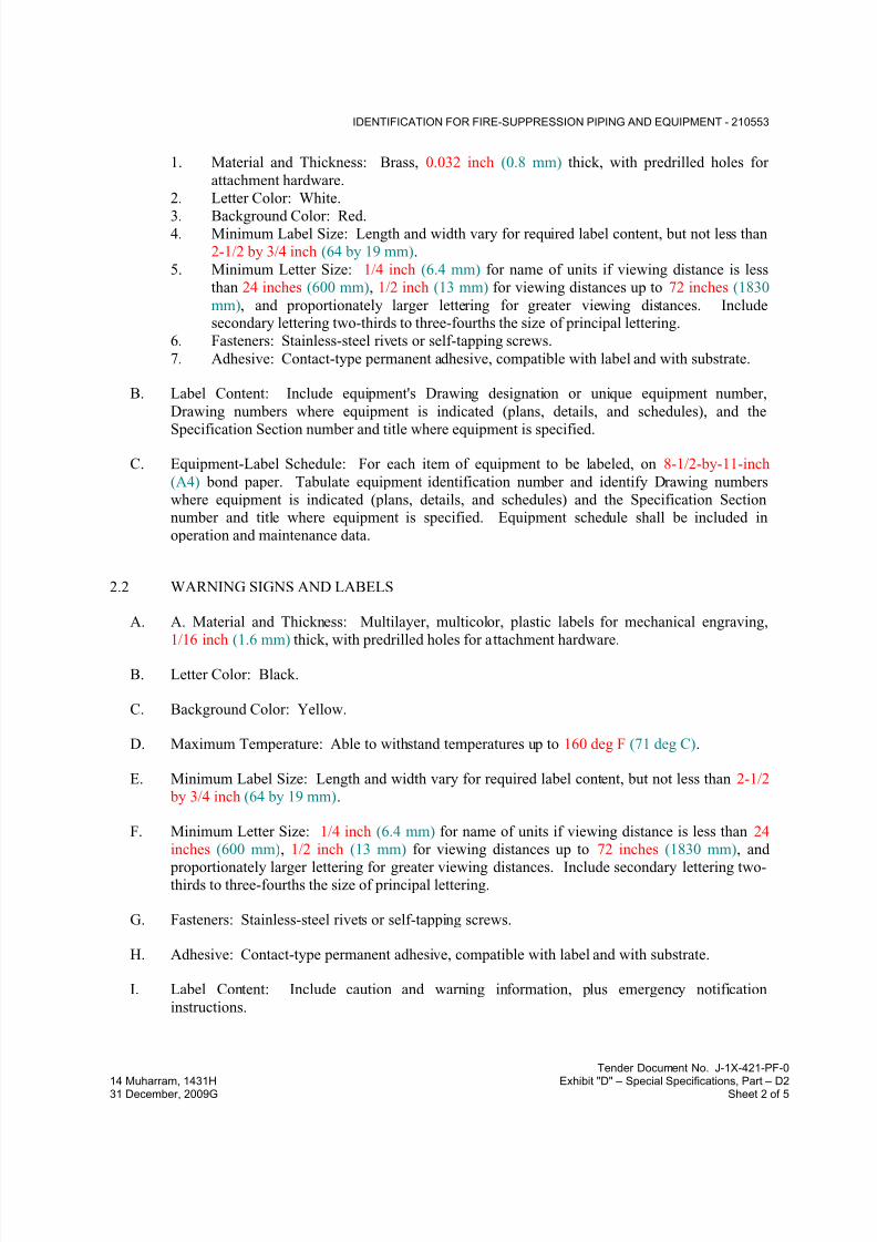
1. Material and Thickness: Brass, 0.032 inch (0.8 mm) thick, with predrilled holes for
attachment hardware.
2. Letter Color: White.
3. Background Color: Red.4. Minimum Label Size: Length and width vary for required label content, but not less than
2-1/2 by 3/4 inch (64 by 19 mm).
5. Minimum Letter Size: 1/4 inch (6.4 mm) for name of units if viewing distance is less
than 24 inches (600 mm), 1/2 inch (13 mm) for viewing distances up to 72 inches (1830
mm), and proportionately larger lettering for greater viewing distances. Includesecondary lettering two-thirds to three-fourths the size of principal lettering.
6. Fasteners: Stainless-steel rivets or self-tapping screws.
7. Adhesive: Contact-type permanent adhesive, compatible with label and with substrate.
B. Label Content: Include equipment's Drawing designation or unique equipment number,
Drawing numbers where equipment is indicated (plans, details, and schedules), and the
Specification Section number and title where equipment is specified.
C. Equipment-Label Schedule: For each item of equipment to be labeled, on 8-1/2-by-11-inch
(A4) bond paper. Tabulate equipment identification number and identify Drawing numbers
where equipment is indicated (plans, details, and schedules) and the Specification Section
number and title where equipment is specified. Equipment schedule shall be included in
operation and maintenance data.
2.2 WARNING SIGNS AND LABELS
A. A. Material and Thickness: Multilayer, multicolor, plastic labels for mechanical engraving,
1/16 inch (1.6 mm) thick, with predrilled holes for attachment hardware.
B. Letter Color: Black.
C. Background Color: Yellow.
D. Maximum Temperature: Able to withstand temperatures up to 160 deg F (71 deg C).
E. Minimum Label Size: Length and width vary for required label content, but not less than 2-1/2
by 3/4 inch (64 by 19 mm).
F. Minimum Letter Size: 1/4 inch (6.4 mm) for name of units if viewing distance is less than 24
inches (600 mm), 1/2 inch (13 mm) for viewing distances up to 72 inches (1830 mm), and
proportionately larger lettering for greater viewing distances. Include secondary lettering two-thirds to three-fourths the size of principal lettering.
G. Fasteners: Stainless-steel rivets or self-tapping screws.
H. Adhesive: Contact-type permanent adhesive, compatible with label and with substrate.
I. Label Content: Include caution and warning information, plus emergency notification
instructions.

7/18/2019 SEC DPS
http://slidepdf.com/reader/full/sec-dps 23/541
IDENTIFICATION FOR FIRE-SUPPRESSION PIPING AND EQUIPMENT - 210553
Tender Document No. J-1X-421-PF-0
14 Muharram, 1431H Exhibit "D" – Special Specifications, Part – D231 December, 2009G Sheet 3 of 5
2.3 PIPE LABELS
A. General Requirements for Manufactured Pipe Labels: Preprinted, color-coded, with lettering
indicating service and showing flow direction.
B. Pretensioned Pipe Labels: Precoiled, semirigid plastic formed to cover full circumference of
pipe and to attach to pipe without fasteners or adhesive.
C. Self-Adhesive Pipe Labels: Printed plastic with contact-type, permanent-adhesive backing.
D. Pipe-Label Contents: Include identification of piping service using same designations or
abbreviations as used on Drawings; pipe size; and an arrow indicating flow direction.
1. Flow-Direction Arrows: Integral with piping-system service lettering to accommodate
both directions, or as separate unit on each pipe label to indicate flow direction.
2. Lettering Size: At least 1-1/2 inches (38 mm) high.
E. Pipe-Label Colors:
1. Background Color: Red.
2. Letter Color: White.
2.4 STENCILS
A. Stencils: Prepared with letter sizes according to ASME A13.1 for piping; and minimum letter
height of 3/4 inch (19 mm) for access panel and door labels, equipment labels, and similar
operational instructions.
1. Stencil Material: Brass.
2. Stencil Paint: Exterior, gloss, alkyd enamel black unless otherwise indicated. Paint may
be in pressurized spray-can form.
3. Identification Paint: Exterior, alkyd enamel in colors according to ASME A13.1 unless
otherwise indicated.
2.5 VALVE TAGS
A. Valve Tags: Stamped or engraved with 1/4-inch (6.4-mm) letters for piping-systemabbreviation and 1/2-inch (13-mm) numbers.
1. Tag Material: Brass, 0.032 inch (0.8 mm) thick, with predrilled holes for attachment
hardware.
2. Fasteners: Brass beaded chain.
3. Valve-Tag Color: Red.
4. Letter Color: White.
B. Valve Schedules: For each piping system, on 8-1/2-by-11-inch (A4) bond paper. Tabulate
valve number, piping system, system abbreviation (as shown on valve tag), location of valve

7/18/2019 SEC DPS
http://slidepdf.com/reader/full/sec-dps 24/541
IDENTIFICATION FOR FIRE-SUPPRESSION PIPING AND EQUIPMENT - 210553
Tender Document No. J-1X-421-PF-0
14 Muharram, 1431H Exhibit "D" – Special Specifications, Part – D231 December, 2009G Sheet 4 of 5
(room or space), normal-operating position (open, closed, or modulating), and variations for
identification. Mark valves for emergency shutoff and similar special uses.
1. Valve-tag schedule shall be included in operation and maintenance data.
2.6 WARNING TAGS
A. Warning Tags: Preprinted or partially preprinted, accident-prevention tags, of plasticized card
stock with matte finish suitable for writing.
1. Size: Approximately 4 by 7 inches (100 by 178 mm).
2. Fasteners: Brass grommet and wire.
3. Nomenclature: Large-size primary caption such as "DANGER," "CAUTION," or "DO
NOT OPERATE."
4. Color: Yellow background with black lettering.
PART 3 - EXECUTION
3.1 PREPARATION
A. Clean piping and equipment surfaces of substances that could impair bond of identificationdevices, including dirt, oil, grease, release agents, and incompatible primers, paints, and
encapsulants.
3.2 LABEL INSTALLATION
A. Coordinate installation of identifying devices with completion of covering and painting of
surfaces where devices are to be applied.
B. Coordinate installation of identifying devices with locations of access panels and doors.
C. Install or permanently fasten labels on each major item of mechanical equipment.
D. Locate equipment labels where accessible and visible.
E. Piping Color-Coding: Painting of piping is specified in Division 09 Section
F. Stenciled Pipe-Label Option: Stenciled labels may be provided instead of manufactured pipe
labels, at Installer's option. Install stenciled pipe labels, complying with ANSI/ASME A13.1
2007on each piping system.
1. Identification Paint: Use for contrasting background.
2. Stencil Paint: Use for pipe marking.
G. Pipe-Label Locations: Locate pipe labels where piping is exposed or above accessible ceilings
in finished spaces; machine rooms; accessible maintenance spaces such as shafts, tunnels, and
plenums; and exterior exposed locations as follows:

7/18/2019 SEC DPS
http://slidepdf.com/reader/full/sec-dps 25/541
IDENTIFICATION FOR FIRE-SUPPRESSION PIPING AND EQUIPMENT - 210553
Tender Document No. J-1X-421-PF-0
14 Muharram, 1431H Exhibit "D" – Special Specifications, Part – D231 December, 2009G Sheet 5 of 5
1. Near each valve and control device.
2. Near each branch connection excluding short takeoffs. Where flow pattern is not
obvious, mark each pipe at branch.
3. Near penetrations through walls, floors, ceilings, and inaccessible enclosures.4. At access doors, manholes, and similar access points that permit view of concealed
piping.
5. Near major equipment items and other points of origination and termination.
6. Spaced at maximum intervals of 50 feet (15 m) along each run. Reduce intervals to 25
feet (7.6 m) in areas of congested piping and equipment.7. On piping above removable acoustical ceilings. Omit intermediately spaced labels.
3.3 VALVE-TAG INSTALLATION
A. Install tags on valves and control devices in piping systems. List tagged valves in a valve-tag
schedule.
B. Valve-Tag Application Schedule: Tag valves according to size, shape, and with captions
similar to those indicated in "Valve-Tag Size and Shape" Subparagraph below:
1. Valve-Tag Size and Shape:
a. Fire-Suppression Standpipe: 1-1/2 inches (38 mm),round.
b. Wet-Pipe Sprinkler System: 1-1/2 inches (38 mm),round.
c. Dry-Pipe Sprinkler System: 1-1/2 inches (38 mm) ,round.
d. Foam-Water System: 1-1/2 inches (38 mm)], round .
e. Clean-Agent Fire-Extinguishing System: 1-1/2 inches (38 mm), round.
3.4 WARNING-TAG INSTALLATION
A. Write required message on, and attach warning tags to, equipment and other items where
required.
END OF SECTION 210553
7/18/2019 SEC DPS
http://slidepdf.com/reader/full/sec-dps 26/541
FACILITY FIRE-SUPPRESSION WATER-SERVICE PIPING - 211100
Tender Document No. J-0X-421-PF-014 Muharram, 1431H Exhibit “D” – Special Specifications, Part – D231 December, 2009G Sheet 1 of 14
SECTION 211100 - FACILITY FIRE-SUPPRESSION WATER-SERVICE PIPING
PART 1 - GENERAL
1.1 RELATED DOCUMENTS
A. Drawings and general provisions of the Contract, including General and Supplementary
Conditions and Division 01 Specification Sections, apply to this Section.
1.2 SUMMARY
A. Section includes fire-suppression water-service piping and related components outside the
building
B. Related Sections:
1. Division 21 Section "Fire-Suppression Standpipes" for fire-suppression standpipes inside
the building.
2. Division 21 Section "Wet-Pipe Sprinkler Systems" for wet-pipe fire-suppression
sprinkler systems inside the building.
3. Division 21 Section "Dry-Pipe Sprinkler Systems" for dry-pipe fire-suppression sprinkler
systems inside the building.
4. Division 21 Section "Foam-Water Systems" for AFFF piping.
5. Division 21 Section for fire pumps, pressure-maintenance pumps, and controllers.
1.3 ACTION SUBMITTALS
A. Product Data: Submit manufacturer's technical product data and installation instructions for
system materials and products.
B. Shop Drawings: Include plans, elevations, details, and attachments for the following:
1. Fire fighting pipe network, including pipe diameters and gradients.
2. Chambers and other structures, including invert levels, frames, covers, and grates.
1.4 INFORMATIONAL SUBMITTALS
A. Coordination Drawings: For piping and specialties including relation to other services in same
area, drawn to scale. Show piping and specialty sizes and valves, meter and specialty locations,
and elevations.
B. Field quality-control reports.

7/18/2019 SEC DPS
http://slidepdf.com/reader/full/sec-dps 27/541
FACILITY FIRE-SUPPRESSION WATER-SERVICE PIPING - 211100
Tender Document No. J-0X-421-PF-014 Muharram, 1431H Exhibit “D” – Special Specifications, Part – D231 December, 2009G Sheet 2 of 14
1.5 QUALITY ASSURANCE
A. Regulatory Requirements:
1. Comply with requirements of utility company supplying water. Include tapping of water
mains and backflow prevention.
2. Comply with standards of authorities having jurisdiction for fire-suppression water-
service piping, including materials, hose threads, installation, and testing.
B. Piping materials shall bear label, stamp, or other markings of specified testing agency.
C. Electrical Components, Devices, and Accessories: Listed and labeled as defined in NFPA 70,
by a qualified testing agency, and marked for intended location and application.
D. Comply with the "Approval Guide," published by FM Global, or UL's "Fire Protection
Equipment Directory" for fire-service-main products.
E. NFPA Compliance: Comply with NFPA 24 for materials, installations, tests, flushing, and
valve and hydrant supervision for fire-suppression water-service piping.
1.6 DELIVERY, STORAGE, AND HANDLING
A. Preparation for Transport: Prepare valves, including fire hydrants, according to the following:
1. Ensure that valves are dry and internally protected against rust and corrosion.
2. Protect valves against damage to threaded ends and flange faces.
3. Set valves in best position for handling. Set valves closed to prevent rattling.
B. During Storage: Use precautions for valves, including fire hydrants, according to the following:
1. Do not remove end protectors unless necessary for inspection; then reinstall for storage.
2. Protect from weather. Store indoors and maintain temperature higher than ambient dew
point temperature. Support off the ground or pavement in watertight enclosures when
outdoor storage is necessary.
C. Handling: Use sling to handle valves and fire hydrants if size requires handling by crane or lift.
Rig valves to avoid damage to exposed parts. Do not use handwheels or stems as lifting or
rigging points.
D. Deliver piping with factory-applied end caps. Maintain end caps through shipping, storage, andhandling to prevent pipe-end damage and to prevent entrance of dirt, debris, and moisture.
E. Protect stored piping from moisture and dirt. Elevate above grade. Do not exceed structural
capacity of floor when storing inside.
F. Protect flanges, fittings, and specialties from moisture and dirt.
G. Store plastic piping protected from direct sunlight. Support to prevent sagging and bending.

7/18/2019 SEC DPS
http://slidepdf.com/reader/full/sec-dps 28/541
FACILITY FIRE-SUPPRESSION WATER-SERVICE PIPING - 211100
Tender Document No. J-0X-421-PF-014 Muharram, 1431H Exhibit “D” – Special Specifications, Part – D231 December, 2009G Sheet 3 of 14
1.7 PROJECT CONDITIONS
A. Perform site survey, research public utility records, and verify existing utility locations.
B. Interruption of Existing Fire-Suppression Water-Service Piping: Do not interrupt service to
facilities occupied by Owner or others unless permitted under the following conditions and then
only after arranging to provide temporary water-distribution service according to requirements
indicated:
1. Notify Construction Manager not less than three days in advance of proposed interruption
of service.
2. Do not proceed with interruption of water-distribution service without Construction
Manager’s written permission.
1.8 COORDINATION
A. Coordinate connection to water main with the Engineer and relevant authorities.
PART 2 - PRODUCTS
2.1 DUCTILE-IRON PIPE AND FITTINGS
A. Mechanical-Joint, Ductile-Iron Pipe: AWWA C151, with mechanical-joint bell and plain spigot
end unless grooved or flanged ends are indicated.
1. Mechanical-Joint, Ductile-Iron Fittings: AWWA C110, ductile- or gray-iron standard pattern or AWWA C153, ductile-iron compact pattern.
2. Glands, Gaskets, and Bolts: AWWA C111, ductile- or gray-iron glands, rubber gaskets,
and steel bolts.
B. Push-on-Joint, Ductile-Iron Pipe: AWWA C151, with push-on-joint bell and plain spigot end
unless grooved or flanged ends are indicated.
1. Push-on-Joint, Ductile-Iron Fittings: AWWA C110, ductile- or gray-iron standard
pattern or AWWA C153, ductile-iron compact pattern.
2. Gaskets: AWWA C111, rubber.
C. Grooved-Joint, Ductile-Iron Pipe: AWWA C151, with cut, rounded-grooved ends.
1. Grooved-End, Ductile-Iron Pipe Appurtenances:
a. Grooved-End, Ductile-Iron Fittings: ASTM A 47/A 47M, malleable-iron castings
or ASTM A 536, ductile-iron castings with dimensions matching pipe.
b. Grooved-End, Ductile-Iron-Piping Couplings: AWWA C606, for ductile-iron-pipe
dimensions. Include ferrous housing sections, gasket suitable for water, and bolts
and nuts.
D. Flanges: ASME 16.1, Class 125, cast iron.

7/18/2019 SEC DPS
http://slidepdf.com/reader/full/sec-dps 29/541
FACILITY FIRE-SUPPRESSION WATER-SERVICE PIPING - 211100
Tender Document No. J-0X-421-PF-014 Muharram, 1431H Exhibit “D” – Special Specifications, Part – D231 December, 2009G Sheet 4 of 14
2.2 FIBERGLASS PIPE AND FITTINGS
A. AWWA RTRP: AWWA C950, Class 250, with bell-and-spigot ends for bonded joints. Liner is
optional unless otherwise indicated. Bonding Adhesive for Fiberglass Piping shall be asrecommended by fiberglass piping manufacturer.
B. For type and grade of RTRP pipes, provide manufacturer recommendations for the best suitable
for the project conditions and submit to the Engineer for approval.
2.3 JOINING MATERIALS
A. Refer to Divisions 21 and 2, sections related to commonly used joining materials.
B. Transition Couplings:
1. Underground Piping, DN 40 and Smaller: Manufactured fitting or coupling same size as,
with pressure rating at least equal to and ends compatible with, piping to be joined.
2. Underground Piping, DN 50 and Larger: AWWA C219, metal, sleeve-type coupling
same size as, with pressure rating at least equal to and ends compatible with, piping to be
joined.3. Aboveground Piping: Pipe fitting same size as, with pressure rating at least equal to and
ends compatible with, piping to be joined.
C. Plastic Pipe-Flange Gasket, Bolts, and Nuts: Type and material of gaskets to be as
recommended by piping system manufacturer, unless otherwise indicated. Bolts, nuts and
washer to be stainless steel grade 316.
2.4 PIPING SPECIALTIES
A. Dielectric Fittings: Combination of copper alloy and ferrous; threaded, solder, or plain end
types; and matching piping system materials.
1. Dielectric Unions: Factory-fabricated union assembly, designed for 1725 kPa minimum
working pressure at 82 deg. C. Include insulating material that isolates dissimilar metals
and ends with inside threads according to ASME B1.20.1.2. Dielectric Flanges: Factory-fabricated companion-flange assembly, for 1035 or 2070-
kPa minimum working pressure to suit system pressures.
Dielectric-Flange Insulation Kits: Field-assembled companion-flange assembly, full-face
or ring type. Components include neoprene or phenolic gasket, phenolic or polyethylene bolt sleeves, phenolic washers, and steel backing washers.
a. Provide separate companion flanges and steel bolts and nuts for 1035 or 2070 kPa
minimum working pressure to suit system pressures.
3. Dielectric Couplings: Galvanized-steel couplings with inert and noncorrosive
thermoplastic lining, with threaded ends and 2070 kPa minimum working pressure at
107 deg C.
7/18/2019 SEC DPS
http://slidepdf.com/reader/full/sec-dps 30/541
FACILITY FIRE-SUPPRESSION WATER-SERVICE PIPING - 211100
Tender Document No. J-0X-421-PF-014 Muharram, 1431H Exhibit “D” – Special Specifications, Part – D231 December, 2009G Sheet 5 of 14
B. Dielectric Nipples: Electroplated steel nipples with inert and noncorrosive thermoplastic lining,
with combination of plain, threaded, or grooved end types and 2070-kPa minimum working
pressure at 107 deg. C (225 deg. F).
2.5 ENCASEMENT FOR PIPING
A. Standard: ASTM A 674 or AWWA C105.
B. Form: Sheet or tube.
C. Material: LLDPE film of 0.20-mm minimum thickness or high-density, cross-laminated PE film
of 0.10-mm or High-density, cross-laminated PE film of 0.10-mm minimum thickness.
D. Color: Black or Natural.
2.6 CORPORATION VALVES AND CURB VALVES
A. Corporation Valves: Comply with AWWA C800. Include saddle and valve compatible with
tapping machine.
1. Service Saddle: Copper alloy with seal and AWWA C800, threaded outlet for
corporation valve.2. Corporation Valve: Bronze body and ground-key plug, with AWWA C800, threaded
inlet and outlet matching service piping material.
3. Manifold: Copper fitting with two to four inlets as required, with ends matching
corporation valves and outlet matching service piping material. Retain subparagraph
below if utility company requires multiple connections.
B. Corporation Valves: Comply with AWWA C800. Include saddle and valve compatible with
tapping machine.
1. Service Saddle: Copper alloy with seal and AWWA C800, threaded outlet for
corporation valve.
2. Corporation Valve: Bronze body and ground-key plug, with AWWA C800, threaded
inlet and outlet matching service piping material.3. Manifold: Copper fitting with two to four inlets as required, with ends matching
corporation valves and outlet matching service piping material.
C. Curb Valves: Comply with AWWA C800 for high-pressure service-line valves. Valve has bronze body, ground-key plug or ball, wide tee head, and inlet and outlet matching service
piping material.
D. Service Boxes for Curb Valves: Similar to AWWA M44 requirements for cast-iron valve
boxes. Include cast-iron telescoping top section of length required for depth of burial of valve,
plug with lettering "WATER," and bottom section with base that fits over curb valve and with a
barrel approximately 75 mm in diameter.
1. Shutoff Rods: Steel; with tee-handle with one pointed end, stem of length to operate
deepest buried valve, and slotted end matching curb valve.

7/18/2019 SEC DPS
http://slidepdf.com/reader/full/sec-dps 31/541
FACILITY FIRE-SUPPRESSION WATER-SERVICE PIPING - 211100
Tender Document No. J-0X-421-PF-014 Muharram, 1431H Exhibit “D” – Special Specifications, Part – D231 December, 2009G Sheet 6 of 14
2.7 GATE VALVES
A. AWWA, Cast-Iron Gate Valves:
1. Nonrising-Stem, High-Pressure, Resilient-Seated Gate Valves:
2. Description: Ductile-iron body and bonnet; with bronze or ductile-iron gate, resilient
seats, bronze stem, and stem nut.
a. Standard: AWWA C509.
b. Minimum Pressure Rating: 1725 kPa.
c. End Connections: Push on or mechanical joint.
d. Interior Coating: Complying with AWWA C550.
2.8 GATE VALVE ACCESSORIES AND SPECIALTIES
A. Tapping-Sleeve Assemblies:
1. Comply with MSS SP-60. Include sleeve and valve compatible with drilling machine.
2. Tapping Sleeve: Ductile-iron or stainless steel, two-piece bolted sleeve with flanged
outlet for new branch connection. Include sleeve matching size and type of pipe material being tapped and with recessed flange for branch valve.
3. Valve: AWWA, ductile-iron, non-rising-stem with one raised face flange mating
tapping-sleeve flange.
B. Valve Boxes:
1. Construction: To be in situ or precast concrete as shown on the Drawings.
2. Protective coating for internal surfaces shall be bituminous damp-proofing as specified
elsewhere in this specification.
3. Provide flexible joints along pipes on each side of chambers for connections to pipes built
into structures. Submit details to the Engineer for approval.
4. Waterproofing for external surfaces:
a. Structures above groundwater level: Waterproofing for external surfaces shall be
bituminous damp-proofing as specified elsewhere in this specification.
b. Structures below groundwater level: Waterproofing for external surfaces shall be
app-modified bituminous sheet waterproofing as specified elsewhere in this
specification.
5. Covers and Frames: ASTM A 536, Grade 40, 60 or 90 ductile-iron castings dependingon location. If not available, BS EN124 shall be applied subject to Engineer approval.
Include 610 mm ID by 178 to 225 mm riser with 100-mm minimum width flange. Covers
shall be machine seated, epoxy coated, non-rocking and watertight, suitable lifting
devices shall be provided at a rate of one for every 10 covers. Frames to be bolted to
manhole to ensure proper fixity. Type to be as follows:
a. For sidewalks: Light duty. Minimum test load 125 KN. For roadways and taxiway
strip beyond the graded strip limit: heavy duty non-rock type for wheel loads up to
11.5 tons, minimum test load 400KN. For apron and graded area of the taxiway

7/18/2019 SEC DPS
http://slidepdf.com/reader/full/sec-dps 32/541
FACILITY FIRE-SUPPRESSION WATER-SERVICE PIPING - 211100
Tender Document No. J-0X-421-PF-014 Muharram, 1431H Exhibit “D” – Special Specifications, Part – D231 December, 2009G Sheet 7 of 14
strip (Taxiway and Shoulder): Class F900 ultra heavy duty non-rock type for
aircraft wheel loads. Minimum test load 900 kN.
b. Size: As indicated on the drawings.
6. Operating Wrenches: Steel, tee-handle with one pointed end, stem of length to operate
deepest buried valve, and socket matching valve operating nut.
C. Valve caps: To applicable American standards. If not available, BS 5163 shall be applied
subject to engineer approval, of cast iron or malleable iron to BS EN 1561 grade 12 or BS EN
1562 respectively. Set screw of valve cap is to be mild steel M12.
D. Operation keys: Combination rising bar and lifting key type, with 1.5 m vertical bar and 0.5 m
horizontal bar. Keys are to be supplied at a rate of one for every 5 valves
E. Extension spindles for gate valves: steel to applicable American standards. If not available, BS
2470 - M12, hot dip galvanized to BS 1387, size 18 x 18 mm for valves up to 200 mm diameterand 24 x 24 mm for valves 250 mm to 400 mm diameter. Length for each valve size is to suit
excavation requirements. Spindles are to have cast iron or malleable iron cap and coupling, to
BS EN 1561 grade 12 and BS EN 1562 respectively, on both sides of extension spindle (cap for
operating spindle and coupling for connecting to valve). Set screws of caps and couplings are
to be mild steel M12.
F. Protection tubes: Either UPVC or cast iron. Shape, sizes and other constructional details are to
be to manufacturer's standards and/or as shown on the Drawings. Tubes are to have caps
circling extension spindles.
G. Steps shall be galvanized steel to applicable American standards. If not available, BS 1247:
PT1.
2.9 BUTTERFLY VALVES
A. AWWA Butterfly Valves:
1. Description: Rubber seated.
a. Standard: AWWA C504.
b. Body: Cast or ductile iron.
c. Body Type: Flanged.
d. Pressure Rating: 1725 kPa.
2.10 CHECK VALVES
A. AWWA Check Valves:
1. Description: Swing-check type with resilient seat. Include interior coating according to
AWWA C550 and ends to match piping.
a. Standard: AWWA C508.
b. Pressure Rating: 1725 kPa.
7/18/2019 SEC DPS
http://slidepdf.com/reader/full/sec-dps 33/541
FACILITY FIRE-SUPPRESSION WATER-SERVICE PIPING - 211100
Tender Document No. J-0X-421-PF-014 Muharram, 1431H Exhibit “D” – Special Specifications, Part – D231 December, 2009G Sheet 8 of 14
2.11 PRESSURE-REDUCING VALVES
A. Water Regulators:
1. Manufacturers: Subject to compliance with requirements
2. Standard: ASSE 1003.
3. Pressure Rating: Initial working pressure of 1725 kPa.
4. Size: As applicable
5. Design Flow Rate: As applicable
6. Design Inlet Pressure: As applicable
7. Design Outlet Pressure Setting: As applicable
8. Body: Bronze with chrome-plated finish for DN 50 and smaller; cast iron with interior
lining complying with AWWA C550 or that is FDA approved for DN 65 and DN 80.
9. Valves for Booster Heater Water Supply: Include integral bypass.
10. End Connections: Threaded for DN 50 and smaller; flanged for DN 65 and DN 80.
B. Water Control Valves:
1. Manufacturers: Subject to compliance with requirements
2. Basis-of-Design Product: Subject to compliance with requirements
3. Description: Pilot-operation, diaphragm-type, single-seated main water control valve.
4. Pressure Rating: Initial working pressure of 1725 kPa minimum with AWWA C550 or
FDA-approved, interior epoxy coating. Include small pilot-control valve, restrictor
device, specialty fittings, and sensor piping.
5. Main Valve Body: Cast- or ductile-iron body with AWWA C550 or FDA-approved,
interior epoxy coating; or stainless-steel body.
a. Size: As applicable b. Pattern: Globe-valve design.
c. Trim: Stainless steel.
6. Design Flow: As applicable
7. Design Inlet Pressure: As applicable
8. Design Outlet Pressure Setting: As applicable
9. End Connections: Threaded for DN 50 and smaller; flanged for DN 65 and larger.
2.12 BACKFLOW PREVENTERS
A. General: ASSE standard, backflow preventers
1. Working Pressure: 1725 kPa minimum, unless otherwise indicated.
2. DN 50 and Smaller: Bronze body with threaded ends.
3. DN 65 and Larger: Bronze, cast-iron, steel, or stainless-steel body with flanged ends.
a. Interior and Exterior coating to be 300 microns (minimum) fusion bonded epoxy.
4. Interior Components: Corrosion-resistant materials.
5. Exterior Finish: Polished chrome plate if used in chrome-plated piping system.
6. Strainer: On inlet, if indicated.
7/18/2019 SEC DPS
http://slidepdf.com/reader/full/sec-dps 34/541
FACILITY FIRE-SUPPRESSION WATER-SERVICE PIPING - 211100
Tender Document No. J-0X-421-PF-014 Muharram, 1431H Exhibit “D” – Special Specifications, Part – D231 December, 2009G Sheet 9 of 14
2.13 FIRE HYDRANTS
A. Wet-Barrel Fire Hydrants: AWWA C503, 1 DN 115 and 2 DN 65 outlets, DN 150 threaded or
flanged inlet, and base section with DN 150 mechanical-joint inlet. Interior and exterior coatingto be 300 microns (minimum) fusion bonded epoxy. Hydrant shall have 1725 kPa minimum
working-pressure design.
1. Outlet 2Φ65 mm instantaneous fire couplings for hose connection and 1Φ115 mm.
Round thread fire coupling for pumper connection used by local fire department. Include
cast-iron caps with steel chains.
2. Operating and Cap Nuts: Pentagon, 40 mm point to flat.
3. Direction of Opening: Open hydrant valves by turning operating nut to left or
counterclockwise.
4. Exterior Finish: Red alkyd-gloss enamel paint, unless otherwise indicated.
2.14 HOSE STORAGE CABINET
A. Provide hose storage cabinet at each external fire hydrant following the fire authority’s
requirements and to the Engineer’s approval, furnished in steel-primed or galvanized heavy
gauge steel, waterproof sloping top, front overhang, double panel reinforced doors with
continuous steel hinge (brass pin) equipment brackets, hasp for padlock, and ventilated design.
Provide all necessary equipment including – but not limited to - the following together with
hooks for their storage:
1. Fog nozzle, 65 mm (2 1/2 inches) brass.
2. 2-30000 x 65 (100ft x 2 1/2 inches) single jacket lined hose with brass couplings.
3. Handle wrench.4. Hydrant wrench.
5. Others as dictated by fire authority and the Engineer
2.15 RELIEF VALVES
A. Air-Release Valves: AWWA C512, hydromechanical device to automatically release
accumulated air. Include 16 bar working-pressure design.
B. Air/Vacuum Valves: AWWA C512, direct-acting, float-operated, hydromechanical device with
large orifice to automatically release accumulated air or to admit air during filling of piping.
Include 16 bar working-pressure design.
C. Combination Air Valves: AWWA C512, float-operated, hydromechanical device to
automatically release accumulated air or to admit air. Include 16 bar working-pressure design.
Interior and Exterior coating: Complying with AWWA C550.
2.16 PRESSURE GUAGES
A. Refer to mechanical section 211200 of the specifications.
7/18/2019 SEC DPS
http://slidepdf.com/reader/full/sec-dps 35/541
FACILITY FIRE-SUPPRESSION WATER-SERVICE PIPING - 211100
Tender Document No. J-0X-421-PF-014 Muharram, 1431H Exhibit “D” – Special Specifications, Part – D231 December, 2009G Sheet 10 of 14
PART 3 - EXECUTION
3.1 EARTHWORK
A. Comply with excavating, trenching, and backfilling requirements in Division 31 Section "Earth
Moving."
3.2 PIPING INSTALLATION
A. Water-Main Connection: Arrange with the Engineer and relevant authority for tap of size and
in location indicated in water main.
B. Follow the manufacturer's instructions regarding placement of bedding and backfilling,
cleanliness of joint surfaces, lubricant used, correct location of components, provision of correctgaps between end of spigot and back of socket, maximum permissible deflection of joints for
detachable couplings and flexible joints, provision of flexible joints for connections to pipes
built into structures.
C. Make connections DN 50 and smaller with drilling machine according to the following:
1. Install service-saddle assemblies and corporation valves in size, quantity, and
arrangement required by utility company standards.
2. Install service-saddle assemblies on water-service pipe to be tapped. Position outlets for
corporation valves.
3. Use drilling machine compatible with service-saddle assemblies and corporation valves.
Drill hole in main. Remove drilling machine and connect water-service piping.
4. Install corporation valves into service-saddle assemblies.
5. Install manifold for multiple taps in water main.
6. Install curb valve in water-service piping with head pointing up and with service box.
D. Bury piping with depth of cover over top at least 1200 mm under roads and 1000 mm in
landscaped areas.
E. Install piping by tunneling, jacking, or combination of both, under streets and other obstructions
that cannot be disturbed.
F. Install underground piping with restrained joints at horizontal and vertical changes in direction.
Use restrained-joint piping, thrust blocks, anchors, tie-rods and clamps, and other supports.
G. Anchor service-entry piping to building wall.
H. Comply with NFPA 24 for fire-service-main piping materials and installation.
I. Install ductile-iron, water-service piping according to AWWA C600 and AWWA M41.
J. Install encasement for piping according to ASTM A 674 or AWWA C105.
K. Install fiberglass AWWA pipe according to AWWA M45.

7/18/2019 SEC DPS
http://slidepdf.com/reader/full/sec-dps 36/541
FACILITY FIRE-SUPPRESSION WATER-SERVICE PIPING - 211100
Tender Document No. J-0X-421-PF-014 Muharram, 1431H Exhibit “D” – Special Specifications, Part – D231 December, 2009G Sheet 11 of 14
L. Comply with requirements in Division 21 Sections for fire-suppression-water piping inside the
building.
M. Comply with requirements in Division 22 Section "Domestic Water Piping" for potable-water piping inside the building.
N. Install sleeves for piping penetrations of walls, ceilings, and floors. Comply with requirements
for sleeves specified in Division 21 Section "Sleeves and Sleeve Seals for Fire-Suppression
Piping."
O. Install sleeve seals for piping penetrations of concrete walls and slabs. Comply with
requirements for sleeve seals specified in Division 21 Section "Sleeves and Sleeve Seals for
Fire-Suppression Piping."
3.3 JOINT CONSTRUCTION
A. Install couplings, flanges, flanged fittings, unions, nipples, and transition and special fittings
that have finish and pressure rating same as or higher than systems pressure rating for
aboveground applications unless otherwise indicated.
B. Install unions adjacent to each valve in tubing DN 50 and smaller.
C. Install flanges, flange adaptors, or couplings for grooved-end piping on valves, apparatus, and
equipment having DN 65 and larger end connections.
D. Ream ends of tubes and remove burrs.
E. Remove scale, slag, dirt, and debris from outside and inside of pipes, tubes, and fittings beforeassembly.
F. Ductile-Iron Piping, Gasketed Joints for Fire-Service-Main Piping: UL 194.
G. Ductile-Iron Piping, Grooved Joints: Cut-groove pipe. Assemble joints with grooved-end,
ductile-iron-piping couplings, gaskets, lubricant, and bolts.
H. Flanged Joints: Select appropriate gasket material in size, type, and thickness suitable for water
service. Join flanges with bolts according to ASME B31.9.
I. Fiberglass Piping Bonded Joints: Use adhesive and procedure recommended by piping
manufacturer.
J. Dissimilar Materials Piping Joints: Use adapters compatible with both piping materials, with
OD, and with system working pressure.
K. Do not use flanges or unions for underground piping.
3.4 ANCHORAGE INSTALLATION
A. Install anchorages for tees, plugs and caps, bends, crosses, valves, and hydrant branches in fire-
suppression water-service piping according to NFPA 24 and the following:

7/18/2019 SEC DPS
http://slidepdf.com/reader/full/sec-dps 37/541
FACILITY FIRE-SUPPRESSION WATER-SERVICE PIPING - 211100
Tender Document No. J-0X-421-PF-014 Muharram, 1431H Exhibit “D” – Special Specifications, Part – D231 December, 2009G Sheet 12 of 14
1. Gasketed-Joint, Ductile-Iron, Water-Service Piping: According to AWWA C600.
2. Bonded-Joint Fiberglass, Water-Service Piping: According to AWWA M45.
B. Apply full coat of asphalt or other acceptable corrosion-resistant material to surfaces of installedferrous anchorage devices.
3.5 VALVE INSTALLATION
A. AWWA Gate Valves: Comply with AWWA C600 and AWWA M44. Install each
underground valve with stem pointing up and with valve box.
B. AWWA Valves Other Than Gate Valves: Comply with AWWA C600 and AWWA M44.
C. UL-Listed or FM-Approved Gate Valves: Comply with NFPA 24. Install each underground
valve and valves in vaults with stem pointing up and with vertical cast-iron indicator post.
D. UL-Listed or FM-Approved Valves Other Than Gate Valves: Comply with NFPA 24.
E. MSS Valves: Install as component of connected piping system.
F. Corporation Valves and Curb Valves: Install each underground curb valve with head pointed
up and with service box.
G. Pressure-Reducing Valves: Install in chambers or aboveground between shutoff valves.
H. Relief Valves: Comply with AWWA C512. Install aboveground with shutoff valve on inlet.
3.6 BACKFLOW PREVENTER INSTALLATION
A. Install backflow preventers of type, size, and capacity indicated. Include valves and test cocks.
Install according to requirements of plumbing and health department and authorities having
jurisdiction.
B. Do not install backflow preventers that have relief drain in vault or in other spaces subject to
flooding.
C. Do not install bypass piping around backflow preventers.
D. Support DN 65 and larger backflow preventers, valves, and piping near floor and on brick orconcrete piers.
3.7 FIRE HYDRANT INSTALLATION
A. General: Install each fire hydrant with separate gate valve in supply pipe, anchor with
restrained joints or thrust blocks, and support in upright position.
B. Wet-Barrel Fire Hydrants: Install with valve below frost line. Provide for drainage.
C. AWWA Fire Hydrants: Comply with AWWA M17.

7/18/2019 SEC DPS
http://slidepdf.com/reader/full/sec-dps 38/541
FACILITY FIRE-SUPPRESSION WATER-SERVICE PIPING - 211100
Tender Document No. J-0X-421-PF-014 Muharram, 1431H Exhibit “D” – Special Specifications, Part – D231 December, 2009G Sheet 13 of 14
D. UL-Listed or FM-Approved Fire Hydrants: Comply with NFPA 24.
3.8 FIELD QUALITY CONTROL
A. Field testing: Generally:
1. Provision of test equipment: All items for test have to be provided on site before the test
i.e. pressure gauges, instruments, water etc.
2. Carry out tests in the presence of the Engineer's Representative.
3. Fittings and joints: Permanently anchor fittings before testing and leave all joints exposed
for checking.
4. Test sections: Limit test sections to not more than 500 m.
5. Test sections: Test pressure lines between valve chambers whenever possible.
6. Test sections: No testing shall be carried out against or through the pressure reducing
valves. The setting of the pressure reducing valves shall not be changed for testing purposes.
7. Test plug: Secure end of main and test plug by struts.
8. Closed valve: Do not test against a closed valve unless there is no acceptable alternative.
9. Apply pressure by manually operated test pump or, in the case of large diameter mains,
by power driven test pump, if approved.
10. Examine exposed joints and repair visible leaks.
11. Failure: Should a test fail, locate and replace or make good defective pipe or replace and
make good faulty joint. Retest main.
12. Records: keep test records in an approved form. Hand original copy to the Engineer
immediately after completion of test.
13. Carry out hydrostatic test while pipeline is partially backfilled.
B. Hydrostatic testing of pressure pipelines:
1. Fill pipe slowly with water from lowest point. Do not use power-driven pump unless
approved.
2. Fill absorbent pipes with water and allow to stand for at least 24 hours to allow complete
absorption.
3. Entrapped air is to be bled before pressurizing.
4. Pressurizing is to continue until specified test pressure is reached in lowest part of section
under test. Bleed further quantities of entrapped air while raising pressure.
5. Maintain test pressure for specified test duration with pumping stopped.
6. Repressurize to original test pressure and record respective volumes of water pumped.
7. Failure: Pipeline will be deemed to have failed test if:
a. Visible leaks are detected, regardless of leakage being within specified limits.
b. Volume of water lost during period when pumping was stopped exceeds allowable
leakage.
8. Test pressure: Generally 1.5 times the maximum sustained pressure, minimum 1725 kPa.
9. Test period: 2 hours.
10. Allowable leakage 0.1 liter/mm diameter/km length/day/30 m of applied pressure.
C. Visual Inspection Test
7/18/2019 SEC DPS
http://slidepdf.com/reader/full/sec-dps 39/541
FACILITY FIRE-SUPPRESSION WATER-SERVICE PIPING - 211100
Tender Document No. J-0X-421-PF-014 Muharram, 1431H Exhibit “D” – Special Specifications, Part – D231 December, 2009G Sheet 14 of 14
1. Timing: Carry out test after total backfilling of length under test.
2. Limit of length to be tested at one time is 3 full length pipes unless otherwise approved.
3. Apparatus: Use rubber tyred bogies which do not damage lining of pipe and an adequate
supply of electric lamps.4. Check joints by means of feelers to ensure rubber rings are correctly located.
5. Check pipe barrel for visible cracks.
3.9 CLEANING AND DISINFECTIONS
A. Clean and disinfect water-distribution piping as follows:
1. Purge new water-distribution piping systems before use.
2. Use purging and disinfecting procedure prescribed by authorities having jurisdiction or, if
method is not prescribed by authorities having jurisdiction, use procedure described in
AWWA C651 or as described below:
a. Fill system or part of system with water/chlorine solution containing at least 50
ppm of chlorine; isolate and allow standing for 24 hours.
b. Drain system or part of system of previous solution and refill with water/chlorine
solution containing at least 200 ppm of chlorine; isolate and allow standing for 3
hours.
c. After standing time, flush system with clean, potable water until no chlorine
remains in water coming from system.
d. Submit water samples in sterile bottles to authorities having jurisdiction. Repeat
procedure if biological examination shows evidence of contamination.
B. Prepare reports of purging and disinfecting activities.
END OF SECTION 211100
7/18/2019 SEC DPS
http://slidepdf.com/reader/full/sec-dps 40/541
FIRE-SUPPRESSION STANDPIPES - 211200
Tender Document No. J-1X-421-PF-0
14 Muharram, 1431H Exhibit "D" – Special Specifications, Part – D231 December, 2009G Sheet 1 of 19
SECTION 211200 - FIRE-SUPPRESSION STANDPIPES
PART 1 - GENERAL
1.1 RELATED DOCUMENTS
A. Drawings and general provisions of the Contract, including General and Supplementary
Conditions and Division 01 Specification Sections, apply to this Section.
1.2 SUMMARY
A. Section Includes:
1. Pipes, fittings, and specialties.
2. Fire-protection valves.3. Hose connections.
4. Hose stations.
5. Monitors.
6. Fire-department connections.
7. Alarm devices.8. Manual control stations.
9. Control panels.
10. Pressure gages.
B. Related Sections:
1. Division 21 Section "Wet-Pipe Sprinkler Systems" for wet-pipe sprinkler piping.2. Division 21 Section "Dry-Pipe Sprinkler Systems" for dry-pipe sprinkler piping.
3. Division 21 Section "Foam-Water Systems" for AFFF piping.
4. Division 21 Section "Electric-Drive, Centrifugal Fire Pumps & Diesel-Drive, Centrifugal
Fire Pumps" for fire pumps, pressure-maintenance pumps, and fire-pump controllers.
5. Division 28 Section "Digital, Addressable Fire-Alarm System&Zoned (DC Loop) Fire-
Alarm System" for alarm devices not specified in this Section.
1.3 DEFINITIONS
A. High-Pressure Standpipe Piping: Fire-suppression standpipe piping designed to operate at
working pressure higher than standard 175 psig (1200 kPa), but not higher than 250 psig
(1725 kPa).
B. Standard-Pressure Standpipe Piping: Fire-suppression standpipe piping designed to operate at
working pressure 175 psig (1200 kPa) maximum.
7/18/2019 SEC DPS
http://slidepdf.com/reader/full/sec-dps 41/541
FIRE-SUPPRESSION STANDPIPES - 211200
Tender Document No. J-1X-421-PF-0
14 Muharram, 1431H Exhibit "D" – Special Specifications, Part – D231 December, 2009G Sheet 2 of 19
1.4 SYSTEM DESCRIPTIONS
A. Automatic Wet-Type, Class I Standpipe System: Includes NPS 2-1/2 (DN 65) hose
connections. Has open water-supply valve with pressure maintained and is capable ofsupplying water demand.
B. Automatic Wet-Type, Class II Standpipe System: Includes NPS 1-1/2 (DN 40) hose stations.
Has open water-supply valve with pressure maintained and is capable of supplying water
demand.
C. Automatic Wet-Type, Class III Standpipe System: Includes NPS 1-1/2 (DN 40) hose stations
and NPS 2-1/2 (DN 65) hose connections. Has open water-supply valve with pressure
maintained and is capable of supplying water demand.
D. Automatic Dry-Type, Class I Standpipe System: Includes NPS 2-1/2 (DN 65) hose
connections. Has open water-supply valve and dry-pipe valve with standpipes containingcompressed air. Opening fire-hose valve releases compressed air and permits water pressure to
open dry-pipe valve. Water then flows into standpipes.
E. Automatic Dry-Type, Class II Standpipe System: Includes NPS 1-1/2 (DN 40) hose stations.
Has open water-supply valve and dry-pipe valve with standpipes containing compressed air.
Opening fire-hose valve releases compressed air and permits water pressure to open dry-pipe
valve. Water then flows into standpipes.
F. Automatic Dry-Type, Class III Standpipe System: Includes NPS 1-1/2 (DN 40) hose stations
and NPS 2-1/2 (DN 65) hose connections. Has open water-supply valve and dry-pipe valve
with standpipes containing compressed air. Opening fire-hose valve releases compressed air
and permits water pressure to open dry-pipe valve. Water then flows into standpipes.
G. Manual Dry-Type, Class I Standpipe System: Includes NPS 2-1/2 (DN 65) hose connections.
Does not have permanent water supply. Piping is dry. Water must be pumped into standpipes
to satisfy demand.
1.5 PERFORMANCE REQUIREMENTS
A. Standard-Pressure, Fire-Suppression Standpipe System Component: Listed for 175-psig (1200-
kPa) minimum working pressure.
B. High-Pressure, Fire-Suppression Standpipe System Component: Listed for 250-psig (1725-kPa)
minimum working pressure.
C. Delegated Design: Design fire-suppression standpipes, including comprehensive engineering
analysis by a qualified professional engineer, using performance requirements and design
criteria indicated.
1.
D. Fire-suppression standpipe design shall be approved by authorities having jurisdiction.

7/18/2019 SEC DPS
http://slidepdf.com/reader/full/sec-dps 42/541
FIRE-SUPPRESSION STANDPIPES - 211200
Tender Document No. J-1X-421-PF-0
14 Muharram, 1431H Exhibit "D" – Special Specifications, Part – D231 December, 2009G Sheet 3 of 19
1. Minimum residual pressure at each hose-connection outlet is as follows:
a. NPS 1-1/2 (DN 40) Hose Connections: 65 psig (450 kPa).
b. NPS 2-1/2 (DN 65) Hose Connections: 100 psig (690 kPa).
2. Maximum residual pressure at required flow at each hose-connection outlet is as follows
unless otherwise indicated:
a. NPS 1-1/2 (DN 40) Hose Connections: 100 psig (690 kPa).
b. NPS 2-1/2 (DN 65) Hose Connections: 175 psig (1200 kPa).
E. Seismic Performance: Fire-suppression standpipes shall withstand the effects of earthquake
motions determined according to NFPA 13 and ASCE/SEI 7.
1.6 ACTION SUBMITTALS
A. Product Data: For each type of product indicated. Include rated capacities, operating
characteristics, electrical characteristics, and furnished specialties and accessories.
B. Shop Drawings: For fire-suppression standpipes. Include plans, elevations, sections, details,
and attachments to other work.
1. Wiring Diagrams: For power, signal, and control wiring.
C. Delegated-Design Submittal: For standpipe systems indicated to comply with performance
requirements and design criteria, including analysis data signed and sealed by the qualified
professional engineer responsible for their preparation.
1.7 INFORMATIONAL SUBMITTALS
A. Coordination Drawings: Fire-suppression standpipes, drawn to scale, on which the following
items are shown and coordinated with each other, using input from installers of the items
involved:
1. Domestic water piping.
2. Compressed air piping.
3. HVAC hydronic piping.4. Drainage/Storm water piping.
B. Qualification Data: For qualified Installer and professional engineer.
C. Approved Standpipe Drawings: Working plans, prepared according to NFPA 14, that have
been approved by authorities having jurisdiction, including hydraulic calculations if applicable.
D. Welding certificates.
E. Fire-hydrant flow test report.

7/18/2019 SEC DPS
http://slidepdf.com/reader/full/sec-dps 43/541
FIRE-SUPPRESSION STANDPIPES - 211200
Tender Document No. J-1X-421-PF-0
14 Muharram, 1431H Exhibit "D" – Special Specifications, Part – D231 December, 2009G Sheet 4 of 19
F. Field Test Reports and Certificates: Indicate and interpret test results for compliance with
performance requirements and as described in NFPA 14. Include "Contractor's Material and
Test Certificate for Aboveground Piping" and "Contractor's Material and Test Certificate for
Underground Piping."
G. Field quality-control reports.
1.8 CLOSEOUT SUBMITTALS
A. Operation and Maintenance Data: For fire-suppression standpipes specialties to include in
emergency, operation, and maintenance manuals.
1.9 QUALITY ASSURANCE
A. Installer Qualifications:
1. Installer's responsibilities include designing, fabricating, and installing fire-suppression
standpipes and providing professional engineering services needed to assume engineering
responsibility. Base calculations on results of fire-hydrant flow test.
a. Engineering Responsibility: Preparation of working plans, calculations, and fieldtest reports by a qualified professional engineer.
B. Welding Qualifications: Qualify procedures and operators according to ASME Boiler and
Pressure Vessel Code.
C. Electrical Components, Devices, and Accessories: Listed and labeled as defined in NFPA 70, by a qualified testing agency, and marked for intended location and application.
D. NFPA Standards: Fire-suppression standpipe equipment, specialties, accessories, installation,
and testing shall comply with NFPA 14, "Installation of Standpipe and Hose Systems."
PART 2 - PRODUCTS
2.1 PIPING MATERIALS
A. Comply with requirements in "Piping Schedule" Article for applications of pipe, tube, andfitting materials, and for joining methods for specific services, service locations, and pipe sizes.
2.2 STEEL PIPE AND FITTINGS
A. Standard Weight, Galvanized- and Black-Steel Pipe: ASTM A 53/A 53M, Type S, Grade B.
Pipe ends may be factory or field formed to match joining method.

7/18/2019 SEC DPS
http://slidepdf.com/reader/full/sec-dps 44/541
FIRE-SUPPRESSION STANDPIPES - 211200
Tender Document No. J-1X-421-PF-0
14 Muharram, 1431H Exhibit "D" – Special Specifications, Part – D231 December, 2009G Sheet 5 of 19
B. Schedule 30, Galvanized-and] Black-Steel Pipe: ASTM A 135; ASTM A 795/A 795M, Type S;
or ASME B36.10M, wrought steel; with wall thickness not less than Schedule 30 and not more
than Schedule 40. Pipe ends may be factory or field formed to match joining method.
C. Thinwall Galvanized-andBlack-Steel Pipe: ASTM A 135 or ASTM A 795/A 795M, threadable,
with wall thickness less than Schedule 30 and equal to or greater than Schedule 10. Pipe ends
may be factory or field formed to match joining method.
D. Standard-Weight, Galvanized- and Black-Steel Pipe Nipples: ASTM A 733, made of
ASTM A 53/A 53M, seamless steel pipe with threaded ends.
E. Galvanized and Uncoated, Steel Couplings: ASTM A 865, threaded.
F. Galvanized and Uncoated,, Gray-Iron Threaded Fittings: ASME B16.4, Class 125, standard
pattern.
G. Malleable- or Ductile-Iron Unions: UL 860.
H. Cast-Iron Flanges: ASME B16.1, Class 125.
I. Steel Flanges and Flanged Fittings: ASME B16.5, Class 150.
J. Steel Welding Fittings: ASTM A 234/A 234M and ASME B16.9.
K. Grooved-Joint, Steel-Pipe Appurtenances:
1. Manufacturers: Subject to compliance with requirements.
2. Pressure Rating: As applicable, 175 psig (1200 kPa) or 250 psig (1725 kPa) minimum.3. Galvanized and Uncoated, Grooved-End Fittings for Steel Piping: ASTM A 47/A 47M,
malleable-iron casting or ASTM A 536, ductile-iron casting; with dimensions matching
steel pipe.
4. Grooved-End-Pipe Couplings for Steel Piping: AWWA C606 and UL 213, rigid pattern,
unless otherwise indicated, for steel-pipe dimensions. Include ferrous housing sections,
EPDM-rubber gasket, and bolts and nuts.
2.3 PIPING JOINING MATERIALS
A. Pipe-Flange Gasket Materials: AWWA C110, rubber, flat face, 1/8 inch (3.2 mm) thick or
ASME B16.21, nonmetallic and asbestos free.
1. Class 125, Cast-Iron Flanges and Class 150, Bronze Flat-Face Flanges: Full-face
gaskets.
2. Class 250, Cast-Iron Flanges and Class 300, Steel Raised-Face Flanges: Ring-type
gaskets.
B. Metal, Pipe-Flange Bolts and Nuts: ASME B18.2.1, carbon steel unless otherwise indicated.

7/18/2019 SEC DPS
http://slidepdf.com/reader/full/sec-dps 45/541
FIRE-SUPPRESSION STANDPIPES - 211200
Tender Document No. J-1X-421-PF-0
14 Muharram, 1431H Exhibit "D" – Special Specifications, Part – D231 December, 2009G Sheet 6 of 19
2.4 LISTED FIRE-PROTECTION VALVES
A. General Requirements:
1. Valves shall be UL listed or FM approved.
2. Minimum Pressure Rating for Standard-Pressure Piping: 175 psig (1200 kPa).
3. Minimum Pressure Rating for High-Pressure Piping: 250 psig (1725 kPa).
B. Ball Valves:
1. Standard: UL 1091 except with ball instead of disc.
2. Valves NPS 1-1/2 (DN 40) and Smaller: Bronze body with threaded ends.
3. Valves NPS 2 and NPS 2-1/2 (DN 50 and DN 65): Bronze body with threaded ends or
ductile-iron body with grooved ends.
4. Valves NPS 3 (DN 80): Ductile-iron body with grooved ends.
C. Bronze Butterfly Valves:
1. Standard: UL 1091.
2. Pressure Rating: 175 psig (1200 kPa).
3. Body Material: Bronze.
4. End Connections: Threaded.
D. Iron Butterfly Valves:
1. Standard: UL 1091.
2. Pressure Rating: 175 psig (1200 kPa).
3. Body Material: Cast or ductile iron.
4. Style: Lug or wafer.
5. End Connections: Grooved.
E. Check Valves:
1. Standard: UL 312.
2. Pressure Rating: 250 psig (1725 kPa) minimum.
3. Type: Swing check.
4. Body Material: Cast iron.
5. End Connections: Flanged or grooved.
F. Bronze OS&Y Gate Valves:
1. Standard: UL 262.
2. Pressure Rating: 175 psig (1200 kPa).
3. Body Material: Bronze.
4. End Connections: Threaded.
G. Iron OS&Y Gate Valves:
1. Standard: UL 262.
2. Pressure Rating: 250 psig (1725 kPa) minimum.

7/18/2019 SEC DPS
http://slidepdf.com/reader/full/sec-dps 46/541
FIRE-SUPPRESSION STANDPIPES - 211200
Tender Document No. J-1X-421-PF-0
14 Muharram, 1431H Exhibit "D" – Special Specifications, Part – D231 December, 2009G Sheet 7 of 19
3. Body Material: Cast or ductile iron.
4. End Connections: Flanged or grooved.
H. Indicating-Type Butterfly Valves:
1. Standard: UL 1091.
2. Pressure Rating: 175 psig (1200 kPa) minimum.
3. Valves NPS 2 (DN 50) and Smaller:
a. Valve Type: Ball or butterfly.
b. Body Material: Bronze.
c. End Connections: Threaded.
4. Valves NPS 2-1/2 (DN 65) and Larger:
a. Valve Type: Butterfly. b. Body Material: Cast or ductile iron.
c. End Connections: Flanged, grooved, or wafer.
5. Valve Operation: Integral electrical, 220-V ac, prewired, single-circuit, supervisory
switch indicating device.
I. NRS Gate Valves:
1. Standard: UL 262.
2. Pressure Rating: 250 psig (1725 kPa) minimum.
3. Body Material: Cast iron with indicator post flange.
4. Stem: Nonrising.
5. End Connections: Flanged or grooved.
J. Indicator Posts:
1. Standard: UL 789.
2. Type: Horizontal for wall mounting.
3. Body Material: Cast iron with extension rod and locking device.
4. Operation: Hand wheel.
2.5 TRIM AND DRAIN VALVES
A. General Requirements:
1. Standard: UL's "Fire Protection Equipment Directory" listing or "Approval Guide,"
published by FM Global, listing.
2. Pressure Rating: 175 psig (1200 kPa) minimum.
2.6 SPECIALTY VALVES
A. General Requirements:

7/18/2019 SEC DPS
http://slidepdf.com/reader/full/sec-dps 47/541
FIRE-SUPPRESSION STANDPIPES - 211200
Tender Document No. J-1X-421-PF-0
14 Muharram, 1431H Exhibit "D" – Special Specifications, Part – D231 December, 2009G Sheet 8 of 19
1. Standard: UL's "Fire Protection Equipment Directory" listing or "Approval Guide,"
published by FM Global, listing.
2. Pressure Rating:
a. Standard-Pressure Piping Specialty Valves: 175 psig (1200 kPa) minimum.
b. High-Pressure Piping Specialty Valves: 250 psig (1725 kPa) minimum.
3. Body Material: Cast or ductile iron.
4. Size: Same as connected piping.
5. End Connections: Flanged or grooved.
B. Alarm Valves:
1. Standard: UL 193.
2. Design: For horizontal or vertical installation.
3. Include trim sets for bypass, drain, electrical sprinkler alarm switch, pressuregages, retarding chamber, and fill-line attachment with strainer.
4. Drip Cup Assembly: Pipe drain without valves and separate from main drain piping.
C. Dry-Pipe Valves:
1. Standard: UL 260.
2. Design: Differential-pressure type.
3. Include UL 1486, quick-opening devices, trim sets for air supply, drain, priming level,
alarm connections, ball drip valves, pressure gages, priming chamber attachment, and
fill-line attachment.
4. Air-Pressure Maintenance Device:
a. Standard: UL 260.
b. Type: Automatic device to maintain minimum air pressure in piping.
c. Include shutoff valves to permit servicing without shutting down sprinkler piping,
bypass valve for quick filling, pressure regulator or switch to maintain pressure,
strainer, pressure ratings with 14- to 60-psig (95- to 410-kPa) adjustable range, and
175-psig (1200-kPa) or 300-psig (2070-kPa) outlet pressure, as applicable.
5. Air Compressor:
a. Standard: UL's "Fire Protection Equipment Directory" listing.
b. Motor Horsepower: Fractional.c. Power: 220-V ac, 60 Hz, single phase.
D. Deluge Valves:
1. Standard: UL 260.
2. Design: Hydraulically operated, differential-pressure type.
3. Include trim sets for bypass, drain, electrical sprinkler alarm switch, pressure gages, drip
cup assembly piped without valves and separate from main drain line, fill-line attachmentwith strainer, and push-rod chamber supply connection.
4. Wet, Pilot-Line Trim Set: Include gage to read push-rod chamber pressure, globe valve
for manual operation of deluge valve, and connection for actuation device.
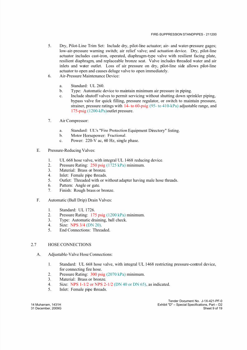
7/18/2019 SEC DPS
http://slidepdf.com/reader/full/sec-dps 48/541
FIRE-SUPPRESSION STANDPIPES - 211200
Tender Document No. J-1X-421-PF-0
14 Muharram, 1431H Exhibit "D" – Special Specifications, Part – D231 December, 2009G Sheet 9 of 19
5. Dry, Pilot-Line Trim Set: Include dry, pilot-line actuator; air- and water-pressure gages;
low-air-pressure warning switch; air relief valve; and actuation device. Dry, pilot-line
actuator includes cast-iron, operated, diaphragm-type valve with resilient facing plate,
resilient diaphragm, and replaceable bronze seat. Valve includes threaded water and airinlets and water outlet. Loss of air pressure on dry, pilot-line side allows pilot-line
actuator to open and causes deluge valve to open immediately.
6. Air-Pressure Maintenance Device:
a. Standard: UL 260.
b. Type: Automatic device to maintain minimum air pressure in piping.
c. Include shutoff valves to permit servicing without shutting down sprinkler piping,
bypass valve for quick filling, pressure regulator, or switch to maintain pressure,
strainer, pressure ratings with 14- to 60-psig (95- to 410-kPa) adjustable range, and
175-psig (1200-kPa)outlet pressure.
7. Air Compressor:
a. Standard: UL's "Fire Protection Equipment Directory" listing.
b. Motor Horsepower: Fractional.
c. Power: 220-V ac, 60 Hz, single phase.
E. Pressure-Reducing Valves:
1. UL 668 hose valve, with integral UL 1468 reducing device.
2. Pressure Rating: 250 psig (1725 kPa) minimum.
3. Material: Brass or bronze.
4. Inlet: Female pipe threads.
5. Outlet: Threaded with or without adapter having male hose threads.6. Pattern: Angle or gate.
7. Finish: Rough brass or bronze.
F. Automatic (Ball Drip) Drain Valves:
1. Standard: UL 1726.
2. Pressure Rating: 175 psig (1200 kPa) minimum.
3. Type: Automatic draining, ball check.
4. Size: NPS 3/4 (DN 20).
5. End Connections: Threaded.
2.7 HOSE CONNECTIONS
A. Adjustable-Valve Hose Connections:
1. Standard: UL 668 hose valve, with integral UL 1468 restricting pressure-control device,
for connecting fire hose.
2. Pressure Rating: 300 psig (2070 kPa) minimum.3. Material: Brass or bronze.
4. Size: NPS 1-1/2 or NPS 2-1/2 (DN 40 or DN 65), as indicated.
5. Inlet: Female pipe threads.
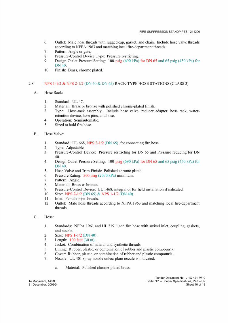
7/18/2019 SEC DPS
http://slidepdf.com/reader/full/sec-dps 49/541
FIRE-SUPPRESSION STANDPIPES - 211200
Tender Document No. J-1X-421-PF-0
14 Muharram, 1431H Exhibit "D" – Special Specifications, Part – D231 December, 2009G Sheet 10 of 19
6. Outlet: Male hose threads with lugged cap, gasket, and chain. Include hose valve threads
according to NFPA 1963 and matching local fire-department threads.
7. Pattern: Angle or gate.
8. Pressure-Control Device Type: Pressure restricting.9. Design Outlet Pressure Setting: 100 psig (690 kPa) for DN 65 and 65 psig (450 kPa) for
DN 40.
10. Finish: Brass, chrome plated.
2.8 NPS 1-1/2 & NPS 2-1/2 (DN 40 & DN 65) RACK-TYPE HOSE STATIONS (CLASS 3)
A. Hose Rack:
1. Standard: UL 47.
2. Material: Brass or bronze with polished chrome-plated finish.
3. Type: Hose-rack assembly. Include hose valve, reducer adapter, hose rack, water-retention device, hose pins, and hose.
4. Operation: Semiautomatic.
5. Sized to hold fire hose.
B. Hose Valve:
1. Standard: UL 668, NPS 2-1/2 (DN 65), for connecting fire hose.
2. Type: Adjustable.
3. Pressure-Control Device: Pressure restricting for DN 65 and Pressure reducing for DN
40.
4. Design Outlet Pressure Setting: 100 psig (690 kPa) for DN 65 and 65 psig (450 kPa) for
DN 40.5. Hose Valve and Trim Finish: Polished chrome plated.
6. Pressure Rating: 300 psig (2070 kPa) minimum.
7. Pattern: Angle.
8. Material: Brass or bronze.
9. Pressure-Control Device: UL 1468, integral or for field installation if indicated.
10. Size: NPS 2-1/2 (DN 65) & NPS 1-1/2 (DN 40).
11. Inlet: Female pipe threads.
12. Outlet: Male hose threads according to NFPA 1963 and matching local fire-department
threads.
C. Hose:
1. Standards: NFPA 1961 and UL 219, lined fire hose with swivel inlet, coupling, gaskets,
and nozzle.
2. Size: NPS 1-1/2 (DN 40).
3. Length: 100 feet (30 m).
4. Jacket: Combination of natural and synthetic threads.
5. Lining: Rubber, plastic, or combination of rubber and plastic compounds.
6. Cover: Rubber, plastic, or combination of rubber and plastic compounds.
7. Nozzle: UL 401 spray nozzle unless plain nozzle is indicated.
a. Material: Polished chrome-plated brass.

7/18/2019 SEC DPS
http://slidepdf.com/reader/full/sec-dps 50/541
FIRE-SUPPRESSION STANDPIPES - 211200
Tender Document No. J-1X-421-PF-0
14 Muharram, 1431H Exhibit "D" – Special Specifications, Part – D231 December, 2009G Sheet 11 of 19
b. Type: Spray, adjustable from shutoff to fog spray or straight stream.
2.9 FIRE-DEPARTMENT CONNECTIONS
A. Exposed-Type, Fire-Department Connection:
1. Standard: UL 405.
2. Type: Exposed, projecting, for wall mounting.
3. Pressure Rating: 175 psig (1200 kPa) minimum.
4. Body Material: Corrosion-resistant metal.
5. Inlets: Brass with threads according to NFPA 1963 and matching local fire-department
sizes and threads. Include extension pipe nipples, brass lugged swivel connections, and
check devices or clappers.
6. Caps: Brass, lugged type, with gasket and chain.
7. Escutcheon Plate: Round, brass, wall type.8. Outlet: Back, with pipe threads.
9. Number of Inlets: Four.
10. Escutcheon Plate Marking: Similar to "AUTO SPKR & STANDPIPE."
11. Finish: Polished chrome plated.
12. Outlet Size: NPS 6 (DN 150).
B. Flush-Type, Fire-Department Connection:
1. Standard: UL 405.
2. Type: Flush, for wall mounting.
3. Pressure Rating: 175 psig (1200 kPa) minimum.
4. Body Material: Corrosion-resistant metal.5. Inlets: Brass with threads according to NFPA 1963 and matching local fire-department
sizes and threads. Include extension pipe nipples, brass lugged swivel connections, and
check devices or clappers.
6. Caps: Brass, lugged type, with gasket and chain.
7. Escutcheon Plate: Rectangular, brass, wall type.
8. Outlet: With pipe threads.
9. Body Style: Horizontal.
10. Number of Inlets: Four.
11. Outlet Location: Back or Bottom.
12. Escutcheon Plate Marking: Similar to "AUTO SPKR & STANDPIPE."
13. Finish: Polished chrome plated.
14. Outlet Size: NPS 6 (DN 150).
C. Yard-Type, Fire-Department Connection:
1. Standard: UL 405.
2. Type: Exposed, freestanding.
3. Pressure Rating: 175 psig (1200 kPa) minimum] or 00 psig (2070 kPa), as applicable.
4. Body Material: Corrosion-resistant metal.
5. Inlets: Brass with threads according to NFPA 1963 and matching local fire-department
sizes and threads. Include extension pipe nipples, brass lugged swivel connections, andcheck devices or clappers.

7/18/2019 SEC DPS
http://slidepdf.com/reader/full/sec-dps 51/541
FIRE-SUPPRESSION STANDPIPES - 211200
Tender Document No. J-1X-421-PF-0
14 Muharram, 1431H Exhibit "D" – Special Specifications, Part – D231 December, 2009G Sheet 12 of 19
6. Caps: Brass, lugged type, with gasket and chain.
7. Escutcheon Plate: Round, brass, floor type.
8. Outlet: Bottom, with pipe threads.
9. Number of Inlets: Four.10. Sleeve: Brass.
11. Sleeve Height: 18 inches (460 mm).
12. Escutcheon Plate Marking: Similar to "AUTO SPKR & STANDPIPE."
13. Finish, Including Sleeve: Polished chrome plated.
14. Outlet Size: NPS 6 (DN 150).
2.10 ALARM DEVICES
A. Alarm-device types shall match piping and equipment connections.
B. Water-Motor-Operated Alarm:
1. Manufacturers: Subject to compliance with requirements
2. Standard: UL 753.
3. Type: Mechanically operated, with Pelton wheel.
4. Alarm Gong: Cast aluminum with red-enamel factory finish.
5. Size: 10-inch (250-mm) diameter.
6. Components: Shaft length, bearings, and sleeve to suit wall construction.
7. Inlet: NPS 3/4 (DN 20).
8. Outlet: NPS 1 (DN 25) drain connection.
C. Electrically Operated Alarm Bell:
1. Manufacturers: Subject to compliance with requirements
2. Standard: UL 464.
3. Type: Vibrating, metal alarm bell.
4. Size: [10-inch (250-mm) diameter.5. Finish: Red-enamel factory finish, suitable for outdoor use.
D. Water-Flow Indicators:
1. Standard: UL 346.
2. Water-Flow Detector: Electrically supervised.
3. Components: Two single-pole, double-throw circuit switches for isolated alarm andauxiliary contacts, 7 A, 220-V ac and 0.25 A, 24-V dc; complete with factory-set, field-
adjustable retard element to prevent false signals and tamperproof cover that sends signal
if removed.
4. Type: Paddle operated.
5. Pressure Rating: 250 psig (1725 kPa).
6. Design Installation: Horizontal or vertical.
E. Pressure Switches:
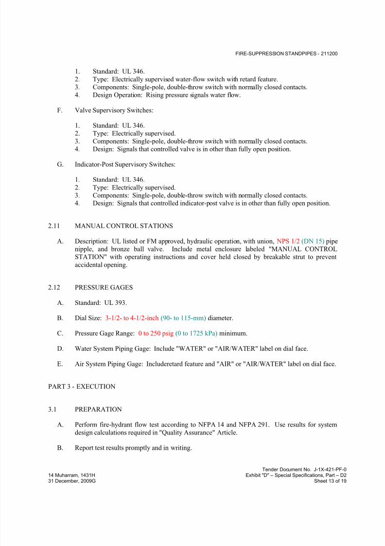
7/18/2019 SEC DPS
http://slidepdf.com/reader/full/sec-dps 52/541
FIRE-SUPPRESSION STANDPIPES - 211200
Tender Document No. J-1X-421-PF-0
14 Muharram, 1431H Exhibit "D" – Special Specifications, Part – D231 December, 2009G Sheet 13 of 19
1. Standard: UL 346.
2. Type: Electrically supervised water-flow switch with retard feature.
3. Components: Single-pole, double-throw switch with normally closed contacts.
4. Design Operation: Rising pressure signals water flow.
F. Valve Supervisory Switches:
1. Standard: UL 346.
2. Type: Electrically supervised.
3. Components: Single-pole, double-throw switch with normally closed contacts.
4. Design: Signals that controlled valve is in other than fully open position.
G. Indicator-Post Supervisory Switches:
1. Standard: UL 346.
2. Type: Electrically supervised.3. Components: Single-pole, double-throw switch with normally closed contacts.
4. Design: Signals that controlled indicator-post valve is in other than fully open position.
2.11 MANUAL CONTROL STATIONS
A. Description: UL listed or FM approved, hydraulic operation, with union, NPS 1/2 (DN 15) pipe
nipple, and bronze ball valve. Include metal enclosure labeled "MANUAL CONTROL
STATION" with operating instructions and cover held closed by breakable strut to prevent
accidental opening.
2.12 PRESSURE GAGES
A. Standard: UL 393.
B. Dial Size: 3-1/2- to 4-1/2-inch (90- to 115-mm) diameter.
C. Pressure Gage Range: 0 to 250 psig (0 to 1725 kPa) minimum.
D. Water System Piping Gage: Include "WATER" or "AIR/WATER" label on dial face.
E. Air System Piping Gage: Includeretard feature and "AIR" or "AIR/WATER" label on dial face.
PART 3 - EXECUTION
3.1 PREPARATION
A. Perform fire-hydrant flow test according to NFPA 14 and NFPA 291. Use results for system
design calculations required in "Quality Assurance" Article.
B. Report test results promptly and in writing.
7/18/2019 SEC DPS
http://slidepdf.com/reader/full/sec-dps 53/541
FIRE-SUPPRESSION STANDPIPES - 211200
Tender Document No. J-1X-421-PF-0
14 Muharram, 1431H Exhibit "D" – Special Specifications, Part – D231 December, 2009G Sheet 14 of 19
3.2 EXAMINATION
A. Examine roughing-in for hose connections and stations to verify actual locations of piping
connections before installation.
B. Examine walls and partitions for suitable thickness, fire- and smoke-rated construction, framing
for hose-station cabinets, and other conditions where hose connections and stations are to be
installed.
C. Proceed with installation only after unsatisfactory conditions have been corrected.
3.3 SERVICE-ENTRANCE PIPING
A. Connect fire-suppression standpipe piping to water-service piping at service entrance into
building. Comply with requirements for exterior piping in Division 21 Section "Facility Fire-Suppression Water-Service Piping."
B. Install shutoff valve, backflow preventer, pressure gage, drain, and other accessories at
connection to fire-suppression water-service piping. Comply with requirements for backflow
preventers in Division 21 Section "Facility Fire-Suppression Water-Service Piping."
3.4 PIPING INSTALLATION
A. Locations and Arrangements: Drawing plans, schematics, and diagrams indicate general
location and arrangement of piping. Install piping as indicated, as far as practical.
1. Deviations from approved working plans for piping require written approval fromauthorities having jurisdiction. File written approval with Architect before deviating
from approved working plans.
B. Piping Standard: Comply with requirements in NFPA 14 for installation of fire-suppression
standpipe piping.
C. Install seismic restraints on piping. Comply with requirements in NFPA 13 for seismic-restraint
device materials and installation.
D. Install listed fittings to make changes in direction, branch takeoffs from mains, and reductionsin pipe sizes.
E. Install drain valves on standpipes. Extend drain piping to outside of building.
F. Install automatic (ball drip) drain valves to drain piping between fire-department connections
and check valves. Drain to floor drain or outside building.
G. Install alarm devices in piping systems.
H. Install hangers and supports for standpipe system piping according to NFPA 14. Comply with
requirements in NFPA 13 for hanger materials.

7/18/2019 SEC DPS
http://slidepdf.com/reader/full/sec-dps 54/541
FIRE-SUPPRESSION STANDPIPES - 211200
Tender Document No. J-1X-421-PF-0
14 Muharram, 1431H Exhibit "D" – Special Specifications, Part – D231 December, 2009G Sheet 15 of 19
I. Install pressure gages on riser or feed main and at top of each standpipe. Include pressure gages
with connection not less than NPS 1/4 (DN 8) and with soft-metal seated globe valve, arranged
for draining pipe between gage and valve. Install gages to permit removal, and install where
they will not be subject to freezing.
J. Drain dry-type standpipe system piping.
K. Pressurize and check dry-type standpipe system piping and air-pressure maintenance devices.
L. Fill wet-type standpipe system piping with water.
M. Install electric heating cables and pipe insulation on wet-type, fire-suppression standpipe piping
in areas subject to freezing. Comply with requirements for heating cables in Division 21
Section "Heat Tracing for Fire-Suppression Piping" and for piping insulation in Division 21
Section "Fire-Suppression Systems Insulation."
N. Connect air compressor to the following piping and wiring:
1. Pressure gages and controls.
2. Electrical power system.
3. Fire-alarm devices, including low-pressure alarm.
O. Install sleeves for piping penetrations of walls, ceilings, and floors. Comply with requirements
for sleeves specified in Division 21 Section "Sleeves and Sleeve Seals for Fire-Suppression
Piping."
P. Install sleeve seals for piping penetrations of concrete walls and slabs. Comply with
requirements for sleeve seals specified in Division 21 Section "Sleeves and Sleeve Seals for
Fire-Suppression Piping."
Q. Install escutcheons for piping penetrations of walls, ceilings, and floors. Comply with
requirements for escutcheons specified in Division 21 Section "Escutcheons for Fire-
Suppression Piping."
3.5 JOINT CONSTRUCTION
A. Install couplings, flanges, flanged fittings, unions, nipples, and transition and special fittings
that have finish and pressure ratings same as or higher than system's pressure rating for
aboveground applications unless otherwise indicated.
B. Install unions adjacent to each valve in pipes NPS 2 (DN 50) and smaller.
C. Install flanges, flange adapters, or couplings for grooved-end piping on valves, apparatus, and
equipment having NPS 2-1/2 (DN 65) and larger end connections.
D. Ream ends of pipes and tubes and remove burrs. Bevel plain ends of steel pipe.
E. Remove scale, slag, dirt, and debris from inside and outside of pipes, tubes, and fittings before
assembly.
7/18/2019 SEC DPS
http://slidepdf.com/reader/full/sec-dps 55/541
FIRE-SUPPRESSION STANDPIPES - 211200
Tender Document No. J-1X-421-PF-0
14 Muharram, 1431H Exhibit "D" – Special Specifications, Part – D231 December, 2009G Sheet 16 of 19
F. Flanged Joints: Select appropriate gasket material in size, type, and thickness suitable for water
service. Join flanges with gasket and bolts according to ASME B31.9.
G. Threaded Joints: Thread pipe with tapered pipe threads according to ASME B1.20.1. Cutthreads full and clean using sharp dies. Ream threaded pipe ends to remove burrs and restore
full ID. Join pipe fittings and valves as follows:
1. Apply appropriate tape or thread compound to external pipe threads.
2. Damaged Threads: Do not use pipe or pipe fittings with threads that are corroded or
damaged.
H. Steel-Piping, Cut-Grooved Joints: Cut square-edge groove in end of pipe according to
AWWA C606. Assemble coupling with housing, gasket, lubricant, and bolts. Join steel pipe
and grooved-end fittings according to AWWA C606 for steel-pipe joints.
I. Steel-Piping, Roll-Grooved Joints: Roll rounded-edge groove in end of pipe according toAWWA C606. Assemble coupling with housing, gasket, lubricant, and bolts. Join steel pipe
and grooved-end fittings according to AWWA C606 for steel-pipe grooved joints.
J. Welded Joints: Construct joints according to AWS D10.12M/D10.12, using qualified processes
and welding operators according to "Quality Assurance" Article.
1. Shop weld pipe joints where welded piping is indicated. Do not use welded joints for
galvanized-steel pipe.
K. Dissimilar-Material Piping Joints: Make joints using adapters compatible with materials of both piping systems.
3.6 VALVE AND SPECIALTIES INSTALLATION
A. Install listed fire-protection valves, trim and drain valves, specialty valves and trim, controls,
and specialties according to NFPA 14 and authorities having jurisdiction.
B. Install listed fire-protection shutoff valves supervised-open, located to control sources of water
supply except from fire-department connections. Install permanent identification signsindicating portion of system controlled by each valve.
C. Install check valve in each water-supply connection. Install backflow preventers instead of
check valves in potable-water-supply sources.
D. Specialty Valves:
1. General Requirements: Install in vertical position for proper direction of flow, in main
supply to system.
2. Alarm Valves: Install bypass check valve and retarding chamber drain-line connection.
3. Dry-Pipe and Deluge Valves: Install trim sets for air supply, drain, priming level, alarm
connections, ball drip valves, pressure gages, priming chamber attachment, and fill-line
attachment.

7/18/2019 SEC DPS
http://slidepdf.com/reader/full/sec-dps 56/541
FIRE-SUPPRESSION STANDPIPES - 211200
Tender Document No. J-1X-421-PF-0
14 Muharram, 1431H Exhibit "D" – Special Specifications, Part – D231 December, 2009G Sheet 17 of 19
a. Air-Pressure Maintenance Device: Install shutoff valves to permit servicing
without shutting down sprinkler system; bypass valve for quick system filling;
pressure regulator or switch to maintain system pressure; strainer; pressure ratings
with 14- to 60-psig (95- to 410-kPa) adjustable range; and 175-psig (1200-kPa) maximum inlet pressure.
b. Install compressed-air supply piping from building's compressed-air piping system.
3.7 HOSE-CONNECTION INSTALLATION
A. Install hose connections adjacent to standpipes.
B. Install freestanding hose connections for access and minimum passage restriction.
C. Install NPS 1-1/2 (DN 40) hose-connection valves with flow-restricting device.
D. Install NPS 2-1/2 (DN 65) hose connections with quick-disconnect NPS 2-1/2 by NPS 1-1/2
(DN 65 by DN 40) reducer adapter and flow-restricting device.
E. Install wall-mounted-type hose connections in cabinets. Include pipe escutcheons, with finish
matching valves, inside cabinet where water-supply piping penetrates cabinet. Install valves atangle required for connection of fire hose. Comply with requirements for cabinets in
Division 10 Section "Fire Extinguisher Cabinets."
3.8 HOSE-STATION INSTALLATION
A. Install freestanding hose stations for access and minimum passage restriction.
B. Install NPS 1-1/2 (DN 40) hose-station valves with flow-restricting device unless otherwise
indicated.
C. Install NPS 2-1/2 (DN 65) hose connections with quick-disconnect NPS 2-1/2 by NPS 1-1/2
(DN 65 by DN 40) reducer adapter and flow-restricting device unless otherwise indicated.
D. Install freestanding hose stations with support or bracket attached to standpipe.
E. Install wall-mounted, rack hose stations in cabinets. Include pipe escutcheons, with finish
matching valves, inside cabinet where water-supply piping penetrates cabinet. Install valves atangle required for connection of fire hose. Comply with requirements for cabinets in
Division 10 Section "Fire Extinguisher Cabinets."
F. Install hose-reel hose stations on wall with bracket.
3.9 MONITOR INSTALLATION
A. Install monitors on standpipe piping.

7/18/2019 SEC DPS
http://slidepdf.com/reader/full/sec-dps 57/541
FIRE-SUPPRESSION STANDPIPES - 211200
Tender Document No. J-1X-421-PF-0
14 Muharram, 1431H Exhibit "D" – Special Specifications, Part – D231 December, 2009G Sheet 18 of 19
3.10 FIRE-DEPARTMENT CONNECTION INSTALLATION
A. Install wall-type, fire-department connections.
B. Install yard-type, fire-department connections in concrete slab support. Comply with
requirements for concrete in Division 03 Section "Cast-in-Place Concrete."
1. Install three protective pipe bollards around each fire-department connection. Comply
with requirements for bollards in Division 05 Section "Metal Fabrications."
C. Install automatic (ball drip) drain valve at each check valve for fire-department connection.
3.11 IDENTIFICATION
A. Install labeling and pipe markers on equipment and piping according to requirements in NFPA 14.
B. Identify system components, wiring, cabling, and terminals. Comply with requirements for
identification specified in Division 26 Section "Identification for Electrical Systems."
3.12 FIELD QUALITY CONTROL
A. Perform tests and inspections.
B. Tests and Inspections:
1. Leak Test: After installation, charge systems and test for leaks. Repair leaks and retestuntil no leaks exist.
2. Test and adjust controls and safeties. Replace damaged and malfunctioning controls and
equipment.
3. Flush, test, and inspect standpipe systems according to NFPA 14, "System Acceptance"
Chapter.
4. Energize circuits to electrical equipment and devices.
5. Start and run air compressors.
6. Coordinate with fire-alarm tests. Operate as required.
7. Coordinate with fire-pump tests. Operate as required.
8. Verify that equipment hose threads are same as local fire-department equipment.
C. Fire-suppression standpipe system will be considered defective if it does not pass tests andinspections.
D. Prepare test and inspection reports.
3.13 DEMONSTRATION
A. Engage a factory-authorized service representative to train Owner's maintenance personnel to
adjust, operate, and maintain specialty valves.

7/18/2019 SEC DPS
http://slidepdf.com/reader/full/sec-dps 58/541
FIRE-SUPPRESSION STANDPIPES - 211200
Tender Document No. J-1X-421-PF-0
14 Muharram, 1431H Exhibit "D" – Special Specifications, Part – D231 December, 2009G Sheet 19 of 19
3.14 PIPING SCHEDULE
A. Piping between Fire-Department Connections and Check Valves: Galvanized, standard-weight
steel pipe with threaded ends; cast-iron threaded fittings; and threaded joints.
B. Standard-pressure, wet-type, fire-suppression standpipe piping, NPS 4 (DN 100) and smaller,
shall bethe following:
1. Standard-weight, black-steel pipe with plain ends; steel welding fittings; and welded
joints.
C. Standard-pressure, wet-type, fire-suppression standpipe piping, NPS 5 to NPS 8 (DN 125 to
DN 200), shall be the following:
1. Standard-weight, black-steel pipe with plain ends; steel welding fittings; and welded
joints.
D. Standard-pressure, wet-type, fire-suppression standpipe piping,[ NPS 10 and NPS 12 (DN 250and DN 300), shall beone of the following:
1. Standard-weight, black-steel pipe with cut- or roll-grooved ends; uncoated, grooved-end
fittings for steel piping; grooved-end-pipe couplings for steel piping; and grooved joints.
2. Standard-weight, black-steel pipe with plain ends; steel welding fittings; and welded
joints.
E. Standard-pressure, dry-type, fire-suppression standpipe piping, NPS 4 (DN 100) and smaller,
shall beone of the following:
1. Standard-weight, galvanized-steel pipe with threaded ends; galvanized, gray-iron
threaded fittings; and threaded joints.
2. Standard-weight, galvanized-steel pipe with cut-grooved ends; galvanized, grooved-endfittings for steel piping; grooved-end-pipe couplings for steel piping; and grooved joints.
F. Standard-pressure, dry-type, fire-suppression standpipe piping, NPS 5 and NPS 6 (DN 125 and
DN 150), shall be one of the following:
1. Standard-weight, galvanized-steel pipe with threaded ends; galvanized, gray-iron
threaded fittings; and threaded joints.
2. Standard-weight, galvanized-steel pipe with cut-grooved ends; galvanized, grooved-end
fittings for steel piping; grooved-end-pipe couplings for steel piping; and grooved joints.
END OF SECTION 211200
7/18/2019 SEC DPS
http://slidepdf.com/reader/full/sec-dps 59/541
WET-PIPE SPRINKLER SYSTEMS - 211313
Tender Document No. J-1X-421-PF-0
14 Muharram, 1431H Exhibit "D" – Special Specifications, Part – D231 December, 2009G Sheet 1 of 22
SECTION 211313 - WET-PIPE SPRINKLER SYSTEMS
PART 1 - GENERAL
1.1 RELATED DOCUMENTS
A. Drawings and general provisions of the Contract, including General and Supplementary
Conditions and Division 01 Specification Sections, apply to this Section.
1.2 SUMMARY
A. Section Includes:
1. Pipes, fittings, and specialties.
2. Fire-protection valves.3. Fire-department connections.
4. Sprinklers.
5. Alarm devices.
6. Manual control stations.
7. Control panels.8. Pressure gages.
B. Related Sections:
1. Division 21 Section "Fire-Suppression Standpipes" for standpipe piping.2. Division 21 Section "Dry-Pipe Sprinkler Systems" for dry-pipe sprinkler piping.
3. Division 21 Section "Foam-Water Systems" for AFFF piping.4. Division 21 Section "Electric-Drive, Centrifugal Fire Pumps and Diesel-Drive,
Centrifugal Fire Pumps " for fire pumps, pressure-maintenance pumps, and fire-pump
controllers.
1.3 DEFINITIONS
A. High-Pressure Sprinkler Piping: Wet-pipe sprinkler system piping designed to operate at
working pressure higher than standard 175 psig (1200 kPa), but not higher than 300 psig
(2070 kPa).
B. Standard-Pressure Sprinkler Piping: Wet-pipe sprinkler system piping designed to operate at
working pressure of 175 psig (1200 kPa) maximum.
1.4 SYSTEM DESCRIPTIONS
A. Wet-Pipe Sprinkler System: Automatic sprinklers are attached to piping containing water and
that is connected to water supply through alarm valve. Water discharges immediately from
7/18/2019 SEC DPS
http://slidepdf.com/reader/full/sec-dps 60/541
WET-PIPE SPRINKLER SYSTEMS - 211313
Tender Document No. J-1X-421-PF-0
14 Muharram, 1431H Exhibit "D" – Special Specifications, Part – D231 December, 2009G Sheet 2 of 22
sprinklers when they are opened. Sprinklers open when heat melts fusible link or destroys
frangible device. Hose connections are included if indicated.
B. Deluge Sprinkler System: Open sprinklers are attached to piping connected to water supplythrough deluge valve. Fire-detection system, in same area as sprinklers, opens valve. Water
flows into piping system and discharges from attached sprinklers when valve opens.
1.5 PERFORMANCE REQUIREMENTS
A. Standard-Pressure Piping System Component: Listed for 175-psig (1200-kPa) minimum
working pressure.
B. High-Pressure Piping System Component: Listed for 250-psig (1725-kPa) minimum or 300-
psig (2070-kPa) working pressure as applicable.
C. Delegated Design: Design sprinkler system(s), including comprehensive engineering analysis
by a qualified professional engineer, using performance requirements and design criteria
indicated.
a.
D. Sprinkler system design shall be approved by authorities having jurisdiction.
1. Margin of Safety for Available Water Flow and Pressure: 10percent, including losses
through water-service piping, valves, and backflow preventers.
2. Sprinkler Occupancy Hazard Classifications:
a. Automobile Parking Areas: Ordinary Hazard, Group 1. b. Building Service Areas: Ordinary Hazard, Group 1.
c. Prayer Areas: Light Hazard.
d. Electrical Equipment Rooms: Ordinary Hazard, Group 1.
e. Dry Cleaners: Ordinary Hazard, Group 2.
f. General Storage Areas: Ordinary Hazard, Group 1.
g. Laundries: Ordinary Hazard, Group 1.h. Libraries except Stack Areas: Light Hazard.
i. Library Stack Areas: Ordinary Hazard, Group 2.
j. Machine Shops: Ordinary Hazard, Group 2.
k. Mechanical Equipment Rooms: Ordinary Hazard, Group 1.
l. Office and Public Areas: Light Hazard.m. Plastics Processing Areas: Extra Hazard, Group 2.
n. Printing Plants: Extra Hazard, Group 1.
o. Repair Garages: Ordinary Hazard, Group 2.
p. Residential Living Areas: Light Hazard.
q. Restaurant Service Areas: Ordinary Hazard, Group 1.
r. Solvent Cleaning Areas: Extra Hazard, Group 2.
s. Upholstering Plants: Extra Hazard, Group 1
t. Other spaces: Hazard classification according to NFPA recommendations unless
otherwise indicated.

7/18/2019 SEC DPS
http://slidepdf.com/reader/full/sec-dps 61/541
WET-PIPE SPRINKLER SYSTEMS - 211313
Tender Document No. J-1X-421-PF-0
14 Muharram, 1431H Exhibit "D" – Special Specifications, Part – D231 December, 2009G Sheet 3 of 22
3. Minimum Density for Automatic-Sprinkler Piping Design:
a. Residential (Dwelling) Occupancy: 0.05 gpm over 400-sq. ft. (2.04 mm/min. over
37.2-sq. m) area. b. Light-Hazard Occupancy: 0.10 gpm over 1500-sq. ft. (4.1 mm/min. over 139-
sq. m) area.
c. Ordinary-Hazard, Group 1 Occupancy: 0.15 gpm over 1500-sq. ft. (6.1 mm/min.
over 139-sq. m) area.
d. Ordinary-Hazard, Group 2 Occupancy: 0.20 gpm over 1500-sq. ft. (8.1 mm/min.
over 139-sq. m)] area.
e. Extra-Hazard, Group 1 Occupancy: 0.30 gpm over 2500-sq. ft. (12.2 mm/min.
over 232-sq. m) area.
f. Extra-Hazard, Group 2 Occupancy: 0.40 gpm over 2500-sq. ft. (16.3 mm/min.
over 232-sq. m) area.
g. Special Occupancy Hazard: As determined by authorities having jurisdiction.
4. Minimum Density for Deluge-Sprinkler Piping Design:
a. Ordinary-Hazard, Group 1 Occupancy: 0.15 gpm (6.1 mm/min.) over entire area.
b. Ordinary-Hazard, Group 2 Occupancy: 0.20 gpm (8.1 mm/min.) over entire area.
c. Extra-Hazard, Group 1 Occupancy: 0.30 gpm (12.2 mm/min.) over entire area.
d. Extra-Hazard, Group 2 Occupancy: 0.40 gpm (16.3 mm/min.) over entire area.
e. Special Occupancy Hazard: As determined by authorities having jurisdiction.
5. Maximum Protection Area per Sprinkler: Per UL listing.
6. Maximum Protection Area per Sprinkler:
a. Residential Areas: 400 sq. ft. (37 sq. m). b. Office Spaces: 120 sq. ft. (11.1 sq. m) or 225 sq. ft. (20.9 sq. m).
c. Storage Areas: 130 sq. ft. (12.1 sq. m) .
d. Mechanical Equipment Rooms: 130 sq. ft. (12.1 sq. m).
e. Electrical Equipment Rooms: 130 sq. ft. (12.1 sq. m) .
f. Other Areas: According to NFPA 13 recommendations unless otherwise indicated.
7. Total Combined Hose-Stream Demand Requirement: According to NFPA 13 unless
otherwise indicated:
a. Light-Hazard Occupancies: 100 gpm (6.3 L/s) for 30 minutes.
b. Ordinary-Hazard Occupancies: 250 gpm (15.75 L/s) for 60 to 90 minutes.
c. Extra-Hazard Occupancies: 500 gpm (31.5 L/s) for 90 to 120 minutes.
E. Seismic Performance: Sprinkler piping shall withstand the effects of earthquake motions
determined according to NFPA 13 and ASCE/SEI 7.
1.6 ACTION SUBMITTALS
A. Product Data: For each type of product indicated. Include rated capacities, operating
characteristics, electrical characteristics, and furnished specialties and accessories.

7/18/2019 SEC DPS
http://slidepdf.com/reader/full/sec-dps 62/541
WET-PIPE SPRINKLER SYSTEMS - 211313
Tender Document No. J-1X-421-PF-0
14 Muharram, 1431H Exhibit "D" – Special Specifications, Part – D231 December, 2009G Sheet 4 of 22
B. LEED Submittal:
1. Product Data for Credit EQ 4.1: For solvent cements and adhesive primers, including
printed statement of VOC content and chemical components.
C. Shop Drawings: For wet-pipe sprinkler systems. Include plans, elevations, sections, details,
and attachments to other work.
1. Wiring Diagrams: For power, signal, and control wiring.
D. Delegated-Design Submittal: For sprinkler systems indicated to comply with performance
requirements and design criteria, including analysis data signed and sealed by the qualified
professional engineer responsible for their preparation.
1.7 INFORMATIONAL SUBMITTALS
A. Coordination Drawings: Sprinkler systems, drawn to scale, on which the following items are
shown and coordinated with each other, using input from installers of the items involved:
1. Domestic water piping.
2. Compressed air piping.
3. HVAC hydronic piping.
4. Items penetrating finished ceiling include but not limited to the following:
a. Lighting fixtures.
b. Air outlets and inlets.
B. Qualification Data: For qualified Installer and professional engineer.
C. Approved Sprinkler Piping Drawings: Working plans, prepared according to NFPA 13, that
have been approved by authorities having jurisdiction, including hydraulic calculations if
applicable.
D. Welding certificates.
E. Fire-hydrant flow test report.
F. Field Test Reports and Certificates: Indicate and interpret test results for compliance with performance requirements and as described in NFPA 13. Include "Contractor's Material and
Test Certificate for Aboveground Piping."
G. Field quality-control reports.
1.8 CLOSEOUT SUBMITTALS
A. Operation and Maintenance Data: For sprinkler specialties to include in emergency, operation,
and maintenance manuals.

7/18/2019 SEC DPS
http://slidepdf.com/reader/full/sec-dps 63/541
WET-PIPE SPRINKLER SYSTEMS - 211313
Tender Document No. J-1X-421-PF-0
14 Muharram, 1431H Exhibit "D" – Special Specifications, Part – D231 December, 2009G Sheet 5 of 22
1.9 QUALITY ASSURANCE
A. Installer Qualifications:
1. Installer's responsibilities include designing, fabricating, and installing sprinkler systems
and providing professional engineering services needed to assume engineering
responsibility. Base calculations on results of fire-hydrant flow test.
a. Engineering Responsibility: Preparation of working plans, calculations, and field
test reports by a qualified professional engineer.
B. Welding Qualifications: Qualify procedures and operators according to ASME Boiler and
Pressure Vessel Code.
C. Electrical Components, Devices, and Accessories: Listed and labeled as defined in NFPA 70,
by a qualified testing agency, and marked for intended location and application.
D. NFPA Standards: Sprinkler system equipment, specialties, accessories, installation, and testing
shall comply with the following:
1. NFPA 13, "Installation of Sprinkler Systems."2. NFPA 13R, "Installation of Sprinkler Systems in Residential Occupancies up to and
Including Four Stories in Height."
3. NFPA 24, "Installation of Private Fire Service Mains and Their Appurtenances."
1.10 PROJECT CONDITIONS
A. Interruption of Existing Sprinkler Service: Do not interrupt sprinkler service to facilitiesoccupied by Owner or others unless permitted under the following conditions and then only
after arranging to provide temporary sprinkler service according to requirements indicated:
1. Notify , Engineer, or Owner no fewer than two days in advance of proposed interruption
of sprinkler service.
2. Do not proceed with interruption of sprinkler service without , [Engineer, orwritten
permission.
1.11 COORDINATION
A. Coordinate layout and installation of sprinklers with other construction that penetrates ceilings,including light fixtures, HVAC equipment, and partition assemblies.
1.12 EXTRA MATERIALS
A. Furnish extra materials that match products installed and that are packaged with protective
covering for storage and identified with labels describing contents.
1. Sprinkler Cabinets: Finished, wall-mounted, steel cabinet with hinged cover, and with
space for minimum of six spare sprinklers plus sprinkler wrench. Include number of
7/18/2019 SEC DPS
http://slidepdf.com/reader/full/sec-dps 64/541
WET-PIPE SPRINKLER SYSTEMS - 211313
Tender Document No. J-1X-421-PF-0
14 Muharram, 1431H Exhibit "D" – Special Specifications, Part – D231 December, 2009G Sheet 6 of 22
sprinklers required by NFPA 13 and sprinkler wrench. Include separate cabinet with
sprinklers and wrench for each type of sprinkler used on Project.
PART 2 - PRODUCTS
2.1 PIPING MATERIALS
A. Comply with requirements in "Piping Schedule" Article for applications of pipe, tube, and
fitting materials, and for joining methods for specific services, service locations, and pipe sizes.
2.2 STEEL PIPE AND FITTINGS
A.
Standard Weight, Black-Steel Pipe: ASTM A 53/A 53M, Type S, Grade B. Pipe ends may befactory or field formed to match joining method.
B. Pipe in first paragraph below is intended for use with flanged, roll-grooved, and welded joints.
Pipe is available in NPS 1 to NPS 3 (DN 25 to DN 80).
C. Black-Steel Pipe Nipples: ASTM A 733, made of ASTM A 53/A 53M, standard-weight,
seamless steel pipe with threaded ends.
D. Galvanized and Uncoated, Steel Couplings: ASTM A 865, threaded.
E. Galvanized and Uncoated, Gray-Iron Threaded Fittings: ASME B16.4, Class 125, standard
pattern.
F. Malleable- or Ductile-Iron Unions: UL 860.
G. Cast-Iron Flanges: ASME 16.1, Class 125.
H. Steel Flanges and Flanged Fittings: ASME B16.5, Class 150.
I. Steel Welding Fittings: ASTM A 234/A 234M and ASME B16.9.
J. Grooved-Joint, Steel-Pipe Appurtenances:
1. Pressure Rating: 175 psig (1200 kPa), 250 psig (1725 kPa), or 300 psig (2070 kPa)
minimum as applicable.2. GalvanizedUncoated, Grooved-End Fittings for Steel Piping: ASTM A 47/A 47M,
malleable-iron casting or ASTM A 536, ductile-iron casting; with dimensions matching
steel pipe.
3. Grooved-End-Pipe Couplings for Steel Piping: AWWA C606 and UL 213, rigid pattern,
unless otherwise indicated, for steel-pipe dimensions. Include ferrous housing sections,
EPDM-rubber gasket, and bolts and nuts.
K. Steel Pressure-Seal Fittings: UL 213, FM-approved, 175-psig (1200-kPa) or 250-psig (1725-
kPa) pressure rating as applicable with steel housing, rubber O-rings, and pipe stop; for use with
fitting manufacturers' pressure-seal tools.
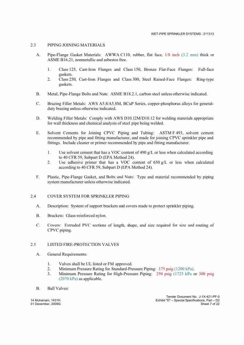
7/18/2019 SEC DPS
http://slidepdf.com/reader/full/sec-dps 65/541
WET-PIPE SPRINKLER SYSTEMS - 211313
Tender Document No. J-1X-421-PF-0
14 Muharram, 1431H Exhibit "D" – Special Specifications, Part – D231 December, 2009G Sheet 7 of 22
2.3 PIPING JOINING MATERIALS
A. Pipe-Flange Gasket Materials: AWWA C110, rubber, flat face, 1/8 inch (3.2 mm) thick or
ASME B16.21, nonmetallic and asbestos free.
1. Class 125, Cast-Iron Flanges and Class 150, Bronze Flat-Face Flanges: Full-face
gaskets.
2. Class 250, Cast-Iron Flanges and Class 300, Steel Raised-Face Flanges: Ring-type
gaskets.
B. Metal, Pipe-Flange Bolts and Nuts: ASME B18.2.1, carbon steel unless otherwise indicated.
C. Brazing Filler Metals: AWS A5.8/A5.8M, BCuP Series, copper-phosphorus alloys for general-
duty brazing unless otherwise indicated.
D. Welding Filler Metals: Comply with AWS D10.12M/D10.12 for welding materials appropriatefor wall thickness and chemical analysis of steel pipe being welded.
E. Solvent Cements for Joining CPVC Piping and Tubing: ASTM F 493, solvent cement
recommended by pipe and fitting manufacturer, and made for joining CPVC sprinkler pipe and
fittings. Include cleaner or primer recommended by pipe and fitting manufacturer.
1. Use solvent cement that has a VOC content of 490 g/L or less when calculated according
to 40 CFR 59, Subpart D (EPA Method 24).
2. Use adhesive primer that has a VOC content of 650 g/L or less when calculated
according to 40 CFR 59, Subpart D (EPA Method 24).
F. Plastic, Pipe-Flange Gasket, and Bolts and Nuts: Type and material recommended by piping
system manufacturer unless otherwise indicated.
2.4 COVER SYSTEM FOR SPRINKLER PIPING
A. Description: System of support brackets and covers made to protect sprinkler piping.
B. Brackets: Glass-reinforced nylon.
C. Covers: Extruded PVC sections of length, shape, and size required for size and routing of
CPVC piping.
2.5 LISTED FIRE-PROTECTION VALVES
A. General Requirements:
1. Valves shall be UL listed or FM approved.
2. Minimum Pressure Rating for Standard-Pressure Piping: 175 psig (1200 kPa).
3. Minimum Pressure Rating for High-Pressure Piping: 250 psig (1725 kPa or 300 psig
(2070 kPa) as applicable.
B. Ball Valves:

7/18/2019 SEC DPS
http://slidepdf.com/reader/full/sec-dps 66/541
WET-PIPE SPRINKLER SYSTEMS - 211313
Tender Document No. J-1X-421-PF-0
14 Muharram, 1431H Exhibit "D" – Special Specifications, Part – D231 December, 2009G Sheet 8 of 22
1. Standard: UL 1091 except with ball instead of disc.
2. Valves NPS 1-1/2 (DN 40) and Smaller: Bronze body with threaded ends.
3. Valves NPS 2 and NPS 2-1/2 (DN 50 and DN 65): Bronze body with threaded ends or
ductile-iron body with grooved ends.4. Valves NPS 3 (DN 80): Ductile-iron body with grooved ends.
C. Bronze Butterfly Valves:
1. Standard: UL 1091.
2. Pressure Rating: 175 psig (1200 kPa) or 250 psig (1725 kPa) as applicable.
3. Body Material: Bronze.
4. End Connections: Threaded.
D. Iron Butterfly Valves:
1. Standard: UL 1091.2. Pressure Rating: 175 psig (1200 kPa) or 250 psig (1725 kPa) as applicable.
3. Body Material: Cast or ductile iron.
4. Style: Lug or wafer.
5. End Connections: Grooved.
E. Check Valves:
1. Standard: UL 312.
2. Pressure Rating: 250 psig (1725 kPa) minimum or 300 psig (2070 kPa) as applicable.
3. Type: Swing check.
4. Body Material: Cast iron.
5. End Connections: Flanged or grooved.
F. Bronze OS&Y Gate Valves:
1. Standard: UL 262.
2. Pressure Rating: 175 psig (1200 kPa) or 250 psig (1725 kPa) as applicable.
3. Body Material: Bronze.
4. End Connections: Threaded.
G. Iron OS&Y Gate Valves:
1. Standard: UL 262.
2. Pressure Rating: 250 psig (1725 kPa) minimum or 300 psig (2070 kPa) as applicable.
3. Body Material: Cast or ductile iron.4. End Connections: Flanged or grooved.
H. Indicating-Type Butterfly Valves:
1. Standard: UL 1091.
2. Pressure Rating: 175 psig (1200 kPa) minimum or 250 psig (1725 kPa) as applicable.
3. Valves NPS 2 (DN 50) and Smaller:
a. Valve Type: Ball or butterfly.

7/18/2019 SEC DPS
http://slidepdf.com/reader/full/sec-dps 67/541
WET-PIPE SPRINKLER SYSTEMS - 211313
Tender Document No. J-1X-421-PF-0
14 Muharram, 1431H Exhibit "D" – Special Specifications, Part – D231 December, 2009G Sheet 9 of 22
b. Body Material: Bronze.
c. End Connections: Threaded.
4. Valves NPS 2-1/2 (DN 65) and Larger:
a. Valve Type: Butterfly.
b. Body Material: Cast or ductile iron.
c. End Connections: Flanged, grooved, or wafer.
5. Valve Operation: Integral electrical, 115-V ac, prewired, single-circuit, supervisory
switch indicating device.
I. NRS Gate Valves:
1. Standard: UL 262.
2. Pressure Rating: 250 psig (1725 kPa) minimum or 300 psig (2070 kPa) as applicable.3. Body Material: Cast iron with indicator post flange.
4. Stem: Nonrising.
5. End Connections: Flanged or grooved.
J. Indicator Posts:
1. Standard: UL 789.
2. Type: Horizontal for wall mounting.
3. Body Material: Cast iron with extension rod and locking device.
4. Operation: [Wrench] [Hand wheel].
2.6 TRIM AND DRAIN VALVES
A. General Requirements:
1. Standard: UL's "Fire Protection Equipment Directory" listing or "Approval Guide,"
published by FM Global, listing.
2. Pressure Rating: 175 psig (1200 kPa) minimum or 250 psig (1725 kPa) as applicable.
SPECIALTY VALVES
B. General Requirements:
1. Standard: UL's "Fire Protection Equipment Directory" listing or "Approval Guide," published by FM Global, listing.
2. Pressure Rating:
a. Standard-Pressure Piping Specialty Valves: 175 psig (1200 kPa) minimum.
b. High-Pressure Piping Specialty Valves: 250 psig (1725 kPa) minimumor 300 psig
(2070 kPa) as applicable.
3. Body Material: Cast or ductile iron.
4. Size: Same as connected piping.

7/18/2019 SEC DPS
http://slidepdf.com/reader/full/sec-dps 68/541
WET-PIPE SPRINKLER SYSTEMS - 211313
Tender Document No. J-1X-421-PF-0
14 Muharram, 1431H Exhibit "D" – Special Specifications, Part – D231 December, 2009G Sheet 10 of 22
5. End Connections: Flanged or grooved.
C. Alarm Valves:
1. Standard: UL 193.
2. Design: For horizontal or vertical installation.
3. Include trim sets for bypass, drain, electrical sprinkler alarm switch, pressure
gages, retarding chamber, and fill-line attachment with strainer.
4. Drip Cup Assembly: Pipe drain without valves and separate from main drain piping.
5. Drip Cup Assembly: Pipe drain with check valve to main drain piping.
D. Deluge Valves:
1. Standard: UL 260.
2. Design: Hydraulically operated, differential-pressure type.
3. Include trim sets for bypass, drain, electrical sprinkler alarm switch, pressure gages, dripcup assembly piped without valves and separate from main drain line, fill-line attachment
with strainer, and push-rod chamber supply connection.
4. Wet, Pilot-Line Trim Set: Include gage to read push-rod chamber pressure, globe valve
for manual operation of deluge valve, and connection for actuation device.
E. Automatic (Ball Drip) Drain Valves:
1. Standard: UL 1726.
2. Pressure Rating: 175 psig (1200 kPa) minimum or 250 psig (1725 kPa) as applicable.
3. Type: Automatic draining, ball check.
4. Size: NPS 3/4 (DN 20).
5. End Connections: Threaded.
2.7 FIRE-DEPARTMENT CONNECTIONS
A. Exposed-Type, Fire-Department Connection:
1. Standard: UL 405.
2. Type: Exposed, projecting, for wall mounting.
3. Pressure Rating: 175 psig (1200 kPa) minimum or 250 psig (1725 kPa) as applicable.
4. Body Material: Corrosion-resistant metal.
5. Inlets: Brass with threads according to NFPA 1963 and matching local fire-department
sizes and threads. Include extension pipe nipples, brass lugged swivel connections, and
check devices or clappers.6. Caps: Brass, lugged type, with gasket and chain.
7. Escutcheon Plate: Round, brass, wall type.
8. Outlet: Back, with pipe threads.
9. Number of Inlets: Four.
10. Escutcheon Plate Marking: Similar to "AUTO SPKR & STANDPIPE."
11. Finish: Polished chrome plated .
12. Outlet Size: NPS 6 (DN 150).
B. Flush-Type, Fire-Department Connection:

7/18/2019 SEC DPS
http://slidepdf.com/reader/full/sec-dps 69/541
WET-PIPE SPRINKLER SYSTEMS - 211313
Tender Document No. J-1X-421-PF-0
14 Muharram, 1431H Exhibit "D" – Special Specifications, Part – D231 December, 2009G Sheet 11 of 22
1. Standard: UL 405.
2. Type: Flush, for wall mounting.
3. Pressure Rating: 175 psig (1200 kPa) minimum or 250 psig (1725 kPa) as applicable.
4. Body Material: Corrosion-resistant metal.5. Inlets: Brass with threads according to NFPA 1963 and matching local fire-department
sizes and threads. Include extension pipe nipples, brass lugged swivel connections, and
check devices or clappers.
6. Caps: Brass, lugged type, with gasket and chain.
7. Escutcheon Plate: Rectangular, brass, wall type.8. Outlet: With pipe threads.
9. Body Style: [Horizontal] [Square] [Vertical].
10. Number of Inlets: Four.
11. Outlet Location: Back,Bottom, Left side, Right side, or Top as approved by Engineer.
12. Escutcheon Plate Marking: Similar to "AUTO SPKR & STANDPIPE."
13. Finish: Polished chrome plated.
14. Outlet Size: NPS 6 (DN 150).
C. Yard-Type, Fire-Department Connection:
1. Standard: UL 405.
2. Type: Exposed, freestanding.
3. Pressure Rating: 175 psig (1200 kPa) minimum or 300 psig (2070 kPa) as applicable.
4. Body Material: Corrosion-resistant metal.
5. Inlets: Brass with threads according to NFPA 1963 and matching local fire-department
sizes and threads. Include extension pipe nipples, brass lugged swivel connections, and
check devices or clappers.
6. Caps: Brass, lugged type, with gasket and chain.
7. Escutcheon Plate: Round, brass, floor type.8. Outlet: Bottom, with pipe threads.
9. Number of Inlets: Four.
10. Sleeve: Brass.
11. Sleeve Height: 18 inches (460 mm).
12. Escutcheon Plate Marking: Similar to "AUTO SPKR & STANDPIPE."
13. Finish[, Including Sleeve: Polished chrome plated
14. Outlet Size: NPS 6 (DN 150).
2.8 SPRINKLER SPECIALTY PIPE FITTINGS
A. Branch Outlet Fittings:
1. Standard: UL 213.
2. Pressure Rating: 175 psig (1200 kPa) minimum or 300 psig (2070 kPa) as applicable.
3. Body Material: Ductile-iron housing with EPDM seals and bolts and nuts.
4. Type: Mechanical-T and -cross fittings.
5. Configurations: Snap-on and strapless, ductile-iron housing with branch outlets.
6. Size: Of dimension to fit onto sprinkler main and with outlet connections as required to
match connected branch piping.
7. Branch Outlets: Grooved, plain-end pipe, or threaded.
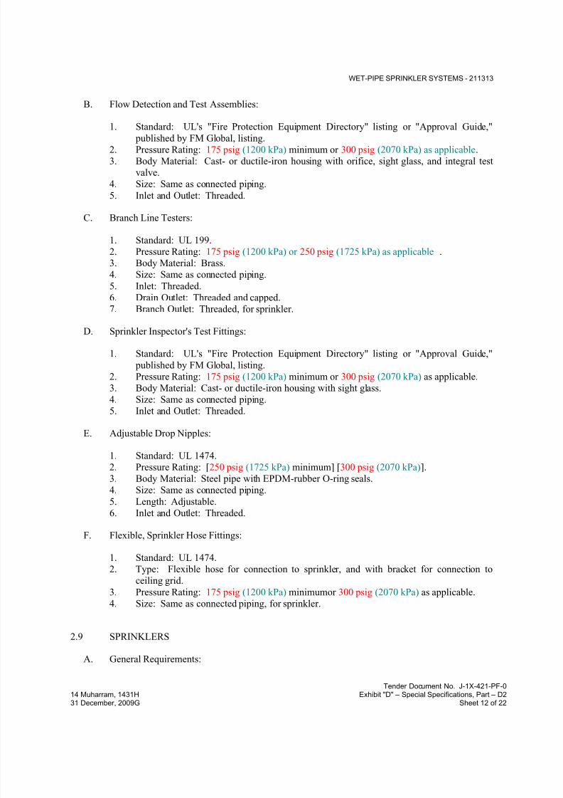
7/18/2019 SEC DPS
http://slidepdf.com/reader/full/sec-dps 70/541
WET-PIPE SPRINKLER SYSTEMS - 211313
Tender Document No. J-1X-421-PF-0
14 Muharram, 1431H Exhibit "D" – Special Specifications, Part – D231 December, 2009G Sheet 12 of 22
B. Flow Detection and Test Assemblies:
1. Standard: UL's "Fire Protection Equipment Directory" listing or "Approval Guide,"
published by FM Global, listing.2. Pressure Rating: 175 psig (1200 kPa) minimum or 300 psig (2070 kPa) as applicable.
3. Body Material: Cast- or ductile-iron housing with orifice, sight glass, and integral test
valve.
4. Size: Same as connected piping.
5. Inlet and Outlet: Threaded.
C. Branch Line Testers:
1. Standard: UL 199.
2. Pressure Rating: 175 psig (1200 kPa) or 250 psig (1725 kPa) as applicable .
3. Body Material: Brass.
4. Size: Same as connected piping.5. Inlet: Threaded.
6. Drain Outlet: Threaded and capped.
7. Branch Outlet: Threaded, for sprinkler.
D. Sprinkler Inspector's Test Fittings:
1. Standard: UL's "Fire Protection Equipment Directory" listing or "Approval Guide,"
published by FM Global, listing.
2. Pressure Rating: 175 psig (1200 kPa) minimum or 300 psig (2070 kPa) as applicable.
3. Body Material: Cast- or ductile-iron housing with sight glass.
4. Size: Same as connected piping.
5. Inlet and Outlet: Threaded.
E. Adjustable Drop Nipples:
1. Standard: UL 1474.
2. Pressure Rating: [250 psig (1725 kPa) minimum] [300 psig (2070 kPa)].
3. Body Material: Steel pipe with EPDM-rubber O-ring seals.
4. Size: Same as connected piping.
5. Length: Adjustable.
6. Inlet and Outlet: Threaded.
F. Flexible, Sprinkler Hose Fittings:
1. Standard: UL 1474.
2. Type: Flexible hose for connection to sprinkler, and with bracket for connection to
ceiling grid.
3. Pressure Rating: 175 psig (1200 kPa) minimumor 300 psig (2070 kPa) as applicable.
4. Size: Same as connected piping, for sprinkler.
2.9 SPRINKLERS
A. General Requirements:

7/18/2019 SEC DPS
http://slidepdf.com/reader/full/sec-dps 71/541
WET-PIPE SPRINKLER SYSTEMS - 211313
Tender Document No. J-1X-421-PF-0
14 Muharram, 1431H Exhibit "D" – Special Specifications, Part – D231 December, 2009G Sheet 13 of 22
1. Standard: UL's "Fire Protection Equipment Directory" listing or "Approval Guide,"
published by FM Global, listing.
2. Pressure Rating for Residential Sprinklers: 175 psig (1200 kPa) maximum.
3. Pressure Rating for Automatic Sprinklers: 175 psig (1200 kPa) minimum.4. Pressure Rating for High-Pressure Automatic Sprinklers: 250 psig (1725 kPa) minimum.
B. Automatic Sprinklers with Heat-Responsive Element:
1. Early-Suppression, Fast-Response Applications: UL 1767.
2. Nonresidential Applications: UL 199.
3. Residential Applications: UL 1626.
4. Characteristics: Nominal 1/2-inch (12.7-mm) orifice with Discharge Coefficient K of
5.6, and for "Ordinary" temperature classification rating unless otherwise indicated or
required by application.
C. Open Sprinklers with Heat-Responsive Element Removed: UL 199.
1. Characteristics:
a. Nominal 1/2-inch (12.7-mm) Orifice: With Discharge Coefficient K between 5.3
and 5.8.
b. Nominal 17/32-inch (13.5-mmOrifice: With Discharge Coefficient K between 7.4
and 8.2.
D. Sprinkler Finishes:
1. Chrome plated.
2. Bronze.
3. Painted.
E. Special Coatings:
1. Wax.
2. Lead.3. Corrosion-resistant paint.
F. Sprinkler Escutcheons: Materials, types, and finishes for the following sprinkler mounting
applications. Escutcheons for concealed, flush, and recessed-type sprinklers are specified with
sprinklers.
1. Ceiling Mounting: Chrome-plated steel, one piece, flator Chrome-plated steel, two piece,with 1-inch (25-mm) vertical adjustment.
2. Sidewall Mounting: Chrome-plated steel, one piece, flat.
G. Sprinkler Guards:
1. Manufacturers: Subject to compliance with requirements.

7/18/2019 SEC DPS
http://slidepdf.com/reader/full/sec-dps 72/541
WET-PIPE SPRINKLER SYSTEMS - 211313
Tender Document No. J-1X-421-PF-0
14 Muharram, 1431H Exhibit "D" – Special Specifications, Part – D231 December, 2009G Sheet 14 of 22
2. Standard: UL 199.
3. Type: Wire cage with fastening device for attaching to sprinkler.
2.10 ALARM DEVICES
A. Alarm-device types shall match piping and equipment connections.
B. Water-Motor-Operated Alarm:
1. Standard: UL 753.
2. Type: Mechanically operated, with Pelton wheel.
3. Alarm Gong: Cast aluminum with red-enamel factory finish.
4. Size: 10-inch (250-mm) diameter.
5. Components: Shaft length, bearings, and sleeve to suit wall construction.
6. Inlet: NPS 3/4 (DN 20).7. Outlet: NPS 1 (DN 25) drain connection.
C. Electrically Operated Alarm Bell:
1. Standard: UL 464.2. Type: Vibrating, metal alarm bell.
3. Size: 10-inch (250-mm) diameter.
4. Finish: Red-enamel factory finish, suitable for outdoor use.
D. Water-Flow Indicators:
1. Standard: UL 346.2. Water-Flow Detector: Electrically supervised.
3. Components: Two single-pole, double-throw circuit switches for isolated alarm and
auxiliary contacts, 7 A, 125-V ac and 0.25 A, 24-V dc; complete with factory-set, field-
adjustable retard element to prevent false signals and tamperproof cover that sends signal
if removed.
4. Type: Paddle operated.5. Pressure Rating: 250 psig (1725 kPa).
6. Design Installation: Horizontal or vertical.
E. Pressure Switches:
1. Standard: UL 346.
2. Type: Electrically supervised water-flow switch with retard feature.3. Components: Single-pole, double-throw switch with normally closed contacts.
4. Design Operation: Rising pressure signals water flow.
F. Valve Supervisory Switches:
1. Standard: UL 346.
2. Type: Electrically supervised.
3. Components: Single-pole, double-throw switch with normally closed contacts.4. Design: Signals that controlled valve is in other than fully open position.
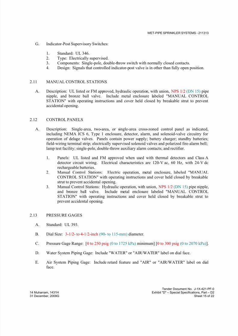
7/18/2019 SEC DPS
http://slidepdf.com/reader/full/sec-dps 73/541
WET-PIPE SPRINKLER SYSTEMS - 211313
Tender Document No. J-1X-421-PF-0
14 Muharram, 1431H Exhibit "D" – Special Specifications, Part – D231 December, 2009G Sheet 15 of 22
G. Indicator-Post Supervisory Switches:
1. Standard: UL 346.
2. Type: Electrically supervised.3. Components: Single-pole, double-throw switch with normally closed contacts.
4. Design: Signals that controlled indicator-post valve is in other than fully open position.
2.11 MANUAL CONTROL STATIONS
A. Description: UL listed or FM approved, hydraulic operation, with union, NPS 1/2 (DN 15) pipe
nipple, and bronze ball valve. Include metal enclosure labeled "MANUAL CONTROL
STATION" with operating instructions and cover held closed by breakable strut to prevent
accidental opening.
2.12 CONTROL PANELS
A. Description: Single-area, two-area, or single-area cross-zoned control panel as indicated,
including NEMA ICS 6, Type 1 enclosure, detector, alarm, and solenoid-valve circuitry for
operation of deluge valves. Panels contain power supply; battery charger; standby batteries;field-wiring terminal strip; electrically supervised solenoid valves and polarized fire-alarm bell;
lamp test facility; single-pole, double-throw auxiliary alarm contacts; and rectifier.
1. Panels: UL listed and FM approved when used with thermal detectors and Class A
detector circuit wiring. Electrical characteristics are 120-V ac, 60 Hz, with 24-V dc
rechargeable batteries.
2. Manual Control Stations: Electric operation, metal enclosure, labeled "MANUAL
CONTROL STATION" with operating instructions and cover held closed by breakable
strut to prevent accidental opening.
3. Manual Control Stations: Hydraulic operation, with union, NPS 1/2 (DN 15) pipe nipple,
and bronze ball valve. Include metal enclosure labeled "MANUAL CONTROL
STATION" with operating instructions and cover held closed by breakable strut to
prevent accidental opening.
2.13 PRESSURE GAGES
A. Standard: UL 393.
B. Dial Size: 3-1/2- to 4-1/2-inch (90- to 115-mm) diameter.
C. Pressure Gage Range: [0 to 250 psig (0 to 1725 kPa) minimum] [0 to 300 psig (0 to 2070 kPa)].
D. Water System Piping Gage: Include "WATER" or "AIR/WATER" label on dial face.
E. Air System Piping Gage: Include retard feature and "AIR" or "AIR/WATER" label on dial
face.

7/18/2019 SEC DPS
http://slidepdf.com/reader/full/sec-dps 74/541
WET-PIPE SPRINKLER SYSTEMS - 211313
Tender Document No. J-1X-421-PF-0
14 Muharram, 1431H Exhibit "D" – Special Specifications, Part – D231 December, 2009G Sheet 16 of 22
PART 3 - EXECUTION
3.1 PREPARATION
A. Perform fire-hydrant flow test according to NFPA 13 and NFPA 291. Use results for system
design calculations required in "Quality Assurance" Article.
B. Report test results promptly and in writing.
3.2 SERVICE-ENTRANCE PIPING
A. Connect sprinkler piping to water-service piping for service entrance to building. Comply with
requirements for exterior piping in Division 21 Section "Facility Fire-Suppression Water-
Service Piping."
B. Install shutoff valve, backflow preventer, pressure gage, drain, and other accessories indicated
at connection to water-service piping. Comply with requirements for backflow preventers in
Division 21 Section "Facility Fire-Suppression Water-Service Piping."
C. Install shutoff valve, check valve, pressure gage, and drain at connection to water service.
3.3 WATER-SUPPLY CONNECTIONS
A. Connect sprinkler piping to building's interior water-distribution piping. Comply with
requirements for interior piping in Division 22 Section "Domestic Water Piping."
B. Install shutoff valve, backflow preventer, pressure gage, drain, and other accessories indicated
at connection to water-distribution piping. Comply with requirements for backflow preventers
in Division 22 Section "Domestic Water Piping Specialties."
C. Install shutoff valve, check valve, pressure gage, and drain at connection to water supply.
3.4 PIPING INSTALLATION
A. Locations and Arrangements: Drawing plans, schematics, and diagrams indicate general
location and arrangement of piping. Install piping as indicated, as far as practical.
1. Deviations from approved working plans for piping require written approval from
authorities having jurisdiction. File written approval with Architect before deviating
from approved working plans.
B. Piping Standard: Comply with requirements for installation of sprinkler piping in NFPA 13.
C. Install seismic restraints on piping. Comply with requirements for seismic-restraint device
materials and installation in NFPA 13.

7/18/2019 SEC DPS
http://slidepdf.com/reader/full/sec-dps 75/541
WET-PIPE SPRINKLER SYSTEMS - 211313
Tender Document No. J-1X-421-PF-0
14 Muharram, 1431H Exhibit "D" – Special Specifications, Part – D231 December, 2009G Sheet 17 of 22
D. Use listed fittings to make changes in direction, branch takeoffs from mains, and reductions in
pipe sizes.
E. Install unions adjacent to each valve in pipes NPS 2 (DN 50) and smaller.
F. Install flanges, flange adapters, or couplings for grooved-end piping on valves, apparatus, and
equipment having NPS 2-1/2 (DN 65) and larger end connections.
G. Install "Inspector's Test Connections" in sprinkler system piping, complete with shutoff valve,
and sized and located according to NFPA 13.
H. Install sprinkler piping with drains for complete system drainage.
I. Install sprinkler control valves, test assemblies, and drain risers adjacent to standpipes when
sprinkler piping is connected to standpipes.
J. Install automatic (ball drip) drain valve at each check valve for fire-department connection, to
drain piping between fire-department connection and check valve. Install drain piping to and
spill over floor drain or to outside building.
K. Install alarm devices in piping systems.
L. Install hangers and supports for sprinkler system piping according to NFPA 13. Comply with
requirements for hanger materials in NFPA 13.
M. Install pressure gages on riser or feed main, at each sprinkler test connection, and at top of each
standpipe. Include pressure gages with connection not less than NPS 1/4 (DN 8) and with soft
metal seated globe valve, arranged for draining pipe between gage and valve. Install gages to permit removal, and install where they will not be subject to freezing.
N. Pressurize and check preaction sprinkler system piping and air-pressure maintenance devices
and air compressors.
O. Fill sprinkler system piping with water.
P. Install electric heating cables and pipe insulation on sprinkler piping in areas subject to freezing.
Comply with requirements for heating cables in Division 21 "Heat Tracing for Fire-SuppressionPiping" and for piping insulation in Division 21 Section "Fire-Suppression Systems Insulation."
Q. Install sleeves for piping penetrations of walls, ceilings, and floors. Comply with requirements
for sleeves specified in Division 21 Section "Sleeves and Sleeve Seals for Fire-SuppressionPiping."
R. Install sleeve seals for piping penetrations of concrete walls and slabs. Comply with
requirements for sleeve seals specified in Division 21 Section "Sleeves and Sleeve Seals for
Fire-Suppression Piping."
S. Install escutcheons for piping penetrations of walls, ceilings, and floors. Comply with
requirements for escutcheons specified in Division 21 Section "Escutcheons for Fire-
Suppression Piping."
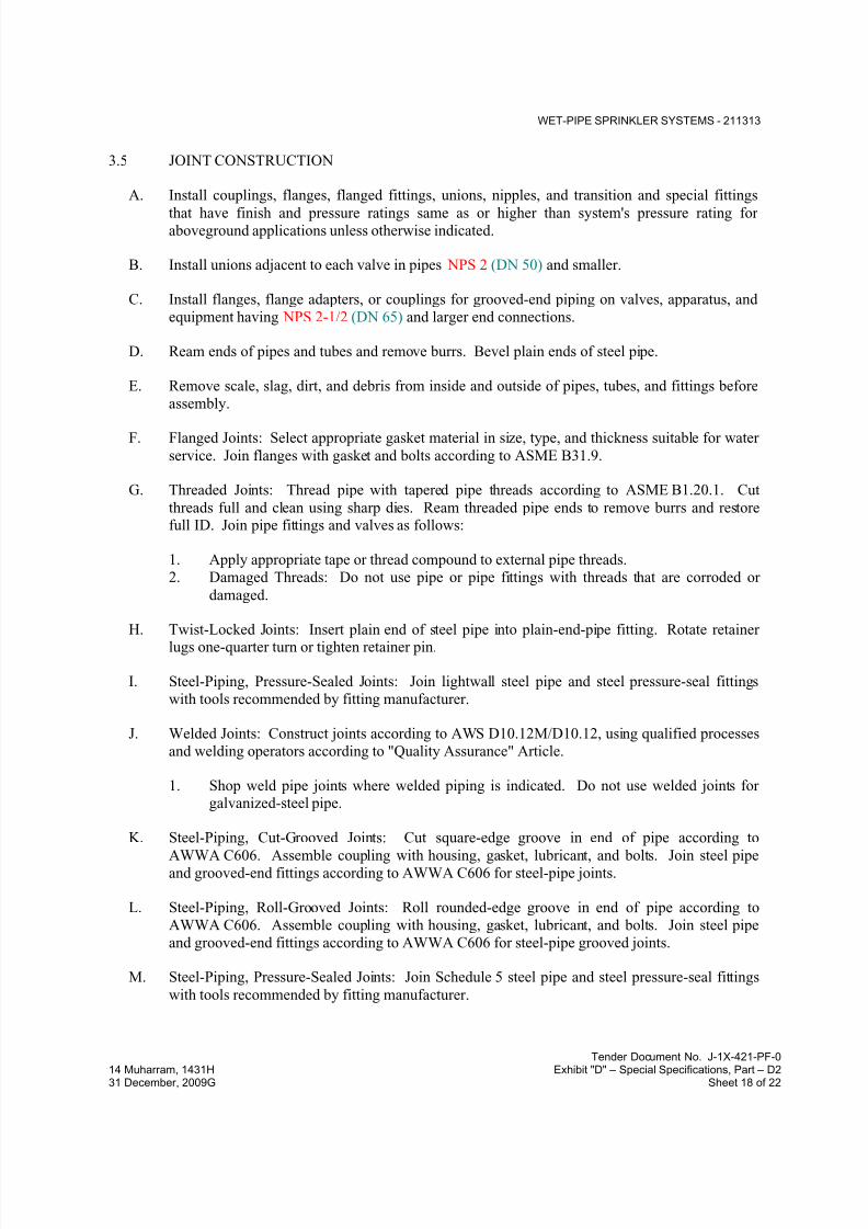
7/18/2019 SEC DPS
http://slidepdf.com/reader/full/sec-dps 76/541
WET-PIPE SPRINKLER SYSTEMS - 211313
Tender Document No. J-1X-421-PF-0
14 Muharram, 1431H Exhibit "D" – Special Specifications, Part – D231 December, 2009G Sheet 18 of 22
3.5 JOINT CONSTRUCTION
A. Install couplings, flanges, flanged fittings, unions, nipples, and transition and special fittings
that have finish and pressure ratings same as or higher than system's pressure rating foraboveground applications unless otherwise indicated.
B. Install unions adjacent to each valve in pipes NPS 2 (DN 50) and smaller.
C. Install flanges, flange adapters, or couplings for grooved-end piping on valves, apparatus, and
equipment having NPS 2-1/2 (DN 65) and larger end connections.
D. Ream ends of pipes and tubes and remove burrs. Bevel plain ends of steel pipe.
E. Remove scale, slag, dirt, and debris from inside and outside of pipes, tubes, and fittings before
assembly.
F. Flanged Joints: Select appropriate gasket material in size, type, and thickness suitable for water
service. Join flanges with gasket and bolts according to ASME B31.9.
G. Threaded Joints: Thread pipe with tapered pipe threads according to ASME B1.20.1. Cut
threads full and clean using sharp dies. Ream threaded pipe ends to remove burrs and restorefull ID. Join pipe fittings and valves as follows:
1. Apply appropriate tape or thread compound to external pipe threads.
2. Damaged Threads: Do not use pipe or pipe fittings with threads that are corroded or
damaged.
H. Twist-Locked Joints: Insert plain end of steel pipe into plain-end-pipe fitting. Rotate retainerlugs one-quarter turn or tighten retainer pin.
I. Steel-Piping, Pressure-Sealed Joints: Join lightwall steel pipe and steel pressure-seal fittings
with tools recommended by fitting manufacturer.
J. Welded Joints: Construct joints according to AWS D10.12M/D10.12, using qualified processes
and welding operators according to "Quality Assurance" Article.
1. Shop weld pipe joints where welded piping is indicated. Do not use welded joints forgalvanized-steel pipe.
K. Steel-Piping, Cut-Grooved Joints: Cut square-edge groove in end of pipe according to
AWWA C606. Assemble coupling with housing, gasket, lubricant, and bolts. Join steel pipeand grooved-end fittings according to AWWA C606 for steel-pipe joints.
L. Steel-Piping, Roll-Grooved Joints: Roll rounded-edge groove in end of pipe according to
AWWA C606. Assemble coupling with housing, gasket, lubricant, and bolts. Join steel pipe
and grooved-end fittings according to AWWA C606 for steel-pipe grooved joints.
M. Steel-Piping, Pressure-Sealed Joints: Join Schedule 5 steel pipe and steel pressure-seal fittings
with tools recommended by fitting manufacturer.

7/18/2019 SEC DPS
http://slidepdf.com/reader/full/sec-dps 77/541
WET-PIPE SPRINKLER SYSTEMS - 211313
Tender Document No. J-1X-421-PF-0
14 Muharram, 1431H Exhibit "D" – Special Specifications, Part – D231 December, 2009G Sheet 19 of 22
N. Brazed Joints: Join copper tube and fittings according to CDA's "Copper Tube Handbook,"
"Brazed Joints" Chapter.
O. Copper-Tubing Grooved Joints: Roll rounded-edge groove in end of tube according toAWWA C606. Assemble coupling with housing, gasket, lubricant, and bolts. Join copper tube
and grooved-end fittings according to AWWA C606 for steel-pipe grooved joints.
P. Copper-Tubing, Pressure-Sealed Joints: Join copper tube and copper pressure-seal fittings with
tools recommended by fitting manufacturer.
Q. Extruded-Tee Connections: Form tee in copper tube according to ASTM F 2014. Use tool
designed for copper tube; drill pilot hole, form collar for outlet, dimple tube to form seating
stop, and braze branch tube into collar.
R. Dissimilar-Material Piping Joints: Make joints using adapters compatible with materials of both
piping systems.
S. Plastic-Piping, Solvent-Cement Joints: Clean and dry joining surfaces. Join pipe and fittings
according to the following:
1. Comply with ASTM F 402 for safe-handling practice of cleaners, primers, and solvent
cements. Apply primer.
2. CPVC Piping: Join according to ASTM D 2846/D 2846M Appendix.
3.6 INSTALLATION OF COVER SYSTEM FOR SPRINKLER PIPING
A. Install cover system, brackets, and cover components for sprinkler piping according tomanufacturer's "Installation Manual" and with NFPA 13 or NFPA 13R for supports.
3.7 VALVE AND SPECIALTIES INSTALLATION
A. Install listed fire-protection valves, trim and drain valves, specialty valves and trim, controls,
and specialties according to NFPA 13 and authorities having jurisdiction.
B. Install listed fire-protection shutoff valves supervised open, located to control sources of water
supply except from fire-department connections. Install permanent identification signs
indicating portion of system controlled by each valve.
C. Install check valve in each water-supply connection. Install backflow preventers instead ofcheck valves in potable-water-supply sources.
D. Specialty Valves:
1. General Requirements: Install in vertical position for proper direction of flow, in main
supply to system.
2. Alarm Valves: Include bypass check valve and retarding chamber drain-line connection.

7/18/2019 SEC DPS
http://slidepdf.com/reader/full/sec-dps 78/541
WET-PIPE SPRINKLER SYSTEMS - 211313
Tender Document No. J-1X-421-PF-0
14 Muharram, 1431H Exhibit "D" – Special Specifications, Part – D231 December, 2009G Sheet 20 of 22
3. Deluge Valves: Install in vertical position, in proper direction of flow, and in main
supply to deluge system. Install trim sets for drain, priming level, alarm connections, ball
drip valves, pressure gages, priming chamber attachment, and fill-line attachment.
3.8 SPRINKLER INSTALLATION
A. Install sprinklers in suspended ceilings in center of acoustical ceiling panels.
B. Install dry-type sprinklers with water supply from heated space. Do not install pendent or
sidewall, wet-type sprinklers in areas subject to freezing.
C. Install sprinklers into flexible, sprinkler hose fittings and install hose into bracket on ceiling
grid.
3.9 FIRE-DEPARTMENT CONNECTION INSTALLATION
A. Install wall-type, fire-department connections.
B. Install yard-type, fire-department connections in concrete slab support. Comply with
requirements for concrete in Division 03 Section "Cast-in-Place Concrete.".
1. Install twoor threeprotective pipe bollards aroundor on sides of each fire-departmentconnection as approved by Engineer. Comply with requirements for bollards in
Division 05 Section "Metal Fabrications.".
C. Install automatic (ball drip) drain valve at each check valve for fire-department connection.
3.10 IDENTIFICATION
A. Install labeling and pipe markers on equipment and piping according to requirements in
NFPA 13.
B. Identify system components, wiring, cabling, and terminals. Comply with requirements for
identification specified in Division 26 Section "Identification for Electrical Systems."
3.11 FIELD QUALITY CONTROL
A. Perform tests and inspections.
B. Tests and Inspections:
1. Leak Test: After installation, charge systems and test for leaks. Repair leaks and retest
until no leaks exist.
2. Test and adjust controls and safeties. Replace damaged and malfunctioning controls and
equipment.
3. Flush, test, and inspect sprinkler systems according to NFPA 13, "Systems Acceptance"
Chapter.
7/18/2019 SEC DPS
http://slidepdf.com/reader/full/sec-dps 79/541
WET-PIPE SPRINKLER SYSTEMS - 211313
Tender Document No. J-1X-421-PF-0
14 Muharram, 1431H Exhibit "D" – Special Specifications, Part – D231 December, 2009G Sheet 21 of 22
4. Energize circuits to electrical equipment and devices.
5. Coordinate with fire-alarm tests. Operate as required.
6. Coordinate with fire-pump tests. Operate as required.
7. Verify that equipment hose threads are same as local fire-department equipment.
C. Sprinkler piping system will be considered defective if it does not pass tests and inspections.
D. Prepare test and inspection reports.
3.12 CLEANING
A. Clean dirt and debris from sprinklers.
B. Remove and replace sprinklers with paint other than factory finish.
3.13 DEMONSTRATION
A. Engage a factory-authorized service representative to trainOwner's maintenance personnel to
adjust, operate, and maintain specialty valvesandpressure-maintenance pumps.
3.14 PIPING SCHEDULE
A. Piping between Fire-Department Connections and Check Valves: Galvanized, standard-weightsteel pipe with grooved ends; grooved-end fittings; grooved-end-pipe couplings; and grooved
joints.
B. Sprinkler specialty fittings may be used, downstream of control valves, instead of specified
fittings.
C. Standard-pressure, wet-pipe sprinkler system, NPS 2 (DN 50) and smaller, shall be one of the
following:
1. Standard-weight, black-steel pipe with plain ends; steel welding fittings; and welded
joints.
D. Standard-pressure, wet-pipe sprinkler system, NPS 2-1/2 to NPS 4 (DN 65 to DN 100), shall
be one of the following:
1.
2. Standard-weight, black-steel pipe with plain ends; steel welding fittings; and welded joints.
E. Standard-pressure, wet-pipe sprinkler system, NPS 5 (DN 125) and larger, shall be one ofthe
following:
1. Standard-weight, black-steel pipe with cut- orroll-grooved ends; uncoated, grooved-end
fittings for steel piping; grooved-end-pipe couplings for steel piping; and grooved joints.
2. Standard-weight or Schedule 30, black-steel pipe with plain ends; steel welding fittings;
and welded joints.
7/18/2019 SEC DPS
http://slidepdf.com/reader/full/sec-dps 80/541
WET-PIPE SPRINKLER SYSTEMS - 211313
Tender Document No. J-1X-421-PF-0
14 Muharram, 1431H Exhibit "D" – Special Specifications, Part – D231 December, 2009G Sheet 22 of 22
F. High-pressure, wet-pipe sprinkler system, NPS 4 (DN 100) and smaller, shall be one of the
following:
1. Standard-weightor, galvanized-steel pipe with cut-grooved ends; galvanized, grooved-
end fittings for steel piping; grooved-end-pipe couplings for steel piping; and grooved joints.
2. Standard-weight, black-steel pipe with plain ends; steel welding fittings; and welded
joints.
G. High-pressure, wet-pipe sprinkler system, NPS 5 (DN 125) and larger, shall bethe following:
1. Standard-weight, galvanized-steel pipe with cut-grooved ends; galvanized, grooved-end
fittings for steel piping; grooved-end-pipe couplings for steel piping; and grooved joints.
2. Standard-weight, black-steel pipe with plain ends; steel welding fittings; and welded
joints.
3.15 SPRINKLER SCHEDULE
A. Use sprinkler types in subparagraphs below for the following applications:
1. Rooms without Ceilings: Upright sprinklers.
2. Rooms with Suspended Ceilings in Interior Decorator Areas: Concealed sprinklers.
3. Rooms with Suspended Ceilings in Back of House Areas: Pendent sprinklers.
4. Wall Mounting: Sidewall sprinklers.
5. 6. Special Applications: Extended-coverage, and quick-response sprinklers where required.
B. Provide sprinkler types in subparagraphs below with finishes indicated.
1. Concealed Sprinklers: Rough brass, with factory-painted white cover plate.
2. Flush Sprinklers: Bright chrome, with painted white escutcheon.
3. Recessed Sprinklers: Bright chrome, with bright chrome escutcheon.
4. Residential Sprinklers: Dull chrome.
5. Upright , Pendent and Sidewall Sprinklers: Chrome plated in finished spaces exposed to
view; rough bronze in unfinished spaces not exposed to view; wax coated where exposed
to acids, chemicals, or other corrosive fumes.
END OF SECTION 211313

7/18/2019 SEC DPS
http://slidepdf.com/reader/full/sec-dps 81/541
DRY-PIPE SPRINKLER SYSTEMS - 211316
Tender Document No. J-1X-421-PF-0
14 Muharram, 1431H Exhibit "D" – Special Specifications, Part – D231 December, 2009G Sheet 1 of 22
SECTION 211316 - DRY-PIPE SPRINKLER SYSTEMS
PART 1 - GENERAL
1.1 RELATED DOCUMENTS
A. Drawings and general provisions of the Contract, including General and Supplementary
Conditions and Division 01 Specification Sections, apply to this Section.
1.2 SUMMARY
A. Section Includes:
1. Pipes, fittings, and specialties.
2. Fire-protection valves.3. Fire-department connections.
4. Sprinkler specialty pipe fittings.
5. Sprinklers.
6. Alarm devices.
7. Manual control stations.8. Control panels.
9. Pressure gages.
B. Related Sections:
1. Division 21 Section "Fire-Suppression Standpipes" for standpipe piping.
2. Division 21 Section "Wet-Pipe Sprinkler Systems" for wet-pipe sprinkler piping.3. Division 21 Section "Foam-Water Systems" for AFFF piping.
4. Division 21 Section "Electric-Drive, Centrifugal Fire Pumps, Diesel-Drive, Centrifugal
Fire Pumps," for fire pumps, pressure-maintenance pumps, and fire-pump controllers.
5. Division 28 Section "Digital, Addressable Fire-Alarm System, and Zoned (DC Loop)
Fire-Alarm System" for alarm devices not specified in this Section.
1.3 DEFINITIONS
A. Standard-Pressure Sprinkler Piping: Dry-pipe sprinkler system piping designed to operate atworking pressure 175 psig (1200 kPa) maximum.
1.4 SYSTEM DESCRIPTIONS
A. Dry-Pipe Sprinkler System: Automatic sprinklers are attached to piping containing compressed
air. Opening of sprinklers releases compressed air and permits water pressure to open dry-pipe
valve. Water then flows into piping and discharges from sprinklers that are open.

7/18/2019 SEC DPS
http://slidepdf.com/reader/full/sec-dps 82/541
DRY-PIPE SPRINKLER SYSTEMS - 211316
Tender Document No. J-1X-421-PF-0
14 Muharram, 1431H Exhibit "D" – Special Specifications, Part – D231 December, 2009G Sheet 2 of 22
B. Combined Dry-Pipe and Preaction Sprinkler System: Automatic sprinklers are attached to
piping containing compressed air. Fire-detection system in same area as sprinklers actuates
tripping devices that open dry-pipe valve without loss of air pressure and actuates fire alarm.
Water discharges from sprinklers that have opened.
C. Single-Interlock Preaction Sprinkler System: Automatic sprinklers are attached to piping
containing low-pressure air. Actuation of fire-detection system in same area as sprinklers opens
deluge valve, permitting water to flow into piping and to discharge from sprinklers that have
opened.
D. Double-Interlock Preaction Sprinkler System: Automatic sprinklers are attached to piping
containing low-pressure air. Actuation of a fire-detection system in the same area as sprinklers
opens the deluge valve permitting water to flow into the sprinkler piping; a closed solenoid
valve in the sprinkler piping is opened by another fire-detection device; then water will
discharge from sprinklers that have opened.
1.5 PERFORMANCE REQUIREMENTS
A. Standard-Pressure Piping System Component: Listed for 175-psig (1200-kPa) minimum
working pressure or 250-psig (1725-kPa) as applicable.
B. Delegated Design: Design sprinkler system(s), including comprehensive engineering analysis
by a qualified professional engineer, using performance requirements and design criteria
indicated.
a.
C. Sprinkler system design shall be approved by authorities having jurisdiction.
1. Margin of Safety for Available Water Flow and Pressure: 10percent, including losses
through water-service piping, valves, and backflow preventers.
2. Sprinkler Occupancy Hazard Classifications:
a. Automobile Parking Areas: Ordinary Hazard, Group 1 b. Building Service Areas: Ordinary Hazard, Group 1
c. Electrical Equipment Rooms: Ordinary Hazard, Group 1.
d. Dry Cleaners: Ordinary Hazard, Group 2
e. General Storage Areas: Ordinary Hazard, Group 1
f. Laundries: Ordinary Hazard, Group 1g. Libraries Except Stack Areas: Light Hazard.
h. Library Stack Areas: Ordinary Hazard, Group 2.
i. Machine Shops: Ordinary Hazard, Group 2.
j. Mechanical Equipment Rooms: Ordinary Hazard, Group 1.
k. Office and Public Areas: Light Hazard.
l. Plastics Processing Areas: Extra Hazard, Group 2.
m. Printing Plants: Extra Hazard, Group 1.
n. Repair Garages: Ordinary Hazard, Group 2.
o. Restaurant Service Areas: Ordinary Hazard, Group 1.
p. Solvent Cleaning Areas: Extra Hazard, Group 2.
q. Upholstering Plants: Extra Hazard, Group 1.
7/18/2019 SEC DPS
http://slidepdf.com/reader/full/sec-dps 83/541
DRY-PIPE SPRINKLER SYSTEMS - 211316
Tender Document No. J-1X-421-PF-0
14 Muharram, 1431H Exhibit "D" – Special Specifications, Part – D231 December, 2009G Sheet 3 of 22
r. Other spaces: Hazard classification according to NFPA recommendations unless
otherwise indicated.
3. Minimum Density for Automatic-Sprinkler Piping Design:
a. Light-Hazard Occupancy: 0.10 gpm over 1500-sq. ft. (4.1 mm/min. over 139-
sq. m) area.
b. Ordinary-Hazard, Group 1 Occupancy: 0.15 gpm over 1500-sq. ft. (6.1 mm/min.
over 139-sq. m) area.
c. Ordinary-Hazard, Group 2 Occupancy: 0.20 gpm over 1500-sq. ft. (8.1 mm/min.
over 139-sq. m).
d. Extra-Hazard, Group 1 Occupancy: 0.30 gpm over 2500-sq. ft. (12.2 mm/min.
over 232-sq. m) area.
e. Extra-Hazard, Group 2 Occupancy: 0.40 gpm over 2500-sq. ft. (16.3 mm/min.
over 232-sq. m) area.
f. Special Occupancy Hazard: As determined by authorities having jurisdiction.
4. Maximum Protection Area per Sprinkler: Per UL listing.
5. Maximum Protection Area per Sprinkler:
a. Office Spaces: 225 sq. ft. (20.9 sq. m).
b. Storage Areas: 130 sq. ft. (12.1 sq. m).
c. Mechanical Equipment Rooms: 130 sq. ft. (12.1 sq. m).
d. Electrical Equipment Rooms: 130 sq. ft. (12.1 sq. m).
e. Other Areas: According to NFPA 13 recommendations unless otherwise indicated.
6. Total Combined Hose-Stream Demand Requirement: According to NFPA 13 unless
otherwise indicated:
a. Light-Hazard Occupancies: 100 gpm (6.3 L/s) for 30 minutes.
b. Ordinary-Hazard Occupancies: 250 gpm (15.75 L/s) for 60 to 90 minutes.
c. Extra-Hazard Occupancies: 500 gpm (31.5 L/s) for 90 to 120 minutes.
D. Seismic Performance: Sprinkler piping shall withstand the effects of earthquake motions
determined according to NFPA 13 and ASCE/SEI 7.
1.6 ACTION SUBMITTALS
A. Product Data: For each type of product indicated. Include rated capacities, operating
characteristics, electrical characteristics, and furnished specialties and accessories.
B. Shop Drawings: For dry-pipe sprinkler systems. Include plans, elevations, sections, details,
and attachments to other work.
1. Wiring Diagrams: For power, signal, and control wiring.
C. Delegated-Design Submittal: For sprinkler systems indicated to comply with performance
requirements and design criteria, including analysis data signed and sealed by the qualified professional engineer responsible for their preparation.
7/18/2019 SEC DPS
http://slidepdf.com/reader/full/sec-dps 84/541
DRY-PIPE SPRINKLER SYSTEMS - 211316
Tender Document No. J-1X-421-PF-0
14 Muharram, 1431H Exhibit "D" – Special Specifications, Part – D231 December, 2009G Sheet 4 of 22
1.7 INFORMATIONAL SUBMITTALS
A. Coordination Drawings: Sprinkler systems, drawn to scale, on which the following items are
shown and coordinated with each other, using input from installers of the items involved:
1. Domestic water piping.
2. Compressed air piping.
3. HVAC hydronic piping.
4. Items penetrating finished ceiling including but not limited to the following:
a. Lighting fixtures.
b. Air outlets and inlets.
B. Qualification Data: For qualified Installer and professional engineer.
C. Approved Sprinkler Piping Drawings: Working plans, prepared according to NFPA 13, thathave been approved by authorities having jurisdiction, including hydraulic calculations if
applicable.
D. Fire-hydrant flow test report.
E. Field Test Reports and Certificates: Indicate and interpret test results for compliance with
performance requirements and as described in NFPA 13. Include "Contractor's Material and
Test Certificate for Aboveground Piping."
F. Field quality-control reports.
1.8 CLOSEOUT SUBMITTALS
A. Operation and Maintenance Data: For sprinkler specialties to include in emergency, operation,
and maintenance manuals.
1.9 MAINTENANCE MATERIAL SUBMITTALS
A. Furnish extra materials that match products installed and that are packaged with protective
covering for storage and identified with labels describing contents.
1. Sprinkler Cabinets: Finished, wall-mounted, steel cabinet with hinged cover, and with
space for minimum of six spare sprinklers plus sprinkler wrench. Include number ofsprinklers required by NFPA 13 and sprinkler wrench. Include separate cabinet with
sprinklers and wrench for each type of sprinkler used on Project.
1.10 QUALITY ASSURANCE
A. Installer Qualifications:
7/18/2019 SEC DPS
http://slidepdf.com/reader/full/sec-dps 85/541
DRY-PIPE SPRINKLER SYSTEMS - 211316
Tender Document No. J-1X-421-PF-0
14 Muharram, 1431H Exhibit "D" – Special Specifications, Part – D231 December, 2009G Sheet 5 of 22
1. Installer's responsibilities include designing, fabricating, and installing sprinkler systems
and providing professional engineering services needed to assume engineering
responsibility. Base calculations on results of fire-hydrant flow test.
a. Engineering Responsibility: Preparation of working plans, calculations, and field
test reports by a qualified professional engineer.
B. Electrical Components, Devices, and Accessories: Listed and labeled as defined in NFPA 70,
by a qualified testing agency, and marked for intended location and application.
C. NFPA Standards: Sprinkler system equipment, specialties, accessories, installation, and testing
shall comply with the following:
1. NFPA 13, "Installation of Sprinkler Systems."
2. NFPA 13R, "Installation of Sprinkler Systems in Residential Occupancies up to and
Including Four Stories in Height."3. NFPA 24, "Installation of Private Fire Service Mains and Their Appurtenances."
1.11 PROJECT CONDITIONS
A. Interruption of Existing Sprinkler Service: Do not interrupt sprinkler service to facilities
occupied by Owner or others unless permitted under the following conditions and then only
after arranging to provide temporary sprinkler service according to requirements indicated:
1. Notify Engineer, or Owner no fewer than two days in advance of proposed interruption of
sprinkler service.
2. Do not proceed with interruption of sprinkler service without Engineer, or Owner's
written permission.
1.12 COORDINATION
A. Coordinate layout and installation of sprinklers with other construction that penetrates ceilings,
including light fixtures, HVAC equipment, and partition assemblies.
PART 2 - PRODUCTS
2.1 PIPING MATERIALS
A. Comply with requirements in "Piping Schedule" Article for applications of pipe, tube, and
fitting materials, and joining methods for specific services, service locations, and pipe sizes.
2.2 STEEL PIPE AND FITTINGS
A. Standard Weight, Galvanized-Steel Pipe: ASTM A 53/A 53M, Type S, Grade B. Pipe ends
may be factory or field formed to match joining method.
7/18/2019 SEC DPS
http://slidepdf.com/reader/full/sec-dps 86/541
DRY-PIPE SPRINKLER SYSTEMS - 211316
Tender Document No. J-1X-421-PF-0
14 Muharram, 1431H Exhibit "D" – Special Specifications, Part – D231 December, 2009G Sheet 6 of 22
B. Schedule 30, Galvanized-Steel Pipe: ASTM A 135; ASTM A 795/A 795M, Type S; or
ASME B36.10M, wrought steel; with wall thickness not less than Schedule 30 and not more
than Schedule 40. Pipe ends may be factory or field formed to match joining method.
C. Thinwall Galvanized-Steel Pipe: ASTM A 135 or ASTM A 795/A 795M, threadable, with wall
thickness less than Schedule 30 and equal to or greater than Schedule 10. Pipe ends may be
factory or field formed to match joining method.
D. Galvanized-Steel Pipe Nipples: ASTM A 733, made of ASTM A 53/A 53M, standard-weight,
seamless steel pipe with threaded ends.
E. Galvanized, Steel Couplings: ASTM A 865, threaded.
F. Galvanized, Gray-Iron Threaded Fittings: ASME B16.4, Class 125, standard pattern.
G. Malleable- or Ductile-Iron Unions: UL 860.
H. Cast-Iron Flanges: ASME B16.1, Class 125.
I. Plain-End-Pipe Fittings: UL 213, ductile-iron body with retainer lugs that require one-quarter
turn or screwed retainer pin to secure pipe in fitting.
J. Grooved-Joint, Steel-Pipe Appurtenances:
1. Manufacturers: Subject to compliance with requirements.
2. Pressure Rating: 175 psig (1200 kPa) , 250 psig (1725 kPa) , 300 psig (2070 kPa)
minimum as applicable.
3. Galvanized, Grooved-End Fittings for Steel Piping: ASTM A 47/A 47M, malleable-ironcasting or ASTM A 536, ductile-iron casting; with dimensions matching steel pipe.
4. Grooved-End-Pipe Couplings for Steel Piping: AWWA C606 and UL 213, rigid pattern,
unless otherwise indicated, for steel-pipe dimensions. Include ferrous housing sections,
EPDM-rubber gasket, and bolts and nuts.
2.3 PIPING JOINING MATERIALS
A. Pipe-Flange Gasket Materials: AWWA C110, rubber, flat face, 1/8 inch (3.2 mm) thick or
ASME B16.21, nonmetallic and asbestos free.
1. Class 125, Cast-Iron and Class 150, Bronze Flat-Face Flanges: Full-face gaskets.2. Class 250, Cast-Iron and Class 300, Raised-Face Flanges: Ring-type gaskets.
B. Metal, Pipe-Flange Bolts and Nuts: ASME B18.2.1, carbon steel unless otherwise indicated.
2.4 LISTED FIRE-PROTECTION VALVES
A. General Requirements:
1. Valves shall be UL listed or FM approved.
7/18/2019 SEC DPS
http://slidepdf.com/reader/full/sec-dps 87/541
DRY-PIPE SPRINKLER SYSTEMS - 211316
Tender Document No. J-1X-421-PF-0
14 Muharram, 1431H Exhibit "D" – Special Specifications, Part – D231 December, 2009G Sheet 7 of 22
2. Minimum Pressure Rating for Standard-Pressure Piping: 175psig (1200 kPa) or250 psig
(1725 kPa) as applicable.
B. Ball Valves:
1. Standard: UL 1091 except with ball instead of disc.
2. Valves NPS 1-1/2 (DN 40) and Smaller: Bronze body with threaded ends.
3. Valves NPS 2 and NPS 2-1/2 (DN 50 and DN 65): Bronze body with threaded ends or
ductile-iron body with grooved ends.
4. Valves NPS 3 (DN 80): Ductile-iron body with grooved ends.
C. Bronze Butterfly Valves:
1. Manufacturers: Subject to compliance with requirements.
2. Basis-of-Design Product: Subject to compliance with requirements.
3. Standard: UL 1091.
4. Pressure Rating: 250 psig (1725 kPa).
5. Body Material: Bronze.
6. End Connections: Threaded.
D. Iron Butterfly Valves:
1. Manufacturers: Subject to compliance with requirements.
2. Basis-of-Design Product: Subject to compliance with requirements.
3. Standard: UL 1091.
4. Pressure Rating: 250 psig (1725 kPa).
5. Body Material: Cast or ductile iron.
6. Style: Lug or wafer.
7. End Connections: Grooved.
E. Check Valves:
1. Manufacturers: Subject to compliance with requirements.
2. Basis-of-Design Product: Subject to compliance with requirements.
3. Standard: UL 312
4. Pressure Rating: 250 psig (1725 kPa) minimum or 300 psig (2070 kPa) as applicable.5. Type: Swing check.
6. Body Material: Cast iron.
7. End Connections: Flanged or grooved.
F. Bronze OS&Y Gate Valves:
1. Manufacturers: Subject to compliance with requirements.
2. Basis-of-Design Product: Subject to compliance with requirements.
7/18/2019 SEC DPS
http://slidepdf.com/reader/full/sec-dps 88/541
DRY-PIPE SPRINKLER SYSTEMS - 211316
Tender Document No. J-1X-421-PF-0
14 Muharram, 1431H Exhibit "D" – Special Specifications, Part – D231 December, 2009G Sheet 8 of 22
3. Standard: UL 262.
4. Pressure Rating: 250 psig (1725 kPa).
5. Body Material: Bronze.
6. End Connections: Threaded.
G. Iron OS&Y Gate Valves:
1. Basis-of-Design Product: Subject to compliance with requirements.
2. Standard: UL 262.
3. Pressure Rating: 250 psig (1725 kPa) minimum or 300 psig (2070 kPa) as applicable.
4. Body Material: Cast or ductile iron.
5. End Connections: Flanged or grooved.
H. Indicating-Type Butterfly Valves:
1. Manufacturers: Subject to compliance with requirements.2. Basis-of-Design Product: Subject to compliance with requirements.
3. Standard: UL 1091.
4. Pressure Rating: 250 psig (1725 kPa) minimum.
5. Valves NPS 2 (DN 50) and Smaller:
a. Valve Type: Ball or butterfly.
b. Body Material: Bronze.
c. End Connections: Threaded.
6. Valves NPS 2-1/2 (DN 65) and Larger:
a. Valve Type: Butterfly.
b. Body Material: Cast or ductile iron.
c. End Connections: Flanged, grooved, or wafer.
7. Valve Operation: Integral electrical, 115-V ac, prewired, single-circuit, supervisory
switch indicating device.
I. NRS Gate Valves:
1. Standard: UL 262.
2. Pressure Rating: 250 psig (1725 kPa) minimum or 300 psig (2070 kPa) as applicable.
3. Body Material: Cast iron with indicator post flange.
4. Stem: Nonrising.5. End Connections: Flanged or grooved.
J. Indicator Posts:
1. Standard: UL 789.
2. Type: Horizontal for wall mounting.
3. Body Material: Cast iron with extension rod and locking device.
4. Operation: Hand wheel.
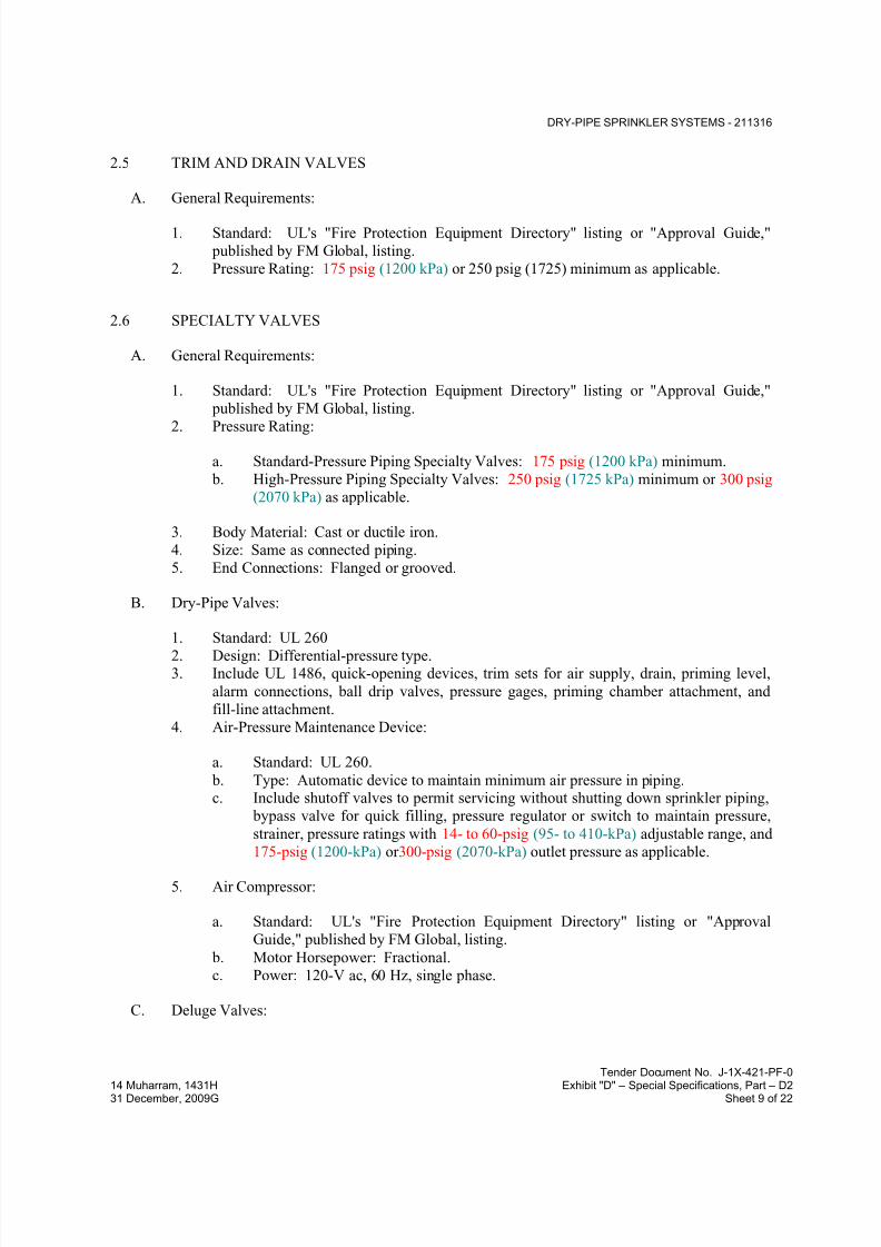
7/18/2019 SEC DPS
http://slidepdf.com/reader/full/sec-dps 89/541
DRY-PIPE SPRINKLER SYSTEMS - 211316
Tender Document No. J-1X-421-PF-0
14 Muharram, 1431H Exhibit "D" – Special Specifications, Part – D231 December, 2009G Sheet 9 of 22
2.5 TRIM AND DRAIN VALVES
A. General Requirements:
1. Standard: UL's "Fire Protection Equipment Directory" listing or "Approval Guide,"
published by FM Global, listing.
2. Pressure Rating: 175 psig (1200 kPa) or 250 psig (1725) minimum as applicable.
2.6 SPECIALTY VALVES
A. General Requirements:
1. Standard: UL's "Fire Protection Equipment Directory" listing or "Approval Guide,"
published by FM Global, listing.
2. Pressure Rating:
a. Standard-Pressure Piping Specialty Valves: 175 psig (1200 kPa) minimum.
b. High-Pressure Piping Specialty Valves: 250 psig (1725 kPa) minimum or 300 psig
(2070 kPa) as applicable.
3. Body Material: Cast or ductile iron.
4. Size: Same as connected piping.
5. End Connections: Flanged or grooved.
B. Dry-Pipe Valves:
1. Standard: UL 260
2. Design: Differential-pressure type.3. Include UL 1486, quick-opening devices, trim sets for air supply, drain, priming level,
alarm connections, ball drip valves, pressure gages, priming chamber attachment, and
fill-line attachment.
4. Air-Pressure Maintenance Device:
a. Standard: UL 260.
b. Type: Automatic device to maintain minimum air pressure in piping.c. Include shutoff valves to permit servicing without shutting down sprinkler piping,
bypass valve for quick filling, pressure regulator or switch to maintain pressure,
strainer, pressure ratings with 14- to 60-psig (95- to 410-kPa) adjustable range, and
175-psig (1200-kPa) or 300-psig (2070-kPa) outlet pressure as applicable.
5. Air Compressor:
a. Standard: UL's "Fire Protection Equipment Directory" listing or "Approval
Guide," published by FM Global, listing.
b. Motor Horsepower: Fractional.
c. Power: 120-V ac, 60 Hz, single phase.
C. Deluge Valves:
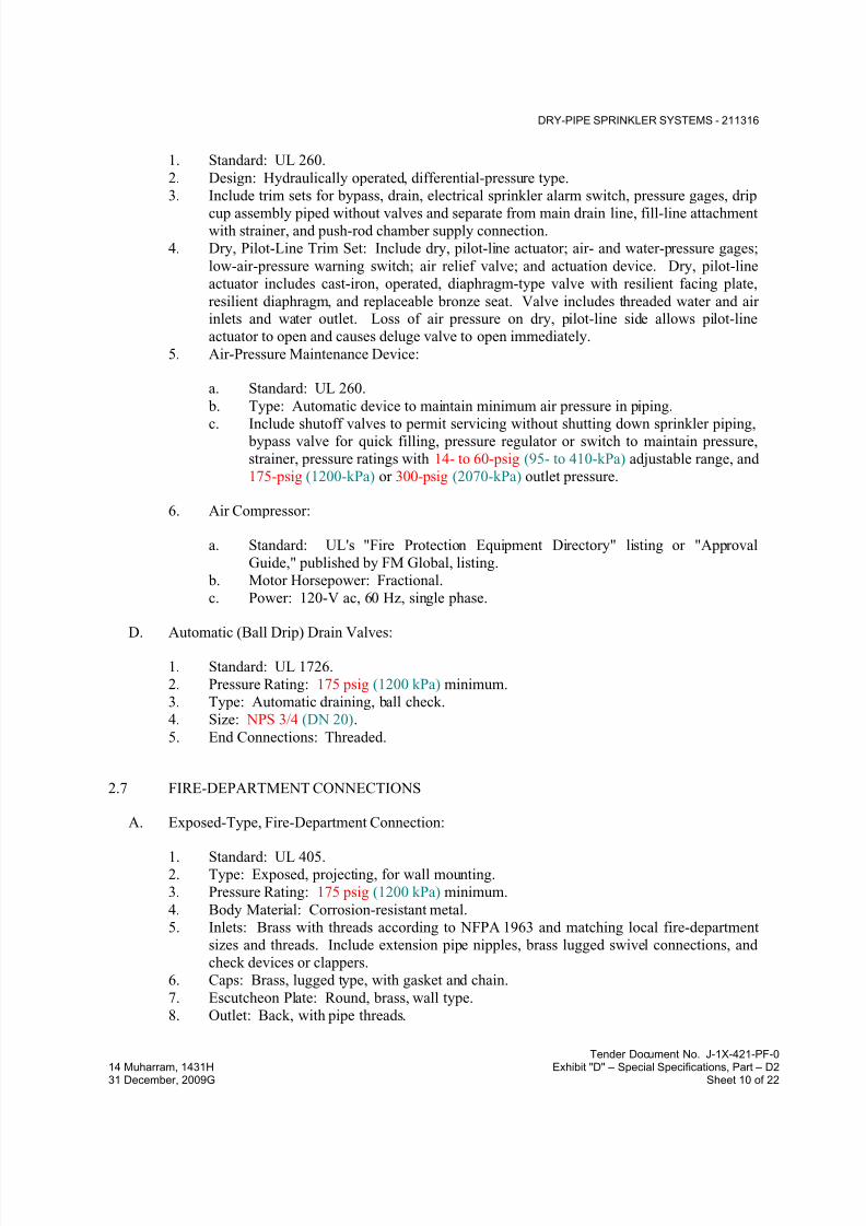
7/18/2019 SEC DPS
http://slidepdf.com/reader/full/sec-dps 90/541
DRY-PIPE SPRINKLER SYSTEMS - 211316
Tender Document No. J-1X-421-PF-0
14 Muharram, 1431H Exhibit "D" – Special Specifications, Part – D231 December, 2009G Sheet 10 of 22
1. Standard: UL 260.
2. Design: Hydraulically operated, differential-pressure type.
3. Include trim sets for bypass, drain, electrical sprinkler alarm switch, pressure gages, drip
cup assembly piped without valves and separate from main drain line, fill-line attachmentwith strainer, and push-rod chamber supply connection.
4. Dry, Pilot-Line Trim Set: Include dry, pilot-line actuator; air- and water-pressure gages;
low-air-pressure warning switch; air relief valve; and actuation device. Dry, pilot-line
actuator includes cast-iron, operated, diaphragm-type valve with resilient facing plate,
resilient diaphragm, and replaceable bronze seat. Valve includes threaded water and airinlets and water outlet. Loss of air pressure on dry, pilot-line side allows pilot-line
actuator to open and causes deluge valve to open immediately.
5. Air-Pressure Maintenance Device:
a. Standard: UL 260.
b. Type: Automatic device to maintain minimum air pressure in piping.
c. Include shutoff valves to permit servicing without shutting down sprinkler piping, bypass valve for quick filling, pressure regulator or switch to maintain pressure,
strainer, pressure ratings with 14- to 60-psig (95- to 410-kPa) adjustable range, and
175-psig (1200-kPa) or 300-psig (2070-kPa) outlet pressure.
6. Air Compressor:
a. Standard: UL's "Fire Protection Equipment Directory" listing or "Approval
Guide," published by FM Global, listing.
b. Motor Horsepower: Fractional.
c. Power: 120-V ac, 60 Hz, single phase.
D. Automatic (Ball Drip) Drain Valves:
1. Standard: UL 1726.
2. Pressure Rating: 175 psig (1200 kPa) minimum.
3. Type: Automatic draining, ball check.
4. Size: NPS 3/4 (DN 20).
5. End Connections: Threaded.
2.7 FIRE-DEPARTMENT CONNECTIONS
A. Exposed-Type, Fire-Department Connection:
1. Standard: UL 405.
2. Type: Exposed, projecting, for wall mounting.
3. Pressure Rating: 175 psig (1200 kPa) minimum.
4. Body Material: Corrosion-resistant metal.
5. Inlets: Brass with threads according to NFPA 1963 and matching local fire-department
sizes and threads. Include extension pipe nipples, brass lugged swivel connections, and
check devices or clappers.
6. Caps: Brass, lugged type, with gasket and chain.
7. Escutcheon Plate: Round, brass, wall type.
8. Outlet: Back, with pipe threads.
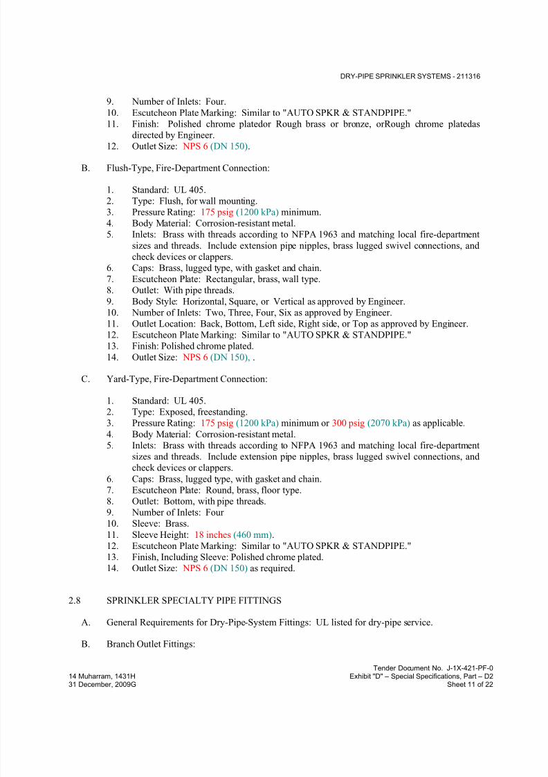
7/18/2019 SEC DPS
http://slidepdf.com/reader/full/sec-dps 91/541
DRY-PIPE SPRINKLER SYSTEMS - 211316
Tender Document No. J-1X-421-PF-0
14 Muharram, 1431H Exhibit "D" – Special Specifications, Part – D231 December, 2009G Sheet 11 of 22
9. Number of Inlets: Four.
10. Escutcheon Plate Marking: Similar to "AUTO SPKR & STANDPIPE."
11. Finish: Polished chrome platedor Rough brass or bronze, orRough chrome platedas
directed by Engineer.12. Outlet Size: NPS 6 (DN 150).
B. Flush-Type, Fire-Department Connection:
1. Standard: UL 405.
2. Type: Flush, for wall mounting.
3. Pressure Rating: 175 psig (1200 kPa) minimum.
4. Body Material: Corrosion-resistant metal.
5. Inlets: Brass with threads according to NFPA 1963 and matching local fire-department
sizes and threads. Include extension pipe nipples, brass lugged swivel connections, and
check devices or clappers.
6. Caps: Brass, lugged type, with gasket and chain.7. Escutcheon Plate: Rectangular, brass, wall type.
8. Outlet: With pipe threads.
9. Body Style: Horizontal, Square, or Vertical as approved by Engineer.
10. Number of Inlets: Two, Three, Four, Six as approved by Engineer.
11. Outlet Location: Back, Bottom, Left side, Right side, or Top as approved by Engineer.
12. Escutcheon Plate Marking: Similar to "AUTO SPKR & STANDPIPE."
13. Finish: Polished chrome plated.
14. Outlet Size: NPS 6 (DN 150), .
C. Yard-Type, Fire-Department Connection:
1. Standard: UL 405.2. Type: Exposed, freestanding.
3. Pressure Rating: 175 psig (1200 kPa) minimum or 300 psig (2070 kPa) as applicable.
4. Body Material: Corrosion-resistant metal.
5. Inlets: Brass with threads according to NFPA 1963 and matching local fire-department
sizes and threads. Include extension pipe nipples, brass lugged swivel connections, and
check devices or clappers.
6. Caps: Brass, lugged type, with gasket and chain.
7. Escutcheon Plate: Round, brass, floor type.
8. Outlet: Bottom, with pipe threads.
9. Number of Inlets: Four
10. Sleeve: Brass.
11. Sleeve Height: 18 inches (460 mm).12. Escutcheon Plate Marking: Similar to "AUTO SPKR & STANDPIPE."
13. Finish, Including Sleeve: Polished chrome plated.
14. Outlet Size: NPS 6 (DN 150) as required.
2.8 SPRINKLER SPECIALTY PIPE FITTINGS
A. General Requirements for Dry-Pipe-System Fittings: UL listed for dry-pipe service.
B. Branch Outlet Fittings:

7/18/2019 SEC DPS
http://slidepdf.com/reader/full/sec-dps 92/541
DRY-PIPE SPRINKLER SYSTEMS - 211316
Tender Document No. J-1X-421-PF-0
14 Muharram, 1431H Exhibit "D" – Special Specifications, Part – D231 December, 2009G Sheet 12 of 22
1. Standard: UL 213.
2. Pressure Rating: 175 psig (1200 kPa) minimumor 300 psig (2070 kPa)as applicable.
3. Body Material: Ductile-iron housing with EPDM seals and bolts and nuts.
4. Type: Mechanical-T and -cross fittings.5. Configurations: Snap-on and strapless, ductile-iron housing with branch outlets.
6. Size: Of dimension to fit onto sprinkler main and with outlet connections as required to
match connected branch piping.
7. Branch Outlets: Grooved, plain-end pipe, or threaded.
C. Flow Detection and Test Assemblies:
1. Standard: UL's "Fire Protection Equipment Directory" listing or "Approval Guide,"
published by FM Global, listing.
2. Pressure Rating: 175 psig (1200 kPa) minimum or 300 psig (2070 kPa)as applicable.
3. Body Material: Cast- or ductile-iron housing with orifice, sight glass, and integral test
valve.4. Size: Same as connected piping.
5. Inlet and Outlet: Threaded.
D. Branch Line Testers:
1. Standard: UL 199.
2. Pressure Rating: 175 psig (1200 kPa) minimum or 250 psig (1725 kPa) as applicable.
3. Body Material: Brass.
4. Size: Same as connected piping.
5. Inlet: Threaded.
6. Drain Outlet: Threaded and capped.
7. Branch Outlet: Threaded, for sprinkler.
E. Sprinkler Inspector's Test Fittings:
1. Standard: UL's "Fire Protection Equipment Directory" listing or "Approval Guide,"
published by FM Global, listing.
2. Pressure Rating: 175 psig (1200 kPa) minimum or 300 psig (2070 kPa)as applicable.
3. Body Material: Cast- or ductile-iron housing with sight glass.
4. Size: Same as connected piping.
5. Inlet and Outlet: Threaded.
F. Adjustable Drop Nipples:
1. Standard: UL 1474.
2. Pressure Rating: 250 psig (1725 kPa) minimum or 300 psig (2070 kPa)as applicable.
3. Body Material: Steel pipe with EPDM O-ring seals.
4. Size: Same as connected piping.
5. Length: Adjustable.
6. Inlet and Outlet: Threaded.
G. Flexible, Sprinkler Hose Fittings:
1. Standard: UL 1474.

7/18/2019 SEC DPS
http://slidepdf.com/reader/full/sec-dps 93/541
DRY-PIPE SPRINKLER SYSTEMS - 211316
Tender Document No. J-1X-421-PF-0
14 Muharram, 1431H Exhibit "D" – Special Specifications, Part – D231 December, 2009G Sheet 13 of 22
2. Type: Flexible hose for connection to sprinkler, and with bracket for connection to
ceiling grid.
3. Pressure Rating: 175 psig (1200 kPa) minimum or 300 psig (2070 kPa)as applicable.
4. Size: Same as connected piping, for sprinkler.
2.9 SPRINKLERS
A. General Requirements:
1. Standard: UL's "Fire Protection Equipment Directory" listing or "Approval Guide,"
published by FM Global, listing.
2. Pressure Rating for Residential Sprinklers: 175 psig (1200 kPa) maximum.
3. Pressure Rating for Automatic Sprinklers: 175 psig (1200 kPa) minimum.
4. Pressure Rating for High-Pressure Automatic Sprinklers: 250 psig (1725 kPa) minimum
or 300 psig (2070 kPa) as applicable.
B. Automatic Sprinklers with Heat-Responsive Element:
1. Nonresidential Applications: UL 199.
2. Residential Applications: UL 1626.
3. Characteristics: Nominal 1/2-inch (12.7-mm) orifice with discharge coefficient K of 5.6,
and for "Ordinary" temperature classification rating unless otherwise indicated or
required by application.
C. Sprinkler Finishes:
1. Chrome plated.
2. Bronze.
3. Painted.
D. Special Coatings:
1. Wax.
2. Lead.
3. Corrosion-resistant paint.
E. Sprinkler Escutcheons: Materials, types, and finishes for the following sprinkler mounting
applications. Escutcheons for concealed, flush, and recessed-type sprinklers are specified with
sprinklers.
1. Ceiling Mounting: Chrome-plated steel, one piece, flat or Chrome-plated steel, two
piece, with 1-inch (25-mm) vertical adjustment, .
2. Sidewall Mounting: Chrome-plated steelone piece, flat.
F. Sprinkler Guards:
1. Manufacturers: Subject to compliance with requirements.

7/18/2019 SEC DPS
http://slidepdf.com/reader/full/sec-dps 94/541
DRY-PIPE SPRINKLER SYSTEMS - 211316
Tender Document No. J-1X-421-PF-0
14 Muharram, 1431H Exhibit "D" – Special Specifications, Part – D231 December, 2009G Sheet 14 of 22
2. Standard: UL 199.
3. Type: Wire cage with fastening device for attaching to sprinkler.
2.10 ALARM DEVICES
A. Alarm-device types shall match piping and equipment connections.
B. Water-Motor-Operated Alarm:
1. Standard: UL 753.
2. Type: Mechanically operated, with Pelton wheel.
3. Alarm Gong: Cast aluminum with red-enamel factory finish.
4. Size: 10-inch (250-mm) diameter.
5. Components: Shaft length, bearings, and sleeve to suit wall construction.
6. Inlet: NPS 3/4 (DN 20).7. Outlet: NPS 1 (DN 25) drain connection.
C. Electrically Operated Alarm Bell:
1. Standard: UL 464.2. Type: Vibrating, metal alarm bell.
3. Size: 10-inch (250-mm) diameter.
4. Finish: Red-enamel factory finish, suitable for outdoor use.
D. Pressure Switches:
1. Standard: UL 346.2. Type: Electrically supervised water-flow switch with retard feature.
3. Components: Single-pole, double-throw switch with normally closed contacts.
4. Design Operation: Rising pressure signals water flow.
E. Valve Supervisory Switches:
1. Standard: UL 346.
2. Type: Electrically supervised.3. Components: Single-pole, double-throw switch with normally closed contacts.
4. Design: Signals that controlled valve is in other than fully open position.
F. Indicator-Post Supervisory Switches:
1. Standard: UL 346.
2. Type: Electrically supervised.
3. Components: Single-pole, double-throw switch with normally closed contacts.
4. Design: Signals that controlled indicator-post valve is in other than fully open position.

7/18/2019 SEC DPS
http://slidepdf.com/reader/full/sec-dps 95/541
DRY-PIPE SPRINKLER SYSTEMS - 211316
Tender Document No. J-1X-421-PF-0
14 Muharram, 1431H Exhibit "D" – Special Specifications, Part – D231 December, 2009G Sheet 15 of 22
2.11 MANUAL CONTROL STATIONS
A. Description: UL listed or FM Global approved, hydraulic operation, with union, NPS 1/2
(DN 15) pipe nipple, and bronze ball valve. Include metal enclosure labeled "MANUALCONTROL STATION" with operating instructions and cover held closed by breakable strut to
prevent accidental opening.
2.12 CONTROL PANELS
A. Description: Single-area, two-area, or single-area cross-zoned type control panel as indicated,
including NEMA ICS 6, Type 1 enclosure, detector, alarm, and solenoid-valve circuitry for
operation of deluge valves. Panels contain power supply; battery charger; standby batteries;
field-wiring terminal strip; electrically supervised solenoid valves and polarized fire-alarm bell;
lamp test facility; single-pole, double-throw auxiliary alarm contacts; and rectifier.
1. Panels: UL listed and FM Global approved when used with thermal detectors and
Class A detector circuit wiring. Electrical characteristics are 120-V ac, 60 Hz, with 24-V
dc rechargeable batteries.
2. Manual Control Stations: Electric operation, metal enclosure, labeled "MANUAL
CONTROL STATION" with operating instructions and cover held closed by breakable
strut to prevent accidental opening.
3. Manual Control Stations: Hydraulic operation, with union, NPS 1/2 (DN 15) pipe nipple,
and bronze ball valve. Include metal enclosure labeled "MANUAL CONTROL
STATION" with operating instructions and cover held closed by breakable strut to
prevent accidental opening.
2.13 PRESSURE GAGES
A. Standard: UL 393.
B. Dial Size: 3-1/2- to 4-1/2-inch (90- to 115-mm) diameter.
C. Pressure Gage Range: 0 to 250 psig (0 to 1725 kPa) minimum or 0 to 300 psig (0 to
2070 kPa)as applicable.
D. Water System Piping Gage: Include "WATER" or "AIR/WATER" label on dial face.
E. Air System Piping Gage: Include retard feature and "AIR" or "AIR/WATER" label on dial
face.
PART 3 - EXECUTION
3.1 PREPARATION
A. Perform fire-hydrant flow test according to NFPA 13 and NFPA 291. Use results for system
design calculations required in "Quality Assurance" Article.

7/18/2019 SEC DPS
http://slidepdf.com/reader/full/sec-dps 96/541
DRY-PIPE SPRINKLER SYSTEMS - 211316
Tender Document No. J-1X-421-PF-0
14 Muharram, 1431H Exhibit "D" – Special Specifications, Part – D231 December, 2009G Sheet 16 of 22
B. Report test results promptly and in writing.
3.2 SERVICE-ENTRANCE PIPING
A. Connect sprinkler piping to water-service piping for service entrance to building. Comply with
requirements in Division 21 Section "Facility Fire-Suppression Water-Service Piping" for
exterior piping.
B. Install shutoff valve, backflow preventer, pressure gage, drain, and other accessories indicated
at connection to water-service piping. Comply with requirements in Division 21 Section
"Facility Fire-Suppression Water-Service Piping" for backflow preventers.
C. Install shutoff valve, check valve, pressure gage, and drain at connection to water service.
3.3 WATER-SUPPLY CONNECTIONS
A. Connect sprinkler piping to building's interior water-distribution piping. Comply with
requirements in Division 22 Section "Domestic Water Piping" for interior piping.
B. Install shutoff valve, backflow preventer, pressure gage, drain, and other accessories indicated
at connection to water-distribution piping. Comply with requirements in Division 22 Section"Domestic Water Piping Specialties" for backflow preventers.
C. Install shutoff valve, check valve, pressure gage, and drain at connection to water supply.
3.4 PIPING INSTALLATION
A. Locations and Arrangements: Drawing plans, schematics, and diagrams indicate general
location and arrangement of piping. Install piping as indicated, as far as practical.
1. Deviations from approved working plans for piping require written approval from
authorities having jurisdiction. File written approval with Architect before deviating
from approved working plans.
B. Piping Standard: Comply with requirements in NFPA 13 for installation of sprinkler piping.
C. Install seismic restraints on piping. Comply with requirements in NFPA 13 for seismic-restraint
device materials and installation.
D. Use listed fittings to make changes in direction, branch takeoffs from mains, and reductions in
pipe sizes.
E. Install unions adjacent to each valve in pipes NPS 2 (DN 50) and smaller.
F. Install flanges, flange adapters, or couplings for grooved-end piping on valves, apparatus, and
equipment having NPS 2-1/2 (DN 65) and larger end connections.

7/18/2019 SEC DPS
http://slidepdf.com/reader/full/sec-dps 97/541
DRY-PIPE SPRINKLER SYSTEMS - 211316
Tender Document No. J-1X-421-PF-0
14 Muharram, 1431H Exhibit "D" – Special Specifications, Part – D231 December, 2009G Sheet 17 of 22
G. Install "Inspector's Test Connections" in sprinkler system piping, complete with shutoff valve,
and sized and located according to NFPA 13.
H. Install sprinkler piping with drains for complete system drainage.
I. Install sprinkler control valves, test assemblies, and drain risers adjacent to standpipes when
sprinkler piping is connected to standpipes.
J. Install automatic (ball drip) drain valves to drain piping between fire-department connections
and check valves. Drain to floor drain or to outside building.
K. Connect compressed-air supply to dry-pipe sprinkler piping.
L. Connect air compressor to the following piping and wiring:
1. Pressure gages and controls.2. Electrical power system.
3. Fire-alarm devices, including low-pressure alarm.
M. Install alarm devices in piping systems.
N. Install hangers and supports for sprinkler system piping according to NFPA 13. Comply with
requirements in NFPA 13 for hanger materials.
O. Install pressure gages on riser or feed main, at each sprinkler test connection, and at top of each
standpipe. Include pressure gages with connection not less than NPS 1/4 (DN 8) and with soft
metal seated globe valve, arranged for draining pipe between gage and valve. Install gages to
permit removal, and install where they will not be subject to freezing.
P. Drain dry-pipe sprinkler piping.
Q. Pressurize and check dry-pipe sprinkler system piping , air-pressure maintenance devices, and
air compressors.
R. Install sleeves for piping penetrations of walls, ceilings, and floors. Comply with requirements
for sleeves specified in Division 21 Section "Sleeves and Sleeve Seals for Fire-Suppression
Piping."
S. Install sleeve seals for piping penetrations of concrete walls and slabs. Comply with
requirements for sleeve seals specified in Division 21 Section "Sleeves and Sleeve Seals for
Fire-Suppression Piping."
T. Install escutcheons for piping penetrations of walls, ceilings, and floors. Comply with
requirements for escutcheons specified in Division 21 Section "Escutcheons for Fire-
Suppression Piping."

7/18/2019 SEC DPS
http://slidepdf.com/reader/full/sec-dps 98/541
DRY-PIPE SPRINKLER SYSTEMS - 211316
Tender Document No. J-1X-421-PF-0
14 Muharram, 1431H Exhibit "D" – Special Specifications, Part – D231 December, 2009G Sheet 18 of 22
3.5 JOINT CONSTRUCTION
A. Install couplings, flanges, flanged fittings, unions, nipples, and transition and special fittings
that have finish and pressure ratings same as or higher than system's pressure rating foraboveground applications unless otherwise indicated.
B. Install unions adjacent to each valve in pipes NPS 2 (DN 50) and smaller.
C. Install flanges, flange adapters, or couplings for grooved-end piping on valves, apparatus, and
equipment having NPS 2-1/2 (DN 65) and larger end connections.
D. Ream ends of pipes and tubes and remove burrs. Bevel plain ends of steel pipe.
E. Remove scale, slag, dirt, and debris from inside and outside of pipes, tubes, and fittings before
assembly.
F. Flanged Joints: Select appropriate gasket material in size, type, and thickness suitable for water
service. Join flanges with gasket and bolts according to ASME B31.9.
G. Threaded Joints: Thread pipe with tapered pipe threads according to ASME B1.20.1. Cut
threads full and clean using sharp dies. Ream threaded pipe ends to remove burrs and restorefull ID. Join pipe fittings and valves as follows:
1. Apply appropriate tape or thread compound to external pipe threads.
2. Damaged Threads: Do not use pipe or pipe fittings with threads that are corroded or
damaged.
H. Twist-Locked Joints: Insert plain end of steel pipe into plain-end-pipe fitting. Rotate retainerlugs one-quarter turn or tighten retainer pin.
I. Steel-Piping, Cut-Grooved Joints: Cut square-edge groove in end of pipe according to
AWWA C606. Assemble coupling with housing, gasket, lubricant, and bolts. Join steel pipe
and grooved-end fittings according to AWWA C606 for steel-pipe joints.
J. Extruded-Tee Connections: Form tee in copper tube according to ASTM F 2014. Use tool
designed for copper tube; drill pilot hole, form collar for outlet, dimple tube to form seatingstop, and braze branch tube into collar.
K. Dissimilar-Material Piping Joints: Make joints using adapters compatible with materials of both
piping systems.
3.6 VALVE AND SPECIALTIES INSTALLATION
A. Install listed fire-protection valves, trim and drain valves, specialty valves and trim, controls,
and specialties according to NFPA 13 and authorities having jurisdiction.
B. Install listed fire-protection shutoff valves supervised open, located to control sources of water
supply except from fire-department connections. Install permanent identification signs
indicating portion of system controlled by each valve.

7/18/2019 SEC DPS
http://slidepdf.com/reader/full/sec-dps 99/541
DRY-PIPE SPRINKLER SYSTEMS - 211316
Tender Document No. J-1X-421-PF-0
14 Muharram, 1431H Exhibit "D" – Special Specifications, Part – D231 December, 2009G Sheet 19 of 22
C. Install check valve in each water-supply connection. Install backflow preventers instead of
check valves in potable-water-supply sources.
D. Specialty Valves:
1. General Requirements: Install in vertical position for proper direction of flow, in main
supply to system.
2. Dry-Pipe and Deluge Valves: Install trim sets for air supply, drain, priming level, alarm
connections, ball drip valves, pressure gages, priming chamber attachment, and fill-line
attachment.
a. Install air compressor and compressed-air supply piping.
b. Air-Pressure Maintenance Device: Install shutoff valves to permit servicing
without shutting down sprinkler system; bypass valve for quick system filling;
pressure regulator or switch to maintain system pressure; strainer; pressure ratings
with 14- to 60-psig (95- to 410-kPa) adjustable range; and 175-psig (1200-kPa) maximum inlet pressure.
c. Install compressed-air supply piping from building's compressed-air piping system.
3.7 SPRINKLER INSTALLATION
A. Install sprinklers in suspended ceilings in center of narrow dimension of acoustical ceiling
panels.
B. Install dry-type sprinklers with water supply from heated space. Do not install pendent orsidewall, wet-type sprinklers in areas subject to freezing.
C. Install sprinklers into flexible, sprinkler hose fittings and install hose into bracket on ceiling
grid.
3.8 FIRE-DEPARTMENT CONNECTION INSTALLATION
A. Install wall-type, fire-department connections.
B. Install yard-type, fire-department connections in concrete slab support. Comply withrequirements for concrete in Division 03 Section "Cast-in-Place Concrete".
1. Install two or three protective pipe bollards around or on sides of each fire-department
connection. Comply with requirements for bollards in Division 05 Section "MetalFabrications".
C. Install automatic (ball drip) drain valve at each check valve for fire-department connection.
3.9 IDENTIFICATION
A. Install labeling and pipe markers on equipment and piping according to requirements in
NFPA 13.

7/18/2019 SEC DPS
http://slidepdf.com/reader/full/sec-dps 100/541
DRY-PIPE SPRINKLER SYSTEMS - 211316
Tender Document No. J-1X-421-PF-0
14 Muharram, 1431H Exhibit "D" – Special Specifications, Part – D231 December, 2009G Sheet 20 of 22
B. Identify system components, wiring, cabling, and terminals. Comply with requirements for
identification specified in Division 26 Section "Identification for Electrical Systems."
3.10 FIELD QUALITY CONTROL
A. Perform tests and inspections.
B. Tests and Inspections:
1. Leak Test: After installation, charge systems and test for leaks. Repair leaks and retest
until no leaks exist.
2. Test and adjust controls and safeties. Replace damaged and malfunctioning controls and
equipment.
3. Flush, test, and inspect sprinkler systems according to NFPA 13, "Systems Acceptance"
Chapter.4. Energize circuits to electrical equipment and devices.
5. Start and run air compressors.
6. Coordinate with fire-alarm tests. Operate as required.
7. Coordinate with fire-pump tests. Operate as required.
8. Verify that equipment hose threads are same as local fire-department equipment.
C. Sprinkler piping system will be considered defective if it does not pass tests and inspections.
D. Prepare test and inspection reports.
3.11 CLEANING
A. Clean dirt and debris from sprinklers.
B. Remove and replace sprinklers with paint other than factory finish.
3.12 DEMONSTRATION
A. Engage a factory-authorized service representative to train Owner's maintenance personnel to
adjust, operate, and maintain specialty valves.
3.13 PIPING SCHEDULE
A. Piping between Fire-Department Connections and Check Valves: Galvanized, standard-weight
steel pipe with grooved ends; grooved-end fittings; grooved-end-pipe couplings; and grooved
joints.
B. Sprinkler specialty fittings may be used, downstream of control vales, instead of specified
fittings.
C. Copper-tube, extruded-tee connections may be used for tee branches in copper tubing instead of
specified copper fittings. Branch-connection joints must be brazed.

7/18/2019 SEC DPS
http://slidepdf.com/reader/full/sec-dps 101/541
DRY-PIPE SPRINKLER SYSTEMS - 211316
Tender Document No. J-1X-421-PF-0
14 Muharram, 1431H Exhibit "D" – Special Specifications, Part – D231 December, 2009G Sheet 21 of 22
D. Standard-pressure, dry-pipe sprinkler system, NPS 2 (DN 50) and smaller, shall be one of the
following:
1. Standard-weight, galvanized-steel pipe with threaded ends; galvanized, gray-ironthreaded fittings; and threaded joints.
2. Standard-weight, galvanized-steel pipe with plain ends; plain-end-pipe fittings; and twist-
locked joints.
3. Standard-weight, galvanized-steel pipe with cut-grooved ends; galvanized, grooved-end
fittings for steel piping; grooved-end-pipe couplings for steel piping; and grooved joints.
4.
E. Standard-pressure, dry-pipe sprinkler system, NPS 2-1/2 to NPS 4 (DN 65 to DN 100), shall
be one of the following:
1. Standard-weight, galvanized-steel pipe with threaded ends; galvanized, gray-iron
threaded fittings; and threaded joints.2. Standard-weight, galvanized-steel pipe with cut-grooved ends; galvanized, grooved-end
fittings for steel piping; grooved-end-pipe couplings for steel piping; and grooved joints.
3.
F. Standard-pressure, dry-pipe sprinkler system, NPS 5 and NPS 6 (DN 125 and DN 150), shall be
one of the following:
1. Standard-weight, galvanized-steel pipe with threaded ends; galvanized, gray-iron
threaded fittings; and threaded joints.
2. Standard-weight, galvanized-steel pipe with cut-grooved ends; galvanized, grooved-end
fittings for steel piping; grooved-end-pipe couplings for steel piping; and grooved joints.
3.
3.14 SPRINKLER SCHEDULE
A. Use sprinkler types in subparagraphs below for the following applications:
1. Rooms without Ceilings: Upright sprinklers.
2. Rooms with Suspended Ceilings in Interior Decorator Areas: Dry concealed sprinklers
3. Rooms with Suspended Ceilings in Back of House Areas: Dry Pendent sprinklers.
4. Wall Mounting: Dry sidewall sprinklers.
5. Spaces Subject to Freezing: Upright, dry pendent sprinklers; and dry sidewall sprinklersas indicated and as directed by Engineer.
6. Special Applications: Extended-coverage and quick-response sprinklers where indicated.
B. Provide sprinkler types in subparagraphs below with finishes indicated.
1. Concealed Sprinklers: Rough brass, with factory-painted white cover plate.
2. Flush Sprinklers: Bright chrome, with painted white escutcheon.
3. Recessed Sprinklers: Bright chrome, with bright chrome escutcheon.4. Upright, Pendent, and Sidewall Sprinklers: Chrome plated in finished spaces exposed to
view; rough bronze in unfinished spaces not exposed to view; wax coated where exposed
to acids, chemicals, or other corrosive fumes.

7/18/2019 SEC DPS
http://slidepdf.com/reader/full/sec-dps 102/541
DRY-PIPE SPRINKLER SYSTEMS - 211316
Tender Document No. J-1X-421-PF-0
14 Muharram, 1431H Exhibit "D" – Special Specifications, Part – D231 December, 2009G Sheet 22 of 22
END OF SECTION 211316

7/18/2019 SEC DPS
http://slidepdf.com/reader/full/sec-dps 103/541
FOAM-WATER SYSTEMS - 211339
Tender Document No. J-1X-421-PF-0
14 Muharram, 1431H Exhibit "D" – Special Specifications, Part – D231 December, 2009G Sheet 1 of 10
SECTION 211339 - FOAM-WATER SYSTEMS
PART 1 - GENERAL
1.1 RELATED DOCUMENTS
A. Drawings and general provisions of the Contract, including General and Supplementary
Conditions and Division 01 Specification Sections, apply to this Section.
1.2 SUMMARY
A. Section Includes:
1. Concentrate piping and piping specialties.
2. Bladder tanks and proportioning devices.3. Foam concentrate.
4. Discharge devices.
5. Monitoring and alarm devices.
1.3 DEFINITIONS
A. AFFF: Aqueous film-forming foam.
B. AR-AFFF: Alcohol-resistant aqueous film-forming foam.
1.4 SYSTEM DESCRIPTION
A. Description: Engineered, fixed, automatically actuated, low-expansion, AFFF fire-
extinguishing system for flammable-liquid fires. System includes diaphragm proportioning
tanks and devices as described in NFPA 16.
1.5 PERFORMANCE REQUIREMENTS
A. Standard Working Pressure of Piping-System Component: Listed for at least 175 psig (1200kPa).
B. Unless authorities having jurisdiction have stricter requirements, minimum design parameters
are as follows:
1. Solution: 3percent foam-water solution.
2. Sprinkler Spacing: Maximum of 9.5 sq. m per sprinkler, and maximum 3.7-mspacing.
3. Design Density: Minimum 0.108 L/s per sq. m.
4. Foam Supply: Minimum 10minute discharge time.
5. Water Supply: Minimum 60minutes.
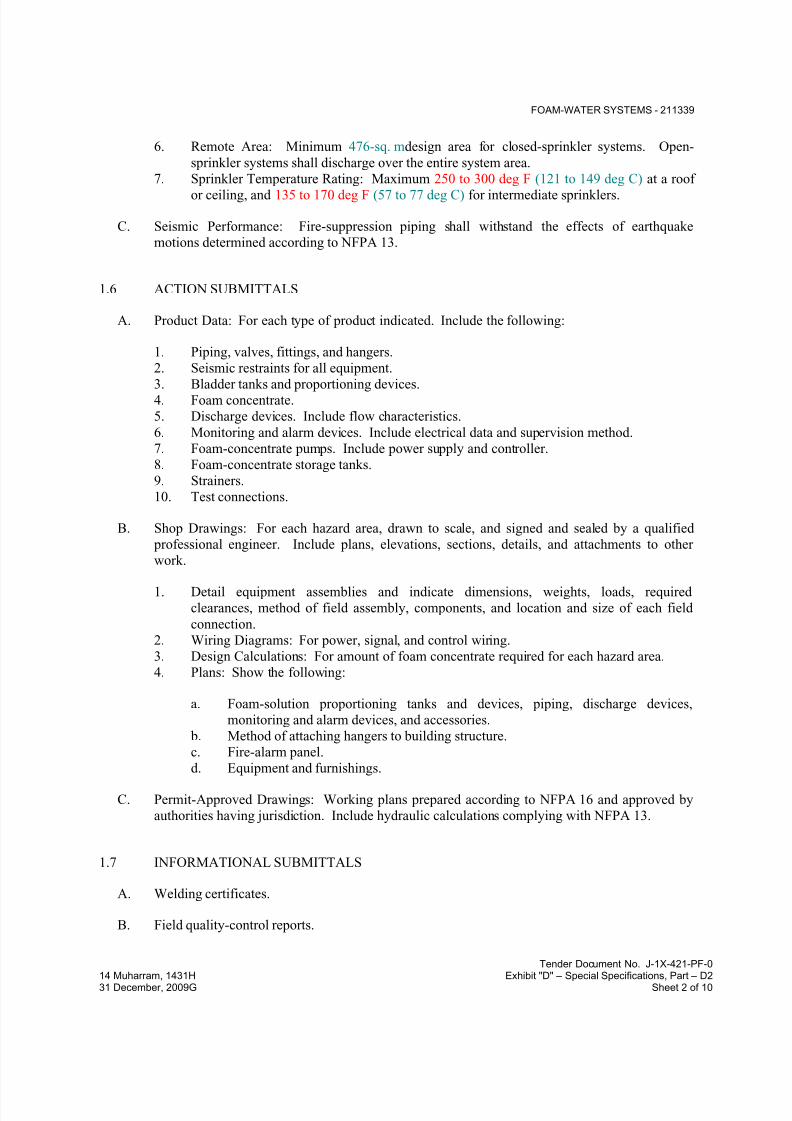
7/18/2019 SEC DPS
http://slidepdf.com/reader/full/sec-dps 104/541
FOAM-WATER SYSTEMS - 211339
Tender Document No. J-1X-421-PF-0
14 Muharram, 1431H Exhibit "D" – Special Specifications, Part – D231 December, 2009G Sheet 2 of 10
6. Remote Area: Minimum 476-sq. mdesign area for closed-sprinkler systems. Open-
sprinkler systems shall discharge over the entire system area.
7. Sprinkler Temperature Rating: Maximum 250 to 300 deg F (121 to 149 deg C) at a roof
or ceiling, and 135 to 170 deg F (57 to 77 deg C) for intermediate sprinklers.
C. Seismic Performance: Fire-suppression piping shall withstand the effects of earthquake
motions determined according to NFPA 13.
1.6 ACTION SUBMITTALS
A. Product Data: For each type of product indicated. Include the following:
1. Piping, valves, fittings, and hangers.
2. Seismic restraints for all equipment.
3. Bladder tanks and proportioning devices.4. Foam concentrate.
5. Discharge devices. Include flow characteristics.
6. Monitoring and alarm devices. Include electrical data and supervision method.
7. Foam-concentrate pumps. Include power supply and controller.
8. Foam-concentrate storage tanks.
9. Strainers.
10. Test connections.
B. Shop Drawings: For each hazard area, drawn to scale, and signed and sealed by a qualified
professional engineer. Include plans, elevations, sections, details, and attachments to other
work.
1. Detail equipment assemblies and indicate dimensions, weights, loads, required
clearances, method of field assembly, components, and location and size of each field
connection.
2. Wiring Diagrams: For power, signal, and control wiring.
3. Design Calculations: For amount of foam concentrate required for each hazard area.
4. Plans: Show the following:
a. Foam-solution proportioning tanks and devices, piping, discharge devices,
monitoring and alarm devices, and accessories.
b. Method of attaching hangers to building structure.
c. Fire-alarm panel.
d. Equipment and furnishings.
C. Permit-Approved Drawings: Working plans prepared according to NFPA 16 and approved by
authorities having jurisdiction. Include hydraulic calculations complying with NFPA 13.
1.7 INFORMATIONAL SUBMITTALS
A. Welding certificates.
B. Field quality-control reports.
7/18/2019 SEC DPS
http://slidepdf.com/reader/full/sec-dps 105/541
FOAM-WATER SYSTEMS - 211339
Tender Document No. J-1X-421-PF-0
14 Muharram, 1431H Exhibit "D" – Special Specifications, Part – D231 December, 2009G Sheet 3 of 10
1.8 CLOSEOUT SUBMITTALS
A. Operation and Maintenance Data: For foam fire extinguishing to include in emergency,
operation, and maintenance manuals. In addition to items specified in Division 01 Section"Operation and Maintenance Data," include the following:
1. Valves and specialties.
2. Bladder tanks and proportioning devices.
3. Foam concentrate.
4. Discharge devices. Include flow characteristics.
5. Monitoring and alarm devices. Include supervision method.
6. Foam-concentrate pumps. Include controller.
7. Foam-concentrate storage tanks.
8. Strainers.
9. Test connections.
1.9 QUALITY ASSURANCE
A. Welding Qualifications: Qualify procedures and operators according to ASME Boiler and
Pressure Vessel Code: Section IX.
B. Electrical Components, Devices, and Accessories: Listed and labeled as defined in NFPA 70,
by a qualified testing agency, and marked for intended location and application.
C. FM Global Compliance: Provide components that are FM Approved and that are listed in FM's"Approval Guide."
D. UL Compliance: Provide equipment listed in UL's "Fire Protection Equipment Directory."
1.10 EXTRA MATERIALS
A. Furnish extra materials that match products installed and that are packaged with protective
covering for storage and identified with labels describing contents.
1. Discharge Devices: Not less than 20 percent of amount of each type installed.2. Foam Concentrate: Not less than 200 percent of amount installed.
PART 2 - PRODUCTS
2.1 CONCENTRATE PIPING MATERIALS
A. Comply with requirements specified in Division 21 Section "Wet-Pipe Sprinkler Systems" or
Division 21 Section "Dry-Pipe Sprinkler Systems" for pipes, fittings, joining materials, and
valves.
B. Schedule 40, Black Steel Pipe: ASTM A 53/A 53M, Type S, Grade B. Pipe ends may be
factory or field formed to match joining method.

7/18/2019 SEC DPS
http://slidepdf.com/reader/full/sec-dps 106/541
FOAM-WATER SYSTEMS - 211339
Tender Document No. J-1X-421-PF-0
14 Muharram, 1431H Exhibit "D" – Special Specifications, Part – D231 December, 2009G Sheet 4 of 10
1. Gray Iron Threaded Fittings, Classes 125 and 250: ASME B16.4.
2. Gray Iron Pipe Flanges and Flanged Fittings: ASME B16.1.
3. Malleable Iron Threaded Fittings, Classes 150 and 300: ASME B16.3.
2.2 VALVES
A. General Valve Requirements:
1. UL listed or FM Approved for use in fire-protection systems.
2. Compatible with type of foam concentrate used.
B. Ball Valves:
1. Manufacturers: Subject to compliance with requirements.
2. Description:
a. Standard: UL 258.
b. For trim and drain functions.
c. Valves NPS 1-1/2 (DN 40) and Smaller: Bronze body with threaded ends.
d. Valves NPS 2 and NPS 2-1/2 (DN 50 and DN 65): Bronze body with threaded
ends or ductile-iron body with grooved ends.
e. Valves NPS 3 (DN 80): Ductile-iron body with grooved ends.
C. OS&Y Gate Valves:
1. Description:
a. Standard: UL 262.
b. Accessories: Pregrooved stem for mounting tamper switch for monitoring by fire-
alarm panel.
c. Body Material: Cast or ductile iron.
d. Ends: Flanged or mechanical.
e. Packing: Asbestos free.
D. Indicating-Type Butterfly Valves:
1. Manufacturers: Subject to compliance with requirements.
2. Description:
a. Standard: UL 1091.
b. Pressure Rating: 175 psig (1200 kPa) minimum.
c. Valves NPS 2 (DN 50) and Smaller:
1) Body Material: Bronze.
2) End Connections: Threaded.
d. Valves NPS 2-1/2 (DN 65) and Larger:

7/18/2019 SEC DPS
http://slidepdf.com/reader/full/sec-dps 107/541
FOAM-WATER SYSTEMS - 211339
Tender Document No. J-1X-421-PF-0
14 Muharram, 1431H Exhibit "D" – Special Specifications, Part – D231 December, 2009G Sheet 5 of 10
1) Body Material: Cast or ductile iron.
2) End Connections: Flanged, grooved, or wafer.
3) Ends: Flanged or mechanical.
e. Accessories: Tamper switch for monitoring by fire-alarm panel.
E. Swing Check Valves:
1. Manufacturers: Subject to compliance with requirements.
2.
3. Description:
a. Standard: UL 312.
b. Pressure Rating: 250 psig (1725 kPa) minimum.c. Body Material: Cast iron.
d. End Connections: Flanged or grooved.
F. Trim and Drain Valves:
1. General Requirements:
a. Compatible with type of foam concentrate used.
b. Pressure Rating: 175 psig (1200 kPa) minimum.
2.3 SPECIALTIES
A. Manufacturers: Subject to compliance with requirements.
1.
B. Specialties shall comply with NFPA 16, be compatible with the foam concentrate, and be
designed to be drained and cleaned.
C. Foam-Concentrate Storage Tanks: Buna-N, bladder-type proportioning tank complying with
UL 162 and ASME Boiler and Pressure Vessel Code: Section VIII; designed for use with
foam-concentrate pumps and for specific type of foam concentrate used. Include bladder,
internal piping, fill and drain, glass sight gage, piping, and valves. Contain concentrate in the bladder.
1. Orientation: Vertical design with skirt support.
D. Foam-Concentrate Pumps: Listed for use in foam-water systems according to NFPA 20.
Include supply side pressure relief valve and drain cock or valve.
E. Proportioning Controllers: Venturi type complying with UL 162 and of capacity to match
design at minimum and maximum flow.
F. Concentrate Control Valves: Water-operated ball or deluge valve designed to open with flow
through the proportioning controller.
7/18/2019 SEC DPS
http://slidepdf.com/reader/full/sec-dps 108/541
FOAM-WATER SYSTEMS - 211339
Tender Document No. J-1X-421-PF-0
14 Muharram, 1431H Exhibit "D" – Special Specifications, Part – D231 December, 2009G Sheet 6 of 10
G. Concentrate Strainers: Bronze body and stainless-steel mesh strainer with minimum 0.125-inch
(3.2-mm) perforations to remove solids that would block system components.
H. Pressure Gages: Comply with UL 393; with 3-1/2-inch (90-mm) minimum-diameter dial, 0- to300-psig (0- to 2070-kPa) dial range, and caption "WATER" or "CONCENTRATE" on dial
face.
2.4 FOAM CONCENTRATE
A. Description: AFFF liquid concentrate, complying with NFPA 11 and UL 162, for making
foam-water fire-extinguishing foam solution.
2.5 DISCHARGE DEVICES
A. Discharge devices shall be UL listed or FM Approved.
B. Sprinklers: Open air-aspirating type; UL listed or FM Approved and listed for use with type of
foam concentrate used.
C. Spray Nozzles: For foam water; include foam generator and distributing deflector to distribute
foam or water.
2.6 MONITORING DEVICES
A. Valve Supervisory Switches: Single pole, double throw, with normally closed contacts
complying with UL 753. Switch shall signal fire-alarm panel or releasing panel when valve isin other than fully open position.
B. Pressure Switches: Single pole, double throw, UL listed or FM Approved and complying with
UL 753. Switch shall signal an alarm condition at the fire-alarm panel or releasing panel when
switch is in other than fully open position.
C. Flow Switches: Single pole, double throw, UL listed or FM Approved and complying with
UL 753. Switch shall signal an alarm condition at the fire-alarm panel or releasing panel when
switch is in other than fully open position.
2.7 ALARM DEVICES
A. Description: UL listed or FM Approved, low voltage, and surface mounting. Alarm and
monitoring devices are specified in Division 28 Section "Digital, Addressable Fire-Alarm
System" or Division 28 Section "Zoned (DC Loop) Fire-Alarm System."

7/18/2019 SEC DPS
http://slidepdf.com/reader/full/sec-dps 109/541
FOAM-WATER SYSTEMS - 211339
Tender Document No. J-1X-421-PF-0
14 Muharram, 1431H Exhibit "D" – Special Specifications, Part – D231 December, 2009G Sheet 7 of 10
PART 3 - EXECUTION
3.1 CONCENTRATE STORAGE TANK INSTALLATION
A. Equipment Mounting: Install concentrate storage tanks on cast-in-place concrete equipment
bases. Comply with requirements for equipment bases specified in Division 03.
1. Coordinate sizes and locations of concrete bases with actual equipment provided.
2. Construct bases to withstand, without damage to equipment, seismic force required by
code.
3. Construct concrete bases and extend base not less than 6 inches (150 mm) in all
directions beyond the maximum dimensions of concentrate storage tank unless otherwise
indicated or unless required for seismic anchor support.
4. Minimum Compressive Strength: 4000 psi (27.6 MPa) at 28 days.
5. Install dowel rods to connect concrete base to concrete floor. Unless otherwise indicated,install dowel rods on 18-inch (450-mm) centers around the full perimeter of concrete
base.
6. For supported equipment, install epoxy-coated anchor bolts that extend through concrete
base, and anchor into structural concrete floor.
7. Place and secure anchorage devices. Use setting drawings, templates, diagrams,
instructions, and directions furnished with items to be embedded.
8. Install anchor bolts to elevations required for proper attachment to supported equipment.
B. Install concentrate storage tanks anchored to substrate according to tank manufacturer's written
instructions.
C. Install tanks level and plumb, according to layout drawings, original design, and referencedstandards. Maintain manufacturer's recommended clearances. Arrange units so controls and
devices needing service are accessible.
D. Install seismic restraints for tanks and Anchor tanks to substrate.
3.2 PIPING INSTALLATION
A. Install piping and other components level and plumb.
B. Install pipe and fittings, valves, and discharge devices according to requirements listed in
NFPA 16, "Installation of Foam-Water Sprinkler and Foam-Water Spray Systems."
1. Support piping using supports and methods according to NFPA 13.
2. Install seismic restraints for concentrate storage tanks and piping systems.
3. Install monitoring and alarm devices according to NFPA 16 and NFPA 72.
C. Install flanges, flange adapters, or couplings for grooved-end piping on piping, valves,
apparatus, and equipment having NPS 2-1/2 (DN 65) and larger end connections.
D. Ream ends of pipes and tubes and remove burrs.
7/18/2019 SEC DPS
http://slidepdf.com/reader/full/sec-dps 110/541
FOAM-WATER SYSTEMS - 211339
Tender Document No. J-1X-421-PF-0
14 Muharram, 1431H Exhibit "D" – Special Specifications, Part – D231 December, 2009G Sheet 8 of 10
E. Remove scale, slag, dirt, and debris from inside and outside of pipes, tubes, and fittings before
assembly.
F. Flanged Joints: Select appropriate gasket material in size, type, and thickness suitable for foamconcentrate. Join flanges with gasket and bolts according to ASME B31.9.
G. Threaded Joints: Thread pipe with tapered pipe threads according to ASME B1.20.1. Cut
threads full and clean using sharp dies. Ream threaded pipe ends to remove burrs and restore
full ID. Join pipe fittings and valves as follows:
1. Apply appropriate tape or thread compound to external pipe threads.
2. Damaged Threads: Do not use pipe or pipe fittings with threads that are corroded or
damaged.
H. Steel-Piping, Cut-Grooved Joints: Cut square-edge groove in end of pipe according to
AWWA C606. Assemble coupling with housing, gasket, lubricant, and bolts. Join steel pipeand grooved-end fittings according to AWWA C606 for steel-pipe joints.
I. Steel-Piping, Roll-Grooved Joints: Roll rounded-edge groove in end of pipe according to
AWWA C606. Assemble coupling with housing, gasket, lubricant, and bolts. Join steel pipe
and grooved-end fittings according to AWWA C606 for steel-pipe grooved joints.
J. Welded Joints: Construct joints according to AWS D10.12M/D10.12, using qualified processes
and welding operators according to "Quality Assurance" Article.
1. Shop weld pipe joints where welded piping is indicated.
K. Dissimilar-Material Piping Joints: Make joints using adapters compatible with materials of both
piping systems and with foam concentrate.
3.3 CONNECTIONS
A. Comply with requirements for piping specified in Division 21 Section "Wet-Pipe Sprinkler
Systems" or Division 21 Section "Dry-Pipe Sprinkler Systems." Drawings indicate general
arrangement of piping, fittings, and specialties.
B. Provide concentrate control and drain valves with piping to permit maintenance of the foam
concentrate with continuous sprinkler-system service.
C. Install proportioning controller in fire-suppression piping to provide coverage to area indicatedon Drawings.
D. Where installing piping adjacent to equipment, allow space for service and maintenance of
equipment.
E. Connect electrical devices to building's fire-alarm system. Comply with requirements for
wiring and connections in Division 28 Section "Digital, Addressable Fire-Alarm System" or
Division 28 Section "Zoned (DC Loop) Fire-Alarm System."

7/18/2019 SEC DPS
http://slidepdf.com/reader/full/sec-dps 111/541
FOAM-WATER SYSTEMS - 211339
Tender Document No. J-1X-421-PF-0
14 Muharram, 1431H Exhibit "D" – Special Specifications, Part – D231 December, 2009G Sheet 9 of 10
F. Install a fire department connection on the supply side of the proportioning controller when
required.
3.4 LABELING
A. Install labeling on piping, equipment, and panels according to Division 22 Section
"Identification for Plumbing Piping and Equipment."
3.5 CHARGING SYSTEM
A. Fill proportioning tanks with foam concentrate after field quality-control testing is complete and
satisfactory results have been achieved.
3.6 FIELD QUALITY CONTROL
A. Inspection: Engage the services of a qualified professional engineer to inspect installed fire-
extinguishing systems, prepare installation report, and certify that installation complies with the
Contract Documents, calculations, and requirements of authorities having jurisdiction.
B. Comply with operating instructions and procedures in NFPA 16, "Acceptance Tests" Chapter.
Include the following tests and inspections to demonstrate compliance with requirements:
1. Check mechanical items.
2. Inspect equipment and check mountings for adequate anchoring to substrate.
3. Check electrical systems.
4. Flush supply piping.5. Perform hydrostatic pressure test.
6. Perform acceptance test.
7. Perform proportioning system test.
8. Perform discharge test.
9. Flush system piping.
10. Correct malfunctioning equipment; retest to demonstrate compliance. Replace equipment
that cannot be satisfactorily corrected or does not perform as specified and indicated;retest to demonstrate compliance. Repeat procedure until satisfactory results are
obtained.
C. Perform tests and inspections.
1. Manufacturer's Field Service: Engage a factory-authorized service representative to
inspect components, assemblies, and equipment installations including connections, and
to assist in testing.
D. Tests and Inspections:
1. After installing foam fire-extinguishing piping system and after electrical circuitry has
been energized, test for compliance with requirements.
7/18/2019 SEC DPS
http://slidepdf.com/reader/full/sec-dps 112/541
FOAM-WATER SYSTEMS - 211339
Tender Document No. J-1X-421-PF-0
14 Muharram, 1431H Exhibit "D" – Special Specifications, Part – D231 December, 2009G Sheet 10 of 10
2. Leak Test: After installation, charge system and test for leaks. Repair leaks and retest
until no leaks exist.
3. Operational Test: After electrical circuitry has been energized, start systems to confirm
proper unit operation.4. Test and adjust controls and safeties. Replace damaged and malfunctioning controls and
equipment.
E. Foam fire-extinguishing piping system will be considered defective if it does not pass tests and
inspections.
F. Prepare test and inspection reports.
END OF SECTION 211339
7/18/2019 SEC DPS
http://slidepdf.com/reader/full/sec-dps 113/541
CLEAN-AGENT FIRE-EXTINGUISHING SYSTEMS - 212200
Tender Document No. J-1X-421-PF-0
14 Muharram, 1431H Exhibit "D" – Special Specifications, Part – D231 December, 2009G Sheet 1 of 13
SECTION 212200 - CLEAN-AGENT FIRE-EXTINGUISHING SYSTEMS
PART 1 - GENERAL
1.1 RELATED DOCUMENTS
A. Drawings and general provisions of the Contract, including General and Supplementary
Conditions and Division 01 Specification Sections, apply to this Section.
1.2 SUMMARY
A. Section Includes:
1. Piping and piping specialties.
2. Extinguishing-agent containers.3. Extinguishing agent.
4. Detection and alarm devices.
5. Control and alarm panels.
6. Accessories.
7. Connection devices for and wiring between system components.8. Connection devices for power and integration into building's fire-alarm system.
1.3 DEFINITIONS
A. ATS: Acceptance Testing Specifications.
B. EPO: Emergency Power Off.
1.4 ACTION SUBMITTALS
A. Product Data: For each type of product indicated.
B. LEED Submittals:
1. Product Data for Credit EA 4: Documentation indicating that clean agents comply.
C. Shop Drawings: For clean-agent fire-extinguishing system signed and sealed by a qualified
professional engineer.
1. Include plans, elevations, sections, details, and attachments to other work.
2. Include design calculations.
3. Detail equipment assemblies and indicate dimensions, weights, loads, required
clearances, method of field assembly, components, and location and size of each field
connection.
4. Wiring Diagrams: For power, signal, and control wiring.

7/18/2019 SEC DPS
http://slidepdf.com/reader/full/sec-dps 114/541
CLEAN-AGENT FIRE-EXTINGUISHING SYSTEMS - 212200
Tender Document No. J-1X-421-PF-0
14 Muharram, 1431H Exhibit "D" – Special Specifications, Part – D231 December, 2009G Sheet 2 of 13
D. Delegated-Design Submittal: For clean-agent fire-extinguishing system signed and sealed by
the qualified professional engineer.
1. Indicate compliance with performance requirements and design criteria, includinganalysis data.
2. Include design calculations for weight, volume, and concentration of extinguishing agent
required for each hazard area.
3. Indicate the Following on Reflected Ceiling Plans:
a. Ceiling penetrations and ceiling-mounted items.
b. Extinguishing-agent containers if mounted above floor, piping and discharge
nozzles, detectors, and accessories.
c. Method of attaching hangers to building structure.
d. Other ceiling-mounted items including light fixtures, diffusers, grilles, speakers,
sprinklers, and access panels.
4. Indicate the Following on Occupied Work Area Plans:
a. Controls and alarms.
b. Extinguishing-agent containers, piping and discharge nozzles if mounted in space,
detectors, and accessories.
c. Equipment and furnishings.
5. Indicate the Following on Access Floor Space Plans:
a. Extinguishing-agent containers, piping and discharge nozzles, detectors, and
accessories.
b. Method of supporting piping.
6. Indicate the Following on Ceiling Plans:
a. Extinguishing-agent containers, piping and discharge nozzles, detectors, and
accessories.
b. Method of supporting piping.
c. Other equipment located in the ceiling space that is being protected including
sprinkler piping, HVAC equipment, raceways, or conduit.
1.5 INFORMATIONAL SUBMITTALS
A. Coordination Drawings: Sprinkler systems, drawn to scale, on which the following items areshown and coordinated with each other, using input from Installers of the items involved:
1. Domestic water piping.
2. Items Penetrating Finished Ceiling Include the Following:
a. Lighting fixtures.
b. Air outlets and inlets.

7/18/2019 SEC DPS
http://slidepdf.com/reader/full/sec-dps 115/541
CLEAN-AGENT FIRE-EXTINGUISHING SYSTEMS - 212200
Tender Document No. J-1X-421-PF-0
14 Muharram, 1431H Exhibit "D" – Special Specifications, Part – D231 December, 2009G Sheet 3 of 13
B. Permit Approved Drawings: Working plans, prepared according to NFPA 2001, that have been
approved by authorities having jurisdiction. Include design calculations.
C. Seismic Qualification Certificates: For extinguishing-agent containers and control panels frommanufacturer.
1. Basis for Certification: Indicate whether withstand certification is based on actual test of
assembled components or on calculation.
2. Dimensioned Outline Drawings of Equipment Unit: Identify center of gravity and locate
and describe mounting and anchorage provisions.
3. Detailed description of equipment anchorage devices on which the certification is based
and their installation requirements.
D. Field quality-control reports.
1.6 CLOSEOUT SUBMITTALS
A. Operation and Maintenance Data: For special agent system to include in emergency, operation,
and maintenance manuals.
1.7 MAINTENANCE MATERIAL SUBMITTALS
A. Furnish extra materials that match products installed and that are packaged with protective
covering for storage and identified with labels describing contents. Deliver extra materials to
Owner.
1. Detection Devices: Not less than 20 percent of amount of each type installed.2. Container Valves: Not less than 10 percent of amount of each size and type installed.
3. Nozzles: Not less than 20 percent of amount of each type installed.
4. Extinguishing Agent: Not less than 100 percent of amount installed in largest hazard
area. Include pressure-rated containers with valves.
1.8 QUALITY ASSURANCE
A. Electrical Components, Devices, and Accessories: Listed and labeled as defined in NFPA 70,
by a qualified testing agency, and marked for intended location and application.
B. FM Global Compliance: Provide components that are FM Approved and that are listed in FMGlobal's "Approval Guide."
C. UL Compliance: Provide equipment listed in UL's "Fire Protection Equipment Directory."
7/18/2019 SEC DPS
http://slidepdf.com/reader/full/sec-dps 116/541
CLEAN-AGENT FIRE-EXTINGUISHING SYSTEMS - 212200
Tender Document No. J-1X-421-PF-0
14 Muharram, 1431H Exhibit "D" – Special Specifications, Part – D231 December, 2009G Sheet 4 of 13
PART 2 - PRODUCTS
2.1 CLEAN-AGENT SYSTEMS
A. Manufacturers: Subject to compliance with requirements.
B. Basis-of-Design Product: Subject to compliance with requirements.
C. Description: Clean-agent fire-extinguishing system shall be an engineered system for total
flooding of the hazard area including the room cavity above the ceiling, below the ceiling, and
below the raised floor. System includes separate zones above and below the ceiling and beneath
the raised floor. If smoke is detected below the raised floor, extinguishing agent shall be
discharged in the underfloor zone only. If smoke is detected below the ceiling, extinguishingagent shall be discharged in zones above and below the ceiling and below the floor. If smoke is
detected above the ceiling, extinguishing agent shall be discharged in the zone above the ceiling
only.
D. Delegated Design: Design clean-agent fire-extinguishing system and obtain approval fromauthorities having jurisdiction. Design system for Class A, B, and C fires as appropriate for
areas being protected, and include safety factor. Use clean agent indicated and in concentration
suitable for normally occupied areas.
E. Performance Requirements: Discharge HFC 227ea within 10 seconds and maintain 7.1 percent
concentration by volume at 70 deg F (21 deg C) for 10-minute holding time in hazard areas.
1. HFC 227ea concentration in hazard areas greater than 9.0percent immediately after
discharge or less than 5.8 percent throughout holding time will not be accepted without
written authorization from Owner and authorities having jurisdiction.
2. System Capabilities: Minimum 620-psig (4278-kPa) calculated working pressure and
360-psig (2484-kPa) initial charging pressure.
3.
F. Cross-Zoned Detection: Devices located in two separate zones. Sound alarm on activating
single-detection device, and discharge extinguishing agent on actuating single-detection device
in other zone.
G. Verified Detection: Devices located in single zone. Sound alarm on activating single-detection
device, and discharge extinguishing agent on actuating second-detection device.
H. System Operating Sequence:
1. Actuating First Detector: Visual indication on annunciator panel. Energize audible and
visual alarms (slow pulse), shut down air-conditioning and ventilating systems serving
protected area, close doors in protected area, and send signal to fire-alarm system.
2. Actuating Second Detector: Visual indication on annunciator panel. Energize audible
and visual alarms (fast pulse), shut down power to protected equipment, start time delay

7/18/2019 SEC DPS
http://slidepdf.com/reader/full/sec-dps 117/541
CLEAN-AGENT FIRE-EXTINGUISHING SYSTEMS - 212200
Tender Document No. J-1X-421-PF-0
14 Muharram, 1431H Exhibit "D" – Special Specifications, Part – D231 December, 2009G Sheet 5 of 13
for extinguishing-agent discharge for 30 seconds, and discharge extinguishing agent. On
agent discharge, release preaction valve to allow water to fill sprinkler system.
3. Extinguishing-agent discharge will operate audible alarms and strobe lights inside and
outside the protected area.
I. System Operating Sequence: System shall be cross-zoned, air-sampling detectors and
photoelectric detectors reporting to a fully programmable microprocessor-based control panel
programmed to operate as follows:
1. If one photoelectric detector and air-sampling detector reaches the third detection level
(Fire 1), agent discharge will be initiated as described for the third detection level (Fire 1)
below.
2. Air-Sampling System:
a. First Detection Level (Alert): Mild audible and visual indication on annunciator
panel. Strobe lights flash slowly in the protected area. b. Second Detection Level (Action): Strong audible and visual indication on
annunciator panel. Strobe lights flash rapidly in the protected area.
c. Third Detection Level (Fire 1): Strong audible and visual indication on
annunciator panel. Energize horn(s), bell(s), and strobe light(s) in the protected
area and outside entry doors. Shut down air-conditioning and ventilating systems
serving the protected area, and close doors in the protected area. Send signal to
fire-alarm system, initiate 30-second time delay for extinguishing-agent discharge,
and discharge extinguishing agent. At agent discharge, terminate power to
equipment in the protected area.
d. Fourth Detection Level (Fire 2): Same as Fire 1.
J. Manual stations shall immediately discharge extinguishing agent when activated.
K. Operating abort switches will delay extinguishing-agent discharge while being activated, and
switches must be reset to prevent agent discharge. Release of hand pressure on the switch will
cause agent discharge if the time delay has expired.
L. EPO: Will terminate power to protected equipment immediately on actuation.
M. Low-Agent Pressure Switch: Initiate trouble alarm if sensing less than set pressure.
N. Power Transfer Switch: Transfer from normal to stand-by power source.
O. Seismic Performance: Fire-suppression piping and containers shall withstand the effects of
earthquake motions determined according to ASCE/SEI 7.
1. The term "withstand" means "the unit will remain in place without separation of any parts
from the device when subjected to the seismic forces specified and the unit will be fully
operational after the seismic event."

7/18/2019 SEC DPS
http://slidepdf.com/reader/full/sec-dps 118/541
CLEAN-AGENT FIRE-EXTINGUISHING SYSTEMS - 212200
Tender Document No. J-1X-421-PF-0
14 Muharram, 1431H Exhibit "D" – Special Specifications, Part – D231 December, 2009G Sheet 6 of 13
2.2 PIPING MATERIALS
A. See "HFC 227ea Agent Piping Applications"Article for applications of pipe, tube, fitting, and
joining materials.
B. Piping, Valves, and Discharge Nozzles: Comply with types and standards listed in NFPA 2001,
Section "Distribution," for charging pressure of system.
2.3 PIPE AND FITTINGS
A. Steel Pipe: ASTM A 53/A 53M, Type S, Grade B or ASTM A 106/A 106M, Grade B;
Schedule 40, Schedule 80, and Schedule 160, seamless steel pipe.
1. Threaded Fittings:
a. Malleable-Iron Fittings: ASME B16.3, Class 300.
b. Flanges and Flanged Fittings: ASME B16.5, Class 300 unless Class 600 is
indicated.
c. Fittings Working Pressure: 620 psig (4278 kPa) minimum.
d. Flanged Joints: Class 300 minimum.
2. Forged-Steel Welding Fittings: ASME B16.11, Class 3000, socket pattern.
3. Steel, Grooved-End Fittings: FM Approved and NRTL listed, ASTM A 47/A 47M
malleable iron or ASTM A 536 ductile iron, with dimensions matching steel pipe and
ends factory grooved according to AWWA C606.
B. Pipe-Flange Gasket Materials: Suitable for chemical and thermal conditions of piping systemcontents.
1. ASME B16.21, nonmetallic, flat, asbestos-free, 1/8-inch (3.2-mm) maximum thickness
unless thickness or specific material is indicated.
C. Flange Bolts and Nuts: ASME B18.2.1, carbon steel.
D. Welding Filler Metals: Comply with AWS D10.12M/D10.12 for welding materials appropriate
for wall thickness and chemical analysis of steel pipe being welded.
E. Steel, Keyed Couplings: UL 213, AWWA C606, approved or listed for clean-agent service, and
matching steel-pipe dimensions. Include ASTM A 536, ductile-iron housing, rubber gasket, and
steel bolts and nuts.
2.4 VALVES
A. General Valve Requirements:
1. UL listed or FM Approved for use in fire-protection systems.
2. Compatible with type of clean agent used.

7/18/2019 SEC DPS
http://slidepdf.com/reader/full/sec-dps 119/541
CLEAN-AGENT FIRE-EXTINGUISHING SYSTEMS - 212200
Tender Document No. J-1X-421-PF-0
14 Muharram, 1431H Exhibit "D" – Special Specifications, Part – D231 December, 2009G Sheet 7 of 13
B. Container Valves: With rupture disc or solenoid and manual-release lever, capable of
immediate and total agent discharge and suitable for intended flow capacity.
C. Valves in Sections of Closed Piping and Manifolds: Fabricate to prevent entrapment of liquid,or install valve and separate pressure relief device.
D. Valves in Manifolds: Check valve; installed to prevent loss of extinguishing agent when
container is removed from manifold.
2.5 EXTINGUISHING-AGENT CONTAINERS
A. Description: Steel tanks complying with ASME Boiler and Pressure Vessel Code:
Section VIII, for unfired pressure vessels. Include minimum working-pressure rating that
matches system charging pressure, valve, pressure switch, and pressure gage.
1. Finish: Manufacturer's standard color, enamel or epoxy paint.
2. Manifold: Fabricate with valves, pressure switches, and connections for multiple storage
containers, as indicated.
3. Manifold: Fabricate with valves, pressure switches, selector switch, and connections for
main- and reserve-supply banks of multiple storage containers.
4. Storage-Tank Brackets: Factory- or field-fabricated retaining brackets consisting of steel
straps and channels; suitable for container support, maintenance, and tank refilling or
replacement.
2.6 FIRE-EXTINGUISHING CLEAN AGENT
A. HFC 227ea Clean Agent: Heptafluoropropane.
2.7 DISCHARGE NOZZLES
A. Equipment manufacturer's standard one-piece brass or aluminum alloy of type, size, discharge
pattern, and capacity required for application.
2.8 MANIFOLD AND ORIFICE UNIONS
A. Description: NRTL-listed device with minimum 2175-psig (15-MPa) pressure rating, to control
flow and reduce pressure of IG-541 gas in piping.
1. NPS 2 (DN 50) and Smaller: Piping assembly with orifice, sized for system design
requirements.
2. NPS 2-1/2 (DN 65) and Larger: Piping assembly with nipple, sized for system design
requirements.
7/18/2019 SEC DPS
http://slidepdf.com/reader/full/sec-dps 120/541
CLEAN-AGENT FIRE-EXTINGUISHING SYSTEMS - 212200
Tender Document No. J-1X-421-PF-0
14 Muharram, 1431H Exhibit "D" – Special Specifications, Part – D231 December, 2009G Sheet 8 of 13
2.9 CONTROL PANELS
A. Description: FM Approved or NRTL listed, including equipment and features required for
testing, supervising, and operating fire-extinguishing system.
B. Power Requirements: 120/240-V ac; with electrical contacts for connection to system
components and fire-alarm system, and transformer or rectifier as needed to produce power at
voltage required for accessories and alarm devices.
C. Enclosure: NEMA ICS 6, Type 1, enameled-steel cabinet.
1. Mounting: Recessed flush with surface or Surface mounted as directed by Engineer.
D. Supervised Circuits: Separate circuits for each independent hazard area.
1. Detection circuits equal to the required number of zones, or addressable devices assignedto the required number of zones.
2. Manual pull-station circuit.
3. Alarm circuit.
4. Release circuit.
5. Abort circuit.
6. EPO circuit.
E. Control-Panel Features:
1. Electrical contacts for shutting down fans, activating dampers, and operating system
electrical devices.
2. Automatic switchover to standby power at loss of primary power.
3. Storage container, low-pressure indicator.
4. Service disconnect to interrupt system operation for maintenance with visual status
indication on the annunciator panel.
F. Annunciator Panel: Graphic type showing protected, hazard-area plans, as well as locations of
detectors and abort, EPO, and manual stations. Include lamps to indicate device-initiatingalarm, electrical contacts for connection to control panel, and stainless-steel or aluminum
enclosure.
G. Standby Power: Sealed lead calcium, Vented, wet-cell pocket, plate nickel cadmium batteries
with capacity to operate system for 24 hours and alarm for minimum of 15 minutes. Include
automatic battery charger that has a varying charging rate between trickle and high depending
on battery voltage, and that is capable of maintaining batteries fully charged. Include manualvoltage control, dc voltmeter, dc ammeter, electrical contacts for connection to control panel,
automatic transfer switch, and suitable enclosure.
2.10 DETECTION DEVICES
A. General Requirements for Detection Devices:
1. Comply with NFPA 2001, NFPA 72, and UL 268.

7/18/2019 SEC DPS
http://slidepdf.com/reader/full/sec-dps 121/541
CLEAN-AGENT FIRE-EXTINGUISHING SYSTEMS - 212200
Tender Document No. J-1X-421-PF-0
14 Muharram, 1431H Exhibit "D" – Special Specifications, Part – D231 December, 2009G Sheet 9 of 13
2. 24-V dc, nominal.
B. Ionization Detectors: Dual-chamber type, having sampling and referencing chambers, with
smoke-sensing element.
C. Photoelectric Detectors: LED light source and silicon photodiode receiving element.
D. Remote Air-Sampling Detector System: Includes air-sampling pipe network, a laser-based
photoelectric detector, a sample transport fan, and a control unit.
1. Pipe Network: CPVC tubing connects control unit with calibrated sampling holes.
2. Smoke Detector: Particle-counting type with continuous laser beam. Sensitivity
adjustable to a minimum of four preset values.
3. Sample Transport Fan: Centrifugal type, creating a minimum static pressure of 0.05-inch
wg (12.5 Pa) at all sampling ports.
4. Control Unit: Multizone unit as indicated on Drawings. Provides same system powersupply, supervision, and alarm features as specified for the control panel plus separate
trouble indication for airflow and detector problems.
E. Signals to the Central Fire Alarm Control Panel: Any type of local system trouble is reported to
the central fire alarm control panel as a composite "trouble" signal. Alarms on each system
zone are individually reported to the central fire alarm control panel as separately identified
zones.
2.11 MANUAL STATIONS
A. General Description: Surface or Semirecessed as directed by Engineer, FM Approved or NRTL
listed, with clear plastic hinged cover, 120-V ac or low voltage compatible with controls.
Include contacts for connection to control panel.
B. Manual Release: "MANUAL RELEASE" caption, and red finish. Unit can manually discharge
extinguishing agent with operating device that remains engaged until unlocked.
C. Abort Switch: "ABORT" caption, momentary contact, with green finish.
D. EPO Switch: "EPO" caption, with yellow finish.
2.12 SWITCHES
A. Description: FM Approved or NRTL listed, where available, 120-Vac or low voltage
compatible with controls. Include contacts for connection to control panel.
1. Low-Agent Pressure Switches: Pneumatic operation.
2. Power Transfer Switches: Key-operation selector, for transfer of release circuit signal
from main supply to reserve supply.
3. Door Closers: Magnetic retaining and release device or electrical interlock to cause the
door operator to drive the door closed.

7/18/2019 SEC DPS
http://slidepdf.com/reader/full/sec-dps 122/541
CLEAN-AGENT FIRE-EXTINGUISHING SYSTEMS - 212200
Tender Document No. J-1X-421-PF-0
14 Muharram, 1431H Exhibit "D" – Special Specifications, Part – D231 December, 2009G Sheet 10 of 13
2.13 ALARM DEVICES
A. Description: Listed and labeled by an NRTL or FM Approved, low voltage, and surface
mounting. Comply with requirements in Division 28 Section "Digital, Addressable Fire-AlarmSystem" or Division 28 Section "Zoned (DC Loop) Fire-Alarm System" for alarm and
monitoring devices.
B. Bells: Minimum 6-inch (150-mm) diameter.
C. Horns: 90 to 94 dBA.
D. Strobe Lights: Translucent lens, with "FIRE" or similar caption.
2.14 ELECTRICAL POWER AND WIRING
A. Electrical power, wiring, and devices are specified in Division 26.
PART 3 - EXECUTION
3.1 EXAMINATION
A. Examine areas and conditions, with Installer present, for compliance with hazard-area leakage
requirements, installation tolerances, and other conditions affecting work performance.
B. Proceed with installation only after unsatisfactory conditions have been corrected.
3.2 HFC 227ea agent PIPING APPLICATIONS
A. Flanged pipe and fittings and flanged joints may be used to connect to specialties and
accessories and where required for maintenance.
B. NPS 2 (DN 50) and Smaller: Schedule 40, steel pipe; malleable-iron threaded fittings; and
threaded joints.
C. NPS 2-1/2 (DN 65) and Larger: Schedule 40, steel pipe; forged-steel welding fittings; and
welded joints.
3.3 CLEAN-AGENT PIPING INSTALLATION
A. Install clean-agent extinguishing piping and other components level and plumb, according to
manufacturers' written instructions.

7/18/2019 SEC DPS
http://slidepdf.com/reader/full/sec-dps 123/541
CLEAN-AGENT FIRE-EXTINGUISHING SYSTEMS - 212200
Tender Document No. J-1X-421-PF-0
14 Muharram, 1431H Exhibit "D" – Special Specifications, Part – D231 December, 2009G Sheet 11 of 13
B. Grooved Piping Joints: Groove pipe ends according to AWWA C606 dimensions. Assemble
grooved-end steel pipe and steel, grooved-end fittings with steel, keyed couplings and lubricant
according to manufacturer's written instructions.
C. Install extinguishing-agent containers anchored to substrate.
D. Install pipe and fittings, valves, and discharge nozzles according to requirements listed in
NFPA 2001, Section "Distribution."
1. Install valves designed to prevent entrapment of liquid, or install pressure relief devices
in valved sections of piping systems.
2. Support piping using supports and methods according to NFPA 13.
3. Install seismic restraints for extinguishing-agent containers and piping systems.
4. Install control panels, detection system components, alarms, and accessories, complying
with requirements of NFPA 2001, Section "Detection, Actuation, and Control Systems,"
as required for supervised system application.
3.4 CONNECTIONS
A. Drawings indicate general arrangement of piping, fittings, and specialties.
B. Where installing piping adjacent to equipment, allow space for service and maintenance.
C. Connect electrical devices to control panel and to building's fire-alarm system. Electrical
power, wiring, and devices are specified in Division 28 Section "Digital, Addressable Fire-
Alarm System" or Division 28 Section "Zoned (DC Loop) Fire-Alarm System."
3.5 IDENTIFICATION
A. Identify system components and equipment. Comply with requirements for identification
specified in Division 26 Section "Identification for Electrical Systems."
B. Identify piping, extinguishing-agent containers, other equipment, and panels according to
NFPA 2001.
C. Install signs at entry doors for protected areas to warn occupants that they are entering a room
protected with a clean-agent fire-extinguishing system.
D. Install signs at entry doors to advise persons outside the room the meaning of the horn(s), bell(s), and strobe light(s) outside the protected space.
3.6 FIELD QUALITY CONTROL
A. Testing Agency: Engage a qualified testing agency to perform tests and inspections.
B. Manufacturer's Field Service: Engage a factory-authorized service representative to inspect,
test, and adjust components, assemblies, and equipment installations, including connections.

7/18/2019 SEC DPS
http://slidepdf.com/reader/full/sec-dps 124/541
CLEAN-AGENT FIRE-EXTINGUISHING SYSTEMS - 212200
Tender Document No. J-1X-421-PF-0
14 Muharram, 1431H Exhibit "D" – Special Specifications, Part – D231 December, 2009G Sheet 12 of 13
C. Perform tests and inspections.
1. Manufacturer's Field Service: Engage a factory-authorized service representative to
inspect components, assemblies, and equipment installations, including connections, andto assist in testing.
D. Tests and Inspections:
1. After installing clean-agent extinguishing piping system and after electrical circuitry has
been energized, test for compliance with requirements.
2. Perform each electrical test and visual and mechanical inspection stated in NETA ATS,
Sections "Inspection and Test Procedures" and "System Function Tests." Certify
compliance with test parameters.
3. Leak Test: After installation, charge system and test for leaks. Repair leaks and retest
until no leaks exist.
4. Operational Test: After electrical circuitry has been energized, start units to confirm proper motor rotation and unit operation. Remove malfunctioning units, replace with
new units, and retest.
5. Test and adjust controls and safeties. Replace damaged and malfunctioning controls and
equipment.
E. Units will be considered defective if they do not pass tests and inspections.
F. Prepare test and inspection reports.
3.7 CLEANING
A. Each pipe section shall be cleaned internally after preparation and before assembly by means of
swabbing, using a suitable nonflammable cleaner. Pipe network shall be free of particulate
matter and oil residue before installing nozzles or discharge devices.
3.8 SYSTEM FILLING
A. Preparation:
1. Verify that piping system installation is completed and cleaned.
2. Check for complete enclosure integrity.
3. Check operation of ventilation and exhaust systems.
B. Filling Procedures:
1. Fill extinguishing-agent containers with extinguishing agent, and pressurize to indicated
charging pressure.
2. Install filled extinguishing-agent containers.
3. Energize circuits.
4. Adjust operating controls.

7/18/2019 SEC DPS
http://slidepdf.com/reader/full/sec-dps 125/541
CLEAN-AGENT FIRE-EXTINGUISHING SYSTEMS - 212200
Tender Document No. J-1X-421-PF-0
14 Muharram, 1431H Exhibit "D" – Special Specifications, Part – D231 December, 2009G Sheet 13 of 13
3.9 DEMONSTRATION
A. Engage a factory-authorized service representative to train Owner's maintenance personnel to
adjust, operate, and maintain clean-agent fire-extinguishing systems.
END OF SECTION 212200

7/18/2019 SEC DPS
http://slidepdf.com/reader/full/sec-dps 126/541
ELECTRIC-DRIVE, CENTRIFUGAL FIRE PUMPS - 213113
Tender Document No. J-1X-421-PF-0
14 Muharram, 1431H Exhibit "D" – Special Specifications, Part – D231 December, 2009G Sheet 1 of 8
SECTION 213113 - ELECTRIC-DRIVE, CENTRIFUGAL FIRE PUMPS
PART 1 - GENERAL
1.1 RELATED DOCUMENTS
A. Drawings and general provisions of the Contract, including General and Supplementary
Conditions and Division 01 Specification Sections, apply to this Section.
1.2 SUMMARY
A. Section Includes:
1. End-suction and Split-case fire pumps.
2. Fire-pump accessories and specialties.3. Flowmeter systems.
1.3 PERFORMANCE REQUIREMENTS
A. Seismic Performance: Fire pumps shall withstand the effects of earthquake motions determined
according to ASCE/SEI 7.
1. The term "withstand" means "the unit will remain in place without separation of any parts
from the device when subjected to the seismic forces specified and the unit will be fullyoperational after the seismic event."
B. Pump Equipment, Accessory, and Specialty Pressure Rating: 250 psig (1725 kPa) minimum
unless higher pressure rating is indicated.
C. Pump pressure rating to be 1.5 times the fire fighting system operating pressure.
1.4 ACTION SUBMITTALS
A. Product Data: For each type of product indicated. Include rated capacities, operating
characteristics, performance curves, electrical characteristics, and furnished specialties andaccessories.
B. Shop Drawings: For fire pumps, motor drivers, and fire-pump accessories and specialties.
Include plans, elevations, sections, details, and attachments to other work.
1. Detail equipment assemblies and indicate dimensions, weights, loads, required
clearances, method of field assembly, components, and location and size of each field
connection.
2. Wiring Diagrams: For power, signal, and control wiring.

7/18/2019 SEC DPS
http://slidepdf.com/reader/full/sec-dps 127/541
ELECTRIC-DRIVE, CENTRIFUGAL FIRE PUMPS - 213113
Tender Document No. J-1X-421-PF-0
14 Muharram, 1431H Exhibit "D" – Special Specifications, Part – D231 December, 2009G Sheet 2 of 8
1.5 INFORMATIONAL SUBMITTALS
A. Seismic Qualification Certificates: For fire pumps, accessories, and components, from
manufacturer.
1. Basis for Certification: Indicate whether withstand certification is based on actual test of
assembled components or on calculation.
2. Dimensioned Outline Drawings of Equipment Unit: Identify center of gravity and locate
and describe mounting and anchorage provisions.
3. Detailed description of equipment anchorage devices on which the certification is based
and their installation requirements.
B. Product Certificates: For each fire pump, from manufacturer.
C. Source quality-control reports.
D. Field quality-control reports.
1.6 CLOSEOUT SUBMITTALS
A. Operation and Maintenance Data: For fire pumps to include in operation and maintenance
manuals.
1.7 QUALITY ASSURANCE
A. Electrical Components, Devices, and Accessories: Listed and labeled as defined in NFPA 70,
by a qualified testing agency, and marked for intended location and application.
B. NFPA Compliance: Comply with NFPA 20, "Installation of Stationary Pumps for Fire
Protection."
1.8 COORDINATION
A. Coordinate sizes and locations of concrete bases with actual equipment provided.
PART 2 - PRODUCTS
2.1 GENERAL REQUIREMENTS FOR CENTRIFUGAL FIRE PUMPS
A. Description: Factory-assembled and -tested fire-pump and driver unit.
7/18/2019 SEC DPS
http://slidepdf.com/reader/full/sec-dps 128/541
ELECTRIC-DRIVE, CENTRIFUGAL FIRE PUMPS - 213113
Tender Document No. J-1X-421-PF-0
14 Muharram, 1431H Exhibit "D" – Special Specifications, Part – D231 December, 2009G Sheet 3 of 8
B. Base: Fabricated and attached to fire-pump and driver unit with reinforcement to resist
movement of pump during seismic events when base is anchored to building substrate.
C. Finish: Red paint applied to factory-assembled and -tested unit before shipping.
2.2 HORIZONTALLY MOUNTED, SINGLE-STAGE, SPLIT-CASE FIRE PUMPS
A. Pump:
1. Standard: UL 448, for split-case pumps for fire service.
2. Casing: Axially split case, cast iron with ASME B16.1 pipe-flange connections.
3. Impeller: Cast bronze, statically and dynamically balanced, and keyed to shaft.
4. Wear Rings: Replaceable bronze.
5. Shaft and Sleeve: Steel shaft with bronze sleeve.
a. Shaft Bearings: Grease-lubricated ball bearings in cast-iron housing.
b. Seals: Stuffing box with minimum of four rings of graphite-impregnated braided
yarn and bronze packing gland.
6. Mounting: Pump and driver shafts are horizontal, with pump and driver on same base.
B. Coupling: Flexible and capable of absorbing torsional vibration and shaft misalignment.
Include metal coupling guard.
C. Driver:
1. Standard: UL 1004A.
2. Type: Electric motor; NEMA MG 1, polyphase Design B.
2.3 HORIZONTALLY MOUNTED, MULTISTAGE, SPLIT-CASE FIRE PUMPS
A. Pump:
1. Standard: UL 448, for split-case pumps for fire service.
2. Number of Stages: Two.
3. Casing: Axially split case, cast iron with ASME B16.1 pipe-flange connections.4. Impeller: Cast bronze, statically and dynamically balanced, and keyed to shaft.
5. Wear Rings: Replaceable bronze.6. Shaft and Sleeve: Steel shaft with bronze sleeve.
a. Shaft Bearings: Grease-lubricated ball bearings in cast-iron housing.
b. Seals: Stuffing box with minimum of four rings of graphite-impregnated braided
yarn and bronze packing gland.
7. Mounting: Pump and driver shafts are horizontal, with pump and driver on same base.
B. Coupling: Flexible and capable of absorbing torsional vibration and shaft misalignment.
Include metal coupling guard.

7/18/2019 SEC DPS
http://slidepdf.com/reader/full/sec-dps 129/541
ELECTRIC-DRIVE, CENTRIFUGAL FIRE PUMPS - 213113
Tender Document No. J-1X-421-PF-0
14 Muharram, 1431H Exhibit "D" – Special Specifications, Part – D231 December, 2009G Sheet 4 of 8
C. Driver:
1. Standard: UL 1004A.
2. Type: Electric motor; NEMA MG 1, polyphase Design B.
2.4 FIRE-PUMP ACCESSORIES AND SPECIALTIES
A. Automatic Air-Release Valves: Comply with NFPA 20 for installation in fire-pump casing.
B. Circulation Relief Valves: UL 1478, brass, spring loaded; for installation in pump discharge
piping.
C. Relief Valves:
1. Manufacturers: Subject to compliance with requirements.
2. Description: UL 1478, bronze or cast iron, spring loaded; for installation in fire-
suppression water-supply piping.
D. Inlet Fitting: Eccentric tapered reducer at pump suction inlet.
E. Outlet Fitting: Concentric tapered reducer at pump discharge outlet.
F. Discharge Cone: Closed or open type.
G. Hose Valve Manifold Assembly:
1. Standard: Comply with requirements in NFPA 20.
2. Header Pipe: ASTM A 53/A 53M, Schedule 40, galvanized steel with ends threaded
according to ASME B1.20.1.
3. Header Pipe Fittings: ASME B16.4, galvanized cast-iron threaded fittings.
4. Automatic Drain Valve: UL 1726.
5. Manifold:
a. Test Connections: Comply with UL 405 except provide outlets without clappers
instead of inlets.
b. Body: Flush type, brass or ductile iron, with number of outlets required by NFPA 20.
c. Nipples: ASTM A 53/A 53M, Schedule 40, galvanized-steel pipe with endsthreaded according to ASME B1.20.1.
d. Adapters and Caps with Chain: Brass or bronze, with outlet threaded according to
NFPA 1963 and matching local fire-department threads.
e. Escutcheon Plate: Brass or bronze; rectangular.
f. Hose Valves: UL 668, bronze, with outlet threaded according to NFPA 1963 and
matching local fire-department threads.
g. Exposed Parts Finish: Polishedbrass.
h. Escutcheon Plate Marking: Equivalent to "FIRE PUMP TEST."

7/18/2019 SEC DPS
http://slidepdf.com/reader/full/sec-dps 130/541
ELECTRIC-DRIVE, CENTRIFUGAL FIRE PUMPS - 213113
Tender Document No. J-1X-421-PF-0
14 Muharram, 1431H Exhibit "D" – Special Specifications, Part – D231 December, 2009G Sheet 5 of 8
6. Manifold:
a. Test Connections: Comply with UL 405 except provide outlets without clappers
instead of inlets. b. Body: Exposed type, brass, with number of outlets required by NFPA 20.
c. Escutcheon Plate: Brass or bronze; round.
d. Hose Valves: UL 668, bronze, with outlet threaded according to NFPA 1963 and
matching local fire-department threads. Include caps and chains.
e. Exposed Parts Finish: Polishedbrass.
f. Escutcheon Plate Marking: Equivalent to "FIRE PUMP TEST."
2.5 FLOWMETER SYSTEMS
A. Description: UL-listed or FM-Approved, fire-pump flowmeter system with capability to
indicate flow to not less than 175 percent of fire-pump rated capacity.
B. Pressure Rating: 250 psig (1725 kPa).
C. Sensor: Annubar probe, orifice plate, or venturi unless otherwise indicated. Sensor size shall
match pipe, tubing, flowmeter, and fittings.
D. Permanently Mounted Flowmeter: Compatible with flow sensor; with dial not less than 4-1/2
inches (115 mm) in diameter. Include bracket or device for wall mounting.
1. Tubing Package: NPS 1/8 or NPS 1/4 (DN 6 or DN 10) soft copper tubing with copper
or brass fittings and valves.
E. Portable Flowmeter: Compatible with flow sensor; with dial not less than 4-1/2 inches (115
mm) in diameter and with two 12-foot- (3.7-m-) long hoses in carrying case.
2.6 GROUT
A. Standard: ASTM C 1107, Grade B, post-hardening and volume-adjusting, dry, hydraulic-
cement grout.
B. Characteristics: Nonshrink and recommended for interior and exterior applications.
C. Design Mix: 5000-psi (34-MPa), 28-day compressive strength.
D. Packaging: Premixed and factory packaged.
2.7 SOURCE QUALITY CONTROL
A. Testing: Test and inspect fire pumps according to UL 448 requirements for "Operation Test"
and "Manufacturing and Production Tests."
1. Verification of Performance: Rate fire pumps according to UL 448.

7/18/2019 SEC DPS
http://slidepdf.com/reader/full/sec-dps 131/541
ELECTRIC-DRIVE, CENTRIFUGAL FIRE PUMPS - 213113
Tender Document No. J-1X-421-PF-0
14 Muharram, 1431H Exhibit "D" – Special Specifications, Part – D231 December, 2009G Sheet 6 of 8
B. Fire pumps will be considered defective if they do not pass tests and inspections.
C. Prepare test and inspection reports.
PART 3 - EXECUTION
3.1 EXAMINATION
A. Examine equipment bases and anchorage provisions, with Installer present, for compliance with
requirements and for conditions affecting performance of fire pumps.
B. Examine roughing-in for fire-suppression piping systems to verify actual locations of piping
connections before fire-pump installation.
C. Proceed with installation only after unsatisfactory conditions have been corrected.
3.2 INSTALLATION
A. Fire-Pump Installation Standard: Comply with NFPA 20 for installation of fire pumps, relief
valves, and related components.
B. Equipment Mounting: Install fire pumps on concrete bases. Comply with requirements for
concrete bases specified in Division 03
1. Install dowel rods to connect concrete base to concrete floor. Unless otherwise indicated,
install dowel rods on 18-inch (450-mm) centers around the full perimeter of concrete base.
2. For supported equipment, install epoxy-coated anchor bolts that extend through concrete
base and anchor into structural concrete floor.
3. Place and secure anchorage devices. Use setting drawings, templates, diagrams,
instructions, and directions furnished with items to be embedded.
4. Install anchor bolts to elevations required for proper attachment to supported equipment.
C. Install fire-pump suction and discharge piping equal to or larger than sizes required by
NFPA 20.
D. Support piping and pumps separately so weight of piping does not rest on pumps.
E. Install valves that are same size as connecting piping. Comply with requirements for fire-
protection valves
F. Install pressure gages on fire-pump suction and discharge flange pressure-gage tappings.
Comply with requirements for pressure gages
G. Install piping hangers and supports, anchors, valves, gages, and equipment supports according
to NFPA 20.

7/18/2019 SEC DPS
http://slidepdf.com/reader/full/sec-dps 132/541
ELECTRIC-DRIVE, CENTRIFUGAL FIRE PUMPS - 213113
Tender Document No. J-1X-421-PF-0
14 Muharram, 1431H Exhibit "D" – Special Specifications, Part – D231 December, 2009G Sheet 7 of 8
H. Install flowmeters and sensors. Install flowmeter-system components and make connections
according to NFPA 20 and manufacturer's written instructions.
I. Electrical Wiring: Install electrical devices furnished by equipment manufacturers but notfactory mounted. Furnish copies of manufacturers' wiring diagram submittals to electrical
Installer.
J. Wiring Method: Conceal conductors and cables in accessible ceilings, walls, and floors where
possible.
3.3 ALIGNMENT
A. Align split-case pump and driver shafts after complete unit has been leveled on concrete base,
grout has set, and anchor bolts have been tightened.
B. After alignment is correct, tighten anchor bolts evenly. Fill baseplate completely with grout,
with metal blocks and shims or wedges in place. Tighten anchor bolts after grout has hardened.
Check alignment and make required corrections.
C. Align piping connections.
D. Align pump and driver shafts for angular and parallel alignment according to HI 1.4 and to
tolerances specified by manufacturer.
3.4 CONNECTIONS
A. Comply with requirements for piping and valves specified in Division 21 Section "Fire-Suppression Standpipes." and Section "Wet-Pipe Sprinkler Systems.". Drawings indicate
general arrangement of piping, fittings, and specialties.
B. Install piping adjacent to pumps and equipment to allow service and maintenance.
C. Connect relief-valve discharge to drainage piping or point of discharge.
D. Connect flowmeter-system meters, sensors, and valves to tubing.
E. Connect fire pumps to their controllers.
3.5 IDENTIFICATION
A. Identify system components. Comply with requirements for fire-pump marking according to
NFPA 20.
7/18/2019 SEC DPS
http://slidepdf.com/reader/full/sec-dps 133/541
ELECTRIC-DRIVE, CENTRIFUGAL FIRE PUMPS - 213113
Tender Document No. J-1X-421-PF-0
14 Muharram, 1431H Exhibit "D" – Special Specifications, Part – D231 December, 2009G Sheet 8 of 8
3.6 FIELD QUALITY CONTROL
A. Test each fire pump with its controller as a unit. Comply with requirements for electric-motor-
driver fire-pump controllers specified in Division 21 Section "Controllers for Fire-PumpDrivers."
B. Manufacturer's Field Service: Engage a factory-authorized service representative to inspect,
test, and adjust components, assemblies, and equipment installations, including connections.
C. Perform tests and inspections.
1. Manufacturer's Field Service: Engage a factory-authorized service representative to
inspect components, assemblies, and equipment installations, including connections, and
to assist in testing.
D. Tests and Inspections:
1. After installing components, assemblies, and equipment including controller, test for
compliance with requirements.
2. Test according to NFPA 20 for acceptance and performance testing.
3. Leak Test: After installation, charge system and test for leaks. Repair leaks and retest
until no leaks exist.
4. Operational Test: After electrical circuitry has been energized, start units to confirm
proper motor rotation and unit operation.
5. Test and adjust controls and safeties. Replace damaged and malfunctioning controls and
equipment.
E. Components, assemblies, and equipment will be considered defective if they do not pass tests
and inspections.
F. Prepare test and inspection reports.
G. Furnish fire hoses in number, size, and length required to reach storm drain or other acceptable
location to dispose of fire-pump test water. Hoses are for tests only and do not convey toOwner.
3.7 STARTUP SERVICE
A. Engage a factory-authorized service representative to perform startup service.
1. Complete installation and startup checks according to manufacturer's written instructions.
3.8 DEMONSTRATION
Engage a factory-authorized service representative to train Owner's maintenance personnel to adjust,
operate, and maintain fire pumps.
END OF SECTION 213113

7/18/2019 SEC DPS
http://slidepdf.com/reader/full/sec-dps 134/541
DIESEL-DRIVE, CENTRIFUGAL FIRE PUMPS - 213116
Tender Document No. J-1X-421-PF-0
14 Muharram, 1431H Exhibit "D" – Special Specifications, Part – D231 December, 2009G Sheet 1 of 11
SECTION 213116 - DIESEL-DRIVE, CENTRIFUGAL FIRE PUMPS
PART 1 - GENERAL
1.1 RELATED DOCUMENTS
A. Drawings and general provisions of the Contract, including General and Supplementary
Conditions and Division 01 Specification Sections, apply to this Section.
1.2 SUMMARY
A. Section Includes:
1. End-suction and Split-case fire pumps.
2. Fire-pump accessories and specialties.3. Flowmeter systems.
1.3 PERFORMANCE REQUIREMENTS
A. Seismic Performance: Fire pumps shall withstand the effects of earthquake motions determined
according to UBC 1997, Zone 2A.
1. The term "withstand" means "the unit will remain in place without separation of any parts
from the device when subjected to the seismic forces specified and the unit will be fullyoperational after the seismic event."
B. Pump Equipment, Accessory, and Specialty Pressure Rating: 250 psig (1725 kPa) minimum
unless higher pressure rating is indicated.
C. Pump pressure rating to be 1.5 times the fire fighting system operating pressure.
1.4 ACTION SUBMITTALS
A. Product Data: For each type of product indicated. Include rated capacities, operating
characteristics, performance curves, electrical characteristics, and furnished specialties andaccessories.
B. Shop Drawings: For fire pumps, engine drivers, and fire-pump accessories and specialties.
Include plans, elevations, sections, details, and attachments to other work.
1. Detail equipment assemblies and indicate dimensions, weights, loads, required
clearances, method of field assembly, components, and location and size of each field
connection.
2. Wiring Diagrams: For power, signal, and control wiring.
7/18/2019 SEC DPS
http://slidepdf.com/reader/full/sec-dps 135/541
DIESEL-DRIVE, CENTRIFUGAL FIRE PUMPS - 213116
Tender Document No. J-1X-421-PF-0
14 Muharram, 1431H Exhibit "D" – Special Specifications, Part – D231 December, 2009G Sheet 2 of 11
1.5 INFORMATIONAL SUBMITTALS
A. Seismic Qualification Certificates: For fire pumps, accessories, and components, from
manufacturer.
1. Basis for Certification: Indicate whether withstand certification is based on actual test of
assembled components or on calculation.
2. Dimensioned Outline Drawings of Equipment Unit: Identify center of gravity and locate
and describe mounting and anchorage provisions.
3. Detailed description of equipment anchorage devices on which the certification is based
and their installation requirements.
B. Product Certificates: For each fire pump, from manufacturer.
C. Source quality-control reports.
D. Field quality-control reports.
1.6 CLOSEOUT SUBMITTALS
A. Operation and Maintenance Data: For fire pumps to include in operation and maintenance
manuals.
1.7 QUALITY ASSURANCE
A. Electrical Components, Devices, and Accessories: Listed and labeled as defined in NFPA 70,
by a qualified testing agency, and marked for intended location and application.
B. NFPA Compliance: Comply with NFPA 20, "Installation of Stationary Pumps for Fire
Protection."
1.8 COORDINATION
A. Coordinate sizes and locations of concrete bases with actual equipment provided.
PART 2 - PRODUCTS
2.1 GENERAL REQUIREMENTS FOR CENTRIFUGAL FIRE PUMPS
A. Description: Factory-assembled and -tested fire-pump and driver unit.

7/18/2019 SEC DPS
http://slidepdf.com/reader/full/sec-dps 136/541
DIESEL-DRIVE, CENTRIFUGAL FIRE PUMPS - 213116
Tender Document No. J-1X-421-PF-0
14 Muharram, 1431H Exhibit "D" – Special Specifications, Part – D231 December, 2009G Sheet 3 of 11
B. Base: Fabricated and attached to fire-pump and driver unit with reinforcement to resist
movement of pump during seismic events when base is anchored to building substrate.
C. Finish: Red paint applied to factory-assembled and -tested unit before shipping.
2.2 END-SUCTION FIRE PUMPS
A. Pump:
1. Standard: UL 448, for end-suction pumps for fire service.
2. Casing: Radially split case, cast iron with ASME B16.1 pipe-flange connections.
3. Impeller: Cast bronze, statically and dynamically balanced, and keyed to shaft.
4. Wear Rings: Replaceable bronze.
5. Shaft and Sleeve: Steel shaft with bronze sleeve.
a. Shaft Bearings: Grease-lubricated ball bearings in cast-iron housing.
b. Seals: Stuffing box with minimum of four rings of graphite-impregnated braided
yarn and bronze packing gland.
6. Mounting: Pump and driver shafts are horizontal, with pump and driver on same base.
B. Coupling: Flexible and capable of absorbing torsional vibration and shaft misalignment.
Include metal coupling guard.
C. Driver:
1. Standard: UL 1247.
2. Type: Diesel engine.3. Emergency Manual Operator: Factory wired for starting and operating standby engine in
case of malfunction in main controller or wiring.
4. Engine Cooling System: Factory-installed radiator.
a. Coolant: Type recommended by driver manufacturer.
5. Engine Cooling System: Factory-installed water piping, valves, strainer, pressure
regulator, heat exchanger, coolant pump, bypass piping, and fittings.
a. Piping: ASTM B 88, Type L (ASTM B 88M, Type B), copper water tube;
ASME B16.22, wrought-copper, solder-joint pressure fittings; AWS A5.8/A5.8M,
BCuP Series brazing filler metal; and brazed joints.
6. Engine-Jacket Water Heater: Factory-installed electric elements.
7. Dual Batteries: Lead-acid-storage type with 100 percent standby reserve capacity.
8. Fuel System: Comply with NFPA 20.
a. Fuel Storage Tank: Size indicated but not less than required by NFPA 20. Include
floor legs, direct-reading level gage, and secondary containment tank with capacity
at least equal to fuel storage tank.
7/18/2019 SEC DPS
http://slidepdf.com/reader/full/sec-dps 137/541
DIESEL-DRIVE, CENTRIFUGAL FIRE PUMPS - 213116
Tender Document No. J-1X-421-PF-0
14 Muharram, 1431H Exhibit "D" – Special Specifications, Part – D231 December, 2009G Sheet 4 of 11
9. Exhaust System: ASTM A 53/A 53M, Type E or S, Schedule 40, black steel pipe;
ASME B16.9, weld-type pipe fittings; ASME B16.5, steel flanges; and ASME B16.21,
nonmetallic gaskets. Fabricate double-wall, ventilated thimble from steel pipe.
a. Exhaust Connector: Flexible type.
b. Exhaust Silencer: Industrial type.
D. Characteristics:
1. Inlet Flange: Class 125.
2. Outlet Flange: Class 250.
2.3 SINGLE-STAGE, SPLIT-CASE FIRE PUMPS
A. Pump:
1. Standard: UL 448, for split-case pumps for fire service.
2. Casing: Axially split case, cast iron with ASME B16.1 pipe-flange connections.
3. Impeller: Cast bronze, statically and dynamically balanced, and keyed to shaft.
4. Wear Rings: Replaceable bronze.
5. Shaft and Sleeve: Steel shaft with bronze sleeve.
a. Shaft Bearings: Grease-lubricated ball bearings in cast-iron housing.
b. Seals: Stuffing box with minimum of four rings of graphite-impregnated braided
yarn and bronze packing gland.
6. Mounting: Pump and driver shafts are horizontal, with pump and driver on same base.
B. Coupling: Flexible and capable of absorbing torsional vibration and shaft misalignment.
Include metal coupling guard.
C. Driver:
1. Standard: UL 1247.
2. Type: Diesel engine.
3. Emergency Manual Operator: Factory wired for starting and operating standby engine incase of malfunction in main controller or wiring.
4. Engine Cooling System: Factory-installed radiator.
a. Coolant: Type recommended by driver manufacturer.
5. Engine Cooling System: Factory-installed water piping, valves, strainer, pressure
regulator, heat exchanger, coolant pump, bypass piping, and fittings.
a. Piping: ASTM B 88, Type L (ASTM B 88M, Type B), copper water tube;
ASME B16.22, wrought-copper, solder-joint pressure fittings; AWS A5.8/A5.8M,
BCuP Series brazing filler metal; and brazed joints.
6. Engine-Jacket Water Heater: Factory-installed electric elements.
7. Dual Batteries: Lead-acid-storage type with 100 percent standby reserve capacity.
7/18/2019 SEC DPS
http://slidepdf.com/reader/full/sec-dps 138/541
DIESEL-DRIVE, CENTRIFUGAL FIRE PUMPS - 213116
Tender Document No. J-1X-421-PF-0
14 Muharram, 1431H Exhibit "D" – Special Specifications, Part – D231 December, 2009G Sheet 5 of 11
8. Fuel System: Comply with NFPA 20.
a. Fuel Storage Tank: Size indicated but not less than required by NFPA 20. Include
floor legs, direct-reading level gage, and secondary containment tank with capacityat least equal to fuel storage tank.
9. Exhaust System: ASTM A 53/A 53M, Type E or S, Schedule 40, black steel pipe;
ASME B16.9, weld-type pipe fittings; ASME B16.5, steel flanges; and ASME B16.21,
nonmetallic gaskets. Fabricate double-wall, ventilated thimble from steel pipe.
a. Exhaust Connector: Flexible type.
b. Exhaust Silencer: Industrial type.
2.4 MULTISTAGE, SPLIT-CASE FIRE PUMPS
A. Pump:
1. Standard: UL 448, for split-case pumps for fire service.
2. Number Stages: Two.3. Casing: Axially split case, cast iron with ASME B16.1 pipe-flange connections.
4. Impeller: Cast bronze, statically and dynamically balanced, and keyed to shaft.
5. Wear Rings: Replaceable bronze.
6. Shaft and Sleeve: Steel shaft with bronze sleeve.
a. Shaft Bearings: Grease-lubricated ball bearings in cast-iron housing.
b. Seals: Stuffing box with minimum of four rings of graphite-impregnated braided
yarn and bronze packing gland.
7. Mounting: Pump and driver shafts are horizontal, with pump and driver on same base.
B. Coupling: Flexible and capable of absorbing torsional vibration and shaft misalignment.
Include metal coupling guard.
C. Driver:
1. Standard: UL 1247.
2. Type: Diesel engine.
3. Emergency Manual Operator: Factory wired for starting and operating standby engine in
case of malfunction in main controller or wiring.4. Engine Cooling System: Factory-installed radiator.
a. Coolant: Type recommended by driver manufacturer.
5. Engine Cooling System: Factory-installed water piping, valves, strainer, pressure
regulator, heat exchanger, coolant pump, bypass piping, and fittings.

7/18/2019 SEC DPS
http://slidepdf.com/reader/full/sec-dps 139/541
DIESEL-DRIVE, CENTRIFUGAL FIRE PUMPS - 213116
Tender Document No. J-1X-421-PF-0
14 Muharram, 1431H Exhibit "D" – Special Specifications, Part – D231 December, 2009G Sheet 6 of 11
a. Piping: ASTM B 88, Type L (ASTM B 88M, Type B), copper water tube;
ASME B16.22, wrought-copper, solder-joint pressure fittings; AWS A5.8/A5.8M,
BCuP Series brazing filler metal; and brazed joints.
6. Engine-Jacket Water Heater: Factory-installed electric elements.
7. Dual Batteries: Lead-acid-storage type with 100 percent standby reserve capacity.
8. Fuel System: Comply with NFPA 20.
a. Fuel Storage Tank: Size indicated but not less than required by NFPA 20. Include
floor legs, direct-reading level gage, and secondary containment tank with capacity
at least equal to fuel storage tank.
9. Exhaust System: ASTM A 53/A 53M, Type E or S, Schedule 40, black steel pipe;
ASME B16.9, weld-type pipe fittings; ASME B16.5, steel flanges; and ASME B16.21,
nonmetallic gaskets. Fabricate double-wall, ventilated thimble from steel pipe.
a. Exhaust Connector: Flexible type.
b. Exhaust Silencer: Industrial type.
2.5 FIRE-PUMP ACCESSORIES AND SPECIALTIES
A. Automatic Air-Release Valves: Comply with NFPA 20 for installation in fire-pump casing.
B. Circulation Relief Valves: UL 1478, brass, spring loaded; for installation in pump discharge
piping.
C. Relief Valves:
1. Manufacturers: Subject to compliance with requirements.
2. Description: UL 1478, bronze or cast iron, spring loaded; for installation in fire-
suppression water-supply piping.
D. Inlet Fitting: Eccentric tapered reducer at pump suction inlet.
E. Outlet Fitting: Concentric tapered reducer at pump discharge outlet.
F. Discharge Cone: Closed or open type.
G. Hose Valve Manifold Assembly:
1. Standard: Comply with requirements in NFPA 20.
2. Header Pipe: ASTM A 53/A 53M, Schedule 40, galvanized steel with ends threaded
according to ASME B1.20.1.
3. Header Pipe Fittings: ASME B16.4, galvanized cast-iron threaded fittings.
4. Automatic Drain Valve: UL 1726.
5. Manifold:
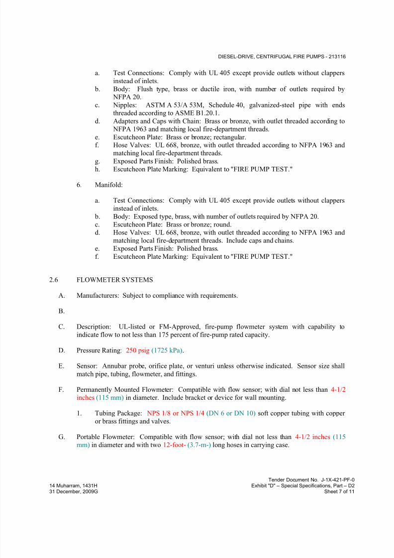
7/18/2019 SEC DPS
http://slidepdf.com/reader/full/sec-dps 140/541
DIESEL-DRIVE, CENTRIFUGAL FIRE PUMPS - 213116
Tender Document No. J-1X-421-PF-0
14 Muharram, 1431H Exhibit "D" – Special Specifications, Part – D231 December, 2009G Sheet 7 of 11
a. Test Connections: Comply with UL 405 except provide outlets without clappers
instead of inlets.
b. Body: Flush type, brass or ductile iron, with number of outlets required by
NFPA 20.c. Nipples: ASTM A 53/A 53M, Schedule 40, galvanized-steel pipe with ends
threaded according to ASME B1.20.1.
d. Adapters and Caps with Chain: Brass or bronze, with outlet threaded according to
NFPA 1963 and matching local fire-department threads.
e. Escutcheon Plate: Brass or bronze; rectangular.f. Hose Valves: UL 668, bronze, with outlet threaded according to NFPA 1963 and
matching local fire-department threads.
g. Exposed Parts Finish: Polished brass.
h. Escutcheon Plate Marking: Equivalent to "FIRE PUMP TEST."
6. Manifold:
a. Test Connections: Comply with UL 405 except provide outlets without clappers
instead of inlets.
b. Body: Exposed type, brass, with number of outlets required by NFPA 20.
c. Escutcheon Plate: Brass or bronze; round.
d. Hose Valves: UL 668, bronze, with outlet threaded according to NFPA 1963 and
matching local fire-department threads. Include caps and chains.
e. Exposed Parts Finish: Polished brass.
f. Escutcheon Plate Marking: Equivalent to "FIRE PUMP TEST."
2.6 FLOWMETER SYSTEMS
A. Manufacturers: Subject to compliance with requirements.
B.
C. Description: UL-listed or FM-Approved, fire-pump flowmeter system with capability to
indicate flow to not less than 175 percent of fire-pump rated capacity.
D. Pressure Rating: 250 psig (1725 kPa).
E. Sensor: Annubar probe, orifice plate, or venturi unless otherwise indicated. Sensor size shall
match pipe, tubing, flowmeter, and fittings.
F. Permanently Mounted Flowmeter: Compatible with flow sensor; with dial not less than 4-1/2inches (115 mm) in diameter. Include bracket or device for wall mounting.
1. Tubing Package: NPS 1/8 or NPS 1/4 (DN 6 or DN 10) soft copper tubing with copper
or brass fittings and valves.
G. Portable Flowmeter: Compatible with flow sensor; with dial not less than 4-1/2 inches (115
mm) in diameter and with two 12-foot- (3.7-m-) long hoses in carrying case.

7/18/2019 SEC DPS
http://slidepdf.com/reader/full/sec-dps 141/541
DIESEL-DRIVE, CENTRIFUGAL FIRE PUMPS - 213116
Tender Document No. J-1X-421-PF-0
14 Muharram, 1431H Exhibit "D" – Special Specifications, Part – D231 December, 2009G Sheet 8 of 11
2.7 GROUT
A. Standard: ASTM C 1107, Grade B, post-hardening and volume-adjusting, dry, hydraulic-
cement grout.
B. Characteristics: Nonshrink and recommended for interior and exterior applications.
C. Design Mix: 5000-psi (34-MPa), 28-day compressive strength.
D. Packaging: Premixed and factory packaged.
2.8 SOURCE QUALITY CONTROL
A. Testing: Test and inspect fire pumps according to UL 448 requirements for "Operation Test"
and "Manufacturing and Production Tests."
1. Verification of Performance: Rate fire pumps according to UL 448.
B. Fire pumps will be considered defective if they do not pass tests and inspections.
C. Prepare test and inspection reports.
PART 3 - EXECUTION
3.1 EXAMINATION
A. Examine equipment bases and anchorage provisions, with Installer present, for compliance with
requirements and for conditions affecting performance of fire pumps.
B. Examine roughing-in for fire-suppression piping systems to verify actual locations of piping
connections before fire-pump installation.
C. Proceed with installation only after unsatisfactory conditions have been corrected.
3.2 INSTALLATION
A. Fire-Pump Installation Standard: Comply with NFPA 20 for installation of fire pumps, reliefvalves, and related components.
B. Equipment Mounting: Install fire pumps on concrete bases. Comply with requirements for
concrete bases specified in Division 03
1. Install dowel rods to connect concrete base to concrete floor. Unless otherwise indicated,
install dowel rods on 18-inch (450-mm) centers around the full perimeter of concrete
base.
2. For supported equipment, install epoxy-coated anchor bolts that extend through concrete
base and anchor into structural concrete floor.

7/18/2019 SEC DPS
http://slidepdf.com/reader/full/sec-dps 142/541
DIESEL-DRIVE, CENTRIFUGAL FIRE PUMPS - 213116
Tender Document No. J-1X-421-PF-0
14 Muharram, 1431H Exhibit "D" – Special Specifications, Part – D231 December, 2009G Sheet 9 of 11
3. Place and secure anchorage devices. Use setting drawings, templates, diagrams,
instructions, and directions furnished with items to be embedded.
4. Install anchor bolts to elevations required for proper attachment to supported equipment.
C. Install fire-pump suction and discharge piping equal to or larger than sizes required by
NFPA 20.
D. Support piping and pumps separately so weight of piping does not rest on pumps.
E. Install valves that are same size as connecting piping. Comply with requirements for fire-
protection valves
F. Install pressure gages on fire-pump suction and discharge flange pressure-gage tappings.
Comply with requirements for pressure gages
G. Install piping hangers and supports, anchors, valves, gages, and equipment supports accordingto NFPA 20.
H. Install fuel system according to NFPA 20.
I. Install water supply and drain piping for diesel-engine heat exchangers. Extend drain pipingfrom heat exchangers to point of disposal.
J. Install exhaust-system piping for diesel engines. Extend to point of termination outside
structure. Install pipe and fittings with welded joints; install components having flanged
connections with gasketed joints.
K. Install condensate-drain piping for diesel-engine exhaust system. Extend drain piping from low points of exhaust system to condensate traps and to point of disposal.
L. Install flowmeters and sensors. Install flowmeter-system components and make connections
according to NFPA 20 and manufacturer's written instructions.
M. Electrical Wiring: Install electrical devices furnished by equipment manufacturers but not
factory mounted. Furnish copies of manufacturers' wiring diagram submittals to electrical
Installer.
N. Wiring Method: Conceal conductors and cables in accessible ceilings, walls, and floors where
possible.
3.3 ALIGNMENT
A. Align end-suction and split-case pump and driver shafts after complete unit has been leveled on
concrete base, grout has set, and anchor bolts have been tightened.
B. After alignment is correct, tighten anchor bolts evenly. Fill baseplate completely with grout,
with metal blocks and shims or wedges in place. Tighten anchor bolts after grout has hardened.
Check alignment and make required corrections.
C. Align piping connections.

7/18/2019 SEC DPS
http://slidepdf.com/reader/full/sec-dps 143/541
DIESEL-DRIVE, CENTRIFUGAL FIRE PUMPS - 213116
Tender Document No. J-1X-421-PF-0
14 Muharram, 1431H Exhibit "D" – Special Specifications, Part – D231 December, 2009G Sheet 10 of 11
D. Align pump and driver shafts for angular and parallel alignment according to HI 1.4 and to
tolerances specified by manufacturer.
3.4 CONNECTIONS
A. Comply with requirements for piping and valves .Drawings indicate general arrangement of
piping, fittings, and specialties.
B. Install piping adjacent to pumps and equipment to allow service and maintenance.
C. Connect relief-valve discharge to drainage piping or point of discharge.
D. Connect flowmeter-system meters, sensors, and valves to tubing.
E. Connect fire pumps to their controllers.
3.5 IDENTIFICATION
A. Identify system components. Comply with requirements for fire-pump marking according to
NFPA 20.
3.6 FIELD QUALITY CONTROL
A. Test each fire pump with its controller as a unit. Comply with requirements for diesel-engine-
driver fire-pump controllers specified in Division 21 Section "Controllers for Fire-Pump
Drivers."
B. Manufacturer's Field Service: Engage a factory-authorized service representative to inspect,
test, and adjust components, assemblies, and equipment installations, including connections.
C. Perform tests and inspections.
1. Manufacturer's Field Service: Engage a factory-authorized service representative to
inspect components, assemblies, and equipment installations, including connections, and
to assist in testing.
D. Tests and Inspections:
1. After installing components, assemblies, and equipment including controller, test for
compliance with requirements.
2. Test according to NFPA 20 for acceptance and performance testing.
3. Leak Test: After installation, charge system and test for leaks. Repair leaks and retest
until no leaks exist.
4. Operational Test: After electrical circuitry has been energized, start units to confirm
proper motor rotation and unit operation.
5. Test and adjust controls and safeties. Replace damaged and malfunctioning controls and
equipment.
7/18/2019 SEC DPS
http://slidepdf.com/reader/full/sec-dps 144/541
DIESEL-DRIVE, CENTRIFUGAL FIRE PUMPS - 213116
Tender Document No. J-1X-421-PF-0
14 Muharram, 1431H Exhibit "D" – Special Specifications, Part – D231 December, 2009G Sheet 11 of 11
E. Components, assemblies, and equipment will be considered defective if they do not pass tests
and inspections.
F. Prepare test and inspection reports.
G. Furnish fire hoses in number, size, and length required to reach storm drain or other acceptable
location to dispose of fire-pump test water. Hoses are for tests only and do not convey to
Owner.
3.7 STARTUP SERVICE
A. Engage a factory-authorized service representative to perform startup service.
1. Complete installation and startup checks according to manufacturer's written instructions.
3.8 DEMONSTRATION
A. Engage a factory-authorized service representative to train Owner's maintenance personnel to
adjust, operate, and maintain fire pumps.
END OF SECTION 213116

7/18/2019 SEC DPS
http://slidepdf.com/reader/full/sec-dps 145/541
PRESSURE-MAINTENANCE PUMPS - 213400
Tender Document No. J-1X-421-PF-0
14 Muharram, 1431H Exhibit "D" – Special Specifications, Part – D231 December, 2009G Sheet 1 of 4
SECTION 213400 - PRESSURE-MAINTENANCE PUMPS
PART 1 - GENERAL
1.1 RELATED DOCUMENTS
A. Drawings and general provisions of the Contract, including General and Supplementary
Conditions and Division 01 Specification Sections, apply to this Section.
1.2 SUMMARY
A. Section Includes:
1. Multistage, pressure-maintenance pumps.
1.3 PERFORMANCE REQUIREMENTS
A. Pump Equipment, Accessory, and Specialty Pressure Rating: 250 psig (1725 kPa) minimum
unless higher pressure rating is indicated.
B.
1.4 ACTION SUBMITTALS
A. Product Data: For each type of product indicated. Include rated capacities, operating
characteristics, performance curves, electrical characteristics, and furnished specialties and
accessories.
B. Shop Drawings: For pumps, accessories, and specialties. Include plans, elevations, sections,
details, and attachments to other work.
1. Detail equipment assemblies and indicate dimensions, weights, loads, requiredclearances, method of field assembly, components, and location and size of each field
connection.
2. Wiring Diagrams: For power, signal, and control wiring.
1.5 INFORMATIONAL SUBMITTALS
A. Field quality-control reports.
7/18/2019 SEC DPS
http://slidepdf.com/reader/full/sec-dps 146/541
PRESSURE-MAINTENANCE PUMPS - 213400
Tender Document No. J-1X-421-PF-0
14 Muharram, 1431H Exhibit "D" – Special Specifications, Part – D231 December, 2009G Sheet 2 of 4
1.6 CLOSEOUT SUBMITTALS
A. Operation and Maintenance Data: For pumps to include in operation and maintenance manuals.
1.7 QUALITY ASSURANCE
A. Electrical Components, Devices, and Accessories: Listed and labeled as defined in NFPA 70,
by a qualified testing agency, and marked for intended location and application.
1.8 COORDINATION
A.
Coordinate sizes and locations of concrete bases with actual equipment provided.
PART 2 - PRODUCTS
2.1 MULTISTAGE, PRESSURE-MAINTENANCE PUMPS
A. Manufacturers: Subject to compliance with requirements.
B.
C. Description: Factory-assembled and -tested, multistage, barrel-type vertical pump as defined in
HI 2.1-2.2 and HI 2.3; designed for surface installation with pump and motor direct coupled andmounted vertically.
D. Pump Construction:
1. Barrel: Stainless steel.
2. Suction and Discharge Chamber: Cast iron with flanged inlet and outlet.
3. Pump Head/Motor Mount: Cast iron.
4. Impellers: Stainless steel, balanced, and keyed to shaft.
5. Pump Shaft: Stainless steel.
6. Seal: Mechanical type with carbon rotating face and silicon-carbide stationary seat.
7. Intermediate Chamber Bearings: Aluminum-oxide ceramic or bronze.
8. Chamber-Base Bearing: Tungsten carbide.9. O-Rings: EPDM or NBR.
E. Motor: Single speed with permanently lubricated ball bearings and rigidly mounted to pump
head. Comply with requirements in Division 21 Section "Common Motor Requirements for
Fire Suppression Equipment."
1. Power Cord: Factory-connected to motor for field connection to controller and at least 10
feet (3 m) long.
F. Nameplate: Permanently attached to pump and indicating capacity and characteristics.
7/18/2019 SEC DPS
http://slidepdf.com/reader/full/sec-dps 147/541
PRESSURE-MAINTENANCE PUMPS - 213400
Tender Document No. J-1X-421-PF-0
14 Muharram, 1431H Exhibit "D" – Special Specifications, Part – D231 December, 2009G Sheet 3 of 4
G. Characteristics:
1. Inlet Flange: Class 125.
2. Outlet Flange: Class 250.
2.2 MOTORS
A. Comply with NEMA designation, temperature rating, service factor, enclosure type, and
efficiency requirements for motors specified in Division 21 Section "Common Motor
Requirements for Fire Suppression Equipment."
1. Motor Sizes: Minimum size as indicated; if not indicated, large enough so driven load
will not require motor to operate in service factor range above 1.0.
2. Electrical Devices, and Wiring: Comply with requirements for electrical devices and
connections specified in Division 26 Sections.
PART 3 - EXECUTION
3.1 EQUIPMENT INSTALLATION
A. NFPA Standard: Comply with NFPA 20 for installation of pressure-maintenance pumps.
B. Base-Mounted Pump Mounting: Install pumps on concrete bases. Comply with requirements
for concrete bases specified in Division 03
1. Install dowel rods to connect concrete base to concrete floor. Unless otherwise indicated,
install dowel rods on 18-inch (450-mm) centers around the full perimeter of concrete base.
2. For supported equipment, install epoxy-coated anchor bolts that extend through concrete
base and anchor into structural concrete floor.
3. Place and secure anchorage devices. Use setting drawings, templates, diagrams,
instructions, and directions furnished with items to be embedded.
4. Install anchor bolts to elevations required for proper attachment to supported equipment.
5. Attach pumps to equipment base using anchor bolts.
C. Install multistage, pressure-maintenance pumps according to HI 1.4.
3.2 FIELD QUALITY CONTROL
A. Manufacturer's Field Service: Engage a factory-authorized service representative to inspect,
test, and adjust components, assemblies, and equipment installations, including connections.
B. Perform tests and inspections.
1. Manufacturer's Field Service: Engage a factory-authorized service representative to
inspect components, assemblies, and equipment installations, including connections, and
to assist in testing.

7/18/2019 SEC DPS
http://slidepdf.com/reader/full/sec-dps 148/541
PRESSURE-MAINTENANCE PUMPS - 213400
Tender Document No. J-1X-421-PF-0
14 Muharram, 1431H Exhibit "D" – Special Specifications, Part – D231 December, 2009G Sheet 4 of 4
C. Tests and Inspections:
1. Operational Test: After electrical circuitry has been energized, start units to confirm
proper motor rotation and unit operation.2. Test and adjust controls and safeties. Replace damaged and malfunctioning controls and
equipment.
D. Pressure-maintenance pumps will be considered defective if they do not pass tests and
inspections.
E. Prepare test and inspection reports.
3.3 ADJUSTING
A. Lubricate pumps as recommended by manufacturer.
Set field-adjustable pressure-switch ranges as indicated.
END OF SECTION 213400

7/18/2019 SEC DPS
http://slidepdf.com/reader/full/sec-dps 149/541
CONTROLLERS FOR FIRE-PUMP DRIVERS - 213900
Tender Document No. J-1X-421-PF-0
14 Muharram, 1431H Exhibit "D" – Special Specifications, Part – D231 December, 2009G Sheet 1 of 15
SECTION 213900 - CONTROLLERS FOR FIRE-PUMP DRIVERS
PART 1 - GENERAL
1.1 RELATED DOCUMENTS
A. Drawings and general provisions of the Contract, including General and Supplementary
Conditions and Division 01 Specification Sections, apply to this Section.
1.2 SUMMARY
A. Section Includes:
1. Full-service, full-voltage controllers rated 600 V and less.
2. Controllers for diesel-drive fire pumps.3. Remote alarm panels.
4. Low-suction-shutdown panels.
1.3 DEFINITIONS
A. ATS: Automatic transfer switch(es).
B. ECM: Electronic control module.
C. MCCB: Molded-case circuit breaker.
D. N.O.: Normally open.
1.4 PERFORMANCE REQUIREMENTS
A. Seismic Performance: Fire-pump controllers and alarm panels shall withstand the effects of
earthquake motions determined according to UBC 1997, Zone 2A.
1. The term "withstand" means "the unit will remain in place without separation of any parts
from the device when subjected to the seismic forces specified and the unit will be fullyoperational after the seismic event."

7/18/2019 SEC DPS
http://slidepdf.com/reader/full/sec-dps 150/541
CONTROLLERS FOR FIRE-PUMP DRIVERS - 213900
Tender Document No. J-1X-421-PF-0
14 Muharram, 1431H Exhibit "D" – Special Specifications, Part – D231 December, 2009G Sheet 2 of 15
1.5 ACTION SUBMITTALS
A. Product Data: For each type of product indicated. Include rated capacities, operating
characteristics, electrical characteristics, and furnished specialties and accessories.
B. Shop Drawings: For each type of product indicated. Include dimensioned plans, elevations,
sections, details, and attachments to other work, including required clearances and service
spaces around controller enclosures.
1. Show tabulations of the following:
a. Each installed unit's type and details.
b. Enclosure types and details for types other than NEMA 250, Type 2.
c. Factory-installed devices.
d. Nameplate legends.
e. Short-circuit current (withstand) rating of integrated unit.f. Features, characteristics, ratings, and factory settings of individual overcurrent
protective devices.
g. Specified modifications.
2. Detail equipment assemblies and indicate dimensions, weights, loads, method of field
assembly, components, and location and size of each field connection.
3. Schematic and Connection Diagrams: For power, signal, alarm, and control wiring and
for pressure-sensing tubing.
1.6 INFORMATIONAL SUBMITTALS
A. Qualification Data: For qualified testing agency.
B. Seismic Qualification Certificates: For each type of product indicated, from manufacturer.
1. Basis for Certification: Indicate whether withstand certification is based on actual test ofassembled components or on calculation.
2. Dimensioned Outline Drawings of Equipment Unit: Identify center of gravity and locate
and describe mounting and anchorage provisions.
3. Detailed description of equipment anchorage devices on which the certification is based
and their installation requirements.
C. Product Certificates: For each type of product indicated, from manufacturer.
D. Manufacturer's factory test reports of fully assembled and tested equipment.
E. Source quality-control reports.
F. Field quality-control reports.

7/18/2019 SEC DPS
http://slidepdf.com/reader/full/sec-dps 151/541
CONTROLLERS FOR FIRE-PUMP DRIVERS - 213900
Tender Document No. J-1X-421-PF-0
14 Muharram, 1431H Exhibit "D" – Special Specifications, Part – D231 December, 2009G Sheet 3 of 15
1.7 CLOSEOUT SUBMITTALS
A. Operation and Maintenance Data: For each type of product indicated to include in emergency,
operation, and maintenance manuals. In addition to items specified in Division 01 Section
"Operation and Maintenance Data," include the following:
1. Manufacturer's written instructions for setting field-adjustable timers, controls, and status
and alarm points.
2. Manufacturer's written instructions for testing, adjusting, and reprogramming
microprocessor-based logic controls.
1.8 MAINTENANCE MATERIAL SUBMITTALS
A. Furnish extra materials that match products installed and that are packaged with protective
covering for storage and identified with labels describing contents.
1. Indicating Lights: Two of each type and color of lens installed; two of each type and size
of lamp installed.2. Auxiliary Contacts: One for each size and type of magnetic contactor installed.
3. Power Contacts: Three for each size and type of magnetic contactor installed.
4. Contactor Coils: One for each size and type of magnetic controller installed.
5. Relay Boards: One for each size and type of relay board installed.
6. Operator Interface: One microprocessor board(s), complete with display and membranekeypad.
1.9 QUALITY ASSURANCE
A. Testing Agency Qualifications: Member company of an NRTL.
B. Source Limitations: Obtain fire-pump controllers and all associated equipment from single
source or producer.
C. Electrical Components, Devices, and Accessories: Listed and labeled as defined in NFPA 70, by a qualified testing agency, and marked for intended location and application.
D. Comply with standards of authorities having jurisdiction pertaining to materials and installation.
E. Comply with NFPA 20 and NFPA 70.
F. IEEE Compliance: Fabricate and test enclosed controllers according to IEEE 344 to withstand
seismic forces defined in Division 26 Section "Vibration and Seismic Controls for Electrical
Systems."

7/18/2019 SEC DPS
http://slidepdf.com/reader/full/sec-dps 152/541
CONTROLLERS FOR FIRE-PUMP DRIVERS - 213900
Tender Document No. J-1X-421-PF-0
14 Muharram, 1431H Exhibit "D" – Special Specifications, Part – D231 December, 2009G Sheet 4 of 15
1.10 DELIVERY, STORAGE, AND HANDLING
A. Store controllers indoors in clean, dry space with uniform temperature to prevent condensation.
Protect enclosed controllers from exposure to dirt, fumes, water, corrosive substances, and physical damage.
B. If stored in areas subject to weather, protect controllers from weather, dirt, dust, corrosive
substances, and physical damage. Remove loose packing and flammable materials from inside
controllers;
1.11 PROJECT CONDITIONS
A. Environmental Limitations:
1. Ambient Temperature Rating: Not less than 40 deg F (5 deg C) and not exceeding 132deg F (55 deg C) unless otherwise indicated.
2. Altitude Rating: Not exceeding 6600 feet (2010 m) unless otherwise indicated.
B. Interruption of Existing Electric Service: Notify Owner no fewer than seven days in advance of
proposed interruption of electric service, and comply with NFPA 70E.
1.12 COORDINATION
A. Coordinate layout and installation of controllers with other construction including conduit,
piping, fire-pump equipment, and adjacent surfaces. Maintain required clearances for
workspace and equipment access doors and panels. Ensure that controllers are within sight of
fire-pump drivers.
B. Coordinate sizes and locations of concrete bases with actual equipment provided.
C.
PART 2 - PRODUCTS
2.1 FULL-SERVICE CONTROLLERS
A. Manufacturers: Subject to compliance with requirements.
B.
C. General Requirements for Full-Service Controllers:
1. Comply with NFPA 20 and UL 218.
2. Listed by an NRTL for electric-motor driver for fire-pump service.
3. Combined automatic and nonautomatic operation.
4. Factory assembled, wired, and tested; continuous-duty rated.
5. Service Equipment Label: NRTL labeled for use as service equipment.

7/18/2019 SEC DPS
http://slidepdf.com/reader/full/sec-dps 153/541
CONTROLLERS FOR FIRE-PUMP DRIVERS - 213900
Tender Document No. J-1X-421-PF-0
14 Muharram, 1431H Exhibit "D" – Special Specifications, Part – D231 December, 2009G Sheet 5 of 15
D. Method of Starting:
1. Pressure-switch actuated.
a. Water-pressure-actuated switch and pressure transducer with independent high-
and low-calibrated adjustments responsive to water pressure in fire-suppression
piping.
b. System pressure recorder, electric ac driven, with spring backup.
c. Programmable minimum-run-time relay to prevent short cycling.
d. Programmable timer for weekly tests.
2. Magnetic Controller: Autotransformer type.
3. Solid-State Controller: Reduced-voltage type.
4. Emergency Start: Mechanically operated start handle that closes and retains the motor
RUN contactor independent of all electric or pressure actuators.
E. Method of Stopping: Automatic and nonautomatic shutdown after automatic starting.
F. Capacity: Rated for fire-pump-driver horsepower and short-circuit-current (withstand) rating
equal to or greater than short-circuit current available at controller location.
G. Method of Isolation and Overcurrent Protection: Interlocked isolating switch and nonthermal
MCCB; with a common, externally mounted operating handle, and providing locked-rotor
protection.
H. Door-Mounted Operator Interface and Controls:
1. Monitor, display, and control the devices, alarms, functions, and operations listed in
NFPA 20 as required for drivers and controller types used.
2. Method of Control and Indication:
a. Microprocessor-based logic controller, with multiline digital readout.
b. LED alarm and status indicating lights.
3. Local and Remote Alarm and Status Indications:
a. Controller power on.
b. Motor running condition.
c. Loss-of-line power.
d. Line-power phase reversal.
e. Line-power single-phase condition.
4. Audible alarm, with silence push button.
5. Nonautomatic START and STOP push buttons or switches.
I. Optional Features:
1. Extra Output Contacts:
a. One N.O. contact(s) for motor running condition.
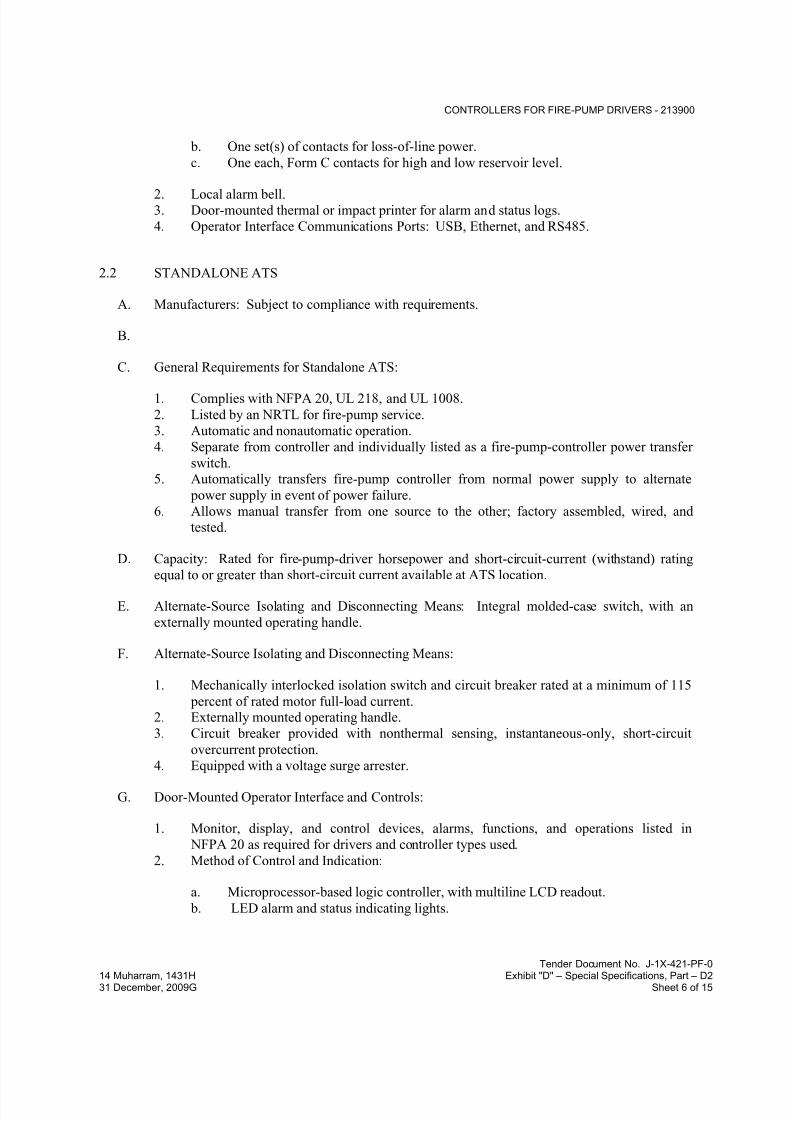
7/18/2019 SEC DPS
http://slidepdf.com/reader/full/sec-dps 154/541
CONTROLLERS FOR FIRE-PUMP DRIVERS - 213900
Tender Document No. J-1X-421-PF-0
14 Muharram, 1431H Exhibit "D" – Special Specifications, Part – D231 December, 2009G Sheet 6 of 15
b. One set(s) of contacts for loss-of-line power.
c. One each, Form C contacts for high and low reservoir level.
2. Local alarm bell.3. Door-mounted thermal or impact printer for alarm and status logs.
4. Operator Interface Communications Ports: USB, Ethernet, and RS485.
2.2 STANDALONE ATS
A. Manufacturers: Subject to compliance with requirements.
B.
C. General Requirements for Standalone ATS:
1. Complies with NFPA 20, UL 218, and UL 1008.
2. Listed by an NRTL for fire-pump service.
3. Automatic and nonautomatic operation.
4. Separate from controller and individually listed as a fire-pump-controller power transfer
switch.5. Automatically transfers fire-pump controller from normal power supply to alternate
power supply in event of power failure.
6. Allows manual transfer from one source to the other; factory assembled, wired, and
tested.
D. Capacity: Rated for fire-pump-driver horsepower and short-circuit-current (withstand) rating
equal to or greater than short-circuit current available at ATS location.
E. Alternate-Source Isolating and Disconnecting Means: Integral molded-case switch, with an
externally mounted operating handle.
F. Alternate-Source Isolating and Disconnecting Means:
1. Mechanically interlocked isolation switch and circuit breaker rated at a minimum of 115
percent of rated motor full-load current.2. Externally mounted operating handle.
3. Circuit breaker provided with nonthermal sensing, instantaneous-only, short-circuit
overcurrent protection.
4. Equipped with a voltage surge arrester.
G. Door-Mounted Operator Interface and Controls:
1. Monitor, display, and control devices, alarms, functions, and operations listed in
NFPA 20 as required for drivers and controller types used.
2. Method of Control and Indication:
a. Microprocessor-based logic controller, with multiline LCD readout.
b. LED alarm and status indicating lights.
7/18/2019 SEC DPS
http://slidepdf.com/reader/full/sec-dps 155/541
CONTROLLERS FOR FIRE-PUMP DRIVERS - 213900
Tender Document No. J-1X-421-PF-0
14 Muharram, 1431H Exhibit "D" – Special Specifications, Part – D231 December, 2009G Sheet 7 of 15
3. Local and Remote Alarm and Status Indications:
a. Normal source available.
b. Alternate source available.c. In normal position.
d. In alternate position.
e. Isolating means open.
4. Audible alarm, with silence push button.
5. Nonautomatic (manual, nonelectric) means of transfer.
6. Engine test push button.
7. Start generator output contacts.
8. Timer for weekly generator tests
H. Optional Features:
1. Extra Output Contacts:
a. One each, Form A; isolating means open.
b. One each, Form C; in normal or alternate position
2. Door-mounted thermal or impact printer for alarm and status logs.
3. Operator Interface Communications Ports: USB, Ethernet, and RS485.
2.3 CONTROLLERS FOR DIESEL-DRIVE FIRE PUMPS
A. Manufacturers: Subject to compliance with requirements.
B.
C. General Requirements for Controllers:
1. Comply with NFPA 20 and UL 218.
2. Listed by an NRTL for diesel-engine driver for fire-pump service.
3. Combined automatic and nonautomatic operation.
4. Factory assembled, wired, and tested.
D. Method of Starting:
1. Pressure-switch actuated.
a. Water-pressure-actuated switch and pressure transducer with independent high-
and low-calibrated adjustments responsive to water pressure in fire-suppression
piping.
b. System pressure recorder, electric ac driven, with spring backup.
c. Programmable minimum-run-time relay to prevent short cycling.
d. Programmable timer for weekly tests.
2. Dual, redundant dc-voltage battery units, with automatic changeover.
7/18/2019 SEC DPS
http://slidepdf.com/reader/full/sec-dps 156/541
CONTROLLERS FOR FIRE-PUMP DRIVERS - 213900
Tender Document No. J-1X-421-PF-0
14 Muharram, 1431H Exhibit "D" – Special Specifications, Part – D231 December, 2009G Sheet 8 of 15
3. Emergency Control: Bypasses all automatic control circuits during manual starting and
running.
4. Automatic engine start on loss of ac power to the controller.
E. Method of Stopping: Automatic and nonautomatic shutdown after automatic starting.
F. Door-Mounted Operator Interface and Controls:
1. Monitor, display, and control devices, alarms, functions, and operations listed in
NFPA 20 as required for drivers and controller types used.
2. Method of Control and Indication:
a. Microprocessor-based logic controller, with multiline LCD readout.
b. LED alarm and status indicating lights.
3. Local and Remote Alarm and Status Indications:
a. Controller power on.
b. Engine-lubrication-system critically low oil pressure.
c. Engine-jacket coolant high temperature.
d. Engine fail-to-start.
e. Engine overspeed shutdown.
f. Low fuel level.
g. Missing or failed battery.
h. Battery charger failure.
i. System overpressure.
j. ECM selector switch in alternate ECM position.
k. Fuel injector malfunction.
4. Audible alarm.
5. Nonautomatic START and STOP push buttons or switches.
G. Optional Features:
1. Extra Output Contacts:
a. One Form C contacts for low pump-room temperature.
b. One each, Form C contacts for high and low fuel levels.
c. One each, Form C contacts for high and low reservoir levels.
2. Door-mounted thermal or impact printer for alarm and status logs.3. Operator Interface Communications Ports: USB, Ethernet, and RS485.
4. Powered louver contacts.
5. Powered engine-oil heater contacts.
H. Battery Charger System:
1. Built-in, independent, dual battery chargers with automatic changeover; 12-V dc for
nickel-cadmium batteries.2. Standard: UL 1236.

7/18/2019 SEC DPS
http://slidepdf.com/reader/full/sec-dps 157/541
CONTROLLERS FOR FIRE-PUMP DRIVERS - 213900
Tender Document No. J-1X-421-PF-0
14 Muharram, 1431H Exhibit "D" – Special Specifications, Part – D231 December, 2009G Sheet 9 of 15
2.4 REMOTE ALARM PANELS
A. General Requirements for Remote Alarm Panels: Comply with NFPA 20 and UL 218; listed by
an NRTL for fire-pump service.
B. Manufacturers: Subject to compliance with requirements.
C.
D. General Requirements for Remote Alarm Panels: Factory assembled, wired, and tested.
E. Supervisory and Normal Control Voltage: 220-V ac; single source.
F. Audible and Visual Alarm and Status Indications:
1. Driver running.2. Loss of phase.
3. Phase reversal.
4. Supervised power on.
5. Common trouble on the controller.
6. Controller connected to alternate power source.
G. Audible and Visual Alarm and Status Indications: Manufacturer's standard indicating lights;
push-to-test.
1. Engine running.
2. Controller main switch turned to the off or manual position.
3. Supervised power on.4. Common trouble on the controller or engine.
5. Common pump room trouble.
6. Controller connected to alternate power source.
H. Audible alarm, with silence push button.
I. Pump REMOTE START push button.
2.5 LOW-SUCTION-SHUTDOWN PANELS
A. Manufacturers: Subject to compliance with requirements.
B.
C. General Requirements for Low-Suction-Shutdown Panels:
1. Listed by an NRTL for fire-pump service.
2. Factory assembled, wired, and tested.
3. Prevents automatic start of fire pump, and shuts down automatically started fire pump, on
low-suction pressure.

7/18/2019 SEC DPS
http://slidepdf.com/reader/full/sec-dps 158/541
CONTROLLERS FOR FIRE-PUMP DRIVERS - 213900
Tender Document No. J-1X-421-PF-0
14 Muharram, 1431H Exhibit "D" – Special Specifications, Part – D231 December, 2009G Sheet 10 of 15
4. Automatic reset.
D. Operation: External contact input.
E. Supervisory and Normal Control Voltage: 220-V ac; single source.
F. Include audible and visual alarms and status indications, with silence push button, for the
following conditions:
1. Control power available.
2. Low-suction pressure.
3. Normal-suction pressure.
2.6 ENCLOSURES
A. Fire-Pump Controllers, ATS, Remote Alarm Panels, and Low-Suction-Shutdown Panels:
NEMA 250, to comply with environmental conditions at installed locations and NFPA 20.
1. Wet or Damp, Indoor Locations: Type 4 (IEC IP56).
B. Enclosure Color: Manufacturer's standard "fire-pump-controller red".
C. Nameplates: Comply with NFPA 20; complete with capacity, characteristics, approvals,listings, and other pertinent data.
D. Optional Features:
1. Floor stands, 12 inches (305 mm) high, for floor-mounted controllers.
2. Tropicalization.
2.7 SOURCE QUALITY CONTROL
A. Testing: Test and inspect fire-pump controllers according to requirements in NFPA 20 and
UL 218.
1. Verification of Performance: Rate controllers according to operation of functions and
features specified.
B. Fire-pump controllers will be considered defective if they do not pass tests and inspections.
C. Prepare test and inspection reports.
PART 3 - EXECUTION
3.1 EXAMINATION
A. Examine areas and surfaces to receive equipment, with Installer present, for compliance with
requirements and other conditions affecting performance.

7/18/2019 SEC DPS
http://slidepdf.com/reader/full/sec-dps 159/541
CONTROLLERS FOR FIRE-PUMP DRIVERS - 213900
Tender Document No. J-1X-421-PF-0
14 Muharram, 1431H Exhibit "D" – Special Specifications, Part – D231 December, 2009G Sheet 11 of 15
B. Examine equipment before installation. Reject equipment that is wet or damaged by moisture
or mold.
C. Proceed with installation only after unsatisfactory conditions have been corrected.
3.2 CONTROLLER INSTALLATION
A. Install controllers within sight of their respective drivers.
B. Connect controllers to their dedicated pressure-sensing lines.
C. Wall-Mounting Controllers: Install controllers on walls with disconnect operating handles not
higher than 79 inches (2006 mm) above finished floor, and bottom of enclosure not less than 12
inches (305 mm) above finished floor unless otherwise indicated. Bolt units to wall or mount
on lightweight structural-steel channels bolted to wall. For controllers not on walls, providefreestanding racks complying with Division 26 Section "Hangers and Supports for Electrical
Systems."
D. Floor-Mounting Controllers: Install controllers on 4-inch (100-mm) nominal-thickness concrete
bases, using floor stands high enough so that the bottom of enclosure cabinet is not less than 12inches (305 mm) above finished floor. Comply with requirements for concrete bases specified
in Division 03
1. Install dowel rods to connect concrete base to concrete floor. Unless otherwise indicated,
install dowel rods on 18-inch (450-mm) centers around the full perimeter of concrete
base.
2. For supported equipment, install epoxy-coated anchor bolts that extend through concrete
base, and anchor into structural concrete floor.
3. Place and secure anchorage devices. Use setting drawings, templates, diagrams,
instructions, and directions furnished with items to be embedded.
4. Install anchor bolts to elevations required for proper attachment to supported equipment.
E. Seismic Bracing: Comply with requirements specified in Division 26 Section "Vibration andSeismic Controls for Electrical Systems."
F. Temporary Lifting Provisions: Remove temporary lifting eyes, channels, and brackets and
temporary blocking of moving parts from enclosures and components.
G. Comply with NEMA ICS 15.
3.3 STANDALONE ATS INSTALLATION
A. Wall-Mounting ATS: Install ATS on walls with disconnect operating handles not higher than
79 inches (2006 mm) above finished floor, and bottom of enclosure not less than 12 inches (305
mm) above finished floor unless otherwise indicated. Bolt units to wall or mount on lightweight
structural-steel channels bolted to wall. For ATS not on walls, provide freestanding racks
complying with Division 26 Section "Hangers and Supports for Electrical Systems."

7/18/2019 SEC DPS
http://slidepdf.com/reader/full/sec-dps 160/541
CONTROLLERS FOR FIRE-PUMP DRIVERS - 213900
Tender Document No. J-1X-421-PF-0
14 Muharram, 1431H Exhibit "D" – Special Specifications, Part – D231 December, 2009G Sheet 12 of 15
B. Floor-Mounting ATS: Install ATS on 4-inch (100-mm) nominal-thickness concrete bases,
using floor stands high enough so that the bottom of enclosure cabinet is not less than 12 inches
(305 mm) above finished floor. Comply with requirements for concrete bases specified in
Division 03
1. Install dowel rods to connect concrete base to concrete floor. Unless otherwise indicated,
install dowel rods on 18-inch (450-mm) centers around the full perimeter of concrete
base.
2. For supported equipment, install epoxy-coated anchor bolts that extend through concrete
base, and anchor into structural concrete floor.
3. Place and secure anchorage devices. Use setting drawings, templates, diagrams,
instructions, and directions furnished with items to be embedded.
4. Install anchor bolts to elevations required for proper attachment to supported equipment.
C. Seismic Bracing: Comply with requirements specified in Division 26 Section "Vibration and
Seismic Controls for Electrical Systems."
D. Temporary Lifting Provisions: Remove temporary lifting eyes, channels, and brackets and
temporary blocking of moving parts from enclosures and components.
3.4 REMOTE ALARM AND LOW-SUCTION-SHUTDOWN PANEL INSTALLATION
A. Install panels on walls with tops not higher than 72 inches (1829 mm) above finished floor
unless otherwise indicated. Bolt units to wall or mount on lightweight structural-steel channels
bolted to wall. For ATS not on walls, provide freestanding racks complying with Division 26
Section "Hangers and Supports for Electrical Systems."
3.5 POWER WIRING INSTALLATION
A. Install power wiring between controllers and their services or sources, and between controllers
and their drivers. Comply with requirements in NFPA 20, NFPA 70, and Division 26 Section
"Low-Voltage Electrical Power Conductors and Cables."
3.6 CONTROL AND ALARM WIRING INSTALLATION
A. Install wiring between controllers and remote devices. Comply with requirements in NFPA 20,
NFPA 70, and Division 26 Section "Control-Voltage Electrical Power Cables."
B. Install wiring between remote alarm and low-suction-shutdown panels and controllers. Comply
with requirements in NFPA 20, NFPA 70, and Division 26 Section "Control-Voltage Electrical
Power Cables."
C. Install wiring between controllers and the building's fire-alarm system. Comply with
requirements specified in Division 28 Section "Digital, Addressable Fire-Alarm System."
D. Bundle, train, and support wiring in enclosures.

7/18/2019 SEC DPS
http://slidepdf.com/reader/full/sec-dps 161/541
CONTROLLERS FOR FIRE-PUMP DRIVERS - 213900
Tender Document No. J-1X-421-PF-0
14 Muharram, 1431H Exhibit "D" – Special Specifications, Part – D231 December, 2009G Sheet 13 of 15
E. Connect remote manual and automatic activation devices where applicable.
3.7 IDENTIFICATION
A. Comply with requirements in NFPA 20 for marking fire-pump controllers.
B. Identify system components, wiring, cabling, and terminals. Comply with requirements for
identification in NFPA 20 and as specified in Division 26 Section "Identification for Electrical
Systems."
3.8 FIELD QUALITY CONTROL
A. Testing Agency: Engage a qualified testing agency to perform tests and inspections.
B. Manufacturer's Field Service: Engage a factory-authorized service representative to inspect,
test, and adjust components, assemblies, and equipment installations, including connections.
C. Perform tests and inspections.
1. Manufacturer's Field Service: Engage a factory-authorized service representative to
inspect components, assemblies, and equipment installations, including connections, and
to assist in testing.
D. Acceptance Testing Preparation:
1. Inspect and Test Each Component:
a. Inspect wiring, components, connections, and equipment installations. Test and
adjust components and equipment.
b. Test insulation resistance for each element, component, connecting supply, feeder,
and control circuits.
c. Test continuity of each circuit.
2. Verify and Test Each Electric-Driver Controller:
a. Verify that voltages at controller locations are within plus 10 or minus 1 percent of
motor nameplate rated voltages, with motors off. If outside this range for any
motor, notify Construction Manager before starting the motor(s).
b. Test each motor for proper phase rotation.
3. Operational Test: After electrical circuitry has been energized, start units to confirm
proper unit operation.
4. Test and adjust controls and safeties. Replace damaged and malfunctioning controls and
equipment.
E. Field Acceptance Tests:

7/18/2019 SEC DPS
http://slidepdf.com/reader/full/sec-dps 162/541
CONTROLLERS FOR FIRE-PUMP DRIVERS - 213900
Tender Document No. J-1X-421-PF-0
14 Muharram, 1431H Exhibit "D" – Special Specifications, Part – D231 December, 2009G Sheet 14 of 15
1. Do not begin field acceptance testing until suction piping has been flushed and
hydrostatically tested and the certificate for flushing and testing has been submitted to
engineer and authorities having jurisdiction.
2. Prior to starting, notify authorities having jurisdiction of the time and place of theacceptance testing.
3. Engage manufacturer's factory-authorized service representative to be present during the
testing.
4. Perform field acceptance tests as outlined in NFPA 20.
F. Controllers will be considered defective if they do not pass tests and inspections.
G. Prepare test and inspection reports.
3.9 STARTUP SERVICE
A. Engage a factory-authorized service representative to perform startup service.
1. Complete installation and startup checks according to manufacturer's written instructions.
3.10 ADJUSTING
A. Adjust controllers and battery charger systems to function smoothly and as recommended by
manufacturer.
B. Set field-adjustable switches, auxiliary relays, time-delay relays, and timers.
C. Program microprocessors for required operational sequences, status indications, alarms, eventrecording, and display features. Clear events memory after final acceptance testing and prior to
Substantial Completion.
D. Set field-adjustable pressure switches.
3.11 PROTECTION
A. Temporary Heating: Apply temporary heat to maintain temperature according to manufacturer's
written instructions until enclosed controllers are ready to be energized and placed into service.
B. Replace controllers whose interiors have been exposed to water or other liquids prior toSubstantial Completion.
3.12 DEMONSTRATION
A. Engage a factory-authorized service representative to train Owner's maintenance personnel to
adjust, operate, and maintain controllers, remote alarm panels, low-suction-shutdown
panels, and to use and reprogram microprocessor-based controls within this equipment.

7/18/2019 SEC DPS
http://slidepdf.com/reader/full/sec-dps 163/541
CONTROLLERS FOR FIRE-PUMP DRIVERS - 213900
Tender Document No. J-1X-421-PF-0
14 Muharram, 1431H Exhibit "D" – Special Specifications, Part – D231 December, 2009G Sheet 15 of 15
END OF SECTION 213900

7/18/2019 SEC DPS
http://slidepdf.com/reader/full/sec-dps 164/541
COMMON MOTOR REQUIREMENTS FOR PLUMBING EQUIPMENT - 220513
Tender Document No. J-1X-421-PF-0
14 Muharram, 1431H Exhibit "D" – Special Specifications, Part – D231 December, 2009G Sheet 1 of 3
SECTION 220513 - COMMON MOTOR REQUIREMENTS FOR PLUMBING EQUIPMENT
PART 1 - GENERAL
1.1 RELATED DOCUMENTS
A. Drawings and general provisions of the Contract, including General and Supplementary
Conditions and Division 01 Specification Sections, apply to this Section.
1.2 SUMMARY
A. Section includes general requirements for single-phase and polyphase, general-purpose,
horizontal, small and medium, squirrel-cage induction motors for use on ac power systems up to
600 V and installed at equipment manufacturer's factory or shipped separately by equipmentmanufacturer for field installation.
1.3 COORDINATION
A. Coordinate features of motors, installed units, and accessory devices to be compatible with the
following:
1. Motor controllers.
2. Torque, speed, and horsepower requirements of the load.
3. Ratings and characteristics of supply circuit and required control sequence.4. Ambient and environmental conditions of installation location.
PART 2 - PRODUCTS
2.1 GENERAL MOTOR REQUIREMENTS
A. Comply with requirements in this Section except when stricter requirements are specified in
plumbing equipment schedules or Sections.
B. Comply with NEMA MG 1 unless otherwise indicated.
C. Comply with IEEE 841 for severe-duty motors.
2.2 MOTOR CHARACTERISTICS
A. Duty: Continuous duty at ambient temperature of 40 deg C and at sea level. Where exposed tooutside or ambient temperature, motors should withstand ambient temperatures up to 55 deg C
under operating conditions.
7/18/2019 SEC DPS
http://slidepdf.com/reader/full/sec-dps 165/541
COMMON MOTOR REQUIREMENTS FOR PLUMBING EQUIPMENT - 220513
Tender Document No. J-1X-421-PF-0
14 Muharram, 1431H Exhibit "D" – Special Specifications, Part – D231 December, 2009G Sheet 2 of 3
B. Capacity and Torque Characteristics: Sufficient to start, accelerate, and operate connected loads
at designated speeds, at installed altitude and environment, with indicated operating sequence,
and without exceeding nameplate ratings or considering service factor.
2.3 POLYPHASE MOTORS
A. Description: NEMA MG 1, Design B, medium induction motor.
B. Efficiency: Energy efficient, as defined in NEMA MG 1.
C. Service Factor: 1.15.
D. Multispeed Motors: Variable torque.
1. For motors with 2:1 speed ratio, consequent pole, single winding.2. For motors with other than 2:1 speed ratio, separate winding for each speed.
E. Multispeed Motors: Separate winding for each speed.
F. Rotor: Random-wound, squirrel cage.
G. Bearings: Regreasable, shielded, antifriction ball bearings suitable for radial and thrust loading.
H. Temperature Rise: Match insulation rating.
I. Insulation: Class F.
J. Code Letter Designation:
1. Motors 15 HP and Larger: NEMA starting Code F or Code G.
2. Motors Smaller than 15 HP: Manufacturer's standard starting characteristic.
K. Enclosure Material: Cast iron for motor frame sizes 324T and larger; rolled steel for motor
frame sizes smaller than 324T.
2.4 POLYPHASE MOTORS WITH ADDITIONAL REQUIREMENTS
A. Motors Used with Reduced-Voltage and Multispeed Controllers: Match wiring connection
requirements for controller with required motor leads. Provide terminals in motor terminal box,suited to control method.
B. Motors Used with Variable Frequency Controllers: Ratings, characteristics, and features
coordinated with and approved by controller manufacturer.
1. Windings: Copper magnet wire with moisture-resistant insulation varnish, designed and
tested to resist transient spikes, high frequencies, and short time rise pulses produced by
pulse-width modulated inverters.
2. Energy- and Premium-Efficient Motors: Class B temperature rise; Class F insulation.
3. Inverter-Duty Motors: Class F temperature rise; Class H insulation.

7/18/2019 SEC DPS
http://slidepdf.com/reader/full/sec-dps 166/541
COMMON MOTOR REQUIREMENTS FOR PLUMBING EQUIPMENT - 220513
Tender Document No. J-1X-421-PF-0
14 Muharram, 1431H Exhibit "D" – Special Specifications, Part – D231 December, 2009G Sheet 3 of 3
4. Thermal Protection: Comply with NEMA MG 1 requirements for thermally protected
motors.
C. Severe-Duty Motors: Comply with IEEE 841, with 1.15 minimum service factor.
2.5 SINGLE-PHASE MOTORS
A. Motors larger than 1/20 hp shall be one of the following, to suit starting torque and
requirements of specific motor application:
1. Permanent-split capacitor.
2. Split phase.
3. Capacitor start, inductor run.
4. Capacitor start, capacitor run.
B. Multispeed Motors: Variable-torque, permanent-split-capacitor type.
C. Bearings: Prelubricated, antifriction ball bearings or sleeve bearings suitable for radial and
thrust loading.
D. Motors 1/20 HP and Smaller: Shaded-pole type.
E. Thermal Protection: Internal protection to automatically open power supply circuit to motor
when winding temperature exceeds a safe value calibrated to temperature rating of motor
insulation. Thermal-protection device shall automatically reset when motor temperature returns
to normal range.
PART 3 - EXECUTION (Not Applicable)
END OF SECTION 220513

7/18/2019 SEC DPS
http://slidepdf.com/reader/full/sec-dps 167/541
EXPANSION FITTINGS AND LOOPS FOR PLUMBING PIPING - 220516
Tender Document No. J-1X-421-PF-0
14 Muharram, 1431H Exhibit "D" – Special Specifications, Part – D231 December, 2009G Sheet 1 of 6
SECTION 220516 - EXPANSION FITTINGS AND LOOPS FOR PLUMBING PIPING
PART 1 - GENERAL
1.1 RELATED DOCUMENTS
A. Drawings and general provisions of the Contract, including General and Supplementary
Conditions and Division 01 Specification Sections, apply to this Section.
1.2 SUMMARY
A. Section Includes:
1. Flexible-hose packless expansion joints.
2. Metal-bellows packless expansion joints.3. Rubber packless expansion joints.
4. Grooved-joint expansion joints.
5. Pipe loops and swing connections.
6. Alignment guides and anchors.
1.3 PERFORMANCE REQUIREMENTS
A. Compatibility: Products shall be suitable for piping service fluids, materials, working pressures,
and temperatures.
B. Capability: Products to absorb 200 percent of maximum axial movement between anchors.
1.4 ACTION SUBMITTALS
A. Product Data: For each type of product indicated.
B. Delegated-Design Submittal: For each anchor and alignment guide indicated to comply with
performance requirements and design criteria, including analysis data signed and sealed by the
qualified professional engineer responsible for their preparation.
1. Design Calculations: Calculate requirements for thermal expansion of piping systems
and for selecting and designing expansion joints, loops, and swing connections.
2. Anchor Details: Detail fabrication of each anchor indicated. Show dimensions and
methods of assembly and attachment to building structure.
3. Alignment Guide Details: Detail field assembly and attachment to building structure.
4. Schedule: Indicate type, manufacturer's number, size, material, pressure rating, end
connections, and location for each expansion joint.

7/18/2019 SEC DPS
http://slidepdf.com/reader/full/sec-dps 168/541
EXPANSION FITTINGS AND LOOPS FOR PLUMBING PIPING - 220516
Tender Document No. J-1X-421-PF-0
14 Muharram, 1431H Exhibit "D" – Special Specifications, Part – D231 December, 2009G Sheet 2 of 6
1.5 INFORMATIONAL SUBMITTALS
A. Welding certificates.
B. Product Certificates: For each type of expansion joint, from manufacturer.
1.6 CLOSEOUT SUBMITTALS
A. Maintenance Data: For expansion joints to include in maintenance manuals.
1.7 QUALITY ASSURANCE
A. Welding Qualifications: Qualify procedures and personnel according to the following:
1. AWS D1.1/D1.1M, "Structural Welding Code - Steel."
2. ASME Boiler and Pressure Vessel Code: Section IX.
PART 2 - PRODUCTS
2.1 PACKLESS EXPANSION JOINTS
A. Flexible-Hose Packless Expansion Joints:
1. Manufacturers: Subject to compliance with requirements
2. Basis-of-Design Product: Subject to compliance with requirements
3. Description: Manufactured assembly with inlet and outlet elbow fittings and two
flexible-metal-hose legs joined by long-radius, 180-degree return bend or center section
of flexible hose.
4. Flexible Hose: Corrugated-metal inner hoses and braided outer sheaths.
5. Expansion Joints for Copper Tubing NPS 2 (DN 50) and Smaller: Copper-alloy fittings
with solder-joint end connections.
a. Bronze hoses and single-braid bronze sheaths with 450 psig at 70 deg F (3100 kPa
at 21 deg C) and 340 psig at 450 deg F (2340 kPa at 232 deg C) ratings.
b. Bronze hoses and double-braid bronze sheaths with 700 psig at 70 deg F (4830 kPaat 21 deg C) and 500 psig at 450 deg F (3450 kPa at 232 deg C) ratings.
6. Expansion Joints for Copper Tubing NPS 2-1/2 to NPS 4 (DN 65 to DN 100): Copper-
alloy fittings with threaded end connections.
a. Stainless-steel hoses and single-braid, stainless-steel sheaths with 300 psig at 70
deg F (2070 kPa at 21 deg C) and 225 psig at 450 deg F (1550 kPa at 232 deg C)
ratings.

7/18/2019 SEC DPS
http://slidepdf.com/reader/full/sec-dps 169/541
EXPANSION FITTINGS AND LOOPS FOR PLUMBING PIPING - 220516
Tender Document No. J-1X-421-PF-0
14 Muharram, 1431H Exhibit "D" – Special Specifications, Part – D231 December, 2009G Sheet 3 of 6
b. Stainless-steel hoses and double-braid, stainless-steel sheaths with 420 psig at 70
deg F (2890 kPa at 21 deg C) and 315 psig at 450 deg F (2170 kPa at 232 deg C)
ratings.
7. Expansion Joints for Steel Piping NPS 2 (DN 50) and Smaller: Stainless-steel fittings
with threaded end connections.
a. Stainless-steel hoses and single-braid, stainless-steel sheaths with 450 psig at 70
deg F (3100 kPa at 21 deg C) and 325 psig at 600 deg F (2250 kPa at 315 deg C)
ratings.
b. Stainless-steel hoses and double-braid, stainless-steel sheaths with 700 psig at 70
deg F (4830 kPa at 21 deg C) and 515 psig at 600 deg F (3550 kPa at 315 deg C)
ratings.
8. Expansion Joints for Steel Piping NPS 2-1/2 to NPS 6 (DN 65 to DN 150): Stainless-
steel fittings with flanged end connections.
a. Stainless-steel hoses and single-braid, stainless-steel sheaths with 200 psig at 70
deg F (1380 kPa at 21 deg C) and 145 psig at 600 deg F (1000 kPa at 315 deg C)
ratings.
b. Stainless-steel hoses and double-braid, stainless-steel sheaths with 275 psig at 70
deg F (1900 kPa at 21 deg C) and 200 psig at 600 deg F (1380 kPa at 315 deg C)
ratings.
9. Expansion Joints for Steel Piping NPS 8 to NPS 12 (DN 200 to DN 300): Stainless-steel
fittings with flanged end connections.
a. Stainless-steel hoses and single-braid, stainless-steel sheaths with 125 psig at 70deg F (860 kPa at 21 deg C) and 90 psig at 600 deg F (625 kPa at 315 deg C)
ratings.
b. Stainless-steel hoses and double-braid, stainless-steel sheaths with 165 psig at 70
deg F (1130 kPa at 21 deg C) and 120 psig at 600 deg F (830 kPa at 315 deg C)
ratings.
B. Metal-Bellows Packless Expansion Joints:
1. Manufacturers: Subject to compliance with requirements
2. Basis-of-Design Product: Subject to compliance with requirements
3. Standards: ASTM F 1120 and EJMA's "Standards of the Expansion Joint Manufacturers
Association, Inc."
4. Type: Circular, corrugated bellows with external tie rods.
5. Minimum Pressure Rating: 150 psig (1035 kPa) unless otherwise indicated.
6. Configuration: Single joint with base and double joint with base class(es) unless
otherwise indicated.
7. Expansion Joints for Copper Tubing: Single- or multi-ply phosphor-bronze bellows,
copper pipe ends, and brass shrouds.
a. End Connections for Copper Tubing NPS 2 (DN 50) and Smaller: threaded.
b. End Connections for Copper Tubing NPS 2-1/2 to NPS 4 (DN 65 to DN 100):
threaded.

7/18/2019 SEC DPS
http://slidepdf.com/reader/full/sec-dps 170/541
EXPANSION FITTINGS AND LOOPS FOR PLUMBING PIPING - 220516
Tender Document No. J-1X-421-PF-0
14 Muharram, 1431H Exhibit "D" – Special Specifications, Part – D231 December, 2009G Sheet 4 of 6
c. End Connections for Copper Tubing NPS 5 (DN 125) and Larger: Flanged.
C. Rubber Packless Expansion Joints:
1. Manufacturers: Subject to compliance with requirements
2. Basis-of-Design Product: Subject to compliance with requirements
a. A
3. Standards: ASTM F 1123 and FSA's "Technical Handbook: Non-Metallic Expansion
Joints and Flexible Pipe Connectors."
4. Material: Fabric-reinforced rubber complying with FSA-NMEJ-703.
5. Arch Type: multiple archeswith external control rods.
6. Spherical Type: Single or multiple sphereswith external control rods.
7. Minimum Pressure Rating for NPS 1-1/2 to NPS 4 (DN 40 to DN 100): 150 psig (1035
kPa) at 220 deg F (104 deg C).8. Minimum Pressure Rating for NPS 5 and NPS 6 (DN 125 and DN 150): 140 psig (966
kPa) at 200 deg F (93 deg C).
9. Minimum Pressure Rating for NPS 8 to NPS 12 (DN 200 to DN 300): 140 psig (966
kPa) at 180 deg F (82 deg C).
10. Material for Fluids Containing Acids, Alkalies, or Chemicals: EPDM
11. Material for Fluids Containing Gas, Hydrocarbons, or Oil: Buna-N.
12. Material for Water: EPDM.
13. End Connections: Full-faced, integral steel flanges with steel retaining rings.
2.2 GROOVED-JOINT EXPANSION JOINTS
A. Manufacturers: Subject to compliance with requirements
B. Basis-of-Design Product: Subject to compliance with requirements
C. Description: Factory-assembled expansion joint made of several grooved-end pipe nipples,
couplings, and grooved joints.
D. Standard: AWWA C606, for grooved joints.
E. Nipples: Galvanized ASTM A 53/A 53M, Schedule 40, Type E or S, steel pipe with grooved
ends.
F. Couplings: Five, flexible type for steel-pipe dimensions. Include ferrous housing sections,EPDM gasket suitable for cold and hot water, and bolts and nuts.
2.3 ALIGNMENT GUIDES AND ANCHORS
A. Alignment Guides:
1. Manufacturers: Subject to compliance with requirements:
2. Basis-of-Design Product: Subject to compliance with requirements

7/18/2019 SEC DPS
http://slidepdf.com/reader/full/sec-dps 171/541
EXPANSION FITTINGS AND LOOPS FOR PLUMBING PIPING - 220516
Tender Document No. J-1X-421-PF-0
14 Muharram, 1431H Exhibit "D" – Special Specifications, Part – D231 December, 2009G Sheet 5 of 6
3. Description: Steel, factory-fabricated alignment guide, with bolted two-section outer
cylinder and base for attaching to structure; with two-section guiding spider for bolting to
pipe.
B. Anchor Materials:
1. Steel Shapes and Plates: ASTM A 36/A 36M.
2. Bolts and Nuts: ASME B18.10 or ASTM A 183, steel hex head.
3. Washers: ASTM F 844, steel, plain, flat washers.
4. Mechanical Fasteners: Insert-wedge-type stud with expansion plug anchor for use in
hardened portland cement concrete, with tension and shear capacities appropriate for
application.
a. Stud: Threaded, zinc-coated carbon steel.
b. Expansion Plug: Zinc-coated steel.
c. Washer and Nut: Zinc-coated steel.
5. Chemical Fasteners: Insert-type-stud, bonding-system anchor for use with hardened
portland cement concrete, with tension and shear capacities appropriate for application.
a. Bonding Material: ASTM C 881/C 881M, Type IV, Grade 3, two-component
epoxy resin suitable for surface temperature of hardened concrete where fastener is
to be installed.
b. Stud: ASTM A 307, zinc-coated carbon steel with continuous thread on stud
unless otherwise indicated.
c. Washer and Nut: Zinc-coated steel.
PART 3 - EXECUTION
3.1 EXPANSION-JOINT INSTALLATION
A. Install expansion joints of sizes matching sizes of piping in which they are installed.
B. Install metal-bellows expansion joints according to EJMA's "Standards of the Expansion JointManufacturers Association, Inc."
C. Install rubber packless expansion joints according to FSA-NMEJ-702.
D. Install grooved-joint expansion joints to grooved-end steel piping
3.2 PIPE LOOP AND SWING CONNECTION INSTALLATION
A. Install pipe loops cold-sprung in tension or compression as required to partly absorb tension or
compression produced during anticipated change in temperature.
B. Connect risers and branch connections to mains with at least five pipe fittings including tee in
main.
7/18/2019 SEC DPS
http://slidepdf.com/reader/full/sec-dps 172/541
EXPANSION FITTINGS AND LOOPS FOR PLUMBING PIPING - 220516
Tender Document No. J-1X-421-PF-0
14 Muharram, 1431H Exhibit "D" – Special Specifications, Part – D231 December, 2009G Sheet 6 of 6
C. Connect risers and branch connections to terminal units with at least four pipe fittings including
tee in riser.
D. Connect mains and branch connections to terminal units with at least four pipe fittings includingtee in main.
3.3 ALIGNMENT-GUIDE AND ANCHOR INSTALLATION
A. Install alignment guides to guide expansion and to avoid end-loading and torsional stress.
B. Install one guide(s) on each side of pipe expansion fittings and loops. Install guides nearest to
expansion joint not more than four pipe diameters from expansion joint.
C. Attach guides to pipe and secure guides to building structure.
D. Install anchors at locations to prevent stresses from exceeding those permitted by ASME B31.9
and to prevent transfer of loading and stresses to connected equipment.
E. Anchor Attachments:
1. Anchor Attachment to Black-Steel Pipe: Attach by welding. Comply with ASME B31.9
and ASME Boiler and Pressure Vessel Code: Section IX, "Welding and BrazingQualifications."
2. Anchor Attachment to Galvanized-Steel Pipe: Attach with pipe hangers. Use MSS SP-
69, Type 42, riser clamp welded to anchor.
3. Anchor Attachment to Copper Tubing: Attach with pipe hangers. Use MSS SP-69,
Type 24, U-bolts bolted to anchor.
F. Fabricate and install steel anchors by welding steel shapes, plates, and bars. Comply with
ASME B31.9 and AWS D1.1/D1.1M.
1. Anchor Attachment to Steel Structural Members: Attach by welding.
2. Anchor Attachment to Concrete Structural Members: Attach by fasteners. Follow
fastener manufacturer's written instructions.
G. Use grout to form flat bearing surfaces for guides and anchors attached to concrete.
END OF SECTION 220516

7/18/2019 SEC DPS
http://slidepdf.com/reader/full/sec-dps 173/541
SLEEVES AND SLEEVE SEALS FOR PLUMBING PIPING - 220517
Tender Document No. J-1X-421-PF-014 Muharram, 1431H Exhibit "D" – Special Specifications, Part – D231 December, 2009G Sheet 1 of 5
SECTION 220517 - SLEEVES AND SLEEVE SEALS FOR PLUMBING PIPING
PART 1 - GENERAL
1.1 RELATED DOCUMENTS
A. Drawings and general provisions of the Contract, including General and Supplementary
Conditions and Division 01 Specification Sections, apply to this Section.
1.2 SUMMARY
A. Section Includes:
1. Sleeves.
2. Stack-sleeve fittings.3. Sleeve-seal systems.
4. Sleeve-seal fittings.
5. Grout.
1.3 ACTION SUBMITTALS
A. Product Data: For each type of product indicated.
PART 2 - PRODUCTS
2.1 SLEEVES
A. Cast-Iron Wall Pipes: Cast or fabricated of cast or ductile iron and equivalent to ductile-iron
pressure pipe, with plain ends and integral waterstop unless otherwise indicated.
B. Galvanized-Steel Wall Pipes: ASTM A 53/A 53M, Schedule 40, with plain ends and weldedsteel collar; zinc coated.
C. Galvanized-Steel-Pipe Sleeves: ASTM A 53/A 53M, Type E, Grade B, Schedule 40, zinccoated, with plain ends.
D. PVC-Pipe Sleeves: ASTM D 1785, Schedule 40.
E. Galvanized-Steel-Sheet Sleeves: 0.0239-inch (0.6-mm) minimum thickness; round tube closed
with welded longitudinal joint.
F. Molded-PE or -PP Sleeves: Removable, tapered-cup shaped, and smooth outer surface with
nailing flange for attaching to wooden forms.
G. Molded-PVC Sleeves: With nailing flange for attaching to wooden forms.

7/18/2019 SEC DPS
http://slidepdf.com/reader/full/sec-dps 174/541
SLEEVES AND SLEEVE SEALS FOR PLUMBING PIPING - 220517
Tender Document No. J-1X-421-PF-014 Muharram, 1431H Exhibit "D" – Special Specifications, Part – D231 December, 2009G Sheet 2 of 5
2.2 STACK-SLEEVE FITTINGS
A. Manufacturers: Subject to compliance with requirements
B. Basis-of-Design Product: Subject to compliance with requirements
C. Description: Manufactured, cast-iron sleeve with integral clamping flange. Include clamping
ring, bolts, and nuts for membrane flashing.
1. Underdeck Clamp: Clamping ring with setscrews.
2.3 SLEEVE-SEAL SYSTEMS
A. Manufacturers: Subject to compliance with requirements
B. Basis-of-Design Product: Subject to compliance with requirements
C. Description: Modular sealing-element unit, designed for field assembly, for filling annular
space between piping and sleeve.
1. Sealing Elements: EPDM-rubber interlocking links shaped to fit surface of pipe. Include
type and number required for pipe material and size of pipe.
2. Pressure Plates: Carbon steel.3. Connecting Bolts and Nuts: Carbon steel, with corrosion-resistant coating, of length
required to secure pressure plates to sealing elements.
2.4 SLEEVE-SEAL FITTINGS
A. Manufacturers: Subject to compliance with requirements
B. Basis-of-Design Product: Subject to compliance with requirements
C. Description: Manufactured plastic, sleeve-type, waterstop assembly made for imbedding in
concrete slab or wall. Unit has plastic or rubber waterstop collar with center opening to match
piping OD.
2.5 GROUT
A. Standard: ASTM C 1107/C 1107M, Grade B, post-hardening and volume-adjusting, dry,
hydraulic-cement grout.
B. Characteristics: Nonshrink; recommended for interior and exterior applications.
C. Design Mix: 5000-psi (34.5-MPa), 28-day compressive strength.
D. Packaging: Premixed and factory packaged.

7/18/2019 SEC DPS
http://slidepdf.com/reader/full/sec-dps 175/541
SLEEVES AND SLEEVE SEALS FOR PLUMBING PIPING - 220517
Tender Document No. J-1X-421-PF-014 Muharram, 1431H Exhibit "D" – Special Specifications, Part – D231 December, 2009G Sheet 3 of 5
PART 3 - EXECUTION
3.1 SLEEVE INSTALLATION
A. Install sleeves for piping passing through penetrations in floors, partitions, roofs, and walls.
B. For sleeves that will have sleeve-seal system installed, select sleeves of size large enough to
provide 1-inch (25-mm) annular clear space between piping and concrete slabs and walls.
1. Sleeves are not required for core-drilled holes.
C. Install sleeves in concrete floors, concrete roof slabs, and concrete walls as new slabs and walls
are constructed.
1. Cut sleeves to length for mounting flush with both surfaces.
a. Exception: Extend sleeves installed in floors of mechanical equipment areas or
other wet areas 2 inches (50 mm) above finished floor level.
2. Using grout, seal the space outside of sleeves in slabs and walls without sleeve-seal
system.
D. Install sleeves for pipes passing through interior partitions.
1. Cut sleeves to length for mounting flush with both surfaces.
2. Install sleeves that are large enough to provide 1/4-inch (6.4-mm) annular clear space
between sleeve and pipe or pipe insulation.
3. Seal annular space between sleeve and piping or piping insulation; use joint sealants
appropriate for size, depth, and location of joint. Comply with requirements for sealantsspecified in Division 07 Section "Joint Sealants."
E. Fire-Barrier Penetrations: Maintain indicated fire rating of walls, partitions, ceilings, and floors
at pipe penetrations. Seal pipe penetrations with firestop materials. Comply with requirements
for firestopping specified in Division 07 Section "Penetration Firestopping."
3.2 STACK-SLEEVE-FITTING INSTALLATION
A. Install stack-sleeve fittings in new slabs as slabs are constructed.
1. Install fittings that are large enough to provide 1/4-inch (6.4-mm) annular clear space between sleeve and pipe or pipe insulation.
2. Secure flashing between clamping flanges for pipes penetrating floors with membrane
waterproofing. Comply with requirements for flashing specified in Division 07 Section
"Sheet Metal Flashing and Trim."
3. Install section of cast-iron soil pipe to extend sleeve to 2 inches (50 mm) above finished
floor level.
4. Extend cast-iron sleeve fittings below floor slab as required to secure clamping ring if
ring is specified.
5. Using grout, seal the space around outside of stack-sleeve fittings.

7/18/2019 SEC DPS
http://slidepdf.com/reader/full/sec-dps 176/541
SLEEVES AND SLEEVE SEALS FOR PLUMBING PIPING - 220517
Tender Document No. J-1X-421-PF-014 Muharram, 1431H Exhibit "D" – Special Specifications, Part – D231 December, 2009G Sheet 4 of 5
B. Fire-Barrier Penetrations: Maintain indicated fire rating of floors at pipe penetrations. Seal
pipe penetrations with firestop materials. Comply with requirements for firestopping specified
in Division 07 Section "Penetration Firestopping."
3.3 SLEEVE-SEAL-SYSTEM INSTALLATION
A. Install sleeve-seal systems in sleeves in exterior concrete walls and slabs-on-grade at service
piping entries into building.
B. Select type, size, and number of sealing elements required for piping material and size and for
sleeve ID or hole size. Position piping in center of sleeve. Center piping in penetration,
assemble sleeve-seal system components, and install in annular space between piping and
sleeve. Tighten bolts against pressure plates that cause sealing elements to expand and make a
watertight seal.
3.4 SLEEVE-SEAL-FITTING INSTALLATION
A. Install sleeve-seal fittings in new walls and slabs as they are constructed.
B. Assemble fitting components of length to be flush with both surfaces of concrete slabs and
walls. Position waterstop flange to be centered in concrete slab or wall.
C. Secure nailing flanges to concrete forms.
D. Using grout, seal the space around outside of sleeve-seal fittings.
3.5 SLEEVE AND SLEEVE-SEAL SCHEDULE
A. Use sleeves and sleeve seals for the following piping-penetration applications:
1. Exterior Concrete Walls above Grade:
a. Piping Smaller Than NPS 6 (DN 150): Galvanized-steel-pipe sleeves.
b. Piping NPS 6 (DN 150) and Larger: Galvanized-steel-pipe sleeves.
2. Exterior Concrete Walls below Grade:
a. Piping Smaller Than NPS 6 (DN 150): Galvanized-steel wall sleeves with sleeve-seal system.
1) Select sleeve size to allow for 1-inch (25-mm) annular clear space between
piping and sleeve for installing sleeve-seal system.
b. Piping NPS 6 (DN 150) and Larger: Galvanized-steel wall sleeves with sleeve-
seal system.
1) Select sleeve size to allow for 1-inch (25-mm) annular clear space between
piping and sleeve for installing sleeve-seal system.

7/18/2019 SEC DPS
http://slidepdf.com/reader/full/sec-dps 177/541
SLEEVES AND SLEEVE SEALS FOR PLUMBING PIPING - 220517
Tender Document No. J-1X-421-PF-014 Muharram, 1431H Exhibit "D" – Special Specifications, Part – D231 December, 2009G Sheet 5 of 5
3. Concrete Slabs-on-Grade:
a. Piping Smaller Than NPS 6 (DN 150): Galvanized-steel wall sleeves with sleeve-
seal system.
1) Select sleeve size to allow for 1-inch (25-mm) annular clear space between
piping and sleeve for installing sleeve-seal system.
b. Piping NPS 6 (DN 150) and Larger: Galvanized-steel wall sleeves with sleeve-
seal system.
1) Select sleeve size to allow for 1-inch (25-mm) annular clear space between
piping and sleeve for installing sleeve-seal system.
4. Concrete Slabs above Grade:
a. Piping Smaller Than NPS 6 (DN 150): Galvanized-steel-pipe sleeves.
b. Piping NPS 6 (DN 150) and Larger: Galvanized-steel-pipe sleeves.
5. Interior Partitions:
a. Piping Smaller Than NPS 6 (DN 150): Galvanized-steel-pipe sleeves.
b. Piping NPS 6 (DN 150) and Larger: Galvanized-steel-sheet sleeves.
END OF SECTION 220517

7/18/2019 SEC DPS
http://slidepdf.com/reader/full/sec-dps 178/541
ESCUTCHEONS FOR PLUMBING PIPING - 220518
Tender Document No. J-1X-421-PF-014 Muharram, 1431H Exhibit "D" – Special Specifications, Part – D231 December, 2009G Sheet 1 of 2
SECTION 220518 - ESCUTCHEONS FOR PLUMBING PIPING
PART 1 - GENERAL
1.1 RELATED DOCUMENTS
A. Drawings and general provisions of the Contract, including General and Supplementary
Conditions and Division 01 Specification Sections, apply to this Section.
1.2 SUMMARY
A. Section Includes:
1. Escutcheons.
2. Floor plates.
1.3 ACTION SUBMITTALS
A. Product Data: For each type of product indicated.
PART 2 - PRODUCTS
2.1 ESCUTCHEONS
A. One-Piece, Cast-Brass Type: With polished, chrome-plated and rough-brass finish and setscrew
fastener.
B. One-Piece, Deep-Pattern Type: Deep-drawn, box-shaped brass with chrome-plated finish and
spring-clip fasteners.
C. One-Piece, Stamped-Steel Type: With chrome-plated finish and spring-clip fasteners.
D. Split-Casting Brass Type: With polished, chrome-plated and rough-brass finish and with
concealed hinge and setscrew.
E. Split-Plate, Stamped-Steel Type: With chrome-plated finish, concealed hinge, and spring-clip
fasteners.
2.2 FLOOR PLATES
A. One-Piece Floor Plates: Cast-iron flange with holes for fasteners.
B. Split-Casting Floor Plates: Cast brass with concealed hinge.

7/18/2019 SEC DPS
http://slidepdf.com/reader/full/sec-dps 179/541
ESCUTCHEONS FOR PLUMBING PIPING - 220518
Tender Document No. J-1X-421-PF-014 Muharram, 1431H Exhibit "D" – Special Specifications, Part – D231 December, 2009G Sheet 2 of 2
PART 3 - EXECUTION
3.1 INSTALLATION
A. Install escutcheons for piping penetrations of walls, ceilings, and finished floors.
B. Install escutcheons with ID to closely fit around pipe, tube, and insulation of insulated piping
and with OD that completely covers opening.
1. Escutcheons for New Piping:
a. Piping with Fitting or Sleeve Protruding from Wall: One-piece, deep-pattern type.
b. Chrome-Plated Piping: One-piece, cast-brass or split-casting brass type with
polished, chrome-plated finish.
c. Insulated Piping: One-piece, stamped-steel type or split-plate, stamped-steel typewith concealed hinge.
d. Bare Piping at Wall and Floor Penetrations in Finished Spaces: One-piece, cast-
brass or split-casting brass type with polished, chrome-plated finish.
e. Bare Piping at Wall and Floor Penetrations in Finished Spaces: One-piece,
stamped-steel type or split-plate, stamped-steel type with concealed hinge.
f. Bare Piping at Ceiling Penetrations in Finished Spaces: One-piece, cast-brass or
split-casting brass type with polished, chrome-plated finish.
g. Bare Piping at Ceiling Penetrations in Finished Spaces: One-piece, stamped-steel
type or split-plate, stamped-steel type with concealed hinge.
h. Bare Piping in Unfinished Service Spaces: One-piece, cast-brass or split-casting
brass type with polished, chrome-plated finish.
i. Bare Piping in Unfinished Service Spaces: One-piece, stamped-steel type or split- plate, stamped-steel type with concealed hinge.
j. Bare Piping in Equipment Rooms: One-piece, cast-brass or split-casting brass type
with rough-brass finish.
k. Bare Piping in Equipment Rooms: One-piece, stamped-steel type or split-plate,
stamped-steel type with concealed hinge.
C. Install floor plates for piping penetrations of equipment-room floors.
D. Install floor plates with ID to closely fit around pipe, tube, and insulation of piping and with OD
that completely covers opening.
1. New Piping: One-piece, floor-plate type.
3.2 FIELD QUALITY CONTROL
A. Replace broken and damaged escutcheons and floor plates using new materials.
END OF SECTION 220518
7/18/2019 SEC DPS
http://slidepdf.com/reader/full/sec-dps 180/541
METERS AND GAGES FOR PLUMBING PIPINGN - 220519
Tender Document No. J-1X-421-PF-0
14 Muharram, 1431H Exhibit "D" – Special Specifications, Part – D231 December, 2009G Sheet 1 of 8
SECTION 220519 - METERS AND GAGES FOR PLUMBING PIPING
PART 1 - GENERAL
1.1 RELATED DOCUMENTS
A. Drawings and general provisions of the Contract, including General and Supplementary
Conditions and Division 01 Specification Sections, apply to this Section.
1.2 SUMMARY
A. Section Includes:
1. Bimetallic-actuated thermometers.
2. Filled-system thermometers.3. Liquid-in-glass thermometers.
4. Light-activated thermometers.
5. Thermowells.
6. Dial-type pressure gages.
7. Gage attachments.8. Test plugs.
9. Test-plug kits.
10. Sight flow indicators.
B. Related Sections:
1. Division 21 Section "Facility Fire-Suppression Water-Service Piping" for fire-protectionwater-service meters outside the building.
2. Division 21 fire-suppression piping Sections for fire-protection pressure gages.
3. Division 22 Section "Facility Water Distribution Piping" for domestic water meters and
combined domestic and fire-protection water-service meters outside the building.
4. Division 22 Section " Domestic Water Piping" for water meters inside the building.
1.3 ACTION SUBMITTALS
A. Product Data: For each type of product indicated.
1.4 INFORMATIONAL SUBMITTALS
A. Product Certificates: For each type of meter and gage, from manufacturer.
7/18/2019 SEC DPS
http://slidepdf.com/reader/full/sec-dps 181/541
METERS AND GAGES FOR PLUMBING PIPINGN - 220519
Tender Document No. J-1X-421-PF-0
14 Muharram, 1431H Exhibit "D" – Special Specifications, Part – D231 December, 2009G Sheet 2 of 8
1.5 CLOSEOUT SUBMITTALS
A. Operation and Maintenance Data: For meters and gages to include in operation and
maintenance manuals.
PART 2 - PRODUCTS
2.1 BIMETALLIC-ACTUATED THERMOMETERS
A. Manufacturers: Subject to compliance with requirements
B. Basis-of-Design Product: Subject to compliance with requirements
C.
Standard: ASME B40.200.
D. Case: Liquid-filled and sealed type(s); stainless steel with 5-inch (127-mm) nominal diameter.
E. Dial: Nonreflective aluminum with permanently etched scale markings and scales in (deg C).
F. Connector Type(s): Union joint, adjustable angle, with unified-inch screw threads.
G. Connector Size: 1/2 inch (13 mm), with ASME B1.1 screw threads.
H. Stem: 0.25 or 0.375 inch (6.4 or 9.4 mm) in diameter; stainless steel.
I. Window: Plain glass .
J. Ring: Stainless steel.
K. Element: Bimetal coil.
L. Pointer: Dark-colored metal.
M. Accuracy: Plus or minus 1 percent of scale range.
2.2 FILLED-SYSTEM THERMOMETERS
A. Direct-Mounted, Metal-Case, Vapor-Actuated Thermometers:
1. Manufacturers: Subject to compliance with requirements:
2. Basis-of-Design Product: Subject to compliance with requirements or comparable
product by one of the following:
3. Standard: ASME B40.200.
4. Case: Sealed type, cast aluminum or drawn steel; 5-inch (127-mm) nominal diameter.5. Element: Bourdon tube or other type of pressure element.
6. Movement: Mechanical, dampening type, with link to pressure element and connection
to pointer.

7/18/2019 SEC DPS
http://slidepdf.com/reader/full/sec-dps 182/541
METERS AND GAGES FOR PLUMBING PIPINGN - 220519
Tender Document No. J-1X-421-PF-0
14 Muharram, 1431H Exhibit "D" – Special Specifications, Part – D231 December, 2009G Sheet 3 of 8
7. Dial: Nonreflective aluminum with permanently etched scale markings graduated in
[(deg C).
8. Pointer: Dark-colored metal.
9. Window: Glass.10. Ring: Metal.
11. Connector Type(s): Union joint, adjustable, 180 degrees in vertical plane, 360 degrees in
horizontal plane, with locking device; with ASME B1.1 screw threads.
12. Thermal System: Liquid-filled bulb in copper-plated steel, aluminum, or brass stem and
of length to suit installation.
a. Design for Thermowell Installation: Bare stem.
13. Accuracy: Plus or minus 1 percent of scale range.
B. Remote-Mounted, Metal-Case, Vapor-Actuated Thermometers:
1. Manufacturers: Subject to compliance with requirements
2. Basis-of-Design Product: Subject to compliance with requirements
3. Standard: ASME B40.200.
4. Case: Sealed type, cast aluminum or drawn steel; 4-1/2-inch (114-mm) nominal diameter
with back flange and holes for panel mounting.
5. Element: Bourdon tube or other type of pressure element.
6. Movement: Mechanical, with link to pressure element and connection to pointer.
7. Dial: Nonreflective aluminum with permanently etched scale markings graduated in
(deg C).
8. Pointer: Dark-colored metal.
9. Window: Glass.10. Ring: Metal.
11. Connector Type(s): Union joint, back; with ASME B1.1 screw threads.
12. Thermal System: Liquid-filled bulb in copper-plated steel, aluminum, or brass stem and
of length to suit installation.
a. Design for Thermowell Installation: Bare stem.
13. Accuracy: Plus or minus 1 percent of scale range.
2.3 LIQUID-IN-GLASS THERMOMETERS
A. Metal-Case, Compact-Style, Liquid-in-Glass Thermometers:
1. Manufacturers: Subject to compliance with requirements
2. Basis-of-Design Product: Subject to compliance with requirements
3. Standard: ASME B40.200.
4. Case: Cast aluminum; 6-inch (152-mm) nominal size.
5. Case Form: Back angle unless otherwise indicated.
6. Tube: Glass with magnifying lens and blue or red organic liquid.

7/18/2019 SEC DPS
http://slidepdf.com/reader/full/sec-dps 183/541
METERS AND GAGES FOR PLUMBING PIPINGN - 220519
Tender Document No. J-1X-421-PF-0
14 Muharram, 1431H Exhibit "D" – Special Specifications, Part – D231 December, 2009G Sheet 4 of 8
7. Tube Background: Nonreflective aluminum with permanently etched scale markings
graduated in (deg C).
8. Window: Glass or plastic.
9. Stem: Aluminum or brass and of length to suit installation.
a. Design for Thermowell Installation: Bare stem.
10. Connector: 3/4 inch (19 mm), with ASME B1.1 screw threads.
11. Accuracy: Plus or minus 1 percent of scale range or one scale division, to a maximum of
1.5 percent of scale range.
2.4 THERMOWELLS
A. Thermowells:
1. Standard: ASME B40.200.
2. Description: Pressure-tight, socket-type fitting made for insertion into piping tee fitting.
3. Material for Use with Copper Tubing: CNR.
4. Material for Use with Steel Piping: CRES.
5. Type: Stepped shank unless straight or tapered shank is indicated.
6. External Threads: NPS 1/2, NPS 3/4, or NPS 1, (DN 15, DN 20, or NPS 25,)
ASME B1.20.1 pipe threads.
7. Internal Threads: 1/2, 3/4, and 1 inch (13, 19, and 25 mm), with ASME B1.1 screw
threads.
8. Bore: Diameter required to match thermometer bulb or stem.
9. Insertion Length: Length required to match thermometer bulb or stem.
10. Lagging Extension: Include on thermowells for insulated piping and tubing.11. Bushings: For converting size of thermowell's internal screw thread to size of
thermometer connection.
B. Heat-Transfer Medium: Mixture of graphite and glycerin.
2.5 PRESSURE GAGES
A. Direct-Mounted, Metal-Case, Dial-Type Pressure Gages:
1. Manufacturers: Subject to compliance with requirement
2. Basis-of-Design Product: Subject to compliance with requirements
3. Standard: ASME B40.100.
4. Case: Liquid-filled type(s); cast aluminum or drawn steel; 4-1/2-inch (114-mm) nominal
diameter.
5. Pressure-Element Assembly: Bourdon tube unless otherwise indicated.
6. Pressure Connection: Brass, with NPS 1/4 or NPS 1/2 (DN 8 or DN 15), ASME B1.20.1
pipe threads and bottom-outlet type unless back-outlet type is indicated.
7. Movement: Mechanical, with link to pressure element and connection to pointer.
8. Dial: Nonreflective aluminum with permanently etched scale markings graduated in
(kPa)].

7/18/2019 SEC DPS
http://slidepdf.com/reader/full/sec-dps 184/541
METERS AND GAGES FOR PLUMBING PIPINGN - 220519
Tender Document No. J-1X-421-PF-0
14 Muharram, 1431H Exhibit "D" – Special Specifications, Part – D231 December, 2009G Sheet 5 of 8
9. Pointer: Dark-colored metal.
10. Window: Glass.
11. Ring: Metal.
12. Accuracy: Grade A, plus or minus 1 percent of middle half of scale range.
B. Remote-Mounted, Metal-Case, Dial-Type Pressure Gages:
1. Manufacturers: Subject to compliance with requirements
2. Basis-of-Design Product: Subject to compliance with requirements
3. Standard: ASME B40.100.
4. Case: Liquid-filled; 4-1/2-inch (114-mm) nominal diameter with [back] [front] flange
and holes for panel mounting.
5. Pressure-Element Assembly: Bourdon tube unless otherwise indicated.
6. Pressure Connection: Brass, with NPS 1/4 or NPS 1/2 (DN 8 or DN 15), ASME B1.20.1
pipe threads and bottom-outlet type unless back-outlet type is indicated.7. Movement: Mechanical, with link to pressure element and connection to pointer.
8. Dial: Nonreflective aluminum with permanently etched scale markings graduated in
(kPa)].
9. Pointer: Dark-colored metal.
10. Window: Glass.
11. Ring: Metal.
12. Accuracy: Grade A, plus or minus 1 percent of middle half of scale range.
2.6 GAGE ATTACHMENTS
A. Snubbers: ASME B40.100, brass; with NPS 1/4 or NPS 1/2 (DN 8 or DN 15), ASME B1.20.1 pipe threads and piston-type surge-dampening device. Include extension for use on insulated
piping.
B. Valves: Brass ball, with NPS 1/4 or NPS 1/2 (DN 8 or DN 15), ASME B1.20.1 pipe threads.
2.7 TEST PLUGS
A. Manufacturers: Subject to compliance with requirements
B. Basis-of-Design Product: Subject to compliance with requirements
C. Description: Test-station fitting made for insertion into piping tee fitting.
D. Body: Brass or stainless steel with core inserts and gasketed and threaded cap. Include
extended stem on units to be installed in insulated piping.
E. Thread Size: NPS 1/2 (DN 15) ASME B1.20.1 pipe thread.
F. Minimum Pressure and Temperature Rating: 500 psig at 200 deg F (3450 kPa at 93 deg C) .
G. Core Inserts: Chlorosulfonated polyethylene synthetic and EPDM self-sealing rubber.

7/18/2019 SEC DPS
http://slidepdf.com/reader/full/sec-dps 185/541
METERS AND GAGES FOR PLUMBING PIPINGN - 220519
Tender Document No. J-1X-421-PF-0
14 Muharram, 1431H Exhibit "D" – Special Specifications, Part – D231 December, 2009G Sheet 6 of 8
2.8 TEST-PLUG KITS
A. Manufacturers: Subject to compliance with requirements
B. Basis-of-Design Product: Subject to compliance with requirements
C. Furnish three test-plug kit(s) containing one thermometer(s), one pressure gage and adapter, and
carrying case. Thermometer sensing elements, pressure gage, and adapter probes shall be of
diameter to fit test plugs and of length to project into piping.
D. High-Range Thermometer: Small, bimetallic insertion type with 1- to 2-inch- (25- to 51-mm-)
diameter dial and tapered-end sensing element. Dial range shall be at least 0 to 220 deg F
(minus 18 to plus 104 deg C).
E. Pressure Gage: Small, Bourdon-tube insertion type with 2- to 3-inch- (51- to 76-mm-)
diameter dial and probe. Dial range shall be at least 0 to 200 psig (0 to 1380 kPa).
F. Carrying Case: Metal or plastic, with formed instrument padding.
2.9 SIGHT FLOW INDICATORS
A. Manufacturers: Subject to compliance with requirements
B. Basis-of-Design Product: Subject to compliance with requirements
C. Description: Piping inline-installation device for visual verification of flow.
D. Construction: Bronze or stainless-steel body, with sight glass and ball, flapper, or paddle wheelindicator, and threaded or flanged ends.
E. Minimum Pressure Rating: 150 psig (1034 kPa).
F. Minimum Temperature Rating: 200 deg F (93 deg C).
G. End Connections for NPS 2 (DN 50) and Smaller: Threaded.
H. End Connections for NPS 2-1/2 (DN 65) and Larger: Flanged.
PART 3 - EXECUTION
3.1 INSTALLATION
A. Install thermowells with socket extending to center of pipe and in vertical position in piping
tees.
B. Install thermowells of sizes required to match thermometer connectors. Include bushings if
required to match sizes.
7/18/2019 SEC DPS
http://slidepdf.com/reader/full/sec-dps 186/541
METERS AND GAGES FOR PLUMBING PIPINGN - 220519
Tender Document No. J-1X-421-PF-0
14 Muharram, 1431H Exhibit "D" – Special Specifications, Part – D231 December, 2009G Sheet 7 of 8
C. Install thermowells with extension on insulated piping.
D. Fill thermowells with heat-transfer medium.
E. Install direct-mounted thermometers in thermowells and adjust vertical and tilted positions.
F. Install remote-mounted thermometer bulbs in thermowells and install cases on panels; connect
cases with tubing and support tubing to prevent kinks. Use minimum tubing length.
G. Install direct-mounted pressure gages in piping tees with pressure gage located on pipe at the
most readable position.
H. Install remote-mounted pressure gages on panel.
I. Install valve and snubber in piping for each pressure gage for fluids.
J. Install test plugs in piping tees.
K. Install thermometers in the following locations:
1. Inlet and outlet of each water heater.
2. Inlets and outlets of each domestic water heat exchanger.
3. Inlet and outlet of each domestic hot-water storage tank.
L. Install pressure gages in the following locations:
1. Building water service entrance into building.
2. Inlet and outlet of each pressure-reducing valve.
3. Suction and discharge of each domestic water pump.
3.2 CONNECTIONS
A. Install meters and gages adjacent to machines and equipment to allow service and maintenance
of meters, gages, machines, and equipment.
3.3 ADJUSTING
A. Adjust faces of meters and gages to proper angle for best visibility.
3.4 THERMOMETER SCALE-RANGE SCHEDULE
A. Scale Range for Domestic Cold-Water Piping: Minus 20 to plus 70 deg C).
B. Scale Range for Domestic Hot-Water Piping: (0 to 150 deg C).

7/18/2019 SEC DPS
http://slidepdf.com/reader/full/sec-dps 187/541
METERS AND GAGES FOR PLUMBING PIPINGN - 220519
Tender Document No. J-1X-421-PF-0
14 Muharram, 1431H Exhibit "D" – Special Specifications, Part – D231 December, 2009G Sheet 8 of 8
3.5 PRESSURE-GAGE SCALE-RANGE SCHEDULE
A. Scale Range for Water Service Piping: 0 to 1400 kPa.
B. Scale Range for Domestic Water Piping: 0 to 100 psi and 0 to 600 kPa.
C. Scale Range for Domestic Water Piping: 0 to 160 psi and 0 to 1100 kPa.
D. Scale Range for Domestic Water Piping: 0 to 1400 kPa.
END OF SECTION 220519

7/18/2019 SEC DPS
http://slidepdf.com/reader/full/sec-dps 188/541
GENERAL-DUTY VALVES FOR PLUMBING PIPING - 220523
Tender Document No. J-1X-421-PF-0
14 Muharram, 1431H Exhibit "D" – Special Specifications, Part – D231 December, 2009G Sheet 1 of 17
SECTION 220523 - GENERAL-DUTY VALVES FOR PLUMBING PIPING
PART 1 - GENERAL
1.1 RELATED DOCUMENTS
A. Drawings and general provisions of the Contract, including General and Supplementary
Conditions and Division 01 Specification Sections, apply to this Section.
1.2 SUMMARY
A. Section Includes:
1. Bronze angle valves.
2. Bronze ball valves.3. Iron ball valves.
4. Iron, single-flange butterfly valves.
5. Iron, grooved-end butterfly valves.
6. Bronze lift check valves.
7. Bronze swing check valves.8. Iron swing check valves.
9. Iron swing check valves with closure control.
10. Iron, grooved-end swing check valves.
11. Bronze gate valves.
12. Iron gate valves.13. Bronze globe valves.
14. Iron globe valves.
15. Chainwheels.
B. Related Sections:
1. Division 22 plumbing piping Sections for specialty valves applicable to those Sections
only.2. Division 22 Section "Identification for Plumbing Piping and Equipment" for valve tags
and schedules.
3. Division 33 water distribution piping Sections for general-duty and specialty valves for
site construction piping.
1.3 DEFINITIONS
A. CWP: Cold working pressure.
B. EPDM: Ethylene propylene copolymer rubber.
C. NBR: Acrylonitrile-butadiene, Buna-N, or nitrile rubber.
7/18/2019 SEC DPS
http://slidepdf.com/reader/full/sec-dps 189/541
GENERAL-DUTY VALVES FOR PLUMBING PIPING - 220523
Tender Document No. J-1X-421-PF-0
14 Muharram, 1431H Exhibit "D" – Special Specifications, Part – D231 December, 2009G Sheet 2 of 17
D. NRS: Nonrising stem.
E. OS&Y: Outside screw and yoke.
F. RS: Rising stem.
G. SWP: Steam working pressure.
1.4 ACTION SUBMITTALS
A. Product Data: For each type of valve indicated.
1.5 QUALITY ASSURANCE
A. Source Limitations for Valves: Obtain each type of valve from single source from single
manufacturer.
B. ASME Compliance:
1. ASME B16.10 and ASME B16.34 for ferrous valve dimensions and design criteria.
2. ASME B31.1 for power piping valves.
3. ASME B31.9 for building services piping valves.
C. NSF Compliance: NSF 61 for valve materials for potable-water service.
1.6 DELIVERY, STORAGE, AND HANDLING
A. Prepare valves for shipping as follows:
1. Protect internal parts against rust and corrosion.
2. Protect threads, flange faces, grooves, and weld ends.
3. Set angle, gate, and globe valves closed to prevent rattling.
4. Set ball and plug valves open to minimize exposure of functional surfaces.
5. Set butterfly valves closed or slightly open.
6. Block check valves in either closed or open position.
B. Use the following precautions during storage:
1. Maintain valve end protection.
2. Store valves indoors and maintain at higher than ambient dew point temperature. If
outdoor storage is necessary, store valves off the ground in watertight enclosures.
C. Use sling to handle large valves; rig sling to avoid damage to exposed parts. Do not use
handwheels or stems as lifting or rigging points.

7/18/2019 SEC DPS
http://slidepdf.com/reader/full/sec-dps 190/541
GENERAL-DUTY VALVES FOR PLUMBING PIPING - 220523
Tender Document No. J-1X-421-PF-0
14 Muharram, 1431H Exhibit "D" – Special Specifications, Part – D231 December, 2009G Sheet 3 of 17
PART 2 - PRODUCTS
2.1 GENERAL REQUIREMENTS FOR VALVES
A. Refer to valve schedule articles for applications of valves.
B. Valve Pressure and Temperature Ratings: Not less than indicated and as required for system
pressures and temperatures.
C. Valve Sizes: Same as upstream piping unless otherwise indicated.
D. Valve Actuator Types:
1. Gear Actuator: For quarter-turn valves NPS 8 (DN 200) and larger.
2. Handwheel: For valves other than quarter-turn types.3. Handlever: For quarter-turn valves NPS 6 (DN 150) and smaller except plug valves.
4. Wrench: For plug valves with square heads. Furnish Owner with 1 wrench for every 5
10 plug valves, for each size square plug-valve head.
5. Chainwheel: Device for attachment to valve handwheel, stem, or other actuator; of size
and with chain for mounting height, as indicated in the "Valve Installation" Article.
E. Valves in Insulated Piping: With 2-inch (50-mm) stem extensions and the following features:
1. Gate Valves: With rising stem.
2. Ball Valves: With extended operating handle of non-thermal-conductive material, and
protective sleeve that allows operation of valve without breaking the vapor seal or
disturbing insulation.3. Butterfly Valves: With extended neck.
F. Valve-End Connections:
1. Flanged: With flanges according to ASME B16.1 for iron valves.
2. Grooved: With grooves according to AWWA C606.
3. Threaded: With threads according to ASME B1.20.1.
G. Valve Bypass and Drain Connections: MSS SP-45.
2.2 BRONZE ANGLE VALVES
A. Class 125, Bronze Angle Valves with Bronze Disc:
1. Manufacturers: Subject to compliance with requirements
2. Description:
a. Standard: MSS SP-80, Type 1.
b. CWP Rating: 200 psig (1380 kPa).
c. Body Material: ASTM B 62, bronze with integral seat and screw-in bonnet.
d. Ends: Threaded.

7/18/2019 SEC DPS
http://slidepdf.com/reader/full/sec-dps 191/541
GENERAL-DUTY VALVES FOR PLUMBING PIPING - 220523
Tender Document No. J-1X-421-PF-0
14 Muharram, 1431H Exhibit "D" – Special Specifications, Part – D231 December, 2009G Sheet 4 of 17
e. Stem and Disc: Bronze.
f. Packing: Asbestos free.
g. Handwheel: Malleable ironor .
B. Class 125, Bronze Angle Valves with Nonmetallic Disc:
1. Manufacturers: Subject to compliance with requirements
2. Description:
a. Standard: MSS SP-80, Type 2.
b. CWP Rating: 200 psig (1380 kPa).
c. Body Material: ASTM B 62, bronze with integral seat and screw-in bonnet.
d. Ends: Threaded.
e. Stem: Bronze.
f. Disc: PTFE or TFE.g. Packing: Asbestos free.
h. Handwheel: Malleable ironor.
C. Class 150, Bronze Angle Valves with Bronze Disc:
1. Description:
a. Standard: MSS SP-80, Type 1.
b. CWP Rating: 300 psig (2070 kPa).
c. Body Material: ASTM B 62, bronze with integral seat and union-ring bonnet.d. Ends: Threaded.
e. Stem and Disc: Bronze.
f. Packing: Asbestos free.
g. Handwheel: Malleable iron[, bronze, or aluminum.
D. Class 150, Bronze Angle Valves with Nonmetallic Disc:
1. Manufacturers: Subject to compliance with requirements
2. Description:
a. Standard: MSS SP-80, Type 2.
b. CWP Rating: 300 psig (2070 kPa).
c. Body Material: ASTM B 62, bronze with integral seat and union-ring bonnet.
d. Ends: Threaded.e. Stem: Bronze.
f. Disc: PTFE or TFE.
g. Packing: Asbestos free.
h. Handwheel: Malleable iron.
2.3 BRONZE BALL VALVES
A. One-Piece, Reduced-Port, Bronze Ball Valves with Bronze Trim:

7/18/2019 SEC DPS
http://slidepdf.com/reader/full/sec-dps 192/541
GENERAL-DUTY VALVES FOR PLUMBING PIPING - 220523
Tender Document No. J-1X-421-PF-0
14 Muharram, 1431H Exhibit "D" – Special Specifications, Part – D231 December, 2009G Sheet 5 of 17
1. Manufacturers: Subject to compliance with requirements
2. Description:
a. Standard: MSS SP-110.
b. CWP Rating: 400 psig (2760 kPa).
c. Body Design: One piece.
d. Body Material: Bronze.
e. Ends: Threaded.
f. Seats: PTFE or TFE.
g. Stem: Bronze.
h. Ball: Chrome-plated brass.
i. Port: Reduced.
B. Two-Piece, Full-Port, Bronze Ball Valves with Bronze Trim:
1. Manufacturers: Subject to compliance with requirements:
2. Description:
a. Standard: MSS SP-110.
b. SWP Rating: 150 psig (1035 kPa).
c. CWP Rating: 600 psig (4140 kPa).
d. Body Design: Two piece.
e. Body Material: Bronze.
f. Ends: Threaded.
g. Seats: PTFE or TFE.
h. Stem: Bronze.i. Ball: Chrome-plated brass.
j. Port: Full.
3. Manufacturers: Subject to compliance with requirements
4. Description:
a. Standard: MSS SP-110.
b. SWP Rating: 150 psig (1035 kPa).
c. CWP Rating: 600 psig (4140 kPa).
d. Body Design: Two piece.e. Body Material: Bronze.
f. Ends: Threaded.
g. Seats: PTFE or TFE.
h. Stem: Bronze.
i. Ball: Chrome-plated brass.
j. Port: Regular.
2.4 IRON BALL VALVES
A. Class 125, Iron Ball Valves:

7/18/2019 SEC DPS
http://slidepdf.com/reader/full/sec-dps 193/541
GENERAL-DUTY VALVES FOR PLUMBING PIPING - 220523
Tender Document No. J-1X-421-PF-0
14 Muharram, 1431H Exhibit "D" – Special Specifications, Part – D231 December, 2009G Sheet 6 of 17
1. Manufacturers: Subject to compliance with requirements
2. Description:
a. Standard: MSS SP-72.
b. CWP Rating: 200 psig (1380 kPa).
c. Body Design: Split body.
d. Body Material: ASTM A 126, gray iron.
e. Ends: Flanged.
f. Seats: PTFE or TFE.
g. Stem: Stainless steel.
h. Ball: Stainless steel.
i. Port: Full.
2.5 IRON, SINGLE-FLANGE BUTTERFLY VALVES
A. 200 CWP, Iron, Single-Flange Butterfly Valves with EPDM Seat and Aluminum-Bronze Disc:
1. Manufacturers: Subject to compliance with requirements
2. Description:
a. Standard: MSS SP-67, Type I.
b. CWP Rating: 200 psig (1380 kPa).
c. Body Design: Lug type; suitable for bidirectional dead-end service at rated
pressure without use of downstream flange.
d. Body Material: ASTM A 126, cast iron or ASTM A 536, ductile iron.
e. Seat: EPDM.
f. Stem: One- or two-piece stainless steel.
g. Disc: Aluminum bronze.
B. 200 CWP, Iron, Single-Flange Butterfly Valves with NBR Seat and Aluminum-Bronze Disc:
1. Manufacturers: Subject to compliance with requirements
2. Description:
a. Standard: MSS SP-67, Type I.
b. CWP Rating: 200 psig (1380 kPa).
c. Body Design: Lug type; suitable for bidirectional dead-end service at rated pressure without use of downstream flange.
d. Body Material: ASTM A 126, cast iron or ASTM A 536, ductile iron.
e. Seat: NBR.
f. Stem: One- or two-piece stainless steel.
g. Disc: Aluminum bronze.
C. 200 CWP, Iron, Single-Flange Butterfly Valves with EPDM Seat and Ductile-Iron Disc:
1. Manufacturers: Subject to compliance with requirements

7/18/2019 SEC DPS
http://slidepdf.com/reader/full/sec-dps 194/541
GENERAL-DUTY VALVES FOR PLUMBING PIPING - 220523
Tender Document No. J-1X-421-PF-0
14 Muharram, 1431H Exhibit "D" – Special Specifications, Part – D231 December, 2009G Sheet 7 of 17
2. Description:
a. Standard: MSS SP-67, Type I.
b. CWP Rating: 200 psig (1380 kPa).c. Body Design: Lug type; suitable for bidirectional dead-end service at rated
pressure without use of downstream flange.
d. Body Material: ASTM A 126, cast iron or ASTM A 536, ductile iron.
e. Seat: EPDM.
f. Stem: One- or two-piece stainless steel.
g. Disc: Nickel-plated[ or -coated] ductile iron.
D. 200 CWP, Iron, Single-Flange Butterfly Valves with NBR Seat and Ductile-Iron Disc:
1. Manufacturers: Subject to compliance with requirements
2. Description:
a. Standard: MSS SP-67, Type I.
b. CWP Rating: 200 psig (1380 kPa).
c. Body Design: Lug type; suitable for bidirectional dead-end service at rated
pressure without use of downstream flange.
d. Body Material: ASTM A 126, cast iron or ASTM A 536, ductile iron.
e. Seat: NBR.
f. Stem: One- or two-piece stainless steel.
g. Disc: Nickel-plated[ or -coated] ductile iron.
2.6 IRON, GROOVED-END BUTTERFLY VALVES
A. 175 CWP, Iron, Grooved-End Butterfly Valves:
1. Manufacturers: Subject to compliance with requirements
2. Description:
a. Standard: MSS SP-67, Type I. b. CWP Rating: 175 psig (1200 kPa).
c. Body Material: Coated, ductile iron.
d. Stem: Two-piece stainless steel.
e. Disc: Coated, ductile iron.
f. Seal: EPDM.
B. 300 CWP, Iron, Grooved-End Butterfly Valves:
1. Manufacturers: Subject to compliance with requirements
2. Description:
a. Standard: MSS SP-67, Type I.
b. NPS 8 (DN 200) and Smaller CWP Rating: 300 psig (2070 kPa).

7/18/2019 SEC DPS
http://slidepdf.com/reader/full/sec-dps 195/541
GENERAL-DUTY VALVES FOR PLUMBING PIPING - 220523
Tender Document No. J-1X-421-PF-0
14 Muharram, 1431H Exhibit "D" – Special Specifications, Part – D231 December, 2009G Sheet 8 of 17
c. NPS 10 (DN 250) and Larger CWP Rating: 200 psig (1380 kPa).
d. Body Material: Coated, ductile iron.
e. Stem: Two-piece stainless steel.
f. Disc: Coated, ductile iron.g. Seal: EPDM.
2.7 BRONZE LIFT CHECK VALVES
A. Class 125, Lift Check Valves with Bronze Disc:
1. Manufacturers: Subject to compliance with requirements
2. Description:
a. Standard: MSS SP-80, Type 1. b. CWP Rating: 200 psig (1380 kPa).
c. Body Design: Vertical flow.
d. Body Material: ASTM B 61 or ASTM B 62, bronze.
e. Ends: Threaded.
f. Disc: Bronze.
2.8 CBRONZE SWING CHECK VALVES
A. Class 125, Bronze Swing Check Valves with Bronze Disc:
1. Manufacturers: Subject to compliance with requirements
2. Description:
a. Standard: MSS SP-80, Type 3.
b. CWP Rating: 200 psig (1380 kPa).
c. Body Design: Horizontal flow.
d. Body Material: ASTM B 62, bronze.
e. Ends: Threaded.
f. Disc: Bronze.
B. Class 150, Bronze Swing Check Valves with Bronze Disc:
1. Manufacturers: Subject to compliance with requirements
2. Description:
a. Standard: MSS SP-80, Type 3.
b. CWP Rating: 300 psig (2070 kPa).
c. Body Design: Horizontal flow.
d. Body Material: ASTM B 62, bronze.
e. Ends: Threaded.
f. Disc: Bronze.
7/18/2019 SEC DPS
http://slidepdf.com/reader/full/sec-dps 196/541
GENERAL-DUTY VALVES FOR PLUMBING PIPING - 220523
Tender Document No. J-1X-421-PF-0
14 Muharram, 1431H Exhibit "D" – Special Specifications, Part – D231 December, 2009G Sheet 9 of 17
2.9 IRON SWING CHECK VALVES
A. Class 125, Iron Swing Check Valves with Metal Seats:
1. Manufacturers: Subject to compliance with requirements
2. Description:
a. Standard: MSS SP-71, Type I.
b. CWP Rating: 200 psig (1380 kPa).
c. Body Design: Clear or full waterway.
d. Body Material: ASTM A 126, gray iron with bolted bonnet.
e. Ends: Flanged.
f. Trim: Bronze.
g. Gasket: Asbestos free.
B. Class 250, Iron Swing Check Valves with Metal Seats:
1. Manufacturers: Subject to compliance with requirements
2. Description:
a. Standard: MSS SP-71, Type I.
b. CWP Rating: 500 psig (3450 kPa).
c. Body Design: Clear or full waterway.
d. Body Material: ASTM A 126, gray iron with bolted bonnet.
e. Ends: Flanged.
f. Trim: Bronze.
g. Gasket: Asbestos free.
2.10 IRON SWING CHECK VALVES WITH CLOSURE CONTROL
A. Class 125, Iron Swing Check Valves with Lever- and Spring-Closure Control:
1. Manufacturers: Subject to compliance with requirements
2. Description:
a. Standard: MSS SP-71, Type I.
b. CWP Rating: 200 psig (1380 kPa).c. Body Design: Clear or full waterway.
d. Body Material: ASTM A 126, gray iron with bolted bonnet.
e. Ends: Flanged.
f. Trim: Bronze.
g. Gasket: Asbestos free.
h. Closure Control: Factory-installed, exterior lever and spring.
B. Class 125, Iron Swing Check Valves with Lever- and Weight-Closure Control:
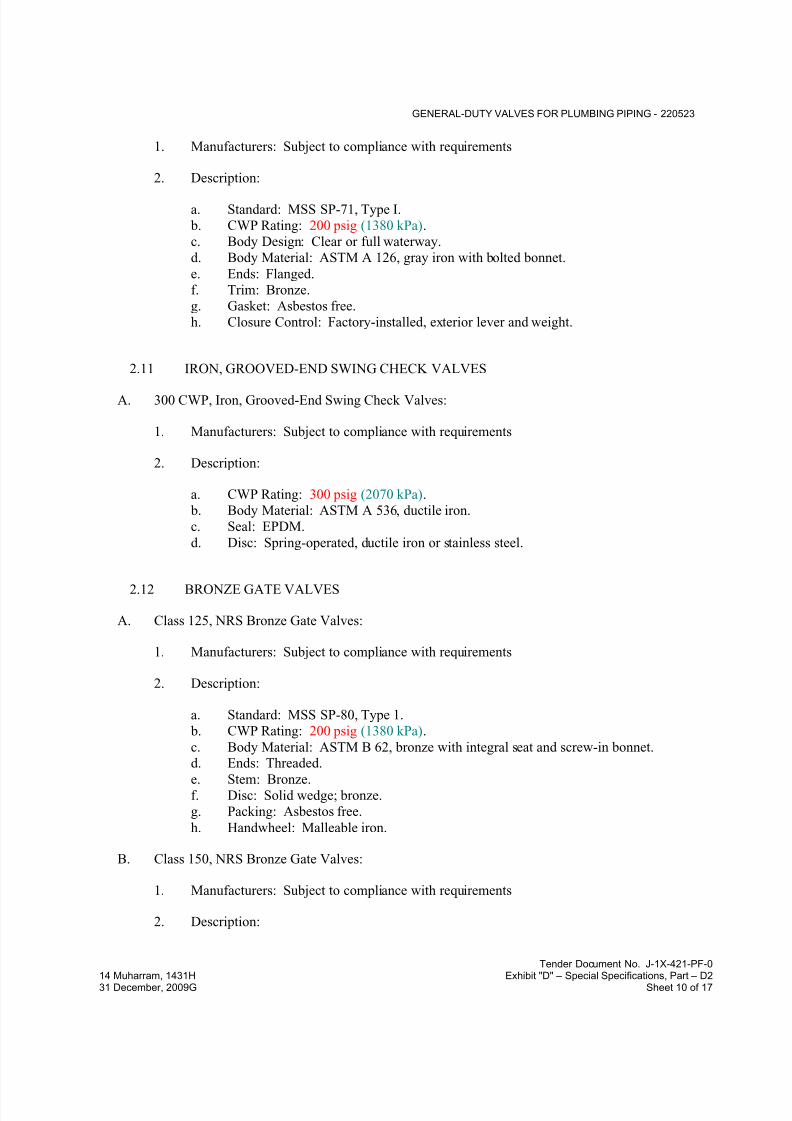
7/18/2019 SEC DPS
http://slidepdf.com/reader/full/sec-dps 197/541
GENERAL-DUTY VALVES FOR PLUMBING PIPING - 220523
Tender Document No. J-1X-421-PF-0
14 Muharram, 1431H Exhibit "D" – Special Specifications, Part – D231 December, 2009G Sheet 10 of 17
1. Manufacturers: Subject to compliance with requirements
2. Description:
a. Standard: MSS SP-71, Type I.
b. CWP Rating: 200 psig (1380 kPa).
c. Body Design: Clear or full waterway.
d. Body Material: ASTM A 126, gray iron with bolted bonnet.
e. Ends: Flanged.
f. Trim: Bronze.
g. Gasket: Asbestos free.
h. Closure Control: Factory-installed, exterior lever and weight.
2.11 IRON, GROOVED-END SWING CHECK VALVES
A. 300 CWP, Iron, Grooved-End Swing Check Valves:
1. Manufacturers: Subject to compliance with requirements
2. Description:
a. CWP Rating: 300 psig (2070 kPa).
b. Body Material: ASTM A 536, ductile iron.
c. Seal: EPDM.
d. Disc: Spring-operated, ductile iron or stainless steel.
2.12 BRONZE GATE VALVES
A. Class 125, NRS Bronze Gate Valves:
1. Manufacturers: Subject to compliance with requirements
2. Description:
a. Standard: MSS SP-80, Type 1.
b. CWP Rating: 200 psig (1380 kPa).
c. Body Material: ASTM B 62, bronze with integral seat and screw-in bonnet.d. Ends: Threaded.
e. Stem: Bronze.f. Disc: Solid wedge; bronze.
g. Packing: Asbestos free.
h. Handwheel: Malleable iron.
B. Class 150, NRS Bronze Gate Valves:
1. Manufacturers: Subject to compliance with requirements
2. Description:

7/18/2019 SEC DPS
http://slidepdf.com/reader/full/sec-dps 198/541
GENERAL-DUTY VALVES FOR PLUMBING PIPING - 220523
Tender Document No. J-1X-421-PF-0
14 Muharram, 1431H Exhibit "D" – Special Specifications, Part – D231 December, 2009G Sheet 11 of 17
a. Standard: MSS SP-80, Type 1.
b. CWP Rating: 300 psig (2070 kPa).
c. Body Material: ASTM B 62, bronze with integral seat and union-ring bonnet.
d. Ends: Threaded.e. Stem: Bronze.
f. Disc: Solid wedge; bronze.
g. Packing: Asbestos free.
h. Handwheel: Malleable iron.
2.13 IRON GATE VALVES
A. Class 125, NRS, Iron Gate Valves:
1. Manufacturers: Subject to compliance with requirements
2. Description:
a. Standard: MSS SP-70, Type I.
b. CWP Rating: 200 psig (1380 kPa).
c. Body Material: ASTM A 126, gray iron with bolted bonnet.
d. Ends: Flanged.
e. Trim: Bronze.
f. Disc: Solid wedge.
g. Packing and Gasket: Asbestos free.
B. Class 125, OS&Y, Iron Gate Valves:
1. Manufacturers: Subject to compliance with requirements
2. Description:
a. Standard: MSS SP-70, Type I.
b. CWP Rating: 200 psig (1380 kPa).
c. Body Material: ASTM A 126, gray iron with bolted bonnet.
d. Ends: Flanged.
e. Trim: Bronze.
f. Disc: Solid wedge.
g. Packing and Gasket: Asbestos free.
C. Class 250, NRS, Iron Gate Valves:
1. Manufacturers: Subject to compliance with requirements
2. Description:
a. Standard: MSS SP-70, Type I.
b. CWP Rating: 500 psig (3450 kPa).
c. Body Material: ASTM A 126, gray iron with bolted bonnet.
d. Ends: Flanged.
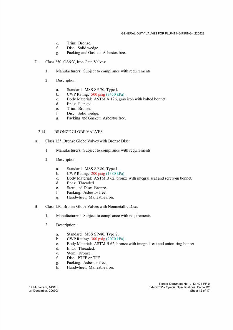
7/18/2019 SEC DPS
http://slidepdf.com/reader/full/sec-dps 199/541
GENERAL-DUTY VALVES FOR PLUMBING PIPING - 220523
Tender Document No. J-1X-421-PF-0
14 Muharram, 1431H Exhibit "D" – Special Specifications, Part – D231 December, 2009G Sheet 12 of 17
e. Trim: Bronze.
f. Disc: Solid wedge.
g. Packing and Gasket: Asbestos free.
D. Class 250, OS&Y, Iron Gate Valves:
1. Manufacturers: Subject to compliance with requirements
2. Description:
a. Standard: MSS SP-70, Type I.
b. CWP Rating: 500 psig (3450 kPa).
c. Body Material: ASTM A 126, gray iron with bolted bonnet.
d. Ends: Flanged.
e. Trim: Bronze.
f. Disc: Solid wedge.g. Packing and Gasket: Asbestos free.
2.14 BRONZE GLOBE VALVES
A. Class 125, Bronze Globe Valves with Bronze Disc:
1. Manufacturers: Subject to compliance with requirements
2. Description:
a. Standard: MSS SP-80, Type 1.
b. CWP Rating: 200 psig (1380 kPa).c. Body Material: ASTM B 62, bronze with integral seat and screw-in bonnet.
d. Ends: Threaded.
e. Stem and Disc: Bronze.
f. Packing: Asbestos free.
g. Handwheel: Malleable iron.
B. Class 150, Bronze Globe Valves with Nonmetallic Disc:
1. Manufacturers: Subject to compliance with requirements
2. Description:
a. Standard: MSS SP-80, Type 2.
b. CWP Rating: 300 psig (2070 kPa).
c. Body Material: ASTM B 62, bronze with integral seat and union-ring bonnet.
d. Ends: Threaded.
e. Stem: Bronze.
f. Disc: PTFE or TFE.
g. Packing: Asbestos free.
h. Handwheel: Malleable iron.

7/18/2019 SEC DPS
http://slidepdf.com/reader/full/sec-dps 200/541
GENERAL-DUTY VALVES FOR PLUMBING PIPING - 220523
Tender Document No. J-1X-421-PF-0
14 Muharram, 1431H Exhibit "D" – Special Specifications, Part – D231 December, 2009G Sheet 13 of 17
2.15 IRON GLOBE VALVES
A. Class 125, Iron Globe Valves:
1. Manufacturers: Subject to compliance with requirements:
2. Description:
a. Standard: MSS SP-85, Type I.
b. CWP Rating: 200 psig (1380 kPa).
c. Body Material: ASTM A 126, gray iron with bolted bonnet.
d. Ends: Flanged.
e. Trim: Bronze.
f. Packing and Gasket: Asbestos free.
B. Class 250, Iron Globe Valves:
1. Manufacturers: Subject to compliance with requirements
2. Description:
a. Standard: MSS SP-85, Type I.
b. CWP Rating: 500 psig (3450 kPa).
c. Body Material: ASTM A 126, gray iron with bolted bonnet.
d. Ends: Flanged.
e. Trim: Bronze.
f. Packing and Gasket: Asbestos free.
2.16 CHAINWHEELS
A. Manufacturers: Subject to compliance with requirements
B. Description: Valve actuation assembly with sprocket rim, brackets, and chain.
1. Brackets: Type, number, size, and fasteners required to mount actuator on valve.
2. Attachment: For connection to ball butterfly and plug valve stems.
3. Sprocket Rim with Chain Guides: Ductile or cast iron], of type and size required for
valve. Include zinc coating.
4. Chain: Hot-dip, galvanized steel], of size required to fit sprocket rim.
PART 3 - EXECUTION
3.1 EXAMINATION
A. Examine valve interior for cleanliness, freedom from foreign matter, and corrosion. Remove
special packing materials, such as blocks, used to prevent disc movement during shipping and
handling.

7/18/2019 SEC DPS
http://slidepdf.com/reader/full/sec-dps 201/541
GENERAL-DUTY VALVES FOR PLUMBING PIPING - 220523
Tender Document No. J-1X-421-PF-0
14 Muharram, 1431H Exhibit "D" – Special Specifications, Part – D231 December, 2009G Sheet 14 of 17
B. Operate valves in positions from fully open to fully closed. Examine guides and seats made
accessible by such operations.
C. Examine threads on valve and mating pipe for form and cleanliness.
D. Examine mating flange faces for conditions that might cause leakage. Check bolting for proper
size, length, and material. Verify that gasket is of proper size, that its material composition is
suitable for service, and that it is free from defects and damage.
E. Do not attempt to repair defective valves; replace with new valves.
3.2 VALVE INSTALLATION
A. Install valves with unions or flanges at each piece of equipment arranged to allow service,
maintenance, and equipment removal without system shutdown.
B. Locate valves for easy access and provide separate support where necessary.
C. Install valves in horizontal piping with stem at or above center of pipe.
D. Install valves in position to allow full stem movement.
E. Install chainwheels on operators for ball butterfly gateand globe valves NPS 8 (DN 200) andlarger and more than 120 inches (3000 mm) above floor. Extend chains to 60 inches (1520 mm)
above finished floor.
F. Install check valves for proper direction of flow and as follows:
1. Swing Check Valves: In horizontal position with hinge pin level.
2. Lift Check Valves: With stem upright and plumb.
3.3 ADJUSTING
A. Adjust or replace valve packing after piping systems have been tested and put into service but
before final adjusting and balancing. Replace valves if persistent leaking occurs.
3.4 GENERAL REQUIREMENTS FOR VALVE APPLICATIONS
A. If valve applications are not indicated, use the following:
1. Shutoff Service: Ball, butterfly or gate valves.
2. Butterfly Valve Dead-End Service: Single-flange (lug) type.
3. Throttling Service: Globe or butterfly valves.
4. Pump-Discharge Check Valves:
a. NPS 2 (DN 50) and Smaller: Bronze swing check valves with bronze disc.
b. NPS 2-1/2 (DN 65) and Larger for Domestic Water: Iron swing check valves with
lever and weight or with spring or iron, center-guided, metal-seat check valves.

7/18/2019 SEC DPS
http://slidepdf.com/reader/full/sec-dps 202/541
GENERAL-DUTY VALVES FOR PLUMBING PIPING - 220523
Tender Document No. J-1X-421-PF-0
14 Muharram, 1431H Exhibit "D" – Special Specifications, Part – D231 December, 2009G Sheet 15 of 17
c. NPS 2-1/2 (DN 65) and Larger for Sanitary Waste and Storm Drainage: Iron
swing check valves with lever and weight or spring.
B. If valves with specified SWP classes or CWP ratings are not available, the same types of valveswith higher SWP classes or CWP ratings may be substituted.
C. Select valves, except wafer types, with the following end connections:
1. For Copper Tubing, NPS 2 (DN 50) and Smaller: Threaded ends except where solder-
joint valve-end option is indicated in valve schedules below.
2. For Copper Tubing, NPS 2-1/2 to NPS 4 (DN 65 to DN 100): Flanged ends except where
threaded valve-end option is indicated in valve schedules below.
3. For Copper Tubing, NPS 5 (DN 125) and Larger: Flanged ends.
4. For Steel Piping, NPS 2 (DN 50) and Smaller: Threaded ends.
5. For Steel Piping, NPS 2-1/2 to NPS 4 (DN 65 to DN 100): Flanged ends except where
threaded valve-end option is indicated in valve schedules below.6. For Steel Piping, NPS 5 (DN 125) and Larger: Flanged ends.
7. For Grooved-End Copper Tubing and Steel Piping: Valve ends may be grooved.
3.5 LOW-PRESSURE, COMPRESSED-AIR VALVE SCHEDULE (150 PSIG (1035 kPa)
OR LESS)
A. Pipe NPS 2 (DN 50) and Smaller:
1. Bronze Valves: May be provided with solder-joint ends instead of threaded ends.2. Ball Valves: One or Two piece, regular port, bronze with bronze trim.
3. Bronze Lift Check Valves: Class 125, bronze disc.
4. Bronze Swing Check Valves: Class 150, bronze disc.
5. Bronze Gate Valves: Class 150, NRS.
B. Pipe NPS 2-1/2 (DN 65) and Larger:
1. Iron Valves, NPS 2-1/2 to NPS 4 (DN 65 to DN 100): May be provided with threadedends instead of flanged ends.
2. Iron, Single-Flange Butterfly Valves: 200 CWP, NBR seat, [ductile-iron disc.
3. Iron, Grooved-End Butterfly Valves: 175 CWP.
4. Iron Swing Check Valves: Class 125metal] seats.
5. Iron, Grooved-End Swing Check Valves: 300 CWP.6. Iron Gate Valves: Class 125NR.
3.6 HIGH-PRESSURE, COMPRESSED-AIR VALVE SCHEDULE (150 TO 200 PSIG (1035
TO 1380 kPa))
A. Pipe NPS 2 (DN 50) and Smaller:
1. Bronze Valves: May be provided with solder-joint ends instead of threaded ends.
2. Ball Valves: One or Two piece, regular port, bronze with bronze trim.3. Bronze Lift Check Valves: Class 125, bronze disc.

7/18/2019 SEC DPS
http://slidepdf.com/reader/full/sec-dps 203/541
GENERAL-DUTY VALVES FOR PLUMBING PIPING - 220523
Tender Document No. J-1X-421-PF-0
14 Muharram, 1431H Exhibit "D" – Special Specifications, Part – D231 December, 2009G Sheet 16 of 17
4. Bronze Swing Check Valves: Class 150, bronze] disc.
5. Bronze Gate Valves: Class 150, NRS.
B. Pipe NPS 2-1/2 (DN 65) and Larger:
1. Iron Valves, NPS 2-1/2 to NPS 4 (DN 65 to DN 100): May be provided with threaded
ends instead of flanged ends.
2. Iron, Single-Flange Butterfly Valves: 200 CWP, NBR seat, ductile-iron disc.
3. Iron, Grooved-End Butterfly Valves: 300 CWP.
4. Iron Swing Check Valves: Class 250, metal seats.
5. Iron, Grooved-End Swing Check Valves: 300 CWP.
6. Iron Gate Valves: Class 250, NRS.
3.7 DOMESTIC, HOT- AND COLD-WATER VALVE SCHEDULE
A. Pipe NPS 2 (DN 50) and Smaller:
1. Bronze Valves: May be provided with solder-joint ends instead of threaded ends.
2. Bronze Angle Valves: Class 125bronze disc.
3. Ball Valves: One piece, regular port, bronze with bronze trim.
4. Bronze Swing Check Valves: Class 125or Class 150 as applicable to system pressure
requirement bronze disc.
5. Bronze Gate Valves: Class 125 or Class 150 as applicable to system pressure
requirement, NRS.
6. Bronze Globe Valves: Class 125or Class 150 as applicable to system pressure
requirement, bronze disc.
B. Pipe NPS 2-1/2 (DN 65) and Larger:
1. Iron Valves, NPS 2-1/2 to NPS 4 (DN 65 to DN 100): May be provided with threaded
ends instead of flanged ends.
2. Iron Ball Valves: Class 150.
3. Iron, Single-Flange Butterfly Valves: 200 CWP, EPDM seat, ductile-iron disc.
4. Iron, Grooved-End Butterfly Valves: 175 or 300 CWP, as applicable to system pressure
requirement.
5. Iron Swing Check Valves: Class 125 or Class 250 as applicable to system pressure
requirement, metal seats.
6. Iron Swing Check Valves with Closure Control: Class 125, lever and [spring] [weight].
7. Iron, Grooved-End Swing Check Valves: 300 CWP.
8. Iron Gate Valves: Class 125 or Class 150 as applicable to system pressure requirement,,
NRS.
9. Iron Globe Valves: Class 125 or Class 150 as applicable to system pressure requirement,.
3.8 SANITARY-WASTE AND STORM-DRAINAGE VALVE SCHEDULE
A. Pipe NPS 2 (DN 50) and Smaller:
1. Bronze Valves: May be provided with solder-joint ends instead of threaded ends.

7/18/2019 SEC DPS
http://slidepdf.com/reader/full/sec-dps 204/541
GENERAL-DUTY VALVES FOR PLUMBING PIPING - 220523
Tender Document No. J-1X-421-PF-0
14 Muharram, 1431H Exhibit "D" – Special Specifications, Part – D231 December, 2009G Sheet 17 of 17
2. Bronze Angle Valves: Class 125 or Class 150 as applicable to system pressure
requirement,, bronze disc.
3. Ball Valves: One piece, regular port, bronze with bronze trim.
4. Bronze Swing Check Valves: Class 125 or Class 150 as applicable to system pressurerequirement,, bronze disc.
5. Bronze Gate Valves: Class 125 or Class 150 as applicable to system pressure
requirement,, NRS.
6. Bronze Globe Valves: Class 125 or Class 150 as applicable to system pressure
requirement,, bronze disc.
B. Pipe NPS 2-1/2 (DN 65) and Larger:
1. Iron Valves, NPS 2-1/2 to NPS 4 (DN 65 to DN 100): May be provided with threaded
ends instead of flanged ends.
2. Iron Ball Valves: Class 150.
3. Iron Swing Check Valves: Class 125 or Class 250 as applicable to system pressurerequirement, , metal seats.
4. Iron Swing Check Valves with Closure Control: Class 125, lever and weight.
5. Iron, Grooved-End Swing Check Valves: 300 CWP.
6. Iron Gate Valves: Class 125 or Class 250 as applicable to system pressure requirement,,
NRS.
7. Iron Globe Valves: Class 125 or Class 150 as applicable to system pressure requirement,.
END OF SECTION 220523

7/18/2019 SEC DPS
http://slidepdf.com/reader/full/sec-dps 205/541
HANGERS AND SUPPORTS FOR PLUMBING PIPING AND EQUIPMENT - 220529
Tender Document No. J-1X-421-PF-0
14 Muharram, 1431H Exhibit "D" – Special Specifications, Part – D231 December, 2009G Sheet 1 of 13
SECTION 220529 - HANGERS AND SUPPORTS FOR PLUMBING PIPING AND EQUIPMENT
PART 1 - GENERAL
1.1 RELATED DOCUMENTS
A. Drawings and general provisions of the Contract, including General and Supplementary
Conditions and Division 01 Specification Sections, apply to this Section.
1.2 SUMMARY
A. Section Includes:
1. Metal pipe hangers and supports.
2. Trapeze pipe hangers.3. Fiberglass pipe hangers.
4. Metal framing systems.
5. Fiberglass strut systems.
6. Thermal-hanger shield inserts.
7. Fastener systems.8. Pipe stands.
9. Pipe positioning systems.
10. Equipment supports.
B. Related Sections:
1. Division 05 Section "Metal Fabrications" for structural-steel shapes and plates for trapezehangers for pipe and equipment supports.
2. Division 21 fire-suppression piping Sections for pipe hangers for fire-suppression piping.
3. Division 22 Section "Expansion Fittings and Loops for Plumbing Piping" for pipe guides
and anchors.
4. Division 22 Section "Vibration and Seismic Controls for Plumbing Piping and
Equipment" for vibration isolation devices.
1.3 DEFINITIONS
A. MSS: Manufacturers Standardization Society of The Valve and Fittings Industry Inc.
1.4 PERFORMANCE REQUIREMENTS
A. Delegated Design: Design trapeze pipe hangers and equipment supports, including
comprehensive engineering analysis by a qualified professional engineer, using performance
requirements and design criteria indicated.
7/18/2019 SEC DPS
http://slidepdf.com/reader/full/sec-dps 206/541
HANGERS AND SUPPORTS FOR PLUMBING PIPING AND EQUIPMENT - 220529
Tender Document No. J-1X-421-PF-0
14 Muharram, 1431H Exhibit "D" – Special Specifications, Part – D231 December, 2009G Sheet 2 of 13
B. Structural Performance: Hangers and supports for plumbing piping and equipment shall
withstand the effects of gravity loads and stresses within limits and under conditions indicated
according to UBC 1997, Zone 2A.
1. Design supports for multiple pipes, including pipe stands, capable of supporting
combined weight of supported systems, system contents, and test water.
2. Design equipment supports capable of supporting combined operating weight of
supported equipment and connected systems and components.
3. Design seismic-restraint hangers and supports for piping and equipment.
1.5 ACTION SUBMITTALS
A. Product Data: For each type of product indicated.
B. Shop Drawings: Signed and sealed by a qualified professional engineer. Show fabrication andinstallation details and include calculations for the following; include Product Data for
components:
1. Trapeze pipe hangers.
2. Metal framing systems.
3. Fiberglass strut systems.
4. Pipe stands.
5. Equipment supports.
C. Delegated-Design Submittal: For trapeze hangers indicated to comply with performancerequirements and design criteria, including analysis data signed and sealed by the qualified
professional engineer responsible for their preparation.
1. Detail fabrication and assembly of trapeze hangers.
2. Design Calculations: Calculate requirements for designing trapeze hangers.
1.6 INFORMATIONAL SUBMITTALS
A. Welding certificates.
1.7 QUALITY ASSURANCE
A. Structural Steel Welding Qualifications: Qualify procedures and personnel according toAWS D1.1/D1.1M, "Structural Welding Code - Steel."
B. Pipe Welding Qualifications: Qualify procedures and operators according to ASME Boiler and
Pressure Vessel Code.

7/18/2019 SEC DPS
http://slidepdf.com/reader/full/sec-dps 207/541
HANGERS AND SUPPORTS FOR PLUMBING PIPING AND EQUIPMENT - 220529
Tender Document No. J-1X-421-PF-0
14 Muharram, 1431H Exhibit "D" – Special Specifications, Part – D231 December, 2009G Sheet 3 of 13
PART 2 - PRODUCTS
2.1 METAL PIPE HANGERS AND SUPPORTS
A. Carbon-Steel Pipe Hangers and Supports:
1. Description: MSS SP-58, Types 1 through 58, factory-fabricated components.
2. Galvanized Metallic Coatings: hot dipped.
3. Nonmetallic Coatings: Plastic coating, jacket, or liner.
4. Padded Hangers: Hanger with fiberglass or other pipe insulation pad or cushion to
support bearing surface of piping.
5. Hanger Rods: Continuous-thread rod, nuts, and washer made of hot dipped galvanized
steel.
B. Copper Pipe Hangers:
1. Description: MSS SP-58, Types 1 through 58, copper-coated-steel, factory-fabricated
components.
2. Hanger Rods: Continuous-thread rod, nuts, and washer made of copper-coated steel.
2.2 TRAPEZE PIPE HANGERS
A. Description: MSS SP-69, Type 59, shop- or field-fabricated pipe-support assembly made from
structural carbon-steel shapes with MSS SP-58 carbon-steel hanger rods, nuts, saddles, and U-
bolts.
2.3 FIBERGLASS PIPE HANGERS
A. Clevis-Type, Fiberglass Pipe Hangers:
1. Description: Similar to MSS SP-58, Type 1, steel pipe hanger except hanger is made of
fiberglass or fiberglass-reinforced resin.
2. Hanger Rods: Continuous-thread rod, washer, and nuts made of hot dipped galvanized
steel.
B. Strap-Type, Fiberglass Pipe Hangers:
1. Description: Similar to MSS SP-58, Type 9 or Type 10, steel pipe hanger except hangeris made of fiberglass-reinforced resin.
2. Hanger Rod and Fittings: Continuous-thread rod, washer, and nuts made of hot dipped
galvanized steel.
2.4 METAL FRAMING SYSTEMS
A. MFMA Manufacturer Metal Framing Systems:
1. Manufacturers: Subject to compliance with requirements
7/18/2019 SEC DPS
http://slidepdf.com/reader/full/sec-dps 208/541
HANGERS AND SUPPORTS FOR PLUMBING PIPING AND EQUIPMENT - 220529
Tender Document No. J-1X-421-PF-0
14 Muharram, 1431H Exhibit "D" – Special Specifications, Part – D231 December, 2009G Sheet 4 of 13
2. Basis-of-Design Product: Subject to compliance with requirements
3. Description: Shop- or field-fabricated pipe-support assembly for supporting multiple
parallel pipes.4. Standard: MFMA-4.
5. Channels: Continuous slotted steel channel with inturned lips.
6. Channel Nuts: Formed or stamped steel nuts or other devices designed to fit into channel
slot and, when tightened, prevent slipping along channel.
7. Hanger Rods: Continuous-thread rod, nuts, and washer made of hot dipped galvanized
steel.
8. Metallic Coating: Hot-dipped galvanized
9. Paint Coating: Vinyl.
10. Plastic Coating: PVC.
B. Non-MFMA Manufacturer Metal Framing Systems:
1. Manufacturers: Subject to compliance with requirements:
2. Basis-of-Design Product: Subject to compliance with requirements
3. Description: Shop- or field-fabricated pipe-support assembly made of steel channels,
accessories, fittings, and other components for supporting multiple parallel pipes.
4. Standard: Comply with MFMA-4.
5. Channels: Continuous slotted steel channel with inturned lips.
6. Channel Nuts: Formed or stamped steel nuts or other devices designed to fit into channel
slot and, when tightened, prevent slipping along channel.
7. Hanger Rods: Continuous-thread rod, nuts, and washer made of hot dipped galvanized
steel.
8. Coating: Zinc.
2.5 FIBERGLASS STRUT SYSTEMS
A. Manufacturers: Subject to compliance with requirements
B. Basis-of-Design Product: Subject to compliance with requirements
C. Description: Shop- or field-fabricated pipe-support assembly similar to MFMA-4 for
supporting multiple parallel pipes.
1. Channels: Continuous slotted fiberglass channel with inturned lips.
2. Channel Nuts: Fiberglass nuts or other devices designed to fit into channel slot and,when tightened, prevent slipping along channel.
3. Hanger Rods: Continuous-thread rod, nuts, and washer made of fiberglass.
2.6 THERMAL-HANGER SHIELD INSERTS
A. Manufacturers: Subject to compliance with requirements
B. Basis-of-Design Product: Subject to compliance with requirements
7/18/2019 SEC DPS
http://slidepdf.com/reader/full/sec-dps 209/541
HANGERS AND SUPPORTS FOR PLUMBING PIPING AND EQUIPMENT - 220529
Tender Document No. J-1X-421-PF-0
14 Muharram, 1431H Exhibit "D" – Special Specifications, Part – D231 December, 2009G Sheet 5 of 13
C. Insulation-Insert Material for Cold Piping: ASTM C 552, Type II cellular glass with 100-psig
(688-kPa) minimum compressive strength and vapor barrier.
D. Insulation-Insert Material for Hot Piping: Water-repellent treated, ASTM C 533, Type Icalcium silicate with 100-psig (688-kPa) minimum compressive strength.
E. For Trapeze or Clamped Systems: Insert and shield shall cover entire circumference of pipe.
F. For Clevis or Band Hangers: Insert and shield shall cover lower 180 degrees of pipe.
G. Insert Length: Extend 2 inches (50 mm) beyond sheet metal shield for piping operating below
ambient air temperature.
2.7 FASTENER SYSTEMS
A. Powder-Actuated Fasteners: Threaded-steel stud, for use in hardened portland cement concrete
with pull-out, tension, and shear capacities appropriate for supported loads and building
materials where used.
B. Mechanical-Expansion Anchors: Insert-wedge-type, zinc-coated steel anchors, for use in
hardened portland cement concrete; with pull-out, tension, and shear capacities appropriate for
supported loads and building materials where used.
2.8 PIPE STANDS
A. General Requirements for Pipe Stands: Shop- or field-fabricated assemblies made of
manufactured corrosion-resistant components to support roof-mounted piping.
B. Compact Pipe Stand: One-piece plastic unit with integral-rod roller, pipe clamps, or V-shapedcradle to support pipe, for roof installation without membrane penetration.
C. Low-Type, Single-Pipe Stand: One-piece plastic base unit with plastic roller, for roof
installation without membrane penetration.
D. High-Type, Single-Pipe Stand:
1. Description: Assembly of base, vertical and horizontal members, and pipe support, for
roof installation without membrane penetration.
2. Base: Plastic.3. Vertical Members: Two or more cadmium-plated-steel or stainless-steel, continuous-
thread rods.
4. Horizontal Member: Cadmium-plated-steel or stainless-steel rod with plastic or stainless-
steel, roller-type pipe support.
E. High-Type, Multiple-Pipe Stand:
1. Description: Assembly of bases, vertical and horizontal members, and pipe supports, for
roof installation without membrane penetration.
2. Bases: One or more; plastic.

7/18/2019 SEC DPS
http://slidepdf.com/reader/full/sec-dps 210/541
HANGERS AND SUPPORTS FOR PLUMBING PIPING AND EQUIPMENT - 220529
Tender Document No. J-1X-421-PF-0
14 Muharram, 1431H Exhibit "D" – Special Specifications, Part – D231 December, 2009G Sheet 6 of 13
3. Vertical Members: Two or more protective-coated-steel channels.
4. Horizontal Member: Protective-coated-steel channel.
5. Pipe Supports: Galvanized-steel, clevis-type pipe hangers.
F. Curb-Mounting-Type Pipe Stands: Shop- or field-fabricated pipe supports made from
structural-steel shapes, continuous-thread rods, and rollers, for mounting on permanent
stationary roof curb.
2.9 PIPE POSITIONING SYSTEMS
A. Description: IAPMO PS 42, positioning system of metal brackets, clips, and straps for
positioning piping in pipe spaces; for plumbing fixtures in commercial applications.
2.10 EQUIPMENT SUPPORTS
A. Description: Welded, shop- or field-fabricated equipment support made from structural carbon-
steel shapes.
2.11 MISCELLANEOUS MATERIALS
A. Structural Steel: ASTM A 36/A 36M, carbon-steel plates, shapes, and bars; black andgalvanized.
B. Grout: ASTM C 1107, factory-mixed and -packaged, dry, hydraulic-cement, nonshrink and
nonmetallic grout; suitable for interior and exterior applications.
1. Properties: Nonstaining, noncorrosive, and nongaseous.
2. Design Mix: 5000-psi (34.5-MPa), 28-day compressive strength.
PART 3 - EXECUTION
3.1 HANGER AND SUPPORT INSTALLATION
A. Metal Pipe-Hanger Installation: Comply with MSS SP-69 and MSS SP-89. Install hangers,
supports, clamps, and attachments as required to properly support piping from the building
structure.
B. Metal Trapeze Pipe-Hanger Installation: Comply with MSS SP-69 and MSS SP-89. Arrange
for grouping of parallel runs of horizontal piping, and support together on field-fabricated
trapeze pipe hangers.
1. Pipes of Various Sizes: Support together and space trapezes for smallest pipe size or
install intermediate supports for smaller diameter pipes as specified for individual pipe
hangers.
2. Field fabricate from ASTM A 36/A 36M, carbon-steel shapes selected for loads being
supported. Weld steel according to AWS D1.1/D1.1M.

7/18/2019 SEC DPS
http://slidepdf.com/reader/full/sec-dps 211/541
HANGERS AND SUPPORTS FOR PLUMBING PIPING AND EQUIPMENT - 220529
Tender Document No. J-1X-421-PF-0
14 Muharram, 1431H Exhibit "D" – Special Specifications, Part – D231 December, 2009G Sheet 7 of 13
C. Fiberglass Pipe-Hanger Installation: Comply with applicable portions of MSS SP-69 and
MSS SP-89. Install hangers and attachments as required to properly support piping from
building structure.
D. Metal Framing System Installation: Arrange for grouping of parallel runs of piping, and
support together on field-assembled metal framing systems.
E. Fiberglass Strut System Installation: Arrange for grouping of parallel runs of piping, and
support together on field-assembled fiberglass struts.
F. Thermal-Hanger Shield Installation: Install in pipe hanger or shield for insulated piping.
G. Fastener System Installation:
1. Install powder-actuated fasteners for use in lightweight concrete or concrete slabs less
than 4 inches (100 mm) thick in concrete after concrete is placed and completely cured.Use operators that are licensed by powder-actuated tool manufacturer. Install fasteners
according to powder-actuated tool manufacturer's operating manual.
2. Install mechanical-expansion anchors in concrete after concrete is placed and completely
cured. Install fasteners according to manufacturer's written instructions.
H. Pipe Stand Installation:
1. Pipe Stand Types except Curb-Mounted Type: Assemble components and mount on
smooth roof surface. Do not penetrate roof membrane.
2. Curb-Mounted-Type Pipe Stands: Assemble components or fabricate pipe stand andmount on permanent, stationary roof curb. See Division 07 Section "Roof Accessories"
for curbs.
I. Pipe Positioning-System Installation: Install support devices to make rigid supply and waste
piping connections to each plumbing fixture. See Division 22 plumbing fixture Sections for
requirements for pipe positioning systems for plumbing fixtures.
J. Install hangers and supports complete with necessary attachments, inserts, bolts, rods, nuts,washers, and other accessories.
K. Equipment Support Installation: Fabricate from welded-structural-steel shapes.
L. Install hangers and supports to allow controlled thermal and seismic movement of piping
systems, to permit freedom of movement between pipe anchors, and to facilitate action of
expansion joints, expansion loops, expansion bends, and similar units.
M. Install lateral bracing with pipe hangers and supports to prevent swaying.
N. Install building attachments within concrete slabs or attach to structural steel. Install additional
attachments at concentrated loads, including valves, flanges, and strainers, NPS 2-1/2 (DN 65)
and larger and at changes in direction of piping. Install concrete inserts before concrete is
placed; fasten inserts to forms and install reinforcing bars through openings at top of inserts.

7/18/2019 SEC DPS
http://slidepdf.com/reader/full/sec-dps 212/541
HANGERS AND SUPPORTS FOR PLUMBING PIPING AND EQUIPMENT - 220529
Tender Document No. J-1X-421-PF-0
14 Muharram, 1431H Exhibit "D" – Special Specifications, Part – D231 December, 2009G Sheet 8 of 13
O. Load Distribution: Install hangers and supports so that piping live and dead loads and stresses
from movement will not be transmitted to connected equipment.
P. Pipe Slopes: Install hangers and supports to provide indicated pipe slopes and to not exceedmaximum pipe deflections allowed by ASME B31.9 for building services piping.
Q. Insulated Piping:
1. Attach clamps and spacers to piping.
a. Piping Operating above Ambient Air Temperature: Clamp may project through
insulation.
b. Piping Operating below Ambient Air Temperature: Use thermal-hanger shield
insert with clamp sized to match OD of insert.
c. Do not exceed pipe stress limits allowed by ASME B31.9 for building services
piping.
2. Install MSS SP-58, Type 39, protection saddles if insulation without vapor barrier is
indicated. Fill interior voids with insulation that matches adjoining insulation.
a. Option: Thermal-hanger shield inserts may be used. Include steel weight-
distribution plate for pipe NPS 4 (DN 100) and larger if pipe is installed on rollers.
3. Install MSS SP-58, Type 40, protective shields on cold piping with vapor barrier. Shields
shall span an arc of 180 degrees.
a. Option: Thermal-hanger shield inserts may be used. Include steel weight-
distribution plate for pipe NPS 4 (DN 100) and larger if pipe is installed on rollers.
4. Shield Dimensions for Pipe: Not less than the following:
a. NPS 1/4 to NPS 3-1/2 (DN 8 to DN 90): 12 inches (305 mm) long and 0.048 inch
(1.22 mm) thick.
b. NPS 4 (DN 100): 12 inches (305 mm) long and 0.06 inch (1.52 mm) thick.
c. NPS 5 and NPS 6 (DN 125 and DN 150): 18 inches (457 mm) long and 0.06 inch
(1.52 mm) thick.
d. NPS 8 to NPS 14 (DN 200 to DN 350): 24 inches (610 mm) long and 0.075 inch
(1.91 mm) thick.
e. NPS 16 to NPS 24 (DN 400 to DN 600): 24 inches (610 mm) long and 0.105 inch
(2.67 mm) thick.
5. Pipes NPS 8 (DN 200) and Larger: Include wood or reinforced calcium-silicate-
insulation inserts of length at least as long as protective shield.
6. Thermal-Hanger Shields: Install with insulation same thickness as piping insulation.
3.2 EQUIPMENT SUPPORTS
A. Fabricate structural-steel stands to suspend equipment from structure overhead or to support
equipment above floor.

7/18/2019 SEC DPS
http://slidepdf.com/reader/full/sec-dps 213/541
HANGERS AND SUPPORTS FOR PLUMBING PIPING AND EQUIPMENT - 220529
Tender Document No. J-1X-421-PF-0
14 Muharram, 1431H Exhibit "D" – Special Specifications, Part – D231 December, 2009G Sheet 9 of 13
B. Grouting: Place grout under supports for equipment and make bearing surface smooth.
C. Provide lateral bracing, to prevent swaying, for equipment supports.
3.3 METAL FABRICATIONS
A. Cut, drill, and fit miscellaneous metal fabrications for trapeze pipe hangers and equipment
supports.
B. Fit exposed connections together to form hairline joints. Field weld connections that cannot be
shop welded because of shipping size limitations.
C. Field Welding: Comply with AWS D1.1/D1.1M procedures for shielded, metal arc welding;
appearance and quality of welds; and methods used in correcting welding work; and with the
following:
1. Use materials and methods that minimize distortion and develop strength and corrosion
resistance of base metals.
2. Obtain fusion without undercut or overlap.
3. Remove welding flux immediately.4. Finish welds at exposed connections so no roughness shows after finishing and so
contours of welded surfaces match adjacent contours.
3.4 ADJUSTING
A. Hanger Adjustments: Adjust hangers to distribute loads equally on attachments and to achieve
indicated slope of pipe.
B. Trim excess length of continuous-thread hanger and support rods to [1-1/2 inches (40 mm)].
3.5 PAINTING
A. Touchup: Clean field welds and abraded areas of shop paint. Paint exposed areas immediately
after erecting hangers and supports. Use same materials as used for shop painting. Comply
with SSPC-PA 1 requirements for touching up field-painted surfaces.
1. Apply paint by brush or spray to provide a minimum dry film thickness of 2.0 mils (0.05
mm).
B. Touchup: Cleaning and touchup painting of field welds, bolted connections, and abraded areas
of shop paint on miscellaneous metal are specified in Division 09]
C. Galvanized Surfaces: Clean welds, bolted connections, and abraded areas and apply
galvanizing-repair paint to comply with ASTM A 780.
7/18/2019 SEC DPS
http://slidepdf.com/reader/full/sec-dps 214/541
HANGERS AND SUPPORTS FOR PLUMBING PIPING AND EQUIPMENT - 220529
Tender Document No. J-1X-421-PF-0
14 Muharram, 1431H Exhibit "D" – Special Specifications, Part – D231 December, 2009G Sheet 10 of 13
3.6 HANGER AND SUPPORT SCHEDULE
A. Specific hanger and support requirements are in Sections specifying piping systems and
equipment.
B. Comply with MSS SP-69 for pipe-hanger selections and applications that are not specified in
piping system Sections.
C. Use hangers and supports with galvanized metallic coatings for piping and equipment that will
not have field-applied finish.
D. Use nonmetallic coatings on attachments for electrolytic protection where attachments are in
direct contact with copper tubing.
E. Use carbon-steel pipe hangers and supports and attachments for general service applications.
F. Use fiberglass pipe hangers and fiberglass strut systems or corrosion-resistant attachments for
hostile environment applications.
G. Use copper-plated pipe hangers and copper attachments for copper piping and tubing.
H. Use padded hangers for piping that is subject to scratching.
I. Use thermal-hanger shield inserts for insulated piping and tubing.
J. Horizontal-Piping Hangers and Supports: Unless otherwise indicated and except as specified in
piping system Sections, install the following types:
1. Adjustable, Steel Clevis Hangers (MSS Type 1): For suspension of noninsulated orinsulated, stationary pipes NPS 1/2 to NPS 30 (DN 15 to DN 750).
2. Yoke-Type Pipe Clamps (MSS Type 2): For suspension of up to 1050 deg F (566 deg
C), pipes NPS 4 to NPS 24 (DN 100 to DN 600), requiring up to 4 inches (100 mm) of
insulation.
3. Carbon- or Alloy-Steel, Double-Bolt Pipe Clamps (MSS Type 3): For suspension of
pipes NPS 3/4 to NPS 36 (DN 20 to DN 900), requiring clamp flexibility and up to 4
inches (100 mm) of insulation.4. Steel Pipe Clamps (MSS Type 4): For suspension of cold and hot pipes NPS 1/2 to
NPS 24 (DN 15 to DN 600) if little or no insulation is required.
5. Pipe Hangers (MSS Type 5): For suspension of pipes NPS 1/2 to NPS 4 (DN 15 to
DN 100), to allow off-center closure for hanger installation before pipe erection.
6. Adjustable, Swivel Split- or Solid-Ring Hangers (MSS Type 6): For suspension ofnoninsulated, stationary pipes NPS 3/4 to NPS 8 (DN 20 to DN 200).
7. Adjustable, Steel Band Hangers (MSS Type 7): For suspension of noninsulated,
stationary pipes NPS 1/2 to NPS 8 (DN 15 to DN 200).
8. Adjustable Band Hangers (MSS Type 9): For suspension of noninsulated, stationary
pipes NPS 1/2 to NPS 8 (DN 15 to DN 200).
9. Adjustable, Swivel-Ring Band Hangers (MSS Type 10): For suspension of noninsulated,stationary pipes NPS 1/2 to NPS 8 (DN 15 to DN 200).
10. Split Pipe Ring with or without Turnbuckle Hangers (MSS Type 11): For suspension of
noninsulated, stationary pipes NPS 3/8 to NPS 8 (DN 10 to DN 200).
7/18/2019 SEC DPS
http://slidepdf.com/reader/full/sec-dps 215/541
HANGERS AND SUPPORTS FOR PLUMBING PIPING AND EQUIPMENT - 220529
Tender Document No. J-1X-421-PF-0
14 Muharram, 1431H Exhibit "D" – Special Specifications, Part – D231 December, 2009G Sheet 11 of 13
11. Extension Hinged or Two-Bolt Split Pipe Clamps (MSS Type 12): For suspension of
noninsulated, stationary pipes NPS 3/8 to NPS 3 (DN 10 to DN 80).
12. U-Bolts (MSS Type 24): For support of heavy pipes NPS 1/2 to NPS 30 (DN 15 to
DN 750).13. Clips (MSS Type 26): For support of insulated pipes not subject to expansion or
contraction.
14. Pipe Saddle Supports (MSS Type 36): For support of pipes NPS 4 to NPS 36 (DN 100 to
DN 900), with steel-pipe base stanchion support and cast-iron floor flange or carbon-steel
plate.15. Pipe Stanchion Saddles (MSS Type 37): For support of pipes NPS 4 to NPS 36 (DN 100
to DN 900), with steel-pipe base stanchion support and cast-iron floor flange or carbon-
steel plate, and with U-bolt to retain pipe.
16. Adjustable Pipe Saddle Supports (MSS Type 38): For stanchion-type support for pipes
NPS 2-1/2 to NPS 36 (DN 65 to DN 900) if vertical adjustment is required, with steel-
pipe base stanchion support and cast-iron floor flange.
17. Single-Pipe Rolls (MSS Type 41): For suspension of pipes NPS 1 to NPS 30 (DN 25 toDN 750), from two rods if longitudinal movement caused by expansion and contraction
might occur.
18. Adjustable Roller Hangers (MSS Type 43): For suspension of pipes NPS 2-1/2 to
NPS 24 (DN 65 to DN 600), from single rod if horizontal movement caused by expansion
and contraction might occur.
19. Complete Pipe Rolls (MSS Type 44): For support of pipes NPS 2 to NPS 42 (DN 50 to
DN 1050) if longitudinal movement caused by expansion and contraction might occur but
vertical adjustment is not necessary.
20. Pipe Roll and Plate Units (MSS Type 45): For support of pipes NPS 2 to NPS 24 (DN 50to DN 600) if small horizontal movement caused by expansion and contraction might
occur and vertical adjustment is not necessary.
21. Adjustable Pipe Roll and Base Units (MSS Type 46): For support of pipes NPS 2 to NPS 30 (DN 50 to DN 750) if vertical and lateral adjustment during installation might be
required in addition to expansion and contraction.
K. Vertical-Piping Clamps: Unless otherwise indicated and except as specified in piping system
Sections, install the following types:
1. Extension Pipe or Riser Clamps (MSS Type 8): For support of pipe risers NPS 3/4 to
NPS 24 (DN 24 to DN 600).
2. Carbon- or Alloy-Steel Riser Clamps (MSS Type 42): For support of pipe risers NPS 3/4
to NPS 24 (DN 20 to DN 600) if longer ends are required for riser clamps.
L. Hanger-Rod Attachments: Unless otherwise indicated and except as specified in piping systemSections, install the following types:
1. Steel Turnbuckles (MSS Type 13): For adjustment up to 6 inches (150 mm) for heavy
loads.
2. Steel Clevises (MSS Type 14): For 120 to 450 deg F (49 to 232 deg C) piping
installations.
3. Swivel Turnbuckles (MSS Type 15): For use with MSS Type 11, split pipe rings.
4. Malleable-Iron Sockets (MSS Type 16): For attaching hanger rods to various types of
building attachments.

7/18/2019 SEC DPS
http://slidepdf.com/reader/full/sec-dps 216/541
HANGERS AND SUPPORTS FOR PLUMBING PIPING AND EQUIPMENT - 220529
Tender Document No. J-1X-421-PF-0
14 Muharram, 1431H Exhibit "D" – Special Specifications, Part – D231 December, 2009G Sheet 12 of 13
5. Steel Weldless Eye Nuts (MSS Type 17): For 120 to 450 deg F (49 to 232 deg C) piping
installations.
M. Building Attachments: Unless otherwise indicated and except as specified in piping systemSections, install the following types:
1. Steel or Malleable Concrete Inserts (MSS Type 18): For upper attachment to suspend
pipe hangers from concrete ceiling.
2. Top-Beam C-Clamps (MSS Type 19): For use under roof installations with bar-joist
construction, to attach to top flange of structural shape.
3. Side-Beam or Channel Clamps (MSS Type 20): For attaching to bottom flange of beams,
channels, or angles.
4. Center-Beam Clamps (MSS Type 21): For attaching to center of bottom flange of beams.
5. Welded Beam Attachments (MSS Type 22): For attaching to bottom of beams if loads
are considerable and rod sizes are large.
6. C-Clamps (MSS Type 23): For structural shapes.7. Top-Beam Clamps (MSS Type 25): For top of beams if hanger rod is required tangent to
flange edge.
8. Side-Beam Clamps (MSS Type 27): For bottom of steel I-beams.
9. Steel-Beam Clamps with Eye Nuts (MSS Type 28): For attaching to bottom of steel I-
beams for heavy loads.
10. Linked-Steel Clamps with Eye Nuts (MSS Type 29): For attaching to bottom of steel I-
beams for heavy loads, with link extensions.
11. Malleable-Beam Clamps with Extension Pieces (MSS Type 30): For attaching to
structural steel.
12. Welded-Steel Brackets: For support of pipes from below or for suspending from above
by using clip and rod. Use one of the following for indicated loads:
a. Light (MSS Type 31): 750 lb (340 kg).
b. Medium (MSS Type 32): 1500 lb (680 kg).
c. Heavy (MSS Type 33): 3000 lb (1360 kg).
13. Side-Beam Brackets (MSS Type 34): For sides of steel or wooden beams.
14. Plate Lugs (MSS Type 57): For attaching to steel beams if flexibility at beam is required.
15. Horizontal Travelers (MSS Type 58): For supporting piping systems subject to linear
horizontal movement where headroom is limited.
N. Saddles and Shields: Unless otherwise indicated and except as specified in piping system
Sections, install the following types:
1. Steel-Pipe-Covering Protection Saddles (MSS Type 39): To fill interior voids with
insulation that matches adjoining insulation.
2. Protection Shields (MSS Type 40): Of length recommended in writing by manufacturer
to prevent crushing insulation.
3. Thermal-Hanger Shield Inserts: For supporting insulated pipe.
O. Spring Hangers and Supports: Unless otherwise indicated and except as specified in piping
system Sections, install the following types:
1. Restraint-Control Devices (MSS Type 47): Where indicated to control piping movement.

7/18/2019 SEC DPS
http://slidepdf.com/reader/full/sec-dps 217/541
HANGERS AND SUPPORTS FOR PLUMBING PIPING AND EQUIPMENT - 220529
Tender Document No. J-1X-421-PF-0
14 Muharram, 1431H Exhibit "D" – Special Specifications, Part – D231 December, 2009G Sheet 13 of 13
2. Spring Cushions (MSS Type 48): For light loads if vertical movement does not exceed
1-1/4 inches (32 mm).
3. Spring-Cushion Roll Hangers (MSS Type 49): For equipping Type 41, roll hanger with
springs.4. Spring Sway Braces (MSS Type 50): To retard sway, shock, vibration, or thermal
expansion in piping systems.
5. Variable-Spring Hangers (MSS Type 51): Preset to indicated load and limit variability
factor to 25 percent to allow expansion and contraction of piping system from hanger.
6. Variable-Spring Base Supports (MSS Type 52): Preset to indicated load and limitvariability factor to 25 percent to allow expansion and contraction of piping system from
base support.
7. Variable-Spring Trapeze Hangers (MSS Type 53): Preset to indicated load and limit
variability factor to 25 percent to allow expansion and contraction of piping system from
trapeze support.
8. Constant Supports: For critical piping stress and if necessary to avoid transfer of stress
from one support to another support, critical terminal, or connected equipment. Includeauxiliary stops for erection, hydrostatic test, and load-adjustment capability. These
supports include the following types:
a. Horizontal (MSS Type 54): Mounted horizontally.
b. Vertical (MSS Type 55): Mounted vertically.
c. Trapeze (MSS Type 56): Two vertical-type supports and one trapeze member.
P. Comply with MSS SP-69 for trapeze pipe-hanger selections and applications that are not
specified in piping system Sections.
Q. Comply with MFMA-103 for metal framing system selections and applications that are not
specified in piping system Sections.
R. Use powder-actuated fasteners or mechanical-expansion anchors instead of building
attachments where required in concrete construction.
S. Use pipe positioning systems in pipe spaces behind plumbing fixtures to support supply and
waste piping for plumbing fixtures.
END OF SECTION 220529
7/18/2019 SEC DPS
http://slidepdf.com/reader/full/sec-dps 218/541
VIBRATION AND SEISMIC CONTROLS FOR PLUMBING PIPING AND EQUIPMENT - 220548
Tender Document No. J-1X-421-PF-0
14 Muharram, 1431H Exhibit "D" – Special Specifications, Part – D231 December, 2009G Sheet 1 of 11
SECTION 220548 - VIBRATION AND SEISMIC CONTROLS FOR PLUMBING PIPING AND
EQUIPMENT
PART 1 - GENERAL
1.1 RELATED DOCUMENTS
A. Drawings and general provisions of the Contract, including General and Supplementary
Conditions and Division 01 Specification Sections, apply to this Section.
1.2 SUMMARY
A. This Section includes the following:
1. Isolation pads.
2. Isolation mounts.
3. Restrained elastomeric isolation mounts.
4. Freestanding and restrained spring isolators.
5. Housed spring mounts.
6. Elastomeric hangers.7. Spring hangers.
8. Spring hangers with vertical-limit stops.
9. Pipe riser resilient supports.
10. Resilient pipe guides.
11. Seismic snubbers.12. Restraining braces and cables.
13. Steel and inertia, vibration isolation equipment bases.
1.3 DEFINITIONS
A. IBC: International Building Code.
B. ICC-ES: ICC-Evaluation Service.
C. OSHPD: Office of Statewide Health Planning and Development for the State of California.
1.4 PERFORMANCE REQUIREMENTS
A. Seismic-Restraint Loading:
1. Site Class as Defined in the UBC 1997, Zone 2A.
2. Assigned Seismic Use Group or Building Category as defined per structural
requirements..
a. Component Importance Factor: 1.0

7/18/2019 SEC DPS
http://slidepdf.com/reader/full/sec-dps 219/541
VIBRATION AND SEISMIC CONTROLS FOR PLUMBING PIPING AND EQUIPMENT - 220548
Tender Document No. J-1X-421-PF-0
14 Muharram, 1431H Exhibit "D" – Special Specifications, Part – D231 December, 2009G Sheet 2 of 11
b. Component Response Modification Factor: 1.5.
c. Component Amplification Factor: 1.0.
1.5 ACTION SUBMITTALS
A. Product Data: For the following:
1. Include rated load, rated deflection, and overload capacity for each vibration isolation
device.
2. Illustrate and indicate style, material, strength, fastening provision, and finish for each
type and size of seismic-restraint component used.
a. Tabulate types and sizes of seismic restraints, complete with report numbers and
rated strength in tension and shear as evaluated by an evaluation service member
of ICC-ES b. Annotate to indicate application of each product submitted and compliance with
requirements.
3. Interlocking Snubbers: Include ratings for horizontal, vertical, and combined loads.
B. Delegated-Design Submittal: For vibration isolation and seismic-restraint details indicated to
comply with performance requirements and design criteria, including analysis data signed and
sealed by the qualified professional engineer responsible for their preparation.
1. Design Calculations: Calculate static and dynamic loading due to equipment weight and
operation, seismic forces required to select vibration isolators, seismic restraints, and for
designing vibration isolation bases.
2. Riser Supports: Include riser diagrams and calculations showing anticipated expansion
and contraction at each support point, initial and final loads on building structure, spring
deflection changes, and seismic loads. Include certification that riser system has been
examined for excessive stress and that none will exist.
3. Vibration Isolation Base Details: Detail overall dimensions, including anchorages and
attachments to structure and to supported equipment. Include auxiliary motor slides and
rails, base weights, equipment static loads, power transmission, component misalignment,
and cantilever loads.
4. Seismic-Restraint Details:
a. Design Analysis: To support selection and arrangement of seismic restraints.Include calculations of combined tensile and shear loads.
b. Details: Indicate fabrication and arrangement. Detail attachments of restraints to
the restrained items and to the structure. Show attachment locations, methods, and
spacings. Identify components, list their strengths, and indicate directions and
values of forces transmitted to the structure during seismic events. Indicate
association with vibration isolation devices.
c. Preapproval and Evaluation Documentation: By an evaluation service member of
ICC-ES, showing maximum ratings of restraint items and the basis for approval
(tests or calculations).
7/18/2019 SEC DPS
http://slidepdf.com/reader/full/sec-dps 220/541
VIBRATION AND SEISMIC CONTROLS FOR PLUMBING PIPING AND EQUIPMENT - 220548
Tender Document No. J-1X-421-PF-0
14 Muharram, 1431H Exhibit "D" – Special Specifications, Part – D231 December, 2009G Sheet 3 of 11
1.6 INFORMATIONAL SUBMITTALS
A. Coordination Drawings: Show coordination of seismic bracing for plumbing piping and
equipment with other systems and equipment in the vicinity, including other supports andseismic restraints.
B. Qualification Data: For professional engineer.
C. Welding certificates.
D. Field quality-control test reports.
1.7 CLOSEOUT SUBMITTALS
A. Operation and Maintenance Data: For air-mounting systems to include in operation andmaintenance manuals.
1.8 QUALITY ASSURANCE
A. Testing Agency Qualifications: An independent agency, with the experience and capability to
conduct the testing indicated, that is a nationally recognized testing laboratory (NRTL) as
defined by OSHA in 29 CFR 1910.7, and that is acceptable to authorities having jurisdiction.
B. Comply with seismic-restraint requirements in the IBC unless requirements in this Section are
more stringent.
C. Welding: Qualify procedures and personnel according to AWS D1.1/D1.1M, "StructuralWelding Code - Steel."
D. Seismic-restraint devices shall have horizontal and vertical load testing and analysis and shall
bear anchorage preapproval OPA number from OSHPD, preapproved by ICC-ES, or
preapproved by another agency acceptable to authorities having jurisdiction, showing maximum
seismic-restraint ratings. Ratings based on independent testing are preferred to ratings based on
calculations. If preapproved ratings are not available, submittals based on independent testing
are preferred. Calculations (including combining shear and tensile loads) to support seismic-
restraint designs must be signed and sealed by a qualified professional engineer.
PART 2 - PRODUCTS
2.1 VIBRATION ISOLATORS
A. Manufacturers: Subject to compliance with requirements
B. Pads: Arranged in single or multiple layers of sufficient stiffness for uniform loading over pad
area, molded with a nonslip pattern and galvanized-steel baseplates, and factory cut to sizes that
match requirements of supported equipment.
7/18/2019 SEC DPS
http://slidepdf.com/reader/full/sec-dps 221/541
VIBRATION AND SEISMIC CONTROLS FOR PLUMBING PIPING AND EQUIPMENT - 220548
Tender Document No. J-1X-421-PF-0
14 Muharram, 1431H Exhibit "D" – Special Specifications, Part – D231 December, 2009G Sheet 4 of 11
1. Resilient Material: Oil- and water-resistant neoprene.
C. Mounts: Double-deflection type, with molded, oil-resistant rubber, hermetically sealed
compressed fiberglass, or neoprene isolator elements with factory-drilled, encapsulated top platefor bolting to equipment and with baseplate for bolting to structure. Color-code or otherwise
identify to indicate capacity range.
1. Materials: Cast-ductile-iron or welded steel housing containing two separate and
opposing, oil-resistant rubber or neoprene elements that prevent central threaded element
and attachment hardware from contacting the housing during normal operation.
2. Neoprene: Shock-absorbing materials compounded according to the standard for bridge-
bearing neoprene as defined by AASHTO.
D. Restrained Mounts: All-directional mountings with seismic restraint.
1. Materials: Cast-ductile-iron or welded steel housing containing two separate andopposing, oil-resistant rubber or neoprene elements that prevent central threaded element
and attachment hardware from contacting the housing during normal operation.
2. Neoprene: Shock-absorbing materials compounded according to the standard for bridge-
bearing neoprene as defined by AASHTO.
E. Spring Isolators: Freestanding, laterally stable, open-spring isolators.
1. Outside Spring Diameter: Not less than 80 percent of the compressed height of the
spring at rated load.
2. Minimum Additional Travel: 50 percent of the required deflection at rated load.
3. Lateral Stiffness: More than 80 percent of rated vertical stiffness.
4. Overload Capacity: Support 200 percent of rated load, fully compressed, withoutdeformation or failure.
5. Baseplates: Factory drilled for bolting to structure and bonded to 1/4-inch- (6-mm-)
thick, rubber isolator pad attached to baseplate underside. Baseplates shall limit floor
load to 500 psig (3447 kPa).
6. Top Plate and Adjustment Bolt: Threaded top plate with adjustment bolt and cap screw
to fasten and level equipment.
F. Restrained Spring Isolators: Freestanding, steel, open-spring isolators with seismic or limit-stop
restraint.
1. Housing: Steel with resilient vertical-limit stops to prevent spring extension due to
weight being removed; factory-drilled baseplate bonded to 1/4-inch- (6-mm-) thick,
neoprene or rubber isolator pad attached to baseplate underside; and adjustable
equipment mounting and leveling bolt that acts as blocking during installation.
2. Restraint: Seismic or limit-stop as required for equipment and authorities having
jurisdiction.
3. Outside Spring Diameter: Not less than 80 percent of the compressed height of the
spring at rated load.
4. Minimum Additional Travel: 50 percent of the required deflection at rated load.
5. Lateral Stiffness: More than 80 percent of rated vertical stiffness.
6. Overload Capacity: Support 200 percent of rated load, fully compressed, withoutdeformation or failure.
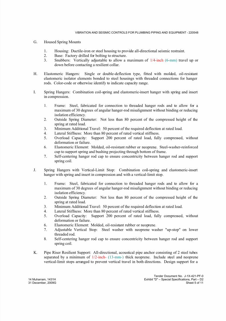
7/18/2019 SEC DPS
http://slidepdf.com/reader/full/sec-dps 222/541
VIBRATION AND SEISMIC CONTROLS FOR PLUMBING PIPING AND EQUIPMENT - 220548
Tender Document No. J-1X-421-PF-0
14 Muharram, 1431H Exhibit "D" – Special Specifications, Part – D231 December, 2009G Sheet 5 of 11
G. Housed Spring Mounts
1. Housing: Ductile-iron or steel housing to provide all-directional seismic restraint.
2. Base: Factory drilled for bolting to structure.3. Snubbers: Vertically adjustable to allow a maximum of 1/4-inch (6-mm) travel up or
down before contacting a resilient collar.
H. Elastomeric Hangers: Single or double-deflection type, fitted with molded, oil-resistant
elastomeric isolator elements bonded to steel housings with threaded connections for hanger
rods. Color-code or otherwise identify to indicate capacity range.
I. Spring Hangers: Combination coil-spring and elastomeric-insert hanger with spring and insert
in compression.
1. Frame: Steel, fabricated for connection to threaded hanger rods and to allow for a
maximum of 30 degrees of angular hanger-rod misalignment without binding or reducingisolation efficiency.
2. Outside Spring Diameter: Not less than 80 percent of the compressed height of the
spring at rated load.
3. Minimum Additional Travel: 50 percent of the required deflection at rated load.
4. Lateral Stiffness: More than 80 percent of rated vertical stiffness.
5. Overload Capacity: Support 200 percent of rated load, fully compressed, without
deformation or failure.
6. Elastomeric Element: Molded, oil-resistant rubber or neoprene. Steel-washer-reinforced
cup to support spring and bushing projecting through bottom of frame.
7. Self-centering hanger rod cap to ensure concentricity between hanger rod and support
spring coil.
J. Spring Hangers with Vertical-Limit Stop: Combination coil-spring and elastomeric-insert
hanger with spring and insert in compression and with a vertical-limit stop.
1. Frame: Steel, fabricated for connection to threaded hanger rods and to allow for a
maximum of 30 degrees of angular hanger-rod misalignment without binding or reducing
isolation efficiency.
2. Outside Spring Diameter: Not less than 80 percent of the compressed height of the
spring at rated load.
3. Minimum Additional Travel: 50 percent of the required deflection at rated load.
4. Lateral Stiffness: More than 80 percent of rated vertical stiffness.
5. Overload Capacity: Support 200 percent of rated load, fully compressed, without
deformation or failure.
6. Elastomeric Element: Molded, oil-resistant rubber or neoprene.
7. Adjustable Vertical Stop: Steel washer with neoprene washer "up-stop" on lower
threaded rod.
8. Self-centering hanger rod cap to ensure concentricity between hanger rod and support
spring coil.
K. Pipe Riser Resilient Support: All-directional, acoustical pipe anchor consisting of 2 steel tubes
separated by a minimum of 1/2-inch- (13-mm-) thick neoprene. Include steel and neoprene
vertical-limit stops arranged to prevent vertical travel in both directions. Design support for a

7/18/2019 SEC DPS
http://slidepdf.com/reader/full/sec-dps 223/541
VIBRATION AND SEISMIC CONTROLS FOR PLUMBING PIPING AND EQUIPMENT - 220548
Tender Document No. J-1X-421-PF-0
14 Muharram, 1431H Exhibit "D" – Special Specifications, Part – D231 December, 2009G Sheet 6 of 11
maximum load on the isolation material of 500 psig (3.45 MPa) and for equal resistance in all
directions.
L. Resilient Pipe Guides: Telescopic arrangement of 2 steel tubes or post and sleeve arrangementseparated by a minimum of 1/2-inch- (13-mm-) thick neoprene. Where clearances are not
readily visible, a factory-set guide height with a shear pin to allow vertical motion due to pipe
expansion and contraction shall be fitted. Shear pin shall be removable and reinsertable to
allow for selection of pipe movement. Guides shall be capable of motion to meet location
requirements.
2.2 VIBRATION ISOLATION EQUIPMENT BASES
A. Manufacturers: Subject to compliance with requirements
B. Basis-of-Design Product: Subject to compliance with requirements
C. Steel Base: Factory-fabricated, welded, structural-steel bases and rails.
1. Design Requirements: Lowest possible mounting height with not less than 1-inch (25-
mm) clearance above the floor. Include equipment anchor bolts and auxiliary motor slide bases or rails.
a. Include supports for suction and discharge elbows for pumps.
2. Structural Steel: Steel shapes, plates, and bars complying with ASTM A 36/A 36M.
Bases shall have shape to accommodate supported equipment.
3. Support Brackets: Factory-welded steel brackets on frame for outrigger isolationmountings and to provide for anchor bolts and equipment support.
D. Inertia Base: Factory-fabricated, welded, structural-steel bases and rails ready for placement of
cast-in-place concrete.
1. Design Requirements: Lowest possible mounting height with not less than 1-inch (25-
mm) clearance above the floor. Include equipment anchor bolts and auxiliary motor slide
bases or rails.
a. Include supports for suction and discharge elbows for pumps.
2. Structural Steel: Steel shapes, plates, and bars complying with ASTM A 36/A 36M.
Bases shall have shape to accommodate supported equipment.3. Support Brackets: Factory-welded steel brackets on frame for outrigger isolation
mountings and to provide for anchor bolts and equipment support.
4. Fabrication: Fabricate steel templates to hold equipment anchor-bolt sleeves and anchors
in place during placement of concrete. Obtain anchor-bolt templates from supported
equipment manufacturer.

7/18/2019 SEC DPS
http://slidepdf.com/reader/full/sec-dps 224/541
VIBRATION AND SEISMIC CONTROLS FOR PLUMBING PIPING AND EQUIPMENT - 220548
Tender Document No. J-1X-421-PF-0
14 Muharram, 1431H Exhibit "D" – Special Specifications, Part – D231 December, 2009G Sheet 7 of 11
2.3 SEISMIC-RESTRAINT DEVICES
A. Manufacturers: Subject to compliance with requirements, provide products by one of the
following:
B. Basis-of-Design Product: Subject to compliance with requirements
C. General Requirements for Restraint Components: Rated strengths, features, and applications
shall be as defined in reports by an evaluation service member of ICC-ES.
1. Structural Safety Factor: Allowable strength in tension, shear, and pullout force of
components shall be at least four times the maximum seismic forces to which they will be
subjected.
D. Snubbers: Factory fabricated using welded structural-steel shapes and plates, anchor bolts, and
replaceable resilient isolation washers and bushings.
1. Anchor bolts for attaching to concrete shall be seismic-rated, drill-in, and stud-wedge or
female-wedge type.
2. Resilient Isolation Washers and Bushings: Oil- and water-resistant neoprene.
3. Maximum 1/4-inch (6-mm) air gap, and minimum 1/4-inch- (6-mm-) thick resilient
cushion.
E. Channel Support System: MFMA-3, shop- or field-fabricated support assembly made of slotted
steel channels with accessories for attachment to braced component at one end and to building
structure at the other end and other matching components and with corrosion-resistant coating;and rated in tension, compression, and torsion forces.
F. Restraint Cables: ASTM A 603 galvanized -steel cables with end connections made of steel
assemblies with thimbles, brackets, swivel, and bolts designed for restraining cable service; and
with a minimum of two clamping bolts for cable engagement.
G. Hanger Rod Stiffener: Steel tube or steel slotted-support-system sleeve with internally bolted
connections to hanger rod.
H. Bushings for Floor-Mounted Equipment Anchor Bolts: Neoprene bushings designed for rigid
equipment mountings, and matched to type and size of anchor bolts and studs.
I. Bushing Assemblies for Wall-Mounted Equipment Anchorage: Assemblies of neoprene
elements and steel sleeves designed for rigid equipment mountings, and matched to type and
size of attachment devices used.
J. Resilient Isolation Washers and Bushings: One-piece, molded, oil- and water-resistant
neoprene, with a flat washer face.
K. Mechanical Anchor Bolts: Drilled-in and stud-wedge or female-wedge type in zinc-coated steel
for interior applications and stainless steel for exterior applications. Select anchor bolts with
strength required for anchor and as tested according to ASTM E 488. Minimum length of eight
times diameter.

7/18/2019 SEC DPS
http://slidepdf.com/reader/full/sec-dps 225/541
VIBRATION AND SEISMIC CONTROLS FOR PLUMBING PIPING AND EQUIPMENT - 220548
Tender Document No. J-1X-421-PF-0
14 Muharram, 1431H Exhibit "D" – Special Specifications, Part – D231 December, 2009G Sheet 8 of 11
L. Adhesive Anchor Bolts: Drilled-in and capsule anchor system containing polyvinyl or urethane
methacrylate-based resin and accelerator, or injected polymer or hybrid mortar adhesive.
Provide anchor bolts and hardware with zinc-coated steel for interior applications and stainless
steel for exterior applications. Select anchor bolts with strength required for anchor and astested according to ASTM E 488.
2.4 FACTORY FINISHES
A. Finish: Manufacturer's standard prime-coat finish ready for field painting.
B. Finish: Manufacturer's standard paint applied to factory-assembled and -tested equipment
before shipping.
1. Powder coating on springs and housings.
2. All hardware shall be galvanized. Hot-dip galvanize metal components for exterior use.3. Baked enamel or powder coat for metal components on isolators for interior use.
4. Color-code or otherwise mark vibration isolation and seismic-control devices to indicate
capacity range.
PART 3 - EXECUTION
3.1 EXAMINATION
A. Examine areas and equipment to receive vibration isolation and seismic-control devices for
compliance with requirements for installation tolerances and other conditions affecting
performance.
B. Examine roughing-in of reinforcement and cast-in-place anchors to verify actual locations
before installation.
C. Proceed with installation only after unsatisfactory conditions have been corrected.
3.2 APPLICATIONS
A. Multiple Pipe Supports: Secure pipes to trapeze member with clamps approved for application
by an evaluation service member of ICC-ES.
B. Hanger Rod Stiffeners: Install hanger rod stiffeners where indicated or scheduled on Drawings
to receive them and where required to prevent buckling of hanger rods due to seismic forces.
C. Strength of Support and Seismic-Restraint Assemblies: Where not indicated, select sizes of
components so strength will be adequate to carry present and future static and seismic loads
within specified loading limits.

7/18/2019 SEC DPS
http://slidepdf.com/reader/full/sec-dps 226/541
VIBRATION AND SEISMIC CONTROLS FOR PLUMBING PIPING AND EQUIPMENT - 220548
Tender Document No. J-1X-421-PF-0
14 Muharram, 1431H Exhibit "D" – Special Specifications, Part – D231 December, 2009G Sheet 9 of 11
3.3 VIBRATION-CONTROL AND SEISMIC-RESTRAINT DEVICE INSTALLATION
A. Equipment Restraints:
1. Install seismic snubbers on plumbing equipment mounted on vibration isolators. Locate
snubbers as close as possible to vibration isolators and bolt to equipment base and
supporting structure.
2. Install resilient bolt isolation washers on equipment anchor bolts where clearance
between anchor and adjacent surface exceeds 0.125 inches (3.2 mm).
3. Install seismic-restraint devices using methods approved by an evaluation service
member of ICC-ES providing required submittals for component.
B. Piping Restraints:
1. Comply with requirements in MSS SP-127.
2. Space lateral supports a maximum of 40 feet (12 m) o.c., and longitudinal supports amaximum of 80 feet (24 m) o.c.
3. Brace a change of direction longer than 12 feet (3.7 m).
C. Install cables so they do not bend across edges of adjacent equipment or building structure.
D. Install seismic-restraint devices using methods approved by an evaluation service member of
ICC-ES providing required submittals for component.
E. Install bushing assemblies for anchor bolts for floor-mounted equipment, arranged to provide
resilient media between anchor bolt and mounting hole in concrete base.
F. Install bushing assemblies for mounting bolts for wall-mounted equipment, arranged to provide
resilient media where equipment or equipment-mounting channels are attached to wall.
G. Attachment to Structure: If specific attachment is not indicated, anchor bracing to structure at
flanges of beams, at upper truss chords of bar joists, or at concrete members.
H. Drilled-in Anchors:
1. Identify position of reinforcing steel and other embedded items prior to drilling holes foranchors. Do not damage existing reinforcing or embedded items during coring or
drilling. Notify the structural engineer if reinforcing steel or other embedded items are
encountered during drilling. Locate and avoid prestressed tendons, electrical and
telecommunications conduit, and gas lines.
2. Do not drill holes in concrete or masonry until concrete, mortar, or grout has achievedfull design strength.
3. Wedge Anchors: Protect threads from damage during anchor installation. Heavy-duty
sleeve anchors shall be installed with sleeve fully engaged in the structural element to
which anchor is to be fastened.
4. Adhesive Anchors: Clean holes to remove loose material and drilling dust prior to
installation of adhesive. Place adhesive in holes proceeding from the bottom of the holeand progressing toward the surface in such a manner as to avoid introduction of air
pockets in the adhesive.
5. Set anchors to manufacturer's recommended torque, using a torque wrench.
7/18/2019 SEC DPS
http://slidepdf.com/reader/full/sec-dps 227/541
VIBRATION AND SEISMIC CONTROLS FOR PLUMBING PIPING AND EQUIPMENT - 220548
Tender Document No. J-1X-421-PF-0
14 Muharram, 1431H Exhibit "D" – Special Specifications, Part – D231 December, 2009G Sheet 10 of 11
6. Install zinc-coated steel anchors for interior and stainless steel anchors for exterior
applications.
3.4 ACCOMMODATION OF DIFFERENTIAL SEISMIC MOTION
A. Install flexible connections in piping where they cross seismic joints, where adjacent sections or
branches are supported by different structural elements, and where the connections terminate
with connection to equipment that is anchored to a different structural element from the one
supporting the connections as they approach equipment. Comply with requirements in
Division 22 Section "Domestic Water Piping" for piping flexible connections.
3.5 FIELD QUALITY CONTROL
A. Testing Agency: Engage a qualified testing agency to perform tests and inspections.
B. Perform tests and inspections.
C. Tests and Inspections:
1. Provide evidence of recent calibration of test equipment by a testing agency acceptable to
authorities having jurisdiction.2. Schedule test with Owner, through Architect, before connecting anchorage device to
restrained component (unless postconnection testing has been approved), and with at least
seven days' advance notice.
3. Obtain Architect's approval before transmitting test loads to structure. Provide temporary
load-spreading members.4. Test at least four of each type and size of installed anchors and fasteners selected by
Architect.
5. Test to 90 percent of rated proof load of device.
6. Measure isolator restraint clearance.
7. Measure isolator deflection.
8. Verify snubber minimum clearances.9. Air-Mounting System Leak Test: After installation, charge system and test for leaks.
Repair leaks and retest until no leaks exist.
10. Air-Mounting System Operational Test: Test the compressed-air leveling system.
11. Test and adjust air-mounting system controls and safeties.
12. If a device fails test, modify all installations of same type and retest until satisfactoryresults are achieved.
D. Remove and replace malfunctioning units and retest as specified above.
E. Prepare test and inspection reports.
3.6 ADJUSTING
A. Adjust isolators after piping system is at operating weight.

7/18/2019 SEC DPS
http://slidepdf.com/reader/full/sec-dps 228/541
VIBRATION AND SEISMIC CONTROLS FOR PLUMBING PIPING AND EQUIPMENT - 220548
Tender Document No. J-1X-421-PF-0
14 Muharram, 1431H Exhibit "D" – Special Specifications, Part – D231 December, 2009G Sheet 11 of 11
B. Adjust limit stops on restrained spring isolators to mount equipment at normal operating height.
After equipment installation is complete, adjust limit stops so they are out of contact during
normal operation.
C. Adjust active height of sprint isolators.
D. Adjust restraints to permit free movement of equipment within normal mode of operation.
3.7 PLUMBING VIBRATION-CONTROL AND SEISMIC-RESTRAINT DEVICE SCHEDULE
A. Supported or Suspended Equipment: .
1. Equipment Location: as per contract documents and design requirements.
2. Pads:
a. Material: Neoprene.
b. Thickness: As required by Seismic professional.
c. Number of Pads: As required by Seismic professional thick.
3. Isolator Type: As required by Seismic professional.
4. Base Type: As required by Seismic professional.
5. Minimum Deflection: As required by Seismic professional.
6. Component Importance Factor: 1.0.
7. Component Response Modification Factor: 1.5.
8. Component Amplification Factor: 1.0.
END OF SECTION 220548

7/18/2019 SEC DPS
http://slidepdf.com/reader/full/sec-dps 229/541
IDENTIFICATION FOR PLUMBING PIPING AND EQUIPMENT - 220553
Tender Document No. J-1X-421-PF-0
14 Muharram, 1431H Exhibit "D" – Special Specifications, Part – D231 December, 2009G Sheet 1 of 6
SECTION 220553 - IDENTIFICATION FOR PLUMBING PIPING AND EQUIPMENT
PART 1 - GENERAL
1.1 RELATED DOCUMENTS
A. Drawings and general provisions of the Contract, including General and Supplementary
Conditions and Division 01 Specification Sections, apply to this Section.
1.2 SUMMARY
A. Section Includes:
1. Equipment labels.
2. Warning signs and labels.3. Pipe labels.
4. Stencils.
5. Valve tags.
6. Warning tags.
1.3 ACTION SUBMITTALS
A. Product Data: For each type of product indicated.
B. Samples: For color, letter style, and graphic representation required for each identification
material and device.
C. Equipment Label Schedule: Include a listing of all equipment to be labeled with the proposed
content for each label.
D. Valve numbering scheme.
E. Valve Schedules: For each piping system to include in maintenance manuals.
1.4 COORDINATION
A. Coordinate installation of identifying devices with completion of covering and painting of
surfaces where devices are to be applied.
B. Coordinate installation of identifying devices with locations of access panels and doors.
C. Install identifying devices before installing acoustical ceilings and similar concealment.

7/18/2019 SEC DPS
http://slidepdf.com/reader/full/sec-dps 230/541
IDENTIFICATION FOR PLUMBING PIPING AND EQUIPMENT - 220553
Tender Document No. J-1X-421-PF-0
14 Muharram, 1431H Exhibit "D" – Special Specifications, Part – D231 December, 2009G Sheet 2 of 6
PART 2 - PRODUCTS
2.1 EQUIPMENT LABELS
A. Metal Labels for Equipment:
1. Material and Thickness: Brass, 0.032-inch (0.8-mm) minimum thickness, and having
predrilled or stamped holes for attachment hardware.
2. Minimum Label Size: Length and width vary for required label content, but not less than
2-1/2 by 3/4 inch (64 by 19 mm).
3. Minimum Letter Size: 1/4 inch (6.4 mm) for name of units if viewing distance is less
than 24 inches (600 mm), 1/2 inch (13 mm) for viewing distances up to 72 inches (1830
mm), and proportionately larger lettering for greater viewing distances. Include
secondary lettering two-thirds to three-fourths the size of principal lettering.
4. Fasteners: Stainless-steel rivets or self-tapping screws.5. Adhesive: Contact-type permanent adhesive, compatible with label and with substrate.
B. Label Content: Include equipment's Drawing designation or unique equipment number,
Drawing numbers where equipment is indicated (plans, details, and schedules), plus the
Specification Section number and title where equipment is specified.
C. Equipment Label Schedule: For each item of equipment to be labeled, on 8-1/2-by-11-inch
(A4) bond paper. Tabulate equipment identification number and identify Drawing numbers
where equipment is indicated (plans, details, and schedules), plus the Specification Section
number and title where equipment is specified. Equipment schedule shall be included in
operation and maintenance data.
2.2 WARNING SIGNS AND LABELS
A. Material and Thickness: Multilayer, multicolor, plastic labels for mechanical engraving, 1/8
inch (3.2 mm) thick, and having predrilled holes for attachment hardware.
B. Letter Color: Black.
C. Background Color: Yellow.
D. Maximum Temperature: Able to withstand temperatures up to 160 deg F (71 deg C).
E. Minimum Label Size: Length and width vary for required label content, but not less than 2-1/2 by 3/4 inch (64 by 19 mm).
F. Minimum Letter Size: 1/4 inch (6.4 mm) for name of units if viewing distance is less than 24
inches (600 mm), 1/2 inch (13 mm) for viewing distances up to 72 inches (1830 mm), and
proportionately larger lettering for greater viewing distances. Include secondary lettering two-
thirds to three-fourths the size of principal lettering.
G. Fasteners: Stainless-steel rivets or self-tapping screws.
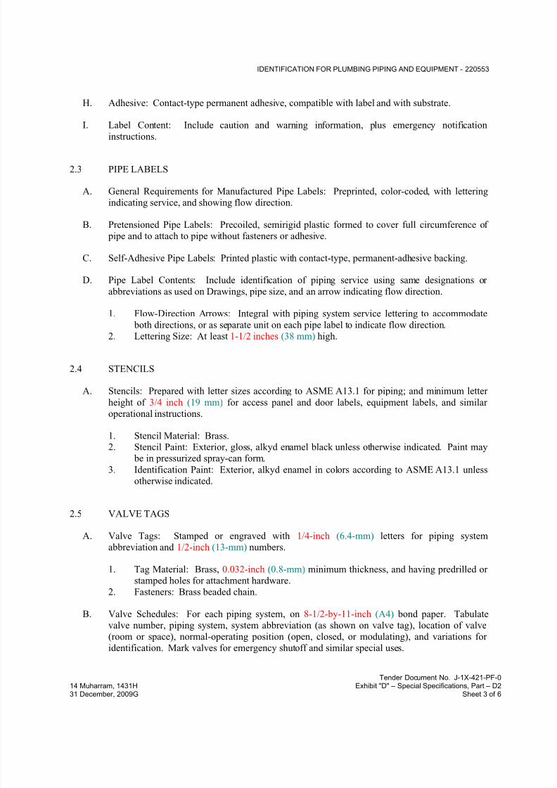
7/18/2019 SEC DPS
http://slidepdf.com/reader/full/sec-dps 231/541
IDENTIFICATION FOR PLUMBING PIPING AND EQUIPMENT - 220553
Tender Document No. J-1X-421-PF-0
14 Muharram, 1431H Exhibit "D" – Special Specifications, Part – D231 December, 2009G Sheet 3 of 6
H. Adhesive: Contact-type permanent adhesive, compatible with label and with substrate.
I. Label Content: Include caution and warning information, plus emergency notification
instructions.
2.3 PIPE LABELS
A. General Requirements for Manufactured Pipe Labels: Preprinted, color-coded, with lettering
indicating service, and showing flow direction.
B. Pretensioned Pipe Labels: Precoiled, semirigid plastic formed to cover full circumference of
pipe and to attach to pipe without fasteners or adhesive.
C. Self-Adhesive Pipe Labels: Printed plastic with contact-type, permanent-adhesive backing.
D. Pipe Label Contents: Include identification of piping service using same designations or
abbreviations as used on Drawings, pipe size, and an arrow indicating flow direction.
1. Flow-Direction Arrows: Integral with piping system service lettering to accommodate
both directions, or as separate unit on each pipe label to indicate flow direction.
2. Lettering Size: At least 1-1/2 inches (38 mm) high.
2.4 STENCILS
A. Stencils: Prepared with letter sizes according to ASME A13.1 for piping; and minimum letter
height of 3/4 inch (19 mm) for access panel and door labels, equipment labels, and similar
operational instructions.
1. Stencil Material: Brass.2. Stencil Paint: Exterior, gloss, alkyd enamel black unless otherwise indicated. Paint may
be in pressurized spray-can form.
3. Identification Paint: Exterior, alkyd enamel in colors according to ASME A13.1 unless
otherwise indicated.
2.5 VALVE TAGS
A. Valve Tags: Stamped or engraved with 1/4-inch (6.4-mm) letters for piping system
abbreviation and 1/2-inch (13-mm) numbers.
1. Tag Material: Brass, 0.032-inch (0.8-mm) minimum thickness, and having predrilled or
stamped holes for attachment hardware.
2. Fasteners: Brass beaded chain.
B. Valve Schedules: For each piping system, on 8-1/2-by-11-inch (A4) bond paper. Tabulate
valve number, piping system, system abbreviation (as shown on valve tag), location of valve
(room or space), normal-operating position (open, closed, or modulating), and variations for
identification. Mark valves for emergency shutoff and similar special uses.

7/18/2019 SEC DPS
http://slidepdf.com/reader/full/sec-dps 232/541
IDENTIFICATION FOR PLUMBING PIPING AND EQUIPMENT - 220553
Tender Document No. J-1X-421-PF-0
14 Muharram, 1431H Exhibit "D" – Special Specifications, Part – D231 December, 2009G Sheet 4 of 6
1. Valve-tag schedule shall be included in operation and maintenance data.
2.6 WARNING TAGS
A. Warning Tags: Preprinted or partially preprinted, accident-prevention tags, of plasticized card
stock with matte finish suitable for writing.
1. Size: Approximately 4 by 7 inches (100 by 178 mm).
2. Fasteners: Brass grommet and wire.
3. Nomenclature: Large-size primary caption such as "DANGER," "CAUTION," or "DO
NOT OPERATE."
4. Color: Yellow background with black lettering.
PART 3 - EXECUTION
3.1 PREPARATION
A. Clean piping and equipment surfaces of substances that could impair bond of identification
devices, including dirt, oil, grease, release agents, and incompatible primers, paints, and
encapsulants.
3.2 EQUIPMENT LABEL INSTALLATION
A. Install or permanently fasten labels on each major item of mechanical equipment.
B. Locate equipment labels where accessible and visible.
3.3 PIPE LABEL INSTALLATION
A. Piping Color-Coding: Painting of piping is specified in Division 09 Section
B. Stenciled Pipe Label Option: Stenciled labels may be provided instead of manufactured pipe
labels, at Installer's option. Install stenciled pipe labels , complying with ANSI/ASME A13.1
2007, on each piping system.
1. Identification Paint: Use for contrasting background.2. Stencil Paint: Use for pipe marking.
C. Locate pipe labels where piping is exposed or above accessible ceilings in finished spaces;
machine rooms; accessible maintenance spaces such as shafts, tunnels, and plenums; and
exterior exposed locations as follows:
1. Near each valve and control device.
2. Near each branch connection, excluding short takeoffs for fixtures and terminal units.
Where flow pattern is not obvious, mark each pipe at branch.
3. Near penetrations through walls, floors, ceilings, and inaccessible enclosures.
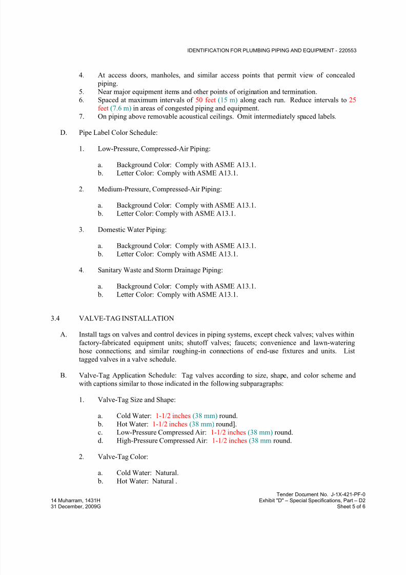
7/18/2019 SEC DPS
http://slidepdf.com/reader/full/sec-dps 233/541
IDENTIFICATION FOR PLUMBING PIPING AND EQUIPMENT - 220553
Tender Document No. J-1X-421-PF-0
14 Muharram, 1431H Exhibit "D" – Special Specifications, Part – D231 December, 2009G Sheet 5 of 6
4. At access doors, manholes, and similar access points that permit view of concealed
piping.
5. Near major equipment items and other points of origination and termination.
6. Spaced at maximum intervals of 50 feet (15 m) along each run. Reduce intervals to 25feet (7.6 m) in areas of congested piping and equipment.
7. On piping above removable acoustical ceilings. Omit intermediately spaced labels.
D. Pipe Label Color Schedule:
1. Low-Pressure, Compressed-Air Piping:
a. Background Color: Comply with ASME A13.1.
b. Letter Color: Comply with ASME A13.1.
2. Medium-Pressure, Compressed-Air Piping:
a. Background Color: Comply with ASME A13.1.
b. Letter Color: Comply with ASME A13.1.
3. Domestic Water Piping:
a. Background Color: Comply with ASME A13.1.
b. Letter Color: Comply with ASME A13.1.
4. Sanitary Waste and Storm Drainage Piping:
a. Background Color: Comply with ASME A13.1.
b. Letter Color: Comply with ASME A13.1.
3.4 VALVE-TAG INSTALLATION
A. Install tags on valves and control devices in piping systems, except check valves; valves within
factory-fabricated equipment units; shutoff valves; faucets; convenience and lawn-watering
hose connections; and similar roughing-in connections of end-use fixtures and units. List
tagged valves in a valve schedule.
B. Valve-Tag Application Schedule: Tag valves according to size, shape, and color scheme and
with captions similar to those indicated in the following subparagraphs:
1. Valve-Tag Size and Shape:
a. Cold Water: 1-1/2 inches (38 mm) round.
b. Hot Water: 1-1/2 inches (38 mm) round].
c. Low-Pressure Compressed Air: 1-1/2 inches (38 mm) round.
d. High-Pressure Compressed Air: 1-1/2 inches (38 mm round.
2. Valve-Tag Color:
a. Cold Water: Natural.
b. Hot Water: Natural .

7/18/2019 SEC DPS
http://slidepdf.com/reader/full/sec-dps 234/541
IDENTIFICATION FOR PLUMBING PIPING AND EQUIPMENT - 220553
Tender Document No. J-1X-421-PF-0
14 Muharram, 1431H Exhibit "D" – Special Specifications, Part – D231 December, 2009G Sheet 6 of 6
c. Low-Pressure Compressed Air: Natural.
d. High-Pressure Compressed Air: Natural.
3. Letter Color:
a. Cold Water: Black.
b. Hot Water: Black.
c. Low-Pressure Compressed Air: Black.
d. High-Pressure Compressed Air: Black.
3.5 WARNING-TAG INSTALLATION
A. Write required message on, and attach warning tags to, equipment and other items where
required.
END OF SECTION 220553

7/18/2019 SEC DPS
http://slidepdf.com/reader/full/sec-dps 235/541
PLUMBING EQUIPMENT INSULATION - 220716
Tender Document No. J-1X-421-PF-0
14 Muharram, 1431H Exhibit "D" – Special Specifications, Part – D231 December, 2009G Sheet 1 of 18
SECTION 220716 - PLUMBING EQUIPMENT INSULATION
PART 1 - GENERAL
1.1 RELATED DOCUMENTS
A. Drawings and general provisions of the Contract, including General and Supplementary
Conditions and Division 01 Specification Sections, apply to this Section.
1.2 SUMMARY
A. Section includes insulating the following plumbing equipment:
1. Domestic water heat exchangers.
2. Domestic water converters.3. Domestic water, hot-water cold-water and chilled-water pumps.
4. Domestic water storage tanks.
5. Domestic water filter housings.
B. Related Sections:
1. Division 22 Section "Plumbing Piping Insulation."
1.3 ACTION SUBMITTALS
A. Product Data: For each type of product indicated. Include thermal conductivity, water-vapor
permeance thickness, and jackets (both factory and field applied, if any).
B. LEED Submittals:
1. Product Data for Credit IEQ 4.1: For adhesives and sealants, documentation including
printed statement of VOC content and chemical components.
2. Laboratory Test Reports for Credit IEQ 4: For adhesives and sealants, documentation
indicating that product complies with the testing and product requirements of the
California Department of Health Services' "Standard Practice for the Testing of Volatile
Organic Emissions from Various Sources Using Small-Scale Environmental Chambers."
C. Shop Drawings: Include plans, elevations, sections, details, and attachments to other work.
1. Detail application of protective shields, saddles, and inserts at hangers for each type of
insulation and hanger.
2. Detail attachment and covering of heat tracing inside insulation.
3. Detail removable insulation at equipment connections and access panels.
4. Detail application of field-applied jackets.
5. Detail application at linkages of control devices.
6. Detail field application for each equipment type.
7/18/2019 SEC DPS
http://slidepdf.com/reader/full/sec-dps 236/541
PLUMBING EQUIPMENT INSULATION - 220716
Tender Document No. J-1X-421-PF-0
14 Muharram, 1431H Exhibit "D" – Special Specifications, Part – D231 December, 2009G Sheet 2 of 18
D. Samples: For each type of insulation and jacket indicated. Identify each Sample, describing
product and intended use. Sample sizes are as follows:
1. Sheet Form Insulation Materials: 12 inches (300 mm) square.2. Sheet Jacket Materials: 12 inches (300 mm) square.
3. Manufacturer's Color Charts: For products where color is specified, show the full range
of colors available for each type of finish material.
1.4 INFORMATIONAL SUBMITTALS
A. Qualification Data: For qualified Installer.
B. Material Test Reports: From a qualified testing agency acceptable to authorities having
jurisdiction indicating, interpreting, and certifying test results for compliance of insulation
materials, sealers, attachments, cements, and jackets, with requirements indicated. Includedates of tests and test methods employed.
C. Field quality-control reports.
1.5 QUALITY ASSURANCE
A. Installer Qualifications: Skilled mechanics who have successfully completed an apprenticeship
program or another craft training program certified by the Department of Labor, Bureau of
Apprenticeship and Training.
B. Surface-Burning Characteristics: For insulation and related materials, as determined by testing
identical products according to ASTM E 84 by a testing agency acceptable to authorities having jurisdiction. Factory label insulation and jacket materials and adhesive, mastic, tapes, and
cement material containers, with appropriate markings of applicable testing agency.
1. Insulation Installed Indoors: Flame-spread index of 25 or less, and smoke-developed
index of 50 or less.
2. Insulation Installed Outdoors: Flame-spread index of 75 or less, and smoke-developed
index of 150 or less.
C. Mockups: Before installing insulation, build mockups for each type of insulation and finish
listed below to demonstrate quality of insulation application and finishes. Build mockups in the
location indicated or, if not indicated, as directed by Architect. Use materials indicated for the
completed Work.
1. Equipment Mockups: One tank or vessel and pump.
2. For each mockup, fabricate cutaway sections to allow observation of application details
for insulation materials, adhesives, mastics, attachments, and jackets.
3. Notify Architect seven days in advance of dates and times when mockups will be
constructed.
4. Obtain Architect's approval of mockups before starting insulation application.

7/18/2019 SEC DPS
http://slidepdf.com/reader/full/sec-dps 237/541
PLUMBING EQUIPMENT INSULATION - 220716
Tender Document No. J-1X-421-PF-0
14 Muharram, 1431H Exhibit "D" – Special Specifications, Part – D231 December, 2009G Sheet 3 of 18
5. Approval of mockups does not constitute approval of deviations from the Contract
Documents contained in mockups unless Architect specifically approves such deviations
in writing.
6. Maintain mockups during construction in an undisturbed condition as a standard for judging the completed Work.
7. Demolish and remove mockups when directed.
1.6 DELIVERY, STORAGE, AND HANDLING
A. Packaging: Insulation material containers shall be marked by manufacturer with appropriate
ASTM standard designation, type and grade, and maximum use temperature.
1.7 COORDINATION
A. Coordinate sizes and locations of supports, hangers, and insulation shields specified in
Division 22 Section "Hangers and Supports for Plumbing Piping and Equipment."
B. Coordinate clearance requirements with equipment Installer for equipment insulation
application.
C. Coordinate installation and testing of heat tracing.
1.8 SCHEDULING
A. Schedule insulation application after pressure testing systems and, where required, after
installing and testing heat tracing. Insulation application may begin on segments that havesatisfactory test results.
B. Complete installation and concealment of plastic materials as rapidly as possible in each area of
construction.
PART 2 - PRODUCTS
2.1 INSULATION MATERIALS
A. Comply with requirements in "Equipment Insulation Schedule" article for where insulatingmaterials shall be applied.
B. Products shall not contain asbestos, lead, mercury, or mercury compounds.
C. Products that come in contact with stainless steel shall have a leachable chloride content of less
than 50 ppm when tested according to ASTM C 871.
D. Insulation materials for use on austenitic stainless steel shall be qualified as acceptable
according to ASTM C 795.

7/18/2019 SEC DPS
http://slidepdf.com/reader/full/sec-dps 238/541
PLUMBING EQUIPMENT INSULATION - 220716
Tender Document No. J-1X-421-PF-0
14 Muharram, 1431H Exhibit "D" – Special Specifications, Part – D231 December, 2009G Sheet 4 of 18
E. Foam insulation materials shall not use CFC or HCFC blowing agents in the manufacturing
process.
F. Cellular Glass: Inorganic, incombustible, foamed or cellulated glass with annealed, rigid,hermetically sealed cells. Factory-applied jacket requirements are specified in "Factory-
Applied Jackets" Article.
1. Products: Subject to compliance with requirements
2. Block Insulation: ASTM C 552, Type I.
3. Special-Shaped Insulation: ASTM C 552, Type III.
4. Board Insulation: ASTM C 552, Type IV.
5. Preformed Pipe Insulation without Jacket: Comply with ASTM C 552, Type II, Class 1.
6. Preformed Pipe Insulation with Factory-Applied ASJ-SSL: Comply with ASTM C 552,
Type II, Class 2.
7. Factory fabricate shapes according to ASTM C 450 and ASTM C 585.
G. Flexible Elastomeric Insulation: Closed-cell, sponge- or expanded-rubber materials. Comply
with ASTM C 534, Type I for tubular materials and Type II for sheet materials.
1. Products: Subject to compliance with requirements
H. Mineral-Fiber Blanket Insulation: Mineral or glass fibers bonded with a thermosetting resin.
Comply with ASTM C 553, Type II and ASTM C 1290, Type I. Factory-applied jacket
requirements are specified in "Factory-Applied Jackets" Article.
1. Products: Subject to compliance with requirements
I. High-Temperature, Mineral-Fiber Blanket Insulation: Mineral or glass fibers bonded with a
thermosetting resin. Comply with ASTM C 553, Type V, without factory-applied jacket.
1. Products: Subject to compliance with requirements
J. Mineral-Fiber Board Insulation: Mineral or glass fibers bonded with a thermosetting resin.
Comply with ASTM C 612, Type IA or Type IB. For equipment applications, provide
insulation with factory-applied ASJ. Factory-applied jacket requirements are specified in
"Factory-Applied Jackets" Article.
1. Products: Subject to compliance with requirements
K. High-Temperature, Mineral-Fiber Board Insulation: Mineral or glass fibers bonded with athermosetting resin. Comply with ASTM C 612, Type III, without factory-applied jacket.
1. Products: Subject to compliance with requirements
2.2 ADHESIVES
A. Materials shall be compatible with insulation materials, jackets, and substrates and for bonding
insulation to itself and to surfaces to be insulated unless otherwise indicated.

7/18/2019 SEC DPS
http://slidepdf.com/reader/full/sec-dps 239/541
PLUMBING EQUIPMENT INSULATION - 220716
Tender Document No. J-1X-421-PF-0
14 Muharram, 1431H Exhibit "D" – Special Specifications, Part – D231 December, 2009G Sheet 5 of 18
B. Cellular-Glass Adhesive: Two-component, thermosetting urethane adhesive containing no
flammable solvents, with a service temperature range of minus 100 to plus 200 deg F (minus 73
to plus 93 deg C).
1. Products: Subject to compliance with requirements
2. For indoor applications, adhesive shall have a VOC content of 50 g/L or less when
calculated according to 40 CFR 59, Subpart D (EPA Method 24).
C. Flexible Elastomeric and Polyolefin Adhesive: Comply with MIL-A-24179A, Type II, Class I.
1. Products: Subject to compliance with requirements
2. For indoor applications, adhesive shall have a VOC content of 50 g/L or less when
calculated according to 40 CFR 59, Subpart D (EPA Method 24).
3. Adhesive shall comply with the testing and product requirements of the CaliforniaDepartment of Health Services' "Standard Practice for the Testing of Volatile Organic
Emissions from Various Sources Using Small-Scale Environmental Chambers."
D. Mineral-Fiber Adhesive: Comply with MIL-A-3316C, Class 2, Grade A.
1. Products: Subject to compliance with requirements
2. For indoor applications, adhesive shall have a VOC content of 80 g/L or less when
calculated according to 40 CFR 59, Subpart D (EPA Method 24).
3. Adhesive shall comply with the testing and product requirements of the California
Department of Health Services' "Standard Practice for the Testing of Volatile Organic
Emissions from Various Sources Using Small-Scale Environmental Chambers."
E. ASJ Adhesive, and FSK and PVDC Jacket Adhesive: Comply with MIL-A-3316C, Class 2,
Grade A for bonding insulation jacket lap seams and joints.
1. Products: Subject to compliance with requirements
2. For indoor applications, adhesive shall have a VOC content of 50 g/L or less when
calculated according to 40 CFR 59, Subpart D (EPA Method 24).3. Adhesive shall comply with the testing and product requirements of the California
Department of Health Services' "Standard Practice for the Testing of Volatile Organic
Emissions from Various Sources Using Small-Scale Environmental Chambers."
F. PVC Jacket Adhesive: Compatible with PVC jacket.
1. Products: Subject to compliance with requirements
2. For indoor applications, adhesive shall have a VOC content of 50 g/L or less when
calculated according to 40 CFR 59, Subpart D (EPA Method 24).
3. Adhesive shall comply with the testing and product requirements of the California
Department of Health Services' "Standard Practice for the Testing of Volatile Organic
Emissions from Various Sources Using Small-Scale Environmental Chambers."
7/18/2019 SEC DPS
http://slidepdf.com/reader/full/sec-dps 240/541
PLUMBING EQUIPMENT INSULATION - 220716
Tender Document No. J-1X-421-PF-0
14 Muharram, 1431H Exhibit "D" – Special Specifications, Part – D231 December, 2009G Sheet 6 of 18
2.3 MASTICS
A. Materials shall be compatible with insulation materials, jackets, and substrates; comply with
MIL-PRF-19565C, Type II.
1. For indoor applications, use mastics that have a VOC content of 50 g/L or less when
calculated according to 40 CFR 59, Subpart D (EPA Method 24).
B. Vapor-Barrier Mastic: Water based; suitable for indoor use on below ambient services.
1. Products: Subject to compliance with requirements
2. Water-Vapor Permeance: ASTM E 96/E 96M, Procedure B, 0.013 perm (0.009 metric
perm) at 43-mil (1.09-mm) dry film thickness.
3. Service Temperature Range: Minus 20 to plus 180 deg F (Minus 29 to plus 82 deg C).
4. Solids Content: ASTM D 1644, 58 percent by volume and 70 percent by weight.5. Color: White.
C. Vapor-Barrier Mastic: Solvent based; suitable for indoor use on below ambient services.
1. Products: Subject to compliance with requirements
2. Water-Vapor Permeance: ASTM F 1249, 0.05 perm (0.03 metric perm) at 35-mil (0.9-
mm) dry film thickness.
3. Service Temperature Range: 0 to 180 deg F (Minus 18 to plus 82 deg C).
4. Solids Content: ASTM D 1644, 44 percent by volume and 62 percent by weight.
5. Color: White.
D. Vapor-Barrier Mastic: Solvent based; suitable for outdoor use on below ambient services.
1. Products: Subject to compliance with requirements
2. Water-Vapor Permeance: ASTM F 1249, 0.05 perm (0.033 metric perm) at 30-mil (0.8-
mm) dry film thickness.
3. Service Temperature Range: Minus 50 to plus 220 deg F (Minus 46 to plus 104 deg C).
4. Solids Content: ASTM D 1644, 33 percent by volume and 46 percent by weight.5. Color: White.
E. Breather Mastic: Water based; suitable for indoor and outdoor use on above ambient services.
1. Products: Subject to compliance with requirements
2. Water-Vapor Permeance: ASTM F 1249, 1.8 perms (1.2 metric perms) at 0.0625-inch
(1.6-mm) dry film thickness.
3. Service Temperature Range: Minus 20 to plus 180 deg F (Minus 29 to plus 82 deg C).
4. Solids Content: 60 percent by volume and 66 percent by weight.
5. Color: White.

7/18/2019 SEC DPS
http://slidepdf.com/reader/full/sec-dps 241/541
PLUMBING EQUIPMENT INSULATION - 220716
Tender Document No. J-1X-421-PF-0
14 Muharram, 1431H Exhibit "D" – Special Specifications, Part – D231 December, 2009G Sheet 7 of 18
2.4 LAGGING ADHESIVES
A. Description: Comply with MIL-A-3316C, Class I, Grade A, and shall be compatible with
insulation materials, jackets, and substrates.
1. For indoor applications, use lagging adhesives that have a VOC content of 80> g/L or
less when calculated according to 40 CFR 59, Subpart D (EPA Method 24).
2. Products: Subject to compliance with requirements
3. Fire-resistant, water-based lagging adhesive and coating for use indoors to adhere fire-
resistant lagging cloths over insulation.
4. Service Temperature Range: 0 to plus 180 deg F (Minus 18 to plus 82 deg C).
5. Color: White.
2.5 SEALANTS
A. Joint Sealants:
1. Joint Sealants for Cellular-Glass Products: Subject to compliance with requirements
2. Materials shall be compatible with insulation materials, jackets, and substrates.
3. Permanently flexible, elastomeric sealant.
4. Service Temperature Range: Minus 100 to plus 300 deg F (Minus 73 to plus 149 deg C).
5. Color: White or gray.
6. For indoor applications, sealants shall have a VOC content of 420 g/L or less when
calculated according to 40 CFR 59, Subpart D (EPA Method 24).
B. FSK and Metal Jacket Flashing Sealants:
1. Products: Subject to compliance with requirements
2. Materials shall be compatible with insulation materials, jackets, and substrates.
3. Fire- and water-resistant, flexible, elastomeric sealant.
4. Service Temperature Range: Minus 40 to plus 250 deg F (Minus 40 to plus 121 deg C).
5. Color: Aluminum.6. For indoor applications, sealants shall have a VOC content of 420 g/L or less when
calculated according to 40 CFR 59, Subpart D (EPA Method 24).
C. ASJ Flashing Sealants, and Vinyl, PVDC, and PVC Jacket Flashing Sealants:
1. Products: Subject to compliance with requirements
2. Materials shall be compatible with insulation materials, jackets, and substrates.
3. Fire- and water-resistant, flexible, elastomeric sealant.
4. Service Temperature Range: Minus 40 to plus 250 deg F (Minus 40 to plus 121 deg C).
5. Color: White.
6. For indoor applications, sealants shall have a VOC content of 420 g/L or less when
calculated according to 40 CFR 59, Subpart D (EPA Method 24).
7/18/2019 SEC DPS
http://slidepdf.com/reader/full/sec-dps 242/541
PLUMBING EQUIPMENT INSULATION - 220716
Tender Document No. J-1X-421-PF-0
14 Muharram, 1431H Exhibit "D" – Special Specifications, Part – D231 December, 2009G Sheet 8 of 18
2.6 FACTORY-APPLIED JACKETS
A. Insulation system schedules indicate factory-applied jackets on various applications. When
factory-applied jackets are indicated, comply with the following:
1. ASJ: White, kraft-paper, fiberglass-reinforced scrim with aluminum-foil backing;
complying with ASTM C 1136, Type I.
2. ASJ-SSL: ASJ with self-sealing, pressure-sensitive, acrylic-based adhesive covered by a
removable protective strip; complying with ASTM C 1136, Type I.
3. FSK Jacket: Aluminum-foil, fiberglass-reinforced scrim with kraft-paper backing;
complying with ASTM C 1136, Type II.
2.7 FIELD-APPLIED JACKETS
A. Field-applied jackets shall comply with ASTM C 921, Type I, unless otherwise indicated.
B. Metal Jacket:
1. Products: Subject to compliance with requirements
2. Aluminum Jacket: Comply with ASTM B 209 (ASTM B 209M), Alloy 3003, 3005,
3105, or 5005, Temper H-14.
a. Factory cut and rolled to size.
b. Finish and thickness are indicated in field-applied jacket schedules.
c. Moisture Barrier for Indoor Applications: 1-mil- (0.025-mm-) thick, heat-bonded
polyethylene and kraft paper.d. Moisture Barrier for Outdoor Applications: 3-mil- (0.075-mm-) thick, heat-
bonded polyethylene and kraft paper.
2.8 TAPES
A. ASJ Tape: White vapor-retarder tape matching factory-applied jacket with acrylic adhesive,
complying with ASTM C 1136.
1. Products: Subject to compliance with requirements
2. Width: 3 inches (75 mm).
3. Thickness: 11.5 mils (0.29 mm).4. Adhesion: 90 ounces force/inch (1.0 N/mm) in width.
5. Elongation: 2 percent.
6. Tensile Strength: 40 lbf/inch (7.2 N/mm) in width.
7. ASJ Tape Disks and Squares: Precut disks or squares of ASJ tape.
B. FSK Tape: Foil-face, vapor-retarder tape matching factory-applied jacket with acrylic adhesive;
complying with ASTM C 1136.
1. Products: Subject to compliance with requirements

7/18/2019 SEC DPS
http://slidepdf.com/reader/full/sec-dps 243/541
PLUMBING EQUIPMENT INSULATION - 220716
Tender Document No. J-1X-421-PF-0
14 Muharram, 1431H Exhibit "D" – Special Specifications, Part – D231 December, 2009G Sheet 9 of 18
2. Width: 3 inches (75 mm).
3. Thickness: 6.5 mils (0.16 mm).
4. Adhesion: 90 ounces force/inch (1.0 N/mm) in width.
5. Elongation: 2 percent.6. Tensile Strength: 40 lbf/inch (7.2 N/mm) in width.
7. FSK Tape Disks and Squares: Precut disks or squares of FSK tape.
C. Aluminum-Foil Tape: Vapor-retarder tape with acrylic adhesive.
1. Products: Subject to compliance with requirements
2. Width: 2 inches (50 mm).
3. Thickness: 3.7 mils (0.093 mm).
4. Adhesion: 100 ounces force/inch (1.1 N/mm) in width.
5. Elongation: 5 percent.
6. Tensile Strength: 34 lbf/inch (6.2 N/mm) in width.
2.9 SECUREMENTS
A. Bands:
1. Products: Subject to compliance with requirements
2. Aluminum: ASTM B 209 (ASTM B 209M), Alloy 3003, 3005, 3105, or 5005;
Temper H-14, 0.020 inch (0.51 mm) thick, 1/2 inch (13 mm) wide with wing seal or
closed seal.3. Springs: Twin spring set constructed of stainless steel with ends flat and slotted to accept
metal bands. Spring size determined by manufacturer for application.
B. Insulation Pins and Hangers:
1. Capacitor-Discharge-Weld Pins: Copper- or zinc-coated steel pin, fully annealed for
capacitor-discharge welding, 0.106-inch- (2.6-mm-) diameter shank, length to suit depth
of insulation indicated.
a. Products: Subject to compliance with requirements
2. Cupped-Head, Capacitor-Discharge-Weld Pins: Copper- or zinc-coated steel pin, fully
annealed for capacitor-discharge welding, 0.135-inch- (3.5-mm-) diameter shank, length
to suit depth of insulation indicated with integral 1-1/2-inch (38-mm) galvanized carbon-
steel washer.
a. Products: Subject to compliance with requirements
3. Metal, Adhesively Attached, Perforated-Base Insulation Hangers: Baseplate welded to
projecting spindle that is capable of holding insulation, of thickness indicated, securely in
position indicated when self-locking washer is in place.
a. Products: Subject to compliance with requirements

7/18/2019 SEC DPS
http://slidepdf.com/reader/full/sec-dps 244/541
PLUMBING EQUIPMENT INSULATION - 220716
Tender Document No. J-1X-421-PF-0
14 Muharram, 1431H Exhibit "D" – Special Specifications, Part – D231 December, 2009G Sheet 10 of 18
b. Baseplate: Perforated, galvanized carbon-steel sheet, 0.030 inch (0.76 mm) thick
by 2 inches (50 mm) square.
c. Spindle: Copper- or zinc-coated, low-carbon steel, fully annealed, 0.106-inch-
(2.6-mm-) diameter shank, length to suit depth of insulation indicated.d. Adhesive: Recommended by hanger manufacturer. Product with demonstrated
capability to bond insulation hanger securely to substrates indicated without
damaging insulation, hangers, and substrates.
4. Nonmetal, Adhesively Attached, Perforated-Base Insulation Hangers: Baseplate fastened
to projecting spindle that is capable of holding insulation, of thickness indicated, securely
in position indicated when self-locking washer is in place.
a. Products: Subject to compliance with requirements
b. Baseplate: Perforated, nylon sheet, 0.030 inch (0.76 mm) thick by 1-1/2 inches (38
mm) in diameter.c. Spindle: Nylon, 0.106-inch- (2.6-mm-) diameter shank, length to suit depth of
insulation indicated, up to 2-1/2 inches (63 mm).
d. Adhesive: Recommended by hanger manufacturer. Product with demonstrated
capability to bond insulation hanger securely to substrates indicated without
damaging insulation, hangers, and substrates.
5. Self-Sticking-Base Insulation Hangers: Baseplate welded to projecting spindle that is
capable of holding insulation, of thickness indicated, securely in position indicated when
self-locking washer is in place.
a. Products: Subject to compliance with requirements
b. Baseplate: Galvanized carbon-steel sheet, 0.030 inch (0.76 mm) thick by 2 inches
(50 mm) square.
c. Spindle: Copper- or zinc-coated, low-carbon steel, fully annealed, 0.106-inch-
(2.6-mm-) diameter shank, length to suit depth of insulation indicated.
d. Adhesive-backed base with a peel-off protective cover.
6. Insulation-Retaining Washers: Self-locking washers formed from 0.016-inch- (0.41-mm-
) thick, galvanized-steel sheet, with beveled edge sized as required to hold insulation
securely in place but not less than 1-1/2 inches (38 mm) in diameter.
a. Products: Subject to compliance with requirements
b. Protect ends with capped self-locking washers incorporating a spring steel insert to
ensure permanent retention of cap in exposed locations.
7. Nonmetal Insulation-Retaining Washers: Self-locking washers formed from 0.016-inch-
(0.41-mm-) thick nylon sheet, with beveled edge sized as required to hold insulation
securely in place but not less than 1-1/2 inches (38 mm) in diameter.
a. Manufacturers: Subject to compliance with requirements

7/18/2019 SEC DPS
http://slidepdf.com/reader/full/sec-dps 245/541
PLUMBING EQUIPMENT INSULATION - 220716
Tender Document No. J-1X-421-PF-0
14 Muharram, 1431H Exhibit "D" – Special Specifications, Part – D231 December, 2009G Sheet 11 of 18
C. Staples: Outward-clinching insulation staples, nominal 3/4-inch- (19-mm-) wide, stainless steel
or Monel.
D. Wire: 0.062-inch (1.6-mm) soft-annealed, galvanized steel.
1. Manufacturers: Subject to compliance with requirements,
2.10 CORNER ANGLES
A. Aluminum Corner Angles: 0.040 inch (1.0 mm) thick, minimum 1 by 1 inch (25 by 25 mm),
aluminum according to ASTM B 209 (ASTM B 209M), Alloy 3003, 3005, 3105, or 5005;
Temper H-14.
PART 3 - EXECUTION
3.1 EXAMINATION
A. Examine substrates and conditions for compliance with requirements for installation tolerances
and other conditions affecting performance of insulation application.
1. Verify that systems and equipment to be insulated have been tested and are free of
defects.
2. Verify that surfaces to be insulated are clean and dry.
B. Proceed with installation only after unsatisfactory conditions have been corrected.
3.2 PREPARATION
A. Surface Preparation: Clean and dry surfaces to receive insulation. Remove materials that will
adversely affect insulation application.
B. Coordinate insulation installation with the trade installing heat tracing. Comply with
requirements for heat tracing that apply to insulation.
C. Mix insulating cements with clean potable water; if insulating cements are to be in contact with
stainless-steel surfaces, use demineralized water.
3.3 GENERAL INSTALLATION REQUIREMENTS
A. Install insulation materials, accessories, and finishes with smooth, straight, and even surfaces;
free of voids throughout the length of equipment.
B. Install insulation materials, forms, vapor barriers or retarders, jackets, and thicknesses required
for each item as specified in insulation system schedules.

7/18/2019 SEC DPS
http://slidepdf.com/reader/full/sec-dps 246/541
PLUMBING EQUIPMENT INSULATION - 220716
Tender Document No. J-1X-421-PF-0
14 Muharram, 1431H Exhibit "D" – Special Specifications, Part – D231 December, 2009G Sheet 12 of 18
C. Install accessories compatible with insulation materials and suitable for the service. Install
accessories that do not corrode, soften, or otherwise attack insulation or jacket in either wet or
dry state.
D. Install insulation with longitudinal seams at top and bottom of horizontal runs.
E. Install multiple layers of insulation with longitudinal and end seams staggered.
F. Keep insulation materials dry during application and finishing.
G. Install insulation with tight longitudinal seams and end joints. Bond seams and joints with
adhesive recommended by insulation material manufacturer.
H. Install insulation with least number of joints practical.
I. Where vapor barrier is indicated, seal joints, seams, and penetrations in insulation at hangers,supports, anchors, and other projections with vapor-barrier mastic.
1. Install insulation continuously through hangers and around anchor attachments.
2. For insulation application where vapor barriers are indicated, extend insulation on anchor
legs from point of attachment to supported item to point of attachment to structure. Taperand seal ends at attachment to structure with vapor-barrier mastic.
3. Install insert materials and install insulation to tightly join the insert. Seal insulation to
insulation inserts with adhesive or sealing compound recommended by insulation
material manufacturer.
4. Cover inserts with jacket material matching adjacent pipe insulation. Install shields over jacket, arranged to protect jacket from tear or puncture by hanger, support, and shield.
J. Apply adhesives, mastics, and sealants at manufacturer's recommended coverage rate and wet
and dry film thicknesses.
K. Install insulation with factory-applied jackets as follows:
1. Draw jacket tight and smooth.
2. Cover circumferential joints with 3-inch- (75-mm-) wide strips, of same material as
insulation jacket. Secure strips with adhesive and outward clinching staples along both
edges of strip, spaced 4 inches (100 mm) o.c.
3. Overlap jacket longitudinal seams at least 1-1/2 inches (38 mm). Install insulation with
longitudinal seams at bottom of pipe. Clean and dry surface to receive self-sealing lap.
Staple laps with outward clinching staples along edge at 2 inches (50 mm) o.c.
a. For below ambient services, apply vapor-barrier mastic over staples.
4. Cover joints and seams with tape, according to insulation material manufacturer's written
instructions, to maintain vapor seal.
5. Where vapor barriers are indicated, apply vapor-barrier mastic on seams and joints.
L. Cut insulation in a manner to avoid compressing insulation more than 75 percent of its nominal
thickness.

7/18/2019 SEC DPS
http://slidepdf.com/reader/full/sec-dps 247/541
PLUMBING EQUIPMENT INSULATION - 220716
Tender Document No. J-1X-421-PF-0
14 Muharram, 1431H Exhibit "D" – Special Specifications, Part – D231 December, 2009G Sheet 13 of 18
M. Finish installation with systems at operating conditions. Repair joint separations and cracking
due to thermal movement.
N. Repair damaged insulation facings by applying same facing material over damaged areas.Extend patches at least 4 inches (100 mm) beyond damaged areas. Adhere, staple, and seal
patches similar to butt joints.
O. For above ambient services, do not install insulation to the following:
1. Vibration-control devices.
2. Testing agency labels and stamps.
3. Nameplates and data plates.
4. Manholes.
5. Handholes.
6. Cleanouts.
3.4 INSTALLATION OF EQUIPMENT, TANK, AND VESSEL INSULATION
A. Mineral-Fiber, Pipe, and Tank Insulation Installation for Tanks and Vessels: Secure insulation
with adhesive and anchor pins and speed washers.
1. Apply adhesives according to manufacturer's recommended coverage rates per unit area,
for 100 percent coverage of tank and vessel surfaces.
2. Groove and score insulation materials to fit as closely as possible to equipment, including
contours. Bevel insulation edges for cylindrical surfaces for tight joints. Stagger end joints.
3. Protect exposed corners with secured corner angles.
4. Install adhesively attached or self-sticking insulation hangers and speed washers on sides
of tanks and vessels as follows:
a. Do not weld anchor pins to ASME-labeled pressure vessels.
b. Select insulation hangers and adhesive that are compatible with service
temperature and with substrate.
c. On tanks and vessels, maximum anchor-pin spacing is 3 inches (75 mm) from
insulation end joints, and 16 inches (400 mm) o.c. in both directions.
d. Do not overcompress insulation during installation.
e. Cut and miter insulation segments to fit curved sides and domed heads of tanks
and vessels.
f. Impale insulation over anchor pins and attach speed washers.
g. Cut excess portion of pins extending beyond speed washers or bend parallel with
insulation surface. Cover exposed pins and washers with tape matching insulation
facing.
5. Secure each layer of insulation with stainless-steel or aluminum bands. Select band
material compatible with insulation materials.
6. Where insulation hangers on equipment and vessels are not permitted or practical and
where insulation support rings are not provided, install a girdle network for securing
insulation. Stretch prestressed aircraft cable around the diameter of vessel and make taut
with clamps, turnbuckles, or breather springs. Place one circumferential girdle around
7/18/2019 SEC DPS
http://slidepdf.com/reader/full/sec-dps 248/541
PLUMBING EQUIPMENT INSULATION - 220716
Tender Document No. J-1X-421-PF-0
14 Muharram, 1431H Exhibit "D" – Special Specifications, Part – D231 December, 2009G Sheet 14 of 18
equipment approximately 6 inches (150 mm) from each end. Install wire or cable
between two circumferential girdles 12 inches (300 mm) o.c. Install a wire ring around
each end and around outer periphery of center openings, and stretch prestressed aircraft
cable radially from the wire ring to nearest circumferential girdle. Install additionalcircumferential girdles along the body of equipment or tank at a minimum spacing of 48
inches (1200 mm) o.c. Use this network for securing insulation with tie wire or bands.
7. Stagger joints between insulation layers at least 3 inches (75 mm).
8. Install insulation in removable segments on equipment access doors, manholes,
handholes, and other elements that require frequent removal for service and inspection.9. Bevel and seal insulation ends around manholes, handholes, ASME stamps, and
nameplates.
10. For equipment with surface temperatures below ambient, apply mastic to open ends,
joints, seams, breaks, and punctures in insulation.
B. Flexible Elastomeric Thermal Insulation Installation for Tanks and Vessels: Install insulation
over entire surface of tanks and vessels.
1. Apply 100 percent coverage of adhesive to surface with manufacturer's recommended
adhesive.
2. Seal longitudinal seams and end joints.
C. Insulation Installation on Pumps:
1. Fabricate metal boxes lined with insulation. Fit boxes around pumps and coincide box
joints with splits in pump casings. Fabricate joints with outward bolted flanges. Bolt
flanges on 6-inch (150-mm) centers, starting at corners. Install 3/8-inch- (10-mm-)
diameter fasteners with wing nuts. Alternatively, secure the box sections together using a
latching mechanism.2. Fabricate boxes from aluminum, at least 0.040 inch (1.0 mm) thick.
3. For below ambient services, install a vapor barrier at seams, joints, and penetrations.
Seal between flanges with replaceable gasket material to form a vapor barrier.
3.5 INSTALLATION OF FLEXIBLE ELASTOMERIC INSULATION
A. Seal longitudinal seams and end joints with manufacturer's recommended adhesive to eliminate
openings in insulation that allow passage of air to surface being insulated.
3.6 FIELD-APPLIED JACKET INSTALLATION
A. Where glass-cloth jackets are indicated, install directly over bare insulation or insulation with
factory-applied jackets.
1. Draw jacket smooth and tight to surface with 2-inch (50-mm) overlap at seams and joints.
2. Embed glass cloth between two 0.062-inch- (1.6-mm-) thick coats of lagging adhesive.
3. Completely encapsulate insulation with coating, leaving no exposed insulation.
B. Where FSK jackets are indicated, install as follows:

7/18/2019 SEC DPS
http://slidepdf.com/reader/full/sec-dps 249/541
PLUMBING EQUIPMENT INSULATION - 220716
Tender Document No. J-1X-421-PF-0
14 Muharram, 1431H Exhibit "D" – Special Specifications, Part – D231 December, 2009G Sheet 15 of 18
1. Draw jacket material smooth and tight.
2. Install lap or joint strips with same material as jacket.
3. Secure jacket to insulation with manufacturer's recommended adhesive.
4. Install jacket with 1-1/2-inch (38-mm) laps at longitudinal seams and 3-inch- (75-mm-) wide joint strips at end joints.
5. Seal openings, punctures, and breaks in vapor-retarder jackets and exposed insulation
with vapor-barrier mastic.
C. Where PVC jackets are indicated, install with 1-inch (25-mm) overlap at longitudinal seams and
end joints; for horizontal applications, install with longitudinal seams along top and bottom of
tanks and vessels. Seal with manufacturer's recommended adhesive.
1. Apply two continuous beads of adhesive to seams and joints, one bead under lap and the
finish bead along seam and joint edge.
D. Where metal jackets are indicated, install with 2-inch (50-mm) overlap at longitudinal seamsand end joints. Overlap longitudinal seams arranged to shed water. Seal end joints with
weatherproof sealant recommended by insulation manufacturer. Secure jacket with stainless-
steel bands 12 inches (300 mm) o.c. and at end joints.
E. Where PVDC jackets are indicated, install as follows:
1. Jacket can be wrapped in cigarette fashion along length of roll for insulation systems with
an outer circumference of 33-1/2 inches (850 mm) or less. 33-1/2-inch- (850-mm-)
circumference limit allows for 2-inch- (50-mm-) overlap seal. Using the length of roll
allows for longer sections of jacket to be installed at one time. Use adhesive on the lap
seal. Visually inspect lap seal for "fishmouthing," and use PVDC tape along lap seal to
secure joint.2. Repair holes or tears in PVDC jacket by placing PVDC tape over the hole or tear and
wrapping a minimum of 1-1/4 circumferences to avoid damage to tape edges.
3.7 FINISHES
A. Insulation with ASJ, Glass-Cloth, or Other Paintable Jacket Material: Paint jacket with paint
system identified below and as specified in Division 09 painting Sections.
1. Flat Acrylic Finish: Two finish coats over a primer that is compatible with jacket
material and finish coat paint. Add fungicidal agent to render fabric mildew proof.
a. Finish Coat Material: Interior, flat, latex-emulsion size.
B. Flexible Elastomeric Thermal Insulation: After adhesive has fully cured, apply two coats of
insulation manufacturer's recommended protective coating.
C. Color: Final color as selected by Architect. Vary first and second coats to allow visual
inspection of the completed Work.
D. Do not field paint aluminum or stainless-steel jackets.

7/18/2019 SEC DPS
http://slidepdf.com/reader/full/sec-dps 250/541
PLUMBING EQUIPMENT INSULATION - 220716
Tender Document No. J-1X-421-PF-0
14 Muharram, 1431H Exhibit "D" – Special Specifications, Part – D231 December, 2009G Sheet 16 of 18
3.8 FIELD QUALITY CONTROL
A. Testing Agency: Engage a qualified testing agency to perform tests and inspections.
B. Perform tests and inspections.
C. Tests and Inspections:
1. Inspect field-insulated equipment, randomly selected by Architect, by removing field-
applied jacket and insulation in layers in reverse order of their installation. Extent of
inspection shall be limited to one location(s) for each type of equipment defined in the
"Equipment Insulation Schedule" Article. For large equipment, remove only a portion
adequate to determine compliance.
D. All insulation applications will be considered defective Work if sample inspection reveals
noncompliance with requirements.
3.9 EQUIPMENT INSULATION SCHEDULE
A. Insulation materials and thicknesses are identified below. If more than one material is listed for
a type of equipment, selection from materials listed is Contractor's option.
B. Insulate indoor and outdoor equipment that is not factory insulated.
C. Heat-exchanger (water-to-water for domestic water heating service) insulation shall be one of
the following:
1. Cellular Glass: 3 inches (75 mm).
2. Mineral-Fiber Blanket: 2 inches (50 mm) thick and 3-lb/cu. ft. (48-kg/cu. m) nominaldensity.
D. Domestic water pump insulation shall be one of the following:
1. Cellular Glass: 2 inches (50 mm) thick.
2. Mineral-Fiber Blanket: 1 inch (25 mm) thick and 3-lb/cu. ft. (48-kg/cu. m) nominal
density.
E. Domestic chilled-water (potable) pump insulation shall be one of the following:
1. Cellular Glass: 2 inches (50 mm) thick.
2. Mineral-Fiber Blanket: 1 inch (25 mm) thick and 3-lb/cu. ft. (48-kg/cu. m) nominaldensity.
F. Domestic hot-water pump insulation shall be one of the following:
1. Cellular Glass: 2 inches (50 mm) thick.
2. Mineral-Fiber Blanket: 1 inch (25 mm) thick and 3-lb/cu. ft. (48-kg/cu. m) nominal
density.
G. Domestic water, domestic chilled-water (potable), and domestic hot-water hydropneumatic tank
insulation shall be one of the following:

7/18/2019 SEC DPS
http://slidepdf.com/reader/full/sec-dps 251/541
PLUMBING EQUIPMENT INSULATION - 220716
Tender Document No. J-1X-421-PF-0
14 Muharram, 1431H Exhibit "D" – Special Specifications, Part – D231 December, 2009G Sheet 17 of 18
1. Flexible Elastomeric: 1 inch (25 mm) thick.
2. Cellular Glass: 2 inches (50 mm) thick.
3. Mineral-Fiber Blanket: 1 inch (25 mm) thick and 3-lb/cu. ft. (48-kg/cu. m) nominaldensity.
H. Domestic hot-water storage tank insulation shall be one of the following, of thickness to provide
an R-value of 12.5:
1. Cellular glass.
2. Mineral-Fiber Blanket: 3-lb/cu. ft. (48-kg/cu. m) nominal density.
3. Mineral-Fiber Board: 3-lb/cu. ft. (48-kg/cu. m) nominal density.
I. Domestic water storage tank insulation shall be one of the following:
1. Flexible Elastomeric: 1 inch (25 mm) thick.
2. Cellular Glass: 2 inches (50 mm) thick.
3. Mineral-Fiber Blanket: 1 inch (25 mm) thick and 3-lb/cu. ft. (48-kg/cu. m) nominal
density.
4. Mineral-Fiber Board: 1 inch (25 mm) thick and 3-lb/cu. ft. (48-kg/cu. m) nominal
density.
J. Domestic chilled-water (potable) storage tank insulation shall be one of the following:
1. Flexible Elastomeric: 1 inch (25 mm) thick.
2. Cellular Glass: 2 inches (50 mm) thick.3. Mineral-Fiber Blanket: 1 inch (25 mm) thick and 3-lb/cu. ft. (48-kg/cu. m) nominal
density.
K. Domestic water filter-housing insulation shall be[ one of] the following:
1. Flexible Elastomeric: 1 inch (25 mm) thick.
2. Cellular Glass: 2 inches (50 mm) thick.
3. Mineral-Fiber Blanket: 1 inch (25 mm) thick and 3-lb/cu. ft. (48-kg/cu. m) nominaldensity.
3.10 INDOOR, FIELD-APPLIED JACKET SCHEDULE
A. Install jacket over insulation material.
B. If more than one material is listed, selection from materials listed is Contractor's option.
C. Equipment, Concealed:
1. None.
D. Equipment, Exposed, up to 48 Inches (1200 mm) in Diameter or with Flat Surfaces up to 72
Inches (1800 mm):
1. Aluminum, Corrugated, Stucco Embossed: 0.024 inch (0.61 mm) thick.
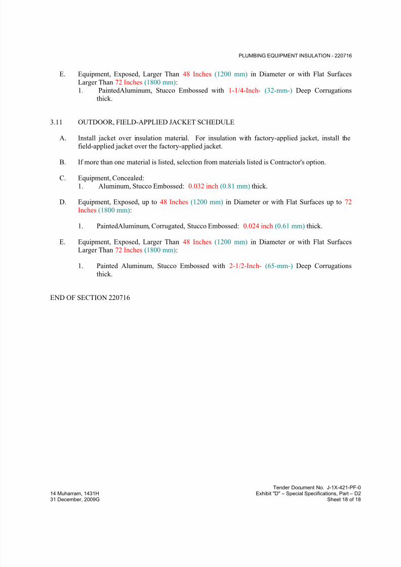
7/18/2019 SEC DPS
http://slidepdf.com/reader/full/sec-dps 252/541
PLUMBING EQUIPMENT INSULATION - 220716
Tender Document No. J-1X-421-PF-0
14 Muharram, 1431H Exhibit "D" – Special Specifications, Part – D231 December, 2009G Sheet 18 of 18
E. Equipment, Exposed, Larger Than 48 Inches (1200 mm) in Diameter or with Flat Surfaces
Larger Than 72 Inches (1800 mm):
1. PaintedAluminum, Stucco Embossed with 1-1/4-Inch- (32-mm-) Deep Corrugations
thick.
3.11 OUTDOOR, FIELD-APPLIED JACKET SCHEDULE
A. Install jacket over insulation material. For insulation with factory-applied jacket, install the
field-applied jacket over the factory-applied jacket.
B. If more than one material is listed, selection from materials listed is Contractor's option.
C. Equipment, Concealed:
1. Aluminum, Stucco Embossed: 0.032 inch (0.81 mm) thick.
D. Equipment, Exposed, up to 48 Inches (1200 mm) in Diameter or with Flat Surfaces up to 72
Inches (1800 mm):
1. PaintedAluminum, Corrugated, Stucco Embossed: 0.024 inch (0.61 mm) thick.
E. Equipment, Exposed, Larger Than 48 Inches (1200 mm) in Diameter or with Flat Surfaces
Larger Than 72 Inches (1800 mm):
1. Painted Aluminum, Stucco Embossed with 2-1/2-Inch- (65-mm-) Deep Corrugations
thick.
END OF SECTION 220716

7/18/2019 SEC DPS
http://slidepdf.com/reader/full/sec-dps 253/541
PLUMBING PIPING INSULATION - 220719
Tender Document No. J-1X-421-PF-0
14 Muharram, 1431H Exhibit "D" – Special Specifications, Part – D231 December, 2009G Sheet 1 of 19
SECTION 220719 - PLUMBING PIPING INSULATION
PART 1 - GENERAL
1.1 RELATED DOCUMENTS
A. Drawings and general provisions of the Contract, including General and Supplementary
Conditions and Division 01 Specification Sections, apply to this Section.
1.2 SUMMARY
A. Section includes insulating the following plumbing piping services:
1. Domestic cold-water piping.
2. Domestic hot-water piping.3. Domestic recirculating hot-water piping.
4. Domestic chilled-water piping for drinking fountains.
5. Roof drains and rainwater leaders.
6. Supplies and drains for handicap-accessible lavatories and sinks.
B. Related Sections:
1. Division 22 Section "Plumbing Equipment Insulation."
1.3 ACTION SUBMITTALS
A. Product Data: For each type of product indicated. Include thermal conductivity, water-vapor
permeance thickness, and jackets (both factory- and field-applied, if any).
B. LEED Submittals:
1. Product Data for Credit IEQ 4.1: For adhesives and sealants, documentation including
printed statement of VOC content and chemical components.
C. Shop Drawings: Include plans, elevations, sections, details, and attachments to other work.
1. Detail application of protective shields, saddles, and inserts at hangers for each type of
insulation and hanger.
2. Detail attachment and covering of heat tracing inside insulation.
3. Detail insulation application at pipe expansion joints for each type of insulation.
4. Detail insulation application at elbows, fittings, flanges, valves, and specialties for each
type of insulation.
5. Detail removable insulation at piping specialties, equipment connections, and access
panels.
6. Detail application of field-applied jackets.
7. Detail application at linkages of control devices.
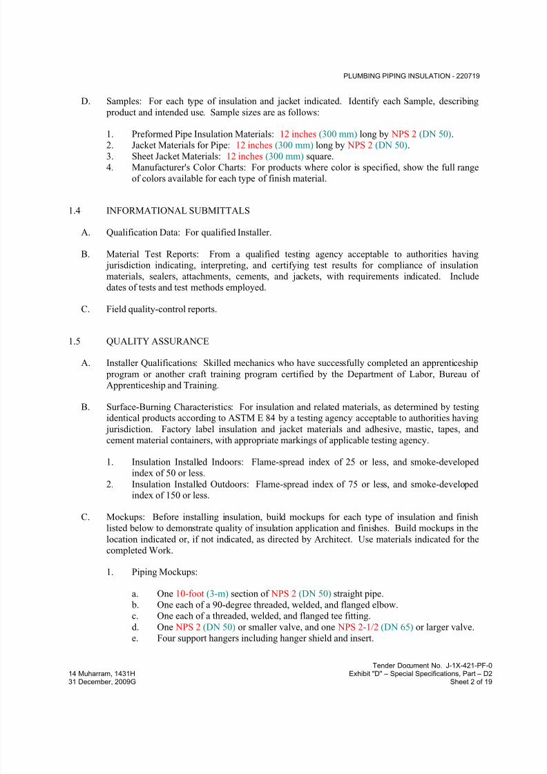
7/18/2019 SEC DPS
http://slidepdf.com/reader/full/sec-dps 254/541
PLUMBING PIPING INSULATION - 220719
Tender Document No. J-1X-421-PF-0
14 Muharram, 1431H Exhibit "D" – Special Specifications, Part – D231 December, 2009G Sheet 2 of 19
D. Samples: For each type of insulation and jacket indicated. Identify each Sample, describing
product and intended use. Sample sizes are as follows:
1. Preformed Pipe Insulation Materials: 12 inches (300 mm) long by NPS 2 (DN 50).2. Jacket Materials for Pipe: 12 inches (300 mm) long by NPS 2 (DN 50).
3. Sheet Jacket Materials: 12 inches (300 mm) square.
4. Manufacturer's Color Charts: For products where color is specified, show the full range
of colors available for each type of finish material.
1.4 INFORMATIONAL SUBMITTALS
A. Qualification Data: For qualified Installer.
B. Material Test Reports: From a qualified testing agency acceptable to authorities having
jurisdiction indicating, interpreting, and certifying test results for compliance of insulationmaterials, sealers, attachments, cements, and jackets, with requirements indicated. Include
dates of tests and test methods employed.
C. Field quality-control reports.
1.5 QUALITY ASSURANCE
A. Installer Qualifications: Skilled mechanics who have successfully completed an apprenticeship
program or another craft training program certified by the Department of Labor, Bureau of
Apprenticeship and Training.
B. Surface-Burning Characteristics: For insulation and related materials, as determined by testingidentical products according to ASTM E 84 by a testing agency acceptable to authorities having
jurisdiction. Factory label insulation and jacket materials and adhesive, mastic, tapes, and
cement material containers, with appropriate markings of applicable testing agency.
1. Insulation Installed Indoors: Flame-spread index of 25 or less, and smoke-developed
index of 50 or less.
2. Insulation Installed Outdoors: Flame-spread index of 75 or less, and smoke-developedindex of 150 or less.
C. Mockups: Before installing insulation, build mockups for each type of insulation and finish
listed below to demonstrate quality of insulation application and finishes. Build mockups in the
location indicated or, if not indicated, as directed by Architect. Use materials indicated for thecompleted Work.
1. Piping Mockups:
a. One 10-foot (3-m) section of NPS 2 (DN 50) straight pipe.
b. One each of a 90-degree threaded, welded, and flanged elbow.
c. One each of a threaded, welded, and flanged tee fitting.
d. One NPS 2 (DN 50) or smaller valve, and one NPS 2-1/2 (DN 65) or larger valve.
e. Four support hangers including hanger shield and insert.

7/18/2019 SEC DPS
http://slidepdf.com/reader/full/sec-dps 255/541
PLUMBING PIPING INSULATION - 220719
Tender Document No. J-1X-421-PF-0
14 Muharram, 1431H Exhibit "D" – Special Specifications, Part – D231 December, 2009G Sheet 3 of 19
f. One threaded strainer and one flanged strainer with removable portion of
insulation.
g. One threaded reducer and one welded reducer.
h. One pressure temperature tap.i. One mechanical coupling.
2. For each mockup, fabricate cutaway sections to allow observation of application details
for insulation materials, adhesives, mastics, attachments, and jackets.
3. Notify Architect seven days in advance of dates and times when mockups will be
constructed.
4. Obtain Architect's approval of mockups before starting insulation application.
5. Approval of mockups does not constitute approval of deviations from the Contract
Documents contained in mockups unless Architect specifically approves such deviations
in writing.
6. Maintain mockups during construction in an undisturbed condition as a standard for
judging the completed Work.7. Demolish and remove mockups when directed.
D. Comply with the following applicable standards and other requirements specified for
miscellaneous components:
1. Supply and Drain Protective Shielding Guards: ICC A117.1.
1.6 DELIVERY, STORAGE, AND HANDLING
A. Packaging: Insulation material containers shall be marked by manufacturer with appropriate
ASTM standard designation, type and grade, and maximum use temperature.
1.7 COORDINATION
A. Coordinate sizes and locations of supports, hangers, and insulation shields specified in
Division 22 Section "Hangers and Supports for Plumbing Piping and Equipment."
B. Coordinate clearance requirements with piping Installer for piping insulation application.
Before preparing piping Shop Drawings, establish and maintain clearance requirements for
installation of insulation and field-applied jackets and finishes and for space required for
maintenance.
C. Coordinate installation and testing of heat tracing.
1.8 SCHEDULING
A. Schedule insulation application after pressure testing systems and, where required, after
installing and testing heat tracing. Insulation application may begin on segments that have
satisfactory test results.

7/18/2019 SEC DPS
http://slidepdf.com/reader/full/sec-dps 256/541
PLUMBING PIPING INSULATION - 220719
Tender Document No. J-1X-421-PF-0
14 Muharram, 1431H Exhibit "D" – Special Specifications, Part – D231 December, 2009G Sheet 4 of 19
B. Complete installation and concealment of plastic materials as rapidly as possible in each area of
construction.
PART 2 - PRODUCTS
2.1 INSULATION MATERIALS
A. Comply with requirements in "Piping Insulation Schedule, General," "Indoor Piping Insulation
Schedule," "Outdoor, Aboveground Piping Insulation Schedule," and "Outdoor, Underground
Piping Insulation Schedule" articles for where insulating materials shall be applied.
B. Products shall not contain asbestos, lead, mercury, or mercury compounds.
C. Products that come in contact with stainless steel shall have a leachable chloride content of lessthan 50 ppm when tested according to ASTM C 871.
D. Insulation materials for use on austenitic stainless steel shall be qualified as acceptable
according to ASTM C 795.
E. Foam insulation materials shall not use CFC or HCFC blowing agents in the manufacturing
process.
F. Cellular Glass: Inorganic, incombustible, foamed or cellulated glass with annealed, rigid,
hermetically sealed cells. Factory-applied jacket requirements are specified in "Factory-
Applied Jackets" Article.
1. Products: Subject to compliance with requirements
2. Block Insulation: ASTM C 552, Type I.3. Special-Shaped Insulation: ASTM C 552, Type III.
4. Preformed Pipe Insulation without Jacket: Comply with ASTM C 552, Type II, Class 1.
5. Preformed Pipe Insulation with Factory-Applied ASJ-SSL: Comply with ASTM C 552,
Type II, Class 2.
6. Factory fabricate shapes according to ASTM C 450 and ASTM C 585.
G. Flexible Elastomeric Insulation: Closed-cell, sponge- or expanded-rubber materials. Comply
with ASTM C 534, Type I for tubular materials.
1. Products: Subject to compliance with requirements
H. Mineral-Fiber Blanket Insulation: Mineral or glass fibers bonded with a thermosetting resin.
Comply with ASTM C 553, Type II and ASTM C 1290, Type I. Factory-applied jacket
requirements are specified in "Factory-Applied Jackets" Article.
1. Products: Subject to compliance with requirements
I. Mineral-Fiber, Preformed Pipe Insulation:
1. Products: Subject to compliance with requirements
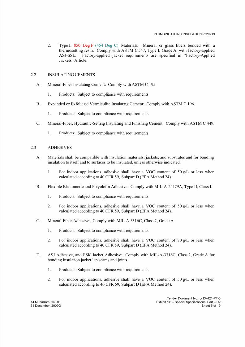
7/18/2019 SEC DPS
http://slidepdf.com/reader/full/sec-dps 257/541
PLUMBING PIPING INSULATION - 220719
Tender Document No. J-1X-421-PF-0
14 Muharram, 1431H Exhibit "D" – Special Specifications, Part – D231 December, 2009G Sheet 5 of 19
2. Type I, 850 Deg F (454 Deg C) Materials: Mineral or glass fibers bonded with a
thermosetting resin. Comply with ASTM C 547, Type I, Grade A, with factory-applied
ASJ-SSL. Factory-applied jacket requirements are specified in "Factory-Applied
Jackets" Article.
2.2 INSULATING CEMENTS
A. Mineral-Fiber Insulating Cement: Comply with ASTM C 195.
1. Products: Subject to compliance with requirements
B. Expanded or Exfoliated Vermiculite Insulating Cement: Comply with ASTM C 196.
1. Products: Subject to compliance with requirements
C. Mineral-Fiber, Hydraulic-Setting Insulating and Finishing Cement: Comply with ASTM C 449.
1. Products: Subject to compliance with requirements
2.3 ADHESIVES
A. Materials shall be compatible with insulation materials, jackets, and substrates and for bonding
insulation to itself and to surfaces to be insulated, unless otherwise indicated.
1. For indoor applications, adhesive shall have a VOC content of 50 g/L or less when
calculated according to 40 CFR 59, Subpart D (EPA Method 24).
B. Flexible Elastomeric and Polyolefin Adhesive: Comply with MIL-A-24179A, Type II, Class I.
1. Products: Subject to compliance with requirements
2. For indoor applications, adhesive shall have a VOC content of 50 g/L or less when
calculated according to 40 CFR 59, Subpart D (EPA Method 24).
C. Mineral-Fiber Adhesive: Comply with MIL-A-3316C, Class 2, Grade A.
1. Products: Subject to compliance with requirements
2. For indoor applications, adhesive shall have a VOC content of 80 g/L or less whencalculated according to 40 CFR 59, Subpart D (EPA Method 24).
D. ASJ Adhesive, and FSK Jacket Adhesive: Comply with MIL-A-3316C, Class 2, Grade A for
bonding insulation jacket lap seams and joints.
1. Products: Subject to compliance with requirements
2. For indoor applications, adhesive shall have a VOC content of 50 g/L or less when
calculated according to 40 CFR 59, Subpart D (EPA Method 24).
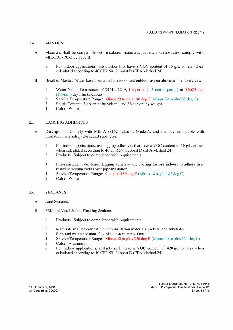
7/18/2019 SEC DPS
http://slidepdf.com/reader/full/sec-dps 258/541
PLUMBING PIPING INSULATION - 220719
Tender Document No. J-1X-421-PF-0
14 Muharram, 1431H Exhibit "D" – Special Specifications, Part – D231 December, 2009G Sheet 6 of 19
2.4 MASTICS
A. Materials shall be compatible with insulation materials, jackets, and substrates; comply with
MIL-PRF-19565C, Type II.
1. For indoor applications, use mastics that have a VOC content of 50 g/L or less when
calculated according to 40 CFR 59, Subpart D (EPA Method 24).
B. Breather Mastic: Water based; suitable for indoor and outdoor use on above-ambient services.
1. Water-Vapor Permeance: ASTM F 1249, 1.8 perms (1.2 metric perms) at 0.0625-inch
(1.6-mm) dry film thickness.
2. Service Temperature Range: Minus 20 to plus 180 deg F (Minus 29 to plus 82 deg C).
3. Solids Content: 60 percent by volume and 66 percent by weight.
4. Color: White.
2.5 LAGGING ADHESIVES
A. Description: Comply with MIL-A-3316C, Class I, Grade A, and shall be compatible with
insulation materials, jackets, and substrates.
1. For indoor applications, use lagging adhesives that have a VOC content of 50 g/L or less
when calculated according to 40 CFR 59, Subpart D (EPA Method 24).
2. Products: Subject to compliance with requirements
3. Fire-resistant, water-based lagging adhesive and coating for use indoors to adhere fire-
resistant lagging cloths over pipe insulation.4. Service Temperature Range: 0 to plus 180 deg F (Minus 18 to plus 82 deg C).
5. Color: White.
2.6 SEALANTS
A. Joint Sealants:
B. FSK and Metal Jacket Flashing Sealants:
1. Products: Subject to compliance with requirements
2. Materials shall be compatible with insulation materials, jackets, and substrates.3. Fire- and water-resistant, flexible, elastomeric sealant.
4. Service Temperature Range: Minus 40 to plus 250 deg F (Minus 40 to plus 121 deg C).
5. Color: Aluminum.
6. For indoor applications, sealants shall have a VOC content of 420 g/L or less when
calculated according to 40 CFR 59, Subpart D (EPA Method 24).

7/18/2019 SEC DPS
http://slidepdf.com/reader/full/sec-dps 259/541
PLUMBING PIPING INSULATION - 220719
Tender Document No. J-1X-421-PF-0
14 Muharram, 1431H Exhibit "D" – Special Specifications, Part – D231 December, 2009G Sheet 7 of 19
2.7 FACTORY-APPLIED JACKETS
A. Insulation system schedules indicate factory-applied jackets on various applications. When
factory-applied jackets are indicated, comply with the following:
1. ASJ: White, kraft-paper, fiberglass-reinforced scrim with aluminum-foil backing;
complying with ASTM C 1136, Type I.
2. ASJ-SSL: ASJ with self-sealing, pressure-sensitive, acrylic-based adhesive covered by a
removable protective strip; complying with ASTM C 1136, Type I.
3. FSK Jacket: Aluminum-foil, fiberglass-reinforced scrim with kraft-paper backing;
complying with ASTM C 1136, Type II.
2.8 FIELD-APPLIED FABRIC-REINFORCING MESH
A. Woven Glass-Fiber Fabric: Approximately 2 oz./sq. yd. (68 g/sq. m) with a thread count of 10strands by 10 strands/sq. in. (4 strands by 4 strands/sq. mm) for covering pipe and pipe fittings.
1. Products: Subject to compliance with requirements
B. Woven Polyester Fabric: Approximately 1 oz./sq. yd. (34 g/sq. m) with a thread count of 10strands by 10 strands/sq. in. (4 strands by 4 strands/sq. mm), in a Leno weave, for pipe.
1. Products: Subject to compliance with requirements
2.9 FIELD-APPLIED CLOTHS
A. Woven Glass-Fiber Fabric: Comply with MIL-C-20079H, Type I, plain weave, and presized aminimum of 8 oz./sq. yd. (271 g/sq. m).
1. Products: Subject to compliance with requirements
2.10 FIELD-APPLIED JACKETS
A. Field-applied jackets shall comply with ASTM C 921, Type I, unless otherwise indicated.
B. Metal Jacket:
1. Products: Subject to compliance with requirements
2. Aluminum Jacket: Comply with ASTM B 209 (ASTM B 209M), Alloy 3003, 3005,
3105, or 5005, Temper H-14.
a. Factory cut and rolled to size.
b. Finish and thickness are indicated in field-applied jacket schedules.
c. Moisture Barrier for Indoor Applications: 1-mil- (0.025-mm-) thick, heat-bonded
polyethylene and kraft paper.
d. Moisture Barrier for Outdoor Applications: 3-mil- (0.075-mm-) thick, heat-
bonded polyethylene and kraft paper.

7/18/2019 SEC DPS
http://slidepdf.com/reader/full/sec-dps 260/541
PLUMBING PIPING INSULATION - 220719
Tender Document No. J-1X-421-PF-0
14 Muharram, 1431H Exhibit "D" – Special Specifications, Part – D231 December, 2009G Sheet 8 of 19
e. Factory-Fabricated Fitting Covers:
1) Same material, finish, and thickness as jacket.
2) Preformed 2-piece or gore, 45- and 90-degree, short- and long-radiuselbows.
3) Tee covers.
4) Flange and union covers.
5) End caps.
6) Beveled collars.
7) Valve covers.
8) Field fabricate fitting covers only if factory-fabricated fitting covers are not
available.
2.11 TAPES
A. ASJ Tape: White vapor-retarder tape matching factory-applied jacket with acrylic adhesive,
complying with ASTM C 1136.
1. Products: Subject to compliance with requirements
2. Width: 3 inches (75 mm).
3. Thickness: 11.5 mils (0.29 mm).
4. Adhesion: 90 ounces force/inch (1.0 N/mm) in width.
5. Elongation: 2 percent.
6. Tensile Strength: 40 lbf/inch (7.2 N/mm) in width.
7. ASJ Tape Disks and Squares: Precut disks or squares of ASJ tape.
B. FSK Tape: Foil-face, vapor-retarder tape matching factory-applied jacket with acrylic adhesive;
complying with ASTM C 1136.
1. Products: Subject to compliance with requirements
2. Width: 3 inches (75 mm).3. Thickness: 6.5 mils (0.16 mm).
4. Adhesion: 90 ounces force/inch (1.0 N/mm) in width.
5. Elongation: 2 percent.
6. Tensile Strength: 40 lbf/inch (7.2 N/mm) in width.
7. FSK Tape Disks and Squares: Precut disks or squares of FSK tape.
C. Aluminum-Foil Tape: Vapor-retarder tape with acrylic adhesive.
1. Products: Subject to compliance with requirements
2. Width: 2 inches (50 mm).
3. Thickness: 3.7 mils (0.093 mm).
4. Adhesion: 100 ounces force/inch (1.1 N/mm) in width.
5. Elongation: 5 percent.
6. Tensile Strength: 34 lbf/inch (6.2 N/mm) in width.
7/18/2019 SEC DPS
http://slidepdf.com/reader/full/sec-dps 261/541
PLUMBING PIPING INSULATION - 220719
Tender Document No. J-1X-421-PF-0
14 Muharram, 1431H Exhibit "D" – Special Specifications, Part – D231 December, 2009G Sheet 9 of 19
2.12 SECUREMENTS
A. Bands:
1. Products: Subject to compliance with requirements
2. Aluminum: ASTM B 209 (ASTM B 209M), Alloy 3003, 3005, 3105, or 5005;
Temper H-14, 0.020 inch (0.51 mm) thick, 1/2 inch (13 mm) wide with closed seal.
B. Staples: Outward-clinching insulation staples, nominal 3/4-inch- (19-mm-) wide, stainless steel
or Monel.
C. Wire: 0.062-inch (1.6-mm) soft-annealed, galvanized steel.
1. Manufacturers: Subject to compliance with requirements
PART 3 - EXECUTION
3.1 EXAMINATION
A. Examine substrates and conditions for compliance with requirements for installation tolerances
and other conditions affecting performance of insulation application.
1. Verify that systems to be insulated have been tested and are free of defects.
2. Verify that surfaces to be insulated are clean and dry.
B. Proceed with installation only after unsatisfactory conditions have been corrected.
3.2 PREPARATION
A. Surface Preparation: Clean and dry surfaces to receive insulation. Remove materials that will
adversely affect insulation application.
B. Surface Preparation: Clean and prepare surfaces to be insulated. Before insulating, apply a
corrosion coating to insulated surfaces as follows:
1. Carbon Steel: Coat carbon steel operating at a service temperature between 32 and 300
deg F (0 and 149 deg C) with an epoxy coating. Consult coating manufacturer for
appropriate coating materials and application methods for operating temperature range.
C. Coordinate insulation installation with the trade installing heat tracing. Comply with
requirements for heat tracing that apply to insulation.
D. Mix insulating cements with clean potable water; if insulating cements are to be in contact with
stainless-steel surfaces, use demineralized water.

7/18/2019 SEC DPS
http://slidepdf.com/reader/full/sec-dps 262/541
PLUMBING PIPING INSULATION - 220719
Tender Document No. J-1X-421-PF-0
14 Muharram, 1431H Exhibit "D" – Special Specifications, Part – D231 December, 2009G Sheet 10 of 19
3.3 GENERAL INSTALLATION REQUIREMENTS
A. Install insulation materials, accessories, and finishes with smooth, straight, and even surfaces;
free of voids throughout the length of piping including fittings, valves, and specialties.
B. Install insulation materials, forms, vapor barriers or retarders, jackets, and thicknesses required
for each item of pipe system as specified in insulation system schedules.
C. Install accessories compatible with insulation materials and suitable for the service. Install
accessories that do not corrode, soften, or otherwise attack insulation or jacket in either wet or
dry state.
D. Install insulation with longitudinal seams at top and bottom of horizontal runs.
E. Install multiple layers of insulation with longitudinal and end seams staggered.
F. Do not weld brackets, clips, or other attachment devices to piping, fittings, and specialties.
G. Keep insulation materials dry during application and finishing.
H. Install insulation with tight longitudinal seams and end joints. Bond seams and joints with
adhesive recommended by insulation material manufacturer.
I. Install insulation with least number of joints practical.
J. Where vapor barrier is indicated, seal joints, seams, and penetrations in insulation at hangers,
supports, anchors, and other projections with vapor-barrier mastic.
1. Install insulation continuously through hangers and around anchor attachments.2. For insulation application where vapor barriers are indicated, extend insulation on anchor
legs from point of attachment to supported item to point of attachment to structure. Taper
and seal ends at attachment to structure with vapor-barrier mastic.
3. Install insert materials and install insulation to tightly join the insert. Seal insulation to
insulation inserts with adhesive or sealing compound recommended by insulation
material manufacturer.
4. Cover inserts with jacket material matching adjacent pipe insulation. Install shields over jacket, arranged to protect jacket from tear or puncture by hanger, support, and shield.
K. Apply adhesives, mastics, and sealants at manufacturer's recommended coverage rate and wet
and dry film thicknesses.
L. Install insulation with factory-applied jackets as follows:
1. Draw jacket tight and smooth.
2. Cover circumferential joints with 3-inch- (75-mm-) wide strips, of same material as
insulation jacket. Secure strips with adhesive and outward clinching staples along both
edges of strip, spaced 4 inches (100 mm) o.c.
3. Overlap jacket longitudinal seams at least 1-1/2 inches (38 mm). Install insulation with
longitudinal seams at bottom of pipe. Clean and dry surface to receive self-sealing lap.
Staple laps with outward clinching staples along edge at 2 inches (50 mm) o.c.
7/18/2019 SEC DPS
http://slidepdf.com/reader/full/sec-dps 263/541
PLUMBING PIPING INSULATION - 220719
Tender Document No. J-1X-421-PF-0
14 Muharram, 1431H Exhibit "D" – Special Specifications, Part – D231 December, 2009G Sheet 11 of 19
a. For below-ambient services, apply vapor-barrier mastic over staples.
4. Cover joints and seams with tape, according to insulation material manufacturer's written
instructions, to maintain vapor seal.5. Where vapor barriers are indicated, apply vapor-barrier mastic on seams and joints and at
ends adjacent to pipe flanges and fittings.
M. Cut insulation in a manner to avoid compressing insulation more than 75 percent of its nominal
thickness.
N. Finish installation with systems at operating conditions. Repair joint separations and cracking
due to thermal movement.
O. Repair damaged insulation facings by applying same facing material over damaged areas.
Extend patches at least 4 inches (100 mm) beyond damaged areas. Adhere, staple, and seal
patches similar to butt joints.
P. For above-ambient services, do not install insulation to the following:
1. Vibration-control devices.
2. Testing agency labels and stamps.
3. Nameplates and data plates.
4. Cleanouts.
3.4 PENETRATIONS
A. Insulation Installation at Roof Penetrations: Install insulation continuously through roof penetrations.
1. Seal penetrations with flashing sealant.
2. For applications requiring only indoor insulation, terminate insulation above roof surface
and seal with joint sealant. For applications requiring indoor and outdoor insulation,
install insulation for outdoor applications tightly joined to indoor insulation ends. Seal
joint with joint sealant.
3. Extend jacket of outdoor insulation outside roof flashing at least 2 inches (50 mm) below
top of roof flashing.
4. Seal jacket to roof flashing with flashing sealant.
B. Insulation Installation at Underground Exterior Wall Penetrations: Terminate insulation flush
with sleeve seal. Seal terminations with flashing sealant.
C. Insulation Installation at Aboveground Exterior Wall Penetrations: Install insulation
continuously through wall penetrations.
1. Seal penetrations with flashing sealant.
2. For applications requiring only indoor insulation, terminate insulation inside wall surface
and seal with joint sealant. For applications requiring indoor and outdoor insulation,
install insulation for outdoor applications tightly joined to indoor insulation ends. Seal joint with joint sealant.

7/18/2019 SEC DPS
http://slidepdf.com/reader/full/sec-dps 264/541
PLUMBING PIPING INSULATION - 220719
Tender Document No. J-1X-421-PF-0
14 Muharram, 1431H Exhibit "D" – Special Specifications, Part – D231 December, 2009G Sheet 12 of 19
3. Extend jacket of outdoor insulation outside wall flashing and overlap wall flashing at
least 2 inches (50 mm).
4. Seal jacket to wall flashing with flashing sealant.
D. Insulation Installation at Interior Wall and Partition Penetrations (That Are Not Fire Rated):
Install insulation continuously through walls and partitions.
E. Insulation Installation at Fire-Rated Wall and Partition Penetrations: Install insulation
continuously through penetrations of fire-rated walls and partitions.
1. Comply with requirements in Division 07 Section "Penetration Firestopping" for
firestopping and fire-resistive joint sealers.
F. Insulation Installation at Floor Penetrations:
1. Pipe: Install insulation continuously through floor penetrations.2. Seal penetrations through fire-rated assemblies. Comply with requirements in
Division 07 Section "Penetration Firestopping."
3.5 GENERAL PIPE INSULATION INSTALLATION
A. Requirements in this article generally apply to all insulation materials except where more
specific requirements are specified in various pipe insulation material installation articles.
B. Insulation Installation on Fittings, Valves, Strainers, Flanges, and Unions:
1. Install insulation over fittings, valves, strainers, flanges, unions, and other specialties with
continuous thermal and vapor-retarder integrity unless otherwise indicated.2. Insulate pipe elbows using preformed fitting insulation or mitered fittings made from
same material and density as adjacent pipe insulation. Each piece shall be butted tightly
against adjoining piece and bonded with adhesive. Fill joints, seams, voids, and irregular
surfaces with insulating cement finished to a smooth, hard, and uniform contour that is
uniform with adjoining pipe insulation.
3. Insulate tee fittings with preformed fitting insulation or sectional pipe insulation of same
material and thickness as used for adjacent pipe. Cut sectional pipe insulation to fit. Butt
each section closely to the next and hold in place with tie wire. Bond pieces with
adhesive.
4. Insulate valves using preformed fitting insulation or sectional pipe insulation of same
material, density, and thickness as used for adjacent pipe. Overlap adjoining pipe
insulation by not less than two times the thickness of pipe insulation, or one pipediameter, whichever is thicker. For valves, insulate up to and including the bonnets,
valve stuffing-box studs, bolts, and nuts. Fill joints, seams, and irregular surfaces with
insulating cement.
5. Insulate strainers using preformed fitting insulation or sectional pipe insulation of same
material, density, and thickness as used for adjacent pipe. Overlap adjoining pipe
insulation by not less than two times the thickness of pipe insulation, or one pipe
diameter, whichever is thicker. Fill joints, seams, and irregular surfaces with insulating
cement. Insulate strainers so strainer basket flange or plug can be easily removed and
replaced without damaging the insulation and jacket. Provide a removable reusable

7/18/2019 SEC DPS
http://slidepdf.com/reader/full/sec-dps 265/541
PLUMBING PIPING INSULATION - 220719
Tender Document No. J-1X-421-PF-0
14 Muharram, 1431H Exhibit "D" – Special Specifications, Part – D231 December, 2009G Sheet 13 of 19
insulation cover. For below-ambient services, provide a design that maintains vapor
barrier.
6. Insulate flanges and unions using a section of oversized preformed pipe insulation.
Overlap adjoining pipe insulation by not less than two times the thickness of pipeinsulation, or one pipe diameter, whichever is thicker.
7. Cover segmented insulated surfaces with a layer of finishing cement and coat with a
mastic. Install vapor-barrier mastic for below-ambient services and a breather mastic for
above-ambient services. Reinforce the mastic with fabric-reinforcing mesh. Trowel the
mastic to a smooth and well-shaped contour.8. For services not specified to receive a field-applied jacket except for flexible elastomeric
and polyolefin, install fitted PVC cover over elbows, tees, strainers, valves, flanges, and
unions. Terminate ends with PVC end caps. Tape PVC covers to adjoining insulation
facing using PVC tape.
9. Stencil or label the outside insulation jacket of each union with the word "union." Match
size and color of pipe labels.
C. Insulate instrument connections for thermometers, pressure gages, pressure temperature taps,
test connections, flow meters, sensors, switches, and transmitters on insulated pipes. Shape
insulation at these connections by tapering it to and around the connection with insulating
cement and finish with finishing cement, mastic, and flashing sealant.
D. Install removable insulation covers at locations indicated. Installation shall conform to the
following:
1. Make removable flange and union insulation from sectional pipe insulation of same
thickness as that on adjoining pipe. Install same insulation jacket as adjoining pipe
insulation.
2. When flange and union covers are made from sectional pipe insulation, extend insulationfrom flanges or union long at least two times the insulation thickness over adjacent pipe
insulation on each side of flange or union. Secure flange cover in place with stainless-
steel or aluminum bands. Select band material compatible with insulation and jacket.
3. Construct removable valve insulation covers in same manner as for flanges, except divide
the two-part section on the vertical center line of valve body.
4. When covers are made from block insulation, make two halves, each consisting of
mitered blocks wired to stainless-steel fabric. Secure this wire frame, with its attached
insulation, to flanges with tie wire. Extend insulation at least 2 inches (50 mm) over
adjacent pipe insulation on each side of valve. Fill space between flange or union cover
and pipe insulation with insulating cement. Finish cover assembly with insulating
cement applied in two coats. After first coat is dry, apply and trowel second coat to a
smooth finish.5. Unless a PVC jacket is indicated in field-applied jacket schedules, finish exposed
surfaces with a metal jacket.
3.6 INSTALLATION OF FLEXIBLE ELASTOMERIC INSULATION
A. Seal longitudinal seams and end joints with manufacturer's recommended adhesive to eliminate
openings in insulation that allow passage of air to surface being insulated.
B. Insulation Installation on Pipe Flanges:
7/18/2019 SEC DPS
http://slidepdf.com/reader/full/sec-dps 266/541
PLUMBING PIPING INSULATION - 220719
Tender Document No. J-1X-421-PF-0
14 Muharram, 1431H Exhibit "D" – Special Specifications, Part – D231 December, 2009G Sheet 14 of 19
1. Install pipe insulation to outer diameter of pipe flange.
2. Make width of insulation section same as overall width of flange and bolts, plus twice the
thickness of pipe insulation.
3. Fill voids between inner circumference of flange insulation and outer circumference ofadjacent straight pipe segments with cut sections of sheet insulation of same thickness as
pipe insulation.
4. Secure insulation to flanges and seal seams with manufacturer's recommended adhesive
to eliminate openings in insulation that allow passage of air to surface being insulated.
C. Insulation Installation on Pipe Fittings and Elbows:
1. Install mitered sections of pipe insulation.
2. Secure insulation materials and seal seams with manufacturer's recommended adhesive to
eliminate openings in insulation that allow passage of air to surface being insulated.
D. Insulation Installation on Valves and Pipe Specialties:
1. Install preformed valve covers manufactured of same material as pipe insulation when
available.
2. When preformed valve covers are not available, install cut sections of pipe and sheet
insulation to valve body. Arrange insulation to permit access to packing and to allow
valve operation without disturbing insulation.
3. Install insulation to flanges as specified for flange insulation application.
4. Secure insulation to valves and specialties and seal seams with manufacturer's
recommended adhesive to eliminate openings in insulation that allow passage of air to
surface being insulated.
3.7 INSTALLATION OF MINERAL-FIBER INSULATION
A. Insulation Installation on Straight Pipes and Tubes:
1. Secure each layer of preformed pipe insulation to pipe with wire or bands and tighten
bands without deforming insulation materials.
2. Where vapor barriers are indicated, seal longitudinal seams, end joints, and protrusions
with vapor-barrier mastic and joint sealant.
3. For insulation with factory-applied jackets on above-ambient surfaces, secure laps with
outward clinched staples at 6 inches (150 mm) o.c.
4. For insulation with factory-applied jackets on below-ambient surfaces, do not staple
longitudinal tabs. Instead, secure tabs with additional adhesive as recommended by
insulation material manufacturer and seal with vapor-barrier mastic and flashing sealant.
B. Insulation Installation on Pipe Flanges:
1. Install preformed pipe insulation to outer diameter of pipe flange.
2. Make width of insulation section same as overall width of flange and bolts, plus twice the
thickness of pipe insulation.
3. Fill voids between inner circumference of flange insulation and outer circumference of
adjacent straight pipe segments with mineral-fiber blanket insulation.
7/18/2019 SEC DPS
http://slidepdf.com/reader/full/sec-dps 267/541
PLUMBING PIPING INSULATION - 220719
Tender Document No. J-1X-421-PF-0
14 Muharram, 1431H Exhibit "D" – Special Specifications, Part – D231 December, 2009G Sheet 15 of 19
4. Install jacket material with manufacturer's recommended adhesive, overlap seams at least
1 inch (25 mm), and seal joints with flashing sealant.
C. Insulation Installation on Pipe Fittings and Elbows:
1. Install preformed sections of same material as straight segments of pipe insulation when
available.
2. When preformed insulation elbows and fittings are not available, install mitered sections
of pipe insulation, to a thickness equal to adjoining pipe insulation. Secure insulation
materials with wire or bands.
D. Insulation Installation on Valves and Pipe Specialties:
1. Install preformed sections of same material as straight segments of pipe insulation when
available.
2. When preformed sections are not available, install mitered sections of pipe insulation tovalve body.
3. Arrange insulation to permit access to packing and to allow valve operation without
disturbing insulation.
4. Install insulation to flanges as specified for flange insulation application.
3.8 FIELD-APPLIED JACKET INSTALLATION
A. Where glass-cloth jackets are indicated, install directly over bare insulation or insulation with
factory-applied jackets.
1. Draw jacket smooth and tight to surface with 2-inch (50-mm) overlap at seams and joints.
2. Embed glass cloth between two 0.062-inch- (1.6-mm-) thick coats of lagging adhesive.
3. Completely encapsulate insulation with coating, leaving no exposed insulation.
B. Where FSK jackets are indicated, install as follows:
1. Draw jacket material smooth and tight.
2. Install lap or joint strips with same material as jacket.
3. Secure jacket to insulation with manufacturer's recommended adhesive.
4. Install jacket with 1-1/2-inch (38-mm) laps at longitudinal seams and 3-inch- (75-mm-)
wide joint strips at end joints.
5. Seal openings, punctures, and breaks in vapor-retarder jackets and exposed insulation
with vapor-barrier mastic.
C. Where PVC jackets are indicated, install with 1-inch (25-mm) overlap at longitudinal seams and
end joints. Seal with manufacturer's recommended adhesive.
1. Apply two continuous beads of adhesive to seams and joints, one bead under lap and the
finish bead along seam and joint edge.
D. Where metal jackets are indicated, install with 2-inch (50-mm) overlap at longitudinal seams
and end joints. Overlap longitudinal seams arranged to shed water. Seal end joints with

7/18/2019 SEC DPS
http://slidepdf.com/reader/full/sec-dps 268/541
PLUMBING PIPING INSULATION - 220719
Tender Document No. J-1X-421-PF-0
14 Muharram, 1431H Exhibit "D" – Special Specifications, Part – D231 December, 2009G Sheet 16 of 19
weatherproof sealant recommended by insulation manufacturer. Secure jacket with stainless-
steel bands 12 inches (300 mm) o.c. and at end joints.
3.9 FINISHES
A. Insulation with ASJ, Glass-Cloth, or Other Paintable Jacket Material: Paint jacket with paint
system identified below and as specified in Division 09 painting Sections.
1. Flat Acrylic Finish: Two finish coats over a primer that is compatible with jacket
material and finish coat paint. Add fungicidal agent to render fabric mildew proof.
a. Finish Coat Material: Interior, flat, latex-emulsion size.
B. Flexible Elastomeric Thermal Insulation: After adhesive has fully cured, apply two coats of
insulation manufacturer's recommended protective coating.
C. Color: Final color as selected by Architect. Vary first and second coats to allow visual
inspection of the completed Work.
D. Do not field paint aluminum or stainless-steel jackets.
3.10 FIELD QUALITY CONTROL
A. Testing Agency: Engage a qualified testing agency to perform tests and inspections.
B. Perform tests and inspections.
C. Tests and Inspections:
1. Inspect pipe, fittings, strainers, and valves, randomly selected by Architect, by removing
field-applied jacket and insulation in layers in reverse order of their installation. Extent
of inspection shall be limited to three locations of straight pipe, three locations of
threaded fittings, three locations of welded fittings, two locations of threaded strainers,
two locations of welded strainers, three locations of threaded valves, and three locations
of flanged valves for each pipe service defined in the "Piping Insulation Schedule,
General" Article.
D. All insulation applications will be considered defective Work if sample inspection reveals
noncompliance with requirements.
3.11 PIPING INSULATION SCHEDULE, GENERAL
A. Acceptable preformed pipe and tubular insulation materials and thicknesses are identified for
each piping system and pipe size range. If more than one material is listed for a piping system,
selection from materials listed is Contractor's option.
B. Items Not Insulated: Unless otherwise indicated, do not install insulation on the following:

7/18/2019 SEC DPS
http://slidepdf.com/reader/full/sec-dps 269/541
PLUMBING PIPING INSULATION - 220719
Tender Document No. J-1X-421-PF-0
14 Muharram, 1431H Exhibit "D" – Special Specifications, Part – D231 December, 2009G Sheet 17 of 19
1. Drainage piping located in crawl spaces.
2. Underground piping.
3. Chrome-plated pipes and fittings unless there is a potential for personnel injury.
3.12 INDOOR PIPING INSULATION SCHEDULE
A. Domestic Cold Water (For outdoor, indoor exposed to ambient temperatures or in shafts):
1. NPS 2 (DN 50) and Smaller: Insulation shall be the following:
a. Flexible Elastomeric: 3/4 inch (19 mm) thick.
2. NPS 2.5 (DN 65) and Larger: Insulation shall be[ one of] the following:
a.
b. Flexible Elastomeric: 1/2 inch (13 mm)] thick.
B. Domestic Hot and Recirculated Hot Water:
1. NPS 2 (DN 50) and Smaller: Insulation shall be the following:
2. Flexible Elastomeric: 3/4 inch (19 mm) NPS 2.5 (DN 65) and Larger: Insulation shall
be[ one of] the following:a. Flexible Elastomeric: 1 inch (25 mm) thick.
C. Domestic Chilled Water (Potable):
1. All Pipe Sizes: Insulation shall be the following:
a. Flexible Elastomeric: 3/4 inch (19 mm) thick.
D. Stormwater and Overflow (Horizontal rainwater piping directly under roof slab, pipes runningin VIP areas and conference rooms and vertical and horizontal rain water leaders if condensate
pipe is connected to rain water system):
1. All Pipe Sizes: Insulation shall be the following:
a. Flexible Elastomeric: 3/4 inch (19 mm) thick.
E. Roof Drain and Overflow Drain Bodies (Roof drain bodies including underside of roof drain
fittings, horizontal rainwater piping directly under roof slab, pipes running in VIP areas andconference rooms and vertical and horizontal rain water leaders if condensate pipe is connected
to rain water system):
1. All Pipe Sizes: Insulation shall be[ one of] the following:
a. Flexible Elastomeric: 3/4 inch (19 mm) thick.
F. Exposed Sanitary Drains, Domestic Water, Domestic Hot Water, and Stops for Plumbing
Fixtures for People with Disabilities:
1. All Pipe Sizes: Insulation shall be the following:
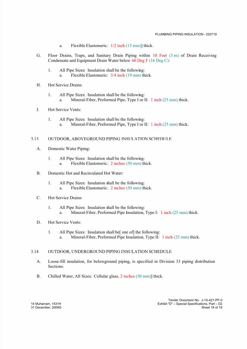
7/18/2019 SEC DPS
http://slidepdf.com/reader/full/sec-dps 270/541
PLUMBING PIPING INSULATION - 220719
Tender Document No. J-1X-421-PF-0
14 Muharram, 1431H Exhibit "D" – Special Specifications, Part – D231 December, 2009G Sheet 18 of 19
a. Flexible Elastomeric: 1/2 inch (13 mm)] thick.
G. Floor Drains, Traps, and Sanitary Drain Piping within 10 Feet (3 m) of Drain Receiving
Condensate and Equipment Drain Water below 60 Deg F (16 Deg C):
1. All Pipe Sizes: Insulation shall be the following:
a. Flexible Elastomeric: 3/4 inch (19 mm) thick.
H. Hot Service Drains:
1. All Pipe Sizes: Insulation shall be the following:
a. Mineral-Fiber, Preformed Pipe, Type I or II: 1 inch (25 mm) thick.
I. Hot Service Vents:
1. All Pipe Sizes: Insulation shall be the following:a. Mineral-Fiber, Preformed Pipe, Type I or II: 1 inch (25 mm) thick.
3.13 OUTDOOR, ABOVEGROUND PIPING INSULATION SCHEDULE
A. Domestic Water Piping:
1. All Pipe Sizes: Insulation shall be the following:a. Flexible Elastomeric: 2 inches (50 mm) thick.
B. Domestic Hot and Recirculated Hot Water:
1. All Pipe Sizes: Insulation shall be the following:a. Flexible Elastomeric: 2 inches (50 mm) thick.
C. Hot Service Drains:
1. All Pipe Sizes: Insulation shall be the following:
a. Mineral-Fiber, Preformed Pipe Insulation, Type I: 1 inch (25 mm) thick.
D. Hot Service Vents:
1. All Pipe Sizes: Insulation shall be[ one of] the following:
a. Mineral-Fiber, Preformed Pipe Insulation, Type II: 1 inch (25 mm) thick.
3.14 OUTDOOR, UNDERGROUND PIPING INSULATION SCHEDULE
A. Loose-fill insulation, for belowground piping, is specified in Division 33 piping distribution
Sections.
B. Chilled Water, All Sizes: Cellular glass, 2 inches (50 mm)] thick.
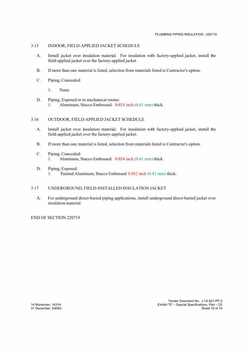
7/18/2019 SEC DPS
http://slidepdf.com/reader/full/sec-dps 271/541
PLUMBING PIPING INSULATION - 220719
Tender Document No. J-1X-421-PF-0
14 Muharram, 1431H Exhibit "D" – Special Specifications, Part – D231 December, 2009G Sheet 19 of 19
3.15 INDOOR, FIELD-APPLIED JACKET SCHEDULE
A. Install jacket over insulation material. For insulation with factory-applied jacket, install the
field-applied jacket over the factory-applied jacket.
B. If more than one material is listed, selection from materials listed is Contractor's option.
C. Piping, Concealed:
1. None.
D. Piping, Exposed or in mechanical rooms:
1. Aluminum, Stucco Embossed: 0.024 inch (0.61 mm) thick.
3.16 OUTDOOR, FIELD-APPLIED JACKET SCHEDULE
A. Install jacket over insulation material. For insulation with factory-applied jacket, install the
field-applied jacket over the factory-applied jacket.
B. If more than one material is listed, selection from materials listed is Contractor's option.
C. Piping, Concealed:
1. Aluminum, Stucco Embossed: 0.024 inch (0.61 mm) thick.
D. Piping, Exposed:
1. Painted Aluminum, Stucco Embossed 0.032 inch (0.81 mm) thick.
3.17 UNDERGROUND, FIELD-INSTALLED INSULATION JACKET
A. For underground direct-buried piping applications, install underground direct-buried jacket over
insulation material.
END OF SECTION 220719

7/18/2019 SEC DPS
http://slidepdf.com/reader/full/sec-dps 272/541
FACILITY WATER DISTRIBUTION PIPING – 221113
Tender Document No. J-0X-421-PF-014 Muharram, 1431H Exhibit “D” – Special Specifications, Part – D231 December, 2009G Sheet 1 of 15
SECTION 221113 - FACILITY WATER DISTRIBUTION PIPING
PART 1 - GENERAL
1.1 RELATED DOCUMENTS
A. Drawings and general provisions of the Contract, including General and Supplementary
Conditions and Division 01 Specification Sections, apply to this Section.
1.2 SUMMARY
A. This Section includes water-distribution piping and related components outside the building forwater service.
B. Utility-furnished products include water meters that will be furnished to the site, ready for
installation.
1.3 DEFINITIONS
A. RTRP: Reinforced thermosetting resin (fiberglass) pipe.
1.4 ACTION SUBMITTALS
A. Product Data: Submit manufacturer's technical product data and installation instructions for
system materials and products.
B. Shop Drawings: Include plans, elevations, details, and attachments for the following:
1. Water pipe network, including pipe diameters and gradients.
2. Chambers and other structures, including invert levels, frames, covers, and grates.
1.5 INFORMATIONAL SUBMITTALS
A. Coordination Drawings: For piping and specialties including relation to other services in samearea, drawn to scale. Show piping and specialty sizes and valves, meter and specialty locations,
and elevations.
B. Field quality-control test reports.
1.6 CLOSEOUT SUBMITTALS
A. Operation and Maintenance Data: For water valves and specialties to include in emergency,
operation, and maintenance manuals.

7/18/2019 SEC DPS
http://slidepdf.com/reader/full/sec-dps 273/541
FACILITY WATER DISTRIBUTION PIPING – 221113
Tender Document No. J-0X-421-PF-014 Muharram, 1431H Exhibit “D” – Special Specifications, Part – D231 December, 2009G Sheet 2 of 15
1.7 QUALITY ASSURANCE
A. Regulatory Requirements:
1. Comply with requirements of utility company supplying water. Include tapping of water
mains and backflow prevention.
2. Comply with standards of authorities having jurisdiction for potable-water-service piping,
including materials, installation, testing, and disinfection.
B. Piping materials shall bear label, stamp, or other markings of specified testing agency.
C. Electrical Components, Devices, and Accessories: Listed and labeled as defined in NFPA 70,
Article 100, by a testing agency acceptable to authorities having jurisdiction, and marked for
intended use.
D. Comply with ASTM F 645 for selection, design, and installation of thermoplastic water piping.
E. Comply with FMG's "Approval Guide" or UL's "Fire Protection Equipment Directory" for fire-
service-main products.
F. NFPA Compliance: Comply with NFPA 24 for materials, installations, tests, flushing, and
valve and hydrant supervision for fire-service-main piping for fire suppression.
G. NSF Compliance:
1. Comply with NSF 61 for materials for water-service piping and specialties for domestic
water.
1.8 DELIVERY, STORAGE, AND HANDLING
A. Preparation for Transport: Prepare valves, according to the following:
1. Ensure that valves are dry and internally protected against rust and corrosion.
2. Protect valves against damage to threaded ends and flange faces.
3. Set valves in best position for handling. Set valves closed to prevent rattling.
B. During Storage: Use precautions for valves according to the following:
1. Do not remove end protectors unless necessary for inspection; then reinstall for storage.2. Protect from weather. Store indoors and maintain temperature higher than ambient dew-
point temperature. Support off the ground or pavement in watertight enclosures when
outdoor storage is necessary.
C. Handling: Use sling to handle valves and fire hydrants if size requires handling by crane or lift.
Rig valves to avoid damage to exposed parts. Do not use hand wheels or stems as lifting or
rigging points.
D. Deliver piping with factory-applied end caps. Maintain end caps through shipping, storage, and
handling to prevent pipe-end damage and to prevent entrance of dirt, debris, and moisture.

7/18/2019 SEC DPS
http://slidepdf.com/reader/full/sec-dps 274/541
FACILITY WATER DISTRIBUTION PIPING – 221113
Tender Document No. J-0X-421-PF-014 Muharram, 1431H Exhibit “D” – Special Specifications, Part – D231 December, 2009G Sheet 3 of 15
E. Protect stored piping from moisture and dirt. Elevate above grade. Do not exceed structural
capacity of floor when storing inside.
F. Protect flanges, fittings, and specialties from moisture and dirt.
G. Store plastic piping protected from direct sunlight. Support to prevent sagging and bending.
1.9 PROJECT CONDITIONS
A. Perform site survey, research public utility records, and verify existing utility locations.
B. Interruption of Existing Water-Distribution Service: Do not interrupt service to facilities
occupied by Owner or others unless permitted under the following conditions and then only
after arranging to provide temporary water-distribution service according to requirements
indicated:
1. Notify Construction Manager not less than three days in advance of proposed interruption
of service.
2. Do not proceed with interruption of water-distribution service without Construction
Manager’s written permission.
1.10 COORDINATION
A. Coordinate connection to water main with the Engineer and relevant authorities.
PART 2 - PRODUCTS
2.1 DUCTILE-IRON PIPE AND FITTINGS
A. Mechanical-Joint, Ductile-Iron Pipe: AWWA C151, with mechanical-joint bell and plain spigot
end unless grooved or flanged ends are indicated.
1. Mechanical-Joint, Ductile-Iron Fittings: AWWA C110, ductile- or gray-iron standard
pattern or AWWA C153, ductile-iron compact pattern.
2. Glands, Gaskets, and Bolts: AWWA C111, ductile- or gray-iron glands, rubber gaskets,
and steel bolts.
B. Push-on-Joint, Ductile-Iron Pipe: AWWA C151, with push-on-joint bell and plain spigot end
unless grooved or flanged ends are indicated.
1. Push-on-Joint, Ductile-Iron Fittings: AWWA C110, ductile- or gray-iron standard
pattern or AWWA C153, ductile-iron compact pattern.
2. Gaskets: AWWA C111, rubber.
C. Grooved-Joint, Ductile-Iron Pipe: AWWA C151, with cut, rounded-grooved ends.
1. Grooved-End, Ductile-Iron Pipe Appurtenances:

7/18/2019 SEC DPS
http://slidepdf.com/reader/full/sec-dps 275/541
FACILITY WATER DISTRIBUTION PIPING – 221113
Tender Document No. J-0X-421-PF-014 Muharram, 1431H Exhibit “D” – Special Specifications, Part – D231 December, 2009G Sheet 4 of 15
a. Grooved-End, Ductile-Iron Fittings: ASTM A 47/A 47M, malleable-iron castings
or ASTM A 536, ductile-iron castings with dimensions matching pipe.
b. Grooved-End, Ductile-Iron-Piping Couplings: AWWA C606, for ductile-iron-pipe
dimensions. Include ferrous housing sections, gasket suitable for water, and bolts
and nuts.
D. Flanges: ASME 16.1, Class 125, cast iron.
2.2 FIBERGLASS PIPE AND FITTINGS
A. AWWA RTRP: AWWA C950, Class 250, with bell-and-spigot ends for bonded joints. Liner is
optional unless otherwise indicated. Bonding Adhesive for Fiberglass Piping shall be as
recommended by fiberglass piping manufacturer.
B. For type and grade of RTRP pipes, provide manufacturer recommendations for the best suitable
for the project conditions and submit to the Engineer for approval.
2.3 JOINING MATERIALS
A. Refer to Division 22 Section "Common Work Results for Plumbing" for commonly used
joining materials.
B. Transition Couplings:
1. Underground Piping, DN 40 and Smaller: Manufactured fitting or coupling same size as,with pressure rating at least equal to and ends compatible with, piping to be joined.
2. Underground Piping, DN 50 and Larger: AWWA C219, metal, sleeve-type coupling
same size as, with pressure rating at least equal to and ends compatible with, piping to be
joined.
3. Aboveground Piping: Pipe fitting same size as, with pressure rating at least equal to and
ends compatible with, piping to be joined.
C. Plastic Pipe-Flange Gasket, Bolts, and Nuts: Type and material of gaskets to be as
recommended by piping system manufacturer, unless otherwise indicated. Bolts, nuts and
washer to be stainless steel grade 316.
2.4 PIPING SPECIALTIES
A. Dielectric Fittings: Combination of copper alloy and ferrous; threaded, solder, or plain end
types; and matching piping system materials.
1. Dielectric Unions: Factory-fabricated union assembly, designed for 1725 kPa minimum
working pressure at 82 deg. C (180 deg. F). Include insulating material that isolates
dissimilar metals and ends with inside threads according to ASME B1.20.1.2. Dielectric Flanges: Factory-fabricated companion-flange assembly, for 1035 or 2070-
kPa minimum working pressure to suit system pressures.

7/18/2019 SEC DPS
http://slidepdf.com/reader/full/sec-dps 276/541
FACILITY WATER DISTRIBUTION PIPING – 221113
Tender Document No. J-0X-421-PF-014 Muharram, 1431H Exhibit “D” – Special Specifications, Part – D231 December, 2009G Sheet 5 of 15
3. Dielectric-Flange Insulation Kits: Field-assembled companion-flange assembly, full-face
or ring type. Components include neoprene or phenolic gasket, phenolic or polyethylene
bolt sleeves, phenolic washers, and steel backing washers.
a. Provide separate companion flanges and steel bolts and nuts for 1035 or 2070 kPa
minimum working pressure to suit system pressures.
4. Dielectric Couplings: Galvanized-steel couplings with inert and noncorrosive
thermoplastic lining, with threaded ends and 2070 kPa minimum working pressure at
107 deg C.
B. Dielectric Nipples: Electroplated steel nipples with inert and noncorrosive thermoplastic lining,
with combination of plain, threaded, or grooved end types and 2070-kPa minimum working
pressure at 107 deg. C (225 deg. F).
2.5 ENCASEMENT FOR PIPING
A. Standard: ASTM A 674 or AWWA C105.
B. Form: Sheet or tube.
C. Material: LLDPE film of 0.20-mm minimum thickness or high-density, cross-laminated PE film
of 0.10-mm or High-density, cross-laminated PE film of 0.10-mm minimum thickness.
D. Color: Black or Natural.
2.6 GATE VALVES
A. AWWA, Cast-Iron Gate Valves:
1. Nonrising-Stem, High-Pressure, Resilient-Seated Gate Valves:
a. Description: Ductile-iron body and bonnet; with bronze or ductile-iron gate,
resilient seats, bronze stem, and stem nut.
1) Standard: AWWA C509.
2) Minimum Pressure Rating: 1725 kPa.
3) End Connections: Push on or mechanical joint.4) Interior Coating: Complying with AWWA C550.
2.7 GATE VALVE ACCESSORIES AND SPECIALTIES
A. Tapping-Sleeve Assemblies:
1. Comply with MSS SP-60. Include sleeve and valve compatible with drilling machine.
2. Tapping Sleeve: Ductile-iron or stainless steel, two-piece bolted sleeve with flanged
outlet for new branch connection. Include sleeve matching size and type of pipe material
being tapped and with recessed flange for branch valve.

7/18/2019 SEC DPS
http://slidepdf.com/reader/full/sec-dps 277/541
FACILITY WATER DISTRIBUTION PIPING – 221113
Tender Document No. J-0X-421-PF-014 Muharram, 1431H Exhibit “D” – Special Specifications, Part – D231 December, 2009G Sheet 6 of 15
3. Valve: AWWA, ductile-iron, non-rising-stem with one raised face flange mating
tapping-sleeve flange.
B. Valve Boxes:
1. Construction: To be in situ or precast concrete as shown on the Drawings.
2. Protective coating for internal surfaces shall be bituminous damp-proofing as specified
elsewhere in this specification.
3. Provide flexible joints along pipes on each side of chambers for connections to pipes built
into structures. Submit details to the Engineer for approval.
4. Waterproofing for external surfaces:
a. Structures above groundwater level: Waterproofing for external surfaces shall be bituminous damp-proofing as specified elsewhere in this specification.
b. Structures below groundwater level: Waterproofing for external surfaces shall be
app-modified bituminous sheet waterproofing as specified elsewhere in this
specification.
5. Covers and Frames: ASTM A 536, Grade 40, 60 or 90 ductile-iron castings depending
on location. If not available, BS EN124 shall be applied subject to Engineer approval.
Include 610 mm ID by 178 to 225 mm riser with 100-mm minimum width flange. Covers
shall be machine seated, epoxy coated, non-rocking and watertight, suitable lifting
devices shall be provided at a rate of one for every 10 covers. Frames to be bolted to
manhole to ensure proper fixity. Type to be as follows:
a. For sidewalks: Light duty. Minimum test load 125 KN. For roadways and taxiway
strip beyond the graded strip limit: heavy duty non-rock type for wheel loads up to
11.5 tons, minimum test load 400KN. For apron and graded area of the taxiwaystrip (Taxiway and Shoulder): Class F900 ultra heavy duty non-rock type for
aircraft wheel loads. Minimum test load 900 kN.
b. Size: As indicated on the drawings.
6. Operating Wrenches: Steel, tee-handle with one pointed end, stem of length to operate
deepest buried valve, and socket matching valve operating nut.
C. Valve caps: To applicable American standards. If not available, BS 5163 shall be applied
subject to engineer approval, of cast iron or malleable iron to BS EN 1561 grade 12 or BS EN
1562 respectively. Set screw of valve cap is to be mild steel M12.
D. Operation keys: Combination rising bar and lifting key type, with 1.5 m vertical bar and 0.5 mhorizontal bar. Keys are to be supplied at a rate of one for every 5 valves
E. Extension spindles for gate valves: steel to applicable American standards. If not available, BS
2470 - M12, hot dip galvanized to BS 1387, size 18 x 18 mm for valves up to 200 mm diameter
and 24 x 24 mm for valves 250 mm to 400 mm diameter. Length for each valve size is to suit
excavation requirements. Spindles are to have cast iron or malleable iron cap and coupling, to
BS EN 1561 grade 12 and BS EN 1562 respectively, on both sides of extension spindle (cap for
operating spindle and coupling for connecting to valve). Set screws of caps and couplings are
to be mild steel M12.
7/18/2019 SEC DPS
http://slidepdf.com/reader/full/sec-dps 278/541
FACILITY WATER DISTRIBUTION PIPING – 221113
Tender Document No. J-0X-421-PF-014 Muharram, 1431H Exhibit “D” – Special Specifications, Part – D231 December, 2009G Sheet 7 of 15
F. Protection tubes: Either UPVC or cast iron. Shape, sizes and other constructional details are to
be to manufacturer's standards and/or as shown on the Drawings. Tubes are to have caps
circling extension spindles.
G. Steps shall be galvanized steel to applicable American standards. If not available, BS 1247:
PT1.
2.8 CHECK VALVES
A. AWWA Check Valves:
1. Description: Swing-check type with resilient seat. Include interior coating according to
AWWA C550 and ends to match piping.
a. Standard: AWWA C508. b. Pressure Rating: 1725 kPa
2.9 BUTTERFLY VALVES
A. AWWA Butterfly Valves:
1. Description: Rubber seated.
a. Standard: AWWA C504.
b. Body: Cast or ductile iron.
c. Body Type: Flanged.d. Pressure Rating: 1725 kPa.
2.10 WATER METERS
A. Provide, furnish and install as indicated, water meter of approved type by the Engineer
suitable for service connection as shown on the drawings. Obtain the necessary authorities’approval.
B. Unless directed otherwise, use Turbine-Type Water Meters:
1. Description:
a. Standard: AWWA C701.
b. Registration: Flow in liters per seconds unless otherwise directed
2.11 PRESSURE-REDUCING VALVES
A. Water Regulators:
1. Manufacturers: Subject to compliance with requirements.
2. Standard: ASSE 1003.
7/18/2019 SEC DPS
http://slidepdf.com/reader/full/sec-dps 279/541
FACILITY WATER DISTRIBUTION PIPING – 221113
Tender Document No. J-0X-421-PF-014 Muharram, 1431H Exhibit “D” – Special Specifications, Part – D231 December, 2009G Sheet 8 of 15
3. Pressure Rating: Initial working pressure of 1725 kPa.
4. Size: As applicable
5. Design Flow Rate: As applicable6. Design Inlet Pressure: As applicable
7. Design Outlet Pressure Setting: As applicable8. Body: Bronze with chrome-plated finish for DN 50 and smaller; cast iron with interior
lining complying with AWWA C550 or that is FDA approved for DN 65 and DN 80.
9. Valves for Booster Heater Water Supply: Include integral bypass.
10. End Connections: Threaded for DN 50 and smaller; flanged for DN 65 and DN 80.
B. Water Control Valves:1. Manufacturers: Subject to compliance with requirements
2. Basis-of-Design Product: Subject to compliance with requirements
3. Description: Pilot-operation, diaphragm-type, single-seated main water control valve.
4. Pressure Rating: Initial working pressure of 1725 kPa minimum with AWWA C550 or
FDA-approved, interior epoxy coating. Include small pilot-control valve, restrictor
device, specialty fittings, and sensor piping.5. Main Valve Body: Cast- or ductile-iron body with AWWA C550 or FDA-approved,
interior epoxy coating; or stainless-steel body.
a. Size: As applicable
b. Pattern: Globe-valve design.
c. Trim: Stainless steel.
6. Design Flow: As applicable
7. Design Inlet Pressure: As applicable
8. Design Outlet Pressure Setting: As applicable >a. End Connections: Threaded for DN 50 and smaller; flanged for DN 65 and larger.
2.12 RELIEF VALVES
A. Air-Release Valves: AWWA C512, hydromechanical device to automatically release
accumulated air. Include 10 bar working-pressure design.
B. Air/Vacuum Valves: AWWA C512, direct-acting, float-operated, hydromechanical device with
large orifice to automatically release accumulated air or to admit air during filling of piping.
Include 10 bar working-pressure design.
C. Combination Air Valves: AWWA C512, float-operated, hydromechanical device to
automatically release accumulated air or to admit air. Include 10 bar working-pressure design.
D. Interior and Exterior coating: Complying with AWWA C550.
2.13 BACKFLOW PREVENTERS
A. General: ASSE standard, backflow preventers
1. Working Pressure: 1725 kPa minimum, unless otherwise indicated.

7/18/2019 SEC DPS
http://slidepdf.com/reader/full/sec-dps 280/541
FACILITY WATER DISTRIBUTION PIPING – 221113
Tender Document No. J-0X-421-PF-014 Muharram, 1431H Exhibit “D” – Special Specifications, Part – D231 December, 2009G Sheet 9 of 15
2. DN 50 and Smaller: Bronze body with threaded ends.
3. DN 65 and Larger: Bronze, cast-iron, steel, or stainless-steel body with flanged ends.
a. Interior and Exterior coating to be 300 microns (minimum) fusion bonded epoxy.
4. Interior Components: Corrosion-resistant materials.
5. Exterior Finish: Polished chrome plate if used in chrome-plated piping system.
6. Strainer: On inlet, if indicated.
2.14 WATER METER BOXES
A. This section shall apply to water meters installed in dedicated chambers.
B. Description: Concrete body and ductile-iron/steel cover as specified with lettering "WATER
METER" in cover; service piping connections and other details as indicated on the Drawings.All details shall be as directed and approved by the Engineer.
2.15 CORPORATION VALVES AND CURB VALVES
A. Corporation Valves: Comply with AWWA C800. Include saddle and valve compatible with
tapping machine.
1. Service Saddle: Copper alloy with seal and AWWA C800, threaded outlet for
corporation valve.
2. Corporation Valve: Bronze body and ground-key plug, with AWWA C800, threaded
inlet and outlet matching service piping material.3. Manifold: Copper fitting with two to four inlets as required, with ends matching
corporation valves and outlet matching service piping material. Retain subparagraph
below if utility company requires multiple connections.
B. Corporation Valves: Comply with AWWA C800. Include saddle and valve compatible with
tapping machine.
1. Service Saddle: Copper alloy with seal and AWWA C800, threaded outlet for
corporation valve.
2. Corporation Valve: Bronze body and ground-key plug, with AWWA C800, threaded
inlet and outlet matching service piping material.
3. Manifold: Copper fitting with two to four inlets as required, with ends matchingcorporation valves and outlet matching service piping material.
C. Curb Valves: Comply with AWWA C800 for high-pressure service-line valves. Valve has
bronze body, ground-key plug or ball, wide tee head, and inlet and outlet matching service
piping material.
D. Service Boxes for Curb Valves: Similar to AWWA M44 requirements for cast-iron valve
boxes. Include cast-iron telescoping top section of length required for depth of burial of valve,
plug with lettering "WATER," and bottom section with base that fits over curb valve and with a
barrel approximately 75 mm in diameter.
7/18/2019 SEC DPS
http://slidepdf.com/reader/full/sec-dps 281/541
FACILITY WATER DISTRIBUTION PIPING – 221113
Tender Document No. J-0X-421-PF-014 Muharram, 1431H Exhibit “D” – Special Specifications, Part – D231 December, 2009G Sheet 10 of 15
1. Shutoff Rods: Steel; with tee-handle with one pointed end, stem of length to operate
deepest buried valve, and slotted end matching curb valve.
E. Meter Valves: Comply with AWWA C800 for high-pressure service-line valves. Include
angle- or straight-through-pattern bronze body, ground-key plug or ball, and wide tee head, with
inlet and outlet matching service piping material.
2.16 PRESSURE GUAGES
A. Refer to mechanical section 211200 of the specifications.
PART 3 - EXECUTION
3.1 EARTHWORK
A. Refer to Division 31 Section "Earth Moving" for excavating, trenching, and backfilling.
3.2 PIPING APPLICATIONS
A. General: Use pipe, fittings, and joining methods for piping systems according to the following
applications.
B. Transition couplings and special fittings with pressure ratings at least equal to piping pressure
rating may be used, unless otherwise indicated.
C. Do not use flanges or unions for underground piping.
D. Flanges, unions, grooved-end-pipe couplings, and special fittings may be used, instead of joints
indicated, on aboveground piping and piping in vaults.
E. Underground water-service piping shall be the following:
1. Fiberglass, AWWA RTRP, Class 250; and bonded joints.
F. Water Meter Box shall be same as underground water-service piping.
3.3 VALVE APPLICATIONS
A. General Application: Use mechanical-joint-end valves for DN 80 and larger underground
installation. Use threaded- or flanged-end valves for installation in vaults. Use UL/FM, non
rising-stem gate valves for installation with indicator posts. Use corporation valves and curb
valves with ends compatible with piping, for DN 50 and smaller installation.
B. Drawings indicate valve types to be used. Where specific valve types are not indicated, the
following requirements apply:

7/18/2019 SEC DPS
http://slidepdf.com/reader/full/sec-dps 282/541
FACILITY WATER DISTRIBUTION PIPING – 221113
Tender Document No. J-0X-421-PF-014 Muharram, 1431H Exhibit “D” – Special Specifications, Part – D231 December, 2009G Sheet 11 of 15
1. Underground Valves, DN 80 and Larger: AWWA, ductile cast-iron, non rising-stem,
high-pressure, resilient-seated gate valves with valve box.
2. Underground Valves, DN 100 and Larger, for Indicator Posts: UL/FM, ductile cast-iron,non rising-stem gate valves with indicator post.
3. Use the following for valves in chambers and aboveground:
a. Gate Valves, DN 50 and Smaller: Bronze, nonrising stem.
b. Gate Valves, DN 80 and Larger: AWWA, cast iron, resilient seated
c. Check Valves: AWWA C508 swing type.
4. Pressure-Reducing Valves: Use for water-service piping in vaults and aboveground to
control water pressure.
5. Relief Valves: Use for water-service piping in vaults and aboveground.
a. Air-Release Valves: To release accumulated air.
b. Air/Vacuum Valves: To release or admit large volume of air during filling of
piping.
c. Combination Air Valves: To release or admit air.
6. Detector Check Valves: Use for water-service piping in vaults and aboveground to detect
unauthorized use of water.
3.4 PIPING SYSTEMS - COMMON REQUIREMENTS
A. See Division 22 Section "Common Work Results for Plumbing" for piping-system common
requirements.
3.5 PIPING INSTALLATION
A. Follow the manufacturer's instructions regarding placement of bedding and backfilling,
cleanliness of joint surfaces, lubricant used, correct location of components, provision of correct
gaps between end of spigot and back of socket, maximum permissible deflection of joints for
detachable couplings and flexible joints, provision of flexible joints for connections to pipes
built into structures.
B. Water-Main Connection: Tap water main according to requirements of the water utility
company and of size and in location indicated.
C. Install encasement for piping according to ASTM A 674 or AWWA C105.
D. Make connections larger than DN 50 with tapping machine according to the following:
1. Install tapping sleeve and tapping valve according to the manufacturer's written
instructions.
2. Install tapping sleeve on pipe to be tapped. Position flanged outlet for gate valve.
3. Use tapping machine compatible with valve and tapping sleeve; cut hole in main.
Remove tapping machine and connect water-service piping.
4. Install gate valve onto tapping sleeve. Comply with AWWA C600. Install valve with
stem pointing up and with valve box.

7/18/2019 SEC DPS
http://slidepdf.com/reader/full/sec-dps 283/541
FACILITY WATER DISTRIBUTION PIPING – 221113
Tender Document No. J-0X-421-PF-014 Muharram, 1431H Exhibit “D” – Special Specifications, Part – D231 December, 2009G Sheet 12 of 15
E. Make connections DN 50 and smaller with drilling machine according to the following:
1. Install service-saddle assemblies and corporation valves in size, quantity, andarrangement required by utility company standards.
2. Install service-saddle assemblies on water-service pipe to be tapped. Position outlets for
corporation valves.
3. Use drilling machine compatible with service-saddle assemblies and corporation valves.
Drill hole in main. Remove drilling machine and connect water-service piping.
4. Install corporation valves into service-saddle assemblies.
5. Install manifold for multiple taps in water main.
6. Install curb valve in water-service piping with head pointing up and with service box.
F. Bury piping with depth of cover over top at least 1200 mm under roads and 1000 mm in
landscaped areas.
G. Install piping by tunneling, jacking, or combination of both, under streets and other obstructions
that cannot be disturbed.
H. Extend water-service piping and connect to water-supply source and building water piping
systems at outside face of building wall in locations and pipe sizes indicated.
1. Terminate water-service piping at building wall until building water piping systems are
installed. Terminate piping with caps, plugs, or flanges as required for piping material.
Make connections to building water piping systems when those systems are installed..
I. Sleeves are specified in Division 22 Section "Sleeves and Sleeve Seals for Plumbing Piping."
J. Mechanical sleeve seals are specified in Division 22 Section "Sleeves and Sleeve Seals for
Plumbing Piping."
K. Install underground piping with restrained joints at horizontal and vertical changes in direction.
Use restrained-joint piping, thrust blocks, anchors, tie-rods and clamps, and other supports.
L. See Division 21 Section "Water-Based Fire-Suppression Systems" for fire-suppression-water
piping inside the building.
M. See Division 22 Section "Domestic Water Piping" for potable-water piping inside the building.
N. Anchor service-entry piping to building wall.
3.6 JOINT CONSTRUCTION
A. See Division 22 Section "Common Work Results for Plumbing" for basic piping joint
construction.
B. Make pipe joints according to the following:
1. Ductile-Iron Piping, Gasketed Joints for Water-Service Piping: AWWA C600 and
AWWA M41.
2. Fiberglass Piping Bonded Joints: Use adhesive and procedure recommended by piping
manufacturer.

7/18/2019 SEC DPS
http://slidepdf.com/reader/full/sec-dps 284/541
FACILITY WATER DISTRIBUTION PIPING – 221113
Tender Document No. J-0X-421-PF-014 Muharram, 1431H Exhibit “D” – Special Specifications, Part – D231 December, 2009G Sheet 13 of 15
3. Install dielectric fittings in piping at connections of dissimilar metal piping and tubing.
3.7 ANCHORAGE INSTALLATION
A. Install anchorages for tees, plugs and caps, bends, crosses, valves.
B. Apply full coat of asphalt or other acceptable corrosion-resistant material to surfaces of installed
ferrous anchorage devices.
3.8 VALVE INSTALLATION
A. AWWA Gate Valves: Comply with AWWA C600 and AWWA M44. Install each
underground valve with stem pointing up and with valve box.
B. AWWA Valves Other Than Gate Valves: Comply with AWWA C600 and AWWA M44.
C. Corporation Valves and Curb Valves: Install each underground curb valve with head pointed
up and with service box.
D. Pressure-Reducing Valves: Install in chambers or aboveground between shutoff valves.
E. Relief Valves: Comply with AWWA C512. Install aboveground with shutoff valve on inlet.
3.9 WATER METER INSTALLATION
A. Install water meters, piping, and specialties according to utility company's written instructions
and following the Engineer’s directives.
3.10 BACKFLOW PREVENTER INSTALLATION
A. Install backflow preventers of type, size, and capacity indicated. Include valves and test cocks.
Install according to requirements of plumbing and health department and authorities having
jurisdiction.
B. Do not install backflow preventers that have relief drain in vault or in other spaces subject to
flooding.
C. Do not install bypass piping around backflow preventers.
D. Support DN 65 and larger backflow preventers, valves, and piping near floor and on brick or
concrete piers.
3.11 WATER METER BOX INSTALLATION
A. Install water meter boxes in paved areas flush with surface.

7/18/2019 SEC DPS
http://slidepdf.com/reader/full/sec-dps 285/541
FACILITY WATER DISTRIBUTION PIPING – 221113
Tender Document No. J-0X-421-PF-014 Muharram, 1431H Exhibit “D” – Special Specifications, Part – D231 December, 2009G Sheet 14 of 15
B. Install water meter boxes in grass or earth areas with top 100mm above surface.
3.12 FIELD QUALITY CONTROL
A. Field testing: Generally:
1. Provision of test equipment: All items for test have to be provided on site before the test
i.e. pressure gauges, instruments, water etc.
2. Carry out tests in the presence of the Engineer's Representative.
3. Fittings and joints: Permanently anchor fittings before testing and leave all joints exposed
for checking.
4. Test sections: Limit test sections to not more than 500 m.
5. Test sections: Test pressure lines between valve chambers whenever possible.
6. Test sections: No testing shall be carried out against or through the pressure reducing
valves. The setting of the pressure reducing valves shall not be changed for testing
purposes.
7. Test plug: Secure end of main and test plug by struts.
8. Closed valve: Do not test against a closed valve unless there is no acceptable alternative.
9. Apply pressure by manually operated test pump or, in the case of large diameter mains,
by power driven test pump, if approved.
10. Examine exposed joints and repair visible leaks.
11. Failure: Should a test fail, locate and replace or make good defective pipe or replace and
make good faulty joint. Retest main.
12. Records: keep test records in an approved form. Hand original copy to the Engineer
immediately after completion of test.
13. Carry out hydrostatic test while pipeline is partially backfilled.
B. Hydrostatic testing of pressure pipelines:
1. Fill pipe slowly with water from lowest point. Do not use power-driven pump unless
approved.
2. Fill absorbent pipes with water and allow to stand for at least 24 hours to allow complete
absorption.
3. Entrapped air is to be bled before pressurizing.
4. Pressurizing is to continue until specified test pressure is reached in lowest part of section
under test. Bleed further quantities of entrapped air while raising pressure.
5. Maintain test pressure for specified test duration with pumping stopped.
6. Repressurize to original test pressure and record respective volumes of water pumped.
7. Failure: Pipeline will be deemed to have failed test if:
a. Visible leaks are detected, regardless of leakage being within specified limits.
b. Volume of water lost during period when pumping was stopped exceeds allowable
leakage.
8. Test pressure: Generally 1.5 times the maximum sustained pressure, minimum 1725 kPa.
9. Test period: 2 hours.
10. Allowable leakage 0.1 liter/mm diameter/km length/day/30 m of applied pressure.
C. Visual Inspection Test

7/18/2019 SEC DPS
http://slidepdf.com/reader/full/sec-dps 286/541
FACILITY WATER DISTRIBUTION PIPING – 221113
Tender Document No. J-0X-421-PF-014 Muharram, 1431H Exhibit “D” – Special Specifications, Part – D231 December, 2009G Sheet 15 of 15
1. Timing: Carry out test after total backfilling of length under test.
2. Limit of length to be tested at one time is 3 full length pipes unless otherwise approved.
3. Apparatus: Use rubber tyred bogies which do not damage lining of pipe and an adequatesupply of electric lamps.
4. Check joints by means of feelers to ensure rubber rings are correctly located.5. Check pipe barrel for visible cracks.
3.13 CLEANING AND DISINFECTIONS
A. Clean and disinfect water-distribution piping as follows:
1. Purge new water-distribution piping systems before use.
2. Use purging and disinfecting procedure prescribed by authorities having jurisdiction or, if
method is not prescribed by authorities having jurisdiction, use procedure described in
AWWA C651 or as described below:
a. Fill system or part of system with water/chlorine solution containing at least 50
ppm of chlorine; isolate and allow standing for 24 hours.
b. Drain system or part of system of previous solution and refill with water/chlorine
solution containing at least 200 ppm of chlorine; isolate and allow standing for 3
hours.
c. After standing time, flush system with clean, potable water until no chlorine
remains in water coming from system.
d. Submit water samples in sterile bottles to authorities having jurisdiction. Repeat
procedure if biological examination shows evidence of contamination.
B. Prepare reports of purging and disinfecting activities.
END OF SECTION 221113

7/18/2019 SEC DPS
http://slidepdf.com/reader/full/sec-dps 287/541
DOMESTIC WATER PIPING - 221116
Tender Document No. J-1X-421-PF-0
14 Muharram, 1431H Exhibit "D" – Special Specifications, Part – D231 December, 2009G Sheet 1 of 21
SECTION 221116 - DOMESTIC WATER PIPING
PART 1 - GENERAL
1.1 RELATED DOCUMENTS
A. Drawings and general provisions of the Contract, including General and Supplementary
Conditions and Division 01 Specification Sections, apply to this Section.
1.2 SUMMARY
A. Section Includes:
1. Under-building slab and aboveground domestic water pipes, tubes, fittings, and
specialties inside the building.2. Encasement for piping.
3. Specialty valves.
4. Flexible connectors.
5. Water meters furnished by utility company for installation by Contractor.
6. Water meters.
B. Related Section:
1. Division 22 Section "Facility Water Distribution Piping" for water-service piping and
water meters outside the building from source to the point where water-service pipingenters the building.
1.3 PERFORMANCE REQUIREMENTS
A. Seismic Performance: Domestic water piping and support and installation shall withstand
effects of earthquake motions determined according to ASCE/SEI 7.
1.4 ACTION SUBMITTALS
A. Product Data: For the following products:
1. Specialty valves.
2. Transition fittings.
3. Dielectric fittings.
4. Flexible connectors.
5. Water meters.
6. Backflow preventers and vacuum breakers.
7. Water penetration systems.
B. LEED Submittals:

7/18/2019 SEC DPS
http://slidepdf.com/reader/full/sec-dps 288/541
DOMESTIC WATER PIPING - 221116
Tender Document No. J-1X-421-PF-0
14 Muharram, 1431H Exhibit "D" – Special Specifications, Part – D231 December, 2009G Sheet 2 of 21
1. Product Data for Credit IEQ 4.1: For solvent cements and adhesive primers,
documentation including printed statement of VOC content.
1.5 INFORMATIONAL SUBMITTALS
A. Water Samples: Specified in "Cleaning" Article.
B. Coordination Drawings: For piping in equipment rooms and other congested areas, drawn to
scale, on which the following items are shown and coordinated with each other, using input
from Installers of the items involved:
1. Fire-suppression-water piping.
2. Domestic water piping.
3. Compressed air piping.
4. HVAC hydronic piping.
C. Field quality-control reports.
1.6 QUALITY ASSURANCE
A. Piping materials shall bear label, stamp, or other markings of specified testing agency.
B. Comply with NSF 14 for plastic, potable domestic water piping and components. Include
marking "NSF-pw" on piping.
C. Comply with NSF 61 for potable domestic water piping and components.
1.7 PROJECT CONDITIONS
A. Interruption of Existing Water Service: Do not interrupt water service to facilities occupied by
Owner or others unless permitted under the following conditions and then only after arranging
to provide temporary water service according to requirements indicated:
1. Notify Owner no fewer than two days in advance of proposed interruption of water
service.
2. Do not proceed with interruption of water service without Owner's written permission.
1.8 COORDINATION
A. Coordinate sizes and locations of concrete bases with actual equipment provided.
7/18/2019 SEC DPS
http://slidepdf.com/reader/full/sec-dps 289/541
DOMESTIC WATER PIPING - 221116
Tender Document No. J-1X-421-PF-0
14 Muharram, 1431H Exhibit "D" – Special Specifications, Part – D231 December, 2009G Sheet 3 of 21
PART 2 - PRODUCTS
2.1 PIPING MATERIALS
A. Comply with requirements in "Piping Schedule" Article for applications of pipe, tube, fitting
materials, and joining methods for specific services, service locations, and pipe sizes.
2.2 COPPER TUBE AND FITTINGS
A. Hard Copper Tube: ASTM B 88, Type L (ASTM B 88M, Type B) and ASTM B 88, Type M
(ASTM B 88M, Type C) water tube, drawn temper.
1. Cast-Copper Solder-Joint Fittings: ASME B16.18, pressure fittings.
2. Wrought-Copper Solder-Joint Fittings: ASME B16.22, wrought-copper pressure fittings.3. Bronze Flanges: ASME B16.24, Class 150, with solder-joint ends.
4. Copper Unions: MSS SP-123, cast-copper-alloy, hexagonal-stock body, with ball-and-
socket, metal-to-metal seating surfaces, and solder-joint or threaded ends.
5. Copper Pressure-Seal-Joint Fittings:
a. Manufacturers: Subject to compliance with requirements
b. NPS 2 (DN 50) and Smaller: Wrought-copper fitting with EPDM-rubber O-ring
seal in each end.
c. NPS 2-1/2 to NPS 4 (DN 65 to DN 100): Cast-bronze or wrought-copper fitting
with EPDM-rubber O-ring seal in each end.
6. Copper Push-on-Joint Fittings:
a. Manufacturers: Subject to compliance with requirements
b. Description: Cast-copper fitting complying with ASME B16.18 or wrought-
copper fitting complying with ASME B 16.22; with stainless-steel teeth and
EPDM-rubber O-ring seal in each end instead of solder-joint ends.
7. Copper-Tube Extruded-Tee Connections:
a. Manufacturers: Subject to compliance with requirements
b. Description: Tee formed in copper tube according to ASTM F 2014.
8. Grooved-Joint Copper-Tube Appurtenances:
a. Manufacturers: Subject to compliance with requirements
b. Copper Grooved-End Fittings: ASTM B 75 (ASTM B 75M) copper tube or
ASTM B 584 bronze castings.
c. Grooved-End-Tube Couplings: Copper-tube dimensions and design similar to
AWWA C606. Include ferrous housing sections, EPDM-rubber gaskets suitable
for hot and cold water, and bolts and nuts.
7/18/2019 SEC DPS
http://slidepdf.com/reader/full/sec-dps 290/541
DOMESTIC WATER PIPING - 221116
Tender Document No. J-1X-421-PF-0
14 Muharram, 1431H Exhibit "D" – Special Specifications, Part – D231 December, 2009G Sheet 4 of 21
B. Soft Copper Tube: ASTM B 88, Type K (ASTM B 88M, Type A) and ASTM B 88, Type L
(ASTM B 88M, Type B) water tube, annealed temper.
1. Copper Solder-Joint Fittings: ASME B16.22, wrought-copper pressure fittings.2. Copper Pressure-Seal-Joint Fittings:
a. Manufacturers: Subject to compliance with requirements
b. NPS 2 (DN 50) and Smaller: Wrought-copper fitting with EPDM-rubber O-ring
seal in each end.
c. NPS 3 and NPS 4 (DN 80 and DN 100): Cast-bronze or wrought-copper fitting
with EPDM-rubber O-ring seal in each end.
2.3 DUCTILE-IRON PIPE AND FITTINGS
A. Mechanical-Joint, Ductile-Iron Pipe: AWWA C151, with mechanical-joint bell and plain spigot
end unless grooved or flanged ends are indicated.
1. Standard-Pattern, Mechanical-Joint Fittings: AWWA C110, ductile or gray iron.
2. Compact-Pattern, Mechanical-Joint Fittings: AWWA C153, ductile iron.
a. Glands, Gaskets, and Bolts: AWWA C111, ductile- or gray-iron glands, rubber
gaskets, and steel bolts.
B. Push-on-Joint, Ductile-Iron Pipe: AWWA C151, with push-on-joint bell and plain spigot end
unless grooved or flanged ends are indicated.
1. Standard-Pattern, Push-on-Joint Fittings: AWWA C110, ductile or gray iron.
a. Gaskets: AWWA C111, rubber.
2. Compact-Pattern, Push-on-Joint Fittings: AWWA C153, ductile iron.
a. Gaskets: AWWA C111, rubber.
C. Plain-End, Ductile-Iron Pipe: AWWA C151.
1. Grooved-Joint, Ductile-Iron-Pipe Appurtenances:
a. Manufacturers: Subject to compliance with requirements
b. Grooved-End, Ductile-Iron Fittings: ASTM A 47/A 47M, malleable-iron castings
or ASTM A 536, ductile-iron castings with dimensions matching pipe.
c. Grooved-End, Ductile-Iron-Pipe Couplings: AWWA C606 for ductile-iron-pipe
dimensions. Include ferrous housing sections, EPDM-rubber gaskets suitable for
hot and cold water, and bolts and nuts.

7/18/2019 SEC DPS
http://slidepdf.com/reader/full/sec-dps 291/541
DOMESTIC WATER PIPING - 221116
Tender Document No. J-1X-421-PF-0
14 Muharram, 1431H Exhibit "D" – Special Specifications, Part – D231 December, 2009G Sheet 5 of 21
2.4 GALVANIZED-STEEL PIPE AND FITTINGS
A. Galvanized-Steel Pipe: ASTM A 53/A 53M, Type E, Grade B, Standard Weight. Include ends
matching joining method.
1. Galvanized-Steel Pipe Nipples: ASTM A 733, made of ASTM A 53/A 53M or
ASTM A 106/A 106M, Standard Weight, seamless steel pipe with threaded ends.
2. Galvanized, Gray-Iron Threaded Fittings: ASME B16.4, Class 125, standard pattern.
3. Malleable-Iron Unions: ASME B16.39, Class 150, hexagonal-stock body with ball-and-
socket, metal-to-metal, bronze seating surface, and female threaded ends.
4. Flanges: ASME B16.1, Class 125, cast iron.
5. Grooved-Joint, Galvanized-Steel-Pipe Appurtenances:
a. Manufacturers: Subject to compliance with requirements
b. Galvanized, Grooved-End Fittings for Galvanized-Steel Piping:ASTM A 47/A 47M, malleable-iron casting; ASTM A 106/A 106M, steel pipe; or
ASTM A 536, ductile-iron casting; with dimensions matching steel pipe.
c. Grooved-End-Pipe Couplings for Galvanized-Steel Piping: AWWA C606 for
steel-pipe dimensions. Include ferrous housing sections, EPDM-rubber gaskets
suitable for hot and cold water, and bolts and nuts.
2.5 CPVC PIPING
A. CPVC Pipe: ASTM F 441/F 441M, Schedule 40 and Schedule 80 (As per application pressurerequirement).
1. CPVC Socket Fittings: ASTM F 438 for Schedule 40 and [ASTM F 439 for
Schedule 80.
2. CPVC Threaded Fittings: ASTM F 437, Schedule 80.
B. CPVC Piping System: ASTM D 2846/D 2846M, SDR 11, pipe and socket fittings.
C. CPVC Tubing System: ASTM D 2846/D 2846M, SDR 11, tube and socket fittings.
2.6 PVC PIPE AND FITTINGS
A. PVC Pipe: ASTM D 1785, Schedule 40 and Schedule 80 (As per application pressure
requirement).
1. PVC Socket Fittings: ASTM D 2466 for Schedule 40 and ASTM D 2467 for
Schedule 80.
2. PVC Schedule 80 Threaded Fittings: ASTM D 2464.

7/18/2019 SEC DPS
http://slidepdf.com/reader/full/sec-dps 292/541
DOMESTIC WATER PIPING - 221116
Tender Document No. J-1X-421-PF-0
14 Muharram, 1431H Exhibit "D" – Special Specifications, Part – D231 December, 2009G Sheet 6 of 21
2.7 PIPING JOINING MATERIALS
A. Pipe-Flange Gasket Materials: AWWA C110, rubber, flat face, 1/8 inch (3.2 mm) thick or
ASME B16.21, nonmetallic and asbestos free, unless otherwise indicated; full-face or ring typeunless otherwise indicated.
B. Metal, Pipe-Flange Bolts and Nuts: ASME B18.2.1, carbon steel unless otherwise indicated.
C. Solder Filler Metals: ASTM B 32, lead-free alloys. Include water-flushable flux according to
ASTM B 813.
D. Brazing Filler Metals: AWS A5.8/A5.8M, BCuP Series, copper-phosphorus alloys for general-
duty brazing unless otherwise indicated.
E. Solvent Cements for Joining CPVC Piping and Tubing: ASTM F 493.
1. CPVC solvent cement shall have a VOC content of 490 g/L or less when calculated
according to 40 CFR 59, Subpart D (EPA Method 24).
2. Adhesive primer shall have a VOC content of 550 g/L or less when calculated according
to 40 CFR 59, Subpart D (EPA Method 24).
F. Solvent Cements for Joining PVC Piping: ASTM D 2564. Include primer according to
ASTM F 656.
1. PVC solvent cement shall have a VOC content of 510 g/L or less when calculated
according to 40 CFR 59, Subpart D (EPA Method 24).
2. Adhesive primer shall have a VOC content of 550 g/L or less when calculated according
to 40 CFR 59, Subpart D (EPA Method 24).
G. Plastic, Pipe-Flange Gaskets, Bolts, and Nuts: Type and material recommended by piping
system manufacturer unless otherwise indicated.
2.8 ENCASEMENT FOR PIPING
A. Standard: ASTM A 674 or AWWA C105.
B. Form: Sheet.
C. Material: High-density, cross-laminated PE film of 0.004-inch (0.10-mm) minimum thickness.
D. Color: Black or Natural.
2.9 SPECIALTY VALVES
A. Comply with requirements in Division 22 Section "General-Duty Valves for Plumbing Piping"
for general-duty metal valves.
B. Comply with requirements in Division 22 Section "Domestic Water Piping Specialties" for
balancing valves, drain valves, backflow preventers, and vacuum breakers.

7/18/2019 SEC DPS
http://slidepdf.com/reader/full/sec-dps 293/541
DOMESTIC WATER PIPING - 221116
Tender Document No. J-1X-421-PF-0
14 Muharram, 1431H Exhibit "D" – Special Specifications, Part – D231 December, 2009G Sheet 7 of 21
2.10 TRANSITION FITTINGS
A. General Requirements:
1. Same size as pipes to be joined.
2. Pressure rating at least equal to pipes to be joined.
3. End connections compatible with pipes to be joined.
B. Fitting-Type Transition Couplings: Manufactured piping coupling or specified piping system
fitting.
C. Sleeve-Type Transition Coupling: AWWA C219.
1. Manufacturers: Subject to compliance with requirements
D. Plastic-to-Metal Transition Fittings:
1. Manufacturers: Subject to compliance with requirements
2. Description: CPVC or PVC one-piece fitting with manufacturer's Schedule 80 equivalent
dimensions; one end with threaded brass insert and one solvent-cement-socket or
threaded end.
E. Plastic-to-Metal Transition Unions:
1. Manufacturers: Subject to compliance with requirements
2. Description: CPVC or PVC four-part union. Include brass threaded end, solvent-
cement-joint or threaded plastic end, rubber O-ring, and union nut.
2.11 DIELECTRIC FITTINGS
A. General Requirements: Assembly of copper alloy and ferrous materials with separating
nonconductive insulating material. Include end connections compatible with pipes to be joined.
B. Dielectric Unions:
1. Manufacturers: Subject to compliance with requirements
2. Description:
a. Standard: ASSE 1079.
b. Pressure Rating: 125 psig (860 kPa) minimum at 180 deg F (82 deg C) or 150 psig
(1035 kPa) or 250 psig (1725 kPa) as dictated by building working pressure.
c. End Connections: Solder-joint copper alloy and threaded ferrous.
C. Dielectric Flanges:
1. Manufacturers: Subject to compliance with requirements
7/18/2019 SEC DPS
http://slidepdf.com/reader/full/sec-dps 294/541
DOMESTIC WATER PIPING - 221116
Tender Document No. J-1X-421-PF-0
14 Muharram, 1431H Exhibit "D" – Special Specifications, Part – D231 December, 2009G Sheet 8 of 21
2. Description:
a. Standard: ASSE 1079.
b. Factory-fabricated, bolted, companion-flange assembly.a. Pressure Rating: 125 psig (860 kPa) minimum at 180 deg F (82 deg C) or 150 psig
(1035 kPa) or 250 psig (1725 kPa) as dictated by building working pressure.
b. End Connections: Solder-joint copper alloy and threaded ferrous; threaded solder-
joint copper alloy and threaded ferrous.
D. Dielectric-Flange Insulating Kits:
1. Manufacturers: Subject to compliance with requirements
2. Description:
a. Nonconducting materials for field assembly of companion flanges. b. Pressure Rating: 150 psig (1035 kPa).
c. Gasket: Neoprene or phenolic.
d. Bolt Sleeves: Phenolic or polyethylene.
e. Washers: Phenolic with steel backing washers.
E. Dielectric Nipples:
1. Manufacturers: Subject to compliance with requirements
2. Description:
a. Standard: IAPMO PS 66 b. Electroplated steel nipple. complying with ASTM F 1545.
c. Pressure Rating: 300 psig (2070 kPa) at 225 deg F (107 deg C).
d. End Connections: Male threaded or grooved.
e. Lining: Inert and noncorrosive, propylene.
2.12 FLEXIBLE CONNECTORS
A. Bronze-Hose Flexible Connectors: Corrugated-bronze tubing with bronze wire-braid coveringand ends brazed to inner tubing.
1. Working-Pressure Rating: Minimum 200 psig (1380 kPa) or 250 psig (1725 kPa), as
dictated by building working pressure.2. End Connections NPS 2 (DN 50) and Smaller: Threaded copper pipe or plain-end copper
tube.
3. End Connections NPS 2-1/2 (DN 65) and Larger: Flanged copper alloy.
B. Stainless-Steel-Hose Flexible Connectors: Corrugated-stainless-steel tubing with stainless-steel
wire-braid covering and ends welded to inner tubing.
1. Working-Pressure Rating: Minimum 200 psig (1380 kPa) or 250 psig (1725 kPa), as
dictated by building working pressure..

7/18/2019 SEC DPS
http://slidepdf.com/reader/full/sec-dps 295/541
DOMESTIC WATER PIPING - 221116
Tender Document No. J-1X-421-PF-0
14 Muharram, 1431H Exhibit "D" – Special Specifications, Part – D231 December, 2009G Sheet 9 of 21
2. End Connections NPS 2 (DN 50) and Smaller: Threaded steel-pipe nipple.
3. End Connections NPS 2-1/2 (DN 65) and Larger: Flanged steel nipple.
2.13 WATER METERS
A. Displacement-Type Water Meters:
1. Manufacturers: Subject to compliance with requirements:
2. Description:
a. Standard: AWWA C700.
b. Pressure Rating: 150-psig (1035-kPa) working pressure.
c. Body Design: Nutating disc; totalization meter.
d. Registration: In gallons (liters) or cubic feet (cubic meters) as required by utility.e. Case: Bronze.
f. End Connections: Threaded.
B. Turbine-Type Water Meters:
1. Manufacturers: Subject to compliance with requirements
2. Description:
a. Standard: AWWA C701.
b. Pressure Rating: 150-psig (1035-kPa) working pressure.
c. Body Design: Turbine; totalization meter.
d. Registration: In gallons (liters) or cubic feet (cubic meters) as required by utilitycompany .
e. Case: Bronze.
f. End Connections for Meters NPS 2 (DN 50) and Smaller: Threaded.
g. End Connections for Meters NPS 2-1/2 (DN 65) and Larger: Flanged.
C. Compound-Type Water Meters:
1. Manufacturers: Subject to compliance with requirements
2. Description:
a. Standard: AWWA C702. b. Pressure Rating: 150-psig (1035-kPa) working pressure.
c. Body Design: With integral mainline and bypass meters; totalization meter.
d. Registration: In gallons (liters) or cubic feet (cubic meters) as required by utility
company.
e. Case: Bronze.
f. Pipe Connections: Flanged.
D. Fire-Service-Type Water Meters:

7/18/2019 SEC DPS
http://slidepdf.com/reader/full/sec-dps 296/541
DOMESTIC WATER PIPING - 221116
Tender Document No. J-1X-421-PF-0
14 Muharram, 1431H Exhibit "D" – Special Specifications, Part – D231 December, 2009G Sheet 10 of 21
1. Manufacturers: Subject to compliance with requirements
2. Description:
a. Standard: AWWA C703 and UL listing.
b. Pressure Rating: 175-psig (1200-kPa) working pressure.
c. Body Design:
1) Proportional, Detector-Type Water Meters: With meter on bypass.
a) Bypass Meter: AWWA C701, turbine type with bronze case; size not
less than one-half nominal size of main-line meter.
2) Turbine-Type Water Meters: With strainer, and with meter on bypass.
a) Strainer: Full size, matching water meter. b) Bypass Meter: AWWA C701, turbine type with bronze case; not less
than NPS 2 (DN 50).
d. Registration: In gallons (liters) or cubic feet (cubic meters) as required by utility
company.e. Case: Bronze.
f. Pipe Connections for Meters NPS 2 (DN 50) and Smaller: Threaded.
g. Pipe Connections for Meters NPS 2-1/2 (DN 65) and Larger: Flanged.
E. Remote Registration System: Direct-reading type complying with AWWA C706; modified
with signal transmitting assembly, low-voltage connecting wiring, and remote register assembly
as required by utility company.
F. Remote Registration System: Encoder type complying with AWWA C707; modified with
signal transmitting assembly, low-voltage connecting wiring, and remote register assembly as
required by utility company.
PART 3 - EXECUTION
3.1 EARTHWORK
A. Comply with requirements in Division 31 Section "Earth Moving" for excavating, trenching,
and backfilling.
3.2 PIPING INSTALLATION
A. Drawing plans, schematics, and diagrams indicate general location and arrangement of domestic
water piping. Indicated locations and arrangements are used to size pipe and calculate friction
loss, expansion, and other design considerations. Install piping as indicated unless deviations to
layout are approved on Coordination Drawings.
B. Install copper tubing under building slab according to CDA's "Copper Tube Handbook."
7/18/2019 SEC DPS
http://slidepdf.com/reader/full/sec-dps 297/541
DOMESTIC WATER PIPING - 221116
Tender Document No. J-1X-421-PF-0
14 Muharram, 1431H Exhibit "D" – Special Specifications, Part – D231 December, 2009G Sheet 11 of 21
C. Install ductile-iron piping under building slab with restrained joints according to AWWA C600
and AWWA M41.
D. Install underground copper tube and ductile-iron pipe in PE encasement according toASTM A 674 or AWWA C105.
E. Install shutoff valve, hose-end drain valve, strainer, pressure gage, and test tee with valve,
inside the building at each domestic water service entrance. Comply with requirements in
Division 22 Section "Meters and Gages for Plumbing Piping" for pressure gages and
Division 22 Section "Domestic Water Piping Specialties" for drain valves and strainers.
F. Install shutoff valve immediately upstream of each dielectric fitting.
G. Install water-pressure-reducing valves downstream from shutoff valves. Comply with
requirements in Division 22 Section "Domestic Water Piping Specialties" for pressure-reducing
valves.
H. Install domestic water piping level with 0.25 percent slope downward toward drain and plumb.
I. Rough-in domestic water piping for water-meter installation according to utility company's
requirements.
J. Install seismic restraints on piping. Comply with requirements in Division 22 Section
"Vibration and Seismic Controls for Plumbing Piping and Equipment" for seismic-restraint
devices.
K. Install piping concealed from view and protected from physical contact by building occupants
unless otherwise indicated and except in equipment rooms and service areas.
L. Install piping indicated to be exposed and piping in equipment rooms and service areas at right
angles or parallel to building walls. Diagonal runs are prohibited unless specifically indicated
otherwise.
M. Install piping above accessible ceilings to allow sufficient space for ceiling panel removal, and
coordinate with other services occupying that space.
N. Install piping adjacent to equipment and specialties to allow service and maintenance.
O. Install piping to permit valve servicing.
P. Install nipples, unions, special fittings, and valves with pressure ratings the same as or higherthan system pressure rating used in applications below unless otherwise indicated.
Q. Install piping free of sags and bends.
R. Install fittings for changes in direction and branch connections.
S. Install PEX piping with loop at each change of direction of more than 90 degrees.
T. Install unions in copper tubing at final connection to each piece of equipment, machine, and
specialty.
7/18/2019 SEC DPS
http://slidepdf.com/reader/full/sec-dps 298/541
DOMESTIC WATER PIPING - 221116
Tender Document No. J-1X-421-PF-0
14 Muharram, 1431H Exhibit "D" – Special Specifications, Part – D231 December, 2009G Sheet 12 of 21
U. Install pressure gages on suction and discharge piping from each plumbing pump and packaged
booster pump. Comply with requirements in Division 22 Section "Meters and Gages for
Plumbing Piping" for pressure gages.
V. Install thermostats in hot-water circulation piping. Comply with requirements in Division 22
Section "Domestic Water Pumps" for thermostats.
W. Install thermometers on outlet piping from each water heater. Comply with requirements in
Division 22 Section "Meters and Gages for Plumbing Piping" for thermometers.
X. Install sleeves for piping penetrations of walls, ceilings, and floors. Comply with requirements
for sleeves specified in Division 22 Section "Sleeves and Sleeve Seals for Plumbing Piping."
Y. Install sleeve seals for piping penetrations of concrete walls and slabs. Comply with
requirements for sleeve seals specified in Division 22 Section "Sleeves and Sleeve Seals for
Plumbing Piping."
Z. Install escutcheons for piping penetrations of walls, ceilings, and floors. Comply with
requirements for escutcheons specified in Division 22 Section "Escutcheons for Plumbing
Piping."
3.3 JOINT CONSTRUCTION
A. Ream ends of pipes and tubes and remove burrs. Bevel plain ends of steel pipe.
B. Remove scale, slag, dirt, and debris from inside and outside of pipes, tubes, and fittings before
assembly.
C. Threaded Joints: Thread pipe with tapered pipe threads according to ASME B1.20.1. Cut
threads full and clean using sharp dies. Ream threaded pipe ends to remove burrs and restore
full ID. Join pipe fittings and valves as follows:
1. Apply appropriate tape or thread compound to external pipe threads.
2. Damaged Threads: Do not use pipe or pipe fittings with threads that are corroded or
damaged.
D. Brazed Joints: Join copper tube and fittings according to CDA's "Copper Tube Handbook,"
"Brazed Joints" Chapter.
E. Soldered Joints: Apply ASTM B 813, water-flushable flux to end of tube. Join copper tube andfittings according to ASTM B 828 or CDA's "Copper Tube Handbook."
F. Pressure-Sealed Joints: Join copper tube and pressure-seal fittings with tools recommended by
fitting manufacturer.
G. Copper-Tubing, Push-on Joints: Clean end of tube. Measure insertion depth with
manufacturer's depth gage. Join copper tube and push-on-joint fittings by inserting tube to
measured depth.
7/18/2019 SEC DPS
http://slidepdf.com/reader/full/sec-dps 299/541
DOMESTIC WATER PIPING - 221116
Tender Document No. J-1X-421-PF-0
14 Muharram, 1431H Exhibit "D" – Special Specifications, Part – D231 December, 2009G Sheet 13 of 21
H. Extruded-Tee Connections: Form tee in copper tube according to ASTM F 2014. Use tool
designed for copper tube; drill pilot hole, form collar for outlet, dimple tube to form seating
stop, and braze branch tube into collar.
I. Copper-Tubing Grooved Joints: Roll groove end of tube. Assemble coupling with housing,
gasket, lubricant, and bolts. Join copper tube and grooved-end fittings according to
AWWA C606 for roll-grooved joints.
J. Ductile-Iron-Piping Grooved Joints: Cut groove end of pipe. Assemble coupling with housing,
gasket, lubricant, and bolts. Join ductile-iron pipe and grooved-end fittings according to
AWWA C606 for ductile-iron-pipe, cut-grooved joints.
K. Steel-Piping Grooved Joints: [Cut or roll groove end of pipe. Assemble coupling with housing,
gasket, lubricant, and bolts. Join steel pipe and grooved-end fittings according to AWWA C606
for steel-pipe grooved joints.
L. Flanged Joints: Select appropriate asbestos-free, nonmetallic gasket material in size, type, and
thickness suitable for domestic water service. Join flanges with gasket and bolts according to
ASME B31.9.
M. Plastic Piping Solvent-Cement Joints: Clean and dry joining surfaces. Join pipe and fittings
according to the following:
1. Comply with ASTM F 402 for safe-handling practice of cleaners, primers, and solvent
cements. Apply primer.
2. CPVC Piping: Join according to ASTM D 2846/D 2846M Appendix.
3. PVC Piping: Join according to ASTM D 2855.
N. PEX Piping Joints: Join according to ASTM F 1807.
O. Dissimilar-Material Piping Joints: Make joints using adapters compatible with materials of both
piping systems.
3.4 VALVE INSTALLATION
A. General-Duty Valves: Comply with requirements in Division 22 Section "General-Duty Valves
for Plumbing Piping" for valve installations.
B. Install shutoff valve close to water main on each branch and riser serving plumbing fixtures or
equipment, on each water supply to equipment, and on each water supply to plumbing fixturesthat do not have supply stops. Use ball or gate valves for piping NPS 2 (DN 50) and smaller.
Use butterfly or gate valves for piping NPS 2-1/2 (DN 65) and larger.
C. Install drain valves for equipment at base of each water riser, at low points in horizontal piping,
and where required to drain water piping. Drain valves are specified in Division 22 Section
"Domestic Water Piping Specialties."
1. Hose-End Drain Valves: At low points in water mains, risers, and branches.
2. Stop-and-Waste Drain Valves: Instead of hose-end drain valves where indicated.
7/18/2019 SEC DPS
http://slidepdf.com/reader/full/sec-dps 300/541
DOMESTIC WATER PIPING - 221116
Tender Document No. J-1X-421-PF-0
14 Muharram, 1431H Exhibit "D" – Special Specifications, Part – D231 December, 2009G Sheet 14 of 21
D. Install balancing valve in each hot-water circulation return branch and discharge side of each
pump and circulator. Set balancing valves partly open to restrict but not stop flow. Use ball
valves for piping NPS 2 (DN 50) and smaller and butterfly valves for piping NPS 2-1/2 (DN 65)
and larger. Comply with requirements in Division 22 Section "Domestic Water PipingSpecialties" for balancing valves.
E. Install calibrated balancing valves in each hot-water circulation return branch and discharge side
of each pump and circulator. Set calibrated balancing valves partly open to restrict but not stop
flow. Comply with requirements in Division 22 Section "Domestic Water Piping Specialties"
for calibrated balancing valves.
3.5 TRANSITION FITTING INSTALLATION
A. Install transition couplings at joints of dissimilar piping.
B. Transition Fittings in Underground Domestic Water Piping:
1. NPS 1-1/2 (DN 40) and Smaller: Fitting-type coupling.
2. NPS 2 (DN 50) and Larger: Sleeve-type coupling.
C. Transition Fittings in Aboveground Domestic Water Piping NPS 2 (DN 50) and Smaller:
Plastic-to-metal transition [fittings] [or] [unions].
3.6 DIELECTRIC FITTING INSTALLATION
A. Install dielectric fittings in piping at connections of dissimilar metal piping and tubing.
B. Dielectric Fittings for NPS 2 (DN 50) and Smaller: Use dielectric couplings or nipples.
C. Dielectric Fittings for NPS 2-1/2 to NPS 4 (DN 65 to DN 100): Use dielectric flanges.
D. Dielectric Fittings for NPS 5 (DN 125) and Larger: Use dielectric flange kits.
3.7 FLEXIBLE CONNECTOR INSTALLATION
A. Install flexible connectors in suction and discharge piping connections to each domestic water
pump and in suction and discharge manifold connections to each domestic water booster pump.
B. Install bronze-hose flexible connectors in copper domestic water tubing.
C. Install stainless-steel-hose flexible connectors in steel domestic water piping.
3.8 WATER METER INSTALLATION
A. Rough-in domestic water piping for water meter installation and install water meters according
to utility company's requirements.

7/18/2019 SEC DPS
http://slidepdf.com/reader/full/sec-dps 301/541
DOMESTIC WATER PIPING - 221116
Tender Document No. J-1X-421-PF-0
14 Muharram, 1431H Exhibit "D" – Special Specifications, Part – D231 December, 2009G Sheet 15 of 21
B. Water meters will be furnished and installed by utility company.
C. Install water meters according to AWWA M6, utility company's requirements, and the
following:
D. Install displacement-type water meters with shutoff valve on water-meter inlet. Install valve on
water-meter outlet and valved bypass around meter unless prohibited by authorities having
jurisdiction.
E. Install turbine-type water meters with shutoff valve on water-meter inlet. Install valve on
water-meter outlet and valved bypass around meter unless prohibited by authorities having
jurisdiction.
F. Install compound-type water meters with shutoff valves on water-meter inlet and outlet and on
valved bypass around meter. Support meters, valves, and piping on brick or concrete piers.
G. Install fire-service water meters with shutoff valves on water-meter inlet and outlet and on full-
size valved bypass around meter. Support meter, valves, and piping on brick or concrete piers.
H. Install remote registration system according to standards of utility company and of authorities
having jurisdiction.
3.9 HANGER AND SUPPORT INSTALLATION
A. Comply with requirements in Division 22 Section "Vibration and Seismic Controls for
Plumbing Piping and Equipment" for seismic-restraint devices.
B. Comply with requirements in Division 22 Section "Hangers and Supports for Plumbing Pipingand Equipment" for pipe hanger and support products and installation.
1. Vertical Piping: MSS Type 8 or 42, clamps.
2. Individual, Straight, Horizontal Piping Runs:
a. 100 Feet (30 m) and Less: MSS Type 1, adjustable, steel clevis hangers.
b. Longer Than 100 Feet (30 m): MSS Type 43, adjustable roller hangers.
c. Longer Than 100 Feet (30 m) If Indicated: MSS Type 49, spring cushion rolls.
3. Multiple, Straight, Horizontal Piping Runs 100 Feet (30 m) or Longer: MSS Type 44,
pipe rolls. Support pipe rolls on trapeze.
4. Base of Vertical Piping: MSS Type 52, spring hangers.
C. Support vertical piping and tubing at base and at each floor.
D. Rod diameter may be reduced one size for double-rod hangers, to a minimum of 3/8 inch
(10 mm).
E. Install hangers for copper tubing with the following maximum horizontal spacing and minimum
rod diameters:
1. NPS 3/4 (DN 20) and Smaller: 60 inches (1500 mm) with 3/8-inch (10-mm) rod.
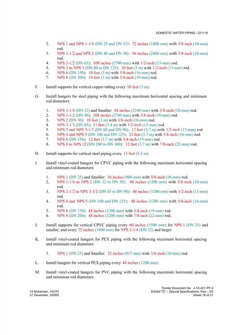
7/18/2019 SEC DPS
http://slidepdf.com/reader/full/sec-dps 302/541
DOMESTIC WATER PIPING - 221116
Tender Document No. J-1X-421-PF-0
14 Muharram, 1431H Exhibit "D" – Special Specifications, Part – D231 December, 2009G Sheet 16 of 21
2. NPS 1 and NPS 1-1/4 (DN 25 and DN 32): 72 inches (1800 mm) with 3/8-inch (10-mm)
rod.
3. NPS 1-1/2 and NPS 2 (DN 40 and DN 50): 96 inches (2400 mm) with 3/8-inch (10-mm)
rod.4. NPS 2-1/2 (DN 65): 108 inches (2700 mm) with 1/2-inch (13-mm) rod.
5. NPS 3 to NPS 5 (DN 80 to DN 125): 10 feet (3 m) with 1/2-inch (13-mm) rod.
6. NPS 6 (DN 150): 10 feet (3 m) with 5/8-inch (16-mm) rod.
7. NPS 8 (DN 200): 10 feet (3 m) with 3/4-inch (19-mm) rod.
F. Install supports for vertical copper tubing every 10 feet (3 m).
G. Install hangers for steel piping with the following maximum horizontal spacing and minimum
rod diameters:
1. NPS 1-1/4 (DN 32) and Smaller: 84 inches (2100 mm) with 3/8-inch (10-mm) rod.
2. NPS 1-1/2 (DN 40): 108 inches (2700 mm) with 3/8-inch (10-mm) rod.3. NPS 2 (DN 50): 10 feet (3 m) with 3/8-inch (10-mm) rod.
4. NPS 2-1/2 (DN 65): 11 feet (3.4 m) with 1/2-inch (13-mm) rod.
5. NPS 3 and NPS 3-1/2 (DN 80 and DN 90): 12 feet (3.7 m) with 1/2-inch (13-mm) rod.
6. NPS 4 and NPS 5 (DN 100 and DN 125): 12 feet (3.7 m) with 5/8-inch (16-mm) rod.
7. NPS 6 (DN 150): 12 feet (3.7 m) with 3/4-inch (19-mm) rod.
8. NPS 8 to NPS 12 (DN 200 to DN 300): 12 feet (3.7 m) with 7/8-inch (22-mm) rod.
H. Install supports for vertical steel piping every 15 feet (4.5 m).
I. Install vinyl-coated hangers for CPVC piping with the following maximum horizontal spacing
and minimum rod diameters:
1. NPS 1 (DN 25) and Smaller: 36 inches (900 mm) with 3/8-inch (10-mm) rod.
2. NPS 1-1/4 to NPS 2 (DN 32 to DN 50): 48 inches (1200 mm) with 3/8-inch (10-mm)
rod.
3. NPS 2-1/2 to NPS 3-1/2 (DN 65 to DN 90): 48 inches (1200 mm) with 1/2-inch (13-mm)
rod.
4. NPS 4 and NPS 5 (DN 100 and DN 125): 48 inches (1200 mm) with 5/8-inch (16-mm)
rod.
5. NPS 6 (DN 150): 48 inches (1200 mm) with 3/4-inch (19-mm) rod.
6. NPS 8 (DN 200): 48 inches (1200 mm) with 7/8-inch (22-mm) rod.
J. Install supports for vertical CPVC piping every 60 inches (1500 mm) for NPS 1 (DN 25) and
smaller, and every 72 inches (1800 mm) for NPS 1-1/4 (DN 32) and larger.
K. Install vinyl-coated hangers for PEX piping with the following maximum horizontal spacing
and minimum rod diameters:
1. NPS 1 (DN 25) and Smaller: 32 inches (815 mm) with 3/8-inch (10-mm) rod.
L. Install hangers for vertical PEX piping every 48 inches (1200 mm).
M. Install vinyl-coated hangers for PVC piping with the following maximum horizontal spacing
and minimum rod diameters:

7/18/2019 SEC DPS
http://slidepdf.com/reader/full/sec-dps 303/541
DOMESTIC WATER PIPING - 221116
Tender Document No. J-1X-421-PF-0
14 Muharram, 1431H Exhibit "D" – Special Specifications, Part – D231 December, 2009G Sheet 17 of 21
1. NPS 2 (DN 50) and Smaller: 48 inches (1200 mm) with 3/8-inch (10-mm) rod.
2. NPS 2-1/2 to NPS 3-1/2 (DN 65 to DN 90): 48 inches (1200 mm) with 1/2-inch (13-mm)
rod.
3. NPS 4 and NPS 5 (DN 100 and DN 125): 48 inches (1200 mm) with 5/8-inch (16-mm) rod.
4. NPS 6 (DN 150): 48 inches (1200 mm) with 3/4-inch (19-mm) rod.
5. NPS 8 (DN 200): 48 inches (1200 mm) with 7/8-inch (22-mm) rod.
N. Install supports for vertical PVC piping every 48 inches (1200 mm).
O. Support piping and tubing not listed in this article according to MSS SP-69 and manufacturer's
written instructions.
3.10 CONNECTIONS
A. Drawings indicate general arrangement of piping, fittings, and specialties.
B. Install piping adjacent to equipment and machines to allow service and maintenance.
C. Connect domestic water piping to exterior water-service piping. Use transition fitting to joindissimilar piping materials.
D. Connect domestic water piping to water-service piping with shutoff valve; extend and connect
to the following:
1. Domestic Water Booster Pumps: Cold-water suction and discharge piping.
2. Water Heaters: Cold-water inlet and hot-water outlet piping in sizes indicated, but notsmaller than sizes of water heater connections.
3. Plumbing Fixtures: Cold- and hot-water supply piping in sizes indicated, but not smaller
than required by plumbing code. Comply with requirements in Division 22 plumbing
fixture Sections for connection sizes.
4. Equipment: Cold- and hot-water supply piping as indicated, but not smaller than
equipment connections. Provide shutoff valve and union for each connection. Useflanges instead of unions for NPS 2-1/2 (DN 65) and larger.
3.11 IDENTIFICATION
A. Identify system components. Comply with requirements in Division 22 Section "Identification
for Plumbing Piping and Equipment" for identification materials and installation.
B. Label pressure piping with system operating pressure.
3.12 FIELD QUALITY CONTROL
A. Perform tests and inspections.
B. Piping Inspections:

7/18/2019 SEC DPS
http://slidepdf.com/reader/full/sec-dps 304/541
DOMESTIC WATER PIPING - 221116
Tender Document No. J-1X-421-PF-0
14 Muharram, 1431H Exhibit "D" – Special Specifications, Part – D231 December, 2009G Sheet 18 of 21
1. Do not enclose, cover, or put piping into operation until it has been inspected and
approved by authorities having jurisdiction.
2. During installation, notify authorities having jurisdiction at least one day before
inspection must be made. Perform tests specified below in presence of authorities having jurisdiction:
a. Roughing-in Inspection: Arrange for inspection of piping before concealing or
closing-in after roughing-in and before setting fixtures.
b. Final Inspection: Arrange final inspection for authorities having jurisdiction to
observe tests specified below and to ensure compliance with requirements.
3. Reinspection: If authorities having jurisdiction find that piping will not pass tests or
inspections, make required corrections and arrange for reinspection.
4. Reports: Prepare inspection reports and have them signed by authorities having
jurisdiction.
C. Piping Tests:
1. Fill domestic water piping. Check components to determine that they are not air bound
and that piping is full of water.
2. Test for leaks and defects in new piping and parts of existing piping that have been
altered, extended, or repaired. If testing is performed in segments, submit a separate
report for each test, complete with diagram of portion of piping tested.
3. Leave new, altered, extended, or replaced domestic water piping uncovered and
unconcealed until it has been tested and approved. Expose work that was covered or
concealed before it was tested.
4. Cap and subject piping to static water pressure of 50 psig (345 kPa) above operating
pressure, without exceeding pressure rating of piping system materials. Isolate testsource and allow to stand for four hours. Leaks and loss in test pressure constitute
defects that must be repaired.
5. Repair leaks and defects with new materials and retest piping or portion thereof until
satisfactory results are obtained.
6. Prepare reports for tests and for corrective action required.
D. Domestic water piping will be considered defective if it does not pass tests and inspections.
E. Prepare test and inspection reports.
3.13 ADJUSTING
A. Perform the following adjustments before operation:
1. Close drain valves, hydrants, and hose bibbs.
2. Open shutoff valves to fully open position.
3. Open throttling valves to proper setting.
4. Adjust balancing valves in hot-water-circulation return piping to provide adequate flow.
a. Manually adjust ball-type balancing valves in hot-water-circulation return piping
to provide flow of hot water in each branch.

7/18/2019 SEC DPS
http://slidepdf.com/reader/full/sec-dps 305/541
DOMESTIC WATER PIPING - 221116
Tender Document No. J-1X-421-PF-0
14 Muharram, 1431H Exhibit "D" – Special Specifications, Part – D231 December, 2009G Sheet 19 of 21
b. Adjust calibrated balancing valves to flows indicated.
5. Remove plugs used during testing of piping and for temporary sealing of piping during
installation.6. Remove and clean strainer screens. Close drain valves and replace drain plugs.
7. Remove filter cartridges from housings and verify that cartridges are as specified for
application where used and are clean and ready for use.
8. Check plumbing specialties and verify proper settings, adjustments, and operation.
3.14 CLEANING
A. Clean and disinfect potable[ and non-potable] domestic water piping as follows:
1. Purge new piping and parts of existing piping that have been altered, extended, or
repaired before using.2. Use purging and disinfecting procedures prescribed by authorities having jurisdiction; if
methods are not prescribed, use procedures described in either AWWA C651 or
AWWA C652 or follow procedures described below:
a. Flush piping system with clean, potable water until dirty water does not appear at
outlets.
b. Fill and isolate system according to either of the following:
1) Fill system or part thereof with water/chlorine solution with at least 50 ppm
(50 mg/L) of chlorine. Isolate with valves and allow to stand for 24 hours.2) Fill system or part thereof with water/chlorine solution with at least 200
ppm (200 mg/L) of chlorine. Isolate and allow to stand for three hours.
c. Flush system with clean, potable water until no chlorine is in water coming from
system after the standing time.
d. Submit water samples in sterile bottles to authorities having jurisdiction. Repeat
procedures if biological examination shows contamination.
B. Clean non-potable domestic water piping as follows:
1. Purge new piping and parts of existing piping that have been altered, extended, or
repaired before using.
2. Use purging procedures prescribed by authorities having jurisdiction or; if methods are
not prescribed, follow procedures described below:
a. Flush piping system with clean, potable water until dirty water does not appear at
outlets.
b. Submit water samples in sterile bottles to authorities having jurisdiction. Repeat
procedures if biological examination shows contamination.
C. Prepare and submit reports of purging and disinfecting activities.
D. Clean interior of domestic water piping system. Remove dirt and debris as work progresses.

7/18/2019 SEC DPS
http://slidepdf.com/reader/full/sec-dps 306/541
DOMESTIC WATER PIPING - 221116
Tender Document No. J-1X-421-PF-0
14 Muharram, 1431H Exhibit "D" – Special Specifications, Part – D231 December, 2009G Sheet 20 of 21
3.15 PIPING SCHEDULE
A. Transition and special fittings with pressure ratings at least equal to piping rating may be used
in applications below unless otherwise indicated.
B. Flanges and unions may be used for aboveground piping joints unless otherwise indicated.
C. Fitting Option: Extruded-tee connections and brazed joints may be used on aboveground
copper tubing.
D. Under-building-slab, domestic water, building service piping, NPS 3 (DN 80) and smaller, shall
be the following:
1. PVC, Schedule 40 pipe; PVC, Schedule 40 socket fittings; and solvent-cemented joints.
E. Under-building-slab, domestic water, building-service piping, NPS 4 to NPS 8 (DN 100 to
DN 200) and larger, shall be the following:1. PVC, Schedule 80 pipe; PVC, Schedule 80 socket fittings; and solvent-cemented joints.
F. Under-building slab, combined domestic water, building-service, and fire-service-main piping,
NPS 6 to NPS 12 (DN 150 to DN 300), shall be one of the following:
1. Mechanical-joint, ductile-iron pipe; standard or compact- pattern mechanical-joint
fittings; and mechanical joints.
2. Plain-end, ductile-iron pipe; grooved-joint, ductile-iron-pipe appurtenances; and grooved
joints.
G. Aboveground domestic water piping, NPS 2 (DN 50) and smaller, shall be the following:
1. Where running exposed outside building for domestic cold, hot and potable water
systems within building plot limit Galvanized-steel pipe and nipples; galvanized, gray-
iron threaded fittings; and threaded joints.
2. For domestic and potable water systems where running concealed or exposed inside
building CPVC, CPVC, Schedule 40; and solvent-cemented joints.
3. For domestic hot water system where running concealed or exposed inside building,CPVC, Schedule 40; and solvent-cemented joints.
H. Aboveground domestic water piping, NPS 2-1/2 to NPS 4 (DN 65 to DN 100), shall be the
following:
1. Where running exposed outside building for domestic cold, hot and potable water
systems within building plot limit Galvanized-steel pipe and nipples; galvanized, gray-iron threaded fittings; and threaded joints.
2. For domestic and potable water systems where running concealed or exposed inside
building CPVC, CPVC, Schedule 40; and solvent-cemented joints.
3. For domestic hot water system where running concealed or exposed inside building,
CPVC, Schedule 80; and solvent-cemented joints.
I. Aboveground domestic water piping, NPS 5 to NPS 8 (DN 125 to DN 200), shall be the
following:
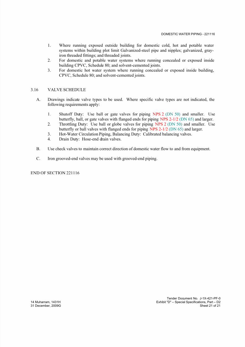
7/18/2019 SEC DPS
http://slidepdf.com/reader/full/sec-dps 307/541
DOMESTIC WATER PIPING - 221116
Tender Document No. J-1X-421-PF-0
14 Muharram, 1431H Exhibit "D" – Special Specifications, Part – D231 December, 2009G Sheet 21 of 21
1. Where running exposed outside building for domestic cold, hot and potable water
systems within building plot limit Galvanized-steel pipe and nipples; galvanized, gray-
iron threaded fittings; and threaded joints.
2. For domestic and potable water systems where running concealed or exposed inside building CPVC, Schedule 80; and solvent-cemented joints.
3. For domestic hot water system where running concealed or exposed inside building,
CPVC, Schedule 80; and solvent-cemented joints.
3.16 VALVE SCHEDULE
A. Drawings indicate valve types to be used. Where specific valve types are not indicated, the
following requirements apply:
1. Shutoff Duty: Use ball or gate valves for piping NPS 2 (DN 50) and smaller. Use
butterfly, ball, or gate valves with flanged ends for piping NPS 2-1/2 (DN 65) and larger.2. Throttling Duty: Use ball or globe valves for piping NPS 2 (DN 50) and smaller. Use
butterfly or ball valves with flanged ends for piping NPS 2-1/2 (DN 65) and larger.
3. Hot-Water Circulation Piping, Balancing Duty: Calibrated balancing valves.
4. Drain Duty: Hose-end drain valves.
B. Use check valves to maintain correct direction of domestic water flow to and from equipment.
C. Iron grooved-end valves may be used with grooved-end piping.
END OF SECTION 221116
7/18/2019 SEC DPS
http://slidepdf.com/reader/full/sec-dps 308/541
DOMESTIC WATER PIPING SPECIALTIES - 221119
Tender Document No. J-1X-421-PF-0
14 Muharram, 1431H Exhibit "D" – Special Specifications, Part – D231 December, 2009G Sheet 1 of 14
SECTION 221119 - DOMESTIC WATER PIPING SPECIALTIES
PART 1 - GENERAL
1.1 RELATED DOCUMENTS
A. Drawings and general provisions of the Contract, including General and Supplementary
Conditions and Division 01 Specification Sections, apply to this Section.
1.2 SUMMARY
A. This Section includes the following domestic water piping specialties:
1. Vacuum breakers.
2. Backflow preventers.3. Water pressure-reducing valves.
4. Balancing valves.
5. Temperature-actuated water mixing valves.
6. Strainers.
7. Hose stations.8. Hose bibbs.
9. Wall hydrants.
10. Ground hydrants.
11. Post hydrants.
12. Drain valves.13. Water hammer arresters.
14. Air vents.
15. Trap-seal primer valves.
16. Trap-seal primer systems.
B. Related Sections include the following:
1. Division 22 Section "Meters and Gages For Plumbing Piping" for thermometers, pressuregages, and flow meters in domestic water piping.
2. Division 22 Section "Domestic Water Piping" for water meters.
3. Division 22 Section "Domestic Water Filtration Equipment" for water filters in domestic
water piping.4. Division 22 Section "Healthcare Plumbing Fixtures" for thermostatic mixing valves for
sitz baths, thermostatic mixing-valve assemblies for hydrotherapy equipment, and outlet
boxes for dialysis equipment.
5. Division 22 Section "Emergency Plumbing Fixtures" for water tempering equipment.
6. Division 22 Section "Drinking Fountains and Water Coolers" for water filters for water
coolers.

7/18/2019 SEC DPS
http://slidepdf.com/reader/full/sec-dps 309/541
DOMESTIC WATER PIPING SPECIALTIES - 221119
Tender Document No. J-1X-421-PF-0
14 Muharram, 1431H Exhibit "D" – Special Specifications, Part – D231 December, 2009G Sheet 2 of 14
1.3 PERFORMANCE REQUIREMENTS
A. Minimum Working Pressure for Domestic Water Piping Specialties: 125 psig (860 kPa), 150
psig (1032 kPa) or 175 psig (1204 kPa) (as applicable for building operating pressure).
1.4 ACTION SUBMITTALS
A. Product Data: For each type of product indicated.
B. Shop Drawings: Diagram power, signal, and control wiring.
1.5 INFORMATIONAL SUBMITTALS
A.
Field quality-control test reports.
1.6 CLOSEOUT SUBMITTALS
A. Operation and Maintenance Data: For domestic water piping specialties to include in
emergency, operation, and maintenance manuals.
1.7 QUALITY ASSURANCE
A. Electrical Components, Devices, and Accessories: Listed and labeled as defined in NFPA 70,
Article 100, by a testing agency acceptable to authorities having jurisdiction, and marked for
intended use.
B. NSF Compliance:
1. Comply with NSF 14, "Plastics Piping Components and Related Materials," for plastic
domestic water piping components.
2. Comply with NSF 61, "Drinking Water System Components - Health Effects; Sections 1
through 9."
PART 2 - PRODUCTS
2.1 VACUUM BREAKERS
A. Pipe-Applied, Atmospheric-Type Vacuum Breakers:
1. Manufacturers: Subject to compliance with requirements
2. Standard: ASSE 1001.
3. Size: NPS 1/4 to NPS 3 (DN 8 to DN 80), as required to match connected piping.
4. Body: Bronze.
5. Inlet and Outlet Connections: Threaded.
6. Finish: Chrome plated.

7/18/2019 SEC DPS
http://slidepdf.com/reader/full/sec-dps 310/541
DOMESTIC WATER PIPING SPECIALTIES - 221119
Tender Document No. J-1X-421-PF-0
14 Muharram, 1431H Exhibit "D" – Special Specifications, Part – D231 December, 2009G Sheet 3 of 14
B. Hose-Connection Vacuum Breakers:
1. Manufacturers: Subject to compliance with requirements
2. Standard: ASSE 1011.3. Body: Bronze, nonremovable, with manual drain.
4. Outlet Connection: Garden-hose threaded complying with ASME B1.20.7.
5. Finish: Chrome or nickel plated.
C. Pressure Vacuum Breakers:
1. Manufacturers: Subject to compliance with requirements
2. Basis-of-Design Product: Subject to compliance with requirements
3. Standard: ASSE 1020.
4. Operation: Continuous-pressure applications.
5. Pressure Loss: 5 psig (35 kPa) maximum, through middle 1/3 of flow range.
6. Accessories:
a. Valves: Ball type, on inlet and outlet.
D. Laboratory-Faucet Vacuum Breakers:
1. Manufacturers: Subject to compliance with requirements
2. Standard: ASSE 1035.
3. Size: NPS 1/4 or NPS 3/8 (DN 8 or DN 10) matching faucet size.
4. Body: Bronze.
5. End Connections: Threaded.
6. Finish: Chrome plated.
2.2 BACKFLOW PREVENTERS
A. Intermediate Atmospheric-Vent Backflow Preventers:
1. Manufacturers: Subject to compliance with requirements
2. Standard: ASSE 1012.
3. Operation: Continuous-pressure applications.
4. Body: Bronze.
5. End Connections: Union, solder joint.
6. Finish: Chrome plated.
B. Double-Check Backflow-Prevention Assemblies:1. Manufacturers: Subject to compliance with requirements
2. Basis-of-Design Product: Subject to compliance with requirements
3. Standard: ASSE 1015.
4. Operation: Continuous-pressure applications, unless otherwise indicated.
5. Pressure Loss: 5 psig (35 kPa) maximum, through middle 1/3 of flow range.
6. Body: Bronze for NPS 2 (DN 50) and smaller; cast iron with interior lining complying
with AWWA C550 or that is FDA approved for NPS 2-1/2 (DN 65) and larger.

7/18/2019 SEC DPS
http://slidepdf.com/reader/full/sec-dps 311/541
DOMESTIC WATER PIPING SPECIALTIES - 221119
Tender Document No. J-1X-421-PF-0
14 Muharram, 1431H Exhibit "D" – Special Specifications, Part – D231 December, 2009G Sheet 4 of 14
7. End Connections: Threaded for NPS 2 (DN 50) and smaller; flanged for NPS 2-1/2
(DN 65) and larger.
8. Configuration: Designed for horizontal, straight through flow.
9. Accessories:
a. Valves: Ball type with threaded ends on inlet and outlet of NPS 2 (DN 50) and
smaller; outside screw and yoke gate-type with flanged ends on inlet and outlet of
NPS 2-1/2 (DN 65) and larger.
C. Dual-Check-Valve Backflow Preventers:
1. Manufacturers: Subject to compliance with requirements
2. Standard: ASSE 1024.
3. Operation: Continuous-pressure applications.
4. Size: NPS 1/2 (DN 15), NPS 3/4 (DN 20), NPS 1 (DN 25),or NPS 1-1/4 (DN 32) (as
applicable).5. Body: Bronze with union inlet.
D. Backflow-Preventer Test Kits:
1. Manufacturers: Subject to compliance with requirements
2. Basis-of-Design Product: Subject to compliance with requirements
3. Description: Factory calibrated, with gages, fittings, hoses, and carrying case with test-
procedure instructions.
2.3 WATER PRESSURE-REDUCING VALVES
A. Water Regulators:
1. Manufacturers: Subject to compliance with requirements
2. Standard: ASSE 1003.
3. Body: Bronze with chrome-plated finish for NPS 2 (DN 50) and smaller; cast iron with
interior lining complying with AWWA C550 or that is FDA approved for NPS 2-1/2 and NPS 3 (DN 65 and DN 80).
4. Valves for Booster Heater Water Supply: Include integral bypass.
5. End Connections: Threaded for NPS 2 (DN 50) and smaller; flanged for NPS 2-1/2 and
NPS 3 (DN 65 and DN 80).
B. Water Control Valves:
1. Manufacturers: Subject to compliance with requirements2. Basis-of-Design Product: Subject to compliance with requirements
3. Description: Pilot-operation, diaphragm-type, single-seated main water control valve.
4. Pressure Rating: with AWWA C550 or FDA-approved, interior epoxy coating. Include
small pilot-control valve, restrictor device, specialty fittings, and sensor piping.
5. Main Valve Body: Cast- or ductile-iron body with AWWA C550 or FDA-approved,interior epoxy coating; or stainless-steel body.
a. Pattern: Globe-valve design.
b. Trim: Stainless steel.

7/18/2019 SEC DPS
http://slidepdf.com/reader/full/sec-dps 312/541
DOMESTIC WATER PIPING SPECIALTIES - 221119
Tender Document No. J-1X-421-PF-0
14 Muharram, 1431H Exhibit "D" – Special Specifications, Part – D231 December, 2009G Sheet 5 of 14
6. End Connections: Threaded for NPS 2 (DN 50) and smaller; flanged for NPS 2-1/2
(DN 65) and larger.
2.4 BALANCING VALVES
A. Copper-Alloy Calibrated Balancing Valves:
1. Manufacturers: Subject to compliance with requirements
2. Basis-of-Design Product: Subject to compliance with requirements
3. Type: Y-pattern globe valve with two readout ports and memory setting indicator.
4. Body: bronze,
5. Size: Same as connected piping, but not larger than NPS 2 (DN 50).
6. Accessories: Meter hoses, fittings, valves, differential pressure meter, and carrying case.
B. Cast-Iron Calibrated Balancing Valves:1. Manufacturers: Subject to compliance with requirements
2. Basis-of-Design Product: Subject to compliance with requirements
3. Type: Adjustable with Y-pattern globe valve, two readout ports, and memory-setting
indicator.
4. Size: Same as connected piping, but not smaller than NPS 2-1/2 (DN 65).
C. Accessories: Meter hoses, fittings, valves, differential pressure meter, and carrying case.
D. Memory-Stop Balancing Valves:
1. Manufacturers: Subject to compliance with requirements
2. Standard: MSS SP-110 for two-piece, copper-alloy ball valves.
3. Pressure Rating: 400-psig (2760-kPa) minimum CWP.
4. Size: NPS 2 (DN 50) or smaller.
5. Body: Copper alloy.
6. Port: Standard or full port.
7. Ball: Chrome-plated brass.8. Seats and Seals: Replaceable.
9. End Connections: Solder joint or threaded.
10. Handle: Vinyl-covered steel with memory-setting device.
2.5 TEMPERATURE-ACTUATED WATER MIXING VALVES
A. Water-Temperature Limiting Devices:
1. Manufacturers: Subject to compliance with requirements
2. Basis-of-Design Product: Subject to compliance with requirements
3. Standard: ASSE 1017.
4. Type: Thermostatically controlled water mixing valve.
5. Material: Bronze body with corrosion-resistant interior components.
6. Connections: Threaded union inlets and outlet.
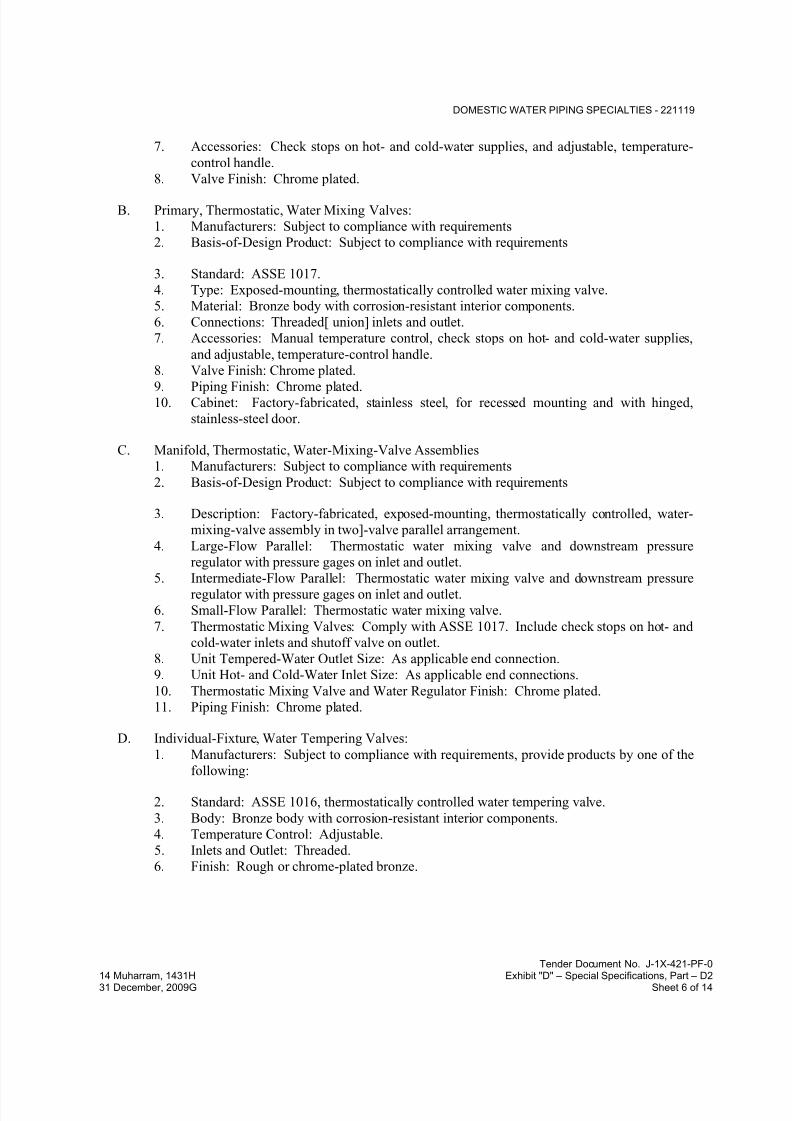
7/18/2019 SEC DPS
http://slidepdf.com/reader/full/sec-dps 313/541
DOMESTIC WATER PIPING SPECIALTIES - 221119
Tender Document No. J-1X-421-PF-0
14 Muharram, 1431H Exhibit "D" – Special Specifications, Part – D231 December, 2009G Sheet 6 of 14
7. Accessories: Check stops on hot- and cold-water supplies, and adjustable, temperature-
control handle.
8. Valve Finish: Chrome plated.
B. Primary, Thermostatic, Water Mixing Valves:
1. Manufacturers: Subject to compliance with requirements
2. Basis-of-Design Product: Subject to compliance with requirements
3. Standard: ASSE 1017.
4. Type: Exposed-mounting, thermostatically controlled water mixing valve.
5. Material: Bronze body with corrosion-resistant interior components.
6. Connections: Threaded[ union] inlets and outlet.
7. Accessories: Manual temperature control, check stops on hot- and cold-water supplies,
and adjustable, temperature-control handle.
8. Valve Finish: Chrome plated.
9. Piping Finish: Chrome plated.10. Cabinet: Factory-fabricated, stainless steel, for recessed mounting and with hinged,
stainless-steel door.
C. Manifold, Thermostatic, Water-Mixing-Valve Assemblies
1. Manufacturers: Subject to compliance with requirements
2. Basis-of-Design Product: Subject to compliance with requirements
3. Description: Factory-fabricated, exposed-mounting, thermostatically controlled, water-
mixing-valve assembly in two]-valve parallel arrangement.
4. Large-Flow Parallel: Thermostatic water mixing valve and downstream pressure
regulator with pressure gages on inlet and outlet.
5. Intermediate-Flow Parallel: Thermostatic water mixing valve and downstream pressureregulator with pressure gages on inlet and outlet.
6. Small-Flow Parallel: Thermostatic water mixing valve.
7. Thermostatic Mixing Valves: Comply with ASSE 1017. Include check stops on hot- and
cold-water inlets and shutoff valve on outlet.
8. Unit Tempered-Water Outlet Size: As applicable end connection.
9. Unit Hot- and Cold-Water Inlet Size: As applicable end connections.
10. Thermostatic Mixing Valve and Water Regulator Finish: Chrome plated.
11. Piping Finish: Chrome plated.
D. Individual-Fixture, Water Tempering Valves:
1. Manufacturers: Subject to compliance with requirements, provide products by one of the
following:
2. Standard: ASSE 1016, thermostatically controlled water tempering valve.
3. Body: Bronze body with corrosion-resistant interior components.
4. Temperature Control: Adjustable.
5. Inlets and Outlet: Threaded.
6. Finish: Rough or chrome-plated bronze.
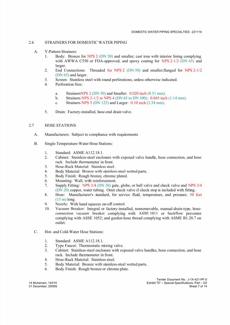
7/18/2019 SEC DPS
http://slidepdf.com/reader/full/sec-dps 314/541
DOMESTIC WATER PIPING SPECIALTIES - 221119
Tender Document No. J-1X-421-PF-0
14 Muharram, 1431H Exhibit "D" – Special Specifications, Part – D231 December, 2009G Sheet 7 of 14
2.6 STRAINERS FOR DOMESTIC WATER PIPING
A. Y-Pattern Strainers:
1. Body: Bronze for NPS 2 (DN 50) and smaller; cast iron with interior lining complyingwith AWWA C550 or FDA-approved, and epoxy coating for NPS 2-1/2 (DN 65) and
larger.
2. End Connections: Threaded for NPS 2 (DN 50) and smaller;flanged for NPS 2-1/2
(DN 65) and larger.
3. Screen: Stainless steel with round perforations, unless otherwise indicated.
4. Perforation Size:
a. Strainers NPS 2 (DN 50) and Smaller: 0.020 inch (0.51 mm).
b. Strainers NPS 2-1/2 to NPS 4 (DN 65 to DN 100): 0.045 inch (1.14 mm).
c. Strainers NPS 5 (DN 125) and Larger: 0.10 inch (2.54 mm).
5. Drain: Factory-installed, hose-end drain valve.
2.7 HOSE STATIONS
A. Manufacturers: Subject to compliance with requirements
B. Single-Temperature-Water Hose Stations:
1. Standard: ASME A112.18.1.
2. Cabinet: Stainless-steel enclosure with exposed valve handle, hose connection, and hose
rack. Include thermometer in front.
3. Hose-Rack Material: Stainless steel.
4. Body Material: Bronze with stainless-steel wetted parts.
5. Body Finish: Rough bronze, chrome plated.
6. Mounting: Wall, with reinforcement.
7. Supply Fitting: NPS 3/4 (DN 20) gate, globe, or ball valve and check valve and NPS 3/4
(DN 20) copper, water tubing. Omit check valve if check stop is included with fitting.
8. Hose: Manufacturer's standard, for service fluid, temperature, and pressure; 50 feet
(15 m) long.
9. Nozzle: With hand squeeze on-off control.
10. Vacuum Breaker: Integral or factory-installed, nonremovable, manual-drain-type, hose-
connection vacuum breaker complying with ASSE 1011 or backflow preventer
complying with ASSE 1052; and garden-hose thread complying with ASME B1.20.7 on
outlet.
C. Hot- and Cold-Water Hose Stations:
1. Standard: ASME A112.18.1.
2. Type Faucet: Thermostatic mixing valve.
3. Cabinet: Stainless-steel enclosure with exposed valve handles, hose connection, and hose
rack. Include thermometer in front.
4. Hose-Rack Material: Stainless steel.
5. Body Material: Bronze with stainless-steel wetted parts.
6. Body Finish: Rough bronze or chrome plate.
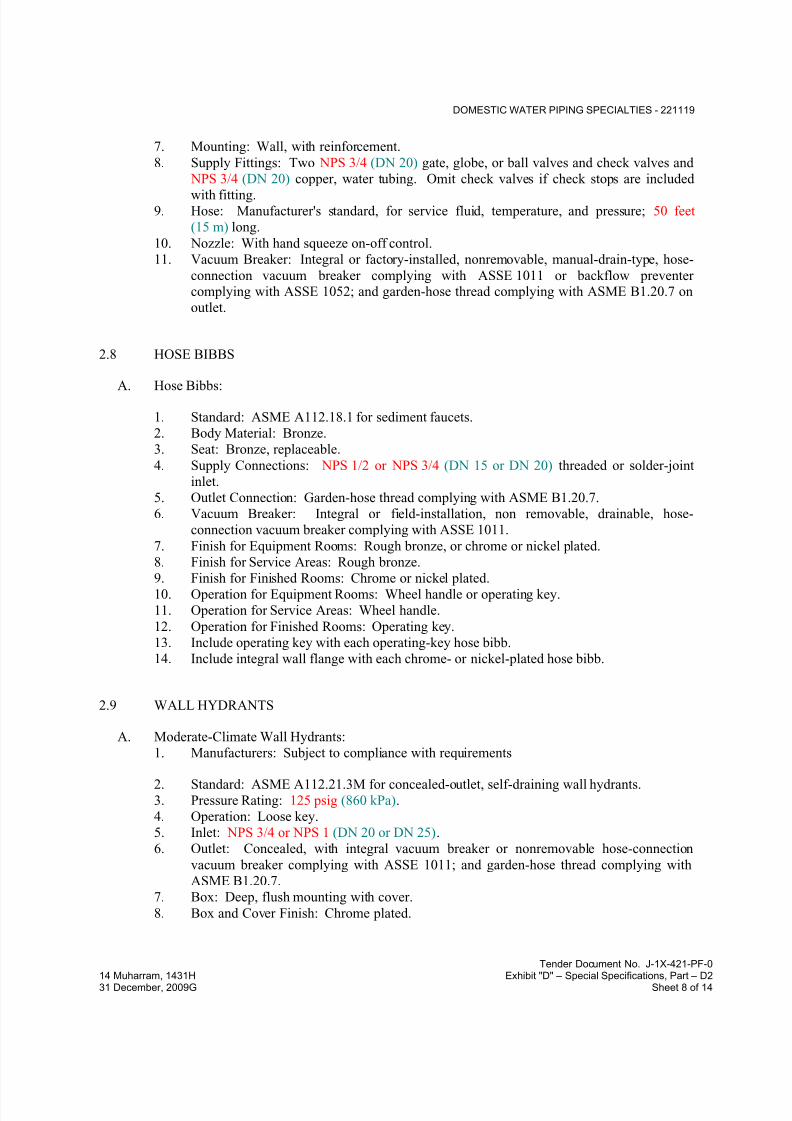
7/18/2019 SEC DPS
http://slidepdf.com/reader/full/sec-dps 315/541
DOMESTIC WATER PIPING SPECIALTIES - 221119
Tender Document No. J-1X-421-PF-0
14 Muharram, 1431H Exhibit "D" – Special Specifications, Part – D231 December, 2009G Sheet 8 of 14
7. Mounting: Wall, with reinforcement.
8. Supply Fittings: Two NPS 3/4 (DN 20) gate, globe, or ball valves and check valves and
NPS 3/4 (DN 20) copper, water tubing. Omit check valves if check stops are included
with fitting.9. Hose: Manufacturer's standard, for service fluid, temperature, and pressure; 50 feet
(15 m) long.
10. Nozzle: With hand squeeze on-off control.
11. Vacuum Breaker: Integral or factory-installed, nonremovable, manual-drain-type, hose-
connection vacuum breaker complying with ASSE 1011 or backflow preventercomplying with ASSE 1052; and garden-hose thread complying with ASME B1.20.7 on
outlet.
2.8 HOSE BIBBS
A. Hose Bibbs:
1. Standard: ASME A112.18.1 for sediment faucets.
2. Body Material: Bronze.
3. Seat: Bronze, replaceable.
4. Supply Connections: NPS 1/2 or NPS 3/4 (DN 15 or DN 20) threaded or solder-joint
inlet.
5. Outlet Connection: Garden-hose thread complying with ASME B1.20.7.
6. Vacuum Breaker: Integral or field-installation, non removable, drainable, hose-
connection vacuum breaker complying with ASSE 1011.
7. Finish for Equipment Rooms: Rough bronze, or chrome or nickel plated.
8. Finish for Service Areas: Rough bronze.
9. Finish for Finished Rooms: Chrome or nickel plated.10. Operation for Equipment Rooms: Wheel handle or operating key.
11. Operation for Service Areas: Wheel handle.
12. Operation for Finished Rooms: Operating key.
13. Include operating key with each operating-key hose bibb.
14. Include integral wall flange with each chrome- or nickel-plated hose bibb.
2.9 WALL HYDRANTS
A. Moderate-Climate Wall Hydrants:
1. Manufacturers: Subject to compliance with requirements
2. Standard: ASME A112.21.3M for concealed-outlet, self-draining wall hydrants.
3. Pressure Rating: 125 psig (860 kPa).
4. Operation: Loose key.
5. Inlet: NPS 3/4 or NPS 1 (DN 20 or DN 25).
6. Outlet: Concealed, with integral vacuum breaker or nonremovable hose-connection
vacuum breaker complying with ASSE 1011; and garden-hose thread complying with
ASME B1.20.7.
7. Box: Deep, flush mounting with cover.
8. Box and Cover Finish: Chrome plated.

7/18/2019 SEC DPS
http://slidepdf.com/reader/full/sec-dps 316/541
DOMESTIC WATER PIPING SPECIALTIES - 221119
Tender Document No. J-1X-421-PF-0
14 Muharram, 1431H Exhibit "D" – Special Specifications, Part – D231 December, 2009G Sheet 9 of 14
B. Vacuum Breaker Wall Hydrants:
1. Manufacturers: Subject to compliance with requirements
2. Standard: ASSE 1019, Type A or Type B.3. Type: Freeze-resistant, automatic draining with integral air-inlet valve.
4. Classification: Type B, for automatic draining with hose removed or with hose attached
and nozzle closed.
5. Operation: Loose key or wheel handle
6. Casing and Operating Rod: Of length required to match wall thickness. Include wall
clamp.
7. Inlet: NPS 1/2 or NPS 3/4 (DN 15 or DN 20).
8. Outlet: Exposed with garden-hose thread complying with ASME B1.20.7.
2.10 GROUND HYDRANTS
2.11 POST HYDRANTS
A. Nonfreeze, Draining-Type Post Hydrants:
1. Manufacturers: Subject to compliance with requirements
2. Standard: ASME A112.21.3M.
3. Type: Nonfreeze, exposed-outlet post hydrant.
4. Operation: Loose key.
5. Casing and Operating Rod: Of at least length required for burial of valve below frostline.
6. Casing: Bronze with casing guard.
7. Inlet: NPS 3/4 (DN 20).
8. Outlet: Garden-hose thread complying with ASME B1.20.7.
9. Drain: Designed with hole to drain into ground when shut off.
10. Vacuum Breaker: Nonremovable, drainable, hose-connection vacuum breaker complying
with ASSE 1011; and garden-hose thread complying with ASME B1.20.7 on outlet.
11. Operating Key(s): Two with each loose-key-operation wall hydrant.
2.12 DRAIN VALVES
A. Ball-Valve-Type, Hose-End Drain Valves:
1. Standard: MSS SP-110 for standard-port, two-piece ball valves.2. Pressure Rating: 400-psig (2760-kPa) minimum CWP.
3. Size: NPS 3/4 (DN 20).
4. Body: Copper alloy.
5. Ball: Chrome-plated brass.
6. Seats and Seals: Replaceable.
7. Handle: Vinyl-covered steel.8. Inlet: Threaded or solder joint.
9. Outlet: Threaded, short nipple with garden-hose thread complying with ASME B1.20.7
and cap with brass chain.

7/18/2019 SEC DPS
http://slidepdf.com/reader/full/sec-dps 317/541
DOMESTIC WATER PIPING SPECIALTIES - 221119
Tender Document No. J-1X-421-PF-0
14 Muharram, 1431H Exhibit "D" – Special Specifications, Part – D231 December, 2009G Sheet 10 of 14
B. Gate-Valve-Type, Hose-End Drain Valves:
1. Standard: MSS SP-80 for gate valves.
2. Pressure Rating: Class 125.3. Size: NPS 3/4 (DN 20).
4. Body: ASTM B 62 bronze.
5. Inlet: NPS 3/4 (DN 20) threaded or solder joint.
6. Outlet: Garden-hose thread complying with ASME B1.20.7 and cap with brass chain.
C. Stop-and-Waste Drain Valves:
1. Standard: MSS SP-110 for ball valves or MSS SP-80 for gate valves.
2. Pressure Rating: 200-psig (1380-kPa) minimum CWP or Class 125.
3. Size: NPS 3/4 (DN 20).
4. Body: Copper alloy or ASTM B 62 bronze.
5. Drain: NPS 1/8 (DN 6) side outlet with cap.
2.13 WATER HAMMER ARRESTERS
A. Water Hammer Arresters:
1. Manufacturers: Subject to compliance with requirements
2. Standard: ASSE 1010 or PDI-WH 201.
3. Type: Metal bellows.
4. Size: ASSE 1010, Sizes AA and A through F or PDI-WH 201, Sizes A through F.
2.14 AIR VENTS
A. Bolted-Construction Automatic Air Vents:
1. Body: Bronze.
2. Float: Replaceable, corrosion-resistant metal.
3. Mechanism and Seat: Stainless steel.
4. Size: NPS 1/2 (DN 15) minimum inlet.5. Inlet and Vent Outlet End Connections: Threaded.
2.15 TRAP-SEAL PRIMER VALVES
A. Supply-Type, Trap-Seal Primer Valves:
1. Manufacturers: Subject to compliance with requirements
2. Standard: ASSE 1018.
3. Body: Bronze.
4. Inlet and Outlet Connections: NPS 1/2 (DN 15) threaded, union, or solder joint.
5. Gravity Drain Outlet Connection: NPS 1/2 (DN 15) threaded or solder joint.
6. Finish: Chrome plated, or rough bronze for units used with pipe or tube that is not
chrome finished.
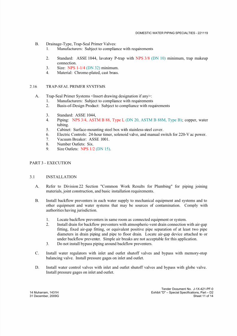
7/18/2019 SEC DPS
http://slidepdf.com/reader/full/sec-dps 318/541
DOMESTIC WATER PIPING SPECIALTIES - 221119
Tender Document No. J-1X-421-PF-0
14 Muharram, 1431H Exhibit "D" – Special Specifications, Part – D231 December, 2009G Sheet 11 of 14
B. Drainage-Type, Trap-Seal Primer Valves:
1. Manufacturers: Subject to compliance with requirements
2. Standard: ASSE 1044, lavatory P-trap with NPS 3/8 (DN 10) minimum, trap makeupconnection.
3. Size: NPS 1-1/4 (DN 32) minimum.
4. Material: Chrome-plated, cast brass.
2.16 TRAP-SEAL PRIMER SYSTEMS
A. Trap-Seal Primer Systems <Insert drawing designation if any>:
1. Manufacturers: Subject to compliance with requirements
2. Basis-of-Design Product: Subject to compliance with requirements
3. Standard: ASSE 1044,4. Piping: NPS 3/4, ASTM B 88, Type L (DN 20, ASTM B 88M, Type B); copper, water
tubing.
5. Cabinet: Surface-mounting steel box with stainless-steel cover.
6. Electric Controls: 24-hour timer, solenoid valve, and manual switch for 220-V ac power.
7. Vacuum Breaker: ASSE 1001.
8. Number Outlets: Six.
9. Size Outlets: NPS 1/2 (DN 15).
PART 3 - EXECUTION
3.1 INSTALLATION
A. Refer to Division 22 Section "Common Work Results for Plumbing" for piping joining
materials, joint construction, and basic installation requirements.
B. Install backflow preventers in each water supply to mechanical equipment and systems and to
other equipment and water systems that may be sources of contamination. Comply with
authorities having jurisdiction.
1. Locate backflow preventers in same room as connected equipment or system.
2. Install drain for backflow preventers with atmospheric-vent drain connection with air-gap
fitting, fixed air-gap fitting, or equivalent positive pipe separation of at least two pipe
diameters in drain piping and pipe to floor drain. Locate air-gap device attached to orunder backflow preventer. Simple air breaks are not acceptable for this application.
3. Do not install bypass piping around backflow preventers.
C. Install water regulators with inlet and outlet shutoff valves and bypass with memory-stop
balancing valve. Install pressure gages on inlet and outlet.
D. Install water control valves with inlet and outlet shutoff valves and bypass with globe valve.
Install pressure gages on inlet and outlet.
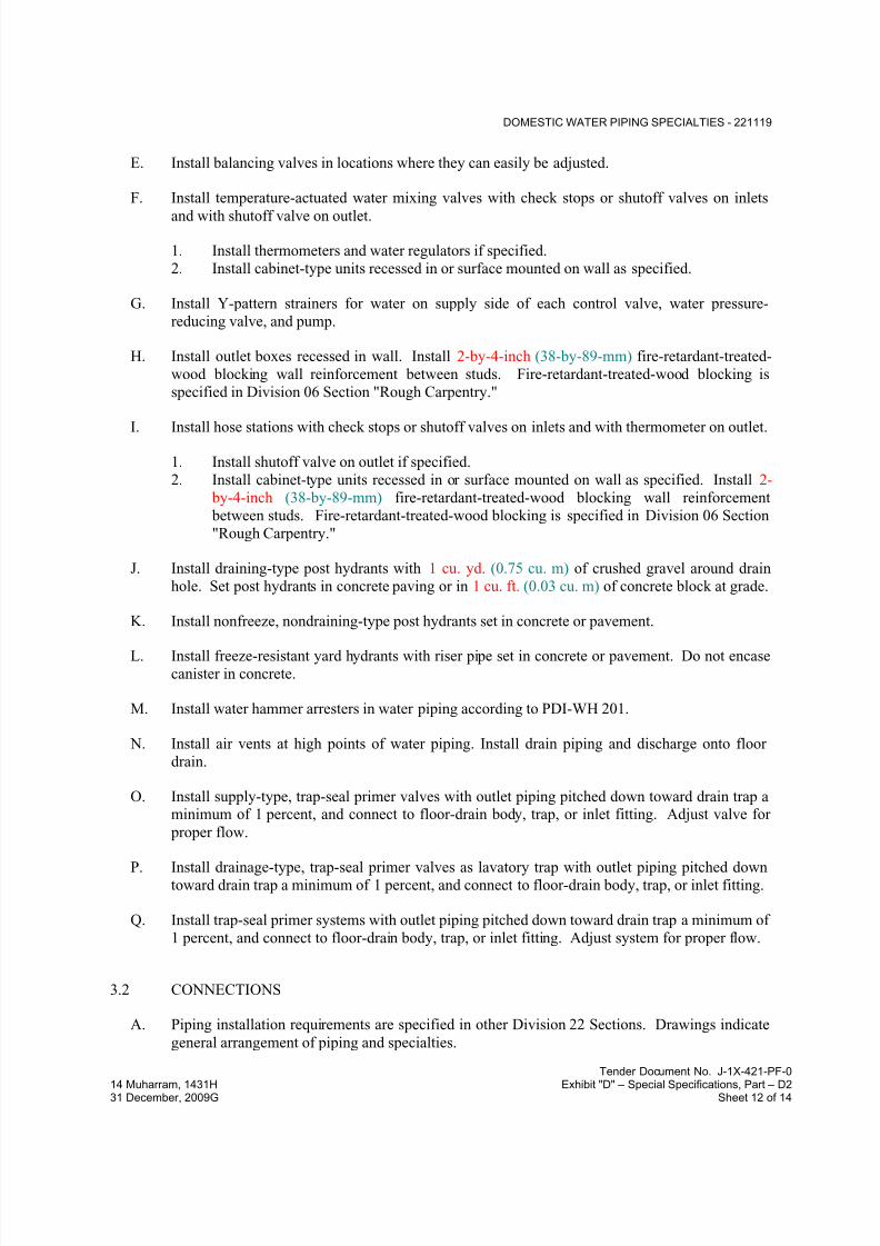
7/18/2019 SEC DPS
http://slidepdf.com/reader/full/sec-dps 319/541
DOMESTIC WATER PIPING SPECIALTIES - 221119
Tender Document No. J-1X-421-PF-0
14 Muharram, 1431H Exhibit "D" – Special Specifications, Part – D231 December, 2009G Sheet 12 of 14
E. Install balancing valves in locations where they can easily be adjusted.
F. Install temperature-actuated water mixing valves with check stops or shutoff valves on inlets
and with shutoff valve on outlet.
1. Install thermometers and water regulators if specified.
2. Install cabinet-type units recessed in or surface mounted on wall as specified.
G. Install Y-pattern strainers for water on supply side of each control valve, water pressure-
reducing valve, and pump.
H. Install outlet boxes recessed in wall. Install 2-by-4-inch (38-by-89-mm) fire-retardant-treated-
wood blocking wall reinforcement between studs. Fire-retardant-treated-wood blocking is
specified in Division 06 Section "Rough Carpentry."
I. Install hose stations with check stops or shutoff valves on inlets and with thermometer on outlet.
1. Install shutoff valve on outlet if specified.
2. Install cabinet-type units recessed in or surface mounted on wall as specified. Install 2-
by-4-inch (38-by-89-mm) fire-retardant-treated-wood blocking wall reinforcement
between studs. Fire-retardant-treated-wood blocking is specified in Division 06 Section
"Rough Carpentry."
J. Install draining-type post hydrants with 1 cu. yd. (0.75 cu. m) of crushed gravel around drain
hole. Set post hydrants in concrete paving or in 1 cu. ft. (0.03 cu. m) of concrete block at grade.
K. Install nonfreeze, nondraining-type post hydrants set in concrete or pavement.
L. Install freeze-resistant yard hydrants with riser pipe set in concrete or pavement. Do not encase
canister in concrete.
M. Install water hammer arresters in water piping according to PDI-WH 201.
N. Install air vents at high points of water piping. Install drain piping and discharge onto floor
drain.
O. Install supply-type, trap-seal primer valves with outlet piping pitched down toward drain trap aminimum of 1 percent, and connect to floor-drain body, trap, or inlet fitting. Adjust valve for
proper flow.
P. Install drainage-type, trap-seal primer valves as lavatory trap with outlet piping pitched downtoward drain trap a minimum of 1 percent, and connect to floor-drain body, trap, or inlet fitting.
Q. Install trap-seal primer systems with outlet piping pitched down toward drain trap a minimum of
1 percent, and connect to floor-drain body, trap, or inlet fitting. Adjust system for proper flow.
3.2 CONNECTIONS
A. Piping installation requirements are specified in other Division 22 Sections. Drawings indicate
general arrangement of piping and specialties.

7/18/2019 SEC DPS
http://slidepdf.com/reader/full/sec-dps 320/541
DOMESTIC WATER PIPING SPECIALTIES - 221119
Tender Document No. J-1X-421-PF-0
14 Muharram, 1431H Exhibit "D" – Special Specifications, Part – D231 December, 2009G Sheet 13 of 14
B. Ground equipment according to Division 26 Section "Grounding and Bonding for Electrical
Systems."
C. Connect wiring according to Division 26 Section "Low-Voltage Electrical Power Conductorsand Cables."
3.3 LABELING AND IDENTIFYING
A. Equipment Nameplates and Signs: Install engraved plastic-laminate equipment nameplate or
sign on or near each of the following:
1. Pressure vacuum breakers.
2. Intermediate atmospheric-vent backflow preventers.
3. Reduced-pressure-principle backflow preventers.
4. Double-check backflow-prevention assemblies.5. Dual-check-valve backflow preventers.
6. Double-check, detector-assembly backflow preventers.
7. Water pressure-reducing valves.
8. Calibrated balancing valves.
9. Primary, thermostatic, water mixing valves.
10. Manifold, thermostatic, water-mixing-valve assemblies.
11. Primary water tempering valves.
12. Hose stations.
13. Supply-type, trap-seal primer valves.
14. Trap-seal primer systems.
B. Distinguish among multiple units, inform operator of operational requirements, indicate safetyand emergency precautions, and warn of hazards and improper operations, in addition to
identifying unit. Nameplates and signs are specified in Division 22 Section "Identification for
Plumbing Piping and Equipment."
3.4 FIELD QUALITY CONTROL
A. Perform the following tests and prepare test reports:
1. Test each pressure vacuum breaker , double-check backflow-prevention assembly and
according to authorities having jurisdiction and the device's reference standard.
B. Remove and replace malfunctioning domestic water piping specialties and retest as specifiedabove.
3.5 ADJUSTING
A. Set field-adjustable pressure set points of water pressure-reducing valves.
B. Set field-adjustable flow set points of balancing valves.

7/18/2019 SEC DPS
http://slidepdf.com/reader/full/sec-dps 321/541
DOMESTIC WATER PIPING SPECIALTIES - 221119
Tender Document No. J-1X-421-PF-0
14 Muharram, 1431H Exhibit "D" – Special Specifications, Part – D231 December, 2009G Sheet 14 of 14
C. Set field-adjustable temperature set points of temperature-actuated water mixing valves.
END OF SECTION 221119
7/18/2019 SEC DPS
http://slidepdf.com/reader/full/sec-dps 322/541
DOMESTIC WATER PUMPS - 221123
Tender Document No. J-1X-421-PF-0
14 Muharram, 1431H Exhibit "D" – Special Specifications, Part – D231 December, 2009G Sheet 1 of 7
SECTION 221123 - DOMESTIC WATER PUMPS
PART 1 - GENERAL
1.1 RELATED DOCUMENTS
A. Drawings and general provisions of the Contract, including General and Supplementary
Conditions and Division 01 Specification Sections, apply to this Section.
1.2 SUMMARY
A. Section Includes:
1. Horizontally mounted, in-line, separately coupled centrifugal pumps.
2. Horizontally mounted, in-line, close-coupled centrifugal pumps.3. Vertically mounted, in-line, close-coupled centrifugal pumps.
B. Related Sections include the following:
1. Division 22 Section "Domestic-Water Packaged Booster Pumps" for booster systems.
1.3 DEFINITIONS
A. Low Voltage: As defined in NFPA 70 for circuits and equipment operating at less than 50 V or
for remote-control, signaling power-limited circuits.
1.4 ACTION SUBMITTALS
A. Product Data: For each type of product indicated. Include materials of construction, rated
capacities, certified performance curves with operating points plotted on curves, operating
characteristics, electrical characteristics, and furnished specialties and accessories.
B. LEED Submittals:
1. Product Data for Prerequisite EA 2: Documentation indicating that units comply with
applicable requirements in ASHRAE/IESNA 90.1, without amendments, Section 7 -"Service Water Heating."
1.5 CLOSEOUT SUBMITTALS
A. Operation and Maintenance Data: For domestic water pumps to include in operation and
maintenance manuals.
7/18/2019 SEC DPS
http://slidepdf.com/reader/full/sec-dps 323/541
DOMESTIC WATER PUMPS - 221123
Tender Document No. J-1X-421-PF-0
14 Muharram, 1431H Exhibit "D" – Special Specifications, Part – D231 December, 2009G Sheet 2 of 7
1.6 QUALITY ASSURANCE
A. Electrical Components, Devices, and Accessories: Listed and labeled as defined in NFPA 70,
by a qualified testing agency, and marked for intended location and application.
B. UL Compliance: Comply with UL 778 for motor-operated water pumps.
1.7 DELIVERY, STORAGE, AND HANDLING
A. Retain shipping flange protective covers and protective coatings during storage.
B. Protect bearings and couplings against damage.
C. Comply with pump manufacturer's written rigging instructions for handling.
1.8 COORDINATION
A. Coordinate sizes and locations of concrete bases with actual equipment provided.
PART 2 - PRODUCTS
2.1 HORIZONTALLY MOUNTED, IN-LINE, SEPARATELY COUPLED CENTRIFUGAL
PUMPS
A. Manufacturers: Subject to compliance with requirements
B. Basis-of-Design Product: Subject to compliance with requirements
C. Description: Factory-assembled and -tested, in-line, single-stage, separately coupled, overhung-
impeller centrifugal pumps designed for installation with pump and motor shafts mounted
horizontal.
D. Pump Construction:
1. Casing: Radially split with threaded companion-flange connections for pumps with
NPS 2 (DN 50) pipe connections and flanged connections for pumps with NPS 2-1/2
(DN 65) pipe connections.2. Impeller: Statically and dynamically balanced, closed, and keyed to shaft.
3. Shaft and Shaft Sleeve: Steel shaft, with copper-alloy shaft sleeve.
4. Coupling: Flexible.
5. Seal: Mechanical, with carbon-steel rotating ring, stainless-steel spring, ceramic seat,
and rubber bellows and gasket.
6. Bearings: Oil-lubricated; bronze-journal or ball type.
7. Shaft Coupling: Flexible, capable of absorbing torsional vibration and shaft
misalignment.

7/18/2019 SEC DPS
http://slidepdf.com/reader/full/sec-dps 324/541
DOMESTIC WATER PUMPS - 221123
Tender Document No. J-1X-421-PF-0
14 Muharram, 1431H Exhibit "D" – Special Specifications, Part – D231 December, 2009G Sheet 3 of 7
E. Motor: Single speed, with grease-lubricated ball bearings; and [resiliently] [or] [rigidly]
mounted to pump casing.
F. Capacities and Characteristics:1. Casing Material: Bronze.
2. Impeller Material: ASTM B 584, cast bronze.
3. Minimum Working Pressure: 125 psig (860 kPa) or 175 psig (1200 kPa), as applicable.
4. Maximum Continuous Operating Temperature: 225 deg F (107 deg C).
5. Equipment electrical characteristics to follow those of the project requirements
2.2 HORIZONTALLY MOUNTED, IN-LINE, CLOSE-COUPLED CENTRIFUGAL PUMPS
A. Manufacturers: Subject to compliance with requirements
B. Basis-of-Design Product: Subject to compliance with requirements
C. Description: Factory-assembled and -tested, in-line, single-stage, close-coupled, overhung-
impeller centrifugal pumps designed for installation with pump and motor shaft mounted
horizontal.
D. Pump Construction:
1. Casing: Radially split with threaded companion-flange connections for pumps with
NPS 2 (DN 50) pipe connections and flanged connections for pumps with NPS 2-1/2
(DN 65) pipe connections.
2. Impeller: Statically and dynamically balanced, closed, and keyed to shaft.3. Shaft and Shaft Sleeve: Steel shaft with deflector, with copper-alloy shaft sleeve.
Include water slinger on shaft between motor and seal.
4. Seal: Mechanical, with carbon-steel rotating ring, stainless-steel spring, ceramic seat,
and rubber bellows and gasket.
5. Bearings: Oil-lubricated; bronze-journal or ball type.
6. Shaft Coupling: Flexible, capable of absorbing torsional vibration and shaftmisalignment.
E. Motor: Single speed, with grease-lubricated ball bearings; and resiliently or rigidly mounted to
pump casing.
F. Capacities and Characteristics:
1. Casing Material: Bronze.2. Impeller Material: ASTM B 584, cast bronze.
3. Minimum Working Pressure: 175 psig (1200 kPa).
4. Maximum Continuous Operating Temperature: 225 deg F (107 deg C).
5. Equipment electrical characteristics to follow those of the project requirements

7/18/2019 SEC DPS
http://slidepdf.com/reader/full/sec-dps 325/541
DOMESTIC WATER PUMPS - 221123
Tender Document No. J-1X-421-PF-0
14 Muharram, 1431H Exhibit "D" – Special Specifications, Part – D231 December, 2009G Sheet 4 of 7
2.3 VERTICALLY MOUNTED, IN-LINE, CLOSE-COUPLED CENTRIFUGAL PUMPS
A. Manufacturers: Subject to compliance with requirements
B. Basis-of-Design Product: Subject to compliance with requirements
C. Description: Factory-assembled and -tested, in-line, single-stage, close-coupled, overhung-
impeller centrifugal pumps designed for installation with pump and motor shaft mounted
vertical.
D. Pump Construction:
1. Casing: Radially split, cast iron, with wear rings and threaded companion-flange
connections for pumps with NPS 2 (DN 50) pipe connections and flanged connections for
pumps with NPS 2-1/2 (DN 65) pipe connections. Include pump manufacturer's base
attachment for mounting pump on concrete base.2. Impeller: Statically and dynamically balanced, closed, and keyed to shaft.
3. Shaft and Shaft Sleeve: Stainless-steel shaft, with copper-alloy shaft sleeve.
4. Seal: Mechanical, with carbon-steel rotating ring, stainless-steel spring, ceramic seat,
and rubber bellows and gasket. Include water slinger on shaft between motor and seal.
5. Bearings: Oil-lubricated; bronze-journal or ball type.
6. Shaft Coupling: Flexible or rigid type if pump is provided with coupling.
E. Motor: Single speed, with grease-lubricated ball bearings; and rigidly mounted to pump casing.
F. Capacities and Characteristics:1. Casing Material: Bronze.
2. Impeller Material: ASTM B 584, cast bronze.
3. Minimum Operating Pressure: 175 psig (1200 kPa).
4. Maximum Continuous Operating Temperature: 225 deg F (107 deg C).
5. Equipment electrical characteristics to follow those of the project requirements
2.4 MOTORS
A. Comply with NEMA designation, temperature rating, service factor, enclosure type, and
efficiency requirements for motors specified in Division 22 Section "Common Motor
Requirements for Plumbing Equipment."
1. Motor Sizes: Minimum size as indicated. If not indicated, large enough so driven loadwill not require motor to operate in service factor range above 1.0.
2. Controllers, Electrical Devices, and Wiring: Comply with requirements for electrical
devices and connections specified in Division 26 Sections.
7/18/2019 SEC DPS
http://slidepdf.com/reader/full/sec-dps 326/541
DOMESTIC WATER PUMPS - 221123
Tender Document No. J-1X-421-PF-0
14 Muharram, 1431H Exhibit "D" – Special Specifications, Part – D231 December, 2009G Sheet 5 of 7
PART 3 - EXECUTION
3.1 EXAMINATION
A. Examine roughing-in of domestic-water-piping system to verify actual locations of connections
before pump installation.
3.2 PUMP INSTALLATION
A. Comply with HI 1.4.
B. Install horizontally mounted, in-line, separately coupled and close-coupled centrifugal pumps
with shaft(s) horizontal.
C. Install vertically mounted, in-line, close-coupled centrifugal pumps with shaft vertical.
D. Pump Mounting: Install vertically mounted, in-line, close-coupled centrifugal pumps with cast-
iron base mounted on concrete base using elastomeric pads. Comply with requirements for
concrete base specified in Division 03 Section.
1. Minimum Deflection: 1/4 inch (6 mm).
2. Install dowel rods to connect concrete base to concrete floor. Unless otherwise indicated,install dowel rods on 18-inch (450-mm) centers around the full perimeter of concrete
base.
3. For supported equipment, install epoxy-coated anchor bolts that extend through concrete
base and anchor into structural concrete floor.
4. Place and secure anchorage devices. Use setting drawings, templates, diagrams,instructions, and directions furnished with items to be embedded.
5. Install anchor bolts to elevations required for proper attachment to supported equipment.
E. Install continuous-thread hanger rods and spring hangers] of size required to support pump
weight.
1. Comply with requirements for vibration isolation devices specified in Division 22
Section "Vibration and Seismic Controls for Plumbing Piping and Equipment." Fabricate brackets or supports as required.
2. Comply with requirements for hangers and supports specified in Division 22 Section
"Hangers and Supports for Plumbing Piping and Equipment."
F. Install pressure switches in water supply piping.
G. Install thermostats in hot-water return piping.
H. Install time-delay relays in piping between water heaters and hot-water storage tanks.

7/18/2019 SEC DPS
http://slidepdf.com/reader/full/sec-dps 327/541
DOMESTIC WATER PUMPS - 221123
Tender Document No. J-1X-421-PF-0
14 Muharram, 1431H Exhibit "D" – Special Specifications, Part – D231 December, 2009G Sheet 6 of 7
3.3 CONNECTIONS
A. Comply with requirements for piping specified in Division 22 Section "Domestic Water
Piping." Drawings indicate general arrangement of piping, fittings, and specialties.
B. Install piping adjacent to pumps to allow service and maintenance.
C. Connect domestic water piping to pumps. Install suction and discharge piping equal to or
greater than size of pump nozzles.
1. Install flexible connectors adjacent to pumps in suction and discharge piping of the
following pumps:
a. Horizontally mounted, in-line, separately coupled centrifugal pumps.
b. Horizontally mounted, in-line, close-coupled centrifugal pumps.
c. Vertically mounted, in-line, close-coupled centrifugal pumps.d. Comply with requirements for flexible connectors specified in Division 22 Section
"Domestic Water Piping."
2. Install shutoff valve and strainer on suction side of each pump, and check, shutoff, and
throttling valves on discharge side of each pump. Install valves same size as connected
piping. Comply with requirements for valves specified in Division 22 Section "General-
Duty Valves for Plumbing Piping" and comply with requirements for strainers specified
in Division 22 Section "Domestic Water Piping Specialties."
3. Install pressure gage and snubber at suction of each pump and pressure gage and snubber
at discharge of each pump. Install at integral pressure-gage tappings where provided or
install pressure-gage connectors in suction and discharge piping around pumps. Comply
with requirements for pressure gages and snubbers specified in Division 22 Section"Meters and Gages for Plumbing Piping."
D. Comply with Division 26 Sections for electrical connections, and wiring methods.
E. Interlock pump between water heater and hot-water storage tank with water heater burner and
time-delay relay.
3.4 IDENTIFICATION
A. Comply with requirements for identification specified in Division 22 Section "Identification for
Plumbing Piping and Equipment" for identification of pumps.
3.5 STARTUP SERVICE
A. Engage a factory-authorized service representative to perform startup service.
1. Complete installation and startup checks according to manufacturer's written instructions.
2. Check piping connections for tightness.
3. Clean strainers on suction piping.

7/18/2019 SEC DPS
http://slidepdf.com/reader/full/sec-dps 328/541
DOMESTIC WATER PUMPS - 221123
Tender Document No. J-1X-421-PF-0
14 Muharram, 1431H Exhibit "D" – Special Specifications, Part – D231 December, 2009G Sheet 7 of 7
4. Set pressure switches, thermostats, timers, and time-delay relays for automatic starting
and stopping operation of pumps.
5. Perform the following startup checks for each pump before starting:
a. Verify bearing lubrication.
b. Verify that pump is free to rotate by hand and that pump for handling hot liquid is
free to rotate with pump hot and cold. If pump is bound or drags, do not operate
until cause of trouble is determined and corrected.
c. Verify that pump is rotating in the correct direction.
6. Prime pump by opening suction valves and closing drains, and prepare pump for
operation.
7. Start motor.
8. Open discharge valve slowly.
9. Adjust temperature settings on thermostats.
10. Adjust timer settings.
3.6 ADJUSTING
A. Adjust domestic water pumps to function smoothly, and lubricate as recommended by
manufacturer.
B. Adjust initial temperature set points.
C. Set field-adjustable switches and circuit-breaker trip ranges as indicated.
END OF SECTION 221123

7/18/2019 SEC DPS
http://slidepdf.com/reader/full/sec-dps 329/541
DOMESTIC-WATER PACKAGED BOOSTER PUMPS - 221123.13
Tender Document No. J-1X-421-PF-0
14 Muharram, 1431H Exhibit "D" – Special Specifications, Part – D231 December, 2009G Sheet 1 of 14
SECTION 221123.13 - DOMESTIC-WATER PACKAGED BOOSTER PUMPS
PART 1 - GENERAL
1.1 RELATED DOCUMENTS
A. Drawings and general provisions of the Contract, including General and Supplementary
Conditions and Division 01 Specification Sections, apply to this Section.
1.2 SUMMARY
A. Section Includes:
1. Simplex, constant-speed booster pumps.
2. Multiplex, constant-speed booster pumps.3. Simplex, variable-speed booster pumps.
4. Multiplex, variable-speed booster pumps.
B. Related Sections:
1. Division 22 Section "Domestic Water Pumps" for domestic-water circulation pumps.
2. Division 22 Section "Facility Indoor Potable-Water Storage Tanks" for separatehydropneumatic domestic-water tanks for multiplex booster pumps.
1.3 DEFINITIONS
A. VFC: Variable-frequency controller(s).
1.4 PERFORMANCE REQUIREMENTS
A. Seismic Performance: Booster pumps shall withstand the effects of earthquake motions
determined according to ASCE/SEI 7.
1. The term "withstand" means "the booster pump will remain in place without separation of
any parts from the booster pump when subjected to the seismic forces specified and the booster pump will be fully operational after the seismic event."
1.5 ACTION SUBMITTALS
A. Product Data: For each type of product indicated. Include construction details, material
descriptions, and dimensions of individual components and profiles. Include rated capacities,
operating characteristics, electrical characteristics, and furnished specialties and accessories.

7/18/2019 SEC DPS
http://slidepdf.com/reader/full/sec-dps 330/541
DOMESTIC-WATER PACKAGED BOOSTER PUMPS - 221123.13
Tender Document No. J-1X-421-PF-0
14 Muharram, 1431H Exhibit "D" – Special Specifications, Part – D231 December, 2009G Sheet 2 of 14
B. Shop Drawings: For booster pumps. Include plans, elevations, sections, details, and
attachments to other work.
1. Detail equipment assemblies and indicate dimensions, weights, loads, requiredclearances, method of field assembly, components, and location and size of each field
connection.
2. Wiring Diagrams: For power, signal, and control wiring.
1.6 INFORMATIONAL SUBMITTALS
A. Seismic Qualification Certificates: For booster pumps, accessories, and components, from
manufacturer.
1. Basis for Certification: Indicate whether withstand certification is based on actual test of
assembled components or on calculation.2. Dimensioned Outline Drawings of Equipment Unit: Identify center of gravity and locate
and describe mounting and anchorage provisions.
3. Detailed description of equipment anchorage devices on which the certification is based
and their installation requirements.
1.7 CLOSEOUT SUBMITTALS
A. Operation and Maintenance Data: For booster pumps to include in emergency, operation, and
maintenance manuals.
1.8 QUALITY ASSURANCE
A. Electrical Components, Devices, and Accessories: Listed and labeled as defined in NFPA 70,
by a qualified testing agency, and marked for intended location and application.
B. ASME Compliance: Comply with ASME B31.9 for piping.
C. UL Compliance for Packaged Pumping Systems:
1. UL 508, "Industrial Control Equipment."
2. UL 508A, "Industrial Control Panels."3. UL 778, "Motor-Operated Water Pumps."
4. UL 1995, "Heating and Cooling Equipment."
D. Booster pumps shall be listed and labeled as packaged pumping systems by testing agency
acceptable to authorities having jurisdiction.
1.9 DELIVERY, STORAGE, AND HANDLING
A. Retain protective coatings and flange's protective covers during storage.

7/18/2019 SEC DPS
http://slidepdf.com/reader/full/sec-dps 331/541
DOMESTIC-WATER PACKAGED BOOSTER PUMPS - 221123.13
Tender Document No. J-1X-421-PF-0
14 Muharram, 1431H Exhibit "D" – Special Specifications, Part – D231 December, 2009G Sheet 3 of 14
1.10 COORDINATION
A. Coordinate sizes and locations of concrete bases with actual equipment provided.
PART 2 - PRODUCTS
2.1 SIMPLEX, CONSTANT-SPEED BOOSTER PUMPS
A. Manufacturers: Subject to compliance with requirements
B. Basis-of-Design Product: Subject to compliance with requirements
C. Description: Factory-assembled and -tested, fluid-handling system for domestic water, with
pump, piping, valves, specialties, and controls, and mounted on base.
D. Pump:
1. Type: End suction as defined in HI 1.1-1.2 and HI 1.3 for end-suction, close-coupled,
single-stage, overhung-impeller, centrifugal pump.
2. Casing: Radially split; cast iron.
3. Impeller: Closed, stainless steel; statically and dynamically balanced and keyed to shaft.
4. Shaft and Shaft Sleeve: Steel shaft, with copper-alloy shaft sleeve and deflector.5. Seal: Mechanical.
6. Orientation: Mounted horizontally or vertically.
E. Motor: Single speed, with pre-greased, permanently shielded, ball-type bearings, and directly
mounted to pump casing. Select motor that will not overload through full range of pump performance curve.
F. Piping: Stainless-steel pipe and fittings for potable water booster sets. Galvanized-steel pipe
and cast-iron fittings for domestic water booster sets.
G. Valves:
1. Shutoff Valves NPS 2 (DN 50) and smaller: two-piece, full-port ball valve, in pump
suction and discharge piping.
2. Shutoff Valves NPS 2-1/2 (DN 65) and Larger: Gate valve, in pump suction anddischarge piping.
3. Check Valve NPS 2 (DN 50) and smaller: Silent type in pump discharge piping.4. Check Valve NPS 2-1/2 (DN 65) and Larger: Silent type in pump discharge piping.
5. Thermal-Relief Valve: Temperature-and-pressure relief type in pump discharge piping.
H. Dielectric Fittings: With insulating material isolating joined dissimilar metals.
I. Hydropneumatic Tank: Precharged, ASME-construction, diaphragm or bladder tank made of
materials complying with NSF 61.
J. Control Panel: Factory installed and connected as an integral part of booster pump; automatic
for single-pump, constant-speed operation, with load control and protection functions.

7/18/2019 SEC DPS
http://slidepdf.com/reader/full/sec-dps 332/541
DOMESTIC-WATER PACKAGED BOOSTER PUMPS - 221123.13
Tender Document No. J-1X-421-PF-0
14 Muharram, 1431H Exhibit "D" – Special Specifications, Part – D231 December, 2009G Sheet 4 of 14
1. Control Logic: Electromechanical system with switches, relays, and other devices in the
controller.
2. Motor Controller: NEMA ICS 2, general-purpose, Class A, full-voltage, combination-
magnetic type with undervoltage release feature, motor-circuit-protector-type disconnect,and short-circuit protective device.
a. Control Voltage: 24 or 220-V ac, with integral control-power transformer.
3. Motor Controller: NEMA ICS 2, solid-state, reduced-voltage type.
a. Control Voltage: 24 or 220-V ac, with integral control-power transformer.
4. Enclosure: NEMA 250.
5. Motor Overload Protection: Overload relay in each phase.
6. Starting Devices: Hand-off-automatic selector switch in cover of control panel, plus pilot
device for automatic control.7. Pump Operation: pressure- sensing method.
a. Time Delay: Controls pump on-off operation; adjustable from 1 to 300 seconds.
8. Instrumentation: Suction and discharge pressure gages.
9. Light: Running light for pump.
10. Thermal-bleed cutoff.
11. Low-suction-pressure and Water-storage-tank, low-level cutout.
12. High-suction-pressure cutout.
13. Low-discharge-pressure cutout.
14. High-discharge-pressure cutout.
15. Building Automation System Interface: Provide auxiliary contacts for interface toBACnet building automation system. Building automation systems are specified in
Division 23 Section "Instrumentation and Control for HVAC." Include the following:
a. On-off status of pump.
b. Alarm status.
K. Base: Structural steel.
L. Capacities and Characteristics:
1. Minimum Pressure Rating: 150 psig (1035 kPa) or 250 psig (1725 kPa), as applicable.
2. Equipment electrical characteristics to follow those of the project requirements
3. Hydropneumatic Tank:
a. Minimum Water Volume: Calculation to be submitted for engineer’s approval.
b. Pressure Rating: 150 psig (1035 kPa) or 250 psig (1725 kPa), as applicable..
c. Air Precharge: To be included in calculation for engineer’s approval.

7/18/2019 SEC DPS
http://slidepdf.com/reader/full/sec-dps 333/541
DOMESTIC-WATER PACKAGED BOOSTER PUMPS - 221123.13
Tender Document No. J-1X-421-PF-0
14 Muharram, 1431H Exhibit "D" – Special Specifications, Part – D231 December, 2009G Sheet 5 of 14
2.2 MULTIPLEX, CONSTANT-SPEED BOOSTER PUMPS
A. Manufacturers: Subject to compliance with requirements
B. Basis-of-Design Product: Subject to compliance with requirements
C. Description: Factory-assembled and -tested, fluid-handling system for domestic water, with
pumps, piping, valves, specialties, and controls, and mounted on base.
D. Pumps:
1. Type: End suction as defined in HI 1.1-1.2 and HI 1.3 for end-suction, close-coupled,
single-stage, overhung-impeller, centrifugal pump.
2. Casing: Radially split; cast iron.
3. Impeller: Closed, stainless steel; statically and dynamically balanced and keyed to shaft.
4. Shaft and Shaft Sleeve: Steel shaft, with copper-alloy shaft sleeve and deflector.5. Seal: Mechanical.
6. Orientation: Mounted horizontally or vertically.
E. Pumps:
1. Type: End suction as defined in HI 1.1-1.2 and HI 1.3 for end-suction, frame-mounted,
separately coupled, single-stage, overhung-impeller, centrifugal pump.[ Include back-
pullout design.]
2. Casing: Radially split; cast iron.
3. Impeller: Closed, stainless steel; statically and dynamically balanced and keyed to shaft.4. 5. Shaft and Shaft Sleeve: Stainless-steel shaft, with copper-alloy shaft sleeve and
deflector.
6. Seal: Mechanical.
7. Bearing: pre-greased, permanently shielded ball type.
8. Coupling: Flexible, with metal guard.
F. Pumps:
1. Type: In line, single stage as defined in HI 1.1-1.2 and HI 1.3 for in-line, single-stage,
close-coupled, overhung-impeller, centrifugal pump.
2. Casing: Radially split; cast iron.
3. Impeller: Closed, stainless steel; statically and dynamically balanced and keyed to shaft.4. 5. Shaft and Shaft Sleeve: Stainless-steel shaft, with copper-alloy shaft sleeve.
6. Seal: Mechanical.
7. Bearing: pre-greased, permanently shielded ball type.
G. Pumps:
1. Type: Vertical, multistage as defined in HI 1.1-1.2 and HI 1.3 for in-line, multistage,separately coupled, overhung-impeller, centrifugal pump.
2. Casing: Cast-iron or steel base and stainless-steel chamber.
3. Impeller: Closed, stainless steel; statically and dynamically balanced and keyed to shaft.
7/18/2019 SEC DPS
http://slidepdf.com/reader/full/sec-dps 334/541
DOMESTIC-WATER PACKAGED BOOSTER PUMPS - 221123.13
Tender Document No. J-1X-421-PF-0
14 Muharram, 1431H Exhibit "D" – Special Specifications, Part – D231 December, 2009G Sheet 6 of 14
4. Shaft: Stainless steel.
5. Seal: Mechanical.
6. Bearing: Water-lubricated sleeve type.
H. Motors: Single speed, with pre-greased, permanently shielded, ball-type bearings. Select
motors that will not overload through full range of pump performance curve.
I. Piping: Stainless-steel pipe and fittings for potable water booster sets. Galvanized-steel pipe
and cast-iron fittings for domestic water booster sets.
J. Valves:
1. Shutoff Valves NPS 2 (DN 50) and smaller: two-piece, full-port ball valve, in pump
suction and discharge piping.
2. Shutoff Valves NPS 2-1/2 (DN 65) and Larger: Gate valve, in pump suction and
discharge piping.3. Check Valve NPS 2 (DN 50) and smaller: Silent type in pump discharge piping.
4. Check Valve NPS 2-1/2 (DN 65) and Larger: Silent type in pump discharge piping.
K. Dielectric Fittings: With insulating material isolating joined dissimilar metals.
L. Control Panel: Factory installed and connected as an integral part of booster pump; automatic
for multiple-pump, constant-speed operation, with load control and protection functions.
1. Control Logic: Electromechanical system with switches, relays, and other devices in the
controller.2. Motor Controller: NEMA ICS 2, general-purpose, Class A, full-voltage, combination-
magnetic type with undervoltage release feature, motor-circuit-protector-type disconnect,
and short-circuit protective device.
a. Control Voltage: 24 or 220-V ac, with integral control-power transformer.
3. Motor Controller: NEMA ICS 2, solid-state, reduced-voltage type.
a. Control Voltage: 24 or 220 V ac, with integral control-power transformer.
4. Enclosure: NEMA 250.
5. Motor Overload Protection: Overload relay in each phase.
6. Starting Devices: Hand-off-automatic selector switch for each pump in cover of control
panel, plus pilot device for automatic control.
a. Duplex, Automatic, Alternating Starter: Switches lead pump to lag main pump
and to two-pump operation.
b. Triplex, Sequence (Lead-Lag-Lag) Starter: Switches lead pump to one lag main
pump and to three-pump operation.
7. Pump Operation and Sequencing: pressure- sensing method.
a. Time Delay: Controls pump on-off operation; adjustable from 1 to 300 seconds.

7/18/2019 SEC DPS
http://slidepdf.com/reader/full/sec-dps 335/541
DOMESTIC-WATER PACKAGED BOOSTER PUMPS - 221123.13
Tender Document No. J-1X-421-PF-0
14 Muharram, 1431H Exhibit "D" – Special Specifications, Part – D231 December, 2009G Sheet 7 of 14
8. Instrumentation: Suction and discharge pressure gages.
9. Lights: Running light for each pump.
10. Alarm Signal Device: Sounds alarm when backup pumps are operating.
a. Time Delay: Controls alarm operation; adjustable from 1 to 300 seconds, with
manual reset.
11. Thermal-bleed cutoff.
12. Low-suction-pressure and Water-storage-tank, low-level cutout.
13. High-suction-pressure cutout.
14. Low-discharge-pressure cutout.
15. High-discharge-pressure cutout.
16. Building Automation System Interface: Provide auxiliary contacts for interface to
BACnet building automation system. Building automation systems are specified in
Division 23 Section "Instrumentation and Control for HVAC." Include the following:
a. On-off status of each pump.
b. Alarm status.
M. Base: Structural steel.
N. Capacities and Characteristics:
1. Minimum Pressure Rating: 150 psig (1035 kPa) or 250 psig (1725 kPa), as applicable.
2. Equipment electrical characteristics to follow those of the project requirements
3. Hydropneumatic Tank:
a. Minimum Water Volume: Calculation to be submitted for engineer’s approval.
b. Pressure Rating: 150 psig (1035 kPa) or 250 psig (1725 kPa), as applicable..
c. Air Precharge: To be included in calculation for engineer’s approval.
2.3 SIMPLEX, VARIABLE-SPEED BOOSTER PUMPS
A. Manufacturers: Subject to compliance with requirements
B. Basis-of-Design Product: Subject to compliance with requirements
C. Description: Factory-assembled and -tested, fluid-handling system for domestic water, with pump, piping, valves, specialties, and controls, and mounted on base.
D. Pump:
1. Type: Vertical, single or multistage as defined in HI 1.1-1.2 and HI 1.3 for in-line, single
or multistage, as shown on drawings separately coupled, overhung-impeller, centrifugal
pump.
2. Casing: Cast-iron or steel base and stainless-steel chamber.
3. Impeller: Closed, stainless steel; statically and dynamically balanced and keyed to shaft.

7/18/2019 SEC DPS
http://slidepdf.com/reader/full/sec-dps 336/541
DOMESTIC-WATER PACKAGED BOOSTER PUMPS - 221123.13
Tender Document No. J-1X-421-PF-0
14 Muharram, 1431H Exhibit "D" – Special Specifications, Part – D231 December, 2009G Sheet 8 of 14
4. Shaft: Stainless steel.
5. Seal: Mechanical.
E. Motor: Single speed, with pre-greased, permanently shielded, ball-type bearings, and directlymounted to pump casing. Select motor that will not overload through full range of pump
performance curve.
F. Piping: for domestic water booster pump: Galvanized-steel pipe and cast-iron fittings. For
potable water booster pump: Stainless-steel pipe and fittings.
G.
H. Valves:
1. Shutoff Valves NPS 2 (DN 50) and Smaller: two-piece, full-port ball valve], in each
pump's suction and discharge piping.2. Shutoff Valves NPS 2-1/2 (DN 65) and Larger: Gate valve, in each pump's suction and
discharge piping and in inlet and outlet headers.
3. Check Valves NPS 2 (DN 50) and Smaller: Silent type in each pump's discharge piping.
4. Check Valves NPS 2-1/2 (DN 65) and Larger: Silent type in each pump's discharge
piping.
5. Thermal-Relief Valve: Temperature-and-pressure relief type in pump's discharge header
piping.
I. Dielectric Fittings: With insulating material isolating joined dissimilar metals.
J. Hydropneumatic Tank: Precharged[, ASME-construction,] diaphragm or bladder tank made of
materials complying with NSF 61.
K. Control Panel: Factory installed and connected as an integral part of booster pump; automatic
for single-pump, variable-speed operation, with load control and protection functions.
1. Control Logic: Solid-state system with transducers, programmable microprocessor, VFC,
and other devices in the controller.2. Motor Controller: NEMA ICS 2, variable-frequency, solid-state type.
a. Control Voltage: 24 or 220-V ac, with integral control-power transformer.
3. Enclosure: NEMA 250.
4. Motor Overload Protection: Overload relay in each phase.
5. Starting Devices: Hand-off-automatic selector switch in cover of control panel, plus pilotdevice for automatic control.
6. Pump Operation: Pressure-sensing method.
a. Time Delay: Controls pump on-off operation; adjustable from 1 to 300 seconds.
7. VFC: Voltage-source, pulse-width, modulating-frequency converter; installed in control
panel.
8. Manual Bypass: Magnetic contactor arranged to transfer to constant-speed operationupon VFC failure.

7/18/2019 SEC DPS
http://slidepdf.com/reader/full/sec-dps 337/541
DOMESTIC-WATER PACKAGED BOOSTER PUMPS - 221123.13
Tender Document No. J-1X-421-PF-0
14 Muharram, 1431H Exhibit "D" – Special Specifications, Part – D231 December, 2009G Sheet 9 of 14
9. Instrumentation: Suction and discharge pressure gages.
10. Light: Running light for pump.
11. Thermal-bleed cutoff.
12. Low-suction-pressure and Water-storage-tank, low-level cutout.13. High-suction-pressure cutout.
14. Low-discharge-pressure cutout.
15. High-discharge-pressure cutout.
16. Building Automation System Interface: Provide auxiliary contacts for interface to
BACnet building automation system. Building automation systems are specified inDivision 23 Section "Instrumentation and Control for HVAC." Include the following:
a. On-off status of each pump.
b. Alarm status.
L. Base: Structural steel.
M. Capacities and Characteristics:
1. Minimum Pressure Rating: 150 psig (1035 kPa) or 250 psig (1725 kPa), as applicable.
N. Equipment electrical characteristics to follow those of the project requirements
1. Hydropneumatic Tank to be as per manufacturer recommendations:
2.4 MULTIPLEX, VARIABLE-SPEED BOOSTER PUMPS
A. Manufacturers: Subject to compliance with requirements
B. Basis-of-Design Product: Subject to compliance with requirements
C. Description: Factory-assembled and -tested, fluid-handling system for domestic water, with
pumps, piping, valves, specialties, and controls, and mounted on base.
D. Pumps:
1. Type: End suction as defined in HI 1.1-1.2 and HI 1.3 for end-suction, close-coupled,
single-stage, overhung-impeller, centrifugal pump.
2. Casing: Radially split; [bronze] [cast iron] [stainless steel].
3. Impeller: Closed, [ASTM B 584 cast bronze] [stainless steel] <Insert material>;
statically and dynamically balanced and keyed to shaft.4. Shaft and Shaft Sleeve: Steel shaft, with copper-alloy shaft sleeve and deflector.
5. Seal: Mechanical.
6. Orientation: Mounted [horizontally] [or] [vertically].
E. Pumps:
1. Type: In line, single stage as defined in HI 1.1-1.2 and HI 1.3 for in-line, single-stage,
close-coupled, overhung-impeller, centrifugal pump.
2. Casing: Radially split; bronze.

7/18/2019 SEC DPS
http://slidepdf.com/reader/full/sec-dps 338/541
DOMESTIC-WATER PACKAGED BOOSTER PUMPS - 221123.13
Tender Document No. J-1X-421-PF-0
14 Muharram, 1431H Exhibit "D" – Special Specifications, Part – D231 December, 2009G Sheet 10 of 14
3. Impeller: Closed, stainless steel; statically and dynamically balanced and keyed to shaft.
4. Shaft and Shaft Sleeve: Stainless-steel[ or steel] shaft, with copper-alloy shaft sleeve.
5. Seal: Mechanical.
6. Bearing: pre-greased, permanently shielded ball type.
F. Pumps:
1. Type: Vertical, single or multistage as defined in HI 1.1-1.2 and HI 1.3 for in-line,
multistage, separately coupled, overhung-impeller, centrifugal pump.
2. Casing: Cast-iron or steel base and stainless-steel chamber.
3. Impeller: Closed, stainless steel; statically and dynamically balanced and keyed to shaft.
4. Shaft: Stainless steel.
5. Seal: Mechanical.
6. Bearing: Water-lubricated sleeve type.
G. Motors: Single speed, with pre-greased, permanently shielded, ball-type bearings. Selectmotors that will not overload through full range of pump performance curve.
H. Piping for domestic water booster pump: Galvanized-steel pipe and cast-iron fittings. For
potable water booster pump: Stainless-steel pipe and fittings.
I.
J. Valves:
1. Shutoff Valves NPS 2 (DN 50) and Smaller: two-piece, full-port ball valve], in each pump's suction and discharge piping.
2. Shutoff Valves NPS 2-1/2 (DN 65) and Larger: Gate valve, in each pump's suction and
discharge piping and in inlet and outlet headers.
3. Check Valves NPS 2 (DN 50) and Smaller: Silent type in each pump's discharge piping.
4. Check Valves NPS 2-1/2 (DN 65) and Larger: Silent type in each pump's discharge
piping.
5. Thermal-Relief Valve: Temperature-and-pressure relief type in pump's discharge header
piping.
K. Dielectric Fittings: With insulating material isolating joined dissimilar metals.
L. Control Panel: Factory installed and connected as an integral part of booster pump; automatic
for multiple-pump, variable-speed operation, with load control and protection functions.
1. Control Logic: Solid-state system with transducers, programmable microprocessor, VFC,and other devices in controller. Install VFC for pump motors larger than 25 hp in
separate panel; same type as motor control panel enclosure.
2. Motor Controller: NEMA ICS 2, variable-frequency, solid-state type.
a. Control Voltage: 24 or 220-V ac, with integral control-power transformer.
3. Enclosure: NEMA 250.
4. Motor Overload Protection: Overload relay in each phase.
7/18/2019 SEC DPS
http://slidepdf.com/reader/full/sec-dps 339/541
DOMESTIC-WATER PACKAGED BOOSTER PUMPS - 221123.13
Tender Document No. J-1X-421-PF-0
14 Muharram, 1431H Exhibit "D" – Special Specifications, Part – D231 December, 2009G Sheet 11 of 14
5. Starting Devices: Hand-off-automatic selector switch for each pump in cover of control
panel, plus pilot device for automatic control.
a. Duplex, Automatic, Alternating Starter: Switches lead pump to lag main pumpand to two-pump operation.
b. Triplex, Sequence (Lead-Lag-Lag) Starter: Switches lead pump to one lag main
pump and to three-pump operation.
6. Pump Operation and Sequencing: Pressure-sensing method].
a. Time Delay: Controls pump on-off operation; adjustable from 1 to 300 seconds.
7. VFC: Voltage-source, pulse-width, modulating-frequency converter for each pump.
8. Manual Bypass: Magnetic contactor arranged to transfer to constant-speed operation
upon VFC failure.
9. Instrumentation: Suction and discharge pressure gages.10. Lights: Running light for each pump.
11. Alarm Signal Device: Sounds alarm when backup pumps are operating.
a. Time Delay: Controls alarm operation; adjustable from 1 to 300 seconds, with
manual reset.
12. Thermal-bleed cutoff.
13. Low-suction-pressure and Water-storage-tank, low-level cutout.
14. High-suction-pressure cutout.
15. Low-discharge-pressure cutout.
16. High-discharge-pressure cutout.
17. Building Automation System Interface: Provide auxiliary contacts for interface toBACnet building automation system. Building automation systems are specified in
Division 23 Section "Instrumentation and Control for HVAC." Include the following:
a. On-off status of each pump.
b. Alarm status.
M. Base: Structural steel.
N. Capacities and Characteristics:
1. Minimum Pressure Rating: 150 psig (1035 kPa) or 250 psig (1725 kPa), as applicable.
O. Equipment electrical characteristics to follow those of the project requirements
2.5 MOTORS
A. Comply with NEMA designation, temperature rating, service factor, enclosure type, and
efficiency requirements for motors.
1. Motor Sizes: Minimum size as indicated. If not indicated, large enough so driven load
will not require motor to operate in service factor range above 1.0.

7/18/2019 SEC DPS
http://slidepdf.com/reader/full/sec-dps 340/541
DOMESTIC-WATER PACKAGED BOOSTER PUMPS - 221123.13
Tender Document No. J-1X-421-PF-0
14 Muharram, 1431H Exhibit "D" – Special Specifications, Part – D231 December, 2009G Sheet 12 of 14
2. Controllers, Electrical Devices, and Wiring: Comply with requirements for electrical
devices and connections specified in NFPA 70.
PART 3 - EXECUTION
3.1 EXAMINATION
A. Examine roughing-in for booster pumps to verify actual locations of piping connections before
booster-pump installation.
3.2 INSTALLATION
A.
Equipment Mounting: Install booster pumps on concrete base using elastomeric pads. Complywith requirements for concrete base specified in Division 03 Section
1. Minimum Deflection: 1 inch (25 mm).
2. Install dowel rods to connect concrete base to concrete floor. Unless otherwise indicated,
install dowel rods on 18-inch (450-mm) centers around the full perimeter of concrete
base.
3. For supported equipment, install epoxy-coated anchor bolts that extend through concrete base and anchor into structural concrete floor.
4. Place and secure anchorage devices. Use setting drawings, templates, diagrams,
instructions, and directions furnished with items to be embedded.
5. Install anchor bolts to elevations required for proper attachment to supported equipment.
B. Equipment Mounting: Install booster pumps using elastomeric pads]. Comply withrequirements for vibration isolation devices specified in Division 22 Section "Vibration and
Seismic Controls for Plumbing Piping and Equipment."
1. Minimum Deflection: 1 inch (25 mm).
C. Support connected domestic-water piping so weight of piping is not supported by booster
pumps.
3.3 CONNECTIONS
A. Comply with requirements for piping specified in Division 22 Section "Domestic WaterPiping." Drawings indicate general arrangement of piping, fittings, and specialties.
B. Connect domestic-water piping to booster pumps. Install suction and discharge pipe equal to or
greater than size of system suction and discharge headers.
1. Install shutoff valves on piping connections to booster-pump suction and discharge
piping. Install ball, butterfly, or gate valves same size as suction and discharge piping.
Comply with requirements for general-duty valves specified in Division 22 Section
"General-Duty Valves for Plumbing Piping."
7/18/2019 SEC DPS
http://slidepdf.com/reader/full/sec-dps 341/541
DOMESTIC-WATER PACKAGED BOOSTER PUMPS - 221123.13
Tender Document No. J-1X-421-PF-0
14 Muharram, 1431H Exhibit "D" – Special Specifications, Part – D231 December, 2009G Sheet 13 of 14
2. Install union, flanged, or grooved-joint connections on suction and discharge headers and
piping at connection to domestic-water piping. Comply with requirements for unions and
flanges specified in Division 22 Section "Domestic Water Piping."
3. Install valved bypass, same size as and between piping, at connections to booster-pumpsuction and discharge headers. Comply with requirements for domestic-water piping
specified in Division 22 Section "Domestic Water Piping."
4. Install flexible connectors, same size as piping, on piping connections to booster-pump
suction and discharge headers. Comply with requirements for flexible connectors
specified in Division 22 Section "Domestic Water Piping."5. Install piping adjacent to booster pumps to allow service and maintenance.
3.4 IDENTIFICATION
A. Identify system components. Comply with requirements for identification specified in
Division 22 Section "Identification for Plumbing Piping and Equipment."
3.5 FIELD QUALITY CONTROL
A. Manufacturer's Field Service: Engage a factory-authorized service representative to inspect,
test, and adjust components, assemblies, and equipment installations, including connections.
B. Perform tests and inspections.
1. Manufacturer's Field Service: Engage a factory-authorized service representative to
inspect components, assemblies, and equipment installations, including connections, and
to assist in testing.
C. Tests and Inspections:
1. Perform visual and mechanical inspection.
2. Leak Test: After installation, charge booster pump and test for leaks. Repair leaks and
retest until no leaks exist.
3. Operational Test: After electrical circuitry has been energized, start booster pumps to
confirm proper motor rotation and booster-pump operation.
4. Test and adjust controls and safeties. Replace damaged and malfunctioning controls and
equipment.
D. Pumps and controls will be considered defective if they do not pass tests and inspections.
E. Prepare test and inspection reports.
3.6 STARTUP SERVICE
A. Engage a factory-authorized service representative to perform startup service.
1. Complete installation and startup checks according to manufacturer's written instructions.
7/18/2019 SEC DPS
http://slidepdf.com/reader/full/sec-dps 342/541
DOMESTIC-WATER PACKAGED BOOSTER PUMPS - 221123.13
Tender Document No. J-1X-421-PF-0
14 Muharram, 1431H Exhibit "D" – Special Specifications, Part – D231 December, 2009G Sheet 14 of 14
3.7 ADJUSTING
A. Adjust booster pumps to function smoothly, and lubricate as recommended by manufacturer.
B. Adjust pressure set points.
C. Occupancy Adjustments: When requested within 12 months of date of Substantial Completion,
provide on-site assistance in adjusting booster pump to suit actual occupied conditions. Provide
up to two visits to Project during other-than-normal occupancy hours for this purpose.
3.8 DEMONSTRATION
A. Engage a factory-authorized service representative to train Owner's maintenance personnel to
adjust, operate, and maintain booster pumps.
END OF SECTION 221123.13

7/18/2019 SEC DPS
http://slidepdf.com/reader/full/sec-dps 343/541
FACILITY INDOOR -WATER STORAGE TANKS - 221223
Tender Document No. J-1X-421-PF-0
14 Muharram, 1431H Exhibit "D" – Special Specifications, Part – D231 December, 2009G Sheet 1 of 7
SECTION 221223 - FACILITY INDOOR -WATER STORAGE TANKS
PART 1 - GENERAL
1.1 RELATED DOCUMENTS
A. Drawings and general provisions of the Contract, including General and Supplementary
Conditions and Division 01 Specification Sections, apply to this Section.
1.2 SUMMARY
A. This Section includes potable-water storage tanks and related accessories for indoor installation.
1.3 DEFINITIONS
A. FRP: Fiberglass-reinforced plastic.
B. HDPE: High-density polyethylene plastic.
C. LDPE: Low-density polyethylene plastic.
D. PE: Polyethylene plastic.
1.4 PERFORMANCE REQUIREMENTS
A. Seismic Performance: Steel water tanks shall withstand the effects of earthquake motions
determined according to ASCE/SEI 7.
B. The term "withstand" means "the unit will remain in place without separation of any parts from
the device when subjected to the seismic forces specified and the unit will be fully operational
after the seismic event."
1.5 ACTION SUBMITTALS
A. Product Data: Include rated capacities, operating characteristics, furnished specialties, and
accessories, construction details, and material description. Indicate dimensions, wall thickness,
insulation, finishes and coatings, required clearances, methods of assembly of components, and
piping connections.

7/18/2019 SEC DPS
http://slidepdf.com/reader/full/sec-dps 344/541
FACILITY INDOOR -WATER STORAGE TANKS - 221223
Tender Document No. J-1X-421-PF-0
14 Muharram, 1431H Exhibit "D" – Special Specifications, Part – D231 December, 2009G Sheet 2 of 7
1.6 INFORMATIONAL SUBMITTALS
A. Manufacturer Seismic Qualification Certification: Submit certification that indicated steel,
potable-water storage tanks, accessories, and components will withstand seismic forces definedin Division 22 Section "Vibration and Seismic Controls for Plumbing Piping and Equipment."
1. Basis for Certification: Indicate whether withstand certification is based on actual test of
assembled components or on calculation.
a. The term "withstand" means "the unit will remain in place without separation of
any parts from the device when subjected to the seismic forces specified and the
unit will be fully operational after the seismic event."
2. Dimensioned Outline Drawings of Equipment Unit: Identify center of gravity and locate
and describe mounting and anchorage provisions.
3. Detailed description of equipment anchorage devices on which the certification is based
and their installation requirements.
B. Manufacturer Certificates: Signed by manufacturers certifying that potable-water storage tanks
comply with requirements.
C. Source quality-control test reports.
D. Purging and disinfecting reports.
1.7 QUALITY ASSURANCE
A. Product Options: Drawings indicate size, profiles, and dimensional requirements of potable-water storage tanks and are based on the specific system indicated. Refer to Division 01
Section "Product Requirements."
B. ASME Compliance for Steel Tanks: Fabricate and label steel, potable-water storage tanks to
comply with ASME Boiler and Pressure Vessel Code: Section VIII, Division 1, where
indicated.
C. ASME Compliance for FRP Tanks: Fabricate and label FRP, potable-water storage tanks tocomply with ASME Boiler and Pressure Vessel Code: Section X, where indicated.
D. Comply with NSF 14, "Plastics Piping Components and Related Materials," for plastic potable-
water storage tanks and components. Include appropriate NSF marking.
E. Comply with NSF 61, "Drinking Water System Components--Health Effects, Sections 1 to 9,"
for potable-water storage tanks. Include appropriate NSF marking.
1.8 COORDINATION
A. Coordinate size and location of concrete bases. Cast anchor-bolt inserts into bases. Concrete,
reinforcement, and formwork requirements are specified in Division 03.

7/18/2019 SEC DPS
http://slidepdf.com/reader/full/sec-dps 345/541
FACILITY INDOOR -WATER STORAGE TANKS - 221223
Tender Document No. J-1X-421-PF-0
14 Muharram, 1431H Exhibit "D" – Special Specifications, Part – D231 December, 2009G Sheet 3 of 7
PART 2 - PRODUCTS
2.1 MANUFACTURERS
A. In other Part 2 articles where titles below introduce lists, the following requirements apply to
product selection:
1. Available Manufacturers: Subject to compliance with requirements.
B.
2.2 STAINLESS STEEL, GRAVITY, NONPRESSURE, POTABLE-WATER STORAGE TANKS
A.
Description: Stainless steel, horizontal or vertical nonpressure-rated tank with rectangularsidewalls.
B. Fabricate supports and attachments to tank with reinforcement strong enough to resist tank
movement during seismic event when tank supports are anchored to building structure.
C. Construction: Nonpressure rated, factory or field fabricated from 3mm thick stainless steel
316 matt finish, with nontoxic welded joints.
D. Reinforcement: structural-stainless steel shapes, welded to tank as required to maintain tank
shape.
E. Manhole: Watertight, for tank more than 36 inches (915 mm).
F. Tappings: Factory-fabricated stainless steel, welded to tank.
1. NPS 2 (DN 50) and Smaller: ASME B1.20.1, with female thread.
2. NPS 2-1/2 (DN 65) and Larger: ASME B16.5, flanged.
G. Specialties and Accessories: Include tappings in tank and the following:
1. Vacuum relief valve.
2. Free air vent with insect screen.
3. Thermometer.
4. Gage glass, brass fittings, compression stops, and gage-glass guard.
H. Horizontal Tank Supports: Factory-fabricated steel saddles or legs, welded to tank.
I. Vertical Tank Supports: Factory-fabricated steel legs or steel skirt, welded to tank.
2.3 PLASTIC, NONPRESSURE, POTABLE-WATER STORAGE TANKS
A. PE Potable-Water Storage Tanks:

7/18/2019 SEC DPS
http://slidepdf.com/reader/full/sec-dps 346/541
FACILITY INDOOR -WATER STORAGE TANKS - 221223
Tender Document No. J-1X-421-PF-0
14 Muharram, 1431H Exhibit "D" – Special Specifications, Part – D231 December, 2009G Sheet 4 of 7
1. Manufacturers: Subject to compliance with requirements.
2. Basis-of-Design Product: Subject to compliance with requirements.
3. Description: PE, vertical, flat-bottom, nonpressure-rated water tank; complying with
NSF 61 barrier materials for potable-water tanks.
4. Construction: ASTM D 1998, molded PE.
5. Tappings: Factory-fabricated bulkhead fittings attached to tank.
a. NPS 2 (DN 50) and Smaller: With female thread.
b. NPS 2-1/2 (DN 65) and Larger: Flanged.
6. Vertical Tank Support: Separate factory-fabricated steel stand capable of supporting
entire bottom of tank.
B. Manhole: Watertight, for tank more than 36 inches (915 mm) in diameter.
C. Cover for Open Tank: Plastic, same as or similar to tank material and with shape that encloses
top of tank.
D. Specialties and Accessories: Include tappings in the tank and the following:
1. Vacuum relief valve.
2. Free air vent with insect screen.
3. Thermometer.
4. Gage glass, brass fittings, compression stops, and gage-glass guard.
E.
2.4 SOURCE QUALITY CONTROL
A. Test and inspect potable-water storage tanks according to the following tests and inspections
and prepare test reports:
1. Pressure Testing for ASME-Code, Potable-Water Storage Tanks: Hydrostatically test to
ensure structural integrity and freedom from leaks. Fill tanks with water, vent air,
pressurize to 1-1/2 times tank pressure rating, disconnect test equipment, hold pressure
for 30 minutes with no drop in pressure, and check for leaks. Replace tanks that fail testwith new tanks, and repeat until test is satisfactory.
2. Pressure Testing for Non-ASME-Code, Pressure, Potable-Water Storage Tanks:
Hydrostatically test to ensure structural integrity and freedom from leaks at pressure of
50 psig (345 kPa) above system operating pressure, but not less than 150 psig (1035 kPa).
Fill tanks with water, vent air, pressurize tanks, disconnect test equipment, hold pressure
for two hours with no drop in pressure, and check for leaks. Repair or replace tanks that
fail test with new tanks and repeat until test is satisfactory.
3. Nonpressure Testing for Potable-Water Storage Tanks: Fill tanks to water operating levelto ensure structural integrity and freedom from leaks. Hold water level for two hours
7/18/2019 SEC DPS
http://slidepdf.com/reader/full/sec-dps 347/541
FACILITY INDOOR -WATER STORAGE TANKS - 221223
Tender Document No. J-1X-421-PF-0
14 Muharram, 1431H Exhibit "D" – Special Specifications, Part – D231 December, 2009G Sheet 5 of 7
with no drop in water level. Repair or replace tanks that fail test with new tanks, and
repeat until test is satisfactory.
PART 3 - EXECUTION
3.1 CONCRETE BASES
A. Install concrete bases of dimensions indicated for tanks. Refer to Division 22 Section
"Common Work Results for Plumbing."
1. Install dowel rods to connect concrete base to concrete floor. Unless otherwise indicated,
install dowel rods on 18-inch (450-mm) centers around full perimeter of base.
2. For supported tanks, install epoxy-coated anchor bolts that extend through concrete base
and anchor into structural concrete floor.3. Place and secure anchorage devices. Use setting drawings, templates, diagrams,
instructions, and directions furnished with items to be embedded.
4. Install anchor bolts to elevations required for proper attachment to supported tanks.
B. Cast-in-place concrete materials and placement requirements are specified in Division 03.
3.2 INSTALLATION
A. Install water storage tanks on concrete bases, level and plumb, firmly anchored. Arrange so
devices needing servicing are accessible.
1. Install horizontal tanks on concrete piers and factory-fabricated saddles.
B. Anchor tank supports and tanks to substrate.
C. Install tank seismic restraints.
D. Install thermometers and pressure gages on water storage tanks and piping, if indicated.
Thermometers and pressure gages are specified in Division 22 Section "Meters and Gages for
Plumbing Piping."
E. Install the following devices on tanks where indicated:
1. Pressure relief valves.2. Temperature and pressure relief valves.
3. Vacuum relief valves.
4. Tank vents on nonpressure tanks.
5. Connections to accessories.
F. After installing tanks with factory finish, inspect finishes and repair damages to finishes.

7/18/2019 SEC DPS
http://slidepdf.com/reader/full/sec-dps 348/541
FACILITY INDOOR -WATER STORAGE TANKS - 221223
Tender Document No. J-1X-421-PF-0
14 Muharram, 1431H Exhibit "D" – Special Specifications, Part – D231 December, 2009G Sheet 6 of 7
3.3 CONNECTIONS
A. Piping installation requirements are specified in other Division 22 Sections. Drawings indicate
general arrangement of piping, fittings, and specialties.
B. Install piping adjacent to potable-water storage tanks to allow service and maintenance.
C. Connect water piping to water storage tanks with unions or flanges and with shutoff valves.
Connect tank drains with shutoff valves and discharge over closest floor drains.
1. General-duty valves are specified in Division 22 Section "General-Duty Valves for
Plumbing Piping."
a. Valves NPS 2 (DN 50) and Smaller: Gate or ball.
b. Valves NPS 2-1/2 (DN 65) and Larger: Gate or butterfly.
c. Drain Valves: NPS 3/4 (DN 20) gate or ball valve. Include outlet with, or nipplein outlet with, ASME B1.20.7, 3/4-11.5NH thread for garden-hose service,
threaded cap, and chain.
2. Water Piping Connections: Make connections to dissimilar metals with dielectric
fittings. Dielectric fittings are specified in Division 22 Section "Common Work Results
for Plumbing."
3. Connect air piping to hydropneumatic tanks with unions or flanges and gate or ball
valves. Make connections to dissimilar metals with dielectric fittings, which are
specified in Division 22 Section "Common Work Results for Plumbing."
3.4 IDENTIFICATION
A. Test operation Identify system components. Comply with requirements for identification
specified in Division 22 Section "Identification for Plumbing Piping and Equipment."
3.5 FIELD QUALITY CONTROL
A. Perform the following final checks before filling:
1. Verify that air precharge in precharged tanks is correct.
2. Test operation of tank accessories and devices.
3. Verify that pressure relief valves have correct setting.
a. Manually operate pressure relief valves.
b. Adjust pressure settings.
4. Verify that vacuum relief valves are correct size.
a. Manually operate vacuum relief valves.
b. Adjust vacuum settings.
B. Filling Procedures: Follow manufacturer's written procedures. Fill tanks with water to
operating level.

7/18/2019 SEC DPS
http://slidepdf.com/reader/full/sec-dps 349/541
FACILITY INDOOR -WATER STORAGE TANKS - 221223
Tender Document No. J-1X-421-PF-0
14 Muharram, 1431H Exhibit "D" – Special Specifications, Part – D231 December, 2009G Sheet 7 of 7
3.6 CLEANING
A. Clean and disinfect potable-water storage tanks.
B. Use purging and disinfecting procedure prescribed by authorities having jurisdiction or, if
method is not prescribed, use procedure described in AWWA C652 or as described below:
1. Purge water storage tanks with potable water.
2. Disinfect tanks by one of the following methods:
a. Fill tanks with water-chlorine solution containing at least 50 ppm (50 mg/L) of
chlorine. Isolate tanks and allow to stand for 24 hours.
b. Fill tanks with water-chlorine solution containing at least 200 ppm (200 mg/L) of
chlorine. Isolate tanks and allow to stand for three hours.
3. Flush tanks, after required standing time, with clean, potable water until chlorine is not present in water coming from tank.
4. Submit water samples in sterile bottles to authorities having jurisdiction. Repeat
procedure if biological examination made by authorities having jurisdiction shows
evidence of contamination.
C. Prepare written reports for purging and disinfecting activities.
END OF SECTION 221223

7/18/2019 SEC DPS
http://slidepdf.com/reader/full/sec-dps 350/541
FACILITY SANITARY SEWERS – 221313
Tender Document No. J-0X-421-PF-014 Muharram, 1431H Exhibit “D” – Special Specifications, Part – D231 December, 2009G Sheet 1 of 13
SECTION 221313 - FACILITY SANITARY SEWERS
PART 1 - GENERAL
1.1 RELATED DOCUMENTS
A. Drawings and general provisions of the Contract, including General and Supplementary
Conditions apply to this Section.
1.2 SUMMARY
A. This Section includes sanitary sewerage outside the buildings.
B. Section Includes:
1. Pipe and fittings.
2. Nonpressure and pressure couplings.
3. Flexible couplings and deflection fittings.
4. Valves.
5. Encasement for piping.
6. Manholes.
1.3 DEFINITIONS
A. RTRP: Reinforced Thermal Resin Pipe
B. uPVC: Unplastisised Polyvinyl Chloride
1.4 ACTION SUBMITTALS
A. Product Data: Submit manufacturer's technical product data and installation instructions for
system materials and products.
B. Shop Drawings: for manholes. Include plans, elevations, sections, details, ladder, and framesand covers.
C. Coordination Drawings: Show pipe sizes, locations, and elevations. Include details of
underground structures and connections. Show other piping in same trench and clearances from
sewer system piping. Indicate interface and spatial relationship between manholes, piping, and
proximate structures.
D. Profile Drawings: Show system piping in elevation. Draw profiles at horizontal and vertical
scale as required in Exhibit D. Indicate manholes and piping. Show types, sizes, materials, and
elevations of other utilities crossing system piping.
7/18/2019 SEC DPS
http://slidepdf.com/reader/full/sec-dps 351/541
FACILITY SANITARY SEWERS – 221313
Tender Document No. J-0X-421-PF-014 Muharram, 1431H Exhibit “D” – Special Specifications, Part – D231 December, 2009G Sheet 2 of 13
E. As-Built Drawings: At project close-out, submit record drawings of installed pipework and products, in accordance with requirements of the Specification, Division 1.
F. Maintenance Data: Submit maintenance data and parts lists for system materials and products.
Include this data, product data, Shop Drawings, and submit drawings in maintenance manual; in
accordance with requirements of the Specification, Division 1.
G. Product Certificates: For each type of product, from manufacturer.
H. Field quality-control reports.
1.5 DELIVERY, STORAGE, AND HANDLING
A. Do not store plastic manholes, pipe, and fittings in direct sunlight.
B. Protect pipe, pipe fittings, and seals from dirt and damage.
C. Handle manholes according to manufacturer's written rigging instructions.
D. Manufacturer's recommendations on handling, repairing, laying, jointing, anchoring, cutting and
other works for pipes and fittings are to be strictly followed.
1.6 PROJECT CONDITIONS
A. Site Information: Perform site survey, research public utility records, and verify existing utilitylocations.
B. Locate existing structures and piping, if any, to be closed and abandoned.
C. Interruption of Existing Sanitary Sewerage Service: Do not interrupt service to facilities
occupied by Owner or others unless permitted under the following conditions and then only
after arranging to provide temporary service according to requirements indicated:
1. Notify Engineer no fewer than five days in advance of proposed interruption of service.
2. Do not proceed with interruption of service without Engineer written permission.
PART 2 - PRODUCTS
2.1 DUCTILE-IRON, PRESSURE PIPE AND FITTINGS
A. Push-on-Joint Piping:
1. Pipe: AWWA C151.
2. Standard Fittings: AWWA C110, ductile or gray iron.
3. Compact Fittings: AWWA C153.
4. Gaskets: AWWA C111, rubber, of shape matching pipe and fittings.
7/18/2019 SEC DPS
http://slidepdf.com/reader/full/sec-dps 352/541
FACILITY SANITARY SEWERS – 221313
Tender Document No. J-0X-421-PF-014 Muharram, 1431H Exhibit “D” – Special Specifications, Part – D231 December, 2009G Sheet 3 of 13
B. Mechanical-Joint Piping:
1. Pipe: AWWA C151, with bolt holes in bell.2. Standard Fittings: AWWA C110, ductile or gray iron, with bolt holes in bell.
3. Compact Fittings: AWWA C153, with bolt holes in bells.
4. Glands: Cast or ductile iron; with bolt holes and high-strength, cast-iron or high-strength,
low-alloy steel bolts and nuts.5. Gaskets: AWWA C111, rubber, of shape matching pipe, fittings, and glands.
2.2 PVC PIPE AND FITTINGS
A. PVC Piping:
1. Pipe: AWWA C900, Class 100, PVC pipe with bell-and-spigot ends for gasketed joints.2. Fittings: AWWA C900, Class 100, PVC pipe with bell ends.
3. Gaskets: ASTM F 477, elastomeric seals.
2.3 FIBERGLASS PIPE AND FITTINGS
A. RTRP Pressure and Gravity piping: AWWA C950, Class 250, with bell-and-spigot ends for
bonded joints. Liner is optional unless otherwise indicated. Bonding Adhesive for Fiberglass
Piping shall be as recommended by fiberglass piping manufacturer.
B. For type and grade of RTRP pipes, provide manufacturer recommendations for the best suitable
for the project conditions and submit to the Engineer for approval.
2.4 NONPRESSURE-TYPE TRANSITION COUPLINGS
A. Comply with ASTM C 1173, elastomeric, sleeve-type, reducing or transition coupling, for
joining underground nonpressure piping. Include ends of same sizes as piping to be joined and
corrosion-resistant-metal tension band and tightening mechanism on each end.
B. Sleeve Materials:1. For Fiberglass Pipes: ASTM F 477, elastomeric seal or ASTM D 5926, PVC.
2. For Plastic Pipes: ASTM F 477, elastomeric seal or ASTM D 5926, PVC.
C. Unshielded, Flexible Couplings:
1. Description: Elastomeric sleeve with stainless-steel shear ring and corrosion-resistant-
metal tension band and tightening mechanism on each end.
D. Ring-Type, Flexible Couplings:
1. Description: Elastomeric compression seal with dimensions to fit inside bell of larger
pipe and for spigot of smaller pipe to fit inside ring.
E. Nonpressure-Type, Rigid Couplings:
7/18/2019 SEC DPS
http://slidepdf.com/reader/full/sec-dps 353/541
FACILITY SANITARY SEWERS – 221313
Tender Document No. J-0X-421-PF-014 Muharram, 1431H Exhibit “D” – Special Specifications, Part – D231 December, 2009G Sheet 4 of 13
1. Description: ASTM C 1461, sleeve-type, reducing- or transition-type mechanicalcoupling, molded from ASTM C 1440, TPE material; with corrosion-resistant-metal
tension band and tightening mechanism on each end.
2.5 PRESSURE-TYPE PIPE COUPLINGS
A. Tubular-Sleeve Couplings: AWWA C219, with center sleeve, gaskets, end rings, and bolt
fasteners.
B. Metal, bolted, sleeve-type, reducing or transition coupling, for joining underground pressure
piping. Include 1380-kPa minimum pressure rating and ends of same sizes as piping to be
joined.
C. Center-Sleeve Material: provide manufacturer recommendations for the best suitable for the project conditions and submit to the Engineer for approval.
D. Gasket Material: Natural or synthetic rubber.
E. Metal Component Finish: Corrosion-resistant coating or material.
2.6 EXPANSION JOINTS AND DEFLECTION FITTINGS
A. Ductile-Iron, Flexible Expansion Joints:
1. Description: Compound fitting with combination of flanged and mechanical-joint endscomplying with AWWA C110 or AWWA C153. Include two gasketed ball-joint sections
and one or more gasketed sleeve sections, rated for 1725-kPa minimum working pressure
and for offset and expansion indicated.
B. Ductile-Iron Expansion Joints:
1. Description: Three-piece assembly of telescoping sleeve with gaskets and restrained-type,
ductile-iron, bell-and-spigot end sections complying with AWWA C110 or
AWWA C153. Include rating for 1725-kPa minimum working pressure and forexpansion indicated.
C. Ductile-Iron Deflection Fittings:
A. Description: Compound coupling fitting with ball joint, flexing section, gaskets, and restrained-
joint ends complying with AWWA C110 or AWWA C153. Include rating for 1725-kPa
minimum working pressure and for up to 15 degrees of deflection.
2.7 ENCASEMENT FOR PIPING
A. Standard: ASTM A 674 or AWWA C105.
B. Form: Sheet or tube.
7/18/2019 SEC DPS
http://slidepdf.com/reader/full/sec-dps 354/541
FACILITY SANITARY SEWERS – 221313
Tender Document No. J-0X-421-PF-014 Muharram, 1431H Exhibit “D” – Special Specifications, Part – D231 December, 2009G Sheet 5 of 13
C. Material: LLDPE film of 0.20-mm minimum thickness or high-density, cross-laminated PEfilm of 0.10-mm or High-density, cross-laminated PE film of 0.10-mm minimum thickness.
D. Color: Black or Natural.
2.8 VALVES
A. GATE VALVES
1. AWWA, Cast-Iron Gate Valves, Nonrising-Stem, High-Pressure, Resilient-Seated Gate
Valves:
a. Description: Ductile-iron body and bonnet; with bronze or ductile-iron gate,
resilient seats, bronze stem, and stem nut.
1) Standard: AWWA C509.
2) Minimum Pressure Rating: 1725 kPa.
3) End Connections: Push on or mechanical joint.
4) Interior Coating: Complying with AWWA C550.
B. RELIEF VALVES
1. Combination Air Valves: AWWA C512, float-operated, hydromechanical device to
automatically release accumulated air or to admit air. Include 10 bar working-pressure
design.
2. Interior and Exterior coating: Complying with AWWA C550.
2.9 MANHOLES AND CHAMBERS
A. Normal-Traffic Precast Concrete Manholes: ASTM C 478M, precast, reinforced concrete, of
depth indicated, with provision for rubber gasketed joints.
1. Diameter: 1200 mm minimum, unless otherwise indicated.
2. Ballast: Increase thickness of precast concrete sections or add concrete to base section,
as required to prevent flotation.
3. Base Section: Unless otherwise indicated, 150 mm minimum thickness for floor slab and
100-mm minimum thickness for walls and base riser section, and having separate base
slab or base section with integral floor.
4. Riser Sections: 100 mm minimum thickness, and lengths to provide depth indicated.
5. Top Section: Eccentric-cone type. Top of cone of size that matches grade rings.
6. Gaskets: ASTM C 443M rubber.
7. Grade Rings: Include two or three brick or reinforced-concrete rings, of 150 to 225 mm
total thickness, that match 610 mm diameter frame and cover.
8. Pipe Connectors: ASTM C 923M, resilient, of size required, for each pipe connecting to
base section.
B. Heavy-Traffic Precast Concrete Manholes: ASTM C 913; designed according to ASTM C 890
for A-16, heavy-traffic, structural loading; of depth, shape, and dimensions indicated, with
provision for rubber gasketed joints.

7/18/2019 SEC DPS
http://slidepdf.com/reader/full/sec-dps 355/541
FACILITY SANITARY SEWERS – 221313
Tender Document No. J-0X-421-PF-014 Muharram, 1431H Exhibit “D” – Special Specifications, Part – D231 December, 2009G Sheet 6 of 13
1. Ballast: Increase thickness of one or more precast concrete sections or add concrete tostructure, as required to prevent flotation.
2. Gaskets: Rubber.
3. Grade Rings: Include two or three brick or reinforced-concrete rings, of 150 to 225 mm
total thickness, that match 610 mm diameter frame and cover.
4. Pipe Connectors: ASTM C 923M, resilient, of size required, for each pipe connecting to
base section.
C. Cast-in-Place Concrete chambers: Construct of reinforced-concrete bottom, walls, and top; de-
signed according to ASTM C 890 for A-16, heavy-traffic, structural loading; of depth, shape,
dimensions, and appurtenances indicated.
1. Ballast: Increase thickness of concrete, as required to prevent flotation.
2. Grade Rings: Include two or three brick or reinforced-concrete rings, of 150 to 225 mm
total thickness, that match 610 mm diameter frame and cover.
D. Manhole and chamber Frames and Covers: ASTM A536, Grade 40, 60 or 90 Ductile Iron. If
not available, apply BS EN 124 or equivalent, epoxy coated, ventilated top. Suitable lifting de-
vice for covers to be provided at a rate of one for every 10 covers. Frames to be bolted to man-
hole to ensure proper fixity. Wording on cover is to be as approved on Site. Types to be as fol-
lows:
1. For apron and graded area of the taxiway strip (Taxiway and Shoulder): Class F900 ultra
heavy duty non-rock type for aircraft wheel loads. Minimum test load 900 kN.
2. For roadways: heavy duty non-rock type for wheel loads up to 11.5 tons. Minimum test
load 400KN.3. For sidewalks: light duty. Minimum test load 125 KN.
4. Size: As indicated on the Drawings.
5. Steps shall be galvanized steel to applicable American standards. If not available, BS
1247: PT1.
E. Flexible Joints: Provide flexible joints along pipes on each side of manholes and chambers for
connections to pipes built into walls of manholes or chambers. Submit details to the Engineer
for approval.
2.10 PROTECTIVE COATINGS
A. Unless specified or detailed otherwise, internal faces of manholes and chambers shall be coated
with four coats of coal tar epoxy paint, 70% epoxy and 30% coal tar. The coating shall be
applied by brush in accordance with manufacturer's instructions. Minimum thickness shall be
1000 microns.
B. Waterproofing for external surfaces: Unless specified otherwise, the following shall apply:
1. Structures above groundwater level: Waterproofing for external surfaces shall be bitu-
minous damp-proofing as specified elsewhere in this specification.

7/18/2019 SEC DPS
http://slidepdf.com/reader/full/sec-dps 356/541
FACILITY SANITARY SEWERS – 221313
Tender Document No. J-0X-421-PF-014 Muharram, 1431H Exhibit “D” – Special Specifications, Part – D231 December, 2009G Sheet 7 of 13
2. Structures below groundwater level: Waterproofing for external surfaces shall be app-modified bituminous sheet waterproofing as specified elsewhere in this specification.
PART 3 - EXECUTION
3.1 EARTHWORK
A. Excavating, trenching, and backfilling are specified in Division 31 Section "Earth Moving."
3.2 PIPING INSTALLATION
A. General Locations and Arrangements: Drawing plans and details indicate general location andarrangement of underground sanitary sewer piping. Location and arrangement of piping layout
take into account design considerations. Install piping as indicated, to extent practical. Where
specific installation is not indicated, follow piping manufacturer's written instructions.
B. Install piping beginning at low point, true to grades and alignment indicated with unbroken
continuity of invert. Place bell ends of piping facing upstream. Install gaskets, seals, sleeves,
and couplings according to manufacturer's written instructions for using lubricants, cements,
and other installation requirements.
C. Install manholes for changes in direction unless fittings are indicated. Use fittings for branch
connections unless direct tap into existing sewer is indicated.
D. Install two flexible joints: the first at 1 diameter distance maximum from outside face of
manhole or chamber and the second at not more than 1.0m away from the first joint.
E. All gravity pipes will be laid crown to crown.
F. When installing pipe under streets or other obstructions that cannot be disturbed, use pipe-
jacking process of microtunneling.
G. Install gravity-flow, nonpressure, drainage piping according to the following:
1. Install piping pitched down in direction of flow.
2. Install piping with 1200-mm minimum cover.
3. Install PVC gravity sewer piping according to ASTM D 2321 and ASTM F 1668.
4. Install fiberglass and RTRP sewer piping according to ASTM D 3839 and ASTM F 1668.
H. Install force-main, pressure piping according to the following:
1. Install piping with restrained joints at tee fittings and at horizontal and vertical changes in
direction. Use corrosion-resistant rods, pipe or fitting manufacturer's proprietary restraint
system, or cast-in-place-concrete supports or anchors.
2. Install piping with 1200-mm minimum cover.
3. Install ductile-iron pressure piping according to AWWA C600 or AWWA M41.
4. Install ductile-iron special fittings according to AWWA C600.

7/18/2019 SEC DPS
http://slidepdf.com/reader/full/sec-dps 357/541
FACILITY SANITARY SEWERS – 221313
Tender Document No. J-0X-421-PF-014 Muharram, 1431H Exhibit “D” – Special Specifications, Part – D231 December, 2009G Sheet 8 of 13
I. Install corrosion-protection piping encasement over the following underground metal pipingaccording to ASTM A 674 or AWWA C105:
1. Hub-and-spigot, cast-iron soil pipe.
2. Hubless cast-iron soil pipe and fittings.
3. Ductile-iron pipe and fittings.
4. Expansion joints and deflection fittings.
J. Clear interior of piping and manholes of dirt and superfluous material as work progresses.
Maintain swab or drag in piping, and pull past each joint as it is completed. Place plug in end of
incomplete piping at end of day and when work stops.
3.3 PIPE JOINT CONSTRUCTION
A. Join gravity-flow, nonpressure, drainage piping according to the following:
1. Join PVC gravity sewer piping according to ASTM D 2321 and ASTM D 3034 for
elastomeric-seal joints or ASTM D 3034 for elastomeric-gasket joints.
2. Join fiberglass sewer piping according to ASTM D 4161 for elastomeric-seal joints.
3. Join dissimilar pipe materials with nonpressure-type, flexible couplings.
B. Join force-main, pressure piping according to the following:
1. Join PVC pressure piping according to AWWA M23 for gasketed joints.
2. Join dissimilar pipe materials with pressure-type couplings.
C. Pipe couplings, expansion joints, and deflection fittings with pressure ratings at least equal to
piping rating may be used in applications below unless otherwise indicated.
1. Use nonpressure flexible couplings where required to join gravity-flow, nonpressure
sewer piping unless otherwise indicated.
a. As directed by the Engineer, use Unshielded or Shielded, flexible or rigid
couplings for pipes of same or slightly different OD.
b. Unshielded, increaser/reducer-pattern, flexible or rigid couplings for pipes with
different OD.
c. Ring-type flexible couplings for piping of different sizes where annular space
between smaller piping's OD and larger piping's ID permits installation.
2. Use pressure pipe couplings for force-main joints.
3.4 MANHOLE INSTALLATION
A. General: Install manholes complete with appurtenances and accessories indicated.
B. Set tops of frames and covers flush with finished surface of manholes that occur in pavements.
Set tops 100 mm above finished surface elsewhere, unless otherwise indicated.
C. Precast Units: The Contractor shall cast in steel watertight forms at least 3 weeks beforesections are used. The Contractor shall bed lowest unit on in situ concrete base and bed and
7/18/2019 SEC DPS
http://slidepdf.com/reader/full/sec-dps 358/541
FACILITY SANITARY SEWERS – 221313
Tender Document No. J-0X-421-PF-014 Muharram, 1431H Exhibit “D” – Special Specifications, Part – D231 December, 2009G Sheet 9 of 13
haunch in cement mortar. The Contractor shall liberally coat joints of units with approved bituminous material of trowelling grade prior to fixing. The Contractor shall ensure joints are
filled solid and neatly strike off surplus compound. The Contractor shall not disturb work for 7
days thereafter. Alternatively, the Contractor shall seal joints with approved preformed jointing
strip in accordance with manufacturer's instructions and shall bed precast concrete cover slab on
top unit in cement mortar.
D. Channels in bottom of manhole shall be smooth, semi-circular and size equal to diameter of
adjacent sewers. For straight through manholes, the Contractor shall construct channels of half
pipe sections. The Contractor shall make changes in direction of flow with smooth curves as
large as manholes permit. Changes in size and grade of channels shall be gradual and even.
E. Benching: Unless otherwise directed by the Engineer, the Contractor shall form in sulphate
resisting concrete Class 250/20 to rise vertically from top of channels to a height not less than
soffit of outlet pipe, then slope upwards 1 in 10 to walls. Within 3 hours, the Contractor shallfloat with coat of sulphate resisting cement-sand mortar 1:2 and finish smooth with steel trowel.
F. External Coating: Refer to Division 7 for related specifications.
G. Internal Coating: Refer to Division 7for related specifications.
H. Step Irons: The Contractor shall cast into precast units or grout into preformed mortices. The
Contractor shall not use step irons as lifting eyes. Devices for lifting and handling shall be
provided on exterior faces.
I. Adjustment for Level: The Contractor shall build top courses of brickwork or concrete rings
after completion of surrounding levels and adjust as necessary to give accurate and even finallevels.
J. Covers and Gratings: The Contractor shall bed frame solidly in mortar and fix firmly using
fixing bolts and set cover in position to prevent twisting. The Contractor shall position centrally
over opening and level and square with surrounding finishes.
3.5 CONCRETE PLACEMENT
A. Place cast-in-place concrete as specified in Division 03.
3.6 CONNECTIONS
A. Connect nonpressure, gravity-flow drainage piping to building's sanitary building drains
specified in Division 22 Section "Sanitary Waste and Vent Piping."
B. Connect force-main piping to building's sanitary force mains specified in Division 22 Section
"Sanitary Waste and Vent Piping." Terminate piping where indicated.
C. Make connections to existing piping and underground manholes.

7/18/2019 SEC DPS
http://slidepdf.com/reader/full/sec-dps 359/541
FACILITY SANITARY SEWERS – 221313
Tender Document No. J-0X-421-PF-014 Muharram, 1431H Exhibit “D” – Special Specifications, Part – D231 December, 2009G Sheet 10 of 13
1. Protect existing piping and manholes to prevent concrete or debris from entering whilemaking tap connections. Remove debris or other extraneous material that may
accumulate.
D. Connect to grease oil and sand interceptors specified in Division 22 Section "Sanitary Waste
Interceptors."
3.7 CLOSING ABANDONED SANITARY SEWER SYSTEMS
A. Abandoned Piping: Close open ends of abandoned underground piping indicated to remain in
place. Include closures strong enough to withstand hydrostatic and earth pressures that may
result after ends of abandoned piping have been closed. Use either procedure below as directed
by the Engineer:
1. Close open ends of piping with at least 203-mm thick, brick masonry bulkheads.
2. Close open ends of piping with threaded metal caps, plastic plugs, or other acceptable
methods suitable for size and type of material being closed. Do not use wood plugs.
B. Abandoned Manholes: Excavate around manhole as required and use either procedure below as
directed by the Engineer:
1. Remove manhole and close open ends of remaining piping.
2. Remove top of manhole down to at least 915 mm below final grade. Fill to within 300
mm of top with stone, rubble, gravel, or compacted dirt. Fill to top with concrete.
C. Backfill to grade according to Division 31 Section "Earth Moving."
3.8 IDENTIFICATION
A. Materials and their installation are specified in Division 31 Section "Earth Moving." Arrange
for installation of green warning tapes directly over piping and at outside edges of underground
manholes.
1. Use detectable warning tape over nonferrous piping and over edges of underground
manholes.
3.9 FIELD QUALITY CONTROL
A. Clear interior of piping and structures of dirt and superfluous material as work progresses.
Maintain swab or drag in piping, and pull past each joint as it is completed.
1. In large, accessible piping, brushes and brooms may be used for cleaning.
2. Place plug in end of incomplete piping at the end of the day and when work stops.
3. Flush piping between manholes and other structures to remove collected debris, if re-
quired by the Engineer, or authorities having jurisdiction.

7/18/2019 SEC DPS
http://slidepdf.com/reader/full/sec-dps 360/541
FACILITY SANITARY SEWERS – 221313
Tender Document No. J-0X-421-PF-014 Muharram, 1431H Exhibit “D” – Special Specifications, Part – D231 December, 2009G Sheet 11 of 13
B. Inspect the interior of piping to determine whether line displacement or other damage has oc-curred. Inspect after approximately 600 mm of backfill is in place, and again immediately prior
to Substantial Completion. Submit separate reports for each system inspection.
C. Alignment: Tolerances are to be 6 mm in level and 25 mm in line between manholes or access
points unless otherwise specified. Where pipe is to be constructed in straight lines between
manholes or lampholes, the length will not be accepted if a light at each manhole or lampholecannot be seen from adjacent manholes.
D. Test new piping systems, and parts of existing systems that have been altered, extended, or re-
paired, for leaks and defects as follows:
1. Field testing: Generally
a. Provision of test equipment: All items for test have to be provided on site beforethe test, i.e. pressure gauges, instruments, water etc.
b. Carry out tests in the presence of the Engineer's Representative.
c. Fittings and joints: Permanently anchor fittings before testing and leave all joints
exposed for checking.
d. Test sections: Test gravity sewers in sections between manholes.
e. Test sections: Limit test sections in pressure lines to not more than 500 m.
f. Test sections: Test pressure lines between valve chambers whenever possible.
g. Test plug: Secure end of main and test plug by struts.
h. Closed valve: Do not test against a closed valve unless there is no acceptable
alternative.
i. Apply pressure by manually operated test pump or, in the case of large diameter
mains, by power driven test pump, if approved. j. Examine exposed joints and repair visible leaks.
k. Failure: Should a test fail, locate leak and replace or make good defective pipe or
replace and make good faulty joint. Retest main.
l. Records: Keep test records in an approved form. Hand original copy to the
Engineer immediately after completion of test.m. Non-pressure lines not exceeding 1000 mm diameter are to be air tested before
backfilling and hydrostatic tested after backfilling.
n. Non-pressure lines over 1000 mm diameter are to be visually inspected from the
inside and tested at joints by hydraulic individual joint test.
o. Non-pressure lines: Carry out infiltration tests where crown of pipe at high part of
length under test is more than 1.2 m below water table.
p. Pressure lines: Carry out hydrostatic test while pipeline is partially backfilled.
2. Hydrostatic testing of pressure pipelines:
a. Refer to section 221113 of the specifications. Generally 1.5 times the maximum
sustained pressure, minimum 1035 kPa.
3. Hydrostatic Testing of Non-pressure Pipelines
a. Procedure is to be as described for pressure pipelines.

7/18/2019 SEC DPS
http://slidepdf.com/reader/full/sec-dps 361/541
FACILITY SANITARY SEWERS – 221313
Tender Document No. J-0X-421-PF-014 Muharram, 1431H Exhibit “D” – Special Specifications, Part – D231 December, 2009G Sheet 12 of 13
b. Test pressure: 1.0 m head of water above pipe soffit at highest point and not great-er than 6 m head of water at lowest point of section under test. If maximum head
is exceeded, test section in stages.
c. Test period: 30 minutes.
d. Allowable leakage: 0.02 litres/linear metre/metre diameter/30 minutes.
4. Air Testing of Pipelines
a. Test procedure to applicable American Standard. If not available, BS EN 752:
Parts 2-4 should be applied subject to engineer approval.
b. Plug effectively length under test.
c. Apply pressure by approved method (i.e. hand pump) until a pressure 120 mm
head of water is indicated on a U-tube connected to the system.
d. Pressure drop: Without further pumping, pressure is not to fall by more than
25 mm in a period of 5 minutes.e. Failure to pass the air test is not conclusive and if no leakage can be traced by ex-
ternal application of soapy water to all sealing areas, then a hydrostatic test is to be
carried out before final rejection.
5. Infiltration Test for Gravity Pipes
a. Timing: Carry out test after total backfilling of length under test.
b. Plug effectively all inlets to system as directed.
c. Measure residual flow by approved method i.e. weir or other.
d. Infiltration limits: The following limits are not to be exceeded:
1) Pipelines not exceeding 700 mm: 0.02 litres/hour/100 linear metres/mm di-
ameter,
2) Pipelines over 700 mm: 0.03 litres/hour/100 linear metres/mm diameter.
e. Failure: Test will be deemed to have failed if allowable infiltration water is ex-
ceeded. Locate source of excessive infiltration by approved means i.e. traversing
light and mirrors or inflated rubber plug etc. and make good. Repeat test until suc-
cessful.
6. Visual Inspection Test
a. Timing: Carry out test after total backfilling of length under test.
b. Limit of length to be tested at one time is three full length pipes unless otherwise
approved.c. Apparatus: Use rubber tyred bogies which do not damage lining of pipe and an
adequate supply of electric lamps.
d. Check joints by means of feelers to ensure rubber rings are correctly located.
e. Check pipe barrel for visible cracks.
7. Hydraulic Individual Joint Test for Pipes Exceeding 1000 mm:
a. Procedure: Test procedure to applicable American Standard. If not available, carry
out to BS 5886, Type 2 testing after backfilling. Pressurize joint to 2 bars. Wait for

7/18/2019 SEC DPS
http://slidepdf.com/reader/full/sec-dps 362/541
FACILITY SANITARY SEWERS – 221313
Tender Document No. J-0X-421-PF-014 Muharram, 1431H Exhibit “D” – Special Specifications, Part – D231 December, 2009G Sheet 13 of 13
10 minutes at the end of which repressure to 2 bars. Wait for 5 minutes. No pressure drop shall be observed at the end of the latter period.
b. Test pressure: 2 bar.
c. Test period: 5 minutes.
d. Allowable leakage or pressure drop: None.
8. Cleaning and Inspection of sewers:
a. Cleaning: Clean pipeline of silt and debris after backfilling pipe trenches and
completing manholes, hatch boxes etc. but before surfaces are permanently
reinstated and make ready for inspection by the Engineer's Representative.
b. Inspection: Pipelines of 700 mm diameter and over are, where practicable, to be
inspected from the inside and when necessary a suitable trolley is to be provided
for this purpose.
c. Inspection: Pipelines less than 700 mm diameter and larger pipelines which cannot be inspected from the inside, are to be inspected by passing a cylinder of diameter
25 mm less than the internal diameter of the pipe and length not less than the inter-
nal diameter of the pipe through each pipeline.
E. Testing of manholes: Plug manhole inlets and outlets, fill manhole with water and allow
standing for at least 24 hours or such longer period to allow for complete absorption. Re-top
with water. Allowable leakage over 24 hours is not to exceed 1% of total volume of manhole,
otherwise make good and retest.
3.10 CLEANING
1. Clean interior of piping of dirt and superfluous materials. Flush with potable water.
END OF SECTION 221313
7/18/2019 SEC DPS
http://slidepdf.com/reader/full/sec-dps 363/541
SANITARY WASTE AND VENT PIPING - 221316
Tender Document No. J-1X-421-PF-0
14 Muharram, 1431H Exhibit "D" – Special Specifications, Part – D231 December, 2009G Sheet 1 of 19
SECTION 221316 - SANITARY WASTE AND VENT PIPING
PART 1 - GENERAL
1.1 RELATED DOCUMENTS
A. Drawings and general provisions of the Contract, including General and Supplementary
Conditions and Division 01 Specification Sections, apply to this Section.
1.2 SUMMARY
A. Section Includes:
1. Pipe, tube, and fittings.
2. Specialty pipe fittings.3. Encasement for underground metal piping.
B. Related Sections:
1. Division 22 Section "Facility Sanitary Sewers" for sanitary sewerage piping and
structures outside the building.
2. Division 22 Section "Sanitary Sewerage Pumps" for effluent and sewage pumps.3. Division 22 Section "Chemical-Waste Systems for Laboratory and Healthcare Facilities"
for chemical-waste and vent piping systems.
1.3 DEFINITIONS
A. Sewerage Piping: Building sewer piping outside building that conveys sanitary sewerage from
building.
B. Drainage Piping: Building sewer piping outside building that conveys storm drainage from
building.
C. Service Entrance Piping: Drainage piping at entry into building between outside building sewer
piping and inside drainage piping.
D. Drainage and Vent Piping: Piping inside building that conveys wastewater and vapors from fix-
tures and equipment throughout the building.
E. Force-Main Piping: Drainage piping, under pressure.
F. The following are industry abbreviations for plastic and other piping materials:
1. uPVC: Polyvinyl chloride, unplasticized.
2. ABS: Acrylonitrile-butadiene-styrene plastic.
7/18/2019 SEC DPS
http://slidepdf.com/reader/full/sec-dps 364/541
SANITARY WASTE AND VENT PIPING - 221316
Tender Document No. J-1X-421-PF-0
14 Muharram, 1431H Exhibit "D" – Special Specifications, Part – D231 December, 2009G Sheet 2 of 19
3. EPDM: Ethylene-propylene-diene terpolymer rubber.
4. LLDPE: Linear, low-density polyethylene plastic.
5. NBR: Acrylonitrile-butadiene rubber.
6. PE: Polyethylene plastic.
7. PVC: Polyvinyl chloride plastic.
8. TPE: Thermoplastic elastomer.
1.4 PERFORMANCE REQUIREMENTS
A.
Components and installation shall be capable of withstanding the following minimum working pressure unless otherwise indicated:
1. Soil, Waste, and Vent Piping: 10-foot head of water (30 kPa).
2. Waste, Force-Main Piping: 100 psig (690 kPa).
B. Seismic Performance: Soil, waste, and vent piping and support and installation shall withstand
the effects of earthquake motions determined according to ASCE/SEI 7.
1.5 ACTION SUBMITTALS
A. Product Data: For each type of product indicated.
B. LEED Submittals:
1. Product Data for Credit IEQ 4.1: For solvent cements and adhesive primers,
documentation including printed statement of VOC content.
2. Laboratory Test Reports for Credit IEQ 4: For solvent cements and adhesive primers,
documentation indicating that products comply with the testing and product requirements
of the California Department of Health Services' "Standard Practice for the Testing of
Volatile Organic Emissions from Various Sources Using Small-Scale Environmental
Chambers."
C. Shop Drawings: For solvent drainage system. Include plans, elevations, sections, and details.
1.6 INFORMATIONAL SUBMITTALS
A. Seismic Qualification Certificates: For waste and vent piping, accessories, and components,
from manufacturer.
1. Basis for Certification: Indicate whether withstand certification is based on actual test of
assembled components or on calculation.
2. Detailed description of piping anchorage devices on which the certification is based and
their installation requirements.

7/18/2019 SEC DPS
http://slidepdf.com/reader/full/sec-dps 365/541
SANITARY WASTE AND VENT PIPING - 221316
Tender Document No. J-1X-421-PF-0
14 Muharram, 1431H Exhibit "D" – Special Specifications, Part – D231 December, 2009G Sheet 3 of 19
B. Field quality-control reports.
1.7 QUALITY ASSURANCE
A. Piping materials shall bear label, stamp, or other markings of specified testing agency.
B. Comply with NSF/ANSI 14, "Plastics Piping Systems Components and Related Materials," for
plastic piping components. Include marking with "NSF-dwv" for plastic drain, waste, and vent
piping and "NSF-sewer" for plastic sewer piping.
1.8 PROJECT CONDITIONS
A. Interruption of Existing Sanitary Waste Service: Do not interrupt service to facilities occupied
by Owner or others unless permitted under the following conditions and then only afterarranging to provide temporary service according to requirements indicated:
1. Notify Engineer no fewer than two days in advance of proposed interruption of sanitary
waste service.
2. Do not proceed with interruption of sanitary waste service without Engineer written
permission.
PART 2 - PRODUCTS
2.1 PIPING MATERIALS
A. Comply with requirements in "Piping Schedule" Article for applications of pipe, tube, fitting
materials, and joining methods for specific services, service locations, and pipe sizes.
B.
2.2 HUBLESS, CAST-IRON SOIL PIPE AND FITTINGS
A. Pipe and Fittings: ASTM A 888 or CISPI 301.
B. Sovent Stack Fittings: ASME B16.45 or ASSE 1043, hubless, cast-iron aerator and deaerator
drainage fittings.
C. CISPI, Hubless-Piping Couplings:
1. Manufacturers: Subject to compliance with requirements.
2. Standards: ASTM C 1277 and CISPI 310.
3. Description: Stainless-steel corrugated shield with stainless-steel bands and tightening
devices; and ASTM C 564, rubber sleeve with integral, center pipe stop.

7/18/2019 SEC DPS
http://slidepdf.com/reader/full/sec-dps 366/541
SANITARY WASTE AND VENT PIPING - 221316
Tender Document No. J-1X-421-PF-0
14 Muharram, 1431H Exhibit "D" – Special Specifications, Part – D231 December, 2009G Sheet 4 of 19
D. Heavy-Duty, Hubless-Piping Couplings:
1. Manufacturers: Subject to compliance with requirements.
2. Standards: ASTM C 1277 and ASTM C 1540.
3. Description: Stainless-steel shield with stainless-steel bands and tightening devices; and
ASTM C 564, rubber sleeve with integral, center pipe stop.
E. Cast-Iron, Hubless-Piping Couplings:
1. Manufacturers: Subject to compliance with requirements.
2. Standard: ASTM C 1277.
3. Description: Two-piece ASTM A 48/A 48M, cast-iron housing; stainless-steel bolts and
nuts; and ASTM C 564, rubber sleeve with integral, center pipe stop.
2.3 STEEL PIPE AND FITTINGS
A. Steel Pipe: ASTM A 53/A 53M, Type E, Standard Weight class. Include square-cut-groovedor threaded ends matching joining method.
B. Cast-Iron Drainage Fittings: ASME B16.12, threaded.
C. Steel Pipe Pressure Fittings:
1. Steel Pipe Nipples: ASTM A 733, made of ASTM A 53/A 53M or
ASTM A 106/A 106M, Schedule 40, seamless steel pipe. Include ends matching joining
method.
2. Malleable-Iron Unions: ASME B16.39; Class 150; hexagonal-stock body with ball-and-
socket, metal-to-metal, bronze seating surface; and female threaded ends.
3. Gray-Iron, Threaded Fittings: ASME B16.4, Class 125, standard pattern.
D. Cast-Iron Flanges: ASME B16.1, Class 125.
1. Flange Gasket Materials: ASME B16.21, full-face, flat, nonmetallic, asbestos-free, 1/8-
inch (3.2-mm) maximum thickness unless thickness or specific material is indicated.2. Flange Bolts and Nuts: ASME B18.2.1, carbon steel unless otherwise indicated.
2.4 DUCTILE-IRON PIPE AND FITTINGS
A. Ductile-Iron, Mechanical-Joint Piping:
7/18/2019 SEC DPS
http://slidepdf.com/reader/full/sec-dps 367/541
SANITARY WASTE AND VENT PIPING - 221316
Tender Document No. J-1X-421-PF-0
14 Muharram, 1431H Exhibit "D" – Special Specifications, Part – D231 December, 2009G Sheet 5 of 19
1. Ductile-Iron Pipe: AWWA C151/A21.51, with mechanical-joint bell and plain spigot
end unless grooved or flanged ends are indicated.
2. Ductile-Iron Fittings: AWWA C110/A21.10, mechanical-joint, ductile- or gray-iron
standard pattern or AWWA C153/A21.53, ductile-iron compact pattern.3. Glands, Gaskets, and Bolts: AWWA C111/A21.11, ductile- or gray-iron glands, rubber
gaskets, and steel bolts.
B. Ductile-Iron, Push-on-Joint Piping:
1. Ductile-Iron Pipe: AWWA C151/A21.51, with push-on-joint bell and plain spigot end
unless grooved or flanged ends are indicated.
2. Ductile-Iron Fittings: AWWA C110/A21.10, push-on-joint ductile- or gray-iron standard
pattern or AWWA C153/A21.53, ductile-iron compact pattern.
3. Gaskets: AWWA C111/A21.11, rubber.
C. Ductile-Iron, Grooved-Joint Piping:
1. Ductile-Iron Pipe: AWWA C151/A21.51 with round-cut-grooved ends according to
AWWA C606.
2. Ductile-Iron-Pipe Appurtenances:
a. Manufacturers: Subject to compliance with requirements.
b. Grooved-End, Ductile-Iron Fittings: ASTM A 536 ductile-iron castings withdimensions matching AWWA C110/A 21.10 ductile-iron pipe or
AWWA C153/A 21.53 ductile-iron fittings and complying with AWWA C606 for
grooved ends.
c. Grooved Mechanical Couplings for Ductile-Iron Pipe: ASTM F 1476, Type I.
Include ferrous housing sections with continuous curved keys; EPDM-rubber
center-leg gasket suitable for hot and cold water; and bolts and nuts.
2.5 ABS PIPE AND FITTINGS
A. Solid-Wall ABS Pipe: ASTM D 2661, Schedule 40.
B. Cellular-Core ABS Pipe: ASTM F 628, Schedule 40.
C. ABS Socket Fittings: ASTM D 2661, made to ASTM D 3311, drain, waste, and vent patterns.
D. Solvent Cement: ASTM D 2235.
1. ABS solvent cement shall have a VOC content of 325 g/L or less when calculated
according to 40 CFR 59, Subpart D (EPA Method 24).
2. Solvent cement shall comply with the testing and product requirements of the California
Department of Health Services' "Standard Practice for the Testing of Volatile Organic
Emissions from Various Sources Using Small-Scale Environmental Chambers."
7/18/2019 SEC DPS
http://slidepdf.com/reader/full/sec-dps 368/541
SANITARY WASTE AND VENT PIPING - 221316
Tender Document No. J-1X-421-PF-0
14 Muharram, 1431H Exhibit "D" – Special Specifications, Part – D231 December, 2009G Sheet 6 of 19
2.6 PVC PIPE AND FITTINGS
A. Solid-Wall PVC Pipe: ASTM D 2665, drain, waste, and vent.
B. Cellular-Core PVC Pipe: ASTM F 891, Schedule 40.
C. PVC Socket Fittings: ASTM D 2665, made to ASTM D 3311, drain, waste, and vent patterns
and to fit Schedule 40 pipe.
D. Adhesive Primer: ASTM F 656.
1. Adhesive primer shall have a VOC content of 550 g/L or less when calculated according
to 40 CFR 59, Subpart D (EPA Method 24).
2. Adhesive primer shall comply with the testing and product requirements of the California
Department of Health Services' "Standard Practice for the Testing of Volatile Organic
Emissions from Various Sources Using Small-Scale Environmental Chambers."
E. Solvent Cement: ASTM D 2564.
1. PVC solvent cement shall have a VOC content of 510 g/L or less when calculated
according to 40 CFR 59, Subpart D (EPA Method 24).2. Solvent cement shall comply with the testing and product requirements of the California
Department of Health Services' "Standard Practice for the Testing of Volatile Organic
Emissions from Various Sources Using Small-Scale Environmental Chambers."
2.7 SINGLE-WALL PIPE AND FITTINGS
A. PE Drainage Pipe and Fittings: Made of ASTM D 4976, PE resin.
1. Manufacturers: Subject to compliance with requirements.
2. Pipe: ASTM F 1412, Schedule 40.
3. Fittings: ASTM F 1412, Schedule 40, socket-fusion, drainage pattern complying with
ASTM D 3311.
2.8 SPECIALTY PIPE FITTINGS
A. Transition Couplings:
1. General Requirements: Fitting or device for joining piping with small differences in
OD's or of different materials. Include end connections same size as and compatible with
pipes to be joined.
2. Fitting-Type Transition Couplings: Manufactured piping coupling or specified piping
system fitting.
3. Unshielded, Nonpressure Transition Couplings:
a. Manufacturers: Subject to compliance with requirements.

7/18/2019 SEC DPS
http://slidepdf.com/reader/full/sec-dps 369/541
SANITARY WASTE AND VENT PIPING - 221316
Tender Document No. J-1X-421-PF-0
14 Muharram, 1431H Exhibit "D" – Special Specifications, Part – D231 December, 2009G Sheet 7 of 19
b. Standard: ASTM C 1173.
c. Description: Elastomeric, sleeve-type, reducing or transition pattern. Includeshear ring and corrosion-resistant-metal tension band and tightening mechanism on
each end.
d. Sleeve Materials:
1) For Cast-Iron Soil Pipes: ASTM C 564, rubber.
2) For Plastic Pipes: ASTM F 477, elastomeric seal or ASTM D 5926, PVC.
3) For Dissimilar Pipes: ASTM D 5926, PVC or other material compatible
with pipe materials being joined.
4. Shielded, Nonpressure Transition Couplings:
a. Manufacturers: Subject to compliance with requirements.
b. Standard: ASTM C 1460.
c. Description: Elastomeric or rubber sleeve with full-length, corrosion-resistant
outer shield and corrosion-resistant-metal tension band and tightening mechanism
on each end.
5. Pressure Transition Couplings:
a. Manufacturers: Subject to compliance with requirements.
b. Standard: AWWA C219.
c. Description: Metal, sleeve-type same size as, with pressure rating at least equal to,
and ends compatible with, pipes to be joined.
d. Center-Sleeve Material: Manufacturer's standard.
e. Gasket Material: Natural or synthetic rubber.
f. Metal Component Finish: Corrosion-resistant coating or material.
B. Dielectric Fittings:
1. General Requirements: Assembly of copper alloy and ferrous materials with separating
nonconductive insulating material. Include end connections compatible with pipes to be joined.
2. Dielectric Unions:
a. Manufacturers: Subject to compliance with requirements.
b. Description:

7/18/2019 SEC DPS
http://slidepdf.com/reader/full/sec-dps 370/541
SANITARY WASTE AND VENT PIPING - 221316
Tender Document No. J-1X-421-PF-0
14 Muharram, 1431H Exhibit "D" – Special Specifications, Part – D231 December, 2009G Sheet 8 of 19
1) Standard: ASSE 1079.
2) 3) End Connections: Solder-joint copper alloy and threaded ferrous.
3. Dielectric Flanges:
a. Manufacturers: Subject to compliance with requirements.
b. Description:
1) Standard: ASSE 1079.
2) Factory-fabricated, bolted, companion-flange assembly.
3) End Connections: Solder-joint copper alloy and threaded ferrous; threaded
solder-joint copper alloy and threaded ferrous.
4. Dielectric-Flange Insulating Kits:
a. Manufacturers: Subject to compliance with requirements.
b. Description:
1) Nonconducting materials for field assembly of companion flanges.
2) Pressure Rating: 150 psig (1035 kPa) or as applicable.
3) Gasket: Neoprene or phenolic.
4) Bolt Sleeves: Phenolic or polyethylene.
5) Washers: Phenolic with steel backing washers.
5. Dielectric Nipples:
a. Manufacturers: Subject to compliance with requirements.
b. Description:
1) Standard: IAPMO PS 66
2) Electroplated steel nipple.
3) Pressure Rating: 300 psig (2070 kPa) at 225 deg F (107 deg C).
4) End Connections: Male threaded or grooved.5) Lining: Inert and noncorrosive, propylene.
2.9 ENCASEMENT FOR UNDERGROUND METAL PIPING
A. Standard: ASTM A 674 or AWWA C105/A 21.5.
B. Material: high-density, cross-laminated polyethylene film of 0.004-inch (0.10-mm)] minimum
thickness.
C. Form: Sheet.
D. Color: Black or natural.
7/18/2019 SEC DPS
http://slidepdf.com/reader/full/sec-dps 371/541
SANITARY WASTE AND VENT PIPING - 221316
Tender Document No. J-1X-421-PF-0
14 Muharram, 1431H Exhibit "D" – Special Specifications, Part – D231 December, 2009G Sheet 9 of 19
PART 3 - EXECUTION
3.1 EARTH MOVING
A. Comply with requirements for excavating, trenching, and backfilling specified in Division 31
Section "Earth Moving."
3.2 PIPING INSTALLATION
A. Drawing plans, schematics, and diagrams indicate general location and arrangement of piping
systems. Indicated locations and arrangements were used to size pipe and calculate friction
loss, expansion, pump sizing, and other design considerations. Install piping as indicated unless
deviations to layout are approved on coordination drawings.
B. Install piping in concealed locations unless otherwise indicated and except in equipment rooms
and service areas.
C. Install piping indicated to be exposed and piping in equipment rooms and service areas at right
angles or parallel to building walls. Diagonal runs are prohibited unless specifically indicated
otherwise.
D. Install piping above accessible ceilings to allow sufficient space for ceiling panel removal.
E. Install piping to permit valve servicing.
F. Install piping at indicated slopes.
G. Install piping free of sags and bends.
H. Install fittings for changes in direction and branch connections.
I. Install piping to allow application of insulation.
J. Install seismic restraints on piping. Comply with requirements for seismic-restraint devices
specified in Division 22 Section "Vibration and Seismic Controls for Plumbing Piping and
Equipment."
K. Make changes in direction for soil and waste drainage and vent piping using appropriate
branches, bends, and long-sweep bends. Sanitary tees and short-sweep 1/4 bends may be usedon vertical stacks if change in direction of flow is from horizontal to vertical. Use long-turn,
double Y-branch and 1/8-bend fittings if two fixtures are installed back to back or side by side
with common drain pipe. Straight tees, elbows, and crosses may be used on vent lines. Do not
change direction of flow more than 90 degrees. Use proper size of standard increasers and
reducers if pipes of different sizes are connected. Reducing size of drainage piping in direction
of flow is prohibited.
L. Lay buried building drainage piping beginning at low point of each system. Install true to
grades and alignment indicated, with unbroken continuity of invert. Place hub ends of piping
upstream. Install required gaskets according to manufacturer's written instructions for use of

7/18/2019 SEC DPS
http://slidepdf.com/reader/full/sec-dps 372/541
SANITARY WASTE AND VENT PIPING - 221316
Tender Document No. J-1X-421-PF-0
14 Muharram, 1431H Exhibit "D" – Special Specifications, Part – D231 December, 2009G Sheet 10 of 19
lubricants, cements, and other installation requirements. Maintain swab in piping and pull past
each joint as completed.
M. Install soil and waste drainage and vent piping at the following minimum slopes unlessotherwise indicated:
1. Building Sanitary Drain: 2 percent downward in direction of flow for piping NPS 3
(DN 80) and smaller; 1 percentdownward in direction of flow for piping NPS 4 (DN 100)
and larger.
2. Horizontal Sanitary Drainage Piping: 2 percentdownward in direction of flow.
3. Vent Piping: 1 percent down toward vertical fixture vent or toward vent stack.
N. Install cast-iron soil piping according to CISPI's "Cast Iron Soil Pipe and Fittings Handbook,"
Chapter IV, "Installation of Cast Iron Soil Pipe and Fittings."
1. Install encasement on underground piping according to ASTM A 674 orAWWA C105/A 21.5.
O. Install steel piping according to applicable plumbing code.
P. Install stainless-steel piping according to ASME A112.3.1 and applicable plumbing code.
Q. Install aboveground copper tubing according to CDA's "Copper Tube Handbook."
R. Install aboveground ABS piping according to ASTM D 2661.
S. Install aboveground PVC piping according to ASTM D 2665.
T. Install underground PVC piping according to ASTM D 2321.
U. Install engineered soil and waste drainage and vent piping systems as follows:
1. Combination Waste and Vent: Comply with standards of authorities having jurisdiction.
2. Sovent Drainage System: Comply with ASSE 1043 and sovent fitting manufacturer's
written installation instructions.
3. Reduced-Size Venting: Comply with standards of authorities having jurisdiction.
V. Install underground, ductile-iron, force-main piping according to AWWA C600. Install buried
piping inside building between wall and floor penetrations and connection to sanitary sewer
piping outside building with restrained joints. Anchor pipe to wall or floor. Install thrust-block
supports at vertical and horizontal offsets.
1. Install encasement on piping according to ASTM A 674 or AWWA C105/A 21.5.
W. Install underground, copper, force-main tubing according to CDA's "Copper Tube Handbook."
1. Install encasement on piping according to ASTM A 674 or AWWA C105/A 21.5.
X. Install force mains at elevations indicated.
Y. Plumbing Specialties:
7/18/2019 SEC DPS
http://slidepdf.com/reader/full/sec-dps 373/541
SANITARY WASTE AND VENT PIPING - 221316
Tender Document No. J-1X-421-PF-0
14 Muharram, 1431H Exhibit "D" – Special Specifications, Part – D231 December, 2009G Sheet 11 of 19
1. Install backwater valves in sanitary waster gravity-flow piping. Comply with
requirements for backwater valves specified in Division 22 Section "Sanitary Waste
Piping Specialties."
2. Install cleanouts at grade and extend to where building sanitary drains connect to buildingsanitary sewers in sanitary drainage gravity-flow piping. Install cleanout fitting with
closure plug inside the building in sanitary drainage force-main piping. Comply with
requirements for cleanouts specified in Division 22 Section "Sanitary Waste Piping
Specialties."
3. Install drains in sanitary drainage gravity-flow piping. Comply with requirements fordrains specified in Division 22 Section "Sanitary Waste Piping Specialties."
Z. Do not enclose, cover, or put piping into operation until it is inspected and approved by
authorities having jurisdiction.
AA. Install sleeves for piping penetrations of walls, ceilings, and floors. Comply with requirements
for sleeves specified in Division 22 Section "Sleeves and Sleeve Seals for Plumbing Piping."
BB. Install sleeve seals for piping penetrations of concrete walls and slabs. Comply with
requirements for sleeve seals specified in Division 22 Section "Sleeves and Sleeve Seals for
Plumbing Piping."
CC. Install escutcheons for piping penetrations of walls, ceilings, and floors. Comply with
requirements for escutcheons specified in Division 22 Section "Escutcheons for Plumbing
Piping."
3.3 JOINT CONSTRUCTION
A. Join hub-and-spigot, cast-iron soil piping with gasket joints according to CISPI's "Cast Iron Soil
Pipe and Fittings Handbook" for compression joints.
B. Join hub-and-spigot, cast-iron soil piping with calked joints according to CISPI's "Cast Iron Soil
Pipe and Fittings Handbook" for lead-and-oakum calked joints.
C. Join hubless, cast-iron soil piping according to CISPI 310 and CISPI's "Cast Iron Soil Pipe and
Fittings Handbook" for hubless-piping coupling joints.
D. Threaded Joints: Thread pipe with tapered pipe threads according to ASME B1.20.1. Cut
threads full and clean using sharp dies. Ream threaded pipe ends to remove burrs and restore
full ID. Join pipe fittings and valves as follows:
1. Apply appropriate tape or thread compound to external pipe threads unless dry seal
threading is specified.
2. Damaged Threads: Do not use pipe or pipe fittings with threads that are corroded or
damaged. Do not use pipe sections that have cracked or open welds.
E. Join stainless-steel pipe and fittings with gaskets according to ASME A112.3.1.
F. Join copper tube and fittings with soldered joints according to ASTM B 828. UseASTM B 813, water-flushable, lead-free flux and ASTM B 32, lead-free-alloy solder.

7/18/2019 SEC DPS
http://slidepdf.com/reader/full/sec-dps 374/541
SANITARY WASTE AND VENT PIPING - 221316
Tender Document No. J-1X-421-PF-0
14 Muharram, 1431H Exhibit "D" – Special Specifications, Part – D231 December, 2009G Sheet 12 of 19
G. Grooved Joints: Cut groove ends of pipe according to AWWA C606. Lubricate and install
gasket over ends of pipes or pipe and fitting. Install coupling housing sections, over gasket,
with keys seated in piping grooves. Install and tighten housing bolts.
H. Flanged Joints: Align bolt holes. Select appropriate gasket material, size, type, and thickness.
Install gasket concentrically positioned. Use suitable lubricants on bolt threads. Torque bolts in
cross pattern.
I. Plastic, Nonpressure-Piping, Solvent-Cement Joints: Clean and dry joining surfaces. Join pipe
and fittings according to the following:
1. Comply with ASTM F 402 for safe-handling practice of cleaners, primers, and solvent
cements.
2. ABS Piping: Join according to ASTM D 2235 and ASTM D 2661 Appendixes.
3. PVC Piping: Join according to ASTM D 2855 and ASTM D 2665 Appendixes.
3.4 SPECIALTY PIPE FITTING INSTALLATION
A. Transition Couplings:
1. Install transition couplings at joints of piping with small differences in OD's.
2. In Drainage Piping: Unshielded, Shielded, nonpressure transition couplings.
3. In Aboveground Force Main Piping: Fitting-type transition couplings.
4. In Underground Force Main Piping:
a. NPS 1-1/2 (DN 40) and Smaller: Fitting-type transition couplings.
b. NPS 2 (DN 50) and Larger: Pressure transition couplings.
B. Dielectric Fittings:
1. Install dielectric fittings in piping at connections of dissimilar metal piping and tubing.
2. Dielectric Fittings for NPS 2 (DN 50) and Smaller: Use dielectric unions.
3. Dielectric Fittings for NPS 2-1/2 to NPS 4 (DN 65 to DN 100): Use dielectric flanges.
4. Dielectric Fittings for [ NPS 5 (DN 125) and Larger: Use dielectric flange kits.
3.5 VALVE INSTALLATION
A. General valve installation requirements are specified in Division 22 Section "General-Duty
Valves for Plumbing Piping."
B. Shutoff Valves:
1. Install shutoff valve on each sewage pump discharge.
2. Install gate or full-port ball valve for piping NPS 2 (DN 50) and smaller.
3. Install gate valve for piping NPS 2-1/2 (DN 65) and larger.
C. Check Valves: Install swing check valve, between pump and shutoff valve, on each sewage
pump discharge.

7/18/2019 SEC DPS
http://slidepdf.com/reader/full/sec-dps 375/541
SANITARY WASTE AND VENT PIPING - 221316
Tender Document No. J-1X-421-PF-0
14 Muharram, 1431H Exhibit "D" – Special Specifications, Part – D231 December, 2009G Sheet 13 of 19
D. Backwater Valves: Install backwater valves in piping subject to backflow.
1. Horizontal Piping: Horizontal backwater valves.
2. Floor Drains: Drain outlet backwater valves unless drain has integral backwater valve.3. Install backwater valves in accessible locations.
4. Comply with requirements for backwater valve specified in Division 22 Section "Sanitary
Waste Piping Specialties."
3.6 HANGER AND SUPPORT INSTALLATION
A. Comply with requirements for seismic-restraint devices specified in Division 22 Section
"Vibration and Seismic Controls for Plumbing Piping and Equipment."
B. Comply with requirements for pipe hanger and support devices and installation specified in
Division 22 Section "Hangers and Supports for Plumbing Piping and Equipment."1. 2. Install stainless-steel pipe support clamps for vertical piping in corrosive environments.
3. Vertical Piping: MSS Type 8 or Type 42, clamps.
4. Install individual, straight, horizontal piping runs:
a. 100 Feet (30 m) and Less: MSS Type 1, adjustable, steel clevis hangers.
b. Longer Than 100 Feet (30 m): MSS Type 43, adjustable roller hangers.
c. Longer Than 100 Feet (30 m) if Indicated: MSS Type 49, spring cushion rolls.
5. Multiple, Straight, Horizontal Piping Runs 100 Feet (30 m) or Longer: MSS Type 44, pipe rolls. Support pipe rolls on trapeze.
6. Base of Vertical Piping: MSS Type 52, spring hangers.
C. Support horizontal piping and tubing within 12 inches (300 mm) of each fitting[, valve,] and
coupling.
D. Support vertical piping and tubing at base and at each floor.
E. Rod diameter may be reduced one size for double-rod hangers, with 3/8-inch (10-mm)
minimum rods.
F. Install hangers for cast-iron soil piping with the following maximum horizontal spacing and
minimum rod diameters:
1. NPS 1-1/2 and NPS 2 (DN 40 and DN 50): 60 inches (1500 mm) with 3/8-inch (10-mm) rod.
2. NPS 3 (DN 80): 60 inches (1500 mm) with 1/2-inch (13-mm) rod.
3. NPS 4 and NPS 5 (DN 100 and DN 125): 60 inches (1500 mm) with 5/8-inch (16-mm)
rod.
4. NPS 6 and NPS 8 (DN 150 and DN 200): 60 inches (1500 mm) with 3/4-inch (19-mm)
rod.
5. NPS 10 and NPS 12 (DN 250 and DN 300): 60 inches (1500 mm) with 7/8-inch (22-
mm) rod.

7/18/2019 SEC DPS
http://slidepdf.com/reader/full/sec-dps 376/541
SANITARY WASTE AND VENT PIPING - 221316
Tender Document No. J-1X-421-PF-0
14 Muharram, 1431H Exhibit "D" – Special Specifications, Part – D231 December, 2009G Sheet 14 of 19
6. Spacing for 10-foot (3-m) lengths may be increased to 10 feet (3 m). Spacing for fittings
is limited to 60 inches (1500 mm).
G. Install supports for vertical cast-iron soil piping every 15 feet (4.5 m).
H. Install hangers for steel piping with the following maximum horizontal spacing and minimum
rod diameters:
1. NPS 1-1/4 (DN 32): 84 inches (2100 mm) with 3/8-inch (10-mm) rod.
2. NPS 1-1/2 (DN 40): 108 inches (2700 mm) with 3/8-inch (10-mm) rod.
3. NPS 2 (DN 50): 10 feet (3 m) with 3/8-inch (10-mm) rod.
4. NPS 2-1/2 (DN 65): 11 feet (3.4 m) with 1/2-inch (13-mm) rod.
5. NPS 3 (DN 80): 12 feet (3.7 m) with 1/2-inch (13-mm) rod.
6. NPS 4 and NPS 5 (DN 100 and DN 125): 12 feet (3.7 m) with 5/8-inch (16-mm) rod.
7. NPS 6 and NPS 8 (DN 150 and DN 200): 12 feet (3.7 m) with 3/4-inch (19-mm) rod.
8. NPS 10 and NPS 12 (DN 250 and DN 300): 12 feet (3.7 m) with 7/8-inch (22-mm) rod.
I. Install supports for vertical steel piping every 15 feet (4.5 m).
J.
K. Install hangers for PVC piping with the following maximum horizontal spacing and minimum
rod diameters:
1. NPS 1-1/2 and NPS 2 (DN 40 and DN 50): 48 inches (1200 mm) with 3/8-inch (10-mm)
rod.2. NPS 3 (DN 80): 48 inches (1200 mm) with 1/2-inch (13-mm) rod.
3. NPS 4 and NPS 5 (DN 100 and DN 125): 48 inches (1200 mm) with 5/8-inch (16-mm)
rod.
4. NPS 6 and NPS 8 (DN 150 and DN 200): 48 inches (1200 mm) with 3/4-inch (19-mm)
rod.
5. NPS 10 and NPS 12 (DN 250 and DN 300): 48 inches (1200 mm) with 7/8-inch (22-
mm) rod.
L. Install supports for vertical PVC piping every 48 inches (1200 mm).
M. Support piping and tubing not listed above according to MSS SP-69 and manufacturer's written
instructions.
3.7 CONNECTIONS
A. Drawings indicate general arrangement of piping, fittings, and specialties.
B. Connect soil and waste piping to exterior sanitary sewerage piping. Use transition fitting to join
dissimilar piping materials.
C. Connect drainage and vent piping to the following:

7/18/2019 SEC DPS
http://slidepdf.com/reader/full/sec-dps 377/541
SANITARY WASTE AND VENT PIPING - 221316
Tender Document No. J-1X-421-PF-0
14 Muharram, 1431H Exhibit "D" – Special Specifications, Part – D231 December, 2009G Sheet 15 of 19
1. Plumbing Fixtures: Connect drainage piping in sizes indicated, but not smaller than
required by plumbing code.
2. Plumbing Fixtures and Equipment: Connect atmospheric vent piping in sizes indicated,
but not smaller than required by authorities having jurisdiction.3. Plumbing Specialties: Connect drainage and vent piping in sizes indicated, but not
smaller than required by plumbing code.
4. Install test tees (wall cleanouts) in conductors near floor and floor cleanouts with cover
flush with floor.
5. Install horizontal backwater valves with cleanout cover flush with floor or in pit with pitcover flush with floor.
6. Comply with requirements for backwater valves, cleanoutsanddrains specified in
Division 22 Section "Sanitary Waste Piping Specialties."
7. Equipment: Connect drainage piping as indicated. Provide shutoff valve if indicated and
union for each connection. Use flanges instead of unions for connections NPS 2-1/2
(DN 65) and larger.
D. Connect force-main piping to the following:
1. Sanitary Sewer: To exterior force main.
2. Sewage Pump: To sewage pump discharge.
E. Where installing piping adjacent to equipment, allow space for service and maintenance of
equipment.
F. Make connections according to the following unless otherwise indicated:
1. Install unions, in piping NPS 2 (DN 50) and smaller, adjacent to each valve and at final
connection to each piece of equipment.2. Install flanges, in piping NPS 2-1/2 (DN 65) and larger, adjacent to flanged valves and at
final connection to each piece of equipment.
3.8 IDENTIFICATION
A. Identify exposed sanitary waste and vent piping. Comply with requirements for identification
specified in Division 22 Section "Identification for Plumbing Piping and Equipment."
3.9 FIELD QUALITY CONTROL
A. During installation, notify authorities having jurisdiction at least 24 hours before inspectionmust be made. Perform tests specified below in presence of authorities having jurisdiction.
1. Roughing-in Inspection: Arrange for inspection of piping before concealing or closing-in
after roughing-in and before setting fixtures.
2. Final Inspection: Arrange for final inspection by authorities having jurisdiction to
observe tests specified below and to ensure compliance with requirements.
B. Reinspection: If authorities having jurisdiction find that piping will not pass test or inspection,make required corrections and arrange for reinspection.

7/18/2019 SEC DPS
http://slidepdf.com/reader/full/sec-dps 378/541
SANITARY WASTE AND VENT PIPING - 221316
Tender Document No. J-1X-421-PF-0
14 Muharram, 1431H Exhibit "D" – Special Specifications, Part – D231 December, 2009G Sheet 16 of 19
C. Reports: Prepare inspection reports and have them signed by authorities having jurisdiction.
D. Test sanitary drainage and vent piping according to procedures of authorities having jurisdiction
or, in absence of published procedures, as follows:
1. Test for leaks and defects in new piping and parts of existing piping that have been
altered, extended, or repaired. If testing is performed in segments, submit separate report
for each test, complete with diagram of portion of piping tested.
2. Leave uncovered and unconcealed new, altered, extended, or replaced drainage and vent
piping until it has been tested and approved. Expose work that was covered or concealed
before it was tested.
3. Roughing-in Plumbing Test Procedure: Test drainage and vent piping except outside
leaders on completion of roughing-in. Close openings in piping system and fill with
water to point of overflow, but not less than 10-foot head of water (30 kPa). From 15
minutes before inspection starts to completion of inspection, water level must not drop.
Inspect joints for leaks.4. Finished Plumbing Test Procedure: After plumbing fixtures have been set and traps
filled with water, test connections and prove they are gastight and watertight. Plug vent-
stack openings on roof and building drains where they leave building. Introduce air into
piping system equal to pressure of 1-inch wg (250 Pa). Use U-tube or manometer
inserted in trap of water closet to measure this pressure. Air pressure must remain
constant without introducing additional air throughout period of inspection. Inspect
plumbing fixture connections for gas and water leaks.
5. Repair leaks and defects with new materials and retest piping, or portion thereof, until
satisfactory results are obtained.
6. Prepare reports for tests and required corrective action.
E. Test force-main piping according to procedures of authorities having jurisdiction or, in absenceof published procedures, as follows:
1. Leave uncovered and unconcealed new, altered, extended, or replaced force-main piping
until it has been tested and approved. Expose work that was covered or concealed before
it was tested.
2. Cap and subject piping to static-water pressure of 50 psig (345 kPa) above operating
pressure, without exceeding pressure rating of piping system materials. Isolate test
source and allow to stand for four hours. Leaks and loss in test pressure constitute
defects that must be repaired.
3. Repair leaks and defects with new materials and retest piping, or portion thereof, until
satisfactory results are obtained.
4. Prepare reports for tests and required corrective action.
3.10 CLEANING AND PROTECTION
A. Clean interior of piping. Remove dirt and debris as work progresses.
B. Protect drains during remainder of construction period to avoid clogging with dirt and debris
and to prevent damage from traffic and construction work.
C. Place plugs in ends of uncompleted piping at end of day and when work stops.

7/18/2019 SEC DPS
http://slidepdf.com/reader/full/sec-dps 379/541
SANITARY WASTE AND VENT PIPING - 221316
Tender Document No. J-1X-421-PF-0
14 Muharram, 1431H Exhibit "D" – Special Specifications, Part – D231 December, 2009G Sheet 17 of 19
D. Exposed [ABS] [and] [PVC] Piping: Protect plumbing vents exposed to sunlight with two coats
of water-based latex paint.
3.11 PIPING SCHEDULE
A. Flanges and unions may be used on aboveground pressure piping unless otherwise indicated.
B. Aboveground, soil and waste piping NPS 4 (DN 100) and smallershall be the following:
1. For main kitchens and laundries areas Hubless cast-iron soil pipe and fittings and
standard, shielded, stainless-steel couplings; and hubless-coupling joints.
2. For main kitchens and laundries areas where pipe diameters are smaller than NPS 2 (DN
50) Steel pipe, drainage fittings, and threaded joints.
3. For all remaining areas Solid-wall PVC pipe, PVC socket fittings, and solvent-cemented joints.
4. Dissimilar Pipe-Material Couplings: Flexible, nonpressure pipe couplings for joining
dissimilar pipe materials with small difference in OD.
C. Aboveground, soil and waste piping NPS 5 (DN 125) and largershall bethe following:
1. For main kitchens and laundries areas Hubless cast-iron soil pipe and fittings and
standard, shielded, stainless-steel couplings; and hubless-coupling joints.
2. For all remaining areas Solid-wall PVC pipe, PVC socket fittings, and solvent-cemented joints.
3. Dissimilar Pipe-Material Couplings: Flexible, nonpressure pipe couplings for joining
dissimilar pipe materials with small difference in OD.
D. Aboveground, vent piping NPS 4 (DN 100) and smaller shall be the following:
1. For main kitchens and laundries areas Hubless cast-iron soil pipe and fittings and
standard, shielded, stainless-steel couplings; and hubless-coupling joints.
2. For main kitchens and laundries areas where pipe diameters are smaller than NPS 2 (DN
50) Steel pipe, drainage fittings, and threaded joints.
3. For all remaining areas Solid-wall PVC pipe, PVC socket fittings, and solvent-cemented joints.
4. Dissimilar Pipe-Material Couplings: Flexible, nonpressure pipe couplings for joining
dissimilar pipe materials with small difference in OD.
5.
E. Aboveground, vent piping NPS 5 (DN 125) and larger shall be the following:
1. For main kitchens and laundries areas Hubless cast-iron soil pipe and fittings and
standard, shielded, stainless-steel couplings; and hubless-coupling joints.
7/18/2019 SEC DPS
http://slidepdf.com/reader/full/sec-dps 380/541
SANITARY WASTE AND VENT PIPING - 221316
Tender Document No. J-1X-421-PF-0
14 Muharram, 1431H Exhibit "D" – Special Specifications, Part – D231 December, 2009G Sheet 18 of 19
2. For all remaining areas Solid-wall PVC pipe, PVC socket fittings, and solvent-cemented
joints.
3. Dissimilar Pipe-Material Couplings: Flexible, nonpressure pipe couplings for joining
dissimilar pipe materials with small difference in OD.
F. Underground, soil, waste, and vent piping NPS 4 (DN 100) and smaller shall bethe following:
1. For main kitchens and laundries areas Hubless cast-iron soil pipe and fittings and
standard, shielded, stainless-steel couplings; and hubless-coupling joints.
2. For main kitchens and laundries areas where pipe diameters are smaller than NPS 2 (DN
50) Steel pipe, drainage fittings, and threaded joints.
3. For all remaining areas Solid-wall PVC pipe, PVC socket fittings, and solvent-cemented
joints.4. Dissimilar Pipe-Material Couplings: Flexible, non pressure pipe couplings for joining
dissimilar pipe materials with small difference in OD.
G. Underground, soil and waste piping NPS 5 (DN 125) and larger shall bethe following:
1. For main kitchens and laundries areas Hubless cast-iron soil pipe and fittings and
standard, shielded, stainless-steel couplings; and hubless-coupling joints.
2. For all remaining areas Solid-wall PVC pipe, PVC socket fittings, and solvent-cemented
joints.
3. Dissimilar Pipe-Material Couplings: Flexible, non pressure pipe couplings for joining
dissimilar pipe materials with small difference in OD.
H. Aboveground sanitary-sewage force mains NPS 1-1/2 and NPS 2 (DN 40 and DN 50) shall be
the following:
1. Mechanical-joint, ductile-iron pipe; mechanical-joint, ductile-iron fittings; glands,
gaskets, and bolts; and mechanical joints.
a. Include grooved-joint system fittings and couplings and grooved joints where
indicated.
I. Aboveground sanitary-sewage force mains NPS 2-1/2 to NPS 6 (DN 65 to DN 150 shall be the
following:
1. Mechanical-joint, ductile-iron pipe; mechanical-joint, ductile-iron fittings; glands,
gaskets, and bolts; and mechanical joints.
a. Include grooved-joint system fittings and couplings and grooved joints where
indicated.
J. Underground sanitary-sewage force mains NPS 4 (DN 100) and smaller shall be the following:

7/18/2019 SEC DPS
http://slidepdf.com/reader/full/sec-dps 381/541
SANITARY WASTE AND VENT PIPING - 221316
Tender Document No. J-1X-421-PF-0
14 Muharram, 1431H Exhibit "D" – Special Specifications, Part – D231 December, 2009G Sheet 19 of 19
1. Mechanical-joint, ductile-iron pipe; mechanical-joint, ductile-iron fittings; glands,
gaskets, and bolts; and mechanical joints.
2. a. Include grooved-joint system fittings and couplings and grooved joints where
indicated.
3.
K. Underground sanitary-sewage force mains NPS 5 (DN 125) and larger shall bethe following:
1. Mechanical-joint, ductile-iron pipe; mechanical-joint, ductile-iron fittings; glands,
gaskets, and bolts; and mechanical joints.
2.
L. Under ground Single-Wall, Acid-Waste Sewerage Piping serving battery charging areas: Use
the following piping materials for each size range:1. NPS 1-1/2 to NPS 4 (DN 40 to DN 100): PE drainage pipe and fittings and heat-fusion
joints.
2. NPS 6 (DN 150): PE drainage pipe and fittings and heat-fusion joints
END OF SECTION 221316

7/18/2019 SEC DPS
http://slidepdf.com/reader/full/sec-dps 382/541
SANITARY WASTE PIPING SPECIALTIES - 221319
Tender Document No. J-1X-421-PF-0
14 Muharram, 1431H Exhibit "D" – Special Specifications, Part – D231 December, 2009G Sheet 1 of 19
SECTION 221319 - SANITARY WASTE PIPING SPECIALTIES
PART 1 - GENERAL
1.1 RELATED DOCUMENTS
A. Drawings and general provisions of the Contract, including General and Supplementary
Conditions and Division 01 Specification Sections, apply to this Section.
1.2 SUMMARY
A. Section Includes:
1. Backwater valves.
2. Cleanouts.3. Floor drains.
4. Trench drains.
5. Channel drainage systems.
6. Air-admittance valves.
7. Roof flashing assemblies.8. Through-penetration firestop assemblies.
9. Miscellaneous sanitary drainage piping specialties.
10. Flashing materials.
11. FOG disposal systems.
12. Grease interceptors.13. Grease removal devices.
14. Oil interceptors.
15. Solids interceptors.
B. Related Requirements:
1. Division 22 Section "Storm Drainage Piping Specialties" for storm drainage piping inside
the building, drainage piping specialties, and drains.2. Division 22 Section "Plumbing Fixtures" for hair interceptors.
3. Division 22 Section "Healthcare Plumbing Fixtures" for plaster sink interceptors.
4. Division 33 Section "Storm Utility Drainage Piping" for storm draining piping and piping
specialties outside the building.
1.3 DEFINITIONS
A. ABS: Acrylonitrile-butadiene-styrene plastic.
B. FOG: Fats, oils, and greases.
C. FRP: Fiberglass-reinforced plastic.

7/18/2019 SEC DPS
http://slidepdf.com/reader/full/sec-dps 383/541
SANITARY WASTE PIPING SPECIALTIES - 221319
Tender Document No. J-1X-421-PF-0
14 Muharram, 1431H Exhibit "D" – Special Specifications, Part – D231 December, 2009G Sheet 2 of 19
D. HDPE: High-density polyethylene plastic.
E. PE: Polyethylene plastic.
F. PP: Polypropylene plastic.
G. PVC: Polyvinyl chloride plastic.
1.4 ACTION SUBMITTALS
A. Product Data: For each type of product indicated. Include rated capacities, operating
characteristics, and accessories for the following:
1. FOG disposal systems.
2. Grease interceptors.3. Grease removal devices.
4. Oil interceptors.
B. Shop Drawings: Show fabrication and installation details for frost-resistant vent terminals.
1. Wiring Diagrams: Power, signal, and control wiring.
1.5 INFORMATIONAL SUBMITTALS
A. Manufacturer Seismic Qualification Certification: Submit certification that FOG disposal
systems, grease interceptors, grease removal devices, oil interceptors, accessories, and
components will withstand seismic forces defined in Division 22 Section "Vibration andSeismic Controls for Plumbing Piping and Equipment." Include the following:
1. Basis for Certification: Indicate whether withstand certification is based on actual test of
assembled components or on calculation.
a. The term "withstand" means "the unit will remain in place without separation of
any parts from the device when subjected to the seismic forces specified."
b. The term "withstand" means "the unit will remain in place without separation of
any parts from the device when subjected to the seismic forces specified and the
unit will be fully operational after the seismic event."
2. Dimensioned Outline Drawings of Equipment Unit: Identify center of gravity and locateand describe mounting and anchorage provisions.
3. Detailed description of equipment anchorage devices on which the certification is based
and their installation requirements.
B. Field quality-control test reports.
7/18/2019 SEC DPS
http://slidepdf.com/reader/full/sec-dps 384/541
SANITARY WASTE PIPING SPECIALTIES - 221319
Tender Document No. J-1X-421-PF-0
14 Muharram, 1431H Exhibit "D" – Special Specifications, Part – D231 December, 2009G Sheet 3 of 19
1.6 CLOSEOUT SUBMITTALS
A. Operation and Maintenance Data: For drainage piping specialties to include in emergency,
operation, and maintenance manuals.
1.7 QUALITY ASSURANCE
A. Drainage piping specialties shall bear label, stamp, or other markings of specified testing
agency.
B. Electrical Components, Devices, and Accessories: Listed and labeled as defined in NFPA 70,
Article 100, by a testing agency acceptable to authorities having jurisdiction, and marked for
intended use.
C. Comply with NSF 14, "Plastics Piping Components and Related Materials," for plastic sanitary piping specialty components.
1.8 COORDINATION
A. Coordinate size and location of concrete bases. Cast anchor-bolt inserts into bases. Concrete,
reinforcement, and formwork requirements are specified in Division 03.
B. Coordinate size and location of roof penetrations.
1.9 EXTRA MATERIALS
A. Furnish extra materials described below that match products installed and that are packaged
with protective covering for storage and identified with labels describing contents.
1. Cultures: Provide 1-gal. (3.8-L) bottles of bacteria culture recommended by
manufacturer of FOG disposal systems equal to 200 percent of amount installed, but no
fewer than 2 1-gal. (3.8-L) bottles.
PART 2 - PRODUCTS
2.1 BACKWATER VALVES
A. Horizontal, Cast-Iron Backwater Valves:
1. Available Manufacturers: Subject to compliance with requirements, manufacturers
offering products that may be incorporated into the Work include, but are not limited to,
the following:
2. Manufacturers: Subject to compliance with requirements.
3. Basis-of-Design Product: Subject to compliance with requirements.
7/18/2019 SEC DPS
http://slidepdf.com/reader/full/sec-dps 385/541
SANITARY WASTE PIPING SPECIALTIES - 221319
Tender Document No. J-1X-421-PF-0
14 Muharram, 1431H Exhibit "D" – Special Specifications, Part – D231 December, 2009G Sheet 4 of 19
4. Standard: ASME A112.14.1.
5. Size: Same as connected piping.
6. Body: Cast iron.
7. Cover: Cast iron with bolted access check valve.8. End Connections: Hub and spigot or hubless to suit drainage system.
9. Type Check Valve: Removable, bronze, swing check, factory assembled or field
modified to hang open for airflow unless subject to backflow condition.
10. Extension: ASTM A 74, Service class; full-size, cast-iron, soil-pipe extension to field-
installed cleanout at floor; replaces backwater valve cover.
B. Drain-Outlet Backwater Valves:
1. Available Manufacturers: Subject to compliance with requirements.
2. Manufacturers: Subject to compliance with requirements.
3. Size: Same as floor drain outlet.
4. Body: Cast iron or bronze made for vertical installation in bottom outlet of floor drain.
5. Check Valve: Removable ball float.
6. Inlet: Threaded.
7. Outlet: Threaded or spigot.
C. Horizontal, Plastic Backwater Valves:
1. Available Manufacturers: Subject to compliance with requirements.
2. Manufacturers: Subject to compliance with requirements.
3. Size: Same as connected piping.
4. Body: PVC.
5. Cover: Same material as body with threaded access to check valve.
6. Check Valve: Removable swing check.
7. End Connections: Socket type.
2.2 CLEANOUTS
A. Exposed Metal Cleanouts in kitchens, laundries and where pipes are running exposed:
1. Manufacturers: Subject to compliance with requirements.
2. Standard: ASME A112.36.2M for cast iron for cleanout test tee.
3. Size: Same as connected drainage piping
4. Body Material: Hub-and-spigot, cast-iron soil pipe T-branch or as required to match
connected piping.
5. Closure: Countersunk, cast-ironplug.
6. Closure Plug Size: Same as or not more than one size smaller than cleanout size.
7. Closure: Stainless-steel plug with seal.
B. Metal Floor Cleanouts :

7/18/2019 SEC DPS
http://slidepdf.com/reader/full/sec-dps 386/541
SANITARY WASTE PIPING SPECIALTIES - 221319
Tender Document No. J-1X-421-PF-0
14 Muharram, 1431H Exhibit "D" – Special Specifications, Part – D231 December, 2009G Sheet 5 of 19
1. Manufacturers: Subject to compliance with requirements.
2. Basis-of-Design Product: Subject to compliance with requirements.
3. Standard: ASME A112.36.2M for threaded, adjustable housing cleanout.
4. Size: Same as connected branch.
5. Type: Threaded, adjustable housing.
6. Body or Ferrule: Cast iron.
7. Clamping Device: Required.
8. Outlet Connection: Spigot.
9. Closure: Brass plug with tapered threads.
10. Adjustable Housing Material: Cast iron with set-screws or other device.
11. Frame and Cover Material and Finish: Polished bronze.
12. Frame and Cover Shape: Square.
13. Top Loading Classification: Heavy Duty.
14. Riser: ASTM A 74, Service class, cast-iron drainage pipe fitting and riser to cleanout.15. Standard: ASME A112.3.1.
16. Size: Same as connected branch.
17. Housing: Stainless steel.
18. Closure: Stainless steel with seal.
19. Riser: Stainless-steel drainage pipe fitting to cleanout.
C. Cast-Iron Wall Cleanouts:
1. Manufacturers: Subject to compliance with requirements.
2. Basis-of-Design Product: Subject to compliance with requirements.
3. Standard: ASME A112.36.2M. Include wall access.4. Size: Same as connected drainage piping.
5. Body: Hub-and-spigot, cast-iron soil pipe T-branch as required to match connected
piping.
6. Closure: Countersunk, brass plug.
7. Closure Plug Size: Same as or not more than one size smaller than cleanout size.
8. Wall Access: Round, cover plate with screw.
9. Wall Access: Round, copper-alloy, wall-installation frame and cover.
10.
2.3 FLOOR DRAINS
A. Cast-Iron Floor Drains:
1. Manufacturers: Subject to compliance with requirements.
2. Basis-of-Design Product: Subject to compliance with requirements.
3. Standard: ASME A112.6.3.
4. .
5. Body Material: Gray iron.
6. Seepage Flange: Required.
7. Anchor Flange: Required.
7/18/2019 SEC DPS
http://slidepdf.com/reader/full/sec-dps 387/541
SANITARY WASTE PIPING SPECIALTIES - 221319
Tender Document No. J-1X-421-PF-0
14 Muharram, 1431H Exhibit "D" – Special Specifications, Part – D231 December, 2009G Sheet 6 of 19
8. Clamping Device: Required.
9. Outlet: Bottom.
10. Backwater Valve: Not required.
11. 12. Top or Strainer Material: Bronze.
13. Top of Body and Strainer Finish: Polished bronze.
14. Top Shape: Round.
15. 16. Top Loading Classification: Heavy Dutyor Medium Duty as applicable.17. Funnel: Where Required.
18. Inlet Fitting: Gray iron, with threaded inlet and threaded or spigot outlet,.
19. Trap Material: Cast iron.
20. Trap Pattern: Standard P-trap.
21.
B. Stainless-Steel Floor Drainsused on acid waste system:1. Manufacturers: Subject to compliance with requirements.
2. Basis-of-Design Product: Subject to compliance with requirements.
3. Standard: ASME A112.3.1.
4. Outlet: Bottom .
5. Top or Strainer Material: Stainless steel.
6. Top Shape: Square.
7. Seepage Flange: Required.
8. Anchor Flange: Required.
9. Clamping Device: Required.
10. Trap Material: Cast iron coated with acid resistant coat.11. Trap Pattern: Standard P-trap.
C. Plastic Floor Drains:
1. 2. Manufacturers: Subject to compliance with requirements.
3. Basis-of-Design Product: Subject to compliance with requirements.
4. Standard: ASME A112.6.3.
5. Material: PVC.
6. Seepage Flange: Required.
7. Clamping Device: Required.
8. Outlet: Bottom.
9. Top or Strainer Material: Bronze.
10. Top of Body and Strainer Finish: Polished bronze.
11. Top Shape: Square.
12. 13. Trap Material: Plastic drainage piping.
14. Trap Pattern: Standard P-trap.

7/18/2019 SEC DPS
http://slidepdf.com/reader/full/sec-dps 388/541
SANITARY WASTE PIPING SPECIALTIES - 221319
Tender Document No. J-1X-421-PF-0
14 Muharram, 1431H Exhibit "D" – Special Specifications, Part – D231 December, 2009G Sheet 7 of 19
2.4 TRENCH DRAINS
A. Trench Drains:
1. Manufacturers: Subject to compliance with requirements.2. Basis-of-Design Product: Subject to compliance with requirements.
3. Standard: ASME A112.6.3 for trench drains.
4. Material: Ductile or gray iron use stainless steel construction for kitchen applications
5. Flange: Seepage.
6. Clamping Device: Required.
7. Outlet: Bottom.
8. Grate Material: Ductile iron or gray iron.
9. Grate Finish: Painted.
10. Top Loading Classification: Extra Heavy-Dutyor Heavy Dutyor Medium Duty as
applicable.11. Trap Material: Cast iron .
12. Trap Pattern: Standard P-trap.
B. 6" wide modular Trench Drains:
1. Manufacturers: Subject to compliance with requirements.
2. Basis-of-Design Product: Subject to compliance with requirements.
3. dura coated cast iron deep sump body with bottom outlet and secondary strainer. Both
12" long outlet module and 12’’ extension module are complete with integral seepage pan
and membrane clamp and slotted grate.
a.
2.5 GARAGE DRAINS
A. Garage drain:
1. Manufacturers: Subject to compliance with requirements.
2. Basis-of-Design Product: Subject to compliance with requirements.
3. Heavy duty suitable for car trench loading coated cast iron, (300 mm), diameter top drain,
4. Bottom outlet,
5. Seepage pan and combination flashing clamp and frame for heavy duty, deep flange
slotted grate.
6. Grate to have polished bronze finish.
B. Garage Side Drain:
1. Manufacturers: Subject to compliance with requirements.
2. Basis-of-Design Product: Subject to compliance with requirements.

7/18/2019 SEC DPS
http://slidepdf.com/reader/full/sec-dps 389/541
SANITARY WASTE PIPING SPECIALTIES - 221319
Tender Document No. J-1X-421-PF-0
14 Muharram, 1431H Exhibit "D" – Special Specifications, Part – D231 December, 2009G Sheet 8 of 19
3. Heavy duty parapet side drainage,
4. Secured slotted side grating integral with flashing clamp, shallow sump and flashing
flange.
2.6 AIR-ADMITTANCE VALVES
A. Fixture Air-Admittance Valves <Insert drawing designation if any>:
1. Available Manufacturers: Subject to compliance with requirements.
2. Manufacturers: Subject to compliance with requirements.
3.
4. Standard: ASSE 1051, Type A for single fixture or Type B for branch piping.
5. Housing: Plastic.
6. Operation: Mechanical sealing diaphragm.7. Size: Same as connected fixture or branch vent piping.
B. Stack Air-Admittance Valves:
1. Manufacturers: Subject to compliance with requirements.
2. Standard: ASSE 1050 for vent stacks.
3. Housing: Plastic.
4. Operation: Mechanical sealing diaphragm.
5. Size: Same as connected stack vent or vent stack.
C. Wall Box:
1. Manufacturers: Subject to compliance with requirements.
2. Description: White plastic housing with white plastic grille, made for recessed
installation. Include bottom pipe connection and space to contain one air-admittance
valve.3. Size: About 9 inches wide by 8 inches high by 4 inches deep (230 mm wide by 200 mm
high by 100 mm deep).
2.7 ODOR CONTROL UNIT
A. Description: the unit shall consist of the following:
a. Odor control unit vessel b. Activated carbon filtering media.
c. Blower and blower motor.
d. Accessories such as drain valves. Overflow, air sampling devices, weather cap,manhole, inlet chamber and as recommended by the unit supplier.
B. The unit shall be designed for the hot climates of the Middle East where high concentrations ofH2S and high humidity are encountered.

7/18/2019 SEC DPS
http://slidepdf.com/reader/full/sec-dps 390/541
SANITARY WASTE PIPING SPECIALTIES - 221319
Tender Document No. J-1X-421-PF-0
14 Muharram, 1431H Exhibit "D" – Special Specifications, Part – D231 December, 2009G Sheet 9 of 19
C. The odor control unit shall be constructed of GRP and provided with all the necessary
connections including, drain connection, overflow connection, air inlet connection, air outlet
connection with weather cap, air dampening connections, and access manhole.
D. Belt driven centrifugal air blower shall be constructed of corrosion resistant material such as
GRP, or aluminium and according to AMCA, and shall be supplied with volume control
damper.
E. The fan motor shall be FLC continuously rated for 50°C ambient temperature with Class F
insulation. Junction box shall be according to AMCA, and shall be supplied with volume
control damper.
F. Activated carbon filtering media shall be similar to Calgon IVP activated carbon, which shall be
chemically regenerated and restored in place. The filtering media shall be specially designed
and chemically enhanced for sewage odor control.
G. The odor control unit shall be similar to the units supplied by “Chemviron Carbon”
2.8 ROOF FLASHING ASSEMBLIES
A. Roof Flashing Assemblies :
1. Manufacturers: Subject to compliance with requirements.
2. Basis-of-Design Product: Subject to compliance with requirements.
B. Description: Manufactured assembly made of 6.0-lb/sq. ft. (30-kg/sq. m), 0.0938-inch- (2.4-
mm-) thick, lead flashing collar and skirt extending at least 10 inches (250 mm) from pipe, with
galvanized-steel boot reinforcement and counterflashing fitting.
1. Open-Top Vent Cap: Without cap.
2. Low-Silhouette Vent Cap: With vandal-proof vent cap.
3. Extended Vent Cap: With field-installed, vandal-proof vent cap.
2.9 THROUGH-PENETRATION FIRESTOP ASSEMBLIES
A. Through-Penetration Firestop Assemblies:
1. Manufacturers: Subject to compliance with requirements.
2. Standard: UL 1479 assembly of sleeve and stack fitting with firestopping plug.
3. Size: Same as connected soil, waste, or vent stack.
4. Sleeve: Molded PVC plastic, of length to match slab thickness and with integral nailing
flange on one end for installation in cast-in-place concrete slabs.
5. Stack Fitting: ASTM A 48/A 48M, gray-iron, hubless-pattern, wye branch with neoprene
O-ring at base and gray-iron plug in thermal-release harness. Include PVC protective cap
for plug.
6. Special Coating: Corrosion resistant on interior of fittings.

7/18/2019 SEC DPS
http://slidepdf.com/reader/full/sec-dps 391/541
SANITARY WASTE PIPING SPECIALTIES - 221319
Tender Document No. J-1X-421-PF-0
14 Muharram, 1431H Exhibit "D" – Special Specifications, Part – D231 December, 2009G Sheet 10 of 19
2.10 MISCELLANEOUS SANITARY DRAINAGE PIPING SPECIALTIES
A. Open Drains:
1. Description: Shop or field fabricate from ASTM A 74, Service class, hub-and-spigot,
cast-iron, soil-pipe fittings. Include P-trap, hub-and-spigot riser section; and where
required, increaser fitting joined with ASTM C 564, rubber gaskets.
2. Size: Same as connected waste piping[ with increaser fitting of size indicated].
B. Deep-Seal Traps:
1. Description: Cast-iron or bronze casting, with inlet and outlet matching connected piping
and cleanout trap-seal primer valve connection.
2. Size: Same as connected waste piping.
a. NPS 2 (DN 50): 4-inch- (100-mm-) minimum water seal. b. NPS 2-1/2 (DN 65) and Larger: 5-inch- (125-mm-) minimum water seal.
C. Floor-Drain, Trap-Seal Primer Fittings:
1. Description: Cast iron, with threaded inlet and threaded or spigot outlet, and trap-seal primer valve connection.
2. Size: Same as floor drain outlet with NPS 1/2 (DN 15) side inlet.
D. Air-Gap Fittings:
1. Standard: ASME A112.1.2, for fitting designed to ensure fixed, positive air gap between
installed inlet and outlet piping.2. Body: Bronze or cast iron.
3. Inlet: Opening in top of body.
4. Outlet: Larger than inlet.
5. Size: Same as connected waste piping and with inlet large enough for associated indirect
waste piping.
E. Sleeve Flashing Device:
1. Description: Manufactured, cast-iron fitting, with clamping device, that forms sleeve for
pipe floor penetrations of floor membrane. Include galvanized-steel pipe extension in top
of fitting that will extend 2 inches (51 mm) above finished floor and galvanized-steel
pipe extension in bottom of fitting that will extend through floor slab.
2. Size: As required for close fit to riser or stack piping.
F. Stack Flashing Fittings:
1. Description: Counterflashing-type, cast-iron fitting, with bottom recess for terminating
roof membrane, and with threaded or hub top for extending vent pipe.
2. Size: Same as connected stack vent or vent stack.
G. Vent Caps:

7/18/2019 SEC DPS
http://slidepdf.com/reader/full/sec-dps 392/541
SANITARY WASTE PIPING SPECIALTIES - 221319
Tender Document No. J-1X-421-PF-0
14 Muharram, 1431H Exhibit "D" – Special Specifications, Part – D231 December, 2009G Sheet 11 of 19
1. Description: Cast-iron body with threaded or hub inlet and vandal-proof design. Include
vented hood and setscrews to secure to vent pipe.
2. Size: Same as connected stack vent or vent stack.
H. Frost-Resistant Vent Terminals:
1. Description: Manufactured or shop-fabricated assembly constructed of copper, lead-
coated copper, or galvanized steel.
2. Design: To provide 1-inch (25-mm) enclosed air space between outside of pipe and
inside of flashing collar extension, with counterflashing.
I. Expansion Joints:
1. Standard: ASME A112.21.2M.
2. Body: Cast iron with bronze sleeve, packing, and gland.
3. End Connections: Matching connected piping.4. Size: Same as connected soil, waste, or vent piping.
2.11 FLASHING MATERIALS
A. Lead Sheet: ASTM B 749, Type L51121, copper bearing, with the following minimum weights
and thicknesses, unless otherwise indicated:
1. General Use: 4.0-lb/sq. ft. (20-kg/sq. m), 0.0625-inch (1.6-mm) thickness.
2. Vent Pipe Flashing: 3.0-lb/sq. ft. (15-kg/sq. m), 0.0469-inch (1.2-mm) thickness.
3. Burning: 6-lb/sq. ft. (30-kg/sq. m), 0.0938-inch (2.4-mm) thickness.
B. Copper Sheet: ASTM B 152/B 152M, of the following minimum weights and thicknesses,
unless otherwise indicated:
1. General Applications: 12 oz./sq. ft. (3.7 kg/sq. m or 0.41-mm thickness).
2. Vent Pipe Flashing: 8 oz./sq. ft. (2.5 kg/sq. m or 0.27-mm thickness).
C. Zinc-Coated Steel Sheet: ASTM A 653/A 653M, with 0.20 percent copper content and 0.04-
inch (1.01-mm) minimum thickness, unless otherwise indicated. Include G90 (Z275) hot-dipgalvanized, mill-phosphatized finish for painting if indicated.
D. Elastic Membrane Sheet: ASTM D 4068, flexible, chlorinated polyethylene, 40-mil (1.01-mm)
minimum thickness.
E. Fasteners: Metal compatible with material and substrate being fastened.
F. Metal Accessories: Sheet metal strips, clamps, anchoring devices, and similar accessory units
required for installation; matching or compatible with material being installed.
G. Solder: ASTM B 32, lead-free alloy.
H. Bituminous Coating: SSPC-Paint 12, solvent-type, bituminous mastic.

7/18/2019 SEC DPS
http://slidepdf.com/reader/full/sec-dps 393/541
SANITARY WASTE PIPING SPECIALTIES - 221319
Tender Document No. J-1X-421-PF-0
14 Muharram, 1431H Exhibit "D" – Special Specifications, Part – D231 December, 2009G Sheet 12 of 19
2.12 FOG DISPOSAL SYSTEMS
A. FOG Disposal Systems:
1. Manufacturers: Subject to compliance with requirements.2. Basis-of-Design Product: Subject to compliance with requirements.
3.
4. Standard: IAPMO PS 118, for removing solids from and breaking down and digesting
suspended fats, oils, and greases from food-preparation or -processing wastewater.
5. Flow-Control Fitting: Matching unit size.
6. Strainer Unit: Stainless-steel housing with aluminum cover and removable-basket-type,
stainless-steel, wire-mesh strainer
7. Media Chamber: Stainless-steel housing and aluminum cover, with internal baffles,
piping, plastic coalescing surfaces, and clarifier section with test ports.
8. Shelf: Stainless steel, 19.5 inches wide by 13 inches high by 8.75 inches deep (495 mm
wide by 330 mm high by 222 mm deep), for metering pump, control devices, and culture bottle.
9. Culture Metering Pump, Timer, Control, and Tubing: Proprietary.
10. Culture: Include 1-gal. (3.8-L) bottle, as recommended by unit manufacturer.
11. Piping: Waste and vent piping is specified in Division 22 Section "Sanitary Waste and
Vent Piping."
12. Equipment electrical characteristics to follow those of the project requirements
2.13 GREASE INTERCEPTORS
A. Grease Interceptors <Insert drawing designation if any>:1. Manufacturers: Subject to compliance with requirements.
2. Basis-of-Design Product: Subject to compliance with requirements.
3. Standard: ASME A112.14.3, for intercepting and retaining fats, oils, and greases from
food wastewater.
4. Body Material: Cast iron or steel.
5. Interior Lining: Corrosion-resistant enamel.
6. Exterior Coating: Corrosion-resistant enamel.
7. End Connections: Flanged or Threaded.
8. Cleanout: Integral or field installed on outlet.
9. Mounting: Recessed, flush with floor.
10. Flow-Control Fitting: Required.
11. Operation: Semiautomatic, manual drawoff.
2.14 OIL INTERCEPTORS
A. Oil Interceptors:
1. Manufacturers: Subject to compliance with requirements.
2. Basis-of-Design Product: Subject to compliance with requirements.

7/18/2019 SEC DPS
http://slidepdf.com/reader/full/sec-dps 394/541
SANITARY WASTE PIPING SPECIALTIES - 221319
Tender Document No. J-1X-421-PF-0
14 Muharram, 1431H Exhibit "D" – Special Specifications, Part – D231 December, 2009G Sheet 13 of 19
3. Type: Factory-fabricated interceptor for separating and removing oil from wastewater.
4. Body Material: Cast iron or steel.
5. Interior Lining: Corrosion-resistant enamel.
6. Exterior Coating: Corrosion-resistant enamel.7. End Connections: Flanged or Threaded.
8. Cleanout: Integral or field installed on outlet.
9. Mounting: Recessed, flush with floor.
10. Flow-Control Fitting: Required.
11.
2.15 SOLIDS INTERCEPTORS
A. Solids Interceptors:
1. Manufacturers: Subject to compliance with requirements.
2. Basis-of-Design Product: Subject to compliance with requirements.
3. Type: Factory-fabricated interceptor made for removing and retaining solids from
drainage water.
4. Body Material: Acid resistant coated fabricated steel.
5. Interior Separation Device: Removable primary and secondary flow
diffusing/intercepting screens, and sediment bucket..
6. Interior Lining: Corrosion-resistant enamel.
7. Exterior Coating: Corrosion-resistant enamel.
8. Cover: Gasketed non-skid cover
9. End Connections: Threaded or flanged.10. Mounting: Recessed flush with floor.
B. Solid/Lint Interceptors
1. Manufacturers: Subject to compliance with requirements.
2. Basis-of-Design Product: Subject to compliance with requirements.
3. Type: Factory-fabricated interceptor made for removing and retaining lint from
wastewater.
4. Body Material: Cast iron or steel.
5. Interior Separation Device: Baffles.
6. Interior Lining: Corrosion-resistant enamel.
7. Exterior Coating: Corrosion-resistant enamel.
8. End Connections: Threaded or flanged.
9. Mounting: Recessed flush with floor.
2.16 MOTORS
A. General requirements for motors are specified in Division 22 Section "Common Motor
Requirements for Plumbing Equipment."

7/18/2019 SEC DPS
http://slidepdf.com/reader/full/sec-dps 395/541
SANITARY WASTE PIPING SPECIALTIES - 221319
Tender Document No. J-1X-421-PF-0
14 Muharram, 1431H Exhibit "D" – Special Specifications, Part – D231 December, 2009G Sheet 14 of 19
1. Motor Sizes: Minimum size as indicated. If not indicated, large enough so driven load
will not require motor to operate in service factor range above 1.0.
2. Controllers, Electrical Devices, and Wiring: Electrical devices and connections are
specified in Division 26 Sections.
PART 3 - EXECUTION
3.1 INSTALLATION
A. Equipment Mounting: Install FOG disposal systems, grease interceptors,grease removal
devices, and solids interceptors on cast-in-place concrete equipment base(s). Comply with
requirements for equipment bases specified in Division 03 Section "Cast-in-Place Concrete and
Miscellaneous Cast-in-Place Concrete."
1. Coordinate sizes and locations of concrete bases with actual equipment provided.
2. Construct bases to withstand, without damage to equipment, seismic force required by
code.
3. Construct concrete bases and extend base not less than 6 inches (150 mm) in all
directions beyond the maximum dimensions of FOG disposal systems or interceptors,
unless otherwise indicated or unless required for seismic anchor support.
4. Minimum Compressive Strength: 4000 psi (27.6 MPa) at 28 days.
5. Install dowel rods to connect concrete base to concrete floor. Unless otherwise indicated,
install dowel rods on 18-inch (450-mm) centers around the full perimeter of concrete
base.
6. For supported equipment, install epoxy-coated anchor bolts that extend through concrete
base, and anchor into structural concrete floor.7. Place and secure anchorage devices. Use setting drawings, templates, diagrams,
instructions, and directions furnished with items to be embedded.
8. Install anchor bolts to elevations required for proper attachment to supported equipment.
B. Install backwater valves in building drain piping. For interior installation, provide cleanout
deck plate flush with floor and centered over backwater valve cover, and of adequate size to
remove valve cover for servicing.
C. Install cleanouts in aboveground piping and building drain piping according to the following,
unless otherwise indicated:
1. Size same as drainage piping up to NPS 4 (DN 100). Use NPS 4 (DN 100) for larger
drainage piping unless larger cleanout is indicated.
2. Locate at each change in direction of piping greater than 45 degrees.
3. Locate at minimum intervals of 50 feet (15 m) for piping NPS 4 (DN 100) and smaller
and 100 feet (30 m) for larger piping.
4. Locate at base of each vertical soil and waste stack.
D. For floor cleanouts for piping below floors, install cleanout deck plates with top flush with
finished floor.

7/18/2019 SEC DPS
http://slidepdf.com/reader/full/sec-dps 396/541
SANITARY WASTE PIPING SPECIALTIES - 221319
Tender Document No. J-1X-421-PF-0
14 Muharram, 1431H Exhibit "D" – Special Specifications, Part – D231 December, 2009G Sheet 15 of 19
E. For cleanouts located in concealed piping, install cleanout wall access covers, of types
indicated, with frame and cover flush with finished wall.
F. Install floor drains at low points of surface areas to be drained. Set grates of drains flush withfinished floor, unless otherwise indicated.
1. Position floor drains for easy access and maintenance.
2. Set floor drains below elevation of surrounding finished floor to allow floor drainage.
Set with grates depressed according to the following drainage area radii:
a. Radius, 30 Inches (750 mm) or Less: Equivalent to 1 percent slope, but not less
than 1/4-inch (6.35-mm) total depression.
b. Radius, 30 to 60 Inches (750 to 1500 mm): Equivalent to 1 percent slope.
c. Radius, 60 Inches (1500 mm) or Larger: Equivalent to 1 percent slope, but not
greater than 1-inch (25-mm) total depression.
3. Install floor-drain flashing collar or flange so no leakage occurs between drain and
adjoining flooring. Maintain integrity of waterproof membranes where penetrated.
4. Install individual traps for floor drains connected to sanitary building drain, unless
otherwise indicated.
G. Install trench drains at low points of surface areas to be drained. Set grates of drains flush with
finished surface, unless otherwise indicated.
H. Assemble and install ASME A112.3.1, stainless-steel channel drainage systems according to
ASME A112.3.1. Install on support devices so that top will be flush with surface.
I. Assemble non-ASME A112.3.1, stainless-steel channel drainage system components according
to manufacturer's written instructions. Install on support devices so that top will be flush with
adjacent surface.
J. Assemble FRP channel drainage system components according to manufacturer's written
instructions. Install on support devices so that top will be flush with adjacent surface.
K. Assemble plastic channel drainage system components according to manufacturer's written
instructions. Install on support devices so that top will be flush with adjacent surface.
L. Install fixture air-admittance valves on fixture drain piping.
M. Install stack air-admittance valves at top of stack vent and vent stack piping.
N. Install air-admittance-valve wall boxes recessed in wall.
O. Install roof flashing assemblies on sanitary stack vents and vent stacks that extend through roof.
P. Install flashing fittings on sanitary stack vents and vent stacks that extend through roof.
Q. Install through-penetration firestop assemblies in plastic conductors and stacks at floor
penetrations.

7/18/2019 SEC DPS
http://slidepdf.com/reader/full/sec-dps 397/541
SANITARY WASTE PIPING SPECIALTIES - 221319
Tender Document No. J-1X-421-PF-0
14 Muharram, 1431H Exhibit "D" – Special Specifications, Part – D231 December, 2009G Sheet 16 of 19
R. Assemble open drain fittings and install with top of hub 1 inch (25 mm) above floor.
S. Install deep-seal traps on floor drains and other waste outlets, if indicated.
T. Install floor-drain, trap-seal primer fittings on inlet to floor drains that require trap-seal primer
connection.
1. Exception: Fitting may be omitted if trap has trap-seal primer connection.
2. Size: Same as floor drain inlet.
U. Install air-gap fittings on draining-type backflow preventers and on indirect-waste piping
discharge into sanitary drainage system.
V. Install sleeve flashing device with each riser and stack passing through floors with waterproof
membrane.
W. Install vent caps on each vent pipe passing through roof.
X. Install frost-resistant vent terminals on each vent pipe passing through roof. Maintain 1-inch
(25-mm) clearance between vent pipe and roof substrate.
Y. Install expansion joints on vertical stacks and conductors. Position expansion joints for easy
access and maintenance.
Z. Install frost-proof vent caps on each vent pipe passing through roof. Maintain 1-inch (25-mm)
clearance between vent pipe and roof substrate.
AA. Assemble components of FOG disposal systems and install on floor. Install trap, vent, fresh-air
inlet, and flow-control fitting according to authorities having jurisdiction. Install shelf fastenedto reinforcement in wall construction and adjacent to unit, unless otherwise indicated. Install
culture bottle, culture metering pump, timer, and control on shelf. Install tubing between
culture bottle, metering pump, and chamber.
BB. Install grease interceptors, including trapping, venting, and flow-control fitting, according to
authorities having jurisdiction and with clear space for servicing.
1. Above-Floor Installation: Set unit with bottom resting on floor, unless otherwiseindicated.
2. Flush with Floor Installation: Set unit and extension, if required, with cover flush with
finished floor.
3. Recessed Floor Installation: Set unit in receiver housing having bottom or cradlesupports, with receiver housing cover flush with finished floor.
4. Install cleanout immediately downstream from interceptors not having integral cleanout
on outlet.
CC. Install grease removal devices on floor. Install trap, vent, and flow-control fitting according to
authorities having jurisdiction. Install control panel adjacent to unit, unless otherwise indicated.

7/18/2019 SEC DPS
http://slidepdf.com/reader/full/sec-dps 398/541
SANITARY WASTE PIPING SPECIALTIES - 221319
Tender Document No. J-1X-421-PF-0
14 Muharram, 1431H Exhibit "D" – Special Specifications, Part – D231 December, 2009G Sheet 17 of 19
DD. Install oil interceptors, including trapping, venting, and flow-control fitting, according to
authorities having jurisdiction and with clear space for servicing. Coordinate oil-interceptor
storage tank and gravity drain with Division 23 Section "Facility Fuel-Oil Piping."
EE. Install solids interceptors with cleanout immediately downstream from interceptors that do not
have integral cleanout on outlet. Install trap on interceptors that do not have integral trap and
are connected to sanitary drainage and vent systems.
FF. Install wood-blocking reinforcement for wall-mounting-type specialties.
GG. Install traps on plumbing specialty drain outlets. Omit traps on indirect wastes unless trap is
indicated.
3.2 CONNECTIONS
A. Piping installation requirements are specified in other Division 22 Sections. Drawings indicate
general arrangement of piping, fittings, and specialties.
B. Install piping adjacent to equipment to allow service and maintenance.
C. FOG Disposal Systems: Connect inlet and outlet to unit, connect flow-control fitting and fresh-
air inlet piping to unit inlet piping, and connect vent piping between trap and media chamber.
Connect electrical power.
D. Grease Interceptors: Connect inlet and outlet to unit, and connect flow-control fitting and vent
to unit inlet piping. Install valve on outlet of automatic drawoff-type unit.
E. Grease Removal Devices: Connect controls, electrical power, factory-furnished accessories,and inlet, outlet, and vent piping to unit.
F. Oil Interceptors: Connect inlet, outlet, vent, and gravity drawoff piping to unit; flow-control
fitting and vent to unit inlet piping; and gravity drawoff and suction piping to oil storage tank.
G. Ground equipment according to Division 26 Section "Grounding and Bonding for Electrical
Systems."
H. Connect wiring according to Division 26 Section "Low-Voltage Electrical Power Conductors
and Cables."
3.3 FLASHING INSTALLATION
A. Fabricate flashing from single piece unless large pans, sumps, or other drainage shapes are
required. Join flashing according to the following if required:
1. Lead Sheets: Burn joints of lead sheets 6.0-lb/sq. ft. (30-kg/sq. m), 0.0938-inch (2.4-mm)
thickness or thicker. Solder joints of lead sheets 4.0-lb/sq. ft. (20-kg/sq. m), 0.0625-inch
(1.6-mm) thickness or thinner.
2. Copper Sheets: Solder joints of copper sheets.

7/18/2019 SEC DPS
http://slidepdf.com/reader/full/sec-dps 399/541
SANITARY WASTE PIPING SPECIALTIES - 221319
Tender Document No. J-1X-421-PF-0
14 Muharram, 1431H Exhibit "D" – Special Specifications, Part – D231 December, 2009G Sheet 18 of 19
B. Install sheet flashing on pipes, sleeves, and specialties passing through or embedded in floors
and roofs with waterproof membrane.
1. Pipe Flashing: Sleeve type, matching pipe size, with minimum length of 10 inches (250mm), and skirt or flange extending at least 8 inches (200 mm) around pipe.
2. Sleeve Flashing: Flat sheet, with skirt or flange extending at least 8 inches (200 mm)
around sleeve.
3. Embedded Specialty Flashing: Flat sheet, with skirt or flange extending at least 8 inches
(200 mm) around specialty.
C. Set flashing on floors and roofs in solid coating of bituminous cement.
D. Secure flashing into sleeve and specialty clamping ring or device.
E. Install flashing for piping passing through roofs with counterflashing or commercially made
flashing fittings, according to Division 07 Section "Sheet Metal Flashing and Trim."
F. Extend flashing up vent pipe passing through roofs and turn down into pipe, or secure flashing
into cast-iron sleeve having calking recess.
G. Fabricate and install flashing and pans, sumps, and other drainage shapes.
3.4 LABELING AND IDENTIFYING
A. Equipment Nameplates and Signs: Install engraved plastic-laminate equipment nameplate or
sign on or near each of the following:
1. FOG disposal systems.2. Grease interceptors.
3. Grease removal devices.
4. Oil interceptors.
5. Solids interceptors.
B. Distinguish among multiple units, inform operator of operational requirements, indicate safety
and emergency precautions, and warn of hazards and improper operations, in addition toidentifying unit. Nameplates and signs are specified in Division 22 Section "Identification for
Plumbing Piping and Equipment."
3.5 FIELD QUALITY CONTROL
A. Perform tests and inspections and prepare test reports.
1. Manufacturer's Field Service: Engage a factory-authorized service representative to
inspect field-assembled FOG disposal systems and grease removal devices and their
installation, including piping and electrical connections, and to assist in testing.
B. Tests and Inspections:

7/18/2019 SEC DPS
http://slidepdf.com/reader/full/sec-dps 400/541
SANITARY WASTE PIPING SPECIALTIES - 221319
Tender Document No. J-1X-421-PF-0
14 Muharram, 1431H Exhibit "D" – Special Specifications, Part – D231 December, 2009G Sheet 19 of 19
1. Leak Test: After installation, charge system and test for leaks. Repair leaks and retest
until no leaks exist.
2. Test and adjust controls and safeties. Replace damaged and malfunctioning controls and
equipment.
3.6 PROTECTION
A. Protect drains during remainder of construction period to avoid clogging with dirt or debris and
to prevent damage from traffic or construction work.
B. Place plugs in ends of uncompleted piping at end of each day or when work stops.
3.7 DEMONSTRATION
A. Engage a factory-authorized service representative to train Owner's maintenance personnel to
adjust, operate, and maintain FOG disposal systems and grease removal devices. Refer to
Division 01 Section "Demonstration and Training."
END OF SECTION 221319

7/18/2019 SEC DPS
http://slidepdf.com/reader/full/sec-dps 401/541
SANITARY SEWERAGE PUMPS - 221329
Tender Document No. J-1X-421-PF-0
14 Muharram, 1431H Exhibit "D" – Special Specifications, Part – D231 December, 2009G Sheet 1 of 6
SECTION 221329 - SANITARY SEWERAGE PUMPS
PART 1 - GENERAL
1.1 RELATED DOCUMENTS
A. Drawings and general provisions of the Contract, including General and Supplementary
Conditions and Division 01 Specification Sections, apply to this Section.
1.2 SUMMARY
A. Section Includes:
1. Submersible sewage pumps.
B. Related Sections include the following:1. Division 22 Section "Sump Pumps" for applications in storm-drainage systems.
1.3 ACTION SUBMITTALS
A. Product Data: For each type of product indicated. Include construction details, material
descriptions, dimensions of individual components and profiles. Include rated capacities,
operating characteristics, electrical characteristics, and furnished specialties and accessories.
B. Wiring Diagrams: For power, signal, and control wiring.
1.4 CLOSEOUT SUBMITTALS
A. Operation and Maintenance Data: For pumps and controls, to include in operation and
maintenance manuals.
1.5 QUALITY ASSURANCE
A. Electrical Components, Devices, and Accessories: Listed and labeled as defined in NFPA 70,
by a qualified testing agency, and marked for intended location and application.
B. UL Compliance: Comply with UL 778 for motor-operated water pumps.
1.6 DELIVERY, STORAGE, AND HANDLING
A. Retain shipping flange protective covers and protective coatings during storage.

7/18/2019 SEC DPS
http://slidepdf.com/reader/full/sec-dps 402/541
SANITARY SEWERAGE PUMPS - 221329
Tender Document No. J-1X-421-PF-0
14 Muharram, 1431H Exhibit "D" – Special Specifications, Part – D231 December, 2009G Sheet 2 of 6
B. Protect bearings and couplings against damage.
C. Comply with pump manufacturer's written rigging instructions for handling.
1.7 COORDINATION
A. Coordinate sizes and locations of concrete bases with actual equipment provided.
PART 2 - PRODUCTS
2.1 SUBMERSIBLE SEWAGE PUMPS
A. Discharge Pipe End Connections DN50 (NPS 2) and Smaller: Threaded. Pumps available only
with flanged-end discharge pipe may be furnished with threaded companion flanges.
B. Discharge Pipe End Connections DN65 (NPS 2-1/2) and Larger: Flanged.
C. Motors: Motor shall be manufacturer's standard construction for the service and shall be
permanently sealed, oil-filled, and watertight. Motor space shall be fitted with watertight
expansion provisions to accommodate temperature normal to specified duty. Motor seals shall
remain watertight under any pressure developed in the volute and under a sump-level static head
of not less than 9100 mm of water; Shop Drawings shall so certify. Motors shall be single
speed, with grease-lubricated ball bearings, and non-overloading through full range of pump
performance curves. Power cord shall be of suitable length, waterproof, internally grounded,
oil-resistant, Type SO chloroprene, with 3 prong plug.
D. Bolts, nuts and washers shall be stainless steel, AISI Type 316.
E. Pump shaft shall be constructed of ground and polished AISI Type 304 or 316 corrosion-
resistant steel with hardened wearing surfaces at intermediate shaft-bearing locations. Hardened
surfaces may be overlays of 500 Brinell Stellite, Wall Colmonoy, or similar proprietary metals,
or plasma-spray-applied ceramic materials of not less than 900 Brinell hardness. Mechanical
properties and diameter of the shaft shall ensure that whip, deflection, or vibration will not be of
sufficient magnitude to impose greater than design loads on the specified shaft bearings under
normal operating conditions. Means shall be provided for external adjustment of the clearance
between the impeller and the inner surfaces of the volute section.
F. Bearings and Lubrication: One or more antifriction ball- or roller-bearings shall be furnished inthe motor and bearing support housing above the cover-plate surface, with full provision for the
mechanical and hydraulic radial and thrust loads imposed. Bearings shall be sealed and grease-
lubricated and shall have an L-10 rating of not less than 200,000 hours. Shop Drawings shall
bear the manufacturer's certification of bearing life. Bearings shall be manufactured from
vacuum-processed or degassed-alloy steels. Bearings shall be furnished with grease and
pressure-relief fittings at bottom or opposite side the bearing where discharge may be viewed.
G. Intermediate shaft bearings shall be of the sleeve type. Center distance between any 2 bearings
on the shaft shall not exceed 1370 mm or 1520 mm for pumps operating at 1,200 rpm or less.
7/18/2019 SEC DPS
http://slidepdf.com/reader/full/sec-dps 403/541
SANITARY SEWERAGE PUMPS - 221329
Tender Document No. J-1X-421-PF-0
14 Muharram, 1431H Exhibit "D" – Special Specifications, Part – D231 December, 2009G Sheet 3 of 6
Sleeve-bearing length shall be not less than 2 times the shaft diameter. A sleeve bearing located
near the lower extremity of the shaft shall be provided.
H. Flexible Couplings: Pump shaft shall be connected to the motor shaft through a flexiblecoupling. Flexible member shall be a tire shape or a solid-mass serrated-edge disk shape made
of chloroprene material and retained by fixed flanges. Flexible coupling shall act as a dielectric
connector, shall not transmit vibration or end thrust, and shall permit up to 4-degree
misalignment under normal duty.
I. Support Pipe: A wrought-iron or steel support pipe concentric with the pump shaft shall connect
the pump to the sump coverplate. Support-pipe flanges shall be machined and doweled to
ensure proper alignment of the pump and shaft whenever the pipe is disassembled and
reassembled in the field.
J. Submersible, Quick-Disconnect, Grinder Sewage Pumps:
1. Manufacturers: Subject to compliance with requirements.
2. Description: Factory-assembled and -tested, grinder sewage-pump unit with guide-rail
supports.
3. Pump Type: Submersible, end-suction, single-stage, close-coupled, overhung-impeller,
centrifugal sewage pump as defined in HI 1.1-1.2 and HI 1.3.
4. Pump Casing: Cast iron, with open inlet, and discharge fittings for connection to guide-
rail supports.
5. Impeller: Bronze or stainless steel; statically and dynamically balanced, with stainless-
steel cutter, grinder, or slicer assembly; capable of handling solids; and keyed andsecured to shaft.
6. Pump and Motor Shaft: Stainless steel, with factory-sealed, grease-lubricated ball
bearings.
7. Seal: Mechanical.
8. Motor: Hermetically sealed, capacitor-start type; with built-in overload protection; lifting
eye or lug; and three-conductor, waterproof power cable of length required and with
grounding plug and cable-sealing assembly for connection at pump.
a. Motor Housing Fluid: Oil.
9. Controls:
a. Enclosure: NEMA 250, Type 1.
b. Switch Type: Pedestal-mounted float switch with float rods and rod buttons.
c. Automatic Alternator: Start pumps on successive cycles and start multiple pumps
if one cannot handle load.
d. Float Guides: Pipe or other restraint for floats and rods in basins of depth greater
than 60 inches (1500 mm).
e. High-Water Alarm: Cover-mounted, compression-probe alarm, with electric bell;
220-V ac, with transformer and contacts for remote alarm bell.
10. Controls:

7/18/2019 SEC DPS
http://slidepdf.com/reader/full/sec-dps 404/541
SANITARY SEWERAGE PUMPS - 221329
Tender Document No. J-1X-421-PF-0
14 Muharram, 1431H Exhibit "D" – Special Specifications, Part – D231 December, 2009G Sheet 4 of 6
a. Enclosure: NEMA 250, Type 1wall-mounted.
b. Switch Type: Mercury-float type, in NEMA 250, Type 6 enclosures with
mounting rod and electric cables.
c. Automatic Alternator: Start pumps on successive cycles and start multiple pumpsif one cannot handle load.
d. High-Water Alarm: Rod-mounted, NEMA 250, Type 6 enclosure with mercury-
float, or pressure switch matching control and electric bell; 120-V ac, with
transformer and contacts for remote alarm bell.
11. Control-Interface Features:
a. Remote Alarm Contacts: For remote alarm interface.
b. Building Automation System Interface: Auxiliary contacts in pump controls for
interface to building automation system and capable of providing the following:
1) On-off status of pump.2) Alarm status.
12. Guide-Rail Supports:
a. Standard: SWPA's "Submersible Sewage Pumping Systems (SWPA) Handbook."
b. Guide Rails: Vertical pipes or structural members, made of galvanized steel or
other corrosion-resistant metal, attached to baseplate and basin sidewall or cover.
c. Baseplate: Corrosion-resistant metal plate, attached to basin floor, supporting
guide rails and stationary elbow.
d. Pump Yoke: Motor-mounted or casing-mounted yokes or other attachments for
aligning pump during connection of flanges.
e. Movable Elbow: Pump discharge-elbow fitting with flange, seal, and positioningdevice.
f. Stationary Elbow: Fixed discharge-elbow fitting with flange that mates to
movable-elbow flange and support attached to baseplate.
g. Lifting Cable: Stainless steel; attached to pump and cover at manhole.
2.2 MOTORS
A. Comply with NEMA designation, temperature rating, service factor, enclosure type, and
efficiency requirements for motors specified in Division 22 Section "Common Motor
Requirements for Plumbing Equipment."
1. Motor Sizes: Minimum size as indicated. If not indicated, large enough so driven load
will not require motor to operate in service factor range above 1.0.
2. Controllers, Electrical Devices, and Wiring: Comply with requirements for electrical
devices and connections specified in Division 26 Sections.
B. Motors for submersible pumps shall be hermetically sealed.

7/18/2019 SEC DPS
http://slidepdf.com/reader/full/sec-dps 405/541
SANITARY SEWERAGE PUMPS - 221329
Tender Document No. J-1X-421-PF-0
14 Muharram, 1431H Exhibit "D" – Special Specifications, Part – D231 December, 2009G Sheet 5 of 6
PART 3 - EXECUTION
3.1 EARTHWORK
A. Excavation and filling are specified in Division 31 Section "Earth Moving."
3.2 EXAMINATION
A. Examine roughing-in for plumbing piping to verify actual locations of sanitary drainage and
vent piping connections before sewage pump installation.
3.3 INSTALLATION
A. Pump Installation Standards:
1. Comply with HI 1.4 for installation of centrifugal pumps.
B. Wiring Method: Comply with requirements in Division 26 Section "Low-Voltage Electrical
Power Conductors and Cables."
C. Wiring within Enclosures: Bundle, lace, and train conductors to terminal points with no excess
and without exceeding manufacturer's limitations on bending radii. Provide and use lacing bars
and distribution spools.
3.4 CONNECTIONS
A. Comply with requirements for piping specified in Division 22 Section "Sanitary Waste and
Vent Piping." Drawings indicate general arrangement of piping, fittings, and specialties.
B. Install piping adjacent to equipment to allow service and maintenance.
3.5 FIELD QUALITY CONTROL
A. Manufacturer's Field Service: Engage a factory-authorized service representative to inspect,
test, and adjust components, assemblies, and equipment installations, including connections.
B. Perform tests and inspections.
1. Manufacturer's Field Service: Engage a factory-authorized service representative to
inspect components, assemblies, and equipment installations, including connections, and
to assist in testing.
C. Tests and Inspections:
1. Perform each visual and mechanical inspection.
7/18/2019 SEC DPS
http://slidepdf.com/reader/full/sec-dps 406/541
SANITARY SEWERAGE PUMPS - 221329
Tender Document No. J-1X-421-PF-0
14 Muharram, 1431H Exhibit "D" – Special Specifications, Part – D231 December, 2009G Sheet 6 of 6
2. Leak Test: After installation, charge system and test for leaks. Repair leaks and retest
until no leaks exist.
3. Operational Test: After electrical circuitry has been energized, start units to confirm
proper motor rotation and unit operation.4. Test and adjust controls and safeties. Replace damaged and malfunctioning controls and
equipment.
D. Pumps and controls will be considered defective if they do not pass tests and inspections.
E. Prepare test and inspection reports.
3.6 STARTUP SERVICE
A. Engage a factory-authorized service representative to perform startup service.
1. Complete installation and startup checks according to manufacturer's written instructions.
3.7 ADJUSTING
A. Adjust pumps to function smoothly, and lubricate as recommended by manufacturer.
B. Adjust control set points.
3.8 DEMONSTRATION
A. Engage a factory-authorized service representative to train Owner's maintenance personnel toadjust, operate, and maintain controls and pumps.
END OF SECTION 221329

7/18/2019 SEC DPS
http://slidepdf.com/reader/full/sec-dps 407/541
FACILITY STORM DRAINAGE PIPING - 221413
Tender Document No. J-1X-421-PF-0
14 Muharram, 1431H Exhibit "D" – Special Specifications, Part – D231 December, 2009G Sheet 1 of 16
SECTION 221413 - FACILITY STORM DRAINAGE PIPING
PART 1 - GENERAL
1.1 RELATED DOCUMENTS
A. Drawings and general provisions of the Contract, including General and Supplementary
Conditions and Division 01 Specification Sections, apply to this Section.
1.2 SUMMARY
A. Section Includes:
1. Pipe, tube, and fittings.
2. Specialty pipe fittings.3. Encasement for underground metal piping.
B. Related Sections:
1. Division 22 Section "Sump Pumps" for storm drainage pumps.
2. Division 33 Section "Storm Utility Drainage Piping" for storm drainage piping outside
the building.
1.3 PERFORMANCE REQUIREMENTS
A. Components and installation shall be capable of withstanding the following minimum working
pressure unless otherwise indicated:
1. Storm Drainage Piping: 10-foot head of water (30 kPa).
2. Storm Drainage, Force-Main Piping: 100 psig (690 kPa).
B. Seismic Performance: Storm drainage piping and support and installation shall withstand the
effects of earthquake motions determined according to ASCE/SEI 7.
1.4 ACTION SUBMITTALS
A. Product Data: For each type of product indicated.
B. LEED Submittals:
1. Product Data for Credit IEQ 4.1: For solvent cements and adhesive primers,
documentation including printed statement of VOC content.
2. Laboratory Test Reports for Credit IEQ 4: For solvent cements and adhesive primers,
documentation indicating that products comply with the testing and product requirements
of the California Department of Health Services' "Standard Practice for the Testing of

7/18/2019 SEC DPS
http://slidepdf.com/reader/full/sec-dps 408/541
FACILITY STORM DRAINAGE PIPING - 221413
Tender Document No. J-1X-421-PF-0
14 Muharram, 1431H Exhibit "D" – Special Specifications, Part – D231 December, 2009G Sheet 2 of 16
Volatile Organic Emissions from Various Sources Using Small-Scale Environmental
Chambers."
C. Shop Drawings: For controlled-flow or siphonic roof drainage system. Include calculations, plans, and details.
1.5 INFORMATIONAL SUBMITTALS
A. Seismic Qualification Certificates: For storm drainage piping, accessories, and components,
from manufacturer.
1. Basis for Certification: Indicate whether withstand certification is based on actual test of
assembled components or on calculation.
2. Detailed description of equipment anchorage devices on which the certification is based
and their installation requirements.
B. Field quality-control reports.
1.6 QUALITY ASSURANCE
A. Piping materials shall bear label, stamp, or other markings of specified testing agency.
B. Comply with NSF/ANSI 14, "Plastics Piping System Components and Related Materials," for
plastic piping components. Include marking with "NSF-drain" for plastic drain piping and
"NSF-sewer" for plastic sewer piping.
1.7 PROJECT CONDITIONS
A. Interruption of Existing Storm-Drainage Service: Do not interrupt service to facilities occupied
by Owner or others unless permitted under the following conditions and then only after
arranging to provide temporary service according to requirements indicated:
1. Notify Engineer no fewer than two days in advance of proposed interruption of storm-
drainage service.
2. Do not proceed with interruption of storm-drainage service without Engineer written
permission.
PART 2 - PRODUCTS
2.1 PIPING MATERIALS
A. Comply with requirements in "Piping Schedule" Article for applications of pipe, tube, fitting
materials, and joining methods for specific services, service locations, and pipe sizes.
7/18/2019 SEC DPS
http://slidepdf.com/reader/full/sec-dps 409/541
FACILITY STORM DRAINAGE PIPING - 221413
Tender Document No. J-1X-421-PF-0
14 Muharram, 1431H Exhibit "D" – Special Specifications, Part – D231 December, 2009G Sheet 3 of 16
2.2 HUBLESS, CAST-IRON SOIL PIPE AND FITTINGS
A. Pipe and Fittings: ASTM A 888 or CISPI 301.
B. CISPI, Hubless-Piping Couplings:
1. Manufacturers: Subject to compliance with requirements.
2. Standards: ASTM C 1277 and CISPI 310.
3. Description: Stainless-steel corrugated shield with stainless-steel bands and tightening
devices; and ASTM C 564, rubber sleeve with integral, center pipe stop.
C. Heavy-Duty, Hubless-Piping Couplings:
1. Manufacturers: Subject to compliance with requirements.
2. Standards: ASTM C 1277 and ASTM C 1540.
3. Description: Stainless-steel shield with stainless-steel bands and tightening devices; and
ASTM C 564, rubber sleeve with integral, center pipe stop.
D. Cast-Iron, Hubless-Piping Couplings:
1. Manufacturers: Subject to compliance with requirements.
2. Standard: ASTM C 1277.
3. Description: Two-piece ASTM A 48/A 48M, cast-iron housing; stainless-steel bolts and
nuts; and ASTM C 564, rubber sleeve with integral, center pipe stop.
2.3 STEEL PIPE AND FITTINGS
A. Steel Pipe: ASTM A 53/A 53M, Type E, Standard Weight. Include square-cut-grooved or
threaded ends matching joining method.
B. Cast-Iron Drainage Fittings: ASME B16.12 threaded.
C. Steel-Pipe Pressure Fittings:
1. Steel Pipe Nipples: ASTM A 733, made of ASTM A 53/A 53M or
ASTM A 106/A 106M, Schedule 40, seamless steel pipe. Include ends matching joining
method.
2. Malleable-Iron Unions: ASME B16.39; Class 150; hexagonal-stock body with ball-and-
socket, metal-to-metal, bronze seating surface; and female threaded ends.
3. Gray-Iron, Threaded Fittings: ASME B16.4, Class 125, standard pattern.

7/18/2019 SEC DPS
http://slidepdf.com/reader/full/sec-dps 410/541
FACILITY STORM DRAINAGE PIPING - 221413
Tender Document No. J-1X-421-PF-0
14 Muharram, 1431H Exhibit "D" – Special Specifications, Part – D231 December, 2009G Sheet 4 of 16
D. Cast-Iron Flanges: ASME B16.1, Class 125.
1. Flange Gasket Materials: ASME B16.21, full-face, flat, nonmetallic, asbestos-free, 1/8-
inch (3.2-mm) maximum thickness unless thickness or specific material is indicated.2. Flange Bolts and Nuts: ASME B18.2.1, carbon steel unless otherwise indicated.
E. Grooved-Joint, Galvanized-Steel-Pipe Appurtenances:
1. Manufacturers: Subject to compliance with requirements.
2. Galvanized, Grooved-End Fittings for Galvanized-Steel Piping: ASTM A 536 ductile-
iron castings, ASTM A 47/A 47M malleable-iron castings, ASTM A 234/A 234M
forged-steel fittings, or ASTM A 106/A 106M steel pipes with dimensions matching
ASTM A 53/A 53M steel pipe, and complying with AWWA C606 for grooved ends.3. Grooved Mechanical Couplings for Galvanized-Steel Piping: ASTM F 1476, Type I.
Include ferrous housing sections with continuous curved keys; EPDM-rubber gasket
suitable for hot and cold water; and bolts and nuts.
2.4 DUCTILE-IRON PIPE AND FITTINGS
A. Ductile-Iron, Mechanical-Joint Piping:
1. Ductile-Iron Pipe: AWWA C151/A21.51, with mechanical-joint bell and plain spigot
end unless grooved or flanged ends are indicated.
2. Ductile-Iron Fittings: AWWA C110/A21.10, mechanical-joint ductile- or gray-ironstandard pattern or AWWA C153/A21.53, ductile-iron compact pattern.
3. Glands, Gaskets, and Bolts: AWWA C111/A21.11, ductile- or gray-iron glands, rubber
gaskets, and steel bolts.
B. Ductile-Iron, Push-On-Joint Piping:
1. Ductile-Iron Pipe: AWWA C151/A21.51, with push-on-joint bell and plain spigot end
unless grooved or flanged ends are indicated.2. Ductile-Iron Fittings: AWWA C110/A21.10, push-on-joint ductile- or gray-iron standard
pattern or AWWA C153/A21.53, ductile-iron compact pattern.
3. Gaskets: AWWA C111/A21.11, rubber.
C. Ductile-Iron, Grooved-Joint Piping:
1. Ductile-Iron Pipe: AWWA C151/A21.51 with round-cut-grooved ends according to
AWWA C606.
2. Ductile-Iron-Pipe Appurtenances:
a. Manufacturers: Subject to compliance with requirements.

7/18/2019 SEC DPS
http://slidepdf.com/reader/full/sec-dps 411/541
FACILITY STORM DRAINAGE PIPING - 221413
Tender Document No. J-1X-421-PF-0
14 Muharram, 1431H Exhibit "D" – Special Specifications, Part – D231 December, 2009G Sheet 5 of 16
b. Grooved-End, Ductile-Iron Fittings: ASTM A 536 ductile-iron castings with
dimensions matching AWWA C110/A21.10 ductile-iron pipe or
AWWA C153/A21.53 ductile-iron fittings and complying with AWWA C606 for
grooved ends.c. Grooved Mechanical Couplings for Ductile-Iron Pipe: ASTM F 1476, Type I.
Include ferrous housing sections with continuous curved keys; EPDM-rubber
center-leg gasket suitable for hot and cold water; and bolts and nuts.
2.5 PVC PIPE AND FITTINGS
A. Solid-Wall PVC Pipe: ASTM D 2665, drain, waste, and vent.
B. Cellular-Core PVC Pipe: ASTM F 891, Schedule 40.
C. PVC Socket Fittings: ASTM D 2665, made to ASTM D 3311, drain, waste, and vent patternsand to fit Schedule 40 pipe.
D. Adhesive Primer: ASTM F 656.
1. Adhesive primer shall have a VOC content of 550 g/L or less when calculated accordingto 40 CFR 59, Subpart D (EPA Method 24).
2. Adhesive primer shall comply with the testing and product requirements of the California
Department of Health Services' "Standard Practice for the Testing of Volatile Organic
Emissions from Various Sources Using Small-Scale Environmental Chambers."
E. Solvent Cement: ASTM D 2564.
1. PVC solvent cement shall have a VOC content of 510 g/L or less when calculated
according to 40 CFR 59, Subpart D (EPA Method 24).
2. Solvent cement shall comply with the testing and product requirements of the California
Department of Health Services' "Standard Practice for the Testing of Volatile Organic
Emissions from Various Sources Using Small-Scale Environmental Chambers."
2.6 SPECIALTY PIPE FITTINGS
A. Transition Couplings:
1. General Requirements: Fitting or device for joining piping with small differences in
OD's or of different materials. Include end connections same size as and compatible with pipes to be joined.
2. Fitting-Type Transition Couplings: Manufactured piping coupling or specified-piping-
system fitting.
3. Unshielded, Nonpressure Transition Couplings:
a. Manufacturers: Subject to compliance with requirements.

7/18/2019 SEC DPS
http://slidepdf.com/reader/full/sec-dps 412/541
FACILITY STORM DRAINAGE PIPING - 221413
Tender Document No. J-1X-421-PF-0
14 Muharram, 1431H Exhibit "D" – Special Specifications, Part – D231 December, 2009G Sheet 6 of 16
b. Standard: ASTM C 1173.
c. Description: Elastomeric, sleeve-type, reducing or transition pattern. Include
shear ring and corrosion-resistant-metal tension band and tightening mechanism on
each end.d. Sleeve Materials:
1) For Cast-Iron Soil Pipes: ASTM C 564, rubber.
2) For Plastic Pipes: ASTM F 477, elastomeric seal or ASTM D 5926, PVC.
3) For Dissimilar Pipes: ASTM D 5926, PVC or other material compatible
with pipe materials being joined.
4. Shielded, Nonpressure Transition Couplings:
a. Manufacturers: Subject to compliance with requirements.
b. Standard: ASTM C 1460.c. Description: Elastomeric or rubber sleeve with full-length, corrosion-resistant
outer shield and corrosion-resistant-metal tension band and tightening mechanism
on each end.
5. Pressure Transition Couplings:
a. Manufacturers: Subject to compliance with requirements.
b. Standard: AWWA C219.
c. Description: Metal, sleeve-type couplings same size as, with pressure rating atleast equal to and ends compatible with, pipes to be joined.
d. Center-Sleeve Material: Manufacturer's standard.
e. Gasket Material: Natural or synthetic rubber.
f. Metal Component Finish: Corrosion-resistant coating or material.
B. Dielectric Fittings:
1. General Requirements: Assembly of copper alloy and ferrous materials with separatingnonconductive insulating material. Include end connections compatible with pipes to be
joined.
2. Dielectric Unions:
a. Manufacturers: Subject to compliance with requirements.
b. Description:
1) Standard: ASSE 1079.
2) Pressure Rating: 150 psig (1035 kPa) or 250 psig (1725 kPa) at 180 deg F
(82 deg C) as applicable.
3) End Connections: Solder-joint copper alloy and threaded ferrous.
3. Dielectric Flanges:
7/18/2019 SEC DPS
http://slidepdf.com/reader/full/sec-dps 413/541
FACILITY STORM DRAINAGE PIPING - 221413
Tender Document No. J-1X-421-PF-0
14 Muharram, 1431H Exhibit "D" – Special Specifications, Part – D231 December, 2009G Sheet 7 of 16
a. Manufacturers: Subject to compliance with requirements.
b. Description:
1) Standard: ASSE 1079.
2) Factory-fabricated, bolted, companion-flange assembly.
3) 4) End Connections: Solder-joint copper alloy and threaded ferrous; threaded
solder-joint copper alloy and threaded ferrous.
4. Dielectric-Flange Insulating Kits:
a. Manufacturers: Subject to compliance with requirements.
b. Description:
1) Nonconducting materials for field assembly of companion flanges.
2) Pressure Rating: 150 psig (1035 kPa) .
3) Gasket: Neoprene or phenolic.
4) Bolt Sleeves: Phenolic or polyethylene.
5) Washers: Phenolic with steel-backing washers.
5. Dielectric Nipples:
a. Manufacturers: Subject to compliance with requirements.
b. Description:
1) Electroplated steel nipple complying with ASTM F 1545.
2) Pressure Rating: 300 psig (2070 kPa) at 225 deg F (107 deg C).
3) End Connections: Male threaded or grooved.
4) Lining: Inert and noncorrosive, propylene.
2.7 ENCASEMENT FOR UNDERGROUND METAL PIPING
A. Standard: ASTM A 674 or AWWA C105.
B. Material: High-density, crosslaminated PE film of 0.004-inch (0.10-mm) minimum thickness.
C. Form: Sheet.
D. Color: Black.

7/18/2019 SEC DPS
http://slidepdf.com/reader/full/sec-dps 414/541
FACILITY STORM DRAINAGE PIPING - 221413
Tender Document No. J-1X-421-PF-0
14 Muharram, 1431H Exhibit "D" – Special Specifications, Part – D231 December, 2009G Sheet 8 of 16
PART 3 - EXECUTION
3.1 EARTH MOVING
A. Comply with requirements for excavating, trenching, and backfilling specified in Division 31
Section "Earth Moving."
3.2 PIPING INSTALLATION
A. Drawing plans, schematics, and diagrams indicate general location and arrangement of piping
systems. Indicated locations and arrangements were used to size pipe and calculate friction
loss, expansion, pump sizing, and other design considerations. Install piping as indicated unless
deviations from layout are approved on coordination drawings.
B. Install piping in concealed locations unless otherwise indicated and except in equipment rooms
and service areas.
C. Install piping indicated to be exposed and piping in equipment rooms and service areas at right
angles or parallel to building walls. Diagonal runs are prohibited unless specifically indicated
otherwise.
D. Install piping above accessible ceilings to allow sufficient space for ceiling panel removal.
E. Install piping to permit valve servicing.
F. Install piping at indicated slopes.
G. Install piping free of sags and bends.
H. Install fittings for changes in direction and branch connections.
I. Install piping to allow application of insulation.
J. Install seismic restraints on piping. Comply with requirements for seismic-restraint devices
specified in Division 22 Section "Vibration and Seismic Controls for Plumbing Piping and
Equipment."
K. Make changes in direction for storm drainage piping using appropriate branches, bends, and
long-sweep bends. Do not change direction of flow more than 90 degrees. Use proper size ofstandard increasers and reducers if pipes of different sizes are connected. Reducing size of
drainage piping in direction of flow is prohibited.
L. Lay buried building storm drainage piping beginning at low point of each system. Install true to
grades and alignment indicated, with unbroken continuity of invert. Place hub ends of piping
upstream. Install required gaskets according to manufacturer's written instructions for use of
lubricants, cements, and other installation requirements. Maintain swab in piping and pull past
each joint as completed.
M. Install storm drainage piping at the following minimum slopes unless otherwise indicated:

7/18/2019 SEC DPS
http://slidepdf.com/reader/full/sec-dps 415/541
FACILITY STORM DRAINAGE PIPING - 221413
Tender Document No. J-1X-421-PF-0
14 Muharram, 1431H Exhibit "D" – Special Specifications, Part – D231 December, 2009G Sheet 9 of 16
1. Building Storm Drain: 1 percent downward in direction of flow for piping NPS 3
(DN 80) and smaller; 1 percent downward in direction of flow for piping NPS 4
(DN 100) and larger.
2. Horizontal Storm-Drainage Piping: 2 percent downward in direction of flow.
N. Install cast-iron soil piping according to CISPI's "Cast Iron Soil Pipe and Fittings Handbook,"
Chapter IV, "Installation of Cast Iron Soil Pipe and Fittings."
1. Install encasement on underground piping according to ASTM A 674 or AWWA C105.
O. Install steel piping according to applicable plumbing code.
P. Install aboveground copper tubing according to CDA's "Copper Tube Handbook."
Q. Install aboveground ABS piping according to ASTM D 2661.
R. Install aboveground PVC piping according to ASTM D 2665.
S. Install underground PVC piping according to ASTM D 2321.
T. Install engineered controlled-flowand siphonic drain specialties and storm drainage piping in
locations indicated.
U. Install underground, ductile-iron, force-main piping according to AWWA C600. Install buried
piping inside building between wall and floor penetrations and connection to storm sewer
piping outside building with restrained joints. Anchor pipe to wall or floor. Install thrust-block
supports at vertical and horizontal offsets.
1. Install encasement on piping according to ASTM A 674 or AWWA C105.
V. Install underground, copper, force-main tubing according to CDA's "Copper Tube Handbook."
1. Install encasement on piping according to ASTM A 674 or AWWA C105.
W. Install force mains at elevations indicated.
X. Plumbing Specialties:
1. Install backwater valves in storm drainage gravity-flow piping. Comply with
requirements for backwater valves specified in Division 22 Section "Storm Drainage
Piping Specialties."2. Install cleanouts at grade and extend to where building storm drains connect to building
storm sewers in storm drainage gravity-flow piping. Install cleanout fitting with closure
plug inside the building in storm drainage force-main piping. Comply with requirements
for cleanouts specified in Division 22 Section "Storm Drainage Piping Specialties."
3. Install drains in storm drainage gravity-flow piping. Comply with requirements for
drains specified in Division 22 Section "Storm Drainage Piping Specialties."
Y. Do not enclose, cover, or put piping into operation until it is inspected and approved by
authorities having jurisdiction.
7/18/2019 SEC DPS
http://slidepdf.com/reader/full/sec-dps 416/541
FACILITY STORM DRAINAGE PIPING - 221413
Tender Document No. J-1X-421-PF-0
14 Muharram, 1431H Exhibit "D" – Special Specifications, Part – D231 December, 2009G Sheet 10 of 16
Z. Install sleeves for piping penetrations of walls, ceilings, and floors. Comply with requirements
for sleeves specified in Division 22 Section "Sleeves and Sleeve Seals for Plumbing Piping."
AA. Install sleeve seals for piping penetrations of concrete walls and slabs. Comply withrequirements for sleeve seals specified in Division 22 Section "Sleeves and Sleeve Seals for
Plumbing Piping."
BB. Install escutcheons for piping penetrations of walls, ceilings, and floors. Comply with
requirements for escutcheons specified in Division 22 Section "Escutcheons for Plumbing
Piping."
3.3 JOINT CONSTRUCTION
A. Hub-and-Spigot, Cast-Iron Soil Piping Gasketed Joints: Join according to CISPI's "Cast Iron
Soil Pipe and Fittings Handbook" for compression joints.
B. Hub-and-Spigot, Cast-Iron Soil Piping Calked Joints: Join according to CISPI's "Cast Iron Soil
Pipe and Fittings Handbook" for lead-and-oakum calked joints.
C. Hubless, Cast-Iron Soil Piping Coupled Joints: Join according to CISPI 310 and CISPI's "CastIron Soil Pipe and Fittings Handbook" for hubless-piping coupling joints.
D. Threaded Joints: Thread pipe with tapered pipe threads according to ASME B1.20.1. Cut
threads full and clean using sharp dies. Ream threaded pipe ends to remove burrs and restore
full ID. Join pipe fittings and valves as follows:
1. Apply appropriate tape or thread compound to external pipe threads unless dry sealthreading is specified.
2. Damaged Threads: Do not use pipe or pipe fittings with threads that are corroded or
damaged. Do not use pipe sections that have cracked or open welds.
E. Join copper tube and fittings with soldered joints according to ASTM B 828 procedure. Use
ASTM B 813, water-flushable, lead-free flux and ASTM B 32, lead-free-alloy solder.
F. Grooved Joints: Cut groove ends of pipe according to AWWA C606. Lubricate and installgasket over ends of pipes or pipe and fittings. Install coupling housing sections, over gasket,
with keys seated in piping grooves. Install and tighten housing bolts.
G. Flanged Joints: Align bolt holes. Select appropriate gasket material, size, type, and thickness.
Install gasket concentrically positioned. Use suitable lubricants on bolt threads. Torque bolts incross pattern.
H. Plastic, Nonpressure-Piping, Solvent-Cemented Joints: Clean and dry joining surfaces. Join
pipe and fittings according to the following:
1. Comply with ASTM F 402 for safe-handling practice of cleaners, primers, and solvent
cements.
2. ABS Piping: Join according to ASTM D 2235 and ASTM D 2661 Appendixes.
3. PVC Piping: Join according to ASTM D 2855 and ASTM D 2665 Appendixes.
7/18/2019 SEC DPS
http://slidepdf.com/reader/full/sec-dps 417/541
FACILITY STORM DRAINAGE PIPING - 221413
Tender Document No. J-1X-421-PF-0
14 Muharram, 1431H Exhibit "D" – Special Specifications, Part – D231 December, 2009G Sheet 11 of 16
3.4 SPECIALTY PIPE FITTING INSTALLATION
A. Transition Couplings:
1. Install transition couplings at joints of piping with small differences in OD's.
2. In Drainage Piping: Unshielded,Shielded, nonpressure transition couplings.
3. In Aboveground Force-Main Piping: Fitting-type transition couplings.
4. In Underground Force-Main Piping:
a. NPS 1-1/2 (DN 40) and Smaller: Fitting-type transition couplings.
b. NPS 2 (DN 50) and Larger: Pressure transition couplings.
B. Dielectric Fittings:
1. Install dielectric fittings in piping at connections of dissimilar metal piping and tubing.
2. Dielectric Fittings for NPS 2 (DN 50) and Smaller: Use dielectric unions.3. Dielectric Fittings for NPS 2-1/2 to NPS 4 (DN 65 to DN 100): Use dielectric flanges.
4. Dielectric Fittings for NPS 5 (DN 125) and Larger: Use dielectric flange kits.
3.5 VALVE INSTALLATION
A. General valve installation requirements are specified in Division 22 Section "General-Duty
Valves for Plumbing Piping."
B. Shutoff Valves: Install shutoff valve on each sump pump discharge.
1. Install gate or full-port ball valve for piping NPS 2 (DN 50) and smaller.
2. Install gate valve for piping NPS 2-1/2 (DN 65) and larger.
C. Check Valves: Install swing-check valve, between pump and shutoff valve, on each sump
pump discharge.
D. Backwater Valves: Install backwater valves in piping subject to backflow.
1. Horizontal Piping: Horizontal backwater valves.
2. Install backwater valves in accessible locations.
3. Comply with requirements for backwater valves specified in Division 22 Section "Storm
Drainage Piping Specialties."
3.6 HANGER AND SUPPORT INSTALLATION
A. Comply with requirements for seismic-restraint devices specified in Division 22 Section
"Vibration and Seismic Controls for Plumbing Piping and Equipment."
B. Comply with requirements for pipe hanger and support devices and installation specified in
Division 22 Section "Hangers and Supports for Plumbing Piping and Equipment."
1. 2. Install stainless-steel pipe support clamps for vertical piping in corrosive environments.
3. Vertical Piping: MSS Type 8 or Type 42, clamps.
7/18/2019 SEC DPS
http://slidepdf.com/reader/full/sec-dps 418/541
FACILITY STORM DRAINAGE PIPING - 221413
Tender Document No. J-1X-421-PF-0
14 Muharram, 1431H Exhibit "D" – Special Specifications, Part – D231 December, 2009G Sheet 12 of 16
4. Individual, Straight, Horizontal Piping Runs:
a. 100 Feet (30 m) and Less: MSS Type 1, adjustable, steel clevis hangers.
b. Longer Than 100 Feet (30 m): MSS Type 43, adjustable roller hangers.c. Longer Than 100 Feet (30 m) if Indicated: MSS Type 49, spring cushion rolls.
5. Multiple, Straight, Horizontal Piping Runs 100 Feet (30 m) or Longer: MSS Type 44,
pipe rolls. Support pipe rolls on trapeze.
6. Base of Vertical Piping: MSS Type 52, spring hangers.
C. Support horizontal piping and tubing within 12 inches (300 mm) of each fitting[, valve,] and
coupling.
D. Support vertical piping and tubing at base and at each floor.
E. Rod diameter may be reduced one size for double-rod hangers, with 3/8-inch (10-mm) minimum rods.
F. Install hangers for cast-iron soil piping with the following maximum horizontal spacing and
minimum rod diameters:
1. NPS 1-1/2 and NPS 2 (DN 40 and DN 50): 60 inches (1500 mm) with 3/8-inch (10-mm)
rod.
2. NPS 3 (DN 80): 60 inches (1500 mm) with 1/2-inch (13-mm) rod.
3. NPS 4 and NPS 5 (DN 100 and DN 125): 60 inches (1500 mm) with 5/8-inch (16-mm)
rod.4. NPS 6 and NPS 8 (DN 150 and DN 200): 60 inches (1500 mm) with 3/4-inch (19-mm)
rod.
5. NPS 10 and NPS 12 (DN 250 and DN 300): 60 inches (1500 mm) with 7/8-inch (22-
mm) rod.
6. Spacing for 10-foot (3-m) pipe lengths may be increased to 10 feet (3 m). Spacing for
fittings is limited to 60 inches (1500 mm).
G. Install supports for vertical cast-iron soil piping every 15 feet (4.5 m).
H. Install hangers for steel piping with the following maximum horizontal spacing and minimum
rod diameters:
1. NPS 1-1/4 (DN 32): 84 inches (2100 mm) with 3/8-inch (10-mm) rod.
2. NPS 1-1/2 (DN 40): 108 inches (2700 mm) with 3/8-inch (10-mm) rod.
3. NPS 2 (DN 50): 10 feet (3 m) with 3/8-inch (10-mm) rod.4. NPS 2-1/2 (DN 65): 11 feet (3.4 m) with 1/2-inch (13-mm) rod.
5. NPS 3 (DN 80): 12 feet (3.7 m) with 1/2-inch (13-mm) rod.
6. NPS 4 and NPS 5 (DN 100 and DN 125): 12 feet (3.7 m) with 5/8-inch (16-mm) rod.
7. NPS 6 and NPS 8 (DN 150 and DN 200): 12 feet (3.7 m) with 3/4-inch (19-mm) rod.
8. NPS 10 and NPS 12 (DN 250 and DN 300): 12 feet (3.7 m) with 7/8-inch (22-mm) rod.
I. Install supports for vertical steel piping every 15 feet (4.5 m).
J.

7/18/2019 SEC DPS
http://slidepdf.com/reader/full/sec-dps 419/541
FACILITY STORM DRAINAGE PIPING - 221413
Tender Document No. J-1X-421-PF-0
14 Muharram, 1431H Exhibit "D" – Special Specifications, Part – D231 December, 2009G Sheet 13 of 16
K. Install hangers for PVC piping with the following maximum horizontal spacing and minimum
rod diameters:
1. NPS 1-1/2 and NPS 2 (DN 40 and DN 50): 48 inches (1200 mm) with 3/8-inch (10-mm) rod.
2. NPS 3 (DN 80): 48 inches (1200 mm) with 1/2-inch (13-mm) rod.
3. NPS 4 and NPS 5 (DN 100 and DN 125): 48 inches (1200 mm) with 5/8-inch (16-mm)
rod.
4. NPS 6 and NPS 8 (DN 150 and DN 200): 48 inches (1200 mm) with 3/4-inch (19-mm)
rod.
5. NPS 10 and NPS 12 (DN 250 and DN 300): 48 inches (1200 mm) with 7/8-inch (22-
mm) rod.
L. Install supports for vertical PVC piping every 48 inches (1200 mm).
M. Support piping and tubing not listed above according to MSS SP-69 and manufacturer's writteninstructions.
3.7 CONNECTIONS
A. Drawings indicate general arrangement of piping, fittings, and specialties.
B. Connect interior storm drainage piping to exterior storm drainage piping. Use transition fitting
to join dissimilar piping materials.
C. Connect storm drainage piping to roof drains and storm drainage specialties.
1. Install test tees (wall cleanouts) in conductors near floor, and floor cleanouts with cover
flush with floor.
2. Install horizontal backwater valves with cleanout cover flush with flooror in pit with pit
cover flush with floor.
3. Comply with requirements for backwater valves, cleanouts, anddrains specified in
Division 22 Section "Storm Drainage Piping Specialties."
D. Connect force-main piping to the following:
1. Storm Sewer: To exterior force main.
2. Sump Pumps: To sump pump discharge.
E. Where installing piping adjacent to equipment, allow space for service and maintenance ofequipment.
F. Make connections according to the following unless otherwise indicated:
1. Install unions, in piping NPS 2 (DN 50) and smaller, adjacent to each valve and at final
connection to each piece of equipment.
2. Install flanges, in piping NPS 2-1/2 (DN 65) and larger, adjacent to flanged valves and at
final connection to each piece of equipment.

7/18/2019 SEC DPS
http://slidepdf.com/reader/full/sec-dps 420/541
FACILITY STORM DRAINAGE PIPING - 221413
Tender Document No. J-1X-421-PF-0
14 Muharram, 1431H Exhibit "D" – Special Specifications, Part – D231 December, 2009G Sheet 14 of 16
3.8 IDENTIFICATION
A. Identify exposed storm drainage piping. Comply with requirements for identification specified
in Division 22 Section "Identification for Plumbing Piping and Equipment."
3.9 FIELD QUALITY CONTROL
A. During installation, notify authorities having jurisdiction at least 24 hours before inspection
must be made. Perform tests specified below in presence of authorities having jurisdiction.
1. Roughing-in Inspection: Arrange for inspection of piping before concealing or closing-in
after roughing-in.
2. Final Inspection: Arrange for final inspection by authorities having jurisdiction to
observe tests specified below and to ensure compliance with requirements.
B. Reinspection: If authorities having jurisdiction find that piping will not pass test or inspection,
make required corrections and arrange for reinspection.
C. Reports: Prepare inspection reports and have them signed by authorities having jurisdiction.
D. Test storm drainage piping according to procedures of authorities having jurisdiction or, in
absence of published procedures, as follows:
1. Test for leaks and defects in new piping and parts of existing piping that have been
altered, extended, or repaired. If testing is performed in segments, submit separate report
for each test, complete with diagram of portion of piping tested.
2. Leave uncovered and unconcealed new, altered, extended, or replaced storm drainage piping until it has been tested and approved. Expose work that was covered or concealed
before it was tested.
3. Test Procedure: Test storm drainage piping on completion of roughing-in. Close
openings in piping system and fill with water to point of overflow, but not less than 10-
foot head of water (30 kPa). From 15 minutes before inspection starts until completion of
inspection, water level must not drop. Inspect joints for leaks.4. Repair leaks and defects with new materials and retest piping, or portion thereof, until
satisfactory results are obtained.
5. Prepare reports for tests and required corrective action.
E. Test force-main piping according to procedures of authorities having jurisdiction or, in absence
of published procedures, as follows:
1. Leave uncovered and unconcealed new, altered, extended, or replaced force-main piping
until it has been tested and approved. Expose work that was covered or concealed before
it was tested.
2. Cap and subject piping to static-water pressure of 50 psig (345 kPa) above operating
pressure, without exceeding pressure rating of piping system materials. Isolate test
source and allow to stand for four hours. Leaks and loss in test pressure constitutedefects that must be repaired.
3. Repair leaks and defects with new materials and retest piping, or portion thereof, until
satisfactory results are obtained.

7/18/2019 SEC DPS
http://slidepdf.com/reader/full/sec-dps 421/541
FACILITY STORM DRAINAGE PIPING - 221413
Tender Document No. J-1X-421-PF-0
14 Muharram, 1431H Exhibit "D" – Special Specifications, Part – D231 December, 2009G Sheet 15 of 16
4. Prepare reports for tests and required corrective action.
3.10 CLEANING
A. Clean interior of piping. Remove dirt and debris as work progresses.
B. Protect drains during remainder of construction period to avoid clogging with dirt and debris
and to prevent damage from traffic and construction work.
C. Place plugs in ends of uncompleted piping at end of day and when work stops.
3.11 PIPING SCHEDULE
A.
Flanges and unions may be used on aboveground pressure piping unless otherwise indicated.
B. Aboveground storm drainage piping NPS 6 (DN 150) and smaller shall be the following:
1. Where running exposed to outdoor weather conditions Hubless cast-iron soil pipe and
fittings; standard, shielded, stainless-steel couplings; and coupled joints.
2. Where running concealed or exposed within buildings Solid-wall PVC pipe, PVC socket
fittings, and solvent-cemented joints.3. Dissimilar Pipe-Material Couplings: Flexible,Shielded, nonpressure pipe couplings for
joining dissimilar pipe materials with small difference in OD.
C. Aboveground, storm drainage piping NPS 8 (DN 200) and largershall bethe following:
1. Where running exposed to outdoor weather conditions Hubless cast-iron soil pipe and
fittings; standard, shielded, stainless-steel couplings; and coupled joints.
2. Where running concealed or exposed within buildings Solid-wall PVC pipe, PVC socket
fittings, and solvent-cemented joints.
3. Dissimilar Pipe-Material Couplings: Flexible,Shielded, nonpressure pipe couplings for
joining dissimilar pipe materials with small difference in OD.
D. Underground storm drainage piping NPS 6 (DN 150) and smallershall be the following:
1. Solid-wall PVC pipe, PVC socket fittings, and solvent-cemented joints.
2. Dissimilar Pipe-Material Couplings: Flexible, or Shielded, nonpressure pipe couplings
for joining dissimilar pipe materials with small difference in OD.
E. Underground, storm drainage piping NPS 8 (DN 200) and largershall bethe following:
7/18/2019 SEC DPS
http://slidepdf.com/reader/full/sec-dps 422/541
FACILITY STORM DRAINAGE PIPING - 221413
Tender Document No. J-1X-421-PF-0
14 Muharram, 1431H Exhibit "D" – Special Specifications, Part – D231 December, 2009G Sheet 16 of 16
1. Solid-wall PVC pipe, PVC socket fittings, and solvent-cemented joints.
2. Dissimilar Pipe-Material Couplings: Flexible, or Shielded, nonpressure pipe couplings
for joining dissimilar pipe materials with small difference in OD.
F. Aboveground storm drainage force mains NPS 1-1/2 and NPS 2 (DN 40 and DN 50) shall be
the following:
1. Mechanical-joint, ductile-iron pipe; mechanical-joint, ductile-iron fittings; glands,
gaskets, and bolts; and mechanical joints.
a. Include grooved-joint system fittings and couplings and grooved joints where
indicated.
G. Aboveground storm drainage force mains NPS 2-1/2 to NPS 6 (DN 65 to DN 150) shall be the
following:
1. Mechanical-joint, ductile-iron pipe; mechanical-joint, ductile-iron fittings; glands,
gaskets, and bolts; and mechanical joints.
a. Include grooved-joint system fittings and couplings and grooved joints where
indicated.
H. Underground storm drainage force mains NPS 4 (DN 100) and smaller shall be the following:
1. Mechanical-joint, ductile-iron pipe; mechanical-joint, ductile-iron fittings; glands,
gaskets, and bolts; and mechanical joints.
a. Include grooved-joint system fittings and couplings and grooved joints where
indicated.
I. Underground storm drainage force mains NPS 5 (DN 125) and larger shall be the following:
1. Mechanical-joint, ductile-iron pipe; mechanical-joint, ductile-iron fittings; glands,
gaskets, and bolts; and mechanical joints.
a. Include grooved-joint system fittings and couplings and grooved joints where
indicated.
END OF SECTION 221413
7/18/2019 SEC DPS
http://slidepdf.com/reader/full/sec-dps 423/541
STORM DRAINAGE PIPING SPECIALTIES - 221423
Tender Document No. J-1X-421-PF-0
14 Muharram, 1431H Exhibit "D" – Special Specifications, Part – D231 December, 2009G Sheet 1 of 12
SECTION 221423 - STORM DRAINAGE PIPING SPECIALTIES
PART 1 - GENERAL
1.1 RELATED DOCUMENTS
A. Drawings and general provisions of the Contract, including General and Supplementary
Conditions and Division 01 Specification Sections, apply to this Section.
1.2 SUMMARY
A. Section Includes:
1. Roof drains.
2. Miscellaneous storm drainage piping specialties.3. Cleanouts.
4. Backwater valves.
5. Trench drains.
6. Channel drainage systems.
7. Through-penetration firestop assemblies.8. Flashing materials.
1.3 ACTION SUBMITTALS
A. Product Data: For each type of product indicated.
1.4 QUALITY ASSURANCE
A. Drainage piping specialties shall bear label, stamp, or other markings of specified testing
agency.
PART 2 - PRODUCTS
2.1 METAL ROOF DRAINS
A. Cast-Iron, Large-Sump, General-Purpose Roof Drains:
1. Manufacturers: Subject to compliance with requirements.
2. Basis-of-Design Product: Subject to compliance with requirements.
3. Standard: ASME A112.6.4, for general-purpose roof drains.
4. Body Material: Coated Cast iron.
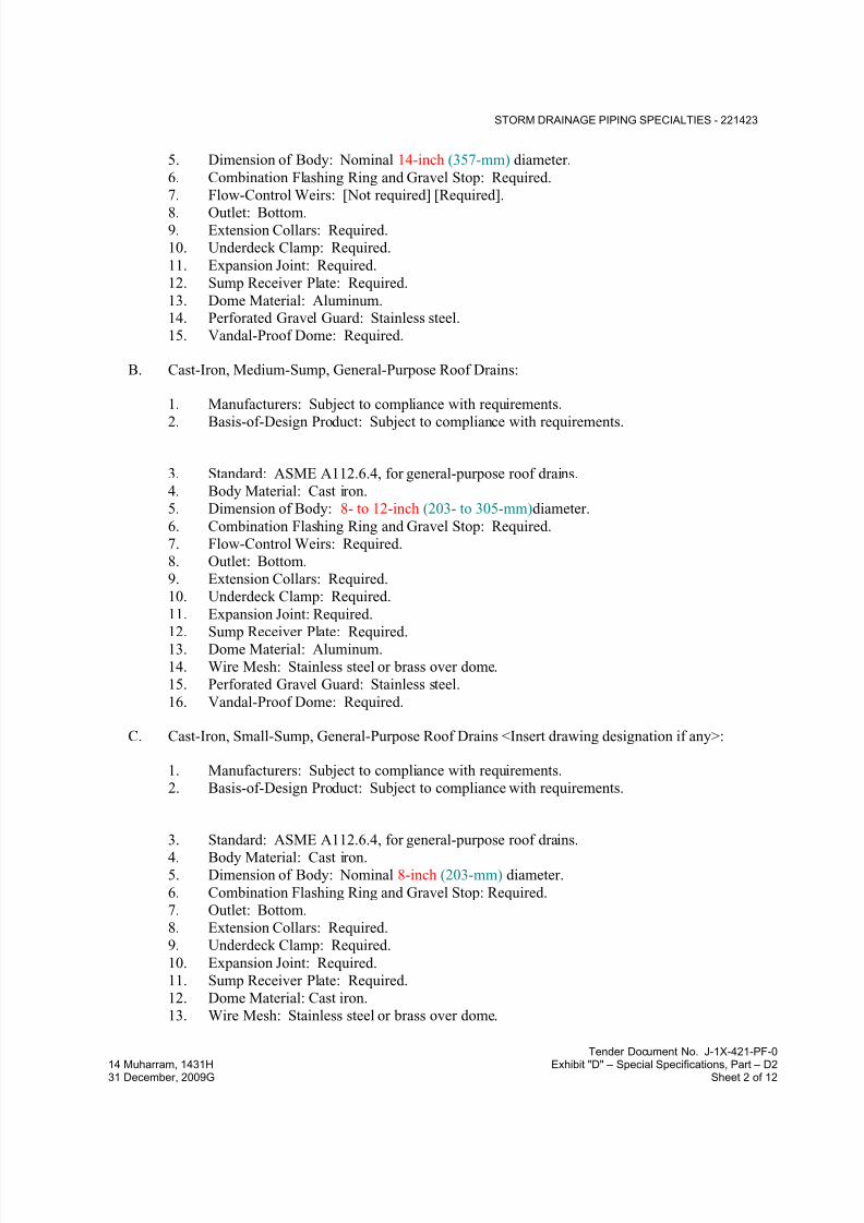
7/18/2019 SEC DPS
http://slidepdf.com/reader/full/sec-dps 424/541
STORM DRAINAGE PIPING SPECIALTIES - 221423
Tender Document No. J-1X-421-PF-0
14 Muharram, 1431H Exhibit "D" – Special Specifications, Part – D231 December, 2009G Sheet 2 of 12
5. Dimension of Body: Nominal 14-inch (357-mm) diameter.
6. Combination Flashing Ring and Gravel Stop: Required.
7. Flow-Control Weirs: [Not required] [Required].
8. Outlet: Bottom.9. Extension Collars: Required.
10. Underdeck Clamp: Required.
11. Expansion Joint: Required.
12. Sump Receiver Plate: Required.
13. Dome Material: Aluminum.14. Perforated Gravel Guard: Stainless steel.
15. Vandal-Proof Dome: Required.
B. Cast-Iron, Medium-Sump, General-Purpose Roof Drains:
1. Manufacturers: Subject to compliance with requirements.
2. Basis-of-Design Product: Subject to compliance with requirements.
3. Standard: ASME A112.6.4, for general-purpose roof drains.
4. Body Material: Cast iron.
5. Dimension of Body: 8- to 12-inch (203- to 305-mm)diameter.
6. Combination Flashing Ring and Gravel Stop: Required.
7. Flow-Control Weirs: Required.
8. Outlet: Bottom.
9. Extension Collars: Required.
10. Underdeck Clamp: Required.
11. Expansion Joint: Required.
12. Sump Receiver Plate: Required.13. Dome Material: Aluminum.
14. Wire Mesh: Stainless steel or brass over dome.
15. Perforated Gravel Guard: Stainless steel.
16. Vandal-Proof Dome: Required.
C. Cast-Iron, Small-Sump, General-Purpose Roof Drains <Insert drawing designation if any>:
1. Manufacturers: Subject to compliance with requirements.
2. Basis-of-Design Product: Subject to compliance with requirements.
3. Standard: ASME A112.6.4, for general-purpose roof drains.
4. Body Material: Cast iron.
5. Dimension of Body: Nominal 8-inch (203-mm) diameter.
6. Combination Flashing Ring and Gravel Stop: Required.
7. Outlet: Bottom.
8. Extension Collars: Required.
9. Underdeck Clamp: Required.
10. Expansion Joint: Required.
11. Sump Receiver Plate: Required.
12. Dome Material: Cast iron.
13. Wire Mesh: Stainless steel or brass over dome.

7/18/2019 SEC DPS
http://slidepdf.com/reader/full/sec-dps 425/541
STORM DRAINAGE PIPING SPECIALTIES - 221423
Tender Document No. J-1X-421-PF-0
14 Muharram, 1431H Exhibit "D" – Special Specifications, Part – D231 December, 2009G Sheet 3 of 12
14. Vandal-Proof Dome: Required.
D. Metal, CorniceandGutter Roof Drains:
1. Manufacturers: Subject to compliance with requirements.
2. Basis-of-Design Product: Subject to compliance with requirements.
3. Standard: ASME A112.6.4, for corniceandgutter roof drains.
4. Body Material: Metal.
5. Dimension of Body: Nominal 6-inch (152-mm) diameter.
6. Outlet: Bottom.
7. Dome Material: Bronze .
8. Vandal-Proof Dome: Required.
E. Metal, Parapet Roof Drains:
1. Manufacturers: Subject to compliance with requirements.
2. Basis-of-Design Product: Subject to compliance with requirements.
3. Standard: ASME A112.6.4, for parapet roof drains.
4. Body Material: Cast iron.
5. Outlet: Back.
6. Grate Material: Cast iron.
7. Vandal-Proof Grate: Required.
F. Street Gutter type:
1. Manufacturers: Subject to compliance with requirements.
2. Basis-of-Design Product: Subject to compliance with requirements.
3. Heavy duty coated cast iron body with secured ductile iron heavy duty grating including
flashing clamps and seepage opening.
4. Gutter drain size shall be 450 x 350 mm and shall have a minimum free area of 200 sq.
cm.
G. Scupper Drain:
1. Manufacturers: Subject to compliance with requirements.2. Basis-of-Design Product: Subject to compliance with requirements.
3. Dura-coated cast iron body with reversible back or bottom outlet, oblique grate with 90°
combination frame and membrane flashing clamp.
H. Gutter Drain:
1. Manufacturers: Subject to compliance with requirements.
2. Basis-of-Design Product: Subject to compliance with requirements.
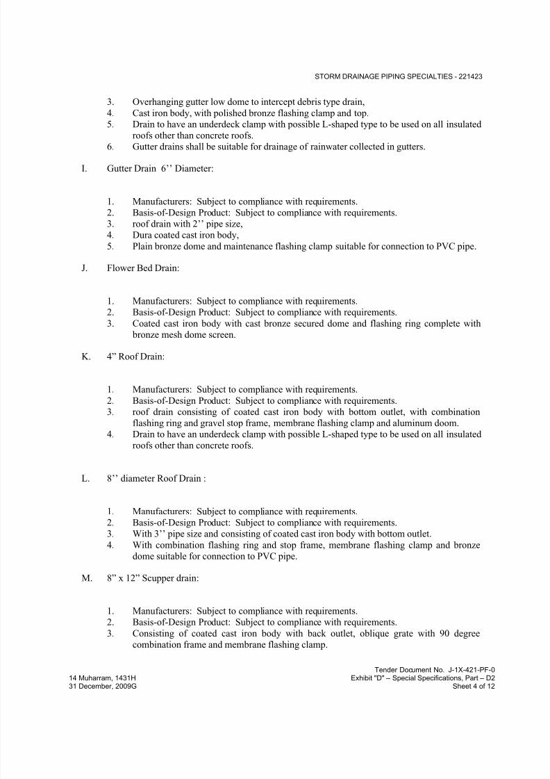
7/18/2019 SEC DPS
http://slidepdf.com/reader/full/sec-dps 426/541
STORM DRAINAGE PIPING SPECIALTIES - 221423
Tender Document No. J-1X-421-PF-0
14 Muharram, 1431H Exhibit "D" – Special Specifications, Part – D231 December, 2009G Sheet 4 of 12
3. Overhanging gutter low dome to intercept debris type drain,
4. Cast iron body, with polished bronze flashing clamp and top.
5. Drain to have an underdeck clamp with possible L-shaped type to be used on all insulated
roofs other than concrete roofs.6. Gutter drains shall be suitable for drainage of rainwater collected in gutters.
I. Gutter Drain 6’’ Diameter:
1. Manufacturers: Subject to compliance with requirements.
2. Basis-of-Design Product: Subject to compliance with requirements.
3. roof drain with 2’’ pipe size,
4. Dura coated cast iron body,
5. Plain bronze dome and maintenance flashing clamp suitable for connection to PVC pipe.
J. Flower Bed Drain:
1. Manufacturers: Subject to compliance with requirements.
2. Basis-of-Design Product: Subject to compliance with requirements.
3. Coated cast iron body with cast bronze secured dome and flashing ring complete with
bronze mesh dome screen.
K. 4” Roof Drain:
1. Manufacturers: Subject to compliance with requirements.
2. Basis-of-Design Product: Subject to compliance with requirements.3. roof drain consisting of coated cast iron body with bottom outlet, with combination
flashing ring and gravel stop frame, membrane flashing clamp and aluminum doom.
4. Drain to have an underdeck clamp with possible L-shaped type to be used on all insulated
roofs other than concrete roofs.
L. 8’’ diameter Roof Drain :
1. Manufacturers: Subject to compliance with requirements.
2. Basis-of-Design Product: Subject to compliance with requirements.
3. With 3’’ pipe size and consisting of coated cast iron body with bottom outlet.
4. With combination flashing ring and stop frame, membrane flashing clamp and bronze
dome suitable for connection to PVC pipe.
M. 8” x 12” Scupper drain:
1. Manufacturers: Subject to compliance with requirements.
2. Basis-of-Design Product: Subject to compliance with requirements.
3. Consisting of coated cast iron body with back outlet, oblique grate with 90 degree
combination frame and membrane flashing clamp.

7/18/2019 SEC DPS
http://slidepdf.com/reader/full/sec-dps 427/541
STORM DRAINAGE PIPING SPECIALTIES - 221423
Tender Document No. J-1X-421-PF-0
14 Muharram, 1431H Exhibit "D" – Special Specifications, Part – D231 December, 2009G Sheet 5 of 12
N. Terrace Drain:
1. Manufacturers: Subject to compliance with requirements.2. Basis-of-Design Product: Subject to compliance with requirements.
3. Coated cast iron body and flashing clamp with seepage openings and secured square hole
heavy duty grate.
4. No-hub bottom or side as indicated outlet, brass finish.
O. Metal, Large-Sump, Promenade Roof Drains :
1. Manufacturers: Subject to compliance with requirements.
2. Basis-of-Design Product: Subject to compliance with requirements.
3. Standard: ASME A112.6.4, for promenade roof drains.4. Body Material: Cast iron.
5. Dimension of Body: Nominal 14-inch (357-mm) diameter.
6. Dimension of Frame and Grate: Nominal 14 inches (357 mm) square.
7. Outlet: Bottom.
8. Grate Material: Cast iron.
9. Vandal-Proof Grate: Required.
10. Extension Collars: Required.
11. Underdeck Clamp: Required]
12. Expansion Joint: Required.
13. Sump Receiver Plate: Required.
P. Metal, Medium-Sump, Promenade Roof Drains:
1. Manufacturers: Subject to compliance with requirements.
2. Basis-of-Design Product: Subject to compliance with requirements.
3. Standard: ASME A112.6.4, for promenade roof drains.
4. Body Material: Cast iron.
5. Dimension of Body: 11- to 12-inch (280- to 305-mm) diameter.
6. Dimension of Frame and Grate: Nominal 12 inches (305 mm) square.
7. Outlet: Bottom.
8. Grate Material: Cast iron.
9. Vandal-Proof Grate: Required.
10. Extension Collars: Required.
11. Underdeck Clamp: Required.
12. Expansion Joint: Required.
13. Sump Receiver Plate: Required.
Q. Metal, Small-Sump, Promenade Roof Drains:
1. Manufacturers: Subject to compliance with requirements.
2. Basis-of-Design Product: Subject to compliance with requirements.
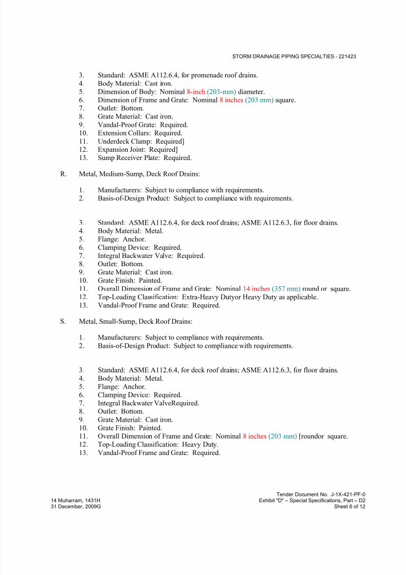
7/18/2019 SEC DPS
http://slidepdf.com/reader/full/sec-dps 428/541
STORM DRAINAGE PIPING SPECIALTIES - 221423
Tender Document No. J-1X-421-PF-0
14 Muharram, 1431H Exhibit "D" – Special Specifications, Part – D231 December, 2009G Sheet 6 of 12
3. Standard: ASME A112.6.4, for promenade roof drains.
4. Body Material: Cast iron.
5. Dimension of Body: Nominal 8-inch (203-mm) diameter.
6. Dimension of Frame and Grate: Nominal 8 inches (203 mm) square.7. Outlet: Bottom.
8. Grate Material: Cast iron.
9. Vandal-Proof Grate: Required.
10. Extension Collars: Required.
11. Underdeck Clamp: Required]12. Expansion Joint: Required]
13. Sump Receiver Plate: Required.
R. Metal, Medium-Sump, Deck Roof Drains:
1. Manufacturers: Subject to compliance with requirements.
2. Basis-of-Design Product: Subject to compliance with requirements.
3. Standard: ASME A112.6.4, for deck roof drains; ASME A112.6.3, for floor drains.
4. Body Material: Metal.
5. Flange: Anchor.
6. Clamping Device: Required.
7. Integral Backwater Valve: Required.
8. Outlet: Bottom.
9. Grate Material: Cast iron.
10. Grate Finish: Painted.
11. Overall Dimension of Frame and Grate: Nominal 14 inches (357 mm) round or square.
12. Top-Loading Classification: Extra-Heavy Dutyor Heavy Duty as applicable.13. Vandal-Proof Frame and Grate: Required.
S. Metal, Small-Sump, Deck Roof Drains:
1. Manufacturers: Subject to compliance with requirements.
2. Basis-of-Design Product: Subject to compliance with requirements.
3. Standard: ASME A112.6.4, for deck roof drains; ASME A112.6.3, for floor drains.
4. Body Material: Metal.
5. Flange: Anchor.
6. Clamping Device: Required.
7. Integral Backwater ValveRequired.
8. Outlet: Bottom.
9. Grate Material: Cast iron.
10. Grate Finish: Painted.
11. Overall Dimension of Frame and Grate: Nominal 8 inches (203 mm) [roundor square.
12. Top-Loading Classification: Heavy Duty.
13. Vandal-Proof Frame and Grate: Required.

7/18/2019 SEC DPS
http://slidepdf.com/reader/full/sec-dps 429/541
STORM DRAINAGE PIPING SPECIALTIES - 221423
Tender Document No. J-1X-421-PF-0
14 Muharram, 1431H Exhibit "D" – Special Specifications, Part – D231 December, 2009G Sheet 7 of 12
2.2 MISCELLANEOUS STORM DRAINAGE PIPING SPECIALTIES
A. Downspout Adaptors:
1. Description: Manufactured, gray-iron casting, for attaching to horizontal-outlet, parapet
roof drain and to exterior, sheet metal downspout.
2. Size: Inlet size to match parapet drain outlet.
B. Downspout Boots:
1. Description: Manufactured, ASTM A 48/A 48M, gray-iron casting, with strap or ears for
attaching to building; NPS 4 (DN 100) outlet; and shop-applied bituminous coating.
2. Size: Inlet size to match downspout and NPS 4 (DN 100) outlet.
C. Conductor Nozzles:
1. Description: Bronze body with threaded inlet and bronze wall flange with mounting
holes.
2. Size: Same as connected conductor.
2.3 CLEANOUTS
A. Floor Cleanouts:
1. Manufacturers: Subject to compliance with requirements.
2. Basis-of-Design Product: Subject to compliance with requirements.
3. Standard: ASME A112.36.2M, for cast-iron soil pipe cleanouts and test tees.
4. Size: Same as connected drainage pipe.
5. Cast iron round check plug with threaded spanner wrench cover, water tight, with nickel
bronze finish except in kitchen installations to be polished stainless-steel finish.
6.
B. Test Tees:
1. Manufacturers: Subject to compliance with requirements.
2. Basis-of-Design Product: Subject to compliance with requirements.
3. Standard: ASME A112.36.2M and ASTM A 74, ASTM A 888, or CISPI 301, for
cleanout test tees.
4. Size: Same as connected drainage piping.
5. Body Material: Hub-and-spigot, cast-iron soil-pipe T-branch or hubless, cast-iron soil-
pipe test tee as required to match connected piping.
6. Closure Plug: Countersunk or raised head, brass.
7. Closure Plug Size: Same as or not more than one size smaller than cleanout size.
C. Wall Cleanouts:

7/18/2019 SEC DPS
http://slidepdf.com/reader/full/sec-dps 430/541
STORM DRAINAGE PIPING SPECIALTIES - 221423
Tender Document No. J-1X-421-PF-0
14 Muharram, 1431H Exhibit "D" – Special Specifications, Part – D231 December, 2009G Sheet 8 of 12
1. Manufacturers: Subject to compliance with requirements.
2. Basis-of-Design Product: Subject to compliance with requirements.
3. Standard: ASME A112.36.2M, for cleanouts. Include wall access.
4. Size: Same as connected drainage piping.
5. Body Material: Hub-and-spigot, cast-iron soil-pipe T-branch as required to match
connected piping.
6. Closure: Countersunk, cast-iron plug.
7. Closure Plug Size: Same as or not more than one size smaller than cleanout size.
8. Wall Access: Round, cover plate with screw.
9. Wall Access: Round, copper-alloy, wall-installation frame and cover.
D. Plastic Floor Cleanouts:
1. Manufacturers: Subject to compliance with requirements2. Basis-of-Design Product: Subject to compliance with requirements.
3. Size: Same as connected branch.
4. Body Material: PVC.
5. Closure Plug: PVC.
6. Riser: Drainage pipe fitting and riser to cleanout of same material as drainage piping.
2.4 BACKWATER VALVES
A. Cast-Iron, Horizontal Backwater Valves:
1. Manufacturers: Subject to compliance with requirements.
2. Basis-of-Design Product: Subject to compliance with requirements.
3. Standard: ASME A112.14.1, for backwater valves.4. Size: Same as connected piping.
5. Body Material: Cast iron.
6. Cover: Cast iron with bolted access check valve.
7. End Connections: Hub and spigot orhubless to suit system
8. Check Valve: Removable, bronze, swing check, factory assembled or field modified tohang or open for airflow unless subject to backflow condition.
9. Extension: ASTM A 74, Service class; full-size, cast-iron soil-pipe extension to field-
installed cleanout at floor; replaces backwater valve cover.
B. Cast-Iron, Drain-Outlet Backwater Valves:
1. Manufacturers: Subject to compliance with requirements.
2. Basis-of-Design Product: Subject to compliance with requirements.
3. Size: Same as floor drain outlet.

7/18/2019 SEC DPS
http://slidepdf.com/reader/full/sec-dps 431/541
STORM DRAINAGE PIPING SPECIALTIES - 221423
Tender Document No. J-1X-421-PF-0
14 Muharram, 1431H Exhibit "D" – Special Specifications, Part – D231 December, 2009G Sheet 9 of 12
4. Body Material: Cast iron or bronze made for vertical installation in bottom outlet of floor
drain.
5. Check Valve: Removable ball float.
6. Inlet: Threaded.7. Outlet: Threaded or spigot.
C. Plastic, Horizontal Backwater Valves:
1. Manufacturers: Subject to compliance with requirements.
2. Basis-of-Design Product: Subject to compliance with requirements
3. Standard: ASME A112.14.1, for backwater valves.
4. Size: Same as connected piping.
5. Body Material: PVC.
6. Cover: Same material as body with threaded access to check valve.7. Check Valve: Removable swing check.
8. End Connections: Socket type.
2.5 TRENCH DRAINS
A. 6" wide modular Trench Drain:
1. Manufacturers: Subject to compliance with requirements.2. Basis-of-Design Product: Subject to compliance with requirements.
3. Dura coated cast iron deep sump body with bottom outlet and secondary strainer. Both
12" long outlet module and 12’’ extension module are complete with integral seepage pan
and membrane clamp and slotted grate.
B. Trench Drains
1. Manufacturers: Subject to compliance with requirements.
2. Basis-of-Design Product: Subject to compliance with requirements.
3. Standard: ASME A112.6.3, for trench drains.
4. Body Material: Cast iron. For kitchen applications use stainless steel construction.
5. Flange: Seepage.6. Clamping Device: Required. Trench drains for installation in floors not having
membrane water proofing may have seepage flange without clamping device.
7. Outlet: Bottom.
8. Grate Material: Ductile gray iron.
9. Grate Finish: Painted.
10. Top-Loading Classification: Extra-Heavy Dutyor Heavy Duty as applicable.
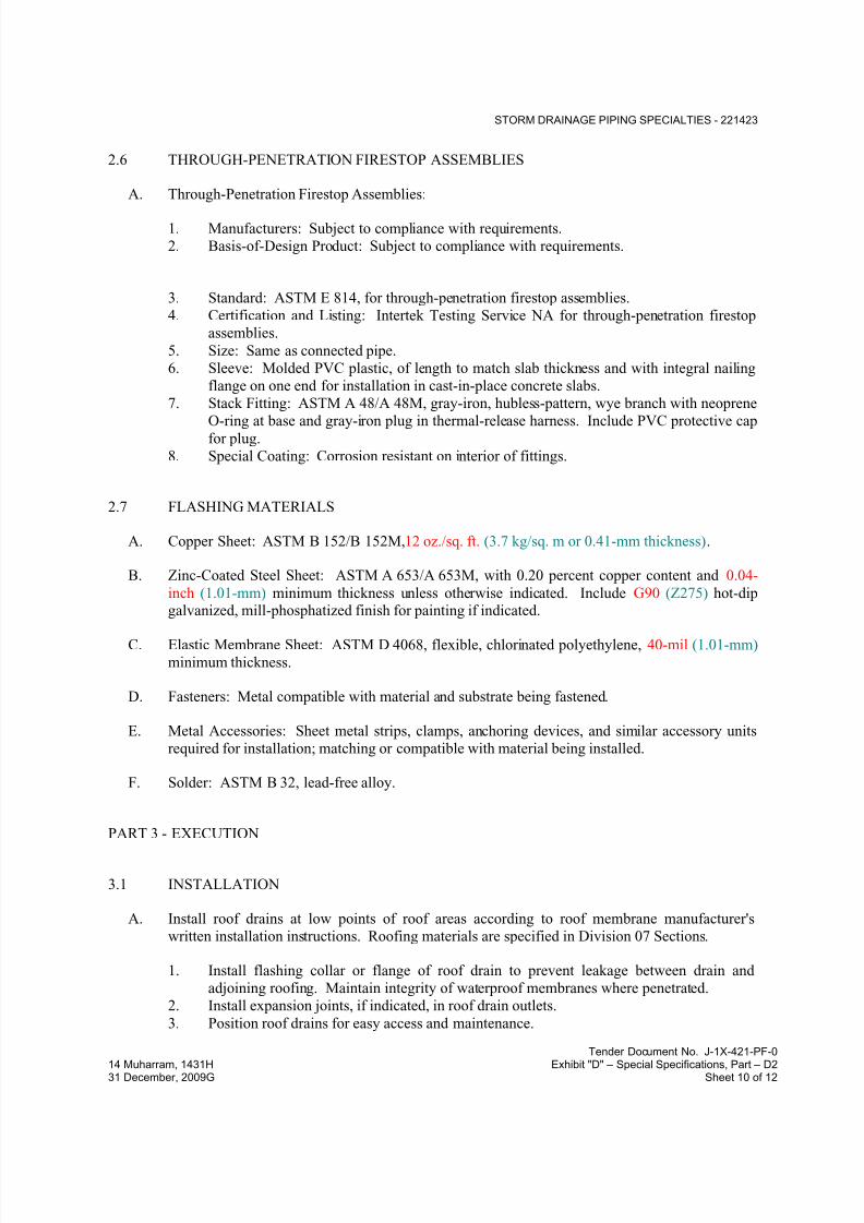
7/18/2019 SEC DPS
http://slidepdf.com/reader/full/sec-dps 432/541
STORM DRAINAGE PIPING SPECIALTIES - 221423
Tender Document No. J-1X-421-PF-0
14 Muharram, 1431H Exhibit "D" – Special Specifications, Part – D231 December, 2009G Sheet 10 of 12
2.6 THROUGH-PENETRATION FIRESTOP ASSEMBLIES
A. Through-Penetration Firestop Assemblies:
1. Manufacturers: Subject to compliance with requirements.
2. Basis-of-Design Product: Subject to compliance with requirements.
3. Standard: ASTM E 814, for through-penetration firestop assemblies.
4. Certification and Listing: Intertek Testing Service NA for through-penetration firestop
assemblies.
5. Size: Same as connected pipe.
6. Sleeve: Molded PVC plastic, of length to match slab thickness and with integral nailing
flange on one end for installation in cast-in-place concrete slabs.
7. Stack Fitting: ASTM A 48/A 48M, gray-iron, hubless-pattern, wye branch with neoprene
O-ring at base and gray-iron plug in thermal-release harness. Include PVC protective capfor plug.
8. Special Coating: Corrosion resistant on interior of fittings.
2.7 FLASHING MATERIALS
A. Copper Sheet: ASTM B 152/B 152M,12 oz./sq. ft. (3.7 kg/sq. m or 0.41-mm thickness).
B. Zinc-Coated Steel Sheet: ASTM A 653/A 653M, with 0.20 percent copper content and 0.04-
inch (1.01-mm) minimum thickness unless otherwise indicated. Include G90 (Z275) hot-dipgalvanized, mill-phosphatized finish for painting if indicated.
C. Elastic Membrane Sheet: ASTM D 4068, flexible, chlorinated polyethylene, 40-mil (1.01-mm)
minimum thickness.
D. Fasteners: Metal compatible with material and substrate being fastened.
E. Metal Accessories: Sheet metal strips, clamps, anchoring devices, and similar accessory units
required for installation; matching or compatible with material being installed.
F. Solder: ASTM B 32, lead-free alloy.
PART 3 - EXECUTION
3.1 INSTALLATION
A. Install roof drains at low points of roof areas according to roof membrane manufacturer's
written installation instructions. Roofing materials are specified in Division 07 Sections.
1. Install flashing collar or flange of roof drain to prevent leakage between drain and
adjoining roofing. Maintain integrity of waterproof membranes where penetrated.
2. Install expansion joints, if indicated, in roof drain outlets.
3. Position roof drains for easy access and maintenance.

7/18/2019 SEC DPS
http://slidepdf.com/reader/full/sec-dps 433/541
STORM DRAINAGE PIPING SPECIALTIES - 221423
Tender Document No. J-1X-421-PF-0
14 Muharram, 1431H Exhibit "D" – Special Specifications, Part – D231 December, 2009G Sheet 11 of 12
B. Install downspout adapters on outlet of back-outlet parapet roof drains and connect to sheet
metal downspouts.
C. Install downspout boots at grade with top 12 inches (305 mm), or 18 inches (457 mm) abovegrade as applicable. Secure to building wall.
D. Install conductor nozzles at exposed bottom of conductors where they spill onto grade.
E. Install cleanouts in aboveground piping and building drain piping according to the following
instructions unless otherwise indicated:
1. Use cleanouts the same size as drainage piping up to NPS 4 (DN 100). Use NPS 4
(DN 100) for larger drainage piping unless larger cleanout is indicated.
2. Locate cleanouts at each change in direction of piping greater than 45 degrees.
3. Locate cleanouts at minimum intervals of 50 feet (15 m) for piping NPS 4 (DN 100) and
smaller and 100 feet (30 m) for larger piping.4. Locate cleanouts at base of each vertical soil and waste stack.
F. For floor cleanouts for piping below floors, install cleanout deck plates with top flush with
finished floor.
G. For cleanouts located in concealed piping, install cleanout wall access covers, of types
indicated, with frame and cover flush with finished wall.
H. Install horizontal backwater valves in floor with cover flush with floor.
I. Install drain-outlet backwater valves in outlet of drains.
J. Install test tees in vertical conductors and near floor.
K. Install wall cleanouts in vertical conductors. Install access door in wall if indicated.
L. Install trench drains at low points of surface areas to be drained. Set grates of drains flush with
finished surface unless otherwise indicated.
M. Assemble channel drainage system components according to manufacturer's written
instructions. Install on support devices so that top will be flush with adjacent surface.
N. Install through-penetration firestop assemblies in plastic conductors at concrete floor
penetrations.
O. Install sleeve flashing device with each conductor passing through floors with waterproof
membrane.
3.2 CONNECTIONS
A. Comply with requirements for piping specified in Division 22 Sections. Drawings indicate
general arrangement of piping, fittings, and specialties.

7/18/2019 SEC DPS
http://slidepdf.com/reader/full/sec-dps 434/541
STORM DRAINAGE PIPING SPECIALTIES - 221423
Tender Document No. J-1X-421-PF-0
14 Muharram, 1431H Exhibit "D" – Special Specifications, Part – D231 December, 2009G Sheet 12 of 12
3.3 FLASHING INSTALLATION
A. Fabricate flashing from single piece of metal unless large pans, sumps, or other drainage shapes
are required. Join flashing according to the following if required:
1. Lead Sheets: Burn joints of 6.0-lb/sq. ft. (30-kg/sq. m) lead sheets, 0.0938-inch (2.4-mm)
thickness or thicker. Solder joints of 4.0-lb/sq. ft. (20-kg/sq. m) lead sheets, 0.0625-inch
(1.6-mm) thickness or thinner.
2. Copper Sheets: Solder joints of copper sheets.
B. Install sheet flashing on pipes, sleeves, and specialties passing through or embedded in floors
and roofs with waterproof membrane.
1. Pipe Flashing: Sleeve type, matching the pipe size, with a minimum length of 10 inches
(250 mm) and with skirt or flange extending at least 8 inches (200 mm) around pipe.
2. Sleeve Flashing: Flat sheet, with skirt or flange extending at least 8 inches (200 mm) around sleeve.
3. Embedded Specialty Flashing: Flat sheet, with skirt or flange extending at least 8 inches
(200 mm) around specialty.
C. Set flashing on floors and roofs in solid coating of bituminous cement.
D. Secure flashing into sleeve and specialty clamping ring or device.
E. Fabricate and install flashing and pans, sumps, and other drainage shapes.
3.4 PROTECTION
A. Protect drains during remainder of construction period to avoid clogging with dirt or debris and
to prevent damage from traffic or construction work.
B. Place plugs in ends of uncompleted piping at end of each day or when work stops.
END OF SECTION 221423

7/18/2019 SEC DPS
http://slidepdf.com/reader/full/sec-dps 435/541
SUMP PUMPS - 221429
Tender Document No. J-1X-421-PF-0
14 Muharram, 1431H Exhibit "D" – Special Specifications, Part – D231 December, 2009G Sheet 1 of 6
SECTION 221429 - SUMP PUMPS
PART 1 - GENERAL
1.1 RELATED DOCUMENTS
A. Drawings and general provisions of the Contract, including General and Supplementary
Conditions and Division 01 Specification Sections, apply to this Section.
1.2 SUMMARY
A. Section Includes:
1. Submersible sump pumps.
B. Related Section:
1. Division 22 Section "Sanitary Sewerage Pumps" for effluent and sewage pumps.
1.3 ACTION SUBMITTALS
A. Product Data: For each type of product indicated. Include construction details, material
descriptions, dimensions of individual components and profiles. Include rated capacities,
operating characteristics, electrical characteristics, and furnished specialties and accessories.
B. Wiring Diagrams: For power, signal, and control wiring.
1.4 CLOSEOUT SUBMITTALS
A. Operation and Maintenance Data: For pumps and controls, to include in operation and
maintenance manuals.
1.5 QUALITY ASSURANCE
A. Electrical Components, Devices, and Accessories: Listed and labeled as defined in NFPA 70,
by a qualified testing agency, and marked for intended location and application.
B. UL Compliance: Comply with UL 778 for motor-operated water pumps.
1.6 DELIVERY, STORAGE, AND HANDLING
A. Retain shipping flange protective covers and protective coatings during storage.
7/18/2019 SEC DPS
http://slidepdf.com/reader/full/sec-dps 436/541
SUMP PUMPS - 221429
Tender Document No. J-1X-421-PF-0
14 Muharram, 1431H Exhibit "D" – Special Specifications, Part – D231 December, 2009G Sheet 2 of 6
B. Protect bearings and couplings against damage.
C. Comply with pump manufacturer's written rigging instructions for handling.
PART 2 - PRODUCTS
2.1 SUBMERSIBLE SUMP PUMPS
A. Description: Factory-assembled and -tested, single-stage, centrifugal, end-suction sump pump
units complying with UL 778. Include motor, operating controls, and construction for
permanent installation.
B. Discharge Pipe End Connections DN50 (NPS 2) and Smaller: Threaded. Pumps available only
with flanged-end discharge pipe may be furnished with threaded companion flanges.
C. Discharge Pipe End Connections DN65 (NPS 2-1/2) and Larger: Flanged.
D. Motors: Single speed, with grease-lubricated ball bearings, and non-overloading through full
range of pump performance curves.
E. Bolts, nuts and washers shall be AISI Type 316.
F. Flexible Couplings: Pump shaft shall be connected to the motor shaft through a flexible
coupling. Flexible member shall be a tire shape or a solid-mass serrated-edge disk shape made
of chloroprene material and retained by fixed flanges. Flexible coupling shall act as a dielectric
connector, shall not transmit vibration or end thrust, and shall permit up to 4-degree
misalignment under normal duty.
G. Support Pipe: A wrought-iron or steel support pipe concentric with the pump shaft shall connectthe pump to the sump coverplate. Support-pipe flanges shall be machined and doweled to
ensure proper alignment of the pump and shaft whenever the pipe is disassembled and
reassembled in the field.
H. Pump shaft shall be constructed of ground and polished AISI Type 304 or 316 corrosion-
resistant steel with hardened wearing surfaces at intermediate shaft-bearing locations. Hardened
surfaces may be overlays of 500 Brinell Stellite, Wall Colmonoy, or similar proprietary metals,
or plasma-spray-applied ceramic materials of not less than 900 Brinell hardness. Mechanical
properties and diameter of the shaft shall ensure that whip, deflection, or vibration will not be of
sufficient magnitude to impose greater than design loads on the specified shaft bearings undernormal operating conditions. Means shall be provided for external adjustment of the clearance
between the impeller and the inner surfaces of the volute section.
I. Bearings and Lubrication: One or more antifriction ball- or roller-bearings shall be furnished in
the motor and bearing support housing above the cover-plate surface, with full provision for the
mechanical and hydraulic radial and thrust loads imposed. Bearings shall be sealed and grease-
lubricated and shall have an L-10 rating of not less than 200,000 hours. Shop Drawings shall
bear the manufacturer's certification of bearing life. Bearings shall be manufactured from

7/18/2019 SEC DPS
http://slidepdf.com/reader/full/sec-dps 437/541
SUMP PUMPS - 221429
Tender Document No. J-1X-421-PF-0
14 Muharram, 1431H Exhibit "D" – Special Specifications, Part – D231 December, 2009G Sheet 3 of 6
vacuum-processed or degassed-alloy steels. Bearings shall be furnished with grease and
pressure-relief fittings at bottom or opposite side the bearing where discharge may be viewed.
J. Intermediate shaft bearings shall be of the sleeve type. Center distance between any 2 bearingson the shaft shall not exceed 1370 mm or 1520 mm for pumps operating at 1,200 rpm or less.
Sleeve-bearing length shall be not less than 2 times the shaft diameter. A sleeve bearing located
near the lower extremity of the shaft shall be provided.
K. Submersible, Quick-Disconnect Type , Double -Seal Sump Pumps:
a.
2. Description: Factory-assembled and -tested sump-pump unit.
3. Pump Type: Submersible, end-suction, single-stage, close-coupled, overhung-impeller,
centrifugal sump pump as defined in HI 1.1-1.2 and HI 1.3.
4. Pump Casing: Cast iron, with strainer inlet, legs that elevate pump to permit flow into
impeller, and vertical discharge for piping connection.5. Impeller: Statically and dynamically balanced, ASTM A 532/A 532M, abrasion-resistant
cast iron, and keyed and secured to shaft.
6. Pump and Motor Shaft: Stainless steel, with factory-sealed, grease-lubricated ball
bearings.
7. Seal: Mechanical.
8. Motor: Hermetically sealed, capacitor-start type; with built-in overload protection; lifting
eye or lug; and three-conductor, waterproof power cable of length required and with
grounding plug and cable-sealing assembly for connection at pump.
a. Motor Housing Fluid: Air.
9. Controls:
a. Enclosure: NEMA 250, Type 1.
b. Switch Type: Pedestal-mounted float switch with float rods and rod buttons.
c. Automatic Alternator: Start pumps on successive cycles and start multiple pumps
if one cannot handle load.
d. Float Guides: Pipe or other restraint for floats and rods in basins of depth greater
than 60 inches (1500 mm).
e. High-Water Alarm: Cover-mounted, compression-probe alarm, with electric bell;
120-V ac, with transformer and contacts for remote alarm bell.
10. Controls:
a. Enclosure: NEMA 250, Type 1wall-mounted.
b. Switch Type: Mercury-float type, in NEMA 250, Type 6 enclosures with
mounting rod and electric cables.
c. Automatic Alternator: Start pumps on successive cycles and start multiple pumps
if one cannot handle load.
d. High-Water Alarm: Rod-mounted, NEMA 250, Type 6 enclosure with mercury-
float, switch matching control and electric bell; 120-V ac, with transformer and
contacts for remote alarm bell.
11. Control-Interface Features:

7/18/2019 SEC DPS
http://slidepdf.com/reader/full/sec-dps 438/541
SUMP PUMPS - 221429
Tender Document No. J-1X-421-PF-0
14 Muharram, 1431H Exhibit "D" – Special Specifications, Part – D231 December, 2009G Sheet 4 of 6
a. Remote Alarm Contacts: For remote alarm interface.
b. Building Automation System Interface: Auxiliary contacts in pump controls for
interface to building automation system and capable of providing the following:
1) On-off status of pump.
2) Alarm status.
2.2 SUMP PUMP PITS
A. Description: Cast-in-place concrete with steel curb frames and covers. Refer to Division 3 Sec-
tion "Cast-in Place Concrete."
B. Curb Frames: Galvanized steel or steel with bitumastic coating of dimension to fit cover.
1. Pattern: Z-cross-section shape with raised outer rim of height matching cover for re-
cessed mounting that will have installed cover flush with top of floor slab.
C. Pit Cover: Fabricate with openings with gaskets, seals, and bushings, for access, pumps, pump
shafts, control rods, discharge piping, vent connections, and power cables.
1. Material: Steel, with bitumastic coating.
2. Reinforcement: Steel or cast-iron reinforcement capable of supporting foot-traffic areas.
2.3 MOTORS
A. Comply with NEMA designation, temperature rating, service factor, enclosure type, and
efficiency requirements for motors specified in Division 22 Section "Common Motor
Requirements for Plumbing Equipment."
1. Motor Sizes: Minimum size as indicated. If not indicated, large enough so driven load
will not require motor to operate in service factor range above 1.0.
2. Controllers, Electrical Devices, and Wiring: Comply with requirements for electricaldevices and connections specified in Division 26 Sections.
B. Motors for submersible pumps shall be hermetically sealed.
PART 3 - EXECUTION
3.1 EARTHWORK
A. Excavation and filling are specified in Division 31 Section "Earth Moving."

7/18/2019 SEC DPS
http://slidepdf.com/reader/full/sec-dps 439/541
SUMP PUMPS - 221429
Tender Document No. J-1X-421-PF-0
14 Muharram, 1431H Exhibit "D" – Special Specifications, Part – D231 December, 2009G Sheet 5 of 6
3.2 EXAMINATION
A. Examine roughing-in for plumbing piping to verify actual locations of storm drainage piping
connections before sump pump installation.
3.3 INSTALLATION
A. Pump Installation Standards: Comply with HI 1.4 for installation of sump pumps.
3.4 CONNECTIONS
A. Comply with requirements for piping specified in Division 22 Section "Facility Storm Drainage
Piping." Drawings indicate general arrangement of piping, fittings, and specialties.
B. Install piping adjacent to equipment to allow service and maintenance.
3.5 FIELD QUALITY CONTROL
A. Manufacturer's Field Service: Engage a factory-authorized service representative to inspect,
test, and adjust components, assemblies, and equipment installations, including connections.
B. Perform tests and inspections.
1. Manufacturer's Field Service: Engage a factory-authorized service representative to
inspect components, assemblies, and equipment installations, including connections, and
to assist in testing.
C. Tests and Inspections:
1. Perform each visual and mechanical inspection.
2. Leak Test: After installation, charge system and test for leaks. Repair leaks and retest
until no leaks exist.
3. Operational Test: After electrical circuitry has been energized, start units to confirm
proper motor rotation and unit operation.
4. Test and adjust controls and safeties. Replace damaged and malfunctioning controls and
equipment.
D. Pumps and controls will be considered defective if they do not pass tests and inspections.
E. Prepare test and inspection reports.
3.6 STARTUP SERVICE
A. Engage a factory-authorized service representative to perform startup service.
1. Complete installation and startup checks according to manufacturer's written instructions.

7/18/2019 SEC DPS
http://slidepdf.com/reader/full/sec-dps 440/541
SUMP PUMPS - 221429
Tender Document No. J-1X-421-PF-0
14 Muharram, 1431H Exhibit "D" – Special Specifications, Part – D231 December, 2009G Sheet 6 of 6
3.7 ADJUSTING
A. Adjust pumps to function smoothly, and lubricate as recommended by manufacturer.
B. Adjust control set points.
3.8 DEMONSTRATION
A. Engage a factory-authorized service representative to train Owner's maintenance personnel to
adjust, operate, and maintain pumps.
END OF SECTION 221429

7/18/2019 SEC DPS
http://slidepdf.com/reader/full/sec-dps 441/541
GENERAL-SERVICE COMPRESSED-AIR PIPING - 221513
Tender Document No. J-1X-421-PF-0
14 Muharram, 1431H Exhibit "D" – Special Specifications, Part – D231 December, 2009G Sheet 1 of 13
SECTION 221513 - GENERAL-SERVICE COMPRESSED-AIR PIPING
PART 1 - GENERAL
1.1 RELATED DOCUMENTS
A. Drawings and general provisions of the Contract, including General and Supplementary
Conditions and Division 01 Specification Sections, apply to this Section.
1.2 SUMMARY
A. This Section includes piping and related specialties for general-service compressed-air systems
operating at 200 psig (1380 kPa) or less.
B. Related Sections include the following:
1. Division 22 Section "General-Service Packaged Air Compressors and Receivers" for
general-service air compressors and accessories.
1.3 DEFINITIONS
A. ABS: Acrylonitrile-butadiene-styrene plastic.
B. CR: Chlorosulfonated polyethylene synthetic rubber.
C. EPDM: Ethylene-propylene-diene terpolymer rubber.
D. HDPE: High-density polyethylene plastic.
E. NBR: Acrylonitrile-butadiene rubber.
F. PE: Polyethylene plastic.
G. PVC: Polyvinyl chloride plastic.
H. High-Pressure Compressed-Air Piping: System of compressed-air piping and specialtiesoperating at pressures between 150 and 200 psig (1035 and 1380 kPa).
I. Low-Pressure Compressed-Air Piping: System of compressed-air piping and specialties
operating at pressures of 150 psig (1035 kPa) or less.

7/18/2019 SEC DPS
http://slidepdf.com/reader/full/sec-dps 442/541
GENERAL-SERVICE COMPRESSED-AIR PIPING - 221513
Tender Document No. J-1X-421-PF-0
14 Muharram, 1431H Exhibit "D" – Special Specifications, Part – D231 December, 2009G Sheet 2 of 13
1.4 PERFORMANCE REQUIREMENTS
A. Seismic Performance: Compressed-air piping and support and installation shall withstand
effects of seismic events determined according to SEI/ASCE 7, "Minimum Design Loads forBuildings and Other Structures."
1.5 ACTION SUBMITTALS
A. Product Data: For the following:
1. Plastic pipes, fittings, and valves.
2. Dielectric fittings.
3. Flexible pipe connectors.
4. Safety valves.
5. Pressure regulators. Include rated capacities and operating characteristics.6. Automatic drain valves.
7. Filters. Include rated capacities and operating characteristics.
8. Lubricators. Include rated capacities and operating characteristics.
9. Quick couplings.
10. Hose assemblies.
1.6 INFORMATIONAL SUBMITTALS
A. Brazing and welding certificates.
B. Qualification Data: For Installers.
C. Field quality-control test reports.
1.7 CLOSEOUT SUBMITTALS
A. Operation and Maintenance Data: For general-service compressed-air piping specialties to
include in emergency, operation, and maintenance manuals.
1.8 QUALITY ASSURANCE
A. Installer Qualifications:
1. Extruded-Tee Outlet Procedure: Qualify operators according to training provided by T-
DRILL Industries Inc., for making branch outlets.
2. Pressure-Seal Joining Procedure for Copper Tubing: Qualify operators according to
training provided by Viega; Plumbing and Heating Systems.
3. Pressure-Seal Joining Procedure for Steel Piping. Qualify operators according to training
provided by Victaulic Company.

7/18/2019 SEC DPS
http://slidepdf.com/reader/full/sec-dps 443/541
GENERAL-SERVICE COMPRESSED-AIR PIPING - 221513
Tender Document No. J-1X-421-PF-0
14 Muharram, 1431H Exhibit "D" – Special Specifications, Part – D231 December, 2009G Sheet 3 of 13
B. Brazing: Qualify processes and operators according to ASME Boiler and Pressure Vessel
Code: Section IX, "Welding and Brazing Qualifications," or to AWS B2.2, "Standard for
Brazing Procedure and Performance Qualification."
C. Welding: Qualify processes and operators according to ASME Boiler and Pressure Vessel
Code: Section IX.
D. ASME Compliance:
1. Comply with ASME B31.1, "Power Piping," for high-pressure compressed-air piping.
2. Comply with ASME B31.9, "Building Services Piping," for low-pressure compressed-air
piping.
1.9 PROJECT CONDITIONS
A. Interruption of Existing Compressed-Air Service: Do not interrupt compressed-air service to
facilities occupied by Owner or others unless permitted under the following conditions and then
only after arranging to provide temporary compressed-air service according to requirements
indicated:
1. Notify Owner no fewer than two days in advance of proposed interruption of
compressed-air service.
2. Do not proceed with interruption of compressed-air service without Owner's written
permission.
PART 2 - PRODUCTS
2.1 PIPES, TUBES, AND FITTINGS
A. Schedule 40, Steel Pipe: ASTM A 53/A 53M, Type E or S, Grade B, black or hot-dip zinc
coated with ends threaded according to ASME B1.20.1.
1. Steel Nipples: ASTM A 733, made of ASTM A 53/A 53M or ASTM A 106,
Schedule 40, galvanized seamless steel pipe. Include ends matching joining method.
2. Malleable-Iron Fittings: ASME B16.3, Class 150 or 300, threaded.
3. Malleable-Iron Unions: ASME B16.39, Class 150 or 300, threaded.
4. Steel Flanges: ASME B16.5, Class 150 or 300, carbon steel, threaded.
5. Wrought-Steel Butt-Welding Fittings: ASME B16.9, Schedule 40.6. Steel Flanges: ASME B16.5, Class 150 or 300, carbon steel.
7. Grooved-End Fittings and Couplings:
a. Available Manufacturers: Subject to compliance with requirements
b. Manufacturers: Subject to compliance with requirements
c. Grooved-End Fittings: ASTM A 47/A 47M, malleable-iron castings or
ASTM A 536, ductile-iron casting; with grooves according to AWWA C606 and
dimensions matching steel pipe.

7/18/2019 SEC DPS
http://slidepdf.com/reader/full/sec-dps 444/541
GENERAL-SERVICE COMPRESSED-AIR PIPING - 221513
Tender Document No. J-1X-421-PF-0
14 Muharram, 1431H Exhibit "D" – Special Specifications, Part – D231 December, 2009G Sheet 4 of 13
d. Couplings: AWWA C606 or UL 213, for steel-pipe dimensions and rated for 300-
psig (2070-kPa) minimum working pressure. Include ferrous housing sections,
gasket suitable for compressed air, and bolts and nuts. Provide EDPM gaskets for
oil-free compressed air. Provide NBR gaskets if compressed air contains oil or oilvapor.
2.2 JOINING MATERIALS
A. Pipe-Flange Gasket Materials: Suitable for compressed-air piping system contents.
1. ASME B16.21, nonmetallic, flat, asbestos free, 1/8-inch (3.2-mm) maximum thickness
unless thickness or specific material is indicated.
a. Full-Face Type: For flat-face, Class 125, cast-iron and cast-bronze flanges.
b. Narrow-Face Type: For raised-face, Class 250, cast-iron and steel flanges.
B. Flange Bolts and Nuts: ASME B18.2.1, carbon steel, unless otherwise indicated.
C. Solder Filler Metals: ASTM B 32, lead-free alloys. Include water-flushable flux according to
ASTM B 813.
D. Brazing Filler Metals: AWS A5.8/A5.8M, BCuP Series, copper-phosphorus alloys for general-
duty brazing, unless otherwise indicated.
E. Welding Filler Metals: Comply with AWS D10.12/D10.12M for welding materials appropriate
for wall thickness and chemical analysis of steel pipe being welded.
2.3 VALVES
A. Metal Ball, Butterfly, Check, Gate, and Globe Valves: Comply with requirements in
Division 22 Section "General-Duty Valves for Plumbing Piping."
2.4 DIELECTRIC FITTINGS
A. General Requirements: Assembly of copper alloy and ferrous materials with separating
nonconductive insulating material. Include end connections compatible with pipes to be joined.
B. Dielectric Unions:
1. Manufacturers: Subject to compliance with requirements
2. Description:
a. Standard: ASSE 1079.
b. Pressure Rating: 150 psig (1035 kPa) or 250 psig (1725 kPa), as applicable.
c. End Connections: Solder-joint copper alloy and threaded ferrous.
C. Dielectric Flanges:
7/18/2019 SEC DPS
http://slidepdf.com/reader/full/sec-dps 445/541
GENERAL-SERVICE COMPRESSED-AIR PIPING - 221513
Tender Document No. J-1X-421-PF-0
14 Muharram, 1431H Exhibit "D" – Special Specifications, Part – D231 December, 2009G Sheet 5 of 13
1. Manufacturers: Subject to compliance with requirements
2. Description:
a. Standard: ASSE 1079.
b. Factory-fabricated, bolted, companion-flange assembly.
c. Pressure Rating: 150 psig (1035 kPa), 175 psig (1200 kPa), or 300 psig (2070
kPa), as applicable
d. End Connections: Solder-joint copper alloy and threaded ferrous; threaded solder-
joint copper alloy and threaded ferrous.
D. Dielectric-Flange Insulating Kits:
1. Manufacturers: Subject to compliance with requirements
2. Description:
a. Nonconducting materials for field assembly of companion flanges.
b. Pressure Rating: 150 psig (1035 kPa.
c. Gasket: Neoprene or phenolic.
d. Bolt Sleeves: Phenolic or polyethylene.
e. Washers: Phenolic with steel backing washers.
2.5 FLEXIBLE PIPE CONNECTORS
A. Available Manufacturers: Subject to compliance with requirements
B. Manufacturers: Subject to compliance with requirements
C. Bronze-Hose Flexible Pipe Connectors: Corrugated-bronze tubing with bronze wire-braid
covering and ends brazed to inner tubing.
1. Working-Pressure Rating: 200 psig (1380 kPa) or 250 psig (1725 kPa) minimum, as
applicable.
2. End Connections, NPS 2 (DN 50) and Smaller: Threaded copper pipe or plain-end
copper tube.3. End Connections, NPS 2-1/2 (DN 65) and Larger: Flanged copper alloy.
2.6 SPECIALTIES
A. Safety Valves: ASME Boiler and Pressure Vessel Code: Section VIII, "Pressure Vessels,"
construction; National Board certified, labeled, and factory sealed; constructed of bronze body
with poppet-type safety valve for compressed-air service.
1. Pressure Settings: Higher than discharge pressure and same or lower than receiver
pressure rating.
B. Air-Main Pressure Regulators: Bronze body, direct acting, spring-loaded manual pressure-
setting adjustment, and rated for 250-psig (1725-kPa) inlet pressure, unless otherwise indicated.
7/18/2019 SEC DPS
http://slidepdf.com/reader/full/sec-dps 446/541
GENERAL-SERVICE COMPRESSED-AIR PIPING - 221513
Tender Document No. J-1X-421-PF-0
14 Muharram, 1431H Exhibit "D" – Special Specifications, Part – D231 December, 2009G Sheet 6 of 13
1. Type: Pilot operated.
C. Air-Line Pressure Regulators: Diaphragm or pilot operated, bronze body, direct acting, spring-
loaded manual pressure-setting adjustment, and rated for 200-psig (1380-kPa) minimum inlet pressure, unless otherwise indicated.
D. Air-Line Pressure Regulators: Diaphragm operated, aluminum alloy or plastic body, direct
acting, spring-loaded manual pressure-setting adjustment, and rated for 200-psig (1380-kPa)
minimum inlet pressure, unless otherwise indicated.
E. Automatic Drain Valves: Stainless-steel body and internal parts, rated for 200-psig (1380-kPa)
minimum working pressure, capable of automatic discharge of collected condensate. Include
mounting bracket if wall mounting is indicated.
F. Coalescing Filters: Coalescing type with activated carbon capable of removing water and oil
aerosols; with color-change dye to indicate when carbon is saturated and warning light toindicate when selected maximum pressure drop has been exceeded. , Include mounting bracket
if wall mounting is indicated.
G. Mechanical Filters: Two-stage, mechanical-separation-type, air-line filters. Equip with
deflector plates, resin-impregnated-ribbon-type filters with edge filtration, and drain cock,
Include mounting bracket if wall mounting is indicated.
H. Air-Line Lubricators: With drip chamber and sight dome for observing oil drop entering air
stream; with oil-feed adjustment screw and quick-release collar for easy bowl removal. Include
mounting bracket if wall mounting is indicated.
1. Provide with automatic feed device for supplying oil to lubricator.
2.7 QUICK COUPLINGS
A. Available Manufacturers: Subject to compliance with requirements
B. Manufacturers: Subject to compliance with requirements
C. General Requirements for Quick Couplings: Assembly with locking-mechanism feature forquick connection and disconnection of compressed-air hose.
D. Automatic-Shutoff Quick Couplings: Straight-through brass body with O-ring or gasket seal
and stainless-steel or nickel-plated-steel operating parts.
1. Socket End: With one-way valve and threaded inlet for connection to piping or threaded
hose fitting.
2. Plug End: Flow-sensor-bleeder, check-valve type with barbed outlet for attaching hose.
E. Valveless Quick Couplings: Straight-through brass body with stainless-steel or nickel-plated-
steel operating parts.

7/18/2019 SEC DPS
http://slidepdf.com/reader/full/sec-dps 447/541
GENERAL-SERVICE COMPRESSED-AIR PIPING - 221513
Tender Document No. J-1X-421-PF-0
14 Muharram, 1431H Exhibit "D" – Special Specifications, Part – D231 December, 2009G Sheet 7 of 13
1. Socket End: With O-ring or gasket seal, without valve, and with barbed inlet for
attaching hose.
2. Plug End: With barbed outlet for attaching hose.
2.8 HOSE ASSEMBLIES
A. Description: Compatible hose, clamps, couplings, and splicers suitable for compressed-air
service, of nominal diameter indicated, and rated for 300-psig (2070-kPa) minimum working
pressure, unless otherwise indicated.
1. Hose: Reinforced single- or double-wire-braid, CR-covered hose for compressed-air
service.
2. Hose Clamps: Stainless-steel clamps or bands.
3. Hose Couplings: Two-piece, straight-through, threaded brass or stainless-steel O-ring or
gasket-seal swivel coupling with barbed ends for connecting two sections of hose.4. Hose Splicers: One-piece, straight-through brass or stainless-steel fitting with barbed
ends for connecting two sections of hose.
PART 3 - EXECUTION
3.1 PIPING APPLICATIONS
A. Compressed-Air Piping between Air Compressors and Receivers: Use the following piping
materials for each size range:
1. DN50 and Smaller: Galvanized steel pipe, schedule 40; galvanized, threaded, malleable-iron fittings; and threaded joints.
1. DN65 to DN100: Galvanized steel pipe ,schedule 40; galvanized, threaded, malleable-
iron fittings; and threaded joints.
1. DN125 and Larger : Galvanized steel pipe, schedule 40; galvanized, threaded, malleable-
iron fittings; and threaded joints.
B. Low-Pressure Compressed-Air Distribution Piping: Use[ one of] the following piping materialsfor each size range:
1. DN50 and Smaller: Galvanized steel pipe; galvanized, threaded, malleable-iron fittings;
and threaded joints.
2. DN65 to DN100: Galvanized steel pipe; galvanized, threaded, malleable-iron fittings;and threaded joints.
C. High-Pressure Compressed-Air Distribution Piping: Use[ one of] the following piping
materials for each size range:
1. DN50 and Smaller: Galvanized steel pipe; galvanized, threaded, malleable-iron fittings;
and threaded joints.
2. DN65 to DN100: Galvanized steel pipe; galvanized, threaded, malleable-iron fittings;
and threaded joints.

7/18/2019 SEC DPS
http://slidepdf.com/reader/full/sec-dps 448/541
GENERAL-SERVICE COMPRESSED-AIR PIPING - 221513
Tender Document No. J-1X-421-PF-0
14 Muharram, 1431H Exhibit "D" – Special Specifications, Part – D231 December, 2009G Sheet 8 of 13
D. Drain Piping: Use the following piping materials:
1. NPS 2 (DN 50)] and Smaller: PVC pipe and fittings; and solvent-cemented joints.
3.2 VALVE APPLICATIONS
A. General-Duty Valves: Comply with requirements in Division 22 Section "General-Duty Valves
for Plumbing Piping" for metal general-duty valves. Use metal valves, unless otherwise
indicated.
1. Metal General-Duty Valves: Use valve types specified in "Valve Applications" Article in
Division 22 Section "General-Duty Valves for Plumbing Piping" according to the
following:
a. Low-Pressure Compressed Air: Valve types specified for low-pressure
compressed air. b. High-Pressure Compressed Air: Valve types specified for medium-pressure
compressed air.
c. Equipment Isolation NPS 2 (DN 50) and Smaller: Safety-exhaust, copper-alloy
ball valve with exhaust vent and pressure rating at least as great as piping system
operating pressure.
d. Grooved-end valves may be used with grooved-end piping and grooved joints.
3.3 PIPING INSTALLATION
A. Drawing plans, schematics, and diagrams indicate general location and arrangement of
compressed-air piping. Indicated locations and arrangements were used to size pipe and
calculate friction loss, expansion, air-compressor sizing, and other design considerations.
Install piping as indicated unless deviations to layout are approved on Coordination Drawings.
B. Install piping concealed from view and protected from physical contact by building occupants,
unless otherwise indicated and except in equipment rooms and service areas.
C. Install piping indicated to be exposed and piping in equipment rooms and service areas at right
angles or parallel to building walls. Diagonal runs are prohibited, unless otherwise indicated.
D. Install piping above accessible ceilings to allow sufficient space for ceiling panel removal and
to coordinate with other services occupying that space.
E. Install piping adjacent to equipment and machines to allow service and maintenance.
F. Install air and drain piping with 1 percent slope downward in direction of flow.
G. Install nipples, flanges, unions, transition and special fittings, and valves with pressure ratings
same as or higher than system pressure rating, unless otherwise indicated.
H. Equipment and Specialty Flanged Connections:
1. Use steel companion flange with gasket for connection to steel pipe.
7/18/2019 SEC DPS
http://slidepdf.com/reader/full/sec-dps 449/541
GENERAL-SERVICE COMPRESSED-AIR PIPING - 221513
Tender Document No. J-1X-421-PF-0
14 Muharram, 1431H Exhibit "D" – Special Specifications, Part – D231 December, 2009G Sheet 9 of 13
2. Use cast-copper-alloy companion flange with gasket and brazed[ or soldered] joint for
connection to copper tube. Do not use soldered joints for connection to air compressors
or to equipment or machines producing shock or vibration.
I. Flanged joints may be used instead of specified joint for any piping or tubing system.
J. Extended-tee outlets with brazed branch connection may be used for copper tubing, within
extruded-tee connection diameter to run tube diameter ratio for tube type, according to Extruded
Tee Connections Sizes and Wall Thickness for Copper Tube (Inches) Table in ASTM F 2014.
K. Install eccentric reducers where compressed-air piping is reduced in direction of flow, with
bottoms of both pipes and reducer fitting flush.
L. Install branch connections to compressed-air mains from top of main. Provide drain leg and
drain trap at end of each main and branch and at low points.
M. Install thermometer and pressure gage on discharge piping from each air compressor and on
each receiver. Comply with requirements in Division 22 Section "Meters and Gages for
Plumbing Piping."
N. Install piping to permit valve servicing.
O. Install piping free of sags and bends.
P. Install fittings for changes in direction and branch connections.
Q. Install seismic restraints on piping. Seismic-restraint devices are specified in Division 22
Section "Vibration and Seismic Controls for Plumbing Piping and Equipment."
R. Install sleeves for piping penetrations of walls, ceilings, and floors. Comply with requirements
for sleeves specified in Division 22 Section "Sleeves and Sleeve Seals for Plumbing Piping."
S. Install sleeve seals for piping penetrations of concrete walls and slabs. Comply with
requirements for sleeve seals specified in Division 22 Section "Sleeves and Sleeve Seals for
Plumbing Piping."
T. Install escutcheons for piping penetrations of walls, ceilings, and floors. Comply withrequirements for escutcheons specified in Division 22 Section "Escutcheons for Plumbing
Piping."
3.4 JOINT CONSTRUCTION
A. Ream ends of pipes and tubes and remove burrs. Bevel plain ends of steel pipe.
B. Remove scale, slag, dirt, and debris from inside and outside of pipe and fittings before
assembly.
C. Threaded Joints: Thread pipe with tapered pipe threads according to ASME B1.20.1. Cut
threads full and clean using sharp dies. Ream threaded pipe ends to remove burrs and restore
full ID. Join pipe fittings and valves as follows:

7/18/2019 SEC DPS
http://slidepdf.com/reader/full/sec-dps 450/541
GENERAL-SERVICE COMPRESSED-AIR PIPING - 221513
Tender Document No. J-1X-421-PF-0
14 Muharram, 1431H Exhibit "D" – Special Specifications, Part – D231 December, 2009G Sheet 10 of 13
1. Apply appropriate tape or thread compound to external pipe threads unless dry seal
threading is specified.
2. Damaged Threads: Do not use pipe or pipe fittings with threads that are corroded or
damaged. Do not use pipe sections that have cracked or open welds.
D. Welded Joints for Steel Piping: Join according to AWS D10.12/D10.12M.
E. Brazed Joints for Copper Tubing: Join according to AWS's "Brazing Handbook," "Pipe and
Tube" Chapter.
F. Soldered Joints: Apply ASTM B 813, water-flushable flux, unless otherwise indicated, to tube
end. Join according to ASTM B 828 or CDA's "Copper Tube Handbook."
G. Extruded-Tee Outlets for Copper Tubing: Form branches according to ASTM F 2014, with
tools recommended by procedure manufacturer, and using operators qualified according to
Part 1 "Quality Assurance" Article.
H. Flanged Joints: Use asbestos-free, nonmetallic gasket suitable for compressed air. Join flanges
with gasket and bolts according to ASME B31.9 for bolting procedure.
I. Grooved Joints: Assemble couplings with housing, gasket, lubricant, and bolts. Join according
to AWWA C606 for grooved joints. Do not apply lubricant to prelubricated gaskets.
J. Heat-Fusion Joints for PE Piping: Clean and dry joining surfaces by wiping with clean cloth or
paper towels. Join according to ASTM D 2657 for socket-fusion joints.
K. Pressure-Sealed Joints: Join with tools recommended by fitting manufacturer, using operators
qualified according to Part 1 "Quality Assurance" Article.
L. Solvent-Cemented Joints for PVC Piping: Clean and dry joining surfaces. Join according to the
following:
1. Comply with ASTM F 402 for safe-handling practice of cleaners, primers, and solvent
cements.
2. Apply primer and join according to ASME B31.9 for solvent-cemented joints and to
ASTM D 2672.
M. Dissimilar Metal Piping Material Joints: Use dielectric fittings.
3.5 VALVE INSTALLATION
A. General-Duty Valves: Comply with requirements in Division 22 Section "General-Duty Valves
for Plumbing Piping."
B. Install shutoff valves and unions or flanged joints at compressed-air piping to air compressors.
C. Install shutoff valve at inlet to each automatic drain valve, filter, lubricator, and pressure
regulator.

7/18/2019 SEC DPS
http://slidepdf.com/reader/full/sec-dps 451/541
GENERAL-SERVICE COMPRESSED-AIR PIPING - 221513
Tender Document No. J-1X-421-PF-0
14 Muharram, 1431H Exhibit "D" – Special Specifications, Part – D231 December, 2009G Sheet 11 of 13
D. Install check valves to maintain correct direction of compressed-air flow to and from
compressed-air piping specialties and equipment.
3.6 DIELECTRIC FITTING INSTALLATION
A. Install dielectric fittings in piping at connections of dissimilar metal piping and tubing.
B. NPS 2 (DN 50) and Smaller: Use dielectric unions.
C. NPS 2-1/2 to NPS 4 (DN 65 to DN 100): Use dielectric flanges.
D. NPS 5 (DN 125) and Larger: Use dielectric flange kits.
3.7
FLEXIBLE PIPE CONNECTOR INSTALLATION
A. Install flexible pipe connectors in discharge piping and in inlet air piping from remote air-inletfilter of each air compressor.
B. Install bronze-hose flexible pipe connectors in copper compressed-air tubing.
C. Install stainless-steel-hose flexible pipe connectors in steel compressed-air piping.
3.8 SPECIALTY INSTALLATION
A. Install safety valves on receivers in quantity and size to relieve at least the capacity of connected
air compressors.
B. Install air-main pressure regulators in compressed-air piping at or near air compressors.
C. Install air-line pressure regulators in branch piping to equipment and tools.
D. Install automatic drain valves on aftercoolers, receivers, and dryers. Discharge condensate onto
nearest floor drain.
E. Install coalescing filters in compressed-air piping at or near air compressors and upstream from
mechanical filters. Mount on wall at locations indicated.
F. Install mechanical filters in compressed-air piping at or near air compressors and downstreamfrom coalescing filters. Mount on wall at locations indicated.
G. Install air-line lubricators in branch piping to machine tools. Mount on wall at locations
indicated.
H. Install quick couplings at piping terminals for hose connections.
I. Install hose assemblies at hose connections.
7/18/2019 SEC DPS
http://slidepdf.com/reader/full/sec-dps 452/541
GENERAL-SERVICE COMPRESSED-AIR PIPING - 221513
Tender Document No. J-1X-421-PF-0
14 Muharram, 1431H Exhibit "D" – Special Specifications, Part – D231 December, 2009G Sheet 12 of 13
3.9 CONNECTIONS
A. Install unions, in piping NPS 2 (DN 50) and smaller, adjacent to each valve and at final
connection to each piece of equipment and machine.
B. Install flanges, in piping NPS 2-1/2 (DN 65) and larger, adjacent to flanged valves and at final
connection to each piece of equipment and machine.
3.10 HANGER AND SUPPORT INSTALLATION
A. Comply with requirements in Division 22 Section "Vibration and Seismic Controls for
Plumbing Piping and Equipment " for seismic-restraint devices.
B. Comply with requirements in Division 22 Section "Hangers and Supports for Plumbing Piping
and Equipment" for pipe hanger and support devices.
C. Vertical Piping: MSS Type 8 or 42, clamps.
D. Individual, Straight, Horizontal Piping Runs:
1. 100 Feet (30 m) or Less: MSS Type 1, adjustable, steel clevis hangers.
2. Longer Than 100 Feet (30 m): MSS Type 43, adjustable roller hangers.
E. Multiple, Straight, Horizontal Piping Runs 100 Feet (30 m) or Longer: MSS Type 44, pipe
rolls. Support pipe rolls on trapeze.
F. Base of Vertical Piping: MSS Type 52, spring hangers.
G. Support horizontal piping within 12 inches (300 mm) of each fitting and coupling.
H. Rod diameter may be reduced 1 size for double-rod hangers, with 3/8-inch (10-mm) minimum
rods.
I. Install hangers for Schedule 40, steel piping with the following maximum horizontal spacing
and minimum rod diameters:
1. NPS 1/4 to NPS 1/2 (DN 8 to DN 15): 96 inches (2400 mm) with 3/8-inch (10-mm) rod.
2. NPS 3/4 to NPS 1-1/4 (DN 20 to DN 32): 84 inches (2100 mm) with 3/8-inch (10-mm)
rod.
3. NPS 1-1/2 (DN 40): 12 feet (3.7 m) with 3/8-inch (10-mm) rod.4. NPS 2 (DN 50): 13 feet (4 m) with 3/8-inch (10-mm) rod.
5. NPS 2-1/2 (DN 65): 14 feet (4.3 m) with 1/2-inch (13-mm) rod.
6. NPS 3 (DN 80): 15 feet (4.6 m) with 1/2-inch (13-mm) rod.
7. NPS 3-1/2 (DN 90): 16 feet (4.9 m) with 1/2-inch (13-mm) rod.
8. NPS 4 (DN 100): 17 feet (5.2 m) with 5/8-inch (16-mm) rod.
9. NPS 5 (DN 125): 19 feet (5.8 m) with 5/8-inch (16-mm) rod.
10. NPS 6 (DN 150): 21 feet (6.4 m) with 3/4-inch (19-mm) rod.
11. NPS 8 (DN 200): 24 feet (7.3 m) with 3/4-inch (19-mm) rod.
12. NPS 10 (DN 250): 26 feet (7.9 m) with 7/8-inch (22-mm) rod.
7/18/2019 SEC DPS
http://slidepdf.com/reader/full/sec-dps 453/541
GENERAL-SERVICE COMPRESSED-AIR PIPING - 221513
Tender Document No. J-1X-421-PF-0
14 Muharram, 1431H Exhibit "D" – Special Specifications, Part – D231 December, 2009G Sheet 13 of 13
13. NPS 12 (DN 300): 30 feet (9.1 m) with 7/8-inch (22-mm) rod.
J. Install supports for vertical, Schedule 40, steel piping every 15 feet (4.6 m).
3.11 LABELING AND IDENTIFICATION
A. Install identifying labels and devices for general-service compressed-air piping, valves, and
specialties. Comply with requirements in Division 22 Section "Identification for Plumbing
Piping and Equipment."
3.12 FIELD QUALITY CONTROL
A. Perform field tests and inspections.
B. Tests and Inspections:
1. Piping Leak Tests for Metal Compressed-Air Piping: Test new and modified parts of
existing piping. Cap and fill general-service compressed-air piping with oil-free dry air
or gaseous nitrogen to pressure of 50 psig (345 kPa) above system operating pressure, but
not less than 150 psig (1035 kPa). Isolate test source and let stand for four hours to
equalize temperature. Refill system, if required, to test pressure; hold for two hours withno drop in pressure.
2. Repair leaks and retest until no leaks exist.
3. Inspect filters lubricators and pressure regulators for proper operation.
C. Prepare test reports.
END OF SECTION 221513
7/18/2019 SEC DPS
http://slidepdf.com/reader/full/sec-dps 454/541
GENERAL-SERVICE PACKAGED AIR COMPRESSORS AND RECEIVERS - 221519
Tender Document No. J-1X-421-PF-0
14 Muharram, 1431H Exhibit "D" – Special Specifications, Part – D231 December, 2009G Sheet 1 of 8
SECTION 221519 - GENERAL-SERVICE PACKAGED AIR COMPRESSORS AND RECEIVERS
PART 1 - GENERAL
1.1 RELATED DOCUMENTS
A. Drawings and general provisions of the Contract, including General and Supplementary
Conditions and Division 01 Specification Sections, apply to this Section.
1.2 SUMMARY
A. Section Includes:
1. Lubricated, reciprocating air compressors.
2. Oil-free, reciprocating air compressors.3. Oilless, reciprocating air compressors.
4. Oil-free, rotary-screw air compressors.
5. Oil-flooded, rotary-screw air compressors.
6. Oil-free, rotary, sliding-vane air compressors.
7. Oil-sealed, rotary, sliding-vane air compressors.8. Inlet-air filters.
9. Air-cooled, compressed-air aftercoolers.
10. Water-cooled, compressed-air aftercoolers.
11. Refrigerant compressed-air dryers.
12. Desiccant compressed-air dryers.13. Computer interface cabinet.
1.3 DEFINITIONS
A. Actual Air: Air delivered from air compressors. Flow rate is delivered compressed air
measured in acfm (actual L/s).
B. Low Voltage: As defined in NFPA 70 for circuits and equipment operating at less than 50 V or
for remote-control, signaling power-limited circuits.
C. Standard Air: Free air at 68 deg F (20 deg C) and 1 atmosphere (29.92 in. Hg) beforecompression or expansion and measured in scfm (standard L/s).
1.4 PERFORMANCE REQUIREMENTS
A. Delegated Design: Design compressed-air equipment mounting, including comprehensive
engineering analysis by a qualified professional engineer, using performance requirements and
design criteria indicated.

7/18/2019 SEC DPS
http://slidepdf.com/reader/full/sec-dps 455/541
GENERAL-SERVICE PACKAGED AIR COMPRESSORS AND RECEIVERS - 221519
Tender Document No. J-1X-421-PF-0
14 Muharram, 1431H Exhibit "D" – Special Specifications, Part – D231 December, 2009G Sheet 2 of 8
B. Seismic Performance: Compressed-air equipment shall withstand the effects of earthquake
motions determined according to SEI/ASCE 7.
1. The term "withstand" means "the unit will remain in place without separation of any partsfrom the device when subjected to the seismic forces specified and the unit will be fully
operational after the seismic event."
1.5 ACTION SUBMITTALS
A. Product Data: For each type of product indicated. Include rated capacities, operating
characteristics, electrical characteristics, and furnished specialties and accessories.
1. Wiring Diagrams: For power, signal, and control wiring.
B. Delegated-Design Submittal: For compressed-air equipment mounting indicated to complywith performance requirements and design criteria, including analysis data signed and sealed by
the qualified professional engineer responsible for their preparation.
1. Detail fabrication and assembly of supports.
2. Design Calculations: Calculate requirements for selecting vibration isolators and seismicrestraints and for designing vibration isolation bases.
1.6 INFORMATIONAL SUBMITTALS
A. Seismic Qualification Certificates: For compressed-air equipment, accessories, and
components, from manufacturers.
1. Basis for Certification: Indicate whether withstand certification is based on actual test of
assembled components or on calculation.
2. Dimensioned Outline Drawings of Equipment Unit: Identify center of gravity and locate
and describe mounting and anchorage provisions.
3. Detailed description of equipment anchorage devices on which the certification is based
and their installation requirements.
1.7 CLOSEOUT SUBMITTALS
A. Operation and Maintenance Data: For compressed-air equipment to include in emergency,
operation, and maintenance manuals.
1.8 MAINTENANCE MATERIAL SUBMITTALS
A. Furnish extra materials that match products installed and that are packaged with protective
covering for storage and identified with labels describing contents.
1. Air-Compressor, Inlet-Air-Filter Elements: Equal to 5 percent of amount installed, but
no fewer than 2 units.
2. Belts: One for each belt-driven compressor.

7/18/2019 SEC DPS
http://slidepdf.com/reader/full/sec-dps 456/541
GENERAL-SERVICE PACKAGED AIR COMPRESSORS AND RECEIVERS - 221519
Tender Document No. J-1X-421-PF-0
14 Muharram, 1431H Exhibit "D" – Special Specifications, Part – D231 December, 2009G Sheet 3 of 8
1.9 QUALITY ASSURANCE
A. Electrical Components, Devices, and Accessories: Listed and labeled as defined in NFPA 70,
by a qualified testing agency, and marked for intended location and application.
B. ASME Compliance: Fabricate and label receivers to comply with ASME Boiler and Pressure
Vessel Code.
1.10 PROJECT CONDITIONS
A. Interruption of Existing Compressed-Air Service: Do not interrupt service to facilities occupied
by Owner or others unless permitted under the following conditions and then only after
arranging to provide temporary service according to requirements indicated:
1. Notify Owner no fewer than two days in advance of proposed interruption ofcompressed-air service.
2. Do not proceed with interruption of compressed-air service without Owner's written
permission.
1.11 COORDINATION
A. Coordinate sizes and locations of concrete bases with actual equipment provided.
PART 2 - PRODUCTS
2.1 GENERAL REQUIREMENTS FOR PACKAGED AIR COMPRESSORS AND RECEIVERS
A. General Description: Factory-assembled, -wired, -piped, and -tested; electric-motor-driven; air-
cooled; continuous-duty air compressors and receivers that deliver air of quality equal to intake
air.
B. Control Panels: Automatic control station with load control and protection functions. Comply
with NEMA ICS 2 and UL 508.
1. Enclosure: NEMA ICS 6, Type 12 control panel unless otherwise indicated.
2. Motor Controllers: Full-voltage, combination magnetic type with undervoltage release
feature and motor-circuit-protector-type disconnecting means and short-circuit protectivedevice.
3. Control Voltage: 220-V ac or less, using integral control power transformer.
4. Motor Overload Protection: Overload relay in each phase.
5. Starting Devices: Hand-off-automatic selector switch in cover of control panel, plus pilot
device for automatic control.
6. Automatic control switches to alternate lead-lag compressors for duplex and sequence
lead-lag compressors for multiplex air compressors.
7/18/2019 SEC DPS
http://slidepdf.com/reader/full/sec-dps 457/541
GENERAL-SERVICE PACKAGED AIR COMPRESSORS AND RECEIVERS - 221519
Tender Document No. J-1X-421-PF-0
14 Muharram, 1431H Exhibit "D" – Special Specifications, Part – D231 December, 2009G Sheet 4 of 8
7. Instrumentation: Include discharge-air pressure gage, air-filter maintenance indicator,
hour meter, compressor discharge-air and coolant temperature gages, and control
transformer.
8. Alarm Signal Device: For connection to alarm system to indicate when backup aircompressor is operating.
C. Receivers: Steel tank constructed according to ASME Boiler and Pressure Vessel Code:
Section VIII, Division 1.
1. Pressure Rating: At least as high as highest discharge pressure of connected
compressors, and bearing appropriate code symbols.
2. Interior Finish: Corrosion-resistant coating.
3. Accessories: Include safety valve, pressure gage, drain, and pressure-reducing valve.
D. Mounting Frame: Fabricate mounting and attachment to pressure vessel with reinforcement
strong enough to resist packaged equipment movement during a seismic event when base isanchored to building structure.
2.2 Oil-Free, Reciprocating Air Compressors
A. Manufacturers: Subject to compliance with requirements
B. Basis-of-Design Product: Subject to compliance with requirements
C. Compressor(s): Oil-free, reciprocating-piston type with nonlubricated compression chamber,
lubricated crankcase, and of construction that prohibits oil from entering compression chamber.
1. Submerged gear-type oil pump.
2. Oil filter.
3. Combined high discharge-air temperature and low lubrication-oil pressure switch.
4. Belt guard totally enclosing pulleys and belts.
D. Capacities and Characteristics:
1. Air Compressor(s): One, Two, or Three(as applicable); single stage.2. Discharge-Air Pressure: 100 psig (690 kPa), 125 psig (860 kPa) or 175 psig (1200 kPa),
(as applicable).
3. Mounting: Freestanding or Tank mounted.
4. Equipment electrical characteristics to follow those of the project requirements
5. Receiver: ASME construction steel tank.
a. Arrangement: Horizontal or Vertical.
b. Capacity: as applicable.
c. Interior Finish: Galvanized coating.
d. Pressure Rating: 100 psig (690 kPa), 125 psig (860 kPa), 150 psig (1035 kPa), 200
psig (1380 kPa), or 250 psig (1725 kPa) minimu, as applicable.
e. Drain: Automatic valve.

7/18/2019 SEC DPS
http://slidepdf.com/reader/full/sec-dps 458/541
GENERAL-SERVICE PACKAGED AIR COMPRESSORS AND RECEIVERS - 221519
Tender Document No. J-1X-421-PF-0
14 Muharram, 1431H Exhibit "D" – Special Specifications, Part – D231 December, 2009G Sheet 5 of 8
2.3 Oil-Free, Rotary-Screw Air Compressors
A. Manufacturers: Subject to compliance with requirements
B. Basis-of-Design Product: Subject to compliance with requirements
C. Compressor(s): Oil-free, rotary-screw type with nonlubricated helical screws and lubricated
gear box, and of construction that prohibits oil from entering compression chamber.
1. Coupling: Nonlubricated, flexible type.
2. Cooling/Lubrication System: Unit-mounted, air-cooled exchanger package prepiped to
unit; with air pressure circulation system with coolant stop valve, full-flow coolant filter,
and thermal bypass valve.
3. Air Filter: Dry type, with maintenance indicator and cleanable replaceable filter element.
4. Air/Coolant Receiver and Separation System: 150-psig- (1035-kPa-) rated steel tank
with ASME safety valve, coolant-level gage, multistage air-coolant separator element,minimum pressure valve, blowdown valve, discharge check valve, coolant stop valve,
full-flow coolant filter, and thermal bypass valve.
5. Capacity Control: Capacity modulation between zero and 100 percent air delivery, with
operating pressures between 50 and 100 psig (345 and 690 kPa). Include necessary
control to hold constant pressure. When air demand is zero, unload compressor by using
pressure switch and blowdown valve.
D. Capacities and Characteristics:
1. Air Compressor(s): One, Two, or Three (as applicable); single stage.
2. Discharge-Air Pressure: 100 psig (690 kPa), 125 psig (860 kPa) or 175 psig (1200 kPa),
(as applicable).
3. Equipment electrical characteristics to follow those of the project requirements
4. Receiver: ASME construction steel tank.
a. Arrangement: Horizontal or Vertical. b. Capacity: as applicable.
c. Interior Finish: Galvanized coating.
d. Pressure Rating: 100 psig (690 kPa), 125 psig (860 kPa), 150 psig (1035 kPa), 200
psig (1380 kPa), or 250 psig (1725 kPa) minimu, as applicable.
e. Drain: Automatic valve.
5. Enclosure: Steel with sound-attenuating material lining.
2.4 INLET-AIR FILTERS
A. Description: Combination inlet-air filter-silencer, suitable for remote installation, for each air
compressor.
1. Construction: Weatherproof housing for replaceable, dry-type filter element, with
silencer tubes or other method of sound reduction.

7/18/2019 SEC DPS
http://slidepdf.com/reader/full/sec-dps 459/541
GENERAL-SERVICE PACKAGED AIR COMPRESSORS AND RECEIVERS - 221519
Tender Document No. J-1X-421-PF-0
14 Muharram, 1431H Exhibit "D" – Special Specifications, Part – D231 December, 2009G Sheet 6 of 8
2. Capacity: Match capacity of air compressor, with filter having collection efficiency of 99
percent retention of particles larger than 10 micrometers.
B. Description: Combination inlet-air filter-silencer, suitable for remote installation, for multipleair compressors.
1. Construction: Weatherproof housing for replaceable, dry-type filter element, with
silencer tubes or other method of sound reduction.
2. Capacity: Match total capacity of connected air compressors, with filter having
collection efficiency of 99 percent retention of particles larger than 10 micrometers.
2.5 Air-Cooled, Compressed-Air Aftercoolers
A. Manufacturers: Subject to compliance with requirements
B. Basis-of-Design Product: Subject to compliance with requirements
C. Description: Electric-motor-driven, fan-operation, finned-tube unit; rated at 250 psig (1725
kPa) and leak tested at 350-psig (2415-kPa) minimum air pressure; in capacities indicated. Size
units to cool compressed air in compressor-rated capacities to 10 deg F (6 deg C) abovesummertime maximum ambient temperature. Include moisture separator and automatic drain.
D. Capacities and Characteristics:
1. Capacities to be as per application requirements
2. Equipment electrical characteristics to follow those of the project requirements
2.6 Refrigerant Compressed-Air Dryers
A. Manufacturers: Subject to compliance with requirements
B. Basis-of-Design Product: Subject to compliance with requirements
C. Description: Non-cycling, air-cooled, electric-motor-driven unit with steel enclosure and
capability to deliver 35 deg F (2 deg C), 100-psig (690-kPa) air at dew point. Include automatic
ejection of condensate from airstream, step-down transformers, disconnect switches, inlet and
outlet pressure gages, thermometers, automatic controls, and filters.
D. Capacities and Characteristics:
1. Capacities to be as per application requirements2. 2. Equipment electrical characteristics to follow those of the project requirements
2.7 COMPUTER INTERFACE CABINET
A. Description:
1. Wall mounting.
2. Welded steel with white enamel finish.
3. Gasketed door.
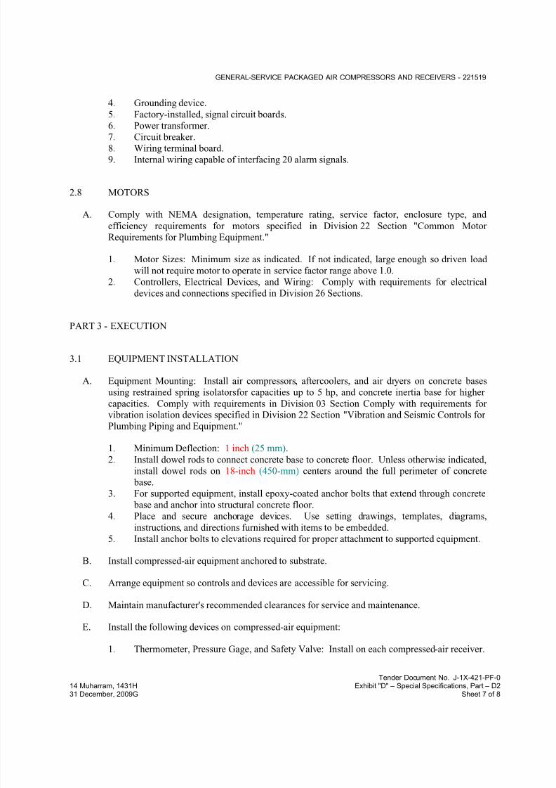
7/18/2019 SEC DPS
http://slidepdf.com/reader/full/sec-dps 460/541
GENERAL-SERVICE PACKAGED AIR COMPRESSORS AND RECEIVERS - 221519
Tender Document No. J-1X-421-PF-0
14 Muharram, 1431H Exhibit "D" – Special Specifications, Part – D231 December, 2009G Sheet 7 of 8
4. Grounding device.
5. Factory-installed, signal circuit boards.
6. Power transformer.
7. Circuit breaker.8. Wiring terminal board.
9. Internal wiring capable of interfacing 20 alarm signals.
2.8 MOTORS
A. Comply with NEMA designation, temperature rating, service factor, enclosure type, and
efficiency requirements for motors specified in Division 22 Section "Common Motor
Requirements for Plumbing Equipment."
1. Motor Sizes: Minimum size as indicated. If not indicated, large enough so driven load
will not require motor to operate in service factor range above 1.0.2. Controllers, Electrical Devices, and Wiring: Comply with requirements for electrical
devices and connections specified in Division 26 Sections.
PART 3 - EXECUTION
3.1 EQUIPMENT INSTALLATION
A. Equipment Mounting: Install air compressors, aftercoolers, and air dryers on concrete bases
using restrained spring isolatorsfor capacities up to 5 hp, and concrete inertia base for higher
capacities. Comply with requirements in Division 03 Section Comply with requirements forvibration isolation devices specified in Division 22 Section "Vibration and Seismic Controls for
Plumbing Piping and Equipment."
1. Minimum Deflection: 1 inch (25 mm).
2. Install dowel rods to connect concrete base to concrete floor. Unless otherwise indicated,
install dowel rods on 18-inch (450-mm) centers around the full perimeter of concrete
base.
3. For supported equipment, install epoxy-coated anchor bolts that extend through concrete
base and anchor into structural concrete floor.
4. Place and secure anchorage devices. Use setting drawings, templates, diagrams,
instructions, and directions furnished with items to be embedded.
5. Install anchor bolts to elevations required for proper attachment to supported equipment.
B. Install compressed-air equipment anchored to substrate.
C. Arrange equipment so controls and devices are accessible for servicing.
D. Maintain manufacturer's recommended clearances for service and maintenance.
E. Install the following devices on compressed-air equipment:
1. Thermometer, Pressure Gage, and Safety Valve: Install on each compressed-air receiver.

7/18/2019 SEC DPS
http://slidepdf.com/reader/full/sec-dps 461/541
GENERAL-SERVICE PACKAGED AIR COMPRESSORS AND RECEIVERS - 221519
Tender Document No. J-1X-421-PF-0
14 Muharram, 1431H Exhibit "D" – Special Specifications, Part – D231 December, 2009G Sheet 8 of 8
2. Pressure Regulators: Install downstream from air compressors[ and dryers].
3. Automatic Drain Valves: Install on aftercoolers, receivers, and dryers. Discharge
condensate over nearest floor drain.
3.2 CONNECTIONS
A. Comply with requirements for piping specified in Division 22 Section "General-Service
Compressed-Air Piping." Drawings indicate general arrangement of piping, fittings, and
specialties.
B. Install piping adjacent to machine to allow service and maintenance.
3.3 IDENTIFICATION
A. Identify general-service air compressors and components. Comply with requirements for
identification specified in Division 22 Section "Identification for Plumbing Piping and
Equipment."
3.4 STARTUP SERVICE
A. Engage a factory-authorized service representative to perform startup service.
1. Complete installation and startup checks according to manufacturer's written instructions.
2. Check for lubricating oil in lubricated-type equipment.
3. Check belt drives for proper tension.
4. Verify that air-compressor inlet filters and piping are clear.5. Check for equipment vibration-control supports and flexible pipe connectors and verify
that equipment is properly attached to substrate.
6. Check safety valves for correct settings. Ensure that settings are higher than air-
compressor discharge pressure but not higher than rating of system components.
7. Check for proper seismic restraints.
8. Drain receiver tanks.
9. Operational Test: After electrical circuitry has been energized, start units to confirm proper motor rotation and unit operation.
10. Test and adjust controls and safeties.
3.5 DEMONSTRATION
A. Engage a factory-authorized service representative to train Owner's maintenance personnel to
adjust, operate, and maintain air compressors, aftercoolers, and air dryers.
END OF SECTION 221519
7/18/2019 SEC DPS
http://slidepdf.com/reader/full/sec-dps 462/541
DOMESTIC WATER SOFTENERS - 223100
Tender Document No. J-1X-421-PF-0
14 Muharram, 1431H Exhibit "D" – Special Specifications, Part – D231 December, 2009G Sheet 1 of 11
SECTION 223100 - DOMESTIC WATER SOFTENERS
PART 1 - GENERAL
1.1 RELATED DOCUMENTS
A. Drawings and general provisions of the Contract, including General and Supplementary
Conditions and Division 01 Specification Sections, apply to this Section.
1.2 SUMMARY
A. Section Includes:
1. Residential water softeners.
2. Commercial water softeners.3. Deionizer
4. Chemicals.
5. Water-testing sets.
1.3 PERFORMANCE REQUIREMENTS
A. Seismic Performance: Water softeners shall withstand the effects of earthquake motions
determined according to ASCE/SEI 7.
1. The term "withstand" means "the unit will remain in place without separation of any parts
from the device when subjected to the seismic forces specified and the unit will be fully
operational after the seismic event."
1.4 ACTION SUBMITTALS
A. Product Data: For each type of product indicated.
1. Include construction details, material descriptions, dimensions of individual components
and profiles, and finishes for water softeners.
2. Include rated capacities, operating characteristics, electrical characteristics, and furnishedspecialties and accessories.
3. Wiring Diagrams: For power, signal, and control wiring.
1.5 INFORMATIONAL SUBMITTALS
A. Seismic Qualification Certificates: For water softeners, accessories, and components, from
manufacturer.

7/18/2019 SEC DPS
http://slidepdf.com/reader/full/sec-dps 463/541
DOMESTIC WATER SOFTENERS - 223100
Tender Document No. J-1X-421-PF-0
14 Muharram, 1431H Exhibit "D" – Special Specifications, Part – D231 December, 2009G Sheet 2 of 11
1. Basis for Certification: Indicate whether withstand certification is based on actual test of
assembled components or on calculation.
2. Dimensioned Outline Drawings of Equipment Unit: Identify center of gravity and locate
and describe mounting and anchorage provisions.3. Detailed description of equipment anchorage devices on which the certification is based
and their installation requirements.
B. Source quality-control reports.
C. Field quality-control reports.
D. Warranty: Sample of special warranty.
1.6 CLOSEOUT SUBMITTALS
A. Operation and Maintenance Data: For water softeners to include in emergency, operation, and
maintenance manuals.
1.7 MAINTENANCE MATERIAL SUBMITTALS
A. Furnish extra materials that match products installed and that are packaged with protectivecovering for storage and identified with labels describing contents.
1. Salt for Brine Tanks: Furnish in same form as and at least four times original load, but
not less than 200 lb (90.7 kg). Deliver on pallets according to the following:
a. Food-Grade Pellet Salt: In 80-lb (36.3-kg) packages. b. Plain Pellet Salt: In 80-lb (36.3-kg) packages.
c. Crystallized Solar Salt: In 80-lb (36.3-kg) packages.
d. Plain, Brine Block Salt: In 50-lb (22.7-kg) blocks.
2. Store salt on raised platform where directed by Owner. Do not store in contact with
concrete floor.
1.8 QUALITY ASSURANCE
A. Electrical Components, Devices, and Accessories: Listed and labeled as defined in NFPA 70,
by a qualified testing agency, and marked for intended application.
B. ASME Compliance for Steel Tanks: Fabricate and label mineral tanks to comply with ASME
Boiler and Pressure Vessel Code: Section VIII, Division 1, where indicated.
C. ASME Compliance for FRP Tanks: Fabricate and label mineral tanks to comply with ASME
Boiler and Pressure Vessel Code: Section X, where indicated.
D. UL Compliance: Fabricate and label water softeners to comply with UL 979, "Water Treatment
Appliances."
7/18/2019 SEC DPS
http://slidepdf.com/reader/full/sec-dps 464/541
DOMESTIC WATER SOFTENERS - 223100
Tender Document No. J-1X-421-PF-0
14 Muharram, 1431H Exhibit "D" – Special Specifications, Part – D231 December, 2009G Sheet 3 of 11
1.9 COORDINATION
A. Coordinate sizes and locations of concrete bases with actual equipment provided.
1.10 WARRANTY
A. Special Warranty: Manufacturer's standard form in which manufacturer agrees to repair or
replace components of water softeners that fail in materials or workmanship within specified
warranty period.
1. Failures include, but are not limited to, the following:
a. Structural failures of mineral and brine tanks.
b. Faulty operation of controls.
c. Deterioration of metals, metal finishes, and other materials beyond normal use.d. Attrition loss of resin exceeding 3 percent per year.
e. Mineral washed out of system during service run or backwashing period.
f. Effluent turbidity greater and color darker than incoming water.
g. Fouling of underdrain system, gravel, and resin with turbidity or by dirt, rust, or
scale from water softener or soft water, while operating according to
manufacturer's written operating instructions.
2. Residential Water Softeners, Warranty Period: From date of Substantial Completion.
a. Tanks: Five years.
b. Control Valve: One year(s).
3. Commercial Water Softeners, Warranty Period: From date of Substantial Completion.
a. Mineral Tanks: 10 years.
b. Brine Tanks: 10 years.
c. Control Valve: One year(s).
1.11 MAINTENANCE SERVICE
A. Initial Maintenance Service: Beginning at Substantial Completion, provide 12 months' full
maintenance by skilled employees of water softener Installer. Include monthly preventive
maintenance, repair or replacement of worn or defective components, cleaning, and adjusting as
required for proper water softener operation at rated capacity. Provide parts and supplies thesame as those used in the manufacture and installation of original equipment.
B. Continuing Maintenance Proposal: From Installer to Owner, in the form of a standard yearly
(or other period) maintenance agreement, starting on date initial maintenance service is
concluded. State services, obligations, conditions, and terms for agreement period and for
future renewal options.

7/18/2019 SEC DPS
http://slidepdf.com/reader/full/sec-dps 465/541
DOMESTIC WATER SOFTENERS - 223100
Tender Document No. J-1X-421-PF-0
14 Muharram, 1431H Exhibit "D" – Special Specifications, Part – D231 December, 2009G Sheet 4 of 11
PART 2 - PRODUCTS
2.1 RESIDENTIAL WATER SOFTENERS
A. Manufacturers: Subject to compliance with requirements
B. Basis-of-Design Product: Subject to compliance with requirements
C. Description: Factory-assembled, fully automatic, pressure-type water softener.
1. Standard: Comply with NSF 61, "Drinking Water System Components - Health Effects."
2. Configuration: Unit with one mineral tank and one brine tank or cabinet-style,
combination mineral and brine tank unit with equivalent characteristics.
3. Mineral Tank: Steel or FRP, with coating or liner suitable for potable-water service and
125-psig (860-kPa) minimum pressure rating.4. Controls: For fully automatic operation.
5. Brine Tank: Combination measuring and wet-salt storing system.
a. Tank and Cover Material: FRP or molded PE.
b. Brine Valve: Float operated and plastic fitted for automatic control of brinewithdrawal and freshwater refill.
c. Size: Large enough for at least two regenerations at full salting.
6. Factory-Installed Accessories:
a. Piping, valves, tubing, and drains.
b. Sampling cock.c. Main-operating-valve position indicator.
D. Capacities and Characteristics:
1. Water Analysis: to be carried by contractor
2. Capacities to suit application requirements
3. 3. Equipment electrical characteristics to follow those of the project requirements Salt
Capacity: Subject to engineer’s approval.
2.2 COMMERCIAL WATER SOFTENERS
A. Manufacturers: Subject to compliance with requirements
B. Basis-of-Design Product: Subject to compliance with requirements
C. Description: Factory-assembled, pressure-type water softener.
1. Standard: Comply with NSF 61, "Drinking Water System Components - Health Effects."
2. Configuration: Twin unit with two mineral tanks or Triple unit with three mineral tanks
and one brine tank.
3. Mounting: On skids.
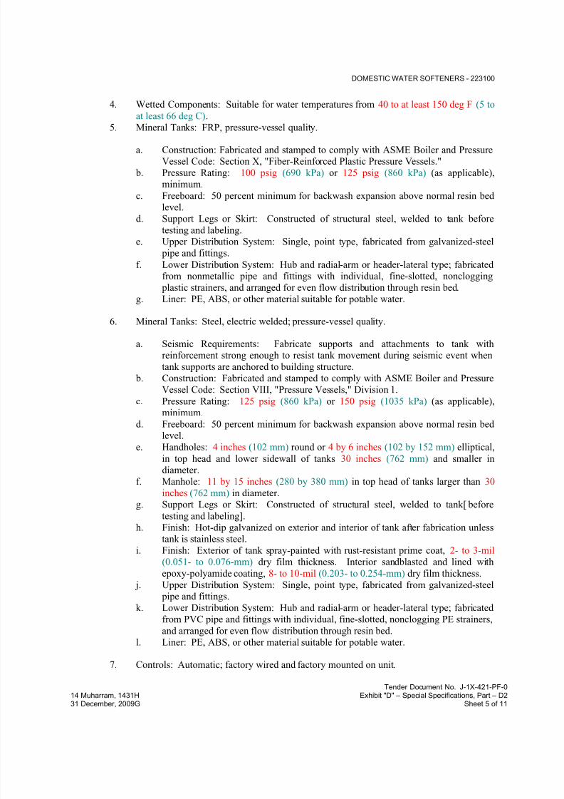
7/18/2019 SEC DPS
http://slidepdf.com/reader/full/sec-dps 466/541
DOMESTIC WATER SOFTENERS - 223100
Tender Document No. J-1X-421-PF-0
14 Muharram, 1431H Exhibit "D" – Special Specifications, Part – D231 December, 2009G Sheet 5 of 11
4. Wetted Components: Suitable for water temperatures from 40 to at least 150 deg F (5 to
at least 66 deg C).
5. Mineral Tanks: FRP, pressure-vessel quality.
a. Construction: Fabricated and stamped to comply with ASME Boiler and Pressure
Vessel Code: Section X, "Fiber-Reinforced Plastic Pressure Vessels."
b. Pressure Rating: 100 psig (690 kPa) or 125 psig (860 kPa) (as applicable),
minimum.
c. Freeboard: 50 percent minimum for backwash expansion above normal resin bed
level.
d. Support Legs or Skirt: Constructed of structural steel, welded to tank before
testing and labeling.
e. Upper Distribution System: Single, point type, fabricated from galvanized-steel
pipe and fittings.
f. Lower Distribution System: Hub and radial-arm or header-lateral type; fabricated
from nonmetallic pipe and fittings with individual, fine-slotted, nonclogging plastic strainers, and arranged for even flow distribution through resin bed.
g. Liner: PE, ABS, or other material suitable for potable water.
6. Mineral Tanks: Steel, electric welded; pressure-vessel quality.
a. Seismic Requirements: Fabricate supports and attachments to tank with
reinforcement strong enough to resist tank movement during seismic event when
tank supports are anchored to building structure.
b. Construction: Fabricated and stamped to comply with ASME Boiler and Pressure
Vessel Code: Section VIII, "Pressure Vessels," Division 1.
c. Pressure Rating: 125 psig (860 kPa) or 150 psig (1035 kPa) (as applicable),
minimum.d. Freeboard: 50 percent minimum for backwash expansion above normal resin bed
level.
e. Handholes: 4 inches (102 mm) round or 4 by 6 inches (102 by 152 mm) elliptical,
in top head and lower sidewall of tanks 30 inches (762 mm) and smaller in
diameter.
f. Manhole: 11 by 15 inches (280 by 380 mm) in top head of tanks larger than 30
inches (762 mm) in diameter.
g. Support Legs or Skirt: Constructed of structural steel, welded to tank[ before
testing and labeling].
h. Finish: Hot-dip galvanized on exterior and interior of tank after fabrication unless
tank is stainless steel.
i. Finish: Exterior of tank spray-painted with rust-resistant prime coat, 2- to 3-mil (0.051- to 0.076-mm) dry film thickness. Interior sandblasted and lined with
epoxy-polyamide coating, 8- to 10-mil (0.203- to 0.254-mm) dry film thickness.
j. Upper Distribution System: Single, point type, fabricated from galvanized-steel
pipe and fittings.
k. Lower Distribution System: Hub and radial-arm or header-lateral type; fabricated
from PVC pipe and fittings with individual, fine-slotted, nonclogging PE strainers,
and arranged for even flow distribution through resin bed.
l. Liner: PE, ABS, or other material suitable for potable water.
7. Controls: Automatic; factory wired and factory mounted on unit.
7/18/2019 SEC DPS
http://slidepdf.com/reader/full/sec-dps 467/541
DOMESTIC WATER SOFTENERS - 223100
Tender Document No. J-1X-421-PF-0
14 Muharram, 1431H Exhibit "D" – Special Specifications, Part – D231 December, 2009G Sheet 6 of 11
a. Adjustable duration of various regeneration steps.
b. Push-button start and complete manual operation.
c. Electric time clock and switch for automatic operation except for manual return to
service.d. Sequence of Operation: Multiport pilot-control valve automatically pressure-
actuates main operating valve through steps of regeneration.
e. Pointer on pilot-control valve shall indicate cycle of operation.
f. Includes means of manual operation of pilot-control valve if power fails.
8. Controls: Fully automatic; factory wired and factory mounted on unit.
a. Adjustable duration of various regeneration steps.
b. Push-button start and complete manual operation.
c. Electric time clock and switch for fully automatic operation, adjustable to initiate
regeneration at any hour of day and any day of week or at fixed intervals.
d. Sequence of Operation: Multiport pilot-control valve automatically pressure-actuates main operating valve through steps of regeneration and return to service.
e. Pointer on pilot-control valve shall indicate cycle of operation.
f. Includes means of manual operation of pilot-control valve if power fails.
9. Main Operating Valves: Industrial, automatic, multiport, diaphragm type with the
following features:
a. Slow opening and closing, nonslam operation.
b. Diaphragm guiding on full perimeter from fully open to fully closed.
c. Isolated, dissimilar metals within valve.
d. Self-adjusting, internal, automatic brine injector that draws brine and rinses at
constant rate independent of pressure.e. Valve for single mineral-tank unit with internal automatic bypass of raw water
during regeneration.
f. Sampling cocks for soft water.
g. Special tools are not required for service.
10. Flow Control: Automatic, to control backwash and flush rates over wide variations in
operating pressure; does not require field adjustments.
a. Meter Control: Each mineral tank is equipped with signal-register-head water
meter that produces electrical signal indicating need for regeneration on reaching
hand-set total in gallons (liters). Signal will continue until reset.
b. Demand-Initiated Control: Single mineral tank is equipped with automatic-reset-
head water meter that electrically activates cycle controller to initiate regeneration
at preset total in gallons (liters). Head automatically resets to preset total in
gallons (liters) for next service run.
c. Demand-Initiated Control: Each mineral tank of twin mineral-tank unit is
equipped with automatic-reset-head water meter that electrically activates cycle
controllers to initiate regeneration at preset total in gallons (liters). Head
automatically resets to preset total in gallons (liters) for next service run. Electrical
lockout prevents simultaneous regeneration of both tanks.
d. Demand-Initiated Control: Each twin mineral-tank unit is equipped with
automatic-reset-head water meter, in common outlet header, that electrically

7/18/2019 SEC DPS
http://slidepdf.com/reader/full/sec-dps 468/541
DOMESTIC WATER SOFTENERS - 223100
Tender Document No. J-1X-421-PF-0
14 Muharram, 1431H Exhibit "D" – Special Specifications, Part – D231 December, 2009G Sheet 7 of 11
activates cycle controller to automatically regenerate one mineral tank at preset
total in gallons (liters) and divert flow to other tank. Automatically repeats with
other tank. Electrical lockout prevents simultaneous regeneration of both tanks.
e. Demand-Initiated Control: Each mineral tank of multiple mineral-tank unit isequipped with automatic-reset-head water meter that electrically activates cycle
controllers to automatically regenerate at preset total in gallons (liters). Head
automatically resets to preset total in gallons (liters) for next service run. Electrical
lockout prevents simultaneous regeneration of more than one tank.
f. Demand-Initiated Control: Each multiple mineral-tank unit is equipped withautomatic-reset-head water meter, in common outlet header, that electrically
activates cycle controller to automatically regenerate one mineral tank at preset
total in gallons (liters) and divert flow to other tanks. Automatically repeats with
other tanks. Electrical lockout prevents simultaneous regeneration of more than
one tank.
11. Brine Tank: Combination measuring and wet-salt storing system.
a. Tank and Cover Material: Fiberglass, 3/16 inch (4.8 mm) thick; or molded PE, 3/8
inch (9.5 mm) thick.
b. Brine Valve: Float operated and plastic fitted for automatic control of brine
withdrawal and freshwater refill.
c. Size: Large enough for at least four regenerations at full salting.
12. Factory-Installed Accessories:
a. Piping, valves, tubing, and drains.
b. Sampling cocks.
c. Main-operating-valve position indicators.d. Water meters.
D. Capacities and Characteristics:
1. Water Analysis: to be carried by contractor
2. Capacities to suit application requirements
3. Equipment electrical characteristics to follow those of the project requirements:
4. Salt Capacity: Subject to engineer’s approval.
2.3 DEIONIZER
A. Description: Factory-assembled, fully-automatic, cartridge type with ion exchange medium
rated for 600 gallons (2270 liters). Unit to be equipped with a resistivity indicator which
monitors the output water continuously and signals when cartridge is exhausted
a. Housing Material: FRP or molded PE.
2. Factory-Installed Accessories:
a. Piping, valves, tubing, and drains.

7/18/2019 SEC DPS
http://slidepdf.com/reader/full/sec-dps 469/541
DOMESTIC WATER SOFTENERS - 223100
Tender Document No. J-1X-421-PF-0
14 Muharram, 1431H Exhibit "D" – Special Specifications, Part – D231 December, 2009G Sheet 8 of 11
b. Sampling cock.
c. Main-operating-valve position indicator.
B. Capacity and Characteristics: As required for building service, subject to engineer’s approval.
2.4 CHEMICALS
A. Mineral: High-capacity, sulfonated-polystyrene, ion-exchange resin that is stable over entire
pH range with good resistance to bead fracture from attrition or shock.
1. Exchange Capacity: 30,000 grains/cu. ft. (69 kg/cu. m) of calcium carbonate of resin
when regenerated with 15 lb (6.8 kg) of salt.
B. Salt for Brine Tanks: High-purity sodium chloride, free of dirt and foreign material. Rock and
granulated forms are unacceptable.
1. Form: Processed, food-grade salt pellets, plain salt pellets, crystallized solar salt
collected from shallow ponds and milled into irregular particles, or plain, brine block salt.
2.5 WATER-TESTING SETS
A. Description: Manufacturer's standard water-hardness testing apparatus and chemicals withtesting procedure instructions. Include metal container suitable for wall mounting.
2.6 SOURCE QUALITY CONTROL
A. Hydrostatically test mineral tanks before shipment to a minimum of one and one-half times the
pressure rating.
B. Prepare test and inspection reports.
PART 3 - EXECUTION
3.1 WATER SOFTENER INSTALLATION
A. Equipment Mounting: Install residential water softeners on floor.
1. Maintain manufacturer's recommended clearances.
2. Arrange units so controls and devices that require servicing are accessible.
B. Equipment Mounting: Install residential and commercial water softeners on concrete base.
1. Maintain manufacturer's recommended clearances.
2. Arrange units so controls and devices that require servicing are accessible.

7/18/2019 SEC DPS
http://slidepdf.com/reader/full/sec-dps 470/541
DOMESTIC WATER SOFTENERS - 223100
Tender Document No. J-1X-421-PF-0
14 Muharram, 1431H Exhibit "D" – Special Specifications, Part – D231 December, 2009G Sheet 9 of 11
3. Install dowel rods to connect concrete base to concrete floor. Unless otherwise indicated,
install dowel rods on 18-inch (450-mm) centers around the full perimeter of concrete
base.
4. For supported equipment, install epoxy-coated anchor bolts that extend through concrete base and anchor into structural concrete floor.
5. Place and secure anchorage devices. Use setting drawings, templates, diagrams,
instructions, and directions furnished with items to be embedded.
6. Install anchor bolts to elevations required for proper attachment to supported equipment.
7. Anchor water softener and brine tanks to substrate.
C. Install seismic restraints for tanks and floor-mounting accessories and anchor to building
structure.
D. Install brine lines and fittings furnished by equipment manufacturer but not specified to be
factory installed.
E. Prepare mineral-tank distribution system and underbed for minerals and place specified mineral
into mineral tanks.
F. Install water-testing sets mounted on wall, unless otherwise indicated, and near water softeners.
3.2 CONNECTIONS
A. Comply with requirements for piping specified in Division 22 Section "Domestic Water
Piping." Drawings indicate general arrangement of piping, fittings, and specialties.
B. Where piping is installed adjacent to equipment, allow space for service and maintenance of
equipment.
C. Install shutoff valves on raw-water inlet and soft-water outlet piping of each mineral tank and
on inlet and outlet headers.
1. Metal general-duty valves are specified in Division 22 Section "General-Duty Valves for
Plumbing Piping."
2. Plastic valves are specified in Division 22 Section "Domestic Water Piping."
3. Exception: Water softeners with factory-installed shutoff valves at locations indicated.
D. Install pressure gages on raw-water inlet and soft-water outlet piping of each mineral tank.
Pressure gages are specified in Division 22 Section "Meters and Gages for Plumbing Piping."
1. Exception: Water softeners with factory-installed pressure gages at locations indicated.
E. Install valved bypass in water piping around water softeners.
1. Metal general-duty valves are specified in Division 22 Section "General-Duty Valves for
Plumbing Piping."
2. Plastic valves are specified in Division 22 Section "Domestic Water Piping."
3. Water piping is specified in Division 22 Section "Domestic Water Piping."
4. Exception: Household water softeners.
7/18/2019 SEC DPS
http://slidepdf.com/reader/full/sec-dps 471/541
DOMESTIC WATER SOFTENERS - 223100
Tender Document No. J-1X-421-PF-0
14 Muharram, 1431H Exhibit "D" – Special Specifications, Part – D231 December, 2009G Sheet 10 of 11
5. Exception: Water softeners in hot-water service.
F. Install drains as indirect wastes to spill into open drains or over floor drains.
3.3 IDENTIFICATION
A. Identify system components. Comply with requirements for identification specified in
Division 22 Section "Identification for Plumbing Piping and Equipment."
3.4 FIELD QUALITY CONTROL
A. Tests and Inspections:
1.
Leak Test: After installation, charge system and test for leaks. Repair leaks and retestuntil no leaks exist.
2. Operational Test: After electrical circuitry has been energized, start units to confirm
proper unit operation.
3. Test and adjust controls and safeties. Replace damaged and malfunctioning controls and
equipment.
B. Water softeners will be considered defective if they do not pass tests and inspections.
C. Prepare test and inspection reports.
3.5 STARTUP SERVICE
A. Engage a factory-authorized service representative to perform startup service.
1. Complete installation and startup checks according to manufacturer's written instructions.
B. Add water to brine tanks and fill with the following form of salt:
1. Residential Water Softeners: Processed, food-grade salt pellets, plain salt pellets, or
crystallized solar salt collected from shallow ponds and milled into irregular particles.
2. Commercial Water Softeners: Processed, plain salt pellets, crystallized solar salt
collected from shallow ponds and milled into irregular particles, or plain, brine block salt.
C. Sample water softener effluent after startup and at three consecutive seven-day intervals (totalof four samples), and prepare certified test reports for required water performance
characteristics. Comply with the following:
1. ASTM D 859, "Test Method for Silica in Water."
2. ASTM D 1067, "Test Methods for Acidity or Alkalinity of Water."
3. ASTM D 1068, "Test Methods for Iron in Water."
4. ASTM D 1126, "Test Method for Hardness in Water."
5. ASTM D 1129, "Terminology Relating to Water."
6. ASTM D 3370, "Practices for Sampling Water from Closed Conduits."
7/18/2019 SEC DPS
http://slidepdf.com/reader/full/sec-dps 472/541
DOMESTIC WATER SOFTENERS - 223100
Tender Document No. J-1X-421-PF-0
14 Muharram, 1431H Exhibit "D" – Special Specifications, Part – D231 December, 2009G Sheet 11 of 11
3.6 DEMONSTRATION
A. Engage a factory-authorized service representative to train Owner's maintenance personnel to
adjust, operate, and maintain water softeners.
END OF SECTION 223100
7/18/2019 SEC DPS
http://slidepdf.com/reader/full/sec-dps 473/541
DOMESTIC WATER FILTRATION EQUIPMENT - 223200
Tender Document No. J-1X-421-PF-0
14 Muharram, 1431H Exhibit "D" – Special Specifications, Part – D231 December, 2009G Sheet 1 of 11
SECTION 223200 - DOMESTIC WATER FILTRATION EQUIPMENT
PART 1 - GENERAL
1.1 RELATED DOCUMENTS
A. Drawings and general provisions of the Contract, including General and Supplementary
Conditions and Division 01 Specification Sections, apply to this Section.
1.2 SUMMARY
A. Section Includes:
1. Freestanding cartridge filters.
2. Carbon filters.3. Multimedia sand filters.
4. Ultra violet sterilizing unit
5. Aircrafts Blue and Potable Water Treatment
6. Aircrafts Blue and Potable Water Pop-Up Pits
B. Related Sections:
1. Division 22 Section "Domestic Water Piping Specialties" for plumbing piping strainers.
1.3 PERFORMANCE REQUIREMENTS
A. Seismic Performance: freestanding cartridge filters, carbon filters, and multimedia sand filters
shall withstand the effects of earthquake motions determined according to ASCE/SEI 7.
1. The term "withstand" means that "the unit will remain in place without separation of any
parts from the device when subjected to the seismic forces specified and the unit will be
fully operational after the seismic event.
1.4 ACTION SUBMITTALS
A. Product Data: For each type of product indicated. Include construction details, materialdescriptions, dimensions of individual components and profiles, and finishes for filters and
separators. and Include rated capacities, operating characteristics, electrical characteristics, and
furnished specialties and accessories.
B. Shop Drawings: For water filtration equipment. Include plans, elevations, sections, details, and
attachments to other work.
1. Detail equipment assemblies and indicate dimensions, weights, loads, required
clearances, method of field assembly, components, and location and size of each field
connection.

7/18/2019 SEC DPS
http://slidepdf.com/reader/full/sec-dps 474/541
DOMESTIC WATER FILTRATION EQUIPMENT - 223200
Tender Document No. J-1X-421-PF-0
14 Muharram, 1431H Exhibit "D" – Special Specifications, Part – D231 December, 2009G Sheet 2 of 11
2. Wiring Diagrams: For power, signal, and control wiring.
1.5 INFORMATIONAL SUBMITTALS
A. Seismic Qualification Certificates: For freestanding cartridge filters, carbon filters, multimedia
sand filters , accessories, and components, from manufacturer.
1. Basis for Certification: Indicate whether withstand certification is based on actual test of
assembled components or on calculation.
2. Dimensioned Outline Drawings of Equipment Unit: Identify center of gravity and locate
and describe mounting and anchorage provisions.
3. Detailed description of equipment anchorage devices on which the certification is based
and their installation requirements.
B. Certificates of Shop Inspections and Data Reports: For products required to have ASME label,signed by product manufacturer.
C. Welding certificates.
D. Source quality-control reports.
E. Field quality-control reports.
1.6 CLOSEOUT SUBMITTALS
A. Operation and Maintenance Data: For water filtration equipment to include in emergency,
operation, and maintenance manuals.
1.7 MATERIALS MAINTENANCE SUBMITTALS
A. Furnish extra materials that match products installed and that are packaged with protective
covering for storage and identified with labels describing contents.
1. Cartridge-Filter Elements: Elements for cartridge filters equal to 200] percent of amount
installed for each size and media indicated.
1.8 QUALITY ASSURANCE
A. Source Limitations: Obtain each type of water filtration equipment through one source from a
single manufacturer.
B. Welding Qualifications: Qualify processes and operators according to ASME Boiler and
Pressure Vessel Code.
C. Electrical Components, Devices, and Accessories: Listed and labeled as defined in NFPA 70,
by a qualified testing agency, and marked for intended location and application.

7/18/2019 SEC DPS
http://slidepdf.com/reader/full/sec-dps 475/541
DOMESTIC WATER FILTRATION EQUIPMENT - 223200
Tender Document No. J-1X-421-PF-0
14 Muharram, 1431H Exhibit "D" – Special Specifications, Part – D231 December, 2009G Sheet 3 of 11
D. Comply with NSF 61, "Drinking Water System Components - Health Effects," for all
components that will be in contact with potable water.
1.9 PROJECT CONDITIONS
A. Feedwater Analysis: To be carried out by contractor to obtain data for the below water
components:
1. Alkalinity
2. Arsenic
3. Calcium
4. Chlorine
5. Color.
6. Hydrogen-Ion Concentration
7. Hardness8. Hydrogen Sulfide
9. Iron
10. Lead
11. Magnesium
12. Manganese
13. Potassium
14. Sand
15. Silt
16. Sodium
17. Total Dissolved Solids
18. Turbidity
B. Feedwater temperature and pressure: As applicable per building.
1.10 COORDINATION
A. Coordinate size and location of concrete bases with actual equipment provided.
PART 2 - PRODUCTS
2.1 CARTRIDGE FILTERS
A. Freestanding Cartridge Filters:
1. Manufacturers: Subject to compliance with requirements
2. Basis-of-Design Product: Subject to compliance with requirements
3. Description: Simplex, floor-mounted housing with replaceable element(s) for removing
suspended particles from water.
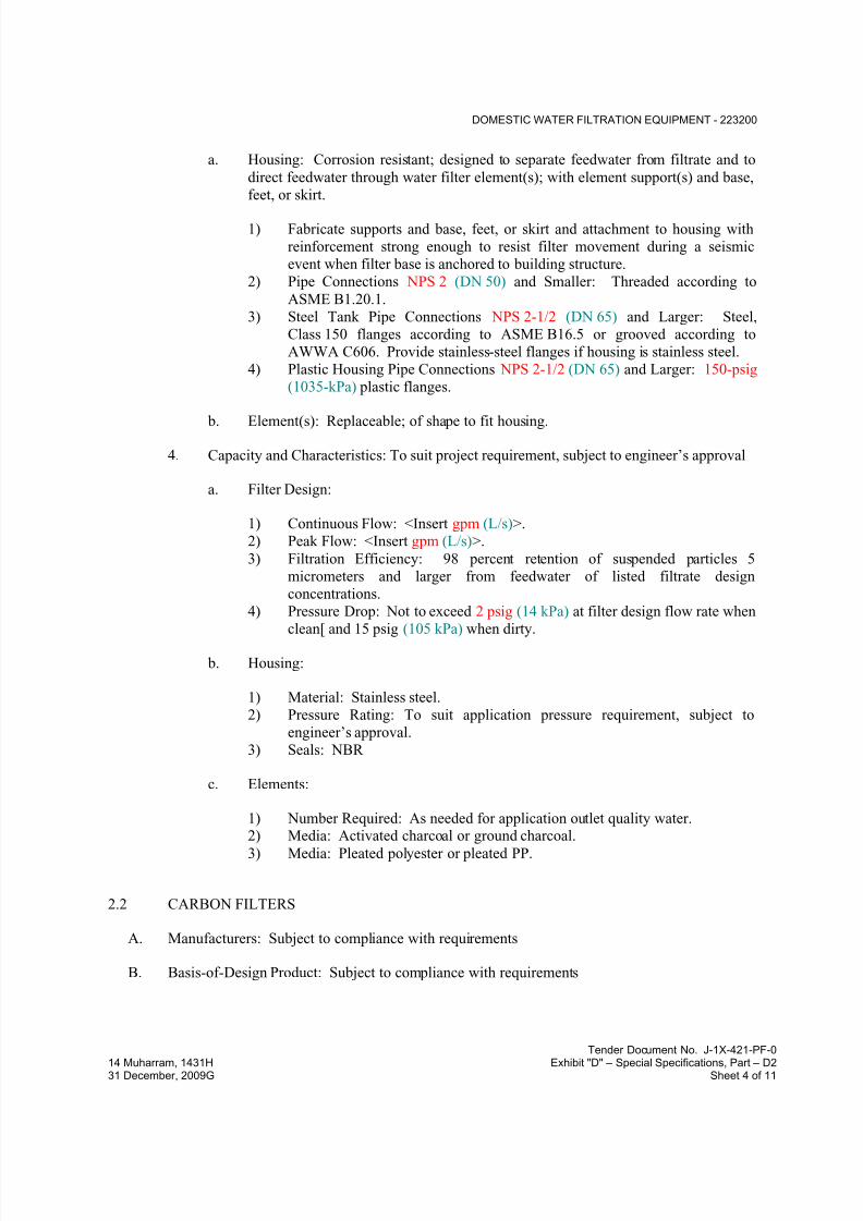
7/18/2019 SEC DPS
http://slidepdf.com/reader/full/sec-dps 476/541
DOMESTIC WATER FILTRATION EQUIPMENT - 223200
Tender Document No. J-1X-421-PF-0
14 Muharram, 1431H Exhibit "D" – Special Specifications, Part – D231 December, 2009G Sheet 4 of 11
a. Housing: Corrosion resistant; designed to separate feedwater from filtrate and to
direct feedwater through water filter element(s); with element support(s) and base,
feet, or skirt.
1) Fabricate supports and base, feet, or skirt and attachment to housing with
reinforcement strong enough to resist filter movement during a seismic
event when filter base is anchored to building structure.
2) Pipe Connections NPS 2 (DN 50) and Smaller: Threaded according to
ASME B1.20.1.
3) Steel Tank Pipe Connections NPS 2-1/2 (DN 65) and Larger: Steel,
Class 150 flanges according to ASME B16.5 or grooved according to
AWWA C606. Provide stainless-steel flanges if housing is stainless steel.
4) Plastic Housing Pipe Connections NPS 2-1/2 (DN 65) and Larger: 150-psig
(1035-kPa) plastic flanges.
b. Element(s): Replaceable; of shape to fit housing.
4. Capacity and Characteristics: To suit project requirement, subject to engineer’s approval
a. Filter Design:
1) Continuous Flow: <Insert gpm (L/s)>.
2) Peak Flow: <Insert gpm (L/s)>.
3) Filtration Efficiency: 98 percent retention of suspended particles 5
micrometers and larger from feedwater of listed filtrate design
concentrations.
4) Pressure Drop: Not to exceed 2 psig (14 kPa) at filter design flow rate when
clean[ and 15 psig (105 kPa) when dirty.
b. Housing:
1) Material: Stainless steel.
2) Pressure Rating: To suit application pressure requirement, subject to
engineer’s approval.
3) Seals: NBR
c. Elements:
1) Number Required: As needed for application outlet quality water.2) Media: Activated charcoal or ground charcoal.
3) Media: Pleated polyester or pleated PP.
2.2 CARBON FILTERS
A. Manufacturers: Subject to compliance with requirements
B. Basis-of-Design Product: Subject to compliance with requirements
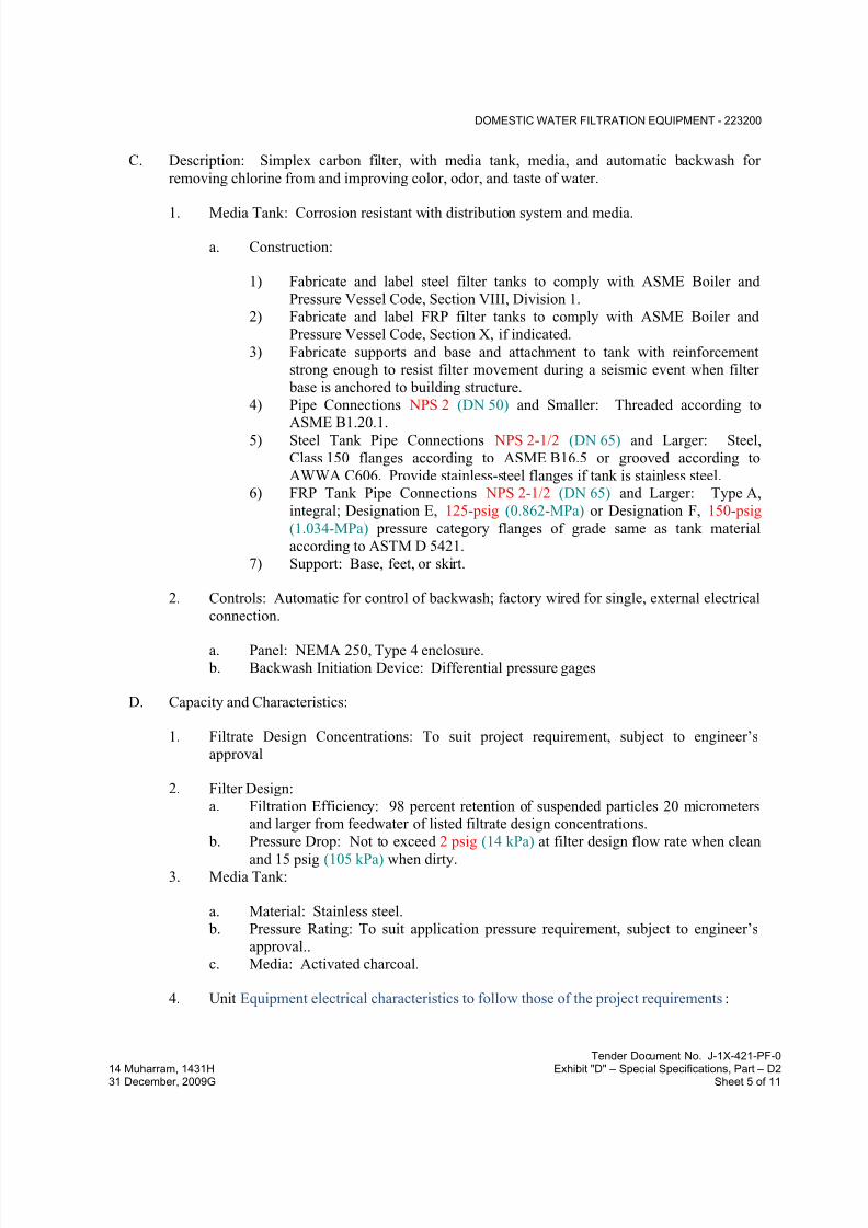
7/18/2019 SEC DPS
http://slidepdf.com/reader/full/sec-dps 477/541
DOMESTIC WATER FILTRATION EQUIPMENT - 223200
Tender Document No. J-1X-421-PF-0
14 Muharram, 1431H Exhibit "D" – Special Specifications, Part – D231 December, 2009G Sheet 5 of 11
C. Description: Simplex carbon filter, with media tank, media, and automatic backwash for
removing chlorine from and improving color, odor, and taste of water.
1. Media Tank: Corrosion resistant with distribution system and media.
a. Construction:
1) Fabricate and label steel filter tanks to comply with ASME Boiler and
Pressure Vessel Code, Section VIII, Division 1.
2) Fabricate and label FRP filter tanks to comply with ASME Boiler and
Pressure Vessel Code, Section X, if indicated.
3) Fabricate supports and base and attachment to tank with reinforcement
strong enough to resist filter movement during a seismic event when filter
base is anchored to building structure.
4) Pipe Connections NPS 2 (DN 50) and Smaller: Threaded according to
ASME B1.20.1.5) Steel Tank Pipe Connections NPS 2-1/2 (DN 65) and Larger: Steel,
Class 150 flanges according to ASME B16.5 or grooved according to
AWWA C606. Provide stainless-steel flanges if tank is stainless steel.
6) FRP Tank Pipe Connections NPS 2-1/2 (DN 65) and Larger: Type A,
integral; Designation E, 125-psig (0.862-MPa) or Designation F, 150-psig
(1.034-MPa) pressure category flanges of grade same as tank material
according to ASTM D 5421.
7) Support: Base, feet, or skirt.
2. Controls: Automatic for control of backwash; factory wired for single, external electrical
connection.
a. Panel: NEMA 250, Type 4 enclosure.
b. Backwash Initiation Device: Differential pressure gages
D. Capacity and Characteristics:
1. Filtrate Design Concentrations: To suit project requirement, subject to engineer’s
approval
2. Filter Design:
a. Filtration Efficiency: 98 percent retention of suspended particles 20 micrometers
and larger from feedwater of listed filtrate design concentrations.
b. Pressure Drop: Not to exceed 2 psig (14 kPa) at filter design flow rate when clean
and 15 psig (105 kPa) when dirty.
3. Media Tank:
a. Material: Stainless steel.
b. Pressure Rating: To suit application pressure requirement, subject to engineer’s
approval..
c. Media: Activated charcoal.
4. Unit Equipment electrical characteristics to follow those of the project requirements:

7/18/2019 SEC DPS
http://slidepdf.com/reader/full/sec-dps 478/541
DOMESTIC WATER FILTRATION EQUIPMENT - 223200
Tender Document No. J-1X-421-PF-0
14 Muharram, 1431H Exhibit "D" – Special Specifications, Part – D231 December, 2009G Sheet 6 of 11
2.3 SAND FILTERS
A. Multimedia Sand Filters:
1. Manufacturers: Subject to compliance with requirements
2. Basis-of-Design Product: Subject to compliance with requirements
3. Description: Factory-fabricated and -tested, duplex or triplex, multimedia, sand-filter
system of filter tank(s), media, piping, and controls for removing sediment particles from
water.
a. Tank Construction:
1) Fabricate and label steel filter tanks to comply with ASME Boiler and
Pressure Vessel Code, Section VIII, Division 1.
2) Fabricate and label FRP filter tanks to comply with ASME Boiler andPressure Vessel Code, Section X, if indicated.
3) Fabricate supports and base and attachment to tank with reinforcement
strong enough to resist filter movement during a seismic event when filter
base is anchored to building structure.
b. Pipe Connections NPS 2 (DN 50) and Smaller: Threaded according to
ASME B1.20.1.
c. Steel Tank Pipe Connections NPS 2-1/2 (DN 65) and Larger: Steel, Class 150
flanges according to ASME B16.5 or grooved according to AWWA C606.
d. FRP Tank Pipe Connections NPS 2-1/2 (DN 65) and Larger: Type A, integral;
Designation E, 125-psig (0.862-MPa) or F, 150-psig (1.034-MPa) pressure
category flanges of grade same as tank material according to ASTM D 5421.e. Service Valve(s): Diaphragm type hydraulically or pneumatically operated.
f. Piping: Galvanized steel pipe, galvanized cast-iron fittings, and flanged, grooved,
or threaded joints.
g. Piping: ASTM B 88, Type L (ASTM B 88M, Type B) copper water tube, copper-
alloy solder-joint fittings, and brazed, flanged, or grooved joints.
h. Piping: Schedule 80 ABS or PVC pipe and fittings with solvent-cemented joints.
i. Safety Valves: Automatic air vent.
j. Controls for Simplex Tank System: Automatic, electric time clock for control of
filter system flow and backwash cycles; factory-wired for single, external electrical
connection.
k. Controls for Duplex or Triplex Tank System: Automatic, electric time clock for
control of filter system flow and backwash cycles; factory-wired for single,
external electrical connection. System operation shall be continuous with bypass
piping and not more than one tank in backwash cycle at same time.
l. Support: Skid mounting.
4. Capacity and Characteristics:
a. Filtrate Design Concentrations: To suit project requirement, subject to engineer’s
approval
b. Filter Design:

7/18/2019 SEC DPS
http://slidepdf.com/reader/full/sec-dps 479/541
DOMESTIC WATER FILTRATION EQUIPMENT - 223200
Tender Document No. J-1X-421-PF-0
14 Muharram, 1431H Exhibit "D" – Special Specifications, Part – D231 December, 2009G Sheet 7 of 11
1) Filtration Efficiency: 98 percent removal of suspended particles 20
micrometers and larger from feedwater of listed filtrate design
concentrations.
c. Media Tank: Single with controls.
d. Media Tanks: Two or Three with manifolded inlet, outlet, and drain piping and
controls.
e. Each Media Tank:
1) Material: Carbon steel with NSF 61 lining material or FRP.
2) Pressure Rating: To suit application pressure requirement, subject to
engineer’s approval.
f. Filter Media: Graded silica sand.
2.4 ULTRA VIOLET STERELIZING UNIT::
1. Unit: to include 304 stainless steel sterilizing chambers with removable head. UV lamps
to slide into high purity sleeves. Sleeves are attached to chamber head so they may be
easily removed as a bundle for inspection or cleaning. Flow regulator on discharge line
to maintain flow to ensure an exposure dosage of 30000 micro watt-sec/cm2. Sterilizer
to include high powered ballast, fuse, power safety switch, all inside white enamel hous-
ing with stainless steel cover and electrical cord.
2. Unit: to include UV intensity sensor and meter with safe/unsafe zones to indicate UV be-
low effective range, mounted on sterilizer housing
3. Unit pressure rating to be 1.5 times the system operating pressure.
2.5 AIRCRAFTS BLUE AND POTABLE WATER TREATMENT
A. Provide all water treatment needed to achieve the quality standard for blue water in accordance
with ICAO regulations including: sand filtration, cartridge filtration, sterilization and blue
disinfectant dosing system. Water treatment system shall be designed and installed completewith all necessary mixing tanks, dosing pumps and associated automatic control system,
interfaced with Building Management System. System equipment shall be provided in duplex in
order to ensure full redundancy.
B. Provide all water treatment needed to achieve the quality standard for potable water in
accordance with ICAO regulation including: sand filtration, cartridge filtration, and
sterilization. Water treatment system shall be designed and installed complete with all necessarymixing tanks dosing pumps and associated automatic control system, interfaced with Building
Management System. System equipment shall be provided in duplex in order to ensure full
redundancy.
2.6 AIRCRAFTS BLUE AND POTABLE WATER POP-UP PITS
A. Pop-up pits shall be equipped with:

7/18/2019 SEC DPS
http://slidepdf.com/reader/full/sec-dps 480/541
DOMESTIC WATER FILTRATION EQUIPMENT - 223200
Tender Document No. J-1X-421-PF-0
14 Muharram, 1431H Exhibit "D" – Special Specifications, Part – D231 December, 2009G Sheet 8 of 11
1. Valve or register motorized with air explosion proof motor, before the flexible pipes,
2. float operated liquid drain traps, with a suitable capacity to be designed by the Contrac-
tor for evacuation of condensate water, due to the low temperature of air specifically at
each starting of the system.3. A vault access for maintenance.
4. A condensate pipe shall be provided at the low point of the pits, and shall be equipped
with a sump pump. The electricity and motor must be explosion proof.
5. Forty meters of flexible pipe of minimum diameter 32 mm (Final length and diameter of
flexible pipe to be verified.
6. A nozzle to assume the connection of aircraft.
7. Wiring for electrical energy
2.7 SOURCE QUALITY CONTROL
A. Before shipping, hydrostatically test carbon filters,and multimedia sand filters to minimum ofone and one-half times pressure rating.
B. Prepare test reports.
PART 3 - EXECUTION
3.1 EXAMINATION
A. Examine areas and conditions, with Installer present, for compliance with requirements for
installation tolerances and other conditions affecting performance of filters.
B. Examine roughing-in for piping systems to verify actual locations of piping connections before
equipment installation.
C. Examine walls and floors for suitable conditions where [filters] [and] [separators] will be
installed.
D. Proceed with installation only after unsatisfactory conditions have been corrected.
3.2 EQUIPMENT MOUNTING
A. Equipment Mounting: Install filters on concrete bases. Comply with requirements for concrete bases specified in Division 03 Section
1. Install dowel rods to connect concrete base to concrete floor. Unless otherwise indicated,
install dowel rods on 18-inch (450-mm) centers around full perimeter of concrete base.
2. For supported equipment, install epoxy-coated anchor bolts that extend through concrete
base and anchor into structural concrete floor.
3. Place and secure anchorage devices. Use setting drawings, templates, diagrams,
instructions, and directions furnished with items to be embedded.
4. Install anchor bolts to elevations required for proper attachment to supported equipment.
7/18/2019 SEC DPS
http://slidepdf.com/reader/full/sec-dps 481/541
DOMESTIC WATER FILTRATION EQUIPMENT - 223200
Tender Document No. J-1X-421-PF-0
14 Muharram, 1431H Exhibit "D" – Special Specifications, Part – D231 December, 2009G Sheet 9 of 11
3.3 CARTRIDGE-FILTER INSTALLATION
A. Install cartridge filters level and plumb, according to layout drawings, original design, and
referenced standards. Maintain manufacturer's recommended clearances. Arrange units socontrols and devices needing service are accessible.
B. Equipment Mounting: Install freestanding cartridge filters on concrete base. Comply with
requirements for concrete base specified in Division 03 Section
1. Exception: Omit concrete bases if installation directly on floor is indicated.
C. Attach wall brackets for off-floor, wall-mounted, cartridge filter to vertical surface. Attach
housing(s), and base if any, to wall bracket.
D. Install housings for off-floor, in-line, cartridge filters in piping.
E. Install filter elements in cartridges.
F. Install seismic restraints for freestanding cartridge-filter housings and anchor to building
structure.
3.4 CARBON-FILTER INSTALLATION
A. Install carbon filters on concrete base. Comply with requirements for concrete base specified in
Division 03 Section
B. Prepare carbon-filter tank distribution system and underbed, if any, for filter media and place
specified media into tanks.
C. Install seismic restraints for carbon-filter housings and anchor to building structure.
3.5 SAND-FILTER INSTALLATION
A. Install sand-filter tanks on concrete base. Comply with requirements for concrete base specified
in Division 03 Section
B. Prepare sand-filter tank distribution system and underbed for filter media and place specified
sand and other media into tanks.
C. Install seismic restraints for sand-filter tanks and accessories and anchor to building structure.
3.6 CONNECTIONS
A. Comply with requirements for piping specified in Division 22 Section "Domestic Water
Piping." Drawings indicate general arrangement of piping, fittings, and specialties.
B. Install piping adjacent to equipment to allow service and maintenance.

7/18/2019 SEC DPS
http://slidepdf.com/reader/full/sec-dps 482/541
DOMESTIC WATER FILTRATION EQUIPMENT - 223200
Tender Document No. J-1X-421-PF-0
14 Muharram, 1431H Exhibit "D" – Special Specifications, Part – D231 December, 2009G Sheet 10 of 11
C. Make piping connections between water filtration equipment and dissimilar-metal water piping
with dielectric fittings. Comply with requirements for dielectric fittings specified in Division 22
Section "Domestic Water Piping."
D. Install shutoff valves on feedwater-inlet and filtrate-outlet piping of each water filtration
equipment filter and on inlet and outlet headers.
1. Comply with requirements for metal general-duty valves specified in Division 22 Section
"General-Duty Valves for Plumbing Piping."
2. Comply with requirements for plastic valves specified in Division 22 Section "Domestic
Water Piping."
3. Exception: Water filtration equipment with factory-installed shutoff valves at locations
indicated.
E. Install pressure gages on feedwater-inlet and filtrate-outlet piping of each water filtration
equipment filter. Comply with requirements for pressure gages specified in Division 22 Section"Meters and Gages for Plumbing Piping."
1. Exception: Water filtration equipment with factory-installed pressure gages at locations
indicated.
F. Install valved bypass water piping around each water filtration equipment filter.
1. Comply with requirements for metal general-duty valves specified in Division 22 Section
"General-Duty Valves for Plumbing Piping."
2. Comply with requirements for plastic valves specified in Division 22 Section "Domestic
Water Piping."
3. Comply with requirements for water piping specified in Division 22 Section "DomesticWater Piping."
G. Install drains as indirect wastes to spill into open drains or over floor drains.
3.7 IDENTIFICATION
A. Identify system components. Comply with requirements for identification specified in
Division 22 Section "Identification for Plumbing Piping and Equipment."
3.8 FIELD QUALITY CONTROL
A. Manufacturer's Field Service: Engage a factory-authorized service representative to inspect,
test, and adjust components, assemblies, and equipment installations, including connections.
B. Perform tests and inspections.
1. Manufacturer's Field Service: Engage a factory-authorized service representative to
inspect components, assemblies, and equipment installations, including connections, and
to assist in testing.
7/18/2019 SEC DPS
http://slidepdf.com/reader/full/sec-dps 483/541
DOMESTIC WATER FILTRATION EQUIPMENT - 223200
Tender Document No. J-1X-421-PF-0
14 Muharram, 1431H Exhibit "D" – Special Specifications, Part – D231 December, 2009G Sheet 11 of 11
C. Tests and Inspections:
1. Leak Test: After installation, charge system and test for leaks. Repair leaks and retest
until no leaks exist.2. Operational Test: After electrical circuitry has been energized, start units to confirm
proper unit operation.
3. Test and adjust controls and safeties. Replace damaged and malfunctioning controls and
equipment.
D. Domestic water filtration equipment will be considered defective if it does not pass tests and
inspections.
E. Prepare test and inspection reports.
3.9 STARTUP SERVICE
A. Engage a factory-authorized service representative to perform startup service for multimedia
sand filters.
1. Complete installation and startup checks according to manufacturer's written instructions.
B. Sample filter filtrate after startup and at three consecutive seven-day intervals (total of four
samples), and prepare certified test reports for required water performance characteristics.
3.10 DEMONSTRATION
A. Engage a factory-authorized service representative to train Owner's maintenance personnel toadjust, operate, and maintain multimedia sand filters.
END OF SECTION 223200
7/18/2019 SEC DPS
http://slidepdf.com/reader/full/sec-dps 484/541
ELECTRIC, DOMESTIC-WATER HEATERS - 223300
Tender Document No. J-1X-421-PF-0
14 Muharram, 1431H Exhibit "D" – Special Specifications, Part – D231 December, 2009G Sheet 1 of 10
SECTION 223300 - ELECTRIC, DOMESTIC-WATER HEATERS
PART 1 - GENERAL
1.1 RELATED DOCUMENTS
A. Drawings and general provisions of the Contract, including General and Supplementary
Conditions and Division 01 Specification Sections, apply to this Section.
1.2 SUMMARY
A. Section Includes:
1. Commercial, electric, storage, domestic-water heaters.
2. Residential, small-capacity, electric, domestic-water heaters.3. Residential, collector-to-tank-coil, solar, electric, domestic-water heaters.
4. Residential, electric, storage, domestic-water heaters.
5. Domestic-water heater accessories.
1.3 PERFORMANCE REQUIREMENTS
A. Seismic Performance: Commercial domestic-water heaters shall withstand the effects ofearthquake motions determined according to ASCE/SEI 7.
1. The term "withstand" means "the unit will remain in place without separation of any partsfrom the device when subjected to the seismic forces specified and the unit will be fully
operational after the seismic event."
1.4 ACTION SUBMITTALS
A. Product Data: For each type and size of domestic-water heater indicated. Include rated
capacities, operating characteristics, electrical characteristics, and furnished specialties and
accessories.
B. LEED Submittals:
1. Product Data for Prerequisite EA 2: Documentation indicating that units comply with
applicable requirements in ASHRAE/IESNA 90.1, Section 7, "Service Water Heating."
C. Shop Drawings:
1. Wiring Diagrams: For power, signal, and control wiring.

7/18/2019 SEC DPS
http://slidepdf.com/reader/full/sec-dps 485/541
ELECTRIC, DOMESTIC-WATER HEATERS - 223300
Tender Document No. J-1X-421-PF-0
14 Muharram, 1431H Exhibit "D" – Special Specifications, Part – D231 December, 2009G Sheet 2 of 10
1.5 INFORMATIONAL SUBMITTALS
A. Seismic Qualification Certificates: For commercial domestic-water heaters, accessories, and
components, from manufacturer.
1. Basis for Certification: Indicate whether withstand certification is based on actual test of
assembled components or on calculation.
2. Dimensioned Outline Drawings of Equipment Unit: Identify center of gravity and locate
and describe mounting and anchorage provisions.
3. Detailed description of equipment anchorage devices on which the certification is based
and their installation requirements.
B. Product Certificates: For each type of commercial and residential, electric, domestic-water
heater, from manufacturer.
C. Domestic-Water Heater Labeling: Certified and labeled by testing agency acceptable toauthorities having jurisdiction.
D. Source quality-control reports.
E. Field quality-control reports.
F. Warranty: Sample of special warranty.
1.6 CLOSEOUT SUBMITTALS
A. Operation and Maintenance Data: For electric, domestic-water heaters to include in emergency,
operation, and maintenance manuals.
1.7 QUALITY ASSURANCE
A. Electrical Components, Devices, and Accessories: Listed and labeled as defined in NFPA 70,
by a qualified testing agency, and marked for intended location and application.
B. ASHRAE/IESNA Compliance: Applicable requirements in ASHRAE/IESNA 90.1.
C. ASME Compliance: Where ASME-code construction is indicated, fabricate and label
commercial, domestic-water heater storage tanks to comply with ASME Boiler and Pressure
Vessel Code: Section VIII, Division 1.
D. NSF Compliance: Fabricate and label equipment components that will be in contact with
potable water to comply with NSF 61, "Drinking Water System Components - Health Effects."
1.8 COORDINATION
A. Coordinate sizes and locations of concrete bases with actual equipment provided.
7/18/2019 SEC DPS
http://slidepdf.com/reader/full/sec-dps 486/541
ELECTRIC, DOMESTIC-WATER HEATERS - 223300
Tender Document No. J-1X-421-PF-0
14 Muharram, 1431H Exhibit "D" – Special Specifications, Part – D231 December, 2009G Sheet 3 of 10
1.9 WARRANTY
A. Special Warranty: Manufacturer's standard form in which manufacturer agrees to repair or
replace components of electric, domestic-water heaters that fail in materials or workmanshipwithin specified warranty period.
1. Failures include, but are not limited to, the following:
a. Structural failures including storage tank and supports.
b. Faulty operation of controls.
c. Deterioration of metals, metal finishes, and other materials beyond normal use.
2. Warranty Periods: From date of Substantial Completion.
a. Commercial, Electric, Storage, Domestic-Water Heaters:
1) Storage Tank: Five years.
2) Controls and Other Components: Three years.
b. Residential, Electric, Storage, Domestic-Water Heaters:
1) Storage Tank: 10 years.
2) Controls and Other Components: Three years.
c. Compression Tanks: Five years.
PART 2 - PRODUCTS
2.1 COMMERCIAL, ELECTRIC, domestic-WATER HEATERS
A. Commercial, Electric, Storage, Domestic-Water Heaters:
1. Manufacturers: Subject to compliance with requirements
2. Basis-of-Design Product: Subject to compliance with requirements
3. Standard: UL 1453.
4. Storage-Tank Construction: ASME-code, steel horizontal or vertical arrangement.
a. Tappings: Factory fabricated of materials compatible with tank and piping
connections. Attach tappings to tank before testing.
1) NPS 2 (DN 50) and Smaller: Threaded ends according to ASME B1.20.1.
2) NPS 2-1/2 (DN 65) and Larger: Flanged ends according to ASME B16.5
for steel and stainless-steel flanges, and according to ASME B16.24 for
copper and copper-alloy flanges.
b. Pressure Rating: 150 psig (1035 kPa) .
c. Interior Finish: Comply with NSF 61 barrier materials for potable-water tank
linings, including extending lining material into tappings.

7/18/2019 SEC DPS
http://slidepdf.com/reader/full/sec-dps 487/541
ELECTRIC, DOMESTIC-WATER HEATERS - 223300
Tender Document No. J-1X-421-PF-0
14 Muharram, 1431H Exhibit "D" – Special Specifications, Part – D231 December, 2009G Sheet 4 of 10
5. Factory-Installed Storage-Tank Appurtenances:
a. Anode Rod: Replaceable magnesium.
b. Drain Valve: Corrosion-resistant metal complying with ASSE 1005.c. Insulation: Comply with ASHRAE/IESNA 90.1.
d. Jacket: Steel with enameled finish.
e. Heating Elements: Electric, screw-in or bolt-on immersion type arranged in
multiples of three.
f. Temperature Control: Adjustable thermostat.
g. Safety Controls: High-temperature-limit and low-water cutoff devices or systems.
h. Relief Valves: ASME rated and stamped for combination temperature-and-
pressure relief valves. Include one or more relief valves with total relieving
capacity at least as great as heat input, and include pressure setting less than
domestic-water heater working-pressure rating. Select one relief valve with
sensing element that extends into storage tank.
6. Special Requirements: NSF 5 construction.
2.2 RESIDENTIAL, ELECTRIC, domestic-WATER HEATERS
A. Residential, Small-Capacity, Electric, Domestic-Water Heaters:
1. Manufacturers: Subject to compliance with requirements
2. Basis-of-Design Product: Subject to compliance with requirements
3. Standard: UL 174.
4. Storage-Tank Construction: Corrosion-resistant metal or steel with corrosion-resistant
coating.
a. Tappings: ASME B1.20.1 pipe thread.
b. Pressure Rating: 150 psig (1035 kPa).
c. Interior Finish: Comply with NSF 61 barrier materials for potable-water tank
linings, including extending lining material into tappings.
5. Factory-Installed Storage-Tank Appurtenances:
a. Drain Valve: ASSE 1005 if tank has drain outlet. Provide hose-end drain valve in
piping for domestic-water heaters without drain outlet. Comply with requirements
for hose-end drain valves specified in Division 22 Section "Domestic Water Piping
Specialties." b. Insulation: Comply with ASHRAE 90.2.
c. Jacket: Steel with enameled finish.
d. Heating Element: One; electric, screw-in immersion type.
e. Temperature Control: Adjustable thermostat.
f. Safety Control: High-temperature-limit cutoff device or system.
g. Power Supply Cord: 24 to 72 inches (610 to 1830 mm) with plug.
h. Relief Valve: ASME rated and stamped for combination temperature-and-pressure
relief valves. Include relieving capacity at least as great as heat input, and include

7/18/2019 SEC DPS
http://slidepdf.com/reader/full/sec-dps 488/541
ELECTRIC, DOMESTIC-WATER HEATERS - 223300
Tender Document No. J-1X-421-PF-0
14 Muharram, 1431H Exhibit "D" – Special Specifications, Part – D231 December, 2009G Sheet 5 of 10
pressure setting less than domestic-water heater working-pressure rating. Select
relief valve with sensing element that extends into storage tank.
B. Residential, Collector-to-Tank-Coil, Solar, Electric, Domestic-Water Heaters:
1. Manufacturers: Subject to compliance with requirements
2. Basis-of-Design Product: Subject to compliance with requirements
3. Standard: UL 174 with integral coil-type heat exchanger.
4. Storage-Tank Construction: Steel.
a. Tappings: ASME B1.20.1 pipe thread.
b. Pressure Rating: 150 psig (1035 kPa).
c. Interior Finish: Comply with NSF 61 barrier materials for potable-water tank
linings, including extending lining material into tappings.
5. Factory-Installed Storage-Tank Appurtenances:
a. Anode Rod: Replaceable magnesium.
b. Dip Tube: Required unless cold-water inlet is near bottom of tank.
c. Drain Valve: ASSE 1005.
d. Insulation: Comply with ASHRAE 90.2.
e. Jacket: Steel with enameled finish.
f. Heat-Trap Fittings: Inlet type in cold-water inlet and outlet type in hot-water
outlet.
g. Heat Exchanger: Corrosion-resistant-metal immersion coil.
h. Heating Element: One; electric, screw-in immersion type. Limited to 6 kW.
i. Temperature Control: Adjustable thermostat. j. Safety Control: High-temperature-limit cutoff device or system.
k. Relief Valve: ASME rated and stamped for combination temperature-and-pressure
relief valves. Include relieving capacity at least as great as heat input, and include
pressure setting less than domestic-water heater working-pressure rating. Select
relief valve with sensing element that extends into storage tank.
C. Residential, Electric, Storage, Domestic-Water Heaters:
1. Manufacturers: Subject to compliance with requirements
2. Basis-of-Design Product: Subject to compliance with requirements
3. Standard: UL 174.
4. Storage-Tank Construction: Steel.
a. Tappings: ASME B1.20.1 pipe thread.
b. Pressure Rating: 150 psig (1035 kPa).
c. Interior Finish: Comply with NSF 61 barrier materials for potable-water tank
linings, including extending lining material into tappings.
5. Factory-Installed Storage-Tank Appurtenances:
a. Anode Rod: Replaceable magnesium.
7/18/2019 SEC DPS
http://slidepdf.com/reader/full/sec-dps 489/541
ELECTRIC, DOMESTIC-WATER HEATERS - 223300
Tender Document No. J-1X-421-PF-0
14 Muharram, 1431H Exhibit "D" – Special Specifications, Part – D231 December, 2009G Sheet 6 of 10
b. Dip Tube: Required unless cold-water inlet is near bottom of tank.
c. Drain Valve: ASSE 1005.
d. Insulation: Comply with ASHRAE 90.2.
e. Jacket: Steel, cylindrical, with enameled finish.f. Heat-Trap Fittings: Inlet type in cold-water inlet and outlet type in hot-water
outlet.
g. Heating Elements: Two; electric, screw-in immersion type; wired for
nonsimultaneous operation unless otherwise indicated. Limited to 12 kW total.
h. Temperature Control: Adjustable thermostat.i. Safety Control: High-temperature-limit cutoff device or system.
j. Relief Valve: ASME rated and stamped for combination temperature-and-pressure
relief valves. Include relieving capacity at least as great as heat input, and include
pressure setting less than domestic-water heater working-pressure rating. Select
relief valve with sensing element that extends into storage tank.
2.3 domestic-WATER HEATER ACCESSORIES
A. Domestic-Water Compression Tanks:
1. Manufacturers: Subject to compliance with requirements
2. Basis-of-Design Product: Subject to compliance with requirements
3. Description: Steel pressure-rated tank constructed with welded joints and factory-
installed butyl-rubber diaphragm. Include air precharge to minimum system-operating
pressure at tank.
4. Construction:
a. Tappings: Factory-fabricated steel, welded to tank before testing and labeling.
Include ASME B1.20.1 pipe thread.
b. Interior Finish: Comply with NSF 61 barrier materials for potable-water tank
linings, including extending finish into and through tank fittings and outlets.
c. Air-Charging Valve: Factory installed.
5. Capacity and Characteristics: calculation to be submitted for engineer’s approval
a. Working-Pressure Rating: 100 psig (690 kPa) or 50 psig (1035 kPa), as
applicable.
B. Drain Pans: Corrosion-resistant metal with raised edge. Comply with ANSI/CSA LC 3.
Include dimensions not less than base of domestic-water heater, and include drain outlet not less
than NPS 3/4 (DN 20) with ASME B1.20.1 pipe threads or with ASME B1.20.7 garden-hose
threads.
C. Piping-Type Heat Traps: Field-fabricated piping arrangement according to
ASHRAE/IESNA 90.1or ASHRAE 90.2.
D. Heat-Trap Fittings: ASHRAE 90.2.

7/18/2019 SEC DPS
http://slidepdf.com/reader/full/sec-dps 490/541
ELECTRIC, DOMESTIC-WATER HEATERS - 223300
Tender Document No. J-1X-421-PF-0
14 Muharram, 1431H Exhibit "D" – Special Specifications, Part – D231 December, 2009G Sheet 7 of 10
E. Manifold Kits: Domestic-water heater manufacturer's factory-fabricated inlet and outlet piping
for field installation, for multiple domestic-water heater installation. Include ball-, butterfly-, or
gate-type shutoff valves to isolate each domestic-water heater and [calibrated] [memory-stop]
balancing valves to provide balanced flow through each domestic-water heater.
1. Comply with requirements for ball-, butterfly-, or gate-type shutoff valves specified in
Division 22 Section "General-Duty Valves for Plumbing Piping."
2. Comply with requirements for balancing valves specified in Division 22 Section
"Domestic Water Piping Specialties."
F. Pressure-Reducing Valves: ASSE 1003 for water. Set at 25-psig- (172.5-kPa-) maximum
outlet pressure unless otherwise indicated.
G. Combination Temperature-and-Pressure Relief Valves: ASME rated and stamped. Include
relieving capacity at least as great as heat input, and include pressure setting less than domestic-
water heater working-pressure rating. Select relief valves with sensing element that extendsinto storage tank.
H. Pressure Relief Valves: ASME rated and stamped. Include pressure setting less than domestic-
water heater working-pressure rating.
I. Vacuum Relief Valves: ANSI Z21.22/CSA 4.4.
J. Shock Absorbers: ASSE 1010 or PDI-WH 201, Size A water hammer arrester.
K. Domestic-Water Heater Stands: Manufacturer's factory-fabricated steel stand for floormounting, capable of supporting domestic-water heater and water. Include dimension that will
support bottom of domestic-water heater a minimum of 18 inches (457 mm) above the floor.
L. Domestic-Water Heater Mounting Brackets: Manufacturer's factory-fabricated steel bracket for
wall mounting, capable of supporting domestic-water heater and water.
2.4 SOURCE QUALITY CONTROL
A. Factory Tests: Test and inspect domestic-water heaters specified to be ASME-codeconstruction, according to ASME Boiler and Pressure Vessel Code.
B. Hydrostatically test commercial domestic-water heaters to minimum of one and one-half times
pressure rating before shipment.
C. Electric, domestic-water heaters will be considered defective if they do not pass tests and
inspections. Comply with requirements in Division 01 Section "Quality Requirements" for
retesting and reinspecting requirements and Division 01 Section "Execution" for requirements
for correcting the Work.
D. Prepare test and inspection reports.
7/18/2019 SEC DPS
http://slidepdf.com/reader/full/sec-dps 491/541
ELECTRIC, DOMESTIC-WATER HEATERS - 223300
Tender Document No. J-1X-421-PF-0
14 Muharram, 1431H Exhibit "D" – Special Specifications, Part – D231 December, 2009G Sheet 8 of 10
PART 3 - EXECUTION
3.1 DOMESTIC-WATER HEATER INSTALLATION
A. Commercial, Electric, Domestic-Water Heater Mounting: Install commercial, electric,
domestic-water heaters on concrete base. Comply with requirements for concrete bases
specified in Division 03
1. Exception: Omit concrete bases for commercial, electric, domestic-water heaters if
installation on stand, bracket, suspended platform, or directly on floor is indicated.
2. Maintain manufacturer's recommended clearances.
3. Arrange units so controls and devices that require servicing are accessible.
4. Install dowel rods to connect concrete base to concrete floor. Unless otherwise indicated,
install dowel rods on 18-inch (450-mm) centers around the full perimeter of concrete
base.5. For supported equipment, install epoxy-coated anchor bolts that extend through concrete
base and anchor into structural concrete floor.
6. Place and secure anchorage devices. Use setting drawings, templates, diagrams,
instructions, and directions furnished with items to be embedded.
7. Install anchor bolts to elevations required for proper attachment to supported equipment.
8. Anchor domestic-water heaters to substrate.
B. Residential, Electric, Domestic-Water Heater Mounting: Install residential, electric, domestic-
water heaters on floor, on water-heater stand on floor, or on domestic-water heater mounting
bracket as required.
1. Maintain manufacturer's recommended clearances.2. Arrange units so controls and devices that require servicing are accessible.
3. Place and secure anchorage devices. Use setting drawings, templates, diagrams,
instructions, and directions furnished with items to be embedded.
4. Install anchor bolts to elevations required for proper attachment to supported equipment.
5. Anchor domestic-water heaters to substrate.
C. Install electric, domestic-water heaters level and plumb, according to layout drawings, original
design, and referenced standards. Maintain manufacturer's recommended clearances. Arrange
units so controls and devices needing service are accessible.
1. Install shutoff valves on domestic-water-supply piping to domestic-water heaters and on
domestic-hot-water outlet piping. Comply with requirements for shutoff valves specified
in Division 22 Section "General-Duty Valves for Plumbing Piping."
D. Install commercial, electric, domestic-water heaters with seismic-restraint devices. Comply
with requirements for seismic-restraint devices specified in Division 22 Section "Vibration and
Seismic Controls for Plumbing Piping and Equipment."
E. Install combination temperature-and-pressure relief valves in top portion of storage tanks. Use
relief valves with sensing elements that extend into tanks. Extend commercial-water-heater
relief-valve outlet, with drain piping same as domestic-water piping in continuous downward
pitch, and discharge by positive air gap onto closest floor drain.
7/18/2019 SEC DPS
http://slidepdf.com/reader/full/sec-dps 492/541
ELECTRIC, DOMESTIC-WATER HEATERS - 223300
Tender Document No. J-1X-421-PF-0
14 Muharram, 1431H Exhibit "D" – Special Specifications, Part – D231 December, 2009G Sheet 9 of 10
F. Install water-heater drain piping as indirect waste to spill by positive air gap into open drains or
over floor drains. Install hose-end drain valves at low points in water piping for electric,
domestic-water heaters that do not have tank drains. Comply with requirements for hose-end
drain valves specified in Division 22 Section "Domestic Water Piping Specialties."
G. Install thermometers on outlet piping of electric, domestic-water heaters. Comply with
requirements for thermometers specified in Division 22 Section "Meters and Gages for
Plumbing Piping."
H. Install thermometers on inlet and outlet piping of residential, solar, electric, domestic-water
heaters. Comply with requirements for thermometers specified in Division 22 Section "Meters
and Gages for Plumbing Piping."
I. Assemble and install inlet and outlet piping manifold kits for multiple electric, domestic-water
heaters. Fabricate, modify, or arrange manifolds for balanced water flow through each electric,
domestic-water heater. Include shutoff valve and thermometer in each domestic-water heaterinlet and outlet, and throttling valve in each electric, domestic-water heater outlet. Comply with
requirements for valves specified in Division 22 Section "General-Duty Valves for Plumbing
Piping," and comply with requirements for thermometers specified in Division 22 Section
"Meters and Gages for Plumbing Piping."
J. Install piping-type heat traps on inlet and outlet piping of electric, domestic-water heater storage
tanks without integral or fitting-type heat traps.
K. Fill electric, domestic-water heaters with water.
L. Charge domestic-water compression tanks with air.
3.2 CONNECTIONS
A. Comply with requirements for piping specified in Division 22 Section "Domestic Water
Piping." Drawings indicate general arrangement of piping, fittings, and specialties.
B. Where installing piping adjacent to electric, domestic-water heaters, allow space for service and
maintenance of water heaters. Arrange piping for easy removal of domestic-water heaters.
3.3 IDENTIFICATION
A. Identify system components. Comply with requirements for identification specified inDivision 22 Section "Identification for Plumbing Piping and Equipment."
3.4 FIELD QUALITY CONTROL
A. Perform tests and inspections.
1. Manufacturer's Field Service: Engage a factory-authorized service representative to
inspect components, assemblies, and equipment installations, including connections, and
to assist in testing.
7/18/2019 SEC DPS
http://slidepdf.com/reader/full/sec-dps 493/541
ELECTRIC, DOMESTIC-WATER HEATERS - 223300
Tender Document No. J-1X-421-PF-0
14 Muharram, 1431H Exhibit "D" – Special Specifications, Part – D231 December, 2009G Sheet 10 of 10
2. Leak Test: After installation, charge system and test for leaks. Repair leaks and retest
until no leaks exist.
3. Operational Test: After electrical circuitry has been energized, start units to confirm
proper operation.4. Test and adjust controls and safeties. Replace damaged and malfunctioning controls and
equipment.
B. Electric, domestic-water heaters will be considered defective if they do not pass tests and
inspections. Comply with requirements in Division 01 Section "Quality Requirements" for
retesting and reinspecting requirements and Division 01 Section "Execution" for requirements
for correcting the Work.
C. Prepare test and inspection reports.
3.5 DEMONSTRATION
A. Engage a factory-authorized service representative to train Owner's maintenance personnel to
adjust, operate, and maintain commercial, electric, domestic-water heaters.
END OF SECTION 223300

7/18/2019 SEC DPS
http://slidepdf.com/reader/full/sec-dps 494/541
DOMESTIC-WATER HEAT EXCHANGERS - 223500
Tender Document No. J-1X-421-PF-0
14 Muharram, 1431H Exhibit "D" – Special Specifications, Part – D231 December, 2009G Sheet 1 of 13
SECTION 223500 - DOMESTIC-WATER HEAT EXCHANGERS
PART 1 - GENERAL
1.1 RELATED DOCUMENTS
A. Drawings and general provisions of the Contract, including General and Supplementary
Conditions and Division 01 Specification Sections, apply to this Section.
1.2 SUMMARY
A. Section Includes:
1. Shell-and-tube, heating-fluid-in-U-tube-coil, domestic-water heat exchangers.
2. Circulating, storage, domestic-water heat exchangers.3. Brazed-plate, domestic-water heat exchangers.
4. Frame-and-plate, domestic-water heat exchangers.
5. Domestic-water, heat reclaimers.
6. Domestic-water, heat-exchanger accessories.
1.3 PERFORMANCE REQUIREMENTS
A. Seismic Performance: Domestic-water heat exchangers shall withstand the effects of
earthquake motions determined according to ASCE/SEI 7.
1. The term "withstand" means "the unit will remain in place without separation of any parts
from the device when subjected to the seismic forces specified and the unit will be fully
operational after the seismic event."
1.4 ACTION SUBMITTALS
A. Product Data: For each type and size of domestic-water heat exchanger indicated. Include rated
capacities, operating characteristics, electrical characteristics, and furnished specialties and
accessories.
B. Shop Drawings:
1. Wiring Diagrams: For power, signal, and control wiring.
1.5 INFORMATIONAL SUBMITTALS
A. Seismic Qualification Certificates: For domestic-water heat exchangers, accessories, and
components, from manufacturer.

7/18/2019 SEC DPS
http://slidepdf.com/reader/full/sec-dps 495/541
DOMESTIC-WATER HEAT EXCHANGERS - 223500
Tender Document No. J-1X-421-PF-0
14 Muharram, 1431H Exhibit "D" – Special Specifications, Part – D231 December, 2009G Sheet 2 of 13
1. Basis for Certification: Indicate whether withstand certification is based on actual test of
assembled components or on calculation.
2. Dimensioned Outline Drawings of Equipment Unit: Identify center of gravity and locate
and describe mounting and anchorage provisions.3. Detailed description of equipment anchorage devices on which the certification is based
and their installation requirements.
B. Product Certificates: For each type of shell-and-tubeand plate, domestic-water heat exchanger,
from manufacturer.
C. Domestic-Water, Heat-Exchanger Labeling: Certified and labeled by testing agency acceptable
to authorities having jurisdiction.
D. Source quality-control reports.
E. Field quality-control reports.
F. Warranty: Sample of special warranty.
1.6 CLOSEOUT SUBMITTALS
A. Operation and Maintenance Data: For domestic-water heat exchangers to include in
emergency, operation, and maintenance manuals.
1.7 QUALITY ASSURANCE
A. Electrical Components, Devices, and Accessories: Listed and labeled as defined in NFPA 70, by a qualified testing agency, and marked for intended location and application.
B. ASHRAE/IESNA 90.1 Compliance: Applicable requirements in ASHRAE/IESNA 90.1.
C. ASME Compliance: Where ASME-code construction is indicated, fabricate and label heat-
exchanger storage tanks to comply with ASME Boiler and Pressure Vessel Code: Section VIII,
Division 1.
D. NSF Compliance: Fabricate and label equipment components that will be in contact with
potable water to comply with NSF 61, "Drinking Water System Components - Health Effects."
1.8 COORDINATION
A. Coordinate sizes and locations of concrete bases with actual equipment provided.
1.9 WARRANTY
A. Special Warranty: Manufacturer's standard form in which manufacturer agrees to repair or
replace components of domestic-water heat exchangers that fail in materials or workmanship
within specified warranty period.
7/18/2019 SEC DPS
http://slidepdf.com/reader/full/sec-dps 496/541
DOMESTIC-WATER HEAT EXCHANGERS - 223500
Tender Document No. J-1X-421-PF-0
14 Muharram, 1431H Exhibit "D" – Special Specifications, Part – D231 December, 2009G Sheet 3 of 13
1. Failures include, but are not limited to, the following:
a. Structural failures including heat exchanger, storage tank, and supports.
b. Faulty operation of controls.c. Deterioration of metals, metal finishes, and other materials beyond normal use.
2. Warranty Periods: From date of Substantial Completion.
a. Shell-and-Tube, Domestic-Water Heat Exchangers:
1) Tube Coil: One year(s).
2) Controls and Other Components: One year(s).
b. Circulating, Storage, Domestic-Water Heat Exchangers:
1) Storage Tank: Five years.2) Tube Coil: Five years.
3) Controls and Other Components: Three years.
c. Plate, Domestic-Water Heat Exchangers:
1) Brazed-Plate Type: One year(s).
2) Plate-and-Frame Type: One year(s).
d. Domestic-Water, Heat Reclaimers: One year(s).
e. Compression Tanks: One year(s).
PART 2 - PRODUCTS
2.1 SHELL-AND-TUBE, DOMESTIC-WATER HEAT EXCHANGERS
A. Shell-and-Tube, Heating-Fluid-in-Coil, Domestic-Water Heat Exchangers:
1. Manufacturers: Subject to compliance with requirements
2. Basis-of-Design Product: Subject to compliance with requirements
3. Description: Packaged assembly of tank, heat-exchanger coils, controls, and specialties
for heating domestic water with heating hot water or steam in coils.
4. Construction: ASME-code, negligible-capacity, copper-lined, carbon-steel shell with150-psig (1035-kPa) minimum working-pressure rating.
a. Tappings: Factory fabricated of materials compatible with heat-exchanger shell.
Attach tappings to shell before testing and labeling.
1) NPS 2 (DN 50) and Smaller: Threaded ends according to ASME B1.20.1.
2) NPS 2-1/2 (DN 65) and Larger: Flanged ends according to ASME B16.5
for steel and stainless-steel flanges and according to ASME B16.24 for
copper and copper-alloy flanges.
7/18/2019 SEC DPS
http://slidepdf.com/reader/full/sec-dps 497/541
DOMESTIC-WATER HEAT EXCHANGERS - 223500
Tender Document No. J-1X-421-PF-0
14 Muharram, 1431H Exhibit "D" – Special Specifications, Part – D231 December, 2009G Sheet 4 of 13
b. Insulation: Complying with ASHRAE/IESNA 90.1, unless otherwise indicated,
and suitable for operating temperature. Surround entire shell and nozzle except
connections and controls.
5. Heat-Exchanger Coils: Copper, helix-wound coils for heating fluid. Include pressure
rating equal to or greater than heating-fluid supply pressure.
6. Temperature Control: Adjustable thermostat that operates control valve and is capable of
maintaining outlet-water temperature within 4 deg F (2 deg C) of setting.
7. Safety Control: Automatic, high-temperature-limit cutoff device or system.
8. Relief Valves: ASME rated and stamped for combination temperature-and-pressure
relief valves. Include one or more relief valves with total relieving capacity at least as
great as heat input, and include pressure setting less than working-pressure rating of heat
exchanger. Select one relief valve with sensing element that extends into storage tank.
9. Miscellaneous Components for Heating Hot-Water Unit: Control valve, valves, and
piping. Include components fitted for pneumatic control.
10. Miscellaneous Components for Steam Unit: Strainers, steam-control valve, steam trap,valves, pressure gage, thermometer, and piping. Include components fitted for pneumatic
control.
a. Exception: Steam trap is not required if manufacturer's written instructions direct
that it not be used.
11. Stand: Factory fabricated for floor mounting.
B. Shell-and-Tube, Domestic-Water-in-Coil, Domestic-Water Heat Exchangers:
1. Manufacturers: Subject to compliance with requirements
2. Basis-of-Design Product: Subject to compliance with requirements
3. Description: Tankless, packaged assembly of heat-exchanger coils, controls, and
specialties for heating domestic water in coils with steam in shell.
4. Construction: ASME code, with cast-iron or steel shell for steam.
a. Cast-Iron Shell Pressure Rating: [50 psig (345 kPa)] [75 psig (517 kPa)].
b. Steel Shell Pressure Rating: 150 psig (1035 kPa).
c. Insulation: Complying with ASHRAE/IESNA 90.1, unless otherwise indicated,
and suitable for operating temperature. Surround entire shell and nozzle except
connections and controls.
5. Heat-Exchanger Coils: Spiral-wound, copper or copper-alloy coils for domestic water.
6. Temperature Control: Adjustable thermostat that operates steam-control valve and is
capable of maintaining outlet-water temperature within 3 deg F (2 deg C) of setting.
7. Safety Control: Automatic, high-temperature-limit cutoff device or system.
8. Miscellaneous Components: Strainers, steam-control valve, steam trap, valves, and
piping.
9. Stand: Factory fabricated for floor mounting.
C. Shell-and-Tube, Heating-Fluid-in-U-Tube-Coil, Domestic-Water Heat Exchangers:
1. Manufacturers: Subject to compliance with requirements
7/18/2019 SEC DPS
http://slidepdf.com/reader/full/sec-dps 498/541
DOMESTIC-WATER HEAT EXCHANGERS - 223500
Tender Document No. J-1X-421-PF-0
14 Muharram, 1431H Exhibit "D" – Special Specifications, Part – D231 December, 2009G Sheet 5 of 13
2. Basis-of-Design Product: Subject to compliance with requirements
3. Description: Tankless, packaged assembly of heat-exchanger coil, controls, and
specialties for heating domestic water in shell with heating hot water or steam in coil.4. Construction: ASME-code, negligible-capacity, copper-lined, carbon-steel or copper-
alloy shell with 150-psig (1035-kPa) minimum working-pressure rating.
a. Configuration: Horizontal or Vertical.
b. Shell Tappings: Factory fabricated of materials compatible with domestic-water,
heat-exchanger shell. Attach tappings to shell before testing and labeling.
1) NPS 2 (DN 50) and Smaller: Threaded ends according to ASME B1.20.1.
2) NPS 2-1/2 (DN 65) and Larger: Flanged ends according to ASME B16.5
for steel and stainless-steel flanges and according to ASME B16.24 for
copper and copper-alloy flanges.
c. Insulation: Complying with ASHRAE/IESNA 90.1, unless otherwise indicated,
and suitable for operating temperature. Surround entire shell and nozzle except
connections and controls.
5. Heat-Exchanger Coil: Copper, double-wall U tubes for heating fluid. Include tube
pressure rating equal to or greater than heating-fluid supply pressure.
6. Temperature Control: Adjustable thermostat that operates steam-control valve and is
capable of maintaining outlet-water temperature within 5 deg F (3 deg C) of setting.
7. Safety Control: Automatic, high-temperature-limit cutoff device or system.
8. Relief Valves: ASME rated and stamped for combination temperature-and-pressure
relief valves. Include one or more relief valves with total relieving capacity at least as
great as heat input, and include pressure setting less than working-pressure rating of heatexchanger. Select one relief valve with sensing element that extends into shell.
9. Miscellaneous Components for Heating Hot-Water Unit: Control valve, valves, and
piping. Include components fitted for pneumatic control.
10. Miscellaneous Components for Steam Unit: Strainers, steam-control valve, steam trap,
valves, pressure gage, thermometer, and piping. Include components fitted for pneumatic
control.
11. Stand: Factory fabricated for floor mounting.
D. Capacity and Characteristics: As required for each building application, subject to engineer’s
approval.
1. Electrical Characteristics: Equipment electrical characteristics to follow those of the
project requirements
E. Circulating, Storage, Domestic-Water Heat Exchangers:
1. Manufacturers: Subject to compliance with requirements
2. Basis-of-Design Product: Subject to compliance with requirements
3. Description: Packaged, large-capacity, hot-water storage tank with heat-exchanger coil;
circulator; controls; and specialties for heating domestic water with heating hot water or
steam in coil.

7/18/2019 SEC DPS
http://slidepdf.com/reader/full/sec-dps 499/541
DOMESTIC-WATER HEAT EXCHANGERS - 223500
Tender Document No. J-1X-421-PF-0
14 Muharram, 1431H Exhibit "D" – Special Specifications, Part – D231 December, 2009G Sheet 6 of 13
4. Flow Pattern: Standard-flow arrangement, with water from bottom of storage tank
circulated across heat-exchanger coil and returned to tank. Include hot-water outlet
located at top of tank and temperature sensor in tank.
5. Flow Pattern: Reverse-flow arrangement, with water from storage tank drawn acrossheat-exchanger coil and returned to bottom of tank. Include hot-water outlet and
temperature sensor located in or at coil shell.
6. Storage-Tank Construction: ASME-code steel with 150-psig (1035-kPa) working-
pressure rating. Include nozzle and head for heat-exchanger tube coil.
a. Configuration: Horizontal or Vertical.
b. Manhole: 11 by 15 inches (280 by 380 mm) in end head of horizontal and
sidewall of vertical storage-tank shell.
c. Tappings: Factory fabricated of materials compatible with tank. Attach tappings
to tank before testing and labeling.
1) NPS 2 (DN 50) and Smaller: Threaded ends according to ASME B1.20.1.2) NPS 2-1/2 (DN 65) and Larger: Flanged ends according to ASME B16.5
for steel and stainless-steel flanges and according to ASME B16.24 for
copper and copper-alloy flanges.
d. Lining: Cement complying with NSF 61 barrier materials for potable-water tank
linings, including extending lining into and through tank fittings and outlets.
e. Insulation: Complying with ASHRAE/IESNA 90.1, unless otherwise indicated,
and suitable for operating temperature. Surround entire storage tank and nozzle
except connections and controls.
f. Anode Rods: Factory installed, magnesium.
7. Heat-Exchanger Coil: Diameter as applicable to heat exchanged capacity, vented,double-wall, copper or copper-alloy U tubes with tube sheet and supporting baffles.
Include heat-exchanger pressure rating equal to or greater than heating-fluid supply
pressure.
8. Temperature Control: Adjustable temperature aquastat, mounted in storage-tank shell
head unless otherwise indicated.
9. Safety Control: Automatic, high-temperature-limit cutoff device or system. Include
automatic low-water cutoff device or system.
10. Relief Valves: ASME rated and stamped for combination temperature-and-pressure
relief valves. Include one or more relief valves with total relieving capacity at least as
great as heat input, and include pressure setting less than working-pressure rating of heat
exchanger. Select one relief valve with sensing element that extends into storage tank.
11. Gages: Factory-mounted thermometer and pressure gage.12. Circulating Pump: UL 778, all-bronze, centrifugal, overhung-impeller, separately
coupled in-line pump as defined in HI 1.1-1.2 and HI 1.3. Include mechanical seals, 125-
psig (860-kPa) minimum working-pressure rating, and 225 deg F (107 deg C)
continuous-water-temperature rating.
a. Pump Control: Sensor for operating pump and control valve.
13. Support: Factory mounted on skids.
14. Energy Management System Interface: Normally closed dry contacts for enabling and
disabling heat exchanger.

7/18/2019 SEC DPS
http://slidepdf.com/reader/full/sec-dps 500/541
DOMESTIC-WATER HEAT EXCHANGERS - 223500
Tender Document No. J-1X-421-PF-0
14 Muharram, 1431H Exhibit "D" – Special Specifications, Part – D231 December, 2009G Sheet 7 of 13
F. Capacity and Characteristics: As required for each building application, subject to engineer’s
approval.
1. Electrical Characteristics: Equipment electrical characteristics to follow those of the
project requirements
2.2 NONCIRCULATING, DOMESTIC-WATER HEAT EXCHANGERS
A. Noncirculating, Storage, Domestic-Water Heat Exchangers:
1. Manufacturers: Subject to compliance with requirements
2. Basis-of-Design Product: Subject to compliance with requirements:
3. Description: Assembly of hot-water storage tanks with separate heat-exchanger coils,
controls, and specialties for heating domestic water with heating hot water or steam in
coil.4. Storage-Tank Construction: ASME-code steel with 150-psig (1035-kPa) working-
pressure rating. Include nozzle and head for heat-exchanger tube coil.
a. Configuration: Horizontal or Vertical.
b. Manhole: 11 by 15 inches (280 by 380 mm) in end head of horizontal and
sidewall of vertical storage-tank shell.
c. Tappings: Factory fabricated of materials compatible with tank. Attach tappings
to tank before testing and labeling.
1) NPS 2 (DN 50) and Smaller: Threaded ends according to ASME B1.20.1.2) NPS 2-1/2 (DN 65) and Larger: Flanged ends according to ASME B16.5
for steel and stainless-steel flanges and according to ASME B16.24 for
copper and copper-alloy flanges.
d. Lining: Cement complying with NSF 61 barrier materials for potable-water tank
linings, including extending lining into and through tank fittings and outlets.
e. Insulation: Complying with ASHRAE/IESNA 90.1, unless otherwise indicated,
and suitable for operating temperature. Surround entire storage tank and nozzle
except connections and controls.
f. Anode Rods: Factory installed, magnesium.
5. Heat-Exchanger Coil: Diameter as applicable to heat exchanged capacity, vented,
double-wall, copper or copper-alloy U tubes with tube sheet and supporting baffles.Include heat-exchanger pressure rating equal to or greater than heating-fluid supply
pressure.
6. Temperature Control: Adjustable temperature aquastat, mounted in storage-tank shell
head, unless otherwise indicated.
7. Relief Valves: ASME rated and stamped for combination temperature-and-pressure
relief valves. Include one or more relief valves with total relieving capacity at least as
great as heat input, and include pressure setting less than working-pressure rating of heat
exchanger. Select one relief valve with sensing element that extends into storage tank.
8. Support: Factory mounted on skids.

7/18/2019 SEC DPS
http://slidepdf.com/reader/full/sec-dps 501/541
DOMESTIC-WATER HEAT EXCHANGERS - 223500
Tender Document No. J-1X-421-PF-0
14 Muharram, 1431H Exhibit "D" – Special Specifications, Part – D231 December, 2009G Sheet 8 of 13
B. Capacity and Characteristics: As required for each building application, subject to engineer’s
approval.
1. Electrical Characteristics: Equipment electrical characteristics to follow those of the
project requirements
2.3 PLATE, DOMESTIC-WATER HEAT EXCHANGERS
A. Brazed-Plate, Domestic-Water Heat Exchangers:
1. Manufacturers: Subject to compliance with requirements
2. Basis-of-Design Product: Subject to compliance with requirements
3. Description: Assembly of heat-exchanger plates, permanently brazed together, for using
heating hot water or steam to heat domestic water.
4. Working-Pressure Rating: 150 psig (1035 kPa) or 200 psig (1380 kPa)(as applicable),minimum.
5. Plate Construction: Vented, double wall.
6. Plate Material: Stainless steel.
7. Plate Thickness: Not less than [0.0197 inch (0.5 mm)] [0.024 inch (0.6 mm)].
8. Connections: Stainless steel, threaded.
9. Brazing Filler Metal: Copper or nickel.
B. Frame-and-Plate, Domestic-Water Heat Exchangers:
1. Manufacturers: Subject to compliance with requirements2. Basis-of-Design Product: Subject to compliance with requirements
3. Description: Assembly of nonfixed-position, heat-exchanger plates, with frame, for
using heating hot water or steam to heat domestic water.
4. Working-Pressure Rating: 150 psig (1035 kPa), 200 psig (1380 kPa), 250 psig (1725
kPa), or 400 psig (2760 kPa)(as applicable), minimum.
5. Frame:
a. Carrying and Guide Bars: Carbon steel
b. Fixed, Frame Plate; Pressure Plate; Support Column; and Nuts and Bolts: Carbon
steel.
6. Channel Plates:
a. Type: Vented, double wall. b. Material: Stainless steel.
c. Plate Thickness: Not less than 0.024 inch (0.6 mm) [.
d. Gasket Material: Butyl or acrylonitrile-butadiene rubber, suitable for potable
water.
7. Connections: Stainless steel suitable for potable water.
a. NPS 2 (DN 50) and Smaller: Threaded. b. NPS 2-1/2 (DN 65) and Larger: Flanged.
7/18/2019 SEC DPS
http://slidepdf.com/reader/full/sec-dps 502/541
DOMESTIC-WATER HEAT EXCHANGERS - 223500
Tender Document No. J-1X-421-PF-0
14 Muharram, 1431H Exhibit "D" – Special Specifications, Part – D231 December, 2009G Sheet 9 of 13
8. Protective Shroud: Steel, covering channel plates.
9. Insulation: Complying with ASHRAE/IESNA 90.1, unless otherwise indicated, and
suitable for operating temperature. Surround entire heat exchanger except connections.
C. Capacity and Characteristics: As required for each building application, subject to engineer’s
approval.
2.4 DOMESTIC-WATER, HEAT RECLAIMERS
A. Manufacturers: Subject to compliance with requirements
B. Basis-of-Design Product: Subject to compliance with requirements
C. Description: Waste-heat recovery device complying with and listed according to UL 207 for
heat reclaimers. Device includes vertical drainage tube with helical, domestic-water preheatcoil around drainage tube.
1. Drainage Tube: ASTM B 306, Type DWV, center, copper drainage tube of size
indicated.
2. Water Preheat Coil: ASTM B 88, Type L (ASTM B 88M, Type B), copper water tube ofsize indicated attached to drainage tube.
3. Working-Pressure Rating: 150 psig (1035 kPa) on potable-water supply tubing.
D. Capacity and Characteristics: As required for each building application, subject to engineer’s
approval.
2.5 DOMESTIC-WATER, HEAT-EXCHANGER ACCESSORIES
A. Domestic-Water Compression Tanks:
1. Manufacturers: Subject to compliance with requirements
2. Basis-of-Design Product: Subject to compliance with requirements
3. Description: Steel pressure-rated tank constructed with welded joints and factory-
installed butyl-rubber diaphragm. Include air precharge to minimum system-operating
pressure at tank.
4. Construction:
a. Tappings: Factory-fabricated steel, welded to tank before testing and labeling.Include ASME B1.20.1 pipe thread.
b. Interior Finish: Comply with NSF 61 barrier materials for potable-water tank
linings, including extending finish into and through tank fittings and outlets.
c. Air-Charging Valve: Factory installed.
5. Capacity and Characteristics: As required for each building application, subject to
engineer’s approval.

7/18/2019 SEC DPS
http://slidepdf.com/reader/full/sec-dps 503/541
DOMESTIC-WATER HEAT EXCHANGERS - 223500
Tender Document No. J-1X-421-PF-0
14 Muharram, 1431H Exhibit "D" – Special Specifications, Part – D231 December, 2009G Sheet 10 of 13
a. Working-Pressure Rating: 100 psig (690 kPa) or 150 psig (1035 kPa), as
applicable.
B. Piping-Type Heat Traps: Field-fabricated piping arrangement according toASHRAE/IESNA 90.1 or ASHRAE 90.2.
C. Heat-Trap Fittings: ASHRAE 90.2.
D. Combination Temperature-and-Pressure Relief Valves: ASME rated and stamped. Include
relieving capacity at least as great as heat input, and include pressure setting less than heat-
exchanger working-pressure rating. Select relief valves with sensing element that extends into
storage tank.
E. Pressure Relief Valves: ASME rated and stamped. Include pressure setting less than heat-
exchanger working-pressure rating.
F. Vacuum Relief Valves: ANSI Z21.22/CSA 4.4-M.
2.6 SOURCE QUALITY CONTROL
A. Factory Tests: Test and inspect domestic-water heat exchangers specified to be ASME-code
construction, according to ASME Boiler and Pressure Vessel Code.
B. Hydrostatically test domestic-water heat exchangers to minimum of one and one-half times
pressure rating before shipment.
C. Domestic-water heat exchangers will be considered defective if they do not pass tests and
inspections. Comply with requirements in Division 01 Section "Quality Requirements" forretesting and reinspecting requirements and Division 01 Section "Execution" for requirements
for correcting the Work.
D. Prepare test and inspection reports.
PART 3 - EXECUTION
3.1 DOMESTIC-WATER, HEAT-EXCHANGER INSTALLATION
A. Domestic-Water, Heat-Exchanger Mounting: Install domestic-water heat exchangers onconcrete base. Comply with requirements for concrete bases specified in Division 03 Section
1. Install dowel rods to connect concrete base to concrete floor. Unless otherwise indicated,
install dowel rods on 18-inch (450-mm) centers around the full perimeter of concrete
base.
2. For supported equipment, install epoxy-coated anchor bolts that extend through concrete
base and anchor into structural concrete floor.
3. Place and secure anchorage devices. Use setting drawings, templates, diagrams,
instructions, and directions furnished with items to be embedded.
4. Install anchor bolts to elevations required for proper attachment to supported equipment.

7/18/2019 SEC DPS
http://slidepdf.com/reader/full/sec-dps 504/541
DOMESTIC-WATER HEAT EXCHANGERS - 223500
Tender Document No. J-1X-421-PF-0
14 Muharram, 1431H Exhibit "D" – Special Specifications, Part – D231 December, 2009G Sheet 11 of 13
5. Anchor heat exchangers to substrate.
B. Install domestic-water heat exchangers level and plumb, according to layout drawings, original
design, and referenced standards. Maintain manufacturer's recommended clearances. Arrangeunits so controls and devices needing service are accessible.
1. Install shutoff valves on domestic-water-supply piping to heat exchangers and on
domestic-hot-water outlet piping. Comply with requirements for shutoff valves specified
in Division 22 Section "General-Duty Valves for Plumbing Piping."
2. Install shutoff valves on heating hot-water piping to heat exchangers. Comply with
requirements for shutoff valves specified in Division 23 Section "General-Duty Valves
for HVAC Piping."
3. Install shutoff valves on steam and condensate piping to heat exchangers. Comply with
requirements for shutoff valves specified in Division 23 Section "General-Duty Valves
for HVAC Piping."
C. Install domestic-water heat exchangers with seismic-restraint devices. Comply with
requirements for seismic-restraint devices specified in Division 22 Section "Vibration and
Seismic Controls for Plumbing Piping and Equipment."
D. Install temperature and pressure relief valves in top portion of storage-tank shells of domestic-
water heat exchangers with domestic-water storage. Use relief valves with sensing elements
that extend into shells. Extend relief-valve outlet, with drain piping same as domestic-water
piping in continuous downward pitch, and discharge by positive air gap onto closest floor drain.
E. Install combination temperature-and-pressure relief valves in water piping for domestic-water
heat exchangers without storage. Extend relief-valve outlet, with drain piping same as
domestic-water piping in continuous downward pitch, and discharge by positive air gap ontoclosest floor drain.
F. Install heat-exchanger drain piping as indirect waste to spill by positive air gap into open drains
or over floor drains. Install hose-end drain valves at low points in water piping for domestic-
water heat exchangers that do not have tank drains. Comply with requirements for hose-end
drain valves specified in Division 22 Section "Domestic Water Piping Specialties."
G. Install thermometer on each domestic-water, heat-exchanger, inlet and outlet piping, and install
thermometer on each domestic-water, heat-exchanger, heating-fluid inlet and outlet piping.
Comply with requirements for thermometers specified in Division 22 Section "Meters and
Gages for Plumbing Piping."
H. Install pressure gages on domestic-water, heat-exchanger, heating-fluid piping. Comply with
requirements for pressure gages specified in Division 22 Section "Meters and Gages for
Plumbing Piping."
I. Fill domestic-water heat exchangers with water.
J. Charge domestic-water compression tanks with air.
7/18/2019 SEC DPS
http://slidepdf.com/reader/full/sec-dps 505/541
DOMESTIC-WATER HEAT EXCHANGERS - 223500
Tender Document No. J-1X-421-PF-0
14 Muharram, 1431H Exhibit "D" – Special Specifications, Part – D231 December, 2009G Sheet 12 of 13
3.2 CONNECTIONS
A. Comply with requirements for piping specified in Division 22 Section "Domestic Water
Piping."
B. Comply with requirements for heating hot-water piping specified in Division 23 Section
"Hydronic Piping."
C. Comply with requirements for steam and condensate piping specified in Division 23 Section
"Steam and Condensate Heating Piping."
D. Drawings indicate general arrangement of piping, fittings, and specialties.
E. Where installing piping adjacent to domestic-water heat exchangers, allow space for service and
maintenance of heat exchangers. Arrange piping for easy removal of domestic-water heat
exchangers.
3.3 IDENTIFICATION
A. Identify system components. Comply with requirements for identification specified in
Division 22 Section "Identification for Plumbing Piping and Equipment."
3.4 FIELD QUALITY CONTROL
A. Perform tests and inspections.
1. Manufacturer's Field Service: Engage a factory-authorized service representative toinspect components, assemblies, and equipment installations, including connections, and
to assist in testing.2. Leak Test: After installation, charge system and test for leaks. Repair leaks and retest
until no leaks exist.
3. Operational Test: After electrical circuitry has been energized, start units to confirm
proper operation.
4. Test and adjust controls and safeties. Replace damaged and malfunctioning controls and
equipment.
B. Domestic-water heat exchangers will be considered defective if they do not pass tests and
inspections. Comply with requirements in Division 01 Section "Quality Requirements" for
retesting and reinspecting requirements and Division 01 Section "Execution" for requirementsfor correcting the Work.
C. Prepare test and inspection reports.
3.5 DEMONSTRATION
A. Engage a factory-authorized service representative to train Owner's maintenance personnel to
adjust, operate, and maintain shell-and-tube and circulating domestic-water heat exchangers.

7/18/2019 SEC DPS
http://slidepdf.com/reader/full/sec-dps 506/541
DOMESTIC-WATER HEAT EXCHANGERS - 223500
Tender Document No. J-1X-421-PF-0
14 Muharram, 1431H Exhibit "D" – Special Specifications, Part – D231 December, 2009G Sheet 13 of 13
END OF SECTION 223500
7/18/2019 SEC DPS
http://slidepdf.com/reader/full/sec-dps 507/541
PLUMBING FIXTURES - 224000
Tender Document No. J-1X-421-PF-0
14 Muharram, 1431H Exhibit "D" – Special Specifications, Part – D231 December, 2009G Sheet 1 of 23
SECTION 224000 - PLUMBING FIXTURES
PART 1 - GENERAL
1.1 RELATED DOCUMENTS
A. Drawings and general provisions of the Contract, including General and Supplementary
Conditions and Division 01 Specification Sections, apply to this Section.
1.2 SUMMARY
A. This Section includes the following conventional plumbing fixtures and related components:
1. Faucets for lavatories showers and sinks.
2. Laminar-flow faucet-spout outlets.3. Flushometers.
4. Toilet seats.
5. Protective shielding guards.
6. Fixture supports.
7. Shower receptors.8. Water closets.
9. Urinals.
10. Lavatories.
11. Individual showers.
12. Kitchen sinks.13. Service sinks.
14. Laundry trays.
15. Emergency shower
B. Plumbing fixtures only and not plumbing fixtures accessories fabricated in local or Far East
markets and meeting the technical requirements of these specifications can be used for this project after granting approval of the Engineers.
C. Related Sections include the following:
1. Division 10 Section "Toilet, Bath, and Laundry Accessories."
2. Division 22 Section "Domestic Water Piping Specialties" for backflow preventers, floor
drains, and specialty fixtures not included in this Section.
3. Division 22 Section "Drinking Fountains and Water Coolers."
1.3 DEFINITIONS
A. ABS: Acrylonitrile-butadiene-styrene plastic.

7/18/2019 SEC DPS
http://slidepdf.com/reader/full/sec-dps 508/541
PLUMBING FIXTURES - 224000
Tender Document No. J-1X-421-PF-0
14 Muharram, 1431H Exhibit "D" – Special Specifications, Part – D231 December, 2009G Sheet 2 of 23
B. Accessible Fixture: Plumbing fixture that can be approached, entered, and used by people with
disabilities.
C. Cast Polymer: Cast-filled-polymer-plastic material. This material includes cultured-marble andsolid-surface materials.
D. Cultured Marble: Cast-filled-polymer-plastic material with surface coating.
E. Fitting: Device that controls the flow of water into or out of the plumbing fixture. Fittings
specified in this Section include supplies and stops, faucets and spouts, shower heads and tub
spouts, drains and tailpieces, and traps and waste pipes. Piping and general-duty valves are
included where indicated.
F. FRP: Fiberglass-reinforced plastic.
G. PMMA: Polymethyl methacrylate (acrylic) plastic.
H. PVC: Polyvinyl chloride plastic.
I. Solid Surface: Nonporous, homogeneous, cast-polymer-plastic material with heat-, impact-,
scratch-, and stain-resistance qualities.
1.4 SUBMITTALS
A. Product Data: For each type of plumbing fixture indicated. Include selected fixture and trim,
fittings, accessories, appliances, appurtenances, equipment, and supports. Indicate materials
and finishes, dimensions, construction details, and flow-control rates.
B. LEED Submittals:
1. Product Data for Prerequisite WE 1, Credit WE 2, and Credit WE 3: Documentation
indicating flow and water consumption requirements.
2. Product Data for Prerequisite WE 1: Documentation indicating flow and water
consumption requirements.
3. Product Data for Prerequisite WE 1 and Credit WE 2: Documentation indicating flow
and water consumption requirements.
C. Shop Drawings: Diagram power, signal, and control wiring.
D. Operation and Maintenance Data: For plumbing fixtures to include in emergency, operation,and maintenance manuals.
E. Warranty: Special warranty specified in this Section.
1.5 QUALITY ASSURANCE
A. Source Limitations: Obtain plumbing fixtures, faucets, and other components of each category
through one source from a single manufacturer.
7/18/2019 SEC DPS
http://slidepdf.com/reader/full/sec-dps 509/541
PLUMBING FIXTURES - 224000
Tender Document No. J-1X-421-PF-0
14 Muharram, 1431H Exhibit "D" – Special Specifications, Part – D231 December, 2009G Sheet 3 of 23
1. Exception: If fixtures, faucets, or other components are not available from a single
manufacturer, obtain similar products from other manufacturers specified for that
category.
B. Electrical Components, Devices, and Accessories: Listed and labeled as defined in NFPA 70,
Article 100, by a testing agency acceptable to authorities having jurisdiction, and marked for
intended use.
C. Regulatory Requirements: Comply with requirements in ICC A117.1, "Accessible and Usable
Buildings and Facilities"; Public Law 90-480, "Architectural Barriers Act"; and Public
Law 101-336, "Americans with Disabilities Act"; for plumbing fixtures for people with
disabilities.
D. Regulatory Requirements: Comply with requirements in Public Law 102-486, "Energy Policy
Act," about water flow and consumption rates for plumbing fixtures.
E. NSF Standard: Comply with NSF 61, "Drinking Water System Components--Health Effects,"
for fixture materials that will be in contact with potable water.
F. Select combinations of fixtures and trim, faucets, fittings, and other components that are
compatible.
G. Comply with the following applicable standards and other requirements specified for plumbing
fixtures:
1. Enameled, Cast-Iron Fixtures: ASME A112.19.1M.2. Plastic Bathtubs: ANSI Z124.1.
3. Plastic Lavatories: ANSI Z124.3.
4. Plastic Laundry Trays: ANSI Z124.6.
5. Plastic Mop-Service Basins: ANSI Z124.6.
6. Plastic Shower Enclosures: ANSI Z124.2.
7. Plastic Sinks: ANSI Z124.6.
8. Porcelain-Enameled, Formed-Steel Fixtures: ASME A112.19.4M.
9. Slip-Resistant Bathing Surfaces: ASTM F 462.
10. Solid-Surface-Material Lavatories and Sinks: ANSI/ICPA SS-1.
11. Vitreous-China Fixtures: ASME A112.19.2M.
12. Water-Closet, Flushometer Tank Trim: ASSE 1037.
H. Comply with the following applicable standards and other requirements specified for lavatory
and sink faucets:
1. Backflow Protection Devices for Faucets with Side Spray: ASME A112.18.3M.
2. Backflow Protection Devices for Faucets with Hose-Thread Outlet: ASME A112.18.3M.
3. Diverter Valves for Faucets with Hose Spray: ASSE 1025.
4. Faucets: ASME A112.18.1.
5. Hose-Connection Vacuum Breakers: ASSE 1011.
6. Hose-Coupling Threads: ASME B1.20.7.
7. Integral, Atmospheric Vacuum Breakers: ASSE 1001.
8. NSF Potable-Water Materials: NSF 61.
9. Pipe Threads: ASME B1.20.1.
10. Sensor-Actuated Faucets and Electrical Devices: UL 1951.
7/18/2019 SEC DPS
http://slidepdf.com/reader/full/sec-dps 510/541
PLUMBING FIXTURES - 224000
Tender Document No. J-1X-421-PF-0
14 Muharram, 1431H Exhibit "D" – Special Specifications, Part – D231 December, 2009G Sheet 4 of 23
11. Supply Fittings: ASME A112.18.1.
12. Brass Waste Fittings: ASME A112.18.2.
I. Comply with the following applicable standards and other requirements specified for showerfaucets:
1. Backflow Protection Devices for Hand-Held Showers: ASME A112.18.3M.
2. Combination, Pressure-Equalizing and Thermostatic-Control Antiscald Faucets:
ASSE 1016.
3. Faucets: ASME A112.18.1.
4. Hose-Coupling Threads: ASME B1.20.7.
5. Pipe Threads: ASME B1.20.1.
J. Comply with the following applicable standards and other requirements specified for
miscellaneous fittings:
1. Atmospheric Vacuum Breakers: ASSE 1001.
2. Brass Waste Fittings: ASME A112.18.2.
K. Comply with the following applicable standards and other requirements specified for
miscellaneous components:
1. Flexible Water Connectors: ASME A112.18.6.
2. Floor Drains: ASME A112.6.3.
3. Hose-Coupling Threads: ASME B1.20.7.
4. Pipe Threads: ASME B1.20.1.
1.6 WARRANTY
A. Special Warranties: Manufacturer's standard form in which manufacturer agrees to repair or
replace components of whirlpools that fail in materials or workmanship within specified
warranty period.
1. Failures include, but are not limited to, the following:
a. Structural failures of unit shell.
b. Faulty operation of controls, blowers, pumps, heaters, and timers.
c. Deterioration of metals, metal finishes, and other materials beyond normal use.
2. Warranty Period for Commercial Applications: Three year(s) from date of Substantial
Completion.3. Warranty Period for Residential Applications of Shells: Five years from date of
Substantial Completion.
1.7 EXTRA MATERIALS
A. Furnish extra materials described below that match products installed and that are packaged
with protective covering for storage and identified with labels describing contents.

7/18/2019 SEC DPS
http://slidepdf.com/reader/full/sec-dps 511/541
PLUMBING FIXTURES - 224000
Tender Document No. J-1X-421-PF-0
14 Muharram, 1431H Exhibit "D" – Special Specifications, Part – D231 December, 2009G Sheet 5 of 23
1. Faucet Washers and O-Rings: Equal to 10 percent of amount of each type and size
installed.
2. Faucet Cartridges and O-Rings: Equal to 5 percent of amount of each type and size
installed.3. Water-Closet Tank, Repair Kits: Equal to 5 percent of amount of each type installed.
4. Toilet Seats: Equal to 5 percent of amount of each type installed.
PART 2 - PRODUCTS
2.1 TOILET SEATS
A. Toilet Seats, :1. Manufacturers: Subject to compliance with requirements.
2. Description: Toilet seat for water-closet-type fixture.
a. Material: Molded, solid plastic.
b. Configuration: Closed front with cover.
c. Size: Regular.
d. Hinge Type: CK, check
e. Class: Residential in private toilets and Heavy-duty commercial in public toilets.f. Color: as directed by Engineers.
2.2 FIXTURE SUPPORTS
A. Manufacturers: Subject to compliance with requirements.
2.3 WATER CLOSETS
A. European Water Closets-Flush Valve::
1. Available Manufacturers: Subject to compliance with requirements.
2. Available Products: Subject to compliance with requirements with Concealed Fixing.
3. Vitreous-China Water Closet4. Flushometer Valve: Infrared sensor.
5. Toilet Seat: White
6. Fixture Color: White.
7. Bowl Type and Operation: Elongated, blowout
8. Mounting and Outlet: Wall hanging, back outlet
9. Fixture Bolt Caps: Color matching bowl, plastic or china.
10. Rim Height: 356 to 394 mm
11. Tank Trim: Flush valve12. Flushometer Valve Construction: Cast-brass body, brass or copper pipe or tubing inlet
with wall flange and tailpiece with spud, screwdriver check stop, and vacuum breaker.

7/18/2019 SEC DPS
http://slidepdf.com/reader/full/sec-dps 512/541
PLUMBING FIXTURES - 224000
Tender Document No. J-1X-421-PF-0
14 Muharram, 1431H Exhibit "D" – Special Specifications, Part – D231 December, 2009G Sheet 6 of 23
13. Flushometer Valve Operation: Diaphragm
14. Flushometer Valve FinishPolished, chrome-plated, exposed metal parts.
15. Flushometer Valve, Water Consumption and Pressure: Factory set
16. Flushometer Valve, including 1.28 gpf battery operated flushometer valve17. Flushometer valve components include the following:
a. Electric, hard-wired, sensor-actuation, automatic flushing system with bat-
tery back-up power operation and with transformer and necessary wiring to
flush valve.
b. Tailpiece, trap-primer connection.
18. Supply Inlet: 32 with wall flange.
19. Supply Riser: 32 flexible riser with collar end rigid riser with collar end.
20. Toilet Seat: Solid-plastic, water-closet seat with bumpers and hardware, compatible withwater closet and as follows:
a. Color: Matching water closet
b. Class: Commercial, Heavy Duty
c. Size: Elongated
d. Pattern: Closed front with cover.
e. Hinge Type: Self-raising (SR).
21. Fixture Support: Vertically adjustable, cast-iron, water-closet carrier with combination
support and waste fitting assemblies and tiling frame or setting gage. Include additional
faceplate and coupling for water closet at wide pipe space. Compact-type carrier for
back-to-back water-closet installation is prohibited.
B. Wheelchair Water Closets:
1. Available Manufacturers: Subject to compliance with requirements.
2. Provide same as specified above for European Water Closets-Flush Valve, except water
closet height to top of seat shall be 432 to 483 mm above floor and complete with two
white nylon coated aluminium grap/support rails with fixing plates to wall provided
with four sets of walls plugs and 45 mm screws, 450 mm and 970 mm long
C. Asiatic Water Closets:
1. Available Products: Subject to compliance with requirements, products that may be
incorporated into the Work include, but are not limited to, the following:
2. Vitreous-China Asiatic Water Closet: With Foot treads.
3. Flushometer Valve: Infrared sensor.
4. Fixture Color: White.5. Mounting and Outlet: Floor mounted , floor outlet with S trap.

7/18/2019 SEC DPS
http://slidepdf.com/reader/full/sec-dps 513/541
PLUMBING FIXTURES - 224000
Tender Document No. J-1X-421-PF-0
14 Muharram, 1431H Exhibit "D" – Special Specifications, Part – D231 December, 2009G Sheet 7 of 23
6. Flushometer Valve Construction: Cast-brass body, brass or copper pipe or tubing inlet
with wall flange and tailpiece with spud, screwdriver check stop, and vacuum breaker.
7. Flushometer Valve Operation: Diaphragm.
8. Flushometer Valve Finish: Polished, chrome-plated, exposed metal parts.9. Flushometer Valve, Water Consumption and Pressure: Factory set.
10. Flushometer Valve, including 1.28 gpf battery operated flushometer valve
11. Flushometer valve components include the following:
a. Electric hard wired sensor actuation automatic flushing system with battery
back-up power operation.
b. Tail piece, trap-primer operation and necessary wiring to flush valve.
12. Supply Inlet: 32mm.
13. Supply Stop: Loose Key.
14. Supply Riser: DN32., flexible riser with collar end. Rigid riser with collar end.
D. European Water Closets 6L Flush Tank:
1. Available Products: Subject to compliance with requirements, products that may be
incorporated into the Work include, but are not limited to, the following:
2. Vitreous –China Water Closet
3. Flushometer Tank
a. 6 liter cistern, Dual flush 6 liters & 3 liters.
4. Toilet Seat:
a. White
5. Fixture Color: White6. Bowl Type and Operation: Elongated, blowout.
7. Mounting and Outlet: Wall hanging, back outlet.
8. Fixture Bolt Caps: White, Color matching bowl, plastic or china.
9. Rim Height: 356 to 394 mm
10. Tank Trim: Flushometer tank.
11. Design Water Consumption: Dual flush 6 liters & 3 liters.
12. Supply Inlet: DN15 with wall flange.
13. Supply Stop: Loose key
14. Supply Riser: DN15, flexible riser with collar end.
15. Toilet Seat: Solid-plastic, water-closet seat with bumpers and hardware, compatible with
water closet and as follows:
a. Color: Matching water closet. b. Class: Commercial, Heavy duty.
c. Size: Elongated, Round front.
d. Pattern: Open front without cover. Open front with cover. Closed front
with cover.
e. Hinge Type: Self-raising (SR).
16. Fixture Support: Vertically adjustable, cast iron, water-closet carrier with combination
support and waste fitting assemblies and tiling frame or setting gage. Include additional
faceplate and coupling for water closet at wide pipe space. Compact-type carrier for
back-to-back water-closet installation is prohibited.

7/18/2019 SEC DPS
http://slidepdf.com/reader/full/sec-dps 514/541
PLUMBING FIXTURES - 224000
Tender Document No. J-1X-421-PF-0
14 Muharram, 1431H Exhibit "D" – Special Specifications, Part – D231 December, 2009G Sheet 8 of 23
E. European Water Closets -Flush Tank:
1. Available Products: Subject to compliance with requirements, products that may beincorporated into the Work include, but are not limited to, the following:
2. Vitreous –China Water Closet
3. Flushometer: Tank
4. Toilet Seat:
a. White
5. Fixture Color: White
6. Bowl Type and Operation: Elongated, blowout.
7. Mounting and Outlet: Wall hanging, back outlet.
8. Fixture Bolt Caps: Color matching bowl, plastic or china
9. Rim Height: 356 to 394 mm
10. Tank: Close coupled.
11. Tank Trim: Flushometer tank.12. Accessible-Fixture Tank: Modified as required for level or push-button mounting on top
of tank or on side of tank that will be on wide of fixture compartment.
13. Design Water Consumption: Dual flush 6 liters & 3 liters
14. Supply Inlet: DN15, with wall flange.
15. Supply Stop: Loose Key.
16. Supply Riser: DN15, flexible riser with collar end.
17. Toilet Seat: Solid-plastic, water-closet seat with bumpers and hardware, compatible with
water closet and as follows:
a. Color: Matching water closet.
b. Class: Commercial, Heavy duty.
c. Size: Elongated, Round front.
d. Pattern: Open front without cover.e. Hinge Type: Self-sustaining check (SC).
18. Fixture Support: Vertically adjustable, cast iron, water-closet carrier with combination
support and waste fitting assemblies and tiling frame or setting gage. Include additional
faceplate and coupling for water closet at wide pipe space. Compact-type carrier for
back-to-back water-closet installation is prohibited.
F. European Water Closets with Flushometer Valve:
1. Available Products: Subject to compliance with requirements, products that may beincorporated into the Work include, but are not limited to, the following:
2. Vitreous –China Water Closet.
3. Flushometer Valve: Infrared sensor.
4. Toilet Seat
a. White
5. Fixture Color: White
6. Bowl Type and Operation: Elongated, blowout.
7. Mounting and Outlet: Wall hanging, back outlet.
8. Fixture Bolt Caps: White, Color matching bowl, plastic or china.
9. Rim Height: 356 to 394mm.10. Tank Trim: Flush valve.
7/18/2019 SEC DPS
http://slidepdf.com/reader/full/sec-dps 515/541
PLUMBING FIXTURES - 224000
Tender Document No. J-1X-421-PF-0
14 Muharram, 1431H Exhibit "D" – Special Specifications, Part – D231 December, 2009G Sheet 9 of 23
11. Flushometer Valve Construction: Cast-brass, brass or copper pipe or tubing inlet with
wall flange and tailpiece with spud, screwdriver check stop, and vacuum breaker.
12. Flushometer Valve Operation: Diaphragm.
13. Flushometer Valve Finish: Polished, chrome-plated, exposed metal parts.14. Flushometer Valve, Water Consumption and Pressure: Factory setFlushometer Valve,
including 1.28 gpf battery operated flushometer valve
15. Flushometer valve components include the following:
a. Electric, hard-wired, sensor-actuation, automatic flushing system.
b. Tailpiece, trap-primer connection.16. Supply Inlet: DN32 with wall flange.
17. Supply Stop: Loose key.
18. Supply Riser: DN32, Flexible riser with collar end.
19. Toilet Seat: Solid- plastic, water-closet seat with bumpers and hardware, compatible with
water closet and as follows:
a. Color: Matching water closet.
b. Class: Commercial, Heavy Duty.c. Size: Elongated.
d. Pattern: Closed front with cover.
e. Hinge Type: Self-raising (SR).
20. Fixture Support: Vertically adjustable, cast-iron, water-closet carrier with combination
support and waste fitting assemblies and tiling frame or setting gage. Include additional
faceplate and coupling for water closet at wide pipe space. Compact-type carrier for
back-to-back water-closet installation is prohibited.
G. Wheelchair Water Closets:
1. Available Manufacturers: Subject to compliance with requirements.
2. Provide same as specified for above European water closets with Flushometer valve
except water closet height to top of seat shall be 432 to 483 mm above floor and
complete with two white nylon coated aluminum grap / support rails with fixing plates
to wall provided with four sets of walls plugs and 45mm screws, 450 mm and 970mm
long.
2.4 URINALS
A. Urinal: Where plumbing fixtures of this designation are indicated, provide products complying
with the following:
1. Available Products: Subject to compliance with requirements, with anti-vandal features
and for concealed services.
2. Products: Subject to compliance with requirements, provide the following:
3. Vitreous-China Urinal: Easy clean design, 822mm by 450mm
4. Flushometer Valve: Concealed
5. Fixture Color: White
6. Type and Operation: Blowout., elongated rim
7. Mounting and Outlet: Wall hanging, back outlet
8. Fixture Bolt Caps: Color matching bowl, plastic or china.

7/18/2019 SEC DPS
http://slidepdf.com/reader/full/sec-dps 516/541
PLUMBING FIXTURES - 224000
Tender Document No. J-1X-421-PF-0
14 Muharram, 1431H Exhibit "D" – Special Specifications, Part – D231 December, 2009G Sheet 10 of 23
9. Rim Height: 822mm
10. Flushometer Valve Construction: Cast-brass body, brass or copper pipe or tubing inlet
with wall flange and tailpiece with spud, screwdriver check stop, and vacuum breaker.
11. Flushometer Valve Operation: Diaphragm12. Flushometer Valve Finish: Polished, chrome-plated, exposed metal parts.
13. Flushometer Valve, Water Consumption and Pressure: Factory set.
14. Flushometer Valve, 1/8 gpf ultra efficient flush valve
15. Flushometer valve components include the following:
a. Electric with battery back-up operation, hard-wired, sensor-actuation, au-
tomatic flushing system and with 24V transformer and necessary wiring to
flush valve.
b. Fixture Support: Type I, vertically adjustable, urinal, chair carrier with
coupling; heavy-duty, rectangular-steel, upright members; bearing plate;
and feet.
2.5 BIDETS
A. Bidets, B-1:
1. Available Products: Subject to compliance with requirements, products that may be
incorporated into the Work include, but are not limited to, the following:
2. Manufacturers: Subject to compliance with requirements
3. Fixture Material: Vitreous china.
4. Fixture Color: White.
5. Mounting: Wall hanging.
6. Fixture Faucet-Hole Spacing: One hole, centered.7. Mounting: Wall hanging.
8. Fixture Bolt Caps: Color matching bowl, plastic or china.
9. Faucet Construction: Single-inlet, cast Brass with pop-up waste and vacuum breaker.
10. Faucet Valve Operation: Manual, over-rim.
11. Faucet including 0.5gpm @ 60 psi rated aerator
12. Faucet Mounting Position: Centered on fixture deck.
13. Faucet Components: Include the following:
a. Handle(s): Single lever.
b. Spout: Integral with body.
14. Supply Inlets: DN15, brass pipe or copper tubing.
15. Supply Stops: Manufacturer's standard brass, angle or straight, compression, loose-key
type, same size as supply inlet and with outlet matching supply riser.
16. Supply Risers: DN10 flexible with knob end.
17. Drain: Pop-up with DN32 tailpiece, included with faucet.
18. Tubular Trap: DN32, 1.1mm wall thickness, tubular brass, 0.8m wall thickness, tubular
brass, plastic tubular fittings, with slip-joint inlet cleanout, and wall flange.
19. Cast-Brass Trap: DN32, cast-brass trap, with slip-joint inlet, cleanout, DN32, pipe nipple
to wall, and wall flange.
20. Fixture Support: Vertically adjustable, lavatory or sink, chair carrier with support plate or
device matching fixture mounting

7/18/2019 SEC DPS
http://slidepdf.com/reader/full/sec-dps 517/541
PLUMBING FIXTURES - 224000
Tender Document No. J-1X-421-PF-0
14 Muharram, 1431H Exhibit "D" – Special Specifications, Part – D231 December, 2009G Sheet 11 of 23
2.6 LAVATORIES
A. Lavatories, 555 x 405 mm Countertype:
1. Available Manufacturers: Subject to compliance with requirements, manufacturers
offering products that may be incorporated into the Work include, but are not limited
to, the following:
2. Manufacturers: Subject to compliance with requirements.
3. Vitreous-China Lavatory: Counter type.
4. Faucet: Single hole.
5. Laminar-Flow, Faucet-Spout Fitting:
6. Hair Interceptor:
7. Fitting Insulation Kit:
8. Fixture Color: White
9. Fixture Dimensions: 555 x 405 mm
10. Fixture Faucet-Hole Spacing: One hole, centered11. Mounting: Under counter
12. Faucet Construction Single-inlet cast-brass underbody and brass escutcheon and without
pop-up waste
13. Faucet Valve Operation: Electric, hard wired, sensor actuation, automatic with battery
back-up
14. Faucet Mounting Position: Counter, centered on fixture
15. Faucet Components: Include the following:
a. Accessible-Fixture Operation: Sensor actuation
b. Handle(s): No handles.
c. Spout: Integral with body
d. Spout Length, Centerline of Inlets to Outlet: 154 mme. 0.5gpm @ 60 psi rated aerator
16. Supply Inlets: DN15, brass pipe or copper tubing.
17. Supply Stops: Manufacturer's standard brass, angle or straight, compression, [loose-key
type,] [wheel-handle type,] same size as supply inlet and with outlet matching supply
riser.
18. Supply Risers: DN10 flexible with knob end backflow preventer and dirt strainer.
19. Supply, Flow-Control Restrictors: DN15, 0.032 L/s.
20. Drain: Pop-up with DN32 tailpiece, included with faucet
21. Tubular Trap: DN40 by DN32 plastic tubular fittings, with slip-joint inlet, cleanout,] and
wall flange.
22. Fixture Support: Type II, concealed arm vertically adjustable, lavatory, chair carrier withheavy-duty, rectangular-steel, upright members; and feet.
B. Lavatories, Wall Hung suitable for special needs:
1. Available Manufacturers: Subject to compliance with requirements, manufacturers
offering products that may be incorporated into the Work include, but are not limited
to, the following:
2. Manufacturers: Subject to compliance with requirements.
7/18/2019 SEC DPS
http://slidepdf.com/reader/full/sec-dps 518/541
PLUMBING FIXTURES - 224000
Tender Document No. J-1X-421-PF-0
14 Muharram, 1431H Exhibit "D" – Special Specifications, Part – D231 December, 2009G Sheet 12 of 23
3. Provide similar to the above specified Lavatories 555 x 405 mm except lavatories to be
wall hung type with semi pedestrial and adjustable wall bracket and suitable for
handicapped people and other special needs.
C. Lavatories, Wall Hung
1. Available Manufacturers: Subject to compliance with requirements, manufacturers
offering products that may be incorporated into the Work include, but are not limited
to, the following:
2. Manufacturers: Subject to compliance with requirements.
3. Provide similar to the above specified Lavatories 555 x 405 mm except lavatories to be
wall hung type for general use.
D. Lavatories-Round Shape
1. Available Manufacturers: Subject to compliance with requirements, manufacturers
offering products that may be incorporated into the Work include, but are not limited
to, the following:
2. Manufacturers: Subject to compliance with requirements.
3. Provide similar to the above specified Lavatories but of round shape with a diameter of
490mm.
E. Lavatories, Countertype:
1. Available Products: Subject to compliance with requirements:
2. Products: Subject to compliance with requirements, provide the following:3. Vitreous-China Lavatory: Counter type
4. Faucet: Single hole
5. Laminar-Flow, Faucet-Spout Fitting:
6. Hair Interceptor:
7. Fitting Insulation Kit
8. Fixture Color: White
9. Fixture Dimensions: 400 x 300 mm or 600 x 400 as applicable.
10. Fixture Faucet-Hole Spacing: 3 holes, centered and 51 mm each side of center.
11. Mounting: Counter
12. Faucet Construction [Center set with central inlets,] cast-brass underbody and brass
escutcheon and with pop-up waste.
13. Faucet Valve Operation: Manual.
14. Faucet Mounting Position: Counter, centered on fixture
15. Faucet Components: Include the following:
a. Accessible-Fixture Operation: Manual.
b. Handle(s): Dual, metal knobs.
c. Spout: Integral with body
d. Spout Length, Centerline of Inlets to Outlet: Standard.
e. 0.5gpm @ 60 psi rated aerator
16. Supply Inlets: DN15, brass pipe or copper tubing.

7/18/2019 SEC DPS
http://slidepdf.com/reader/full/sec-dps 519/541
PLUMBING FIXTURES - 224000
Tender Document No. J-1X-421-PF-0
14 Muharram, 1431H Exhibit "D" – Special Specifications, Part – D231 December, 2009G Sheet 13 of 23
17. Supply Stops: Manufacturer's standard brass, angle or straight, compression, loose key
type, same size as supply inlet and with outlet matching supply riser.
18. Supply Risers: DN10 flexible with knob end.
19. Drain: Grid strainer with DN32 tailpiece.20. Tubular Trap: DN40 by DN32, with slip-joint inlet, cleanout, and wall flange.
21. Fixture Support: Type II, concealed arm, vertically adjustable, lavatory, chair carrier
with heavy-duty, rectangular-steel, upright members; and feet.
F. Accessible Lavatories:
1. Available Products: Subject to compliance with requirements:
2. Products: Subject to compliance with requirements, provide the following:
3. Vitreous-China Lavatory
a. Counter Type.
4. Faucet5. Laminar-Flow, Faucet-Spout Fitting:
6. Hair Interceptor:
7. Fitting Insulation Kit.
8. Fixture Color: White
9. Fixture Dimensions: 570 x 420
10. Fixture Faucet-Hole Spacing: One hole, centered.
11. Mounting: Undercounter.
12. Faucet Construction: Single-inlet, and with pop-up waste
13. Faucet Valve Operation: Manual, adjustable, metering.
14. Faucet Mounting Position: Counter, centered on fixture.
15. Faucet Components: Include the following:
a. Accessible-Fixture Operation: Manual b. Handle(s): Single-lever
c. Spout: Integral with body, fixed-position gooseneck.
d. Spout Outlet: Manufacturer's low flow aerator. 0.032-L/s laminar flow,.
e. 0.5gpm @ 60 psi rated aerator
f. Spout-Outlet, Flow-Control Fitting: 0.032L/s.
16. Supply Inlets: brass pipe or copper tubing.
17. Supply Stops: Manufacturer's standard brass, angle or straight, compression, loose-key
type, same size as supply inlet and with outlet matching supply riser.
18. Supply Risers: DN10 flexible with knob end.
19. Supply, Flow-Control Restrictors: DN15, 0.032 L/s.
20. Drain: Pop-up with DN32 tailpiece, included with faucet.21. Tubular Trap: DN40 by DN32, plastic tubular fittings, with slip-joint inlet, cleanout, and
wall flange.
2.7 SHOWERS SCHEDULE
A. Showers,750 x 750 Receptors :
1. Manufacturers: Subject to compliance with requirements.
2. Available Products: Subject to compliance with requirements, products that may be
incorporated into the Work include, but are not limited to, the following:
3. Products: Subject to compliance with requirements, provide one of the following:
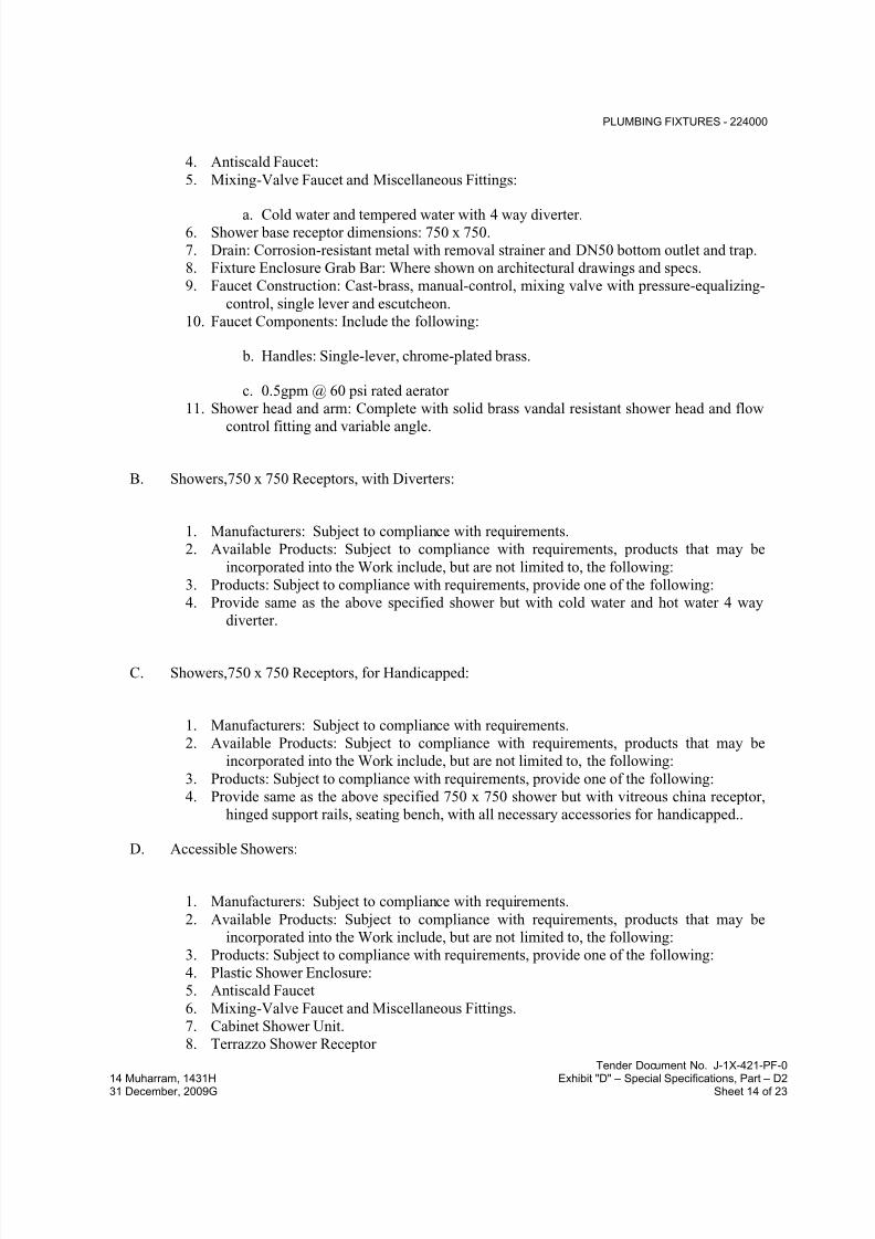
7/18/2019 SEC DPS
http://slidepdf.com/reader/full/sec-dps 520/541
PLUMBING FIXTURES - 224000
Tender Document No. J-1X-421-PF-0
14 Muharram, 1431H Exhibit "D" – Special Specifications, Part – D231 December, 2009G Sheet 14 of 23
4. Antiscald Faucet:
5. Mixing-Valve Faucet and Miscellaneous Fittings:
a. Cold water and tempered water with 4 way diverter.6. Shower base receptor dimensions: 750 x 750.
7. Drain: Corrosion-resistant metal with removal strainer and DN50 bottom outlet and trap.
8. Fixture Enclosure Grab Bar: Where shown on architectural drawings and specs.
9. Faucet Construction: Cast-brass, manual-control, mixing valve with pressure-equalizing-
control, single lever and escutcheon.
10. Faucet Components: Include the following:
b. Handles: Single-lever, chrome-plated brass.
c. 0.5gpm @ 60 psi rated aerator
11. Shower head and arm: Complete with solid brass vandal resistant shower head and flow
control fitting and variable angle.
B. Showers,750 x 750 Receptors, with Diverters:
1. Manufacturers: Subject to compliance with requirements.
2. Available Products: Subject to compliance with requirements, products that may be
incorporated into the Work include, but are not limited to, the following:
3. Products: Subject to compliance with requirements, provide one of the following:
4. Provide same as the above specified shower but with cold water and hot water 4 way
diverter.
C. Showers,750 x 750 Receptors, for Handicapped:
1. Manufacturers: Subject to compliance with requirements.
2. Available Products: Subject to compliance with requirements, products that may be
incorporated into the Work include, but are not limited to, the following:
3. Products: Subject to compliance with requirements, provide one of the following:
4. Provide same as the above specified 750 x 750 shower but with vitreous china receptor,
hinged support rails, seating bench, with all necessary accessories for handicapped..
D. Accessible Showers:
1. Manufacturers: Subject to compliance with requirements.
2. Available Products: Subject to compliance with requirements, products that may be
incorporated into the Work include, but are not limited to, the following:
3. Products: Subject to compliance with requirements, provide one of the following:
4. Plastic Shower Enclosure:
5. Antiscald Faucet
6. Mixing-Valve Faucet and Miscellaneous Fittings.
7. Cabinet Shower Unit.
8. Terrazzo Shower Receptor

7/18/2019 SEC DPS
http://slidepdf.com/reader/full/sec-dps 521/541
PLUMBING FIXTURES - 224000
Tender Document No. J-1X-421-PF-0
14 Muharram, 1431H Exhibit "D" – Special Specifications, Part – D231 December, 2009G Sheet 15 of 23
9. Fixture Enclosure: White
10. Fixture Enclosure: Built-in-place, Acrylic plastic with slip-resistant bathing surface.
11. Fixture Enclosure Dimensions
12. Fixture Enclosure Drain: Integral corrosion-resistant metal with removable strainer andDN50 bottom outlet.
13. Fixture Enclosure Grab Bar: Factory fabricated.
14. Shower Base Receptor: Precast terrazzo with threshold matching enclosure and slip-
resistant bathing surface. Include integral corrosion-resistant-metal drain with
removable strainer and DN50 bottom outlet.15. Shower Base Receptor Color:
16. Shower Base Receptor Dimensions: 1200 x 800
17. Faucet Construction: Cast-brass, dual, mixing valve with escutcheons, pressure-
equalizing-control with high-temperature-limit control and thermostatic-control, and 4
way diverter.
18. Faucet Components: Include the following:
19. Handle(s): Single lever, chrome-plated brass.20. Shower Head, Arm, and Flange: Manufacturer's standard with manual flow control in
head and variable angle.
21. Shower Arm, Flow-Control Fitting: 0.11L/s.
22. Hand Shower, Hose and Brackets or Slide: Manufacturer's standard.
23. Hose-Supply, Flow-Control Fitting: 0.11 L/s.
24. Supplies: Copper tubing with ball, gate, or globe valve if check stops not included with
faucet.
25. Drain:DN50, nickel-bronze-strainer, floor drain.
26. Trap: DN50 drainage piping.
2.8 BATHTUB SCHEDULE
A. Accessible Bathtub:
1. Manufacturers: Subject to compliance with requirements.
2. Available Products: Subject to compliance with requirements, products that may be
incorporated into the Work include, but are not limited to, the following:
3. Products: Subject to compliance with requirements, provide one of the following:
4. Porcelain Enameled , Steel Bathtub
5. Antiscald Bathtub Faucet
6. Mixing-Valve Faucet and Miscellaneous Fittings
7. Fixture Color: White8. Fixture Dimensions: 1700 x 800 or 1800 x 1800 as applicable.
9. Bathing Surface: Manufacturer's standard. Slip resistant. Surface to be provided with an
integral anti-slip strip.
10. Faucet Construction: 4-hole bath and shower mixer with pressure equalizing control.
11. Faucet Components: Include the following:
a. Handles(s); Dual, chrome-plated brass.
b. Tub Filler Spout: Manufacturer's standard.
c. Shower Diverter Valve: Manufacturer's standard with manual flow control in
head.
d. Shower Arm, Flow-Control Fitting: 0.11 L/s.
e. Hand Shower, on deck of fixture, Manufacturer's standard.
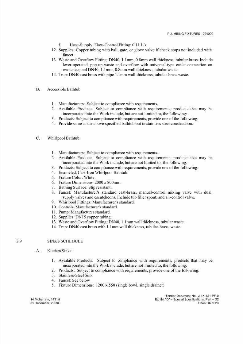
7/18/2019 SEC DPS
http://slidepdf.com/reader/full/sec-dps 522/541
PLUMBING FIXTURES - 224000
Tender Document No. J-1X-421-PF-0
14 Muharram, 1431H Exhibit "D" – Special Specifications, Part – D231 December, 2009G Sheet 16 of 23
f. Hose-Supply, Flow-Control Fitting: 0.11 L/s.
12. Supplies: Copper tubing with ball, gate, or glove valve if check stops not included with
faucet.
13. Waste and Overflow Fitting: DN40, 1.1mm, 0.8mm wall thickness, tubular brass. Includelever-operated, pop-up waste and overflow with universal-type outlet connection on
waste tee; and DN40, 1.1mm, 0.8mm wall thickness, tubular waste.
14. Trap: DN40 cast brass with pipe 1.1mm wall thickness, tubular-brass waste.
B. Accessible Bathtub:
1. Manufacturers: Subject to compliance with requirements.
2. Available Products: Subject to compliance with requirements, products that may be
incorporated into the Work include, but are not limited to, the following:
3. Products: Subject to compliance with requirements, provide one of the following:4. Provide same as the above specified bathtub but in stainless steel construction.
C. Whirlpool Bathtub:
1. Manufacturers: Subject to compliance with requirements.
2. Available Products: Subject to compliance with requirements, products that may be
incorporated into the Work include, but are not limited to, the following:
3. Products: Subject to compliance with requirements, provide one of the following:
4. Enameled, Cast-Iron Whirlpool Bathtub
5. Fixture Color: White6. Fixture Dimensions: 2000 x 800mm.
7. Bathing Surface: Slip resistant.
8. Faucet: Manufacturer's standard cast-brass, manual-control mixing valve with dual,
supply valves and escutcheons. Include tub filler spout, and air-control valve.
9. Whirlpool Fittings: Manufacturer's standard.
10. Controls: Manufacturer's standard.
11. Pump: Manufacturer standard.
12. Supplies: DN15 copper tubing.
13. Waste and Overflow Fitting: DN40, 1.1mm wall thickness, tubular waste.
14. Trap: DN40 cast brass with 1.1mm wall thickness, tubular-brass, waste.
2.9 SINKS SCHEDULE
A. Kitchen Sinks:
1. Available Products: Subject to compliance with requirements, products that may be
incorporated into the Work include, but are not limited to, the following:
2. Products: Subject to compliance with requirements, provide one of the following:
3. Stainless-Steel Sink:
4. Faucet: See below5. Fixture Dimensions: 1200 x 550 (single bowl, single drainer)

7/18/2019 SEC DPS
http://slidepdf.com/reader/full/sec-dps 523/541
PLUMBING FIXTURES - 224000
Tender Document No. J-1X-421-PF-0
14 Muharram, 1431H Exhibit "D" – Special Specifications, Part – D231 December, 2009G Sheet 17 of 23
6. Fixture Stainless-Steel Thickness: 1.3 mm Fixture Faucet-Hole Spacing: One hole,
centered
7. Fixture Mounting: Counter, self-rimming
8. Faucet Construction: Single-inlet and cast-brass underbody and brass escutcheon9. Faucet Mounting: Counter, centered on fixture
10. Faucet Components: Include the following:
a. Accessible-Fixture Operation: Manual
b. Handle[s]: Dual lever
c. Spout: Swing gooseneck
d. Spout Length, Centerline of Inlets to Outlet: 201 mm
e. Gooseneck Height and Offset 273 mm, Centerline of Inlets to Outlet: 185
mm
f. Spout Outlet: 0.032 L/s laminar flow
11. Supply Inlets: DN15, brass pipe or copper tubing
12. Supply Shutoff Valves: DN15 gate, globe, or ball.13. Supply Risers: DN10 flexible with knob end
14. Drain[s]: 38 mm grid strainer with DN40 tubular stainless-steel tailpiece
15. Continuous Waste: DN40tubular plastic with slip-joint inlet
16. Tubular Trap: DN40 plastic tubular fittings, with slip-joint inlet , cleanout, and wall
flange.
B. Kitchen Sinks Double-Bowl
1. Available Products: Subject to compliance with requirements, products that may be
incorporated into the Work include, but are not limited to, the following:2. Products: Subject to compliance with requirements, provide one of the following:
3. Similar to the above specified kitchen sink but with double bowl 1800x550mm.
C. Special Kitchen Sinks Double-Bowl
1. Available Products: Subject to compliance with requirements, products that may be
incorporated into the Work include, but are not limited to, the following:
2. Products: Subject to compliance with requirements, provide one of the following:
3. Similar to the above specified double bowl kitchen sink but 1.6 mm stainless steel
thickness.
4. Fixture mounting: Counter type.
5. Faucet construction: double inlet and chrome plated.
6. Faucet mounting: Wall type with dual lever.

7/18/2019 SEC DPS
http://slidepdf.com/reader/full/sec-dps 524/541
PLUMBING FIXTURES - 224000
Tender Document No. J-1X-421-PF-0
14 Muharram, 1431H Exhibit "D" – Special Specifications, Part – D231 December, 2009G Sheet 18 of 23
2.10 SERVICE SINKS
A. Mop-Service Sinks,:
1. Available Products: Subject to compliance with requirements, products that may be
incorporated into the Work include, but are not limited to, the following:
2. Products: Subject to compliance with requirements, provide one of the following:
3. Terrazzo Mop-Service Basin:
4. Faucet:
5. Fixture Dimensions: 450 by 400 mm 305 mm height
6. Mounting: Wall Hung with supporting legs]
7. Rim Guard: Chrome plated, brass
8. Faucet: 2 bib taps, widespread, cast brass with supplies on 203 mm centers.
9. Faucet Mounting: Wall, centered on fixture.
10. Faucet Components: Include the following:
a. Finish: Polished chrome.
b. Handles: One per faucet
c. Supply Stops: Integral, in shanks for cold and hot water.
d. Spout: With integral vacuum breaker, pail hook, and hose-thread outlet.
e. Wall Brace: Assembly with wall bracket and support to faucet spout.
f. 0.5 gpm @ 60 psi aerator
11. Drain: DN80 with grid strainer.
12. P-Trap: DN80 drainage piping.
13. Supplies: DN15 copper tubing with ball, gate, or globe valve.
2.11 ACCESSORIES FOR ABLUTION TROUGH
A. Accessories to include the following:
1. Manufacturers: Subject to compliance with requirements.
2. Products: Subject to compliance with requirements, provide one of the following:
3. 50mm grid strainer and 50mm drain outlet.
4. Wall mounted chrome plated bibs tap, supply DN 15mm
2.12 ELECTRIC WATER COOLER SCHEDULE
A. Electric Water Cooler:
1. Manufacturers: Subject to compliance with requirements.
2. Available Products: Subject to compliance with requirements, products that may beincorporated into the Work include, but are not limited to, the following:
3. Products: Subject to compliance with requirements, provide one of the following:
4. Fixture Type: Bubbler
5. No. of Bubblers or Stations: 2 level, one level for handicapped usage.
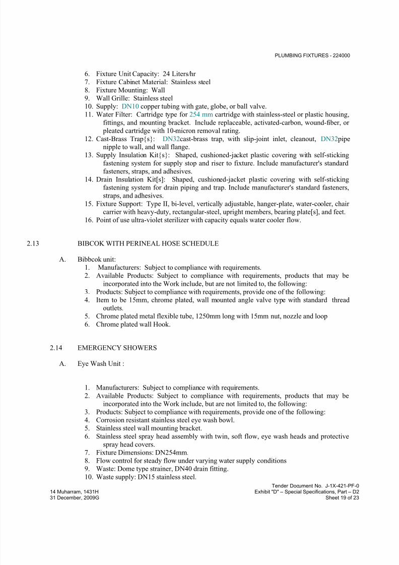
7/18/2019 SEC DPS
http://slidepdf.com/reader/full/sec-dps 525/541
PLUMBING FIXTURES - 224000
Tender Document No. J-1X-421-PF-0
14 Muharram, 1431H Exhibit "D" – Special Specifications, Part – D231 December, 2009G Sheet 19 of 23
6. Fixture Unit Capacity: 24 Liters/hr
7. Fixture Cabinet Material: Stainless steel
8. Fixture Mounting: Wall
9. Wall Grille: Stainless steel10. Supply: DN10 copper tubing with gate, globe, or ball valve.
11. Water Filter: Cartridge type for 254 mm cartridge with stainless-steel or plastic housing,
fittings, and mounting bracket. Include replaceable, activated-carbon, wound-fiber, or
pleated cartridge with 10-micron removal rating.
12. Cast-Brass Trap{s}: DN32cast-brass trap, with slip-joint inlet, cleanout, DN32 pipenipple to wall, and wall flange.
13. Supply Insulation Kit{s}: Shaped, cushioned-jacket plastic covering with self-sticking
fastening system for supply stop and riser to fixture. Include manufacturer's standard
fasteners, straps, and adhesives.
14. Drain Insulation Kit[s]: Shaped, cushioned-jacket plastic covering with self-sticking
fastening system for drain piping and trap. Include manufacturer's standard fasteners,
straps, and adhesives.15. Fixture Support: Type II, bi-level, vertically adjustable, hanger-plate, water-cooler, chair
carrier with heavy-duty, rectangular-steel, upright members, bearing plate[s], and feet.
16. Point of use ultra-violet sterilizer with capacity equals water cooler flow.
2.13 BIBCOK WITH PERINEAL HOSE SCHEDULE
A. Bibbcok unit:
1. Manufacturers: Subject to compliance with requirements.
2. Available Products: Subject to compliance with requirements, products that may be
incorporated into the Work include, but are not limited to, the following:
3. Products: Subject to compliance with requirements, provide one of the following:4. Item to be 15mm, chrome plated, wall mounted angle valve type with standard thread
outlets.
5. Chrome plated metal flexible tube, 1250mm long with 15mm nut, nozzle and loop
6. Chrome plated wall Hook.
2.14 EMERGENCY SHOWERS
A. Eye Wash Unit :
1. Manufacturers: Subject to compliance with requirements.
2. Available Products: Subject to compliance with requirements, products that may be
incorporated into the Work include, but are not limited to, the following:
3. Products: Subject to compliance with requirements, provide one of the following:
4. Corrosion resistant stainless steel eye wash bowl.
5. Stainless steel wall mounting bracket.
6. Stainless steel spray head assembly with twin, soft flow, eye wash heads and protective
spray head covers.
7. Fixture Dimensions: DN254mm.
8. Flow control for steady flow under varying water supply conditions
9. Waste: Dome type strainer, DN40 drain fitting.
10. Waste supply: DN15 stainless steel.
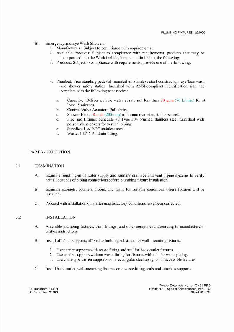
7/18/2019 SEC DPS
http://slidepdf.com/reader/full/sec-dps 526/541
PLUMBING FIXTURES - 224000
Tender Document No. J-1X-421-PF-0
14 Muharram, 1431H Exhibit "D" – Special Specifications, Part – D231 December, 2009G Sheet 20 of 23
B. Emergency and Eye Wash Showers:
1. Manufacturers: Subject to compliance with requirements.
2. Available Products: Subject to compliance with requirements, products that may be
incorporated into the Work include, but are not limited to, the following:3. Products: Subject to compliance with requirements, provide one of the following:
4. Plumbed, Free standing pedestal mounted all stainless steel construction eye/face wash
and shower safety station, furnished with ANSI-compliant identification sign and
complete with the following accessories:
a. Capacity: Deliver potable water at rate not less than 20 gpm (76 L/min.) for at
least 15 minutes.
b. Control-Valve Actuator: Pull chain.
c. Shower Head: 8-inch (200-mm) minimum diameter, stainless steel.d. Pipe and fittings: Schedule 40 Type 304 brushed stainless steel furnished with
polyethylene covers for vertical piping.
e. Supplies: 1 ¼” NPT stainless steel.
f. Waste: 1 ¼” NPT drain fitting.
PART 3 - EXECUTION
3.1 EXAMINATION
A. Examine roughing-in of water supply and sanitary drainage and vent piping systems to verify
actual locations of piping connections before plumbing fixture installation.
B. Examine cabinets, counters, floors, and walls for suitable conditions where fixtures will be
installed.
C. Proceed with installation only after unsatisfactory conditions have been corrected.
3.2 INSTALLATION
A. Assemble plumbing fixtures, trim, fittings, and other components according to manufacturers'
written instructions.
B. Install off-floor supports, affixed to building substrate, for wall-mounting fixtures.
1. Use carrier supports with waste fitting and seal for back-outlet fixtures.
2. Use carrier supports without waste fitting for fixtures with tubular waste piping.
3. Use chair-type carrier supports with rectangular steel uprights for accessible fixtures.
C. Install back-outlet, wall-mounting fixtures onto waste fitting seals and attach to supports.
7/18/2019 SEC DPS
http://slidepdf.com/reader/full/sec-dps 527/541
PLUMBING FIXTURES - 224000
Tender Document No. J-1X-421-PF-0
14 Muharram, 1431H Exhibit "D" – Special Specifications, Part – D231 December, 2009G Sheet 21 of 23
D. Install floor-mounting fixtures on closet flanges or other attachments to piping or building
substrate.
E. Install wall-mounting fixtures with tubular waste piping attached to supports.
F. Install floor-mounting, back-outlet water closets attached to building floor substrate and wall
bracket and onto waste fitting seals.
G. Install counter-mounting fixtures in and attached to casework.
H. Install fixtures level and plumb according to roughing-in drawings.
I. Install water-supply piping with stop on each supply to each fixture to be connected to water
distribution piping. Attach supplies to supports or substrate within pipe spaces behind fixtures.
Install stops in locations where they can be easily reached for operation.
1. Exception: Use ball, gate, or globe valves if supply stops are not specified with fixture.
Valves are specified in Division 22 Section "General-Duty Valves for Plumbing
Piping."
J. Install trap and tubular waste piping on drain outlet of each fixture to be directly connected tosanitary drainage system.
K. Install tubular waste piping on drain outlet of each fixture to be indirectly connected to drainage
system.
L. Install tanks for accessible, tank-type water closets with lever handle mounted on wide side of
compartment.
M. Install toilet seats on water closets.
N. Install faucet-spout fittings with specified flow rates and patterns in faucet spouts if faucets are
not available with required rates and patterns. Include adapters if required.
O. Install traps on fixture outlets.
P. Install escutcheons at piping wall ceiling penetrations in exposed, finished locations and within
cabinets and millwork. Use deep-pattern escutcheons if required to conceal protruding fittings.
Escutcheons are specified in Division 22 Section "Common Work Results for Plumbing."
Q. Set shower receptors in leveling bed of cement grout. Grout is specified in Division 22 Section"Common Work Results for Plumbing."
R. Seal joints between fixtures and walls, floors, and countertops using sanitary-type, one-part,
mildew-resistant silicone sealant. Match sealant color to fixture color. Sealants are specified in
Division 07 Section "Joint Sealants."

7/18/2019 SEC DPS
http://slidepdf.com/reader/full/sec-dps 528/541
PLUMBING FIXTURES - 224000
Tender Document No. J-1X-421-PF-0
14 Muharram, 1431H Exhibit "D" – Special Specifications, Part – D231 December, 2009G Sheet 22 of 23
3.3 CONNECTIONS
A. Piping installation requirements are specified in other Division 22 Sections. Drawings indicate
general arrangement of piping, fittings, and specialties.
B. Connect fixtures with water supplies, stops, and risers, and with traps, soil, waste, and vent
piping. Use size fittings required to match fixtures.
C. Ground equipment according to Division 26 Section "Grounding and Bonding for Electrical
Systems."
D. Connect wiring according to Division 26 Section "Low-Voltage Electrical Power Conductors
and Cables."
3.4 FIELD QUALITY CONTROL
A. Verify that installed plumbing fixtures are categories and types specified for locations where
installed.
B. Check that plumbing fixtures are complete with trim, faucets, fittings, and other specified
components.
C. Inspect installed plumbing fixtures for damage. Replace damaged fixtures and components.
D. Test installed fixtures after water systems are pressurized for proper operation. Replace
malfunctioning fixtures and components, then retest. Repeat procedure until units operate
properly.
E. Install fresh batteries in sensor-operated mechanisms.
3.5 ADJUSTING
A. Operate and adjust faucets and controls. Replace damaged and malfunctioning fixtures, fittings,
and controls.
B. Adjust water pressure at faucets to produce proper flow and stream.
C. Replace washers and seals of leaking and dripping faucets and stops.
D. Install fresh batteries in sensor-operated mechanisms.
3.6 CLEANING
A. Clean fixtures, faucets, and other fittings with manufacturers' recommended cleaning methods
and materials. Do the following:
1. Remove faucet spouts and strainers, remove sediment and debris, and reinstall strainers
and spouts.

7/18/2019 SEC DPS
http://slidepdf.com/reader/full/sec-dps 529/541
PLUMBING FIXTURES - 224000
Tender Document No. J-1X-421-PF-0
14 Muharram, 1431H Exhibit "D" – Special Specifications, Part – D231 December, 2009G Sheet 23 of 23
2. Remove sediment and debris from drains.
B. After completing installation of exposed, factory-finished fixtures, faucets, and fittings, inspect
exposed finishes and repair damaged finishes.
3.7 PROTECTION
A. Provide protective covering for installed fixtures and fittings.
B. Do not allow use of plumbing fixtures for temporary facilities unless approved in writing by
Owner.
END OF SECTION 224000

7/18/2019 SEC DPS
http://slidepdf.com/reader/full/sec-dps 530/541
REFRIGERATED DRINKING FOUNTAINS - 224700
Tender Document No. J-1X-421-PF-0
14 Muharram, 1431H Exhibit "D" – Special Specifications, Part – D231 December, 2009G Sheet 1 of 5
SECTION 224700 – REFRIGERATED DRINKING FOUNTAINS
PART 1 - GENERAL
1.1 RELATED DOCUMENTS
A. Drawings and general provisions of the Contract, including General and Supplementary
Conditions and Division 01 Specification Sections, apply to this Section.
1.2 SUMMARY
A. This Section includes the following refrigerated drinking fountains and related components:
1. Pressure refrigerated drinking fountains.
2. Fixture supports.
1.3 DEFINITIONS
A. Accessible Refrigerated Drinking Fountain: Fixture that can be approached and used by people
with disabilities.
B. Cast Polymer: Dense, cast-filled-polymer plastic.
C. Fitting: Device that controls flow of water into or out of fixture.
D. Fixture: refrigerated drinking fountain .
E. Refrigerated drinking fountain: Electrically powered fixture for generating and delivering
cooled drinking water.
1.4 SUBMITTALS
A. Product Data: For each fixture indicated. Include rated capacities, furnished specialties, andaccessories.
B. Shop Drawings: Diagram power, signal, and control wiring.
C. Field quality-control test reports.
D. Operation and Maintenance Data: For fixtures to include in emergency, operation, and
maintenance manuals.

7/18/2019 SEC DPS
http://slidepdf.com/reader/full/sec-dps 531/541
REFRIGERATED DRINKING FOUNTAINS - 224700
Tender Document No. J-1X-421-PF-0
14 Muharram, 1431H Exhibit "D" – Special Specifications, Part – D231 December, 2009G Sheet 2 of 5
1.5 QUALITY ASSURANCE
A. Electrical Components, Devices, and Accessories: Listed and labeled as defined in NFPA 70,
Article 100, by a testing agency acceptable to authorities having jurisdiction, and marked forintended use.
B. Regulatory Requirements: Comply with requirements in ICC A117.1, "Accessible and Usable
Buildings and Facilities" Public Law 90-480, "Architectural Barriers Act" ; and Public
Law 101-336, "Americans with Disabilities Act" ; for fixtures for people with disabilities.
C. NSF Standard: Comply with NSF 61, "Drinking Water System Components--Health Effects,"
for fixture materials that will be in contact with potable water.
D. ARI Standard: Comply with ARI's "Directory of Certified Drinking Water Coolers" for style
classifications.
E. ARI Standard: Comply with ARI 1010, "Self-Contained, Mechanically Refrigerated Drinking-
Water Coolers," for water coolers and with ARI's "Directory of Certified Drinking Water
Coolers" for type and style classifications.
F. ASHRAE Standard: Comply with ASHRAE 34, "Designation and Safety Classification of
Refrigerants," for refrigerated drinking fountains. Provide HFC 134a (tetrafluoroethane)
refrigerant, unless otherwise indicated.
PART 2 - PRODUCTS
2.1 PRESSURE REFRIGERATED DRINKING FOUNTAINS
A. Refrigerated Drinking Fountains:
1. Manufacturers: Subject to compliance with requirements.
2. Description: ARI 1010, Type PB, pressure with bubbler, Style F, freestanding
refrigerated drinking fountain.
a. Cabinet: All stainless steel.
b. Bubbler: One, with adjustable stream regulator, located on deck.
c. Control: Foot pedal.
d. Supply: NPS 3/8 (DN 10) with ball, gate, or globe valve.e. Drain: Grid with NPS 1-1/4 (DN 32) minimum horizontal waste and trap
complying with ASME A112.18.2.
f. Cooling System: Electric, with hermetically sealed compressor, cooling coil, air-
cooled condensing unit, corrosion-resistant tubing, refrigerant, corrosion-resistant-
metal storage tank, and adjustable thermostat.
1) Capacity: 10 gph (0.0105 L/s)14 gph (0.0147 L/s)
2) Electrical Characteristics: As shown on drawings
7/18/2019 SEC DPS
http://slidepdf.com/reader/full/sec-dps 532/541
REFRIGERATED DRINKING FOUNTAINS - 224700
Tender Document No. J-1X-421-PF-0
14 Muharram, 1431H Exhibit "D" – Special Specifications, Part – D231 December, 2009G Sheet 3 of 5
2.2 FIXTURE SUPPORTS
A. Manufacturers: Subject to compliance with requirements.
B. Description: ASME A112.6.1M, refrigerated drinking fountain carriers. Include vertical, steel
uprights with feet and tie rods and bearing plates with mounting studs matching fixture to be
supported.
1. Type I: Hanger-type carrier with two vertical uprights.
2. Type II: Bilevel, hanger-type carrier with three vertical uprights.
3. Supports for Accessible Fixtures: Include rectangular, vertical, steel uprights instead of
steel pipe uprights.
PART 3 - EXECUTION
3.1 EXAMINATION
A. Examine roughing-in for water and waste piping systems to verify actual locations of piping
connections before fixture installation. Verify that sizes and locations of piping and types ofsupports match those indicated.
B. Examine walls and floors for suitable conditions where fixtures are to be installed.
C. Proceed with installation only after unsatisfactory conditions have been corrected.
3.2 APPLICATIONS
A. Set freestanding and pedestal drinking fountains on floor.
B. Use chrome-plated brass or copper tube, fittings, and valves in locations exposed to view. Plain
copper tube, fittings, and valves may be used in concealed locations.
3.3 INSTALLATION
A. Install off-floor supports affixed to building substrate and attach wall-mounting fixtures, unlessotherwise indicated.
B. Install mounting frames affixed to building construction and attach recessed refrigerated
drinking fountains to mounting frames, unless otherwise indicated.
C. Install fixtures level and plumb. For fixtures indicated for children, install at height required by
authorities having jurisdiction.
D. Install water-supply piping with shutoff valve on supply to each fixture to be connected to water
distribution piping. Use ball, gate, or globe valve. Install valves in locations where they can be

7/18/2019 SEC DPS
http://slidepdf.com/reader/full/sec-dps 533/541
REFRIGERATED DRINKING FOUNTAINS - 224700
Tender Document No. J-1X-421-PF-0
14 Muharram, 1431H Exhibit "D" – Special Specifications, Part – D231 December, 2009G Sheet 4 of 5
easily reached for operation. Valves are specified in Division 22 Section "General-Duty Valves
for Plumbing Piping."
E. Install trap and waste piping on drain outlet of each fixture to be connected to sanitary drainagesystem.
F. Install pipe escutcheons at wall penetrations in exposed, finished locations. Use deep-pattern
escutcheons where required to conceal protruding pipe fittings. Escutcheons are specified in
Division 22 Section "Common Work Results for Plumbing."
G. Seal joints between fixtures and walls and floors using sanitary-type, one-part, mildew-resistant,
silicone sealant. Match sealant color to fixture color. Sealants are specified in Division 07
Section "Joint Sealants."
3.4 CONNECTIONS
A. Piping installation requirements are specified in other Division 22 Sections. Drawings indicate
general arrangement of piping, fittings, and specialties.
B. Connect fixtures with water supplies, stops, and risers, and with traps, soil, waste, and vent piping. Use size fittings required to match fixtures.
C. Ground equipment according to Division 26 Section "Grounding and Bonding for Electrical
Systems."
D. Connect wiring according to Division 26 Section "Low-Voltage Electrical Power Conductors
and Cables."
3.5 FIELD QUALITY CONTROL
A. Refrigerated Drinking Fountain Testing: After electrical circuitry has been energized, test for
compliance with requirements. Test and adjust controls and safeties.
1. Remove and replace malfunctioning units and retest as specified above.
2. Report test results in writing.
3.6 ADJUSTING
A. Adjust fixture flow regulators for proper flow and stream height.
B. Adjust refrigerated drinking fountain temperature settings.
3.7 CLEANING
A. After completing fixture installation, inspect unit. Remove paint splatters and other spots, dirt,
and debris. Repair damaged finish to match original finish.

7/18/2019 SEC DPS
http://slidepdf.com/reader/full/sec-dps 534/541
REFRIGERATED DRINKING FOUNTAINS - 224700
Tender Document No. J-1X-421-PF-0
14 Muharram, 1431H Exhibit "D" – Special Specifications, Part – D231 December, 2009G Sheet 5 of 5
B. Clean fixtures, on completion of installation, according to manufacturer's written instructions.
END OF SECTION 224700

7/18/2019 SEC DPS
http://slidepdf.com/reader/full/sec-dps 535/541
DECORATIVE FOUNTAIN - 224800
Tender Document No. J-1X-421-PF-014 Muharram, 1431H Exhibit "D" – Special Specifications, Part – D231 December, 2009G Sheet 1 of 8
SECTION 224800 - DECORATIVE FOUNTAIN
PART 1 - GENERAL
1.1 RELATED DOCUMENTS
A. Drawings and special provisions of the contract, including general and supplementary
conditions and Division 1 Specification sections apply to this section.
1.2 SCOPE OF WORK
A. The work referred to in this section consists of design, installation, furnishing all labor and
material required, providing and delivering all equipment hereinafter specified, uncrating,
assembling, hanging, setting in place, leveling, and completely installing, decorative water
fountains.
B. Mockup Testing: The Contractor shall design and operate mockup water fountain(s) similar to
the specified water fountains. Dimension of mockup water fountain(s) shall be as directed by
the Engineer. The mockup water fountain(s) shall be produced and fabricated to give the same
effect of the water fountain.
C. Piping materials and equipment specified in this Section include:
1. Pipes and fittings.
2. Special duty valves.
3. Fountain specialities.
4. Filters.5. Special pumps and accessories.
D. The drawings indicate location of the fountain, schematic diagrams showing the equipment to
be installed and tentative schedule of equipment. The Contractor shall submit for the
Engineer’s approval full design calculation, drawings and catalog cuts based on the actual
equipment selection and the design criteria mentioned in the Specification. The Contractor
shall refer to the Landscape and Mechanical drawings.
E. Show on roughing in plans the sizes, utilities, and other requirements as furnished in the
Specification, by the Employer or appropriate supplier in submittals as if the equipment is
Construction Manager furnished.
F. Startup Services: Engage factory-authorized service representatives to perform startup
services and to demonstrate and train the Employer's maintenance personnel.
G. The design of the equipment shall be such as to provide for safe and convenient operation.
Covers or other safety devices shall be provided for all items of equipment presenting safety
hazards.
7/18/2019 SEC DPS
http://slidepdf.com/reader/full/sec-dps 536/541
DECORATIVE FOUNTAIN - 224800
Tender Document No. J-1X-421-PF-014 Muharram, 1431H Exhibit "D" – Special Specifications, Part – D231 December, 2009G Sheet 2 of 8
1.3 PROJECT CONDITIONS
A. Visit the job site to field check actual situation and be responsible for furnishing, fabricating,
and installing the equipment in accordance with the available space and utility services as they
exist on the job site.
B. Physically check the location and utility size at the job site.
C. Check electrical characteristics and water pressure. Provide pressure-regulating valves where
required for proper operation of equipment.
1.4 SUBMITTALS
A. Product data for each fountain filter, pumps, nozzles, drains, piping specialty and special duty
valves. Include the following:
1. Character and dimensions of the display elements consistent with visibility and sound
levels appropriate to the site program and characteristics.2. Underwater lighting, including composition, location and installation details.
3. Dimensions, profiles, colors and finishes for the pools and related structures.
4. Rated capacities dimensions and location of selected models, furnished specialties and
accessories, and installation instructions.
5. Configuration, location and color of pool fittings.
B. Shop drawings detailing dimensions, required clearances for fountain distribution piping
systems in accordance with "Basic Mechanical Materials and Methods" Section.
C. Manufacturer Seismic Qualification Certification: Submit certification that heat exchangers,
accessories, and components will withstand seismic forces defined in 'Mechanical Vibration
and Seismic Controls" Section. Include the following:
1. Basis for Certification: Indicate whether withstand certification is based on actual test
of assembled components or on calculation.
a. The term "withstand" means "the unit will remain in place without separation of
any parts from the device when subjected to the seismic forces specified."
b. The term "withstand" means "the unit will remain in place without separation of
any parts from the device when subjected to the seismic forces specified and the
unit will be fully operational after the seismic event."
2. Dimensional Outline Drawings of Equipment Unit: Identify center of gravity and locate
and describe mounting and anchorage provisions.
3. Details description of equipment anchorage devices on which the certification is based
and their installation requirements.
D. Maintenance data for fountain filters, pumps, nozzles, drains, piping specialties and special
duty valves, for inclusion in operating and maintenance manual specified in the General
Requirements and "Basic Mechanical Materials and Methods" Section.
E. Test reports specified in Part 3 below.
1.5 QUALITY ASSURANCE
7/18/2019 SEC DPS
http://slidepdf.com/reader/full/sec-dps 537/541
DECORATIVE FOUNTAIN - 224800
Tender Document No. J-1X-421-PF-014 Muharram, 1431H Exhibit "D" – Special Specifications, Part – D231 December, 2009G Sheet 3 of 8
A. Guarantee: Provide written guarantee that when fountain pool equipment is operated in
accordance with manufacturer's instructions, fountain pool water will be crystal clear,
sparkling bright, free from suspended matter and completely sterilized at all times.
B. Water to be Clear: When fountain pool is in use, water shall be sufficiently clear to permit a
150 mm diameter black disc on a white background placed on bottom of pool to be clearly
visible from side walls of pool at all distances up to 10 m measured from a line drawn across
the disc.
C. Water to be Sterile: When fountain pool is in use not more than 15% of samples of water
taken covering any considerable period shall contain more than 200 bacteria per millilitre or
are to show positive test in any of five 10 ml samples of water. Primary fermentation tubes
showing gas shall be confirmed.
D. Free residual chlorine in water at all times shall be not less than 0.7 ppm and not more than
1.5 ppm in order to prevent any algae growth.
E. PH of water at all times shall be not less than 7.2 and not more than 7.8 in order to prevent
any algae growth.
F. Water Quality: Make chemical and bacterial analysis in accordance with procedures
recommended in the Standard Methods of the Examination of Water, Sewage and Industrial
Wastes of the American Public Health Association insofar as these methods are applicable to
fountain pool water.
G. Performance Tests: Carry out tests as necessary and as directed to demonstrate that equipment
meets design requirements as noted on the Drawings and in the Specification.
H. Qualified engineer or technician from equipment manufacturer shall supervise installation,
start-up equipment, make necessary adjustments, calibrations and tests in accordance with
manufacturer's instructions and instruct and train the personnel.
PART 2 - PRODUCTS
2.1 PIPE AND TUBING MATERIALS
A. Pipe and Fittings: Pressure PVC to BS 3505 and BS EN 1452 Class E and fittings.
2.2 FITTINGS
A. Fittings shall be integral parallel sockets with solvent welded joints.
2.3 JOINING MATERIALS
A. Sealing rings on PVC pipe shall provide for expansion and contraction to be rubber to BS EN
681.
2.4 VALVES
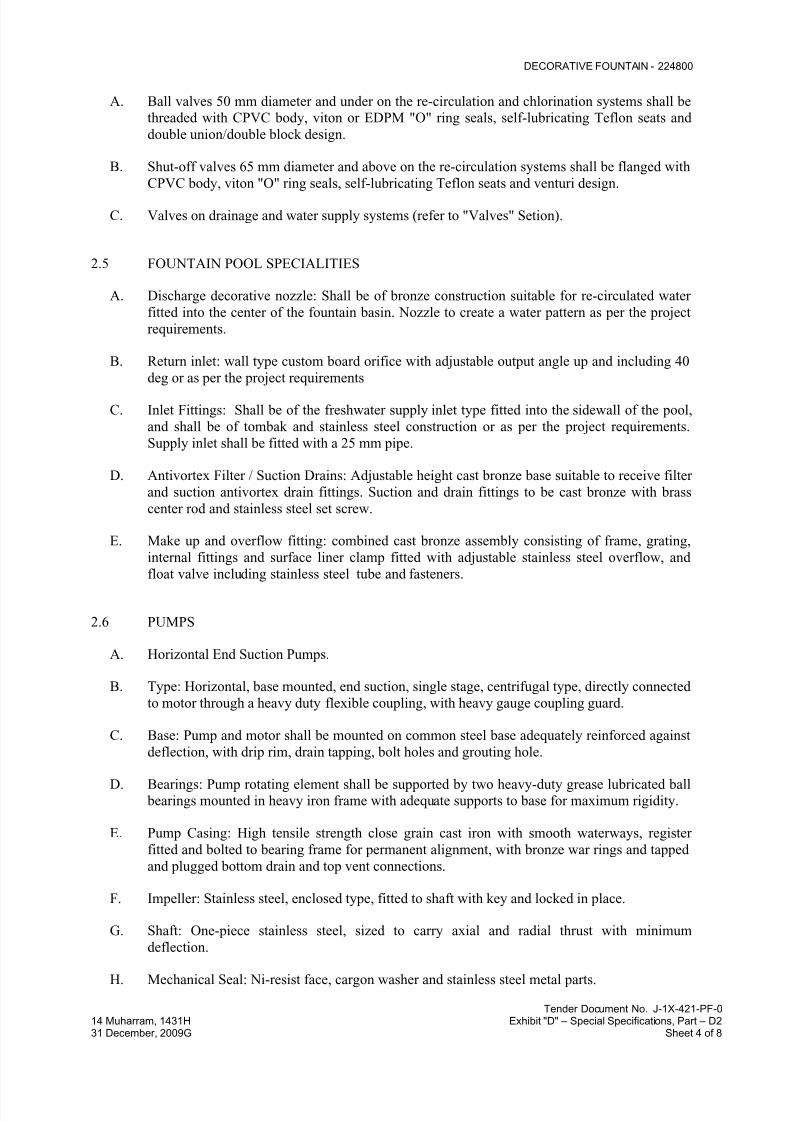
7/18/2019 SEC DPS
http://slidepdf.com/reader/full/sec-dps 538/541
DECORATIVE FOUNTAIN - 224800
Tender Document No. J-1X-421-PF-014 Muharram, 1431H Exhibit "D" – Special Specifications, Part – D231 December, 2009G Sheet 4 of 8
A. Ball valves 50 mm diameter and under on the re-circulation and chlorination systems shall be
threaded with CPVC body, viton or EDPM "O" ring seals, self-lubricating Teflon seats and
double union/double block design.
B. Shut-off valves 65 mm diameter and above on the re-circulation systems shall be flanged with
CPVC body, viton "O" ring seals, self-lubricating Teflon seats and venturi design.
C. Valves on drainage and water supply systems (refer to "Valves" Setion).
2.5 FOUNTAIN POOL SPECIALITIES
A. Discharge decorative nozzle: Shall be of bronze construction suitable for re-circulated water
fitted into the center of the fountain basin. Nozzle to create a water pattern as per the project
requirements.
B. Return inlet: wall type custom board orifice with adjustable output angle up and including 40
deg or as per the project requirements
C. Inlet Fittings: Shall be of the freshwater supply inlet type fitted into the sidewall of the pool,
and shall be of tombak and stainless steel construction or as per the project requirements.
Supply inlet shall be fitted with a 25 mm pipe.
D. Antivortex Filter / Suction Drains: Adjustable height cast bronze base suitable to receive filter
and suction antivortex drain fittings. Suction and drain fittings to be cast bronze with brass
center rod and stainless steel set screw.
E. Make up and overflow fitting: combined cast bronze assembly consisting of frame, grating,
internal fittings and surface liner clamp fitted with adjustable stainless steel overflow, and
float valve including stainless steel tube and fasteners.
2.6 PUMPS
A. Horizontal End Suction Pumps.
B. Type: Horizontal, base mounted, end suction, single stage, centrifugal type, directly connected
to motor through a heavy duty flexible coupling, with heavy gauge coupling guard.
C. Base: Pump and motor shall be mounted on common steel base adequately reinforced against
deflection, with drip rim, drain tapping, bolt holes and grouting hole.
D. Bearings: Pump rotating element shall be supported by two heavy-duty grease lubricated ball
bearings mounted in heavy iron frame with adequate supports to base for maximum rigidity.
E. Pump Casing: High tensile strength close grain cast iron with smooth waterways, register
fitted and bolted to bearing frame for permanent alignment, with bronze war rings and tapped
and plugged bottom drain and top vent connections.
F. Impeller: Stainless steel, enclosed type, fitted to shaft with key and locked in place.
G. Shaft: One-piece stainless steel, sized to carry axial and radial thrust with minimum
deflection.
H. Mechanical Seal: Ni-resist face, cargon washer and stainless steel metal parts.
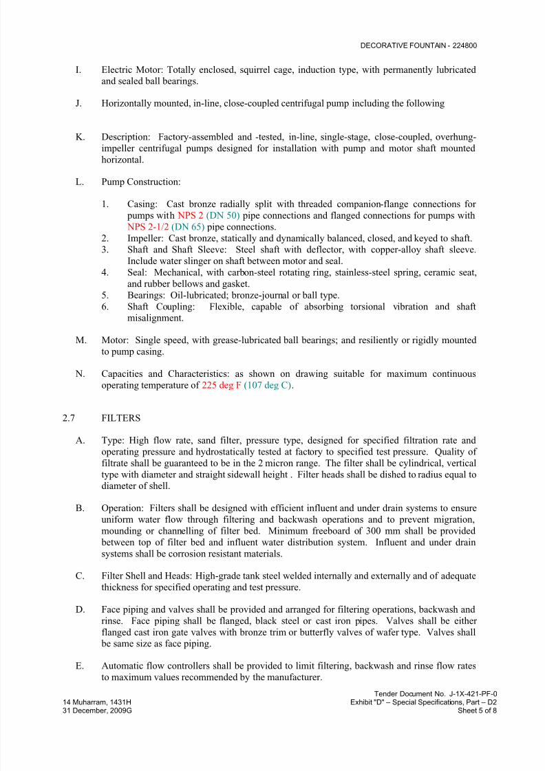
7/18/2019 SEC DPS
http://slidepdf.com/reader/full/sec-dps 539/541
DECORATIVE FOUNTAIN - 224800
Tender Document No. J-1X-421-PF-014 Muharram, 1431H Exhibit "D" – Special Specifications, Part – D231 December, 2009G Sheet 5 of 8
I. Electric Motor: Totally enclosed, squirrel cage, induction type, with permanently lubricated
and sealed ball bearings.
J. Horizontally mounted, in-line, close-coupled centrifugal pump including the following
K. Description: Factory-assembled and -tested, in-line, single-stage, close-coupled, overhung-impeller centrifugal pumps designed for installation with pump and motor shaft mounted
horizontal.
L. Pump Construction:
1. Casing: Cast bronze radially split with threaded companion-flange connections for
pumps with NPS 2 (DN 50) pipe connections and flanged connections for pumps with
NPS 2-1/2 (DN 65) pipe connections.
2. Impeller: Cast bronze, statically and dynamically balanced, closed, and keyed to shaft.
3. Shaft and Shaft Sleeve: Steel shaft with deflector, with copper-alloy shaft sleeve.
Include water slinger on shaft between motor and seal.
4. Seal: Mechanical, with carbon-steel rotating ring, stainless-steel spring, ceramic seat,
and rubber bellows and gasket.
5. Bearings: Oil-lubricated; bronze-journal or ball type.
6. Shaft Coupling: Flexible, capable of absorbing torsional vibration and shaft
misalignment.
M. Motor: Single speed, with grease-lubricated ball bearings; and resiliently or rigidly mounted
to pump casing.
N. Capacities and Characteristics: as shown on drawing suitable for maximum continuous
operating temperature of 225 deg F (107 deg C).
2.7 FILTERS
A. Type: High flow rate, sand filter, pressure type, designed for specified filtration rate and
operating pressure and hydrostatically tested at factory to specified test pressure. Quality of
filtrate shall be guaranteed to be in the 2 micron range. The filter shall be cylindrical, vertical
type with diameter and straight sidewall height . Filter heads shall be dished to radius equal to
diameter of shell.
B. Operation: Filters shall be designed with efficient influent and under drain systems to ensure
uniform water flow through filtering and backwash operations and to prevent migration,
mounding or channelling of filter bed. Minimum freeboard of 300 mm shall be provided between top of filter bed and influent water distribution system. Influent and under drain
systems shall be corrosion resistant materials.
C. Filter Shell and Heads: High-grade tank steel welded internally and externally and of adequate
thickness for specified operating and test pressure.
D. Face piping and valves shall be provided and arranged for filtering operations, backwash and
rinse. Face piping shall be flanged, black steel or cast iron pipes. Valves shall be either
flanged cast iron gate valves with bronze trim or butterfly valves of wafer type. Valves shall
be same size as face piping.
E. Automatic flow controllers shall be provided to limit filtering, backwash and rinse flow ratesto maximum values recommended by the manufacturer.

7/18/2019 SEC DPS
http://slidepdf.com/reader/full/sec-dps 540/541
DECORATIVE FOUNTAIN - 224800
Tender Document No. J-1X-421-PF-014 Muharram, 1431H Exhibit "D" – Special Specifications, Part – D231 December, 2009G Sheet 6 of 8
F. Accessories: Filters shall be complete with the following accessories and appurtenances:
1. Standard size manhole on top dished head with boiler type cover.
2. Four jack type supports individually adjustable for filter level adjustment and of
adequate strength to carry filter contents.
3. Automatic air release valve on top dished head.
4. Gauge panel of cast bronze with two 100 mm minimum diameter dial pressure gauges
connected with copper tubes to filter inlet and outlet connections.
5. Filter drain valve.
6. Substantial lifting lugs.
G. Paint: Supply filters painted inside and outside with two coats of chemical resistant epoxy
paint.
H. Filter Media: Shall be as recommended and as provided by the filter manufacturer specifically
for the filters. Components shall be shipped separately in clearly marked bags. Provide clear
instructions for field application of filter media in filters.
I. Filter Media: Shall be graded rock and gravel to fine sand from bottom up, in layers of
thickness to manufacturer's recommendations.
J. Rock and Gravel: Clean, hard, round stones with average specific gravity of not less than 2.5,
free from shale, mica, clay, sandstone, sand, loam or other impurities. Gravel is not to have
more than 2% by weight of thin, flat or elongated pieces.
K. Sand: Hard, durable grains of round or subangular silica sand, free from clay, loam, dirt and
organic matter. Not more than 1% to be flat or micaceous particles. Sand shall meet screen
requirements given in the following table and have effective size of 0.35 to 0.45 mm and
uniformity coefficient of 1.45 to 1.69.
Sand Screen Requirements
Sieve No. % Retained on % Passing Through
U.S. Tyler Successive
Screens
Successive Screens
16 14 0 - 6 94 - 100
20 20 3 - 23 71 - 97
30 28 24 - 40 31 - 73
40 36 43 - 25 6 - 25
50 43 22 - 6 0 - 3
L. Manufacturers: Filter as manufactured by “GULF POOL EQUIPMENT CO.” or approved
equal.
2.8 CHLORINATION SYSTEM
A. Chlorinator: to be constructed from inalterable plastic with a capacity of 10 Kg chloride ,suitable for fountain installation with similar volumes. The chlorinator is to be equipped with

7/18/2019 SEC DPS
http://slidepdf.com/reader/full/sec-dps 541/541
DECORATIVE FOUNTAIN - 224800
inlet and outlet regulation valves capable of maintaining acceptable post chloride residual
level
2.9 SUNDRIES
A. Strainers on pump suctions shall be straight, in-line, flanged or threaded type, designed forfountain pools, with cast iron body and stainless steel basket, suitable for working pressure of
200 kPa and with quick opening cover lid, positively sealing O-ring, yoke type cover clamp
with threaded tightening bolt and drain plug.
B. Flow Meters: Orifice type with direct reading manometer having indicating fluid other than
mercury, complete with flanges, orifice plate, piping to orifice flanges and by-pass piping and
suitable for measuring design flows.
C. Flow meters shall be as manufactured by “MERIAM” or approved equal.