sea lance -
TRANSCRIPT
NAVAL POSTGRADUATE SCHOOL Monterey, California
Technical Report
Approved for public release, distribution unlimited.
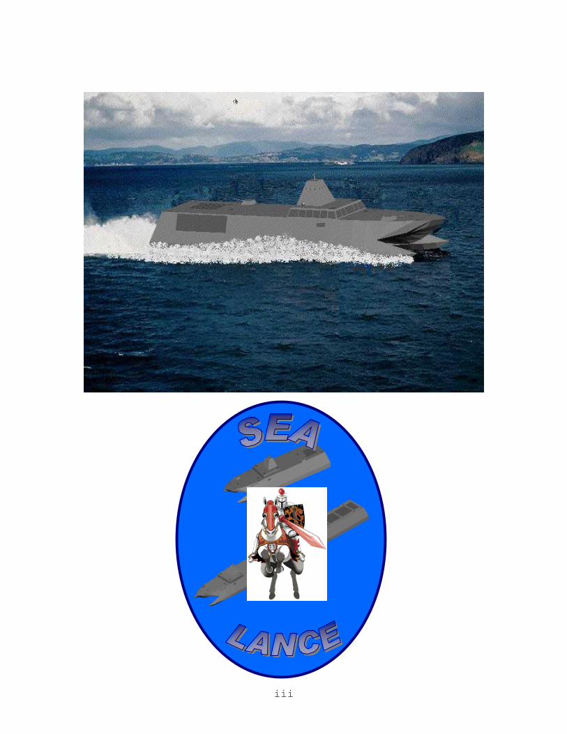
“SEA LANCE” LITTORAL WARFARE SMALL COMBATANT SYSTEM
By
Faculty Members Charles Calvano David Byers Robert Harney Fotis Papoulias
John Ciezki
Student Members LT Howard Markle, USN, Team Leader
LT Rick Trevisan, USN LT Tim Barney, USN LT Karl Eimers, USN
LCDR Garrett Farman, USN LTjg Ahmet Altekin, Turkish Navy LT Ricardo Kompatzki, Chilean Navy
LT Chris Nash, USN
January 2001
NPS-ME-01-001
ii
REPORT DOCUMENTATION PAGE Form Approved OMB No.
0704-0188 Public reporting burden for this collection of information is estimated to average 1 hour per response, including the time for reviewing instruction, searching existing data sources, gathering and maintaining the data needed, and completing and reviewing the collection of information. Send comments regarding this burden estimate or any other aspect of this collection of information, including suggestions for reducing this burden, to Washington headquarters Services, Directorate for Information Operations and Reports, 1215 Jefferson Davis Highway, Suite 1204, Arlington, VA 22202-4302, and to the Office of Management and Budget, Paperwork Reduction Project (0704-0188) Washington DC 20503. 1. AGENCY USE ONLY (Leave blank)
2. REPORT DATE January 2001
3. REPORT TYPE AND DATES COVERED Technical
4. TITLE AND SUBTITLE: Title (Mix case letters) “SEA LANCE” LITTORAL WARFARE SMALL COMBATANT SYSTEM
6. AUTHOR(S) Charles Calvano, David Byers, Robert Harney, Fotis Papoulias, John Ciezki, LT Howard Markle, LT Rick Trevisan, LT Tim Barney, LT Karl Eimers, LCDR Garrett Farman, LT Chris Nash, LTjg Ahmet Altekin, LT Ricardo Kompatzki
5. FUNDING NUMBERS
7. PERFORMING ORGANIZATION NAME(S) AND ADDRESS(ES) Naval Postgraduate School Monterey, CA 93943-5000
8. PERFORMING ORGANIZATION REPORT NUMBER NPS-ME-01-001
9. SPONSORING / MONITORING AGENCY NAME(S) AND ADDRESS(ES)
N/A
10. SPONSORING / MONITORING AGENCY REPORT NUMBER
11. SUPPLEMENTARY NOTES The views expressed in this thesis are those of the author and do not reflect the official policy or position of the Department of Defense or the U.S. Government.
12a. DISTRIBUTION / AVAILABILITY STATEMENT Approved for public release, distribution unlimited.
12b. DISTRIBUTION CODE
13. ABSTRACT (maximum 200 words)
SEA LANCE is designed as the deployment mechanism for the Expeditionary Warfare Grid proposed in the Capabilities of the Navy after Next (CNAN) study being conducted by the Naval Warfare Development Command. The system composed of the SEA LANCE and Expeditionary Grid will be capable of providing the deployability, flexibility, versatility, lethality and survivability necessary within the contested littorals to provide the operational commander with the awareness and access assurance capability lacking in the fleet of the POM.
15. NUMBER OF PAGES 450
14. SUBJECT TERMS Ship Design, Total Ship Systems Engineering, Expeditionary Warfare, Capabilities of the Navy After Next, SEA LANCE, Littoral Warfare
16. PRICE CODE
17. SECURITY CLASSIFICATION OF REPORT
Unclassified
18. SECURITY CLASSIFICATION OF THIS PAGE
Unclassified
19. SECURITY CLASSIFICATION OF ABSTRACT
Unclassified
20. LIMITATION OF ABSTRACT
UL
iii

iv
FACULTY COMMENTS AND PROMULGATION STATEMENT
The level of achievement by the Academic Year 2000 TS 4002/4003 “SEA LANCE” Capstone Design Project Student Team was exceptionally high. As reflected in this report, the depth and breadth of the work performed was significant, particularly in the “front end” portion of the process covering the threat assessment, mission need statement, operational analysis, requirements setting etc. phases. Equally significant was the work done at the “back end”, including hydrostatics, structural analysis, and hydrodynamic (motions and loads) calculations. In the ten years since the Total Ship System Engineering (TSSE) Program was initiated at NPS, this project is considered to have produced the highest overall quality product, given the higher “degree of difficulty” of the initial design problem, i.e., the very general level of requirements provided by the project sponsor, the Navy Warfare Development Command (NWDC) and the impact of some of the front-end decisions the students made as they worked through the process.
In fact, the very favorable reception of the project outbriefing by the sponsor and other high-level Navy officials, is testament to the worth of the work. While SEA LANCE was unquestionably an “academic” project performed by graduate engineering students not having formal degrees in naval architecture, their work represents a rationally derived, through the TSSE process, conceptual design for a small, littoral warfare surface combatant incorporating high risk/high payoff technologies from the starting point of a very broadly defined military requirement. There is a real basis for follow-on work to further validate the feasibility of the basic design concept.
As mentioned above, it is important to note that the students on this project had an exceptionally difficult design challenge for two primary reasons. In the early stages of the design they were confronted with a very “fuzzy” open-ended concept of small, high-speed craft contributing to the concept of Network Centric Warfare in a littoral region, in conjunction with a deployed grid of weapons and sensors. Such basic questions as the geometry of the scenario; whether the craft would both deploy and tend the grid elements; whether the craft would cooperate with the “blue water” fleet after its arrival; whether the grid deployment would occur in the face of active
v
opposition, and many others, required resolution and answers. An unusually difficult and lengthy scenario-development phase consumed the first several weeks of the project, becoming an essential foundation for the remainder of the work. This level of operational analysis greatly exceeded that required in any previous TSSE student project.
The second difficult design challenge was due to the fact that their choice of a catamaran hull form as their basic platform architecture meant that they would have to perform manually, in combination with selected specialized computer tools, the fundamental ship system synthesis process and feasibility check normally accomplished through use of the ASSET design program. Available versions of ASSET are limited to monohulls and can only be applied to multi-hull platforms with difficulty, even by skilled users. Further, much of the data for the specific wave-piercing catamaran hull form variant which the students selected is proprietary to the companies constructing such ships, which have primarily been built for the commercial fast ferry market. Although it accordingly proved difficult for the students to obtain the kind of technical information needed even for a conceptual/feasibility-level study, their persistence in dealing directly with the shipbuilders involved at least gave them as much as could be reasonably obtained.
Among the noteworthy novel features of the SEA LANCE concept, are the following:
• “Tractor/Trailer” platform concept. • Use of Wavepiercing catamaran hull forms for both
“tractor” and “trailer” portions. • Semi-rigid, close-coupled tow system. • Advanced waterjet propulsion. • Minimal manning by specially trained crew. • Telescoping sensor mast. • Gravity-based deployment system for
“Expeditionary Grid” components. • Use of a common missile for both surface-to-air
and surface-to-surface defensive roles. Given the novelty of some of these features, it should
not be surprising that the overall technical feasibility of the SEA LANCE concept as presented in this report will depend on the outcome of follow-on research in associated areas. The students recognized this need in their
vi
recommendations for further work. Some of the more critical questions still to be resolved are as follows:
1. Is the whole concept of a close-coupled semi-
rigid tow feasible, even if applied to conventional monohull forms? The load calculations and sizing of the tow member presented in the report were based on certain assumptions that warrant further review.
2. Is the wave-piercing catamaran hull form suitable for the “trailer” portion of the vessel? The impacts of the wake and flow behind the “tractor” portion, particularly if it is also a catamaran, on the “trailer” portion are unknown. This problem is compounded both by the close-coupled (20-feet) towing system design and the use of waterjet propulsion.
3. Will the significant improvements in efficiency over a range of speeds claimed for the “Advanced Waterjet- 21 (AWJ-21)” concept be borne out in testing? The presumed ability of the AWJ-21 to provide efficient propulsive power at two distinct design points- with the tow at 15 knots and without the tow at 38 knots – is vital to the success of the SEA LANCE concept.
4. Is it possible to achieve a relatively high-speed tow (15 knots) while maintaining adequate directional stability & controllability? This is a concern even for a monohull-based concept, let alone for the catamaran hulls employed in the SEA LANCE approach.
Despite these uncertainties, the SEA LANCE study
clearly shows that the general concept of a force of relatively smaller, fast, stealthy surface combatants offers real potential for a cost-effective improvement in our capability to conduct littoral warfare operations, complementing already programmed future assets such as the DD21. Even if the risks associated with the “tractor-trailer” concept prove too high, the basic SEA LANCE combatant design based on an advanced hull form such as a wave-piercing catamaran hull form remains an attractive candidate for further study.
Fortunately, as of this writing, the favorable reception of SEA LANCE by the NWDC sponsor and other high level officials has led to plans to have the SEA LANCE concept formally evaluated by the Naval Sea Systems Command. Coupled with related efforts to pursue some of the technologies incorporated in SEA LANCE, e.g., a proposal for the US Navy to lease an “off-the-shelf” wave-piercing catamaran for evaluation purposes, there is a real

vii
possibility that the SEA LANCE work can lead to development of a new type of warship and associated operational concept for the “Navy-After-Next”. That possibility alone makes this particular TSSE Capstone Design project a notable success and benchmark against which future projects will be judged.

viii
CHAPTER I: EXECUTIVE SUMMARY AND OPERATIONAL SCENARIO ....... 1
A. EXECUTIVE SUMMARY ................................................................................................ 1 B. OPERATIONAL SCENARIO ............................................................................................ 3
CHAPTER II: REQUIREMENTS DOCUMENT....................................................... 10
A. MISSION NEEDS STATEMENT........................................................................... 10 B. OPERATIONAL REQUIREMENTS DOCUMENT .............................................. 12
1. Description of Operational Capability ................................................................. 12 2. Threat Summary.................................................................................................... 16 3. Shortcomings of Existing Systems......................................................................... 18 4. Range of Capabilities Required ............................................................................ 19 5. Integrated Logistic Support (ILS) ......................................................................... 23 6. Infrastructure Support .......................................................................................... 25 7. Force Structure ..................................................................................................... 26 8. Schedule Considerations....................................................................................... 26 9. Cost Considerations.............................................................................................. 26
CHAPTER III: ANALYSIS OF ALTERNATIVES.................................................... 27
A. ALTERNATIVE ARCHITECTURES ................................................................................ 27 1. Option I ................................................................................................................. 27 2. Option II................................................................................................................ 30 3. Option III .............................................................................................................. 33
B. MEASURES OF EFFECTIVENESS ................................................................................. 36 1. Flexibility .............................................................................................................. 36 2. Versatility.............................................................................................................. 36 3. Lethality ................................................................................................................ 36 4. Survivability .......................................................................................................... 36 5. Deployability......................................................................................................... 36
C. ANALYSIS OF ALTERNATIVES.................................................................................... 38 1. Operations Analysis .............................................................................................. 38 2. Cost Analysis......................................................................................................... 51 3. Flexibility .............................................................................................................. 55 4. Versatility.............................................................................................................. 56 5. Lethality ................................................................................................................ 57 6. Survivability .......................................................................................................... 58 7. Deployability......................................................................................................... 59 8. Architecture Conclusion ....................................................................................... 60 9. Defining The Architecture..................................................................................... 61 10. Overall Conclusions of the Analysis of Alternatives........................................... 70
D. DESIGN DRIVERS/ENABLERS..................................................................................... 71
CHAPTER IV: TECHNICAL EVALUATION........................................................... 74
A. HULL AND STRUCTURE ANALYSIS ............................................................................ 74 1. Structural Analysis................................................................................................ 74 2. Hydrostatics .......................................................................................................... 78

ix
3. Ship Motions Analysis........................................................................................... 83 B. PROPULSION .............................................................................................................. 86
1. Hull Resistance ..................................................................................................... 86 2. Power Requirements ............................................................................................. 88 3. Diesel vs. Gas Turbine Analysis ........................................................................... 90 4. Specific Fuel Consumption Analysis..................................................................... 92 5. Conventional Versus Electric Drive ..................................................................... 94 6. Propulsion Mechanism ......................................................................................... 96
C. ELECTRICAL GENERATION ...................................................................................... 100 1. TOSA................................................................................................................... 100 2. PTO Power Generation ...................................................................................... 103 3. DC Zonal Distribution ........................................................................................ 106
D. COMBAT SYSTEMS, WEAPONS AND C4ISR............................................................. 110 1. Combat Systems and Weapons............................................................................ 110 2. C4ISR .................................................................................................................. 130
E. AUXILIARY AND SPECIAL PURPOSE SYSTEMS ......................................................... 138 1. Tow Analysis ....................................................................................................... 138 2. Grid Deployment Module (GDM) and Deployment ........................................... 147 3. Miscellaneous Auxiliaries................................................................................... 152
F. HABITABILITY AND HUMAN FACTORS ..................................................................... 163 1. Habitability ......................................................................................................... 163 2. Crew.................................................................................................................... 167 3. Technology Advancements/Automation .............................................................. 175
G. TOTAL SHIP EVALUATIONS ..................................................................................... 177 1. Cost Analysis....................................................................................................... 177 2. Radar Cross Section Analysis............................................................................. 181 3. Total Ship System................................................................................................ 186
CHAPTER V: CONCLUSIONS ................................................................................. 197
A. REQUIREMENTS REVIEW ......................................................................................... 197 B. SYSTEMS ENGINEERING DESIGN ANALYSIS ............................................................ 198 C. AREAS FOR FUTURE RESEARCH .............................................................................. 200
APPENDIX........................................................................................................................ 1
Appendix A: Expeditionary Warfare Grid Components/Capabilities and Notional Adversary................................................................................................................ 2
1. Expeditionary Warfare Grid Components/Capabilities .................................. 2 2. Notional Adversary....................................................................................... 45 3. Functional Flow Diagrams............................................................................ 61
Appendix B: Analysis Of Alternatives ................................................................... 1 1. Operational Analysis (Platform Assumptions): .............................................. 1 2. Operational Analysis of Alternatives (Results): ............................................. 4
Appendix C: Structural Analysis Data:................................................................... 1 Appendix D: Hydrostatics....................................................................................... 1
1. Table of Offset for General Hydrostatics (GHS) Model ................................ 1 2. Model Geometry ............................................................................................. 5 3. Hydrostatic Properties..................................................................................... 7
x
4. Cross Curves Of Stability (5 – 30 degrees of heel) ........................................ 8 5. Cross Curves Of Stability (10 – 60 degrees of heel) .................................... 10 6. Floodable Lengths......................................................................................... 11
Appendix E: Motions Analysis............................................................................... 1 1. Graphs of Motions .......................................................................................... 1 2. Bridge Vertical Motions ................................................................................. 3 3. Heave and Pitch Motions at Bridge ......................................................... 19 4. Bridge Accelerations..................................................................................... 25
Appendix F: Propulsion .......................................................................................... 1 1. Efficiency, Powering and Fuel Consumption ................................................. 1 2. Integrated Power System (IPS) vs. Conventional Drive................................. 5
Appendix G: Combat Systems Sensors and Weapons Data ................................... 1 1. SAM/SSM Regression .................................................................................... 1 2. 30-mm Guns Coverage ................................................................................... 5 3. Sensors Coverage Diagrams ........................................................................... 8
Appendix H: Tow Analysis .................................................................................... 1 Appendix I: Survivability ....................................................................................... 1
1. Damage Control .............................................................................................. 1 2. Egress.............................................................................................................. 4
Appendix J: Total Ship Systems ............................................................................. 1 1. Weight Estimation (primarily aluminum construction).................................. 1 2. Cost Estimation (primarily aluminum construction) ...................................... 6 3. Weight Estimation (primarily composite construction)................................ 12 4. Cost Estimation (primarily composite construction) .................................... 16 5. RCS Prediction with Xtract Code ................................................................. 22 6. RCS Regression ............................................................................................ 25 7. Total Ship Drawings ..................................................................................... 28
Appendix K: Advanced Waterjet for the 21st Century (AWJ-21) .......................... 1

xi
Acknowledgements
The team would like to acknowledge the following
individuals or groups that aided us in the design effort.
- The Faculty of the NPS TSSE Program
- The Capabilities Of the Navy After Next Team
- Naval Warfare Development Command
- The Total Ship Systems Team at NAVSEA 05D
- Naval Surface Warfare Center, Carderock
- Naval Surface Warfare Center, Port Hueneme
- Prof. David Jenn, NPS
- Prof. Wayne Hughes, NPS
- Prof. Phil Depoy, NPS
- Mr. Jim Simmons & Mr. Art Chagnon, SPAWAR San Diego
- Mr. John Christian, NAVSEA
- Prof Rex Buddenberg, Information Systems Curriculum
NPS
- Mr. Levedahl & Mr. Fikse, NSWC Philadelphia
- David L. Bartlett, Smart Ship Program Office (PEO
TSC F7S)
- Dr. David Wyllie, Chief Maritime Platforms Division,
AMRL
- Mr. Hermann A. Schaedla, Abeking & Rasmussen GmbH &
CO.
- Captain Poul Grooss, Managing Director, Naval Team
Denmark
- Mr. Ola Alfredsson, Naval Sales Manager, Kockums AB
- Mr. Peter Reed-Larsen, Sales Manager, Umoe Mandal
a.s

xii
- Allan Soars, Technical Director, Advanced Multihull
Designs
- Dr. Lawrence J. Doctors, Associate Professor,
University of South Wales
- Dr. Stuart Cannon, Maritime Platforms Division,
Defense Science and Technology Organization
- Mr. Richard Lowrie, Sales & Marketing Manager, Incat
- Ms. Kim Gillis, Manager Military Projects, Austal
- Mr. Mark F. Nittel & Mr. John Lovasz, Bird-Johnson
Company
- Ms. Robin Smillie, KaMeWa
- Mr. Johan Huber, Lips Jets B.V.
- Mr. Terry Gaido, Boeing
- Mr. Helmut Tramposch, Raytheon
- Mr. Ken Brower, Naval Architecture Consultant
- And all those who aided us in the design who we may
have inadvertently omitted.

1
Chapter I: Executive Summary and Operational Scenario
A. Executive Summary
Tow Equipment
Room
Cleats
Habitability Spaces
Boat Deck
30 mm Gun
51-cell SA/SS
Line Locker
Auxiliary Machinery Room
Main Engine Room
Potable Water
Decoy Launcher
Inport/Emergency Generator
4-Cell Harpoon/SLAM
Refueling Probe
Fuel Tanks
Decoy Launcher
Line Locker
Central Control Station
Electronics Space
30 mm Gun
Chain Locker
Tow Equipment Room
Cleats
Habitability Spaces
Boat Deck
30 mm Gun
51-cell SA/SS
Line Locker
Auxiliary Machinery Room
Main Engine Room
Potable Water
Decoy Launcher
Inport/Emergency Generator
4-Cell Harpoon/SLAM
Refueling Probe
Fuel Tanks
Decoy Launcher
Line Locker
Central Control Station
Electronics Space
30 mm Gun
Chain Locker
The combatant is a robust fighting platform that provides its 13-person crew with all the support necessary to conduct operations in support of the mission needs statement. From the combined control station to the auxiliary equipment, all components are connected to the Ship’s Wide Area Network via a Total Open Systems Architecture (TOSA). Technology advancements like these are key to the success of the austere manning concept.
Extracts from Operational Requirements Document: SEA LANCE must be capable of:
- Maximum speed of 38 knots - Minimum range of 3000 Nm at 13 knots - Maximum crew size of 20 officers and enlisted - Maximum of $100 million for the first ship - Maximum displacement of 1000 LT - Transit in sea state 6, grid deployment in s.s. 4
Seaborne Expeditionary Assets for Littoral Access Necessary in Contested Environments
The fleet of the POM is not ideally suited to directly operate in the highly complex and hostile littoral environment. Concealment together with the surprise factor, inherent to an adversary operating in its own littorals, will pose high risk to our conventional power projection assets.
This situation creates the need to develop a capability that will allow gaining, maintaining, sustaining and exploiting access to the littorals, in order to project power into enemy territory.
SEA LANCE in conjunction with the Expeditionary Warfare Grid will be capable of performing this vital mission.
SEA LANCE is designed as the deployment mechanism for the Expeditionary Warfare Grid proposed in the Capabilities of the Navy after Next (CNAN) study being conducted by the Naval Warfare Development Command. The system composed of the SEA LANCE and Expeditionary Grid will be capable of providing the deployability, flexibility, versatility, lethality and survivability necessary within the contested littorals to provide the operational commander with the awareness and access assurance capability lacking in the fleet of the POM.

2
The combat systems suite of the combatant is capable of operating in a wide range of environments. The air/surface search radar has a range of 54 Nm while the infrared search and track (IRST) as well as the fire control radar has a range of 20 Nm. The electro-optical suite has a range of 10 Nm and the mine-avoidance sonar has a detection range of approximately 350 yards. Additionally it is equipped with an ESM suite and phased array communications antennas. The entire suite is enhanced by the use of an advanced enclosed mast.
The acquisition costs were estimated at approximately $83.9 million dollars for the first combatant and grid deployment module pair. Assuming a learning curve through the first ten ships, the cost of the 11th and subsequent pairs will be $82.7 million. The first squadron will cost $914 million with follow-on squadrons at $827 million.
The combat systems suite of the craft is capable of detecting, classifying and engaging aircraft, missiles and small surface combatants.
The combatant has a 4-cell Harpoon/SLAM launcher capable of engaging both surface and land targets. It also has a 51-cell surface-to-surface and surface-to-air missile system that is outfitted with active, semi-active and infrared guided missiles. Additionally, it has (2) 30 mm guns similar to those proposed on the AAAV and LPD-17 class.
The Naval Postgraduate School’s Total Ship Systems Engineering Program is composed of: Faculty: Prof Charles Calvano, Prof Dave Byers, Prof Robert Harney, Prof Fotis Papoulias, and Prof John Ciezki 2000 Students: LT Howard Markle, LT Rick Trevisan, LT Tim Barney, LCDR Garrett Farman, LT Karl Eimers, LT Chris Nash, LT(jg) Ahmet Altekin and LT Ricardo Kompatzki
30 mm Gun
4-Cell Harpoon/SLAM
51-cell SS/SA
30 mm Gun
4-Cell Harpoon/SLAM
51-cell SS/SA
Infrared Search and Track (IRST)
Air and Surface Search Radar
Navigation Radar
(2) Fire Control Radars
ESM Suite
(2) Electro-Optical Sensors
Phased Array
Comms. Antennae
TACAN
Forward
Infrared Search and Track (IRST)
Air and Surface Search Radar
Air and Surface Search Radar
Navigation Radar
(2) Fire Control Radars
ESM SuiteESM Suite
(2) Electro-Optical Sensors
Phased Array
Comms. Antennae
TACAN
Forward
Combatant Full Load Displacement: 450 LT Light Ship Displacement: 283 LT Length Overall: 167 feet Length at Waterline: 146 feet Draft 8 feet Beam 10 feet Block Coefficient (CB) 0.625 Prismatic Coefficient (CP) 0.857 Midship Section Coeff. (Cx) 0.729
Grid Deployment Module (GDM) Light Ship Displacement 146 LT Payload Fraction 67 %
SEA LANCE is pair of vessels composed of a combatant and tow. The tow has relatively the same hull form and naval architecture characteristics as the combatant. It is a semi-fixed close proximity tow of approximately 20 feet. The tow is referred to throughout the literature and presentation as the Grid Deployment Module (GDM). Some characteristics of the two vessels are provided to the right.
3
B. Operational Scenario The following paragraphs will describe in detail
the operational scenario that was utilized to develop
the NPS TSSE design. The initial discussion will frame
the physical geography of the scenario followed by a
description of the geometry, transit, placement of the
Expeditionary Warfare Grid, operational considerations,
etc. that complete the framework of the overall problem
scenario.
The CNAN craft will be forward-based throughout
the world to allow a rapid response to the area of
interest. These forward bases will provide the
necessary logistic support as outlined in the
requirements document. The forward base will be located
approximately 1000 Nm from the coast of the adversary
nation. The CNAN craft will be outfitted at the forward
base with the desired Expeditionary Warfare Grid
components and will transit with no logistic support
other than is carried by its fellow CNAN craft.
The Expeditionary Warfare Grid will be deployed in
a “cul-de-sac” region. This region can be a gulf, group
of islands or any region that has restricted
maneuverability in a littoral environment. Most coastal
countries have such regions. They are typically vital
in terms of enemy operations and strategy. They are
likely focal points of any access denial strategy. The
“cul-de-sac” will have a radius of 400 Nm and the
adversary nation will encompass the entire area of the
cul-de-sac.
The land littoral region will extend
approximately 200 Nm inland from the coast of the
adversary nation. The sea littoral will be defined as
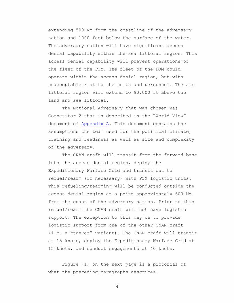
4
extending 500 Nm from the coastline of the adversary
nation and 1000 feet below the surface of the water.
The adversary nation will have significant access
denial capability within the sea littoral region. This
access denial capability will prevent operations of
the fleet of the POM. The fleet of the POM could
operate within the access denial region, but with
unacceptable risk to the units and personnel. The air
littoral region will extend to 90,000 ft above the
land and sea littoral.
The Notional Adversary that was chosen was
Competitor 2 that is described in the “World View”
document of Appendix A. This document contains the
assumptions the team used for the political climate,
training and readiness as well as size and complexity
of the adversary.
The CNAN craft will transit from the forward base
into the access denial region, deploy the
Expeditionary Warfare Grid and transit out to
refuel/rearm (if necessary) with POM logistic units.
This refueling/rearming will be conducted outside the
access denial region at a point approximately 600 Nm
from the coast of the adversary nation. Prior to this
refuel/rearm the CNAN craft will not have logistic
support. The exception to this may be to provide
logistic support from one of the other CNAN craft
(i.e. a “tanker” variant). The CNAN craft will transit
at 15 knots, deploy the Expeditionary Warfare Grid at
15 knots, and conduct engagements at 40 knots.
Figure (1) on the next page is a pictorial of
what the preceding paragraphs describes.

5
1000 ft
Cul de sac < 400 Nm deep
Land Littoral200 Nm
Forward Base1000 Nm
90,000 ft
Access Assurance Zone
500 Nm
Refueling Ops.600 Nm
CNAN Geography
Grid packages (total of 5) 100Nm X 100Nm
Trip Wire 800 Nm long
Figure 1

6
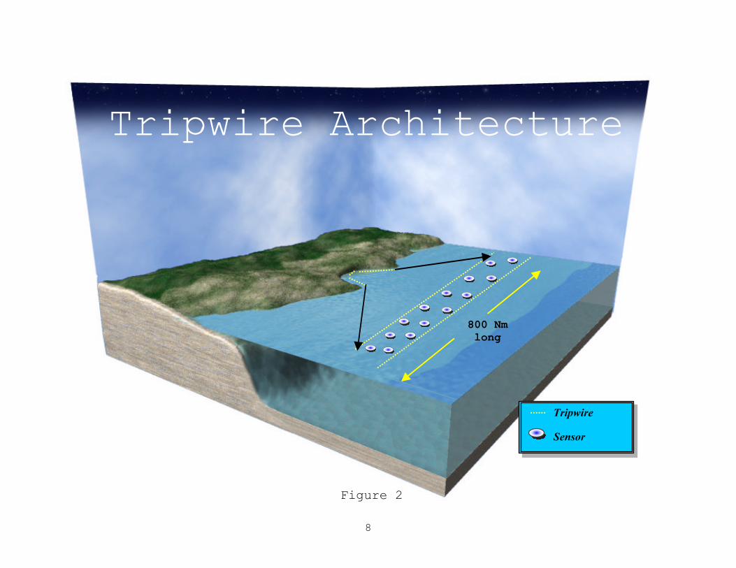
The Expeditionary Warfare Grid will consist of a
tripwire and 5 grid boxes. The tripwire will be
approximately 800 Nm long and be placed in close
proximity to the adversary nation’s coast. The
tripwire will consist of sensors only as depicted in
Figure (2). Sensors and their capabilities were
assumed to be the same as outlined in the CNAN FDCS
Event 3 (CTTAS Game)“tool box” (Appendix A). It will
be assumed that the Expeditionary Warfare Grid
elements have some limited mobility and that three
lines of elements can be deployed by the CNAN craft
per pass through the area.
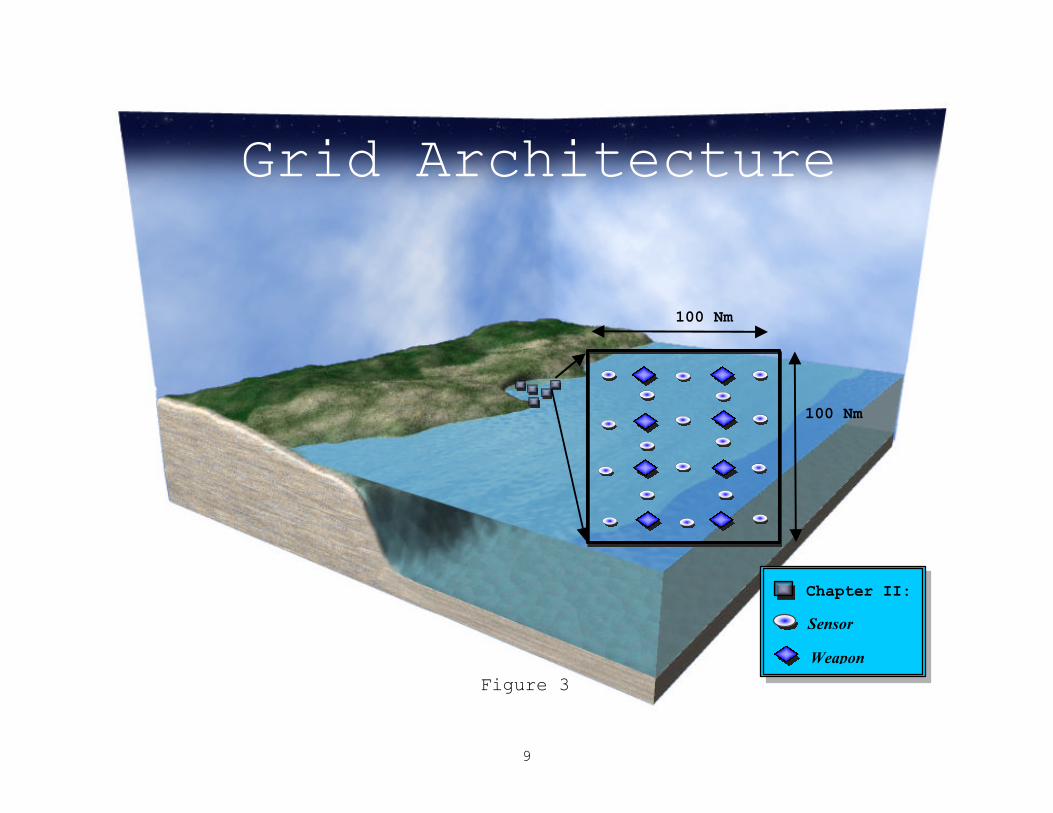
The grid boxes cover an area of 100 Nm by 100 Nm.
They will consist of both sensor and weapon packages.
Once again the weapons ranges, weights, volumes and
capabilities are outlined in the CNAN FDCS[define
term] Event 3 (CTTAS [define term]Game)“tool box”
(Appendix A). The number of weapons required to
effectively attrite the access denial capability of
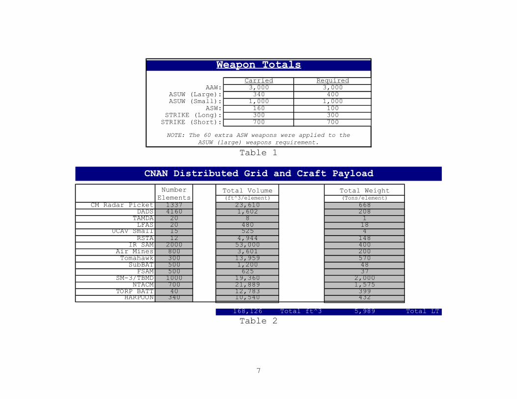
the adversary nation are presented in Table (1). These
numbers include the weapons required to defend the
craft and the grid as well as diminish the access
denial capability. The grid boxes will be deployed
within the cul-de-sac. Three of the grid boxes will be
deployed along the entrance spaced 100 Nm apart. The
remaining two grid boxes will be placed in a line
perpendicular to the grid line at the entrance,
centered in the cul-de-sac and spaced 100 Nm apart.
Figure (3) depicts the geometry of the grid boxes. The
total weight and volume required for all the grid and
weapons elements is presented in Table (2). The total
weight is 6,000 LT with a total volume of 170,000 ft3.
7
Weapon TotalsCarried Required
AAW: 3,000 3,000ASUW (Large): 340 400ASUW (Small): 1,000 1,000
ASW: 160 100STRIKE (Long): 300 300
STRIKE (Short): 700 700
NOTE: The 60 extra ASW weapons were applied to theASUW (large) weapons requirement.
Table 1
Total Volume Total Weight(ft^3/element) (Tons/element)
CM Radar Picket 1337 23,610 668DADS 4160 1,602 208
TAMDA 20 8 1LFAS 20 480 18
UCAV Small 15 525 4RSTA 12 4,944 148
IR SAM 2000 53,000 400Air Mines 800 3,601 200Tomahawk 300 13,959 570
SubBAT 500 1,200 48FSAM 500 625 37
SM-3/TBMD 1000 19,360 2,000NTACM 700 21,889 1,575
TORP BATT 40 12,783 399HARPOON 340 10,540 432
168,126 Total ft^3 5,989 Total LT
CNAN Distributed Grid and Craft Payload
Number Elements
Table 2
8
Tripwire
Sensor
800 Nm long
Tripwire Architecture
Figure 2
9
Chapter II:
Sensor
Weapon
Grid Architecture
100 Nm
100 Nm
Figure 3

10
Chapter II: REQUIREMENTS DOCUMENT
A. MISSION NEEDS STATEMENT
After the end of the Cold War, the view of the world
has shifted from a global-war scenario to one of regional
crisis situations. This fact implies a very important shift
in operational orientation for the Navy, because the
battlefield has moved from “blue waters” into the “contested
littoral environment.” Emerging powers are developing
massive access denial capabilities to prevent power
projection into their territory.
The size of the “contested littoral” environment of
threat nations continues to grow. The Navy needs to develop
a system that can provide assured access in these closely
contested littoral environments. The “Navy After Next” must
marry new capabilities with the best capabilities of the
fleet of the POM to gain, sustain and exploit that access.
It must be an integral part of Network Centric Warfare (NCW)
and be capable of joint and combined operations.
An essential key to success in the littoral
environment is increased numbers of sensors, weapons,
combatants and unmanned vehicles to produce a force
structure capable of tipping the scales in our favor.
Numbers will matter and the Navy After Next must be
affordable and yet be robust enough to provide the support
required of our current forces as well as produce the
numbers necessary to upset the future littoral force
imbalance. The combatant and its payload must be expendable
to the extent that it is not viewed as a high value unit,

11
but have a level of survivability capable of allowing the
crew time to “eject” when the combatant is no longer
capable of sustaining them (much like modern-day aircraft).
The fleet of the POM is not ideally suited to directly
operate in the highly complex and hostile littoral
environment. Concealment together with the surprise factor,
inherent to the enemy operating in its own littorals, will
pose undue risk to our conventional power projection
assets.
This weakness creates the need to develop a capability
that will allow gaining, maintaining, sustaining and
exploiting access to the littorals, in order to project
power into enemy territory.
12
B. OPERATIONAL REQUIREMENTS DOCUMENT
1. Description of Operational Capability
In support of the mission needs statement, the
Naval Warfare Development Center (NWDC) is conducting a
Navy research program, which will explore new
“Capabilities for the Navy After Next” (CNAN) that will
take advantage of the leading edge technology and
information superiority. The Naval Postgraduate School
(NPS) Total Ship Systems Engineering (TSSE) Program is
supporting the Platform Team of the NWDC CNAN study. The
NPS TSSE team will develop a design of a combatant(s)
which will distribute the Expeditionary Warfare Grid
discussed in the mission needs statement, tend (and be
part of) the Expeditionary Warfare Grid once in place
and become an integral part of the warfighting
capability of the Expeditionary Warfare Grid system in
support of the Expeditionary Warfare Grid’s access
mission.
The Expeditionary Warfare Grid system will
consist of four parts: a global satellite-based
network, logistic support ships (which may or may not
be the existing logistics force), a distributed sensor
and weapons system, and small combatants that
deploy/tend the sensors and weapons.
The Expeditionary Warfare Grid is assumed to be
robust, secure, and readily accessible for two-way
exchange of information. Antenna requirements will not

13
exceed 40 cm in diameter and need not be aimed at
specific satellite coordinates.
The logistics force will be capable of providing
any asset needed by the combatants. This will include
food, replacement parts, fuel, replacement-distributed
components, Fly-Away Teams for extensive
preventive/corrective maintenance and all
administrative support. The logistic force will
provide crew replacements for the combatants during
extended operations. The logistic force will not
provide berthing or long-term mooring for the
combatants or their personnel. The logistic force will
not be capable of transporting the combatants.
Logistics replenishment will be performed in
relatively safe waters and in modest sea states.
The sensors will be connected to the
Expeditionary Warfare Grid via some form of modems and
will have some limited mobility. The sensors are
acoustic arrays, radar array elements, magnetic
detectors, ESM sensors, infrared detection arrays, and
optical elements. The weapons are also connected to
the network and receive their firing authorization via
the network. The weapons will include torpedoes,
torpedo-based mines, surface-burst fragmentation
mines, canister surface-to-air missiles, canister
surface-to-surface missiles and strike missiles. The
sensors and weapons will be deployed wherever they are
tactically needed. This may include blue water, in
littoral waters, near the shore or inland.
14
The combatants will carry the sensors and
weapons. Some of the sensor and weapon capability of
the Expeditionary Warfare Grid will be organic to the
combatants. The combatants will have the capability of
exercising local command and control of the sensor and
weapons within the Expeditionary Warfare Grid. It is
expected that the combatants will be capable of a
trans-oceanic crossing when time is not a concern. It
is envisioned that the ocean transit will be limited
to 1000 Nm or less by use of appropriate forward
basing of some kind (i.e. Guam, Naples, Hawaii, Diego
Garcia, etc). Forward bases may be subject to attack
by the enemy, so the combatants must be capable of
rapid sortie. The access denial area is extends
approximately 500 Nm from the enemy’s coastline. The
Expeditionary Warfare Grid will be distributed within
a “cul-de-sac” that has a radius of approximately 400
Nm. The combatants will be required to transit 100 Nm
outside the access denial area to obtain logistic
support.
The Expeditionary Warfare Grid/Combatant System
must perform the following:
a. Perform early warning: detect, classify and track
contacts
b. Destroy or drive off enemy coastal waterborne
commerce

15
c. The combatant must deploy, monitor, protect and
control sensor/weapon Expeditionary Warfare Grid
Some possible Expeditionary Warfare
Grid/Combatant System missions include:
a. Protection of anchorages/MODLOCs [define term]
b. Harbor and restricted waters blockade
c. Theater Ballistic Missile Defense (TBMD)
d. Area Mine mapping operations
e. Escort for amphibious and logistic forces
f. Strike warfare
g. Shallow water ASW
Some possible Combatant missions include:
a. Maritime Interdiction Operations (MIO)
b. Non-combatant Evacuation Operations (NEO)
c. SOF insertion/extraction
d. Independent operations (showing the flag)
e. Strategic deception operations

16
2. Threat Summary
It is difficult to predict exactly what the threat
will be, but projecting current weapons systems into the
future using technologies that are expected to be
available allows us to make realistic threat estimates.
The littoral environments that the CNAN units will
encounter closely resemble a cul-de-sac with a radius of
approximately 400 Nm. The cul-de-sac may be bordered by
the aggressor nation or a combination of the aggressor
nation and other nations that may or may not be friendly
to the U.S. Most of the operations will be conducted
against third world nations, however it is conceivable
that some of the missions will be applied to emerging
world powers.
The contested littoral environment poses a tough
problem in that every fishing vessel or personal water
craft can carry a shoulder-launched missile system
capable of producing significant damage to one of the
combatants or Expeditionary Warfare Grid elements. It is
envisioned that the threat weapons will be much smaller,
faster and more capable in terms of detection,
localization, classification, stealth as well as
maneuverability. The aggressor nation will also have
significantly more of them because they will be
relatively cheap and there will be an ample supply of
them from the weapons producing countries of the world.
Specifically some of these threats include, but are not
limited to:

17
a. Anti-ship missiles
i. Shore launched
ii. Ship launched (small fishing boat to large
cruiser)
iii. Sub-surface launched
iv. Air launched
b. Gunfire
i. Major caliber
1) Shore emplacements
2) Ships
ii. Minor caliber from small fishing vessels to
corvette size combatants
c. Mortars and grenades
d. Torpedoes
i. Air launched
ii. Surface launched
iii. Sub-surface launched
e. Chemical, Biological and Radiological
f. Special Forces
g. Mines
h. Electromagnetic Pulse (EMP)
18
3. Shortcomings of Existing Systems
The current fleet and the POM 00 Program Navy are
capable of performing the assured access and
intelligence gathering mission in the contested
littoral environment. However, they have some
significant shortcomings:
a. To overcome the access denial capability within
the littorals, the present Navy and Navy of the POM
must come dangerously close to the coast of the
aggressor nation. This presents a problem in the
following areas:
i. Cost. Fleet of the POM assets are far too
expensive to risk damage while operating in the
littoral environment. This expense is both in
the cost to procure and operate one of the ships
as well as the large loss of life onboard one of
our personnel-intensive ships.
ii. Stealth. Even with stealth measures, these
ships are too large to enter and operate within
these waters undetected. A smaller combatant may
be able to operate within the littorals for
extended periods of time without being detected,
localized and identified.
iii. Mind Set. Other nations and our country
view these ships as “high value” units. This is
ideal for the purposes of power projection and

19
deterrence, but these ships become prime targets
during a conflict. A smaller ship may be viewed
by an adversary as annoyance rather than a
threat worth expending valuable ammunition on.
b. In the current environment, data collection
sensors are forced to standoff at ranges which are
so great that they can no longer provide the
required information rapidly, timely and with
sufficient coverage and volume to provide a
commander with information required to support
accurate tactical choices. There must be an
increased number of sensors available and these
sensors must be viewed as expendable enough to be
placed in a high-risk environment.
c. The Expeditionary Warfare Grid and combatant
system must be capable of providing the
deployability, flexibility, versatility, lethality
and survivability necessary within the contested
littorals to provide the operational commander with
the awareness and access assurance capability
lacking in today’s fleet and fleet of the POM.
4. Range of Capabilities Required
The proposed Expeditionary Warfare Grid/Combatant
System shall provide the following capabilities (note:
the System includes the combatant):
20
a. The system shall be capable of sufficiently
weakening the area denial capability of the
aggressor to allow an acceptable level of risk to
the fleet of the POM in the littorals.
b. The system will have an anti-ship missile defense
(ASMD) capability.
c. The system will have an area air defense
capability.
d. The system will have an area USW capability.
e. The system will have an area SUW capability.
f. The system will be capable of supporting choke
point and harbor blockade operations.
g. The system will be capable of sending and
receiving data throughout the Network Centric
Warfare Environment.
h. The system will be interoperable with any
Joint/Combined Task Force.
i. The system will be capable of operating in mined
waters.
j. The system shall be designed to produce a low
signature (underwater acoustic, airborne, acoustic,
IR, and electromagnetic).
k. The system shall perform precision strike
missions against land-based targets.

21
The Combatant shall provide the following capabilities:
a. The combatant will have a minimum sustained speed
(80% of full power) of 30 knots with a goal of 34
knots.
b. The combatant will have a maximum speed of 38
knots with a goal of 40 knots. The combatant
displacement will not exceed 1000 LT.
c. The combatant will not exceed 100 million dollars
in “first ship” cost (FY 01 dollars).
d. The combatant shall conduct transits in sea state
6, deployment operations as well as fight in sea
state 4 and small boat operations in sea state 3.
e. The combatant will be capable of conducting a
trans-oceanic crossing with dedicated logistic
support.
f. The combatant will have a range of 3000 Nm with a
goal of 4000 at a minimum endurance speed of 13
knots with a goal of 15 knots.
g. The total combatant force shall be capable of
carrying 6000 LT of Expeditionary Warfare Grid
components with a volume of 170,000 ft3.

22
h. The combatant will have a point air defense
capability.
i. The combatant will have a maximum crew size of 20
officers and enlisted combined with a goal of 13.
j. The combatant will be capable of operating within
a CBR environment.
k. The combatants shall be capable of performing
Maritime Interdiction Operations (MIO) and support
Non-combatant Extraction Operations (NEO).
l. The combatant shall be capable of refueling and
replenishing at sea.
m. The combatant shall be capable of receiving
stores via vertical replenishment.
n. The combatant shall be capable of providing
limited accommodations for special operations teams,
maintenance support Fly-Away Teams (FAT) and
combatant squadron staff.
o. The combatant will have standard couplings and
connections to receive hotel services from the pier.
p. The combatant’s combat systems suite must be
capable of operating in the open ocean as well as
the littoral environment.
q. The combatant shall be capable of towing a
combatant of approximately its size.
r. The combatant will be designed with a 10-year
with a goal of a 15-year frontline service life.
23
s. The combatants control (combat systems,
navigation and HM&E) will be located in a single
location and be networked as much as possible to
support minimum manning.
t. The combatant will utilize advanced technologies
in HM&E systems and design materials to minimize the
size and weight of the craft while maximizing the
payload fraction.
u. The combatant crew accommodations (berthing and
messing) will be austere to maximize the utility of
the combatant.
v. The combatant will be configured to accept
payload modules to perform additional mission
capabilities after they have deployed the
distributed Expeditionary Warfare Grid components.
w. The combatant will meet all MARPOL requirements.
5. Integrated Logistic Support (ILS)
The combatants that support the Expeditionary
Warfare Grid must be minimum manned. The small crew will
only be capable of supporting the underway watch
requirements. The administrative, maintenance and
logistic support must be totally automated onboard the
ship or must be provided from the fleet to support this
minimum manning concept. The following are some of the
key requirements of the ILS:
24
a. A combatant squadron support staff on another
vessel must perform the administrative functions
such as evaluations, fitness reports, medical,
dental, etc. The combatant will not have the
personnel or space to support these administrative
tasks.
b. Any reports or messages the ship must generate
will be incorporated into the ship’s control
workstations in template fashion to facilitate ease
of drafting, release and transmission.
c. Fly Away Teams embarked on the carriers,
amphibious warfare ships or auxiliaries will perform
major preventative and corrective maintenance on the
combatant and the Expeditionary Warfare Grid.
d. All normal watch standing duties will be
performed from the control consoles located in a
central workstation.
e. All monitoring of the combatant’s equipment must
be automated and distributed through the combatants
Ships Wide Area Network (SWAN) to the combatant’s
control consoles.
f. Phased maintenance will performed every 12 months
(15 day duration), with a Docking Selective
Restricted Availability (DSRA) every 5 years (3-
month duration). The homeport support teams that are
also members of the Fly Away Teams will perform all
of the above.

25
g. Commercial-Off-The-Shelf (COTS) equipment will be
utilized wherever possible to utilize and exploit
commercial research and development.
h. Parts support for the combatant as well as the
Expeditionary Warfare Grid will be maintained
elsewhere.
i. Underway Training will be conducted from computer
terminals within the central control station or
within the crew berthing compartments.
j. Inport Training will be conducted in a dedicated
training facility in the homeport of the combatant.
6. Infrastructure Support
The combatant will require augmentation of its crew
while in port. The small crew will be unable to paint
and preserve the ship, on-load stores, refuel, pull
shore power cables and numerous other labor-intensive
tasks. The port facilities will need to be manned with
support personnel who are coordinated with these tasks
to support the ship’s day-to-day routine.
All support material for the ship (charts,
publications, technical manuals, etc.) will be produced
in electronic media format and stored within the
combatant’s SWAN to be displayed at the workstations
when required.

26
All systems produced for the combatant/
Expeditionary Warfare Grid system must have an open
architecture format with minimum storage requirements
and compatibility with all other systems utilized in the
combatant/Expeditionary Warfare Grid.
7. Force Structure
The total number of combatants will be
approximately 100 ships that will be divided into
approximately 10 squadrons. They will be forward
deployed through out the world to facilitate rapid
response.
8. Schedule Considerations
The System must be deployable within 5 years of
authorization and funding with an IOC of no later than
2015. Combatants must be produced at a rate of 10 per
year with an FOC of 2025.
9. Cost Considerations
The system must be robust enough to provide
awareness and gain access as desired, while keeping the
cost of a single combatant to less than 100 million
dollars (FY 01 dollars). The combatants must maintain
deployability, flexibility, versatility and
survivability to meet the challenging requirements of
the contested littoral environment.
27
Chapter III: Analysis of Alternatives
A. Alternative Architectures
There are three main architectures that the NPS TSSE
design team considered. The first of these is a medium size
combatant with a tow (Option I). The second is all medium
size combatants (Option II). The final architecture is a
mixture of small and medium sized combatants (Option III).
A representative combatant already in production will be
presented to provide an idea of the range of capabilities
and limitations of the architecture. The representative
combatant may or may not look like or have the same
capabilities as the TSSE design, but are provided as
starting point to estimate size, range, naval architecture
parameters, etc. The three architectures will be discussed
in more detail in the following paragraphs.
1. Option I
Medium Size Combatant (450 LT) with Tow (450 LT)
In this option the combatant is designed as just
that, an extremely capable fighting craft that is
designed to be a warship. However, this combatant must
be capable of connecting to and towing a “barge” of
approximately the same displacement at the desired
transit and deployment speeds of 15 knots. The
combatant will contain largely self-defense weapons
and be capable of defending itself and the
Expeditionary Warfare Grid. The vast majority of the
Expeditionary Warfare Grid components will be

28
contained on the tow to provide maximum flexibility of
the combatant. The tow may also provide some of the
fuel required during the transit and deployment phases
of the operation. The tow system will be of a semi-
fixed design, similar to that depicted in Figure (4).
This figure depicts a SLICE/KAIMALINO configuration
currently studied by the Office of Naval Research (ONR
362, Advanced Hullforms Program) and Lockheed/Martin
Corporation. In higher sea states the tow may be
extended to a conventional tow or may be rapidly
disengaged to allow the combatant greater
maneuverability during an engagement.
Figure 4

29
The Swedish “GOTEBORG” class is representative of modern
combatants n the 450LT displacement range. Figure (5) is a
picture of the GOTEBORG, with characteristics given below:
Figure 5 (Goteborg Class)
Nation: Sweden
Class: GOTEBORG
Number in Class: 4
Built by: Karlskrona Shipyard
Displacement: 420 tons (full load)
Dimensions (ft): 187 x 26 x 6.6
Speed: 30 knots
Range: 1900 Nm at 12 knots
Propulsion: 3 MTU 16V 396 TB4 diesels (8700 hp)
KaMeWa 80-S62-6 water jets
30
Electrical: 3 285-kVA diesel generators
Weapons: 1 Bofors 57mm
1 Bofors 40mm
4 torpedoes
8 RBS-15 SSM
A/S Mortars 4 Saab 9-tube launchers
Sensors: Sea Giraffe (G/H Band) air and surf
2 Bofors Sea Viking optical directors
Thomson Sintra VDS
Simrad hull mounted active sonar
Manning: 7 Officers, 36 enlisted
Construction: Steel Hull
Aluminum Superstructure
Fin stabilizers
Improvements: Upgrade Sonar (CDS Hydra)
IRST director
Passive Towed Array
2. Option II
All Medium Size Combatants (600 LT)
This variant was looked at to assess the
cost/benefit of building the entire combatant system
using a single hull design versus the alternative of a
system with more than one design, such as that in
Option I. This combatant would need to carry all the
Expeditionary Warfare Grid components. It would either
need to have a reduced number of organic weapons or
greater numbers of hulls to maintain a higher payload
fraction of organic weapons. The combatant would have
the flexibility, upon completing deployment of the

31
Expeditionary Warfare Grid, to transit out of the
access denial zone and have weapons modules placed in
its now empty grid deployment modules. Figure (6)
shows the Swedish VISBY class as an example of the
displacement range of the medium size combatant.
Figure 6 (Visby Class)

32
Nation: Sweden
Class: VISBY
Number in Class: 6 planned
Built by: Karlskrona Shipyard
Displacement: 600 tons (full load)
Dimensions (ft): 236 x 34 x 7.9
Speed: 38 knots (max) 35 (sustained)
Range: 2300 Nm at 15 knots
Propulsion: 4 Allied Signal TF50A gas turb (5370hp)
2 MTU 16V 2000 N90 diesels (1760 hp)
KaMeWa 125 SII water jets (21480 shp)
Electrical: 3 270-kVA diesel generators
Weapons: 1 Bofors 57mm
1 Bofors 40mm
4 torpedoes (400mm tubes)
SSM: 8 RBS 15 MKII inertial
guidance, active homing, 54Nm
A/S mortars Saab Alectro 601 127mm
Sensors: Bow mounted high frequency sonar
Computing Device Canada(CDC) hydra
Passive towed array and VDS active
Ericsson Sea Giraffe 3D(C band)Air/Surf
Celcius Tech Pilot (I band) Surface
CEROS 200 MK3 Fire Control (I/J band)
Manning: 6 Officers, 37 enlisted
Construction: GRP/FRP Hull and superstructure
Fin stabilizers
Aviation: Helo capable
Hangar

33
3. Option III
Mixture of Small (250 LT) and Medium (800 LT) Size Combatants
This design was thought of as the “fighter” and “freighter”
architecture. The small combatant would be designed primarily as
a combatant, while the medium combatant would be designed to
carry the majority of the grid components. As in the case of the
600-ton combatant of Option II, the larger (800 ton) combatant
in this option would have the flexibility upon completing
deployment of the Expeditionary Warfare Grid to transit out of
the access denial zone to have weapons modules placed in its now
empty grid deployment modules. The UM AL MARADIM Class (Figure
(7)) is considered representative of the 250 LT “fighter” and
the Laksamana LAKSAMANA Class (Figure (8)) representative of the
800 LT “freighter”.

34
Figure 7 (Um Al Maradim (Combattante I) Class)
NATION: Kuwait
Class: Um Al Maradim (Combattante I)
Number in Class: 8 planned
Built by: CMN, Cherbourg
Displacement: 245 tons (full load)
Dimensions (ft): 138 x 27 x 6.2
Speed: 30 knots
Range: 1300 Nm at 15 knots
Propulsion: 2 MTU 16V 538 TB93 diesels (4000 hp)
2 KaMeWa water jets
Weapons: 1 Giat type M621 20mm
1 Orobreda 40mm
SSM: 4 BAe Sea Skua (semiactive)8.1Nm
SAM: may be fitted with Simbad twin for
Mistral missiles
Sensors: Thomson-CSF MRR,3D,C-band, air and surf

35
BAe Seaspray Mk3(I/J band) fire control
Manning: 5 Officers, 24 enlisted
Construction: Steel Hull
Figure 8 (Laksamana (Assad) Class)
NATION: Malaysia
Class: Laksamana (Assad)
Number in Class: 4
Built by: Fincantieri, Breda, Mestre, Marghera
Displacement: 705 tons (full load)
Dimensions (ft): 204 x 30 x 8
Speed: 36 knots (max), 34 knots (sustained)
Range: 1900 Nm at 18 knots
Propulsion: 4 MTU 20V 956 TB92 diesels (5030 hp)
4 propellers
Electrical: 3 diesel generators
Weapons: 1 OTO Melera 76mm/62 Super Rapid
2 Breda 40mm/70 (twin)
6 torpedoes (324 mm)
SSM: 6 OTO Melera/Matra Otomat Tesea

36
Mk2 active homing, 98 Nm
SAM: 1 Selenia/Elsag Albatros launcher
(4 cell/2 reload), Aspide,
semi-active homing, 7 Nm
Sensors: Selenia RAN 12L/X(D/I band)air and surf
2 Selenia RTN 10X(I/J Band)fire control
1 Selenia RTN 20X(I/J Band)fire control
STN Atlas Elektronik, 94-41, hull mount
Manning: 52 (combined officer/enlisted)
Construction: Steel Hull
B. Measures Of Effectiveness
The measures of effectiveness/performance (MOE/MOP) were
drawn from the sponsor’s global requirements for the
system. In order to determine the requirements that needed
to be evaluated within each area, the Team broke down each
individual MOE/MOP. These are summarized in Table (1). In
the absence of any guidance to the contrary, the Team
assigned the same weight to each MOE/MOP and the
architectures were ranked in each MOE/MOP based on the
requirements in each category. The following are the
MOE/MOP utilized:
1. Flexibility: How well the mission is performed
2. Versatility: How many missions can be performed
3. Lethality: How much weapon capability
4. Survivability: How well can craft survive in high Threat environment
5. Deployability: How easy to arrive in theatre
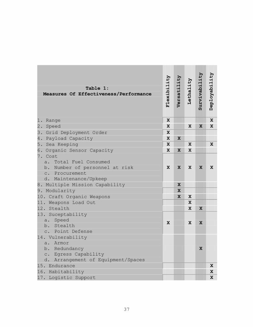
37
Table 1: Measures Of Effectiveness/Performance
Flexibility
Versatility
Lethality
Survivability
Deployability
1. Range X X 2. Speed X X X X 3. Grid Deployment Order X 4. Payload Capacity X X 5. Sea Keeping X X X 6. Organic Sensor Capacity X X X 7. Cost
a. Total Fuel Consumed b. Number of personnel at risk c. Procurement d. Maintenance/Upkeep
X X X X X
8. Multiple Mission Capability X 9. Modularity X 10. Craft Organic Weapons X X 11. Weapons Load Out X 12. Stealth X X 13. Suceptability
a. Speed b. Stealth c. Point Defense
X X X
14. Vulnerability a. Armor b. Redundancy c. Egress Capability d. Arrangement of Equipment/Spaces
X
15. Endurance X 16. Habitability X 17. Logistic Support X
38
C. Analysis of Alternatives
This section outlines in detail the process and outcome of
the analysis conducted on the three alternative architectures
evaluated by the NPS TSSE team during the first half of the
project. The main focus of the analysis of alternatives phase of
the project was to determine the best choice of Option I, II or
III and proceed with a detailed analysis of that option during
the second half of the project. However, in conjunction with the
research on the architectures, the team reviewed some key design
factors to further define the character of the chosen option.
These design factors were the choice of a hull form, hull
material, propulsion plant and mechanism to convert the
propulsion plant’s mechanical work into thrust. The MOE/MOP
utilized were flexibility, versatility, lethality, survivability
and deployability. These MOE/MOP are outlined in more detail in
the previous section. As before, each of the MOE/MOP was
weighted equally in the analysis.
1. Operations Analysis
In order to estimate and compare the effectiveness
of the proposed SEA LANCE designs, it was necessary to
formulate a salvo equation (following Prof. Hughes’
work) that could be used on all platforms of interest.
This equation was used to develop a spreadsheet that
calculates the engagement results of our design options
one salvo at a time. The designs are evaluated using
various sets of initial conditions in order to compare
their relative performance. The following summarizes
the formulation of the basic salvo equation and how it
is implemented.
39
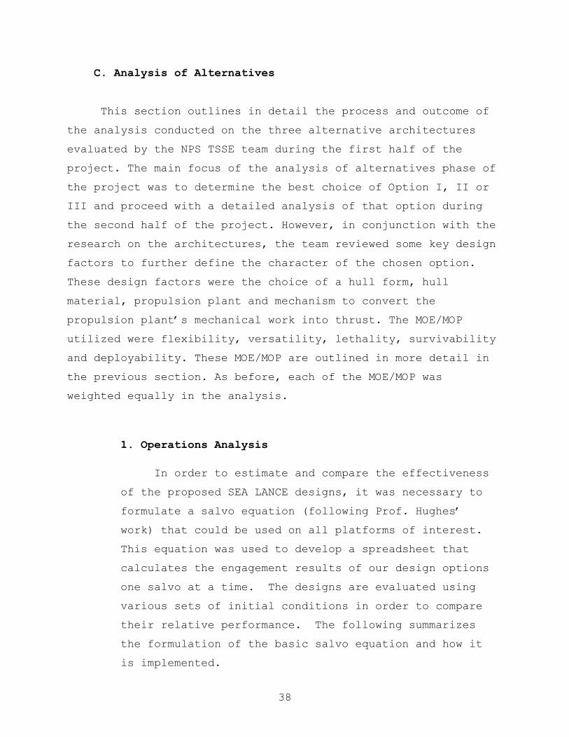
To assess the number of platforms that have been
destroyed, the number of shots fired must first be
determined. This calculation is weapon and platform
specific, based on the firing rate (per salvo) of each
platform multiplied by the number of those platforms
remaining at the beginning of that salvo. A weapon
failure rate, typically 5-15%, is assumed based on
weapon type and platform that slightly reduces the
number of weapons available to inflect damage. The
ammunition remaining on each platform type is also
tracked per salvo and if the platform runs out of
ammunition, it no longer contributes to the number of
shots fired.
1
Weapons Fired (Platform) (Failure Rate) (Shots Per Salvo)
Number of platforms with that weapon type
(Weapons Fired Per Platform) (Weapons Remaining Per Platform)
N
n n nn
N=
=
≡
≤
∑
(Equation 1)
The total weapon delivery capability is then
divided among the total number of targets that weapon
would be used against. The natures of the targets
(i.e. offensive or defensive) are not weighted any
differently for simplicity of calculation and to
compensate for target identification ambiguity.

40
1
d
1
Offensive Weapons Fired
(Offensive Targets)
Defensive Weapons FiredS
(Defensive Targets) (Offensive Targets)
Number of types of platforms that weapon would be used against.
T
nn
T
nn
T
β
=
=
=
=
+
≡
∑
∑
(Equations 2 & 3)
To account for the dual role of most defensive
weapons as missile defense and anti-air weapons, both
planes and incoming missiles are considered targets.
If there are no targets detected, with respect to
weapon type, then no weapons are fired during that
salvo. If there are ANY targets detected, a full
salvo is fired.
The next step is to determine the number of those
missiles fired that hit each target. Threat-specific
defensive weapons, active, and passive defense
characteristics are estimated for each platform type.
The number of defensive weapons available for each
incoming offensive weapon has been determined (Sd). A
“Weapon Kill Factor” is calculated by estimating the
average number of defensive weapons expended (i.e.
“Shoot, Shoot, Look, Shoot”) to destroy one offensive
weapon before it hits the platform (Sk). For our
calculations, it is assumed that if there were two
defensive weapons fired at an incoming surface-to-
surface, or air-to-surface missile, it would be
destroyed. All other offensive weapons are immune to

41
this form of defense. The “Weapon Kill Factor” is
that fraction of incoming offensive weapons destroyed
by defensive weapons and is calculated using the
following equation (Note that it is limited to a 100%
kill rate.):
Weapon Kill Factord
k
SS
ω = =
10 ≤≤ ω
(Equation 4)
This results in the fraction of incoming
offensive weapons not destroyed by defensive weapons
equal to:
( )1 Weapon Leakageω− =
(Equation 5)
Some platforms also have active and/or passive
defenses. To take this into account, the fraction of
incoming offensive weapons deceived by any combination
of these (i.e. ECM, chaff, decoys,…, etc.) was
calculated as the “Platform Deception Factor.” This
calculation assumes that the number of shots expected
to miss, out of 100 shots fired at the target, is Sm.
This was estimated as 30 for our opposition and
manipulated as required to meet our mission objectives
(typically 50-75) for the SEA LANCE combatant. A
42
value of 50 for torpedo decoys was used across the
board. Aircraft were assumed to avoid 90 “air mines”
out of 100 and this was included in this factor, even
though it doesn’t exactly fit the definition. This
factor applied to only surface-to-surface missiles,
air-to-surface missiles, air mines, and torpedoes.
All other weapons were assumed to be immune to this
form of defense.
FactorDeception Platform100
== mSε
10 ≤≤ ε
(Equation 6)
Taking both of these defensive characteristics
into account yields the following representation for
the fraction of weapons fired that are neither
destroyed by defensive fire, nor otherwise deceived.
This fraction is defined as:
( )[ ] FactorHit Weapon 1)1( =−−= ωελ
10 ≤≤ λ
(Equation 7)
Then, taking the number computed in equation 2,
the total number of hits due to that weapon type is
expressed as:

43
PlatformPer Hits=βλ
(Equation 8)
To estimate the damage inflected by these hits,
the number of hits (weapon specific) required to kill
each platform is estimated and defined as ‘a’. If
there are ‘n’ different types of weapons used against
a specific target, the fraction of each target
destroyed each salvo is:
ξλβ
==∑=
DestroyedFraction 1
n
t t
tt
a
(Equation 9)
The fraction that survived that salvo is:
( ) Fraction Survival1 =− ξ
(Equation 10)
For the all of the variations of the SEA LANCE
combatant, it was assumed that one hit would result in
a mission kill. In this case if the salvo
calculations resulted in fractional units remaining,
the number was rounded down prior to calculating the
next salvo. For larger platforms, requiring multiple
hits to kill, fractional units were carried over and
considered damaged. Due to the nature of the
calculations, the damage had no effect on the

44
delectability of the craft, but did reduce its weapon
delivery capability and its sensor contribution.
Assuming ‘A’ equivalent platforms, under uniform
attack, the total remaining force after each salvo is:
( )ξ−= 1of AA
(Equation 11)
Up to this point it is assumed that the opposing
force detects all platforms. This assumption has been
used in the past to evaluate blue water engagements of
large ships. This was not considered “safe” in this
application due to the size, possible stealth, and
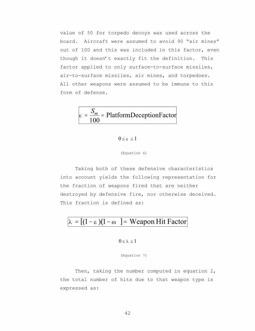
geographic location of the platforms being evaluated.
A platform’s detectability was based on size and
stealth. This however did not account for the ability
of the opposition to locate the target platforms. In
an attempt to correct for this, estimations of
expected sensor characteristics were coupled with the
number of platforms and the possibility of non-organic
sensors (referred to generically as intelligence), to
quantify the sensor ability of each side of the
engagement.
Assumptions made to estimate how easily a
platform can be detected are based on comparisons of
its physical size, relative stealth, and the accuracy
of expected intelligence that would be available on
platforms of that type. For the purposes of these

45
calculations, “intelligence” refers to all non-organic
sensor systems, but is used for stationary targets
only (i.e. bases, ballistic missile sites,…, etc.).
‘X’ is the fractional reduction in the detection
range due to a platform’s stealth (i.e. construction
materials, coatings,…, etc.). Typical values used for
an advisory platform range from 5% to 50%. The SEA
LANCE combatant values were varied to determine the
design value of stealth on mission effectiveness and
typically varied between %50 and 75%. ‘T’ is the
range a platform of its size would be detected
compared to a “Standard Platform” (i.e. Boeing 747 for
an airplane, PERRY (FFG-7) Class for a ship, or LOS
ANGELES (SSN 688) Class for a submarine). ‘I’ is the
reliability of intelligence on that specific platform
type. Based on those estimations, the likely hood of
that platform being detected by a nominal adversary
is:
( ) Factority Detectabil1 =+−= ITXδ
10 ≤≤ δ
(Equation 12)
Based on a curve fit using existing ship designs,
the change in radar cross section is approximately
equal to the fractional change in displacement raised
to the 3/2 power. Unfortunately, the detection range
scales with the 4th power of cross section. This

46
result is the following equation for ‘T’ used for SEA
LANCE combatant of various sizes:
375.0ntDisplaceme StandardntDisplaceme Platform
=T
0 1T< ≤
(Equation 13)
Estimates were made of the opposition
characteristics based on the same standard platforms,
chosen due to the Team’s familiarity with those units.
Because both sensor and detection characteristics were
normalized to these platforms, changing the “standard”
platform would not change the relative performance of
any sensor or the detectability of any platform.
In an access assurance situation, the goal is to
clear an area for the blue water fleet to “safely”
operate. This scenario lends itself to the notion
that the SEA LANCE combatant would sweep the area for
possible threats and engage the enemy as it encounters
them. Likewise, the opposition forces are principally
land based and/or littoral; therefore their pattern of
operation would be unidirectional as well. In both
cases, it is assumed that there would be a “front
line” of some shape that would form the principal
search area. Sensor characteristics were used assuming
that there was this line of engagement. For our
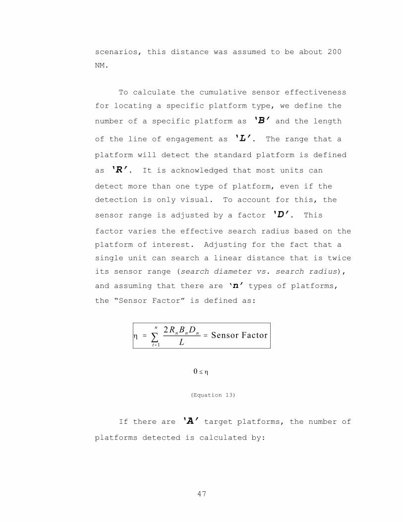
47
scenarios, this distance was assumed to be about 200
NM.
To calculate the cumulative sensor effectiveness
for locating a specific platform type, we define the
number of a specific platform as ‘B’ and the length
of the line of engagement as ‘L’. The range that a
platform will detect the standard platform is defined
as ‘R’. It is acknowledged that most units can
detect more than one type of platform, even if the
detection is only visual. To account for this, the
sensor range is adjusted by a factor ‘D’. This
factor varies the effective search radius based on the
platform of interest. Adjusting for the fact that a
single unit can search a linear distance that is twice
its sensor range (search diameter vs. search radius),
and assuming that there are ‘n’ types of platforms,
the “Sensor Factor” is defined as:
1
2Sensor Factor
nn n n
t
R B DL
η=
= =∑
η≤0
(Equation 13)
If there are ‘A’ target platforms, the number of
platforms detected is calculated by:

48
Platforms DetectedD oA Aηδ= =
D oA A≤
(Equation 14)
It is assumed that if a platform is detected that
both sides are coordinated enough to target it,
regardless of the source or quality of the initial
detection.
Using this modified value for the initial number
of “targets” that the offensive force has to shoot at,
the final value for the number of defensive platforms
remaining after each salvo is:
( )1f o DA A A ξ= − −
(Equation 15)
When the larger platforms were destroyed, all the
assets allocated to that platform were destroyed as
well. For example, if an air base was destroyed, all
the aircraft at that base are destroyed too.
The calculations were integrated into a
spreadsheet capable of predicting several possible
scenarios for each of the three options. The
scenarios considered based on the opponent described
in Chapter 1 are outlined below:
49
a. Opposed Grid Insertion. It is assumed that the
SEA LANCE combatants meet with naval resistance at
500 nm and engage them while attempting to transit
and deploy the trip wire and grids. The first salvo
involves all opposition naval forces, the full land
based ASM threat, and 10% of its “merchant” fleet.
A three salvo per day model was used and 25% of
available aircraft attack each salvo (when
applicable). By the time of the next engagement,
another 10% of the merchant fleet is in range and
the opposition aircraft support the attack along
with all surviving forces. The third and fourth
salvos both add another 30% of the merchant fleet to
all remaining forces. By the fifth salvo, the SEA
LANCE combatant would be about 480 nm into the area
and the remaining 20% of the merchant fleet are now
in range. Assuming the worst-case scenario, the SEA
LANCE combatant would have to transit another 400 nm
into the area before laying the trip wire. This
takes them until salvo number nine. Once the trip
wire is deployed, it adds sensor capability but no
weapons to the SEA LANCE combatant/system. After
the grid is deployed, both the sensor and weapon
capabilities are increased. The first salvo that
makes use of this increased capability is salvo
number eleven. It should be noted that both the
trip wire and the grid are assumed to be cargo until
deployed. As each SEA LANCE combatant/GDM is
destroyed, the capability of the trip wire and grid
is degraded. After the trip wire and grid are

50
deployed, they are immune to attack and are only
degraded by logistics.
b. Semi-Opposed Grid Insertion. In this scenario,
the first salvo doesn’t take place until after the
trip wire is deployed, while the grids are being
deployed. The SEA LANCE combatant engages with the
added benefit of the trip wire’s sensors, but not
the weapon capability of the grids. The first salvo
involves all opposition naval forces, the full land
based ASM threat, and 100% of its “merchant” fleet.
The next engagement includes 25% of available
aircraft along with all surviving forces. After the
second salvo, all grid weapons and sensors are
available.
c. Unopposed Grid Insertion. In this scenario, the
first salvo doesn’t take place until after the trip
wire and grids are deployed. The SEA LANCE
combatants engage all opposition naval forces, the
full land based ASM threat, and 100% of its
“merchant” fleet with full capability trip wire and
grids. The second salvo includes 25% of available
aircraft along with all surviving forces.
The platform characteristics used in the calculations
are included in Appendix B.
51
2. Cost Analysis
In order to compare the alternative architectures on a
level playing field, the cost of each option had to be
factored into the analysis. In order to do this, the
production cost of the Danish FLYVEFISKEN “Standard Flex
300 (STANFLEX 300)" Class variable mission small combatant
was used. This vessel was chosen due to its modern design,
composite construction, and the availability of cost data.
The estimated cost of a STANFLEX 300 , fully equipped for
minesweeping, is $61 million per craft1. This design has a
displacement ofs 450 LT, modular, composite construction,
and a CODAG propulsion plant. To adjust for the increased
combat systems anticipated on our craft, as compared to a
minesweeper, this price will be increased by ~15% to
estimate the cost of a 450 LT SEA LANCE Combatant at $70
million.
Historical data on larger classes of ship suggest that
doubling the displacement of a craft increases the cost by
a factor of 3/2. This weighting factor was used to linearly
scale this cost to the different option sizes. In order to
estimate the cost of the tow, the estimated price of a
craft of that displacement will be multiplied by 2/3. This
results in the following cost estimates:
800800 LT Option (1.5)($70) $87,500,000 $88 Million
960= = ≈
600600 LT Option (1.5)($70) $65,625,000 $66 Million
960= = ≈
1 514 million kroner, CAPT Poul Grooss, Managing Director, Naval Team Denmark
52
400400 LT Option (1.5)($70) $43,750,000 $44 Million
960= = ≈
250250 LT Option (1.5)($70) $27,343,750 $27 Million
960= = ≈
2 400Tow (1.5)($70) $29,166,667 $29 Million
3 960
= = ≈
Payload calculations were used to determine the
minimum number of each option required to deploy the grid
elements. These numbers are based on a total craft payload
capacity of 35% with a standard deduction of 5% for combat
systems and the remaining 30% split between the calculated
fuel required and grid/weapon payload. The tow is assumed
to have a 70% payload fraction added to the unit total
payload available for fuel and grid elements. Each minimum
is defined as the base unit for comparison.
Option I (450 LT with 450 LT Tow): 33 Craft (450 LT)
33 Tow (450 LT)
$2.40 Billion
Option II (600 LT): 60 Craft
$3.96 Billion
Option III (250 LT and 800 LT): 45 Craft (250 LT)
45 Craft (800 LT)
$5.17 Billion

53
These numbers represent the estimated cost of the
craft only. All weapons and grid components are
additional. This additional cost is, however, uniform
because the bases of the “minimum” numbers represented
above are weapon and grid component payload capacity, so it
would cost the same to equip any of the options.
A smaller tow was considered, but later rejected due
to the desire to maximize hull commonality between the
towing craft and the tow. The calculations are included
for comparison, but were not used in the operational
analysis that follows. If the tow size were reduced to 250
LT, the calculations change as follows:
2 250Tow (1.5)($70) $18,229,167 $18 Million
3 960
= = ≈
The base unit for cost comparison is increased to 53
pairs in order to have the same total payload capacity.
Option I (450 LT with 250 LT Tow): 53 Craft (450 LT)
53 Tow (250 LT)
$3.29 Billion
A cost-weighted operational analysis can now be done
using the most expensive option as a benchmark and adding
additional units to the other two options based on the same
total expenditure. The units added are combatants only;
this adds to the combat effectiveness without the
additional expenditure of grid elements. All grid elements
are assumed to be carried in the original units for this
analysis.

54
Since Option III sets the “benchmark” maximum system
cost of $5.17 Billion this leaves $2.77 Billion for Option
I (with the 450 LT tow) and $1.21 Billion for Option II.
Spending this “extra” money on combatants yields the
following results:
Option I (450 LT with 450 LT Tow): $44 Million (per craft)
$2.77 Billion (Extra)= 63
Additional Combatants
Option II (600 LT): $66 Million (per craft)
$1.21 Billion (Extra)
= 18 Additional Combatants
The operational analysis was done using the cost-
adjusted number of craft. Option I starts off with 33
pairs of craft escorted by 63 additional combatants.
Option II starts off with 78 craft. Option III starts with
the original cargo limited number of craft, 90. Option I
was clearly superior. The full results of this analysis
are included in Appendix B.
NOTE: The ability of the opposition to detect the SEA LANCE
craft in this analysis was understated. The factors were later
adjusted based on existing ship design radar cross-section data.
The comparative analysis is considered valid regardless due to
the error being applied consistently across all options. The
finial operational analysis done on the design was considerably
more stressing and the results are not as optimistic.
55
3. Flexibility
The team defined flexibility as a measure of how well
the option performed the mission. Option I, the 450-ton
combatant with equal-sized tow, was at the top of this
category. The tow is immensely flexible and modular by the
nature of its design. The range lost due to the increased
powering requirements when towing the “trailer" can be
recouped by providing additional fuel capacity on the tow.
Payload capacity is the best for the dollar spent because
of the high payload fraction associated with the tow.
Analysis of Option 1 resulted in the fewest number of
manned combatants to complete the mission. This would put
the fewest number of personnel at risk. The maintenance and
upkeep costs should be less than the other options because
of the lower complexity of the tow, which is essentially an
unpowered (except for emergencies), uninhabited barge. The
other options pay the price of increased complexity
(propulsion, electrical, habitability, etc.) by having the
combatants carry the network components.
Assuming that modularity means that the combatants can
be outfitted with weapons/sensor modules following
deployment of the network, Option II and III could carry a
greater number of organic sensors and weapons than Option I
following deployment of the network. This would limit their
flexibility during deployment of the network, but increase
it following deployment. This would greatly increase the
complexity of the Option II and III designs and would
56
provide a number of difficult challenges to overcome. The
modular change-out would need to be performed at sea and
would require the combatant to return outside the access
denial zone to rendezvous with the POM logistic force,
change-out and then return to the access denial zone, a
round trip of up to 1200 nm.. Although the conversion of
the “freighter” to “fighter” capability is attractive, the
time and logistics support force required to do so is felt
to be an excessively high penalty. The tow can shift to a
“fighter” role quicker, simply by releasing the tow, and
without the need for logistic support.
Option I does have its challenges as well. The tow
must be capable of operating in the sea states outlined in
the requirements document. The design will need to account
for the vessel interaction issues of the combatant with a
fixed tow, solve the material and controls requirements of
the fixed tow, produce a platform with the stability to
deploy the network and conduct the secondary missions
outlined in the requirements document.
4. Versatility
The team defined versatility as a measure of how many
different missions could be performed by an option. The
team chose Option I as the overall choice in this measure.
Option I has the advantage that the towing craft becomes a
very capable combatant when it is no longer towing the
“trailer”. It is capable of performing secondary missions
such as MIO or SOF insertion. The tow could be placed on a
sea anchor following the deployment phase. It could then be
used as a “lily pad” for helicopter or UAV operations. It

57
would also provide another target of relatively the same
size and shape of the combatant for the adversary to
consider. It could also be utilized as a platform to house
the retrograde and unexpended network components once the
overall mission is completed.
The other options could produce variants that would be
capable combatants, but would do so at the expense of
network carrying capability. All the platforms would be
designed with modularity in mind. This could lead to the
argument that the larger platform could house more modules
of a more diverse nature and therefore be more versatile.
This could lead to the choice of the “fighter/freighter”
concept of Option II. The towed vessel of Option I would
provide as much versatility of payload as the freighter of
Option II without the burden of protecting the larger, less
capable freighter. Therefore, Option I was the choice for
this versatility.
5. Lethality
The team defined lethality as a measure of the ability
to inflict damage to the enemy and the extent to which the
enemy’s mission capabilities ) are degraded/eliminated by
the damage inflicted. This MOE/MOP evaluates the
combatants, not the entire system. This is the only MOE/MOP
that Option I did not come out the winner. Option II faired
the best under this definition because of its size and
ability to carry a large amount of lethal payload. Assuming
modularity is designed into the craft and/or some of the
medium-size combatants (800 LT) may be designed as fighters

58
vice freighters, this option would provide a large, mobile
organic weapons capability. The 250 LT small combatants
would provide a fast, extremely maneuverable platform to
transport this option’s lethality rapidly around the area
of operations.
Option I performed well in this option too. The
combatant (450 LT) would provide a large amount of organic
weapons capability and could rapidly transit the area of
operations when the tow was detached. Conceivably the tow
could have weapons modules placed in it, but that would add
complexity to both the tow and the modules themselves.
Overall, Option II was the best because of its large
freighter with the ability to carry a large amount of
organic weapons and its small fighter with its stealth and
high degree of maneuverability.
6. Survivability
The team defined survivability as a measure of how
susceptible an option is to attack, how vulnerable it is to
that attack, and how well it recovers from the attack. All
of these factors will determine the level of survivability
of the individual option. The operations analysis based on
cost in the Appendix (page A-53) shows that the Option I
beat the other options in all the scenarios when placed on
a level playing field. It also shows that the 450 LT
combatants with its tow beat all the other combatants in
all the scenarios with the exception of the opposed
assault. The increased stealth of the 250 LT combatants
provides it with less susceptibility and therefore greater
survivability in this scenario.

59
The vulnerability of the combatants should be about
equal. They will all be designed with relatively the same
degree of redundancy (minimal), armor (none), and egress
capability (maximum for crew survival) and with relatively
the same equipment/space arrangements. The larger
combatants may have a slight advantage in number of minor
weapons hits it can absorb, but it is assumed that none of
these craft, due to their relatively small size, are
capable of surviving a cruise missile or similar sized
weapon hit. The tow may provide some deception when it is
“anchored” following deployment of the network. It is
relatively the same size and shape as the combatant and
will provide the adversary another to track to identify.
The recoverability of the craft should be relatively the
same as well, which is minimal. They will all have the same
basic automated damage control and firefighting systems
capable of dealing with minor operational casualty or
weapons effects but, in the aftermath of any significant
weapon hit or fire, they are assumed to be non-recoverable.
Accordingly, most survivability design features are
dedicated to maximizing the ability of the crew to safely
abandon ship. Option I was evaluated as the best overall in
this measure.
7. Deployability
The Team defined deployability as a measure of how
habitable the option is, how much outside support it
requires and how often it requires outside support. If
habitability were based on size, the 800 LT craft component
60
of Option III would be best but, since Option III also
includes the smallest (250 LT) craft as well, which would
be the worst, overall Option III does not do well. The 450
LT craft of Option I and the 600 LT craft of Option II
would probably be of comparable design, with the exception
that Option II would need space and volume for network
components and habitability may be sacrificed to meet
mission requirements. Option I has the greatest potential
for storing sufficient fuel on the combatant and tow
without sacrificing network carrying capacity. The logistic
support required to provide the 800 LT craft of Option III
with the rearming necessary to transform from a freighter
to a fighter would add significantly to the total ownership
cost of the option. All of the combatants would probably
have relatively the same requirements in terms of parts,
maintenance, underway replenishment, etc. Overall, Option I
was found to be the best of all the options.
8. Architecture Conclusion
Option I was the winner in 4 of the 5 MOE/MOP. The
Team assigned equal weight to each of the 5 MOE/MOP and
therefore Option I was the choice of the 3 architectures
reviewed. Option III was next best and had some of the same
attractive features as Option I, but there were substantial
penalties to be paid for meeting the same level of
performance as Option I. Option II performed the worst in
all but one of the categories. It followed the adage that a
ship designed to be a jack of all missions, will be a
master of none.

61
9. Defining The Architecture
The team analyzed the following options to choose
the architecture’s hull form, hull material, propulsion
plant and mechanism to convert the propulsion plant’s
mechanical work into thrust. It should be noted that a
more detailed computational analysis is contained in
Chapter IV, Technical Evaluation of the report.
a. Monohull versus Wave-Piercing Catamaran
Flexibility, versatility, lethality,
survivability, and deployability attributes of the
combatant hull form are crucial to the achievement
of the mission of the vessel. Analysis of hull
stability and seakeeping, hull resistance and
powering requirements, payload capacity and other
characteristics and capabilities against the above
attributes revealed that a Wave-Piercing Catamaran
hull form would provide the required characteristics
necessary for the combatant to meet all mission
requirements.
Seakeeping, maneuverability and operability
characteristics are essential for successful mission
completion. The combatant is required to perform
open ocean transits in Sea State 6, network
deployment operations as well as fight in Sea State
4 and small boat operations in Sea State 3. The
combatant is also required to perform refueling and
replenishing operations at sea. Additionally, the

62
combatant will conduct vertical replenishment
operations.
After reviewing seakeeping information for
several hull forms and the measures of performance,
the Wave-Piercing Catamaran was judged to best meet
all fundamental requirements.
In general, a Wave-Piercing Catamaran is a
catamaran with long, slender outboard hulls designed
to slice through waves. A flared center hull
incorporated into the cross-structure provides wave
deflection. The above-water potions of the outboard
hulls slope sharply forward toward the waterline,
allowing the bows to pierce through waves.
b. Wave Piercing Catamaran
The following are generalized seakeeping,
maneuverability and operability characteristics for
the wave-piercing catamarans.
i. Seakeeping
• Maintain a relatively high percentage of calm water speed in high sea state conditions.
• Ride control systems are able to control relatively high deck-edge accelerations.
• A Shock mounted bridge could further reduce accelerations.

63
ii. Maneuverability
• Ship’s turn radius is relatively larger at high speeds.
• Relatively good turning ability at slow to medium speeds.
iii. Operability
• Capable of a relatively the same endurance as monohulls
• Requires large amounts of fuel during high-speed long-range transits
c. Monohull
The following are general seakeeping,
maneuverability and operability characteristics
obtained from “Seakeeping, maneuvering and
operability issues of high speed
vessels”[reference] for a conventional monohull.
i. Sea Keeping
• Experience substantial speed reduction in heavy seas.
• Speed reduction required to diminish undesirable ship motion, slamming and deck wetness as wave height increases.
• Larger monohulls are less sensitive to rough seas than smaller monohulls.

64
• Active stabilization systems provide improved sea keeping.
• Wave-piecing monohulls improve sea-keeping performance in rough seas, requiring less speed reduction.
ii. Maneuverability
• Good maneuvering performance at higher speeds.
• Directional stability improves with increasing ship speed.
• Overall maneuverability is significantly affected by size, type and location of steering/propulsions system.
• Poor position-keeping, station-keeping, and low speed maneuvering performance.
iii. Operability
• Rugged, simple and survivable.
• Forty knots appears to be the maximum practical speed.
• High speeds are achieved with a cost.
d. Other Comparisons of Monohull versus Catamaran
The catamaran has a greater payload capacity
(weight) than the monohull of the same general
characteristics. A catamaran has greater flexibility
as far as hull option to improve stealth. Appendix F
shows comparisons of resistance, horsepower and fuel
consumption rates for catamarans versus monohulls
65
utilizing diesel engines. The catamaran has a
greater combat efficiency (high speed >15 knots)
than the monohull. However, the monohull has greater
transit efficiency (low speed <15 knots) than the
catamaran. Since the majority of the operations will
be performed at high speed, the catamaran is the
choice based on powering requirements. The catamaran
provides a large deck area to provide space for
combat systems, cargo handling and stowage or
aviation operations.
e. Hull Form Conclusion
The characteristics listed above meet or exceed
the measures of performance required of the
combatant. For a small ship, the wave-piercing
catamaran provides superior seakeeping
characteristics, improved stealth, greater combat
efficiency, greater deck area and greater payload
than a monohull.
The tow option was further analyzed to
determine if the hull forms should both be
catamarans or a combination of catamaran and
monohull. There was a slight benefit powering
advantage to the catamaran combatant and monohull
trailer. The analysis of towability, directional
stability and equivalent motions favored the
catamaran combatant and catamaran tow variant with
relatively the same displacements. This is not to
66
say that the other combinations of tow and trailer
could not be produced, but that they would require
increased complexity and more than likely greater
cost. The commonality between the hull form of the
combatant and trailer will likely decrease design,
fabrication and production costs. The small
advantage in powering that the combination of
monohull and catamaran provides does not outweigh
the large number of benefits from producing a
catamaran/catamaran combination.
f. Hull Material
There were three general classes of materials
analyzed for use during the design effort. They were
steel, aluminum, some composite (i.e. glass/fiber
reinforced plastic GRP/FRP) structure or a
combination of them. The team did not want to rule
out either aluminum or composites, but made a
determination that steel would be used on a limited
basis for structural strengthening only. Steel has
the advantage of being stronger and less susceptible
to damage of fire or weapons. However, it is more
costly and produces a lower payload fraction than
aluminum or composites. Steels exceed the
survivability requirements of the craft and produce
undesirable payload fractions and excessive cost.
Aluminum and/or composites can be designed to meet
the requirements and will be primary construction
materials utilized during the design project.

67
g. Propulsion Plant
The choices for propulsion plant were gas
turbine, diesels or a combination of the two. Gas
turbines have a small machinery box size relative to
a diesel plant of the same horsepower. The large
intake and exhaust ducts required for the gas
turbine are a significant draw back. A comparison of
gas turbine versus diesel fuel consumption rates for
Option I are presented in the Chapter IV. The diesel
consumes less fuel than the gas turbine for the
range of speeds from 5 through 40 knots. This is a
critical point given the distances that the
combatant must travel. Fuel consumes a large amount
of the payload and any extra payload lost to fuel is
network payload that cannot be carried. The large
intake and exhaust ducts that are required for the
gas turbine also take up volume that could be
utilized for network components as well. The gas
turbine will require a reduction gear for both
propellers and water jets. The weight of the gas
turbine and its associated reduction gear will
exceed the weight of a medium speed diesel that
could be directly connected to both the water jet
and the propeller. For these reasons the gas turbine
was eliminated as a choice for propulsion throughout
the range of speeds required. It should be noted
that the team recognizes the ongoing advances in gas
turbine technology and would reconsider this
decision if the weight and specific fuel consumption

68
figures approached those of diesels. Option I will
be powered by a plant consisting of entirely diesel
engines.
h. Conversion of Mechanical Work into Thrust
The process of converting the work of the
diesel engines into thrust becomes even more
difficult with the fact that we are towing a vessel
for a good portion of the mission. Designing a
combatant that can attain a maximum speed of 40
knots without the tow and a speed of at least 15
knots with the tow while maintaining the maximum
efficiency throughout the range to conserve fuel is
a difficult problem. The optimum propeller to
produce the maximum thrust while towing is obviously
not the propeller that you would want to push the
ship through the water at 40 knots. Even a
controllable pitch propeller would have problems
achieving the maximum efficiency throughout the
range. Another problem of a propeller is that it
will normally increase the navigational draft of the
combatant. A good alternative that may improve on
the above problems is the use of water jets. The
water jets could be sized and arranged to provide
the maximum thrust at their most efficient speeds.
They also are not as draft limiting as propellers.
An analysis of the Advanced Water Jet, 21st
Century (AWJ-21) built by Bird-Johnson in
conjunction with Rolls Royce, is presented in

69
Chapter IV. It compares the water jet with a
controllable pitch propeller in the areas of
maintenance, effect on draft, thrust requirements,
etc. The water jet is comparable or outperforms the
propeller in all evaluated areas. In conclusion the
Team chose water jets as their method of converting
the work of the diesels into thrust.

70
10. Overall Conclusions of the Analysis of Alternatives
The architecture chosen was Option I, which is a
450 LT combatant with a 450 LT vessel with a semi-
fixed close proximity tow. The hull form will be a
wave-piercing catamaran combatant and wave-piercing
catamaran tow. The hull will be made of aluminum,
composites or a combination of the two with steel
utilized for structural support where necessary. The
propulsion plant and electrical generation will be
composed of diesel engines and their work will be
converted to thrust by water jets.

71
D. Design Drivers/Enablers
The team determined the design drivers associated with
the choice of the architecture, hull form, propulsion
plant, requirements, etc. An example of a design driver is
the shallow draft requirement that comes from the
requirement to operate in littoral waters. This driver is
also linked to other drivers, such as the choice of
propulsion plant that will produce the endurance and speed
requirements. The interaction between drivers is as
important as determining the individual drivers as well.
The drivers must be analyzed to determine their interaction
with other drivers as well as how many of the requirements
and capabilities they affect.
Next was the process of determining design enablers to
be mapped to the design drivers to enable SEA LANCE to
perform the requirements set forth in the requirements
document. For instance, water jet propulsion was chosen to
provide the shallow draft requirements and the increased
efficiencies at high speeds. Finally the driver/enabler
pairs and pair interactions were reviewed to ensure that
while fulfilling one requirement, a pair did not detract
from another requirement. An example of this was the choice
of a conventional water jet. While it provided good
efficiency at high speeds and enabled a shallower draft by
not extending below the hull, its efficiency dropped to
unacceptable values at our critical tow and deployment
speed of 15 knots. We reviewed the choice of water jets
over propellers and looked at other water jet options. The
AWJ-21 being developed by Bird-Johnson filled this gap by
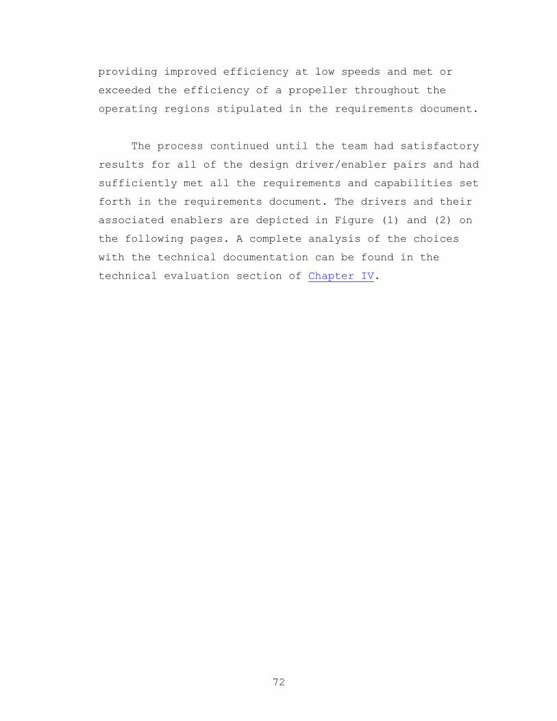
72
providing improved efficiency at low speeds and met or
exceeded the efficiency of a propeller throughout the
operating regions stipulated in the requirements document.
The process continued until the team had satisfactory
results for all of the design driver/enabler pairs and had
sufficiently met all the requirements and capabilities set
forth in the requirements document. The drivers and their
associated enablers are depicted in Figure (1) and (2) on
the following pages. A complete analysis of the choices
with the technical documentation can be found in the
technical evaluation section of Chapter IV.

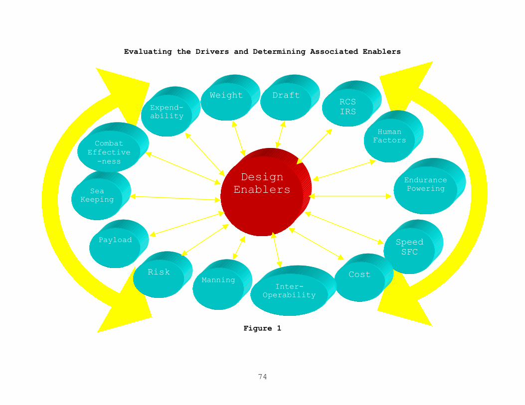
74
Evaluating the Drivers and Determining Associated Enablers
Design Enablers
Payload
Endurance Powering
Manning
Speed SFC
Human Factors
RCS IRS
Draft Weight Expend-ability
Cost Risk
Inter-Operability
Sea Keeping
Combat Effective
-ness
Figure 1

75
Evaluating the Enablers and Mapping to Associated Drivers
Telescoping Mast
Active Stabilization
Astern Refueling
Plane/Squadron Philosophy
SEA LANCEman Rating
COTS
Commercial Construction
PTO Electric System
Tow Concept
AWJ-21 Water jet
Hull Material
SWAN
Technology
Wave Piercer
Enclosed Mast
Commercial Operation
Hull Configuration
Design Drivers
Figure 2

76
Chapter IV: Technical Evaluation
Weight breakdown structure groups divide the technical
evaluation section of the report into sections. The analysis
and computations that pertain the total ship are provided in
the final section of this chapter. Some examples are the radar
cross section analysis and the cost estimation.
A. Hull and Structure Analysis
1. Structural Analysis
A structural analysis was preformed to determine
the structure required to withstand the anticipated
loading conditions. Due to the variable nature of the
loading on the GDM, the combatant was used to
determine the most stressing weight distribution. The
weight distribution used is shown below, the data
table is included in Appendix C. The GDM hull would
have a larger safety margin due to the ability to load
both modules and fuel to match the weight and buoyancy
distributions.
Longitudinal Weight Distribution
0.0
5.0
10.0
15.0
20.0
25.0
30.0
35.0
40.0
45.0
0 8 16 24 32 40 47 55 63 71 79 87 95 103
111
119
126
134
142
150
158
Length from Bow (ft)
Weight (LT)
77
Aluminum (5086-H34) was used as the majority
material for construction. This was chosen both for
weight savings over steel and to allow for rough
pricing estimates using commercial high-speed
catamaran designs. All structural analyses were
preformed using only a simplified version of the skin
of the ship, main deck, and uniformly placed
stiffeners. This provides an inherent safety factor,
as internal floors and bulkheads will provide some
additional structural support.
Simplified Structure
An eight-foot wave was used to determine hogging
and sagging shear, moments, and stresses. Any wave
higher than that would contact the center section and
provide additional buoyancy that would actually reduce
the maximum bending moment. The maximum bending
moment resulting from this analysis was 5.9x10⁶ lb-ft
in a hogging condition, located 94.8 ft aft of the
forward perpendicular.
A thin walled beam model was used to calculate
the bending stresses. The wall thickness in the
calculation was adjusted by varying the skin
thickness, stiffener thickness, and stiffener spacing.
The same structure is used for structural decks and

78
hulls. The finial iteration has a skin thickness of
0.3” with 0.65” thick stiffeners spaced 2’ apart on
center. The resulting maximum stress for longitudinal
bending was 4,700 psi. This gave us a safety margin
of 9.3 to yield.
A transverse analysis was done using a sixteen-
foot wave with the trough between the hulls. This
resulted in a maximum tensile force of 3x10⁵ lbs being
exerted on the weather deck. Using only the 0.3”
skin, this resulted in a 503 psi stress and a safety
margin of 87 to yield. The graphs and analysis
results are included in Appendix C.
Using the same model to estimate the weight of
aluminum required to construct the basic hull resulted
in an estimate of 105 LT of aluminum. This does not
include the superstructure, mast, or structural
reinforcements required for towing. These weights
were estimated using a composite superstructure and
mast with minimal steel reinforcements for the
telescopic section. This resulted in an additional 5
LT. The tow structure is assumed to be all steel and

79
an additional 15 LT was added to account for that
structure. The total weight of the hull structure
(Group 100) is then 125 LT, which is reasonable
considering a commercial fast ferry, car carrier, of
this size would have a hull weight of approximately
128 LT2.
2 Kim Gillis, Manager Military Projects, Austal Ships

80
2. Hydrostatics
The SEA LANCE hull, a wave-piercing catamaran hull,
is an inherently stable hull form.
The hull hydrostatic stability characteristics were
analyzed using General Hydrostatics computer software by
Creative Systems, Inc. Appendix D contains all related
data and plots performed in the analysis.

81
Figure 1.
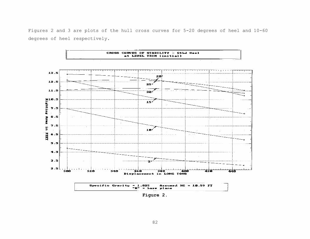
82
Figures 2 and 3 are plots of the hull cross curves for 5-20 degrees of heel and 10-60
degrees of heel respectively.
Figure 2.

83
Figure 3.
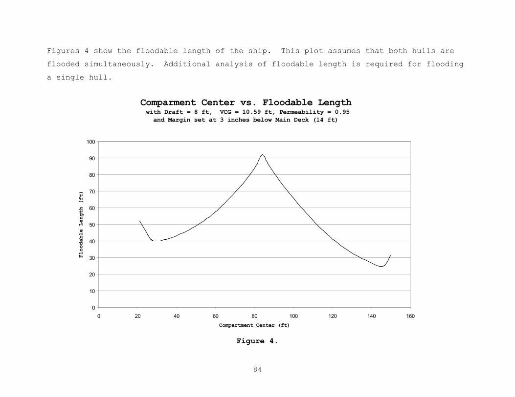
84
Figures 4 show the floodable length of the ship. This plot assumes that both hulls are
flooded simultaneously. Additional analysis of floodable length is required for flooding
a single hull.
Figure 4.
Comparment Center vs. Floodable Length with Draft = 8 ft, VCG = 10.59 ft, Permeability = 0.95
and Margin set at 3 inches below Main Deck (14 ft)
0
10
20
30
40
50
60
70
80
90
100
0 20 40 60 80 100 120 140 160
Compartment Center (ft)
Floodable Length (ft)
85
3. Ship Motions Analysis
Ship Motions were calculated using primarily two
sources. The first of these sources was the motions
chapters of The Principles of Naval Architecture3. These
computations where used to check the results produced by
the Ship Motions Program, SHIPMO4. SHIPMO is a FORTRAN 77
based program that utilizes strip theory to compute motions
in 6-degrees of freedom. The program will compute the
motion responses, shear and bending moments to regular
waves and long or short-crested seas in infinite or finite
water depth. The motion, velocities, acceleration and
relative motions at any point on the vessel could be
calculated. Motions were analyzed at the bow, stern and at
the mid point of the bridge in the horizontal plane. All
points were at the weather deck in the vertical plane.
The viscous damping of the hull forms, the effects of
the wave-piercer and the ride stabilization system were not
taken into account due to the complexity of the modeling.
Accelerations were found to be high as expected without the
effects of these stability features. Accelerations as high
as 1.2 g’s were computed. Ride stability features were
added to the design in space, weight and volume to lower
the accelerations to those of commercial wave-piercing
catamarans of similar design. These commercial designs
produce accelerations in the range of .2 to .4 g’s with a
maximum of .8 g’s through the use of fin stabilizers and
trim tabs.
3 Principles of Naval Architecture, Volume III, Society of Naval Architects and Marine Engineers, 1989 4 Robert F. Beck, Armin W. Troesch SHIPMO, Ship Motions Program, 1989
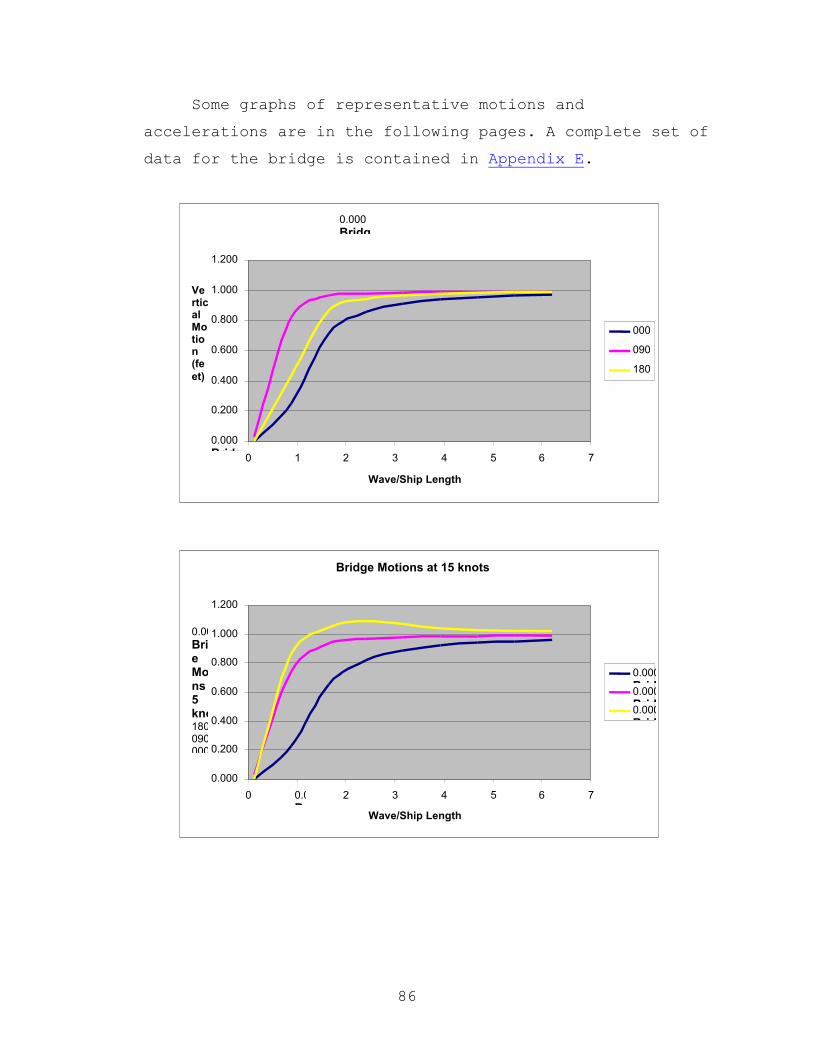
86
Some graphs of representative motions and
accelerations are in the following pages. A complete set of
data for the bridge is contained in Appendix E.
0.000 Bridg
0.000 Bridg
0.200
0.400
0.600
0.800
1.000
1.200
0 1 2 3 4 5 6 7
Wave/Ship Length
Vertical Motion (feet)
000 090 180
Bridge Motions at 15 knots
0.000
0.200
0.400
0.600
0.800
1.000
1.200
0 0.000Bridg
2 3 4 5 6 7 Wave/Ship Length
0.000Bridge Motions at 5 knots180090000
0.000Bridg0.000Bridg0.000Bridg

87
Bridge Motions at 40 knots
-0.500
0.000
0.500
1.000
1.500
2.000
2.500
3.000
3.500
0 1 2 3 4 5 6 7
Wave/Ship Length
Vertical Motions (feet)
000 090 180
Accelerations at the Bridge
0.00
0.20
0.40
0.60
0.80
1.00
1.20
1.40
0 1 2 3 4 5 6 7
Wave/Ship Length
Acc
eler
atio
n (
g's
)

88
B. Propulsion
1. Hull Resistance
Resistance is very important in deciding on the
right hull form, because it directly affects the size,
power and fuel consumption of the engines put on the
ships. The two main hull form types considered to enable
the ships to attain higher speeds are the improved
monohull and advanced catamaran hulls. Recent designs of
fast ferry craft show the superiority of the catamaran
over the monohull in these high (35-40 knot) speed
regimes.
There is enough data for monohulls to make accurate
resistance calculations, but data for high speed
catamarans is lacking in the open literature. This is
due to the fact that the dominant part of catamaran
resistance is wave-making resistance and it is
calculated by modeling utilizing prototypes and is made
for specific, real designs, data for which is generally
proprietary. Therefore, for initial comparisons,
monohull data was used to estimate catamaran resistance
by dividing the displacement between the two separate
hulls of catamaran for the same length of monohull, then
applying corrective factors for relative ship length and
hull spacing. In other words, the resistance of a
catamaran is mainly affected by the wetted surface ratio
(Sw/V2/3), the slenderness ratio (L/V1/3) and the hull
spacing (S/L).
Previous studies on specific designs show that
catamaran has poor resistance performance at low speeds
89
(Fr<0.35). On the other hand with the right
configuration of wetted surface ratio, slenderness ratio
and hull spacing at high speeds, the catamaran has
better performance, up to 45% less resistance than
monohull for the same displacement.
The Fast Patrol Craft design team of MIT mentioned
in their report that they had the same difficulties and
they had generated curves for the catamaran hull by
using ACC prototypes and paper designs, while they were
making their own design. Examination of the resistance
comparisons for monohulls and catamarans from the curves
of the MIT design team verified the previous studies on
this area. The catamaran shows a poor resistance
performance at low speeds but at high speeds (above 15
knots) it decreases the resistance up to 50% percent.
Because the GDM has the same hull form as the
Combatant, the resistance of the GDM was assumed the
same as Combatant’s resistance and the total resistance
for both Combatant and GDM is assumed as the twice of
Combatant’s resistance. The Resistance/Weight vs. Fn
curve that was created by the MIT design team for
catamaran hulls can be seen in Figure (1).

90
Figure 1. Resistance/Weight vs. Fn
References:
- The Royal Institution of Naval Architects (1978), Symposium on
small fast warships and security vessels.
- SNAME, Principles of Naval Architecture (1989)
- Massachusetts Institute of Technology (MIT), Fast Patrol Craft Design Report (2000)
2. Power Requirements
The nature of the mission determines the required
power for SEA LANCE. The missions that require towing
the GDM will demand more power than missions that do not
require the GDM for the same speed. Because of this, the
power requirements up to 15 knots, which is the grid
deploying speed, are defined for both Combatant and GDM.
Power requirements for speeds higher than 15 knots are
defined only for the Combatant. For the safety, service
life and fuel consumption, it is assumed that the
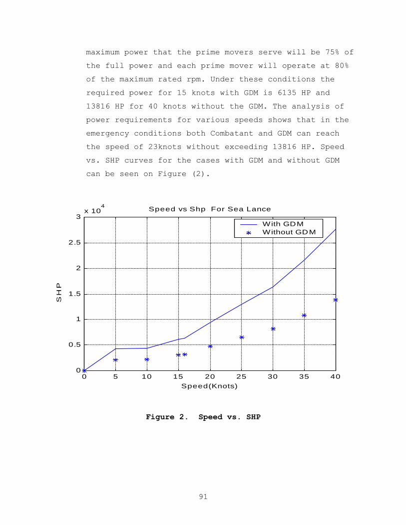
91
maximum power that the prime movers serve will be 75% of
the full power and each prime mover will operate at 80%
of the maximum rated rpm. Under these conditions the
required power for 15 knots with GDM is 6135 HP and
13816 HP for 40 knots without the GDM. The analysis of
power requirements for various speeds shows that in the
emergency conditions both Combatant and GDM can reach
the speed of 23knots without exceeding 13816 HP. Speed
vs. SHP curves for the cases with GDM and without GDM
can be seen on Figure (2).
Figure 2. Speed vs. SHP
0 5 10 15 20 25 30 35 400
0.5
1
1.5
2
2.5
3x 10
4
Speed(Knots)
SH
P
Speed vs Shp For Sea Lance
With GDM Without GDM
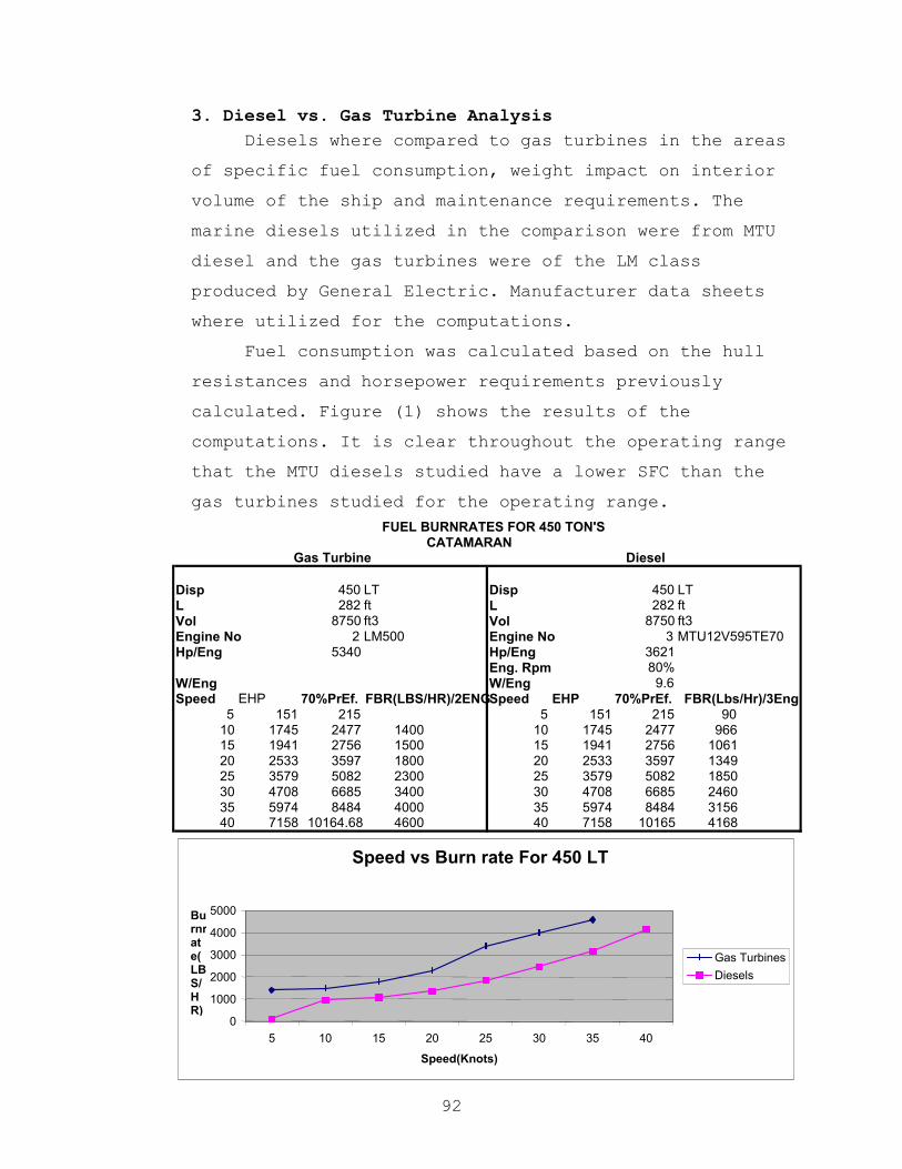
92
3. Diesel vs. Gas Turbine Analysis Diesels where compared to gas turbines in the areas
of specific fuel consumption, weight impact on interior
volume of the ship and maintenance requirements. The
marine diesels utilized in the comparison were from MTU
diesel and the gas turbines were of the LM class
produced by General Electric. Manufacturer data sheets
where utilized for the computations.
Fuel consumption was calculated based on the hull
resistances and horsepower requirements previously
calculated. Figure (1) shows the results of the
computations. It is clear throughout the operating range
that the MTU diesels studied have a lower SFC than the
gas turbines studied for the operating range.
CATAMARAN
Disp 450 LT Disp 450 LT L 282 ft L 282 ft Vol 8750 ft3 Vol 8750 ft3 Engine No 2 LM500 Engine No 3 MTU12V595TE70 Hp/Eng 5340 Hp/Eng 3621
Eng. Rpm 80% W/Eng W/Eng 9.6 Speed EHP 70%PrEf. Speed EHP 70%PrEf.
5 151 215 5 151 215 90 10 1745 2477 1400 10 1745 2477 966 15 1941 2756 1500 15 1941 2756 1061 20 2533 3597 1800 20 2533 3597 1349 25 3579 5082 2300 25 3579 5082 1850 30 4708 6685 3400 30 4708 6685 2460 35 5974 8484 4000 35 5974 8484 3156 40 7158 10164.68 4600 40 7158 10165 4168
FBR(LBS/HR)/2ENG FBR(Lbs/Hr)/3Eng
FUEL BURNRATES FOR 450 TON'S
Gas Turbine Diesel
Speed vs Burn rate For 450 LT
0 1000 2000 3000 4000 5000
5 10 15 20 25 30 35 40 Speed(Knots)
Burnrate(LBS/HR)
Gas Turbines Diesels
93
The team realizes that there are efforts to improve
the thermodynamic efficiency and therefore SFC for gas
turbines. If the advancements such as ICR gas turbines
or others produce results comparable to the diesels,
this decision would need to be reviewed.
Gas turbines had further drawbacks for this design.
The volume that would be necessary for the intake and
the exhaust ducting would require volume that could be
needed for grid elements or fuel tankage. The gas
turbines would also require the use of a reduction gear
to connect to the propellers or water jets. The diesels
could be direct drive and even with their heavier weight
to horsepower ratio, they still added less weight to the
propulsion plant.
The weight and volume limitations for each hull of
catamaran demand the use of 4 medium-size diesel engines
instead of two large ones.
If 4 engines are put on the ship, the best
configuration is CODAD with 2 engines on each side of
the ship (15 knots with tow and up to 25 knots without
tow); one engine on each side can be operated. For
higher speeds all of the engines will be in operation.
For the speed of 15 knots with GDM attached, the
required power is 6135 HP which means that each one of
low speed engines has to have at least the maximum power
of 4100HP(with 75% service factor). For the speed of 40
knots without tow, required power is 13816 HP and this
means that each one of high-speed engines has to have a
maximum power of at least 4610 HP (with 75% service

94
factor). The difference between these 2 numbers is just
510 HP and for the fuel consumption, weight and size,
and cost considerations this does not create a
significant reason to use 2 different types of engine on
the combatant. If 4 of the same type of engine are used
on board, this will provide numerous advantages for the
combatant (i.e. Less spare parts on board for the same
maintenance program). Therefore, it is reasonable to
have one type of engine, which serves the ship. The MTU
Model 16V 595 TE 70 was utilized. This engine has a
maximum power of 4828 Hp and this gives the opportunity
of using 2 engines up to 25 knots. After tow is released
and for the speeds higher than 25 knots, 4 engines
should be used.
4. Specific Fuel Consumption Analysis
The required power for various speeds determines
the fuel burn rates for these various speeds. Relatively
high power requirements up to the 15 knots with GDM
produces the high fuel burn rates. After GDM is released
the fuel burn rates drop significantly. The speed versus
fuel burn rate curve for 70% propulsive efficiency can
be seen in Figure (3).

95
Figure 3. Speed vs. Fuel Burn rate
For the fuel burn rate calculations typical
diesel burn rate curves are used. In the case of 70%
propulsion efficiency is not possible, the power
requirement and fuel burn rate calculations are
performed for 62%, 65%, 68% and 70% propulsive
efficiencies. These calculations showed that the
difference between fuel burn rates for both the speed
of 15 knots with GDM and 40knots without GDM is not
more than 10%.
The resistance, power requirements and fuel burn
rate calculations for different values of propulsive
efficiencies and the data for MTU Model 16V 595 TE 70
can be seen in Appendix F.
0 5 10 15 20 25 30 35 400
1000
2000
3000
4000
5000
6000
Speed(K n o t s )
Fu
el
Bu
rnra
te(L
bs
/Hr)
Speed vs Fue l Burn Rate For Sea Lance
Combatant and GDM
Combatant only

96
5. Conventional Versus Electric Drive
The option of transferring engine power to the
propulsion mechanism via electric drive was
considered. Future naval combatants are expected to
use an Integrated Power System, which includes
electric drive. Electric drive benefits large gas
turbine ships allowing them to burn less fuel, to
increase redundancy and survivability, and to relocate
prime movers to any location.5
Using our diesel engines at our “design point”
speeds of 15 and 40 knots and giving the electric
drive the most advantageous assumptions, we found that
electric drive will be slightly more fuel efficient
than conventional drive at 15 knots. Appendix F
contains this analysis; when conventional drive is
given a best-case assumption, it outperforms electric
drive. The electric drive enjoys an average 4-5%
specific fuel consumption bonus over conventional
drive since the engines are free to spin at their
optimal speed. Despite this possible 5% fuel
efficiency bonus, the electric drive cannot overcome
its inherent and constant 7% transmission efficiency
loss6 when compared to conventional drive.
Further analysis makes electric drive even less
desirable. Electric drive’s other benefits,
survivability and design arrangement flexibility, do
not assist our design. Survivability of each SEA
5 TS3000 Electrical Power Engineering, Naval Post Graduate School, Professor John Ciezki, p. 3-15,16 6 Ibid. p. 4-6
97
LANCE Combatant is not a design priority. Also, the
ability to move the prime movers anywhere in the ship
is not of real benefit to SEA LANCE: the engines are
well-positioned in the hulls where conventional drive
requires them to be. Electric drive also carries the
liabilities of being costlier, having higher
technological risk, and being heavier due to extra
components (electric motors, large generators, high
power distribution equipment, etc.). Cost and weight
are two key parameters that we desire to minimize.
One counter-argument to the above discussion is
worth considering. Since the Navy appears to be
adopting electric drive for DD-21 and other naval
ships, perhaps the Navy should, from a Fleet-wide
perspective, consider using electric drive in the SEA
LANCE Combatant. Simply put, it will be less
expensive for the Navy to make mistakes and build
corporate knowledge in electric drive with low-cost
SEA LANCE Combatants rather than large combatants.
Regardless of this consideration, we have followed the
analysis, which clearly favors the choice of
conventional drive.

98
Patents Approved & Pending
6. Propulsion Mechanism
We have chosen the Bird-Johnson Company’s
Advanced Waterjet Propulsor Application (AWJ21TM)
technology. The AWJ21TM is a podded waterjet that hangs
beneath the aft-body of the hull as shown in Figure 1.
The SEA LANCE Combatant will be equipped with four
AWJ21TMs (two per hull); each directly driven by a
diesel prime mover.
Figure 1
The AWJ21TM adapts efficient, advanced mixed-flow
commercial waterjet technology to high performance
surface ships, incorporating a novel underwater
discharge configuration.7 Finishing in 1999, Bird-
Johnson was sponsored by MARITECH to conduct research
and development of an advanced, high power waterjet
design. The result is the AWJ21TM, which is more
efficient than controllable pitch propeller, quieter
than propellers, and typically will not increase
7 Appendix K Bird-Johnson Brief slide 6

99
Patents Approved & Pending
navigational draft (see Figure 2).8 Additionally, the
AWJ21TM promises to be more maneuverable and will not
require reversing the engines in order to drive
backwards.
Figure 2
Using data provided by the Bird-Johnson Company,
we have estimated the size and expected RPM of AWJ21TM
for our application. Although we did not have
specifications on appropriately sized jets, we have
plotted the size and RPMs versus horsepower of the
examples provided.
Figure 3 shows that the SEA LANCE AWJ21TM should
operate between 900 and 1800 maximum RPM. The
standard MTU 16V 4800HP engines (that served as our
typical engine) spin at 1300 RPM. Hence, we conclude
that the engines will likely be able to direct drive
the AWJ21TM without a reduction gear. Figure 4 shows
that an appropriate diameter of AWJ21TM is between 0.4
and 0.8 meters (1.3 and 2.6 feet). The aft-body of
the SEA LANCE hull sweeps up 2.0 feet leading us to
8 Ibid. slide 10

100
SHP vs RPM Trend
0
10000
20000
30000
40000
50000
60000
1783 892 765 325 265
Series1
SHP vs Diameter
0
10000
20000
30000
40000
50000
60000
0.41 0.82 0.95 2.24 2.74
meters
SH
P
Series1
conclude that AWJ21TM will fit beneath the hull with
little or no impact to navigational draft.
Figure 3 Figure 4
We did examine propellers as an alternative.
Using a propeller optimization program9, we estimated
that the SEA LANCE Combatant would require an
approximately 8 ft. diameter propeller. This exactly
matches our navigational draft of 8 ft. However,
since the wave-piercing catamaran is a planing hull
form, propellers would have to be placed lower to
ensure submersion even at high speed. A reasonable
expectation finds the propellers increasing our
navigational draft by 2 feet or more. In addition,
propellers would require reduction gear regardless of
the engine type chosen. Since weight is a primary
concern for a catamaran hull, we wish to avoid
reduction gear.
A conventional waterjet would also avoid the
problems of increased draft and need to provide
reduction gear. However, the propulsive efficiency of
conventional waterjets is unacceptably low for our
9 http://web1.nps.navy.mil/~fapapoul/propopt_input.html/

101
15 20 25 30 35 40 45 50Speed [knots]
41
42
43
44
46
47
48
49
51
52
53
54
56
57
58
59
61
62
63
64
66
67
68
69
71
72
73
74
40
45
50
55
60
65
70
75
Eff
icie
ncy
[%
]
Efficiency vs. Ship Speed of:
Waterjet LJ84E
40m Catamaran
100% MCR
100% MCR = 3675 kW = 3570 kW waterjet input power
40%
MC
R
US Navy
design speed of 15 knots. As can be seen by this
waterjet efficiency chart (Figure 5) provided by Lips
Propulsion, waterjet efficiency drops to about 45%.
This is significantly lower than the 60+% of
propellers and would require increasing the
Combatant’s fuel load by 25 to 33 percent.
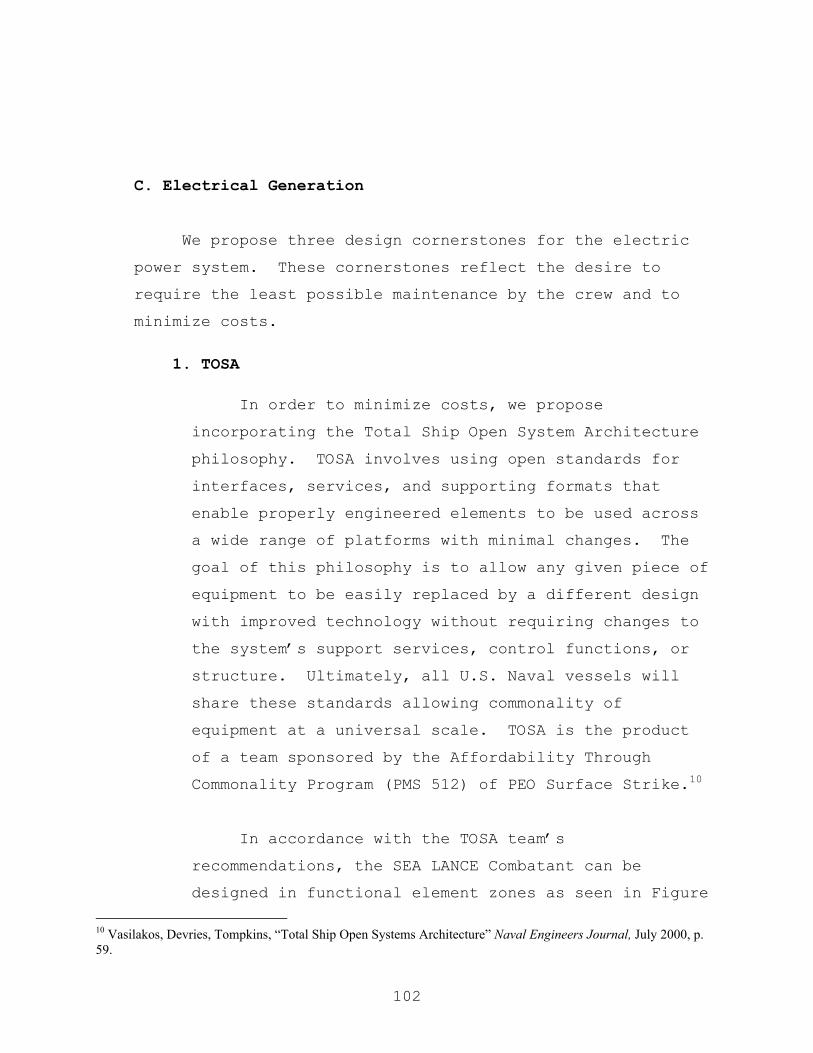
102
C. Electrical Generation
We propose three design cornerstones for the electric
power system. These cornerstones reflect the desire to
require the least possible maintenance by the crew and to
minimize costs.
1. TOSA
In order to minimize costs, we propose
incorporating the Total Ship Open System Architecture
philosophy. TOSA involves using open standards for
interfaces, services, and supporting formats that
enable properly engineered elements to be used across
a wide range of platforms with minimal changes. The
goal of this philosophy is to allow any given piece of
equipment to be easily replaced by a different design
with improved technology without requiring changes to
the system’s support services, control functions, or
structure. Ultimately, all U.S. Naval vessels will
share these standards allowing commonality of
equipment at a universal scale. TOSA is the product
of a team sponsored by the Affordability Through
Commonality Program (PMS 512) of PEO Surface Strike.10
In accordance with the TOSA team’s
recommendations, the SEA LANCE Combatant can be
designed in functional element zones as seen in Figure
10 Vasilakos, Devries, Tompkins, “Total Ship Open Systems Architecture” Naval Engineers Journal, July 2000, p. 59.
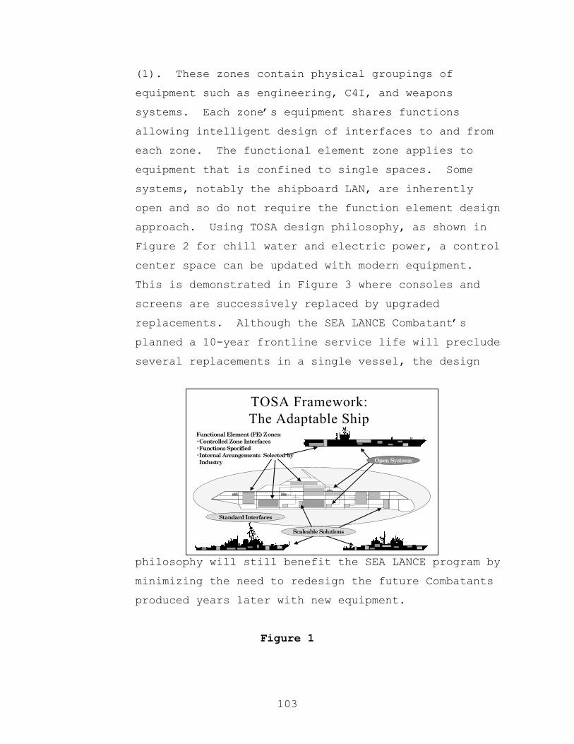
103
TOSA Framework:The Adaptable Ship
Scaleable Solutions
21
Standard Interfaces
Functional Element (FE) Zones:•Controlled Zone Interfaces•Functions Specified•Internal Arrangements Selected byIndustry Open Systems
(1). These zones contain physical groupings of
equipment such as engineering, C4I, and weapons
systems. Each zone’s equipment shares functions
allowing intelligent design of interfaces to and from
each zone. The functional element zone applies to
equipment that is confined to single spaces. Some
systems, notably the shipboard LAN, are inherently
open and so do not require the function element design
approach. Using TOSA design philosophy, as shown in
Figure 2 for chill water and electric power, a control
center space can be updated with modern equipment.
This is demonstrated in Figure 3 where consoles and
screens are successively replaced by upgraded
replacements. Although the SEA LANCE Combatant’s
planned a 10-year frontline service life will preclude
several replacements in a single vessel, the design
philosophy will still benefit the SEA LANCE program by
minimizing the need to redesign the future Combatants
produced years later with new equipment.
Figure 1

104
C4I Interfaces
Open HVACOpen Electric
CIC - c. 2005
CIC - c. 2015
CIC - c. 2035
Underfloor Plenum
SMART Track
Figure 2 Figure 3
The TOSA team has developed, and continues to
develop, reference models for various ship functions
and systems. A detailed SEA LANCE design can use
these models to ensure affordability is incorporated
everywhere possible. A reference model will define
the “Atomic Level” below which, industry suppliers
control the design process.11 The government controls
the design process above the Atomic Level. This
further facilitates commonality amongst different ship
classes reducing overall fleet cost.
Including the TOSA design philosophy in SEA LANCE
will allow for easier insertion of new technologies at
a lower cost. TOSA will allow the SEA LANCE greater
flexibility and adaptability while reducing
requirements to redesign. It also helps the insertion
of commercial products and promoting commonality in
all Navy ships.12
11 Ibid., p. 60 12 Ibid., p. 76
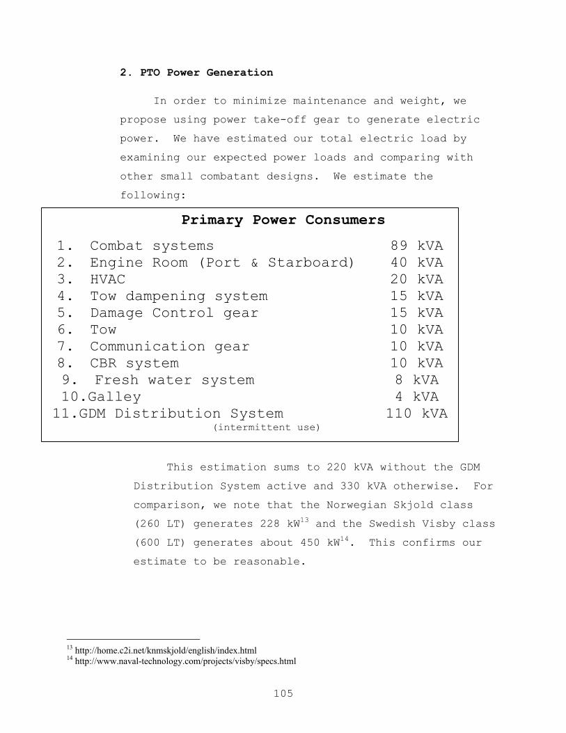
105
2. PTO Power Generation
In order to minimize maintenance and weight, we
propose using power take-off gear to generate electric
power. We have estimated our total electric load by
examining our expected power loads and comparing with
other small combatant designs. We estimate the
following:
This estimation sums to 220 kVA without the GDM
Distribution System active and 330 kVA otherwise. For
comparison, we note that the Norwegian Skjold class
(260 LT) generates 228 kW13 and the Swedish Visby class
(600 LT) generates about 450 kW14. This confirms our
estimate to be reasonable.
13 http://home.c2i.net/knmskjold/english/index.html 14 http://www.naval-technology.com/projects/visby/specs.html
Primary Power Consumers
1. Combat systems 89 kVA 2. Engine Room (Port & Starboard) 40 kVA 3. HVAC 20 kVA 4. Tow dampening system 15 kVA 5. Damage Control gear 15 kVA 6. Tow 10 kVA 7. Communication gear 10 kVA 8. CBR system 10 kVA 9. Fresh water system 8 kVA 10.Galley 4 kVA
11.GDM Distribution System 110 kVA (intermittent use)

106
To minimize size, we have chosen to design our
PTO equipment to be capable of producing 330 kVA at
100% capacity. This results in requiring both PTOs
online running at 75% capacity during normal (non-Grid
deploying) operations.
This scheme allows some flexibility in load
shedding or emergency situations. The emergency
generator set is rated at 150 kVA permitting the SEA
LANCE Combatant to operate without degradation even
with one PTO completely offline. The ship will
continue to function with only vital loads with both
PTOs offline and operating solely from the emergency
generator. Since the GDM is designed to receive power
from the Combatant and since the GDM has an identical
emergency/inport generator set, the SEA LANCE with GDM
attached may have yet another option for alternate
power. If the Combatant has its emergency generator
online and has the GDM generator power available, the
Combatant will be able to operate at full capacity
(without the grid deployment system online). The
following table describes the Combatant (without GDM)
power configurations.
Operational
Condition
PTOs online Emergency/Inport
Generator online
Normal 2 0
Casualty 1 1
Emergency 0 1

107
The weight saved is the primary advantage of PTO.
A generator set capable of producing 180 kVA of power
weighs about 3500 lbs.15. The lightest possible
generator at 180 kVA could weigh as little as 122 lbs.
for permanent magnet and easily under 250 lbs. for
other generator types16. It is difficult to estimate
the PTO gear weight, but this should easily weight
less than one thousand lbs.
We have decided to use a field wound synchronous
machine generator. Although a permanent magnet
generator would be lighter, the field wound generator
offers important advantages without much greater
weight. The permanent magnet option suffers
disadvantage since the PTO will provide a variable
input speed. This causes variable levels of voltage
in the power produced, and variable voltage is
difficult to manage. A field wound generator may be
controlled to produce a steady voltage, which
simplifies the rest of the power generation process.
A step-up gearbox may be required in the PTO gear
in order to smooth out the power frequency produced by
the generator. However, if the generator is an 8-pole
machine with an expected input of 300-1300 rpm
(approximately the expected operating range of our
4800 HP diesel prime movers), the field wound machine
may be able to direct drive from the engines. The
power frequency produced by a synchronous machine is:
15 http://www.armstrongpower.com/b143-cum.pdf 16 TS3000 Electrical Power Engineering, Naval Post Graduate School, Professor John Ciezki, p. 4-7

108
Fe = RPM x poles / 120
Given the above inputs, these produces power
frequencies between 20 and 86 Hz, which may be an
acceptable range depending on the generator. The
generator operates most efficiently at its designed
frequency (often 60 Hz), but it can accept a range
based on its design. This issue is worth further
research since eliminating a step-up gear will save
cost and weight.
The field wound option also best supports the DC
zonal distribution system (discussed in the next
section) by providing constant voltage power to a
rectifier. If an AC distribution system were chosen,
the lighter permanent magnet generator ought to be the
superior choice. The permanent magnet generator would
be followed by a cycloconverter that converts variable
voltage/variable frequency power to constant
voltage/constant frequency power for distribution.
The cycloconverter is a mature technology; its main
drawback is the requirement for complex control
mechanism.
3. DC Zonal Distribution
In order to minimize costs and maintenance, we
propose using a DC zonal distribution system (DCZEDS).
DCZEDS offers the advantages of solid state, low
maintenance components and by means of technologies
already being developed for the DD-21 power
109
distribution system. A notional DCZEDS appears in
Figure 4.
AC power generated by the field wound synchronous
machine is fed to a phase-controlled rectifier. The
rectifier converts the AC power to DC power and
distributes it on a main power bus. The rectifier
will have 6 phases to allow maintenance and repair
while energized. Two sets of three phases will
equally share the electric load. The SEA LANCE will
have a port and starboard main power bus. The ship is
divided into zones (four zones in the notional figure
separated by dashed lines) each of which draws power
from the port and starboard main buses through a DC
converter referred to as a Ship’s Service Converter
Module (SSCM). The SSCM can provide power directly to
equipment requiring DC power, or it provides the power
to a DC to AC inverter referred to as a Ship’s Service
Inverter Module (SSIM). The SSIM services equipment
requiring AC power. The SSCMs and SSIMs are being
developed for the DD-21 power distribution system.
SEA LANCE could use modules identical except scaled
down for our lower power requirements. The port and
starboard buses can cross connect in the forward hull
if one PTO goes offline. There they can be connected
to the emergency/inport generator for inport, at
anchor, and in casualty mode operations.
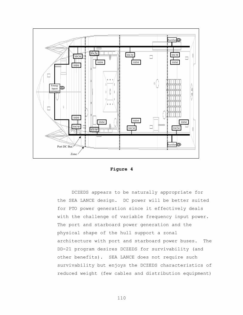
110
Figure 4
DCZEDS appears to be naturally appropriate for
the SEA LANCE design. DC power will be better suited
for PTO power generation since it effectively deals
with the challenge of variable frequency input power.
The port and starboard power generation and the
physical shape of the hull support a zonal
architecture with port and starboard power buses. The
DD-21 program desires DCZEDS for survivability (and
other benefits). SEA LANCE does not require such
survivability but enjoys the DCZEDS characteristics of
reduced weight (few cables and distribution equipment)
Rectifier
RectifierPort DC Bus
Zone
SSCMSSCMSSCM
SSCM
SSCM
SSCMSSCM
SSCM
SSIM
SSIM
SSIM
SSIMSSIM
SSIM SSIM
SSIM
Emerg/Inport
GENSET

111
and reduced manufacturing cost (much less cable
pulling after ship sections are connected).
Another issue in survivability and reliability is
battery backup of vital equipment. Battery backup, or
Uninterruptable Power Supply (UPS), is desirable for
critical systems such as control, communications, and
(possibly) propulsion. Considering the power levels
required, UPS for minimum electronic equipment should
be inexpensive in weight and cost. However, the power
requirements to keep the prime movers and AWJ21TM
operating without ship’s power are expected to be
high. Once those requirements are defined, an
analysis of weight and cost of large UPS systems
should be performed.
112
D. Combat Systems, Weapons and C4ISR
1. Combat Systems and Weapons
a. Overview
The organic sensors and weapons chosen for SEA
LANCE are in accordance with the Operational
Requirements Document (ORD). From the analysis of the
ORD, the need for sensors and weapons can be
summarized by the following functions:
i. Offensive:
• Engage surface targets (surface action)
ii. Defensive:
• Engage surface targets (point defense)
• Engage air targets (point defense)
• Avoid mines
The sensors and weapons that perform the air and
surface engagement functions must be able to detect,
track, identify/classify and destroy/neutralize
targets. Mine avoidance only requires detecting, in
order to maneuver accordingly.
The objective of this analysis is to provide
notional systems for the first iteration of the

113
conceptual design. These theoretical systems will
provide an initial estimation of weight, volume, power
consumption, and cost, so that feasibility of the
proposed platform can be assessed. The systems
described in the following paragraphs have been
conceptualized from existing systems in the market
today. It is reasonable to assume that due to trends
in technology, systems will in general, get smaller,
lighter, more efficient, more reliable, and more
effective.
b. Weapons
The organic weapons that SEA LANCE will carry are
the following:
i. 4 medium range SSM.
ii. 51 short-range dual purpose SAM/SSM.
iii. 2 30mm mounts with 1200 rounds each.
The medium range SSM will give SEA LANCE the
capability of engaging in surface actions. Data is
based on the existing Harpoon missile.

114
Both air and surface point defense are allocated
in two complementary layered systems. The first layer
is given by a dual purpose SAM/SSM. This dual-purpose
system has been conceptualized by linear regression
data analysis from existing SAM and SSM missiles. The
data is shown in Appendix G. The missile system has
been conceived as a dual-purpose system in order to
provide flexibility while saving space, weight, and
manning requirements. It also provides logistic
advantages regarding maintenance and parts. If
different missiles were to be used for SAM and SSM,
more equipment would be needed, resulting in a larger
payload fraction. Also, fewer missiles would be
available for each function. With a dual-purpose
missile, any available missiles will always be usable
against air or surface targets, enhancing the ability
of SEA LANCE to retain capabilities with less need to
reload.
The second point defense layer is given by 2 30
mm gun mounts based on the Mk 46 to be installed in
LPD 17. The guns provide a cheaper alternative to
destroy/neutralize targets at shorter range when the
use of a missile is not justified. It also provides

115
defense at distances below the minimum firing range
for the dual-purpose missile, improving survivability.
Even though the gun is not designed as a Close in
Weapon System, it provides some degree of protection
against incoming missiles that penetrate the SAM
layer.
General characteristics of the weapons are listed
in tables 1 through 3.
Although decoy systems are not weapons, their
description has been included in this section. The
decoy system for SEA LANCE is based on a Rafael/Manor
Israeli system. It is designed to provide a layered
defense against radar emitters and IR sensors. The
first layer is a long-range, tactical confusion chaff
rocket to be used against search radars in their
detection phase. The second layer is a medium-range,
distraction chaff rocket that is designed to protect
against anti-ship missiles before target lock-on. The
third layer is a seduction chaff rocket that protects
the ship against active missiles that have achieved
lock-on. The system also incorporates a rocket
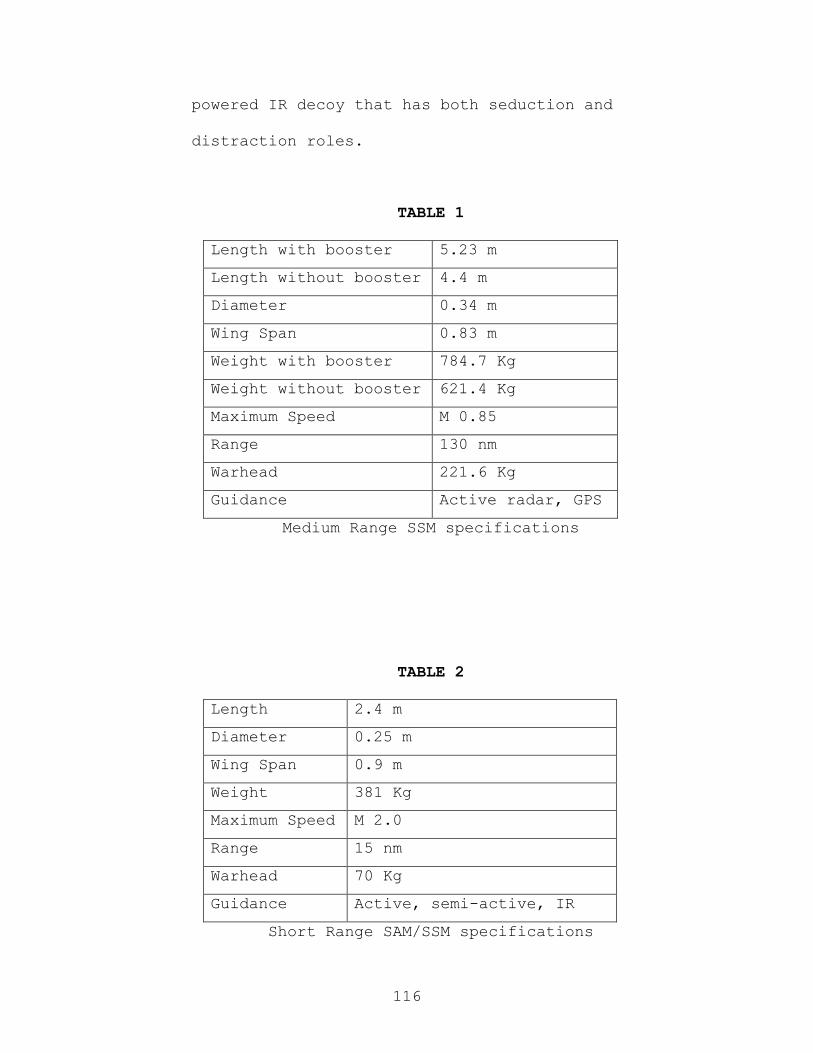
116
powered IR decoy that has both seduction and
distraction roles.
TABLE 1
Length with booster 5.23 m
Length without booster 4.4 m
Diameter 0.34 m
Wing Span 0.83 m
Weight with booster 784.7 Kg
Weight without booster 621.4 Kg
Maximum Speed M 0.85
Range 130 nm
Warhead 221.6 Kg
Guidance Active radar, GPS
Medium Range SSM specifications
TABLE 2
Length 2.4 m
Diameter 0.25 m
Wing Span 0.9 m
Weight 381 Kg
Maximum Speed M 2.0
Range 15 nm
Warhead 70 Kg
Guidance Active, semi-active, IR
Short Range SAM/SSM specifications
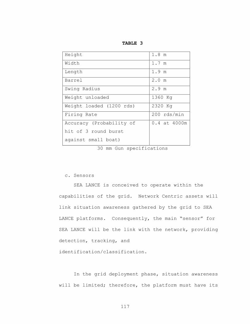
117
TABLE 3
Height 1.8 m
Width 1.7 m
Length 1.9 m
Barrel 2.0 m
Swing Radius 2.9 m
Weight unloaded 1360 Kg
Weight loaded (1200 rds) 2320 Kg
Firing Rate 200 rds/min
Accuracy (Probability of
hit of 3 round burst
against small boat)
0.4 at 4000m
30 mm Gun specifications
c. Sensors
SEA LANCE is conceived to operate within the
capabilities of the grid. Network Centric assets will
link situation awareness gathered by the grid to SEA
LANCE platforms. Consequently, the main “sensor” for
SEA LANCE will be the link with the network, providing
detection, tracking, and
identification/classification.
In the grid deployment phase, situation awareness
will be limited; therefore, the platform must have its

118
own capability to detect, track and identify/classify.
Even when deployed, combatants may have to operate in
areas of limited grid coverage.
In order to allow for the above, SEA LANCE will
carry the following sensors:
i. 1 air/surface search and missile detection
radar.
ii. 2 Fire control radar.
iii. 1 Infrared Search and Track (IRST).
iv. 2 Electro-Optic Suites.
v. 1 Electronic Support Measures (ESM) Suite.
vi. 1 Mine avoidance sonar.
vii. 1 Navigation radar.
The chosen sensors give SEA LANCE enough
capabilities and redundancy in key functions, to
conduct limited operations without the grid. They
also make the combatant another sensor of the grid
itself. Table 4 summarizes the primary (1) and
secondary (2) functions that can be performed with
each sensor.

119
TABLE 4
Sensor/Function Detect Track Classify Identify
Search Radar 1 1 2
Fire Control Radar 1 1 2
IRST 1 1 2
EO Suite 1 1 1 1
Navigation Radar 1 2 2
ESM 1 2 1
Mine Avoidance sonar 1 2 1 1
Primary and secondary functions of each sensor
d. Sensor Description17
i. Air/Surface Search and missile detection
radar:
The search radar is based on the Elta EL/M-
2228S system. It is a fully coherent 2-4 GHz
pulse-Doppler radar. It is a multimode system in
that it provides medium range surface detection,
low to medium height air detection, and sea
17 www.janesonline.com

120
skimming missile automatic threat alert with very
low false alarm rate. The radar is instrumented
to a range of 54 nm.
The antenna is of the cosec square type and
it scans mechanically at 12 or 24 RPM. The radar
has built in track-while-scan capabilities of up
to 100 targets.
ii. Fire Control Radar:
The fire control radar is based on the Elta
EL/M-2221 system. It is a 27-40 GHz monopulse
radar that provides automatic gun fire control
against air and surface targets. Also, the radar
provides tracking and guidance for the dual-
purpose short range SAM/SSM. The radar is
instrumented to 20 nm.
The antenna is mechanical and of the
Cassegrain type, and is constructed of
lightweight composite materials.

121
iii. IRST (Infra Red Search and Track):
The IRST is based on the Signaal SIRIUS
system. It is a long-range dual-band (3-5 and 8-
12 µm) surveillance and tracking system, which
gives passive capabilities against sea skimming
missiles. SIRIUS provides automatic threat
alerts to the weapon systems minimizing reaction
times. Stealth has been incorporated to the
sensor head that scans at 60 RPM. Detection
ranges vary with weather conditions and target
height, but 20 nm could be expected given enough
horizon.
iv. EO Suite:
The Electro-Optical Suite is based on the
Elop Multisensor Stabilized Integrated System
(MSIS). It includes an IR imager in the 8-12 µm
band, television camera, and a 1.064 µm laser
range finder (LRF) and designator. The sensor
provides detection, tracking, and recognition of
targets in day and night operations. The system

122
also provides fire control for the 30-mm guns and
can slave the fire control antennae for missile
guidance in case tracking by them fails.
Detection ranges vary, but 10 nm could be
expected.
v. Navigation radar:
The navigation radar is based on the Signal
Scout system. It is a low probability of
intercept radar working in the 8-10 GHz band.
The radar uses frequency modulated continuous
wave techniques and very low transmitter power,
making it very hard to detect by enemy ESM. It
is a very lightweight system and is instrumented
to 25 nm. The transceiver is integrated into the
antenna, which rotates at 24 RPM.
vi. Electronic Support Measures (ESM) Suite:
ESM is based on the British Aerospace
Australia PRISM III system. It provides
detection, direction finding, classification, and
analysis of radar emissions in the 2-18 GHz

123
range. The system is very lightweight and well
suited for small combatant applications. The
system is capable of detecting continuous wave,
conventional pulse, frequency agile, frequency
hopping, PRF agile, PW agile, and pulse
compression radars. It is mainly intended to
complement the passive capability of automatic
missile threat alert.
vii. Mine avoidance sonar:
The mine avoidance sonar is based on the
Thomson Marconi Sea Scout system. It is a
lightweight sonar working at 250 KHz, designed to
detect and classify objects up to distances of
300 m. The sonar has a 20° fixed azimuth
coverage, which can be scanned giving an overall
coverage of 80°. The azimuth resolution is 0.6°.
The vertical field of view is 10° selectable
within the total vertical range of +10°to -45°.
e. Weight and Volume Summary

124
One of the main goals of the sensor and
weapons assessment was to provide realistic
weight, volume, power consumption, and cost
estimates for the first iteration of the design
spiral. Table 5 summarizes the data. The
numbers correspond to totals; for example, the
numbers for the fire control radar include both
units.
TABLE 5
Sensor Weight Kg Volume m^3 Area m^2Power KVA Cost M$
Search radar 737.00 4.45 4.25 8.00 3
Fire Control radar 2840.00 7.56 1.94 44.00 12
IRST 1010.00 1.01 0.81 8.00 5
EO suite 200.00 0.81 0.61 4.00 5
ESM 67.00 0.59 0.70 0.50 1
Mine avoidance sonar 300.00 0.63 0.50 4.00 1
Navigation radar 80.00 0.48 0.82 0.70 0.5
Sensor Total 5234.00 15.53 9.64 69.20 27.5
Weapon/ECM
Medium range SSM 5100.00 154.01 55.80 1.00 2.88
Short range SAM/SSM 43234.00 100.00 25.00 5.00 15.3
Decoy Launchers 1600.00 1.00 2.00 2.00 1.5
30 mm gun 4640.00 5.81 3.23 12.00 2.44
Weapon Total 54574.00 260.82 86.03 20.00 22.12
Overall Total 59808.00 276.35 95.67 89.20 49.62
(58.86 LT) (9931.19 ft^3) (1041.85 ft^2)
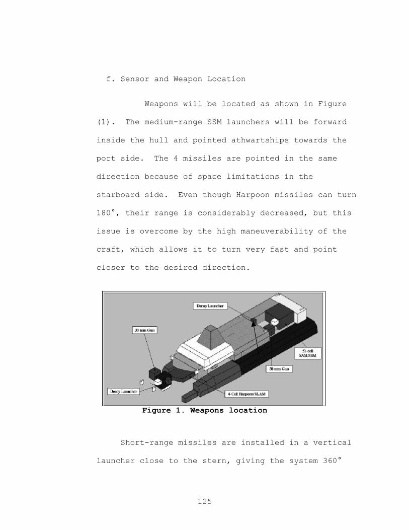
125
f. Sensor and Weapon Location
Weapons will be located as shown in Figure
(1). The medium-range SSM launchers will be forward
inside the hull and pointed athwartships towards the
port side. The 4 missiles are pointed in the same
direction because of space limitations in the
starboard side. Even though Harpoon missiles can turn
180°, their range is considerably decreased, but this
issue is overcome by the high maneuverability of the
craft, which allows it to turn very fast and point
closer to the desired direction.
Figure 1. Weapons location
Short-range missiles are installed in a vertical
launcher close to the stern, giving the system 360°
126
coverage. Both the medium range and short-range
missiles exhaust plume is discharged between the
hulls.
The 30-mm mounts have been installed off
centerline to improve their vertical field of view.
This will allow repelling small boats that come close
to the ship. The arcs of fire, fields of view, and
minimum ranges for the guns are shown in Appendix G.
Sensors are located in a partly telescopic,
enclosed mast shown in Figure 2. At the top of
telescopic part of the mast, the IRST is installed.
With the mast fully extended, the IRST will be at 48
feet above the waterline. This height gives the IRST
a 20-km horizon against a sea skimmer flying at 3
meters above the water. Right below the pedestal of
the IRST, the ESM antenna is installed. The search
radar is also inside the telescopic part of the mast
about 6 feet below the IRST. The horizon of the
search radar against the sea skimmer is approximately
21 km with the mast fully extended.

127
In the base of the mast (the fixed enclosed
portion) the fire control antennae are installed, one
forward and the other aft. This location for the
antennae provides good overlapping towards the beam
and gives the system as a whole 360° coverage. The
Electro-Optic suites are installed outside the
enclosed mast also providing 360° coverage. The
transducer of the mine avoidance sonar is installed
forward in the starboard hull.
Sensors and weapons coverage is summarized in
Table 6, and sensor coverage diagrams are shown in
Appendix G.
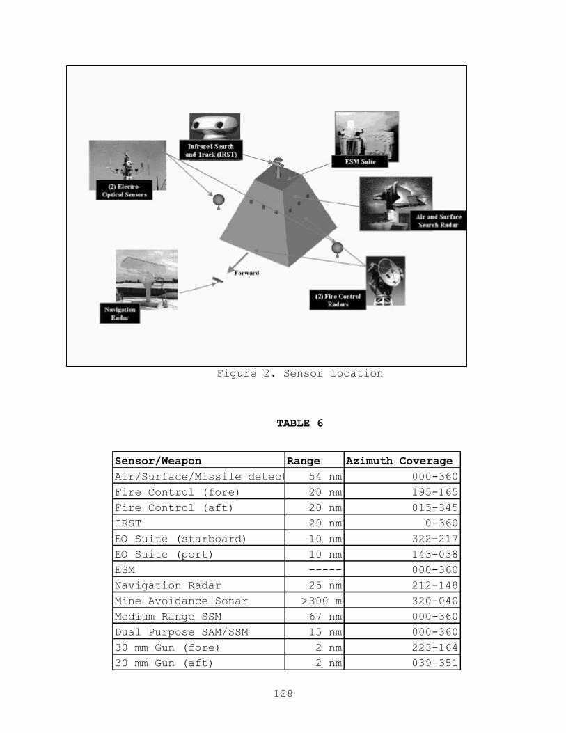
128
Figure 2. Sensor location
TABLE 6
Sensor/Weapon Range Azimuth CoverageAir/Surface/Missile detection54 nm 000-360
Fire Control (fore) 20 nm 195-165
Fire Control (aft) 20 nm 015-345
IRST 20 nm 0-360
EO Suite (starboard) 10 nm 322-217
EO Suite (port) 10 nm 143-038
ESM ----- 000-360
Navigation Radar 25 nm 212-148
Mine Avoidance Sonar >300 m 320-040
Medium Range SSM 67 nm 000-360
Dual Purpose SAM/SSM 15 nm 000-360
30 mm Gun (fore) 2 nm 223-164
30 mm Gun (aft) 2 nm 039-351
129
g. Sensor and Weapons Integration
Sensors and weapons are integrated through the
onboard digital network. They will comply with the
entire plug and play open system features incorporated
in the fast Ethernet LAN.
h. SAM Assessment
The most stressing scenario for SEA LANCE is
during grid deployment. Situation awareness will be
limited; hence detection will probably have to rely on
SEA LANCE’s own sensors.
In order to assess the performance of the SAM
against anti-ship missiles, a simulation was
conducted. A four subsonic (300 m/s) missile salvo
was chosen as the threat, flying at 3 m above the
surface. The missiles were incoming one after the
other separated by 600 m. SEA LANCE’s search radar
horizon is 21,713 m, while the illuminator horizon is
18,652 m. The SAM maximum range is 15,318 m. The
system is capable of launching SAM every 2 seconds,
and good guidance is achieved after 5 seconds in
flight. The simulation only considered the use of one
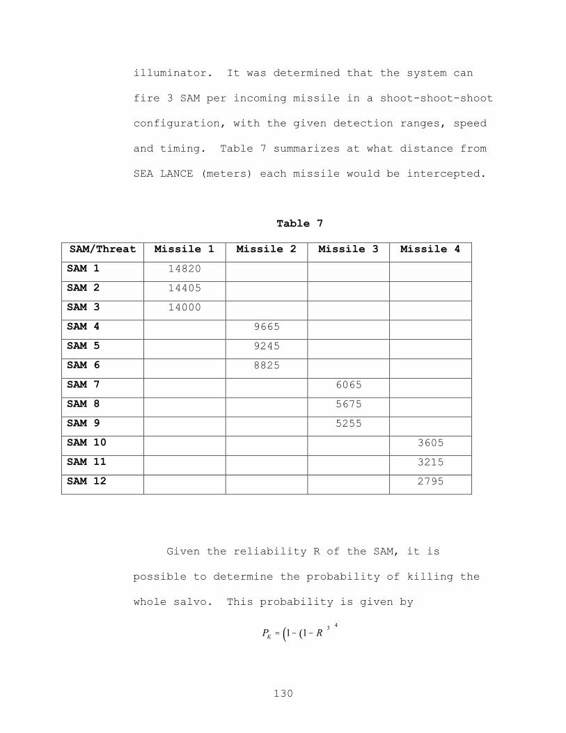
130
illuminator. It was determined that the system can
fire 3 SAM per incoming missile in a shoot-shoot-shoot
configuration, with the given detection ranges, speed
and timing. Table 7 summarizes at what distance from
SEA LANCE (meters) each missile would be intercepted.
Table 7
SAM/Threat Missile 1 Missile 2 Missile 3 Missile 4
SAM 1 14820
SAM 2 14405
SAM 3 14000
SAM 4 9665
SAM 5 9245
SAM 6 8825
SAM 7 6065
SAM 8 5675
SAM 9 5255
SAM 10 3605
SAM 11 3215
SAM 12 2795
Given the reliability R of the SAM, it is
possible to determine the probability of killing the
whole salvo. This probability is given by
( )( )43
1 1KP R= − −

131
Table 8 shows the probability of kill for
different reliabilities.
TABLE 8
R Pk0.5 0.586182
0.55 0.6823650.6 0.767544
0.65 0.8392180.7 0.896296
0.75 0.9389500.8 0.968382
0.85 0.9865680.9 0.996006
0.95 0.9995000.96 0.9997440.97 0.9998920.98 0.9999680.99 0.999996
132
2. C4ISR
The SEA LANCE Combatant is primarily a network
centric warfare ship. Its primary mission entails
supporting and utilizing the networked SEA LANCE Grid.
The Combatant’s C4I suite will reflect this focus
along with the constraint of a limited crew.
The SEA LANCE Combatant will be equipped with two
external data networks. Its primary network will be
what the SEA LANCE Grid employs. This network has not
been defined (SPAWAR San Diego uses the term
“Teamnet”). The TSSE group used a notional network
created by each grid component utilizing acoustic
modems to communicate with specialized grid components
(“RF gateways”) that collect acoustic data, process
it, and transmit it via a high speed RF link to
satellite or AUV. The aerial component transmits the
Teamnet to the Combatants and other Teamnet equipped
units. The real Teamnet may be drastically different;
however, we expect and planned for communicating with
the network via a RF link. To support this RF link,
SEA LANCE is equipped with antenna to communicate with
satellite and by line-of-sight in high frequencies
(expected K band) for high data rates.
Since SEA LANCE Combatants are expected to
perform other missions than Grid employment, they will
be equipped with Link 16/TADIL J. TADIL J is widely
used by U.S. Forces and will allow interoperability
with a wide variety of units. The need to equip SEA
LANCE with another data link besides Teamnet is a

133
point of concern. It reflects the Navy’s problem of
“stovepipe” data nets that cannot be inter-networked.
Ideally, Teamnet should be a starting point for
creating Navy-wide interconnectivity. Rather than
being another specialized data network available only
to Teamnet equipped ships and shore stations, Teamnet
should be the beginning of an integrated, cross-
platform, Internet-Protocol-based network.
The Navy’s worldwide mission requires a worldwide
radio Wide Area Network. This requires a satellite
infrastructure with the traits common to a robust
inter-network. Router-to-router interconnect is one
such trait; it means to be able to connect any
arbitrary set of Internet Protocol routers together.
Each ship’s communications center needs a router along
with each satellite and ground station. To ensure all
systems and local networks can utilize the radio WAN,
they must connect to their router via a standard LAN
protocol such as Ethernet. This virtually eliminates
integration problems between networks.
Another trait desired is the ability of routers
to multicast (i.e. deliver data to multiple
destinations simultaneously). Multicasting is
supported by “shared-use media protocol” which is
another key characteristic of our desired network.
This protocol governs the RF communications format and
abolishes the typical procedure of dividing up
satellite bandwidth equally among users. Division of
the bandwidth is an inherently inefficient (though
some think it “fair” sharing) method of multiplexing

134
several users on the same communications channel.
Additionally, the routers themselves need to use the
Simple Network Management Protocol (SNMP)18 that uses a
get/set/trap algorithm for efficient data flow and
management of networking services.
These issues are well beyond the scope of any
single program; but SEA LANCE/Teamnet is especially
sensitive to this Navy-wide problem.
SEA LANCE will also communicate with satellite
and LOS connections other than its data links. For
the sake of simplicity of design and of use by SEA
LANCE’s reduced crew, we propose a simple
communications suite. SEA LANCE will be able to
communicate LOS via VHF and UHF and to communicate via
satellite on standard EHF/MILSTAR19. The SEA LANCE
will also be able to receive the Global Broadcast
Service (GBS)20. While not robust, these communication
channels along, with the two data links, should allow
SEA LANCE to perform all assigned missions while being
simple enough for the minimally manned crew.
A promising technology to assist high-speed RF
links for SEA LANCE is the active phased antenna21.
This antenna electronically steers radio signal toward
the intended receiver. This allows less power to
achieve greater range and bandwidth. Additionally,
the communication transmission is less likely to be
18 http://www.faqs.org/faqs/snmp-faq/part1/ 19 http://www.losangeles.af.mil/SMC/MC/Milstar/ 20 http://www.laafb.af.mil/SMC/MC/GBS/ 21 SPAWAR Systems Center-San Diego C4ISR Innovation Cell, Art Chagnon

135
intercepted or even detected. Current technology
makes this feasible for high frequency applications
(above 1 GHz). Lower frequency communications, UHF
and VHF, may eventually be able to use active phased
array technology, but current lower frequency antenna
technology (omni-directional) may have to be used. We
have equipped the SEA LANCE Combatant with one large,
high capacity array that lays horizontally topside
behind the superstructure for satellite
communications. For LOS and data link, SEA LANCE has
three smaller antenna arrays mounted on each of the
mast’s four sides. If other (non-array) antennas are
required, they can be located on top of the non-
extending mast.
For interior communications and networking for
the SEA LANCE Combatant we propose a fast Ethernet LAN
arranged in a mesh topology. Ethernet is an extremely
compatible protocol that can be used by virtually any
system. Due to this flexibility, all systems will be
required to use Ethernet if they are installed on SEA
LANCE. A mesh topology creates super redundancy in
the network to ensure the crew will never need to
maintain or repair it while underway. A notional
topology is seen in Figure 1.

136
Figure 1
A design philosophy for SEA LANCE systems is
functional separation. This entails breaking system
functional components and separating them from direct
communications and requiring them to communicate to
each other via the Ethernet LAN. For example, a RADAR
system has a transmit/receive component, a data
reduction function, and a decision-making component
(deciding what to track, where to transmit the next
RADAR pulse, etc.). Normally, these
components/functions are consolidated into a single
physical system that allows direct communications
between them. This is efficient in operation but
difficult in repair and upgrading. An entire system
might need to be completely replaced to improve one
Hub
Hub
Hub
Hub
Hub
Hub
Hub
Hub
Hub
Hub
Hub
Hub Hub
Hub
Hub
Hub
Hub
Hub

137
small part. If these components/functions are
separated and connected to the LAN, they can easily be
removed and replaced individually.
Another aspect to the SEA LANCE LAN will be total
integration of all ship’s systems. We propose a
robust level of automation and control to facilitate
the small crew to operate the ship. The crew through
the digital data network will interface all
engineering, combat systems, operational and
administrative systems. This requires software
engineering to enable a reasonably trained person to
operate a SEA LANCE Combatant.
To interface the ship’s system, we propose a
single type of multi-function console. The SEA LANCE
multi-function console will require multiple touch-
scan screens for presenting information. The Raytheon
Corporation has developed the Enhanced Command Console
(ECC)22 that approaches the level of control and
utility required by SEA LANCE. Raytheon has proposed
similar technology for use on DD-21, but Raytheon was
not at liberty to discuss this technology due to the
upcoming contract decisions at the time of this
writing.
Each console is capable of accessing all
information available and controlling all ship
systems. Each console can assume a mode (Command,
Tactical, Operational, Engineering) that will limit
22 Raytheon Enhanced Command Console Brief, Helmut Tramposch
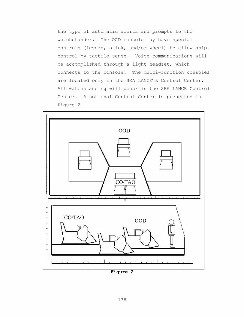
138
the type of automatic alerts and prompts to the
watchstander. The OOD console may have special
controls (levers, stick, and/or wheel) to allow ship
control by tactile sense. Voice communications will
be accomplished through a light headset, which
connects to the console. The multi-function consoles
are located only in the SEA LANCE’s Control Center.
All watchstanding will occur in the SEA LANCE Control
Center. A notional Control Center is presented in
Figure 2.
Figure 2
OODCO/TAO
OOD
CO/TAO

139
The Control Center has four multi-function
consoles to support various manning requirements. An
Officer of the Deck or “Ship’s Navigation and Safety”
watchstander could use the forward most console. If a
tactical environment requires it, a TAO watchstander
can use the aft most console (raised for a commanding
view). In a stressing tactical environment, or
whenever the situation calls for a specialized
watchstander, either of the remaining consoles can be
manned as required. The TAO console is actually two
consoles in one; it is designed to allow the CO ready
access to a console whenever needed.
Since each SEA LANCE Combatant is required to be
able to support a squadron commander and his or her
staff, the extra consoles can be dedicated to allowing
the squadron staff access to consoles.
One other type of control interface will be
available on the SEA LANCE. Each engine room will
have an Engineering control station to allow
maintenance actions and casualty engineering control.
A notional example is provided in Figure 3.
Figure 3

140
E. Auxiliary and Special Purpose Systems
1. Tow Analysis
The semi-rigid towing system developed for the SEA
LANCE project posed unique design challenges. The tow
design philosophy is: Develop an integrated towing
system based on elementary principles of naval
architecture, solid mechanics, and dynamics while
minimizing risks within the framework of the SEA LANCE
concept of operations.
The risks inherent to the semi-rigid towing
system are formidable. First, there are significant
historical and traditional prejudices against a warship
that doubles as a tugboat. Existing towing rigs are
dangerous and hamper the progress of battle groups. For
the SEA LANCE to achieve the requirements presented in
chapter II, a radical tow-rig had to be developed. Such
a radical design is risky because it has to be
technically feasible, must meet the ORD requirements,
and must do so in a cost-effective manner. The
operational guidelines included close-proximity tow
operations into sea state 4, with extended towing
operations to sea state 6. Close-proximity towing
operations utilizing a trailer concept have not been
validated, so there was an enormous amount of risk in
not only the tow-rig, but in the environmental
conditions in which it operates.
The design process utilized in the tow-analysis was
the traditional systems engineering model, wherein a
divergence to collect data was followed by a convergence
141
to a possible solution. First, a search of historical
documentation on towing systems and the integrated tow
in particular was performed. Very little research has
been done with respect to an integrated tow. Existing
data on such systems was limited to concept drawings and
strip theory analysis23. Next, a conceptual architecture
was developed that framed the problem and sources of
stress. Mechanical limitations such as shear and axial
yield stress, as well as Euler buckling were considered
in the sizing of the tow-system components. These
mechanical limitations were married with the geometric
limitations inherent to a close proximity tow, and a
design spiral performed between the two to arrive upon a
proposed close-proximity tow architecture.
Although little documentation on integrated tow
systems was available, an appreciable amount of
background data was assembled to accomplish the
architectural analysis. Concept drawings of SWATH hull
integrated tow system proposals were available from
Lockheed-Martin, and were redesigned to accommodate
wave-piercing catamaran geometry and simplify mating.
Hull form resistance data gathered as described in
chapter (IV.A) was utilized to evaluate forces on the
towbar. Seaway modeling software SHIPMO24 was linked
with MATLABTM files25 to measure the forces on the towbar
due to sea state. Winch characteristics and costs were
provided from commercial manufacturer specifications26.
Mechanical properties and analytic relationships for
23 Prof. Fotis Papoulias, Lockheed-Martin SLICE design project. 24 Robert F. Beck, Armin W. Troesch, SHIPMO ship motions program, 1989 25 Prof. Fotis Papoulias, strip theory modeling M-files. 26 Wintech, International, Inc., www.wintech.com

142
stress analysis were gathered from Mechanics of
Material27s, utilizing handling equipment standard safety
factors.
Standard rigid body motion is limited to six
degrees of freedom as shown in an illustration of the
concept architecture provided as figure (H.1). Forces
on the towing mechanism arise as a result of
constraining theses degrees of freedom between the
combatant and GDM. The most severe motions in a seaway
are expected to be in the form of roll, pitch and yaw.
To minimize handling equipment size these severe motions
are unconstrained between the combatant and GDM. Yaw is
constrained at the bow of the GDM only by "moment
cables" that prevent GDM jackknifing. Surge is
constrained by the towbar, while sway is limited by the
directional stability of the catamaran and installation
of constant tension winches at outer corners of GDM bow.
Heave forces are minimized by hinges that provide for
pitch at both the GDM bow and combatant stern, as well
as by lengthening of the towbar. Roll is decoupled
between the GDM and combatant by a "roll bearing" at the
stern of the combatant that also provides a thrust
bearing for surge forces on the combatant (fig H.2),
(fig H.3).
Geometric separation of the combatant and GDM was
necessary for several reasons. First, the bar must be
long enough to provide clearance in the sea states
outlined in Chapter II. Shipway motions modeled using
27 Bedford, Liechti, Prentice Hall, 2000.

143
strip theory at design operating speed yielded 30o as the
largest expected pitch angle. Using this maximum angle,
towbar length was iterated to ensure physical clearance
between the combatant and GDM. AUTOCADTM drawings were
used extensively in this analysis. The requirement to
keep the hull lines similar for cost purposes resulted
in a longer towbar than would have been necessary if the
GDM bow lines were altered. A similar iteration was
performed to determine the maximum turn (yaw) angle.
The maximum allowed yaw by geometry is 85o, but yaw is
limited to smaller angles due to excessive forces on
moment cables. The towbar is a box beam with 12" side
length to house fuel and power umbilical. The thickness
of the shell is determined from stress analysis.
As mentioned earlier, forces on the tow are due to
the constraint of degrees of freedom between the
combatant and GDM. The assumed forces include: forces
from seaway, impulse force to stop in one ship length,
hydrodynamic resistance, and bending moments due to
maneuver. Each of these forces and moments results in a
stress on the tow system. Three structural limitations
are considered. Euler buckling, tensile yield stress,
and shear yield stress. A brief description of the
engineering method used to find the limiting stresses
follow. A spreadsheet analysis was performed in each
case and is included as fig. (H.4).
a. Seaway forces are derived from strip theory for a
given towbar length. The primary force of concern

144
for a catamaran is the vertical force applied to the
towbar both in compression and tension.
b. Impulse force to stop in one ship length is
derived from stopping 450 LT GDM from 15kts in 167ft
with hydrodynamic forces neglected. This force is a
compressive force to be used in buckling
calculations only.
c. The maximum towing resistance is at 5 kts per
chapter IV, determined from hydrodynamic resistance
curves is Ftow=108,000lbf.
d. The bending moment is derived from the aerial
view free body diagram below, where θ=yaw, Ftow is
described above, and Tcable is the tension in the
moment cables.
lbfFlbfFF verto
vertbar 000,224::::957,111)30sin( ===
lbfFvMtF stop 309,62::::::::: =∂=∂ f
Ψ
θ
Tcable
Ftow
GDM
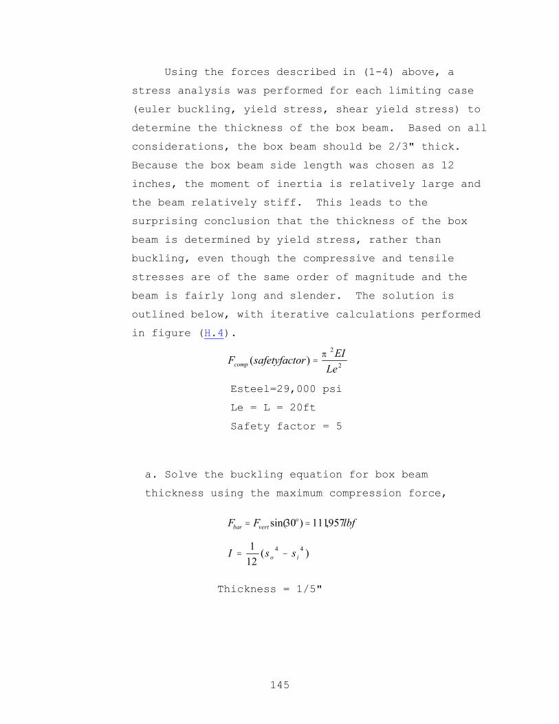
145
Using the forces described in (1-4) above, a
stress analysis was performed for each limiting case
(euler buckling, yield stress, shear yield stress) to
determine the thickness of the box beam. Based on all
considerations, the box beam should be 2/3" thick.
Because the box beam side length was chosen as 12
inches, the moment of inertia is relatively large and
the beam relatively stiff. This leads to the
surprising conclusion that the thickness of the box
beam is determined by yield stress, rather than
buckling, even though the compressive and tensile
stresses are of the same order of magnitude and the
beam is fairly long and slender. The solution is
outlined below, with iterative calculations performed
in figure (H.4).
Esteel=29,000 psi
Le = L = 20ft
Safety factor = 5
a. Solve the buckling equation for box beam
thickness using the maximum compression force,
Thickness = 1/5"
2
2
)(Le
EIorsafetyfactFcomp
π=
lbfFF overtbar 957,111)30sin( ==
)(121 44
io ssI −=

146
b. Now look again at the free body diagram on the
previous page. Two towing mechanisms must be sized
based on the maximum hydrodynamic force. As the yaw
angle increases greater than ψ, the compressive
stress in the towbar increases. Also, for angles
less than ψ, the tension in the towbar rises until
Ftowbar = Ftow = 108,000lbf. However, the maximum
tension in the towbar arises from the vertical force
due to seakeeping, Ftowbar = 111,957lbf. This is
the force that dictates the box beam thickness via
the following yield stress equations:
Thickness = 2/3"
c. The tension in the moment cables is determined
using the same systems of equations used to find the
forces in the towbar from the free body diagram
above. The wire ropes were chosen as 1 ¾" diameter.
From Mark's Mechanical Engineering Handbook28, these
ropes have a 114-ton yield. As a result of this
limitation, the yaw is operationally limited to 44
degrees.
A look at the tow system, fig (H.2) shows three
hinge pins that are sized based on shear stress, with
the maximum forces calculated above and factors of
28 Mark's Handbook , McGraw-Hill, 1979
psi
AorsafetyfactF
y
y
000,36
)(
=
=
σ
σ
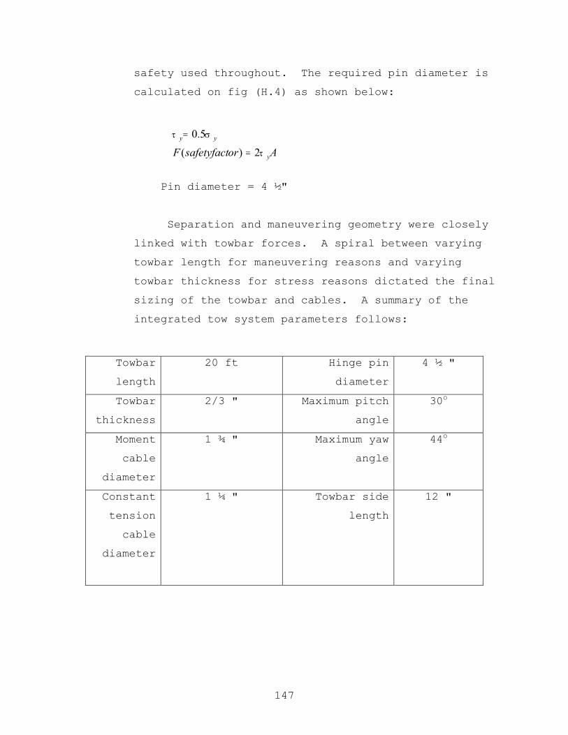
147
safety used throughout. The required pin diameter is
calculated on fig (H.4) as shown below:
Pin diameter = 4 ½"
Separation and maneuvering geometry were closely
linked with towbar forces. A spiral between varying
towbar length for maneuvering reasons and varying
towbar thickness for stress reasons dictated the final
sizing of the towbar and cables. A summary of the
integrated tow system parameters follows:
Towbar
length
20 ft Hinge pin
diameter
4 ½ "
Towbar
thickness
2/3 " Maximum pitch
angle
30o
Moment
cable
diameter
1 ¾ " Maximum yaw
angle
44o
Constant
tension
cable
diameter
1 ¼ "
Towbar side
length
12 "
AorsafetyfactF y
yy
τ
στ
2)(
5.0
=
=
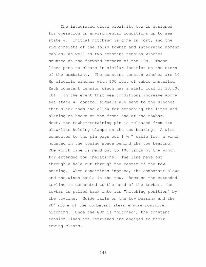
148
The integrated close proximity tow is designed
for operation in environmental conditions up to sea
state 4. Initial hitching is done in port, and the
rig consists of the solid towbar and integrated moment
cables, as well as two constant tension winches
mounted on the forward corners of the GDM. These
lines pass to cleats in similar location on the stern
of the combatant. The constant tension winches are 10
Hp electric winches with 100 feet of cable installed.
Each constant tension winch has a stall load of 33,000
lbf. In the event that sea conditions increase above
sea state 4, control signals are sent to the winches
that slack them and allow for detaching the lines and
placing on hooks on the front end of the towbar.
Next, the towbar-retaining pin is released from its
claw-like holding clamps on the tow bearing. A wire
connected to the pin pays out 1 ¾ " cable from a winch
mounted in the towing space behind the tow bearing.
The winch line is paid out to 100 yards by the winch
for extended tow operations. The line pays out
through a hole cut through the center of the tow
bearing. When conditions improve, the combatant slows
and the winch hauls in the tow. Because the extended
towline is connected to the head of the towbar, the
towbar is pulled back into its "hitching position" by
the towline. Guide rails on the tow bearing and the
20o slope of the combatant stern ensure positive
hitching. Once the GDM is "hitched", the constant
tension lines are retrieved and engaged to their
towing cleats.
149
2. Grid Deployment Module (GDM) and Deployment
The GDM was designed to provide maximum flexibility
in both payload and mission. The GDM is capable of
operations without the combatant. It has a generator
that is rate at 150 KVA. This will be sufficient to
operate the communications and electronics suite
contained onboard the vessel. It was outfitted with
phased array communications antennas along both sides of
the hull to communicate with the combatant as well as to
simulate emitters for a deception mission. The decoy
launchers can serve in the deception mission, by
significantly increasing the radar cross section of the
GDM.
The hulls on both sides were designed as tank
groups to maximize the logistic utility of the craft in
the event that it was needed to provide tankage to other
CNAN units or to some other asset operating in the
region. The large deck area and good stability of the
platform make it a good choice for a “lily pad” or
staging point for SOF units, UAV’s, VSTOL UAV’s, etc.
The payload modules were arranged over the center hull
form to provide maximum flexibility of payload and ease
of deployment. It is envisioned that small boats, fuel
bladders, stores, SOF units, UUV, USV and numerous other
packages could be deployed through the large center
hull.
Designing the mechanism for grid deployment depends
on the units being deployed. The design group was given
a list of grid components which can be found in appendix
a. From the list, the surface to air missile, the

150
largest of all the components with a length of 21 feet,
was selected to size the largest module. The smaller
grid components also had to be considered to ensure they
would fit into the smaller modules. This limited the
length of the module. The GDM was also considered in
deciding module size. The grid units were to be dropped
down between the hulls to take advantage of the hulls
masking grid deployment in a covert operation. This
limited the width and height of the module.
Two different size modules were chosen to keep the
design simple. The large or full module measures 22 feet
long, 18 feet wide and 9 feet high. The small or half
module measures 11 feet long, 18 feet wide and 9 feet
high. The arrangement of the modules in the GDM can be
seen in figure (1) as the large shaded areas on the main
deck of the GDM. The larger areas are capable of
carrying one full or two half modules, the small area
can only carry one small module. Altogether, the GDM may
carry nine half modules or any combination up to one
half and four full modules.

151
To minimize the complexity, gravity is fully
utilized in the design. Vertical rails are mounted on
the fore and aft bulkheads of the module. The rails are
adjusted to port or starboard to accommodate the varying
size grid units. The larger grid units that extend the
entire length of the module have guides affixed to the
ends of their canisters. When loaded into the module,
the guide slides on the rail and an electro-mechanical
locking device holds it in place. Upon deployment,
doors on the bottom of the module open, the electro-
mechanical locking device releases and the grid unit
slides down the rails into the water. Smaller grid
units will be loaded into a receptacle that extends the
full length of the module and mounts on the rail. Upon
deployment, the grid unit will be released from the
receptacle and dropped into the water. The receptacle
will be reutilized once back at a reloading facility.
Module
Figure 1

152
No rearranging after the SEA LANCE was deployed was
allowed in the design due to the fact that volume was
not a concern. The GDM’s as a whole can carry all the
necessary grid units for the mission but an individual
GDM is weight limited to 190 long tons of payload and
could not carry all of its modules fully loaded. Each
GDM’s grid units are well dispersed throughout the
modules so whichever grid unit was needed may be
deployed at any time. A typical half module loading is
displayed in figure (2).
The breakdown of the grid elements is located in
Table (1). The table lists the item, its size, which
module type it will be carried in, quantity and weight
of a module fully loaded with that item. Some grid
elements have notional dimensions compared to today’s
components due to advancements in technology effecting
component size. In all likely hood, the modules will
be loaded out with numerous grid units per module and
will be well below the 144 long ton equivalent of two
fully loaded NTACM half modules.
Figure 2

153
The modules themselves were only designed for
deploying the grid components. Many other functions of
the module were discussed amongst the design group and
numerous outside contacts. One such suggestion is to
load out the GDM with vertically launched GPS or
laser-guided munitions. It could be towed close into
the coast in support of NSFS during an amphibious
landing. Many other suggestions were talked about and
the module could be designed for just about anything
as long as it could fit into the GDM. The main issue
was to deliver the grid components and the GDM with
the above-described modules accomplish the task.
Item Individual SizeModule Type
Units per module
Weight of full module
CM Pickett 1' x 20' Full 128 64Tomahawk 2' x 20' Full 32 60.8SM3 2' x 21' Full 32 64Torpedo 4' x 4' x 20' Full 8 80RSTA 4' x 5' x 20' Full 6 73.8Harpoon 2' x 10' Half 32 40.6NTACM 2' x 10' Half 32 72FSAM .5' x 10' Half 288 21LFAS 2' x 10' Half 32 32DADS .4' x 3' Half 864 43.2TAMDA .4' x 3' Half 864 43.2Air mines 1' x 1.5' x 3' Half 240 60
Table 2
154
3. Miscellaneous Auxiliaries
a. Damage Control
SEA LANCE is not expected to recover from
significant damage such as an anti-ship missile hit;
however, it must have an adequate Damage Control System
to maximize the chances of crew survival and prevent
loss of the ship due to a shipboard casualty.
Therefore, SEA LANCE requires a highly automated,
reflexive, low-impact, austere yet effective Damage
Control System to handle casualties.
SEA LANCE will have the following Damage Control
Systems or capabilities:
i. Multi-function consoles integrated with the
Ship Wide Area Network (SWAN) that control the
Damage Control System
ii. Firemain System
iii. AFFF Bilge Sprinkling System
iv. FM-200 Space Flooding System
v. Magazine Sprinkling System
vi. Chemical, Biological, and Radiological (CBR)
Protection
vii. Main Drainage System
155
Analysis of damage control systems selected is
contained in Appendix I.
Only the crew complex, mess deck, and Control
Center will be manned underway. All engineering
spaces will normally be unmanned. All damage control
functions will be controllable from the multi-function
consoles located in the Control Center space and at
other multi-function consoles on the ship. The Damage
Control System can be manipulated by manual, remote
and automated methods and will be fully integrated
with advanced sensors, fire suppression systems and
that Ship Wide Area Network (SWAN). Standard
automated damage control response actions based on
specific sensor indications for different scenarios
will be programmed into the system. This capability
makes damage control more efficient, allows the
crewmember to perform other duties and does not expose
the crewmember to adverse risk. The Office of Naval
Research is presently developing conceptual
architectures, integrated sensors, smart component
technologies and control algorithms to support
automatic damage control operations.29
SEA LANCE will have a simple, reflexive
distributed firemain system with smart technology that
will serve the following purposes:
viii. Provide firefighting water to fire plugs.
29 http://www.chemistry.nrl.navy.mil/dcarm/

156
ix. Provide seawater for magazine sprinkling
system.
x. Provide seawater to AFFF bilge sprinkling
system.
xi. Provide seawater cooling for auxiliary
systems.
xii. Provide seawater for eductor system.
In the event of a major fuel oil leak, AFFF is an
ideal substance to cover the fire hazard. A single
AFFF station integrated with the Damage Control System
will provide services for the following spaces:
xiii. Port and Starboard Main Engine Room Bilge
Sprinkling System.
xiv. Port and Starboard Auxiliary Machinery
Space Bilge Sprinkling System.
xv. Auxiliary Diesel Generator Room.
xvi. Vertical Replenishment Flight Deck
Sprinkling System.
As a replacement for Halon 1301, primary and
reserve FM-200 Fire protection systems fully
integrated with the Damage Control system will be
installed in the following spaces:
xvii. Port and Starboard Main Engine Room
157
xviii. Port and Starboard Auxiliary Machinery
Space
xix. Auxiliary Diesel Generator Room.
In the event of significant combat damage to a
magazine, the magazine sprinkling system will
extinguish the fire or temporarily control the fire to
allow the crew time to abandon ship. If a magazine
fire occurs in port, the magazine sprinkling system
will extinguish the fire or temporarily control the
fire to allow a shore based fire team time to
extinguish the fire and save the ship.
SEA LANCE will be capable of operating within a
Chemical, Biological, and Radiological (CBR)
environment. As discussed earlier, only the crew
complex, mess deck, Computer/Electronics Room and
Control Center will be manned underway. A Collective
Protection System (CPS) will protect these areas.30
The CPS provides pressurized, filtered air to a full-
time CBR protected zone. The CPS is an integral part
of the heating, ventilation and air conditioning
system. This zone enables the ship to operate in a
CBR contaminated environment. While in the CPS zone,
the crew is not required to don protective clothing.
The CPS is currently being installed on LPD-17.
Figure 1 is a depiction of the Collective Protection
System.
30 http://www.chembiodef.navy.mil/c_a_index.htm
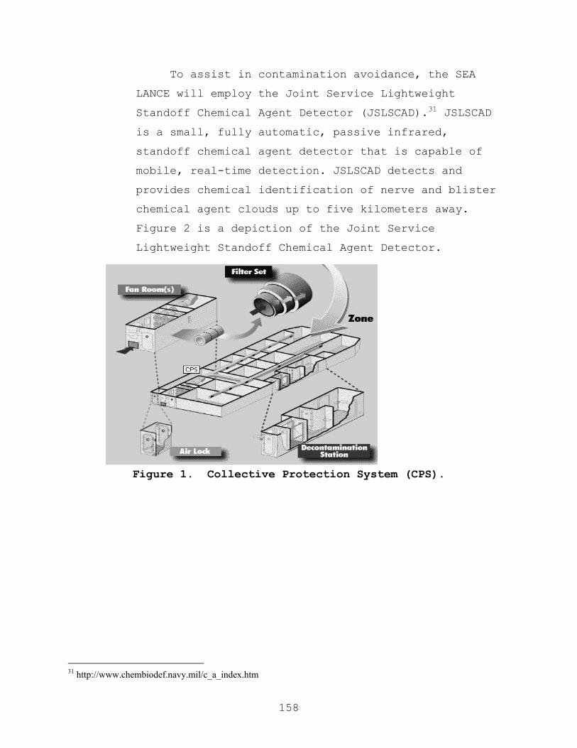
158
To assist in contamination avoidance, the SEA
LANCE will employ the Joint Service Lightweight
Standoff Chemical Agent Detector (JSLSCAD).31 JSLSCAD
is a small, fully automatic, passive infrared,
standoff chemical agent detector that is capable of
mobile, real-time detection. JSLSCAD detects and
provides chemical identification of nerve and blister
chemical agent clouds up to five kilometers away.
Figure 2 is a depiction of the Joint Service
Lightweight Standoff Chemical Agent Detector.
Figure 1. Collective Protection System (CPS).
31 http://www.chembiodef.navy.mil/c_a_index.htm

159
Figure 2. The Joint Service Lightweight Standoff Chemical
Agent Detector.
Additionally the SEA LANCE will be equipped with
the Improved Point Detection System (IPIDS).32 IPDS is
an Ion Mobility Spectroscopy detection system that
detects nerve and blister agent vapors at low
concentrations. Figure 3 is a depiction of the
Improved Point Detection System.
The Collective Protection System along with the
Joint Service Lightweight Standoff Chemical Agent
Detector and Improved Point Detection System will be
integrated with the Ship Wide Area Network and will be
controlled through multi-function consoles.
32 http://www.chembiodef.navy.mil/c_a_index.htm
160
Figure 3. Improved Point Detection System (IPIDS).

161
b. SEA LANCE Crew Egress
SEA LANCE is not expected to recover from an
anti-ship missile hit; therefore, crew egress and
survival is critical design issue.
Several crew egress concepts were explored in
this study. The basic concepts are listed below:
i. A collective escape “pod” containing all
crewmembers at their watch stations that is
“ejected” overboard.
ii. Individual escape “pod” for each crewmember
that is “ejected” overboard.
iii. A free fall lifeboat that is dropped
overboard.
iv. A Rigid Hull Inflatable Boat (RHIB) that is
lowered over the side.
v. The present life raft used by the U. S. Navy.
Of these concepts, SEA LANCE will employ two
methods of egress, a RHIB and rubber life rafts.
The RHIB will be the primary method of egress
with two 25-person life rafts as backup options.
The RHIB was selected as the primary method of
egress because it has the capacity to carry the
entire crew and it has the mobility to reach
safety expeditiously. In the event that the RHIB

162
sustains battle damage or the crew is unable to
reach the boat deck, two 25-person life rafts
located port and starboard of the Control Center
will be used. Analysis of each of the concepts
is contained in Appendix I.
c. Environmental Compliance
SEA LANCE is required to meet or exceed all
anticipated International Convention for the
Prevention of Pollution from Ships (MARPOL) and
Uniform National Discharge Standards (UNDS), in other
words, zero discharge of shipboard wastes. This
requirement is extremely challenging for a small
combatant.
Table 1 shows the current waste generation rate
in pounds per person day for a surface ship and
submarine.33
Surface
Ship
Submarine
Paper 1.1 0.3
Metal 0.5 0.2
Glass 0.1 0
Plastic 0.2 0.1
Food 1.2
Black Water 25-125
Grey Water 210
Laundry 40
Table 1. Current waste generation rate lb/person/day.
33 Committee on Shipboard Pollution Control, “Shipboard Pollution Control U.S. Navy compliance with MARPOL Annex V” National Academy Press, 1996
163
Three general waste streams were addressed in the
SEA LANCE conceptual design:
i. Solid waste (Paper, plastic, glass and metal)
ii. Non-oily liquid waste (Grey and black water)
iii. Oily waste
Analysis of shipboard waste management
technologies is contained in Appendix I.
All solid waste will be retained onboard for off-
load to a shore facility or MSC ship during
replenishment. As seen in Table 1, solid waste
generation is very limited on a submarine. The same
solid waste management techniques such as minimization
of the on load of paper and plastic products onboard
through Waste Reduction Afloat Protects the Sea
(WRAPS) and Plastics removal in Marine Environment
(PRIME) programs must be employed on SEA LANCE. Solid
waste generation in the Galley will be further reduced
through the use of pre-prepared or Advanced Foods.34
Unused food will be pulped in a garbage disposal and
discharged to the Greywater/Blackwater Treatment
System. Metal waste products will be minimal and
retained onboard for disposal ashore or to an MSC
ship. The crew will operate in a near paperless work
environment. A small trash compactor will be
34 LOGICON, NAVSUP “Advance Foods Study Onboard USS McFaul”, Naval Supply Systems Command, 1999.

164
installed onboard to compact solid wastes such as
paper and plastic products for short-term storage in a
sanitary storeroom and future off-load in port or to
an MSC ship during replenishment. This method of
solid waste management negates the need for a plastic
waste processor, metal/glass shredder and pulper.
In order to meet the zero discharge requirements,
all greywater and blackwater will be treated by a
combined greywater/blackwater treatment system that
uses biotreatment in conjunction with microfiltration
to treat the liquid waste. The effluent will meet the
following standards:
iv. Total Suspended Solids (TSS) <100 mg/ml
v. Fecal Coliform (FC) < 200/100 ml
vi. Biochemical Oxygen Demand (BOD) < 50 mg/l
Appendix I contains a detailed description of the
treatment system.
SEA LANCE will process oily waste with a Combined
Oily Waste Membrane System. The Navy Integrate
Membrane System (NIMS) will produce an effluent less
than 15-PPM oil. All bilge water will be processed
through the oily waste system. Appendix I contains a
description of the Navy Integrated Membrane System.

165
F. Habitability and Human Factors
1. Habitability
All crew needs are met with the SEA LANCE habitability
space. The accommodations on the ship are adequate but
comfortable.
The SEA LANCE normal crew size is 13 personnel. The
ship’s berthing space can berth a maximum of 21 personnel.
Berthing arrangements were design for a mixed gender crew
with a maximum of six berth designated for minority gender.
Figure 1 depicts the deck plan for the habitability space.
The habitability space is within the Chemical, Biological
and Radiological (CBR) Collective Protection System (CPS).
Figure 1

166
The dimensions of each stateroom are 7 ft x 7 ft x 8
ft. There are six 3-person enlisted staterooms, one 2-
person officer stateroom and a stateroom for the Commanding
Officer. Each stateroom is accessed through a sliding door
to maximize useful space. The enlisted staterooms have one
3-person lightweight modular berth, three standup lockers
and one desk. The 2-person officer stateroom has a 2-
person modular berth one desk and large partitioned standup
locker. The Commanding Officer’s stateroom has a single
berth, desk and standup locker.
There is a male and female head located on the
starboard side of the ship. The male head has three
toilets, two showers and one sink. The female head has two
toilets, two showers and one sink. Note that in the event
that there are more women than men on board, the heads can
be swapped. All toilets are low flow fresh flush toilets
service by a Vacuum Collection Transfer and Holding (VCHT)
system. There is also a common wash area with two sinks
located at the entrance of the male and female head. These
facilities exceed General Specification requirements which
require one shower for every 10 officers and one toilet for
every 8 officers.35 Dimensions for toilets, sinks and
showers are located in Table 1.
Length (in) Width (in)
Toilet 30 30
Sink 24 24
Shower 30 30
Table 1.
35 Naval Sea Systems Command, “General Specifications for Ships of the United States Navy”, Naval Sea Systems Command, 1985.
167
The crew will prepare their own meals in the galley.
The galley will be equipped with a Hatchable Combination
Convection Oven-Steamer and a microwave oven. All food
will be pre-prepared or will include the new Advanced Foods
being developed by the Naval Supply Command.36 The galley
will also have a deep sink, a durable dishwasher, and a
small beverage bar. All excess food will be disposed of
through a garbage disposal and sent to the
Greywater/Blackwater Treatment System for processing. Next
to the Galley is the refrigerator and freeze box. A dry
goods storeroom is located on the starboard side of the
mess deck. The mess deck will have four 4-person tables
and will also act as a crew lounge.
In addition to cooking their own meals, the crew will
also clean their own laundry in the laundry room. The
laundry room will contain a durable commercial stackable
washer and dryer set.
Since the crew does not normally have access to the
weather deck while underway, there is a small gym next to
the mess deck for the crew to exercise in.
The SEA LANCE is expected to embarked special teams,
such as a SEAL unit, therefore a secure multi-mission space
is available for temporary storage of classified material
and equipment.
36 LOGICON, NAVSUP “Advance Foods Study Onboard USS McFaul”, Naval Supply Systems Command, 1999.

168
Other factors that affected the layout of the
habitability space include:
a. Ambient noise mitigation. Berthing is located
forward on the ship to minimize noise from the
propulsion engines. Additionally, the crew is
closer to their watchstations.
b. The galley and mess decks are located aft on the
ship close the vertical replenishment deck to
shorten the distance that stores must be moved
during strike down.
c. All spaces that require water are located on the
starboard side to assist the drainage to the
Greywater/Blackwater Treatment System located in the
starboard hull. The reverse osmosis unit is located
in the port hull and freshwater is sent to the
starboard side of the ship.
d. Berthing was arranged in staterooms to ensure
flexibility in the crew gender makeup.

169
2. Crew
The SEA LANCE crew will be specially trained to
operate the SEA LANCE Combatant. In order to manage the
problem of ship upkeep, operating the Combatant is all the
crew will be asked to do. We propose an “aircraft
paradigm” for SEA LANCE Combatants where the crew operates
the vessel while underway, but in port the SEA LANCE shore
team maintains the ship just as the maintenance team does
for aircraft.
The SEA LANCE will require a new rate that we have
dubbed “SeaLanceman.” Every SeaLanceman stands watches and
performs duties of Normal and Special Ops and becomes
expert in their specialty. SeaLanceman should be a special
branch applied for by junior enlisted of other rates in a
manner similar to SEALs. The source rate of each applicant
can determine his or her SeaLanceman specialty.
SeaLancemen will specialize in operations, engineering, or
combat systems. These skills are desired so that the crew
will be capable of a high level of “first aid” response and
repair while underway.
Since SEA LANCEs are organized in squadrons, each
squadron will have a staff composed of a CO, Operations
Officer, Supply Officer, Repair Officer, and a senior
enlisted advisor. A Squadron Master Chief SeaLanceman is
selected from senior Sealancemen. Senior Sealancemen not
selected for Squadron duty will become members of the SEA
LANCE system support force or other duties within the Navy.

170
We envision a 13-member crew as follows.
Commanding Officer
Division Officers
Combat Systems Officer
Operations Officer
Operations (and Engineering)
1 QuarterMaster/Signalman
2 Diesel Mechanics
1 Electrician
1 Auxiliary Technician
Combat Systems
2 Electronics Technicians
3 Weaponeers
The breakout of the individual “ratings” indicates the
specialized advanced “C” schools or NEC’s that will be
required on each of the SEA LANCE’s. Not every “SEA
LANCEman” will be required to hold each NEC or attend every
“C” school. The CO will be a lieutenant or lieutenant
commander. His Division Leaders will be second tour line
officers or warrant/Limited Duty Officers. The other ten
will be SeaLancemen specialists.
The unique nature of this vessel calls for an
examination of tradition officer and enlisted personnel.
The officer to enlisted ratio might need to be inverted
with more officers than enlisted. Does the traditional
structure make sense given the intense level of

171
responsibility on even junior members of a SEA LANCE crew?
These decisions are beyond the scope of the TSSE project
but will have to be answered if the SEA LANCE concept is
developed further.
We conducted an analysis of possible watchstation
duties that our 13-person crew using four consoles might
fulfill.
Watchstation duties
4 Person team (crew of 13)
Combat/Battle stations
TAO Engagement decisions
Communications
AAW Air picture
ASUW Surf/sub-surf picture
OOD Ship Navigation/Safety
Grid deployment
TAO Engagement decisions
Communications
Surf/sub-surf picture
AAW Air picture
OOD Ship Navigation/Safety
Grid Field management/verification
GDS Grid Deployment Supervisor

172
Peacetime Steaming
OOD Ship Navigation/Safety
AAW Air/Surf/Sub picture
Communications
The TSSE team also examined the feasibility of the 13-
person crew performing normal and special operations.
Normal Ops
UnRep
TAO Engagement decisions
Communications
Air picture
Surf/sub-surf picture
ENG Plant management/Pump monitoring
OOD Ship Navigation/Safety
Rig Rig Captain and 3 members
Team
VertRep
TAO Engagement decisions
Communications
Air picture/Surf/sub-surf picture
OOD Ship Navigation/Safety
173
Flight Flight safety/Helo control
Control
Officer
Stores Team Captain & 5 members
Handlers
GDM Connection
TAO Engagement decisions
Communications
Air picture
Surf/sub-surf picture
OOD Ship Navigation/Safety
ENG Supervise connection team
Connection 5 members to effect connection
Team
(GDM disconnection is an automatic process initiated and
controlled from the bridge.)

174
Navigation Detail
OOD Ship control
NAV Navigation/Safety
Bearing
Takers
Mooring/Anchoring Detail
OOD Ship control
NAV Navigation/Safety
Line/ 7 member team
Anchor
Handling
Special Ops
a. Protection of anchorages/MODLOCs
No special requirements.
b. Harbor and restricted waters blockade
No special requirements.
c. Theater Ballistic Missile Defense (TBMD)
TBMD planner (if required) uses extra console
175
d. Area Mine mapping operations
Mine Mapper (if required) uses extra console
e. Escort for amphibious and logistic forces
No special requirements.
f. Strike warfare
Strike planner (if required) uses extra console
g. Shallow water ASW
No special requirements.
h. Maritime Interdiction Operations (MIO)
Boarding Party Team Leader (a Division Officer)
i. Boarding Party Team (5 junior SeaLancemen)
Sniper Team (Spotter & Shooter)
j. Non-combatant Evacuation Operations (NEO)
4 person Welcome Party
k. (Expect to house non-coms in GDM people module.
Welcome Party supervises all non-coms 100% of the
time)
l. SOF insertion/extraction
4 person Boat Launch crew
(Expect SEALs primarily to launch boat. SEA LANCE
personnel to assist as required. SEALs and vessel
housed either in/on GDM or on aft center hull.)

176
m. Independent operations (showing the flag)
No special requirements.
n. Strategic deception operations
6 member crew (if required) to launch/manage
decoys
Considering all the operations that a SEA LANCE crew
might be required to perform, the TSSE team believes that a
13-person crew can meet the requirements.

177
3. Technology Advancements/Automation
The SEA LANCE Combatant will make maximum use of
automation to alleviate the stress applied to the crew.
Some areas of possible automation were explored:
Area Agent a. Processing MSG traffic auto
b. Navigation auto
c. Monitoring/Control Own ship auto
d. Electronic Warfare auto
e. Strike planning auto/off ship
f. Damage Control auto & manual
g. Comms circuit set-up auto
h. Line handling manual
i. GDM hook up manual
j. GDM disconnect auto
k. Hotel service connect/disconnect manual
l. Onload stores manual/off ship
m. Refueling manual
n. Cleaning Interior/Exterior off ship
o. Laundry manual
p. Mail off ship
q. Admin off ship
r. Maintenance off ship
s. Training auto
t. Grid component deployment auto
u. Grid component tending manual
v. Module swap out manual/off ship
w. Mechanical/Electric repair (First Aid) manual
x. Mech/Elec repair (minor-major) off ship
y. Food prep manual(pre-made)

178
z. Ammo handling manual/off ship
aa. Detect, track targets auto
bb. Classify, engage targets auto & manual
cc. MIO boarding manual
dd. NEO Op manual
ee. SOF Insertion manual
ff. CBR protection/recovery auto & manual
Other methods of reducing crew tasks can be employed.
All underway inspect and test requirements for equipment
can be automated and facilitated by the Ship LAN. Failed
parts can be automatically ordered from shore when detected
as failed or indicating immanent failure. Appropriate
initiatives from the “Smart Ship” program should be
incorporated such as reduced pilothouse manning, automated
Division Officer’s notebook, and core-flex watchbill to
allow for manning reduction37. The DD-21 program is
expected to use new concepts and technologies to facilitate
reducing the crew of a 10,000+ LT ship to just 95 people.
Due to the stage of contract competition in the DD-21
program, information on enabling crew reduction was
unavailable for this report. If further development of the
SEA LANCE design continues, we can expect DD-21 information
to be releasable by mid 2001.
37 Smartship Program Information Brief
179
G. Total Ship Evaluations
1. Cost Analysis
The weight and cost estimations included in Appendix J
are based on existing designs that were scaled based on
full load displacement and then adjusted based on mission,
hull form, material, and technological variations. The
payload fractions for the combatant and GDM are 35% (11%
without fuel) and 67% respectively. If the 450-ton
displacement goal was considered as a hard limit, these
required payload fractions would only permit design weight
margins of 6.5% for both the combatant and the GDM, which
is significantly below the desired 10-15% margin for a new
design. For purposes of this design study, these smaller
design margins were accepted, partially due to extensive
use of commercial of the shelf technology (COTS) equipments
for which weights are accurately known and partially due to
the limited resources available to further refine our
weight estimates in the time allowed. However, the
alternative of increasing the weight margin to the 10-15%
level reflective of the risk inherent in a new design
concept such as SEA LANCE would add between 16 and 38 tons
to the total displacement, or raising it to between 466 and
488 tons. This higher displacement value is considered an
appropriate starting point for subsequent design
iterations.
The hull weights and cost were validated using
estimates of car carrying fast ferry designs38. A
commercial hull of this size would cost approximately $3.8
million. If you remove the special structures required for
38 Mr. Kim Gillis, Manager Military Projects, Austal Ships
180
items such as the telescoping mast and missile blast
abetment, the Group 100 cost of our design is approximately
$4.5 million for the first combatant and $3.6 million for
the first GDM. The total price of $6.5 million for the
fast ferry is only 10% of the total cost of our design for
obvious reasons. Full weight/cost breakdowns are included
in Appendix J.
The weights and costs of the propulsion, electrical,
combat, weapon, and C4I systems were modified as based on
information outlined in Chapter IV. The final cost of our
design was verified against that of the FLYVEFISKEN CLASS
(Standard Flex 300) as outlined in Chapter 3. The final
price of $64.7 million for the first combatant and $19.1
million for the first GDM were accepted as reasonable and
the total cost per pair was under $100 million as required
in Chapter 2.
The learning curve used to predict the cost of future
units was applied only to the labor due to the extensive
use of COTS technology and a largely commercial platform
design. The curve was set slightly higher than normal
(95%) due the relative inexperience of our shipyards with
respect to this hull form. There is also expected savings
due to the essentially identical hull forms used for the
combatant and GDM.
NSWC Carderock conducted scale model construction
tests whose results were published in 199739. These results
suggest that not only is a composite hull of this size
39 PROFESSIONAL BOAT BUILDER, Aug/Sep 1997, “Competing Composites”, by Paul Lazarus

181
feasible, but that it could be cost-competitive and result
in a weight savings of 30% over an aluminum hull. An
attempt was made to estimate the equivalent composite
weight of our aluminum structure. The volume of material
used was a 6” shell around the outer hull of our design.
Based on this volume and the density derived from the
Carderock data, it was found that the equivalent composite
structure would weigh more. This calculation also showed
an order of magnitude increase in the safety factor. These
factors combined affirmed the requirement to do completely
separate structural analysis of a composite design.
In order to estimate the possible impact of using a
composite hull form, the cost data was used from the
Carderock study40 and the 30% fractional weight savings was
applied without supporting structural analysis. Applying
the fractional savings to only the base aluminum hull
described above and still included the steel reinforcements
for towing and the additional weight of superstructure and
mast, you reduce the light ship weight by 30 LT. If all
other design factors were held constant, that would allow
for a margin of over 20% on the combatant and 34% on the
GDM. Composite construction also increases the payload
fraction of the combatant to 37% (11% without fuel) on the
combatant and 72% on the GDM. A modified weight/cost
breakdown for a composite SEA LANCE pair and the supporting
cost data are included in Appendix J.
It should also be noted that the choice of composites
could lead to substantial savings in the maintenance and
40 Loc Nguyen, NSWC Carderock Division, Code 6551

182
repair cost associated with SEA LANCE. For example, the
FLYVEFISKEN CLASS (Standard Flex 300) has saved the Danish
Navy 80% in maintenance costs compared to a similar steel
hull design.41
41 CAPT Poul Grooss, Managing Director, Naval Team Denmark
183
2. Radar Cross Section Analysis
For this first iteration in the design, three features
have been incorporated for radar cross section (RCS)
reduction: general shaping, enclosed mast technology, and a
telescoping mast.
Hull and superstructure design was driven by
optimization against mono-static radar. The geometry was
kept simple, maintaining parallelism between different
sections in order to concentrate the electromagnetic energy
in well-defined directions. No dihedrals or trihedrals are
used in the structure, and cavity inlets and outlets have
been placed between the catamaran hulls. 20° sloping of
the sides is used throughout the hull and superstructure
design.
The enclosed mast also follows the 20° sloping
guideline. Different portions of the mast are transparent
depending on the frequency of the sensor working behind it;
hence the influence of the mast in overall RCS varies also
due to this factor. The upper part of the mast is
telescopic. When SEA LANCE operates within the grid, and
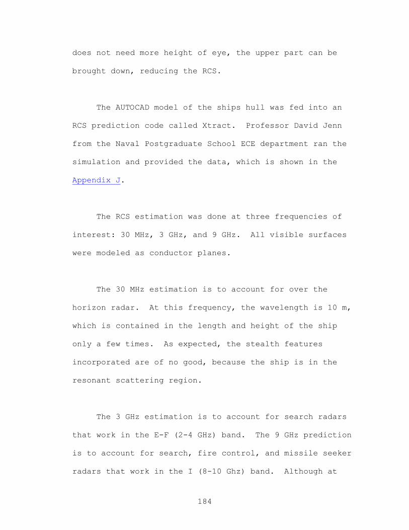
184
does not need more height of eye, the upper part can be
brought down, reducing the RCS.
The AUTOCAD model of the ships hull was fed into an
RCS prediction code called Xtract. Professor David Jenn
from the Naval Postgraduate School ECE department ran the
simulation and provided the data, which is shown in the
Appendix J.
The RCS estimation was done at three frequencies of
interest: 30 MHz, 3 GHz, and 9 GHz. All visible surfaces
were modeled as conductor planes.
The 30 MHz estimation is to account for over the
horizon radar. At this frequency, the wavelength is 10 m,
which is contained in the length and height of the ship
only a few times. As expected, the stealth features
incorporated are of no good, because the ship is in the
resonant scattering region.
The 3 GHz estimation is to account for search radars
that work in the E-F (2-4 GHz) band. The 9 GHz prediction
is to account for search, fire control, and missile seeker
radars that work in the I (8-10 Ghz) band. Although at

185
these two frequencies the RCS is very similar in shape,
numbers are better at 9 GHz.
In order to assess the RCS performance of SEA LANCE,
predicted values are compared with reference data42, shown
in Figure 1.
Figure 1. RCS Comparison
The total average RCS of SEA LANCE is 24.7 dBsm, while
the median is –14.6 dBsm. From the power regression shown
in the Appendix, it was estimated that a 450 LT regular
combatant would have an average RCS of 32.0 dBsm; hence in
average, SEA LANCE performs better by 7.3 dB. Analyzing
42 Introduction to Radar Systems-Merrill I. Skolnik.
Comparison of Average RCS
-17.0
-3.0
0.0
3.0
7.8
16.0
32.0
38.7
-8.0
24.0
-1.3
5.4
-13.1
20.7
24.7
-20.0 -10.0 0.0 10.0 20.0 30.0 40.0 50.0
Small open boat
Missile
Small single engine aircraft
Small fighter aircraft
Large fighter aircraft
Large bomber aircraft
450 LT combatant
SEA LANCE (=180)
SEA LANCE (>90 & <180)
SEA LANCE (=90)
SEA LANCE (>45 & <90)
SEA LANCE (=45)
SEA LANCE (<45 & >0)
SEA LANCE (=0)
SEA LANCE TOTAL
RCS [dBsm]

186
the data by sectors, it can be seen that the bow and beam
present averages in the order of the total average. The
forward quarter has been divided in three sectors for
analysis. Between 0° and 45° relative bearing, the average
RCS is –13.1 dBsm, making it comparable to a small open
boat. At 45° relative bearing, the RCS average is 5.4
dBsm, equivalent to a large fighter aircraft. Between 45°
and 90° the average is –1.3 dBsm, comparable to a missile.
The entire aft quarter, between 90° and 180° relative
bearing, has an average RCS of –8.0 dBsm. The largest RCS
average is 38.7 dBsm, and is obtained when SEA LANCE is
viewed from the rear.
Another comparison is shown in Table 1. An equivalent
displacement has been obtained from the RCS regression for
the SEA LANCE values in the different directions. It can
be seen, that except for the stern view, the RCS is always
equivalent to a much smaller vessel.
TABLE 1
RCS
Equivalent
Displacement [LT]
Total Average 146.55
Median 0.32
0 78.32
>0 & <45 0.40

187
45 7.24
>45 & <90 2.55
90 132.01
>90 & <180 0.90
180 1307.00
Due to time considerations, RCS estimation for the GDM
and combatant-GDM pair was not conducted. As a reference,
the 9 GHz RCS prediction for the port side of SEA LANCE
took approximately 107 hours. It can be inferred that the
GDM will perform better than the combatant, because it
doesn’t have a superstructure or guns. For the pair, it is
expected that the RCS will increase in every direction
except the bow and stern directions.
The next iteration in the design spiral for the RCS
should include more shaping to the superstructure and mast.
Energy should be taken away from the bow and stern and
concentrated, ideally, in the forward and back quarters
(relative bearing angles 45° and 135°). In addition,
radar-absorbing material should be incorporated to cover
the edges.

188
3. Total Ship System SEA LANCE is a compact formidable warship that has
been designed for maximum flexibility while providing as
much comfort as possible for its highly trained 13-person
crew. The operations of the entire ship are controlled from
the central control station located on the bridge. There
are numerous reasons to centrally locate the crew. The crew
berthing spaces are located close to their work
environment. This provides them quick access to their
battle and watchstations. It also limits the amount of
space that must be protected in a CBR environment.
Centrally locating all the berthing compartments within the
habitability spaces allows the team to produce an
environment that was austere in terms of physical space
footprint, but afford the crew some things that normally
would not be present on a small combatant. The gym and
galley area are fairly good size and give the crew ample
space to relax and unwind. The habitability space is also
designed to accommodate ship riders. These could be Fly
Away Teams (FATs) to affect repairs to SEA LANCE or the
expeditionary warfare grid as well as SEAL teams or an
intelligence detachment. The multi-mission space that is
located in the habitability space could be utilized for any
special equipment or compartmentalization that is required.
Figure (1) and Figure (2) demonstrate orientation of the
combatants spaces, while Figure (3) shows the layout of the
habitability compartments.
The ship is designed to withstand only moderate damage
from an enemy weapon. The ship is designed to afford the
crew the maximum opportunity to get off the ship in the

189
event that it sustains heavy damage from an enemy attack.
The 2 life rafts located port and starboard in the central
control station can accommodate 25 people. The RHIB that is
located just aft of the habitability spaces on the
starboard side can be accessed directly from the berthing
passage way. It can accommodate all 21 personnel that could
be assigned. One of these modes of departure should be
available to afford the crew an option to abandon ship when
necessary. The locations of the egress equipment can be
seen in Figures (1) and (2).
The combatant is designed with a robust combat systems
suite to ensure that it could protect the grid once
deployed and would provide protection for the craft while
it is operating independent of the battle group and grid.
It has (4) Harpoon/SLAM tubes along the port side, (2) 30
mm guns located fore and aft, and a 51-cell vertical RF/IR
guided missile launcher aft. The combatant could also
perform such missions as: maritime interdiction operations
(MIO), non-combatant evacuation operations (NEO), escort
for the carrier or amphibious readiness group (ARG) units.
It is ideally suited for combat against the wide range of
small surface combatants that the international navies
possess. The sensors suite of the combatant is capable of
operating in a wide range of environments. The air/surface
search radar has a range of 54 Nm while the infrared search
and track (IRST) as well as the fire control radar has a
range of 20 Nm. The electro-optical suite has a range of 10
Nm and the mine-avoidance sonar has a detection range of
approximately 350 yards. Additionally it is equipped with
an ESM suite and phased array communications antennas. The
entire suite is enhanced by the use of an advanced enclosed
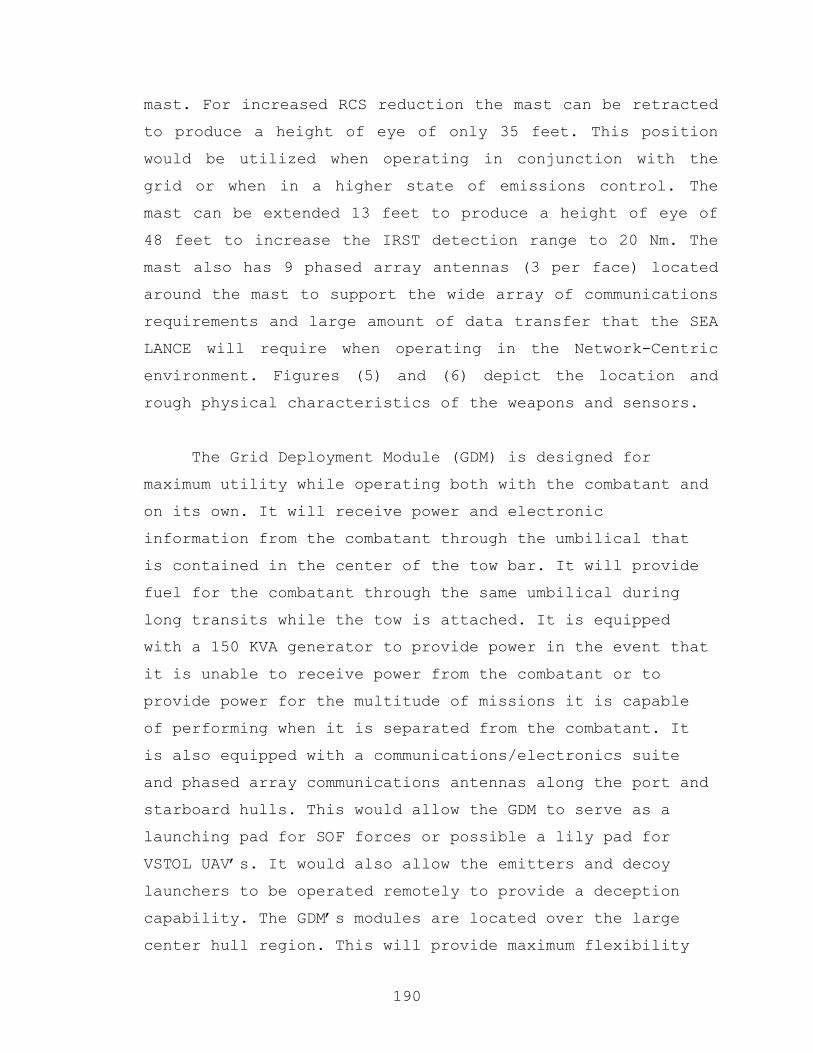
190
mast. For increased RCS reduction the mast can be retracted
to produce a height of eye of only 35 feet. This position
would be utilized when operating in conjunction with the
grid or when in a higher state of emissions control. The
mast can be extended 13 feet to produce a height of eye of
48 feet to increase the IRST detection range to 20 Nm. The
mast also has 9 phased array antennas (3 per face) located
around the mast to support the wide array of communications
requirements and large amount of data transfer that the SEA
LANCE will require when operating in the Network-Centric
environment. Figures (5) and (6) depict the location and
rough physical characteristics of the weapons and sensors.
The Grid Deployment Module (GDM) is designed for
maximum utility while operating both with the combatant and
on its own. It will receive power and electronic
information from the combatant through the umbilical that
is contained in the center of the tow bar. It will provide
fuel for the combatant through the same umbilical during
long transits while the tow is attached. It is equipped
with a 150 KVA generator to provide power in the event that
it is unable to receive power from the combatant or to
provide power for the multitude of missions it is capable
of performing when it is separated from the combatant. It
is also equipped with a communications/electronics suite
and phased array communications antennas along the port and
starboard hulls. This would allow the GDM to serve as a
launching pad for SOF forces or possible a lily pad for
VSTOL UAV’s. It would also allow the emitters and decoy
launchers to be operated remotely to provide a deception
capability. The GDM’s modules are located over the large
center hull region. This will provide maximum flexibility

191
of deployment as well as a wide range of things that can be
deployed. The grid elements could be deployed from the
modules as well as boats, fuel bladders and logistic
containers for SOF units and the marine expeditionary
force. The large tank groups located in the outer two hulls
could hold large quantities of fuel to provide auxiliary
support to units operating the area. The GDM is a very
flexible platform with numerous mission possibilities. The
general arrangements of the GDM are shown in Figure (4)
The combatant and GDM SEA LANCE system is an extremely
viable option for performing the Expeditionary Warfare Grid
deployment mission. Both the combatant and GDM have been
designed to perform countless missions while connected as
well as while operating independently. Detailed
descriptions and technical evaluations of the combatant,
GDM and their individual components are contained
throughout the report.


193
Tow EquipmentRoom
Cleats
HabitabilitySpaces
Boat Deck
30 mm Gun
51-cell SA/SS
Line Locker
Auxiliary MachineryRoom
Main EngineRoom
Potable Water
Decoy Launcher
Inport/EmergencyGenerator
4-Cell Harpoon/SLAM
Refueling Probe
Fuel Tanks
Decoy Launcher
Line Locker
Central Control Station
ElectronicsSpace
30 mm Gun
Chain Locker
Figure 1

194
RHIBBoat/Davit
25-PersonLife Raft
Oily WasteHolding Tanks
Gray/Black WaterStorage/Treatment
Tanks Mine DetectionSonar/Acoustic Modem
RHIBBoat/Davit
25-PersonLife Raft
Oily WasteHolding Tanks
Gray/Black WaterStorage/Treatment
Tanks Mine DetectionSonar/Acoustic Modem
Figure 2

195
Officer’s Stateroom
Common Sinks
Male Head
Female Head
CO’s Cabin
LaundryGalleyRefer/Freezer
Gym
Mess Decks
Dry Stores
Multi-mission Space
3-Person Berthing
Officer’s Stateroom
Common Sinks
Male Head
Female Head
CO’s Cabin
LaundryGalleyRefer/Freezer
Gym
Mess Decks
Dry Stores
Multi-mission Space
3-Person Berthing
Figure 3
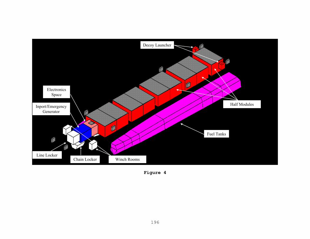
196
Decoy Launcher
Inport/Emergency Generator
Fuel Tanks
Line Locker
Electronics Space
Chain Locker Winch Rooms
Half Modules
Figure 4

197
30 mm Gun
4-Cell Harpoon/SLAM
51-cell SS/SA
30 mm Gun
4-Cell Harpoon/SLAM
51-cell SS/SA
Figure 5
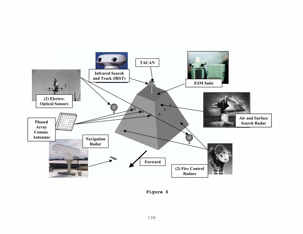
198
Infrared Searchand Track (IRST)
Air and SurfaceSearch Radar
NavigationRadar
(2) Fire ControlRadars
ESM Suite
(2) Electro-Optical Sensors
PhasedArray
Comms. Antennae
TACAN
Forward
Infrared Searchand Track (IRST)
Air and SurfaceSearch Radar
Air and SurfaceSearch Radar
NavigationRadar
(2) Fire ControlRadars
ESM SuiteESM Suite
(2) Electro-Optical Sensors
PhasedArray
Comms. Antennae
TACAN
Forward
Figure 6

199
Chapter V: Conclusions
A. Requirements Review
SEA LANCE is a robust system of vessels that will
ensure the deployability, flexibility, versatility,
lethality and survivability necessary within the contested
littorals to provide the operational commander with the
awareness and access assurance capability lacking in the
fleet of the POM. SEA LANCE in conjunction with the
Expeditionary Warfare Grid will allow gaining, maintaining,
sustaining and exploiting access to the littorals, in order
to project power into enemy territory.
SEA LANCE embodies the capabilities discussed in the
Mission Needs Statement (MNS). The design meets or exceeds
all of the requirements set forth in Operational
Requirements Document (ORD). The relatively low cost,
flexible and stable hull form as well as the high degree of
combatant capability makes SEA LANCE a very effective choice
for deployment of the Expeditionary Warfare Grid. The
combatant is capable of operations in the contested littoral
environment against a wide range of threats without posing
undue risk to the power projection assets of the fleet of
the POM. The GDM has the flexibility to accept a multitude
of diverse payloads. This increases the versatility of SEA
LANCE far beyond those outlined in the requirements
documents.

200
B. Assessment of Systems Engineering Design Process Experience and “Lessons Learned”
The design team was faced with the challenge of
defining the Mission Needs Statement (MNS) and drafting the
Operational Requirements Document (ORD). To accomplish this
task the team had to define an operational scenario and
determine how the ship they would ultimately design would
fit into the overall Expeditionary Warfare Grid System. The
Expeditionary Warfare Grid is in the developmental stages
of design. Many areas of the grid are just conceptual in
nature. The team utilized the Expeditionary Warfare Grid as
it was outlined in the Capabilities of the Navy after Next
(CNAN) study being conducted by the Naval Warfare
Development Command (NWDC). The team attempted to adhere to
a strict systems engineering approach to this effort and
for the most part succeeded. The team was ready to begin
designing the ship at multiple points throughout the first
quarter, but adhered to the guiding principles of systems
engineering to build the foundation for the second quarter
effort. The team dedicated the vast majority of the first
quarter design effort to defining what the ship needed to
do, what the grid would do, how the ship and grid would
interact and what impact they would have on one another.
The first quarter ended with the team choosing an
architecture of the three that were reviewed and defining
some of the basic properties of the ship.
The second quarter began with the team still diverging
and wondering whether it would converge on a solution. The
team was also faced with a compressed schedule of an 11-
week quarter and a deadline to give the presentation in a

201
mere 2 months. Time allocation and planning were lacking in
the second quarter design effort. The team was rapidly
putting out the individual fires that sprang up throughout
the design. Some modifications were necessary to a few
systems after they were incorporated into the larger SEA
LANCE system. The overall system survived these small
trials and tribulations, but the design effort would have
been smoother if systems engineering had been followed in
its purest sense. The team completed the second quarter
design effort with what they believe was the optimum design
for the problem that was presented. It was a difficult
problem, but all members of the team provided their
required inputs and produced a complete design capable of
operating within the overall Expeditionary Warfare Grid
system.
Some other lessons learned were the need to establish
professional contacts early. These professional contacts
were invaluable to the design effort. Some contacts were
discovered too late within the design effort to incorporate
in the design. Networking of the Navy’s design
infrastructure (including NPS) is essential to providing
cost-effective, thorough solutions to the Navy’s
challenges. The team could have benefited from some of the
expertise in other departments within NPS. The operations
analysis, software engineering, manning, etc could have
been reviewed by some of their associated curriculums.
Some design tools were needed to more rapidly and
accurately define some of the areas. NAVSEA is currently
developing a cost evaluation tool for ship design. The
Advanced Surface Ship Evaluation Tool (ASSET) modules that

202
exist for multi-hull ships need to be converted and
incorporated into the current ASSET program. A functional
flow diagram construction program would be of benefit. Many
of the programs are in FORTRAN format, which produce output
that is difficult to analyze and incorporate into a design
report. The efforts to convert these programs to PC based
environments should be continued and funded.
Overall, the team learned a great deal from the design
effort and thoroughly enjoyed being part of the process.
The tools, experiences, and professional contacts gained in
the capstone design project will prove to be invaluable to
our careers and our productivity at future commands.
C. Areas for Future Research
Some areas of the design warrant further analysis to
validate the overall system. Some specific areas of interest
are:
- A Study of Human Factors: The many factors that are
involved in the training and accessions pipeline as well
as those that involve the complexity of the tasks
required onboard the ship need further exploration.
- The Expeditionary Warfare Grid needs more definition of
capability, function and physical appearance.
- The backbone of the Total Ship Open Systems Architecture,
Network-Centric Warfare connectivity and “Team Net”
networks needs further exploration and definition of
shipboard requirements.
- A software engineering study of what is needed to tie all
the systems together onboard SEA LANCE’s SWAN needs to be
conducted.

203
- Modeling and Tow Tank experiments need to be conducted on
close-proximity semi-fixed tows to further validate its
use.
- Resistance data needs to be developed and distributed for
catamaran hull forms.
- The numerous automation and technology advances being
developed by the various commands are essential to the
minimum-manning concept. Some are purely conceptual in
nature and need further funding and study.
- The preliminary radar cross-section study was performed
on an unclassified level. A classified, detailed RCS
analysis and optimization needs to be performed.
- An analysis of the effects of the addition of ride
stability systems needs to be completed to ensure they
produce the desired affects on deck edge accelerations
and stability.
- Composite structures should be incorporated to a greater
degree within the design to produce a more desirable
balance between payload fraction, design margin and other
naval architecture attributes.

1
Appendix Appendix
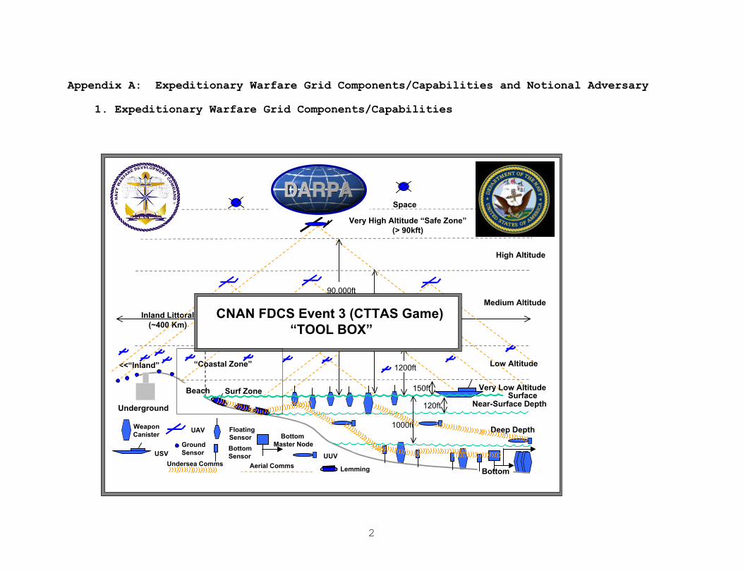
2
Appendix A: Expeditionary Warfare Grid Components/Capabilities and Notional Adversary
1. Expeditionary Warfare Grid Components/Capabilities
1
<<“Inland” “Coastal Zone”
Space
Very High Altitude “Safe Zone”(> 90kft)
High Altitude
Medium Altitude
Low Altitude
Bottom
Deep Depth
Beach Surf Zone
120ft
1000ft
150ft
1200ft
40,000ft
90,000ft
Inland Littoral(~400 Km)
Seaward Littoral(~1000 Km)
WeaponCanister
UAV FloatingSensor
Bottom Sensor
GroundSensor
Bottom Master Node
Undersea Comms Aerial Comms
UUV
SurfaceVery Low Altitude
Near-Surface Depth
USV
CNAN FDCS Event 3 (CTTAS Game) “TOOL BOX”
Underground
Lemming
3
How to Use This Guide
O The purpose of this book is to provide a common frame of reference for operational planners and executors in Event 3 (CTTAS Game) of the FY2000 CNAN Innovation Game Series. This guide provides the game players an overall idea of the options available in distributed weapons, sensors and vehicles. These ideas are drawn from a wide variety of government, military, contractor, academic and commercial sources and have been “notionalized” insofar as possible to protect proprietary interests and maintain security. The pictures shown with each unit are intended as mnemonics; so the item description--of a 2015 possible system--may not match known current capabilities of the pictured object.
O The individual units are representative capabilities in their field(s) and are not indicative of a point solution in any given area. It is entirely possible that there are better solutions available, and it may transpire that we will “mix and match” some of the attached vehicles, sensors and weapons as a result of game play, as well as substitute entire classes of items for others. Quantitative values are ROM estimates that represent the possibilities of the particular technology, rather than an engineering solution. In addition to technical details about the hardware itself, there is some information on how each item will be played in the particular model chosen for Loop 3.
O Questions and comments about this guide may be directed to S. Hester, FDCS Team Leader, at 832-1259, “[email protected]”.

4
Units in PlayAir and Space Units
• Tiered UCAV Architecture • National Sensors • Large UAV/UCAV• VTOL UAV/UCAV • Medium UAV/UCAV • LA UAV/UCAV• Micro UAV/UCAV
Sea Surface Units
• ADAR/ACES Buoy• CM Radar Picket • USVs• Floating Weapons Buoys * Land Attack – Encapsulated Tomahawk,
NTACMS* Counter Small Boat – SubBAT, FASM* Non - Lethals* Missile Defense – SM-3
Sea Volume Units
• Large UUVs • Medium UUVs • Small UUVs
Sea Bottom Units
• Intermediate-Term Acoustic and EM• Short Term Acoustic and EM• Acoustic Source
• Weapons –* Encapsulated Floating Weapons
RECO Release to Surface * Heavyweight Torpedo Batteries* Sub Tags
Surf Zone Units
• Crawlers• Swarm• Water Hammer
Ground Units
• UGS – Acoustic, EM, Chemical• “RSTA Cloud”• RF Tags and Jammers

5
a. Air and Space Units
Air and Space Units
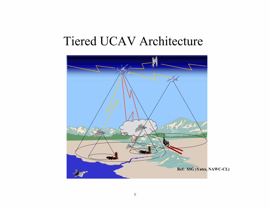
6
Tiered UCAV Architecture
Ref: SSG (Yates, NAWC-CL)
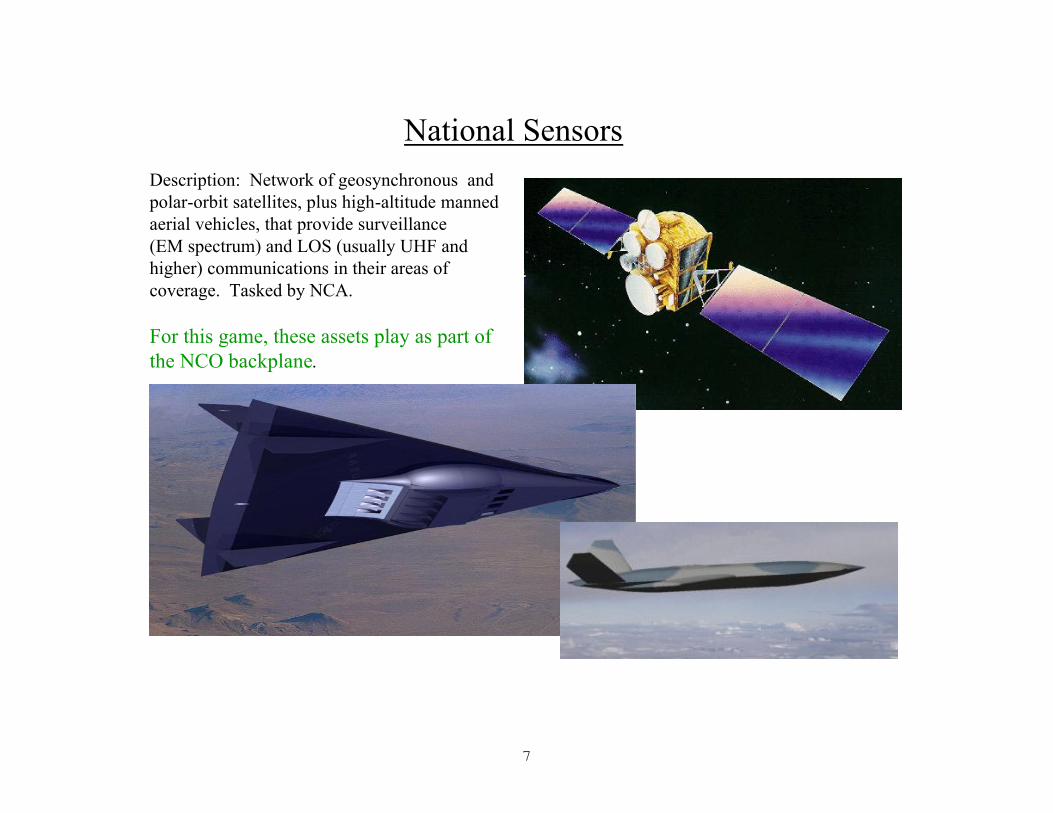
7
National SensorsDescription: Network of geosynchronous and polar-orbit satellites, plus high-altitude manned aerial vehicles, that provide surveillance(EM spectrum) and LOS (usually UHF and higher) communications in their areas of coverage. Tasked by NCA.
For this game, these assets play as part of the NCO backplane.

8
UCAV-L (Large)• 200+ foot Wingspan; 80,000 to 150,000 feet
Normal Operating Altitude; 50 to 200+ kias; CV-Deployed
• Primarily a Sensor and Comms Platform
• Refueled ~Weekly, Airborne for Months
• About 1,000 pounds of Payload of Sensors, Comms, Self-Defense Weapons and Decoys
Backbone of Theater Sensor and Comms Nets• Very Wide Area Surveillance Tool However TLE Generally
Inadequate for Direct Targeting• TLE and ID Frequently Must be Improved by Lower Tiers• Also Prime Link to Very High Bandwidth Global Data Nets• Transmitter of IFTUS for incoming ordnance
UCAV (L) Loadout (Possibility)SAR/GMTI/MASINT Radar 300 lbsIRST/LADAR (2) 200 lbsUpper (Comms) & Lower (Surveillance) Hemispheric CoverageComms/Data/Net Relay Processors 100 lbs10 Spike Variant 2 (Anti-Missile) Missiles 150 lbs10 Spike Maneuvering Active RF/IR Decoys 150 lbs1 AIM-9Z 100 nmi/60 sec GP Missile 150 lbs
Total Payload: 1,050 lbs
Ref: SSG (Yates, NAWC-CL)
For Loop 3, UCAV-L will be a National Asset which the Theater Commander may request

9
UCAV-MV (VTOL)
SpecificationsAir VehicleRotor Disk Area 594.5 ft sqRotor Span (Calc) 27.4 ftMax Takeoff Weight 2550 lbsEmpty Weight 1457 lbsMission Fuel Load 793 lbsPayload Weight 200 lbsHorizontal Tail Area 3.1 ft sqVertical Tail Area 4.7 ft sqAnti-Torque Disk Area 14.2 ft sq
Ref: PMA 263 VTUAV Web Site
• 12 hours of time on station within a 24-hour period atmax mission radius.
• Capable of hover with a 300 lb. mission payload• 20,000 ft ceiling• Internal payload 2 ft3.• 0 to 200 knots• Combat radius 110 nmi, 5 hours loiter (200lb payload)• Combat radius 250 nmi, 2 hours loiter (100lb payload)• Four-person support crew• Meteorological capability
Plays as: Helicopter with same attributes
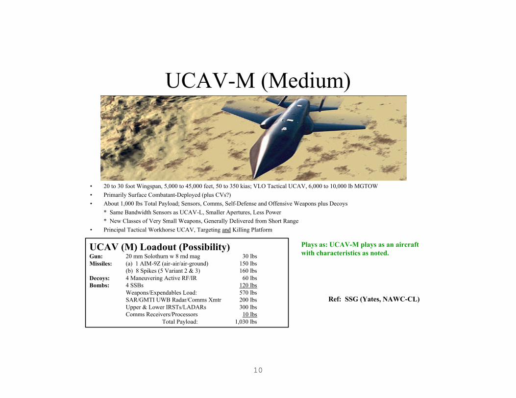
10
UCAV-M (Medium)
• 20 to 30 foot Wingspan, 5,000 to 45,000 feet, 50 to 350 kias; VLO Tactical UCAV, 6,000 to 10,000 lb MGTOW
• Primarily Surface Combatant-Deployed (plus CVs?)
• About 1,000 lbs Total Payload; Sensors, Comms, Self-Defense and Offensive Weapons plus Decoys
* Same Bandwidth Sensors as UCAV-L, Smaller Apertures, Less Power
* New Classes of Very Small Weapons, Generally Delivered from Short Range
• Principal Tactical Workhorse UCAV, Targeting and Killing Platform
UCAV (M) Loadout (Possibility)Gun: 20 mm Solothurn w 8 rnd mag 30 lbsMissiles: (a) 1 AIM-9Z (air-air/air-ground) 150 lbs
(b) 8 Spikes (5 Variant 2 & 3) 160 lbsDecoys: 4 Maneuvering Active RF/IR 60 lbsBombs: 4 SSBs 120 lbs
Weapons/Expendables Load: 570 lbsSAR/GMTI UWB Radar/Comms Xmtr 200 lbsUpper & Lower IRSTs/LADARs 300 lbsComms Receivers/Processors 10 lbs
Total Payload: 1,030 lbs
Ref: SSG (Yates, NAWC-CL)
Need Better UCAV-M Pitcher
Plays as: UCAV-M plays as an aircraft with characteristics as noted.
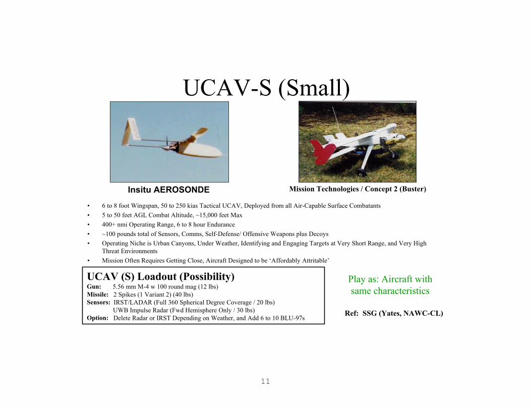
11
UCAV-S (Small)
• 6 to 8 foot Wingspan, 50 to 250 kias Tactical UCAV, Deployed from all Air-Capable Surface Combatants
• 5 to 50 feet AGL Combat Altitude, ~15,000 feet Max
• 400+ nmi Operating Range, 6 to 8 hour Endurance
• ~100 pounds total of Sensors, Comms, Self-Defense/ Offensive Weapons plus Decoys
• Operating Niche is Urban Canyons, Under Weather, Identifying and Engaging Targets at Very Short Range, and Very High Threat Environments
• Mission Often Requires Getting Close, Aircraft Designed to be ‘Affordably Attritable’
Insitu AEROSONDE
UCAV (S) Loadout (Possibility)Gun: 5.56 mm M-4 w 100 round mag (12 lbs) Missile: 2 Spikes (1 Variant 2) (40 lbs)Sensors: IRST/LADAR (Full 360 Spherical Degree Coverage / 20 lbs)
UWB Impulse Radar (Fwd Hemisphere Only / 30 lbs)Option: Delete Radar or IRST Depending on Weather, and Add 6 to 10 BLU-97s
Mission Technologies / Concept 2 (Buster)
Ref: SSG (Yates, NAWC-CL)
Play as: Aircraft withsame characteristics

12
• 6 to 12 inch Very Short Range Recon Aircraft• 5 to 8 lbs.• Flies at 70 - 100 mph.• Carries video camera and transmitter.• Primarily for Marines and SEALs to ‘See’ Around the Next Corner, Over Next Hill, Into Next Room• Also May Have Application as a BDA Collection Tool
* Deployed from Land Attack Missiles Just Prior to Impact* Link Post-Impact Imagery Back to Asset Management System* May Require Pairs or Even Multiples
> One Released Well Before Impact to Serve as Relay(s) > One Released Just Before Impact to Collect Data
* Very Low Cost
UCAV-Mi (Micro)
Ref: SSG (Yates, NAWC-CL)
Plays as: Not specifically modeled--may be used a subpayload for precision delivery of, e. g., RF jammers and tags
13
b. Sea Surface Units
Sea Surface Units
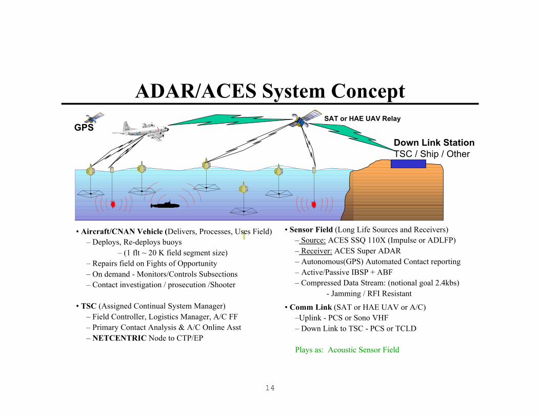
14
• Aircraft/CNAN Vehicle (Delivers, Processes, Uses Field)– Deploys, Re-deploys buoys
– (1 flt ~ 20 K field segment size)– Repairs field on Fights of Opportunity– On demand - Monitors/Controls Subsections– Contact investigation / prosecution /Shooter
• TSC (Assigned Continual System Manager)– Field Controller, Logistics Manager, A/C FF– Primary Contact Analysis & A/C Online Asst– NETCENTRIC Node to CTP/EP
• Sensor Field (Long Life Sources and Receivers)– Source: ACES SSQ 110X (Impulse or ADLFP)– Receiver: ACES Super ADAR– Autonomous(GPS) Automated Contact reporting– Active/Passive IBSP + ABF – Compressed Data Stream: (notional goal 2.4kbs)
Jamming / RFI Resistant
• Comm Link (SAT or HAE UAV or A/C)–Uplink - PCS or Sono VHF– Down Link to TSC - PCS or TCLD
Plays as: Acoustic Sensor Field
Down Link StationTSC / Ship / Other
SAT or HAE UAV RelayGPS
ADAR/ACES System Concept

15
CM Radar Picket
Antenna covers 360° (omni-azimuth). Therefore, no angle info from a single sensor.
However, range and Doppler info on a target can be ascertained through an appropriate spacing of multiple sensors in a barrier configuration. The normal spacing between sensors would be 2 km, resulting in 1.5 sensors per kilometer of barrier length.
Antenna: Array of 6 dipoles @ 150 Mhz VHF
Height of 6 meters
Diameter of 6 to 12 inches
This section 4 to 6 meters
Electronics
Barrier Geometry
l l l l l l
l l l l l l l
l l l l l l
2 km
2 km
Unit Cell
3 sensors
Ref: MITRE (R. Evans)Anchor Chain
Water Surface
99-NUWC/0594U.M2 0160-BL

16
SPARTAN USV TEST BED LONG-RANGE, MULTI-MISSION, MODULAR
GB-12-296 CHALLENGER HIGH SPEED PATROL CRAFT
• Aluminum Hull with Closed Cell Foam Sponsons
• Length: 36 feet (11 meters nominal)
• Beam: 12 feet
• Full Load Displacement: 22,000 lbs.
• Payload: 5,000 lbs.
• Engines: Two EA Caterpillar 660 BHP @ 2300 rpm
• Waterjet Pumps: Two KaMeWa Model F-40
• Design speed: 50 knots in SS320 knots in SS4Steerageway in SS5
• Endurance: 12 hours @ 50+ kts ≈≈ 600 nmi 27 hours @ 30 kts ≈≈ 800 nmi
Plays as: Surface Ship with characteristics noted supra(Photo Courtesy of TEAM ONE USA)
Ref: V. Ricci (NUWC 31)
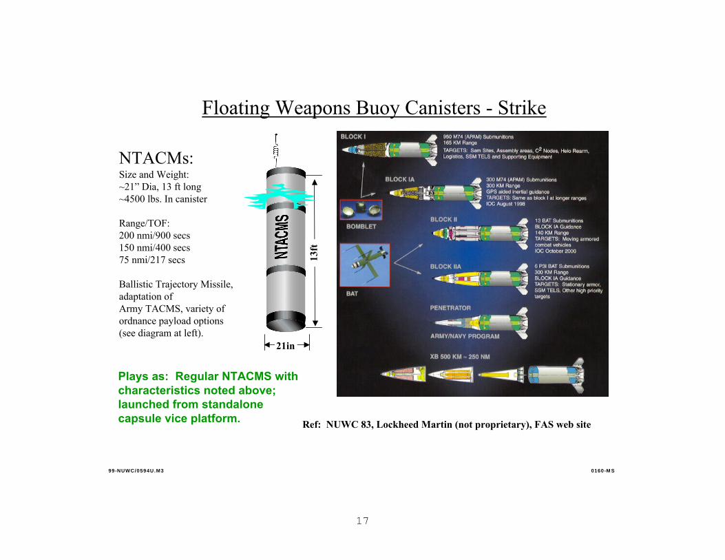
17
Floating Weapons Buoy Canisters - Strike
NTACMs:Size and Weight:~21” Dia, 13 ft long~4500 lbs. In canister
Range/TOF: 200 nmi/900 secs150 nmi/400 secs75 nmi/217 secs
Ballistic Trajectory Missile, adaptation of Army TACMS, variety of ordnance payload options(see diagram at left).
Ref: NUWC 83, Lockheed Martin (not proprietary), FAS web site
99-NUWC/0594U.M3 0160-M S
13ft
21in
Plays as: Regular NTACMS with characteristics noted above; launched from standalone capsule vice platform.
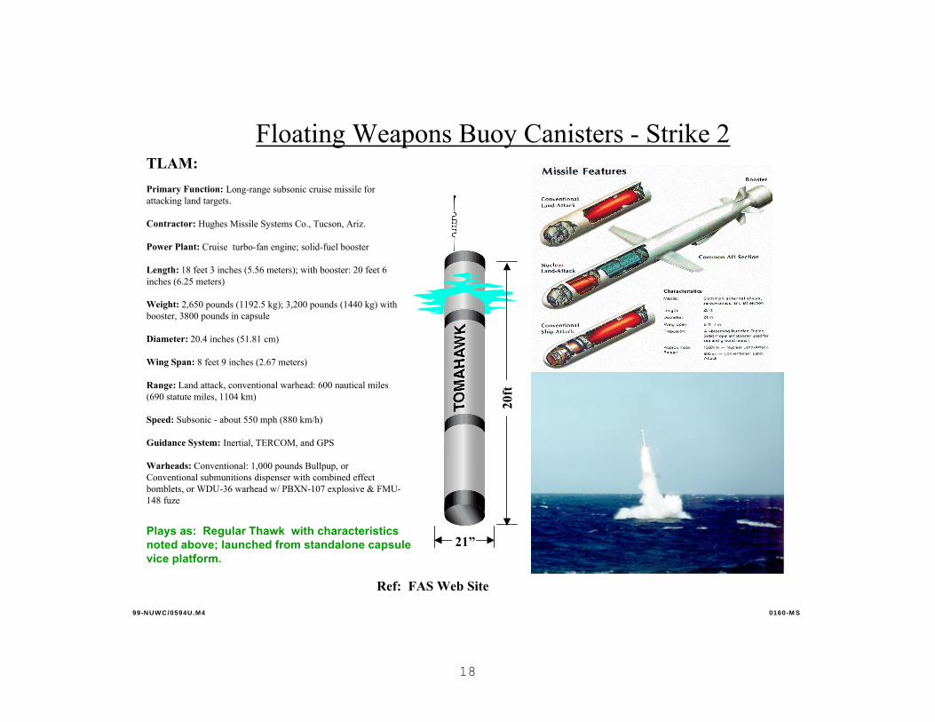
18
Floating Weapons Buoy Canisters - Strike 2TLAM:
Primary Function: Long-range subsonic cruise missile for attacking land targets.
Contractor: Hughes Missile Systems Co., Tucson, Ariz.
Power Plant: Cruise turbo-fan engine; solid-fuel booster
Length: 18 feet 3 inches (5.56 meters); with booster: 20 feet 6 inches (6.25 meters)
Weight: 2,650 pounds (1192.5 kg); 3,200 pounds (1440 kg) with booster, 3800 pounds in capsule
Diameter: 20.4 inches (51.81 cm)
Wing Span: 8 feet 9 inches (2.67 meters)
Range: Land attack, conventional warhead: 600 nautical miles (690 statute miles, 1104 km)
Speed: Subsonic - about 550 mph (880 km/h)
Guidance System: Inertial, TERCOM, and GPS
Warheads: Conventional: 1,000 pounds Bullpup, orConventional submunitions dispenser with combined effectbomblets, or WDU-36 warhead w/ PBXN-107 explosive & FMU-148 fuze
Ref: FAS Web Site
99-NUWC/0594U.M4 0160-M S
21”
20ft
Plays as: Regular Thawk with characteristics noted above; launched from standalone capsule vice platform.
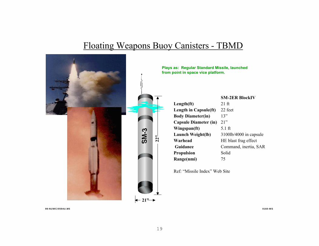
19
Floating Weapons Buoy Canisters - TBMD
99-NUWC/0594U.M5 0160-M S
21”
22”
SM-2ER BlockIVLength(ft) 21 ftLength in Capsule(ft) 22 feetBody Diameter(in) 13”Capsule Diameter (in) 21”Wingspan(ft) 5.1 ftLaunch Weight(lb) 3100lb/4000 in capsuleWarhead HE blast frag effectGuidance Command, inertia, SAR
Propulsion SolidRange(nmi) 75
Ref: “Missile Index” Web Site
Plays as: Regular Standard Missile, launched from point in space vice platform.

20
Counter-Small Boat; SubBAT
Ref: NUWC 83, Northrop Grumman, NAWC-CL (SLWW)
• Sub-BAT consists of:
• Payload section with one Brilliant Anti-Armor (BAT) Submunition and aluminum shroud
• Midbody section with guidance computer, safe arm logic and system interface unit to interface with BAT
• AIM-9X (next generation Sidewinder) rocket motor with thrust vector control
• Capsule
• Specifications:
• Length: 114 inches• Diameter: Missile - 6 inches
Capsule: 8 inches
• Weight: 190 lbs
• Range: 12 - 33 nm
Northrop Grumman Proprietary
Plays as: Regular SubBAT with characteristics noted above; launched from standalone capsule vice platform.

21
Anti-Small Boat; Forward Air Support Marine (FASM) Loitering Munition
Length: 110 inchesBody Diameter: 5 inchesWeight: 146 lbsWing Span: TBDCruise Speed: 80 knots for 3 hoursPayload Weight: 30 lbsCanister size of 6 in x 10 ft x 200 lbs
• FASM: airborne loitering weapon system that can be launched from 5 inch naval cannon. Also by standard gas generator, rocket booster, etc.
• After launch, FASM transitions to cruise flight by deploying inflatable wings, aerodynamic control surfaces and a propeller.
• Sensor package: visual and/or IR cameras with RF datalink.
• COTS components make it cheap; may be used as a “kamikaze”
Ref: NUWC 83, NAWC-CL (SLWW)
99-NUWC/0594U.M7 0160-TR
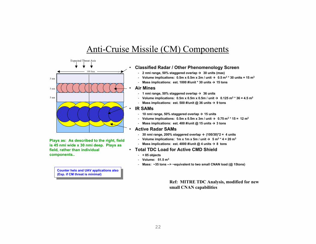
22
Anti-Cruise Missile (CM) ComponentsExpected Threat Axis
• Classified Radar / Other Phenomenology Screen- 2 nmi range, 50% staggered overlap àà 30 units (max)- Volume implications: 0.5m x 0.5m x 2m / unit àà 0.5 m3 * 30 units = 15 m3
- Mass implications: est. 1000 #/unit * 30 units àà 15 tons
• Air Mines- 1 nmi range, 50% staggered overlap àà 36 units- Volume implications: 0.5m x 0.5m x 0.5m / unit àà 0.125 m3 * 36 = 4.5 m3
- Mass implications: est. 500 #/unit @ 36 units àà 9 tons
• IR SAMs- 10 nmi range, 50% staggered overlap àà 15 units- Volume implications: 0.5m x 0.5m x 3m / unit àà 0.75 m3 * 15 = 12 m3
- Mass implications: est. 400 #/unit @ 15 units àà 3 tons
• Active Radar SAMs- 30 nmi range, 200% staggered overlap àà (100/30)*2 = 4 units- Volume implications: 1m x 1m x 5m / unit àà 5 m3 * 4 = 20 m3
- Mass implications: est. 4000 #/unit @ 4 units àà 8 tons
• Total TDC Load for Active CMD Shield- < 85 objects- Volume: 51.5 m3
- Mass: ~35 tons --> ~equivalent to two small CNAN load (@ 15tons)
Counter helo and UAV applications also(Esp. if CM threat is minimal)
Counter helo and UAV applications also(Esp. if CM threat is minimal)
Ref: MITRE TDC Analysis, modified for new small CNAN capabilities
100 0nm
5 nm
5 nm
5 nm
Plays as: As described to the right, field is 45 nmi wide x 30 nmi deep. Plays as field, rather than individual components..

23
Table 1. Non-Lethal TechnologiesTECHNOLOGY MATERIAL/
PERSONNELAPPLICATION
ConductiveParticles
M Any variety of particles that can induce short circuits in electrical or electronicequipment
DepolymerizingAgents
M Chemicals that cause polymers to dissolve or decompose. Could clog air breathingengines. Adhesives could “glue” equipment in place
Liquid MetalEmbrittlementAgents
M Agents that change the molecular structure of base metals or alloys, significantlyreducing their strength. Could be used to attack critical metal structures—aircraft,ships, trucks, metal treads
Non-NuclearElectromagneticPulse
M Pulse generators producing gigawatts of power could be used to explode ammunitiondumps or paralyze electronic systems. Vulnerable systems include electronic ignitionsystems, radars, communications, data processing, navigation, electronic triggers ofexplosive devices
High PoweredMicrowave
M, P Microwave pulse generators are similar to electromagnetic pulse. Applications are alsosimilar; however, microwave frequencies may have anti-personnel applications that cancause pain or incapacitation. May also be used for force protection applications
POL Contaminators M Additives that cause fuel to gel or solidify making it unusableSupercaustics M Acids that corrode or degrade structural materialsSuper Lubricants M Substances that cause lack of traction. Delivered by aircraft, can render railroads,
ramps, or runways unusable for limited timeAcoustics M, P Very low frequency sound generators that could be tuned to incapacitate personnel. At
high power may have anti-material applicationsFoam M, P Sticky or space-filling material that can impede mobility or deny access to equipmentIsotropic Radiators M, P Conventional weapons that produce an omni-directional laser-bright flash that can
dazzle personnel or optical sensorsLasers M, P Low energy lasers could flash blind personnel or disable optical or infrared systems
used for target acquisition, tracking, night vision, and range findingCalmative Agents P Chemical substances that are designed to temporary incapacitate personnel
Categories: P = Anti-Personnel, M = Anti-Material
Non-Lethals
These agents may be used in place of lethal warheads. For the small boat threat in particular, delivery may be made by mine (foam intake clogging and propeller fouling), missile, bomb, or UAV (Laser, Dazzler, Foam). Lethal kill is modeled by removal of the target from the game. Non-lethal kill will be simulated by stopping the object and disallowing further use of same.
24
c. Sea Volume Units
Sea Volume Units
25
Large Unmanned Undersea Vehicles (UUVs)• Speed: 0-10 knots
• Endurance: 100 hrs @ 5 knots (8 x current)
• Depth: 800 feet
• Weight in Air: ~16,000 lbs.
• Free Flood Region: ~16,000 lbs.
• Displacement: ~31,000 lbs.
• In-Water Run Trim: Neutral +/- 200 lbs.
• Dry Payload Capacity: 3476 lbs.
• Reconfigurable and Modular
• RF Surface and Acoustic Comms
• In Stride GPS Updates
Ref: NUWC (Lisiewicz and Ricci)Plays as: Submarine with characteristics noted above..

26
Medium UUVs
Ref: NUWC LMRS PM (Higgins)
Range(s) Thresholds GoalsSingle sortie reach 75 nm 120nmTotal area coverage 400 nm2 650 nm2
Area coverage rate 35 nm2/day 50 nm2/dayEnergy Developments may give as much as twice this endurance.
Size and Wt: 20.95 inches OD
240 inches long
2780 lbs 2 to 7 knots
Sortie Reliability Ps =0 .953, 40 hrs
Full impulse launch capable
Handles like torpedo
Cables connect like torpedo
Plays as: Not modeled separately, plays as part of MCM Shallow Payload.

27
28
Small UUVs
Ref: NUWC EMATT PM (Lebrun)
-Speed: 8 Knots
-Depth: 75-600 feet
-Endurance: 24 hours (8
x current)
-Launch Mode:Air or Surface
-Programmability:
22 Headings/Depths & Tonal Amplitude
“A” SizedSonobuoy Size3 feet long by 4.85 inches in diameterEnables air launch by helicopters and fixed wing aircraft22 lb. in air; -2 lb. in salt water
Currently configured as mobile target (active transmission); payload can be modular. Payload as described above is 10#.
Plays as: Not specifically modeled; plays tacitly as part of other systems (SuperDADS, SubTag).

29
d. Sea Bottom Units
Sea Bottom Units

30
Intermediate-Term Acoustic and EM Sensors
TRIP WIRE
FIELD
BARRIER
AOA
31
Operational Description: These systems are similar to permanent systems described earlier. The differences are that: (1) these systems are hardwired to relatively local land-based processing facilities and external communications, located in vans specifically designed for the purpose. (2) they are smaller in size and weight than the permanent sensors and require less work to install. Nominal installation time is one week from start of installation. Covertness of installation will be difficult. We use a nominal array length of 5 nmiles and postulate that they have been pre-installed in the time-frame of interest. The installation of these units requires a safe haven in relative proximity for the processing vans.
The performance of these systems is extremely dependent on environment, since the long-range sensors are acoustic. They are assigned here a range of 20 nmis perpendicular to their major array axis and 10 miles off the ends of this axis, in the “end-fire” beams.
These arrays serve as acoustic field monitors for detection and classification at long ranges and may also be credited with short-range EM field DCL in the immediate vicinity of the arrays (2 nmi). For long-range acoustics only, these sensors are not adequate for targeting and will need to be supplemented with additional more accurate sensors. They also provide a link to the external comm world from the acoustic communicators (UUVs, submarines, DADS) via their control vans.
Intermediate-Term Acoustic and EM Sensors
Ref: JHU/APL (South) and FAS Web Site
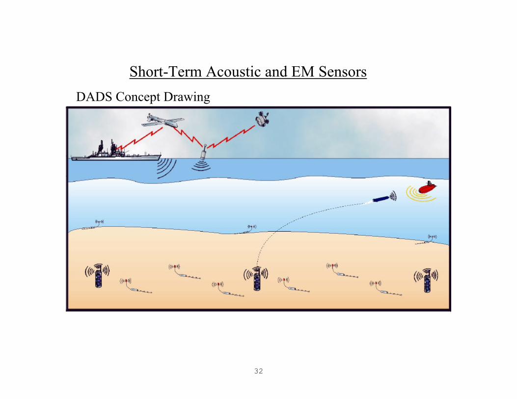
32
DADS Concept Drawing
Short-Term Acoustic and EM Sensors
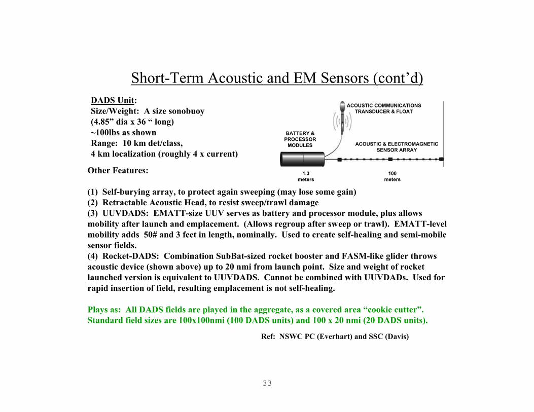
33
Short-Term Acoustic and EM Sensors (cont’d)
BATTERY & PROCESSOR
MODULES
ACOUSTIC COMMUNICATIONS TRANSDUCER & FLOAT
ACOUSTIC & ELECTROMAGNETIC SENSOR ARRAY
100 meters
1.3 meters
DADS Unit: Size/Weight: A size sonobuoy(4.85” dia x 36 “ long)~100lbs as shownRange: 10 km det/class,4 km localization (roughly 4 x current)
Other Features:
(1) Self-burying array, to protect again sweeping (may lose some gain)(2) Retractable Acoustic Head, to resist sweep/trawl damage(3) UUVDADS: EMATT-size UUV serves as battery and processor module, plus allows mobility after launch and emplacement. (Allows regroup after sweep or trawl). EMATT-level mobility adds 50# and 3 feet in length, nominally. Used to create self-healing and semi-mobile sensor fields.(4) Rocket-DADS: Combination SubBat-sized rocket booster and FASM-like glider throws acoustic device (shown above) up to 20 nmi from launch point. Size and weight of rocket launched version is equivalent to UUVDADS. Cannot be combined with UUVDADs. Used for rapid insertion of field, resulting emplacement is not self-healing.
Plays as: All DADS fields are played in the aggregate, as a covered area “cookie cutter”. Standard field sizes are 100x100nmi (100 DADS units) and 100 x 20 nmi (20 DADS units).
Ref: NSWC PC (Everhart) and SSC (Davis)

34
TAMDA/LFAS Sources
Transceiver Elements
Float
LF Xmitter
Anchor
Probe Pulse
BT Sensor
Surface Buoy
Tactical AcouticsMeasurement and Decision Aid (TAMDA)
TAMDA (surface, roughly sonobuoy size) provides, via a combination of probes, acoustic projections, and receivers acoustic environmental information on Bottom Reflection Loss, Reverberation, Bottom Depth, Bottom Type, Bottom Scattering Strength, sound velocity profile and ambient noise monitoring.
LFAS (bottom, roughly 21” dia and 10 ft long in capsule), acting in conjunction with other receiver sources or LFAS units, can act as an illuminator and receiver for multi-static targeting. It can also provide limited insitu environmental data, particularly direct measurement of propagation loss.
TAMDA or a similar environmental monitoring system will be necessary to plan and place bottom acoustic sensors effectively in the real world. An active source will also be necessary to mount an effective acoustic ASW campaign against modern SSs.
For Loop 3; TAMDA is assumed to be employed as a data-gathering device prior to the planning and placement of any acoustic fields. LFAS is presumed to be placed with each 100x100nmi DADS array, four to a field.

35
Play in this game will allow consideration of simliar bunkering in reasonable depths of water (<1000ft) for any of the floating weapons presented previously. In general, the weight of the entire battery is that of the component parts, plus 25-50% for structure and neutral buoyancy (individual canisters may be positively buoyant).
For example, a 16-pack of TLAMs would be estimated at 16x4klb@ = 64000lb + 25% = 80000# = 40 tonsLarger weapons would probably be bunkered in smaller groups, a la Heavyweight Torpedoes (next slide).
Encapsulated Floating Weapons, RECO Release
48”
72”
48”
Ref: Lockheed-Martin and NUWC 83
The unit shown is representative of a class of bottom-mounted vertical-launch canister batteries.Each is remote controlled via acoustic, radio, orother link to the local weapon release authorities.
The unit shown here is sized for Precision Attack Munition (PAM) and similar-sized weaponry. The concept is extendable to any canistered weapon. It isintended for the individual weapons to be watertight in themselves, this bunker will provide an anchor,structural stability, and communications.
The concept of employment is that the weapons are bunkered covertly on the sea bottom within range of their intended targets. On command, the canisterized weapons rise or are propelled to the surface where they launch and perform their missions.
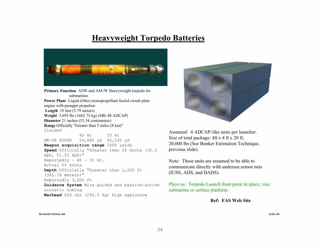
36
Primary Function ASW and ASUW Heavyweight torpedo for submarines
Power Plant Liquid (Otto) monopropellant fueled swash plate engine with pumpjet propulsor.Length 19 feet (5.79 meters)
Weight 3,695 lbs (1662.75 kg) (MK-48 ADCAP) Diameter 21 inches (53.34 centimeters) Range Officially "Greater than 5 miles (8 km)" Claimed
40 kt 55 ktMK-48 ADCAP 54,685 yd 42,530 ydWeapon acquisition range 1600 yardsSpeed Officially "Greater than 28 knots (32.2 mph, 51.52 kph)"Reportedly - 40 - 55 kt.Actual 55 knots Depth Officially "Greater than 1,200 ft (365.76 meters)"Reportedly 3,000 ft Guidance System Wire guided and passive/active acoustic homing Warhead 650 lbs (292.5 kg) high explosive
Heavyweight Torpedo Batteries
Ref: FAS Web Site
Assumed: 4 ADCAP-like units per launcher.Size of total package: 4ft x 4 ft x 20 ft;20,000 lbs (See Bunker Estimation Technique, previous slide).
Note: These units are assumed to be able to communicate directly with undersea sensor nets (IUSS, ADS, and DADS).
Plays as: Torpedo Launch from point in space, vice submarine or surface platform.
99-NUWC/0594U.M6 0160-JR

37
UUV Box
Comms Xponder
EMATT-Sized UUV
Magnetic or Adhesive
Tag
Array
SubTagSystem consists of DADs-linked box launcher containing EMATT-like small UUVs. When launched by field/network, UUVs match SS TMA and place adhesive or magnetic marker on SS. This marking is covert until activated by BLUE RECO, then SS knows it is tagged.Plays as: Small field laid near enemy submarine choke points. Some percentage (approx 50% for this game) of SS’s transiting are successfully tagged.
Unit is 20”x20”x48” (box)Array length is 100 metersWt: 250#UUV Range: 64 miles @ 8 kts

38
e. Surf Zone Units
Surf Zone Units

39
CrawlersPAYLOAD• For this game, this class of vehicle will be for surveillance/marking only. An option exists to have them armed with up to five pounds of C4-level explosive.
TYPES• Legged / Wheeled / Tracked (BEST)
* Tracked: best for most ground conditions (surf, muck, liquified sand, gravel); simple; cheap
SEARCH TYPESORDERED SEARCH: Short-term efficient, but: vehicles slip, meet obstacles, find mines; requires station keeping; requires corrective action; requires communication. Unless tight control is kept, the search degrades to random.RANDOM SEARCH: Does not require station keeping; does not require comms; very inexpensive; easily understood for all environmental conditions; equals ordered search rates within an hour.
COVERAGEPURE RANDOMNESS: Center ReleaseQUASI-RANDOMNESS: Center ReleaseFRANKLIN WAVES (MARCH & FACING MECCA): Seaward Edge
SAMPLE SEARCH STATISTICSSCENARIO: Linear release 75 ft barrier on seaward edge / 100 lemmings / 100 yd x 100 yd / zero to 0.5 current indexRESULTS: Targets (mines) located = 85% to 96% / time 2 hours
Plays as: Field laid down in 100yd x 100yd squares. One small CNAN “load” is 10 fields of this size. Surveillance confidence as noted above.
SIZE: 14”wx14”lx8”h = .9 ft3
WEIGHT• In air: 30 lbs / In water: 20 lbs
POWER• 1 gel pack or 8 “D” cell Ni-Cad batteries
SPEED• 0.25 to 1.5 ft/sec

40
Unmanned Underwater Vehicles -Shallow Water Autonomous Reconnaissance Modules (SWARMs)
DESCRIPTION: The SWARM are expendable or recoverable UUVs that operate as a group to search large areas very rapidly. Upon insertion into the OPAREA they self-organize to provide uniform coverage and compensation for any failed module. Each unit automatically classifies and identifies mines and provides imagery of any objects of interest. Targets, status, oceanography and hydrography are reported to command in near real-time via Comm/Nav Aid modules that assist subgroups of SWARMs.
USE: Insertion into the OPAREA can be by any desired method. Employment patterns and numbers of modules can be selected to accommodate almost any area configuration or desired coverage rate.
One-Sided Diagonal Multi-Sided Random
Operational Concept Options
Communicate
Bottom Mapping
METOC Data
Object Locations
and Images
Host Delivery:
• Manned:– Aircraft
– Ship
– Submarine
Host Delivery:
• Manned:– Aircraft
– Ship
– Submarine
• Unmanned:– UUV
– Surface Craft
– AUV
• Unmanned:– UUV
– Surface Craft
– AUV
• Size LMRS; 2780 lbs; 21”dia. X 240”• Search Speed 8kts.• Search Swath 400yds.• Identification Speed 4kts.• Classification Resolution 1” x 1”• Identification Resolution 1/2” x 1/2”• Range 70 nm.• Maximum Depth 600 ft.• Operating Altitude 40 ft. (nominal)
• Plays as: Part of Mine Surveillance Payload; in conjunction with Crawlers for VSW and SZ. Note: this version of SWARM pertains only to CNAN Loop 3 Innovation Game. The original CSS concept uses smaller vehicles.

41
Water Hammer
40
DESCRIPTION: A mine neutralization system consisting of an array of shock tubes which generate and project to military important distances (tens of meters) a pressure pulse of sufficient energy to neutralize the threat. Water Hammer moves along the bottom, firing repeatedly. It uses chemical energy (aluminum and water) to generate a high pressure in each firing tube. All tubes fire simultaneously to produce a high pressure shock wave.
USE: Two units in tandem could clear a 50-yard lane of mines and obstacles from very shallow water to surf zone (design space … deeper water could be cleared if required). No detection or classification required.
Clearance confidence: 0.95
Size of path cleared: 50 yd
Transit speed: 5 kn
Clearance speed: 2.2 nm/hr
Size: 3 m x 2 m
Weight (“Hammer): 9 tons
• No precursor mine detection/ classification required, and no personnel placed in harm’s way.• Deployed using a 15-ton vessel with adequate handling capability.
• Weapons officer programs unit start point and bearing parameters into control system before launch; logistics personnel can recharge batteries and reload fuel. Units can be loaded and charged at the origin with enough fuel and electricalpower to entirely clear a lane.
• Reload requires about 6 metric tons of aluminum fuel, and recharge requires about a gigajoule of electrical energy.
• Fuel used is non-explosive aluminum.
• Plays as: separate 15-ton Mine Clearance load. After adequate time has elapsed, lane is cleared as described above.
Very Shallow Water and Surf Zone
Clearance
FOR OFFICIAL USE ONLY
NOTE: Do not reference as a source document; system parameters valid for CNAN Innovation Loop 3 War Game only
WatehammerFiring Tubes

42
f. Ground Units
Ground Units

43
Unattended Ground Sensors (UGS)
DESCRIPTIONUGS consist of a series of sensors in the seismic,acoustic, and IR realms, which link to a commonprocessor which in turn links to the comms net..
WEIGHT4.5 to 25 lbs..
POWERFixed or Rechargeable Batteries / Solar panels
INFORMATIONTarget DCL
RANGES• Seismic: people walking 500 meters away / people crawling 250 meters away / vehicles moving 1,000 meters away.• Thermally-Emitted-Radiation: up to 200 ft away at 98.6°F in fog, mist, and other atmospheric obscurants.• IR: up to 2.5 km depending on atmospheric/ground conditions.
COMMUNICATION• Radio to land-link, UUV, or Satellite• Possibility of 8,000 selectable radio frequencies for transmission
•Plays as15 x 15 nmi “field (weight of units 1 ton). Deployed as part of RSTA “Cloud” package. See next slide.
Ref: UGS Web Site
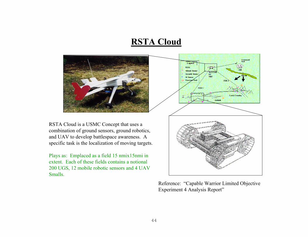
44
RSTA Cloud
Reference: “Capable Warrior Limited Objective Experiment 4 Analysis Report”
RSTA Cloud is a USMC Concept that uses a combination of ground sensors, ground robotics, and UAV to develop battlespace awareness. A specific task is the localization of moving targets.
Plays as: Emplaced as a field 15 nmix15nmi in extent. Each of these fields contains a notional 200 UGS, 12 mobile robotic sensors and 4 UAV Smalls.

45
2. Notional Adversary
WORLD VIEW
The timeframe is 2020+. The world economy has prospered
and several states with ideologies antithetic to that of the
United States have had nearly 20 years of double-digit economic
growth.
Competitor 1 has a population 4 times that of the U. S. and
now has a Gross Domestic Product (GDP) that is twice that of the
United States. It is rapidly transforming itself from an
agrarian economy to an information and manufacturing economy.
It has a modest defense budget in terms of percentages, but that
budget has been 20% larger than that of the U. S. for the last
decade. It has developed an indigenous defense industry and
does not need to buy any item of military equipment externally.
It has one rebellious province that has not been brought into
line, but attempts at conciliation are presently being made
through negotiations, not warfare. It has no serious threats to
its borders or national integrity. It is convinced of the
superiority of its peoples and government over all others. It
has no intrinsic animosity towards the U. S. but neither does it
have any cultural or historical ties. The country has thousands
of miles of coastline and the surrounding sea areas include
large areas of island-filled shallow seas as well as large
tracts of blue water.
Competitor 2 has a population 5 times that of the U. S. and
a GDP that is comparable to that of the U. S. It has a large

46
information and manufacturing sector to its economy, but remains
largely agrarian. It has a significant defense industry, but
still buys most of its aircraft, ships, and armored vehicles.
Its defense budget has been half that of the U. S. for the last
two decades. It has several threats to its national security
and a noticeable amount of internal unrest. It also suffers
from post-Colonial “Angst”, and seethes at the slightest hint of
larger powers interfering in its affairs. It has no intrinsic
animosity towards the U. S., but neither does it have any
significant cultural or historical ties. The country has
coastline for over half the length of its borders. With the
exception of continental shelves that extend less than 100 km
offshore, the surrounding seas are almost entirely blue water.
Competitor 3 has a population half that of the United
States and a GDP that is one quarter that of the U. S. It has
developed significant a manufacturing capability, but is not a
major player in information technology. It is still mostly
agrarian. It has a modest defense budget roughly 20% of that of
the U. S. and no indigenous defense industry. It has several
threats to its national security but little internal unrest.
Its government is closely integrated with its religion, a
religion that has had a history of expansion via conquest. It
has a deeply seated hatred of the U. S. and has a history of
supporting terrorism against the U. S. The country is mostly
land-locked but does enjoy several hundred miles of coastline.
The geography is such that virtually all of the sea areas within
500 km of the coast can be considered to be shallow or littoral
waters. Critical international trade routes are forced by the
geography to pass within 50 km of Competitor’s coastline.
47
All three competitors regard themselves as the logical and
legitimate supreme powers in their respective regions. Since
they have ideological differences with many of their neighbors,
exercise of this power is usually accomplished through the use
or threat of use of military power. They fear the ability of
the U. S. military to interfere in their affairs via it own
power projection forces. To date all three have been able to
cause the U. S. to reduce overseas basing in their respective
regions. To prevent future U. S. exercise of power, all three
competitors have developed substantial “area denial”
capabilities.
THE OPPOSITION
Competitor 1
Competitor 1's goal is an area denial capability based on
four tiers: an ability to attack surface ships anywhere, an
exclusion zone in which it is capable of denying forward basing
capability within 2000 km of Competitor 1's coast, a maritime
exclusion zone in which it is capable of defeating any naval
force within 1000 km of the coast, and a kill zone in which no
hostile forces of any kind (air, land, or sea) will be allowed
to penetrate within 500 km of the coast and in which any pre-
positioned forces can be annihilated within minutes of the
beginning of any hostilities.
Competitor 1 is a nuclear power with 300 land-based ICBMs
and 150 sub-launched ICBMs (carried by six nuclear ballistic
missile submarines). All ICBMs are MIRVed. This means that the

48
U.S. National Missile Defense system cannot handle even a
fraction of the nuclear threat. Competitor 1 has developed and
tested nuclear weapons for EMP applications. It has stated that
use of nuclear weapons for pure EMP generation does not directly
threaten any nation and does not justify nuclear retaliation.
It has a major presence in space with dozens of high-resolution
imaging, radar, and electronic intercept satellites. It has
several commercial and military SATCOM networks and operates a
satellite-based global positioning system that is fundamentally
different than the U. S. system. It has deployed several
redundant undersea surveillance systems that cover all of the
ocean regions within 2500 km. This is augmented by a merchant
marine fleet (several hundred large tankers and cargo ships, a
thousand coastal trading vessels, and a fishing fleet of many
thousands, in which virtually every ship over ten tons
displacement has satellite communications, “GPS”, radar, “fish-
finding” sonar, and rf interferometer systems and at least one
crewman who is a member of the active military reserves). These
vessels ply every mile of the area denial region and serve as a
primary intelligence resource. Each is also covertly armed with
several shoulder-fired anti-tank weapons and shoulder-fired
anti-air missiles. As many as 25 larger merchant vessels have
been covertly modified to support special operations. These
vessels can each house, transport, equip, and covertly
deploy/embark up to 100 special operations commandos. There are
also twelve over-the-horizon radar sites, 200 long-range
maritime patrol aircraft, and roughly 30 AWACS-like platforms
for early warning. Competitor 1 has also invested heavily in
information warfare. It has an IW corps 50,000 strong, supplied
with the latest Japanese and American computer technology.
49
Computer literacy is universal among the younger generation and
the best students are drafted into the IW corps.
Competitor 1 has an air force of roughly 2000 fighter
aircraft comparable to any in the U. S. inventory. It has more
than 1500 strike aircraft capable of delivering anti-ship
missiles. In addition it has roughly 3000 remotely piloted
aircraft useable in a strike role. It has a navy with 2
aircraft carriers (each with 60 STOVL aircraft), 10 air defense
cruisers (each with roughly 120 vertically launched surface to
air missiles), 50 guided missile destroyers (each with roughly
32 vertically launched anti-ship missiles and 30 surface to air
missiles), 100 guided missile frigates (each with 16 anti-ship
missiles and 16 surface to air missiles), and 300 patrol craft
(each with four anti-ship missiles and four torpedoes and
capable of operations out to 500 km from shore). The navy has a
marine force of 30,000 but must rely on the equivalent of
“channel-ferry” hovercraft (100 km range) for amphibious
assault. The navy also has 15 nuclear attack submarines capable
of blue water operations, 20 older diesel submarines, 30 modern
diesel submarines, and 10 air-independent propulsion submarines.
All submarines are armed with modern torpedoes and anti-ship
missiles. In total, Competitor 1 has an aggregate of 30,000
anti-ship missiles. Roughly half have an effective range of 300
km, while the remainder have an effective range of 600 km. All
are capable of land-based, air-based, or sea-based launching.
There are 2000 short-range ballistic missiles (500 km range),
1000 medium range ballistic missiles (1000 km range), and 500
intermediate range ballistic missiles (3000 km range). The
latter missiles have terminally-guided maneuverable warheads,

50
are capable of discriminating between targets, are capable of
hitting moving targets, and cannot be destroyed by any available
theater ballistic missile defense system. All ballistic
missiles are capable of carrying conventional, nuclear, or
chem/bio warheads. Competitor 1 is a major proliferator of WMD
has blatantly disregarded treaties banning such weapons (even
though it has signed some of them). It has a full spectrum of
chemical and biological weapons using every conceivable delivery
means. It is estimated that the stockpile contains over 15,000
tons of chemical and biological agents. The navy has roughly 30
minehunters/minesweepers, 30 dedicated mine-laying ships, and
roughly 20,000 mines. The mines are split between intelligent
CAPTOR-like mines and multiple-influence shallow-water mines.
Intelligence reports that there are a number of submarine-
plantable mines capable of attack using chemical and biological
agents. Remotely activated minefields have been preemptively
placed in waters out to 200 km from the coasts.
The surface forces have roughly 1000 long-range surface-to-
air missiles, 5000 medium-range surface-to-air missiles, and
more than 50,000 man-portable surface-to-air missiles. Roughly
half of the surface-to-air and air-to-air weapons have multi-
mode, counter-stealth seekers. The army can field roughly 36
ready divisions (15,000 combatants each) of which half are
mechanized infantry and half are armored. Roughly 1000 modern
attack helicopters support them. There is a 15,000-person
special operations force comparable in training and equipment to
U. S. SEALS and 3 airborne divisions (30,000 troops). It is
rumored that as much as 1/3 of the special operations forces are
covertly deployed out of the country at all times. The air
51
force has 150 C-5-like heavy lift aircraft capable of delivering
all three divisions in simultaneous air assault. Essentially
all military equipment was new within the last 20 years and is
comparable to that used in the best European armed forces.
Competitor 1 also has developed ground-based high-energy
laser technology for anti-missile and anti-satellite
application. It also has roughly 250 anti-satellite missiles
capable of striking objects in any orbit except geosynchronous
orbit. The laser systems can damage satellites in
geosynchronous orbits. Competitor 1 has a major space launch
capability and has an inventory of 100 launch vehicles and spare
satellites to immediately replace any space asset it may lose.
It has publicly stated that satellite systems are not immune to
attack and are fair game in any conflict. Privately the
government has said that will not preemptively attack primary
ICBM launch warning satellites in geosynchronous orbit. This
act of “good faith” is aimed at preventing escalation of any
hostilities to full nuclear exchanges.
In short Competitor 1 has an army capable of dealing with
any invasion by forces smaller than an army group. It has a
highly trained, well-equipped air force and air defenses capable
of maintaining air superiority anywhere within 500 km of its
shores. It has a navy capable of global undersea operations and
regional surface operations against forces of any size. It has
redundant “at sea and over-the-horizon” targeting capabilities,
the ability to attack surface ships at ranges out to 1000 km by
any of four means (torpedoes, mines, anti-ship cruise missiles,
and guided ballistic missiles), and forces adequate to maneuver
52
and concentrate to deliver massive attacks. It can be
considered to be a second superpower.
Competitor 2
Competitor 2 has elected for a simple 500 km exclusion zone
capability. It is also a nuclear power, having 30 single-
warhead ICBMs and 16 MIRVed ICBMs. Its nuclear weapons are
sufficient to guarantee enough penetrating weapons to inflict
unacceptable (although limited) damage on CONUS (or any other
target). It also has a fully developed chemical and biological
weapon capability although it has developed only a few delivery
mechanisms. It has several thousand tons of stockpiled agents.
It has its own space launch capability and owns a number of
surveillance and communications satellites. It is believed that
the single-warhead ICBMs can be used as anti-satellite weapons.
Competitor 2 has 12 AWACS early warning aircraft and 50 long-
range maritime patrol aircraft. It has deployed an undersea
surveillance system covering all ocean area within 1000 km of
its coasts.
A modern magnetic surveillance system covers those ocean areas
deemed of critical importance.
The navy has 2 conventional aircraft carriers with 70
aircraft each. They are supported by roughly 30 guided missile
destroyers (64 anti-aircraft missiles and 16 anti-ship missiles
each), and 70 guided missile corvettes (16 anti-aircraft
missiles and 8 anti-ship missiles each). Competitor 2 has also
acquired another 100 fast patrol craft (4 anti-ship missiles
each). There are also 20 modern diesel submarines and 10

53
nuclear attack submarines. The sea-based anti-ship missiles all
have nominal 300 km range. There is an additional 1000 anti-
ship missiles available for re-supply. In addition to the ship-
launched missiles there are another 4000 anti-ship missiles,
half of which are capable of being air-launched and the
remainder are shore-based. These missiles have 600 km range.
The navy believes strongly in mine technology and has roughly
20,000 mines of varying types. Since it believes it owns its
neighboring ocean, it stands ready to deploy thousands of
remotely activated, smart, submerged floating mines. Even in
deep water, ships will not be safe from these torpedo-based
mines.
The army has more than 1,000,000 active duty troops. Most
of these are mechanized infantry. It has a total of 2000
armored vehicles and less than 200 attack helicopters. The
infantry are supported by massive quantities (2000-3000) of
tactical ballistic missiles with ranges from 150 km to 2000 km.
The long-range ballistic missiles have terminally guided
maneuverable warheads capable of hitting mobile targets. All
ballistic missiles can employ either conventional or chem/bio
warheads. The nation has invested in fiber-optic communications
for command and control and has several redundant networks that
cover the country, the main lines and nodes of which are deeply
buried.
The air force has roughly 1000 first-rate fighter aircraft
and 1000 strike aircraft. It also has developed an airborne
rapid-fire electromagnetic gun for antimissile and anti-aircraft
defense. There are 12 such rail-gun platforms. The fighter

54
aircraft have state-of-the-art smart missiles with an anti-
stealth capability. It has an indigenous space launch
capability, operates a significant satellite communications
network, and has recently deployed several high-resolution
imaging satellites.
In short, Competitor 2 has a formidable armed force that
can deal with conventional land attacks. Its air defenses and
aircraft that can guarantee air superiority anywhere over it
landmass and possibly as far as 200 km out to sea. It has a
capable but limited antisubmarine warfare capability. It has
the ability to conduct anti-surface operations against carrier
battle groups anywhere in its “ocean” using a complete array of
torpedo, cruise missile, ballistic missile threats, and mine.
Competitor 3
Competitor 3 has opted for a 500 km maritime exclusion
capability. It is likely, but not proven that the country has a
limited nuclear capability. This capability probably consists
of less than 12 warheads. These may be delivered by
intermediate range ballistic missiles (1500 km), aircraft, or
terrorist insertion. It is rumored that at least three 50-
kiloton devices have been smuggled into the U. S. and are
secreted in critical locales under the control of deep cover
agents. The country has a substantial chemical and biological
weapons capability. It is believed that at least 5000 tons of
chemical agents and 1000 tons of biological agents have been
stockpiled. These agents are capable of being delivered by
ballistic missiles, aircraft sprays, and a novel design of naval
mine. The country has roughly 1000 medium and intermediate

55
range ballistic missiles (500 km and 1500 km range) capable of
delivering either conventional or chem/bio warheads. The
country has no space launch capability but has contracted for
surveillance satellite information and satellite communications
from several different countries (including France, Russia, and
China).
Competitor 3 has a small but professional army with roughly
200,000 troops. These troops have 2000 first-rate main battle
tanks and 500 surface-to-air missile batteries. Roughly one-
third of these forces are concentrated around the country’s
three main industrial areas. The remainders are mobile and
patrol the borders concentrating along probable lines of attack.
Doctrine prohibits them from remaining at any one site for more
than twelve hours.
The air force has 200 fighter aircraft and 200 strike
aircraft. None of these aircraft are older than 20 years, but
none is comparable in capability to the newest U. S. aircraft.
The air force also operates 4 airborne early warning aircraft
and 20 long-range maritime patrol aircraft. These forces can
make it impossible for an adversary to achieve air superiority
with certainty but cannot maintain its own air superiority
except at limited times and places.

57
The navy is small but has concentrated on becoming
proficient in using it major assets: 100 fast patrol craft (with
4 anti-ship missiles each) and 150 ocean-capable “pleasure
craft” of 50-70 foot length. Irregular forces that are famed
for suicide missions operate the latter. The pleasure craft are
normally operated for tourist-based ocean fishing but can be
fitted with camouflaged chem/bio agent dispensers, very large
explosive devices (10,000 kg), torpedoes, or medium anti-tank or
anti-armor missiles. Their standard complement of radar, sonar,
ESM, and satellite communications makes them a vital element of
Competitor 3's ocean surveillance. In addition each of these
craft can also operate two remotely operated undersea attack
vehicles (essentially piloted long-endurance torpedoes). The
navy has a long history of mine warfare. Intelligence confirms
the presence of up to 10,000 World War II vintage moored and
floating mines. Four aging destroyers have been adapted to
laying these mines. It is also believed that another 1000
Captor-like mines and 2000 shallow-water bottom mines have been
purchased. The primary anti-ship capability, however, comes
from roughly 5000 anti-ship missiles. 1000 of these are short
range (100 km) shore-launched missiles of ancient vintage. The
remainder are split between 300 km and 600 km range missiles.
The shorter-range missiles are deployed on the patrol craft or
reserved for air launch by strike aircraft. The longer-range
missiles are fired from mobile land-based platforms. These are
distributed at depths up to 100 km inland and are moved every 24
hours. Their locations are typically concealed in caves or
buildings until shortly before launch to minimize enemy
targeting opportunities. Missiles can be launched with ten
minutes of a warning order. The navy also operates 8 kilo-class
diesel submarines, but their capability is unknown and
questionable

58
In short, Competitor 3 is susceptible to overland or
amphibious invasion by army-sized forces.
It can provide effective but not impenetrable air defense. It
can inflict massive damage to any naval force within its
exclusion zone but cannot win a war of attrition. It
anticipates making the costs of U. S. intervention too costly
for us to pursue a protracted conflict.
THE SOLUTION
The Navy After Next
The U. S. has anticipated the development of these area
denial capabilities. The government is convinced that there are
circumstances that would demand U. S. power projection into the
territory of each of these competitors. Knowing that the U. S.
acquisition system will not permit disposal of recently acquired
but legacy assets (such as aircraft carriers, land-attack
destroyers, amphibious assault ships, and attack submarines),
the response to the new threat has involved a new peripheral
capability. The primary carrier battle group and amphibious
ready groups structure remains essentially unchanged. These are
the power projection assets of the Navy. However, the area
denial systems can prevent the projection of power by those
assets. The peripheral capability is an access assurance force.
This force is considered to consist of four parts: a global
satellite-based network, logistics support ships (which may or
may not be the existing logistics force), a distributed sensor
and weapons system, and small, fast combatants that deploy the
distributed sensors and weapons.

59
The network may be assumed to be robust, secure, and
readily accessible for two-way exchange of information. Antenna
requirements will not exceed 50 cm in diameter and need not be
aimed at specific satellite coordinates. We will assume this to
be true even though the enemy may be able to take out the
relevant satellites {we can’t address every problem in this
project).
The logistics force may be assumed to be capable of
provided any asset needed by the combatants. This will include
food, replacement parts, fuel, and replacement distributed
components. The logistics force will not provide berthing or
long-term mooring for the combatants or their personnel.
Logistics re-supply will be performed in relatively safe waters
and modest sea states.
The sensors will be connected to gateways (nodes that
convert from radio signal to acoustic signals) by acoustic
modems. The gateways are connected to the network by radio
communication. The sensors may be acoustic arrays, radar array
“elements”, magnetic detectors, ESM sensors, etc. The weapons
may be torpedo-based mines, surface-burst fragmentation mines,
cannisterized surface-to-air missiles, cannisterized surface-to-
surface missiles (anti-ship or land attack), etc. The weapons
are also connected to the gateways and received their firing
authorization via the gateways. The sensors, weapons, and
gateways will be deployed wherever they need to be deployed.
This may be in blue water, in littoral waters, near the shore,
or inland. Depending on cost, the sensors, weapons, and
gateways may be expendable or retrieval may be required. Any
distributed weapons must either be retrieved or inactivated
after a period of time.

60
The combatants will carry the sensors, weapons, and
gateways. The sensors, weapons, and gateways may or may not be
aboard the combatants during ocean transit. Extra fuel tanks
might be carried instead and the “payloads” picked up from the
logistics force at the other end. They may deploy these items
directly, or they may deploy and use remotely operated vehicles
(air, surface, or undersea) to deploy the sensors, weapons, and
gateways. The combatants may or may not exercise localized
command and control over the sensors and weapons. It is
expected that the combatants will be capable of ocean transit.
However, such transit may require dedicated logistics ship
support (e.g., for fueling). It is hoped that any ocean transit
would be limited to 1000 nm or less (by appropriate forward
basing at Guam, Diego Garcia, Naples, Yokosuka, etc.). However,
such bases might be subject to attack, so the combatants must be
ready to scramble at any time with less than 15 minutes warning.

61
3. Functional Flow Diagrams
SEA LANCE
Grid Operations
Independent Operations
Special Operations
Escort Operations
Network Centric Warfare
62
SEA LANCE
Grid Operations
Independent Operations
Special Operations
Escort Operations
Network Centric Warfare
Deploy Grid
Monitor Grid
Protect Grid
Control Grid
Deploy Weapons and Sensor Grid
Deploy Sensor Grid
Deploy Weapons Grid
Deploy Tripwire

63
SEA LANCE
Grid Operations
Independent Operations
Special Operations
Escort Operations
Network Centric Warfare
Deploy Grid
Monitor Grid
Protect Grid
Control Grid
Communicate with Grid
Operate Within Grid
Monitor Grid
Performance
Maneuver Grid

64
SEA LANCE
Grid Operations
Independent Operations
Special Operations
Escort Operations
Network Centric Warfare
Deploy Grid
Monitor Grid
Protect Grid
Control Grid
Defend Against Surface
Combatants
Defend Against
Small Boats
Defend Against Aircraft
Defend Against Missiles

65
SEA LANCE
Grid Operations
Independent Operations
Special Operations
Escort Operations
Network Centric Warfare
Deploy Grid
Monitor Grid
Protect Grid
Control Grid
Receive/ Transmit Task Force Data
Communicate with Grid
Communicate with Task
Force
Receive/ Transmit Grid Data

66
SEA LANCE
Grid Operations
Independent Operations
Special Operations
Escort Operations
Network Centric Warfare
Maritime Interdiction Operations
Non-combatant Evacuation Operations
Show the Flag
Independent Transit
Conduct Trans-Oceanic
Crossing
Conduct Small
Boat Ops
Conduct VERTREP
Ops
Refuel/ Replenish at Sea
Commissioned Warship

67
SEA LANCE
Grid Operations
Independent Operations
Special Operations
Escort Operations
Network Centric Warfare
Maritime Interdiction Operations
Non-combatant Evacuation Operations
Show the Flag
Independent Transit
Conduct Trans-Oceanic
Crossing
Conduct Small
Boat Ops
Conduct VERTREP
Ops
Refuel/ Replenish at Sea
Commissioned Warship

68
SEA LANCE
Grid Operations
Independent Operations
Special Operations
Escort Operations
Network Centric Warfare
Maritime Interdiction Operations
Non-combatant Evacuation Operations
Show the Flag
Independent Transit
Conduct Trans-Oceanic
Crossing
Conduct Small
Boat Ops
Conduct VERTREP
Ops
Refuel/ Replenish at Sea
Commissioned Warship
69
SEA LANCE
Grid Operations
Independent Operations
Special Operations
Escort Operations
Network Centric Warfare
Maritime Interdiction Operations
Non-combatant Evacuation Operations
Show the Flag
Independent Transit
Conduct Trans-Oceanic
Crossing
Conduct Small
Boat Ops
Conduct VERTREP
Ops
Refuel/ Replenish at Sea
Commissioned Warship
70
SEA LANCE
Grid Operations
Independent Operations
Special Operations
Escort Operations
Network Centric Warfare
Mine Mapping SOF Insertion
Tankage/ Logistics
Transit Mined Waters
Detect/ Map
Mines Conduct VERTREP
Conduct Small
Boat Ops
Refuel/ Replenish At Sea

71
SEA LANCE
Grid Operations
Independent Operations
Special Operations
Escort Operations
Network Centric Warfare
Mine Mapping SOF Insertion
Tankage/ Logistics
Conduct Small
Boat Ops
Provide Berthing
Provide Equipment
Space
Conduct Air
Operations
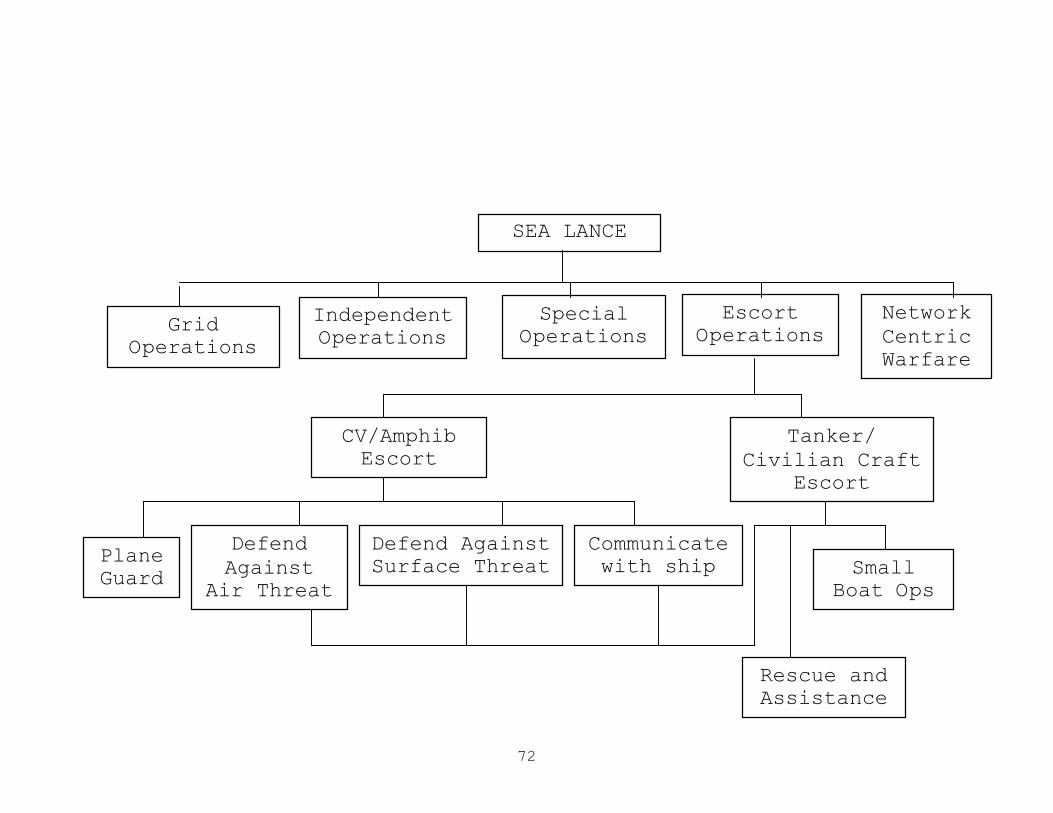
72
SEA LANCE
Grid Operations
Independent Operations
Special Operations
Escort Operations
Network Centric Warfare
CV/Amphib Escort
Small Boat Ops
Tanker/ Civilian Craft
Escort
Defend Against
Air Threat
Plane Guard
Defend Against Surface Threat
Communicate with ship
Rescue and Assistance
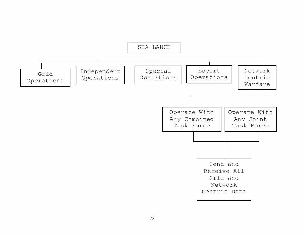
73
SEA LANCE
Grid Operations
Independent Operations
Special Operations
Escort Operations
Network Centric Warfare
Operate With Any Joint Task Force
Send and Receive All Grid and Network
Centric Data
Operate With Any Combined Task Force
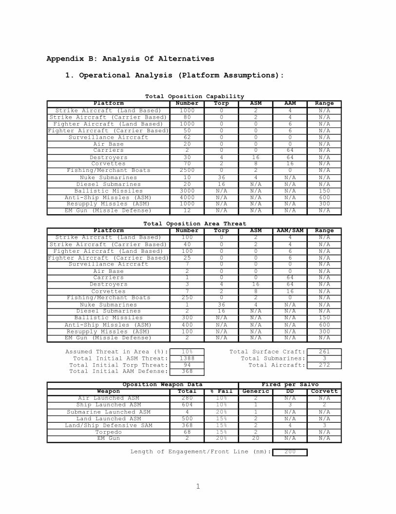
1
Appendix B: Analysis Of Alternatives
1. Operational Analysis (Platform Assumptions):
Total Oposition Capability
Platform Number Torp ASM AAM RangeStrike Aircraft (Land Based) 1000 0 2 4 N/A
Strike Aircraft (Carrier Based) 80 0 2 4 N/AFighter Aircraft (Land Based) 1000 0 0 6 N/A
Fighter Aircraft (Carrier Based) 50 0 0 6 N/ASurveillance Aircraft 62 0 0 0 N/A
Air Base 20 0 0 0 N/ACarriers 2 0 0 64 N/A
Destroyers 30 4 16 64 N/ACorvettes 70 2 8 16 N/A
Fishing/Merchant Boats 2500 0 2 0 N/ANuke Submarines 10 36 4 N/A N/A
Diesel Submarines 20 16 N/A N/A N/ABallistic Missiles 3000 N/A N/A N/A 150
Anti-Ship Missles (ASM) 4000 N/A N/A N/A 600Resupply Missles (ASM) 1000 N/A N/A N/A 300EM Gun (Missle Defense) 12 N/A N/A N/A N/A
Total Oposition Area ThreatPlatform Number Torp ASM AAM/SAM Range
Strike Aircraft (Land Based) 100 0 2 4 N/AStrike Aircraft (Carrier Based) 40 0 2 4 N/AFighter Aircraft (Land Based) 100 0 0 6 N/A
Fighter Aircraft (Carrier Based) 25 0 0 6 N/ASurveillance Aircraft 7 0 0 0 N/A
Air Base 2 0 0 0 N/ACarriers 1 0 0 64 N/A
Destroyers 3 4 16 64 N/ACorvettes 7 2 8 16 N/A
Fishing/Merchant Boats 250 0 2 0 N/ANuke Submarines 1 36 4 N/A N/A
Diesel Submarines 2 16 N/A N/A N/ABallistic Missiles 300 N/A N/A N/A 150
Anti-Ship Missles (ASM) 400 N/A N/A N/A 600Resupply Missles (ASM) 100 N/A N/A N/A 300EM Gun (Missle Defense) 2 N/A N/A N/A N/A
Assumed Threat in Area (%): 10% Total Surface Craft: 261Total Initial ASM Threat: 1388 Total Submarines: 3
Total Initial Torp Threat: 94 Total Aircraft: 272Total Initial AAM Defense: 368
Oposition Weapon Data Fired per SalvoWeapon Total % Fail Generic DD Corvett
Air Launched ASM 280 10% 2 N/A N/AShip Launched ASM 604 10% 1 3 2
Submarine Launched ASM 4 20% 1 N/A N/ALand Launched ASM 500 15% 2 N/A N/A
Land/Ship Defensive SAM 368 15% 2 4 3Torpedo 68 15% 2 N/A N/AEM Gun 2 20% 20 N/A N/A
Length of Engagement/Front Line (nm): 200
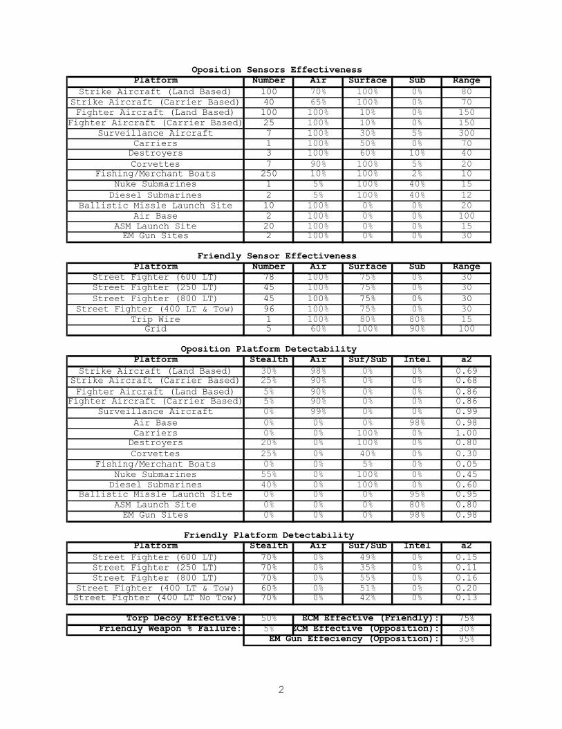
2
Oposition Sensors EffectivenessPlatform Number Air Surface Sub Range
Strike Aircraft (Land Based) 100 70% 100% 0% 80Strike Aircraft (Carrier Based) 40 65% 100% 0% 70Fighter Aircraft (Land Based) 100 100% 10% 0% 150
Fighter Aircraft (Carrier Based) 25 100% 10% 0% 150Surveillance Aircraft 7 100% 30% 5% 300
Carriers 1 100% 50% 0% 70Destroyers 3 100% 60% 10% 40Corvettes 7 90% 100% 5% 20
Fishing/Merchant Boats 250 10% 100% 2% 10Nuke Submarines 1 5% 100% 40% 15Diesel Submarines 2 5% 100% 40% 12
Ballistic Missle Launch Site 10 100% 0% 0% 20Air Base 2 100% 0% 0% 100
ASM Launch Site 20 100% 0% 0% 15EM Gun Sites 2 100% 0% 0% 30
Friendly Sensor EffectivenessPlatform Number Air Surface Sub Range
Street Fighter (600 LT) 78 100% 75% 0% 30Street Fighter (250 LT) 45 100% 75% 0% 30Street Fighter (800 LT) 45 100% 75% 0% 30
Street Fighter (400 LT & Tow) 96 100% 75% 0% 30Trip Wire 1 100% 80% 80% 15
Grid 5 60% 100% 90% 100
Oposition Platform DetectabilityPlatform Stealth Air Suf/Sub Intel a2
Strike Aircraft (Land Based) 30% 98% 0% 0% 0.69Strike Aircraft (Carrier Based) 25% 90% 0% 0% 0.68Fighter Aircraft (Land Based) 5% 90% 0% 0% 0.86
Fighter Aircraft (Carrier Based) 5% 90% 0% 0% 0.86Surveillance Aircraft 0% 99% 0% 0% 0.99
Air Base 0% 0% 0% 98% 0.98Carriers 0% 0% 100% 0% 1.00Destroyers 20% 0% 100% 0% 0.80Corvettes 25% 0% 40% 0% 0.30
Fishing/Merchant Boats 0% 0% 5% 0% 0.05Nuke Submarines 55% 0% 100% 0% 0.45Diesel Submarines 40% 0% 100% 0% 0.60
Ballistic Missle Launch Site 0% 0% 0% 95% 0.95ASM Launch Site 0% 0% 0% 80% 0.80EM Gun Sites 0% 0% 0% 98% 0.98
Friendly Platform DetectabilityPlatform Stealth Air Suf/Sub Intel a2
Street Fighter (600 LT) 70% 0% 49% 0% 0.15Street Fighter (250 LT) 70% 0% 35% 0% 0.11Street Fighter (800 LT) 70% 0% 55% 0% 0.16
Street Fighter (400 LT & Tow) 60% 0% 51% 0% 0.20Street Fighter (400 LT No Tow) 70% 0% 42% 0% 0.13
Torp Decoy Effective: 50% ECM Effective (Friendly): 75%Friendly Weapon % Failure: 5% ECM Effective (Opposition): 30%
EM Gun Effeciency (Opposition): 95%
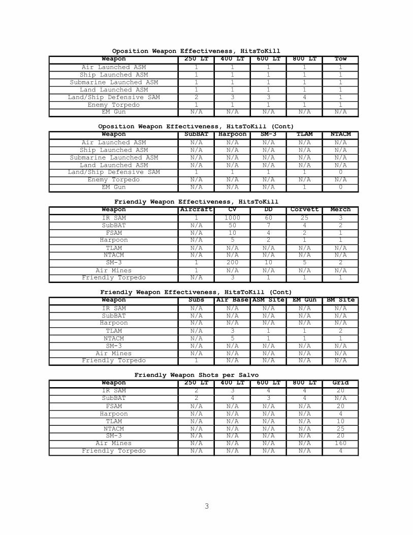
3
Oposition Weapon Effectiveness, HitsToKillWeapon 250 LT 400 LT 600 LT 800 LT Tow
Air Launched ASM 1 1 1 1 1Ship Launched ASM 1 1 1 1 1
Submarine Launched ASM 1 1 1 1 1Land Launched ASM 1 1 1 1 1
Land/Ship Defensive SAM 2 3 3 4 1Enemy Torpedo 1 1 1 1 1
EM Gun N/A N/A N/A N/A N/A
Oposition Weapon Effectiveness, HitsToKill (Cont)Weapon SubBAT Harpoon SM-3 TLAM NTACM
Air Launched ASM N/A N/A N/A N/A N/AShip Launched ASM N/A N/A N/A N/A N/A
Submarine Launched ASM N/A N/A N/A N/A N/ALand Launched ASM N/A N/A N/A N/A N/A
Land/Ship Defensive SAM 1 1 1 1 0Enemy Torpedo N/A N/A N/A N/A N/A
EM Gun N/A N/A N/A 1 0
Friendly Weapon Effectiveness, HitsToKillWeapon Aircraft CV DD Corvett MerchIR SAM 1 1000 60 25 3SubBAT N/A 50 7 4 2FSAM N/A 10 4 2 1
Harpoon N/A 5 2 1 1TLAM N/A N/A N/A N/A N/ANTACM N/A N/A N/A N/A N/ASM-3 1 200 10 5 2
Air Mines 1 N/A N/A N/A N/AFriendly Torpedo N/A 3 1 1 1
Friendly Weapon Effectiveness, HitsToKill (Cont)Weapon Subs Air Base ASM Site EM Gun BM SiteIR SAM N/A N/A N/A N/A N/ASubBAT N/A N/A N/A N/A N/AHarpoon N/A N/A N/A N/A N/ATLAM N/A 3 1 1 2NTACM N/A 5 1 1 1SM-3 N/A N/A N/A N/A N/A
Air Mines N/A N/A N/A N/A N/AFriendly Torpedo 1 N/A N/A N/A N/A
Friendly Weapon Shots per SalvoWeapon 250 LT 400 LT 600 LT 800 LT GridIR SAM 2 3 4 4 20SubBAT 2 4 3 4 N/AFSAM N/A N/A N/A N/A 20
Harpoon N/A N/A N/A N/A 4TLAM N/A N/A N/A N/A 10NTACM N/A N/A N/A N/A 25SM-3 N/A N/A N/A N/A 20
Air Mines N/A N/A N/A N/A 160Friendly Torpedo N/A N/A N/A N/A 4
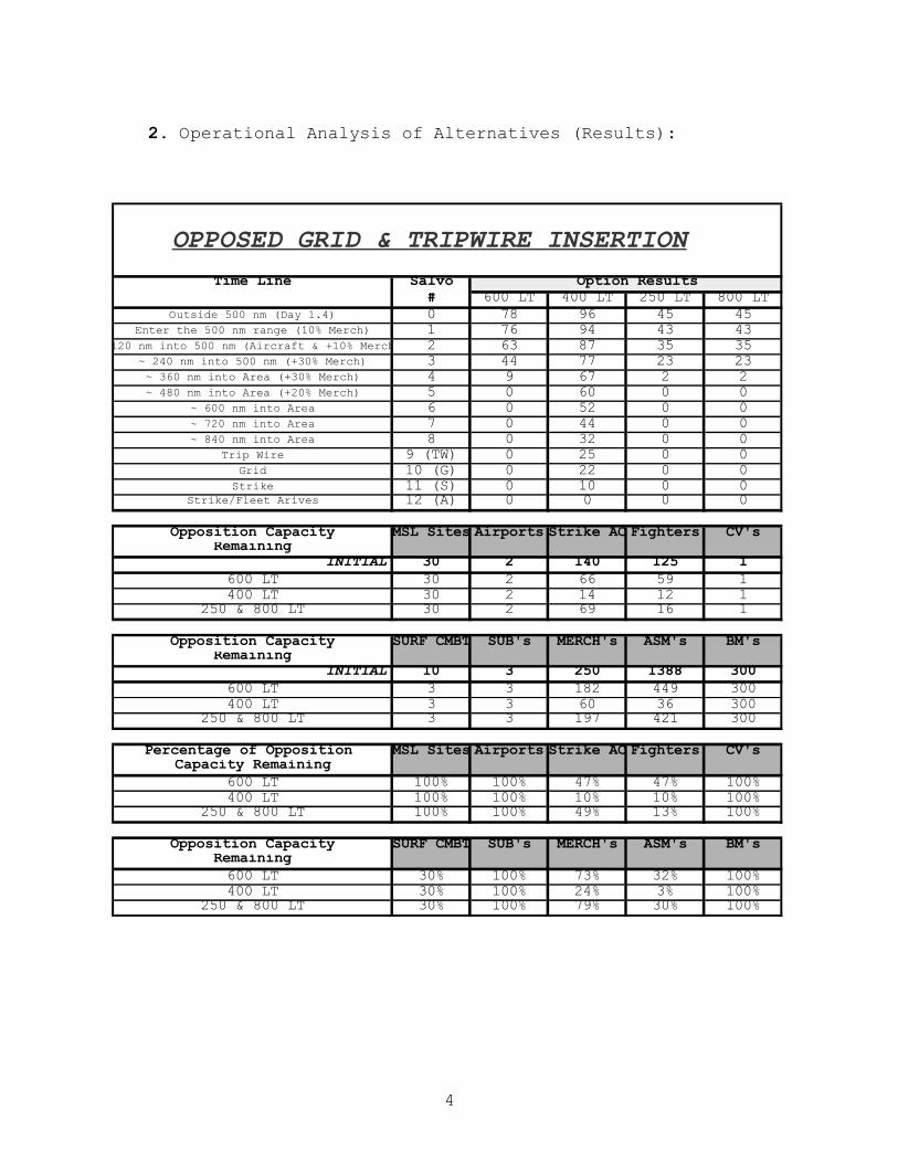
4
2. Operational Analysis of Alternatives (Results):
OPPOSED GRID & TRIPWIRE INSERTION
Time Line Salvo Option Results# 600 LT 400 LT 250 LT 800 LT
Outside 500 nm (Day 1.4) 0 78 96 45 45Enter the 500 nm range (10% Merch) 1 76 94 43 43
~120 nm into 500 nm (Aircraft & +10% Merch) 2 63 87 35 35~ 240 nm into 500 nm (+30% Merch) 3 44 77 23 23~ 360 nm into Area (+30% Merch) 4 9 67 2 2~ 480 nm into Area (+20% Merch) 5 0 60 0 0
~ 600 nm into Area 6 0 52 0 0~ 720 nm into Area 7 0 44 0 0~ 840 nm into Area 8 0 32 0 0
Trip Wire 9 (TW) 0 25 0 0Grid 10 (G) 0 22 0 0
Strike 11 (S) 0 10 0 0Strike/Fleet Arives 12 (A) 0 0 0 0
Opposition Capacity MSL Sites Airports Strike AC Fighters CV'sRemaining
INITIAL 30 2 140 125 1600 LT 30 2 66 59 1400 LT 30 2 14 12 1
250 & 800 LT 30 2 69 16 1
Opposition Capacity SURF CMBT SUB's MERCH's ASM's BM'sRemaining
INITIAL 10 3 250 1388 300600 LT 3 3 182 449 300400 LT 3 3 60 36 300
250 & 800 LT 3 3 197 421 300
Percentage of Opposition MSL Sites Airports Strike AC Fighters CV'sCapacity Remaining
600 LT 100% 100% 47% 47% 100%400 LT 100% 100% 10% 10% 100%
250 & 800 LT 100% 100% 49% 13% 100%
Opposition Capacity SURF CMBT SUB's MERCH's ASM's BM'sRemaining600 LT 30% 100% 73% 32% 100%400 LT 30% 100% 24% 3% 100%
250 & 800 LT 30% 100% 79% 30% 100%
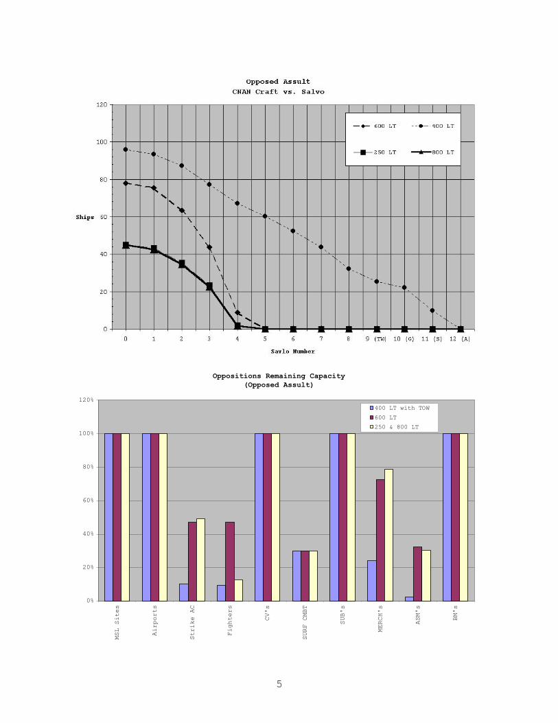
5
Opposed AssultCNAN Craft vs. Salvo
0
20
40
60
80
100
120
0 1 2 3 4 5 6 7 8 9 (TW) 10 (G) 11 (S) 12 (A)
Savlo Number
Ships
600 LT 400 LT
250 LT 800 LT
Oppositions Remaining Capacity(Opposed Assult)
0%
20%
40%
60%
80%
100%
120%
MSL Sites
Airports
Strike AC
Fighters
CV's
SURF CMBT
SUB's
MERCH's
ASM's
BM's
400 LT with TOW
600 LT
250 & 800 LT

6
OPPOSED GRID INSERTION
Time Line Salvo Option Results# 600 LT 400 LT 250 LT 800 LT
Trip Wire (Days 1 - 4) 0 (TW) 78 96 45 45Grid (Full Assult, No Grid) 1 (G) 42 69 4 4
Strike (Full Assult) 2 (S) 1 41 0 0Strike (Full Assult) 3 (S) 0 41 0 0Strike (Full Assult) 4 (S) 0 41 0 0Strike (Full Assult) 5 (S) 0 41 0 0Strike (Full Assult) 6 (S) 0 41 0 0Strike (Full Assult) 7 (S) 0 41 0 0Strike (Full Assult) 8 (S) 0 41 0 0Strike (Full Assult) 9 (S) 0 41 0 0Strike (Full Assult) 10 (S) 0 41 0 0Strike (Full Assult) 11 (S) 0 41 0 0Stirke/Fleet Arives 12 (A) 0 41 0 0
Opposition Capacity MSL Sites Airports Strike AC Fighters CV'sRemaining
INITIAL 30 2 140 125 1600 LT 1 0 0 0 0400 LT 0 0 0 0 0
250 & 800 LT 4 1 0 0 1
Opposition Capacity SURF CMBT SUB's MERCH's ASM's BM'sRemaining
INITIAL 10 3 250 1388 300600 LT 1 0 47 225 0400 LT 0 0 1 272 0
250 & 800 LT 0 0 88 421 0
Percentage of Opposition MSL Sites Airports Strike AC Fighters CV'sCapacity Remaining
600 LT 3% 7% 0% 0% 12%400 LT 0% 0% 0% 0% 0%
250 & 800 LT 13% 58% 0% 0% 66%
Opposition Capacity SURF CMBT SUB's MERCH's ASM's BM'sRemaining600 LT 5% 0% 19% 16% 0%400 LT 0% 0% 0% 20% 0%
250 & 800 LT 2% 0% 35% 30% 0%

7
Oppositions Remaining Capacity(Opposed Grid Insertion)
0%
20%
40%
60%
80%
100%
120%
MSL Sites
Airports
Strike AC
Fighters
CV's
SURF CMBT
SUB's
MERCH's
ASM's
BM's
400 LT with TOW
600 LT
250 & 800 LT
Opposed Grid InsertionCNAN Craft vs. Salvo
0
20
40
60
80
100
120
0 (TW) 1 (G) 2 (S) 3 (S) 4 (S) 5 (S) 6 (S) 7 (S) 8 (S) 9 (S) 10 (S) 11 (S) 12 (A)
Savlo Number
Ships
600 LT 400 LT
250 LT 800 LT
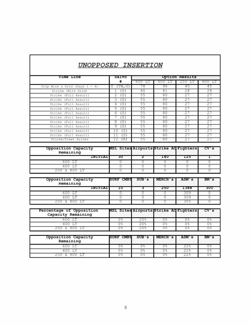
8
UNOPPOSED INSERTION
Time Line Salvo Option Results# 600 LT 400 LT 250 LT 800 LT
Trip Wire & Grid (Days 1 - 4) 0 (TW,G) 78 96 45 45Strike (With Grid) 1 (S) 60 81 28 28
Strike (Full Assult) 2 (S) 55 80 27 27Strike (Full Assult) 3 (S) 55 80 27 27Strike (Full Assult) 4 (S) 55 80 27 27Strike (Full Assult) 5 (S) 55 80 27 27Strike (Full Assult) 6 (S) 55 80 27 27Strike (Full Assult) 7 (S) 55 80 27 27Strike (Full Assult) 8 (S) 55 80 27 27Strike (Full Assult) 9 (S) 55 80 27 27Strike (Full Assult) 10 (S) 55 80 27 27Strike (Full Assult) 11 (S) 55 80 27 27Stirke/Fleet Arives 12 (A) 55 80 27 27
Opposition Capacity MSL Sites Airports Strike AC Fighters CV'sRemaining
INITIAL 30 2 140 125 1600 LT 0 0 0 0 0400 LT 0 0 0 0 0
250 & 800 LT 0 0 0 0 0
Opposition Capacity SURF CMBT SUB's MERCH's ASM's BM'sRemaining
INITIAL 10 3 250 1388 300600 LT 0 0 0 309 0400 LT 0 0 0 309 0
250 & 800 LT 0 0 0 305 0
Percentage of Opposition MSL Sites Airports Strike AC Fighters CV'sCapacity Remaining
600 LT 0% 20% 0% 0% 0%400 LT 0% 20% 0% 0% 0%
250 & 800 LT 0% 20% 0% 0% 0%
Opposition Capacity SURF CMBT SUB's MERCH's ASM's BM'sRemaining600 LT 0% 0% 0% 22% 0%400 LT 0% 0% 0% 22% 0%
250 & 800 LT 0% 0% 0% 22% 0%

9
Unopposed InsertionCNAN Craft vs. Salvo
0
20
40
60
80
100
120
0 (TW,G)
1 (S)
2 (S)
3 (S)
4 (S)
5 (S)
6 (S)
7 (S)
8 (S)
9 (S)
10 (S)
11 (S)
12 (A)
Savlo Number
Ships
600 LT 400 LT
250 LT 800 LT
Oppositions Remaining Capacity(Unopposed Insertion)
0%
20%
40%
60%
80%
100%
120%
MSL Sites
Airports
Strike AC
Fighters
CV's
SURF CMBT
SUB's
MERCH's
ASM's
BM's
400 LT with TOW
600 LT
250 & 800 LT

10
-----Original Message----- From: naval [mailto:[email protected]] Sent: Thursday, August 24, 2000 02 40 To: [email protected] Subject: Information about SF 300
No. 57/00 Dear Lt Barney, The following, I hope, should be an answer to your questions. The answer is not classified. The background for the STANDARDFLEX or STANFLEX Programme is the following. In the Royal Danish Navy in the early 1980'es we had to scrap 22 older ships: 8 minesweepers of the USN BLUEBIRD Class, 6 Fast Patrol Boats (torpedo boats) and 8 small patrol vessels. As the Navy could not get funds for a ship-by-ship replacement and the Navy did not need the different capabilities at the same time the idea slowly matured to build a standard ship with a flexible armament or equipment. The STANFLEX programme is characterised by standard hull, standard sensors and standard propulsion. The operational capabilities are flexible and role dedicated. With operational flexibility we can do the same with fewer units. The ship is used as a platform and the equipment can be "plugged in". Maintenance, repair and overhaul is made easier. Upgrading or re-equipping is simple and the ships will have a growth potential. The result was the STANFLEX 300 or the FLYVEFISKEN Class, a GRP boat of 320 tonnes displacement fitted with four identical "wells" for containers. A container well can take a 3" OTOBREDA gun, MCM-equipment, ASW-equipment, 4 HARPOON missiles, 6 SEA SPARROWs or 12 Evolved SEA SPARROWS. In addition we have containers for hydrographic survey, oceanology, pollution control, a crane module etc. All containers have the same standard connection cables. The CIC is a standard operation room with a number of identical standard consoles that can handle the necessary information required by the equipment that has been plugged into the container well. The system works very well and is very reliable. The MCM-fitted HDMS MAKRELEN was the most successful of the NATO minehunters during OPERATION ALLIED HARVEST off the Adriatic coast last Summer, locating and destroying more bombs on the sea bed than any other ship of the force. This ship was produced at half the cost of a normal minehunter - and in addition we got a real warship that can defend it self with a 3" gun and SEA SPARROWs when on mine warfare operations, and it can change role when not used for that purpose. The concept was used again when the RDN constructed the STANFLEX 3000, the Ocean Patrol Vessels (OPVs) of the THETIS Class in the early 1990'es. This ship is a steel ship reinforced for Arctic operations. There are 3 container positions and a standard CIC. It can therefore use all the weapon containers of the Navy but is normally fitted with a standard 3" gun fore and two crane modules aft. It carries a LYNX naval helicopter on board. In size and type of operation the STANFLEX 3000 can be compared to a US Coast Guard High Endurance Cutter. Representatives from the US Coast Guard Deepwater Project made several visits to study our concept. One of the things that made our project interesting in the eyes of the US Coast Guard admirals was the

11
complement: The USCG High Endurance Cutters have a complement of about 175 while we only have 60 officers and men/women in the STANFLEX 3000 - and that even includes the surgeon and the helicopter crew! As I mentioned the SF 300 is 320 tonnes when delivered from the yard. In its heaviest version the combat load is 485 tonnes, and in that configuration it carries 8 HARPOONs, 6 SEA SPARROWs (in the future version 12 Evolved SEA SPARROWs), a 3" gun, 2 wire guided 53cm/21" torpedoes and one set of Soft Kill Weapon System (SKWS) with two decoy launchers. In the combat role it has a crew of 29 men/women. In the Surveillance role it is 19, ASW 25, MCM also 29. The fuel tanks contain 70 cubic metres of diesel fuel. Economical speed (one diesel): 12 knots 300 litres/hour. Medium speed (two diesels): 16 knots 650 litres/hour. High speed (gas turbine) 25 - 30 knots 2,600 litres/hour. There is also a possibility to use the auxilliary engine and a hydraulic system up to 5 or 6 knots, but it is normally not used by the crews. The hull is made of Glass Reinforced Plastic (GRP). It is easy to repair and maintain. Compared to our missile boats of the WILLEMOES-class (a HARPOON equipped missile boat in steel) the costs for maintenance of the GRP-hull is only 20%. I do not have an exact price for one boat without weapon systems, but we made a very simple calculation, that might be useful for you. If we buy a Mine Hunter abroad we estimate to pay 900 million Danish kroner for it. With this system we took all the expenses for 14 boats plus the 100 various weapon containers and divided it with 14. That gave us a price per boat including fuel, ammunition and everything at 514 million Danish kroner. 1 US $ is 8.35 Danish kroner. Australia (ADI) is for the moment copying the SF 300 without containers and without the gas turbine. They might give you a price for the boat. It is a relief for the FREEMANTLE-class patrol boat. Our expertise lies especially in ships below 1000 tonnes. During the Cold War we operated in the Baltic more or less behind the Iron Curtain, so our boats are made to rather tough staff requirements because we faced a large number of modern enemy units. We could not afford to build ships in large numbers or in low quality seen from a combat view - so we have been forced to find some smart solutions ourselves. The STANDARD FLEX programme I think is a good example of a successful new way of thinking. It is now very easy for our Navy to change the role of the ships. So much for now. I will send you some general information by mail. I would like of copy of your final report. Best wishes for your studies. Yours sincerely, Poul Grooss,
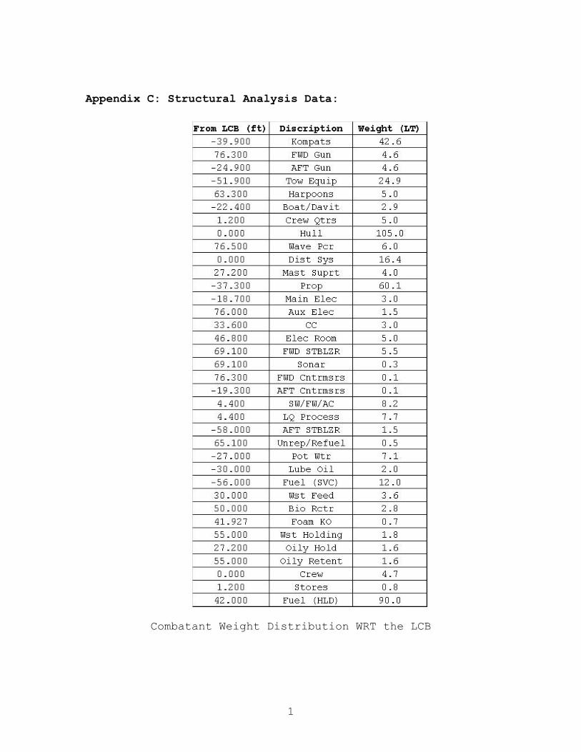
1
Appendix C: Structural Analysis Data:
Combatant Weight Distribution WRT the LCB

2

3
The moments were used as calculated and no correction was applied for the numerical integration error at the stern (non-zero). A typical correction would be to force the end points to be zero and apply a linear correction to all the calculated values. This was not done due to the rough nature of this calculation and to emphasize that our assumed accuracy makes this error insignificant.

4
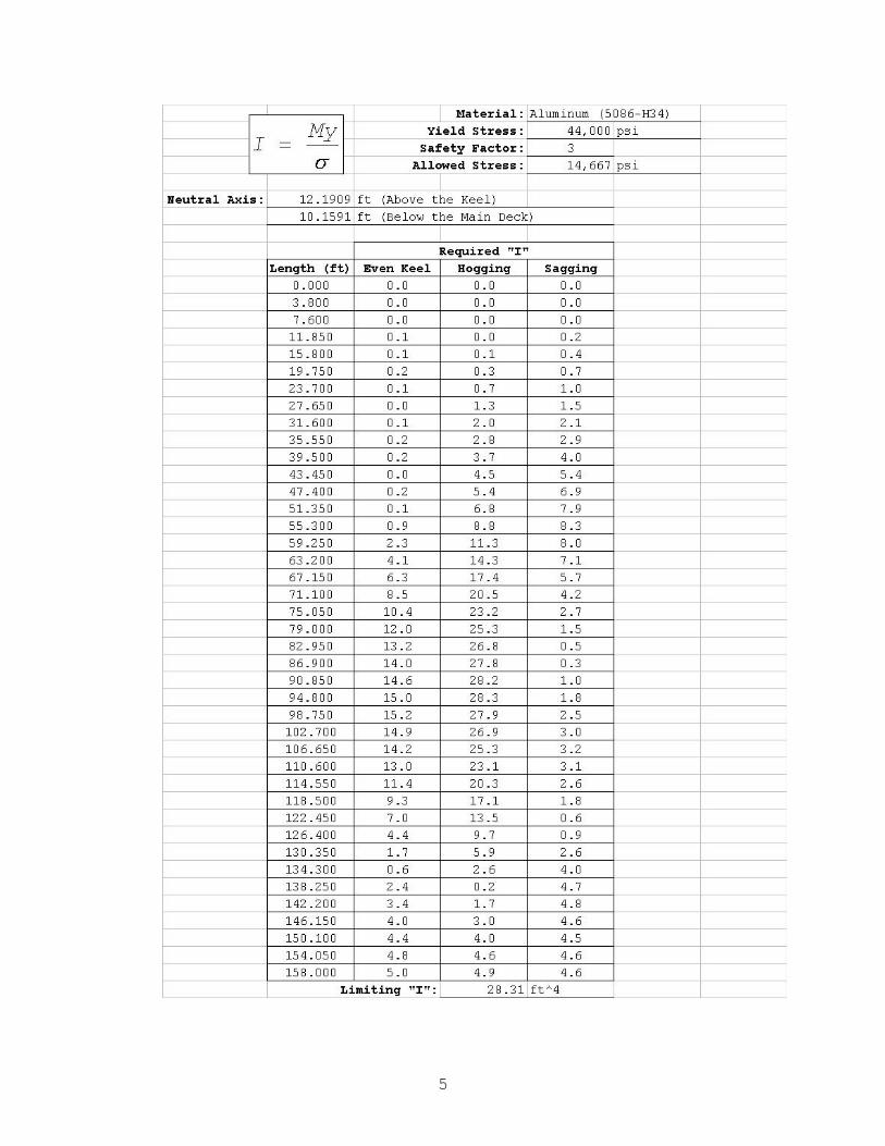
5
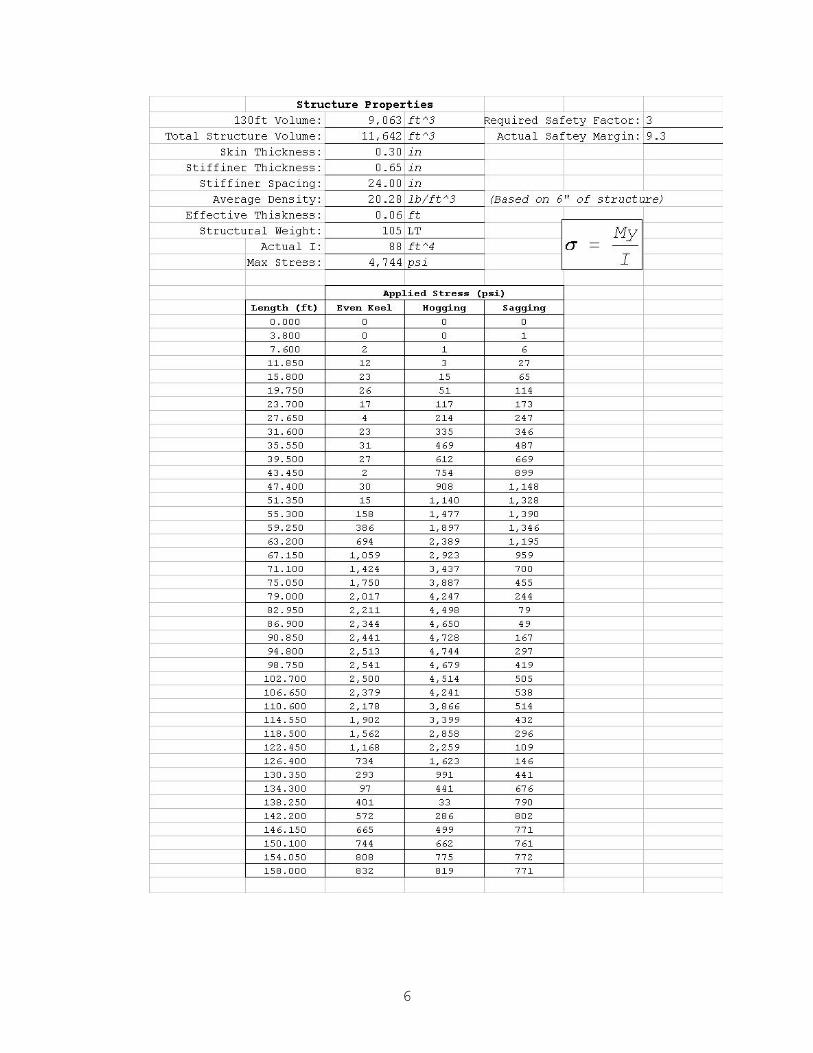
6
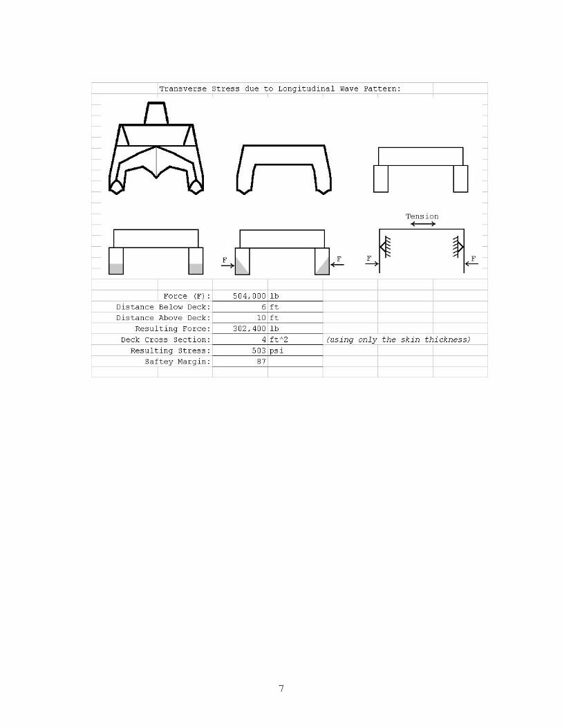
7
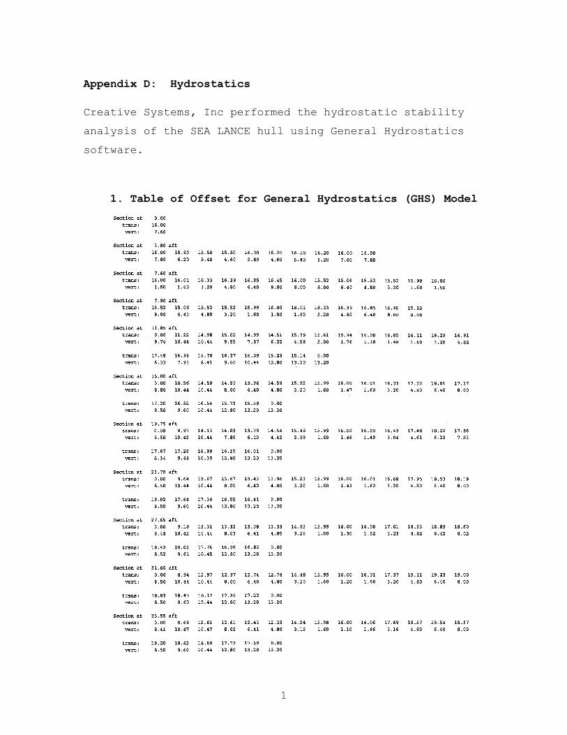
1
Appendix D: Hydrostatics Creative Systems, Inc performed the hydrostatic stability
analysis of the SEA LANCE hull using General Hydrostatics
software.
1. Table of Offset for General Hydrostatics (GHS) Model

2
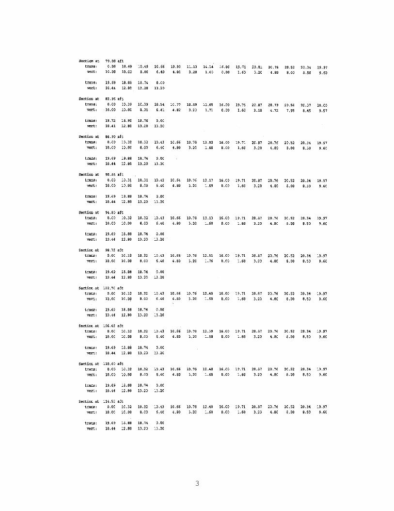
3

4

5
2. Model Geometry

6
Model Geometry
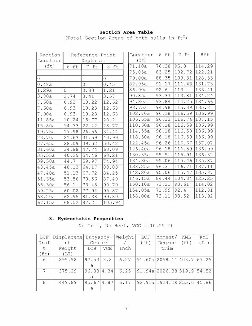
7
Section Area Table (Total Section Areas of both hulls in ft2)
Reference Point Depth at
Section Location
(ft) 6 ft 7 ft 8 ft
0 0 0.48a 0 0.45 1.29a 0 0.83 1.21 3.80a 2.74 3.41 3.57 7.60a 6.93 10.22 12.62 7.60a 6.93 10.23 12.63 7.90a 6.93 10.23 12.63 11.85a 10.24 15.77 20.2 15.80a 14.73 22.42 28.77 19.75a 17.98 26.56 34.44 23.70a 21.63 31.59 40.99 27.65a 28.09 39.52 50.42 31.60a 34.88 47.74 60.09 35.55a 40.29 54.46 68.21 39.50a 44.7 59.97 74.94 43.45a 48.13 64.17 80.03 47.40a 51.13 67.72 84.25 51.35a 53.56 70.56 87.49 55.30a 56.1 73.48 90.79 59.25a 60.02 77.94 95.87 63.20a 62.95 81.38 99.89 67.15a 68.52 87.2 105.94
Location (ft)
6 ft 7 ft 8ft
71.10a 76.38 95.3 114.29 75.05a 83.25 102.72 122.21 79.00a 88.35 108.31 128.33 82.95a 91.17 111.43 131.73 86.90a 92.6 113 133.41 90.85a 93.37 113.81 134.24 94.80a 93.84 114.25 134.66 98.75a 94.98 115.39 135.8 102.70a 96.18 116.59 136.99 106.65a 96.33 116.74 137.15 110.60a 96.18 116.59 136.99 114.55a 96.18 116.58 136.99 118.50a 96.18 116.59 136.99 122.45a 96.26 116.67 137.07 126.40a 96.18 116.59 136.99 130.35a 95.5 115.91 136.32 134.30a 95.06 115.46 135.87 138.25a 96.3 116.71 137.11 142.20a 95.06 115.47 135.87 146.15a 84.44 104.84 125.25 150.10a 73.21 93.61 114.02 154.05a 71.99 92.4 112.81 158.00a 73.11 93.52 113.92
3. Hydrostatic Properties No Trim, No Heel, VCG = 10.59 ft
Buoyancy-Center
LCF Draft
(ft)
Displacement
Weight (LT)
LCB VCB
Weight/
Inch
LCF (ft)
Moment/ Degree trim
KML (ft)
KMT (ft)
6 299.92 97.53a
3.8 6.27 91.60a 2058.11 403.7 67.25
7 375.29 96.33a
4.34 6.25 91.94a 2026.38 319.9 54.52
8 449.89 95.67a
4.87 6.17 92.91a 1924.29 255.6 45.86

8
Distance in FEET ----- Specific Gravity = 1.025 ------ Moment in FT-LT. Draft is from Baseline.
4. Cross Curves Of Stability (5 – 30 degrees of heel) Showing righting arm in heel at VCG = 10.59 ft
Trim: Zero at zero heel (trim righting arms held at zero)
Heel Angle in Degrees Displacement LONG TONS 5.00s 10.00s 15.00s 20.00s 25.00s 30.00s 299.92 4.93s 9.44s 12.70s 13.36s 12.52s 11.60s 375.29 3.82s 7.44s 10.61s 12.73s 12.63s 11.74s 449.89 3.01s 5.93s 8.89s 10.93s 11.55s 11.23s
Distances in FEET -------------- Specific Gravity = 1.025

9

10
5. Cross Curves Of Stability (10 – 60 degrees of heel) Showing righting arm in heel at VCG = 10.59 ft
Trim: Zero at zero heel (trim righting arms held at zero) Displacement Heel Angle in Degrees LONG TONS 10.00s 20.00s 30.00s 40.00s 50.00s 60.00s
299.92 9.44s 13.36s 11.60s 9.50s 7.12s 4.54s 375.29 7.44s 12.73s 11.74s 9.69s 7.35s 4.78s 449.89 5.93s 10.94s 11.23s 9.40s 7.25s 4.88s
Distances in FEET ------------- Specific Gravity = 1.025

11
6. Floodable Lengths
Initial Origin Depth = 8.00 ft Initial Trim = 0.00 Degrees VCG = 10.59 ft Permeability = 0.95
FLOODED ORIGIN DEPTH
Degree TRIM CENTER LENGTH MARGIN GMt
13.73 -2.83 21 52.05 0.25 29.68 13.73 -2.83 24 46.06 0.25 29.68 13.73 -2.83 27 40.67 0.25 29.56 13.73 -2.79 30 39.86 0.25 29.14 13.73 -2.74 33 40.42 0.25 28.58 13.73 -2.68 36 41.45 0.25 28.13 13.74 -2.63 39 42.69 0.25 27.45 13.74 -2.56 42 44.22 0.25 26.88 13.74 -2.48 45 45.88 0.25 26.09 13.74 -2.4 48 47.76 0.25 25.43 13.74 -2.3 51 49.86 0.25 24.68 13.74 -2.19 54 52.09 0.25 23.86 13.74 -2.06 57 54.62 0.25 23.09 13.74 -1.92 60 57.47 0.25 22.22 13.74 -1.76 63 60.71 0.25 21.25 13.74 -1.6 66 64.25 0.25 20.63 13.75 -1.43 69 67.92 0.25 20.03 13.75 -1.27 72 71.7 0.25 19.01 13.75 -1.08 75 75.84 0.25 17.62 13.75 -0.83 78 80.46 0.25 16.13 13.75 -0.5 81 85.67 0.25 14.5 13.75 0 84 91.85 0.25 12.57 12.6 0.42 87 86.19 0.25 14.12 11.76 0.72 90 80.89 0.25 15.62 11.11 0.96 93 75.95 0.25 17.06 10.57 1.15 96 71.33 0.25 18.22 10.1 1.32 99 66.93 0.25 19.05 9.62 1.49 102 62.7 0.25 18.81 9.13 1.67 105 58.67 0.25 19.09 8.64 1.85 108 54.83 0.25 19.96 8.14 2.03 111 51.17 0.25 20.62 7.62 2.22 114 47.68 0.25 21.52 7.1 2.41 117 44.33 0.25 22.51 6.61 2.59 120 41.22 0.25 23.67 6.17 2.74 123 38.42 0.25 24.51 5.78 2.88 126 35.82 0.25 25.41 5.44 3.01 129 33.49 0.25 26.3 5.13 3.12 132 31.39 0.25 26.84 4.83 3.23 135 29.46 0.25 27.22

12
4.57 3.32 138 27.76 0.25 27.66 FLOODED ORIGIN
DEPTH Degree TRIM CENTER LENGTH MARGIN GMt
4.32 3.41 141 26.14 0.25 27.89 4.09 3.49 144 24.7 0.25 28.28 3.93 3.55 147 25.46 0.25 28.55 3.93 3.55 150 31.49 0.25 28.55
Note: The floodable length calculations assume that both hulls are flooded simultaneously. Additional analysis must be performed to evaluate the floodable length when flooding a single hull.
Comparment Center vs. Floodable Length with Draft = 8 ft, VCG = 10.59 ft, Permeability = 0.95
and Margin set at 3 inches below Main Deck (14 ft)
0
10
20
30
40
50
60
70
80
90
100
0 20 40 60 80 100 120 140 160
Compartment Center (ft)
Floodable Length (ft)

13
Flodded Compartment Center vs. Transverse GM with Initial Draft = 8 ft, VCG = 10.59 ft, Permeability = 0.95
and Margin set at 3 inches below the Main Deck (14 ft)
0
5
10
15
20
25
30
35
0 20 40 60 80 100 120 140 160
Compartment Center (ft)
Floodable Length (ft)

1
Appendix E: Motions Analysis
1. Graphs of Motions
Bridge Pitch Motions at 5 knots
0
0.2
0.4
0.6
0.8
1
1.2
1.4
0 1 2 3 4 5 6 7
Wave/Ship Length
Mo
tio
ns
(de
gre
es)
000
090
180
Bridge Pitch Motions at 15 knots
0
0.2
0.4
0.6
0.8
1
1.2
1.4
0 1 2 3 4 5 6 7
Wave/Ship Length
Mo
tio
ns
(de
gre
es)
000
090
180
Bridge Pitch Motions at 40 knots
-0.5
0
0.5
1
1.5
2
2.5
3
3.5
0 1 2 3 4 5 6 7
Wave/Ship Length
Mo
tio
ns
(de
gre
es)
000
090
180

2
Bridge Heave Motions at 5 knots
0
0.2
0.4
0.6
0.8
1
1.2
0 1 2 3 4 5 6 7
Wave/Ship Length
Mo
tio
ns
(de
gre
es)
000
090
180
Bridge Heave Motions at 15 knots
0
0.2
0.4
0.6
0.8
1
1.2
0 1 2 3 4 5 6 7
Wave/Ship Length
Mo
tio
ns
(de
gre
es)
000
090
180
Bridge Heave Motions at 40 knots
-0.5
0
0.5
1
1.5
2
2.5
0 1 2 3 4 5 6 7
Wave/Ship Length
Mo
tio
ns
(de
gre
es)
000
090
180

3
2. Bridge Vertical Motions
0 knotsWave Encounter Amplitude Phase Amplitude Phase Amplitude Phase
000 deg 3.17927 3.17927 20 0.1266 0.005 140 0.00 0 0.031 -117.41.20165 1.20165 140 0.8861 0.207 19.7 0.00 0 0.253 -33.70.88177 0.88177 260 1.6456 0.518 -70 0.00 0 0.747 -21.30.72937 0.72937 380 2.4051 0.724 -83.2 0.00 0 0.880 -14.80.63585 0.63585 500 3.1646 0.822 -90 0.00 0 0.930 -11.40.57101 0.57101 620 3.9241 0.879 -94.9 0.00 0 0.954 -9.20.52267 0.52267 740 4.6835 0.919 -98.9 0.00 0 0.968 -7.80.48483 0.48483 860 5.443 0.951 -102.4 0.00 0 0.976 -6.70.45418 0.45418 980 6.2025 0.979 -105.6 0.00 0 0.981 -5.9
Wave Encounter Amplitude Phase Amplitude Phase3.17927 3.17927 20 0.1266 1.030 -90.8 3.27 -0.81.20165 1.20165 140 0.8861 0.748 139.8 0.90 -130.20.88177 0.88177 260 1.6456 0.253 160.8 0.22 -109.20.72937 0.72937 380 2.4051 0.120 170.3 0.09 -99.70.63585 0.63585 500 3.1646 0.070 176.7 0.04 -93.30.57101 0.57101 620 3.9241 0.046 -178.2 0.03 -88.20.52267 0.52267 740 4.6835 0.033 -174 0.02 -840.48483 0.48483 860 5.443 0.025 -170.2 0.01 -80.20.45418 0.45418 980 6.2025 0.020 -166.8 0.01 -76.8
0 knotsWave Encounter Amplitude Phase Amplitude Phase Amplitude Phase
090 deg 3.17927 3.17927 20 0.1266 0.008 -66.6 0.00 0 0.031 5.51.20165 1.20165 140 0.8861 0.072 -171.9 0.00 0 0.858 -18.70.88177 0.88177 260 1.6456 0.102 -178.4 0.00 0 0.978 -1.60.72937 0.72937 380 2.4051 0.145 -178.8 0.00 0 0.985 -0.40.63585 0.63585 500 3.1646 0.189 -178.8 0.00 0 0.989 -0.20.57101 0.57101 620 3.9241 0.234 -178.7 0.00 0 0.992 -0.20.52267 0.52267 740 4.6835 0.279 -178.7 0.00 0 0.993 -0.20.48483 0.48483 860 5.443 0.324 -178.6 0.00 0 0.994 -0.10.45418 0.45418 980 6.2025 0.369 -178.6 0.00 0 0.995 -0.1
Lateral Motions Vertical MotionsFrequencies Wave Length
Wave/Ship Length
Longitudinal Motions
Wave/Ship Length
Longitudinal Motions Lateral Motions Vertical Motions
Frequencies Wave Length
Wave/Ship Length
Relative Vert. Motion Relative Vert. Velocity
Frequencies Wave Length

4
Wave Encounter Amplitude Phase Amplitude Phase3.17927 3.17927 20 0.1266 0.969 179.8 3.08 -90.21.20165 1.20165 140 0.8861 0.333 -124.1 0.40 -34.10.88177 0.88177 260 1.6456 0.036 -129.2 0.03 -39.20.72937 0.72937 380 2.4051 0.017 -152.4 0.01 -62.40.63585 0.63585 500 3.1646 0.012 -159.8 0.01 -69.80.57101 0.57101 620 3.9241 0.009 -160.5 0.01 -70.50.52267 0.52267 740 4.6835 0.007 -159 0.00 -690.48483 0.48483 860 5.443 0.006 -156.7 0.00 -66.70.45418 0.45418 980 6.2025 0.006 -154.5 0.00 -64.5
0 knotsWave Encounter Amplitude Phase Amplitude Phase Amplitude Phase
180 deg 3.17927 3.17927 20 0.1266 0.012 -158.6 0.00 0 0.032 118.51.20165 1.20165 140 0.8861 0.172 -10.4 0.00 0 0.466 50.40.88177 0.88177 260 1.6456 0.517 69.9 0.00 0 0.774 22.40.72937 0.72937 380 2.4051 0.712 82.8 0.00 0 0.888 14.60.63585 0.63585 500 3.1646 0.805 89.7 0.00 0 0.934 10.90.57101 0.57101 620 3.9241 0.860 94.8 0.00 0 0.956 8.80.52267 0.52267 740 4.6835 0.897 98.9 0.00 0 0.969 7.30.48483 0.48483 860 5.443 0.927 102.5 0.00 0 0.976 6.30.45418 0.45418 980 6.2025 0.954 105.8 0.00 0 0.981 5.5
Wave Encounter Amplitude Phase Amplitude Phase3.17927 3.17927 20 0.1266 1.030 90.9 3.27 -179.11.20165 1.20165 140 0.8861 0.552 -151.4 0.66 -61.40.88177 0.88177 260 1.6456 0.227 -164.7 0.20 -74.70.72937 0.72937 380 2.4051 0.112 -168.8 0.08 -78.80.63585 0.63585 500 3.1646 0.066 -171.1 0.04 -81.10.57101 0.57101 620 3.9241 0.044 -172.6 0.02 -82.60.52267 0.52267 740 4.6835 0.031 -173.5 0.02 -83.50.48483 0.48483 860 5.443 0.024 -173.9 0.01 -83.90.45418 0.45418 980 6.2025 0.019 -174.1 0.01 -84.1
Wave/Ship Length
Relative Vert. Motion Relative Vert. Velocity
Frequencies Wave Length
Wave/Ship Length
Relative Vert. Motion Relative Vert. Velocity
Frequencies Wave Length
Wave/Ship Length
Longitudinal Motions Lateral Motions Vertical Motions
Frequencies Wave Length

5
5 knots
Wave Encounter Amplitude Phase Amplitude Phase Amplitude Phase000 deg 3.17927 0.52808 20 0.1266 0.299 151.4 0.00 0 0.003 -110.1
1.20165 0.82291 140 0.8861 0.413 9.3 0.00 0 0.254 -37.70.88177 0.67783 260 1.6456 0.897 -65.9 0.00 0 0.718 -19.70.72937 0.58984 380 2.4051 1.090 -80.8 0.00 0 0.857 -14.00.63585 0.52981 500 3.1646 1.160 -88.5 0.00 0 0.913 -10.90.57101 0.48549 620 3.9241 1.190 -93.9 0.00 0 0.941 -9.00.52267 0.45102 740 4.6835 1.210 -98.2 0.00 0 0.956 -7.60.48483 0.42318 860 5.443 1.230 -101.9 0.00 0 0.966 -6.60.45418 0.40008 980 6.2025 1.240 -105.2 0.00 0 0.973 -5.8
Wave Encounter Amplitude Phase Amplitude Phase3.17927 0.52808 20 0.1266 1.000 -90.1 0.53 -0.11.20165 0.82291 140 0.8861 0.747 141.1 0.61 -128.90.88177 0.67783 260 1.6456 0.282 156.4 0.19 -113.60.72937 0.58984 380 2.4051 0.143 164.7 0.08 -105.30.63585 0.52981 500 3.1646 0.087 170.5 0.05 -99.50.57101 0.48549 620 3.9241 0.060 175.1 0.03 -94.90.52267 0.45102 740 4.6835 0.044 178.9 0.02 -91.10.48483 0.42318 860 5.443 0.034 -177.7 0.01 -87.70.45418 0.40008 980 6.2025 0.028 -174.7 0.01 -84.7
5 knotsWave Encounter Amplitude Phase Amplitude Phase Amplitude Phase
090 deg 3.17927 3.17927 20 0.1266 0.008 -66.6 0.00 0 0.031 4.51.20165 1.20165 140 0.8861 0.069 -174.4 0.00 0 0.819 -18.10.88177 0.88177 260 1.6456 0.103 -178.9 0.00 0 0.967 -2.10.72937 0.72937 380 2.4051 0.146 -178.9 0.00 0 0.982 -0.70.63585 0.63585 500 3.1646 0.190 -178.8 0.00 0 0.987 -0.40.57101 0.57101 620 3.9241 0.235 -178.7 0.00 0 0.990 -0.30.52267 0.52267 740 4.6835 0.279 -178.6 0.00 0 0.992 -0.30.48483 0.48483 860 5.443 0.324 -178.6 0.00 0 0.993 -0.20.45418 0.45418 980 6.2025 0.370 -178.5 0.00 0 0.994 -0.2
Wave/Ship Length
Relative Vert. Motion Relative Vert. Velocity
Lateral Motions Vertical Motions
Frequencies Wave Length
Wave/Ship Length
Longitudinal Motions Lateral Motions Vertical Motions
Frequencies Wave Length
Frequencies Wave Length
Wave/Ship Length
Longitudinal Motions
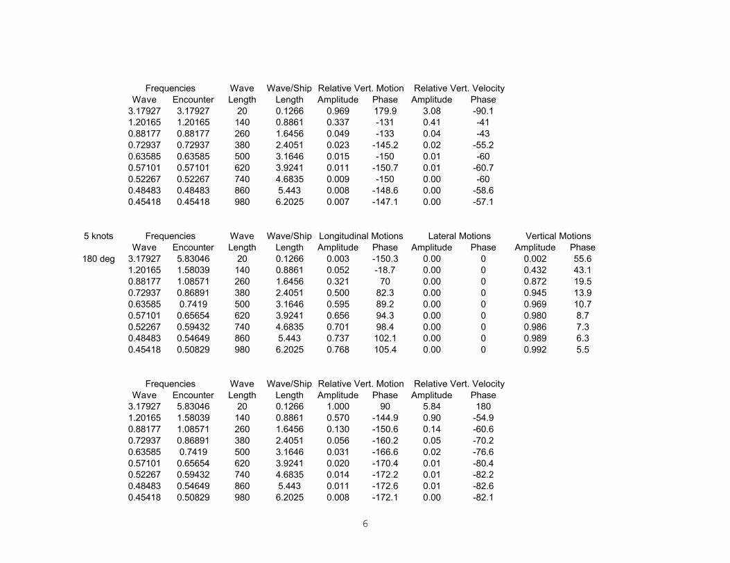
6
Wave Encounter Amplitude Phase Amplitude Phase3.17927 3.17927 20 0.1266 0.969 179.9 3.08 -90.11.20165 1.20165 140 0.8861 0.337 -131 0.41 -410.88177 0.88177 260 1.6456 0.049 -133 0.04 -430.72937 0.72937 380 2.4051 0.023 -145.2 0.02 -55.20.63585 0.63585 500 3.1646 0.015 -150 0.01 -600.57101 0.57101 620 3.9241 0.011 -150.7 0.01 -60.70.52267 0.52267 740 4.6835 0.009 -150 0.00 -600.48483 0.48483 860 5.443 0.008 -148.6 0.00 -58.60.45418 0.45418 980 6.2025 0.007 -147.1 0.00 -57.1
5 knotsWave Encounter Amplitude Phase Amplitude Phase Amplitude Phase
180 deg 3.17927 5.83046 20 0.1266 0.003 -150.3 0.00 0 0.002 55.61.20165 1.58039 140 0.8861 0.052 -18.7 0.00 0 0.432 43.10.88177 1.08571 260 1.6456 0.321 70 0.00 0 0.872 19.50.72937 0.86891 380 2.4051 0.500 82.3 0.00 0 0.945 13.90.63585 0.7419 500 3.1646 0.595 89.2 0.00 0 0.969 10.70.57101 0.65654 620 3.9241 0.656 94.3 0.00 0 0.980 8.70.52267 0.59432 740 4.6835 0.701 98.4 0.00 0 0.986 7.30.48483 0.54649 860 5.443 0.737 102.1 0.00 0 0.989 6.30.45418 0.50829 980 6.2025 0.768 105.4 0.00 0 0.992 5.5
Wave Encounter Amplitude Phase Amplitude Phase3.17927 5.83046 20 0.1266 1.000 90 5.84 1801.20165 1.58039 140 0.8861 0.570 -144.9 0.90 -54.90.88177 1.08571 260 1.6456 0.130 -150.6 0.14 -60.60.72937 0.86891 380 2.4051 0.056 -160.2 0.05 -70.20.63585 0.7419 500 3.1646 0.031 -166.6 0.02 -76.60.57101 0.65654 620 3.9241 0.020 -170.4 0.01 -80.40.52267 0.59432 740 4.6835 0.014 -172.2 0.01 -82.20.48483 0.54649 860 5.443 0.011 -172.6 0.01 -82.60.45418 0.50829 980 6.2025 0.008 -172.1 0.00 -82.1
Relative Vert. VelocityFrequencies Wave Length
Wave/Ship Length
Relative Vert. Motion
Frequencies Wave Length
Wave/Ship Length
Relative Vert. Motion Relative Vert. Velocity
Lateral Motions Vertical MotionsFrequencies Wave Length
Wave/Ship Length
Longitudinal Motions

7
10 knotsWave Encounter Amplitude Phase Amplitude Phase Amplitude Phase
000 deg 3.17927 -2.12311 20 0.1266 0.036 -164.1 0.00 0 0.231 -11.81.20165 0.44417 140 0.8861 1.340 5.3 0.00 0 0.221 -37.70.88177 0.4739 260 1.6456 1.830 -63.2 0.00 0 0.690 -17.50.72937 0.4503 380 2.4051 1.840 -79 0.00 0 0.838 -12.90.63585 0.42376 500 3.1646 1.780 -87.3 0.00 0 0.899 -10.30.57101 0.39997 620 3.9241 1.730 -93 0.00 0 0.929 -8.60.52267 0.37936 740 4.6835 1.680 -97.6 0.00 0 0.947 -7.30.48483 0.36152 860 5.443 1.650 -101.4 0.00 0 0.958 -6.40.45418 0.34597 980 6.2025 1.640 -104.8 0.00 0 0.966 -5.7
Wave Encounter Amplitude Phase Amplitude Phase3.17927 -2.12311 20 0.1266 1.070 -77.8 2.27 -167.81.20165 0.44417 140 0.8861 0.780 141.2 0.35 -128.80.88177 0.4739 260 1.6456 0.314 152 0.15 -1180.72937 0.4503 380 2.4051 0.163 159.2 0.07 -110.80.63585 0.42376 500 3.1646 0.102 164.8 0.04 -105.20.57101 0.39997 620 3.9241 0.071 169.2 0.03 -100.80.52267 0.37936 740 4.6835 0.053 173 0.02 -970.48483 0.36152 860 5.443 0.042 176.4 0.02 -93.60.45418 0.34597 980 6.2025 0.034 179.5 0.01 -90.5
10 knotsWave Encounter Amplitude Phase Amplitude Phase Amplitude Phase
090 deg 3.17927 3.17927 20 0.1266 0.008 -66.7 0.00 0 0.031 3.61.20165 1.20165 140 0.8861 0.066 -177 0.00 0 0.778 -16.90.88177 0.88177 260 1.6456 0.104 -179.5 0.00 0 0.954 -2.60.72937 0.72937 380 2.4051 0.147 -179 0.00 0 0.977 -1.10.63585 0.63585 500 3.1646 0.190 -178.8 0.00 0 0.985 -0.60.57101 0.57101 620 3.9241 0.235 -178.7 0.00 0 0.988 -0.50.52267 0.52267 740 4.6835 0.280 -178.6 0.00 0 0.991 -0.40.48483 0.48483 860 5.443 0.325 -178.6 0.00 0 0.992 -0.30.45418 0.45418 980 6.2025 0.370 -178.5 0.00 0 0.993 -0.3
Relative Vert. VelocityFrequencies Wave Length
Wave/Ship Length
Relative Vert. Motion
Lateral Motions Vertical MotionsFrequencies Wave Length
Wave/Ship Length
Longitudinal Motions
Vertical MotionsFrequencies Wave Length
Wave/Ship Length
Longitudinal Motions Lateral Motions

8
Wave Encounter Amplitude Phase Amplitude Phase3.17927 3.17927 20 0.1266 0.969 179.9 3.08 -90.11.20165 1.20165 140 0.8861 0.341 -138.5 0.41 -48.50.88177 0.88177 260 1.6456 0.063 -137.2 0.06 -47.20.72937 0.72937 380 2.4051 0.030 -142.5 0.02 -52.50.63585 0.63585 500 3.1646 0.019 -145.1 0.01 -55.10.57101 0.57101 620 3.9241 0.014 -145.8 0.01 -55.80.52267 0.52267 740 4.6835 0.011 -145.6 0.01 -55.60.48483 0.48483 860 5.443 0.010 -145 0.00 -550.45418 0.45418 980 6.2025 0.009 -144.3 0.00 -54.3
10 knotsWave Encounter Amplitude Phase Amplitude Phase Amplitude Phase
180 deg 3.17927 8.48165 20 0.1266 0.002 -125.6 0.00 0 0.000 -64.41.20165 1.95913 140 0.8861 0.051 -14.9 0.00 0 2.370 26.60.88177 1.28965 260 1.6456 0.215 78 0.00 0 0.943 14.60.72937 1.00845 380 2.4051 0.364 82.1 0.00 0 1.020 12.50.63585 0.84795 500 3.1646 0.456 88.6 0.00 0 1.010 10.30.57101 0.74206 620 3.9241 0.517 93.7 0.00 0 1.010 8.60.52267 0.66598 740 4.6835 0.562 97.9 0.00 0 1.010 7.30.48483 0.60815 860 5.443 0.600 101.6 0.00 0 1.000 6.30.45418 0.56239 980 6.2025 0.632 104.9 0.00 0 1.000 5.5
Wave Encounter Amplitude Phase Amplitude Phase3.17927 8.48165 20 0.1266 1.000 90 8.48 1801.20165 1.95913 140 0.8861 1.410 18.1 2.76 108.10.88177 1.28965 260 1.6456 0.119 -100.9 0.15 -10.90.72937 1.00845 380 2.4051 0.035 -48.3 0.04 41.70.63585 0.84795 500 3.1646 0.016 -20.3 0.01 69.70.57101 0.74206 620 3.9241 0.009 -3.3 0.01 86.70.52267 0.66598 740 4.6835 0.006 5.8 0.00 95.80.48483 0.60815 860 5.443 0.004 9.5 0.00 99.50.45418 0.56239 980 6.2025 0.003 9.4 0.00 99.4
Relative Vert. VelocityFrequencies Wave Length
Wave/Ship Length
Relative Vert. Motion
Frequencies Wave Length
Wave/Ship Length
Relative Vert. Motion Relative Vert. Velocity
Frequencies Wave Length
Wave/Ship Length
Longitudinal Motions Lateral Motions Vertical Motions
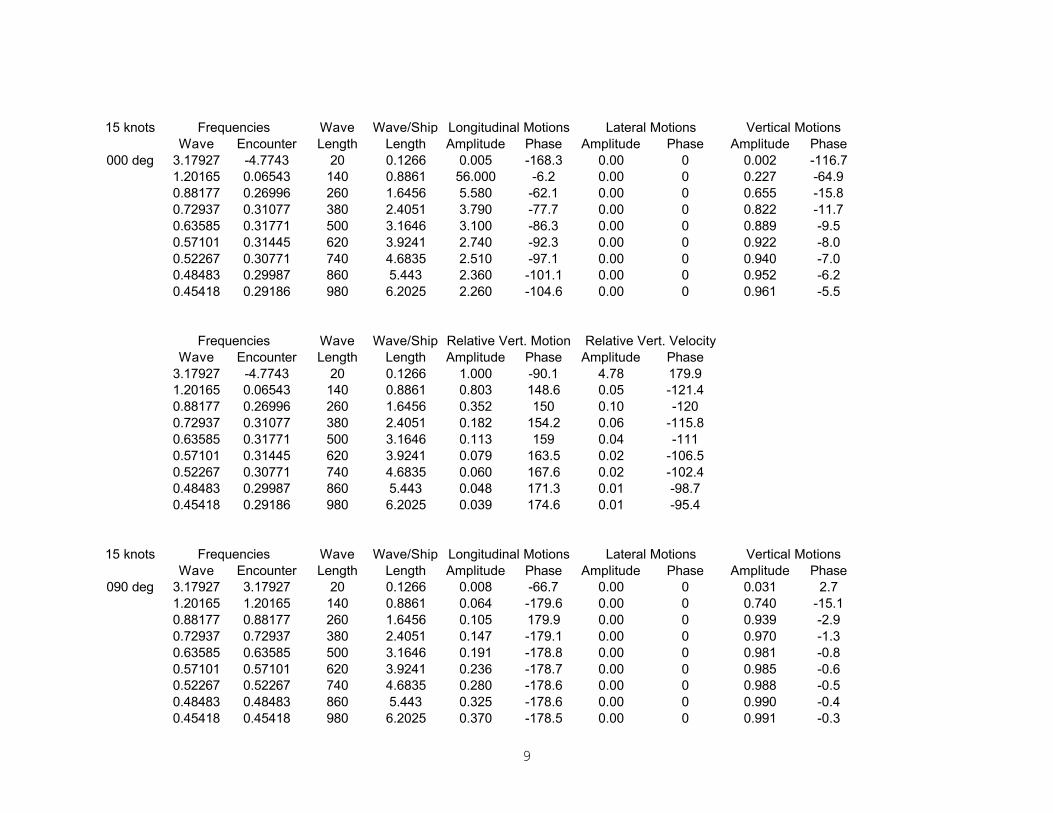
9
15 knotsWave Encounter Amplitude Phase Amplitude Phase Amplitude Phase
000 deg 3.17927 -4.7743 20 0.1266 0.005 -168.3 0.00 0 0.002 -116.71.20165 0.06543 140 0.8861 56.000 -6.2 0.00 0 0.227 -64.90.88177 0.26996 260 1.6456 5.580 -62.1 0.00 0 0.655 -15.80.72937 0.31077 380 2.4051 3.790 -77.7 0.00 0 0.822 -11.70.63585 0.31771 500 3.1646 3.100 -86.3 0.00 0 0.889 -9.50.57101 0.31445 620 3.9241 2.740 -92.3 0.00 0 0.922 -8.00.52267 0.30771 740 4.6835 2.510 -97.1 0.00 0 0.940 -7.00.48483 0.29987 860 5.443 2.360 -101.1 0.00 0 0.952 -6.20.45418 0.29186 980 6.2025 2.260 -104.6 0.00 0 0.961 -5.5
Wave Encounter Amplitude Phase Amplitude Phase3.17927 -4.7743 20 0.1266 1.000 -90.1 4.78 179.91.20165 0.06543 140 0.8861 0.803 148.6 0.05 -121.40.88177 0.26996 260 1.6456 0.352 150 0.10 -1200.72937 0.31077 380 2.4051 0.182 154.2 0.06 -115.80.63585 0.31771 500 3.1646 0.113 159 0.04 -1110.57101 0.31445 620 3.9241 0.079 163.5 0.02 -106.50.52267 0.30771 740 4.6835 0.060 167.6 0.02 -102.40.48483 0.29987 860 5.443 0.048 171.3 0.01 -98.70.45418 0.29186 980 6.2025 0.039 174.6 0.01 -95.4
15 knotsWave Encounter Amplitude Phase Amplitude Phase Amplitude Phase
090 deg 3.17927 3.17927 20 0.1266 0.008 -66.7 0.00 0 0.031 2.71.20165 1.20165 140 0.8861 0.064 -179.6 0.00 0 0.740 -15.10.88177 0.88177 260 1.6456 0.105 179.9 0.00 0 0.939 -2.90.72937 0.72937 380 2.4051 0.147 -179.1 0.00 0 0.970 -1.30.63585 0.63585 500 3.1646 0.191 -178.8 0.00 0 0.981 -0.80.57101 0.57101 620 3.9241 0.236 -178.7 0.00 0 0.985 -0.60.52267 0.52267 740 4.6835 0.280 -178.6 0.00 0 0.988 -0.50.48483 0.48483 860 5.443 0.325 -178.6 0.00 0 0.990 -0.40.45418 0.45418 980 6.2025 0.370 -178.5 0.00 0 0.991 -0.3
Frequencies Wave Length
Wave/Ship Length
Relative Vert. Motion Relative Vert. Velocity
Vertical Motions
Frequencies Wave Length
Wave/Ship Length
Longitudinal Motions Lateral Motions Vertical Motions
Frequencies Wave Length
Wave/Ship Length
Longitudinal Motions Lateral Motions
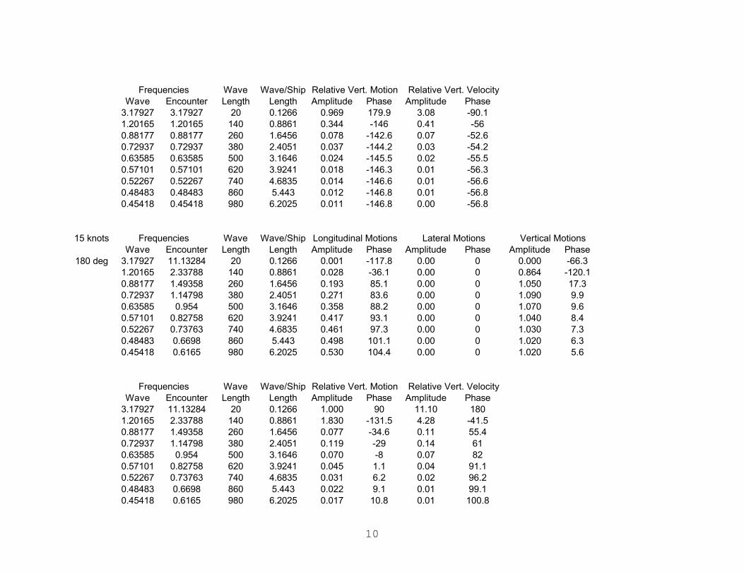
10
Wave Encounter Amplitude Phase Amplitude Phase3.17927 3.17927 20 0.1266 0.969 179.9 3.08 -90.11.20165 1.20165 140 0.8861 0.344 -146 0.41 -560.88177 0.88177 260 1.6456 0.078 -142.6 0.07 -52.60.72937 0.72937 380 2.4051 0.037 -144.2 0.03 -54.20.63585 0.63585 500 3.1646 0.024 -145.5 0.02 -55.50.57101 0.57101 620 3.9241 0.018 -146.3 0.01 -56.30.52267 0.52267 740 4.6835 0.014 -146.6 0.01 -56.60.48483 0.48483 860 5.443 0.012 -146.8 0.01 -56.80.45418 0.45418 980 6.2025 0.011 -146.8 0.00 -56.8
15 knotsWave Encounter Amplitude Phase Amplitude Phase Amplitude Phase
180 deg 3.17927 11.13284 20 0.1266 0.001 -117.8 0.00 0 0.000 -66.31.20165 2.33788 140 0.8861 0.028 -36.1 0.00 0 0.864 -120.10.88177 1.49358 260 1.6456 0.193 85.1 0.00 0 1.050 17.30.72937 1.14798 380 2.4051 0.271 83.6 0.00 0 1.090 9.90.63585 0.954 500 3.1646 0.358 88.2 0.00 0 1.070 9.60.57101 0.82758 620 3.9241 0.417 93.1 0.00 0 1.040 8.40.52267 0.73763 740 4.6835 0.461 97.3 0.00 0 1.030 7.30.48483 0.6698 860 5.443 0.498 101.1 0.00 0 1.020 6.30.45418 0.6165 980 6.2025 0.530 104.4 0.00 0 1.020 5.6
Wave Encounter Amplitude Phase Amplitude Phase3.17927 11.13284 20 0.1266 1.000 90 11.10 1801.20165 2.33788 140 0.8861 1.830 -131.5 4.28 -41.50.88177 1.49358 260 1.6456 0.077 -34.6 0.11 55.40.72937 1.14798 380 2.4051 0.119 -29 0.14 610.63585 0.954 500 3.1646 0.070 -8 0.07 820.57101 0.82758 620 3.9241 0.045 1.1 0.04 91.10.52267 0.73763 740 4.6835 0.031 6.2 0.02 96.20.48483 0.6698 860 5.443 0.022 9.1 0.01 99.10.45418 0.6165 980 6.2025 0.017 10.8 0.01 100.8
Relative Vert. Motion Relative Vert. Velocity
Frequencies Wave Length
Wave/Ship Length
Relative Vert. Motion Relative Vert. Velocity
Lateral Motions Vertical Motions
Frequencies Wave Length
Wave/Ship Length
Frequencies Wave Length
Wave/Ship Length
Longitudinal Motions

11
20 knotsWave Encounter Amplitude Phase Amplitude Phase Amplitude Phase
000 deg 3.17927 -7.42549 20 0.1266 0.002 -150.6 0.00 0 0.001 -113.71.20165 -0.31331 140 0.8861 2.640 -24.2 0.00 0 0.214 -114.80.88177 0.06602 260 1.6456 91.200 -62.7 0.00 0 0.660 -17.20.72937 0.17123 380 2.4051 12.200 -77.1 0.00 0 0.824 -10.30.63585 0.21166 500 3.1646 6.820 -85.6 0.00 0 0.891 -8.60.57101 0.22892 620 3.9241 5.050 -91.8 0.00 0 0.922 -7.50.52267 0.23605 740 4.6835 4.190 -96.7 0.00 0 0.939 -6.60.48483 0.23821 860 5.443 3.680 -100.8 0.00 0 0.950 -5.90.45418 0.23776 980 6.2025 3.360 -104.4 0.00 0 0.958 -5.3
Wave Encounter Amplitude Phase Amplitude Phase3.17927 -7.42549 20 0.1266 1.000 -90 7.43 1801.20165 -0.31331 140 0.8861 0.972 153.8 0.30 63.80.88177 0.06602 260 1.6456 0.344 152.3 0.02 -117.70.72937 0.17123 380 2.4051 0.187 148.3 0.03 -121.70.63585 0.21166 500 3.1646 0.115 152.1 0.02 -117.90.57101 0.22892 620 3.9241 0.081 157.6 0.02 -112.40.52267 0.23605 740 4.6835 0.062 162.4 0.01 -107.60.48483 0.23821 860 5.443 0.050 166.6 0.01 -103.40.45418 0.23776 980 6.2025 0.042 170.2 0.01 -99.8
20 knotsWave Encounter Amplitude Phase Amplitude Phase Amplitude Phase
090 deg 3.17927 3.17927 20 0.1266 0.008 -66.8 0.00 0 0.031 1.81.20165 1.20165 140 0.8861 0.062 178.2 0.00 0 0.709 -12.80.88177 0.88177 260 1.6456 0.106 179.4 0.00 0 0.924 -2.90.72937 0.72937 380 2.4051 0.148 -179.3 0.00 0 0.962 -1.40.63585 0.63585 500 3.1646 0.192 -178.9 0.00 0 0.975 -0.80.57101 0.57101 620 3.9241 0.236 -178.8 0.00 0 0.981 -0.60.52267 0.52267 740 4.6835 0.281 -178.7 0.00 0 0.985 -0.40.48483 0.48483 860 5.443 0.326 -178.6 0.00 0 0.987 -0.40.45418 0.45418 980 6.2025 0.371 -178.6 0.00 0 0.988 -0.3
Relative Vert. VelocityFrequencies Wave Length
Wave/Ship Length
Relative Vert. Motion
Lateral Motions Vertical MotionsFrequencies Wave Length
Wave/Ship Length
Longitudinal Motions
Lateral Motions Vertical MotionsFrequencies Wave Length
Wave/Ship Length
Longitudinal Motions

12
Wave Encounter Amplitude Phase Amplitude Phase3.17927 3.17927 20 0.1266 0.969 179.9 3.08 -90.11.20165 1.20165 140 0.8861 0.346 -153.1 0.42 -63.10.88177 0.88177 260 1.6456 0.090 -149.1 0.08 -59.10.72937 0.72937 380 2.4051 0.045 -149.3 0.03 -59.30.63585 0.63585 500 3.1646 0.029 -150.5 0.02 -60.50.57101 0.57101 620 3.9241 0.021 -151.7 0.01 -61.70.52267 0.52267 740 4.6835 0.017 -153 0.01 -630.48483 0.48483 860 5.443 0.015 -154.2 0.01 -64.20.45418 0.45418 980 6.2025 0.013 -155.1 0.01 -65.1
20 knotsWave Encounter Amplitude Phase Amplitude Phase Amplitude Phase
180 deg 3.17927 13.78403 20 0.1266 0.001 -112.1 0.00 0 0.000 -67.31.20165 2.71662 140 0.8861 0.018 10.4 0.00 0 0.277 -122.00.88177 1.69752 260 1.6456 0.174 77.5 0.00 0 1.280 16.70.72937 1.28752 380 2.4051 0.218 89.2 0.00 0 1.130 8.20.63585 1.06004 500 3.1646 0.286 88 0.00 0 1.120 8.40.57101 0.9131 620 3.9241 0.342 92.5 0.00 0 1.080 8.00.52267 0.80928 740 4.6835 0.385 96.8 0.00 0 1.060 7.10.48483 0.73146 860 5.443 0.420 100.5 0.00 0 1.040 6.40.45418 0.67061 980 6.2025 0.451 103.9 0.00 0 1.030 5.7
Wave Encounter Amplitude Phase Amplitude Phase3.17927 13.78403 20 0.1266 1.000 90 13.80 1801.20165 2.71662 140 0.8861 1.260 -137.2 3.44 -47.20.88177 1.69752 260 1.6456 0.289 2.3 0.49 92.30.72937 1.28752 380 2.4051 0.168 -30.2 0.22 59.80.63585 1.06004 500 3.1646 0.132 -10 0.14 800.57101 0.9131 620 3.9241 0.085 -0.6 0.08 89.40.52267 0.80928 740 4.6835 0.059 4.6 0.05 94.60.48483 0.73146 860 5.443 0.043 8.1 0.03 98.10.45418 0.67061 980 6.2025 0.033 10.7 0.02 100.7
Wave/Ship Length
Relative Vert. Motion Relative Vert. Velocity
Frequencies Wave Length
Wave/Ship Length
Relative Vert. Motion Relative Vert. Velocity
Frequencies Wave Length
Wave/Ship Length
Longitudinal Motions Lateral Motions Vertical Motions
Frequencies Wave Length
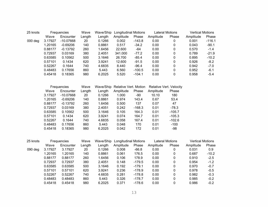
13
25 knotsWave Encounter Amplitude Phase Amplitude Phase Amplitude Phase
000 deg 3.17927 -10.07668 20 0.1266 0.002 -143.8 0.00 0 0.001 -116.11.20165 -0.69206 140 0.8861 0.517 -34.2 0.00 0 0.043 -90.10.88177 -0.13792 260 1.6456 22.600 -64 0.00 0 0.570 -1.40.72937 0.03169 380 2.4051 341.000 -77.2 0.00 0 0.789 -21.90.63585 0.10562 500 3.1646 26.700 -85.4 0.00 0 0.895 -10.20.57101 0.1434 620 3.9241 12.600 -91.5 0.00 0 0.926 -8.20.52267 0.1644 740 4.6835 8.440 -96.4 0.00 0 0.942 -7.00.48483 0.17656 860 5.443 6.560 -100.5 0.00 0 0.952 -6.10.45418 0.18365 980 6.2025 5.520 -104.1 0.00 0 0.958 -5.4
Wave Encounter Amplitude Phase Amplitude Phase3.17927 -10.07668 20 0.1266 1.000 -90 10.10 1801.20165 -0.69206 140 0.8861 0.974 143.4 0.67 53.40.88177 -0.13792 260 1.6456 0.500 137 0.07 470.72937 0.03169 380 2.4051 0.242 -168.3 0.01 -78.30.63585 0.10562 500 3.1646 0.105 164.3 0.01 -105.70.57101 0.1434 620 3.9241 0.074 164.7 0.01 -105.30.52267 0.1644 740 4.6835 0.058 167.4 0.01 -102.60.48483 0.17656 860 5.443 0.048 170 0.01 -1000.45418 0.18365 980 6.2025 0.042 172 0.01 -98
25 knotsWave Encounter Amplitude Phase Amplitude Phase Amplitude Phase
090 deg 3.17927 3.17927 20 0.1266 0.008 -66.8 0.00 0 0.031 0.91.20165 1.20165 140 0.8861 0.061 176.5 0.00 0 0.687 -10.20.88177 0.88177 260 1.6456 0.106 178.9 0.00 0 0.910 -2.50.72937 0.72937 380 2.4051 0.148 -179.5 0.00 0 0.954 -1.20.63585 0.63585 500 3.1646 0.192 -179.1 0.00 0 0.970 -0.70.57101 0.57101 620 3.9241 0.236 -178.9 0.00 0 0.978 -0.50.52267 0.52267 740 4.6835 0.281 -178.8 0.00 0 0.982 -0.30.48483 0.48483 860 5.443 0.326 -178.7 0.00 0 0.985 -0.20.45418 0.45418 980 6.2025 0.371 -178.6 0.00 0 0.986 -0.2
Lateral Motions Vertical Motions
Frequencies Wave Length
Wave/Ship Length
Longitudinal Motions Lateral Motions Vertical Motions
Frequencies Wave Length
Wave/Ship Length
Longitudinal Motions
Relative Vert. VelocityFrequencies Wave Length
Wave/Ship Length
Relative Vert. Motion
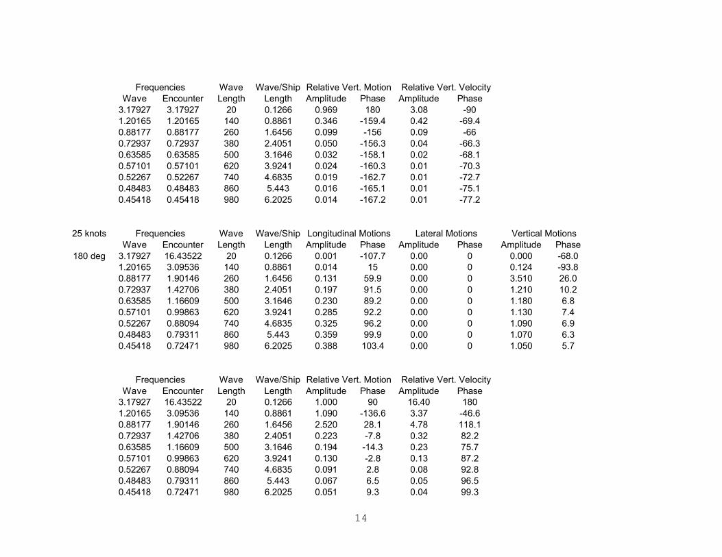
14
Wave Encounter Amplitude Phase Amplitude Phase3.17927 3.17927 20 0.1266 0.969 180 3.08 -901.20165 1.20165 140 0.8861 0.346 -159.4 0.42 -69.40.88177 0.88177 260 1.6456 0.099 -156 0.09 -660.72937 0.72937 380 2.4051 0.050 -156.3 0.04 -66.30.63585 0.63585 500 3.1646 0.032 -158.1 0.02 -68.10.57101 0.57101 620 3.9241 0.024 -160.3 0.01 -70.30.52267 0.52267 740 4.6835 0.019 -162.7 0.01 -72.70.48483 0.48483 860 5.443 0.016 -165.1 0.01 -75.10.45418 0.45418 980 6.2025 0.014 -167.2 0.01 -77.2
25 knotsWave Encounter Amplitude Phase Amplitude Phase Amplitude Phase
180 deg 3.17927 16.43522 20 0.1266 0.001 -107.7 0.00 0 0.000 -68.01.20165 3.09536 140 0.8861 0.014 15 0.00 0 0.124 -93.80.88177 1.90146 260 1.6456 0.131 59.9 0.00 0 3.510 26.00.72937 1.42706 380 2.4051 0.197 91.5 0.00 0 1.210 10.20.63585 1.16609 500 3.1646 0.230 89.2 0.00 0 1.180 6.80.57101 0.99863 620 3.9241 0.285 92.2 0.00 0 1.130 7.40.52267 0.88094 740 4.6835 0.325 96.2 0.00 0 1.090 6.90.48483 0.79311 860 5.443 0.359 99.9 0.00 0 1.070 6.30.45418 0.72471 980 6.2025 0.388 103.4 0.00 0 1.050 5.7
Wave Encounter Amplitude Phase Amplitude Phase3.17927 16.43522 20 0.1266 1.000 90 16.40 1801.20165 3.09536 140 0.8861 1.090 -136.6 3.37 -46.60.88177 1.90146 260 1.6456 2.520 28.1 4.78 118.10.72937 1.42706 380 2.4051 0.223 -7.8 0.32 82.20.63585 1.16609 500 3.1646 0.194 -14.3 0.23 75.70.57101 0.99863 620 3.9241 0.130 -2.8 0.13 87.20.52267 0.88094 740 4.6835 0.091 2.8 0.08 92.80.48483 0.79311 860 5.443 0.067 6.5 0.05 96.50.45418 0.72471 980 6.2025 0.051 9.3 0.04 99.3
Lateral Motions Vertical MotionsFrequencies Wave Length
Wave/Ship Length
Longitudinal Motions
Relative Vert. VelocityFrequencies Wave Length
Wave/Ship Length
Relative Vert. Motion
Frequencies Wave Length
Wave/Ship Length
Relative Vert. Motion Relative Vert. Velocity

15
30 knotsWave Encounter Amplitude Phase Amplitude Phase Amplitude Phase
000 deg 3.17927 -12.72787 20 0.1266 0.001 -138.8 0.00 0 0.001 -117.61.20165 -1.0708 140 0.8861 0.209 -44.3 0.00 0 0.201 -13.30.88177 -0.34186 260 1.6456 3.850 -65.6 0.00 0 0.611 -5.50.72937 -0.10784 380 2.4051 31.200 -77.3 0.00 0 0.863 -6.00.63585 -0.00043 500 3.1646 ######### -86.3 0.00 0 ####### 28.20.57101 0.05788 620 3.9241 74.700 -91.4 0.00 0 0.891 -9.80.52267 0.09275 740 4.6835 25.900 -96.3 0.00 0 0.926 -7.70.48483 0.1149 860 5.443 15.200 -100.4 0.00 0 0.942 -6.50.45418 0.12955 980 6.2025 10.900 -104.1 0.00 0 0.951 -5.6
Wave Encounter Amplitude Phase Amplitude Phase3.17927 -12.72787 20 0.1266 1.000 -90 12.70 1801.20165 -1.0708 140 0.8861 0.823 135.5 0.88 45.50.88177 -0.34186 260 1.6456 0.441 137.8 0.15 47.80.72937 -0.10784 380 2.4051 0.191 125.5 0.02 35.50.63585 -0.00043 500 3.1646 7.070 33.3 0.00 -56.70.57101 0.05788 620 3.9241 0.110 -179.9 0.01 -89.90.52267 0.09275 740 4.6835 0.074 177.6 0.01 -92.40.48483 0.1149 860 5.443 0.058 177.1 0.01 -92.90.45418 0.12955 980 6.2025 0.049 176.9 0.01 -93.1
30 knotsWave Encounter Amplitude Phase Amplitude Phase Amplitude Phase
090 deg 3.17927 3.17927 20 0.1266 0.008 -66.8 0.00 0 0.031 0.01.20165 1.20165 140 0.8861 0.061 175.2 0.00 0 0.674 -7.70.88177 0.88177 260 1.6456 0.106 178.6 0.00 0 0.901 -2.00.72937 0.72937 380 2.4051 0.148 -179.7 0.00 0 0.950 -0.90.63585 0.63585 500 3.1646 0.192 -179.2 0.00 0 0.968 -0.50.57101 0.57101 620 3.9241 0.236 -179 0.00 0 0.976 -0.30.52267 0.52267 740 4.6835 0.281 -178.8 0.00 0 0.981 -0.10.48483 0.48483 860 5.443 0.326 -178.7 0.00 0 0.984 -0.10.45418 0.45418 980 6.2025 0.371 -178.7 0.00 0 0.986 0.0
Lateral Motions Vertical MotionsFrequencies Wave Length
Wave/Ship Length
Longitudinal Motions
Frequencies Wave Length
Wave/Ship Length
Longitudinal Motions Lateral Motions Vertical Motions
Frequencies Wave Length
Wave/Ship Length
Relative Vert. Motion Relative Vert. Velocity

16
Wave Encounter Amplitude Phase Amplitude Phase3.17927 3.17927 20 0.1266 0.970 180 3.08 -901.20165 1.20165 140 0.8861 0.344 -164.8 0.41 -74.80.88177 0.88177 260 1.6456 0.104 -162.4 0.09 -72.40.72937 0.72937 380 2.4051 0.053 -163.4 0.04 -73.40.63585 0.63585 500 3.1646 0.033 -166 0.02 -760.57101 0.57101 620 3.9241 0.024 -169.2 0.01 -79.20.52267 0.52267 740 4.6835 0.019 -172.5 0.01 -82.50.48483 0.48483 860 5.443 0.016 -175.9 0.01 -85.90.45418 0.45418 980 6.2025 0.014 -179 0.01 -89
30 knotsWave Encounter Amplitude Phase Amplitude Phase Amplitude Phase
180 deg 3.17927 19.08641 20 0.1266 0.001 -104.4 0.00 0 0.000 -68.41.20165 3.4741 140 0.8861 0.015 -13.4 0.00 0 0.089 -121.10.88177 2.1054 260 1.6456 0.110 8.5 0.00 0 ###### -21.80.72937 1.56659 380 2.4051 0.183 88.8 0.00 0 1.410 11.50.63585 1.27214 500 3.1646 0.196 92.9 0.00 0 1.210 6.10.57101 1.08415 620 3.9241 0.239 92 0.00 0 1.170 6.60.52267 0.95259 740 4.6835 0.278 95.7 0.00 0 1.130 6.60.48483 0.85477 860 5.443 0.310 99.4 0.00 0 1.090 6.20.45418 0.77882 980 6.2025 0.337 102.8 0.00 0 1.070 5.6
Wave Encounter Amplitude Phase Amplitude Phase3.17927 19.08641 20 0.1266 1.000 90 19.10 1801.20165 3.4741 140 0.8861 1.080 -139.8 3.76 -49.80.88177 2.1054 260 1.6456 12.000 -25 25.20 650.72937 1.56659 380 2.4051 0.409 4.9 0.64 94.90.63585 1.27214 500 3.1646 0.230 -14.9 0.29 75.10.57101 1.08415 620 3.9241 0.179 -5.1 0.19 84.90.52267 0.95259 740 4.6835 0.126 1.1 0.12 91.10.48483 0.85477 860 5.443 0.093 4.9 0.08 94.90.45418 0.77882 980 6.2025 0.072 7.6 0.06 97.6
Frequencies Wave Length
Wave/Ship Length
Longitudinal Motions Lateral Motions Vertical Motions
Relative Vert. Velocity
Frequencies Wave Length
Wave/Ship Length
Relative Vert. Motion Relative Vert. Velocity
Frequencies Wave Length
Wave/Ship Length
Relative Vert. Motion

17
35 knotsWave Encounter Amplitude Phase Amplitude Phase Amplitude Phase
000 deg 3.17927 -15.37906 20 0.1266 0.001 -135.1 0.00 0 0.000 -118.61.20165 -1.44954 140 0.8861 0.088 -48.2 0.00 0 0.265 -43.40.88177 -0.54579 260 1.6456 1.530 -66.9 0.00 0 0.675 -7.10.72937 -0.24738 380 2.4051 6.160 -77.9 0.00 0 0.846 -7.50.63585 -0.10648 500 3.1646 26.500 -85.3 0.00 0 0.927 -7.50.57101 -0.02764 620 3.9241 320.000 -91.3 0.00 0 1.020 -6.30.52267 0.02109 740 4.6835 476.000 -96.3 0.00 0 0.849 -8.60.48483 0.05325 860 5.443 68.500 -100.4 0.00 0 0.920 -6.60.45418 0.07544 980 6.2025 31.300 -104.1 0.00 0 0.940 -5.7
Wave Encounter Amplitude Phase Amplitude Phase3.17927 -15.37906 20 0.1266 1.000 -90 15.40 1801.20165 -1.44954 140 0.8861 0.736 143.2 1.07 53.20.88177 -0.54579 260 1.6456 0.379 134.3 0.21 44.30.72937 -0.24738 380 2.4051 0.188 134.2 0.05 44.20.63585 -0.10648 500 3.1646 0.092 133.9 0.01 43.90.57101 -0.02764 620 3.9241 0.046 61.7 0.00 -28.30.52267 0.02109 740 4.6835 0.152 179.9 0.00 -90.10.48483 0.05325 860 5.443 0.080 177.7 0.00 -92.30.45418 0.07544 980 6.2025 0.060 177 0.00 -93
35 knotsWave Encounter Amplitude Phase Amplitude Phase Amplitude Phase
090 deg 3.17927 3.17927 20 0.1266 0.008 -66.8 0.00 0 0.030 -0.81.20165 1.20165 140 0.8861 0.061 174.4 0.00 0 0.668 -5.40.88177 0.88177 260 1.6456 0.106 178.4 0.00 0 0.897 -1.40.72937 0.72937 380 2.4051 0.148 -179.8 0.00 0 0.948 -0.60.63585 0.63585 500 3.1646 0.191 -179.3 0.00 0 0.967 -0.30.57101 0.57101 620 3.9241 0.236 -179 0.00 0 0.977 -0.10.52267 0.52267 740 4.6835 0.280 -178.9 0.00 0 0.982 0.00.48483 0.48483 860 5.443 0.325 -178.8 0.00 0 0.985 0.10.45418 0.45418 980 6.2025 0.370 -178.7 0.00 0 0.987 0.1
Lateral Motions Vertical Motions
Frequencies Wave Length
Wave/Ship Length
Longitudinal Motions Lateral Motions Vertical Motions
Frequencies Wave Length
Wave/Ship Length
Longitudinal Motions
Relative Vert. VelocityFrequencies Wave Length
Wave/Ship Length
Relative Vert. Motion

18
Wave Encounter Amplitude Phase Amplitude Phase3.17927 3.17927 20 0.1266 0.970 -180 3.08 -901.20165 1.20165 140 0.8861 0.341 -169.4 0.41 -79.40.88177 0.88177 260 1.6456 0.105 -167.9 0.09 -77.90.72937 0.72937 380 2.4051 0.053 -169.5 0.04 -79.50.63585 0.63585 500 3.1646 0.033 -172.6 0.02 -82.60.57101 0.57101 620 3.9241 0.024 -176.3 0.01 -86.30.52267 0.52267 740 4.6835 0.018 179.8 0.01 -90.20.48483 0.48483 860 5.443 0.015 176 0.01 -940.45418 0.45418 980 6.2025 0.013 172.4 0.01 -97.6
35 knotsWave Encounter Amplitude Phase Amplitude Phase Amplitude Phase
180 deg 3.17927 21.7376 20 0.1266 0.001 -101.8 0.00 0 0.000 -68.71.20165 3.85284 140 0.8861 0.012 3.6 0.00 0 0.060 -117.80.88177 2.30933 260 1.6456 0.066 104.2 0.00 0 3.680 -142.80.72937 1.70613 380 2.4051 0.168 83.9 0.00 0 1.440 9.70.63585 1.37819 500 3.1646 0.176 96.1 0.00 0 1.260 7.00.57101 1.16967 620 3.9241 0.201 92.5 0.00 0 1.220 5.70.52267 1.02425 740 4.6835 0.239 95.2 0.00 0 1.160 6.20.48483 0.91642 860 5.443 0.270 98.8 0.00 0 1.120 6.00.45418 0.83292 980 6.2025 0.296 102.3 0.00 0 1.090 5.6
Wave Encounter Amplitude Phase Amplitude Phase3.17927 21.7376 20 0.1266 1.000 90 21.70 1801.20165 3.85284 140 0.8861 1.050 -140.1 4.06 -50.10.88177 2.30933 260 1.6456 4.650 -146.3 10.70 -56.30.72937 1.70613 380 2.4051 0.450 -0.4 0.77 89.60.63585 1.37819 500 3.1646 0.271 -7.2 0.37 82.80.57101 1.16967 620 3.9241 0.229 -7.7 0.27 82.30.52267 1.02425 740 4.6835 0.164 -0.3 0.17 89.70.48483 0.91642 860 5.443 0.121 3.5 0.11 93.50.45418 0.83292 980 6.2025 0.094 6.1 0.08 96.1
Lateral Motions Vertical MotionsFrequencies Wave Length
Wave/Ship Length
Longitudinal Motions
Relative Vert. VelocityFrequencies Wave Length
Wave/Ship Length
Relative Vert. Motion
Frequencies Wave Length
Wave/Ship Length
Relative Vert. Motion Relative Vert. Velocity

19
3. Heave and Pitch Motions at Bridge
Wave Encounter Amplitude Phase Amplitude Phase090 deg 3.17927 3.17927 20 0.1266 0.0344 2.8 0.014 -12.5
1.20165 1.20165 140 0.8861 0.8499 -19.8 0.1504 -58.30.88177 0.88177 260 1.6456 0.9794 -2 0.0468 7.50.72937 0.72937 380 2.4051 0.9875 -0.6 0.0241 21.50.63585 0.63585 500 3.1646 0.9912 -0.3 0.0166 26.50.57101 0.57101 620 3.9241 0.9934 -0.2 0.0133 28.50.52267 0.52267 740 4.6835 0.9948 -0.2 0.0115 29.60.48483 0.48483 860 5.443 0.9958 -0.2 0.0104 30.30.45418 0.45418 980 6.2025 0.9964 -0.1 0.0097 30.8
Wave Encounter Amplitude Phase Amplitude Phase180 deg 3.17927 5.83046 20 0.1266 0.0015 73.6 0.0018 157.8
1.20165 1.58039 140 0.8861 0.1769 23 1.0424 -124.10.88177 1.08571 260 1.6456 0.7024 1 1.158 -113.30.72937 0.86891 380 2.4051 0.8605 -0.3 0.9101 -103.80.63585 0.7419 500 3.1646 0.9217 -0.3 0.7171 -99.40.57101 0.65654 620 3.9241 0.9505 -0.2 0.5858 -96.90.52267 0.59432 740 4.6835 0.9661 -0.2 0.4931 -95.30.48483 0.54649 860 5.443 0.9755 -0.2 0.4249 -94.10.45418 0.50829 980 6.2025 0.9815 -0.1 0.3728 -93.3
Wave Encounter Amplitude Phase Amplitude Phase10 3.17927 -2.12311 20 0.1266 0.1724 -0.5 0.268 139.6
000 deg 1.20165 0.44417 140 0.8861 0.097 -24.8 0.4883 132.50.88177 0.4739 260 1.6456 0.579 0 0.8464 110.80.72937 0.4503 380 2.4051 0.7717 0 0.7391 103.50.63585 0.42376 500 3.1646 0.8569 -0.1 0.6191 99.70.57101 0.39997 620 3.9241 0.9014 -0.1 0.5252 97.40.52267 0.37936 740 4.6835 0.9275 -0.1 0.4538 95.80.48483 0.36152 860 5.443 0.9441 -0.2 0.3986 94.60.45418 0.34597 980 6.2025 0.9554 -0.2 0.3551 93.7
Wave Encounter Amplitude Phase Amplitude Phase090 deg 3.17927 3.17927 20 0.1266 0.0345 2.6 0.0137 -6.6
1.20165 1.20165 140 0.8861 0.8238 -18.9 0.2035 -49.50.88177 0.88177 260 1.6456 0.9709 -2.3 0.0655 13.90.72937 0.72937 380 2.4051 0.9843 -0.8 0.0332 27.60.63585 0.63585 500 3.1646 0.9895 -0.4 0.0221 31.70.57101 0.57101 620 3.9241 0.9923 -0.3 0.0172 32.70.52267 0.52267 740 4.6835 0.9939 -0.2 0.0146 32.50.48483 0.48483 860 5.443 0.995 -0.2 0.013 32.20.45418 0.45418 980 6.2025 0.9957 -0.2 0.012 31.8
Heave PitchFrequencies Wave Length
Wave/Ship Length
Heave Pitch
Frequencies Wave Length
Wave/Ship Length
Heave Pitch
Frequencies Wave Length
Wave/Ship Length
Frequencies Wave Length
Wave/Ship Length
Heave Pitch
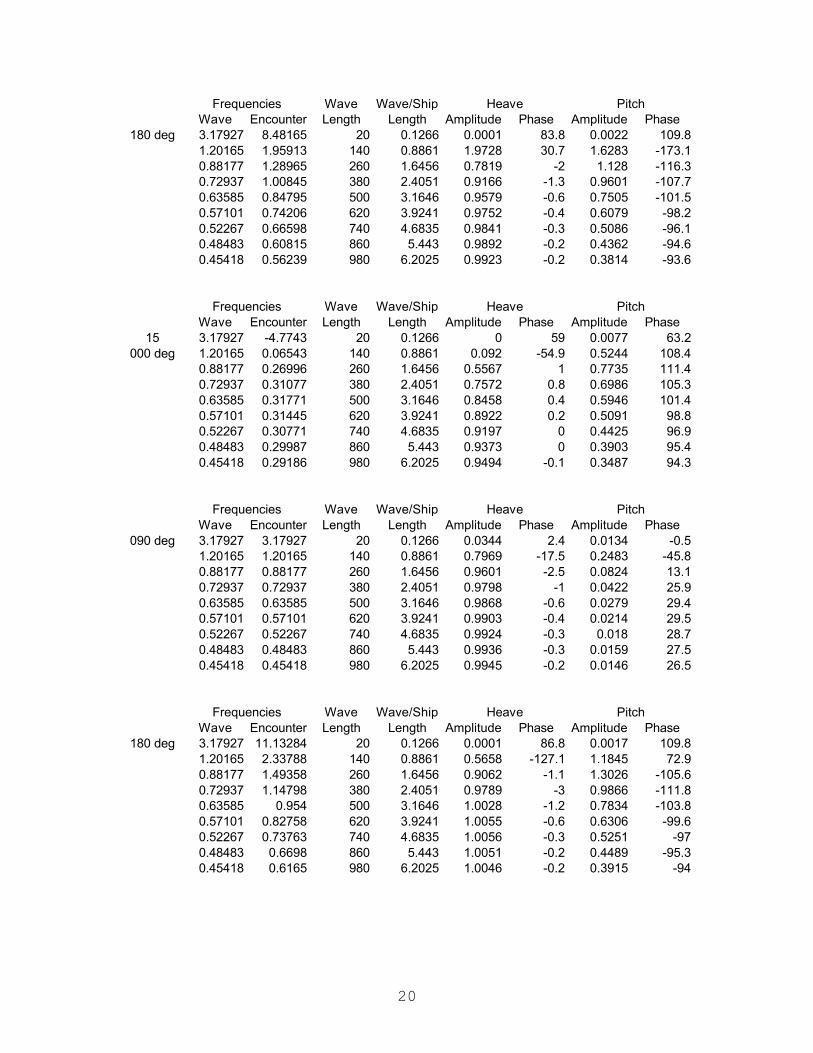
20
Wave Encounter Amplitude Phase Amplitude Phase180 deg 3.17927 8.48165 20 0.1266 0.0001 83.8 0.0022 109.8
1.20165 1.95913 140 0.8861 1.9728 30.7 1.6283 -173.10.88177 1.28965 260 1.6456 0.7819 -2 1.128 -116.30.72937 1.00845 380 2.4051 0.9166 -1.3 0.9601 -107.70.63585 0.84795 500 3.1646 0.9579 -0.6 0.7505 -101.50.57101 0.74206 620 3.9241 0.9752 -0.4 0.6079 -98.20.52267 0.66598 740 4.6835 0.9841 -0.3 0.5086 -96.10.48483 0.60815 860 5.443 0.9892 -0.2 0.4362 -94.60.45418 0.56239 980 6.2025 0.9923 -0.2 0.3814 -93.6
Wave Encounter Amplitude Phase Amplitude Phase15 3.17927 -4.7743 20 0.1266 0 59 0.0077 63.2
000 deg 1.20165 0.06543 140 0.8861 0.092 -54.9 0.5244 108.40.88177 0.26996 260 1.6456 0.5567 1 0.7735 111.40.72937 0.31077 380 2.4051 0.7572 0.8 0.6986 105.30.63585 0.31771 500 3.1646 0.8458 0.4 0.5946 101.40.57101 0.31445 620 3.9241 0.8922 0.2 0.5091 98.80.52267 0.30771 740 4.6835 0.9197 0 0.4425 96.90.48483 0.29987 860 5.443 0.9373 0 0.3903 95.40.45418 0.29186 980 6.2025 0.9494 -0.1 0.3487 94.3
Wave Encounter Amplitude Phase Amplitude Phase090 deg 3.17927 3.17927 20 0.1266 0.0344 2.4 0.0134 -0.5
1.20165 1.20165 140 0.8861 0.7969 -17.5 0.2483 -45.80.88177 0.88177 260 1.6456 0.9601 -2.5 0.0824 13.10.72937 0.72937 380 2.4051 0.9798 -1 0.0422 25.90.63585 0.63585 500 3.1646 0.9868 -0.6 0.0279 29.40.57101 0.57101 620 3.9241 0.9903 -0.4 0.0214 29.50.52267 0.52267 740 4.6835 0.9924 -0.3 0.018 28.70.48483 0.48483 860 5.443 0.9936 -0.3 0.0159 27.50.45418 0.45418 980 6.2025 0.9945 -0.2 0.0146 26.5
Wave Encounter Amplitude Phase Amplitude Phase180 deg 3.17927 11.13284 20 0.1266 0.0001 86.8 0.0017 109.8
1.20165 2.33788 140 0.8861 0.5658 -127.1 1.1845 72.90.88177 1.49358 260 1.6456 0.9062 -1.1 1.3026 -105.60.72937 1.14798 380 2.4051 0.9789 -3 0.9866 -111.80.63585 0.954 500 3.1646 1.0028 -1.2 0.7834 -103.80.57101 0.82758 620 3.9241 1.0055 -0.6 0.6306 -99.60.52267 0.73763 740 4.6835 1.0056 -0.3 0.5251 -970.48483 0.6698 860 5.443 1.0051 -0.2 0.4489 -95.30.45418 0.6165 980 6.2025 1.0046 -0.2 0.3915 -94
Heave PitchFrequencies Wave Length
Wave/Ship Length
Heave Pitch
Frequencies Wave Length
Wave/Ship Length
Heave Pitch
Frequencies Wave Length
Wave/Ship Length
Frequencies Wave Length
Wave/Ship Length
Heave Pitch
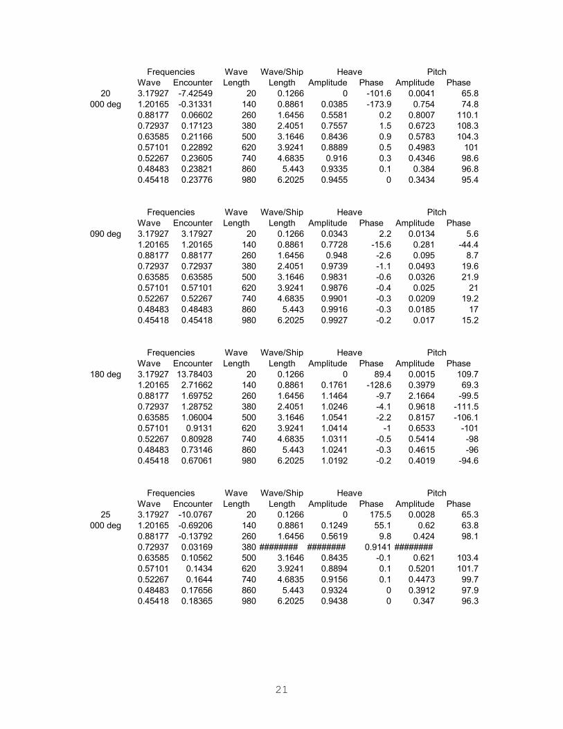
21
Wave Encounter Amplitude Phase Amplitude Phase20 3.17927 -7.42549 20 0.1266 0 -101.6 0.0041 65.8
000 deg 1.20165 -0.31331 140 0.8861 0.0385 -173.9 0.754 74.80.88177 0.06602 260 1.6456 0.5581 0.2 0.8007 110.10.72937 0.17123 380 2.4051 0.7557 1.5 0.6723 108.30.63585 0.21166 500 3.1646 0.8436 0.9 0.5783 104.30.57101 0.22892 620 3.9241 0.8889 0.5 0.4983 1010.52267 0.23605 740 4.6835 0.916 0.3 0.4346 98.60.48483 0.23821 860 5.443 0.9335 0.1 0.384 96.80.45418 0.23776 980 6.2025 0.9455 0 0.3434 95.4
Wave Encounter Amplitude Phase Amplitude Phase090 deg 3.17927 3.17927 20 0.1266 0.0343 2.2 0.0134 5.6
1.20165 1.20165 140 0.8861 0.7728 -15.6 0.281 -44.40.88177 0.88177 260 1.6456 0.948 -2.6 0.095 8.70.72937 0.72937 380 2.4051 0.9739 -1.1 0.0493 19.60.63585 0.63585 500 3.1646 0.9831 -0.6 0.0326 21.90.57101 0.57101 620 3.9241 0.9876 -0.4 0.025 210.52267 0.52267 740 4.6835 0.9901 -0.3 0.0209 19.20.48483 0.48483 860 5.443 0.9916 -0.3 0.0185 170.45418 0.45418 980 6.2025 0.9927 -0.2 0.017 15.2
Wave Encounter Amplitude Phase Amplitude Phase180 deg 3.17927 13.78403 20 0.1266 0 89.4 0.0015 109.7
1.20165 2.71662 140 0.8861 0.1761 -128.6 0.3979 69.30.88177 1.69752 260 1.6456 1.1464 -9.7 2.1664 -99.50.72937 1.28752 380 2.4051 1.0246 -4.1 0.9618 -111.50.63585 1.06004 500 3.1646 1.0541 -2.2 0.8157 -106.10.57101 0.9131 620 3.9241 1.0414 -1 0.6533 -1010.52267 0.80928 740 4.6835 1.0311 -0.5 0.5414 -980.48483 0.73146 860 5.443 1.0241 -0.3 0.4615 -960.45418 0.67061 980 6.2025 1.0192 -0.2 0.4019 -94.6
Wave Encounter Amplitude Phase Amplitude Phase25 3.17927 -10.0767 20 0.1266 0 175.5 0.0028 65.3
000 deg 1.20165 -0.69206 140 0.8861 0.1249 55.1 0.62 63.80.88177 -0.13792 260 1.6456 0.5619 9.8 0.424 98.10.72937 0.03169 380 ######## ######## 0.9141 ########0.63585 0.10562 500 3.1646 0.8435 -0.1 0.621 103.40.57101 0.1434 620 3.9241 0.8894 0.1 0.5201 101.70.52267 0.1644 740 4.6835 0.9156 0.1 0.4473 99.70.48483 0.17656 860 5.443 0.9324 0 0.3912 97.90.45418 0.18365 980 6.2025 0.9438 0 0.347 96.3
Heave PitchFrequencies Wave Length
Wave/Ship Length
Heave Pitch
Frequencies Wave Length
Wave/Ship Length
Heave Pitch
Frequencies Wave Length
Wave/Ship Length
Frequencies Wave Length
Wave/Ship Length
Heave Pitch
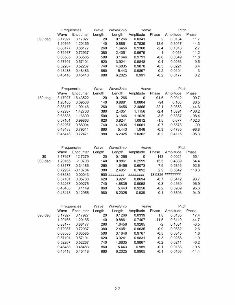
22
Wave Encounter Amplitude Phase Amplitude Phase090 deg 3.17927 3.17927 20 0.1266 0.0341 2 0.0134 11.7
1.20165 1.20165 140 0.8861 0.7539 -13.6 0.3017 -44.30.88177 0.88177 260 1.6456 0.9368 -2.4 0.1018 2.70.72937 0.72937 380 2.4051 0.9679 -1 0.053 11.20.63585 0.63585 500 3.1646 0.9793 -0.6 0.0349 11.80.57101 0.57101 620 3.9241 0.9848 -0.4 0.0266 9.50.52267 0.52267 740 4.6835 0.9878 -0.3 0.0221 6.40.48483 0.48483 860 5.443 0.9897 -0.2 0.0194 30.45418 0.45418 980 6.2025 0.991 -0.2 0.0177 0.2
Wave Encounter Amplitude Phase Amplitude Phase180 deg 3.17927 16.43522 20 0.1266 0 91.6 0.0012 109.7
1.20165 3.09536 140 0.8861 0.0804 -94 0.166 86.50.88177 1.90146 260 1.6456 2.4866 22.1 3.9853 -144.60.72937 1.42706 380 2.4051 1.1156 -2.4 1.0391 -106.20.63585 1.16609 500 3.1646 1.1029 -3.5 0.8367 -108.40.57101 0.99863 620 3.9241 1.0812 -1.5 0.677 -102.30.52267 0.88094 740 4.6835 1.0601 -0.7 0.5578 -990.48483 0.79311 860 5.443 1.046 -0.3 0.4735 -96.80.45418 0.72471 980 6.2025 1.0362 -0.2 0.4115 -95.3
Wave Encounter Amplitude Phase Amplitude Phase30 3.17927 -12.7279 20 0.1266 0 143 0.0021 65.1
000 deg 1.20165 -1.0708 140 0.8861 0.2599 15.5 0.4889 64.40.88177 -0.34186 260 1.6456 0.6073 7.6 0.5316 92.60.72937 -0.10784 380 2.4051 0.7892 2.9 0.5642 118.30.63585 -0.00043 500 ######## ######## 13.9326 ########0.57101 0.05788 620 3.9241 0.8694 -0.7 0.5412 93.70.52267 0.09275 740 4.6835 0.9058 -0.3 0.4569 95.90.48483 0.1149 860 5.443 0.9258 -0.2 0.3969 95.60.45418 0.12955 980 6.2025 0.939 -0.1 0.3503 94.9
Wave Encounter Amplitude Phase Amplitude Phase090 deg 3.17927 3.17927 20 0.1266 0.0339 1.8 0.0135 17.4
1.20165 1.20165 140 0.8861 0.7407 -11.5 0.3119 -44.70.88177 0.88177 260 1.6456 0.9285 -2 0.1031 -3.50.72937 0.72937 380 2.4051 0.9635 -0.9 0.0532 2.60.63585 0.63585 500 3.1646 0.9767 -0.5 0.0345 1.60.57101 0.57101 620 3.9241 0.9831 -0.3 0.0258 -1.90.52267 0.52267 740 4.6835 0.9867 -0.2 0.0211 -6.20.48483 0.48483 860 5.443 0.989 -0.1 0.0183 -10.50.45418 0.45418 980 6.2025 0.9905 -0.1 0.0166 -14.4
Heave PitchFrequencies Wave Length
Wave/Ship Length
Heave Pitch
Frequencies Wave Length
Wave/Ship Length
Heave Pitch
Frequencies Wave Length
Wave/Ship Length
Frequencies Wave Length
Wave/Ship Length
Heave Pitch

23
Wave Encounter Amplitude Phase Amplitude Phase180 deg 3.17927 19.08641 20 0.1266 0 93.5 0.0011 109.7
1.20165 3.4741 140 0.8861 0.057 -126 0.1227 67.80.88177 2.1054 260 1.6456 10.0145 -32.9 13.1633 -167.80.72937 1.56659 380 2.4051 1.3339 -2.1 1.2665 -97.60.63585 1.27214 500 3.1646 1.1402 -4 0.8309 -107.90.57101 1.08415 620 3.9241 1.1243 -2.2 0.7017 -103.60.52267 0.95259 740 4.6835 1.0924 -1 0.5753 -99.80.48483 0.85477 860 5.443 1.0703 -0.5 0.4857 -97.50.45418 0.77882 980 6.2025 1.0554 -0.2 0.4203 -95.9
Wave Encounter Amplitude Phase Amplitude Phase35 3.17927 -15.3791 20 0.1266 0 134.5 0.0017 64.9
000 deg 1.20165 -1.44954 140 0.8861 0.1613 -17 0.5354 105.90.88177 -0.54579 260 1.6456 0.6679 5.7 0.5707 92.10.72937 -0.24738 380 2.4051 0.7916 2.2 0.5684 108.60.63585 -0.10648 500 3.1646 0.864 0.9 0.5541 112.30.57101 -0.02764 620 ######## ######## 0.5445 ########0.52267 0.02109 740 ######## ######## 0.4692 ########0.48483 0.05325 860 5.443 0.914 -0.2 0.3926 90.10.45418 0.07544 980 6.2025 0.9322 -0.1 0.3469 91.9
Wave Encounter Amplitude Phase Amplitude Phase090 deg 3.17927 3.17927 20 0.1266 0.0336 1.6 0.0137 22.9
1.20165 1.20165 140 0.8861 0.7328 -9.5 0.314 -45.30.88177 0.88177 260 1.6456 0.9233 -1.6 0.1004 -9.10.72937 0.72937 380 2.4051 0.9612 -0.6 0.0509 -4.90.63585 0.63585 500 3.1646 0.9756 -0.3 0.0323 -70.57101 0.57101 620 3.9241 0.9826 -0.2 0.0237 -11.40.52267 0.52267 740 4.6835 0.9867 -0.1 0.019 -16.30.48483 0.48483 860 5.443 0.9892 0 0.0162 -21.20.45418 0.45418 980 6.2025 0.9909 0 0.0145 -25.6
Wave Encounter Amplitude Phase Amplitude Phase180 deg 3.17927 21.7376 20 0.1266 0 95.2 0.001 109.7
1.20165 3.85284 140 0.8861 0.0399 -121.7 0.0765 70.10.88177 2.30933 260 1.6456 2.9466 -155.3 3.9148 75.70.72937 1.70613 380 2.4051 1.5078 -11.4 2.0789 -83.90.63585 1.37819 500 3.1646 1.1929 -2.9 0.8473 -105.70.57101 1.16967 620 3.9241 1.1675 -3 0.7238 -105.10.52267 1.02425 740 4.6835 1.1278 -1.4 0.595 -100.50.48483 0.91642 860 5.443 1.0971 -0.7 0.4987 -980.45418 0.83292 980 6.2025 1.0762 -0.3 0.4294 -96.4
Heave PitchFrequencies Wave Length
Wave/Ship Length
Heave Pitch
Frequencies Wave Length
Wave/Ship Length
Heave Pitch
Frequencies Wave Length
Wave/Ship Length
Frequencies Wave Length
Wave/Ship Length
Heave Pitch
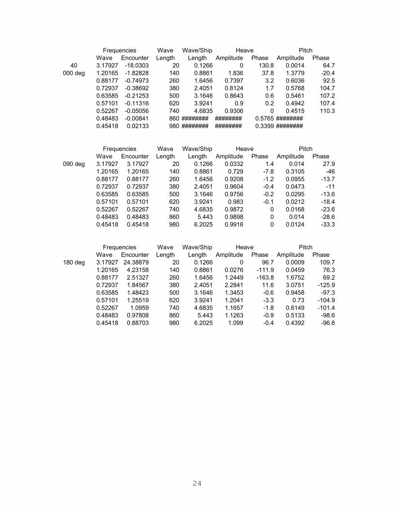
24
Wave Encounter Amplitude Phase Amplitude Phase40 3.17927 -18.0303 20 0.1266 0 130.8 0.0014 64.7
000 deg 1.20165 -1.82828 140 0.8861 1.836 37.8 1.3779 -20.40.88177 -0.74973 260 1.6456 0.7397 3.2 0.6036 92.50.72937 -0.38692 380 2.4051 0.8124 1.7 0.5768 104.70.63585 -0.21253 500 3.1646 0.8643 0.6 0.5461 107.20.57101 -0.11316 620 3.9241 0.9 0.2 0.4942 107.40.52267 -0.05056 740 4.6835 0.9306 0 0.4515 110.30.48483 -0.00841 860 ######## ######## 0.5765 ########0.45418 0.02133 980 ######## ######## 0.3399 ########
Wave Encounter Amplitude Phase Amplitude Phase090 deg 3.17927 3.17927 20 0.1266 0.0332 1.4 0.014 27.9
1.20165 1.20165 140 0.8861 0.729 -7.8 0.3105 -460.88177 0.88177 260 1.6456 0.9208 -1.2 0.0955 -13.70.72937 0.72937 380 2.4051 0.9604 -0.4 0.0473 -110.63585 0.63585 500 3.1646 0.9756 -0.2 0.0295 -13.60.57101 0.57101 620 3.9241 0.983 -0.1 0.0212 -18.40.52267 0.52267 740 4.6835 0.9872 0 0.0168 -23.60.48483 0.48483 860 5.443 0.9898 0 0.014 -28.60.45418 0.45418 980 6.2025 0.9916 0 0.0124 -33.3
Wave Encounter Amplitude Phase Amplitude Phase180 deg 3.17927 24.38879 20 0.1266 0 96.7 0.0009 109.7
1.20165 4.23158 140 0.8861 0.0276 -111.9 0.0459 76.30.88177 2.51327 260 1.6456 1.2449 -163.8 1.6752 69.20.72937 1.84567 380 2.4051 2.2841 11.6 3.0751 -125.90.63585 1.48423 500 3.1646 1.3453 -0.6 0.9458 -97.30.57101 1.25519 620 3.9241 1.2041 -3.3 0.73 -104.90.52267 1.0959 740 4.6835 1.1657 -1.8 0.6149 -101.40.48483 0.97808 860 5.443 1.1263 -0.9 0.5133 -98.60.45418 0.88703 980 6.2025 1.099 -0.4 0.4392 -96.8
Heave Pitch
Frequencies Wave Length
Wave/Ship Length
Heave Pitch
Frequencies Wave Length
Wave/Ship Length
Frequencies Wave Length
Wave/Ship Length
Heave Pitch

25
4. Bridge Accelerations
Wave Encounter Amplitude Phase000 deg 3.17927 3.17927 20 0.1266 3.12E-01 62.6
1.20165 1.20165 140 0.8861 3.65E-01 146.30.88177 0.88177 260 1.6456 5.81E-01 158.70.72937 0.72937 380 2.4051 4.68E-01 165.20.63585 0.63585 500 3.1646 3.76E-01 168.60.57101 0.57101 620 3.9241 3.11E-01 170.80.52267 0.52267 740 4.6835 2.64E-01 172.20.48483 0.48483 860 5.443 2.29E-01 173.30.45418 0.45418 980 6.2025 2.02E-01 174.1
Wave Encounter Amplitude Phase090 deg 3.17927 3.17927 20 0.1266 3.12E-01 -174.5
1.20165 1.20165 140 0.8861 1.24E+00 161.30.88177 0.88177 260 1.6456 7.60E-01 178.40.72937 0.72937 380 2.4051 5.24E-01 179.60.63585 0.63585 500 3.1646 4.00E-01 179.80.57101 0.57101 620 3.9241 3.23E-01 179.80.52267 0.52267 740 4.6835 2.71E-01 179.80.48483 0.48483 860 5.443 2.34E-01 179.90.45418 0.45418 980 6.2025 2.05E-01 179.9
Wave Encounter Amplitude Phase180 deg 3.17927 3.17927 20 0.1266 3.24E-01 -61.5
1.20165 1.20165 140 0.8861 6.73E-01 -129.60.88177 0.88177 260 1.6456 6.02E-01 -157.60.72937 0.72937 380 2.4051 4.73E-01 -165.40.63585 0.63585 500 3.1646 3.78E-01 -169.10.57101 0.57101 620 3.9241 3.12E-01 -171.20.52267 0.52267 740 4.6835 2.65E-01 -172.70.48483 0.48483 860 5.443 2.30E-01 -173.70.45418 0.45418 980 6.2025 2.02E-01 -174.5
Wave Encounter Amplitude Phase000 deg 3.17927 0.52808 20 0.1266 8.08E-04 69.9
1.20165 0.82291 140 0.8861 1.72E-01 142.30.88177 0.67783 260 1.6456 3.30E-01 160.30.72937 0.58984 380 2.4051 2.98E-01 1660.63585 0.52981 500 3.1646 2.56E-01 169.10.57101 0.48549 620 3.9241 2.22E-01 1710.52267 0.45102 740 4.6835 1.95E-01 172.40.48483 0.42318 860 5.443 1.73E-01 173.40.45418 0.40008 980 6.2025 1.56E-01 174.2
Frequencies Wave Length
Wave/Ship Length
Vertical Accel.
Frequencies Wave Length
Wave/Ship Length
Vertical Accel.
Vertical Accel.
Frequencies Wave Length
Wave/Ship Length
Vertical Accel.
Frequencies Wave Length
Wave/Ship Length
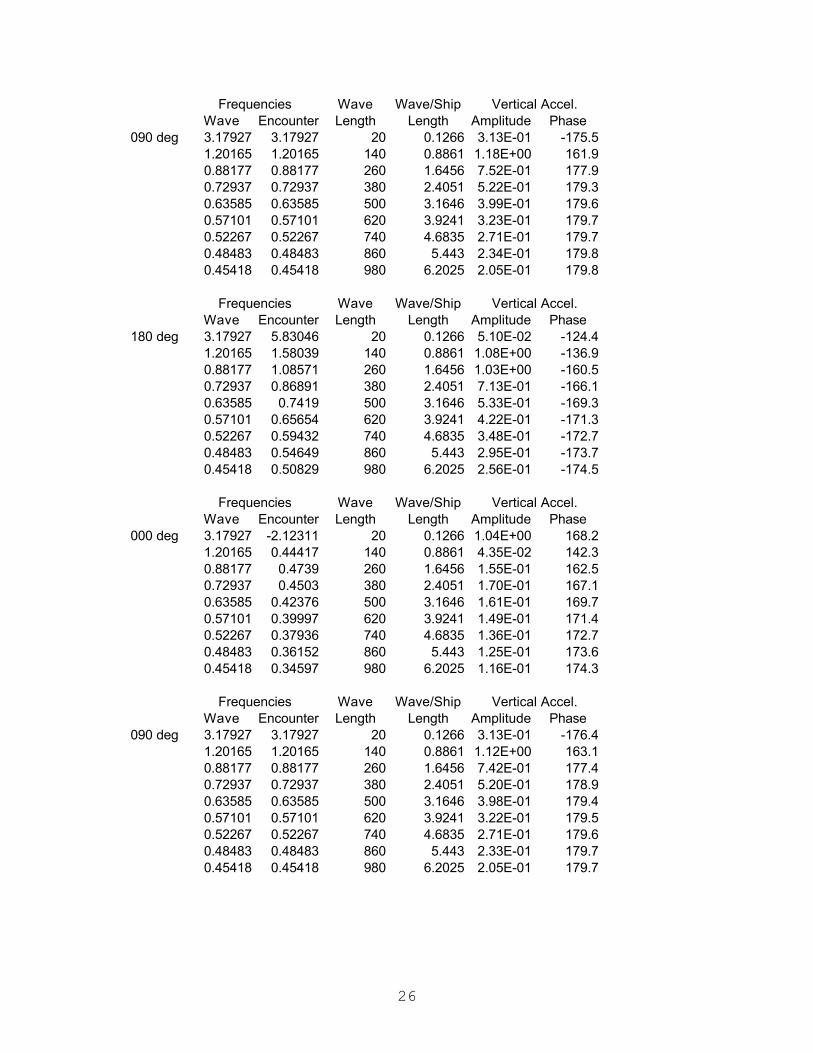
26
Wave Encounter Amplitude Phase090 deg 3.17927 3.17927 20 0.1266 3.13E-01 -175.5
1.20165 1.20165 140 0.8861 1.18E+00 161.90.88177 0.88177 260 1.6456 7.52E-01 177.90.72937 0.72937 380 2.4051 5.22E-01 179.30.63585 0.63585 500 3.1646 3.99E-01 179.60.57101 0.57101 620 3.9241 3.23E-01 179.70.52267 0.52267 740 4.6835 2.71E-01 179.70.48483 0.48483 860 5.443 2.34E-01 179.80.45418 0.45418 980 6.2025 2.05E-01 179.8
Wave Encounter Amplitude Phase180 deg 3.17927 5.83046 20 0.1266 5.10E-02 -124.4
1.20165 1.58039 140 0.8861 1.08E+00 -136.90.88177 1.08571 260 1.6456 1.03E+00 -160.50.72937 0.86891 380 2.4051 7.13E-01 -166.10.63585 0.7419 500 3.1646 5.33E-01 -169.30.57101 0.65654 620 3.9241 4.22E-01 -171.30.52267 0.59432 740 4.6835 3.48E-01 -172.70.48483 0.54649 860 5.443 2.95E-01 -173.70.45418 0.50829 980 6.2025 2.56E-01 -174.5
Wave Encounter Amplitude Phase000 deg 3.17927 -2.12311 20 0.1266 1.04E+00 168.2
1.20165 0.44417 140 0.8861 4.35E-02 142.30.88177 0.4739 260 1.6456 1.55E-01 162.50.72937 0.4503 380 2.4051 1.70E-01 167.10.63585 0.42376 500 3.1646 1.61E-01 169.70.57101 0.39997 620 3.9241 1.49E-01 171.40.52267 0.37936 740 4.6835 1.36E-01 172.70.48483 0.36152 860 5.443 1.25E-01 173.60.45418 0.34597 980 6.2025 1.16E-01 174.3
Wave Encounter Amplitude Phase090 deg 3.17927 3.17927 20 0.1266 3.13E-01 -176.4
1.20165 1.20165 140 0.8861 1.12E+00 163.10.88177 0.88177 260 1.6456 7.42E-01 177.40.72937 0.72937 380 2.4051 5.20E-01 178.90.63585 0.63585 500 3.1646 3.98E-01 179.40.57101 0.57101 620 3.9241 3.22E-01 179.50.52267 0.52267 740 4.6835 2.71E-01 179.60.48483 0.48483 860 5.443 2.33E-01 179.70.45418 0.45418 980 6.2025 2.05E-01 179.7
Frequencies Wave Length
Wave/Ship Length
Vertical Accel.
Frequencies Wave Length
Wave/Ship Length
Vertical Accel.
Frequencies Wave Length
Wave/Ship Length
Vertical Accel.
Frequencies Wave Length
Wave/Ship Length
Vertical Accel.

27
Wave Encounter Amplitude Phase180 deg 3.17927 8.48165 20 0.1266 3.37E-02 115.6
1.20165 1.95913 140 0.8861 9.09E+00 -153.40.88177 1.28965 260 1.6456 1.57E+00 -165.40.72937 1.00845 380 2.4051 1.03E+00 -167.50.63585 0.84795 500 3.1646 7.29E-01 -169.70.57101 0.74206 620 3.9241 5.56E-01 -171.40.52267 0.66598 740 4.6835 4.46E-01 -172.70.48483 0.60815 860 5.443 3.71E-01 -173.70.45418 0.56239 980 6.2025 3.17E-01 -174.5
Wave Encounter Amplitude Phase000 deg 3.17927 -4.7743 20 0.1266 4.53E-02 63.3
1.20165 0.06543 140 0.8861 9.71E-04 115.10.88177 0.26996 260 1.6456 4.77E-02 164.20.72937 0.31077 380 2.4051 7.94E-02 168.30.63585 0.31771 500 3.1646 8.97E-02 170.50.57101 0.31445 620 3.9241 9.11E-02 1720.52267 0.30771 740 4.6835 8.90E-02 1730.48483 0.29987 860 5.443 8.56E-02 173.80.45418 0.29186 980 6.2025 8.18E-02 174.5
Wave Encounter Amplitude Phase090 deg 3.17927 3.17927 20 0.1266 3.12E-01 -177.3
1.20165 1.20165 140 0.8861 1.07E+00 164.90.88177 0.88177 260 1.6456 7.30E-01 177.10.72937 0.72937 380 2.4051 5.16E-01 178.70.63585 0.63585 500 3.1646 3.96E-01 179.20.57101 0.57101 620 3.9241 3.21E-01 179.40.52267 0.52267 740 4.6835 2.70E-01 179.50.48483 0.48483 860 5.443 2.33E-01 179.60.45418 0.45418 980 6.2025 2.04E-01 179.7
Wave Encounter Amplitude Phase180 deg 3.17927 11.13284 20 0.1266 4.86E-02 113.7
1.20165 2.33788 140 0.8861 4.72E+00 59.90.88177 1.49358 260 1.6456 2.33E+00 -162.70.72937 1.14798 380 2.4051 1.44E+00 -170.10.63585 0.954 500 3.1646 9.71E-01 -170.40.57101 0.82758 620 3.9241 7.15E-01 -171.60.52267 0.73763 740 4.6835 5.61E-01 -172.70.48483 0.6698 860 5.443 4.59E-01 -173.70.45418 0.6165 980 6.2025 3.86E-01 -174.4
Frequencies Wave Length
Wave/Ship Length
Vertical Accel.
Frequencies Wave Length
Wave/Ship Length
Vertical Accel.
Frequencies Wave Length
Wave/Ship Length
Vertical Accel.
Frequencies Wave Length
Wave/Ship Length
Vertical Accel.
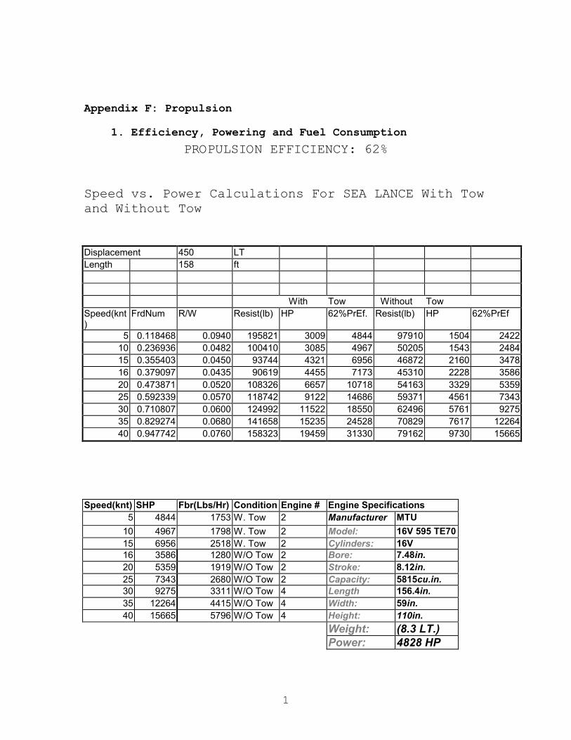
1
Appendix F: Propulsion
1. Efficiency, Powering and Fuel Consumption
PROPULSION EFFICIENCY: 62%
Speed vs. Power Calculations For SEA LANCE With Tow and Without Tow Displacement 450 LT Length 158 ft With Tow Without Tow Speed(knt)
FrdNum R/W Resist(lb) HP 62%PrEf. Resist(lb) HP 62%PrEf
5 0.118468 0.0940 195821 3009 4844 97910 1504 2422 10 0.236936 0.0482 100410 3085 4967 50205 1543 2484 15 0.355403 0.0450 93744 4321 6956 46872 2160 3478 16 0.379097 0.0435 90619 4455 7173 45310 2228 3586 20 0.473871 0.0520 108326 6657 10718 54163 3329 5359 25 0.592339 0.0570 118742 9122 14686 59371 4561 7343 30 0.710807 0.0600 124992 11522 18550 62496 5761 9275 35 0.829274 0.0680 141658 15235 24528 70829 7617 12264 40 0.947742 0.0760 158323 19459 31330 79162 9730 15665
Speed(knt) SHP Fbr(Lbs/Hr) Condition Engine # Engine Specifications 5 4844 1753 W. Tow 2 Manufacturer MTU
10 4967 1798 W. Tow 2 Model: 16V 595 TE70 15 6956 2518 W. Tow 2 Cylinders: 16V 16 3586 1280 W/O Tow 2 Bore: 7.48in. 20 5359 1919 W/O Tow 2 Stroke: 8.12in. 25 7343 2680 W/O Tow 2 Capacity: 5815cu.in. 30 9275 3311 W/O Tow 4 Length 156.4in. 35 12264 4415 W/O Tow 4 Width: 59in. 40 15665 5796 W/O Tow 4 Height: 110in.
Weight: (8.3 LT.) Power: 4828 HP
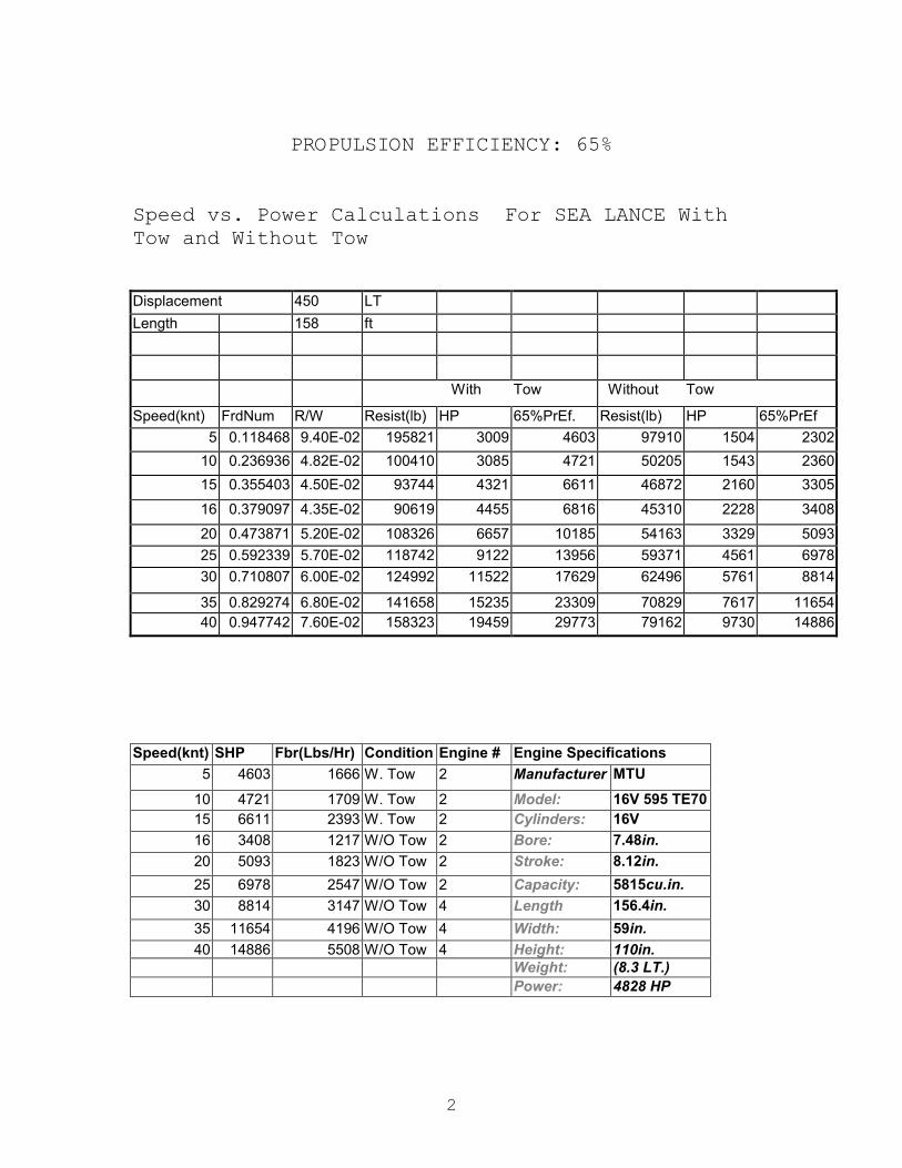
2
PROPULSION EFFICIENCY: 65%
Speed vs. Power Calculations For SEA LANCE With Tow and Without Tow Displacement 450 LT
Length 158 ft
With Tow Without Tow
Speed(knt) FrdNum R/W Resist(lb) HP 65%PrEf. Resist(lb) HP 65%PrEf
5 0.118468 9.40E-02 195821 3009 4603 97910 1504 2302
10 0.236936 4.82E-02 100410 3085 4721 50205 1543 2360
15 0.355403 4.50E-02 93744 4321 6611 46872 2160 3305
16 0.379097 4.35E-02 90619 4455 6816 45310 2228 3408
20 0.473871 5.20E-02 108326 6657 10185 54163 3329 5093
25 0.592339 5.70E-02 118742 9122 13956 59371 4561 6978
30 0.710807 6.00E-02 124992 11522 17629 62496 5761 8814
35 0.829274 6.80E-02 141658 15235 23309 70829 7617 11654 40 0.947742 7.60E-02 158323 19459 29773 79162 9730 14886
Speed(knt) SHP Fbr(Lbs/Hr) Condition Engine # Engine Specifications
5 4603 1666 W. Tow 2 Manufacturer MTU
10 4721 1709 W. Tow 2 Model: 16V 595 TE70 15 6611 2393 W. Tow 2 Cylinders: 16V
16 3408 1217 W/O Tow 2 Bore: 7.48in.
20 5093 1823 W/O Tow 2 Stroke: 8.12in.
25 6978 2547 W/O Tow 2 Capacity: 5815cu.in.
30 8814 3147 W/O Tow 4 Length 156.4in.
35 11654 4196 W/O Tow 4 Width: 59in.
40 14886 5508 W/O Tow 4 Height: 110in. Weight: (8.3 LT.) Power: 4828 HP

3
PROPULSION EFFICIENCY: 68%
Speed vs. Power Calculations For SEA LANCE With Tow and Without Tow Displacement 450 LT
Length 158 ft
With Tow Without Tow
Speed(knt)
FrdNum R/W Resist(lb) HP 68%PrEf. Resist(lb)
HP 68%PrEf
5 0.118468 9.40E-02 195821 3009 4423 97910 1504 2211
10 0.236936 4.82E-02 100410 3085 4535 50205 1543 2268
15 0.355403 4.50E-02 93744 4321 6351 46872 2160 3176
16 0.379097 4.35E-02 90619 4455 6549 45310 2228 3275
20 0.473871 5.20E-02 108326 6657 9786 54163 3329 4893
25 0.592339 5.70E-02 118742 9122 13409 59371 4561 6704
30 0.710807 6.00E-02 124992 11522 16937 62496 5761 8469
35 0.829274 6.80E-02 141658 15235 22395 70829 7617 11197 40 0.947742 7.60E-02 158323 19459 28605 79162 9730 14303
Speed(knt) SHP Fbr(Lbs/Hr) Condition Engine # Engine Specifications
5 4423 1601 W. Tow 2 Manufacturer MTU
10 4535 1642 W. Tow 2 Model: 16V 595 TE70
15 6351 2299 W. Tow 2 Cylinders: 16V
16 3275 1169 W/O Tow 2 Bore: 7.48in.
20 4893 1752 W/O Tow 2 Stroke: 8.12in.
25 6704 2447 W/O Tow 2 Capacity: 5815cu.in.
30 8469 3023 W/O Tow 4 Length 156.4in.
35 11197 4031 W/O Tow 4 Width: 59in.
40 14303 5292 W/O Tow 4 Height: 110in. Weight: (8.3 LT.) Power: 4828 HP

4
PROPULSION EFFICIENCY: 70%
Speed vs. Power Calculations For SEA LANCE With Tow and Without Tow Displacement 450 LT
Length 158 ft
With Tow Without Tow
Speed(knt) FrdNum R/W Resist(lb) HP 70%PrEf. Resist(lb) HP 70%PrEf
5 0.118468 9.40E-02 195821 3009 4272 97910 1504 2136
10 0.236936 4.82E-02 100410 3085 4381 50205 1543 2191
15 0.355403 4.50E-02 93744 4321 6135 46872 2160 3068
16 0.379097 4.35E-02 90619 4455 6326 45310 2228 3163
20 0.473871 5.20E-02 108326 6657 9453 54163 3329 4727
25 0.592339 5.70E-02 118742 9122 12953 59371 4561 6476
30 0.710807 6.00E-02 124992 11522 16361 62496 5761 8181
35 0.829274 6.80E-02 141658 15235 21633 70829 7617 10817 40 0.947742 7.60E-02 158323 19459 27632 79162 9730 13816
Speed(knt) SHP Fbr(Lbs/Hr) Condition Engine # Engine Specifications
5 4272 1546 W. Tow 2 Manufacturer MTU
10 4381 1586 W. Tow 2 Model: 16V 595 TE70
15 6135 2221 W. Tow 2 Cylinders: 16V
16 3163 1129 W/O Tow 2 Bore: 7.48in.
20 4727 1692 W/O Tow 2 Stroke: 8.12in.
25 6476 2364 W/O Tow 2 Capacity: 5815cu.in.
30 8181 2920 W/O Tow 4 Length 156.4in.
35 10817 3894 W/O Tow 4 Width: 59in.
40 13816 5112 W/O Tow 4 Height: 110in.
Weight: (8.3 LT.) Power: 4828 HP
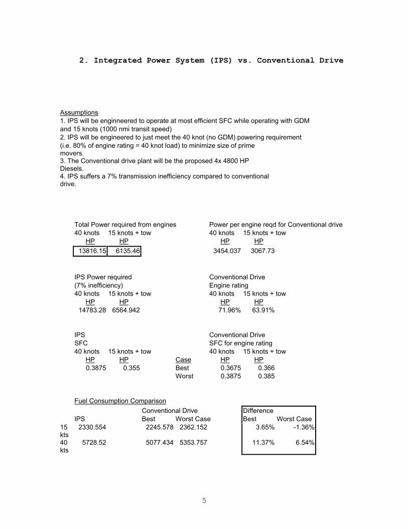
5
2. Integrated Power System (IPS) vs. Conventional Drive
Assumptions 1. IPS will be enginneered to operate at most efficient SFC while operating with GDM and 15 knots (1000 nmi transit speed) 2. IPS will be engineered to just meet the 40 knot (no GDM) powering requirement (i.e. 80% of engine rating = 40 knot load) to minimize size of prime movers.
3. The Conventional drive plant will be the proposed 4x 4800 HP Diesels.
4. IPS suffers a 7% transmission inefficiency compared to conventional drive.
Total Power required from engines Power per engine reqd for Conventional drive 40 knots 15 knots + tow 40 knots 15 knots + tow HP HP HP HP
13816.15 6135.46 3454.037 3067.73
IPS Power required Conventional Drive (7% inefficiency) Engine rating 40 knots 15 knots + tow 40 knots 15 knots + tow HP HP HP HP 14783.28 6564.942 71.96% 63.91% IPS Conventional Drive SFC SFC for engine rating 40 knots 15 knots + tow 40 knots 15 knots + tow HP HP Case HP HP 0.3875 0.355 Best 0.3675 0.366 Worst 0.3875 0.385 Fuel Consumption Comparison
Conventional Drive Difference IPS Best Worst Case Best Worst Case
15 kts
2330.554 2245.578 2362.152 3.65% -1.36%
40 kts
5728.52 5077.434 5353.757 11.37% 6.54%

6
Fuel Consumption Comparison (including 220 kVA electric power)
Conventional Drive Difference IPS Best Worst Case Best Worst Case
15 kts
2437.054 2355.378 2477.652 3.35% -1.67%
40 kts
5844.77 5187.684 5470.007 11.24% 6.41%
Sizing IPS engines HP requirement for Using Engine rating of 80%/40% 40 knots 14783.28 18479.1 (see assumptions) 15 knots + tow 6564.942 16412.35 2066.741 Difference So, IPS needs engine(s) capable of 16412 HP so it can run at 15 knots at 40% power for optimum speed, which allows it .355 SFC at 15 knots. Then it needs one more 2067 HP engine to achieve 40 knots with SFC = .3875.

7
Diesel Engine Specific Fuel Consumption Curves
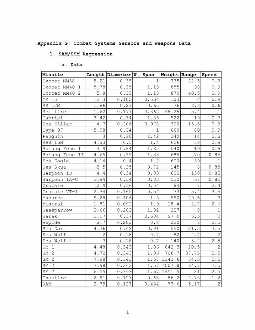
1
Appendix G: Combat Systems Sensors and Weapons Data
1. SAM/SSM Regression
a. Data
Missile Length Diameter W. Span Weight Range SpeedExocet MM38 5.21 0.35 1 735 22.5 0.9Exocet MM40 1 5.78 0.35 1.13 855 38 0.9Exocet MM40 2 5.8 0.35 1.13 870 40.5 0.9MM 15 2.3 0.185 0.564 103 8 0.9SS 12M 1.86 0.21 0.65 76 3.3 0.6Hellfire 1.62 0.177 0.362 48.25 5.4 1Gabriel 3.42 0.34 1.35 522 19 0.7Sea Killer 4.7 0.206 0.978 300 13.5 0.9Type 87 5.08 0.34 1 660 80 0.9Penguin 3 0.28 1.42 340 14 0.8RBS 15M 4.33 0.5 1.4 626 38 0.8Hsiung Feng I 3.9 0.34 1.35 540 19 0.9Hsiung Feng II 4.65 0.39 1.35 685 70 0.85Sea Eagle 4.14 0.4 1.2 600 59 1Sea Skua 2.5 0.25 0.72 145 8 0.85Harpoon 1D 4.4 0.34 0.83 622 130 0.85Harpoon 1A-C 3.84 0.34 0.83 520 67 0.85Crotale 2.9 0.16 0.54 84 7 2.4Crotale VT-1 2.34 0.165 0.54 73 5.4 3.5Masurca 5.29 0.406 1.5 950 29.6 3Mistral 1.81 0.092 1.9 18.4 2.7 2.6Seasparrow 3.66 0.203 1.02 227 8 1Barak 2.17 0.17 0.684 97.9 6.5 2Aspide 3.7 0.203 0.8 220 7 2.5Sea Dart 4.36 0.42 0.91 550 21.5 3.5Sea Wolf 2 0.18 0.7 82 2.7 2Sea Wolf 2 3 0.18 0.7 140 3.2 2.5SM 1 4.48 0.343 1.06 642.3 20.5 2SM 2 4.72 0.343 1.06 706.7 37.75 2.5SM 2 7.98 0.343 1.57 1343.6 34.5 2.5SM 2 7.98 0.343 1.57 1507.8 64.7 2.5SM 2 6.55 0.343 1.57 1451.5 81 2.5Chapfire 2.91 0.127 0.63 86.2 4.75 1.2RAM 2.79 0.127 0.434 73.6 5.17 2

2
b. Weight versus Range
c. Speed versus Range
Speed versus Range
y = 0.0005x + 0.8412
y = 0.0061x + 2.2425
0
0.5
1
1.5
2
2.5
3
3.5
4
0 20 40 60 80 100 120 140
Range in NM
Sp
eed
Mac
h
SSMs SAMs Linear (SSMs) Linear (SAMs)
Missile Weight versus Range
y = 4.4415x + 319.18
y = 21.255x + 57.974
0
200
400
600
800
1000
1200
1400
1600
1800
2000
0 5 10 15 20 25 30 35 40 45 50 55 60 65 70 75 80 85 90 95 100 105 110 115 120 125 130 135 140
Range in NM
Mis
sile
wei
gh
t in
Kg
SSMs SAMs Linear (SSMs) Linear (SAMs)

3
d. Length versus Range
e. Diameter versus Range
Length versus Range
y = 0.0716x + 2.5974
y = 0.0189x + 3.2083
0
1
2
3
4
5
6
7
8
9
0 20 40 60 80 100 120 140
Range in NM
Len
gth
in m
SSMs SAMs Linear (SAMs) Linear (SSMs)
Diameter versus Range
y = 0.0013x + 0.266y = 0.0033x + 0.1778
0
0.1
0.2
0.3
0.4
0.5
0.6
0 20 40 60 80 100 120 140
Range in NM
Dia
met
er in
m
SSMs SAMs Linear (SSMs) Linear (SAMs)

4
f. Wing Span versus Range
Wing Span versus Range
y = 0.0014x + 0.9619
y = 0.012x + 0.7704
0
0.2
0.4
0.6
0.8
1
1.2
1.4
1.6
1.8
2
0 20 40 60 80 100 120 140
Range in NM
Win
g S
pan
in m
SSMs SAMs Linear (SSMs) Linear (SAMs)

5
2. 30-mm Guns Coverage
a. Arcs of Fire
b. Field of View Fore Gun
Field of ViewFore Gun
-20
-10
0
10
20
30
40
50
0 30 60 90 120 150 180 210 240 270 300 330 360
Relative Bearing [degrees]
Ele
vati
on
[d
egre
es]

6
c. Minimum Range Fore Gun
d. Field of View Aft Gun
Minimum Range versus Relative BearingFore Gun
0
50
100
150
200
250
300
350
400
450
0 30 60 90 120 150 180 210 240 270 300 330 360
Relative Bearing [degrees]
Min
imu
m R
ang
e [f
t]
Field of ViewAft Gun
-20
-10
0
10
20
30
40
50
0 30 60 90 120 150 180 210 240 270 300 330 360
Relative Bearing [degrees]
Ele
vati
on
[d
egre
es]

7
e. Minimum Range Aft Gun
Minimum Range versus Relative BearingAft Gun
0
50
100
150
200
250
300
350
400
450
500
550
600
0 30 60 90 120 150 180 210 240 270 300 330 360
Relative Bearing [degrees]
Min
imu
m R
ang
e [f
t]

8
3. Sensors Coverage Diagrams
a. Fire Control Radar
b. EO Suite

9
c. Mine Avoidance Sonar
d. Navigation Radar

1
Appendix H: Tow Analysis
Figure H.1 Rigid body DOF's
Figure H.2 Design Towbar

2
Figure H.3 Design Towbar, Receiver, and Roll Bearing

3
Tow Loading Initial Data: Impulse force: Fdt = mdv To stop in two shiplengths: (314ft) from 15 kts w/tow
m = 450 31304.348 slugs v(kts) convers. v(ft/s) E = 2.90E+07psi 15 1.666667 25 G= 1.10E+07psi Lstop= 314ft
stress(y) 3.60E+04psi t=L/v= 12.56sec Le= 240.00in F=mdv/dt= 62309.61lbf
safety fct= 5.00
BUCKLING: (P = 62309lbf) @ Max pitch=30 deg Yield stress: Steel cable:
P = pi^2*E*I/(Le^2) = 224000 111957.08 *(fs) Tensile force 111957.1 I = 112.7682259 Area(in^2) = 15.54959 0
s(solid sqare beam) = 6.065156319in s(solid sqare beam) = 3.943297 0 Sq. beam outer thickness = 12in s(inner beam) = 11.3336 12
s(inner beam) = 11.7992397in thickness = 0.6664 0 thickness = 0.2007603in
Weight, assuming 12" outer diameter, thickness determined by yield stress, and 20 foot long beam:
Weight = 1043.1186lbf Shear Stress:
shear yield stess (0.5sys) = 18,000psi 1/2(Fmax/sys)*fs = A = 15.54959414in^2
pin diameter = 4.4506629in
Figure H.4-Towbar sizing spreadsheet:
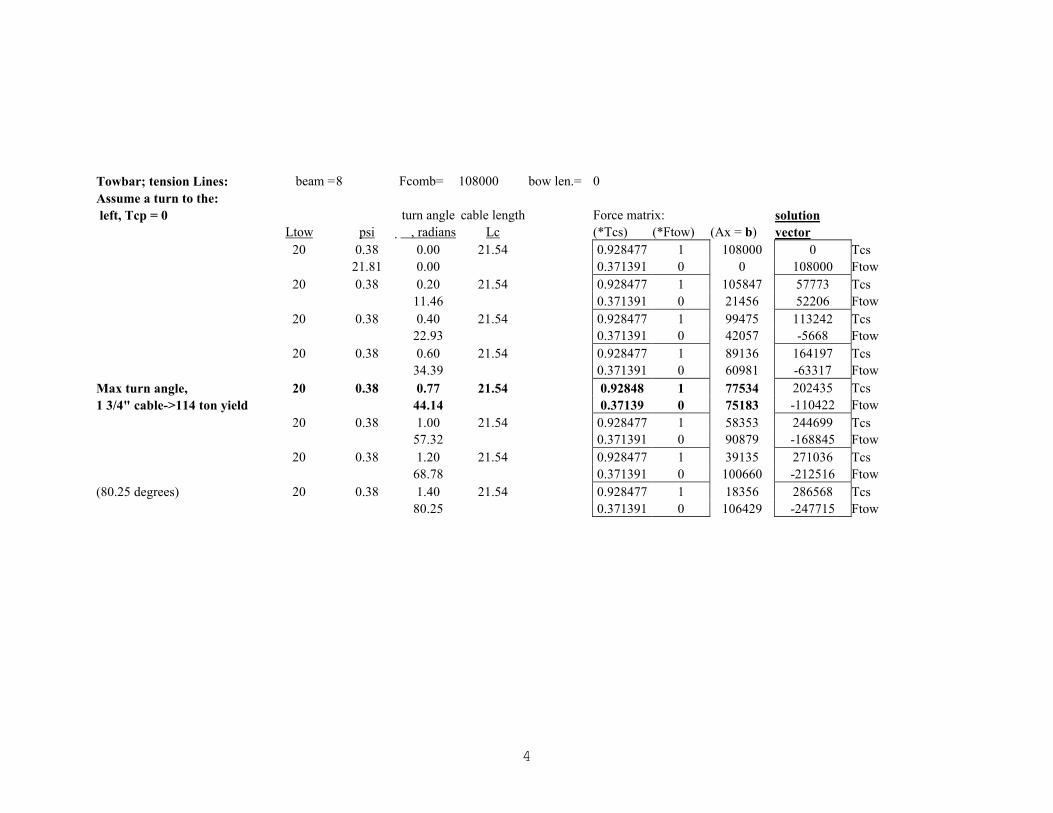
4
Towbar; tension Lines: beam =8 Fcomb= 108000 bow len.= 0 Assume a turn to the: left, Tcp = 0 turn angle cable length Force matrix: solution Ltow psi �, radians Lc (*Tcs) (*Ftow) (Ax = b) vector 20 0.38 0.00 21.54 0.928477 1 108000 0 Tcs 21.81 0.00 0.371391 0 0 108000 Ftow 20 0.38 0.20 21.54 0.928477 1 105847 57773 Tcs 11.46 0.371391 0 21456 52206 Ftow 20 0.38 0.40 21.54 0.928477 1 99475 113242 Tcs 22.93 0.371391 0 42057 -5668 Ftow 20 0.38 0.60 21.54 0.928477 1 89136 164197 Tcs 34.39 0.371391 0 60981 -63317 Ftow Max turn angle, 20 0.38 0.77 21.54 0.92848 1 77534 202435 Tcs 1 3/4" cable->114 ton yield 44.14 0.37139 0 75183 -110422 Ftow 20 0.38 1.00 21.54 0.928477 1 58353 244699 Tcs 57.32 0.371391 0 90879 -168845 Ftow 20 0.38 1.20 21.54 0.928477 1 39135 271036 Tcs 68.78 0.371391 0 100660 -212516 Ftow (80.25 degrees) 20 0.38 1.40 21.54 0.928477 1 18356 286568 Tcs 80.25 0.371391 0 106429 -247715 Ftow

5
10
20
30
30
210
60
240
90
270
120
300
150
330
180 0
Tow Bar Force at 15 knots---- 75 tons ---- 100 tons ---- 125 tons ---- 150 tons
10
20
30
30
210
60
240
90
270
120
300
150
330
180 0
Tow Bar Force at 5 knots---- 50 tons ---- 75 tons ---- 100 tons
Figure H.5 Operating Plot for Towing at 5 knots
Figure H.6 Operating Plot for Towing at 15 knots

1
Appendix I: Survivability
1. Damage Control
Table 1 provides an analysis of what type of fire can be expected in each space. Fire Classification Location Class A Class B Class C Auxiliary Space x x x Berthing x x Boat Deck x x Bridge/CIC x x Computer/Electronics Space x x Engine rooms x x x Galley x x Magazines x x Auxiliary Diesel Generator Room
x x
Radar/Electronic Space x x Vertical Replenishment Deck x Table 1 Analysis of expected fire classifications by space. Table 2 provides a general analysis of several fire suppression systems. FM-200 Water Mist CO2 Flood AFFF Performance Good Good Good Good Heat removal Good Good Poor Good Environmental Impact
None None None None
Cost Low Low Low Low Health Hazard Low None High None Maintenance requirements
Low Low Low Low
Weight/Volume Impact
Low Low High Moderate
Remote activation
Yes Yes Yes Yes
Table 2. Fire Protection System Analysis.

2
CO2 extinguishes fires by displacing oxygen. CO2
Flooding was rejected because of the excessive number of CO2
cylinders that would be required to provide coverage for a
space as compared to FM-200. Furthermore, CO2 is deadly to
personnel if discharged into a manned space.
AFFF is a very effective firefighting agent. AFFF
separates the fuel from the oxygen and has the added
advantage of removing heat from a Class B fire. AFFF is
non-toxic and biodegradable in diluted form.
Water mist was a very attractive option, however it
currently has a few drawbacks. Water mist fire suppression
systems require minutes to extinguish a fire whereas
gaseous fire suppression systems such as FM-200 usually
require less than a minute.43 Additionally, water mist
systems have difficulty extinguishing fires that are
shielded from the spray. The machinery spaces of SEA LANCE
are expected to be extremely tight in terms of space and
will have many shield areas.
FM-200 completely floods the space and does not
experience this problem. FM-200 is non-ozone depleting and
is effective at extinguishing Class A and B fires. FM-200
extinguishes fires primarily by physically cooling the
flame, and secondarily by chemical reaction of FM-200 with
flame species.44 FM-200 thermally decomposes into small
amounts of HF. These concentrations are very low and do
not subject personnel to adverse risk. The FM-200 Fire 43 Back, G. G., Beyler, C. L., DiNenno, P. J., “Full-Scale Testing of Water Mist Fire Suppression Systems in Machinery Spaces”, National technical Information Service, 1996. 44 Great Lakes Chemical Corporation, “Understanding the Thermal Decomposition of FM-200 and the Effect on People and Equipment”, Great Lakes Chemical Corporation, 1997.
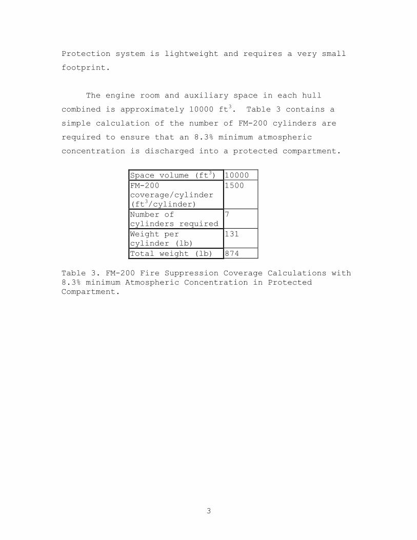
3
Protection system is lightweight and requires a very small
footprint.
The engine room and auxiliary space in each hull
combined is approximately 10000 ft3. Table 3 contains a
simple calculation of the number of FM-200 cylinders are
required to ensure that an 8.3% minimum atmospheric
concentration is discharged into a protected compartment.
Space volume (ft3) 10000 FM-200 coverage/cylinder (ft3/cylinder)
1500
Number of cylinders required
7
Weight per cylinder (lb)
131
Total weight (lb) 874 Table 3. FM-200 Fire Suppression Coverage Calculations with 8.3% minimum Atmospheric Concentration in Protected Compartment.
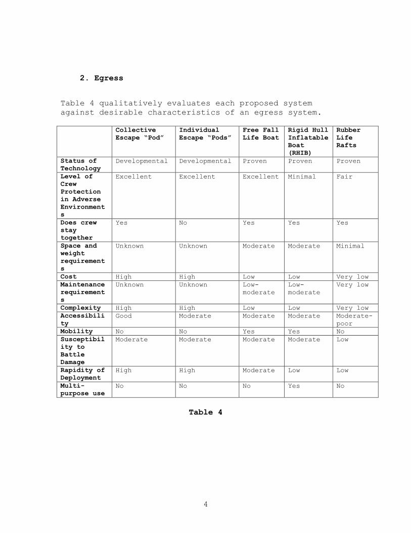
4
2. Egress
Table 4 qualitatively evaluates each proposed system against desirable characteristics of an egress system. Collective
Escape “Pod” Individual Escape “Pods”
Free Fall Life Boat
Rigid Hull Inflatable Boat (RHIB)
Rubber Life Rafts
Status of Technology
Developmental Developmental Proven Proven
Proven
Level of Crew Protection in Adverse Environments
Excellent Excellent Excellent Minimal Fair
Does crew stay together
Yes No Yes Yes Yes
Space and weight requirements
Unknown Unknown Moderate Moderate Minimal
Cost High High Low Low Very low Maintenance requirements
Unknown Unknown Low-moderate
Low-moderate
Very low
Complexity High High Low Low Very low Accessibility
Good Moderate Moderate Moderate Moderate-poor
Mobility No No Yes Yes No Susceptibility to Battle Damage
Moderate Moderate Moderate Moderate Low
Rapidity of Deployment
High High Moderate Low Low
Multi-purpose use
No No No Yes No
Table 4
5
For each characteristic, each system was ranked in Table 5
based on the following scale:
1 - Least Desirable, Unreliable, Poor, Not Proven or
Unknown
5 - Most Desirable, Reliable, Excellent, Proven or Known
This analysis revealed several drawbacks to the collective
escape “pod” and individual escape “pod” concepts for the
SEA LANCE conceptual design. Complexity, estimated cost,
and weight proved to be serious problems for these concepts
on a small combatant like the SEA LANCE.
In Table 6, each characteristic was assigned a weight
factor based on the importance to the design concept.

6
Collective
Escape “Pod” Individual Escape “Pods”
Free Fall Life Boat
Rigid Hull Inflatable Boat (RHIB)
Rubber Life Rafts
Status of technology
1 1 5 5
5
Crew protection in adverse environments
5 5 5 2 3
Does crew stay together
5 1 5 5 5
Space and weight requirements
2 2 3 3 5
Cost 2 2 4 4 5 Level of Maintenance Required
2 2 4 4 5
Level of Complexity
1 1 3 3 5
Accessibility 4 3 3 3 3
Mobility 1 1 5 5 1 Susceptibility to Battle Damage
3 3 3 3 5
Rapidity of Deployment
5 5 4 3 3
Multi-purpose use 1 1 1 5 1 Total 32 27 45 45 46 Total Points Possible
60 60 60 60 60
Table 5
Tables 5 and 6 show that rubber life rafts provide the
best method for crew egress by a very narrow margin. Life
rafts have several advantages over the free fall lifeboat
and the RHIB. The rubber life raft is a simple,
lightweight and reliable technology that requires minimal
space and maintenance. A single life raft can hold the
entire crew of the SEA LANCE. A single life raft out of
two placed in different locations on the ship has a higher
probability of not sustaining damage in an attack. The
free fall lifeboat and RHIB systems provide no backup
method of egress in the event the primary system is

7
damaged. Additionally, having multiple life rafts on the
ship make them relatively accessible. A life raft provides
adequate protection of the crew in adverse environments,
however it is not as effective as the free fall lifeboat.
A major drawback to the life raft is its lack of mobility.
In the case of mobility, the free fall lifeboat and
the RHIB performance are superior. The free fall lifeboat
and the RHIB were essentially equivalent each having
different strong points. The complexity of the launch
system, cost, weight and space required for the free fall
lifeboat and the RHIB is higher than the life raft. A
major advantage of the RHIB is that it has the capability
to perform multiple missions such as ready rescue boat, and
as the ship’s small boat whereas the free fall lifeboat and
the life raft are single mission only.

8
Weighting factor
Free Fall Life Boat
Rigid Hull Inflatable Boat (RHIB)
Rubber Life Rafts
Status of technology
3 15 15
15
Crew protection in adverse environments
5 25 10 15
Does crew stay together
5 25 25 25
Space and weight requirements
5 15 15 25
Cost 4 16 16 20 Level of Maintenance Required
5 20 20 25
Level of Complexity
3 9 9 15
Accessibility 5 15 15 15 Mobility 4 20 20 4 Susceptibility to Battle Damage
5 15 15 25
Rapidity of Deployment
5 20 15 15
Multi-purpose use 5 5 25 5 Total N/A 200 200 204 Total Points Possible
N/A 270 270 270
Table 6
9
Tables 7, 8 and 9 examine shipboard compatibility
attributes for long-range solid and liquid waste disposal
technologies.45
Several of the proposed solid and liquid waste
disposal technologies were rejected because of weight and
space constraints. Additionally several systems have high
power requirements. For example, incineration of solid and
liquid waste was investigated and ruled out as an option
for waste management on that SEA LANCE. Incineration
equipment is very heavy and requires a large volume. The
system also has a large energy requirement and requires
numerous support and interface systems. Other waste
management technologies were rejected because the
technology was not fully developed.
SEA LANCE is weight limited, therefore the best option
for solid waste management is to minimize the solid waste
generated and temporarily store compacted waste in a
sanitary storeroom until it can be disposed of at a shore
facility or to an MSC ship during replenishment.
45 Committee on Shipboard Pollution Control, “Shipboard Pollution Control U.S. Navy Compliance with MARPOL Annex V”, National Academy Press, 1996.

10
Attribute Supercritical
Water Oxidation Molten Metal Technology
Plasma Arc Thermal Conversion Technology
Vitrification Molten Salt Oxidation
Status of technology
One commercial plant operating ashore for a particular waste ARPA program starts mid-95 to develop hardware for eventual shipboard application studies (30-month study)
Commercial plant construction has begun for chemical and nuclear wastes
Technology being marketed for commercial applications to waste disposal Naval application demos planned for waste Feed development needed
Mature technology Pending municipal waste stream demo with industry Application development required Navy shoreside hazardous waste demo being funded
Small-scale use since 1950s Large R&D program in 1990s DOD and DOE mixed waste
Process versatility
Solids pumpable as slurry Organics destruction Inorganics decontamination and concentration
All shipboard solid waste can be processed Concentration of liquid waste streams required Shred solids
All shipboard solid waste can be processed Concentration of liquid waste streams required Shred solids
Concentration of liquid waste streams required Shred solids Large capacity possible
Combustible solids Organic liquids
Process density 0.5 to 1.4 lb/h/ft2
Not known 0.5 to 1 lb/h/ft2
100 to 300 lb/h/ft2 organics 15 to 30 lb/h/ft2 inorganics
Not known
Ship system demands
Cooling water Electric power Discharge pump (brine) Ventilation Fresh water feed
Cooling water Electric power Ventilation Stack gas treatment
Cooling water Need inert gas Ventilation Stack gas treatment Electric power
Cooling water Ventilation Need stack gas treatment Electric power
Salt re-supply Low-pressure air or oxygen Cooling water Ventilation Stack treatment Fuel/ electricity for startup
Installation flexibility
Surface ship only
Surface ship only
Surface ship only
Surface ship only
Surface ships only
Ship motion effects
Manageable Need design development
Need design development
Need design development
Need to minimize
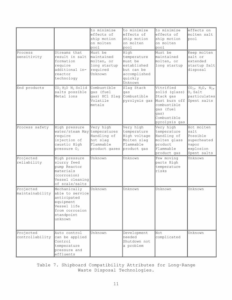
11
to minimize effects of ship motion on molten pool
to minimize effects of ship motion on molten pool
to minimize effects of ship motion on molten pool
effects on molten salt pool
Process sensitivity
Streams that result in salt formation require additional in-reactor technology
Must be maintained molten, or long startup required Unknown
High temperature must be established but can be accomplished quickly Unknown
Must be maintained molten, or long startup
Keep molten salt or extended startup Salt disposal
End products CO2 H2O N2 Solid salts possible Metal ions
Combustible gas (fuel gas) HCl Slag Volatile metals
Slag Stack gas Combustible pyrolysis gas
Vitrified solid (glass) Stack gas Must burn off combustible gas (fuel gas) Combustible pyrolysis gas
CO2, H2O, N2, O2 Salt particulates Spent salts
Process safety High pressure water/steam May require injection of caustic High pressure O2
Very high temperatures Handling of hot slag Flammable product gases
Very high temperature High voltage Molten slag Flammable product gas
Very high temperature Handling of molten glass product Flammable product gas
Hot molten salt Possible superheated vapor explosion Spent salts
Projected reliability
High pressure slurry feed pump Reactor materials (corrosion) Vessel cleaning of scale/salts
Unknown Unknown Few moving parts High temperature risks
Unknown
Projected maintainability
Mechanically able to service anticipated equipment Vessel life from corrosion standpoint unknown
Unknown Unknown Unknown Unknown
Projected controllability
Auto control can be applied Control temperature pressure and effluents
Unknown Development needed Shutdown not a problem
Not complicated
Unknown
Table 7. Shipboard Compatibility Attributes for Long-Range
Waste Disposal Technologies.

12
Attribute Ultrafiltration Biotreatment Semiconductor Photocatalysis
Electrohydraulic Cavitation
Status of technology
Widely used in commercial industry Navy waste stream applications being studied
Used on luxury cruise ships Commercially available
Commercial suppliers available Current used for hazardous waste remediation Will be used on future space stations
Numerous manufacturers of ultrasonic equipment are producing equipment that can be modified for waste treatment applications
Process versatility
Any liquid waste stream requiring concentration, i.e., oily water, gray water, black water
Black water Portions of gray water
Suitable mainly for waterborne dissolved wastes and hazardous wastes at medium to low concentration. BOD and TOC should be = 3000 mg/L
Suitable mainly for waterborne dissolved wastes and hazardous wastes at medium to low concentration. BOD and TOC should be 3000 mg/L
Process density 2 lb/h/ft2 Low Not now available but could be determined
Not now available but could be determined
Ship system demands
Low-pressure pumping only Fresh water for cleaning Concentrated cleaned effluent is hazardous waste–small volume
Space (potential use of holding tanks) Electric power for mixing and aeration Vacuum and/or low-pressure pumps
Source of UV photons which could be derived from the sun or from artificial sources Most convenient sources are simple black lamps Forced aeration is necessary
Electrical power Dissolved oxygen Ventilation
Installation flexibility
No constraints Medium to large surface ships
Surface ships only
Surface ships
Energy requirements
Not significant Vacuum and/or low-pressure pumps Aeration Mixing
Requires power for black lamp operation Solar operation requires power for pumping and filtration
1.0 kW/L per liter at 500 kHz frequency
Ship motion effects
Not significant Not significant with enclosed
Minimal effects on process
Minimal effects on process

13
reactors Could impact gravity setting
Process sensitivity
Relatively insensitive
Microbial activity is sensitive to toxic contaminants
End products Concentrate of feed stream Flush residual soaps, etc. Water
CO2 H2O Oxidized organic compounds Sludge
Process safety Low risk Low risk Projected reliability
Highly reliable simple system Dependent on membrane selection
Reliable with close monitoring
Projected maintainability
Membrane cleaning and replacement within ship’s force capability
Can be maintained by trained crew
Projected controllability
No concerns Rapid startup not possible (needs acclimation time) Requires periodic monitoring of solids (biomass) inventory Continuous process with some automation
Costs $0.50 per 1,000 gallons
$1 to $3 per 1,000 gallons
Note: BOD, biological oxygen demand; TOC, total organic carbons.
Table 8. Shipboard Compatibility Attributes for Long-Range Technologies.

14
Attribute Advanced Oxidation UV Peroxide/Ozone
Electron Beam Wet Air Semiconductor Electrocatalysis
Status of technology
Mature, well developed Commercially available Waste treatment demonstrated
Mature, well developed Commercially available Waste treatment demonstrated
Commercially available
Prototype electrolysis cells being developed Will be commercially available within 2 years
Process versatility
Requires dilute aqueous streams Must remove suspended solids
Any aqueous stream (gray water, black water, oily water)
Shipboard liquid waste stream Pulped paper
Suitable mainly for waterborne dissolved waste and hazardous waste
Process density >5 lb/h/ft2 Not available Ship system demands
Radiation shielding Oxidant storage or ozone generation
Radiation shielding Electromagnetic emissions Ventilation High voltage
Ventilation Electrical power Dissolved oxygen Ventilation
Installation flexibility
All ships and boats
Large surface ships
Surface ships Surface ships Submarines
Energy requirements
2 to 5 kW/gal/min flow
½ kW/gal/min flow
Pumps Startup power Self sustaining from biosludge
Ship motion effects
None None Not significant Minimal
Process sensitivity
Need pretreatment to remove suspended solids or color
None Process susceptible to power loss
End products Probable production of partially oxidized organics
Oxidized organic byproducts at low dose
CO2 H2O Oxidized organic compounds
Process safety Radiation protection (UV light)
Radiation protection (x radiation)
Not significant
Projected reliability
Reliable Reliable Simple equipment
Projected maintainability
Can be maintained by trained crew
Can be maintained by trained crew
Unknown

15
Projected controllability
Easily controlled
Easily controlled
Automated controls operating
Costs Approx. $9 to $12 per 1,000 gallons
Approx. $4 to $6 per 1,000 gallons
Table 9. Shipboard Compatibility Attributes for Long-Range
Technologies.
Table 10 illustrates the weight requirement if all
greywater and blackwater were retained onboard for give
crew size and mission duration. Clearly, the weight and
tankage requirements are significant for a small combatant
that must meet a zero waste discharge requirement. The
ability to treat greywater and blackwater allows SEA LANCE
to meet the zero discharge requirement and operate in the
littorals for long periods of time without having to return
to port or connect to an MSC ship to off-load liquid waste.
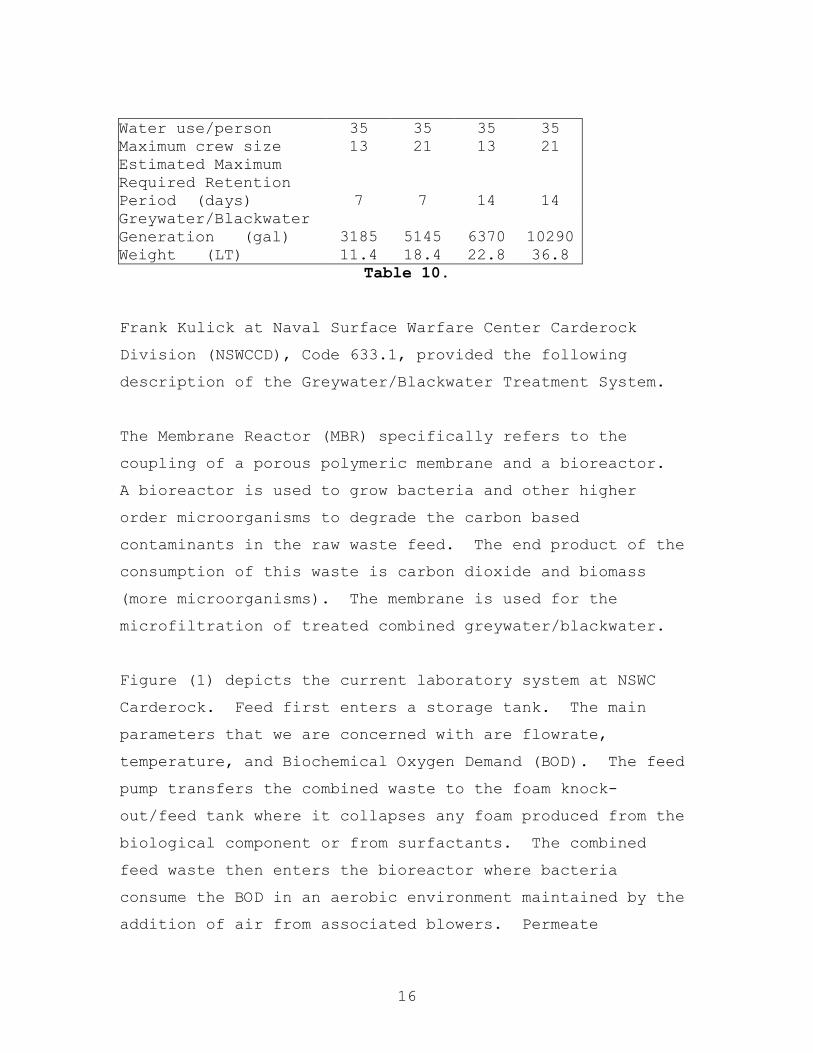
16
Water use/person 35 35 35 35 Maximum crew size 13 21 13 21 Estimated Maximum Required Retention Period (days) 7 7 14 14 Greywater/Blackwater Generation (gal) 3185 5145 6370 10290 Weight (LT) 11.4 18.4 22.8 36.8
Table 10.
Frank Kulick at Naval Surface Warfare Center Carderock
Division (NSWCCD), Code 633.1, provided the following
description of the Greywater/Blackwater Treatment System.
The Membrane Reactor (MBR) specifically refers to the
coupling of a porous polymeric membrane and a bioreactor.
A bioreactor is used to grow bacteria and other higher
order microorganisms to degrade the carbon based
contaminants in the raw waste feed. The end product of the
consumption of this waste is carbon dioxide and biomass
(more microorganisms). The membrane is used for the
microfiltration of treated combined greywater/blackwater.
Figure (1) depicts the current laboratory system at NSWC
Carderock. Feed first enters a storage tank. The main
parameters that we are concerned with are flowrate,
temperature, and Biochemical Oxygen Demand (BOD). The feed
pump transfers the combined waste to the foam knock-
out/feed tank where it collapses any foam produced from the
biological component or from surfactants. The combined
feed waste then enters the bioreactor where bacteria
consume the BOD in an aerobic environment maintained by the
addition of air from associated blowers. Permeate

17
(filtered effluent) is removed from the bioreactor by a
positive displacement pump that transfers it to the
Ultraviolet (UV) treatment unit. The UV will destroy any
remaining fecal coliform bacteria still present after
filtration. A special backpulse process is used by some
membrane manufacturers to pump some permeate back through
the membrane to reduce fouling of the membranes.
The biological component or biomass is a living
organism. It requires energy to move and reproduce. As
this biomass reproduces, the Total Suspended Solids (TSS)
will increase. Ideally the biomass is retain for 20 to 30
days before wasting (the process of pumping out excess
biomass). Wasting is used to maintain an active and
growing biomass, and to meet the volume constraints of the
system. This wasted biomass is referred to as concentrate
and must be stored until disposal is possible.
NSWCCD is currently testing laboratory scale equipment
designed for a volume of 1000 gal/day. The current
specifications are:
Membranes 16 to 46.5 m2 depending upon different manufacturer’s
specifications.
Permeate pump
- Progressive cavity pump ~5gpm.
Concentrate pump
Progressive capacity pump capable of flow rates as low as
0.25 gpm.
Macerator
N434 Navy Macerator – used for transfer pumps.
18
Blower
Rated at 120 scfm at 7 psig.
Diffusers
Coarse bubble diffusers installed for aeration in the
bioreactor.
Each system is operated though a Programmable Logic
Controller (PLC) with a Graphic Interface Unit (GIU) touch
screen. Data logging is accomplished with software that
writes to a database manager. System monitoring devices
include dissolved oxygen sensor, magnetic flow meter, and
continuous bioreactor level sensor, permeate pressure
transducer, and foam detection switch.
The required services are as follows:
Air
Control air for valve actuation < 1scfm from ship’s service
air system
Aeration for bioreactor ~ 75scfm supplied by associated
blowers
Electricity
All electricity is supplied from one 440VAC source and is
stepped down through transformers to 120VAC and 24VAC
control power in the control panel. The total load on the
system is about 60amps.
Firemain
Used solely to flush the tank of contaminants for
maintenance operations.
Potable Water

19
Used solely to flush saltwater from the system and for
startup (~ 700 gal).
Footprint
With a 9-foot deck-to-deck height, 135ft2.
Tank Volume
750 gal. Equalization tank, 770 gal. Bioreactor tank, and a
200 gal. foam knock-out tank.
Membrane Area
16 to 46.5 m2 depending upon which manufacturer’s membrane
is used.

20
EqualizationTankCombined
Graywater andConcentratedBlackwater fromStorage
Foam Knock-Out Tank
Bioreactor
Discharge
Vent toAtmosphere
Bioreactor Vent
In-TankMembranes
UV
Uni
t
BackpulseTank
AerationPermeate
Pump
FoamCondensate
Pump
Feed PumpAeration
Vent toAtmosphere
ConcentrateWastage Pump
ConcentrateWasting
Vent
Figure 1.
Figure 2 depicts the treatment system equipment. The estimated weight of the treatment system with full tanks is approximately 10.3 LT.

21
Figure 2.
The following description of the Navy Integrated
Membrane System (NIMS) was provided by Mike Kelly at Naval
Surface Warfare Center Carderock Division (NSWCCD), Code
634.
The NIMS consists of a bulk oil separator that removes
most of the oil from influent bilge water, followed by a
ceramic membrane ultrafiltration subsystem that reliably
reduces the remaining oil content below 15 ppm. The system
is currently in the design stage, and components are being
tested aboard ship.

22
Interfaces
- Low air pressure Supply (100 psig).
- Potable Water Supply (40-50 psig).
- Overboard Discharge through an Oil Content
Monitor (back pressure 10 psig).
- Suction Pressure from the Oily Waste Holding Tank
(-7 to -10 psig).
- Discharge Pressure of flushing water to Oily
Waste Holding Tank (10 psig minimum
requirements).
- Discharge Pressure of oil concentrates to the
Waste Oil Tank (10 psig minimum requirements).
Estimated Foot Print: LXWXH=77.34"X35"X74.04"
Estimated Weight: 2500-3000 lbs Figure 3 depicts the Navy Integrated Membrane System (NIMS).
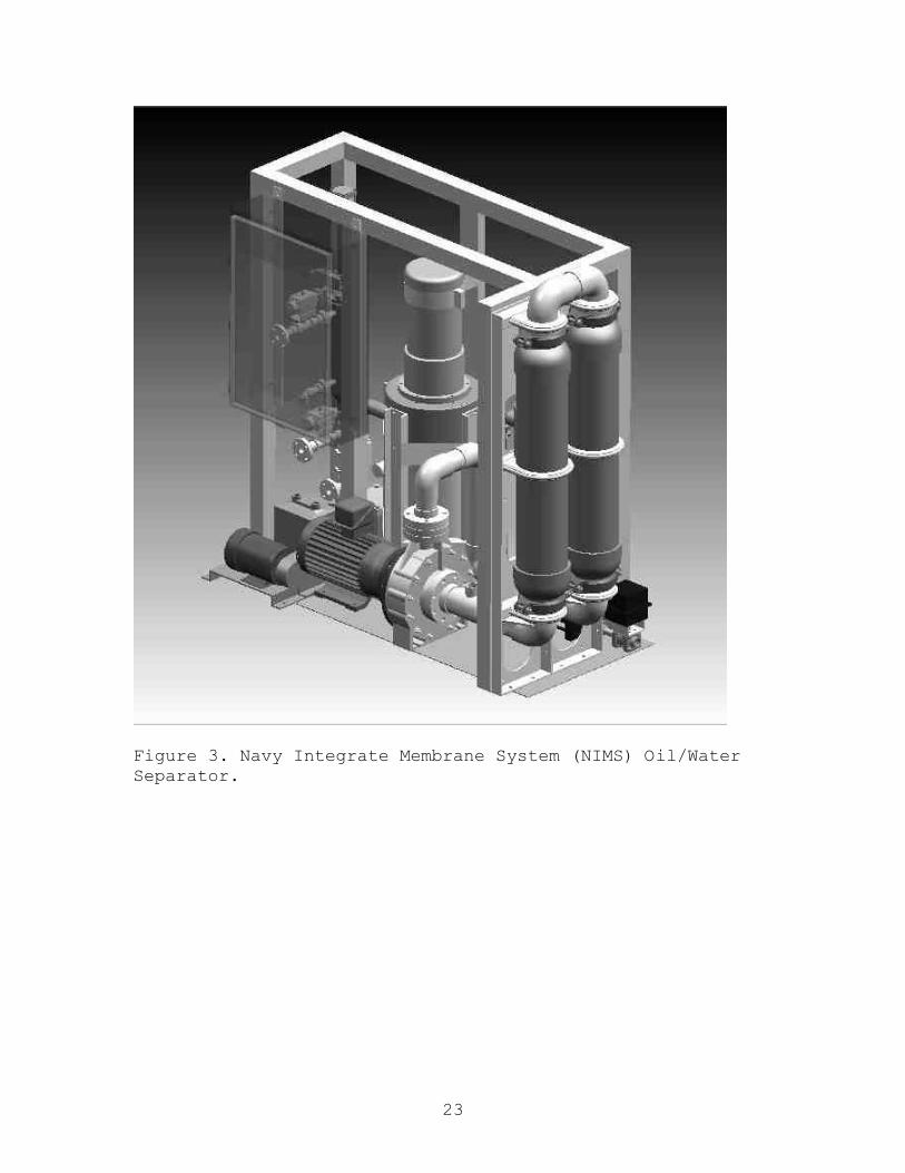
23
Figure 3. Navy Integrate Membrane System (NIMS) Oil/Water Separator.

1
Appendix J: Total Ship Systems
1. Weight Estimation (primarily aluminum construction)
SEA LANCE Combatant Weight Breakdown:
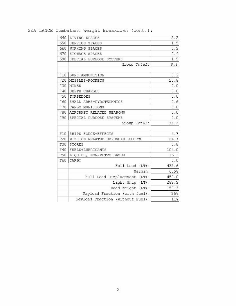
2
SEA LANCE Combatant Weight Breakdown (cont.):

3
SEA LANCE GDM Weight Breakdown:
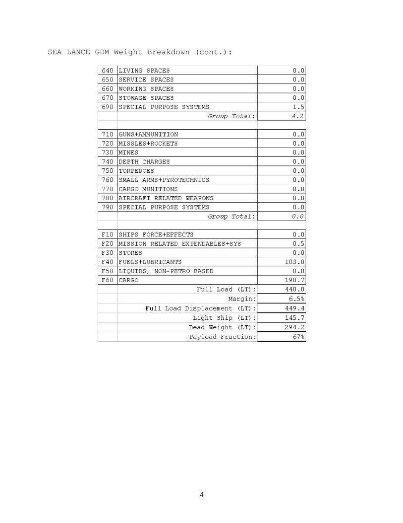
4
SEA LANCE GDM Weight Breakdown (cont.):

5
-----Original Message----- From: Kim Gillis [mailto:[email protected]] Sent: Tuesday, October 31, 2000 03 19 To: 'Barney, Timothy' Subject: RE: Catamaran Combatant Tim Thanks for the update. Those figures help considerably. If this was a commercial vessel of 48m I would be quoting around US$6.5m. This is for an auto express 10 cars 350 pax fully fitted out. The price for the hull on its own is a guess at around US$3.8m. I will get back with some info on weights etc. Kim
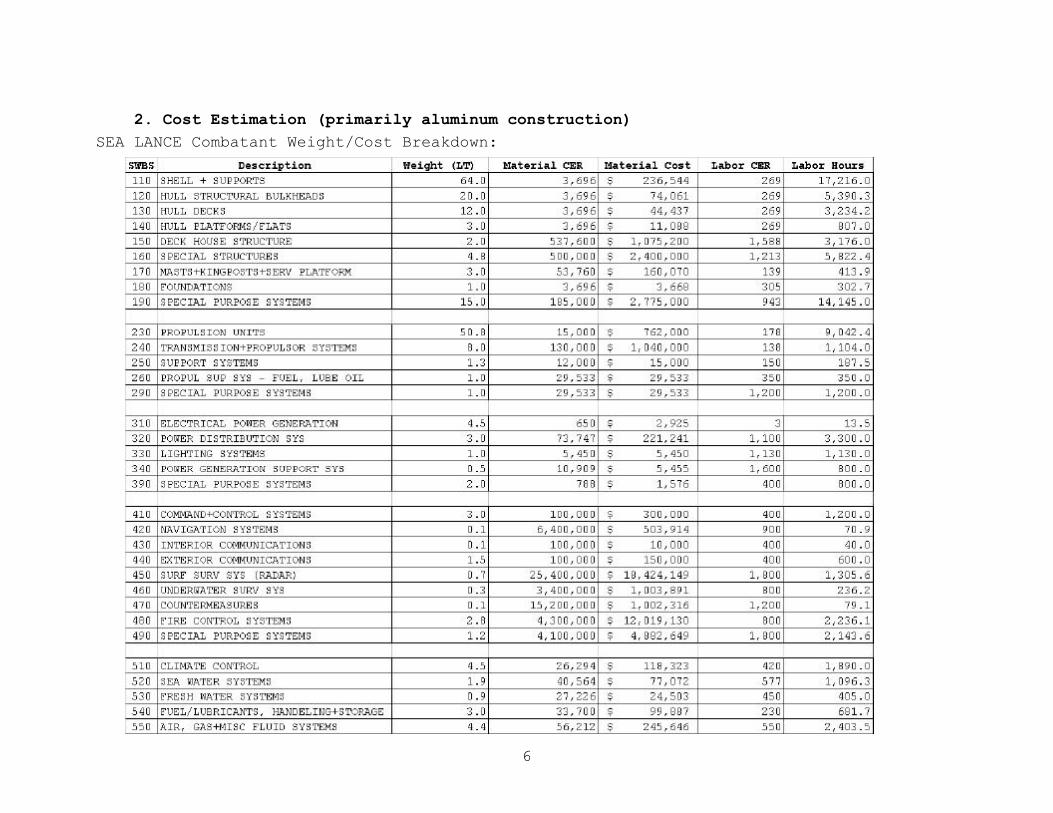
6
2. Cost Estimation (primarily aluminum construction) SEA LANCE Combatant Weight/Cost Breakdown:

7
SEA LANCE Combatant Weight/Cost Breakdown (cont.):

8
SEA LANCE GDM Weight/Cost Breakdown:
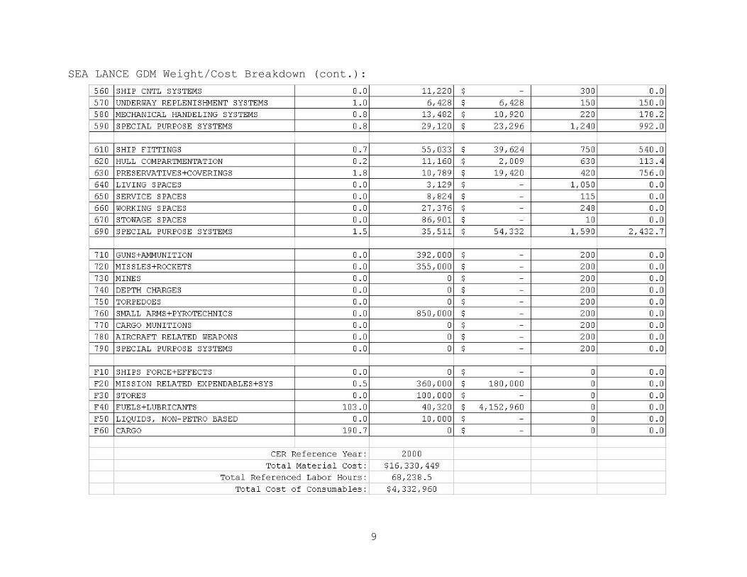
9
SEA LANCE GDM Weight/Cost Breakdown (cont.):
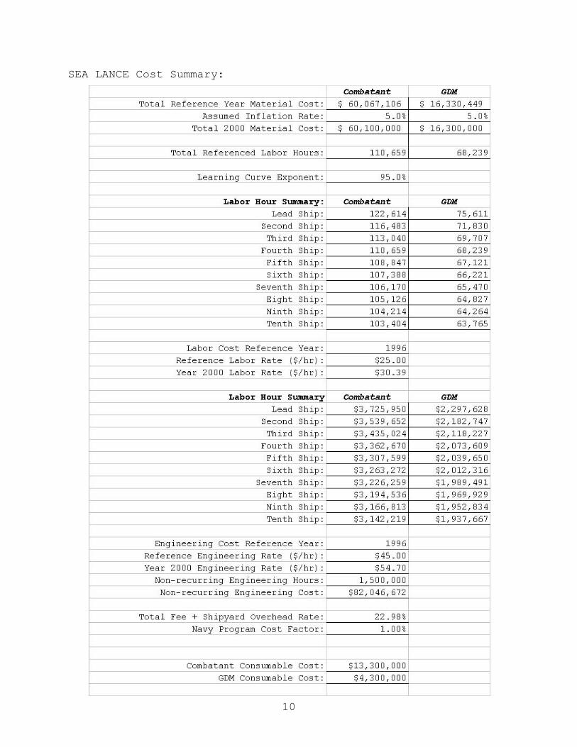
10
SEA LANCE Cost Summary:

11
SEA LANCE Cost Summary (cont.):

12
3. Weight Estimation (primarily composite construction) Composite SEA LANCE Combatant Weight Breakdown:

13
Composite SEA LANCE Combatant Weight Breakdown (cont.):
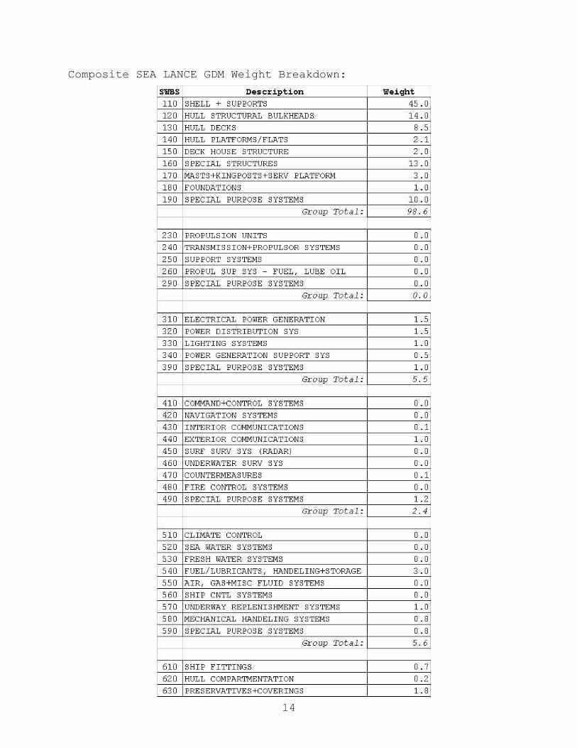
14
Composite SEA LANCE GDM Weight Breakdown:

15
Composite SEA LANCE GDM Weight Breakdown (cont.):
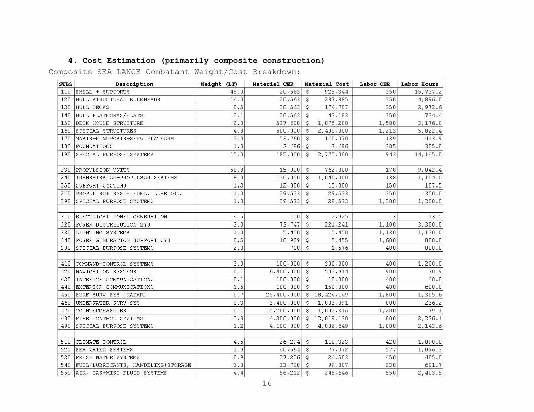
16
4. Cost Estimation (primarily composite construction) Composite SEA LANCE Combatant Weight/Cost Breakdown:
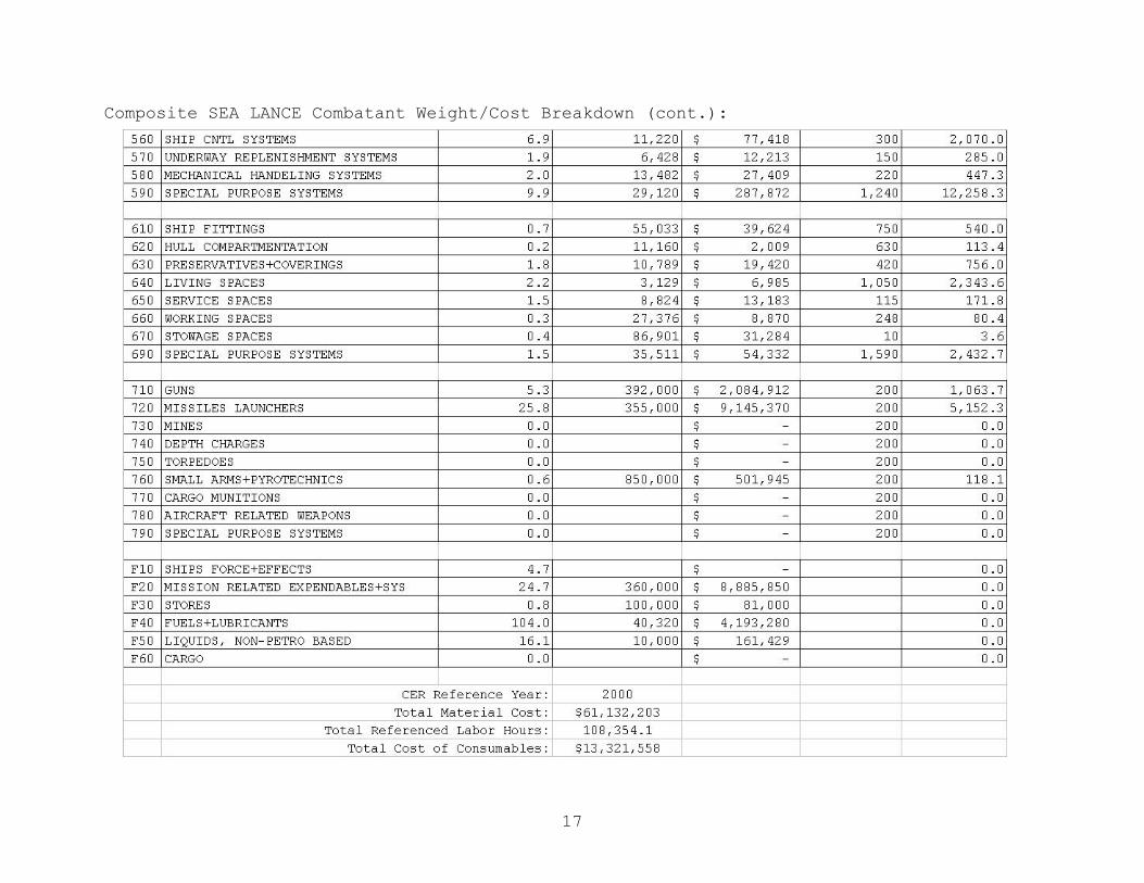
17
Composite SEA LANCE Combatant Weight/Cost Breakdown (cont.):

18
Composite SEA LANCE GDM Weight/Cost Breakdown:
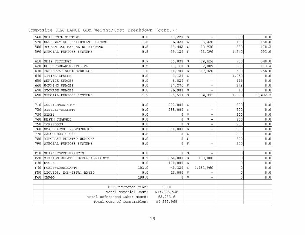
19
Composite SEA LANCE GDM Weight/Cost Breakdown (cont.):

20
Composite SEA LANCE Cost Summary:

21
Composite SEA LANCE Cost Summary (cont.):
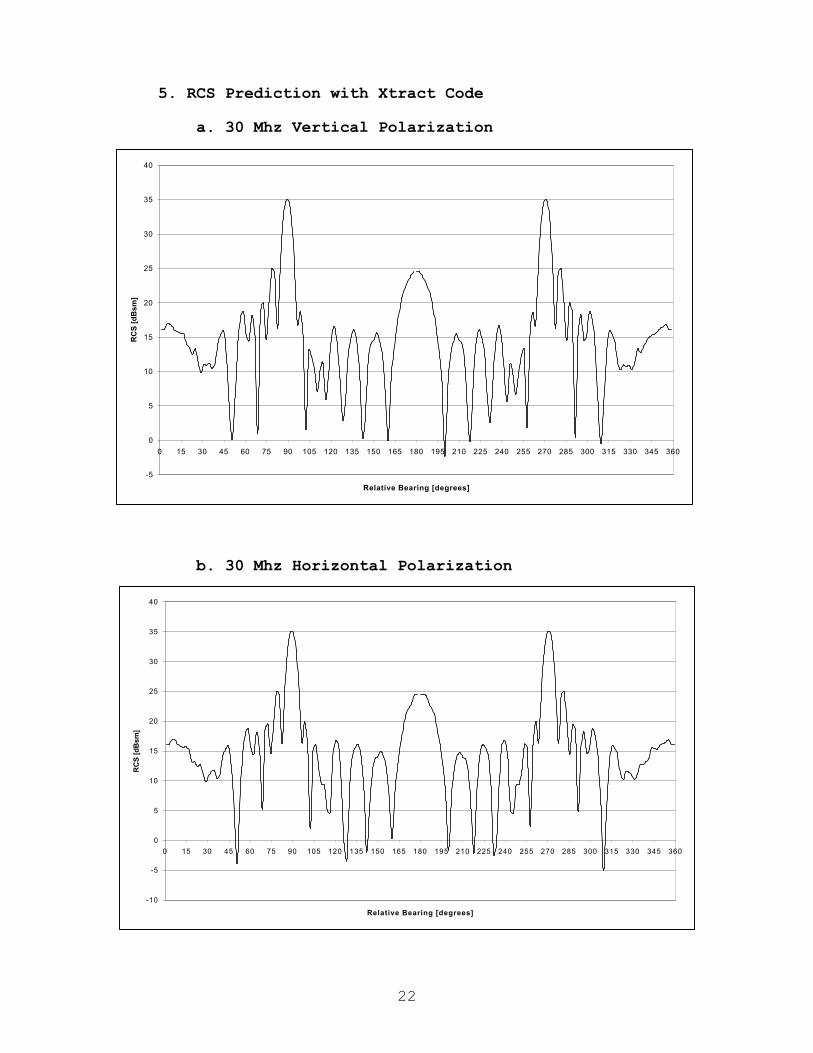
22
5. RCS Prediction with Xtract Code
a. 30 Mhz Vertical Polarization
b. 30 Mhz Horizontal Polarization
-5
0
5
10
15
20
25
30
35
40
0 15 30 45 60 75 90 105 120 135 150 165 180 195 210 225 240 255 270 285 300 315 330 345 360
Relative Bearing [degrees]
RC
S [
dB
sm]
-10
-5
0
5
10
15
20
25
30
35
40
0 15 30 45 60 75 90 105 120 135 150 165 180 195 210 225 240 255 270 285 300 315 330 345 360
Relative Bearing [degrees]
RC
S [
dB
sm]

23
c. 3 GHz Vertical Polarization (port side)
d. 3 GHz Horizontal Polarization (port side)
-50
-40
-30
-20
-10
0
10
20
30
40
50
0 15 30 45 60 75 90 105 120 135 150 165 180
Relative Bearing [degrees]
RC
S [
dB
sm]
-50
-40
-30
-20
-10
0
10
20
30
40
50
0 15 30 45 60 75 90 105 120 135 150 165 180
Relative Bearing [degrees]
RC
S [
dB
sm]
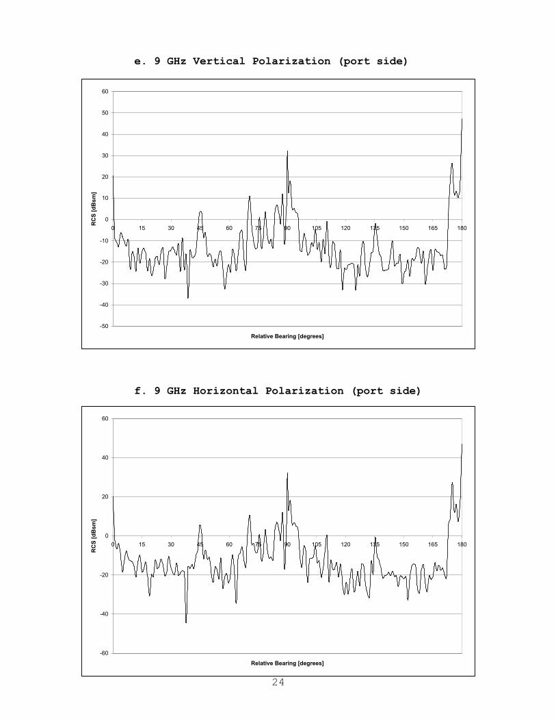
24
e. 9 GHz Vertical Polarization (port side)
f. 9 GHz Horizontal Polarization (port side)
-50
-40
-30
-20
-10
0
10
20
30
40
50
60
0 15 30 45 60 75 90 105 120 135 150 165 180
Relative Bearing [degrees]
RC
S [
dB
sm]
-60
-40
-20
0
20
40
60
0 15 30 45 60 75 90 105 120 135 150 165 180
Relative Bearing [degrees]
RC
S [
dB
sm]
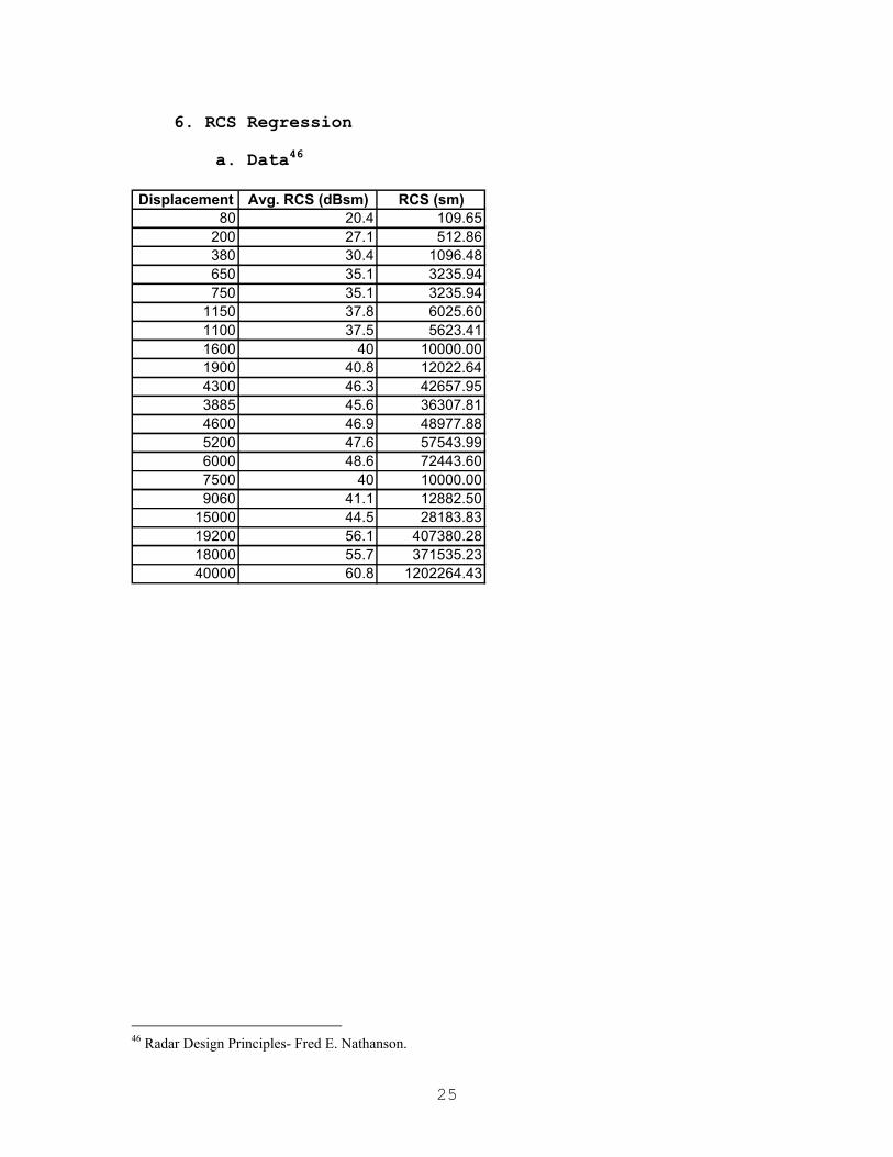
25
6. RCS Regression
a. Data46
46 Radar Design Principles- Fred E. Nathanson.
Displacement Avg. RCS (dBsm) RCS (sm)80 20.4 109.65
200 27.1 512.86380 30.4 1096.48650 35.1 3235.94750 35.1 3235.94
1150 37.8 6025.601100 37.5 5623.411600 40 10000.001900 40.8 12022.644300 46.3 42657.953885 45.6 36307.814600 46.9 48977.885200 47.6 57543.996000 48.6 72443.607500 40 10000.009060 41.1 12882.50
15000 44.5 28183.8319200 56.1 407380.2818000 55.7 371535.2340000 60.8 1202264.43


27
b. Power Regression
RCS versus Displacement
y = 0.1833x1.4787
0.00
2000.00
4000.00
6000.00
8000.00
10000.00
12000.00
14000.00
0 200 400 600 800 1000 1200 1400 1600 1800 2000
Displacement [tons]
RC
S [
sm]
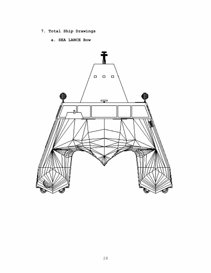
28
7. Total Ship Drawings
a. SEA LANCE Bow
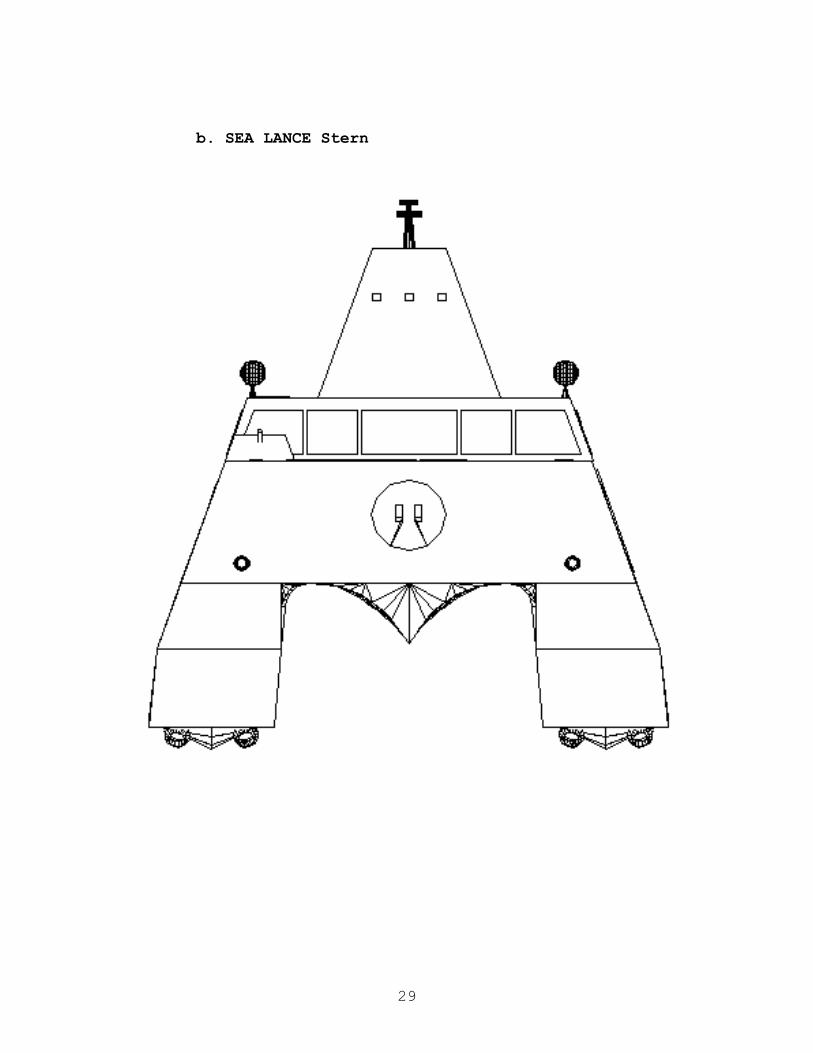
29
b. SEA LANCE Stern


31
c. SEA LANCE Top
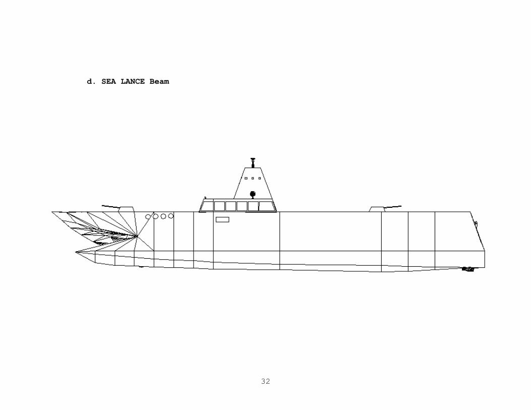
32
d. SEA LANCE Beam

33
e. SEA LANCE Isometric (port-forward)

34
f. Rendered SEA LANCE Isometric (port-forward)
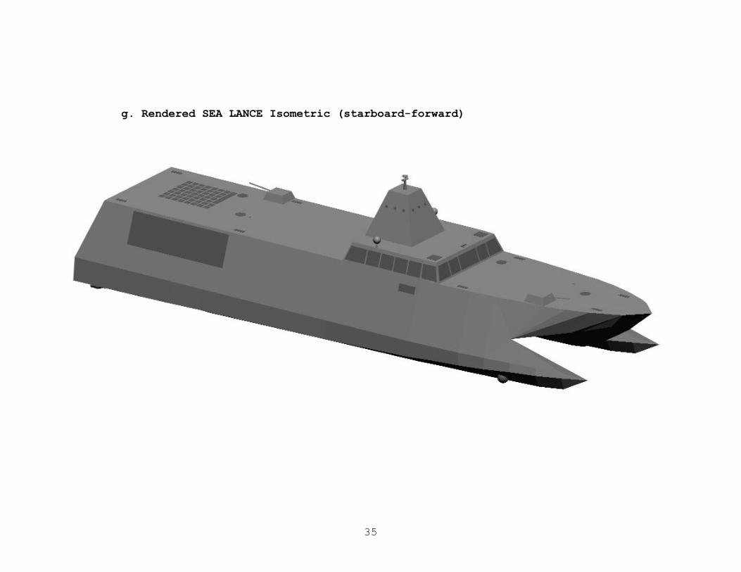
35
g. Rendered SEA LANCE Isometric (starboard-forward)

36
h. Rendered SEA LANCE (Combatant and GDM)

37
i. Table of Offsets
0 0 16 16 16 16 16 16 16 16 16 16 16 167.9 1 16 16 16 16 15.52 16.33 15.52 16.39 15.06 16.85 15.52 16.45
15.8 2 16 16 16 16 15.52 16.33 14.59 17.32 13.96 18.01 14.59 17.3723.7 3 16 16 16 16 15.23 16.68 13.96 17.95 13.43 18.53 13.67 18.1931.6 4 16 16 16 16 14.48 17.37 12.74 19.11 12.74 19.23 12.97 19.0039.5 5 16 16 16 16 13.90 18.07 12.04 19.92 12.16 19.81 12.28 19.6947.4 6 16 16 15.69 16.27 13.43 18.53 11.81 20.16 11.81 20.11 11.81 20.0655.3 7 16 16 15.24 16.30 13.05 18.71 11.47 20.21 11.47 20.16 11.47 20.1163.2 8 16 16 14.74 16.31 12.37 18.90 11.02 20.29 11.02 20.23 10.91 20.1871.1 9 16 16 14.28 19.12 12.12 19.28 10.80 20.31 10.80 20.25 10.69 20.2079 10 16 16 14.14 19.71 11.13 20.81 10.90 20.76 10.66 20.64 10.49 20.52
86.9 11 16 16 13.52 19.71 10.78 20.87 10.66 20.76 10.43 20.64 10.32 20.5294.8 12 16 16 13.13 19.71 10.78 20.87 10.66 20.76 10.43 20.64 10.32 20.52102.7 13 16 16 12.40 19.71 10.78 20.87 10.66 20.76 10.43 20.64 10.32 20.52110.6 14 16 16 12.40 19.71 10.78 20.87 10.66 20.76 10.43 20.64 10.32 20.52118.5 15 16 16 12.40 19.71 10.78 20.87 10.66 20.76 10.43 20.64 10.32 20.52126.4 16 16 16 12.40 19.71 10.78 20.87 10.66 20.76 10.43 20.64 10.32 20.52134.3 17 16 16 12.75 19.71 10.78 20.87 10.66 20.76 10.43 20.64 10.32 20.52142.2 18 16 16 12.75 19.71 10.78 20.87 10.66 20.76 10.43 20.64 10.32 20.52150.1 19 16 16 16 16 10.78 20.87 10.66 20.76 10.43 20.64 10.32 20.52158 20 16 16 16 16 10.78 20.87 10.66 20.76 10.43 20.64 10.32 20.52
1.6 3.2 4.8 6.40 8StationWater Line (feet)
Sea Lance Table of Offsets for B=10' T=8'

38
j. Body Plan
1
Appendix K: Advanced Waterjet for the 21st Century (AWJ-21)
UNCLASSIFIED
UNCLASSIFIED
Bird-Johnson 2000-06-14
PROPRIETARY
TRANSMITTAL OF INFORMATION HEREIN IS IN ACCORDANCE WITH THE APPROPRIATE U.S. EXPORT REGULATIONS
APPLICABLE LICENSE:EUROPE/CANADA EXPORT LICENSE #790149
TRANSMITTAL OF INFORMATION IS ALSO IN ACCORDANCE WITH SPECIFIC PROVISOS TO SAID EXPORT LICENSE

2
UNCLASSIFIED
UNCLASSIFIED
Bird-Johnson 2000-06-14
PROPRIETARY
AWJ21™
Advanced Waterjet Propulsor Application
Patents Approved & Pending
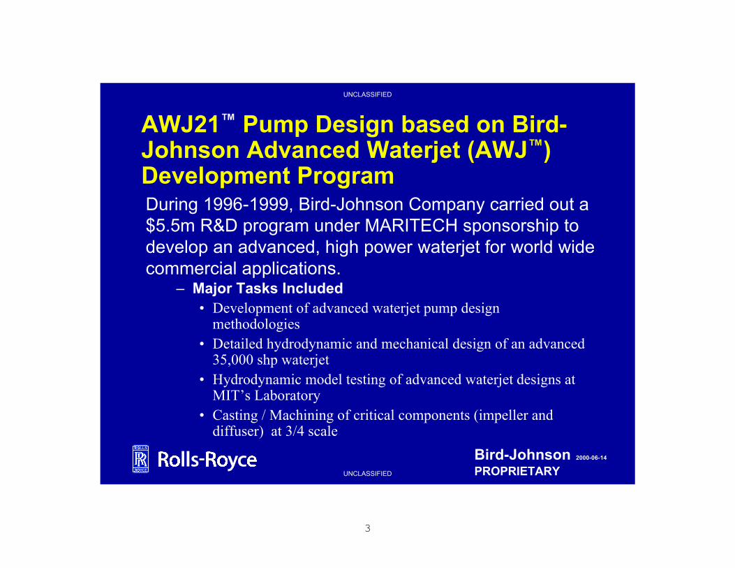
3
UNCLASSIFIED
UNCLASSIFIED
Bird-Johnson 2000-06-14
PROPRIETARY
AWJ21™ Pump Design based on Bird-Johnson Advanced Waterjet (AWJ™) Development Program
– Major Tasks Included• Development of advanced waterjet pump design
methodologies• Detailed hydrodynamic and mechanical design of an advanced
35,000 shp waterjet • Hydrodynamic model testing of advanced waterjet designs at
MIT’s Laboratory• Casting / Machining of critical components (impeller and
diffuser) at 3/4 scale
During 1996-1999, Bird-Johnson Company carried out a $5.5m R&D program under MARITECH sponsorship to develop an advanced, high power waterjet for world wide commercial applications.

4
UNCLASSIFIED
UNCLASSIFIED
Bird-Johnson 2000-06-14
PROPRIETARY
AWJ™ Mechanical Design• Clean sheet of paper
– incorporating experience with current waterjet design
• Design considerations– performance
– reliability
– maintainability
– installation
– weight
– manufacturing cost
• Alternate bearing configurations
– traditional oil-lubricated
– progressive water-lubricated
Oil-Lubricated Hub
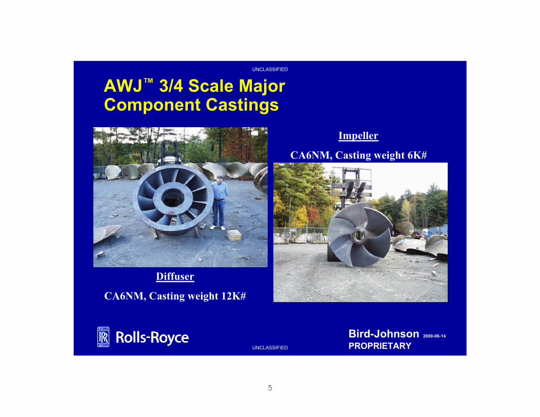
5
UNCLASSIFIED
UNCLASSIFIED
Bird-Johnson 2000-06-14
PROPRIETARY
AWJ™ 3/4 Scale Major Component Castings
Diffuser
CA6NM, Casting weight 12K#
Impeller
CA6NM, Casting weight 6K#

6
UNCLASSIFIED
UNCLASSIFIED
Bird-Johnson 2000-06-14
PROPRIETARY
AWJ21™ General Description
• The adaptation of efficient, advanced mixed-flow commercial waterjet technology to high performance surface ships, incorporating a novel underwater discharge configuration.
Patents Approved & Pending
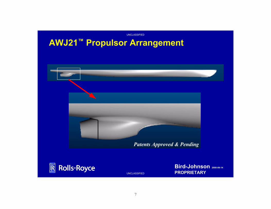
7
UNCLASSIFIED
UNCLASSIFIED
Bird-Johnson 2000-06-14
PROPRIETARY
AWJ21™ Propulsor Arrangement
Patents Approved & Pending

8
UNCLASSIFIED
UNCLASSIFIED
Bird-Johnson 2000-06-14
PROPRIETARY
AWJ21™ Propulsor Arrangement
Patents Approved & Pending

9
UNCLASSIFIED
UNCLASSIFIED
Bird-Johnson 2000-06-14
PROPRIETARY
Candidate Steering/Reversing Systems
Patents Approved & Pending

10
UNCLASSIFIED
UNCLASSIFIED
Bird-Johnson 2000-06-14
PROPRIETARY
AWJ21™ Design Features
• High propulsive efficiency– Up to 8% annual fuel savings vs.
Baseline CPP
• Reduced ship signatures– Discharge below surface– Total swirl cancellation– High cavitation inception speed– Cavitation inception insensitive to
turns• No rudder, shaft, shaft strut cavitation
• Propulsor completely above ship baseline
– Allows for significant reduction in navigational draft
– Propulsor protected from grounding
Patents Pending
• Inherent compact / modular propulsion package
– Short, less vulnerable shaft line
• Current propulsor technology
Patents Approved & Pending
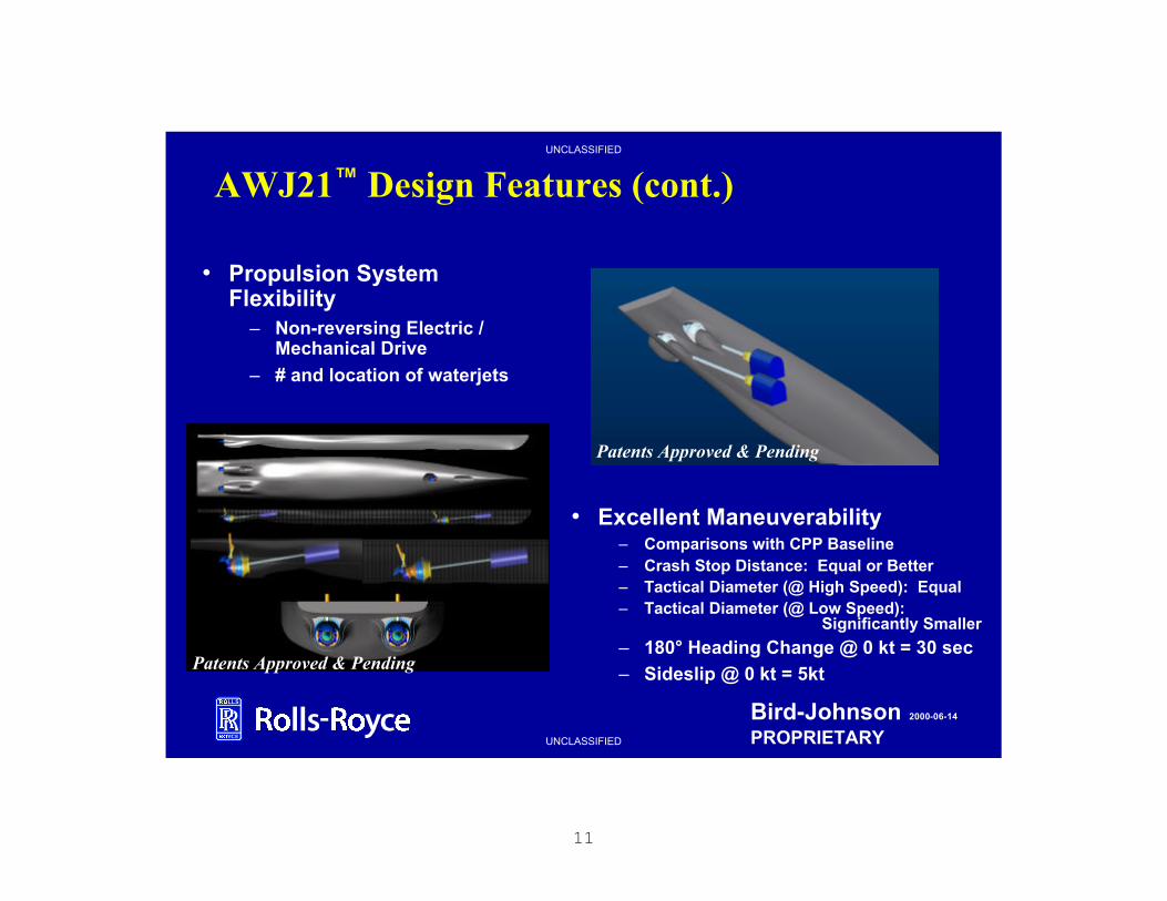
11
UNCLASSIFIED
UNCLASSIFIED
Bird-Johnson 2000-06-14
PROPRIETARY
AWJ21™ Design Features (cont.)
• Propulsion System Flexibility
– Non-reversing Electric / Mechanical Drive
– # and location of waterjets
• Excellent Maneuverability– Comparisons with CPP Baseline– Crash Stop Distance: Equal or Better– Tactical Diameter (@ High Speed): Equal– Tactical Diameter (@ Low Speed):
Significantly Smaller
– 180° Heading Change @ 0 kt = 30 sec– Sideslip @ 0 kt = 5kt
Patents Approved & Pending
Patents Approved & Pending

12
UNCLASSIFIED
UNCLASSIFIED
Bird-Johnson 2000-06-14
PROPRIETARY
• The AWJ21™ is ideal for integration into electric drive ships– The higher operating rpm of the AWJ21™ waterjet pump will result in a
substantially smaller motor than would be required for other propulsortypes
• approximately 1/2 the torque of a conventional propeller
– All waterjet equipment, including the motor, can be mounted compactly on the waterjet module structure
– Inherent flexibility with any conceivable electric drive configuration
– Motor reversing is not required resulting in simplified drive requirements
AWJ21™ and Electric Drive

13
UNCLASSIFIED
UNCLASSIFIED
Bird-Johnson 2000-06-14
PROPRIETARY
Summary of AWJ™ Model Testing Results
• 92% pump efficiency for AWJ design
• Exceptional cavitationinception characteristics predicted for AWJ confirmed by measurements.
0%
10%
20%
30%
40%
Inception Speed
Improvement Over
Baseline Mixed-Flow
Pump
Oct '98 Prediction
Sept '99 Measurement

14
UNCLASSIFIED
UNCLASSIFIED
Bird-Johnson 2000-06-14
PROPRIETARY
AWJ Model Test Configurationpump
Wake screen
AMCA Standard Bellmouth
Orifice plate
shaft
inlet
Laser, pitot tube survey, static pressure ports
return
•Tested Pumps•Baseline Mixed Flow Pump•Advanced Axial Inducer Pump•Advanced Mixed Flow Pump #1•Advanced Mixed Flow Pump #2 - BIRD-JOHNSON 100%
MARITECH AWJ PROJECTGOVT- 25% BJCO-75%

15
UNCLASSIFIED
UNCLASSIFIED
Bird-Johnson 2000-06-14
PROPRIETARY
AWJ Pump Inflow• Pump cavitation characteristics
largely affected by non-uniform inflow to pump
• Non-uniformity at pump governed by axial inflow variation, function of:
– elbow geometry– drive shaft geometry
– vessel speed• Conventional inlet
– approximate maximum 40% wake deficit at rotor tip
• Optimized inlet– approximate maximum 20%
wake deficit at rotor tip
A x ia l In flow Var ia tio n a t P u m p
0
0 .5
1
1 .50
30
60
90
120
150
180
210
240
270
300
330
C o n v e n tio n a l In le t O p tim iz e d In le t
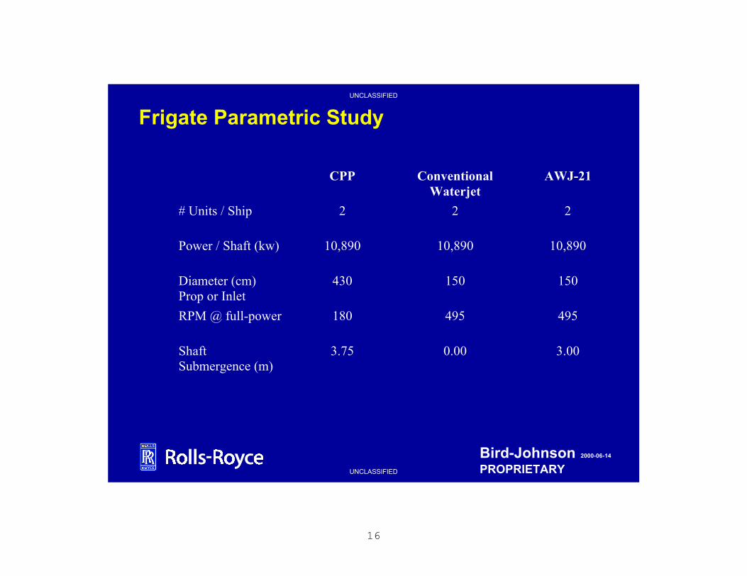
16
UNCLASSIFIED
UNCLASSIFIED
Bird-Johnson 2000-06-14
PROPRIETARY
Frigate Parametric Study
CPP ConventionalWaterjet
AWJ-21
# Units / Ship 2 2 2
Power / Shaft (kw) 10,890 10,890 10,890
Diameter (cm)Prop or Inlet
430 150 150
RPM @ full-power 180 495 495
ShaftSubmergence (m)
3.75 0.00 3.00
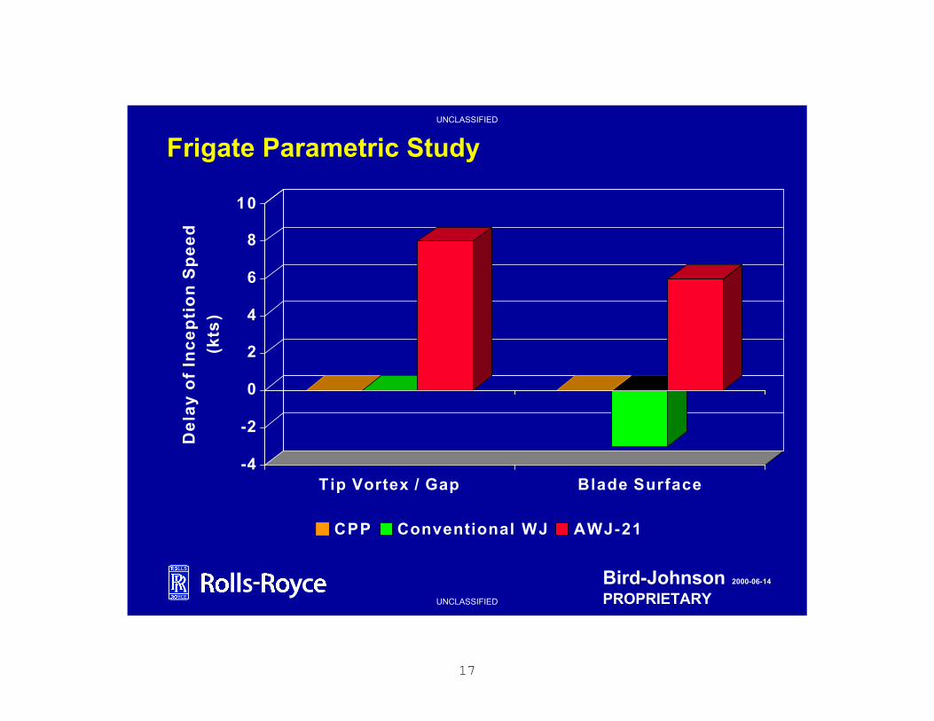
17
UNCLASSIFIED
UNCLASSIFIED
Bird-Johnson 2000-06-14
PROPRIETARY
Frigate Parametric Study
-4
-2
0
2
4
6
8
10D
ela
y o
f In
ce
pti
on
Sp
ee
d
(kts
)
Tip Vortex / Gap Blade Surface
CPP Conventional WJ AWJ-21
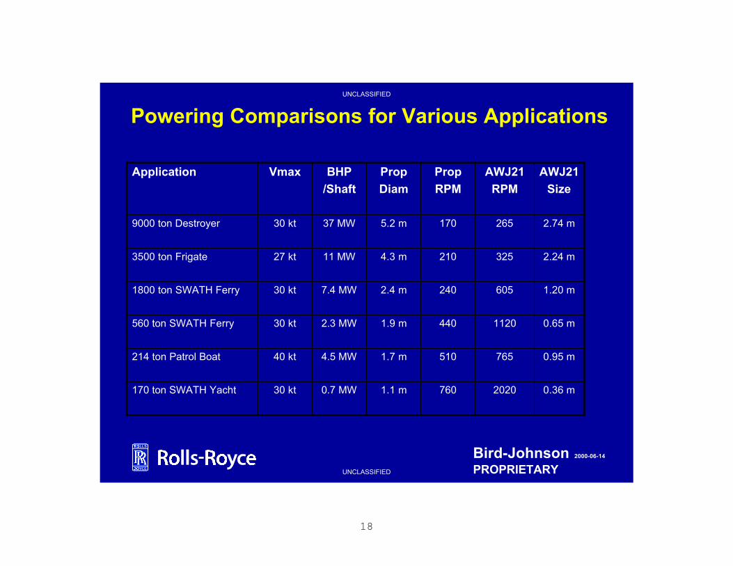
18
UNCLASSIFIED
UNCLASSIFIED
Bird-Johnson 2000-06-14
PROPRIETARY
Powering Comparisons for Various Applications
0.95 m7655101.7 m4.5 MW40 kt214 ton Patrol Boat
0.65 m11204401.9 m2.3 MW30 kt560 ton SWATH Ferry
0.36 m20207601.1 m0.7 MW30 kt170 ton SWATH Yacht
1.20 m6052402.4 m7.4 MW30 kt1800 ton SWATH Ferry
2.24 m3252104.3 m11 MW27 kt3500 ton Frigate
2.74 m2651705.2 m37 MW30 kt9000 ton Destroyer
AWJ21
Size
AWJ21
RPM
Prop
RPM
Prop
Diam
BHP
/Shaft
VmaxApplication
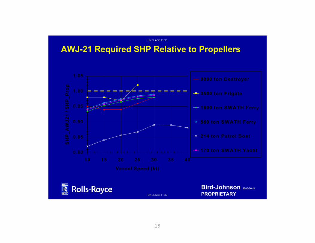
19
UNCLASSIFIED
UNCLASSIFIED
Bird-Johnson 2000-06-14
PROPRIETARY
AWJ-21 Required SHP Relative to Propellers
0.80
0.85
0.90
0.95
1.00
1.05
10 15 20 25 30 35 40
Vessel Speed (kt)
SH
P_
AW
J2
1 /
SH
P_
Pro
p
9000 ton Destroyer
3500 ton Frigate
1800 ton SWATH Ferry
560 ton SWATH Ferry
214 ton Patrol Boat
170 ton SWATH Yacht
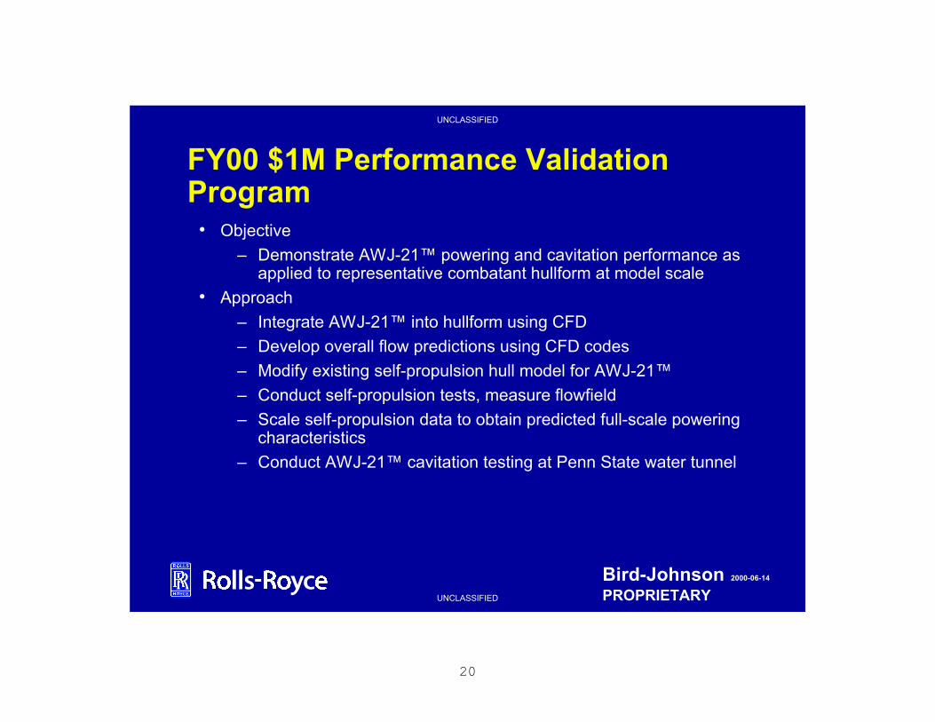
20
UNCLASSIFIED
UNCLASSIFIED
Bird-Johnson 2000-06-14
PROPRIETARY
FY00 $1M Performance Validation Program
• Objective
– Demonstrate AWJ-21™ powering and cavitation performance as applied to representative combatant hullform at model scale
• Approach
– Integrate AWJ-21™ into hullform using CFD
– Develop overall flow predictions using CFD codes
– Modify existing self-propulsion hull model for AWJ-21™
– Conduct self-propulsion tests, measure flowfield
– Scale self-propulsion data to obtain predicted full-scale powering characteristics
– Conduct AWJ-21™ cavitation testing at Penn State water tunnel
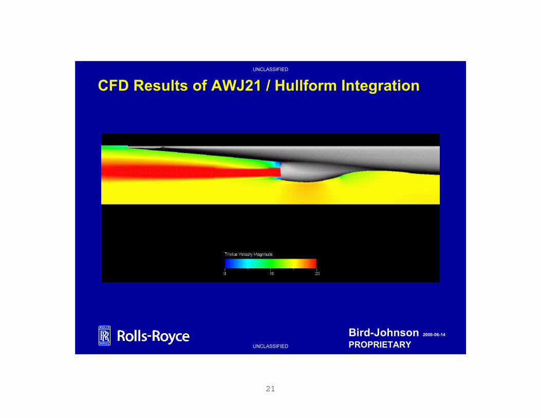
21
UNCLASSIFIED
UNCLASSIFIED
Bird-Johnson 2000-06-14
PROPRIETARY
CFD Results of AWJ21 / Hullform Integration

22
UNCLASSIFIED
UNCLASSIFIED
Bird-Johnson 2000-06-14
PROPRIETARY
Projected Self-Propulsion and Cavitation Test Schedule
• AWJ-21™ design integration (Jun-Jul ’00)
• Model component design, manufacture and assembly (Jul-Sep ’00)
• Model instrumentation (Oct ’00)
• Testing (Nov ’00)
• Data analysis and reporting (Dec ’00)

23
UNCLASSIFIED
UNCLASSIFIED
Bird-Johnson 2000-06-14
PROPRIETARY
FY01-02 $8M 1/4-Scale Technology Demonstration Program• Objective
– Demonstrate AWJ-21™ powering, maneuvering and cavitationperformance at large scale (approximately ¼ scale)
• Approach
– Develop suitable 30 kt demonstrator hullform for single 2000 hp waterjet
– Integrate AWJ-21™ into hullform using CFD
– Conduct model tow tank testing to develop scaling relationships
– Conduct model cavitation testing for scaling relationships
– Build “quiet” electric drive demonstrator
– Conduct at-sea powering, maneuvering and cavitation testing
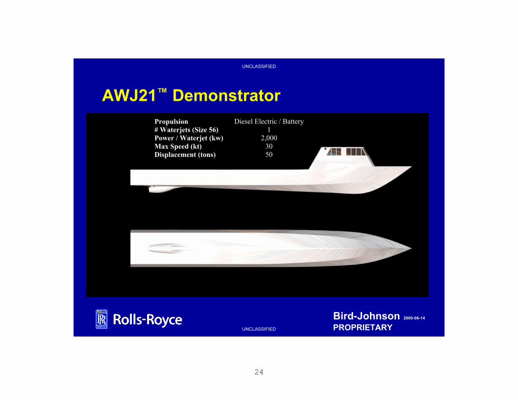
24
UNCLASSIFIED
UNCLASSIFIED
Bird-Johnson 2000-06-14
PROPRIETARY
AWJ21™ DemonstratorPropulsion Diesel Electric / Battery# Waterjets (Size 56) 1Power / Waterjet (kw) 2,000Max Speed (kt) 30Displacement (tons) 50

25
UNCLASSIFIED
UNCLASSIFIED
Bird-Johnson 2000-06-14
PROPRIETARY
Performance Validation / Technology Demonstration Program Plan
ID Task Name BJCO MHRS BUDGET
1 PHASE I - MODEL SCALE DEMONSTRATION $900k
2 AWJ-21 COMBATANT DESIGN INTEGRATION & CFD 500 $100K
3 SELF-PROPULSION TEST @ NSWC $300K
4 CAVITATION TESTS @ PSU/ARL $500K
5
6 PHASE II - 1/4-SCALE PROOF-OF-CONCEPT DEMONSTRATION $3600k
7 DEMONSTRATOR DESIGN & CFD 2040
8 HULL CONSTRUCTION $1000K
9 ELECTRIC PROPULSION PLANT $1000K
10 WATERJET SYSTEM MANUFACTURE $600K
11 OUTFITTING $500K
12 PROOF-OF-CONCEPT TRIALS $500K
13
14 PHASE III - 1/4 DEMONSTRATOR FOLLOW-ON TESTING $4000k
15 MODEL SELF-PROPULSION TESTS @ NSWC $600K
16 CAVITATION TESTS @ PSU/ARL $1000K
17 OTHER TRIALS $2400K
2 3 4 1 2 3 4 1 2 3 4 1 22000 2001 2002 20

26
UNCLASSIFIED
UNCLASSIFIED
Bird-Johnson 2000-06-14
PROPRIETARY
International Navy Interest• Royal Navy
– AWJ-21™ presentation made to DERA in Summer 1999– Very interested in AWJ21™ for Triton Configuration– Expressed interest in participating in model and at-sea
demonstrations– DERA obtained initial funding to review AWJ21™ for future Royal
Navy applications– Export License in Place with US Gov’t and US Navy Provisos
• German Navy– AWJ-21™ presentation made to BWB, B&V Shipyard and MTU in
Summer 1999– All parties expressed great interest in AWJ21™ performance– BWB indicated German Navy will review AWJ-21™ as alternative
propulsion concept for 2nd and 3rd flights of K130 Corvette Class and include AWJ21™ in preliminary design studies for Advanced Frigate Program
– Export License in Place with US Gov’t and US Navy Provisos

27
UNCLASSIFIED
UNCLASSIFIED
Bird-Johnson 2000-06-14
PROPRIETARY
AWJ-21™ Technology Insertion Plan/Schedule
• FY00 - Successful AWJ21™ Model Scale Performance Validation Program
• FY01-02 - Successful AWJ21™ 1/4 Scale At Sea Demonstration
• FY03 - Additional At Sea Trials & Model Testing
• FY03 - AVAILABLE FOR APPLICATION

28
UNCLASSIFIED
UNCLASSIFIED
Bird-Johnson 2000-06-14
PROPRIETARY
RISK MITIGATION PLAN
0
2
4
6
8
10
12
14
R IS K
19
96
19
97
19
98
19
99
20
00
20
01
20
02
20
03
20
04
C A V IT A T IO N P E R F O R M A N C E R IS K
P O W E R I N G P E R F O R M A N C E R I S K
P R O D U C IB IL IT Y R IS K
MARITECH AWJ
MIT TESTING
PERFORMANCE
VALIDATION1/4 SCALE
DEMONSTRATION

29
UNCLASSIFIED
UNCLASSIFIED
Bird-Johnson 2000-06-14
PROPRIETARY
QUANTITY & SIZE VS. COST
QTYINLET SIZE
(CM )
P O W E R
RATING
(MW )
Recurring
COST ($ M )
2 224 26 5.13
3 224 26 7.70
2 200 22 3.90
3 200 22 5.80
2 150 11 1.88
3 150 11 2.83