lance trailer - lance camper | truck campers, travel ... warranty repairs by a non lance trailer...
TRANSCRIPT
1
Lance Trailer
Owner’sManual
WARNING
This User’s Manual contains safety information and instructions for your trailer.
You must read this manual before loading or towing your trailer.
You must follow all safety precautions and instructions.
2
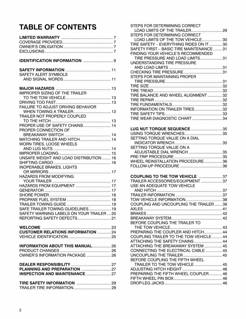
TABLE OF CONTENTSLIMITED WARRANTY ............................................... 7COVERAGE PROVIDED .............................................. 7OWNER’S OBLIGATION ............................................. 7EXCLUSIONS .............................................................. 7
IDENTIFICATION INFORMATION ........................... 9
SAFETY INFORMATION ......................................... 11SAFETY ALERT SYMBOLS AND SIGNAL WORDS ........................................... 11
MAJOR HAZARDS .................................................. 13IMPROPER SIZING OF THE TRAILER TO THE TOW VEHICLE ......................................... 13DRIVING TOO FAST.................................................. 13FAILURE TO ADJUST DRIVING BEHAVIOR WHEN TOWING A TRAILER .................................. 13TRAILER NOT PROPERLY COUPLED TO THE HITCH ...................................................... 13PROPER USE OF SAFETY CHAINS ......................... 14PROPER CONNECTION OF BREAKAWAY SWITCH .......................................... 14MATCHING TRAILER AND HITCH ............................ 14WORN TIRES, LOOSE WHEELS AND LUG NUTS .................................................... 14IMPROPER LOADING ............................................... 15UNSAFE WEIGHT AND LOAD DISTRIBUTION ........ 16SHIFTING CARGO .................................................... 16INOPERABLE BRAKES, LIGHTS OR MIRRORS ........................................................ 17HAZARDS FROM MODIFYING YOUR TRAILER ..................................................... 17HAZARDS FROM EQUIPMENT ................................ 17GENERATOR ............................................................ 17SHORE POWER ........................................................ 18PROPANE FUEL SYSTEM ........................................ 18TRAILER TOWING GUIDE ........................................ 19SAFE TRAILER TOWING GUIDELINES .................... 19SAFETY WARNING LABELS ON YOUR TRAILER .... 20REPORTING SAFETY DEFECTS .............................. 21
WELCOME .............................................................. 23CUSTOMER RELATIONS INFORMATION ............ 24VEHICLE IDENTIFICATION ....................................... 25
INFORMATION ABOUT THIS MANUAL ................. 26PRODUCT CHANGES .............................................. 26OWNER’S INFORMATION PACKAGE ...................... 26
DEALER RESPONSIBILITY .................................... 27PLANNING AND PREPARATION ........................... 27INSPECTION AND MAINTENANCE ....................... 27
TIRE SAFETY INFORMATION ............................... 29TRAILER TIRE INFORMATION .................................. 29
STEPS FOR DETERMINING CORRECT LOAD LIMITS OF THE TRAILER ............................ 29STEPS FOR DETERMINING CORRECT LOAD LIMITS OF THE TOW VEHICLE .................. 30TIRE SAFETY – EVERYTHING RIDES ON IT ............ 30SAFETY FIRST – BASIC TIRE MAINTENANCE ........ 31FINDING YOUR VEHICLE’S RECOMMENDED TIRE PRESSURE AND LOAD LIMITS.................... 31UNDERSTANDING TIRE PRESSURE AND LOAD LIMITS ................................................ 31CHECKING TIRE PRESSURE ................................... 31STEPS FOR MAINTAINING PROPER TIRE PRESSURE ................................................... 31TIRE SIZE .................................................................. 32TIRE TREAD .............................................................. 32TIRE BALANCE AND WHEEL ALIGNMENT ............. 32TIRE REPAIR ............................................................. 32TIRE FUNDAMENTALS ............................................. 32INFORMATION ON TRAILER TIRES ......................... 32TIRE SAFETY TIPS .................................................... 33TIRE WEAR DIAGNOSTIC CHART ........................... 34
LUG NUT TORQUE SEQUENCE ............................ 35USING TORQUE WRENCHES.................................. 35SETTING TORQUE VALUE ON A DIAL INDICATOR WRENCH ........................................... 35SETTING TORQUE VALUE ON A ADJUSTABLE DIAL WRENCH .............................. 35PRE-TRIP PROCEDURE ........................................... 35WHEEL REINSTALLATION PROCEDURE ................ 36FOLLOW-UP PROCEDURE ...................................... 36
COUPLING TO THE TOW VEHICLE ..................... 37TRAILER ACCESSORIES/EQUIPMENT ................... 37USE AN ADEQUATE TOW VEHICLE AND HITCH ........................................................... 37TRAILER INFORMATION .......................................... 37TOW VEHICLE INFORMATION ................................. 38COUPLING AND UNCOUPLING THE TRAILER ....... 39AXLES ....................................................................... 41BRAKES .................................................................... 42BREAKAWAY SYSTEM .............................................. 42BEFORE COUPLING THE TRAILER TO THE TOW VEHICLE ............................................... 43PREPARING THE COUPLER AND HITCH ................ 44COUPLING TRAILER TO THE TOW VEHICLE ......... 44ATTACHING THE SAFETY CHAINS ......................... 44ATTACHING THE BREAKAWAY SYSTEM ................ 45CONNECTING THE ELECTRICAL CABLE ............... 45UNCOUPLING THE TRAILER ................................... 45BEFORE COUPLING THE FIFTH WHEEL TRAILER TO THE TOW VEHICLE ......................... 45ADJUSTING HITCH HEIGHT .................................... 46PREPARING THE FIFTH WHEEL COUPLER ............ 46FIFTH WHEEL PIN BOX ............................................ 46DROP-LEG JACKS .................................................... 46
3
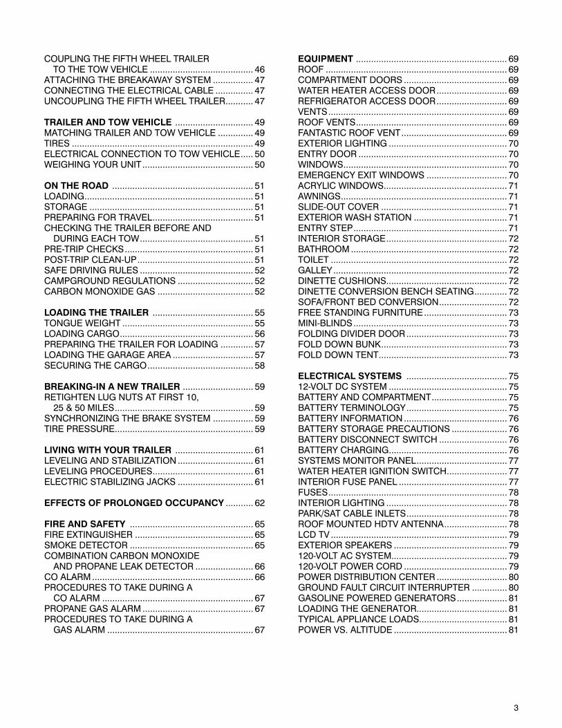
COUPLING THE FIFTH WHEEL TRAILER TO THE TOW VEHICLE ......................................... 46ATTACHING THE BREAKAWAY SYSTEM ................ 47CONNECTING THE ELECTRICAL CABLE ............... 47UNCOUPLING THE FIFTH WHEEL TRAILER ........... 47
TRAILER AND TOW VEHICLE ............................... 49MATCHING TRAILER AND TOW VEHICLE .............. 49TIRES ........................................................................ 49ELECTRICAL CONNECTION TO TOW VEHICLE ..... 50WEIGHING YOUR UNIT ............................................ 50
ON THE ROAD ........................................................ 51LOADING ................................................................... 51STORAGE ................................................................. 51PREPARING FOR TRAVEL ........................................ 51CHECKING THE TRAILER BEFORE AND DURING EACH TOW ............................................. 51PRE-TRIP CHECKS ................................................... 51POST-TRIP CLEAN-UP .............................................. 51SAFE DRIVING RULES ............................................. 52CAMPGROUND REGULATIONS .............................. 52CARBON MONOXIDE GAS ...................................... 52
LOADING THE TRAILER ........................................ 55TONGUE WEIGHT .................................................... 55LOADING CARGO ..................................................... 56PREPARING THE TRAILER FOR LOADING ............. 57LOADING THE GARAGE AREA ................................ 57SECURING THE CARGO .......................................... 58
BREAKING-IN A NEW TRAILER ............................ 59RETIGHTEN LUG NUTS AT FIRST 10, 25 & 50 MILES ....................................................... 59SYNCHRONIZING THE BRAKE SYSTEM ................ 59TIRE PRESSURE ....................................................... 59
LIVING WITH YOUR TRAILER ............................... 61LEVELING AND STABILIZATION .............................. 61LEVELING PROCEDURES ........................................ 61ELECTRIC STABILIZING JACKS .............................. 61
EFFECTS OF PROLONGED OCCUPANCY ........... 62
FIRE AND SAFETY ................................................. 65FIRE EXTINGUISHER ............................................... 65SMOKE DETECTOR ................................................. 65COMBINATION CARBON MONOXIDE AND PROPANE LEAK DETECTOR ....................... 66CO ALARM ................................................................ 66PROCEDURES TO TAKE DURING A CO ALARM ............................................................ 67PROPANE GAS ALARM ............................................ 67PROCEDURES TO TAKE DURING A GAS ALARM .......................................................... 67
EQUIPMENT ............................................................ 69ROOF ........................................................................ 69COMPARTMENT DOORS ......................................... 69WATER HEATER ACCESS DOOR ............................ 69REFRIGERATOR ACCESS DOOR ............................ 69VENTS ....................................................................... 69ROOF VENTS ............................................................ 69FANTASTIC ROOF VENT .......................................... 69EXTERIOR LIGHTING ............................................... 70ENTRY DOOR ........................................................... 70WINDOWS ................................................................. 70EMERGENCY EXIT WINDOWS ................................ 70ACRYLIC WINDOWS ................................................. 71AWNINGS .................................................................. 71SLIDE-OUT COVER .................................................. 71EXTERIOR WASH STATION ..................................... 71ENTRY STEP ............................................................. 71INTERIOR STORAGE ................................................ 72BATHROOM .............................................................. 72TOILET ...................................................................... 72GALLEY ..................................................................... 72DINETTE CUSHIONS................................................ 72DINETTE CONVERSION BENCH SEATING ............. 72SOFA/FRONT BED CONVERSION ........................... 72FREE STANDING FURNITURE ................................. 73MINI-BLINDS ............................................................. 73FOLDING DIVIDER DOOR ........................................ 73FOLD DOWN BUNK .................................................. 73FOLD DOWN TENT ................................................... 73
ELECTRICAL SYSTEMS ........................................ 7512-VOLT DC SYSTEM ............................................... 75BATTERY AND COMPARTMENT .............................. 75BATTERY TERMINOLOGY ........................................ 75BATTERY INFORMATION ......................................... 76BATTERY STORAGE PRECAUTIONS ...................... 76BATTERY DISCONNECT SWITCH ........................... 76BATTERY CHARGING ............................................... 76SYSTEMS MONITOR PANEL .................................... 77WATER HEATER IGNITION SWITCH ........................ 77INTERIOR FUSE PANEL ........................................... 77FUSES ....................................................................... 78INTERIOR LIGHTING ................................................ 78PARK/SAT CABLE INLETS ........................................ 78ROOF MOUNTED HDTV ANTENNA ......................... 78LCD TV ...................................................................... 79EXTERIOR SPEAKERS ............................................. 79120-VOLT AC SYSTEM.............................................. 79120-VOLT POWER CORD ......................................... 79POWER DISTRIBUTION CENTER ............................ 80GROUND FAULT CIRCUIT INTERRUPTER .............. 80GASOLINE POWERED GENERATORS .................... 81LOADING THE GENERATOR.................................... 81TYPICAL APPLIANCE LOADS................................... 81POWER VS. ALTITUDE ............................................. 81
4
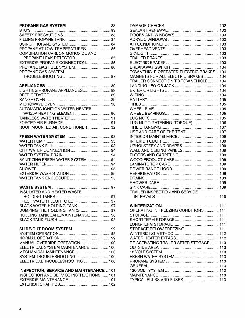
PROPANE GAS SYSTEM ....................................... 83BTU’S ........................................................................ 83SAFETY PRECAUTIONS ........................................... 83FILLING PROPANE TANK ......................................... 84USING PROPANE SYSTEM ...................................... 84PROPANE AT LOW TEMPERATURES ...................... 85COMBINATION CARBON MONOXIDE AND PROPANE LEAK DETECTOR ................................ 85EXTERIOR PROPANE CONNECTION ...................... 85PROPANE GAS FUEL SYSTEM ................................ 86PROPANE GAS SYSTEM TROUBLESHOOTING ........................................... 87
APPLIANCES .......................................................... 89LIGHTING PROPANE APPLIANCES ......................... 89REFRIGERATOR ....................................................... 89RANGE-OVEN ........................................................... 89MICROWAVE OVEN .................................................. 90AUTOMATIC IGNITION WATER HEATER W/120V HEATING ELEMENT ................................ 90TANKLESS WATER HEATER .................................... 91FORCED AIR FURNACE ........................................... 91ROOF MOUNTED AIR CONDITIONER ..................... 92
FRESH WATER SYSTEM ....................................... 93WATER PUMP ........................................................... 93WATER TANK FILL .................................................... 93CITY WATER CONNECTION .................................... 94WATER SYSTEM DRAIN ........................................... 94SANITIZING FRESH WATER SYSTEM ..................... 94WATER FILTER .......................................................... 94SHOWER ................................................................... 95EXTERIOR WASH STATION ..................................... 95WATER TANK ENCLOSURE ..................................... 95
WASTE SYSTEM ..................................................... 97INSULATED AND HEATED WASTE HOLDING TANKS .................................................. 97FRESH WATER FLUSH TOILET ................................ 97BLACK WATER HOLDING TANK .............................. 97DUMPING THE HOLDING TANKS ............................ 97HOLDING TANK CARE/MAINTENANCE .................. 98BLACK TANK FLUSH ................................................ 98
SLIDE-OUT ROOM SYSTEM ................................. 99SYSTEM OPERATION ............................................... 99NORMAL OPERATION .............................................. 99MANUAL OVERRIDE OPERATION ........................... 99ELECTRICAL SYSTEM MAINTENANCE ................. 100MECHANICAL MAINTENANCE .............................. 100SYSTEM TROUBLESHOOTING ............................. 100ELECTRICAL TROUBLESHOOTING ...................... 100
INSPECTION, SERVICE AND MAINTENANCE .. 101INSPECTION AND SERVICE INSTRUCTIONS ....... 101EXTERIOR MAINTENANCE .................................... 101EXTERIOR GRAPHICS............................................ 102
DAMAGE CHECKS ................................................. 102SEALANT RENEWAL .............................................. 102DOORS AND WINDOWS ........................................ 103ACRYLIC WINDOWS ............................................... 103AIR CONDITIONER ................................................. 103OVERHEAD VENTS ................................................ 103SKYLIGHT ............................................................... 103TRAILER BRAKES ................................................... 103ELECTRIC BRAKES ................................................ 103BREAKAWAY SWITCH ............................................ 104TOW VEHICLE OPERATED ELECTRIC BRAKES ... 104MAGNETS FOR ALL ELECTRIC BRAKES .............. 104TRAILER CONNECTION TO TOW VEHICLE .......... 104LANDING LEG OR JACK ........................................ 104EXTERIOR LIGHTS ................................................. 104WIRING.................................................................... 104BATTERY ................................................................. 105TIRES ...................................................................... 105WHEEL RIMS .......................................................... 105WHEEL BEARINGS ................................................. 105LUG NUTS ............................................................... 105LUG NUT TIGHTENING (TORQUE) ........................ 106TIRE CHANGING .................................................... 107USE AND CARE OF THE TENT .............................. 107INTERIOR MAINTENANCE ..................................... 109INTERIOR ODOR .................................................... 109UPHOLSTERY AND DRAPES ................................. 109WALL AND CEILING PANELS ................................. 109FLOORS AND CARPETING .................................... 109WOOD PRODUCT CARE ........................................ 109LAMINATE TOP CARE ............................................ 109POWER RANGE HOOD .......................................... 109REFRIGERATOR ..................................................... 109DRAINS ................................................................... 109SHOWER CARE ...................................................... 109SINK CARE .............................................................. 109TRAILER INSPECTION AND SERVICE INTERVALS .......................................................... 110
WINTERIZATION ................................................... 111OPERATING IN FREEZING CONDITIONS ............. 111STORAGE ............................................................... 111SHORT-TERM STORAGE ........................................ 111LONG-TERM STORAGE ......................................... 111STORAGE BELOW FREEZING ............................... 111WINTERIZING METHOD ......................................... 112WATER HEATER BYPASS ....................................... 112RE-ACTIVATING TRAILER AFTER STORAGE ........ 113OUTSIDE AREA ...................................................... 11312-VOLT SYSTEM ................................................... 113FRESH WATER SYSTEM ........................................ 113PROPANE SYSTEM ................................................ 113GENERAL ................................................................ 113120-VOLT SYSTEM ................................................. 113MAINTENANCE ....................................................... 113TYPICAL BULBS AND FUSES ................................ 113
5
HITCH SYSTEMS .................................................. 114
SCHEMATICS ....................................................... 115TYPICAL FRESH WATER SYSTEM ......................... 116TYPICAL DRAIN PLUMBING SYSTEM ................... 117TYPICAL PROPANE SYSTEM ................................. 118SEVEN PIN TRAILER ELECTRICAL CONNECTOR .... 119TYPICAL 12 VOLT EXTERIOR CIRCUITS ............... 120TYPICAL 12 VOLT INTERIOR CIRCUITS ................ 121MONITOR PANEL WIRING ..................................... 122SLIDEOUT CIRCUIT WIRING .................................. 123STEREO SPEAKER WIRING ................................... 124RVP COLEMAN THERMOSTAT WIRING ................ 125TV SINGLE LOCATION ........................................... 126TV DOUBLE LOCATION .......................................... 127TYPICAL 120 VOLT SYSTEM .................................. 128TYPICAL 120 VOLT CIRCUIT WIRING .................... 129
SUPPLIERS SERVICE PHONE AND INTERNET LISTING .............................................. 130

6
This page intentionally left blank.
7
LIMITED WARRANTYFOR TRAILERS MANUFACTURED BY LANCE CAMPER MANUFACTURING CORPORATION
(“LANCE”) SOLD IN THE UNITED STATES AND CANADA
Lance warrants to the original end user purchaser (“Owner”) of this Trailer (“Trailer”) to be free of defects in materi-als and workmanship and for structural integrity, under normal use, with reasonable care and maintenance, for one (1) year from the date of purchase (the “Warranty Period”), subject to the exclusions given below.
COVERAGE PROVIDEDWithin the Warranty Period, Lance is obligated to repair or replace any part covered by this warranty proven defec-tive. In the event of such an occurrence, the Owner should contact the selling dealer for a service appointment. If it is not possible to return to the selling dealer, call the Lance Factory Service Department, and they will provide you with the location of the nearest authorized dealer or repair facility. The cost of transporting the Trailer to the dealer or service center shall be incurred and paid for by the Owner.
This is the only warranty given with the purchase of the Trailer other than express or implied warranties given by the component manufacturers. Any warranties implied by law are limited to the Warranty Period. Any other warranty, express or implied, not provided for in this Limited Warranty is waived by the Owner, to the extent allowed by law.
OWNER’S OBLIGATIONThe purchaser must notify Lance or a Lance authorized dealer of any defect promptly upon discovery. Warranty repairs by a non Lance Trailer dealer or service center must be approved by the Lance Factory Ser-vice Department prior to any work being started.
EXCLUSIONSThe scope of this warranty is expressly limited to only items actually constructed by Lance. Lance therefore makes no warranty with respect to component parts constructed or assembled by other manufacturers, including, but not limited to, all electrical devices (TV, sound systems, DVD player, antennas, batteries, etc.), the propane appliances, electrical appliances, heaters, refrigerators, plumbing fixtures, light fixtures, lights, entrance door and windows. Such component parts may be warranted by their respective manufacturers, and copies of such warranties are included with the Trailer.
This warranty does not cover damage caused by or related to (1) normal wear and tear, (2) accidents, abuse, misuse or negligence, (3) failure to comply with instructions contained in the Owner’s Manual, (4) any alteration or modification of the Trailer, or (5) environmental conditions, including, but not limited to, road salt, hail, or windstorm. Nor does this warranty apply to parts made out of cloth, leather, wood, paint, or chrome, which have been affected by airborne fallout, including, but not limited to, chemicals and tree sap.
No payment or other compensation will be made for incidental expenses, including, but not limited to, towing, tele-phone, transportation, lodging, travel, gasoline, loss of pay or indirect or consequential damage including, but not limited to, loss of use of the Trailer, inconvenience, damage or injury to person or property, or loss of revenue, which might be paid, incurred or sustained by reason of manufacturer’s defect covered by this warranty. Lance does not warranty equipment or accessories installed at any dealership or other place of business, or by any other party.
As the manufacturer of the Trailer that you purchased, Lance does not know the purpose you have in mind for your tow vehicle and Trailer, nor does Lance know the Gross Vehicle Weight Rating (“GVWR”) of your tow vehicle. There-fore, Lance makes no warranties or representations, express or implied, as to the performance of your tow vehicle with the Trailer or whether the match up of your tow vehicle and Trailer exceeds the GVWR as specified by your tow vehicle’s manufacturer. Specifically, there is no express or implied warranty of merchantability or of fitness for the particular match of your tow vehicle to any particular Trailer.
This Limited Warranty is intended to comply with the requirements of both State and Federal laws. Any part of this Limited Warranty in conflict with any law shall be ineffective to the extent of any such conflict. This warranty gives you specific legal rights, and you may also have other rights, which may vary from state to state.

8
This page intentionally left blank.
9
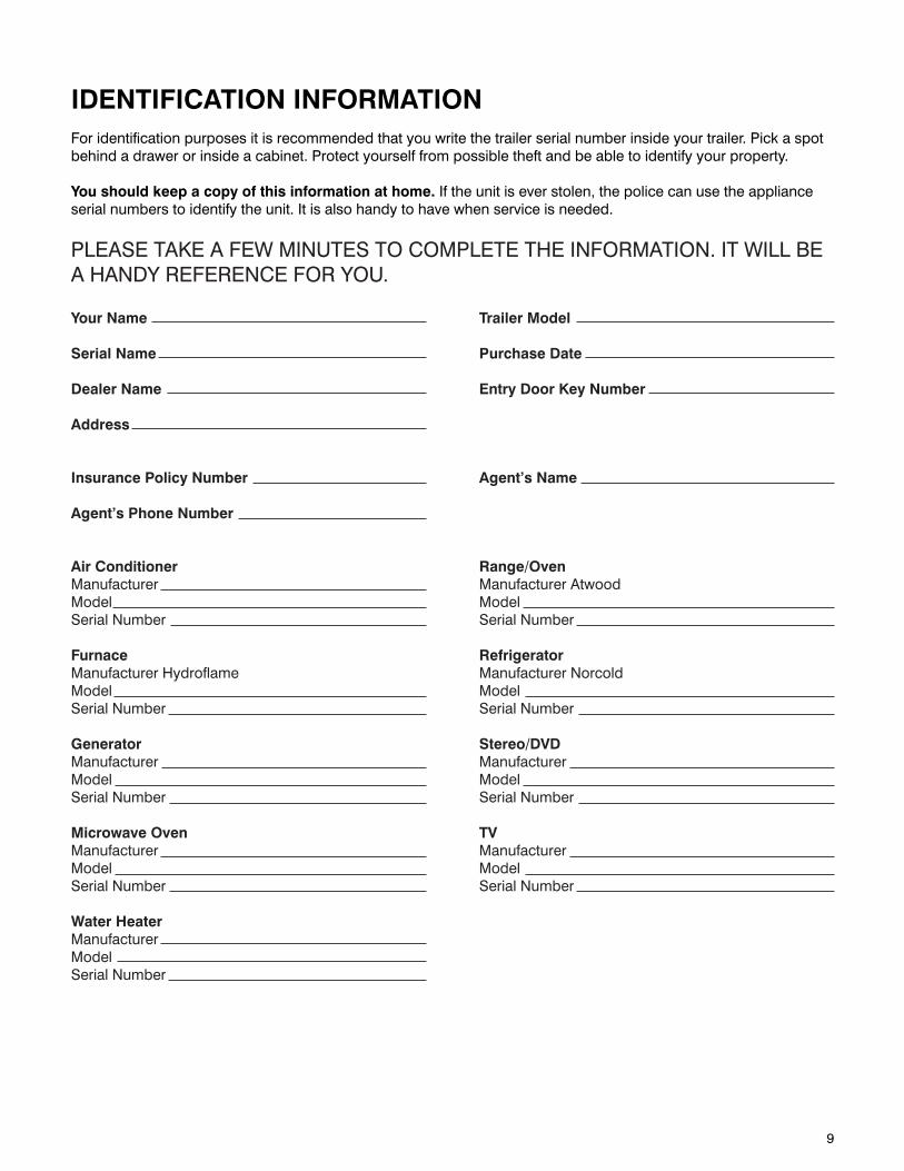
IDENTIFICATION INFORMATIONFor identification purposes it is recommended that you write the trailer serial number inside your trailer. Pick a spot behind a drawer or inside a cabinet. Protect yourself from possible theft and be able to identify your property.
You should keep a copy of this information at home. If the unit is ever stolen, the police can use the appliance serial numbers to identify the unit. It is also handy to have when service is needed.
PLEASE TAKE A FEW MINUTES TO COMPLETE THE INFORMATION. IT WILL BE A HANDY REFERENCE FOR YOU.
Your Name Trailer Model
Serial Name Purchase Date
Dealer Name Entry Door Key Number
Address
Insurance Policy Number Agent’s Name
Agent’s Phone Number
Air Conditioner Range/OvenManufacturer Manufacturer AtwoodModel Model Serial Number Serial Number
Furnace RefrigeratorManufacturer Hydroflame Manufacturer NorcoldModel Model Serial Number Serial Number
Generator Stereo/DVD Manufacturer Manufacturer Model Model Serial Number Serial Number
Microwave Oven TVManufacturer Manufacturer Model Model Serial Number Serial Number
Water HeaterManufacturerModelSerial Number

10
This page intentionally left blank.
11
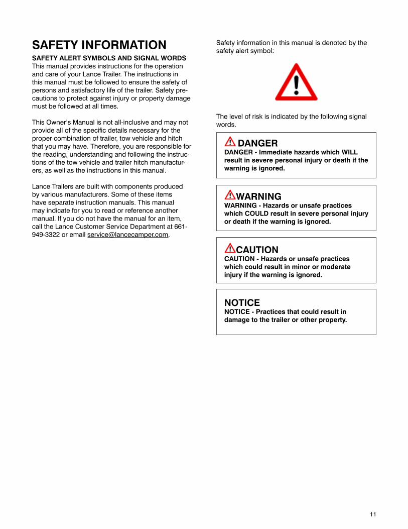
SAFETY INFORMATIONSAFETY ALERT SYMBOLS AND SIGNAL WORDSThis manual provides instructions for the operation and care of your Lance Trailer. The instructions in this manual must be followed to ensure the safety of persons and satisfactory life of the trailer. Safety pre-cautions to protect against injury or property damage must be followed at all times.
This Owner’s Manual is not all-inclusive and may not provide all of the specific details necessary for the proper combination of trailer, tow vehicle and hitch that you may have. Therefore, you are responsible for the reading, understanding and following the instruc-tions of the tow vehicle and trailer hitch manufactur-ers, as well as the instructions in this manual.
Lance Trailers are built with components produced by various manufacturers. Some of these items have separate instruction manuals. This manual may indicate for you to read or reference another manual. If you do not have the manual for an item, call the Lance Customer Service Department at 661-949-3322 or email [email protected].
Safety information in this manual is denoted by the safety alert symbol:
The level of risk is indicated by the following signal words.
DANGERDANGER - Immediate hazards which WILL result in severe personal injury or death if the warning is ignored.
WARNINGWARNING - Hazards or unsafe practices which COULD result in severe personal injury or death if the warning is ignored.
CAUTIONCAUTION - Hazards or unsafe practices which could result in minor or moderate injury if the warning is ignored.
NOTICENOTICE - Practices that could result in damage to the trailer or other property.

12
This page intentionally left blank.
13
MAJOR HAZARDSLoss of control of the trailer or trailer/tow vehicle combination can result in death or serious injury. The most common causes for loss of control of the trailer are:
• Impropersizingthetrailerforthetowvehicle,orvice versa.
• ExcessiveSpeed:Drivingtoofastforthecondi-tions.
• Failuretoadjustdrivingbehaviorwhentowingatrailer.
• Overloadingand/orimproperweightdistribu-tion.
• Improperormis-couplingofthetrailertothehitch.
• Improperbrakingandsteeringunderswaycon-ditions.
• Notmaintainingpropertirepressure.• Notkeepinglugnutstight.
IMPROPER SIZING OF THE TRAILER TO THE TOW VEHICLETrailers that weigh too much for the towing vehicle can cause stability problems, which can lead to death or serious injury. Furthermore, the additional strain put on the engine and drive-train may lead to seri-ous tow vehicle maintenance problems. For these reasons the maximum towing capacity of your towing vehicle should not be exceeded. The towing capac-ity of your tow vehicle, in terms of maximum Gross Trailer Weight (GTW) and maximum Gross Combined Weight Rating (GCWR) can be found in the tow vehicles Owner’s Manual.
DANGERUse of an under-rated hitch, ball or tow ve-hicle can result in loss of control leading to death or serious injury.
Make certain your hitch and tow vehicle are rated for your trailer.
DRIVING TOO FASTWith ideal road conditions, the maximum recom-mended speed for safely towing a trailer is 60 mph. If you drive too fast, the trailer is more likely to sway, thus increasing the possibility for loss of control. Also your tires may overheat, thus increasing the possibil-ity of a blowout.
WARNINGDriving too fast for conditions can result in loss of control and cause death or serious injury.
Adjust speed down when towing trailer.
FAILURE TO ADJUST DRIVING BEHAVIOR WHEN TOWING A TRAILERWhen towing a trailer, you will have decreased accel-eration, increased stopping distance, and increased turning radius (which means you must make wider turns to keep from hitting curbs, vehicles, and any-thing else that is on the inside corner). Furthermore, the trailer will change the handling characteristics of your towing vehicle, making it more sensitive to steering inputs and more likely to be pushed around in windy conditions or when being passed by large vehicles. In addition, you will need a longer distance to pass, due to slower acceleration and increased length. With this in mind:
• Bealertforslipperyconditions.Youaremorelikely to be affected by slippery road surfaces when driving a tow vehicle with a trailer, than driving a tow vehicle without a trailer.
• Anticipatethetrailer“swaying.”Swayingcanbe caused by excessive steering, wind gusts, roadway edges, or by the trailer reaction to the pressure wave created by passing trucks and buses.
• Whenencounteringtrailersway,takeyourfootoff the accelerator, and steer as little as possible in order to stay on the road. Use small “trim-like” steering adjustments. Do not attempt to steer out of the sway; you’ll only make it worse. Also, do not apply the tow vehicle brakes to cor-rect trailer swaying. The application of the trailer brakes alone will tend to straighten out the combination, especially when going downhill.
• Checkrearviewmirrorsfrequentlytoobservethe trailer and traffic.
• Uselowergearwhendrivingdownsteeporlong grades. Use the engine and transmission as a brake. Do not ride the brakes, as they can overheat and become ineffective.
• Beawareofyourtrailerheight,especiallywhenapproaching bridges, roofed areas and around trees.
TRAILER NOT PROPERLY COUPLED TO THE HITCHIt is critical that the trailer be securely coupled to the hitch, and that the safety chains and emergency breakaway brake lanyard are correctly attached. Uncoupling may result in death or serious injury to you and to others.
14
WARNINGCoupler and hitch selection and condition are critical for safe towing.
Uncoupling can result in death or serious injury.
• Makesurethehitchandballareratedfor the trailer.
• Makesurethehitch[ballsize]matchesthe coupler.
• Checkthehitchballforwear,corrosionand cracks before coupling.
• Replaceworn,corrodedorcrackedhitch ball before coupling to the trailer.
• Makesurethehitchballistighttothehitch before coupling the trailer.
WARNINGAn improperly coupled trailer can result in death or serious injury.
Do not move the trailer until:
• Thecouplerissecuredandlocked;
• Thesafetychainsaresecuredtothetowvehicle;and
• Thetrailerjacksarefullyretracted.
Do not tow the trailer on the road until:
• Thetrailerbrakesarechecked;
• Thebreakawayswitchisconnectedtothetowvehicle;
• Theloadissecuredtothetrailer;and
• Thetrailerlightsareconnectedandchecked.
PROPER USE OF SAFETY CHAINSSafety chains are provided on bumper pull trailers so that control of the trailer can still be maintained if the trailer comes loose from the tow vehicle for any reason.
To be effective, safety chains must be in good condition and properly connected to the tow vehicle.
WARNINGIncorrect rigging of the safety chains can result in loss of control of the trailer and tow vehicle, leading to death or serious injury, if the trailer uncouples from the tow vehicle.
Chains must:
• Fastentoframeoftowvehicle,nottohitch or ball.
• Crossunderneathhitchandcouplerwith minimum slack to permit turn-ing and to hold tongue up, if the trailer comes loose.
PROPER CONNECTION OF BREAKAWAY SWITCHYour trailer is equipped with a breakaway system that can apply the brakes on your trailer if your trailer comes loose from the hitch for any reason. The breakaway system, including the trailer battery, must be in good condition and properly rigged to be effective.
WARNINGAn ineffective breakaway system can result in a runaway trailer, leading to death or seri-ous injury if the coupler or ball hitch fails.
Test the function of the breakaway system before towing the trailer. Do not tow the trailer if the breakaway system is not work-ing;haveitservicedorrepaired.
Connect the breakaway lanyard to the tow vehicle –
NOTtothesafetychains;and
NOT to the hitch, ball or support.
MATCHING TRAILER AND HITCH
DANGERUse of an under-rated hitch, ball or tow vehicle can result in loss of control leading to death or serious injury.
Make certain your hitch and tow vehicle are rated for your trailer.
WORN TIRES, LOOSE WHEELS AND LUG NUTSJust as with your tow vehicle, the trailer tires and wheels are important safety items. Therefore, it is essential to inspect the trailer tires before each tow.
15
If a tire has a bald spot, bulge, cut, cracks, or is showing any cords, replace the tire before towing. If a tire has uneven tread wear, take the trailer to a dealer service center for diagnosis. Uneven tread wear can be caused by tire imbalance, axle misalignment or incorrect inflation.
Tires with too little tread will not provide adequate frictional forces on wet roadways and can result in loss of control, leading to death or serious injury.
Improper tire pressure causes increased tire wear and may reduce trailer stability, which can result in a tire blowout or possible loss of control. Therefore, before each tow you must also check the tire pres-sure. Remember, the proper tire pressure is listed on the Certification (VIN) label, and should be checked when tires are cold. Allow 3 hours cool-down after driving as much as 1 mile at 40 mph before checking tire pressure.
WARNINGImproper tire pressure may cause an un- stable trailer. Blowout and loss of control may occur. Death or serious injury can result.
Make sure of proper tire pressure before towing trailer. Inflate tires to pressure indi-cated on the Federal Certification/VIN label.
The tightness of the lug nuts is very important in keeping the wheels properly seated to the hub. Before each tow, check to make sure they are tight-ened to the proper torque.
WARNINGMetal creep between the wheel rim and lug nuts (bolts) will cause rim to loosen.
Death or injury can occur if wheel comes off.
Tighten lug nuts (bolts) before each tow.
The proper tightening sequence and tightness (torque) for lug nuts is listed in the “Lug Nut Sequence” section of this manual. Use a calibrated torque wrench to tighten the lug nuts.
Lug nuts are also prone to loosen after first being assembled. When driving a new trailer (or after wheels have been remounted), check to make sure they are tightened to the proper torque after the first 10, 25 and 50 miles of driving and before each tow thereafter. Failure to perform this check can result in a wheel parting from the trailer and a crash, leading to death or serious injury.
WARNINGLug nuts are prone to loosen after being first assembled. Death or serious injury can result.
Check lug nuts for tightness on a new trailer, and after re-mounting a wheel at 10, 25 and 50 miles.
WARNINGInadequate lug nut torque can cause a wheel to part while towing. Death or serious injury can result.
Make sure lug nuts are tight before towing trailer.
IMPROPER LOADINGThe total weight of the load you put in or on the trailer, plus the empty weight of the trailer itself, must not exceed the trailer’s Gross Vehicle Weight Rating (GVWR). If you do not know the empty weight of the trailer, you must measure it at a commercial scale. In addition, you must distribute the load in the trailer such that the load on any axle does not exceed the Gross Axle Weight Rating (GAWR). The GVWR and GAWR’s are listed on the Federal Certification/VIN label mounted on the front left side of the trailer.
WARNINGAn overloaded trailer can result in failure or in loss of control of the trailer, leading to death or serious injury.
Never load a trailer so that the weight on any tire exceeds its rating.
Never exceed the trailer Gross Vehicle Weight Rating (GVWR).
Never exceed an axle Gross Axle Weight Rating (GAWR).
16
UNSAFE WEIGHT AND LOAD DISTRIBUTIONProper loading of your trailer is essential for your safety. Tire, wheel, axle or structural failure can be caused by overloading.
WARNINGAn overloaded trailer can result in failure or in loss of control of the trailer, leading to death or serious injury.
Never load a trailer so that the weight on any tire exceeds its rating.
Never exceed the trailer Gross Vehicle Weight Rating (GVWR).
Never exceed an axle Gross Axle Weight Rating (GAWR).
Improper front / rear load distribution can lead to poor trailer sway stability or poor tow vehicle handling. Poor trailer sway stability results from tongue weights that are too low, and poor tow vehicle stability results from tongue weights that are too high.
The hitch weight of a loaded trailer (including cargo) should be between 10-15% of the total weight of the trailer on a bumper pull trailer.
The hitch weight of a loaded trailer (including cargo) should be between 20-25% of the total weight of the trailer on a 5th wheel trailer.
Uneven left/right load distribution can cause tire, wheel, axle or structural failure. Be sure your trailer is evenly loaded left / right. Towing stability also depends on keeping the center of gravity as low as possible.
WARNINGAn improperly distributed load can result in loss of control of the trailer, and can lead to death or serious injury.
Proper tongue weight is essential for stable trailer handling.
Distribute the load front to rear to provide proper tongue weight.
Distribute the load evenly, right and left, to avoid tire overload.
Keeping the center of gravity low and centered is essential to minimize the risk of tip-over.
SHIFTING CARGOSince the trailer “ride” can be bumpy and rough, you must secure your cargo so that it does not shift while the trailer is being towed.
WARNINGA shifting load can result in failure, or to loss of control of the trailer, and can lead to death or serious injury.
You must secure all loads to prevent the load from shifting while trailering.
WARNINGCarbon Monoxide is toxic. Breathing it can cause unconsciousness and even kill you.
Do not operate a generator, portable grills, portable heaters, portable lanterns or portable stoves inside the trailer.
WARNINGNever transport people inside your Lance Trailer. Besides putting their lives at risk, the transport of people may be illegal.
WARNINGYour Lance Trailer is not capable of safely transporting flammable, explosive, poison-ous or other dangerous materials.
Exceptions:
• Fuelinthetanksofvehiclesthatarebeinghauled.
• Fuelstoredinpropercontainersusedintrailer living quarters for cooking.
• Fuelstoredinthetankofanonboard generator.
17
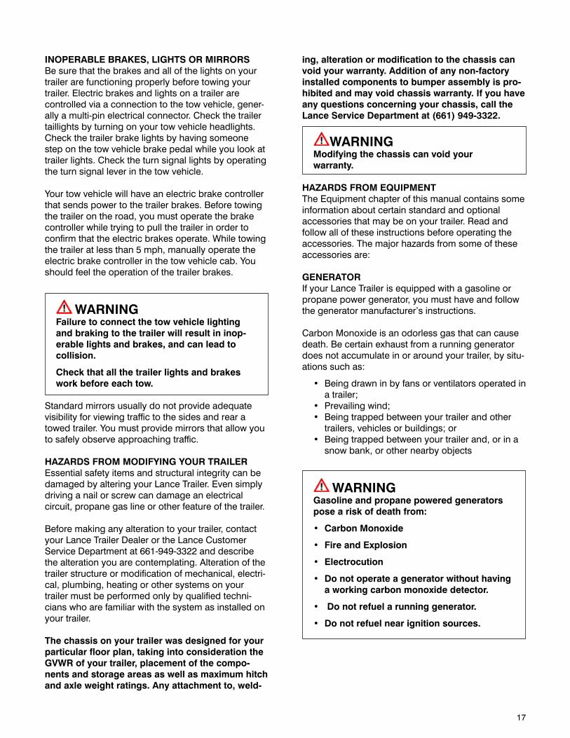
INOPERABLE BRAKES, LIGHTS OR MIRRORSBe sure that the brakes and all of the lights on your trailer are functioning properly before towing your trailer. Electric brakes and lights on a trailer are controlled via a connection to the tow vehicle, gener-ally a multi-pin electrical connector. Check the trailer taillights by turning on your tow vehicle headlights. Check the trailer brake lights by having someone step on the tow vehicle brake pedal while you look at trailer lights. Check the turn signal lights by operating the turn signal lever in the tow vehicle.
Your tow vehicle will have an electric brake controller that sends power to the trailer brakes. Before towing the trailer on the road, you must operate the brake controller while trying to pull the trailer in order to confirm that the electric brakes operate. While towing the trailer at less than 5 mph, manually operate the electric brake controller in the tow vehicle cab. You should feel the operation of the trailer brakes.
WARNINGFailure to connect the tow vehicle lighting and braking to the trailer will result in inop-erable lights and brakes, and can lead to collision.
Check that all the trailer lights and brakes work before each tow.
Standard mirrors usually do not provide adequate visibility for viewing traffic to the sides and rear a towed trailer. You must provide mirrors that allow you to safely observe approaching traffic.
HAZARDS FROM MODIFYING YOUR TRAILEREssential safety items and structural integrity can be damaged by altering your Lance Trailer. Even simply driving a nail or screw can damage an electrical circuit, propane gas line or other feature of the trailer.
Before making any alteration to your trailer, contact your Lance Trailer Dealer or the Lance Customer Service Department at 661-949-3322 and describe the alteration you are contemplating. Alteration of the trailer structure or modification of mechanical, electri-cal, plumbing, heating or other systems on your trailer must be performed only by qualified techni-cians who are familiar with the system as installed on your trailer.
The chassis on your trailer was designed for your particular floor plan, taking into consideration the GVWR of your trailer, placement of the compo-nents and storage areas as well as maximum hitch and axle weight ratings. Any attachment to, weld-
ing, alteration or modification to the chassis can void your warranty. Addition of any non-factory installed components to bumper assembly is pro-hibited and may void chassis warranty. If you have any questions concerning your chassis, call the Lance Service Department at (661) 949-3322.
WARNINGModifying the chassis can void your warranty.
HAZARDS FROM EQUIPMENTThe Equipment chapter of this manual contains some information about certain standard and optional accessories that may be on your trailer. Read and follow all of these instructions before operating the accessories. The major hazards from some of these accessories are:
GENERATORIf your Lance Trailer is equipped with a gasoline or propane power generator, you must have and follow the generator manufacturer’s instructions.
Carbon Monoxide is an odorless gas that can cause death. Be certain exhaust from a running generator does not accumulate in or around your trailer, by situ-ations such as:
• Beingdrawninbyfansorventilatorsoperatedina trailer;
• Prevailingwind;• Beingtrappedbetweenyourtrailerandother
trailers, vehicles or buildings; or• Beingtrappedbetweenyourtrailerand,orina
snow bank, or other nearby objects
WARNINGGasoline and propane powered generators pose a risk of death from:
• CarbonMonoxide
• FireandExplosion
• Electrocution
• Donotoperateageneratorwithouthaving a working carbon monoxide detector.
• Donotrefuelarunninggenerator.
• Donotrefuelnearignitionsources.
18
SHORE POWER“Shore Power” is the name given to connecting your trailer to a source of electrical power using a cord specifically designed for that purpose.
WARNINGShore power poses a risk of death due to electrocution.
Always use a grounded connection.
Never connect to an ungrounded source of shore power.
Never remove the “third prong” from the shore power plug.
WARNINGRisk of fire.
Connect only to source of correct voltage.
Do not overload electrical circuits.
Do not use an extension cord to connect to shore power.
Replace fuses with like rating.
PROPANE FUEL SYSTEM
WARNINGCarbon Monoxide is toxic. Breathing it can cause unconsciousness and even kill you.
Make certain the exhaust from propane appliances is directed to the outdoors.
Have a working carbon monoxide detector in the accommodation spaces of your trailer before operating any propane gas appliance.
Do not operate portable grills, portable stoves, portable lanterns or portable heaters inside the trailer.
WARNINGRisk of death due to fire or explosion.
Do not connect a propane gas system to a supply of natural gas.
Extinguish all pilot lights and turn off all appliances and igniters before refilling fuel or propane gas tanks.
Do not fill propane gas tanks to more than 80- percent of capacity.
Do not fill the tank with any gas other than propane.
Do not store propane gas tanks inside the trailer.
WARNINGRisk of fire or explosion
• Ifpropanegasisdetected(bysmellorbythe propane gas detector):
• Donottouchelectricalswitches
• Extinguishflamesandpilotlights
• Opendoorsforventilation
• Shutoffpropanegassupplyatthepropanetank
• Leavetheareauntilodorclears
Correct the source of propane gas leakage before using propane appliances.
Do not use a flame to locate the source of a propane gas leak.
WARNINGIt is not safe to use cooking appliances for comfort heating.
Cooking appliances need fresh air for safe operation.
Before operation:
• Turnonexhausthood
• Openwindow
Failure to comply could result in death or serious injury.

19
TRAILER TOWING GUIDEDriving a vehicle with a trailer in tow is vastly differ-ent from driving the same vehicle without a trailer in tow. Acceleration, maneuverability and braking are all diminished with a trailer in tow. It takes longer to get up to speed; you need more room to turn and pass, and more distance to stop when towing a trailer. You will need to spend time adjusting to the different feel and maneuverability of the tow vehicle with a loaded trailer. Because of the significant differences in all aspects of maneuverability when towing a trailer, the hazards and risks of injury are also much greater than when driving without a trailer. You are responsible for keeping your vehicle and trailer in control, and for all the damage that is caused if you lose control of your vehicle and trailer.
As you did when learning to drive an automobile, find an open area with little or no traffic for your first practice trailering. Of course, before you start towing the trailer, you must follow all of the instructions for inspection, testing, loading and coupling. Also, before you start towing, adjust the mirrors so you can see the trailer as well as the area to the rear of it.
Drive slowly at first, 5 m.p.h. or so, and turn the wheel to get the feel of how the tow vehicle and trailer combination responds. Next, make some right and left hand turns. Watch in your side mirrors to see how the trailer follows the tow vehicle. Turning with a trailer attached requires more room.
Stop the rig a few times from speeds no greater than 10 m.p.h. If your trailer is equipped with brakes, try using different combinations of trailer/electric brake and tow vehicle brake. Note the effect that the trailer brakes have when they are the only brakes used. When properly adjusted, the trailer brakes will come on just before the tow vehicle brakes.
It will take practice to learn how to back up a tow ve-hicle with a trailer attached. Take it slow. Before back-ing up, get out of the tow vehicle and look behind the trailer to make sure that there are no obstacles. Some drivers place their hands at the bottom of the steering wheel, and while the tow vehicle is in reverse, “think” of the hands as being on the top of the wheel. When the hands move to the right (counter-clockwise, as you would do to turn the tow vehicle to the left when moving forward), the rear of the trailer moves to the right. Conversely, rotating the steering wheel clock-wise with your hands at the bottom of the wheel will move the rear of the trailer to the left, while backing up. If you are towing a bumper hitch rig, be careful not to allow the trailer to turn too much, because it will hit the rear of the tow vehicle. To straighten the rig, either pull forward, or turn the steering wheel in the opposite direction.
SAFE TRAILER TOWING GUIDELINES• Rechecktheloadtiedownstomakesurethe
load will not shift during towing.• Beforetowing,checkcoupling,safetychain,
safety brake, tires, wheels and lights.• Checkthelugnutsorboltsfortightness.• Checkcouplertightnessaftertowing50miles.• Adjustthebrakecontrollertoengagethetrailer
brakes before the tow vehicle brakes. Your deal-er can assist you by making this adjustment.
• Useyourmirrorstoverifythatyouhaveroomtochange lanes or pull into traffic.
• Useyourturnsignalswellinadvance.• Allowplentyofstoppingspaceforyourtrailer
and tow vehicle.• Donotdrivesofastthatthetrailerbeginsto
sway due to speed. Never drive faster than 60 m.p.h.
• Allowplentyofroomforpassing.Aruleofthumb is that the passing distance with a trailer is 4 times the passing distance without a trailer.
• Shiftyourautomatictransmissionintoalowergear for city driving.
• Uselowergearsforclimbinganddescendinggrades.
• Donotridethebrakeswhiledescendinggrades; they may get so hot that they stop work-ing. Then you will potentially have a runaway tow vehicle and trailer.
• Toconservefuel,don’tusefullthrottletoclimbahill. Instead, build speed on the approach.
• Slowdownforbumpsintheroad.Takeyourfoot off the brake when crossing the bump.
• Donotbrakewhileinacurveunlessabsolutelynecessary. Instead, slow down before you enter the curve and power through the curve. This way, the towing vehicle remains “in charge.”
• Donotapplythebrakestocorrectextremetrailer swaying. The application of the trailer brakes alone will tend to straighten out the combination, especially when going downhill.
• Makeregularstops,aboutonceeachhour.
Confirm that• thecouplerissecuretothehitchandis
locked,• electricalconnectorsaremade,• thereisappropriateslackinthesafety
chains,• thereisappropriateslackinthebreakaway
switch pull pin lanyard,• thetiresarenotvisiblylowonpressure,
and• thecargoissecureandingoodcondition.
20
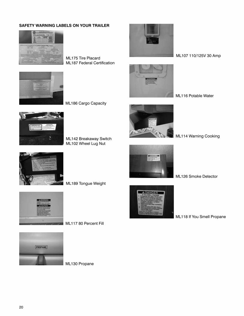
SAFETY WARNING LABELS ON YOUR TRAILER
ML189 Tongue Weight
ML175 Tire PlacardML187 Federal Certification
ML186 Cargo Capacity
ML142 Breakaway SwitchML102 Wheel Lug Nut
ML116 Potable Water
ML117 80 Percent Fill
ML130 Propane
ML107 110/125V 30 Amp
ML118 If You Smell Propane
ML114 Warning Cooking
ML126 Smoke Detector
21
WARNINGTo protect you and others against death or serious injury, all of the labels shown above must be on the trailer and must be legible.
If any of these labels are missing or cannot be read, call the Lance Customer Service Department at 661-949-3322 for free replace-ment labels.
You will need to provide us with your trailer’s serial number and the part number shown at the bottom of the label(s) or as shown in the pictures above in order for us to send the correct one(s).
REPORTING SAFETY DEFECTSIf you believe that your vehicle has a defect that could cause a crash or could cause injury or death, you should immediately inform the National Highway Traffic Safety Administration (NHTSA) in addition to notifying us.
If NHTSA receives similar complaints, it may open an investigation, and if it finds that a safety defect exists in a group of vehicles, it may order a recall and remedy campaign. However, NHTSA cannot become involved in individual problems between you, your dealer, or Lance Camper Manufacturing Corporation.
To contact NHTSA, you may either call the Vehicle Safety Hotline toll-free at 1-888-327- 4236, or write to: Administrator, NHTSA, 1200 New Jersey Ave., SE, Washington, DC 20590. You can also obtain other information about motor vehicle safety from their hotline. They are on the web at www.safercar.gov.
Call 661-949-3322 or [email protected] to reach Lance.

22
This page intentionally left blank.
23
WELCOMECongratulations and welcome to the recreational vehicle lifestyle and the ever-growing family of Lance Recreational Vehicle Owners. We sincerely thank you for choosing Lance. Your selection of a Lance Trailer was a wise investment. Lance Camper Manufacturing Corporation (“Lance”) is confident that your RV will give you years of camping pleasure.
At Lance, we work hard to provide our customers with safe and dependable recreational vehicles. We constantly strive to produce a quality product to meet your needs. Our customers are what are most important. If you are satisfied, then we know we have achieved what we set out to do. That is to be the best recreational vehicle manufacturer in the industry.
Your recreational vehicle has been designed to conform with, or exceed, the American National Standards Institute (ANSI) 1192, National Fire Protection Association (NFPA) 1192, Canadian Standards Association (CSA) Z-240 (for Canadian built units), National Electric Code (NEC), and ap-plicable motor vehicle standards. These standards establish the requirements for electrical, plumb-ing, fuel systems and equipment, fire and life safety provisions and other requirements for quality and safety. Lance is a member of the Recreational Vehicle Industry Association (RVIA) and the Canadian Rec-reational Vehicle Industry Association (CRVIA) which oversees that our products are in compliance with the above agencies and organizations. One of the best ways to enhance the enjoyment of your new Lance recreational vehicle is to read this manual along with the information provided in the Owner’s Information Package. This information will help you learn how to operate all the features of your new recreational vehicle. Afterwards, keep this Owner’s Manual along with the Owner’s Information Package in your RV so you can refer to it at any time.
This Owner’s Manual covers all Lance Trailer models. You may find descriptions of equipment and features that are not on your particular model.
This Owner’s Manual, along with the Owner’s Information Package should be considered a permanent part of the trailer, and should remain with the trailer when it is sold.
The information, specifications and photography included in this publication were as accurate as pos-sible at the time of publication. For the most current product information and changes, please visit our website at www.lancetrailer.com or contact your local
Lance Trailer Dealer. Lance reserves the right, however, to discontinue or change specifications at any time without notice and without incurring any obligation whatsoever. All weights, fuel, liquid capacities, and dimensions are approximate.
Before calling your Lance Trailer Dealer or the Lance Customer Service Department, we suggest that you look for the answer to your problem in the Owner’s Manual and the Component Instruction/Operation Manuals supplied in the Owner’s Information Package.
Several warranties protect your new Lance RV. Read each of the warranties thoroughly so you understand the coverages and are aware of your rights and responsibilities. Lance provides a limited warranty on your Trailer as defined at the front of this manual. Please read the warranty carefully. If you have any questions about the warranty or what it does or does not cover, please contact your Lance Trailer Dealer. At the time of sale, your dealer will fill out and mail your Lance Warranty Registration Card to the factory. Within three weeks you should receive, by mail, your Owner Registration Card. Contact your Lance Trailer Dealer if it does not arrive. The card will have your name, serial number and model, date of purchase and dealer name. If your RV ever needs warranty service, present this card to your dealer.
Your appliances and various other components are warranted by their respective manufacturer and their warranties are included in the Owner’s Information Package. Be sure to fill out the warranty registration cards for these items and mail them as soon as possible after taking delivery of your RV.
24
CUSTOMER RELATIONS INFORMATIONIt is best to return your trailer to the selling dealer for warranty service. If this is not possible, you can find the nearest dealer on our web site, www.lancetrailer.com, under the dealer locator heading, or by contacting the Lance Customer Service Department at 661 949-3322, who can direct you to a dealer in your area.
Service and maintenance on your trailer is easily accomplished by establishing a mutually agreeable partnership between you and your Lance Trailer deal-ership. Take the time to get to know the people who will play an important role in helping you keep your trailer in prime working condition. Visit the dealer’s service center to meet the service manager, techni-cians, service writers, and those charged with order-ing the parts. Ask questions.
Following scheduled maintenance recommendations will save you money in the long run. Carefully read all operation manuals to obtain complete information on prescribed service intervals. Don’t forget about your tow vehicle. It too needs regular service.
If you prefer to perform general maintenance items on your own, your Lance Trailer Dealer service department can be a big help when it comes to making sure you obtain the proper replacement parts. All replacement parts can be ordered from your Lance Trailer Dealer or by contacting the Lance Customer Service Department at (661) 949-3322.
Service and maintenance items may fall outside the scope of your capability. In these instances you may decide to seek the assistance of a qualified RV service center to perform these tasks. Contact your Lance Trailer dealership’s service center in advance for a scheduled appointment time. Advise the service manager, in writing, the specific items needing repair to give the service center an idea of what parts will be required, and how long the work can be expected to take. Keep in mind that seasonal maintenance needs are a popular time of year at most service centers. Call early to schedule annual tune-ups. Always include your vehicle identification number (last six digits) when contacting your Lance Trailer Dealer.
Lance Trailer dealership personnel are trained professionals. They should be able to answer all your questions. If you encounter a problem that your dealership does not solve to your satisfaction, please discuss it with the dealership’s management. The Service Manager or General Manager can help. Almost all problems are solved in this way.
If you are dissatisfied with the decision made by the dealership’s management, contact the Lance Customer Service Center at:
Service ManagerLance Camper Manufacturing Corporation43120 Venture StreetLancaster, California 93535-4510 USA661 949-3322
E-mail inquiries to [email protected].
When you call or write, please give us this information:
Vehicle Identification Number (last six digits)Your name, address, and telephone numberDate of purchaseName and address of the dealer where your RV was purchased, or who services your RV.
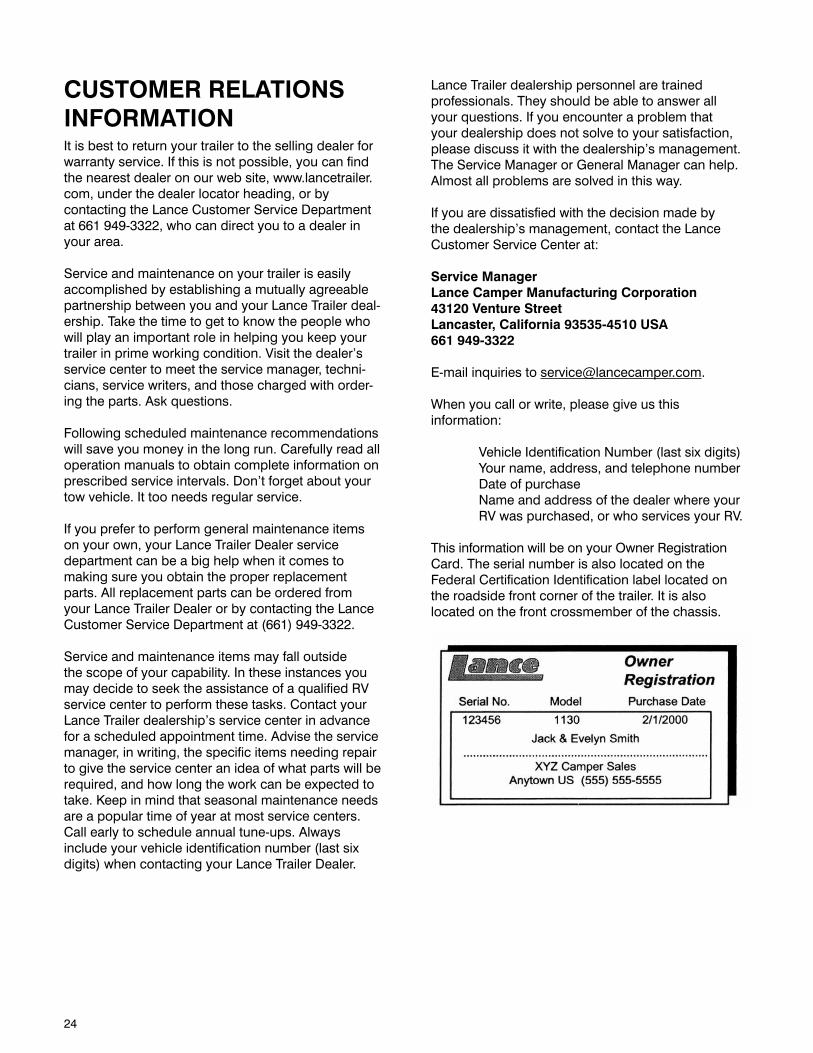
This information will be on your Owner Registration Card. The serial number is also located on the Federal Certification Identification label located on the roadside front corner of the trailer. It is also located on the front crossmember of the chassis.
25
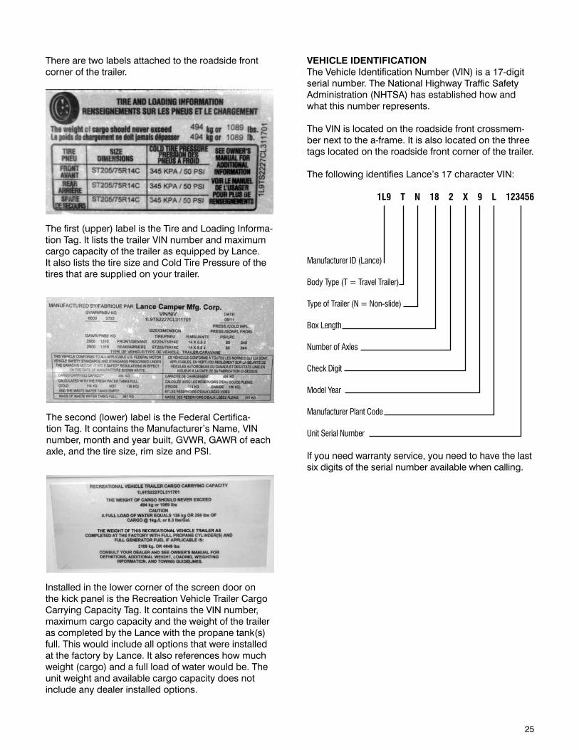
There are two labels attached to the roadside front corner of the trailer.
The first (upper) label is the Tire and Loading Informa-tion Tag. It lists the trailer VIN number and maximum cargo capacity of the trailer as equipped by Lance. It also lists the tire size and Cold Tire Pressure of the tires that are supplied on your trailer.
The second (lower) label is the Federal Certifica-tion Tag. It contains the Manufacturer’s Name, VIN number, month and year built, GVWR, GAWR of each axle, and the tire size, rim size and PSI.
VEHICLE IDENTIFICATIONThe Vehicle Identification Number (VIN) is a 17-digit serial number. The National Highway Traffic Safety Administration (NHTSA) has established how and what this number represents.
The VIN is located on the roadside front crossmem-ber next to the a-frame. It is also located on the three tags located on the roadside front corner of the trailer.
The following identifies Lance’s 17 character VIN:
1L9 T N 18 2 X 9 L 123456
Manufacturer ID (Lance)
Body Type (T = Travel Trailer)
Type of Trailer (N = Non-slide)
Box Length
Number of Axles
Check Digit
Model Year
Manufacturer Plant Code
Unit Serial Number
If you need warranty service, you need to have the last six digits of the serial number available when calling.
Installed in the lower corner of the screen door on the kick panel is the Recreation Vehicle Trailer Cargo Carrying Capacity Tag. It contains the VIN number, maximum cargo capacity and the weight of the trailer as completed by the Lance with the propane tank(s) full. This would include all options that were installed at the factory by Lance. It also references how much weight (cargo) and a full load of water would be. The unit weight and available cargo capacity does not include any dealer installed options.
26
INFORMATION ABOUT THIS MANUALThis Owner’s Manual is of a general nature only and does not cover every aspect of all Trailer models manufactured by Lance. Each owner must read this manual thoroughly and heed the warnings given herein, as well as those warnings given in the com-ponent instruction manuals contained in the Owner’s Information Package.
PRODUCT CHANGESSome equipment and features shown in this manual may be optional or not available on some mod-els. Photographs or illustrations in this manual are representative of function and may not be specific in their depiction of actual equipment, fabrics, interior or exterior decor or design options as installed on or in your trailer. For the most current product information and changes please visit our website at www.lance-trailer.com or contact your local Lance Trailer Dealer. Subsequent modifications may be evident in the actual product. Specifications are subject to change without notice. All weights, fuel, liquid capacities and dimensions are approximate.
OWNER’S INFORMATION PACKAGEThe owner information package contains valuable documents explaining details of operation for major appliances, systems and equipment built into your trailer. Included in this package is warranty informa-tion on various appliances and components in your trailer. Warranty registration cards for these items should be filled out and mailed as soon as possible after you take delivery of your trailer. Since this Own-er’s Manual does not cover every possible detail of equipment and options installed on or in your trailer, these booklets and instructional material in the pack-age will help you operate, maintain and trouble-shoot those items. If you are missing any of the compo-nent material, contact your Lance Trailer Dealer and request the desired or missing information.
This information should be considered a permanent part of the Trailer, and should remain with the trailer when it is sold.
The Owner’s Information Package includes the follow-ing items based on the standard features and appli-cable options on your particular trailer:
Owner’s ManualRefrigerator ManualRange/Oven ManualRange Hood ManualMicrowave ManualFurnace ManualThermostat ManualWater Heater ManualAir Conditioner ManualGenerator ManualWater Pump ManualConverter ManualSmoke, Propane and Carbon Monoxide Detector ManualsGFIC ManualWinterizing ManualAwning ManualTV Antenna ManualStereo ManualLCD TV Manual
27
DEALER RESPONSIBILITYYour trailer has been thoroughly inspected at the factory before shipment. However, your dealer is responsible for performing a complete pre-delivery in-spection of all your trailer’s components. This should assure you that all components are in proper working order and free of defects prior to you taking delivery.
During the delivery process, the dealer should have taken you through the inside, as well as around the exterior of the trailer, to instruct and explain the proper usage of all of the following items:
AppliancesDinette Bed ConversionsElectrical SystemFresh Water SystemPropane Gas SystemLoading and UnloadingCoupling and Uncoupling to the Tow VehicleOptional EquipmentRV Park HookupWaste SystemSlide-Out SystemEgress Exits
While the dealer has provided basic instructions on how to use your trailer, it is ultimately your responsi-bility to make sure you fully understand how to use the trailer prior to doing so. To fulfill this responsibility, in addition to the instructions received from the deal-er, you must read all instructional material furnished with the trailer. If you do not understand how to oper-ate any appliance or equipment, you should return to your dealer for further instructions.
Your Lance trailer comes with applicable loose items based on the standard features and options on your particular trailer. Please make sure that you have each of these items:
• Owner’sInformationPackage• Twosetsofkeysforentrydoorandexterioraccess
doors• FireExtinguisher(mounted)• StabilizerJackHandle• RemotesforTV/LCDandDVD(TV/LCDOptional)• MattressCover
PLANNING AND PREPARATIONProper planning of your trip will ensure a pleasurable experience. A thorough knowledge of your trailer is important if you are going to get the most of the convenience and safety built into your trailer. You should become as familiar with your trailer as you are with your own personal car or tow vehicle. If you have trouble or questions, you should consult your dealer.
INSPECTION AND MAINTENANCEMaintaining your trailer according to the maintenance schedules given in this manual helps to keep your camping experiences trouble-free while preserving your investment. When your trailer needs mainte-nance, keep in mind that your Lance Trailer Dealer’s staff is trained in servicing the many systems in your trailer. Your Lance Trailer Dealer is dedicated to your satisfaction and will be pleased to answer any ques-tions and concerns. The Maintenance Chart located at the rear of this manual defines the minimum maintenance intervals. Adherence to this schedule will minimize the possibility of failure of important systems of your trailer. The time spent inspecting and maintaining your trailer will provide you with many years of trouble free recreational pleasure.

28
This page intentionally left blank.
29
TIRE SAFETY INFORMATIONThis portion of the User’s Manual contains tire safety information as required by 49 CFR 575.6.
TRAILER TIRE INFORMATIONTrailer tires may be worn out even though they still have plenty of tread left. This is because trailer tires have to carry a lot of weight all the time, even when not in use. It is actually better for the tire to be rolling down the road than to be idle. During use, the tire releases lubricants that are beneficial to tire life. Using the trailer tires often also helps prevent flat spots from developing.
The main cause of tire failure is improper inflation. Check the cold tire inflation pressures at least once a week for proper inflation levels. “Cold” means that the tires are at the same temperature as the surround-ing air, such as when the vehicle has been parked overnight. Wheel and tire manufacturers recommend adjusting the air pressure to the trailer manufacturer’s recommended cold inflation pressure, in pounds per square inch (PSI) stated on the vehicle’s Federal Certification Label or Tire Placard when the trailer is loaded to its gross vehicle weight rating (GVWR). If the tires are inflated to less than the recommended inflation level or the GVWR of the trailer is exceeded, the load carrying capacity of the tire could be dra-matically affected. If the tires are inflated more than the recommended inflation level, handling character-istics of the tow vehicle/trailer combination could be affected. Refer to the owner’s manual or talk to your dealer or vehicle manufacturer if you have any ques-tions regarding proper inflation practices.
Tires can lose air over a period of time. In fact, tires can lose 1 to 3 PSI per month. This is because mole-cules of air, under pressure, weave their way from the inside of the tire, through the rubber, to the outside. A drop in tire pressure could cause the tire to become overloaded, leading to excessive heat build up. If a trailer tire is under-inflated, even for a short period of time, the tire could suffer internal damage.
High speed towing in hot conditions degrades trailer tires significantly. As heat builds up during driving, the tire’s internal structure starts to breakdown, compro-mising the strength of the tire. It is recommended to drive at moderate speeds.
Statistics indicate the average life of a trailer tire is about five years under normal use and maintenance conditions. After three years, replacing the trailer tires with new ones should be considered, even if the tires have adequate tread depth. Some expert’s claim that
after five years, trailer tires are considered worn out and should be replaced, even if they have had mini-mal or no use. This is such a general statement that it may not apply in all cases. It is best to have your tires inspected by a tire supplier to determine if your tires need to be replaced.
If you are storing your trailer for an extended period, make sure the tires are fully inflated to the maximum rated pressure and that you store them in a cool, dry place, such as a garage. Use tire covers to protect the trailer tires from the harsh effects of the sun.
STEPS FOR DETERMINING CORRECT LOAD LIMITS OF THE TRAILERDetermining the load limits of a trailer includes more than understanding the load limits of the tires alone. On all trailers there is a Federal Certification/VIN label that is located on the forward half of the left (road) side of the unit. This certification/VIN label will indicate the trailer’s Gross Vehicle Weight Rat-ing (GVWR). This is the most weight the fully loaded trailer can weigh. It will also provide the Gross Axle Weight Rating (GAWR). This is the most a particular axle can weigh. If there are multiple axles, the GAWR of each axle will be provided.
There is a vehicle placard located in the same loca-tion as the certification label described above. This placard provides tire and loading information. In addition, this placard will show a statement regard-ing maximum cargo capacity. Cargo can be added to the trailer, up to the maximum weight specified on the placard. The combined weight of the cargo is pro-vided as a single number. In any case, remember: the total weight of a fully loaded trailer can not exceed the stated GVWR.
The weight of water and propane also needs to be considered. The weight of fully filled propane con-tainers is considered part of the weight of the trailer before it is loaded with cargo, and is not considered part of the disposable cargo load. Water however, is a disposable cargo weight and is treated as such. If there is a fresh water storage tank of 30 gallons, this tank when filled would weigh about 250 pounds. If more cargo is being transported, water can be off-loaded to keep the total amount of cargo added to the vehicle within the limits of the GVWR so as not to overload the vehicle. Understanding this flexibility will allow you, the owner, to make choices that fit your travel needs.
When loading your cargo, be sure it is distributed evenly to prevent overloading front to back and side to side. Heavy items should be placed low and as close to the axle positions as reasonable. Too many
30
items on one side may overload a tire. The best way to know the actual weight of the vehicle is to weigh it at a public scale. Talk to your dealer to discuss the weighing methods needed to capture the various weights related to the trailer. This would include the weight empty or unloaded, weights per axle, wheel, hitch or king-pin, and total weight.
Excessive loads and/or under inflation cause tire overloading and, as a result, abnormal tire flexing occurs. This situation can generate an excessive amount of heat within the tire. Excessive heat may lead to tire failure. It is the air pressure that enables a tire to support the load, so proper inflation is critical. The proper air pressure may be found on the Certi-fication / VIN label and/or on the Tire Placard. This value should never exceed the maximum cold infla-tion pressure stamped on the tire.
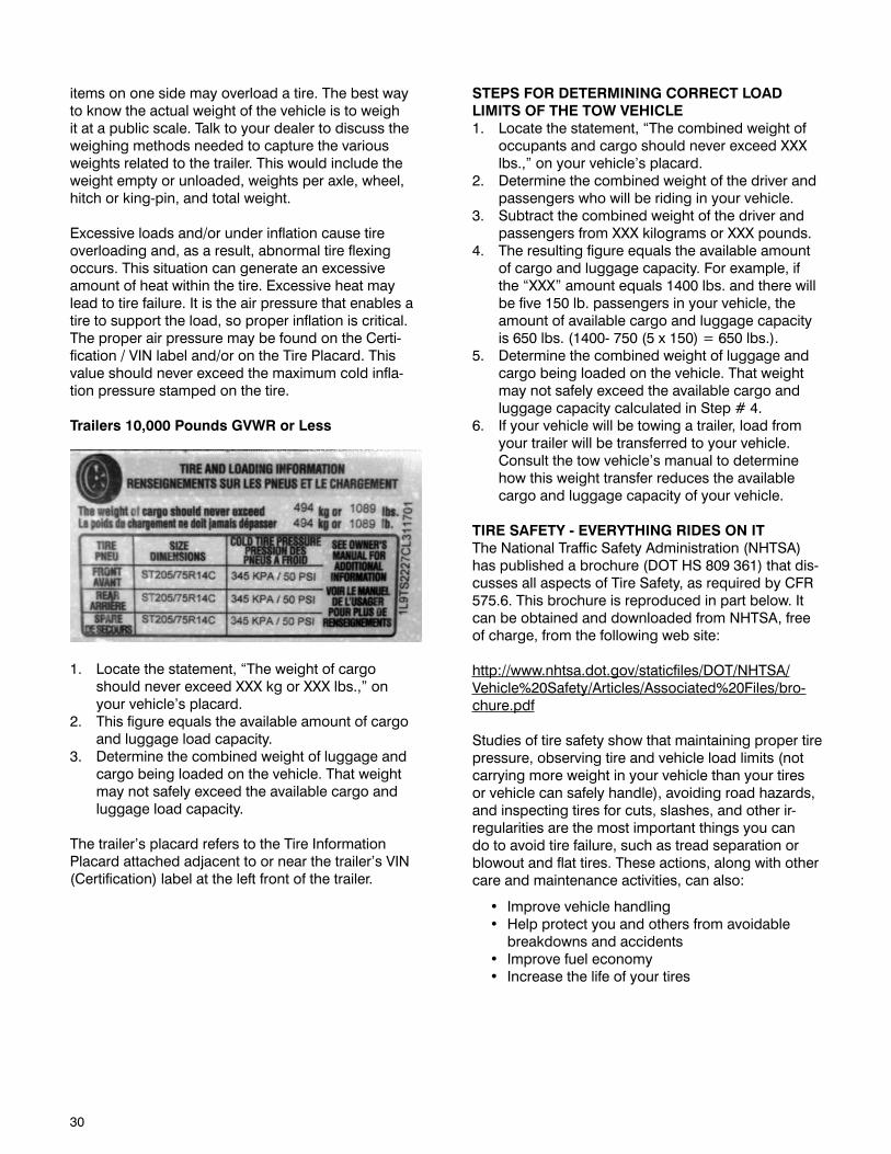
Trailers 10,000 Pounds GVWR or Less
1. Locate the statement, “The weight of cargo should never exceed XXX kg or XXX lbs.,” on your vehicle’s placard.
2. This figure equals the available amount of cargo and luggage load capacity.
3. Determine the combined weight of luggage and cargo being loaded on the vehicle. That weight may not safely exceed the available cargo and luggage load capacity.
The trailer’s placard refers to the Tire Information Placard attached adjacent to or near the trailer’s VIN (Certification) label at the left front of the trailer.
STEPS FOR DETERMINING CORRECT LOAD LIMITS OF THE TOW VEHICLE1. Locate the statement, “The combined weight of
occupants and cargo should never exceed XXX lbs.,” on your vehicle’s placard.
2. Determine the combined weight of the driver and passengers who will be riding in your vehicle.
3. Subtract the combined weight of the driver and passengers from XXX kilograms or XXX pounds.
4. The resulting figure equals the available amount of cargo and luggage capacity. For example, if the “XXX” amount equals 1400 lbs. and there will be five 150 lb. passengers in your vehicle, the amount of available cargo and luggage capacity is 650 lbs. (1400- 750 (5 x 150) = 650 lbs.).
5. Determine the combined weight of luggage and cargo being loaded on the vehicle. That weight may not safely exceed the available cargo and luggage capacity calculated in Step # 4.
6. If your vehicle will be towing a trailer, load from your trailer will be transferred to your vehicle. Consult the tow vehicle’s manual to determine how this weight transfer reduces the available cargo and luggage capacity of your vehicle.
TIRE SAFETY - EVERYTHING RIDES ON ITThe National Traffic Safety Administration (NHTSA) has published a brochure (DOT HS 809 361) that dis-cusses all aspects of Tire Safety, as required by CFR 575.6. This brochure is reproduced in part below. It can be obtained and downloaded from NHTSA, free of charge, from the following web site:
http://www.nhtsa.dot.gov/staticfiles/DOT/NHTSA/Vehicle%20Safety/Articles/Associated%20Files/bro-chure.pdf
Studies of tire safety show that maintaining proper tire pressure, observing tire and vehicle load limits (not carrying more weight in your vehicle than your tires or vehicle can safely handle), avoiding road hazards, and inspecting tires for cuts, slashes, and other ir-regularities are the most important things you can do to avoid tire failure, such as tread separation or blowout and flat tires. These actions, along with other care and maintenance activities, can also:
• Improvevehiclehandling• Helpprotectyouandothersfromavoidable
breakdowns and accidents• Improvefueleconomy• Increasethelifeofyourtires
31
This booklet presents a comprehensive overview of tire safety, including information on the following topics:
• Basictiremaintenance• UniformTireQualityGradingSystem• Fundamentalcharacteristicsoftires• Tiresafetytips
Use this information to make tire safety a regular part of your vehicle maintenance routine. Recognize that the time you spend is minimal compared with the inconvenience and safety consequences of a flat tire or other tire failure.
SAFETY FIRST–BASIC TIRE MAINTENANCEProperly maintained tires improve the steering, stopping, traction, and load-carrying capability of your vehicle. Underinflated tires and overloaded vehicles are a major cause of tire failure. Therefore, as mentioned above, to avoid flat tires and other types of tire failure, you should maintain proper tire pressure, observe tire and vehicle load limits, avoid road hazards, and regularly inspect your tires.
FINDING YOUR VEHICLE’S RECOMMENDED TIRE PRESSURE AND LOAD LIMITSTire information placards and vehicle certification labels contain information on tires and load limits. These labels indicate the vehicle manufacturer’s information including:
• Recommendedtiresize• Recommendedtireinflationpressure• Vehiclecapacityweight(VCW–themaximum
occupant and cargo weight a vehicle is de-signed to carry)
• Frontandreargrossaxleweightratings(GAWR– the maximum weight the axle systems are designed to carry)
Both placards and certification labels are perma- nently attached to the trailer near the left front.
UNDERSTANDING TIRE PRESSURE AND LOAD LIMITSTire inflation pressure is the level of air in the tire that provides it with load-carrying capacity and affects the overall performance of the vehicle. The tire inflation pressure is a number that indicates the amount of air pressure– measured in pounds per square inch (psi)–a tire requires to be properly inflated. (You will also find this number on the vehicle information placard expressed in kilopascals (kPa), which is the metric measure used internationally.)
Manufacturers of passenger vehicles and light trucks determine this number based on the vehicle’s design load limit, that is, the greatest amount of weight a vehicle can safely carry and the vehicle’s tire size.
The proper tire pressure for your vehicle is referred to as the “recommended cold inflation pressure.” (As you will read below, it is difficult to obtain the recommended tire pressure if your tires are not cold.) Because tires are designed to be used on more than one type of vehicle, tire manufacturers list the “maximum permissible inflation pressure” on the tire sidewall. This number is the greatest amount of air pressure that should ever be put in the tire under normal driving conditions.
CHECKING TIRE PRESSUREIt is important to check your vehicle’s tire pressure at least once a month for the following reasons:
• Mosttiresmaynaturallyloseairovertime.• Tirescanloseairsuddenlyifyoudriveovera
pothole or other object or if you strike the curb when parking.
• Withradialtires,itisusuallynotpossibletodetermine under inflation by visual inspection
For convenience, purchase a tire pressure gauge to keep in your vehicle. Gauges can be purchased at tire dealerships, auto supply stores, and other retail outlets.
The recommended tire inflation pressure that vehicle manufacturers provide reflects the proper psi when a tire is cold. The term cold does not relate to the out-side temperature. Rather, a cold tire is one that has not been driven on for at least three hours. When you drive, your tires get warmer, causing the air pressure within them to increase. Therefore, to get an accurate tire pressure reading, you must measure tire pressure when the tires are cold or compensate for the extra pressure in warm tires.
STEPS FOR MAINTAINING PROPER TIRE PRESSURE• Step1:Locatetherecommendedtirepressure
on the vehicle’s tire information placard, certifi-cation label, or in the owner’s manual.
• Step2:Recordthetirepressureofalltires.• Step3:Ifthetirepressureistoohighinanyof
the tires, slowly release air by gently pressing on the tire valve stem with the edge of your tire gauge until you get to the correct pressure.
• Step4:Ifthetirepressureistoolow,notethedifference between the measured tire pressure and the correct tire pressure. These “missing” pounds of pressure are what you will need to add.
• Step5:Ataservicestation,addthemissingpounds of air pressure to each tire that is under-inflated.
• Step6:Checkallthetirestomakesuretheyhave the same air pressure (except in cases in which the front and rear tires are supposed to have different amounts of pressure).
32
If you have been driving your vehicle and think that a tire is underinflated, fill it to the recommended cold inflation pressure indicated on your vehicle’s tire information placard or certification label. While your tire may still be slightly underinflated due to the extra pounds of pressure in the warm tire, it is safer to drive with air pressure that is slightly lower than the vehicle manufacturer’s recommended cold inflation pressure than to drive with a significantly underinflated tire. Since this is a temporary fix, don’t forget to recheck and adjust the tire’s pressure when you can obtain a cold reading.
TIRE SIZETo maintain tire safety, purchase new tires that are the same size as the vehicle’s original tires or another size recommended by the manufacturer. Look at the tire information placard, the owner’s manual, or the sidewall of the tire you are replacing to find this infor-mation. If you have any doubt about the correct size to choose, consult with the tire dealer.
TIRE TREADThe tire tread provides the gripping action and traction that prevent your vehicle from slipping or sliding, especially when the road is wet or icy. In general, tires are not safe and should be replaced when the tread is worn down to 1/16 of an inch. Tires have built-in treadwear indicators that let you know when it is time to replace your tires. These indicators are raised sections spaced intermittently in the bot-tom of the tread grooves. When they appear “even” with the outside of the tread, it is time to replace your tires. Another method for checking tread depth is to place a penny in the tread with Lincoln’s head upside down and facing you. If you can see the top of Lin-coln’s head, you are ready for new tires.
TIRE BALANCE AND WHEEL ALIGNMENT To avoid vibration or shaking of the vehicle when a tire rotates, the tire must be properly balanced. This balance is achieved by positioning weights on the wheel to counterbalance heavy spots on the wheel-and-tire assembly. A wheel alignment adjusts the angles of the wheels so that they are positioned cor-rectly relative to the vehicle’s frame. This adjustment maximizes the life of your tires. These adjustments require special equipment and should be performed by a qualified technician.
TIRE REPAIRThe proper repair of a punctured tire requires a plug for the hole and a patch for the area inside the tire that surrounds the puncture hole. Punctures through the tread can be repaired if they are not too large, but punctures to the sidewall should not be repaired. Tires must be removed from the rim to be properly inspected before being plugged and patched.
TIRE FUNDAMENTALSFederal law requires tire manufacturers to place stan-dardized information on the sidewall of all tires. This information identifies and describes the fundamental characteristics of the tire and also provides a tire identification number for safety standard certification and in case of a recall.
INFORMATION ON TRAILER TIRESWhy “ST” tires.
The physical requirements of “ST” trailer tires greatly differ from those of “P” passenger tires. Passenger tires are designed to maintain traction surface contact during all driving conditions: pulling, stopping, turn-ing, or swerving. Because of this, they are designed with more flexible sidewalls to maintain tread to road contact. Trailers have no driving torque applied to their axles, therefore the only time trailer tires must have traction is during the application of the trailer brakes. Trailers also see heavier loads that typically have a higher center of gravity then an automobile. These conditions, along with inadequate torque loads, and stiffer suspensions can cause swaying of the trailer. Trailer tires are designed with these condi-tions in mind and have stiffer sidewalls to help control and reduce sway. For this reason, it is not recom-mended that “P” Passenger tires be used on trailers. Optimal trailer control will be achieved with “ST” Special Trailer tires.
Industry standards dictate that ST tires are speed restricted to 65 MPH under normal inflation and load conditions unless a different speed restric-tion is indicated on the sidewall of the tire.
WARNINGReplacement tires must meet the same specifications as the originals. Mismatched tires and rims may come apart with explosive force and cause personal injury to yourself or others. Mismatched tires and rims can also blow out and cause you to lose control that can cause an accident which can result in serious injury or death.
33
Please refer to the diagram below.
LTThe “LT” indicates the tire is for light trucks or trailers.
STAn “ST” is an indication the tire is for trailer use only. “ST” tires are design for carrying heavy loads at lower speeds. The Tire and Rim Association Standard indicates that for operation at speeds up to 65 mph, no change in maximum cold tire inflation pressure or load is required. For speeds between 66-75 mph, increase the maximum cold tire inflation pressure 10 psi.
Next number – 3 DigitThis three-digit number gives the width in millimeters of the tire from sidewall edge to sidewall edge. In general, the larger the number, the wider the tire.
Next number – 2 DigitThis two-digit number, known as the aspect ratio, gives the tire’s ratio of height to width. Numbers of 70 or lower indicate a short sidewall for improved steering response and better overall handling on dry pavement.
R or DThe “R” stands for radial. The “D” stands for bias.
Next numberThis two-digit number is the wheel or rim size.
U.S. DOT Tire Identification NumberThis begins with the letters “DOT” and indicates that the tire meets all federal standards. The next two numbers or letters are the plant code where it was manufactured, and the last four numbers represent the week and year the tire was built. For example,
the numbers 3197 means the 31st week of 1997. The other numbers are marketing codes used at the manufacturer’s discretion. This information is used to contact consumers if a tire defect requires a recall.
Tire Ply Composition and Materials UsedThe number of plies indicates the number of layers of rubber-coated fabric in the tire. In general, the greater the number of plies, the more weight a tire can support. Tire manufacturers also must indicate the materials in the tire, which include steel, nylon, polyester, and others.
Max. Load Dual kg (lbs) at kPa (psi) ColdThis information indicates the maximum load and tire pressure when the tire is used as a dual, that is, when four tires are put on each rear axle (a total of six or more tires on the vehicle).
Max. Load Single kg (lbs) at kPa (psi) ColdThis information indicates the maximum load and tire pressure when the tire is used as a single.
Maximum Permissible Inflation PressureThis number is the greatest amount of air pressure that should ever be put in the tire under normal driv-ing conditions.
Load RangeThis information identifies the tire’s load carrying capabilities and its inflation limits.
TIRE SAFETY TIPSPreventing Tire Damage• Slowdownifyouhavetogooverapotholeor
other object in the road.• Donotrunovercurbsorotherforeignobjectsin
the roadway, and try not to strike the curb when parking.
Tire Safety Checklist• Checktirepressureregularly(atleastoncea
month), including the spare.• Inspecttiresforunevenwearpatternsonthe
tread, cracks, foreign objects, or other signs of wear or trauma.
• Removebitsofglassandforeignobjectswedged in the tread.
• Makesureyourtirevalveshavevalvecaps.• Checktirepressurebeforegoingonalongtrip.• Donotoverloadyourvehicle.Checkthetire
information placard or owner’s manual for the maximum recommended load for the vehicle.
34
Tire inflation pressure is the most important factor in tire life. Inflation pressure should be as recommended for the load but in no case should exceed the tire or rim maximum pressure rating. Inflation pressure should be checked cold before operation. Do not bleed air from tires when they are hot. Check inflation pressure weekly during use to insure the maximum tire life and tread wear. The following tire wear diagnostic chart will help you pinpoint the causes and solutions of tire wear problems.
TIRE WEAR DIAGNOSTIC CHART
35
LUG NUT TORQUE SEQUENCEThe axle and wheel assemblies of your Lance Trailer are designed differently than those on your car. The overall size, weight and center of gravity of a recreational vehicle subject the wheels to pressures unique to trailering. During normal cornering, the tires and wheels experience a considerable amount of stress called “side-load”. Therefore, the lug nuts on your recreational vehicle require periodic re-torqueing.
These instructions will show you how to maintain proper lug nut torque by following these important steps:
1. Check torque before every trip.2. Use proper tools.3. Follow the appropriate star pattern sequence.4. Torque lug nuts in the correct stages and follow-
up intervals after any wheel reinstallation.
For further information on these steps, you may want to refer to the axle manufacturer’s owner manual.
Remember, torque is the amount of rotating force applied to a fastener, such as a lug nut. Proper torque of lug nuts can only be achieved by using a torque wrench and a socket.
Note: Some wheel assemblies require an extension. DO NOT USE a flexible extension. Also, DO NOT USE a 4-way socket or any other type of wrench which does not measure the actual pressure applied to the lug nut.
USING TORQUE WRENCHES• Mosttorquewrenchesarerequiredtobesetat“0”
when not in use to maintain calibration.• Pleaserefertothemanufacturer’sinstructionsfor
further information on use and maintenance.
SETTING TORQUE VALUE ON A DIAL INDICATOR WRENCH:
1. Make sure your indicator needle is set to “0”.2. As you apply clockwise pressure to the lug nut,
both needles will show the current amount of torque being applied.
3. When you reach your desired torque value, stop applying pressure and your indicator needle will stay at the highest torque value reached.
SETTING TORQUE VALUE ON AN ADJUSTABLE DIAL WRENCH:1. Unlock the handle and set the dial to your desired
torque value.2. Lock the handle back in place.3. As you apply clockwise pressure to the lug nut,
you will hear and audible “click” when the desired torque wrench value is reached. Do not apply further pressure once you hear the “click”.
Always remember:
•Check lug nut torque before every trip. Lance recommends this maintenance procedure to ensure proper torque has been applied to lug nuts before heading out on the road.
•Lugnutsshouldbetorquedto110-120ft/lbs.•Alwaysfollowtheappropriatestarpatternasindi-
cated to assure proper torque.
PRE-TRIP PROCEDURE:1. Set your torque wrench to 110-120 ft/lbs.2. Begin with the appropriate bolt for your wheel
(12 o’clock position for 8 and 6 hole wheels and 2 o’clock position for 5 hole wheels) and apply torque to all lug nuts following the star pattern indicated.
3. Complete the procedure on each wheel. Before moving to each new wheel, be sure to verify your preset torque wrench value.
WARNINGUnder or over-torque of wheel lug nuts can cause the wheel to separate from the axle and could lead to property damage, serious injury or loss of life.
After removing a wheel from your trailer for any reason, you must carefully follow a 2 step process:
1) Wheel Reinstallation2) Follow-up
36
WHEEL REINSTALLATION PROCEDURE:•Duringwheelreinstallation,thelugnuttorquemust
be applied in 3 stages. This will ensure the wheel studs are centered in the wheel holes, and will help the lug nuts maintain proper torque.
1. Start all lug nuts by hand.2. Stage 1: Set your torque wrench to 20-30 ft/ lbs.3. Begin with the appropriate bolt for your wheel
(12 o’clock position for 8 and 6 hole wheels and 2 o’clock position for 5 hole wheels) and apply torque to all lug nuts following the star pattern.
4. Stage 2: Increase your torque wrench setting to 55-60 ft/lbs.
5. Begin with the appropriate bolt for your wheel and apply torque to all lug nuts following the star pattern.
6. Following stage 2, the wheel can support the weight of the trailer and can be lowered off of the jack.
7. Stage 3: Increase your torque wrench setting to 110-120 ft/lbs.
8. Begin with the appropriate bolt for your wheel and apply torque to all lug nuts following the star pattern.
FOLLOW-UP PROCEDURE: Re-torque after 10, 25, and 50 miles.
1. After the first 10 miles of your trip, pull your trailer off the road into a safe work area.
2. Set your torque wrench to 110-120 ft/lbs.3. Begin with the appropriate bolt for your wheel
and apply torque to all lug nuts following the star pattern.
4. Reapply torque at 110-120 ft/lbs and repeat steps 1, 2, & 3 again at 25 miles and at 50 miles of your first trip.
5. The follow up process is complete.
37
COUPLING TO THE TOW VEHICLEThis manual provides instructions for the operation and care of your Lance trailer.
The instructions in the manual must be followed to ensure safety of persons and satisfactory life of the trailer. Safety precautions to protect against injury or property damage must be followed at all times.
TRAILER ACCESSORIES/EQUIPMENTLance offers trailers with a wide range of optional equipment. Instructions for safe use of these acces-sories are located in separate instruction manuals, which are provided by the accessory manufacturer and are located in the Owner’s Information Package.
Your Lance trailer has been built using parts from var-ious component manufacturers. Where this manual indicates that you should read another manual, and you do not have that manual, call Lance Customer Service at 661-949-3322 or email [email protected] for assistance.
USE AN ADEQUATE TOW VEHICLE AND HITCHIf the tow vehicle or hitch is not properly selected and matched to the Gross Vehicle Weight Rating (GVWR) of your trailer, you can cause an accident that could lead to death or serious injury. Tow vehicle and hitch manufacturers are the appropriate source of compe-tent advice.
If you already have a tow vehicle, know your vehicle tow rating and make certain the trailer’s rated capac-ity is less than or equal to the tow vehicle’s rated towing capacity.
It is important that the trailer is matched with an appropriate tow vehicle. A tow vehicle with an in-adequate Gross Combined Weight Rating (GCWR) may experience mechanical failures and not provide adequate towing stability. Consult your Lance Trailer Dealer for help in selecting the vehicle hitch and relating hitching accessories. Towing the trailer with an inadequate tow vehicle can cause damage to the trailer frame.
If you have a bumper pull trailer, you may need a weight distributing hitch, depending on your trailer, load requirements and tow vehicle. Contact your Lance Trailer Dealer for more information on a weight distributing hitch.
DANGERUse of an under-rated hitch, ball or tow ve-hicle can result in loss of control leading to death or serious injury.
Make certain your hitch and tow vehicle are rated for your trailer.
TRAILER INFORMATIONThe trailer Federal Certification (VIN) tag contains the following critical safety information for the use of your trailer:
Manufacturer: Name of the trailer manufacturer.
Date of Manufacture: Month and year the trailer was manufactured.
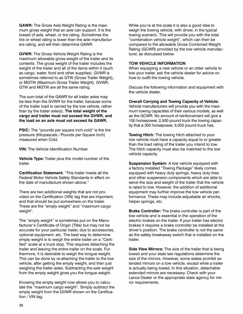
38
GAWR: The Gross Axle Weight Rating is the maxi-mum gross weight that an axle can support. It is the lowest of axle, wheel, or tire rating. Sometimes the tire or wheel rating is lower than the axle manufactur-ers rating, and will then determine GAWR.
GVWR: The Gross Vehicle Weight Rating is the maximum allowable gross weight of the trailer and its contents. The gross weight of the trailer includes the weight of the trailer and all of the items within it (such as cargo, water, food and other supplies). GVWR is sometimes referred to as GTW (Gross Trailer Weight), or MGTW (Maximum Gross Trailer Weight). GVWR, GTW and MGTW are all the same rating.
The sum total of the GAWR for all trailer axles may be less than the GVWR for the trailer, because some of the trailer load is carried by the tow vehicle, rather than by the trailer axle(s). The total weight of the cargo and trailer must not exceed the GVWR, and the load on an axle must not exceed its GAWR.
PSIC: The “pounds per square inch-cold” is the tire pressure (Kilopascals / Pounds per Square Inch) measured when Cold.
VIN: The Vehicle Identification Number.
Vehicle Type: Trailer plus the model number of the trailer.
Certification Statement: “This trailer meets all the Federal Motor Vehicle Safety Standards in effect on the date of manufacture shown above.”
There are two additional weights that are not pro-vided on the Certification (VIN) tag that are important, and that should be put somewhere on the trailer. These are the “empty weight” and “maximum cargo weight”.
The “empty weight” is sometimes put on the Manu-facturer’s Certificate of Origin (Title) but may not be accurate for your particular trailer, due to accessories, optional equipment, etc. The best way to determine empty weight is to weigh the entire trailer on a “Certi-fied” scale at a truck stop. This requires detaching the trailer and leaving the entire trailer on the scale. Fur-thermore, it is desirable to weigh the tongue weight. This can be done by re-attaching the trailer to the tow vehicle, after getting the empty weight, and then just weighing the trailer axles. Subtracting the axle weight from the empty weight gives you the tongue weight.
Knowing the empty weight now allows you to calcu-late the “maximum cargo weight”. Simply subtract the empty weight from the GVWR shown on the Certifica-tion / VIN tag.
While you’re at the scale it is also a good idea to weigh the towing vehicle, with driver, in the typical towing scenario. This will provide you with the total “combination vehicle weight”, which can then be compared to the allowable Gross Combined Weight Rating (GCWR) provided by the tow vehicle manufac-turer, as discussed below.
TOW VEHICLE INFORMATIONWhen equipping a new vehicle or an older vehicle to tow your trailer, ask the vehicle dealer for advice on how to outfit the towing vehicle.
Discuss the following information and equipment with the vehicle dealer.
Overall Carrying and Towing Capacity of Vehicle: Vehicle manufacturers will provide you with the maxi-mum towing capacities of their various models, as well as the GCWR. No amount of reinforcement will give a 100 horsepower, 2,500 pound truck the towing capac-ity that a 300 horsepower, 5,000 pound truck has.
Towing Hitch: The towing hitch attached to your tow vehicle must have a capacity equal to or greater than the load rating of the trailer you intend to tow. The hitch capacity must also be matched to the tow vehicle capacity.
Suspension System: A tow vehicle equipped with a factory installed “Towing Package” likely comes equipped with heavy duty springs, heavy duty tires and other suspension components which are able to serve the size and weight of the trailer that the vehicle is rated to tow. However, the addition of additional equipment may further improve the tow vehicle per-formance. These may include adjustable air shocks, helper springs, etc.
Brake Controller: The brake controller is part of the tow vehicle and is essential in the operation of the electric brakes on the trailer. If your trailer has electric brakes it requires a brake controller be installed at the driver’s position. The brake controller is not the same as the safety breakaway switch that is installed on the trailer.
Side View Mirrors: The size of the trailer that is being towed and your state law regulations determine the size of the mirrors. However, some states prohibit ex-tended mirrors on a tow vehicle, except while a trailer is actually being towed. In this situation, detachable extended mirrors are necessary. Check with your Lance Dealer or the appropriate state agency for mir-ror requirements.
39
Heavy Duty Flasher: A Heavy Duty Flasher is an electrical component that may be required when your trailer turn signal lights are attached to the tow vehicle flasher circuit.
Electrical Connector: An Electrical Connector con-nects the light and brake systems on the trailer to the light and brake controls on the towing vehicle.
Heavy Duty Engine Oil Cooling System: The tow vehicle engine works harder when a trailer is being towed. Depending on the size of the trailer, you may need to install a separate engine oil cooler. Inad-equate cooling may result in sudden engine failure. Ask the tow vehicle dealer if it is necessary to install a heavy duty cooling system.
Automatic Transmission Oil Cooler: The automatic transmission of a towing vehicle handles more power when a trailer is being towed. Inadequate cooling will shorten transmission life, and may result in sudden transmission failure. Ask the tow vehicle dealer if it is necessary to install a separate oil cooler for the auto-matic transmission.
Fire Extinguisher: It is sensible to have a fire extin-guisher in the tow vehicle.
Emergency Flares and Emergency Triangle Reflectors: It is wise to carry these warning devices even if you are not towing a trailer. It is particularly im-portant to have these when towing a trailer because the hazard flashers of your towing vehicle will not operate for as long a period of time when the battery is running both the trailer lights and tow vehicle lights.
COUPLING AND UNCOUPLING THE TRAILERA secure coupling (or fastening) of the trailer to the tow vehicle is essential. A loss of coupling may result in death or serious injury. Therefore, you must under-stand and follow all of the instructions for coupling.
The following parts are involved in making a secure coupling between the trailer and tow vehicle:
Coupling: That part of the trailer connecting mecha-nism by which the connection is actually made to the trailer hitch. The coupler size on bumper pull trailers is 2” or 2 5/16”. This is stamped on the coupler.
Hitch: That part of the connecting mechanism in-cluding the ball support platform and ball and those components that extend and are attached to the towing vehicle, including bumpers intended to serve as hitches.
Safety Chains: Chains are permanently attached to the trailer such that if the coupler connection comes loose, the safety chains can keep the trailer attached to the tow vehicle. With properly rigged safety chains, it is possible to keep the tongue of the trailer from digging into the road pavement, even if the coupler-to-hitch connection comes apart.
Trailer Lighting (And Braking) Connector: A device that connects electrical power from the tow vehicle to the trailer. Electricity is used to turn on brake lights, running lights, and turn signals as required. In ad-dition, if your trailer has a separate braking system, the electrical connector will also supply power to the trailer brakes from the tow vehicle.
Breakaway Switch: If the trailer becomes decoupled from the towing vehicle, the breakaway switch lan-yard, attached independently to the tow vehicle hitch, will pull a pin in the emergency electrical breakaway switch on the trailer. The breakaway switch is activat-ed by a separate coupling to the tow vehicle battery supply in the trailer such as to energize the trailer brakes independently of the towing vehicle. It is im-portant to check the state of charge of the emergency breakaway battery before each trip. Simply pull the pin out of the switch by hand and then try to pull the trailer. If you feel a significant drag force the brakes are activated. Be sure to re-insert the pin in the break-away switch. Also be sure to allow enough slack in the breakaway brake lanyard such that the switch will only activate (pin pulls out) if the coupler connection comes loose.
NOTE: The breakaway switch will not operate unless connected to a power source equivalent to and/or greater than an automotive type 12-volt, 12-amp wet-cell battery.
Jack: A device on the trailer that is used to raise and lower the trailer tongue. The jack is called the “land-ing gear” on 5th wheel trailers.
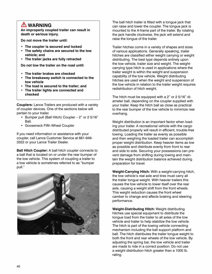
40
WARNINGAn improperly coupled trailer can result in death or serious injury.
Do not move the trailer until:
• Thecouplerissecuredandlocked• Thesafetychainsaresecuredtothetowvehicle;and
• Thetrailerjacksarefullyretracted
Do not tow the trailer on the road until:
• Thetrailerbrakesarechecked• Thebreakawayswitchisconnectedtothe
tow vehicle• Theloadissecuredtothetrailer;and• The trailer lights are connected and
checked
Couplers: Lance Trailers are produced with a variety of coupler devices. One of the sections below will pertain to your trailer.• Bumperpull(BallHitch)Coupler–2”or25/16”
Ball.• GooseneckFifthWheelCoupler
If you need information or assistance with your coupler, call Lance Customer Service at 661-949-3322 or your Lance Trailer Dealer.
Ball Hitch Coupler: A ball hitch coupler connects to a ball that is located on or under the rear bumper of the tow vehicle. This system of coupling a trailer to a tow vehicle is sometimes referred to as “bumper pull.”
The ball hitch trailer is fitted with a tongue jack that can raise and lower the coupler. The tongue jack is mounted to the A-frame part of the trailer. By rotating the jack handle clockwise, the jack will extend and raise the tongue of the trailer.
Trailer hitches come in a variety of shapes and sizes of various applications. Generally speaking, trailer hitches are classified either weight carrying or weight distributing. The best type depends entirely upon the tow vehicle, trailer size and weight. The weight-carrying type hitch is used in applications where the trailer weight is within the weight and suspension capability of the tow vehicle. Weight distributing hitches are used when the weight and suspension of the tow vehicle in relation to the trailer weight requires redistribution of hitch weight.
The hitch must be equipped with a 2” or 2 5/16” di-ameter ball, depending on the coupler supplied with your trailer. Keep the hitch ball as close as practical to the rear bumper of the tow vehicle to minimize rear overhang.
Weight distribution is an important factor when load-ing your trailer. A recreational vehicle with the cargo distributed properly will result in efficient, trouble-free towing. Loading the trailer as evenly as possible and then weighing the loaded trailer can accomplish proper weight distribution. Keep heavier items as low as possible and distribute evenly from front to rear and side to side. Securing your possessions can pre-vent damage from shifting during towing and main-tain the weight distribution balance achieved during preparation for travel.
Weight-Carrying Hitch: With a weight-carrying hitch, the tow vehicle’s real axle and tires must carry all the trailer tongue weight. With heavier trailers this causes the tow vehicle to lower itself over the rear axle, causing a weight shift from the front wheels. This weight reduction causes the front wheel camber to change and affects braking and steering performance.
Weight-Distributing Hitch: Weight distributing hitches use special equipment to distribute the tongue load from the trailer to all axles of the tow vehicle and trailer to help stabilize the tow vehicle. The hitch is part of the towing vehicle connecting mechanism including the ball support platform and ball. The hitch distributes the trailer tongue weight to both the front and rear wheels of the tow vehicle. By adjusting the spring bar, the tow vehicle and trailer are made to ride in a correct position. Do not use a weight distribution hitch greater than a 1000 lb. rating.
41
Your towing equipment, its adjustment and how you load the trailer can affect towing stability and han-dling. The following will help you select and adjust your equipment to produce acceptable towing char-acteristics.
Installation of the hitch, sway control and brake con-trol equipment must be performed by a competent hitch installer. Ensure the installation conforms to the tow vehicle and hitch manufacturer’s instructions.
Be sure the Ball Hitch coupler is suitable for the size and weight of the trailer. The load rating of the coupler and the necessary ball size (2” or 2 5/16”) are listed on the trailer tongue. You must provide a hitch and ball for your tow vehicle, where the load rating of the hitch and ball is equal to or greater than that of your trailer. Also, the ball size must be the same as the coupler size. If the hitch ball is too small, too large, is underrated, is loose or is worn, the trailer can come loose from the tow vehicle, and may cause death or serious injury.
THE TOW VEHICLE, HITCH AND BALL MUST HAVE A RATED TOWING CAPACITY EQUAL TO OR GREAT-ER THAN THE TRAILER GROSS VEHICLE WEIGHT RATING (GVWR).
IT IS ESSENTIAL THAT THE HITCH BALL BE OF THE SAME SIZE AS THE COUPLER.
IF THE HITCH BALL IS TOO SMALL, IS UNDER-RATED, IS LOOSE OR IS WORN, THE TRAILER CAN COME LOOSE FROM THE TOW VEHICLE, RESULT-ING IN DEATH OR SERIOUS INJURY.
The ball size and load rating (capacity) are marked on the ball; hitch capacity is marked on the hitch.
AXLESYour trailer is equipped with a rubber torsion arm suspension system which is completely self- contained within the axle tube and is equipped with E-Z Lube wheel bearing lubrication system. The axles attach directly to the trailer frame using brackets which are an integral part of the axle as-sembly. The torsion axles provides improved sus-pension characteristics relative to leaf spring axles through unique arrangement of a steel torsion bar surrounded by natural rubber cords encased in the main structural member of the axle beam.
The wheel/hub spindle is attached to a lever, called the torsion arm, which is fastened to the rubber en-cased bar. As load is applied, the bar rotates causing a compression resistance. This action provides the same functions as conventional sprung axles with
several operating advantages including independent suspension.
Except for periodic inspection of the fasteners used to attach the torsion axle to the trailer frame, no other suspension maintenance is required on the axles. They are, of course, subject to the maintenance and inspection procedures regarding brakes, hubs, bear-ings, seals, wheels and tires.
The E-Z Lube wheel bearing lubrication system al-lows for periodic lubrication of the wheel bearings without removing the hubs from the axles. This fea-ture consists of axle spindles that have been specially drilled and assembled with grease fittings in the ends. When grease is pumped into the fitting, it is chan-neled to the inner bearing and then flows back to the outer bearing and evidentially back out the grease cap hole. Bearings should be lubricated every 12 months or 12,000 miles.
To lubricate the hubs, the procedure is as follows:
1. Remove the rubber plug from the end of the grease cap.
2. Place a grease gun onto the grease fitting located in the end of the spindle. Make sure the grease gun nozzle is fully engaged on the fitting.
3. Pump grease into the fitting. The old displaced grease will begin to flow out the cap around the grease gun nozzle.
4. When the new clean grease is observed, remove the grease gun, wipe off any excess, and replace the rubber plug in the cap.
5. Rotate hub or drum while adding grease.
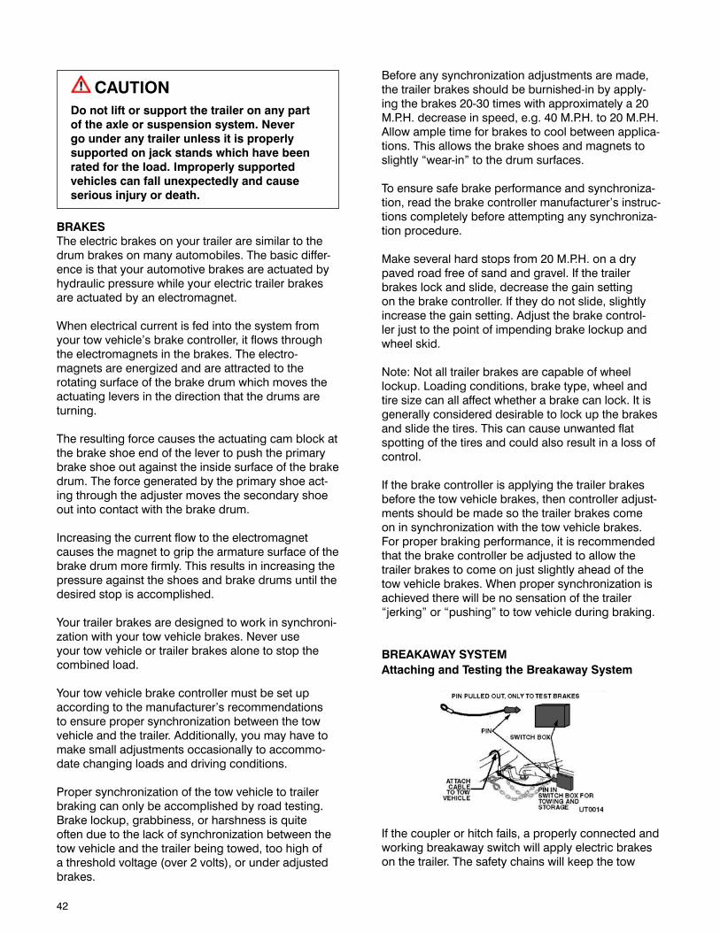
42
CAUTIONDo not lift or support the trailer on any part of the axle or suspension system. Never go under any trailer unless it is properly supported on jack stands which have been rated for the load. Improperly supported vehicles can fall unexpectedly and cause serious injury or death.
BRAKESThe electric brakes on your trailer are similar to the drum brakes on many automobiles. The basic differ-ence is that your automotive brakes are actuated by hydraulic pressure while your electric trailer brakes are actuated by an electromagnet.
When electrical current is fed into the system from your tow vehicle’s brake controller, it flows through the electromagnets in the brakes. The electro- magnets are energized and are attracted to the rotating surface of the brake drum which moves the actuating levers in the direction that the drums are turning.
The resulting force causes the actuating cam block at the brake shoe end of the lever to push the primary brake shoe out against the inside surface of the brake drum. The force generated by the primary shoe act-ing through the adjuster moves the secondary shoe out into contact with the brake drum.
Increasing the current flow to the electromagnet causes the magnet to grip the armature surface of the brake drum more firmly. This results in increasing the pressure against the shoes and brake drums until the desired stop is accomplished.
Your trailer brakes are designed to work in synchroni-zation with your tow vehicle brakes. Never use your tow vehicle or trailer brakes alone to stop the combined load.
Your tow vehicle brake controller must be set up according to the manufacturer’s recommendations to ensure proper synchronization between the tow vehicle and the trailer. Additionally, you may have to make small adjustments occasionally to accommo-date changing loads and driving conditions.
Proper synchronization of the tow vehicle to trailer braking can only be accomplished by road testing. Brake lockup, grabbiness, or harshness is quite often due to the lack of synchronization between the tow vehicle and the trailer being towed, too high of a threshold voltage (over 2 volts), or under adjusted brakes.
Before any synchronization adjustments are made, the trailer brakes should be burnished-in by apply-ing the brakes 20-30 times with approximately a 20 M.P.H. decrease in speed, e.g. 40 M.P.H. to 20 M.P.H. Allow ample time for brakes to cool between applica-tions. This allows the brake shoes and magnets to slightly “wear-in” to the drum surfaces.
To ensure safe brake performance and synchroniza-tion, read the brake controller manufacturer’s instruc-tions completely before attempting any synchroniza-tion procedure.
Make several hard stops from 20 M.P.H. on a dry paved road free of sand and gravel. If the trailer brakes lock and slide, decrease the gain setting on the brake controller. If they do not slide, slightly increase the gain setting. Adjust the brake control-ler just to the point of impending brake lockup and wheel skid.
Note: Not all trailer brakes are capable of wheel lockup. Loading conditions, brake type, wheel and tire size can all affect whether a brake can lock. It is generally considered desirable to lock up the brakes and slide the tires. This can cause unwanted flat spotting of the tires and could also result in a loss of control.
If the brake controller is applying the trailer brakes before the tow vehicle brakes, then controller adjust-ments should be made so the trailer brakes come on in synchronization with the tow vehicle brakes. For proper braking performance, it is recommended that the brake controller be adjusted to allow the trailer brakes to come on just slightly ahead of the tow vehicle brakes. When proper synchronization is achieved there will be no sensation of the trailer “jerking” or “pushing” to tow vehicle during braking.
BREAKAWAY SYSTEM Attaching and Testing the Breakaway System
If the coupler or hitch fails, a properly connected and working breakaway switch will apply electric brakes on the trailer. The safety chains will keep the tow
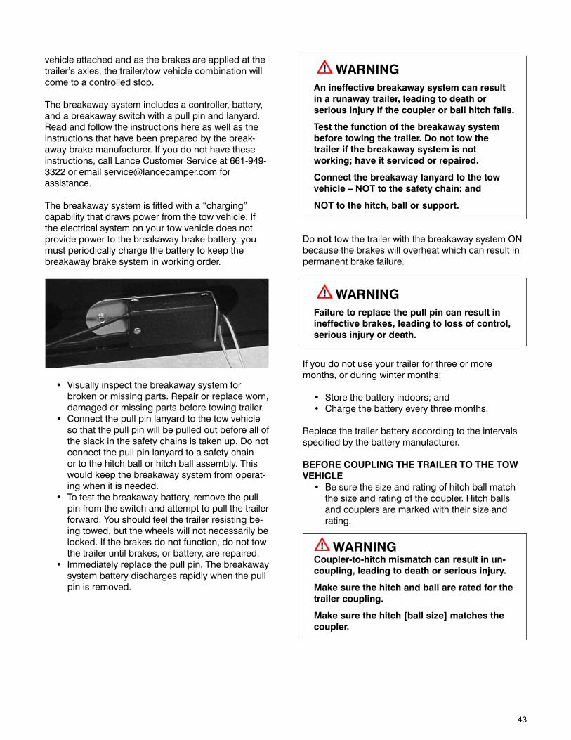
43
vehicle attached and as the brakes are applied at the trailer’s axles, the trailer/tow vehicle combination will come to a controlled stop.
The breakaway system includes a controller, battery, and a breakaway switch with a pull pin and lanyard. Read and follow the instructions here as well as the instructions that have been prepared by the break-away brake manufacturer. If you do not have these instructions, call Lance Customer Service at 661-949-3322 or email [email protected] for assistance.
The breakaway system is fitted with a “charging” capability that draws power from the tow vehicle. If the electrical system on your tow vehicle does not provide power to the breakaway brake battery, you must periodically charge the battery to keep the breakaway brake system in working order.
• Visuallyinspectthebreakawaysystemforbroken or missing parts. Repair or replace worn, damaged or missing parts before towing trailer.
• Connectthepullpinlanyardtothetowvehicleso that the pull pin will be pulled out before all of the slack in the safety chains is taken up. Do not connect the pull pin lanyard to a safety chain or to the hitch ball or hitch ball assembly. This would keep the breakaway system from operat-ing when it is needed.
• Totestthebreakawaybattery,removethepullpin from the switch and attempt to pull the trailer forward. You should feel the trailer resisting be-ing towed, but the wheels will not necessarily be locked. If the brakes do not function, do not tow the trailer until brakes, or battery, are repaired.
• Immediatelyreplacethepullpin.Thebreakawaysystem battery discharges rapidly when the pull pin is removed.
WARNINGAn ineffective breakaway system can result in a runaway trailer, leading to death or serious injury if the coupler or ball hitch fails.
Test the function of the breakaway system before towing the trailer. Do not tow the trailer if the breakaway system is not working;haveitservicedorrepaired.
Connect the breakaway lanyard to the tow vehicle–NOTtothesafetychain;and
NOT to the hitch, ball or support.
Do not tow the trailer with the breakaway system ON because the brakes will overheat which can result in permanent brake failure.
WARNINGFailure to replace the pull pin can result in ineffective brakes, leading to loss of control, serious injury or death.
If you do not use your trailer for three or more months, or during winter months:
• Storethebatteryindoors;and• Chargethebatteryeverythreemonths.
Replace the trailer battery according to the intervals specified by the battery manufacturer.
BEFORE COUPLING THE TRAILER TO THE TOW VEHICLE• Besurethesizeandratingofhitchballmatch
the size and rating of the coupler. Hitch balls and couplers are marked with their size and rating.
WARNINGCoupler-to-hitch mismatch can result in un-coupling, leading to death or serious injury.
Make sure the hitch and ball are rated for the trailer coupling.
Makesurethehitch[ballsize]matchesthecoupler.

44
• Wipethehitchballcleanandinspectitvisuallyand by feel for flat spots, cracks and pits.
WARNINGA worn, cracked or corroded hitch ball can fail while towing, and may result in death or serious injury.
Check the hitch ball for wear, corrosion and cracks before coupling the trailer.
Replace worn, corroded or cracked hitch ball before coupling the trailer.
• Rocktheballtomakesureitistighttothehitch,and visually check that the hitch ball nut is solid against the lock washer and hitch frame.
• Wipetheinsideandoutsideofthecouplercleanand inspect it visually for cracks and deforma-tions; feel the inside of the coupler for worn spots and pits.
• Besurethecoupleristighttothetongueofthetrailer. All coupler fasteners must be visibly solid against the trailer frame.
WARNINGA loose hitch ball nut can result in un- coupling, leading to death or serious injury.
Make sure the hitch ball is tight to the hitch before coupling the trailer.
PREPARING THE COUPLER AND HITCH• Lubricatethehitchballandtheinsideofthe
coupler with a thin layer of automotive bearing grease. Using the jack, raise the coupler above the ball height.
• Openthecouplerlockingmechanism.Ballcouplers have a locking mechanism with an in-ternal moving piece (ball clamp) and an outside handle, wheel, or latch. • Intheopenorreleasedposition,the
coupler is able to drop fully onto the hitch ball.
• Seethecouplerinstructionsfordetailsofplacing the coupler in the open or released position.
• Slowlybackupthetowvehiclesothatthehitchball is near or aligned under the coupler.
COUPLING TRAILER TO THE TOW VEHICLE• Usingthejack,lowerthetrailertongueuntil
the coupler fully engages the hitch ball. If the coupler does not line up with the hitch ball, adjust the position of the tow vehicle.
• Engagethecouplerlockingmechanism.Inthe engaged position, the locking mechanism securely holds the coupler to the hitch ball.
• Insertapinorlockthroughtheholeinthelock-ing mechanism.
• Besurethecouplerisallthewayonthehitchball and the locking mechanism is engaged. A properly engaged locking mechanism will allow the coupler to raise the rear of the tow vehicle. Using the trailer jack, test to see that you can raise the rear of the tow vehicle by 1 inch, after the coupler is locked to the hitch.
WARNINGThe tongue jack can be damaged by over-loading. Do not use the tongue jack to raise the tow vehicle more than 1 inch.
If the coupler cannot be secured to the hitch ball, do not tow the trailer. Call Lance Customer Service at 661-949-3322 or your Lance Trailer Dealer for assistance.
Lower the trailer so that its entire tongue weight is held by the hitch, and continue retracting the jack to its fully retracted position.
ATTACHING THE SAFETY CHAINS
• Visuallyinspectthesafetychainsandhooksforwear or damage. Replace worn or damaged safety chains and hooks before towing.
• Rigthesafetychainssothatthey:• Cris-crossunderneaththecouplersoifthe
trailer uncouples, the safety chains can hold the tongue up above the road.
• Looparoundaframememberofthetowvehicleor to holes provided in the hitch system (but, do not attach them to an interchangeable part of the hitch assembly)
45
• Attachhooksupfromunderneaththehole(donot just drop into hole); and
• Provideenoughslacktopermittightturns,butnot be close to the road surface to drag.
WARNINGIncorrect rigging of the safety chains can result in loss of control of the trailer and tow vehicle, leading to death or serious injury, if the trailer uncouples from the tow vehicle.
Chains must:
• Fastentoframeoftowvehicle,nottohitchor ball.
• Crossunderneathhitchandcouplerwithminimum slack to permit turning and to hold tongue up, if the trailer comes loose.
ATTACHING THE BREAKAWAY SYSTEMIf the coupler fails, a properly connected and working breakaway system will apply electric brakes on the trailer.
The breakaway system includes a brake controller, battery and a breakaway switch with a pullpin and lanyard. Read and follow the instructions here as well as the instructions that have been prepared by the brake controller manufacturer.
CONNECTING THE ELECTRICAL CABLEConnect the 7-pin trailer connector to the tow vehicle.
• Checkalllightsforproperoperation.• ClearanceandRunningLights(Turnon
tow vehicle headlights). • BrakeLights(Stepontowvehiclebrake
pedal). • TurnSignals(Operatetowvehicledirec-
tional signal lever).• BackupLights(Withignitionon,placetow
vehicle into reverse). • Checkelectricbrakesforproperoperation
using brake controller mounted in the cab.
If your trailer has electric brakes, your tow vehicle will have to have an electric brake controller that sends power to the trailer brakes. Before towing the trailer on the road, you must operate the brake controller while trying to pull the trailer in order to confirm that the electric brakes operate. While towing the trailer at less than 5 m.p.h., manually operate the electric brake controller in the tow vehicle cab. You should feel the operation of the trailer brakes.
WARNINGFailure to connect the tow vehicle lighting and braking to the trailer will result in inoperable lights and brakes, and can lead to collision.
Check that all the trailer lights and brakes work before each tow.
UNCOUPLING THE TRAILERFollow these steps to uncouple your trailer from the tow vehicle:
• Blocktrailertirestopreventthetrailerfromroll-ing, before jacking the trailer up.
• Disconnecttheelectricalconnector.• Disconnectthebreakawaybrakeswitchlanyard.• Disconnectthesafetychainsfromthetowve-
hicle.• Unlockthecouplerandopenit.• Beforeextendingjack,makecertaintheground
surface below the jack pad will support the tongue load.
• Rotatethejackhandleclockwise.Thiswillslowly transfer the weight of the trailer tongue to the jack.
BEFORE COUPLING THE FIFTH WHEEL TRAILER TO THE TOW VEHICLE• Besurethesizeandratingofthefifthwheel
hitch matches the pin box rating.• Besurethefifthwheelhitchoperatesfreely.• Lubricatethefifthwheelplatesurfacewitha
light coat of Lithium-base, waterproof grease.• Besurethefifthwheelandpinboxfastenersare
tight and any welds are solid.
WARNINGA loose fifth wheel can result in uncoupling, leading to death or serious injury.
Make sure the fifth wheel and pin box are tight before coupling the trailer.
46
• Besurethebreakawaylanyardandelectricalconnection are clear of the coupling area.
ADJUSTING HITCH HEIGHTIt is your responsibility to have the height of the pin box or fifth wheel adjusted to match the height of the fifth wheel in your tow vehicle. Proper height adjust-ment is required to provide clearance between the bottom of the trailer and sides of the tow vehicle bed, to obtain level running of the trailer and to permit equal weight distribution on the axles. Your Lance Trailer dealer is able to perform the height adjustment to match the trailer to your towing vehicle.
PREPARING THE FIFTH WHEEL COUPLER• Besurethelockisopen.• Ifthetowvehicleisequippedwithatailgate,
lower it.• Blockthetrailerwheels,frontandrear.
FIFTH WHEEL PIN BOXA fifth wheel pin box on the trailer connects to a fifth wheel hitch that is installed on the tow vehicle.
Lance Trailer has selected a fifth wheel pin box that is suitable for the size and weight of the trailer. You must provide a fifth wheel hitch that matches the pin box, and that is rated for the Gross Vehicle Weight Rating (GVWR) of your trailer.
DROP-LEG JACKS
A trailer having a fifth wheel coupler will be outfit-ted with two drop leg jacks for raising and lowering the trailer. Because we use several drop leg jack mechanisms, the general instructions below may vary slightly from the jack manufacturer’s instructions. If the trailer jack on your trailer does not resemble the jack shown in the figures, follow the jack instructions provided by the jack manufacturer.
• Slowlyretractthejackandtransfertheweightof the trailer on to the towing vehicle. When the drop leg base is no longer resting on the ground, the towing vehicle hitch is holding all of the weight of the trailer tongue. Continue retract-ing the jack to its fully retracted position.
• Returnthedroplegstotheirupperpositions.The drop legs are held in the lowered position with a pin. Pulling it out will cause it to come out of the engagement with the drop leg and the leg can be relocated in the travel position and the pin re-installed.
• Raisethetailgate.• Pickupthetrailerwheelblocks.
COUPLING THE FIFTH WHEEL TRAILER TO THE TOW VEHICLE• Backtowvehicleupclosetothetrailer,center-
ing the pin box in the slot of the fifth wheel.• STOP before engaging the coupling.
WARNINGNo one must be under the trailer or coupler during the coupling.
Death or serious injury can occur if the trailer drops.
• Adjusttheheightofthetrailer,usingthejack,sothat the fifth wheel plate just touches the pin box plate.
• Slowlybackupthetowvehicle,keepingthepinbox centered in the slot of the fifth wheel. Con-tinue backing up until the fifth wheel locks firmly on the pin box.
• Visuallychecktoconfirmthatthefifthwheellock is properly locked onto the pin box.
• Attempttopullforwardasaninitialtestoftheclosing of the fifth wheel lock.
WARNINGAn improperly coupled fifth wheel can come loose, resulting in death or serious injury.
47
ATTACHING THE BREAKAWAY SYSTEMIf the coupler fails, a properly connected and working breakaway system will apply electric brakes on the trailer.
The breakaway system includes a brake controller, battery and a breakaway switch with a pullpin and lanyard. Read and follow the instructions here as well as the instructions that have been prepared by the brake controller manufacturer.
CONNECTING THE ELECTRICAL CABLEConnect the 7-pin trailer connector to the tow vehicle.
• Checkalllightsforproperoperation.• ClearanceandRunningLights(Turnontow
vehicle headlights).• BrakeLights(SteponTowvehiclebrake
pedal).• TurnSignals(Operatetowvehicledirectional
signal lever).• BackupLights(Withignitionon,placetwo
vehicle into reverse).• Checkelectricbrakesforproperoperation
using brake controller mounted in the cab.
If your trailer has electric brakes, your tow vehicle will have to have an electric brake controller that sends power to the trailer brakes. Before towing the trailer on the road, you must operate the brake controller while trying to pull the trailer in order to confirm that the electric brakes operate. While towing the trailer at less than 5 m.p.h., manually operate the electric brake controller in the tow vehicle cab. You should feel the operation of the trailer brakes.
WARNINGFailure to connect the tow vehicle lighting and braking to the trailer will result in inoperable lights and brakes, and can lead to collision.
Check that all the trailer lights and brakes work before each tow.
UNCOUPLING THE FIFTH WHEEL TRAILERFollow these steps to uncouple your fifth wheel hitch trailer from your tow vehicle.
• Blocktrailertirestopreventthetrailerfrom rolling before jacking the trailer up.
• Disconnecttheelectricalconnector.
• Disconnectthebreakawaybrakeswitchlanyard.
• Ifthetowvehiclehasatailgate,lowerit.
• Makecertainthatgroundsurfacebelowjackbase will support trailer tongue load.
• Pullthedroplegpinsandreleasethelegstotheground.
• Positiondroplegtothedesiredlocationand re-install pins.
CAUTIONIf the drop legs are not set at the same level, one of the drop leg jacks can be overloaded and can be damaged.
• Extendthejackandtransfertheweightofthetrailer tongue to the jack.
• Continuetoextendthejack(s),makingsurethatthe ground is providing stable and level support for the trailer.
• DoNOTdrivethetowvehicleyet!
• Openthefifthwheellocksbypullingontherelease handle
• Slowlydrivethetowvehicleawayfromthetrailer.
• Raisethetowvehicletailgate.

48
This page intentionally left blank.
49
TRAILER AND TOW VEHICLEMATCHING TRAILER AND TOW VEHICLESelecting the right combination requires understand-ing a few guidelines. Your Lance Trailer Dealer can be a valuable source of information when properly matching a trailer to your tow vehicle.
A Federal Certification Label is required by law on all motor vehicles. On tow vehicles it is usually located on the driver side door post. It lists the Gross Vehicle Weight Rating (GVWR), the maximum weight at which the vehicle may be operated. It also provides a Gross Axle Weight Rating (GAWR), the maximum weight allowed for each axle.
RV’s become overloaded when people put too many things into them. There is no easy way to determine the weight you’ve loaded, so there’s a temptation to keep loading until every available space if filled. People are loading by volume, but weight is far more important. Unfortunately, you may have exceeded the load-carrying capacity of the tires before everything is on board. The only way to tell if your tow vehicle/trailer combination is overloaded is to weigh them fully loaded.
The most critical point about weighing a vehicle is that it must be weighed with everything on board that will be there while you’re traveling. That means you must weigh the tow vehicle/trailer with passengers, supplies, food, water, propane and the tow vehicle full of fuel. Bear in mind that water weighs 8.3 lbs per gal-lon, gasoline weighs 6.74 lbs per gallon and propane weighs 4.2 lbs per gallon. These items alone can add over 300 lbs. Limiting your on-board water until you arrive at your destination will lower your total weight. You must know the actual load on the axles and wheels, and there’s no other way to do it other than on a commercial scale.
In addition to knowing the total weight, it is crucial to know the weight on each end of each axle of your trailer. That’s the only way you can find out if the load is both within the tire capacity, as well as whether or not the load is properly distributed.
You should be able to find certified scales by looking in your Yellow Pages for moving and storage com-panies, farm suppliers, gravel pits, recycling compa-nies or commercial tow vehicle stops. Be sure to call in advance to determine whether the facility offers public weighing services, their hours of operation and any fees that might be involved.
WARNINGFailure to properly match trailer and tow vehicle can result in undesirable handling characteristics and create a safety hazard.
Do not load your vehicle beyond its gross vehicle weight rating (GVWR) and/or gross axle weight rat-ings (GAWR). Both of these ratings are given on an identification label normally located at the driver’s doorpost area.
In addition to knowing the overall weight that can be safely loaded in or attached to the tow vehicle, you should know how to distribute the weight in the trailer so that correct amounts of weight are placed on each tow vehicle axle. Proper weight distribution is re-quired for driving stability and will assure that the tow vehicle/trailer is not rear, front or side heavy. Heavy weights placed at the rear end of the trailer may cause undesirable handling characteristics
When loading the trailer, store heavy gear first, keep-ing it on or close to the floor. Place heavy items over the trailer’s axle area. Store only light objects on high shelves. Distribute weight to obtain even side-to-side balance. Secure loose items to prevent weight shifts that could affect the balance of your trailer.
TIRESTow vehicle tires are available in a variety of load ratings and sizes, and if the tires you currently have cannot handle the load, it may be possible to replace your tires with tires of higher pound capacity. Bear in mind, that the ultimate capacity of the tow vehicle is determined by the weakest link in the system. This could be the tires, wheels, suspension or brakes.
The maximum ratings are molded into the side of the tire. The sidewall of the tire shows maximum and minimum inflation pressure for that load. Be sure you also know the load and inflation pressure ratings for your wheels as well. Often, these are stamped on the
50
inside of the wheels, but if not, your tire dealer can help you find out what they are. Never exceed the maximum load or inflation pressure of your wheels.
Driving on under-inflated tires can cause the tires to overheat, which leads to the breakdown of the tire’s internal structure. Improper inflation also can reduce your ability to control your vehicle. Tire blowouts occur more during summer months than any other time of the year. Properly inflated tires last longer, run quieter, grip better, increase fuel mileage and safely support and control your vehicle.
Check your tire pressure once a month and each time before you take a trip with your tow vehicle and trailer. Use a quality air pressure gauge to check the pressure. Do not under-inflate or over-inflate your tires. Inspect your tires for uneven or excessive wear. Look for bulges, cuts, blisters on the sidewalls.
When you’re traveling, do as professional commer-cial drivers do: inspect your tires regularly and check and adjust cold inflation pressure every day that you travel.
CAUTIONIndividual wheel position weights must not exceed the maximum tire load capacity. Maximum tire load capacity can only be achieved utilizing the maximum allowable psi as listed on the sidewall of the tire.
ELECTRICAL CONNECTION TO TOW VEHICLEYour Lance Trailer comes equipped with a 12-volt electrical cord with a molded connector. If not already installed, the tow vehicle electrical connector will be installed by your Lance Trailer Dealer to your tow vehicle wiring system. With the wiring and connec-tors hooked-up, your tow vehicle will supply 12-volt DC power to charge your trailer battery, operate the trailer’s tail lights and running lights and engage the trailer’s electric brakes.
To protect your tow vehicle’s 12-volt system from overload, a circuit breaker should be installed at the power source under the hood.
WEIGHING YOUR UNITWeigh the Tow VehicleThe tow vehicle must be weighed with occupants and full of fuel. Drive onto the scales and get the weight of the total tow vehicle. Next pull forward until the front axle is off the scale and get the weight on the rear axle. Subtract the weight on the rear axle from the total weight to get the weight on the front axle.
Weigh the TrailerWith the trailer loaded and ready for a camp out-ing, pull on the scales as before, disconnect the tow vehicle and pull it off the scales to get the weight of the trailer.Reconnect the tow vehicle to the trailer and pull for-ward until the tow vehicle’s rear axle is off the scales. The weight will be the trailer axle weight.Subtract the axle weight from the total trailer weight to get the hitch weight.
Combined Weight of Tow Vehicle and TrailerPull onto the scales with both the tow vehicle and trailer to get the combined weight of the total tow vehicle and trailer. Next pull forward until the front axle of the tow vehicle is off the scale and get the weight on the rear axle of the tow vehicle. Subtract the weight on the rear axle from the total tow vehicle and trailer weight to arrive at the weight on the front axle. Subtract the tow vehicle weights from the total tow vehicle and trailer weight for each axle. This amount should be less then the tow vehicle manufacturer’s GAWR rating as shown on the Federal Certification Label. If you are over the GAWR rat-ing, you will need to remove or shift weight accord-ingly. Once you are less then the GAWR, you need to weigh each individual wheel to insure you are not overweight from side to side.
Again pull on to the scales, but with only the right front tire on the scales. Pull forward and get the weight of the right rear tire. Do the same for the left side tires. First the front and then the rear. Take the GAWR rating of the front axle and divide by 2. Do the same for the rear. This is the GAWR for each axle end. Now subtract the individual wheel weights from the individual GAWR for each wheel. If the amount is less, you are within the GAWR for that axle end. If the amount is more, you are over the GAWR for that axle end and you will need to adjust how your unit is loaded to bring the weight down within the GAWR.Proper weight distribution, load management and operating within established limitations will aid in safe and enjoyable travel.
51
ON THE ROADLOADINGWhen loading trailer gear, store heavy items first and place down low. Distribute weight as evenly as pos-sible from side to side. REMEMBER: overloading or uneven loading can create a serious safety hazard and may shorten the service life of chassis compo-nents. Do not load upper cabinets with heavy items. Secure and brace stored items so they won’t move during travel, thereby shifting the load in the trailer. Do not load heavy items near the end of the trailer or on the rear bumper. Carry only as much water as needed for travel use or to balance the load. When-ever possible, empty the waste water holding tanks before traveling.
STORAGEAll cabinets and storage areas should have the heavi-est items on the bottom and lighter items overhead. After loading you should have the skillets and can goods on the floor or bottom shelf, and the cereals and crackers in the overheads. Use the unbreakable type plates and saucers, and consider storing your dishtowels around them.
Clothing hung in wardrobes should be kept on hang-ers that snap over the clothes rods to keep them from “jumping” off on rough roads.
PREPARING FOR TRAVELProperly preparing for a trip before you leave can make things more enjoyable. Make a list of items you will need or wish to take. Keep in mind the following categories:
Bathroom suppliesBeddingCleaning itemsClothingFire ExtinguisherFirst aid itemsFoodHolding tank chemicalKitchenwarePersonal itemsRoad flaresTools
CHECKING THE TRAILER BEFORE AND DURING EACH TOW
PRE TRIP CHECKS(Exterior) 1. Connect battery(s) and check condition. 2. Check for fluid leaks. 3. Check tires and wheels for damage and proper
inflation. Check tires for cuts or other damage. 4. Check tires for unusual tread wear that may
indicate a balance or suspension problem. 5. Always keep tires in good condition and when
replacing, be certain that the new tires have the load carrying capacity of your tow vehicle’s G.V.W.R.
6. Check tire pressure. Inflate tires on trailer and tow vehicle to value indicated on the Federal Certification Label.
7. Check lug nut tightness (torque). 8. Coupler is secured and locked onto ball. 9. Safety chains are properly rigged to tow vehicle.10. Check that access doors are securely closed.11. Check engine and power plant oil levels on tow
vehicle.12. Check engine coolant level, windshield washer
reservoir on tow vehicle.13. Check batteries on both tow vehicle and trailer.14. Check all running lights, taillights and electrical
system.15. Test trailer brakes.16. Safety breakaway switch lanyard is properly
fastened to tow vehicle.17. Cargo is properly loaded, balanced and secured.
(Interior) 1. Secure all loose items. 2. Close all drawers and cabinets. 3. Secure range and refrigerator doors. 4. Check that entry door is locked.
(Systems) 1. Fill fresh water tank. 2. Drain holding tanks and secure drain cap. 3. Check operation of interior lights and appliances. 4. Check propane gas level. Check for kinked
propane lines and possible leaks.
POST-TRIP CLEAN-UP 1. Clean unit and check for damage. 2. Drain waste-holding tanks. 3. Clean waste drain hose and secure drain cap. 4. Drain fresh water tank and rinse. 5. Close outlet valve on propane tank. 6. Disconnect the battery cables or turn off battery
disconnect switch if equipped.
52
SAFE DRIVING RULESYour tow vehicle will have different handling and stop-ping characteristics when it is carrying the trailer. The following rules will help you develop needed skills for safe tow vehicle trailer driving.
Travel slowly with your new tow vehicle/trailer com-bination, until you have learned the handling and stopping characteristics of the combination. Practice turning, stopping and backing in a secluded place away from traffic.
Do not permit a driver who is inexperienced to oper-ate your tow vehicle/trailer combination without your direct supervision. REMEMBER it’s slow speed for beginners.
Drive at moderate speeds allowing for adverse highway and wind conditions. As speed increases, driving stability, stopping ability, and ability to make emergency maneuvers are greatly reduced.
Reduce speed before starting down hills – even short ones - and avoid heavy braking on down-grades. Tow vehicle stability is reduced when travel-ing downhill.
Slow down before entering turns and avoid heavy braking in turns. Tow vehicle stability is reduced in turns, and the weight of the trailer on the tow vehicle will affect the way the tow vehicle handles. Avoid quick steering movements that can reduce tow ve-hicle stability.
Maintain at least twice the normal stopping distance while carrying your trailer. The increased weight of the trailer on the tow vehicle requires greater stopping distance.
Use lower gears on long grades. Downshift on up-grades to avoid overheating or undue engine loads. Downshift on downgrades to allow engine braking to assist in controlling vehicle speed. Avoid continuous or frequent brake application. The added weight of the trailer can cause brakes to overheat and fade.
Allow ample time for passing. Your acceleration will be much slower when you are pulling a trailer.
Become familiar with the position of the tow vehicle and trailer in traffic, and be cautious when maneu-vering to allow for its length and width. Always allow extra room to corner and to change lanes. Learn to use the side mirrors to view the road behind and to the sides. Check them often.
Allow for extra height of your trailer. Check for low hanging tree branches or other obstructions when-ever you drive, park, or when pulling in for fuel or ser-vice. Always check overhead clearance of overpasses and bridges, especially if you drive with the roof vents slightly open or if the trailer is equipped with a roof air conditioner, or TV/radio antenna.
Measure your height from the ground to the highest point on the roof. Write it down on a piece of tape and put it in a visible place in your tow vehicle. This will help you when you get to that “low overpass”.
CAMPGROUND REGULATIONSYou should always check the campground regula-tions on arrival. This will avoid any unnecessary con-flict with the campground management and/or other campground users.
CARBON MONOXIDE GASSafety PrecautionsCarbon monoxide gas is colorless, tasteless, and odor-less. It is a combustion by-product of fuel burn-ing engines. The engines in your tow vehicle and generator system (if installed) produce it constantly while they are running. Carbon monoxide gas is deadly. Please read and understand the following warnings and precautions to protect yourself and others from the effects of carbon monoxide gas.
WARNING Exhaust gases are deadly. Do not block the tailpipes or situate the vehicle in a place where the exhaust gases have any possibility of accumulating either outside, underneath, or inside your vehicle or any nearby vehicles.
WARNING
Outside air movement can carry exhaust gases inside the vehicle through windows or other openings remote from the exhaust outlets.
53
WARNING
Operate the engine(s) only when safe dispersion of exhaust gases can be assured, and monitor outside conditions to be sure that exhaust continues to be dispersed safely.
WARNING
Do not under any circumstances operate any engine while sleeping.
Beware of exhaust gas (carbon monoxide) poisoning symptoms:
DizzinessHeadacheWeakness and sleepinessNauseaVomitingMuscular twitchingThrobbing in templesInability to think coherently
If symptoms indicate the possibility of monoxide gas poisoning:
Turn off engine(s) immediatelyGet out into fresh air at onceSummon medical assistance
Check the exhaust systems during routine mainte-nance and repair any leaks, damage, or obstruction before further operations. Do not modify any exhaust system in any way.

54
This page intentionally left blank.
55
LOADING THE TRAILERImproper trailer loading causes many accidents and deaths. To safely load a trailer, you must consider:
• Overallloadweight;
• Loadweightdistribution;
• Propertongueweight;and
• Securingtheloadproperly.
To determine that you have loaded the trailer within its rating, you must consider the distribution of weight, as well as the total weight of the trailer and its con-tents. The trailer axles carry most of the total weight of the trailer and its contents (Gross Vehicle Weight, or “GVW”).
The remainder of the total weight is carried by the tow vehicle hitch. It is essential for safe towing that the trailer tongue and tow vehicle hitch carry the proper amount of the loaded trailer weight, otherwise the trailer can develop an undesirable sway at tow-ing speeds, or the rear of the towing vehicle can be overloaded. Read the “Tongue Weight” section that follows.
The load distribution must be such that no compo-nent part of the trailer is loaded beyond its rating. This means that you must consider the rating of the tires, wheels and axles. You must make sure that the front-to-rear load distribution does not result in overloading any axle. Proper load distribution is also essential to provide predictable handling. If you load the trailer with too little tongue weight, the trailer will be inclined to suddenly begin to sway when towed at highway speed.
Towing stability also depends on keeping the center of gravity as low as possible. When loading addi-tional items, be sure to maintain even side-to-side weight distribution and proper tongue weight. The total weight of the trailer and its contents must never exceed the total weight rating of the trailer (Gross Vehicle Weight Rating, or “GVWR”).
Your trailer has independent suspension. There-fore the trailer must be level front to rear to main-tain equal weight distribution on the axles while towing.
If the front of the trailer is higher then the rear, you can overload the rear axles. If the front of the trailer is lower then the rear, the front axles can be overloaded. This will overload the axle, wheels and tires and can cause failure to one of these components.
Additionally, a trailer that is not level can also cause the trailer to become unstable while towing. This can cause the trailer to sway.
WARNING
An overloaded trailer can result in failure or in loss of control of the trailer, leading to death or serious injury.
Never load a trailer so that the weight on any tire exceeds its rating.
Never exceed the trailer Gross Vehicle Weight Rating (GVWR).
Never exceed an axle Gross Axle Weight Rating (GAWR).
TONGUE WEIGHTIt is critical to have a portion of the trailer load carried by the tow vehicle. That is, the trailer tongue must ex-ert a downward force on the hitch. This is necessary for two reasons. First, the proper amount of tongue weight is necessary for the tow vehicle to be able to maintain control of the tow vehicle/trailer system. If, for example, the tongue exerts an upward pull on the hitch, instead of pushing down on it because the trailer is overloaded behind its axles, the rear wheel of the tow vehicle can loose traction or grip and cause loss of traction. Also, even if there is some weight on the tongue, but not enough weight on the tongue, the trailer can become unstable at high speeds. Remem-ber, the faster you go, the more likely the trailer is to sway.
If, on the other hand, there is too much tongue weight, the tow vehicle is prone to jack-knife. Further-more, the front wheels of the tow vehicle can be too lightly loaded and cause loss of steering control and traction, if the front wheels are driving.
In addition to tow vehicle control, tongue weight is necessary to insure that the trailer axles do not ex-ceed their Gross Axle Weight Rating (GAWR).

56
If you have a bumper pull trailer, you may need a weight distributing hitch, depending on your trailer, load requirements and tow vehicle. Contact your Lance Trailer Dealer for more information on a weight distributing hitch.
Tongue weight on a bumper pull trailer should be 10-15% of the total weight of the trailer plus cargo (Gross Vehicle Weight, or “GVW”). The tongue weight on a 5th Wheel trailer should be 20-25%.
Towing stability also depends on keeping the center of gravity as low as possible. Load heavy items on the floor and over the axles. Load additional items evenly, right to left, to achieve uniform tire loading. Distribute the load front to rear to obtain proper tongue weight.
WARNINGAn improperly distributed load can result in loss of control of the trailer, and can lead to death or serious injury.
Proper tongue weight is essential for stable trailer handling.
Distribute the load front to rear to provide proper tongue weight.
Distribute the load evenly, right and left, to avoid tire overload.
Keeping the center of gravity low and centered is essential to minimize the risk of tip-over.
You are responsible to secure your cargo in such a way that it does not shift within the trailer while it is being towed. The “ride” inside a trailer can be very bumpy and rough.
WARNINGA shifting load can result in failure, or to loss of control of the trailer, and can lead to death or serious injury.
You must tie down all loads with proper sized fasteners, ropes, straps, etc. to prevent the load from shifting while trailering.
LOADING CARGOCouple the Trailer to the tow vehicle before loading. The tongue of a bumper pull trailer can rise during loading, before the cargo is properly distributed.
Do not transport people, containers of hazardous substances, cans or containers of flammable sub-stances. However, fuel in the tank of an off-road vehicle, or a car or motorcycle, etc., may be carried inside of a Sport Utility Recreational Vehicle (SURV) trailer.
WARNINGNever transport people inside your Lance trailer. Besides putting their lives at risk, the transport of people may be illegal.
WARNINGDo not transport flammable, explosive, poisonous or other dangerous materials in your trailer.
Exceptions:
• Fuelinthetanksofvehiclesthatarebeinghauled.
• Fuelstoredinpropercontainersusedintrailer living quarters for cooking.
• Fuelstoredinthetankofanon-board generator.

57
PREPARING THE TRAILER FOR LOADINGBefore loading cargo into your enclosed trailer, in-spect the interior of the trailer.
Enclosed trailers may be fitted with “D”-ring hold downs, and/or a track system that can be used to secure the cargo. Inspect the “D”-rings and track sys-tem for looseness or signs of bending before loading the cargo onto the trailer.
WARNINGDamaged or loose “D”-rings can break, allowing cargo to become loose inside the trailer. Loose cargo can shift the center of gravity, and result in loss of control of the trailer.
Inspect “D”-rings, and test them for looseness before loading cargo.
Do not use a damaged or loose “D”-ring to secure cargo.
LOADING THE GARAGE AREAEnclosed trailers may be fitted with a drop ramp door. The weight of the drop ramp door may be partially held by a spring counterbalance assembly.
• Turnoffallelectricandfuelburning appliances.
• Carefullylowerthedropramptotheground.• Loadthecargoupthedroprampandinto
the trailer.
DANGERAny motorized vehicle or any motorized equipment powered with flammable liquid can cause fire, explosion, or asphyxiation if stored or transported within the recreational vehicle.
To reduce the risk of fire, explosion, or asphyxiation:
1. Passengers shall not ride in the vehicle storage area while vehicles are present.
2. Occupants shall not sleep in the vehicle storage area while vehicles are present.
3. Doors and windows in walls of separation (if equipped) shall be closed while vehicles are present.
4. Fuel shall be run out of engines of stored vehicles after shutting off fuel at tank.
5. Motor fuel shall not be stored or transported inside this vehicle.
6. The vehicle storage area shall be vented.
7. Propane appliances, pilot lights, or electrical equipment shall not be operated when motorized vehicles or motorized equipment are inside vehicle.
Failure to comply could result in an increased risk of fire, explosion, asphyxiation, death or serious injury.
• Turnthevehiclefuelshut-offvalveoffandrunthe fuel out of the engine.
WARNINGAccumulation of hazardous fumes can cause death or serious injury.
The forward vent must be opened to the front, and the rearward vent must be opened to the rear anytime a vehicle is present in the garage area of the trailer.
58
• Securethecargotothetrailerusingappropriatetensioning devices.
• Closethedroprampdoorandsecurethetrailerdoor catch using a linchpin or other locking device, so that the catch and door cannot open while the trailer is being towed.
WARNINGAlways secure the door latch after closing.
If the door opens, your cargo may be ejected onto the road, resulting in death or serious injury to other drivers.
SECURING THE CARGOSince the trailer cargo is subjected to longitudinal (front / back) and lateral (side / side) forces you must secure all cargo so that it does not shift while the trailer is being towed.
WARNINGA shifting load can result in failure, or to loss of control of the trailer, and can lead to death or serious injury.
You must tie down all loads with proper sized fasteners, ropes, straps, etc. to prevent the load from shifting while trailering.
59
BREAKING-IN A NEW TRAILERRETIGHTEN LUG NUTS AT FIRST 10, 25 & 50 MILESWheel lugs can shift and settle quickly after being first assembled, and must be checked after the first 10, 25 and 50 miles of driving. Failure to perform this check may result in a wheel coming loose from the trailer, causing a crash leading to death or serious injury. Refer to the “Lug Nut Torque Sequence” section for the proper tightening sequence and torque value for the wheel lugs nuts.
WARNINGLug nuts are prone to loosen after being first assembled. Death or serious injury can result.
Check lug nuts for tightness on a new trailer, and after re-mounting a wheel at 10, 25 and 50 miles.
Your trailer is equipped with self-adjusting brakes. This allows the brakes to adjust on both forward and reverse stops. Brake adjustment occurs when lining wear results in enough gap between the shoes and the brake drum surface. This clearance allows the ad-juster mechanism to rotate the screw assembly at the bottom of the brake. This action expands the distance between the shoes and closes the gap to the drum surface.
SYNCHRONIZING THE BRAKE SYSTEMTrailer brakes are designed to work in synchroniza-tion with the brakes on the tow vehicle.
When the tow vehicle and trailer braking systems are synchronized, both braking systems contribute to slowing, and the tongue of the trailer will neither dive nor rise sharply.
WARNINGIf trailer and tow vehicle brakes do not work properly together, death or serious injury can occur.
Road test the brakes in a safe area at no more than 30 m.p.h. before each tow.
To ensure safe brake performance and synchroniza-tion, read and follow the axle/brake and the brake controller manufacturers’ instructions.
TIRE PRESSURECheck tire pressures on both the trailer and tow vehicle. Inflate to the value indicated on the Federal Certification/VIN label.

60
This page intentionally left blank.
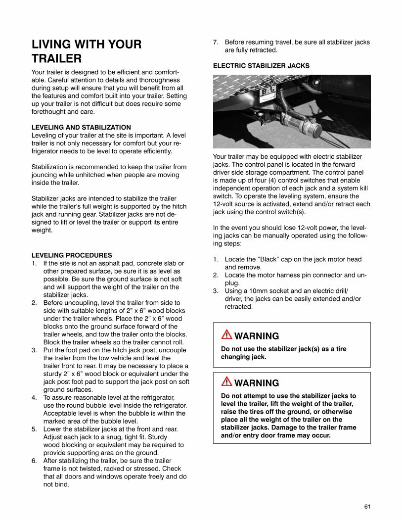
61
LIVING WITH YOUR TRAILERYour trailer is designed to be efficient and comfort-able. Careful attention to details and thoroughness during setup will ensure that you will benefit from all the features and comfort built into your trailer. Setting up your trailer is not difficult but does require some forethought and care.
LEVELING AND STABILIZATIONLeveling of your trailer at the site is important. A level trailer is not only necessary for comfort but your re-frigerator needs to be level to operate efficiently.
Stabilization is recommended to keep the trailer from jouncing while unhitched when people are moving inside the trailer.
Stabilizer jacks are intended to stabilize the trailer while the trailer’s full weight is supported by the hitch jack and running gear. Stabilizer jacks are not de-signed to lift or level the trailer or support its entire weight.
LEVELING PROCEDURES1. If the site is not an asphalt pad, concrete slab or
other prepared surface, be sure it is as level as possible. Be sure the ground surface is not soft and will support the weight of the trailer on the stabilizer jacks.
2. Before uncoupling, level the trailer from side to side with suitable lengths of 2” x 6” wood blocks under the trailer wheels. Place the 2” x 6” wood blocks onto the ground surface forward of the trailer wheels, and tow the trailer onto the blocks. Block the trailer wheels so the trailer cannot roll.
3. Put the foot pad on the hitch jack post, uncouple the trailer from the tow vehicle and level the trailer front to rear. It may be necessary to place a sturdy 2” x 6” wood block or equivalent under the jack post foot pad to support the jack post on soft ground surfaces.
4. To assure reasonable level at the refrigerator, use the round bubble level inside the refrigerator. Acceptable level is when the bubble is within the marked area of the bubble level.
5. Lower the stabilizer jacks at the front and rear. Adjust each jack to a snug, tight fit. Sturdy wood blocking or equivalent may be required to provide supporting area on the ground.
6. After stabilizing the trailer, be sure the trailer frame is not twisted, racked or stressed. Check that all doors and windows operate freely and do not bind.
7. Before resuming travel, be sure all stabilizer jacks are fully retracted.
ELECTRIC STABILIZER JACKS
Your trailer may be equipped with electric stabilizer jacks. The control panel is located in the forward driver side storage compartment. The control panel is made up of four (4) control switches that enable independent operation of each jack and a system kill switch. To operate the leveling system, ensure the 12-volt source is activated, extend and/or retract each jack using the control switch(s).
In the event you should lose 12-volt power, the level-ing jacks can be manually operated using the follow-ing steps:
1. Locate the “Black” cap on the jack motor head and remove.
2. Locate the motor harness pin connector and un-plug.
3. Using a 10mm socket and an electric drill/driver, the jacks can be easily extended and/or retracted.
WARNINGDo not use the stabilizer jack(s) as a tire changing jack.
WARNINGDo not attempt to use the stabilizer jacks to level the trailer, lift the weight of the trailer, raise the tires off the ground, or otherwise place all the weight of the trailer on the stabilizer jacks. Damage to the trailer frame and/or entry door frame may occur.
62
EFFECTS OF PROLONGED OCCUPANCYYour trailer was designed for recreational use and short-term occupancy. If you expect to occupy it for an extended period, you need to be prepared to deal with issues that include condensation, exces-sive humidity and the damage that can be caused by moisture, such as mold. The materials and methods used to construct your trailer were selected in part to minimize air leakage and to create a weather tight ex-terior shell. However, in order to protect your invest-ment and reduce the risk of moisture related damage and costly repairs, attention and care have to be taken to manage moisture inside your trailer.
The relatively small volume of space and air tight construction of a modern recreational vehicle means that the normal living activities of even a few occu-pants will lead to rapid moisture saturation of the air contained in the trailer and the appearance of visible moisture, especially in cold weather.
Just as moisture collects on the outside of a glass of cold water during humid weather, moisture can con-densate on the inside surfaces of your trailer during use in cold weather when the relative humidity of in-terior air is high. This condition is increased because the insulated walls of the trailer are much thinner than house walls.
Estimates indicate that a family of four can vaporize up to three gallons of water daily through breathing, cooking, bathing and washing. Unless this water vapor is carried outside by ventilation, or condensed by a dehumidifier, it will condense on the inside of the windows and walls as moisture, or in cold weather as frost or ice. It may also condense out of sight within the walls or the ceiling where it will manifest itself as warped or stained panels.
Appearance of these conditions may indicate a seri-ous condensation problem. When you recognize the signs of excessive moisture and condensation in your trailer, you should take action to minimize their effects.
NOTE: Your trailer is not designed to be used as permanent housing. Use of this product for long term or permanent occupancy may lead to premature deterioration of the structure, interior finishes, fabrics, carpeting and drapes. Damage or deterioration due to long-term occupancy may not be considered nor-mal, and may under the terms of the warranty con-stitute misuse, abuse or neglect, and may therefore reduce your warranty protection.
Signs of excessive moisture can be obvious, such as water droplets forming on surfaces. Conversely, signs of excess moisture can be subtle, such as condensa-tion forming on metal surfaces. When symptoms ap-pear it is important to timely determine the cause of the excess moisture and take appropriate corrective action to prevent moisture related damage.
Monitoring and controlling relative humidity within the trailer is one of the most important steps to minimize the risk for moisture related damage. Ideally, relative humidity should be at 60% or less. Relative humidity can be monitored utilizing a portable hygrometer, a small device that measures temperature and relative humidity. Hygrometers are available at electronics or building supply stores.
Use exhaust fans, the air conditioner, and/or a porta-ble dehumidifier to manage moisture inside the trailer to maintain relative humidity at 60% or less. In cold climates, relative humidity may need to be at 35% or less to avoid window condensation issues.
If the trailer is used the majority of the time in a hot-humid climate, it may be difficult to keep relative humidity below 60%. A dehumidifier will help, but it is important to check the condensation (water) collec-tion bucket regularly or discharge the condensation (water) directly to a drain.
Cooler surface temperatures increase the potential for condensation and surface mold growth. To minimize the opportunity for condensation to form on interior surfaces, maintain a comfortable temperature in your trailer, and avoid nighttime setbacks of 10 degrees or more. Drastic setbacks that reduce the indoor air temperature quickly can increase the chance for airborne moisture to condense on cool surfaces such as windows. If you are away from your trailer for an extended number of days, we recommend that you do not set the temperature back without taking other measures to manage relative humidity, including op-erating a dehumidifier with a continuous drain.
Window condensation issues can be identified by wa-ter or ice-build up, usually at the base of the window. The majority of these problems can be addressed by managing moisture generated inside the trailer. Minor condensation issues are not unusual, especially for trailers used in colder climates. The key is to manage this small amount of moisture if evident by wiping the surface, and as discussed above, maintaining a reasonable relative humidity within the unit.
63
To help minimize window condensation, use exhaust fans vented to the outside, avoid drastic changes in thermostat settings, do not use “vent-free” heaters and use window coverings wisely. For example, make sure to open curtains or blinds during the day to al-low air to circulate and ward the window surface.
Storage areas are more difficult to condition since the areas are isolated from the main body of the trailer. The surfaces of these areas are more at risk for con-densation and surface mold growth. To minimize this risk, clean storage areas regularly and allow an air space between stored items and the exterior wall to promote air circulation. During prolonged use in very cold weather, leave cabinets and closet doors par-tially open to warm and ventilate the interior of stor-age compartments built against exterior walls. The airflow will warm the exterior wall surface, reducing or eliminating condensation and minimizing possible ice formation.
Unvented combustion equipment, such as propane stovetops are a source of moisture within the trailer. For every gallon of fuel consumed, approximately one gallon of water vapor is evaporated into the air. When-ever possible, operate an exhaust fan in combination with the use of any un-vented combustion appliance within the trailer. Water vapor and other combustion byproducts should be vented to the exterior of the trailer. You need to strictly follow the use and mainte-nance instructions for safe operation of any combus-tion equipment, particularly un-vented equipment.
The exterior of the trailer is the primary weather and moisture barrier. Over the life of the trailer, the exterior will require regular car and maintenance. The shell in-cludes the roof, sidewalls, windows, doors and under-floor of the trailer. Particular attention needs to be devoted to ensure these components are maintained to ensure a tight barrier against water intrusion.
The exterior should be inspected periodically for tears, gaps and condition of sealants. Areas that require maintenance should be resealed utilizing a similar, high quality sealant as was used during the manufacture of your trailer.
Particular attention should be devoted to ensure the slide out is functioning properly. Each time a slide out is used it should be inspected to ensure proper operation and sealing. The slide out gaskets should be inspected to ensure proper sealing when the slide out is operated.
It is important to remember that the square footage of a trailer is significantly less than that of a single fam-ily residence. This fact alone will elevate the relative humidity because there is less volume of air to help absorb or dissipate the humidity. For example, show-ering and cooking create a lot of humidity in a small area. In these instances, use of an exhaust fan and opening windows should reduce the relative humidity, particularly when living in the trailer for an extended period.
Prolonged use of your trailer in severe environments, such as in extreme cold or hot-humid climates, will re-quire extra care and maintenance to avoid moisture-related issues.
In both extremely cold and hot-humid climates, more attention needs to be focused on controlling relative humidity within the trailer. It also may require the use of a portable dehumidifier to manage relative humid-ity within an acceptable range.
During those periods when your trailer is not in use, care must be taken to ensure moisture sources are addressed. Ideal storage of your trailer would be in an enclosed climate controlled environment. When this is not possible, the following steps should be taken to ensure moisture is controlled:
• Turnoffallwatersources
• Turnoffallcombustionappliances
• Drainthewatertank
• Drainthewaterheater
• Openallclosets,cabinetdoorsanddrawers
• Closeallwindowsandentrancedoors
• Openaventorwindowenoughtoallowforsome limited ventilation air flow, but not so far as to allow rain or snow to enter
• Whenstoringthetrailerinhighhumiditycli-mates (ambient relative humidity is grater than 60% year round), add a dehumidifier drained to the exterior to control humidity inside the trailer during storage
It is important that modifications to your trailer be completed by a qualified service person to ensure moisture intrusion or accumulation problems do not occur.
64
Areas that are exposed to water spills or leaks should be dried as soon as possible and definitely within 24-48 hours. Drying areas quickly minimizes the chance for moisture damage and possible mold growth, which can begin to form colonies in 48 hours. A variety of methods can be used to help the drying process:
• Removeexcesswaterwithanextraction vacuum
• Useadehumidifiertoaiddrying
• Useportablefanstomoveairacrossthesurface
• Becausemoistureiskeytomoldissues,treatallsigns of condensation and spills seriously and deal with it promptly. Failure to deal with a mois-ture issue promptly may cause more severe issues where none initially existed, or may make a small problem much worse.
• Learntorecognizesignsofmold.Don’tcoverup suspicious discoloration until you are sure it is not mold. The affected surface must first be cleaned and dried
• Besuretounderstandandeliminatethesourceof moisture accumulation as a part of the clean-up. Otherwise, the same issues will simply reoccur
• Smallamountsofmoldshouldbecleanedassoon as it appears. Small areas of mold should be cleaned using a detergent/soapy solution or an appropriate household cleaner. Gloves should be worn during cleaning. The cleaned area should be thoroughly dried. Dispose of any sponges or rags used to clean mold.
After you first purchase your new trailer and some-times after it has been closed up for an extended pe-riod of time, you may notice some strong odors and feel some chemical sensitivity. This is not a defect in your trailer. Many different products are used in the construction of your trailer. Some of these materi-als such as carpet, linoleum, plywood, insulation, upholstery, may “off-gas” different chemicals. This off-gassing is especially noticeable when the materi-als are new or are exposed to high temperatures and/or humidity. Since your trailer is much smaller than your home, and because the air inside the trailer is exchanged less often, the concentration of these chemicals in your trailer is more noticeable. This condition passes with time, but in an extreme condi-tion, open the door, windows, and vents to allow the interior to “air out” for several hours.
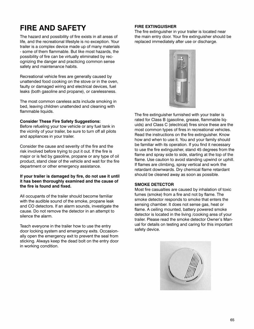
65
FIRE AND SAFETYThe hazard and possibility of fire exists in all areas of life, and the recreational lifestyle is no exception. Your trailer is a complex device made up of many materials - some of them flammable. But like most hazards, the possibility of fire can be virtually eliminated by rec-ognizing the danger and practicing common sense safety and maintenance habits.
Recreational vehicle fires are generally caused by unattended food cooking on the stove or in the oven, faulty or damaged wiring and electrical devices, fuel leaks (both gasoline and propane), or carelessness.
The most common careless acts include smoking in bed, leaving children unattended and cleaning with flammable liquids.
Consider These Fire Safety Suggestions:Before refueling your tow vehicle or any fuel tank in the vicinity of your trailer, be sure to turn off all pilots and appliances in your trailer.
Consider the cause and severity of the fire and the risk involved before trying to put it out. If the fire is major or is fed by gasoline, propane or any type of oil product, stand clear of the vehicle and wait for the fire department or other emergency assistance.
If your trailer is damaged by fire, do not use it until it has been thoroughly examined and the cause of the fire is found and fixed.
All occupants of the trailer should become familiar with the audible sound of the smoke, propane leak and CO detectors. If an alarm sounds, investigate the cause. Do not remove the detector in an attempt to silence the alarm.
Teach everyone in the trailer how to use the entry door locking system and emergency exits. Occasion-ally open the emergency exit to prevent the seal from sticking. Always keep the dead bolt on the entry door in working condition.
FIRE EXTINGUISHERThe fire extinguisher in your trailer is located near the main entry door. Your fire extinguisher should be replaced immediately after use or discharge.
The fire extinguisher furnished with your trailer is rated for Class B (gasoline, grease, flammable liq-uids) and Class C (electrical) fires since these are the most common types of fires in recreational vehicles. Read the instructions on the fire extinguisher. Know how and when to use it. You and your family should be familiar with its operation. If you find it necessary to use the fire extinguisher, stand 45 degrees from the flame and spray side to side, starting at the top of the flame. Use caution to avoid standing upwind or uphill. If flames are climbing, spray vertical and work the retardant downwards. Dry chemical flame retardant should be cleaned away as soon as possible.
SMOKE DETECTORMost fire casualties are caused by inhalation of toxic fumes (smoke) from a fire and not by flame. The smoke detector responds to smoke that enters the sensing chamber. It does not sense gas, heat or flame. A ceiling mounted, battery powered smoke detector is located in the living /cooking area of your trailer. Please read the smoke detector Owner’s Man-ual for details on testing and caring for this important safety device.
66
Test the smoke detector after the trailer has been in storage, before each trip, and at least once a week during use.
The smoke detector should never be disabled due to nuisance or false alarm from cooking smoke, a dusty furnace, etc. Ventilate your trailer with fresh air and the alarm will turn off. Do not disconnect the battery.
Replace the battery once a year or immediately when the low battery “beep” signal sounds once a minute.
The detector uses a standard 9-volt battery. Test smoke detector operation after replacing the battery. If the smoke detector fails to operate with a new bat-tery, replace the detector with a new unit.
COMBINATION CARBON MONOXIDE AND PROPANE LEAK DETECTORA permanently installed detector is located near the floor in the main trailer floor area. The unit contains an alarm that will sound, alerting you to the presence of propane or carbon monoxide.
WARNINGTO REDUCE THE RISK OF CARBON MONOXIDE POISONING OR PROPANE GAS EXPLOSION, TEST THIS ALARM’S OPERATION AFTER THE TRAILER HAS BEEN IN STORAGE, BEFORE EACH TRIP AND AT LEAST ONCE PER WEEK DURING USE.
WARNINGDO NOT USE A CIGARETTE LIGHTER TO TEST THE CO / PROPANE GAS ALARM. BUTANE GAS MAY DAMAGE THE SENSORS.
DO NOT attempt to test the alarm by any other means than by using the TEST/RESET button. DO NOT attempt to produce CO to the alarm. The TEST/RESET button tests all functions of the alarm and is the ONLY safe way to be sure the alarm is working properly.
The alarm may be tested at any time. The TEST/Mute switch is located on the front of the alarm. Press and hold the test button for 1 second. The alarm is work-ing properly if the GREEN indicator light changes color to RED and the alarm beeps 4 times. The Gas
LED should also blink Red.
OperationWhen the unit is first powered up, the CO sensor requires a ten (10) minute initial warm-up period to clean the sensor element and achieve stabilization. The GREEN LED indicator will flash on and off during the 10 minute warm-up period. This unit cannot go into a CO alarm during the warm-up period. After the warm-up period, the GREEN power ON indicator should glow continuously. If the ON indicator light does not light see the section, “Trouble-Shooting Guide” in the User’s Manual for this alarm provided in the Owner’s Information Package.
This alarm will operate normally down to 7v DC. It will not work without power.
Visual and Audible Alarm SignalsThe CO / Propane Gas Alarm is designed to be easy to- operate. The alarm has two indicator lights that display a specific color for each monitored condi-tion. There also is a matching sound pattern for alarm conditions.
CO ALARMThe Red CO LED will flash and the alarm will sound 4 “BEEPS” then silent for 5 seconds. These signals indicate that the CO level over 70 ppm. IMMEDIATE ACTION IS REQUIRED. This cycle will continue until the TEST/Mute button on the front of the alarm is pressed. Ventilate the Trailer. The RED light will stay ON until the CO has cleared, or the alarm will re-activate in approximately 6 minutes if the CO is still present. DO NOT RE-ENTER THE TRAILER. This alarm will return to normal operation after the Trailer’s properly ventilated.
67
PROCEDURES TO TAKE DURING A CO ALARMActuation of this device indicates the presence of car-bon monoxide (CO) or propane gases, which can kill you. If signal sounds (4 beeps and flashing or solid red light), immediately turn off all combustion sources and ventilate the premises. Evacuate the premises immediately. Check that all persons are accounted for. Do not re-enter the trailer until it has been aired out and the problem corrected. Have the problem corrected before restarting appliances.
WARNINGCARBON MONOXIDE CANNOT BE SEEN OR SMELLED AND CAN KILL YOU.
PROPANE GAS ALARMThe Red LED will flash and the alarm will sound a steady tone whenever a dangerous level of propane or methane gas is detected. IMMEDIATE ACTION IS REQUIRED. The detector will continue to alarm until the Test/Mute switch on the front of the alarm is pressed. Ventilate the Trailer. The RED Gas LED will continue to flash until the gas is cleared, or the gas alarm will reactivate in approximately 5 minutes if the gas is still present. DO NOT RE-ENTER THE TRAIL-ER. This alarm will return to normal operation after the Trailer is properly ventilated.
NOTE: This device detects the presence of propane; it does not disconnect the gas supply.
PROCEDURES TO TAKE DURING A GAS ALARMTurn the propane off at the tank(s), turn off all pro-pane appliances, extinguish all flames and smoking material and open all doors and major windows to air out the trailer. Do not re-enter the trailer until the alarm stops sounding. If the alarm sounds a second time after the propane is turned back on, leave the propane off and have a Lance Service Center make the necessary repairs to the source of the propane leak.
Be aware of the difference between a propane leak versus propane escaping from an unlit, open burner. Pure propane from a leaking pipe or fit-ting is heavier than air and will buildup its heavi-est concentration at the floor level first. Propane from open burners is intentionally mixed with air to induce burning and will dissipate into the air. The primary purpose of the detector is to detect propane leaks. The propane from open burn-ers is mixed with air (oxygen) so that it will burn. When mixed with air, the propane becomes only marginally heavier than air and may not sink to the floor. If a burner is left on, the area around the
burner, range and adjoining counter space will be combustible and will cause injury and damage if ignited. This condition may exist for an extended time period before the propane can reach the detector’s location and be detected. The detector only indicates the presence of propane at the sensor. Propane may be present in other areas.
The detector is powered by the 12-volt DC system and is always powered as long as the trailer is con-nected to the tow vehicle, a charged battery, or 120-volt AC power.
The fuse for the detector is located in the Power Dis-tribution Center.
NOTE: The detector is continuously powered; dis-connect the battery if you are not using your trailer. The detector can evidentially drain the trailer battery.

68
This page intentionally left blank.

69
EQUIPMENTSOME FEATURES DESCRIBED HERE DO NOT APPEAR ON ALL LANCE MODELS. SOME FEATURES MAY BE OPTIONAL ON YOUR MODEL.
After taking delivery of your Lance trailer, spend some time familiarizing yourself with the exterior and interior features. Your interior has been designed with utility and comfort in mind to provide spaciousness and versatility. Familiarize yourself with the bedding and dining arrangements as well as the various storage areas inside and out.
ROOFMost Lance trailer models have a fully decked and laminated roof that may be walked on from front to rear and are rated at 2,000 lbs. The top decking is TPO (Thermal Plastic Olefin). When walking on the roof use deck shoes as leather shoes become slip-pery and can also leave marks on the decking. When on the roof, use caution to avoid slips and falls. Care must be taken when working on the roof to avoid disrupting the seals which could void your warranty.
COMPARTMENT DOORS
Various exterior compartment doors provide access to certain appliances, controls, and general storage. Exterior compartment doors may not be water tight in all weather and road conditions. Any article which could be damaged by water or dirt should be carried inside the trailer or tow vehicle.
WATER HEATER ACCESS DOOR
The Water Heater Door provides access for service of the water heater.
REFRIGERATOR ACCESS DOOR
The Refrigerator Vent/Door provides access to the rear of the refrigerator for service and supplies inlet ventilation for proper operation.
VENTSAll exterior vents and louvers provide needed air circulation. Be sure not to block these vents because damage to equipment, as well as hazards to individu-als could result.
ROOF VENTS
The roof vents are operated from inside and have built-in screens. To operate, turn the crank in the cen-ter of the vent clockwise to open and adjust. The bath vent may be equipped with a 12-volt exhaust fan. The switch to control the fan is located on the vent. These vents may be left slightly open while traveling, but be careful when traveling where vertical clearance is limited. Vent lids can crack if left open too far.
FANTASTIC ROOF VENT
The Fantastic high-volume power roof vent is designed to quickly exhaust stale hot air.
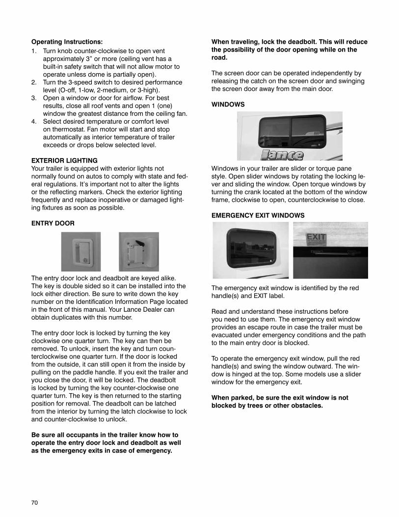
70
Operating Instructions:1. Turn knob counter-clockwise to open vent
approximately 3” or more (ceiling vent has a built-in safety switch that will not allow motor to operate unless dome is partially open).
2. Turn the 3-speed switch to desired performance level (O-off, 1-low, 2-medium, or 3-high).
3. Open a window or door for airflow. For best results, close all roof vents and open 1 (one) window the greatest distance from the ceiling fan.
4. Select desired temperature or comfort level on thermostat. Fan motor will start and stop automatically as interior temperature of trailer exceeds or drops below selected level.
EXTERIOR LIGHTINGYour trailer is equipped with exterior lights not normally found on autos to comply with state and fed-eral regulations. It’s important not to alter the lights or the reflecting markers. Check the exterior lighting frequently and replace inoperative or damaged light-ing fixtures as soon as possible.
ENTRY DOOR
The entry door lock and deadbolt are keyed alike. The key is double sided so it can be installed into the lock either direction. Be sure to write down the key number on the Identification Information Page located in the front of this manual. Your Lance Dealer can obtain duplicates with this number.
The entry door lock is locked by turning the key clockwise one quarter turn. The key can then be removed. To unlock, insert the key and turn coun-terclockwise one quarter turn. If the door is locked from the outside, it can still open it from the inside by pulling on the paddle handle. If you exit the trailer and you close the door, it will be locked. The deadbolt is locked by turning the key counter-clockwise one quarter turn. The key is then returned to the starting position for removal. The deadbolt can be latched from the interior by turning the latch clockwise to lock and counter-clockwise to unlock.
Be sure all occupants in the trailer know how to operate the entry door lock and deadbolt as well as the emergency exits in case of emergency.
When traveling, lock the deadbolt. This will reduce the possibility of the door opening while on the road.
The screen door can be operated independently by releasing the catch on the screen door and swinging the screen door away from the main door.
WINDOWS
Windows in your trailer are slider or torque pane style. Open slider windows by rotating the locking le-ver and sliding the window. Open torque windows by turning the crank located at the bottom of the window frame, clockwise to open, counterclockwise to close.
EMERGENCY EXIT WINDOWS
The emergency exit window is identified by the red handle(s) and EXIT label.
Read and understand these instructions before you need to use them. The emergency exit window provides an escape route in case the trailer must be evacuated under emergency conditions and the path to the main entry door is blocked.
To operate the emergency exit window, pull the red handle(s) and swing the window outward. The win-dow is hinged at the top. Some models use a slider window for the emergency exit.
When parked, be sure the exit window is not blocked by trees or other obstacles.
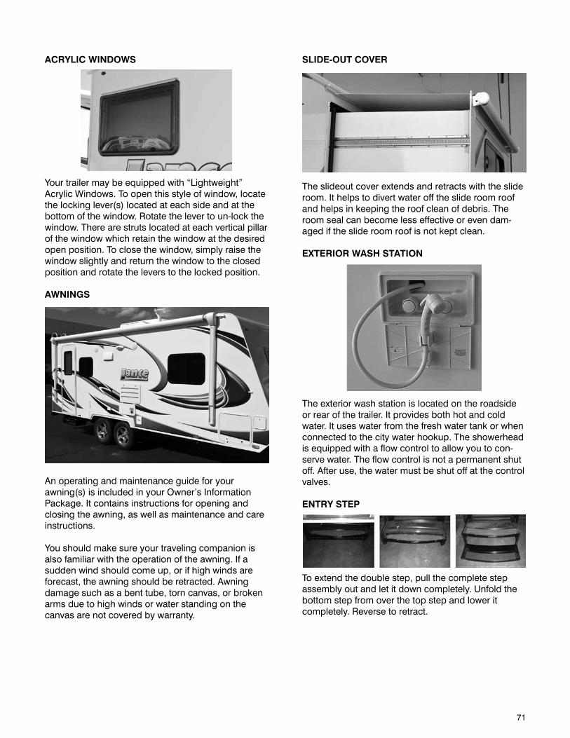
71
SLIDE-OUT COVER
The slideout cover extends and retracts with the slide room. It helps to divert water off the slide room roof and helps in keeping the roof clean of debris. The room seal can become less effective or even dam-aged if the slide room roof is not kept clean.
EXTERIOR WASH STATION
The exterior wash station is located on the roadside or rear of the trailer. It provides both hot and cold water. It uses water from the fresh water tank or when connected to the city water hookup. The showerhead is equipped with a flow control to allow you to con-serve water. The flow control is not a permanent shut off. After use, the water must be shut off at the control valves.
ENTRY STEP
To extend the double step, pull the complete step assembly out and let it down completely. Unfold the bottom step from over the top step and lower it completely. Reverse to retract.
ACRYLIC WINDOWS
Your trailer may be equipped with “Lightweight” Acrylic Windows. To open this style of window, locate the locking lever(s) located at each side and at the bottom of the window. Rotate the lever to un-lock the window. There are struts located at each vertical pillar of the window which retain the window at the desired open position. To close the window, simply raise the window slightly and return the window to the closed position and rotate the levers to the locked position.
AWNINGS
An operating and maintenance guide for your awning(s) is included in your Owner’s Information Package. It contains instructions for opening and closing the awning, as well as maintenance and care instructions.
You should make sure your traveling companion is also familiar with the operation of the awning. If a sudden wind should come up, or if high winds are forecast, the awning should be retracted. Awning damage such as a bent tube, torn canvas, or broken arms due to high winds or water standing on the canvas are not covered by warranty.
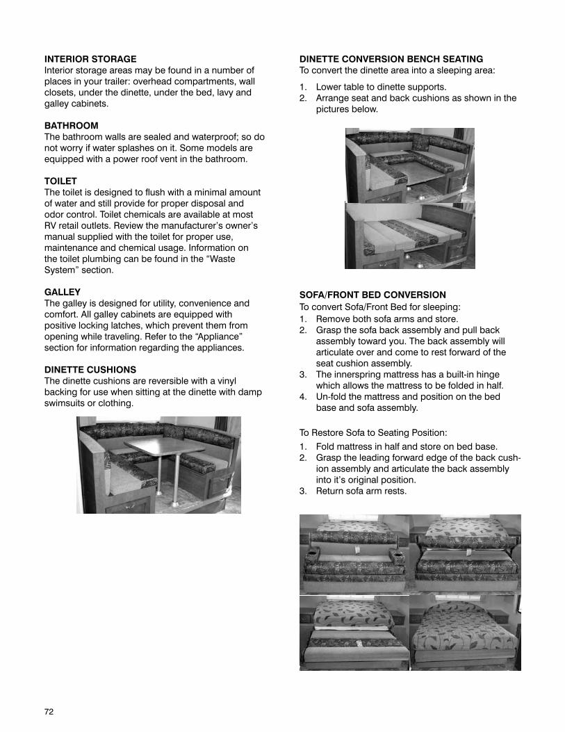
72
DINETTE CONVERSION BENCH SEATINGTo convert the dinette area into a sleeping area:
1. Lower table to dinette supports.2. Arrange seat and back cushions as shown in the
pictures below.
SOFA/FRONT BED CONVERSIONTo convert Sofa/Front Bed for sleeping:1. Remove both sofa arms and store.2. Grasp the sofa back assembly and pull back
assembly toward you. The back assembly will articulate over and come to rest forward of the seat cushion assembly.
3. The innerspring mattress has a built-in hinge which allows the mattress to be folded in half.
4. Un-fold the mattress and position on the bed base and sofa assembly.
To Restore Sofa to Seating Position:
1. Fold mattress in half and store on bed base.2. Grasp the leading forward edge of the back cush-
ion assembly and articulate the back assembly into it’s original position.
3. Return sofa arm rests.
INTERIOR STORAGEInterior storage areas may be found in a number of places in your trailer: overhead compartments, wall closets, under the dinette, under the bed, lavy and galley cabinets.
BATHROOMThe bathroom walls are sealed and waterproof; so do not worry if water splashes on it. Some models are equipped with a power roof vent in the bathroom.
TOILETThe toilet is designed to flush with a minimal amount of water and still provide for proper disposal and odor control. Toilet chemicals are available at most RV retail outlets. Review the manufacturer’s owner’s manual supplied with the toilet for proper use, maintenance and chemical usage. Information on the toilet plumbing can be found in the “Waste System” section.
GALLEYThe galley is designed for utility, convenience and comfort. All galley cabinets are equipped with positive locking latches, which prevent them from opening while traveling. Refer to the “Appliance” section for information regarding the appliances.
DINETTE CUSHIONSThe dinette cushions are reversible with a vinyl backing for use when sitting at the dinette with damp swimsuits or clothing.
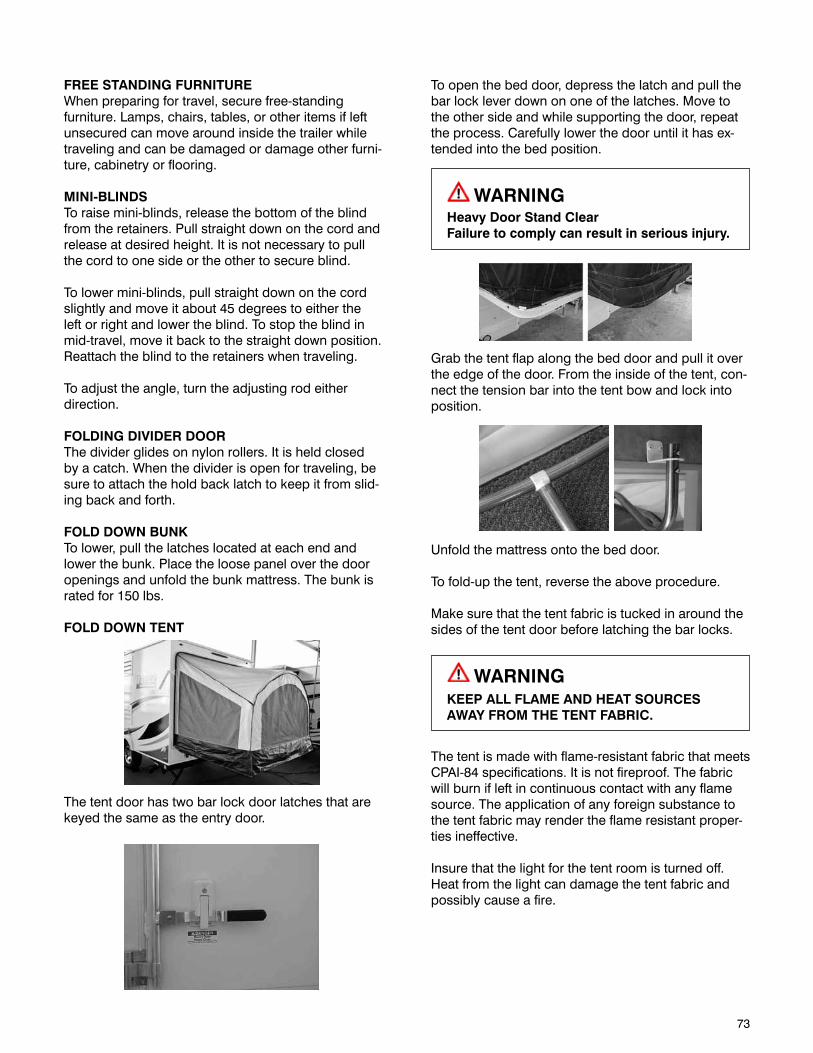
73
FREE STANDING FURNITUREWhen preparing for travel, secure free-standing furniture. Lamps, chairs, tables, or other items if left unsecured can move around inside the trailer while traveling and can be damaged or damage other furni-ture, cabinetry or flooring.
MINI-BLINDSTo raise mini-blinds, release the bottom of the blind from the retainers. Pull straight down on the cord and release at desired height. It is not necessary to pull the cord to one side or the other to secure blind.
To lower mini-blinds, pull straight down on the cord slightly and move it about 45 degrees to either the left or right and lower the blind. To stop the blind in mid-travel, move it back to the straight down position. Reattach the blind to the retainers when traveling.
To adjust the angle, turn the adjusting rod either direction.
FOLDING DIVIDER DOORThe divider glides on nylon rollers. It is held closed by a catch. When the divider is open for traveling, be sure to attach the hold back latch to keep it from slid-ing back and forth.
FOLD DOWN BUNKTo lower, pull the latches located at each end and lower the bunk. Place the loose panel over the door openings and unfold the bunk mattress. The bunk is rated for 150 lbs.
FOLD DOWN TENT
The tent door has two bar lock door latches that are keyed the same as the entry door.
To open the bed door, depress the latch and pull the bar lock lever down on one of the latches. Move to the other side and while supporting the door, repeat the process. Carefully lower the door until it has ex-tended into the bed position.
WARNINGHeavy Door Stand ClearFailure to comply can result in serious injury.
Grab the tent flap along the bed door and pull it over the edge of the door. From the inside of the tent, con-nect the tension bar into the tent bow and lock into position.
Unfold the mattress onto the bed door.
To fold-up the tent, reverse the above procedure.
Make sure that the tent fabric is tucked in around the sides of the tent door before latching the bar locks.
WARNINGKEEP ALL FLAME AND HEAT SOURCES AWAY FROM THE TENT FABRIC.
The tent is made with flame-resistant fabric that meets CPAI-84 specifications. It is not fireproof. The fabric will burn if left in continuous contact with any flame source. The application of any foreign substance to the tent fabric may render the flame resistant proper-ties ineffective.
Insure that the light for the tent room is turned off. Heat from the light can damage the tent fabric and possibly cause a fire.
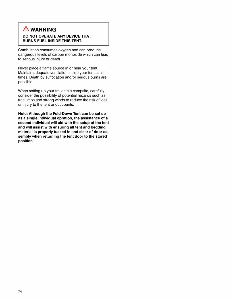
74
WARNINGDO NOT OPERATE ANY DEVICE THAT BURNS FUEL INSIDE THIS TENT.
Combustion consumes oxygen and can produce dangerous levels of carbon monoxide which can lead to serious injury or death.
Never place a flame source in or near your tent. Maintain adequate ventilation inside your tent at all times. Death by suffocation and/or serious burns are possible.
When setting up your trailer in a campsite, carefully consider the possibility of potential hazards such as tree limbs and strong winds to reduce the risk of loss or injury to the tent or occupants.
Note: Although the Fold-Down Tent can be set up as a single individual opration, the assistance of a second individual will aid with the setup of the tent and will assist with ensuring all tent and bedding material is properly tucked in and clear of door as-sembly when returning the tent door to the stored position.
75
ELECTRICAL SYSTEMSThe electrical system consists of a primary 12-volt DC system and a 120-volt AC system. The 12-volt system uses battery power similar to that used in automobiles. The 120-volt system requires a source of 120-volt power provided through the power supply cord or optional generator.
These systems are connected through a power converter. When connected to 120-volt power, the converter transforms 120-volt AC input into 12-volt DC power output and charges the storage battery(s) when installed.
12-VOLT DC SYSTEMThe 12-volt system provides power for the following components:
Electric JacksInterior LightingExterior LightingWater PumpPower Range HoodFurnace BlowerRefrigerator Light & ControlsWater Heater IgnitionStereo/CD/DVD PlayerTV Antenna Systems Monitor PanelFantastic FanPower VentStarting the GeneratorSlideout RoomAccessories Plugged into 12-volt OutletPower Awning
BATTERY AND COMPARTMENTYour trailer may be outfitted with a battery. The battery may be kept charged either by the tow vehicle, by the generator or shore power.
NOTE: The 12-volt battery(s) is not supplied with the trailer by the manufacturer.
A disconnect switch is provided to disconnect the battery when you do not plan to be using the trailer for an extended period, such as seasonal storage. If there is no disconnect switch, then remove the cables from the battery terminals.
BATTERY TERMINOLOGYDeep Cycle BatteriesThe term “deep cycle” refers to a battery that has the capability of deeply discharging hundreds of times. How it differs from an automotive starting battery is that the automotive battery is manufactured to specifi-cally provide a quick burst of energy thousands of times while only being able to deeply discharge less than 50 cycles during its lifetime. A cycle refers to one battery discharge and recharge.
Battery Ratings and SpecificationsMarine/RV deep cycle batteries have rating speci-fications which include cold cranking amps (CCA), marine cranking amps (MCA), reserve capacity (RC) and ampere hours (Ah). RC and approximate Ah rat-ings may not be listed on the battery decal. However, they should be available through your local battery distributor.
Cold Cranking Amps (CCA)The amount of current (amps) a battery at 0°F (-17.8°C) can deliver for 30 seconds and maintain at least 1.2 volts per cell (7.2 volts for a 12-volt battery).
Marine Cranking Amps (MCA)The amount of discharge current a battery tested at 32°F (0°C) can deliver for 30 seconds and maintain at least 1.2 volts per cell (7.2 volts on a 12-volt battery).
Reserve Capacity (RC)The amount of time a battery can deliver 25 amps at 80°F (26.7°C) without falling below 1.75 volts per cell (10.5 volts on a 12-volt battery). An approximate Ah rating can be attained by multiplying the battery’s RC rating by 0.6. Example 180 RC x 0.6 = 108 Ah.
Ampere hours (Ah)Tested at 80°F (26.7°C). It is the amount of current (in amps) a battery can deliver, multiplied by the amount of hours, without falling below 1.75 volts per cell (10.5 volts on a 12-volt battery). Most marine/RV deep cycle batteries are rated on a 20-hour discharge rate. Example: a 100 Ah battery can deliver 5 amps for 20 hours (amps x hours = Ah). The Ah rating is important when determining the type and amount of battery(s) required to meet your specific component needs.
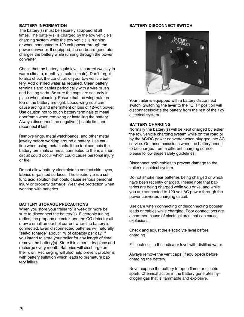
76
BATTERY INFORMATIONThe battery(s) must be securely strapped at all times. The battery(s) is charged by the tow vehicle’s charging system while the tow vehicle is running or when connected to 120-volt power through the power converter. If equipped, the on-board generator charges the battery while running through the power converter.
Check that the battery liquid level is correct (weekly in warm climate, monthly in cold climate). Don’t forget to also check the condition of your tow vehicle bat-tery. Add distilled water as required. Clean battery terminals and cables periodically with a wire brush and baking soda. Be sure the caps are securely in place when cleaning. Ensure that the wing nuts on top of the battery are tight. Loose wing nuts can cause arcing and intermittent or loss of 12-volt power. Use caution not to touch battery terminals to metal doorframe when removing or installing the battery. Always disconnect the negative (-) cable first and reconnect it last.
Remove rings, metal watchbands, and other metal jewelry before working around a battery. Use cau-tion when using metal tools. If the tool contacts the battery terminals or metal connected to them, a short circuit could occur which could cause personal injury or fire.
Do not allow battery electrolyte to contact skin, eyes, fabrics or painted surfaces. The electrolyte is a sul-furic acid solution that could cause serious personal injury or property damage. Wear eye protection when working with batteries.
BATTERY STORAGE PRECAUTIONSWhen you store your trailer for a week or more be sure to disconnect the battery(s). Electronic tuning radios, the propane detector, and the CO detector all draw a small amount of current when the battery is connected. Even disconnected batteries will naturally “self-discharge” about 1 % of capacity per day. If you intend to store your trailer for any length of time, remove the battery(s). Store it in a cool, dry place and recharge every month. Batteries will discharge on their own. Recharging will also help prevent problems with battery sulfation which leads to premature bat-tery failure.
BATTERY DISCONNECT SWITCH
Your trailer is equipped with a battery disconnect switch. Switching the lever to the “OFF” position will disconnect/isolate the battery from the rest of the 12V electrical system.
BATTERY CHARGINGNormally the battery(s) will be kept charged by either the tow vehicle charging system while on the road or by the AC/DC power converter when plugged into AC service. On those occasions when the battery needs to be charged from a different charging source, please follow these safety guidelines:
Disconnect both cables to prevent damage to the trailer’s electrical system.
Do not smoke near batteries being charged or which have been recently charged. Please note that bat-teries are being charged while you drive, and while you are connected to 120-volt AC power through the power converter/charging circuit.
Use care when connecting or disconnecting booster leads or cables while charging. Poor connections are a common cause of electrical arcs that can cause explosions.
Check and adjust the electrolyte level before charging.
Fill each cell to the indicator level with distilled water.
Always remove the vent caps (if equipped) before charging the battery.
Never expose the battery to open flame or electric spark. Chemical action in the battery generates hy-drogen gas that is flammable and explosive.
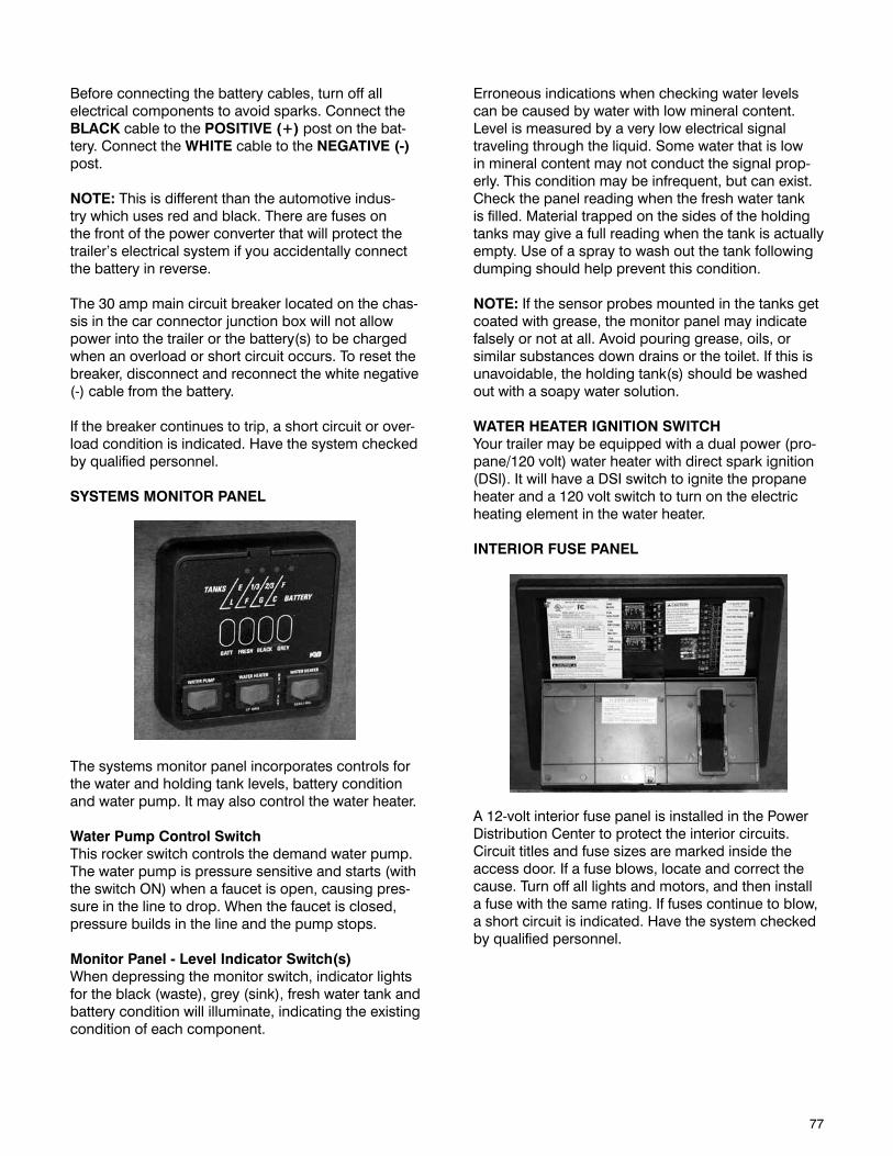
77
Before connecting the battery cables, turn off all electrical components to avoid sparks. Connect the BLACK cable to the POSITIVE (+) post on the bat-tery. Connect the WHITE cable to the NEGATIVE (-) post.
NOTE: This is different than the automotive indus-try which uses red and black. There are fuses on the front of the power converter that will protect the trailer’s electrical system if you accidentally connect the battery in reverse.
The 30 amp main circuit breaker located on the chas-sis in the car connector junction box will not allow power into the trailer or the battery(s) to be charged when an overload or short circuit occurs. To reset the breaker, disconnect and reconnect the white negative (-) cable from the battery.
If the breaker continues to trip, a short circuit or over-load condition is indicated. Have the system checked by qualified personnel.
SYSTEMS MONITOR PANEL
The systems monitor panel incorporates controls for the water and holding tank levels, battery condition and water pump. It may also control the water heater.
Water Pump Control SwitchThis rocker switch controls the demand water pump. The water pump is pressure sensitive and starts (with the switch ON) when a faucet is open, causing pres-sure in the line to drop. When the faucet is closed, pressure builds in the line and the pump stops.
Monitor Panel - Level Indicator Switch(s)When depressing the monitor switch, indicator lights for the black (waste), grey (sink), fresh water tank and battery condition will illuminate, indicating the existing condition of each component.
Erroneous indications when checking water levels can be caused by water with low mineral content. Level is measured by a very low electrical signal traveling through the liquid. Some water that is low in mineral content may not conduct the signal prop-erly. This condition may be infrequent, but can exist. Check the panel reading when the fresh water tank is filled. Material trapped on the sides of the holding tanks may give a full reading when the tank is actually empty. Use of a spray to wash out the tank following dumping should help prevent this condition.
NOTE: If the sensor probes mounted in the tanks get coated with grease, the monitor panel may indicate falsely or not at all. Avoid pouring grease, oils, or similar substances down drains or the toilet. If this is unavoidable, the holding tank(s) should be washed out with a soapy water solution.
WATER HEATER IGNITION SWITCHYour trailer may be equipped with a dual power (pro-pane/120 volt) water heater with direct spark ignition (DSI). It will have a DSI switch to ignite the propane heater and a 120 volt switch to turn on the electric heating element in the water heater.
INTERIOR FUSE PANEL
A 12-volt interior fuse panel is installed in the Power Distribution Center to protect the interior circuits. Circuit titles and fuse sizes are marked inside the access door. If a fuse blows, locate and correct the cause. Turn off all lights and motors, and then install a fuse with the same rating. If fuses continue to blow, a short circuit is indicated. Have the system checked by qualified personnel.
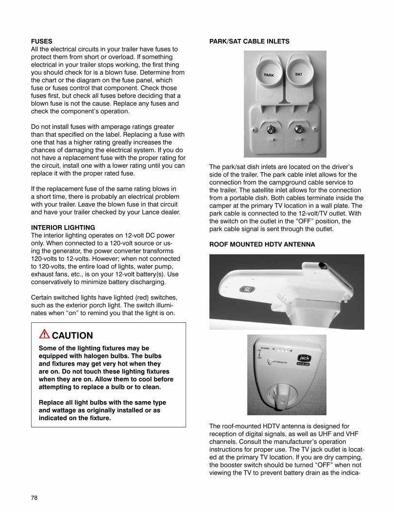
78
FUSESAll the electrical circuits in your trailer have fuses to protect them from short or overload. If something electrical in your trailer stops working, the first thing you should check for is a blown fuse. Determine from the chart or the diagram on the fuse panel, which fuse or fuses control that component. Check those fuses first, but check all fuses before deciding that a blown fuse is not the cause. Replace any fuses and check the component’s operation.
Do not install fuses with amperage ratings greater than that specified on the label. Replacing a fuse with one that has a higher rating greatly increases the chances of damaging the electrical system. If you do not have a replacement fuse with the proper rating for the circuit, install one with a lower rating until you can replace it with the proper rated fuse.
If the replacement fuse of the same rating blows in a short time, there is probably an electrical problem with your trailer. Leave the blown fuse in that circuit and have your trailer checked by your Lance dealer.
INTERIOR LIGHTINGThe interior lighting operates on 12-volt DC power only. When connected to a 120-volt source or us-ing the generator, the power converter transforms 120-volts to 12-volts. However; when not connected to 120-volts, the entire load of lights, water pump, exhaust fans, etc., is on your 12-volt battery(s). Use conservatively to minimize battery discharging.
Certain switched lights have lighted (red) switches, such as the exterior porch light. The switch illumi-nates when “on” to remind you that the light is on.
CAUTIONSome of the lighting fixtures may be equipped with halogen bulbs. The bulbs and fixtures may get very hot when they are on. Do not touch these lighting fixtures when they are on. Allow them to cool before attempting to replace a bulb or to clean.
Replace all light bulbs with the same type and wattage as originally installed or as indicated on the fixture.
PARK/SAT CABLE INLETS
The park/sat dish inlets are located on the driver’s side of the trailer. The park cable inlet allows for the connection from the campground cable service to the trailer. The satellite inlet allows for the connection from a portable dish. Both cables terminate inside the camper at the primary TV location in a wall plate. The park cable is connected to the 12-volt/TV outlet. With the switch on the outlet in the “OFF” position, the park cable signal is sent through the outlet.
ROOF MOUNTED HDTV ANTENNA
The roof-mounted HDTV antenna is designed for reception of digital signals, as well as UHF and VHF channels. Consult the manufacturer’s operation instructions for proper use. The TV jack outlet is locat-ed at the primary TV location. If you are dry camping, the booster switch should be turned “OFF” when not viewing the TV to prevent battery drain as the indica-
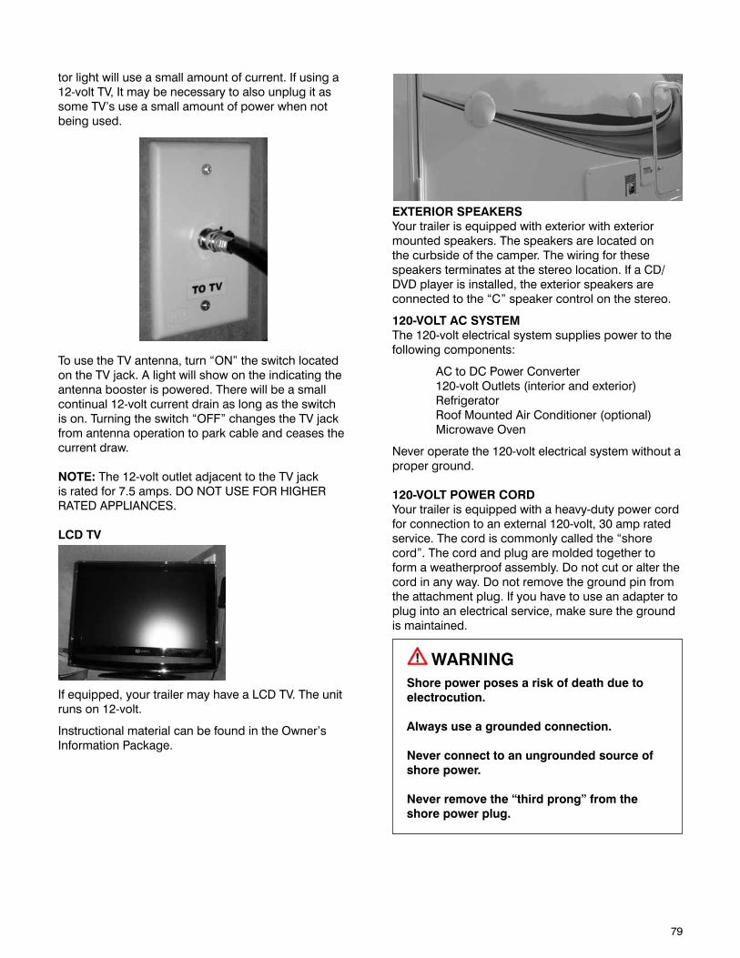
79
tor light will use a small amount of current. If using a 12-volt TV, It may be necessary to also unplug it as some TV’s use a small amount of power when not being used.
EXTERIOR SPEAKERSYour trailer is equipped with exterior with exterior mounted speakers. The speakers are located on the curbside of the camper. The wiring for these speakers terminates at the stereo location. If a CD/DVD player is installed, the exterior speakers are connected to the “C” speaker control on the stereo.
120-VOLT AC SYSTEMThe 120-volt electrical system supplies power to the following components:
AC to DC Power Converter120-volt Outlets (interior and exterior)RefrigeratorRoof Mounted Air Conditioner (optional)Microwave Oven
Never operate the 120-volt electrical system without a proper ground.
120-VOLT POWER CORDYour trailer is equipped with a heavy-duty power cord for connection to an external 120-volt, 30 amp rated service. The cord is commonly called the “shore cord”. The cord and plug are molded together to form a weatherproof assembly. Do not cut or alter the cord in any way. Do not remove the ground pin from the attachment plug. If you have to use an adapter to plug into an electrical service, make sure the ground is maintained.
WARNINGShore power poses a risk of death due to electrocution.
Always use a grounded connection.
Never connect to an ungrounded source of shore power.
Never remove the “third prong” from the shore power plug.
To use the TV antenna, turn “ON” the switch located on the TV jack. A light will show on the indicating the antenna booster is powered. There will be a small continual 12-volt current drain as long as the switch is on. Turning the switch “OFF” changes the TV jack from antenna operation to park cable and ceases the current draw.
NOTE: The 12-volt outlet adjacent to the TV jack is rated for 7.5 amps. DO NOT USE FOR HIGHER RATED APPLIANCES.
LCD TV
If equipped, your trailer may have a LCD TV. The unit runs on 12-volt.
Instructional material can be found in the Owner’s Information Package.
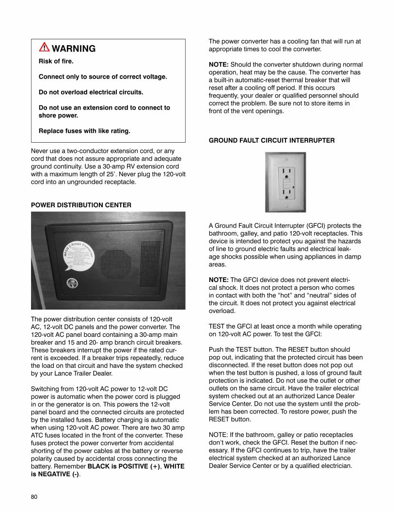
80
WARNINGRisk of fire.
Connect only to source of correct voltage.
Do not overload electrical circuits.
Do not use an extension cord to connect to shore power.
Replace fuses with like rating.
Never use a two-conductor extension cord, or any cord that does not assure appropriate and adequate ground continuity. Use a 30-amp RV extension cord with a maximum length of 25’. Never plug the 120-volt cord into an ungrounded receptacle.
POWER DISTRIBUTION CENTER
The power distribution center consists of 120-volt AC, 12-volt DC panels and the power converter. The 120-volt AC panel board containing a 30-amp main breaker and 15 and 20- amp branch circuit breakers. These breakers interrupt the power if the rated cur-rent is exceeded. If a breaker trips repeatedly, reduce the load on that circuit and have the system checked by your Lance Trailer Dealer.
Switching from 120-volt AC power to 12-volt DC power is automatic when the power cord is plugged in or the generator is on. This powers the 12-volt panel board and the connected circuits are protected by the installed fuses. Battery charging is automatic when using 120-volt AC power. There are two 30 amp ATC fuses located in the front of the converter. These fuses protect the power converter from accidental shorting of the power cables at the battery or reverse polarity caused by accidental cross connecting the battery. Remember BLACK is POSITIVE (+), WHITE is NEGATIVE (-).
The power converter has a cooling fan that will run at appropriate times to cool the converter.
NOTE: Should the converter shutdown during normal operation, heat may be the cause. The converter has a built-in automatic-reset thermal breaker that will reset after a cooling off period. If this occurs frequently, your dealer or qualified personnel should correct the problem. Be sure not to store items in front of the vent openings.
GROUND FAULT CIRCUIT INTERRUPTER
A Ground Fault Circuit Interrupter (GFCI) protects the bathroom, galley, and patio 120-volt receptacles. This device is intended to protect you against the hazards of line to ground electric faults and electrical leak-age shocks possible when using appliances in damp areas.
NOTE: The GFCI device does not prevent electri-cal shock. It does not protect a person who comes in contact with both the “hot” and “neutral” sides of the circuit. It does not protect you against electrical overload.
TEST the GFCI at least once a month while operating on 120-volt AC power. To test the GFCI:
Push the TEST button. The RESET button should pop out, indicating that the protected circuit has been disconnected. If the reset button does not pop out when the test button is pushed, a loss of ground fault protection is indicated. Do not use the outlet or other outlets on the same circuit. Have the trailer electrical system checked out at an authorized Lance Dealer Service Center. Do not use the system until the prob-lem has been corrected. To restore power, push the RESET button.
NOTE: If the bathroom, galley or patio receptacles don’t work, check the GFCI. Reset the button if nec-essary. If the GFCI continues to trip, have the trailer electrical system checked at an authorized Lance Dealer Service Center or by a qualified electrician.
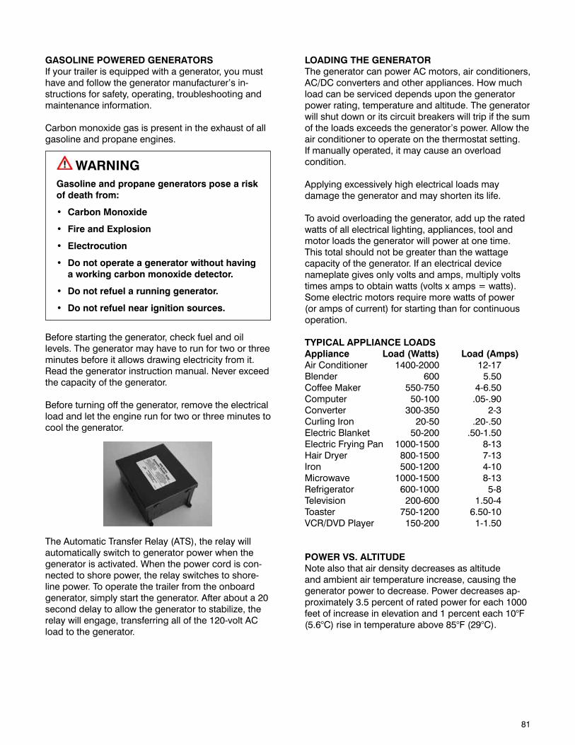
81
GASOLINE POWERED GENERATORSIf your trailer is equipped with a generator, you must have and follow the generator manufacturer’s in-structions for safety, operating, troubleshooting and maintenance information.
Carbon monoxide gas is present in the exhaust of all gasoline and propane engines.
WARNINGGasoline and propane generators pose a risk of death from:
• CarbonMonoxide
• FireandExplosion
• Electrocution
• Donotoperateageneratorwithouthaving a working carbon monoxide detector.
• Donotrefuelarunninggenerator.
• Donotrefuelnearignitionsources.
Before starting the generator, check fuel and oil levels. The generator may have to run for two or three minutes before it allows drawing electricity from it. Read the generator instruction manual. Never exceed the capacity of the generator.
Before turning off the generator, remove the electrical load and let the engine run for two or three minutes to cool the generator.
The Automatic Transfer Relay (ATS), the relay will automatically switch to generator power when the generator is activated. When the power cord is con-nected to shore power, the relay switches to shore-line power. To operate the trailer from the onboard generator, simply start the generator. After about a 20 second delay to allow the generator to stabilize, the relay will engage, transferring all of the 120-volt AC load to the generator.
LOADING THE GENERATORThe generator can power AC motors, air conditioners, AC/DC converters and other appliances. How much load can be serviced depends upon the generator power rating, temperature and altitude. The generator will shut down or its circuit breakers will trip if the sum of the loads exceeds the generator’s power. Allow the air conditioner to operate on the thermostat setting. If manually operated, it may cause an overload condition.
Applying excessively high electrical loads may damage the generator and may shorten its life.
To avoid overloading the generator, add up the rated watts of all electrical lighting, appliances, tool and motor loads the generator will power at one time. This total should not be greater than the wattage capacity of the generator. If an electrical device nameplate gives only volts and amps, multiply volts times amps to obtain watts (volts x amps = watts). Some electric motors require more watts of power (or amps of current) for starting than for continuous operation.
TYPICAL APPLIANCE LOADSAppliance Load (Watts) Load (Amps)Air Conditioner 1400-2000 12-17Blender 600 5.50Coffee Maker 550-750 4-6.50Computer 50-100 .05-.90Converter 300-350 2-3Curling Iron 20-50 .20-.50Electric Blanket 50-200 .50-1.50Electric Frying Pan 1000-1500 8-13Hair Dryer 800-1500 7-13Iron 500-1200 4-10Microwave 1000-1500 8-13Refrigerator 600-1000 5-8Television 200-600 1.50-4Toaster 750-1200 6.50-10VCR/DVD Player 150-200 1-1.50
POWER VS. ALTITUDENote also that air density decreases as altitude and ambient air temperature increase, causing the generator power to decrease. Power decreases ap-proximately 3.5 percent of rated power for each 1000 feet of increase in elevation and 1 percent each 10°F (5.6°C) rise in temperature above 85°F (29°C).

82
This page intentionally left blank.
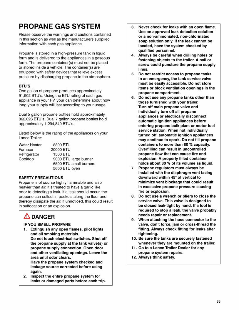
83
PROPANE GAS SYSTEMPlease observe the warnings and cautions contained in this section as well as the manufacturers supplied information with each gas appliance.
Propane is stored in a high-pressure tank in liquid form and is delivered to the appliances in a gaseous form. The propane container(s) must not be placed or stored inside a vehicle. The container(s) are equipped with safety devices that relieve excess pressure by discharging propane to the atmosphere.
BTU’SOne gallon of propane produces approximately 91,502 BTU’s. Using the BTU rating of each gas appliance in your RV, your can determine about how long your supply will last according to your usage.
Dual 5 gallon propane bottles hold approximately 862,026 BTU’s. Dual 7 gallon propane bottles hold approximately 1,294,840 BTU’s.
Listed below is the rating of the appliances on your Lance Trailer:
Water Heater 8800 BTUFurnace 20000 BTURefrigerator 1500 BTUCooktop 9000 BTU large burner 6500 BTU small burners 5600 BTU oven
SAFETY PRECAUTIONSPropane is of course highly flammable and also heavier than air. It’s treated to have a garlic like odor to detecting a leak. If a leak should occur, the propane can collect in pockets along the floor and thereby dissipate the air. If unnoticed, this could result in suffocation or an explosion.
DANGERIF YOU SMELL PROPANE1. Extinguish any open flames, pilot lights
and all smoking materials. Do not touch electrical switches. Shut off
the propane supply at the tank valve(s) or propane supply connection. Open door and other ventilating openings. Leave the area until odor clears.
Have the propane system checked and leakage source corrected before using again.
2. Inspect the entire propane system for leaks or damaged parts before each trip.
3. Never check for leaks with an open flame. Use an approved leak detection solution or a non-ammoniated, non-chlorinated soap solution only. If the leak cannot be located, have the system checked by qualified personnel.
4. Always be careful when drilling holes or fastening objects to the trailer. A nail or screw could puncture the propane supply lines.
5. Do not restrict access to propane tanks. In an emergency, the tank service valve must be easily accessible. Do not store items or block ventilation openings in the propane compartment.
6. Do not use any propane tanks other than those furnished with your trailer.
Turn off main propane valve and individually turn off all propane appliances or electrically disconnect automatic ignition appliances before entering propane bulk plant or motor fuel service station. When not individually turned off, automatic ignition appliances may continue to spark. Do not fill propane containers to more than 80 % capacity. Overfilling can result in uncontrolled propane flow that can cause fire and explosion. A properly filled container holds about 80 % of its volume as liquid.
7. Propane regulators must always be installed with the diaphragm vent facing downward within 45° of vertical to minimize vent blockage that could result in excessive propane pressure causing fire or explosion.
8. Do not use a wrench or pliers to close the service valve. This valve is designed to be closed leak-tight by hand. If a tool is required to stop a leak, the valve probably needs repair or replacement.
9. When attaching the hose connector to the valve, don’t force, jam or cross-thread the fitting. Always check fitting for leaks after tightening.
10. Be sure the tanks are securely fastened whenever they are mounted on the trailer.
11. Go to a Lance Trailer Dealer for any propane system repairs.
12. Always think safety.

84
FILLING PROPANE TANKAll new propane tanks must be purged of air and moisture before filling for the first time. The propane tanks should be filled according to the instructions on the tank safety labels.
Filling should be done only at authorized propane fueling stations. Please observe the following instruc-tions when filling the storage tanks.
D.O.T. regulation #173-34 prohibits propane tanks from being refilled inside the RV. The tank(s) must be removed from the compartment to be properly inspected before refilling.
Use propane tanks in their proper position.
1. A small amount of anhydrous methanol (3/4 oz per 5 gal) can be added before filling an empty tank to prevent freeze ups. Check with your propane dealer or the propane tank manufacturer’s information in the Owner’s Information Package provided with your trailer.
2. The law requires at least a 20% vapor space for safety. A special liquid level valve is installed in the tank to indicate when the tank has reached 80% of it volume as liquid propane. Stop filling when liquid appears at this valve.
3. Use vapor only. All propane appliances for cooking, heating, lighting, water heating and refrigeration are designed to operate on propane vapor only. Therefore, all propane tanks designed for vapor service must be transported, installed and used in the proper position. Propane containers are permanently marked with “TOP” stamped on tank, welded to the tank or “ARROWS must point up” stamped in the guard or bracket to identify the proper position.
4. Do not transport, install or use a vertical cylinder in a horizontal or upside down position. Never use a horizontal cylinder or tank on its improper side. Liquid propane could enter systems designed for vapor only, creating a hazardous condition.
5. Do not carry or store filled or empty propane containers inside your trailer. Propane containers are equipped with a safety device that relieves excessive pressure by discharging gas to the atmosphere. Leaks can occur at valves and fittings. Always store propane tanks with the valves closed.
6. Always use the dust cap when transporting or storing disconnected tanks (full or empty).
7. All propane tanks must be securely attached in the proper position for intended use. Use all brackets provided to ensure proper support and positioning.
8. Route all propane lines carefully and avoids kinking the lines. A kinked hose can limit or cutoff the flow of propane through the system. It is normal to have a slight gas odor when initially opening the outlet valve. Fully open and seat valve by hand only to prevent leakage past the valve stem. If an odor seems to linger perform a leak test.
USING PROPANE SYSTEMIt is normal to have a slight gas odor when initially opening the outlet valve. Fully open and seat valve by hand only to prevent leakage past the valve stem. If an odor seems to linger perform a leak test.
Keep outlet valves closed when not using the pro-pane system.
Do not attempt to adjust the regulator. The manu-facturer has preset it. If any adjustment is required, a qualified propane service technician using special equipment must make it.
NOTE: The Owner’s Information Package contains a helpful hints pamphlet about propane containers.
Dual propane tanks are equipped with a two-stage automatic changeover regulator, which transfers pro-pane demand automatically to the second tank when the first tank becomes empty.
For proper operation, both outlet valves must be opened. Turn or slide the tank selector knob so it points to the tank you wish to provide service. A small glass window is located on the regulator. A clear or green band will appear in the window indicating that pressure is in the line from the tank. After all propane is used from that tank, the regulator will automatically switch service to the other tank, and a red band will show in the window, with the arrow or slide pointing to the empty tank.
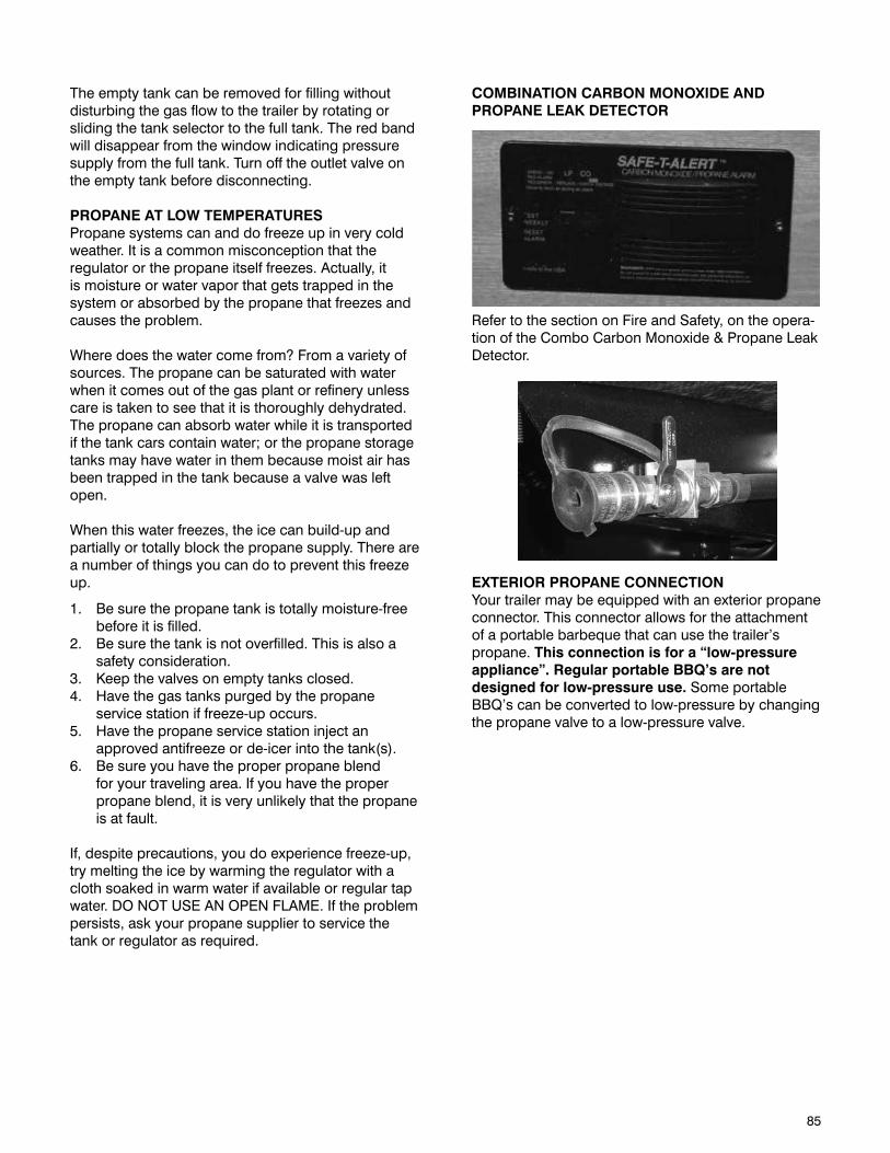
85
The empty tank can be removed for filling without disturbing the gas flow to the trailer by rotating or sliding the tank selector to the full tank. The red band will disappear from the window indicating pressure supply from the full tank. Turn off the outlet valve on the empty tank before disconnecting.
PROPANE AT LOW TEMPERATURESPropane systems can and do freeze up in very cold weather. It is a common misconception that the regulator or the propane itself freezes. Actually, it is moisture or water vapor that gets trapped in the system or absorbed by the propane that freezes and causes the problem.
Where does the water come from? From a variety of sources. The propane can be saturated with water when it comes out of the gas plant or refinery unless care is taken to see that it is thoroughly dehydrated. The propane can absorb water while it is transported if the tank cars contain water; or the propane storage tanks may have water in them because moist air has been trapped in the tank because a valve was left open.
When this water freezes, the ice can build-up and partially or totally block the propane supply. There are a number of things you can do to prevent this freeze up.
1. Be sure the propane tank is totally moisture-free before it is filled.
2. Be sure the tank is not overfilled. This is also a safety consideration.
3. Keep the valves on empty tanks closed.4. Have the gas tanks purged by the propane
service station if freeze-up occurs.5. Have the propane service station inject an
approved antifreeze or de-icer into the tank(s).6. Be sure you have the proper propane blend
for your traveling area. If you have the proper propane blend, it is very unlikely that the propane is at fault.
If, despite precautions, you do experience freeze-up, try melting the ice by warming the regulator with a cloth soaked in warm water if available or regular tap water. DO NOT USE AN OPEN FLAME. If the problem persists, ask your propane supplier to service the tank or regulator as required.
COMBINATION CARBON MONOXIDE AND PROPANE LEAK DETECTOR
Refer to the section on Fire and Safety, on the opera-tion of the Combo Carbon Monoxide & Propane Leak Detector.
EXTERIOR PROPANE CONNECTIONYour trailer may be equipped with an exterior propane connector. This connector allows for the attachment of a portable barbeque that can use the trailer’s propane. This connection is for a “low-pressure appliance”. Regular portable BBQ’s are not designed for low-pressure use. Some portable BBQ’s can be converted to low-pressure by changing the propane valve to a low-pressure valve.
86
PROPANE GAS FUEL SYSTEMPropane gas systems are installed to operate a variety of appliances, such as stoves, refrigerators, heating units and electrical generators. The exhaust fumes from burning propane gas contain odorless and can cause death or serious brain injury if in-haled. The exhaust from propane appliances must be directed to the outdoors. You must have an operating carbon monoxide detector in the accommodation space of your trailer.
DANGERYou can die or be brain damaged by Carbon Monoxide.
Make certain the exhaust from Propane appliances is directed to the outdoors.
Have a working carbon monoxide detector in the accommodation spaces of your trailer before operating any Propane gas appliance.
Do not operate portable grills, portable stoves, portable lanterns or portable heaters inside the trailer.
When used for the first time, or after a period of stor-age, the Propane gas lines will be full of air and must be purged of air, before the appliances will stay lit. Have the Propane gas lines purged by your Lance Trailer Dealer, or a Propane gas dealer.
A Propane gas system is designed to operate with a supply of Propane gas only, NOT natural gas. A natural gas supply is unsafe for the system’s pressure regulation devices.
WARNINGRisk of death due to fire or explosion.
Do not connect a Propane gas system to a supply of natural gas.
Extinguish all pilot lights and turn off all appliances before refilling fuel or Propane gas tanks.
Do not fill the tank with any gas other than Propane.
Do not store Propane gas tanks inside the trailer.
Keep the shutoff valve on your Propane gas tank closed at all times, except when you are operating a Propane gas appliance. Before opening the Propane shutoff valve, turn off all Propane gas appliances. If an appliance is on when you open the shutoff valve, Propane gas can accumulate in the trailer, which can result in an explosion.
Do not use a wrench to open or close the shutoff valve. If the shutoff does not completely stop the flow of Propane gas when it is hand-tightened, replace the shutoff valve.
Propane gas leaks can result in fire or explosion. If your trailer is equipped with a Propane gas system, it must also be equipped with a Propane gas detec-tor. The Propane gas detector will be located near the floor to detect the heavier-than-air Propane gas. If a leak is suspected, use a soapy water solution to search for the leak. Do not use a solution that con-tains ammonia or chlorine (common in window and other household cleaning compounds), because those chemicals will cause Propane piping corrosion.
WARNINGRisk of fire or explosion
If Propane gas is detected (by smell or by the Propane gas detector):
• Donottouchelectricalswitches
• Extinguishflamesandpilotlights
• Opendoorsforventilation
• ShutoffPropanegassupplyatthe Propane tank
• Leavetheareauntilodorclears
Correct the source of Propane gas leakage before using Propane appliances.
Do not use a flame to locate the source of a propane gas leak.
Propane gas is compressed into liquid form. Propane gas must be completely vaporized before being burned.
NOTICEPropane gas will operate at temperatures as low as minus 44 degrees Fahrenheit (-44 F).

87
Keep the regulator for the Propane gas system (located near the Propane gas tank) covered with a guard to protect it from road debris.
Propane gas is prohibited on some roadways, bridg-es and tunnels. Check a map and with Department of Transportation (or with the AAA) for travel routes that do not have such restrictions.
PROPANE GAS SYSTEM TROUBLESHOOTING• Havingliquid“gas”atyourapplianceisanindi-
cation that the Propane gas tank is overfilled, or that the temperature is too cold.
• IfyourPropanegasappliancesdonotstaylit,itmight be because your Propane gas system is contaminated with air or moisture. Many Pro-pane gas vendors have facilities to purge the air from a Propane gas system.
• IfyourPropanegassystemisnotprovidinggas,even when the shutoff valve is open, it might be because the Propane gas regulator has frozen water in it.
WARNINGRisk of fire or explosion.
Never use a flame, heat lamp or hair dryer to thaw a Propane gas regulator.
Use an incandescent light bulb to warm the regulator.
Do not remove the regulator cover or attempt to service the Propane gas regulator.

88
This page intentionally left blank.
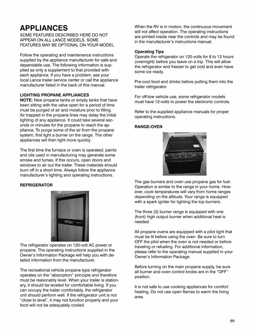
89
APPLIANCESSOME FEATURES DESCRIBED HERE DO NOT APPEAR ON ALL LANCE MODELS. SOME FEATURES MAY BE OPTIONAL ON YOUR MODEL.
Follow the operating and maintenance instructions supplied by the appliance manufacturer for safe and dependable use. The following information is sup-plied as only a supplement to that provided with each appliance. If you have a problem, see your local Lance trailer service center or call the appliance manufacturer listed in the back of this manual.
LIGHTING PROPANE APPLIANCES NOTE: New propane tanks or empty tanks that have been sitting with the valve open for a period of time must be purged of air and moisture prior to filling. Air trapped in the propane lines may delay the initial lighting of any appliance. It could take several sec-onds or minutes for the propane to reach the ap-pliance. To purge some of the air from the propane system, first light a burner on the range. The other appliances will then light more quickly.
The first time the furnace or oven is operated; paints and oils used in manufacturing may generate some smoke and fumes. If this occurs, open doors and windows to air out the trailer. These materials should burn off in a short time. Always follow the appliance manufacturer’s lighting and operating instructions.
REFRIGERATOR
The refrigerator operates on 120-volt AC power or propane. The operating instructions supplied in the Owner’s Information Package will help you with de-tailed information from the manufacturer.
The recreational vehicle propane type refrigerator operates on the “absorption” principle and therefore must be reasonably level. When your trailer is station-ary, it should be leveled for comfortable living. If you can occupy the trailer comfortably, the refrigerator unit should perform well. If the refrigerator unit is not “close to level”, it may not function properly and your food will not be adequately cooled.
When the RV is in motion, the continuous movement will not affect operation. The operating instructions are printed inside near the controls and may be found in the manufacturer’s instructions manual.
Operating TipsOperate the refrigerator on 120-volts for 8 to 12 hours (overnight) before you leave on a trip. This will allow the refrigerator and freezer to get cold and even have some ice ready.
Pre-cool food and drinks before putting them into the trailer refrigerator.
For off-tow vehicle use, some refrigerator models must have 12-volts to power the electronic controls.
Refer to the supplied appliance manuals for proper operating instructions.
RANGE-OVEN
The gas burners and oven use propane gas for fuel. Operation is similar to the range in your home. How-ever, cook temperatures will vary from home ranges depending on the altitude. Your range is equipped with a spark igniter for lighting the top burners.
The three (3) burner range is equipped with one (front) high output burner when additional heat is needed.
All propane ovens are equipped with a pilot light that must be lit before using the oven. Be sure to turn OFF the pilot when the oven is not needed or before traveling or refueling. For additional information, please refer to the operating manual supplied in your Owner’s Information Package.
Before turning on the main propane supply, be sure all burner and oven control knobs are in the “OFF” position.
It is not safe to use cooking appliances for comfort heating. Do not use open flames to warm the living area.
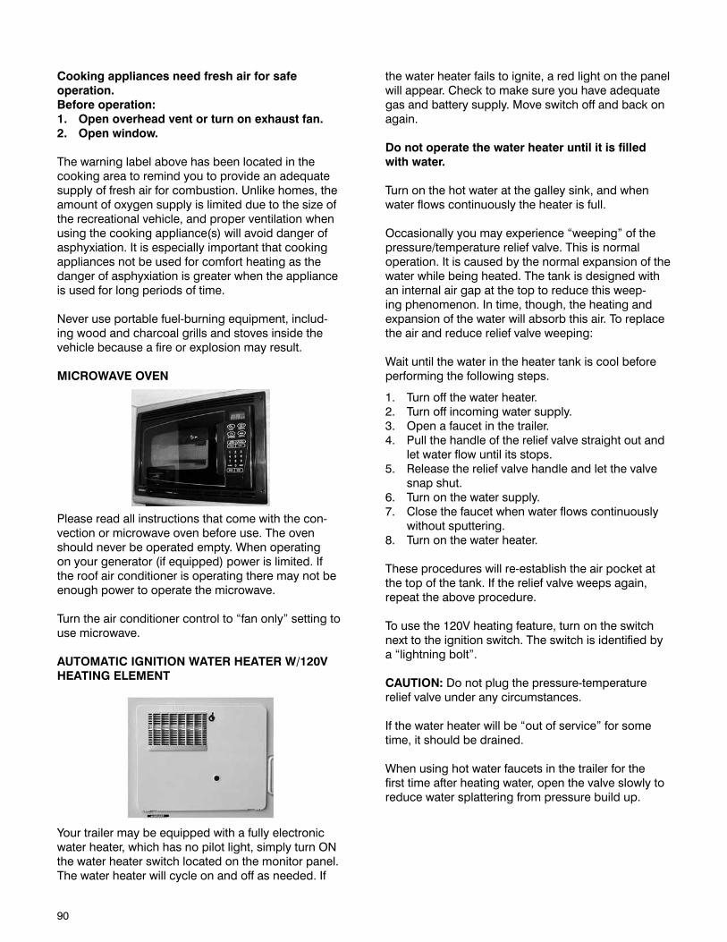
90
Cooking appliances need fresh air for safe operation.Before operation:1. Open overhead vent or turn on exhaust fan.2. Open window.
The warning label above has been located in the cooking area to remind you to provide an adequate supply of fresh air for combustion. Unlike homes, the amount of oxygen supply is limited due to the size of the recreational vehicle, and proper ventilation when using the cooking appliance(s) will avoid danger of asphyxiation. It is especially important that cooking appliances not be used for comfort heating as the danger of asphyxiation is greater when the appliance is used for long periods of time.
Never use portable fuel-burning equipment, includ-ing wood and charcoal grills and stoves inside the vehicle because a fire or explosion may result.
MICROWAVE OVEN
Please read all instructions that come with the con-vection or microwave oven before use. The oven should never be operated empty. When operating on your generator (if equipped) power is limited. If the roof air conditioner is operating there may not be enough power to operate the microwave.
Turn the air conditioner control to “fan only” setting to use microwave.
AUTOMATIC IGNITION WATER HEATER W/120V HEATING ELEMENT
Your trailer may be equipped with a fully electronic water heater, which has no pilot light, simply turn ON the water heater switch located on the monitor panel. The water heater will cycle on and off as needed. If
the water heater fails to ignite, a red light on the panel will appear. Check to make sure you have adequate gas and battery supply. Move switch off and back on again.
Do not operate the water heater until it is filled with water.
Turn on the hot water at the galley sink, and when water flows continuously the heater is full.
Occasionally you may experience “weeping” of the pressure/temperature relief valve. This is normal operation. It is caused by the normal expansion of the water while being heated. The tank is designed with an internal air gap at the top to reduce this weep-ing phenomenon. In time, though, the heating and expansion of the water will absorb this air. To replace the air and reduce relief valve weeping:
Wait until the water in the heater tank is cool before performing the following steps.
1. Turn off the water heater.2. Turn off incoming water supply.3. Open a faucet in the trailer.4. Pull the handle of the relief valve straight out and
let water flow until its stops.5. Release the relief valve handle and let the valve
snap shut.6. Turn on the water supply.7. Close the faucet when water flows continuously
without sputtering.8. Turn on the water heater.
These procedures will re-establish the air pocket at the top of the tank. If the relief valve weeps again, repeat the above procedure.
To use the 120V heating feature, turn on the switch next to the ignition switch. The switch is identified by a “lightning bolt”.
CAUTION: Do not plug the pressure-temperature relief valve under any circumstances.
If the water heater will be “out of service” for some time, it should be drained.
When using hot water faucets in the trailer for the first time after heating water, open the valve slowly to reduce water splattering from pressure build up.
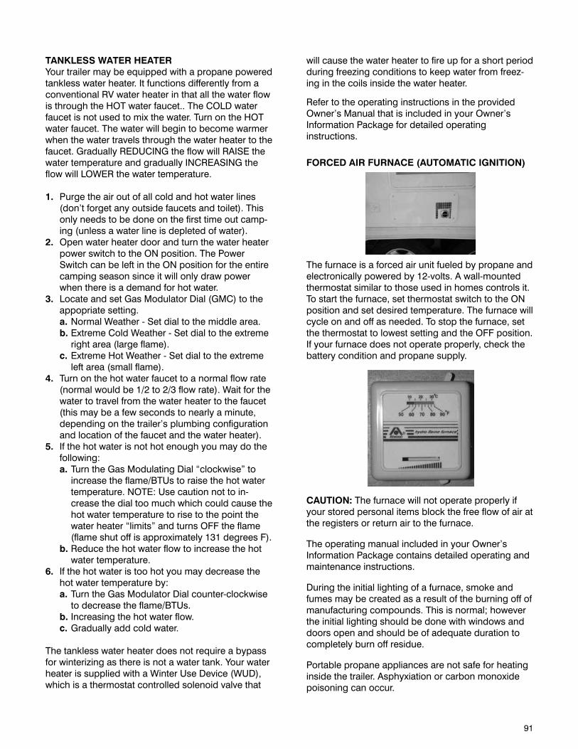
91
will cause the water heater to fire up for a short period during freezing conditions to keep water from freez-ing in the coils inside the water heater.
Refer to the operating instructions in the provided Owner’s Manual that is included in your Owner’s Information Package for detailed operating instructions.
FORCED AIR FURNACE (AUTOMATIC IGNITION)
The furnace is a forced air unit fueled by propane and electronically powered by 12-volts. A wall-mounted thermostat similar to those used in homes controls it. To start the furnace, set thermostat switch to the ON position and set desired temperature. The furnace will cycle on and off as needed. To stop the furnace, set the thermostat to lowest setting and the OFF position. If your furnace does not operate properly, check the battery condition and propane supply.
CAUTION: The furnace will not operate properly if your stored personal items block the free flow of air at the registers or return air to the furnace.
The operating manual included in your Owner’s Information Package contains detailed operating and maintenance instructions.
During the initial lighting of a furnace, smoke and fumes may be created as a result of the burning off of manufacturing compounds. This is normal; however the initial lighting should be done with windows and doors open and should be of adequate duration to completely burn off residue.
Portable propane appliances are not safe for heating inside the trailer. Asphyxiation or carbon monoxide poisoning can occur.
TANKLESS WATER HEATERYour trailer may be equipped with a propane powered tankless water heater. It functions differently from a conventional RV water heater in that all the water flow is through the HOT water faucet.. The COLD water faucet is not used to mix the water. Turn on the HOT water faucet. The water will begin to become warmer when the water travels through the water heater to the faucet. Gradually REDUCING the flow will RAISE the water temperature and gradually INCREASING the flow will LOWER the water temperature.
1. Purge the air out of all cold and hot water lines (don’t forget any outside faucets and toilet). This only needs to be done on the first time out camp-ing (unless a water line is depleted of water).
2. Open water heater door and turn the water heater power switch to the ON position. The Power Switch can be left in the ON position for the entire camping season since it will only draw power when there is a demand for hot water.
3. Locate and set Gas Modulator Dial (GMC) to the appopriate setting.
a. Normal Weather - Set dial to the middle area. b. Extreme Cold Weather - Set dial to the extreme
right area (large flame). c. Extreme Hot Weather - Set dial to the extreme
left area (small flame).4. Turn on the hot water faucet to a normal flow rate
(normal would be 1/2 to 2/3 flow rate). Wait for the water to travel from the water heater to the faucet (this may be a few seconds to nearly a minute, depending on the trailer’s plumbing configuration and location of the faucet and the water heater).
5. If the hot water is not hot enough you may do the following:
a. Turn the Gas Modulating Dial “clockwise” to increase the flame/BTUs to raise the hot water temperature. NOTE: Use caution not to in-crease the dial too much which could cause the hot water temperature to rise to the point the water heater “limits” and turns OFF the flame (flame shut off is approximately 131 degrees F).
b. Reduce the hot water flow to increase the hot water temperature.
6. If the hot water is too hot you may decrease the hot water temperature by:
a. Turn the Gas Modulator Dial counter-clockwise to decrease the flame/BTUs.
b. Increasing the hot water flow. c. Gradually add cold water.
The tankless water heater does not require a bypass for winterizing as there is not a water tank. Your water heater is supplied with a Winter Use Device (WUD), which is a thermostat controlled solenoid valve that

92
ROOF MOUNTED AIR CONDITIONER
The roof-mounted Air Conditioner operates on 120-volt power, which is supplied through the 30-amp power cord, either from an outside 120-volt power service or by the onboard generator, if equipped.
The air conditioner will provide cooled air for your comfort. However, it is the largest single load of elec-trical usage. It is important to manage your electrical usage when you have either an air conditioner or microwave oven installed or both.
1. Be sure air conditioner is OFF before connecting electricity.
2. When the air conditioner has been shut down, wait at least five minutes before restarting.
3. Do not operate without a filter installed.
Keep window curtains closed. Use kitchen vent fan when cooking. Air conditioning removes moisture from the air and it is normal to have water discharge off the roof.
Experience has shown that some RV parks may experience reduced power (low voltage) on days with high heat or humidity, commonly referred to as a “brown out”. This condition may result in the air conditioner circuit breaker tripping in your power distribution center. This protects your air conditioner motor from damage and is necessary during low voltage conditions. This breaker tripping is sometimes perceived as a fault in your trailer, but it is a necessary “safety valve”.
The wall-mounted combination thermostat will operate either the furnace or air conditioner from one location.
The operating instructions included in your Owner’s Information Package contain detailed operating and maintenance instructions.
Operating the air conditioner on the optional generator will use most of the electrical power available. Energy management is important when the air conditioner is operating. Care must be taken when turning on too many other 120-volt appliances. Experience will provide knowledge of how to operate the trailers’ electrical system the best.
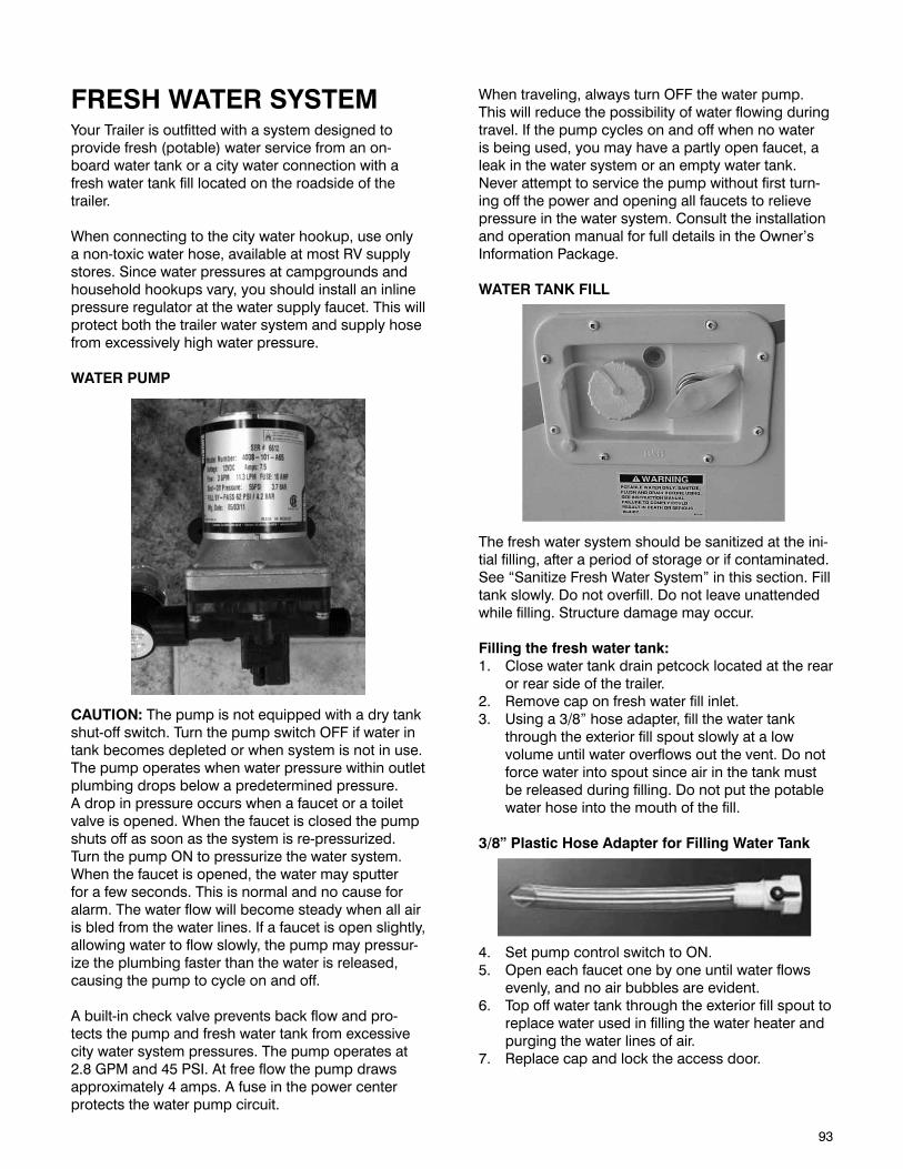
93
FRESH WATER SYSTEMYour Trailer is outfitted with a system designed to provide fresh (potable) water service from an on-board water tank or a city water connection with a fresh water tank fill located on the roadside of the trailer.
When connecting to the city water hookup, use only a non-toxic water hose, available at most RV supply stores. Since water pressures at campgrounds and household hookups vary, you should install an inline pressure regulator at the water supply faucet. This will protect both the trailer water system and supply hose from excessively high water pressure.
WATER PUMP
CAUTION: The pump is not equipped with a dry tank shut-off switch. Turn the pump switch OFF if water in tank becomes depleted or when system is not in use. The pump operates when water pressure within outlet plumbing drops below a predetermined pressure. A drop in pressure occurs when a faucet or a toilet valve is opened. When the faucet is closed the pump shuts off as soon as the system is re-pressurized. Turn the pump ON to pressurize the water system. When the faucet is opened, the water may sputter for a few seconds. This is normal and no cause for alarm. The water flow will become steady when all air is bled from the water lines. If a faucet is open slightly, allowing water to flow slowly, the pump may pressur-ize the plumbing faster than the water is released, causing the pump to cycle on and off.
A built-in check valve prevents back flow and pro-tects the pump and fresh water tank from excessive city water system pressures. The pump operates at 2.8 GPM and 45 PSI. At free flow the pump draws approximately 4 amps. A fuse in the power center protects the water pump circuit.
When traveling, always turn OFF the water pump. This will reduce the possibility of water flowing during travel. If the pump cycles on and off when no water is being used, you may have a partly open faucet, a leak in the water system or an empty water tank.Never attempt to service the pump without first turn-ing off the power and opening all faucets to relieve pressure in the water system. Consult the installation and operation manual for full details in the Owner’s Information Package.
WATER TANK FILL
The fresh water system should be sanitized at the ini-tial filling, after a period of storage or if contaminated. See “Sanitize Fresh Water System” in this section. Fill tank slowly. Do not overfill. Do not leave unattended while filling. Structure damage may occur.
Filling the fresh water tank:1. Close water tank drain petcock located at the rear
or rear side of the trailer.2. Remove cap on fresh water fill inlet.3. Using a 3/8” hose adapter, fill the water tank
through the exterior fill spout slowly at a low volume until water overflows out the vent. Do not force water into spout since air in the tank must be released during filling. Do not put the potable water hose into the mouth of the fill.
3/8” Plastic Hose Adapter for Filling Water Tank
4. Set pump control switch to ON.5. Open each faucet one by one until water flows
evenly, and no air bubbles are evident.6. Top off water tank through the exterior fill spout to
replace water used in filling the water heater and purging the water lines of air.
7. Replace cap and lock the access door.

94
CITY WATER CONNECTION
The city water inlet connection is located on the road-side of your trailer.
It’s a good idea to purchase a pressure regulator to protect your trailer from possible damage due to excessive water pressure.
To supply city water to your trailer’s water system and bypass the water pump:1. Attach a potable water hose to the exterior city
water inlet connection.2. Pump switch should remain in OFF position.3. Open each faucet until water flows evenly.
WATER SYSTEM DRAIN
The water system should be drained if it will be out of service for more than one week. This will prevent algae and bacteria contamination of your fresh water system.
To drain your trailer:1. The trailer should be level and pump control
switch in OFF position.2. Open all faucets and showerhead.3. Open water tank drain valve.4. Open water line low point drains are located on
the roadside, under the floor.5. Open water heater drain and relief valves. (See Winterization and Storage section for more
information.)
SANITIZING FRESH WATER SYSTEMSanitize the fresh water system and piping at initial use, at least once a year and whenever the trailer sits for a prolonged period. This will help keep the tank and lines fresh and will discourage the growth of bacteria and other organisms that can contaminate the water supply. Rinse the tank with a chlorine/fresh water solution as follow:
1. Drain water system. (See Drain Water System above).
2. Prepare a chlorine solution with one gallon of water and 1/4 cup household bleach.
3. Pour one gallon of solution for each 15 gallons of tank capacity into fill spout.
4. Fill tank with fresh water. 5. Open each faucet and water heater relief valve
until water flows evenly. 6. Set pump switch to OFF. 7. Allow solution to stand for 3 hours. 8. Drain and flush with fresh water. 9. To remove any chlorine taste or odor, fill tank
with one-quart vinegar to 5 gallons water. Allow solution to remain in tank several days if possible.
10. Drain and flush with fresh water.
WARNINGPOTABLE WATER ONLY. SANITIZE, FLUSH AND DRAIN BEFORE USING. SEE INSTRUCTION MANUAL. FAILURE TO COMPLY COULD RESULT IN DEATH OR SERIOUS INJURY.
WATER FILTER
An in-line water filter attached to the inlet side of the water pump filters dirt, mineral scale, or organic matter out of the fresh water system. If you suspect a clogged filter, it is easily removed and cleaned. Loosen the clamp at the inlet end of the filter. Pull the water hose off the filter. Unscrew the filter from the water pump. Turn each end of the filter and pull apart.
Flush out and clean screen. Reverse procedure to install and check for leaks. Inspect the filter after the first 90 days of use, clean it if necessary, and inspect annually thereafter.
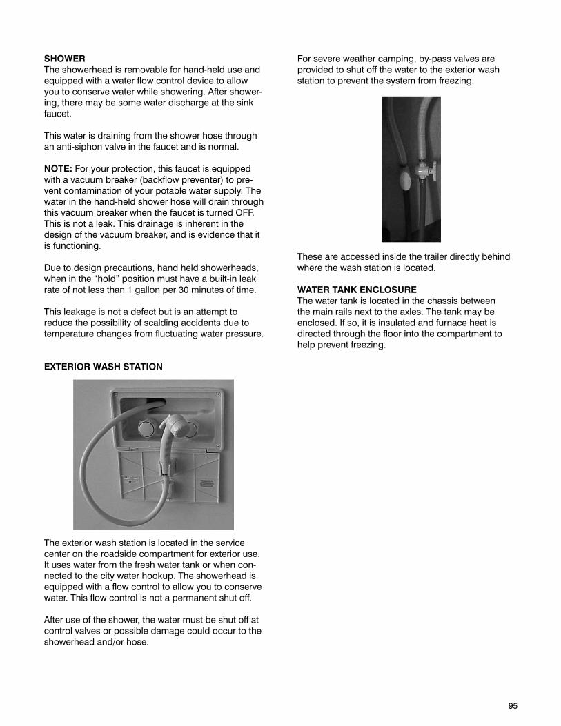
95
SHOWERThe showerhead is removable for hand-held use and equipped with a water flow control device to allow you to conserve water while showering. After shower-ing, there may be some water discharge at the sink faucet.
This water is draining from the shower hose through an anti-siphon valve in the faucet and is normal.
NOTE: For your protection, this faucet is equipped with a vacuum breaker (backflow preventer) to pre-vent contamination of your potable water supply. The water in the hand-held shower hose will drain through this vacuum breaker when the faucet is turned OFF. This is not a leak. This drainage is inherent in the design of the vacuum breaker, and is evidence that it is functioning.
Due to design precautions, hand held showerheads, when in the “hold” position must have a built-in leak rate of not less than 1 gallon per 30 minutes of time.
This leakage is not a defect but is an attempt to reduce the possibility of scalding accidents due to temperature changes from fluctuating water pressure.
EXTERIOR WASH STATION
The exterior wash station is located in the service center on the roadside compartment for exterior use. It uses water from the fresh water tank or when con-nected to the city water hookup. The showerhead is equipped with a flow control to allow you to conserve water. This flow control is not a permanent shut off.
After use of the shower, the water must be shut off at control valves or possible damage could occur to the showerhead and/or hose.
For severe weather camping, by-pass valves are provided to shut off the water to the exterior wash station to prevent the system from freezing.
These are accessed inside the trailer directly behind where the wash station is located.
WATER TANK ENCLOSUREThe water tank is located in the chassis between the main rails next to the axles. The tank may be enclosed. If so, it is insulated and furnace heat is directed through the floor into the compartment to help prevent freezing.

96
This page intentionally left blank.
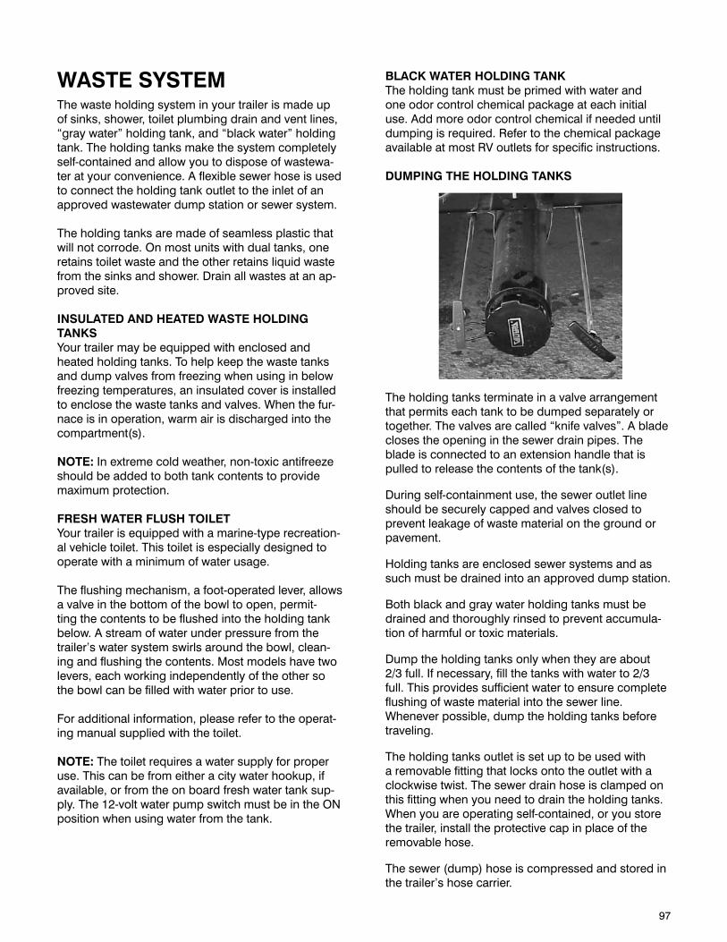
97
WASTE SYSTEMThe waste holding system in your trailer is made up of sinks, shower, toilet plumbing drain and vent lines, “gray water” holding tank, and “black water” holding tank. The holding tanks make the system completely self-contained and allow you to dispose of wastewa-ter at your convenience. A flexible sewer hose is used to connect the holding tank outlet to the inlet of an approved wastewater dump station or sewer system.
The holding tanks are made of seamless plastic that will not corrode. On most units with dual tanks, one retains toilet waste and the other retains liquid waste from the sinks and shower. Drain all wastes at an ap-proved site.
INSULATED AND HEATED WASTE HOLDING TANKSYour trailer may be equipped with enclosed and heated holding tanks. To help keep the waste tanks and dump valves from freezing when using in below freezing temperatures, an insulated cover is installed to enclose the waste tanks and valves. When the fur-nace is in operation, warm air is discharged into the compartment(s).
NOTE: In extreme cold weather, non-toxic antifreeze should be added to both tank contents to provide maximum protection.
FRESH WATER FLUSH TOILETYour trailer is equipped with a marine-type recreation-al vehicle toilet. This toilet is especially designed to operate with a minimum of water usage.
The flushing mechanism, a foot-operated lever, allows a valve in the bottom of the bowl to open, permit-ting the contents to be flushed into the holding tank below. A stream of water under pressure from the trailer’s water system swirls around the bowl, clean-ing and flushing the contents. Most models have two levers, each working independently of the other so the bowl can be filled with water prior to use.
For additional information, please refer to the operat-ing manual supplied with the toilet.
NOTE: The toilet requires a water supply for proper use. This can be from either a city water hookup, if available, or from the on board fresh water tank sup-ply. The 12-volt water pump switch must be in the ON position when using water from the tank.
BLACK WATER HOLDING TANKThe holding tank must be primed with water and one odor control chemical package at each initial use. Add more odor control chemical if needed until dumping is required. Refer to the chemical package available at most RV outlets for specific instructions.
DUMPING THE HOLDING TANKS
The holding tanks terminate in a valve arrangement that permits each tank to be dumped separately or together. The valves are called “knife valves”. A blade closes the opening in the sewer drain pipes. The blade is connected to an extension handle that is pulled to release the contents of the tank(s).
During self-containment use, the sewer outlet line should be securely capped and valves closed to prevent leakage of waste material on the ground or pavement.
Holding tanks are enclosed sewer systems and as such must be drained into an approved dump station.
Both black and gray water holding tanks must be drained and thoroughly rinsed to prevent accumula-tion of harmful or toxic materials.
Dump the holding tanks only when they are about 2/3 full. If necessary, fill the tanks with water to 2/3 full. This provides sufficient water to ensure complete flushing of waste material into the sewer line. Whenever possible, dump the holding tanks before traveling.
The holding tanks outlet is set up to be used with a removable fitting that locks onto the outlet with a clockwise twist. The sewer drain hose is clamped on this fitting when you need to drain the holding tanks. When you are operating self-contained, or you store the trailer, install the protective cap in place of the removable hose.
The sewer (dump) hose is compressed and stored in the trailer’s hose carrier.
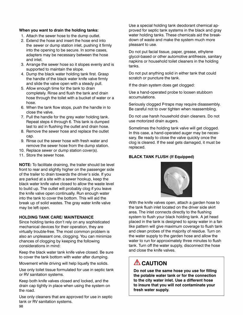
98
When you want to drain the holding tanks: 1. Attach the sewer hose to the dump outlet. 2. Extend the hose and insert the hose end into
the sewer or dump station inlet, pushing it firmly into the opening to be secure. In some cases, adapters may be necessary between the hose and inlet.
3. Arrange the sewer hose so it slopes evenly and is supported to maintain the slope.
4. Dump the black water holding tank first. Grasp the handle of the black water knife valve firmly and slide the valve open with a steady pull.
5. Allow enough time for the tank to drain completely. Rinse and flush the tank and drain hose through the toilet with a bucket of water or a hose.
6. When the tank flow stops, push the handle in to close the valve.
7. Pull the handle for the grey water holding tank. Repeat steps 4 through 6. This tank is dumped last to aid in flushing the outlet and drain hose.
8. Remove the sewer hose and replace the outlet cap.
9. Rinse out the sewer hose with fresh water and remove the sewer hose from the dump station.
10. Replace sewer or dump station cover(s).11. Store the sewer hose.
NOTE: To facilitate draining, the trailer should be level front to rear and slightly higher on the passenger side of the trailer to drain towards the driver’s side. If you are parked at a site with a sewer hookup, keep the black water knife valve closed to allow the waste level to build up. The outlet will probably clog if you leave the knife valve open continually. Run enough water into the tank to cover the bottom. This will aid the break up of solid wastes. The gray water knife valve may be left open.
HOLDING TANK CARE/ MAINTENANCESince holding tanks don’t rely on any sophisticated mechanical devices for their operation, they are virtually trouble-free. The most common problem is also an unpleasant one, clogging. You can minimize chances of clogging by keeping the following considerations in mind:
Keep the black water tank knife valve closed. Be sure to cover the tank bottom with water after dumping.
Movement while driving will help liquefy the solids.
Use only toilet tissue formulated for use in septic tank or RV sanitation systems.
Keep both knife valves closed and locked, and the drain cap tightly in place when using the system on the road.
Use only cleaners that are approved for use in septic tank or RV sanitation systems.
Use a special holding tank deodorant chemical ap-proved for septic tank systems in the black and gray water holding tanks. These chemicals aid the break-down of waste and make the system much more pleasant to use.
Do not put facial tissue, paper, grease, ethylene glycol-based or other automotive antifreeze, sanitary napkins or household toilet cleaners in the holding tanks.
Do not put anything solid in either tank that could scratch or puncture the tank.
If the drain system does get clogged:
Use a hand-operated probe to loosen stubborn accumulations.
Seriously clogged P-traps may require disassembly. Be careful not to over tighten when reassembling.
Do not use harsh household drain cleaners. Do not use motorized drain augers.
Sometimes the holding tank valve will get clogged. In this case, a hand-operated auger may be neces-sary. Be ready to close the valve quickly once the clog is cleared. If the seal gets damaged, it must be replaced.
BLACK TANK FLUSH (If Equipped)
With the knife valves open, attach a garden hose to the tank flush inlet located on the driver side skirt area. The inlet connects directly to the flushing system to flush your black holding tank. A jet head placed in the tank is designed to spray water in a fan like pattern will give maximum coverage to flush tank and clean probes of the majority of residue. Turn on the water supply to the garden hose and allow the water to run for approximately three minutes to flush tank. Turn off the water supply, disconnect the hose and close the knife valves.
CAUTION
Do not use the same hose you use for filling the potable water tank or for the connection to the city water inlet. Use a different hose to insure that you will not contaminate your fresh water supply.
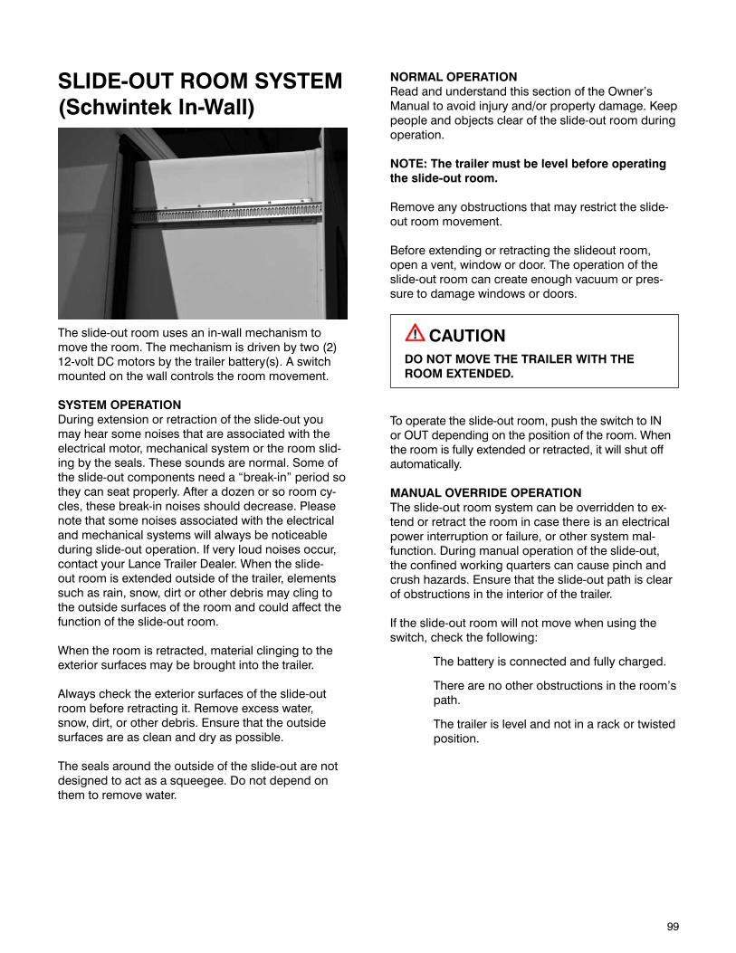
99
SLIDE-OUT ROOM SYSTEM (Schwintek In-Wall)
The slide-out room uses an in-wall mechanism to move the room. The mechanism is driven by two (2) 12-volt DC motors by the trailer battery(s). A switch mounted on the wall controls the room movement.
SYSTEM OPERATIONDuring extension or retraction of the slide-out you may hear some noises that are associated with the electrical motor, mechanical system or the room slid-ing by the seals. These sounds are normal. Some of the slide-out components need a “break-in” period so they can seat properly. After a dozen or so room cy-cles, these break-in noises should decrease. Please note that some noises associated with the electrical and mechanical systems will always be noticeable during slide-out operation. If very loud noises occur, contact your Lance Trailer Dealer. When the slide-out room is extended outside of the trailer, elements such as rain, snow, dirt or other debris may cling to the outside surfaces of the room and could affect the function of the slide-out room.
When the room is retracted, material clinging to the exterior surfaces may be brought into the trailer.
Always check the exterior surfaces of the slide-out room before retracting it. Remove excess water, snow, dirt, or other debris. Ensure that the outside surfaces are as clean and dry as possible.
The seals around the outside of the slide-out are not designed to act as a squeegee. Do not depend on them to remove water.
NORMAL OPERATIONRead and understand this section of the Owner’s Manual to avoid injury and/or property damage. Keep people and objects clear of the slide-out room during operation.
NOTE: The trailer must be level before operating the slide-out room.
Remove any obstructions that may restrict the slide-out room movement.
Before extending or retracting the slideout room, open a vent, window or door. The operation of the slide-out room can create enough vacuum or pres-sure to damage windows or doors.
CAUTIONDO NOT MOVE THE TRAILER WITH THE ROOM EXTENDED.
To operate the slide-out room, push the switch to IN or OUT depending on the position of the room. When the room is fully extended or retracted, it will shut off automatically.
MANUAL OVERRIDE OPERATIONThe slide-out room system can be overridden to ex-tend or retract the room in case there is an electrical power interruption or failure, or other system mal-function. During manual operation of the slide-out, the confined working quarters can cause pinch and crush hazards. Ensure that the slide-out path is clear of obstructions in the interior of the trailer.
If the slide-out room will not move when using the switch, check the following:
The battery is connected and fully charged.
There are no other obstructions in the room’s path.
The trailer is level and not in a rack or twisted position.

100
In the event that the slide-out room fails to operate after review of the troubleshooting steps mentioned above, proceed with the following:
1. Locate the control board. (Located in your Owners Manual is an insert which will direct you to the location of the Control Board for your specific model).
2. Un-plug both motors connectors at control board.
3. The slide-out room may now be pushed in or out as desired. Larger slide-out room(s) may need several individuals to push. When pushing the slide-out room, push both sides equally to ensure the slide-out room remains even. Once slide-out room is fully retracted or in, plug both motors connectors back in at the control board, this applies a brake to the motor and keeps the slide-out room locked in position.
CAUTIONDO NOT MOVE THE TRAILER UNLESS THE MOTORS ARE PLUGGED IN AT THE CONTROL BOARD.
ELECTRICAL SYSTEM MAINTENANCEDisconnect all power sources before performing any service work on the system. This includes the 120-volt AC power to the converter, the battery and the connection between the camper and the truck.
The slide-out room system requires a minimum battery voltage of 12-volts. Be sure the battery is fully charged for best performance.
Maintain the battery as outlined in the Battery Sec-tion under Electrical Systems. Check the terminals and other connections at the battery, fuse panel and the control board. Be sure the connections are tight, clean, undamaged and corrosion-free.
MECHANICAL MAINTENANCEThe slide-out room mechanism is designed to be virtually maintenance free. During long-term storage, apply a seal dressing such as 303© Protectant to the slide-out room seals. 303© Protectant is available at most RV or auto parts supply stores. This dress-ing will also lubricate the seals and make it easier to extend and retract the slide room.
SYSTEM TROUBLESHOOTINGThe trailer body, the slide-out room and the slide-out room mechanism make up a slide-out room system. Each needs to function properly with the others. Every unit has its own characteristics. Symptoms of malfunction may appear to be the same, but trouble-shooting and fixing a problem must include a thor-ough check of all the interrelated components. When something restricts room travel, the drive mechanism is designed to stop. If the room is restricted, the system may put undue pressure on the trailer body, slide-out room or mechanism. The room may not seal properly and the obstruction may cause fatigue and premature system failure.
Before troubleshooting the system or contacting an authorized Lance Service Center, make sure the bat-tery is fully charged and there are no obstructions to room movement.
ELECTRICAL TROUBLESHOOTINGThere are no field serviceable parts in the motor or control system, therefore electrical troubleshoot-ing and service by the owner is limited to thorough checking of wiring and connections, checking the fuse at the fuse box and proper battery maintenance. Contact your Lance Trailer Dealer for any other ser-vice requirements.
101
INSPECTION, SERVICE & MAINTENANCEThis section explains why it is important to keep your trailer well maintained, how to preserve the appear-ance of the exterior and interior and to follow basic maintenance safety precautions. Also included are several things you can do to help prevent corrosion. This section also includes a Maintenance Schedule for when service should be performed on your trailer and instructions for simple maintenance tasks you may want to take care of yourself. If you cannot or are unsure how to perform the items listed here, have your Lance Trailer Dealer do them.
Regularly maintaining your trailer is the best way to protect your investment. Proper maintenance is essential to your safety and will also reward you with many years of trouble-free use of your trailer.
The Maintenance Schedule specifies how often you should have your trailer serviced and what things need attention. It is essential that you have your trailer serviced as scheduled to retain its high level of safety and dependability and to insure safe and reliable operation.
In addition to this manual, also check the relevant component manufacturer’s manual.
INSPECTION AND SERVICE INSTRUCTIONSAxle Bolts, Frame, Suspension, & Structure
WARNINGWorn or broken suspension parts can cause loss of control and injury may result.
Have trailer professionally inspected annually and after any impact.
To perform many of the inspection and maintenance activities, you must jack up the trailer.
When jacking and using jack stands, place them so as to clear wiring, brake lines, and suspension parts (torsion bars, etc.). Place jacks and jack stands inside of the perimeter strip on the supporting structure to which the axles are attached.
WARNINGNever crawl under your trailer unless it is on firm and level ground and resting on properly placed and secured jack stands.
EXTERIOR MAINTENANCESome exterior parts of your trailer are made of fiber-glass, metal, rubber and plastic materials. The finish on these parts is durable, but not indestructible. Any material and finish will deteriorate over time. Expo-sure to sunlight, moisture, and airborne pollutants can chemically alter the composition of the base and finish materials and cause dulling and fading of the finish. Generally, changes in the finish due to weath-ering are cosmetic. They are on the surface of the part and do not affect its strength.
The best insurance against these effects is routine maintenance. If the finish is not washed thoroughly and waxed, the surface can deteriorate very rapidly. The following guidelines can help you reduce these weathering effects:
Wash the exterior at least once a month using a mild liquid detergent. Never use strong abrasives to clean the exterior surfaces. Wash your trailer in a shady area, not in direct sunlight. If the trailer is parked in the sun, move it into the shade and let the exterior cool down before you start. Chemical solvents and strong cleaners can damage the siding, roofing, metal and plastic trims on your trailer. Rinse the trailer thoroughly with cool water to remove loose dirt. Fill a bucket with cool water. Mix in a mild detergent, such as dishwashing liquid or a product made especially for auto or RV washing. Wash the trailer using the water and mild detergent solution and a soft-bristle brush, sponge, or soft cloth. Start at the top and work your way down. Rinse frequently. Check the surface for road tar, tree sap, etc. Remove these stains with tar remover or turpentine. Rinse it off immediately so it does not harm the finish. Remember to re-wax these areas, even if the rest of the trailer does not need waxing. When you have washed and rinsed the whole exterior, dry it with a chamois or soft towel. Letting it air-dry will cause dulling and water spots. As you dry your trailer, inspect around the seals and repair as necessary.
102
Wax the exterior at least once a year, preferably twice. Use automotive waxes or cleaners/polishes devel-oped for use on fiberglass boats, showers and tubs. Be sure to follow the directions on the wax container. Some cleaners and waxes are recommended for use on only certain types of surfaces. Exterior streaking is reduced with more frequent waxing. Do not use abra-sive cleaners or rubbing compounds. Always wash and dry the whole trailer before waxing it. Rubbing alcohol can be used on caulking that show signs of yellowing.
You should clean your roof at least four (4) times a year. For normal cleaning use a mild liquid detergent and water mixture, or Murphy’s Oil Soap with a soft nylon brush or sponge. Do not use solid or granu-lated cleaners, as they will mar the finish. For more difficult stains, use a cloth dampened with mineral spirits. DO NOT use mineral spirits in a large area or allow it to soak into the roof membrane.
CAUTION
ROOF IS SLIPPERY WHEN WET.
EXTERIOR GRAPHICSThe pressure sensitive vinyl graphics installed on the exterior surface of your trailer require little main-tenance and should be treated similarly to a painted surface. The following cleaning and maintenance recommendations should be followed to ensure the maximum appearance and performance of your exte-rior graphics.
Wash your graphics with the same solution as noted above for washing the exterior of your trailer. Be sure to rinse thoroughly.
Test any cleaning solution on a small section of the graphic before using the cleaning solution on a larger surface. A non-abrasive cleaner, suitable for high quality painted surfaces, is recommended. The clean-ing solution should be neither high acidic nor highly alkaline; a pH range of 3 to 11 is recommended. The cleaning solution should be free of strong solvents or alcohol. Avoid contact of window cleaners that contain ammonia.
DAMAGE CHECKSIt is important to periodically check the exterior for damage. Pay particular attention to the following areas:• Wastetanksandplumbinglines.• Propanetanksandassembly.• Sealantarounddoors,roof,ventsandwindows.• Exteriorlighting.
SEALANT RENEWALThe adhesives and sealants used in the construction of your trailer were developed to remain waterproof under sustained effects of weather and vibration. However, even the finest materials will eventually dry out and lose their effectiveness under the constant heat of the sun, attack by other elements and road vi-bration. Leak damage caused by neglecting to follow these procedures may affect your warranty.
Your Lance Trailer Dealer can perform the reseal-ing inspection and work for you, and has current information on sealants used in your trailer and can recommend the appropriate sealants if you prefer to do this work yourself. Always use the recommended sealants.
To protect your trailer from possible water intrusion damage, your unit should be inspected thoroughly and resealed bi-annually. Inspect the sealant around the roof moldings, windows and doors at least every six months. If any of the following are evident during inspection, the affected areas must be resealed:
Weathering or drying of sealant.Sealant cracked or peeling.Voids in sealant.Shrunken or separated sealant.
Clean all areas to be resealed with mineral spirits. Make sure that all areas to be resealed are absolutely dry before new sealant is applied.
Mineral spirits is a flammable liquid. Use extreme care when handling. Do not expose to open flame, sparks, or smoking materials. Do not use in unventi-lated areas.
Check and tighten any loose fasteners. Be careful not to over-tighten, or stripping will occur.
If you find any of the above:
If areas on the roof need to be resealed, remove any loose or cracked sealant being careful not to damage the roof. Use a wooden or plastic scraper that will not gouge, pierce, or otherwise damage the roof. The roof can be cut or punctured by sharp objects.
Apply the new sealant in a continuous bead along the seams and flanges, being careful not to leave any voids. Apply enough sealant to flow over the heads of all fasteners.
Allow at least 48 hours for the sealant to set com-pletely (firm and tack-free when pushed with the thumb) before washing or waxing the trailer.
103
DOORS AND WINDOWSLubricate door hinges, locks and window mecha-nisms periodically with powdered graphite. Clean window frames and tracks to ensure easy operation. Clean the glass windows, inside and out, with a com-mercially available glass cleaner. You can also use a mixture of one part white vinegar to ten parts water. This will remove the haze that builds up on the inside of the glass windows. Use a soft cloth or paper towels to clean all glass. Clean the seals with a damp cloth or mild detergent every three to six months, taking care not to use strong solvents, as they will damage the seals. A coat of natural silicone lubricant applied after the seal has dried will keep it flexible. This is a good practice for all the rubber seals in your trailer. If the trailer is exposed to salt air, more frequent lubrica-tion will be required.
ACRYLIC WINDOWSKeep your acrylic windows looking and performing like new by using the proper care, products and techniques, and by understanding a little about the material you are working with. Acrylic windows can be scratched with a rough cloth, harsh soaps, or cleaning products and these must be avoided. When cleaning a window always remove as much abrasive dirt as possible without touching the surface. It’s also a good idea to remove jewelry, which can cause deep scratches. Ideally this would involve flushing the surface with water and allowing the accumulated bug residue to soak, possibly with a mild dish washing liquid added to the water. Use a non-abrasive soap or detergent and water. Use a soft sponge, cloth or chamois and rinse often to keep it free of grit. Wash up and down or side to side, never in a circular motion. After a final flushing with more water carefully dry with a clean soft cloth. A good rule of thumb is to gently (let the weight of the cloth do the work) wick up the excess water on your first pass which will also wick up any residual loose particles. Start at the top of the window and work down turning the cloth to a fresh side after each pass. Again do not use a circular motion on the windows. Acrylic Cleaning Kits are avail-able from your Lance Trailer Dealer.
WARNINGNever use abrasive, caustic cleaners, alcohol or solvents as they can cause permanent damage to the finish.DO NOT USE WINDEX as it will damage the acrylic. Never use any petroleum based cleaners, or caustic chemicals on your windows.DO NOT USE WD-40 (as it is petroleum based).Never use a razor blade, putty knife or abrasive pad to clean your windows.Do not use a high pressure spray nozzle when rinsing your windows after washing.Avoid washing windows in direct sunlight.
AIR CONDITIONERThe air conditioner mounting bolts should be checked for tightness after the first 500 miles. Removing the interior shroud and inspecting the four (4) bolts located in the corners of the roof opening accomplishes this. Aside from securing the air con-ditioner to the roof, these fasteners apply pressure to the sealing gasket between the air conditioner and the top of the roof. Loose fasteners could cause water intrusion around the roof opening.
OVERHEAD VENTSThe vents can be cleaned from the top of the trailer. Use soapy water on the vent cover. The screens may be vacuumed or lightly brushed to remove accumula-tion of leaves or other debris. Lubricate the gears and mechanism yearly with a light, water resistant grease.
SKYLIGHTThe skylight should be cleaned at least once a year. Rinse the skylight with lukewarm water. Wash with mild soap and lukewarm water using a soft cloth or sponge and gently wash to loosen dirt and grime. DO NOT SCRUB or use brushes or squeegees. Repeat rinse and dry with a soft cloth to prevent water spotting.
TRAILER BRAKESInitial InspectionYour trailer is equipped with self-adjusting brakes. This allows the brakes to adjust on both forward and reverse stops. Brake adjustment occurs when lining wear results in enough gap between the shoes and the brake drum surface. This clearance allows the ad-juster mechanism to rotate the screw assembly at the bottom of the brake. This action expands the distance between the shoes and closes the gap to the drum surface.
Periodic InspectionProperly functioning brake shoes and drums are es-sential to ensure safety. You must have your dealer inspect these components at least once per year, or each 12,000 miles.
ELECTRIC BRAKESTwo different types of electric brakes may be present on the trailer: an emergency electric breakaway sys-tem, which acts only if the trailer comes loose from the hitch and the breakaway pin is pulled. The other brake is an electric braking system that acts when-ever the brakes of the tow vehicle are applied.
104
BREAKAWAY SWITCHThis switch causes the breakaway battery to operate the electric brakes if the trailer uncouples from the tow vehicle.
The lanyard for the pull pin is connected to the tow vehicle, and the switch is connected to the trailer. To check for proper functioning of the switch, battery and brakes, you must pull the pin from the switch and confirm that the brakes apply to each wheel. You can do this by trying to pull the trailer with the tow vehicle, after pulling the pin. The trailer brakes may not lock, but you will notice that a greater force is needed to pull the trailer.
WARNINGIf electric breakaway brakes do not operate when trailer is uncoupled from the tow vehicle, death or serious injury can occur.
Check emergency breakaway brake system BEFORE each tow.
TOW VEHICLE OPERATED ELECTRIC BRAKESThe electric brakes that operate in conjunction with the tow vehicle brakes must be “synchronized” so that braking is properly distributed to the tow vehicle brakes and the trailer brakes. For proper operation and synchronization, read and follow the axle/brake and the brake controller manufacturers’ instructions.
MAGNETS FOR ALL ELECTRIC BRAKESTo make certain an electrically-operated braking sys-tem will function properly; you must have your dealer inspect the magnets at least once a year, or each 12,000 miles. See the brake manual for wear and cur-rent inspection instructions.
TRAILER CONNECTION TO TOW VEHICLECoupler and BallThe coupler on the trailer connects to the ball at-tached to the hitch on the tow vehicle. The coupler, ball and hitch transfer the towing forces between the tow vehicle and the trailer. Before each tow, coat the ball with a thin layer of automotive bearing grease to reduce wear and ensure proper operation; and check the locking device that secures the coupler to the ball for proper operation.
If you see or feel evidence of wear, such as flat spots, deformations, pitting or corrosion, on the ball or coupler, immediately have your dealer inspect them to determine the proper action to prevent possible failure of the ball and coupler system. All bent or broken coupler parts must be replaced before towing the trailer.
The coupler handle lever must be able to rotate freely and automatically snap into the latched position. Oil the pivot points, sliding surfaces, and spring ends with SAE 30W motor oil. Keep the ball pocket and latch mechanism clean. Dirt or contamination can prevent proper operation of the latching mechanism. When replacing a ball, the load rating must match or exceed the GVWR of the trailer.
Fifth Wheel KingpinBefore each tow, inspect the fifth wheel and kingpin for wear, and coat the contact surface of the fifth wheel plate with water-resistant Lithium-base grease. If you see evidence of wear on the fifth wheel or king-pin, immediately have your dealer inspect them to determine the proper action to prevent failure of the fifth wheel and kingpin system.
LANDING LEG OR JACKIf a grease fitting is present, you must use a grease gun to lubricate the jack mechanism.
Grease the gears in the top of hand-cranked jacks once a year, by removing the top of the jack and pumping or hand packing grease into the gears.
EXTERIOR LIGHTSCheck the operation of your trailer’s exterior lights prior to each trip. This should also include your tow vehi-cle’s lighting. An inoperative bulb or fixture can create an unsafe condition by reducing your ability to signal your intentions to other drivers. When replacing exte-rior bulbs, take care that the sealant around the light is not disturbed. When replacing exterior LED fixtures, ensure the new fixture is installed using a recommend-ed sealant. Your Lance Trailer Dealer can assist you with replacement of the fixture and/or provide informa-tion on the appropriate sealants if you prefer to do this work yourself.
WARNINGTo avoid collisions, taillights, stoplights and turn signals must work.
WIRINGMake sure the connector-plug prongs and recep-tacles are clean. Lightly coat all electrical terminal connections with non-conducting (dielectric), light waterproof grease. Clean the prongs with very fine sandpaper, being careful not to damage the contact area.
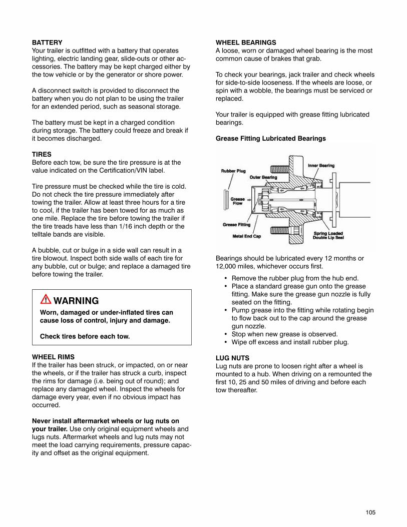
105
BATTERYYour trailer is outfitted with a battery that operates lighting, electric landing gear, slide-outs or other ac-cessories. The battery may be kept charged either by the tow vehicle or by the generator or shore power.
A disconnect switch is provided to disconnect the battery when you do not plan to be using the trailer for an extended period, such as seasonal storage.
The battery must be kept in a charged condition during storage. The battery could freeze and break if it becomes discharged.
TIRESBefore each tow, be sure the tire pressure is at the value indicated on the Certification/VIN label.
Tire pressure must be checked while the tire is cold. Do not check the tire pressure immediately after towing the trailer. Allow at least three hours for a tire to cool, if the trailer has been towed for as much as one mile. Replace the tire before towing the trailer if the tire treads have less than 1/16 inch depth or the telltale bands are visible.
A bubble, cut or bulge in a side wall can result in a tire blowout. Inspect both side walls of each tire for any bubble, cut or bulge; and replace a damaged tire before towing the trailer.
WARNINGWorn, damaged or under-inflated tires can cause loss of control, injury and damage.
Check tires before each tow.
WHEEL RIMSIf the trailer has been struck, or impacted, on or near the wheels, or if the trailer has struck a curb, inspect the rims for damage (i.e. being out of round); and replace any damaged wheel. Inspect the wheels for damage every year, even if no obvious impact has occurred.
Never install aftermarket wheels or lug nuts on your trailer. Use only original equipment wheels and lugs nuts. Aftermarket wheels and lug nuts may not meet the load carrying requirements, pressure capac-ity and offset as the original equipment.
WHEEL BEARINGSA loose, worn or damaged wheel bearing is the most common cause of brakes that grab.
To check your bearings, jack trailer and check wheels for side-to-side looseness. If the wheels are loose, or spin with a wobble, the bearings must be serviced or replaced.
Your trailer is equipped with grease fitting lubricated bearings.
Grease Fitting Lubricated Bearings
Bearings should be lubricated every 12 months or 12,000 miles, whichever occurs first.
• Removetherubberplugfromthehubend.• Placeastandardgreasegunontothegrease
fitting. Make sure the grease gun nozzle is fully seated on the fitting.
• Pumpgreaseintothefittingwhilerotatingbeginto flow back out to the cap around the grease gun nozzle.
• Stopwhennewgreaseisobserved.• Wipeoffexcessandinstallrubberplug.
LUG NUTSLug nuts are prone to loosen right after a wheel is mounted to a hub. When driving on a remounted the first 10, 25 and 50 miles of driving and before each tow thereafter.
106
LUG NUT TIGHTENING (Torque) Being sure wheel mounting nuts (lug nuts) on trailer wheels are tight and properly torqued is an impor-tant responsibility that trailer owners and users need to be familiar with and practice. Inadequate and/or inappropriate wheel nut torque (tightness) is a major reason that lug nuts loosen in service. Loose lug nuts can rapidly lead to a wheel separation with potentially serious safety consequences.
• Becertainyouhaveaclearunderstandingofthe specific wheel maintenance responsibili-ties your vehicle manufacturer requires/rec-ommends you, as the owner, must perform in order to insure your wheel equipment is safely maintained. Check the lug nut tightness the first 10, 25 and 50 miles of driving and before each tow thereafter. Refer to the owner’s manual and speak with your dealer if you have any ques-tions about proper tightening practices.
• Theonlywaytobecertainyouhavecheckedthe tightness or torque the lug nuts to the proper value is with a torque wrench. Four-way wrenches, ratchets, and similar tools can be useful for short-term emergency repairs but are not appropriate tools for accurately checking lug nut torque. You must use a torque wrench to accurately indicate the torque that you are applying to the lug nut
• Keeparecordofthedateandapproximatemileage when you check the lug nut torque. Note any lug nut that has lost torque. Investigate the reason(s) if the lug nut torque is not main-tained after more than one re-torque application, because this indicates there is something wrong with the lug nuts, nut studs, wheels and/or hubs and should be corrected.
• Contactyourdealerorvehiclemanufacturerimmediately if you experience any persistent lug nut loosening or any other lug, wheel or axle problems.
• Intheeventofawheelseparationincident,notify the vehicle manufacturer and dealer. Seek prompt professional assistance in assessing the trailer and its gear, and retain, but don’t re-use involved lugs, wheels and studs. Don’t repair or service the trailer yourself. Contact a trained technician.
WARNINGLug nuts are prone to loosen after being first assembled. Death or serious injury can result.
Check lug nuts for tightness on a new trailer, and after re-mounting a wheel at 10, 25 and 50 miles.
WARNINGMetal creep between the wheel rim and lug nuts (bolts) will cause rim to loosen.
Death or injury can occur if wheel comes off.
Tighten lug nuts (bolts) before each tow.
Tighten the lug nuts to the proper tightness to prevent wheels from coming loose. Refer to the steps that follow and the axle manufacturer’s information. Use a calibrated torque wrench to tighten the lug nuts. Over-tightening may result in breaking the studs or permanently deforming the mounting stud holes in the wheels.
Remove all excess paint, oil and grease from mount-ing surfaces.
Start all lug nuts by hand to prevent cross threading.
Tighten lug nuts in sequence shown in “Lug Nut Sequence of Tightening”.
Never install aftermarket wheels or lug nuts on your trailer. Use only original equipment wheels and lugs nuts. Aftermarket wheels and lug nuts may not meet the load carrying requirements, pressure capac-ity and offset as the original equipment.
Never install aluminum wheels on hubs/studs that were designed for steel wheels. The stud length required for aluminum wheels is greater than that required for steel wheels.
WARNINGAftermarket wheels may part from the trailer, resulting in death or serious injury.
Never install aftermarket wheels or lug nuts on your Lance trailer.
Never install aluminum wheels on hubs/studs that were designed for steel wheels.
WARNINGLug nuts are prone to loosen after being first assembled. Death or serious injury can result.
Check lug nuts for tightness on a new trailer, and after re-mounting a wheel at 10, 25 and 50 miles.
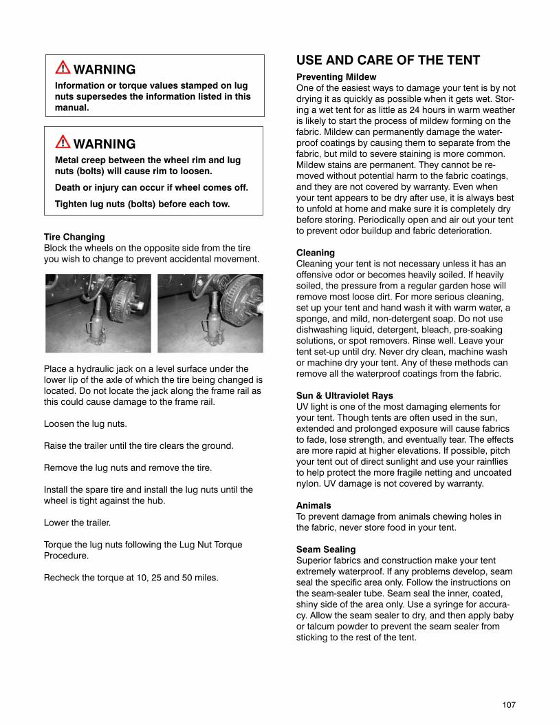
107
WARNINGInformation or torque values stamped on lug nuts supersedes the information listed in this manual.
WARNINGMetal creep between the wheel rim and lug nuts (bolts) will cause rim to loosen.
Death or injury can occur if wheel comes off.
Tighten lug nuts (bolts) before each tow.
Tire ChangingBlock the wheels on the opposite side from the tire you wish to change to prevent accidental movement.
Place a hydraulic jack on a level surface under the lower lip of the axle of which the tire being changed is located. Do not locate the jack along the frame rail as this could cause damage to the frame rail.
Loosen the lug nuts.
Raise the trailer until the tire clears the ground.
Remove the lug nuts and remove the tire.
Install the spare tire and install the lug nuts until the wheel is tight against the hub.
Lower the trailer.
Torque the lug nuts following the Lug Nut Torque Procedure.
Recheck the torque at 10, 25 and 50 miles.
USE AND CARE OF THE TENTPreventing MildewOne of the easiest ways to damage your tent is by not drying it as quickly as possible when it gets wet. Stor-ing a wet tent for as little as 24 hours in warm weather is likely to start the process of mildew forming on the fabric. Mildew can permanently damage the water-proof coatings by causing them to separate from the fabric, but mild to severe staining is more common. Mildew stains are permanent. They cannot be re-moved without potential harm to the fabric coatings, and they are not covered by warranty. Even when your tent appears to be dry after use, it is always best to unfold at home and make sure it is completely dry before storing. Periodically open and air out your tent to prevent odor buildup and fabric deterioration.
CleaningCleaning your tent is not necessary unless it has an offensive odor or becomes heavily soiled. If heavily soiled, the pressure from a regular garden hose will remove most loose dirt. For more serious cleaning, set up your tent and hand wash it with warm water, a sponge, and mild, non-detergent soap. Do not use dishwashing liquid, detergent, bleach, pre-soaking solutions, or spot removers. Rinse well. Leave your tent set-up until dry. Never dry clean, machine wash or machine dry your tent. Any of these methods can remove all the waterproof coatings from the fabric.
Sun & Ultraviolet RaysUV light is one of the most damaging elements for your tent. Though tents are often used in the sun, extended and prolonged exposure will cause fabrics to fade, lose strength, and eventually tear. The effects are more rapid at higher elevations. If possible, pitch your tent out of direct sunlight and use your rainflies to help protect the more fragile netting and uncoated nylon. UV damage is not covered by warranty.
AnimalsTo prevent damage from animals chewing holes in the fabric, never store food in your tent.
Seam SealingSuperior fabrics and construction make your tent extremely waterproof. If any problems develop, seam seal the specific area only. Follow the instructions on the seam-sealer tube. Seam seal the inner, coated, shiny side of the area only. Use a syringe for accura-cy. Allow the seam sealer to dry, and then apply baby or talcum powder to prevent the seam sealer from sticking to the rest of the tent.
108
CondensationCondensation is the buildup of moisture inside your tent due to differences between the inside and out-side temperature. In your tent, it is caused by three main sources:
•Weatherconditions:Highhumidity,lowtem-peratures, and rainy conditions create the most condensation.
•People:Weproduceabout1-2pintsofmoisturein a night through breathing and skin evapora-tion.
•Wetenvironment:Wetgroundorwetgearstoredinside the shelter will increase condensation.
The key to reducing condensation is ventilation. Fresh air has to flow into your tent, and warm, moist air has to escape. The tent manufacturer has de-signed a variety of features and options that allow for interior ventilation.
First, tent bodies and ceilings are made of breath-able fabric and MicroMesh™. This allows moisture to escape, so condensation will be on the waterproof rainfly, not inside the tent. Unfortunately, no tent design will totally eliminate condensation in all condi-tions, but providing good ventilation using any of the above tips will help in reducing it.
ZippersEnvironments where sand and grit get in the zipper teeth can cause abrasion and damage to your zip-per sliders. If you use your tent in these conditions, keep the zipper teeth clean by rinsing them out with water. The pressure from a regular garden hose will push out small sand particles from inside the zipper coil. Handling your zipper slider with care can also prolong the life of the zipper. Just like a zipper on a duffle bag or piece of luggage, align the tracks before sliding the zipper. If you do not camp in the type of conditions described above, your zippers should last indefinitely.
Fabrics & MicroMeshTM TearsUnfortunately, sometimes damage does occur to your shelter. Seam sealers are a good option for small holes, and duct tape can be used for minor, tem-porary field repairs. If you use duct tape, be sure to remove it as soon as you are through with your trip. Otherwise, the adhesive will eventually eat away at the fabric and you will end up needing a larger patch. We recommend carrying at least one emergency repair item as a precaution.
109
INTERIOR MAINTENANCEINTERIOR ODORNew trailers may have a strong odor and even cause eye irritation when closed up in hot weather. This is due to glues used in the cabinetry and paneling. This condition passes with time but in an extreme condi-tion open the entry door and all windows and allow the inside to air out for several hours.
UPHOLSTERY AND DRAPESDraperies, mattress covers, upholstery and wall pads are manufactured from quality materials and should be dry cleaned only. Some dry cleaning methods will damage vinyl or plastic found on cushions and drapes. Be sure to consult your local cleaners. Fre-quent vacuuming or light brushes between cleanings will help prevent accumulation of dirt and grime. Use of water based or detergent based cleaners may cause shrinking. Water stains may become perma-nent. Minor spills should be cleaned up quickly to avoid staining. The affected area should be blotted, not rubbed, to prevent the stain from working deeper into the fabric. On vinyl upholstery, remove dirt and dust with a vacuum cleaner. Wipe the vinyl with a soft cloth and dampen in a solution of mild soap and water. Use the same solution with a soft-bristle brush on more difficult spots. Your can also use commer-cially-available spray or foam-type vinyl cleaners.
WARNINGDo not use lacquer thinner, nail polish remover, carbon tetrachloride, gasoline, or naphtha for any cleaning purpose. These products may cause damage to the material being cleaned, and are highly flammable or poisonous.
WALL AND CEILING PANELSThe paneling and ceiling of your trailer may be any of several finishes and textures. Never use harsh deter-gents or abrasive cleaners on walls or ceilings. Most surfaces will clean with a soft cloth moistened with mild liquid detergent in warm water. Do not use large amounts of water, which could saturate the material.
FLOORS AND CARPETINGVinyl flooring requires only washing and periodic waxing. Vacuum the carpeting frequently to remove dirt. Ground-in dirt will make the carpet wear our fast-er. Periodically shampoo the carpet to keep it looking new. Use one of the foam-type carpet cleaners on the market. Follow the instructions that come with the cleaner, applying it with a sponge or soft brush. Keep the carpeting as dry as possible by not adding water to the foam
WOOD PRODUCT CARERemove dust with a clean slightly damp cloth. Ap-ply a quality furniture polish and buff with a soft, dry cloth. Never use harsh detergents and solvents.
LAMINATE TOP CAREUse a mild dishwashing liquid with warm water to clean your laminate tops. Use a soft cloth for both washing and drying. Abrasive cleaners, steel wool or gritty cleaners will damage the surface.
POWER RANGE HOODClean the filter in detergent and hot water periodically and wipe down the surface of the unit with mild soap and water. Use a soft cloth for both washing and drying.
REFRIGERATORClean interior with mild soap and water after each trip. Defrost freezer and empty ice trays. When defrosting, place dry towels in the refrigerator to absorb the water. Place trays containing hot water into freezer compart-ment. After defrosting (when the freezer compartment and condenser are frost-free), remove the damp tow-els and water trays and use a clean cloth towel to dry off refrigerator.
DRAINSIf a stoppage develops in the sink or shower drain, DO NOT use lye or any strong chemicals. Strong chemicals can harm the plastic in your waste system. A standard wire drain cleaner is recommended.
SHOWER CAREFor routine cleaning use a non-abrasive cleaner. Household fiberglass cleaners are recommended. Never use harsh detergents or abrasive cleaners. Never use a razor blade or steel wool to clean the surfaces.
SINK CAREDo not use abrasive cleaners or scouring powders. Use of abrasive cleaners will dull or damage the surface of this product and could leave scratches. If material gets scratched, easy polishing brings back the original shine. It is recommended you use a gel cleaner or household cleaner made for fiberglass and acrylic. Do not use scouring pads, steel wool, “scotch brite” type scratch pads, or any other abra-sive scrubbers. Wipe only with a soft cloth or sponge. Always use a cutting board or a sink protector when using knives or sharp objects. It is recommended that you use protective mats, racks, or dishpans to help protect your sink. Always allow pans to cool before setting them in your sink.
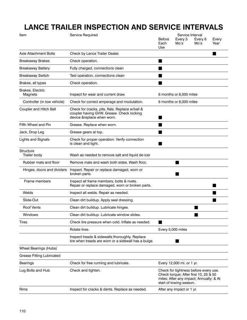
110
LANCE TRAILER INSPECTION AND SERVICE INTERVALSItem Service Required Service Interval Before Every 3 Every 6 Every Each Mo’s Mo’s Year Use
Axle Attachment Bolts Check by Lance Trailer Dealer. n
Breakaway Brakes Check operation. n
Breakaway Battery Fully charged, connections clean n
Breakaway Switch Test operation, connections clean n
Brakes, all types Check operation. n
Brakes, Electric Magnets Inspect for wear and current draw. 6 months or 6,000 miles
Controller (in tow vehicle) Check for correct amperage and modulation. 6 months or 6,000 miles
Coupler and Hitch Ball Check for cracks, pits, flats. Replace w/ball & coupler having GVW. Grease. Check locking device &replace when worn. n
Fifth Wheel and Pin Grease. Replace when worn. n
Jack, Drop Leg Grease gears at top. n
Lights and Signals Check for proper operation. Verify connection is clean and tight. n
Structure Trailer body Wash as needed to remove salt and liquid de-icer
Rubber mats and floor Remove mats and wash both sides. Wash floor. n
Hinges, doors and dividers Inspect. Repair or replace damaged, worn or broken parts. n
Frame members Inspect all frame members, bolts & rivets. Repair or replace damaged, worn or broken parts. n
Welds Inspect all welds. Repair as needed. n
Slide-Out Clean dirt buildup. Apply seal dressing. n
Roof Vents Clean dirt buildup. Lubricate hinges. n
Windows Clean dirt buildup. Lubricate window slides. n
Tires Check tire pressure when cold. Inflate as needed. n
Rotate tires. Every 5,000 miles
Inspect treads & sidewalls thoroughly. Replace tire when treads are worn or a sidewall has a bulge. n
Wheel Bearings (Hubs)
Grease Fitting Lubricated
Bearings Check for free running and lubricate. Every 12,000 mi. or 1 yr.
Lug Bolts and Hub Check and tighten. Check for tightness before every use. Check torque; After first 10, 25 & 50 miles; After any impact; Annually; & At start of towing season.
Rims Inspect for cracks & dents. Replace as needed. After any impact or 1 yr.
111
WINTERIZATIONOPERATING IN FREEZING CONDITIONSIf water freezes inside the system, it can damage pip-ing and equipment.
Keeping the interior warm will aid in preventing water in the storage tank, pump and piping from freezing. Open inside cabinets and allow warm air to circulate over the water system components.
Add non-toxic anti-freeze to the holding tank(s). Refer to the instructions that came with the anti-freeze. Install a winter cover on the air conditioner.
Propane for the appliances will work down to 44 de-grees below zero (-44°).
The windows have weep holes, which drain water from the window tracks. In heavy rain and wind, water could be blown into the trailer through these holes. Put a piece of sponge in the track over the hole to prevent this from occurring.
STORAGEThe following checklists will help you perform the steps necessary to prepare your trailer for storage. Use the checklist that applies to the storage condi-tions you anticipate. These checklists do not include every detail required, and you may want to expand them to suit your needs.
SHORT-TERM STORAGE(Less than 45 days - Above Freezing)
1. Wash the exterior. 2. Park the trailer as level as possible front to rear
and side to side. 3. Before disconnecting the battery cables, check
the charge in the battery. Recharge as necessary. Clean terminals, top and sides of battery and battery box. Leave the battery disconnected or switch the battery disconnect switch to the “STORE” position.
4. Drain the holding tanks, toilet, and fresh water tank. Turn off the water pump and water heater.
5. Turn off the propane at tank valve. 6. Turn off the refrigerator, furnace, all range and
oven burner valves and pilot. 7. Remove all perishables from refrigerator and
galley cabinets. Leave the refrigerator door open to reduce odor buildup. An open box or tray of baking soda in the refrigerator will help absorb odors.
8. Slightly open (1/4”) a roof vent. 9. Close and lock all windows. Be sure the vent fan
and range hood fan switches are off.
10. Cap and close the holding tank drain, city water inlet and fresh water fill spout.
11. Turn off all radios, TV’s, interior and exterior lights.
12. Close the mini blinds and day/night shades.13. Disconnect the 120-volt power cord and store in
compartment.14. If removing the trailer from the tow vehicle, see
procedure and warnings in the “Loading the Trailer” section.
15. Check the trailer weekly.
LONG-TERM STORAGE - Above Freezing 1. Perform all the preceding short-term storage
steps. 2. Operate air conditioner periodically to lubricate
compressor seals. 3. Remove and place the battery in a cool, dry area.
Check the battery charge every 30 days. Recharge as necessary. 4. Check the sealants around all roof seams, body
seams and windows. Reseal if necessary. 5. Prepare the generator (if equipped). See
generator Operating Manual included in the Owner’s Information Package. 6. Remove the smoke detector’s battery. Leave the
cover open as a reminder to replace the battery. 7. Cover exterior vents; water heater, furnace, air
conditioner shroud, range hood, refer, to prevent insects and small animals from getting in the trailer. Be sure to remove all covering materials before using appliances and vents.
STORAGE BELOW FREEZINGTo avoid damage to the plumbing fixtures and other components, we recommend that your trailer plumb-ing systems be properly drained and have antifreeze protection. The following is a procedure checklist you can follow if you prefer to winterize your trailer yourself. Many owners prefer to have a Lance Trailer Dealer Service Center perform this service.
1. Perform all steps in the short and long term storage procedures.
2. Drain the fresh water tank by opening the water tank drain and leave open.
3. Turn the water pump ON and open all hot and cold water faucets. When the flow of water stops, turn the pump OFF. Open the low point drains on the hot and cold water pipes.
4. Drain the water heater by opening the drain plug at the bottom of the heater and open the pressure relief valve.
5. Depress the toilet flush pedal or hand-operated lever. Shut OFF all faucets, close the water line drain valves, fresh water tank drain valve, water heater drain and pressure relief valve.

112
6. Drain the showerhead and hose by disconnecting the hose at the faucet from the inside and outside shower.
7. Drain the waste water system by following the normal procedure for draining the holding tanks.
See “Waste System” section. 8. Be sure ALL water from ALL plumbing has been
drained.
Draining the water system alone will not provide adequate cold weather protection. If the trailer is to be unheated during freezing temperatures, consult your dealer for the best winterizing procedure for your climate. Your dealer can supply you with one of the special non-toxic antifreezes that are safe and approved for use in RV water systems. Follow the instructions furnished with the antifreeze.
Do not use automotive or windshield washer anti-freeze in the trailer water system. These could be harmful if swallowed.
WINTERIZING METHOD (IF EQUIPPED)
1. Make sure the water pump switch is off. 2. Insert the hose from the winterizing valve into a
container of RV approved non-toxic antifreeze. 3. Turn the water heater bypass valve to Bypass
position and drain the water heater by removing the drain plug and opening the safety relief valve.
Open faucets to relieve pressure. (Hot and Cold) Open the hot and cold low point drains. 4. Drain the water tank by opening the tank drain
and leave open to drain completely. 5. After the system is completely drained, close all
faucets and turn off the low point drain valves. 6. Turn the winterize valve to “Winterize” position. 7. Turn ON the water pump switch. 8. Open the hot water faucet farthest from the water
tank. When antifreeze appears, let at least one cup run down the drain to winterize the P-trap. Do the same to all other water outlets, hot and cold, including shower, toilet and outside shower.
9. Turn OFF the pump switch.10. Open a water faucet to relieve pressure, and then
close.11. The procedure is complete.
WATER HEATER BYPASS (IF EQUIPPED)
The water heater bypass valve is located behind the water heater and is used when winterizing the water system for storage. By rotating the lever to the bypass position, antifreeze will not enter the water heater requiring less antifreeze to protect the water system plumbing. Follow the instructions shown on the valve.
NOTE: Be sure to drain the water heater by opening the drain plug at the bottom of the heater and open the pressure relief valve.
To De-Winterize: 1. First fill the water tank. 2. Turn the winterizing valve to normal flow position. 3. Turn the water heater bypass valve to “bypass”;
this will keep antifreeze from entering the water heater.
4. Turn ON the water pump switch. 5. Open the water faucet farthest from water tank,
catching antifreeze in a container for future use, until clear water appears. Shut off the faucet. Do this to all other faucets and the showerhead, including outside shower.
6. Turn the water heater bypass valve to normal flow position.
7. Open a hot water faucet until water appears. 8. Your system is now ready for use.

113
REACTIVATING TRAILER AFTER STORAGEThe following procedure checklist assumes that you stored the trailer with care. If you didn’t and extensive freeze damage or other serious deterioration may have occurred, please consult your Lance Trailer Dealer Service Center for advise.
Outside Area 1. Thoroughly inspect the outside of the trailer and
open all doors and compartments. Check for animals or insect intrusion, water damage or other deterioration.
2. Remove all appliance vent, ceiling vent and air conditioner coverings. Be sure all furnace, water heater, and refrigerator openings are clear and free of debris or insect nests, webs, etc.
NOTE: Spiders and other small insects climb into burner tube(s). The spiders spin webs, build nests and lay eggs. These webs and nests can be very small, but they are very strong and can block the flow of gas.
Mud Daubers are another insect to watch out for. It is not uncommon for Mud Daubers to build their mud huts in places like the furnace exhaust ports. This can be dangerous in two ways. First by causing a restriction that could cause carbon monoxide to build up on the inside of the trailer, second, the same restriction can also cause heat and flame problems which could cause a fire. Both scenarios are dangerous and can cause death.
3. Open vents and windows.
12-Volt System 1. Prior to the battery installation, check charge
level. Refill and recharge as necessary. Inspect cable
ends and ensure that terminals are clean and free of corrosion. Place the battery into the storage rack, install tiedowns, and connect cables. Turn battery switch to “on” position. Check battery condition on monitor panel.
2. Be sure all 12-volt DC and 120-volt AC circuit breakers are ON.
3. Inspect and operate all 12-volt lights and accessories.
Fresh Water System 1. If the fresh water system has been winterized,
drain the antifreeze from fresh water system. 2. Turn the water pump on and open all faucets until
flow of antifreeze stops. 3. Do not let antifreeze stand on plastic sinks or
outside shower components or stains may occur. 4. Open the water heater bypass valves. 5. Flush and sanitize the fresh water system as
outlined in the “Fresh Water System” section.
6. Operate all faucets and fixtures in the fresh water system. Check for leaks at all joints and fittings.
Repair if necessary.
Propane System 1. Turn on propane valves and inspect all pipes and
fittings in the propane system. Check for leaks as outlined in the “Propane System” section.
2. Operate each propane appliance. Observe all burners and pilot flames for proper color and size. If there are any problems, refer to an authorized Lance Trailer Dealer Service Center.
General 1. Install new 9-volt battery in smoke detector. 2. Check the monitor panel operation. 3. Open and operate vents and vent fans.
120-Volt System 1. Inspect the 120-volt electrical system – power
cord, converter, and outlets. If defects are found, refer service to a Lance Trailer Dealer Service Center.
2. Prepare the AC generator (if equipped) for operation following instructions in the generator operating manual in your Owner’s Information Package.
3. Operate 120-volt AC appliances and air conditioner.
Maintenance 1. Check the sealant around all roof, body seams,
and windows. Reseal if necessary. 2. Lubricate all exterior locks, hinges and latches. 3. Wash and wax the exterior. Inspect the body for
scratches or other damage. Touch-up or repair as necessary.
TYPICAL BULBS AND FUSESThe following is a list of typical 12-volt bulbs and fuses used in your trailer. It is wise to keep a couple of spares of each type on hand.
Fuses AmpBlade type (ATC) 1, 3, 7.5, 10, 15, 20 & 30(ATM) 2
Lights Bulb NumberVanity light # 9-019FDome light # 1141Wall Sconce light # 194Reading light # MR16GU5.3Range hood light # 921
Happy Camping
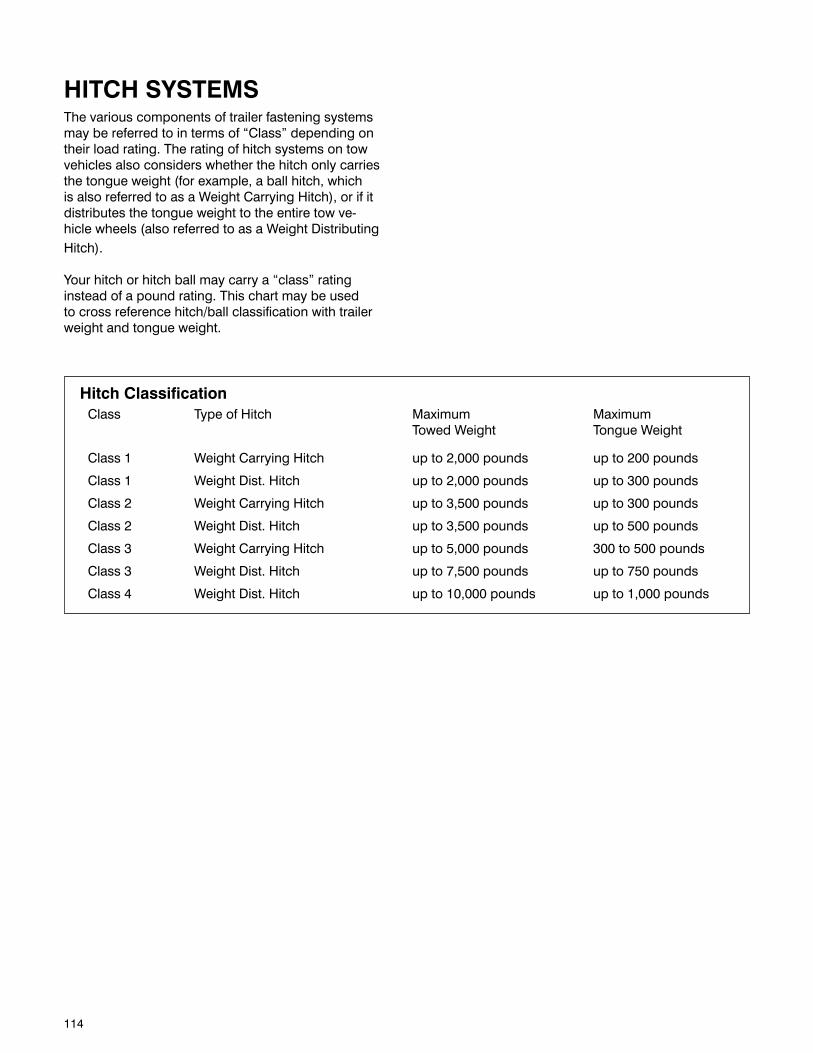
114
HITCH SYSTEMSThe various components of trailer fastening systems may be referred to in terms of “Class” depending on their load rating. The rating of hitch systems on tow vehicles also considers whether the hitch only carries the tongue weight (for example, a ball hitch, which is also referred to as a Weight Carrying Hitch), or if it distributes the tongue weight to the entire tow ve-hicle wheels (also referred to as a Weight Distributing Hitch).
Your hitch or hitch ball may carry a “class” rating instead of a pound rating. This chart may be used to cross reference hitch/ball classification with trailer weight and tongue weight.
Hitch ClassificationClass Type of Hitch Maximum Maximum Towed Weight Tongue Weight
Class 1 Weight Carrying Hitch up to 2,000 pounds up to 200 pounds
Class 1 Weight Dist. Hitch up to 2,000 pounds up to 300 pounds
Class 2 Weight Carrying Hitch up to 3,500 pounds up to 300 pounds
Class 2 Weight Dist. Hitch up to 3,500 pounds up to 500 pounds
Class 3 Weight Carrying Hitch up to 5,000 pounds 300 to 500 pounds
Class 3 Weight Dist. Hitch up to 7,500 pounds up to 750 pounds
Class 4 Weight Dist. Hitch up to 10,000 pounds up to 1,000 pounds

115
SCHEMATICS

116
SH
OW
ER
FAU
CE
T S
HO
WE
R
LAV
ATO
RY
FA
UC
ET
TOIL
ET
WA
TER
HE
ATE
R
EX
TER
IOR
WA
SH
STA
TIO
N
LOW
PO
INT
DR
AIN
S
WA
TER
TA
NK
DR
AIN
WA
TER
PU
MP
WIN
TER
IZIN
G V
ALV
E(IF
EQ
UIP
PE
D)
GA
LLE
Y F
AU
CE
T FRE
SH
WA
TER
TA
NK
WA
TER
FIL
L
VE
NT
CIT
Y W
ATE
R IN
LET
TYPI
CA
L FR
ESH
WA
TER
SYS
TEM
BY
PA
SS
VA
LVE
(IF E
QU
IPP
ED
)W
AS
H S
TATI
ON
SH
UT-
OFF
VA
LVE
S
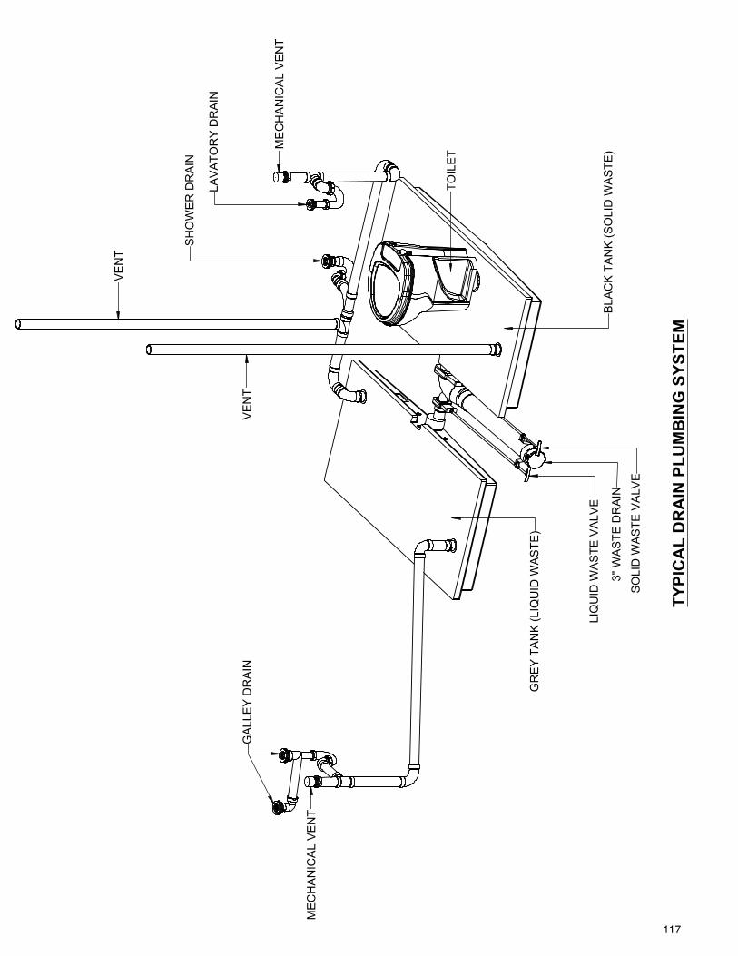
117
ME
CH
AN
ICA
L V
EN
T
VE
NT
VE
NT
ME
CH
AN
ICA
L V
EN
T
TYPI
CA
L D
RA
IN P
LUM
BIN
G S
YSTE
M
TOIL
ET
GA
LLE
Y D
RA
IN
SO
LID
WA
STE
VA
LVE
3" W
AS
TE D
RA
IN
LIQ
UID
WA
STE
VA
LVE
BLA
CK
TA
NK
(SO
LID
WA
STE
)
GR
EY
TA
NK
(LIQ
UID
WA
STE
)
LAV
ATO
RY
DR
AIN
SH
OW
ER
DR
AIN
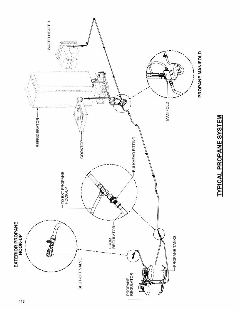
118
PRO
PAN
E M
AN
IFO
LD
MA
NIF
OLD
EXTE
RIO
R P
RO
PAN
EH
OO
K-U
P
BU
LKH
EA
D F
ITTI
NG
TO E
XT
PR
OP
AN
E
SH
UT-
OFF
VA
LVE
HO
OK
-UP
FRO
MR
EG
ULA
TOR
CO
OK
TOP
TYPI
CA
L PR
OPA
NE
SYST
EM
WA
TER
HE
ATE
R
PR
OP
AN
ER
EG
ULA
TOR
PR
OP
AN
E T
AN
KS
RE
FRIG
ER
ATO
R
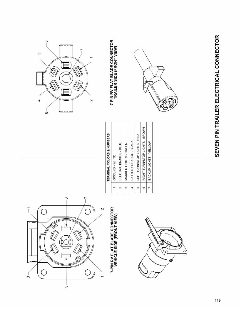
119
7-PI
N R
V FL
AT
BLA
DE
CO
NN
ECTO
RTR
AIL
ER S
IDE
(FR
ON
T VI
EW)
3
5
1
7
2
6
4
65
34 2
1
7-PI
N R
V FL
AT
BLA
DE
CO
NN
ECTO
RVE
HIC
LE S
IDE
(FR
ON
T VI
EW)
7
SEVE
N P
IN T
RA
ILER
ELE
CTR
ICA
L C
ON
NEC
TOR
S
TER
MIN
AL
CO
LOR
S &
NU
MB
ERS
1 G
RO
UN
D -
WH
ITE
2 E
LEC
TRIC
BR
AK
ES
- B
LUE
3 M
AR
KE
R L
IGH
TS -
GR
EE
N
4 B
ATT
ER
Y C
HA
RG
E -
BLA
CK
5 L
EFT
TU
RN
/STO
P L
IGH
TS -
RE
D
6 R
IGH
T TU
RN
/STO
P L
IGH
TS -
BR
OW
N
7 B
AC
KU
P L
IGH
TS -
YE
LLO
W
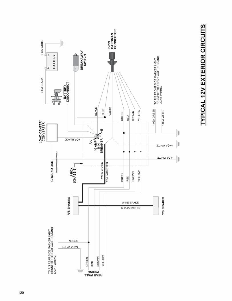
120
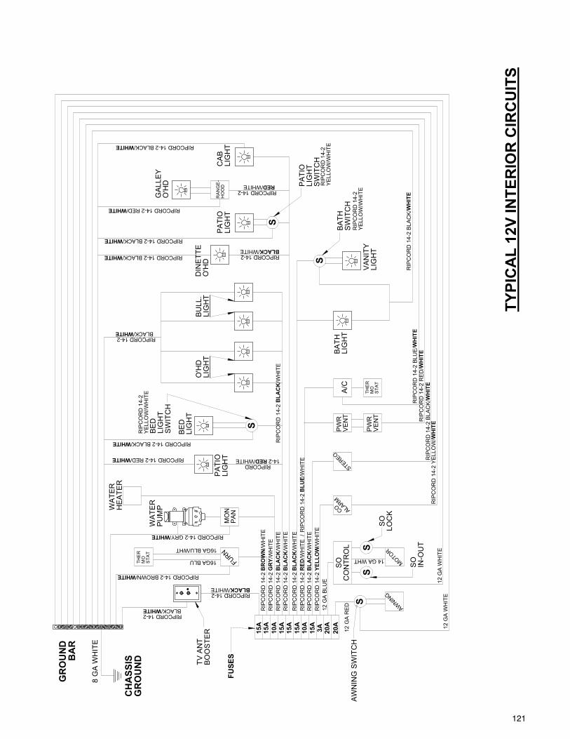
121 119
S
BLU
E /W
HIT
E
LIG
HT
BA
TH
RIP
CO
RD
14-
2
WH
ITE
RIP
CO
RD
14-
2 YE
LLO
W/
RIP
CO
RD
14-
2 /W
HIT
EG
RY
/WH
ITE
RED/WHITE RIP
CO
RD
14-
2
GR
OU
ND
WHITE
THE
RV
AN
ITY
/WH
ITE
16GA BLU/WHT
WA
TER
A/C
YELL
OW
RIP
CO
RD
14-
2
12 G
A W
HIT
E
WHITE
CH
ASS
IS
RIPCORD 14-2 BLACK/WHITE
CA
BLI
GH
T
WH
ITE
/WH
ITE
/
YELL
OW
/WH
ITE
12 G
A BL
UE
LIG
HT
S
RIP
CO
RD
14-
2
16GA BLU
PU
MP
RED
STA
TM
O
RIP
CO
RD
14-
2
ALARM
AWNIN
G
PW
RV
EN
T
8 G
A W
HIT
E
FURN
GR
OU
ND
COTY
PIC
AL
12V
INTE
RIO
R C
IRC
UIT
S
PA
TIO
LIG
HT
LIG
HT
BE
D
RIPCORD 14-2 RED/WHITE
WHITE BLACK/
O'H
DG
ALL
EY
BLACK/
PW
R
RIPCORD 14-2 BLACK/WHITE RIPCORD 14-2BLACK
HE
ATE
RW
ATE
R
/WH
ITE
BLA
CK
RIP
CO
RD
14-
2 S
MOTOR
RIPCORD 14-2 BROWN/
RIPCORDS
WH
ITE
RIP
CO
RD
14-
2 BL
UE/
RIP
CO
RD
14-
2
WH
ITE
RIP
CO
RD
14-
2 R
ED/
SO
CO
NTR
OL
BLA
CK
/WH
ITE
RIP
CO
RD
14-
2 BL
ACK/
WH
ITE
RIP
CO
RD
14-
2
VE
NT
14 GA WHT
12 G
A W
HIT
E
12 G
A R
ED
RIPCORD 14-2
AW
NIN
G S
WIT
CH
/WHITE
WHITERIPCORD 14-2
/WHITE
BR
OW
N/W
HIT
E
BA
R
WHITE
BLA
CK
/WH
ITE
MO
NP
AN
RIPCORD 14-2 BLACK/WHITE
RIPCORD 14-2 /WHITE BLACK
PA
TIO
LIG
HT
14-2 RED
DIN
ETT
EO
'HD
RIP
CO
RD
14-
2 /W
HIT
EB
LAC
K
RA
NG
E-
HO
OD
YELL
OW
/WH
ITE
RIP
CO
RD
14-
2
RIPCORD 14-2 GRY/
RIPCORD 14-2 BLACK/WHITE
RIPCORD 14-2 RED/
STEREO
RIP
CO
RD
14-
2 BL
ACK/
RIP
CO
RD
14-
2YE
LLO
W/W
HIT
E
RIP
CO
RD
14-
2
S
BLA
CK
S
RIPCORD 14-2
THE
RM
OS
TAT
15A
15A
15A
15A
10A
15A
10A
20A
20A
3AS
WIT
CH
15A
LOC
KS
O
SO
SW
ITC
HB
ATH
LIG
HT
BE
D
O'H
D
IN-O
UT
LIG
HT
SW
ITC
H
LIG
HT
BU
LL.
LIG
HT
PA
TIO
TV A
NT
BO
OS
TER
FUSE
S
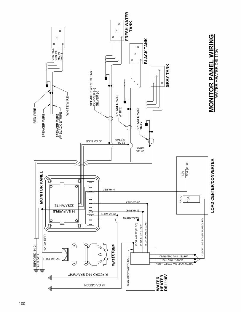
122
GREEN W/YELOW STRIPE - GRN
22 GA
14 GA PURPLE
BLACK - 110V (HOT)
GRAY
22GA WHITE
BLA
CK
TA
NK
BROWN22 GA BLUE
12 G
A R
ED
GR
AY
TAN
K22 GA
/
WHITE - 110V (NEUTRAL)
TAN
K
120V
AC 1
4-2
RO
MEX
W/G
RO
UN
D
18 G
A O
RAN
GE
(GAS
)
FUSE
FRES
H W
ATE
R
15A
18 G
A W
HIT
E (E
LEC
)
W/ B
LAC
K S
TRIP
E
OR
G-F
ULL
GR
N-2
/3YE
L-1/
3W
HT-
E
WA
TER
PU
MP
20 GA GREY
20 GA PINK22 GA WHITE
RE
D W
IRE
20 GA GREEN
RIPCORD 14-2 GRAY/
18 G
A BL
UE
(LIG
HT)
WHT
WH
ITE
WIR
E
SP
EA
KE
R W
IRE
SP
EA
KE
R W
IRE
WH
T
12 GA WHT
18 G
A G
REE
N (G
RO
UN
D)
GR
Y
DSI
110
V
MO
NIT
OR
PA
NEL
18 GA GREEN
12V
110V
LOA
D C
ENTE
R/C
ON
VER
TER
10A
RIP
CO
RD
14-
2
WA
TER
HEA
TER
14 GA RED
SP
EA
KE
R W
IRE
WH
ITE
GR
AY
CO
PP
ER
(+)
SIL
VE
R (-
)
SP
EA
KE
R W
IRE
CLE
AR
SP
EA
KE
R W
IRE MO
NIT
OR
PA
NEL
WIR
ING
WA
TER
HE
ATE
R D
SI 1
10V
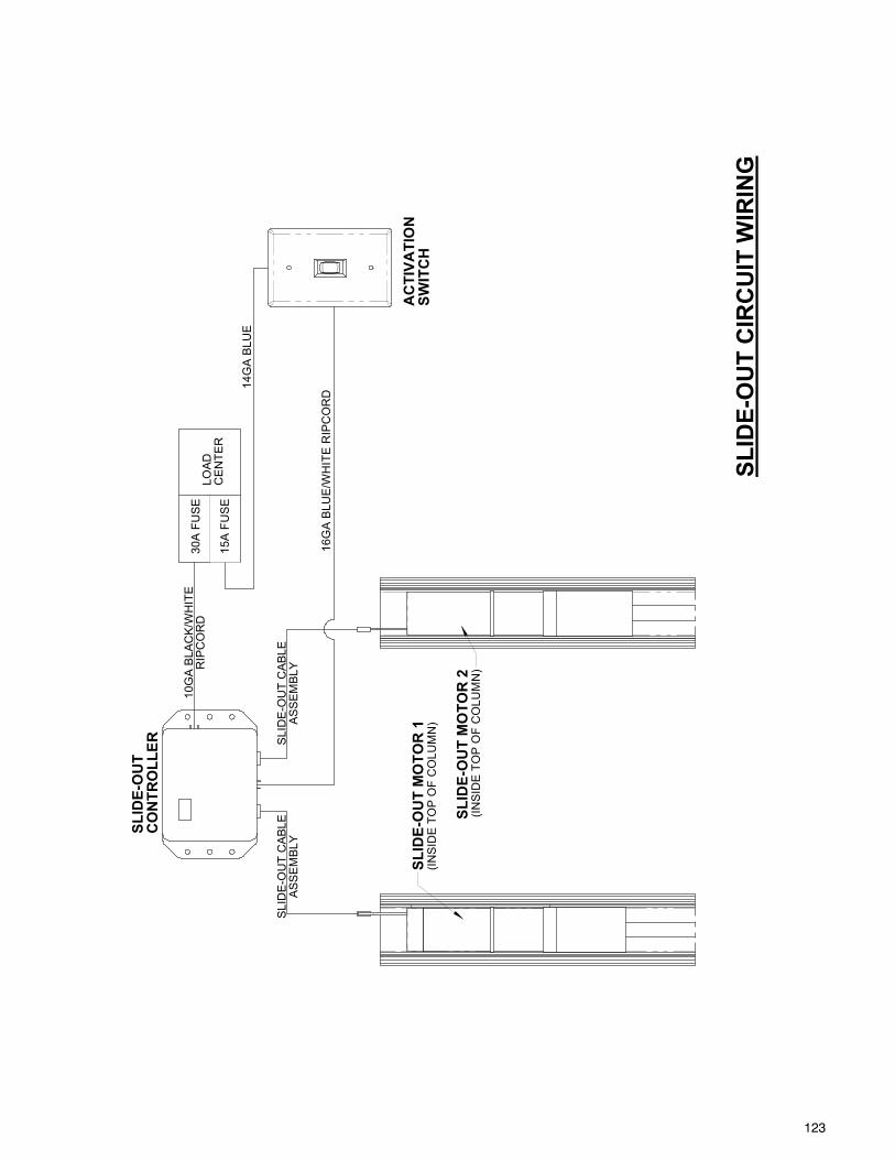
123
16G
A B
LUE
/WH
ITE
RIP
CO
RD
15A
FU
SE
AS
SE
MB
LYS
LID
E-O
UT
CA
BLE
SLID
E-O
UT
CIR
CU
IT W
IRIN
G
CO
NTR
OLL
ERSL
IDE-
OU
T
SWIT
CH
AC
TIVA
TIO
N
RIP
CO
RD
10G
A B
LAC
K/W
HIT
E
CE
NTE
R
(INS
IDE
TO
P O
F C
OLU
MN
)SL
IDE-
OU
T M
OTO
R 1
30A
FU
SE
LOA
D
AS
SE
MB
LY
SLID
E-O
UT
MO
TOR
2
(INS
IDE
TO
P O
F C
OLU
MN
)
SLI
DE
-OU
T C
AB
LE
14G
A B
LUE
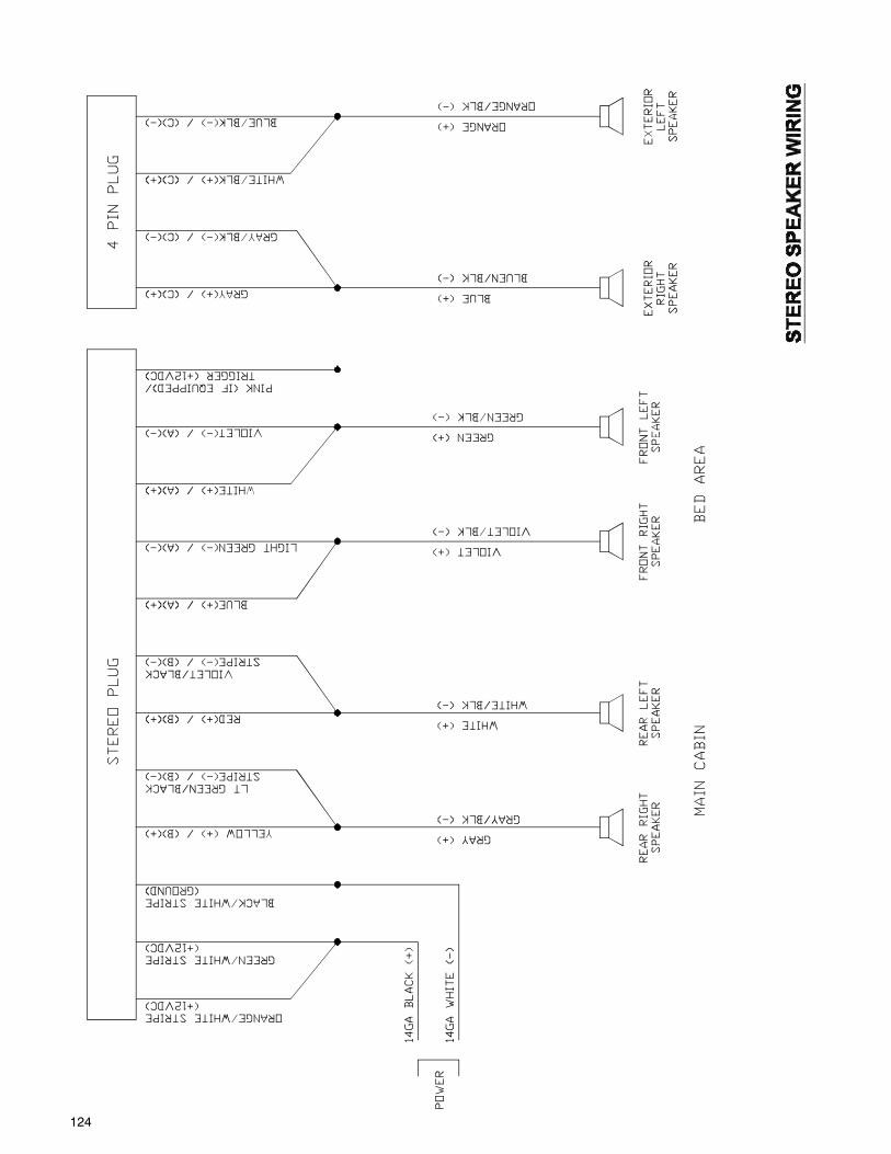
124
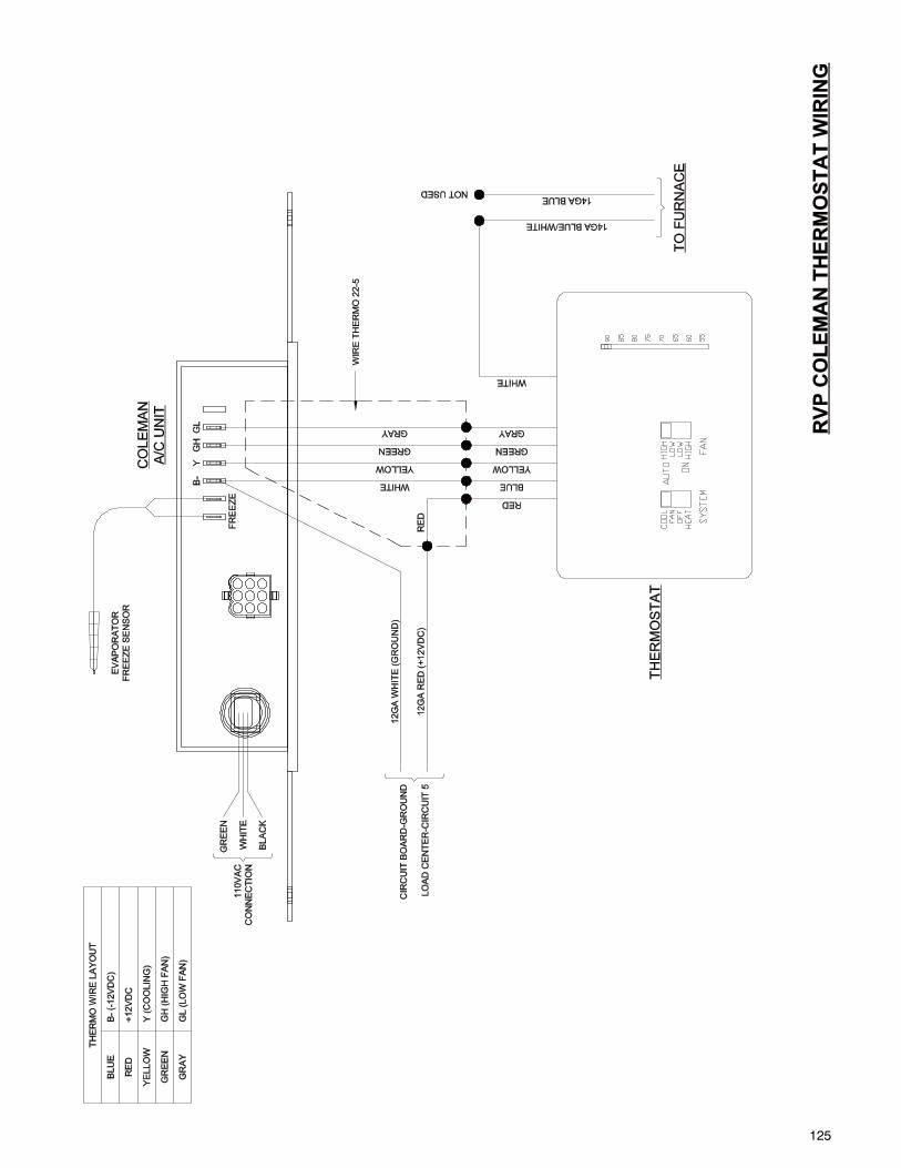
125
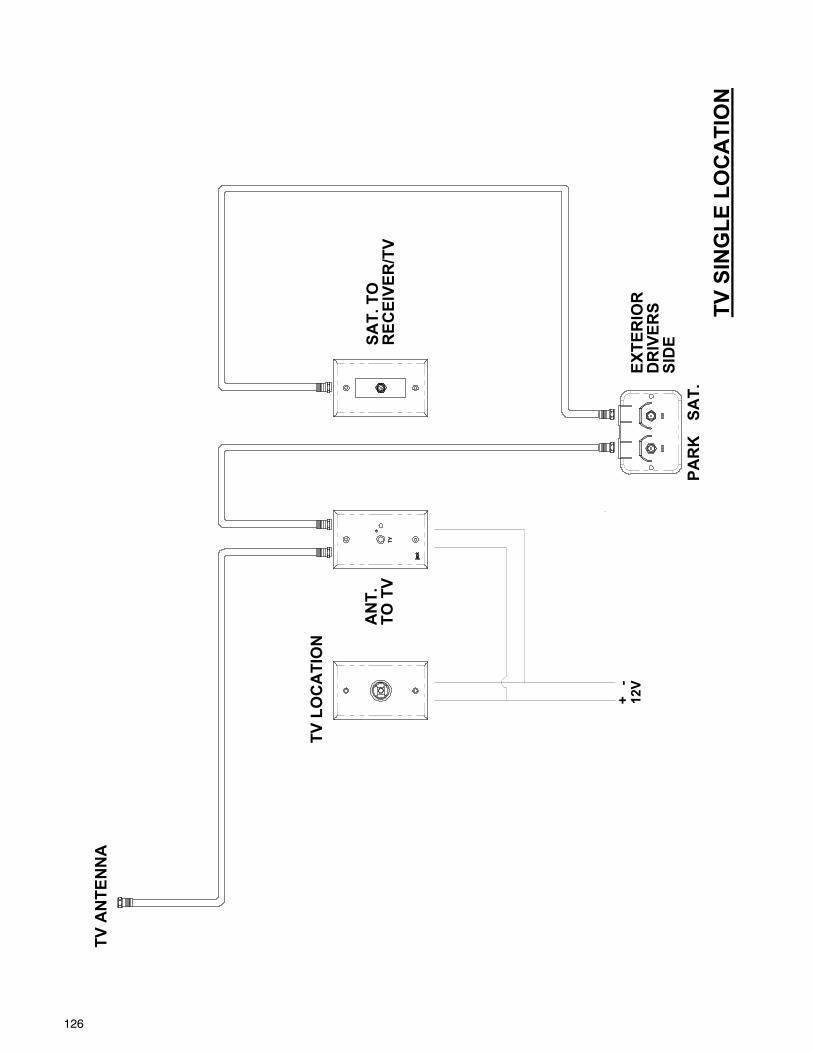
126
AN
T.
TO T
V
TV S
ING
LE L
OC
ATI
ON
SAT.
TO
SID
EPA
RK
SAT.
DR
IVER
S
REC
EIVE
R/T
V
TV L
OC
ATI
ON
TV A
NTE
NN
A
EXTE
RIO
R
+ -
12V

127
DR
IVER
SSI
DE
TV D
OU
BLE
LO
CA
TIO
N
TO T
VTO
TV
AN
T.
LOC
ATI
ON
TV L
OC
ATI
ON
PAR
KSA
T.
2ND
TV
12V
FRO
M R
ECEI
VER
TO R
ECEI
VER
+ -
2ND
TV
SAT.
TO
2ND
TV
AN
T. T
O
EXTE
RIO
R
SAT.
TV A
NTE
NN
A
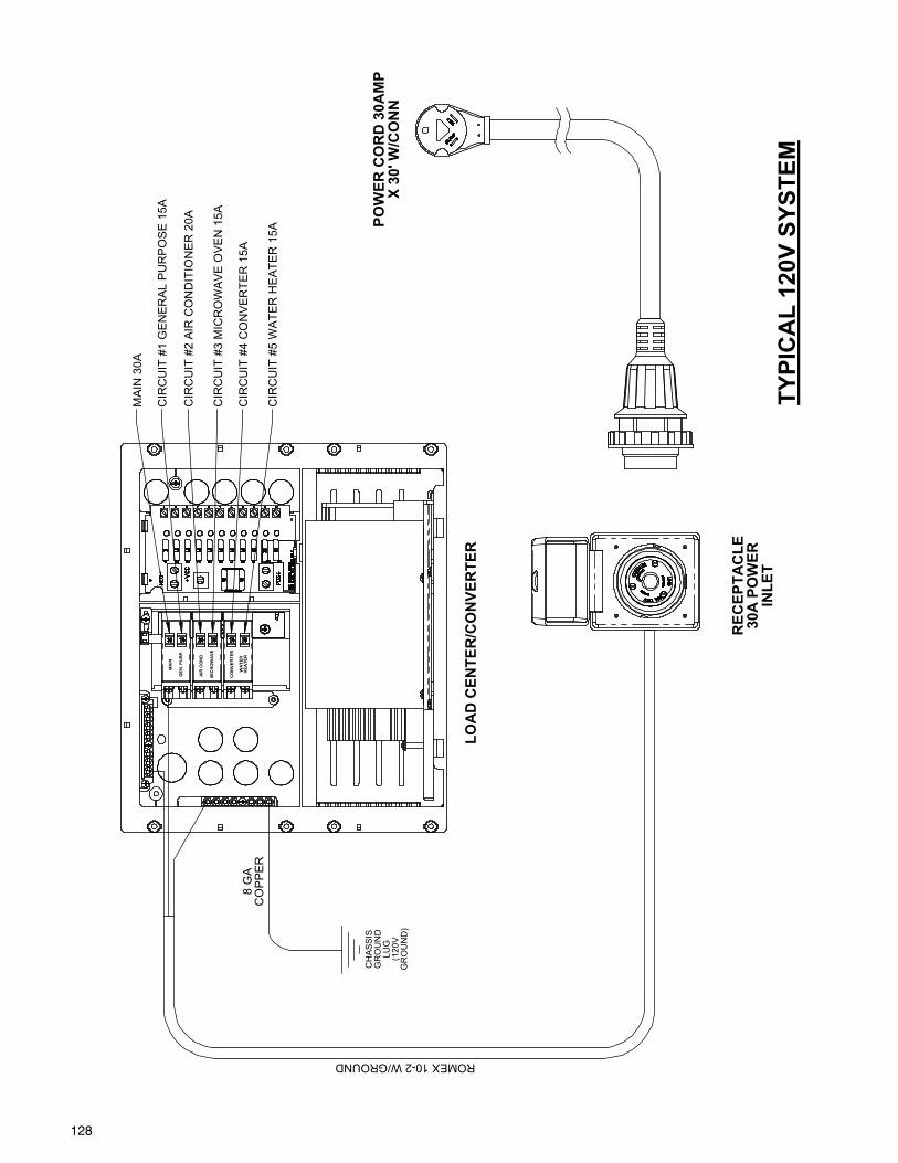
128
TYPI
CA
L 12
0V S
YSTE
M
MA
IN 3
0A
CH
ASSI
SG
RO
UN
DLU
G(1
20V
GR
OU
ND
)
8 G
AC
OP
PE
R
ROMEX 10-2 W/GROUND
REC
EPTA
CLE
30A
PO
WER
INLE
T
LOA
D C
ENTE
R/C
ON
VER
TER
WA
TER
HEA
TER
MIC
RO
WA
VE
GEN
. PU
RP.
AIR
CO
ND
.
MA
IN
CO
NVE
RTE
R
POW
ER C
OR
D 3
0AM
P X
30' W
/CO
NN
CIR
CU
IT #
1 G
EN
ER
AL
PU
RP
OS
E 1
5A
CIR
CU
IT #
2 A
IR C
ON
DIT
ION
ER
20A
CIR
CU
IT #
3 M
ICR
OW
AV
E O
VE
N 1
5A
CIR
CU
IT #
4 C
ON
VE
RTE
R 1
5A
CIR
CU
IT #
5 W
ATE
R H
EA
TER
15A
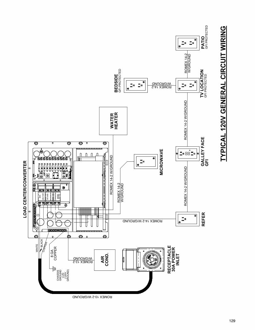
129
TYPI
CA
L 12
0V G
ENER
AL
CIR
CU
IT W
IRIN
G
ROMEX 14-2 W/GROUND
TV L
OC
ATI
ON
GFI
PR
OTE
CTE
DG
ALL
EY F
AC
EG
FIR
EFER
MIC
RO
WA
VE
RO
ME
X 1
4-2
W/G
RO
UN
D
CH
ASSI
SG
RO
UN
DLU
G(1
20V
GR
OU
ND
)
CO
PPERBL
ACK
WH
ITE
8 G
AC
OP
PE
R
ROMEX 10-2 W/GROUND
ROMEX 14-2W/GROUND
RO
ME
X 1
4-2
W/G
RO
UN
D
RO
ME
X 1
4-2
W/G
RO
UN
D
REC
EPTA
CLE
30A
PO
WER
INLE
T
AIR
CO
ND
.W
ATE
RH
EATE
R
LOA
D C
ENTE
R/C
ON
VER
TER
ROMEX 12-2W/GROUND
WA
TER
HEA
TER
MIC
RO
WA
VE
GEN
. PU
RP.
AIR
CO
ND
.
MA
IN
PATI
OG
FI P
RO
TEC
TED
RO
ME
X 1
4-2
W/G
RO
UN
D
BED
SID
EG
FI P
RO
TEC
TED
RO
ME
X 1
4-2
W/G
RO
UN
D
CO
NVE
RTE
R
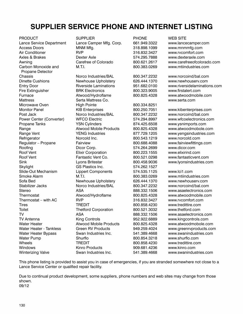
130
SUPPLIER SERVICE PHONE AND INTERNET LISTINGPRODUCT SUPPLIER PHONE WEB SITELance Service Department Lance Camper Mfg. Corp. 661.949.3322 www.lancecamper.comAccess Doors MNM Mfg. 318.898.1099 www.mnmmfg.comAir Conditioner RVP 316.832.3427 www.rvcomfort.comAxles & Brakes Dexter Axle 574.295.7888 www.dexteraxle.comAwning Carefree of Colorado 800.621.2617 www.carefreeofcolorado.comCarbon Monoxide and M.T.I. 800.383.0269 www.mtiindustries.com Propane Detector Chassis Norco Industries/BAL 800.347.2232 www.norcoind/bal.comDinette Cushions Newhouse Upholstery 626.444.1370 www.newhouserv.com Entry Door Riverside Laminations 951.682.0100 www.riversidelaminations.comFire Extinguisher BRK Electronics 800.323.9005 www.firstalert.comFurnace Atwood/Hydroflame 800.825.4328 www.atwoodmobile.comMattress Serta Mattress Co. www.serta.comMicrowave Oven High Pointe 800.334.8251 Monitor Panel KIB Enterprises 800.250.7051 www.kibenterprises.com Post Jack Norco Industries/BAL 800.347.2232 www.norcoind/bal.comPower Center (Converter) WFCO Electric 574.294.8997 www.wfcoelectronics.comPropane Tanks YSN Cylinders 874.425.6508 www.ysnimports.comRange Atwood Mobile Products 800.825.4328 www.atwoodmobole.comRange Vent YENG Industries 877.729.1205 www.yengsindustries.comRefrigerator Norcold Inc. 800.543.1219 www.norcold.comRegulator – Propane Fairview 800.688.4088 www.fairviewfittings.comRoofing Dicor Corp. 574.264.2699 www.dicor.comRoof Vent Elixir Corporation 800.223.1555 www.elixirind.com Roof Vent Fantastic Vent Co. 800.521.0298 www.fantasticvent.com Sink Lyons Britestar 800.458.9036 www.lyonsindustries.comSkylight GS Plastics Inc. 574.262.1527Slide-Out Mechanism Lippert Components 574.535.1125 www.lci1.comSmoke Alarm M.T.I. 800.383.0269 www.mtiindustries.comSofa Bed Newhouse Upholstery 626.444.1370 www.newhouserv.comStabilizer Jacks Norco Industries/BAL 800.347.2232 www.norcoind/bal.comStereo ASA 888.332.1506 www.asaelectronics.comThermostat Atwood/Hydroflame 800.825.4328 www.atwoodmobile.comThermostat – with AC RVP 316.832.3427 www.rvcomfort.comTires TREDIT 800.858.4230 www.tredittire.comToilet Thetford Corporation 800.521.3032 www.thetford.comTV ASA 888.332.1506 www.asaelectronics.comTV Antenna King Controls 952.922.6889 www.kingcontrols.comWater Heater Atwood Mobile Products 800.825.4328 www.atwoodmobole.comWater Heater - Tankless Green RV Products 949.259.4024 www.greenrvproducts.comWater Heater Bypass Swan Industries Inc. 541.389.4668 www.swanindustries.comWater Pump Shurflo 800.854.3218 www.shurflo.comWheels TREDIT 800.858.4230 www.tredittire.comWindows Kinro Products 909.681.4236 www.kinro.comWinterizing Valve Swan Industries Inc. 541.389.4668 www.swanindustries.com
This phone listing is provided to assist you in case of emergencies, if you are stranded somewhere not close to a Lance Service Center or qualified repair facility.
Due to continual product development, some suppliers, phone numbers and web sites may change from those shown.09/12

131

132