se77 devicenet advanced user guide - electrocentr · user guide solutions module for: • unidrive...
TRANSCRIPT

EF www.controltechniques.com
User Guide
Solutions Module for:
• Unidrive SP
Part Number: 0471-0048-04Issue: 4
SM-SERCOS

General InformationThe manufacturer accepts no liability for any consequences resulting from inappropriate, negligent or incorrect installation or adjustment of the optional operating parameters of the equipment or from mismatching the variable speed drive with the motor.
The contents of this guide are believed to be correct at the time of printing. In the interests of a commitment to a policy of continuous development and improvement, Control Techniques reserves the right to change the specification of the product or its performance or the contents of this guide without notice.
All rights reserved. No parts of this guide may be reproduced or transmitted in any form or by any means, electrical or mechanical including photocopying, recording or by an information storage or retrieval system, without permission in writing from the publisher.
Copyright © 17 March 2006 Control Techniques Drives.
Issue Code: 4

Contents1 Safety Information ..........................................................61.1 Warnings, Cautions and Notes ................................................................61.2 Electrical safety - general warning ..........................................................61.3 System design and safety of personnel ..................................................61.4 Environmental limits ................................................................................71.5 Compliance with regulations ...................................................................71.6 Motor .......................................................................................................71.7 Adjusting parameters ..............................................................................7
2 Introduction ....................................................................82.1 What Is SERCOS? ..................................................................................82.2 SERCOS Data transfer ...........................................................................92.3 What is SM-SERCOS? ..........................................................................102.4 Features ................................................................................................102.5 Solutions Module identification ..............................................................122.6 Product conformance certificate ............................................................122.7 Conventions used in this guide .............................................................122.8 Product conformance certificate ............................................................132.9 Backup / Auxiliary Supply ......................................................................13
3 Mechanical installation ................................................143.1 Solutions Module slots ..........................................................................143.2 Installation .............................................................................................14
4 Electrical installation ...................................................164.1 SM-SERCOS terminal Descriptions ......................................................164.2 Digital Input connections .......................................................................164.3 SERCOS connections ...........................................................................174.4 SERCOS cable ......................................................................................174.5 Maximum network length ......................................................................184.6 Minimum cable length ...........................................................................184.7 Node addressing ...................................................................................184.8 Typical network connections .................................................................18
5 Getting started ..............................................................205.1 SERCOS Network Operation ................................................................205.2 Set-up flow chart ...................................................................................235.3 Configuring the SM-SERCOS ...............................................................245.4 Configuring the SERCOS master ..........................................................295.5 Control operating modes .......................................................................30
6 IDNs ...............................................................................346.1 What are IDNs? .....................................................................................346.2 Supported IDNs .....................................................................................346.3 Summary of IDNs ..................................................................................35
7 Manufacture IDNs .........................................................687.1 Drive Parameter Access ........................................................................68
SM-SERCOS User Guide 3Issue Number: 4 www.controltechniques.com

8 Control and Status Words ...........................................708.1 What are control and status words? ......................................................708.2 MDT Control word .................................................................................708.3 AT Status word .....................................................................................72
9 Procedure Commands .................................................739.1 What are procedure commands? ..........................................................739.2 Homing procedure commands ..............................................................739.3 Cancel reference point procedure command ........................................749.4 Measurements .......................................................................................759.5 Reset Class 1 Diagnostic Procedure Command ...................................759.6 CP3 and CP4 transition check procedure commands ...........................76
10 Data Synchronisation ..................................................7710.1 Synchronisation .....................................................................................7710.2 Synchronisation status ..........................................................................7810.3 Synchronisation period ..........................................................................7810.4 Internal interrupts ..................................................................................7910.5 Position control without interpolation .....................................................7910.6 Position control with interpolation ..........................................................8010.7 Timing accuracy ....................................................................................82
11 Advanced Features ......................................................8411.1 SM-SERCOS network loss trip ..............................................................8411.2 SM-SERCOS data endian format ..........................................................8411.3 SM-SERCOS register control ................................................................8511.4 SM-SERCOS second encoder enable ..................................................8511.5 SM-SERCOS second encoder source ..................................................8511.6 SM-SERCOS second encoder turns bits ..............................................8611.7 SM-SERCOS homing backoff behaviour ..............................................8611.8 Restore SM-SERCOS defaults .............................................................8611.9 Storing SM-SERCOS parameters (backup) ..........................................8711.10 Restore previous SM-SERCOS configuration .......................................8711.11 Marker pulse source ..............................................................................8811.12 Freeze main drive position ....................................................................8911.13 Test mode .............................................................................................8911.14 Disable SM-SERCOS control ................................................................8911.15 Menu 61 - SM-SERCOS virtual parameters ..........................................9011.16 Cyclic and non-cyclic data communications ..........................................9011.17 Telegram type 7 ....................................................................................9111.18 Cyclic Access to SM-Applications .........................................................91
4 SM-SERCOS User Guidewww.controltechniques.com Issue Number: 4
12 Diagnostics ...................................................................9412.1 Diagnostic flow chart .............................................................................9412.2 Module ID code .....................................................................................9512.3 SM-SERCOS firmware version .............................................................9512.4 SM-SERCOS node address ..................................................................9512.5 SM-SERCOS data rate .........................................................................9612.6 SM-SERCOS optical transmitter power level .......................................9612.7 SM-SERCOS operating status ..............................................................9612.8 Drive trip display codes .........................................................................9712.9 SM-SERCOS network diagnostic parameters .......................................9812.10 SM-SERCOS error codes .....................................................................9812.11 SM-SERCOS serial number ..................................................................9912.12 Diagnostic IDNs .....................................................................................99
13 Quick reference ..........................................................10013.1 SM-SERCOS parameter reference .....................................................10013.2 SM-SERCOS IDN reference ...............................................................102
14 Glossary Of Terms .....................................................108
SM-SERCOS User Guide 5Issue Number: 4 www.controltechniques.com
1 Safety Information
1.1 Warnings, Cautions and Notes
1.2 Electrical safety - general warningThe voltages used in the drive can cause severe electrical shock and/or burns, and could be lethal. Extreme care is necessary at all times when working with or adjacent to the drive.
Specific warnings are given at the relevant places in this User Guide.
1.3 System design and safety of personnelThe drive is intended as a component for professional incorporation into complete equipment or a system. If installed incorrectly, the drive may present a safety hazard.
The drive uses high voltages and currents, carries a high level of stored electrical energy, and is used to control equipment which can cause injury.
Close attention is required to the electrical installation and the system design to avoid hazards either in normal operation or in the event of equipment malfunction. System design, installation, commissioning and maintenance must be carried out by personnel who have the necessary training and experience. They must read this safety information and this User Guide carefully.
The STOP and SECURE DISABLE functions of the drive do not isolate dangerous voltages from the output of the drive or from any external option unit. The supply must be disconnected by an approved electrical isolation device before gaining access to the electrical connections.
With the sole exception of the SECURE DISABLE function, none of the drive functions must be used to ensure safety of personnel, i.e. they must not be used for safety-related functions.
Note that the SECURE DISABLE function is only available as standard on the Unidrive SP.
Careful consideration must be given to the functions of the drive which might result in a hazard, either through their intended behavior or through incorrect operation due to a fault. In any application where a malfunction of the drive or its control system could lead to or allow damage, loss or injury, a risk analysis must be carried out, and where necessary, further measures taken to reduce the risk - for example, an over-speed protection device in case of failure of the speed control, or a fail-safe mechanical brake in case of loss of motor braking.
A Warning contains information, which is essential for avoiding a safety hazard.
A Caution contains information, which is necessary for avoiding a risk of damage to the product or other equipment.
A Note contains information, which helps to ensure correct operation of the product.
WARNING
CAUTION
NOTE
6 SM-SERCOS User Guidewww.controltechniques.com Issue Number: 4

Safety Inform
ationIntroduction
Mechanical
installationElectrical
installationG
etting started
IDN
sM
anufacture ID
Ns
Control and
Status Words
Procedure C
omm
andsD
ata Synchronisation
Advanced Features
Diagnostics
Quick
referenceG
lossary Of
Terms
Index
The SECURE DISABLE function and secure input on Unidrive SP meet the requirements of EN954-1 category 3 for the prevention of unexpected starting of the drive. They may be used in a safety-related application. The system designer is responsible for ensuring that the complete system is safe and designed correctly according to the relevant safety standards.
1.4 Environmental limitsInstructions in the Unidrive SP User Guide regarding transport, storage, installation and use of the drive must be complied with, including the specified environmental limits. Drives must not be subjected to excessive physical force.
1.5 Compliance with regulationsThe installer is responsible for complying with all relevant regulations, such as national wiring regulations, accident prevention regulations and electromagnetic compatibility (EMC) regulations. Particular attention must be given to the cross-sectional areas of conductors, the selection of fuses or other protection, and protective earth (ground) connections.
The Unidrive SP User Guide contain instructions for achieving compliance with specific EMC standards.
Within the European Union, all machinery in which this product is used must comply with the following directives:
98/37/EC: Safety of machinery.
89/336/EEC: Electromagnetic Compatibility.
1.6 MotorEnsure the motor is installed in accordance with the manufacturer’s recommendations. Ensure the motor shaft is not exposed.
Standard squirrel cage induction motors are designed for single speed operation. If it is intended to use the capability of the drive to run a motor at speeds above its designed maximum, it is strongly recommended that the manufacturer is consulted first.
Low speeds may cause the motor to overheat because the cooling fan becomes less effective. The motor should be fitted with a protection thermistor. If necessary, an electric forced vent fan should be used.
The values of the motor parameters set in the drive affect the protection of the motor. The default values in the drive should not be relied upon.
It is essential that the correct value is entered in the motor rated current parameter: Pr 0.46 for Unidrive SP. This affects the thermal protection of the motor.
1.7 Adjusting parametersSome parameters have a profound effect on the operation of the drive. They must not be altered without careful consideration of the impact on the controlled system. Measures must be taken to prevent unwanted changes due to error or tampering.
SM-SERCOS User Guide 7Issue Number: 4 www.controltechniques.com

2 Introduction
2.1 What Is SERCOS?SERCOS (SErial Real time COmmunication System interface) is a networking system that is intended to replace traditional wiring systems. Figure 2-1 shows the traditional cabling requirements to transfer signals between 2 slaves and a master.
Figure 2-1 Traditional cable layout
Figure 2-1 details how the wiring is used to communicate data between the master and the slaves. Each signal that is communicated requires 1 signal wire giving a total of 66 signal wires plus a 0V return.
A network system such as SERCOS allows the same configuration to be realised using only 2 optical connections per slave. This method of communication saves significantly on the amount of cabling required and can improve overall system reliability as the number of interconnections is greatly reduced.
Figure 2-2 shows a typical SERCOS network system transferring the same signals as given in the traditionally wired example. The signals are now transmitted by converting them into a optical data stream which is received by the slaves as if they were connected using traditional wiring.
Hardwired masterS
lave
Num
ber
1
Slave N
umber
2
Analogue 1 Analogue 2
Dig
ital 1
AD
igita
l 1B
Digital 2A
Digital 2B
Digital 1A Digital 1B Digital 2A Digital 2B
Analogue 1 Analogue 2
8 SM-SERCOS User Guidewww.controltechniques.com Issue Number: 4

Safety Inform
ationIntroduction
Mechanical
installationElectrical
installationG
etting started
IDN
sM
anufacture ID
Ns
Control and
Status Words
Procedure C
omm
andsD
ata Synchronisation
Advanced Features
Diagnostics
Quick
referenceG
lossary Of
Terms
Index
Figure 2-2 SERCOS cable layout
2.2 SERCOS Data transferThe SERCOS master reads and writes data to slaves using a pre-defined set of parameters, which provides a non-vendor specific standard for controlling slave devices. These are known as IDNs (IDentification Numbers). The SM-SERCOS interprets this data and passes it through to the appropriate drive parameters.A SERCOS network uses three kinds of messages to handle data transfer.
• MST - Master Synchronisation Telegram.This telegram is transmitted from the master on a pre-defined time basis and is used to keep the slave devices in sync with the master.
• MDT - Master Data Telegram.This telegram is transmitted from the master once every network cycle. The MDT contains the cyclic data, non-cyclic data, velocity / position / torque reference and control word for each slave device.
• AT - Amplifier Telegram.This telegram is the response message from a slave device and contains the slave cyclic data, non-cyclic data, velocity / position / torque feedback and status word.
It is also possible to directly access all of the Unidrive SP parameters using the manufacturer specific IDNs (see Chapter 7 Manufacture IDNs on page 68).
SERCOS masterDigital 1A Digital 1B Digital 2A Digital 2B
Analogue 1 Analogue 2
Data stream
Analogue 1
Dig
ital 1
AD
igita
l 1B
Sla
ve N
umbe
r 1
Tx Rx
TxR
x
Analogue 2
Digital 2A
Digital 2B
Slave N
umber 2
TxR
x
SM-SERCOS User Guide 9Issue Number: 4 www.controltechniques.com

2.3 What is SM-SERCOS?The SM-SERCOS is a Solutions Module that can be fitted to any of the expansion slots on a Unidrive SP to provide SERCOS slave connectivity.
By utilising the other solution module slots on the Unidrive SP it is possible to have a combination of SM-SERCOS and other solution modules to add additional functionality such as extended I/O, gateway functionality, or additional PLC features.
Figure 2-3 SM-SERCOS
2.4 Features2.4.1 General specification
The following section gives a brief overview of the functionality available within SM-SERCOS.
• SERCOS Class B compliant - The torque, velocity and position control modes supported.
• Supported data rates (bits/sec): 2Mb, 4Mb, 8Mb and 16Mb.• Minimum 250µs network cycle time.• 2 digital high-speed probe inputs for position capture.• Telegram Type 7 Support - User definable application telegrams are
supported in addition to the standard telegrams.• Additional IDNs supported - The probing and drive controlled homing
functions are included, • Direct access to the drive parameters using the additional manufacturer-
specific IDNs.• Unidrive SP digital control loops (current, velocity, and position) are
synchronised to the SERCOS master.• Synchronous access to SM-Applications allowing specialist solutions to be
implemented in SM-Application DPL code.• Second encoder support for one and a half axis machines (not for use with the
SM-SERCOS APC).
Only one SM-SERCOS should be fitted on to a Unidrive SP. If more than one SM-SERCOS module is installed only the SM-SERCOS in the lowest numerical slot will be fully functional.
NOTE
10 SM-SERCOS User Guidewww.controltechniques.com Issue Number: 4

Safety Inform
ationIntroduction
Mechanical
installationElectrical
installationG
etting started
IDN
sM
anufacture ID
Ns
Control and
Status Words
Procedure C
omm
andsD
ata Synchronisation
Advanced Features
Diagnostics
Quick
referenceG
lossary Of
Terms
Index
2.4.2 Torque controlThe SM-SERCOS module provides the class B compliant torque control mode of operation. The module defines torque values as a percentage of rated torque. The torque control mode uses the torque/current control loops onboard the Unidrive SP.
Users can set the torque reference, read the torque feedback and set a bipolar torque limit.They can also set a torque reference offset (referred to as the additive torque command value in SERCOS), and the current loop controller proportional gain.
2.4.3 Velocity controlThe SM-SERCOS module provides the class B compliant velocity control mode of operation.The velocity control mode uses the velocity loop onboard the Unidrive SP.
Users can set the velocity reference, read the velocity feedback, and set a bipolar velocity limit. Additionally they can set “At-speed” and “At zero speed” windows, and read a diagnostic parameter available over SERCOS to indicate when these conditions are true.
A velocity reference offset (referred to as the additive velocity command value in SERCOS) and the velocity loop controller proportional gain, can also be set.
2.4.4 Position controlThe SM-SERCOS module provides the class B compliant position control mode of operation. This includes linear interpolation using SM-SERCOS between the master command values. linear interpolation is necessary where the network or controller cycle times are greater than the Unidrive SP drive cycle time (250µs). A position command value is sent each controller or network cycle, and interpolation is used to provide a position command for each drive cycle. It is possible to set the position reference and read the position feedback. A window can be set to detect when the drive is “At position” and the position loop controller proportional gain.
The drive controlled homing procedure is provided – this uses the encoder marker pulse and/or a homing switch connected to the drive to datum the position feedback to a known position.
2.4.5 Control Techniques specific featuresThe manufacturer-specific IDN section is implemented to provide access to the drive parameter database allowing users higher degree of control over the drive configuration. A facility is provided to synchronise other Control Techniques option modules to the SM-SERCOS module, such as SM-Applications and SM-Applications Lite. Data can be transferred synchronously to these modules to allow advanced solutions to be implemented in DPL.
A group of parameters are provided in the configuration menu of the SM-SERCOS module to which data can be written to and read from using IDNs (can only be used non-cyclically). This allows the user to control other Unidrive SP option modules over the SERCOS network. A typical example would be for the user to program the embedded Advanced Position Controller (APC) on the SM-Applications module, which would run in phase with the SERCOS network cycle, adding extra functionality to the SM-SERCOS module.
2.4.6 Default ConfigurationThe default configuration of the module is 16Mbps at the maximum optical power level, with an address of 1. Drive parameters are provided to change the basic network parameters, including the network address (0 to 254), the optical power level and the
SM-SERCOS User Guide 11Issue Number: 4 www.controltechniques.com

baud rate. These parameters also allow the continuous light and zero bit stream test modes to be selected and provide diagnostics to show the progress of the phase run-up, etc. The SERCOS master specifies all other parameters over the network.
Drive parameters are also included to specify the connection of the homing switch, the probes and other features.
2.5 Solutions Module identificationThe SM-SERCOS can be identified by:
1. The label located on the underside of the Solutions Module.2. The colour coding across the front of the SM-SERCOS (red).
Figure 2-4 SM-SERCOS labels
2.5.1 Date code formatThe date code is split into two sections: a letter followed by a number.
The letter indicates the year, and the number indicates the week number (within the year) in which the Solutions Module was built.
The letters go in alphabetical order, starting with A in 1990 (B in 1991, C in 1992 etc.).
Example:A date code of L35 would correspond to week 35 of year 2002.
2.6 Product conformance certificateThe SM-SERCOS has been submitted to the “Interests Group SERCOS e.V.” to be tested for full SERCOS Conformance Certification.
2.7 Conventions used in this guideThe configuration of the host drive and Solutions Module is done using menus and parameters. A menu is a logical collection of parameters that have similar functionality. In the case of a Solutions Module, the parameters will appear in menu 15, 16 or 17 for the Unidrive SP depending on the slot the module is fitted into. The menu is determined by the number before the decimal point.
The method used to determine the menu or parameter is as follows:
• Pr xx.00 - signifies any menu and parameter number 00• Pr MM.xx - signifies the menu allocated to the solution module. This could be
15, 16 or 17 on the Unidrive SP, xx signifies a parameter number.
.
Always ensure that the correct baud rate is set and that all SM-SERCOS modules have a unique network address.
NOTE
Customerand date code
Serial number
STDJ41
SM-SERCOS
Hardwareissuenumber
Solutions Modulename
Ser No : 3000005001
Issue: 1.00
12 SM-SERCOS User Guidewww.controltechniques.com Issue Number: 4

Safety Inform
ationIntroduction
Mechanical
installationElectrical
installationG
etting started
IDN
sM
anufacture ID
Ns
Control and
Status Words
Procedure C
omm
andsD
ata Synchronisation
Advanced Features
Diagnostics
Quick
referenceG
lossary Of
Terms
Index
2.8 Backup / Auxiliary SupplyThe Unidrive SP can be connected to a back-up power supply. This keeps the control electronics and Solutions Module powered up, allowing the SM-SERCOS to continue communicating with the SERCOS master controller when the main supply to the drive is switched off. When a SM-SERCOS is fitted allow for an extra 90mA of supply current to be drawn from the backup supply.
SM-SERCOS User Guide 13Issue Number: 4 www.controltechniques.com

3 Mechanical installation3.1 Solutions Module slots
Unidrive SPThree Solutions Module slots are available on Unidrive SP. The Solutions Module can be plugged into any of these slots but it is recommended that slot 3 be used for the first Solutions Module, then slot 2 and then slot 1. This ensures the maximum mechanical support for the Solutions Module once fitted.
3.2 Installation1. Before installing a Solutions Module in a drive, ensure the AC supply has been
disconnected for at least 10 minutes.2. Ensure that any +24V and low voltage DC power supplies (if used) have been
disconnected from the drive.3. Check that the exterior of the Solutions Module is not damaged and the multiway
connector on the underside of the module is free from dirt and debris. 4. Do not install a damaged or dirty Solutions Module in the drive.5. Remove the terminal cover from the drive as shown in Figure 3-1.6. Position the drive connector of the Solutions Module over the appropriate connector
of the drive and push downwards until it locks into place. Make any wiring connections as appropriate (see Chapter 4 Electrical installation on page 16). Re-fit the.terminal cover to the drive by reversing the procedure shown in Figure 3-1.
Before installing the Solutions Module, refer to Chapter 1 Safety Information on page 6.
WARNING
Figure 3-1 Removing the Unidrive SP terminal cover
Figure 3-2 Fitting and removing a Solutions Module into the Unidrive SP
Pz21 N m (8.8 lb in)
SM slot 1(Menu 15)
SM slot 2(Menu 16)
SM slot 3(Menu 17)
14 SM-SERCOS User Guidewww.controltechniques.com Issue Number: 4

Safety Inform
ationIntroduction
Mechanical
installationElectrical
installationG
etting started
IDN
sM
anufacture ID
Ns
Control and
Status Words
Procedure C
omm
andsD
ata Synchronisation
Advanced Features
Diagnostics
Quick
referenceG
lossary Of
Terms
Index
7. Connect the AC supply to the drive.8. When a Solutions Module is fitted for the first time, as the drive is powered-up, the
drive will trip on SL1.dF or SL2.dF or SL3.dF depending on which slot the Solutions Module is fitted to. A parameter save must be performed. Set Pr xx.00 = 1000 (or 1001 in the case of solely using the 24V back-up power supply) and press the Stop/Reset button. If a parameter save is not performed, the drive will trip on the above trips the next time the drive is powered up.
9. To access the Unidrive SP advanced parameters set Pr 0.49 to L2.10. Check that Menu 15 (slot 1), 16 (slot 2), or 17 (slot 3) parameters are now available
(depending on which slot is used).11. Check that Pr 15.01, Pr 16.01 or Pr 17.01 shows the correct code for the SM-
SERCOS: 40912. Power the drive down and back up. The Solutions Module is now ready for
programming.13. If the checks in steps 11 and 12 fail, either the Solutions Module is not fully inserted,
or it is faulty. If a trip code is now present refer to Chapter 12 Diagnostics on page 94.
When using the 24V back-up power supply only, the SLx.dF trip will not occur (as the drive is already displaying a UU trip).
When fitting two or more Solutions Modules simultaneously, the SLx.dF trip is only applicable to the module fitted in the lowest numerical slot.
If an SLx.dF trip is not seen after the first power-up, the Solutions Module is not fitted properly to the drive. Power down the drive, remove and re-fit the Solutions Module.
NOTE
NOTE
NOTENOTE
If the Solutions Module is changed for another, the drive will trip as in step 8. Follow the above procedure.
NOTENOTE
SM-SERCOS User Guide 15Issue Number: 4 www.controltechniques.com

4 Electrical installation
4.1 SM-SERCOS terminal DescriptionsThe SM-SERCOS has a two connectors for the SERCOS network and a 3-way plugable screw terminal for the module’s digital inputs. The SM-SERCOS also has a diagnostic L.E.D to indicate when a network ring is not present or is severely distorted.
Figure 4-1 SM-SERCOS connectors
4.2 Digital Input connectionsThe SM-SERCOS is equipped with 2 digital inputs for use as FREEZE, Homing and / or Marker pulse inputs.
The connector type supplied with the module is a 3.81mm pitch 3-way plugable screw terminal labelled 1 to 3.
.
Table 4.1 SM-SERCOS connections
Terminal Function Description1 0V 0V connection for digital I/O2 DI/P0 Digital input 03 DI/P1 Digital input 1
RX Rx Data Receiver optical inputTX Tx Data Transmitter optical output
RX TX1 2 3
Table 4.2 Digital input specifications
Resolution <1µs (position is calculated using linear interpolation over 250µs
Logic levels Low = 0 to +10.6VHigh = 11 to +24V
Absolute maximum applied voltage relative to 0V +30V
PORT ISOLATIONThe digital input circuits are isolated from the power circuits by basic insulation (single insulation) only. The installer must ensure that external control circuits are insulated from human contact by at least one layer of insulation (supplementary insulation) rated for the AC supply voltage.
WARNING
16 SM-SERCOS User Guidewww.controltechniques.com Issue Number: 4

Safety Inform
ationIntroduction
Mechanical
installationElectrical
installationG
etting started
IDN
sM
anufacture ID
Ns
Control and
Status Words
Procedure C
omm
andsD
ata Synchronisation
Advanced Features
Diagnostics
Quick
referenceG
lossary Of
Terms
Index
4.3 SERCOS connectionsThe SM-SERCOS uses two 9mm F-SMA type connectors which is the standard for SERCOS. Protective screw-on dust caps are supplied fitted.
The SERCOS specification states that connectors used for fibre cables must be:-
• F-SMA type.• Quality level 5 or greater.• Have a metallic outer ring
In addition to the specification it is also recommended that the connectors have a strain relief fitted to further protect the cable.
4.4 SERCOS cable4.4.1 Overview
SERCOS uses fibre optic cables to link between devices. Optical fibres require special care during installation to ensure reliable operation. Installation guidelines regarding minimum bend radius, tensile loads, twisting, squeezing, or pinching of cable must be followed (always refer to the cable manufacturers data sheet). Cable connectors should be protected from contamination and scratching at all times.
There are two types of fibre optic cables available for use with SERCOS networks:-• Plastic fibre (polymer), often abbreviated as POF.• Glass fibre (hard clad silica glass), often abbreviated as HCS.
The type chosen will depend upon the application. However special care must be taken when handling fibre optic cable as it is not as robust as other copper type network cables.The SERCOS specification states that the multimode fibre optic cable used must have the following characteristics:-
• Step or graded index profile. • Core diameter of 980µm plastic or 200µm glass.• Cladding diameter of 1000µm plastic or 230µm glass.• Numeric aperture of 0.47 plastic or 0.37 glass.• Bandwidth values of ≥ 5MHz x 1km or ≥ 10MHz x 1km.
CLASS 1 LED PRODUCTThe optical transmitter is a LED which is safe under reasonably foreseeable conditions of operation. In view of the slight possibility of the brightness being increased by a fault, users should avoid looking directly into the light.WARNING
Failure to adhere to these precautions may cause increased attenuation or permanent damage to the cable.
Control Techniques can only guarantee correct and reliable operation of the SM-SERCOS if all other equipment installed on the SERCOS network has been approved by the “Interests Group SERCOS e.V.” and suitable fibre optic cable is used.
NOTE
NOTE
SM-SERCOS User Guide 17Issue Number: 4 www.controltechniques.com

4.5 Maximum network length4.5.1 Network loading
Due to the architecture of a fibre optic network such as SERCOS, network loading is not a limiting factor as each device on the network acts as a repeater, i.e every incoming signal is actually buffered (re-transmitted) which means that there is never more than 2 devices connected to a section of cable.
4.5.2 Cable attenuationCable attenuation is an important point to consider (as with any network type) when using long length of cables. With modern optic fibre cables typical attenuation figures are approximately 220 dB/km for plastic and 6 dB/km for glass, however coupling sections of fibre optic cable together also introduces extra attenuation.
To compensate for optical fibre cable attenuation, each SERCOS device is capable of driving the optical signal at different light intensities, however it is possible to over-drive the signal which can distort it and therefore corrupt the data. Therefore the intensity selected should be chosen based on the length of each segment of fibre optic cable.
4.6 Minimum cable lengthThere is no minimum cable length for SERCOS, however when installing a network it is advisable to use practical and realistic cable lengths so as to avoid excessive bend radii and cable tensions.
4.7 Node addressingSM-SERCOS has an active address range of 1 to 254. Address 0 is used to disable the module from actively taking part on the network and to put it in to a passive mode where it behaves as a repeater. The addressing scheme used is at the discretion of the end user however it is recommended that nodes are numbered in order as they appear on the physical network. It is not necessary to use consecutive numbers and gaps in the addressing scheme may be left to allow for future expansion.
In practice the maximum number of SERCOS slave devices that can be used depends upon the SERCOS cycle time and data rate. Such is the nature of these limitations that SERCOS master interfaces are often limited to only support a small number of slave devices and to be able to communicate with a larger amount of slave devices 2 or more master interface devices have to be fitted into the controlling PLC or computer. Whilst this will create multiple SERCOS networks some types of PLC or computer may ignore this and handle all SERCOS slave devices as if they were on a single network.
4.8 Typical network connections4.8.1 Master to a single slave
Connecting a SERCOS master to a single SM-SERCOS requires the use of a duplex/zipcord or two simplex fibre cables. The SM-SERCOS default settings are such that it is ready to work on a SERCOS network in a one-to-one set-up straight away.
When using very short lengths of fibre, signal distortion can be caused by excess optical transmitter power levels.
NOTE
18 SM-SERCOS User Guidewww.controltechniques.com Issue Number: 4

Safety Inform
ationIntroduction
Mechanical
installationElectrical
installationG
etting started
IDN
sM
anufacture ID
Ns
Control and
Status Words
Procedure C
omm
andsD
ata Synchronisation
Advanced Features
Diagnostics
Quick
referenceG
lossary Of
Terms
Index
Figure 4-2 Connecting a master to a single SM-SERCOS Master to multiple slaves
4.8.2 Master to multiple slavesConnecting multiple SM-SERCOS modules to a master device will require the use of several lengths of simplex fibre cable.
Figure 4-3 Connecting a master to multiple SM-SERCOS modules
RX TX1 2 3
PLC
Data Direction
Data Direction
RX TX1 2 3
PLC
Data Direction
Data Direction
RX TX1 2 3
RX TX1 2 3
SM-SERCOS User Guide 19Issue Number: 4 www.controltechniques.com

5 Getting startedThis section is intended to provide a generic guide for setting up SM-SERCOS and a master controller. Figure 5-1 on page 23 is intended as a guide only and is provided to detail the stages that are required to achieve a functioning network. It is recommended that all of this chapter is read, before attempting to configure a system.
5.1 SERCOS Network Operation5.1.1 How does it work?
A SERCOS network is based on a fibre optic ring topology, using one master to control the network, and a number of slaves (which are usually drives, and represent machine axes). SERCOS is specifically intended for motion control applications where the master is a motion controller, using a profile generator and interpolator to generate an individual motion profile for each axis. These profiles are transmitted to each axis (drive) as position commands, which are then executed simultaneously by all of the drives, it can also be used for velocity and torque control. In all of these cases, the control loops are closed within the drive and/or module. Other data about the drives, process, etc. can be transmitted over the network using non-cyclic data (the service channel).
The SERCOS master reads and writes data to a slave using a predefined set of parameters, which provides an open standard for controlling slave devices. These are known as IDNs (IDentification Numbers). The SM-SERCOS interprets this data and passes it through to the appropriate Unidrive SP parameters.
5.1.2 TerminologyThe state of a SERCOS device from start up (power up or re-initialisation) to full communications is known as the “Communications Phase” these phases are numbered from 0 to 4.
A SERCOS network uses three kinds of messages to handle data transfer.
Due to the large number of masters that support SERCOS details are not provided for a specific master. Generic support is available through your supplier or local drive centre. Refer to the Unidrive SP User Guide, for details on the drives torque and speed loop tuning (see optimisation section).
If you are contacting your supplier or local drive centre for support ensure you have read Chapter 12 Diagnostics on page 94 of this manual and check you have configured all parameters correctly.
Ensure the following information is available before calling:
• A list of all parameters in SM-SERCOS.• The drive firmware version (see the Unidrive SP User Guide).• The system file version of SM-Applications if applicable (see the SM-
Applications User Guide).
NOTE
NOTE
To directly access the internal Unidrive SP parameters over SERCOS the manufacture specific IDNs must be used. See Chapter 7 Manufacture IDNs on page 68
NOTE
20 SM-SERCOS User Guidewww.controltechniques.com Issue Number: 4

Safety Inform
ationIntroduction
Mechanical
installationElectrical
installationG
etting started
IDN
sM
anufacture ID
Ns
Control and
Status Words
Procedure C
omm
andsD
ata Synchronisation
Advanced Features
Diagnostics
Quick
referenceG
lossary Of
Terms
Index
• MST - Master Synchronisation Telegram.This telegram is transmitted from the master on a predefined time basis and is used to keep the slave devices synchronised with the master.
• MDT - Master Data Telegram.This telegram is transmitted from the master once every network cycle. The MDT contains the cyclic data, non-cyclic data, velocity / position / torque reference and a control word for each slave device.
• AT - Amplifier Telegram.This telegram is the response message from a slave device and contains the slave cyclic data, non-cyclic data, velocity / position / torque feedback and status word.
5.1.3 Module Start-up RoutineCommunications Phase 0 (CP0) CP0 is used by the master to establish the existence of the SERCOS ring. It is not necessary for the slave devices to do anything in this phase, as long as their network repeaters are active. The master transmits MSTs and waits for them to be passed around the ring and back to the master.Communications Phase 1 (CP1)CP1 is entered when CP0 is completed. Each of the slaves on the ring will be interrogated by the master to establish their existence on the network. If the slave has been given address zero, it will not respond but act as a repeater. No IDNs are written to or read from during this phase.Communications Phase 2 (CP2)CP2 is entered when CP1 is completed. The master communicates to all the slave devices that were identified in CP1 using non-cyclic data (the service channel). The master communicates to a special group of IDNs that are used to configure the slave device for full cyclic communications. These start-up IDNs are listed in IDN 00018 and are only configurable during CP2. At the end of CP2 the master will perform a transition check (IDN 00127) to ensure that before proceeding to CP3, all of the IDNs listed in IDN 00018 have valid values. If any of the listed IDNs have failed to be set correctly, then a list of failed IDNs will be listed in IDN 00021. Communications Phase 3 (CP3)The Unidrive SP will now synchronise its speed loop to the SM-SERCOS. Whilst the cyclic data is now active no data is transmitted, i.e. drive operating commands such as Drive ON, Halt and Reset are ignored and the drives power stage will remain inhibited. At the end of CP3 the master will perform a transition check (IDN 00128) to ensure that before proceeding to CP4 all of the IDNs listed in IDN 00019 have valid values and the drive is properly synchronised. If any of the listed IDNs have failed to be set correctly, then a list of failed IDNs will be listed in IDN 00022.Communications Phase 4 (CP4) CP4 is the final phase and it is the only phase that data is exchanged cyclically. Here the drive power stage can become active (if the master selects it) and command values can be used.
5.1.4 Normal Operation1. In full cyclic operation (CP4) the network cycle starts with the master broadcasting a
Master Synchronisation Telegram (MST), which contains no data other than the
Failure to perform the transition checks in CP2 and CP3 will prevent the slave advancing to the next communication phase.
NOTE
SM-SERCOS User Guide 21Issue Number: 4 www.controltechniques.com

network phase number. All of the slave devices are then synchronised to this message (as timings in the network cycle are measured relative to this point).
2. Each of the slaves then transmits its Amplifier Telegram (AT) to the master in a pre-defined time slot. This telegram contains feedback and status values as well as the service channel reply data.
3. The master then broadcasts the Master Data Telegram (MDT) to all of the slaves. The MDT consists of several sections, one for each slave device. Each section contains the slave’s cyclic and non-cyclic data (service channel).
4. The slaves sample the necessary feedback values to be sent using the next AT and use the new command values. This is done at a pre-defined time, measured from the end of the MST.
This cycle is then repeated on a regular time intervals. The period of which is set during CP2, permitted values for this time period are 250µs, 500µs and 1ms to 65ms (in 1ms increments).
All data items / network parameters are transmitted using SERCOS Identification Numbers (IDNs).
NOTE
22 SM-SERCOS User Guidewww.controltechniques.com Issue Number: 4

Safety Inform
ationIntroduction
Mechanical
installationElectrical
installationG
etting started
IDN
sM
anufacture ID
Ns
Control and
Status Words
Procedure C
omm
andsD
ata Synchronisation
Advanced Features
Diagnostics
Quick
referenceG
lossary Of
Terms
Index
5.2 Set-up flow chartFigure 5-1 Set-up flow chart
Start
End
Ensure cable lengthsdo not exceed
maximum
Check cablingSM-SERCOS allowsthe transmitter to beplaced in test mode*
Ensure SM-SERCOSis correctly fitted then
turn on the drive
Ensure the nodeaddress in
SM-SERCOS is setand unique
(See Pr MM.03)
Ensure SM-SERCOSis using the correct
data rate(See Pr MM.04)
Set SM-SERCOSoptical power level(See Pr MM.05)*
Set homing digitalinput source as
required(See Pr MM.41)
Set position feedbacksource as required
(See Pr MM.42)
Perform a drive save(See drive manual)
Set encoder turn bit asrequired
(See Pr MM.43)
ReinitialiseSM-SERCOS
(See Pr MM.32)
Start
Install SERCOSmaster interface unit
Configure controller touse SERCOS
interface
Create master CP0start up routine**
Create master CP1start up routine**
Create master CP2start up routine**
Create master CP3start up routine**
Create master CP4start up routine**
Check communictionsto SM-SERCOS(See Pr MM.06)
Check controllerdiagnostics for errors.
End
Slave Axis Master
**Some masters willconfigure thisautomatically
**Some masters willconfigure thisautomatically
**Some masters willconfigure thisautomatically
**Some masters willconfigure thisautomatically
**Some masters willconfigure thisautomatically
*An optical powermeter is required tomake exact settings
*An optical powermeter is required tomake exact settings
Note: Refer to Unidrive SP User Guide for details on the drives torque and speed loop tuning (see optimisation section)
SM-SERCOS User Guide 23Issue Number: 4 www.controltechniques.com

5.3 Configuring the SM-SERCOS5.3.1 Setting the drive operating mode
SERCOS is primarily used for dynamic closed loop applications, that typically employ servo drives as the slave axes. Therefore it is strongly recommended that the Unidrive SP is configured to operate in either “closed loop vector mode” or “servo mode”, prior to configuring SM-SERCOS. For details on how to change the drive operating mode see the Unidrive SP User Guide.
5.3.2 Setting the node addressEvery node on a SERCOS network must be given a unique network node address. The SM-SERCOS node address is set using Pr MM.03.
5.3.3 Setting the data rateAll nodes (master and slaves) on the SERCOS network must be set to use the same network data rate.The SM-SERCOS data rate is set using Pr MM.04.
Each value represents a data rate as follows:
5.3.4 Setting the optical transmitter power levelThis parameter controls the light output power level of the optical transmitter. It is provided so that different lengths and types of fibre optic cable can be used.
A value of zero means that the light is off (which effectively breaks the network ring), and four is the most intense.
SM-SERCOS node address
Pr MM.03Default 1Range 0 to 254Access RW
SERCOS data rate
Pr MM.04Default 3Range 0 to 3Access RW
Table 5.1 SM-SERCOS data rates
Pr MM.04 bit/s0 2M1 4M2 8M3 16M
SM-SERCOS transmitter optical power level
Pr MM.05Default 4Ranges 0 to 4Access RW
24 SM-SERCOS User Guidewww.controltechniques.com Issue Number: 4

Safety Inform
ationIntroduction
Mechanical
installationElectrical
installationG
etting started
IDN
sM
anufacture ID
Ns
Control and
Status Words
Procedure C
omm
andsD
ata Synchronisation
Advanced Features
Diagnostics
Quick
referenceG
lossary Of
Terms
Index
To calculate a match between the fibre cable attenuation and the optical power level, the following formulae can be used to calculate the minimum and maximum transmitter power level that can be set:-
5.3.5 Reverse on homing switchThis parameter applies to the SERCOS drive controlled homing procedure command. If this parameter is set to zero, then the procedure command will behave in the normal way. If the parameter is set to one, when the appropriate home switch edge has been detected the module will search for the marker pulse in the reverse direction. If the home switch is not to be evaluated (See description of IDN 00147), then this parameter will have no effect, and the standard homing behaviour will apply.
Table 5.2 SM-SERCOS optical transmitter power levels
Pr MM.05 dBm0 Off1 -6.942 -6.383 -5.464 -5.04
These are typical values of the transmitter level and are subject to temperature variation of the installed SM-SERCOS.
Table 5.3 Power level formula key
Function Description UnitsPTXmin Minimum permitted
transmitter power level dBm
PTXmax Maximum permitted transmitter power level dBm
PRXmin Minimum permitted receiver power level-20dBm for plastic-22dBm for glass
dBm
PRXmax Maximum permitted receiver power level
-5dBm for plastic-7dBm for glass
dBm
Att Cable attenuation dB/ml Length of fibre cable m
NOTE
PTXmin PRXmin Att l 1–( )×( )+=
PTXmax PRXmax Att l 1–( )×( )+=
SM-SERCOS reverse on home switch
Pr MM.39Default 0Range 0 to 1Access RW
Pr MM.15 (homing backoff behaviour) will alter the operation of the homing routine. NOTE
SM-SERCOS User Guide 25Issue Number: 4 www.controltechniques.com

5.3.6 Homing switch digital input sourceThe SM-SERCOS is provided with a built in homing routine (see section 9.2 Homing procedure commands on page 73). If used and depending upon the homing method required it may be necessary to select one of the Unidrive SP digital inputs as the source of the homing switch signal. When using a Unidrive SP digital input as the homing switch input it is advisable to deselect its I/O mapping in menu 8 to avoid inadvertently setting other drive functions.
A value between 0 to 6 are used to represent a Unidrive SP digital input as follows:
5.3.7 Position feedback sourceIf the position control mode is used it will be necessary to specify the source of the position feedback.
SM-SERCOS Homing switch input source
Pr MM.41Default 1Range 0 to 6Access RW
Table 5.4 SM-SERCOS homing switch input source
Pr MM.41 Unidrive SP digital input0 No inputs are used1 Digital I/O 1 - Terminal 242 Digital I/O 2 - Terminal 253 Digital I/O 3 - Terminal 264 Digital I/P 4 - Terminal 275 Digital I/P 5 - Terminal 286 Digital I/P 6 - Terminal 29
Pr MM.15 (homing backoff behaviour) will alter the operation of the homing routine. NOTE
SM-SERCOS Position feedback source
Pr MM.42Default 0Range 0 to 3Access RW
Table 5.5 SM-SERCOS position feedback source
Pr MM.42 Position feedback input source0 Position feedback from the Unidrive SP built in encoder port.1 Position feedback from module slot 12 Position feedback from module slot 23 Position feedback from module slot 3
26 SM-SERCOS User Guidewww.controltechniques.com Issue Number: 4

Safety Inform
ationIntroduction
Mechanical
installationElectrical
installationG
etting started
IDN
sM
anufacture ID
Ns
Control and
Status Words
Procedure C
omm
andsD
ata Synchronisation
Advanced Features
Diagnostics
Quick
referenceG
lossary Of
Terms
Index
5.3.8 Encoder turn bits
This parameter determines the resolution and scaling of the data presented to the SM-SERCOS position controller. The value determines the number of bits that the SM-SERCOS position data window is shifted by.
In a positioning system the number of positional bits made available to SERCOS through the drive and feedback system is made up from three 16 bit numbers indicating the number of whole turns, the course position and the fine position. Thus these 48 bits determine the absolute position of the motor. SM-SERCOS can only utilise 32 bits of this data and depending on the application these values will require scaling, e.g.
• A value of 16 will reduce the fine resolution of the encoder by 16 bits, but would increase the resolution of turns to the full 16 bits.
• A value of 1 will reduce the whole turns resolution to 1 bit, but would increase the resolution of fine position to the full 15 bits. However, unless a suitable high resolution encoder is used then several or all of the fine bits will contain no data.
By using a suitable value in this parameter a compromise between whole turns and fine position can be achieved for a specific application. The maximum values of velocities will also be dependant on this parameter.
Figure 5-2 Encoder turn bits
This value in this parameter will depend on the encoder type selected.
SM-SERCOS encoder turn bits
Pr MM.43Default 16Range 1 to 16Access RW
Pr MM.43
Data available to SM-SERCOS
Number of turns Course Position Fine Position
SM-SERCOS User Guide 27Issue Number: 4 www.controltechniques.com

5.3.9 Re-initialising the SM-SERCOS moduleChanges to the SM-SERCOS configuration in menu (15, 16 or 17) parameters will not take effect until the SM-SERCOS has been re-initialised.
To re-initialise SM-SERCOS:
1. Set Pr MM.32 to ON.2. When the sequence has been completed, Pr MM.32 will be reset to OFF.3. The SM-SERCOS will re-initialise using the updated configuration
It is also possible to re-initialise all Solutions Modules* fitted on a Unidrive SP simultaneously by:
1. Set Pr MM.00 to 1070.2. Press the red RESET button on the drive.
5.3.10 SM-SERCOS operating statusThis parameter provides status information about the SM-SERCOS module during and after initialisation.
When the SM-SERCOS is communicating successfully with the SERCOS master controller, Pr MM.06 will indicate the communication phase number. If there is a network or module error then Pr MM.06 will display a negative number.
SM-SERCOS re-initialise
Pr MM.32Default 0 (OFF)Range 0 (OFF) to 1 (ON)Access RW
Pr MM.32 will change back to OFF immediately and as such the change may not be visible on the display.
These re-initialisation sequences do NOT store the SM-SERCOS configuration parameters in the drive or the SM-SERCOS FLASH memory.
* 1070 may not be applicable for SM-Ethernet.
NOTE
NOTE
SERCOS operating status
Pr MM.06Default N/ARange -8 to 4Access RO
Table 5.6 SM-SERCOS operating status codes
Pr MM.06 Status Description4 CP 4 Communication phase 4, full cyclic operation3 CP 3 Communication phase 3, cyclic operation2 CP 2 Communication phase 2, non-cyclic operation1 CP1 Communication phase 1, slave identification sequence0 CP 0 Communication phase 0, checking network ring presence-1 Network error No network present (or is in a test mode)-2 Initialisation failure Module failed to initialise (or node address is zero)-4 Module error Error in the SM-SERCOS firmware
-8 Re-booting
The drive interface is being initialised. This will be set for a prolonged period (Up to 30s) whenever the drive database has to be re-written to the option module flash (e.g. after the drive firmware has changed).
28 SM-SERCOS User Guidewww.controltechniques.com Issue Number: 4

Safety Inform
ationIntroduction
Mechanical
installationElectrical
installationG
etting started
IDN
sM
anufacture ID
Ns
Control and
Status Words
Procedure C
omm
andsD
ata Synchronisation
Advanced Features
Diagnostics
Quick
referenceG
lossary Of
Terms
Index
5.3.11 Enabling the drive control wordFor a SERCOS master to be able to control a Unidrive SP fitted with a SM-SERCOS, the drive control word must be enabled, the SM-SERCOS can then translate the SERCOS master control word and pass into the Unidrive SP control word (Pr 6.42).
To enable the Unidrive SP control word Pr 6.43 must be set to “ON”.
5.3.12 Enabling the drive hard speed referenceFor a SERCOS master to be able to control a Unidrive SP fitted with a SM-SERCOS, in either velocity or position control the Unidrive SP hard speed reference (Pr 3.22) must be enabled.
To enable the Unidrive SP hard speed reference Pr 3.23 must be set to “ON”.
5.3.13 Saving parameters to the driveTo avoid loss of the configured settings when the drive is powered down it is necessary to write 1000 to Pr MM.00 followed by pressing the reset button to perform a drive save.
To store drive parameters:
• Set Pr MM.00 to 1000.• Press the red RESET button.
The drive will store all parameters (except Menu 20). The operation of SM-SERCOS will not be affected. Changes made to the SM-SERCOS configuration parameters will not take effect until the SM-SERCOS is re-initialised.
5.4 Configuring the SERCOS masterDue to the large amount of different SERCOS master types it is not possible to provide specific details. What follows is a generic procedure list that should be implemented when configuring a master to operate with SM-SERCOS.
5.4.1 Communication Phase 01. Set the master optical transmitter power level to the required amount.2. Set the master data / baud rate to the required value.
The settings of drive parameters Pr 6.15 and Pr 3.23 should also be considered. NOTE
It is strongly recommend that Pr 1.14 is set to a non-analog source to avoid potential noise being introduced to the drives speed reference. See the Unidrive SP User Guide for further details.
NOTE
Menu 20 may be saved if an SM-Application module is fitted, menu 20 is stored in the SM-Applications module’s memory. See the SM-Application documentation for more information.
If the drive is running on a backup supply only, Pr MM.00 must be set to 1001 to perform a save. See the Unidrive SP User Guide for more details about unconditional saving of parameters.
NOTE
NOTE
Some masters will automatically configure themselves, so the following sections should be taken as a guide only. Always consult your master controller documentation.It has been noted that certain masters do not toggle the IPOSYNC bit until after the drive has been enabled, this can lead to issues (un-requested axis movement) with SM-SERCOS system files prior to V01.02.00.
NOTE
NOTE
SM-SERCOS User Guide 29Issue Number: 4 www.controltechniques.com

3. Check the status of the network ring ( i.e. ensure that it is “closed”). This ensure that all the slaves are powered on and are repeating the network messages.
5.4.2 Communication Phase 1Check that all the slave devices identified can respond correctly.
5.4.3 Communication Phase 21. Clear any startup errors.2. Send timing and setup information (via the appropriate IDNs) to each slave device,
this includes the slave mode of operation, i.e. Torque, Velocity or Position and other additional parameters.
3. Check that each slave passes the phase transition check.5.4.4 Communication Phase 3
Check that each slave passes the phase transition check.
5.4.5 Communication Phase 4This is the final stage where full operation can commence, the master now has full control of the network and slave devices.
5.5 Control operating modes5.5.1 Overview
A Unidrive SP when fitted with a SM-SERCOS can be controlled and operated in 3 different modes.
• Torque control.• Velocity control (including Torque feed forward if supplied).• Position control (including Velocity feed forward if supplied).• Position control without following error (lagless, with on board feed forward)
In each control mode, only the relevant command values can be used. For example, in the torque control mode, velocity and position command values will be ignored.
5.5.2 Torque control codeThe torque control mode uses the drive current loop. The units used for the torque value are specified as a percentage of the motor rated current.
The SM-SERCOS will pass the torque reference directly to the Unidrive SP current loop controller, and the value will be visible in parameter Pr 4.08 torque reference.
The current loop proportional and integral gains can be set from the SERCOS master over the network which the SM-SERCOS will translate and set in the Unidrive SP current loop PI gain parameters (Pr 4.13, and Pr 4.14).
The bipolar torque limit value is handled by the SM-SERCOS module, as this function does not exist in the drive.
In system file versions prior to V01.02.00 it was possible to achieve CP4 with a trip present on the drive. Versions V01.02.00 and above will not allow the SERCOS network to reach CP4 with a trip present. The only exception to this is when a UU trip is present when SM-SERCOS initialises, this will not be reported as an error, however subsequent UU trips will be correctly reported. This allows the network to be started when powering up on 24V only.
NOTE
30 SM-SERCOS User Guidewww.controltechniques.com Issue Number: 4

Safety Inform
ationIntroduction
Mechanical
installationElectrical
installationG
etting started
IDN
sM
anufacture ID
Ns
Control and
Status Words
Procedure C
omm
andsD
ata Synchronisation
Advanced Features
Diagnostics
Quick
referenceG
lossary Of
Terms
Index
To be able to use the torque control mode, it is necessary for the user to set an appropriate value for the “torque mode selector” (Pr 4.11) see Unidrive SP User Guide for details. If the operating mode is changed then Pr 4.08 will be set to zero
5.5.3 Velocity control modeThe velocity control mode uses the drive speed loop. The units used for the velocity value are in encoder counts per second.
The SM-SERCOS will pass the velocity reference and offset directly to the Unidrive SP speed loop controller, and the value will be visible in Pr 3.22 hard speed reference (scaled to RPM).
The speed loop proportional, integral and differential gains can be set from the SERCOS master over the network which the SM-SERCOS will translate and set in the Unidrive SP speed loop primary set of PID gain parameters (Pr 3.10, Pr 3.11 and Pr 3.12).
The bipolar velocity limit value is handled by the SM-SERCOS module, as this function does not exist in the drive. The velocity and standstill windows are also handled by the SM-SERCOS module as the equivalent Unidrive SP functions (“At Speed” and At Zero-speed thresholds” respectively) operate at a slower update rate.
The torque reference can be written in velocity control mode (but not in position control mode). This means that the torque reference can be used as a torque feed-forward value. To be able to use the speed control with torque feed-forward, it is necessary for the user to set an appropriate value for the “torque mode selector” (Pr 4.11 = 4) see the Unidrive SP User Guide for details.
To be able to use the velocity control mode, it is necessary for the user to set the “hard speed reference selector” (Pr 3.23 = ON) see Unidrive SP User Guide for details. If the operating mode is changed then Pr 3.22 will be set to zero.
5.5.4 Position control modeThe SM-SERCOS module has an in built position controller that is synchronised with the drive control loops (i.e. every 250µs).
As it is possible to have different network, drive and master cycle / scan times, the SM-SERCOS has a basic linear interpolator that increments the position reference in steps up to the next command value. The interpolator stores the “next” and “current” position values. When active it will move the “next” position value to the “current” value and load a new “next” position value. This means that a position value will be delayed by one controller cycle time period. When the controller and network cycle times are both the same as the drive cycle time i.e. 250µs, the interpolation is not required, however, there will be an artificial delay introduced, so that the position command will be placed into the position control loop 250µs later.
Position values (course and fine) exchanged over the SERCOS network are specified in terms of encoder revolutions, Pr MM.43 is used to scale this (see section 5.3.8 Encoder turn bits on page 27).
The SM-SERCOS position controller is disabled in torque control mode. Unless a homing routine is performed.
NOTE
The SM-SERCOS position controller is disabled in velocity control mode.NOTE
SM-SERCOS User Guide 31Issue Number: 4 www.controltechniques.com
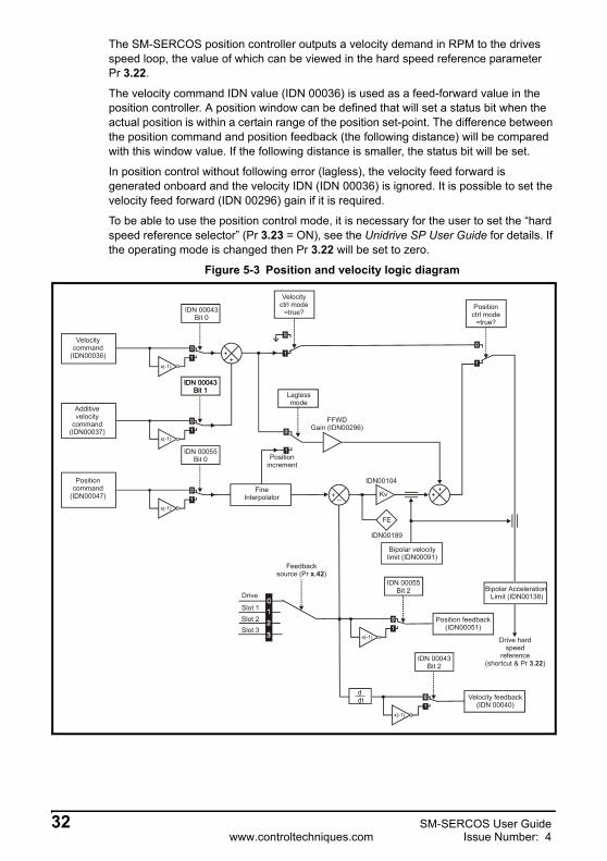
The SM-SERCOS position controller outputs a velocity demand in RPM to the drives speed loop, the value of which can be viewed in the hard speed reference parameter Pr 3.22.
The velocity command IDN value (IDN 00036) is used as a feed-forward value in the position controller. A position window can be defined that will set a status bit when the actual position is within a certain range of the position set-point. The difference between the position command and position feedback (the following distance) will be compared with this window value. If the following distance is smaller, the status bit will be set.
In position control without following error (lagless), the velocity feed forward is generated onboard and the velocity IDN (IDN 00036) is ignored. It is possible to set the velocity feed forward (IDN 00296) gain if it is required.
To be able to use the position control mode, it is necessary for the user to set the “hard speed reference selector” (Pr 3.23 = ON), see the Unidrive SP User Guide for details. If the operating mode is changed then Pr 3.22 will be set to zero.
Figure 5-3 Position and velocity logic diagram
x(-1)
x(-1)
++
x(-1)
Position command
(IDN00047)Fine
Interpolator + _ Kv
FE
++
Positionincrement
FFWDGain (IDN00296)
Laglessmode
Velocityctrl mode
=true?
Bipolar velocitylimit (IDN00091)
Bipolar Acceleration Limit (IDN00138)
Drive hard speed
reference (shortcut & Pr )3.22
Feedbacksource (Pr ) x.42
x(-1)
IDN 00055Bit 2
Positionctrl mode
=true?
Position feedback(IDN00051)
ddt
x(-1)
Velocity feedback(IDN 00040)
IDN 00043Bit 2
IDN 00055Bit 0
IDN 00043Bit 1
IDN 00043Bit 1
IDN 00043Bit 0
Drive
Slot 1Slot 2Slot 3
IDN00189
IDN00104
32 SM-SERCOS User Guidewww.controltechniques.com Issue Number: 4

Safety Inform
ationIntroduction
Mechanical
installationElectrical
installationG
etting started
IDN
sM
anufacture ID
Ns
Control and
Status Words
Procedure C
omm
andsD
ata Synchronisation
Advanced Features
Diagnostics
Quick
referenceG
lossary Of
Terms
Index
Figure 5-4 Torque logic diagram
x(-1)
++
IDN 00085Bit 0
x(-1)
IDN 00085Bit 1
x(-1)
Positionctrl mode=false?
Torque feedback(IDN 00084)
IDN 00085Bit 2
Bipolar torquelimit
(IDN 00092)
To drive torquereference (shortcut & Pr ) 4.08
SM-SERCOS User Guide 33Issue Number: 4 www.controltechniques.com

6 IDNs
6.1 What are IDNs?IDNs (IDentification Numbers) are a predefined list of SERCOS parameters. Several of the basic IDNs are used to set-up the network operating parameters, others are used specifically during slave configuration and the rest are used for normal data transaction handling. The additional manufacturer specific IDNs whilst still being defined by the SERCOS specification are used to set-up and/or control functions specific to the slave device.
Several of the basic IDNs are used to configure the timing sequences used within SERCOS.
The timing sequence within SERCOS is critical as all network operations are based upon it. Figure 6-1 shows a basic timing sequence chart for a SERCOS network.
Figure 6-1 SERCOS network timing sequence chart
For further details of the SERCOS refer to the official SERCOS web-site at www.sercos.de.
6.2 Supported IDNsThe SM-SERCOS module supports all of the necessary IDNs for class B compliance (with torque, velocity, position control modes, drive-controlled homing and the probe cycle functions). It also supports a variety of additional IDNs. The following is a list of all the IDNs supported by the SM-SERCOS.
MST AT1 AT2 ATn MDT
time
t1 - IDN 0006
t2 - IDN 0089
tScyc - IDN 0002
tATMT - IDN 0004 tMTSG - IDN 0090
tMTSY - IDN 0088
t4 - IDN 0007
t5 - IDN 0005
t1.min - IDN 0003
MST
t3 - IDN 0008
34 SM-SERCOS User Guidewww.controltechniques.com Issue Number: 4

Safety Inform
ationIntroduction
Mechanical
installationElectrical
installationG
etting started
IDN
sM
anufacture ID
Ns
Control and
Status Words
Procedure C
omm
andsD
ata Synchronisation
Advanced Features
Diagnostics
Quick
referenceG
lossary Of
Terms
Index
6.3 Summary of IDNs6.3.1 IDN - 00001
The control unit cycle time defines the cyclic intervals during which the control unit makes new command values available. The control unit cycle time must be transferred from the master to the slave during CP2 and becomes active in the slave during CP3. The control unit cycle time must be an integer multiple of the communication cycle time (IDN 00002). Values are 250µs, 500µs, 1ms up to 65ms in 1ms increments - any other value will cause the CP3 transition check to fail.
tNcyc = tScyc * n [n =1,2,3,4...]. The ratio of this value and the drive cycle time will determine the number of points for the fine interpolation.
6.3.2 IDN - 00002
The SERCOS network cycle time. Values are 250µs, 500µs, 1ms up to 65ms in 1ms increments - attempts to set any other value will cause the CP3 transition check to fail. MSTs are transmitted by the master on this timebase. This value shall be transferred from the master to the slave during CP2 and becomes active in the slave during CP3.
6.3.3 IDN - 00003
The time required by the SM-SERCOS module from the end of the MST until it is able to transmit its AT. Read by the master during CP2.
6.3.4 IDN - 00004
The time required by the slave to switch from transmitting the AT to receiving the MDT. This is read by the master in CP2 in order to calculate the starting time for an MST transmission (t2).
6.3.5 IDN - 00005
The master reads this value from the slave axes during CP2. This value specifies the process time required by the slave to acquire the feedback data and make it available to the SERCOS interface. In the case of SM-SERCOS the required process time is 90µs.
Name Control unit cycle time (tNcyc)
Size 2 bytes Units µs Access RWDefault 1000 Range 250 to 65000
Name Communication cycle time (tScyc)
Size 2 bytes Units µs Access RWDefault 1000 Range 250 to 65000
Name Shortest AT transmission starting time (t1.min)
Size 2 bytes Units µs Access RODefault 90 Range
Name Transmit/receive transition time (tATMT)
Size 2 bytes Units µs Access RODefault 10 Range
Name Minimum feedback processing time (t5)Size 2 bytes Units µs Access RODefault 90 Range
SM-SERCOS User Guide 35Issue Number: 4 www.controltechniques.com

This is read so that the master can synchronise the measurement times of the feedback acquisition capture point, t4 (IDN 00007) appropriately for all drive axes.
6.3.6 IDN - 00006
This is the time at which the SM-SERCOS module must transmit its AT after the end of the MST. This value is set by the master during CP2. Each drive will require a different setting for this IDN.
6.3.7 IDN - 00007
The master sets the acquisition capture point for the slave feedback to be less than or equal to the difference between the communication cycle time (IDN 00002) and the requested minimum feedback processing time (IDN 00005), i.e.
t4 ≤ tScyc-t5This is done to ensure that all the slave axes feedback sampling are synchronised.
6.3.8 IDN - 00008
This is the time point at which the command values (cyclic data) received in the last MDT become available for the drive to use.
6.3.9 IDN - 00009
This value will be set by the master during CP2. It is used to specify to a slave axis where the start byte position of its MDT data record is, i.e. the section of data it should use.
Name AT transmission starting time (t1)
Size 2 bytes Units µs Access RWDefault 90 Range 0 to 65000
Name Feedback acquisition capture point (t4)
Size 2 bytes Units µs Access RWDefault 0 Range 0 to 65000
The interval between t4 and t3 (see IDN 00008) will be checked in the CP3 transition check. If the time t3 occurs first in the same network cycle, there must be at least 15µs between t3 and t4. If the t4 occurs first in the network cycle, there must be at least 5µs between t3 and t4.
NOTE
Name Command value valid time (t3)
Size 2 bytes Units µs Access RWDefault 0 Range 0 to 65000
See note below IDN - 00007.NOTE
Name Position of data record in MDTSize 2 bytes Units N/A Access RWDefault 1 Range 1 to 63331
36 SM-SERCOS User Guidewww.controltechniques.com Issue Number: 4

Safety Inform
ationIntroduction
Mechanical
installationElectrical
installationG
etting started
IDN
sM
anufacture ID
Ns
Control and
Status Words
Procedure C
omm
andsD
ata Synchronisation
Advanced Features
Diagnostics
Quick
referenceG
lossary Of
Terms
Index
6.3.10 IDN - 00010
This is the length of the entire MDT (including the control word and service channel for each slave). The actual size of the MDT will depend upon how many slaves devices are on the network and how much cyclic data there is. The actual size of the MDT will be:
• 2 bytes per slave control word.• 2 bytes per slave service channel.• Each slave devices cyclic data, (the size of which depends upon the mode of
operation and whether any additional cyclic data is included by using Telegram type 7).
6.3.11 IDN - 00011
This diagnostic IDN provides a reason code for why a drive has tripped and disabled the motor output. The bits supported are as follows:
Name Length of MDTSize 2 bytes Units N/A Access RWDefault 4 Range 4 to 65534
Name Class 1 diagnosticSize 2 bytes Units N/A Access RODefault Range N/A
Bit 0: Overload shutdown. Set when an It.AC, It.br or O.Ld1 trip occurs.
Bit 1: Amplifier over-temperature shutdown. Set when an O.CtL, O.ht1, O.ht2, O.ht3, Oht2.P or Oht4.P trip occurs.
Bit 2: Motor over-temperature shutdown. Set when a th trip occurs.
Bit 3 and 4: Not supported.
Bit 5: Feedback error. Set when an Enc1 to Enc9, tunE7, tunE1, tunE2 or EnP.Err trip occurs.
Bit 6: Error in the communications system. Set when a tunE3 to tunE6 trip occurs.
Bit 7: Over-current error. Set when an OI.AC, OI.br, PS.10V, PS.24V, thS, OIbr.P, OIAC.P or OidC.P trip occurs.
Bit 8: Over-voltage error. Set when an OV or OV.P trip occurs.
Bit 9: Under-voltage error. Set when an UU or ACUU.P trip occurs.
Bit 10: Power supply phase error. Set when a Ph, PH.P or PS.P trip occurs.
Bit 11: Excessive position deviation. Set when the position error is greater than IDN 00159.
Bit 12: Communication error. Set if one of the error bits is set in IDN 00014.
Bit 13: Not supported.
Bit 14: Reserved.
Bit 15*: Manufacturer specific error. Set if a bit in IDN 00129 is set.
Bits 11, 12 and 15* are not associated with an actual drive trip condition therefore the drive will not trip and disable the motor when any of these bits are equal to a 1.
*Bit 15 will in effect cause a trip as the bits in IDN 00129 are associated with trips.
In system file versions V01.02.00 and after, bit 9 is now set for a UU trip condition.
NOTE
SM-SERCOS User Guide 37Issue Number: 4 www.controltechniques.com

6.3.12 IDN - 00012
This diagnostic IDN defines a drive warning. Not all of the bits contained here are supported. The ones that are, however, correspond to the drive alarm conditions. The following bits are supported:
6.3.13 IDN - 00013
This diagnostic IDN contains bits relating to the drive/module status. These are not error conditions. The supported bits are as follows:.
Name Class 2 diagnosticSize 2 bytes Units N/A Access RODefault Range N/A
Bit 0: Overload warning. Set when the br.rS (braking resistor overload) or OVLd (motor overload) alarm indications are set.
Bit 1: Amplifier over-temperature warning. Set when the Hot alarm indication is set.
Bit 2 to bit 14: Reserved or not supported.
Bit 15: Manufacturer specific warning. Set if a bit is set in IDN 00181.
Name Class 3 diagnosticSize 2 bytes Units N/A Access RODefault Range N/A
Bit 0: nfeedback = ncommand. Set when the velocity feedback is within range of the velocity command. Also see “Window Velocity” IDN - 00157 on page 56.
Bit 1: nfeedback = 0. Set when the velocity feedback is within range of zero.Also see “Standstill Window” IDN - 00124 on page 52.
Bit 2: |nfeedback| < |nx|. Set when the feedback velocity falls below the velocity threshold nxAlso see “Velocity Threshold” IDN - 00125 on page 53.
Bit 3: Not supported.
Bit 4: Set when the torque feedback exceeds IDN 00092.
Bit 5: |ncommand| > |nLimit|. Set when IDN 00036 + IDN 00037 exceeds IDN 00091
Bit 6: In Position. Set when IDN 00047 - IDN 00051 is less than IDN 00057.
Bit 7 to Bit 14: Reserved or not supported.
Bit 15: Manufacturer specific operation status. Set if a bit is set in IDN 00182.
38 SM-SERCOS User Guidewww.controltechniques.com Issue Number: 4

Safety Inform
ationIntroduction
Mechanical
installationElectrical
installationG
etting started
IDN
sM
anufacture ID
Ns
Control and
Status Words
Procedure C
omm
andsD
ata Synchronisation
Advanced Features
Diagnostics
Quick
referenceG
lossary Of
Terms
Index
6.3.14 IDN - 00014
When the SERCOS communications are healthy then bits 0 to 2 contain the actual communications phase number.
If an error occurs, then the following bits will be set as appropriate, in addition to this, bit 12 of IDN 00011 will also be set:
6.3.15 IDN - 00015
Defines the format of the AT and MDT. This is set by the master in CP2. The supported telegram types are as follows:
Name Interface statusSize 2 bytes Units N/A Access RODefault Range N/A
Bit 0 to Bit 2 Communication phase number.
Bit 3: MST failure.
Bit 4: MDT failure.
Bit 5: Invalid phase.
Bit 6: Error during phase downshift (not to phase 0).
Bit 7: Error during phase upshift (invalid sequence).
Bit 8: Phase switching without ready acknowledge.
Bit 9: Switching to uninitialised operation mode.
Bit 10: Drives with the same address in the ring.
Bit 11: Not supported.
Bit 12 to Bit 15: Reserved.
Name Telegram type parametersSize 2 bytes Units N/A Access RWDefault 4 Range 0 to 7
Type 0: No cyclic data.
Type 1: MDT - Torque command value. AT - No cyclic data.
Type 2: MDT - Velocity command value. AT - Velocity feedback value.
Type 3: MDT - Velocity command value. AT - Position feedback value.
Type 4: MDT - Position command value. AT - Position feedback value.
Type 5: MDT - Position and velocity command values. AT - Position and velocity feedback values.
Type 6: MDT - Velocity command value. AT - No cyclic data.
Type 7: User-defined data (See IDNs 00016 and 00024 for data contents).
Bit 3 is used to select position feedback (1 or 2) in the telegrams that return position feedback (except telegram type 7). This does not affect the source used for the SM-SERCOS APC.
NOTE
SM-SERCOS User Guide 39Issue Number: 4 www.controltechniques.com

6.3.16 IDN - 00016
This IDN is set by the master during CP2, but only if telegram type 7 is selected in IDN 00015 (specifies the IDNs when telegram type 7 is selected). However, the IDNs must be listed under IDN 00187; no other IDNs are allowed.
During the CP3 transition check a comparison is made between this IDN and IDN 00187, if IDN 00016 contains IDNs that are not listed within IDN 00187 the transition check will fail.
When using this IDN check that the total data length of these additional IDNs does not exceed that set in IDN 00185 (this is checked in the CP3 transmission cycle).
6.3.17 IDN - 00017
This lists all of the operation data IDNs (excluding procedure commands) supported by the SM-SERCOS module.
6.3.18 IDN - 00018
This is a list of operational IDNs that the master must set during CP2:
Name Configuration list of ATSize Variable Units N/A Access RWDefault Range N/A
Name IDN-list of all operation dataSize 236 bytes Units N/A Access RODefault Range N/A
This IDN does not include manufacturer specific IDNs as SM-SERCOS contains such a large number of these.
NOTE
Name IDN-list of operation data for CP2Size 28 bytes Units N/A Access RODefault Range N/A
00001 Control unit cycle time.
00002 Communication cycle time.
00006 AT transmission starting time.
00007 Feedback acquisition capture point.
00008 Command value valid time.
00009 Position of data record in MDT.
00010 Length of MDT.
00015 Telegram type parameter.
00032 Primary operation mode.
00033 Secondary operation mode 1.
00088 Receive to receive recovery time.
00089 MDT transmission starting time.
IDNs 00016 and 00024 are also required when telegram type 7 is set in IDN 00015.NOTE
40 SM-SERCOS User Guidewww.controltechniques.com Issue Number: 4

Safety Inform
ationIntroduction
Mechanical
installationElectrical
installationG
etting started
IDN
sM
anufacture ID
Ns
Control and
Status Words
Procedure C
omm
andsD
ata Synchronisation
Advanced Features
Diagnostics
Quick
referenceG
lossary Of
Terms
Index
6.3.19 IDN - 00019
This is a list of operational IDNs that the master must set during CP3.
Currently the SM-SERCOS does not require any operational IDNs to be set during CP3 and this list is inactive.
6.3.20 IDN - 00021
This IDN is used during the CP2 to CP3 transition check (see “IDN - 00127” on page 53) to list any of the IDNs that should have been set during CP2 (as listed in IDN 00018) that failed.
6.3.21 IDN - 00022
This IDN is used during the CP3 to CP4 transition check (see “IDN - 00128” on page 53) to list any of the IDNs that should have been set during CP3 (as listed in IDN 00019) that failed.
Currently the SM-SERCOS does not require any operational IDNs to be set during CP3 and therefore no failure should be reported.
6.3.22 IDN - 00024
This IDN is set by the master during CP2, but only if telegram type 7 is selected in IDN 00015, this then specifies the IDNs used when using telegram type 7. However, the IDNs must be listed under IDN 00188; no other IDNs are allowed.
During the CP3 transition check, a comparison is made between this IDN and IDN 00188, if IDN 00024 contains IDNs that are not listed within IDN 00188 the transition check will fail.
When using this IDN check that the total data length of these additional IDNs does not exceed that set in IDN 00186. This is also checked during the CP3 transition check.
Name IDN-list of operation data for CP3Size 0 Units N/A Access RODefault Range N/A
Name IDN-list of invalid operation data, CP2Size Variable Units N/A Access RODefault Range N/A
Name IDN-list of invalid operation data, CP3Size Variable Units N/A Access RODefault Range N/A
Name Configuration list of MDTSize 2,Variable Units N/A Access RWDefault Range N/A
SM-SERCOS User Guide 41Issue Number: 4 www.controltechniques.com

6.3.23 IDN - 00025
This IDN contains a list of procedure command IDNs supported by SM-SERCOS, which are as follows:
See Procedure Commands on page 73 for details on each supported procedure command.
6.3.24 IDN - 00028
This IDN is used to count invalid MSTs in CP3 and CP4. If two consecutive invalid MSTs are detected, all future MSTs will not be counted and the SM-SERCOS will return to CP0 and will disable the drive. This value is reset to zero on a transition from CP2 to CP3.
6.3.25 IDN - 00029
This IDN is used to count invalid MDTs during CP4. If two consecutive invalid MDTs are detected, all future MDTs will not be counted and the SM-SERCOS will return to CP0 thus disabling the drive. This value is reset to zero on a transition from CP2 to CP3.
6.3.26 IDN - 00030
This IDN contains a string that is made up from the module name and its system file version, the drive type and its firmware version number, e.g.
“CT SM-SERCOS V01.00.00. Unidrive SP V01.07.01.”
The SM-SERCOS version number is derived from Pr MM.02 and Pr MM.51. The Unidrive SP version number is derived from Pr 11.29 and Pr 11.34.
Name IDN-list of all procedure commandsSize 16 bytes Units N/A Access RODefault Range N/A
00099 Reset class 1 diagnostic.
00127 CP3 transition check.
00128 CP4 transition check.
00148 Drive-controlled homing procedure command.
00170 Probing cycle procedure command.
00191 Cancel reference point procedure command.
Name MST error counterSize 2 bytes Units N/A Access RODefault Range 0 to 65535
Name MDT error counterSize 2 bytes Units N/A Access RODefault Range 0 to 65535
Name Manufacturer versionSize 50 bytes Units N/A Access RODefault Range N/A
42 SM-SERCOS User Guidewww.controltechniques.com Issue Number: 4

Safety Inform
ationIntroduction
Mechanical
installationElectrical
installationG
etting started
IDN
sM
anufacture ID
Ns
Control and
Status Words
Procedure C
omm
andsD
ata Synchronisation
Advanced Features
Diagnostics
Quick
referenceG
lossary Of
Terms
Index
6.3.27 IDN - 00032
This IDN is set by the master during CP2 and is used to set the SM-SERCOS primary mode of operation. Only the modes listed in IDN 00292 will be available to be set.The primary or secondary mode selection is controlled in the MDT control word.
6.3.28 IDN - 00033
This IDN is set by the master during CP2 and is used to set the SM-SERCOS secondary mode of operation. Only the modes listed in IDN 00292 will be available to be set. The primary or secondary mode selection is controlled in the MDT control word.
6.3.29 IDN - 00036
The velocity reference in velocity control mode. If bit 0 in IDN 00043 is set, the value will be negated. This will be written to the hard speed reference parameter or the position controller external speed feedforward after being summed with IDN 00037 and then converted to the drive internal units (encoder counts / 250µs). In velocity control mode, this value (scaled) will also be written to the user hard speed reference parameter during the background task to give a user indication.
6.3.30 IDN - 00037
This IDN is used when operating a slave axis in velocity control mode and is used to add a velocity offset. The value of this offset will be added to the value of IDN 00036 by the slave.
6.3.31 IDN - 00040
The SM-SERCOS sources the speed feedback direct from the Unidrive SP speed loop as it is quicker than Pr 3.02 (which is only updated every 4ms) This value is then transferred from the slave to the master as part of the AT cyclic data.
Name Primary operation modeSize 2 bytes Units N/A Access RWDefault 3 Range See IDN 00292
Name Secondary operation mode 1Size 2 bytes Units N/A Access RWDefault 3 Range See IDN 00292
Care should be taken when switching between primary and secondary operation modes when the drive is enabled.
Name Velocity command valueSize 4 bytes Units See IDN 00044 Access RWDefault 0 Range See IDN 00044
CAUTION
Name Additive velocity command valueSize 4 bytes Units See IDN 00044 Access RWDefault 0 Range See IDN 00044
Name Velocity feedback value 1Size 4 bytes Units See IDN 00044 Access RODefault Range See IDN 00044
SM-SERCOS User Guide 43Issue Number: 4 www.controltechniques.com

6.3.32 IDN - 00041
The homing velocity is used during the drive controlled homing procedure command (IDN 00148). When enabled the drive then performs its own homing routine.
6.3.33 IDN - 00042
The homing acceleration is used during the drive controlled homing procedure command (IDN 00148). When enabled the drive then performs it’s own homing routine.
6.3.34 IDN - 00043
The IDN invert bits of this IDN are used to change the sign of the velocity data going into the Unidrive SP speed loop, it will also change the sign of the data produced by the Unidrive SP speed loop.
A positive velocity with no inversion programmed here means that the motor shaft will rotate in a clockwise direction (as viewed from the motor shaft).
Name Homing velocitySize 4 bytes Units See IDN 00044 Access RWDefault 4096 Range See IDN 00044
Name Homing accelerationSize 4 bytes Units See IDN 00160 Access RWDefault 65536 Range See IDN 00160
Name Velocity polarity parameterSize 2 bytes Units N/A Access RWDefault 0 Range N/A
Bit 0: Velocity command value (IDN 00036)0 - Non-inverted1 - Inverted
Bit 1: Additive velocity command value (IDN 00037)0 - Non-inverted1 - Inverted
Bit 2: Velocity feedback value 1(IDN 00040)0 - Non-inverted1 - Inverted
Bit 3 to Bit 15: Reserved or not supported
44 SM-SERCOS User Guidewww.controltechniques.com Issue Number: 4

Safety Inform
ationIntroduction
Mechanical
installationElectrical
installationG
etting started
IDN
sM
anufacture ID
Ns
Control and
Status Words
Procedure C
omm
andsD
ata Synchronisation
Advanced Features
Diagnostics
Quick
referenceG
lossary Of
Terms
Index
6.3.35 IDN - 00044
The SM-SERCOS does not use any scaling, therefore the value of this IDN is fixed. As there is no scaling all velocity related IDN values are specified in encoder counts per second, such as:
• The bipolar velocity limit (IDN 00091).• The standstill window (IDN 00124).• The velocity threshold (IDN 00125).• The velocity window (IDN 00157).
6.3.36 IDN - 00045
Defines the scaling factor for all velocity data. This is fixed at a value of 1.
6.3.37 IDN - 00046
Defines the scaling exponent for all velocity data. This is fixed at a value of 0.
6.3.38 IDN - 00047
This IDN is used by the master during CP4 to send the slave axes that are operating in position control mode their position references.
The SM-SERCOS will convert and if necessary interpolate this data (depending if the master and network cycle times are different to the drive, i.e. 250µs) and pass it in to the SM-SERCOS position controller.
Name Velocity data scaling typeSize 2 bytes Units N/A Access RODefault 0 Range N/A
The maximum rpm rating of the Unidrive SP is 40,000rpm, therefore all velocity data values will have a range of ±MAX, where MAX is the equivalent of the ±40,000rpm in encoder counts per second the value of which will depend upon the resolution of the feedback device used and the number of turns bits set in Pr MM.43 (see Chapter 5.3.8 Encoder turn bits on page 27).
NOTE
Name Velocity data scaling factorSize 2 bytes Units N/A Access RODefault 1 Range
Name Velocity data scaling exponentSize 2 bytes Units N/A Access RODefault 0 Range
Name Position command valueSize 4 bytes Units See IDN 00076 Access RWDefault 0 Range -231 to +231-1
SM-SERCOS User Guide 45Issue Number: 4 www.controltechniques.com

6.3.39 IDN - 00051
The SM-SERCOS sources the position feedback direct from the Unidrive SP encoder input or optional Solution Module feedback device as selected by Pr MM.42. This value is then transferred from the slave to the master as part of the AT cyclic data.
6.3.40 IDN - 00052
This IDN is used during the drive controlled homing procedure (see IDN - 00148 on page 56). Once a homing command has been initiated the SM-SERCOS monitors the position feedback marker pulse.
6.3.41 IDN - 00053
This IDN is provided to allow access to a second encoder (if fitted) for applications requiring one and a half axis control. It can be used for cyclic or non-cyclic position feedback, but cannot be used by the SERCOS APC (position control) as a feedback source.This IDN will be mapped to the position feedback selected by Pr MM.11(second encoder source), the value will be negated if bit 3 in IDN 00055 is set and the value will be zeroed if the second encoder is disabled in Pr MM.10 (second encoder enable). Pr MM.12 (second encoder turns bits) will specify the number of turns bits in the external encoder position.
6.3.42 IDN - 00055
The IDN invert bits of this IDN are used to change the sign of the position data going into the position loop, it will also change the sign of the data produced by the SM-SERCOS position loop.
Moving from a negative or zero position value to a positive position value, with no inversion programmed here, will cause the motor shaft to rotate in a clockwise direction (as viewed from the motor shaft).
Name Position feedback valueSize 4 bytes Units See IDN 00076 Access RWDefault Range -231 to +231-1
Name Reference distance 1Size 4 bytes Units See IDN 00076 Access RWDefault 0 Range -231 to +231-1
Name Position feedback value 2 (external feedback)Size 4 bytes Units See IDN 00076 Access RDefault 0 Range -231 to +231-1
Name Position polarity parametersSize 2 bytes Units N/A Access RWDefault 0 Range N/A
Bit 0: Position command value (IDN 00047)0 - Non-inverted1 - Inverted
Bit 1: Not supported
Bit 2: Position feedback value 1 (IDN 00051).0 - Non-inverted1 - Inverted
46 SM-SERCOS User Guidewww.controltechniques.com Issue Number: 4

Safety Inform
ationIntroduction
Mechanical
installationElectrical
installationG
etting started
IDN
sM
anufacture ID
Ns
Control and
Status Words
Procedure C
omm
andsD
ata Synchronisation
Advanced Features
Diagnostics
Quick
referenceG
lossary Of
Terms
Index
6.3.43 IDN - 00057
When the position feedback value is within a range of the position command value defined by this IDN, the "In Position" bit in the class 3 diagnostic IDN is set, otherwise the bit is cleared. This IDN defines the distance either side of the position command value.
6.3.44 IDN - 00076
SM-SERCOS does not use any scaling for position data, therefore the value of this IDN will always be 0. As there is no scaling the position is defined as a combination of encoder revolutions, coarse position and fine position. See Encoder turn bits on page 27 for further details.
6.3.45 IDN - 00079
This IDN defines the resolution for all rotational position data. The value represents the number of encoder counts in one revolution which is derived from the number of turns bits Pr MM.43. See Encoder turn bits on page 27 for further details.
6.3.46 IDN - 00080
This IDN is used by the master during CP4 to send the slave axes that are operating in torque control mode their torque references.
The SM-SERCOS will pass this value to the Unidrive SP torque reference Pr 4.08.
6.3.47 IDN - 00081
This IDN is used when operating a slave axis in torque control mode and is used to add a torque offset. The value of this offset will be added to the value of IDN 00080 by the slave.
Bit 3: Position feedback value 2 (IDN 00053).0 - Non-inverted1 - Inverted
Bit 4 to Bit 15: Reserved or not supported
Name Position windowSize 4 bytes Units See IDN 00076 Access RWDefault 0 Range 0 to +231-1
Name Position data scaling typeSize 2 bytes Units N/A Access RODefault 0 Range N/A
Name Rotational position resolutionSize 4 bytes Units N/A Access RODefault Range 1 to +231-1
Name Torque command valueSize 2 bytes Units See IDN 00086 Access RWDefault 0 Range -10000 to +10000
Name Additive torque command valueSize 2 bytes Units See IDN 00086 Access RWDefault 0 Range -10000 to +10000
SM-SERCOS User Guide 47Issue Number: 4 www.controltechniques.com

6.3.48 IDN - 00084
This IDN does not quite function as its name implies. It returns the sum of IDN 00080 added to IDN 00081. This value is then transferred from the slave to the master as part of the AT cyclic data, the calculation is as follows:
IDN 00084 = IDN 00080 + IDN 00081
6.3.49 IDN - 00085
The IDN invert bits of this IDN are used to change the sign of the torque data going into Unidrive SP current loop, it will also change the sign of the data produced by the Unidrive SP current loop.
A positive torque when the motor shaft is not moving, with no inversion programmed, will cause the motor shaft to rotate in a clockwise direction (as viewed from the motor shaft).:
6.3.50 IDN - 00086
The SM-SERCOS only uses percentage scaling for torque values, therefore the value of this IDN will always be 0. All of the torque related IDN values are specified in units of 0.1% of the motor rated torque, for example:
A torque value of 105 = 10.5%.
6.3.51 IDN - 00088
The master reads this value from the slave axes during CP2. The value of this IDN specifies the time required by a slave between the receipt of the MDT and the next MST.
Name Torque feedback valueSize 2 bytes Units See IDN 00086 Access RWDefault Range -10000 to +10000
Name Torque polarity parameterSize 2 bytes Units N/A Access RWDefault 0 Range N/A
Bit 0: Torque command value (IDN 00080)0 - Non-inverted1 - Inverted
Bit 1: Additive torque command value (IDN 00081)0 - Non-inverted1 - Inverted
Bit 2: Torque feedback value 1(IDN 00084)0 - Non-inverted1 - Inverted
Bit 3 to Bit 15: Reserved or not supported
Name Torque/force data scaling typeSize 2 bytes Units N/A Access RODefault 0 Range N/A
Name Receive to receive recovery time (tMTSY)
Size 2 bytes Units µs Access RODefault 10 Range
48 SM-SERCOS User Guidewww.controltechniques.com Issue Number: 4

Safety Inform
ationIntroduction
Mechanical
installationElectrical
installationG
etting started
IDN
sM
anufacture ID
Ns
Control and
Status Words
Procedure C
omm
andsD
ata Synchronisation
Advanced Features
Diagnostics
Quick
referenceG
lossary Of
Terms
Index
6.3.52 IDN - 00089
The master writes this value to the slave axes during CP2. The value of this IDN specifies the time at which the master will transmit the MDT during CP3 and CP4. It is then used by the slaves to check that the MDT is received on time.
6.3.53 IDN - 00090
The master reads this value from the slave axes during CP2 to calculate a valid time value for t3 (IDN 0003). The value of this IDN specifies the time period required by the SM-SERCOS module to process the cyclic data received in the MDT. Once the cyclic data / command values have been processed they will be executed between the time periods t3 and t4.
6.3.54 IDN - 00091
This is the maximum allowed velocity in the positive or negative direction. This value is checked by the SM-SERCOS module and if it is exceeded, bit 5 in the class 3 diagnostic IDN will be set.
6.3.55 IDN - 00092
This is the maximum allowed torque in the positive or negative direction. This value is checked by the SM-SERCOS module and if it is exceeded, bit 4 in the class 3 diagnostic IDN will be set.
6.3.56 IDN - 00095
This IDN contains a string relating to the status of the SM-SERCOS module. It will contain one of the following messages:
Name MDT transmission starting time (t2)
Size 2 bytes Units µs Access RWDefault 0 Range 0 to tScyc
Name Command value proceeding time (tMTSG)
Size 2 bytes Units µs Access RODefault 10 Range
Name Bipolar velocity limit valueSize 4 bytes Units See IDN 00044 Access RWDefault 3276800 Range See IDN 00044
Name Bipolar torque limit valueSize 2 bytes Units See IDN 00086 Access RWDefault 10000 Range 0 to +10000
Name Diagnostic messageSize Variable Units N/A Access RODefault Range N/A
Status IDN 00095 message stringAfter entering CP2: "Communication phase 2 ready"After entering CP3: "Communication phase 3 ready"After entering CP4: "Communication phase 4 ready"After procedure command 99 has finished: "No Error"
SM-SERCOS User Guide 49Issue Number: 4 www.controltechniques.com

6.3.57 IDN - 00096
If used the master reads this value from the slaves during CP2. The SM-SERCOS can only be used with a Unidrive SP which is a single axis drive therefore this IDN will return the SM-SERCOS network address in each byte, e.g. 101HEX or 257DEC
6.3.58 IDN - 00097
This IDN contains mask bits that are directly related to the class 2 diagnostic IDN 00012. However, clearing a mask bit does not disable the equivalent diagnostic bit it just prevents that bit causing the class 2 change bit in the AT status word from being set (see AT Status word on page 72). This is set to zero by default.
6.3.59 IDN - 00098
This IDN contains mask bits that are directly related to the class 3 diagnostic IDN 00013. However, clearing a mask bit does not disable the equivalent diagnostic bit it just prevents that bit causing the class 3 change bit in the AT status word from being set (see AT Status word on page 72). This is set to zero by default.
6.3.60 IDN - 00099
This IDN when set will reset the following status:
• Class 1 diagnostic (IDN 00011).• Interface error (IDN 00014).
IDN 00014 Bit 3 is set: “Error: MST failure”IDN 00014 Bit 4 is set: “Error: MDT failure”IDN 00014 Bit 5 is set: “Error: Invalid phase”IDN 00014 Bit 6 is set: “Error during phase upshift”IDN 00014 Bit 7 is set: “Error during phase downshift”IDN 00014 Bit 8 is set: “Error: Phase switching without ready acknowledge
IDN 00014 Bit 10 is set: “Error: 2 drives with same address in the ring”.If an optical fibre break
has occurred: “Error: optical fibre break”
If the SERCON DPRAMfails to be initialised: “Error on SERCON initialisation”
Status IDN 00095 message string
Name Slave arrangement (SLKN)Size 2 bytes Units N/A Access RODefault Range N/A
Name Mask class 2 diagnosticSize 2 bytes Units N/A Access RWDefault 0 Range N/A
Name Mask class 3 diagnosticSize 2 bytes Units N/A Access RWDefault 0 Range N/A
Name Reset class 1 diagnosticSize 2 bytes Units N/A Access RWDefault Range N/A
50 SM-SERCOS User Guidewww.controltechniques.com Issue Number: 4

Safety Inform
ationIntroduction
Mechanical
installationElectrical
installationG
etting started
IDN
sM
anufacture ID
Ns
Control and
Status Words
Procedure C
omm
andsD
ata Synchronisation
Advanced Features
Diagnostics
Quick
referenceG
lossary Of
Terms
Index
• Manufacturer class 1 diagnostic (IDN 00129).• Drive shut down bit (AT status word bit 13).• Will attempt to clear a drive trip.
This will be possible if there is no active trip condition currently set in the drive (and no other error condition that would cause bits to be set in the above IDNs).
6.3.61 IDN - 00100
The value of this IDN is mapped directly to the Unidrive SP speed loop proportional gain Pr 3.10. The Unidrive SP has multiple sets of PID gains but it is only possible to control the primary set over the SERCOS network, therefore the gain selector Pr 3.16 should be set to 0.
6.3.62 IDN - 00101
The value of this IDN is mapped directly to the Unidrive SP speed loop integral gain Pr 3.11. The Unidrive SP has multiple sets of PID gains but it is only possible to control the primary set over the SERCOS network, therefore the gain selector Pr 3.16 should be set to 0.
6.3.63 IDN - 00102
The value of this IDN is mapped directly to the Unidrive SP speed loop differential gain Pr 3.12. The Unidrive SP has multiple sets of PID gains but it is only possible to control the primary set over the SERCOS network, therefore the gain selector Pr 3.16 should be set to 0.
6.3.64 IDN - 00104
The position loop proportional gain. This is mapped directly to the SM-SERCOS position controller.
Name Velocity loop proportional gainSize 2 bytes Units 10-4 (1/rads-1) Access RW
Default Range 0 to 65535
Control of the secondary PID gains is possible using the manufacturer specific IDNs.NOTE
Name Velocity loop integral gainSize 2 bytes Units 10-2 (1/rads) Access RW
Default Range 0 to 65535
Control of the secondary PID gains is possible using the manufacturer specific IDNs.NOTE
Name Velocity loop differential timeSize 2 bytes Units 10-5 s Access RW
Default Range 0 to 65535
This value is a gain and not a time.NOTE
Name Position loop Kv-factorSize 2 bytes Units 10-4 Access RW
Default 2500 Range 0 to 65535
SM-SERCOS User Guide 51Issue Number: 4 www.controltechniques.com

6.3.65 IDN - 00106
The value of this IDN is mapped directly to the Unidrive SP Pr 4.13.
6.3.66 IDN - 00107
The value of this IDN is mapped directly to the Unidrive SP Pr 4.14.
6.3.67 IDN - 00109
The value of this IDN is derived from Pr 4.18 (the overriding current limit, a percentage) but is multiplied by the value of Pr 5.07 (the motor rated current, in Amps) and scaled to mA by SM-SERCOS.
6.3.68 IDN - 00110
The value of this IDN is derived from Pr 11.32 but is multiplied by 2.2 (the maximum drive current) scaled to mA by SM-SERCOS.
6.3.69 IDN - 00112
The value of this IDN is derived from Pr 11.32 but is scaled to mA by SM-SERCOS.
6.3.70 IDN - 00114
The value of this IDN is derived from Pr 5.07 but is scaled to mA by SM-SERCOS. The overload warning bit in the class 2 diagnostic (IDN 00012) is set once the Unidrive SP Pr 10.17 Overload alarm is set. See the Unidrive SP Advanced User Guide for details on the how the I2t alarm operates.
Name Current loop proportional gain 1Size 2 bytes Units N/A Access RWDefault Range 0 to 30000
Name Current loop integral gain 1Size 2 bytes Units N/A Access RWDefault Range 0 to 30000
Name Motor peak currentSize 4 bytes Units mA Access RODefault Range 0 to 232-1
Name Amplifier peak currentSize 4 bytes Units mA Access RODefault Range 0 to 232-1
Name Amplifier rated currentSize 4 bytes Units mA Access RODefault Range 0 to 232-1
Name Load limit of the motorSize 4 bytes Units mA Access RODefault Range 0 to 232-1
52 SM-SERCOS User Guidewww.controltechniques.com Issue Number: 4

Safety Inform
ationIntroduction
Mechanical
installationElectrical
installationG
etting started
IDN
sM
anufacture ID
Ns
Control and
Status Words
Procedure C
omm
andsD
ata Synchronisation
Advanced Features
Diagnostics
Quick
referenceG
lossary Of
Terms
Index
6.3.71 IDN - 00124
This IDN is used when detecting the zero speed condition. This value is checked by the SM-SERCOS module and if the magnitude of the difference between zero speed and the velocity feedback is less than this IDN, then bit 1 in the class 3 diagnostic (IDN 00013) will be set.
6.3.72 IDN - 00125
This IDN is used when detecting the velocity threshold. This value is checked by the SM-SERCOS module and if the magnitude falls below this value, bit 2 in class 3 diagnostic (IDN 00013) will be set.
6.3.73 IDN - 00127
This IDN is used to check that the SM-SERCOS module and Unidrive SP are ready to enter CP3. The master must execute this procedure command before entering CP3. If the drive/module is ready to enter CP3, it will give a positive acknowledgement to the procedure command. If it is not ready, it will give an acknowledgement "procedure command not yet executed". If some of the required IDNs have not been set (see IDN 00018), it will give a negative acknowledgement "Error, procedure command execution impossible", and a list of the IDNs that are still required will be placed in the list IDN 00021.
6.3.74 IDN - 00128
This IDN is used to check that the SM-SERCOS module and Unidrive SP are ready to enter CP4. The master must execute this procedure command before entering CP4. If the drive/module is ready to enter CP4, it will give a positive acknowledgement to the procedure command. If it is not ready, it will give an acknowledgement "procedure command not yet executed". If some of the required IDNs have not been set (See IDN 00019), it will give a negative acknowledgement "Error, procedure command execution impossible", and a list of the IDNs that are still required will be placed in IDN 00022. The negative acknowledgement will also be given if the module is not the synchronisation master (or if its synchronisation signal is not within the correct specification).
Name Standstill windowSize 4 bytes Units See IDN 00044 Access RWDefault 0 Range See IDN 00044
Name Velocity thresholdSize 4 bytes Units See IDN 00044 Access RWDefault 0 Range See IDN 00044
Name CP3 Transition checkSize 2 bytes Units N/A Access RWDefault Range N/A
Name CP4 Transition checkSize 2 bytes Units N/A Access RWDefault Range N/A
SM-SERCOS User Guide 53Issue Number: 4 www.controltechniques.com

6.3.75 IDN - 00129
This diagnostic IDN provides a reason code for why a drive has tripped and disabled the motor output. It specifies other errors that are more specific to the Unidrive SP not covered by the error codes in the Class 1 diagnostic (IDN 00011). These are all drive trips:
6.3.76 IDN - 00130
This will contain the position value saved when a positive edge occurred at the probe 1 input and the probe cycle procedure command is active, the Probe 1 enable bit is set and bit 0 in the probe control parameter (IDN 00169) is set.
6.3.77 IDN - 00131
This will contain the position value saved when a negative edge occurred at the probe 1 input only when the probe cycle procedure command is active, the probe 1 enable bit is set and bit 1 in the probe control parameter (IDN 00169) is set.
Name Manufacturer class 1 diagnosticSize 2 bytes Units N/A Access RODefault Range N/A
Bit 0: User Error. Set when a trip t010, t038, t040 to t089, t099, t111 to t160, t168 to t175 or a t216 occurs.
Bit 1: User Program Error. Set when a trip UP div0, UP Par, UP ro, UP So, UP ovr, UP OFL, UP uSEr, UP udf or a UP ACC occurs.
Bit 2: Solutions Module Error. Set when trip a SL1.HF, SL1.To, SL1.Er, SL1.nF, SL1.dF, SL2.HF, SL2.tO, SL2.Er, SL2.nF, SL2.dF, SL3.HF, SL3.tO, SL3.Er, SL3.nF, SL3.dF or a SL.rtd occurs.
Bit 3: Smartcard Error. Set when trip a C.Boot, C.BUsy, C.Chg, C.Optn, C.RdO, C.Err, C.dat, C.FULL, C.Acc, C.rtg, C.Typ or a C.cpr occurs.
Bit 4: Hardware Error. Set when trip a HF17 to HF32 occurs.
Bit 5: Miscellaneous Error. Set when a trip a PS, Et, OSPd, tunE, cL2, cL3, SCL, EEF, rS, PAd, CL.bit, SAVE.Er, PSAVE.Er, L.SYNC, Unid.P or a dESt occurs.
Bit 6: Set if any other trip code occurs.
Bit 7 to Bit 15: Reserved or not supported.
Name Probe value 1 positive edgeSize 4 bytes Units See IDN 00076 Access RODefault Range -231 to +231-1
Name Probe value 1 negative edgeSize 4 bytes Units See IDN 00076 Access RODefault Range -231 to +231-1
54 SM-SERCOS User Guidewww.controltechniques.com Issue Number: 4

Safety Inform
ationIntroduction
Mechanical
installationElectrical
installationG
etting started
IDN
sM
anufacture ID
Ns
Control and
Status Words
Procedure C
omm
andsD
ata Synchronisation
Advanced Features
Diagnostics
Quick
referenceG
lossary Of
Terms
Index
6.3.78 IDN - 00132
This will contain the position value saved when a positive edge occurred at the probe 2 input and the probe cycle procedure command is active, the probe 2 enable bit is set and bit 2 in the probe control parameter (IDN 00169).
6.3.79 IDN - 00133
This will contain the position value saved when a negative edge occurred at the probe 2 input and the probe cycle procedure command is active, the probe 2 enable bit is set and bit 3 in the probe control parameter (IDN 00169) is set.
6.3.80 IDN - 00134
This IDN value will contain the value of the last control word received in the master from the MDT.
6.3.81 IDN - 00135
This IDN value will contain the current value of the status word to be transmitted to the master in the AT (but not including the service channel status bits, which are generated by the SM-SERCOS hardware).
6.3.82 IDN - 00138
This IDN value will be used on the speed output of the position controller. If the acceleration generated exceeds this value, it will be limited. This limit applies when operating in the position and velocity modes, but not in torque control mode.
6.3.83 IDN - 00142
This will contain the string "CT SM-SERCOS Slave for Uni SP."
Name Probe value 2 positive edgeSize 4 bytes Units See IDN 00076 Access RODefault Range -231 to +231-1
Name Probe value 2 negative edgeSize 4 bytes Units See IDN 00076 Access RODefault Range -231 to +231-1
Name MDT control wordSize 2 bytes Units N/A Access RODefault Range N/A
Name AT status wordSize 2 bytes Units N/A Access RODefault Range N/A
Name Bipolar acceleration limit valueSize 4 bytes Units See IDN 00160 Access RWDefault 2147483647 Range 0 to +231-1
Name Application typeSize 34 bytes Units N/A Access RODefault Range N/A
SM-SERCOS User Guide 55Issue Number: 4 www.controltechniques.com
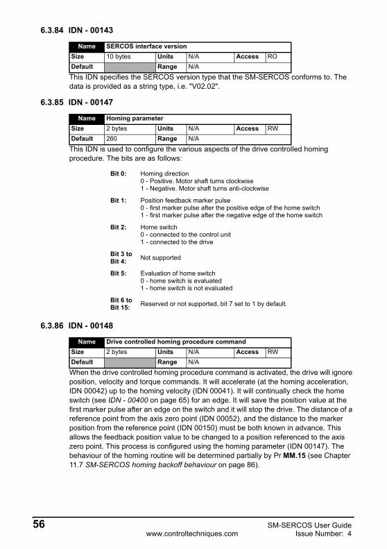
6.3.84 IDN - 00143
This IDN specifies the SERCOS version type that the SM-SERCOS conforms to. The data is provided as a string type, i.e. "V02.02".
6.3.85 IDN - 00147
This IDN is used to configure the various aspects of the drive controlled homing procedure. The bits are as follows:
6.3.86 IDN - 00148
When the drive controlled homing procedure command is activated, the drive will ignore position, velocity and torque commands. It will accelerate (at the homing acceleration, IDN 00042) up to the homing velocity (IDN 00041). It will continually check the home switch (see IDN - 00400 on page 65) for an edge. It will save the position value at the first marker pulse after an edge on the switch and it will stop the drive. The distance of a reference point from the axis zero point (IDN 00052), and the distance to the marker position from the reference point (IDN 00150) must be both known in advance. This allows the feedback position value to be changed to a position referenced to the axis zero point. This process is configured using the homing parameter (IDN 00147). The behaviour of the homing routine will be determined partially by Pr MM.15 (see Chapter 11.7 SM-SERCOS homing backoff behaviour on page 86).
Name SERCOS interface versionSize 10 bytes Units N/A Access RODefault Range N/A
Name Homing parameterSize 2 bytes Units N/A Access RWDefault 260 Range N/A
Bit 0: Homing direction0 - Positive. Motor shaft turns clockwise1 - Negative. Motor shaft turns anti-clockwise
Bit 1: Position feedback marker pulse0 - first marker pulse after the positive edge of the home switch1 - first marker pulse after the negative edge of the home switch
Bit 2: Home switch0 - connected to the control unit1 - connected to the drive
Bit 3 to Bit 4: Not supported
Bit 5: Evaluation of home switch0 - home switch is evaluated1 - home switch is not evaluated
Bit 6 to Bit 15: Reserved or not supported, bit 7 set to 1 by default.
Name Drive controlled homing procedure commandSize 2 bytes Units N/A Access RWDefault Range N/A
56 SM-SERCOS User Guidewww.controltechniques.com Issue Number: 4

Safety Inform
ationIntroduction
Mechanical
installationElectrical
installationG
etting started
IDN
sM
anufacture ID
Ns
Control and
Status Words
Procedure C
omm
andsD
ata Synchronisation
Advanced Features
Diagnostics
Quick
referenceG
lossary Of
Terms
Index
6.3.87 IDN - 00150
This IDN defines the distance between the reference marker pulse and the reference point. It is used in the drive controlled homing procedure to calculate the new position feedback value relative to the machine zero point.
6.3.88 IDN - 00157
This IDN is used when detecting the difference between the total velocity command value and the velocity feedback. This difference is then checked by the SM-SERCOS module and if the magnitude is less than this IDN the bit 0 in the class 3 diagnostic (IDN 00013) will be set.
6.3.89 IDN - 00159
This IDN is used to define a maximum allowable position deviation. If the position error (difference between the position command and feedback) exceeds this value, the excessive position error bit 11 in the class 1 diagnostic (IDN 0011) will be set.
6.3.90 IDN - 00160
The SM-SERCOS does not use any scaling, therefore the value of this IDN will always be 0. As there is no scaling all of the acceleration data will be specified in units of encoder counts per second per second (counts/second2).
6.3.91 IDN - 00161
This IDN defines the scaling factor for all acceleration data. This is fixed at a value of 1.
6.3.92 IDN - 00162
This IDN defines the scaling exponent for all acceleration data. The is fixed at a value of 0.
Name Reference offset 1Size 4 bytes Units See IDN 00076 Access RWDefault 0 Range -231 to +231-1
Name Velocity windowSize 4 bytes Units Access RWDefault 0 Range See IDN 00044
Name Monitoring windowSize 4 bytes Units See IDN 00076 Access RWDefault 2147483647 Range 0 to 231-1
Name Acceleration data scaling typeSize 2 bytes Units N/A Access RODefault 0 Range -231 to 231-1
Name Acceleration data scaling factorSize 2 bytes Units N/A Access RODefault 1 Range
Name Acceleration data scaling exponentSize 2 bytes Units N/A Access RODefault 0 Range
SM-SERCOS User Guide 57Issue Number: 4 www.controltechniques.com

6.3.93 IDN - 00169
This specifies the selected probes and edges for the probing cycle procedure command:
6.3.94 IDN - 00170
This IDN can be set by the master to enable the probing cycle procedure, which enables the SM-SERCOS to capture position data when triggered by its two probe inputs. This IDN should be used in conjunction with the following IDNs:
• IDNs 00405 and 00406 are used to enable probe inputs 1 and 2 respectively.• IDNs 00130 to 00133 are used to store the captured position data depending
upon the capture types enabled in IDN 00169.• IDNs 00409 to 00412 are used to provide a status for each of the probe signal
edge triggers.
Name Probe control parameterSize 2 bytes Units N/A Access RWDefault 0 Range N/A
Bit 0: Probe 1 positive edge0 - Positive edge is not active1 - Positive edge is active. Position data will be saved in IDN 00130 on the edge trigger.
Bit 1: Probe 1 negative edge0 - Negative edge is not active1 - Negative edge is active. Position data will be saved in IDN 00131 on the edge trigger.
Bit 2: Probe 2 positive edge0 - Positive edge is not active1 - Positive edge is active. Position data will be saved in IDN 00132 on the edge trigger.
Bit 3: Probe 2 negative edge0 - Negative edge is not active1 - Negative edge is active. Position data will be saved in IDN 00133 on the edge trigger.
Bit 4 to Bit 15: Reserved or not supported
Name Probing cycle procedure commandSize 2 bytes Units N/A Access RWDefault Range N/A
58 SM-SERCOS User Guidewww.controltechniques.com Issue Number: 4

Safety Inform
ationIntroduction
Mechanical
installationElectrical
installationG
etting started
IDN
sM
anufacture ID
Ns
Control and
Status Words
Procedure C
omm
andsD
ata Synchronisation
Advanced Features
Diagnostics
Quick
referenceG
lossary Of
Terms
Index
6.3.95 IDN - 00179
This IDN is used when the probing cycle procedure command is enabled. This IDN duplicates the values in IDNs 00409 to 00412.
When the procedure command is disabled, all of these bits will be cleared.
If the probe 1 enable bit is cleared, the bits 0 and 1 are reset.
If the probe 2 enable bit is cleared, the bits 2 and 3 will be reset:
6.3.96 IDN - 00181
This IDN is used to display if any IPOSYNC errors occur. If this IDN is set, bit 15 in IDN00012 will also be set.
6.3.97 IDN - 00182
Currently no bits in this IDN are used, however if a bit is set in this IDN, bit 15 in the IDN 00013 will be set.
Name Probe statusSize 2 bytes Units N/A Access RODefault Range N/A
Bit 0: Probe 1 positive latched - IDN 004090 - Not latched1 - Latched
Bit 1: Probe 1 negative latched - IDN 004100 - Not latched1 - Latched
Bit 2: Probe 2 positive latched IDN 004110 - Not latched1 - Latched
Bit 3: Probe 2 negative latched IND 004120 - Not latched1 - Latched
Bit 4 to Bit 15: Reserved or not supported
Name Manufacturer class 2 diagnosticSize 2 bytes Units N/A Access RODefault Range N/A
Bit 1: 0-No IPOSYNC errors1 - IPOSYNC errors are occurring due to the IPOSYNC bit in the MDT control word being toggled at incorrect intervals.
Name Manufacturer class 3 diagnosticSize 2 bytes Units N/A Access RODefault Range N/A
SM-SERCOS User Guide 59Issue Number: 4 www.controltechniques.com

6.3.98 IDN - 00185
This IDN is used to specify the maximum length of cyclic data that can be configured in the slave AT when using telegram type 7.
6.3.99 IDN - 00186
This IDN is used to specify the maximum length of cyclic data that can be configured in the master MDT when using telegram type 7.
6.3.100IDN - 00187
This IDN lists operational data IDNs that the slave can use as cyclic data feedback values in its AT when using telegram type 7. The IDNs are:
For more information on application menu 3 see Chapter 11.18 Cyclic Access to SM-Applications on page 91.
6.3.101IDN - 00188
This IDN lists operational data IDNs that the master can use as cyclic data command values in its MDT when using telegram type 7. The IDNs are:
Name Length of the configurable data record in the ATSize 2 bytes Units Byte Access RODefault 10 Range N/A
Name Length of the configurable data record in the MDTSize 2 bytes Units Byte Access RODefault 10 Range
Name IDN-list of configurable data in the ATSize 12 bytes Units N/A Access RODefault Range N/A
00040 Velocity feedback value.
00051 Position feedback value.
00084 Torque feedback value.
00189 Following distance.
42001 Application menu 3 read-write integer (Pr 20.01).
42002 Application menu 3 read-write integer (Pr 20.02).
42021 Application menu 3 read-write integer (Pr 20.21).
42022 Application menu 3 read-write integer (Pr 20.22).
Name IDN-list of configurable data in the MDTSize 10 bytes Units N/A Access RODefault Range N/A
00036 Velocity command value.
00047 Position command value.
00080 Torque command value.
42003 Application menu 3 read-write integer (Pr 20.03).
42004 Application menu 3 read-write integer (Pr 20.04).
60 SM-SERCOS User Guidewww.controltechniques.com Issue Number: 4

Safety Inform
ationIntroduction
Mechanical
installationElectrical
installationG
etting started
IDN
sM
anufacture ID
Ns
Control and
Status Words
Procedure C
omm
andsD
ata Synchronisation
Advanced Features
Diagnostics
Quick
referenceG
lossary Of
Terms
Index
For more information on application menu 3 see Chapter 11.18 Cyclic Access to SM-Applications on page 91.
6.3.102IDN - 00189
This IDN indicates the current position error. It is obtained from the position command value minus the selected position feedback value, i.e.
IDN 00189 = IDN 00047 - IDN 00051
6.3.103IDN - 00191
Setting this IDN clears the position feedback status bit (IDN 00403) and the position feedback offset.
6.3.104IDN - 00196
The value of this IDN is derived from Pr 5.07 but is scaled to mA by SM-SERCOS.
6.3.105IDN - 00206
This IDN is used to specify the time period of the delay used by the MDT control word “Halt / Restart” bit 13.
When the MDT control word “Drive On” bit 15 is set the Unidrive SP will be enabled and go to a stop state for the duration specified by this IDN. When this time has elapsed the SM-SERCOS will then put the Unidrive SP in to the condition controlled by the MDT control word “Halt / Restart” bit 13.
42023 Application menu 3 read-write integer (Pr 20.23).
42024 Application menu 3 read-write integer (Pr 20.24).
Name Following distanceSize 4 bytes Units See IDN 00076 Access RODefault Range -231 to 231-1
Name Cancel reference point procedure commandSize 2 bytes Units N/A Access RWDefault Range N/A
This cancels the effects of the homing routine.NOTE
Name Motor rated currentSize 4 bytes Units mA Access RODefault Range 0 to 232-1
Although Pr 5.07 is a RW drive parameter IDN 00196 is only RO and therefore can not be set by the SERCOS master.
NOTE
Name Drive on delay timeSize 2 bytes Units 10-4 s Access RW
Default 0 Range 0 to 65535
SM-SERCOS User Guide 61Issue Number: 4 www.controltechniques.com

6.3.106IDN - 00207
This IDN is used to specify the time period of the delay used by SM-SERCOS to before stopping the Unidrive SP after the MDT control word “Drive On” bit 15 has been cleared i.e. set to 0. During this delay period the Unidrive SP will remain enabled but in a stop state, i.e. full torque available at zero speed.
6.3.107IDN - 00208
The Unidrive SP only uses °C for units of temperature, therefore the value of this IDN will always be 0.
6.3.108IDN - 00292
This IDN lists the supported modes of operation that can be configured in primary mode of operation (IDN 00032) and the secondary mode of operation (IDN 00033):
6.3.109IDN - 00296
The position loop feed forward gain has a default value of 1000, this equates to a unity gain. In many cases, it will probably not be necessary to adjust this value. If the SERCOS specification is followed strictly, this should have no effect on motion in position control mode with following error. However, because a feed forward can be supplied by the user in this mode, this parameter will still have an effect.
Name Drive off delay timeSize 2 bytes Units 10-4 s Access RW
Default 0 Range 0 to 65535
Name Temperature data scaling typeSize 2 bytes Units N/A Access RODefault 0 Range
Name List of supported operation modesSize 12 bytes Units N/A Access RODefault Range N/A
0 = No operation mode.
1 = Torque control.
2 = Velocity control.
3 = Position control with following error using position feedback 1.
11 = Position control without following error (lagless) (see IDN00296).
Name Velocity feed forward gainSize 2 bytes Units N/A Access RWDefault 1000 Range 0 to 2000
62 SM-SERCOS User Guidewww.controltechniques.com Issue Number: 4
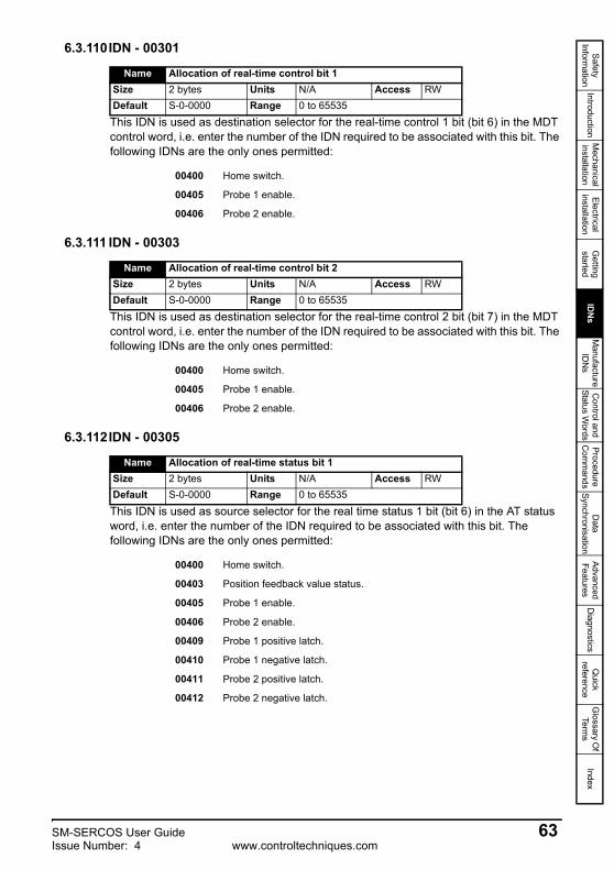
Safety Inform
ationIntroduction
Mechanical
installationElectrical
installationG
etting started
IDN
sM
anufacture ID
Ns
Control and
Status Words
Procedure C
omm
andsD
ata Synchronisation
Advanced Features
Diagnostics
Quick
referenceG
lossary Of
Terms
Index
6.3.110IDN - 00301
This IDN is used as destination selector for the real-time control 1 bit (bit 6) in the MDT control word, i.e. enter the number of the IDN required to be associated with this bit. The following IDNs are the only ones permitted:
6.3.111 IDN - 00303
This IDN is used as destination selector for the real-time control 2 bit (bit 7) in the MDT control word, i.e. enter the number of the IDN required to be associated with this bit. The following IDNs are the only ones permitted:
6.3.112IDN - 00305
This IDN is used as source selector for the real time status 1 bit (bit 6) in the AT status word, i.e. enter the number of the IDN required to be associated with this bit. The following IDNs are the only ones permitted:
Name Allocation of real-time control bit 1Size 2 bytes Units N/A Access RWDefault S-0-0000 Range 0 to 65535
00400 Home switch.
00405 Probe 1 enable.
00406 Probe 2 enable.
Name Allocation of real-time control bit 2Size 2 bytes Units N/A Access RWDefault S-0-0000 Range 0 to 65535
00400 Home switch.
00405 Probe 1 enable.
00406 Probe 2 enable.
Name Allocation of real-time status bit 1Size 2 bytes Units N/A Access RWDefault S-0-0000 Range 0 to 65535
00400 Home switch.
00403 Position feedback value status.
00405 Probe 1 enable.
00406 Probe 2 enable.
00409 Probe 1 positive latch.
00410 Probe 1 negative latch.
00411 Probe 2 positive latch.
00412 Probe 2 negative latch.
SM-SERCOS User Guide 63Issue Number: 4 www.controltechniques.com

6.3.113IDN - 00307
This IDN is used as source selector for the real-time status 2 bit (bit 7) in the AT status word, i.e. enter the number of the IDN required to be associated with this bit. The following IDNs are the only ones permitted:
6.3.114IDN - 00376
This IDN specifies all of the baud rates supported by the SM-SERCOS module. The definition of each bits is as follows:
6.3.115IDN - 00380
The value of this IDN is taken directly from Unidrive SP Pr 5.05 DC link (bus) voltage.
Name Allocation of real-time status bit 2Size 2 bytes Units N/A Access RWDefault S-0-0000 Range 0 to 65535
00400 Home switch.
00403 Position feedback value status.
00405 Probe 1 enable.
00406 Probe 2 enable.
00409 Probe 1 positive latch.
00410 Probe 1 negative latch.
00411 Probe 2 positive latch.
00412 Probe 2 negative latch.
Name Baud rateSize 2 bytes Units N/A Access RODefault Range N/A
Bit 0: 2Mbps1 - Supported.
Bit 1: 4Mbps1 - Supported.
Bit 2: 8Mbps1 - Supported.
Bit 3: 16Mbps1 - Supported.
Bit 4: Automatic baudrate recognition0 - Not Supported.
Name DC bus voltageSize 2 bytes Units V Access RODefault Range 0 to 1190
64 SM-SERCOS User Guidewww.controltechniques.com Issue Number: 4

Safety Inform
ationIntroduction
Mechanical
installationElectrical
installationG
etting started
IDN
sM
anufacture ID
Ns
Control and
Status Words
Procedure C
omm
andsD
ata Synchronisation
Advanced Features
Diagnostics
Quick
referenceG
lossary Of
Terms
Index
6.3.116IDN - 00384
The Unidrive SP has two temperature parameters;
• Stack 1 temperature Pr 7.04.• Stack 2 temperature Pr 7.05.
The SM-SERCOS will monitor both of these parameters and will use the one with the highest value as the source data for this IDN.
6.3.117IDN - 00390
During normal operation when the Unidrive SP and SM-SERCOS are in a healthy status this IDN will have a value of 0. If the Unidrive SP trips this IDN will contain the drive trip code (see the Unidrive SP User Guide for code definitions).
6.3.118IDN - 00400
This IDN is used as part of the drive homing procedure set-up. It provides the status of the chosen home switch input. The source of the homing switch input is controlled by Pr MM.41 and IDN 00147.
6.3.119IDN - 00403
This IDN is used as part of the drive homing procedure. It provides the status of the position feedback.
0 = The position feedback is not referenced to the machine zero point.1 = The position feedback is referenced to the machine zero point.
This status bit is cleared when the cancel reference point (IDN 00191) or when the drive home controlled homing procedure is activated. This will also be set when a home has successfully completed.
Name Amplifier temperatureSize 2 bytes Units See IDN 00208 Access RODefault Range -128 to 127
Name Diagnostic numberSize 4 bytes Units N/A Access RODefault Range 0 to 232-1
Name Home switchSize 2 bytes Units N/A Access RWDefault 0 Range 0 to 1
If the controller is selected as the home switch source in IDN00147 the master must write this IDN.
With system file versions prior to V01.02.00 IDN00400 is not updated from the internal home switch, unless the homing procedure is active.
NOTE
NOTE
Name Position feedback value statusSize 2 bytes Units N/A Access RODefault Range 0 to 1
SM-SERCOS User Guide 65Issue Number: 4 www.controltechniques.com

6.3.120IDN - 00405
This IDN is used during the probe cycle procedure to enable the probe 1 input.
0 = Probe 1 is not enabled.1 = Probe 1 is enabled.
6.3.121IDN - 00406
This IDN is used during the probe cycle procedure to enable the probe 2 input.
0 = Probe 2 is not enabled.1 = Probe 2 is enabled.
6.3.122IDN - 00409
This IDN is set when the probe cycle procedure command has been executed, the probe 1 enable bit (IDN 00405) has been set, the appropriate bit is set in IDN 00169 and a positive edge has occurred at the probe 1 input.
6.3.123IDN - 00410
This IDN is set when the probe cycle procedure command has been executed, the probe 1 enable bit (IDN 00405) has been set, the appropriate bit is set in IDN 00169 and a negative edge has occurred at the probe 1 input.
6.3.124IDN - 00411
This IDN is set when the probe cycle procedure command has been executed, the probe 2 enable bit (IDN 00406) has been set, the appropriate bit is set in IDN 00169 and a positive edge has occurred at the probe 2 input.
Name Probe 1 enableSize 2 bytes Units N/A Access RWDefault 0 Range 0 to 1
Name Probe 2 enableSize 2 bytes Units N/A Access RWDefault 0 Range 0 to 1
Name Probe 1 positive latchedSize 2 bytes Units N/A Access RODefault Range 0 to 1
Name Probe 1 negative latchedSize 2 bytes Units N/A Access RODefault Range 0 to 1
Name Probe 2 positive latchedSize 2 bytes Units N/A Access RODefault Range 0 to 1
66 SM-SERCOS User Guidewww.controltechniques.com Issue Number: 4

Safety Inform
ationIntroduction
Mechanical
installationElectrical
installationG
etting started
IDN
sM
anufacture ID
Ns
Control and
Status Words
Procedure C
omm
andsD
ata Synchronisation
Advanced Features
Diagnostics
Quick
referenceG
lossary Of
Terms
Index
6.3.125IDN - 00412
This IDN is set when the probe cycle procedure command has been executed, the probe 2 enable bit (IDN 00406) has been set, the appropriate bit is set in IDN 00169 and a negative edge has occurred at the probe 2 input.
Name Probe 2 negative latchedSize 2 bytes Units N/A Access RODefault Range 0 to 1
SM-SERCOS User Guide 67Issue Number: 4 www.controltechniques.com

7 Manufacture IDNs
7.1 Drive Parameter Access7.1.1 Overview
IDNs starting at 32768 and upwards are used for manufacturer specific data access. SM-SERCOS uses IDNs 40000 and upwards to access the Unidrive SP and SM-Applications module parameters directly using the SERCOS service channel (non-cyclic data).
Parameter attributes, such as read-only bits, etc, will be mapped to the IDNs. When a parameter is accessed using the service channel, any errors occurring in the parameter access will be mapped to an appropriate service channel error.
7.1.2 Associating drive parameters to IDNsTo access the drive parameters using IDNs, the required menu must be multiplied by 100 and then added to the parameter number. This number can then be added to 40000 to form the correct IDN.
Example 1 - Accessing drive parameters
• To access Unidrive SP parameter Pr 1.21 the IDN is “IDN 40121”.• To access Unidrive SP parameter Pr 20.11 the IDN is “IDN 42011”.
7.1.3 Associating SM-Application parameters to IDNs
With the use of the manufacturer IDNs SM-SERCOS can read and write data non-cyclically to and from the internal registers of an SM-Applications module.
To access the SM-Application parameters using IDNs, the required menu must be multiplied by 100 and then added to the parameter number. This number can then be added to 40000 to form the correct IDN.
The mapping parameters are shown in Table 7.1.
For information on using SM-Applications for direct motor control using the SERCOS network see section 11.18 Cyclic Access to SM-Applications on page 91.
NOTE
Table 7.1 SM-Applications parameters
SM-Applications parametersLowest SM-Application
SlotDirect to
slot 1Direct to
slot 2Direct to
slot 3
_Pxx% PLC Registers Pr 70.xx Pr 100.xx Pr 130.xx Pr 160.xx_Qxx% PLC Registers Pr 71.xx Pr 101.xx Pr 131.xx Pr 161.xx_Rxx% PLC Registers Pr 72.xx Pr 102.xx Pr 132.xx Pr 162.xx_Sxx% PLC Registers Pr 73.xx Pr 103.xx Pr 133.xx Pr 163.xx_Txx% PLC Registers Pr 74.xx Pr 104.xx Pr 134.xx Pr 164.xx_Uxx% PLC Registers Pr 75.xx Pr 105.xx Pr 135.xx Pr 165.xx
Local Configuration Parameters Pr 81.xx Pr 111.xx Pr 141.xx Pr 171.xxTimer Function Parameters Pr 85.xx Pr 115.xx Pr 145.xx Pr 175.xx
Digital I/O Parameters Pr 86.xx Pr 116.xx Pr 146.xx Pr 176.xx
68 SM-SERCOS User Guidewww.controltechniques.com Issue Number: 4

Safety Inform
ationIntroduction
Mechanical
installationElectrical
installationG
etting started
IDN
sM
anufacture ID
Ns
Control and
Status Words
Procedure C
omm
andsD
ata Synchronisation
Advanced Features
Diagnostics
Quick
referenceG
lossary Of
Terms
Index
Using parameters Pr 70.xx to Pr 91.xx allows data to be exchanged with the SM-Applications fitted in the Unidrive SP lowest numerical slot number. This method is convenient to use if there is only one SM-Applications fitted to the Unidrive SP as it guarantees that data will always be written to the SM-Applications even if it is moved to a different slot. If two SM-Applications modules are fitted it is recommend to that the “direct to slot” parameters are used.
Example 2 - Unidrive SP: Single SM-Applications fittedConsider a Unidrive SP with the following configuration:
Slot 1 - VacantSlot 2 - SM-Applications.Slot 3 - SM-SERCOS.• To access SM-Application parameter Pr 71.08 (_Q08%) in the Unidrive SP
lowest numerical slot the IDN is “IDN 47108”.• To access SM-Application parameter Pr 131.08 (_Q08%) in the Unidrive SP
slot 2 the IDN is “IDN 53108”.• To access SM-Application parameter Pr 101.08 (_Q08%) in the Unidrive SP
slot 1 the IDN is “IDN 50108”. However, as there is no SM-Applications fitted in slot 1 an error message will be returned indicating that the parameter does not exist.
Example 3 - Unidrive SP: Dual SM-Applications fittedConsider a Unidrive SP with the following configuration:
Slot 1 - SM-Applications.Slot 2 - SM-Applications.Slot 3 - SM-SERCOS.
• To access SM-Application parameter Pr 71.08 (_Q08%) in the Unidrive SP lowest numerical slot (slot 1) the IDN is “IDN 47108”.
• To access SM-Application parameter Pr 131.08 (_Q08%) in the Unidrive SP slot 2 the IDN is “IDN 53108”.
• To access SM-Application parameter Pr 101.08 (_Q08%) in the Unidrive SP slot 1 the IDN is “IDN 50108”.
Status Parameters Pr 88.xx Pr 118.xx Pr 148.xx Pr 178.xxGeneral Parameters Pr 90.xx Pr 120.xx Pr 150.xx Pr 180.xx
Fast Access Parameters Pr 91.xx Pr 121.xx Pr 151.xx Pr 181.xx
For information on using SM-Applications for cyclic data transfer see section 11.18 Cyclic Access to SM-Applications on page 91.
Table 7.1 SM-Applications parameters
SM-Applications parametersLowest SM-Application
SlotDirect to
slot 1Direct to
slot 2Direct to
slot 3
NOTE
SM-SERCOS User Guide 69Issue Number: 4 www.controltechniques.com

8 Control and Status Words
8.1 What are control and status words?The drive control and status words allow the digital control and monitoring of the drive to be implemented using a single data word for each function. Each bit in the control word has a particular function and provides a method of controlling the output functions of the drive, such as run and direction.
Each bit in the status word provides feedback about the drives state of health and operational condition, such as drive healthy, drive at speed etc.
To use SERCOS control and status words always refer to the master device user guide for details as the majority of SERCOS masters will have their own style of control and status words which are internally interpreted to the actual SERCOS control word (MDT Control Word) and the slave axis status word (AT Status Word).
If a master device does not have its own style of control or status word then details of the actual SERCOS MDT control word and AT status word are provided in section 8.2 MDT Control word and section 8.3 AT Status word .
8.2 MDT Control word Every MDT (Master Data Telegram) from the SERCOS master contains a control word for each slave. The control word is made up of 16 control bits some of which are reserved. See Table 8.1 for the individual bit function descriptions.
Table 8.1 MDT Control word bit definitions
For safety reasons, the external HARDWARE ENABLE signal must be present before the SERCOS control word can be used to start the drive. This terminal is normally controlled by an external “Emergency Stop” circuit to ensure that the drive is disabled in an emergency situation.
Table 8.2 lists in detail the function of each control word bit.
b15 b14 b13 b12 b11 b10 b9 b8Drive
ON / OFFEnableDrive
Halt / Restart
OperationMode IPOSYNC Operation
Mode
b7 b6 b5 b4 b3 b2 b1 b0Real- time
control bit 2
Real- timecontrol
bit 1Data block element Last
TransmitRead / Write MHS
When a trip occurs, the MDT control word MUST be set to a safe, disabled state. This ensures that the drive does not re-start unexpectedly when it is reset. This can be achieved by continuously monitoring the slave AT status word, and interlocking it with the MDT control word.
The Unidrive SP control word must be enabled (Pr 6.43 = ‘ON’) to allow the MDT control word to control the drive.
NOTE
70 SM-SERCOS User Guidewww.controltechniques.com Issue Number: 4

Safety Inform
ationIntroduction
Mechanical
installationElectrical
installationG
etting started
IDN
sM
anufacture ID
Ns
Control and
Status Words
Procedure C
omm
andsD
ata Synchronisation
Advanced Features
Diagnostics
Quick
referenceG
lossary Of
Terms
Index
Table 8.2 MDT control word bit functions
Bit Function Description0 MHS 0/1 = Service transport handshake of the master.
1 Read / Write 0 = Read Service INFO1 = Write Service INFO
2 Lasttransmission
Status of the service channel0 = Transmission in progress1 = Last Transmission
3Data block
elementSpecifies which data block of an IDN is to be accessed by the service channel.4
5
6 Real timeControl Bit 1 Destination specified by IDN 00301.
7 Real timeControl Bit 2 Destination specified by IDN 00303.
8 OperationMode
0002 = Primary operation mode (IDN 00032)0012 = Secondary operation mode 1 (IDN 00033)9
10 IPOSYNCIPOSYNC - the state of this bit is toggled every control unit cycle time.It is used to indicate the availability of either a new position, velocity or torque command.
11 OperationMode Used in conjunction with Bits 8 and 9. See bits 8 and 9 for full description.
12 Reserved
13 Halt / Restart
Specifies which state the drive is in when the Drive ON bit is set. 0 =Halt Drive - Drive Stop state1 = Restart Drive - Drive Run state
14 EnableDrive
0 = Drive Inhibited. Bits 15 and 13 will be ignored.1 = Drive Enabled.
15 DriveON / OFF
0 = Drive OFF - The drive will stop, after a period specified by IDN 00207 it will be switched to the drive ready state.1 = Drive ON - The drive will be placed in the stop state. The module will wait for the period specified by IDN 00206, and then it will place the drive in the state specified by the Halt/Restart drive bit.
Although the MDT control word provides the ability to start and stop the drive, the actual method of stopping is controlled by Pr 6.01 Stop mode, see the Unidrive SP User Guide for more details.
NOTE
SM-SERCOS User Guide 71Issue Number: 4 www.controltechniques.com

8.3 AT Status wordThe SM-SERCOS AT (Amplifier Telegram) status word consists of 16 control bits, some of which are reserved. See the following table for the individual bit function descriptions.
Table 8.3 AT status word bit definitions
b15 b14 b13 b12 b11 b10 b9 b8
Ready to operate Driveshut-down
Class 2Diagnostic
Class 3Diagnostic Actual operation mode
b7 b6 b5 b4 b3 b2 b1 b0
Real-timestatus Bit2
Real-timestatus Bit1
Procedure command changed
Statuscommand
Service channel
errorBusy AHS
Bit Function Description0 AHS Service channel handshake of the drive
1 BusyStatus of the service channel0 = step finished, ready for new one1 = step in progress
2Service channel
error
0 = No error1 = Service channel error, error message in drive service INFO
3 Statuscommand
Status command value processing0 = Drive ignores the command values1 = Drive follows the command values
4 Reserved
5Procedure command changed
Procedure command change bit0 = No change in procedure command acknowledgement1 = Changing procedure command acknowledgement
6 Real-timestatus Bit 1 Real time status bit 1 (Source specified by IDN 00305).
7 Real-timestatus Bit 2 Real time status bit 2 (Source specified by IDN 00307)
8 Actual operation
mode
Actual operation mode0002 = Primary operation mode (IDN 00032).0012 = Secondary operation mode 1 (IDN 00033).
910
11 Class 3Diagnostics
Class 3 Diagnostics has changed0 = No change has occurred1 = A change has occurred
12 Class 2Diagnostics
Class 2 Diagnostics has changed0 = No change has occurred1 = A change has occurred
13 Driveshut-down
Drive shut-down error in IDN 00011 - Class 1 diagnostics0 = No shut-down1 = The drive is shut-down due to an error (Trip)
15 Ready to operate
These bits will be determined from the actual drive status, as detailed below.002 = The base state at power on. The drive initialised flag is not set.012 = This will be set when only the drive initialised flag is set and the drive is inhibited - i.e. the Drive State area of the DPRAM contains code 0.102 = This will be set when the drive initialised flag is set and the drive is enabled (In the Ready state) - i.e. the Drive State area of the DPRAM contains code 1.112 = This will be set when the drive initialised flag is set, the drive is enabled and the Run or Stop states are set - i.e. the Drive State area of the DPRAM contains code 4 or 2.
72 SM-SERCOS User Guidewww.controltechniques.com Issue Number: 4

Safety Inform
ationIntroduction
Mechanical
installationElectrical
installationG
etting started
IDN
sM
anufacture ID
Ns
Control and
Status Words
Procedure C
omm
andsD
ata Synchronisation
Advanced Features
Diagnostics
Quick
referenceG
lossary Of
Terms
Index
9 Procedure Commands
9.1 What are procedure commands?A procedure command is a non-cyclic data item that is used to start some functional process in the drive. All of the procedure commands that are supported by the SM-SERCOS module are described below.
9.2 Homing procedure commands9.2.1 Homing overview
The purpose of the homing procedure is to calculate and set (calibrate) the position feedback value with respect to the machine axis zero point.
9.2.2 The drive controlled homing procedure commandThis method of homing utilises the drive position feedback and requires a home input signal to be directly connected to the drive or master.
To utilise this homing function the associated configuration IDNs and parameters listed below must be set as required.
• Homing velocity (see section 6.3.32 IDN - 00041 on page 44).• Homing acceleration (see section 6.3.33 IDN - 00042 on page 44).• Reference distance 1 (see section 6.3.40 IDN - 00052 on page 45).• Homing parameter (see section 6.3.85 IDN - 00147 on page 55).• Reference offset (see section 6.3.87 IDN - 00150 on page 56).• Homing switch (see section 6.3.118 IDN - 00400 on page 65).• Reverse direction on home switch (see Pr MM.39 on page 25)• Homing switch digital input source (see Pr MM.41 on page 26).• Marker pulse input source (see Pr MM.34 on page 88). If this is set you will
also need to check Pr MM.36 (see Pr MM.36 on page 89) & Pr MM.37 (see Pr MM.37 on page 89) if drive feedback is used.
• The homing backoff behaviour (Pr MM.15).The homing sequence operates as follows:-
1. The drive homing routine is enabled and armed by setting the SERCOS masters procedure command function.
2. The drive then accelerates the motor up to the homing velocity value set in IDN 00041.
3. SM-SERCOS continuously monitors the home switch status (IDN 0400) for a valid signal. When such a signal in detected the SM-SERCOS waits until the next feedback device marker pulse, upon which it will save the current position value as its reference marker pulse and decelerate the motor to a stop. If the home signal is active at the start of the homing procedure then the homing backoff behaviour parameter (Pr MM.15) will determine the operation of the axis (see section 11.7 SM-SERCOS homing backoff behaviour on page 86).
All SM-SERCOS procedure commands once enabled are latched and remain latched even after the procedure has completed. Therefore it is necessary for the master to clear the relevant procedure command enable bit(s) to cancel the procedure.
NOTE
SM-SERCOS User Guide 73Issue Number: 4 www.controltechniques.com

4. Using the values set in IDN 00052, IDN 00150 and marker position the SM-SERCOS calculates the actual machine axis position with respect to the machine axis 0 position.
i.e. IDN 00052 - IDN 001505. IDN 00403 status bit is set after the drive controlled homing procedure has
completed successfully, and indicates that the position feedback is relative to the machine zero point, i.e. the position feedback IDN 00051 is set to this new value.
6. Once the new machine axis position feedback value has been acquired the drive controlled homing procedure will have to be cancelled before normal slave axis operation can continue.
Figure 9-1 Homing sequence
9.3 Cancel reference point procedure commandThis procedure command is operated by setting IDN 00191. It is used to clear the position feedback value status (IDN 00403) and reset the position feedback offset to zero. Once the reference point has been cleared the procedure will have to be cancelled before the homing procedure can be used again.
Setting Pr MM.34 allows a freeze input to be used instead of a feedback device marker pulse.
The second encoder feedback should not be left enabled (Pr MM.10) during execution of the homing command. As this may cause a timer task overrun (trip 54).
The SM-SERCOS will ignore position, velocity and torque demands whilst operating the home procedure.
Pr MM.15 (see section 11.7 SM-SERCOS homing backoff behaviour on page 86) allows for the situation where the home switch is active at the start of the homing procedure. In this case the drive will reverse (at homing speed) until the home switch is no longer active then continue with a standard homing routine.
NOTE
NOTE
Home switch(IDN 00400)
1
0
Position feedbackmarker pulse
Motion directionof the drive
Reference distance 1(IDN 00052)
Reference offset 1(IDN 00150)
Referencepoint
Referencemarker pulse
Machinezero point
Homing velocity(IDN 00041)
NOTE
NOTE
74 SM-SERCOS User Guidewww.controltechniques.com Issue Number: 4

Safety Inform
ationIntroduction
Mechanical
installationElectrical
installationG
etting started
IDN
sM
anufacture ID
Ns
Control and
Status Words
Procedure C
omm
andsD
ata Synchronisation
Advanced Features
Diagnostics
Quick
referenceG
lossary Of
Terms
Index
9.4 Measurements9.4.1 Probe cycle overview
The probing (capture) cycle utilises the drive position feedback and requires one or two input signals to be directly connected to SM-SERCOS.
The SM-SERCOS has two fast 24V digital probe inputs. One or both of these inputs can be used to capture and store position data on both a positive and/or negative signal edges.
The probing cycle provides a method of capturing motor shaft position data whenever a SM-SERCOS probe input is triggered.
Cable connections to the probe inputs can be up to 30m in length. Cable lengths longer than this are not recommended, to avoid EMC issues.
9.4.2 The probing cycle procedure commandTo utilise this function the associated configuration IDNs listed below must be set as required:-
• Probe control parameter (IDN 00169).• Probing cycle procedure command (IDN 00170).• Probe 1 enable (IDN 00405).• Probe 2 enable (IDN 00406).
The probing cycle sequence operate as follows:-
1. The probing cycle routine is enabled and armed by setting IDN 00170.2. When a probe input detects a signal edge (as defined in IDN 00169) the appropriate
status bits in IDN 00179 (and IDNs 00409 to 00412 which can be used as source data for AT real time status bits) are set. At the same time SM-SERCOS logs the time since the last drive position update (updates occur every 250µs) and uses interpolation to calculate the position for the time logged (this assumes a constant velocity between the position update points either side of the time sample).
3. The SM-SERCOS updates the status bits in IDN 00179 every 250µs. When a bit is set, the calculated position is then stored in either IDN 00130 to IDN 00133 as appropriate.
4. To reuse / repeat the procedure the probe enable IDN(s) must be cleared and then re-enabled by the master.
Digital input 1 can also be used as freeze input, allowing other position feedback modules and the drive position to be frozen, if supported, (see section 11.12 Freeze main drive position on page 89).
9.5 Reset Class 1 Diagnostic Procedure CommandThis procedure when called by setting IDN 00099 will clear / reset the following status:
• Class 1 diagnostic (IDN 00011).• Interface error (IDN 00014).• Manufacturers class 1 diagnostic (IDN 00192).
When this procedure command is operating, any changes made to IDN 00169 will not take effect until the appropriate probe enable IDN has seen the required signal edge. The probing cycle command is effected by the second encoder feedback (i.e. if it is enabled (Pr MM.10), the registration position will come from there and not the primary feedback).
NOTE
SM-SERCOS User Guide 75Issue Number: 4 www.controltechniques.com

• Drive shut down bit (AT status word bit 13).• Attempt to clear the drive trip.
However, this will only be possible if there is no active trip condition currently set in the drive (and no other error condition that would cause bits to be set in the mentioned IDNs).
9.6 CP3 and CP4 transition check procedure commandsThese procedure commands (IDNs 00127 and 00128) are initiated by the master at the end of CP2 and CP3, before entering CP3 and CP4 respectively. This is to check that the communications phase has been completed, and that all of the necessary IDN data for the phase has been set.
The CP4 transition check will also ensure that the SM-SERCOS is operating correctly as the synchronisation master for the Unidrive SP and any other Solution Modules that are linked to the synchronisation signal. If the SM-SERCOS is not the synchronisation signal producer (or if the synchronisation signal it is providing is not within specification), the CP4 transition check will fail.
76 SM-SERCOS User Guidewww.controltechniques.com Issue Number: 4

Safety Inform
ationIntroduction
Mechanical
installationElectrical
installationG
etting started
IDN
sM
anufacture ID
Ns
Control and
Status Words
Procedure C
omm
andsD
ata Synchronisation
Advanced Features
Diagnostics
Quick
referenceG
lossary Of
Terms
Index
10 Data Synchronisation
10.1 Synchronisation10.1.1 Overview
Synchronised position control allows a group of axes on a SERCOS network to make their programmed position moves at the same time. This is very important in precision CNC machines, as the level of synchronisation between axes partly determines the “smoothness” of motion when following a curved profile.
Unidrive SP will allow one of the installed option modules to adjust the timing of the internal loops to keep it synchronised to an external signal. The solutions module responsible for this is known as the “synchronisation producer”.
Synchronisation over SERCOS is a method of operation where the SM-SERCOS synchronises the Unidrive SP control loops with the cycle time of the SERCOS network. This ensures that the Unidrive SP speed loops are synchronised across the SERCOS network, and will use their new data references at the same time.
If the SM-SERCOS is unable to become the synchronisation producer, it will not be possible to advance to CP4. This might occur, for example, if another module in a lower option slot is the synchronisation producer. In this case, the CP4 transition check (see IDN - 00128 on page 53) will fail. Also during CP4 the synchronisation status is checked periodically. If the producer status is lost (e.g. if a module in lower option slot becomes the synchronisation producer), or if the drive detects that the synchronisation waveform being provided from the SERCOS network is not within the proper specification, the SM-SERCOS will signal an error and return to CP0.
When a SM-Application module is fitted it is possible to make the POS tasks also synchronise to the SERCOS network master. See SM-Application User Guide for details on how to make it operate as a synchronisation consumer when using inter-option synchronisation.
10.1.2 Synchronisation modesSM-SERCOS will automatically configure itself as the synchronisation producer for its Unidrive SP, however, if 2 or more option modules are configured to be the synchronisation producer for the Unidrive SP, the module fitted in the lowest numerical slot will be the synchronisation producer.When SM-SERCOS is enabled as the synchronisation producer, it will use the SERCOS MST message as the external synchronisation signal.
Unidrive SP must have firmware V01.06.00 or later to support inter-option synchronisation. Any SM-Application modules fitted must have V1.03.00 or later system file installed to support inter-option module synchronisation. Cyclic transfer of data is supported using the cyclic data transfer method as described in section 11.18 Cyclic Access to SM-Applications on page 91
NOTE
Only one SM-SERCOS should be fitted on a Unidrive SP. If more than one SM-SERCOS module is installed only the SM-SERCOS in the lowest numerical slot will be functional.
NOTE
SM-SERCOS User Guide 77Issue Number: 4 www.controltechniques.com

10.2 Synchronisation status
Synchronisation status indicates the current synchronisation state of the SM-SERCOS. Pr MM.44 is only updated when the SM-SERCOS has been enabled as the synchronisation producer (see Synchronisation modes on page 77).
The timing accuracy of the MST from the SERCOS master controller is very important if the SM-SERCOS is to maintain synchronisation. See section 10.7 Timing accuracy on page 82. When using SM-Applications this parameter should be monitored to ensure reliable motion.
10.3 Synchronisation period
When the SM-SERCOS has synchronised with the SERCOS network and become the synchronisation producer for the Unidrive SP, Pr MM.45 indicates the current synchronisation period. If synchronisation is lost for any reason, this value will be reset to 0. When using SM-Applications this parameter should be monitored to ensure reliable motion.
SM-SERCOS Synchronisation status
Pr MM.44Default N/ARange 0 to 7Access RO
Table 10.1 Synchronisation status
Bit Function Description
0 to 1 SYNCMODE
Indicates the requested synchronisation mode0 = The module is independent.1 = The module is the synchronisation producer.
2 PRODUCERACTIVE
This bit indicates that the SM-SERCOS has successfully become the synchronisation producer for the Unidrive SP
3 SYNCOK
Indicates that the jitter in the external signal being used to generate the DINT message is within tolerance for Unidrive SP
4 to 7 Reserved Reserved
SM-SERCOS Synchronisation period
Pr MM.45Default N/ARange 0 to 6Access RO
Table 10.2 Synchronisation period
Value Period0 Not synchronised1 250µs2 500µs3 1ms4 2ms5 4ms6 8ms
78 SM-SERCOS User Guidewww.controltechniques.com Issue Number: 4

Safety Inform
ationIntroduction
Mechanical
installationElectrical
installationG
etting started
IDN
sM
anufacture ID
Ns
Control and
Status Words
Procedure C
omm
andsD
ata Synchronisation
Advanced Features
Diagnostics
Quick
referenceG
lossary Of
Terms
Index
10.4 Internal interrupts10.4.1 RMINT
RMINT is a hardware interrupt within the Unidrive SP, and is used to control the execution of the Unidrive SP speed loop. It is generated nominally every 250µs, but the internal phase-locked loop may be adjusted to synchronise to an external signal (see section 10.7 Timing accuracy ).Synchronisation between a SERCOS master and a Unidrive SP is achieved by specifying SM-SERCOS as the “synchronisation producer”. It is also possible to set a SM-Applications as “synchronisation consumer”; SM-Applications will synchronise to the same RMINT as SM-SERCOS and synchronisation between the modules is guaranteed. For more information on synchronous transfer of data see section 11.18 Cyclic Access to SM-Applications on page 91).
10.4.2 DINTDINT is generated by the SM-SERCOS every 250µs. It is used by the Unidrive SP to determine the phase-lock loop adjustment required, and this adjustment is applied when the next RMINT occurs. Any change of timing in RMINT will be seen on the 2nd RMINT after DINT occurred.
10.5 Position control without interpolationPosition reference interpolation is not required if the SERCOS master and network cycle times (see section 10.3 Synchronisation period ) are the same as the Unidrive SP speed loop cycle time (250µs). The new position reference received from the SERCOS master controller can be processed in the SM-SERCOS position controller on each cycle. Figure 10-1 shows a synchronised SERCOS system consisting of 4 nodes running at 250µs SYNC time.
Figure 10-1 Position control without interpolation
MDT
MST
AT1
AT2
AT3
AT4
MDT
MST
AT1
AT2
AT3
AT4
tScyc - IDN 0002(250µs)
t4 - IDN 0007
250µs
MDT
MST
AT1
AT2
AT3
AT4
SERCOSData
RMINT
90µs
SM-SERCOSPosition loop
active when high
Drive PositionSample Point
t3 - IDN 0008
SM-SERCOS User Guide 79Issue Number: 4 www.controltechniques.com

Figure 10-2 Example profile 1
10.6 Position control with interpolationPosition reference interpolation is required if the SERCOS master and network cycle times (see section 10.3 Synchronisation period ) are different to the Unidrive SP speed loop cycle time (250µs).
Figure 10-3 Position control with interpolation
0 1 2 3 4
0
1000
2000
Time(ms)
Position
specified profile
250µs positionreference increments
actual profile
MDT
MST
AT1
AT2
AT3
AT4
MDT
MST
AT1
AT2
AT3
AT4
tScyc - IDN 0002(1ms)
t4 - IDN 0007
250µs
MDT
MST
AT1
AT2
AT3
AT4
SERCOSData
RMINT
SM-SERCOSPosition loop
Drive PositionSample Point
90µs
Interpolation between samplepoint and the next commandvalue valid time(t3)
t3 - IDN 0008
80 SM-SERCOS User Guidewww.controltechniques.com Issue Number: 4

Safety Inform
ationIntroduction
Mechanical
installationElectrical
installationG
etting started
IDN
sM
anufacture ID
Ns
Control and
Status Words
Procedure C
omm
andsD
ata Synchronisation
Advanced Features
Diagnostics
Quick
referenceG
lossary Of
Terms
Index
When the SERCOS master cycle time is 1ms, the position reference received from the master controller is the target position that must be achieved 1ms later. If the SM-SERCOS position controller is running every 250µs, it will try to move to the new position in 250µs, instead of 1ms. The actual movement that will be produced is shown in Figure 10-4, and looks nothing like the specified profile.
Figure 10-4 Uninterpolated position profile
The solution is to use position reference interpolation. When a new position reference is received from the SERCOS master controller, 4 intermediate step positions can be calculated and passed to the position controller on each 250µs cycle. This is shown in Figure 10-5 using linear interpolation, where each interpolated position reference is a quarter of the position move required during the 1ms period.
Figure 10-5 Profile with interpolation
0 1 2 3 4
2000
1000
0 Time(ms)
specified profile
Position
250µs positionreference increments
actual profile
0 1 2 3 4
2000
1000
0 Time(ms)
specified profile
250µs interpolatedposition reference
Position
master positionreference increments
actual profile
SM-SERCOS User Guide 81Issue Number: 4 www.controltechniques.com
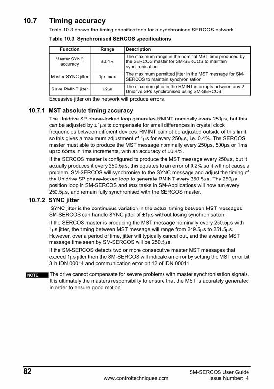
10.7 Timing accuracyTable 10.3 shows the timing specifications for a synchronised SERCOS network.
Excessive jitter on the network will produce errors.
10.7.1 MST absolute timing accuracyThe Unidrive SP phase-locked loop generates RMINT nominally every 250µs, but this can be adjusted by ±1µs to compensate for small differences in crystal clock frequencies between different devices. RMINT cannot be adjusted outside of this limit, so this gives a maximum adjustment of 1µs for every 250µs, i.e. 0.4%. The SERCOS master must able to produce the MST message nominally every 250µs, 500µs or 1ms up to 65ms in 1ms increments, with an accuracy of ±0.4%.If the SERCOS master is configured to produce the MST message every 250µs, but it actually produces it every 250.5µs, this equates to an error of 0.2% so it will not cause a problem. SM-SERCOS will synchronise to the SYNC message and adjust the timing of the Unidrive SP phase-locked loop to generate RMINT every 250.5µs. The 250µs position loop in SM-SERCOS and POS tasks in SM-Applications will now run every 250.5µs, and remain fully synchronised with the SERCOS master.
10.7.2 SYNC jitter SYNC jitter is the continuous variation in the actual timing between MST messages. SM-SERCOS can handle SYNC jitter of ±1µs without losing synchronisation.If the SERCOS master is producing the MST message nominally every 250.5µs with 1µs jitter, the timing between MST message will range from 249.5µs to 251.5µs. However, over a period of time, jitter will typically cancel out, and the average MST message time seen by SM-SERCOS will be 250.5µs.If the SM-SERCOS detects two or more consecutive master MST messages that exceed 1µs jitter then the SM-SERCOS will indicate an error by setting the MST error bit 3 in IDN 00014 and communication error bit 12 of IDN 00011.
Table 10.3 Synchronised SERCOS specifications
Function Range Description
Master SYNC accuracy ±0.4%
The maximum range in the nominal MST time produced by the SERCOS master for SM-SERCOS to maintain synchronisation
Master SYNC jitter 1µs max The maximum permitted jitter in the MST message for SM-SERCOS to maintain synchronisation
Slave RMINT jitter ±2µs The maximum jitter in the RMINT interrupts between any 2 Unidrive SPs synchronised using SM-SERCOS
The drive cannot compensate for severe problems with master synchronisation signals. It is ultimately the masters responsibility to ensure that the MST is acurately generated in order to ensure good motion.
NOTE
82 SM-SERCOS User Guidewww.controltechniques.com Issue Number: 4

Safety Inform
ationIntroduction
Mechanical
installationElectrical
installationG
etting started
IDN
sM
anufacture ID
Ns
Control and
Status Words
Procedure C
omm
andsD
ata Synchronisation
Advanced Features
Diagnostics
Quick
referenceG
lossary Of
Terms
Index
10.7.3 Slave RMINT accuracyThe accuracy of the synchronisation process using SM-SERCOS is quoted as the maximum jitter that will be seen between the RMINT signals of any 2 Unidrive SPs on the SERCOS network.
Maximum RMINT jitter = ±2.0µs
As the Unidrive SP speed loop runs every 250µs, the maximum synchronisation jitter BETWEEN ANY 2 DRIVES equates to 0.8% across the SERCOS network. Figure 10-6 shows how the timings of RMINT may vary between 4 Unidrive SPs across a network, but the difference between any 2 RMINT signals will not exceed ±2µs.
Figure 10-6 Jitter on RMINT
In this case, the worst case delay between RMINTs is between node 2 and node 3. The difference between any other pair of nodes is always less then 2µs.
RMINT (N2)
2µs
RMINT (N1)
RMINT (N3)
RMINT (N4)
SM-SERCOS User Guide 83Issue Number: 4 www.controltechniques.com

11 Advanced Features
11.1 SM-SERCOS network loss trip
Enabling the network loss trip provides a method of tripping and therefore disabling the drive, if an error occurs that causes SM-SERCOS operating status (Pr MM.06) to return to CP0 such as an optical fibre fault or excessive distortion.
When SM-SERCOS forces the trip, the trip displayed on the drive will be “SLx.Er”, where “x” is the slot number where the trip originated. The SM-SERCOS error code parameter (Pr MM.50) will show 65 when a network loss trip has occurred.
11.2 SM-SERCOS data endian format11.2.1 What does endian format mean?
When data is sent over a network it is transmitted as 8 bit bytes. Therefore when a 16 bit word or 32 bit word is transmitted it is split into two or four 8 bit bytes. It is important that the receiving node reconstructs the received 8 bit bytes in the correct order to arrive at the 16 bit or 32 bit data value that was originally transmitted, this order is known as the “Data Endian Format”.
11.2.2 SERCOS endian formatThis read only parameter displays the endian format of the SM-SERCOS module. The SM-SERCOS uses little endian format as should all SERCOS conformant devices.
SM-SERCOS network loss trip enable
Pr MM.07Default 0Range 0 to 1Access RW
Any return to CP0 will cause this trip.When the network loss trip is disabled by setting Pr MM.07 to 0, the SM-SERCOS will still disable the drive but will not trip it.
NOTE
Data endian format
Pr MM.0816-bit value 32-bit value
Byte order Word order Byte order
Big OFF High byte firstLow byte second
High word firstLow word second
High byte firstMid high byte second
Mid low byte thirdLow byte fourth
Little ON Low byte firstHigh byte second
Low word firstHigh word second
Low byte firstMid low byte secondMid high byte thirdHigh byte fourth
SM-SERCOS data endian format
Pr MM.08Default ONRange OFF (0) or ON (1)Access RO
84 SM-SERCOS User Guidewww.controltechniques.com Issue Number: 4

Safety Inform
ationIntroduction
Mechanical
installationElectrical
installationG
etting started
IDN
sM
anufacture ID
Ns
Control and
Status Words
Procedure C
omm
andsD
ata Synchronisation
Advanced
FeaturesD
iagnosticsQ
uick reference
Glossary O
f Term
sIndex
11.3 SM-SERCOS register controlThis read only parameter displays the register mode of the 'I' and 'O' registers (Pr MM.10 to Pr MM.29). The value of 1 (ON) signifies the 'I' and 'O' registers are to store data directly (they are not parameter mappings). This parameter cannot be changed on SM-SERCOS.
11.4 SM-SERCOS second encoder enableSpecifies if the position value in the second encoder is to be made available in IDN 00053. A value of 0 signifies that the value should not be made available. This parameter will take effect immediately (it is not necessary to reset the option module). When this value changes from 0 to 1, parameters Pr MM.11 and Pr MM.12 will configure the feedback. When this facility is disabled, IDN 00053 will be assigned a value of 0. The second encoder cannot be used by the APC in SM-SERCOS and is intended for use in one and a half axis machines.
11.5 SM-SERCOS second encoder sourceSpecifies where the second position feedback device is connected. This encoder cannot be used for on-board control (SM-SERCOS APC), but can be sent over the network cyclically or read by the master non-cyclically, using IDN 00053.
The value in Pr MM.11 will determine the second encoder feedback source.
SM-SERCOS register control
Pr MM.09Default ONRange OFF (0) or ON (1)Access RO
SM-SERCOS second encoder enable
Pr MM.10Default ONRange OFF (0) or ON (1)Access RW
The second encoder feedback should not be left enabled during execution of the homing command. As this may cause a timer task overrun (trip 54).
NOTE
SM-SERCOS second encoder source
Pr MM.11Default 0Range 0 to 3Access RW
Pr MM.11 second encoder source0 Drive encoder feedback.1 Encoder feedback from slot 12 Encoder feedback from slot 2.3 Encoder feedback from slot 3.
This parameter requires a 0 to 1 transition of Pr MM.10 to implement any changes.NOTE
SM-SERCOS User Guide 85Issue Number: 4 www.controltechniques.com

11.6 SM-SERCOS second encoder turns bitsSpecifies the number of bits of the external encoder revolution count that will be right-shifted into SERCOS second encoder feedback values. A corresponding number of fine position bits will be right-shifted out of the position parameter.
11.7 SM-SERCOS homing backoff behaviour
This parameter defines the behaviour of the homing routine in the event that the home switch is active at the start of the homing procedure. This is important if the home switch could be active for multiple marker pulses.
If the homing input is active when homing starts, this parameter defines the method of backoff that will occur in order to deactivate the homing input before homing is started.
11.8 Restore SM-SERCOS defaults
If the host drive is defaulted (see the drive user guide for details) it will also clear the current configuration for the slot SM-SERCOS is fitted to. Setting Pr MM.30 to 1 additionally clears the backup copy of the SM-SERCOS configuration stored in the SM-SERCOS (see Section 11.9 for more details).
The sequence is as follows:
• Set Pr MM.30 to 1.• Set Pr MM.00 to 1233 to restore European defaults (1244 for USA defaults).• SERCOS communications will be stopped.• The host drive will load and store its default parameter values.• Default parameter values for the SM-SERCOS will be loaded in Pr MM.XX
parameters.
SM-SERCOS second encoder turns bits
Pr MM.12Default 16Range 1 to 16Access RW
This parameter requires a 0 to 1 transition of Pr MM.10 to implement any changes.NOTE
SM-SERCOS homing backoff behaviour
Pr MM.15Default 0Range 0 to 2Access RW
Pr MM.15 homing backoff behaviour
0 The backoff direction is the opposite of the selected homing direction (see IDN 00147). This is the default operation.
1 The backoff direction is the same as the selected homing direction (see IDN 00147).
2 No Backing off will occur.
Restore SM-SERCOS defaults
Pr MM.30Default OFF (0)Range OFF (0) or ON (1)Access RW
86 SM-SERCOS User Guidewww.controltechniques.com Issue Number: 4

Safety Inform
ationIntroduction
Mechanical
installationElectrical
installationG
etting started
IDN
sM
anufacture ID
Ns
Control and
Status Words
Procedure C
omm
andsD
ata Synchronisation
Advanced
FeaturesD
iagnosticsQ
uick reference
Glossary O
f Term
sIndex
• SM-SERCOS default parameter values will be stored in the backup copy in SM-SERCOS FLASH memory.
• The SM-SERCOS will reset and re-initialise using the default values.
11.9 Storing SM-SERCOS parameters (backup)
Option slot parameters are stored in the host drive memory and SM-SERCOS will always use these values during initialisation to configure itself. If a new SM-SERCOS is fitted to the same slot it will communicate using the same settings as the previous SM-SERCOS.
Using Pr MM.31 it is possible to store the configuration as a backup copy in the SM-SERCOS module. This allows the module to contain a backup copy of its configuration that may be restored using Pr MM.33 (see section 11.10). This is of particular use when setting up a module to send to site as a replacement or as a method of keeping a backup copy of the SM-SERCOS settings that may be used in the event of a drive failure.
To store SM-SERCOS parameters in the SM-SERCOS FLASH backup copy:
• Set Pr MM.31 to 1.• Set Pr MM.00 to 1000.• Press the red RESET button.
The drive will perform a drive save and additionally copy the settings from the slot menu associated with the SM-SERCOS and copy them in the SM-SERCOS local FLASH memory.
11.10 Restore previous SM-SERCOS configuration
If valid configuration parameters have previously been stored in the SM-SERCOS FLASH memory these values can be restored to the host settings for SM-SERCOS. When the configuration parameter values have been uploaded to the host drive the SM-SERCOS will reset and re-configure using the updated parameter values. This feature allows a pre-configured SM-SERCOS to be fitted to a host drive without losing the SM-SERCOS configuration.
Store to SM-SERCOS FLASH memory
Pr MM.31Default OFFRange OFF (0) to ON (1)Access RW
If the stored values in the drive are for a different type of Solutions Module, the drive will trip with a slot error. The slot configuration parameters will be set to default values for SM-SERCOS, but the default values will NOT be stored in the drive.
Drive parameters are NOT stored in SM-SERCOS.
NOTE
NOTE
Restore previous SM-SERCOS configuration
Pr MM.33Default OFF (0)Range OFF (0) or ON (1)Access RW
If the SM-SERCOS is unable to upload the configuration parameters to the host drive or configuration parameters have never been stored in the SM-SERCOS FLASH memory the drive will trip with a slot error and set the error code (Pr MM.49) to 70.
NOTE
SM-SERCOS User Guide 87Issue Number: 4 www.controltechniques.com

When Pr MM.33 is set to ON the SM-SERCOS will transfer the configuration parameters from its FLASH memory to the host drive over-writing the existing values in the host drive.
The full sequence of events for restoring values from a SM-SERCOS fitted in slot MM is as follows:.
• Set Pr MM.33 to ON.• SERCOS communications will be stopped.• The SM-SERCOS will overwrite all Pr MM.XX parameters with the values
stored in its internal FLASH memory.• Pr MM.33 will be reset to OFF.• The SM-SERCOS will reset and re-initialise using the restored values.
11.11 Marker pulse source
Normally the drive controlled homing procedure command requires a marker pulse to home the axis to. However, some motor position feedback devices do not produce a marker pulse, therefore this parameter, when set, allows the freeze input from the currently selected feedback source (see section 5.3.7 Position feedback source on page 26) to be used instead of the marker pulse see section 11.12 Freeze main drive position for details on freeze input source.
This procedure will NOT store the updated host drive parameters and a drive save will be required to update the drive memory. Failure to do this will result in SM-SERCOS resorting to previously stored parameters in the drive FLASH following a power down.
SM-SERCOS will restore its configuration parameters to the menu of parameters associated with the slot that it is installed in. If SM-SERCOS is moved from a slot on a drive it can be re-installed in any slot on another drive and will pass its configuration to the drive.
The SM-SERCOS store and upload parameters should not be used whilst the SERCOS network is operational.
NOTE
NOTE
NOTE
SM-SERCOS freeze main drive position
Pr MM.34Default OFF (0)Range OFF(0) to ON (1)Access RW
The homing procedure command will function as normal even when using a freeze input as the marker pulse source.
NOTE
88 SM-SERCOS User Guidewww.controltechniques.com Issue Number: 4

Safety Inform
ationIntroduction
Mechanical
installationElectrical
installationG
etting started
IDN
sM
anufacture ID
Ns
Control and
Status Words
Procedure C
omm
andsD
ata Synchronisation
Advanced
FeaturesD
iagnosticsQ
uick reference
Glossary O
f Term
sIndex
11.12 Freeze main drive position
When parameter Pr MM.36 is set to ON, the freeze 1 input (pin 2 on the digital input connector) will be routed onto the main drive freeze line in addition to the module freeze. When a freeze occurs, the position can be determined by reading the appropriate drive parameters.
If the parameter Pr MM.37 is set to ON, the freeze 1 input will be inverted before it is routed onto the main drive freeze.
11.13 Test mode
This parameter is used to enable either the zero bit stream or continuous light test modes. These test modes are particularly useful during commissioning and when diagnosing network problems.
The zero bit stream test mode will generate a square wave output, with a frequency that is half of the SERCOS data rate. For example, a 16Mbps zero bit stream will give an 8MHz square wave. This based on the NRZI encoding used by SERCOS networks. The continuous light test mode uses a test signal of a continuous stream of high bits.
11.14 Disable SM-SERCOS control
This parameter is provided to prevent the SM-SERCOS module from controlling the drive control parameters directly. This is particularly useful when an SM-Applications module is required to have control of the drive based on references supplied over SERCOS. A value of 1 in this parameter will prevent SM-SERCOS from directly controlling the drive.
SM-SERCOS freeze main drive position
Pr MM.36Default OFF (0)Range OFF(0) to ON (1)Access RW
SM-SERCOS Invert drive freeze
Pr MM.37Default OFF (0)Range OFF(0) to ON (1)Access RW
SM-SERCOS Test mode
Pr MM.38Default 0Range 0 to 2Access RW
When one of the test modes is selected, Pr MM.06 will display a value of -1 (no network present).
NOTE
SM-SERCOS disable SM-SERCOS control
Pr MM.40Default 0 Range 0 to 1Access RW
SM-SERCOS will still provide a synchronisation signal to the drive and option modules, regardless of this parameters setting.
NOTE
SM-SERCOS User Guide 89Issue Number: 4 www.controltechniques.com

11.15 Menu 61 - SM-SERCOS virtual parametersMenu 61 allows a SERCOS master to adjust parameters on an SM-SERCOS module independently of the slot number the module is fitted to. The required SM-SERCOS node is accessed using its SERCOS address in conjunction with menu 61.
To change a parameter on SM-SERCOS a non-cyclic message should be sent to the node using menu 61 as the destination.
11.16 Cyclic and non-cyclic data communications11.16.1Overview
All master to slave cyclic and non-cyclic data transactions are actually contained within the same network MDT messages. Likewise all slave to master cyclic and non-cyclic data are contained within each slaves AT message.
As with the control and status words (which are also contained within the MDTs and ATs see Chapter 8 Control and Status Words on page 70) each SERCOS master manufacturer has their own method of implementing control strategies in their PLC / motion controllers, therefore it is beyond the scope of this user guide to document how to construct cyclic and non-cyclic messages on the master, however section 11.16.2 Cyclic data and section 11.16.3 Non-cyclic data briefly outlines the functions of each message type.
11.16.2Cyclic dataCyclic data transfer is a method of transferring data on a regular time period and is often known as “polled data”. SERCOS cyclic data must be pre-configured so that the source and destinations are set just the once. Then data is updated on the defined time period.
Typical SERCOS cyclic data is:-
• The master to drive axis velocity / position / torque references.• The slave (drive) to master velocity / position / torque feedback values.
11.16.3Non-cyclic dataIn addition to the cyclic transmission of data, the SERCOS interface provides the ability to transmit non-cyclic data. Control and status bits in the MDT control word and the AT status word are used to control execution of the service channel. Therefore, the master is able to support a separate service channel for every connected drive.
Non-cyclic transmissions are used for the following operations:
• Initialisation of the SERCOS interface.• Transmission of all elements of a data block.• Transmission of procedure commands.• Changing limit values on demand.
Table 11.1 Local slot configuration parameter access
Parameter SM-SERCOS in slot 1 SM-SERCOS in slot 2 SM-SERCOS in slot 3Pr 61.01 - Pr 61.51 Pr 15.01 - Pr 15.51 Pr 16.01 - Pr 16.51 Pr 17.01 - Pr 17.51
Menu 61 parameters are only accessible from the SERCOS network using the non-cyclic data access method (service channel), for more details see section 11.16.3 Non-cyclic data on page 90.
WARNING
90 SM-SERCOS User Guidewww.controltechniques.com Issue Number: 4

Safety Inform
ationIntroduction
Mechanical
installationElectrical
installationG
etting started
IDN
sM
anufacture ID
Ns
Control and
Status Words
Procedure C
omm
andsD
ata Synchronisation
Advanced
FeaturesD
iagnosticsQ
uick reference
Glossary O
f Term
sIndex
• Changing control loop parameters on demand.• Obtaining detailed status messages from a drive.• Diagnostic functions.
Service channel non-cyclic transmissions are always initiated and controlled by the master.
The service channel is initialised during CP2 and is functional for the remainder of the communication phases.
In addition to dynamically controlling IDNs, if required the service channel can also be used to communicate directly to the Unidrive SP parameters, (see section 7 Manufacture IDNs for further details).
11.17 Telegram type 7This is the user defined telegram type that allows the user to choose the required cyclic data that is to be transferred between the SERCOS master and slaves.
To utilise this telegram type it has to selected using IDN 00015. The required IDNs to be transmitted cyclically have to be listed in IDN 00016 (AT) and IDN 00024 (MDT).
When using telegram type 7 only the IDNs listed in IDN 00187 (AT) and IDN 00188 (MDT) can be used for the cyclic data. Attempting to use IDNs that are not listed will result in the SM-SERCOS failing the slave CP3 transition check.
11.18 Cyclic access to SM-ApplicationsA facility is available that allows data to be passed cyclically to and from SM-Applications. This allows a SM-Applications module to receive data from the MDT cyclic channel (through menu 20) and to return data in the AT cyclic channel (through menu 20) to the SERCOS controller.
This requires SM-SERCOS to be synchronised with the SERCOS MST, hence allowing the real time tasks on SM-Applications to be synchronised across multiple SM-Application modules or drives.
11.18.1SM-SERCOS as a synchronisation producerSM-SERCOS will automatically act as the synchronisation producer within the Unidrive-SP, the remaining configuration must be done within SM-Applications. Parameters Pr MM.44 (synchronisation status) and Pr MM.45 (synchronisation period) should be monitored within DPL to ensure the SM-SERCOS is functioning correctly as a synchronisation producer for the drive.
11.18.2SM-Applications/SM-Applications as a synchronisation consumerFor SM-Applications/SM-Applications Lite setup details see the combined user guide under the section “Inter-option Synchronisation”. The SM-Applications POS task interval should be made equal to or less than the SERCOS network cycle time. This also dictates that the SERCOS cycle times should be either 250us, 500us, 1ms, 2ms, 4ms or 8ms.
For SERCOS the correct name associated with the network non-cyclic data transfer is the “Service Channel”.
NOTE
Telegram type 7 can be configured to send data to and from SM-Applications for use in systems requiring the SM-Applications to have direct control of the drive, see section 11.18 Cyclic Access to SM-Applications for more information.
NOTE
SM-SERCOS User Guide 91Issue Number: 4 www.controltechniques.com

11.18.3IDNs required for SM-ApplicationsData to be transferred cyclically must be achieved using menu 20 as an intermediate step, the list of IDNs used to send data to the master is given in IDN 00187, the specific IDNs for menu 20 AT transfers are listed below. These are the IDNs you should configure in your cyclic data.
• IDN 42001 [P-2-1041] Application Menu 3 read-write integer (Pr 20.01)• IDN 42002 [P-2-1042] Application Menu 3 read-write integer (Pr 20.02)• IDN 42021 [P-2-1061] Application Menu 3 read-write long integer (Pr 20.21)• IDN 42022 [P-2-1062] Application Menu 3 read-write long integer (Pr 20.22)
The list of IDNs used to receive data from the master is given in IDN 00188, the specific IDNs for menu 20 MDT transfers are listed below. These are the IDNs you should configure in your cyclic data.
• IDN 42003 [P-2-1043] Application Menu 3 read-write integer (Pr 20.03)• IDN 42004 [P-2-1044] Application Menu 3 read-write integer (Pr 20.04)• IDN 42023 [P-2-1063] Application Menu 3 read-write long integer (Pr 20.23)• IDN 42024 [P-2-1064] Application Menu 3 read-write long integer (Pr 20.24)
11.18.4Timing constraintsData transfer to and from SM-Applications will occur in the period immediately before the start of the real time task, and as such will be available without change during the task. This has the effect of introducing a delay between the data arriving in SM-Applications and conversely arriving back in the PLC. This delay will be dependent on the PLCs internal timings, but will be consistent for a specific configuration.
The SM-SERCOS module will write data to and read data from the parameters on every T4 when the IPOSYNC bit has been toggled. The data written will be that cached at the last T3 point.
From the point at which data is received from the master (in the MDT), it will be cached at the following T3 point. This data will then be written in the 90us period immediately after the next T4 point, if the IPOSYNC bit has been toggled.
92 SM-SERCOS User Guidewww.controltechniques.com Issue Number: 4

Safety Inform
ationIntroduction
Mechanical
installationElectrical
installationG
etting started
IDN
sM
anufacture ID
Ns
Control and
Status Words
Procedure C
omm
andsD
ata Synchronisation
Advanced
FeaturesD
iagnosticsQ
uick reference
Glossary O
f Term
sIndex
Figure 11-1 SERCOS network timing sequence chart
If the SM-Applications is correctly operating as a consumer of the SM-SERCOS synchronisation signal, the SM-Applications POS task will begin 90us after the T4 point (and so the user should include code to use the cyclic data received from the SM-SERCOS module at the start of POS).
The SM-SERCOS module will read feedback data from the cyclic parameters every T4, when IPOSYNC has been toggled. This means that the data will be transmitted to the master in the following AT. The user must ensure that the SM-Applications POS task code writes the feedback data to the parameters before this point.
It should be noted that IPOSYNC bit in the control word, must be toggled, else data mapping will not occur. This should be done in the user PLC code (unless this process is performed automatically by the master). If the network is unstable synchronisation cannot be maintained.
MST AT1 AT2 ATn MDT
time
t1 - IDN 0006
t2 - IDN 0089
tScyc - IDN 0002
tATMT - IDN 0004 tMTSG - IDN 0090
tMTSY - IDN 0088
t4 - IDN 0007
t5 - IDN 0005
t1.min - IDN 0003
MST
t3 - IDN 0008
NOTE
SM-SERCOS User Guide 93Issue Number: 4 www.controltechniques.com

12 DiagnosticsThis section provides basic diagnostic information intended to enable resolution of the most common problems encountered when setting up a SM-SERCOS on a SERCOS network.
A high percentage of problems reported are basic set-up problems that can be avoided by using the following pages. Start by using the flow chart on the following page to determine the possible cause of a problem. If after following the flow chart you are still experiencing problems please contact your supplier or local drive centre for support.
12.1 Diagnostic flow chart
Please note that support will be limited to the setting up the drive and SM-SERCOS.NOTE
Start
Is Pr MM.06= -2?
Is Pr MM.06= -1?
No networkdetected or the
SM-SERCOS is intest mode (see
Pr MM.38)
Y
Y
N
N
Is Pr MM.06= -8?
Interface is beingreinitalised. If
status continuesafter 30 secondsremove all powerwait 30 seconds,re-apply power. Ifproblem persistsexchange module
Is Pr MM.06= -4?
Y
Y
N
N
Remove all powerwait 30 seconds,re-apply power.
If problem persistsexchange module
Remove all powerwait 30 seconds,re-apply power.
If problem persistsexchange module
Set the nodeaddress to a valuegreater than 0 and
reinitialise themodule
SM-SERCOSIs ready and waiting for
the master(Pr MM.06 ≥ 0)
Is Pr MM.06= 0?
Y
N
Is Pr MM.06= 1?
Y
N
Is Pr MM.06= 2?
Y
N
Is Pr MM.06= 3?
Y
N
The master ischecking network
ring presence.
The master isidentifying slaves on
the network
The master isconfiguring slaves
for networkoperation.
The master enablescyclic data and
synchronises slaveaxes
See CP2 to CP3transisition check
results if the statusdoes not change
The master iscommunicating with the
SM-SERCOS
End
Is Pr MM.06≥ 0?
Y
N
Is Pr MM.03> 0?
Y
N
See CP3 to CP4transisition check
results if the statusdoes not change
SERCOS Master iscomunicating
succesfully and is inCP4
(Pr MM.06 = 4)
N
94 SM-SERCOS User Guidewww.controltechniques.com Issue Number: 4

Safety Inform
ationIntroduction
Mechanical
installationElectrical
installationG
etting started
IDN
sM
anufacture ID
Ns
Control and
Status Words
Procedure C
omm
andsD
ata Synchronisation
Advanced Features
Diagnostics
Quick
referenceG
lossary Of
Terms
Index
12.2 Module ID code
The module ID code indicates the type of module fitted to the slot corresponding to menu MM. The module ID code for SM-SERCOS is 409.
12.3 SM-SERCOS firmware version
The full version of the SM-SERCOS firmware can be read for the module. The full version is assembled by combining the major version (xx.yy) and the minor version (zz) as follows: xx.yy.zz.
12.4 SM-SERCOS node address
Each node on a SERCOS network must be given a unique network node address. The SM-SERCOS must be re-initialised to make a change of node address take effect. Address 0 is used to disable the SM-SERCOS from being an active node, but the network ring will remain functional as the module will behave as a repeater.
Module ID code
Pr MM.01Default 409 (SM-SERCOS)Range 0 to 499Access RO
SM-SERCOS firmware - major version (xx.yy)
Pr MM.02Default N/ARange 00.00 to 99.99Access RO
SM-SERCOS firmware - minor version (zz)
Pr MM.51Default N/ARange 0 to 99Access RO
SERCOS node address
Pr MM.03Default 254Range 0 to 254Access RW
SM-SERCOS User Guide 95Issue Number: 4 www.controltechniques.com

12.5 SM-SERCOS data rateAll nodes (master and slaves) on the SERCOS network must be set to use the same network data rate.The SM-SERCOS is set using Pr MM.04.
A value between 0 to 3 may be used. Each value represents a data rate as follows:
12.6 SM-SERCOS optical transmitter power level
This parameter controls the light power level of the optical transmitter. It is provided so that different lengths and types of fibre cable can be used.
A value of zero means that the light is off (which effectively breaks the network ring), and four is the maximum output.
In practice leaving the power level set at the default level is acceptable for the majority of applications, however, if it is necessary to calculate a more accurate match between the fibre cable attenuation and the optical power level see section 5.3.4 Setting the optical transmitter power level on page 24.
12.7 SM-SERCOS operating status
The operating status of the SM-SERCOS can be viewed in the operating status parameter (Pr MM.06). When the SM-SERCOS is communicating successfully with the SERCOS master controller, Pr MM.06 will indicate the communication phase number. If there is a network or module error then Pr MM.06 will display a negative number.
SERCOS data rate
Pr MM.04Default 3Range 0 to 3Access RW
Table 12.1 SM-SERCOS data rates
Pr MM.04 bit/s0 2M1 4M2 8M3 16M
SM-SERCOS transmitter optical power level
Pr MM.05Default 4Ranges 0 to 4Access RW
If the optical power level is set too high it is possible to saturate the next node in the SERCOS ring. If in doubt a optical signal strength meter should be used.
NOTE
SM-SERCOS operating status
Pr MM.06Default N/ARange -8 to 4Access RO
96 SM-SERCOS User Guidewww.controltechniques.com Issue Number: 4

Safety Inform
ationIntroduction
Mechanical
installationElectrical
installationG
etting started
IDN
sM
anufacture ID
Ns
Control and
Status Words
Procedure C
omm
andsD
ata Synchronisation
Advanced Features
Diagnostics
Quick
referenceG
lossary Of
Terms
Index
.
12.8 Drive trip display codesIf the SM-SERCOS detects an error during operation, it will force a trip on the drive. However, the trip code displayed on the drive will only indicate which slot initiated the trip. The exact reason for the trip will be indicated in the SM-SERCOS error code parameter, Pr MM.50.
Table 12.3 shows the possible trip codes that will be displayed on the drive when a problem is detected with the SM-SERCOS or when the SM-SERCOS initiates a trip.
Table 12.2 SM-SERCOS operating status codes
Pr MM.06 Status Description4 CP 4 Communication phase 4, full cyclic operation.3 CP 3 Communication phase 3, cyclic operation.2 CP 2 Communication phase 2, non-cyclic operation.1 CP1 Communication phase 1, slave identification sequence.0 CP 0 Communication phase 0, checking network ring presence.-1 Network error No network present (or is in test mode).-2 Initialisation failure Module failed to initialise (or node address is zero).-4 Module error Error in the SM-SERCOS firmware.
-8 Re-booting
The drive interface is being initialised. This will be set for a prolonged period (Up to 30s) whenever the drive database has to be re-written to the option module flash (e.g. after the drive firmware has changed).
In system file versions prior to V01.02.00 it was possible to achieve CP4 with a trip present on the drive. Versions V01.02.00 and above will not allow the SERCOS network to reach CP4 with a trip present. The only exception to this is when a UU trip is present when SM-SERCOS initialises, this will not be reported as an error, however subsequent UU trips will be correctly reported. This allows the network to be started when powering up on 24V only.
NOTE
Table 12.3 Drive trip display codes
Trip Code Fault Description
SLx.HF Hardware fault
The drive has detected that a Solutions Module is present, but is unable to communicate with it.
SLx.tO Watchdog time-out Not used by SM-SERCOS.
SLx.Er Error User trip generated by the SM-SERCOS
SLx.nF Not fittedThis trip will occur if a drive slot is configured for a SM-SERCOS, but a different module is fitted in the slot.
SLx.dFDifferent module
fitted
The slot configuration parameters stored in the drive are not valid SM-SERCOS configuration parameters. This trip will also occur when an SM-SERCOS is fitted to a previously un-used slot.
SM-SERCOS User Guide 97Issue Number: 4 www.controltechniques.com

12.9 SM-SERCOS network diagnostic parameters
The SERCOS MDT and AT can be written to a series of 32 bit parameters such as those in menu 20. Pr MM.14 contains the starting parameter for the MDT data to start at, with each IDN using a single parameter (regardless of the size), after the MDT the AT is then stored in the next ascending parameter(s), again using 1 parameter per IDN.
To enable the recording of data from the SERCOS network, Pr MM.13 must be set to 1, the transition of this parameter from 0 to 1 causes the value in Pr MM.14 to be used as the starting parameter for data storage. Only the cyclic data from the MDT and AT are written (not the service channel, control and status words), only the part of the MDT corresponding to the SM-SERCOS address is written.
12.10 SM-SERCOS error codes
If the SM-SERCOS detects an error during operation, it will force a trip on the drive and update the error code parameter, (Pr MM.50). Table 12.4 shows the SM-SERCOS error codes.
SM-SERCOS network diagnostic destination
Pr MM.14Default 2025Range n/aAccess RW
SM-SERCOS network diagnostic enable
Pr MM.13Default 0Range 0 to 1Access RW
These diagnostic parameters must not be used for transferring data, they are provided for diagnostics only and must not be used as part of a control scheme.
If the value in Pr MM.14 is changed, a transition of 0 to 1 is required on Pr MM.13 for the change to become active.
NOTE
NOTE
SM-SERCOS error code
Pr MM.50Default N/ARange 0 to 255Access RO
Table 12.4 SM-SERCOS error codes
Error code Fault Description
0 No error detectedIndicates that the trip was not caused by the SM-SERCOS. It is possible to trip the drive externally via various communication channels.
54 Timer task over-run Ensure that when homing the second encoder feedback is disabled in Pr MM.10.
61 Configuration error An invalid configuration has been detected.
65 Network loss SM-SERCOS has detected a loss of communications from the master. Refer to Pr MM.07.
70 FLASH transfer error
The SM-SERCOS was unable to upload the configuration parameters from its FLASH memory to the drive.
98 SM-SERCOS User Guidewww.controltechniques.com Issue Number: 4
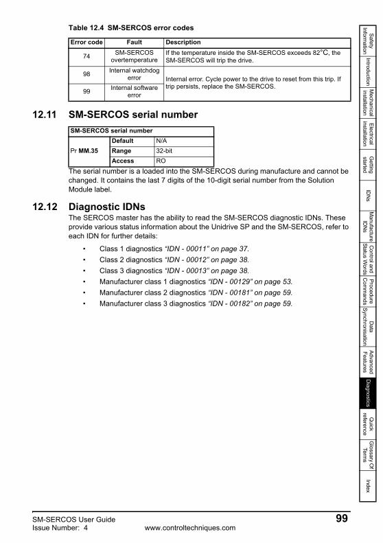
Safety Inform
ationIntroduction
Mechanical
installationElectrical
installationG
etting started
IDN
sM
anufacture ID
Ns
Control and
Status Words
Procedure C
omm
andsD
ata Synchronisation
Advanced Features
Diagnostics
Quick
referenceG
lossary Of
Terms
Index
12.11 SM-SERCOS serial number
The serial number is a loaded into the SM-SERCOS during manufacture and cannot be changed. It contains the last 7 digits of the 10-digit serial number from the Solution Module label.
12.12 Diagnostic IDNsThe SERCOS master has the ability to read the SM-SERCOS diagnostic IDNs. These provide various status information about the Unidrive SP and the SM-SERCOS, refer to each IDN for further details:
• Class 1 diagnostics “IDN - 00011” on page 37.• Class 2 diagnostics “IDN - 00012” on page 38.• Class 3 diagnostics “IDN - 00013” on page 38.• Manufacturer class 1 diagnostics “IDN - 00129” on page 53.• Manufacturer class 2 diagnostics “IDN - 00181” on page 59.• Manufacturer class 3 diagnostics “IDN - 00182” on page 59.
74 SM-SERCOS overtemperature
If the temperature inside the SM-SERCOS exceeds 82°C, the SM-SERCOS will trip the drive.
98 Internal watchdog error Internal error. Cycle power to the drive to reset from this trip. If
trip persists, replace the SM-SERCOS.99 Internal software
error
Table 12.4 SM-SERCOS error codes
Error code Fault Description
SM-SERCOS serial number
Pr MM.35Default N/ARange 32-bitAccess RO
SM-SERCOS User Guide 99Issue Number: 4 www.controltechniques.com

13 Quick reference
13.1 SM-SERCOS parameter referenceTable 13.1 lists all the SM-SERCOS set-up parameters that are required to configure the module.
Table 13.1 SM-SERCOS parameter reference
Menu Default Cross reference Description
Pr MM.01 409 Section 12.2 on page 95 Module ID code.
Pr MM.02 ---- Section 12.3 on page 95 Major firmware version.
Pr MM.03 1 Section 12.4 on page 95 Node address.
Pr MM.04 3 Section 12.5 on page 96 Data rate.
Pr MM.05 4 Section 12.6 on page 96 Transmitter optical power level.
Pr MM.06 ---- Section 12.7 on page 96 Operating status.
Pr MM.07 OFF (0) Section 11.1 on page 84 Network loss trip.
Pr MM.08 ON (1) Section 11.2 on page 84 Endian format.
Pr MM.09 ON (1) Section 11.3 on page 85 Register control.
Pr MM.10 0 Section 11.4 on page 85 Second encoder enable.
Pr MM.11 0 Section 11.5 on page 85 Second encoder source.
Pr MM.12 0 Section 11.6 on page 86 Second encoder turns bits.
Pr MM.13 0 Section 12.9 on page 98 Network diagnostic enable.
Pr MM.14 0 Section 12.9 on page 98 Network diagnostic destination.
Pr MM.15 0 Section 11.7 on page 86 Homing backoff behaviour.
Pr MM.16
0 ---- I / O register.Pr MM.17Pr MM.18Pr MM.19Pr MM.20
--- Reserved.Pr MM.21Pr MM.22Pr MM.23
100 SM-SERCOS User Guidewww.controltechniques.com Issue Number: 4

Safety Inform
ationIntroduction
Mechanical
installationElectrical
installationG
etting started
IDN
sM
anufacture ID
Ns
Control and
Status Words
Procedure C
omm
andsD
ata Synchronisation
Advanced Features
Diagnostics
Quick
referenceG
lossary Of
Terms
Index
Pr MM.24
0 --- I / O register.
Pr MM.25Pr MM.26Pr MM.27Pr MM.28Pr MM.29
Pr MM.30 0 Section 11.8 on page 86 Restore SM-SERCOS defaults.
Pr MM.31 0 Section 11.9 on page 87 Store to SM-SERCOS FLASH memory.
Pr MM.32 0 Section 5.3.9 on page 28
Re-initialise SM-SERCOS. This will automatically change back to 0 after re-initialisation.
Pr MM.33 0 Section 11.10 on page 87
Restore previous configuration from SM-SERCOS FLASH memory.
Pr MM.34 0 Section 11.11 on page 88 Marker pulse source selector.
Pr MM.35 ---- Section 12.11 on page 99 Serial Number.
Pr MM.36 0 Section 11.12 on page 89 Freeze main drive position.
Pr MM.37 0 Section 11.12 on page 89 Invert drive freeze.
Pr MM.38 0 Section 11.13 on page 89 Test mode.
Pr MM.39 0 Section on page 25 Reverse on home switch.
Pr MM.40 0 Section 11.14 on page 89 Disable SM-SERCOS control.
Pr MM.41 1 Section on page 25 Homing switch digital input source.
Pr MM.42 0 Section 5.3.7 on page 26 Position feedback source.
Pr MM.43 16 Section 5.3.8 on page 27 Encoder turn bits.
Pr MM.44 --- Section 10.2 on page 78 Synchronisation status.
Pr MM.45 --- Section 10.3 on page 78 Synchronisation period.
Pr MM.46
0 ---- Reserved.Pr MM.47Pr MM.48Pr MM.49
Pr MM.50 ---- Section 12.10 on page 98 SM-SERCOS error codes.
Pr MM.51 ---- Section 12.3 on page 95 Minor firmware version.
Table 13.1 SM-SERCOS parameter reference
Menu Default Cross reference Description
SM-SERCOS User Guide 101Issue Number: 4 www.controltechniques.com

13.2 SM-SERCOS IDN referenceTable 13.2 lists all the IDNs supported by SM-SERCOS.
Table 13.2 SM-SERCOS IDN reference
IDN Default Cross reference Description
00001 1000 Section 6.3.1 on page 35 Control unit cycle time (tNcyc).
00002 1000 Section 6.3.2 on page 35 Communication cycle time (tScyc).
00003 90 Section 6.3.3 on page 35
Shortest AT transmission starting time (t1.min).
00004 10 Section 6.3.4 on page 35 Transmit/receive time (tATMT).
00005 90 Section 6.3.5 on page 35 Minimum feedback processing time (t5).
00006 90 Section 6.3.6 on page 36
AT transmission starting time (t1).
00007 0 Section 6.3.7 on page 36 Feedback acquisition capture point (t4).
00008 0 Section 6.3.8 on page 36 Command value valid time (t3).
00009 1 Section 6.3.9 on page 36 Position of data record in MDT.
00010 4 Section 6.3.10 on page 37 Length of MDT.
00011 --- Section 6.3.11 on page 37 Class 1 diagnostics.
00012 --- Section 6.3.12 on page 38 Class 2 diagnostics.
00013 --- Section 6.3.9 on page 36 Class 3 diagnostics.
00014 --- Section 6.3.14 on page 39 Interface status.
00015 4 Section 6.3.15 on page 39 Telegram type.
00016 --- Section 6.3.16 on page 40 Configuration list of AT.
00017 --- Section 6.3.17 on page 40 IDN list of all operation data.
00018 --- Section 6.3.18 on page 40 IDN list of operational data in CP2.
00019 --- Section 6.3.19 on page 41 IDN list of operational data in CP3.
00021 --- Section 6.3.20 on page 41 IDN list of invalid operational data in CP2.
00022 --- Section 6.3.21 on page 41 IDN list of invalid operational data in CP3.
00024 --- Section 6.3.22 on page 41 Configuration list of MDT.
00025 --- Section 6.3.23 on page 42 IDN list of all procedure commands.
00028 --- Section 6.3.24 on page 42 MST error counter.
102 SM-SERCOS User Guidewww.controltechniques.com Issue Number: 4

Safety Inform
ationIntroduction
Mechanical
installationElectrical
installationG
etting started
IDN
sM
anufacture ID
Ns
Control and
Status Words
Procedure C
omm
andsD
ata Synchronisation
Advanced Features
Diagnostics
Quick
referenceG
lossary Of
Terms
Index
00029 --- Section 6.3.25 on page 42 MDT error counter.
00030 --- Section 6.3.26 on page 42 Manufacturer version.
00032 3 Section 6.3.27 on page 43 Primary operation mode.
00033 3 Section 6.3.28 on page 43 Secondary operation mode.
00036 0 Section 6.3.29 on page 43 Velocity command value.
00037 0 Section 6.3.30 on page 43 Additive velocity command value.
00040 --- Section 6.3.31 on page 43 Velocity feedback value 1.
00041 4096 Section 6.3.32 on page 44 Homing velocity.
00042 65536 Section 6.3.33 on page 44 Homing acceleration.
00043 0 Section 6.3.34 on page 44 Velocity polarity parameter.
00044 0 Section 6.3.35 on page 44 Velocity data scaling type.
00045 1 Section 6.3.36 on page 45 Velocity data scaling factor.
00046 0 Section 6.3.37 on page 45 Velocity data scaling exponent.
00047 0 Section 6.3.38 on page 45 Position command value.
00051 --- Section 6.3.39 on page 45 Position feedback value.
00052 0 Section 6.3.40 on page 45 Reference distance 1.
00053 --- Section 6.3.41 on page 46
Position feedback value 2 (external feedback/second encoder).
00055 0 Section 6.3.42 on page 46 Position polarity parameter.
00057 0 Section 6.3.43 on page 46 Position window.
00076 0 Section 6.3.44 on page 47 Position data scaling type.
00079 --- Section 6.3.45 on page 47 Rotational position resolution.
00080 0 Section 6.3.46 on page 47 Torque command value.
00081 0 Section 6.3.47 on page 47 Additive torque command value.
00084 --- Section 6.3.48 on page 47 Torque feedback value.
00085 0 Section 6.3.49 on page 48 Torque polarity parameter.
Table 13.2 SM-SERCOS IDN reference
IDN Default Cross reference Description
SM-SERCOS User Guide 103Issue Number: 4 www.controltechniques.com

00086 0 Section 6.3.50 on page 48 Torque/force data scaling type.
00088 10 Section 6.3.51 on page 48 Receive to receive recovery time (tTMSTY).
00089 0 Section 6.3.52 on page 48
MDT transmission starting time (t2).
00090 10 Section 6.3.53 on page 49 Command value proceeding time (tMTSG).
00091 3276800 Section 6.3.54 on page 49 Bipolar velocity limit value.
00092 10000 Section 6.3.55 on page 49 Bipolar torque limit value.
00095 --- Section 6.3.56 on page 49 Diagnostic message.
00096 --- Section 6.3.57 on page 50 Slave arrangement (SLKN).
00097 0 Section 6.3.58 on page 50 Mask class 2 diagnostics.
00098 0 Section 6.3.59 on page 50 Mask class 3 diagnostics.
00099 --- Section 6.3.60 on page 50 Reset class 1 diagnostics.
00100 --- Section 6.3.61 on page 51 Velocity loop proportional gain.
00101 --- Section 6.3.62 on page 51 Velocity loop integral gain.
00102 --- Section 6.3.63 on page 51 Velocity loop differential time.
00104 2500 Section 6.3.64 on page 51 Position loop Kv-factor.
00106 --- Section 6.3.65 on page 51 Current loop proportional gain 1.
00107 --- Section 6.3.66 on page 52 Current loop integral gain 1.
00109 --- Section 6.3.67 on page 52 Motor peak current.
00110 --- Section 6.3.68 on page 52 Amplifier peak current.
00112 --- Section 6.3.69 on page 52 Amplifier rated current.
00114 --- Section 6.3.70 on page 52 Load limit of the motor.
00124 0 Section 6.3.71 on page 52 Standstill window.
00125 0 Section 6.3.72 on page 53 Velocity threshold.
00127 --- Section 6.3.73 on page 53 Communication 3 transition check.
00128 --- Section 6.3.74 on page 53 Communication 4 transition check.
00129 --- Section 6.3.75 on page 53 Manufacturer class 1 diagnostics.
Table 13.2 SM-SERCOS IDN reference
IDN Default Cross reference Description
104 SM-SERCOS User Guidewww.controltechniques.com Issue Number: 4

Safety Inform
ationIntroduction
Mechanical
installationElectrical
installationG
etting started
IDN
sM
anufacture ID
Ns
Control and
Status Words
Procedure C
omm
andsD
ata Synchronisation
Advanced Features
Diagnostics
Quick
referenceG
lossary Of
Terms
Index
00130 --- Section 6.3.76 on page 54 Probe value 1 positive edge.
00131 --- Section 6.3.77 on page 54 Probe value 1 negative edge.
00132 --- Section 6.3.78 on page 54 Probe value 2 positive edge.
00133 --- Section 6.3.79 on page 54 Probe value 2 negative edge.
00134 --- Section 6.3.80 on page 55 MDT control word.
00135 --- Section 6.3.81 on page 55 AT status word.
00138 2147483647 Section 6.3.82 on page 55 Bipolar acceleration limit value.
00142 --- Section 6.3.83 on page 55 Application type.
00143 --- Section 6.3.84 on page 55 SERCOS interface version.
00147 260 Section 6.3.85 on page 55 Homing parameter.
00148 --- Section 6.3.86 on page 56 Drive controlled homing procedure.
00150 0 Section 6.3.87 on page 56 Reference offset 1.
00157 0 Section 6.3.88 on page 56 Velocity window.
00159 2147483647 Section 6.3.89 on page 57 Monitoring window.
00160 0 Section 6.3.90 on page 57 Acceleration data scaling type.
00161 1 Section 6.3.91 on page 57 Acceleration data scaling factor.
00162 0 Section 6.3.92 on page 57 Acceleration data scaling exponent.
00169 0 Section 6.3.93 on page 58 Probe control parameter.
00170 --- Section 6.3.94 on page 58 Probing cycle procedure command.
00179 --- Section 6.3.95 on page 59 Probe status.
00181 --- Section 6.3.96 on page 59 Manufacturer class 2 diagnostics.
00182 --- Section 6.3.97 on page 59 Manufacturer class 3 diagnostics.
00185 10 Section 6.3.98 on page 60 Length of the configurable data record in the AT.
00186 10 Section 6.3.99 on page 60 Length of the configurable data record in the MDT.
00187 --- Section 6.3.100 on page 60 IDN list of configurable data in the AT.
00188 --- Section 6.3.101 on page 60 IDN list of configurable data in the MDT.
Table 13.2 SM-SERCOS IDN reference
IDN Default Cross reference Description
SM-SERCOS User Guide 105Issue Number: 4 www.controltechniques.com

00189 --- Section 6.3.102 on page 61 Following distance.
00191 --- Section 6.3.103 on page 61 Cancel reference point procedure command.
00196 --- Section 6.3.104 on page 61 Motor rated current.
00206 0 Section 6.3.105 on page 61 Drive on delay time.
00207 0 Section 6.3.106 on page 62 Drive off delay time.
00208 0 Section 6.3.107 on page 62 Temperature data scaling type.
00292 --- Section 6.3.108 on page 62 List of supported operational modes.
00296 1000 Section 6.3.109 on page 62 Velocity feed forward gain.
00301 S-0-0000 Section 6.3.110 on page 63 Allocation of real-time control bit 1.
00303 S-0-0000 Section 6.3.111 on page 63 Allocation of real-time control bit 2.
00305 S-0-0000 Section 6.3.112 on page 63 Allocation of real-time status bit 1.
00307 S-0-0000 Section 6.3.113 on page 64 Allocation of real-time status bit 2.
00376 --- Section 6.3.114 on page 64 Baud rate.
00380 --- Section 6.3.115 on page 64 DC bus voltage.
00384 --- Section 6.3.116 on page 65 Amplifier temperature.
00390 --- Section 6.3.117 on page 65 Diagnostic number.
00400 0 Section 6.3.118 on page 65 Home switch.
00403 --- Section 6.3.119 on page 65 Position feedback value status.
00405 0 Section 6.3.120 on page 66 Probe 1 enable.
00406 0 Section 6.3.121 on page 66 Probe 2 enable.
00409 --- Section 6.3.122 on page 66 Probe 1 positive latched.
00410 --- Section 6.3.123 on page 66 Probe 1 negative latched.
00411 --- Section 6.3.124 on page 66 Probe 2 positive latched.
00412 --- Section 6.3.125 on page 67 Probe 2 negative latched.
42001 --- Section 11.18 on page 91 Application menu 3 read-write integer (Pr 20.01).
42002 --- Section 11.18 on page 91 Application menu 3 read-write integer (Pr 20.02).
Table 13.2 SM-SERCOS IDN reference
IDN Default Cross reference Description
106 SM-SERCOS User Guidewww.controltechniques.com Issue Number: 4

Safety Inform
ationIntroduction
Mechanical
installationElectrical
installationG
etting started
IDN
sM
anufacture ID
Ns
Control and
Status Words
Procedure C
omm
andsD
ata Synchronisation
Advanced Features
Diagnostics
Quick
referenceG
lossary Of
Terms
Index
42003 --- Section 11.18 on page 91 Application menu 3 read-write integer (Pr 20.03).
42004 --- Section 11.18 on page 91 Application menu 3 read-write integer (Pr 20.04).
42021 --- Section 11.18 on page 91 Application menu 3 read-write integer (Pr 20.21).
42022 --- Section 11.18 on page 91 Application menu 3 read-write integer (Pr 20.22).
42023 --- Section 11.18 on page 91 Application menu 3 read-write integer (Pr 20.23).
42024 --- Section 11.18 on page 91 Application menu 3 read-write integer (Pr 20.24).
Table 13.2 SM-SERCOS IDN reference
IDN Default Cross reference Description
SM-SERCOS User Guide 107Issue Number: 4 www.controltechniques.com

Safety Inform
ationIntroduction
Mechanical
installationElectrical
installationG
etting started
IDN
sM
anufacture ID
Ns
Control and
Status Words
Procedure C
omm
andsD
ata Synchronisation
Advanced Features
Diagnostics
Quick
referenceG
lossary O
f Terms
Index
14 Glossary Of Terms
Address: This is the unique network identification given to a networked device to allow communication on a network. When a device sends or receives data the address is used to determine the source and the destination of the message.
Amplifier: Traditional name for a servo variable speed drive slave axis.
Amplifier Telegram: Slave response message (containing its cyclic and non-cyclic data) to the master
AT: See Amplifier Telegram
Bit: A binary digit, this may have the value of 1 or 0.
Byte: A collection of 8 binary digits that collectively store a value. This may be signed or unsigned.
Casting: The process of changing between data sizes without changing the value represented, e.g. changing from 16 bit to 32 bit.
Control word: A collection of binary digits that are used to control the drive. Features typically include directional controls, run controls and other similar functions.
Communication phase: This reflects the status of the network and is graded 0 to 4.
Cyclic data: This consists of values that are sent at regular or cyclic intervals across the network. A typical use of cyclic data would be the transmission of a speed reference or a control word.
Data format: Determines the quantity and function of the data sent and received across the network.
Data rate: Determines the communication speed of the network, the higher the value the more data can be sent across the network in the same time period.
Device: A piece of equipment connected to a network, this may be any type of equipment including repeaters, hubs, masters or slaves.
Direct data mapping: Data is sent directly to the mapping parameters in the drive rather than the parameters redirecting the data to another parameter.
Double word: A 32 bit word, this may be signed or unsigned.
Grounding: See earthing.
Earthing: Describes the electrical safety or screening connections for the module.
108 SM-SERCOS User Guidewww.controltechniques.com Issue Number: 4

Endian format: When a value uses more than 8 bits to represent its value it needs to be sent in sets of 8 bits (bytes) across the network, the endian format determines the order the bytes that constitute the whole value are transmitted.
Event task: A special way to use a message or change of state to trigger a software routine.
Freeze: A function where motor position data is captured and stored following event.
IDN: Identification number.
Long word: A 32bit data word that may be signed or unsigned.
Network cycle time: Is the periodic rate at which is sent and received on the network.
Network loss trip: A method to determine when a node has lost communication with the master.
Node: A device on the network. This may be either a device such as a drive or part of the network such as a repeater.
Non-cyclic data: Data that is requested or sent by the master as required. This is not sent on a regular basis and generally allows access to any parameter. This is useful for occasional changes or configuration purposes.
Marker pulse: Signal produced by a motor feedback device once per shaft revolution.
Master: The controlling device on the network, generally this will include programming features.
Master Data Telegram (MDT): Messages (containing its cyclic and non-cyclic data) sent to the slave devices.
Master Synchronisation Telegram (MST): This telegram is transmitted from the master on a predefined time basis and is used to keep the slave devices synchronised with the master.
Re-initialise: Restarts the module using any configured settings.
SERCOS: SErial Real time COmmunication System interface.
Service channel: See non-cyclic data
Slave: A device on the SERCOS network such as a drive or sensor. A slave device will only respond to messages from a master.
Status word: A value that denotes the status of the drive. Each bit within the word will have a specific meaning.
Synchronisation: A method of ensuring that devices use data simultaneously.
SM-SERCOS User Guide 109Issue Number: 4 www.controltechniques.com

Safety Inform
ationIntroduction
Mechanical
installationElectrical
installationG
etting started
IDN
sM
anufacture ID
Ns
Control and
Status Words
Procedure C
omm
andsD
ata Synchronisation
Advanced Features
Diagnostics
Quick
referenceG
lossary O
f Terms
Index
Telegram: A message used within data communication. This term is some times used to represent a generic message on the network.
Watchdog: A method used to determine if a communication system is healthy. A typical watchdog scheme uses a handshaking system to check both the master and slave are participating in communications.
Word: A collection of 16 binary digits.
110 SM-SERCOS User Guidewww.controltechniques.com Issue Number: 4

Safety Inform
ationIntroduction
Mechanical
installationElectrical
installationG
etting started
IDN
sM
anufacture ID
Ns
Control and
Status Words
Procedure C
omm
andsD
ata Synchronisation
Advanced Features
Diagnostics
Quick
referenceG
lossary Of
Terms
Index
Index
AAuxiliary ......................................................................................................13Auxiliary supply ..........................................................................................13
BBackup .......................................................................................................87Backup supply ............................................................................................13Byte order ...................................................................................................84
CCable ..........................................................................................................17Cautions .......................................................................................................6Certificate .............................................................................................12, 13Compliance ..................................................................................................7Conformance ........................................................................................12, 13Control word ...............................................................................................70Control word bit functions ...........................................................................71Cyclic data ..................................................................................................68
DData endian format .....................................................................................84Data rate .....................................................................................................96Data rates .......................................................................................24, 26, 96Diagnostic flow chart ..................................................................................94Diagnostics .................................................................................................94Disable SM-SERCOS control .....................................................................89D-Type pin out ............................................................................................16Dual SM-Applications .................................................................................69
EElectrical installation ...................................................................................16Electrical safety ............................................................................................6Endian format .............................................................................................84Environmental limits .....................................................................................7Error codes .................................................................................................98
FFirmware version ........................................................................................95
GGeneral information ......................................................................................2Getting started ............................................................................................20Glossary of terms .....................................................................................108
HHardware enable ........................................................................................70Homing backoff behaviour ..........................................................................86
IID code .......................................................................................................95
SM-SERCOS User Guide 111Issue Number: 4 www.controltechniques.com

LLocal solutions access ...............................................................................90
MMenu 60 .....................................................................................................90
NNetwork length ...........................................................................................18Network loss trip .........................................................................................84Node address .............................................................................................95Non-cyclic data ...........................................................................................73
OOperating status ...................................................................................28, 96Operating status codes ........................................................................28, 97
PParameter reference ................................................................................100Parameters - adjusting .................................................................................7Problems ....................................................................................................94
QQuick reference ........................................................................................100
RRe-initialise .................................................................................................28Restore configuration .................................................................................87Restore defaults .........................................................................................86
SSafety Information ........................................................................................6Safety of personnel ......................................................................................6Saving ........................................................................................................29Second encoder enable .............................................................................85Second encoder source .............................................................................85Second encoder turns bits ..........................................................................86SECURE DISABLE ......................................................................................6Serial number .............................................................................................99Set-up flow chart ........................................................................................23Single SM-Applications ..............................................................................69Specification ...............................................................................................10Status codes .........................................................................................28, 97Status word ................................................................................................72Storing parameters .....................................................................................87
TTerminal descriptions .................................................................................16Trip 54 ........................................................................................................85Trip display codes ......................................................................................97
UUnidrive SP control word ............................................................................70
WWarnings ......................................................................................................6Word order .................................................................................................84
112 SM-SERCOS User Guidewww.controltechniques.com Issue Number: 4


0471-0048-04