sdm-lecture damping 16jan2014damping is an important aspect ! of spacecraft design and...
TRANSCRIPT

Vibration Damping: ���The Turbulence of Structural Mechanics?
George A. Lesieutre Department of Aerospace Engineering Center for Acoustics & Vibration
SDM Lecture AIAA Science and Technology Forum and Exposition (SciTech 2104)
National Harbor, MD
16 January 2014
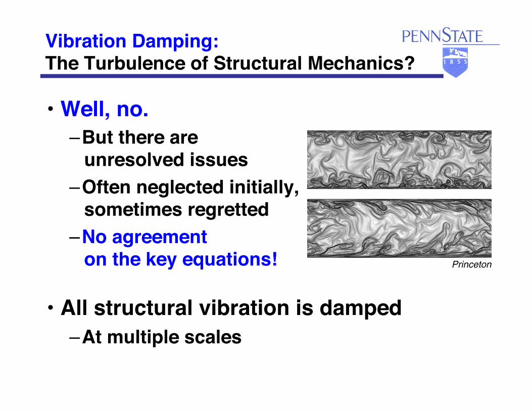
Vibration Damping: ���The Turbulence of Structural Mechanics?
• Well, no. – But there are ���
unresolved issues – Often neglected initially, ���
sometimes regretted – No agreement ���
on the key equations!
• All structural vibration is damped – At multiple scales
Princeton!

We will survey some ���passive damping methods and models
• Conventional damping treatments
• Material behavior
• Conventional damping models
NOT isolation, structural mods
Material damping models
• Structural damping models
• Unconventional damping treatments
C[ ] x{ }C
R
piezoVs
cG ′′w

Vibration damping matters
• Damping is important in aerospace – Dynamic response, fatigue, noise – Aeroelastic response and stability – Margin for active structural control – Wave-based SHM and NDE – MEMS resonators, sensors
• System benefits require considering damping during the design process
• Effective damping methods are needed • Accurate damping models are needed

Damping is an important aspect ���of spacecraft design and performance
• Launch vehicles – Payload isolation and vibroacoustics – Solid propellant; Deployable nozzles
• “Flexible” spacecraft – Deployment – High-BW precision pointing, disturbances – Damped struts, equipment sandwich panels, ���
joints, isolators – VEM (CLD via MSE), piezo, magnetic (eddy-current)
• Ongoing concerns – Meeting stringent system req’ts
• Multi-stage isolation, damping, active pointing – Thermal (cryo-) environments; outgassing – Effects of cabling – Ground-based validation; effects of gravity.
Modal damping in bare JWST composite structure ���at 35K is as low as 0.017% (!)
Abbruzzese, Parker, Lin, Innis (NGST), “Measurement of Damping ���
in Composite Structure Assembly at Cryogenic Temperatures,” ���AIAA 2008–2192, 49th AIAA SDM.

Damping is an important aspect ���of aircraft design and performance
Pressure loads decrease damping
Liguore, Montgomery, Foss (Boeing), “Prediction and Measurement of Structural Loss Factors in Damped Composite
Panels under Pressure Loads,” AIAA 2008–2236, 49th SDM.
• Fatigue and strength – Aerodynamic (buffet); Acoustic; Landing – Damped composite bonded repairs – Stress-coupled, co-cured damped composites
• Payload isolation
• Interior noise reduction – Composite panel ���
acoustic attenuation • Light, stiff, fewer joints
• Aeroelastic response and stability – Gusts; Flutter; ASE – Design analysis and practical augmentation
• Ongoing concerns – Effectiveness over broad operating range – Pressure and CF loads – Joint modeling (LCO) – Damped structural composite materials
• Rotorcraft lag damping

Damping is an important aspect ���of engine design and performance
• High-cycle fatigue – Monolithic blisks (IBR)
• Compressor, turbine; turbopumps – Composite fan blades
• Ongoing concerns – Integral damping
• Damped structural materials – CF loads – High temperature
Modal damping in Inconel 718 specimen���as low as 0.01% (!)
Min, Harris, Ting (NASA), “Advances in Ceramic Matrix Composite Blade
Damping for Aerospace Turbomachinery Applications,” ���AIAA 2011–1784, 52th AIAA SDM.

Let’s start from the beginning • Nominal equations of motion
• Sources of damping
• Measures of damping
M[ ] !!q{ }+ C[ ] !q{ }+ K[ ] q{ } = f{ }
ζ ≈ η2
= ψ4π
notional energy dissipation
modal ���damping ratio
loss ���factor
specific ���damping capacity
Some amenable to design specification
… acoustic���attenuation

Intrinsic damping is often low
CSA Engineering!
�
˙ ̇ a m + 2ζmωm ˙ a m + ωm2 am = Am (t)
modal EOM
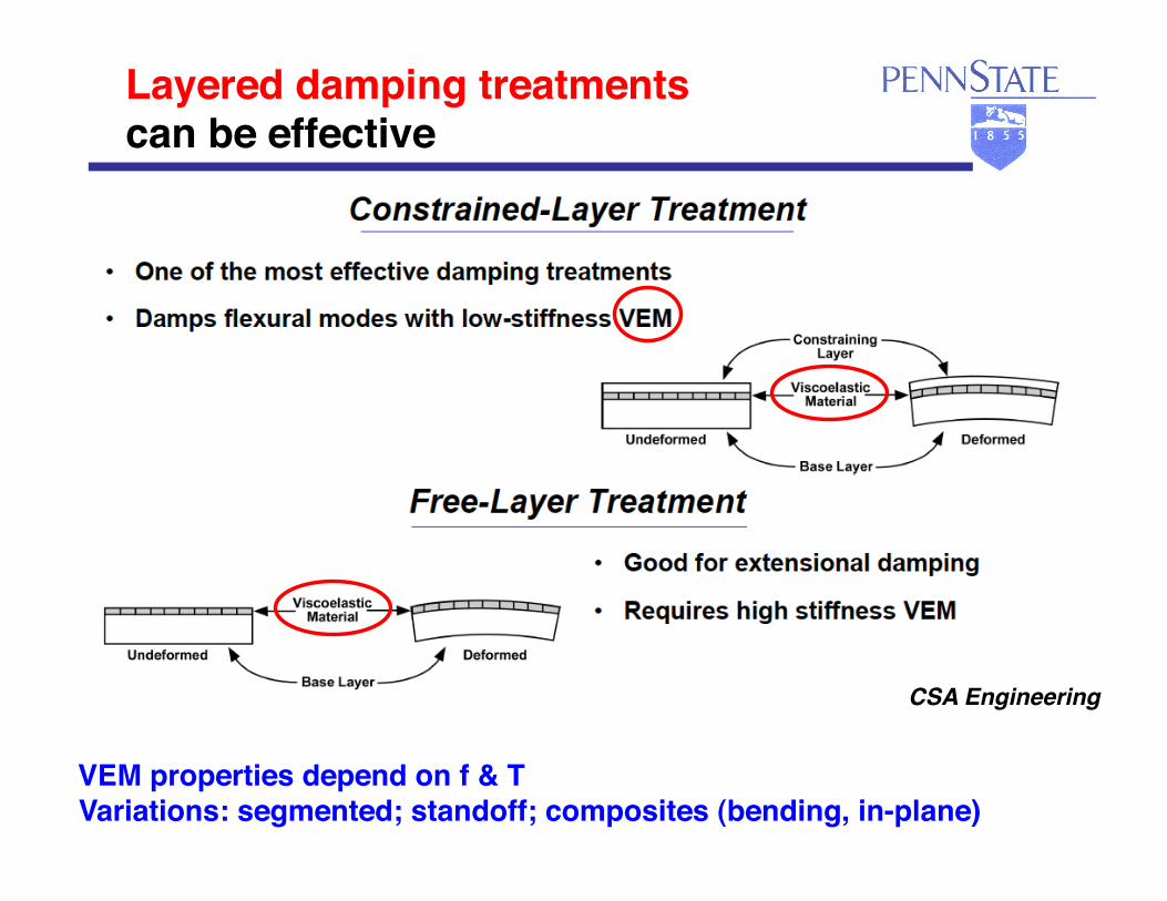
Layered damping treatments ���can be effective
VEM properties depend on f & T Variations: segmented; standoff; composites (bending, in-plane)
CSA Engineering!

What do we need ���to design a layered damping treatment?
• Models (placement and sizing) – Proportional viscous damping – Viscoelastic damping (freq-domain)
• Complex modulus; loss factor • Modal Strain Energy method (FE)
• VEM materials selection • Reduced-frequency nomogram

Viscous damping models are ���simple and popular
• Proportional Damping: linear and viscous
– Convenient, not physics-based: dissipation in time-domain model, real vibration modes
M[ ] q{ } + C[ ] q{ } + K[ ] q{ } = Q{ }C[ ] = β K[ ] + γ M[ ]
• Strain-based (stiffness-proportional) viscous damping yields modal damping that increases with frequency
• Motion-based (mass-proportional) viscous damping yields modal damping that decreases with frequency
Normalized Frequency, ω!1.0! 10.!0.1!
Nor
mal
ized
D
ampi
ng!
Proportional damping model!
Typical material damping behavior!
�
γ ω2
�
β2ω
(Curves offset vertically for clarity.)!

Frequency Response models avoid some difficulties of viscous damping • Modify viscous damping matrix
– Ω is a harmonic forcing frequency
• Complex structural stiffness
– Complex modulus – Possible frequency-dependent properties
C[ ]hysteretic
1Ω
C[ ]viscous =γΩ
K[ ]
M[ ] !!q{ }+ γ
ΩK[ ] !q{ }+ K[ ] q{ } = f{ }eiΩt
−Ω2 M[ ]+ 1+ iγ( ) K[ ]⎡⎣ ⎤⎦ q(Ω){ } = f{ }σ (Ω){ } = (1+ iη) E[ ] ε(Ω){ }
= E '[ ] + i E"[ ]⎡⎣ ⎤⎦ ε(Ω){ }
“structural” ���damping
loss factor η = ′′E′E
Myklestad, N. (1952). The concept of complex damping. Journal of Applied Mechanics, 19(3):284–286.!

Modal damping can be estimated ���for non-specific material damping
• Dynamic response ���via modal superposition
• Canonical SDOF modal eqns of motion
• How to find modal damping?
�
˙ ̇ a m + 2ζmωm ˙ a m + ωm2 am = Am (t)
ζ m > 0

Modal Strain Energy (MSE) method provides results and insight
• Damping of a mode of a structure is a weighted sum of the damping of its parts – Weighting factors are the ���
fraction of strain energy stored in each part
• Applicable to multi-mode deformation,
composite materials, built-up structures
ηm =Upart
UTOTAL
⎛⎝⎜
⎞⎠⎟ m
ηpartparts∑
Ungar, E. E. and Kerwin Jr., E. M. (1962). Loss factors of viscoelastic systems in terms of energy concepts. Journal of the Acoustical Society of America, 34(7):954–957.!

High-damping materials (VEM) exhibit ���frequency- and temperature-dependence
• 3M ISD 112, for instance
modulus
loss factor
Variations possible (multilayer CLD, copolymer blends)
T
f

Modal Strain Energy method ���is very suitable for use with FEA
CSA Engineering!Johnson, C. D. and Kienholz, D. A. (1981). Finite element prediction of damping in
beams with constrained viscoelastic layers. Shock and Vibration Bulletin, 51:71–81.!

• Models – Time-domain viscoelasticity
• Temperature dependence • Wave propagation
– Nonlinear elastomers (helo lag damper) – “Geometric” viscous damping
• Shear beams (spacecraft cabling) – Membrane loads
• Methods – Damped composites – Piezoelectric materials
• Resistive shunts • Energy harvesting
– Particle damping
Potpourri of models and methods are ���available for accuracy and design options
CR
piezoVs

Better damping models are available • Experiments on built-up structures show relatively
weak frequency-dependence • More accurate damping models are available
– Complex modulus models can yield frequency-independent modal damping, but useful mainly in frequency domain
• Fractional derivative – Frequency-dependence of high-loss viscoelastic materials
• Time-domain internal variable models
�
ε
�
εA
�
σ
�
Δ +1Δ
Eu
Ω
�
Eu
Δ
�
Eu

Fractional Derivative model ���captures weak frequency dependence
• Compact frequency domain model – Captures relatively weak frequency
dependence of damping and stiffness
m is order ���of time derivative
E * (iω ) = E0 + E1(iω )m
1+ b(iω )m
Normalized Frequency, ω!1.0! 10.!0.1!
Nor
mal
ized
D
ampi
ng!
Typical material damping behavior!
m −m
Some utility in time domain Bagley and Torvik, “Fractional calculus – a different approach to the analysis of
viscoelastically damped structures,” AIAA Journal, 1983, 21(5):741–748.

Internal Variable viscoelastic models can capture frequency-dependence
• Total displacement field is the sum of elastic and anelastic parts (ADF model)
• Constitutive eqns
• Evolution eqns
σ = Eu ′u − ′u A( )σ A = Eu ′u − c ′u A( )
ρu − Eu ′′u − ′′u A( ) = p x,t( )
cEu
Ω′′u A − Eu ′′u − c ′′u A( ) = 0
u x,t( ) = uE x,t( ) + uA x,t( )
�
ε
�
εA
�
σ
�
Δ +1Δ
Eu
Ω
�
Eu
Δ
�
Eu
�
ε
�
εA
�
σ
cEu
Ω
c −1( )Eu
�
Eu
Δ relaxation strength
motion
relaxation

ADF Finite Element (Rod)
m 3 m 6 0 0m 6 m 3 0 00 0 0 00 0 0 0
⎡
⎣
⎢⎢⎢⎢⎢
⎤
⎦
⎥⎥⎥⎥⎥
u1u2u1A
u2A
⎧
⎨
⎪⎪
⎩
⎪⎪
⎫
⎬
⎪⎪
⎭
⎪⎪
+
0 0 0 00 0 0 00 0 ck Ω − ck Ω0 0 − ck Ω ck Ω
⎡
⎣
⎢⎢⎢⎢⎢
⎤
⎦
⎥⎥⎥⎥⎥
u1u2u1A
u2A
⎧
⎨
⎪⎪
⎩
⎪⎪
⎫
⎬
⎪⎪
⎭
⎪⎪
+
k −k k −k−k k −k kk −k ck −ck−k k −ck ck
⎡
⎣
⎢⎢⎢⎢
⎤
⎦
⎥⎥⎥⎥
u1u2u1A
u2A
⎧
⎨
⎪⎪
⎩
⎪⎪
⎫
⎬
⎪⎪
⎭
⎪⎪
=
f1f200
⎧
⎨⎪⎪
⎩⎪⎪
⎫
⎬⎪⎪
⎭⎪⎪
A time-domain model Lesieutre, G.A., “Finite Elements for Dynamic Modeling of Uniaxial Rods with Frequency-Dependent
Material Properties,” International Journal of Solids and Structures, Vol. 29, No. 12, 1992, pp. 1567–1579.!

Single-ADF FE Results Modal damping vs. modal frequency (~15 elements)
Hysteresis loops at different frequencies
Mod
al d
ampi
ng ra
tio
Stre
ss (P
a)
Frequency (r/s)
Strain
100 (r/s)
10,000 (r/s) 1000 (r/s)

Multiple ADF model can capture weaker-frequency dependence
• Complex modulus – Single-ADF building blocks
– Unrelaxed and relaxed modulus – Relaxation strength
E * ω( ) = Er 1+ Δn
ω Ωn( )2
1+ ω Ωn( )2n∑
⎛
⎝⎜
⎞
⎠⎟
storage modulus
+ i Er Δn
ω Ωn( )1+ ω Ωn( )2
n∑
⎛
⎝⎜
⎞
⎠⎟
loss modulus
Δ total = Δnn∑
Eu = Er 1+ Δ total( )M
odul
us

Multiple ADFs ���can capture material behavior well
• ISD112 • 1 ADF (single)
Single-ADF building
blocks

Multiple ADFs ���can capture material behavior well
• ISD112 • 3 ADFs
Lesieutre, G.A., and E. Bianchini, “Time-Domain Modeling of Linear Viscoelasticity using Anelastic Displacement Fields,” Journal of Vibration and Acoustics, Vol. 117, No. 4, October, 1995, pp. 424–430. !
Ω1
Ω2Ω3

ADF Finite Elements used to model ���Active Constrained Layer damping
Elastic model
ADF model Lesieutre, G.A., and Lee, U. “A Finite Element Model for Beams Having Segmented Active Constrained Layers with Frequency-Dependent Viscoelastic Material Properties,” Smart Materials and Structures, Vol. 5, 1996, pp. 615–627. !
piezo visco elastic

• Predict wave propagation ���in viscoelastic rods, ���
shock absorption ���in mechanical filters
• 3-D, ADF-based FE for axisymmetric geometry
• Prediction vs. experiment: ���velocity of mass on 3-mm filter – Matches magnitude, ���
frequency content • Captures geometric dispersion, ���
viscoelastic dispersion ���and attenuation
ADF model can capture behavior ���of shock filters on Hopkinson bar
Air plenum Projectile Force gauge
Rubber filter
Accelerometer and 30-g mass
Rusovici, R., Lesieutre, G. and Inman, D. J. “Modeling of Shock Propagation and Attenuation in Viscoelastic Components”, Shock and Vibration Digest, Vol. 8, No. 5, 2001, pp. 287–302. !
Rubber filter
Accel / mass force ���gauge projectile
0 0.2 0.4 0.6 0.8 1 1.2 1.4 1.6 1.8 2-0.2
-0.1
0
0.1
0.2
0.3
0.4
0.5
msec
m/s
predictedexperiment
msec
m/s

Internal variable models can also capture temperature-dependence
• Add thermal evolution equations – Conduction and heat generation
– Relaxation of anelastic displacement is faster at high temperature: shift function
cv T − k ′′T = r(x,t) r(x,t) = cGu
Ω′u A( )2
αT
cGu
Ω!′′u A −Gu ′′u − c ′′u A( ) = 0 αT T( ) = ea
1T( )− 1
Tref( )⎡⎣⎢
⎤⎦⎥

ADF-T shear FE ���includes thermal dynamics
m 0 0 00 1 0 00 0 αT c Ω( )k 00 0 0 C
⎡
⎣
⎢⎢⎢⎢
⎤
⎦
⎥⎥⎥⎥
!!u!u!uA!T
⎧
⎨⎪⎪
⎩⎪⎪
⎫
⎬⎪⎪
⎭⎪⎪
+
0 k −k 0−1 0 0 00 −k ck 00 0 0 K
⎡
⎣
⎢⎢⎢⎢
⎤
⎦
⎥⎥⎥⎥
!uuuA
T
⎧
⎨⎪⎪
⎩⎪⎪
⎫
⎬⎪⎪
⎭⎪⎪
=
F00R
⎧
⎨⎪⎪
⎩⎪⎪
⎫
⎬⎪⎪
⎭⎪⎪
Three coupled fields

ADF-T model can capture ���“thermal runaway”
Tip displacement
Tip temperature Force-displacement
hysteresis
Lesieutre, G.A., and Govindswamy, K.M., “Finite Element Modeling of Frequency–Dependent and Temperature–Dependent Dynamic Behavior of Viscoelastic Materials in Simple Shear,” International Journal of Solids and Structures, Vol. 33, No. 3, 1995, pp. 419–432. !
displacement
forc
e
time
time
disp
lace
men
t te
mpe
ratu
re

-1 -0.5 0 0.5 1-10
-5
0
5
10
-20 -10 0 10 20-60
-40
-20
0
20
40
60
Stre
ss (p
si)!
Strain (%)!
Variation of material hysteresis with strain amplitude
Stre
ss (p
si)!
Strain (%)!
Nearly elliptical at low amplitude!
E 100 W, Room Temperature, 1 Hz!
Significant slope and area changes!
Elastomeric materials can exhibit nonlinear behavior with increasing strain
Helo lag damper app

A nonlinear elastomeric model:���Nonlinear Multi-ADF with Friction (NMAF)
∑∑==
+−=M
j
fj
N
i
Aiuu GG
11σεεσ
),,1( Ni
FcGGGciNL
Aiiuu
Ai
i
ui
…
!
=
=+−Ω
εεε
Friction Stress Contribution!
(Rate Independent Nonlinearity)!
Nonlinear Viscous Force (Rate Dependent
Nonlinearity)!
Current Model:!!3 internal fields (N=3)!!3 friction elements (M=3)!
Model Schematic:!
Simple Shear!
Brackbill, C.R., E.C. Smith, G.A. Lesieutre, “Application of a Refined Time Domain Elastomeric Damper Model to Helicopter Rotor Aeroelastic Response and Stability,” AHS Journal, Vol. 47, No. 3, July 2002, pp. 186–197. !

Shear Stress (psi)
-20
-10
0
10
20
-10 -5 0 5 10
Stre
ss (p
si)
Shear Strain (%)
Experimental DataPrediction
10% Strain1% Strain
-0.5
0
0.5
-0.1 0 0.1
0.1% Strain
E100W, 75°F, 1Hz!
Nonlinear model validated ���with experimental data
Data used in fit: storage modulus and loss factor ��� vs. amplitude and frequency

Viscous damping models are ���simple and popular
• Proportional Damping: linear and viscous
– Convenient, not physics-based: dissipation in time-domain model, real vibration modes
M[ ] q{ } + C[ ] q{ } + K[ ] q{ } = Q{ }C[ ] = β K[ ] + γ M[ ]
• Strain-based (stiffness-proportional) viscous damping yields modal damping that increases with frequency
• Motion-based (mass-proportional) viscous damping yields modal damping that decreases with frequency
Normalized Frequency, ω!1.0! 10.!0.1!
Nor
mal
ized
D
ampi
ng!
Proportional damping model!
Typical material damping behavior!
�
γ ω2
�
β2ω
(Curves offset vertically for clarity.)!

Strain-based viscous damping yields damping that increases w/ modal frequency
• Modal damping
strain-based viscous damping (stiffness-proportional)
�
ρA ˙ ̇ w + cK ′ ′ ′ ′ ˙ w + EI ′ ′ ′ ′ w = 0
�
˙ ̇ a m +cK
ρAmπL
⎛ ⎝
⎞ ⎠
4
˙ a m +1ρA
EI mπL
⎛ ⎝
⎞ ⎠
4⎡
⎣ ⎢
⎤
⎦ ⎥ am = 0
�
ζK m =cK
mπL
⎛ ⎝
⎞ ⎠
2
2 ρA EI( )1 2=cK ωm
2EI

Motion-based viscous damping yields damping that decreases w/ modal frequency
• Modal damping
motion-based viscous damping (mass proportional)
�
ρA ˙ ̇ w + cM ˙ w + EI ′ ′ ′ ′ w = 0
�
˙ ̇ a m +cM
ρA˙ a m +
1ρA
EI mπL
⎛ ⎝
⎞ ⎠
4⎡
⎣ ⎢
⎤
⎦ ⎥ am = 0
�
ζM m =cM
2 ρA EI( )1 2 mπL
⎛ ⎝
⎞ ⎠
2 =cM
2EI ωm

• Modal damping
“Geometric” viscous damping yields relatively constant modal damping
�
ρA ˙ ̇ w − cG ′ ′ ˙ w + EI ′ ′ ′ ′ w = 0
�
˙ ̇ a m +cG
ρAmπL
⎛ ⎝
⎞ ⎠
2
˙ a m +1ρA
EI mπL
⎛ ⎝
⎞ ⎠
4⎡
⎣ ⎢
⎤
⎦ ⎥ am = 0
�
ζG m =cG
2 ρAωm
mπL
⎛ ⎝
⎞ ⎠
2
=cG
2 ρA EI( )1 2
“geometric” viscous damping (flexural structures)!

Geometric Damping, SS BC, FEA – ���Modal damping is very nearly constant • 50 finite elements, 1st 49 modes
Norm
aliz
ed m
odal
dam
ping
Mode number
1.00
0.97
0.5%
2.5%
Non-proportional damping, but REAL modes!
Lesieutre, G.A., “Frequency-Independent Modal Damping for Flexural Structures via a Viscous ‘Geometric’ Damping Model,” Journal of Guidance, Control, and Dynamics, 2010, v 33, n 6, p 1931–1935. !

Damping model for shear beams ���captures dynamics of spacecraft cabling
• Behavior separated into bending- ���and shear-dominated regimes – Corresponding physical insight
• Freq-independent modal damping ���achievable in bending region – Can control damping ���
in shear regime
ζ =αϕ
2 ρAEI1+ αβ
αϕεm2
1+ εm2
−ρA !!w +κAG − ′ϕ + ′′w( ) = −q −αβ! ′β −αϕ ! ′ϕ
Kauffman, J.L., Lesieutre, G.A. and Babuska, V., “Damping Models for Shear Beams with Applications to Spacecraft Wiring Harnesses,” Journal of Spacecraft and Rockets, 2013; doi:10.2514/1.A32440!
Mode number, m M
odal
dam
ping
Mode number, m Norm
mod
al d
ampi
ng
bending shear

Membrane loads affect the ���modal damping of flexural structures
• Rotor blades • Airplane fuselages • Actuators; Acoustic transducers • MEMS resonators
HSCT

Pressurization can decrease damping ���of some fuselage modes by 80%
• Damping of thin sandwich shell
Of concern for interior noise Lesieutre, Wodtke, Zapfe; Damped Composite Honeycomb Sandwich Panels ���
for High-Speed Aircraft Interior Noise Reduction, BCA, 1995.
n!
m!
Loss
fact
or

• High Q (>106) attributed to tensile stress The precise mechanism by which tension increases Q even in the presence of increased material damping and boundary losses “remains unknown.”
Tension decreases modal damping ���in MEMS resonators
Verbridge, Shapiro, Craighead, Parpia, “Macroscopic Tuning of Nanomechanics: Substrate Bending For Reversible Control of Frequency And Quality Factor of Nanostring Resonators,” Nano Letters, Vol. 7, No. 6, 2007, pp. 1728–1735.

Model: Tension decreases ���modal damping of a SS beam
• Modal damping
T
ρA w + cs ′′′′w − T ′′w + EI ′′′′w = 0
strain-based viscous damping
T Pcr
ζEI m =cEI
mπL
⎛⎝⎜
⎞⎠⎟2
2 ρA EI( )1 2ζEI m 0
1
1+ Tm2Pcr
⎛⎝⎜
⎞⎠⎟
1 2 =ζEI m0
1+ T Pcrm2
⎛⎝⎜
⎞⎠⎟1 2

Tension increases modal frequencies ���and decreases modal damping
0.001
0.01
0.1
1
Rela
tive
Mod
al L
oss
Fact
or
5 61
2 3 4 5 610
2 3 4 5 6100
2
Normalized Modal Frequency
m = 1
m = 5
0 -0.5
+0.5
5
50
500
T/Pcr
Lesieutre, G.A., “How Membrane Loads Influence the Modal Damping of Flexural Structures,” AIAA Journal, Vol. 47, No. 7, July 2009, pp. 1642–1646. !

Modal Strain Energy method ���provides insight
• Consider the fraction of strain (potential) energy associated with each contributor to the stiffness
ηm =UEI
UTOTAL
⎛⎝⎜
⎞⎠⎟ m
ηEI +VT
UTOTAL
⎛⎝⎜
⎞⎠⎟ m
ηT
mat’l loss factor loss factor assoc. w/ tension = 0
=UEI
UEI +VT
⎛⎝⎜
⎞⎠⎟ m
ηEI =1
1+ T Pcrm2
⎛⎝⎜
⎞⎠⎟ηEI

Non-strain-based damping needed ���—highly distributed vibration absorbers
• Metamaterials? Zapfe, J.A. and G.A. Lesieutre, “Broadband Vibration Damping Using Highly Distributed Tuned
Mass Absorbers,” 1996, AIAA Journal, Vol. 35, No. 4, April 1997, pp. 753–756. !
F s( ) = ki s2mi
s2mi + kii=1
N
∑ u s( )
Hébert, C.A. and G.A. Lesieutre, “Rotorcraft Blade Lag Damping using Highly Distributed Tuned Vibration Absorbers,” AIAA 98–2001, 39th SDM, 1998, 2452–2457. !
Mod
al lo
ss fa
ctor
Modal frequency (Hz)
200-1000 Hz!
10-1000 Hz!
CLD T

Sandwich panel damping ���increased via internal VEM layers
Zapfe, J.A., and G.A. Lesieutre, “A Discrete Layer Finite Element for the Dynamic Analysis of Composite Sandwich Beams with Integral Damping Layers,” Computers and Structures, Vol. 70, 1999, pp. 647–666. !
VEM just inside facesheet Discrete layer finite element model linear u, quadratic w; lock-free (shear stress ~ constant)
Mode number
Mod
al lo
ss fa
ctor
0.0
0.2
baseline
Frequency (Hz)
Acce
lera
nce
(mag
, kg-
1 )

High-damping fiber ���would enhance composite damping
• Most of the strain energy of deformation is in the fiber
• Modal strain energy ���shows leverage of fiber damping
ηEL=
vf E f
EL
⎛⎝⎜
⎞⎠⎟η f +
1− vf( )Em
EL
⎛
⎝⎜
⎞
⎠⎟ ηm
EL = vf E f + 1− vf( )Em
Yarlagadda, S., and G.A. Lesieutre, “Fiber Contribution to Modal Damping of Polymer Matrix Composite Panels,” Journal of Spacecraft and Rockets, Vol. 32, No. 5, September-October, 1995, pp. 825–831.
Ef ≫ Em

Damping of carbon fibers is low, ���but can be improved
• Nominal loss factor of P-100 fiber: 10-4
• Bromine intercalation increases 10–40X
400 Hz
Lesieutre, Eckel, DiCarlo, “Damping of Bromine-Intercalated P-100 Graphite Fibers,” Carbon, Vol. 29, No. 7, 1991, pp. 1025–32
Temperature (K)
Dam
ping
cap
acity

High-damping piezoelectric fiber ���might be possible
• Piezo (3–3) – Stiffness ~ aluminum – Loss factor ~ 30%
• Whisker • Resistance
• 4% loss factor, 10% vf – Small capacitance (~stray)
• Challenges – Poling, resistance, capacitance, freq-dependence
Yarlagadda, S., G.A. Lesieutre, S. Yoshikawa, and J. Witham, “Resistively-Shunted Piezocomposites for Passive Vibration Damping,” 37th AIAA/ASME Adaptive Structures Forum, Salt Lake City, UT, April 18–19, 1996, pp. 217–227.

Shape Memory Alloys ���can provide high damping — at high strain
Thomson, Balas and Leo, “The use of shape memory alloys for passive ���structural damping,” Smart Materials and Structures, 1995, v4, 36–42.
Strain
Stre
ss (N
/mm
2 )

Piezoelectric shunting can ���provide damping, vibration reduction
• Mechanical structure interacts with electrical circuit via (capacitive) piezo transducer – Capacitive shunting yields ���
frequency-dependent stiffness – Resistive shunting yields ���
frequency-dependent damping – Inductive shunting yields ���
electrical resonant absorber – Switch-shunting could provide ���
broadband damping, stored energy
CR
piezoVs
C
piezoVs
Zsh
CL
piezoVs
R
CC
piezoVs sh
Lesieutre, G.A., “Vibration Damping and Control using Shunted Piezoelectric Materials,” Shock and Vibration Digest, Vol. 30, 1998, pp. 187–195. !

Resistive shunts provide damping (dissipation)
10-1 100 1010
0.1
0.2
0.3
0.4
Loss
fact
or
10-1 100 1011
1.5
2
Non-dimensional frequency
Non-
dim
ensio
nal m
odul
us
!τ = τ S
1− k2= R CS
1− k2
Loss factor
CR
piezoVs
coupling coefficient k = 0.70
0.35
k = 0.35 η = 0.070 k = 0.70 η= 0.343
η(ω ) =ηmax
2(ω !τ )1+ (ω !τ )2
ηmax =k2
2 1− k2
Davis, C.L., and G.A. Lesieutre, “A Modal Strain Energy Approach to the Prediction of Resistively–Shunted Piezoceramic Damping,” Journal of Sound and Vibration, Vol. 184, No. 1, 1995, pp. 129–139.
Frequency
Loss
fact
or

Semi-passive switch shunting ���can also be effective
• Can remove electrical energy from piezo / structure
– Semi-passive damping
• May be able to store it – Energy harvesting (and damping)
C
piezo
sV DCV+
+
-
-
Lefeuvre, E., Badel, A., Petit, L., Richard, C., and Guyomar, D., “Semi-Passive Piezoelectric Structural Damping by Synchronized Switching on Voltage Sources,” Journal of Intelligent Material Systems and Structures, Vol. 17, Nos. 8–9, 2006, pp. 653–660.

A self-powered energy harvesting ���circuit also provides damping

Measured damping due to energy harvesting agrees well with theory
�
foc = 53.50 Hzηoc = 0.173
fsc = 51.50 Hzηsc = 0.174
k = 0.2709
ηharvest = 2k 2
π 2 − k 2( ) = 0.024
ηmeasured = 0.197Δηmeasured = 0.024
Excellent agreement with theory Lesieutre, G.A., Hofmann, H., and Ottman, G., “Damping as a Result of Piezoelectric Energy
Harvesting,” Journal of Sound and Vibration, v 269, 22 January 2004, pp. 991–1001. !

Particle Impact Damper can be effective, but nonlinearity complicates design
• Enclosure / void partially filled with particles (sand, BBs, etc.)
– Kinetic energy dissipated via impacts!• Adds mass and damping

Master curve collapses performance on frequency, gap size, particle size, and N layers
ÄÄ0
forfor
CeC
DPEC
C
<ΓΓ<<
⎩⎨⎧
Δ= −
Δ
4
2
3
1
0
0.1
0.2
0.3
0.4
0.5
0.6
0.0 0.2 0.4 0.6 0.8 1.0Displacement / (#Layers * Gap)
Dis
sipa
ted
Pow
er E
ffic
ienc
y
1/16" 10.5 grams3/32" 10.5 grams1/8" 10.5 grams5/32" 10.5 grams3/16" 10.5 grams1/16" 14 grams3/32" 14 grams1/8" 14 gramsCurve FitCurve Fit
Purely empirical
�
DPE ≡PdissipatedPtotal
= Real(P)ω mbed V
2Dissipated Power Efficiency
Γ
Yang, M.Y., G.A. Lesieutre, S.A. Hambric, and G.H. Koopmann, “Development of a Design Curve For Particle Impact Dampers,” Noise Control Engineering Journal, v 53, n 1, 2005, p 5–13. !

An event-based model ���was developed to predict performance
e=0.1, d=3.0!
• Parameters – Non-dimensional gap, d = Δ / A!– Non-dimensional base acceleration, β = Aω2/g!– Effective coefficient of restitution, e!
Time simulation for β=10.0!
time di
spla
cem
ent

High loss factors correspond to ���two-impact-per-cycle solutions
Continuation plot!
e=0.1, d=3.0!
Design: optimum gap to yield high / constant loss factors • Given M and operating range of β, ���
select e and d for two-impact-per-cycle behavior • Adjust μ to change loss factor
Ramachandran, S., and G. Lesieutre, “Dynamics and Performance of a Vertical Impact Damper,” Journal of Vibration and Acoustics, v 130, n 2, April, 2008, #021008. !
acceleration lo
ss fa
ctor
acceleration
phas
e at
impa
ct

A broad variety of damping methods and models are available
Layered treatments can be effective
Viscoelastic polymers have high damping
– f, T
Proportional viscous damping is inadequate
MSE+FE can predict modal damping
Complex modulus can be useful for FRF
ADF viscoelastic model useful in time domain
– f, T, heating – Nonlinear versions
“Geometric” viscous damping is ~constant
Tensile loads reduce modal damping
Piezo shunting and energy harvesting can provide damping
Particle damping is nonlinear, can be effective
K[ ] !x{ }C
R
piezoVs
cG ′′w
helo lag damper
spacecraft cable
fuselage, rotor blade

Challenging req’ts and environments demand advances in damping
• Effectiveness over broad range ���of operating conditions
• System benefits require ���damping-by-design
• Close integration ���with load-bearing structure
• Joints, cabling, multi-D models • Materials
– Active fiber composites; others • Micro-nano tailoring
– Materials genome – Metamaterials
• Additive manufacturing C.T. Chan, HKUST
Continuum Control Corp.

Acknowledgments • Colleagues, students and
post-docs: – Ted Nishimoto – Jim DiCarlo – Ed Smith – Hans-Walter Wodtke – Shoko Yoshikawa – Farhan Gandhi – Mikael Enelund – Y.C. Yiu – Vikram Kinra – Dan Inman – Gary Koopmann – Steve Hambric – Heath Hofmann – John Kosmatka – Norm Wereley – Vit Babuska
– Jeff Zapfe
– Emanuele Bianchini – Shridhar Yarlagadda – Kiran Govindswamy – Chris Brackbill – Eric Ruhl – Lynn Byers – Chris Davis – Chad Hébert – Julien Bernard – Razvan Rusovici – Deepak Ramrakhyani – Geff Ottman – Mike Yang – Sanjiv Ramachandran – Jeff Kauffman
• Sponsors – CIRA, NSF, UTRC, Lord,
Boeing (BCA, Helo), Bell, Army (RCOE), ONR, Sandia, AFRL, AFOSR, NASA, PCB
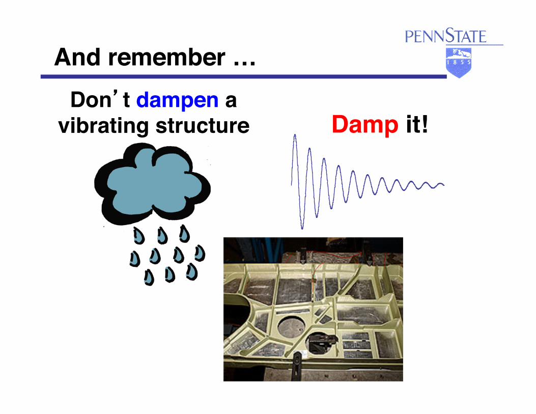
And remember … Don’t dampen a
vibrating structure Damp it!