sdi audio ip cores user guide - altera · pdf filesdi audio ip cores user guide last updated...
TRANSCRIPT

SDI Audio Intel FPGA IP User Guide
Last updated for Quartus Prime Design Suite: 18.0
Subscribe
Send Feedback
UG-SDI-AUD2018.05.16
101 Innovation DriveSan Jose, CA 95134www.altera.com

Contents
SDI Audio Intel FPGA IP Overview................................................................... 1-1
SDI Audio Intel FPGA IP Getting Started..........................................................2-1Instantiating the SDI Audio Intel FPGA IP..............................................................................................2-1Simulating the Testbench............................................................................................................................ 2-2
Guidelines..........................................................................................................................................2-3
SDI Audio Intel FPGA IP Functional Description.............................................3-1SDI Audio Embed IP Core..........................................................................................................................3-1SDI Audio Extract IP Core......................................................................................................................... 3-3SDI Clocked Audio Input IP Core............................................................................................................. 3-4SDI Clocked Audio Output IP Core.......................................................................................................... 3-4AES Format...................................................................................................................................................3-4Avalon-ST Audio Interface......................................................................................................................... 3-5
SDI Audio Intel FPGA IP Parameters................................................................ 4-1SDI Audio Embed Parameters....................................................................................................................4-1SDI Audio Extract Parameters................................................................................................................... 4-2SDI Audio Clocked Audio Input Parameters........................................................................................... 4-3SDI Audio Clocked Audio Output Parameters........................................................................................ 4-4
SDI Audio Intel FPGA IP Interface Signals........................................................5-1SDI Audio Embed Signals...........................................................................................................................5-1SDI Audio Extract Signals...........................................................................................................................5-6SDI Audio Clocked Input Signals.............................................................................................................. 5-9SDI Audio Clocked Output Signals......................................................................................................... 5-11SDI Audio IP Register Interface Signals..................................................................................................5-12
SDI Audio Intel FPGA IP Registers.................................................................... 6-1SDI Audio Embed Registers....................................................................................................................... 6-1SDI Audio Extract Registers....................................................................................................................... 6-5SDI Clocked Audio Input Registers...........................................................................................................6-8SDI Clocked Audio Output Registers........................................................................................................6-9
SDI Audio Intel FPGA IP Design Example........................................................ 7-1Components of Design Example................................................................................................................7-1
SDI Transmitter P0.......................................................................................................................... 7-2SDI Duplex........................................................................................................................................7-2
TOC-2
Altera Corporation
Audio Extract....................................................................................................................................7-2AES Input Module............................................................................................................................7-2AES Output Module........................................................................................................................ 7-2Audio Embed P0/P1........................................................................................................................ 7-2Video Pattern Generator P0/P1......................................................................................................7-2Audio Pattern Generator.................................................................................................................7-2Ancillary Data Insertion P0/P1......................................................................................................7-2Transceiver Dynamic Reconfiguration Control Logic................................................................ 7-3
Hardware and Software Requirements......................................................................................................7-3Running the Design Example.....................................................................................................................7-4
Transmit SD-SDI with Embedding of Audio Group 1................................................................7-5Transmit HD-SDI with Embedding of Audio Group 1 and 2....................................................7-5Transmit 3G-SDI Level A with Embedding of Audio Group 1, 2 and 3...................................7-6Transmit 3G-SDI Level B with Embedding of Audio Group 1, 2, 3 and 4............................... 7-6
SDI Audio Intel FPGA IP User Guide Archives.................................................A-1
Document Revision History for the SDI Audio Intel FPGA IP User Guide..... B-1
TOC-3
Altera Corporation

SDI Audio Intel FPGA IP Overview 12018.05.16
UG-SDI-AUD Subscribe Send Feedback
The SDI Audio Intel FPGA IP cores ease the development of video and image processing designs. Forsome instances, you combine the audio and video into one digital signal, and at other times you processthe audio and video signals separately.
The SDI Audio Intel FPGA IP cores are part of the IP Catalog Library, which is distributed with the Intel®Quartus® Prime software and downloadable from the Intel website at www.altera.com.
You can use the following cores to embed, extract or convert audio:
• Audio Embed Intel FPGA IP• Audio Extract Intel FPGA IP• Clocked Audio Input Intel FPGA IP• Clocked Audio Output Intel FPGA IP
You can instantiate the SDI Audio Intel FPGA IP cores with the SDI and SDI II Intel FPGA IP cores, andconfigure each Audio IP core at run time using an Avalon-MM slave interface.
Table 1-1: Brief Information About the SDI Audio IP Cores
Item Description
ReleaseInforma‐tion
Version 18.0
Release Date May 2018
Ordering Code IP-SDI
IP CoreInforma‐tion
Device Family Arria® II GX, Arria V, Cyclone IV GX, Cyclone V, Stratix IV GX,and Stratix V FPGA device families.
Related Information
• SDI Audio Intel FPGA IP User Guide Archives on page 8-1Provides a list of user guides for previous versions of the SDI Audio Intel FPGA IP cores.
• Serial Digital Interface (SDI) IP Core User GuideFor information about SDI IP core.
Intel Corporation. All rights reserved. Intel, the Intel logo, Altera, Arria, Cyclone, Enpirion, MAX, Nios, Quartus and Stratix words and logos are trademarks ofIntel Corporation or its subsidiaries in the U.S. and/or other countries. Intel warrants performance of its FPGA and semiconductor products to currentspecifications in accordance with Intel's standard warranty, but reserves the right to make changes to any products and services at any time without notice.Intel assumes no responsibility or liability arising out of the application or use of any information, product, or service described herein except as expresslyagreed to in writing by Intel. Intel customers are advised to obtain the latest version of device specifications before relying on any published informationand before placing orders for products or services.*Other names and brands may be claimed as the property of others.
ISO9001:2008Registered
www.altera.com101 Innovation Drive, San Jose, CA 95134

• SDI II Intel FPGA IP User GuideFor information about SDI II Intel FPGA IP core.
1-2 SDI Audio Intel FPGA IP OverviewUG-SDI-AUD
2018.05.16
Altera Corporation SDI Audio Intel FPGA IP Overview
Send Feedback
SDI Audio Intel FPGA IP Getting Started 22018.05.16
UG-SDI-AUD Subscribe Send Feedback
The SDI Audio Intel FPGA IP cores are installed as part of the Intel Quartus Prime installation process.
You can select and parameterize any Intel FPGA IP from the library. Intel provides an integratedparameter editor that allows you to customize the SDI Audio Intel FPGA IP cores to support a widevariety of applications.
Related Information
• Introduction to Altera IP CoresProvides general information about all Intel FPGA IP cores, including parameterizing, generating,upgrading, and simulating IP cores.
• Creating Version-Independent IP and Qsys Simulation ScriptsCreate simulation scripts that do not require manual updates for software or IP version upgrades.
• Project Management Best PracticesGuidelines for efficient management and portability of your project and IP files.
Instantiating the SDI Audio Intel FPGA IPYou can instantiate the SDI Audio Embed and Audio Extract IP cores in the following ways:
• Instantiate within Platform Designer (Standard) with the audio inputs exposed outside PlatformDesigner (Standard).
• Instantiate within Platform Designer (Standard) with the audio inputs exposed as Avalon-ST Audiowithin Platform Designer (Standard).As the SDI Audio Embed and Extract IP cores use an Avalon-MM slave interface to access the controlregisters, the most convenient way for you to instantiate the components are within Platform Designer(Standard). You are provided with the component declaration TCL files to support either the ordinaryAES audio inputs or the Avalon-ST audio interface.
• Instantiate directly in RTL with a CPU register interface.You can instantiate the SDI Audio Embed and Audio Extract IP cores directly in your RTL and drivethe direct control interface signals directly without the accompanying Avalon-MM register interface
• Instantiate the encrypted core directly on RTL with control ports.
Intel Corporation. All rights reserved. Intel, the Intel logo, Altera, Arria, Cyclone, Enpirion, MAX, Nios, Quartus and Stratix words and logos are trademarks ofIntel Corporation or its subsidiaries in the U.S. and/or other countries. Intel warrants performance of its FPGA and semiconductor products to currentspecifications in accordance with Intel's standard warranty, but reserves the right to make changes to any products and services at any time without notice.Intel assumes no responsibility or liability arising out of the application or use of any information, product, or service described herein except as expresslyagreed to in writing by Intel. Intel customers are advised to obtain the latest version of device specifications before relying on any published informationand before placing orders for products or services.*Other names and brands may be claimed as the property of others.
ISO9001:2008Registered
www.altera.com101 Innovation Drive, San Jose, CA 95134

Simulating the TestbenchIntel provides a fixed testbench as an example to simulate the SDI Audio Intel FPGA IP cores. Use thistestbench to simulate the SDI Audio Embed and the associated SDI Audio Extract IP cores, and the SDIClocked Audio Input and the associated SDI Clocked Audio Output IP cores.
You can obtain the testbench from ip/altera/audio_ip/simulation directory.
To use the testbench with the ModelSim simulator, follow these steps:
1. Open the Intel Quartus Prime software.2. On the File menu, click the New Project Wizard.3. Specify the working directory to ip/altera/audio_ip/simulation/megacore_build, and give a sensible
name for your project and top-level entity.4. Click Next, and select Stratix IV for the device family.5. Click Finish.6. In the IP Catalog (Tools > IP Catalog), locate and double-click the variant
audio_embed_avalon_top.v file.The SDI Audio Embed parameter editor appears.
7. In the SDI Audio Embed parameter editor, click Finish to regenerate the variantaudio_embed_avalon_top.v file and produce the simulation model.
8. Repeat steps 6 to 9 for the remaining variant files in the megacore_build directory.9. In a text editor, open the simulation script, simulation/run.tcl. Edit the script to point to your installa‐
tion of the Intel Quartus Prime software.For example, set quartusdir /tools/acds/14.0/157/linux32/quartus/eda/sim_lib/
10.Start the ModelSim simulator.11.Run run.tcl in the simulation directory. This file compiles the design.
A selection of signals appears on the waveform viewer. The simulation runs automatically, providing apass or fail indication upon completion.
2-2 Simulating the TestbenchUG-SDI-AUD
2018.05.16
Altera Corporation SDI Audio Intel FPGA IP Getting Started
Send Feedback

GuidelinesWhen you use the testbench to simulate the IP cores, consider the following guidelines:
• Select the video standard for the video test source through the generic G_TEST_STD of the testbenchentity. Set 0, 1, 2 or 3 to select SD-SDI, HD-SDI, 3G-SDI Level A, or 3G-SDI Level B.
• The audio test source uses the 48-kHz clock output from the SDI Audio Embed IP core. The audio testsample comprises an increasing count which allows the testbench to check the extracted audio at thefar end of the processing chain.
• The SDI Audio Embed IP core accepts these video and audio test sources to create a video stream withembedded audio. The SDI Audio Extract IP core then receives the resulting stream to recover theembedded audio. Examine this audio sequence to ensure that the count pattern that was created ispreserved.
• The synchronisation requirements of the receive FIFO buffer in the SDI Audio Extract IP core allowsyou to repeat the occasional sample from the SDI Audio Extract IP core. Synchronisation may take upto a field period of typically 16.7 ms to complete.
• Select G_INCLUDE_AVALON_ST = 1, if you want to instantiate another SDI Audio Embed IP core withAvalon-ST interface (with embedded clocked audio output component) and the associated SDI AudioExtract IP core with Avalon-ST interface (with embedded clocked audio input component) in thistestbench.
UG-SDI-AUD2018.05.16 Guidelines 2-3
SDI Audio Intel FPGA IP Getting Started Altera Corporation
Send Feedback

SDI Audio Intel FPGA IP Functional Description 32018.05.16
UG-SDI-AUD Subscribe Send Feedback
The following sections describe the block diagrams and components for the SDI Audio Intel FPGA IPcores.
SDI Audio Embed IP CoreThe SDI Audio Embed Audio IP core embeds audio into the SD-, HD-, and 3G-SDI video standards.
The format of the embedded audio is in accordance with the following standards:
• SMPTE272M-ABCD standard for SD-SDI• SMPTE299M standard for HD-SDI• SMPTE299M standard for 3G-SDI (provisional)
This IP core supports AES audio format for 48-kHz sampling rate
This figure shows a block diagram of the SDI Audio Embed IP core.
Intel Corporation. All rights reserved. Intel, the Intel logo, Altera, Arria, Cyclone, Enpirion, MAX, Nios, Quartus and Stratix words and logos are trademarks ofIntel Corporation or its subsidiaries in the U.S. and/or other countries. Intel warrants performance of its FPGA and semiconductor products to currentspecifications in accordance with Intel's standard warranty, but reserves the right to make changes to any products and services at any time without notice.Intel assumes no responsibility or liability arising out of the application or use of any information, product, or service described herein except as expresslyagreed to in writing by Intel. Intel customers are advised to obtain the latest version of device specifications before relying on any published informationand before placing orders for products or services.*Other names and brands may be claimed as the property of others.
ISO9001:2008Registered
www.altera.com101 Innovation Drive, San Jose, CA 95134

Figure 3-1: SDI Audio Embed IP Core Block Diagram
Avalon-ST Audio to Audio Embed with Avalon Only
FIFO FIFO FIFO FIFO FIFO FIFO FIFO FIFO
Audio Embedder
SD/HD/3G-SDI SD/HD/3G-SDI
Avalon-MM
Audio Embed or Audio Embed with Avalon
SD/HD Audio Embedder
Packet Creation
Packet Distribution
Channel Status RAM
Register Interface
The SDI Audio Embed IP core embeds up to 16 channels or 8 channel pairs. The input audio can be any ofthe sample rates permitted by the SMPTE272M-ABCD and SMPTE299M standards; synchronous to thevideo. If you want to embed audio pairs together in a sample audio group, the audio pairs must besynchronous with each other.
The SDI Audio Embed IP core consists of the following components:
• An encrypted audio embedder core• A register interface block that provides support for an Avalon-MM control bus
The audio embedder accepts the audio in AES format, and stores each channel pair in an input FIFObuffer. As the embedder places the audio sample in the FIFO buffer, it also records and stores the videoclock phase information.
When accepting the audio in AES format, the SDI Audio Embed IP core does one of the followingoperations:
• maintains the channel-status details• replaces the channel-status details with the default or the RAM versions
3-2 SDI Audio Embed IP CoreUG-SDI-AUD
2018.05.16
Altera Corporation SDI Audio Intel FPGA IP Functional Description
Send Feedback

SDI Audio Extract IP CoreThe SDI Audio Extract IP core accepts the SD-, HD-, and 3G-SDI from the SDI IP cores and extracts onechannel pair of embedded audio.
The format of the embedded audio is in accordance with the following standards:
• SMPTE272M-ABCD standard for SD-SDI• SMPTE299M standard for HD-SDI• SMPTE299M standard for 3G-SDI (provisional)
If you are extracting more than one channel pair, you must use multiple instances of the component. ThisIP core supports AES audio format for 48-kHz sampling rate.
This figure shows a block diagram of the SDI Audio Extract IP core.
Figure 3-2: SDI Audio Extract IP Core Block Diagram
Sample FIFO
Clock Recovery
Audio Extract or Audio Extract with Avalon
Avalon-MM
48 KHz Clock
Core
Error Detection
Packet Findand
Extract
AES to
Avalon-ST Audio
(Audio Extract with Avalon Only)
Channel Status RAM
Register Interface
aud_clk
internal AES Avalon-ST Audio
vid_clk
SD/HD/3G-SDI
The SDI Audio Extract IP core consists of the following components:
• An audio extraction core• A register interface block that provides support for an Avalon-MM control bus
The clock recovery block recreates a 64 × sample rate clock, which you can use to clock the audio outputlogic. As the component recreates this clock from a 200-MHz reference clock, the created clock may have ahigher jitter than is desirable.
A digital PLL synchronizes this created clock to a 24-kHz reference source.
UG-SDI-AUD2018.05.16 SDI Audio Extract IP Core 3-3
SDI Audio Intel FPGA IP Functional Description Altera Corporation
Send Feedback

For the HD-SDI embedded audio, the 24-kHz reference source is the embedded clock phase information.
For the SD-SDI embedded audio, where the embedded clock phase data is not present, you can create the24-kHz reference signal directly from the video clock.
This figure shows the clock recovery block diagram.Figure 3-3: Clock Recovery Block Diagram
ProgrammableDivide
DigitalPLL
Clock PhaseRecovery
vid_clk
Video standard
3.072 MHz Output
24 KHz
200 MHzExtracted
audio data/128
SD
HD
SDI Clocked Audio Input IP CoreThe Clocked Audio Input IP core converts clocked audio in AES formats to Avalon-ST audio.
For a typical AES input, for each channel, the clocked audio input function does the following operations:
• Creates a 192-bit validity word, user word and channel status word• Presents the words as a control packet after the audio data packet
SDI Clocked Audio Output IP CoreThe SDI Clocked Audio Output IP core accepts clocked Avalon-ST audio and converts to audio inmodified AES formats.
AES FormatThe SDI cores use the AES standard. The Audio Engineering Society (AES), together with the EuropeanBroadcasting Union (EBU), created a digital audio transmission standard known as the AES/EBUstandard. The AES standard is a digital audio standard for transporting digital audio signals seriallybetween devices.
Using the AES format requires the entire 64-bit AES frame to be sent serially. As the AES defines thepreambles as biphase mark codes, which cannot be directly decoded to 4 bits, you must replace thepreambles with X = 0000b, Y = 0001b, and Z = 0010b. This internal AES format serializes the bit-paralleldata words by sending the least significant bits (LSB) first, with the audio sample (up to 24 bits).
This figure shows the timing diagram of the internal AES format.
3-4 SDI Clocked Audio Input IP CoreUG-SDI-AUD
2018.05.16
Altera Corporation SDI Audio Intel FPGA IP Functional Description
Send Feedback
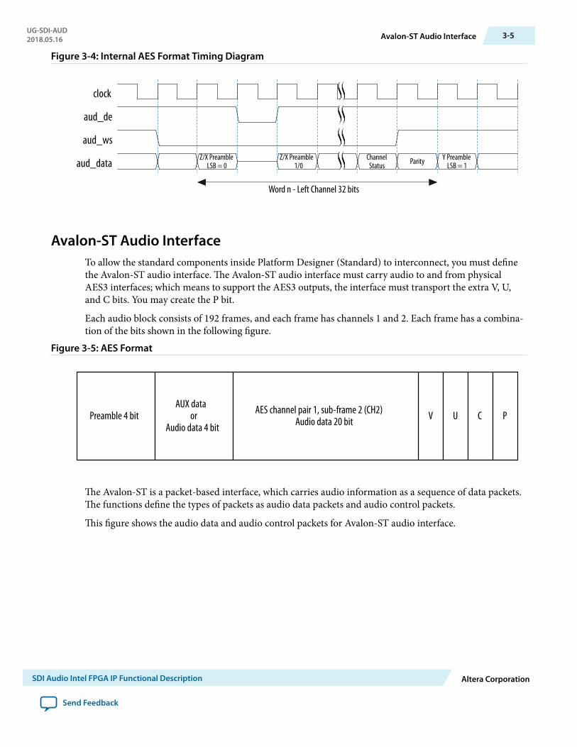
Figure 3-4: Internal AES Format Timing Diagram
clock
aud_de
aud_ws
aud_dataChannel
Status Parity Y PreambleLSB = 1
Z/X Preamble 1/0
Word n - Left Channel 32 bits
Z/X PreambleLSB = 0
Avalon-ST Audio InterfaceTo allow the standard components inside Platform Designer (Standard) to interconnect, you must definethe Avalon-ST audio interface. The Avalon-ST audio interface must carry audio to and from physicalAES3 interfaces; which means to support the AES3 outputs, the interface must transport the extra V, U,and C bits. You may create the P bit.
Each audio block consists of 192 frames, and each frame has channels 1 and 2. Each frame has a combina‐tion of the bits shown in the following figure.
Figure 3-5: AES Format
PPreamble 4 bit U CVAUX data
orAudio data 4 bit
AES channel pair 1, sub-frame 2 (CH2)Audio data 20 bit
The Avalon-ST is a packet-based interface, which carries audio information as a sequence of data packets.The functions define the types of packets as audio data packets and audio control packets.
This figure shows the audio data and audio control packets for Avalon-ST audio interface.
UG-SDI-AUD2018.05.16 Avalon-ST Audio Interface 3-5
SDI Audio Intel FPGA IP Functional Description Altera Corporation
Send Feedback

Figure 3-6: Audio Data and Audio Control Packets for Avalon-ST Audio Interface
The sequence of audio control packets begins with V bit, U bit, and finally C bit. The audio control packetsfor U and C bits are similar to V bits.
D0 D192...
V0 V7... ...
MSB
Audio Data Packet
Audio Control Packet
LSB MSB LSB
AUX data (4 bits) Audio data (20 bits) AUX data (4 bits) Audio data (20 bits)
MSB LSB MSB LSB
1st frame of V bit
24th frame of V bit
192nd frame of V bit
The Avalon-ST audio protocol separates the audio data from the control or status data to facilitate audiodata processing. The protocol defines that the data is packed LSB first, which matches the AES3 data. Theaudio data size is configurable at compile time and matches the audio data sample size. Including the aux,the audio data word would be 24 bits.
In Avalon-ST audio, the data is packed as 24 bit symbols, typically with 1 symbol per beat [23:0]. The coretransmits the audio control data as a packet after the audio data to meet the latency requirements.
The packet type identifier defines the packet type. The packet type identifier is the first value of any packet,when the start of packet signal is high. The audio data packet identifier is 0×A and the audio control datapacket identifier is 0×E.
The table below lists the packet types.
Table 3-1: Avalon-ST Packet Types
Type Identifier Description
0 Video data packet
1–8 User packet types
10 Audio data packet
14 Audio control data packet
15 Video control data packet
9–15 Reserved
3-6 Avalon-ST Audio InterfaceUG-SDI-AUD
2018.05.16
Altera Corporation SDI Audio Intel FPGA IP Functional Description
Send Feedback

The preamble data, XYZ from AES, describes whether the data is at the start of a block and which channelthe audio refers to. In Avalon-ST audio protocol, you are not required to transport the preamble databecause the information stored in the data is described by the start of packet, end of packet, and channelsignals.
The start of packet, end of packet, and channel signals indicate the start of the audio sample data and theassociated audio channel.
For a single audio channel, the channel signal indicates channel 1 for all valid samples. This figure showsan example of a single audio channel.
Figure 3-7: Single Audio Channel
sop
Audio data header identifier
Single channel audio data (Channel = 1)
Audio data control packet header identifier (LSB 4 bits)
eop
data [23:0]
channel
A D0 D1 D2 D3 D4 D5 D6 D7 D8 D190 D191 E V0 V1 V2 V3 V4 V5 V6 V7 U0 C4 C5 C6 C7
1 1
Audio sample data Audio control data
For multiple channels, the Avalon-ST interface standard allows the packets to interleave across thechannels. By interleaving, the interface allows multiple audio sources to be multiplexed and demultiplexed.
This figure shows an example of two audio channels, where the channel signal indicates either channel 1 orchannel 2. Each channel has a start of packet and an end of packet signal, which allows the channelinterleaving and de-interleaving.
Figure 3-8: Multiple Audio Channels
sop
eop
data
channel
A D0 A D1 D188 D189 D2 D3 D190 D4 D191 D188 D189 D190 D191 E E
1 2 1 1 2 1 2 2 21 1
Start of packet for audio sample data channel 1
End of packet for audio sample data channel 1
End of packet for audio sample data channel 2
Channel signal indicatesaudio channel number
Control dataControl data
Start of packet for audio sample data channel 1
UG-SDI-AUD2018.05.16 Avalon-ST Audio Interface 3-7
SDI Audio Intel FPGA IP Functional Description Altera Corporation
Send Feedback

SDI Audio Intel FPGA IP Parameters 42018.05.16
UG-SDI-AUD Subscribe Send Feedback
The following sections describe the parameters for the SDI Audio IP cores.
SDI Audio Embed ParametersThe following table lists the parameters for the SDI Audio Embed IP core.
Table 4-1: SDI Audio Embed Parameters
Parameter Value Description
Number ofsupported audiogroups
1, 2, 3, 4 Specifies the maximum number of audio groups supported.
Each audio group consists of 4 audio channels (2 channel pairs). You must specify all the four channels to the same samplefrequencies.
Async AudioInterface
On or Off Turn on to enable the Asynchronous input.
In this mode, the audio clock provides higher than 64* samplerate.
Frequency of fix_clk
0, 24.576, 25, 50, 100,200
Sets the expected frequency of the fix_clk input; used asfrequency reference when detecting the difference betweenvideo rate of 1/1.000 or 1/1.001.
Setting this parameter to 0 drives fix_clk low.
Include SD-SDI24-bit support
On or Off Enables the embedding of SD-SDI Extended Data Packets(EDP) for each audio group.
Intel Corporation. All rights reserved. Intel, the Intel logo, Altera, Arria, Cyclone, Enpirion, MAX, Nios, Quartus and Stratix words and logos are trademarks ofIntel Corporation or its subsidiaries in the U.S. and/or other countries. Intel warrants performance of its FPGA and semiconductor products to currentspecifications in accordance with Intel's standard warranty, but reserves the right to make changes to any products and services at any time without notice.Intel assumes no responsibility or liability arising out of the application or use of any information, product, or service described herein except as expresslyagreed to in writing by Intel. Intel customers are advised to obtain the latest version of device specifications before relying on any published informationand before placing orders for products or services.*Other names and brands may be claimed as the property of others.
ISO9001:2008Registered
www.altera.com101 Innovation Drive, San Jose, CA 95134

Parameter Value Description
Cleanly removeexisting audio
0,1, 2 Enables the removal of existing embedded audio data.
When set to 1, the system requires extra storage to delay thevideo and remove any existing audio from SD-SDI, HD-SDI, or3G-SDI Level A standard.
When set to 2, the system includes extra storage to remove theexisting audio from 3G-SDI Level B standard.
Select 0 to turn off this parameter.
Channel statusRAM
0,1, 2 Enables storage of the custom channel status data.
Select 1 to generate a single channel status RAM, or 2 togenerate separate RAMs for each input audio pair.
Select 0 to turn off this parameter.
Frequency sinewave generator
On or Off Turn on to enable a four-frequency sine wave generator.
You can use the four-frequency sine wave generator as a testsource for the audio embedder.
Include clock On or Off Turn on to enable a 48-kHz pulse generator synchronous to thevideo clock. You can use the 48-kHz pulse generator to requestdata from a sample rate convertor.
When you turn on the Frequency Sine Wave Generatorparameter, the core automatically includes this pulse generator.
Include Avalon-ST interface
On or Off Turn on to include the SDI Clocked Audio Output IP core.
When you turn on this parameter, the Avalon-ST interfacesignals appear at the top level. Otherwise, the audio inputsignals appear at the top level.
Include Avalon-MM controlinterface
On or Off Turn on to include the Avalon-MM control interface.
When you turn on this parameter, the register interface signalsappear at the top level. Otherwise, the direct control interfacesignals appear at the top level.
Related InformationSDI Audio Embed Signals on page 5-1
SDI Audio Extract ParametersThe following table lists the parameters for the SDI Audio Extract IP core.
4-2 SDI Audio Extract ParametersUG-SDI-AUD
2018.05.16
Altera Corporation SDI Audio Intel FPGA IP Parameters
Send Feedback
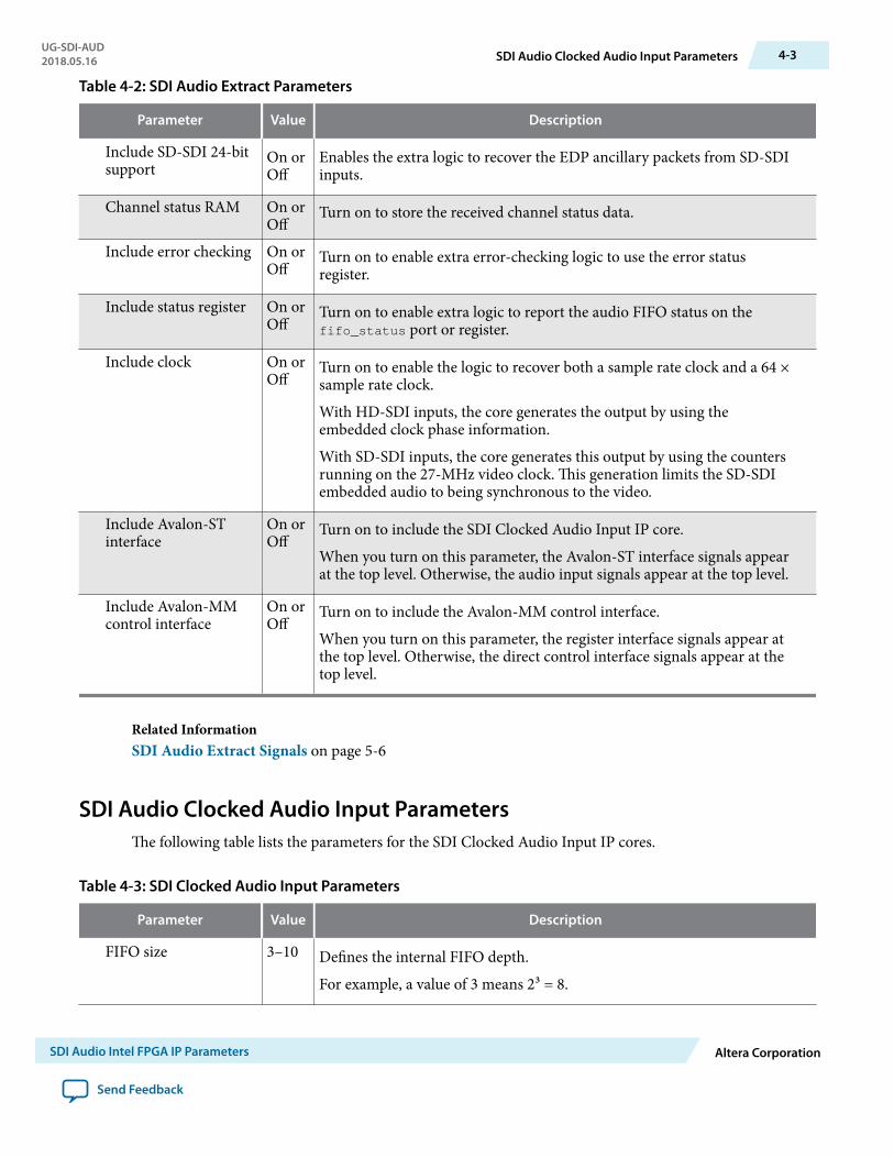
Table 4-2: SDI Audio Extract Parameters
Parameter Value Description
Include SD-SDI 24-bitsupport
On orOff
Enables the extra logic to recover the EDP ancillary packets from SD-SDIinputs.
Channel status RAM On orOff
Turn on to store the received channel status data.
Include error checking On orOff
Turn on to enable extra error-checking logic to use the error statusregister.
Include status register On orOff
Turn on to enable extra logic to report the audio FIFO status on thefifo_status port or register.
Include clock On orOff
Turn on to enable the logic to recover both a sample rate clock and a 64 ×sample rate clock.
With HD-SDI inputs, the core generates the output by using theembedded clock phase information.
With SD-SDI inputs, the core generates this output by using the countersrunning on the 27-MHz video clock. This generation limits the SD-SDIembedded audio to being synchronous to the video.
Include Avalon-STinterface
On orOff
Turn on to include the SDI Clocked Audio Input IP core.
When you turn on this parameter, the Avalon-ST interface signals appearat the top level. Otherwise, the audio input signals appear at the top level.
Include Avalon-MMcontrol interface
On orOff
Turn on to include the Avalon-MM control interface.
When you turn on this parameter, the register interface signals appear atthe top level. Otherwise, the direct control interface signals appear at thetop level.
Related InformationSDI Audio Extract Signals on page 5-6
SDI Audio Clocked Audio Input ParametersThe following table lists the parameters for the SDI Clocked Audio Input IP cores.
Table 4-3: SDI Clocked Audio Input Parameters
Parameter Value Description
FIFO size 3–10 Defines the internal FIFO depth.
For example, a value of 3 means 2³ = 8.
UG-SDI-AUD2018.05.16 SDI Audio Clocked Audio Input Parameters 4-3
SDI Audio Intel FPGA IP Parameters Altera Corporation
Send Feedback

Parameter Value Description
Include Avalon-MMcontrol interface
On orOff
Turn on to include the Avalon-MM control interface.
When you turn on this parameter, the register interface signals appear atthe top level. Otherwise, the direct control interface signals appear at thetop level.
SDI Audio Clocked Audio Output ParametersThe following table lists the parameters for the SDI Clocked Audio Output IP cores.
Table 4-4: SDI Clocked Audio Output Parameters
Parameter Value Description
FIFO size 3–10 Defines the internal FIFO depth.
For example, a value of 3 means 2³ = 8.
Include Avalon-MMcontrol interface
On orOff
Turn on to include the Avalon-MM control interface.
When you turn on this parameter, the register interface signals appear atthe top level. Otherwise, the direct control interface signals appear at thetop level.
4-4 SDI Audio Clocked Audio Output ParametersUG-SDI-AUD
2018.05.16
Altera Corporation SDI Audio Intel FPGA IP Parameters
Send Feedback
SDI Audio Intel FPGA IP Interface Signals 52018.05.16
UG-SDI-AUD Subscribe Send Feedback
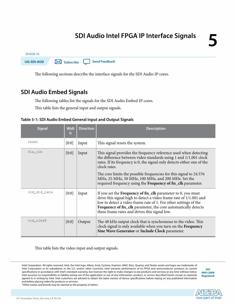
The following sections describe the interface signals for the SDI Audio IP cores.
SDI Audio Embed SignalsThe following tables list the signals for the SDI Audio Embed IP cores.
This table lists the general input and output signals.
Table 5-1: SDI Audio Embed General Input and Output Signals
Signal Width
Direction Description
reset [0:0] Input This signal resets the system.
fix_clk [0:0] Input This signal provides the frequency reference used when detectingthe difference between video standards using 1 and 1/1.001 clockrates. If its frequency is 0, the signal only detects either one of theclock rates.
The core limits the possible frequencies for this signal to 24.576MHz, 25 MHz, 50 MHz, 100 MHz, and 200 MHz. Set therequired frequency using the Frequency of fix_clk parameter.
vid_std_rate [0:0] Input If you set the Frequency of fix_clk parameter to 0, you mustdrive this signal high to detect a video frame rate of 1/1.001 andlow to detect a video frame rate of 1. For other settings of theFrequency of fix_clk parameter, the core automatically detectsthese frame rates and drives this signal low.
vid_clk48 [0:0] Output The 48 kHz output clock that is synchronous to the video. Thisclock signal is only available when you turn on the FrequencySine Wave Generator or Include Clock parameter.
This table lists the video input and output signals.
Intel Corporation. All rights reserved. Intel, the Intel logo, Altera, Arria, Cyclone, Enpirion, MAX, Nios, Quartus and Stratix words and logos are trademarks ofIntel Corporation or its subsidiaries in the U.S. and/or other countries. Intel warrants performance of its FPGA and semiconductor products to currentspecifications in accordance with Intel's standard warranty, but reserves the right to make changes to any products and services at any time without notice.Intel assumes no responsibility or liability arising out of the application or use of any information, product, or service described herein except as expresslyagreed to in writing by Intel. Intel customers are advised to obtain the latest version of device specifications before relying on any published informationand before placing orders for products or services.*Other names and brands may be claimed as the property of others.
ISO9001:2008Registered
www.altera.com101 Innovation Drive, San Jose, CA 95134

Table 5-2: SDI Audio Embed Video Input and Output Signals
Signal Width Direction Description
vid_clk [0:0] Input The video clock that is typically 27 MHz for SD-SDI, 74.25 MHzor 74.17 MHz for HD-SDI, or 148.5 MHz or 148.35 MHz for 3G-SDI standards. You can use higher clock rates with the vid_datavalid signal.
Set exclusive clock group to aud_clk and vid_clk to preventunstable or flickering image.
vid_std [1:0] Input Indicates the received video standard. Applicable for 3G-SDI,dual standard, and triple standard modes only.
Set this signal to indicate the following formats:
• [00] for10-bit SD-SDI• [01] for 20-bit HD-SDI• [10] for 3G-SDI Level B• [11] for 3G-SDI Level A
vid_datavalid [0:0] Input Assert this signal when the video data is valid.
vid_data [19:0] Input Receiver protocol reset signal. This signal must be driven by therx_rst_proto_out reset signal from the transceiver block.
This signal carries luma and chroma information.
SD-SDI:
• [19:10] Unused• [9:0] Cb,Y, Cr, Y multiplex
HD-SDI and 3G-SDI Level A:
• [19:10] Y• [9:0] C
3G-SDI Level B:
• [19:10] Cb,Y, Cr, Y multiplex (link A)• [9:0] Cb,Y, Cr, Y multiplex (link B)
vid_out_
datavalid[0:0] Output The core drives this signal high during valid output video clock
cycles.
vid_out_trs [0:0] Output The core drives this signal high during the first 3FF clock cycle ofa video timing reference signal; the first two 3FF cycles for 3G-SDI Level B. This signal provides easy connection to the SDI IPcores.
vid_out_ln [10:0] Output The video line signal that provides for easy connection to the SDIIP cores. To observe the correct video out line number, allowtwo-frame duration for the audio embed IP to correctly embedand show the line number.
5-2 SDI Audio Embed SignalsUG-SDI-AUD
2018.05.16
Altera Corporation SDI Audio Intel FPGA IP Interface Signals
Send Feedback

Signal Width Direction Description
vid_out_data [19:0] Output The video output signal.
This table lists the audio input signals.
Table 5-3: SDI Audio Embed Audio Input Signals
N is the number of audio group.Signal Width Direction Description
aud_clk [2N–1:0]
Input Set this clock to 3.072 MHz that is synchronous to the extractedaudio. In asynchronous mode, set this to any frequency above3.072 MHz. Intel recommends that you set this clock to 50 MHz.
For SD-SDI inputs, this mode of operation limits the core toembedding audio that is synchronous to the video. For HD-SDIinputs, this clock must either be generated from the optional 48Hz output or the audio must be synchronous to the video.
Set exclusive clock group to aud_clk and vid_clk to preventunstable or flickering image.
aud_de [2N–1:0]
Input Assert this data enable signal to indicate valid information on theaud_ws and aud_data signals.
In synchronous mode, the core ignores this signal.
aud_ws [2N–1:0]
Input Assert this word select signal to provide framing for deserializa‐tion and to indicate left or right sample of channel pair.
aud_data [2N–1:0]
Input Internal AES data signal from the AES input module.
This table lists the Avalon-ST audio signals when you instantiate the SDI Audio Embed IP core in PlatformDesigner (Standard).
Table 5-4: SDI Audio Embed Avalon-ST Audio Signals
n is the number of audio channels, the value starts from from 0 to n-1.Signal Width Direction Description
aud(n)_clk [0:0] Input Clocked audio clock. All the audio input signals are synchronousto this clock.
aud(n)_ready [0:0] Output Avalon-ST ready signal. Assert this signal when the device is ableto receive data.
aud(n)_valid [0:0] Input Avalon-ST valid signal. The core asserts this signal when itreceives data.
UG-SDI-AUD2018.05.16 SDI Audio Embed Signals 5-3
SDI Audio Intel FPGA IP Interface Signals Altera Corporation
Send Feedback

Signal Width Direction Description
aud(n)_sop [0:0] Input Avalon-ST start of packet signal. The core asserts this signalwhen it is starting a new frame.
aud(n)_eop [0:0] Input Avalon-ST end of packet signal. The core asserts this signal whenit is ending a frame.
aud(n)_channel [7:0] Input Avalon-ST select signal. Use this signal to select a specificchannel.
aud(n)_data [23:0] Input Avalon-ST data bus. This bus transfers data.
This table lists the register interface signals. The register interface is a standard 8-bit wide Avalon-MMslave.
Table 5-5: SDI Audio Embed Register Interface Signals
Signal Width Direction Description
reg_clk [0:0] Input Clock for the Avalon-MM register interface.
reg_reset [0:0] Input Reset for the Avalon-MM register interface.
reg_base_addr [5:0] Input Reset for the Avalon-MM register interface.
reg_burst_count [5:0] Input Transfer size in bytes.
reg_waitrequest [0:0] Output Wait request.
reg_write [7:0] Input Write request.
reg_writedata [0:0] Input Data to be written to target.
reg_read [0:0] Input Read request.reg_readdata-
valid
[0:0] Output Requested read data valid after read latency.
reg_readdata [7:0] Output Data read from target.
This table lists the direct control interface signals. These signals are exposed as ports if you turn off theInclude Avalon-MM Control Interface parameter.
Table 5-6: SDI Audio Embed Direct Control Interface Signals
Signal Width Direction Description
reg_clk [0:0] Input Clock for the direct control interface.
5-4 SDI Audio Embed SignalsUG-SDI-AUD
2018.05.16
Altera Corporation SDI Audio Intel FPGA IP Interface Signals
Send Feedback

Signal Width Direction Description
audio_control [7:0] Input Assert this 8-bit signal to enable the audio channels. Each bitcontrols one audio channel.
extended_control [7:0] Input This signal does the same function as the extended controlregister.
video_status [7:0] Output This signal does the same function as the video status register.
sd_edp_control [7:0] Output This signal does the same function as the SD EDP controlregister.
audio_status [7:0] Output This signal does the same function as the audio status register.
cs_control [15:0] Input This signal does the same function as the channel status controlregister.
strip_control [7:0] Input This signal does the same function as the strip control register.
strip_status [7:0] Output This signal does the same function as the strip status register.
sine_freq_ch1 [7:0] Input This signal does the same function as the sine channel 1frequency register.
sine_freq_ch2 [7:0] Input This signal does the same function as the sine channel 2frequency register.
sine_freq_ch3 [7:0] Input This signal does the same function as the sine channel 3frequency register.
sine_freq_ch4 [7:0] Input This signal does the same function as the sine channel 4frequency register.
csram_addr [5:0] Input Channel status RAM address.csram_we [0:0] Input Drive this signal high for a single cycle of reg_clk signal to load
the value of the csram_data port into the channel status RAM atthe address on the csram_addr port.
If each input audio pair gets separate channel status RAMs, thissignal addresses the RAM selected by the extended_controlport.
csram_data [7:0] Input Channel status data. This signal does the same function as thechannel status RAM register in Table 4–9.
Related Information
• SDI Audio Embed Registers on page 6-1• SDI Audio IP Register Interface Signals on page 5-12All SDI Audio IP cores use the same register interface signals.
UG-SDI-AUD2018.05.16 SDI Audio Embed Signals 5-5
SDI Audio Intel FPGA IP Interface Signals Altera Corporation
Send Feedback
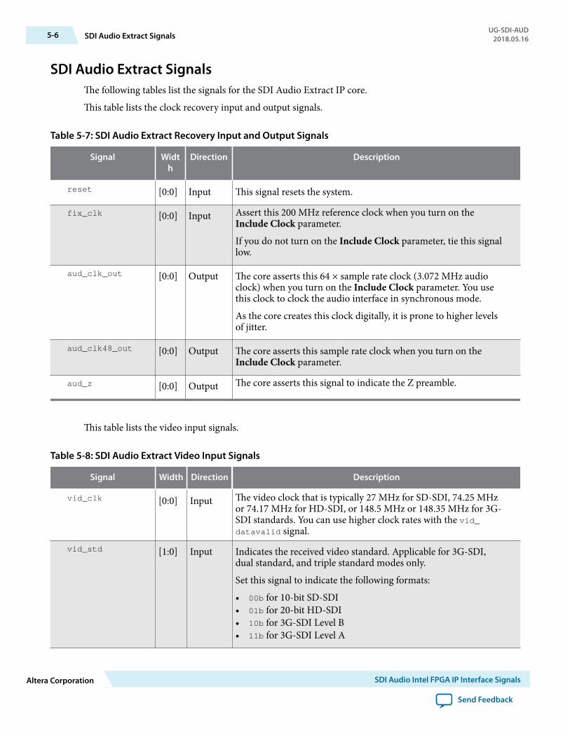
SDI Audio Extract SignalsThe following tables list the signals for the SDI Audio Extract IP core.
This table lists the clock recovery input and output signals.
Table 5-7: SDI Audio Extract Recovery Input and Output Signals
Signal Width
Direction Description
reset [0:0] Input This signal resets the system.
fix_clk [0:0] Input Assert this 200 MHz reference clock when you turn on theInclude Clock parameter.
If you do not turn on the Include Clock parameter, tie this signallow.
aud_clk_out [0:0] Output The core asserts this 64 × sample rate clock (3.072 MHz audioclock) when you turn on the Include Clock parameter. You usethis clock to clock the audio interface in synchronous mode.
As the core creates this clock digitally, it is prone to higher levelsof jitter.
aud_clk48_out [0:0] Output The core asserts this sample rate clock when you turn on theInclude Clock parameter.
aud_z [0:0] Output The core asserts this signal to indicate the Z preamble.
This table lists the video input signals.
Table 5-8: SDI Audio Extract Video Input Signals
Signal Width Direction Description
vid_clk [0:0] Input The video clock that is typically 27 MHz for SD-SDI, 74.25 MHzor 74.17 MHz for HD-SDI, or 148.5 MHz or 148.35 MHz for 3G-SDI standards. You can use higher clock rates with the vid_datavalid signal.
vid_std [1:0] Input Indicates the received video standard. Applicable for 3G-SDI,dual standard, and triple standard modes only.
Set this signal to indicate the following formats:
• 00b for 10-bit SD-SDI• 01b for 20-bit HD-SDI• 10b for 3G-SDI Level B• 11b for 3G-SDI Level A
5-6 SDI Audio Extract SignalsUG-SDI-AUD
2018.05.16
Altera Corporation SDI Audio Intel FPGA IP Interface Signals
Send Feedback

Signal Width Direction Description
vid_datavalid [0:0] Input Assert this signal when the video data is valid.
vid_data [19:0] Input This signal carries luma and chroma information.
SD-SDI:
• [19:10] Unused• [9:0] Cb,Y, Cr, Y multiplex
HD-SDI and 3G-SDI Level A:
• [19:10] Y• [9:0] C
3G-SDI Level B:
• [19:10] Cb,Y, Cr, Y multiplex (link A)• [9:0] Cb,Y, Cr, Y multiplex (link B)
vid_locked [0:0] Input Assert this signal when the video is locked.
This table lists the audio input and output signals.
Table 5-9: SDI Audio Extract Audio Input and Output Signals
Signal Width Direction Description
aud_clk [0:0] Input Set this clock to 3.072 MHz that is synchronous to the extractedaudio.
For SD-SDI inputs, this mode of operation limits the core toextracting audio that is synchronous to the video. For HD-SDIinputs, you must generate this clock from the optional 48 kHzoutput or the audio must be synchronous to the video.
aud_ws_in [0:0] Input Some audio receivers provide a word select output to align theserial outputs of several audio extract cores. In thesecircumstances, assert this signal to control the output timing ofthe audio extract externally, otherwise set it to 0. This signal mustbe a repeating cycle of high for 32 aud_clk cycles followed bylow for 32 aud_clk cycles.
aud_de [0:0] Output Assert this data enable signal to indicate valid information on theaud_ws and aud_data signals.
In synchronous mode, the core ignores this signal.
The core asserts this data enable signal to indicate valid informa‐tion on the aud_ws and aud_data signals.
In synchronous mode, the core drives this signal high.
UG-SDI-AUD2018.05.16 SDI Audio Extract Signals 5-7
SDI Audio Intel FPGA IP Interface Signals Altera Corporation
Send Feedback

Signal Width Direction Description
aud_ws [0:0] Output The core asserts this word select signal to provide framing fordeserialization and to indicate left or right sample of channelpair.
aud_data [0:0] Output The core asserts this signal to extract the internal AES audiosignal from the AES output module.
This table lists the Avalon-ST audio signals when you instantiate the SDI Audio Extract IP core inPlatform Designer (Standard).
Table 5-10: SDI Audio Extract Avalon-ST Audio Signals
n is the number of audio channels, the value starts from from 0 to n-1.Signal Width Direction Description
aud(n)_clk [0:0] Input Clocked audio clock. All the audio input signals are synchronousto this clock.
aud(n)_ready [0:0] Output Avalon-ST ready signal. Assert this signal when the device is ableto receive data.
aud(n)_valid [0:0] Input Avalon-ST valid signal. The core asserts this signal when itreceives data.
aud(n)_sop [0:0] Input Avalon-ST start of packet signal. The core asserts this signalwhen it is starting a new frame.
aud(n)_eop [0:0] Input Avalon-ST end of packet signal. The core asserts this signal whenit is ending a frame.
aud(n)_channel [7:0] Input Avalon-ST select signal. Use this signal to select a specificchannel.
aud(n)_data [23:0] Input Avalon-ST data bus. This bus transfers data.
This table lists the direct control interface signals. The direct control interface is internal to the SDI AudioExtract IP core.
Table 5-11: SDI Audio Extract Direct Control Interface Signals
Signal Width Direction Description
reg_clk [0:0] Input Clock for the direct control interface.
audio_control [7:0] Input This signal does the same function as the audio control register.
audio_presence [7:0] Input This signal does the same function as the audio presence register.
5-8 SDI Audio Extract SignalsUG-SDI-AUD
2018.05.16
Altera Corporation SDI Audio Intel FPGA IP Interface Signals
Send Feedback
Signal Width Direction Description
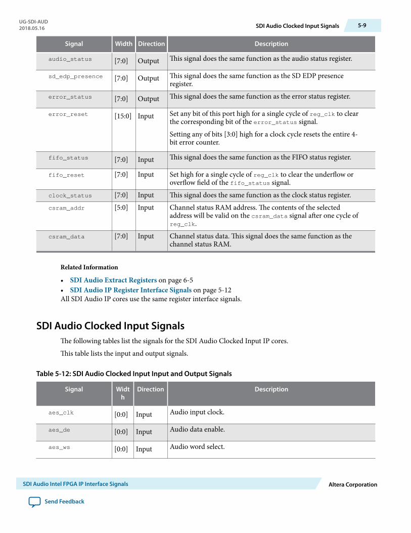
audio_status [7:0] Output This signal does the same function as the audio status register.
sd_edp_presence [7:0] Output This signal does the same function as the SD EDP presenceregister.
error_status [7:0] Output This signal does the same function as the error status register.
error_reset [15:0] Input Set any bit of this port high for a single cycle of reg_clk to clearthe corresponding bit of the error_status signal.
Setting any of bits [3:0] high for a clock cycle resets the entire 4-bit error counter.
fifo_status [7:0] Input This signal does the same function as the FIFO status register.
fifo_reset [7:0] Input Set high for a single cycle of reg_clk to clear the underflow oroverflow field of the fifo_status signal.
clock_status [7:0] Input This signal does the same function as the clock status register.csram_addr [5:0] Input Channel status RAM address. The contents of the selected
address will be valid on the csram_data signal after one cycle ofreg_clk.
csram_data [7:0] Input Channel status data. This signal does the same function as thechannel status RAM.
Related Information
• SDI Audio Extract Registers on page 6-5• SDI Audio IP Register Interface Signals on page 5-12All SDI Audio IP cores use the same register interface signals.
SDI Audio Clocked Input SignalsThe following tables list the signals for the SDI Audio Clocked Input IP cores.
This table lists the input and output signals.
Table 5-12: SDI Audio Clocked Input Input and Output Signals
Signal Width
Direction Description
aes_clk [0:0] Input Audio input clock.
aes_de [0:0] Input Audio data enable.
aes_ws [0:0] Input Audio word select.
UG-SDI-AUD2018.05.16 SDI Audio Clocked Input Signals 5-9
SDI Audio Intel FPGA IP Interface Signals Altera Corporation
Send Feedback

Signal Width
Direction Description
aes_data [0:0] Input Audio data input in internal AES format.
This table lists the Avalon-ST audio signals when you instantiate the SDI Audio Clocked Input IP core inPlatform Designer (Standard).
Table 5-13: SDI Audio Clocked Input Avalon-ST Audio Signals
Signal Width Direction Description
aud_clk [0:0] Input Clocked audio clock. All the audio input signals are synchronousto this clock.
aud_ready [0:0] Input Avalon-ST ready signal. Assert this signal when the device is ableto receive data.
aud_valid [0:0] Output Avalon-ST valid signal. The core asserts this signal when itproduces data.
aud_sop [0:0] Output Avalon-ST start of packet signal. The core asserts this signalwhen it is starting a new frame.
aud_eop [0:0] Output Avalon-ST end of packet signal. The core asserts this signal whenit is ending a frame.
aud_data [23:0] Output Avalon-ST data bus. The core asserts this signal to transfer data.
This table lists the direct control interface signals. The direct control interface is internal to the audioextract component.
Table 5-14: SDI Audio Clocked Input Direct Control Interface Signals
Signal Width Direction Description
channel0 [7:0] Input Indicates the channel number of audio channel 1.
channel1 [7:0] Input Indicates the channel number of audio channel 2.
fifo_status [7:0] Input Drive bit 7 high to reset the clocked audio input FIFO buffer.
fifo_reset [0:0] Output Assert this signal when the clocked audio input FIFO bufferoverflows.
5-10 SDI Audio Clocked Input SignalsUG-SDI-AUD
2018.05.16
Altera Corporation SDI Audio Intel FPGA IP Interface Signals
Send Feedback

Related InformationSDI Audio IP Register Interface Signals on page 5-12All SDI Audio IP cores use the same register interface signals.
SDI Audio Clocked Output SignalsThe following tables list the signals for the SDI Audio Clocked Output IP cores.
This table lists the input and output signals.
Table 5-15: SDI Audio Clocked Output Input and Output Signals
Signal Width
Direction Description
aes_clk [0:0] Input Audio input clock.
aes_de [0:0] Output Audio data enable.
aes_ws [0:0] Output Audio word select.
aes_data [0:0] Output Audio data input in internal AES format.
This table lists the Avalon-ST audio signals when you instantiate the SDI Audio Clocked Output IP core inPlatform Designer (Standard).
Table 5-16: SDI Audio Clocked Output Avalon-ST Audio Signals
Signal Width Direction Description
aud_clk [0:0] Input Clocked audio clock. All the audio input signals are synchronousto this clock.
aud_ready [0:0] Output Avalon-ST ready signal. Assert this signal when the device is ableto receive data.
aud_valid [0:0] Input Avalon-ST valid signal. The core asserts this signal when itreceives data.
aud_sop [0:0] Input Avalon-ST start of packet signal. The core asserts this signalwhen it is starting a new frame.
aud_eop [0:0] Input Avalon-ST end of packet signal. The core asserts this signal whenit is ending a frame.
aud_data [23:0] Input Avalon-ST data bus. This bus transfers data.
UG-SDI-AUD2018.05.16 SDI Audio Clocked Output Signals 5-11
SDI Audio Intel FPGA IP Interface Signals Altera Corporation
Send Feedback

Related InformationSDI Audio IP Register Interface Signals on page 5-12All SDI Audio IP cores use the same register interface signals.
SDI Audio IP Register Interface SignalsAll SDI Audio IP cores use the same register interface signals.
The register interface is a standard 8-bit wide Avalon-MM slave.
Table 5-17: SDI Audio IP Register Interface Signals
Signal Width Direction Description
reg_clk [0:0] Input Clock for the Avalon-MM register interface.
reg_reset [0:0] Input Reset for the Avalon-MM register interface.
reg_base_addr [5:0] Input Reset for the Avalon-MM register interface.
reg_burst_count [5:0] Input Transfer size in bytes.
reg_waitrequest [0:0] Output Wait request.
reg_write [7:0] Input Write request.
reg_writedata [0:0] Input Data to be written to target.
reg_read [0:0] Input Read request.
reg_readdata-
valid[0:0] Output Requested read data valid after read latency.
reg_readdata [7:0] Output Data read from target.
5-12 SDI Audio IP Register Interface SignalsUG-SDI-AUD
2018.05.16
Altera Corporation SDI Audio Intel FPGA IP Interface Signals
Send Feedback

SDI Audio Intel FPGA IP Registers 62018.05.16
UG-SDI-AUD Subscribe Send Feedback
The following sections describe the registers for the SDI Audio IP cores.
SDI Audio Embed RegistersThe following tables list the registers for the SDI Audio Embed IP core.
Table 6-1: SDI Audio Embed Register Map
Bytes Offset Name
00h Audio Control Register
01h Extended Control Register
02h Video Status Register
03h SD EDP Control Register
04h Channel Status Control Registers (3:0)
05h Channel Status Control Registers (7:4)
06h Strip Control Register
07h Strip Status Register
08h Sine Channel 1 Frequency
09h Sine Channel 2 Frequency
0Ah Sine Channel 3 Frequency
0Bh Sine Channel 4 Frequency
0Ch Audio Status Register
Intel Corporation. All rights reserved. Intel, the Intel logo, Altera, Arria, Cyclone, Enpirion, MAX, Nios, Quartus and Stratix words and logos are trademarks ofIntel Corporation or its subsidiaries in the U.S. and/or other countries. Intel warrants performance of its FPGA and semiconductor products to currentspecifications in accordance with Intel's standard warranty, but reserves the right to make changes to any products and services at any time without notice.Intel assumes no responsibility or liability arising out of the application or use of any information, product, or service described herein except as expresslyagreed to in writing by Intel. Intel customers are advised to obtain the latest version of device specifications before relying on any published informationand before placing orders for products or services.*Other names and brands may be claimed as the property of others.
ISO9001:2008Registered
www.altera.com101 Innovation Drive, San Jose, CA 95134
Bytes Offset Name
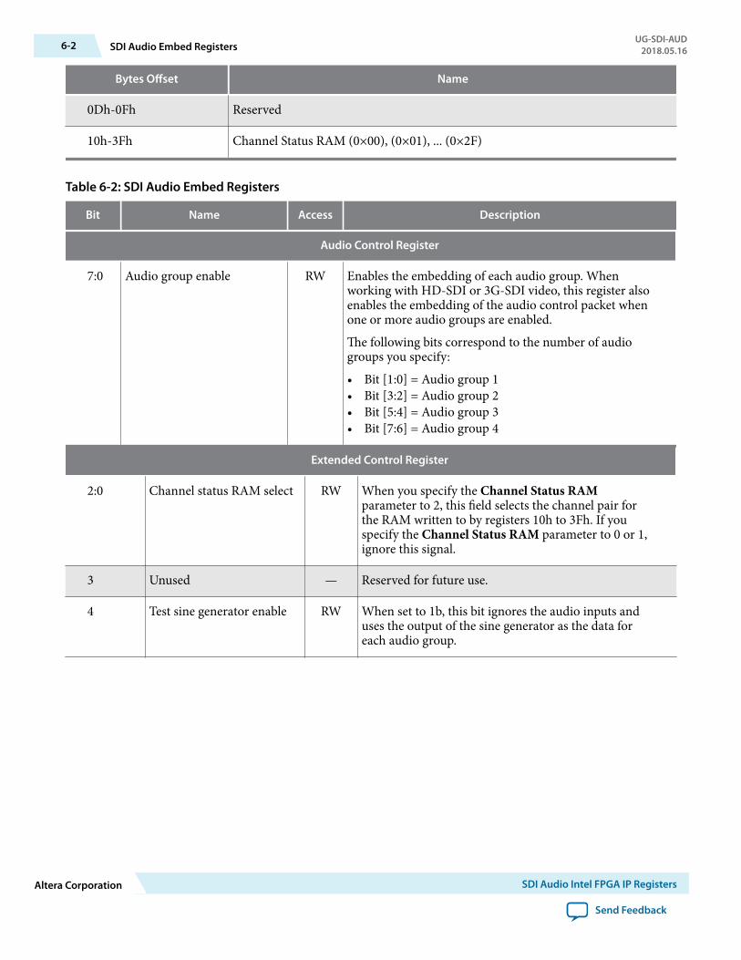
0Dh-0Fh Reserved
10h-3Fh Channel Status RAM (0×00), (0×01), ... (0×2F)
Table 6-2: SDI Audio Embed Registers
Bit Name Access Description
Audio Control Register
7:0 Audio group enable RW Enables the embedding of each audio group. Whenworking with HD-SDI or 3G-SDI video, this register alsoenables the embedding of the audio control packet whenone or more audio groups are enabled.
The following bits correspond to the number of audiogroups you specify:
• Bit [1:0] = Audio group 1• Bit [3:2] = Audio group 2• Bit [5:4] = Audio group 3• Bit [7:6] = Audio group 4
Extended Control Register
2:0 Channel status RAM select RW When you specify the Channel Status RAMparameter to 2, this field selects the channel pair forthe RAM written to by registers 10h to 3Fh. If youspecify the Channel Status RAM parameter to 0 or 1,ignore this signal.
3 Unused — Reserved for future use.
4 Test sine generator enable RW When set to 1b, this bit ignores the audio inputs anduses the output of the sine generator as the data foreach audio group.
6-2 SDI Audio Embed RegistersUG-SDI-AUD
2018.05.16
Altera Corporation SDI Audio Intel FPGA IP Registers
Send Feedback

Extended Control Register
6:5 Link AB Control RW This register applies only for 3G-SDI Level B standard.
Controls which link the ancillary data is embedded in.
• 00b = No data is embedded• 01b = Data is embedded only in Link B.• 10b = Data is embedded only in Link A (default
value).• 11b = Data is embedded in Link A and Link B at
the same time.
When set to 11b, the IP core inserts new packets afterany existing ancillary data on Link A and in theidentical location on Link B.
If the packet distribution of existing ancillary data onLink B differs, existing packets may be corrupted. Inthese circumstances, Intel recommends you use twoseparate instances of the ancillary embedder.
7 Unused — Reserved for future use.
Video Status Register
7:0 Active channel RO Reports the detected video input standard.
• Bits[7:5] = Picture structure code. Defined valuesfor picture structure code are:
• 001b = 486 or 576 line SD-SDI• 100b = 720 line HD-SDI• 101b = 1080 line HD-SDI• 010b = 1080 line 3G-SDI• 011b = 1080 line 3GA-SDI• 110b = 720 line 3GA-SDI• 111b = 720 line 3GB-SDI
• Bit[4] = 0b—Interlace or segmented frame, 1b—Progressive.
• Bits[3:0] = Frame rate code. Defined values forframe rate code (in Hz) are:
• 0010b = 23.97• 0011b = 24• 0101b = 25• 0110b = 29.97• 0111b = 30• 1001b = 50• 1010b = 59.94• 1011b = 60
UG-SDI-AUD2018.05.16 SDI Audio Embed Registers 6-3
SDI Audio Intel FPGA IP Registers Altera Corporation
Send Feedback

SD EDP Control Register
3:0 Enable SD EDP RW Enables the embedding of SD-SDI Extended DataPackets (EDP) for each audio group.
7:4 Enable SD ACP RW Enables the embedding of SD-SDI Audio ControlPackets (ACP) for each audio group.
Channel Status Control Register
7:0 CS mode select RW When set to 00b, the core keeps the existing channelstatus data.
When set to 01b, the core replaces the channel statusdata with these default values:
• Channel status byte 0: 0x8• Channel status byte 1: 0x02• Channel status byte 2–22: 0x00• Channel status byte 23: 0xDD
When set to 10b, the core replaces the data with thecontents of the appropriate channel status RAM.
The following bits correspond to the number of audiogroups you specify:
• Bit [1:0] = Audio group 1• Bit [3:2] = Audio group 2• Bit [5:4] = Audio group 3• Bit [7:6] = Audio group 4
Strip Control Register
3:0 Strip enable RW Enables the removal of both ACP and ADP (and anySD-SDI EDP) for each of the four audio groups.
7:4 Unused — Reserved for future use.
Strip Status Register
3:0 Data packet present RO
3:0
Reports which audio data groups are detected in theSDI stream.
When in 3G-SDI Level B mode, this register reportsthe presence of audio on Link A (Link B should be aduplicate).
6-4 SDI Audio Embed RegistersUG-SDI-AUD
2018.05.16
Altera Corporation SDI Audio Intel FPGA IP Registers
Send Feedback

Strip Status Register
7:4 Control packet present RO Reports which audio control groups are detected in theSDI stream.
When in 3G-SDI Level B mode, this register reportsthe presence of audio on Link A (Link B should be aduplicate).
Sine Channel n Frequency
7:0 Sine channel frequency RW Defines the frequency of the generated audio.
Audio Status Register
4 Frame lock RO Reports whether the video frame with the embeddedaudio is locked.
Channel Status RAM
7:0 Channel status data WO Write accesses within the address range 10h to 3Fh tothe channel status RAM. This field returns the 24 bytesof channel status for X channels starting at address 10hto 27h, and the 24 bytes of channel status for Ychannels starting at address 28h to 3Fh.
Related InformationSDI Audio Embed Signals on page 5-1
SDI Audio Extract RegistersThe following tables list the registers for the SDI Audio Extract IP core.
Table 6-3: SDI Audio Extract Register Map
Bytes Offset Name
00h Audio Control Register
01h Audio Presence Register
02h Audio Status Register
03h SD EDP Presence Register
04h Error Status Register
05h Reserved
UG-SDI-AUD2018.05.16 SDI Audio Extract Registers 6-5
SDI Audio Intel FPGA IP Registers Altera Corporation
Send Feedback
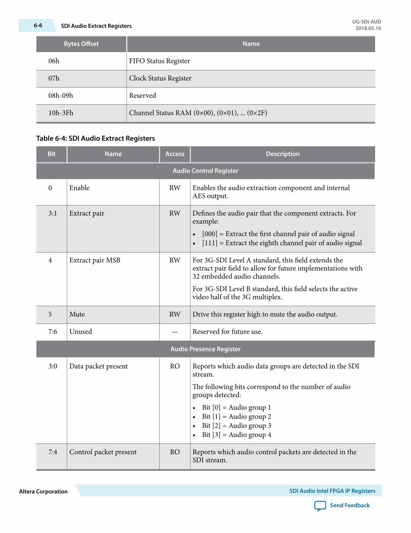
Bytes Offset Name
06h FIFO Status Register
07h Clock Status Register
08h-09h Reserved
10h-3Fh Channel Status RAM (0×00), (0×01), ... (0×2F)
Table 6-4: SDI Audio Extract Registers
Bit Name Access Description
Audio Control Register
0 Enable RW Enables the audio extraction component and internalAES output.
3:1 Extract pair RW Defines the audio pair that the component extracts. Forexample:
• [000] = Extract the first channel pair of audio signal• [111] = Extract the eighth channel pair of audio signal
4 Extract pair MSB RW For 3G-SDI Level A standard, this field extends theextract pair field to allow for future implementations with32 embedded audio channels.
For 3G-SDI Level B standard, this field selects the activevideo half of the 3G multiplex.
5 Mute RW Drive this register high to mute the audio output.
7:6 Unused — Reserved for future use.
Audio Presence Register
3:0 Data packet present RO Reports which audio data groups are detected in the SDIstream.
The following bits correspond to the number of audiogroups detected:
• Bit [0] = Audio group 1• Bit [1] = Audio group 2• Bit [2] = Audio group 3• Bit [3] = Audio group 4
7:4 Control packet present RO Reports which audio control packets are detected in theSDI stream.
6-6 SDI Audio Extract RegistersUG-SDI-AUD
2018.05.16
Altera Corporation SDI Audio Intel FPGA IP Registers
Send Feedback
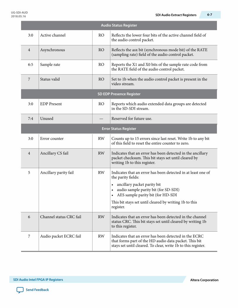
Audio Status Register
3:0 Active channel RO Reflects the lower four bits of the active channel field ofthe audio control packet.
4 Asynchronous RO Reflects the asx bit (synchronous mode bit) of the RATE(sampling rate) field of the audio control packet.
6:5 Sample rate RO Reports the X1 and X0 bits of the sample rate code fromthe RATE field of the audio control packet.
7 Status valid RO Set to 1b when the audio control packet is present in thevideo stream.
SD EDP Presence Register
3:0 EDP Present RO Reports which audio extended data groups are detectedin the SD-SDI stream.
7:4 Unused — Reserved for future use.
Error Status Register
3:0 Error counter RW Counts up to 15 errors since last reset. Write 1b to any bitof this field to reset the entire counter to zero.
4 Ancillary CS fail RW Indicates that an error has been detected in the ancillarypacket checksum. This bit stays set until cleared bywriting 1b to this register.
5 Ancillary parity fail RW Indicates that an error has been detected in at least one ofthe parity fields:
• ancillary packet parity bit• audio sample parity bit (for SD-SDI)• AES sample parity bit (for HD-SDI
This bit stays set until cleared by writing 1b to thisregister.
6 Channel status CRC fail RW Indicates that an error has been detected in the channelstatus CRC. This bit stays set until cleared by writing 1bto this register.
7 Audio packet ECRC fail RW Indicates that an error has been detected in the ECRCthat forms part of the HD audio data packet. This bitstays set until cleared. To clear, write 1b to this register.
UG-SDI-AUD2018.05.16 SDI Audio Extract Registers 6-7
SDI Audio Intel FPGA IP Registers Altera Corporation
Send Feedback
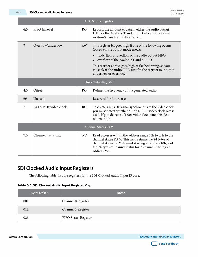
FIFO Status Register
6:0 FIFO fill level RO Reports the amount of data in either the audio outputFIFO or the Avalon-ST audio FIFO when the optionalAvalon-ST Audio interface is used.
7 Overflow/underflow RW This register bit goes high if one of the following occurs(based on the output mode used):
• underflow or overflow of the audio output FIFO• overflow of the Avalon-ST audio FIFO
This register always goes high at the beginning, so youmust clear the audio FIFO first for the register to indicateunderflow or overflow.
Clock Status Register
4:0 Offset RO Defines the frequency of the generated audio.
6:5 Unused — Reserved for future use.
7 74.17-MHz video clock RO To create a 48-kHz signal synchronous to the video clock,you must detect whether a 1 or 1/1.001 video clock rate isused. If you detect a 1/1.001 video clock rate, this fieldreturns high.
Channel Status RAM
7:0 Channel status data WO Read accesses within the address range 10h to 3Fh to thechannel status RAM. This field returns the 24 bytes ofchannel status for X channel starting at address 10h, andthe 24 bytes of channel status for Y channel starting ataddress 28h.
SDI Clocked Audio Input RegistersThe following tables list the registers for the SDI Clocked Audio Input IP core.
Table 6-5: SDI Clocked Audio Input Register Map
Bytes Offset Name
00h Channel 0 Register
01h Channel 1 Register
02h FIFO Status Register
6-8 SDI Clocked Audio Input RegistersUG-SDI-AUD
2018.05.16
Altera Corporation SDI Audio Intel FPGA IP Registers
Send Feedback

Bytes Offset Name
03h FIFO Reset Register
Table 6-6: SDI Clocked Audio Input Registers
Bit Name Access Description
Channel 0 Register
7:0 Channel 0 RW The user-defined channel number of audio channel 0.
Channel 1 Register
7:0 Channel status RAM select RW The user-defined channel number of audio channel 1.
FIFO Status Register
7:0 Active channel RO This sticky bit reports the overflow of the clocked audioinput FIFO.
FIFO Reset Register
6:0 Unused WO Reserved for future use.
7 FIFO reset WO Resets the clocked audio FIFO.
SDI Clocked Audio Output RegistersThe following tables list the registers for the SDI Clocked Audio Output IP core.
Table 6-7: SDI Clocked Audio Output Register Map
Bytes Offset Name
00h Channel 0 Register
01h Channel 1 Register
02h FIFO Status Register
03h FIFO Reset Register
UG-SDI-AUD2018.05.16 SDI Clocked Audio Output Registers 6-9
SDI Audio Intel FPGA IP Registers Altera Corporation
Send Feedback

Table 6-8: SDI Clocked Audio Output Registers
Bit Name Access Description
Channel 0 Register
7:0 Channel 0 RW The user-defined channel number of audio channel 0.
Channel 1 Register
7:0 Channel status RAM select RW The user-defined channel number of audio channel 1.
FIFO Status Register
7:0 Active channel RO This sticky bit reports the overflow of the clocked audiooutput FIFO.
FIFO Reset Register
6:0 Unused WO Reserved for future use.
7 FIFO reset WO Resets the clocked audio FIFO.
6-10 SDI Clocked Audio Output RegistersUG-SDI-AUD
2018.05.16
Altera Corporation SDI Audio Intel FPGA IP Registers
Send Feedback

SDI Audio Intel FPGA IP Design Example 72018.05.16
UG-SDI-AUD Subscribe Send Feedback
Intel provides a design example with the SDI Audio Embed and Extract IP cores. This design exampleincludes the SDI Audio IP cores and instances of the SDI IP cores.
Figure 7-1: High-Level Block Diagram of Stratix IV GX FPGA
Video Pattern Generator P0
Audio Pattern Generator
Ancillary Data Insertion P1
Video Pattern Generator P1
(internal AES)
(internal AES)aud_dataaud_wsaud_de
aud_dataaud_wsaud_de
AES
Stratix IV GX FPGA
Encrypted IP core
Ancillary Data Insertion P0
Transceiver Dynamic Reconfiguration
Control Logic
Waveform Monitor
(WFM 700)
Audio Embed P0 SDI TX P0 SDI_OUT_2
SDI_OUT_1AES_IN_1
AES_OUT_1SDI_IN_1
Audio Extract
Audio Embed P1
AES Output Module
AES Input Module
SDI Duplex
RX
TX P1
Components of Design ExampleThe following sections describe the various elements in design example.
Intel Corporation. All rights reserved. Intel, the Intel logo, Altera, Arria, Cyclone, Enpirion, MAX, Nios, Quartus and Stratix words and logos are trademarks ofIntel Corporation or its subsidiaries in the U.S. and/or other countries. Intel warrants performance of its FPGA and semiconductor products to currentspecifications in accordance with Intel's standard warranty, but reserves the right to make changes to any products and services at any time without notice.Intel assumes no responsibility or liability arising out of the application or use of any information, product, or service described herein except as expresslyagreed to in writing by Intel. Intel customers are advised to obtain the latest version of device specifications before relying on any published informationand before placing orders for products or services.*Other names and brands may be claimed as the property of others.
ISO9001:2008Registered
www.altera.com101 Innovation Drive, San Jose, CA 95134

SDI Transmitter P0The triple-standard SDI transmitter that outputs a 3G-SDI (2.970 Gbps), HD-SDI (1.485 Mbps), or SD-SDI (270 Mbps) data stream. This transmitter gets the parallel data source from the SDI Audio Embed IPcore. The SDI Audio Embed component embeds the internally generated audio in AES format into theinternally generated video. The transmitter transmits the serial signal through a BNC cable to the receiverof the SDI duplex instance.
SDI DuplexThe triple-standard SDI duplex provides a full-duplex SD-SDI, HD-SDI, and 3G-SDI standards. The SDIduplex instance routes the received data to the SDI Audio Extract IP core to extract the AES audio. TheSDI Audio Embed IP core embeds the internally generated audio in AES format into the internallygenerated video. The transmitter in this duplex connects its output to the external waveform monitor, suchas the WFM700.
Audio ExtractThe Audio Extract IP core extracts the embedded AES audio from the SDI stream. The Audio Extract IPcore routes the extracted AES audio to the AES output of the daughter card.
AES Input ModuleThe AES input module converts the AES signal to aud_de, aud_ws, and aud_data (internal AES) signals tointerface with Audio Embed P1. When this module interfaces with the Audio Embed IP core, both mustuse the same clock.
AES Output ModuleThe AES output module converts the aud_de, aud_ws, and aud_data signals to AES signal. This moduleconfigures the extracted internal AES audio signal (aud_data) without the biphase mark encoding. Whenthis module interfaces with the Audio Extract IP core, it must use the same clock as the Audio Extract IPcore.
Audio Embed P0/P1The Audio Embed P0 embeds the AES audio generated by the Audio Pattern Generator into the videostream, as a transmitting data, for the SDI transmitter P0. The Audio Embed P1 embeds the AES audiofrom the external AES input into the video stream for the SDI duplex
Video Pattern Generator P0/P1You can configure the internal video pattern generator to output an SD-SDI, HD-SDI, 3G-SDI Level A or3G-SDI Level B colorbar pattern.
Audio Pattern GeneratorYou can configure the internal audio pattern generator to create an AES audio test sample that comprisesan increasing count. You configure the generator using the 48-kHz clock output from the Audio Embed IPcore.
Ancillary Data Insertion P0/P1The Ancillary Data Insertion module inserts the ancillary data defined by SMPTE352 into the SDI videostream.
7-2 SDI Transmitter P0UG-SDI-AUD
2018.05.16
Altera Corporation SDI Audio Intel FPGA IP Design Example
Send Feedback
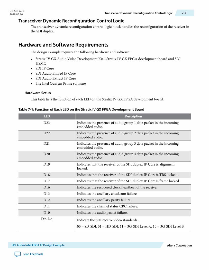
Transceiver Dynamic Reconfiguration Control LogicThe transceiver dynamic reconfiguration control logic block handles the reconfiguration of the receiver inthe SDI duplex.
Hardware and Software RequirementsThe design example requires the following hardware and software:
• Stratix IV GX Audio Video Development Kit—Stratix IV GX FPGA development board and SDIHSMC
• SDI IP Core• SDI Audio Embed IP Core• SDI Audio Extract IP Core• The Intel Quartus Prime software
Hardware Setup
This table lists the function of each LED on the Stratix IV GX FPGA development board.
Table 7-1: Function of Each LED on the Stratix IV GX FPGA Development Board
LED Description
D23 Indicates the presence of audio group 1 data packet in the incomingembedded audio.
D22 Indicates the presence of audio group 2 data packet in the incomingembedded audio.
D21 Indicates the presence of audio group 3 data packet in the incomingembedded audio.
D20 Indicates the presence of audio group 4 data packet in the incomingembedded audio.
D19 Indicates that the receiver of the SDI duplex IP Core is alignmentlocked.
D18 Indicates that the receiver of the SDI duplex IP Core is TRS locked.D17 Indicates that the receiver of the SDI duplex IP Core is frame locked.D16 Indicates the recovered clock heartbeat of the receiver.D13 Indicates the ancillary checksum failure.D12 Indicates the ancillary parity failure.D11 Indicates the channel status CRC failure.D10 Indicates the audio packet failure.
D9–D8 Indicate the SDI receive video standards.
00 = SD-SDI, 01 = HD-SDI, 11 = 3G-SDI Level A, 10 = 3G-SDI Level B
UG-SDI-AUD2018.05.16 Transceiver Dynamic Reconfiguration Control Logic 7-3
SDI Audio Intel FPGA IP Design Example Altera Corporation
Send Feedback
LED Description
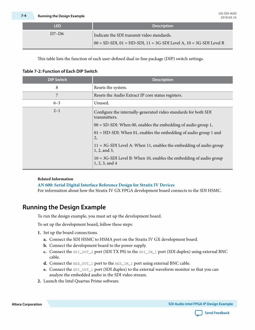
D7–D6 Indicate the SDI transmit video standards.
00 = SD-SDI, 01 = HD-SDI, 11 = 3G-SDI Level A, 10 = 3G-SDI Level B
This table lists the function of each user-defined dual in-line package (DIP) switch settings.
Table 7-2: Function of Each DIP Switch
DIP Switch Description
8 Resets the system.7 Resets the Audio Extract IP core status registers.
6–3 Unused.2–1 Configure the internally-generated video standards for both SDI
transmitters.
00 = SD-SDI: When 00, enables the embedding of audio group 1,
01 = HD-SDI: When 01, enables the embedding of audio group 1 and2,
11 = 3G-SDI Level A: When 11, enables the embedding of audio group1, 2, and 3,
10 = 3G-SDI Level B: When 10, enables the embedding of audio group1, 2, 3, and 4
Related InformationAN 600: Serial Digital Interface Reference Design for Stratix IV DevicesFor information about how the Stratix IV GX FPGA development board connects to the SDI HSMC.
Running the Design ExampleTo run the design example, you must set up the development board.
To set up the development board, follow these steps:
1. Set up the board connections.a. Connect the SDI HSMC to HSMA port on the Stratix IV GX development board.b. Connect the development board to the power supply.c. Connect the SDI_OUT_2 port (SDI TX P0) to the SDI_IN_1 port (SDI duplex) using external BNC
cable.d. Connect the AES_OUT_1 port to the AES_IN_1 port using external BNC cable.e. Connect the SDI_OUT_1 port (SDI duplex) to the external waveform monitor so that you can
analyze the embedded audio in the SDI video stream.2. Launch the Intel Quartus Prime software.
7-4 Running the Design ExampleUG-SDI-AUD
2018.05.16
Altera Corporation SDI Audio Intel FPGA IP Design Example
Send Feedback

a. On the File menu, click Open Project, navigate to ip/altera/audio_ip/example/s4gx_sdi_audio/s4gxsdi_audio.qpf, and click Open.
b. On the Processing menu, click Start Compilation.3. Download the Intel Quartus Prime-generated SRAM Object File (.sof).
After you set up the board, run the different configurations described in the following sections.
Transmit SD-SDI with Embedding of Audio Group 1To transmit the SD-SDI video standard, follow these steps:
1. Set DIP switch[2:1] = 002. The demonstration runs and the LEDs indicate the following conditions:
a. LED D16 blinks indicating the heartbeat of the receiver's recovered clock.b. LED D17 illuminates when the receiver is frame locked.c. LED D18 illuminates when the receiver is TRS locked.d. LED D19 illuminates when the receiver is alignment locked.e. LED D23 illuminates when the data packet of audio group 1 is detected in the incoming SDI stream.This figure shows the condition of the LEDs.
Figure 7-2: Condition of LEDs for Transmitting SDI-SDI Video Standard
D6 D7 D8 D9 D10 D11 D12 D13
D16 D17 D18 D19 D20 D21 D22 D23
3. The external waveform monitor (WFM700) displays the following observation:a. Colorbar video patternb. Video format detected is 625i 50.00c. Embedded audio standard detected is SMPTE272Md. Audio channel pairs (1,2) and (3,4) are present
Transmit HD-SDI with Embedding of Audio Group 1 and 2To transmit the HD-SDI video standard, follow these steps:
1. Set DIP switch[2:1] = 012. The demonstration runs and the LEDs indicate the following conditions:
a. LEDs D6 and D7 indicate the internal video pattern generator signal standard.b. LEDs D8 and D9 indicate the receive video standard.c. LED D16 blinks indicating the heartbeat of the receiver's recovered clock. The frequency is blinking
is slower than the previous demonstration.d. LED D17 illuminates when the receiver is frame locked.e. LED D18 illuminates when the receiver is TRS locked.f. LED D19 illuminates when the receiver is alignment locked.g. LEDs D23 and D22 illuminate when the data packet of audio groups 1 and 2 are detected in the
incoming SDI stream.
UG-SDI-AUD2018.05.16 Transmit SD-SDI with Embedding of Audio Group 1 7-5
SDI Audio Intel FPGA IP Design Example Altera Corporation
Send Feedback

This figure shows the condition of the LEDs.Figure 7-3: Condition of LEDs for Transmitting HDI-SDI Video Standard
D6 D7 D8 D9 D10 D11 D12 D13
D16 D17 D18 D19 D20 D21 D22 D23
3. The external waveform monitor (WFM700) displays the following observation:a. Colorbar video patternb. Video format detected is 1080i 60.00c. Embedded audio standard detected is SMPTE299Md. Audio channel pairs (1,2), (3,4), (5,6) and (7,8) are present
Transmit 3G-SDI Level A with Embedding of Audio Group 1, 2 and 3To transmit the 3G-SDI Level A video standard, follow these steps:
1. Set DIP switch[2:1] = 112. The demonstration runs and the LEDs indicate the following conditions:
a. LEDs D6 and D7 indicate the internal video pattern generator signal standard.b. LEDs D8 and D9 indicate the receive video standard.c. LED D16 blinks indicating the heartbeat of the receiver's recovered clock..d. LED D17 illuminates when the receiver is frame locked.e. LED D18 illuminates when the receiver is TRS locked.f. LED D19 illuminates when the receiver is alignment locked.g. LEDs D23, D22 and D21 illuminate when the data packet of audio groups 1, 2 and 3 are detected in
the incoming SDI stream.This figure shows the condition of the LEDs.
Figure 7-4: Condition of LEDs for Transmitting 3G-SDI Level A Video Standard
D6 D7 D8 D9 D10 D11 D12 D13
D16 D17 D18 D19 D20 D21 D22 D23
Transmit 3G-SDI Level B with Embedding of Audio Group 1, 2, 3 and 4To transmit the 3G-SDI Level B video standard, follow these steps:
1. Set DIP switch[2:1] = 102. The demonstration runs and the LEDs indicate the following conditions:
7-6 Transmit 3G-SDI Level A with Embedding of Audio Group 1, 2 and 3UG-SDI-AUD
2018.05.16
Altera Corporation SDI Audio Intel FPGA IP Design Example
Send Feedback

a. LEDs D6 and D7 indicate the internal video pattern generator signal standard.b. LEDs D8 and D9 indicate the receive video standard.c. LED D16 blinks indicating the heartbeat of the receiver's recovered clock.d. LED D17 illuminates when the receiver is frame locked.e. LED D18 illuminates when the receiver is TRS locked.f. LED D19 illuminates when the receiver is alignment locked.g. LEDs D23, D22, D21 and D20 illuminate when the data packet of audio groups 1, 2, 3 and 4 are
detected in the incoming SDI stream.This figure shows the condition of the LEDs.
Figure 7-5: Condition of LEDs for Transmitting 3G-SDI Level B Video Standard
D6 D7 D8 D9 D10 D11 D12 D13
D16 D17 D18 D19 D20 D21 D22 D23
UG-SDI-AUD2018.05.16 Transmit 3G-SDI Level B with Embedding of Audio Group 1, 2, 3 and 4 7-7
SDI Audio Intel FPGA IP Design Example Altera Corporation
Send Feedback

SDI Audio Intel FPGA IP User Guide Archives A2018.05.16
UG-SDI-AUD Subscribe Send Feedback
If an IP core version is not listed, the user guide for the previous IP core version applies.IP Core Version User Guide
16.0 SDI Audio IP Cores User Guide
14.0 SDI Audio IP Cores User Guide
Intel Corporation. All rights reserved. Intel, the Intel logo, Altera, Arria, Cyclone, Enpirion, MAX, Nios, Quartus and Stratix words and logos are trademarks ofIntel Corporation or its subsidiaries in the U.S. and/or other countries. Intel warrants performance of its FPGA and semiconductor products to currentspecifications in accordance with Intel's standard warranty, but reserves the right to make changes to any products and services at any time without notice.Intel assumes no responsibility or liability arising out of the application or use of any information, product, or service described herein except as expresslyagreed to in writing by Intel. Intel customers are advised to obtain the latest version of device specifications before relying on any published informationand before placing orders for products or services.*Other names and brands may be claimed as the property of others.
ISO9001:2008Registered
www.altera.com101 Innovation Drive, San Jose, CA 95134

Document Revision History for the SDI AudioIntel FPGA IP User Guide B
2018.05.16
UG-SDI-AUD Subscribe Send Feedback
Document Version Intel QuartusPrime Version
Changes
2018.05.16 18.0 • Rebranded as Intel.• Edited the vid_std settings for SDI Audio Extract IP core. The
correct settings should be 10b for 3G-SDI Level B and 11b for 3G-SDI Level A.
• Removed Audio group presence register (bit 3:0). The register is nolonger supported in the current IP code.
Date Version Changes
May 2016 2016.05.30 • Added a new signal for the SDI Audio Extract IP core: aud_z[0:0].This signal indicates the Z preamble.
• Added the default values that replace the channel status data whenyou set the CS mode select register to 01b.
• Added link to an archived version of the SDI Audio IP Cores UserGuide.
• Changed instances of Quartus II to Quartus Prime.
June 2014 2014.06.30 • Created a separate user guide for the SDI Audio IP cores.• Removed the SDI Audio IP section from the SDI IP Core User Guide.• Added new registers for the SDI Audio Embed IP core: SD EDP
Control, Strip Control, and Strip Status.• Added new signals for the SDI Audio Embed IP core: extended_
control, strip_control, and strip_control.• Added a new register for the SDI Audio Extract IP core: SD EDP
Presence.• Added a new signal for the SDI Audio Extract IP core: sd_edp_
presence.
Intel Corporation. All rights reserved. Intel, the Intel logo, Altera, Arria, Cyclone, Enpirion, MAX, Nios, Quartus and Stratix words and logos are trademarks ofIntel Corporation or its subsidiaries in the U.S. and/or other countries. Intel warrants performance of its FPGA and semiconductor products to currentspecifications in accordance with Intel's standard warranty, but reserves the right to make changes to any products and services at any time without notice.Intel assumes no responsibility or liability arising out of the application or use of any information, product, or service described herein except as expresslyagreed to in writing by Intel. Intel customers are advised to obtain the latest version of device specifications before relying on any published informationand before placing orders for products or services.*Other names and brands may be claimed as the property of others.
ISO9001:2008Registered
www.altera.com101 Innovation Drive, San Jose, CA 95134