sd 311 method of test for determining the cutout
TRANSCRIPT

SD 311
mso.mat 9-21
Method of Test for Determining the Cutout Correction and In Place Density of Asphalt Concrete by the Nuclear Gauge Method
1. Scope:
This test is for determining the in place density of asphalt concrete by using the nuclear gauge. A correction needs to be applied to the nuclear gauge to obtain an accurate in place density. A gauge reading will be taken at the cutout or core site prior to the removal the asphalt concrete. The density of the cutout or core will then be determined.
Definitions:
Standard Density: Average of the 5 most recent theoretical maximum specific density determinations.
Lot: A quantity of material from a single source, representing a specific segment of construction, upon which decision is made for acceptance.
Random Measurement: A specific individual measurement of in place density (One of 5 measurements made for a lot), the location is chosen such that each portion of the lot has an equal probability of being selected.
2. Apparatus:
2.1 Scale or balance having the capacity to weigh any sample which may be
tested utilizing this procedure and readable to the nearest 0.1 gram. The scale or balance will be equipped with a suitable suspension apparatus and holder to permit weighing the sample while suspended from the center of the scale pan of the weighing device.
2.2 The water bath for immersing the sample will be equipped with an overflow outlet for maintaining a constant water level. An aquarium heater will suffice to control the temperature of the water bath at 77° ± 2° F. The water bath must be large enough to allow the suspension apparatus holder to be covered with water at all times. The sample and suspension apparatus must be completely covered with water during weighing. The wire suspending the suspension apparatus will be the smallest practical size to minimize any possible effects of a variable immersed length.
2.3 A thermometer with subdivisions and maximum scale error of 1˚F to cover the
range of testing. 2.4 Power-driven masonry saw capable of cutting a 6” x 6” compaction sample or
a coring device capable of cutting a 6” diameter core from the pavement. Furnished and operated by Contractor.

SD 311 Page 2
mso.mat 9-21
2.5 Miscellaneous. Pails, pans, hammer, roofing tacks, aluminum foil or pavement marking tape, spray paint, 50’ tape measure, 1” x 2” x 12” stakes.
2.6 Nuclear moisture-density gauge capable of determining densities by the
backscatter method and conforming to the requirements of AASHTO T 310. 2.7 A reference standard block for taking standard counts.
2.8 A manufacturer’s instruction manual for the nuclear gauge. 2.9 A nuclear gauge logbook with transportation documents, and dosimeter.
3. Procedure:
3.1 Calibration and Standardization of Nuclear Gauge.
A. Calibration (1) The Central Laboratory will calibrate nuclear gauges annually and
each time repairs are made.
B. Standard Count – Troxler Model 3440 (1) Turn the gauge on and allow the gauge to warm up for at least 10
minutes.
(2) Place the gauge on the reference standard block and take the standard count as recommended by the manufacturer.
(3) Take at least one 4 minute standard count daily. This count should compare within 1% of the average of the 4 previous standard density counts and compare within 2% of the average of the 4 previous standard moisture counts for the gauge. If the standard count varies by more than these tolerances, do not accept the standard count. Check that all the manufacturer’s guidelines have been followed and take another standard count. NOTE: If the second count also fails, follow the manufacturer’s recommendation for the particular model gauge for taking and recording 4 additional standard counts.
(4) Record the results of the standard count in the gauge’s logbook.
C. Standard Count – Troxler Model 4640-B
(1) Turn the gauge on and allow the gauge to warm up for at least 10 minutes.

SD 311 Page 3
mso.mat 9-21
(2) Place the air gap spacer on the Magnesium (Mg) reference block and then place the gauge on top of the spacer. Take the 4 minute standard count as recommended by the manufacturer.
(3) Take at least one standard count daily. The results will be compared with the average of the 4 previous standard counts for the gauge. The system 1 count should compare within 1.0% and the system 2 within 1.2%. If the standard count varies by more than these tolerances, do not accept the standard count. Check that all the manufacturer’s guidelines have been followed and take another standard count. NOTE: If the second count also fails, follow the manufacturer’s recommendation for the particular model gauge for taking and recording 4 additional standard counts.
(4) Record the results of the standard count in the gauge’s logbook.
3.2 Compaction Sample Test Sites
A. Randomly select test sites. The compaction samples will be representative of the lift thickness. A minimum of 3 compaction samples will be obtained per lift.
B. Tack a double layer of aluminum foil or pavement marking tape,
approximately 12” x 18” in size, to the base with roofing nails at each test site. There will be 3 compaction sample sites plus a backup for each lift. The backup will be cut or cored if one of the three samples is damaged.
C. Mark the location of the foil or tape by measuring from the center of the
foil or tape to 2 offset stakes and recording the distance.
D. After the asphalt concrete has been placed and compacted, locate the foil by measuring the recorded distance from each stake and swinging arcs.
3.3 Compaction Sample Density
A. Just prior to obtaining the compaction samples from the road, take 3
nuclear wet density readings in backscatter mode. Place the gauge near the middle of the test site and make sure that it doesn’t “Rock” or shift due to an uneven surface. Keep the gauge turned parallel with the direction of travel of the paver and rollers. Lower the handle to the first notch, being careful not to pass the proper position and take a 1 minute reading to determine the wet density. Move the gauge approximately 3 inches perpendicular to the direction of travel and take the second reading. Move the gauge approximately 6 inches in the opposite direction and take the third reading. Note: When using the Troxler 4640-B, you must enter into the gauge the asphalt concrete thickness minus ¼ inch.
SD 311 Page 4
mso.mat 9-21
B. Record the 3 wet density readings to the nearest 0.1 lbs./ft³ in the
Cutout/Core Correction section on form DOT-42 and determine the average of the 3 wet densities at each compaction sample location.
C. The Contractor will cool, saw and remove a 6” square sample or a 6”
diameter core sample from the area designated. Check the sample closely for damage caused during removal.
D. Immediately upon removal from the pavement, place the samples with the
finished side down in a clean pan and place in a level position away from exposure to heat or other damaging conditions. As soon as sampling has been finished, transport the samples to the laboratory for the density determination. When the samples arrive at the field laboratory, place on a clean surface.
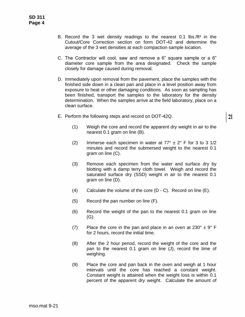
E. Perform the following steps and record on DOT-42Q.
(1) Weigh the core and record the apparent dry weight in air to the nearest 0.1 gram on line (B).
(2) Immerse each specimen in water at 77° ± 2° F for 3 to 3 1/2
minutes and record the submersed weight to the nearest 0.1 gram on line (C).
(3) Remove each specimen from the water and surface dry by
blotting with a damp terry cloth towel. Weigh and record the saturated surface dry (SSD) weight in air to the nearest 0.1 gram on line (D).
(4) Calculate the volume of the core (D - C). Record on line (E). (5) Record the pan number on line (F). (6) Record the weight of the pan to the nearest 0.1 gram on line
(G).
(7) Place the core in the pan and place in an oven at 230° ± 9° F for 2 hours, record the initial time.
(8) After the 2 hour period, record the weight of the core and the
pan to the nearest 0.1 gram on line (J), record the time of weighing.
(9) Place the core and pan back in the oven and weigh at 1 hour
intervals until the core has reached a constant weight. Constant weight is attained when the weight loss is within 0.1 percent of the apparent dry weight. Calculate the amount of

SD 311 Page 5
mso.mat 9-21
allowable loss (B x 0.001) to the nearest 0.1 gram. Record on line (M).
(10) After a constant weight has been attained, cool the pan and
core to room temperature. Record the weight to the nearest 0.1 gram on line (N).
(11) Determine the actual dry weight of the core (N - G). Record on
line (H). (12) Determine the core bulk specific gravity (H / E) to the nearest
0.001. Record on line (I). (13) Determine the moisture in the core (D - H). Record on line (K). (14) Calculate the percent water absorbed by volume (K / E x 100)
to the nearest 0.1 percent. Record on line (L).
F. Compare the average of the 3 wet densities determined by the nuclear gauge to the average density determined by the 3 compaction samples. When the nuclear gauge average is greater than the compaction sample average, the correction will be subtracted and when the nuclear gauge average is less, the correction will be added to the wet density determined by the nuclear gauge. (Figure 2)
3.4 Standard Density.
A. The standard unit weight will be determined by the theoretical
maximum specific gravity method in accordance with SD 312 (Figure 2).
(1) The average of the 5 most recent standard unit weight
determinations will be used as the standard density.
(2) Until 5 standard unit weight determinations have been made, base the standard density on the first determination, then on the average of the first 2, 3, 4, and 5 determinations. Each standard density thereafter will be the average of the 5 most recent valid standard unit weight determinations and will be used when the same source, mix and plant are being used on one or more projects.
3.5 Selecting Density Test Locations.
A. Record the location of the lot to be tested by indicating Sta. to Sta. and
the distance right or left of the centerline. Show the length, width, and quantity represented by the lot.
SD 311 Page 6
mso.mat 9-21
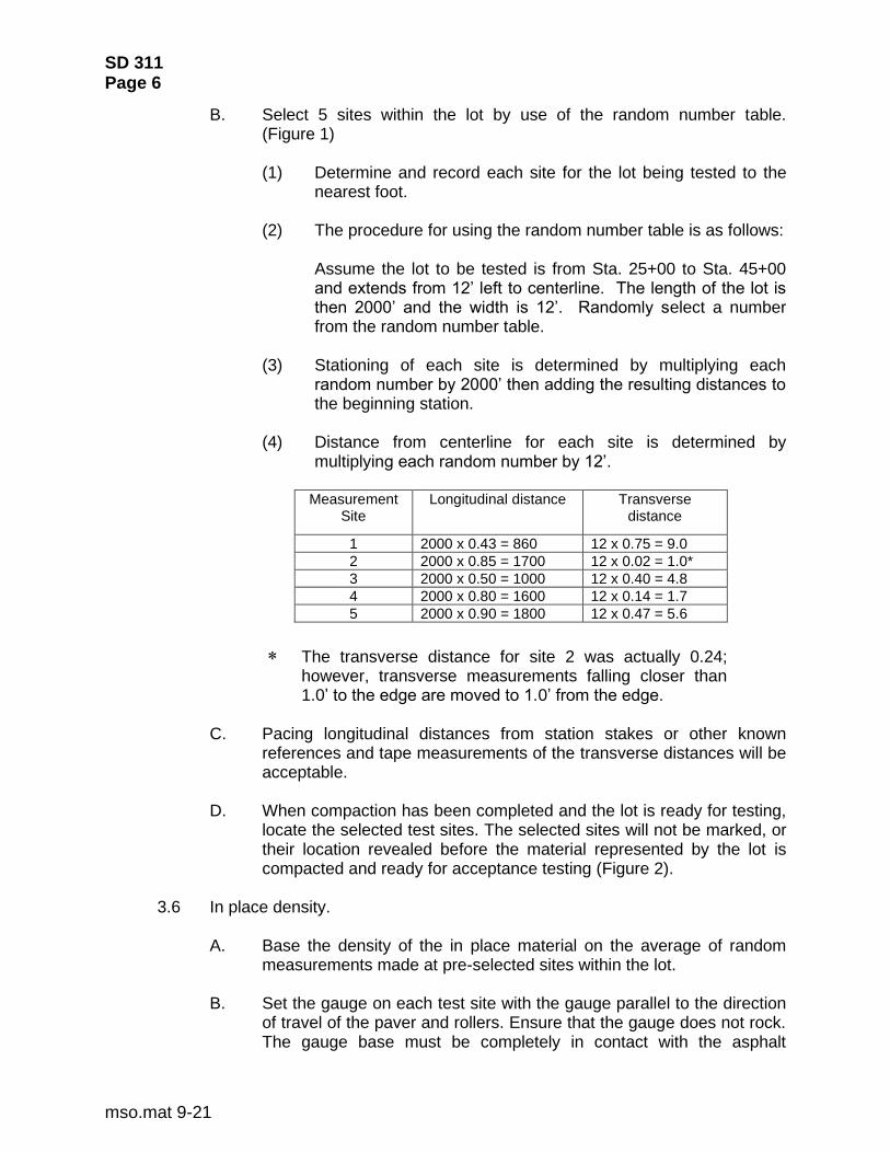
B. Select 5 sites within the lot by use of the random number table. (Figure 1)
(1) Determine and record each site for the lot being tested to the
nearest foot.
(2) The procedure for using the random number table is as follows:
Assume the lot to be tested is from Sta. 25+00 to Sta. 45+00 and extends from 12’ left to centerline. The length of the lot is then 2000’ and the width is 12’. Randomly select a number from the random number table.
(3) Stationing of each site is determined by multiplying each random number by 2000’ then adding the resulting distances to the beginning station.
(4) Distance from centerline for each site is determined by
multiplying each random number by 12’.
Measurement Site
Longitudinal distance Transverse distance
1 2000 x 0.43 = 860 12 x 0.75 = 9.0
2 2000 x 0.85 = 1700 12 x 0.02 = 1.0*
3 2000 x 0.50 = 1000 12 x 0.40 = 4.8
4 2000 x 0.80 = 1600 12 x 0.14 = 1.7
5 2000 x 0.90 = 1800 12 x 0.47 = 5.6
The transverse distance for site 2 was actually 0.24; however, transverse measurements falling closer than 1.0’ to the edge are moved to 1.0’ from the edge.
C. Pacing longitudinal distances from station stakes or other known
references and tape measurements of the transverse distances will be acceptable.
D. When compaction has been completed and the lot is ready for testing,
locate the selected test sites. The selected sites will not be marked, or their location revealed before the material represented by the lot is compacted and ready for acceptance testing (Figure 2).
3.6 In place density.
A. Base the density of the in place material on the average of random
measurements made at pre-selected sites within the lot.
B. Set the gauge on each test site with the gauge parallel to the direction of travel of the paver and rollers. Ensure that the gauge does not rock. The gauge base must be completely in contact with the asphalt

SD 311 Page 7
mso.mat 9-21
material. Small shifts in the site locations necessary for proper seating of the gauge are permissible. Take a 1 minute wet density reading in the backscatter mode and record the results. Rotate the gauge 180 degrees and take a 2nd reading in the backscatter mode. Average the two results.
Note: When using the Troxler 4640-B, you must enter into the gauge the asphalt concrete thickness minus ¼ inch.
C. Record the wet density to the nearest 0.1 lb./ft³ on the DOT-42.
4. Report:
4.1 Calculations – Nuclear Gauge Correction.
A. Calculate the cutout/core density (PCF) in lbs./ft³ from numbers recorded on DOT-42Q in the cutout calibration check on the DOT-42 in the following manner.
Weight of water (77° F) = 62.245 lb./ft3
H = Actual dry weight.
D = Saturated surface dry weight (SSD) in air
C = Submersed weight in water Cutout/Core Density = H / (D - C) x 62.245
B. Calculate the Correction as follows:
Correction in lb./ft³ = Cutout/Core average – Nuclear Gauge average
4.2 Calculations - Percent of Standard Density
A. Calculate the percent of standard density for each random
measurement as follows:
Percent of Standard Density = Wet density lb./ft³ ± correction lb./ft³ x 100 Standard density
B. Record the percent of standard density for each random measurement
to the nearest whole percent.
C. Calculate the percent of standard density for the lot by averaging the 5 random measurement percents of standard as recorded and report to the nearest whole percent.
4.3 Report the test as being satisfactory, provided all of the following conditions
are met for each lot:

SD 311 Page 8
mso.mat 9-21
A. The percent of standard density obtained for the lot is equal to or greater than that specified for the project.
B. No more than 2 tests below specification.
C. No more than 1 test that is 2% below specification.
D. No tests that are 3% or more below specification. 5. References:
AASHTO T 310 SD 312 DOT-42 DOT-42Q

SD 311 Page 9
mso.mat 9-21

SD 311 Page 10
mso.mat 9-21

SD 311 Page 11
mso.mat 9-21

SD 311 Page 12
mso.mat 9-21
.53 .74 .23 .99 .67 .61 .32 .28 .69 .84 .94 .62 .67 .86 .24 .98 .33 .74 .19 .95 .47 .53 .53 .38 .09
.63 .38 .06 .86 .54 .99 .00 .65 .26 .94 .02 .82 .90 .23 .07 .79 .62 .67 .80 .60 .75 .91 .12 .81 .19
.35 .30 .58 .21 .46 .06 .72 .17 .10 .94 .25 .21 .31 .75 .96 .49 .28 .24 .00 .49 .55 .65 .79 .78 .07
.63 .43 .36 .82 .69 .65 .51 .18 .37 .88 .61 .38 .44 .12 .45 .32 .92 .85 .88 .65 .54 .34 .81 .85 .35
.98 .25 .37 .55 .26 .01 .91 .82 .81 .46 .74 .71 .12 .94 .97 .24 .02 .71 .37 .07 .03 .92 .18 .66 .75
.02 .63 .21 .17 .69 .71 .50 .80 .89 .56 .38 .15 .70 .11 .48 .43 .40 .45 .86 .98 .00 .83 .26 .91 .03
.64 .55 .22 .21 .82 .48 .22 .28 .06 .00 .61 .54 .13 .43 .91 .82 .78 .12 .23 .29 .06 .66 .24 .12 .27
.85 .07 .26 .13 .89 .01 .10 .07 .82 .04 .59 .63 .69 .36 .03 .69 .11 .15 .83 .80 .13 .29 .54 .19 .28
.58 .54 .16 .24 .15 .51 .54 .44 .82 .00 .62 .61 .65 .04 .69 .38 .18 .65 .18 .97 .85 .72 .13 .49 .21
.34 .85 .27 .84 .87 .61 .48 .64 .56 .26 .90 .18 .48 .13 .26 .37 .70 .15 .42 .57 .65 .65 .80 .39 .07
.03 .92 .18 .27 .46 .57 .99 .16 .96 .56 .30 .33 .72 .85 .22 .84 .64 .38 .56 .98 .99 .01 .30 .98 .64
.62 .95 .30 .27 .59 .37 .75 .41 .66 .48 .86 .97 .80 .61 .45 .23 .53 .04 .01 .63 .45 .76 .08 .64 .27
.08 .45 .93 .15 .22 .60 .21 .75 .46 .91 .98 .77 .27 .85 .42 .28 .88 .61 .08 .84 .69 .62 .03 .42 .73
.07 .08 .55 .18 .40 .45 .44 .75 .13 .90 .24 .94 .96 .61 .02 .57 .55 .66 .83 .15 .73 .42 .37 .11 .16
.01 .85 .89 .95 .66 .51 .10 .19 .34 .88 .15 .84 .97 .19 .75 .12 .76 .39 .43 .78 .64 .63 .91 .08 .25
.72 .84 .71 .14 .35 .19 .11 .58 .49 .26 .50 .11 .17 .17 .76 .86 .31 .57 .20 .18 .95 .60 .78 .46 .75
.88 .78 .28 .16 .84 .13 .52 .53 .94 .53 .75 .45 .69 .30 .96 .73 .89 .65 .70 .31 .99 .17 .43 .48 .76
.45 .17 .75 .65 .57 .28 .40 .19 .72 .12 .25 .12 .74 .75 .67 .60 .40 .60 .81 .19 .24 .62 .01 .61 .16
.96 .76 .28 .12 .54 .22 .01 .11 .94 .25 .71 .96 .16 .16 .88 .68 .64 .36 .74 .45 .19 .59 .50 .88 .92
.43 .31 .67 .72 .30 .24 .02 .94 .08 .63 .38 .32 .36 .66 .02 .69 .36 .38 .25 .39 .48 .03 .45 .15 .22
.50 .44 .66 .44 .21 .66 .06 .58 .05 .62 .68 .15 .54 .35 .02 .42 .35 .48 .96 .32 .14 .52 .41 .52 .48
.22 .55 .22 .15 .86 .26 .63 .75 .41 .99 .58 .42 .36 .72 .24 .58 .37 .52 .18 .51 .03 .37 .18 .39 .11
.96 .24 .40 .14 .51 .23 .22 .30 .88 .57 .95 .67 .47 .29 .83 .94 .69 .40 .06 .07 .18 .16 .36 .78 .86
.31 .73 .91 .61 .19 .60 .20 .72 .93 .48 .98 .57 .07 .23 .69 .65 .95 .39 .69 .58 .56 .80 .30 .19 .44
.78 .60 .73 .99 .34 .43 .89 .94 .36 .45 .56 .69 .47 .07 .41 .90 .22 .91 .07 .12 .78 .35 .34 .08 .72
.84 .37 .90 .61 .56 .70 .10 .23 .98 .05 .85 .11 .34 .76 .60 .76 .48 .45 .34 .60 .01 .64 .18 .39 .96
.36 .67 .10 .08 .23 .98 .93 .35 .08 .86 .99 .29 .76 .29 .81 .33 .34 .91 .58 .93 .63 .14 .52 .32 .52
.07 .28 .59 .07 .48 .89 .64 .58 .89 .75 .83 .85 .62 .27 .89 .30 .14 .78 .56 .27 .86 .63 .59 .80 .02
.10 .15 .83 .87 .60 .79 .24 .31 .66 .56 .21 .48 .24 .06 .93 .91 .98 .94 .05 .49 .01 .47 .59 .38 .00
.55 .19 .68 .97 .65 .03 .73 .52 .16 .56 .00 .53 .55 .90 .27 .33 .42 .29 .38 .87 .22 .13 .88 .83 .34
.53 .81 .29 .13 .39 .35 .01 .20 .71 .34 .62 .33 .74 .82 .14 .53 .73 .19 .09 .03 .56 .54 .29 .56 .93
.51 .86 .32 .68 .92 .33 .98 .74 .66 .99 .40 .14 .71 .94 .58 .45 .94 .19 .38 .81 .14 .44 .99 .81 .07
.35 .91 .70 .29 .13 .80 .03 .54 .07 .27 .96 .94 .78 .32 .66 .50 .95 .52 .74 .33 .13 .80 .55 .62 .54
.37 .71 .67 .95 .13 .20 .02 .44 .95 .94 .64 .85 .04 .05 .72 .01 .32 .90 .76 .14 .53 .89 .74 .60 .41
.93 .66 .13 .83 .27 .92 .79 .64 .64 .72 .28 .54 .96 .53 .84 .48 .14 .52 .98 .94 .56 .07 .93 .89 .30
.02 .96 .08 .45 .65 .13 .05 .00 .41 .84 .93 .07 .54 .72 .59 .21 .45 .57 .09 .77 .19 .48 .56 .27 .44
.49 .83 .43 .48 .35 .82 .88 .33 .69 .96 .72 .36 .04 .19 .76 .47 .45 .15 .18 .60 .82 .11 .08 .95 .97
.84 .60 .71 .62 .46 .40 .80 .81 .30 .37 .34 .39 .23 .05 .38 .25 .15 .35 .71 .30 .88 .12 .57 .21 .77
.18 .17 .30 .88 .71 .44 .91 .14 .88 .47 .89 .23 .30 .63 .15 .56 .34 .20 .47 .89 .99 .82 .93 .24 .98
.79 .69 .10 .61 .78 .71 .32 .76 .95 .62 .87 .00 .22 .58 40 .92 .54 .01 .75 .25 .43 .11 .71 .99 .31
.75 .93 .36 .57 .83 .56 .20 .14 .82 .11 .74 .21 .97 .90 .65 .96 .42 .68 .63 .86 .74 .54 .13 .26 .94
.38 .30 .92 .29 .03 .06 .28 .81 .39 .38 .62 .25 .06 .84 .63 .61 .29 .08 .93 .67 .04 .32 .92 .08 .09
.51 .28 .50 .10 .34 .31 .57 .75 .95 .80 .51 .97 .02 .74 .77 .76 .15 .48 .49 .44 .18 .55 .63 .77 .09
.21 .31 .38 .86 .24 .37 .79 .81 .53 .74 .73 .24 .16 .10 .33 .52 .83 .90 .94 .76 .70 .47 .14 .54 .36
.29 .01 .23 .87 .88 .58 .02 .39 .37 .67 .42 .10 .14 .20 .92 .16 .55 .23 .42 .45 .54 .96 .09 .11 .06
.95 .33 .95 .22 .00 .18 .74 .72 .00 .18 .38 .79 .58 .69 .32 .81 .76 .80 .26 .92 .82 .80 .84 .25 .39
.90 .84 .60 .79 .80 .24 .36 .59 .87 .38 .82 .07 .53 .89 .35 .96 .35 .23 .79 .18 .05 .98 .90 .07 .35
.46 .40 .62 .98 .82 .54 .97 .20 .56 .95 .15 .74 .809.08 .32 .16 .46 .70 .50 .80 .67 .72 .16 .42 .79
.20 .31 .89 .03 .43 .38 .46 .82 .68 .72 .32 .14 .82 .99 .70 .80 .60 .47 .18 .97 .63 .49 .30 .21 .30
.71 .59 .73 .05 .50 .08 .22 .23 .71 .77 .91 .01 .93 .20 .49 .82 .96 .59 .26 .94 .66 .39 .67 .98 .60
SDDOT
TABLE OF RANDOM NUMBERS
Figure 3