scorpio 1000 user's manual -...
TRANSCRIPT
V1.4 07008-00071 2005/11/21
TAINET
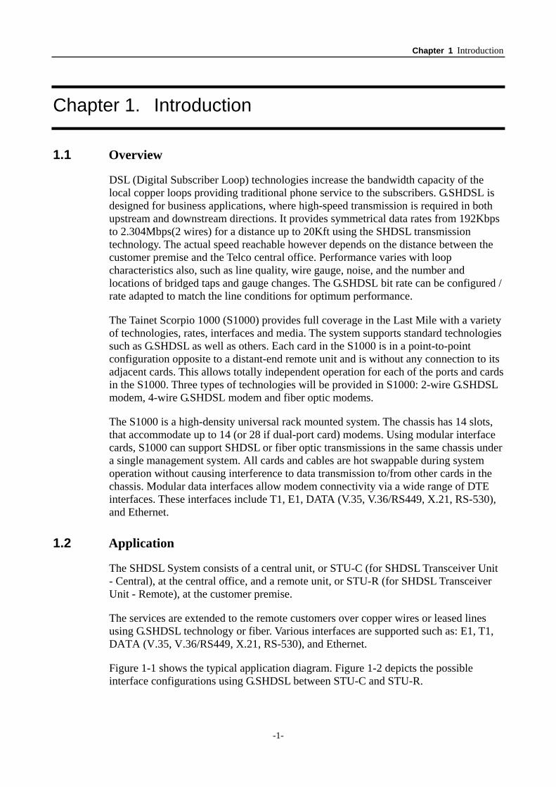
Scorpio 1000 Universal Sub Rack System
USER'S MANUAL
The Professional Partner TAINET COMMUNICATION SYSTEM CORP. Headquarters: No. 25, Alley 15, Lane 120, Sec. 1. Nei-Hu Rd,Taipei 114, Taiwan TEL: 886-2-26583000 FAX: 886-2-26583232 http://www.tainet.net
Beijing Branch: 3F, A Building, 113 Zhi Chun Lu, HaiDian District, Beijing, China Zip Code: 100086 TEL: 86-10-62522081~87 FAX: 86- 10-62522077

Scorpio 1000 User’s Manual Rev. 1.4
-i-
Copyright © 2005 TAINET COMMUNICATION SYSTEM CORP. All rights reserved
Notice This document is protected by the international copyright law. No part of this publication may be reproduced by any means without the expressed permission of Tainet Communication System Corporation.
TAINET is a registered trademark, and Scorpio 1000 is a trademark of Tainet Communication System Corporation.
Other product names mentioned in this manual are used for identification purposes only and may be trademarks or trademarks of their respective companies.
The information provided from Tainet Communication System Corporation is believed to be accurate. Any changes and enhancements to the product and to the information thereof will be documented and issued as a new release to this manual.
Trademark All products and services mentioned herein are the trademarks, service marks, registered trademarks or registered service marks of their respective owners.
Scorpio 1000 User’s Manual Rev. 1.4
-ii-
ABOUT THIS MANUAL
This section guides users on how to use the manual effectively. The manual contains information needed to install, configure, and operate TAINET’s Scorpio 1000 Universal Sub Rack System. The summary of this manual is as follows:
Chapter 1: Introduction Presents overview, application, and other general information on the Scorpio 1000.
Chapter 2: Specification The specifications are summarized in a condensed format in this chapter.
Chapter 3: Interfacing Describes the different interfaces, their connectors, and pin assignments.
Chapter 4: Installation & Setup Describes preparation required to get the installation underway.
Chapter 5: Operation of CID (Craft Interface Device) Describes the commands and operational procedures used to control and monitor a Scorpio 1000.
Appendix A: VT-100 Menu Tree
Describes the commands at different tiers when operating the VT-100.
Appendix B: Pin Assignment Describes all cables and connectors with pin definition.
Scorpio 1000 User’s Manual Rev. 1.4
-iii-
SYMBOLS USED IN THIS MANUAL
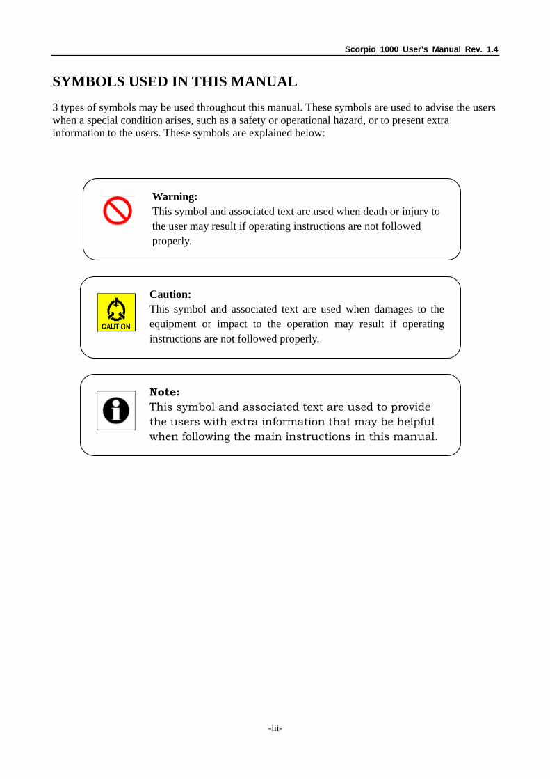
3 types of symbols may be used throughout this manual. These symbols are used to advise the users when a special condition arises, such as a safety or operational hazard, or to present extra information to the users. These symbols are explained below:
Warning: This symbol and associated text are used when death or injury to the user may result if operating instructions are not followed properly.
Note: This symbol and associated text are used to provide the users with extra information that may be helpful when following the main instructions in this manual.
Caution: This symbol and associated text are used when damages to theequipment or impact to the operation may result if operatinginstructions are not followed properly.

Scorpio 1000 User’s Manual Rev. 1.4
-iv-
WARRANTY AND SERVICE
Contact:
If there are any questions, contact your local sales representative, service representative, or distributor directly for any help needed. You might use one of the following methods..
Via the Internet: visit our World Wide Web site at http://www.tainet.net
Via the Sales Representatives:
HQ No. 25, Alley 15,. Lane 120, Sec. 1. N-e-is-H-u Rd. Taipei, Taiwan, R.O.C. TEL: (886) 2-2658-3000 E-mail: [email protected] FAX: (886) 2-2658-3232 URL: http://www.tainet.net/
Moscow Branch Phone: (7) 095 518-5777 URL: http://www.tainet.ru/ Beijing Branch 3F, A Building, 113 Zhi Chun Lu, HaiDian District, Beijing, China Zip Code: 100086 TEL: (86) 10-62522081~87 E-mail: [email protected] FAX: (86) 10-62522077 URL: http://www.tainet.com.cn
Scorpio 1000 User’s Manual Rev. 1.4
-v-
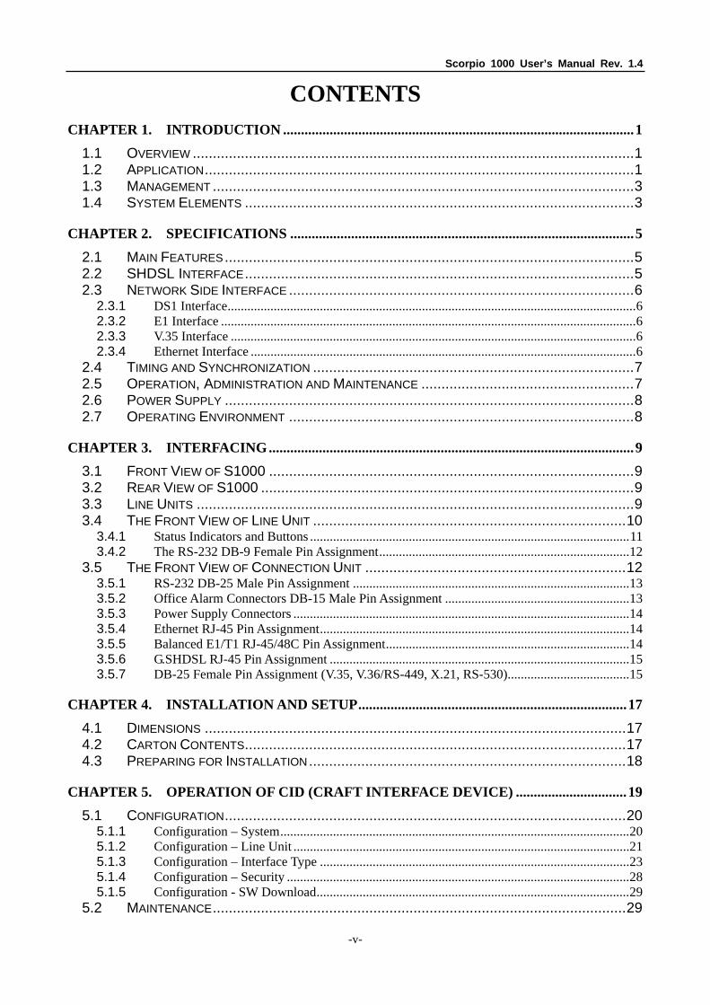
CONTENTS CHAPTER 1. INTRODUCTION ..................................................................................................1
1.1 OVERVIEW ..............................................................................................................1 1.2 APPLICATION...........................................................................................................1 1.3 MANAGEMENT .........................................................................................................3 1.4 SYSTEM ELEMENTS .................................................................................................3
CHAPTER 2. SPECIFICATIONS ................................................................................................5
2.1 MAIN FEATURES......................................................................................................5 2.2 SHDSL INTERFACE.................................................................................................5 2.3 NETWORK SIDE INTERFACE ......................................................................................6
2.3.1 DS1 Interface............................................................................................................................6 2.3.2 E1 Interface ..............................................................................................................................6 2.3.3 V.35 Interface ...........................................................................................................................6 2.3.4 Ethernet Interface .....................................................................................................................6
2.4 TIMING AND SYNCHRONIZATION ................................................................................7 2.5 OPERATION, ADMINISTRATION AND MAINTENANCE .....................................................7 2.6 POWER SUPPLY ......................................................................................................8 2.7 OPERATING ENVIRONMENT ......................................................................................8
CHAPTER 3. INTERFACING......................................................................................................9 3.1 FRONT VIEW OF S1000 ...........................................................................................9 3.2 REAR VIEW OF S1000 .............................................................................................9 3.3 LINE UNITS .............................................................................................................9 3.4 THE FRONT VIEW OF LINE UNIT ..............................................................................10
3.4.1 Status Indicators and Buttons .................................................................................................11 3.4.2 The RS-232 DB-9 Female Pin Assignment............................................................................12
3.5 THE FRONT VIEW OF CONNECTION UNIT .................................................................12 3.5.1 RS-232 DB-25 Male Pin Assignment ....................................................................................13 3.5.2 Office Alarm Connectors DB-15 Male Pin Assignment ........................................................13 3.5.3 Power Supply Connectors ......................................................................................................14 3.5.4 Ethernet RJ-45 Pin Assignment..............................................................................................14 3.5.5 Balanced E1/T1 RJ-45/48C Pin Assignment..........................................................................14 3.5.6 G.SHDSL RJ-45 Pin Assignment ...........................................................................................15 3.5.7 DB-25 Female Pin Assignment (V.35, V.36/RS-449, X.21, RS-530).....................................15
CHAPTER 4. INSTALLATION AND SETUP...........................................................................17
4.1 DIMENSIONS .........................................................................................................17 4.2 CARTON CONTENTS...............................................................................................17 4.3 PREPARING FOR INSTALLATION...............................................................................18
CHAPTER 5. OPERATION OF CID (CRAFT INTERFACE DEVICE) ...............................19
5.1 CONFIGURATION....................................................................................................20 5.1.1 Configuration – System..........................................................................................................20 5.1.2 Configuration – Line Unit ......................................................................................................21 5.1.3 Configuration – Interface Type ..............................................................................................23 5.1.4 Configuration – Security ........................................................................................................28 5.1.5 Configuration - SW Download...............................................................................................29
5.2 MAINTENANCE.......................................................................................................29
Scorpio 1000 User’s Manual Rev. 1.4
-vi-
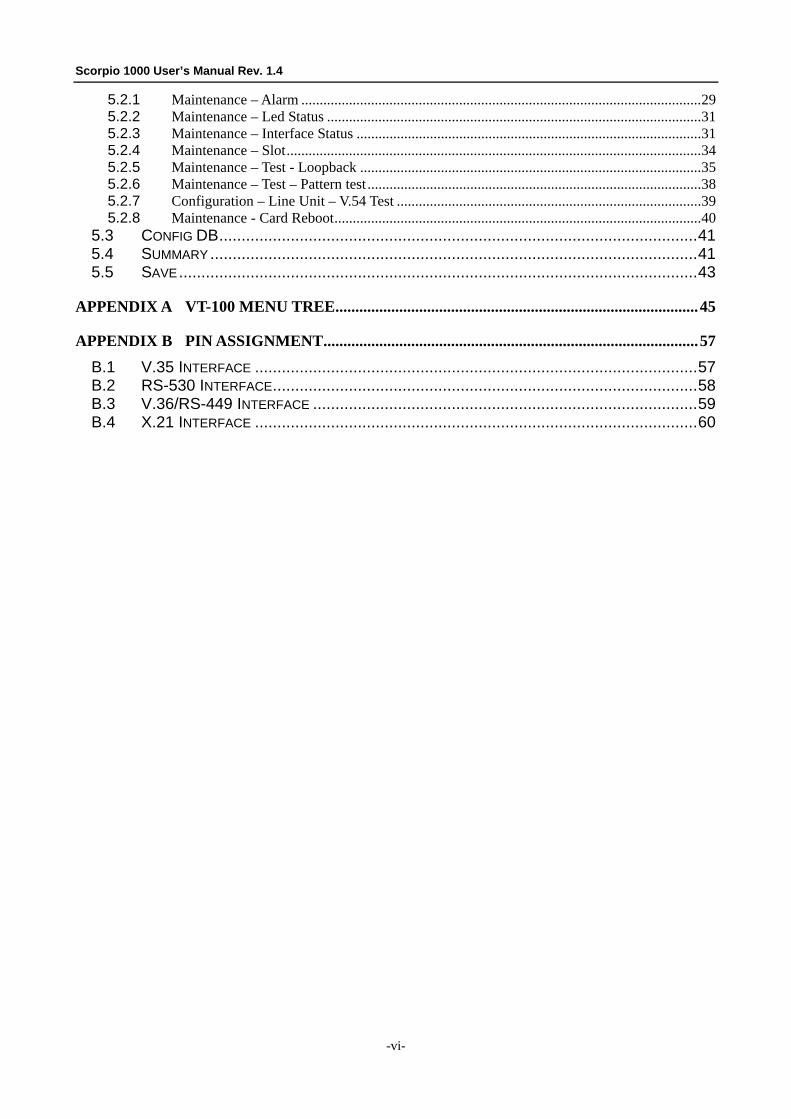
5.2.1 Maintenance – Alarm .............................................................................................................29 5.2.2 Maintenance – Led Status ......................................................................................................31 5.2.3 Maintenance – Interface Status ..............................................................................................31 5.2.4 Maintenance – Slot.................................................................................................................34 5.2.5 Maintenance – Test - Loopback .............................................................................................35 5.2.6 Maintenance – Test – Pattern test ...........................................................................................38 5.2.7 Configuration – Line Unit – V.54 Test ...................................................................................39 5.2.8 Maintenance - Card Reboot....................................................................................................40
5.3 CONFIG DB...........................................................................................................41 5.4 SUMMARY .............................................................................................................41 5.5 SAVE....................................................................................................................43
APPENDIX A VT-100 MENU TREE...........................................................................................45
APPENDIX B PIN ASSIGNMENT..............................................................................................57
B.1 V.35 INTERFACE ...................................................................................................57 B.2 RS-530 INTERFACE...............................................................................................58 B.3 V.36/RS-449 INTERFACE ......................................................................................59 B.4 X.21 INTERFACE ...................................................................................................60
Scorpio 1000 User’s Manual Rev. 1.4
-vii-
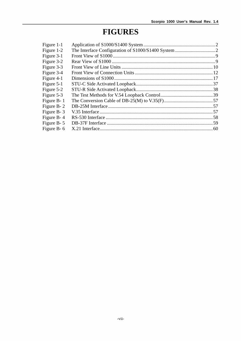
FIGURES
Figure 1-1 Application of S1000/S1400 System ...........................................................2 Figure 1-2 The Interface Configuration of S1000/S1400 System .................................2 Figure 3-1 Front View of S1000 ....................................................................................9 Figure 3-2 Rear View of S1000 .....................................................................................9 Figure 3-3 Front View of Line Units ...........................................................................10 Figure 3-4 Front View of Connection Units ................................................................12 Figure 4-1 Dimensions of S1000.................................................................................17 Figure 5-1 STU-C Side Activated Loopback...............................................................37 Figure 5-2 STU-R Side Activated Loopback...............................................................38 Figure 5-3 The Test Methods for V.54 Loopback Control...........................................39 Figure B- 1 The Conversion Cable of DB-25(M) to V.35(F)........................................57 Figure B- 2 DB-25M Interface ......................................................................................57 Figure B- 3 V.35 Interface .............................................................................................57 Figure B- 4 RS-530 Interface ........................................................................................58 Figure B- 5 DB-37F Interface .......................................................................................59 Figure B- 6 X.21 Interface.............................................................................................60
Scorpio 1000 User’s Manual Rev. 1.4
-viii-
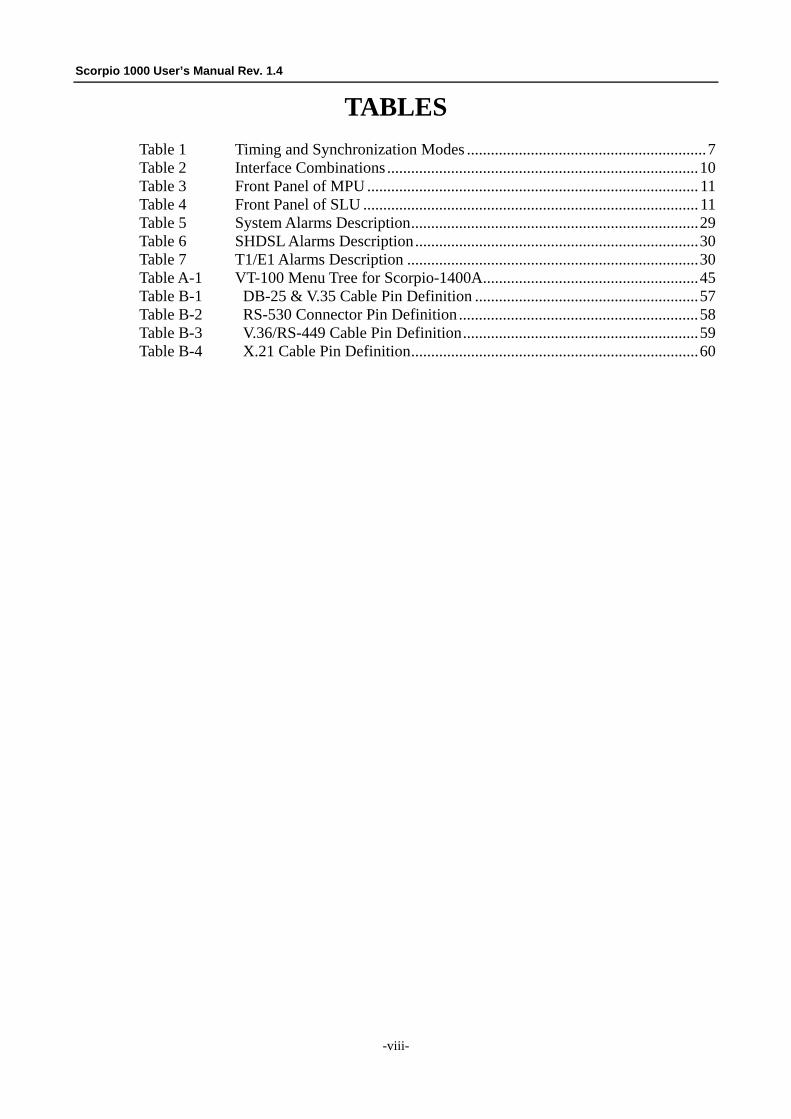
TABLES
Table 1 Timing and Synchronization Modes ............................................................7 Table 2 Interface Combinations ..............................................................................10 Table 3 Front Panel of MPU ................................................................................... 11 Table 4 Front Panel of SLU .................................................................................... 11 Table 5 System Alarms Description........................................................................29 Table 6 SHDSL Alarms Description.......................................................................30 Table 7 T1/E1 Alarms Description .........................................................................30 Table A-1 VT-100 Menu Tree for Scorpio-1400A......................................................45 Table B-1 DB-25 & V.35 Cable Pin Definition ........................................................57 Table B-2 RS-530 Connector Pin Definition ............................................................58 Table B-3 V.36/RS-449 Cable Pin Definition...........................................................59 Table B-4 X.21 Cable Pin Definition........................................................................60
Chapter 1 Introduction
-1-
Chapter 1. Introduction
1.1 Overview
DSL (Digital Subscriber Loop) technologies increase the bandwidth capacity of the local copper loops providing traditional phone service to the subscribers. G.SHDSL is designed for business applications, where high-speed transmission is required in both upstream and downstream directions. It provides symmetrical data rates from 192Kbps to 2.304Mbps(2 wires) for a distance up to 20Kft using the SHDSL transmission technology. The actual speed reachable however depends on the distance between the customer premise and the Telco central office. Performance varies with loop characteristics also, such as line quality, wire gauge, noise, and the number and locations of bridged taps and gauge changes. The G.SHDSL bit rate can be configured / rate adapted to match the line conditions for optimum performance.
The Tainet Scorpio 1000 (S1000) provides full coverage in the Last Mile with a variety of technologies, rates, interfaces and media. The system supports standard technologies such as G.SHDSL as well as others. Each card in the S1000 is in a point-to-point configuration opposite to a distant-end remote unit and is without any connection to its adjacent cards. This allows totally independent operation for each of the ports and cards in the S1000. Three types of technologies will be provided in S1000: 2-wire G.SHDSL modem, 4-wire G.SHDSL modem and fiber optic modems.
The S1000 is a high-density universal rack mounted system. The chassis has 14 slots, that accommodate up to 14 (or 28 if dual-port card) modems. Using modular interface cards, S1000 can support SHDSL or fiber optic transmissions in the same chassis under a single management system. All cards and cables are hot swappable during system operation without causing interference to data transmission to/from other cards in the chassis. Modular data interfaces allow modem connectivity via a wide range of DTE interfaces. These interfaces include T1, E1, DATA (V.35, V.36/RS449, X.21, RS-530), and Ethernet.
1.2 Application
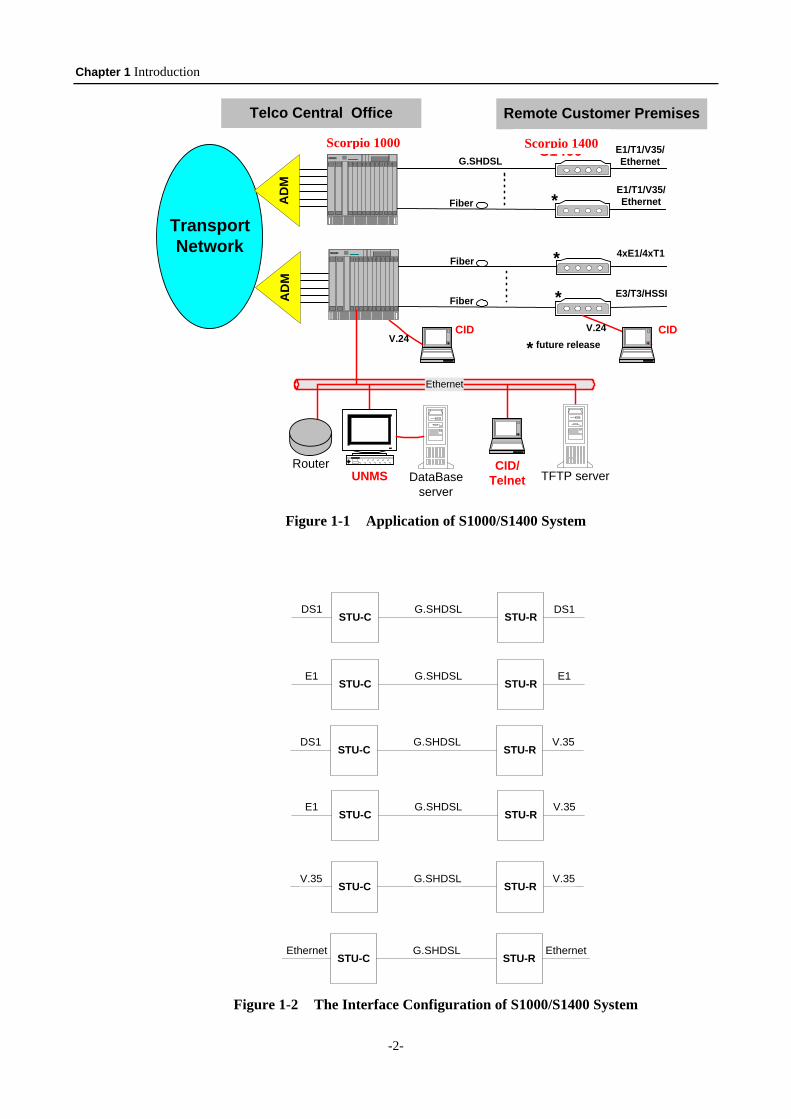
The SHDSL System consists of a central unit, or STU-C (for SHDSL Transceiver Unit - Central), at the central office, and a remote unit, or STU-R (for SHDSL Transceiver Unit - Remote), at the customer premise.
The services are extended to the remote customers over copper wires or leased lines using G.SHDSL technology or fiber. Various interfaces are supported such as: E1, T1, DATA (V.35, V.36/RS449, X.21, RS-530), and Ethernet.
Figure 1-1 shows the typical application diagram. Figure 1-2 depicts the possible interface configurations using G.SHDSL between STU-C and STU-R.
Chapter 1 Introduction
-2-
TransportNetwork
S1000
AD
MA
DM
S1400G.SHDSL
Fiber
E1/T1/V35/Ethernet
E1/T1/V35/Ethernet
Fiber
4xE1/4xT1
E3/T3/HSSI
Fiber
*
*
*
Ethernet
UNMSRouter
TFTP serverDataBaseserver
CID/Telnet
* future releaseCID CID
V.24V.24
Telco Central Office Remote Customer Premises
Figure 1-1 Application of S1000/S1400 System
STU-C STU-RG.SHDSLDS1 DS1
STU-C STU-RG.SHDSLE1 E1
STU-C STU-RG.SHDSLDS1 V.35
STU-C STU-RG.SHDSLE1 V.35
STU-C STU-RG.SHDSLV.35 V.35
STU-C STU-RG.SHDSLEthernet Ethernet
Figure 1-2 The Interface Configuration of S1000/S1400 System
Scorpio 1000 Scorpio 1400
Chapter 1 Introduction
-3-
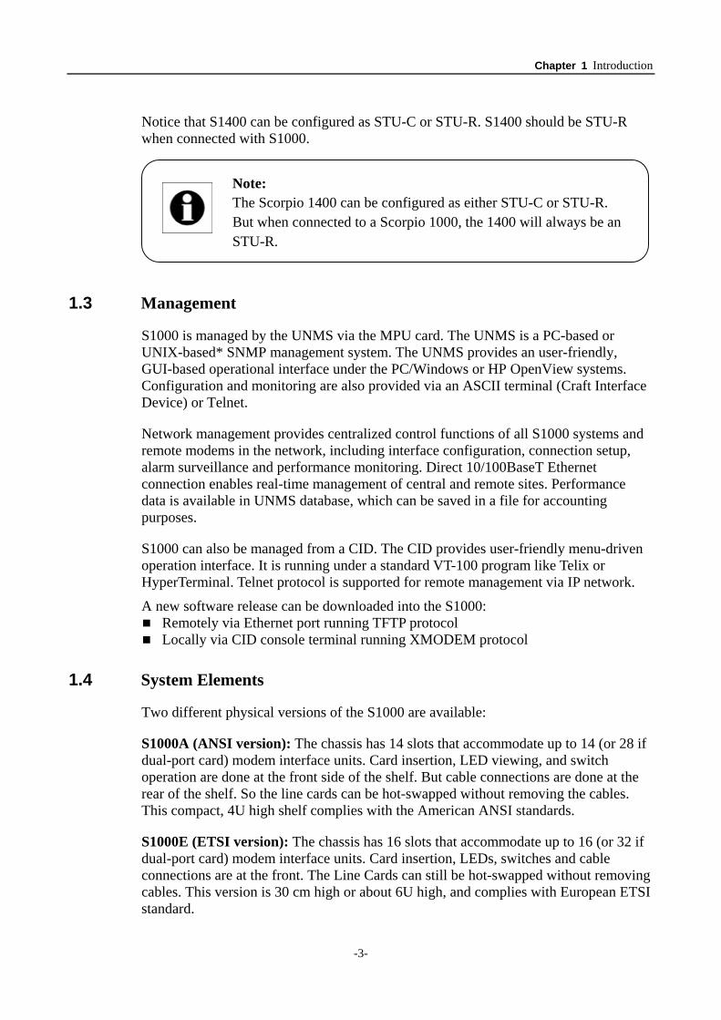
Notice that S1400 can be configured as STU-C or STU-R. S1400 should be STU-R when connected with S1000.
1.3 Management
S1000 is managed by the UNMS via the MPU card. The UNMS is a PC-based or UNIX-based* SNMP management system. The UNMS provides an user-friendly, GUI-based operational interface under the PC/Windows or HP OpenView systems. Configuration and monitoring are also provided via an ASCII terminal (Craft Interface Device) or Telnet.
Network management provides centralized control functions of all S1000 systems and remote modems in the network, including interface configuration, connection setup, alarm surveillance and performance monitoring. Direct 10/100BaseT Ethernet connection enables real-time management of central and remote sites. Performance data is available in UNMS database, which can be saved in a file for accounting purposes.
S1000 can also be managed from a CID. The CID provides user-friendly menu-driven operation interface. It is running under a standard VT-100 program like Telix or HyperTerminal. Telnet protocol is supported for remote management via IP network.
A new software release can be downloaded into the S1000: Remotely via Ethernet port running TFTP protocol Locally via CID console terminal running XMODEM protocol
1.4 System Elements
Two different physical versions of the S1000 are available:
S1000A (ANSI version): The chassis has 14 slots that accommodate up to 14 (or 28 if dual-port card) modem interface units. Card insertion, LED viewing, and switch operation are done at the front side of the shelf. But cable connections are done at the rear of the shelf. So the line cards can be hot-swapped without removing the cables. This compact, 4U high shelf complies with the American ANSI standards.
S1000E (ETSI version): The chassis has 16 slots that accommodate up to 16 (or 32 if dual-port card) modem interface units. Card insertion, LEDs, switches and cable connections are at the front. The Line Cards can still be hot-swapped without removing cables. This version is 30 cm high or about 6U high, and complies with European ETSI standard.
Note: The Scorpio 1400 can be configured as either STU-C or STU-R. But when connected to a Scorpio 1000, the 1400 will always be an STU-R.
Chapter 1 Introduction
-4-
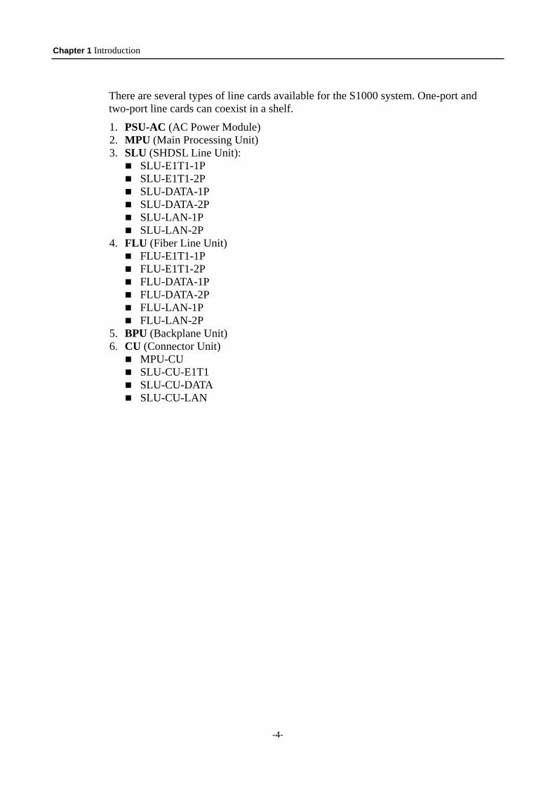
There are several types of line cards available for the S1000 system. One-port and two-port line cards can coexist in a shelf.
1. PSU-AC (AC Power Module) 2. MPU (Main Processing Unit) 3. SLU (SHDSL Line Unit):
SLU-E1T1-1P SLU-E1T1-2P SLU-DATA-1P SLU-DATA-2P SLU-LAN-1P SLU-LAN-2P
4. FLU (Fiber Line Unit) FLU-E1T1-1P FLU-E1T1-2P FLU-DATA-1P FLU-DATA-2P FLU-LAN-1P FLU-LAN-2P
5. BPU (Backplane Unit) 6. CU (Connector Unit)
MPU-CU SLU-CU-E1T1 SLU-CU-DATA SLU-CU-LAN
Chapter 2 Specifications
-5-
Chapter 2. Specifications
2.1 Main Features
The chassis has 14 slots accommodating up to 14 (or 28 if dual-port card) modems. Carrying symmetrical 2048 Kbps payload for up to 2.4 miles (3.9 Km) over 26
AWG single pair copper wire. Supporting loop interface in G.SHDSL and fiber (in near future). Supporting DTE interface T1, E1, DATA (V.35, X.21, RS-530, V.36 / RS449), and
Ethernet. With 1 pair, both DS1 and E1 network side for STU-C and V.35 customer side for
STU-R. The data rate shall be nx64 Kbit/s (n = 1 to 24 for DS1, n = 1 to 31 for E1). V.35 network side for STU-C and V.35 customer side for STU-R. The data rate is nx64 Kbit/s (n = 1 to 36). Ethernet network side for STU-C and Ethernet customer side for STU-R. The data rate is multiple, including nx64 Kbit/s (n = 1 to 36). With 2 pairs, both DS1 and E1 network side for STU-C and V.35 customer side for
STU-R. The data rate shall be nx64 Kbit/s (n = 2 to 24 for DS1, n = 2 to 31 for E1). V.35 network side for STU-C and V.35 customer side for STU-R. The data rate is nx64 Kbit/s (n = 2 to 72). Ethernet network side for STU-C and Ethernet customer side for STU-R. The data rate is multiple, including nx64 Kbit/s (n = 2 to 72) Supporting SHDSL payload rates of n × 64 Kbps, where n is 3 to 36. The S1000 shelf can be mounted in 19” or 23” standard rack. Two Shelf versions: ANSI: 4U high, connectors on the back (S1000A). ETSI: 6U high, connectors on the front (S1000B). Optional dual AC power supply units with full redundancy. Hot swapping of cards and power supply module. Supporting Timing and Synchronization: Local (internal) timing, Line timing (loop
received clock), DTE timing. For test and diagnostic purpose, the S1000 / S1400 systems provide various
loopback paths, including ITU-T V.54 in-band activated / deactivated loopback codeword for end-to-end loopback function. Management via NMS or CID. SNMP management message interface. Remote control / monitoring S1000 via Telnet and Ethernet. Remote in-band control / monitoring CPE via G.SHDSL EOC. Remote software upgrade via TFTP.
2.2 SHDSL Interface
Meeting ITU-T G.991.2 relative requirements. Supporting Wetting Current function for feeding of a low current (between 1.0 mA
and 20 mA)on the pair to mitigate the effect of corrosion of contacts. Support for power back off functions. Rate adaptive from 192 Kbps to 2.304 Mbps in 64 Kbps increment. Modulation method: 16-TCPAM (16-levels Trellis Coded Pulse Amplitude
Chapter 2 Specifications
-6-
Modulation). Physical Connection Type: Standard RJ-45 jack, 135 ohm balanced via 2 wire
twisted pair. Port enabled / disabled configurable.
2.3 Network Side Interface
2.3.1 DS1 Interface
Bit Rate: 1,544 Kbit/s ± 32 ppm. Frame Format: SF (D4), ESF, ESF+CRC, or Unframed; frame format is field
selectable. Line Code: AMI or B8ZS, field selectable. Impedance: Nominal 100 ohms ± 5% resistive, symmetrical pair. Jitter performance: meet ITU-T G.824 requirements. Physical Connection Type: Standard RJ-48C / RJ-45 jack.
2.3.2 E1 Interface Complies with G.703 Standard. Frame Format: Unstructured or Structured framing, field selectable. Line Code: High Density Bipolar of Order 3 (HDB3). Impedance: Nominal 120 ohms ± 5% resistive symmetrical pair or 75 ohm
asymmetrical pair. Jitter performance: meet ITU-T G.823 requirements. Line Interface: 120 ohm (RJ-45) balanced or 75 ohm (BNC) unbalanced, selectable. Physical Connection Type: Standard RJ-48C/RJ45 jack (Balance) or BNC
(Unbalance).
2.3.3 V.35 Interface Electrical Characteristics: comply with ITU-T V.35 interface. Software configurable for V.35, X.21, RS530, V.36/RS-449. Data Rate: n x 64 Kbit/s, where n = 3~36. Data inversion selectable. Clock inversion selectable Physical Connection Type: pin assignment of ITU-T V.35 interface complies with
DB-25 female connector.
2.3.4 Ethernet Interface Provides 10/100 Base-T auto sensing and half/full duplex configurable Ethernet
Interface. Electrical Characteristics: 10/100 Base-T Ethernet Interface complies with the IEEE
802.3/IEEE 802.3u. Physical Connection Type: Standard RJ-45 connector. Bridging Capability: Operates as a self-learning bridge specified in the IEEE 802.1d
full protocol transparent bridging function. Supporting up to 128 MAC learning addresses. Supporting Bridge filter function
Chapter 2 Specifications
-7-
2.4 Timing and Synchronization
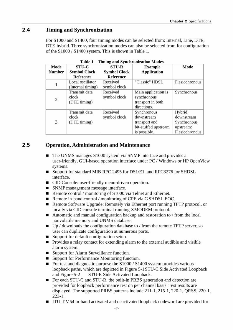
For S1000 and S1400, four timing modes can be selected from: Internal, Line, DTE, DTE-hybrid. Three synchronization modes can also be selected from for configuration of the S1000 / S1400 system. This is shown in Table 1.
Table 1 Timing and Synchronization Modes
Mode Number
STU-C Symbol Clock
Reference
STU-R Symbol Clock
Reference
Example Application
Mode
1 Local oscillator (Internal timing)
Received symbol clock
"Classic" HDSL Plesiochronous
2 Transmit data clock (DTE timing)
Received symbol clock
Main application is synchronous transport in both directions.
Synchronous
3
Transmit data clock (DTE timing)
Received symbol clock
Synchronous downstream transport and bit-stuffed upstream is possible.
Hybrid: downstream Synchronous upstream: Plesiochronous
2.5 Operation, Administration and Maintenance
The UNMS manages S1000 system via SNMP interface and provides a user-friendly, GUI-based operation interface under PC / Windows or HP OpenView systems. Support for standard MIB RFC 2495 for DS1/E1, and RFC3276 for SHDSL
interface. CID Console: user-friendly menu-driven operation. SNMP management message interface. Remote control / monitoring of S1000 via Telnet and Ethernet. Remote in-band control / monitoring of CPE via G.SHDSL EOC. Remote Software Upgrade: Remotely via Ethernet port running TFTP protocol, or
locally via CID console terminal running XMODEM protocol. Automatic and manual configuration backup and restoration to / from the local
nonvolatile memory and UNMS database. Up / downloads the configuration database to / from the remote TFTP server, so
user can duplicate configuration at numerous ports. Support for default configuration setup. Provides a relay contact for extending alarm to the external audible and visible
alarm system. Support for Alarm Surveillance function. Support for Performance Monitoring function. For test and diagnostic purpose the S1000 / S1400 system provides various
loopback paths, which are depicted in Figure 5-1 STU-C Side Activated Loopback and Figure 5-2 STU-R Side Activated Loopback. For each STU-C and STU-R, the built-in PRBS generation and detection are
provided for loopback performance test on per channel basis. Test results are displayed. The supported PRBS patterns include 211-1, 215-1, 220-1, QRSS, 220-1, 223-1. ITU-T V.54 in-band activated and deactivated loopback codeword are provided for
Chapter 2 Specifications
-8-
end-to-end loopback function; details are depicted in Figure 5-3 The Test Methods for V.54 Loopback Control.
2.6 Power Supply
DC Power Input: -36 ~ -72VDC. Power Consumption: 180 watt. (ETSI shelf is 200Watt)
AV Power Input: The redundant PSU-AC power supply module can be replaced during operation,
without affecting the system performance (hot- swapping). Power Input:
AC input: 85 ~ 264VAC, Frequency: 47 ~ 63 Hz Output: (48V)
Voltage: 48 VDC ± 10% Current: 6.25A (full load)
2.7 Operating Environment
Ambient Temperature: Indoor Type: 0 ~ 45 oC, Outdoor Type: 0 ~ 60 oC. Relative Humility:
Indoor Type: Up to 90% without condensation, Outdoor Type: Up to 95% without condensation.
Chapter 3 Interfacing
-9-
Chapter 3. Interfacing
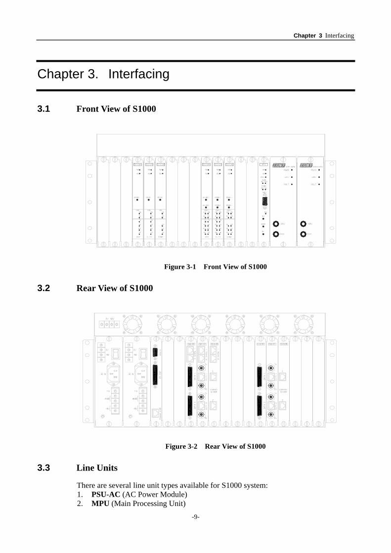
3.1 Front View of S1000
Figure 3-1 Front View of S1000
3.2 Rear View of S1000
Figure 3-2 Rear View of S1000
3.3 Line Units
There are several line unit types available for S1000 system: 1. PSU-AC (AC Power Module) 2. MPU (Main Processing Unit)
Chapter 3 Interfacing
-10-
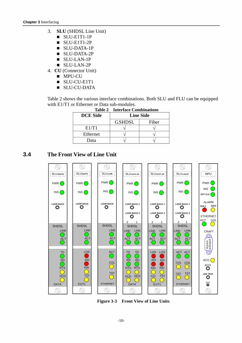
3. SLU (SHDSL Line Unit) SLU-E1T1-1P SLU-E1T1-2P SLU-DATA-1P SLU-DATA-2P SLU-LAN-1P SLU-LAN-2P
4. CU (Connector Unit) MPU-CU SLU-CU-E1T1 SLU-CU-DATA
Table 2 shows the various interface combinations. Both SLU and FLU can be equipped with E1/T1 or Ethernet or Data sub-modules.
Table 2 Interface Combinations Line Side DCE Side
G.SHDSL Fiber E1/T1 √ √
Ethernet √ √ Data √ √
3.4 The Front View of Line Unit
DATA
TD
RD
SHDSLLINK
ACT
RTS
DCD
LOOP BACK
SLU-DATA
INS
PWR
E1/T1
LOS
AIS
SHDSLLINK
ACT
RAI
TST
LOOP BACK
SLU-E1/T1
ETHERNET
ACT
COL
SHDSLLINK
ACT
TST
LOOP BACK
SLU-LAN
INS
PWR
INS
PWR
E1/T1
LOSLOS
AISAIS
SHDSL2 1
LINKLINK
ACTACT
RAIRAI
TSTTST
LOOP BACK 1
LOOP BACK 2
ETHERNET
ACTACT
COLCOL
SHDSL2 1
LINKLINK
ACTACT
TSTTST
LOOP BACK 1
LOOP BACK 2
DATA
TDTD
RDRD
SHDSL2 1
LINKLINK
ACTACT
RTSRTS
DCDDCD
LOOP BACK 1
LOOP BACK 2
SLU-DATA-2P
INS
PWR
INS
PWR
INS
PWR
INS
RST
ACO
PWR
ALARMMINMAJ
COLACT
ACO
MPU
EXT CLK
ETHERNET
LED TEST
CRAFT
SLU-E1/T1-2P SLU-LAN-2P
Figure 3-3 Front View of Line Units
Chapter 3 Interfacing
-11-
3.4.1 Status Indicators and Buttons Table 3 Front Panel of MPU
LED Indicator Description PWR On: The card is powered on. INS On: The card finishes the startup procedure and passes the test EXT CLK On: An external clock is detected. MAJ On: A major alarm has occurred. MIN On: A minor alarm has occurred. ACT On: Data is transmitted / received actively on the SHDSL link. COL On: Collision is occurring on the Ethernet management port. ACO On: When the ACO button had been pressed once but the alarm is
not cleared yet, indicating the user is aware of the alarm. Connector Description
Craft DB-9 female, RS-232 connector, for local CID VT-100 console. Push Button Description
ACO Alarm Cut Off button; to turn off the audible alarm. LED TEST Press this to light up the LEDs on all of the inserted line units. RST Resets the MPU software.
Table 4 Front Panel of SLU
LED Indicator Description PWR On: The card is powered on. INS On: The card finished startup procedure and passed the test.LINK On: HDSL link has entered data mode.
Slow blinking: SHDSL link is in startup stage. Fast blinking: SHDSL link is in handshaking stage. Off: the SHDSL link is not connected.
Common
ACT On: Data is transmitted / received actively on the Ethernet management port.
LOS On: A LOS defect has been detected. AIS On: An AIS defect has been detected. RAI On: A Remote Alarm Indication defect has been detected.
E1/T1
TST On: A local loopback function has been activated. TD On: Indicates data has being transmitted. RD On: Indicates data is being receiving. DCD On: The device is sending DCD (Data Carrier Detected)
signal toward DTE interface.
DATA
RTS On: The device is receiving RTS (Request To Send) signal from DTE interface.
ACT On: Data is transmitted / received actively on the SHDSL link.
LAN
COL On: Collision is occurring on the Ethernet management port. Push Button Description
LOOP BACK Press to activate the local loopback function.
Chapter 3 Interfacing
-12-
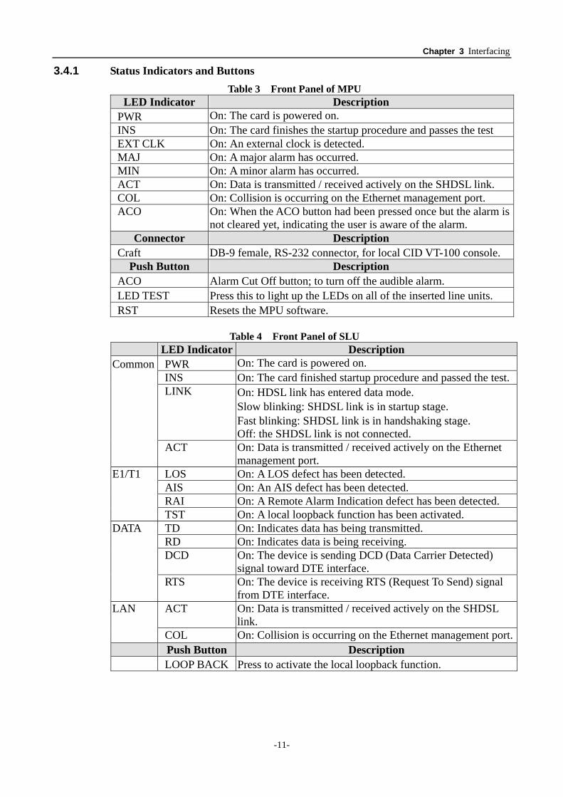
3.4.2 The RS-232 DB-9 Female Pin Assignment
PIN Description
1 Data Carrier Detect (DCD) 2 Receive Data (RXD) 3 Transmit Data (TXD) 4 Data Terminal Ready (DTR) 5 Signal Ground 6 Data Set Ready (DSR) 7 Request To Send (RTS) 8 Clear To Send (CTS) 9 Ring Indicator (RI)
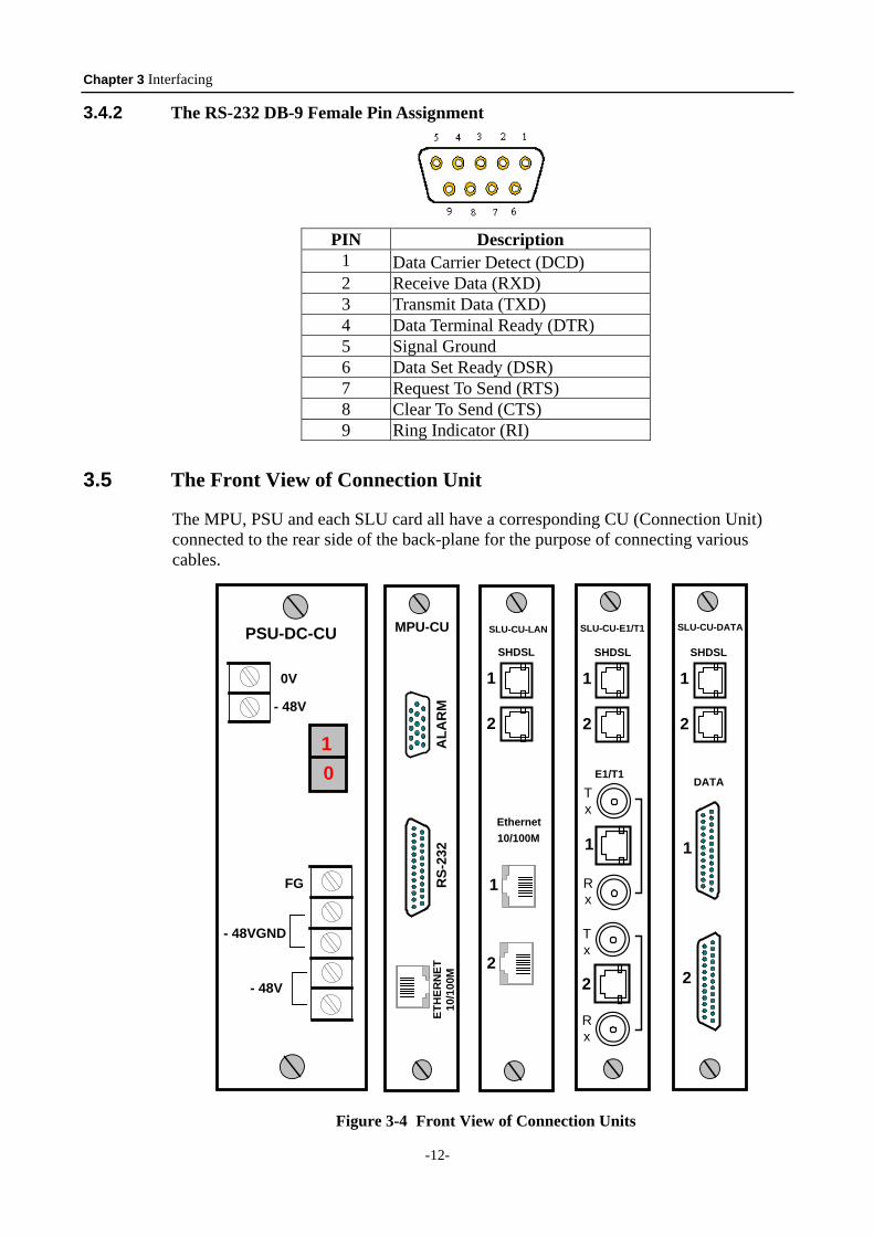
3.5 The Front View of Connection Unit
The MPU, PSU and each SLU card all have a corresponding CU (Connection Unit) connected to the rear side of the back-plane for the purpose of connecting various cables.
MPU-CU
ALA
RM
RS-
232
ETH
ERN
ET10
/100
M
1
2
SHDSL
SLU-CU-LAN
Ethernet10/100M
2
1
SLU-CU-E1/T1
Tx
Rx
Tx
Rx
E1/T1
2
1
1
2
SHDSL
SLU-CU-DATA
1
2
DATA
1
2
SHDSLPSU-DC-CU
- 48VGND
- 48V
FG
- 48V
0V
10
Figure 3-4 Front View of Connection Units
Chapter 3 Interfacing
-13-
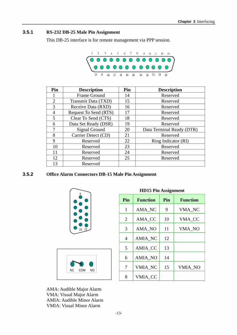
3.5.1 RS-232 DB-25 Male Pin Assignment This DB-25 interface is for remote management via PPP session.
Pin Description Pin Description 1 Frame Ground 14 Reserved 2 Transmit Data (TXD) 15 Reserved 3 Receive Data (RXD) 16 Reserved 4 Request To Send (RTS) 17 Reserved 5 Clear To Send (CTS) 18 Reserved 6 Data Set Ready (DSR) 19 Reserved 7 Signal Ground 20 Data Terminal Ready (DTR) 8 Carrier Detect (CD) 21 Reserved 9 Reserved 22 Ring Indicator (RI) 10 Reserved 23 Reserved 11 Reserved 24 Reserved 12 Reserved 25 Reserved 13 Reserved
3.5.2 Office Alarm Connectors DB-15 Male Pin Assignment
HD15 Pin Assignment
Pin Function Pin Function
1 AMA_NC 9 VMA_NC
2 AMA_CC 10 VMA_CC
3 AMA_NO 11 VMA_NO
4 AMIA_NC 12
5 AMIA_CC 13
6 AMIA_NO 14
7 VMIA_NC 15 VMIA_NO
6
10 15
8 VMIA_CC
AMA: Audible Major Alarm VMA: Visual Major Alarm AMIA: Audible Minor Alarm VMIA: Visual Minor Alarm
NC COM NO
Chapter 3 Interfacing
-14-
NC: Normal Close NO: Normal Open
There are four office alarm connectors on the back-plane: AMA, VMA, AMIA, and VMIA, each of which has three pins. The audio alarm connection can be connected to an external audio device to generate an audible alarm when an error occurs in the system. The visual alarm connection is connected to an external device that will give a visual indication when an error occurs in the system.
COM pin: Common pin for NC and NO.
NC pin: If a normally close signal is required, connect the alarm wires to the COM pin and NC pin. In normal state, the NC and COM are short-circuited. If an alarm occurs, NC and COM are open-circuited.
NO pin: If a normally open signal is required, connect the alarm wires to the COM pin and NO pin. In normal state, the NO and COM are open-circuited. If an alarm occurs, NO and COM are short-circuited.
3.5.3 Power Supply Connectors
There are two connectors for DC –48V power source input in the rear panel.
-48VGND PIN: Connect to ground of -48V power supply source.
-48V PIN: Connect to -48V power supply source.
FG PIN: Connect to frame ground.
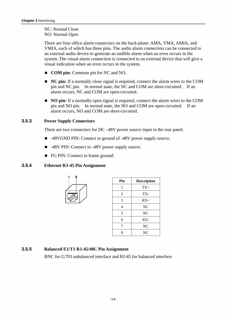
3.5.4 Ethernet RJ-45 Pin Assignment
3.5.5 Balanced E1/T1 RJ-45/48C Pin Assignment BNC for G.703 unbalanced interface and RJ-45 for balanced interface
Pin Description
1 TX+
2 TX-
3 RX+
4 NC
5 NC
6 RX-
7 NC
8 NC
Chapter 3 Interfacing
-15-
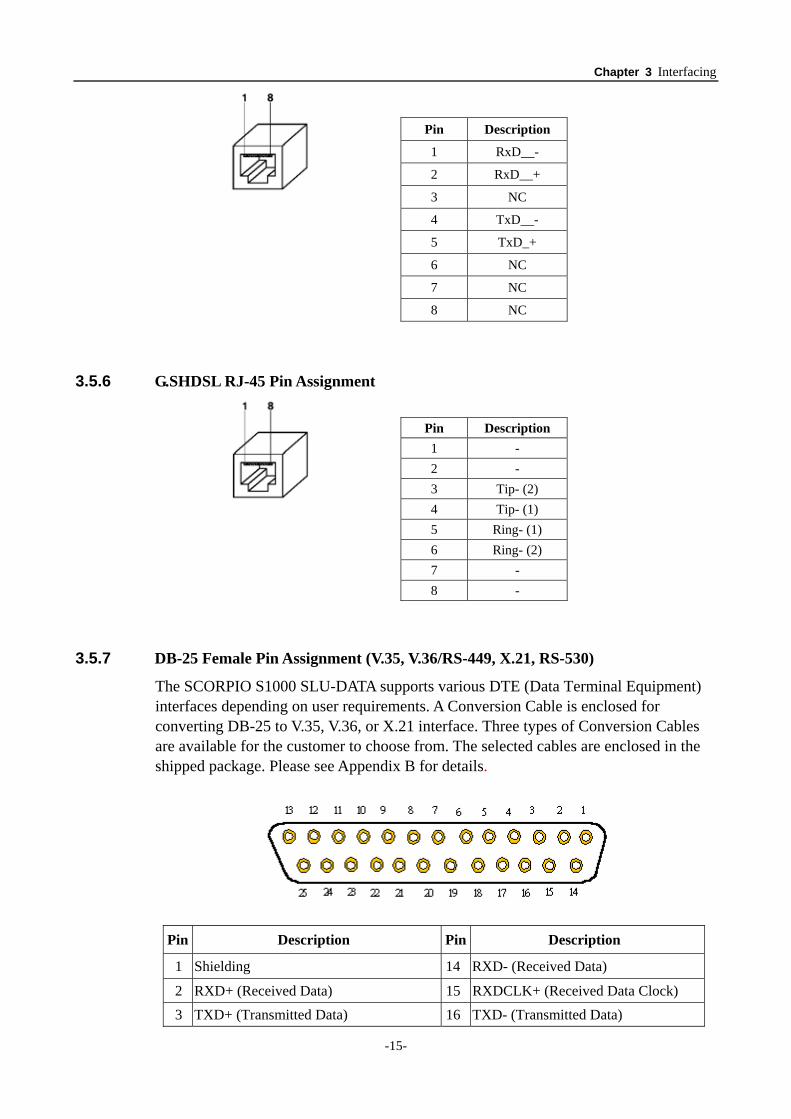
3.5.6 G.SHDSL RJ-45 Pin Assignment
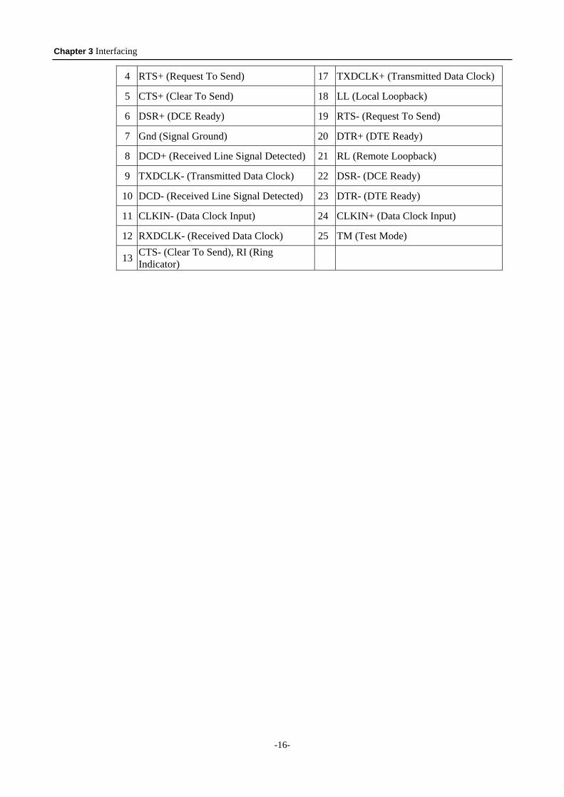
3.5.7 DB-25 Female Pin Assignment (V.35, V.36/RS-449, X.21, RS-530)
The SCORPIO S1000 SLU-DATA supports various DTE (Data Terminal Equipment) interfaces depending on user requirements. A Conversion Cable is enclosed for converting DB-25 to V.35, V.36, or X.21 interface. Three types of Conversion Cables are available for the customer to choose from. The selected cables are enclosed in the shipped package. Please see Appendix B for details.
Pin Description Pin Description
1 Shielding 14 RXD- (Received Data)
2 RXD+ (Received Data) 15 RXDCLK+ (Received Data Clock) 3 TXD+ (Transmitted Data) 16 TXD- (Transmitted Data)
Pin Description
1 RxD__-
2 RxD__+
3 NC
4 TxD__-
5 TxD_+
6 NC
7 NC
8 NC
Pin Description 1 - 2 - 3 Tip- (2) 4 Tip- (1) 5 Ring- (1) 6 Ring- (2) 7 - 8 -
Chapter 3 Interfacing
-16-
4 RTS+ (Request To Send) 17 TXDCLK+ (Transmitted Data Clock)
5 CTS+ (Clear To Send) 18 LL (Local Loopback)
6 DSR+ (DCE Ready) 19 RTS- (Request To Send)
7 Gnd (Signal Ground) 20 DTR+ (DTE Ready)
8 DCD+ (Received Line Signal Detected) 21 RL (Remote Loopback)
9 TXDCLK- (Transmitted Data Clock) 22 DSR- (DCE Ready)
10 DCD- (Received Line Signal Detected) 23 DTR- (DTE Ready)
11 CLKIN- (Data Clock Input) 24 CLKIN+ (Data Clock Input)
12 RXDCLK- (Received Data Clock) 25 TM (Test Mode)
13 CTS- (Clear To Send), RI (Ring Indicator)
Chapter 4 Installation and Setup
-17-
Chapter 4. Installation and Setup
Installation or servicing of any part of the S1000 should be performed by trained and qualified personnel. Always wear an ESD (Electronic Static Discharge) wrist or ankle strap to avoid ESD damage to the equipment or its associated circuitry
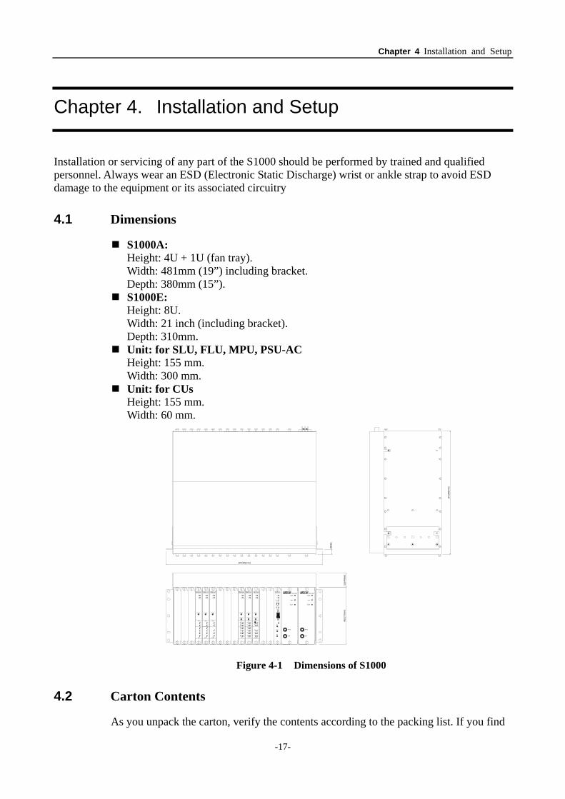
4.1 Dimensions
S1000A: Height: 4U + 1U (fan tray). Width: 481mm (19”) including bracket. Depth: 380mm (15”). S1000E:
Height: 8U. Width: 21 inch (including bracket). Depth: 310mm. Unit: for SLU, FLU, MPU, PSU-AC
Height: 155 mm. Width: 300 mm. Unit: for CUs
Height: 155 mm. Width: 60 mm.
4U(1
77m
m)
1U(4
4mm
)
19"(481mm)
15"(
380m
m)
15m
m
Figure 4-1 Dimensions of S1000
4.2 Carton Contents
As you unpack the carton, verify the contents according to the packing list. If you find
Chapter 4 Installation and Setup
-18-
anything missing or damaged, contact your sales representative for assistance. After installing the S1000, keep the user’s manual or unused cables and accessories for future maintenance or servicing of the S1000.
4.3 Preparing for Installation
To begin installing the S1000, have the following accessories ready.
A console terminal with standard VT-100 emulation program
This is a computer or notebook that is connected to S1000 for console operation. It should be installed with standard VT-100 program like Telix or HyperTerminal running Version 5 or above. The craft port speed is 9600 by default and it is a software configurable option (9600 /115200), for the software version is 3.01 or earlier the craft port speed is 115200 by default and the speed is not configurable.
Two straight-through RS-232 cables
a. A DB-9 male cable is used to connect the S1000 to the above console terminal for VT-100 session.
b. *A DB-25 male cable is used to connect the REMOTE port to a modem for remote dial-in via PPP connection session (future).
An RJ-45 LAN connection cable This cable connects the S1000 to LAN.
Dummy face panel(s)
Optional dummy face panel is available to cover an empty slot.
Chapter 5 Operation of CID (Craft Interface Device)
-19-
Chapter 5. Operation of CID (Craft Interface Device)
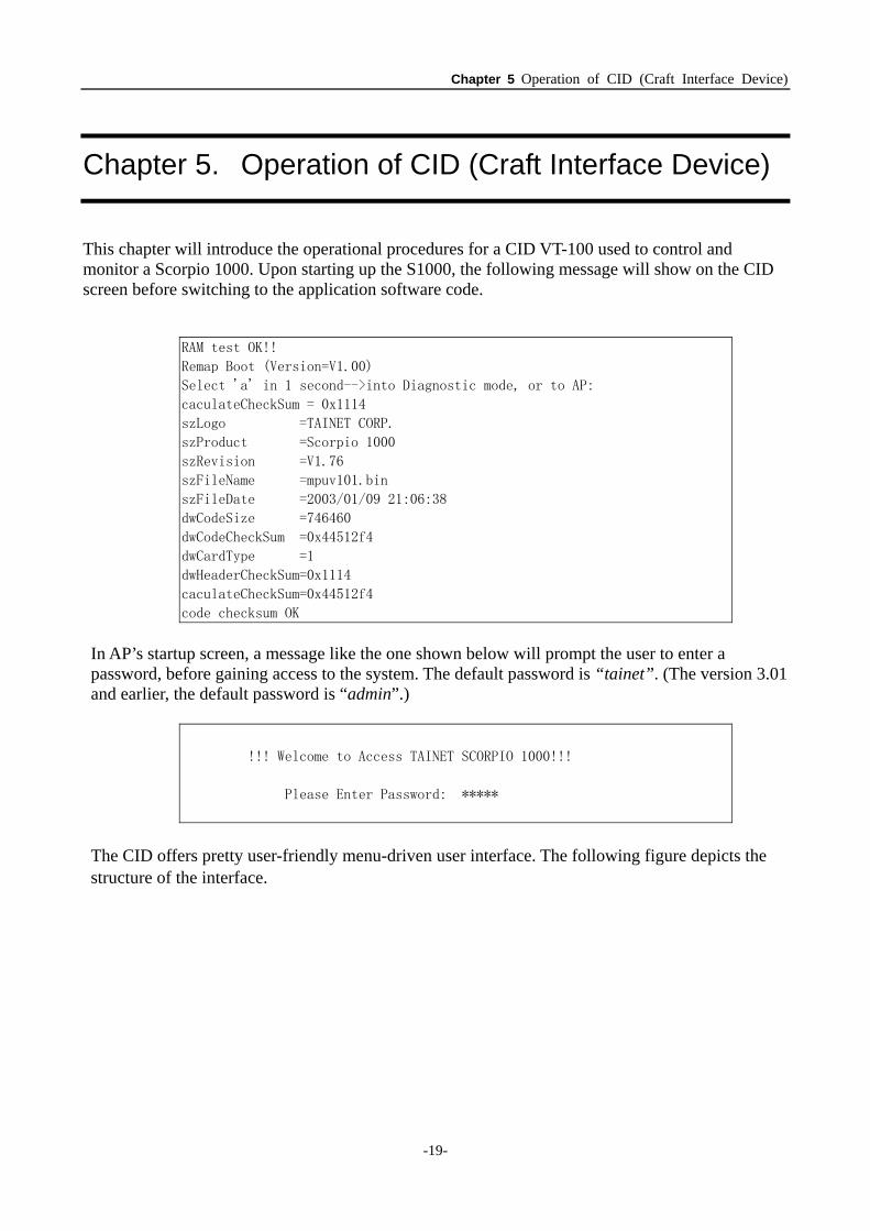
This chapter will introduce the operational procedures for a CID VT-100 used to control and monitor a Scorpio 1000. Upon starting up the S1000, the following message will show on the CID screen before switching to the application software code.
RAM test OK!!
Remap Boot (Version=V1.00)
Select 'a' in 1 second-->into Diagnostic mode, or to AP:
caculateCheckSum = 0x1114
szLogo =TAINET CORP.
szProduct =Scorpio 1000
szRevision =V1.76
szFileName =mpuv101.bin
szFileDate =2003/01/09 21:06:38
dwCodeSize =746460
dwCodeCheckSum =0x44512f4
dwCardType =1
dwHeaderCheckSum=0x1114
caculateCheckSum=0x44512f4
code checksum OK
In AP’s startup screen, a message like the one shown below will prompt the user to enter a password, before gaining access to the system. The default password is “tainet”. (The version 3.01 and earlier, the default password is “admin”.)
!!! Welcome to Access TAINET SCORPIO 1000!!!
Please Enter Password: *****
The CID offers pretty user-friendly menu-driven user interface. The following figure depicts the structure of the interface.
Chapter 5 Operation of CID (Craft Interface Device)
-20-
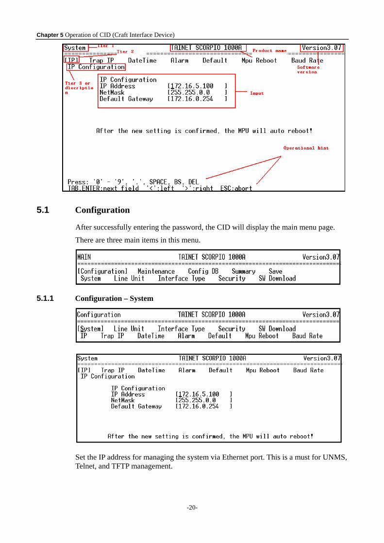
5.1 Configuration
After successfully entering the password, the CID will display the main menu page.
There are three main items in this menu.
5.1.1 Configuration – System
Set the IP address for managing the system via Ethernet port. This is a must for UNMS, Telnet, and TFTP management.
Chapter 5 Operation of CID (Craft Interface Device)
-21-
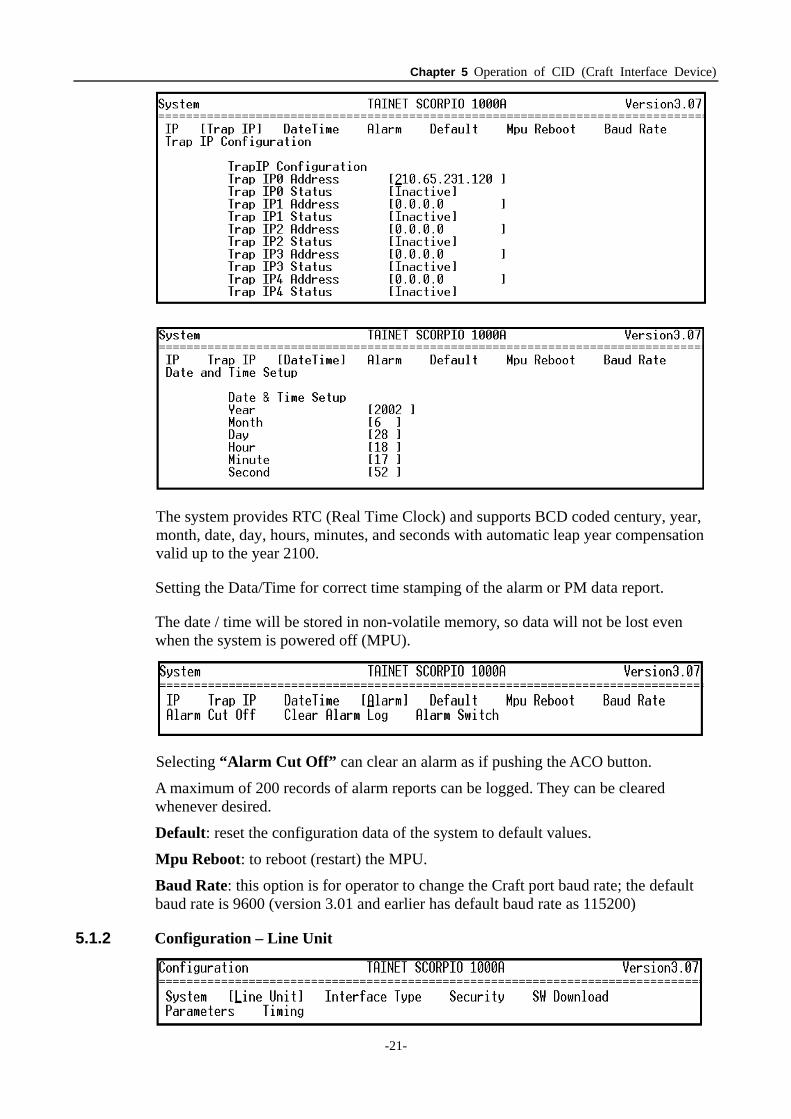
The system provides RTC (Real Time Clock) and supports BCD coded century, year, month, date, day, hours, minutes, and seconds with automatic leap year compensation valid up to the year 2100.
Setting the Data/Time for correct time stamping of the alarm or PM data report.
The date / time will be stored in non-volatile memory, so data will not be lost even when the system is powered off (MPU).
Selecting “Alarm Cut Off” can clear an alarm as if pushing the ACO button.
A maximum of 200 records of alarm reports can be logged. They can be cleared whenever desired.
Default: reset the configuration data of the system to default values.
Mpu Reboot: to reboot (restart) the MPU.
Baud Rate: this option is for operator to change the Craft port baud rate; the default baud rate is 9600 (version 3.01 and earlier has default baud rate as 115200)
5.1.2 Configuration – Line Unit
Chapter 5 Operation of CID (Craft Interface Device)
-22-
5.1.2.1 Configuration – Line Unit - Parameters
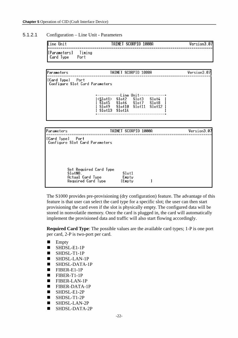
The S1000 provides pre-provisioning (dry configuration) feature. The advantage of this feature is that user can select the card type for a specific slot; the user can then start provisioning the card even if the slot is physically empty. The configured data will be stored in nonvolatile memory. Once the card is plugged in, the card will automatically implement the provisioned data and traffic will also start flowing accordingly.
Required Card Type: The possible values are the available card types; 1-P is one port per card, 2-P is two-port per card.
Empty SHDSL-E1-1P SHDSL-T1-1P SHDSL-LAN-1P SHDSL-DATA-1P FIBER-E1-1P FIBER-T1-1P FIBER-LAN-1P FIBER-DATA-1P SHDSL-E1-2P SHDSL-T1-2P SHDSL-LAN-2P SHDSL-DATA-2P
Chapter 5 Operation of CID (Craft Interface Device)
-23-
FIBER-E1-2P FIBER-T1-2P FIBER-LAN-2P FIBER-DATA-2P
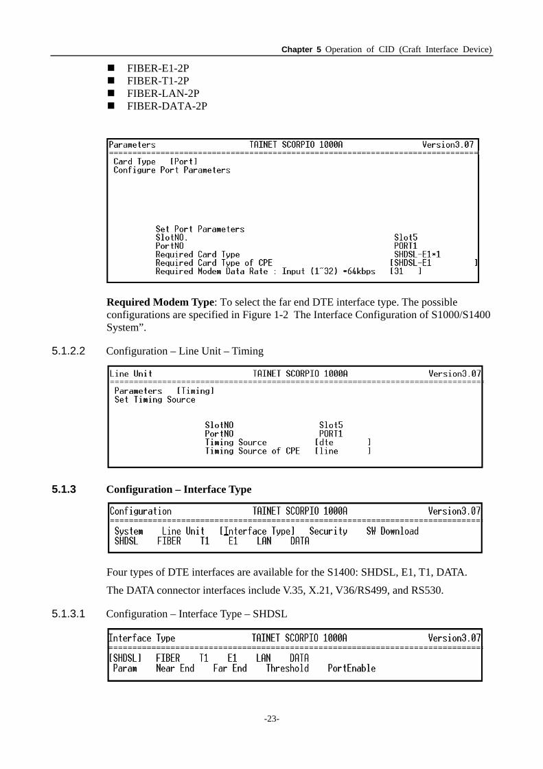
Required Modem Type: To select the far end DTE interface type. The possible configurations are specified in Figure 1-2 The Interface Configuration of S1000/S1400 System”.
5.1.2.2 Configuration – Line Unit – Timing
5.1.3 Configuration – Interface Type
Four types of DTE interfaces are available for the S1400: SHDSL, E1, T1, DATA.
The DATA connector interfaces include V.35, X.21, V36/RS499, and RS530.
5.1.3.1 Configuration – Interface Type – SHDSL
Chapter 5 Operation of CID (Craft Interface Device)
-24-
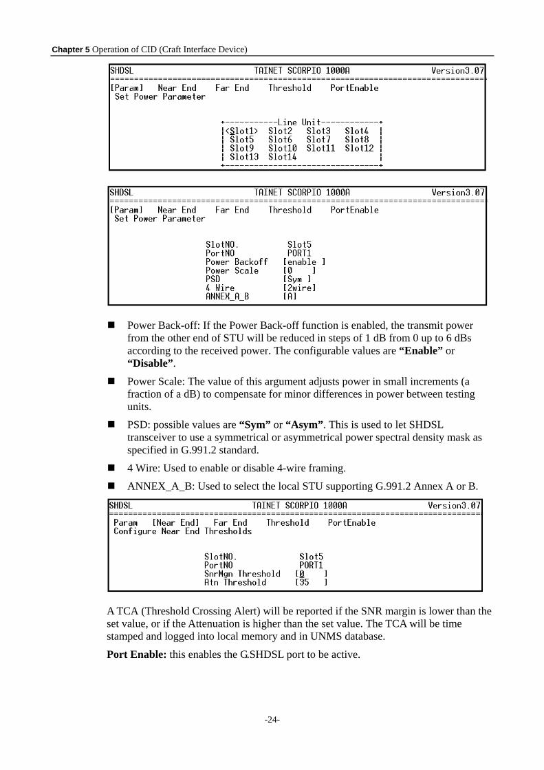
Power Back-off: If the Power Back-off function is enabled, the transmit power from the other end of STU will be reduced in steps of 1 dB from 0 up to 6 dBs according to the received power. The configurable values are “Enable” or “Disable”.
Power Scale: The value of this argument adjusts power in small increments (a fraction of a dB) to compensate for minor differences in power between testing units.
PSD: possible values are “Sym” or “Asym”. This is used to let SHDSL transceiver to use a symmetrical or asymmetrical power spectral density mask as specified in G.991.2 standard.
4 Wire: Used to enable or disable 4-wire framing.
ANNEX_A_B: Used to select the local STU supporting G.991.2 Annex A or B.
A TCA (Threshold Crossing Alert) will be reported if the SNR margin is lower than the set value, or if the Attenuation is higher than the set value. The TCA will be time stamped and logged into local memory and in UNMS database.
Port Enable: this enables the G.SHDSL port to be active.
Chapter 5 Operation of CID (Craft Interface Device)
-25-
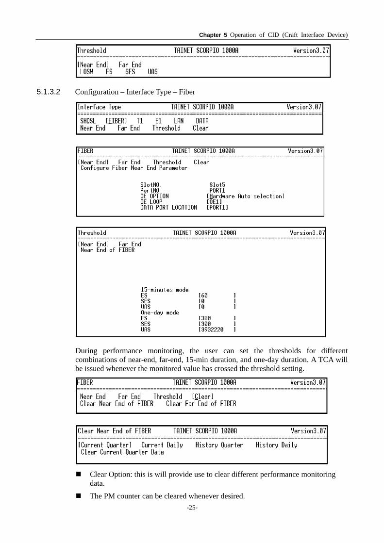
5.1.3.2 Configuration – Interface Type – Fiber
During performance monitoring, the user can set the thresholds for different combinations of near-end, far-end, 15-min duration, and one-day duration. A TCA will be issued whenever the monitored value has crossed the threshold setting.
Clear Option: this is will provide use to clear different performance monitoring
data.
The PM counter can be cleared whenever desired.
Chapter 5 Operation of CID (Craft Interface Device)
-26-
Current Quarter: The measured value in seconds of the monitored performance parameters within the current 15-min period.
Current Day: The measured value in seconds of the monitored performance parameters within the current 1-day period.
History Quarter: Accumulates the values in seconds of the monitored performance parameters for up to 96 of the past 15-min periods.
History Day: Accumulates the values in seconds of the monitored performance parameters for up to 7 of the past 1-day periods.
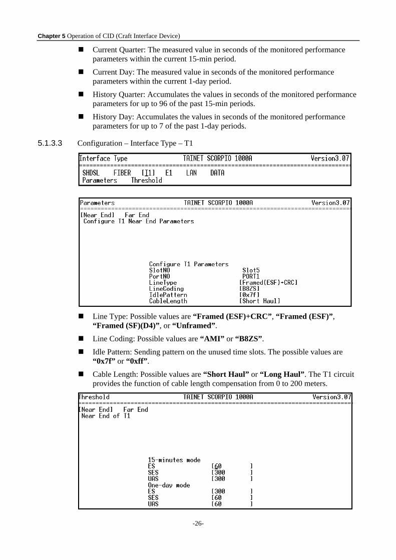
5.1.3.3 Configuration – Interface Type – T1
Line Type: Possible values are “Framed (ESF)+CRC”, “Framed (ESF)”,
“Framed (SF)(D4)”, or “Unframed”.
Line Coding: Possible values are “AMI” or “B8ZS”.
Idle Pattern: Sending pattern on the unused time slots. The possible values are “0x7f” or “0xff”.
Cable Length: Possible values are “Short Haul” or “Long Haul”. The T1 circuit provides the function of cable length compensation from 0 to 200 meters.
Chapter 5 Operation of CID (Craft Interface Device)
-27-
During performance monitoring, the user can set the thresholds for different combinations of near-end, far-end, 15-min duration, and 1-day duration. A TCA will be issued whenever the monitored value has crossed the threshold setting.
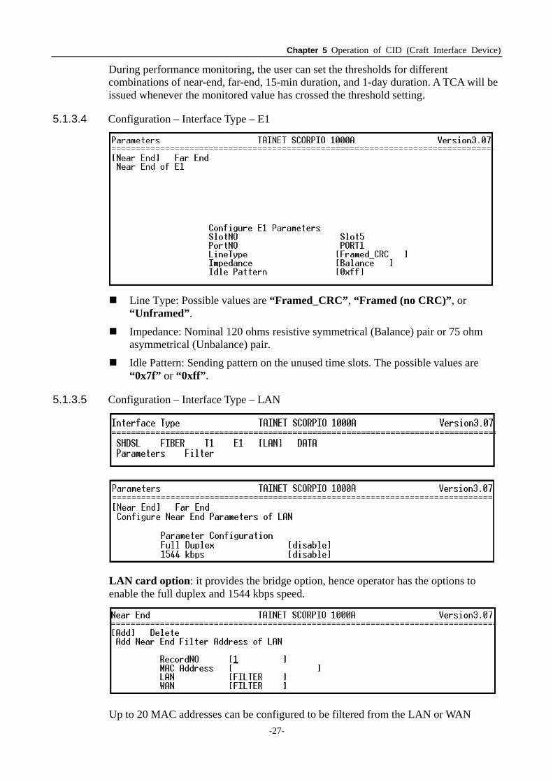
5.1.3.4 Configuration – Interface Type – E1
Line Type: Possible values are “Framed_CRC”, “Framed (no CRC)”, or
“Unframed”.
Impedance: Nominal 120 ohms resistive symmetrical (Balance) pair or 75 ohm asymmetrical (Unbalance) pair.
Idle Pattern: Sending pattern on the unused time slots. The possible values are “0x7f” or “0xff”.
5.1.3.5 Configuration – Interface Type – LAN
LAN card option: it provides the bridge option, hence operator has the options to enable the full duplex and 1544 kbps speed.
Up to 20 MAC addresses can be configured to be filtered from the LAN or WAN
Chapter 5 Operation of CID (Craft Interface Device)
-28-
interface.
Up to 128 MAC learning addresses can be stored in the forwarding table.
There are three types of filtering settings: “FILTER”, “DYNAMIC”, and “FORWARDING”. “DYNAMIC” means that the handling of the MAC frame in the interface follows the learning result of the bridging function.
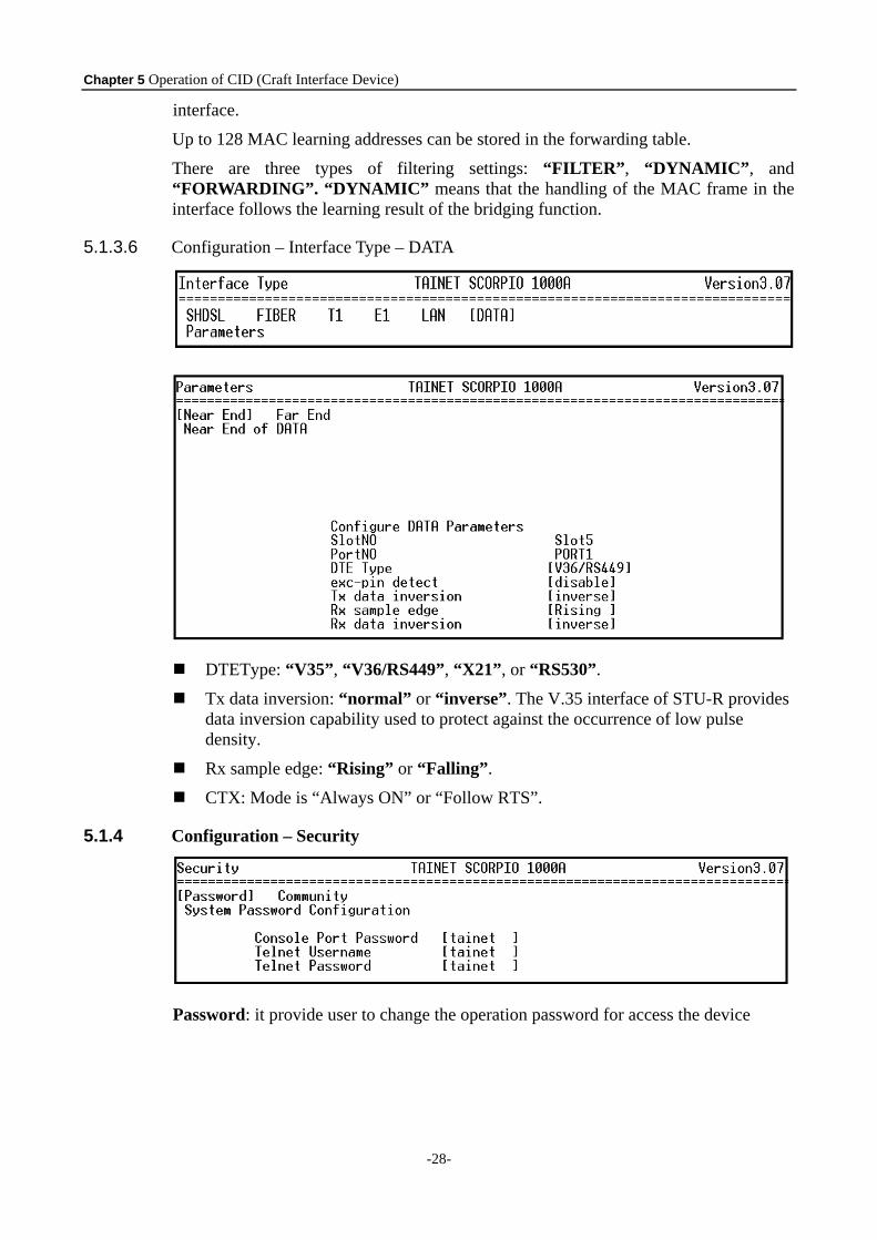
5.1.3.6 Configuration – Interface Type – DATA
DTEType: “V35”, “V36/RS449”, “X21”, or “RS530”.
Tx data inversion: “normal” or “inverse”. The V.35 interface of STU-R provides data inversion capability used to protect against the occurrence of low pulse density.
Rx sample edge: “Rising” or “Falling”.
CTX: Mode is “Always ON” or “Follow RTS”.
5.1.4 Configuration – Security
Password: it provide user to change the operation password for access the device
Chapter 5 Operation of CID (Craft Interface Device)
-29-
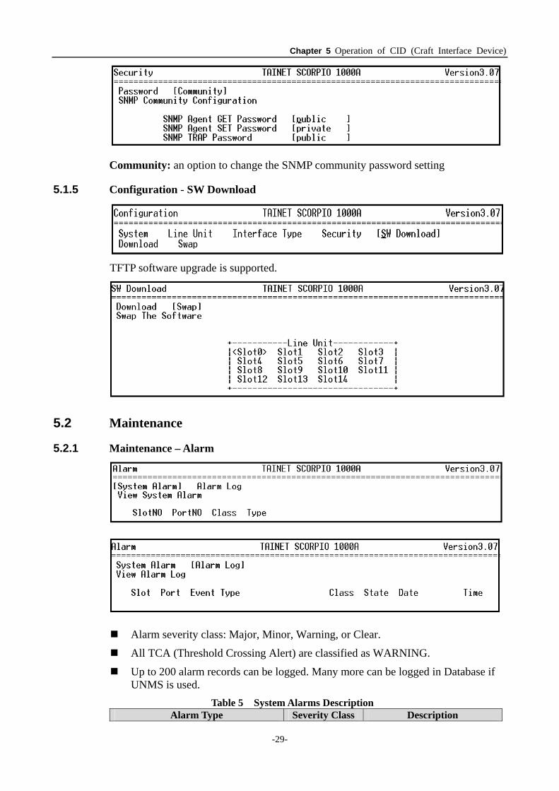
Community: an option to change the SNMP community password setting
5.1.5 Configuration - SW Download
TFTP software upgrade is supported.
5.2 Maintenance
5.2.1 Maintenance – Alarm
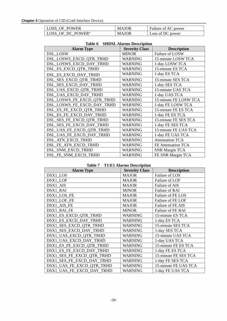
Alarm severity class: Major, Minor, Warning, or Clear.
All TCA (Threshold Crossing Alert) are classified as WARNING.
Up to 200 alarm records can be logged. Many more can be logged in Database if UNMS is used.
Table 5 System Alarms Description Alarm Type Severity Class Description
Chapter 5 Operation of CID (Craft Interface Device)
-30-
LOSS_OF_POWER MAJOR Failure of AC power LOSS_OF_DC_POWER" MAJOR Loss of DC power
Table 6 SHDSL Alarms Description
Alarm Type Severity Class Description DSL_LOSW MINOR Failure of LOSW DSL_LOSWS_EXCD_QTR_TRHD WARNING 15-minute LOSW TCA DSL_LOSWS_EXCD_DAY_TRHD WARNING 1-day LOSW TCA DSL_ES_EXCD_QTR_TRHD WARNING 15-minute ES TCA DSL_ES_EXCD_DAY_TRHD WARNING 1-day ES TCA DSL_SES_EXCD_QTR_TRHD WARNING 15-minute SES TCA DSL_SES_EXCD_DAY_TRHD WARNING 1-day SES TCA DSL_UAS_EXCD_QTR_TRHD WARNING 15-minute UAS TCA DSL_UAS_EXCD_DAY_TRHD WARNING 1-day UAS TCA DSL_LOSWS_FE_EXCD_QTR_TRHD WARNING 15-minute FE LOSW TCA DSL_LOSWS_FE_EXCD_DAY_TRHD WARNING 1-day FE LOSW TCA DSL_ES_FE_EXCD_QTR_TRHD WARNING 15-minute FE ES TCA DSL_ES_FE_EXCD_DAY_TRHD WARNING 1-day FE ES TCA DSL_SES_FE_EXCD_QTR_TRHD WARNING 15-minute FE SES TCA DSL_SES_FE_EXCD_DAY_TRHD WARNING 1-day FE SES TCA DSL_UAS_FE_EXCD_QTR_TRHD WARNING 15-minute FE UAS TCA DSL_UAS_FE_EXCD_DAY_TRHD WARNING 1-day FE UAS TCA DSL_ATN_EXCD_TRHD WARNING Attenuation TCA DSL_FE_ATN_EXCD_TRHD WARNING FE Attenuation TCA DSL_SNM_EXCD_TRHD WARNING SNR Margin TCA DSL_FE_SNM_EXCD_TRHD WARNING FE SNR Margin TCA
Table 7 T1/E1 Alarms Description
Alarm Type Severity Class Description DSX1_LOS MAJOR Failure of LOS DSX1_LOF MAJOR Failure of LOF DSX1_AIS MAJOR Failure of AIS DSX1_RAI MINOR Failure of RAI DSX1_LOS_FE MAJOR Failure of FE LOS DSX1_LOF_FE MAJOR Failure of FE LOF DSX1_AIS_FE MAJOR Failure of FE AIS DSX1_RAI_FE MINOR Failure of FE RAI DSX1_ES_EXCD_QTR_TRHD WARNING 15-minute ES TCA DSX1_ES_EXCD_DAY_TRHD WARNING 1-day ES TCA DSX1_SES_EXCD_QTR_TRHD WARNING 15-minute SES TCA DSX1_SES_EXCD_DAY_TRHD WARNING 1-day SES TCA DSX1_UAS_EXCD_QTR_TRHD WARNING 15-minute UAS TCA DSX1_UAS_EXCD_DAY_TRHD WARNING 1-day UAS TCA DSX1_ES_FE_EXCD_QTR_TRHD WARNING 15-minute FE ES TCA DSX1_ES_FE_EXCD_DAY_TRHD WARNING 1-day FE ES TCA DSX1_SES_FE_EXCD_QTR_TRHD WARNING 15-minute FE SES TCA DSX1_SES_FE_EXCD_DAY_TRHD WARNING 1-day FE SES TCA DSX1_UAS_FE_EXCD_QTR_TRHD WARNING 15-minute FE UAS TCA DSX1_UAS_FE_EXCD_DAY_TRHD WARNING 1-day FE UAS TCA
Chapter 5 Operation of CID (Craft Interface Device)
-31-
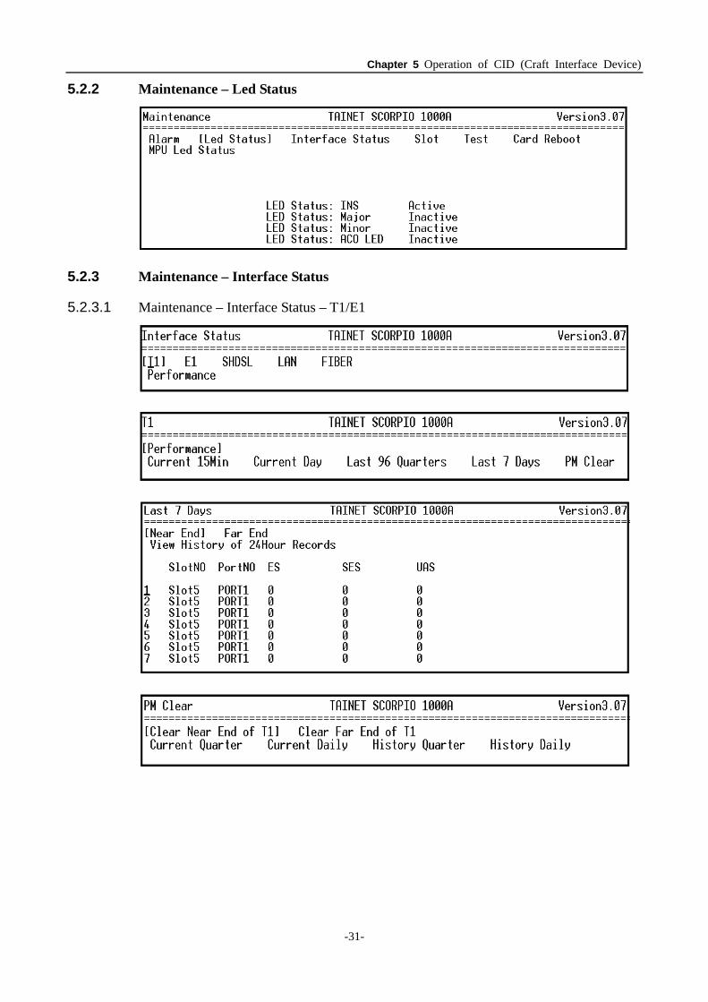
5.2.2 Maintenance – Led Status
5.2.3 Maintenance – Interface Status
5.2.3.1 Maintenance – Interface Status – T1/E1
Chapter 5 Operation of CID (Craft Interface Device)
-32-
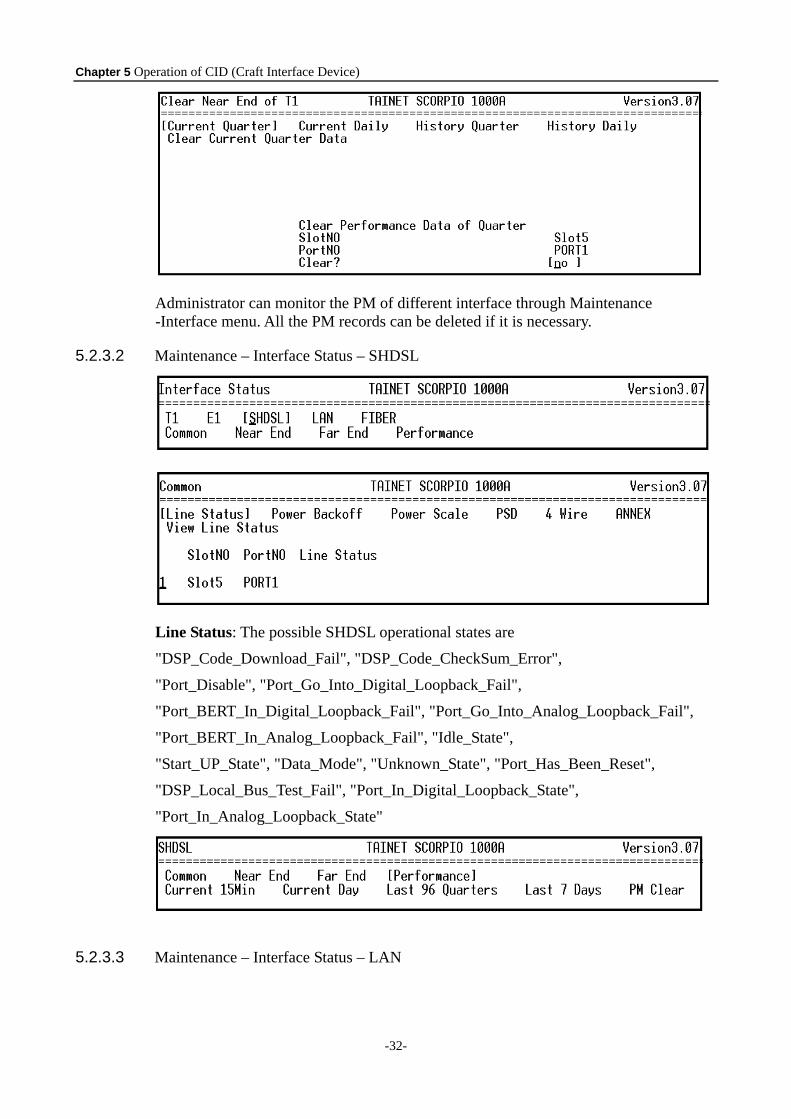
Administrator can monitor the PM of different interface through Maintenance -Interface menu. All the PM records can be deleted if it is necessary.
5.2.3.2 Maintenance – Interface Status – SHDSL
Line Status: The possible SHDSL operational states are
"DSP_Code_Download_Fail", "DSP_Code_CheckSum_Error",
"Port_Disable", "Port_Go_Into_Digital_Loopback_Fail",
"Port_BERT_In_Digital_Loopback_Fail", "Port_Go_Into_Analog_Loopback_Fail",
"Port_BERT_In_Analog_Loopback_Fail", "Idle_State",
"Start_UP_State", "Data_Mode", "Unknown_State", "Port_Has_Been_Reset",
"DSP_Local_Bus_Test_Fail", "Port_In_Digital_Loopback_State",
"Port_In_Analog_Loopback_State"
5.2.3.3 Maintenance – Interface Status – LAN
Chapter 5 Operation of CID (Craft Interface Device)
-33-
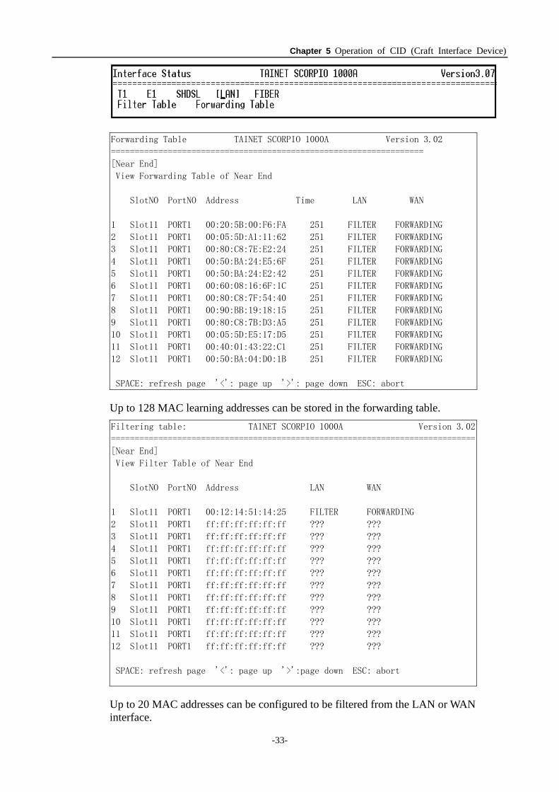
Forwarding Table TAINET SCORPIO 1000A Version 3.02
==================================================================
[Near End]
View Forwarding Table of Near End
SlotNO PortNO Address Time LAN WAN
1 Slot11 PORT1 00:20:5B:00:F6:FA 251 FILTER FORWARDING
2 Slot11 PORT1 00:05:5D:A1:11:62 251 FILTER FORWARDING
3 Slot11 PORT1 00:80:C8:7E:E2:24 251 FILTER FORWARDING
4 Slot11 PORT1 00:50:BA:24:E5:6F 251 FILTER FORWARDING
5 Slot11 PORT1 00:50:BA:24:E2:42 251 FILTER FORWARDING
6 Slot11 PORT1 00:60:08:16:6F:1C 251 FILTER FORWARDING
7 Slot11 PORT1 00:80:C8:7F:54:40 251 FILTER FORWARDING
8 Slot11 PORT1 00:90:BB:19:18:15 251 FILTER FORWARDING
9 Slot11 PORT1 00:80:C8:7B:D3:A5 251 FILTER FORWARDING
10 Slot11 PORT1 00:05:5D:E5:17:D5 251 FILTER FORWARDING
11 Slot11 PORT1 00:40:01:43:22:C1 251 FILTER FORWARDING
12 Slot11 PORT1 00:50:BA:04:D0:1B 251 FILTER FORWARDING
SPACE: refresh page '<': page up '>': page down ESC: abort
Up to 128 MAC learning addresses can be stored in the forwarding table. Filtering table: TAINET SCORPIO 1000A Version 3.02
=============================================================================
[Near End]
View Filter Table of Near End
SlotNO PortNO Address LAN WAN
1 Slot11 PORT1 00:12:14:51:14:25 FILTER FORWARDING
2 Slot11 PORT1 ff:ff:ff:ff:ff:ff ??? ???
3 Slot11 PORT1 ff:ff:ff:ff:ff:ff ??? ???
4 Slot11 PORT1 ff:ff:ff:ff:ff:ff ??? ???
5 Slot11 PORT1 ff:ff:ff:ff:ff:ff ??? ???
6 Slot11 PORT1 ff:ff:ff:ff:ff:ff ??? ???
7 Slot11 PORT1 ff:ff:ff:ff:ff:ff ??? ???
8 Slot11 PORT1 ff:ff:ff:ff:ff:ff ??? ???
9 Slot11 PORT1 ff:ff:ff:ff:ff:ff ??? ???
10 Slot11 PORT1 ff:ff:ff:ff:ff:ff ??? ???
11 Slot11 PORT1 ff:ff:ff:ff:ff:ff ??? ???
12 Slot11 PORT1 ff:ff:ff:ff:ff:ff ??? ???
SPACE: refresh page '<': page up '>':page down ESC: abort
Up to 20 MAC addresses can be configured to be filtered from the LAN or WAN interface.
Chapter 5 Operation of CID (Craft Interface Device)
-34-
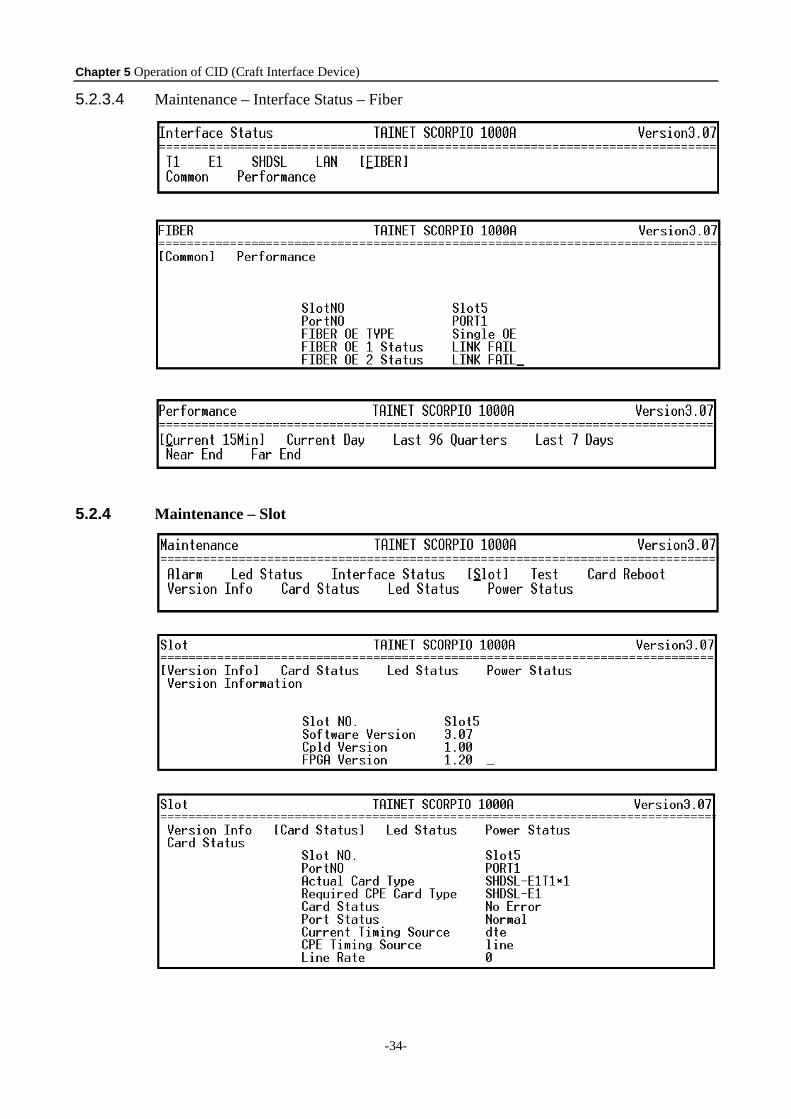
5.2.3.4 Maintenance – Interface Status – Fiber
5.2.4 Maintenance – Slot
Chapter 5 Operation of CID (Craft Interface Device)
-35-
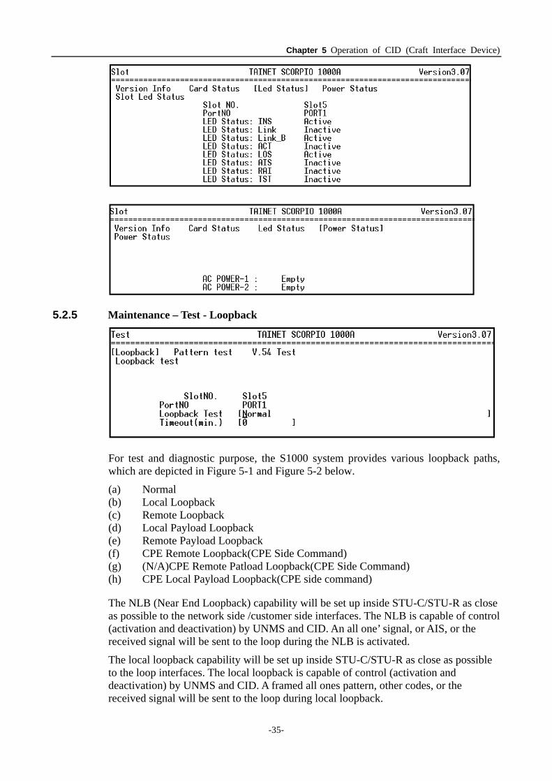
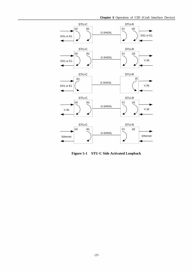
5.2.5 Maintenance – Test - Loopback
For test and diagnostic purpose, the S1000 system provides various loopback paths, which are depicted in Figure 5-1 and Figure 5-2 below.
(a) Normal (b) Local Loopback (c) Remote Loopback (d) Local Payload Loopback (e) Remote Payload Loopback (f) CPE Remote Loopback(CPE Side Command) (g) (N/A)CPE Remote Patload Loopback(CPE Side Command) (h) CPE Local Payload Loopback(CPE side command)
The NLB (Near End Loopback) capability will be set up inside STU-C/STU-R as close as possible to the network side /customer side interfaces. The NLB is capable of control (activation and deactivation) by UNMS and CID. An all one’ signal, or AIS, or the received signal will be sent to the loop during the NLB is activated.
The local loopback capability will be set up inside STU-C/STU-R as close as possible to the loop interfaces. The local loopback is capable of control (activation and deactivation) by UNMS and CID. A framed all ones pattern, other codes, or the received signal will be sent to the loop during local loopback.
Chapter 5 Operation of CID (Craft Interface Device)
-36-
The RLB(Remote Loopback) is able to be activated and deactivated through EOC via CID and UNMS interfaces. This loopback is used for checking the loop and transceiver units of STU-C/STU-R. A suitable signal will be sent towards the customer side /network side interface during the RLB loopback.
The PLB (Remote Payload Loopback) is able to be activated and deactivated through EOC via CID and UNMS, and be set up inside STU-C/STU-R as close as possible to the network side customer side interfaces. A suitable signal will be sent towards the customer side/network side during the PLB loopback. The PLB of V.35 interface is also able to be activated and deactivated by in band signal and the procedure and codeword will comply with ITU-T V.54.
For V.35 interface STU-R, the ITU-T V.54 in band activated and deactivated loopback codeword provided by S1400 for end-to-end loopback function.
For each STU-C and STU-R, the built-in PRBS (11-stage or higher) generation and detection will be provided for loopback performance test on a per channel basis. Test results will be displayed.
Note: There are different loopback type could be configured. When it acts as CO, all remote loopback types will display the (N/A). It means the item can’t be applied, vice versa. When it act as CPE, all CO loopback types will display the (N/A). It means the item can’t be applied. “RT” is represented as remote。
Chapter 5 Operation of CID (Craft Interface Device)
-37-
G.SHDSL(a) (b) (c) (d)
DS1 or E1 DS1 or E1
STU-C STU-R
G.SHDSL(a) (b) (c) (d)
DS1 or E1 V.35
STU-C STU-R
G.SHDSL(a) (b) (c) (d)
V.35 V.35
STU-C STU-R
G.SHDSL(a) (b) (c) (d)
Ethernet Ethernet
STU-C STU-R
V.35
STU-C STU-R
G.SHDSL(f)(e)
DS1 or E1
Figure 5-1 STU-C Side Activated Loopback
Chapter 5 Operation of CID (Craft Interface Device)
-38-
DS1 or E1 DS1 or E1
STU-C STU-R
DS1 or E1 V.35
STU-C STU-R
V.35 V.35
STU-C STU-R
Ethernet Ethernet
STU-C STU-R
G.SHDSL(a)(b)(c)(d)
G.SHDSL(a)(b)(c)(d)
G.SHDSL(a)(b)(c)(d)
G.SHDSL(a)(b)(c)(d)
G.SHDSL(f) (e)
DS1 or E1 V.35
STU-C STU-R
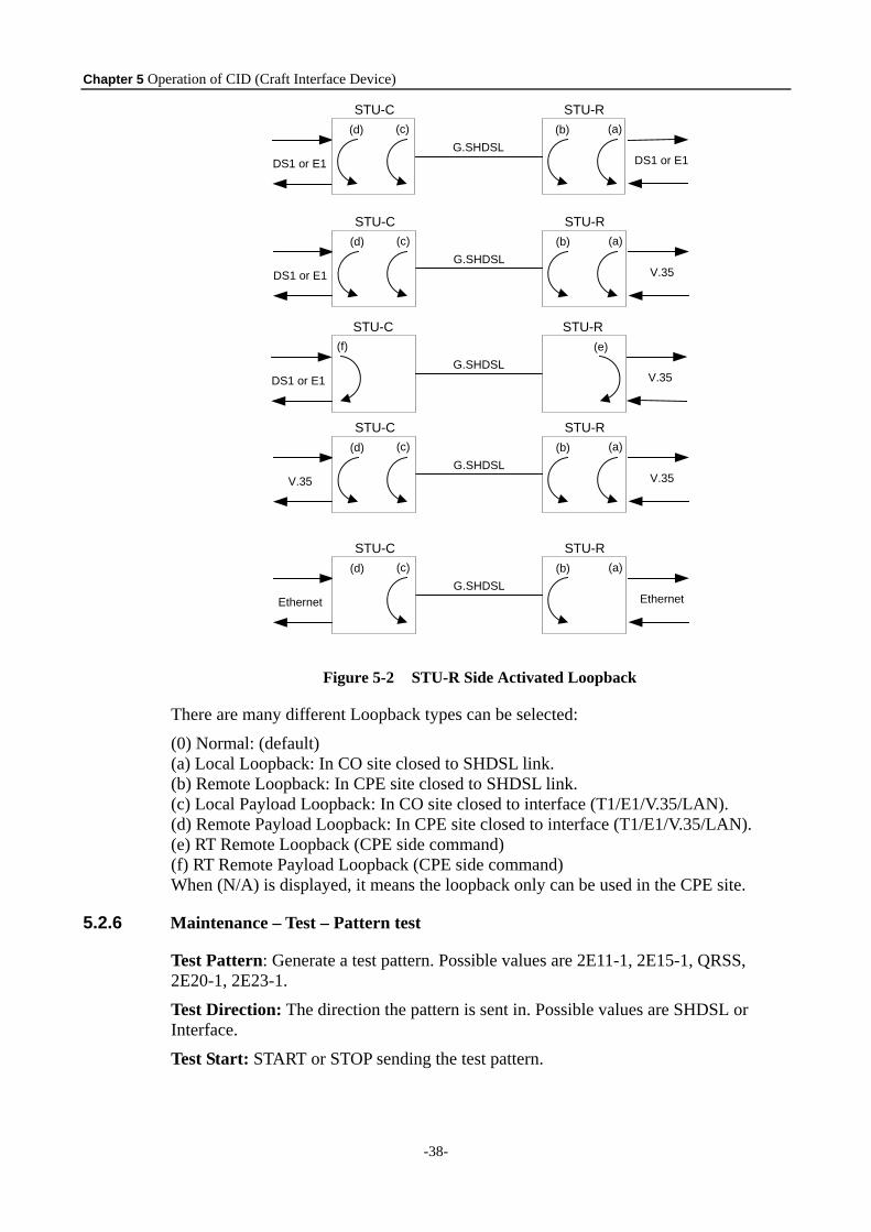
Figure 5-2 STU-R Side Activated Loopback
There are many different Loopback types can be selected:
(0) Normal: (default) (a) Local Loopback: In CO site closed to SHDSL link. (b) Remote Loopback: In CPE site closed to SHDSL link. (c) Local Payload Loopback: In CO site closed to interface (T1/E1/V.35/LAN). (d) Remote Payload Loopback: In CPE site closed to interface (T1/E1/V.35/LAN). (e) RT Remote Loopback (CPE side command) (f) RT Remote Payload Loopback (CPE side command) When (N/A) is displayed, it means the loopback only can be used in the CPE site.
5.2.6 Maintenance – Test – Pattern test
Test Pattern: Generate a test pattern. Possible values are 2E11-1, 2E15-1, QRSS, 2E20-1, 2E23-1.
Test Direction: The direction the pattern is sent in. Possible values are SHDSL or Interface.
Test Start: START or STOP sending the test pattern.
Chapter 5 Operation of CID (Craft Interface Device)
-39-
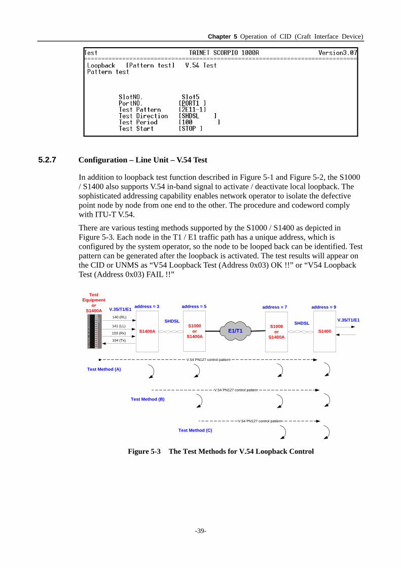
5.2.7 Configuration – Line Unit – V.54 Test
In addition to loopback test function described in Figure 5-1 and Figure 5-2, the S1000 / S1400 also supports V.54 in-band signal to activate / deactivate local loopback. The sophisticated addressing capability enables network operator to isolate the defective point node by node from one end to the other. The procedure and codeword comply with ITU-T V.54.
There are various testing methods supported by the S1000 / S1400 as depicted in Figure 5-3. Each node in the T1 / E1 traffic path has a unique address, which is configured by the system operator, so the node to be looped back can be identified. Test pattern can be generated after the loopback is activated. The test results will appear on the CID or UNMS as “V54 Loopback Test (Address 0x03) OK !!” or “V54 Loopback Test (Address 0x03) FAIL !!”
S1400A
V.35/T1/E1
SHDSLS1000
orS1400A
E1/T1
140 (RL)
141 (LL)
103 (Rx)
104 (Tx)
S1000or
S1400AS1400
V.54 PN127 control pattern
SHDSL
address = 3 address = 5 address = 7 address = 9
Test Method (B)
Test Method (C)
V.54 PN127 control pattern
Test Method (A)
V.54 PN127 control pattern
TestEquipment
orS1400A
V.35/T1/E1
Figure 5-3 The Test Methods for V.54 Loopback Control
Chapter 5 Operation of CID (Craft Interface Device)
-40-
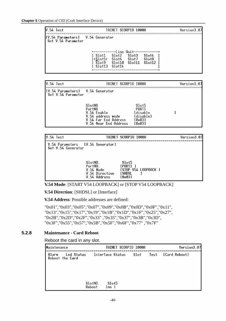
V.54 Mode: [START V54 LOOPBACK] or [STOP V54 LOOPBACK]
V.54 Direction: [SHDSL] or [Interface]
V.54 Address: Possible addresses are defined:
"0x01","0x03","0x05","0x07","0x09","0x0B","0x0D","0x0F","0x11", "0x13","0x15","0x17","0x19","0x1B","0x1D","0x1F","0x25","0x27", "0x2B","0x2D","0x2F","0x33" ,"0x35","0x37","0x3B","0x3D", "0x3F","0x55","0x57","0x5B","0x5F","0x6F","0x77" ,"0x7F"
5.2.8 Maintenance - Card Reboot
Reboot the card in any slot.
Chapter 5 Operation of CID (Craft Interface Device)
-41-
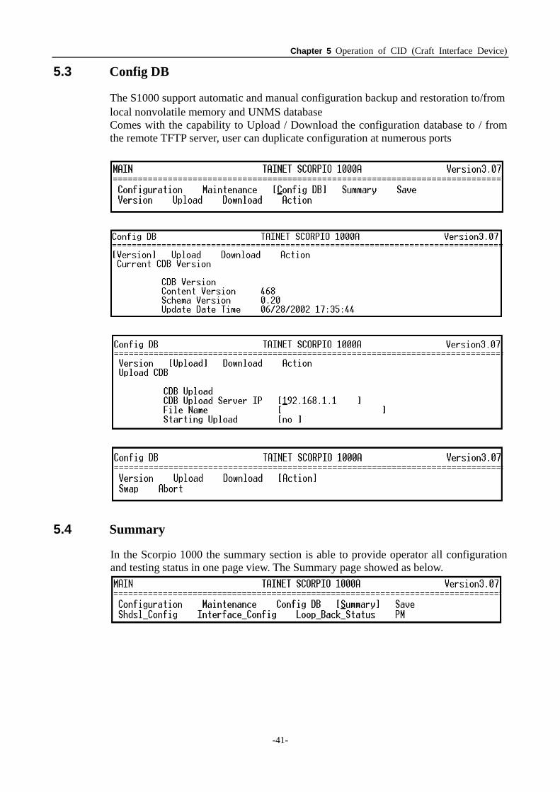
5.3 Config DB
The S1000 support automatic and manual configuration backup and restoration to/from local nonvolatile memory and UNMS database Comes with the capability to Upload / Download the configuration database to / from the remote TFTP server, user can duplicate configuration at numerous ports
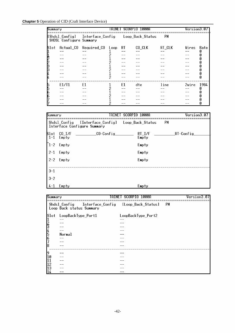
5.4 Summary
In the Scorpio 1000 the summary section is able to provide operator all configuration and testing status in one page view. The Summary page showed as below.
Chapter 5 Operation of CID (Craft Interface Device)
-42-
Chapter 5 Operation of CID (Craft Interface Device)
-43-
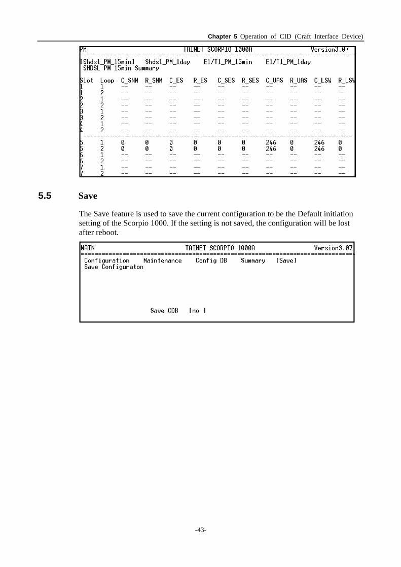
5.5 Save
The Save feature is used to save the current configuration to be the Default initiation setting of the Scorpio 1000. If the setting is not saved, the configuration will be lost after reboot.

Appendix A
-45-
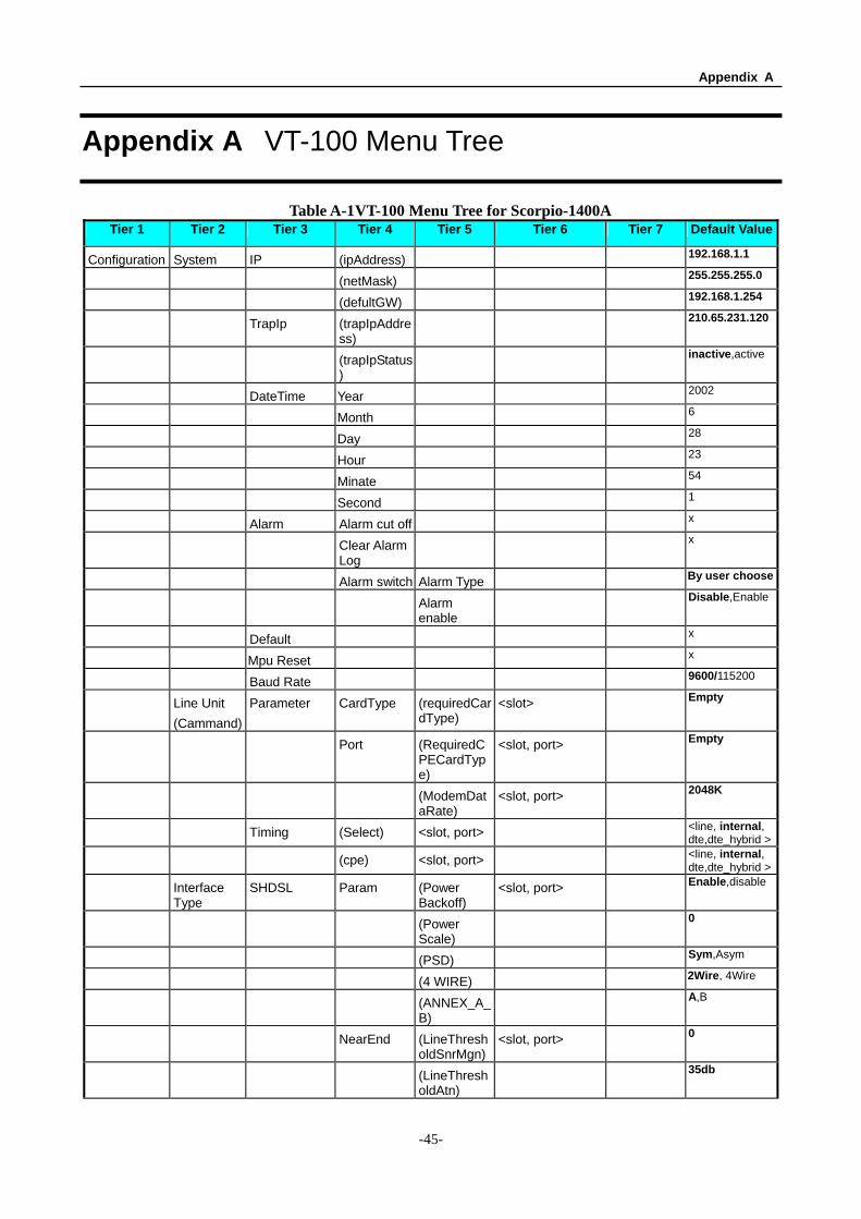
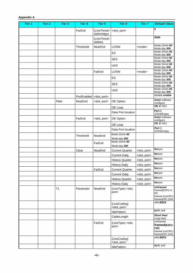
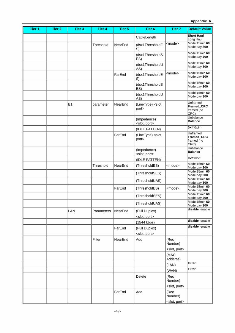
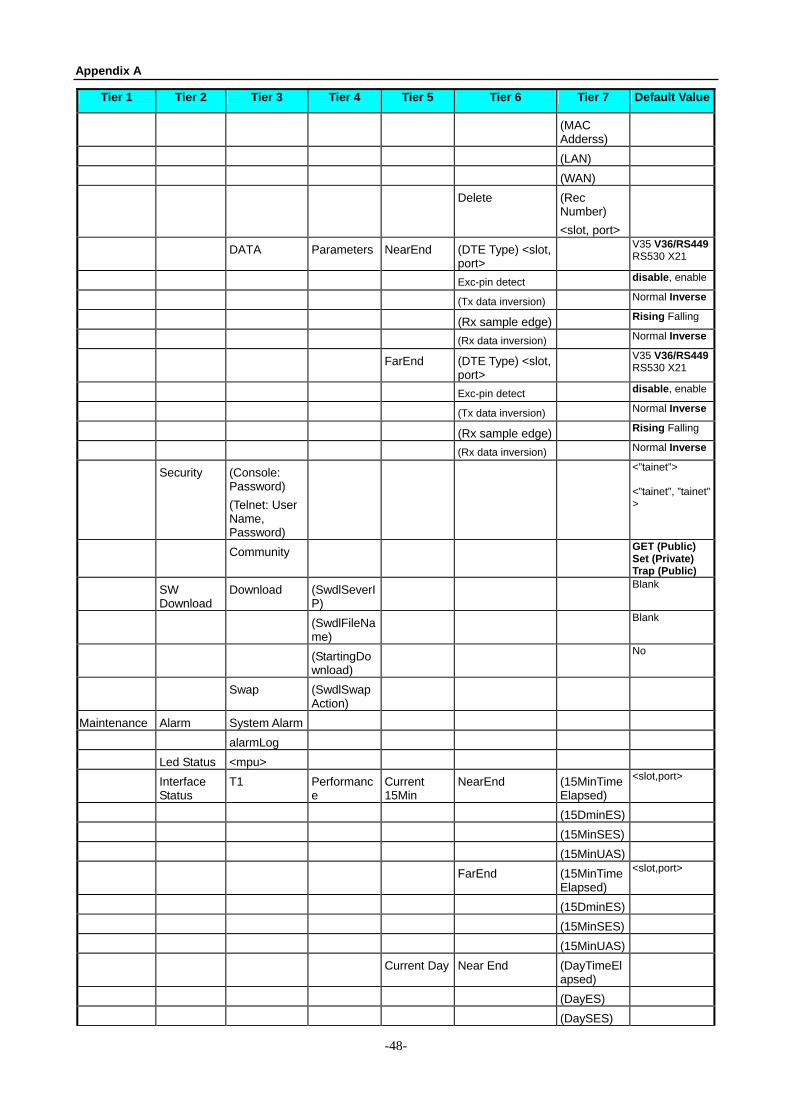
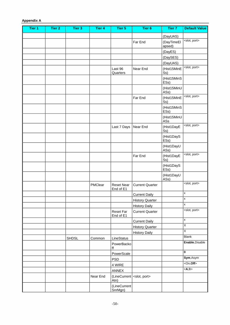
Appendix A VT-100 Menu Tree
Table A-1 VT-100 Menu Tree for Scorpio-1400A Tier 1 Tier 2 Tier 3 Tier 4 Tier 5 Tier 6 Tier 7 Default Value
Configuration System IP (ipAddress) 192.168.1.1
(netMask) 255.255.255.0
(defultGW) 192.168.1.254
TrapIp (trapIpAddress)
210.65.231.120
(trapIpStatus)
inactive,active
DateTime Year 2002
Month 6
Day 28
Hour 23
Minate 54
Second 1
Alarm Alarm cut off x
Clear Alarm Log
x
Alarm switch Alarm Type By user choose
Alarm enable
Disable,Enable
Default x
Mpu Reset x
Baud Rate 9600/115200
Line Unit (Cammand)
Parameter CardType (requiredCardType)
<slot> Empty
Port (RequiredCPECardType)
<slot, port> Empty
(ModemDataRate)
<slot, port> 2048K
Timing (Select) <slot, port> <line, internal, dte,dte_hybrid >
(cpe) <slot, port> <line, internal, dte,dte_hybrid >
Interface Type
SHDSL Param (Power Backoff)
<slot, port> Enable,disable
(Power Scale)
0
(PSD) Sym,Asym
(4 WIRE) 2Wire, 4Wire
(ANNEX_A_B)
A,B
NearEnd (LineThresholdSnrMgn)
<slot, port> 0
(LineThresholdAtn)
35db
Appendix A
-46-
Tier 1 Tier 2 Tier 3 Tier 4 Tier 5 Tier 6 Tier 7 Default Value
FarEnd (LineThresholdSnrMgn)
<slot, port> 0
(LineThresholdAtn)
35db
Threshold NearEnd LOSW <mode> Mode:15min 60Mode:day 300
ES Mode:15min 60Mode:day 300
SES Mode:15min 60Mode:day 300
UAS Mode:15min 60Mode:day 300
FarEnd LOSW <mode> Mode:15min 60Mode:day 300
ES Mode:15min 60Mode:day 300
SES Mode:15min 60Mode:day 300
UAS Mode:15min 60Mode:day 300
PortEnabled <slot, port> disable,enable
Fiber NearEnd <slot, port> OE Option Auto/ software configure
OE Loop OE 1/ OE2
Data Port location Port 1 /2/3/4/Empty
FarEnd <slot, port> OE Option Auto/ software configure
OE Loop OE 1/ OE2
Data Port location Port 1 /2/3/4/Empty
Threshold NearEnd Mode:15min 60 Mode:day 300
FarEnd Mode:15min 60 Mode:day 300
Clear NearEnd Current Quarter <slot, port> No/yes
Current Daily <slot, port> No/yes
History Quarter <slot, port> No/yes
History Daily <slot, port> No/yes
FarEnd Current Quarter <slot, port> No/yes
Current Daily <slot, port> No/yes
History Quarter <slot, port> No/yes
History Daily <slot, port> No/yes
T1 Parameter NearEnd (LineType) <slot, port>
Unframed framed(ESF)+CRC framed (noCRC)framed(SF) (D4)
(LineCoding) <slot, port>
AMI,B8ZS
IdlePattern 0x7f, 0xff
CableLength Short Haul Long Haul
FarEnd (LineType) <slot, port>
Unframed framed(ESF)+CRC framed (noCRC)framed(SF) (D4)
(LineCoding) <slot, port>
AMI,B8ZS
IdlePattern 0x7f, 0xff
Appendix A
-47-
Tier 1 Tier 2 Tier 3 Tier 4 Tier 5 Tier 6 Tier 7 Default Value
CableLength Short Haul Long Haul
Threshold NearEnd (dsx1ThresholdES)
<mode> Mode:15min 60Mode:day 300
(dsx1ThresholdSES)
Mode:15min 60Mode:day 300
(dsx1ThresholdUAS)
Mode:15min 60Mode:day 300
FarEnd (dsx1ThresholdES)
<mode> Mode:15min 60Mode:day 300
(dsx1ThresholdSES)
Mode:15min 60Mode:day 300
(dsx1ThresholdUAS)
Mode:15min 60Mode:day 300
E1 parameter NearEnd (LineType) <slot, port>
Unframed Framed_CRC framed (no CRC)
(Impedance) <slot, port>
Unbalance Balance
(IDLE PATTEN) 0xff,0x7f
FarEnd (LineType) <slot, port>
Unframed Framed_CRC framed (no CRC)
(Impedance) <slot, port>
Unbalance Balance
(IDLE PATTEN) 0xff,0x7f
Threshold NearEnd (ThresholdES) <mode> Mode:15min 60Mode:day 300
(ThresholdSES) Mode:15min 60Mode:day 300
(ThresholdUAS) Mode:15min 60Mode:day 300
FarEnd (ThresholdES) <mode> Mode:15min 60Mode:day 300
(ThresholdSES) Mode:15min 60Mode:day 300
(ThresholdUAS) Mode:15min 60Mode:day 300
LAN Parameters NearEnd (Full Duplex) <slot, port>
disable, enable
(1544 kbps) disable, enable
FarEnd (Full Duplex) <slot, port>
disable, enable
Filter NearEnd Add (Rec Number) <slot, port>
(MAC Adderss)
(LAN) Filter
(WAN) Filter
Delete (Rec Number) <slot, port>
FarEnd Add (Rec Number) <slot, port>
Appendix A
-48-
Tier 1 Tier 2 Tier 3 Tier 4 Tier 5 Tier 6 Tier 7 Default Value
(MAC Adderss)
(LAN)
(WAN)
Delete (Rec Number) <slot, port>
DATA Parameters NearEnd (DTE Type) <slot, port>
V35 V36/RS449 RS530 X21
Exc-pin detect disable, enable
(Tx data inversion) Normal Inverse
(Rx sample edge) Rising Falling
(Rx data inversion) Normal Inverse
FarEnd (DTE Type) <slot, port>
V35 V36/RS449 RS530 X21
Exc-pin detect disable, enable
(Tx data inversion) Normal Inverse
(Rx sample edge) Rising Falling
(Rx data inversion) Normal Inverse
Security (Console: Password) (Telnet: User Name, Password)
<”tainet”> <”tainet”, ”tainet”>
Community GET (Public) Set (Private) Trap (Public)
SW Download
Download (SwdlSeverIP)
Blank
(SwdlFileName)
Blank
(StartingDownload)
No
Swap (SwdlSwapAction)
Maintenance Alarm System Alarm
alarmLog
Led Status <mpu>
Interface Status
T1 Performance
Current 15Min
NearEnd (15MinTimeElapsed)
<slot,port>
(15DminES)
(15MinSES)
(15MinUAS)
FarEnd (15MinTimeElapsed)
<slot,port>
(15DminES)
(15MinSES)
(15MinUAS)
Current Day Near End (DayTimeElapsed)
(DayES)
(DaySES)
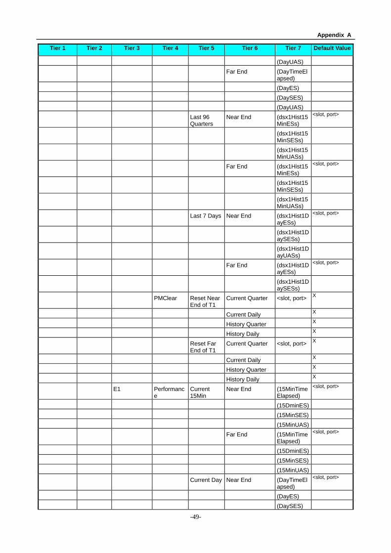
Appendix A
-49-
Tier 1 Tier 2 Tier 3 Tier 4 Tier 5 Tier 6 Tier 7 Default Value
(DayUAS)
Far End (DayTimeElapsed)
(DayES)
(DaySES)
(DayUAS)
Last 96 Quarters
Near End (dsx1Hist15MinESs)
<slot, port>
(dsx1Hist15MinSESs)
(dsx1Hist15MinUASs)
Far End (dsx1Hist15MinESs)
<slot, port>
(dsx1Hist15MinSESs)
(dsx1Hist15MinUASs)
Last 7 Days Near End (dsx1Hist1DayESs)
<slot, port>
(dsx1Hist1DaySESs)
(dsx1Hist1DayUASs)
Far End (dsx1Hist1DayESs)
<slot, port>
(dsx1Hist1DaySESs)
PMClear Reset Near End of T1
Current Quarter <slot, port> X
Current Daily X
History Quarter X
History Daily X
Reset Far End of T1
Current Quarter <slot, port> X
Current Daily X
History Quarter X
History Daily X
E1 Performance
Current 15Min
Near End (15MinTimeElapsed)
<slot, port>
(15DminES)
(15MinSES)
(15MinUAS)
Far End (15MinTimeElapsed)
<slot, port>
(15DminES)
(15MinSES)
(15MinUAS)
Current Day Near End (DayTimeElapsed)
<slot, port>
(DayES)
(DaySES)
Appendix A
-50-
Tier 1 Tier 2 Tier 3 Tier 4 Tier 5 Tier 6 Tier 7 Default Value
(DayUAS)
Far End (DayTimeElapsed)
<slot, port>
(DayES)
(DaySES)
(DayUAS)
Last 96 Quarters
Near End (Hist15MinESs)
<slot, port>
(Hist15MinSESs)
(Hist15MinUASs)
Far End (Hist15MinESs)
<slot, port>
(Hist15MinSESs)
(Hist15MinUASs
Last 7 Days Near End (Hist1DayESs)
<slot, port>
(Hist1DaySESs)
(Hist1DayUASs)
Far End (Hist1DayESs)
<slot, port>
(Hist1DaySESs)
(Hist1DayUASs)
PMClear Reset Near End of E1
Current Quarter <slot, port>
Current Daily x
History Quarter x
History Daily x
Reset Far End of E1
Current Quarter <slot, port>
Current Daily x
History Quarter X
History Daily X
SHDSL Common LineStatus Blank
PowerBackoff
Enable,Disable
PowerScale 0
PSD Sym,Asym
4 WIRE <On,Off>
ANNEX <A,B>
Near End (LineCurrentAtn)
<slot, port>
(LineCurrentSnrMgn)
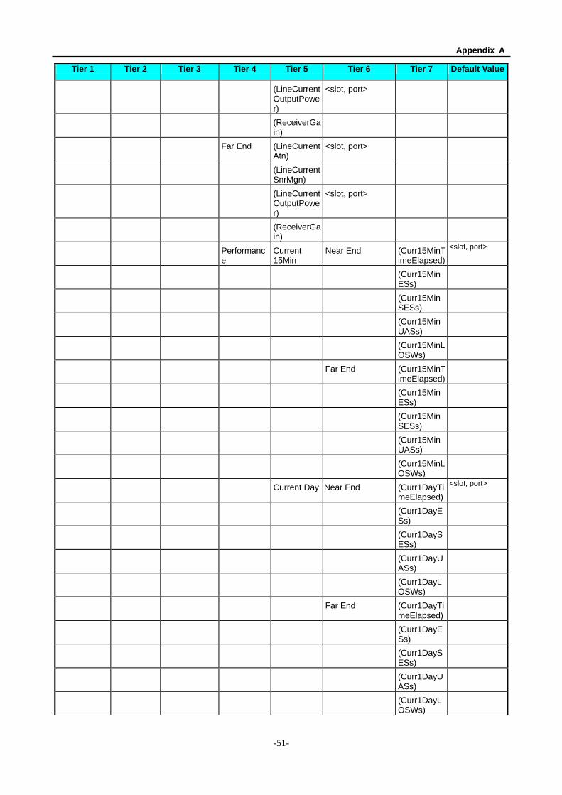
Appendix A
-51-
Tier 1 Tier 2 Tier 3 Tier 4 Tier 5 Tier 6 Tier 7 Default Value
(LineCurrentOutputPower)
<slot, port>
(ReceiverGain)
Far End (LineCurrentAtn)
<slot, port>
(LineCurrentSnrMgn)
(LineCurrentOutputPower)
<slot, port>
(ReceiverGain)
Performance
Current 15Min
Near End (Curr15MinTimeElapsed)
<slot, port>
(Curr15MinESs)
(Curr15MinSESs)
(Curr15MinUASs)
(Curr15MinLOSWs)
Far End (Curr15MinTimeElapsed)
(Curr15MinESs)
(Curr15MinSESs)
(Curr15MinUASs)
(Curr15MinLOSWs)
Current Day Near End (Curr1DayTimeElapsed)
<slot, port>
(Curr1DayESs)
(Curr1DaySESs)
(Curr1DayUASs)
(Curr1DayLOSWs)
Far End (Curr1DayTimeElapsed)
(Curr1DayESs)
(Curr1DaySESs)
(Curr1DayUASs)
(Curr1DayLOSWs)
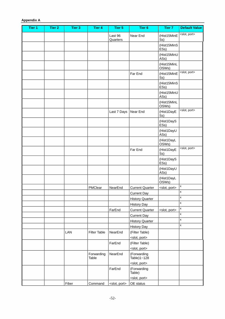
Appendix A
-52-
Tier 1 Tier 2 Tier 3 Tier 4 Tier 5 Tier 6 Tier 7 Default Value
Last 96 Quarters
Near End (Hist15MinESs)
<slot, port>
(Hist15MinSESs)
(Hist15MinUASs)
(Hist15MinLOSWs)
Far End (Hist15MinESs)
<slot, port>
(Hist15MinSESs)
(Hist15MinUASs)
(Hist15MinLOSWs)
Last 7 Days Near End (Hist1DayESs)
<slot, port>
(Hist1DaySESs)
(Hist1DayUASs)
(Hist1DayLOSWs)
Far End (Hist1DayESs)
<slot, port>
(Hist1DaySESs)
(Hist1DayUASs)
(Hist1DayLOSWs)
PMClear NearEnd Current Quarter <slot, port> x
Current Day x
History Quarter x
History Day x
FarEnd Current Quarter <slot, port> x
Current Day x
History Quarter x
History Day x
LAN Filter Table NearEnd (Filter Table) <slot, port>
FarEnd (Filter Table) <slot, port>
Forwarding Table
NearEnd (Forwarding Table)1~128 <slot, port>
FarEnd (Forwarding Table) <slot, port>
Fiber Command <slot, port> OE status
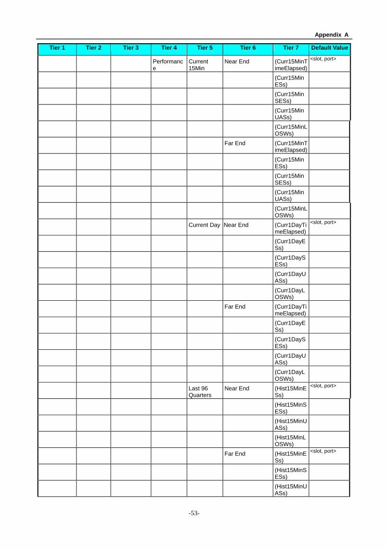
Appendix A
-53-
Tier 1 Tier 2 Tier 3 Tier 4 Tier 5 Tier 6 Tier 7 Default Value
Performance
Current 15Min
Near End (Curr15MinTimeElapsed)
<slot, port>
(Curr15MinESs)
(Curr15MinSESs)
(Curr15MinUASs)
(Curr15MinLOSWs)
Far End (Curr15MinTimeElapsed)
(Curr15MinESs)
(Curr15MinSESs)
(Curr15MinUASs)
(Curr15MinLOSWs)
Current Day Near End (Curr1DayTimeElapsed)
<slot, port>
(Curr1DayESs)
(Curr1DaySESs)
(Curr1DayUASs)
(Curr1DayLOSWs)
Far End (Curr1DayTimeElapsed)
(Curr1DayESs)
(Curr1DaySESs)
(Curr1DayUASs)
(Curr1DayLOSWs)
Last 96 Quarters
Near End (Hist15MinESs)
<slot, port>
(Hist15MinSESs)
(Hist15MinUASs)
(Hist15MinLOSWs)
Far End (Hist15MinESs)
<slot, port>
(Hist15MinSESs)
(Hist15MinUASs)
Appendix A
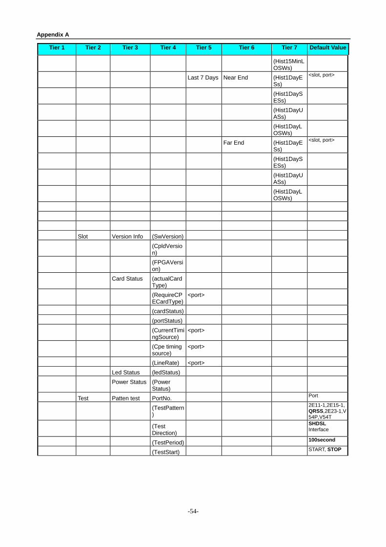
-54-
Tier 1 Tier 2 Tier 3 Tier 4 Tier 5 Tier 6 Tier 7 Default Value
(Hist15MinLOSWs)
Last 7 Days Near End (Hist1DayESs)
<slot, port>
(Hist1DaySESs)
(Hist1DayUASs)
(Hist1DayLOSWs)
Far End (Hist1DayESs)
<slot, port>
(Hist1DaySESs)
(Hist1DayUASs)
(Hist1DayLOSWs)
Slot Version Info (SwVersion)
(CpldVersion)
(FPGAVersion)
Card Status (actualCardType)
(RequireCPECardType)
<port>
(cardStatus)
(portStatus)
(CurrentTimingSource)
<port>
(Cpe timing source)
<port>
(LineRate) <port>
Led Status (ledStatus)
Power Status (Power Status)
Test Patten test PortNo. Port
(TestPattern)
2E11-1,2E15-1,QRSS,2E23-1,V54P,V54T
(Test Direction)
SHDSL Interface
(TestPeriod) 100second
(TestStart) START, STOP
Appendix A
-55-
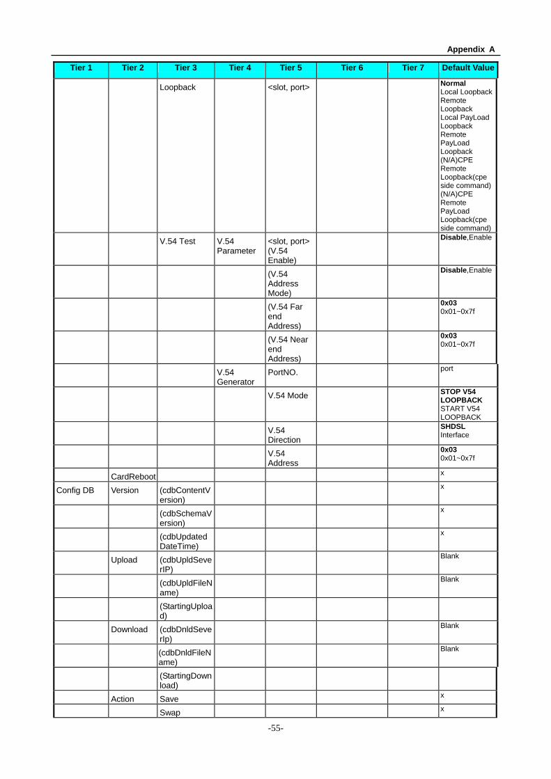
Tier 1 Tier 2 Tier 3 Tier 4 Tier 5 Tier 6 Tier 7 Default Value
Loopback <slot, port> Normal Local LoopbackRemote Loopback Local PayLoad Loopback Remote PayLoad Loopback (N/A)CPE Remote Loopback(cpe side command)(N/A)CPE Remote PayLoad Loopback(cpe side command)
V.54 Test V.54 Parameter
<slot, port> (V.54 Enable)
Disable,Enable
(V.54 Address Mode)
Disable,Enable
(V.54 Far end Address)
0x03 0x01~0x7f
(V.54 Near end Address)
0x03 0x01~0x7f
V.54 Generator
PortNO. port
V.54 Mode STOP V54 LOOPBACK START V54 LOOPBACK
V.54 Direction
SHDSL Interface
V.54 Address
0x03 0x01~0x7f
CardReboot x
Config DB Version (cdbContentVersion)
x
(cdbSchemaVersion)
x
(cdbUpdatedDateTime)
x
Upload (cdbUpldSeverIP)
Blank
(cdbUpldFileName)
Blank
(StartingUpload)
Download (cdbDnldSeverIp)
Blank
(cdbDnldFileName)
Blank
(StartingDownload)
Action Save x
Swap x
Appendix A
-56-
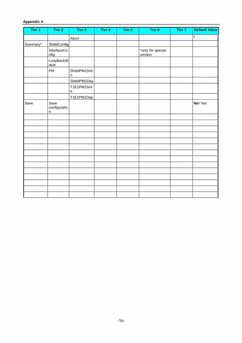
Tier 1 Tier 2 Tier 3 Tier 4 Tier 5 Tier 6 Tier 7 Default Value
Abort x
Summary* ShdslConfig InterfaceCo
nfig *only for special
version
LoopBackStatus
PM ShdslPM15min
ShdslPM1Day T1E1PM15mi
n
T1E1PM1Day Save Save
configuration
No/ Yes
Appendix B
-57-
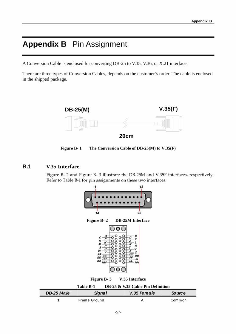
Appendix B Pin Assignment
A Conversion Cable is enclosed for converting DB-25 to V.35, V.36, or X.21 interface.
There are three types of Conversion Cables, depends on the customer’s order. The cable is enclosed in the shipped package.
DB-25(M) V.35(F)
20cm
Figure B- 1 The Conversion Cable of DB-25(M) to V.35(F)
B.1 V.35 Interface Figure B- 2 and Figure B- 3 illustrate the DB-25M and V.35F interfaces, respectively. Refer to Table B-1 for pin assignments on these two interfaces.
Figure B- 2 DB-25M Interface
Figure B- 3 V.35 Interface
Table B-1 DB-25 & V.35 Cable Pin Definition DB-25 Male Signal V.35 Female Source
1 Frame Ground A Common
Appendix B
-58-
7 Signal Ground B Common
4 Request to Send C DTE
5 Clear to Send D DCE
6 Data Set Ready E DCE
8 Data Carrier Detect F DCE
20 Data Terminal Ready H DTE
2 Transmit Data (A) P DTE
3 Receive Data (A) R DCE
14 Transmit Data (B) S DTE
16 Receive Data (B) T DCE
24 Terminal Timing (A) U DTE
17 Receive Timing (A) V DCE
11 Terminal Timing (B) W DTE
9 Receive Timing (B) X DCE
15 Terminal Timing (A) Y DCE
12 Terminal Timing (B) AA DCE
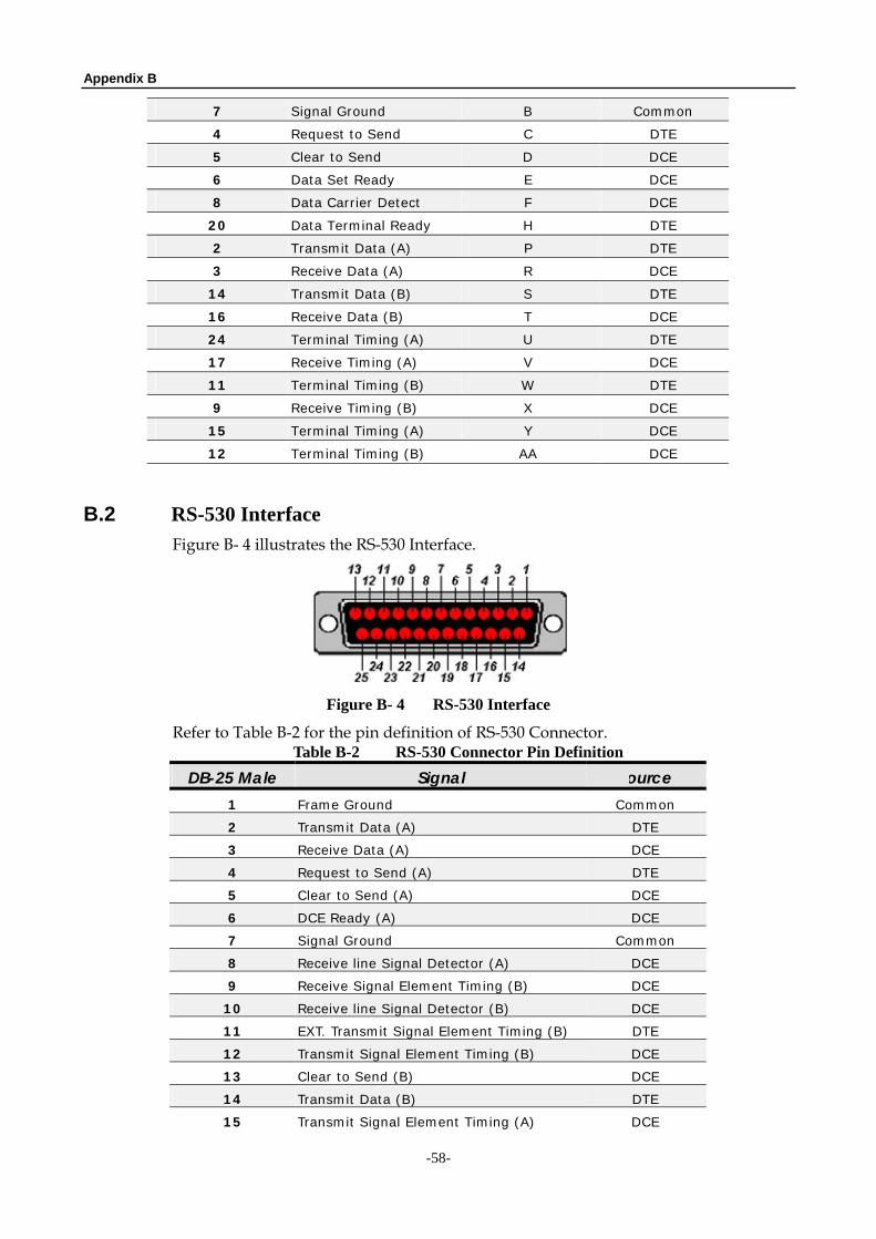
B.2 RS-530 Interface Figure B- 4 illustrates the RS-530 Interface.
Figure B- 4 RS-530 Interface
Refer to Table B-2 for the pin definition of RS-530 Connector. Table B-2 RS-530 Connector Pin Definition
DB-25 Male Signal Source 1 Frame Ground Common
2 Transmit Data (A) DTE
3 Receive Data (A) DCE
4 Request to Send (A) DTE
5 Clear to Send (A) DCE
6 DCE Ready (A) DCE
7 Signal Ground Common
8 Receive line Signal Detector (A) DCE
9 Receive Signal Element Timing (B) DCE
10 Receive line Signal Detector (B) DCE
11 EXT. Transmit Signal Element Timing (B) DTE
12 Transmit Signal Element Timing (B) DCE
13 Clear to Send (B) DCE
14 Transmit Data (B) DTE
15 Transmit Signal Element Timing (A) DCE
Appendix B
-59-
16 Receive Data (B) DCE
17 Receive Signal Element Timing (A) DCE
18
19 Request to Send (B) DTE
20 DTE Ready (A) DTE
21
22 DCE Ready (B) DCE
23 DTE Ready (B) DTE
24 EXT. Transmit Signal Element Timing (A) DTE
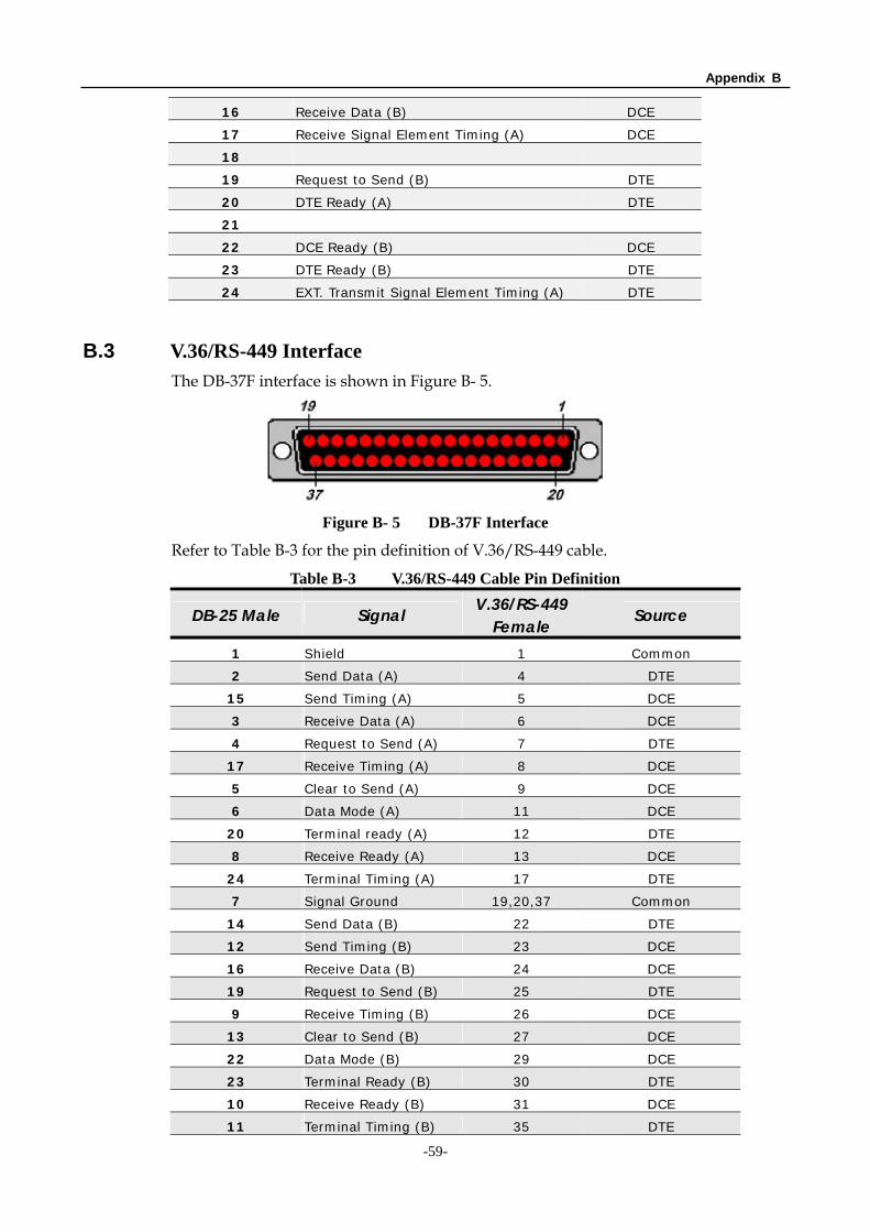
B.3 V.36/RS-449 Interface The DB-37F interface is shown in Figure B- 5.
Figure B- 5 DB-37F Interface
Refer to Table B-3 for the pin definition of V.36/RS-449 cable.
Table B-3 V.36/RS-449 Cable Pin Definition
DB-25 Male Signal V.36/RS-449 Female Source
1 Shield 1 Common
2 Send Data (A) 4 DTE
15 Send Timing (A) 5 DCE
3 Receive Data (A) 6 DCE
4 Request to Send (A) 7 DTE
17 Receive Timing (A) 8 DCE
5 Clear to Send (A) 9 DCE
6 Data Mode (A) 11 DCE
20 Terminal ready (A) 12 DTE
8 Receive Ready (A) 13 DCE
24 Terminal Timing (A) 17 DTE
7 Signal Ground 19,20,37 Common
14 Send Data (B) 22 DTE
12 Send Timing (B) 23 DCE
16 Receive Data (B) 24 DCE
19 Request to Send (B) 25 DTE
9 Receive Timing (B) 26 DCE
13 Clear to Send (B) 27 DCE
22 Data Mode (B) 29 DCE
23 Terminal Ready (B) 30 DTE
10 Receive Ready (B) 31 DCE
11 Terminal Timing (B) 35 DTE
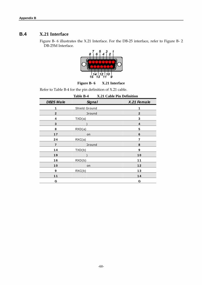
Appendix B
-60-
B.4 X.21 Interface Figure B- 6 illustrates the X.21 Interface. For the DB-25 interface, refer to Figure B- 2 DB-25M Interface.
Figure B- 6 X.21 Interface
Refer to Table B-4 for the pin definition of X.21 cable.
Table B-4 X.21 Cable Pin Definition DB25 Male Signal X.21 Female
1 Shield Ground 1
2 Signal Ground 2
4 TXD(a) 3
3 CTRL(a) 4
8 RXD(a) 5
17 Indication 6
24 RXC(a) 7
7 Signal Ground 8
14 TXD(b) 9
19 CTRL(b) 10
16 RXD(b) 11
10 Indication 12
9 RXC(b) 13
11 EXC(b) 14
G G