schneider electric/square d trench duct - steven...
TRANSCRIPT

Trench DuctCatalog5230CT9601R10/08
2009Class 5230
CONTENTS
Application . . . . . . . . . . . . . . . . . . . . . . . . . . . . . . . . . . . . . . . . . . . . . . . . .5
Unassembled Trench Duct Components . . . . . . . . . . . . . . . . . . . . . . . . .6
Factory Assembled Trench Duct . . . . . . . . . . . . . . . . . . . . . . . . . . . . . .11
Accessories . . . . . . . . . . . . . . . . . . . . . . . . . . . . . . . . . . . . . . . . . . . . . . .14
Unassembled Rail-Way Trench Duct Specifications. . . . . . . . . . . . . . .18
Factory Assembled Rail-Way Trench Duct Specifications . . . . . . . . . .19
Courtesy of Steven Engineering, Inc.-230 Ryan Way, South San Francisco, CA 94080-6370-Main Office: (650) 588-9200-Outside Local Area: (800) 258-9200-www.stevenengineering.com

Courtesy of Steven Engineering, Inc.-230 Ryan Way, South San Francisco, CA 94080-6370-Main Office: (650) 588-9200-Outside Local Area: (800) 258-9200-www.stevenengineering.com
Trench Duct
301/2009© 1997–2009 Schneider Electric
All Rights Reserved
CONTENTS
APPLICATION ....................................................................................................................................... 5
Product Description ................................................................................................................... 5Standard Sizes and Types ........................................................................................................ 5
UNASSEMBLED TRENCH DUCT COMPONENTS .............................................................................. 6
Side Rail Assembly .................................................................................................................... 6U-Trough and Z-Dividers ........................................................................................................... 6Vertical Elbows and Risers with Cabinet Connectors ................................................................ 7Cover Plates .............................................................................................................................. 7Bottom Plates ............................................................................................................................ 7Support Post Strips .................................................................................................................... 8End Closures ............................................................................................................................. 8Spacer Bar and Partition Height Adjustment Gauge ......................................................................................................... 8Railway Trench Duct ................................................................................................................. 9Bottom Plates ............................................................................................................................ 9Cover Plates .............................................................................................................................. 9Bottom Plates for Elbows ........................................................................................................ 10Tee–RT .................................................................................................................................... 10Horizontal Elbow–RL ............................................................................................................... 10
FACTORY ASSEMBLED TRENCH DUCT.......................................................................................... 11
Tee .......................................................................................................................................... 12Cross ....................................................................................................................................... 12Horizontal Elbow ...................................................................................................................... 13
ACCESSORIES................................................................................................................................... 14
U-Compartment ....................................................................................................................... 14Z-Divider .................................................................................................................................. 14Support Post Strip ................................................................................................................... 14Vertical Elbow .......................................................................................................................... 15Panel Rise and Connector ....................................................................................................... 15End Closure ............................................................................................................................. 15Space Bar ................................................................................................................................ 15Leveling Legs .......................................................................................................................... 16Trench Duct Support Channel ................................................................................................. 16Tape ........................................................................................................................................ 16Plastic Grommets .................................................................................................................... 16Cover Lifter .............................................................................................................................. 16Straight Through Tunnel .......................................................................................................... 1790° Elbow Tunnel .................................................................................................................... 17
UNASSEMBLED RAIL-WAY TRENCH DUCT SPECIFICATIONS ..................................................... 18
FACTORY ASSEMBLED RAIL-WAY TRENCH DUCT SPECIFICATIONS ........................................ 19
Courtesy of Steven Engineering, Inc.-230 Ryan Way, South San Francisco, CA 94080-6370-Main Office: (650) 588-9200-Outside Local Area: (800) 258-9200-www.stevenengineering.com
© 1997–2009 Schneider ElectricAll Rights Reserved
Trench Duct
401/2009
Courtesy of Steven Engineering, Inc.-230 Ryan Way, South San Francisco, CA 94080-6370-Main Office: (650) 588-9200-Outside Local Area: (800) 258-9200-www.stevenengineering.com
Trench DuctApplication
501/2009© 1997–2009 Schneider Electric
All Rights Reserved
Application
Product Description
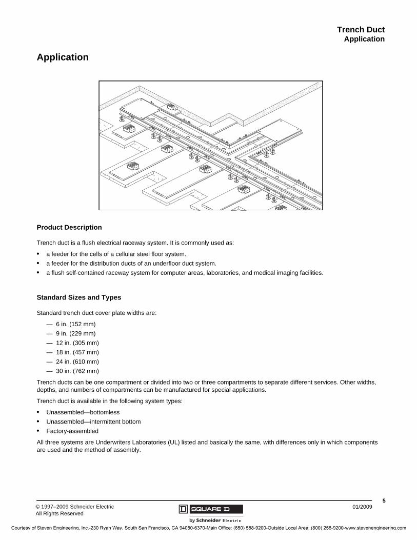
Trench duct is a flush electrical raceway system. It is commonly used as:
• a feeder for the cells of a cellular steel floor system.
• a feeder for the distribution ducts of an underfloor duct system.
• a flush self-contained raceway system for computer areas, laboratories, and medical imaging facilities.
Standard Sizes and Types
Standard trench duct cover plate widths are:
— 6 in. (152 mm)
— 9 in. (229 mm)
— 12 in. (305 mm)
— 18 in. (457 mm)
— 24 in. (610 mm)
— 30 in. (762 mm)
Trench ducts can be one compartment or divided into two or three compartments to separate different services. Other widths, depths, and numbers of compartments can be manufactured for special applications.
Trench duct is available in the following system types:
• Unassembled—bottomless
• Unassembled—intermittent bottom
• Factory-assembled
All three systems are Underwriters Laboratories (UL) listed and basically the same, with differences only in which components are used and the method of assembly.
Courtesy of Steven Engineering, Inc.-230 Ryan Way, South San Francisco, CA 94080-6370-Main Office: (650) 588-9200-Outside Local Area: (800) 258-9200-www.stevenengineering.com

Trench DuctUnassembled Trench Duct Components
© 1997–2009 Schneider ElectricAll Rights Reserved
601/2009
Unassembled Trench Duct Components
Side Rail Assembly
Side rail assemblies are the heart of the railway system. They are furnished in 10 ft. (3 m) lengths and are positioned opposite each other by the use of spacer bars to form the various widths of trench duct. Side rails are coupled together and aligned by a wraparound coupler and aligner. Two screws in the coupler engage abutting side rails and assure continuity of ground.
The side rail assemblies have a full 1 in. (25 mm) of height adjust.
• 2.375–3.375 in. adjustability(60–86 mm) for 2.5 in. (64 mm) deep trench
• 3-4 in. adjustability (76–102 mm) for 3.25 in. (83 mm) deep trench
Side rail assemblies have a longitudinal slot along the full length of the extrusion to accept the cover plate hold-down screws. This permits cover plates to be placed anywhere along the run of trench without the restriction of fixed cover plate screw-hole locations. The bottom flange of this assembly forms a continuous weld tab along the entire length of the trench.
U-Trough and Z-Dividers
Most trench duct systems contain wiring for more than one type of service. Separation of the various services must be maintained.
A U-trough is used as the power compartment in bottomless trench ducts with cellular floor systems.
The Z-divider is used in bottom type trench systems.
Courtesy of Steven Engineering, Inc.-230 Ryan Way, South San Francisco, CA 94080-6370-Main Office: (650) 588-9200-Outside Local Area: (800) 258-9200-www.stevenengineering.com

Trench DuctUnassembled Trench Duct Components
701/2009© 1997–2009 Schneider Electric
All Rights Reserved
Vertical Elbows and Risers with Cabinet Connectors
A vertical elbow is a short section of trench duct with a riser welded to it. A vertical elbow can be mounted directly onto the side rail assemblies of the trench duct. The longitudinal screw slot in the side rail assemblies allows for tolerance, thereby enabling an exact positioning of the elbow.
The riser is manufactured to slip-fit on the elbow. One face of the riser is removable, allowing easy access for pulling wire and cable. A matching cabinet connector is manufactured to slip-fit on the riser and attach to the underside of a standard depth power panel tub.
A riser and cabinet connector, used as a power feeder, always uses a vertical elbow. However, a riser and cabinet connector are seldom used as a telephone feeder. Open telephone cabling from the vertical elbow to a terminal board is permissible and most often preferable.
Cover Plates
Cover plates are made of 0.25 in. (6 mm) nominal thickness steel, phosphatized with a baked enamel finish. Cover plate screw holes accommodate a 0.12 in. (3 mm) high pan-head screw for tile floor finishes, or flat head screws that finish flush for carpet installations. Screw holes in the opposite corners are threaded so that a 0.37 in. (10 mm) lifting bolt can be used for removing and replacing covers. Suction cups can also be used to remove covers.
Bottom Plates
Bottom plates are 5 ft. (1.5 m) long for ease of handling and are manufactured of 14-gauge galvanized steel. The width of the bottom plates is 3 in. (76 mm) wider than the cover plates.
Courtesy of Steven Engineering, Inc.-230 Ryan Way, South San Francisco, CA 94080-6370-Main Office: (650) 588-9200-Outside Local Area: (800) 258-9200-www.stevenengineering.com

Trench DuctUnassembled Trench Duct Components
© 1997–2009 Schneider ElectricAll Rights Reserved
801/2009
Spacer Bar and Partition Height Adjustment Gauge
The space bar is used to establish exact width by placing two pins in either end of the bar to which engages the cover plate screw slot. After the side rail assemblies are adjusted to proper height, you can reverse the bar (with the pins up) to become a gauge for accurate partition adjustment.
Support Post Strips
Underwriters Laboratories permits 16.125 in. (409 mm) of free support span for cover plates.This is to control the amount of deflection and permanent set encountered in normal office floor loadings. The support post strip is available (where needed) to provide intermediate support in bottomless trench duct.
The support posts are mounted on a 5 ft. (1.5 m) channel and are adjustable to the underside of the cover plate. A nut locks the post firmly in place. The adjustable support posts are welded directly to the trench bottom plate in the factory-assembled bottom-type trench.
End Closures
End closures, by design, close the end of a system run. They have a “0” length, thereby causing no field application problems related to length of runs. The end closure screws into the slot provided in the side rail assembly.
The slot has an upward and downward adjustment to correspond to the adjustment of the side rail assemblies.
Courtesy of Steven Engineering, Inc.-230 Ryan Way, South San Francisco, CA 94080-6370-Main Office: (650) 588-9200-Outside Local Area: (800) 258-9200-www.stevenengineering.com

Trench DuctUnassembled Trench Duct Components
901/2009© 1997–2009 Schneider Electric
All Rights Reserved
1. Cover plate screw slot
2. Cover plate gasket
3. 0.125 in. (3 mm) or 0.0625 in. (2 mm) Wide – reversible tile trim
4. Adjusting screw - 5 per rail
5. Concrete locking lug
Cover Plates
1. 0.25 in. (6 mm) nominal thick steel plates
2. Four clearance holes for cover plate hold-down screws. Two are tapped for the use of a 0.375 in. (10 mm) bolt as a lifting device
3. Gasket support
NOTE: 12 in. (305 mm) long coverplates are available.
Railway Trench Duct
Use 10 ft. (3 m) long trench duct rail assemblies and other components listed below to field-assemble trench duct to fit specific job requirements. Side rail assemblies can be field cut to meet job conditions. Cover plates are shipped separately. Longitudinal slot for cover plate screws in side rail assembly permits random placement of cover plates. Cover plates are a standard 2 ft. (0.61 m) long and can be modified to suit odd lengths of trench duct runs. Spacer bars assure correct width and partition height adjustment. Illustrated installation instructions are included with all orders.
Catalog Number RS-120
.120.00 in.3048 mm
Catalog NumberWeight
Lbs. Kg.
RS-120 20.0 10
For device with 3–4 in. (76–102 mm) adjustment range, add -3 suffix (RS120-3)
1 2 3
4
5
Adjustable2.38–3.38 in.60–86 mm
1.50 in38 mm
.38 in.10 mm
.25 in.6 mm
Catalog NumberWidth-W Length-L
in. mm in. mm
RCP0624 6 152 24 610
RCP0924 9 229 24 610
RCP1224 12 305 24 610
RCP1824 18 457 24 610
RCP2424 24 610 24 610
RCP3024 30 762 24 610
Catalog NumberWidth-W Length-L
in. mm in. mm
RB06-60 9 228 60 1524
RB09-60 12 305 60 1524
RB12-60 15 381 60 1524
RB18-60 21 533 60 1524
RB24-60 27 686 60 1524
RB30-60 33 838 60 1524
Bottom Plates
L
W
Courtesy of Steven Engineering, Inc.-230 Ryan Way, South San Francisco, CA 94080-6370-Main Office: (650) 588-9200-Outside Local Area: (800) 258-9200-www.stevenengineering.com

Trench DuctUnassembled Trench Duct Components
© 1997–2009 Schneider ElectricAll Rights Reserved
1001/2009
NOTE: All holes are 0.312 in. (8 mm) in. diameterBottom Plates for Elbows
20.10 sq. ft.1.87 sq. m
21.00 sq. ft. 1.95 sq. m
14.10 sq. ft.1.3 sq. m
15.00 sq.ft. 1.40 sq.m
14.10 sq. ft.1.30 sq. m
26.10 sq. ft. 1.87 sq. m
27.00 sq. ft. 2.50 sq. m
14.10 sq. ft. 1.3 sq. m
20.10 sq. ft. 1.95 sq. m
45.00 sq. ft. 4.8 sq. m
Catalog Number RTLB12 Catalog Number RTLB18 Catalog Number RTLB24
.45 in.11 mm
.1.50 in.38 mm
1.00 in.25 mm
.Adjustable:2.35–3.38 in. 60–86 mm
Tee–RT When a RT25 or RT3 is ordered, the two corner assemblies shown are furnished.
1.00 in.25 mm
.45 in.11 mm
.1.50 in.38 mm
.Adjustable:2.35–3.38 in.60–86 mm
2.27 in.58 mm
Horizontal Elbow–RL When a RL is ordered, the two corner assemblies are shown shipped.
Courtesy of Steven Engineering, Inc.-230 Ryan Way, South San Francisco, CA 94080-6370-Main Office: (650) 588-9200-Outside Local Area: (800) 258-9200-www.stevenengineering.com

Trench DuctFactory Assembled Trench Duct
1101/2009© 1997–2009 Schneider Electric
All Rights Reserved
Factory Assembled Trench Duct
1. Standard length of trench duct is 10 ft. (3 m). Cover plates are shipped separately.
2. Features of trench duct are as follows:
a. Trench duct width is cover plate width.
b. Tub width is trench duct width less 1.875 in. (48 mm).
c. Overall width (bottom flange to flange) is 3 in. (76 mm) wider than trench duct width.
d. Standard depth is adjustable from 2.375–3.375 in. (61–86 mm). Also available as standard depth adjustable from 3–4 in. (76–102 mm). Other depths available.
e. Tees, crosses, and horizontal elbows are shipped complete with cover plates assembled.
f. Gray vinyl tile trim is furnished as standard. Aluminum is available when requested.
3. The following features are available:
a. Cover plate support post.
b. Double tile trim on two sides of covers.
c. Double tile trim on four sides of covers.
d. Tunnels in horizontal elbows, tees and crosses
A
B
C
Assembly has a 1 in. adjustment. Standards are 2.375–3.375 in. (61–86 mm)2.5 in. (64 mm) depth and 3–4 in. (76–102 mm) for 3.25 in. (83 mm) depth.
Straight Length(Cover Plates shipped separately)
Straight Lengths
1. Cover plate screw slot
2. Cover plate gasket
3. Adjusting screw – 5 per rail
4. 0.125 in. (3 mm) wide – reversible tile trim
5. Concrete locking lug
6. Adjustable height partition
7. Plastic sound dampener
Adjustable
1 2
7 5
43
6
.50 in.13 mm
.3.75 in.10 mm
Trench Width
Cover Plate
Width–A
Bottom Plate
Width–B
TubWidth–C
Tub Assembly
Length
in. mm in. mm in. mm in. mm in. mm
6 152 6 152 9 229 4.10 104 120 3048
9 229 9 229 12 305 7.10 180 120 3048
12 305 12 305 15 381 10.10 257 120 3048
18 457 18 457 21 533 16.10 409 120 3048
24 610 24 610 27 686 22.10 561 120 3048
30 762 30 762 33 838 28.10 714 120 3048
Courtesy of Steven Engineering, Inc.-230 Ryan Way, South San Francisco, CA 94080-6370-Main Office: (650) 588-9200-Outside Local Area: (800) 258-9200-www.stevenengineering.com

Trench DuctFactory Assembled Trench Duct
© 1997–2009 Schneider ElectricAll Rights Reserved
1201/2009
Catalog Number
Width–W Length–L
in. mm in. mm
RCP0624 6 152 24 610
RCP0924 9 229 24 610
RCP1224 12 305 24 610
RCP1824 18 457 24 610
RCP2424 24 610 24 610
RCP3024 30 762 24 610
.50 in.13 mm
.25 in.6 mm
Cover Plates (ordered separately)
Section a-a
L
W
a
a
Catalog NumberWidth Weight
in. mm Lbs. Kg.
RTV 062100-011 6 152 8 4
RTV 092100-014 9 229 16 7
RTV 122100-017 12 305 24 11
RTV 182100-023 18 457 44 20
RTV 242100-029 24 610 71 32
RTV 302100-035 30 712 111 50
Tee
A
B
Catalog NumberWidth Weight
in. mm Lbs. Kg.
RXV 062100-012 6 152 15 7
RXV 092100-015 9 229 19 9
RXV 122100-018 12 305 23 10
RXV 182100-024 18 457 42 19
RXV 242100-030 24 610 68 31
RXV 302100-036 30 712 106 48
Cross
B
A
Courtesy of Steven Engineering, Inc.-230 Ryan Way, South San Francisco, CA 94080-6370-Main Office: (650) 588-9200-Outside Local Area: (800) 258-9200-www.stevenengineering.com

Trench DuctFactory Assembled Trench Duct
1301/2009© 1997–2009 Schneider Electric
All Rights Reserved
Trench WidthCover Plate
Width–ABottom Plate
Width–BTub
Width–C
in. mm in. mm in. mm in. mm
6 152 6 152 9 229 4.10 104
9 229 9 229 12 305 7.10 180
12 305 12 305 15 381 10.10 257
18 457 18 457 21 533 16.10 409
24 610 24 610 27 686 22.10 561
30 762 30 762 33 838 28.10 714
Cover plates are furnished in place as part of these devices
Catalog NumberWidth Weight
in. mm Lbs. Kg.
RHV 062100-009 6 152 8 4
RHV 092100-012 9 229 15 7
RHV 122100-015 12 305 23 10
RHV 182100-021 18 457 43 20
RHV 242100-027 24 610 70 32
RHV 302100-033 30 712 100 45
Horizontal Elbow
B
A
Courtesy of Steven Engineering, Inc.-230 Ryan Way, South San Francisco, CA 94080-6370-Main Office: (650) 588-9200-Outside Local Area: (800) 258-9200-www.stevenengineering.com

Trench DuctAccessories
© 1997–2009 Schneider ElectricAll Rights Reserved
1401/2009
Accessories
NOTE: All part numbers shown are for use with trench duct that is adjustable from 2.37–3.37 in. (61–86 mm). For devices to be used with 3–4 in. (76–102 mm) adjustable trench, add -3 suffix to all part numbers shown.
Catalog Number
Weight
Lbs. Kg.
RUC-60 24 11
1. Plastic sound dampeners
2. Temporary 10–24 in. holding screw for adjustable partitions
3.50 in. 89 mm
1
2
.50 in.13 mm
Adjustable2.13–3.13 in.54–80 mm
U-Compartment
60.00 in.1524 mm
Catalog Number
Weight
Lbs. Kg.
RZD-60 10 5
1
2
.50 in. 13 mm
Adjustable2.13–3.13 in. 54–80 mm
Z-Divider
1. Plastic sound dampeners
2. Temporary holding screw for adjustable partitions
60.00 in.1524 mm
1
2
Adjustable2.13–3.13 in.54–80 mm
Support Post Strip
1. Support post screw
2. Lock nut
Catalog Number
Weight
Lbs. Kg.
RSP-60 6 3
60.00 in.1524 mm
Courtesy of Steven Engineering, Inc.-230 Ryan Way, South San Francisco, CA 94080-6370-Main Office: (650) 588-9200-Outside Local Area: (800) 258-9200-www.stevenengineering.com

Trench DuctAccessories
1501/2009© 1997–2009 Schneider Electric
All Rights Reserved
Catalog NumberWidth
in. mm
RVE-06 6 152
RVE-09 9 229
RVE-12 12 305
RVE-18 18 457
RVE-24 24 610
RVE-30 30 762
Vertical Elbow
6.00 in. 152 mm
W
W4.00 in.102 mm
6.00 in. 152 mm
3.50 in.89 mm
RVE-09
Panel Rise and Connector
5.00 in.127 mm
W
W+80 in.20 mm
Adjustable46.00–50.00 in.1168–1270 mm
Catalog NumberWidth
in. mm
RRC-06 2 51
RRC-09 5 127
RRC-12 8 203
RRC-18 14 356
RRC-24 20 508
RRC-30 26 660
RRC-09
End Closure
W
W +3.20 in.81 mm
Adjustable2.30–3.30 in.58–84 mm
Catalog Number
Width
in. mm
REC-06 6.50 165
REC-09 9.50 241
REC-12 12.50 318
REC-18 18.50 470
REC-24 24.50 622
REC-30 30.50 775
REC-09
L
Space Bar
L+2.20 in.56 mm
1.50 in.38 mm
Catalog Number
Length-L
in. mm
RSB-06 4 102
RSB-09 7 178
RSB-12 10 254
RSB-18 16 406
RSB-24 22 569
RSB-30 28 711
RSB-09
Courtesy of Steven Engineering, Inc.-230 Ryan Way, South San Francisco, CA 94080-6370-Main Office: (650) 588-9200-Outside Local Area: (800) 258-9200-www.stevenengineering.com
Trench DuctAccessories
© 1997–2009 Schneider ElectricAll Rights Reserved
1601/2009
Catalog Number
Description Weight
Lbs. Kg.
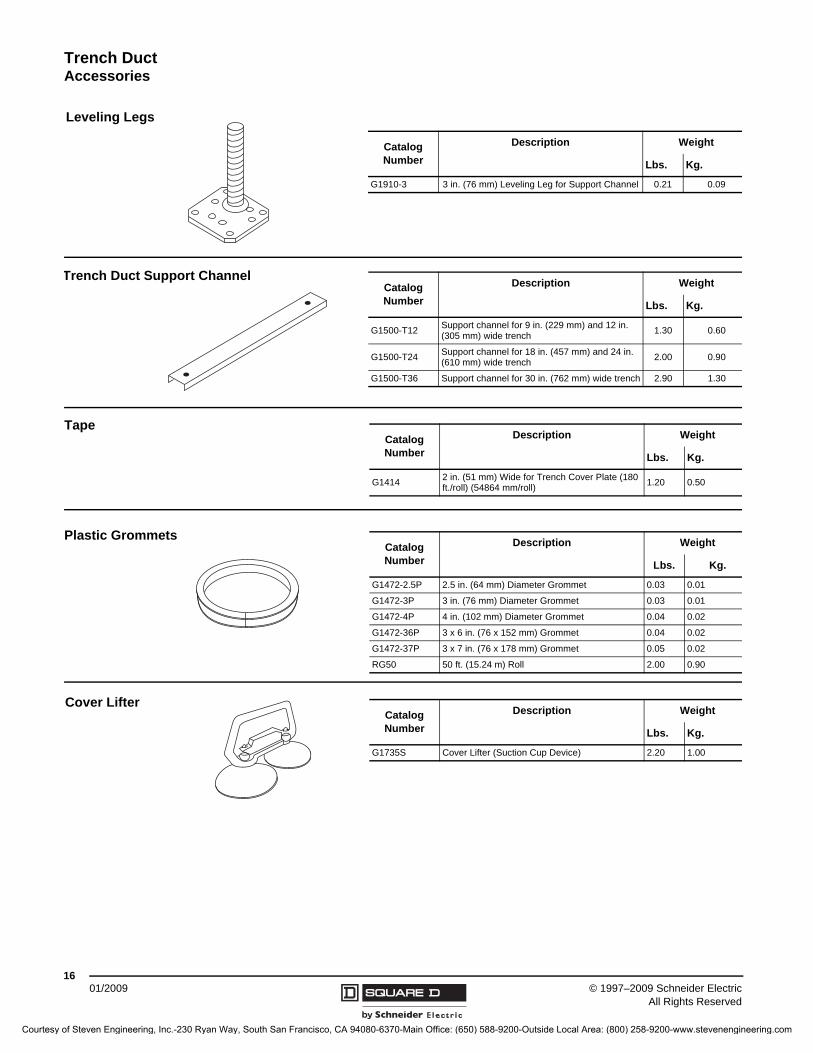
G1910-3 3 in. (76 mm) Leveling Leg for Support Channel 0.21 0.09
Leveling Legs
Catalog Number
Description Weight
Lbs. Kg.
G1500-T12Support channel for 9 in. (229 mm) and 12 in. (305 mm) wide trench
1.30 0.60
G1500-T24Support channel for 18 in. (457 mm) and 24 in. (610 mm) wide trench
2.00 0.90
G1500-T36 Support channel for 30 in. (762 mm) wide trench 2.90 1.30
Trench Duct Support Channel
Catalog Number
Description Weight
Lbs. Kg.
G14142 in. (51 mm) Wide for Trench Cover Plate (180 ft./roll) (54864 mm/roll)
1.20 0.50
Tape
Catalog Number
Description Weight
Lbs. Kg.
G1472-2.5P 2.5 in. (64 mm) Diameter Grommet 0.03 0.01
G1472-3P 3 in. (76 mm) Diameter Grommet 0.03 0.01
G1472-4P 4 in. (102 mm) Diameter Grommet 0.04 0.02
G1472-36P 3 x 6 in. (76 x 152 mm) Grommet 0.04 0.02
G1472-37P 3 x 7 in. (76 x 178 mm) Grommet 0.05 0.02
RG50 50 ft. (15.24 m) Roll 2.00 0.90
Plastic Grommets
Catalog Number
Description Weight
Lbs. Kg.
G1735S Cover Lifter (Suction Cup Device) 2.20 1.00
Cover Lifter
Courtesy of Steven Engineering, Inc.-230 Ryan Way, South San Francisco, CA 94080-6370-Main Office: (650) 588-9200-Outside Local Area: (800) 258-9200-www.stevenengineering.com

Trench DuctAccessories
1701/2009© 1997–2009 Schneider Electric
All Rights Reserved
Cross Section: Details of Trench Duct Side Rail and Cover
Catalog Number
Description Weight
Lbs. Kg.
RSV12-2STStraight tunnel for 12 x 2.5 in. (305 x 64 mm) floor trench tee or cross
2.90 1.32
RSV18-2STStraight tunnel for 18 x 2.5 in. (457 x 64 mm) floor trench tee or cross
3.80 1.73
Straight Through Tunnel
Catalog Number
Description Weight
Lbs. Kg.
RSV12-2ET90° tunnel for 12 x 2.5 in. (305 x 64 mm) floor trench tee or cross
3.20 1.45
RSV18-2ET90° tunnel for 18 x 2.5 in. (457 x 64 mm) floor trench tee or cross
5.10 2.32
90° Elbow Tunnel
0.375 in. (10 mm) tile ledge
Fillister Head screw for tile(part no. 45102-808-01)
Cover Plate Screws Furnished for Tile or Carpet InstallationsThree Tile Trim Positions
Aluminum side rail
0.25 in. (6 mm) nominal thicksteel cover plate
Phillips Head screw for carpet(part no. 2122-10240)
Bottom plate
Adjust screw (adjustable prior to concrete pour only)
Outer flange
Aligning key and coupler(part no. 45206-176-50)
0.125 in. (2 mm) tile trim
Flush trim for carpet(as shipped)
0.125 in. (3 mm) tile trim(most common)
Gasket
Courtesy of Steven Engineering, Inc.-230 Ryan Way, South San Francisco, CA 94080-6370-Main Office: (650) 588-9200-Outside Local Area: (800) 258-9200-www.stevenengineering.com
Trench DuctUnassembled Rail-Way Trench Duct Specifications
© 1997–2009 Schneider ElectricAll Rights Reserved
1801/2009
Unassembled Rail-Way Trench Duct Specifications
1. All components of the trench header assembly shall be manufactured in accordance with the standards of Underwriters Laboratories, Inc.
2. Cover plates for trench duct shall be of nominal 0.25 in. (6 mm) thick steel sheet, roller leveled after being sheared to size.
3. The tile trim strip shall be of neutral gray vinyl and be designed so that either a 0.06 in. (2 mm) or 0.12 in. (3 mm) wide trim edge is available.
4. The side rail assemblies shall be furnished in 10 ft. maximum lengths. Height adjustment shall be from:
— 2.37–3.37 in. (61–86 mm) for a 2.25 in. (64 mm fill)
— 3–4 in. (76–102 mm) for a 3.25 in. (83 mm) fillAssemblies shall be adjustable prior to the installation of the cover plates. The inside dimension of the trench shall not be more than 1.87 in. (48 mm) less than the cover plate width. Assemblies shall be non-adjustable after the pour to assure rigidity of installation.
5. The side rail assemblies shall utilize a continuous screw slot to receive the cover plates in random position anywhere along the trench duct run.
6. The power compartment (U-trough) shall be 3.25 in. (89 mm) wide. The access hole into the power cell shall be field-drilled. The side partitions of the U-trough shall be adjustable to provide a cover plate support. Installer shall adjust the barriers and weld them into permanent position with a 0.50 in. (13 mm) long weld approximately 2 ft. (610 mm) on center. Extruded plastic sound dampeners shall be provided on the top of the adjustable barriers at approximately 20 in. (508 mm) intervals. Adjustment and welding shall be done prior to placement of the covers to provide support during construction.
7. Any compartment greater than 16 in. (407 mm) wide shall have additional cover plate support.
8. The cover plates shall be a maximum of 2 ft. (610 mm) long, and the abutting ends shall be gasketed. Cover plates shall be held in place by screws. The holes in the cover plate shall accept 0.12 in. (3 mm) high pan-head screws if floor tile is used or flat head screws that shall finish flush with the cover plate if carpet is used. Cover plates shall be shipped separately to the job site.
9. Vertical elbows, where required, shall be an integral part of a cover plate. Tees, horizontal elbows, crosses, offsets, cover plate tape, grommets, end closures, risers and connectors shall be furnished to complete the installation as specified.
Courtesy of Steven Engineering, Inc.-230 Ryan Way, South San Francisco, CA 94080-6370-Main Office: (650) 588-9200-Outside Local Area: (800) 258-9200-www.stevenengineering.com

Trench DuctFactory Assembled Rail-Way Trench Duct Specifications
1901/2009© 1997–2009 Schneider Electric
All Rights Reserved
Factory Assembled Rail-Way Trench Duct Specifications
1. All components of the trench header assembly shall be manufactured in accord with the standards of Underwriters Laboratories, Inc.
2. Cover plates for trench duct shall be of nominal 0.25 in. (6 mm) thick steel sheet, roller leveled after being sheared to size.
3. The tile trim strip shall be of neutral gray vinyl and be designed so that either a 0.06 in. (2 mm) or 0.12 in. (3 mm) wide trim edge is available.
4. Trench duct assemblies shall be furnished in 10 ft. maximum lengths. Height adjustment shall be from:
— 2.37–3.37 in. (61–86 mm) for a 2.50 in. (64 mm) fill
— 3–4 in. (76–102 mm) for a 3.25 in. (83 mm) fillAssemblies shall be adjustable prior to the installation of the cover plates. The tub portion of the trench shall not be more than 1.87 in. (48 mm) less than the cover plate width. Assemblies shall be non-adjustable after the pour to assure rigidity of installation.
5. The side rail assemblies shall utilize a continuous screw slot to receive the cover plates in random position anywhere along the trench duct run.
6. Provide trench partitions where required to maintain separation of services. The partition shall be adjustable to provide a cover plate support. Installer shall adjust barriers and weld barriers into permanent position with a 0.50 in. (13 mm) long weld approximately 2 ft. (610 mm) on center. Extruded plastic sound dampeners shall be provided on the top of the adjustable barriers at approximately 20 in. (508 mm) intervals. Adjustment and welding shall be done prior to the placement of covers to provide support during construction.
7. Any compartment greater than 16 in. (407 mm) wide shall have additional cover plate support.
8. The cover plates shall be a maximum of 2 ft. (610 mm) long and the abutting ends shall be gasketed. Cover plates shall be held in place by screws. The holes in the cover plate shall accept 0.12 in. (3 mm) high pan-head screws if floor tile is used or flat-head screws that shall finish flush with the cover plate if carpet is used. Cover plates shall be shipped to the job site separately from the trench duct assemblies.
9. Vertical elbows, where required, shall be an integral part of a cover plate. Tees, horizontal elbows, crosses, offsets, cover plate tape, grommets, end enclosures, risers and connectors shall be furnished to complete the installation as specified.
Courtesy of Steven Engineering, Inc.-230 Ryan Way, South San Francisco, CA 94080-6370-Main Office: (650) 588-9200-Outside Local Area: (800) 258-9200-www.stevenengineering.com

5230CT9601R10/08 © 1997–2009 Schneider Electric All Rights Reserved Replaces 52309601R505
01/2009
Schneider Electric USA5735 College Corner PikeOxford, OH USA1-888-Square D1-888-778-2733www.us.SquareD.com
Courtesy of Steven Engineering, Inc.-230 Ryan Way, South San Francisco, CA 94080-6370-Main Office: (650) 588-9200-Outside Local Area: (800) 258-9200-www.stevenengineering.com