power-style commercial multi-metering - steven...
TRANSCRIPT

Power-Style® Commercial Multi-MeteringLever Bypass
Catalog2755CT9501R03/10
2010Class 2755
CONTENTS
Description . . . . . . . . . . . . . . . . . . . . . . . . . . . . . . . . . . . . . . . . . . . . . Page
General and Application Information . . . . . . . . . . . . . . . . . . . . . . . . . . . . . .3Specifications . . . . . . . . . . . . . . . . . . . . . . . . . . . . . . . . . . . . . . . . . . . . . . . .6Technical Information . . . . . . . . . . . . . . . . . . . . . . . . . . . . . . . . . . . . . . . . .8Replacement Parts . . . . . . . . . . . . . . . . . . . . . . . . . . . . . . . . . . . . . . . . . .13
Courtesy of Steven Engineering, Inc.-230 Ryan Way, South San Francisco, CA 94080-6370-Main Office: (650) 588-9200-Outside Local Area: (800) 258-9200-www.stevenengineering.com

Courtesy of Steven Engineering, Inc.-230 Ryan Way, South San Francisco, CA 94080-6370-Main Office: (650) 588-9200-Outside Local Area: (800) 258-9200-www.stevenengineering.com

Power-Style® Commercial Multi-Metering/Lever BypassGeneral and Application Information
303/2010© 1996–2010 Schneider Electric
All Rights Reserved
Product Description
Power-Style® Commercial Multi-Metering (CMM) meets the high quality design standards expected from Schneider Electric. Applications include strip shopping centers, office complexes, resorts, and similar multi-tenant facilities. Power-Style CMM follows a standard construction process to meet delivery requirements, yet is versatile and flexible enough to meet the customization needs of individual projects.
Power-Style CMM is Underwriters Laboratories (UL ) Listed. It meets applicable standards for commercial multi-metering equipment, NEMA Type 1 and NEMA Type 3R enclosures, and National Electrical Code (NEC) wire bending space. Applicable standards also apply for the installed devices, including meter sockets, circuit breakers, and fusible pullouts.
In addition, Power-Style CMM is UL Listed for dead-front construction and suitable for use as a service entrance (when required). The totally front-accessible design makes it easy to install and to add tenant circuits at the job site.
Utility metering compartment barriers are placed between the user compartments. The covers have sealing provisions.
Standard Short Circuit Current Ratings (SCCR)
UL Standard 891 limits the maximum peak let-through current of self-contained meter sockets to 30,000 A. The use of devices connected in series with meter sockets must be tested and the peak amperes must be measured, unless the over current protective device peak let-through ampere value is known to be 30,000 A or less. This provides a true SCCR for the entire assembly from incoming line termination provisions to load cable termination provisions.
Schneider Electric has performed the necessary tests to determine the actual SCCR of Class 2755 Power-Style CMM with available devices installed. The results are summarized in the tables on the following pages. These tables list the UL Listed SCCR for each combination tested. The ratings are for hot or cold sequence metering.
Ratings vary depending on incoming section and branch device selection. The rating of the lineup is that of the lowest rated device in the lineup.
Ground fault protection is provided on all 480Y/277 V mains and large tenant mains at 1000 A and greater.
Commercial Multi-Metering Lineup: Main and Meter Mains ( 200 A)
Courtesy of Steven Engineering, Inc.-230 Ryan Way, South San Francisco, CA 94080-6370-Main Office: (650) 588-9200-Outside Local Area: (800) 258-9200-www.stevenengineering.com

Power-Style® Commercial Multi-Metering/Lever BypassGeneral and Application Information
© 1996–2010 Schneider ElectricAll Rights Reserved
403/2010
Features
• UL Listed Service Entrance
• Service:
— 208Y/120 Vac, 34W
— 480Y/277 Vac, 34W
• Ampacity 400–4000 A
• Short Circuit Current Ratings (SCCR) 100,000 A RMS Symmetrical
• Bussing:
— Aluminum (standard)
— Copper (optional)
• Enclosure:
— NEMA Type 1
— NEMA Type 3R
• Hot and Cold Sequence Metering
• Mains:
— Underground Pull Section 400–4000 A
— Circuit Breaker 400–4000 A
— Fusible Switch 400–4000 A
• Large Tenant Mains:
— Current Transformer (CT) Compartment 400–2000 A
— Circuit Breaker, Fusible Switch, or Multiple Main
• Meter Sections:
— Three-socket
— Circuit Breaker or Fusible Pullout
• Meter Sockets:
— 200 A continuous (7-jaw)
— Ringless type
• Integrated, front-accessible wireway for top-exiting load cables
• Customer-accessible area for top exit of load cables
Courtesy of Steven Engineering, Inc.-230 Ryan Way, South San Francisco, CA 94080-6370-Main Office: (650) 588-9200-Outside Local Area: (800) 258-9200-www.stevenengineering.com
Power-Style® Commercial Multi-Metering/Lever BypassGeneral and Application Information
503/2010© 1996–2010 Schneider Electric
All Rights Reserved
Meter Sections
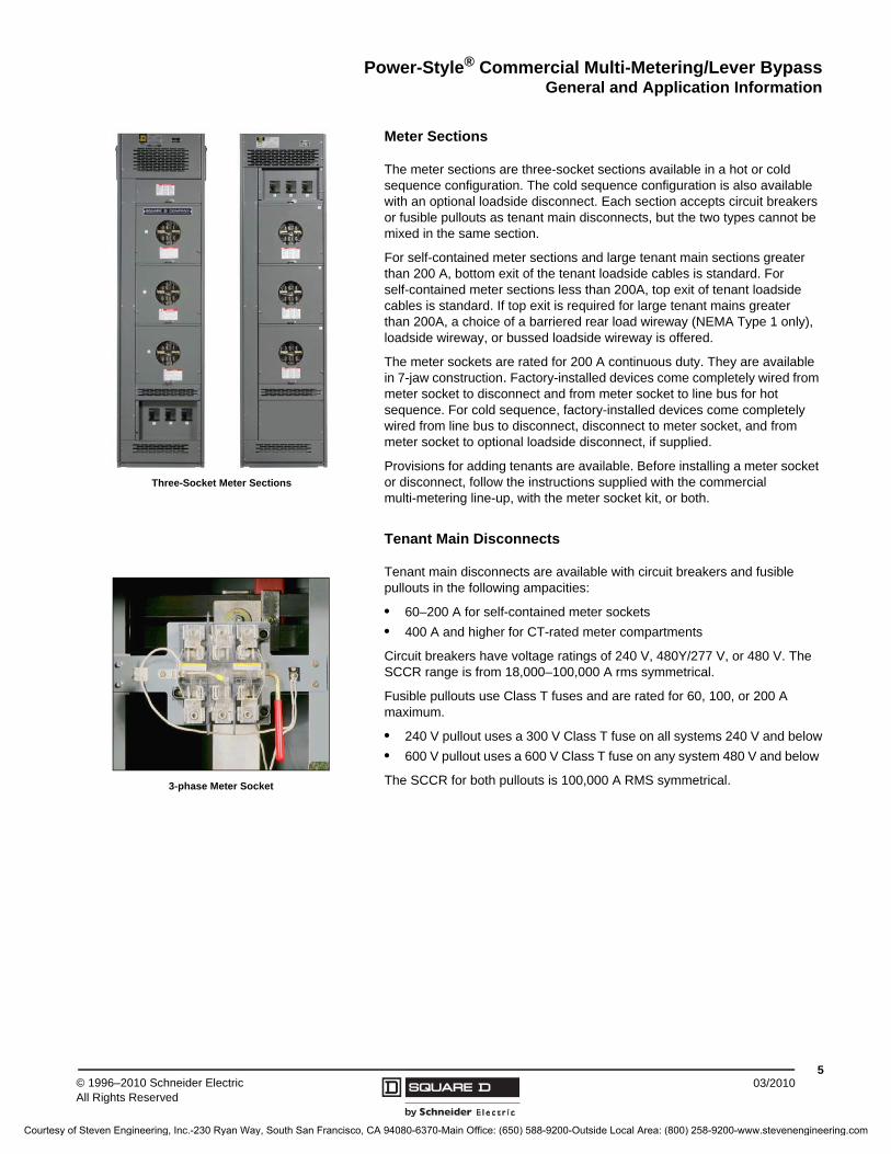
The meter sections are three-socket sections available in a hot or cold sequence configuration. The cold sequence configuration is also available with an optional loadside disconnect. Each section accepts circuit breakers or fusible pullouts as tenant main disconnects, but the two types cannot be mixed in the same section.
For self-contained meter sections and large tenant main sections greater than 200 A, bottom exit of the tenant loadside cables is standard. For self-contained meter sections less than 200A, top exit of tenant loadside cables is standard. If top exit is required for large tenant mains greater than 200A, a choice of a barriered rear load wireway (NEMA Type 1 only), loadside wireway, or bussed loadside wireway is offered.
The meter sockets are rated for 200 A continuous duty. They are available in 7-jaw construction. Factory-installed devices come completely wired from meter socket to disconnect and from meter socket to line bus for hot sequence. For cold sequence, factory-installed devices come completely wired from line bus to disconnect, disconnect to meter socket, and from meter socket to optional loadside disconnect, if supplied.
Provisions for adding tenants are available. Before installing a meter socket or disconnect, follow the instructions supplied with the commercial multi-metering line-up, with the meter socket kit, or both.
Tenant Main Disconnects
Tenant main disconnects are available with circuit breakers and fusible pullouts in the following ampacities:
• 60–200 A for self-contained meter sockets
• 400 A and higher for CT-rated meter compartments
Circuit breakers have voltage ratings of 240 V, 480Y/277 V, or 480 V. The SCCR range is from 18,000–100,000 A rms symmetrical.
Fusible pullouts use Class T fuses and are rated for 60, 100, or 200 A maximum.
• 240 V pullout uses a 300 V Class T fuse on all systems 240 V and below
• 600 V pullout uses a 600 V Class T fuse on any system 480 V and below
The SCCR for both pullouts is 100,000 A RMS symmetrical.
Three-Socket Meter Sections
3-phase Meter Socket
Courtesy of Steven Engineering, Inc.-230 Ryan Way, South San Francisco, CA 94080-6370-Main Office: (650) 588-9200-Outside Local Area: (800) 258-9200-www.stevenengineering.com

© 1996–2010 Schneider ElectricAll Rights Reserved
Power-Style® Commercial Multi-Metering/Lever BypassSpecifications
603/2010
General
Furnish and install the Power-Style Commercial Multi-Metering equipment as specified and shown on the associated electrical drawings. The equipment is furnished by Schneider Electric and meets UL requirements. The equipment is furnished with a UL service entrance label when applicable.
Structure
The commercial multi-metering equipment is totally enclosed, dead-front construction, free-standing, front and rear aligned. Accessibility is from the front. The equipment is NEMA Type 1 or NEMA Type 3R, non-walk-in, weather-resistant construction. The framework is steel, secured together to support all cover plates, bussing, and component devices during shipment and installation. Formed removable closure plates are used on the front, rear, and sides. All covers have utility sealing provisions where required by the utility.
Finish
All painted parts are pre-treated and provided with a corrosion-resistant, UL Recognized acrylic baked paint finish. The paint color is ANSI 49 medium light gray.
NEMA Type 3R enclosures are treated with the same process, except all exterior parts are of painted, galvannealed steel. All exterior hardware on NEMA Type 3R enclosures is zinc-plated steel.
Fault Withstand Rating
The entire multi-metering equipment is suitable for operation at the specified available fault current. The equipment is labeled to indicate the maximum available fault current rating, taking into account the structure, bussing, main disconnects, and tenant main disconnects.
The maximum allowable current any device may let through when used in series with self-contained meter sockets is 30,000 A. Multi-metering tenant main disconnects are fully rated.
Bussing
The multi-metering equipment through bus is tin-plated aluminum or silver-plated copper. The bussing is of sufficient cross-sectional area to meet UL Standard 891 for temperature rise. There are provisions for future splicing of additional sections from either end. The neutral bus is 100% rated. The ground bus is sized per UL Standard 891, and of the same material as the through bus.
Utility Compartments
The utility metering compartments are arranged in hot sequence. The metering compartment is barriered and covers have sealing provisions.
Tenant Main Disconnects
The tenant main disconnects are circuit breaker or fusible pullout devices. Equipment ground fault is provided when required per the NEC, or when requested by the customer for large tenant mains (LTMs). Top exit of load-side cables is provided through use of a built-in front accessible vertical wireway for small tenant meter sections.
Meter Sockets
Meter sockets are rated 200 A continuous duty and are 7-jaw construction.
Courtesy of Steven Engineering, Inc.-230 Ryan Way, South San Francisco, CA 94080-6370-Main Office: (650) 588-9200-Outside Local Area: (800) 258-9200-www.stevenengineering.com

Power-Style® Commercial Multi-Metering/Lever BypassSpecifications
703/2010© 1996–2010 Schneider Electric
All Rights Reserved
Branch Devices
Circuit breakers are common trip for simultaneous opening of all poles. Breakers have an over-center, trip-free, toggle-type operating mechanism with quick-make, quick-break action and positive handle indication. Circuit breakers are UL Listed in accordance with UL Standard 489 and are rated for the maximum voltage specified and with continuous current ratings as noted on the plans. The circuit breakers are thermal magnetic or current limiting.
Fusible pullouts are UL Listed and rated 240 V or 600 V with a 200 A maximum rating. The pullout uses a Class T fuse. When the pullout head is removed, the fuses remain with the pullout head. The 240 V pullout uses 300 V Class T fuses. The 600 V pullout uses 600 V Class T fuses.
Shipping Splits
The multi-metering equipment is separated into shipping blocks. Each shipping block is capable of being handled with the use of removable lifting bars or rollers and be clearly labeled with proper handling procedures.
Courtesy of Steven Engineering, Inc.-230 Ryan Way, South San Francisco, CA 94080-6370-Main Office: (650) 588-9200-Outside Local Area: (800) 258-9200-www.stevenengineering.com

© 1996–2010 Schneider ElectricAll Rights Reserved
Power-Style® Commercial Multi-Metering/Lever BypassTechnical Information
803/2010
Conduit Layout
These drawings are valid for all mains, feeders, and distribution sections based on depth and width. For mains and feeders, top conduit area is not available for bottom exit/entry nor is bottom conduit area available for top exit/entry.
Width (W) 30 in. (762 mm) 36 in. (914 mm) 42 in. (1,087 mm) 48 in. (1,219 mm) 54 in. (1,372 mm)
Width (W1) 25 in. (635 mm) 31 in. (787 mm) 37 in. (940 mm) 43 in. (1,092 mm) 49 in. (1,245 mm)
24.00(610)
W
W1
14.25(362)
2.50 (64)
2.50 (64)
36.00 (914)
W
W1
9.75 (248)
13.50 (343)
2.50(64)
3.00 (76)
2.50 (64)
48.00 (1219)
W
2.50 (64)
19.50 (495)
W1
15.25 (387)
2.50 (64)
3.00 (76)
36 in. (914 mm) Deep
48 in. (1219 mm) Deep
24 in. (610 mm) Deep
W1
26.75(680)
W
14.75(375)
W1 2.50 (64)
W
W
W1
38.75(984)
Floor Plan Top View
Conduit
Area
Dimensions given in INCHES (millimeters).
Conduit area is based on a minimum of 10 in. (254 mm) to any obstruction.
Courtesy of Steven Engineering, Inc.-230 Ryan Way, South San Francisco, CA 94080-6370-Main Office: (650) 588-9200-Outside Local Area: (800) 258-9200-www.stevenengineering.com
Power-Style® Commercial Multi-Metering/Lever BypassTechnical Information
903/2010© 1996–2010 Schneider Electric
All Rights Reserved
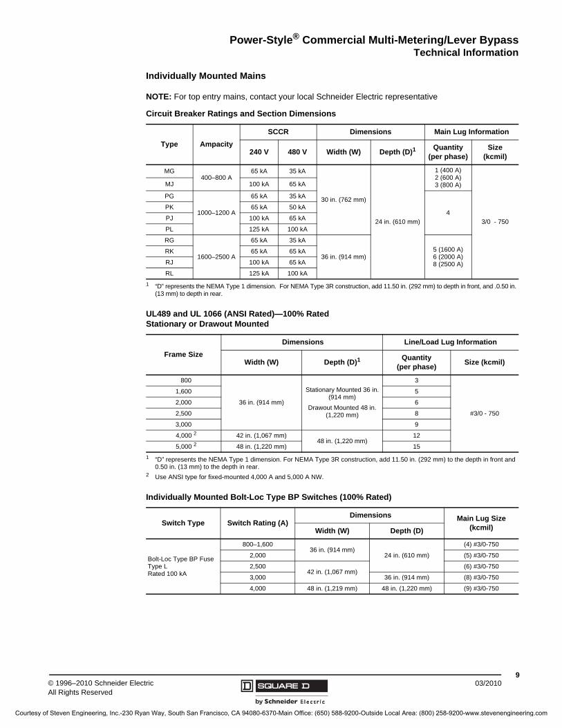
Individually Mounted Mains
NOTE: For top entry mains, contact your local Schneider Electric representative
Circuit Breaker Ratings and Section Dimensions
Type Ampacity
SCCR Dimensions Main Lug Information
240 V 480 V Width (W) Depth (D)1
1 “D” represents the NEMA Type 1 dimension. For NEMA Type 3R construction, add 11.50 in. (292 mm) to depth in front, and .0.50 in. (13 mm) to depth in rear.
Quantity(per phase)
Size(kcmil)
MG400–800 A
65 kA 35 kA
30 in. (762 mm)
24 in. (610 mm)
1 (400 A)2 (600 A)3 (800 A)
3/0 - 750
MJ 100 kA 65 kA
PG
1000–1200 A
65 kA 35 kA
4PK 65 kA 50 kA
PJ 100 kA 65 kA
PL 125 kA 100 kA
RG
1600–2500 A
65 kA 35 kA
36 in. (914 mm)5 (1600 A)6 (2000 A)8 (2500 A)
RK 65 kA 65 kA
RJ 100 kA 65 kA
RL 125 kA 100 kA
UL489 and UL 1066 (ANSI Rated)—100% RatedStationary or Drawout Mounted
Frame Size
Dimensions Line/Load Lug Information
Width (W) Depth (D)1
1 “D” represents the NEMA Type 1 dimension. For NEMA Type 3R construction, add 11.50 in. (292 mm) to the depth in front and 0.50 in. (13 mm) to the depth in rear.
Quantity(per phase)
Size (kcmil)
800
36 in. (914 mm)
Stationary Mounted 36 in. (914 mm)
Drawout Mounted 48 in. (1,220 mm)
3
#3/0 - 750
1,600 5
2,000 6
2,500 8
3,000 9
4,000 2
2 Use ANSI type for fixed-mounted 4,000 A and 5,000 A NW.
42 in. (1,067 mm)48 in. (1,220 mm)
12
5,000 2 48 in. (1,220 mm) 15
Individually Mounted Bolt-Loc Type BP Switches (100% Rated)
Switch Type Switch Rating (A) Dimensions Main Lug Size
(kcmil)Width (W) Depth (D)
Bolt-Loc Type BP Fuse Type L Rated 100 kA
800–1,60036 in. (914 mm)
24 in. (610 mm)
(4) #3/0-750
2,000 (5) #3/0-750
2,50042 in. (1,067 mm)
(6) #3/0-750
3,000 36 in. (914 mm) (8) #3/0-750
4,000 48 in. (1,219 mm) 48 in. (1,220 mm) (9) #3/0-750
Courtesy of Steven Engineering, Inc.-230 Ryan Way, South San Francisco, CA 94080-6370-Main Office: (650) 588-9200-Outside Local Area: (800) 258-9200-www.stevenengineering.com
© 1996–2010 Schneider ElectricAll Rights Reserved
Power-Style® Commercial Multi-Metering/Lever BypassTechnical Information
1003/2010
Large Tenant Mains > 400–2000 A
Top Exit of Load Cables for Large Tenant Main (LTM)
A loadside wireway section with a minimum width of 12 in. (305 mm) can be used for top exit of load cables. A 12 in. wide section can only accommodate cables for one LTM. A minimum width of 24 in. (610 mm) is required between two LTMs and for NEMA Type 3R applications. Rear load wireway is only available for LTMs and will require increased depth for tenant metering sections. See page 12 for more details.
Circuit Breaker Ratings and Section Dimensions
Type Ampacity
SCCR Dimensions Load Lug Information
240 V 480 V Width (W) Depth (D)1
1 “D” represents NEMA Type 1 dimension without rear wireway. For rear wireway add 12 in. (305 mm) to depth. For NEMA Type 3R construction, add 11.50 in. (292 mm) to depth in front, and .0.50 in. (13 mm) to depth in rear.
Quantity(per phase)
Size(kcmil)
MG400–800 A
65 kA 35 kA30 in. (762 mm)
24 in. (610 mm)
3
3/0 - 500
MJ 100 kA 65 kA
PG
1000–1200 A
65 kA 35 kA
36 in. (914 mm)
4PK 65 kA 50 kA
PJ 100 kA 65 kA
PL 100 kA 100 kA
RG
1600–2000 A
65 kA 35 kA
6 3/0 - 750RK 65 kA 65 kA
RJ 100 kA 65 kA
RL 100 kA 100 kA
Fusible Switch Ratings and Section Dimensions
Type Ampacity
SCCR Dimensions Load Lug Information
Fuse Type
240/480 V Width (W) Depth (D)1
1 “D” represents NEMA Type 1 dimension without rear wireway. For rear wireway add 12 in. (305 mm) to depth. For NEMA Type 3R construction, add 11.50 in. (292 mm) to depth in front, and .0.50 in. (13 mm) to depth in rear.
Quantity(per phase)
Size(kcmil)
MCS2
2 MCS = molded case switch
400-600 A J, T
100 kA30 in. (762 mm)
24 in. (610 mm)3
3/0 - 500800 AL
BP3
3 Not available with load lugs, only available with load through bus.
800-1600 A 36 in. (914 mm) 4
Underground Pull Section
AmpacityDimensions
Width (W) Depth (D) 1
1 “D” represents NEMA Type 1 dimension. Depth matches that of the deepest section in the lineup. Front and rear alignment. For NEMA Type 3R construction, add 11.5 in. (292 mm) to depth in front and 0.5 in. (13 mm) to depth in rear.
800
24 in. (610 mm) 24 in. (610 mm)1200
1600
2000
250036 in. (914 mm) 2
2 Requires power company approval.
24 in. (610 mm)
3000 36 in. (914 mm)
4000 42 in. (1067 mm) 2 48 in. (1219 mm)
Courtesy of Steven Engineering, Inc.-230 Ryan Way, South San Francisco, CA 94080-6370-Main Office: (650) 588-9200-Outside Local Area: (800) 258-9200-www.stevenengineering.com

Power-Style® Commercial Multi-Metering/Lever BypassTechnical Information
1103/2010© 1996–2010 Schneider Electric
All Rights Reserved
Lever Bypass Meter Section—Tenant Mains 200 A (Hot and Cold Sequence)
Circuit Breaker Ratings Fusible Pullout Ratings
TypeAmpacity
(A)SCCR Load Lug
Information 1
1 Neutral lug terminations are #6 - 350 kcmil.
TypeAmpacity
(A)SCCR Load Lug
Information 1240 V 480 V 240 V 480 VFAL
60–10022 kA 18 kA #12 - 1/0 AWG
Al or CuFTL43060 60 N/A 100 kA #14 - #2
FHL 65 kA 18 kA FTL43100 100 N/A 100 kA #14 - 1/0 AWGHJL 100 kA 65 kA
#4 - 3/0 kcmil Al or Cu
FTL43200 200 N/A 100 kA 1/0 AWG - 300 kcmil HDL
110–150
22 kA 18 kAHGL 65 kA 35 kAHJL 100 kA 65 kAHLL 100 kA 100 kAJDL
175–200
22 kA 18 kA #4 - 300 kcmil
Al or CuJGL 65 kA 35 kAJJL 100 kA 65 kAJLL 100 kA 100 kA
M
M
M
24.00(610)
2.50(64)
2.50(64)
2.50(64)
8.87(225)
19.00(483)
24.00(610)
3.00(76)
13.00(330)
24.00(610)
2.50(64)
16.00(406)
24.00(610)
Top View
Floor Plan
Front
Front
M
M
M
24.00(610)
Top Exit of Load Cables
Tenant metering sections come standard with a front accessible loadside wireway in each section for routing of load cables for top exit. Rear load wireway is not required for top exit applications.
Depth Dimensions
System Ampacity (A) Depth 1
1 For NEMA Type 3R (outdoor) construction, add 11.50 in. (292 mm) to depth in front, and 0.50 in. (13 mm) to depth in rear.
400–2,500 24 in. (610 mm)
3,000 36 in. (914 mm)
4,000 48 in. (1,219 mm)
Three-Socket Main
Loadside wireway
Customer- accessible
area
Cold SequenceHot Sequence
Cold SequenceHot Sequence
Conduit
Area
Dimensions given in INCHES (millimeters).
Courtesy of Steven Engineering, Inc.-230 Ryan Way, South San Francisco, CA 94080-6370-Main Office: (650) 588-9200-Outside Local Area: (800) 258-9200-www.stevenengineering.com

Power-Style® Commercial Multi-Metering/Lever BypassTechnical Information
© 1996–2010 Schneider ElectricAll Rights Reserved
1203/2010
Corner Sections
Loadside Wireway
Rear Load Wireway
Rear load wireway is not available for tenant metering sections < 200 A or in NEMA Type 3R construction. Adding rear wireway to a large tenant main could require increased depth for other sections in the lineup.
Dimensions1
Depth (D) 2 D1 D2 W1 W2
24 in. (610 mm) 36 in. (914 mm) 24 in. (610 mm) 36 in. (914 mm) 24 in. (610 mm)
36 in. (914 mm) 48 in. (1220 mm) 36 in. (914 mm) 48 in. (1220 mm) 36 in. (914 mm)
48 in. (1220 mm) Contact the factory.
1 Not available in NEMA Type 3R construction. Maximum system bus is 2500 A heat rise rated, or 2000 A density rated.
2 Depth of commercial multi-metering lineup.D1
W1
D2
W2
Dimensions given in INCHES (millimeters).
Dimensions
System Ampacity
Depth (D) 1
400–2500 A 24 in. (610 mm)
3000 A 36 in. (914 mm)
4000 A 48 in. (1220 mm)
1 For NEMA Type 3R (outdoor) construction, add 11.50 in. (292 mm) to depth in front, and 0.50 in. (13 mm) to depth in rear.
NEMA Type 3R Extension
Top View
11.50(292)
24.00(610) 2.50
(64)
2.50(64)
D
NEMA Type 3R Extension
Top View
11.50(292)
24.00(610) 2.50
(64)
D
2.50(64)
12.75(324)
2.50(64)
Top View
12.00(305) 2.50
(64)
D
2.50(64)
12.75(324)
2.50(64)
Non-Bussed Loadside Wireway a 24 in. Wide Bussed Loadside Wireway12 in. Wide Bussed Loadside Wireway
a Must be an end section. No provisions for bus extension.
Dimensions given in INCHES (millimeters).
Conduit
Area
Dimensions
System Ampacity
Depth
Dimension A Dimension D 1
400–2500 A 10 in. (254 mm) 36 in. (914 mm)
3000 A 16.5 in. (419 mm) 48 in. (1220 mm)
1 Depth includes rear wireway.
2.50(64)
2.50(64)
Top View
D
W
A
2.50(64)
Dimensions given in INCHES (millimeters).
Conduit
Area
Courtesy of Steven Engineering, Inc.-230 Ryan Way, South San Francisco, CA 94080-6370-Main Office: (650) 588-9200-Outside Local Area: (800) 258-9200-www.stevenengineering.com
Power-Style® Commercial Multi-Metering/Lever BypassReplacement Parts
1303/2010© 1996–2010 Schneider Electric
All Rights Reserved
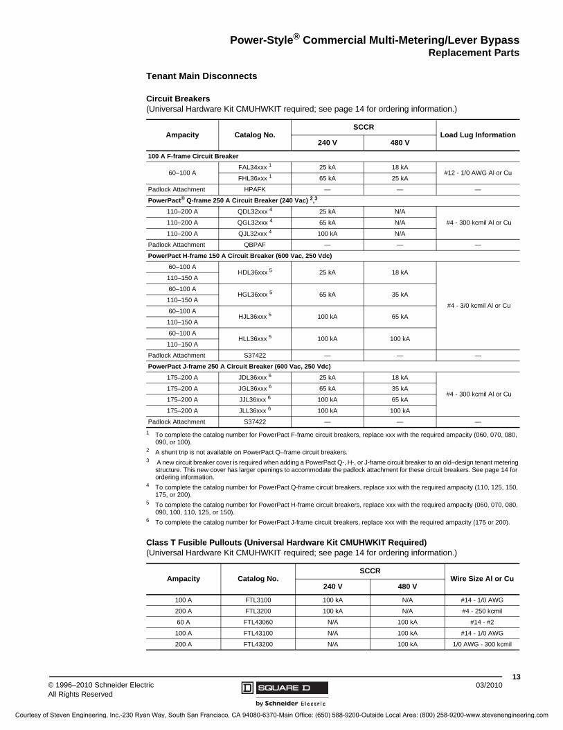
Tenant Main Disconnects
Circuit Breakers(Universal Hardware Kit CMUHWKIT required; see page 14 for ordering information.)
Ampacity Catalog No.SCCR
Load Lug Information240 V 480 V
100 A F-frame Circuit Breaker
60–100 AFAL34xxx 1
1 To complete the catalog number for PowerPact F-frame circuit breakers, replace xxx with the required ampacity (060, 070, 080, 090, or 100).
25 kA 18 kA#12 - 1/0 AWG Al or Cu
FHL36xxx 1 65 kA 25 kA
Padlock Attachment HPAFK — — —
PowerPact® Q-frame 250 A Circuit Breaker (240 Vac) 2,3
2 A shunt trip is not available on PowerPact Q–frame circuit breakers.3 A new circuit breaker cover is required when adding a PowerPact Q-, H-, or J-frame circuit breaker to an old–design tenant metering
structure. This new cover has larger openings to accommodate the padlock attachment for these circuit breakers. See page 14 for ordering information.
110–200 A QDL32xxx 4
4 To complete the catalog number for PowerPact Q-frame circuit breakers, replace xxx with the required ampacity (110, 125, 150, 175, or 200).
25 kA N/A
#4 - 300 kcmil Al or Cu 110–200 A QGL32xxx 4 65 kA N/A
110–200 A QJL32xxx 4 100 kA N/A
Padlock Attachment QBPAF — — —
PowerPact H-frame 150 A Circuit Breaker (600 Vac, 250 Vdc)
60–100 AHDL36xxx 5
5 To complete the catalog number for PowerPact H-frame circuit breakers, replace xxx with the required ampacity (060, 070, 080, 090, 100, 110, 125, or 150).
25 kA 18 kA
#4 - 3/0 kcmil Al or Cu
110–150 A
60–100 AHGL36xxx 5 65 kA 35 kA
110–150 A
60–100 AHJL36xxx 5 100 kA 65 kA
110–150 A
60–100 AHLL36xxx 5 100 kA 100 kA
110–150 A
Padlock Attachment S37422 — — —
PowerPact J-frame 250 A Circuit Breaker (600 Vac, 250 Vdc)
175–200 A JDL36xxx 6
6 To complete the catalog number for PowerPact J-frame circuit breakers, replace xxx with the required ampacity (175 or 200).
25 kA 18 kA
#4 - 300 kcmil Al or Cu175–200 A JGL36xxx 6 65 kA 35 kA
175–200 A JJL36xxx 6 100 kA 65 kA
175–200 A JLL36xxx 6 100 kA 100 kA
Padlock Attachment S37422 — — —
Class T Fusible Pullouts (Universal Hardware Kit CMUHWKIT Required)(Universal Hardware Kit CMUHWKIT required; see page 14 for ordering information.)
Ampacity Catalog No.SCCR
Wire Size Al or Cu240 V 480 V
100 A FTL3100 100 kA N/A #14 - 1/0 AWG
200 A FTL3200 100 kA N/A #4 - 250 kcmil
60 A FTL43060 N/A 100 kA #14 - #2
100 A FTL43100 N/A 100 kA #14 - 1/0 AWG
200 A FTL43200 N/A 100 kA 1/0 AWG - 300 kcmil
Courtesy of Steven Engineering, Inc.-230 Ryan Way, South San Francisco, CA 94080-6370-Main Office: (650) 588-9200-Outside Local Area: (800) 258-9200-www.stevenengineering.com
© 1996–2010 Schneider ElectricAll Rights Reserved
Power-Style® Commercial Multi-Metering/Lever BypassReplacement Parts
1403/2010
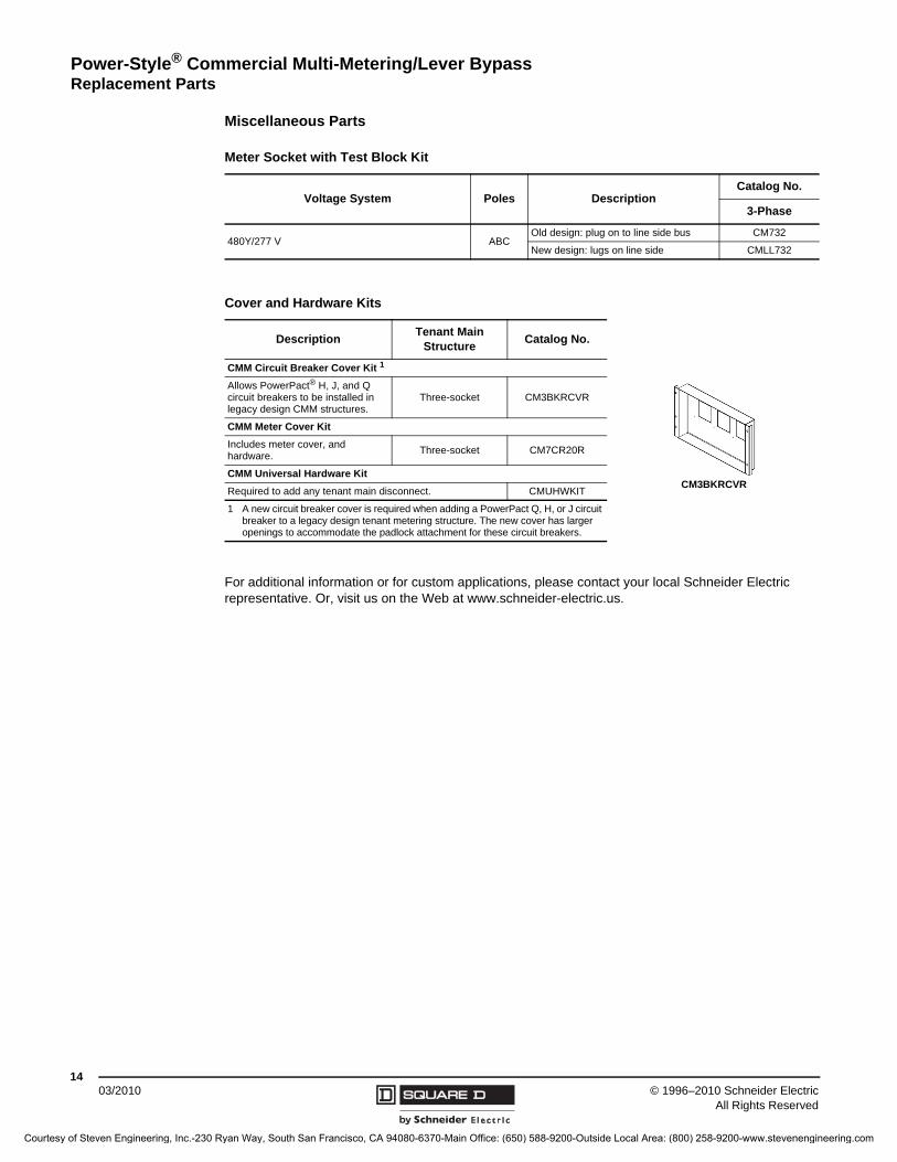
Miscellaneous Parts
For additional information or for custom applications, please contact your local Schneider Electric representative. Or, visit us on the Web at www.schneider-electric.us.
Meter Socket with Test Block Kit
Voltage System Poles DescriptionCatalog No.
3-Phase
480Y/277 V ABCOld design: plug on to line side bus CM732
New design: lugs on line side CMLL732
Cover and Hardware Kits
DescriptionTenant Main
StructureCatalog No.
CMM Circuit Breaker Cover Kit 1
Allows PowerPact® H, J, and Q circuit breakers to be installed in legacy design CMM structures.
Three-socket CM3BKRCVR
CMM Meter Cover Kit
Includes meter cover, and hardware.
Three-socket CM7CR20R
CMM Universal Hardware Kit
Required to add any tenant main disconnect. CMUHWKIT
1 A new circuit breaker cover is required when adding a PowerPact Q, H, or J circuit breaker to a legacy design tenant metering structure. The new cover has larger openings to accommodate the padlock attachment for these circuit breakers.
CM3BKRCVR
Courtesy of Steven Engineering, Inc.-230 Ryan Way, South San Francisco, CA 94080-6370-Main Office: (650) 588-9200-Outside Local Area: (800) 258-9200-www.stevenengineering.com

Courtesy of Steven Engineering, Inc.-230 Ryan Way, South San Francisco, CA 94080-6370-Main Office: (650) 588-9200-Outside Local Area: (800) 258-9200-www.stevenengineering.com

2755CT9501R03/10 © 1996–2010 Schneider Electric All Rights Reserved Replaces 2755CT9501 01/1996
03/2010
Schneider Electric USA, Inc.1010 Airpark Center DriveNashville, TN 37217 USA1-888-Square D1-888-778-2733www.schneider-electric.us
PowerPact® and Power-Style® are registered trademarks of Schneider Electric and/or its affiliates in the United States and/or other countries. Other marks used herein may be the property of their respective owners.
Courtesy of Steven Engineering, Inc.-230 Ryan Way, South San Francisco, CA 94080-6370-Main Office: (650) 588-9200-Outside Local Area: (800) 258-9200-www.stevenengineering.com