sbt-90 leds · applications • fiber-coupled illumination • architectural and entertainment...
TRANSCRIPT
Applications• Fiber-coupled illumination
• Architectural and Entertainment lighting
• Projection and micro-display based applications
• High-Brightness and large format LCD back-light units
• Edge-illuminated lighting guides
• High output, Etendue-limited lighting applications
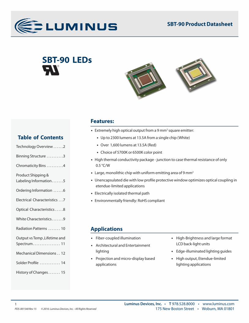
Features:• Extremely high optical output from a 9 mm2 square emitter:
• Up to 2300 lumens at 13.5A from a single chip (White)
• Over 1,600 lumens at 13.5A (Red)
• Choice of 5700K or 6500K color point
• High thermal conductivity package - junction to case thermal resistance of only 0.5 °C/W
• Large, monolithic chip with uniform emitting area of 9 mm2
• Unencapsulated die with low profile protective window optimizes optical coupling in etendue-limited applications
• Electrically isolated thermal path
• Environmentally friendly: RoHS compliant
Table of ContentsTechnology Overview . . . . . .2
Binning Structure . . . . . . . . . .3
Chromaticity Bins . . . . . . . . . .4
Product Shipping & Labeling Information . . . . . . .5
Ordering Information . . . . . .6
Electrical Characteristics . . .7
Optical Characteristics . . . . .8
White Characteristics . . . . . . .9
Radiation Patterns . . . . . . . 10
Output vs Temp ,Lifetime and Spectrum . . . . . . . . . . . . . . . . 11
Mechanical Dimensions . . 12
Solder Profile . . . . . . . . . . . . 14
History of Changes . . . . . . . 15
1PDS-001540 Rev 15 © 2016 Luminus Devices, Inc. - All Rights Reserved
Luminus Devices, Inc. • T 978.528.8000 • www.luminus.com175 New Boston Street • Woburn, MA 01801
SBT-90 LEDs
SBT-90 Product Datasheet
Testing Temperature
Luminus surface mount LEDs are typically tested with a 20 msec input pulse and a junction temperature of 25ºC. Expected flux values in real world operation can be extrapolated based on the information contained within this product data sheet.
Multiple Operating Points
The tables on the following pages provide typical optical and electrical characteristics. Since the LEDs can be operated over a wide range of drive conditions (currents from less than 1A to 13.5A, and duty cycle from <1% to 100%), multiple drive conditions are listed.
SBT-90 White LEDs are production tested at 9.0 A. The values shown at other current conditions are for additional reference at other possible drive conditions.
SBT-90 Red LEDs are productions tested of 13.5A
Understanding Luminus LED Test Specifications
Every Luminus LED is fully tested to ensure that it meets the high quality standards expected from Luminus’ products.
2PDS-001540 Rev 15 © 2016 Luminus Devices, Inc. - All Rights Reserved
Luminus Devices, Inc. • T 978.528.8000 • www.luminus.com175 New Boston Street • Woburn, MA 01801
Luminus Technology
Luminus’ technology enables large area LED chips with uniform brightness over the entire LED chip surface. The optical power and brightness produced by these large monolithic chips enable solutions which replace arc and halogen lamps where arrays of traditional high power LEDs cannot.
Packaging Technology
Thermal management is critical in high power LED applications. With a thermal resistance from junction to heat sink of 0.5º C/W, Luminus SBT-90 LEDs have the lowest thermal resistance of any LED on the market. This allows the LED to be driven at higher current densities while maintaining a low junction temperature, thereby resulting in brighter solutions and longer lifetimes.
Reliability
Designed from the ground up, Luminus LEDs are one of the most reliable light sources in the world today. They have passed a rigorous suite of environmental and mechanical stress tests, including mechanical shock, vibration, temperature cycling and humidity, and have been fully qualified for use in extreme high power and high current applications. With very low failure rates and median lifetimes that typically exceed 60,000 hours, Luminus LEDs are ready for even the most demanding applications.
Environmental Benefits
Luminus LEDs Whitehelp reduce power consumption and the amount of hazardous waste entering the environment. All Luminus LED products manufactured by Luminus are RoHS compliant and free of hazardous materials, including lead and mercury.
Technology Overview
Luminus LED benefit from a suite of innovations in the fields of chip technology, packaging and thermal management. These breakthroughs allow illumination engineers and designers to achieve solutions that are high brightness and high efficiency.
SBT-90 Product Datasheet

3PDS-001540 Rev 15 © 2016 Luminus Devices, Inc. - All Rights Reserved
Luminus Devices, Inc. • T 978.528.8000 • www.luminus.com175 New Boston Street • Woburn, MA 01801
Flux Bins
SBT-90 Binning StructureSBT-90 LEDs are tested for luminous flux and chromaticity of the drive current specified below and placed into one of the following luminous flux (FF) and chromaticity (WW) bins:
Color Flux Bin (FF) Minumum Flux (lm) @ 9.0A
Maximum Flux (lm) @ 9.0A
W57S/ W65S5700K / 6500K, Standard CRI (typ. 70)
NA 1,590 1,710
NB 1,710 1,830
PA 1830 1966
PB 1966 2100
QA 2100 2260
QB 2260 2420
Chromaticity BinsLuminus’ Standard Chromaticity Bins: 1931 CIE Curve
Red
Flux Bin (FF) Minumum Flux (lm) @ 13.5A
Minumum Flux (lm) @ 13.5A
BM 770 970
BN 970 1150
BP 1150 1350
BQ 1350 1570
BR 1570 1850
Color Wavelength Bin (WW) Minimum Wavelength @ 13.5A
Maximum Wavelength @ 13.5A
Red
R3 615 619
R4 619 623
R5 623 627
Wavelength Bins
0.380
0.355
0.330
0.305
0.2800.270 0.295 0.320 0.345 0.370
CIEx
CIEy
BB Locus
6500
5700
DE
EF
EH
H4
J4
H3
J3
DJ
F4
G4
G3
F3
DF
DG
*Note: Luminus maintains a +/- 6% tolerance on flux measurements. Luminus maintains a +/- 2% tolerance on CRI measurements.
SBT-90 Product Datasheet

4PDS-001540 Rev 15 © 2016 Luminus Devices, Inc. - All Rights Reserved
Luminus Devices, Inc. • T 978.528.8000 • www.luminus.com175 New Boston Street • Woburn, MA 01801
*Sub-bins within ANSI defined quadrangles per ANSI C78.377-2008
The following tables describe the four chromaticity points that bound each chromaticity bin. Chromaticity bins are grouped together based on the color temperature.
6500K Chromaticity Bins
Bin Code(WW) CIEx CIEy
DG
0.307 0.311
0.322 0.326
0.323 0.316
0.309 0.302
F3*
0.305 0.321
0.313 0.329
0.315 0.319
0.307 0.311
F4*
0.303 0.330
0.312 0.339
0.313 0.329
0.305 0.321
G3*
0.313 0.329
0.321 0.337
0.322 0.326
0.315 0.319
G4*
0.312 0.339
0.321 0.348
0.321 0.337
0.313 0.329
EF
0.302 0.335
0.320 0.354
0.321 0.348
0.303 0.330
DE
0.283 0.304
0.303 0.330
0.307 0.311
0.289 0.293
DF
0.289 0.293
0.307 0.311
0.309 0.302
0.293 0.285
5700K Chromaticity Bins
Bin Code(WW) CIEx CIEy
DJ
0.322 0.324
0.337 0.337
0.336 0.326
0.323 0.314
H3*
0.321 0.335
0.329 0.342
0.329 0.331
0.322 0.324
H4*
0.321 0.346
0.329 0.354
0.329 0.342
0.321 0.335
J3*
0.329 0.342
0.337 0.349
0.337 0.337
0.330 0.331
J4*
0.329 0.354
0.338 0.362
0.337 0.349
0.329 0.342
EH
0.320 0.352
0.338 0.368
0.338 0.362
0.321 0.346
SBT-90 Product Datasheet

5PDS-001540 Rev 15 © 2016 Luminus Devices, Inc. - All Rights Reserved
Luminus Devices, Inc. • T 978.528.8000 • www.luminus.com175 New Boston Street • Woburn, MA 01801
Note 1: WNNX nomenclature corresponds to the following:
W = White
NN = color temperature, where:
65 corresponds to 6500K
57 corresponds to 5700K
X = color rendering index, where:
S (standard) corresponds to a typical CRI of 70
Example:
The part label SBT-90-W65S-F71-NA-G4 refers to a 6500K standard CRI white, SBT-90 emitter, with a flux range from 1,590 to 1,710 lumens and a
chromaticity value within the box defined by the four points (0.313, 0.329), (0.321, 0.337), (0.321, 0.348),(0.312, 0.339).
Product Family Chip Area Color Package Configuration Flux Bin Chromaticity Bin
Surface Mount (window) 9.0 mm2 CCT & CRI
See Note 1 below Internal Code See page 3 for bins See page 3 for bins
SBT 90 WNNX F71 FF WW
Product Shipping & Labeling Information
All SBT-90 products are packaged and labeled with their respective bin as outlined in the tables on pages 3 & 4. When shipped, each package will only contain one bin. The part number designation is as follows:
SBT-90 White
SBT-90- Red SBT 90 R F75 FF WW
Product Family Chip Area Color Package Configuration Flux Bin Wavlength Bin
Surface Mount (window) 9.0 mm2 R: Red Internal Code See bins page See bins page
Example:
The part number SBT-90-R-F75-BK-R4 refers to a red part, with a flux range of 600 - 770 lumens and a wavelength range of 619 nm to 623 nm.
Note 2: Some flux and chromaticity bins may have limited availability. Application specific bin kits, consisting of multiple bins, may be available.
SBT-90 Product Datasheet
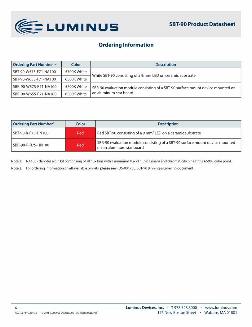
Note 1: NA100 - denotes a bin kit comprising of all flux bins with a minimum flux of 1,590 lumens and chromaticity bins at the 6500K color point.
Note 2: For ordering information on all available bin kits, please see PDS-001788: SBT-90 Binning & Labeling document.
6PDS-001540 Rev 15 © 2016 Luminus Devices, Inc. - All Rights Reserved
Luminus Devices, Inc. • T 978.528.8000 • www.luminus.com175 New Boston Street • Woburn, MA 01801
Ordering Part Number 1,2 Color Description
SBT-90-W57S-F71-NA100 5700K WhiteWhite SBT-90 consisting of a 9mm2 LED on ceramic substrate
SBT-90-W65S-F71-NA100 6500K White
SBR-90-W57S-R71-NA100 5700K White SBR-90 evaluation module consisting of a SBT-90 surface mount device mounted on an aluminum star boardSBR-90-W65S-R71-NA100 6500K White
Ordering Part Number 2 Color Description
SBT-90-R-F75-HN100 Red Red SBT-90 consisting of a 9 mm2 LED on a ceramic substrate
SBR-90-R-R75-HN100 Red SBR-90 evaluation module consisting of a SBT-90 surface mount device mounted on an aluminum star board
Ordering Information
SBT-90 Product Datasheet

White
Drive Condition2 9.0 A
Parameter Symbol Values at Test Currents Unit
Current Density j 1.0 A/mm2
Forward Voltage VF 3.5 V
Note 1: All ratings are based on operation at room temperature.
Note 2: Listed drive conditions are typical for common applications. SBT-90 devices can be driven at currents ranging from 1A to 13.5A and at duty cycles ranging from 1% to 100%. Drive current and duty cycle should be adjusted as necessary to maintain the junction temperature desired to meet application lifetime requirements.
Note 3: Forward voltage temperature coefficient at current density of 1 A/mm2 and heat sink temperature of 40ºC. Contact Luminus for value at other drive conditions.
Note 4: Luminus SBT-90 LEDs are designed for operation to an absolute maximum forward drive current density of 1.5 A/mm2. Product lifetime data is specified at recommended forward drive currents. Sustained operation at absolute maximum currents will result in a reduction of device lifetime compared to recommended forward drive currents. Actual device lifetimes will also depend on junction temperature. Refer to the lifetime derating curves for further information. In pulsed operation, rise time from 10-90% of forward current should be larger than 0.5 microseconds.
Note 5: Lifetime is dependent on LED junction temperature . Thermal calculations based on input power and thermal management system should be performed to ensure Tj is maintained below Tj-max rating or life will be reduced. Refer to lifetime plots on page 9 and lifetime and reliability application note for further information.
Absolute Maximum Ratings
Parameter Symbol White Red Unit
Absolute Minimum Operating Current 0.2 0.2 AMaximum Current4 13.5 13.5 A
Maximum Junction Temperature5 Tj-max 150 125 ºC
Storage Temperature Range -40/+100 -40/+100 ºC
Common CharacteristicsParameter Symbol White Red Unit
Emitting Area 9.0 9.0 mm2
Emitting Area Dimensions 3 x 3 3 x 3 mm
Forward Voltage Temperature Coefficient3 -2.45 -1.3 mV/C
Thermal Coefficient of Photometric Flux -0.96 %/C
SBT- 90- Electrical Characteristics1
7PDS-001540 Rev 15 © 2016 Luminus Devices, Inc. - All Rights Reserved
Luminus Devices, Inc. • T 978.528.8000 • www.luminus.com175 New Boston Street • Woburn, MA 01801
SBT-90 Product Datasheet

8PDS-001540 Rev 15 © 2016 Luminus Devices, Inc. - All Rights Reserved
Luminus Devices, Inc. • T 978.528.8000 • www.luminus.com175 New Boston Street • Woburn, MA 01801
SBT-90-R Optical & Electrical Characteristics
Red
Drive Condition2 13.5A
Parameter Symbol Values3 Unit
Current Density j 1.5 A/mm2
Forward Voltage
VF min 2.3 V
VF 2.7 V
VF max 3.6 V
Luminous Flux4 ΦV typ 1350 lm
Dominant Wavelength5 λd 620 nm
FWHM Δλ1/2 18 nm
Chromaticity Coordinates6,7x 0.695 -
y 0.305 -
Relative Luminous Flux vs. Forward Current1 Forward Current vs. Forward Voltage
Note 1: All ratings are based on a junction test temperature Tj = 25ºC. See Thermal Resistance section for Tj definition.
Note 2: Listed drive conditions are typical for common applications. SBT-90 devices can be driven at currents ranging from <1 A to 13.5 A and at duty cycles ranging from 1% to 100%. Drive current and duty cycle should be adjusted as necessary to maintain the junction temperature desired to meet application lifetime requirements.
Note 3: Unless otherwise noted, values listed are typical. Devices are production tested and specified at 13.5A. Other values are for reference only.
Note 4: Total flux from emitting area at listed dominant wavelength. Reported performance is included to show trends for a selected power level. For specific minimum and maximum values, use bin tables. For product roadmap and future performance of devices, contact Luminus.
Note 5: Minimum and Maximum Dominant Wavelengths are based on typical values +/- 5nm for Red.
Note 6: In CIE 1931 chromaticity diagram coordinates, normalized to X+Y+Z=1.
Note 7: For reference only.
SBT-90 Product Datasheet

Note 1: Yellow squares indicate typical operating conditions.
Note 2: Median expected lifetime in dependence of junction temperature at 0.35 A/mm2 in continuous operation. Lifetime defined as time to 70% of initial intensity. Based on lifetime test data of uncoated GaN devices at this time. Data can be used to model failure rate over typical product lifetime (contact Luminus for lifetime reliability test data for 1A/mm2 condition).
Note 3: Lumen maintenance in dependence of time at 0.35 A/mm2 in continuous operation with junction temperatures of 100 ºC. Lumen maintenance calculation doesn’t consider open and short circuit failure modes into account.
Note 4: Typical spectrum at current density of 0.35 A/mm2 in continuous operation.
Relative Output Flux vs. Forward Current1 Forward Current vs. Forward Voltage
Luminus Devices, Inc. • T 978.528.8000 • www.luminus.com175 New Boston Street • Woburn, MA 01801
Median Lifetime2 Lumen Maintenance vs. Time3
Typical Spectrum4 Current Derating Curve
0
20
40
60
80
100
120
140
160
000,001000,01000,1
Median Lifetime Extrapolation (Hours)
Devi
ce J
unct
ion
Tem
pera
ture
(°C
)
9PDS-001540 Rev 15 © 2016 Luminus Devices, Inc. - All Rights Reserved
0%
20%
40%
60%
80%
100%
120%
0 3 6 9
Rela
tive
Lum
inus
Flu
x (%
)
Current (A)
0
3
4.5
6
7.5
9
0 0.5 1 1.5 2 2.5 3 3.5 4
Curr
ent
(A)
Forward Voltage (V)
1.5
0
3
4.5
6
7.5
9
Curr
ent
(A)
1.5
0
0.2
0.4
0.6
0.8
1
1.2
100 1,000 10,000 100,000
Time (hours)
Lum
en M
aint
enan
ce
MeasuredExtrapolated
L70
0
0.2
0.4
0.6
0.8
1
1.2
400 450 500 550 600 650 700
Wavelength (nm)
Rela
tive
Spe
ctra
l Pow
er D
istr
ibut
ion
0
1
2
3
4
5
6
7
8
9
10
0 20 40 60 80 100 120 140
Ambient Temperature (C)
LED
Dri
ve C
urre
nt (
A)
Rth j-a = 1.82 C/WRth j-a = 2.00 C/WRth j-a = 3.00 C/WRth j-a = 4.00 C/W
SBT-90-W Characteristics
SBT-90 Product Datasheet
10PDS-001540 Rev 15 © 2016 Luminus Devices, Inc. - All Rights Reserved
Luminus Devices, Inc. • T 978.528.8000 • www.luminus.com175 New Boston Street • Woburn, MA 01801
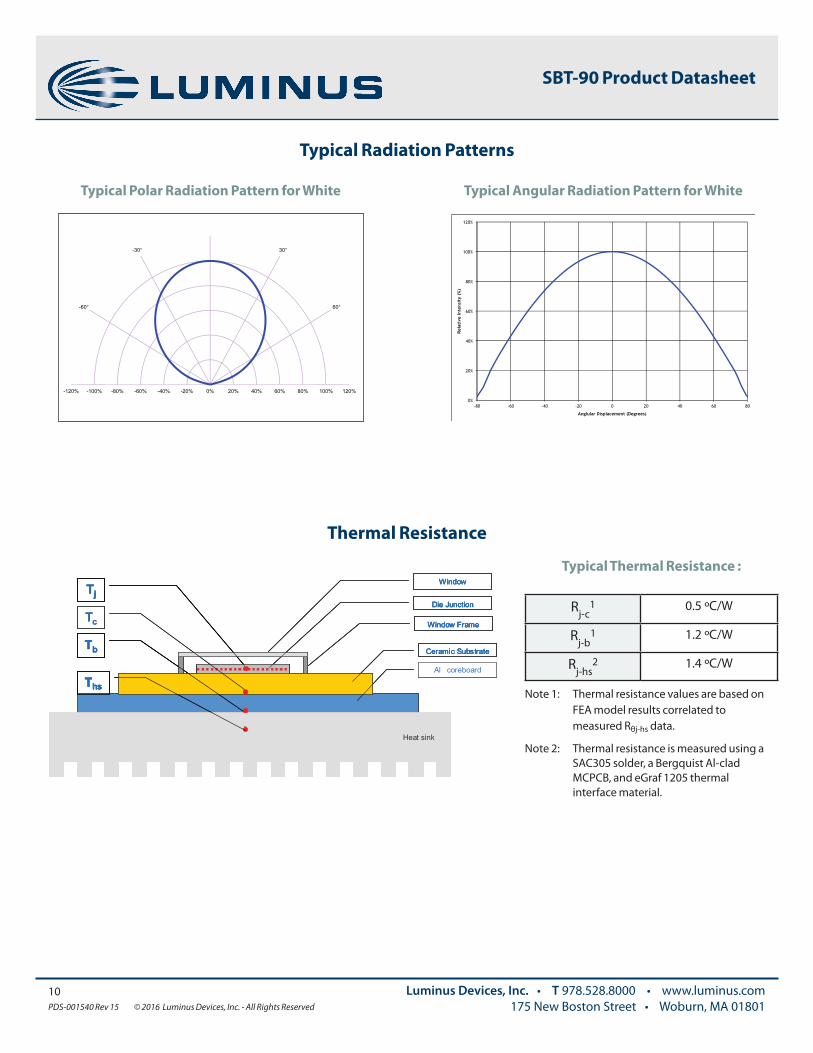
Typical Radiation Patterns
Thermal Resistance
Typical Thermal Resistance :
Rj-c1 0.5 ºC/W
Rj-b1 1.2 ºC/W
Rj-hs2 1.4 ºC/W
Note 1: Thermal resistance values are based on FEA model results correlated to measured Rθj-hs data.
Note 2: Thermal resistance is measured using a SAC305 solder, a Bergquist Al-clad MCPCB, and eGraf 1205 thermal interface material.
Typical Polar Radiation Pattern for White Typical Angular Radiation Pattern for White
Window
Ceramic Substrate
Tj
Window Frame
Die Junction
Heat sink
Ths
TbAl coreboard
Tc
Window
Ceramic Substrate
Tj
Window Frame
Die Junction
Heat sink
Ths
TbAl coreboard
Window
Ceramic Substrate
Tj
Window Frame
Die Junction
Heat sink
Ths
TbAl coreboard
Window
Ceramic Substrate
Tj
Window Frame
Die Junction
Heat sink
Ths
TbAl coreboard
Tc
-30°
-60°
120°
150° 210°
240°
60°
30°
-120% -100% -80% -60% -40% -20% 0% 20% 40% 60% 80% 100% 120%
0%
20%
40%
60%
80%
100%
120%
-80 -60 -40 -20 0 20 40 60 80
Rela
tive
Inte
nsit
y (%
)
Anglular Displacement (Degrees)
SBT-90 Product Datasheet

11PDS-001540 Rev 15 © 2016 Luminus Devices, Inc. - All Rights Reserved
Luminus Devices, Inc. • T 978.528.8000 • www.luminus.com175 New Boston Street • Woburn, MA 01801
SBT-90-R Output vs. Temp., Lifetime and Spectrum
Note 1. Median lifetime estimate as a function of junction temperature at 1.5A/mm2 in continuous operation. Lifetime defined as time to 70% of initial intensity. Based on preliminary lifetime test data. Data can be used to model failure rate over typical product lifetime.
Note 2. Lumen maintenance vs. time at 1.5A/mm2 in continuous operation, junction temperature equal to 25ºC.
Note 3. Typical spectrum at current density of 1.5 A/mm2 in continuous operation.
Median Lifetime Estimate vs. Tj1 Lumen Maintenance2
Typical Spectrum3 Angular Distribution
SBT-90 Product Datasheet

12PDS-001540 Rev 15 © 2016 Luminus Devices, Inc. - All Rights Reserved
Luminus Devices, Inc. • T 978.528.8000 • www.luminus.com175 New Boston Street • Woburn, MA 01801
Mechanical Dimensions – SBT-90 Emitter
SBT-90 Product Datasheet

13PDS-001540 Rev 15 © 2016 Luminus Devices, Inc. - All Rights Reserved
Luminus Devices, Inc. • T 978.528.8000 • www.luminus.com175 New Boston Street • Woburn, MA 01801
Mechanical Dimensions – SBT-90 Star Board
Note 1: Tolerances per IPC-610, Class 2
Note 2: For detail drawing of SBT-90, please see DWG-001553
Note 3: Recommended mounting screw: M3 or #4
Note 4: All dimensions in millimeters
Note 5: All anode pads on board are interconnected. All cathode pads on board are interconnected
7.1
60.0°
4.1
16.4SOLDER PADS 19.9
TYP
3.26x
30.0°
60.0°
19
CATHODEPADS
ANODEPADS
3.5
SBT-90 Product Datasheet

0 0
Tem
pera
ture
(ºC
)
Time (sec) 30 60 90 120 150 180 210 240 270 300
25
50
75
100
125
150
175
200
225
250
Note 1: Temperatures are taken and monitored at the component copper layer
Note 2: Optimum profile may differ due to oven type, circuit board or assembly layout
Note 3: Recommended lead free, no-clean solder: AIM NC254-SAC305
Note 4: Refer to APN-001473 soldering and handling application note for additional solder profiles and details
Note 5: MSL- 1 Level
Solder Profile
14PDS-001540 Rev 15 © 2016 Luminus Devices, Inc. - All Rights Reserved
Luminus Devices, Inc. • T 978.528.8000 • www.luminus.com175 New Boston Street • Woburn, MA 01801
Lead free solder guideline for low density boards
Solder Profile Stage Lead-Free Solder
Profile length, Ambient to Peak 2.75 - 3.5 minutes
Time above 217º C 30 - 60 seconds
Cooldown Rate ≤4º C/sec
Cooldown duration 45 ± 15 sec
SAC 305 Reflow Profile Window For Low Density Boards
SBT-90 Product Datasheet

15PDS-001540 Rev 15 © 2016 Luminus Devices, Inc. - All Rights Reserved
Luminus Devices, Inc. • T 978.528.8000 • www.luminus.com175 New Boston Street • Woburn, MA 01801
The products, their specifications and other information appearing in this document are subject to change by Luminus Devices without notice. Luminus Devices assumes no liability for errors that may appear in this document, and no liability otherwise arising from the application or use of the product or information contained herein. None of the information provided herein should be considered to be a representation of the fitness or suitability of the product for any particular application or as any other form of warranty. Luminus Devices’ product warranties are limited to only such warranties as accompany a purchase contract or purchase order for such products. Nothing herein is to be construed as constituting an additional warranty. No information contained in this publication may be considered as a waiver by Luminus Devices of any intellectual property rights that Luminus Devices may have in such information. Big Chip LEDs™ is a registered trademark of Luminus Devices, Inc., all rights reserved.
This product is protected by U.S. Patents 6,831,302; 7,074,631; 7,083,993; 7,084,434; 7,098,589; 7,105,861; 7,138,666; 7,166,870; 7,166,871; 7,170,100; 7,196,354; 7,211,831; 7,262,550; 7,274,043; 7,301,271; 7,341,880; 7,344,903; 7,345,416; 7,348,603; 7,388,233; 7,391,059 Patents Pending in the U.S. and other countries.
SBT-90 Product Datasheet
Rev Date Description of Change
15 06/16/2016 Added SBT-90-W57S Product Editorial Fixs
14 07/20/2016 Updated graphs on page 8 and 11
13 06/04/2016
Clarified minimum operating current
Updated thermal resistance values
Editorial Changes
History of Changes