satellite constellations for data transfer from the moon
TRANSCRIPT
Satellite Constellations for Data Transferfrom the Moon
Bachelor Thesis
Institute for Communications and Navigation
Prof. Dr. sc. nat. Christoph Gunther
Supervised by:
Prof. Dr. sc. nat. Christoph Gunther
by:
Quirin Funke
Munich, December 22, 2009

Contents
1 Abstract 3
2 Deutsche Zusammenfassung 4
3 Introduction 5
4 Orbits 74.1 Delay Map . . . . . . . . . . . . . . . . . . . . . . . . . . . . . . . . . 74.2 Constellations . . . . . . . . . . . . . . . . . . . . . . . . . . . . . . . . 8
4.2.1 Polar orbits . . . . . . . . . . . . . . . . . . . . . . . . . . . . . 94.2.2 Polar orbits with one equatorial orbit . . . . . . . . . . . . . . . . 144.2.3 Inclined orbits . . . . . . . . . . . . . . . . . . . . . . . . . . . 164.2.4 Comparison of the constellations . . . . . . . . . . . . . . . . . . 21
4.3 Special constellations . . . . . . . . . . . . . . . . . . . . . . . . . . . . 234.3.1 Constant coverage with polar orbits . . . . . . . . . . . . . . . . 234.3.2 Libration point orbit . . . . . . . . . . . . . . . . . . . . . . . . 26
5 Protocols 355.1 TCP/IP . . . . . . . . . . . . . . . . . . . . . . . . . . . . . . . . . . . 36
5.1.1 IP . . . . . . . . . . . . . . . . . . . . . . . . . . . . . . . . . . 365.1.2 TCP . . . . . . . . . . . . . . . . . . . . . . . . . . . . . . . . . 37
5.2 DTN . . . . . . . . . . . . . . . . . . . . . . . . . . . . . . . . . . . . . 385.3 Communication scenarios . . . . . . . . . . . . . . . . . . . . . . . . . . 40
5.3.1 Scenario 1: real-time . . . . . . . . . . . . . . . . . . . . . . . . 405.3.2 Scenario 2: real-time with intercepted connection . . . . . . . . . 405.3.3 Scenario 3: non-real-time . . . . . . . . . . . . . . . . . . . . . 405.3.4 Scenario 4: optimisation of non-real-time scenario . . . . . . . . 405.3.5 Scenario 5: finite buffer sizes, multi-user case with random access 41
5.4 Conclusion . . . . . . . . . . . . . . . . . . . . . . . . . . . . . . . . . 41
6 Outlook 43
2

1 Abstract
This thesis is a study of orbit constellations for a satellite communication network atthe moon. The focus of the network is to transfer data between Moon and Earth. Thisis why the constellation does not need to provide constant full coverage. A periodiccommunication possibility is sufficient. A good orbit constellation shall minimise themaximum delay a user has to wait for transmission and need as few satellites as possibleat the same time.
Besides the inspection of orbit constellations, a short essay about the communicationprotocols TCP/IP and DTN which can be used for such a satellite network is part of thisthesis as well.
3

2 Deutsche Zusammenfassung
Diese Bachelorarbeit mit dem Titel ”Satellitenkonstellationen fur den Datentransfer vomMond” beschaftigt sich damit, Satellitenkonstellationen auf ihre Tauglichkeit fur ein Satel-litenkommunikationsnetz am Mond zu uberprufen. Ziel dieses Netzes ist der Datentrans-fer vom Mond. Daher wird keine konstante Abdeckung der gesamten Mondoberflachevorausgesetzt. Es ist ausreichend, wenn Kommunikationsmoglichkeiten in regelmaßigenAbstanden auftreten.
Bei der Untersuchung moglicher Satellitenkonstellationen wurde darauf geachtet, dieAnzahl der benotigten Satelliten gering und gleichzeitig die Wartezeit, bis eine gewunschteUbertragung stattfinden kann, so kurz wie moglich zu halten. Dabei stellte sich heraus,dass eine Konstellation mit vier inklinierten und gegenlaufigen Satelliten auf einer Hohevon 550km wie sie in Kapitel 4.2.3 unter ”Variant 3” aufgefuhrt ist, von den untersuchtenKonstellationen die besten Ergebnisse liefert.
Des Weiteren wurden eine Konstellation fur standige Komplettabdeckung sowie eineMoglichkeit, die Mondruckseite konstant zu versorgen, untersucht. Dies ist uber einenSatelliten an dem Librationspunkt L2, der sich im Erde-Mond-Systems hinter dem Mondbefindet, moglich. An diesem Punkt heben sich die beiden Gravitationskrafte von Erdeund Mond mit der Fliehkraft auf. Die Untersuchungen an einem Orbit um diesen Punktwurden mit Hilfe der Satellitensimulationssoftware STK angestellt.
Im letzten Kapitel wird das Gebiet der Kommunikationsprotokolle fur solch ein Satel-litennetz kurz angeschnitten. Mogliche Protokolle (TCP/IP und DTN) werden kurz erlau-tert und auf Routingstrategien kurz eingegangen.
4
3 Introduction
The year 1969 is often mentioned as the birthday of the internet. From 1969’s pointof view, its features such as decentralisation, inherent redundancy and self-organisationwere most innovative. Thanks to these properties, even 40 years later the internet isstill growing and has changed our everyday life completely, for example through onlineshopping, emailing and voice-over-IP services.
1969 was also the year when mankind made its first step on another celestial body inthe Apollo 11 mission. In the same 40 years since then, the Moon became increasinglyinteresting to researchers and continues to be visited by multiple space probes, preparingfor future manned missions to our celestial neighbour. It is obvious that communicationwith these spacecrafts is a mission-critical task as a failure will result in a total loss ofscientific outcome. At the same time, however, there is the need to reduce the costsfor such missions considerably. For these reasons, engineers are looking for ways tomake communication connections between the Earth and Moon-bound spacecrafts notonly even more reliable, but also cheaper at the same time. A solution for this desire can befound by introducing advanced techniques such as decentralisation, inherent redundancyand self-organisation - properties we do know from Earth’s internet.
A network like this consists of multiple satellites, each of them acting as network node.There are communication connections not only between the probes and ground, but alsobetween the satellites themselves. This shifts the mission-critical importance of dedicatedconnections to a far more flexible architecture, that is even able to reorganise itself in caseof failure of some connections. Data packets can be routed to their destination acrossmultiple satellites, avoiding broken links and keeping all participating satellites on linein the best possible way. Using this principle, it is even possible to maintain contact to asatellite that is behind the Moon, a rover surveying the far side of the Moon or even anastronaut with a low-power radio unit.
To prove the properties and the general feasibility of a lunar internet, the European Stu-dent Moon Orbiter, designed, built and operated by European students and planned to belaunched in 2014, contains a communication experiment called the LunaNet. LunaNet’spurpose is to test required technology for a space internet. In addition to the featureswell known from Earth’s everyday internet, there are additional requirements originatingfrom high bit error rates and high signal propagation delay typical for long-distance spacecommunication links. For a grown out satellite communication system there is also theneed for optimised satellite orbits around the Moon in order to ensure optimal coverage
5

of the Moon and its surrounding space with communication services.This bachelor thesis aims at the investigation of the properties of such networks, par-
ticularly in terms of optimal satellite constellations and the protocols suited to satisfy theincreased needs of a lunar internet. In the first chapter several satellite constellations areexamined and their use for a communication network evaluated and the second chapter isabout the protocols. The problems and solutions that occur if the internet protocols areused in space and a new approach that shall solve these problems by default.
6
4 Orbits
The proper orbit constellation is very important for the success of a satellite communi-cation network and depends on the coverage requirements. In comparison to traditionalsatellite communication networks where constant coverage of a specific area is required,the scenario considered here has completely different needs. It is sufficient that every spoton the Moon sees at least one satellite once during an appropriate time window, but thismust be guaranteed. As the exact definition of the time window is not important for theresult, the decision was made to use one revolution period of the satellites. This makescalculations easier, but the size of the time window varies depending on the altitude.
The second requirement on the constellation is to minimise the number of needed satel-lites. Therefore several possible constellations were studied and rated depending on theneeded satellites and the worst case delays the spots on the Moon experience. The num-bers of needed satellites were calculated analytically while the worst case delays werecomputed numerically using Matlab R© and visualised in a delay map.
4.1 Delay Map
The delay map is a map of the Moon surface showing the worst case delays in colourcode for a specified set of satellites. The delay of a transmission is caused by the time thesender has to wait until the next satellite comes into sight plus the time it takes the satelliteto reestablish a connection to Earth. This last time is in most cases zero as the link to theearth is already set up. Only when the satellite is behind the Moon the transmission datamust be stored in the satellite memory and send to earth when it rises out of the shadowagain. The worst case delay for one spot is then the highest delay that occurs if the senderalways wants to transmit by the time one satellite just disappeared.
Figure 4.1 is an example for a delay map of a constellation with three polar satellites.The delay at the poles shown here in blue is very low in comparison to the equator (yellowto red). Two of the satellites pass by during one revolution at different times, thus the timebetween two contacts is at the poles half the time as at the equator. The higher delay on thefar side of the Moon, located in the center of the map and marked in red, is a characteristicall delay maps have. The black lines show the satellite ground tracks and the arrows marktheir starting positions and flight directions.
The Matlab R© code behind the delay map takes as input arguments the Kepplarian ele-ments of the circular satellite orbits. Based on this the times, when a spot has a link to a
7
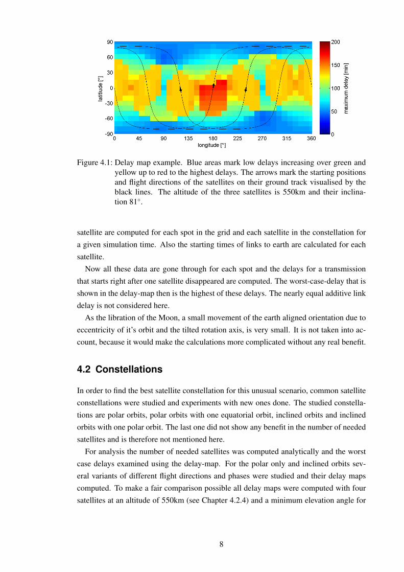
Figure 4.1: Delay map example. Blue areas mark low delays increasing over green andyellow up to red to the highest delays. The arrows mark the starting positionsand flight directions of the satellites on their ground track visualised by theblack lines. The altitude of the three satellites is 550km and their inclina-tion 81◦.
satellite are computed for each spot in the grid and each satellite in the constellation fora given simulation time. Also the starting times of links to earth are calculated for eachsatellite.
Now all these data are gone through for each spot and the delays for a transmissionthat starts right after one satellite disappeared are computed. The worst-case-delay that isshown in the delay-map then is the highest of these delays. The nearly equal additive linkdelay is not considered here.
As the libration of the Moon, a small movement of the earth aligned orientation due toeccentricity of it’s orbit and the tilted rotation axis, is very small. It is not taken into ac-count, because it would make the calculations more complicated without any real benefit.
4.2 Constellations
In order to find the best satellite constellation for this unusual scenario, common satelliteconstellations were studied and experiments with new ones done. The studied constella-tions are polar orbits, polar orbits with one equatorial orbit, inclined orbits and inclinedorbits with one polar orbit. The last one did not show any benefit in the number of neededsatellites and is therefore not mentioned here.
For analysis the number of needed satellites was computed analytically and the worstcase delays examined using the delay-map. For the polar only and inclined orbits sev-eral variants of different flight directions and phases were studied and their delay mapscomputed. To make a fair comparison possible all delay maps were computed with foursatellites at an altitude of 550km (see Chapter 4.2.4) and a minimum elevation angle for
8

a successful contact of 5◦.
4.2.1 Polar orbits
Needed satellites for full coverage
Polar orbits exclusively is probably the simplest constellation, but also the most inefficientas the coverage at the poles is very redundant.
To calculate the number of needed satellites we first need the half apex angle α of thecoverage cone. It can be calculated using the law of sine:
sin(β)
RM
=sin(90◦ + E)
h+RM
(4.1)
where β is the half apex angle of the satellite beam cone, RM the Moon radius, h thesatellite height and E the smallest elevation where communication is possible. With
α = 180◦ − (90◦ + E)− β (4.2)
we get the following result for the half apex angle of the coverage cone:
α = 90◦ − E − arcsin(cos(E) · RM
h+RM
)(4.3)
The criteria for full coverage is the coverage at the equator. Thus the number of neededsatellites can be calculated as follows:
Npol =⌈180◦
2α
⌉(4.4)
The plot as a function of the height is shown in the combined Figure 4.18 in Chapter 4.2.4.
Constellation variants
Several variants of the constellation with quite different results in the delay map are pos-sible. With the same number of satellites, orbital planes and altitudes, flight directionsand phase can vary. This doesn’t affect the coverage itself, but the maximum delay.
For polar orbits four variants have been studied (all in phase, with different flight direc-tions, with different phases and with both together). It was tried to find the best constella-tion possible for all variants to make a fair comparison feasible.
9

Variant 1: All in phase
The variant with all satellites in phase (same flight direction and same phase) in Figure4.2 is the simplest but also the worst in terms of delay as they all pass one line of latitudeat the same time. So one spot that can communicate with multiple satellites sees them allat the same time but has to wait a full revolution period to the next contact.
As the satellites move northwards on the one side and southwards on the other side ofthe Moon, the areas around 157.5 and 337.5 longitude are passed twice per revolutionwhich leads to a lower maximum delay at these spots (Figure 4.3).
Figure 4.2: Constellation of four polar orbits with same flight direction and same phase at550km altitude.
Figure 4.3: Delay map of four polar orbits with same flight direction and same phase at550km altitude. The meaning of the elements is the same as in Figure 4.1.
10

Variant 2: Different flight directions
A method to improve the all-in-phase constellation is to change the flight directions oftwo of the satellites (Figure 4.4). Now the poles are passed twice per revolution but theequator is still passed just once per revolution. The delay at the areas around 157.5◦ and337.5◦ is still better than in other regions because of the same reason as in variant 1. Theresulting delay map is shown in Figure 4.5.
Figure 4.4: Constellation of four polar orbits with different flight directions and samephase at 550km altitude.
Figure 4.5: Delay map of four polar orbits with different flight directions and same phaseat 550km altitude. The meaning of the elements is the same as in Figure 4.1.
11

Variant 3: Different phases
Another method to improve the all-in-phase constellation is to introduce a phase-offsetbetween the satellites as shown in Figure 4.6. This solves the problem at the equator asadjacent satellites pass a spot which can see both of them, with a phase shift of half arevolution. That is way the spot has two contacts per revolution. The problem with foursatellites is that this doesn’t work out even, which leads to the two big spots with higherdelay in Figure 4.7. An odd number of satellites would be better for this constellation.
Figure 4.6: Constellation of four polar orbits with same flight direction and differentphases at 550km altitude.
Figure 4.7: Delay map of four polar orbits with same flight direction and different phasesat 550km altitude. The meaning of the elements is the same as in Figure 4.1.
12

Variant 4: Different phases and flight directions
A slight improvement of variant 3 is the combination of different flight directions anddifferent phases. This constellation, shown in Figure 4.8, has a slightly lower delay atthe high delay spots but also a slightly higher delay at some low delay parts of variant3 (Figure 4.9). But the overall variance of the delay is smaller which leads to a morehomogeneous coverage.
Figure 4.8: Constellation of four polar orbits with different flight directions and differentphases at 550km altitude.
Figure 4.9: Delay map of four polar orbits with different flight directions and differentphases at 550km altitude. The meaning of the elements is the same as inFigure 4.1.
13

4.2.2 Polar orbits with one equatorial orbit
Needed satellites for full coverage
The efficiency of polar orbits can be increased by adding an equatorial orbit to the constel-lation because the criterion for full coverage is not the coverage at the equator anymorebut the coverage at latitude α (the half apex angle of the coverage cone of the equatorialsatellite). This leads to a multiplication with the factor cos(α) and one extra satellite:
Npolequ =⌈180◦
2α· cos(α)
⌉+ 1 (4.5)
Constellation
Adding the equatorial orbit to the constellation has one huge benefit for the delay. Theproblem area around the equator gets additional coverage. For the polar satellites, onlythe best constellation from Chapter 4.2.1 was considered. This is the one with differentflight directions and phases. As this constellation has an odd number of polar satellites theproblem of the high delay spots does not occur anymore. The equatorial orbit is shiftedabout 180◦ in comparison to the polar orbits so that they complement ideally (Figure4.10).
In the delay-map in Figure 4.11 it is shown that within the coverage band of the equa-torial satellite the delay gets significantly better. Additionally the delay at the far side ofthe Moon is also much lower in this constellation.
Figure 4.10: Constellation of three polar and one equatorial orbit with different flight di-rections and different phases at 550km altitude.
14

Figure 4.11: Delay map of three polar and one equatorial orbit with different flight direc-tions and different phases at 550km altitude. The meaning of the elements isthe same as in Figure 4.1.
15

4.2.3 Inclined orbits
Needed satellites for full coverage
Adding the equatorial orbit to the polar orbit constellation as done in Chapter 4.2.2 in-creases the efficiency but the coverage at the poles is still very redundant. The idea of theinclined orbits is to better disperse the coverage over the whole globe at the expense ofthe redundancy at the poles. To reach this goal the borders of the covered band of eachsatellite shall traverse at the poles. The criterion for full coverage is still the coverage atthe equator, but the covered angle is bigger than 2α now, as the covered bands are rotatedby α. Thus the new half of the covered angle at the equator is:
sin(α′) =sin(α)
cos(α)= tan(α) (4.6)
and the number of needed satellites can be calculated as follows:
Nincl =⌈180◦
2α′
⌉=
⌈180◦
2 · (arcsin(tan(α)))
⌉(4.7)
Constellation variants
In this constellation are also several variants possible and have quite different results inthe delay-map. The number of satellites, orbital planes and the altitudes stay the sameagain and flight directions and phases vary.
Just like for the polar orbits four variants were studied again: All in phase, with differentphases, with different flight directions and both together. As the different flight directionslead to the best result and the additional different phases have no improvement, only thefirst three variants are mentioned.
It was tried to find the best constellation possible for each variant to make a fair com-parison feasible here as well.
16

Variant 1: All in phase
The simplest variant is with all four satellites in phase again, meaning all having the sameflight direction and phase as shown in Figure 4.12. The fourth satellite is behind the Moonbecause it wasn’t possible to get all of them on one expressive picture.
With the inclined constellations the poles are the weak points and with this variant allsatellites cover them at the same time. Thus the poles have only one contact to a relaysatellite per revolution and because of this a high maximum delay. Figure 4.13 showsthe belonging delay map. The situation at the equator is better, as two satellites pass byduring one revolution. The far side of the Moon has a slightly higher delay because thesatellites need to store the data until they get out of Moon’s shadow again.
Figure 4.12: Constellation of four inclined orbits with same flight direction and samephase at 550km altitude.
Figure 4.13: Delay map of four inclined orbits with same flight direction and same phaseat 550km altitude. The meaning of the elements is the same as in Figure 4.1.
17

Variant 2: Different phases
To improve variant 1 a phase offset between the satellites can be introduced again whichleads to the optimised constellation in Figure 4.14.
The delay map in Figure 4.15 shows a significant improvement at the poles which re-sults from the different directions the satellites are crossing the equator now, two satellitesnorthwards and two southwards. Thus the poles are covered by just two satellites at thesame time now, leading to two contacts per revolution. The situation at the equator be-tween two nodes is still a bit unhandy as two satellites are passing by, but with one fourthrevolution difference only. This leads to a gap of a three fourth revolution afterwards.
Figure 4.14: Constellation of four inclined orbits with same flight direction and differentphases at 550km altitude.
Figure 4.15: Delay map of four inclined orbits with same flight direction and differentphases at 550km altitude. The meaning of the elements is the same as inFigure 4.1.
18

Variant 3: Different flight directions
The other method to improve variant 1 is putting the satellites on different flight directionsas shown in Figure 4.16. As they cross the equator in different directions again, theproblem at the poles is solved as well. In addition the problem spots of variant 2 at theequator between two nodes are fixed as the phase difference between two passing satellitesis half a revolution. The delay map in Figure 4.17 shows this very well.
In this constellation the average delay and also the variance in delay are very low. Onlythe far side of the Moon experiences a slightly higher delay for obvious reasons. Thisproblem will be solved with the Libration Point satellite in Chapter 4.3.2.
Experiments with a combination of different flight directions and different phases dif-ferences did not show any improvements. In fact these combinations mostly led to im-pairments. That is why it is not mentioned here anymore.
Figure 4.16: Constellation of four inclined orbits with different flight directions and samephase at 550km altitude.
19

Figure 4.17: Delay map of four inclined orbits with different flight directions and samephase at 550km altitude. The meaning of the elements is the same as inFigure 4.1.
20

4.2.4 Comparison of the constellations
Figure 4.18: Comparison of the needed satellites of the three constellations. In black thepolar constellations, green showing the polar with one equatorial constella-tion and red the inclined.
As Figure 4.18 shows, the constellation with inclined orbits is the most efficient. Italways needs less or equal satellites as the other two constellations to cover the wholeMoon surface. The polar with one equatorial satellite constellation is the worst in thisdiscipline. It needs the most satellites to achieve full coverage.
But the number of needed satellites is not the only important attribute. The delay needsto be considered, too. The constellation with one equatorial satellite can score here incomparison to polar satellites only. But the inclined orbits are in this category the bestagain.
The computed delay maps are all without taking Moon’s rotation into account and witha simulation time of one day. On this plot the regional coverage can be seen very goodand bad covered areas marked in red can be located and eliminated by optimising theorbital parameters of the satellites. But to get a more realistic simulation Moon’s rotationmust be taken into account and the simulation time needs to be the revolution time of theMoon, 28 days. As this simulation takes quite a while it was only done with the bestconstellation, the inclined orbits with different flight directions.
At first the simulations were done with an altitude of 500km. When doing the simula-tion with Moon’s rotation taken into account it revealed a weak point around the equatoras Figure 4.19 shows it. Some spots come out of sight with the satellite due to Moon’srotation. Increasing the altitude to 550km solves this problem. The delay map in Figure4.20 shows a nearly constant maximum delay with only the usual higher delay area at thecentre.
21

Figure 4.19: Delay map of four inclined orbits with different flight directions and samephase at 500km altitude with Moon’s rotation taken into account and a simu-lation time of 28 days. The meaning of the elements is the same as in Figure4.1.
Figure 4.20: Delay map of four inclined orbits with different flight directions and samephase at 550km altitude with Moon’s rotation taken into account and a simu-lation time of 28 days. The meaning of the elements is the same as in Figure4.1.
22

4.3 Special constellations
This chapter is about two special constellations which cover areas of the Moon perma-nently, in contrary to the original LunaNet idea. A simple polar orbit constellation thatcovers the whole Moon surface and a constellation with only one satellite at the Librationpoint L2 that covers Moon’s far side.
4.3.1 Constant coverage with polar orbits
Figure 4.21: Example for a constant coverage constellation with three polar orbits planesand six satellites on each plane at an altitude of 800km.
In contrary to the previously considered constellations this one covers every spot on theMoon at all times. It is basically an extension of the constellation with polar orbits fromChapter 4.2.1. But now the equator needs to be covered by more than one satellite perorbit. Every orbit must be filled by enough satellites so that a constant coverage of theequator is assured. If the equator is covered constantly every spot on the Moon is coveredconstantly as the distance between two satellites on neighbouring planes is largest at theequator.
A small improvement can be made if the satellites on two neighbouring orbital planesare shifted in phase so that the overlap of the covered areas is minimised. The geometryof this shift is shown in Figure 4.22. Figure 4.21 shows an example constellation withthree orbital planes and six satellites on each plane.
As the satellites’ orbits all have the same characteristics, perturbations affect all satel-lites alike and the constellation keeps it’s shape over time.
23

r
r
r
60°
r
r
ra dlat
dlong
Figure 4.22: Geometry of the calculations on the constant link constellation. On the leftside the covered areas of three neighbouring satellites are shown. On theright side a zoom into the interesting area for the calculation.
Needed satellites for constant coverage
The radius of the covered circle can be calculated out of the half apex angle α of thecovered cone and Moon’s radius RM :
r = α ·RM (4.8)
The distance dlong between two neighbouring orbit planes on the equator can be calcu-lated out of r. As this distance is also the covered part of the equator of one orbital plane,the apex angle αlong of the covered part can be obtained using Equation 4.8:
dlong = r · cos(60◦) + r =3
2· r =
3
2· α ·RM ⇒ αlong =
3
2· α (4.9)
The distance dlat between two neighbouring satellites on one orbit plane can be calcu-lated out of r, too. As this distance is also the covered part of one satellite on a line oflongitude, the apex angle αlat of the covered part can be obtained using Equation 4.8:
dlat = 2 · r · sin(60◦) =√
3 · r =√
3 · α ·RM ⇒ αlat =√
3 · α (4.10)
The orbital planes need to cover half of the equator as the other half is then coveredautomatically. The satellites on one orbital plane however need to cover the full circle.
24

The resulting equation for the number of needed satellites for a full constant coverage is:
Nc,pol =
⌈π
αlong
⌉·⌈
2π
αlat
⌉(4.11)
Figure 4.23: The number of needed satellites (N) for a constant coverage constellationwith polar orbits as a function of the altitude.
Figure 4.23 shows the result from Equation 4.10 as a function of the altitude. Theconstellation with the fewest needed satellites is possible from an altitude of 4651kmwhere two orbital planes with three satellites each are needed.
To make a constant connection possible even at the far side of the Moon, inter-satellitelinks are mandatory. Satellites in Moon’s shadow need another satellite outside of it andin visibility to relay the data to Earth. But as the covered areas of neighbouring satellitesdo overlap a satellite can always reach it’s neighbours.
25

4.3.2 Libration point orbit
In an orbital configuration with a central body and a smaller one orbiting it, like the Earth-Moon configuration, five points of orbital equilibrium, called Libration points, exist [7].In these points the sum of the two gravitational pulls and the centripetal force equals zero.
L1, L2 and L3 are located on the line defined by Earth and Moon. L1 between themnearer to the Moon, L2 behind the Moon and L3 on Moon’s orbit but on the opposite ofEarth. They are all stable in the plane perpendicular to the Earth-Moon axis but unstablein the direction of the axis itself. It is possible to stay in an orbit around these Librationpoints but periodical correction manoeuvres are needed [7]. L4 and L5 are on Moon’sorbit 60◦ ahead and behind the Moon. They are both instable in the orbital plane of Moonbut the Coriolis effect keeps objects at these two Libration points on Halo orbits aroundthem. Figure 4.24 shows the Libration points of the Earth-Moon system.
Figure 4.24: Position and stability of the five Libration points in the Earth-Moon system.Source: NASA
An orbit around the libration Point L2 has the positive attribute that the satellite isalways in view of the far side of the Moon, which makes it very interesting for a commu-nication satellite. The far side could constantly be covered and with a large enough orbitradius constant connection to earth is also possible.
As an analytical calculation of an orbit around the L2 is nearly impossible, the orbit inFigure 4.25 was computed numerically using STK of AGI. The shape of the orbit is notcircular or periodic. The satellite is orbiting the L2 on a Lissajous curve which can beseen in Figure 4.26, showing the same orbit but for a time period of eight instead of two
26

Figure 4.25: Orbit around the libration point L2 for a two week time period.
weeks. After about one year the Lissajous curve is repeating itself. Figure 4.27 shows theorbit for a one year time period. As the satellite gets very near to the center of it’s orbit,the libration point, constant connection to earth is not guaranteed anymore. During thepurple sections of the orbit, communication with earth is not possible (Figure 4.27).
In addition to the oscillations perpendicular to the Earth-Moon-axis responsible for theLissajous curve there is a third oscillation in the direction of the Earth-Moon-axis formingthe trajectory to a tube. Figure 4.28 shows detailed views of the constellation. The x-axisis defined as the Earth-Moon axis pointing away from Earth, the y-axis is the direction ofmotion of the coordinate system and the z-axis is perpendicular to the two others.
Figure 4.29 shows the proportions and distances of the constellation.
27

Figure 4.26: Orbit around the libration point L2 for an eight week time period.
Figure 4.27: Orbit around the libration point L2 for a one year time period. The purplesections of the orbit mark the phases of no connection to earth.
28

YZ XZ XY
Figure 4.28: Detail views of the L2 orbit. Left: view of the YZ plane (as seen from Earth).Middle: View of the XZ plane (from the side). Right: View of the XY plane(from the top).
Figure 4.29: Wide view of the L2 constellation with Moon and Earth in the picture, illus-trating the proportions.
29

Manoeuvres
As the Libration point L2 and orbits around it are instable in the direction of the Earth-Moon-axis a satellite would not stay there without active corrections. Periodical manoeu-vres are needed. In the example treated here a manoeuvre is done every two weeks. Amanoeuvre consists of a small change in velocity along the Earth-Moon-axis as it can beinduced by a cold gas thruster [7].
The mechanics of Libration points are very complicated and determining the manoeu-vres needed to stay there as well. Calculating this would go beyond the scope of thisbachelor thesis. This is why the values of the needed velocity changes were determinedby trial and error. Therefore, this needs to be seen as a basic investigation on the feasibilityof such a mission rather than a detailed analysis.
To make biweekly manoeuvres possible they need to be of an accuracy of at least 1mms
.This is clearly feasible as cold gas thrusters can produce thrusts of down to 20mN [7].With a satellite mass of 500kg this would result in a thrust time of 25s. This can becalculated using the conservation of linear momentum:
m · v =∫Fdt = F · t ⇒ t =
m · vF
=500kg · 1mm
s
20mN= 25s (4.12)
Constant coverage cone
As the satellite is moving on a non-circular orbit around the libration point L2 azimuthand elevation under which it is seen from a spots on Moon’s surface vary over time. Forspots near the edge of the covered area this can also result in loosing the connection. Tocalculate the cone in which a constant connection is guaranteed the worst-case must beassumed. In terms of elevation and range relative to the center of Moon’s far side theworst-case is the combination of the lowest elevation and the shortest range. These valuescan be taken from the simulation. An applicable plot of elevation and range over time isshown in Figure 4.30.
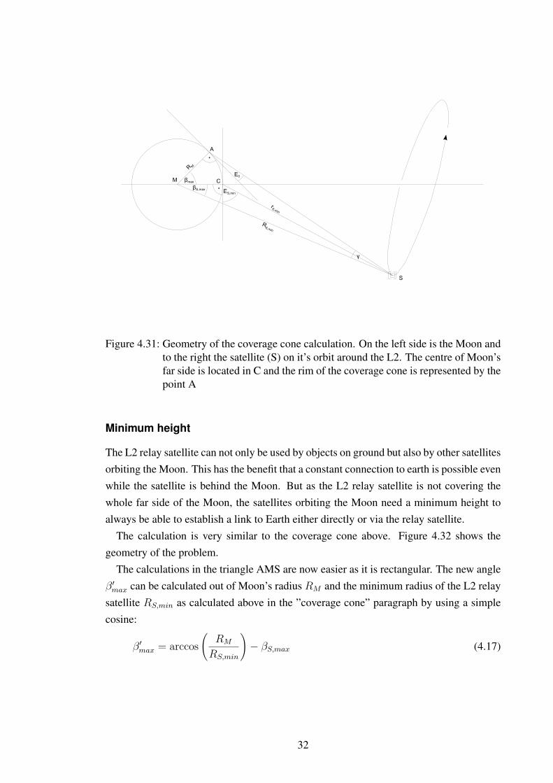
The half apex angle of the constant covered cone can be calculated by using the lawsof cosine and sine. Figure 4.31 shows the geometry of the problem.
The minimal radius RS,min of the satellite can be calculated out of Moon’s radius RM ,the minimum distance rS,min to the centre of Moon’s far side C and the minimum eleva-tion ES,min under which the satellite is seen from that point by using the law of cosine:
R2S,min = R2
M + r2S,min − 2 ·RM · rS,min · cos(90◦ + ES,min) (4.13)
Using this value the angle βS,max between the satellite radius vector and the vectorpointing from M to C can be calculated with the law of sine:
sin(90◦ + ES,min)
RS,min
=sin(βS,max)
rS,min
⇒ βS,max = arcsin
(rS,min
RS,min
· cos(ES,min)
)(4.14)
30

Figure 4.30: Elevation and range over time relative to the centre of Moon’s far side.Source: STK
The last angle needed to calculate βmax is the apex angle γ of the triangle AMS at thepoint S. It can be calculated out of RS,min, RM and the minimum elevation E0 underwhich a communication with the satellite is possible, using the law of sine:
sin(90◦ + E0)
RS,min
=sin(γ)
RM
⇒ γ = arcsin
(RM
RS,min
· cos(E0)
)(4.15)
With a simple angle summation the half apex angle βmax of the constant covered conecan be obtained:
βmax = 180◦ − 90◦ − E0 − γ − βS,max (4.16)
With a minimum elevation of the satellite seen from the centre of Moon’s far sideES,min = 68◦ and a minimum range of rS,min = 54000km obtained from Figure 4.31,the radius of the Moon RM = 1737.1km [8] and a minimum elevation under whichcommunication is possible of E0 = 5◦, the half apex angle of the constant covered coneis:
βmax ≈ 62◦
31
ES,min
βmaxβS,max
E0
γ
R M
rS,min
M
A
C
S
RS,min
Figure 4.31: Geometry of the coverage cone calculation. On the left side is the Moon andto the right the satellite (S) on it’s orbit around the L2. The centre of Moon’sfar side is located in C and the rim of the coverage cone is represented by thepoint A
Minimum height
The L2 relay satellite can not only be used by objects on ground but also by other satellitesorbiting the Moon. This has the benefit that a constant connection to earth is possible evenwhile the satellite is behind the Moon. But as the L2 relay satellite is not covering thewhole far side of the Moon, the satellites orbiting the Moon need a minimum height toalways be able to establish a link to Earth either directly or via the relay satellite.
The calculation is very similar to the coverage cone above. Figure 4.32 shows thegeometry of the problem.
The calculations in the triangle AMS are now easier as it is rectangular. The new angleβ′max can be calculated out of Moon’s radius RM and the minimum radius of the L2 relaysatellite RS,min as calculated above in the ”coverage cone” paragraph by using a simplecosine:
β′max = arccos
(RM
RS,min
)− βS,max (4.17)
32

ES,min
β'max
βS,max
R M
rS,min
M
A
C
S
RS,min
hmin
α
B
Figure 4.32: Geometry of the minimum height calculation. The Moon with it’s centre Mis located on the left side and the L2 satellite to the right. Point B is theintersection of the coverage edges of the connection to earth and to the L2satellite. Satellites that are higher above the ground as point B always havea connection to Earth.
Using a simple angle summation the angle α can be determined:
α =1
2(90◦ − β′max) (4.18)
With this angle α and another cosine the minimum orbit height needed for a constantconnection to Earth can be calculated:
hmin =RM
cos(α)−RM = RM
(1
cos(α)− 1
)(4.19)
With the same values for ES,min, rS,min and RM as in the coverage cone calculationabove, the minimum orbit height needed for a constant connection either directly or viathe L2 relay satellite is:
hmin ≈ 27km
This is as already expected from the geometry in Figure 4.32 very small in comparison tocommon orbit heights. Some margin needs to be added but nevertheless, most missionswould be able to establish a constant connection to earth using the L2 relay satellite.
33

Conclusion
The L2 relay satellite is a very good solution to cover Moon’s far side, but with higheroperational efforts than other options. The biggest benefit is that only one satellite isneeded to provide a nearly constant link to Earth. It’s weak point is the edge region. Aconstant coverage on ground can not be guaranteed here.
For satellite missions not lower than approximately 50km altitude a constant link toearth can be realised. This can be very interesting for missions observing the far side ofthe Moon with instruments producing huge amounts of data as the need for storing theresults in a mass memory disappears.
34

5 Protocols
In classic space missions links to and from the satellites are direct, using a dedicatedground station. The ground stations are rented or owned by the satellite operator andthe whole communication is scheduled to a specific time. New commands are preparedfar before their execution so that there are multiple contact chances left if one ore moretransmissions fail. In other words the high effort needed for operating a satellite missionmainly is due to the high effort that is put into communication with the satellite. Evenmore effort is required if relay satellites are needed. This is mainly the case in rovermissions, as rovers normally do not have the transmission power to send radio waves allthe way back to earth or do not even see the earth.
The Consultative Committee for Space Data Systems (CCSDS), an interagency work-ing group defining standards for space applications, founded 1982 made a lot of progressin establishing standards for space communication links [1]. It is mainly thanks to them,that ground stations have standard interfaces to the satellites and mission control centresnowadays. Multiple agencies can work together on operating a mission without definingthe communication protocols every time and a lot of the communication on ground is al-ready handled by the internet. But the used communication protocols for space links arestill very unintelligent.
When designing a satellite communication network for satellites and other objects inspace, the protocols must be more flexible and self organised. Otherwise the operationaleffort would be excessive. The internet protocols Transmission Control Protocol (TCP)and Internet Protocol (IP) are the successful solution in the internet. So why not considerto use them for a space application? The flexible routing and the possibility to easilyexpand the network of IP as well as the fault tolerance and reliability of TCP are consid-erable attributes for a satellite communication network.
However, some characteristics of the space environment will cause problems. Thehigher bit error rates for example will cause TCP’s slow start mechanism to throttle downthe transmission speed lower than the link capacity. This is an issue that needs to besolved.
Other problems are the link delay and the fact that satellites might need to store packetsuntil the next possibility to send it to the destination. A solution for these problems iscurrently under development by a group around Vint Cerf on behalf of NASA. It is calledDelay Tolerant Networking (DTN) and can also be combined with TCP/IP [4].
Both solutions shall be covered here. As well as different communication scenarios at
35

the Moon and their requirements on the protocols.
5.1 TCP/IP
5.1.1 IP
The Internet Protocol (IP) is the protocol defining the internet. In the Open Systems Inter-connection Reference Model (OSI Model) it has the function of layer three, the NetworkLayer (see Figure 5.1) and thus has the following tasks:
1. ”The Network Layer provides the functional and procedural means for connec-tionless-mode or connection-mode transmission among transport-entities and, there-fore, provides to the transport-entities independence of routing and relay consider-ations.
2. The Network Layer provides the means to establish, maintain, and terminate net-work-connections between open systems containing communicating application-entities and the functional and procedural means to exchange network-service-data-units between transport-entities over network-connections.
3. It provides to the transport-entities independence from routing and relay considera-tion associated with the establishment and operation of a given network-connection.This includes the case where several subnetworks are used in tandem [...] or inparallel. It makes invisible to transport-entities how underlying resources such asdata-link-connections are used to provide network-connections.
4. Any relay functions and hop-by-hop service enhancement protocols used to supportthe network-service between the OSI end systems are operating below the TransportLayer, i.e. within the Network Layer or below.” [6]
In other words, it shall handle the network and all the routing and be transparent to higherlayers.
The internet is designed hierarchically. A backbone network spans it worldwide andis divided into subnetworks locally. These subnetworks are then again divided into sub-subnetworks and so on. The address under which a client can be reached, called the IPaddress, contains the information to which subnetwork it belongs. This makes it possibleto find the destination of a packet very fast. Routers check in which subnetwork the des-tination is and then pass the packet to the responsible router. This router then checks inwhich subsubnetwork the destination is and passes the packet accordingly and so on. Apacket from one client to another client in a completely different subnetwork thus makesall the way up in the hierarchy and down again to the destination.
36
This makes it very useful for a space communication network, status and availabilityinformation just needs to be broadcasted locally. A satellite at the Moon does not need toknow how the router configuration on earth is. It just knows that the packets destination ison earth because of the address and sends it to the next node which is mentioned as routerto Earth in it’s routing table. In terms of subnetworks the network at the Moon would be asubnetwork for it’s own and the ground stations on earth it’s routers to the earth internet.
However there is a difference to Earth subnetworks. Earth subnetworks are normallystatic and a satellite communication network is not. In a static subnetwork one nodeis the router to other subnetworks and this doesn’t change over time. Thus the routingtables of the clients are fix. In satellite networks however the nodes move relative to eachother which causes constant changes of the available links. The routes must constantly beadapted to the current situation. But this is no problem for the IP, the satellites just needto be aware of the current situation and adapt their routing tables accordingly.
5.1.2 TCP
To make communication reliable is the main purpose of the Transmission Control Proto-col (TCP) in the internet. In the OSI model it is attached to layer four, the transport layer(see Figure 5.1) which has the following tasks:
1. ”The transport-service provides transparent transfer of data between session-entitiesand relieves them from any concern with the detailed way in which reliable and costeffective transfer of data is achieved.
2. The Transport Layer optimises the use of the available network-service to providethe performance required by each session-entity at minimum cost. This optimisa-tion is achieved within the constraints imposed by the overall demands of all con-current session-entities and the overall quality and capacity of the network-serviceavailable to the Transport Layer.
3. All protocols defined in the Transport Layer have end-to-end significance, where theends are defined as transport entities having transport associations. Therefore, theTransport Layer is OSI end open system oriented and transport-protocols operateonly between OSI end open systems.
4. The Transport Layer is relieved of any concern with routing and relaying sincethe network-service provides data transfer from any transport-entity to any other,including the case of tandem subnetworks [...]” [6]
In other words, the Transport Layer shall establish an end-to-end connection betweentwo nodes and make the communication between them reliable and cost effective so thatprotocols above (next layer is Session Layer) do not need to deal with network resources.
37

To fulfil these requirements TCP has congestion and flow control and error detectionmechanisms.
The error detection mechanism is based on checksums and acknowledgements. Everypacket contains a checksum the receiver can validate it’s correctness with. If the packet isreceived and correct, the receiver sends an acknowledgement to the sender. If the senderdoes not receive an acknowledgement in time it transmits the packet again.
The flow control mechanism ensures, that the receiver buffer will not exceed. Thereforthe remaining buffer size is sent by the receiver in every acknowledgement. The senderstops to send when the receiver buffer is full and waits for a message indicating that thereceiver is ready to receive data again.
Finally the congestion control mechanism takes care that the network will not becomeoverloaded. This is done by testing out the capacity of the connection. Therefor thetransmission is started with the so called slow start. The congestion window that definesthe number of not acknowledged packages that is allowed on the link, is set to a very lowvalue and increased every time a positive acknowledgement is received. When a packetis lost the sender enters slow start again.
This works out perfectly for wired networks, where packet losses mainly occur whenrouters are overloaded and start to drop packets because of full buffers. For wirelessnetworks this behaviour causes the transmission to be much slower than the link’s ability.On a wireless link lost packets are much more likely but most times not a reason fora needed slow start. The main reason for package loss is the unreliable transmissionmedium. This is a problem for space links as well as for Wifi networks. One approach tosolve it is to introduce a fast retransmit, if a packet is lost. The slow start phase is onlyentered after several lost packets. This is done in TCP-Reno.
However for severe round-trip delays TCP is even with adaptions ineligible as the pro-tocol is very much based on close statement-answer loops with the receiver. To reach thelink capacity with the transmission speed for example takes multiple round-trips. Withround-trip times of several minutes this is very inefficient.
5.2 DTN
Delay Tolerant Networking (DTN) has a different attempt to solve the problems with highdelays and bit error rates on long distance radio links. DTN introduces a new layer abovethe Transport Layer called Bundle Layer (see Figure 5.1) with the purpose to handlemultiple hops with waiting times in the nodes and unite networks and links with differentunderlying protocols. Thus local TCP/IP networks on Earth and Moon or other planetscan be interconnected by a protocol more suitable for a long distance radio link. And evenif this link is not always available applications do not need to take care of scheduling theircommunication as the bundle layer does this.
38

Space Link, Ethernet, ...
IPLTP
TCP
DTN
4 Transport
3 Network
2 Data Link
1 Physical
Bundle
Figure 5.1: OSI model protocol stack showing TCP, IP and LTP with Bundle Layer ex-tension including DTN.
But at first some deeper introductions into what bundles are and what the Bundle Layerdoes. A bundle contains a huge amount of data in the ideal case everything of one trans-mission. If for example multiple correlated files shall be downloaded from a satellite, allthese files should be packed in one bundle. This makes it possible for the Bundle Layerto optimise the routing as fragmentation of transmission can be avoided. The benefit ofthis mechanism can be best shown with an example. If there is a link from a router to thedestination, or a router near it and this link will terminate soon but multiple bundles stillwait for transmission and not all of them can be transmitted, the bundle layer can decideto send multiple small bundles instead of starting the transmission of one large one, whichcould not be transmitted completely anyway. The link can be used much more efficientlythis way, as the fragment of the large bundle would not be of any use for the receiver. Itneeds to wait for the next possible link anyway.
This leads directly to the next mechanism of the Bundle Layer. The possibility tostore bundles in routing nodes until the next hop is available. If for example a satelliteis relaying data from a ground vehicle on the far side of the Moon to Earth and is notpositioned in an orbit around the Libration Point L2 (see Chapter 4.3.2), it needs to storethe data first as it has no link to Earth at the moment itself. Hence the bundle is firsttransmitted to the relay satellite which stores it until it raises out of Moon’s shadow andforwards the bundle to Earth.
The Bundle Layer expects the underlying protocols to be capable of transferring datareliably which eliminates the need for acknowledgements on bundle level. However theyare still a possible option. This requirement for reliable communication makes TCP anexcellent candidate for local networks. But as described in Chapter 5.1.2 it has somedisadvantages on very long range links such as to Mars, which are disqualifying it. A newapproach that is especially designed for DTN is called Licklider Transmission Protocol(LTP) which is named in honour of the American computer scientist Joseph Carl RobnettLicklider. The LTP approach to deal with severe round-trip times is to send large blocks
39

and not to wait for an acknowledgement to continue with the next block. It distinguishesbetween red blocks which need to be transmitted reliably, like file headers, and greenblocks where bit errors are acceptable, like the pixels of an image. When transmittinga red block, the receiver answers with an acknowledgement indicating which parts wereread correctly and the sender can then retransmit missing parts.
5.3 Communication scenarios
5.3.1 Scenario 1: real-time
The simplest scenario is with a satellite as information source and a constant communi-cation link to earth. Either directly or via a relay like the L2 relay satellite from Chap-ter 4.3.2. The router on the source satellite needs to be aware of it’s and other relayingnodes orbits. This scenario can be realised with IP and a constantly updated routing table.
5.3.2 Scenario 2: real-time with intercepted connection
If interceptions of the connections are taken into account the situation becomes morecomplex and can not be handled by simple routing table updates. This scenario occurs ifa relay satellite is needed but not available. For example a satellite behind the Moon andwithout a L2 relay satellite from Chapter 4.3.2, or a rover on the near side with a too lowpowered radio transmitter to establish a link to Earth.
Three states are now possible: direction, relayed and no communication. The orbitaware router does now need to buffer data during times of no connection. This can berealised by extending the buffer sizes of IP so that all the packets send during phases ofno connection can be stored until the next possibility to forward them. The other solutionis using DTN, which is designed for such situations, for storing and routing.
5.3.3 Scenario 3: non-real-time
What has not be taken into account until now is the case of a rover on the far side ofthe Moon where a Moon orbiting relay satellite needs to store the data the rover wants tosend to Earth. This scenario is not real-time anymore as the receiving time is delayed incomparison to the sending time. However the solution for this scenario is very similar tothe real-time with intercepted connection scenario. The only difference is that the relaysatellites also need extended buffers now. This can again be realised with IP or DTN.
5.3.4 Scenario 4: optimisation of non-real-time scenario
In the previous scenarios the situation was very much simplified as the problems causedby multiple relay satellites were not considered. In a relay satellite constellation however
40

multiple possible relays are the case. The sender somehow needs to decide which relay totake.
The easiest routing algorithm is to take the first available satellite always. A bettersolution would be to take the satellite that gets in contact with Earth again next, but thisrequires additional knowledge of all the satellites orbits.
5.3.5 Scenario 5: finite buffer sizes, multi-user case with random access
To finally get to the complexity a real satellite communication is of, multiple users mustbe taken into account. This introduces new problems like contention of communicationwith the relay and contention of memory on the relay satellite which leads to a morecomplex situation on the satellite.
For routing solutions to satisfy this problem additional information of the other usersare mandatory. Different levels of detail of this information are applicable:
• The number of upcoming connections and their mean data volume is known. In thisscenario two possible solutions for optimising the routing strategy are conceivable.Every user optimises it’s routing for it’s own delay or the mean delay.
• Reservations are possible and known by all users as well as the buffer levels ofthe relays. The relay satellites calculate a buffer overflow likelihood based on theircurrent buffer levels, buffer sizes, reservations, density of sources and remainingtime in shadow and distribute it to all the users. The users can decide then whichsatellite to use depending on the buffer overflow likelihood and delays the relaysatellites bring along.
• The third possibility is that all participating nodes know all influencing factors andcan calculate the optimum routing strategy. This however needs a lot of broadcast-ing and calculation power in the nodes.
5.4 Conclusion
For a communication network at the Moon DTN is not mandatory. TCP and IP will mostprobably do a good job. The round trip delay to Moon is still small in comparison to otherPlanets. It’s maximum is:
trt =2 · rM,max
c=
2 · 405, 500km
299, 792kms
≈ 2.7s (5.1)
It is very likely that TCP is still able to handle this delay and DTN with LTP is notnecessarily needed. When thinking of a future satellite network at Mars or planets evenfarther away the use of a protocol like DTN is obligatory. Because of this the test in a
41

communication network at the Moon is very interesting. The routing however is also inDTN still a field of research and was only touched in this thesis.
42

6 Outlook
The most interesting aspects of a satellite communication system were attended to ortouched in this bachelor thesis. However multiple topics for further research are stillavailable. In the field of the Libration Point orbit for example a lot of work is still neededto be done to actually implement such a mission. Examining and planing the mission to aLibration Point is very demanding.
More detailed investigations are also needed on the protocols. Simulations especiallyof the various routing strategies will most probably bring up new conclusions and newproblems.
The motivation for this thesis was the communication experiment LunaNet which willbe a payload of the European Student Moon Orbiter. This mission will be a great possi-bility to test technologies of the space internet in the near future. The focus is hereby totest the protocols and also routing strategies can be tested up to a certain level. The workon finding a proper orbit constellation for satellite communication systems done in thisthesis will not have an impact on the LunaNet experiment as the orbit is defined by otherfactors. The research on the protocols however will continue as a part of this mission.
43

Bibliography
[1] CCSDS. CCSDS History. Website, 2009. Available online athttp://public.ccsds.org/about/history.aspx visited on October 27th 2009.
[2] Institute for Communications and Navigation at TUM. Satellite Navigation Labora-tory lecture notes, 2008.
[3] Network Working Group. RFC 2581: TCP Congestion Control. Website, 1999.Available online at http://tools.ietf.org/html/rfc2581 visited on October 28th 2009.
[4] Network Working Group. RFC 4838: Delay-Tolerant Networking Architecture.Website, 2007. Available online at http://tools.ietf.org/html/rfc4838 visited on Oc-tober 28th 2009.
[5] Network Working Group. RFC 5325: Licklider Transmission Protocol - Motiva-tion. Website, 2007. Available online at http://tools.ietf.org/html/rfc5325 visited onOctober 28th 2009.
[6] ITU-T. ITU-T Recommendation X.200: Information Technology - Open SystemsInterconnection - Basic Reference Model: The Basic Model. Website, 1994. Avail-able online at http://www.itu.int/rec/T-REC-X.200-199407-I/en visited on October28th 2009.
[7] Wilfried Ley, Klaus Wittmann, and Willi Hallmann. Handbuch der Raumfahrttech-
nik. Hanser, 2008.
[8] Dr. David R. Williams (NASA). Moon Fact Sheet. Website, 2006. Available onlineat http://nssdc.gsfc.nasa.gov/planetary/factsheet/moonfact.html visited on October28th 2009.
[9] Information Sciences Institute University of Southern California. RFC 791: InternetProtocol. Website, 1981. Available online at http://tools.ietf.org/html/rfc791 visitedon October 28th 2009.
[10] Information Sciences Institute University of Southern California. RFC793: Transmission Control Protocol. Website, 1981. Available online athttp://tools.ietf.org/html/rfc793 visited on October 28th 2009.
44