satcom retrodirective array - pure
TRANSCRIPT

SATCOM Retrodirective Array
Buchanan, N. B., Fusco, V. F., & van der Vorst, M. (2016). SATCOM Retrodirective Array. IEEE Transactions onMicrowave Theory and Techniques, 64(5), 1641-1621. https://doi.org/10.1109/TMTT.2016.2541121
Published in:IEEE Transactions on Microwave Theory and Techniques
Document Version:Peer reviewed version
Queen's University Belfast - Research Portal:Link to publication record in Queen's University Belfast Research Portal
Publisher rightsCopyright 2016 IEEE.Personal use of this material is permitted. Permission from IEEE must be obtained for all other users, including reprinting/ republishing thismaterial for advertising or promotional purposes, creating new collective works for resale or redistribution to servers or lists, or reuse of anycopyrighted components of this work in other works.
General rightsCopyright for the publications made accessible via the Queen's University Belfast Research Portal is retained by the author(s) and / or othercopyright owners and it is a condition of accessing these publications that users recognise and abide by the legal requirements associatedwith these rights.
Take down policyThe Research Portal is Queen's institutional repository that provides access to Queen's research output. Every effort has been made toensure that content in the Research Portal does not infringe any person's rights, or applicable UK laws. If you discover content in theResearch Portal that you believe breaches copyright or violates any law, please contact [email protected].
Download date:27. Mar. 2022
TMTT-2014-11-1273
1
Abstract— We present an in depth look at the challenges
involved in using analogue retrodirective arrays for satellite
communications. The main technical issues surrounding the
development of a retrodirective (self-steering) Satellite
Communications (SATCOM) system are given and techniques
for mitigating these issues provided. Detailed results are given for
a prototype high performance circularly polarized retrodirective
array architecture suitable for mounting on an un-stabilized
mobile platform. The paper concludes with practical
retrodirective L-band array results with the array used to
acquire actual broadband satellite data signals from a
commercial L-band satellite system. Received satellite signals as
low as -130dBm at the antenna elements are tracked. Accurate
self-tracking occurs over the azimuth range of up to ±±±±40°°°°.
Index Terms— Antenna arrays, Beam steering, Phase
conjugation, Phased arrays, Phased Locked Loop
I. INTRODUCTION
etrodirective, self-steering, antennas (RDA) have the
advantage of being able to automatically return a signal
back in the direction along from which it originated, [1].
If a retrodirective array could react to fast signal variations
with sufficient sensitivity then it could be used as a transceiver
in a mobile satellite communications (SATCOM) system, or
indeed as a self-steered transceiver in other mobile
applications where the requirement for automatic beam
alignment between un-stabilized platforms exists.
One application that could benefit from a retrodirective
self-tracking arrangement is satellite communications,
particularly when applied to terrestrial mobile scenarios. A
service that is currently available globally at L band, 1.5 GHz
receive (RX), 1.6 GHz transmit (TX), is the Inmarsat
Broadband Global Area Network (BGAN) [2]. A study of the
specification required for BGAN reveals that major step
changes of the type discussed in this paper are required if
retrodirective array technology is to be considered as a viable
option for this type of application.
The BGAN ground terminal is required to transmit an
Effective Isotropic Radiated Power (EIRP) of up to 50 dBm,
and the signal level it receives, at a single low gain antenna
element, can be down to -130 dBm. The stringent specification
on receiver sensitivity rules out the majority of known
retrodirective antenna array architectures, which fall into two
broad classes, either the frequency offset Van Atta type [3] or
the Phase Conjugating Pon type [4]. In addition to lack of
receive sensitivity these basic architectures are unable to deal
with complex modulation scenarios where transmit and
receive phase modulated signals are required to operate in full
duplex mode, e.g. for L-Band BGAN 16QAM at 150 kbps.
The top level specification needed for L-Band BGAN
SATCOM is compared with what is currently achievable with
reported self-steered antennas, and with the new architectural
approach presented in this paper in Table 1.
If retrodirective array technology is to be used in actual
SATCOM systems, then a fresh look at the approach used for
carrying out phase conjugation within the beam forming
circuitry is required. In this paper, we will describe an all
analogue phase conjugation circuit solution. The rationale for
this was given in [10], where analogue circuits were found to
be significantly more conservative with regards to power
consumption and simplicity when compared to digital
techniques. For example, it was calculated in [10] that a 4x5
RDA operating with data at a bit rate of 20 Mbps requires a dc
input power level of 16 W for Digital Signal Processing (DSP)
implementation, whereas an analogue implementation
consumes only 2 W and is largely bandwidth independent. In
addition to the power consumption issue, analogue electronics
are not governed by DSP throughput limitations, i.e. they
allow for real time instantaneous processing.
The type of analogue retrodirective antenna proposed here
operates without a priori knowledge of the target positon, and
therefore provides near instant signal acquisition., <10 mS, in
comparison to current motorized tracking antennas (for
example, the Hughes 9350 BGAN mobile satellite terminal)
that take approximately 1 minute to acquire since they require
a certain acquisition phase before switching to a tracking
phase.
The main contributions of this paper over previous works
are: (1) First presentation of practical results of a retrodirective
array with comparable performance to a commercial
SATCOM user terminal, (2) An in depth analysis of the many
design challenges of using analogue retrodirective arrays in a
SATCOM application (3) Six significant changes to the pre-
existing retrodirective architecture (Detailed in Sec. III).
II. HIGH PERFORMANCE PHASE CONJUGATION CIRCUIT
The generic block diagram for a ‘fit for SATCOM purpose’
phase conjugator shown within the context of a single
element, after considering the features in Table 1, is proposed
SATCOM Retrodirective Array
Neil B. Buchanan, Vincent F. Fusco, Fellow IEEE, Maarten van der Vorst
R
Manuscript received August 5th, 2015. The work reported here was
sponsored by European Space Agency contract “Self Focusing Retro-
Reflective Antennas for Mobile Terminal Applications”. AO/1-
6168/09/NL/JD
Vincent Fusco and Neil .B. Buchanan are with the Institute of
Electronics, Communications and Information Technology (ECIT),
Queen's University Belfast, Northern Ireland Science Park, Queen’s Road,
Queen’s Island, Belfast, United Kingdom, BT3 9DT, Tel +44 2890
971806, Fax +44 28 9097 1702 (e-mail: [email protected],
Maarten van der Vorst is with the European Space Agency, Keplerlaan
1, 2201 AZ Noordwijk, The Netherlands (e-mail:
TMTT-2014-11-1273
2
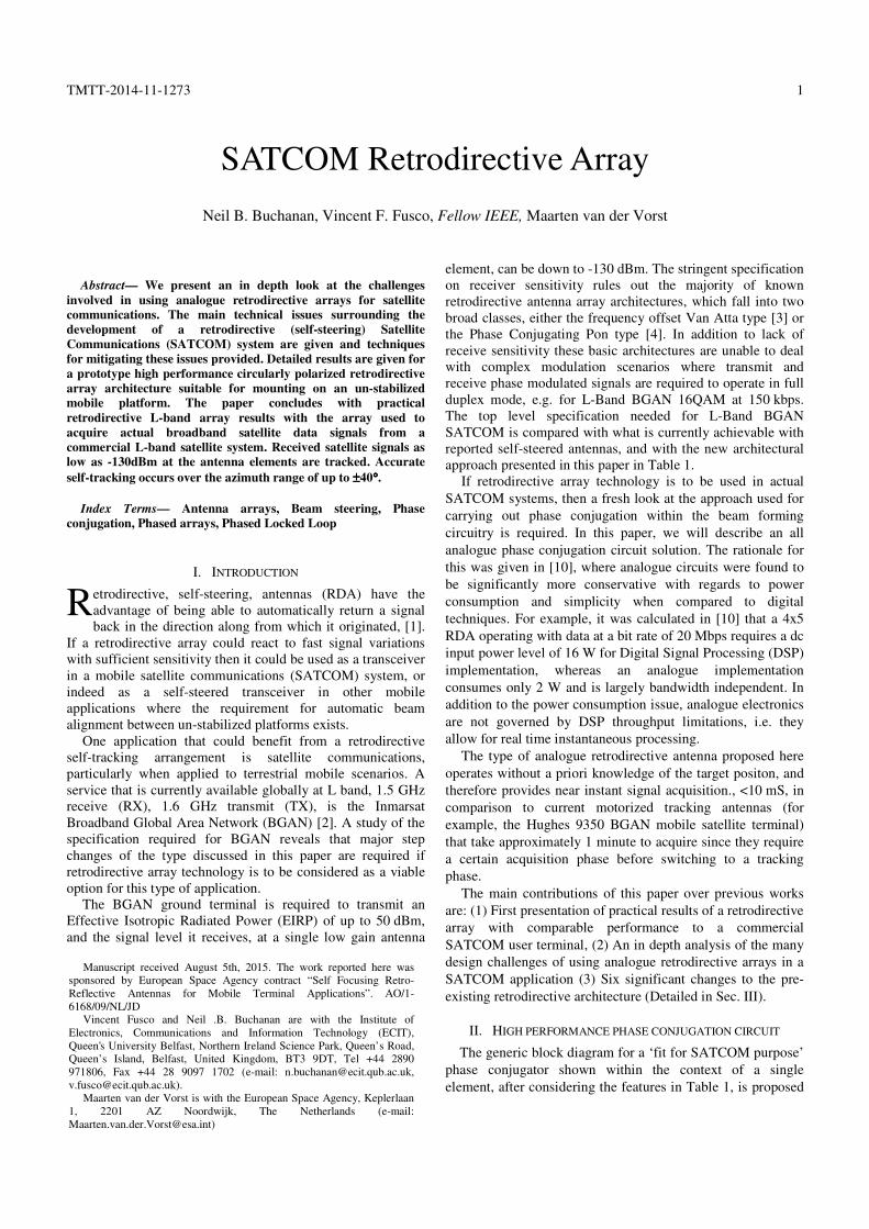
in Fig. 1.
In order to recover weak receive signal levels, and also to
provide a “clean” retransmit signal, a carrier recovery circuit
(tracking PLL) is required. This tracks the phase of the
received signal while concurrently removing its modulation
for subsequent receive side processing. The recovered clean
carrier is then phase conjugated, and transmit modulation is
applied to the PA for self-aligned data re-transmission to the
satellite.
For SATCOMs, a major challenge is that the system should
be able to coherently combine on receive. Normally this is a
feature not considered in retrodirective array design, where the
emphasis is on un-modified re-transmission of incoming pilot
and data. With the arrangement in Fig. 1, automatic optimal
signal re-combination from the array receive elements can be
performed since each of the array element’s carrier recovery
circuits output identical phase signals such that phase does not
vary with the angle of arrival of the received signal (RX IF,
Fig. 1). This is achieved within the phase locked loop circuit
by locking the received signal to a constant phase reference
signal, as described in detail in [11]. Maximal signal
recombining from all elements in the array then follows
through simple scalar summation at the chosen IF frequency.
This method allows optimal combination on receive over a
wide range of angles of arrival, and thus permits the array
factor of the retrodirective antenna to be used both on receive,
and on retransmit.
Fig. 1. Generic retrodirective element for SATCOM.
A. G/T performance
As with any satellite system the G/T performance needs to
be considered. Classical retrodirective antennas are not
normally characterised in this way since they are usually only
deployed for working with moderately strong signals. A
typical G/T figure for a high bit rate L band SATCOM system
[2] requires to be better than -10 dB/K. To analyse the G/T of
a retrodirective antenna we use the generic receiver
configuration [13] of Fig. 2. Here the low frequency IF signal
presented to the phase detector is considered to be the final
received signal, i.e. the one where signal to noise ratio will be
critical for successful demodulation of the data signal. Hence
it is essential to know what level of S/N the tracking PLL can
operate with, such that the quality of the regenerated carrier
used for retransmit is not adversely affected.
The G/T of a receiver can be characterized by using
cascaded receiver noise temperature, TR, [12] where:
�� � ���� � ��1 1/� ���� ������� 1�� ���
� ��������� 1�� �������
� ��������� 1�� ��������������
� ���� 1�� ���������������������
� ������ 1�� �����������������������
here: G/T = GANT/TR.
(1)
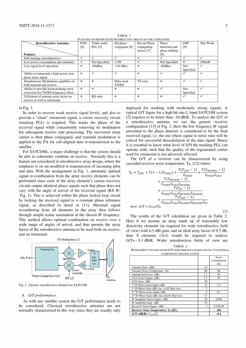
The results of the G/T calculation are given in Table 2.
Here if we assume an array made up of reasonably low
directivity elements (as required for wide retrodirective field
of view) with 6.5 dBi gain, and an ideal array factor of 9.5 dB,
then 9 elements (3x3) would be required to achieve
G/T= - 9.1 dB/K. Wider retrodirective fields of view are
TABLE 1
FEATURES OF REPORTED RETRODIRECTIVE ARRAYS IN THE LITERATURE.
Retrodirective Antenna:
Feature:
PON
[4]
Triple mode
PLL [5]
I/Q phase
conjugator [6]
Recent Phase
conjugating
mixers [7]
Phase
detection and
phase shifting
[8]
DSP
[9]
This Work
Self tracking (retrodirective) � � � � � � �
Low power consumption (per element) � Not Specified 1.5W � Not Specified � 100mW
Low signal level operation � -60dBm -110 dBm � -60dBm Not
Specified
�
Ability to retransmit a high power, low
phase noise signal
� � � � � � �
Simultaneous Modulation capability on
both transmit and receive
� � Pulse mod.
TX/RX
TX only � � �
Ability to provide beam pointing error
correction for TX/RX frequency offset
� � � � � Not
Specified
�
Utilization of antenna array factor on
receive as well as retransmit
� RX only � � � � �
TABLE 2
RETRODIRECTIVE RECEIVER G/T PERFORMANCE BASED ON FIG.2 WITH REAL
COMPONENT SPECIFICATIONS
Noise
Contribution
(K)
Antenna Gain (dBi) 16
Antenna Noise Temperature (K) 80 80
Antenna feed Loss (dB) 1.1 84
LNA Noise Figure (dB) 1.5 93
LNA Gain (dB) 30
1st IF Mixer noise figure (dB) 12 3.3
1st IF Mixer Gain (dB), Inc 1st IF filter loss 7
2nd IF Mixer noise figure (dB) 5 0.1
2nd IF Mixer Gain (dB), Inc 2nd IF filter loss 17
IF Amplifier Noise Figure (dB) 10 0.008
IF Amplifier Gain (dB) 53
Receiver Noise Figure (dB) 3 4.47E-09
Receiver Noise Temperature, TR (ΣΣΣΣTe) 260
G/T (dB/K) GANT/TR -9.1

TMTT-2014-11-1273
3
possible with lower gain elements [14] , or conversely, smaller
numbers of higher gain elements could be used at the expense
of steering coverage.
Fig. 2. Retrodirective transceiver architecture for G/T calculation.
B. Receiver carrier recovery requirements and effect on re-
transmitted signal
One major challenge of operating a retrodirective array
within satellite communications, is that the received signal at
each element is generally much weaker than experienced in
terrestrial applications. Levels as low as -130 dBm are present
at each element, close to the noise floor of the receiver. The
result is that the tracking PLL is required to lock to a signal
with very low S/N ratio, typically an S/N close to 0 dB after
the 2nd IF Filter (Fig. 2), resulting in phase jitter on the PLL
output. The RMS phase jitter of a PLL type receiver is given
by [15] as:
������� !"## � � $% &'�/() rads (2)
Equation (2) shows that in order for the PLL to recover
carrier information a sufficiently low cut off frequency (Bl)
needs to be used as the PLL loop filter (Fig. 2).
In [15] for an input signal of -120 dBm, an IF filter
bandwidth of 3 kHz, and a loop filter bandwidth of 99 Hz, an
RMS phase jitter of 6° is predicted. This compares favorably
with the measured results of the receiver in Fig. 2 which was
5° for a signal level of -120 dBm, and for -130 dBm, 8°
predicted, 10° measured. These results confirm that provided
the signal strength received at each individual element is
above -130 dBm then accurate phase tracking and conjugation
is possible. In an operational Inmarsat BGAN system the spot
beam received signal strength should be in the region of
-110 dBm per element. It is shown in [16] that for a
retrodirective array to have the ability to retransmit a high
quality retrodirected wavefront, that the conjugately phased
re-transmit carrier signal phases need to be matched within
10° for a 16 element array, meaning that the worst case
measured result reported here would be compliant.
Phase noise measurements at the IF output of the phase
tracking PLL VCO (Fig. 2) for a -120 dBm input gives an
output phase noise of -77 dBc/Hz @ 1 kHz offset and
-125 dBc/Hz @ 1 MHz offset, thus offering a low phase noise,
conjugately phased re-transmit carrier that is suitable to up
convert for high quality signal retransmission.
Generating the retransmitted signal from the retrodirective
array involves applying a modulated transmit LO signal
(TXLO Fig. 2), to the TX mixer (Fig. 2) and multiplying it
with a lower frequency signal from the tracking PLL VCO
(Fig. 2), in this case 156 MHz derived from a phase locked
26 MHz Temperature Compensated Voltage Controlled
Crystal Oscillator (TCVCXO). The lower sideband is filtered
(to provide phase conjugation) via the TX filter and
transmitted through a PA. Assuming the TX mixer and PA are
operating in the linear region, then the quality of the
retransmitted signal is dependent on the phase noise/phase
jitter characteristics of the 156 MHz tracking PLL signal.
To determine the quality of the phase modulated
retransmitted signal we measure the resultant Error Vector
Magnitude (EVM). Using the configuration of Fig. 2, a
16QAM 151.2 kbps modulated signal was applied to the
transmit LO signal and the up-converted retransmitted Error
Vector Magnitude (EVM) measured. The results of Fig. 3
show that a signal with a 2.7% EVM is retransmitted when the
retrodirective array is receiving a -110 dBm CW pilot beacon
while simultaneously retransmitting a 16QAM 151.2 kbps
signal. A received signal of -110 dBm per element is fairly
typical of an Inmarsat spot beam, based on practical
experience. If the array was receiving a global beam at
-130 dBm, then the retransmitted EVM for an 8.4 kbps QPSK
signal carried by that beam, is about 3.6%.
For a 9 element array, using (3), with a 9.5 dB array factor
(AF), 6.5 dBi element gain (GELE), one PA per element, NPA =
9, a transmit EIRP of 15 dBW can be achieved through ideal
spatial combining with 19.5 dBm (PPA) being radiated at each
PA per element, suggesting that a single or dual stage PA at
each up-converter output would be needed. Systems such as
Inmarsat BGAN need to conform to ETSI [17] standard for
retransmit spectral purity, so appropriate filters would be
necessary in the transmit up-converter chain.
EIRP(dBW) = PPA(dBm) -30 + 10log(NPA) + GELE+ AF (3)
Fig. 3. Measured retransmit EVM Vs received signal strength.
TMTT-2014-11-1273
4
C. Effect of TX/RX Frequency Offset on Beam Pointing
It was shown in [18] that for a frequency offset
retrodirective array that there is a difference in the received
signal angle of arrival, θin, compared to the retransmitted beam
direction, θs, (4)
(4)
BGAN via INMARSAT uses TX/RX 1.65/1.55 GHz
frequency operation. If we assume an array size of 3x3
elements, and the commonly used approximation for the shape
of the central region of the main beam of an antenna [19] as
being:
G(θ ) = G − 12 (θ /α )2 (5)
where G is the boresight gain (dB) and the half power
beamwidth is α, and we assume the half power beamwidth of
a 3x3 element array at 0.45λ element spacing to be 40°, then
from (4) the maximum beam pointing error is 3.2°, and (5)
pointing loss is 0.075 dB at ±40° which is the maximum
azimuth/elevation coverage achievable using the array of
planar antennas reported here.
III. RETRODIRECTIVE SATCOM PLL PHASE CONJUGATOR
The aim of this section is to describe a high performance
retrodirective array, which has been tailored for SATCOM
applications such as Inmarsat BGAN [2]. There are some
significant step changes to the retrodirective array to make this
possible, which will be discussed in detail.
Inmarsat BGAN [2] ground terminals receive and transmit
respectively in the frequency range 1525 to 1559 MHz and
1626 to 1660 MHz. To facilitate initial pointing of the user
ground terminal the BGAN system transmits an ‘always on’
global beam at 1537 MHz which is modulated with QPSK at
8 kbps. The global beam produces approximately -130 dBm
received signal strength at a ground terminal with an
omnidirectional antenna. The BGAN system’s three satellites
also support 256 spot beams per satellite, which are service
activated from the user terminal. For current land portable
ground terminal operation the user is required to first manually
align the terminal. The initial direction can be determined via
the use of information fed from a GPS receiver. Final
alignment is then carried through manually peaking a C/N0
display of the received global beam strength. Only after this
alignment does user terminal transmission occur which then
initiates a spot beam signal response from the satellite.
The challenge of tracking Inmarsat BGAN with a
retrodirective array is that the array must be capable of
initially acquiring the weak global beam signal, which is
typically 20 dB lower in signal strength than a spot beam. In
current systems the global beam is intended to be received
with an accurately aligned relatively high gain 12-20 dBi user
terminal antenna. The challenge with the retrodirective array is
that for zero manual alignment each individual low gain
element in the RDA must be able to track the global beam
signal phase independently. For a wide field of view RDA
each element may only have a gain in the region of 4-5 dBi
resulting in a -130 dBm received signal strength at each
antenna element output.
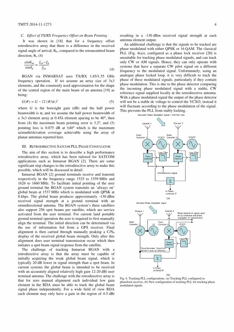
An additional challenge is that the signals to be tracked are
phase modulated with either QPSK or 16 QAM. The classical
PLL (Fig. 4(a)), configured as a phase lock receiver [20] is
unsuitable for tracking phase modulated signals, and can track
only CW or AM signals. Hence, they can only operate with
systems that have a separate CW pilot signal on a different
frequency to the modulated signal. Unfortunately, using an
analogue phase locked loop, it is very difficult to track the
phase of these modulated signals, particularly if they contain
phase modulation. This is due to the phase detector comparing
the incoming phase modulated signal with a stable, CW
reference signal supplied locally at the retrodirective antenna.
With a phase modulated signal the output of the phase detector
will not be a stable dc voltage to control the VCXO, instead it
will fluctuate according to the phase modulation of the signal.
This prevents the PLL from stably locking.
(a)
(b)
Fig. 4. Tracking PLL configurations. (a) Tracking PLL configured as
phaselock receiver, (b) New configuration of tracking PLL for tracking phase
modulated signals.

TMTT-2014-11-1273
5
To counteract this problem the architecture of Fig. 4(b) is
used, shown here in a simplified form. The basic principle is
that the signal from element 1 is used as the phase reference,
so that the phase detector is presented with two identically
modulated signals. This allows for a constant dc voltage to be
available at the phase detector output thus making the self
tracking architecture completely independent of the
modulation type used. The first channel has a fixed LO
frequency, and the second uses a Voltage Controlled Crystal
Oscillator (VCXO) as the LO, which has its control voltage
derived from the phase detector. The idea of using a narrow
band VCXO is that the jitter and phase noise of the signal is
very low, allowing for a high quality spectrally pure signal for
retransmission. It is shown in [21], when phase tracking a
received signal of -130 dBm, the phase jitter performance of
the VCXO is only degraded by 3° in comparison to the
classical phase lock receiver configuration of [20].
The architecture of Fig. 4(b) results in the two down
converted outputs always being in phase and can therefore be
optimally combined regardless of input phase of the input
signals. The relative phase difference of the LO and VCXO
track the phase of the incoming signals and can be used for
retransmission, back in the same direction, if they are up
converted using a phase conjugating mixer. The representation
in Fig. 4(b) is a simplified single conversion architecture, in
reality dual stage downconversion is required to allow the
removal of image frequencies on receive mode. Larger arrays
can be accommodated by using element 1 (Fig. 5) as the phase
reference and adding additional elements and phase
conjugation circuits.
Fig. 5. Accommodation of reference element on a larger 3x3 array.
To allow the tracking PLL to operate with the challenging
link budgets found in systems such as Inmarsat BGAN, some
improvements, in addition to the above, are required to the
retrodirective antenna phase conjugating PLL architecture.
These are: (1) An active PLL loop filter has been added,
which is 2nd Order with a cutoff frequency of 100 Hz
providing the best compromise between PLL stability and
locking performance to signals of low S/N ratio. (2) The
transmit and receive filters use a low loss commercial BGAN
duplexer (0.8dB loss on RX path, >60dB TX/RX isolation).
(3) The IF filter prior to the phase detector is a 10 KHz
bandwidth optimized for the 8.4 kbps global beam signal. (4)
The low noise amplifier uses two cascaded LNAS to give a
combined gain of 30 dB and noise figure of 1.2 dB. (5) Power
amplifiers were added to allow transmitted EIRPs in the
region of 10 dBW for a 3x3 element array. The new block
diagram, incorporating these changes, is shown in Fig. 7.
IV. RETRODIRECTIVE SATCOM PROOF OF CONCEPT ARRAY
A 3x3 element retrodirective proof of concept array has
been constructed, Fig. 6(a), according to the block diagram of
Fig. 7. The array elements are approximately λ/2 spaced to
prevent grating lobes. Power consumption was measured at
<100mW per element on receive tracking mode. The size of
the 3x3 array is 28cm x 28cm, c.f. 26cm x 32cm for a
commercial conventional terminal (Hughes 9201), Fig. 6(b).
(a) (b)
Fig. 6 (a) 1.5/1.6 GHz retrodirective array configured as 3x3, (b) Hughes 9201
commercial BGAN user terminal.
Fig. 7. Block diagram showing two elements of the retrodirective array for
BGAN tracking applications.
SATCOM systems such as Inmarsat BGAN [2] require
circular polarised antennas operating over a wide range of
scan angles. The array elements used in Fig. 6(a) are circular
patches with dual linear polarisation and are described in
detail in [22]. By feeding the dual linear ports with 0° and 90°,
circular polarisation can be generated over sufficient
bandwidth for this application. Sequential rotation of the
antenna elements [23] was deployed in order to reduce mutual
coupling effect and improve axial ratio, which was determined
TMTT-2014-11-1273
6
by the methods of [22] to be most favourable for retrodirective
circular polarised array use.
The patch element gain was measured as 6.65 dBi. This
reasonably high gain for a single element helps to achieve the
boresight G/T and EIRP, although is a compromise in terms of
the pointing loss obtained at other scanning angles when
deployed as a retrodirective array, since the element gain
reduces by at least 2 dB for ±40° azimuth/elevation angle,
which means that the overall monostatic response of these
elements, configured as a retrodirective array, will have a
similar pointing loss. This pointing loss is comparable to other
SATCOM proof of concept scanning antennas [24].
To correct for phase inaccuracies in the transmit local
oscillator beam forming network a preset phase adjust is used
(shown in Fig. 7). This phase shifting arrangement is used as a
one-off calibration adjustment to achieve coherent
transmission at boresight. After this adjustment the array will
phase-conjugate correctly over the required azimuth range.
The 3x3 array was measured in a 10m far field anechoic
chamber facility configured for retrodirective monostatic
radiation pattern measurements. In addition, the retrodirective
array had the ability to selectively switch on individual
elements, allowing active radiation patterns to be measured.
The methods of [25] were then used to calculate the bistatic
radation patterns, which account for the real effects of the
individual elements in the array, rather than the less accurate
method of using a generic element, multiplied by the array
factor.
Within the anechoic chamber the signal was transmitted to
the antenna under test at 1.54 GHz, using a dual polarised horn
antenna which was configured to transmit circular
polarisation. The retrodirective return signal retransmitted
from the antenna under test was then received in the far field
by a linear polarised horn antenna. Both vertical and
horizontal components of the retransmitted signal are
measured, and post processed to form circular polarised
radiation patterns.
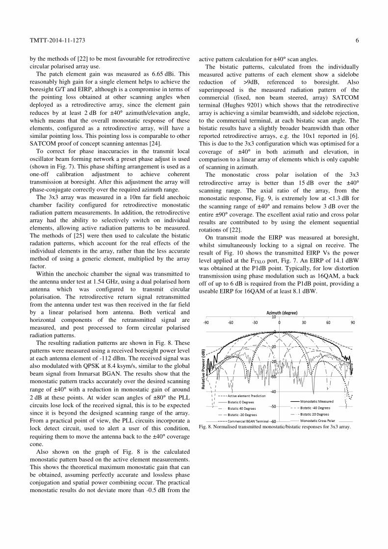
The resulting radiation patterns are shown in Fig. 8. These
patterns were measured using a received boresight power level
at each antenna element of -112 dBm. The received signal was
also modulated with QPSK at 8.4 ksym/s, similar to the global
beam signal from Inmarsat BGAN. The results show that the
monostatic pattern tracks accurately over the desired scanning
range of ±40° with a reduction in monostatic gain of around
2 dB at these points. At wider scan angles of ±80° the PLL
circuits lose lock of the received signal, this is to be expected
since it is beyond the designed scanning range of the array.
From a practical point of view, the PLL circuits incorporate a
lock detect circuit, used to alert a user of this condition,
requiring them to move the antenna back to the ±40° coverage
cone.
Also shown on the graph of Fig. 8 is the calculated
monostatic pattern based on the active element measurements.
This shows the theoretical maximum monostatic gain that can
be obtained, assuming perfectly accurate and lossless phase
conjugation and spatial power combining occur. The practical
monostatic results do not deviate more than -0.5 dB from the
active pattern calculation for ±40° scan angles.
The bistatic patterns, calculated from the individually
measured active patterns of each element show a sidelobe
reduction of >9dB, referenced to boresight. Also
superimposed is the measured radiation pattern of the
commercial (fixed, non beam steered, array) SATCOM
terminal (Hughes 9201) which shows that the retrodirective
array is achieving a similar beamwidth, and sidelobe rejection,
to the commercial terminal, at each bistatic scan angle. The
bistatic results have a slightly broader beamwidth than other
reported retrodirective arrays, e.g. the 10x1 reported in [6].
This is due to the 3x3 configuration which was optimised for a
coverage of ±40° in both azimuth and elevation, in
comparison to a linear array of elements which is only capable
of scanning in azimuth.
The monostatic cross polar isolation of the 3x3
retrodirective array is better than 15 dB over the ±40°
scanning range. The axial ratio of the array, from the
monostatic response, Fig. 9, is extremely low at <1.3 dB for
the scanning range of ±40° and remains below 3 dB over the
entire ±90° coverage. The excellent axial ratio and cross polar
results are contributed to by using the element sequential
rotations of [22].
On transmit mode the EIRP was measured at boresight,
whilst simultaneously locking to a signal on receive. The
result of Fig. 10 shows the transmitted EIRP Vs the power
level applied at the FTXLO port, Fig. 7. An EIRP of 14.1 dBW
was obtained at the P1dB point. Typically, for low distortion
transmission using phase modulation such as 16QAM, a back
off of up to 6 dB is required from the P1dB point, providing a
useable EIRP for 16QAM of at least 8.1 dBW.
Fig. 8. Normalised transmitted monostatic/bistatic responses for 3x3 array.

TMTT-2014-11-1273
7
Fig. 9. Measured monostatic Axial Ratio for 3x3 array
Fig. 10. Measured boresight EIRP Vs TX LO drive power for 3x3 array.
V. ON AIR INMARSAT BGAN MEASUREMENTS
To measure the system with actual Inmarsat signals the 3x3
array, (Fig. 6(a)) was placed outdoors. It was configured for
receive operation, with the measured C/N0 taken from the in
phase combined IF port, as per Fig. 7. For comparison, the
results were benchmarked against a commercial BGAN user
terminal antenna (Hughes 9201), Fig. 6(b). On-air results for
receive mode are presented in order to show that accurate
phase tracking of the BGAN global beam was possible. It was
confirmed, at the time of the measurement, that the BGAN
global beam was producing a power level in the region of
-130 dBm at each antenna element.
The results are shown in Fig. 11 where the retrodirective
array demonstrates an almost flat response over the steering
range of ±40°, with an amplitude variation of <1 dB over the
steering range -35° to 30°. The commercial BGAN terminal,
which is not self-steering, maintains a 1 dB flatness over ±10°
azimuth range. The commercial terminal is able to receive a
C/N0 of 51 dBHz at boresight, whereas the 3x3 retrodirective
array, with a similar aperture area receives 48 dBHz. With
regard to Table 2 when antenna gain is reduced by 1 dB, and
antenna feed loss increased by 1 dB, G/T reduces by 3 dB,
thus suggesting the likely differences between retrodirective
and commercial terminal receive performance.
Fig. 11. C/N0 Vs azimuth angle of 3x3 retrodirective array, Vs Commerical
BGAN terminal (Hughes 9201) receiving a live Inmarsat global beam signal.
To further confirm that the retrodirective antenna is tracking
the phase of the global beam signal accurately results were
taken of the phase relationship between two of the 156 MHz
TCVCXO signals [21] (Fig. 7), since these track the phase of
the incoming signal. This result in Fig. 12 shows that phase is
being recovered with sufficient accuracy so that post
conjugation an accurate self-pointing high quality signal could
be retransmitted back to the satellite.
Fig. 12. Phase tracking ability of two elements of retrodirective array
receiving a live Inmarsat global beam signal.
VI. CONCLUSIONS
This paper has presented the first in depth look at the
challenges involved in using analogue retrodirective arrays for
use with an actual BGAN satellite communications system. It
was shown that it is possible to construct a retrodirective array
that can detect received signal power levels as low as
-130 dBm and recover phase sufficiently accurately such that
simultaneously self-tracking retransmission is possible.
Practical results have been shown for a 3x3 element array
tracking signals from Inmarsat BGAN. These showed a
significant increase in the beam steering range, from -35° to
30° being achieved as compared to ±10° from a commercial
fixed user terminal.

TMTT-2014-11-1273
8
REFERENCES
[1] V.F. Fusco, S.L. Karode, “Self-Phasing Antenna Array Techniques for
Mobile Communications Applications,” Electronics and
Communications Journal, IEE, Vol.11, no.6, Dec. 1999, pp. 279-286.
[2] http://www.inmarsat.com/service/bgan/ , Last accessed 14-Jan-2016
[3] S. L. Karode, V. F. Fusco, “Frequency Offset Retrodirective Antenna
Array”, Electronic Letters, July 31, 1997 pp. 1350-1351
[4] C. Y. Pon, "Retrodirective Array Using the Heterodyne Technique",
IEEE Trans. Antennas Propag., pp. 176-180, 1964.
[5] N.B. Buchanan, V.F. Fusco, "Triple mode PLL antenna array,"
Microwave Symposium Digest, 2004 IEEE MTT-S International , vol.3,
no., pp.1691,1694 Vol.3, 6-11 June 2004.
[6] V.F. Fusco, N.B. Buchanan, "High-Performance IQ Modulator-Based
Phase Conjugator for Modular Retrodirective Antenna Array
Implementation," IEEE Trans. Microw. Theory Techn., vol.57, no.10,
pp.2301-2306, Oct. 2009
[7] R. Y. Miyamoto and T. Itoh, “Retrodirective arrays for wireless
communications”, IEEE Microwave Magazine, vol. 3, no. 1, pp. 71-79,
2002.
[8] G.S. Shiroma, R.Y. Miyamoto, W.A. Shiroma, "A full-duplex dual-
frequency self-steering array using phase detection and phase shifting,"
IEEE Trans. Microw. Theory Techn., vol.54, no.1, pp.128-134, Jan.
2006.
[9] L.D. DiDomenico, G.M. Rebeiz, "Digital communications using self-
phased arrays," IEEE Trans. Microw. Theory Techn., vol.49, no.4,
pp.677-684, Apr 2001
[10] N.B. Buchanan, V.F. Fusco, M. Van Der Vorst, “Real time analogue
self tracking antenna compatible with Inmarsat BGAN modulation
schemes” in Proc. 34th Antenna Workshop, ESA/ESTEC, Noordwijk,
The Netherlands, October 2012.
[11] N.B. Buchanan, V. Fusco, M. Van der Vorst, "A high performance
analogue retrodirective phase conjugation circuit with RX array factor
combination ability," Microwave Symposium Digest (MTT), 2011 IEEE
MTT-S International , 5-10 June 2011.
[12] A. van der Ziel, Noise: Sources, Characterization, Measurement,
Prentice-Hall, Inc., Englewood Cliffs, New Jersey, 1970.
[13] N.B. Buchanan, V. Fusco, M. Van Der Vorst, "Phase conjugating circuit
with frequency offset beam pointing error correction facility for
precision retrodirective antenna applications," in Microwave Conference
(EuMC), 2011 41st European , pp.1281-1283, 10-13 Oct. 2011
[14] O. Malyuskin, V.F. Fusco, “Pointing Accuracy and Gain Reduction
Mechanisms in CP Retrodirective Arrays for SATCOM Applications”
in Proc. European Conference on Antennas and Propagation 2012,
April 2012, Prague
[15] P.V. Brennan, "Phase-locked loops: Principles & Practice", Macmillan,
1996, pp 77-89.
[16] B.Y. Toh, V.F. Fusco, N.B. Buchanan, "Assessment of performance
limitations of Pon retrodirective arrays," IEEE Trans. Antennas Propag.,
vol.50, no.10, pp.1425-1432, Oct 2002.
[17] ETSI EN 301 444 V1.2.0 (2011-02) “Satellite Earth Stations and
Systems (SES)”.
[18] Y.C. Guo, X.W. Shi, L. Chen, "Retrodirective Array Technology,"
Progress In Electromagnetics Research B, Vol. 5, 2008.
[19] R.A. Nelson, “Antennas: The Interface with Space” Via Satellite
Magazine, September, 1999
[20] F. M. Gardner, Phaselock Techniques, John Wiley & Sons Inc., New
York, NY, 1979
[21] N.B. Buchanan, V. Fusco, “Modulation Insensitive PLL for Tracking
Antenna Applications”, Microwave and Optical Technology Letters,
Vol. 57, no. 6, 06.2015, p. 1286-1289
[22] N.B. Buchanan, V.F. Fusco, M. Van Der Vorst, “Circular Polarized Self
Tracking L Band Array with High Bandwidth and Scan Beamwidth for
Inmarsat BGAN Applications” in Proc. European Conference on
Antennas and Propagation 2011, 11-15 April 2011, Rome.
[23] M. Thiel, A. Dreher, "Sequential rotation in a smart antenna terminal for
broadband communication," in Proc. Antennas and Propagation Society
International Symposium, 2004. IEEE , vol.1, pp. 145- 148, 20-25 June
2004.
[24] R. Baggen, R.S. Vaccaro, D. Llorens del Río, J. Padilla, R. Torres
Sánchez, , “NATALIA: A SATCOM Phased Array in Ku-Band” in
Proc. ESA Antennas Workshop, ESA/ESTEC, Noordwijk, The
Netherlands, 2-5 October 2012
[25] B. Y. Toh, V.F. Fusco, N.B. Buchanan, "Retrodirective array tracking
prediction using active element characterisation," Electronics Letters,
vol.37, no.12, pp.727,728, 7 Jun 2001
Neil B. Buchanan received a B.Eng. Hons degree from
the Queens University of Belfast in 1993. In July 2000, he
graduated with a Ph.D. entitled "Phase Locked Millimetre
Wave HEMT Oscillators" from the Queens University of
Belfast. Dr Buchanan’s research interests include novel
phase conjugating architectures for self-steered antennas,
mm-wave MMIC design and innovative mm-wave
transceivers. At present he is employed by Queens
University Belfast as a Lecturer. Dr Buchanan has
published over 65 scientific papers in major journals and in refereed
international conferences. He has been involved in several world class
research projects, and has recently led a research activity with the European
Space Agency (ESA) to produce a TRL5 self-steered antenna for use with
satellite broadband services. In October 2010 Neil Buchanan was presented
with the “ESA Young Antenna Engineer Prize” at the ESA Antennas
workshop for Space applications.
Vincent Fusco (M’82-SM’96-F’04). Since 1995, he has
held a personal chair in High Frequency Electronic
Engineering at Queens University of Belfast. His
research interests include nonlinear microwave circuit
design, and active and passive antenna techniques. At
present he is technical director of the High Frequency
Laboratories at ECIT (www.ecit.qub.ac.uk). Prof. Fusco
has published numerous scientific papers in major
journals and in referred international conferences, and is
the author of two text books. He holds several patents and has contributed
invited chapters to books in the field of active antenna design and EM field
computation. He is a Fellow of the Royal Academy of Engineering, a Fellow
of the Institution of Engineering and Technology (IET), a Fellow of the
Institute of Electrical and Electronic Engineers (IEEE), and of the Royal Irish
Academy. In 2012 he was awarded the IET Mountbatten Medal for his
lifetime achievements in the area of Microwave Wireless Communications.