saradar patel vidyut bhavan, race course, baroda … office/0-2016/120416_a... · saradar patel...
TRANSCRIPT

Quality Assurance 1
GUJARAT ENERGY TRANSMISSION COR-
PORATION LTD.
SARADAR PATEL VIDYUT BHAVAN, RACE COURSE, BARODA – 390 007.
TECHNICAL SPECIFICATIONS
CIVIL WORKS FOR
220KV/66KV GIS
SUB STATION
Quality Assurance 2
TECHNICAL SPECIFICAITONS OF CIVIL WORKS FOR GIS s/s The scope of work under this contract shall include design and construction of all the items mentioned hereunder, but not limited to, which are required for satisfactory & suc-cessful completion and commissioning of 220kv/66kv GIS Sub-station at place in the state of Gujarat. The exact place is mentioned elsewhere in tender document.
1.0 GENERAL The intent of specification covers the following. Design, engineering & construction of all civil work 220kv/66kv GIS at sub-station. All civil works shall also satisfy the general technical specifications specified in other sec-tions of this specification as detailed below. Civil works shall be designed to the service conditions / loads as specified elsewhere in this specification or as implied as per Na-tional / International standards.
The building and all civil works will be provided as per recommendation from the manu-facturer. Special attention shall be given to an optimized design with small space re-quirements and therefore the bidder input is essential. An overhead crane will be sup-plied for installation and maintenance work. The bidder shall specify the lifting height and capacity necessary for lifting of the heaviest peace during installation of maintenance. However, minimum capacity of EOT crane shall be 5.0 MT. The Bidder shall have to ob-tain required approvals of statutory authorities wherever applicable.
All civil, structural and of architectural works shall be designed, provided and constructed as per latest editions of Indian Codes and Standards with addendums and supplements as issued by ISI. Wherever Indian Standards are not available/formulated, applicable BS or international standards shall be used. In case of ambiguity between codes, specifica-tions and drawings, the most stringent of them shall govern.
The contractor shall provide all design, drawings, labor, tools, equipments, material, temporary works, construction plants & machinery, fuel supply, transportation and all other incidental items not specified but as they may be required for complete perfor-mance of the works in accordance with approved drawings, specifications & direction of the GETCO.
The work shall be carried out according to design & drawings to be developed by the contractor and approved by GETCO based on the tender drawings specified by GETCO to the contractor. For all buildings ,structures, foundations etc. necessary layout & de-tails shall be developed by the contractor keeping in view the functional requirement of the substation, required facilities & providing enough space to access for operation, use & maintenance based on the inputs provided by GETCO. Certain minimum requirements are indicated hereunder for guidance purpose only. However, contractor shall quote the rates according to the complete system requirements.
The specification is not intended to specify the complete details of various practices of manufactures/ bidders, but to specify the requirements with regard to performance, du-rability and satisfactory operation under the specified site conditions
All the design and drawings shall be submitted in five set of hard copy and two set of soft copy. Drawing shall be submitted in „AutoCAD‟ format. Submitted design and drawings will be property of GETCO. Also design basis document for civil and architectural work for control room cum administrative building, 400kv, 220kv/66kV GIS building, Type.4 quarter, security cabin and Store Building shall be submitted for approval. 3D model based on architectural drawing for all buildings with all possible views shall be prepared and submitted.

Quality Assurance 3
All the work shall be strictly executed as per FIELD QUALITY PLAN approved by GETCO which is shown as ANNEXTURE „B‟ & Approved technical specification of GETCO for civil works. Technical specification for civil works is available in corporate of-fice for study purpose.
2.0 The scope of work under this contract shall include but not limited to the following. 1. Site preparation. 2. Soil investigation. 3. Design ,Engineering and civil work for :-
a) Control room cum administrative Building. Including Septic tank and soak pit required for building.
b) GIS ROOM BUILDING FOR 220/66KV SYSTEM c) Foundations for Switch Yard Structures, Equipments ,bus
duct supporting structures, GIS(sf6/Air) bushing ,lighting poles, Supporting structures of AIS, panels and control cubi-cles of equipments wherever required.
d) Cable trenches in switch yard area. e) Septic Tank with Soak Pit and drainage system (Internal & Ex-
ternal). f) Water Supply System internal & external with (U/G + OH
tanks. g) Roads, Culverts, Paving & Storm water Drains. h) Rain water harvesting in substation area. i) Transformer/Reactor Foundations with marshalling work & its
track up-to road with oil sump. j) Fire Protection Wall. k) Chain link Fencing for substation. l) Metal spreading with micro-levelling & anti-weed treatment. m) Tree Plantation – (Green Belt) & Horticultural Work n) Car / Scooter Parking Sheds. o) Type.4 Quarter. p) Store Building. q) Security cabin. r) Hinged type Gate. s) Specific Requirement. t) Any other civil work that is required for successful comple-
tion & commissioning of 220kv/66kv GIS Sub-station.
(1) Site Preparation:
Levelling of the plot area (i.e.) grading prior to EPC contractor commencing work in plot boundary area, will be done by others to a formation level as per site condition for the formation level to be fixed . The final grading to the required finished level, with slopes to drainage system final landscaping etc. shall be done by the bidder as per approved Construction Drawings. Water supply system, Storm water drainage system, Sewage

Quality Assurance 4
system, Septic Tank and disposal system shall be designed and constructed by the bidder. The drainage and treated effluent from the plot area shall be disposed up to disposal point (outside) including development of drain beyond disposal point.
(2) Soil investigation (Geo Technical Investigation):
1.0 GENERAL Soil data has been provided in bid for reference only. Bidder shall take soil investigation at their own cost and design the civil buildings accordingly as per specification and re-quirement. GETCO shall pay as per quoted LUMPSUM price only. The BIDDER shall perform a detailed soil investigation to arrive at sufficiently accurate, general as well as specific information about the soil profile and the necessary soil pa-rameters of the Site in order that the foundation of the various structures can be de-signed and constructed safely and rationally. A report to the effect will be submitted by the BIDDER for GETCO‟s specific approval giving details regarding data proposed to be utilized for civil structures design. The BIDDER may visit the site to ascertain the soil parameters. Any Variation in soil data shall not constitute a valid reason for any Additional cost & shall not affect the terms & conditions of the contract. This specification covers the technical requirements for carrying out detailed “Geotechnical in-
vestigation of soil and submission of a detailed Geotechnical report”. The detailed geotechnical
investigation shall be carried out to provide the designer with sufficiently accurate information,
both general and specific about the substrata profile and relevant soil and rock parameters at
site, on the basis of which the foundation for various structures and equipment of the substation
can be designed rationally. Such structures may include control room building, quarters, Gantry
tower foundation, cable trench, oil sump, peripheral drain, WBM/asphalt road, retaining wall,
compound wall, fire protection wall, Electrical equipment foundation, foundation for vibratory
equipment such as „circuit breaker and all other related structures of the substation etc. The
above list is indicative and not exhaustive.
2.0 SCOPE OF WORK
The scope of work shall include mobilisation of necessary equipment, deploying engineering
and technical personnel, skilled and unskilled labour etc. as required in carrying out detailed geo
technical investigation, Laboratory investigation/ analysis & interpretation of data, preparation of
detailed Geo-technical report covering specific recommendations for the type of foundations with
the allowable safe bearing capacity. The work will be for different sizes of foundations at different
founding strata for the various structures of the substation. All the work shall be carried out as
per applicable Indian Standard Codes & amended up to date. The investigation agency shall be
acquainted himself about the type of structures and their functions from the GETCO.
This specification covers drilling of boreholes with SPT test, Trial pits, chemical analysis of water,
Plate load test, back filling of bore and trial pit, required laboratory tests, analysis of test results
and preparation of reports and recommendations for design of various structures of substation.
The location of boreholes, trial pits & plate load tests will be given by GETCO for which testing
laboratory shall capture latitude/longitude data and shall record it jointly with GETCO field officer.
2.1 BORE HOLES
Bore holes of 150 mm diameter in accordance with the provisions of IS: 1892 up to 10 meter
depth or up to refusal which ever occur earlier shall be drilled. In any case number of boreholes

Quality Assurance 5
shall not be less than ten for EHV substation and four for 66kv Substation. By refusal it shall
mean that a standard penetration blow count (N) of 100 is recorded for 30 cm penetration. Num-
ber of boreholes may be increased, in case soil strata are varying from borehole to borehole, in
order to have fair idea of soil profile. In case of deep pile foundations, soil investigation is to be
carried out up to 30 m depth from ground level or up to refusal whichever is earlier. In case rock
is encountered, coring in all the boreholes shall be carried out up to 3 meter in rock.
Standard Penetration Tests shall be performed at approximately 1.5 m interval in the borehole
starting from 0.5 m below ground level onwards and at every change of stratum. The disturbed
samples from the standard penetrometer shall also be collected for necessary tests. Collecting
undisturbed samples of 100/75 mm diameter & 450 mm long from the bore holes at intervals of
2.5 m and at every change of stratum starting from 0.5 m below ground level onwards in clayey
strata.
The depth of Water Table, if encountered, shall be recorded in each borehole. In case the soil
investigation is carried out in winter/summer, the water table for rainy season shall be collected
from reliable sources and recorded in the report. All samples, both disturbed and undisturbed,
shall be identified properly with the borehole number and depth from which they have been tak-
en. The sample shall be sealed at both ends of the sampling tubes with wax immediately after
the sampling and shall be packed properly and transported to laboratory without any damage or
loss.
The logging of the boreholes shall be compiled immediately after the boring is completed and a
copy of the bore log shall be handed over to the Engineer-in-charge.
2. 2 TRIAL PITS
Trial pits shall be carried at specified location given by the GETCO. The trial pits shall be 2 m x 2
m in size extending to 4 m depths, or as specified by the GETCO. Undisturbed samples shall be
taken from the trial pits as per relevant IS CODE. In any case number of trial pit shall not be less
than five for EHV sub station and two for 66kv substation.
2.3 PLATE LOAD TEST
Plate load test shall be conducted to determine the bearing capacity, modulus of sub grade reac-
tion and load/settlement characteristics of soil at shallow depths by loading a plane and level
steel plate kept at the desired depth and measuring the settlement under different loads, until a
desired settlement takes place or failure occurs. The Specification for the equipment and acces-
sories required for conducting the test, the test procedure, field observations and reporting of re-
sults shall conform to IS: 1888. Modulus of sub grade reaction shall be conducted as per IS:
9214. The location and depth of the test shall be as given below:
a) One each at Control Room Building location, 400kv GIS building location and 220kv GIS
building location at the proposed foundation depth below finished ground level for bear-
ing capacity.
b) One at colony area Undisturbed tube samples shall be collected at 1.0 m and 2.5m
depths from natural ground level for carrying out laboratory tests. The size of the pit in
plate load test shall not be less than five times the plate size and shall be taken up to the
specified depth. All provisions regarding excavation and visual examination of pit shall
apply here. Unless otherwise specified the reaction method of loading shall be adopted.
Settlement shall be recorded from dial gauges placed at four diametrically opposite ends
Quality Assurance 6
of the test plate. The load shall be increased in stages. Under each loading stage, record
of Time v/s Settlement shall be kept as specified in IS: 1888. Backfilling of the pit shall be
carried out as per the directions of the GETCO. Unless otherwise specified the excavated
soil shall be used for this purpose. In cases of gravel-boulder or rocky strata, respective
relevant codes shall be followed for tests.
2.4 WATER SAMPLE
Representative samples of ground water shall be taken when ground water is first encountered
before the addition of water to aid drilling of boreholes. The samples shall be of sufficient quanti-
ty for chemical analysis to be carried out and shall be stored in air-tight containers.
2.5 BACK FILLING OF BORE HOLES
On completion of each hole and trial pit, the Soil investigation agency shall backfill all bore holes
and trial pits. The backfill material shall be the excavated material.
2.6 LABORATORY TEST
1. The laboratory tests shall be carried out at laboratory, progressively during the field work
after sufficient numbers of samples have reached the laboratory in order that the test re-
sults of the initial bore holes can be made use of in planning the later stages of the field
investigation and quantum of laboratory tests.
2. All samples brought from field, whether disturbed or undisturbed shall be extract-
ed/prepared and examined by competent technical personnel, and the test shall be car-
ried out as per the procedures laid in the relevant I.S. Codes and standard.
The following laboratory tests shall be carried out on collected sample.
a) Visual and Engineering Classification
b) Liquid limit, plastic limit and shrinkage limit for C-Ø soils.
c) Natural moisture content, bulk density and specific gravity.
d) Grain size distribution.
e) Swell pressure and free swell index determination.
f) California bearing ratio.
g) Consolidated drained test with pore pressure measurement.
h) Chemical tests on soil and water to determine the carbonates, sulphates, nitrates, chlo-
rides, Ph value, and organic matter and any other chemical harmful to the concrete foun-
dation.
i) In case of rock samples following tests shall also be conducted:
i. Rock quality designation (RQD), RMR.
ii. UCC test.
iii. Point load index test.
2.7 TEST RESULTS AND REPORTS
The Bidder shall submit the detailed report in duplicate covering information regarding the
geological detail of the site, summarised observations and test data, bore logs, conclu-

Quality Assurance 7
sions and recommendations on the type of foundations supported by calculations for the
recommendations. The test data shall bear the signatures of the Investigation Agency
and site representative of GETCO.
2.7.1 The report shall include, but not limited to the following:-
a) A plan showing the locations of the exploration work i.e. bore holes, dynamic cone pene-
tration tests, trial pits, plate load test etc. with latitude and longitude.
b) Bore logs of each bore holes clearly identifying the stratification and the type of soil stra-
tum with depth. The values of Standard Penetration Test (SPT) at the depths where the
tests were conducted on the samples collected at various depths shall be clearly shown
against that particular stratum. Test results of field and laboratory tests shall be summa-
rised strata wise as well in combined tabular form. All relevant graphs, charts tables, dia-
grams and photographs, if any, shall be submitted along with report. Sample illustrative
reference calculations for settlement, bearing capacity, pile capacity shall be enclosed.
Sample table as Annexure-A (Tabular form only for SBC) and Annexure-B (For Tabular
form only for pile capacity) is attached herewith as ready reference. However other de-
tails as mentioned in this specification shall be shown
2.7.2 RECOMMENDATIONS:
The report shall contain specific recommendations for the type of foundation for the various
structures envisaged at site. The observations and recommendations shall include but not limited
to the following:
a. Geological formation of the area, past observations or historical data, if available, for the
area and for the structures in the nearby area, fluctuations of water table etc.
b. Recommended type of foundations for various structures. If piles are recommended the
type, size and capacity of pile and groups of piles shall be given after comparing different
types and sizes of piles and pile groups.
c. Allowable bearing pressure on the soil at various depths for different sizes of the founda-
tions based on shear strength and settlement characteristics of soil with supporting calcu-
lations. Minimum factor of safety for calculating net safe bearing capacity shall be taken as
2.5. Recommendation of liquefaction characteristics of soil shall be provided.
d. Recommendations regarding slope of excavations and dewatering scheme.
e. Comments on the Chemical nature of soil and ground water with due regard to deleterious
effects of the same on concrete and steel and recommendations for protective measures.
f. If expansive soil is met with, recommendations on removal or retainment of the same un-
der the structure, road, drains, etc. shall be given. In the latter case detailed specification
of any special treatment required including specification or materials to be used, construc-
tion method, equipment to be deployed etc. shall be furnished.
g. Recommendations for additional investigations beyond the scope of the present work, if
considered such investigation as necessary.
h. In case of foundation in rocky strata, type of foundation and recommendation regarding
rock anchoring etc. should also be given.
i. In case of pile foundation, the details of Liner depth and thickness, Depth of fixity, scour
depth etc.
j. Grade of pile to be adopted as per site condition.
Quality Assurance 8
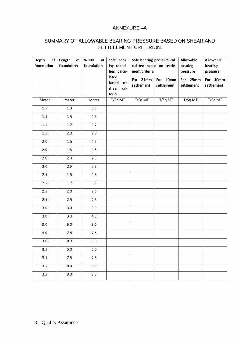
ANNEXURE –A
SUMMARY OF ALLOWABLE BEARING PRESSURE BASED ON SHEAR AND
SETTELEMENT CRITERION.
Depth of
foundation
Length of
foundation
Width of
foundation
Safe bear-
ing capaci-
ties calcu-
lated
based on
shear cri-
teria
Safe bearing pressure cal-
culated based on settle-
ment criteria
Allowable
bearing
pressure
Allowable
bearing
pressure
For 25mm
settlement
For 40mm
settlement
For 25mm
settlement
For 40mm
settlement
Meter Meter Meter T/Sq.MT T/Sq.MT T/Sq.MT T/Sq.MT T/Sq.MT
1.5 1.3 1.3
1.5 1.5 1.5
1.5 1.7 1.7
1.5 2.0 2.0
2.0 1.5 1.5
2.0 1.8 1.8
2.0 2.0 2.0
2.0 2.5 2.5
2.5 1.5 1.5
2.5 1.7 1.7
2.5 2.0 2.0
2.5 2.5 2.5
3.0 3.0 3.0
3.0 3.0 4.5
3.0 5.0 5.0
3.0 7.5 7.5
3.0 8.0 8.0
3.5 5.0 7.0
3.5 7.5 7.5
3.5 8.0 8.0
3.5 9.0 9.0
Quality Assurance 9
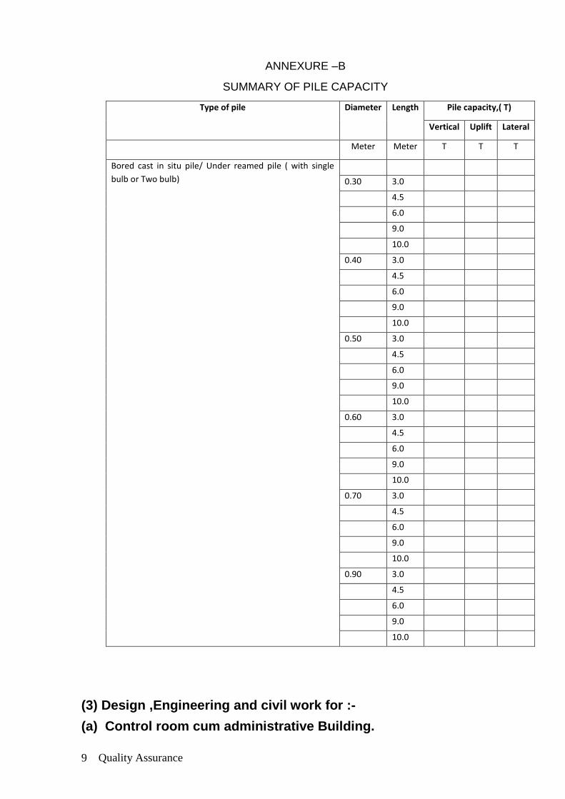
ANNEXURE –B
SUMMARY OF PILE CAPACITY
Type of pile Diameter Length Pile capacity,( T)
Vertical Uplift Lateral
Meter Meter T T T
Bored cast in situ pile/ Under reamed pile ( with single
bulb or Two bulb)
0.30 3.0
4.5
6.0
9.0
10.0
0.40 3.0
4.5
6.0
9.0
10.0
0.50 3.0
4.5
6.0
9.0
10.0
0.60 3.0
4.5
6.0
9.0
10.0
0.70 3.0
4.5
6.0
9.0
10.0
0.90 3.0
4.5
6.0
9.0
10.0
(3) Design ,Engineering and civil work for :-
(a) Control room cum administrative Building.
Quality Assurance 10
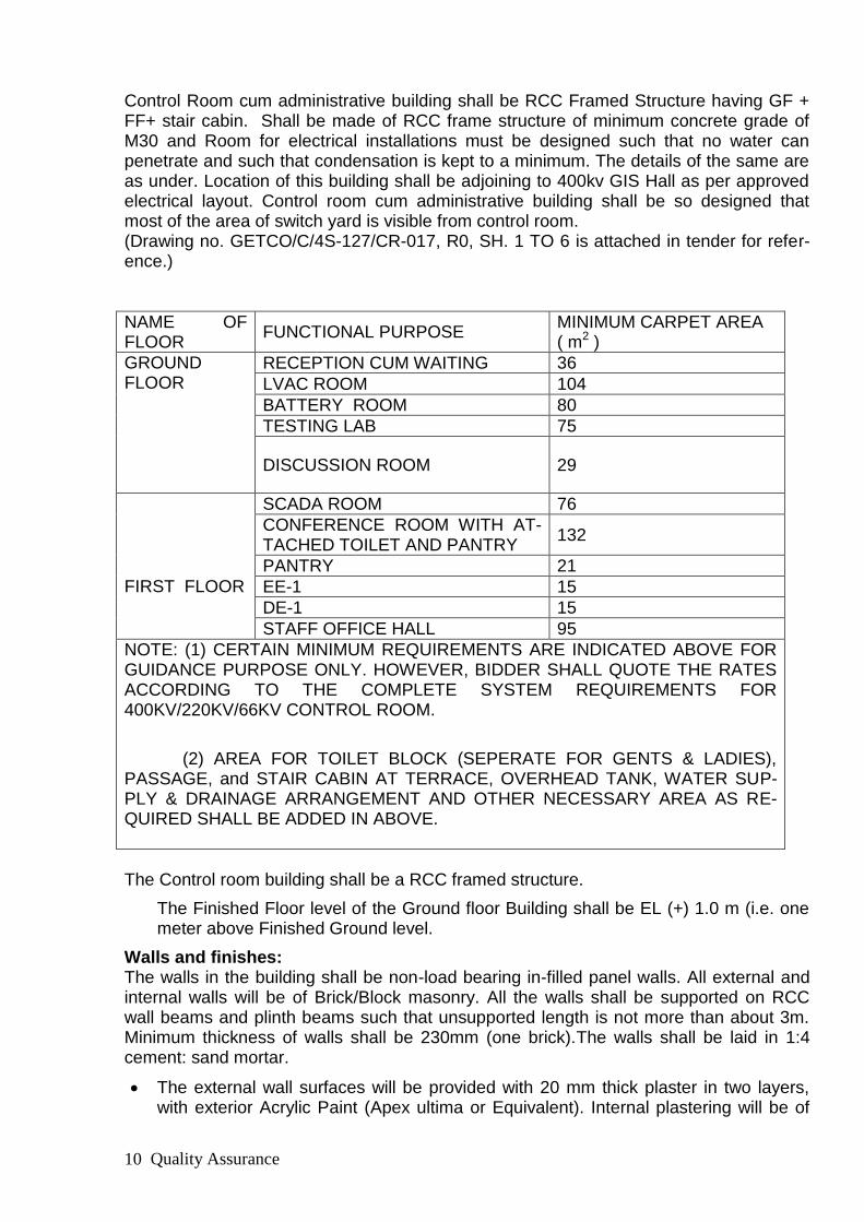
Control Room cum administrative building shall be RCC Framed Structure having GF + FF+ stair cabin. Shall be made of RCC frame structure of minimum concrete grade of M30 and Room for electrical installations must be designed such that no water can penetrate and such that condensation is kept to a minimum. The details of the same are as under. Location of this building shall be adjoining to 400kv GIS Hall as per approved electrical layout. Control room cum administrative building shall be so designed that most of the area of switch yard is visible from control room. (Drawing no. GETCO/C/4S-127/CR-017, R0, SH. 1 TO 6 is attached in tender for refer-ence.)
NAME OF FLOOR
FUNCTIONAL PURPOSE MINIMUM CARPET AREA ( m2 )
GROUND FLOOR
RECEPTION CUM WAITING 36
LVAC ROOM 104
BATTERY ROOM 80
TESTING LAB 75
DISCUSSION ROOM 29
FIRST FLOOR
SCADA ROOM 76
CONFERENCE ROOM WITH AT-TACHED TOILET AND PANTRY
132
PANTRY 21
EE-1 15
DE-1 15
STAFF OFFICE HALL 95
NOTE: (1) CERTAIN MINIMUM REQUIREMENTS ARE INDICATED ABOVE FOR GUIDANCE PURPOSE ONLY. HOWEVER, BIDDER SHALL QUOTE THE RATES ACCORDING TO THE COMPLETE SYSTEM REQUIREMENTS FOR 400KV/220KV/66KV CONTROL ROOM.
(2) AREA FOR TOILET BLOCK (SEPERATE FOR GENTS & LADIES), PASSAGE, and STAIR CABIN AT TERRACE, OVERHEAD TANK, WATER SUP-PLY & DRAINAGE ARRANGEMENT AND OTHER NECESSARY AREA AS RE-QUIRED SHALL BE ADDED IN ABOVE.
The Control room building shall be a RCC framed structure.
The Finished Floor level of the Ground floor Building shall be EL (+) 1.0 m (i.e. one meter above Finished Ground level.
Walls and finishes: The walls in the building shall be non-load bearing in-filled panel walls. All external and internal walls will be of Brick/Block masonry. All the walls shall be supported on RCC wall beams and plinth beams such that unsupported length is not more than about 3m. Minimum thickness of walls shall be 230mm (one brick).The walls shall be laid in 1:4 cement: sand mortar.
The external wall surfaces will be provided with 20 mm thick plaster in two layers, with exterior Acrylic Paint (Apex ultima or Equivalent). Internal plastering will be of

Quality Assurance 11
12 mm thick in 1:3 cement mortars. Ceiling in areas where false ceiling is not pro-vided will be given ceiling plaster 12 mm thick.
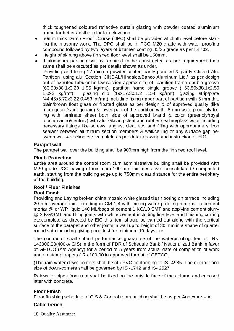
Minimum 25% of area of elevation above plinth of control cum administrative build-ing (front and both side elevations except rear elevation ) shall be covered with 6mm thick toughened coloured reflective curtain glazing with powder coated aluminium frame for better aesthetic look in elevation
50mm thick Damp Proof Course (DPC) shall be provided at plinth level before start-ing the masonry work. The DPC shall be in PCC M20 grade with water proofing compound followed by two layers of bitumen coating 85/25 grade as per IS 702.
Height of skirting above finished floor level shall be 150mm.
If aluminum partition wall is required to be constructed as per requirement then same shall be executed as per details shown as under. Providing and Fixing 17 micron powder coated Partly panneled & partly Glazed Alu.Partition using alu. Section "JINDAL/Hindalco/Banco Aluminium Ltd." as per de-sign out of extruted tubuler hollow section approx size of partition frame double groove (63.50x38.1x3.20 1.95 kg/rmt), partition frame single groove ( 63.50x38.1x2.50 1.092 kg/rmt), glazing clip (19x17.3x.1.2 .154 kg/rmt), glazing strip/plate (44.45x5.72x3.22 0.453 kg/rmt) including fixing upper part of partition with 5 mm thk. plain/brown float glass or froasted glass as per design & of approved quality (like modi gaurd/saint gobain) & lower part of the partiton with 8 mm water-proof ply fixing with laminate sheet both side of approved brand & colour (green-ply/royal touch/marino/century) with alu. glazing cleat and rubber sealing/glass wool including necessary fittings like screws, angles, cleat etc and filling with appropriete silicon sealent between aluminium section members & wall/ceiling or any surface gap between wall & section etc. complete as per detail drawing and instruction of EIC.
Parapet wall The parapet wall over the building shall be 900mm high from the finished roof level.
Plinth Protection Entire area around the control room cum administrative building shall be provided with M20 grade PCC paving of minimum 100 mm thickness over consolidated / compacted earth, starting from the building edge up to 750mm clear distance for the entire periphery of the building.
Roof / Floor Finishes Roof Finish Providing and Laying broken china mosaic white glazed tiles flooring on terrace including 20 mm average thick bedding in CM 1:4 with mixing water proofing material in cement mortar @ or WP liquid 140 ML/bags of cement 1 KG/10 SMT and applying cement slurry @ 2 KG/SMT and filling joints with white cement including line level and finishing,curring etc.complete as directed by EIC this item should be carried out along with the vertical surface of the parapet and other joints in wall up to height of 30 mm in a shape of quarter round vata including giving pond test for minimum 10 days etc.
The contractor shall submit performance guarantee of the waterproofing item of Rs. 60000.00 in the form of FDR of Schedule Bank / Nationalised Bank in favour of GETCO (A/c Agency) for a period of 5 years from actual date of completion of work and on stamp paper of Rs.100.00 in approved format of GETCO.
(The rain water down comers shall be of uPVC conforming to IS- 4985. The number and size of down-comers shall be governed by IS -1742 and IS- 2527.

Quality Assurance 12
Rainwater pipes from roof shall be fixed on the outside face of the column and encased later with concrete. .
Floor Finish Floor finishing schedule of GIS & Control room building shall be as per Annexure – A.
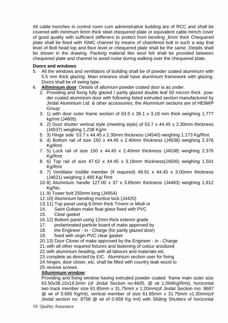
Cable trench: All cable trenches in control room cum administrative building are of RCC and shall be covered with minimum 6mm thick steel chequered plate or equivalent cable trench cover of good quality with sufficient stiffeners to protect from bending. 6mm thick Chequered plate shall be fixed with ISMC channel by means of chamfered bolt in such a way that level of Bolt head top and floor level or chequered plate shall be the same. Details shall be shown in the drawing. Packing material like wool felt shall be provided between chequered plate and channel to avoid noise during walking over the chequered plate.
For SCADA room at first floor, cut out to be kept in RCC slab and appropriate arrangement for hanging cable trench below slab and arrangement for cable route from GL to F.F. slab shall be provided. Care to be taken to see that all the arrangements provided for cable in and out system shall be aesthetically pleasant and strong enough as per relevant codes and standards.
Doors and windows 1. All the windows and ventilators of building shall be of powder coated aluminium with
5.5 mm thick glazing. Main entrance shall have aluminium framework with glazing. Doors shall be of swing type.
2. Alliminium door: Details of allumium powder coated door is as under. Providing and fixing fully glazed / partly glazed double leaf 50 micron thick powder coated aluminium door with following listed extruded section manufactured by Jindal Aluminium Ltd. & other accessories, the Alluminium sections are of HE9WP Group: 1) with door outer frame section of 63.5 x 38.1 x 3.18 mm thick weighing 1.777 kg/rmt (J4605) 2) Door shutter vertical style (meeting style) of 53.7 x 44.45 x 2.30mm thickness (J4537) weighing 1.238 Kg/m 3) Hinge side 53.7 x 44.45 x 2.30mm thickness (J4540) weighing 1.173 Kg/Rmt 4) Bottom rail of size 150 x 44.45 x 2.40mm thickness (J4538) weighing 2.376 Kg/Rmt 5) Lock rail of size 150 x 44.45 x 2.40mm thickness (J4538) weighing 2.376 Kg/Rmt 6) Top rail of size 47.62 x 44.45 x 3.18mm thickness(J4506) weighing 1.501 Kg/Rmt 7) Ventilator middle member (if required) 49.91 x 44.45 x 3.00mm thickness (J4621) weighing 1.495 Kg/ Rmt 8) Aluminium handle 127.00 x 37 x 3.65mm thickness (J4483) weighing 1.912 Kg/No. 9) Tower bolt 250mm long (J4954) 10) Aluminium bending mortice lock (J4420) 11) Top panel using 6.0mm thick Triveni or Modi or Saint Gobain make float glass fixed with PVC Clear gasket 12) Bottom panel using 12mm thick exterior grade prelaminated particle board of make approved by the Engineer - in - Charge (for partly glazed door) fixed with virgin PVC clear gasket 13) Door Closer of make approved by the Engineer - in - Charge with all other required fixtures and fastening of colour anodized

Quality Assurance 13
with aluminium beading, with all labours and materials etc. complete as directed by EIC. Aluminium section user for fixing hinges, door closer, etc. shall be filled with country teak wood to receive screws. Alluminium window: Providing and fixing window having extruded powder coated frame main outer size 63.50x38.10x19.5mm (of Jindal Section no:4605, @ wt 1.094Kg/Rmt), horizontal two track member size 61.85mm x 31.75mm x 1.20mm(of Jindal Section mo: 8687 @ wt of 0.695 Kg/mt), vertical member of size 61.85mm x 31.75mm x1.30mm(of Jindal section no: 8758 @ wt of 0.659 Kg /mt) with Sliding Shutters of horizontal member Size 40mm x 18mm x 1.29mm(of Jindal section no: 8949 @ wt of 0.456Kf/mt), vertical member of size 40mm x 18mm x 1.29mm (of Jindal Sectio: 8947 @ wt 0.457 Kg/mt, section 8948 @ 0.457kG/mt) with 5 mm thick transparent bronze colour/white tinted float glass with aluminium fittings and fixtures and trans-parent silicon sealant glass fixing to frame as per details etc. complete for Window. Alluminium ventilator: Providing and fixing standard extruded of aluminium section of size 63.0X38.10X1.20mm(of Jindal section No.2434 @Wt. 0.643Kg/Rmt ) with powder coated alluminium frame for ventilation with 5mm thick white/brown glass fixed hori-zontal louvers in aluminium channel as per details and drawings.
3. Rolling shutters with manual operating arrangement according to size shall be pro-vided in GIS room (Control Room Building) to facilitate handling and transportation of dry type transformer. Providing & fixing steel rolling shutter 18 Gauge of approved make & made 80 mm wide M. S. Laths interlock together through their entire length and jointed together at the end by end locks mounted on specially designed pipe shaft with brackert plates guide channel and arrangement for inside and outside locking with push pull opera-tion complete including the cost of hood cover and spring etc., complete as directed.
4. All doors/shutters/windows shall be provided with all standard accessories such as handles, tower bolts, locks, stoppers, floor mounted spring type door closure etc. of best quality as approved by the GETCO.
Glazing and its thickness 1. Minimum thickness of glazing shall be 5.0/6.0 mm(window/door). Glazing shall have fire rating of minimum 1 hour.
False ceiling
The Gypsum board false ceiling shall be provided in all air- conditioned area.
Providing & fixing gypsum board suspended false ceiling in the grid of 600 x 600 mm us-ing aluminum Tees with interlock system for main ( 25 mm x 25 mm x 1.6 mm ) or equiv-alent and cross tees ( 25 x 25 x 1.6 mm ) etc complete with 6 mm adjustable suspenders and other required accessories for hanging skeleton and supported at walls by 25 x 25 x 1.6 mm anodized aluminum angles screwed with rawled plug including making ar-rangement for holding the skeleton from slab / roof etc. by using 6 mm bar 6 feet c/c. and using gypsum board tiles comprises non - combustible gypsum casting plaster reinforced with a glass fiber membrane resulting in a light weight , strong and prestressed panel of 12.5 mm thickness. The tiles are in their natural colour and smooth or textured finish as per manufactures specifications. The ceiling system shall be confirming to non-combustible as defined in BS- 476 part 6 & 7 including making, opening/ cutouts for elec-trical fittings, fixtures etc. with finishing etc. complete as directed by E.I.C Toilet details including plumbing and sanitation:

Quality Assurance 14
(I) All plumbing and sanitation shall be executed to comply with the requirements of the appropriate bye-laws, rules and regulations of the Local Authority having ju-risdiction over such matters. The Contractor shall arrange for all necessary For-malities to be met in regard to inspection, testing, obtaining approval and giving notices etc.
(II) Two toilets at each floor, one for Gents and other for ladies, shall be provided in the building. Attached toilet shall be provided with conference room, separate for Gents and ladies.
(III) A shaft shall be provided in the Toilet area for water supply, soil and vent pipes. (IV) PVC “SYNTEX” or equivalent make white color (Three layered) Roof water tank of
adequate capacity depending on the number of users for 24hours storage shall be provided. Minimum 2 Nos 1500 liter capacity shall be provided.
(V) Galvanized MS pipe of medium class conforming to IS: 1239 shall be used for in-ternal & external piping work for potable water supply.
(VI) uPVC pipes conforming to IS: 4985 shall be used for sanitary works above ground level and RCC pipe shall be used for works below ground.
(VII) Each toilet shall have the following minimum fittings. a. WC (Western type) 390 mm high with toilet paper roll holder and all fittings in
toilets atached to conference and sub-station in charge office.andWC (Indian Type) Orissa Pattern (580 x 440 mm) with all fittings shall be provided in com-mon toilets.
b. Urinal (430 x 260 x 350 mm size) with all fittings. c. Wash basin (550 x 400 mm) with all fittings. d. Bathroom mirror (600 x 450 x 6 mm thick) hard board backing e. CP brass towel rail (600 x 20 mm) with C.P. brass brackets f. Soap holder and liquid soap dispenser. g. All urinals and washbasins shall be provided with built in sensors.
(VIII) Water cooler for drinking water with adequate water storage facility shall be pro-vided and located near control room and not near toilet block.
(IX) 1 no. stainless steel kitchen sink with Drain board (510 x1040 x 178 mm bowl depth) shall be provided.
(X) All fittings, fastener, grating shall be chromium plated. (XI) All sanitary fixtures and fittings shall be of approved quality and type manufac-
tured by well-known manufacturers. All items brought to site must bear identifica-tion marks of the type of the Manufacturer.
(XII) Soil, waste and drain pipes, for underground works shall be stone ware for areas not subject to traffic load. Heavyduty cast iron pipes shall be used otherwise.
(XIII) Contractor shall provide septic tank and soak pit of adequate capacity to treat the sewage / sullage from the building.
Contractor shall implement all other jobs required to complete and commission the build-ing.
Projection over doors and windows:
Doors and windows on external walls buildings shall be provided with RCC sun-shade over the openings. Projection of sunshade from the wall shall be minimum 750 mm over window openings and 900 mm over door openings.
Finishing : Plastic paint : Providing and Applying Three Coats Acrylic/Luxury Emulsion paint with approved brand (like asian royal/ici dulux velvet) and manufacture and of required shade on wall / ceiling surface to give an even shade over and including applying two/required coats of lapi (sythetic oil paint & whiting chalk & varnish) for make surface smooth & even with lapi,
Quality Assurance 15
including primer coat (cement based primer in two coats) with alkali resistance/synthetic primer of approved brand, after thoroughly brushing the surface free from water dropping and other foriegn matter and also including preparing the surface even and smooth, etc. complete as directed by EIC. Exterior paint: Providing & applying wall painting 2 coats with weather proof acralic emulsion APEX ULTIMA-ultima or equivalent type paint of approved brand and manufacture and of re-quired shade on exterior wall surface to give an even shade over and including a primary coat with alkali resistance primer of approved brand after thoroughly brushing surface to to all dirty and remains of loose powder material etc complete for all heights. A gap of 6 hrs. Should be given between 2 subsequent coats.The work should be carried out strictly as per manufacture‟s specification and requirement etc complete as directed by EIC
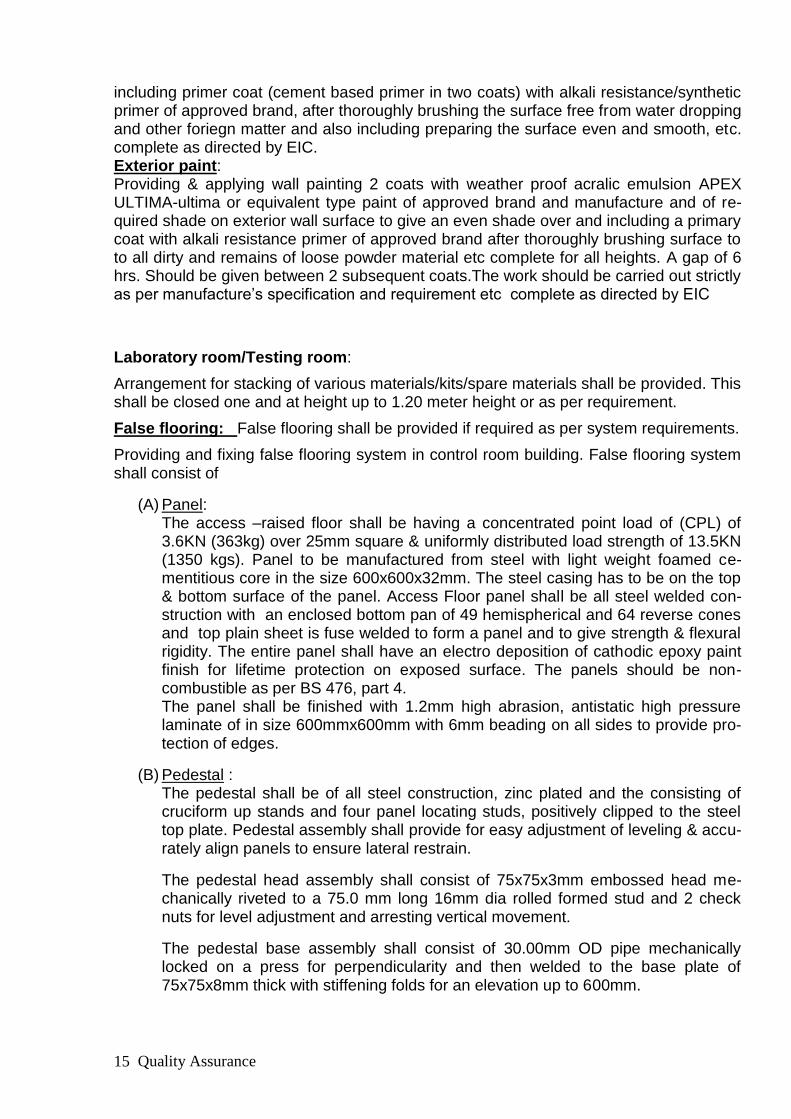
Laboratory room/Testing room:
Arrangement for stacking of various materials/kits/spare materials shall be provided. This shall be closed one and at height up to 1.20 meter height or as per requirement.
False flooring: False flooring shall be provided if required as per system requirements.
Providing and fixing false flooring system in control room building. False flooring system shall consist of
(A) Panel: The access –raised floor shall be having a concentrated point load of (CPL) of 3.6KN (363kg) over 25mm square & uniformly distributed load strength of 13.5KN (1350 kgs). Panel to be manufactured from steel with light weight foamed ce-mentitious core in the size 600x600x32mm. The steel casing has to be on the top & bottom surface of the panel. Access Floor panel shall be all steel welded con-struction with an enclosed bottom pan of 49 hemispherical and 64 reverse cones and top plain sheet is fuse welded to form a panel and to give strength & flexural rigidity. The entire panel shall have an electro deposition of cathodic epoxy paint finish for lifetime protection on exposed surface. The panels should be non-combustible as per BS 476, part 4. The panel shall be finished with 1.2mm high abrasion, antistatic high pressure laminate of in size 600mmx600mm with 6mm beading on all sides to provide pro-tection of edges.
(B) Pedestal : The pedestal shall be of all steel construction, zinc plated and the consisting of cruciform up stands and four panel locating studs, positively clipped to the steel top plate. Pedestal assembly shall provide for easy adjustment of leveling & accu-rately align panels to ensure lateral restrain.
The pedestal head assembly shall consist of 75x75x3mm embossed head me-chanically riveted to a 75.0 mm long 16mm dia rolled formed stud and 2 check nuts for level adjustment and arresting vertical movement.
The pedestal base assembly shall consist of 30.00mm OD pipe mechanically locked on a press for perpendicularity and then welded to the base plate of 75x75x8mm thick with stiffening folds for an elevation up to 600mm.

Quality Assurance 16
The steel base plate of the pedestal shall be fixed onto the sub floor with epoxy pedestal adhesive & or mechanical fixing. Pedestal head shall be designed to avoid rattles or squeaks.
(C) Stringers: An all steel rectangular stringer of 30mmx20mmx570mm length and 1.50mm thick having pre punched holes at both the ends to ensure correct alignment with ped-
estal heads should be applied for maximum stability. All steel components shall be zinc electro plated. Work shall be executed as per ap-proved drawing. Cut outs for Automation panels & other equipments installations shall be as per panel/equipment drawings. Lay out drawing along with supporting stud ar-rangement shall be submitted for approval at the time of detailed engineering. Rate is inclusive of providing required channel support to panels. Automation panels and other equipments shall not be supported directly on the skeleton, but it shall be supported on channel.
Hand railing of stair case : Hand railing shall be provided in stair case as per ap-proved design and drawing.
Providing and fabricating and fixing 1.00 MT. high anti corrosive high grade AISI 316 Stainless Steel Railing heavy gauge materials to be used with required removable patch fitting for fixing frosted glass of standard company like modi gaurd/saint gobain/ashi float as per architectural drawing & details, for the railing, in staircase, etc fabricating, hoist-ing fixing in position with angle cleats, anchor fasteners, holdfast etc in RCC or mason-ry etc. fasteners should be covered with S.S. plate with cover cap in true line level & plumb, including complete welding, clearing the welding dots with grinder machine, & buffing the same with required buffing machine & match to original & complete no pin-holes kept, including buffing in smooth or matt finish as per detailed drawing to railing of approved quality, including wrap to all the members with plastic paper after buffing, after the complete finishing work completed of building remove plastics from railing, scaffold-ing etc. complete as directed by Engineer in charge.
Approach road to building:
Approach road from main road of substation to building is in the scope of this item and shall be of 3.0 meter wide and shall be prepared from Paver block of 75mm thick. The description of the paver block and its detail is given below.
Providing & Fixing precast rubber dye interlocking concrete block 75mm thick with con-crete M-20 compressed by mechanically Pressed and as per approved design incl. 75 mm average thick layer of approved quality of river sand bellow concrete block in slope, filling the joints of the concrete block with screened sand etc. Complete including all ma-terial, labour, tools & tackles, curing for successful complication of the work as directed by EIC.
.Misc.:
Package includes all miscellaneous items such as Granite year plate, Acrylic sign board, Substation board as per GETCO standard,
Notice board covered with Glass door etc.
Special note : Protection of RCC structure under ground and above ground against corrsion and weather due to lying in saline atmosphere/marine environment conditions shall be provided with painting/coating of FOSROC or Equivalent company product

Quality Assurance 17
(b) GIS ROOM BUILDING :( FOR 220/66KV SYSTEM)
GIS building consist of GIS hall, Room for control & protection panels and AHU room. Dimensions of the building shall be decided by the bidder depending upon requirement and as shown in tender drawing whichever is higher. Provision for extension in future of the building shall be made. A corridor having minimum width of 3000 mm shall be pro-vided all around GIS to facilitate maintenance of equipment. Provision for service bay shall also be made.
Minimum carpet area and height of GIS Hall for 400KV system shall be as shown in the drawing no. GETCO/C/4S-127/220KV GIS-017, R0, SH. 1of 1. GIS hall shall be either of (1) RCC Framed Structure or (1) Steel structure.
Dimension for GIS Room shall be decided as per following.
(1) Length of GIS Room, L = out to out dimension of 220KV GIS module maximum length + 8000mm.+ out to out dimension of 66KV GIS module maximum length + 9000.
(2) Width of GIS Room, B= out to out dimension of 220 and 66kv GIS module maximum width + 6000 mm.
(3) Height of GIS Room, H = Top most portion of GIS module height + clearance re-quired between bottom of EOT crane hook & top most portion of GIS module as per rel-evant standards and codes/ Sling angle not to be more than 45 degree + Height of crane ( as given by supplier) + Clearance required between top of crane & bottom of roof beam ( For crane maintenance requirement) + depth of roof beam.
LCC and C & R panel room.
Minimum Width of LCC and C & R panel room shown in the drawing. However, width may increase if required as per clearance and working requirement as per standards and codes.
1. GIS HALL OF RCC FRAMED STRUCTURE :
The GIS building shall be a RCC framed structure. Room for control & protection panels and AHU room shall also be a RCC framed structure.
The Finished Floor level of the Ground floor Building shall be EL (+) 1.0 m. (i.e. one me-ter above Finished Ground level.
Walls and finishes: The walls in the building shall be non-load bearing in-filled panel walls. All external and internal walls will be of Brick/Block masonry. All the walls shall be supported on RCC wall beams and plinth beams such that unsupported length is not more than about 3m. Minimum thickness of walls shall be 230mm (one brick).The walls shall be laid in 1:4 cement: sand mortar.
The external wall surfaces will be provided with 20 mm thick plaster in two layers, with exterior Acrylic Paint (Apex ultima or Equivalent). Internal plastering will be of 12 mm thick in 1:3 cement mortars. Ceiling in areas where false ceiling is not pro-vided will be given ceiling plaster 12 mm thick.
Minimum 25% of area of elevation above plinth of control cum administrative build-ing (front and both side elevations except rear elevation ) shall be covered with 6mm
Quality Assurance 18
thick toughened coloured reflective curtain glazing with powder coated aluminium frame for better aesthetic look in elevation
50mm thick Damp Proof Course (DPC) shall be provided at plinth level before start-ing the masonry work. The DPC shall be in PCC M20 grade with water proofing compound followed by two layers of bitumen coating 85/25 grade as per IS 702.
Height of skirting above finished floor level shall be 150mm.
If aluminum partition wall is required to be constructed as per requirement then same shall be executed as per details shown as under. Providing and fixing 17 micron powder coated partly paneled & partly Glazed Alu. Partition using alu. Section "JINDAL/Hindalco/Banco Aluminum Ltd." as per design out of extruted tubuler hollow section approx size of partition frame double groove (63.50x38.1x3.20 1.95 kg/rmt), partition frame single groove ( 63.50x38.1x2.50 1.092 kg/rmt), glazing clip (19x17.3x.1.2 .154 kg/rmt), glazing strip/plate (44.45x5.72x3.22 0.453 kg/rmt) including fixing upper part of partition with 5 mm thk. plain/brown float glass or frosted glass as per design & of approved quality (like modi guard/saint gobain) & lower part of the partition with 8 mm waterproof ply fix-ing with laminate sheet both side of approved brand & color (greenply/royal touch/marino/century) with alu. Glazing cleat and rubber sealing/glass wool including necessary fittings like screws, angles, cleat etc. and filling with appropriate silicon sealant between aluminum section members & wall/ceiling or any surface gap be-tween wall & section etc. complete as per detail drawing and instruction of EIC.
Parapet wall The parapet wall over the building shall be 900mm high from the finished roof level.
Plinth Protection Entire area around the control room cum administrative building shall be provided with M20 grade PCC paving of minimum 100 mm thickness over consolidated / compacted earth, starting from the building edge up to 750mm clear distance for the entire periphery of the building.
Roof / Floor Finishes Roof Finish Providing and Laying broken china mosaic white glazed tiles flooring on terrace including 20 mm average thick bedding in CM 1:4 with mixing water proofing material in cement mortar @ or WP liquid 140 ML/bags of cement 1 KG/10 SMT and applying cement slurry @ 2 KG/SMT and filling joints with white cement including line level and finishing,curring etc.complete as directed by EIC this item should be carried out along with the vertical surface of the parapet and other joints in wall up to height of 30 mm in a shape of quarter round vata including giving pond test for minimum 10 days etc.
The contractor shall submit performance guarantee of the waterproofing item of Rs. 143000.00(400kv GIS) in the form of FDR of Schedule Bank / Nationalized Bank in favor of GETCO (A/c Agency) for a period of 5 years from actual date of completion of work and on stamp paper of Rs.100.00 in approved format of GETCO.
(The rain water down comers shall be of uPVC conforming to IS- 4985. The number and size of down-comers shall be governed by IS -1742 and IS- 2527.
Rainwater pipes from roof shall be fixed on the outside face of the column and encased later with concrete.
Floor Finish Floor finishing schedule of GIS & Control room building shall be as per Annexure – A.
Cable trench:
Quality Assurance 19
All cable trenches in control room cum administrative building are of RCC and shall be covered with minimum 6mm thick steel chequered plate or equivalent cable trench cover of good quality with sufficient stiffeners to protect from bending. 6mm thick Chequered plate shall be fixed with ISMC channel by means of chamfered bolt in such a way that level of Bolt head top and floor level or chequered plate shall be the same. Details shall be shown in the drawing. Packing material like wool felt shall be provided between chequered plate and channel to avoid noise during walking over the chequered plate.
Doors and windows 5. All the windows and ventilators of building shall be of powder coated aluminium with
5.5 mm thick glazing. Main entrance shall have aluminium framework with glazing. Doors shall be of swing type.
6. Alliminium door: Details of allumium powder coated door is as under. 2. Providing and fixing fully glazed / partly glazed double leaf 50 micron thick pow-
der coated aluminium door with following listed extruded section manufactured by Jindal Aluminium Ltd. & other accessories, the Aluminium sections are of HE9WP Group:
3. 1) with door outer frame section of 63.5 x 38.1 x 3.18 mm thick weighing 1.777 kg/rmt (J4605)
4. 2) Door shutter vertical style (meeting style) of 53.7 x 44.45 x 2.30mm thickness (J4537) weighing 1.238 Kg/m
5. 3) Hinge side 53.7 x 44.45 x 2.30mm thickness (J4540) weighing 1.173 Kg/Rmt 6. 4) Bottom rail of size 150 x 44.45 x 2.40mm thickness (J4538) weighing 2.376
Kg/Rmt 7. 5) Lock rail of size 150 x 44.45 x 2.40mm thickness (J4538) weighing 2.376
Kg/Rmt 8. 6) Top rail of size 47.62 x 44.45 x 3.18mm thickness(J4506) weighing 1.501
Kg/Rmt 9. 7) Ventilator middle member (if required) 49.91 x 44.45 x 3.00mm thickness
(J4621) weighing 1.495 Kg/ Rmt 10. 8) Aluminium handle 127.00 x 37 x 3.65mm thickness (J4483) weighing 1.912
Kg/No. 11. 9) Tower bolt 250mm long (J4954) 12. 10) Aluminium bending mortice lock (J4420) 13. 11) Top panel using 6.0mm thick Triveni or Modi or 14. Saint Gobain make float glass fixed with PVC 15. Clear gasket 16. 12) Bottom panel using 12mm thick exterior grade 17. prelaminated particle board of make approved by 18. the Engineer - in - Charge (for partly glazed door) 19. fixed with virgin PVC clear gasket 20. 13) Door Closer of make approved by the Engineer - in - Charge 21. with all other required fixtures and fastening of colour anodized 22. with aluminium beading, with all labours and materials etc. 23. complete as directed by EIC. Aluminium section user for fixing 24. hinges, door closer, etc. shall be filled with country teak wood to 25. receive screws. Alluminium window: Providing and fixing window having extruded powder coated frame main outer size 63.50x38.10x19.5mm (of Jindal Section no:4605, @ wt 1.094Kg/Rmt), horizontal two track member size 61.85mm x 31.75mm x 1.20mm(of Jindal Section mo: 8687 @ wt of 0.695 Kg/mt), vertical member of size 61.85mm x 31.75mm x1.30mm(of Jindal section no: 8758 @ wt of 0.659 Kg /mt) with Sliding Shutters of horizontal
Quality Assurance 20
member Size 40mm x 18mm x 1.29mm(of Jindal section no: 8949 @ wt of 0.456Kf/mt), vertical member of size 40mm x 18mm x 1.29mm (of Jindal Sectio: 8947 @ wt 0.457 Kg/mt, section 8948 @ 0.457kG/mt) with 5 mm thick transparent bronze colour/white tinted float glass with aluminium fittings and fixtures and trans-parent silicon sealant glass fixing to frame as per details etc complete for Window. Alluminium ventilator: Providing and fixing standard extruded of aluminium section of size 63.0X38.10X1.20mm(of Jindal section No.2434 @Wt. 0.643Kg/Rmt ) with powder coated frame for ventilation with 5mm thick white/brown glass fixed horizontal lou-vers in aluminium channel as per details drawings.
1. Rolling shutters with Gear operating arrangement according to size shall be provid-ed in GIS room (Control Room Building) to facilitate handling and transportation of dry type transformer
2. Providing & fixing steel rolling shutter 18 Gauge of approved make & made 80 mm wide M. S. Laths interlock together through their entire length and jointed together at the end by end locks mounted on specially designed pipe shaft with brackert plates guide channel and arrangement for inside and outside locking with push pull opera-tion complete including the cost of hood cover and spring etc., complete as directed.
3. All doors/shutters/windows shall be provided with all standard accessories such as handles, tower bolts, locks, stoppers, floor mounted spring type door closure etc. of best quality as approved by the GETCO.
Glazing and its thickness 1. Minimum thickness of glazing shall be 5.5 mm. Glazing shall have fire rating of mini-mum 1 hour.
False ceiling
The Gypsum board false ceiling shall be provided in all air- conditioned area.
Providing & fixing gypsum board suspended false ceiling in the grid of 600 x 600 mm us-ing alluminium Tees with interlock system for main ( 25 mm x 25 mm x 1.6 mm ) or equivalent and cross tees ( 25 x 25 x 1.6 mm ) etc complete with 6 mm adjustable sus-penders and other required accessories for hanging skeleton and supported at walls by 25 x 25 x 1.6 mm anodized alluminium angles screwed with rawled plug including mak-ing arrangement for holding the skeleton from slab / roof etc. by using 6 mm bar 6 feet c/c. and using gypsum board tiles comprises non - combustible gypsum casting plaster reinforced with a glass fiber membrane resulting in a light weight , strong and pre-stressed panel of 12.5 mm thickness. The tiles are in their natural colour and smooth or textured finish as per manufactures specifications. The ceiling system shall be confirm-ing to non-combustible as defined in BS- 476 part 6 & 7 including making , opening/ cut-outs for electrical fittings, fixtures etc. with finishing etc. complete as directed by E.I.C Toilet details including plumbing and sanitation:
(I) All plumbing and sanitation shall be executed to comply with the requirements of the appropriate bye-laws, rules and regulations of the Local Authority having juris-diction over such matters. The Contractor shall arrange for all necessary formali-ties to be met in regard to inspection, testing, obtaining approval and giving notices etc.
(II) Two toilets at each floor , one for Gents and other for ladies, shall be provided in the building.
(III) A shaft shall be provided in the Toilet area for water supply, soil and vent pipes.

Quality Assurance 21
(IV) PVC “SYNTEX” or equivalent make white color (Three layered) Roof water tank of adequate capacity depending on the number of users for 24hours storage shall be provided. Minimum 2 Nos 1500 liter capacity shall be provided.
(V) Galvanized MS pipe of medium class conforming to IS: 1239 shall be used for
internal & external piping work for potable water supply. (VI) uPVC pipes conforming to IS: 4985 shall be used for sanitary works above ground
level and RCC pipe shall be used for works below ground. (VII) Each toilet shall have the following minimum fittings.
a) WC (Western type) 390 mm high with toilet paper roll holder and all fittings in toilets attached to conference and sub-station in charge office.andWC (Indian Type) Orissa Pattern (580 x 440 mm) withall fittings shall be provided in com-mon toilets.
b) Urinal (430 x 260 x 350 mm size) with all fittings. c) Wash basin (550 x 400 mm) with all fittings. d) Bathroom mirror (600 x 450 x 6 mm thick) hard board backing e) CP brass towel rail (600 x 20 mm) with C.P. brass brackets f) Soap holder and liquid soap dispenser. g) All urinals and washbasins shall be provided with built in sensors.
(VIII) Water cooler for drinking water with adequate water storage facility shall be pro-vided and located near control room and not near toilet block.
(IX) 1 no. stainless steel kitchen sink with Drain board (510 x1040 x 178 mm bowl depth) shall be provided.
(X) All fittings, fastener, grating shall be chromium plated. (XI) All sanitary fixtures and fittings shall be of approved quality and type manufactured
by well known manufacturers. All items brought to site must bear identification marks of the type of the Manufacturer.
(XII) Soil, waste and drain pipes, for underground works shall be stone ware for areas not subject to traffic load. Heavyduty cast iron pipes shall be used otherwise.
(XIII) Contractor shall provide septic tank and soak pit of adequate capacity to treat the sewage / sullage from the building.
Contractor shall implement all other jobs required to complete and commission the build-ing.
Projection over doors and windows:
Doors and windows on external walls buildings shall be provided with RCC sun-shade over the openings. Projection of sunshade from the wall shall be minimum 600 mm over window openings and 600 mm over door openings.
Finishing : Plastic paint : Providing and Applying Three Coats Acrylic/Luxury Emulsion paint with approved brand (like asian royal/ici dulux velvet) and manufacture and of required shade on wall / ceiling surface to give an even shade over and including applying two/required coats of lapi (sythetic oil paint & whiting chalk & varnish) for make surface smooth & even with lapi, including primer coat (cement based primer in two coats) with alkali resistance/synthetic primer of approved brand, after thoroughly brushing the surface free from water dropping and other foriegn matter and also including preparing the surface even and smooth, etc. complete as directed by EIC.. Exterior paint: Providing & applying wall painting 2 coats with weather proof acralic emulsion APEX ULTIMA-ultima or equivalent type paint of approved brand and manufacture and of re-quired shade on exterior wall surface to give an even shade over and including a primary

Quality Assurance 22
coat with alkali resistance primer of approved brand after thoroughly brushing surface to to all dirty and remains of loose powder material etc complete for all heights. A gap of 6 hrs. Should be given between 2 subsequent coats.The work should be carried out strictly as per manufacture‟s specification and requirement etc complete as directed by EIC
False flooring: False flooring shall be provided if required as per system requirements.
Providing and fixing false flooring system in control room building. False flooring system shall consist of
(D) Panel: The access –raised floor shall be having a concentrated point load of (CPL) of 3.6KN (363kg) over 25mm square & uniformly distributed load strength of 13.5KN (1350 kgs). Panel to be manufactured from steel with light weight foamed ce-mentitious core in the size 600x600x32mm. The steel casing has to be on the top & bottom surface of the panel. Access Floor panel shall be all steel welded con-struction with an enclosed bottom pan of 49 hemispherical and 64 reverse cones and top plain sheet is fuse welded to form a panel and to give strength & flexural rigidity. The entire panel shall have an electro deposition of cathodic epoxy paint finish for lifetime protection on exposed surface. The panels should be non-combustible as per BS 476, part 4. The panel shall be finished with 1.2mm high abrasion, antistatic high pressure laminate of in size 600mmx600mm with 6mm beading on all sides to provide pro-tection of edges.
(E) Pedestal : The pedestal shall be of all steel construction, zinc plated and the consisting of cruciform up stands and four panel locating studs, positively clipped to the steel top plate. Pedestal assembly shall provide for easy adjustment of leveling & accu-rately align panels to ensure lateral restrain.
The pedestal head assembly shall consist of 75x75x3mm embossed head me-chanically riveted to a 75.0 mm long 16mm dia rolled formed stud and 2 check nuts for level adjustment and arresting vertical movement.
The pedestal base assembly shall consist of 30.00mm OD pipe mechanically locked on a press for perpendicularity and then welded to the base plate of 75x75x8mm thick with stiffening folds for an elevation up to 600mm.
The steel base plate of the pedestal shall be fixed onto the sub floor with epoxy pedestal adhesive & or mechanical fixing. Pedestal head shall be designed to avoid rattles or squeaks.
(F) Stringers: An all steel rectangular stringer of 30mmx20mmx570mm length and 1.50mm thick having pre punched holes at both the ends to ensure correct alignment with ped-estal heads should be applied for maximum stability.
All steel components shall be zinc electro plated. Work shall be executed as per ap-proved drawing. Cut outs for Automation panels & other equipments installations shall be as per panel/equipment drawings. Lay out drawing along with supporting stud ar-rangement shall be submitted for approval at the time of detailed engineering. Rate is inclusive of providing required channel support to panels. Automation panels and other

Quality Assurance 23
equipments shall not be supported directly on the skeleton, but it shall be supported on channel.
Approach road to building:
Approach road from main road of substation to building is in the scope of this item and shall be of 3.0 meter wide and shall be prepared from Paver block of 75mm thick. The description of the paver block and its detail is given below.
Providing & Fixing precast rubber dye interlocking concrete block 75mm thick with con-crete M-20 compressed by mechanically Pressed and as per approved design incl. 75 mm average thick layer of approved quality of river sand bellow concrete block in slope, filling the joints of the concrete block with screened sand etc. Complete including all ma-terial, labour, tools & tackles, curing for successful complication of the work as directed by EIC.
.Misc.:
Package includes all miscellaneous items such as Granite year plate, Acrylic sign board, Substation board as per GETCO standard,
Notice board covered with Glass door etc.
Special note : Protection of RCC structure under ground and above ground against corrsion and weather due to lying in saline atmosphere/marine environment conditions shall be provided with painting/coating of FOSROC or Equivalent company product
OR
1. GIS HALL OF STEEL STRUCTURE
GIS hall shall be of steel structure. Room for control & protection panels and AHU room shall also be a RCC framed structure. Specification of control room cum administrative building shall be applicable for control & protection panels and AHU rooms.
Steel used for construction of GIS building shall conform to IS: 2062of grade E250 (Fe410W) or higher grade. Steel Structures shall be shop fabricated and shall have ei-ther welded or bolted joints. The GIS Building roof shall consist of a steel truss with pur-lins etc. Tubular truss fabricated from pipe conforming to IS: 1161 and IS:806 can also be used. Fabrication shall generally be done as specified in IS: 800. The base plate of steel columns shall be mounted on the RCC foundation by means of foundation bolts. In order to facilitate inspection and maintenance, the structures shall be provided with climbing devices. The built up frame shall be applied with a priming coat of red oxide zinc chromate primmer before taken out of workshop. Separate fire escape doors shall also be provided in the GIS Building. Panels shall be kept in an air-conditioned enclosure preferably within the GIS hall. This enclosure shall be separated from main GIS hall by providing a glazed partition made of aluminium frame and 5.5mm thick glass. In case re-lay room is separate from GIS building, this will be made of RCC framed structure and specification of control room building shall be followed for panel room also. Walkway of width not less than 1.0m shall be provided at gantry girder level along with climbing ar-rangement to facilitate maintenance. All steel work shall be painted with one coat of steel primer and two coats of synthetic enamel paint after erection.
Walls:
Quality Assurance 24
230mm thick brick wall shall be provided up to a height of 3.0 meter from plinth level. Above brick wall 50mm thick rock wool( having 100 Kg/Cu.Mt. density ) insulated, factory
made sandwiched panel shall be provided. This panel shall be made of 50 mm thick rock
wool (having 100 Kg/Cu.Mt. density ) insulated, factory made sandwiched panel sandwiched between two nos 24G thick SMP coated galvalume steel sheets. Panels shall be fixed with steel frame work using galvanized fasteners. GETCO may also ask to provide rock
wool( having 100 Kg/Cu.Mt. density ) insulated, factory made sandwiched panel from plinth level to roof level.
Plinth Protection Entire area around the GIS building shall be provided with M20 grade PCC paving of minimum 100 mm thickness over consolidated/compacted earth, starting from the build-ing edge up to 750mm clear distance for the entire periphery of the building.
Roof / Floor Finishes Roofing panel for GIS hall: 50mm thick rock wool( having 100 Kg/Cu.Mt. density ) insulated, factory made sandwiched
panel shall be provided. These panels shall be made of 50 mm thick rock wool (having 100
Kg/Cu.Mt. density ) insulated, factory made sandwiched panel sandwiched between two nos 24G thick SMP coated galvalume steel sheets. Panel shall be fixed with roof truss using galvanized fasteners. GIS hall shall be water tight from roof. Cable trench: All cable trenches in GIS hall and panel room and AHU room are of RCC and shall be covered with minimum 6mm thick steel chequered plate or equivalent cable trench cover of good quality with sufficient stiffeners to protect from bending. 6mm thick Chequered plate covered with fibre shall be fixed with ISMC channel by means of chamfered bolt in such a way that level of Bolt head top and floor level or chequered plate shall be the same. Details shall be shown in the drawing. Packing material like wool felt shall be pro-vided between chequered plate and channel to avoid noise during walking over the chequered plate.
Floor Finish Floor finishing schedule of GIS building shall be as per Annexure – A.
Doors and windows 4. All the windows and ventilators of building shall be of powder coated aluminium with
5.5 mm thick glazing. Main entrance shall have aluminium framework with glazing. Doors shall be of swing type.
5. Alliminium door: Details of allumium powder coated door is as under. 26. Providing and fixing fully glazed / partly glazed double leaf 50 micron thick pow-
der coated aluminium door with following listed extruded section manufactured by Jindal Aluminium Ltd. & other accessories, the Alluminium sections are of HE9WP Group:
27. 1) with door outer frame section of 63.5 x 38.1 x 3.18 mm thick weighing 1.777 kg/rmt (J4605)
28. 2) Door shutter vertical style (meeting style) of 53.7 x 44.45 x 2.30mm thickness (J4537) weighing 1.238 Kg/m
29. 3) Hinge side 53.7 x 44.45 x 2.30mm thickness (J4540) weighing 1.173 Kg/Rmt 30. 4) Bottom rail of size 150 x 44.45 x 2.40mm thickness (J4538) weighing 2.376
Kg/Rmt
Quality Assurance 25
31. 5) Lock rail of size 150 x 44.45 x 2.40mm thickness (J4538) weighing 2.376 Kg/Rmt
32. 6) Top rail of size 47.62 x 44.45 x 3.18mm thickness(J4506) weighing 1.501 Kg/Rmt
33. 7) Ventilator middle member (if required) 49.91 x 44.45 x 3.00mm thickness (J4621) weighing 1.495 Kg/ Rmt
34. 8) Aluminium handle 127.00 x 37 x 3.65mm thickness (J4483) weighing 1.912 Kg/No.
35. 9) Tower bolt 250mm long (J4954) 36. 10) Aluminium bending mortice lock (J4420) 37. 11) Top panel using 6.0mm thick Triveni or Modi or 38. Saint Gobain make float glass fixed with PVC 39. Clear gasket 40. 12) Bottom panel using 12mm thick exterior grade 41. prelaminated particle board of make approved by 42. the Engineer - in - Charge (for partly glazed door) 43. fixed with virgin PVC clear gasket 44. 13) Door Closer of make approved by the Engineer - in - Charge 45. with all other required fixtures and fastening of colour anodized 46. with aluminium beading, with all labours and materials etc. 47. complete as directed by EIC. Aluminium section user for fixing 48. hinges, door closer, etc. shall be filled with country teak wood to 49. receive screws. . Alluminium window: Providing and fixing window having extruded powder coated frame main outer size 63.50x38.10x19.5mm (of Jindal Section no:4605, @ wt 1.094Kg/Rmt), horizontal two track member size 61.85mm x 31.75mm x 1.20mm(of Jindal Section mo: 8687 @ wt of 0.695 Kg/mt), vertical member of size 61.85mm x 31.75mm x1.30mm(of Jindal section no: 8758 @ wt of 0.659 Kg /mt) with Sliding Shutters of horizontal member Size 40mm x 18mm x 1.29mm(of Jindal section no: 8949 @ wt of 0.456Kf/mt), vertical member of size 40mm x 18mm x 1.29mm (of Jindal Sectio: 8947 @ wt 0.457 Kg/mt, section 8948 @ 0.457kG/mt) with 5 mm thick transparent bronze colour/white tinted float glass with aluminium fittings and fixtures and trans-parent silicon sealant glass fixing to frame as per details etc complete for Window. Alluminium ventilator: Providing and fixing standard extruded of aluminium section of size 63.0X38.10X1.20mm(of Jindal section No.2434 @Wt. 0.643Kg/Rmt ) with powder coated frame for ventilation with 5mm thick white/brown glass fixed horizontal lou-vers in aluminium channel as per details drawings.
1. Rolling shutters with manual operating arrangement according to size shall be pro-vided in GIS room (Control Room Building) to facilitate handling and transportation of dry type transformer
2. Providing & fixing steel rolling shutter 18 Gauge of approved make & made 80 mm wide M. S. Laths interlock together through their entire length and jointed together at the end by end locks mounted on specially designed pipe shaft with brackert plates guide channel and arrangement for inside and outside locking with push pull opera-tion complete including the cost of hood cover and spring etc., complete as directed.
3. All doors/shutters/windows shall be provided with all standard accessories such as handles, tower bolts, locks, stoppers, floor mounted spring type door closure etc. of best quality as approved by the GETCO Glazing and its thickness. Minimum

Quality Assurance 26
thickness of glazing shall be 5.5 mm. Glazing shall have fire rating of minimum 1 hour.
False ceiling
The Gypsum board false ceiling shall be provided in all air- conditioned area.
Providing & fixing gypsum board suspended false ceiling in the grid of 600 x 600 mm us-ing aluminum Tees with interlock system for main ( 25 mm x 25 mm x 1.6 mm ) or equiv-alent and cross tees ( 25 x 25 x 1.6 mm ) etc. complete with 6 mm adjustable suspend-ers and other required accessories for hanging skeleton and supported at walls by 25 x 25 x 1.6 mm anodized aluminum angles screwed with rawled plug including making ar-rangement for holding the skeleton from slab / roof etc. by using 6 mm bar 6 feet c/c. and using gypsum board tiles comprises non - combustible gypsum casting plaster reinforced with a glass fiber membrane resulting in a light weight , strong and prestressed panel of 12.5 mm thickness. The tiles are in their natural colour and smooth or textured finish as per manufactures specifications. The ceiling system shall be confirming to non-combustible as defined in BS- 476 part 6 & 7 including making , opening/ cutouts for electrical fittings, fixtures etc. with finishing etc. complete as directed by E.I.C Toilet details including plumbing and sanitation: (i) All plumbing and sanitation shall be executed to comply with the requirements of the
appropriate bye-laws, rules and regulations of the Local Authority having jurisdiction over such matters. The Contractor shall arrange for all necessary formalities to be met in regard to inspection, testing, obtaining approval and giving notices etc.
(ii) Two toilets at each floor, one for Gents and other for ladies, shall be provided in the building.
(iii) A shaft shall be provided in the Toilet area for water supply, soil and vent pipes. (iv) PVC “SYNTEX” or equivalent make white color (Three layered) Roof water tank of
adequate capacity depending on the number of users for 24hours storage shall be provided. Minimum 2 Nos 1500 liter capacity shall be provided.
(iii) Galvanized MS pipe of medium class conforming to IS: 1239 shall be used for inter-
nal & external piping work for potable water supply. (iv) uPVC pipes conforming to IS: 4985 shall be used for sanitary works above ground
level and RCC pipe shall be used for works below ground.
(v) Each toilet shall have the following minimum fittings. (a) WC (Western type) 390 mm high with toilet paper roll holder and all fittings in toilets attached to conference and sub-station in charge office and WC (Indian Type) Orissa Pattern (580 x 440 mm) with all fittings shall be provided in common toilets. (b) Urinal (430 x 260 x 350 mm size) with all fittings. (c) Wash basin (550 x 400 mm) with all fittings. (d) Bathroom mirror (600 x 450 x 6 mm thick) hard board backing (e) CP brass towel rail (600 x 20 mm) with C.P. brass brackets (f) Soap holder and liquid soap dispenser. (g) All urinals and washbasins shall be provided with built in sensors.
(vi) Water cooler for drinking water with adequate water storage facility shall be provided and located near control room and not near toilet block.
(viii) 1 no. stainless steel kitchen sink with Drain board (510 x1040 x 178 mm bowl depth) shall be provided.
(ix) All fittings, fastener, grating shall be chromium plated.
Quality Assurance 27
(x) All sanitary fixtures and fittings shall be of approved quality and type manufactured by well-known manufacturers. All items brought to site must bear identification marks of the type of the Manufacturer.
(xi) Soil, waste and drain pipes, for underground works shall be stone ware for areas not subject to traffic load. Heavyduty cast iron pipes shall be used otherwise.
(xii) Contractor shall provide septic tank and soak pit of adequate capacity to treat the sewage / sullage from the building.
(xiii) Contractor shall implement all other jobs required to complete and commission the building.
Projection over doors and windows:
Doors and windows on external walls buildings shall be provided with RCC sun-shade over the openings. Projection of sunshade from the wall shall be minimum 600 mm over window openings and 600 mm over door openings.
Finishing : Plastic paint : Providing and Applying Three Coats Acrylic/Luxury Emulsion paint with approved brand (like asian royal/ici dulux velvet) and manufacture and of required shade on wall / ceiling surface to give an even shade over and including applying two/required coats of lapi (sythetic oil paint & whiting chalk & varnish) for make surface smooth & even with lapi, including primer coat (cement based primer in two coats) with alkali resistance/synthetic primer of approved brand, after thoroughly brushing the surface free from water dropping and other foriegn matter and also including preparing the surface even and smooth, etc. complete as directed by EIC.. Exterior paint: Providing & applying wall painting 2 coats with weather proof acralic emulsion APEX ULTIMA-ultima or equivalent type paint of approved brand and manufacture and of re-quired shade on exterior wall surface to give an even shade over and including a primary coat with alkali resistance primer of approved brand after thoroughly brushing surface to to all dirty and remains of loose powder material etc complete for all heights. A gap of 6 hrs. Should be given between 2 subsequent coats. The work should be carried out strict-ly as per manufacture‟s specification and requirement etc complete as directed by EIC.
False flooring: False flooring shall be provided if required as per system requirements.
Providing and fixing false flooring system in control room building. False flooring system shall consist of
(G) Panel: The access –raised floor shall be having a concentrated point load of (CPL) of 3.6KN (363kg) over 25mm square & uniformly distributed load strength of 13.5KN (1350 kgs). Panel to be manufactured from steel with light weight foamed ce-mentitious core in the size 600x600x32mm. The steel casing has to be on the top & bottom surface of the panel. Access Floor panel shall be all steel welded con-struction with an enclosed bottom pan of 49 hemispherical and 64 reverse cones and top plain sheet is fuse welded to form a panel and to give strength & flexural rigidity. The entire panel shall have an electro deposition of cathodic epoxy paint finish for lifetime protection on exposed surface. The panels should be non-combustible as per BS 476, part 4. The panel shall be finished with 1.2mm high abrasion, antistatic high pressure laminate of in size 600mmx600mm with 6mm beading on all sides to provide pro-tection of edges.

Quality Assurance 28
(H) Pedestal : The pedestal shall be of all steel construction, zinc plated and the consisting of cruciform up stands and four panel locating studs, positively clipped to the steel top plate. Pedestal assembly shall provide for easy adjustment of leveling & accu-rately align panels to ensure lateral restrain.
The pedestal head assembly shall consist of 75x75x3mm embossed head me-chanically riveted to a 75.0 mm long 16mm dia rolled formed stud and 2 check nuts for level adjustment and arresting vertical movement.
The pedestal base assembly shall consist of 30.00mm OD pipe mechanically locked on a press for perpendicularity and then welded to the base plate of 75x75x8mm thick with stiffening folds for an elevation up to 600mm.
The steel base plate of the pedestal shall be fixed onto the sub floor with epoxy pedestal adhesive & or mechanical fixing. Pedestal head shall be designed to avoid rattles or squeaks.
(I) Stringers: An all steel rectangular stringer of 30mmx20mmx570mm length and 1.50mm thick having pre punched holes at both the ends to ensure correct alignment with ped-estal heads should be applied for maximum stability.
All steel components shall be zinc electro plated. Work shall be executed as per ap-proved drawing. Cut outs for Automation panels & other equipment installations shall be as per panel/equipment drawings. Lay out drawing along with supporting stud arrange-ment shall be submitted for approval at the time of detailed engineering. Rate is inclusive of providing required channel support to panels. Automation panels and other equipment shall not be supported directly on the skeleton, but it shall be supported on channel.
Following points to be noted for pre Engineered Building.
1) Building Dimension: Internal clear width and length shall be finalized based on actual
dimension of GIS Module and minimum clearance required from outer face of GIS
Module.
2) Highest plan dimension shall be referred to for working out required width of GIS Hall.
3) Building shall be designed with “fixed base’ condition as per tech. specification.
4) Aluminium partition shall be provided between GIS Hall and LCC room.
5) To accommodate cable trench in LCC room, common column shall be rcc up to LCC
roof slab level and thereafter steel column shall be provided.
6) Steel structure shall be designed as per technical specification, min. size / thickness of
member as per technical specification and relevant I.S.Code for rolled steel sections,
cold formed steel and built up sections using high strength steel i.e. Grade 345.
7) PEB sections are cut and drilled as per computer aided detailing with interface. In view
of this, oblong holes are not required.
8) For better quality of painted surface, it is necessary to paint the members at shop after
sand blasting. This is applicable to hot rolled sections and built up sections. Cold formed
sections shall be painted after cleaning the surface.
9) Use ‘Z’ purlins for roofing as well as side cladding.
10) Use ‘Factory made’ sandwich panel for better workmanship.
11) Insulation is proposed to be used using 100 Kg per cu.mt. rock wool having 50 mm
thickness. This shall lead to better / full proof panel making and better insulation.
12) Use fasteners conforming to AS: 3566 Class 4.
13) Colour of roof sheet shall be decided as per GETCO requirement.
Quality Assurance 29
14) Crane clearance and capacity have been proposed to be considered as per GIS mfg.’s re-
quirement for shifting the part to repair bay.
15) Positive pressure shall be maintained in GIS hall through properly designed Ventilation
System.
Approach road to building:
Approach road from main road of substation to building is in the scope of this item and shall be of 3.0 meter wide and shall be prepared from Paver block of 75mm thick. The description of the paver block and its detail is given below.
Providing & Fixing precast rubber dye interlocking concrete block 75mm thick with con-crete M-20 compressed by mechanically Pressed and as per approved design incl. 75 mm average thick layer of approved quality of river sand bellow concrete block in slope, filling the joints of the concrete block with screened sand etc. Complete including all ma-terial, labour, tools & tackles, curing for successful complication of the work as directed by EIC.
.Misc.:
Package includes all miscellaneous items such as Granite year plate, Acrylic sign board, Substation board as per GETCO standard,
Notice board covered with Glass door etc.
Special note : Protection of RCC structure under ground and above ground against corrsion and weather due to lying in saline atmosphere/marine environment conditions shall be provided with painting/coating of FOSROC or Equivalent company product
(c) Foundations for Switch Yard Structures, Equipments ,GIS duct supporting structures, GIS(sf6-Air) bushing ,lighting poles, Supporting structures of AIS, panels and control cubicles of equipments wherever required
The foundations for switch yard Structures, equipment & support structure for GIS Bus duct shall be constructed as per approved layout plan of switch yard. All structural & equipment foundations shall be cast in RCC minimum grade M25. The TOC shall be 300 mm above FGL for switch yard foundation unless otherwise specified. The grouting of foundation bolts shall be done with GP-2 or equivalent high strength non-shrink type ma-terial.
Equipment foundations shall be analysed for all possible load combinations both static and dynamic, wherever applicable. However, if the dynamic load component is very less when compared to static loads and or if the requirement of plinth / pedestal size is more, then static analysis will be adopted by considering 3 times the static weight of the equipment. D.G. set plinth shall be designed as per relevant codes and standards and as per manu-facture‟s specification and guide lines. Work covered under this Clause of the Specification comprises the Construction of foun-dations and other RCC constructions for Switchyard structures, equipment supports, trenches, drains, jacking pad, pulling block, control cubicles, bus supports, Autotransformer/Reactors, marshaling kiosks, auxiliary equipment & systems buildings, tanks or for any other equipment or service and any other foundation required to com-

Quality Assurance 30
plete the work. This clause is as well applicable to the other RCC constructions The pro-cedure used for the design of the foundations shall be the most critical loading combination of the steel structure and or equipment and/or super-structure and other conditions which produces the maximum stresses in the foundation or the foundation component and as per the relevant IS Codes of foundation design. De-tailed design calculations shall be submitted by the bidder showing complete details of piles/pile groups proposed to be used. Design shall consider any sub-soil water pressure that may be encountered following relevant standard strictly. Necessary protection to the foundation work, if required shall be provided to take care of any special requirements for aggressive alkaline soil, black cot-ton soil or any other type of soil which is detrimental/harmful to the concrete foundations. The design and detailing of foundations shall be done based on the approved soil data and sub-soil conditions as well as for all possible critical loads and the combinations thereof. The Spread footings foundation or pile foundation as may be required based on soil/sub-soil conditions and superimposed loads shall be provided. If pile foundations are adopted, the same shall be cast-in-situ bored or pre-cast or under reamed type as per relevant parts of IS 2911. Only RCC piles shall be provided. Neces-sary initial load test shall be carried out by the bidder at their cost to establish the piles design capacity. Only after the design capacity of piles has been established, the Con-tractor shall take up the job of piling. Routine tests for the piles shall also be conducted as per IS-2911. All the testing work shall be planned in such a way that these shall not cause any delay in project completion. Special note : Protection of RCC structure under ground and above ground against corrsion and weather due to lying in saline atmosphere/marine environment conditions shall be provided with painting/coating of FOSROC or Equivalent company product
(d) Cable trenches switch yard area. Cable trench shall be constructed as per approved drawing with RCC walls and RCC prestressed covers. The cable trays shall be fabricated with structural steel dully galvanized and fixed with vertical walls of cable trench with suitable grouting or with an-chor bolts. The cable tray and racks shall be galvanized.The Grade of cable trench shall be M25. All cable trench bed shall have slope of 1/500 along the run and 1/250 perpendicular to the run. All the construction joints of cable trenches i.e. between base slab to base slab, the junction of vertical wall to base slab from vertical wall to wall and all the expansion joints shall be provided with approved quality PVC water stops of approximately 230 x 6 mm size for those sections where the ground water table is expected to rise above the junction of base slab and vertical wall of cable trenches. Cable trenches shall be blocked at the ends if required with RCC wall. Cable trenches at road crossing shall be designed in such a way that it can take mini-mum load of 400 kV (i.e. up to 500 mva Transformer with trailer). Due to marine environment, the fabricated racks and trays shall have a minimum overall Zinc coating of 900 gm/sq. m of surface are except for plates and sections below 5 mm which shall have a minimum overall Zinc coating 610 gm/sq. m of surface area. The av-erage Zinc coating for all sections and plates 5 mm and above shall be maintained min-imum 127 microns and that for plates and sections below 5 mm shall be maintained min-imum 87 microns.
(e) Septic Tank with Soak Pit and drainage system (Internal & External):

Quality Assurance 31
RCC Septic tank with soak pit for 20/10 users shall be provided with internal & external drainage system. Rate is inclusive of providing and installing submersible sewage pump of approved quality and make as per relevant codes and standards.
The drawing for the Sewage system consisting of glazed stoneware pipes Grade-A with all round cement grade 1:5:10 including manholes, road crossing, gali trap connections etc for connecting each fittings with the septic tank shall be developed by the Bidder and submitted to Engineer-in-Charge for approval before execution. Manholes of suitable size as per standard design and depth shall be provided at all turning points and junction with spacing between 2 manholes not exceeding 30m. Heavy duty covers shall be provided for the manholes in case it comes on the road.
(f) Water Supply System internal & external with (U/G + OH tanks.
External Water supply system with U Pvc pipe with required fixture, fastening & re-quired valves etc for drinking water, service water & for earthing pits shall be pro-vided. Water supply: (I) The Bidder shall carry out all the external plumbing/erection works required for
supply of water to the control room cum administrative building. Type.4 quarter, Transit camp cum Guest house building beyond the Bore well.
(II) The Bidder shall carry out all the plumbing/erection works required for supply of water to fire water tank beyond the Bore well.
(III) A scheme shall be prepared by the Bidder indicating the layout and details of water supply which shall be got approved from the Owner before actual start of work in-cluding all other incidental items not shown or specified but as may be required for complete performance of the works. Earth pressure for all underground struc-tures shall be calculated using co-efficient of earth pressure at rest, co-efficient of active or passive earth pressure (whichever is applicable). However, for the de-sign of substructures of any underground enclosures, earth pressure at rest shall be considered. In addition to earth pressure and ground water pressure etc., a surcharge load of 2T/Sq.m shall also be considered for the design of all under-ground structures including channels, sumps, tanks, trenches, substructure of any underground hollow enclosure etc., for the vehicular traffic in the vicinity of the structure. Following conditions shall be considered for the design of water tank in pumps house, channels, sumps, trenches and other underground structures.
a) Full water pressure from inside and no earth pressure & ground water pressure &
surcharge pressure from outside (application only to structures which are liable to be filled up with water or any other liquid).
b) Full earth pressure, surcharge pressure and ground water pressure from outside and no water pressure from inside.
c) Design shall also be checked against buoyancy due to the ground water during construction and maintenance stages. Minimum factor of safety of 1.5 against buoyancy shall be ensured ignoring the superimposed loadings. The drawing for the water supply from bore-well to underground water tank shall be developed by the bidder and submitted to GETCO for approval.80 mm dia GI pipe shall be provided by the bidder from the bore-well to the terrace water tank of control room cum administrative building.
(g) Roads, Culverts, Paving & Storm water Drains:
Main road of width as shown in approved Electrical lay out shall be of RCC supported by WBM road( minimum thickness of WBM road shall be 350 mm), C.D Works designed to IRC Standards. RCC paving of 1500 width for main road from entrance gate to front end

Quality Assurance 32
of main Switchyard. Open storm water RCC rectangular drains will be provided on both sides of road or one side of the road as per the layout with RCC.The drains will have a longitudinal slope of 1 in 1000. Storm water drain crossing the roads shall be of RCC Hume pipe class NP3 with RCC encasement shall be provided. Also 300 dia. pipe class NP3 across the road shall be provided at suitable distance to pass the cables below road.
The road shall have 300mm thick RCC (1:1.5:3 nominal mix with reinforcement as per requirement of IS code) on the top. Below it 100mm thick PCC (1:4:8) shall be provided. 350mm thick water bound macadam (WBM) in three equal layers of 100mm each at the bottom. PCC and WBM shall extend upto the shoulder width on both sides of the road outside switchyard area. In case of road within the switchyard PCC and WBM shall place only up to the width of the road. Polythene sheet of 125 microns shall be placed between the RCC and PCC slab. Expansion joint (12mm thick) shall be provided at every 8.0 m. In addition, in case of 5.5 m wide road, expansion joint shall also be provided longitudi-nally at the center. 100mm dia RCC hume pipe (NP-3) shall be provided at every 20m interval across the length of the road for cable crossing. The concrete shall be laid and finished with screed board, vibration, vacuum Dewatering process and finishing by float-ing brooming with wire brush etc. Also, RCC garland drain around the control room and other building shall be provided with prestressed covers. The prestressed cover shall be provided. The storm water drain shall be provided with sufficient gradient and connected up to disposal point at approved loca-tion outside the boundary limit. The quantity shall be measured as mentioned in BOQ complied with the required specifications. At cross drainage work minimum load of 400kv Transformer ( 500 MVA) with trailer shall be considered while designing.
(h) Rain Water Harvesting:
Adequate rain water harvesting system shall be provided with all required sumps, drains & piping as per relevant codes and standards. However few minimum re-quirements are given below. 1. In addition to drainage of rainwater, the contractor shall make arrangement for
Rainwater harvesting also. 2. Rainwater harvesting shall be done by providing two numbers recharge tructures
with bore wells. The recharge structures shall be suitably located within the sub-station. Branch drains from the main drain carrying rainwater from entire switchyard shall be connected to the recharge structures.
3. The internal diameter of recharge shafts shall be 4.5 meter with 230mm thick lining of brick work upto a depth of 2.0 meter from ground level and 345mm thick brickwork below 2.0 meter depth. The brickwork shall be constructed with cement mortar 1:6 (1 cement : 6 coarse sand). The overall depth of shaft shall be 5.0 me-ter below invert level of drain. The shaft shall be covered with RCC slab for a live load of 300 kg. per sq.m. Two openings of size 0.7 x 0.7 meter shall be provided in the RCC cover slab as shown in the drawing. An iron cover made of 5mm thick chequered plate with hinges shall be provided on the openings. Galvanized M.S. rungs of 20mm diameter at spacing of 300 mm shall be provided in the wall of shaft below the opening in the RCC slab to facilitate cleaning of shaft.
4. 300 mm diameter bore well shall be drilled in the centre of the shaft. The depth of bore well shall be 5.0 meter more than the depth of sub soil water.
5. A 100 mm dia medium duty MS pipe conforming to IS 1161 shall be lowered in the bore well keeping bail plug towards bottom of bore well. The pipe shall have

Quality Assurance 33
1.58mm holes for 4.0 meter length starting from 1.0 meter from bottom of bore well. Holes of 3.0mm dia shall be provided for a length of 2.0 meter starting from the bottom level of coarse sand and down wards. The overall length of pipe shall be equal to total depth of bore well plus depth of shaft.
6. Gravel of size 3mm to 6mm shall be filled around 100 dia MS pipe in the bore-well. The shaft shall be filled with 500 mm thick layers each from the bottom of shaft with boulders of size 50mm to 150mm, gravel of size 5mm to 10mm, coarse sand having particle size 1.5mm to 2.0mm and boulders of size not less than 200mm respectively .
(i) Transformer/Reactor Foundations with marshalling work & its track up-to road:
This shall be provided as per approved manufacture drawing with RCC M25 grade of concrete. The guide rail as per drawing shall be grouted in the foundation. The marshal-ling arrangement with rail shall be provided up-to the road.
Transformer/Reactor foundations shall be analysed for all possible load combinations both static and dynamic, wherever applicable. However, if the dynamic load component is very less when compared to static loads and or if the requirement of plinth / pedestal size is more, then static analysis will be adopted by considering 3 times the static weight of the equipment. The Contractor shall provide a RCC Rail cum road system integrated with the Autotrans-former / Reactor foundation to enable installation and the replacement of any failed unit. The transfer track system shall be suitable to permit the movement of any failed unit fully assembled (including OLTC, bushings) with oil. This system shall enable the removal of any failed unit from its foundation to the nearest road. If trench/drain crossings are re-quired then suitable R.C.C. culverts shall be provided in accordance with I.R.C. standard / relevant IS codes. This work includes radiator bank and other foundations required for commissioning of transformer/Reactor successfully. Each Autotransformer/Reactor including oil conservator tank and cooler banks etc. shall be placed in a self-sufficient pit surrounded by retaining walls (Pit walls). The clear dis-tance of the retaining wall of the pit from the Autotransformer/Reactor shall be 20% of the Autotransformer/Reactor height or 0.8m whichever is more. The oil collection pit thus formed shall have a void volume equal to 200% volume of total oil in the Autotransform-er/Reactor. The minimum height of the retaining walls shall be 15 cm above the finished level of the ground to avoid outside water pouring inside the pit. The bottom of the pit shall have an uniform slope towards the sump pit. While designing the oil collection pit, the movement of the autotransformer / reactor must be taken into account. The grating shall be made of MS flat of size 40mmx 5mm placed at 30mm center to cen-ter and 25mmx5mm MS flat at an spacing of 150mm at right angle to each other. Maxi-mum length of grating shall be 2000mm and width shall not be more than 500mm. The gratings, supported on ISMB 150mm, shall be placed at the formation level and will be covered with 100mm thick layer of broken/crushed/non-crushed stone having size 40mm to 60mm which acts as an extinguisher for flaming oil. Each oil collection pit shall be drained towards a sump pit of size 1000X750mm and 500mm deep below the floor level within the collection pit whose role is to drain water and oil due to leakage within the collection pit so that collection pit remains dry. The rate includes design and construction of oil soak pit of required capacity for Trans-former and Reactor as per relevant standards and codes.

Quality Assurance 34
The rate includes design and construction of oil soak pit of required capacity for Trans-former and Reactor as per relevant standards and codes. Transformer oil sump shall be designed for minimum 50000 litre capacity with all sys-tems and arrangement required to collect the oil in sump etc required for complete satis-faction of EIC and as per latest prevailing practices for oil sump. Special note : Protection of RCC structure under ground and above ground against corrsion and weather due to lying in saline atmosphere/marine environment conditions shall be provided with painting/coating of FOSROC or Equivalent company product
(j) Fire Protection Wall:
Fire Protection wall for Transformer and Reactor shall be provided as per design & draw-ing at locations marked in approved layout plan. The firewall shall have a minimum fire resistance of 4 hours. The partitions, which are made to reduce the noise level, shall have the same fire resistance. The walls of the building, which are used as firewalls, shall also have a minimum fire resistance of 4 hours. The firewall shall be designed to protect against the effect of radiant heat and fly-ing debris from an adjacent fire. The firewall shall extend 600 mm on each side of the Autotransformer / Reactors and 600 mm above the conservator tank or safety vent. A minimum of 2.0meter clearance shall be provided between the equipment e.g. Auto-transformer/Reactors and firewalls. In case of space constraints, these dimensions can be reduced as per the approval of GETCO. The building walls, which act as firewalls, shall extend at least 1 m above the roof in order to protect it. The firewall will be made of reinforced concrete of minimum M25 Grade of concrete. Special note : Protection of RCC structure under ground and above ground against corrsion and weather due to lying in saline atmosphere/marine environment conditions shall be provided with painting/coating of FOSROC or Equivalent company product.
(k) Chain link fencing with Gate:
Chain link fencing & gate shall be provided as per approved drawing. The angle posts of fencing shall be rested on suitably designed foundations. The Grade of foundation shall be minimum M25. Providing, supplying, fabricating & erecting chain link fencing as per instruction of EIC. The item rate includes necessary excavation and foundation of minimum grade of M20, chain-link fencing panel, supporting angle post, erection and cost of all materi-als,labours,bolts,nuts,chainlink fencing, Barbed wire fencing etc. The detaied description of chainlink fencing panel and supporting angle is as under. CHAIN LINK FENCING PANEL: Chain-link fencing panel of size 2400 X 200Omm. made from 75X75mm & 10 Gauge G.I. Chain-link &50X50X6mm. angle including fix-ing the chain-link in angle frame by means of 40X3mm. M.S. Flat welded to angle frame drilling to holes in angle frame & flat & fixing the same with angle post in line level & plumb by means of 10mm. dia. bolts frame & flat & nuts, 3 coats of oil painting to angle iron etc., completed as per drawing & as directed by E.I.C. .. CHAINLINK FENCING ANGLE: Chain link fencing angle of size 50X50X6mm. M.S. An-gle for vertical support 3.35Mt. long including providing & 50X6mm. M.S. Flat/pieces, 150mm. long welded at top & bottom of support with 18mm. dia. slotted holes in flats, cutting & bending angle at 45 degree as required at top with 3 nos. of 6mm.dia. holes for fixing barbed wire at top as per drawing & as directed by E.I.C. Providing & applying one coat of red oxide and 2 coats of oil painting of approved shade & make & grouting
Quality Assurance 35
the same in pillar in line & level etc., complete. Rate is inclusive of BB masonry below chainlink fencing upto depth depending on soil conditions. Payment shall be made in RMT basis.( ALL THE MS STRUCTURE SHALL BE GALVA-NIZED)
(l) Metal spreading with micro-levelling & anti-weed treatment:
The entire yard surfacing with 100 mm thick sand filling & 100 mm thick 25-40 mm size metal shall be provided after carrying out anti weed treatment. 1. After all the structures/equipments are erected, antiweed treatment shall be
applied in the switchyard where ever stone spreading along with cement concrete is to be done and the area shall be thoroughly de-weeded including removal of roots. The recommendation of local agriculture or horticulture department may be sought where ever feasible while choosing the type of chemical to be used. The antiweed chemical shall be procured from reputed manufacturers. The doses and application of chemical shall be strictly done as per manufacturer‟s recommenda-tion. Nevertheless the effectiveness of the chemical shall be demonstrated by the contractor in a test area of 10MX10M (appx) and shall be sprinkled with water at least once in the afternoon every day after forty eight hours of application of chemical. The treated area shall be monitored over a period of two to three weeks for any growth of weeds by the Engineer – in- charge. The final approval shall be given by Engineer – in –charge based on the results.
2. After antiweed treatment is complete, the surface of the switchyard area shall be maintained, rolled/compacted to the lines and grades as decided by Engineer-incharge.The sub grade shall be consolidated by using half ton roller with suitable water sprinkling arrangement to form a smooth and compact surface. The roller shall run over the sub grade till the soil is evenly and densely consolidated and behaves as an elastic mass.
3. In areas that are considered by the Engineer-in-Charge to be too congested with foundations and structures for proper rolling of the site surfacing material by nor-mal rolling equipments, the material shall be compacted by hand, if necessary. Due care shall be exercised so as not to damage any foundation structures or equipment during rolling compaction.
4. The sub grade shall be in moist condition at the time the SAND is placed. If nec-essary, it should be saturated with water for not less than 6 hours but not exceed-ing 20 hours before placing of cement concrete. If it becomes dry prior to the ac-tual placing of cement concrete, it shall be sprinkled with water and it shall be en-sured that no pools of water or soft patches are formed on the surface.
5. For easy drainage of water, the slope of 1:1000 is to be provided from the ridge to the nearest drain. The ridge shall be suitably located at the centre of the area be-tween the nearest drains. A final layer of 100mm thickness of uncrushed/crushed/broken stone of 25 TO 40MM size shall be spread uniformly over SAND layer.
(m) Tree Plantation & Landscaping:
The landscaping with flower beds at available places shall be provided. The tree planta-tion suitable to the prevailing environment in consultation with Horticulturist shall be pro-vided. The layout of the area where tree plantation is to be provided shall be decided at the time of detailed engineering.
(n) Vehicle parking shed :

Quality Assurance 36
The parking Shed approx. Size of 15.0 meter x 3.0 meter with MS tubular sections with PVC Fire retardant roofing system shall be provided. The foundation for shed shall have RCC grade M25 with rain water draining arrangement. Flooring shall be done with paver block of 80mm thick with screened sand bedding over 100mm thick PCC as per relevant standards. The scope of work also includes the approach from adjoining road of 3.0 me-ter width to shed with paver blocks. Special note : Protection of RCC structure under ground and above ground against corrsion and weather due to lying in saline atmosphere/marine environment conditions shall be provided with painting/coating of FOSROC or Equivalent company product.
(o) Type.4 Quarter:
Type.4 quarter shall be RCC Framed Structure having GF + FF+ stair cabin. Shall be made of RCC frame structure of minimum concrete grade of M30. Architect drawing is given with this tender. Bidder has to develop working construction drawings (plan, sec-tion, elevation, detailed structure drawings, door/window/ventilator drawing, water supply and drainage arrangement drawing, finishing schedule etc to facilitate construction work) on the basis of this drawing, specification and relevant IS codes and standards.
The Finished Floor level of the Ground floor Building shall be EL (+) 1.0 m (i.e. one meter above Finished Ground level. (Drawing no. GETCO/C/4S-127/TYPE.4 QUARTER-017,R0, SH. NO.1 TO 3 for ref-erence purpse.)
Walls and finishes: The walls in the building shall be non-load bearing in-filled panel walls. All external and internal walls will be of Brick/Block masonry. All the walls shall be supported on RCC wall beams and plinth beams such that unsupported length is not more than about 3m. Minimum thickness of walls shall be 230mm (one brick).The walls shall be laid in 1:4 cement: sand mortar.
The external wall surfaces will be provided with 20 mm thick plaster in two layers, with exterior Acrylic Paint (Apex ultima or Equivalent). Internal plastering will be of 12 mm thick in 1:3 cement mortars.
50mm thick Damp Proof Course (DPC) shall be provided at plinth level before start-ing the masonry work. The DPC shall be in PCC M20 grade with water proofing compound followed by two layers of bitumen coating 85/25 grade as per IS 702.
Height of skirting above finished floor level shall be 100mm.
Parapet wall The parapet wall over the building shall be 1000mm high from the finished roof level.
Plinth Protection Entire area around the Type.4 quarter shall be provided with M20 grade PCC paving of minimum 100 mm thickness over consolidated / compacted earth, starting from the build-ing edge up to 750mm clear distance for the entire periphery of the building.
Roof / Floor Finishes Roof Finish Providing & laying water proofing treatment on terrace including applying neat cement slurry 2.75 kg./sq.mt. on cement admixed with water proofing component after cleaning the surface, Laying cement concrete with brick bat 75mm to 100mm thick with 50% of C.M. 1:5 admixed with water proofing component over 20mm thick layer of C.M. 1:5 to required slope including ramming at junction of wall and slab, after two days of proper
Quality Assurance 37
curing applying a second coat of cement slurry, finished the surface with 20mm thick C.M. 1:4 china mosaic flooring and finally finishing flooding 75mm deep with water on terrace for a period of two week. The contractor shall submit performance guarantee of Rs.7000.00 in the form of FDR of Schedule Bank / Nationalised Bank in favour of GETCO (A/c Agency) for a period of 5 years from actual date of completion of work stamp paper of Rs.100.00 in approved format of GETCO.
(The rain water down comers shall be of uPVC conforming to IS- 4985. The number and size of down-comers shall be governed by IS -1742 and IS- 2527.
Rainwater pipes from roof shall be fixed on the outside face of the column and encased later with concrete. .
Floor Finish Floor finishing schedule of Type.4 quarter shall be as per Annexure – A.
Glazed tiles:
Providing and laying colour glazed tiles of size 300mmX200mmX8mm /300mmX450mmX8mm -JOHNSON /KAJARIA /NITTCO or its equivalent make in floor-ing & dado laid on bed of 12mm thick cement mortar 1:3 (1 cement: 3 course sand) & fixing the same in cement & providing 12mm thick back coating of cement plaster in CM 1:3 for base, filling the joints with white/colour cement neatly finishing the joints curing etc. Complete.
8mm thick vitrified tiles
Providing & fixing 300mm x 300mm (24"*24") Vitrified 8 mm thick tile flooring over 20 mm (average) base of cement morter 1:6(1 Cement:6 coarse sand) on new surface or fixing on existing flooring by adhesive material including dismentalling of existing flooring and jointed with colour cement slurry(pigment) including finished with flush pointing and cleaning the surface etc.complete For dark shade.
Doors , windows and Ventilator: Details of doors/windows and ventilator shall be as shown in drawing and Annex-ure-A
50. All the windows and ventilators of building shall be of powder coated aluminium. Windows: Providing and fixing window having extruded powder coated frame main outer size 63.50x38.10x19.5mm (of Jindal Section no:4605, @ wt 1.094Kg/Rmt), horizontal two track member size 61.85mm x 31.75mm x 1.20mm(of Jindal Section mo: 8687 @ wt of 0.695 Kg/mt), vertical member of size 61.85mm x 31.75mm x1.30mm(of Jindal section no: 8758 @ wt of 0.659 Kg /mt) with Sliding Shutters of horizontal member Size 40mm x 18mm x 1.29mm(of Jindal section no: 8949 @ wt of 0.456Kf/mt), vertical member of size 40mm x 18mm x 1.29mm (of Jindal Sectio: 8947 @ wt 0.457 Kg/mt, section 8948 @ 0.457kG/mt) with 5 mm thick transparent bronze colour/white tinted float glass with aluminium fittings and fixtures and trans-parent silicon sealant glass fixing to frame as per details etc complete for Window. Ventilator: Providing and fixing standard extruded of aluminium section of size 63.0X38.10X1.20mm(of Jindal section No.2434 @Wt. 0.643Kg/Rmt ) with powder coated frame for ventilation with 5mm thick white/brown glass fixed horizontal lou-vers in aluminium channel as per details drawings Teak wood door with angle frame: Providing & fixing in position approved quality 35mm. thick fully panelled teakwood door with40x40x5mm MS Angle size frame with single or double shutters with

Quality Assurance 38
100X35mm. size styles and top rails and bottom rail of 125X35mm. and lock rail 175X35mm. including 100 mm to 125 mm x 20mm thick equal size vertical battens in panels with tongue and groove arrangement as per drawing as panels without fix-tures and fastening but with 3No. of 100mm. long butt or parliamentary hinges for each flap of double shutter and 150mm long to single shutter as per instructions in-cluding 3 nos of M.S. flat hold fast grouted in wall on each side, 3 coats of oil paint-ing with primer of approved shade and make etc., complete as per drawing & as di-rected by E.I.C. All the fixtures shall be of approved quality and make and of good quality. 35mm thick FRP door: Providing & fixing FRP door having FRP frame of size 125 x 65 mm & 35 mm thick FRP shutter with Depressed Panel shutter having extra reinforcement on side and edges and in Gel coat finish.The core of the shutter is to be filled up with injected fire extinguishing grade polyurethane foam done in situ along with embedded wooden pieces for stiffening and also for fixing hinges and fixtures.The whole FRP frame and shutter is to be water proof, weather proof, termite proof and resistance to mild ac-id/Alkali resistance including SS hinges with necessary screws and aluminum fixture and fastenings etc complete. The product should have 03 years performence guar-ranty and company have ISO 9001:2000 certificate. 100 x 50 size & 35 mm Thick 28mm thick FRP door: Providing & fixing FRP door having FRP frame of size 100 x 50 mm & 28 mm thick FRP shutter with Depressed Panel shutter having extra reinforcement on side and edges and in Gel coat finish. The core of the shutter is to be filled up with injected fire extinguishing grade polyurethane foam done in situ along with embedded wood-en pieces for stiffening and also for fixing hinges and fixtures. The whole FRP frame and shutter is to be water proof, weather proof, termite proof and resistance to mild acid/Alkali resistance including SS hinges with necessary screws and aluminium fix-ture and fastenings etc complete. The product should have 03 years performance guaranty and company have ISO 9001:2000 certificate. 100 x 50 size & 28 mm Thick. M.S.Grill for window: Providing & fixing MS Grill of approved quality & design weighing 25 to 30 kg/smt. as per drawing & as directed with necessary grill door (if required) including welding or bolted fixtures and fastening. M.S. Flat hold fasts, 300mm long, 16mm dia. aldrop & 300mm. long tower bolt necessary with handles etc. with 3 coats of oil painting of approved shade & tint with one coat of red oxide primer including grouted hold fast in CC (1:2:4) etc. complete as directed by EIC. All doors/shutters/windows shall be provided with all standard accessories such as handles, tower bolts, locks, stoppers, floor mounted spring type door closure etc. of best quality as approved by the GETCO. Steel cup board: Providing & fixing steel cupboard shutter of 18 gauge with steel frame and fixing the frame with brick masonary including locking arrangement with 3 coats of approved oil paint etc. Comp.Steel cup board of 15.00 square meter shall be provided. Cooking plat form: Providing COOKING PLATFORM 2000 X 675 mm.size with app. quality of stainless steel sink of size 450 mm dia.& 4 Nos.of partition walls (middle) with plaster in C.M. (1:3) to all exposed faces,75 mm thick RCC Slab etc.Cooking top shall be covered with Granite slab.
Glazing and its thickness 1. Minimum thickness of glazing shall be 5.0mm. Glazing shall have fire rating of
minimum 1 hour.

Quality Assurance 39
Toilet details including plumbing and sanitation: All the internal water supply and drainage works is in the scope of this item. (I) All plumbing and sanitation shall be executed to comply with the requirements of
the appropriate bye-laws, rules and regulations of the Local Authority having juris-diction over such matters. The Contractor shall arrange for all necessary formalities to be met in regard to inspection, testing, obtaining approval and giving notices etc.
(II) A shaft shall be provided in the Toilet area for water supply,soil and vent pipes. (III) PVC “SYNTEX” or equivalent make Roof water tank of adequate capacity depend-
ing on the number of users for 24hours storage shall be provided. Minimum 4Nos 1500 liter capacity shall be provided.
(IV) Galvanized MS pipe of medium class conforming to IS: 1239 shall be used for in-ternal & external piping work for potable water supply.
(V) uPVC pipes conforming to IS: 4985 shall be used for sanitary works above ground level and RCC pipe shall be used for works below ground.
(VI) Each toilet shall have the following minimum fittings. (a) WC (Indian type type) roll holder and all fittings in toilets attached toconference and
sub-station in charge office and WC (Indian Type) Orissa Pattern (580 x 440 mm) with all fittings shall be provided in common toilets.
(b) Urinal (430 x 260 x 350 mm size) with all fittings. (c) Wash basin (550 x 400 mm) with all fittings. (d) Bathroom mirror (600 x 450 x 6 mm thick) hard board backing (e) CP brass towel rail (600 x 20 mm) with C.P. brass brackets (f) Soap holder and liquid soap dispenser. (g) All urinals and washbasins shall be provided with built in sensors. (VII) Water cooler for drinking water with adequate water storage facility shall be provid-
ed and located near control room and not near toilet block. (VIII) 1 no. stainless steel kitchen sink with Drain board (510 x1040 x 178 mm bowl
depth) shall be provided. (IX) All fittings, fastener, grating shall be chromium plated. (X) All sanitary fixtures and fittings shall be of approved quality and type manufactured
by well known manufacturers. All items brought to site must bear identification marks of the type of the Manufacturer.
(XI) Soil, waste and drain pipes, for underground works shall be stone ware for areas not subject to traffic load. Heavyduty cast iron pipes shall be used otherwise.
(XII) Contractor shall provide septic tank and soak pit of adequate capacity to treat the sewage / sullage from the building.
(XIII) Contractor shall implement all other jobs required to complete and commission the building.
Finishing : Oil bound Distemper : Distempering (three coats) with oil bound distemper of approved brand & manufacturer & of required shade on wall surfaces to give an even shade, over & including a priming coat with a distemper primer of approved brand & manufacture after throughly brushing the surface free from mortar droping & other foreign matter & also including preparing the surface even & smooth. Exterior paint: Providing & applying 2 coats of APOCOLITE APEX ULTIMA or its euqi.ACRYLIC EX-TERIOR paint on exiting plastered surface or approved make & shade including finishing

Quality Assurance 40
& thinning as per manufacture‟s instruction A gap of 6 hrs.should be given between 2 subsequent coats.The work should be carried out strictly as per manufacture‟s specifica-tion and requirement etc complete as directed by EIC Anti termite treatment: Anti termite treatment shall be provided to Type.4 quarter. Providing & applying anti termite treatment, as per IS 6313 (Part.II & II 2001) for building works in pre construction & post const. stages, using chemicals conforming to relevant IS in water emulsion and effective when applied uniformly over the area to be treated. The chemical to be used is chlorophriphos 20% EC or its equivalent. The treatment is to be carried out as per the procedure mentioned below and treated plinth surface area is to be taken for measurement. (with performance guarantee for 5 years)a)For pre con-struction treatment: For plinth filling & periphery holes in side plinth to be drilled 300MM C/C each having depth 1.5M and for inside plinth the hole are to be treated with diluted chemical solution, 1.5 lit. per hole, in the ratio of 1:20. For periphery i.e. outside plinth the ditch is to be treated with diluted solution 2.25 litre per rmt. In the ratio 1:20. The en-tire surface area is to be treated with diluted solution of dose 2.5 litres per smt. over and above as a plinth surface treatment. The contractor shall submit performance guarantee of the anti termite item at the rate of 20 % of cost of item of work order in the form of FDR of Schedule Bank / Nationalized Bank in favour of GETCO (A/c Agency) for a period of 5 years from actual date of completion of work stamp paper of appropriate value in approved format. The contractor shall submit performance guarantee of the anti termite item Rs. 3500.00 in the form of FDR of Schedule Bank / Nationalized Bank in favour of GETCO (A/c Agency) for a period of 5 years from actual date of completion of work stamp paper of Rs.100.00 in approved format. Hand railing of stair case : Hand railing shall be provided in stair case as per ap-proved design and drawing.
Providing and fabricating and fixing M.S steel Railing heavy gauge materials to be used as per architectural drawing & details, for the railing, in staircase, etc fabricating, hoist-ing fixing in position with angle cleats, anchor fasteners, holdfast etc in RCC or mason-ry etc. fasteners should be covered with m.s. plate with cover cap in true line level & plumb, including complete welding, clearing the welding dots with grinder machine, & as per detailed drawing to railing of approved quality, including wrap to all the members with plastic paper after buffing, after the complete finishing work completed of building remove plastics from railing, scaffolding etc complete as directed by Engineer in charge. Approach road to building:
Approach road from main road to building is in the scope of this item and shall be of 3.0 meter wide and shall be prepared from Paver block of 75mm thick. The description of the paver block and its detail is given below.
Providing, lyaing & laying c.c. 1:2:4 precast @ 75 MM THICK PAVERS BLOCK having compressive strength not less than 300 kg/cm2 of approved brand & quality fixing as per design/pattern & quality in Flooring & laid on 25 mm (average) base of sand with com-pacting with vibrator laid over and corners & joints at the end connected with wall / any vertical surface jointed with grey cement slurry/colour match shade pigment of block col-our if required, including cleaning , levelling … etc., complete in true line and level / slope as per approved pattern as per detailed drawing as directed by E.I.C.
Misc.:
Package includes all miscellaneous items such as Granite year plate, Acrylic sign board, etc as per GETCO standard.
Special note : Protection of RCC structure under ground and above ground against corrsion and weather due to lying in saline atmosphere/marine environment conditions shall be provided with painting/coating of FOSROC or Equivalent company product
Quality Assurance 41
(p) Store Building: Store Building shall be RCC Framed Structure having GF+ Stair cabin shall be made of RCC frame structure of minimum concrete grade of M30. Architect drawing no. GETCO/C/4S-127/SR-019,R0,SH.1 OF 1 is given with this tender. Bidder has to develop working construction drawings (plan, section, elevation, detailed structure drawings, door/window/ventilator drawing, water supply and drainage arrangement drawing, finish-ing schedule etc. to facilitate construction work) on the basis of this drawing, specifica-tion and relevant IS codes and standards
The Finished Floor level of the Ground floor Building shall be EL (+) 1.0 m (i.e. one meter above Finished Ground level.
Rate is inclusive of Design, Engineering, supply, construction and installation of EOT overhead crane of 3.0 M.T. capacity of approved make and its related civil works. The bidder shall specify the lifting height and capacity necessary for lifting of the heaviest peace. However, minimum capacity of EOT crane shall be 3.0 MT. The Bidder shall have to obtain required approvals of statutory authorities wherever applicable. However, following formula shall be used for calculation of clear height of store building.
Clear Height of store building (H) = Distance between bottom of EOT crane hook and top of finished floor
( 3.0 meter) + Height of crane ( As given by manufacturer) + clearance required be-tween top of crane and bottom of roof beam ( for crane maintenance requirement) + Depth of roof beam.
Walls and finishes: The walls in the building shall be non-load bearing in-filled panel walls. All external and internal walls will be of Brick/Block masonry. All the walls shall be supported on RCC wall beams and plinth beams such that unsupported length is not more than about 3m. Minimum thickness of walls shall be 230mm (one brick).The walls shall be laid in 1:4 cement: sand mortar.
The external wall surfaces will be provided with 20 mm thick plaster in two layers, with exterior Acrylic Paint (Apex ultima or Equivalent). Internal plastering will be of 12 mm thick in 1:3 cement mortars.
50mm thick Damp Proof Course (DPC) shall be provided at plinth level before start-ing the masonry work. The DPC shall be in PCC M20 grade with water proofing compound followed by two layers of bitumen coating 85/25 grade as per IS 702.
Height of skirting above finished floor level shall be 100mm.
Parapet wall The parapet wall over the building shall be 600mm high from the finished roof level.
Plinth Protection Entire area around the Store Building shall be provided with M20 grade PCC paving of minimum 100 mm thickness over consolidated / compacted earth, starting from the build-ing edge up to 750mm clear distance for the entire periphery of the building.
Roof / Floor Finishes Roof Finish Providing and Laying broken china mosaic white glazed tiles flooring on terrace including 20 mm average thick bedding in CM 1:4 with mixing water proofing material in cement mortar @ or WP liquid 140 ML/bags of cement 1 KG/10 SMT and applying cement slurry
Quality Assurance 42
@ 2 KG/SMT and filling joints with white cement including line level and finishing, curing etc. Complete as directed by EIC this item should be carried out along with the vertical surface of the parapet and other joints in wall up to height of 30 mm in a shape of quarter round vata including giving pond test for minimum 10 days etc.
The contractor shall submit performance guarantee of the waterproofing item of Rs. 60000.00 in the form of FDR of Schedule Bank / Nationalized Bank in favor of GETCO (A/c Agency) for a period of 5 years from actual date of completion of work and on stamp paper of Rs.100.00 in approved format of GETCO.
(The rain water down comers shall be of uPVC conforming to IS- 4985. The number and size of down-comers shall be governed by IS -1742 and IS- 2527.
Rainwater pipes from roof shall be fixed on the outside face of the column and encased later with concrete. .
Floor Finish Floor finishing schedule of Store Building shall be as per Annexure – A.
Polished kotah stone with marble strips:
Providing, lyaing & fixing 22 to 25 MM THICK POLISHED KOTAH STONE with machine cut edges (COLOUR GREEN) SLAB OF assorted even thickness, size 600 x 450 & col-our with MARBLE STRRIP in Flooring /skirting/ dedo of Rooms, Passages & dedo of walls laid on 20mm (average) base of CM 1:3 (1 cement : 3 course sand) laid over and jointed with grey cement slurry, including rubbing and mirror polishing of 3 stages… etc., complete in true line and level / slope as per given pattern & as per detailed drawing by consultant as directed by E.I.C.
Doors, windows and Ventilator: Details of doors/windows and ventilator shall be as shown in drawing and Annexure-A
51. All the windows and ventilators of building shall be of powder coated aluminium. Windows: Providing and fixing window having extruded powder coated frame main outer size 63.50x38.10x19.5mm (of Jindal Section no:4605, @ wt 1.094Kg/Rmt), horizontal two track member size 61.85mm x 31.75mm x 1.20mm(of Jindal Section mo: 8687 @ wt of 0.695 Kg/mt), vertical member of size 61.85mm x 31.75mm x1.30mm(of Jindal section no: 8758 @ wt of 0.659 Kg /mt) with Sliding Shutters of horizontal member Size 40mm x 18mm x 1.29mm(of Jindal section no: 8949 @ wt of 0.456Kf/mt), vertical member of size 40mm x 18mm x 1.29mm (of Jindal Sectio: 8947 @ wt 0.457 Kg/mt, section 8948 @ 0.457kG/mt) with 5 mm thick transparent bronze colour/white tinted float glass with aluminium fittings and fixtures and trans-parent silicon sealant glass fixing to frame as per details etc complete for Window. Ventilator: Providing and fixing standard extruded of aluminium section of size 63.0X38.10X1.20mm(of Jindal section No.2434 @Wt. 0.643Kg/Rmt ) with powder coated frame for ventilation with 5mm thick white/brown glass fixed horizontal lou-vers in aluminium channel as per details drawings M.S.Grill for window: Providing & fixing MS Grill of approved quality & design weighing 25 to 30 kg/smt. as per drawing & as directed with necessary grill door (if required) including welding or bolted fixtures and fastening. M.S. Flat hold fasts, 300mm long, 16mm dia. aldrop & 300mm. long tower bolt necessary with handles etc. with 3 coats of oil painting of
Quality Assurance 43
approved shade & tint with one coat of red oxide primer including grouted hold fast in CC (1:2:4) etc. complete as directed by EIC. All doors/shutters/windows shall be provided with all standard accessories such as handles, tower bolts, locks, stoppers, floor mounted spring type door closure etc. of best quality as approved by the GETCO.
Glazing and its thickness 2. Minimum thickness of glazing shall be 5.0mm. Glazing shall have fire rating of
minimum 1 hour.
Finishing : Exterior paint/Interior paint: Providing & applying 2 coats of APOCOLITE APEX ULTIMA or its euqi.ACRYLIC EX-TERIOR paint on exiting plastered surface or approved make & shade including finishing & thinning as per manufacture‟s instruction A gap of 6 hrs.should be given between 2 subsequent coats.The work should be carried out strictly as per manufacture‟s specifica-tion and requirement etc complete as directed by EIC Anti termite treatment: Anti termite treatment shall be provided. Providing & applying anti termite treatment, as per IS 6313 (Part. I & II 2001) for building works in pre-construction & post const. stages, using chemicals conforming to relevant IS in water emulsion and effective when applied uniformly over the area to be treated. The chemical to be used is chlorophriphos 20% EC or its equivalent. The treatment is to be carried out as per the procedure mentioned below and treated plinth surface area is to be taken for measurement. (with performance guarantee for 5 years)a)For pre-construction treatment: For plinth filling & periphery holes in side plinth to be drilled 300MM C/C each having depth 1.5M and for inside plinth the hole are to be treated with diluted chemical solution, 1.5 lit. per hole, in the ratio of 1:20. For periphery i.e. outside plinth the ditch is to be treated with diluted solution 2.25 litre per rmt. In the ratio 1:20. The entire surface area is to be treated with diluted solution of dose 2.5 litres per smt. over and above as a plinth surface treatment. The contractor shall submit performance guarantee of the anti-termite item of Rs. 10000.00 in the form of FDR of Schedule Bank / Nationalized Bank in favour of GETCO (A/c Agency) for a period of 5 years from actual date of completion of work stamp paper of Rs.100.00 in approved format. ROLLING SHUTTER:
Providing and fixing approved quality gear operated rolling shutters of approved make made of 80mm wide M.S. Laths interlocked together through their entire length and jointed together at the ends by end locks mounted on specially designed pipe shaft with bracket plates guide channels and arrangements for inside locking with push pull operation complete including the cost of hood cover & spring oil painting etc. complete.
Approach road to building:
Approach road from main road of substation to building is in the scope of this item and shall be of 3.0 meter wide and shall be prepared from Paver block of 75mm thick. The description of the paver block and its detail is given below.
Providing & Fixing precast rubber dye interlocking concrete block 75mm thick with con-crete M-20 compressed by mechanically Pressed and as per approved design incl. 75 mm average thick layer of approved quality of river sand bellow concrete block in slope, filling the joints of the concrete block with screened sand etc. Complete including all ma-terial, labour, tools & tackles, curing for successful complication of the work as directed by EIC.

Quality Assurance 44
Misc.:
Package includes all miscellaneous items such as Granite year plate, Acrylic sign board, etc as per GETCO standard Special note : Protection of RCC structure underground and above ground against corrsion and weather due to lying in saline atmosphere/marine environment conditions shall be provided with painting/coating of FOSROC or Equivalent company product
(q) Security cabin :
Security Cabin shall be constructed as per design and drawing approved by GETCO. Architect drawing is given with this tender. Bidder has to develop working construction drawings (plan, section, elevation, detailed structure drawings, door/window/ventilator drawing, water supply and drainage arrangement drawing, finishing schedule etc to fa-cilitate construction work) on the basis of this drawing, specification and relevant IS codes and standards. With attached toilet incl. soak pit & septic tank near main gate with RCC structure & slab as per approved design and drawing. Preparation of Drawing of water supply, drainage arrangement, septic tank and soak pit in the scope of bidder.All internal water supply and drainage is in the scope of this item. Rate is inclusive of Gypsum board false ceiling in security officer room. Specification shall be same as mentioned in control room building.
Approach road to building:
Approach road from main road of substation to building is in the scope of this item and shall be of 3.0 meter wide and shall be prepared from Paver block of 75mm thick. The description of the paver block and its detail is given below.
Providing & Fixing precast rubber dye interlocking concrete block 75mm thick with con-crete M-20 compressed by mechanically Pressed and as per approved design incl. 75 mm average thick layer of approved quality of river sand bellow concrete block in slope, filling the joints of the concrete block with screened sand etc. Complete including all ma-terial, labour, tools & tackles, curing for successful complication of the work as directed by EIC.
(r) Hinged type gate:
Providing and fixing approved quality hinged type gate as shown in tender drawing no. GETCO/4S-127/GT-20, R0, sh. 1of 1. The rate is also inclusive of RCC column, beam, base rail, sliding rod, ball bearing rollers, hold fast, masonry, Required Electrification work for domes in column, Girder to be embedded in RCC column, decorative dooms, any type of dismantling, base raft, Excavation, structural steel, concrete, Reinforcement, Dismantling of Brick/Block masonry, RCC/PCC of any grade etc. required to complete the job successfully.
Architect drawing shall be provided by GETCO. However, construction drawing shall be prepared by bidder based on soil conditions, tender specifications and relevant codes and standards.
(s) Specific Requirement:
After installation, ceiling and wall penetrations must be sealed in such a way that the fire prevention specifications applying to the building are fully complied with. In event of fire, escape routes, rescue routes and emergency exits must be usable and unobstructed for Control room cum administrative building, 220/66kv GIS hall.
Quality Assurance 45
(t) Any other civil work that is required for successful completion & commissioning of 220/66kv GIS Sub-station and all the building shown in the lay out.
Codes & Standards The following Indian Codes and Standards shall generally be used for design of civil and structural works. In all cases, the latest revisions with amendments, if any, shall be fol-lowed. SP: 6 ISI handbooks for structural engineers. IS: 2062 Specification for Structural Steel (Standard quality). IS: 456 Code of practice for plain and reinforced concrete. IS: 800 Code of practice for general construction in steel. IS: 806 Code of practice for use of steel tubes in general building construction, IS: 808 Rolled steel beam, channel & angle sections IS: 813 Scheme of symbols for welding. IS: 816 Code of practice for use of metal arc welding for general construction in
mild steel. IS: 875 Code of practice for design loads (other than earthquake) for buildings and
structures. IS: 1038 Steel doors, windows and ventilators. IS: 1080 Code of practice for design and construction of shallow foundations in soils
(other than raft, ring and shell). IS: 1172 Code of basic requirements for water supply, drainage and sanitation. IS: 1230 Cast iron rain water pipes and fittings. IS: 1346 Code of practice for water proofing of roofs with bitumen felts. IS: 1361 Steel windows for industrial buildings. IS: 1742 Code of practice for Building Drainage IS: 1893 Criteria for earthquake resistant design of structure IS: 1904 Code of practice for foundations in soil:-General requirements IS: 1905 Code of practice for structural safety of buildings IS: 2065 Code of practice for water supply in buildings IS: 2074 Ready mixed paint, air drying, red oxide chrome, priming IS: 2212 Code of practice for brick work IS: 2470 Code of practice for installation of septic tank IS: 2527 Code of practice for fixing rain water gutters and down pipes for roof drain-
age IS: 2911 Code of practice for design & construction of pile foundation IS: 2950 Code of Practice for design and construction of raft foundations IS: 2974 Code of Practice for design and construction of machine foundations IS: 3067 Code of Practice for general design details for prepatory work for damp
proofing and water proofing buildings IS: 3370 Code of Practice for concrete structures for the storage of liquids IS: 3414 Code of Practice for design and installation of joints in buildings IS: 3614 Fire check doors & TAC rules IS: 4326 Code of Practice for earthquake resistant design and construction of build-
ings IS: 4971 Recommendations for selection of industrial floor finishes IS: 5624 Specification for Foundation bolts IS: 8009 Code of Practice for calculation of settlement of foundations: (parts 1 & 2)

Quality Assurance 46
IS: 1829 Code practice for protection of iron and steel (Part I to III) structures for at-mosphere corrosion
IS: 13301 Guidelines for design of flexible pavements IS: 13920 Code practice for ductile detailing of reinforced concrete structure subject-
ed to seismic force IRC: 37 Guide lines for design of flexible pavements IRC: 73 Geometric designs of roads DIN: 4024 Machine foundations: - Flexible supporting structures for machine with ro-
tating masses. SP 16 Design Aids for Reinforced Concrete to IS: 456-1978.
(A) Design Criteria
The Soil investigation report furnished with tender document is for reference purpose only. The bidder has to conduct geotechnical investigation and decide on the various design parameters one proposes to adopt for foundation design. No commercial implications for any variations in this regard during execution shall be entertained for Soil Test Results as well as any of foundation design. FOR BUILDING( Control room cum administrative building, GIS building, Security cabin,Store building etc; I.GENERAL:
a) The buildings shall be designed: 1. To the requirements of the National Building Code of India and the standards
quoted therein. 2. for the specified climatic & loading conditions. 3. to adequately suit the requirements of the equipment and apparatus contained
in the buildings and in all respects to be compatible with the intended use and Occupancy.
4. with a functional and economical space arrangement. 5. to be aesthetically pleasing. Different buildings shall show a uniformity and
consistency in architectural design. 6. to allow for easy access to equipment and maintenance of the equipment. 7. with, wherever required, fire retarding materials for walls, ceilings and doors,
which would prevent supporting or spreading of fire. 8. with materials preventing dust accumulation. 9. Suitable expansion joints shall be provided in the longitudinal direction wherev-
er necessary with provision of twin columns. b) Suitable expansion joints shall be provided in the longitudinal direction wherever
necessary with provision of twin columns. c) Individual members of the buildings frame shall be designed for the worst combina-
tion of forces such as bending moment, axial force, shear force, torsion etc. d) Permissible stresses for different load combinations shall be taken as per relevant
IS Codes. e) The building lighting shall be designed in accordance with the requirements of rele-
vant section. f) The building auxiliary services like air conditioning and ventilation systems, fire pro-
tection and detection systems and all other miscellaneous services shall be de-signed in accordance with the requirements specified in relevant section or else-where in this Specification.
II. DESIGN LOADS
Quality Assurance 47
Building structures shall be designed for the most critical combinations of dead loads, super- imposed loads, equipment loads, crane load (if any), wind loads and seismic loads. Dead loads shall include the weight of structures complete with finishes, fixtures and partitions. Super-imposed loads in different areas shall include live loads, minor equipment loads, cable trays, small pipe racks/hangers and erection, operation and maintenance loads wherever these loads are expected. Equipment loads shall con-stitute, if applicable, all load of equipments to be supported on the building frame. For crane loads an impact factor of 30% and lateral crane surge of 10% (lifted weight + trolley) shall be considered in the analysis of frame according to provisions of IS:875. The horizontal surge shall be 5% of the static wheel load. The wind loads shall be computed as per IS 875 - 1987, Seismic Coefficient meth-od/Response Spectrum method shall be used for the seismic analysis as per IS 1893 with importance factor 1.5. Wind and Seismic forces shall not be considered to act simul-taneously. Floors/slabs shall be designed to carry loads imposed by equipment, cables and other loads associated with building. Floors shall be designed for live loads as per relevant IS. Cable load shall also be considered additionally for floors where these loads are expected. In addition, beams shall be designed for any incidental point loads to be applied at any point along the beams. The floor loads shall be subject to Employer‟s ap-proval. For consideration of loads on structures, IS: 875 -1987 shall be followed, the fol-lowing minimum superimposed live loads shall, however, be considered for the design.
I. Roof 1.5 KN/M2 for accessible roofs 0.75 KN/M2 for in-accessible roofs
a) RCC-Floor 5 KN/M2 for offices (ii 10 KN/M2(min.) For equipment floors
a. or actual b. requirement, c. if higher than 10 d. kN/sqm based on e. equipment f. component weight g. and layout plans.
b) Stairs & balconies 5 KN/M2 c) Toilet Rooms 2 KN/M2 d) Chequered
Plate floor 4 KN/M2 e) Walkways 3 KN/M2 f)
Any additional load coming in the structure shall be calculated as per IS: 875 -1987. Seismic Zone – V shall be considered irrespective of location. For Security cabin, Type.4 Quarter and Transit camp cum Guest house , loading shall be considered as per relevant codes and standards. III. DESIGN a. All structures shall be designed for the worst combination of dead loads, live loads,
wind loads as per IS-875, seismic forces as per IS-1893, b. The design of steel structures for the GIS building shall be done by based on IS:
800. c. The design of R.C.C. structures for the GIS building shall be done in accordance
with IS: 456.

Quality Assurance 48
d. Permissible stresses for different load combinations shall be taken as per relevant IS Codes.Necessary protection to the foundation work, if required shall be provided to take care of any special requirements for aggressive alkaline soil, black cotton soil or any other type of soil which is detrimental/harmful to the concrete foundations.
e. All joints including construction and expansion joints for the water retaining struc-tures shall be made water tight by using PVC ribbed water stops with central bulb. However, kicker type (externally placed) PVC water stops shall be used for the base slab and in other areas where it is required to facilitate concreting. The minimum thickness of PVC water stops shall be 5 mm and minimum width shall be 230 mm.
f. The protections required to be carried out for aggressive alkaline soil, black cotton soil or any other type of soil which is detrimental/harmful to the concrete foundations shall be provided.
g. Dense concrete with controlled water cement ratio as per IS-code shall be used for all underground concrete structures such as pump-house, tanks, water retaining structures, cable and pipe trenches etc. for achieving water-tightness.
h. RCC water retaining structures like storage tanks, etc. shall be designed as uncracked section in accordance with IS: 3370 (Part Ito IV) by working stress meth-od. However, water channels shall be designed as cracked section with limited steel stresses as per IS:3370 (Part I to IV) by working stress method.
i. The procedure used for the design of the foundations shall be the most critical load-ing combination of the steel structure and or equipment and/or superstructure and other conditions which produces the maximum stresses in the foundation or the foundation component and as per the relevant IS Codes of foundation design. De-tailed design calculations shall be submitted by the bidder showing complete details of piles/pile groups proposed to be used.
j. The thickness of fill material under the foundations shall be such that the maximum pressure from the footing, transferred through the fill material and distributed onto the original undisturbed soil will not exceed the allowable soil bearing pressure of the original undisturbed soil. For expansive soils the fill materials and other protec-tions etc. to be used under the foundation is to be got approved by the GETCO.
k. Limit state method of design shall be adopted unless specified otherwise in specifi-cation.
l. All sub-structures shall be checked for sliding and overturning stability during both construction and operating conditions for various combinations of loads. Factors of safety for these cases shall be taken as mentioned in relevant IS Codes or as stipu-lated elsewhere in the Specifications. For checking against overturning, weight of soil vertically above footing shall be taken and inverted frustum of pyramid of earth on the foundation should not be considered.
m. Earth pressure for all underground structures shall be calculated using co-efficient of earth pressure at rest, co-efficient of active or passive earth pressure (whichever is applicable). However, for the design of substructures of any underground enclo-sures, earth pressure at rest shall be considered.
n. In addition to earth pressure and ground water pressure etc., a surcharge load of 2T/Sq.m shall also be considered for the design of all underground structures includ-ing channels, sumps, tanks, trenches, substructure of any underground hollow en-closure etc. For the vehicular traffic in the vicinity of the structure.
o. Following conditions shall be considered for the design of water tank in pumps house, channels, sumps, trenches and other underground structures.
1. Water pressure from inside and no earth pressure & ground water pressure & surcharge pressure from outside (application only to structures which are liable to be filled up with water or any other liquid).
Quality Assurance 49
2. Full earth pressure, surcharge pressure and ground water pressure from out-side and water pressure from inside. 3. Design shall also be checked against buoyancy due to the ground water during construction and maintenance stages. Minimum factor of safety of 1.5 against buoyancy shall be ensured ignoring the superimposed loadings.
p. Base slab of any underground enclosure shall also be designed for empty condition during construction and maintenance stages with maximum ground water table (GWT). Minimum factor of safety of 1.5 against buoyancy shall be ensured ignoring the super-imposed loadings. IV. SUBMISSION The following information shall be submitted for review and approval to the Employer:
1. Structural design calculations and drawing (including construction/fabrication) for all reinforced concrete and structural steel structures.
2. Fully, dimensioned concept plan including floor plans, cross sections, longitudinal sections, elevations and perspective view of each building. These drawings shall be drawn at a scale not smaller than 1:50 and shall identify the major building components.
3. Fully dimensioned drawings showing details and sections drawn to scales of suffi-cient size to clearly show sizes and configuration of the building components and the relationship between them.
4. Product information of building components and materials, including walls parti-tions flooring ceiling, roofing, door and windows and building finishes.
5. A detailed schedule of building finishes including colour schemes. 6. A door & window schedule showing door types and locations, door lock sets and
latch sets and other door hardware. Approval of the above information shall be obtained before ordering materials or starting fabrication or construction as applicable. FOR SWITCH YARD & OTHER STRUCTURES: All structures and portions thereof shall be analysed and designed to sustain various loads and combinations thereof, conforming to the latest revision of applicable Indian Standards, Specifications, engineering practice and other technical requirements.. All structures shall be designed to sustain dead loads plus assigned live loads, impact load equipment, wind, seismic or other loads it is being subjected to.
(A-1) Dead Loads
Dead load shall include the weight of all structural components and architectural appurtenances incorporated in the structures plus hung loads and any other permanent, externally applied loads including equipment dead load.
(A-2) Live Loads
Live load reductions as per provisions of IS: 875. Special use areas shall be investigated and loading revised upward as necessary. Hung loads shall be based on minimum loading equivalents of 100 Kgs. / Sqm. for piping and 50 Kgs/.Sqm. for electrical, ventilation and air conditioning. Loading due to concentrations of facilities in specific areas shall be considered.
(A-3) Equipment Loads
a. Loads (both static and dynamic) of major equipment shall be considered as per manufacturer's certified drawings. Equipment foundations shall be analysed for all possible load combinations both static and dynamic, wherever applicable.

Quality Assurance 50
However, if the dynamic load component is very less compared to static loads and or if the requirement of plinth / pedestal size is more, then static analysis will be adopted by considering 3 times the static weight of the equipment.
b. Crane girders and supporting columns shall be designed for vertical and horizontal forces (including impact forces) as developed from the crane weights and wheel loads.
(A-4) Wind Loading
Wind loads shall be considered in accordance with Indian Standard Code IS: 875 for a basic wind speed of 50m/sec. up to height of 10 meters above mean ground level.
(A-5) Seismic Loading
Seismic Zone – V shall be considered irrespective of location. Importance factor of 1.5 shall be considered as per latest IS code.
(A-6) Combination of Loads
a. All structures shall be analyzed for the load combinations in accordance with the requirements of IS: 456 and IS: 875 for all possible combination of loads e.g. Dead load, live load, crane loads, wind or seismic loads, soil loads and surcharge loads.
Appropriate allowable increase in permissible stresses as per IS codes, shall be taken except where as per above load combinations, load factors shall be used.
(B) Cement & Concrete Grades
The cement shall be OPC cement with having „C3A content 5 to 8% for all civil works. The following minimum grades of concrete as per provisions of IS: 456 and other applicable codes shall generally be used for concrete structures.
(B-1) M-30: All reinforced concrete structures of GIS BUILDING /Control Room cum ad-ministrative building, Type.4 Quarter, Security cabin and store building etc.
(Min. cement consumption shall be 450 Kg. Per cmt of concrete)
(B-2) M-25: Fire water Pump house, concrete for main gate column,beam, Foundations for outdoor GIS, equipment foundations, Foundation for tower Gantry , structural concrete for foundation, super structure, reinforced concrete in Pavement, plinth protection etc (Min. cement consumption shall be 400 Kg. Per cmt of concrete).
(B-3) M-15: Levelling course (Min. 100 mm thick) Below footings, Tanks, base slab for drains, fill concrete etc (Min. cement consumption shall be 300 kg. Per cmt of concrete.
Minimum Grade of concrete is given however higher grade of concrete shall be adopted if required as per codes and standards.
(C) Reinforcement: The reinforcing bars of Fe 500 shall be TMT bars generally conform to various requirements of IS: 1786 (for High Strength deformed steel bars and wires for concrete reinforcement). Corrosion resistant steel shall be used as per relevant codes and standard.
(D) General requirements:
Excavation shall be carried out in all sort of soil for any depth and throwing away the extra stuff with in the lead of 2.0 KM radius and its dressing etc. Complete as directed by site in charge.

Quality Assurance 51
Plinth level of all buildings shall be maintained at not less than 1000 mm above the plot formation level herein.
All Brick/Block work shall be CM (1:6) both faces of the brick work shall be plastered in CM. The inside plaster shall be finished in CM (1:3) with smooth cement Neeru Finish and outside shall be finished with plaster in two coats with cement mortar. The brick shall have min. compressive strength of 35 Kg / Cm2 for non-load bearing wall.
All building shall be provided with U-PVC rain water down takes pipes, plinth protection and drainage system connected to main storm water drain. Plinth protection shall be in the form of 750 mm wide and 100 mm thick (M20 grade) concrete laid over 230 mm thick rubble soiling, interstices filled with small stone chips and sand. The air-conditioning system shall be provided for Control Room cum administrative building, Room for control & protection panels and AHU room . The Gypsum board False Ceiling shall be provided in all air-conditioned area.
False flooring shall be providing at first floor whenever required as per system requirement.
The Switch Yard area will be graded and covered with metal of size 25 to 40mm. in layer of 100 mm thickness Also, the RCC/Paver block path way shall be provided in Switch Yard as per the requirement.
Plinth protection 750 mm wide shall be provided around all buildings. Required number of PVC service water tank of approved make and quantity shall
be Provided on Control Room building. / GIS building, Security cabin, Store building.
Suitable Plantation shall be done as directed within S/S premises. The architect/structure designer to be engaged for this work shall have experience
of designing of minimum one 400kv GIS building or shall have experience of design of heavy industrial building of reputed firm. The architect/structure designer shall be reputed architect/Structure designer (To be approved by GETCO) for design of architecturally pleasing and structurally strong building.
All mild steel parts used in the water retaining structures shall be hot-double dip galvanized. The minimum coating of the zinc shall be 750 gm/sq. m. for galva-nized structures and shall comply with IS:2629 and IS:2633. Galvanizing shall be checked and tested in accordance with IS: 2633. The galvanizing shall be fol-lowed by the application of an etching primer and dipping in black bitumen in ac-cordance with BS: 3416
Angles 50x50x5 mm (minimum) with lugs shall be provided for edge protection all
round cut outs/openings in floor slab, edges of drains supporting grating covers, edges of RCC cable/pipe trenches supporting covers, edges of manholes sup-porting covers, supporting edges of manhole precast cover and any other place where breakage of corners of concrete is expected.
Anti-termite chemical treatment shall be given to column pits, wall trenches, foun-dations of buildings, filling below the floors etc. as per IS: 6313 and other relevant Indian Standards.
Layout of the roads shall be as shown in the General Arrangement drawing for the
substation issued along with the tender documents. Adequate turning space for

Quality Assurance 52
vehicles shall be provided and bend radii shall be set accordingly. Road to the Au-totransformer/Reactor shall be as short and straight as Possible.
Construction water: The bidder has to make his own arrangement of water for construction activity at his own cost. The contractor shall be allowed to draw water from bore well/open well by making his own arrangement such as drilling, pump with all electrical accessories, pipe line & electricity to run the bore well/open well from the electric power point provided by DISCOM to them. Water shall be free of cost to the bidder. The electric consumption charges shall be borne by the bidder. In those cases where in bore well has been constructed at the cost of GETCO as per contract, even then no water shall be charged, however electricity connection and electricity charges till the completion of work shall be to contractor.
All water supply and drainage arrangement in the buildings (control room building, Security cabin, Store building) shall be concealed as per relevant standards.
Electrical wiring in the buildings (control room building, Security cabin, Store build-ing) shall be concealed as per relevant standards.
Powder Coated (minimum thickness 50 micron) aluminum work for doors, win-dows, ventilators and partitions shall be provided and fixed in building with ex-truded built up standard tubular and other sections of approved make conforming to IS:733 and IS : 1285,fixed with rawl plugs and screws or with fixing clips, or with expansion hold fasteners including necessary filling up of gaps at junctions at top, bottom and sides with required PVC/neoprene felt etc and joined mechanical-ly wherever required including cleat angle,Aluminium snap beading for glazing / panelling, C.P. brass/ stainless steel screws including glazing and fittings as spec-ified. All doors except for toilet and kitchen shall have 100mm 6 lever CP Brass mortice latch and lock with a pair of lever handle.
. All works shall be carried out as per drawings. Double action hydraulic floor spring of approved brand and manufacture IS:6315
marked "hardwyn" make(Model 3000) or equivalent for doors shall be provided and fixed at the following door including cost of cutting floors as required, embed-ding in floors and cover plates with brass pivot and single piece MS sheet outer box with slide plate etc. as per the direction of Engineer-in-charge. With stainless steel cover plate: a. Main Entrance to Control Room Building / Passage/Scada room/staff/office room. b. Conference Room c. Control Room.
The proper coordination & execution of all interfacing civil works activities like fix-ing of conduits in roofs/walls/floors, fixing of foundation bolts, fixing of lighting fix-tures, fixing of supports/embedment, provision of cut outs etc. Shall be the sole responsibility of the Contractor. He shall plan all such activities in advance and execute in such a manner that interfacing activities do not become bottlenecks and dismantling, breakage etc. is reduced to minimum.
Contractor shall comply with all the applicable statutory rules pertaining to facto-ries act (as applicable for the State). Fire Safety Rules of Tariff Advisory Commit-tee. Water Act for pollution control etc.
All building/construction materials shall conform to the best quality specified in PWD specifications if not otherwise mentioned in this specification.
The contractor shall execute the work as per the standard field quality plan (FQP) attached. All testing required shall be arranged by the bidder at his own cost.

Quality Assurance 53
The Bidder shall fully apprise himself of the prevailing conditions at the proposed site. Climatic conditions including monsoon patterns, local conditions and site specific parameters and shall include for all such conditions and contingent measures in the bid, including those which may not have been specifically brought out in the specifications.
Polished vitrified tiles in 60x60 cm size (thickness to be specified by the manufacturer) in flooring and skirting, with water absorption‟s less than 0.08% and conforming to IS: 15622 of approved make in all colors and shades, laid on cement mortar 20mm thick for flooring & 2mm thick for skirting 1:4 (1 cement: 4coarse sand) including grouting the joints with white cement and matching pigments etc., complete.
Due to marine environment, all steel structure shall have a minimum overall
Zinc coating of 900 gm/sq. m of surface are except for plates and sections be-
low 5 mm which shall have a minimum overall Zinc coating 610 gm/sq. m of
surface area. The average Zinc coating for all sections and plates 5 mm and
above shall be maintained minimum 127 microns and that for plates and sec-
tions below 5 mm shall be maintained minimum 87 microns.

Quality Assurance 54
ANNEXTURE - A
Sr. no.
Type of Foundation & Structure
Wall Wall fin-ishing
Floor finish Ceiling Doors windows Painting
A
CONTROL ROOM CUM ADMINISTRATIVE BUILDING ( GF + FF)
Foundation as per Soil Condition with RCC framed structure. As ap-proved by GETCO
BB Mason-ry in CM 1:6
1 SCADA ROOM Aluminium partition (Partly Glazed and partly panelled)
Inside: 15 mm thick Cement smooth Plaster in CM 1:3 on walls Outside: 20mm thk sand faced
Vitrified ce-ramic tiles 8 mm thick as per design with 100 mm skirting. OR FALSE FLOORING as approved by GETCO
Gypsum board false ceiling
Door/Window/ventilator shall be of powder coated aluminium with 5.5/6.0 mm thick glaz-ing as per specifica-tion.
** Plastic paint for inte-rior walls & Apex ultima or equivalent paint for out-side portions for complete building
2 LVAC ROOM Aluminium partition (Partly Glazed and partly panelled
Inside: 15 mm thick Cement smooth Plaster in
62mm thick cement con-crete floor-ing with me-tallic hard-ener top-
Door/Window/ventilator shall be of powder coated aluminium with 5.5/6.0 mm thick glaz-ing as per specifica-tion.
* Plastic paint for interior walls & Apex ultima or equivalent paint for out-

Quality Assurance 55
CM 1:3 on walls Outside: 20mm thk sand faced
ping. side portions for complete building
3 BATTERY ROOM Inside: 15 mm thick Cement smooth Plaster in CM 1:3 on walls Outside: 20mm thick sand faced
Acid re-sistasnt non skid tiles.
Door/Window/ventilator shall be of powder coated aluminium with 5.5/6.0 mm thick glaz-ing as per specification
Acid/Alkali resistant painting on walls&ceiling
4 TESTING LAB Inside: 15 mm thick Cement smooth Plaster in CM 1:3 on walls Outside: 20mm thk sand faced
62mm thick cement con-crete floor-ing with me-tallic hard-ener top-ping.
Gypsum board false ceiling
Door/Window/ventilator shall be of powder coated aluminium with 5.5/6.0 mm thick glaz-ing as per specifica-tion.
* Plastic paint for interior walls & Apex ultima or equivalent paint for out-side portions for complete building
5 STORE ROOM Inside: 15 mm
62mm thick cement con-
Slab thickness
Door/Window/ventilator shall be of powder
* Plastic paint for interior
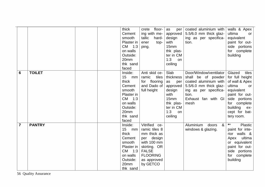
Quality Assurance 56
thick Cement smooth Plaster in CM 1:3 on walls Outside: 20mm thk sand faced
crete floor-ing with me-tallic hard-ener top-ping.
as per approved design with 15mm thk plas-ter in CM 1:3 on ceiling
coated aluminium with 5.5/6.0 mm thick glaz-ing as per specifica-tion.
walls & Apex ultima or equivalent paint for out-side portions for complete building
6 TOILET Inside: 15 mm thick Cement smooth Plaster in CM 1:3 on walls Outside: 20mm thk sand faced
Anti skid ce-ramic tiles for flooring and Dado of full height
Slab thickness as per approved design with 15mm thk plas-ter in CM 1:3 on ceiling
Door/Window/ventilator shall be of powder coated aluminium with 5.5/6.0 mm thick glaz-ing as per specifica-tion. Exhaust fan with GI mesh
Glazed tiles for full height of wall & Apex ultima or equivalent paint for out-side portions for complete building ex-cept for bat-tery room.
7 PANTRY Inside: 15 mm thick Cement smooth Plaster in CM 1:3 on walls Outside: 20mm thk sand
Vitrified ce-ramic tiles 8 mm thick as per design with 100 mm skirting. OR FALSE FLOORING as approved by GETCO
Aluminium doors & windows & glazing.
** Plastic paint for inte-rior walls & Apex ultima or equivalent paint for out-side portions for complete building

Quality Assurance 57
faced
8 CONFERENCE ROOM WITH ATTACHED TOI-LET
Aluminium partition (Partly Glazed and partly panelled)
Inside: 15 mm thick Cement smooth Plaster in CM 1:3 on walls Outside: 20mm thk sand faced
Vitrified ce-ramic tiles 8 mm thick as per design with 100 mm skirting. OR Flooring suitable to CABLE ROOM as approved by GETCO
Gypsum board false ceiling
Door/Window/ventilator shall be of powder coated aluminium with 5.5/6.0 mm thick glaz-ing as per specifica-tion.
Plastic paint for interior walls
9 DISCUSSION ROOM Aluminium partition (Partly Glazed and partly panelled)
Inside: 15 mm thick Cement smooth Plaster in CM 1:3 on walls Outside: 20mm thk sand faced
Vitrified ce-ramic tiles 8 mm thick as per design with 100 mm skirting. OR Flooring suitable to CABLE ROOM as approved by GETCO
Gypsum board false ceiling
Door/Window/ventilator shall be of powder coated aluminium with 5.5/6.0 mm thick glaz-ing as per specifica-tion.
Plastic paint for interior walls
10 OFFICE (EE-1 & EE-2) & HALL FOR STAFF,WAITING ROOM
Aluminium partition (Partly Glazed and partly panelled)
Inside: 15 mm thick Cement smooth Plaster in CM 1:3 on walls
Vitrified ce-ramic tiles 8 mm thick as per design with 100 mm skirting. OR Flooring suitable to
Gypsum board false ceiling
Door/Window/ventilator shall be of powder coated aluminium with 5.5/6.0 mm thick glaz-ing as per specifica-tion.
Plastic paint for interior walls

Quality Assurance 58
Outside: 20mm thk sand faced
CABLE ROOM as approved by GETCO
11 STAIR CASE WITH STAIR CABIN ON TER-RACE
Railing of stainless steel pipe with glass of approved quality and make and de-sign
Marbo gran-ite tiles OR Granite of approved quality with non slippery arrangement
Slab thickness as per approved design with 15mm thk plas-ter in CM 1:3 on ceiling
Door/Window/ventilator shall be of powder coated aluminium with 5.5/6.0 mm thick glaz-ing as per specifica-tion..
Plastic paint for interior walls & Apex ultima or equivalent paint for out-side portions for complete building
B GIS BUILDING (OPTION-I)
(1) GIS BUILDING(FOR RCC FRAMED STRUC-TURE)
Foundation as per Soil Condition with RCC framed structure. As ap-proved by GETCO
a CONTROL & PROTEC-TION PANEL ROOM
Aluminium partition (Partly Glazed and partly panelled)
Inside: 15 mm thick Cement smooth Plaster in CM 1:3 on walls
Vitrified ce-ramic tiles 8 mm thick as per design with 100 mm skirting. OR Flooring suitable to
Gypsum board false ceiling
Door/Window/ventilator shall be of powder coated aluminium with 5.5/6.0 mm thick glaz-ing as per specifica-tion.
* Plastic paint for interior walls & Apex ultima or equivalent paint for out-side portions for complete
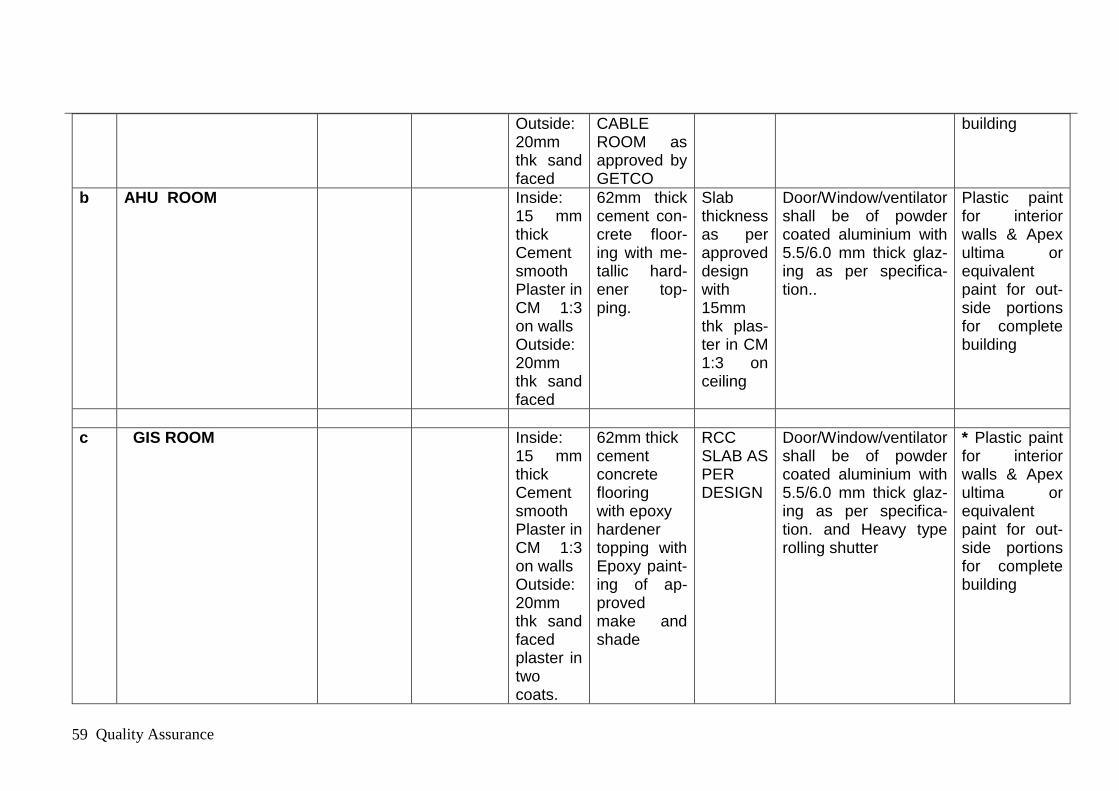
Quality Assurance 59
Outside: 20mm thk sand faced
CABLE ROOM as approved by GETCO
building
b AHU ROOM Inside: 15 mm thick Cement smooth Plaster in CM 1:3 on walls Outside: 20mm thk sand faced
62mm thick cement con-crete floor-ing with me-tallic hard-ener top-ping.
Slab thickness as per approved design with 15mm thk plas-ter in CM 1:3 on ceiling
Door/Window/ventilator shall be of powder coated aluminium with 5.5/6.0 mm thick glaz-ing as per specifica-tion..
Plastic paint for interior walls & Apex ultima or equivalent paint for out-side portions for complete building
c GIS ROOM Inside: 15 mm thick Cement smooth Plaster in CM 1:3 on walls Outside: 20mm thk sand faced plaster in two coats.
62mm thick cement concrete flooring with epoxy hardener topping with Epoxy paint-ing of ap-proved make and shade
RCC SLAB AS PER DESIGN
Door/Window/ventilator shall be of powder coated aluminium with 5.5/6.0 mm thick glaz-ing as per specifica-tion. and Heavy type rolling shutter
* Plastic paint for interior walls & Apex ultima or equivalent paint for out-side portions for complete building

Quality Assurance 60
* In corridor false ceiling shall be provided of Gypsum board false ceiling‟.
Note: (1) China Mosaic flooring water proofing as per technical specification shall be done for the above build-ings on terrace slab of the above buildings with guarantee of water proofing for at least five years from date of completion (2) In toilet block, there shall be approved quality of European WC with flush tank, Wash basin, Glass mirror etc for complete function of Toilet block. (3) RCC stair case from GF to FF, FF to SF & SF to terrace shall be provided including cabin at top. (4) In GIS control room as the height is more, a care shall be taken for sufficient lighting and ventilation. (5) Aesthetic view of building as a whole shall be main-tained. (6) GIS Housing staircase railing shall be of stainless grill of approved design with polished hand rail of appropriate size. (7) Aluminium doors and windows shall be heavy type as per latest IS codes and practices. (8) Leak proof test shall be given for water supply and drainage line.
(9) False flooring of approved make and pattern shall be provided at first floor as per system requirements.
(10) CABLE TRENCH IN GIS HALL: All cable trenches in GIS hall, control & protection panels and AHU rooms,
CONTROL ROOM shall be covered with minimum 6mm thick steel chequered plate with suitable stiffeners
OR
Sr. no.
Type of Foundation & Structure
Wall Wall finish-ing
Floor finish Ceiling Doors win-dows
Painting
B GIS BUILDING (OPTION-II)
(1) GIS BUILDING(FOR GIS HALL SHALL BE OF STEEL STRUCTURE & CONTROL AND PROTECTION PANEL ROOM AND
RCC Foundation as per Soil Condition with STEEL structure.

Quality Assurance 61
AHU ROOM OF RCC FRAMED STRUCTURE)
As ap-proved by GETCO
a CONTROL & PRO-TECTION PANEL ROOM
Aluminium partition (Partly Glazed and partly pan-elled)
Inside: 15 mm thick Cement smooth Plas-ter in CM 1:3 on walls Outside: 20mm thk sand faced
Vitrified ceramic tiles 8 mm thick as per design with 100 mm skirting. OR Flooring suitable to CABLE ROOM as ap-proved by GETCO
Slab thickness as per ap-proved design with 15mm thk plaster in CM 1:3 on ceiling AND Gypsum board false ceiling
Door/Window/ventilator shall be of powder coated alu-minium with 5.5/6.0 mm thick glazing as per speci-fication.
* Plastic paint for interior walls & Apex ultima or equivalent paint for out-side portions for complete building
b AHU ROOM Inside: 15 mm thick Cement smooth Plas-ter in CM 1:3 on walls Outside: 20mm thk sand faced
62mm thick ce-ment concrete flooring with me-tallic hardener topping.
Slab thickness as per ap-proved design with 15mm thk plaster in CM 1:3 on ceiling
Door/Window/ventilator shall be of powder coated alu-minium with 5.5/6.0 mm thick glazing as per speci-fication..
Plastic paint for interior walls & Apex ultima or equivalent paint for out-side portions for complete building
c GIS ROOM Inside: 15 mm thick Cement smooth Plas-ter in CM 1:3 on walls Outside: 20mm thk sand faced plaster in
62mm thick cement concrete flooring with epoxy hardener topping with Epoxy painting of approved make and
Roofing Panel: 50mm thick puff sand-wiched panels shall be Provided. The-se panels shall be made of puff insulation sandwiched
Door/Window/ventilator shall be of powder coated alu-minium with 5.5/6.0 mm thick glazing as per speci-fication. and
* Plastic paint for interior walls & Apex ultima or equivalent paint for out-side portions for complete building

Quality Assurance 62
two coats. shade
between two nos 24G thick SMP coated galvalume steel sheets. Panels shall be fixed with roof truss using gal-vanized fasteners.
Heavy type rolling shut-ter
* In corridor false ceiling shall be provided of „Gypsum board false ceiling‟.
Note: (1) China Mosaic flooring water proofing as per technical specification shall be done for the above build-ings on terrace slab of the above buildings with guarantee of water proofing for at least five years from date of completion (2) In toilet block, there shall be approved quality of European WC with flush tank, Wash basin, Glass mirror etc for complete function of Toilet block. (3) RCC stair case from GF to FF, FF to SF & SF to terrace shall be provided including cabin at top. (4) In GIS control room as the height is more, a care shall be taken for suffi-cient lighting and ventilation. (5) Aesthetic view of building as a whole shall be maintained. (6) GIS Housing staircase railing shall be of stainless grill of approved design with polished hand rail of appropriate size. (7) Al-uminium doors and windows shall be heavy type as per latest IS codes and practices. (8) Leak proof test shall be given for water supply and drainage line(9) False flooring of approved make and pattern shall be provided at first floor as per system requirements (9) CABLE TRENCH IN GIS HALL: All cable trenches in in GIS hall, control & protection
panels and AHU rooms,
CONTROL ROOM shall be covered with minimum 6mm thick steel chequered plate with suitable stiffeners.
.
Sr. no.
Type of Foundation
Wall Wall finish-ing
Floor finish Ceiling Doors win-dows
Painting

Quality Assurance 63
& Structure
C TYPE.4 QUARTER
(1) TYPE.4 QUARTER WITH RCC FRAMED STRUC-TURE
Foundation as per Soil Condition with RCC framed structure. As ap-proved by GETCO
a LIVING ROOM Inside: 15 mm thick Cement smooth Plas-ter in CM 1:3 on walls Outside: 20mm thk sand faced
Vitrified ceramic tiles 8 mm thick as per design with 100 mm skirting.
Slab thickness as per ap-proved design with 15mm thk plaster in CM 1:3 on ceiling.
Entrance door of T.W.door with M.S. Angle frame and door be-tween LR & balcony of 35mm thick FRP door as per spec. All windows shall be powder coated alu-minium and covered with M.S Grill from out side.
* Oil bound distemper for interior walls & Apex ultima or equivalent paint for out-side portions for complete building
b BED ROOM Inside: 15 Vitrified ceramic Slab thickness Door be- * Oil bound

Quality Assurance 64
mm thick Cement smooth Plas-ter in CM 1:3 on walls Outside: 20mm thk sand faced
tiles 8 mm thick as per design with 100 mm skirting.
as per ap-proved design with 15mm thk plaster in CM 1:3 on ceiling
tween LR & BR shall be 28mm thick FRP door as per spec. All windows shall be powder coated alu-minium and covered with M.S Grill from out side.
distemper for interior walls & Apex ultima or equivalent paint for out-side portions for complete building
C KITCHEN Inside: 15 mm thick Cement smooth Plas-ter in CM 1:3 on walls Outside: 20mm thk sand faced
Vitrified ceramic tiles 8 mm thick as per design with 100 mm skirting.
Slab thickness as per ap-proved design with 15mm thk plaster in CM 1:3 on ceiling
Door en-trance to Kitchen shall be 28mm thick FRP door as per spec. All windows shall be powder coated alu-minium and covered with M.S Grill from out side
* Oil bound distemper for interior walls & Apex ultima or equivalent paint for out-side portions for complete building

Quality Assurance 65
c TOILET BLOCK Inside: 15 mm thick Cement smooth Plas-ter in CM 1:3 on walls Outside: 20mm thk sand faced
Anti skid ceram-ic tiles for floor-ing and Dado of full height
Slab thickness as per ap-proved design with 15mm thk plaster in CM 1:3 on ceiling
Door en-trance to WCand BATH shall be 28mm thick FRP door as per spec. All Ventilator shall be powder coated alu-minium Exhaust fan with GI mesh
Glazed tiles for full height of wall & Apex ultima or equivalent paint for out-side portions for complete building.
d PASSAGE Inside: 15 mm thick Cement smooth Plas-ter in CM 1:3 on walls Outside: 20mm thk sand faced
Vitrified ceramic tiles 8 mm thick as per design with 100 mm skirting.
Slab thickness as per ap-proved design with 15mm thk plaster in CM 1:3 on ceiling

Quality Assurance 66
e STAIR CASE WITH STAIR CABIN ON TERRACE
Railing of stainless steel pipe with glass of approved quality and make and design
Marbo granite tiles OR Gran-ite of approved quality with non slippery ar-rangement
Slab thickness as per ap-proved design with 15mm thk plaster in CM 1:3 on ceiling
Door at ter-race shall be 28mm thick FRP door as per spec
Oil bound dis-temeper for interior walls & Apex ultima or equivalent paint for out-side portions for complete building
Note: (1) China Mosaic flooring water proofing as per technical specification shall be done for the above buildings on terrace slab of the above buildings with guarantee of water proofing for at least five years from date of completion (2) In toilet block, there shall be approved quality of European WC with flush tank, Wash basin, Glass mirror etc for complete function of Toilet block. (3) Aluminium doors and windows shall be heavy type as per latest IS codes and practices. (4) Leak proof test shall be given for water supply and drainage line. (4) In Kitchen, RCC platform of size 2000 x 675 mm in plan with adequate height and shall be covered with approved quality of marble stone with all fixtures and fastening and steel sunk etc. Cupboard shutter with sun mica top with shelves of 22mm thick kotah stone shall be provided.
Sr. no.
Type of Founda-tion & Structure
Wall Wall finish-ing
Floor finish Ceiling Doors win-dows
Painting
D STORE BUILDING
(1) STORE BUILDING Founda-tion as per Soil Condi-tion with RCC framed

Quality Assurance 67
structure. As ap-proved by GETCO
A STORE ROOM Inside: 15 mm thick Cement smooth Plas-ter in CM 1:3 on walls Outside: 20mm thk sand faced
Polished kotah stone OF 22 to 25mm thick with marble strips of 22mm thick with 100mm skirting
Slab thickness as per ap-proved design with 15mm thk plaster in CM 1:3 on ceiling
Mechanical-ly operated rolling shut-ter of ap-proved make shall be pro-vided as per drawing.
Plastic paint for interior walls & Apex ultima or equivalent paint for out-side portions for complete building
B ENTRANCE STEPS 30mm thick Pol-ished kotah stone with round nose on three sides.
Slab thickness as per ap-proved design with 15mm thk plaster in CM 1:3 on ceiling
Note: (1) China Mosaic flooring water proofing as per technical specification shall be done for the above buildings on terrace slab of the above buildings with guarantee of water proofing for at least five years from date of completion. GUJARAT ENERGY TRANSMISSION CORPORATION LTD
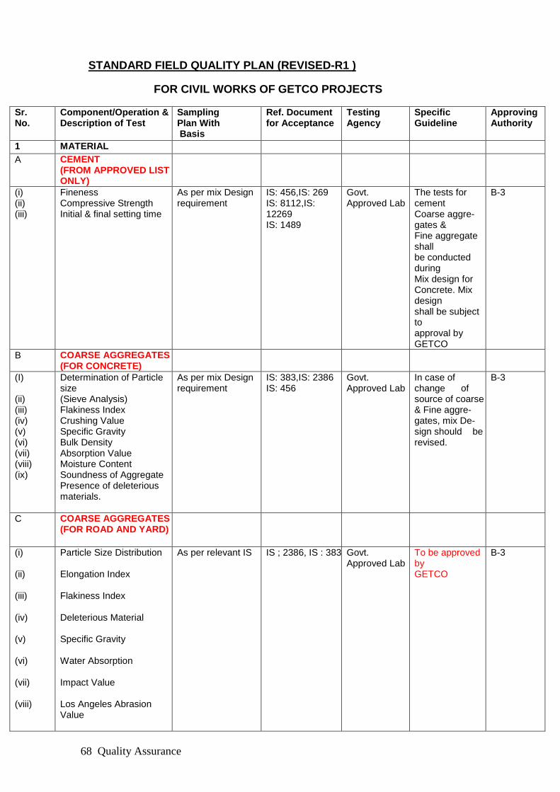
Quality Assurance 68
STANDARD FIELD QUALITY PLAN (REVISED-R1 )
FOR CIVIL WORKS OF GETCO PROJECTS
Sr. No.
Component/Operation & Description of Test
Sampling Plan With Basis
Ref. Document for Acceptance
Testing Agency
Specific Guideline
Approving Authority
1 MATERIAL
A CEMENT (FROM APPROVED LIST ONLY)
(i) (ii) (iii)
Fineness Compressive Strength Initial & final setting time
As per mix Design requirement
IS: 456,IS: 269 IS: 8112,IS: 12269 IS: 1489
Govt. Approved Lab
The tests for cement Coarse aggre-gates & Fine aggregate shall be conducted during Mix design for Concrete. Mix design shall be subject to approval by GETCO
B-3
B COARSE AGGREGATES (FOR CONCRETE)
(I) (ii) (iii) (iv) (v) (vi) (vii) (viii) (ix)
Determination of Particle size (Sieve Analysis) Flakiness Index Crushing Value Specific Gravity Bulk Density Absorption Value Moisture Content Soundness of Aggregate Presence of deleterious materials.
As per mix Design requirement
IS: 383,IS: 2386 IS: 456
Govt. Approved Lab
In case of change of source of coarse & Fine aggre-gates, mix De-sign should be revised.
B-3
C COARSE AGGREGATES (FOR ROAD AND YARD)
(i) (ii) (iii) (iv) (v) (vi) (vii) (viii)
Particle Size Distribution Elongation Index Flakiness Index Deleterious Material Specific Gravity Water Absorption Impact Value Los Angeles Abrasion Value
As per relevant IS
IS ; 2386, IS : 383 Govt. Approved Lab
To be approved by GETCO
B-3

Quality Assurance 69
(ix) (x) (xi) (xii) (xiii)
Aggregate Crushing Value 10% Fines value Soundness Alkali Aggregate Reactivi-ty Petrography
D FINE AGGREGATE
(I) (ii) (iii) (iv) (v) (vi) (vii)
Gradation /Determination of Particle size Specific Gravity and den-sity. Moisture content Absorption Value Bulking Silt Content Test Presence of deleterious materials
As per mix Design requirement
IS: 383,IS: 2386,IS: 456
Govt. Approved Lab
In case of change of source of coarse & Fine aggre-gates, mix De-sign should be revised.
B-3
E BURNT CLAY BRICKS
(i)
(ii)
(iii)
(iv)
Dimensional tolerance Compressive Strength Water Absorption Efflorescence
As per relevant IS
GETCO Specs. IS: 3495) (Part I to Iv)
Govt. Approved Lab
To be approved by GETCO
B-3
F FLY ASH LIME BRICKS
(i)
(ii)
(iii)
(iv)
(v)
Dimension Water absorption Drying Shrinkage Compressive Strength Efflorescence
As per relevant IS
GETCO Specs. IS: 3495 and IS : 12894
Govt. Approved Lab
To be approved by GETCO
B-3
G SOLID CC BLOCKS
(i)
(ii)
(iii)
(iv)
(v)
Dimension Block Density Compressive strength Water absorption Dry Shrinkage
As per relevant IS
GETCO Specs. IS: 2185 Part 1
Govt. Approved Lab
To be approved by GETCO
B-3
H BELLA STONE

Quality Assurance 70
(i)
(ii)
Water absorption Compressive Strength
As per relevant IS
GETCO Specs. IS: 2386 Part 3
Govt. Approved Lab
To be approved by GETCO
B-3
I PRECAST CC PAVER BLOCKS
(i)
(ii)
(iii)
(iv)
(v)
(vi)
Shape and Dimension Compressive Strength Flexural Strength Abrasion Resistance Split Tensile Strength Water absorption
As per relevant IS
GETCO Specs. IS: 15658
Govt. Approved Lab
To be approved by GETCO
B-3
J SOIL TO BE USED FOR BACK FILLING
(i)
(ii)
(iii)
(iv)
(v)
(vi)
(vii)
Grain Size Analysis Atterberg‟s limit Classification of Soil Free Swell Index Swelling Pressure Proctor Test SO3 (Sulphate ) Content
As per relevant IS
IS :2720
Govt. Approved Lab
To be approved by GETCO
B-3
K WATER
(i)
(II)
Cleanliness (Visual Check) Chemical and physical properties of water for checking its suitability for construction proposes.
Random One sample per Source
IS: 456,IS: 3025 and Specification. The Water used for mixing concrete shall be fresh, clean and free from oil, acids and alkalis, organic materials, or other deleteri-ous materials IS: 456,IS: 3025 and GETCO Specification
Contractor / GETCO Govt. Approved Lab
Each source to be Approved by GETCO
C
L REINFORCEMENT STEEL (FROM AP-PROVED LIST ONLY)
(i)
(ii)
Identification & size Chemical Analysis Test
Random One sample per Heat
IS: 432,IS: 1139, IS: 1786 & GETCO Specifi-cation
Contractor should pro-duce manufac-turer‟s test Certifi-
Approved by GETCO.
B-3

Quality Assurance 71
(iii)
(iv)
(v)
(vi)
Tensile Test Yield stress\proof stress Percentage Elongation Bend/Re-bend Test Reverse Bend Test for HYSDWire
One sample per Each size One sample per Each size One sample per Each size One sample per Each size
cate. i.e. from approved Manufacturer. Govt. Approved Lab
M STRUCTURAL STEEL
(i)
(ii)
(iii)
(iv) (v) (vi) (vii) (viii)
Chemical Composition Tensile Strength Yield Strength Percentage Elongation Bend Test Impact Test Y Groove Crackability Test Dimensions
One sample per Heat One sample per Each size One sample per Each size One sample per Each size One sample per Each size One sample per Each size One sample per Each size Random
IS :2062, IS :228, IS : 1608, IS : 1599, IS : 1757, IS : 10842
Govt. Approved Lab
Approved by GETCO.
B-3
N FOUNDATION BOLTS
(i)
(ii)
(iii)
(iv) (v) (vi) (vii)
Identification & size Chemical Analysis Test Tensile Test Yield stress/Proof Stress Percentage Elongation Bend / Rebend Weight/Thickness/Uniformity of Galvanizing
Random One sample per Each One sample per Each One sample per Each One sample per Each One sample per Each One sample per Each
IS : 209, IS : 2016, IS :2062, IS : 2633, IS :12427, & GETCO Specification
Govt. Approved Lab
Approved by GETCO.
B-1
O PVC WATER STOPS
(i) (ii)
(iii)
(iv)
(v)
(vi)
Tensile strength Elongation Hardness Water absorption, per-centage by mass Cold bend temperature at which sample does not crack Accelerated extraction
One sample per Each One sample per Each One sample per Each One sample per Each One sample per Each One sample per
IS : 15058, IS :8543 (Part4 / Sec 1), IS : 13360 (Part 5 / Sec 1), IS ; 9766 & GETCO Specification
Contractor should Produce manufacturer‟s test Certifi-cate. i.e from approved Manufacturer.
Approved by GETCO.
B-3
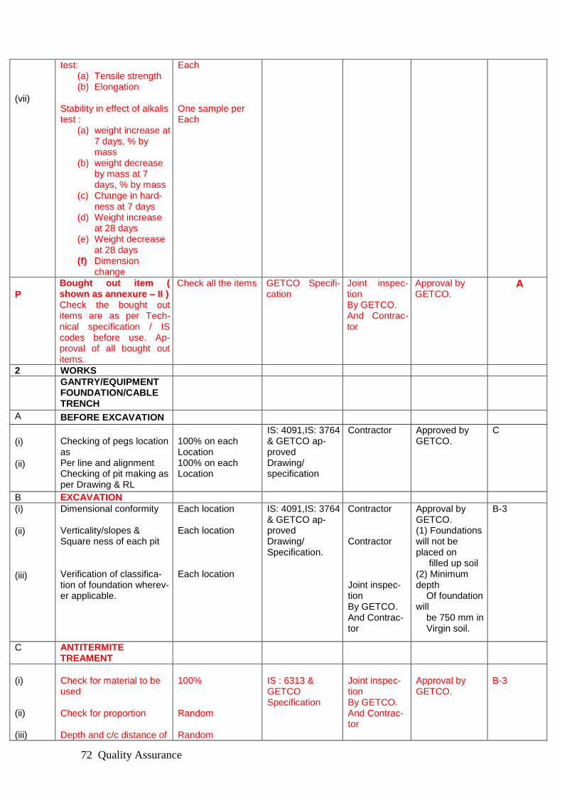
Quality Assurance 72
(vii)
test: (a) Tensile strength (b) Elongation
Stability in effect of alkalis test :
(a) weight increase at 7 days, % by mass
(b) weight decrease by mass at 7 days, % by mass
(c) Change in hard-ness at 7 days
(d) Weight increase at 28 days
(e) Weight decrease at 28 days
(f) Dimension change
Each One sample per Each
P
Bought out item ( shown as annexure – II ) Check the bought out items are as per Tech-nical specification / IS codes before use. Ap-proval of all bought out items.
Check all the items GETCO Specifi-cation
Joint inspec-tion By GETCO. And Contrac-tor
Approval by GETCO.
A
2 WORKS
GANTRY/EQUIPMENT FOUNDATION/CABLE TRENCH
A BEFORE EXCAVATION
(i)
(ii)
Checking of pegs location as Per line and alignment Checking of pit making as per Drawing & RL
100% on each Location 100% on each Location
IS: 4091,IS: 3764 & GETCO ap-proved Drawing/ specification
Contractor
Approved by GETCO.
C
B EXCAVATION
(i)
(ii)
(iii)
Dimensional conformity Verticality/slopes & Square ness of each pit Verification of classifica-tion of foundation wherev-er applicable.
Each location Each location Each location
IS: 4091,IS: 3764 & GETCO ap-proved Drawing/ Specification.
Contractor Contractor Joint inspec-tion By GETCO. And Contrac-tor
Approval by GETCO. (1) Foundations will not be placed on filled up soil (2) Minimum depth Of foundation will be 750 mm in Virgin soil.
B-3
C ANTITERMITE TREAMENT
(i) (ii) (iii)
Check for material to be used Check for proportion Depth and c/c distance of
100% Random Random
IS : 6313 & GETCO Specification
Joint inspec-tion By GETCO. And Contrac-tor
Approval by GETCO.
B-3

Quality Assurance 73
(iv)
holes Check for pouring of re-quired quantity of liquid in holes
Random
D P.C.C. PADDING
For all locations
IS:456,GETCO Approved founda-tion Drawing & specification
Joint inspec-tion By GETCO. And Contrac-tor
Approval by GETCO.
C
E SHUTTERING (Form work)
Check for materials, breakage Or damage Check for plumb, align-ment Parallelism, square-ness and equidistance from stub Dimensional check. Check for level & height Check for rigidity of frame/tightness Cleaning and oiling Diagonal bracing if re-quired as per draw-ings/site conditions. Checking of joints to avoid undue loss of cement slur-ry
100%
IS: 456,GETCO Specification/ Approved draw-ings.
Joint inspec-tion By GETCO. And Contrac-tor
Approved by GETCO.
C
F PLACEMENT OF REIN-FORCEMENT STEEL.
(i) (ii) (iii) (iv) (v)
Check the steel bars for rust, cracks, surface flaws, laminate etc. (Visual check) Check as per the bar bending Schedule before placement of Concrete. Check cutting tolerance for bars as per check List/drawings. Check whether all bent bars and lap lengths are as per approved bar bend-ing schedule. Check whether all joints & crossing of bars are tied properly with right gauge & annealed wire as per specification.
Check for proper cover distance spacing of bars, spacers, & chairs after the reinforcement cage has been put inside the form-
100%
IS: 456,GETCO Specification/ approved draw-ings.
Joint inspec-tion By GETCO. And Contrac-tor
Approved by GETCO.
B-3

Quality Assurance 74
(vi)
work. Check whether lapping of bars are tied properly with right gauge and annealed wire as per specification.
G PILE FOUNDATION (Ad-ditional Tests)
(i) (ii) (iii) (iv) (v) (vi) (vii) (viii) (ix) (x)
Check of centre line of pile group Check pile location Temporary casing tube & permanent line also check Thickness of liner material (if applicable) Bentonite slurry (if appli-cable) Pile depth, level, size and alignment Chipping of pile head Pile load testing Anchor bolts if applicable Level, centre to centre distance Of bolts. Visual check for galvaniz-ing
Each pile group
Each pile
Each pile Each pile Each pile Each pile As per GETCO GBOQ/Specifica- Tion IS: 2911 100% on each Location 100% on each Location
IS:2911 & GETCO Approved pile Foundation Drawings/ Specification. GETCO Approved pile foundation Draw-ings/pecification
Joint inspec-tion by GETCO and Contractor
Checklist to be prepared And signed joint-ly
B-3
H SETTING OF TEMPLATE
(i)
(ii)
(iii)
(iv) (v) (vi)
Identification Check for orientation of template to match with drawing Check for line and level of template Check for center line of foundation and template Check for diagonal dimen-sions Check for diameter and distance of holes
Each foundation Each foundation Each foundation Each foundation Each foundation Each foundation
GETCO Approved specifications
Joint inspec-tion by GETCO. and Contractor
Approval by GETCO
C
I PLACEMENT OF FOUN-DATION BOLTS
(i)
(ii)
Identification (Diameter and length) Check the foundation
Each foundation Each foundation
GETCO Approved specifications
Joint inspec-tion by GETCO and Contractor
Approval by GETCO
C

Quality Assurance 75
(iii) (iv) (v) (vi)
bolts for rust, cracks, sur-face flaws, laminate etc. (Visual check) Check for height of bolts above concrete level as per drawing Check for bolt to bolt dis-tance as per drawing Check for verticality of bolts Check for Fixity of bolts
Each foundation Each foundation Each foundation Each foundation
J
PLACEMENT OF WA-TER STOP
(i) (ii) (iii) (iv)
Check the water stops for blisters, pinholes, cracks, and embedded foreign matters (Visual Check ) Check for width and thick-ness Line and level Fixity during concreting
Random Random 100% 100%
GETCO Approved specifications
Joint inspec-tion by GETCO and Contrac-tor
Approval by GETCO
B-3
K CONCRETING
a APPROVAL OF MIX DE-SIGN.
For each grade of Concrete.
IS: 456 & GETCO Approved specifications
Contractor
Approval by GETCO
B-3
b
Batching, mixing & placing of concrete and compact-ing Placing concrete, and compacting
Random Random
IS: 456 & GETCO Approved draw-ings And specifica-tions
Contractor
Approval by GETCO
B-3
c CONCRETE TESTING
Slump test Check for quantities for cement, fine aggregate, coarse aggregate and wa-ter while batching
Random Random
IS:456,IS:516, IS:1199 And GETCO Specifications
Contractor
Results to be recorded and signed Jointly
B-3
d
CONCRETE CUBE TESTING
Compressive Strength
Sample (Consisting of minimum 6 cu-bes-3 cubes for 7days and 3 cubes for 28 days test) 1-5 Cmt : 1 6-15 Cmt : 2 16-30 Cmt : 3 31-50 Cmt : 4 Above 50 Cmt : 4+1 additional for each additional 50 Cmt
Is:1199,IS:456, IS:516
Govt. Ap-proved lab
To be witnessed for important structure (slab) & Approved by GETCO
B-3

Quality Assurance 76
L BACKFILLING
Check for thickness of Layer & watering Visual check for correc-tion/ramming Compaction test (Percent-age of Max dry density
100%
GETCO Specifications.
Govt. Ap-proved lab
To be witnessed & Approved by GETCO
C
M BRICK-WORK
Mortar mix/proportion Plumb & Alignment Joints
Random Random Random
IS:2250, GETCO Specifi-cation
Joint inspec-tion by GETCO and Contractor
Approval by GETCO
C
N PLASTERING
Plastering thickness and evenness Mortar mix proportion
Random Random
GETCO Specification GETCO Specification
Joint inspec-tion by GETCO and Contractor
Approved by GETCO
C
O FLOORING
(i) (ii) (iii) (iv)
Thickness of flooring ma-terial (Kotah stone/ Vitri-fied tiles/glazed tiles) Mortar mix proportion Line and level Joints
Random Random 100% 100%
GETCO Specification
Joint inspec-tion by GETCO and Contractor
Approved by GETCO
B-3
P WATERPROOFING
(i) (ii) (iii) (iv) (v) (vi)
Check for material to be used Cleaning of terrace Proportion of mortar Level Joints Pond Test
100% 100% Random 100% 100% 100%
GETCO Specification,.
Joint inspec-tion By GETCO. And Contrac-tor
Approval by GETCO
B-3
Q
CURING FOR CON-CRETE, MASONRY,PLASTERING ETC.
100% on all locations
IS 5613 & GETCO Specification,.
Contractor. Approval by GETCO
C
R
ALLUMINIUM DOORS/WINDOWS
(i) (ii) (iii) (iv)
Check for size of different members Check for weight of differ-ent members Check for anodizing Check for joints of various members
Random Random Random Random
IS : 733, IS: 1285, IS : 1868, & GETCO Specification
Joint inspec-tion By GETCO. and Contractor and test report from Manufac-turer
Approval by GETCO
B-2
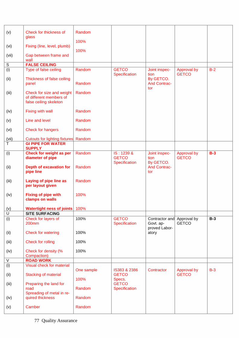
Quality Assurance 77
(v) (vi) (vii)
Check for thickness of glass Fixing (line, level, plumb) Gap between frame and wall
Random 100% 100%
S FALSE CEILING
(i) (ii) (iii) (iv) (v) (vi) (vii)
Type of false ceiling Thickness of false ceiling panel Check for size and weight of different members of false ceiling skeleton Fixing with wall Line and level Check for hangers Cutouts for lighting fixtures
Random Random Random Random Random Random Random
GETCO Specification
Joint inspec-tion By GETCO. And Contrac-tor
Approval by GETCO
B-2
T GI PIPE FOR WATER SUPPLY
(i) (ii) (iii) (iv) (v)
Check for weight as per diameter of pipe Depth of excavation for pipe line Laying of pipe line as per layout given Fixing of pipe with clamps on walls Watertight ness of joints
Random Random Random 100% 100%
IS : 1239 & GETCO Specification
Joint inspec-tion By GETCO. And Contrac-tor
Approval by GETCO
B-3
U SITE SURFACING
(i) (ii) (iii) (iv)
Check for layers of 200mm Check for watering Check for rolling Check for density (% Compaction)
100% 100% 100% 100%
GETCO Specification
Contractor and Govt. ap-proved Labor-atory
Approval by GETCO
B-3
V ROAD WORK
(i) (ii) (iii) (iv) (v)
Visual check for material Stacking of material Preparing the land for road Spreading of metal in re-quired thickness Camber
One sample 100% Random Random Random
IS383 & 2386 GETCO Specs. GETCO Specification
Contractor
Approval by GETCO
B-3

Quality Assurance 78
(vi) (vii)
Rolling Watering
Random Random
W YARD QUARRY DUST/METAL SPREAD-ING
(i) (ii) (iii) (iv) (v)
Visual check of material Stacking of material Preparing the land upto required level Spreading of material of required thickness Compaction
One sample 100% Random Random Random
IS383 & 2386 GETCO Specs.
Contractor Approval by GETCO
B-3
X FALSE FLOORING
(i) (ii) (iii) (iv) (v) (vi) (vii)
Type of false flooring Thickness of false flooring panel Check for size and weight of different members of false flooring skeleton Fixing with floor Line and level Check for studs Cutouts for panel to be supported on MS channel
Random Random Random Random Random Random Random
GETCO Specification
Joint inspec-tion By GETCO. And Contrac-tor
Approval by GETCO
B-2
Y PERIPHERAL/ROAD SIDE DRAIN
(i) Alignment as per lay out 100% on each Location
As per approved draw-ings
contractor Approval by GETCO
C
(ii) Invert level as per outlet points
100% on each Location
As per approved drawings
contractor Approval by GETCO
C
(iii) Concrete and masonry as per FQP
As per approved draw-ings
contractor Approval by GETCO
C
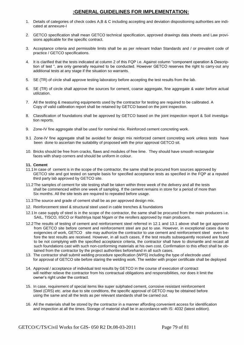
GETCO/C/TS/Civil Works for GIS- 050 R2 Dt.08-03-2011 Page 79 of 81
:GENERAL GUIDELINES FOR IMPLEMENTATION:
1. Details of categories of check codes A,B & C including accepting and deviation dispositioning authorities are indi-cated at annexure-I
2. GETCO specification shall mean GETCO technical specification, approved drawings data sheets and Law provi-
sions applicable for the specific contract.
3. Acceptance criteria and permissible limits shall be as per relevant Indian Standards and / or prevalent code of practice / GETCO specifications.
4. It is clarified that the tests indicated at column 2 of this FQP i.e. Against column “component operation & Descrip-tion of test “, are only generally required to be conducted. However GETCO reserves the right to carry-out any additional tests at any stage if the situation so warrants.
5. SE (TR) of circle shall approve testing laboratory before accepting the test results from the lab.
6. SE (TR) of circle shall approve the sources for cement, coarse aggregate, fine aggregate & water before actual utilization.
7. All the testing & measuring equipments used by the contractor for testing are required to be calibrated. A Copy of valid calibration report shall be retained by GETCO based on the joint inspection.
8. Classification of foundations shall be approved by GETCO based on the joint inspection report & Soil investiga-tion reports.
9. Zone-IV fine aggregate shall be used for nominal mix. Reinforced cement concreting work.
9.1 Zone-IV fine aggregate shall be avoided for design mix reinforced cement concreting work unless tests have been done to ascertain the suitability of proposed with the prior approval GETCO sit.
10. Bricks should be free from cracks, flaws and modules of free lime. They should have smooth rectangular faces with sharp corners and should be uniform in colour.
11. Cement 11.1 In case of cement is in the scope of the contractor, the same shall be procured from sources approved by
GETCO site and got tested on sample basis for specified acceptance tests as specified in the FQP at a reputed third party lab approved by GETCO site.
11.2 The samples of cement for site testing shall be taken within three week of the delivery and all the tests shall be commenced within one week of sampling. If the cement remains in store for a period of more than Six months. All the site tests are required to repeated before usage.
11.3 The source and grade of cement shall be as per approved design mix.
12. Reinforcement steel & structural steel used in cable trenches & foundations
12.1 In case supply of steel is in the scope of the contractor, the same shall be procured from the main producers i.e. SAIL, TISCO, IISCO or Rashtriya Ispat Nigam or the rerollers approved by main producers.
12.2 The results of testing of cement and reinforcement steel referred in 12.1 and 13.1 above shall be got approved from GETCO site before cement and reinforcement steel are put to use. However, in exceptional cases due to exigencies of work, GETCO site may authorize the contractor to use cement and reinforcement steel even be-fore the test results are received. However, in all such cases, if the test results subsequently received are found to be not complying with the specified acceptance criteria, the contractor shall have to dismantle and recast all such foundations cast with such non-conforming materials at his own cost. Confirmation to this effect shall be ob-tained from the contractor by the project authorities beforehand in all such cases.
13. The contractor shall submit welding procedure specification (WPS) including the type of electrode used for approval of GETCO site before staring the welding work. The welder with proper certificate shall be deployed
14. Approval / acceptance of individual test results by GETCO in the course of execution of contract will neither relieve the contractor from his contractual obligations and responsibilities, nor does it limit the owner‟s right under the contract.
15. In case, requirement of special items like super sulphated cement, corrosive resistant reinforcement Steel (CRS) etc. arise due to site conditions, the specific approval of GETCO may be obtained before using the same and all the tests as per relevant standards shall be carried out.
16. All the materials shall be stored by the contractor in a manner affording convenient access for identification and inspection at all the times. Storage of material shall be in accordance with IS: 4032 (latest edition).

GETCO/C/TS/Civil Works for GIS- 050 R2 Dt.08-03-2011 Page 80 of 81
ANNEXURE-I
GUJARAT ENERGY TRANSMISSION CORPORATION LIMITED
Accepting and deviation dispositioning authorities for different Categories of checks as envisaged in field quality plan
Category
type of Check
100%Checking/ witnessing by
counter check/ surveillance check by
Accepting Authority, if Test results Are within Permissible Limit
Deviation Dispositioning Authority
A
Critical EE (civil) of circle with Contractor‟s Engineer
SE(TR) Plus EE(C)
SE(TR) Plus EE(C)
CE, Corporate Office
B-1 Major D E (Quality Deptt)
E E (Quality Deptt)
EE (Quality Deptt)
CE (Quality Deptt)
B-2 Major EE (civil) of circle with Contractor‟s Engineer
SE (Civil) SE (Civil) plus EE (C)
CE, Corporate Office
B-3
Major DE(C)
EE(C) EE(C) SE(TR) Plus EE(C)
C Minor JE(C)
DE(C) DE(C) EE(C) Plus DE(C)

GETCO/C/TS/Civil Works for GIS- 050 R2 Dt.08-03-2011 Page 81 of 81
ANNEXURE-II
BOUGHT OUT ITEMS Check the following bought out items for their specifications / IS codes before use 1. Cement. 2. Murrum or yellow earth for filling in yard or plinth. 3. Bricks/Block. 4. Reinforcement. 5. Structural steel. 6. Foundation bolts. 7. Fine aggregate. 8. Coarse aggregate for all type of concrete, WBM road and metal spreading in yard. 9. PVC water pipe line with fixtures. 10. PVC drainage pipe line with fixture. 11. PVC rain water pipe with fixture. 12. PVC casing pipe for bore well. 13. 4 mm thick flat copper cable for submersible pump 14. Teak wood for frame and shutter. 15. Aluminium door, window and ventilator. 16. FRP door. 17. Steel cup board shutter. 18. False ceiling material. 19. Glazed tiles. 20. Kotah stone and marble strips. 21. Vitrified tiles. 22. Granite or Marbo granite tiles. 23. Metallic hardener topping. 24. Paver concrete block. 25. Prestressed concrete cover for cable trench. 26. Oil bound distemper. 27. Acid/Alkali resistant paint. 28. Apex ultima or equivalent exterior paint. 29. Epoxy paint for flooring in GIS room. 30. Rolling shutter. 31. Chain link fencing panel and angle. 32. Wash basin. 33. Orissa pan/European pan. 34. Glass mirror. 35. Marble year plate. 36. Towel rod for bath room. 37. Sliding gate. 38. RCC Hume pipe.(pressure/Non pressure). 39. Submersible pump for bore well. 40. Substation Sign boards. 41. Acrylic name plates. 42. MS cover for cable trench in control room/GIS room. 43. Ear thing strips. 44. Grout materials for foundation/flooring.