samson - "eks-m" elm İstehsalat mərkəzi | xoŞ … converters, limit switches, position...
TRANSCRIPT
SAMSONSAM
SO
N
2010
-04
WS
· K 1
3 EN
SAMSON AG · MESS- UND REGELTECHNIK · Weismüllerstraße 3 · 60314 Frankfurt am Main · GermanyPhone: +49 69 4009-0 · Fax: +49 69 4009-1507 · E-mail: [email protected] · Internet: http://www.samson.de
Control Valves for Industrial ProcessesVolume 3
Cont
rol V
alve
s fo
r In
dust
rial P
roce
sses
· Vo
lum
e 3

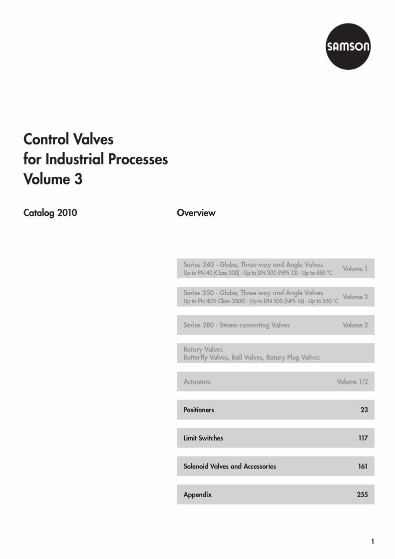
OverviewCatalog 2010
Appendix
Limit Switches
Positioners
Actuators
Rotary ValvesButterfly Valves, Ball Valves, Rotary Plug Valves
Series 280 · Steam-converting Valves
Series 250 · Globe, Three-way and Angle ValvesUp to PN 400 (Class 2500) · Up to DN 500 (NPS 16) · Up to 550 °C
Series 240 · Globe, Three-way and Angle ValvesUp to PN 40 (Class 300) · Up to DN 300 (NPS 12) · Up to 450 °C
255
117
23
Volume 1/2
Volume 2
Volume 2
Volume 1
Solenoid Valves and Accessories 161
Control Valvesfor Industrial ProcessesVolume 3
1

Positioners
Information SheetPositioners, Converters, Limit Switches,Position Transmitters, Solenoid Valves, Accessories 5
Electropneumatic Positioner Type 3730-0 25
Electropneumatic Positioner Type 3730-1 31
Electropneumatic PositionerType 3730-2 and Type 3730-3with HART® communication 37
Electropneumatic Positioner Type 3730-4with PROFIBUS-PA communication 45
Electropneumatic Positioner Type 3730-5with FOUNDATIONTM fieldbus communication 53
Electropneumatic Ex d Positioner Type 3731-3with HART® communication 59
Electropneumatic Ex d Positioner Type 3731-5with FOUNDATIONTM fieldbus communication 65
Series 3730 and Series 3731EXPERTplus Valve Diagnosticswith Partial Stroke Test (PST) 71
TROVIS-VIEW Software TROVIS 6661 79
Pneumatic Positioner Type 3766Electropneumatic Positioner Type 3767 85
Electropneumatic Positioner Type 4763Pneumatic Positioner Type 4765 97
Electropneumatic Positioner andPneumatic Positioner Type 3760 103
System 6000Electropneumatic Converter for Direct Current Signals
i/p Converter Type 6116 109
u/i Module Type 6151 115
Limit Switches
Electric or Pneumatic Limit Switch Type 4746 119
Limit Switch Type 3776 125
Inductive Limit Switchfor Pneumatic Control Valves Type 3768 141
Electric Limit Switch Type 4744 145
Electronic Limit Switch Type 3738-20 149
Analog Position Transmitter Type 4748 157
Solenoid Valves and Accessories
Field Barrier Ex d/Ex i Type 3770 163
Type 3701 Solenoid Valve 167
Solenoid Valve Type 3963 173
Solenoid Valve Type 3967 199
Solenoid Valve Type 3962 211
Supply Pressure Regulator Type 4708 221
Service Unit Type 3999-009X 233
Filter Regulator Type 3999-0096 237
Pneumatic Remote Adjuster Type 3759 241
Pneumatic Lock-up Valve Type 3709 243
Reversing Amplifier Type 3710 245
Pneumatic Volume Booster Type 3755 249
Appendix
SAMSON Product Range 255
SAMSON Subsidiaries, Agenciesand Service Facilities Worldwide 257
Data Sheet Summary 261
Index 263
Contents
3

Positioners • Converters
Limit Switches • Position Transmitters
Solenoid Valves • Accessories
Selection and Application
Information Sheet T 8350 EN 2010-01 5
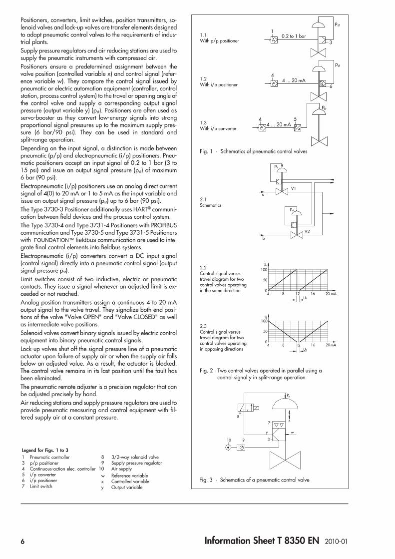
Positioners, converters, limit switches, position transmitters, so-lenoid valves and lock-up valves are transfer elements designedto adapt pneumatic control valves to the requirements of indus-trial plants.Supply pressure regulators and air reducing stations are used tosupply the pneumatic instruments with compressed air.Positioners ensure a predetermined assignment between thevalve position (controlled variable x) and control signal (refer-ence variable w). They compare the control signal issued bypneumatic or electric automation equipment (controller, controlstation, process control system) to the travel or opening angle ofthe control valve and supply a corresponding output signalpressure (output variable y) (pst). Positioners are often used asservo-booster as they convert low-energy signals into strongproportional signal pressures up to the maximum supply pres-sure (6 bar/90 psi). They can be used in standard andsplit-range operation.Depending on the input signal, a distinction is made betweenpneumatic (p/p) and electropneumatic (i/p) positioners. Pneu-matic positioners accept an input signal of 0.2 to 1 bar (3 to15 psi) and issue an output signal pressure (pst) of maximum6 bar (90 psi).Electropneumatic (i/p) positioners use an analog direct currentsignal of 4(0) to 20 mA or 1 to 5 mA as the input variable andissue an output signal pressure (pst) up to 6 bar (90 psi).The Type 3730-3 Positioner additionally uses HART® communi-cation between field devices and the process control system.The Type 3730-4 and Type 3731-4 Positioners with PROFIBUScommunication and Type 3730-5 and Type 3731-5 Positionerswith FOUNDATION™ fieldbus communication are used to inte-grate final control elements into fieldbus systems.Electropneumatic (i/p) converters convert a DC input signal(control signal) directly into a pneumatic control signal (outputsignal pressure pst).Limit switches consist of two inductive, electric or pneumaticcontacts. They issue a signal whenever an adjusted limit is ex-ceeded or not reached.Analog position transmitters assign a continuous 4 to 20 mAoutput signal to the valve travel. They signalize both end posi-tions of the valve "Valve OPEN" and "Valve CLOSED" as wellas intermediate valve positions.Solenoid valves convert binary signals issued by electric controlequipment into binary pneumatic control signals.Lock-up valves shut off the signal pressure line of a pneumaticactuator upon failure of supply air or when the supply air fallsbelow an adjusted value. As a result, the actuator is blocked.The control valve remains in its last position until the fault hasbeen eliminated.The pneumatic remote adjuster is a precision regulator that canbe adjusted precisely by hand.Air reducing stations and supply pressure regulators are used toprovide pneumatic measuring and control equipment with fil-tered supply air at a constant pressure.
10.2 to 1 bar
3
pst
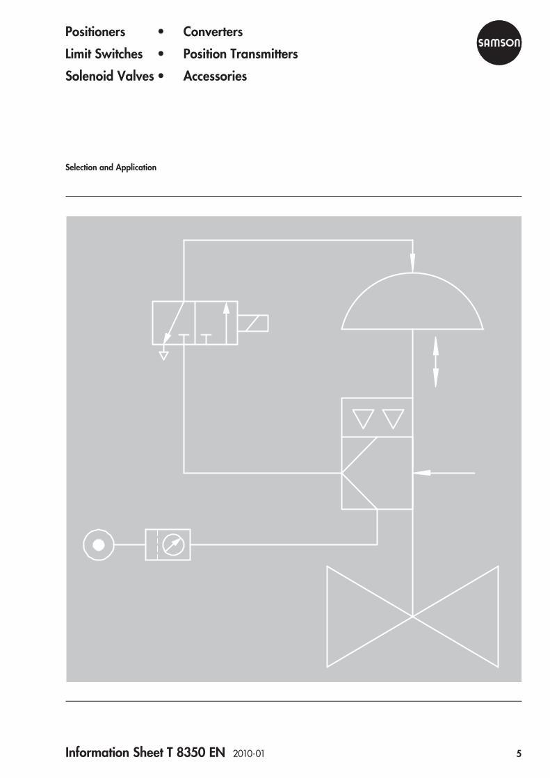
Fig. 1 · Schematics of pneumatic control valves
Fig. 2 · Two control valves operated in parallel using acontrol signal y in split-range operation
Fig. 3 · Schematics of a pneumatic control valve
1.1With p/p positioner
1.2With i/p positioner
1.3With i/p converter
2.1Schematics
2.2Control signal versustravel diagram for twocontrol valves operatingin the same direction
2.3Control signal versustravel diagram for twocontrol valves operatingin opposing directions
Legend for Figs. 1 to 31 Pneumatic controller3 p/p positioner4 Continuous-action elec. controller5 i/p converter6 i/p positioner7 Limit switch
8 3/2-way solenoid valve9 Supply pressure regulator
10 Air supplyw Reference variablex Controlled variabley Output variable
6 Information Sheet T 8350 EN 2010-01

Electropneumatic and pneumatic positionersElectropneumatic (i/p) Pneumatic (p/p)
For linear actuators acc. to IEC 60534-6-1,up to … mm 200 200 200 – 120 90 – – – 120 90
For Type 3277 (direct attachment) • • • • • • •
For linear actuator with rod-type yoke • • • • • • •
For Type 3278 Rotary Actuator • • • • • •
For rotary actuators acc. to VDI/VDE 3845 • • • • • •
Also with explosion protection EEx ia IIC T6 • • • • • • • • • •
Also intrinsically safe w. CSA/FM approval • • • • • •
Referencevariable
0.2...1 bar (3...15 psi) • • • •
4...20 mA • • • • • • •
0...20 mA • • •
1... 5 mA • •
Also split-range operation • • • • • • • • •
Also with limit switch • • • • • • •
Also with solenoid valve • • •
Also with position transmitter • • • •
Convertible to p/p or i/p positioner – • • • • • • • •
Type 3730-0 3730-1 3730-2* 3760 3767 4763 3761 3761 3760 3766 4765
Refer to Data Sheet T … EN for details T 8384-0 T 8384-1 T 8384-2 T 8385 T 8355 T 8359 T 8386 T 8386 T 8385 T 8355 T 8359
* Configuration and operation possible using TROVIS-VIEW software
Smart positionersFor linear actuators acc. to IEC 60534-6-1,up to … mm 200 200 200
For Type 3277 (direct attachment) • • •
For linear actuator with rod-type yoke • • •
For Type 3278 Rotary Actuator • • •
For rotary actuators acc. to VDI/VDE 3845 • • •
Also with explosion protection EEx ia IIC T6 • • •
Also intrinsically safe w. CSA/FM approval • • •
Referencevariable
4...20 mA •
Also split-range operation • • •
Communication HART® PROFIBUS FOUNDATION™ fieldbus
Also with limit switch • • •
Also with solenoid valve • • •
Also with position transmitter •
Type 3730-3* 3730-4* 3730-5*
Refer to Data Sheet for details T 8384-2/3 EN T 8384-4 EN T 8384-5 EN
Ex d version (see next table) Type 3731-3 – Type 3731-5
* Configuration and operation possible using TROVIS-VIEW software
Information Sheet T 8350 EN 2010-01 7

Electropneumatic Ex d positionersFor linear actuators acc. toIEC 60534-6-1, up to … mm 200 200 200 120 90
For Type 3277 (direct attachment) • • • • • –For linear actuator with rod-type yoke • • • • •For Type 3278 Rotary Actuator • • • • •For rotary actuators acc. VDI/VDE 3845 • • • • •
Flameproof enclosure (EEx d) • •With Type 6116 i/p Converter • • • •
Type 3770 Field Barrier •
Referencevariable
4 … 20 mA • • • • • •Also split-range • • • • •
Communication HART® FFM™ (HART®)Also with limit switch • • •Also with solenoid valve • • •Type 3731-3 3731-5 3730/3770 3760/6116 3766/6116 4765/6116 3761/6116Refer to Data Sheet T … EN for details T 8387-3 T 8387-5 8384/8379 8385/6116 8355/6116 8359/6116 8386/6116
Approvals ATEX · FM · CSA · NEPSI ATEX ATEX · FM · CSA · GOST
Limit switches, position transmittersLimit switches for linear actuators • • • •Limit switches for rotary actuators • • •Position transmitter for linear actuators,4 … 20 mA, two-wire connection •
Alarm contacts Inductive • • •Electric • • • •Pneumatic •
Version Without protection • • • • •EEx ia IIC T6 • • • • •EEx de II T6 •
Type 4746 3776 3768 3738-20 4744 4748Refer to Data Sheet for details T 8365 EN T 8368 EN T 8356 EN T 8390 EN T 8367 EN T 8363 EN
Field barriers, solenoid valves, lock-up valves, supply pressure regulators, accessoriesField barrier Ex d/Ex i •Solenoid valve f. pneum. control valves • •Pilot valve Ex d/Ex em •Supply pressure regulator •Service unit model •Filter regulator •Pneumatic remote adjuster •Pneumatic lock-up valve •Reversing amplifier •Pneumatic volume booster •Type 3770 3701 3963 3962 4708 3999-009X3999-0096 3759 3709 3710 3755Refer to Data Sheet T … EN for details T 8379 T 3701 T 963 T 962-4 T 8546 T 3999-6 T 3999-8 T 8510 T 8391 T 8392 T 8393
8 Information Sheet T 8350 EN 2010-01

Digital positionersThe Type 3730 and Type 3731 Positioners are single-acting ordouble-acting positioners designed for attachment to pneu-matic linear or rotary actuators.Compared to conventional positioners, the use of digital signalprocessing provides the following advantages:• User-friendly operation• Automatic adjustment of zero and span during the initializa-
tion procedure (except for Type 3730-0)• Automatic detection of faults occurring in the actuator• Direction of action independent of the mounting position• Permanent monitoring of zero• Minimized air consumption• Safe storage of all parameters in non-volatile EEPROMOptionally, these positioners may be equipped with the follow-ing additional functions:• One or two inductive limit switches (proximity switches)• Forced fail-safe venting of the actuator over a solenoid valve
upon failure of an external signal. As a result, the controlvalve moves to its fail-safe position.
Type 3730-0 Electropneumatic PositionerSingle-acting or double-acting electropneumatic positioner forattachment to pneumatic control valves. Travel range, range ofreference variable, and direction of action selectable over DIPswitches, zero and span adjustable over potentiometers
Travel 5.3 to 200 mm
Attachment Direct attachment to Type 3277 Actuator,to NAMUR ribs or rod-type yokes
Explosion protec-tion
II 2 G EEx ia IIC T6 acc. to ATEXII 3 G EEx nA/nL T6 andII 3 D IP 54/65 T 80 °C acc. to ATEX
FM, CSA, GOST, JIS approvals
Options –
Data Sheet T 8384-0 EN
Type 3730-1 Electropneumatic PositionerSingle-acting or double-acting electropneumatic positioner forattachment to pneumatic control valves. Self-calibrating, auto-matic adaptation to valve and actuator.Simple one-knob, menu-driven operationLC display easy to read in any mounted position due toselectable reading direction
Travel 3.75 to 200 mm
Angle of rotation 24 to 100°
Attachment Direct attachment to Type 3277 Actuator,to NAMUR ribs, rod-type yokes, VDI/VDE 3845
Explosionprotection
II 2 G EEx ia IIC T6 andII 2 D IP 65 T 80 °C acc. to ATEXII 3 G EEx nA/nL II T6 andII 3 D IP 54/65 T 80 °C acc. to ATEX
FM, CSA approval
Options Two standard programmable position alarms
Data Sheet T 8384-1 EN
Fig. 4 · Type 3730-0 Electropneumatic Positioner,direct attachment to Type 3277 Actuator
Fig. 5 · Type 3730-1 Electropneumatic Positioner,attachment to NAMUR rib of Type 3271 Actuator
Fig. 6 · Type 3730-1 Electropneumatic Positioner,attachment to rotary actuators acc. to VDI/VDE 3845
Information Sheet T 8350 EN 2010-01 9

Type 3730-2 and Type 3730-3 Electropneumatic Positionerwith HART® communicationSingle-acting or double-acting electropneumatic positioner forattachment to pneumatic control valves. Self-calibrating, auto-matic adaptation to valve and actuator. EXPERT diagnosticfunctions.
Travel 3.6 to 200 mm
Angle of rotation 24 to 100°
Attachment Direct attachment to Type 3277 Actuator,to NAMUR ribs, rod-type yokes, VDI/VDE 3845
Reference variable 4 to 20 mA
Communication Type 3730-3 with HART® communication
Explosionprotection
II 2 G EEx ia IIC T6 andII 2 D IP 65 T 80 °C acc. to ATEXII 3 G EEx nA/nL II T6 andII 3 D IP 65 T 80 °C acc. to ATEX
FM, CSA approval
Options Extended EXPERTplus diagnostics, ESD version,inductive limit switch, position transmitter,solenoid valve with SIL 4 approval acc. toIEC 61508, external position sensor
Data Sheet T 8384-2 EN
Type 3730-4 Positioner with PROFIBUS-PA communicationand Type 3730-5 Positioner with FOUNDATION™ fieldbus
communicationSmart, bus-powered field devices according to PROFIBUS-PAor FOUNDATION™ fieldbus specification based onEN 61158-2 transmission technology.
Travel 3.6 to 200 mm
Angle of rotation 24 to 100°
Attachment Direct attachment to Type 3277 Actuator,to NAMUR ribs, rod-type yokes, VDI/VDE 3845
Communication Type 3730-4 with PROFIBUS-PA communicationType 3730-5 with FOUNDATION™ fieldbus
communication
Explosionprotection
II 2 G EEx ia IIC T6 andII 2 D IP 65 T 80 °C acc. to ATEXII 3 G EEx nA II T6 andII 3 D IP 65 T 80 °C acc. to ATEX
FM, CSA, NEPSI Ex ia/nL approval
Options Inductive limit switch, solenoid valve, binaryinput, external position sensor, EXPERT+
Data Sheets T 8384-4 EN and T 8384-5 EN
EXPERT+ valve diagnostics for Series 3730 and Series 3731PositionersPositioner firmware for early detection of control valve faultsgiving maintenance recommendations.EXPERT is an enhanced firmware designed for predictive,status-oriented maintenance on control valves with pneumaticactuators. The diagnostic functions are completely integratedinto the positioner.EXPERT enables viewing and editing in TROVIS-VIEW operatorinterface or FDT/DTM engineering tools, which makes opera-tion easy to learn.Refer to Data Sheet T 8388 EN for details.
Fig. 8 · Typ 3730-4 PROFIBUS-PA Positioner,attachment to rotary actuators acc. to VDI/VDE 3845
Fig. 7 · Type 3730-2/-3 Electropneumatic Positionerwith external position sensor mounted on Type 3510Micro-flow Valve
Fig. 9 · Step response test for checking dynamic control response
10 Information Sheet T 8350 EN 2010-01

Ex d positionersType 3731-3 Ex d Positioner with HART communicationSingle-acting or double-acting Ex d positioner for attachment topneumatic control valves. Self-calibrating, automatic adapta-tion to valve and actuator.
Travel 3.6 to 200 mm
Angle of rotation 24 to 100°
Attachment Direct attachment to Type 3277 Actuator,to NAMUR ribs, rod-type yokes, VDI/VDE 3845
Reference variable 4 … 20 mA
Communication HART® communication
Explosionprotection
II 2 G EEx d IIC T6 andEEx de IIC T6 andII 2 D IP 65 T 80 °C acc. to ATEX
FM, CSA, NEPSI approvals
Options Binary contact, position feedback,forced venting, EXPERT+
Data Sheet T 8387-3 EN
Type 3731-5 Ex d Positioner with FOUNDATION™ fieldbus
communicationSmart, bus-powered field devices according to FOUNDATION™
fieldbus specification based on EN 61158-2 transmission tech-nology. Integrated Function Blocks: PID Process Controller, An-alog Output (AO), 2 Discrete Inputs (DI) and Link Master Capa-bility.
Travel 3.6 to 200 mm
Angle of rotation 24 to 100°
Attachment Direct attachment to Type 3277 Actuator,to NAMUR ribs, rod-type yokes, VDI/VDE 3845
Communication FOUNDATION™ fieldbus communication
Explosionprotection
II 2 G EEx d IIC T6 andEEx de IIC T6 andII 2 D IP 65 T 80 °C acc. to ATEX
FM, CSA, NEPSI approvals
Options Binary input, limit switch,forced venting, external position sensor
Data Sheet T 8387-5 EN
TROVIS-VIEW Operator InterfaceTROVIS-VIEW is a standard operator interface, allowing theuser to configure and parameterize various SAMSON instru-ments using a device-specific database module.Data is transferred between the TROVIS-VIEW software and theSAMSON device either directly using a connecting cable or in-frared adapter or indirectly using a memory pen or memorymodule. A direct connection enables both online and offline op-eration. This means that data can be changed in the device im-mediately, or they can be saved on the PC first and later down-loaded to the device on site.The device-specific modules contain a database providing thecharacteristic properties of each device type, such as parame-ters, data points, user levels, etc.Refer to Data Sheet T 6661 EN for details.
Fig. 12 · TROVIS-VIEW Operator Interface withType 3730 Positioner
Fig. 11 · Type 3731 Ex d Positioner, terminal compartmentand cover for operating button opened
Fig. 10 · Type 3731-3 Ex d Positioner withHART® communication or Type 3731-5 Positionerwith FOUNDATION™ fieldbus communication
Information Sheet T 8350 EN 2010-01 11

Electropneumatic and pneumaticpositionersType 3766 Pneumatic PositionerType 3767 Electropneumatic PositionerSingle- or double-acting p/p (Type 3766) or i/p (Type 3767)positioners for pneumatic linear and rotary actuators.
Travel 7.5 to 120 mm
Angle of rotation Up to 90°
Attachment Direct attachment to Type 3277 Actuator,to NAMUR ribs, rod-type yokes, VDI/VDE 3845
Reference variable Type 3766: 0.2 … 1 bar (3 … 15 psi)Type 3767: (0)4 … 20 mA
Explosionprotection
II 2 G EEx ia IIC T6 andII 3 G EEx nA II T6 acc. to ATEX
FM, CSA, GOST, JIS approvalsType 3766 also with IECEx TSA (Australia)approval or Ex d with Type 6116 i/p Converter
Options Limit switch, solenoid valve, position transmitter
Data Sheet T 8355 EN
Type 4763 Electropneumatic PositionerType 4765 Pneumatic PositionerSingle-acting electropneumatic (Type 4763) or pneumatic(Type 4765) positioner for pneumatic linear actuators.
Travel 7.5 to 90 mm
Attachment NAMUR ribs, rod-type yokes
Reference variable Type 4763: (0)4 … 20 mAType 4765: 0.2 … 1 bar
Explosionprotectionfor Type 4763Type 4765
II 2 G EEx ia IIC T6 andII 3 G EEx nA II T6 acc. to ATEX
FM, CSA approvalsEx d with Type 6116 i/p Converter
Options Special version with oxygen as operating me-dium
Data Sheet T 8359 EN
Type 3760 Electropneumatic Positioner andPneumatic PositionerCost-effective, single-acting pneumatic or electropneumaticpositioner designed for direct attachment to Type 3277 Pneu-matic Actuator.
Travel 5 to 15 mm
Attachment Direct attachment to Type 3277 Actuator
Reference variable 0.2 … 1 bar (3 … 15 psi)(0)4 … 20 mA, 1 … 5 mA
Explosionprotection
II 2 G EEx ia IIC T6 andII 3 G EEx nA II T6 acc. to ATEX
FM, CSA, JIS, AUS approvalsEx d with Type 6116 i/p Converter
Options Limit switch
Data Sheet T 8385 EN
Fig. 13 · Type 3766 Positioner,attachment acc. to IEC 60534 (NAMUR)
Fig. 14 · Type 4763 Electropneumatic Positioner withpressure gauges
Fig. 15 · Micro-flow valve with EEx d positioner(Type 3760 Positioner and Type 6116Electropneumatic Converter)
12 Information Sheet T 8350 EN 2010-01

Type 3761 Electropneumatic Positionerfor rotary actuatorsSingle-acting or double-acting pneumatic or electropneumaticpositioner for attachment to rotary actuators.
Angle of rotation Max. 90°
Attachment According to VDI/VDE 3845
Reference variable 0.2 … 1 bar (3 … 15 psi) or4 … 20 mA
Explosionprotection
II 2 G EEx ia IIC T6
Options Limit switch
Data Sheet T 8386 EN
Fig. 16 · Type 3761 Electropneumatic Positionerattached to Type 3278 Rotary Actuator
Information Sheet T 8350 EN 2010-01 13
System 6000Converters for direct current signal
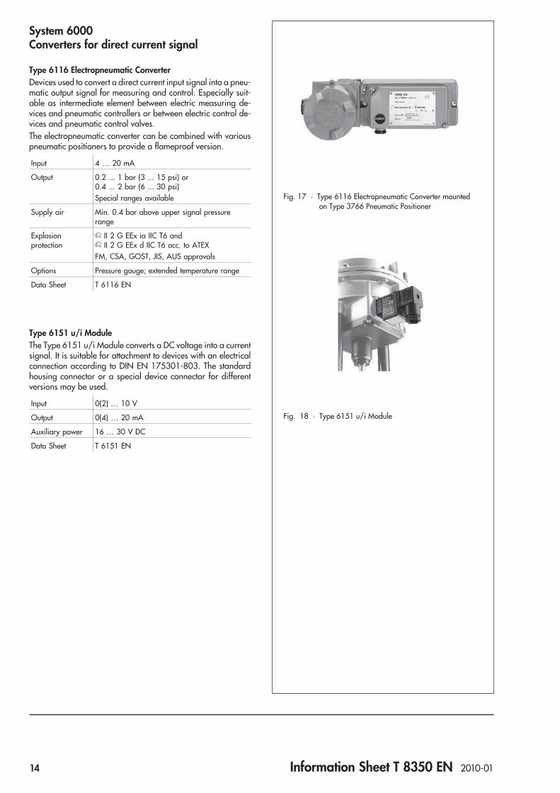
Type 6116 Electropneumatic ConverterDevices used to convert a direct current input signal into a pneu-matic output signal for measuring and control. Especially suit-able as intermediate element between electric measuring de-vices and pneumatic controllers or between electric control de-vices and pneumatic control valves.The electropneumatic converter can be combined with variouspneumatic positioners to provide a flameproof version.
Input 4 … 20 mA
Output 0.2 ... 1 bar (3 ... 15 psi) or0.4 ... 2 bar (6 ... 30 psi)Special ranges available
Supply air Min. 0.4 bar above upper signal pressurerange
Explosionprotection
II 2 G EEx ia IIC T6 andII 2 G EEx d IIC T6 acc. to ATEX
FM, CSA, GOST, JIS, AUS approvals
Options Pressure gauge; extended temperature range
Data Sheet T 6116 EN
Type 6151 u/i ModuleThe Type 6151 u/i Module converts a DC voltage into a currentsignal. It is suitable for attachment to devices with an electricalconnection according to DIN EN 175301-803. The standardhousing connector or a special device connector for differentversions may be used.
Input 0(2) … 10 V
Output 0(4) … 20 mA
Auxiliary power 16 … 30 V DC
Data Sheet T 6151 EN
Fig. 17 · Type 6116 Electropneumatic Converter mountedon Type 3766 Pneumatic Positioner
Fig. 18 · Type 6151 u/i Module
14 Information Sheet T 8350 EN 2010-01

Limit switches, position transmitters
The limit switches supply a signal when an adjusted limit value isexceeded in either direction. This signal is suitable for initiatingvisual or audible alarms as well as pilot valves or other switch-ing units. Moreover, the limit switches can be connected to cen-tral control or alarm systems.
Type 4746 Electric or Pneumatic Limit SwitchLimit switch for attachment to pneumatic or electric controlvalves as well as for attachment to Type 4763 ElectropneumaticPositioners or Type 4765 Pneumatic Positioners.
Contacts 2 contacts optionallyinductive, electric or pneumatic
Attachment Actuators with cast yokes or rod-type yokesacc. to IEC 60534-6Type 4763 Electropneumatic PositionerType 4765 Pneumatic Positioner
Supply air 1.4 bar for pneumatic limit switch
Explosionprotection
II 2 G EEx ia IIC T6 andII 3 G EEx nA II T6, Zone 2 acc. to ATEX
FM, CSA, GOST, NEPSI approvals
Data Sheet T 8365 EN
Type 3776 Limit Switch (SAMSOMATIC)Limit switch with inductive or electric contacts and solenoidvalve for linear actuators or rotary actuators according toVDI/VDE 3845.
Travel range 7.5 … 120 mm
Rotational angle 0 … 100° or 0 … 180° adjustable
Contacts Max. 3 piecesinductive proximity switches,inductive double proximity switches orelectric microswitches
Solenoid valve Safety integrity level SIL 4 acc. to IEC 615081 or 2 integrated pilot valvesNominal signals 6/12/24 V DC or24/115/230 V ACSupply air 2.2 to 6 bar
Attachment Direct attachment to Type 3277 andType 3277-5 ActuatorsAttachment to actuators with NAMUR rib acc.to IEC 60534-6-1Rotary actuators acc. to VDI/VDE 3845 withfixing levels 1 or 2
Explosionprotection
II 2 G EEx ia IIC T6 andII 3 G EEx nA II T6 acc. to ATEX
GOST approval
Options Integrated AS-Interface module with bus con-nection
Data Sheet T 3776 EN
Fig. 19 · Type 4746-x2 Inductive Limit Switch
Fig. 20 · Type 3776 Limit Switch for linear actuators
Fig. 21 · Type 3776 Limit Switch forrotary actuators according to VDI/VDE 3845
Information Sheet T 8350 EN 2010-01 15
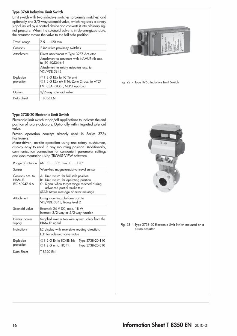
Type 3768 Inductive Limit SwitchLimit switch with two inductive switches (proximity switches) andoptionally one 3/2-way solenoid valve, which registers a binarysignal issued by a control device and converts it into a binary sig-nal pressure. When the solenoid valve is in de-energized state,the actuator moves the valve to the fail-safe position.
Travel range 7.5 … 120 mm
Contacts 2 inductive proximity switches
Attachment Direct attachment to Type 3277 ActuatorAttachment to actuators with NAMUR rib acc.to IEC 60534-6-1Attachment to rotary actuators acc. toVDI/VDE 3845
Explosionprotection
II 2 G EEx ia IIC T6 andII 3 G EEx nA II T6; Zone 2; acc. to ATEX
FM, CSA, GOST, NEPSI approval
Option 3/2-way solenoid valve
Data Sheet T 8356 EN
Type 3738-20 Electronic Limit SwitchElectronic limit switch for on/off applications to indicate the endposition of rotary actuators. Optionally with integrated solenoidvalve.Proven operation concept already used in Series 373xPositioners:Menu-driven, on-site operation using one rotary pushbutton,display easy to read in any mounting position. Additionally,communication connection for convenient parameter settingsand documentation using TROVIS-VIEW software.
Range of rotation Min. 0 … 30°, max. 0 … 170°
Sensor Wear-free magnetoresistive travel sensor
Contacts acc. toNAMURIEC 60947-5-6
A: Limit switch for fail-safe positionB: Limit switch for operating positionC: Signal when target range reached during
advanced partial stroke testSTAT: Status message or error message
Attachment Using mounting platform acc. toVDI/VDE 3845, fixing level 2
Solenoid valve External: 24 V DC, max. 18 WInternal: 3/2-way or 5/2-way-function
Electric powersupply
Supplied over a two-wire system solely from theNAMUR signal
Indications LC display with reversible reading direction,LED for solenoid valve status
Explosionprotection
II 2 G Ex ia IIC/IIB T6: Type 3738-20-110II 2 G e [ia] IIC T4: Type 3738-20-310
Data Sheet T 8390 EN
Fig. 22 · Type 3768 Inductive Limit Switch
Fig. 23 · Type 3738-20 Electronic Limit Switch mounted on apiston actuator
16 Information Sheet T 8350 EN 2010-01

Type 4744 Electric Limit Switch forhazardous areasLimit switch with one or two momentary-contact limit switches intype of protection “Flameproof enclosure” EEx de IIC T6.Type 4744-2 Limit Switch with one momentary-contact switchfor mounting to a rod-type yoke of V2001 Series Valves
Travel range 7.5 … 150 mm
Contacts Type 4744: 1 or 2Type 4744-2: 1
Attachment Type 4744: Attachment to actuators withNAMUR rib acc. to IEC 60534-6-1Type 4744-2: Rod-type yoke of V2001 SeriesValves
Explosionprotection
II 2 G EEx ed IIC T6 andII 2 D IP 65 T 80 °C andII 2 G EEx de IIC T6 andII 2 D IP 65 T 80 °C acc. to ATEX
Type 4744-2: II 2 G EEx d IIC T6/T5GOST approval
Data Sheet T 8367 EN
Type 4748 Analog Position TransmitterAnalog position transmitter for attachment to control valves aswell as Type 4763 Electropneumatic Positioner or Type 4765Pneumatic Positioner to convert the valve travel into a continu-ous output signal between 4 to 20 mA.Connection as two-wire transmitter.
Travel range 7 … 120 mm
Output signal 4 … 20 mA
Attachment Attachment to actuators with NAMUR rib orpillar-type yoke acc. to IEC 60534-6-1Type 4763 Electropneumatic PositionerType 4765 Pneumatic Positioner
Explosionprotection
II 2 G EEx ia IIC T6 andII 3 G EEx nA II T6 Zone 2 acc. to ATEX
Data Sheet T 8363 EN
Fig. 24 · Type 4744 Electric Limit Switch
Fig. 25 · Type 4744-2 Electric Limit Switch
Fig. 26 · Type 4748 Analog Position Transmitter
Information Sheet T 8350 EN 2010-01 17

AccessoriesType 3770 Ex d/Ex i Field BarrierField barrier with flameproof enclosure serving as an interfacebetween intrinsically safe and non-intrinsically safe circuits inhazardous areas. The field barrier is suitable for operatingpositioners, smart positioners using HART protocol,electropneumatic converters, solenoid valves, or limit switches.Refer to Data Sheet T 8379 EN for more details.
Type 3701 Solenoid Valve (SAMSOMATIC)The pilot-controlled solenoid valve converts electric binary sig-nals into binary pneumatic signals.
Solenoid valve 3/2-way or 5/2-way
Attachment Attachment to actuators with NAMUR rib,rod-type yokes or to rotary actuators withNAMUR interface
Nominal signal 6/12/24 V DC or 24/48/115/230 V AC
Supply air 1.4 … 6 bar (20 … 90 psi)
Explosionprotection
II 2 G EEx ia IIC T6; Zone 1 andII 3 G EEx nA II T6; Zone 2; acc. to ATEX
CSA, FM approvals
Options Safety approval SIL 4 or TÜV
Data Sheet T 3701 EN
Type 3963 Solenoid Valve (SAMSOMATIC)Solenoid valve series consisting of a 3/2-way pilot valve anddiverse 3/2-way, 5/2-way or 6/2-way booster valves.Low power consumption between 20 and 150 mW.
Pilot valve e/p binary converter
Nominal signal 6/12/24 V DC or 24/48/115/230 V AC
Supply air 1.4 … 6 bar (20 … 90 psi)
Booster valve 3/2, 5/2, 5/3 or 6/2 function
Attachment Attachment to actuators with NAMUR rib acc.to IEC 60534-6-1 or to rotary actuators withNAMUR interface acc. to VDI/VDE 3845
Explosionprotection
II 2 G EEx ia IIC T6 orII 3 G EEx nA II T6 acc. to ATEX
CSA, FM, GOST, NEPSI approvals
Options SIL 4 acc. to IEC 61508
Data Sheet T 3963 EN
Fig. 27 · Type 3770 Ex d/Ex i Field Barrierwith Type 3780 Positioner
Fig. 28 · Type 3701-01 Solenoid Valve
Fig. 29 · Type 3963-..25 Solenoid Valve
18 Information Sheet T 8350 EN 2010-01
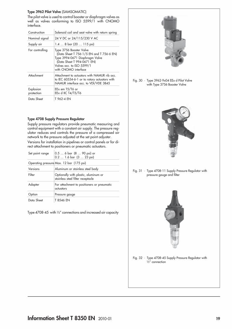
Type 3962 Pilot Valve (SAMSOMATIC)The pilot valve is used to control booster or diaphragm valves aswell as valves conforming to ISO 5599/1 with CNOMOinterface.
Construction Solenoid coil and seat valve with return spring
Nominal signal 24 V DC or 24/115/230 V AC
Supply air 1.4 … 8 bar (20 … 115 psi)
For controlling Type 3756 Booster Valve(Data Sheet T 756-1/5 EN and T 756-6 EN)
Type 3994-0671 Diaphragm Valve(Data Sheet T 994-0671 EN)
Valves acc. to ISO 5599/1with CNOMO interface
Attachment Attachment to actuators with NAMUR rib acc.to IEC 60534-6-1 or to rotary actuators withNAMUR interface acc. to VDI/VDE 3845
Explosionprotection
EEx em T5/T6 orEEx d IIC T4/T5/T6
Data Sheet T 962-4 EN
Type 4708 Supply Pressure RegulatorSupply pressure regulators provide pneumatic measuring andcontrol equipment with a constant air supply. The pressure reg-ulator reduces and controls the pressure of a compressed airnetwork to the pressure adjusted at the set point adjuster.Versions for installation in pipelines or control panels or for di-rect attachment to positioners or pneumatic actuators.
Set point range 0.5 … 6 bar (8 … 90 psi) or0.2 … 1.6 bar (3 … 23 psi)
Operating pressure Max. 12 bar (175 psi)
Versions Aluminum or stainless steel body
Filter Optionally with plastic, aluminum orstainless steel filter receptacle
Adapter For attachment to positioners or pneumaticactuators
Option Pressure gauge
Data Sheet T 8546 EN
Type 4708-45 with ½” connections and increased air capacity
Fig. 30 · Type 3962-9x04 EEx d Pilot Valvewith Type 3756 Booster Valve
Fig. 31 · Type 4708-11 Supply Pressure Regulator withpressure gauge and filter
Fig. 32 · Type 4708-45 Supply Pressure Regulator with½” connection
Information Sheet T 8350 EN 2010-01 19

Type 3999-009x Service Unit Model (SAMSOMATIC)for purifying and controlling compressed airThe service unit model is used to supply compressed air to pneu-matic converters, controllers and positioners. It cleans the com-pressed air, removing any dirt particles, water and oil. In addi-tion, it regulates the air pressure to a constant output pressure.
Set point range 0.5 … 10 bar (8 … 145 psi) adjustable
Operating pressure Max. 16 bar (230 psi)
Version Pipe or wall mounting
Filter unit Coarse filter, submicro filter, pressure regulatorwith secondary venting, pressure gauge
Condensatedrainage
Automatic over float valve or solenoid valve
Options Pressure switch or differential pressure switch,solenoid valves
Data Sheet T 3999-6 EN
Type 3999-0096 Filter Regulator (SAMSOMATIC)The filter regulator is used to supply compressed air to volumeboosters for large actuators. It cleans the compressed air, re-moving any dirt particles, water and oil. In addition, it regulatesthe air pressure to a constant output pressure.
Set point range 0.5 … 10 bar (8 … 145 psi) adjustable
Operatingpressure p1
Max. 16 bar (230 psi)
Version With mounting bracket
Filter unit Filter, pressure regulator and pressure gauge
Condensatedrainage Manually over drainage valve
Data Sheet T 3999-8 EN
Type 3759 Pneumatic Remote AdjusterA precision pressure regulator which can be manually adjusted.It is designed for use in pneumatic control loops as either a setpoint adjuster or manual remote adjuster and can be used as anadjustable precision pressure regulator for measuring, calibra-tion and testing equipment.
Set point ranges 0 … 0.6 bar (0 … 9 psi)0 … 1.6 bar (0 … 23 psi)0 … 4 bar (0 … 60 psi)0 … 6 bar (0 … 90 psi)
Operatingpressure p1
Max. 7 bar (100 psi)
Version Panel mounting or installation
Data Sheet T 8510 EN
Type 3709 Pneumatic Lock-up ValvePneumatic lock-up valve for shutting off the signal pressure lineof pneumatic actuators upon failure of the supply air.
Signal pressure Up to 6 bar (90 psi)
Supply air Max. 12 bar (175 psi)
Data Sheet T 8391 EN
Fig. 34 · Type 3999-0096 Filter Regulator
Fig. 35 · Type 3759 Pneumatic Remote Adjuster
Fig. 36 · Type 3709 Pneumatic Lock-up Valve
Fig. 33 · Type 3999-009x Service Unit Model
20 Information Sheet T 8350 EN 2010-01

Type 3710 Reversing AmplifierThe reversing amplifier allows double-acting pneumatic actua-tors to be operated using single-acting positioners.The positioner creates an output signal pressure Y1, to which theair pressure Y2 is added.The reversing amplifier uses the supply pressure Z as auxiliarypower. The following rule applies:Y1 + Y2 = Z
Supply pressure Max. 6 bar (90 psi)
Threadedconnections ISO 228/1-G ¼ or ¼-18 NPT
Ambient tempera-ture range –25 ... 80 °C (–13 ... 176 °F)
Degree of protec-tion IP 65
Options Pressure gauge for Y1 and Y2 ora pressure gauge for Y2 in conjunction withType 4708-54 Supply Pressure Regulator
Data Sheet T 8392 EN
Type 3755 Pneumatic Volume BoosterThe volume booster is used together with positioners to increasethe positioning speed of pneumatic actuators. It supplies an airflow output at the actuator port whose pressure corresponds ex-actly with the signal pressure, except that it has a much highervolume output.
Supply pressure Max. 10 bar (150 psi)
Signal and actua-tor pressure Max. 7 bar (105 psi)
Pressure ratio Signal to output = 1:1
Ambient tempera-ture range –40 to 80 °C (–40 … 176 °F)
Options Flanged-on exhaust portNPT threads
Data Sheet T 8393 EN
Fig 37 · Type 3710 Reversing Amplifier with two pressuregauges
Fig. 38 · Type 3755 Pneumatic Volume Booster
Information Sheet T 8350 EN 2010-01 21


Positioners
Pneumatic and electropneumatic positionersfor linear and rotary actuators
23


Series 3730
Electropneumatic Positioner Type 3730-0
ApplicationSingle-acting or double-acting positioner for attachment topneumatic control valvesReference variable 4 to 20 mATravels 5.3 to 200 mm
The positioner ensures a predetermined assignment of the valvestem position (controlled variable x) to the input signal (refer-ence variable w). It compares the input signal received from acontroller to the travel of the control valve and issues acorresponding output signal pressure (output variable y).
Special features• Easy attachment to common linear actuators over SAMSON
direct attachment interface (Fig. 1), over NAMUR rib (Fig. 3)or to control valves with rod-type yokes according toIEC 60534-6
• Any desired mounting position• Calibrated travel sensor without gears susceptible to wear• Analog pneumatic output prevents pulsing in case of leaking
actuator• Fast analog control loop• High control accuracy (fine tuning) without dead band and
continuous pneumatic output• Two-wire system with small electric load below 300 Ω for
explosion-protected version and version without explosionprotection
• Output pressure limitation over DIP switch• Selectable tight-closing function with fixed switching point• Low air consumption of approx. 110 ln/h independent of
supply and output pressure• Aluminum housing in IP 66 degree of protection• Check valve in the exhaust air port• Resistant to shock and vibrations• Extended temperature range also for intrinsically safe version• Travel range selectable over DIP switches within the rated
travel range• Zero and span adjustable over potentiometers• Reference variable range and direction of action adjustable
over DIP switches, e.g. for split-range operation• Certified according to IEC 61508/SIL
Additional options– Stainless steel housing
Fig. 2 · Type 3730-0 Positioner on Type 3510 Micro-flow Valve
Fig. 3 · Type 3730-0 Positioner, NAMUR attachment
Fig. 1 · Type 3730-0 Positioner,direct attachment to Type 3277 Pneumatic Actuator
JIS
Data Sheet T 8384-0 EN 2010-01 25

Principle of operationThe electropneumatic positioner is attached to pneumatic con-trol valves. It is used to assign the valve stem position (controlledvariable x) to the input signal (reference variable w). The inputsignal received from a control system is compared to the travelof the control valve, and an output signal pressure (output vari-able y) is produced.The positioner consists of a travel sensor system proportional toresistance, an analog i/p converter with a downstream boosterand the electronics with microcontroller.The position of the valve stem is transmitted as a linear travelmotion over the pick-up lever to the travel sensor (2) and sup-plied to an analog PD controller (3). The PD controller comparesthis actual value to the DC control signal coming from the con-trol system, e.g. a 4 to 20 mA signal. In case of a system devia-tion, the operation of the i/p converter (6) is changed so that theactuator of the control valve (1) is pressurized or vented accord-ingly over the downstream booster (7).This causes the valve plug to move to the position determined bythe reference variable.
The supply air is supplied to the booster and the pressure regu-lator (8). An intermediate flow regulator (9) with fixed settings isused to purge the positioner and, at the same time, guaranteestrouble-free operation of the booster.The output signal pressure of the booster can be limited by acti-vating DIP switch S5 (4).The volume restriction (10) and DIP switch S6 are used to opti-mize the positioner by adapting it to the actuator size andchanging the gain factor.
OperationThe positioner is operated and adjusted over potentiometersand DIP switches. The configuration of the positioner is facili-tated by instructions included on the inside of the cover whichare intended to ensure a quick and trouble-free adaptation ofthe positioner to the control valve.
2
3
6
7
8
10
1
9
4
w
x
Q y
x
Fig. 4 · Functional diagram of the Type 3730-0 Positioner
Legend1 Actuator2 Travel sensor3 Analog PD controller4 DIP switches S1 to S106 i/p converter7 Booster8 Pressure regulator9 Flow regulator
10 Volume restriction
26 Data Sheet T 8384-0 EN 2010-01

Table 1 · Technical data
Type 3730-0 i/p PositionerTravel Adjustable Direct attachment to Type 3277 Actuator 5.3 to 30 mm (lever M)
Attachment to Type 3510 Micro-flow Valve 5.3 to 15 mm (lever S)Attachment acc. to IEC 60534-6 (NAMUR) 5.3 to 200 mm (lever S, M, L, XL)
Travel range Adjustable Within the initialized travel/angle of rotation; restricted to 1/5 at the maximumReference variable w Signal range 4 to 20 mA · 4 to 12 mA and 12 to 20 mA
Adjustable over DIP switches S6 and S7Static destruction limit 100 mA
Minimum current > 3.6 mALoad impedance ≤ 6 V (corresponds to 300 Ω at 20 mA) for versions with and without explosion protectionSupply air Supply air
Air qualityISO 8573-1
1.4 to 7 bar (20 to 105 psi)Max. particle size and density: Class 4 · Oil content: Class 3 · Pressure dew point: Class 3 or atleast 10 K below the lowest ambient temperature to be expected
Signal pressure (output) 0 bar up to the capacity of the supply pressureCan be limited to approx. 2.4 bar over DIP switch S5
Characteristic Linear · Deviation ≤ 1 %Hysteresis ≤ 1 %Sensitivity ≤ 0.1 %Direction of action Adjustable Over DIP switch S4Air consumption Independent of supply air approx. 110 ln/h at a supply pressure of 4 barAir output capacity
for the actuator to bePressurized At Δp = 6 bar: 8.5 mn3/h · At Δp = 1.4 bar: 3.0 mn3/h · KVmax(20 °C) = 0.09
Vented At Δp = 6 bar: 14.0 mn3/h · At Δp = 1.4 bar: 4.5 mn3/h · KVmax(20 °C) = 0.15Permissible ambienttemperature
–20 to +80 °C · –45 to +80 °C with metal cable glandThe limits in the EC Type Examination Certificate additionally apply for explosion-protected versions
Influences Temperature ≤ 0.15 %/10 KSupply air NoneVibrations ≤ 0.25 % up to 2000 Hz and 4 g according to IEC 770
Electromagnetic compatibility Complies with EN 61000-6-2, EN 61000-6-3 and NAMUR Recommendation NE 21 requirementsElectrical connections One M20 x 1.5 cable gland for 6 to 12 mm clamping area · Second M20 x 1.5 threaded
connection additionally exists · Screw terminals for 2.0 to 2.5 mm² wire cross-sectionExplosion protection See table belowDegree of protection IP 66 / NEMA 4XImplementation in safety-related systemsin compliance with IEC 61508
Suitable for use in safety-relevant applications up to SIL 2 (single device) and SIL 3 (with redundantconfiguration), safety shutdown at a reference variable of 0 mA.
MaterialsHousing Die-cast aluminum EN AC-AlSi12(Fe) (EN AC-44300) acc. to DIN EN 1706
Chromated and powder paint coated · Special version in stainless steel 1.4581External parts Stainless steel 1.4571 and 1.4301Cable gland Polyamide, black, M20 x 1.5Weight Approx. 1 kg
Summary of explosion protection certificatesType of approval Certificate number Date CommentsEC Type Examination Certificate
First Addendum
PTB 03 ATEX 2099 2003-07-21
2006-08-25
II 2 G EEx ia IIC T6Perm. ambient temperature T6/50 °C; Type 3730-01II 2 D IP 66 T 80 °C
Statement of Conformity PTB 03 ATEX 2179 X 2003-09-30 II 3 G EEx nA II T6First Addendum 2004-12-09 II 3 G EEx nL IIC T6; Zone 2
II 3 D IP 54/65 T 80 °C; Zone 22; Type 3730-08FM approval 3021579 2004-12-01 Cl. I, II, III; Div. 1; Gr. A, B, C, D, E, F, G
Cl. I, Zone 0, AEx ia IIC T6Cl. I; Div. 2; Gr. A, B, C, DNEMA Type 4X; Type 3730-03
GOST approval POCC DE.GB04.B00885 2008-01-15 0 Ex ia IIC T6 X; 2 Ex nA II T6 X2 Ex nL IIC T6; valid until 2011-01-15
JIS approval TC17330 2005-07-29 Ex ia IIC T6; Type 3730-07
Data Sheet T 8384-0 EN 2010-01 27

Dimensions in mm
70 1558
46
34
40
34
210
86164
2858
M 20x1.5
Output (38) Supply (9)
1480
Directattachment
Attachment acc. toIEC 60534-6 andNAMUR
Pressure gauge bracket or connecting plateG ¼ or ¼ NPT
LeverS = 17 mm, M = 50 mmL = 100 mm, XL = 200 mm
Output A1
Output A2
Supply (9)
A1 Z
A2
50
495979
76
80
130
15164
50
58
150
Attachment to rotary actuatorsVDI/VDE 3845for all sizes of fixing level 2
Reversing amplifier(option)
Connecting plateG ¼ or ¼ NPT
28 Data Sheet T 8384-0 EN 2010-01

Attachment of the positionerThe Type 3730-0 Electropneumatic Positioner can be mounteddirectly on a Type 3277 Actuator. When attached toType 3277-5 (120 cm²) and to actuators with fail-safe action“Actuator stem extends“, the signal pressure is routed to the ac-tuator through an internal bore in the actuator yoke.For all actuators with fail-safe action “Actuator stem retracts“and effective areas of 240 cm² and larger, the signal pressureis routed to the actuator over ready-made external piping.Using the appropriate bracket, the positioner can also be at-tached according to IEC 60534-6 (NAMUR recommendation).The positioner can be mounted on either side of the controlvalve.
Ordering textPositioner Type 3730-0x– Without pneumatic connection (only for direct attachment to
Type 3277 Actuator)– With pneumatic connecting rail ISO 228/1 - G ¼– With pneumatic connecting rail ¼-18 NPT– Without/with pressure gauge up to max. 6 bar– Attachment to Type 3277 Actuator
(120/240/350/700 cm²)– Attachment according to IEC 60534-6 (NAMUR)– Travel: ... mm
If applicable, stem diameter: ... mm– Adapter M 20x1.5 to ½ NPT– Metal cable gland
Specifications subject to change without notice
Article code
Positioner Type 3730- 0 x 0 0 0 0 0 0 0 0 x 0 0 x 0 0 0
With DIP switches, 4 … 20 mA reference variable*
Explosion protection
Without 0
II 2 G EEx ia IIC T6 acc. to ATEX 1
Ex ia acc. to FM/CSA 3
Ex ia Japan JIS 7
II 3 G EEx nA/nL II T6 and II 3 D IP 54/65 T 80 °C acc. to ATEX 8
Housing material
Standard aluminum 0
Stainless steel 1.4581 1
Special applications
Without 0
Device compatible with paint (lowest permissible ambienttemperature –20 °C)
1
Exhaust air connection with ¼-18 NPT thread 2
Special version
None 0 0 0
GOST approval Ex ia/Ex nA 1 0 1 4
* Additional functions such as limit switches, solenoid valve, position transmitter or external position sensor, e.g. with Type 3730-2 Positioner
Data Sheet T 8384-0 EN 2010-01 29


Series 3730
Electropneumatic Positioner Type 3730-1
ApplicationSingle-acting or double-acting positioner for attachment topneumatic control valves. Self-calibrating, automatic adapta-tion to valve and actuator.Reference variable 4 to 20 mATravels 3.75 to 200 mmOpening angle 24° to 100°
The positioner ensures a predetermined assignment of the valvestem position (controlled variable x) to the input signal (refer-ence variable w). It compares the input signal received from acontroller to the travel or rotational angle of the control valveand issues a corresponding output signal pressure (output vari-able y).
Special features• Easy attachment to common linear and rotary actuators with
SAMSON direct attachment interface (Fig. 1), over NAMURrib (Fig. 2), to control valves with rod-type yokes according toIEC 60534-6-1, or to rotary actuators according toVDI/VDE 3845 (Fig. 3)
• Any desired mounting position of the positioner• Simple one-knob, menu-driven operation• LCD easy to read in any mounted position due to selectable
reading direction• Variable, automatic start-up• Preset parameters - only values deviating from the standard
need to be adjusted• Calibrated travel sensor without gears susceptible to wear• Permanent storage of all parameters in EEPROM (protected
against power failure)• Two-wire system with a small electrical load of 300 Ω• Activatable tight-closing function• Continuous monitoring of zero point• Two standard programmable position alarms• Certified according to IEC 61508/SIL
Version– Type 3730-1 · Electropneumatic positioner operable on
site with LCD
Additional options– Stainless steel housing
Fig. 3 · Type 3730,attachment acc. to VDI/VDE 3845
Fig. 2 · Type 3730,attachment to NAMUR rib
Fig. 1 · Type 3730,direct attachment toType 3277 Pneumatic Actuator
Data Sheet T 8384-1 EN 2010-01 31

Principle of operationThe positioner is attached to pneumatic control valves and isused to assign the valve stem position (controlled variable x) tothe electric input signal supplied by a control system (referencevariable w). It compares this signal to the travel or rotational an-gle of the control valve and produces the corresponding outputsignal pressure (output variable y) for the pneumatic actuator.The positioner mainly consists of an electric travel sensor system(2), an analog i/p module with a downstream booster as wellas the electronics unit with a microcontroller (5).When a deviation occurs, the actuator is pressurized or vented.If required, the changes in the signal pressure can be sloweddown by a volume restriction.A constant air stream with a fixed set point to the atmosphere iscreated by flow regulator (9) with a fixed set point. The airstream is used to purge the inside of the case as well as to opti-mize the air capacity booster. The i/p module (6) is suppliedwith a constant upstream pressure by the pressure reducingvalve (8) to make it independent of the supply air pressure.
OperationThe positioner is operated with a user-friendly rotarypushbutton system. The parameters are selected by turning theknob, pushing it activates the required setting. In the menu, allparameters are listed in one level, eliminating the need tosearch in submenus. All parameters can be checked andchanged on site.All values are displayed on the LCD. The reading direction ofthe LCD can be rotated by 180° at the push of a button.
%
Smm
%mm
w
x
Q
PD
A2
A1
4 5
3
14
16
6
7
8
10
1
w
9
xy
2
Fig. 4 · Functional diagram of Type 3730-1 Positioner
Legend1 Control valve2 Travel sensor3 Controller4 A/D converter5 Microcontroller6 i/p module7 Pneumatic booster8 Pressure reducing valve9 Flow regulator10 Volume restriction14 Software limit switches16 LCD
32 Data Sheet T 8384-1 EN 2010-01

Table 1 · Technical data
Type 3730-1 Positioner
Travel Direct attachment to Type 3277 Actuator: 3.75 to 30 mmAttachment according to IEC 60534-6-1: 3.75 to 200 mm
Opening angle Attachment according to VDI/VDE 3845 24 to 100°
Travel range Adjustable within initialized travel/angle of rotation; restricted to 1/5 at the maximum
Reference variable w
Signal range 4 to 20 mA · Two-wire device, reverse polarity protection
Split-range 4 to 11.9 and 12.1 to 20 mA
Static destructionlimit 100 mA
Minimum current 3.7 mA
Load impedance ≤ 6 V (corresponds to 300 Ω at 20 mA)
Supply airSupply pressure 1.4 to 7 bar (20 to 105 psi)
Air quality acc. toISO 8573-1 (2001)
Maximum particle size and density: Class 4 · Oil content: Class 3Pressure dew point: Class 3 or at least 10 K below the lowest ambient temperature to be expected
Signal pressure (output) 0 bar up to the capacity of the supply pressure · Limitable to approx. 2.4 bar per software
Characteristic optionally 1 characteristic for linear travel · 8 characteristics for angle of rotation
Hysteresis ≤ 1 %
Sensitivity ≤ 0.1 %
Direction of action w/x reversible
Air consumption, steady state Independent of supply air approx. 110 ln/h
Air output capacityActuator pressurized At Δp = 6 bar: 8.5 mn3/h · At Δp = 1.4 bar: 3.0 mn3/h · KVmax (20 °C) = 0.09
Actuator vented At Δp = 6 bar: 14.0 mn3/h · At Δp = 1.4 bar: 4.5 mn3/h · KVmax (20 °C) = 0.15
Permissible ambient temperature –20 to +80 °C · –45 to +80 °C with metal cable glandThe limits in EC Type Examination Certificate additionally apply for explosion-protected devices.
Influences
Temperature ≤ 0.15 %
Supply air None
Vibrations ≤ 0.25 % up to 2000 Hz and 4 g acc. to IEC 770
Electromagnetic compatibility Complies with EN 61000-6-2, 61000-6-3 and NAMUR Recommendation NE 21 requirements
Electrical connections One M20 x 1.5 cable gland for 6 to 12 mm clamping range · Second M20 x 1.5 threadedconnection additionally exists · Screw terminals for 2.0 to 2.5 mm² wire cross-sections
Explosion protection See summary of explosion protection certificates
Degree of protection IP 66 / NEMA 4X
Implementation in safety-related systemsin compliance with IEC 61508
Suitable for use in safety-relevant applications up to SIL 2 (single device) and SIL 3 (withredundant configuration), safety shutdown at a reference variable of 0 mA.
Binary contacts 2 software limit switches with adjustable limit values in steps of 0.5 %, reverse polarity protection
Signal status Version Without explosion protection Explosion-protected version
No response Conductive (R = 348 Ω) ≥ 2.1 mA
Response Non-conducting ≤ 1.2 mA
Operating voltage For connection to the binary input of a PLCacc. to EN 61131Pmax = 400 mW
Only for connection to NAMUR switchingamplifier acc. to EN 60947-5-6
Materials
Housing Die-cast aluminum EN AC-AlSi12(Fe) (EN AC-44300) acc. to DIN EN 1706 · Chromated andpowder paint coated · Special version in stainless steel 1.4581
External parts Stainless steel 1.4571 and 1.4301
Cable gland Polyamide, black, M20 x 1.5
Weight Approx. 1.0 kg
Data Sheet T 8384-1 EN 2010-01 33

Dimensions in mm
40
34
210
86
164
2858
M 20x1.5
Output (38) Supply (9)
1480
Direct attachment
70 1558
46
34
Attachment acc. toIEC 60534-6 and NAMUR
Pressure gauge bracket or connecting plateG ¼ or ¼ NPT
LeverS = 17 mmM = 50 mmL = 100 mmXL = 200 mm
Output A1
Output A2
Supply (9)
A1 Z
A2
50
495979
76
80
130
15164
50
58
150
Attachment to rotary actuators
Connecting plateG ¼ or ¼ NPT
Reversing amplifier
Connecting plate
34 Data Sheet T 8384-1 EN 2010-01

Summary of explosion protection certificates
Type of approval Certificate number Date Comments
EC Type Examination CertificateFirst AddendumSecond Addendum
PTB 04 ATEX 2033 2004-04-192005-01-252008-02-25
II 2 G EEx ia IIC T6II 2 D IP 65 T 80 °C; Type 3730-11
Statement of ConformityFirst Addendum
PTB 04 ATEX 2114 X 2004-12-092008-02-26
II 3 G EEx nA II T6II 3 G EEx nL IIC T6; Zone 2
II 3 D IP 54/65 T 80 °C; Zone 22; Type 3730-18
IECEx approval IECEx PTB 06.0055 2006-11-02 Ex ia IIC T6; Type 3730-11
FM approval 3023478 2004-12-012008-11-03
Cl. I, II, III; Div. 1; Gr. A, B, C, D, E, F, GCl. I, Zone 0, AEx ia IIC T6Cl. I; Div. 2; Gr. A, B, C, DNEMA Type 4X; Type 3730-13
CSA approval 1675820 2005-08-292009-07-14
Ex ia IIC T6; Cl. I, Zone 0Cl. II, Gr. E, F, GEx nA II T6; Cl. II, Div. 2, Gr. E, F, GType 4 Enclosure; Type 3730-13
Article code
Positioner Type 3730- 1 x 0 0 0 0 0 0 0 0 x 0 0 x 0 0 0
With LC display and autotune,4 … 20 mA reference variable, two software limit switches*
Explosion protection
Without 0
II 2 G EEx ia IIC T6 and II 2 D IP 65 T 80 °C acc. to ATEX 1
Ex ia / Ex n acc. to FM/CSA 3
II 3 G EEx nA/nL II T6 and II 3 D IP 54/65 T 80 °C acc. to ATEX 8
Housing material
Standard aluminum 0
Stainless steel 1.4581 1
Special applications
None 0
Device compatible with paint (lowest permissible ambient temperature –20 °C) 1
Exhaust air connection with ¼-18 NPT thread 2
Special version
None 0 0 0
* Additional functions such as limit switches, solenoid valve, position transmitter or external position sensor, e.g. with Type 3730-2 Positioner
Data Sheet T 8384-1 EN 2010-01 35

Attachment of the positionerThe Type 3730-1 Electropneumatic Positioner can be attacheddirectly to the Type 3277 Actuator over a connection block. Inactuators with fail-safe action “Actuator stem extends” andType 3277-5 Actuator (120 cm²), the signal pressure is routedover an internal bore in the actuator yoke to the actuator. Inactuators with fail-safe action “Actuator stem retracts” and inactuators with effective diaphragm areas of 240 cm² or larger,the signal pressure is routed to the actuator over ready-madeexternal piping.Using the appropriate bracket, the positioner can also beattached according to IEC 60534-6-1 (NAMURrecommendation). The positioner can be mounted on any sideof the control valve.A pair of universal brackets is used to mount the Type 3730-1Positioner to a Type 3278 Rotary Actuator or other rotaryactuators according to VDI/VDE 3845. The rotary motion of theactuator is transferred to the positioner over a coupling wheelwith degree scale.
Ordering textPositioner Type 3730-1x– Without pneumatic connecting rail
(only when directly attached to Type 3277)– With pneumatic connecting rail ISO 228/1-G ¼– With pneumatic connecting rail ¼-18 NPT– Without/with pressure gauge up to max. 6 bar– Additional cover label with list of parameters and operating
instructions in English/Spanish or English/French (standardversion German/English)
– Attachment to Type 3277 Actuator (120 to 700 cm²)– Attachment to IEC 60534-6-1 (NAMUR)
Travel: ... mm, if applicable, stem diameter: ... mm– Attachment to Type 3278 Rotary Actuator (160/320 cm²)– Attachment to rotary actuators acc. to VDI/VDE 3845– Pneumatic reversing amplifier for double-acting actuators
with connection according to ISO 228/1 - G ¼ or ¼-18 NPT– Adapter M20 x 1.5 to ½ NPT– Metal cable gland– Positioner free of substances that can impair surfaces to be
painted– Exhaust air connection with ¼ NPT thread– Special version: housing made of CrNiMo steel
Specifications subject to change without notice.
36 Data Sheet T 8384-1 EN 2010-01

Series 3730
Electropneumatic Positioner Type 3730-2 andType 3730-3 with HART® communication
ApplicationSingle-acting or double-acting positioner for attachment topneumatic control valves. Self-calibrating, automatic adapta-tion to valve and actuator.Reference variable 4 to 20 mATravels 3.6 to 200 mmOpening angles 24° to 100°
The positioner ensures a predetermined assignment of the valvestem position (controlled variable x) to the electric input signal(reference variable w). It compares the control signal receivedfrom a controller to the travel or opening angle of the controlvalve and issues a corresponding output signal pressure (outputvariable y).
Special features• Simple attachment to common linear and rotary actuators
with SAMSON direct attachment interface (Fig. 1), NAMURrib (Fig. 2), valves with rod-type yokes acc. to IEC 60534-6-1or rotary actuators acc. to VDI/VDE 3845 (Fig. 3)
• Any desired mounting position• Simple one-knob, menu-driven operation• LCD easy to read in any mounting position due to selectable
reading direction• Configurable with a PC over the SSP interface using the
TROVIS-VIEW software• Variable, automatic start-up with four different initialization
modes• Preset parameters – only values deviating from the standard
need to be adjusted• Calibrated travel sensor without gears susceptible to wear• "Sub" initialization mode (substitution) allows the positioner
to be started up in case of emergency whilst the plant is run-ning without the valve moving through the whole travel range
• All parameters saved in EEPROM (protection against powerfailure)
• Two-wire system with a small electrical load between 300 Ωand 410 Ω depending on the version (see Table 1)
• Adjustable output pressure limitation• Tight-closing function can be activated• Continuous monitoring of zero point• Integrated temperature sensor and operating hours counter• Two standard configurable position alarms• Self-diagnostics; alarms as condensed state conforming to
NAMUR Recommendation NE 107, issued over a fault alarmcontact or optional analog position transmitter
• Integrated EXPERTplus diagnostics (see T 8388 EN), suitablefor valves for throttling and on/off service with additionalpartial stroke test for valves in safety-related applications
• Certified according to IEC 61508/SIL
Versions– Type 3730-2 · Electropneumatic positioner with LCD,
operable on site, local communication using SSP interface,EXPERTplus diagnostics
– Type 3730-3 · Positioner as above, additionally with HART®
communication– Type 3731 Ex d Positioner · As above, additionally with
HART® communication · See Data Sheet T 8387-3 EN
Fig. 3 · Type 3730,attachment according toVDI/VDE 3845
Fig. 2 · Type 3730,attachment to NAMUR rib
Fig. 1 · Type 3730,direct attachment to Type 3277Pneumatic Actuator
Fig. 4 · Type 3730,external position sensorwith Type 3510 Micro-flow Valve
Data Sheet T 8384-2/3 EN 2009-12 37

Additional options– Inductive limit switch with proximity switch– Analog position transmitter with two-wire transmitter– Forced venting function with solenoid valve– Binary input– External position sensor (Fig. 4)– Stainless steel housing
Principle of operationThe electropneumatic positioner is attached to pneumatic con-trol valves. It is used to assign the valve stem position (controlledvariable x) to the input signal (reference variable w). The inputsignal received from a control system is compared to the travelor opening angle of the control valve and an output signal pres-sure (output variable y) is produced.The positioner consists of an electric travel sensor system (2), ananalog i/p converter with a downstream booster and the elec-tronics unit with microcontroller (5).When a deviation occurs, the actuator is pressurized or vented.If required, the changes in the signal pressure can be sloweddown by a volume restriction. The signal pressure to the actua-tor can be limited by software to 1.4, 2.4 or 3.7 bar.A constant air stream to the atmosphere is created by the flowregulator (9) with a fixed set point. The air stream is used topurge the inside of the case as well as to optimize the air capac-ity booster. The i/p module (6) is supplied with a constant up-stream pressure by the pressure regulator (8) to make it inde-pendent of the supply air pressure.
OperationThe positioner is operated with a user-friendly rotarypushbutton. The parameters are selected by turning the knob,pushing it activates the required settings. In the menu, all pa-rameters are listed in one level, meaning there is no need tosearch through submenus. All parameters can be checked andchanged on site.All values are displayed on the LCD. The reading direction ofthe LCD can be rotated by 180° at the push of a button.The closing direction of the control valve is indicated to thepositioner by the slide switch "Air to open/Air to close". It assignsthe CLOSED position of the control valve to the 0 % reading.The INIT key activates initialization, which is started accordingto (pre)set parameters (autotune). After initialization has beencompleted, the positioner immediately starts control operation.To configure the positioner with SAMSON’s TROVIS-VIEW con-figuration software, the positioner is equipped with an additionaldigital interface to be connected to the RS-232 interface of a PC.Additionally, all parameters of the Type 3730-3 Positioner canbe accessed using HART® communication.
w
x
Q
%S
mm
GG
PD
SerialInterface 16
13
22
15
A2
A3
BE
A1
112
4
21 FSK
20
195
3
12
6
7
8
10
1
14
14
w
xy
24V DC
9
17 18
Fig. 5 · Functional diagram of Type 3730-2/-3 Positioner
Legend1 Control valve2 Travel sensor3 Controller4 A/D converter5 Microcontroller6 i/p module7 Pneumatic booster8 Pressure regulator9 Flow regulator
10 Volume restriction11 Inductive limit switch (optional)12 Solenoid valve (optional)13 Position transmitter or
binary input (optional)14 Software limit switches15 Fault alarm output16 LCD17 Control of solenoid valve18 Galvanic isolation (optional)19 D/A converter20 Communication interface21 HART® connection
(Type 3730-3 only)22 Binary input BE (optional)
38 Data Sheet T 8384-2/3 EN 2009-12

Table 1 · Technical data for Type 3730 Positioner
Common data for Type 3730-... Positioner
Travel, adjustable Direct attachment to Type 3277 Actuator: 3.6 to 30 mmAttachment acc. to IEC 60 534-6-1: 3.6 to 200 mmAttachment to rotary actuators: 24° to 100° opening angle
Travel range Adjustable Within the initialized travel/opening angle · Can be restricted to maximally 1/5
Referencevariable w
Signal range 4 to 20 mA · Two-wire device with reverse polarity protection · Minimum span 4 mA
Static destructionlimit 100 mA
Minimum current 3.6 mA for display · 3.8 mA for operation
Supply air Supply pressure 1.4 to 7 bar (20 to 105 psi)
Air quality acc. toISO 8573-1 (2001)
Max. particle size and density: Class 4 · Oil content: Class 3Pressure dew point: Class 3 or at least 10 K below the lowest ambient temperature to be expected
Signal pressure (output) 0 bar up to the capacity of the supply pressure · Can be limited to 1.4 bar/2.4 bar/3.7 bar ± 0.2 barusing software
Characteristics Adjustable Linear/equal percentage/reverse equal percentageUser-defined (over operating software and communication)Butterfly valve, rotary plug valve and segmented ball valve: Linear/equal percentage
Deviation ≤ 1 %
Hysteresis ≤ 0.3 %
Sensitivity ≤ 0.1 %
Transit time Up to 240 s separately adjustable for exhaust and supply air via software
Direction of action Reversible
Air consumption, steady-state Independent of supply air approx. 110 ln/h
Air outputcapacity
Actuator pressurized At Δp = 6 bar: 8.5 mn3/h · At Δp = 1.4 bar: 3.0 mn3/h · KVmax (20 °C) = 0.09
Actuator vented At Δp = 6 bar: 14.0 mn3/h · At Δp = 1.4 bar: 4.5 mn3/h · KVmax (20 °C) = 0.15
Permissible ambient temperature –20 to +80 °C · –45 to +80 °C with metal cable glandThe limits in the EC Type Examination Certificate additionally apply for explosion-protected devices.
Influences Temperature ≤ 0.15 %/10 K
Supply air None
Vibrations ≤ 0.25 % up to 2000 Hz and 4 g acc. to IEC 770
Electromagnetic compatibility Complies with EN 61000-6-2, EN 61000-6-3 and NAMUR Recommendation NE 21 requirements
Electrical connections One M20x1.5 cable gland for 6 to 12 mm clamping range · Second M20x1.5 threaded connectionadditionally available · Screw terminals for 0.2 to 2.5 mm² wire cross-sections
Degree of protection IP 66 / NEMA 4X
Use in safety instrumented systems incompliance with IEC 61508
Suitable for use in safety-relevant applications up to SIL 2 (single device) and SIL 3 (with redundantconfiguration), safety shutdown at a reference variable of 0 mA.
Explosion protection
ATEX, IECEx, FM/CSA etc. See summary of explosion protection certificates
Binary contacts
Two software limit switches with reverse polarity protection, configurable switching behavior, default settings according to table below
Signal status Version Without explosion protection With explosion protection
No response Effectively non-conducting ≤ 1.2 mA
Response Conductive (R = 348 Ω) ≥ 2.1 mA
One fault alarm contact
Signal status Version Without explosion protection With explosion protection
No alarm Conductive (R = 348 Ω) ≥ 2.1 mA
Alarm Effectively non-conducting ≤ 1.2 mA
To be connected to Binary input of a PLC acc. to EN 61131,Pmax = 400 mWor for connection to NAMUR switching amplifieracc. to EN 60947-5-6
NAMUR switching amplifier acc. to EN 60947-5-6
Data Sheet T 8384-2/3 EN 2009-12 39

Materials
Housing Die-cast aluminum EN AC-AlSi12(Fe) (EN AC-44300) acc. to DIN EN 1706 · Chromated and powderpaint coated · Special version in stainless steel 1.4581
External parts Stainless steel 1.4571 and 1.4301
Cable gland Polyamide, black, M20 x 1.5
Weight Approx. 1.0 kg
Additional data for Type 3730-2
Load impedance Without explosion protection: ≤ 6 V(corresponds to 300 Ω at 20 mA)
With explosion protection: ≤ 7 V(corresponds to 350 Ω at 20 mA)
Communication (local) SAMSON SSP interface and serial interface adapter
Software requirements (SSP) TROVIS-VIEW with database module 3730-2
Additional data for Type 3730-3
Load impedance ≤ 8.2 V (corresponds to 410 Ω at 20 mA)
Communication (local) SAMSON SSP interface and serial interface adapter
Software requirements (SSP) TROVIS-VIEW with database module 3730-3
Communication (HART®) HART® field communication protocolImpedance in HART® frequency range: Receiving 350 to 450 Ω · Sending approx. 115 Ω
Softwarerequirements(HART®)
Handheld communicator Device description for Type 3730-3
PC DTM file acc. to Specification 1.2, suitable for integrating the positioner into frame applications thatsupport the FDT/DTM concept (e.g. PACTware); other integration options (e.g. AMS, PDM) available
Table 1a · Options for Type 3730-2 and Type 3730-3 Positioners
Solenoid valve · Approval acc. to IEC 61508/SIL
Input 24 V DC · Electrical isolation and reverse polarity protection · Static destruction limit 40 V
Current consumption I =U 5.7 V−3840 Ω
(corresponds to 4.8 mA at 24 V/114 mW)
Signal “0” no pick-up ≤ 15 V
Signal “1” safe pick-up > 19 V
Service life > 5 x 10⁶ switching cycles
Use in safety-related systems incompliance with IEC 61508/SIL Same as positioner pneumatics
Analog position transmitter Two-wire transmitter · Electrical isolation
Power supply 12 to 30 V DC · Reverse polarity protection · Static destruction limit 40 V
Output signal 4 to 20 mA
Direction of action Reversible
Operating range –10 to +114 %
Characteristic Linear
Hysteresis Same as positioner
High-frequency influence Same as positioner
Other influences Same as positioner
Fault alarm Issued as status current 2.4 ± 0.1mA or 21.6 ± 0.1mA
Inductive limit switch
SJ-2SN proximity switch For connection to switching amplifier acc. to EN 60947-5-6.Can be used in combination with a software limit switch.
External position sensor
Travel Same as Type 3730 Positioner
Cable 10 m · Flexible and durable · With M12x1 connector · Flame-retardant acc. to VDE 0472Resistant to oils, lubricants and coolants as well as other aggressive media
Permissible ambient temperature –60 to +105 °C · The limits in the EC Type Examination Certificate additionally apply forexplosion-protected devices.
Immunity to vibration Up to 10 g in the range of 10 to 2000 Hz
Degree of protection IP 67
40 Data Sheet T 8384-2/3 EN 2009-12

Summary of explosion protection certificatesType of approval Certificate number Date Type of protection/Comments
Type 3730-2 Positioner
EC Type Examination Certificate PTB 00 ATEX 2158 2001-03-01 II 2 G EEx ia IIC T6
First Addendum 2002-03-01 Position transmitter
Second Addendum 2004-02-16 II 2 D IP 65 T 80 °C, Zone 21 dust, device index .01
Third Addendum 2007-08-24 Electrical data for forced venting altered
Fourth Addendum 2008-11-06 Electrical data, structure-borne sound sensor and binary input added
Statement of Conformity PTB 03 ATEX 2016 X 2003-03-07 II 3 G EEx nA II T6; Zone 2; Type 3730-28
First Addendum 2005-05-03 II 3 G EEx nL IIC T6; II 3 D IP 54/IP 65 T 80 °C
Second Addendum 2008-11-06 Electrical data, structure-borne sound sensor and binary input added
IECEx IECEx PTB 05.0007 2005-02-21 Ex ia IIC T6/T5/T4; IP 54 and IP 65 T 80 °C; Type 3730-21.9...
GOST approval B02637 2009-02-26 0 Ex ia IIC T6 X, valid until 2012-02-26; Type 3730-21
FM approval ID 3012394 2002-10-30 Intrinsically safe, Class I, II, III; Div. 1, Group A, B, C, D, E, F, G;Class I, Zone 0, AEx ia IIC T6;Non-incendive, Class I, Div. 2, Group A, B, C, D; NEMA Type 4;Type 3730-23
Revision 2004-02-04 Div. 2 Gr. F and G
CSA approval 1330129 2003-03-17 Ex ia IIC T6, Cl. I, Zone 0;Intrinsically safe, Class I, Group A, B, C, D;Class II, Group E, F, G;Non-incendive, Class I, Div. 2, Group A, B, C, D;Type 4 Enclosure; Type 3730-23
Revision to 1330129 1500997 2004-03-05 Class II, Div. 2, Group E, F, G
JIS approval C16679 2003-11-25 Ex ia IIC T6; Type 3730-27
KOSHA 2005-2359-Q1 2005-12-16 Ex ia IIC T6; valid until 2010-12-15; Type 3730-21
SIL 4 acc. to IEC 61508/SIL 3 acc. to IEC 61511
V 60 2007 C4 2008-01-07 Test report by TÜV Rheinland for Series 3730,valid until November 2012
Type 3730-3 Positioner
EC Type Examination Certificate PTB 02 ATEX 2174 2002-11-15 II 2 G EEx ia IIC T6; without position transmitter
First Addendum 2003-06-18 Forced fail-safe venting function
Second Addendum 2004-02-16 II 2 D IP 65 T 80 °C, Zone 21 dust, model index .01
Third Addendum 2007-09-10 Binary input. Electrical data for forced venting altered
IECEx IECEx PTB 05.0008 2005-02-21 Ex ia IIC T6/T5/T4; IP 54 and IP 65 T 80 °C; Type 3730-31.9...
GOST approval B00885 2008-01-15 0 Ex ia IIC T6 X; 2 Ex nA/nL; valid until 2011-01-15
NEPSI approval GYJ04133 2004-02-27 Ex ia IIC T4...T6; valid until 2007-02-27; Type 3730-31
GYJ04134 andGYJ04135
Ex nA II T4...T6; Ex nL IIC T4...T6Valid until 2007-02-27; Type 3730-38
Statement of Conformity PTB 03 ATEX 2180 X 2003-09-30 II 3 G EEx nA II T6; Zone 2; Type 3730-38
First Addendum 2005-04-26 II 3 G EEx nL IIC T6; II 3 D IP 65 T 80 °C; Zone 22
Second Addendum 2007-09-10 Electrical data, structure-borne sound sensor and binary input added
Third Addendum 2008-12-10 Permissible ambient temperature range extended
Binary input · Electrical isolation · Switching behavior configured over software (e.g. TROVIS-VIEW, DTM)
Active switching behavior (default setting)
Connection For external switch (floating contact) or relay contact
Electrical data Open-circuit voltage when contact is open: 10 VPulsed DC current reaching peak value of 100 mA and RMS value of 0.01 mA when contact is closed
ContactClosed, R < 50 Ω “On” switching state (default setting)
Open, R > 400 Ω “Off” switching state (default setting)
Passive switching behavior
Connection For externally applied DC voltage, reverse polarity protection
Electrical data 3 to 30 V, destruction limit 40 V, current draw 3.7 mA at 24 V
Voltage> 6 V “On” switching state (default setting)
< 1 V “Off” switching state (default setting)
Data Sheet T 8384-2/3 EN 2009-12 41

Positioner attachmentThe Type 3730 Electropneumatic Positioner can be attacheddirectly to the Type 3277 Actuator over a connection block. Inactuators with fail-safe action “Actuator stem extends” andType 3277-5 Actuator (120 cm²), the signal pressure is routedover an internal bore in the actuator yoke to the actuator. Inactuators with fail-safe action “Actuator stem retracts” and inactuators with effective diaphragm areas of 240 cm² or larger,the signal pressure is routed to the actuator over ready-madeexternal piping.
Using a bracket, the positioner can also be attached accordingto IEC 60534-6-1 (NAMUR recommendation). The positionercan be mounted on any side of the control valve.A pair of universal brackets is used for the attachment toType 3278 Rotary Actuators or other rotary actuatorsaccording to VDI/VDE 3845. The rotary motion of the actuatoris transferred to the positioner over a coupling wheel.
Type of approval Certificate number Date Type of protection/Comments
EC Type Examination Certificate PTB 03 ATEX 2211 X 2003-10-22 II 2 G EEx d ia IIC T6;Type 3730-39 with Type 3770-1 Field Barrier
FM approvalModel index 01 and higher
3018702 2004-02-02 Intrinsically safe; Class I, II, III; Div. 1, Group A, B, C, D, E, F, G;Class I, Zone 0, AEx ia IIC T6; NEMA Type 4Non incendive, Class I; Div. 2, Group A, B, C, D;Class II, Div. 2, Group F, G; Type 3730-33
CSA approvalModel index 01 and higher
1508990 2004-03-05 Ex ia IIC T6; Cl. I, Zone 0Intrinsically safe, Class I, Group A, B, C, D; Type 4 EnclosureClass II, Gr. E, F, G;Non-incendive, Class I, Div. 2, Group A, B, C, DClass II, Div. 2, Gr. E, F, G; Type 3730-33
KOSHA 2005-2360-Q1 2005-12-16 Ex ia IIC T6; valid until 2010-12-15; Type 3730-31
SIL 4 acc. to IEC 61508/SIL 3 acc. to IEC 61511
V 60 2007 C4 2008-01-07 Test report by TÜV Rheinland for Series 3730,valid until November 2012
The test certificates are included in the mounting and operating instructions or are available on request.Refer to Data Sheet T 8379 EN for EEx d certificates for the Type 3770 Field Barrier.
Dimensions in mm
70
7028
Schil
d
External position sensor
40
34
210
86
164
2858
M 20x1.5
Output (38) Supply (9)
1480
Direct attachment
42 Data Sheet T 8384-2/3 EN 2009-12

Output A1
Output A2
Supply (9)
A1 Z
A2
50
495979
76
80
130
15164
50
58
150
Connecting plate
Reversing amplifier
5686
13080
166
3086
Ø 101
Output A1
Output A2
Supply (9)
A1 Z
A2
76
15164
50
Mounting unit for rotary actuatorsHeavy-duty version
Connecting plateG ¼ or ¼ NPT
Reversing amplifier
Connecting plate
70 1558
46
34
NAMUR attachmentPressure gauge bracket or connecting plateG ¼ or ¼ NPT
LeverS = 17 mmM = 50 mmL = 100 mmXL = 200 mm
Attachment to rotary actuatorsVDI/VDE 3865Fixing level 2
Connecting plateG ¼ or ¼ NPT
Mounting unitCrNiMo steel bracket
Data Sheet T 8384-2/3 EN 2009-12 43

Ordering textType 3730-x... Positioner– Without pneumatic connecting rail (only for direct attachment
to Type 3277 Actuator)– With pneumatic connecting rail ISO 228/1-G ¼– With pneumatic connecting rail ¼-18 NPT– Without/with pressure gauge up to max. 6 bar– Additional cover plate with list of parameters and operating
instructions in English/Spanish or English/French (standardversion in German/English)
– Attachment to Type 3277 Actuator (120 to 700 cm²)– Attachment according to IEC 60534-6-1 (NAMUR)
Travel: ... mm; if applicable, stem diameter: ... mm
– Attachment to Type 3278 Rotary Actuator (160/320 cm²),mounting unit with CrNiMo steel bracket or heavy-duty at-tachment
– Attachment according to rotary actuators acc. to VDI/VDE3845, mounting unit with CrNiMo steel bracket orheavy-duty attachment
– Pneumatic reversing amplifier for double-acting actuatorswith connection acc. to ISO 228/1 - G ¼ or ¼-18 NPT
– Adapter M20 x 1.5 to ½ NPT– Metal cable gland– Special version with CrNiMo steel housing
Article code
Positioner Type 3730- x x x x x x 0 x x 0 x 0 0 x 0 x x
With LCD and autotune, 4 to 20 mA reference variable2 software limit switches, one fault alarm contact 2
With LCD and autotune, HART® communication, 4 to 20 mA,2 software limit switches, one fault alarm contact 3
Explosion protection
Without 0
II 2 G EEx ia IIC T6 and
II 2 D IP 65 T 80 °C acc. to ATEX 1
CSA/FM intrinsically safe/non incendive 3
II 3 G EEx nA/nL II T6 and II 3D IP 65 T 80 °C 8
Additional equipment
Inductive limit switch
Without 0
Type SJ2-SN 1
Solenoid valve
Without 0
With, 24 V DC 4
Position transmitter
Without 0
With 1 0
External position sensor
Without 0
With 0 1 0
Binary input
Without 0
With 0 2
Diagnostics
EXPERTplus 4
Housing material
Aluminum (standard) 0
Stainless steel 1.4581 0 1
Special application
None 0
Device completely free of paint-impairing substances 1
Exhaust air connection with ¼-18 NPT thread 2
Special version
None 0 0
IECEx 1 1 2
GOST approval Ex ia 1 1 4
GOST approval Ex nA/nL 8 2 0
44 Data Sheet T 8384-2/3 EN 2009-12

Series 3730
Electropneumatic Positioner Type 3730-4with PROFIBUS-PA communication
ApplicationPositioner for attachment to pneumatic control valvesTravels 3.6 to 200 mm · Opening angle 24 to 100°Smart, bus-powered field unit conforming to PROFIBUS-PAspecification based on IEC 61158-2 transmission technology.
The microprocessor-controlled positioner compares the refer-ence variable cyclically transmitted over the PROFIBUS-PA net-work to the travel or opening angle of the control valve and pro-duces the corresponding output signal pressure.The Type 3730-4 Positioner communicates using PROFIBUS-PAspecification according to IEC 61158 and IEC 61784 to ex-change data with programmable logic controllers, automationsystems and various engineering tools.Other benefits provided by the smart positioner:• Automatic ID adaptation according to PROFIBUS-PA Profile
3.02 to faciliate replacement of positioners with Profile 2.0 or3.0 (e.g. Type 3785)
• DTM file available to integrate the positioner into FDT/DTMin compliance with specification 1.2
• Simple attachment to common linear with SAMSON directattachment interface (Fig. 1), over NAMUR rib (Fig. 2) or tocontrol valves with rod-type yokes according toIEC 60534-6-1 or to rotary actuators according toVDI/VDE 3845 (Fig. 3)
• Any desired mounting position• One-knob, menu-driven operation• Automatic initialization• LCD easy to read in any mounting position due to selectable
reading direction• Integrated EXPERT diagnostics (T 8388 EN)• Classified status alarms• Control parameters can be changed online• Automatic monitoring of zero point• Calibrated travel sensor without gears susceptible to wear• Permanent storage of all parameters in non-volatile EEPROM
(protection against power failure)• Temperature and supply air effects negligible• Adjustable output pressure limitation• Adjustable tight-closing function• Binary input for DC voltage signals• Certified according to IEC 61508/SIL
Additional options– Inductive limit switch with proximity switch– Integrated solenoid valve– Binary input for floating contact
– External position sensor (Fig. 4)– Extended EXPERT+ diagnostics (refer to T 8388 EN)– Stainless steel housing
Fig. 3 · Type 3730-4,attachment according toVDI/VDE 3845
Fig. 2 · Type 3730-4,attachment to NAMUR rib
Fig. 1 · Type 3730-4,direct attachment to Type3277 Pneumatic Actuator
Fig. 4 · Type 3730-4,external position sensor with Type 3510 Micro-flow Valve
Data Sheet T 8384-4 EN 2010-01 45

Principle of operationThe electropneumatic positioner is attached to pneumatic con-trol valves. It is used to assign the valve stem position (controlledvariable x) to the control signal (reference variable w). The inputsignal received from a control system is compared to the travelor angle of rotation of the control valve and an output signalpressure (output variable y) is produced.The positioner consists of an electric travel sensor system (2), ananalog i/p converter with a downstream booster and the elec-tronics unit with microcontroller (5).When a deviation occurs, the actuator is pressurized or vented.If required, the changes in the signal pressure can be sloweddown by a volume restriction. The signal pressure to the actua-tor can be limited by software to 1.4, 2.4 or 3.7 bar.A constant air stream to the atmosphere is created by the flowregulator (9) with a fixed set point. The air stream is used topurge the inside of the case as well as to optimize the air capac-ity booster. The i/p module (6) is supplied with a constant up-stream pressure by the pressure regulator (8) to make it inde-pendent of the supply air pressure.The positioner communicates and is powered using IEC61158-2 transmission technology conforming to PROFIBUS-PAspecifications.As a standard feature, the positioner comes with a binary inputfor DC voltage signals to signalize process information over thePROFIBUS-PA fieldbus.
OperationThe positioner is operated with a user-friendly rotarypushbutton. The parameters are selected by turning the knob,pushing it activates the required setting. In the menu, all param-eters are listed in one level, meaning there is no need to searchin submenus. All parameters can be checked and changed onsite.All values are displayed on the LCD. The reading direction ofthe LCD can be rotated by 180° at the push of a button.The closing direction of the control valve is indicated to thepositioner by the DIP switch "Air to open/Air to close". It as-signs the CLOSED position of the control valve to the 0 % read-ing.The INIT key activates initialization which is started according tothe (pre)set parameters (autotune). After initialization is com-pleted, the positioner immediately starts control operation.
Configuration with TROVIS-VIEW softwareThe SAMSON configuration software, TROVIS-VIEW, can beused to configure the positioner. For this purpose, the positioneris equipped with an additional digital interface to be connectedto the RS-232 interface of a PC. The positioner is adapted to theprocess requirements over TROVIS-VIEW. The process can bechecked while the process is running. The control valve is con-nected to the process over the PROFIBUS-PA fieldbus.
w
x
Q
%S
mm
GG
PD
SerialInterface
16
15 BE2
BE1
112
4
13
20
17 18
19
24V DC
5
3
12
6
7
8
10
1
14
9
xy
1 Control valve2 Travel sensor3 PD controller4 A/D converter5 Microcontroller6 i/p module7 Pneumatic booster8 Pressure regulator9 Flow regulator
10 Volume restriction11* Inductive limit switch12* Solenoid valve13 IEC 61158-2
interface module14 Binary input 1
(voltage input)15* Binary input 2 (for
floating contact)16 LCD17* Solenoid valve control18 Galvanic isolation19 D/A converter20 Serial interface (SSP)* Option
Fig. 5 · Functional diagram ofType 3730-4 Positioner
PROFIBUS-PAIEC 61158-2
46 Data Sheet T 8384-4 EN 2010-01

Table 1 · Technical data
Type 3730-4 PROFIBUS-PA Positioner
Travel, adjustable Direct attachment to Type 3277 Actuator 3.6 to 30 mm
Attachment acc. to IEC 60 534-6-1: 3.6 to 200 mm
Attachment to rotary actuators (VDI/VDE 3845) 24 to 100° opening angle
Travel range adjustable Within the initialized travel/angle of rotation; restricted to 1/5 at the maximum
Bus connection Fieldbus interface conforming to IEC 61158-2, bus-poweredField device according to FISCO (Fieldbus Intrinsically Safe COncept)
Communication
Fieldbus Data transmission conforming to PROFIBUS-PA specification acc. to IEC 61158 and IEC 61784
DTM file acc. to specification 1.2, suitable for integrating the positioner into frame applications thatsupport the FDT/DTM concept. Other integrations, e.g. PDM also possible
Local SAMSON SSP interface and serial interface adapter
Software requirements TROVIS-VIEW with database module 3730-4
Permissible operating voltage 9 to 32 V DC · Powered over bus lineThe limits in the EC Type Examination Certificate additionally apply for explosion-protected devices.
Maximum operating current 15 mA
Additional current in case of fault 0 mA
Supply air Supply pressureAir quality
1.4 to 7 bar (20 to 105 psi)Acc. to ISO 8573-1 (2001):Max. particle size and density: Class 4 · Oil content: Class 3Pressure dew point: Class 3 or at least 10 K below the lowest ambient temperature to be expected
Signal pressure (output) 0 bar up to the capacity of the supply pressure
Characteristics Linear/equal percentage/reverse equal percentage · User-defined (over operating software andcommunication) · Butterfly valve, rotary plug valve and segmented ball valve: Linear/equal percentageDeviation from terminal-based conformity ≤ 1 %
Hysteresis ≤ 0.3 %
Sensitivity ≤ 0.1 %
Direction of action Reversible
Air consumption Independent of supply air approx. 110 ln/h
Air outputcapacity
Actuator pressurized At Δp = 6 bar: 8.5 mn3/h · At Δp = 1.4 bar: 3.0 mn3/h · KVmax (20 °C) = 0.09
Actuator vented At Δp = 6 bar: 14.0 mn3/h · At Δp = 1.4 bar: 4.5 mn3/h · KVmax (20 °C) = 0.15
Permissible ambient temperature –45 to +80 °CThe limits in the EC Type Examination Certificate additionally apply for explosion-protected devices.
Influences Temperature ≤ 0.15 %/10 K
Supply air None
Vibrations ≤ 0.25 % up to 2000 Hz and 4 g acc. to IEC 770
Electromagnetic compatibility Complies with EN 61000-6-2, EN 61000-6-3 and NAMUR Recommendation NE 21 requirements
Electrical connections One M20x1.5 cable gland for 6 to 12 mm clamping range · Second M20x1.5 threaded connectionadditionally exists · Screw terminals for 0.2 to 2.5 mm² wire cross-sections
Degree of protection IP 66 / NEMA 4X
Implementation in safety-related systemsin compliance with IEC 61508/SIL
Probability of failure on demand of safety functions PFD < 2.8 x 10⁻⁷ for a confidence level of 95 %.The safe failure fraction (SFF) according to Table A1 in IEC 61508-2 is greater or equal to 0.99.Suitable for implementation in safety-related systems with a hardware fault tolerance of 1 or 2 up toand including SIL 4.
Binary input 1
Input 0 to 30 V DC · Reverse polarity protection · Static destruction limit 40 V/5.8 mACurrent consumption 3.5 mA at 24 V, electrically isolated
Signal Signal “1“ at Ue > 5 V Signal “0“ at Ue < 3 V
Data Sheet T 8384-4 EN 2010-01 47
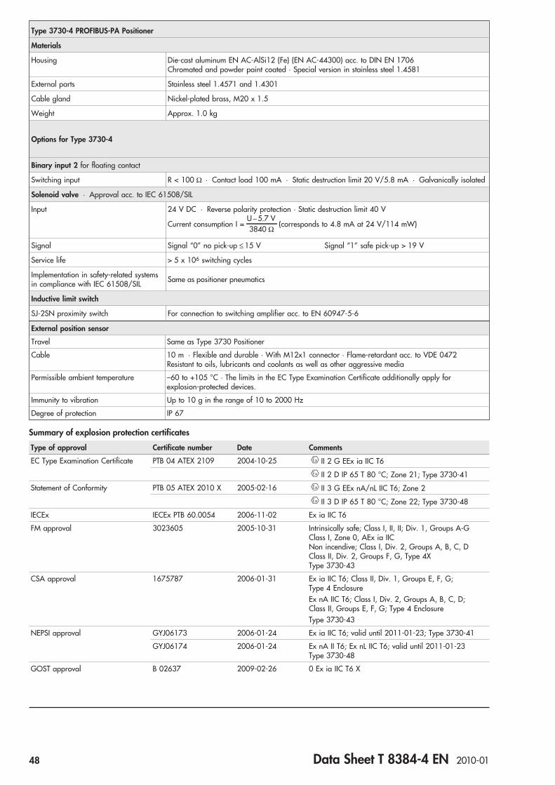
Type 3730-4 PROFIBUS-PA Positioner
Materials
Housing Die-cast aluminum EN AC-AlSi12 (Fe) (EN AC-44300) acc. to DIN EN 1706Chromated and powder paint coated · Special version in stainless steel 1.4581
External parts Stainless steel 1.4571 and 1.4301
Cable gland Nickel-plated brass, M20 x 1.5
Weight Approx. 1.0 kg
Options for Type 3730-4
Binary input 2 for floating contact
Switching input R < 100 Ω · Contact load 100 mA · Static destruction limit 20 V/5.8 mA · Galvanically isolated
Solenoid valve · Approval acc. to IEC 61508/SIL
Input 24 V DC · Reverse polarity protection · Static destruction limit 40 V
Current consumption I =U 5.7 V−3840 Ω
(corresponds to 4.8 mA at 24 V/114 mW)
Signal Signal “0” no pick-up ≤ 15 V Signal “1” safe pick-up > 19 V
Service life > 5 x 10⁶ switching cycles
Implementation in safety-related systemsin compliance with IEC 61508/SIL Same as positioner pneumatics
Inductive limit switch
SJ-2SN proximity switch For connection to switching amplifier acc. to EN 60947-5-6
External position sensor
Travel Same as Type 3730 Positioner
Cable 10 m · Flexible and durable · With M12x1 connector · Flame-retardant acc. to VDE 0472Resistant to oils, lubricants and coolants as well as other aggressive media
Permissible ambient temperature –60 to +105 °C · The limits in the EC Type Examination Certificate additionally apply forexplosion-protected devices.
Immunity to vibration Up to 10 g in the range of 10 to 2000 Hz
Degree of protection IP 67
Summary of explosion protection certificates
Type of approval Certificate number Date Comments
EC Type Examination Certificate PTB 04 ATEX 2109 2004-10-25 II 2 G EEx ia IIC T6
II 2 D IP 65 T 80 °C; Zone 21; Type 3730-41
Statement of Conformity PTB 05 ATEX 2010 X 2005-02-16 II 3 G EEx nA/nL IIC T6; Zone 2
II 3 D IP 65 T 80 °C; Zone 22; Type 3730-48
IECEx IECEx PTB 60.0054 2006-11-02 Ex ia IIC T6
FM approval 3023605 2005-10-31 Intrinsically safe; Class I, II, II; Div. 1, Groups A-GClass I, Zone 0, AEx ia IICNon incendive; Class I, Div. 2, Groups A, B, C, DClass II, Div. 2, Groups F, G, Type 4XType 3730-43
CSA approval 1675787 2006-01-31 Ex ia IIC T6; Class II, Div. 1, Groups E, F, G;Type 4 EnclosureEx nA IIC T6; Class I, Div. 2, Groups A, B, C, D;Class II, Groups E, F, G; Type 4 EnclosureType 3730-43
NEPSI approval GYJ06173 2006-01-24 Ex ia IIC T6; valid until 2011-01-23; Type 3730-41
GYJ06174 2006-01-24 Ex nA II T6; Ex nL IIC T6; valid until 2011-01-23Type 3730-48
GOST approval B 02637 2009-02-26 0 Ex ia IIC T6 X
48 Data Sheet T 8384-4 EN 2010-01

Output A1
Output A2
Supply (9)
A1 Z
A2
50
495979
76
80
130
15164
50
58
150
Reversing amplifier
40
34
210
86
164
2858
M 20x1.5
Output (38) Supply (9)
1480
70 1558
46
34
LeverS = 17 mmM = 50 mmL = 100 mmXL = 200 mm
Pressure gauge bracket or connecting plateG ¼ or ¼ NPT
Attachment acc. toIEC 60534 and NAMUR
Direct attachment
Dimensions in mm
Connecting plate
Connecting plateG ¼ or ¼ NPT
Attachment to rotary actuators
Data Sheet T 8384-4 EN 2010-01 49

Article code
Positioner Type 3730-4 x x x 0 x 0 x x 1 x 0 0 x 0 x x
With LCD and autotune, PROFIBUS-PA
Explosion protection
Without 0
II 2 G EEx ia IIC T6 and II 2 D IP 65 T 80 °C acc. to ATEX 1
CSA/FM intrinsically safe/non incendive 3
II 3 G EEx nA II T6 acc. to ATEX 8
Additional equipment
Inductive limit switch
Without 0
1 x Type SJ2-SN 1
Solenoid valve
Without 0
With, 24 V DC 4
External position sensor
Without 0
With 0 0 1 0 0
Binary input
Without 0
Floating contact 0 1
Diagnostics
EXPERT (standard) 1
EXPERT+ (extended diagnostics) 2
Housing material
Aluminum (standard) 0
Stainless steel 1.4581 0 1
Special application
Without 0
Device free of any substances that might impair paint adhesion 1
Exhaust air connection with ¼-18 NPT thread 0 0 0 0 2
Special version
None 0 0 0
NEPSI Ex ia 1 0 0 9
NEPSI Ex nL/nA 8 0 1 0
IECEx 1 0 1 2
GOST approval 1 0 1 4
50 Data Sheet T 8384-4 EN 2010-01

Power supply and bus connectionThe Type 3730-4 PROFIBUS-PA Positioner must be connectedto bus segments complying with IEC 61158-2 requirements. Ashielded two-wire line is used for both supply power and datacommunication.
Positioner attachmentThe Type 3730-4 PROFIBUS-PA Positioner can be attached di-rectly to the Type 3277 Actuator over a connection block. In ac-tuators with fail-safe action “Actuator stem extends” andType 3277-5 Actuator (120 cm²), the signal pressure is routedover an internal bore in the actuator yoke to the actuator. In ac-tuators with fail-safe action “Actuator stem retracts” and in ac-tuators with effective diaphragm areas of 240 cm² or larger, thesignal pressure is routed to the actuator over a ready-made ex-ternal piping. Using the appropriate bracket, the positioner canalso be attached according to IEC 60534-6-1 (NAMUR recom-mendation). The positioner can be mounted on any side of thecontrol valve.A pair of universal brackets is used for the attachment toType 3278 Rotary Actuators or other rotary actuators accord-ing to VDI/VDE 3845. The rotary motion of the actuator istransferred over a coupling wheel to the positioner.The characteristic is set in the software.A reversing amplifier is required for double-acting, springlessactuators for the second opposing signal pressure.
Ordering textType 3730-4 PROFIBUS-PA Positioner– SAMSON direct attachment– Attachment according to IEC 60534-6-1 (NAMUR)– Attachment to rotary actuators– Without/with pressure gauge up to max. 6 bar– Explosion protection– Limit switch– Solenoid valve– Binary input for floating contact– Extended EXPERT+ diagnostics
Specifications subject to change without notice.
Data Sheet T 8384-4 EN 2010-01 51


Series 3730
Electropneumatic Positioner Type 3730-5with FOUNDATION™ fieldbus communication
ApplicationPositioner for attachment to pneumatic control valvesTravel: 3.6 to 200 mm · Opening angle: 24° to 100°Smart, bus-powered field unit conforming to FOUNDATION™
fieldbus specification based on IEC 61158-2 transmissiontechnology. Integrated Function Blocks: PID Process Controller, AOAnalog Output, 2 DI Discrete Inputs, and Link Master Capability.
The microprocessor-controlled positioner compares the refer-ence variable cyclically transmitted over the FOUNDATION™
fieldbus network to the travel or opening angle of the control valveand issues a corresponding output signal pressure.The Type 3730-5 Positioner communicates according toFOUNDATION™ fieldbus specification with field devices, pro-grammable logic controllers and process control systems.An integrated PID Function Block allows the control of processvariables required directly in the field. The shift to distributedcontrol reduces the number of control tasks to be performed bythe higher-level automation system. Thanks to the Link MasterCapability, autonomous closed control loops can be set up inthe field.Other benefits provided by the smart positioner:• Easy attachment to common linear actuators over SAMSON
direct attachment interface (Fig. 1), over NAMUR rib (Fig. 2)or to control valves with rod-type yokes according toIEC 60534-6 or to rotary actuators according toVDI/VDE 3845 (Fig. 3)
• Any desired mounting position• Simple one-knob, menu-driven operation• Variable, automatic start-up with four different initialization
modes• LCD easy to read in any mounting position due to selectable
reading direction• Integrated EXPERT diagnostics (see T 8388 EN)• Classified status alarms• Control parameters can be changed online• Configurable at a computer over the SSP serial interface
using TROVIS-VIEW software• Automatic monitoring of zero point• Two DI Blocks to analyze binary input signals• Calibrated travel sensor without gears susceptible to wear• Permanent storage of all parameters in non-volatile EEPROM
(protection against power failure)• Adjustable output pressure limitation• Adjustable tight-closing function• Binary input for DC voltage signals• Certified according to IEC 61508/SIL
Additional options– Inductive limit switch with proximity switch
– Integrated solenoid valve– Binary input for floating contact– External position sensor (Fig. 4)– Integrated EXPERT+ extended diagnostics (T 8388 EN)– Stainless steel housing
Fig. 1 · Type 3730-5,direct attachment toType 3277 PneumaticActuator
Fig. 2 · Type 3730-5,attachment acc. toNAMUR
Fig. 3 · Type 3730-5,attachment acc. toVDI/VDE 3845
Fig. 4 · Type 3730-4,with external position sensor
Data Sheet T 8384-5 EN 2010-01 53

Principle of operationThe electropneumatic positioner is attached to pneumatic con-trol valves. It is used to assign the valve stem position (controlledvariable x) to the control signal (reference variable w). The inputsignal received from a control system is compared to the travelor rotational angle of the control valve, and a pneumatic signalpressure (output variable y) is produced.The positioner consists of a travel sensor system proportional toresistance, an analog i/p converter with a downstream boosterand the electronics unit with microcontroller.When a deviation occurs, the actuator is pressurized or vented.If required, the changes in the signal pressure can be sloweddown by a connectable Q restriction. The signal pressure sup-plied to the actuator can be limited by software or on site to 1.4,2.4 or 3.7 bar.A constant air stream to the atmosphere is created by the flowregulator (9) with a fixed set point. The air stream is used topurge the inside of the case as well as to optimize the air capac-ity booster. The i/p module (6) is supplied with a constant up-stream pressure by the pressure regulator (8) to make it inde-pendent of the supply air pressure.The positioner communicates and is powered usingIEC 61158-2 transmission technology conforming toFOUNDATION™ fieldbus specification.As a standard feature, the positioner comes with a binary inputused to signalize process information over the FOUNDATION™
fieldbus network.
OperationThe positioner is operated with a user-friendly rotarypushbutton. The parameters are selected by turning the knob,pushing it activates the required setting. In the menu, all param-eters are listed in one level, meaning there is no need to searchin submenus. All parameters can be checked and changed onsite.All values are displayed on the LCD. The reading direction ofthe LCD can be rotated by 180° at the push of a button.The closing direction of the control valve is indicated to thepositioner by the DIP switch "Air to open/Air to close". It as-signs the CLOSED position of the control valve to the 0 %reading.The INIT key activates initialization which is started according tothe (pre)set parameters. After initialization is completed, thepositioner immediately starts control operation.
Configuration with TROVIS-VIEWThe SAMSON configuration software, TROVIS-VIEW, can beused to configure the positioner. For this purpose, the positioneris equipped with an additional digital interface to be connectedto the RS-232 interface of a PC. TROVIS-VIEW adapts thepositioner to any process requirements and allows the processto be checked online. The control valve is linked to the processover the FOUNDATION™ fieldbus network.The PID Function Block integrated in the positioner can likewisebe configured using TROVIS-VIEW. The configuration of thenetwork connections for the PID Function Block is made usingthe NI-FBUS Configurator or a corresponding digital processcontrol system.
w
x
Q
%S
mm
GG
PD
SerialInterface
16
15 BE2
BE1
112
4
13
20
17 18
19
24V DC
5
3
12
6
7
8
10
1
14
9
xy
1 Control valve2 Travel sensor3 PD controller4 A/D converter5 Microcontroller6 i/p module7 Pneumatic booster8 Pressure regulator9 Flow regulator
10 Q restriction11* Inductive limit switch12* Solenoid valve13 IEC 61158-2
Interface module14 Binary input 1
(voltage input)15* Binary input 2 (for
floating contact)16 LCD17* Solenoid valve control18 Galvanic isolation for
solenoid valve control19 D/A converter20 Serial interface (SSP)* Option
Fig. 5 · Functional diagram ofType 3730-5 Positioner
FOUNDATION™
fieldbus
IEC 61158-2
54 Data Sheet T 8384-5 EN 2010-01

Table 1 · Technical data for Type 3730-5 FOUNDATION™ fieldbus Positioner
Rated travel adjustable Direct attachment to Type 3277 Actuator 3.6 to 30 mm
Attachment according to IEC 60534-6 (NAMUR) 3.6 to 200 mm
Attachment to rotary actuators (VDI/VDE 3845) 24 to 100° opening angle
Travel range adjustable Within the initialized travel/angle of rotation; restricted to 1/5 at the maximum
Bus connection Fieldbus interface as per IEC 61158-2, bus-poweredPhysical Layer Class 113 (without explosion protection)
111 (explosion-protected version)Field device acc. to FM 3610 entity, FISCO and FNICO
Communication
Fieldbus Data transmission conforming to FOUNDATION™ fieldbus specification,Communication Profile Class: 31 PS, 32 L;Interoperability tested acc. to Interoperability System IST Rev. 4.6
Software requirements (local) SAMSON SSP interface and serial interface adapter
TROVIS-VIEW with database module 3730-5
Permissible operating voltage 9 to 32 V DC · Power over bus lineThe limits in the EC Type Examination Certificate additionally apply for explosion-protected devices.
Maximum operating current 15 mA
Additional current in case of error 0 mA
Supply air Supply airAir quality
1.4 to 7 bar (20 to 105 psi)Acc. to ISO 8573-1 (2001): Max. particle size and density: Class 4 · Oil content: Class 3Pressure dew point: Class 3 or at least 10 K below the lowest ambient temperature to be expected
Signal pressure (output) 0 bar up to capacity of the supply pressure
Characteristics Linear/equal percentage/reverse equal percentage · User-defined (over operating software andcommunication) ⋅Butterfly valve linear/equal percentage · Rotary plug valve linear/equal percentage· Segmented ball valve linear/equal percentageDeviation from characteristic ≤ 1 %
Hysteresis ≤ 0.3 %
Sensitivity ≤ 0.1 %
Direction of action Reversible
Air consumption Independent of supply air <110 ln/h
Air output capacity Actuatorpressurized
At Δp = 6 bar: 8.5 mn3/h · At Δp = 1.4 bar: 3.0 mn
3/h · KVmax(20 °C) = 0.09
Actuatorvented
At Δp = 6 bar: 14.0 mn3/h · At Δp = 1.4 bar: 4.5 mn
3/h · KVmax(20 °C) = 0.15
Perm. ambient temperature –45 to +80 °CThe limits in the EC Type Examination Certificate additionally apply for explosion-protected devices.
Influences Temperature ≤ 0.15 %/10 K
Supply air None
Vibrations ≤ 0.25 % up to 2000 Hz and 4 g acc. to IEC 770
Electrical connections One M20x1.5 cable gland for 6 to 12 mm clamping range · Second M20x1.5 threaded connectionadditionally exists · Screw terminals for 0.2 to 2.5 mm² wire cross-sections
Electromagnetic compatibility Conforming to requirements in EN 61000-6-2, 61000-6-3 and NAMUR Recommendation NE 21
Degree of protection IP 66 / NEMA 4X
Implementation in safety-relevant systemsin compliance with IEC 61508/SIL
Probability of failure on demand of safety functions PFD < 2.8 x 10⁻⁷ for a confidence level of 95 %.The safe failure fraction (SFF) according to Table A1 in IEC 61508-2 is greater or equal to 0.99.Suitable for implementation in safety-relevant systems with a hardware fault tolerance of 1 or 2 upto and including SIL 4.
Binary input 1
Input 0 to 30 V DC with reverse polarity protection · Static destruction limit 40 VCurrent consumption 3.5 mA at 24 V, galvanically isolated
Signal Signal “1” at Ue > 5 V Signal “0“ at Ue < 3 V
Materials
Housing Die-cast aluminum EN AC-AlSi12(Fe) (EN AC-44300) acc. to DIN EN 1706Chromated and powder paint coated · Special version in stainless steel 1.4581
External parts Stainless steel 1.4571 and 1.4301
Cable gland Nickel-plated brass, M20 x 1.5
Weight Approx. 1.0 kg
Options for Type 3730-5
Binary input 2 for floating contact
Switching input R < 100 Ω · Contact load 100 mA · Static destruction limit 20 V / 5.8 mA · Galvanically isolated
Data Sheet T 8384-5 EN 2010-01 55
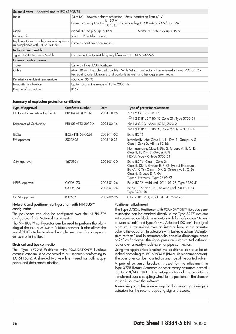
Network and positioner configuration with NI-FBUS™configuratorThe positioner can also be configured over the NI-FBUS™configurator from National Instruments.The NI-FBUS™ configurator can be used to perform the plan-ning of the FOUNDATION™ fieldbus network. It also allows theuse of PID Controller to allow the implementation of an independ-ent control in the field.
Electrical and bus connectionThe Type 3730-5 Positioner with FOUNDATION™ fieldbus
communicationmust be connected to bus segments conforming toIEC 61158-2. A shielded two-wire line is used for both supplypower and data communication.
Positioner attachmentThe Type 3730-5 Positioner with FOUNDATION™ fieldbus com-munication can be attached directly to the Type 3277 Actuatorwith a connection block. In actuators with fail-safe action “Actua-tor stem extends” and Type 3277-5 Actuator (120 cm²), the signalpressure is transmitted over an internal bore in the actuatoryoke to the actuator. In actuators with fail-safe action “Actuatorstem retracts” and in actuators with effective diaphragm areasof 240 cm² or larger, the signal pressure is transmitted to the ac-tuator over a ready-made external pipe connection.Using the appropriate bracket, the positioner can also be at-tached according to IEC 60534-6 (NAMUR recommendation).The positioner can be mounted on any side of the control valve.A pair of universal brackets is used for the attachment toType 3278 Rotary Actuators or other rotary actuators accord-ing to VDI/VDE 3845. The rotary motion of the actuator istransferred over a coupling wheel to the positioner. The charac-teristic is set over the software.A reversing amplifier is necessary for double-acting, springlessactuators for the second opposing signal pressure.
Solenoid valve · Approval acc. to IEC 61508/SIL
Input 24 V DC · Reverse polarity protection · Static destruction limit 40 V
Current consumption I =U 5.7 V−3840 Ω
(corresponding to 4.8 mA at 24 V/114 mW)
Signal Signal “0“ no pick-up ≤ 15 V Signal “1“ safe pick-up > 19 V
Service life > 5 x 10⁶ switching cycles
Implementation in safety-relevant systemsin compliance with IEC 61508/SIL Same as positioner pneumatics
Inductive limit switch
Type SJ 2SN Proximity Switch For connection to switching amplifiers acc. to EN 60947-5-6
External position sensor
Travel Same as Type 3730 Positioner
Cable Max. 10 m · Flexible and durable · With M12x1 connector · Flame-retardant acc. VDE 0472 ·Resistant to oils, lubricants, and coolants as well as other aggressive media
Permissible ambient temperature –60 to +105 °C
Immunity to vibration Up to 10 g in the range of 10 to 2000 Hz
Degree of protection IP 67
Summary of explosion protection certificates
Type of approval Certificate number Date Type of protection/Comments
EC Type Examination Certificate PTB 04 ATEX 2109 2004-10-25 II 2 G EEx ia IIC T6
II 2 D IP 65 T 80 °C; Zone 21; Type 3730-51
Statement of Conformity PTB 05 ATEX 2010 X 2005-02-16 II 3 G EEx nA/nL IIC T6; Zone 2
II 3 D IP 65 T 80 °C; Zone 22; Type 3730-58
IECEx IECEx PTB 06.0054 2006-11-02 Ex ia IIC T6
FM approval 3023605 2005-10-31 Intrinsically safe; Class I, II, III, Div. 1, Groups A-G;Class I, Zone 0, AEx ia IIC T6;Non incendive; Class I, Div. 2, Groups A, B, C, D;Class II, III, Div. 2, Groups F, G;NEMA Type 4X; Type 3730-53
CSA approval 1675804 2006-01-30 Ex ia IIC T6; Class I, Zone 0;Class II, Div. I, Groups E, F, G; Type 4 EnclosureEx nA IIC T6; Class I, Div. 2, Groups A, B, C, D;Class II, Groups E, F, G;Type 4 Enclosure; Type 3730-53
NEPSI approval GYJ06173 2006-01-24 Ex ia IIC T6; valid until 2011-01-23; Type 3730-51
GYJ06174 2006-01-24 Ex nA II T6; Ex nL IIC T6; valid until 2011-01-23Type 3730-58
GOST approval B02637 2009-02-26 0 Ex ia IIC T6 X; valid until 2012-02-26
56 Data Sheet T 8384-5 EN 2010-01

70 1558
46
34
Output A1
Output A2
Supply (9)
A1 Z
A2
50
495979
76
80
130
15164
50
58
150
Dimensions in mm
40
34
210
86
164
2858
M 20x1.5
Output (38) Supply (9)
1480
Direct attachment
NAMUR attachment
LeverS = 17 mmM = 50 mmL = 100 mmXL = 200 mm
Reversing amplifier
Connecting plate
Pressure gauge bracket or connecting plateG ¼ or ¼ NPT
Attachment to rotary actuators
Connecting plateG ¼ or ¼ NPT
Data Sheet T 8384-5 EN 2010-01 57

Ordering textFOUNDATION™ fieldbus Positioner Type 3730-5– SAMSON direct attachment– Attachment according to NAMUR– Attachment to rotary actuator– Without/with pressure gauge up to max. 6 bar– Explosion protection– Limit switch– Solenoid valve– Binary input for floating contact– Extended EXPERT+ diagnostics Specifications subject to change without notice.
Article code
Positioner Type 3730- 5 x x x 0 x 0 x x 0 x 0 0 x 0 x x
With LCD and autotune, FOUNDATION™ fieldbus
Explosion protection
Without 0
II 2 G EEx ia IIC T6 and II 2 D IP 65 T 80 °C acc. to ATEX 1
CSA/FM intrinsically safe/non incendive; Ex ia/Ex nA 3
II 3 G EEx nA II T6 / EEx nL IIC T6II 3 D IP 65 T 80 °C acc. to ATEX 8
Additional equipment
Inductive limit switch
Without 0
1 x Type SJ2-SN 1
Solenoid valve
Without 0
With, 24 V DC 4
External position sensor
Without 0
With 0 0 1 0 0
Binary input
Without 0
Floating contact 0 1
Diagnostics
EXPERT (standard) 1
EXPERT+ (extended diagnostics) 2
Housing material
Aluminum (standard) 0
Stainless steel 1.4581 0 1
Special application
Without 0
Device free of any substances that might impair paint adhesion 1
Exhaust air connection with ¼-18 NPT thread 0 0 0 0 2
Special version
None 0 0 0
NEPSI Ex ia 1 0 0 9
NEPSI Ex nL 8 0 1 0
IECEx 1 0 1 2
58 Data Sheet T 8384-5 EN 2010-01
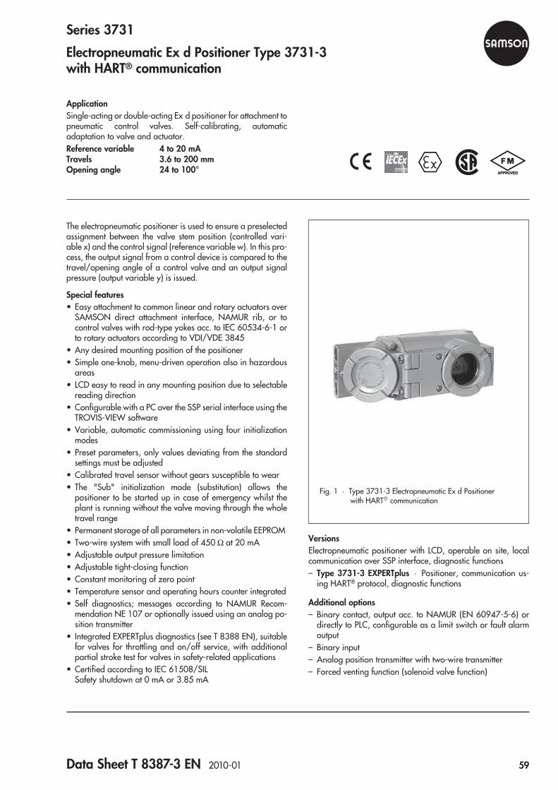
Series 3731
Electropneumatic Ex d Positioner Type 3731-3with HART® communication
ApplicationSingle-acting or double-acting Ex d positioner for attachment topneumatic control valves. Self-calibrating, automaticadaptation to valve and actuator.Reference variable 4 to 20 mATravels 3.6 to 200 mmOpening angle 24 to 100°
The electropneumatic positioner is used to ensure a preselectedassignment between the valve stem position (controlled vari-able x) and the control signal (reference variable w). In this pro-cess, the output signal from a control device is compared to thetravel/opening angle of a control valve and an output signalpressure (output variable y) is issued.
Special features• Easy attachment to common linear and rotary actuators over
SAMSON direct attachment interface, NAMUR rib, or tocontrol valves with rod-type yokes acc. to IEC 60534-6-1 orto rotary actuators according to VDI/VDE 3845
• Any desired mounting position of the positioner• Simple one-knob, menu-driven operation also in hazardous
areas• LCD easy to read in any mounting position due to selectable
reading direction• Configurable with a PC over the SSP serial interface using the
TROVIS-VIEW software• Variable, automatic commissioning using four initialization
modes• Preset parameters, only values deviating from the standard
settings must be adjusted• Calibrated travel sensor without gears susceptible to wear• The "Sub" initialization mode (substitution) allows the
positioner to be started up in case of emergency whilst theplant is running without the valve moving through the wholetravel range
• Permanent storage of all parameters in non-volatile EEPROM• Two-wire system with small load of 450 Ω at 20 mA• Adjustable output pressure limitation• Adjustable tight-closing function• Constant monitoring of zero point• Temperature sensor and operating hours counter integrated• Self diagnostics; messages according to NAMUR Recom-
mendation NE 107 or optionally issued using an analog po-sition transmitter
• Integrated EXPERTplus diagnostics (see T 8388 EN), suitablefor valves for throttling and on/off service, with additionalpartial stroke test for valves in safety-related applications
• Certified according to IEC 61508/SILSafety shutdown at 0 mA or 3.85 mA
VersionsElectropneumatic positioner with LCD, operable on site, localcommunication over SSP interface, diagnostic functions– Type 3731-3 EXPERTplus · Positioner, communication us-
ing HART® protocol, diagnostic functions
Additional options– Binary contact, output acc. to NAMUR (EN 60947-5-6) or
directly to PLC, configurable as a limit switch or fault alarmoutput
– Binary input– Analog position transmitter with two-wire transmitter– Forced venting function (solenoid valve function)
Fig. 1 · Type 3731-3 Electropneumatic Ex d Positionerwith HART® communication
Data Sheet T 8387-3 EN 2010-01 59
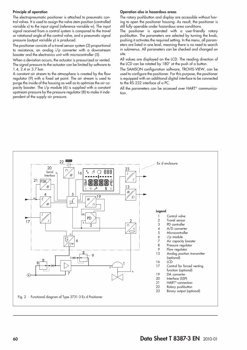
Principle of operationThe electropneumatic positioner is attached to pneumatic con-trol valves. It is used to assign the valve stem position (controlledvariable x) to the input signal (reference variable w). The inputsignal received from a control system is compared to the travelor rotational angle of the control valve, and a pneumatic signalpressure (output variable y) is produced.The positioner consists of a travel sensor system (2) proportionalto resistance, an analog i/p converter with a downstreambooster and the electronics unit with microcontroller (5).When a deviation occurs, the actuator is pressurized or vented.The signal pressure to the actuator can be limited by software to1.4, 2.4 or 3.7 bar.A constant air stream to the atmosphere is created by the flowregulator (9) with a fixed set point. The air stream is used topurge the inside of the housing as well as to optimize the air ca-pacity booster. The i/p module (6) is supplied with a constantupstream pressure by the pressure regulator (8) to make it inde-pendent of the supply air pressure.
Operation also in hazardous areasThe rotary pushbutton and display are accessible without hav-ing to open the positioner housing. As result, the positioner isstill fully operable under hazardous area conditions.The positioner is operated with a user-friendly rotarypushbutton. The parameters are selected by turning the knob,pushing it activates the required setting. In the menu, all param-eters are listed in one level, meaning there is no need to searchin submenus. All parameters can be checked and changed onsite.All values are displayed on the LCD. The reading direction ofthe LCD can be rotated by 180° at the push of a button.The SAMSON configuration software, TROVIS-VIEW, can beused to configure the positioner. For this purpose, the positioneris equipped with an additional digital interface to be connectedto the RS-232 interface of a PC.All the parameters can be accessed over HART® communica-tion.
%
Smm
%mm
w
x
G
PD
SerialInterface
16
22
20
13
23
2
4
21
17
FSK
5 19
3
6
7
8 1
w
9
xy
Fig. 2 · Functional diagram of Type 3731-3 Ex d Positioner
Legend1 Control valve2 Travel sensor3 PD controller4 A/D converter5 Microcontroller6 i/p module7 Air capacity booster8 Pressure regulator9 Flow regulator
13 Analog position transmitter(optional)
16 LCD17 Control for forced venting
function (optional)19 DA converter20 Interface (SSP)21 HART® connection22 Rotary pushbutton23 Binary output (optional)
Ex d enclosure
60 Data Sheet T 8387-3 EN 2010-01
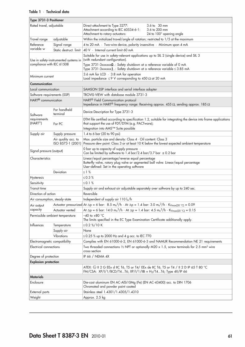
Table 1 · Technical data
Type 3731-3 Positioner
Rated travel, adjustable Direct attachment to Type 3277: 3.6 to 30 mmAttachment according to IEC 60534-6-1: 3.6 to 200 mmAttachment to rotary actuators: 24 to 100° opening angle
Travel range adjustable Within the initialized travel/angle of rotation; restricted to 1/5 at the maximum
Referencevariable w
Signal range 4 to 20 mA · Two-wire device, polarity insensitive · Minimum span 4 mA
Static destruct. limit 40 V · Internal current limit 60 mA
Use in safety-instrumented systems incompliance with IEC 61508
Suitable for use in safety-relevant applications up to SIL 2 (single device) and SIL 3(with redundant configuration).Type 3731-3xxxxxx0..: Safety shutdown at a reference variable of 0 mAType 3731-3xxxxxx1..: Safety shutdown at a reference variable ≤ 3.85 mA
Minimum current 3.6 mA for LCD · 3.8 mA for operationLoad impedance ≤ 9 V corresponding to 450 Ω at 20 mA
Communication
Local communication SAMSON SSP interface and serial interface adapter
Software requirements (SSP) TROVIS-VIEW with database module 3731-3
HART® communication HART® Field Communication protocolImpedance in HART® frequency range: Receiving approx. 455 Ω, sending approx. 185 Ω
Softwarerequirements(HART®)
For handheldterminal Device Description for Type 3731-3
For PCDTM file certified according to specification 1.2, suitable for integrating the device into frame applicationsthat support the use of FDT/DTM (e.g. PACTware);Integration into AMS™ Suite possible
Supply air Supply pressure 1.4 to 6 bar (20 to 90 psi)
Air quality acc. toISO 8573-1 (2001)
Max. particle size and density: Class 4 · Oil content: Class 3Pressure dew point: Class 3 or at least 10 K below the lowest expected ambient temperature
Signal pressure (output) 0 bar up to capacity of supply pressure ·Can be limited by software to 1.4 bar/2.4 bar/3.7 bar ± 0.2 bar
Characteristics Linear/equal percentage/reverse equal percentageButterfly valve, rotary plug valve or segmented ball valve: Linear/equal percentageUser-defined: Set in the operating software
Deviation ≤ 1 %
Hysteresis ≤ 0.3 %
Sensitivity ≤ 0.1 %
Transit time Supply air and exhaust air adjustable separately over software by up to 240 sec.
Direction of action Reversible
Air consumption, steady-state Independent of supply air 110 ln/h
Air outputcapacity
Actuator pressurized At Δp = 6 bar: 8.5 mn3/h · At Δp = 1.4 bar: 3.0 mn3/h · KVmax(20 °C) = 0.09
Actuator vented At Δp = 6 bar: 14.0 mn3/h · At Δp = 1.4 bar: 4.5 mn3/h · KVmax(20 °C) = 0.15
Permissible ambient temperature –40 to +80 °CThe limits specified in the EC Type Examination Certificate additionally apply.
Influences Temperature ≤ 0.2 %/10 K
Supply air None
Vibrations ≤ 0.25 % up to 2000 Hz and 4 g acc. to IEC 770
Electromagnetic compatibility Complies with EN 61000-6-2, EN 61000-6-3 and NAMUR Recommendation NE 21 requirements
Electrical connections Two threaded connections ½ NPT or optionally M20 x 1.5, screw terminals for 2.5 mm² wirecross-section
Degree of protection IP 66 / NEMA 4X
Explosion protection
ATEX: II 2 G EEx d IIC T6, T5 or T4/ EEx de IIC T6, T5 or T4 / II 2 D IP 65 T 80 °CFM/CSA: XP/I/1/BCD/T4...T6; XP/I/1/IIB + H2/T4...T6; Type 4X/IP 66
Materials
Enclosure Die-cast aluminum EN AC-AlSi10Mg (Fe) (EN AC-43400) acc. to DIN 1706Chromated and powder paint coated
External parts Stainless steel 1.4301/1.4305/1.4310
Weight Approx. 2.5 kg
Data Sheet T 8387-3 EN 2010-01 61
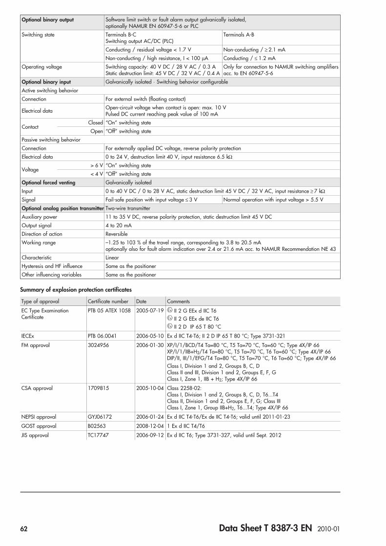
Optional binary output Software limit switch or fault alarm output galvanically isolated,optionally NAMUR EN 60947-5-6 or PLC
Switching state Terminals B-CSwitching output AC/DC (PLC)
Terminals A-B
Conducting / residual voltage < 1.7 V Non-conducting / ≥ 2.1 mA
Non-conducting / high resistance, I < 100 μA Conducting / ≤ 1.2 mA
Operating voltage Switching capacity: 40 V DC / 28 V AC / 0.3 AStatic destruction limit: 45 V DC / 32 V AC / 0.4 A
Only for connection to NAMUR switching amplifiersacc. to EN 60947-5-6
Optional binary input Galvanically isolated · Switching behavior configurable
Active switching behavior
Connection For external switch (floating contact)
Electrical data Open-circuit voltage when contact is open: max. 10 VPulsed DC current reaching peak value of 100 mA
ContactClosed “On” switching state
Open “Off” switching state
Passive switching behavior
Connection For externally applied DC voltage, reverse polarity protection
Electrical data 0 to 24 V, destruction limit 40 V, input resistance 6.5 kΩ
Voltage> 6 V “On” switching state
< 4 V “Off” switching state
Optional forced venting Galvanically isolated
Input 0 to 40 V DC / 0 to 28 V AC, static destruction limit 45 V DC / 32 V AC, input resistance ≥ 7 kΩ
Signal Fail-safe position with input voltage ≤ 3 V Normal operation with input voltage > 5.5 V
Optional analog position transmitter Two-wire transmitter
Auxiliary power 11 to 35 V DC, reverse polarity protection, static destruction limit 45 V DC
Output signal 4 to 20 mA
Direction of action Reversible
Working range –1.25 to 103 % of the travel range, corresponding to 3.8 to 20.5 mAoptionally also for fault alarm indication over 2.4 or 21.6 mA acc. to NAMUR Recommendation NE 43
Characteristic Linear
Hysteresis and HF influence Same as the positioner
Other influencing variables Same as the positioner
Summary of explosion protection certificates
Type of approval Certificate number Date Comments
EC Type ExaminationCertificate
PTB 05 ATEX 1058 2005-07-19 II 2 G EEx d IIC T6II 2 G EEx de IIC T6II 2 D IP 65 T 80 °C
IECEx PTB 06.0041 2006-05-10 Ex d IIC T4-T6; II 2 D IP 65 T 80 °C; Type 3731-321
FM approval 3024956 2006-01-30 XP/I/1/BCD/T4 Ta=80 °C, T5 Ta=70 °C, Ta=60 °C; Type 4X/IP 66XP/I/1/IIB+H2/T4 Ta=80 °C, T5 Ta=70 °C, T6 Ta=60 °C; Type 4X/IP 66DIP/II, III/1/EFG/T4 Ta=80 °C, T5 Ta=70 °C, T6 Ta=60 °C; Type 4X/IP 66Class I, Division 1 and 2, Groups B, C, DClass II and III, Division 1 and 2, Groups E, F, GClass I, Zone 1, IIB + H2; Type 4X/IP 66
CSA approval 1709815 2005-10-04 Class 2258-02:Class I, Division 1 and 2, Groups B, C, D, T6...T4Class II, Division 1 and 2, Groups E, F, G; Class IIIClass I, Zone 1, Group IIB+H2, T6...T4; Type 4X/IP 66
NEPSI approval GYJ06172 2006-01-24 Ex d IIC T4-T6/Ex de IIC T4-T6; valid until 2011-01-23
GOST approval B02563 2008-12-04 1 Ex d IIC T4/T6
JIS approval TC17747 2006-09-12 Ex d IIC T6; Type 3731-327, valid until Sept. 2012
62 Data Sheet T 8387-3 EN 2010-01

14
122
95
28
Output Supply
58
236
34
53
70
15
46
34
58
A1 Z
A2
5686
13080
166
3086
Ø 101
76
50
¼ NPT
Dimensions in mm
Direct attachment
Attachment acc. toIEC 60534-6 and NAMUR
Pressure gauge or connection platebracket (only for G ¼)¼ NPT or G ¼
LeverS = 17 mm, M = 50 mmL = 100 mm, XL = 200 mm
Attachment torotary actuators
Output A1 Supply (9)
Reversing Output A2amplifier¼ NPT or G ¼
2 x female thread½ NPT or M20 x 1.5
Data Sheet T 8387-3 EN 2010-01 63
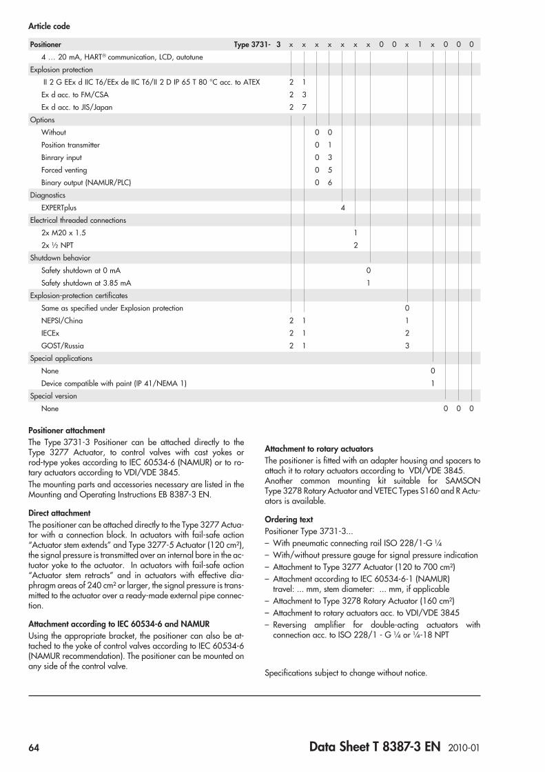
Positioner attachmentThe Type 3731-3 Positioner can be attached directly to theType 3277 Actuator, to control valves with cast yokes orrod-type yokes according to IEC 60534-6 (NAMUR) or to ro-tary actuators according to VDI/VDE 3845.The mounting parts and accessories necessary are listed in theMounting and Operating Instructions EB 8387-3 EN.
Direct attachmentThe positioner can be attached directly to the Type 3277 Actua-tor with a connection block. In actuators with fail-safe action“Actuator stem extends” and Type 3277-5 Actuator (120 cm²),the signal pressure is transmitted over an internal bore in the ac-tuator yoke to the actuator. In actuators with fail-safe action“Actuator stem retracts” and in actuators with effective dia-phragm areas of 240 cm² or larger, the signal pressure is trans-mitted to the actuator over a ready-made external pipe connec-tion.
Attachment according to IEC 60534-6 and NAMURUsing the appropriate bracket, the positioner can also be at-tached to the yoke of control valves according to IEC 60534-6(NAMUR recommendation). The positioner can be mounted onany side of the control valve.
Attachment to rotary actuatorsThe positioner is fitted with an adapter housing and spacers toattach it to rotary actuators according to VDI/VDE 3845.Another common mounting kit suitable for SAMSONType 3278 Rotary Actuator and VETEC Types S160 and R Actu-ators is available.
Ordering textPositioner Type 3731-3...– With pneumatic connecting rail ISO 228/1-G ¼– With/without pressure gauge for signal pressure indication– Attachment to Type 3277 Actuator (120 to 700 cm²)– Attachment according to IEC 60534-6-1 (NAMUR)
travel: ... mm, stem diameter: ... mm, if applicable– Attachment to Type 3278 Rotary Actuator (160 cm²)– Attachment to rotary actuators acc. to VDI/VDE 3845– Reversing amplifier for double-acting actuators with
connection acc. to ISO 228/1 - G ¼ or ¼-18 NPT
Specifications subject to change without notice.
Article code
Positioner Type 3731- 3 x x x x x x x 0 0 x 1 x 0 0 0
4 … 20 mA, HART® communication, LCD, autotune
Explosion protection
II 2 G EEx d IIC T6/EEx de IIC T6/II 2 D IP 65 T 80 °C acc. to ATEX 2 1
Ex d acc. to FM/CSA 2 3
Ex d acc. to JIS/Japan 2 7
Options
Without 0 0
Position transmitter 0 1
Binrary input 0 3
Forced venting 0 5
Binary output (NAMUR/PLC) 0 6
Diagnostics
EXPERTplus 4
Electrical threaded connections
2x M20 x 1.5 1
2x ½ NPT 2
Shutdown behavior
Safety shutdown at 0 mA 0
Safety shutdown at 3.85 mA 1
Explosion-protection certificates
Same as specified under Explosion protection 0
NEPSI/China 2 1 1
IECEx 2 1 2
GOST/Russia 2 1 3
Special applications
None 0
Device compatible with paint (IP 41/NEMA 1) 1
Special version
None 0 0 0
64 Data Sheet T 8387-3 EN 2010-01

Series 3731
Electropneumatic Ex d Positioner Type 3731-5with FOUNDATION™ fieldbus communication
ApplicationPositioner for attachment to pneumatic control valvesTravel: 3.6 to 200 mm · Opening angle: 24° to 100°Smart, bus-powered field unit conforming to FOUNDATION™
fieldbus specification based on IEC 61158-2 transmissiontechnology. Integrated Function Blocks: PID Process Controller,AO Analog Output, one binary input for DC voltage signals(DI1) or for connection of one floating contact (DI2).
The positioner is used to ensure a preselected assignment be-tween the valve stem position (controlled variable x) and thecontrol signal (reference variable w). It compares the referencevariable cyclically transmitted over the FOUNDATION™
fieldbus network to the travel or opening angle of the controlvalve and produces the corresponding signal pressure output(output variable y).The Type 3731-5 Positioner communicates according toFOUNDATION™ fieldbus specification with field devices, pro-grammable logic controllers and process control systems.An integrated PID Function Block allows the control of requiredprocess variables directly in the field. The shift to distributedcontrol reduces the number of control tasks to be performed bythe higher-level automation system.Other benefits provided by the smart positioner:• Easy attachment to common linear actuators over SAMSON
direct attachment interface, over NAMUR rib or to controlvalves with rod-type yokes according to IEC 60534-6-1 torotary actuators according to VDI/VDE 3845
• Any desired mounting position• Simple one-knob, menu-driven operation also in hazardous
areas• Variable, automatic commissioning using four initialization
modes• LCD easy to read in any mounting position due to selectable
reading direction• Monitoring and diagnostics functions• Extended diagnostics and partial stroke test in EXPERT+ ver-
sion. Refer to Data Sheet T 8388 EN for more details.• Control parameters can be changed online• Automatic monitoring of zero point• Two DI Blocks for analysis of binary input signals• Calibrated travel sensor without gears susceptible to wear• Permanent storage of all parameters in non-volatile EEPROM
(protection against power failure)• Adjustable output pressure limitation• Adjustable tight-closing function• Configurable with a PC over the SSP serial interface using the
TROVIS-VIEW softwareAdditional optionsThe digital positioner functions can be optionally extended:– Binary input– Forced venting
Fig. 1 · Type 3731-5 FOUNDATION™ fieldbus Positioner
JIS
Data Sheet T 8387-5 EN 2010-01 65

Principle of operationThe electropneumatic positioner is attached to pneumatic con-trol valves. It is used to assign the valve stem position (controlledvariable x) to the input signal (reference variable w). The inputsignal received from a control system is compared to the travelor rotational angle of the control valve, and a pneumatic signalpressure (output variable y) is produced.The positioner consists of a travel sensor system proportional toresistance, an analog i/p converter with a downstream boosterand the electronics unit with microcontroller.When a deviation occurs, the actuator is filled with more air orvented. The signal pressure to the actuator can be limited bysoftware to 1.4, 2.4 or 3.7 bar.A constant air stream to the atmosphere is created by the flowregulator (9) with a fixed set point. The air stream is used topurge the inside of the housing as well as to optimize the air ca-pacity booster. The i/p module (6) is supplied with a constantupstream pressure by the pressure regulator (8) to make it inde-pendent of the supply air pressure.The positioner communicates and is powered via IEC 61158-2transmission technology conforming to FOUNDATION™ fieldbus
specification.
OperationThe positioner is operated with a user-friendly rotarypushbutton. The parameters are selected by turning the knob,pushing it activates the required setting. In the menu, all param-eters are listed in one level, meaning there is no need to searchin submenus. All parameters can be checked and changed onsite.All values are displayed on the LCD. The reading direction ofthe LCD can be rotated by 180° at the push of a button.The closing direction of the control valve is indicated to thepositioner. It assigns the CLOSED position of the control valve tothe 0 % reading.The initialization is started according to the (pre)set parameters.After initialization is completed, the positioner immediatelystarts control operation.
Configuration with TROVIS-VIEWThe SAMSON configuration software, TROVIS-VIEW, can beused to configure the positioner. For this purpose, the positioneris equipped with an additional digital interface to be connectedto the RS-232 serial interface of a PC. TROVIS-VIEW adapts thepositioner to any process requirements and allows the processto be checked online. The control valve is linked to the processover the FOUNDATION™ fieldbus network.The PID Function Block integrated in the positioner can likewisebe configured using TROVIS-VIEW. The Function Blocks arelinked by the NI-FBUS Configurator or a corresponding processcontrol system.
%
Smm
%mm
w
x
G
PD
SerialInterface
16
22
20 23
2
4
17
5 19
3
6
7
8 1
9
x
y
FOUNDATION™
fieldbus
IEC 61158-2Legend1 Control valve2 Travel sensor3 PD controller4 IEC 61158-2
interface module5 Microcontroller6 i/p module7 Air capacity booster8 Pressure regulator9 Flow regulator
16 LCD17 Forced venting function
(optional)19 DA converter20 Serial interface (SSP)22 Rotary pushbutton23 Binary input (optional)
Fig. 2 · Functional diagram ofType 3731-5 Positioner
66 Data Sheet T 8387-5 EN 2010-01

Table 1 · Technical data
Type 3731-5 FOUNDATION™ fieldbus Positioner
Rated travel adjustable Direct attachment to Type 3277 Actuator 3.6 to 30 mm
Attachment according to IEC 60534-6 (NAMUR) 3.6 to 200 mm
Attachment to rotary actuators (VDI/VDE 3845) 24 to 100° opening angle
Travel range adjustable Within the initialized travel/angle of rotation · Restricted to 1/5 at the maximum
Bus connection Fieldbus interface as per IEC 61158-2, bus-poweredPhysical Layer Class 113 (without explosion protection)
111 (explosion-protected version)Field device acc. to FM 3610 entity and FISCO
Communication
Local communication SAMSON SSP interface and serial interface adapter
Software requirements (SSP) TROVIS-VIEW with database module 3731-5
Fieldbus communication Data transmission conforming to FOUNDATION™ fieldbus specification,Communication Profile Class: 31 PS, 32 L;Interoperability tested acc. to Interoperability System IST Rev. 4.6
Permissible operating voltage 9 to 32 V DC · Power over bus lineThe limits in the EC Type Examination Certificate additionally apply for explosion-protected devices.
Maximum operating current 15 mA
Additional current in case of error 0 mA
Supply air Supply airAir quality
1.4 to 6 bar (20 to 90 psi)Acc. to ISO 8573-1: 2004Particle size and density: Class 4 · Oil content: Class 3 · Humidity and water: Class 3Pressure dew point at least 10 K below the lowest expected ambient temperature
Signal pressure (output) 0 bar up to capacity of supply pressure
Characteristics Linear/equal percentage/reverse equal percentage · User-defined (over operating software andcommunication) · Butterfly valve linear/equal percentage · Rotary plug valve linear/equalpercentage · Segmented ball valve linear/equal percentageDeviation from characteristic ≤ 1 %
Hysteresis ≤ 0.3 %
Sensitivity ≤ 0.1 %
Direction of action Reversible
Air consumption Independent of supply air <110 ln/h
Air outputcapacity
Actuator pressurized At Δp = 6 bar: 8.5 mn3/h · At Δp = 1.4 bar: 3.0 mn3/h · KVmax(20 °C) = 0.09
Actuator vented At Δp = 6 bar:14.0 mn3/h · At Δp = 1.4 bar: 4.5 mn3/h · KVmax(20 °C) = 0.15
Permissible ambient temperature –40 to +80 °CThe limits in the EC Type Examination Certificate additionally apply for explosion-protected devices.
Influences Temperature ≤ 0.15 %/10 K
Supply air None
Vibrations ≤ 0.25 % up to 2000 Hz and 4 g acc. to IEC 770
Electromagnetic compatibility Conforming to requirements in EN 61 000-6-2, 61 000-6-3 and NAMUR Recommendation NE 21
Electrical connections Two threaded connections ½ NPT or optionally M20 x 1.5, screw terminals for 2.5 mm² wirecross-section
Degree of protection IP 66 / NEMA 4X
Materials
Housing Die-cast aluminum EN AC-AlSi10Mg (Fe) (EN AC-43400) acc. to DIN 1706Chromated and powder paint coated
External metal parts Stainless steel 1.4571 and 1.4301
Weight Approx. 2.5 kg
Data Sheet T 8387-5 EN 2010-01 67
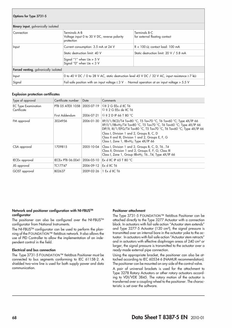
Network and positioner configuration with NI-FBUSTM
configuratorThe positioner can also be configured over the NI-FBUSTM
configurator from National Instruments.The NI-FBUSTM configurator can be used to perform the plan-ning of the FOUNDATION™ fieldbus network. It also allows theuse of PID Controller to allow the implementation of an inde-pendent control in the field.
Electrical and bus connectionThe Type 3731-5 FOUNDATION™ fieldbus Positioner must beconnected to bus segments conforming to IEC 61158-2. Ashielded two-wire line is used for both supply power and datacommunication.
Positioner attachmentThe Type 3731-5 FOUNDATION™ fieldbus Positioner can beattached directly to the Type 3277 Actuator with a connectionblock. In actuators with fail-safe action “Actuator stem extends”and Type 3277-5 Actuator (120 cm²), the signal pressure istransmitted over an internal bore in the actuator yoke to the ac-tuator. In actuators with fail-safe action “Actuator stem retracts”and in actuators with effective diaphragm areas of 240 cm² orlarger, the signal pressure is transmitted to the actuator over aready-made external pipe connection.Using the appropriate bracket, the positioner can also be at-tached according to IEC 60534-6 (NAMUR recommendation).The positioner can be mounted on any side of the control valve.A pair of universal brackets is used for the attachment toType 3278 Rotary Actuators or other rotary actuators accord-ing to VDI/VDE 3845. The rotary motion of the actuator istransferred over a coupling wheel to the positioner. The charac-teristic is set over the software.
Options for Type 3731-5
Binary input, galvanically isolated
Connection Terminals A-BVoltage input 0 to 30 V DC, reverse polarityprotection
Terminals B-Cfor external floating contact
Input Current consumption: 3.5 mA at 24 V R < 100 Ω; contact load: 100 mA
Static destruction limit: 40 V Static destruction limit: 20 V / 5.8 mA
Signal “1” when Ue > 5 VSignal “0” when Ue < 3 V
Forced venting, galvanically isolated
Input 0 to 40 V DC / 0 to 28 V AC, static destruction level 45 V DC / 32 V AC, input resistance ≥ 7 kΩ
Signal Fail-safe position with an input voltage ≤ 3 V · Normal operation at an input voltage > 5.5 V
Explosion protection certificates
Type of approval Certificate number Date Comments
EC Type ExaminationCertificate
PTB 05 ATEX 1058 2005-07-19 II 2 G EEx d IIC T6II 2 G EEx de IIC T6
First Addendum 2006-07-21 II 2 D IP 66 T 80 °C
FM approval 3024956 2006-01-30 XP/I/1/BCD/T4 Ta=80 °C, T5 Ta=70 °C, T6 Ta=60 °C; Type 4X/IP 66XP/I/1/IIB+H2/T4 Ta=80 °C, T5 Ta=70 °C, T6 Ta=60 °C; Type 4X/IP 66DIP/II, III/1/EFG/T4 Ta=80 °C, T5 Ta=70 °C, T6 Ta=60 °C; Type 4X/IP 66Class I, Division 1 and 2, Groups B, C, DClass II and III, Division 1 and 2, Groups E, F, GClass I, Zone 1, IIB+H2; Type 4X/IP 66
CSA approval 1709815 2005-10-04 Class I, Division 1 and 2, Groups B, C, D, T6...T4Class II, Division 1 and 2, Groups E, F, G; Class IIIClass I, Zone 1, Group IIB+H2, T6...T4; Type 4X/IP 66
IECEx approval IECEx PTB 06.0041 2006-05-10 Ex d IIC IP 65 T 80 °C
JIS approval TC17747 2006-09-12 Ex d IIC T6
GOST approval B02637 2009-02-26 1 Ex d IIC T6
68 Data Sheet T 8387-5 EN 2010-01
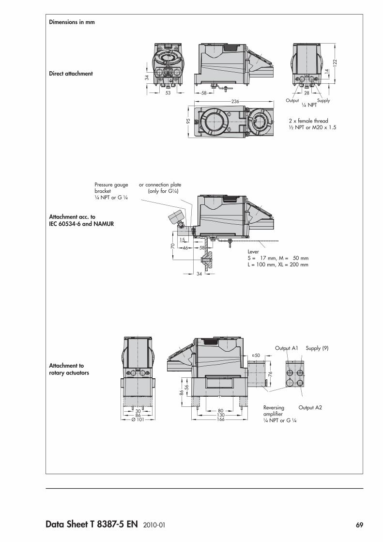
14
122
95
28
Output Supply
58
236
34
53
2 x female thread½ NPT or M20 x 1.5
¼ NPT
Dimensions in mm
Direct attachment
70
15
46
34
58
Attachment acc. toIEC 60534-6 and NAMUR
Pressure gauge or connection platebracket (only for G¼)¼ NPT or G ¼
LeverS = 17 mm, M = 50 mmL = 100 mm, XL = 200 mm
A1 Z
A2
5686
13080
166
3086
Ø 101
76
50
Attachment torotary actuators
Output A1 Supply (9)
Reversing Output A2amplifier¼ NPT or G ¼
Data Sheet T 8387-5 EN 2010-01 69

Ordering textFOUNDATION™ fieldbus Positioner Type 3731-5...– With pneumatic connecting rail ISO 228/1-G ¼– With/without pressure gauge for signal pressure indication– Attachment to Type 3277 Actuator (120 to 700 cm²)– Attachment according to IEC 60534-6-1 (NAMUR)
travel: ... mm, stem diameter: ... mm, if applicable– Attachment to Type 3278 Rotary Actuator (160 cm²)– Attachment to rotary actuators acc. to VDI/VDE 3845– Reversing amplifier for double-acting actuators with
connection acc. to ISO 228/1 - G ¼ or ¼-18 NPT
Specifications subject to change without notice.
Article code
Positioner Type 3731- 5 x x x x x x 0 0 0 x 1 x 0 0 0
With LC display, autotune, FOUNDATION™ fieldbus
Explosion protection
II 2 G EEx d IIC T6/EEx de IIC T6/II 2 D IP 65 T 80 °C acc. to ATEX 2 1
Ex d acc. to FM/CSA 2 3
Ex d acc. to JIS 2 7
Options
Without 0 0
Binary input 0 3
Forced venting 0 5
Diagnostics
EXPERT 1
EXPERT+ 2
Electrical threaded connections
2x M20 x 1.5 1
2x ½ NPT 2
Explosion protection approvals
As specified in Explosion protection 0
IECEx 2 1 2
GOST approval 2 1 3
Special applications
Without 0
Positioner compatible with paint (IP 41/NEMA 1) 1
Special version
None 0 0 0
70 Data Sheet T 8387-5 EN 2010-01

Series 3730 and Series 3731
EXPERTplus Valve Diagnostics with Partial Stroke Test (PST)
ApplicationPositioner firmware for early detection of control valve faultsgiving maintenance recommendations. Valid for firmwareversion V 1.51 and higher
The EXPERTplus valve diagnostics can detect faults and providepredictive, status-oriented maintenance of pneumatic controlvalves. The full scope of diagnostic functions is completely inte-grated into the positioner. The numerous diagnostic functionsallow faults to be pinpointed in control and safety-relatedon/off valves at an early stage. Functions include, for example,partial stroke testing and data logging.The TROVIS-VIEW software, which allows the user to access,read and edit the diagnosis, is easy to learn. The integration op-tions including eDD, eEDD, FDT/DTM allow the diagnosticfunctions to be also used in other engineering tools. Classifiedstatus alarms and the condensed state conforming to theNAMUR Recommendation NE 107 can also be read off at theon-site display of the positioner and can be issued over the faultalarm contact*.
TROVIS-VIEW: Operator interface to configure andparameterize various SAMSON devicesFDT: Field device tool for the manufacturer-independentintegration of field devicesDTM: Device type manager to describe the device andcommunication propertiesDD/eDD: Device description/enhanced device description
Special features• Diagnostic tests performed without any additional sensors in
the control valve• Data required for diagnostics are constantly compiled, saved
and analyzed in the positioner. Status alarms are automati-cally generated. Test data and their analysis are saved in thepositioner.
• Cyclical polling of test data, multiplexer-capable• Statistical information (in-service monitoring) and tests
(out-of-service diagnostics) pinpoint critical states beforemalfunctions can affect the process, allowing the user to planpredictive maintenance and service work on control andon/off valves
• Minimum and maximum temperature readings with detailson how long the limits have been exceeded
• Automatic start of diagnostic functions• Display of service and maintenance recommendations• Display of classified status and fault alarms
• Status classification and condensed state based on NAMURRecommendation NE 107
• Status alarms and condensed state can also be read off at thepositioner display or can be issued over the fault alarm con-tact*
• Plotting of y-x signature (valve signature) for fault detection• Diagnostic function to pinpoint changes in friction• Operating hours counter allows data and events to be sorted
by time• Diagnosis data and test analysis saved in the positioner• Integrated partial stroke testing (PST) and full stroke testing
(FST)• Binary input, e.g. to start tests, connect an external solenoid
valve or a leakage sensor, etc.
Fig. 1 · Type 3241-1 Control Valve and Type 3730-3Positioner with HART® communication
Fig. 2 · Flameproof Type 3731 Electropneumatic Positioner
Data Sheet T 8389 EN 2008-08 71

Summary of diagnostic functionsThere are two main groups of diagnostic functions available:
Statistical information (in-service monitoring)Data are compiled, saved and analyzed by the positioner whilethe process is running without disrupting the process. Thepositioner follows the reference variable during this time. Aclassified status alarm or fault alarm is generated if thepositioner detects an event.
Tests (out-of-service diagnostics)Similar to the statistical information function, data are com-piled, saved and analyzed by the positioner. However, in thiscase, the valve position is not determined by the reference vari-able, but the active test. The tests (PST, FST) can only be startedwhen the conditions in the plant allow it (e.g. plant shutdown orservice work in the workshop). For reasons of safety, these tests,except for partial stroke testing, can only be performed in theMAN operating mode.Table 1 shows the individual diagnostic functions with their testanalyses.
Application type: Control valve or on/off valveThe EXPERTplus valve diagnostics is used in combination withpneumatic control valves. The positioner works using the appli-cation types, control valve or on/off valve. Both applicationtypes allow positioner to run in both AUTO or MAN operatingmodes.The table shows the correlation between the application typeand operating mode:
Control valve On/off valve
AUTOmode
The positioner followscontinuously thereference variable.The valve position(current position)appears in % on thedisplay.
Discrete analysis of thereference variable.The valve position(current position) in %and O/C (Open/Close)appear in alternatingsequence on the display.
MANmode
The positioner follows the reference variable givenover local operation or over acyclic communication.
The discrete analysis of the reference variable with the applica-tion type, on/off valve and in AUTO mode allows the valve tobe moved to the fail-safe position or a user-defined fixed value(e.g. 100 %) by entering the corresponding reference variable.In addition, the partial stroke test (PST) can be started byentering the corresponding reference variable w.
Fig. 3 · EXPERTplus valve diagnostics with TROVIS-VIEW3 Operator Interface
72 Data Sheet T 8389 EN 2008-08

Table 1 · Summary of EXPERTplus functions
Test function Seesection Description
Start-updiagnostics
1.1 Positioner self-test,mechanical attachment, valve travelrange, initialization time, opening andclosing times
Current processvariables
Operatingparameters
1.2.1
1.2.2
Process variables:Reference variable w, valve position x,drive signal y, setpoint deviation eOperating hours counter,number of zero calibrations andinitializations, temperature, total valvetravel, self-monitoring of positioner
Status alarms,classification
1.2.33.1
Display and logging ofclassified status alarms and condensedstate
Statistical information (in-service monitoring)
On/off 2.1.1 Breakaway time, transit time, valve endposition
Data logger 2.1.2 Recording and saving of referencevariable w, valve position x, drive sig-nal y, setpoint deviation e with trigger-ing function
Travel histogramx
2.1.3 Trend of the working range, workingrange
Setpointdeviationhistogram
2.1.4 Limit working range, inner leakage,connection positioner-valve, absolutevalue of max. setpoint deviation
Cycle counterhistogram
2.1.5 External leakage, dynamic stress factoracting on packing and metal bellows
Drive signaldiagramsteady-state
2.1.6 Supply pressureleakage in pneumatics
Drive signaldiagramhysteresis
2.1.7 Frictionexternal leakage
Trend of travelend position
2.1.8 Observing end position, zero pointshift
Tests (out-of-service diagnostics)
Drive signaldiagramsteady-state
2.2.1 Supply pressure; leakage inpneumatics; actuator springs
Drive signaldiagramhysteresis
2.2.2 Friction;external leakage
Staticcharacteristic
2.2.3 Dead band of control valve
Partial stroke test 2.3 Analysis of the dynamic control re-sponse: overshooting, dead time, T63,T98, rise time and settling time
Full stroke test 2.4 Overshooting, dead time, T98,rise time and settling time
Status alarms
Display andparameterizationover software
3 Graph display of all collected data andanalysis results
Option
Binary input 4 Logged actions for individual functionsand tests to be performed once
1 EXPERTplus valve diagnostics1.1 Start-up diagnosticsEXPERTplus monitors the control valve during automatic initial-ization to ensure trouble-free start-up. In addition, the openingand closing times are determined.The diagnosis also indicates faults concerning attachment andthe entire valve travel range as well as hardware, data memorydefects and the initialization time.
1.2 Process variables and operating parameters
1.2.1 Current process variablesEXPERTplus provides the key process variables collected by thepositioner (reference variable w, valve position x, drive sig-nal y, setpoint deviation e and temperature t) and analyzes thediagnostic data.
1.2.2 Key operating parameters/status alarmsTo evaluate the current condition of the control valve and sched-ule maintenance routines, EXPERTplus provides the user with astatus summary. The alarms for the operating parameters listedbelow are time-stamped:– Operating hours counter, distinction between positioner
switched on and positioner in closed-loop operation (sincethe first start-up and the last initialization routine)
– Number of zero calibrations performed– Number of initializations performed– Display of the current temperature as well as saving of the
maximum and minimum temperatures, including alarm func-tion when a limit is exceeded
– Total valve travel, including customizable limit
1.2.3 Direct detection of fault sourcesEXPERTplus generates fault alarms and status alarms allowingquick fault detection in case an error has occurred. The last30 alarms are logged in a FIFO (first in, first out) memory to-gether with the operating hour they were generated in.The following category of status alarms are available:– Status– Operational– Hardware– Initialization– Data memory– Temperature– Extended status alarms
Operational errors, for example:– Control loop error (excessive error, e.g. blocked actuator, in-
sufficient supply pressure etc.)– Zero point shift– Hardware– Data memory– Temperature– Initialization
Data Sheet T 8389 EN 2008-08 73

2 Diagnostic functions
2.1 Statistical information (in-servicemonitoring)
By permanently recording raw diagnostic data (w, x, y and e) inthe positioner, the user can gather information about how thecontrol valve behaves under process conditions.Signal logging enables an analysis of the current measuringscope as well as of the positioner’s entire service life.The following statements can be made, for example:
– Valve position range OK– Valve mainly operates in the upper or the lower end position– Dynamic stress factor
As a result, recommendations for predictive maintenance canbe given. In addition, immediately required action is reported.
2.1.1 On/off diagnosisThe on/off diagnosis provides statements on the valve end posi-tion, i.e. the actual travel range and changes in transit time andbreakaway times.The on/off diagnosis runs for on/off valves in AUTO mode inthe background. The monitoring does not need to be activated.While the plant is running, Breakaway time (rising/falling),Transit time (rising/falling) and Valve end position parametersare recorded. The first values recorded are used as a referencefor further tests.If the analysis detects an error, the positioner generates a corre-sponding alarm.
2.1.2 Data loggerThe variables reference variable w, valve position x, setpointdeviation e, drive signal y and the operating hours counter arerecorded and saved in a FIFO memory. The interval betweenthe individual measuring points can be defined by the user.Apart from permanent sampling, the data can also be collectedonline while the process is running, provided a certain triggercondition is met. The trigger condition can be defined by theuser as certain thresholds.
2.1.3 Travel histogramThe valve travel histogram is a statistical analysis of the plottedvalve positions. The histogram provides information aboutwhere the valve mainly spends the majority of its time during itsservice life and whether it shows a recent trend concerningchanges in its operating range.Data are recorded in the background regardless of the operat-ing mode selected. A short-term histogram and a long-term his-togram are plotted.The positioner generates an alarm if the analysis of the travelhistogram detects an error in “Shifting working range” or“Working range“.
2.1.4 Setpoint deviation histogramThe setpoint deviation histogram contains a statistical analysisof any setpoint deviations recorded. This provides a summary ofhow often and to which level a setpoint deviation has occurredduring the valve service life and whether it shows a recent trendconcerning the setpoint deviation. Ideally, the setpoint deviationshould be as small as possible.Data are recorded in the background regardless of the operat-ing mode selected.
Fig. 4 · Data logger
74 Data Sheet T 8389 EN 2008-08
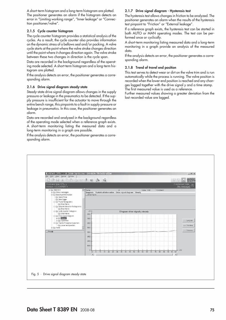
A short-term histogram and a long-term histogram are plotted.The positioner generates an alarm if the histogram detects anerror in “Limiting working range“, “Inner leakage“ or “Connec-tion positioner/valve“.
2.1.5 Cycle counter histogramThe cycle counter histogram provides a statistical analysis of thecycles. As a result, the cycle counter also provides informationon the dynamic stress of a bellows seal and/or packing. A valvecycle starts at the point where the valve stroke changes directionuntil the point where it changes direction again. The valve strokebetween these two changes in direction is the cycle span.Data are recorded in the background regardless of the operat-ing mode selected. A short-term histogram and a long-term his-togram are plotted.If the analysis detects an error, the positioner generates a corre-sponding alarm.
2.1.6 Drive signal diagram steady-stateSteady-state drive signal diagram allows changes in the supplypressure or leakage in the pneumatics to be detected. If the sup-ply pressure is insufficient for the actuator to move through theentire bench range, this pinpoints to a fault in supply pressure orleakage in pneumatics. In this case, the positioner generates analarm.Data are recorded and analyzed in the background regardlessof the operating mode selected when a reference graph exists.A short-term monitoring listing the measured data and along-term monitoring in a graph are possible.If the analysis detects an error, the positioner generates a corre-sponding alarm.
2.1.7 Drive signal diagram - Hysteresis testThe hysteresis test allows changes in friction to be analyzed. Thepositioner generates an alarm when the results of the hysteresistest pinpoint to “Friction” or “External leakage”.If a reference graph exists, the hysteresis test can be started inboth AUTO or MAN operating modes. The test can be per-formed once or cyclically.A short-term monitoring listing measured data and a long-termmonitoring in a graph provide an analysis of the measureddata.If the analysis detects an error, the positioner generates a corre-sponding alarm.
2.1.8 Trend of travel end positionThis test serves to detect wear or dirt on the valve trim and is runautomatically while the process is running. The valve position isrecorded when the lower end position is reached and any chan-ges logged together with the drive signal y and a time stamp.The first measured value is used as a reference.Further measured values showing a greater deviation from thelast recorded value are logged.
Fig. 5 · Drive signal diagram steady-state
Data Sheet T 8389 EN 2008-08 75

2.2 Tests (out-of-service diagnostics)(2.2.1 to 2.2.3)
For reasons of safety, the tests (out-of-service diagnostics) canonly be started when the positioner is in the MAN operatingmode. The control valve moves through its working range aftera test starts. Therefore, it is important to make sure before start-ing a test whether the conditions (in the plant or process) allowthe valve to move.The tests provide a trend showing the current control valve state,any possible existing malfunctions and help to pinpoint faultsand to schedule predictive maintenance work.
2.2.1 Drive signal diagram steady-stateThe drive signal diagram steady-state allows you to check theresults of the steady-state drive signal diagram in Statistical in-formation (in-service monitoring) more closely.After starting the test, the valve moves to various fixed valve po-sitions x distributed over the working range of the valve. Thedrive signal y is measured for each valve position x and com-pared with the reference graph. The statements on the followingfaults can be made:
– Supply pressure– Leakage in the pneumatics– Actuator springs
If the analysis detects an error, the positioner generates a corre-sponding alarm.
2.2.2 Drive signal diagram hysteresisThis test allows you to check the results of the drive signal dia-gram (hysteresis test) in Statistical information (in-service moni-toring) more closely.After starting the test, the valve moves to various fixed valve po-sitions x distributed over the working range of the valve. Aftermoving to the valve position, a ramp movement changing thevalve travel is performed. The change in drive signal y is mea-sured for each valve position x and compared with the refer-ence data.If the analysis of the drive signal detects an error concerning thefriction or external leakage, the positioner generates acorresponding alarm.
2.2.3 Static characteristicThe static performance of the control valve is affected by the fric-tion hysteresis and the elastic processes in the valve stem pack-ing.The positioner specifies the reference variable w in a definedtest range (Start and End) in small steps and records the re-sponse of the valve position x after waiting a defined delaytime.An analysis of the control loop is possible from the recordingand detection of Min. dead band, Max. dead band and Aver-age dead band.
Fig. 6 · Drive signal diagram steady-state
76 Data Sheet T 8389 EN 2008-08

2.3 Partial stroke test (PST)In standard cases of application, a shut-off valve in a safetyloop is fitted with a solenoid valve for emergency shutdown andlimit switches for position feedback. Dedicated shut-off valvestypically remain static for months or years in normal operatingconditions.The use of a positioner with integrated partial stroke testing pro-vides an alternative. The positioner can be mounted on a valveto replace or supplement a solenoid valve.The partial stroke test function prevents the valve from becomingstuck, for example, due to corrosion or material disintegration.Recording the test results additionally allows an analysis of thedynamic control response. For this purpose, the valve is movedfrom a defined start value, e.g. operation point, either as stepresponse or as a ramp function to a defined point and thenmoved back to its original position.As a result, the probability of failure on demand (PFD) can bereduced and it may be possible to extend maintenance inter-vals.
Various cancelation conditions provide additional protectionagainst the valve slamming shut or moving past the end posi-tion:– The test is canceled when the maximum permissible test dura-
tion is exceeded.– x control value: The test is canceled when the value falls be-
low the adjusted valve position.– delta y-monitoring: The test is canceled when the drive signal
y falls below the predetermined comparison value.– The test is canceled as soon as the deviation of the valve posi-
tion exceeds the adjusted PST tolerance band.If a partial stroke test has not been completed, a classified statusalarm is generated directly reporting the partial stroke test at thepositioner display, the engineering tool used and over the faultalarm output*. This allows safety and test functions to bebrought together and partial stroke testing for safety-relatedon/off valves to be performed.
Fig. 7 · Partial stroke test
Data Sheet T 8389 EN 2008-08 77
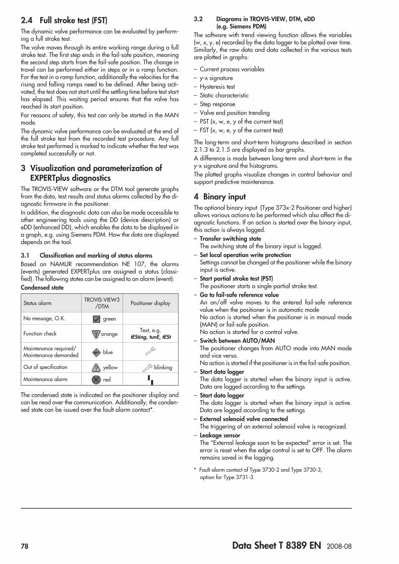
2.4 Full stroke test (FST)The dynamic valve performance can be evaluated by perform-ing a full stroke test.The valve moves through its entire working range during a fullstroke test. The first step ends in the fail-safe position, meaningthe second step starts from the fail-safe position. The change intravel can be performed either in steps or in a ramp function.For the test in a ramp function, additionally the velocities for therising and falling ramps need to be defined. After being acti-vated, the test does not start until the settling time before test starthas elapsed. This waiting period ensures that the valve hasreached its start position.For reasons of safety, this test can only be started in the MANmode.The dynamic valve performance can be evaluated at the end ofthe full stroke test from the recorded test procedure. Any fullstroke test performed is marked to indicate whether the test wascompleted successfully or not.
3 Visualization and parameterization ofEXPERTplus diagnostics
The TROVIS-VIEW software or the DTM tool generate graphsfrom the data, test results and status alarms collected by the di-agnostic firmware in the positioner.In addition, the diagnostic data can also be made accessible toother engineering tools using the DD (device description) oreDD (enhanced DD), which enables the data to be displayed ina graph, e.g. using Siemens PDM. How the data are displayeddepends on the tool.
3.1 Classification and marking of status alarmsBased on NAMUR recommendation NE 107, the alarms(events) generated EXPERTplus are assigned a status (classi-fied). The following states can be assigned to an alarm (event):Condensed state
Status alarm TROVIS-VIEW3/DTM Positioner display
No message, O.K. green
Function check orangeText, e.g.
tESting, tunE, tESt
Maintenance required/Maintenance demanded blue
Out of specification yellow blinking
Maintenance alarm red
The condensed state is indicated on the positioner display andcan be read over the communication. Additionally, the conden-sed state can be issued over the fault alarm contact*.
3.2 Diagrams in TROVIS-VIEW, DTM, eDD(e.g. Siemens PDM)
The software with trend viewing function allows the variables(w, x, y, e) recorded by the data logger to be plotted over time.Similarly, the raw data and data collected in the various testsare plotted in graphs:
– Current process variables– y-x signature– Hysteresis test– Static characteristic– Step response– Valve end position trending– PST (x, w, e, y of the current test)– FST (x, w, e, y of the current test)
The long-term and short-term histograms described in section2.1.3 to 2.1.5 are displayed as bar graphs.A difference is made between long-term and short-term in they-x signature and the histograms.The plotted graphs visualize changes in control behavior andsupport predictive maintenance.
4 Binary inputThe optional binary input (Type 373x-2 Positioner and higher)allows various actions to be performed which also affect the di-agnostic functions. If an action is started over the binary input,this action is always logged.– Transfer switching state
The switching state of the binary input is logged.– Set local operation write protection
Settings cannot be changed at the positioner while the binaryinput is active.
– Start partial stroke test (PST)The positioner starts a single partial stroke test.
– Go to fail-safe reference valueAn on/off valve moves to the entered fail-safe referencevalue when the positioner is in automatic modeNo action is started when the positioner is in manual mode(MAN) or fail-safe position.No action is started for a control valve.
– Switch between AUTO/MANThe positioner changes from AUTO mode into MAN modeand vice versa.No action is started if the positioner is in the fail-safe position.
– Start data loggerThe data logger is started when the binary input is active.Data are logged according to the settings
– Start data loggerThe data logger is started when the binary input is active.Data are logged according to the settings
– External solenoid valve connectedThe triggering of an external solenoid valve is recognized.
– Leakage sensorThe “External leakage soon to be expected” error is set. Theerror is reset when the edge control is set to OFF. The alarmremains saved in the logging.
* Fault alarm contact of Type 3730-2 and Type 3730-3,option for Type 3731-3.
78 Data Sheet T 8389 EN 2008-08

TROVIS-VIEW provides a uniform user interface that allowsusers to configure and parameterize various SAMSON de-vices using device-specific database modules.Data are transmitted between the TROVIS-VIEW software andthe SAMSON device either directly (e.g. using a connectingcable or infrared adapter; also see Table 1) or indirectly usinga memory pen or memory module.
A direct connection enables both online and offline operation.This means that data can be changed in the device immedi-ately, or they can be saved on the PC first and later down-loaded to the device on site.
The device-specific modules contain a database that providesthe characteristic properties of each device type, such as pa-rameters, data points, user levels etc. The various user levelscan be protected with passwords.
The available modules are being extended constantly.
TROVIS-VIEW Software
TROVIS 6661
ApplicationUniform interface for configuration and operation of varioussmart SAMSON devices
Data Sheet T 6661 EN 2009-07 79

Learning to operate TROVIS-VIEW is easy, as it uses the lookand feel of Windows® Explorer. It includes features such as:• Tree structure• List view• Select• Context-sensitive menus by clicking the right mouse button• Open and save
Hardware requirementsA PC with the following minimum requirements is needed:• Pentium II processor or equivalent
(300 MHz or faster), 500 MHz recommended• RS-232 serial interface or USB/RS-232 adapter (USB Con-
verter 3 for TROVIS 5500 Series) and, depending on theSAMSON device used, the suitable hardware as specified inTable 1
• At least 96 MB RAM, 192 MB RAM recommended• At least. 150 MB of available hard disk space. Additionally,
15 to 20 MB of available hard disk space per SAMSONmodule
• SVGA graphics card (at least. 800 x 600)• CD-ROM drive
Software requirements• Operating system: Windows® 2000 (SP2 or higher),
Windows® XP, Windows® Vista• Microsoft® .NET Framework Version 2.0 or higher (included
on installation CD-ROM)• Web browser: Microsoft® Internet Explorer Version 6 or
higher
Scope of deliveryThe TROVIS-VIEW software and the device-specific modulesare delivered on a CD-ROM together with the associated on-line documentation.
Software updates can be downloaded from the “Support &Downloads” section of our website at http://www.samson.de.
Accessories (Figs. 1 to 3)• USB 1.1 serial adapter Order no. 8812-2001• USB Converter3 Order no. 1400-9377• Hardware package (memory pen, modular adapter,
connecting cable) Order no. 1400-7704• Memory pen Order no. 1400-7697• Memory pen – 64 Order no. 1400-9753• Memory module Order no. 1400-9379• Connecting cable RJ-12/D-Sub, 9-pole Order no. 1400-7699• Infrared adapter Order no. 8864-0900• Fixture for infrared adapter Order no. 1400-9769• USB cable (mini-B, USB type A) Order no. 8801-7301• Serial interface adapter Order no. 1400-7700• Isolated USB interface adapter Order no. 1400-9740• FSK modem– RS-232 EEx ia Order no. 8812-0129– RS-232 (not explosion protected) Order no. 8812-0130– PCMCIA (not explosion protected) Order no. 8812-0131– USB (not explosion protected) Order no. 8812-0132• USB dongle for EXPERT+ diagnostics Order no. 1400-9555
Ordering text
TROVIS-VIEW 6661-1���TROVIS 5431 Heating Controller 0 0 1TROVIS 5432 Heating Controller 0 0 2TROVIS 5433 Heating Controller 0 0 3TROVIS 5573 Heating Controller 0 1 4TROVIS 5575 Heating Controller 0 1 1TROVIS 5576 Heating Controller 0 1 2TROVIS 5579 Heating Controller 0 1 3TROVIS 6493 Compact Controller 0 3 1TROVIS 6495-2 Industrial Controller 0 3 3Type 3730-2 Positioner 0 5 1Type 3730-3 Positioner 0 5 6Type 3730-4 Positioner 0 5 7Type 3730-5 Positioner 0 5 8Type 3731-3 Positioner 0 6 3Type 3731-5 Positioner 0 6 5Type 3780 Positioner 0 5 2Type 3785 Positioner 0 5 3Type 3787 Positioner 0 5 4Type 3738-20 Electronic Limit Switch 0 6 8Type 3374 Electric Actuator with Positioner 0 5 5Type 5824 or 5825 Electric Actuatorwith Positioner
0 5 9
Type 5857 Electric Actuator with Positioner 0 6 1Type 5724 or 5725 Controller withElectric Actuator
0 6 0
Type 5725-7 Controller with Electric Actuator 0 6 7Type 5757 Controller with Electric Actuator 0 6 2Type 5757-7 Controller with Electric Actuator 0 6 6Media 6 (Type 5006) Differential Pressure Meter 0 8 1
USB 1.1 serial adapter (8812-2001)
USB RS-232
USB Converter 3 (1400-9377)
Memory pen (1400-7697) Memory pen – 64(1400-9753)
Fig. 1 · Accessories
80 Data Sheet T 6661 EN 2009-07

1 RJ-12 connector on SAMSON device4 COM port (RS-232) on PC*5 USB port on PC*6 Connecting cable7a Memory pen8 Modular adapter9 Memory module (TROVIS 5500 Series)
* Under Windows® 2000 and Windows® XP, the connectioncan be made either using the computer's COM port, theUSB 1.1 serial adapter or USB Converter 3 (Fig. 1).
84
7a
6
1
4
5
6
9 9
Fig. 2 · Data transmission examples
Type 5757Type 5757-7Type 5857
Media 6(Type 5006)
Type 3374
TROVIS 5433
TROVIS 5431
TROVIS 5575TROVIS 5576TROVIS 5579
Type 5724Type 5725Type 5725-7Type 5824Type 5825 TROVIS 5573
Data Sheet T 6661 EN 2009-07 81
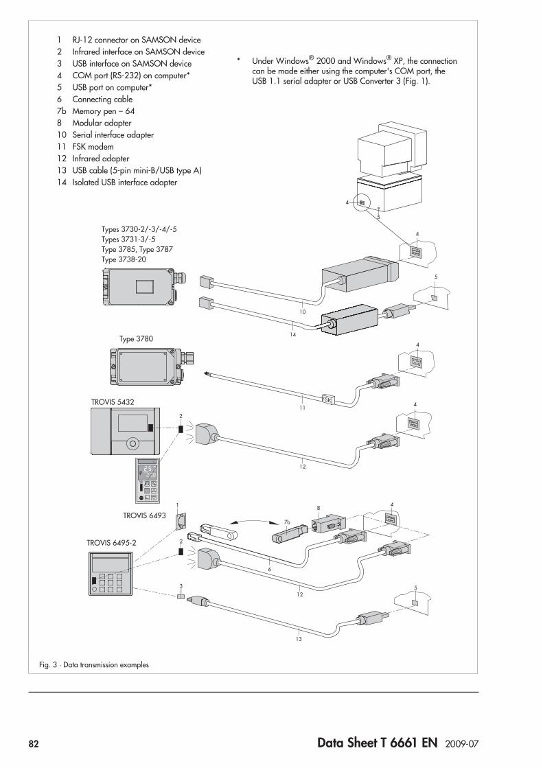
* Under Windows® 2000 and Windows® XP, the connectioncan be made either using the computer's COM port, theUSB 1.1 serial adapter or USB Converter 3 (Fig. 1).
1
2
2
3
FSK
84
7b
6
5
13
5
4
4
4
4
10
11
12
12
14
5
Fig. 3 · Data transmission examples
TROVIS 6495-2
TROVIS 5432
Type 3780
Types 3730-2/-3/-4/-5Types 3731-3/-5Type 3785, Type 3787Type 3738-20
TROVIS 6493
1 RJ-12 connector on SAMSON device2 Infrared interface on SAMSON device3 USB interface on SAMSON device4 COM port (RS-232) on computer*5 USB port on computer*6 Connecting cable7b Memory pen – 648 Modular adapter10 Serial interface adapter11 FSK modem12 Infrared adapter13 USB cable (5-pin mini-B/USB type A)14 Isolated USB interface adapter
82 Data Sheet T 6661 EN 2009-07

Table 1 · Data transmission
Data transmission
Direct Indirect
Con
nect
ing
cabl
e
FSK
mod
em
Seria
lint
erfa
cead
apte
r
Infra
red
adap
ter
Isola
ted
USB
inte
rface
adap
ter
USB
Con
verte
r3
USB
cabl
e
Mem
ory
pen
Mem
ory
pen
–64
Mem
ory
mod
ule
Mod
ular
adap
ter
SAMSON devices Version (or higher)
Heating controllers
TROVIS 5431 1.00 • • • •
TROVIS 5432 1.00 •
TROVIS 5433 1.00 • • • •
TROVIS 5573 1.80 • •
TROVIS 5575 1.13 •* •
TROVIS 5576 1.00 •* •
TROVIS 5579 1.20 •* •
Compact controller
TROVIS 6493 2.03 or 3.03 •
TROVIS 6495-2 Industrial Controller
Without interface board
1.00
•
With interface board RS-232/USB • • • • •
With interface board RS-485/USB • •
Electropneumatic positioners
Type 3730-2 1.10 • •
Type 3730-3 with HART® communication 1.10 • •
Type 3730-4 with PROFIBUS-PA communication R 1.43, K 1.00 • •
Type 3730-5 with FOUNDATION™ fieldbus communication R 1.40, K 1.20 • •
Electropneumatic Ex d positioners
Type 3731-3 with HART® communication 1.30 • •
Type 3731-5 with FOUNDATION™ fieldbus communication R 1.45, K 1.00 • •
Positioners
Type 3780 with HART® communication K 2.11 •
Type 3785 with PROFIBUS-PA communicationPA device profile version 2.0PA device profile version 3.0
K 1.60 – K 1.99K 2.00 • •
Type 3787 with FOUNDATION™ fieldbus communication K 1.10 • •
Type 3738-20 Electronic Limit Switch 1.00 • •
Electric actuators with positioners
Type 3374 1.00 • • • •
Types 5824/5825 1.00 • • • •
Type 5857 1.00 • • • •
Controllers with electric actuators
Type 5757, Types 5724/5725 1.00 • • • •
Type 5757-7, Type 5725-7 1.00 • • • •
Digital transmitter
Media 6 (Type 5006) 2.00 • • • •
* Version 1.41 or higher for TROVIS 5575, 5576, 5579
Data Sheet T 6661 EN 2009-07 83


ApplicationSingle-acting or double-acting positioners for attachment topneumatic control valves. Supplied with a pneumatic inputsignal 0.2 to 1 bar or 3 to 15 psi (Type 3766) or an electricinput signal from 4(0) to 20 mA or 1 to 5 mA (Type 3767).Rated travels from 7.5 to 120 mm or opening angle up to 90°
The positioners ensure a fixed assignment between the valve stemposition (controlled variable x) and the pneumatic or electric in-put signal (reference variable w). They compare the input signalreceived from the control unit with the travel of the control valveand, issue the corresponding output signal pressure pst (outputvariable y). A reversing amplifier for double-acting actuatorsproduces two opposed signal pressures.
Special features• Arbitrary mounting position; suitable for normal or
split-range operation; excellent dynamic response; negligiblysmall influence of supply air; adjustable proportional band(P-band); adjustable air output capacity; low air supply con-sumption; very insensitive to mechanical vibrations;low-maintenance compact design
• Versions for hazardous areas in type of protection "IntrinsicSafety" II 2 G EEx ia IIC T6 or II 3 G EEx nA II T6 forZone 2 (see "Summary of approvals")
• Type of protection "Flameproof Enclosure" EEx d withType 3766 Positioner and Type 6116 i/p Converter (Fig. 2)
• Special version with CrNiMo steel housing available• Direct attachment to Type 3277 Pneumatic Actuator (Fig. 4)• Attachment to actuators according to IEC 60534-6 (Fig. 3)• Attachment to rotary actuators acc. to VDI/VDE 3845 (Fig. 5)
Benefits of integral positioner attachment (Fig. 4)• Tight and exact mechanical connection between actuator and
positioner. No misalignment during shipping• Concealed linkage protected against touch and external in-
fluences to fulfill requirements of accident prevention regula-tions UVV (VBG 5)
• Simple pneumatic connection between actuator and positioner• Presetting of the unit: Actuator with positionerOptional pressure gauge for monitoring the input and outputsignal pressure (dial range from 0 to 6 bar and 0 to 90 psi).Refer to Information Sheet T 8350 EN for details on the selectionand application of positioners, converters, limit switches andsolenoid valves.
Versions– Type 3766 · Pneumatic positioner– Type 3767 · Electropneumatic positionerRefer to article code for details on possible configurations.
Pneumatic Positioner Type 3766
Electropneumatic Positioner Type 3767
Fig. 1 · Type 3767 Electropneumatic Positioner
Fig. 5 · Attachment toType 3278 Rotary Actuator
Fig. 4 · Direct attachment toType 3241-7 ControlValve
Fig. 3 · Attachment acc. toIEC 60534(NAMUR)
Fig. 2 · Type 3766 Ex d Positioner withType 6116 i/p Converter
JIS
Data Sheet T 8355 EN 2010-01 85

Principle of operation (Figs. 6 to 8)The only difference between the two positioners is an i/p con-verter unit (E) in the electropneumatic positioner. Bothpositioners function according to the force-balance principle.In the Type 3767 Electropneumatic Positioner, the control signal(i) flows through the plunger coil (E2) in the field of a permanentmagnet (E1). The force, proportional to the DC current i, is bal-anced against the force of the backpressure at the balancebeam (E3) which is created at the flapper plate (E7) by the jetstream leaving the nozzle (E6). Any changes in the signal causea proportional change in the pressure pe supplied to the pneu-matic control system.The pressure pe creates a force at the measuring diaphragm (5)which is compared to the force of the range spring (4). If thecontrol signal causes the pneumatic input pressure (pe) or theposition of the lever (1) to change, the diaphragm lever (3) func-tioning as a flapper plate varies the distance to the nozzle (2.1or 2.2). The position of the internal turnboard for the operatingdirection (7) determines which nozzle is effective.The pneumatic booster (10) and the pressure regulator (9) areprovided with supply air. The controlled supply flows againstthe diaphragm lever (3) over the Xp restriction (8) and the noz-zle (2.1 or 2.2). Any changes in the control signal or the posi-tion of the lever (1) cause a variation of pressure both upstreamand downstream of the booster (10). The output signal pressurepst issued by the booster flows over the volume restriction (11) tothe actuator and positions the valve to match the input signal.The travel is transmitted to the pick-up lever (1) via the pin (1.1)in globe valves. Whereas, in rotary valves (Fig. 8), a camfollower roll (20) is attached to the front end of the pick-up lever(1) which follows the rotary motion of a cam disk (22) on the ac-tuator shaft (21). The force of the range spring (4) is changed bythe linear motion of pick-up lever.The positioner must be fitted with a reversing amplifier for at-tachment to double-acting actuators, which generates two op-posed signal pressures (pst1 and pst2).The adjustable restrictions Xp (8) and Q (11) are used to opti-mize the control loop. Two adjusting screws (6.1 and 6.2) allowthe adaptation of the control valve to the signal pressure. ZEROand SPAN of the reference variable can be adjusted fordifferent operating modes, such as split-range operation.Operating direction: As the reference variable (pe) increases,the output signal pressure (pst) can either be increasing (direct>>) or decreasing (reverse <>). The operating direction is deter-mined by the position of the turnboard (7) and can be changedsubsequently.
2.1
4
2.2
3
5
1.2
6.1
6.2
1
PemAE10
E3E7E6E9E4E5E2E1 E
E8
1.1
V
Q
Xp
7 8 9 10 11 12
ep
Fig. 7 · Functional diagram of Type 3767 Positioner
2.1
4
2.2
3
5
1.2
6.1
6.2
1 1.1
V
Q
Xp
7 8 9 10 11 12
ep
Fig. 6 · Functional diagram of Type 3766 Positioner(deflection of pick-up lever in case of directattachment to Type 3277 Pneumatic Actuator)
Travel
Operating direction
Control signal peSupply air
Output signalpressure pst
Fig. 8 · Transmission of rotary motion to the positioner
Legend for Figs. 6 to 81 Lever E i/p converter unit1.1 Pin E1 Permanent magnet1.2 Rotary shaft E2 Plunger coil2.1 Nozzle (>>) E3 Balance beam2.2 Nozzle (<>) E4 Universal joint3 Diaphragm lever (flapper) E5 Spring4 Range spring E6 Nozzle5 Measuring diaphragm E7 Flapper plate6.1 Adusting screw (SPAN) E8 Restriction6.2 Adusting screw (ZERO) E9 Damping7 Turnboard for op. direction E10 Protective diode8 Xp restriction (gain)9 Pressure regulator10 Booster 20 Cam follower roll11 Volume restriction Q 21 Actuator shaft12 Solenoid valve (optional) 22 Cam disk
Travel
Press. reg. Control signal peSupply air
Output signalpressure pst
Operating direction
86 Data Sheet T 8355 EN 2010-01

Table 1 · Technical data · All pressures in bar (gauge)
Type 3766 and Type 3767 Positioners
Travel rangeDirect attachment to Type 3277 Actuator: 7.5 ... 30 mmAttachment acc. to IEC 60534 (NAMUR): 7.5 ... 120 mm
Opening angle 70°, 75° or 90° depending on cam diskReference variablewType 3766
Signal range bar (psi) 0.2 ... 1 bar (3 ... 15 psi)Span bar (psi) 0.4 ... 0.8 bar (6 ... 12 psi)Overloadabe max. 2 bar (29 psi)
Reference variablewType 3767
Signal range Two-wire device, reverse polarity protection4(0) ... 20 mA 1 ... 5 mA
Span 8 ... 20 mA 2 ... 4 mAInternal resistance Ri at 20 °C 200 Ω 880 Ω
Supply air Supply air range 1.4 ... 6 bar (20 ... 90 psi)Air quality acc. toISO 8573-1 (2001-02)
Maximum particle size and density: Class 4 · Oil contents: Class 3; Pressure dew point:Class 3 or at least 10 K below the lowest ambient temperature to be expected
Output signal pressure pst Can be limited between 0 ... approx. 2.5 and 0 ... 6 bar (0 ... approx. 35 and 0 ... 90 psi)
Characteristic LinearDeviation from terminal-based conformity: ≤ 1 %
Hysteresis ≤ 0.3 %Sensitivity ≤ 0.1 %Operating direction ReversibleProportional band Xp 0.5 ... 2.5 % (proportional-action coefficient Kp: > 200 ... 40)Air consumption With air supply of 1.4 bar With air supply of 6 bar
Type 3766 ≤ 230 In/h ≤ 230 In/h 1)
Type 3767 ≤ 280 In/h ≤ 280 In/h 1)
Air delivery Actuator filled with air 3.0 mn3/h 8.5 mn3/hActuator vented 4.5 mn3/h 14.0 mn3/h
Permissibleambienttemperature 7)
Type 3766 Standard –20...80 °C: Optional limit switches/solenoid valve/position transmitterwith plastic cable gland
–40...80 °C: Optional limit switches/solenoid valve with metal cable glandLow temperature version –50...80 °C: Optional limit switches/solenoid valve with metal cable glandType 3767 Standard –20...80 °C: Optional limit switches/solenoid valve/position transmitter
with plastic cable gland–40...80 °C: Optional limit switches/solenoid valve with metal cable gland
Low temperature version –45...80 °C: Optional limit switches/solenoid valve with metal cable glandInfluence Temperature: ≤ 0.3 %/10 K · Supply air: ≤ 1 % between 1.4 ... 6 barElectromagnetic compatability Requirements specified in EN 61000-6-2 and EN 61000-6-3 are metVibrations No influence between 10 und 150 Hz and 4 gExplosion protection 2) Type of protection II 2 G EEx ia IIC T6 or II 3 G EEx nA II T6 for Zone 2Degree of protection IP 54 (special version IP 65)Weight Approx. 1 kgAdditional equipmentLimit switches2 inductive proximity switches Type SJ 2-SNControl circuit Specifications corresponding to the connected transistor relayHysteresis at rated travel ≤ 1 %Solenoid valveInput Binary DC voltage signalNominal signal 6 V DC 12 V DC 24 V DCSignal “0” (off) 3) ≤ 1.2 V ≤ 2.4 V ≤ 4.7 VSignal “1” (on) 4) ≥ 5.4 V ≥ 9.6 V ≥ 18.0 VMaximum permissible signal 28 V 25 V 32 VInternal resistance Ri at 20 °C 2909 Ω 5832 Ω 11714 ΩAir consumption in steady state In addition to the positioner “Off” ≤ 60 ln/h · “On” ≤ 10 ln/h 1)
Closing time forrated travel andsignal pressurerange (KVS 0.14)
Type 3277 Actuator 120 cm² 240 cm² 350 cm² 700 cm²0.2 ... 1 bar ≤ 0.5 s ≤ 0.8 s ≤ 1.1 s ≤ 4 s0.4 ... 2 bar ≤ 0.5 s ≤ 2 s ≤ 2.5 s ≤ 8 s0.6 ... 3 bar 6) ≤ 1 s ≤ 1.5 s ≤ 5 s
Analog position transmitterOutput Two-wire device 4 ... 20 mAAuxiliary power Minimum terminal voltage: 12 V
maximum: 45 V
The position transmitter may only beconnected to a certified intrinsically safe
circuit 5)
1) With pressure regulator at minimum setting 2) Refer to Table 2 for explosion-protected version3) DC voltage signal at –25 °C 4) DC voltage signal at +80 °C5) e.g. over SAMSOMATIC 994-0103-KFD2-STC4-Ex1 Loop Isolator 6) Actuator 120 cm² for all signal pressure ranges: ≤ 0.5 s7) The limits specified in the EC Type Examination Certificate additionally apply to explosion-protected devices.
Data Sheet T 8355 EN 2010-01 87

Additional equipmentThe positioners can optionally be equipped with the followingadditional equipment.
Positioner with inductive proximity switches (Fig. 9)This positioner version has a rotary shaft (1.2) with two adjust-able metal tags (33) for inductively actuating the proximityswitches (34). The switches are continuously adjustable and canbe overridden.To operate them, corresponding transistor relays must be con-nected in the output circuit.The proximity switches can also be retrofitted.
Positioner with solenoid valve (Fig. 10)The positioners can be fitted with an intrinsically safe, pi-lot-operated solenoid valve also in combination with the induc-tive limit switches. When the positioner is equipped with this so-lenoid valve, the control valve can be moved to the fail-safe po-sition regardless of the positioner's output signal.The solenoid valve essentially consists of an electropneumaticconverter (12.1) and a 3/2-way solenoid valve (12.2). If a con-trol signal corresponding to the binary signal 0 (off) is appliedto the input, the nozzle (12.3) of the electropneumatic converteris opened, the signal pressure pst is blocked and air is ventedout of the actuator. The force of the compression springs in theactuator move the control valve to its fail-safe position.If a control signal corresponding to binary signal 1 (on) is ap-plied to the input, the relay coil (12.4) is energized, and theflapper plate (12.5) closes the nozzle (12.3). The increasingcascade pressure switches over the 3/2-way valve (12.2). Inthis switching position, the output signal pressure pst is appliedto the actuator. The control valve is in control operation.The solenoid valve can also be retrofitted.
Legend to Figs. 9 and 10
1.2 Rotary shaft 12.5 Flapper plate
12 Solenoid valve 12.6 Restriction
12.1 i/p converter
12.2 3/2-way valve 32 Adjusting screw
12.3 Nozzle 33 Metal tag
12.4 Relay coil 34 Proximity switch
Table 2 · Technical data for Type of Protection EEx ia IIC
i/p converter (Type 3767 only)Maximum values for For connection to certified intrinsically
safe circuitsU0 28 V 25 VI0 85 mA 100 mA 120 mAP 0.7 W 0.7 W 0.7 WInternal inductance and capacitance are negligibly small
Inductive proximity switchesMaximum values for For connection to certified intrinsically
safe circuitsU0 16 VI0 52 mA/25 mAP 169 mW/64 mWInternal inductance Li = 100 μHInternal capacitance Ci = 30 nF
Solenoid valveNominal signal 6 V 12 V 24 VMaximum values for For connection to certified intrinsically
safe circuitsU0 (V) 25 27 28 30 32I0 (mA) 150 125 115 100 90Internal inductance and capacitance are negligibly small
Analog position transmitterMaximum values for For connection to certified intrinsically
safe circuitsU0 28 VI0 115 mAP 1 WCi 5.3 nFInternal inductance negligibly small
Permissible ambient temperaturesSpecifications as stated in the EC Type Examination CertificatePTB 01 ATEX 2167 and the Statement of Conformity PTB 01 ATEX2170 X.
Fig. 9 · Inductive proximity switches
12.5
12.3
12.1
12.4+
–u[V]
12.6
12.2
Fig. 10 · Functional diagram of the solenoid valve
32 1.2 33 34
34
32
1.2
Switch B Switch AMetal tag for switch B
Metal tag forswitch A
Input
Auxiliary power
Venting intopositioner housing
Signal pressure toactuator
Signal pressure frompositioner
88 Data Sheet T 8355 EN 2010-01

Positioner with analog position transmitterDue to the amount of space that the position transmitter re-quires, please note that this option cannot be combined withlimit switches or a solenoid valve!The position transmitter allows the position of the closure mem-ber of the valve (i.e., valve travel or opening angle) to be con-verted into a proportional output signal from 4 to 20 mA. Limitpositions such as “Valve open” or “Valve closed” are indicatedas well as all intermediate positions.
Attachment (Figs. 12 and 13)The positioner can be attached to linear actuators either directly(Type 3277 Pneumatic Actuator) or according to IEC 60534(NAMUR) (Type 3271 Pneumatic Actuator). Rotary actuatorswith an interface according to VDI/VDE 3845 require an inter-mediate piece to mount the positioner.
Arrangement of the positioner and the actuator (Fig. 11)How the positioner and actuator can be arranged depends onthe operating direction of the input signal (pe) and the outputsignal pressure (pst) as well as the fail-safe action of the actua-tor:“Actuator stem extends”“Actuator stem retracts”
Direct attachment to Type 3277 Pneumatic Actuator (Fig. 4)This method of attachment provides the benefit of being aself-contained, preset actuator and positioner unit. A connec-tion block is required for direct attachment to actuators with240, 350 and 700 cm² effective diaphragm areas (Fig. 11).With an actuator with fail-safe action “Actuator stem extends”,the output signal pressure pst issued by the positioner is routedto the bottom diaphragm case over the connection block and ahole in the actuator yoke. In case the spring chamber needs befilled with the exhaust air from the positioner, the air can beconnected to the connection block using a ready-made pipe.With an actuator with fail-safe action “Actuator stem retracts”the output signal pressure pst issued by the positioner isconnected to the top diaphragm case over a ready-made pipe.The bottom diaphragm chamber (spring chamber) can be filledwith the exhaust air from the positioner without additional mea-sures over an internal hole.The signal pressure connection is located at the back of thepositioner for Type 3277-5 Pneumatic Actuator (120 cm² dia-phragm area), therefore eliminating the need for external pip-ing.
Fig. 11.3 · Operating direction <> Left attachment Fig. 11.4 · Operating direction >> Right attachment
Fig. 11 · Direct attachment to Type 3277 Actuator
Fig. 11.1 · Operating direction >> Left attachment Fig. 11.2 · Operating direction<> Right attachment
Fail-safe action: Actuator stem retracts
Fail-safe action: Actuator stem extends
Table 3 · Direct attachment: Assignment of travel and rangespring
Actuator size in cm² Travel in mm Range spring
120/240/350 7.5 2
120/240/350 15 1
700 15 2
700 30 1
The positioner is delivered with range spring 1. Range spring 2is included in the accessories.
Signal pressurepiping pst
Connection block
Connection block
Internal signalpressure connection
Data Sheet T 8355 EN 2010-01 89

Attachment according to IEC 60534 (Figs. 3 and 12)The positioners can be attached to actuators with cast yokes(Fig. 3) (e.g. Series 240, 250 and 280) and valves withrod-type yokes (Fig. 12) using an adapter (15). A clampingplate (15.1) is additionally required for valves with rod-typeyokes.By selecting the appropriate lever (1) and link point on the lever(16), the positioners can be matched to different travels rangingfrom 7.5 to 120 mm.There is no prescribed mounting position for the positioner. Theoperating direction is determined by how the positioner and theadapter are arranged and how the internal turnboard is posi-tioned.Select the range spring according to Table 4.
Attachment to rotary actuators (Fig. 13)The positioners can be attached to the Type 3278 Rotary Actua-tor or any rotary actuators with an interface according toVDI/VDE 3845 over an intermediate piece (2). The rotary mo-tion of the actuator is converted into a linear motion required bythe positioner by the cam disk (7). A cam follower roll (3) is at-tached to the lever (5) of the positioner to trace the motion of thecam disk. Various cams disks are available depending on thecontrol valve characteristic required (e.g. linear or equal per-centage).Double-acting, springless actuators require additionally apneumatic reversing amplifier which produces two opposedsignal pressures.
Select the range spring as follows:Reference variable for split-range operation: Range spring 1Reference variable for normal signal range: Range spring 2The positioner is always delivered with range spring 1; rangespring 2 is included in the mounting kit for rotary actuators.
Table 4 · Assignment of travel and range springfor attachment according to IEC 60534
Travel mm Range spring
7.5 ≤ 15 2
> 15 ≤ 60 1
22 ≤ 120 1
The positioner is delivered with range spring 1. Range spring 2is included in the accessories.
Fig. 13 · Attachment to rotary actuators
Fig. 12 · Attachment to valves with rod-type yoke
9
1
25
3
4
11
10
8 67
1
16
15 15.1
Legend for Fig. 13
1 Positioner 8 Actuator shaft
2 Intermediate piece 9 Plate
3 Lever with cam follower roll 10 Mounting bracket
4 Adapter 11 Coupling
5 Feedback lever 15 Adapter
6 Scale 15.1 Plate
7 Cam disk 16 Slide
For SAMSON Type 3278
Acc. to VDI/VDE 3845
90 Data Sheet T 8355 EN 2010-01

+ –
+ – A
+51 –52 +81 –82 +31 –32
(B)A
(A)B
+41 –42
GEi
+11 –12 +41 –42 +51 –52 +81 –82
AEi
+11 –12 +31 –32
AEi G
Ei
+ – Us
+ –
(B)A
(A)B
+ –
Input
Switching amplifieracc. to EN 60947-5-6
Output Aux. power
Fig. 14.1 · Type 3766Marking(A), (B) on rear
UsPower supply unit
Control signal i [mA]Switching amplifier
acc. to EN 60947-5-6
Solenoid valve
Output Aux. power
Control signal i [mA] Power supply unit for optionalposition transmitter
Fig. 14.2 · Type 3767
Materials
Housing
Special version
Die-cast aluminumchromated and plastic coatedCrNiMo steel, 1.4404 (316 L)
External parts Stainless steel 1.45711.4305
Measuring diaphragm Fluorosilicone rubber
Electrical connections
Dimensions in mm
36
N1 = 113N2 = 200
5856
68185
29
164
76
150
50
Attachment acc. toIEC 60534and NAMUR
44
19.5
393568
185
164
29
50
46 7650
150
82
56 66
28.5
28.5
Output 1(A1)
Output 2(A2)
Supply (Z)Attachment to rotary actuators(with pneum. reversing amplifier)
Fulc
rum
28
1429
150
164
19.5
37
68185
76
Supply(9)Output(36)
M20x1.5
Direct attachment toType 3277 Actuator
Data Sheet T 8355 EN 2010-01 91
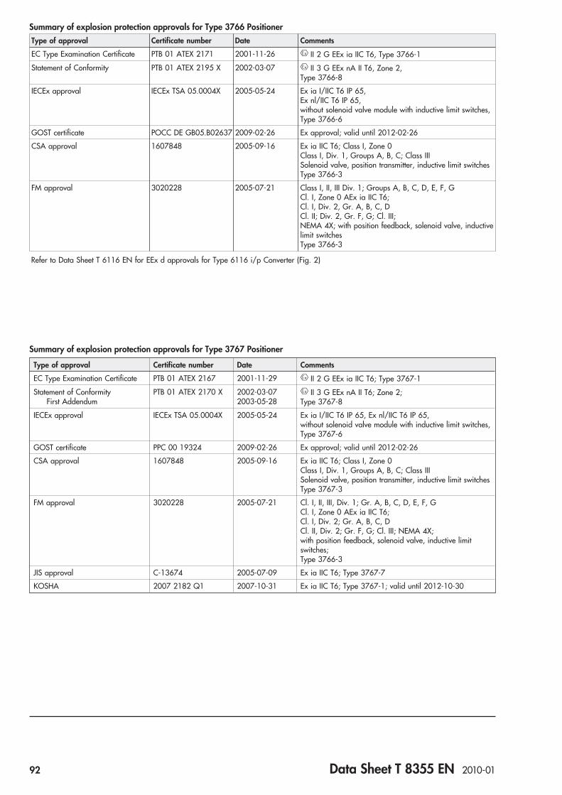
Summary of explosion protection approvals for Type 3766 PositionerType of approval Certificate number Date Comments
EC Type Examination Certificate PTB 01 ATEX 2171 2001-11-26 II 2 G EEx ia IIC T6, Type 3766-1
Statement of Conformity PTB 01 ATEX 2195 X 2002-03-07 II 3 G EEx nA II T6, Zone 2,Type 3766-8
IECEx approval IECEx TSA 05.0004X 2005-05-24 Ex ia I/IIC T6 IP 65,Ex nl/IIC T6 IP 65,without solenoid valve module with inductive limit switches,Type 3766-6
GOST certificate POCC DE GB05.B02637 2009-02-26 Ex approval; valid until 2012-02-26
CSA approval 1607848 2005-09-16 Ex ia IIC T6; Class I, Zone 0Class I, Div. 1, Groups A, B, C; Class IIISolenoid valve, position transmitter, inductive limit switchesType 3766-3
FM approval 3020228 2005-07-21 Class I, II, III Div. 1; Groups A, B, C, D, E, F, GCl. I, Zone 0 AEx ia IIC T6;Cl. I, Div. 2, Gr. A, B, C, DCl. II; Div. 2, Gr. F, G; Cl. III;NEMA 4X; with position feedback, solenoid valve, inductivelimit switchesType 3766-3
Refer to Data Sheet T 6116 EN for EEx d approvals for Type 6116 i/p Converter (Fig. 2)
Summary of explosion protection approvals for Type 3767 Positioner
Type of approval Certificate number Date Comments
EC Type Examination Certificate PTB 01 ATEX 2167 2001-11-29 II 2 G EEx ia IIC T6; Type 3767-1
Statement of ConformityFirst Addendum
PTB 01 ATEX 2170 X 2002-03-072003-05-28
II 3 G EEx nA II T6; Zone 2;Type 3767-8
IECEx approval IECEx TSA 05.0004X 2005-05-24 Ex ia I/IIC T6 IP 65, Ex nl/IIC T6 IP 65,without solenoid valve module with inductive limit switches,Type 3767-6
GOST certificate PPC 00 19324 2009-02-26 Ex approval; valid until 2012-02-26
CSA approval 1607848 2005-09-16 Ex ia IIC T6; Class I, Zone 0Class I, Div. 1, Groups A, B, C; Class IIISolenoid valve, position transmitter, inductive limit switchesType 3767-3
FM approval 3020228 2005-07-21 Cl. I, II, III, Div. 1; Gr. A, B, C, D, E, F, GCl. I, Zone 0 AEx ia IIC T6;Cl. I, Div. 2; Gr. A, B, C, DCl. II, Div. 2; Gr. F, G; Cl. III; NEMA 4X;with position feedback, solenoid valve, inductive limitswitches;Type 3766-3
JIS approval C-13674 2005-07-09 Ex ia IIC T6; Type 3767-7
KOSHA 2007 2182 Q1 2007-10-31 Ex ia IIC T6; Type 3767-1; valid until 2012-10-30
92 Data Sheet T 8355 EN 2010-01

Article code
Pneumatic Positioner Type 3766- x x x 0 1 x x x x 1 x 0 x 0
Explosion protection
Without 0 2
II 2 G EEx ia IIC T6 acc. to ATEX 1
FM/CSA intrinsically safe / non incendive 3
Ex ia / Ex n I/IIC T6 IP 65 IECEx TSA Australia 6
II 3 G EEx nA II T6 acc. to ATEX 8
Additional equipment
Without 0
Limit switch, inductive, 2x SJ2 SN 2
Analog position transmitter 4 to 20 mA 6 0 0
3/2-way solenoid valve
Without 0
6 V DC 2
12 V DC 3
24 V DC 4
Pneumatic connections
¼-18 NPT 1
ISO 228/1 - G ¼ 2
Electrical connections
Without (without additional equipment, without solenoid valve) 0 0 0 0
Cable gland
M20 x 1.5, blue (plastic) 1 0 0
M20 x 1.5, black (plastic) 2 0 0
M20 x 1.5 (nickel-plated brass) 2 1 3
Housing version
Die-cast aluminum 0
Stainless steel (CrNiMo) 2
Temperature range
Standard 0
Low temperature
Tmin ≥ –50 °C; optional limit switches, solenoid valve 2 1 3
Special version
None 0 0 0
GOST approval 1 0 1 0
Device functioning only as analog position transmitter: 3766-x60 000xxx00 000 0
Data Sheet T 8355 EN 2010-01 93

Article code
Electropneumatic Positioner Type 3767- x x x 0 1 x x x x x x 0 x 0
Explosion protection
Without 0 2
II 2 G EEx ia IIC T6 acc. to ATEX 1
FM/CSA intrinsically safe/non incendive 3
II 3 G EEx nA II T6 acc. to ATEX 8
Additional equipment
Without 0
Limit switch, inductive, 2x SJ2 SN 2
Analog position transmitter 4 to 20 mA 6 0
3/2-way solenoid valve
Without 0
6 V DC 2
12 V DC 3
24 V DC 4
Type of mounting
Standard range spring 0 1
Pneumatic connections
¼-18 NPT 1
ISO 228/1 - G ¼ 2
Electrical connections
Cable gland
M20 x 1.5, blue (plastic) 1 0
M20 x 1.5, black (plastic) 2 0
M20 x 1.5 (nickel-plated brass) 2 1
Housing version
Die-cast aluminum 1
Stainless steel (CrNiMo) 2
Reference variable
4 … 20 mA 1
0 … 20 mA 2
1 … 5 mA 3
Temperature range
Standard 0
Low temperature
Tmin ≥ –45 °C; optional limit switches, solenoid valve 2 1 2
Special version
None 0 0 0
GOST approval 1 0 1 0
94 Data Sheet T 8355 EN 2010-01

Ordering textPneumatic Positioner Type 3766orElectropneumatic Positioner Type 3767
Accessories– Adapter NPT for electrical connections– Range spring 2
Additional specifications– Without/with pressure gauge for output signal pressure and
supply airFor mounting to the control valve:– Reference variable presetOperating direction: Increasing/increasing orincreasing/decreasing– Positioner with inductive limit switches:Metal tag outside the pick-up field – Contact closed/Metal tag inside the pick-up field – Contact open– Direct attachment to Type 3277 Actuator (120 to 700 cm²)– Attachment acc. to IEC 60534-6 (NAMUR)Travel: ... mm, if applicable, rod diameter: ... mm– Attachment to Type 3278 Rotary Actuator (160 or 320 cm²)– Attachment to rotary actuators acc. to VDI/VDE 3845,
single-acting or double-acting– Linear or equal percentage valve characteristic– Opening angle 70°/75°/90°
Refer to the Mounting and Operating InstructionsEB 8355-1 EN (for Type 3766) or EB 8355-2 EN (forType 3767) concerning the mounting parts required when thepositioner is delivered unattached to a control valve.
Specifications subject to change without notice
Data Sheet T 8355 EN 2010-01 95


Electropneumatic Positioner Type 4763
Pneumatic Positioner Type 4765
ApplicationSingle-acting positioner for attachment to pneumatic controlvalves. Supplied with either an electric input signal from 4(0) to20 mA or 1 to 5 mA (Type 4763) or a pneumatic input signalfrom 0.2 to 1 bar (3 to 15 psi) (Type 4765).Rated travels from 7.5 to 90 mm
The positioners ensure a predetermined assignment of the valvestem position (controlled variable x) to the electric or pneumaticinput signals (reference variable w). They compare the inputsignal issued by the controller with the travel of the control valveand issue the corresponding output signal pressure pst (outputvariable y).
Special features• Compact, low-maintenance design• Any mounting position possible• Insusceptible to mechanical vibrations• Reversible operating direction• Excellent dynamic behavior• Suitable for normal or split-range operation• Adjustable proportional band (P-band)• Adjustable air output capacity• Low air consumption• Special versions for oxygen serviceAttachment to valves with cast yokes or rod-type yokes accord-ing to IEC 60534-6.Optionally available with two pressure gauges to monitor sup-ply air and signal pressure. Stainless steel pressure gaugehousing with connections either nickel-plated or made of stain-less steel.An existing Type 4765 Pneumatic Positioner can be upgradedinto an electropneumatic positioner.
VersionsType 4763-0 (Fig. 1) · Electropneumatic positioner, withoutexplosion protectionType 4763-1 · Electropneumatic positioner for hazardousareas, input circuit II 2 G EEx ia IIC T6 according to ATEXType 4763-8 · Electropneumatic positioner in EEx nA“non-sparking”Type 4765/6116 (Fig. 3) · Electropneumatic positioner withtype of protection "Flameproof enclosure" EEx d withType 6116 i/p Converter (Fig. 2; refer to T 6116 EN forapprovals)
Type 4765 (Fig. 1) · Pneumatic positionerreference variable 0.2 to 1 bar (3 to 15 psi)
Fig. 1 · Type 4763/Type 4765 Positioner
Fig. 2 · Type 6116 i/p Converter, opened housing
Fig. 3 · Type 4765/6116 Ex d Positionerattachment to NAMUR rib
Data Sheet T 8359 EN 2010-01 97
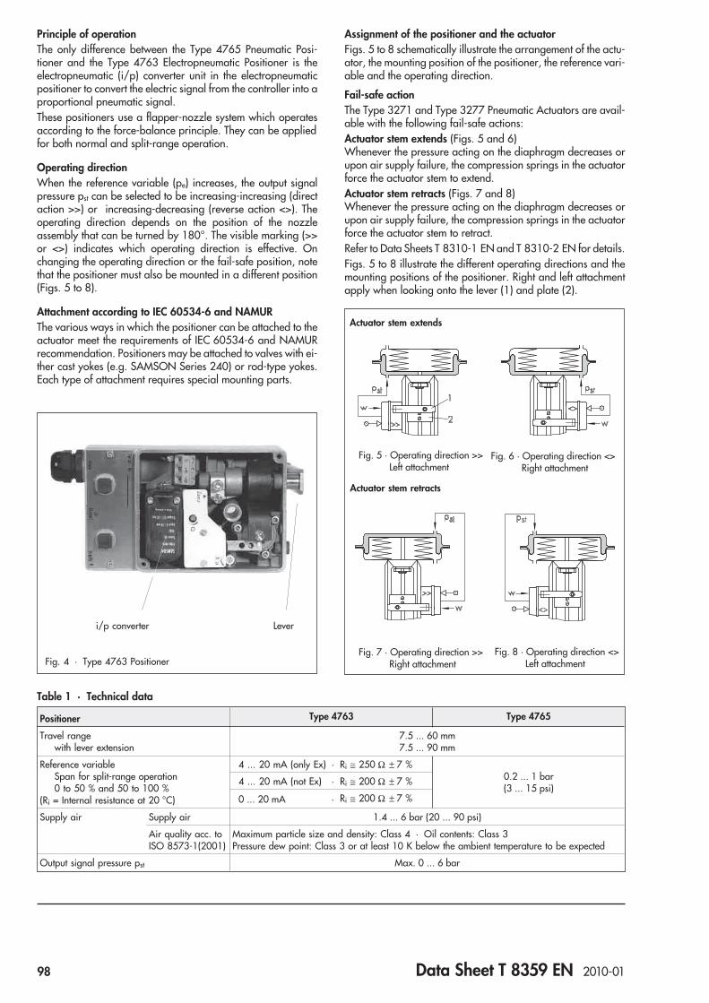
Principle of operationThe only difference between the Type 4765 Pneumatic Posi-tioner and the Type 4763 Electropneumatic Positioner is theelectropneumatic (i/p) converter unit in the electropneumaticpositioner to convert the electric signal from the controller into aproportional pneumatic signal.These positioners use a flapper-nozzle system which operatesaccording to the force-balance principle. They can be appliedfor both normal and split-range operation.
Operating directionWhen the reference variable (pe) increases, the output signalpressure pst can be selected to be increasing-increasing (directaction >>) or increasing-decreasing (reverse action <>). Theoperating direction depends on the position of the nozzleassembly that can be turned by 180°. The visible marking (>>or <>) indicates which operating direction is effective. Onchanging the operating direction or the fail-safe position, notethat the positioner must also be mounted in a different position(Figs. 5 to 8).
Attachment according to IEC 60534-6 and NAMURThe various ways in which the positioner can be attached to theactuator meet the requirements of IEC 60534-6 and NAMURrecommendation. Positioners may be attached to valves with ei-ther cast yokes (e.g. SAMSON Series 240) or rod-type yokes.Each type of attachment requires special mounting parts.
Assignment of the positioner and the actuatorFigs. 5 to 8 schematically illustrate the arrangement of the actu-ator, the mounting position of the positioner, the reference vari-able and the operating direction.
Fail-safe actionThe Type 3271 and Type 3277 Pneumatic Actuators are avail-able with the following fail-safe actions:Actuator stem extends (Figs. 5 and 6)Whenever the pressure acting on the diaphragm decreases orupon air supply failure, the compression springs in the actuatorforce the actuator stem to extend.Actuator stem retracts (Figs. 7 and 8)Whenever the pressure acting on the diaphragm decreases orupon air supply failure, the compression springs in the actuatorforce the actuator stem to retract.Refer to Data Sheets T 8310-1 EN and T 8310-2 EN for details.Figs. 5 to 8 illustrate the different operating directions and themounting positions of the positioner. Right and left attachmentapply when looking onto the lever (1) and plate (2).
Fig. 7 · Operating direction >>Right attachment
Fig. 8 · Operating direction <>Left attachment
1
Fig. 5 · Operating direction >>Left attachment
Fig. 6 · Operating direction <>Right attachment
Actuator stem extends
Actuator stem retracts
i/p converter Lever
Fig. 4 · Type 4763 Positioner
Table 1 · Technical data
Positioner Type 4763 Type 4765
Travel rangewith lever extension
7.5 ... 60 mm7.5 ... 90 mm
Reference variableSpan for split-range operation0 to 50 % and 50 to 100 %
(Ri = Internal resistance at 20 °C)
4 ... 20 mA (only Ex) · Ri ≅ 250 Ω ± 7 %0.2 ... 1 bar(3 ... 15 psi)
4 ... 20 mA (not Ex) · Ri ≅ 200 Ω ± 7 %
0 ... 20 mA · Ri ≅ 200 Ω ± 7 %
Supply air Supply air 1.4 ... 6 bar (20 ... 90 psi)
Air quality acc. toISO 8573-1(2001)
Maximum particle size and density: Class 4 · Oil contents: Class 3Pressure dew point: Class 3 or at least 10 K below the ambient temperature to be expected
Output signal pressure pst Max. 0 ... 6 bar
98 Data Sheet T 8359 EN 2010-01
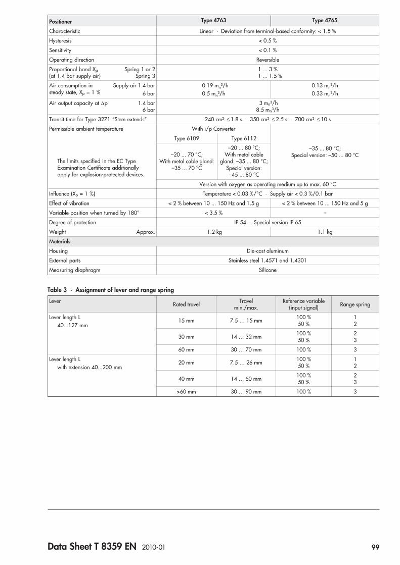
Positioner Type 4763 Type 4765
Characteristic Linear · Deviation from terminal-based conformity: < 1.5 %
Hysteresis < 0.5 %
Sensitivity < 0.1 %
Operating direction Reversible
Proportional band Xp(at 1.4 bar supply air)
Spring 1 or 2Spring 3
1 ... 3 %1 ... 1.5 %
Air consumption insteady state, Xp = 1 %
Supply air 1.4 bar6 bar
0.19 mn³/h0.5 mn³/h
0.13 mn³/h0.33 mn³/h
Air output capacity at Δp 1.4 bar6 bar
3 mn³/h8.5 mn³/h
Transit time for Type 3271 “Stem extends” 240 cm²: ≤ 1.8 s · 350 cm²: ≤ 2.5 s · 700 cm²: ≤ 10 s
Permissible ambient temperature
The limits specified in the EC TypeExamination Certificate additionallyapply for explosion-protected devices.
With i/p Converter
–35 ... 80 °C;Special version: –50 ... 80 °C
Type 6109 Type 6112
–20 ... 70 °C;With metal cable gland:
–35 ... 70 °C
–20 ... 80 °C;With metal cable
gland: –35 ... 80 °C;Special version:–45 ... 80 °C
Version with oxygen as operating medium up to max. 60 °C
Influence (Xp = 1 %) Temperature < 0.03 %/°C · Supply air < 0.3 %/0.1 bar
Effect of vibration < 2 % between 10 ... 150 Hz and 1.5 g < 2 % between 10 ... 150 Hz and 5 g
Variable position when turned by 180° < 3.5 % –
Degree of protection IP 54 · Special version IP 65
Weight Approx. 1.2 kg 1.1 kg
Materials
Housing Die-cast aluminum
External parts Stainless steel 1.4571 and 1.4301
Measuring diaphragm Silicone
Table 3 · Assignment of lever and range spring
Lever Rated travel Travelmin./max.
Reference variable(input signal) Range spring
Lever length L40...127 mm
15 mm 7.5 … 15 mm 100 %50 %
12
30 mm 14 … 32 mm 100 %50 %
23
60 mm 30 … 70 mm 100 % 3
Lever length Lwith extension 40...200 mm
20 mm 7.5 … 26 mm 100 %50 %
12
40 mm 14 … 50 mm 100 %50 %
23
>60 mm 30 … 90 mm 100 % 3
Data Sheet T 8359 EN 2010-01 99
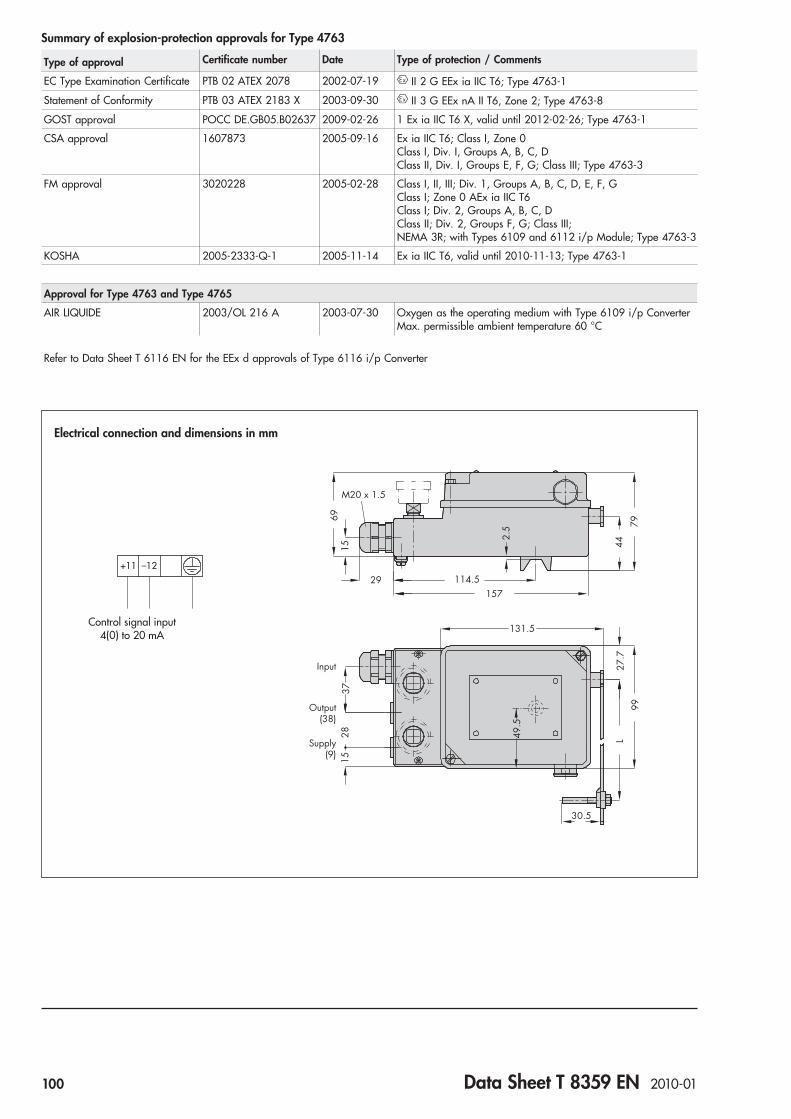
79
69
M20 x 1.5
15 44
2.5
29 114.5157
131.5
Input
Output(38)
Supply(9)
27.7
99
L2815
37
49.5
30.5
Electrical connection and dimensions in mm
+11 –12
Control signal input4(0) to 20 mA
Summary of explosion-protection approvals for Type 4763
Type of approval Certificate number Date Type of protection / Comments
EC Type Examination Certificate PTB 02 ATEX 2078 2002-07-19 II 2 G EEx ia IIC T6; Type 4763-1
Statement of Conformity PTB 03 ATEX 2183 X 2003-09-30 II 3 G EEx nA II T6, Zone 2; Type 4763-8
GOST approval POCC DE.GB05.B02637 2009-02-26 1 Ex ia IIC T6 X, valid until 2012-02-26; Type 4763-1
CSA approval 1607873 2005-09-16 Ex ia IIC T6; Class I, Zone 0Class I, Div. I, Groups A, B, C, DClass II, Div. I, Groups E, F, G; Class III; Type 4763-3
FM approval 3020228 2005-02-28 Class I, II, III; Div. 1, Groups A, B, C, D, E, F, GClass I; Zone 0 AEx ia IIC T6Class I; Div. 2, Groups A, B, C, DClass II; Div. 2, Groups F, G; Class III;NEMA 3R; with Types 6109 and 6112 i/p Module; Type 4763-3
KOSHA 2005-2333-Q-1 2005-11-14 Ex ia IIC T6, valid until 2010-11-13; Type 4763-1
Approval for Type 4763 and Type 4765
AIR LIQUIDE 2003/OL 216 A 2003-07-30 Oxygen as the operating medium with Type 6109 i/p ConverterMax. permissible ambient temperature 60 °C
Refer to Data Sheet T 6116 EN for the EEx d approvals of Type 6116 i/p Converter
100 Data Sheet T 8359 EN 2010-01

Article code
Electropneumatic Positioner Type 4763- x 1 x 0 0 x x x x 0 x 0 x x 0
Explosion protection
Without 0 2/7
II 2 G EEx ia IIC T6 acc. to ATEX 1
CSA/FM intrinsically safe/non incendive 3
II 3 G EEx nA II T6 for Zone 2 acc. to ATEX 8 2/7
Range spring
Range spring 1, travel = 15 mm 1
Range spring 2, travel = 30 mm, split-range 15 mm 2
Range spring 3, travel = 60 mm, split-range 30 mm 3
Pneumatic connections
ISO 228/1 G ¼ 1
¼-18 NPT 3
Electrical connection
Cable gland
M20 x 1.5 blue (plastic) 1
M20 x 1.5 black (plastic) 2
M20 x 1.5 (nickel-plated brass) 7 2
i/p module
Type 6109 1
Type 6112 2
Reference variable
4 … 20 mA 0
0 … 20 mA 2 2
1 … 5 mA 2 3
Temperature range
Standard 0
Low temperature down to –45 °C 2 2
Special version
None 0 0 0
For oxygen as the operating medium 0/1 0 1 6
II 3 D IP 54 T 80 °C (with manufacturer’s declaration) 8 2/7 0 1 8
GOST approval 1 2 0 1 0
Data Sheet T 8359 EN 2010-01 101

Ordering textElectropneumatic Positioner Type 4763-x...orPneumatic Positioner Type 4765-01...
Additional specifications– Without/with pressure gauge– CrNiMo steel pressure gauge housing, connection
nickel-plated or completely of CrNiMo steel for mountingonto control valve
– Reference variable adjusted ... or supply pressure ... bar– Operating direction: Increasing-increasing or increasing-
decreasing– Piping: Zinc-plated steel or completely of CrNiMo steel or
natural PE tubing DN 6/10– Attachment acc. to IEC 60534-6 (NAMUR)
Travel: ... mm, if applicable, rod diameter: …mm– Optionally, special version– Extended temperature range– Special version with oxygen as the operating medium
Refer to the Mounting and Operating InstructionsEB 8359-1 EN (for Type 4765) or EB 8359-2 EN (forType 4763) concerning the mounting parts required when thepositioner is delivered unattached to a control valve.
Specifications subject to change without notice
Article code
Pneumatic Positioner Type 4765- 0 1 x 0 0 x 1 x x x x 0
Range spring
Range spring 1, travel = 15 mm 1
Range spring 2, travel = 30 mm, split-range 15 mm 2
Range spring 3, travel = 60 mm, split-range 30 mm 3
Pneumatic connections
ISO 228/1 - G ¼ 1
¼-18 NPT 3
Temperature range
Standard 0
Low temperature down to –50 °C 1
Special version
None 0 0 0
For oxygen as the operating medium 0 0 1
102 Data Sheet T 8359 EN 2010-01

ApplicationSingle-acting positioners for direct attachment to pneumaticcontrol valves. Supplied with an electric input signal of 4 to20 mA or a pneumatic input signal of 0.2 to 1 bar (3 to 15 psi).For travels from 5 to 15 mm
The positioners ensure a predetermined assignment of the valvestem position (controlled variable x) to the control signal (refer-ence variable w). They compare the control signal issued by acontroller with the travel of the control valve and issue an outputsignal pressure pst (output variable y).The positioners have the following special features: suitable fornormal and split-range operation; reversible operating direc-tion; excellent dynamic response; low supply air consumption,insensitive to mechanical vibration; compact, low-maintenancedesign; optionally available with inductive limit switch and, onrequest, output pressure limiter.A version for hazardous areas with type of protection "Intrinsicsafety" II 2 G EEx ia IIC T6 according to ATEX is available forthe proximity switch circuit and for the signal circuit of theelectropneumatic positioner (see summary of explosion protec-tion certificates).Type of protection EEx d with Type 6116 i/p Converter (Fig. 2)Direct attachment to Type 3277 Pneumatic Actuators with effec-tive areas of 120, 240 and 350 cm² (see T 8310-1 EN).Optionally available with a pressure gauge (scale 0 to 6 barand 0 to 90 psi) to monitor the signal pressure. The pressuregauge housing is made of stainless steel; connection optionallynickel-plated or completely of stainless steel.
VersionsType 3760 Electropneumatic Positioner (Fig. 1)Version suitable for non-hazardous areas. Signal pressureranges from 0 to 6 bar (0 to 90 psi); supply air from 1.4 to 6 bar(20 to 90 psi). Reference variable: standard version 4 to20 mA.Type 3760 Electropneumatic Positioner · Same version asabove, except for its use in hazardous areas. Type of protection
II 2 G EEx ia IIC T6 for the signal circuitType of protection EEx d with Type 6116 i/p Converter (Fig. 2)On request, also available with an intrinsically safe inductivelimit switch.Type 3760 Pneumatic PositionerReference variable 0.2 to 1 bar (3 to 15 psi), signal pressureranges from 0.2 to approx. 6 bar (3 to approx. 90 psi); supplyair from 1.4 to 6 bar (20 to 90 psi).On request, also available with an intrinsically safe inductivelimit switch.
Electropneumatic Positioner andPneumatic PositionerType 3760
Fig. 1 · Type 3760 Positioner
Fig. 2 · Micro-flow valve with EEx d positioner(Type 3760 with Type 6116 i/p Converter)
JIS
Data Sheet T 8385 EN 2010-02 103

Principle of operationThe only difference between the positioners is that the elec-tropneumatic positioner is equipped with an i/p converter (2).Both positioners ensure a predetermined assignment of thevalve stem position to the control signal. The controlled variablex is the valve travel. The reference variable w is either a DC sig-nal (i) for the electropneumatic positioner (i/p) or a pneumaticsignal (pe) for the pneumatic positioner (p/p). The DC signaland the pneumatic signal are both issued by a connected con-troller. The manipulated variable y is the positioner's outputpressure (pst).The Type 3760 Positioners are designed for direct attachment toSAMSON Type 3277 Actuators.In the electropneumatic positioner, the direct current signal i istransmitted from the controller to the i/p converter (2), where itis converted into a proportional air pressure pe of 0.2 to 1 baror 3 to 15 psi. In the pneumatic positioner, the control signal pe
provided as air pressure is directly transmitted to the measuringdiaphragm (3).The pneumatic control signal pe produces a force at the measur-ing diaphragm (3) which is compared to the force of the rangespring (7). The motion of the measuring diaphragm (3) is trans-mitted to the double plug (13) of the force switch (12) via the le-ver (4). As a result, a corresponding signal pressure pst is pro-duced. Any changes in the control signal pe or the valve stemposition causes changes in the signal pressure pst. Thus, the plugstem of the valve moves to the position which corresponds to thereference variable.The positioners can be used for both standard and split-rangeoperation. Note that the signal pressure range (range of theoutput pressure pst) must match the spring range of the actuator.In split-range operation, the output signal of a control station in-tended to control two control valves is divided in such a way thateach actuator passes through its full travel at half the input span.For a span between 0.2 and 1 bar, for example, the first valve isadjusted to the first half (from 0.2 to 0.6 bar), the second is ad-justed to the second half (from to 0.6 to 1 bar).The adjustment screws for zero (5) and span (8) are used to setthe lower and upper range values of the input signal. The rangespring (7) must be chosen to match both the rated travel of thecontrol valve and the nominal span of the reference variable.
Operating directionWhen the pneumatic control signal pe (reference variable) in-creases, the signal pressure pst can be selected to be increasing(direct action >>) or decreasing (reverse action <>). The operat-ing direction is determined by the position of the force switch(12) and can also be changed on site.
1 2 3 4 5 6 7
14
13 12 11 10 9 8
14
pst
pe
pst
pe
Fig. 3 · Functional diagram of Type 3760 Positioner
Supply air
Travel
Force switch,Direct action >>
Force switch,Reverse action <>
Legend1 Pressure regulator 8 Adjustment screw (span)2 i/p converter 9 Clamping screw3 Measuring diaphragm 10 Clamp4 Diaphragm lever 11 Axis of rotation5 Adjustment screw 12 Force switch
(zero) 13 Double plug6 Lever 14 Screw7 Range spring
104 Data Sheet T 8385 EN 2010-02

Table 1 · Technical data
Travel range 5 to 15 mm (see Table 2 for range springs)
Reference variableSpan for split-range operation0 to 50 % or50 to 100 %
Pneumatic 0.2 to 1 bar (3 to 15 psi)
Electric 4 to 20 mA (Ex only) · Ri 250 7 %
4 to 20 mA (non-Ex) · Ri 200 7 %
0 to 20 mA · Ri 200 7 %
(Ri = internal resistance at 20 °C) 1 to 5 mA · Ri 880 7 %
Supply air 1.4 to 6 bar (20 to 90 psi)
Max. particle size and density: Class 2 · Oil content: Class 3 · Pressure dew point:Class 3 or at least 10 K below the lowest ambient temperature to be expected
Signal pressure pst (output) Max. 0 to 6 bar (0 to 90 psi)
Characteristic Linear, deviation from terminal-based conformity 1.5 %
Hysteresis 0.5 %
Sensitivity < 0.1 %
Operating direction Reversible
Air consumption in steady state At 0.6 bar signal pressure and supply pressure up to 6 bar 100 In/h
Air output capacity At p = 1.4 bar 1600 In/h · At p = 6 bar 5000 In/h
Transit times with Type 3277 Actuator(15 mm travel, 0.2 to 1 bar signal pressure) 120 cm²: 2 s · 240 cm²: 6 s · 350 cm²: 8 s
Permissible ambient temperature –20 to +70 °C
(Note the limits in the EC TypeExamination Certificate)
Down to –30 °C with metal cable glandDown to –40 °C with metal cable gland and Type 6112 i/p ConverterThe limits in the EC Type Examination Certificate additionally apply for explosion-protected versions–40 to 70 °C with Type 3760 used as pneumatic positioner without proximity switches
Influences Temperature (zero) 0.03 %/°C
Span 0.03 %/°C
Vibrations Between 5 to 120 Hz and 2 g 0.5 %
Supply air 1 % between 1.4 and 6 bar
Variable position when turned 180° < 3.5 %
Degree of protection IP 54 (IP 65 special version)
Materials Housing: Polyamide · External parts: Stainless steel 1.4571 and 1.4104Measuring diaphragm: Fluorosilicone rubber · Cable gland: Polyamide, M20 x 1.5
Weight 0.6 kg
Additional equipment
Inductive limit switch Type SJ2 � SN
Control current circuit Values corresponding to the downstream transistor relay
Hysteresis at rated travel 1 %
Table 2 . Range springs
Rangespring Reference variable (%) Travel (mm)
1 0 to 100Split-range 0 to 50 or 50 to 100
12/156/7.5
2 0 to 100 6/7.5
3 Split-range 0 to 50 12/15
4 Split-range 50 to 100 12/15
5 0 to 100 5
6 0 to 100 20
7 Split-range 0 to 50 or 50 to 100 5
Data Sheet T 8385 EN 2010-02 105

Positioner attachmentThe positioners are designed for direct attachment to Type 3277Actuators with effective areas 350 cm² and smaller. They aresecured directly to the actuator yoke using two screws.No external piping is necessary for actuators with effective are-as of 120 cm². The signal pressure pst from the positioner istransmitted to the desired diaphragm chamber via a switchoverplate and internal air ducts.
Combination of positioner and actuatorFig. 4 illustrates the different types of attachment. The specifica-tions "left attachment" or "right attachment" apply when look-ing onto the switchover plate and the signal pressure connec-tion. Depending on the intended attachment, the positioner is tobe secured on either the right or the left side of the yoke.Subsequent conversion, such as reversing the operating direc-tion of the positioner control loop or modifying the actuator'sfail-safe action, is possible. In this case, note that the positionermust also be attached in a different position.
Fail-safe actionThe Type 3277 Pneumatic Actuator has the two fail-safe actionswhich move the valve stem to the predetermined position when-ever the signal pressure decreases or the air supply fails.Actuator stem extends:Whenever the pressure acting on the surface of the diaphragmdecreases or the air supply fails, the force of the compressionsprings in the actuator causes the actuator stem to extend.Actuator stem retracts:Whenever the pressure acting on the surface of the diaphragmdecreases or the air supply fails, the force of the compressionsprings in the actuator causes the actuator stem to retract.Further details can be found in Data Sheet T 8310-1 EN.
Fig. 4 · Attachment position
Actuator stem extends
Actuator stem retracts
Direct >>Left attachment
Reverse <>Right attachment
Reverse <>Left attachment
Direct >>Right attachment
Summary of explosion protection certificates for Type 3760
Type of approval Certificate number Date Comments
EC Type Examination Certificate PTB 02 ATEX 2076 2002-07-18 II 2 G EEx ia IIC T6;Inductive limit switches PTB 99 ATEX 2219 X; Type 3760-1
Statement of Conformity PTB 03 ATEX 2181 X 2003-09-30 II 3 G EEx nA II T6; Zone 2; Type 3760-8
CSA approval LR 54227-23
AddendumLR 54227-32
1996-04-22
2005-09-161999-10-14
Class 1, Div. 1; Groups A, B, C, DNLRC approval also valid in USAClass I, Groups A, B, C, DEncl. 3; Inductive limit switches; Type 3760-3
FM approval 3020228Revision
2005-02-28 Classes I, II, III; Div 1; Groups A, B, C, D, E, F, GClass I, Zone 0 AEx ia IIC T6;Class I; Div. 2; Groups A, B, C, DClass II; Div. 2; Groups F, G; Cl. IIINEMA 3RWith inductive limit switch; Type 6109 and Type 6112 i/p Module;Type 3760-3
Refer to Data Sheet T 6116 EN for EEx d certificates for Type 6116 i/p Converter.
106 Data Sheet T 8385 EN 2010-02

110 29
35
Ø40
38
128
121
17
48
36 84
M20 x 1.5
36 output
27 input signal(3760–...00)
9 supply
"A"
Pressuregauge forOutput
Connectoracc. toDIN 43650
View as seen from “A”
+ _
+ _+11 12_
2
3
1
4
Electrical connections
Pneumatic version
Output Supply air
Electropneumatic versionWith mA signal Limit switch
Control signal i
Connection with cable socket(DIN 43650)
Switching amplifieracc. to EN 60947-5-6
Switching amplifieracc. to EN 60947-5-6
Output Supply air
Cable socket Terminal
12
+ 11� 12
i/p converter
34
+�
Limit switch
Dimensions in mm
Pneumatic connections G 18 or 1
8 NPT
Limit switch
Data Sheet T 8385 EN 2010-02 107
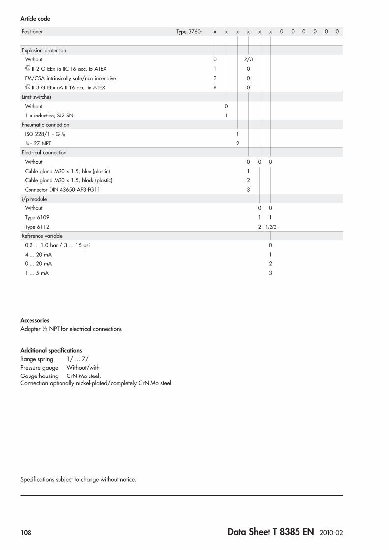
AccessoriesAdapter ½ NPT for electrical connections
Additional specificationsRange spring 1/ ... 7/Pressure gauge Without/withGauge housing CrNiMo steel,Connection optionally nickel-plated/completely CrNiMo steel
Specifications subject to change without notice.
Article code
Positioner Type 3760- x x x x x x 0 0 0 0 0 0
Explosion protection
Without 0 2/3
II 2 G EEx ia IIC T6 acc. to ATEX 1 0
FM/CSA intrinsically safe/non incendive 3 0
II 3 G EEx nA II T6 acc. to ATEX 8 0
Limit switches
Without 0
1 x inductive, SJ2 SN 1
Pneumatic connection
ISO 228/1 - G 18 1
18 - 27 NPT 2
Electrical connection
Without 0 0 0
Cable gland M20 x 1.5, blue (plastic) 1
Cable gland M20 x 1.5, black (plastic) 2
Connector DIN 43650-AF3-PG11 3
i/p module
Without 0 0
Type 6109 1 1
Type 6112 2 1/2/3
Reference variable
0.2 ... 1.0 bar / 3 ... 15 psi 0
4 ... 20 mA 1
0 ... 20 mA 2
1 ... 5 mA 3
108 Data Sheet T 8385 EN 2010-02
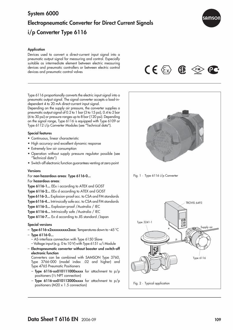
System 6000
Electropneumatic Converter for Direct Current Signals
i/p Converter Type 6116
ApplicationDevices used to convert a direct-current input signal into apneumatic output signal for measuring and control. Especiallysuitable as intermediate element between electric measuringdevices and pneumatic controllers or between electric controldevices and pneumatic control valves
Type 6116 proportionally converts the electric input signal into apneumatic output signal. The signal converter accepts a load-in-dependent 4 to 20 mA direct-current input signal.Depending on the supply air pressure, the converter supplies apneumatic output signal of 0.2 to 1 bar (3 to 15 psi), 0.4 to 2 bar(6 to 30 psi) or pressure ranges up to 8 bar (120 psi). Dependingon the signal range, Type 6116 is equipped with Type 6109 orType 6112 i/p Converter Modules (see "Technical data").
Special features• Continuous, linear characteristic• High accuracy and excellent dynamic response• Extremely low air consumption• Operation without supply pressure regulator possible (see
“Technical data”)• Switch-off electronic function guarantees venting at zero point
VersionsFor non-hazardous areas: Type 6116-0...For hazardous areas:Type 6116-1... EEx i according to ATEX and GOSTType 6116-2... EEx d according to ATEX and GOSTType 6116-3... Explosion-proof acc. to CSA and FM standardsType 6116-4... Intrinsically safe acc. to CSA and FM standardsType 6116-5... Explosion-proof /Australia / IECType 6116-6... Intrinsically safe /Australia / IECType 6116-7... Ex d according to JIS standard /Japan
Special versions– Type 6116-x2xxxxxxxxx2xxx: Temperatures down to –45 °C– Type 6116-0...
– AS-interface connection with Type 6150 Slave– Voltage input (e.g. 0 to 10 V) with Type 6151 u/i Module
– Electropneumatic converter without booster und switch-offelectronic functionConverters can be combined with SAMSON Type 3760,Type 3766-000 (model index .02 and higher) andType 4765 Pneumatic Positioners– Type 6116-xx010111000xxxx for attachment to p/p
positioners (½ NPT connection)– Type 6116-xx010112000xxxx for attachment to p/p
positioners (M20 x 1.5 connection)
Fig. 1 · Type 6116 i/p Converter
Fig. 2 · Typical application
TROVIS 6493
Type 6116
Type 3241-1
Supply aire
p
Data Sheet T 6116 EN 2006-09 109

Principle of operationThe electropneumatic converter consists of an i/p convertermodule, which operates according to the force-balance princi-ple, and a connected volume booster.When operated, the supplied direct current (4) flows throughthe plunger coil (2) located in the field of a permanent magnet(3). At the balance beam (1), the force of the plunger coil whichis in proportion to the current is balanced against the force ofthe dynamic back-pressure. The back-pressure is produced onthe flapper plate (6) by the air jet leaving the nozzle (7).The nozzle is supplied with air from the pneumatic output (36).With an input signal of 0 mA, an output pressure of approxi-mately 100 mbar already exists due to the offset spring.The air supply (8) flows into the lower diaphragm chamber anda certain amount of air flows to the output. When the current in-creases, the flapper moves closer to the nozzle. The force of thedynamic back-pressure which is produced pushes both the dia-phragm (10) and the sleeve (9) downward, allowing additionalair to enter the lower diaphragm chamber. The passing air vol-ume increases until the forces acting on the diaphragm obtain astate of equilibrium. When the current decreases, this action isreversed. The dynamic back-pressure caused by the nozzle andflapper decreases and the diaphragm is pressed upward. In thisprocess, it releases the sleeve (9), if applicable, and opens thevent (EXHAUST) until the forces on the diaphragm are equalagain.Switch-off electronic function (Fig. 4)Converter modules with an input signal range from 4 to 20 mAhave a slide switch which activates the switch-off electronicfunction. This function causes the pneumatic output to be ventedup to approx. 100 mbar when the input signal falls below4.08 mA tolerance. In this way, the tight shut-off function of avalve can be guaranteed.
Combined with a Type 3760, Type 3766-000 or Type 4765Pneumatic PositionerThe Type 6116-xx01011x000xxxx i/p Converter withoutbooster or switch-off electronic function can be combined withthe above listed positioners to form a version in a flameproofenclosure (Ex d). With Type 3760 and Type 4765 Positioners,the i/p converter is attached to the control valve according toNAMUR and its piping connected to the positioner (as shown inFig. 5). The Type 3766-000 Positioner can be connected directto the i/p converter. The positioner type should be specifiedwhen ordering any accessories.
6
7
8
10
8.2
9
1
2
3
4
i
5
pA
pK
ZERO SPAN
SUPPLY 8
EXHAUST
OUTPUT 36
GAUGE (36)
1 Balance beam2 Plunger coil3 Permanent magnet4 Input5 Slide switch, switch-off
electronic function
6 Flapper plate7 Nozzle8 Supply9 Sleeve
10 Diaphragm
Fig. 3 · Functional principle of Type 6116
Fig. 4 · Switch-off electronic function
Fig. 5 · NAMUR attachment to valve with Type 4765 Positioner Fig. 6 · Direct attachment to Type 3766-000 Positioner
4 8 12 16 20mA
0.2
0.4
0.6
0.81.0
bar
4 8 12 16 20mA
1
23
4
5bar
For output 0.8 to 2.7 barResidual pressure approx. 0.3 bar
For output 0.2 to 1 barResidual pressure approx. 0.1 bar
110 Data Sheet T 6116 EN 2006-09
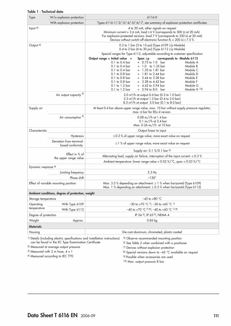
Table 1 · Technical dataType W/o explosion protection 6116-0
With explosion protection Types 6116-1/-2/-3/-4/-5/-6/-7, see summary of explosion protection certificates
Input 6) 4 to 20 mA; other signals on requestMinimum current > 3.6 mA; load ≤ 6 V (corresponds to 300 Ω at 20 mA)
For explosion-protected versions: load 7 V (corresponds to 350 Ω at 20 mA)Devices without switch-off electronic function Ri = 200 Ω ± 7.5 %
Output 6) 0.2 to 1 bar (3 to 15 psi) (Type 6109 i/p Module)0.4 to 2 bar (6 to 30 psi) (Type 6112 i/p Module)
Special ranges for Type 6112, adjustable according to customer specificationOutput range = Initial value + Span Δp corresponds to Module 6112
0.1 to 0.4 bar + 0.75 to 1.0 bar Module A0.1 to 0.4 bar + 1.0 to 1.35 bar Module B0.1 to 0.4 bar + 1.35 to 1.81 bar Module C0.1 to 0.8 bar + 1.81 to 2.44 bar Module D0.1 to 0.8 bar + 2.44 to 3.28 bar Module E0.1 to 0.8 bar + 3.28 to 4.42 bar Module F0.1 to 1.2 bar + 4.42 to 5.94 bar Module G0.1 to 1.2 bar + 5.94 to 8.0 bar Module H 10)
Air output capacity 3) 2.0 m³/h at output 0.6 bar (0.2 to 1.0 bar)2.5 m³/h at output 1.2 bar (0.4 to 2.0 bar)8.5 m³/h at output 5.0 bar (0.1 to 8.0 bar)
Supply air At least 0.4 bar above upper range value, max. 10 bar without supply pressure regulator,max. 6 bar for EEx d version
Air consumption 2) 0.08 mn³/h at 1.4 bar0.1 mn³/h at 2.4 bar
Max. 0.26 mn³/h at 10 bar
Characteristic Output linear to input
Hysteresis ≤ 0.3 % of upper range value; more exact value on request
Deviation from terminal-based conformity ≤ 1 % of upper range value; more exact value on request
Effect in % ofthe upper range value
Supply air: 0.1 %/0.1 bar 2)
Alternating load, supply air failure, interruption of the input current: < 0.3 %
Ambient temperature: lower range value < 0.02 %/°C, span < 0.03 %/°C
Dynamic response 4)
Limiting frequency 5.3 Hz
Phase shift –130°
Effect of variable mounting position Max. 3.5 % depending on attachment: ± 1 % when horizontal (Type 6109)Max. 1 % depending on attachment: ± 0.3 % when horizontal (Type 6112)
Ambient conditions, degree of protection, weight
Storage temperature –45 to +80 °C
Operatingtemperature
With Type 6109 –30 to +70 °C 7); –30 to +60 °C 1)
With Type 6112 –40 to +70 °C 7) 8); –40 to +60 °C 1) 8)
Degree of protection IP 54 5), IP 65 9), NEMA 4
Weight Approx. 0.85 kg
Materials
Housing Die-cast aluminum, chromated, plastic-coated
1) Details (including electric specifications and installation instructions)can be found in the EC Type Examination Certificate
2) Measured at average output pressure3) Measured with 2 m hose, 4 x 14) Measured according to IEC 770
5) Observe recommended mounting position6) See Table 2 when combined with a positioner7) Devices without explosion protection8) Special versions down to –45 °C available on request9) Possible when accessories are used10) Max. output pressure 8 bar
Data Sheet T 6116 EN 2006-09 111

Table 2 · Technical dataType 6116-xx010111000xxxx (½ NPT) 1)
Input 4 to 20 mA, other signals on request,internal resistance approx. 200 Ω at 20 °C
Output 0.2 to 1 bar for positioner
1) Only with Type 6109 i/p Converter,other data same as in Table 1
Electrical connection
For connection to intrinsically safe circuits, the specificationsstated in the certificate of conformity apply as well.
InstallationThe converter can be mounted to a wall, pipe or directly to thecontrol valve according to NAMUR.The converter is to be installed horizontally, with the pressuregauge (or screw plug) facing upward. If a different mountingposition is used, the zero point is to be corrected using the ZEROadjuster.With degree of protection IP 54, the vent must always be in-stalled facing downward to the floor.
Specifications subject to change without notice.
Summary of explosion protection certificates for Type 6116 i/p Converter
Version Type of approval Certificate number Date Type of protection Comments
6116-1 EC Type ExaminationCertificate
PTB 02 ATEX 2199 2003-03-07 II 2 G EEx ia IIC T6 –45 °C ambient temperature
GOST Certificate 2002.C302 2002-12-27 1Ex ia IIC T6 X Valid until 2008-01-01
6116-2 EC Type ExaminationCertificateFirst Addendum
PTB 98 ATEX 1024 X 1998-04-30
2002-01-08
II 2 G EEx d IIC T6 –45 °C ambient temperature
GOST Certificate 2002.C302 2002-12-27 1Ex d IIC T6 X Valid until 2008-01-01
6116-3 CSA Certificate LR 54227-18 1992-11-10 Cl. I, II, Div 1, Gr. B, C, D, E, F + G
LR 54227-24LR 54227-27
1996-05-311997-02-27
With Type 6109 or 6112Encl. NEMA 4
FMRC Certificate J.I.1W5A4.AX 1993-04-01 Cl. I, II, Div 1, Gr. B, C, D
Revision 1996-11-07 With Type 6109 or 6112
6116-4 CSA Certificate LR 54227-16 1992-12-01 Cl. I, Div 1, Gr. A, B, C, DCl. I, Div 2, Gr. A, B, C, D
LR 54227-27LR 54227-28
1997-02-271997-02-27
Encl. NEMA 3 and 4 With Type 6109 or 6112Zero/span electronics
FMRC Certificate J.I.3W2A5.AX
J.I.5YA3.AXJ.I.3Z1A5.AXRevision
1993-02-05
1995-02-011997-04-021998-10-20
Cl. I, II, III; Div 1Gr. A, B, C, D, E, F + G NEMA 3R
Div. 2NEMA 4Zero/span electronics
6116-5 AUS CertificateFirst Extension
Ex 3003 X 1993-09-152001-11-14
EEx d IIC T6 IP 65With Type 6109 or 6112
6116-6 AUS Certificate Ex 1476 X 1993-09-15 EEx ia IIC T6 IP 65 Class I Zone 0
6116-7 JIS Certificate C 13622 1999-05-20 Ex d IIC T6
The test certificates are included in the mounting and operating instructions or, alternatively, can be requested.
11 12
Input 4 to 20 mA
112 Data Sheet T 6116 EN 2006-09
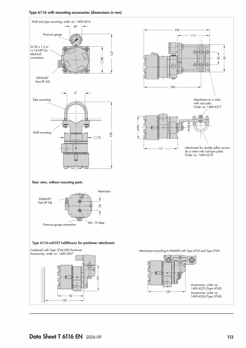
Type 6116 with mounting accessories (dimensions in mm)
40
88
127
75 220
2"
Wall and pipe mounting, order no. 1400-6216
Pressure gauge
M 20 x 1.5 or½-14 NPT forelectricalconnection
30
Rear view, without mounting parts
93
92
129
230
113
200
40 95
117
Ø84 8
120
Type 6116-xx01011x000xxxx for positioner attachment
Attachment according to NAMUR with Type 4765 and Type 3760
Accessories, order no.1400-6223 (Type 4765)Accessories, order no.1400-6224 (Type 3760)
EXHAUSTVent (IP 65)
Pipe mounting
Wall mounting
M6, 10 deepPressure gauge connection
Attachment for double pilllar version(to a valve with rod-type yoke)Order no. 1400-6218
Attachment to a valvewith cast yokeOrder no. 1400-6217
Restriction
EXHAUSTVent (IP 54)
Combined with Type 3766-000 PositionerAccessories, order no. 1400-6227
Data Sheet T 6116 EN 2006-09 113

Article code Type 6116- x x x x x x x x x x x x x x x
Explosionprotection
WithoutIntrinsically safe II 2G EEx ia IIC T6 acc. to ATEX and GOST 1) 2)
Flameproof II 2G EEx d IIC T6 acc. to ATEX and GOST 3)
Explosion-proof acc. to CSA and FM standards 4) 5)
Intrinsically safe acc. to CSA and FM standards 1) 4)
Explosion-proof Ex d IIC T6 IECEx TSA/AUSEx (Australia) 4) 6)
Intrinsically safe Ex ia / Ex n IIC T6 IECEx TSA (Australia) 1)
Ex d IIC T6 acc. to JIS standard (Japan) 4)
01234567
2
3
2
i/p module Type 6109 4)
Type 611212
0 1 1
Input 4 to 20 mA4 to 12 mA 1)
12 to 20 mA, without switch-off electronic function 1) 7)
0 to 20 mA, without switch-off electronic function 7)
222
0000
1345
Output
Special ranges: 8)
0.2 to 1.0 bar3 to 15 psi0.4 to 2.0 bar6 to 30 psiInitial value 0.1 to 0.4 bar; span 0.75 to 1.00 barInitial value 0.1 to 0.4 bar; span 1.00 to 1.35 barInitial value 0.1 to 0.4 bar; span 1.35 to 1.81 barInitial value 0.1 to 0.8 bar; span 1.81 to 2.44 barInitial value 0.1 to 0.8 bar; span 2.44 to 3.28 barInitial value 0.1 to 0.8 bar; span 3.28 to 4.42 barInitial value 0.1 to 1.2 bar; span 4.42 to 5.94 barInitial value 0.1 to 1.2 bar; span 5.94 to 8.00 bar
2222222222
000011111111
124512345678
Operatingdirection
Increasing/increasingIncreasing/decreasing 1)
12
Electricalconnection
½ - 14 NPTM20 x 1.5
12
Pneumaticconnection
Without (for positioner attachment) 9)
¼ - 18 NPTISO-228/1 - G ¼
0 1 0 1 1 012
0 0
Degree ofprotection
Without (vent for positioner attachment)IP 54IP 65NEMA 4 10)
0 1 0 1 1 0 0123
0
Output pressuregauge
WithoutWith 1)
01
Temperaturerange
Tmin ≥ –25 °C (Type 6109 standard)Tmin ≥ –45 °C (Type 6112 subjected to routine test)Tmin ≥ –40 °C (Type 6112 standard)
122
012
Special version Without 0 0 0
1) Not for positioner attachment2) With degree of protection IP 54/IP 65 only3) Output pressure max. 5.6 bar; supply air 6 bar4) Only with 0.2 to 1 bar/3 to 15 psi5) With ½ NPT electrical connection, degree of protection
NEMA 4 or positioner attachment6) With ½ NPT electrical connection, degree of protection IP 65
or positioner attachment7) Without switch-off electronic function and without potentiometer
for zero point and span correction8) Specify setting range, e.g. set to 0.1 to 4 bar; output pressure
max. 8 bar9) Without explosion protection or with EEx d or explosion proof
according to CSA/FM standards10) Only with explosion proof or intrinsically safe according to
CSA/FM standards
AccessoriesMounting on Order no.– Wall and pipe mounting 1400-6216– Mounting to Type 3766 1400-6227– Mounting to Type 4765 1400-6223– Mounting to Type 3760 1400-6224– Mounting on cast yokes acc. to NAMUR 1400-6217– Mounting on valve with rod-type yokes
acc. to NAMUR 1400-6218
114 Data Sheet T 6116 EN 2006-09

u/i Module Type 6151
ApplicationConversion of a standard voltage signal into a standard currentsignal
The Type 6151 u/i Module converts a DC voltage of 0 or 2 V to10 V into a current signal of 0 or 4 mA to 20 mA. An auxiliarypower of 24 V DC is required.
Type 6151 u/i Module is suitable for attachment to devices withan electrical connection according to DIN EN 175301-803.The standard body connector, as shown in Fig. 1, or a specialdevice connector for different versions can be used.
InstallationFor attachment to devices with a connector in accordance withDIN EN 175301-803, simply plug on the Type 6151u/i Module. Connection is established using a cable socketaccording to DIN EN 175301-803.
The following SAMSON devices without device connector cor-responding to DIN EN 175301-803 can be adapted to the u/imodule:
SAMSON deviceDevice connector for
M 20 x 1.5 Case mounting
Positioner
Type 3730-0/-1/-2 x
Type 3760 x
Type 3761 x
Type 3767 x
Type 4763 x
Control valve V2001
V2001-IP x
i/p Converter
Type 6111 x1)
Type 6116 x
1) Type 6111 i/p Converter in special version
Fig. 1 · Type 6151 u/i Module
Data Sheet T 6151 EN 2006-11 115

Electrical connection Ordering textu/i Module Type 6151
Input 0 to 10 V or 2 to 10 VOutput 0 to 20 mA or 4 to 20 mA
Additional versions for input 0 to 10 V and output 4 to 20 mAare available.
On ordering modules for devices without DIN EN 175301-803connectors, also specify the positioner or converter type asgiven overleaf.
Specifications subject to change without notice.
27.5
2
40
31
3 1
25.5
28.5
27
52
33.5
Dimensions
1 Device connector (only necessarywith M20x1.5 connection)
2 Type 6151 u/i Module3 Cable socket acc. to
DIN EN 175301-803
Table 1 · Technical data
Input 0 (2) to 10 V
Maximum values –15 V / +27 V
Static destruction limit –20 V / +32 V (± 32 V for short period)
Input resistance 50 kΩ at Ue = 0 to 10 V · 1 kΩ at Ue < –0.3 V or Ue > 11 V
Output 0 (4) to 20 mA
Maximum load RU V
mAH=
− 1020
· e. g. 700 Ω at power supply of UH = 24 V
Auxiliary power 16 to 30 V DC
Permissible ripple Within the given limits
Static destruction limit ± 32 V DC
Reverse polarity protection Up to –32 V DC
Supply current Max. 22 mA, independent of supply voltage
Characteristic
Characteristic Linear, maximum deviation 0.2 %
Temperature effect Zero: < 0.1 %/10 K · Span: < 0.1 %/10 K
Auxiliary power effect < 0.05 % within the given limits
Operating temperature –25 °C to +85 °C
Degree of protection IP 65 when installed
Electromagnetic compatibility EN 50081 Parts 1 and 2
Body material Polyamide
1
232
12
+
–
+–
+–
24 V DCi
u
0(2)...10 V
0(4)...20 mA
Input
Output
Auxiliary power
116 Data Sheet T 6151 EN 2006-11

Limit switches
Limit switches for linear and rotary actuatorswith inductive, electric and pneumatic contacts
Position transmitters
117


ApplicationLimit switch with inductive, electric or pneumatic limit switchesfor attachment to pneumatic or electric control valves, toType 4763 Electropneumatic Positioners or Type 4765 Pneu-matic PositionersFor rated travels from 7.5 to 150 mm
The limit switches supply a signal when an adjusted limit value isexceeded in either direction. This signal is suitable for initiatingvisual or audible alarms as well as pilot valves or other switch-ing units. Moreover, the limit switches can be connected to cen-tral control or alarm systems.The limit switches are optionally available with:
• Two inductive limit switches• Two electric limit switches or• Two pneumatic limit switches
The limit switches can be overridden. They can optionally beused as normally open or normally closed contacts. The metaltag is outside the inductive field for the NO contact and insidethe inductive field for the NC contact.
Versions for hazardous areas• For use in hazardous areas in type of protection intrinsically
safe II 2 G EEx ia IIC T6 orII 3 G EEx nA II T6 for Zone 2
• Conforming to Canadian or US explosion protectionapprovals
Special features• Excellent switching accuracy• No mutual influencing of the incorporated limit switches• Hysteresis (dead band) dependent on effective lever length
Attachment to control valves with cast yokes or rod-type yokesaccording to IEC 60534-6 as well as to Type 4763Electropneumatic Positioners or Type 4765 PneumaticPositioners
VersionsType 4746-x2 (Fig. 1) · Inductive limit switch with non-contactlimit value pick-up using metal tags and proximity switches (ac-cording to EN 60947-5-6)On request with proximity switches with integral output ampli-fier designed as three-wire switch (no transistor relay)Type 4746-x3 · Electric limit switch with electric double-throwswitch with friction snap-action contactsType 4746-04 · Pneumatic limit switch with incorporated pneu-matic switches and downstream pneumatic microswitchesSupply: 1.4 bar (20 psi), output 0 or 1.4 bar (20 psi)
Versions for hazardous areasType 4746-1 · Limit switch with contact circuit in type of protec-tion intrinsically safe II 2 G EEx ia IIC T6Type 4746-8 · Limit switch in type of protection non-sparking
II 3 G EEx nA II T6 for Zone 2Versions with Canadian or US explosion protection certifica-tions are available. Refer to the summary of explosion protec-tion certificates.Refer to Information Sheet T 8350 EN for information on the se-lection and application of positioners and limit switches.
Electric or PneumaticLimit Switch Type 4746
Fig. 1 · Type 4746-x2 Inductive Limit Switch
Data Sheet T 8365 EN 2010-01 119

Principle of operation (Figs. 2 to 4)The valve travel is transmitted either directly by the plate (20)onto the pin (1.1) and the lever (1) of the limit switch or, whenthe limit switch module is attached to a positioner, by a couplingpin. In this case, the linear valve travel is converted into a rotarymotion by the shaft (2).All limit switches have a small hysteresis which depends on thelever length L (see Technical data). Due to this, unnecessary con-tact changeover is avoided and signal processing is facilitatedeven when the valve stem position is within the limit signalrange.
Type 4746-x2 Inductive Limit Switch (Fig. 2)In these switches, the shaft (2) is provided with two switch cases(3) containing adjustable metal tags (4.1) for frictionless opera-tion of the proximity switches (5). The proximity switches as-sume a high resistance when the metal tag is within the inductivefield, whereas they become low-ohmic when the metal tag isoutside the field. The switching function and the limit value aresteplessly adjustable using the adjustment screw (3.1).For operation of the standard inductive limit switches (two-wireaccording to EN 60947-5-6), appropriate transistor relaysmust be connected to the output circuit. The three-wire versioncomprising the Type SB 3,5-E2 proximity switch includes an in-tegrated output amplifier and does not require a transistor re-lay.
Type 4746-x3 Electric Limit Switch (Fig. 3)In these switches, the shaft (2) is provided with two switch cases(3) containing adjustable cam discs (4.2). Each cam disc actu-ates an electric double-throw switch (7) by the roller (6.1)mounted to the switch lever (6). The switching function and thelimit value are continuously adjustable using the adjustmentscrew (3.1).
Type 4746-04 Pneumatic Limit Switch (Fig. 4)In these devices, the shaft (2) is provided with two switch cases(3) containing adjustable cam discs (4.2). Inside the switch (8),each cam disc actuates a nozzle-flapper system whose cascadepressure (pk1 or pk2) is used to reverse the pneumaticmicroswitches (9).When the cam disc (4.2) with its cam operates the switch lever(6) using the roller (6.1), the nozzle in the switch is opened andthe available supply pressure pz is fed from the microswitch tooutput A1 or A2. This means that input 5 is connected to output 3and pa1 = pz or pa2 = pz. As soon as the cam releases the switchlever (6), the nozzle (8.1) in the pneumatic switch (8) is closed.The microswitch changes over and the available air supply isshut off; i.e. pa1 = 0 or pa2 = 0. The switching function and thelimit value are continuously adjustable using the adjustmentscrew (3.1).The limit switch requires different levers (1) depending on thetravel range of the valve used:Lever I (157 mm) for travels up to max. 60 mmLever II (210 mm) for travels exceeding 60 mmWhenever the limit switch is attached to positioners, a speciallever, regardless of the valve travel, needs to be used.
Fig. 2 · Functional diagram of inductive limit switch
Travel
Fig. 3 · Functional diagram of electric limit switch
Travel
4.1 · Functional diagram of mechanical switching mechanism
Travel
1 1
4.2 · Functional diagram of switching function
Fig. 4 · Pneumatic limit switch
Legend for Figs. 2 to 41 Lever for valve travel1.1 Pin2 Shaft3 Switch case3.1 Adjustment screw4.1 Metal tag4.2 Cam disc5 Proximity switch of
control valve6 Switch lever
6.1 Roller6.2 Spring7 Electric switch8 Pneumatic switch8.1 Nozzle (in switch)8.2 Flapper (in switch)9 Pneumatic microswitch20 Plate attached either to
actuator stem or plug stem
120 Data Sheet T 8365 EN 2010-01

Table 1 · Technical data · All pressures stated in bar (gauge)
Inductive Limit Switch Type 4746-x2 Type 4746-0281
Control circuit Switching amplifier acc. to EN 60947-5-6 Three-wire switchOperating voltage 10 to 30 V
Proximity switch SC 3,5-NO 2) SJ 3,5 SN SB 3,5-E2
Permissible ambient temperature 1) –20 to 70 °C –20 to 100 °C –20 to 70 °C
With metal cable gland –40 to 70 °C –50 to 100 °C –25 to 70 °C
Electrical connection One cable gland M20 x 1.5 for 5.5 to 13 mm clamping rangeScrew terminals for 0.2 to 2.5 mm² wire cross-section
Degree of protection IP 65
Weight Approx. 0.7 kg
Type 4746-x3 Electric Limit Switch
Switching element Electric limit switch: changeover/SPDT (single-pole/double-throw type)
Permissible load AC voltage: 220 V, 6.9 ADC voltage: 220 V, 0.25 A ⋅ 20 V, 6.9 A
Permissible ambient temperature 1) –20 to 85 °C
With metal cable gland –40 to 85 °C
Electrical connection One cable gland M20 x 1.5 for 5.5 to 13 mm clamping rangeScrew terminals for 0.2 to 2.5 mm² wire cross-section
Degree of protection IP 65
Weight Approx. 0.7 kg
Type 4746-04 Pneumatic Limit Switch
Switching element Pneumatic limit switch with downstream pneumatic microswitch
Supply air 1.4 bar (20 psi), can be briefly overloaded up to 4 bar (60 psi)
Air consumption 0.04 mn3/h
Output 0 or 1.4 bar (20 psi)
Air output capacity One switch closed: 0.7 mn3/hTwo switches closed: 1.0 mn3/h
Permissible ambient temperature –20 to 60 °C
Degree of protection IP 54
Weight Approx. 0.75 kg
Materials
Case and cover Aluminium, powder-coated
Lever and shaft 1.4571
Cable gland M20 x 1.5 ⋅ Black polyamide
1) Observe the limits concerning permissible ambient temperatures specified in the EC Type Examination Certificate.2) Models manufactured until 2006 with SJ 3,5 N proximity switch.
Table 2 · Technical data for Type 4746-1 with type of protection Ex ia (ATEX)Maximum values for connection to certified intrinsically safe circuits
Limit Switch Type 4746-12 Type 4746-13
Limit switches Inductive Electric
Ui 16 V 16 V 45 V
Ii 52 mA 25 mA –
Pi 169 mW 64 mW 2 W
Ci - Effective internal capacitance 60 nF 50 nFNegligibly small
Li - Effective internal inductance 160 μH 250 μH
Temperature classes Ambient temperature range according to EC Type Examination Certificate(Technical data specified in Table 1 additionally apply)
T4 –45 to 80 °C –45 to 100 °C –45 to 80 °C
T5 –45 to 70 °C –45 to 81 °C –45 to 70 °C
T6 –45 to 60 °C –45 to 66 °C –45 to 60 °C
Data Sheet T 8365 EN 2010-01 121

Table 3 · Hysteresis (dead band)
Type 4746 -x2 -x3 -04
Lever length L Hysteresis
50 mm 0.15 (0.25*) mm 0.6 mm 0.75 mm
120 mm 0.30 (0.55*) mm 1.0 mm 1.5 mm
* Special version
Ordering textLimit Switch Types 4746-x2/-x3/-04Operating as NO/NC contactTo indicate Valve OPEN/Valve CLOSEDOptionally, special versionAccessoriesMounting parts for attachment to
Type 4763/4765 PositionerValve with cast yoke with lever I or IIValve with rod-type yoke with lever I or II
Adapter ½ NPT for electrical connections
Dimensions in mm
The dimensions required for attachment to Type 4765 Pneumatic Positioner and Type 4763 Electropneumatic Positionerscan be found in Mounting and Operating Instructions EB 8365 EN.
8315
27.5
94
64
44.5
74M20x1.5
20.6
79
Separate air supply
Type 4746-x2, -x3 ⋅ Air connection for separate air supplytapped hole G 1
8
27.5
7644
.5
1837
18
8315
83
7492
Type 4746-04 ⋅ Air connections, tapped hole G 18
or 18 NPT
Air connections
Output
Supply air
32
148
30
7177
NAMUR rib
Fastening screw M8
77 71
32 30
148
NAMUR rib
Fastening screw M8
122 Data Sheet T 8365 EN 2010-01
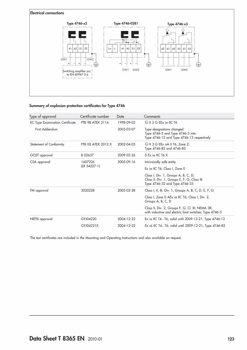
41 42 51 52 42 41 43 52 51 53
GW1 GW2
+ _ _+GW1 GW2
41 42L+ L- 51 52
+ _ _+
GW1 GW2
Type 4746-x3Type 4746-x2
Electrical connections
Type 4746-0281
Switching amplifier acc.to EN 60947-5-6
Summary of explosion protection certificates for Type 4746
Type of approval Certificate number Date CommentsEC Type Examination Certificate PTB 98 ATEX 2114 1998-09-03 II 2 G EEx ia IIC T6
First Addendum 2003-03-07 Type designations changed:Type 4746-2 and Type 4746-3 intoType 4746-12 and Type 4746-13 respectively
Statement of Conformity PTB 02 ATEX 2012 X 2002-04-05 II 3 G EEx nA II T6, Zone 2;Type 4746-82 and 4746-83
GOST approval B 02637 2009-02-26 0 Ex ia IIC T6 X
CSA approval 1607226(LR 54227-1)
2005-09-16 Intrinsically safe entity
Ex ia IIC T6; Class I, Zone 0
Class I, Div. 1, Groups A, B, C, D;Class II, Div. 1, Groups E, F, G; Class IIIType 4746-32 and Type 4746-33
FM approval 3020228 2005-02-28 Class I, II, III, Div. 1, Groups A, B, C, D, E, F, G
Class I, Zone 0 AEx ia IIC T6; Class I, Div. 2,Groups A, B, C, D
Class II, Div. 2, Groups F, G; Cl. III; NEMA 3R,with inductive and electric limit switches; Type 4746-3
NEPSI approval GYJ04220 2004-12-22 Ex ia IIC T4...T6; valid until 2009-12-21; Type 4746-12
GYJ04221X 2004-12-22 Ex nL IIC T4...T6; valid until 2009-12-21; Type 4746-82
The test certificates are included in the Mounting and Operating Instructions and also available on request.
Data Sheet T 8365 EN 2010-01 123

Specifications subject to change without notice
Article code
Electric or Pneumatic Limit Switch Type 4746 x x x x 2 x x 0 x x x 0
Explosion protection
Without 0
II 2 G EEx ia IIC T6 acc. to ATEX 1
CSA/FM intrinsically safe/non incendive 3
II 3 G EEx nA II T6 acc. to ATEX 8
Type
Inductive 2
Electric 3
Pneumatic 0 4
Contacts
Proximity switch SC 3,5-NO (NAMUR NC contact) 2 0 0 1 0
Proximity switch SJ 3,5-SN (NC contact in safety circuit) 2 1 0 1 0
Proximity switch SJ 3,5-S1N (NAMUR NO contact in safety circuit) 2 1 1 1 0
SAIA - electric microswitch XGK 3 (silver contacts) 3 2 0 1 0
SAIA - electric microswitch XGK3-81 (gold-plated contacts) 3 2 1 1 0
Pneumatic microswitch 0 4 4 0 0
Proximity switch SJ 3,5-E2 (three-wire switch), NO contact 0 2 8 1 1 0
Electrical connection
Without 0 4 4 0 0
Cable gland M20 x 1.5 black (plastic) 1 0
Pneumatic connection
Without 0
ISO 228/1 - G18 0 4 4 0 0 1
18-27 NPT 0 4 4 0 0 2
Special versions
None 0 0 0
NEPSI approval Ex ia, Type 4746-12 inductive 1 2 2 0 0 9
NEPSI approval Ex nL, Type 4746-82 inductive 8 2 2 0 1 0
GOST approval, Ex ia, Type 4746-1... 1 2/3 0 1 3
124 Data Sheet T 8365 EN 2010-01

Limit Switch Type 3776With inductive or electric contacts and solenoid valvefor linear actuators or rotary actuators according toVDI/VDE 3845
General
The Type 3776 Limit Switch issues an electrical signal when anadjusted limit value is exceeded or not reached. The signal issuitable for reversing control signals, generating visual and audible alarms, or for connection to central control and alarmsystems. The limit switch can be equipped with a solenoid valvefor controlling the monitored actuator.
Versions
The Type 3776 Limit Switch offers a variety of different contacts,switching functions, connections, and mounting kits for all desiredapplications:
General
● Electrical connection using a cable gland M 20 �1.5 toterminals or using a plug-type connector
● Internal AS-Interface module with bus connection (optional)● Corrosion-resistant, rugged enclosure with degree of protection
IP 54 or IP 65 for applications in aggressive environments● Maximum permissible ambient temperature �45 to �80 °C,
depending on the components and the type of protection● Mounting kits for linear actuators or rotary actuators with
interface according to VDI/VDE 3845
Contacts
● Maximum 3 easily and accurately adjustable contacts● Inductive pick-ups, inductive double proximity switch, or
electric microswitches
Solenoid valve
● Safety Integrity Level SIL 4 according to IEC 61508
● 1 or 2 integral pilot valves for single or double actuationof a booster valve
● e/p binary converter with proven flapper/nozzle assembly● Type of protection II 2 G EEx ia IIC T6 or II 3 G EEx nA II T6
(optional)● Nominal signals 6/12/24 V DC or 24/115/230 V AC● Power consumption 6 to 27 mW or 0.04 to 0.46 VA,
depending on the nominal signal● Manual override (optional)● Air supply 2.2 to 6.0 bar
● Flanged booster valve with diaphragm or piston● 3/2, 5/2, or 5/3-way function● Kvs 0.2 to 0.3● Restrictors for adjusting different closing and opening times
(optional)● Threaded connection G 1/4 or 1/4 NPT
● Flanged connection block for actuation of an externalType 3756 Booster Valve G 1/4 or 1/4 NPT
● Threaded connection G 1/4 or 1/4 NPT
Fig. 1 · Type 3776 Limit Switch
Fig. 2 · Type 3776 Limit Switch for linear actuators orrotary actuators according to VDI/VDE 3845
Data Sheet T 3776 EN 2008-01 125

Type 3776-03203210127100 Limit Switch● Without explosion protection● 2 Type SB3,5-E2 inductive pick-ups● Angle of rotation 0° to 100°● Solenoid valve 24 V DC● Manual override● 3/2-way function with spring return mechanism● Without restrictors● Air connection G 1/4● Electrical plug-type connection● Degree of protection IP 65● Ambient temperature �25 to �70 °C● Without safety function
Mounting kit (order no. 1400-XXXX)
SAMSON Type 3278 Rotary Actuator Rotary actuators according toVDI/VDE 3845 – fixing level 1
Rotary actuators according toVDI/VDE 3845 – fixing level 2
Type 3776-12203210112000 Limit Switch● Type of protection II 2 G EEx ia IIC T6● 2 Type SJ3,5-SN inductive pick-ups● Angle of rotation 0° to 100°● Solenoid valve 24 V DC● Manual override● 3/2-way function with spring return mechanism● Without restrictors● Air connection G 1/4● Electrical terminal connection● Degree of protection IP 54● Ambient temperature �20 to �80 °C● Without safety function
Mounting kit (order no. 1400-XXXX)
Type 3776-02203210110100 Limit Switch● Without explosion protection● 2 Type SJ3,5-SN inductive pick-ups● Angle of rotation 0° to 100°● Solenoid valve 24 V DC● Manual override● 3/2-way function with spring return mechanism● Without restrictors● Air connection G 1/4● Electrical terminal connection● Degree of protection IP 65● Ambient temperature �20 to �80 °C● Without safety function
Mounting kit (order no. 1400-XXXX)
Type 3776-12203210112100 Limit Switch● Type of protection II 2 G EEx ia IIC T6● 2 Type SJ3,5-SN inductive pick-ups● Angle of rotation 0° to 100°● Solenoid valve 24 V DC● Manual override● 3/2-way function with spring return mechanism● Without restrictors● Air connection G 1/4● Electrical terminal connection● Degree of protection IP 65● Ambient temperature �20 to �80 °C● Without safety function
Mounting kit (order no. 1400-XXXX)
SAMSON Type 3241 Control Valve withrib according to DIN EN 60534-6-1
SAMSON Type 3277 Linear Actuator SAMSON Type 3277-5 with internalrouting of the signal pressure
Examples of application
Type 3776-12203290112000 Limit Switch● Type of protection II 2 G EEx ia IIC T6● 2 Type SJ3,5-SN inductive pick-ups● Angle of rotation 0° to 100°● Solenoid valve 24 V DC● Manual override● Connection block, double● Without restrictors● Air connection G 1/4● Electrical terminal connection● Degree of protection IP 54● Ambient temperature �20 to �80 °C● Without safety function
External Type 3756-3025 Booster Valve● 5/2-way function with two locking positions● Kvs 1.4● Air connection G 1/4
Mounting kit (order no. 1400-XXXX)
Type 3776-01203030150000 Limit Switch● Without explosion protection● 2 Type SC3,5-N0 inductive pick-ups● Angle of rotation 0° to 100°● Solenoid valve 24 V DC● Without manual override● 5/2-way function with two locking positions● Without restrictors● Air connection G 1/4● AS-Interface module with bus connection● Degree of protection IP 54● Ambient temperature �20 to �80 °C● Without safety function
Mounting kit (order no. 1400-XXXX)
Fig. 3 Fig. 4 Fig. 5
Fig. 6 Fig. 7 Fig. 8
126 Data Sheet T 3776 EN 2008-01

� Shaft� Metal tag� Inductive double proximity switch� Adjusting screw
Function
Contacts
The limit switch is equipped with a maximum of three inductivepick-ups, one inductive double proximity switch, or three electricmicroswitches.
For most applications, the contacts are adjusted to provide a signal when the actuator has reached one of its end positions. Theswitching point can also be adjusted to any position within therotary range or travel range to signalize an intermediate position(see Mounting and Operating Instructions EB 3776 EN).
The shaft of the limit switch is placed onto the stub of the rotaryactuator or connected to the linear actuator over a couplinglever. The shaft is equipped with a maximum of three metal tagsor cam disks and an indicating cap to indicate the valve positionon the rotary actuator. On linear actuators, there is no indicatingcap because the valve position is indicated on the actuator stem.
The shaft � of the limit switch with inductive pick-ups (Fig. 9) isequipped with a maximum of three adjustable metal tags �.When the metal tag � enters the electromagnetic field of thepick-up �, the initiator becomes attenuated and the output high-resistant (switching function “contact open“). When the metal tag� leaves the electromagnetic field, the pick-up � is unattenuat-ed and the output low-resistant (switching function “contactclosed“). The metal tags � can be adjusted to a switching pointbetween 0° and 180° using the adjusting screws �.
The limit switch with inductive double proximity switch (Fig. 10)is a low-cost version which can be used only on rotary actuators.
The shaft � of the limit switch is equipped with an adjustablemetal tag �. When the metal tag � enters the electromagneticfield of the proximity switch �, the initiator becomes attenuatedand the output high-resistant (switching function “contact open“).When the metal tag � leaves the electromagnetic field of theproximity switch, the initiator � is unattenuated and the outputlow-resistant (switching function “contact closed“). The metal tag� can be adjusted to a switching point of 70° or 90° using theadjusting screw �.
The shaft � of the limit switch with electric microswitches (Fig. 11)is equipped with a maximum of three adjustable cam disks �.The cam disk � actuates an electric microswitch � over theroller mounted on the switch lever �. The cam disks � can beadjusted to a switching point between 0° and 180° using the ad-justing screws �.
� �
� �
Fig. 9
��
� �
Fig. 10
� �
� � �
Fig. 11
Inductive pick-ups
Inductive double proximity switch
Electric microswitches
� Shaft� Metal tag� Inductive pick-up� Adjusting screw
� Shaft� Cam disk� Electric microswitch� Adjusting screw� Switch lever
Data Sheet T 3776 EN 2008-01 127

Fig. 13
Functional diagram of the solenoid valve
��
� �
Fig. 12
Solenoid valve
� e/p binary converter� Pressure reducer
� Manual override (optional)� Booster valve
� e/p binary converter� Outlet nozzle� Flapper� Spring� Solenoid� Pressure reducer� Restrictor
� Manual override (optional)� Booster valve
Function
Solenoid valve
The limit switch can be equipped with an optional solenoid valvefor controlling the monitored actuator. The binary signals issuedby an electric control unit are converted into binary pressure sig-nals, which open or close the control valve (Figs. 12 and 13,symbols see Fig. 14).
The solenoid valve consists of one or two pilot valves and a single-actuated or double-actuated booster valve. The pilot valves areintegrated and the booster valve is flanged to the enclosure. Alternatively, an external Type 3756 Booster Valve G 1/4 or1/4 NPT can be attached to the actuator, which is pneumaticallyactuated by a connection block flanged to the enclosure (see “Examples of application“, Fig. 4).
The limit switch with one pilot valve consists of an e/p binaryconverter � with manual override � and a single-actuated 3/2or 5/2-way booster valve � with return spring. The air is fed tothe binary e/p converter � from connection 9 over the pressurereducer � and the restrictor �.
In normal position, the flapper � is lifted off the outlet nozzle �by the spring �. As a result, a pressure lower than the switch-offpressure of the booster valve � builds up in the pressure deviderthat consists of a restrictor � and an outlet nozzle �. When thesolenoid � is energized by an electrical binary signal, the outletnozzle � is closed by the flapper � against the force of thespring �. As a result, the pressure in the pressure devider risesabove the switch-on pressure of the booster valve �, thus switch-ing it to the operating position. When the electrical binary signalis deactivated and thus the solenoid de-energized, the boostervalve � is switched to the normal position by a return spring.
The limit switch with two pilot valves consists of two e/p binaryconverters � with manual override � and a double-actuated5/2-way booster valve � with two locking positions or spring-centered 5/3-way booster valve �. The air is fed to the e/p binary converters � from the connections 9 over the pressure re-ducers � and the restrictors �.
In normal position, the flapper � is lifted off the outlet nozzle �by the spring �. As a result, a pressure lower than the switch-offpressure of the booster valve � builds up in the pressure deviderthat consists of a restrictor � and an outlet nozzle �. When thesolenoid � is energized by an electrical binary signal, the outletnozzle � is closed by the flapper � against the force of thespring �. As a result, the pressure in the pressure devider risesabove the switch-on pressure of the booster valve �, thus switch-ing it to the operating position. When the electrical binary signalis deactivated and thus the solenoid de-energized, the operatingposition of the booster valve � with locking position will be re-tained until a reverse signal is received. The spring-centeredbooster valve � is switched to mid-position by return springs.
Note for use in safety systems:The solenoid valve of the limit switch is suitable for use in safetysystems with a hardware fault tolerance of 1 or 2 up to SIL 4 ac-cording to IEC 61508 (for detailed results see Report No. V 602004 T1).
128 Data Sheet T 3776 EN 2008-01
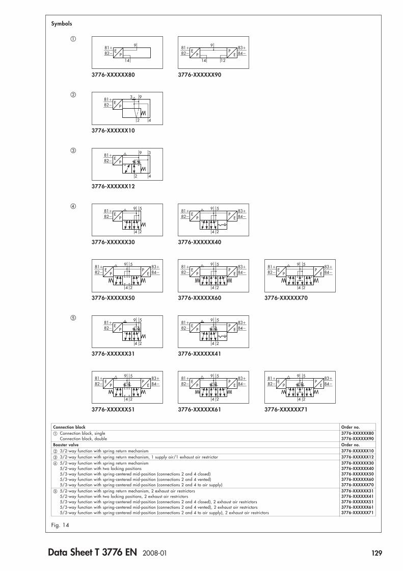
Symbols
Fig. 14
9E
81�5
4 2
82� P
9E
81�5
4 2
82� PP
E
83�84�
9E
81�5
4 2
82� PP
E
83�84�
9E
81�5
4 2
82� PP
E
83�84�
9E
81�
14
82� P
9E
81�
14
82� PP
E
83�84�
12
9E
81�3
2 4
82� P
9E
81�5
4 2
82� PP
E
83�84�
9E
81�5
4 2
82� P
9E
81�5
4 2
82� PP
E
83�84�
9E
81�5
4 2
82� PP
E
83�84�
9E
81�5
4 2
82� PP
E
83�84�
9E
81�5
4 2
82� PP
E
83�84�
3776-XXXXXX80 3776-XXXXXX90
3776-XXXXXX12
3776-XXXXXX30 3776-XXXXXX40
3776-XXXXXX50 3776-XXXXXX60 3776-XXXXXX70
3776-XXXXXX31
3776-XXXXXX51
3776-XXXXXX41
3776-XXXXXX61 3776-XXXXXX71
�
�
�
9E
81�
2 4
82� P
3
3776-XXXXXX10
�
�
Connection block Order no.� Connection block, single 3776-XXXXXX80
Connection block, double 3776-XXXXXX90Booster valve Order no.� 3/2-way function with spring return mechanism 3776-XXXXXX10� 3/2-way function with spring return mechanism, 1 supply air/1 exhaust air restrictor 3776-XXXXXX12� 5/2-way function with spring return mechanism 3776-XXXXXX30
5/2-way function with two locking positions 3776-XXXXXX405/3-way function with spring-centered mid-position (connections 2 and 4 closed) 3776-XXXXXX505/3-way function with spring-centered mid-position (connections 2 and 4 vented) 3776-XXXXXX605/3-way function with spring-centered mid-position (connections 2 and 4 to air supply) 3776-XXXXXX70
� 5/2-way function with spring return mechanism, 2 exhaust air restrictors 3776-XXXXXX315/2-way function with two locking positions, 2 exhaust air restrictors 3776-XXXXXX415/3-way function with spring-centered mid-position (connections 2 and 4 closed), 2 exhaust air restrictors 3776-XXXXXX515/3-way function with spring-centered mid-position (connections 2 and 4 vented), 2 exhaust air restrictors 3776-XXXXXX615/3-way function with spring-centered mid-position (connections 2 and 4 to air supply), 2 exhaust air restrictors 3776-XXXXXX71
Data Sheet T 3776 EN 2008-01 129

Technical data
General dataType 3776Angle of rotation 0° … 100° or 0° … 180°, adjustable,
70° or 90°, fixedTravel range 7.5 … 120 mm for attachment to linear actuators (e. g. SAMSON Type 327X)Material
Enclosure Polyamide PA6-3-T, blackEnclosure cover Polycarbonate 2807, transparentFollower clamp shaft PolyoxymethyleneFilter Filter made of polyethylene,
Filter check valve made of polyamide or stainless steel 1.4305Screws Stainless steel 1.4301
Degree of protection IP 54 with filter,IP 65 with filter check valve
Mounting position Special mounting position (see Mounting and Operating Instructions EB 3776 EN)Ambient temperature, Without explosion protection Permissible componentsdepending on the �20 … �80 °C All componentscomponents and the Type SB3,5-E2 inductive pick-up (max. �70 °C)type of protection �40 … �80 °C Type SC3,5-N0 inductive pick-up
Type SJ3,5-SN inductive pick-upElectric microswitchPilot valve AC/DCAdapter 1/2 NPT made of aluminumCable gland made of brassMale connector (manufactured by Harting) made of aluminumFilter check valve made of stainless steel 1.4305
�45 … �80 °C Type SJ3,5-SN inductive pick-upPilot valve AC/DCAdapter 1/2 NPT made of aluminumCable gland made of brassMale connector (manufactured by Harting) made of aluminumFilter check valve made of stainless steel 1.4305
Type of protection EEx ia IIC 1) Permissible components�20 … �60 °C (temperature class T6) Type SC3,5-N0 inductive pick-up�20 … �70 °C (temperature class T5) Type SJ3,5 SN inductive pick-up�20 … �80 °C (temperature class T4) Type NCN3-F24R-N4 inductive double proximity switch
Electric microswitchPilot valve DCAll electrical connection optionsAll filter options
�45 … �60 °C (temperature class T6) Type SC3,5-N0 inductive pick-up�45 … �70 °C (temperature class T5) Type SJ3,5 SN inductive pick-up�45 … �80 °C (temperature class T4) Pilot valve DC
Adapter 1/2 NPT made of aluminumCable gland made of brassMale connector (manufactured by Harting) made of aluminumFilter check valve made of stainless steel 1.4305
Type of protection EEx nA II 2) Permissible components�45 … �60 °C (temperature class T6) Type SC3,5-N0 inductive pick-up�45 … �70 °C (temperature class T5) Type SJ3,5 SN inductive pick-up�45 … �80 °C (temperature class T4) Electric microswitch
Pilot valve DCAdapter 1/2 NPT made of aluminumCable gland made of brassMale connector (manufactured by Harting) made of aluminumFilter check valve made of stainless steel 1.4305
Electrical connection Terminal connection, plug-type connection or internal AS-Interface module with bus connection(see “Versions and ordering data“)
Weight approx. 450 g (without connection block/booster valve)
1) II 2 G EEx ia IIC T6 according to EC Type Examination Certificate PTB 98 ATEX 20722) II 3 G EEx nA II T6 according to Statement of Conformity PTB 02 ATEX 2007 X
130 Data Sheet T 3776 EN 2008-01
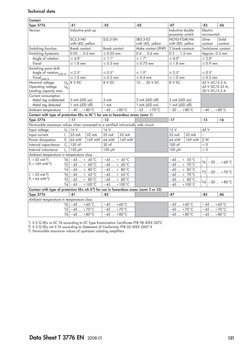
1) II 2 G EEx ia IIC T6 according to EC Type Examination Certificate PTB 98 ATEX 20722) II 3 G EEx nA II T6 according to Statement of Conformity PTB 02 ATEX 2007 X3) Permissible maximum values of upstream isolating amplifiers
Technical data
ContactType 3776 -X1 -X2 -03 -07 -X5 -X6Version Inductive pick-up Inductive double Electric
proximity switch microswitchSC3,5-N0 SJ3,5-SN SB3,5-E2 NCN3-F24R-N4 Silver Goldwith LED, yellow with LED, yellow with LED, yellow contact contact
Switching function Break contact Break contact Make contact (PNP) 2 break contacts Switchover contactSwitching hysteresis 0.03 … 0.2 mm � 0.03 mm 0.4 … 0.6 mm 0.3 … 1.2 mm Approx. 0.3 mm
Angle of rotation � 4.0° � 1.1° � 1.7° � 4.0° � 2.0°Travel � 1.8 mm � 0.5 mm � 0.75 mm � 1.8 mm � 0.9 mm
Switching point driftAngle of rotation�50 K � 2.5° � 0.5° � 1.0° � 2.5° � 0.5°Travel�50 K � 1.0 mm � 0.2 mm � 0.4 mm � 1.0 mm � 0.2 mm
Nominal voltage U0 8 V DC 8 V DC 10 … 30 V DC 8 V DC 42 V AC/5.5 A,Operating voltage UB 42 V DC/0.25 A,Loading capacity max. 20 V DC/5.5 ACurrent consumption
Metal tag undetected 3 mA (LED on) 3 mA 3 mA (LED off) 3 mA (LED on)Metal tag detected 1 mA (LED off) 1 mA 1 mA (LED on) 1 mA (LED off)
Ambient temperature �40 … �80 °C �45 … �80 °C �25 … �70 °C �20 … �80 °C �40 … �80 °CContact with type of protection EEx ia IIC 1) for use in hazardous areas (zone 1)Type 3776 -11 -12 -17 -15 -16Permissible maximum values when connected to a certified intrinsically safe circuitInput voltage Ui 16 V 16 V 15 V 45 VInput current Ii 25 mA 52 mA 25 mA 52 mA 25 mA 52 mA –Power dissipation Pi 64 mW 169 mW 64 mW 169 mW 64 mW 169 mW 2 WInternal capacitance Ci 150 nF 30 nF 100 nF � 0Internal inductance Li 150 μH 100 μH 100 μH � 0Ambient temperature in temperature classIi �52 mA 3) T6 �45 … � 45 °C �45 … � 45 °C �45 … � 55 °C
T6 �20 … �60 °CPi �169 mW 3) T5 �45 … � 60 °C �45 … � 60 °C �45 … � 70 °CT4 �45 … � 80 °C �45 … � 80 °C �45 … � 85 °C
T5 �20 … �70 °CIi �25 mA 3) T6 �45 … � 65 °C �45 … � 65 °C �45 … � 70 °CPi �64 mW 3) T5 �45 … � 80 °C �45 … � 80 °C �45 … � 80 °C
T4 �20 … �80 °CT4 �45 … �100 °C �45 … �100 °C �45 … �100 °C
Contact with type of protection EEx nA II 2) for use in hazardous areas (zone 2 or 22)Type 3776 -81 -82 -87 -85 -86Ambient temperature in temperature class
T6 �45 … �60 °C �45 … �60 °C �45 … �60 °C �45 … �60 °CT5 �45 … �70 °C �45 … �70 °C �45 … �70 °C �45 … �70 °CT4 �45 … �80 °C �45 … �80 °C �45 … �80 °C �45 … �80 °C
Data Sheet T 3776 EN 2008-01 131

Pilot valveElectrical dataType 3776 -XXXX1 -XXXX2 -XXXX3 -0XXX8 -0XXX6 -0XXX5Nominal signal UN 6 V DC 12 V DC 24 V DC 24 V AC 115 V AC 230 V AC
Max. 27 V 1) Max. 25 V 1) Max. 32 V 1) Max. 36 V 1) Max. 130 V 1) Max. 255 V 1)fN 48 … 62 Hz
Switching point U�80 °C 4.8 V 9.6 V 18 V 19 … 36 V 82 … 130 V 183 … 255 V“On“ I �20 °C 1.41 mA 1.52 mA 1.57 mA 1.9 mA 2.2 mA 2.6 mA
P �20 °C 5.47 mW 13.05 mW 26.71 mW 0.04 VA 0.17 VA 0.46 VA“Off“ U�25 °C � 1.0 V � 2.4 V � 4.7 V � 4.5 V � 18 V � 36 V
Impedance R �20 °C 2.6 k 5.5 k 10.7 k Approx. 10 k Approx. 40 k Approx. 80 k
Temperature effect 0.4 %/°C 0.2 %/°C 0.1 %/°C 0.1 %/°C 0.05 %/°C 0.03 %/°CAmbient temperature �45 … �80 °CPilot valve with type of protection EEx ia IIC 2) for use in hazardous areas (zone 1)Type 3776 -1XXX1 -1XXX2 -1XXX3Permissible maximum values for connection to an intrinsically safe circuitOutput voltage 4) Ui 25 V 27 V 28 V 30 V 32 VOutput current 4) Ii 150 mA 125 mA 115 mA 100 mA 85 mAPower dissipation Pi 250 mW No limitationExternal capacitance Ci � 0External inductance Li � 0Ambient temperature in temperature class
T6 �45 … �60 °CT5 �45 … �70 °CT4 �45 … �80 °C
Pilot valve with type of protection EEx nA II 3) for use in hazardous areas (zone 2 or 22)Type 3776 -8XXX1 -8XXX2 -8XXX3Ambient temperature in temperature class
T6 �45 … �60 °CT5 �45 … �70 °CT4 �45 … �80 °C
Pneumatic dataType 3776 -XXXX1 -XXXX2 -XXXX3 -0XXX8 -0XXX6 -0XXX5Kvs
5) 0.01Air supply Medium Instrument air, free of corrosive particles
Pressure 2.2 … 6.0 barOutput signal 1.5 … 2.5 barAir consumption “On“ � 10 l/h at 1.4 bar air supply
“Off“ � 60 l/h at 1.4 bar air supplySwitching time � 50 msTemperature effect 0.4 %/°CSwitching cycles 2 �107
1) Permissible maximum value at 100 % continued on-time. For Ex versions, the permissible maximum value Ui applies2) II 2 G EEx ia IIC T6 according to EC Type Examination Certificate PTB 98 ATEX 20723) II 3 G EEx nA II T6 according to Statement of Conformity PTB 02 ATEX 2007 X4) The Ui/Ii values apply to nominal signals 6/12/24 V DC5) Air flow at p1 �2.4 bar and p2 �1.0 bar can be calculated according to the following equation: Q �Kvs �36.22, expressed in m3/h
Technical data
132 Data Sheet T 3776 EN 2008-01

Technical data
Booster valveType 3776 -XXXXXX10 -XXXXXX12 -XXXXXX3X -XXXXXX4X -XXXXXX5X -XXXXXX6X -XXXXXX7XVersion 3/2-way function 5/2-way function 5/3-way function
with with with with with spring-centered mid-position,spring return spring return spring return two locking connections connections connectionsmechanism mechanism mechanism positions 2 and 4 2 and 4 2 and 4
closed vented to air supplyKvs
1) 0.20 0.30With restrictors 0.01 … 0.18 0.01 … 0.23
Construction Seat valve, Piston valve,soft seating metal-to-metal seating, without overlap
Fail-safe function SIL 4 2)Material
Enclosure GD AlSi12, powder-coated, grayish beige RAL 1019Gaskets Silicone rubber Perbunan, nitrile butadiene rubberFilter PolyethyleneScrews Stainless steel 1.4571
Actuation 3) Single-actuated Double-actuatedOperating medium Instrument air, free of corrosive particles or nitrogenOperating pressure 2.2 … 6.0 barSwitching cycles 107 2 �107
Ambient temperature �45 … �80 °CConnection G 1/4 or 1/4 NPTWeight approx. 150 g 175 g
Connection blockType 3776 -XXXXXX80 -XXXXXX90Version Single 1) Double 2)Safety function SIL 4 3)Kvs
4) 0.01Material
Enclosure GD AlSi 12, powder-coated, grayish beige RAL 1019Gaskets PerbunanScrews Stainless steel 1.4571
Ambient temperature �45 … �80 °CConnection G 1/4 or 1/4 NPTWeight approx. 150 g
1) For single pneumatic actuation of an external Type 3756 3/2 or 5/2-way Booster Valve G 1/4 or 1/4 NPT2) For double pneumatic actuation of an external Type 3756 5/2 or 5/3-way Booster Valve G 1/4 or 1/4 NPT3) Safety Integrity Level SIL 4 according to IEC 61508 (Report No. V 60 2004 T1)4) Air flow at p1 �2.4 bar and p2 �1.0 bar can be calculated according to the following equation: Q �Kvs �36.22, expressed in m3/h
1) Air flow at p1 �2.4 bar and p2 �1.0 bar can be calculated according to the following equation: Q �Kvs �36.22, expressed in m3/h2) Safety Integrity Level SIL 4 according to IEC 61508 (Report No. V 60 2004 T1)3) Actuation by one or two pilot valves
Data Sheet T 3776 EN 2008-01 133

Technical data
Type 3776-0XXXXXXX5X AS-Interface ModuleVersion 1) Internal AS-Interface module for use in non-hazardous areas
(see Mounting and Operating Instructions EB 3776 EN)Transmission of power supply and binary signals over a common two-wire cableConnection of maximum two Type SC3,5-N0 or SJ3,5-SN inductive pick-ups/one Type NCN3-F24R-N4 inductive double proximity switch and two pilot valves 24 V DCWatchdog function “On“/“Off“Cable break and short circuit monitoring
Status indicatorsAS-Interface module LED green “Power supply on“,
LED red “Cable break, short circuit, or interruption of communication“Initiators LED yellow “Unattenuated“Pilot valves LED yellow “Actuated“
Power supply 24 V DCAmbient temperature �25 … �80 °CConnection Cable adapter for AS-i flat cable, 2 wires, made of polyamide, black, or
round plug connector M 12 �1, 4 poles, made of brass, nickel-plated 2)
1) Certification Document No. 28001 of the AS-International Association2) The female connector is not included in the scope of delivery (see “Spare parts and accessories“)
134 Data Sheet T 3776 EN 2008-01

Dimensions
Limit switch
Fig. 15 · Dimensions in mm
� Cable gland M 20 �1.5� Plug-type connector according to EN 175301-803� Plug-type connector (manufactured by Harting)� Plug-type connector (manufactured by Binder)� Cable adapter for AS-i flat cable� Round plug connector M 12 �1� Filter check valve Filter Indicating cap (not used on linear actuators)
Data Sheet T 3776 EN 2008-01 135

Connection block Order no.� Connection block, single 3776-XXXXXX80
Connection block, double 3776-XXXXXX90Booster valve Order no.� 3/2-way function with spring return mechanism 3776-XXXXXX10� 3/2-way function with spring return mechanism, 1 supply air/1 exhaust air restrictor 3776-XXXXXX12� 5/2-way function with spring return mechanism 3776-XXXXXX30
5/2-way function with two locking positions 3776-XXXXXX405/3-way function with spring-centered mid-position (connections 2 and 4 closed) 3776-XXXXXX505/3-way function with spring-centered mid-position (connections 2 and 4 vented) 3776-XXXXXX605/3-way function with spring-centered mid-position (connections 2 and 4 to air supply) 3776-XXXXXX70
� 5/2-way function with spring return mechanism, 2 exhaust air restrictors 3776-XXXXXX315/2-way function with two locking positions, 2 exhaust air restrictors 3776-XXXXXX415/3-way function with spring-centered mid-position (connections 2 and 4 closed), 2 exhaust air restrictors 3776-XXXXXX515/3-way function with spring-centered mid-position (connections 2 and 4 vented), 2 exhaust air restrictors 3776-XXXXXX615/3-way function with spring-centered mid-position (connections 2 and 4 to air supply), 2 exhaust air restrictors 3776-XXXXXX71
Dimensions
Connection block/booster valve
Fig. 16 · Dimensions in mm
All connections with tapped holes G 1/4 or 1/4 NPT
136 Data Sheet T 3776 EN 2008-01
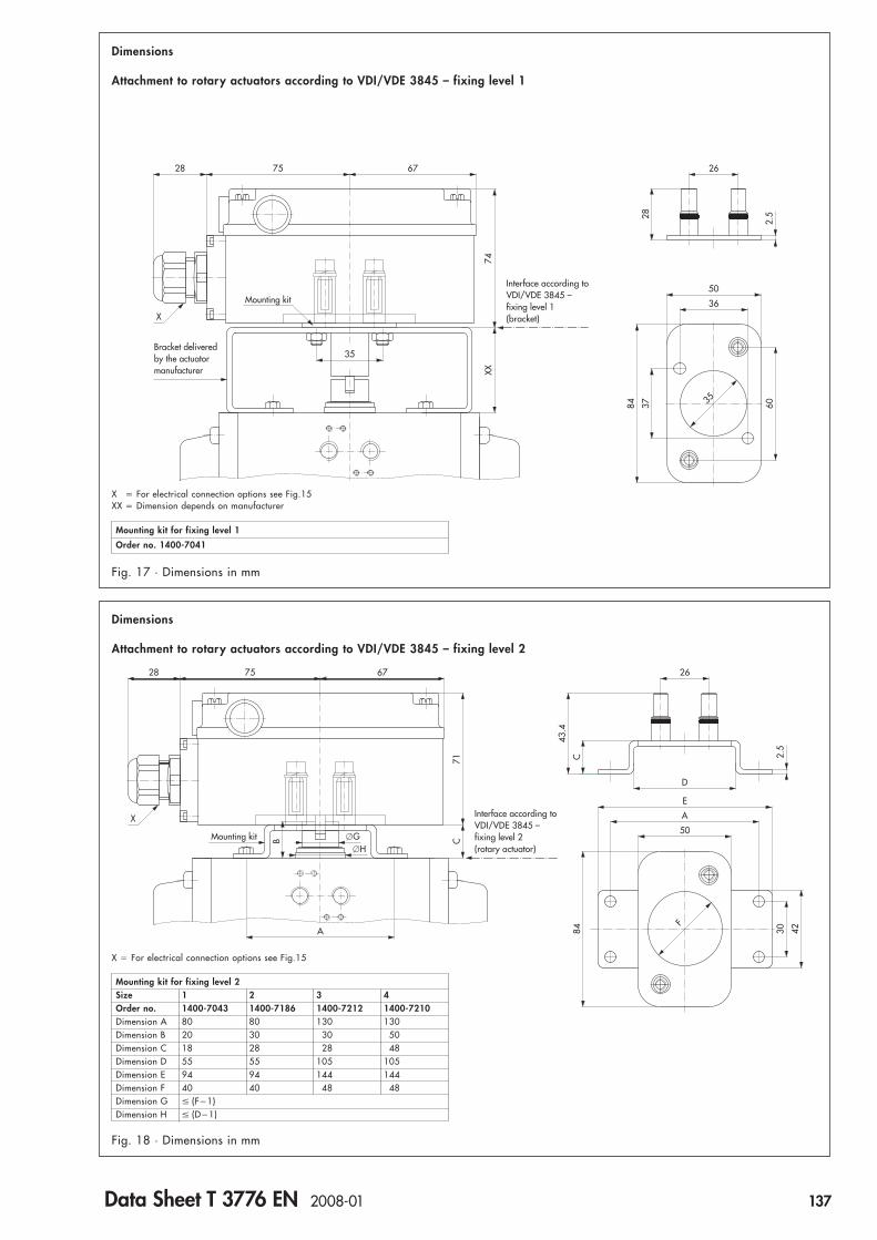
Dimensions
Attachment to rotary actuators according to VDI/VDE 3845 – fixing level 1
Fig. 18 · Dimensions in mm
X � For electrical connection options see Fig.15XX � Dimension depends on manufacturer
Fig. 17 · Dimensions in mm
Dimensions
Attachment to rotary actuators according to VDI/VDE 3845 – fixing level 2
Mounting kit for fixing level 1
Order no. 1400-7041
X � For electrical connection options see Fig.15
Mounting kit for fixing level 2Size 1 2 3 4Order no. 1400-7043 1400-7186 1400-7212 1400-7210Dimension A 80 80 130 130Dimension B 20 30 30 50Dimension C 18 28 28 48Dimension D 55 55 105 105Dimension E 94 94 144 144Dimension F 40 40 48 48Dimension G � (F�1)Dimension H � (D�1)
Data Sheet T 3776 EN 2008-01 137

Type 3776 Limit Switch Order no. 3776- . . . . . . . . . . . . X .Type of protection Without explosion protection 0 ▲ ▲ ▲ ▲ ▲ ▲ ▲ ▲ ▲ ▲ ▲ ▲ ▲
II 2 G EEx ia IIC T6 1) (max. �60/70/80 °C within T6/T5/T4) 1II 3 G EEx nA II T6 2) (max. �60/70/80 °C within T6/T5/T4) 8
Contact Inductive pick-up Type SC3,5-N0 with LED, 2 wires (�40 … �80 °C) 1Versions Type SJ3,5-SN, 2 wires (�45 … �80 °C) 2
Type SB3,5-E2 with LED, 3 wires 3) (without Ex/without AS-i/�25 … �70 °C) 3Inductive double proximity switch Type NCN3-F24R-N4 with LED, 2 �2 wires (�25 … �70 °C) 7 2Electric microswitch, 3 wires 3), with switchover contact made of silver (without AS-i/�40 … �80 °C) 5
with switchover contact made of gold (without AS-i/�40 … �80 °C) 6Quantity 3) 1 contact 1
2 contacts 23 contacts 3
Angle of rotation 0 … 100°, adjustable 00 … 180°, adjustable 10 … 180° with mid-position, adjustable 2
70°, fixed (for Type NCN3-F24R-N4 inductive double proximity switch) 390°, fixed (for Type NCN3-F24R-N4 inductive double proximity switch) 4
Solenoid valve Without solenoid valve 0 0 0 0 0Nominal signal 6 V DC, power consumption 5.47 mW 1
12 V DC, power consumption 13.05 mW 224 V DC, power consumption 26.71 mW 3
230 V AC, power consumption 0.46 VA (without Ex) 5115 V AC, power consumption 0.17 VA (without Ex) 6
24 V AC, power consumption 0.04 VA (without Ex) 8Manual override Without manual override SIL 4 0
Pushbutton underneath enclosure cover SIL 4 1Pushbutton switch underneath enclosure cover 2
Switching function Without switching function (without solenoid valve) 0 0 03/2-way function with spring return mechanism, Kvs 0.20 SIL 4 15/2-way function with spring return mechanism, Kvs 0.30 35/2-way function with two locking positions, Kvs 0.30 45/3-way function with spring-centered mid-position (connections 2 and 4 closed), Kvs 0.30 55/3-way function with spring-centered mid-position (connections 2 and 4 vented), Kvs 0.30 65/3-way function with spring-centered mid-position (connections 2 and 4 to air supply), Kvs 0.30 7Connection block with 1 pilot valve 4) SIL 4 (without restrictors) 8 0Connection block with 2 pilot valves 3 ) 5) (without restrictors) 9 0
Restrictors Without restrictors SIL 4 02 exhaust air restrictors, Kvs 0.01 … 0.23, adjustable (optional for 5/2- or 5/3-way function) 11 supply air/1 exhaust air restrictor, Kvs 0.01 … 0.18, adjustable (optional for 3/2-way function) 2
Air connection Without air connection (without solenoid valve) 0G 1/4 11/4 NPT 2
Electrical connection 1 cable gland made of polyamide, black (min. �20 °C) 1 0Terminal, 12 poles, 2 cable glands made of polyamide, black (min. �20 °C) 1 1threaded connection 1 cable gland made of polyamide, blue (min. �20 °C) 1 2M 20 �1.5 2 cable glands made of polyamide, blue (min. �20 °C) 1 3
1 adapter 1/2 NPT made of aluminum, powder-coated, grayish beige RAL 1019 (min. �45 °C) 1 42 adapter 1/2 NPT made of aluminum, powder-coated, grayish beige RAL 1019 (min. �45 °C) 1 51 EExe cable gland (manufactured by CEAG) made of polyamide, black (min. �20 °C) 1 62 EExe cable glands (manufactured by CEAG) made of polyamide, black (min. �20 °C) 1 71 cable gland made of brass, nickel-plated (min. �45 °C) 1 82 cable glands made of brass, nickel-plated (min. �45 °C) 1 9
Plug-type connection 1 male connector (manufactured by Harting), 8 poles, made of aluminum, silvery gray 6) (min. �40 °C) 2 12 male connectors (manufactured by Harting), 7�7 poles, made of aluminum, silvery gray 6) (min. �40 °C) 2 21 male connector according to EN 175 301-803, 4 poles, made of polyamide, black 6) (min. �20 °C) 2 52 plug-type connectors according to EN 175 301-803, 4�4 poles, made of polyamide, black 7) (min. �20 °C) 2 61 round plug connector (manufactured by Binder), 7 poles, made of polyamide, black 6) (min. �20 °C) 2 72 round plug connectors (manufactured by Binder), 7�6 poles, made of polyamide, black 7) (min. �20 °C) 2 8
AS-Interface module Cable adapter for AS-i flat cable, 2 wires, made of polyamide, black (without Ex/min. �25 °C) 5 0with bus connection 8) Round plug connector M 12 �1, 4 wires, made of brass, nickel-plated 6) (without Ex/min. �25 °C) 5 1
Degree of protection IP 54 with filter made of polyethylene (min. �20 °C) 0IP 65 with filter check valve made of polyamide (min. �20 °C) 1IP 65 with filter check valve made of 1.4305 (min. �45 °C) 2
Ambient temperature 9) The permissible ambient temperature of the limit switch depends on the components, the type of protection, and the temperature class. XSafety function Without safety function 0
SIL 4 10) 1
Versions and ordering data
1) EC Type Examination Certificate PTB 98 ATEX 2072 and GOST Certificate 2002.C312 (1 Ex ia IIC T6 X)2) Statement of Conformity PTB 02 ATEX 2007 X3) With a double actuated solenoid valve, a maximum of two 3-wire contacts can be used4) For pneumatic single actuation of an external Type 3756 3/2 or 5/2-way Booster Valve G 1/4 or 1/4 NPT5) For pneumatic double actuation of an external Type 3756 5/2 or 5/3-way Booster Valve G 1/4 or 1/4 NPT6) The female connector is not included in the scope of delivery (see “Spare parts and accessories“)7) The female connectors are included in the scope of delivery8) According to Certification Document No. 28001 of the AS-International Association9) Safety Integrity Level SIL 4 according to IEC 61508 (Report No.V 60 2004 T1)
138 Data Sheet T 3776 EN 2008-01

Order no. Designation0790-6658 Female connector according to EN 175301-803, type A, made of polyamide, black1400-8298 Female connector (manufactured by Harting), 7 poles, made of aluminum, silvery gray8801-2810 Sensor connecting cable, 2 wires, length 3 m, blue, with angle connector M 12 �1, 4 poles, made of brass, nickel-plated8831-0716 Female connector (manufactured by Binder), 7 poles, made of PBT GV, black8831-0865 Female connector M 12 �1, 4 poles, angle type, made of polyamide, black
1890-4875 Cable gland M 20 �1.5 made of brass, nickel-plated8808-0178 EExe cable gland M 20 �1.5 (manufactured by CEAG) made of polyamide, black8808-1011 Cable gland M 20 �1.5 made of polyamide, black8808-1012 Cable gland M 20 �1.5 made of polyamide, blue
0310-2149 Adapter 1/2 NPT made of aluminum, powder-coated, grayish beige RAL 1019
1089-1159 Enclosure cover made of polycarbonate, transparent, connection G 1/4 for filter/filter check valve
1890-4663 PCB for AS-Interface module
3994-0158 Cable break protection device with enclosure for top hat rail 35, degree of protection IP 20(for Type 3776-XXXX1 with solenoid valve 6 V DC)
1790-7253 Filter check valve made of stainless steel 1.4305, connection G 1/4, degree of protection IP 651790-7408 Filter check valve made of polyamide, connection G 1/4, degree of protection IP 658504-0066 Filter made of polyethylene, connection G 1/4, degree of protection IP 54
Mounting kits
1400-7216 Mounting kit made of stainless steel 1.4301 for Type 3278 Rotary Actuators, actuator size 160 cm2
1400-7217 Mounting kit made of stainless steel 1.4301 for Type 3278 Rotary Actuators, actuator size 320 cm2
1400-7041 Mounting kit made of stainless steel 1.4301 for rotary actuators according to VDI/VDE 3845 – fixing level 10469-0017 Follower clamp for mounting kit with fixing level 1
Mounting kit made of stainless steel 1.4301 for rotary actuators according to VDI/VDE 3845 – fixing level 21400-7043 Size 1, hole spacing A = 80 mm, shaft stub length B = 20 mm1400-7186 Size 2, hole spacing A = 80 mm, shaft stub length B = 30 mm1400-7212 Size 3, hole spacing A = 130 mm, shaft stub length B = 30 mm1400-7210 Size 4, hole spacing A = 130 mm, shaft stub length B = 50 mm
1400-7220 Mounting kit made of stainless steel 1.4301 for Type 3277 Linear Actuators, actuator size 240/350 cm2
1400-7221 Mounting kit made of stainless steel 1.4301 for Type 3277 Linear Actuators, actuator size 700 cm2
1400-7219 Mounting kit made of stainless steel 1.4301 for Type 3277-5 Linear Actuators (external)
1400-7222 Mounting kit made of stainless steel 1.4301 for Type 3277-5 Linear Actuators (internal), connection G 1/41400-7223 Mounting kit made of stainless steel 1.4301 for Type 3277-5 Linear Actuators (internal), connection 1/4 NPT0430-1544 Seal hose for attachment to Type 3277-5 Linear Actuators (internal)
1400-7730 Mounting kit made of stainless steel 1.4301 for Type 3241 Control Valves, nominal size DN 15 to 100
1400-7735 Mounting kit made of stainless steel 1.4301 for Type 3351 Control Valves, nominal size DN 15 to 501400-7736 Mounting kit made of stainless steel 1.4301 for Type 3351 Control Valves, nominal size DN 65 to 801400-7737 Mounting kit made of stainless steel 1.4301 for Type 3351 Control Valves, nominal size DN 100
On request Mounting kit made of stainless steel 1.4301 for stem valves, nominal size DN 15 to 150
On request Mounting kit made of stainless steel 1.4301 for Series 250 and 280 Control Valves with NAMUR rib,nominal size DN 15 to 400
On request Mounting kit made of stainless steel 1.4301 for Type 324X Control Valves, nominal size DN 200 to 300
Spare parts and accessories
Data Sheet T 3776 EN 2008-01 139


Inductive Limit Switch for Pneumatic Control Valves
Type 3768
ApplicationLimit switch with two incorporated inductive switches andoptionally one 3/2-way solenoid valve for attachment topneumatic control valvesFor rated travels from 7.5 to 120 mm
The limit switch is equipped with two inductive proximityswitches which issue a signal when an adjustable limit is ex-ceeded in either direction.Optionally, the limit switch is also available with an integral3/2-way solenoid valve which registers a binary signal issuedby a control device and converts it into a binary signal pressure.When the solenoid valve is in de-energized state, the actuatormoves the valve to the fail-safe position.– All limit switches can be overridden and can be optionally
used as normally closed or normally open contacts– Versions for use in hazardous areas in type of protection
intrinsically safe EEx ia II C T6 are available (refer to the sum-mary of explosion protection certificates)
– Direct attachment to Type 3277 Pneumatic Actuator– Attachment to actuators according to IEC 60534 and
NAMUR recommendations– Attachment to rotary actuators with an interface according to
VDI/VDE 3845
Refer to the Information Sheet T 8350 EN on selection and ap-plication of positioners and limit switches.
Fig. 2 · Type 3768 Limit Switch, opened housing
Fig. 1 · Type 3768 Limit Switch
Data Sheet T 8356 EN 2010-01 141
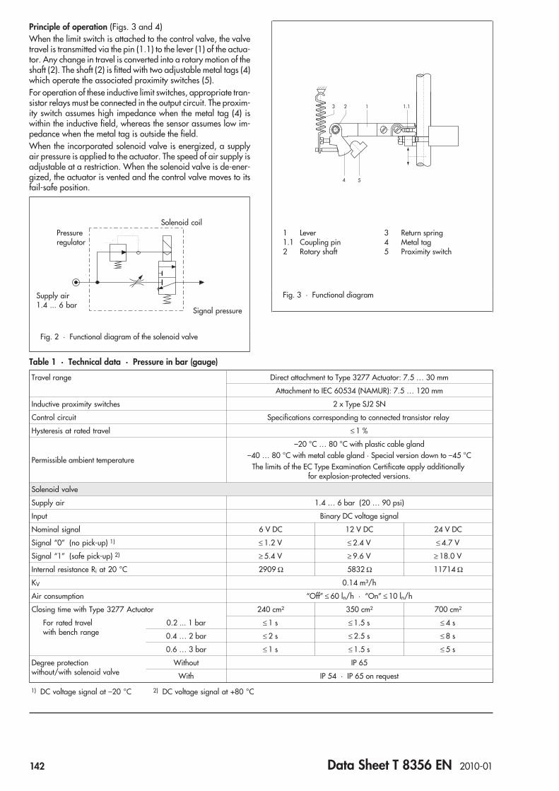
Principle of operation (Figs. 3 and 4)When the limit switch is attached to the control valve, the valvetravel is transmitted via the pin (1.1) to the lever (1) of the actua-tor. Any change in travel is converted into a rotary motion of theshaft (2). The shaft (2) is fitted with two adjustable metal tags (4)which operate the associated proximity switches (5).For operation of these inductive limit switches, appropriate tran-sistor relays must be connected in the output circuit. The proxim-ity switch assumes high impedance when the metal tag (4) iswithin the inductive field, whereas the sensor assumes low im-pedance when the metal tag is outside the field.When the incorporated solenoid valve is energized, a supplyair pressure is applied to the actuator. The speed of air supply isadjustable at a restriction. When the solenoid valve is de-ener-gized, the actuator is vented and the control valve moves to itsfail-safe position.
Fig. 2 · Functional diagram of the solenoid valve
Table 1 · Technical data · Pressure in bar (gauge)
Travel range Direct attachment to Type 3277 Actuator: 7.5 … 30 mm
Attachment to IEC 60534 (NAMUR): 7.5 … 120 mm
Inductive proximity switches 2 x Type SJ2 SN
Control circuit Specifications corresponding to connected transistor relay
Hysteresis at rated travel ≤ 1 %
Permissible ambient temperature
–20 °C … 80 °C with plastic cable gland–40 … 80 °C with metal cable gland · Special version down to –45 °C
The limits of the EC Type Examination Certificate apply additionallyfor explosion-protected versions.
Solenoid valve
Supply air 1.4 … 6 bar (20 … 90 psi)
Input Binary DC voltage signal
Nominal signal 6 V DC 12 V DC 24 V DC
Signal “0” (no pick-up) 1) ≤ 1.2 V ≤ 2.4 V ≤ 4.7 V
Signal “1” (safe pick-up) 2) ≥ 5.4 V ≥ 9.6 V ≥ 18.0 V
Internal resistance Ri at 20 °C 2909 Ω 5832 Ω 11714 Ω
KV 0.14 m³/h
Air consumption “Off” ≤ 60 ln/h · “On” ≤ 10 ln/h
Closing time with Type 3277 Actuator 240 cm² 350 cm² 700 cm²
For rated travelwith bench range
0.2 ... 1 bar ≤ 1 s ≤ 1.5 s ≤ 4 s
0.4 … 2 bar ≤ 2 s ≤ 2.5 s ≤ 8 s
0.6 … 3 bar ≤ 1 s ≤ 1.5 s ≤ 5 s
Degree protectionwithout/with solenoid valve
Without IP 65
With IP 54 · IP 65 on request
1) DC voltage signal at –20 °C 2) DC voltage signal at +80 °C
Fig. 3 · Functional diagram
Solenoid coil
Signal pressure
Pressureregulator
Supply air1.4 ... 6 bar
3 Return spring4 Metal tag5 Proximity switch
1 Lever1.1 Coupling pin2 Rotary shaft
142 Data Sheet T 8356 EN 2010-01
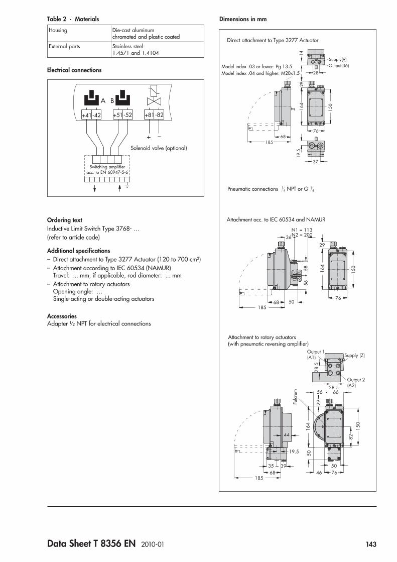
Table 2 · Materials
Housing Die-cast aluminumchromated and plastic coated
External parts Stainless steel1.4571 and 1.4104
Electrical connections
Ordering textInductive Limit Switch Type 3768- …(refer to article code)
Additional specifications– Direct attachment to Type 3277 Actuator (120 to 700 cm²)– Attachment according to IEC 60534 (NAMUR)
Travel: ... mm, if applicable, rod diameter: ... mm– Attachment to rotary actuators
Opening angle: …Single-acting or double-acting actuators
AccessoriesAdapter ½ NPT for electrical connections
Dimensions in mm
A B
+41-42 +51-52 +81-82
_+
Solenoid valve (optional)
Switching amplifieracc. to EN 60947-5-6
28
1429
150
164
19.5
37
68185
76
Supply(9)Output(36)
Direct attachment to Type 3277 Actuator
Model index .03 or lower: Pg 13.5Model index .04 and higher: M20x1.5
Pneumatic connections 14 NPT or G 1
4
36
N1 = 113N2 = 200
5856
68185
29
164
76
150
50
Attachment acc. to IEC 60534 and NAMUR
44
19.5
393568
185
164
29
50
46 7650
150
82
56 66
28.5
28.5
Output 1(A1)
Output 2(A2)
Supply (Z)
Attachment to rotary actuators(with pneumatic reversing amplifier)
Fulc
rum
Data Sheet T 8356 EN 2010-01 143

Summary of explosion protection approvals
Type of approval Certificate number Date Type of protection/Comments
EC Type Examination Certificate PTB 02 ATEX 2077 2002-07-19 II 2 G EEx ia IIC T6; Type 3768-1
Statement of Conformity PTB 03 ATEX 2182 X 2003-09-30 II 3 G EEx nA II T6; Zone 2; Type 3768-8
CSA approval LR 54227-14 1992-04-21 Class I, Div. 1, Groups A, B, C, D; Type 3 EnclosureType 3768-3
FMRC approval J.I.3020228 2005-02-28 Class I, II, III; Div. 1, Groups A, B, C, D, E, F, GClass I, Zone 0 AEx ia IIC T6Class I, Div. 2, Groups A, B, C, DClass II, Div. 2, Groups F, G; Class IIINEMA 4X; with inductive limit switches and solenoid valve;Type 3768-3
NEPSI approval GYJ04218X 2004-12-22 Ex ia IIC T4 … T6; valid until 2009-12-21; Type 3768-1
GYJ04219X Ex nL IIC T4 … T6; valid until 2009-12-21; Type 3768-8
Article code
Limit Switch Type 3768 x 2 x 0 0 x x x x 0 x x 0
Explosion protection
Without 0 2/7
II 2 G EEx ia IIC T6 acc. to ATEX 1
CSA/FM intrinsically safe/non incendive 3
II 3 G EEx nA II T6 acc. toATEX 8 2/7
Solenoid valve
Without 0
6 V DC 2
12 V DC 3
24 V DC 4
Pneumatic connections
Without 0 0
¼-18 NPT 1
ISO 221/1 - G ¼ 2
Electrical connection
Cable gland M20 x 1.5, blue (plastic) 1 0
Cable gland M20 x 1.5, black (plastic) 2 0
Cable gland M20 x 1.5, nickel-plated brass 7 2
Housing version
Aluminum 0
CrNiMo steel 2
Temperature range
Standard 0
–45 … 80 °C 2
Special versions
None 0 0 0
NEPSI approval Ex ia 1 0 0 9
NEPSI approval Ex nL 8 0 1 0
Specifications subject to change without notice
144 Data Sheet T 8356 EN 2010-01

Electric Limit Switchfor hazardous areas
Type 4744
ApplicationLimit switches in type of protection II 2 G EEx ed IIC T6 forattachment to pneumatic control valves according toIEC 60534-6-1For valve travels from 7.5 to 150 mm
The limit switch supplies a limit signal when an adjusted limit isexceeded in either direction, especially when a control valvehas reached a final position. This signal is suitable for reversingcontrol signals, initiating visual or audible alarms and for con-nection to central control or alarm systems.• One or two electric limit switches which can be overridden• High load capacity, for example, alternating current up to
500 V/10 AAttachment to control valves with cast yokes or rod-type yokesaccording to IEC 60534-6-1 and NAMUR recommendation.
Versions– Type 4744 (Figs. 1 and 2) Limit switch with one or two mo-
mentary-contact limit switches designed as a position switchconforming to EN 50041.Each contact is equipped with one NC contact and one NOcontact, acting as snap-action switch, or also switchable as asingle-pole double throw switch (SPDT).
Type of protection "Flameproof Enclosure" II 2 G EEx ed IICT6 according to test certificates PTB 01 ATEX 1053 and II 2 D IP65 T 80 °C according to LCIE ATEX 6308.– Type 4744-2 (Fig. 3) · Limit switch with one momemtary-con-
tact switch for mounting to a rod-type yoke of V2001 SeriesValves
Type of protection "Flameproof Enclosure" II 2 G EEx d IIC T6according to PTB 00 ATEX 1093 X.
Principle of operation of Type 4744 (Fig. 2)When the limit switch is attached to the control valve, the valvetravel is transmitted to the switch lever via the lever. The switchlever actuates the snap-action contact of one of the momen-tary-contact limit switches when the adjusted limit value isreached. This switch can be overridden and is equipped with anoverrange protection. For coarse adjustment (switching point),the momentary-contact limit switch is shifted on the base plate.The adjustment screw is used for fine adjustment. The terminalconnections determine whether the limit switch is used either asan NO contact, an NC contact or a changeover contact (Fig. 4).Refer to Information Sheet T 8350 EN for selection and applica-tion of positioners and limit switches.
Fig. 2 · Type 4744 Electric Limit Switch withtwo momentary-contact switches and protectivecover removed
Fig. 3 · Type 4744-2 Electric Limit Switchpreferably for Series V2001 Valves
24 23 BK BNBU
12 11
Type 4744 Type 4744-2
Fig. 4 · Electrical connection
Fig. 1 · Type 4744 Electric Limit Switchwith protection cover
Data Sheet T 8367 EN 2010-01 145

Table 1 · Technical data
Limit switch Type 4744 4744-2
Momemtary-contact switch 1 or 2 1
Type of protection Flameproof enclosure,terminal space in increased safety.
II 2 G EEx ed IIC T6 - PTB 02 ATEX 1053II 2 D IP 65 T 80 °C - LCIE 03 ATEX 6308
Flameproof enclosure
II 2 G EEx d IIC T6PTB 00 ATEX 1093 X
Permissible load (load capacity) AC voltage
500 V / 10 AUtilization category AC-15 250 V / 5 A
DC voltage
125 V / 10 A250 V / 0.2 A
Utilization category DC-12250 V / 0.4 A
Travel range 7.5 … 100 mmwith extended lever up to max. 150 mm 15 mm
Permissible ambient temperature * –55 … 70 °C –20 … 75 °C
Degree of protection IP 65 IP 66
Weight (approx.) 1.75 kg 0.4 kg
Housing material Glass fiber reinforced polyester Duroplast
* The limits specified in the relevant approval certificate additionally apply for use in hazardous areas.
Summary of approvals
Type of approval Certificate number Date Type of protection/Comments
EC Type Examination Certificate PTB 01 ATEX 1053 2001-08-09 II 2 G EEx ed IIC T6; Type 4744
LCIE 03 ATEX 6308 2003-10-10 II 2 D IP 65 T 80 °C; Type 4744
DMT 01 ATEX E 178 2001-12-28 II 2 G EEx de IIC T6II 2 D IP 65 T 80 °C; Type 4744
PTB 00 ATEX 1093 X 2000-12-07 II 2 G EEx d IIC T6/T5; Type 4744-2
GOST approval B 02637 2009-02-26 2 Ex d IIC T6
23767164.5
117(115-132)
120
60˚
5
8113
7 6330
151
M20x1.5
Dimensions in mm
56
3510
37
68 34
11 53
Ø20
Type 4744-2
Type 4744
146 Data Sheet T 8367 EN 2010-01

Ordering textElectric Limit Switch Type 4744 or
Type 4744-2Momentary-contact switch 1 or 2 functioning as
NO contact or NC contactFor indicating Valve OPEN/Valve CLOSED or
OPEN-CLOSED
Specifications subject to change without notice
Article code
Electric Limit Switch Type 4744- x 0 0 x 1 x 0
Attachment
To NAMUR rib 1 4/5
To rod-type yoke for Type 3372 Actuator 2 1 1
Version
1 double-throw switch 0 0 1 1
2 Series 8070/1-2-S switches 0 0 4
1 Series 8070/1-2-S switch 0 0 5
Special version
None 1
GOST approval (model version -9010) 2
Data Sheet T 8367 EN 2010-01 147


Electronic Limit Switch Type 3738-20
with optional solenoid valvefor on/off rotary actuators
ApplicationElectronic limit switch for on/off applications to indicate the endposition of rotary actuators. Optionally with integrated solenoidvalve.
Special features• Automation of on/off valves• Limit switch and optional integrated solenoid valve united in
a compact housing or with commercially available externalsolenoid valves (Ex ia, Ex e)
• Proven operation concept already used in Series 373xPositioners: Menu-driven, on-site operation using one rotarypushbutton, display easy to read in any mounting position
• Trouble-free integration into existing systemsNAMUR contacts (IEC 60947-5-6)Solenoid valve 24 V DCIntrinsically safe version
• Compact attachment and simple operation• Any mounting position according to VDI/VDE 3845, level 2• Contactless, wear-free magnetoresistive sensor system
No mechanical linkageNo adjustment work necessaryStable measured data and drift-free switching pointsHigh level of accuracy
• Electric power for electronic limit switch supplied over atwo-wire system solely from the NAMUR signal
• Automatic initialization• Easy-to-read LC display with selectable reading direction,
LED for solenoid valve status• Communication connection for convenient parameter set-
tings and documentation• Certified safety, use in safety instrumented systems according
to IEC 61508• Diagnostic functions
Advanced partial stroke test (PST)Rotary motion counterOperating hours counterTransit time measurement
Fig. 1 · Type 3738 Electronic Limit Switchwith open cover
Fig. 2 · Type 3738 mounted on a piston actuator
Data Sheet T 8390 EN 2009-12 149
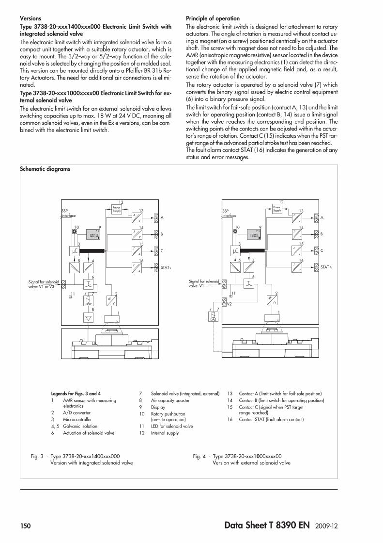
VersionsType 3738-20-xxx1400xxx000 Electronic Limit Switch withintegrated solenoid valveThe electronic limit switch with integrated solenoid valve form acompact unit together with a suitable rotary actuator, which iseasy to mount. The 3/2-way or 5/2-way function of the sole-noid valve is selected by changing the position of a molded seal.This version can be mounted directly onto a Pfeiffer BR 31b Ro-tary Actuators. The need for additional air connections is elimi-nated.Type 3738-20-xxx1000xxxx00 Electronic Limit Switch for ex-ternal solenoid valveThe electronic limit switch for an external solenoid valve allowsswitching capacities up to max. 18 W at 24 V DC, meaning allcommon solenoid valves, even in the Ex e versions, can be com-bined with the electronic limit switch.
Principle of operationThe electronic limit switch is designed for attachment to rotaryactuators. The angle of rotation is measured without contact us-ing a magnet (on a screw) positioned centrically on the actuatorshaft. The screw with magnet does not need to be adjusted. TheAMR (anisotropic magnetoresistive) sensor located in the devicetogether with the measuring electronics (1) can detect the direc-tional change of the applied magnetic field and, as a result,sense the rotation of the actuator.The rotary actuator is operated by a solenoid valve (7) whichconverts the binary signal issued by electric control equipment(6) into a binary pressure signal.The limit switch for fail-safe position (contact A, 13) and the limitswitch for operating position (contact B, 14) issue a limit signalwhen the valve reaches the corresponding end position. Theswitching points of the contacts can be adjusted within the actua-tor’s range of rotation. Contact C (15) indicates when the PST tar-get range of the advanced partial stroke test has been reached.The fault alarm contact STAT (16) indicates the generation of anystatus and error messages.
Schematic diagrams
SSPinterface
10 9
3
12
B
A
13
C
15
STAT
2
4
6
11 7
81
5 16
14
Signal for solenoidvalve: V1 or V3
PowerSupply
Fig. 3 · Type 3738-20-xxx1400xxx000Version with integrated solenoid valve
SSPinterface
10 9
3
12
B
A
13
C
15
STAT
2
4
6
11
71
5 16
14
Signal for solenoidvalve: V1
V2
PowerSupply
Fig. 4 · Type 3738-20-xxx1000xxxx00Version with external solenoid valve
Legends for Figs. 3 and 41 AMR sensor with measuring
electronics2 A/D converter3 Microcontroller4, 5 Galvanic isolation6 Actuation of solenoid valve
7 Solenoid valve (integrated, external)8 Air capacity booster9 Display10 Rotary pushbutton
(on-site operation)11 LED for solenoid valve12 Internal supply
13 Contact A (limit switch for fail-safe position)14 Contact B (limit switch for operating position)15 Contact C (signal when PST target
range reached)16 Contact STAT (fault alarm contact)
150 Data Sheet T 8390 EN 2009-12

An electronic limit switch version for an external solenoid valveis available for higher air capacities required by large actua-tors.
OperationA rotary pushbutton and LC display are used to operate theelectronic limit switch on site.The functions for start-up, display readings and service func-tions are set over Codes (0 to 28). When a fault occurs, a corre-sponding error code appears on the display.SAMSON’s TROVIS-VIEW can be used to operate the elec-tronic limit switch. An SSP interface on the electronic limit switchis used to connect it to the computer using an adapter cable.
MountingThe Type 3730-20 Electronic Limit Switch is mounted accordingto VDI/VDE 3845, fixing level 2 on rotary actuators using amounting platform.Various mounting parts (accessories) are available dependingon the shaft height of the rotary actuator.
Pneumatic connections:Version with external solenoid valve:The input pressure at the external solenoid valvemust not exceedthe maximum supply pressure (refer to the specifications givenby the solenoid valve manufacturer).
Version with integrated solenoid valve:The supply pressure at the inlet must not exceed 6 bar.
All air pipes and hoses must be thoroughly blown through priorto connecting them. The need for external piping is eliminatedwhen certain pneumatic actuators are used. The air is con-nected over holes in the mounting platform and actuator.
Electrical connectionsThe electronic limit switch is powered by the connection of thelimit switch A. An additional electrical auxiliary power supply isnot required.
Cable entryThe threaded connection for the terminal compartment is de-signed with an M20 x 1.5 thread.The screw terminals are designed for wire cross-sections of1.5 mm². Tighten by at least 0.5 Nm.
Use in safety instrumented systems
Safe indication of end positionsAll switching contacts of the Type 3738-20 Electronic LimitSwitch behave as stipulated in IEC 60947-5-6 and are suitablefor use in safety-related applications up to SIL 2 (single device)and SIL 3 (redundant configuration) according to IEC 61508.
Emergency venting (in preparation)When the optional integrated solenoid valve is used, the elec-tronic limit switch discharges its pneumatic output to the atmo-sphere when the solenoid valve is de-energized. This causes themounted actuator to be vented.
Table 1 · Technical data
Electronic limit switch Type 3738-20-xxx1400xxx000 3738-20-xxx1000xxxx00
Version With internal solenoid valve For external solenoid valve
Range ofrotation
Minimum 0 to 30°
Maximum 0 to 170°
Commu-nication
Local communication SAMSON SSP interface with serial interface adapter
Software requirements TROVIS-VIEW with database module 3738-20
Supply air Supply pressure 2.4 to 6 bar Same as specifications of the solenoid valvemanufacturer
Air quality Acc. to ISO 8573-1, edition 2004Max. particle size and density: Class 4Oil content: Class 3Moisture and water: Class 3Pressure dew point: At least 10 K beneath thelowest ambient temperature to be expected
Same as specifications of the solenoid valvemanufacturer
Electric power supply Powered over limit switch A
Permissible ambient temperature –25 to 80 °C –40 to 80 °C
The limits specified in the EC Type Examination Certificate additionally apply.
Influences Temperature ± 0.7 %/90° angle over the permissible temperature range
Vibrations ≤ 0.25 % up to 2500 Hz and 4 g according to IEC 770
Electromagnetic compatibility Requirements conforming to EN 61000-6-2, EN 61000-6-3 and NAMUR Recommendation NE 21
Electrical connections Four M20 x 1.5 cable glands for 6 to 12 mm clamping range, screw terminals for 0.2 to 2.5 mm²wire cross-sections
Explosion protection See certificates in Table 2
Degree of protection IP 66
Data Sheet T 8390 EN 2009-12 151
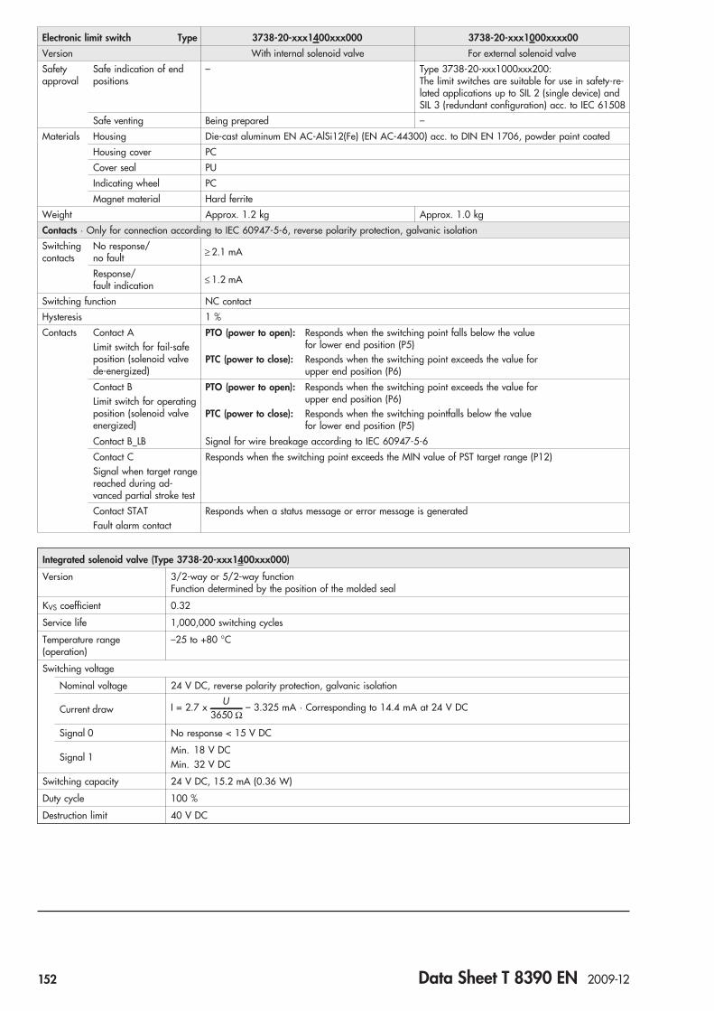
Electronic limit switch Type 3738-20-xxx1400xxx000 3738-20-xxx1000xxxx00
Version With internal solenoid valve For external solenoid valve
Safetyapproval
Safe indication of endpositions
– Type 3738-20-xxx1000xxx200:The limit switches are suitable for use in safety-re-lated applications up to SIL 2 (single device) andSIL 3 (redundant configuration) acc. to IEC 61508
Safe venting Being prepared –
Materials Housing Die-cast aluminum EN AC-AlSi12(Fe) (EN AC-44300) acc. to DIN EN 1706, powder paint coated
Housing cover PC
Cover seal PU
Indicating wheel PC
Magnet material Hard ferrite
Weight Approx. 1.2 kg Approx. 1.0 kg
Contacts · Only for connection according to IEC 60947-5-6, reverse polarity protection, galvanic isolation
Switchingcontacts
No response/no fault ≥ 2.1 mA
Response/fault indication ≤ 1.2 mA
Switching function NC contact
Hysteresis 1 %
Contacts Contact ALimit switch for fail-safeposition (solenoid valvede-energized)
PTO (power to open): Responds when the switching point falls below the valuefor lower end position (P5)
PTC (power to close): Responds when the switching point exceeds the value forupper end position (P6)
Contact BLimit switch for operatingposition (solenoid valveenergized)
PTO (power to open): Responds when the switching point exceeds the value forupper end position (P6)
PTC (power to close): Responds when the switching pointfalls below the valuefor lower end position (P5)
Contact B_LB Signal for wire breakage according to IEC 60947-5-6
Contact CSignal when target rangereached during ad-vanced partial stroke test
Responds when the switching point exceeds the MIN value of PST target range (P12)
Contact STATFault alarm contact
Responds when a status message or error message is generated
Integrated solenoid valve (Type 3738-20-xxx1400xxx000)
Version 3/2-way or 5/2-way functionFunction determined by the position of the molded seal
KVS coefficient 0.32
Service life 1,000,000 switching cycles
Temperature range(operation)
–25 to +80 °C
Switching voltage
Nominal voltage 24 V DC, reverse polarity protection, galvanic isolation
Current draw I = 2.7 xU
3650 Ω– 3.325 mA · Corresponding to 14.4 mA at 24 V DC
Signal 0 No response < 15 V DC
Signal 1Min. 18 V DCMin. 32 V DC
Switching capacity 24 V DC, 15.2 mA (0.36 W)
Duty cycle 100 %
Destruction limit 40 V DC
152 Data Sheet T 8390 EN 2009-12

Electrical connections
_ +282
Connection acc. to EN 60947-5-6
24 V DC
281_+
8281
24 V DC
V1 V3
PTOPTC
_ +_ +62 6184 83
CSTAT B
+_ _ +414252 51515242 41
A
Fig. 5 · Version with internal solenoid valve (Type 3738-20-xxx1400xxx000)
Connection acc. to EN 60947-5-6
PTOPTC
B_ __ _
4252625242
84+ +++
41515141
6183
ACSTAT
24 V DC,max. 18 W
Acc. to manufacturer´sspecifications
_+_+8281
V1V2
Fig. 6 · Version for external solenoid valve (Type 3738-20-xxx1000xxxx00)
External solenoid valve (Type 3730-20-xxx1000xxxx00)
Read manufacturer’s specifications!
24 V DC, max. 18 W
Table 2 · Explosion protection certificates
Type of approval Certificate number Date Comments
EC Type Examination Certificate PTB 08 ATEX 2039 X 2009-03-16 Type 3738-20-110II 2G Ex ia IIC/IIB T6, II 2D Ex iaD A21 IP 66 T80°C
First Addendum 2009-10-20 Type 3738-20-310II 2G Ex e [ia] IIC T4, II 2D Ex tD A21 IP 66 T80°C
Data Sheet T 8390 EN 2009-12 153

Article code
Electronic Limit Switch Type 3738-20 x x x 1 x 0 0 x x x x 0 x
With LC display
Explosion protection
Without 0 0 0
II 2G Ex ia IIC/IIB T6, II 2D Ex iaD A21 IP 66 T 80 °C, ATEX 1 1 0
II 2G Ex e [ia] IIC T4, II 2D Ex tD A21 IP 66 T 80 °C 3 1 0 0
Solenoid valve
External 0
Integrated 4 0
Company version
SAMSON 0
AIR TORQUE 1
Housing
Standard aluminum, black structured, RAL 9005 1
Cover
Gray-beige 0
Black 1
Silver-gray 3
Safety approval
None 0
TÜV/IEC 61508 (for safe indication of end positions) 0 2
Special applications
None 0
231
20
17
97
130185
84
42
10
3040
Fig. 7 · Dimensional drawing for Type 3738-20 Electronic Limit Switch
Dimensions
154 Data Sheet T 8390 EN 2009-12
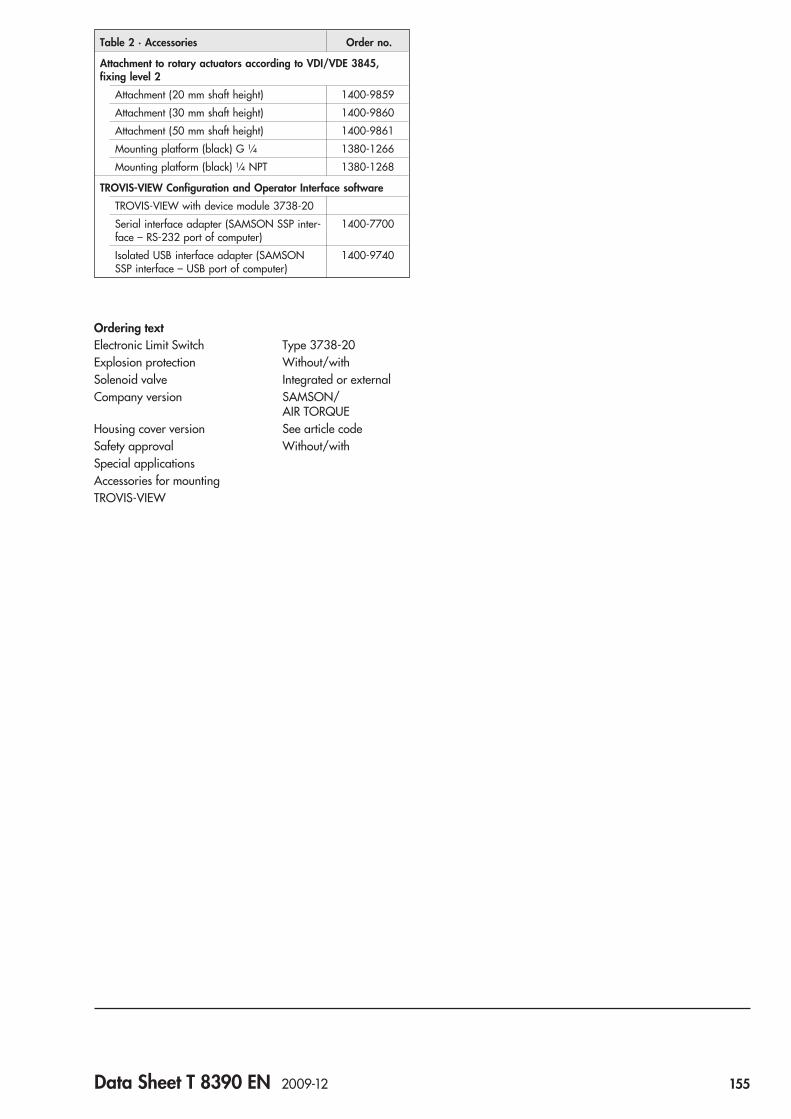
Ordering textElectronic Limit Switch Type 3738-20Explosion protection Without/withSolenoid valve Integrated or externalCompany version SAMSON/
AIR TORQUEHousing cover version See article codeSafety approval Without/withSpecial applicationsAccessories for mountingTROVIS-VIEW
Table 2 · Accessories Order no.
Attachment to rotary actuators according to VDI/VDE 3845,fixing level 2
Attachment (20 mm shaft height) 1400-9859
Attachment (30 mm shaft height) 1400-9860
Attachment (50 mm shaft height) 1400-9861
Mounting platform (black) G ¼ 1380-1266
Mounting platform (black) ¼ NPT 1380-1268
TROVIS-VIEW Configuration and Operator Interface software
TROVIS-VIEW with device module 3738-20
Serial interface adapter (SAMSON SSP inter-face – RS-232 port of computer)
1400-7700
Isolated USB interface adapter (SAMSONSSP interface – USB port of computer)
1400-9740
Data Sheet T 8390 EN 2009-12 155


Analog Position Transmitter Type 4748
ApplicationAnalog position transmitter for attachment to control valves aswell as Type 4763 Electropneumatic Positioner or Type 4765Pneumatic Positioner to convert the valve travel into acontinuous output signal between 4 to 20 mAValve travels from 7 to 120 mm
The position transmitter picks up the travel of pneumatic or elec-tric control valves and converts it into a continuous output signalbetween 4 and 20 mA. If this signal is, for example, supplied toan indicating unit, the current valve stem position can be moni-tored.Attachment to actuators with cast yokes (NAMUR) or rod-typeyokes according to IEC 60534 as well as Type 4763Electropneumatic Positioner or Type 4765 PneumaticPositioners.
Special features• Extensive travel range• Reversible operating direction• Any mounting position possible• Extremely insensitive to vibrations• Small hysteresis• Two-wire circuit connectionVersions in type of protection "Intrinsic safety" EEx ia IIC T6 arealso available for hazardous areas.
Versions and article code
AccessoriesAdapter ½ NPT for electrical connections
Fig. 1 · Type 4748 Position Transmitter
Position Transmitter Type 4748- x 0 x
Explosion protection
Without 0 0
II 2 G EEx ia IIC T6 acc. to ATEX 1
II 3 G EEx nA II T6 for Zone 2 acc. to ATEX 8 0
Electrical connections
M20 x 1.5 cable gland, black (plastic) 0
M20 x 1.5 cable gland, blue (plastic) 1
Data Sheet T 8363 EN 2009-03 157
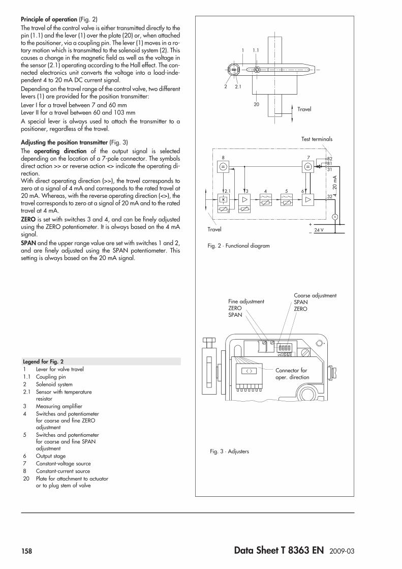
Principle of operation (Fig. 2)The travel of the control valve is either transmitted directly to thepin (1.1) and the lever (1) over the plate (20) or, when attachedto the positioner, via a coupling pin. The lever (1) moves in a ro-tary motion which is transmitted to the solenoid system (2). Thiscauses a change in the magnetic field as well as the voltage inthe sensor (2.1) operating according to the Hall effect. The con-nected electronics unit converts the voltage into a load-inde-pendent 4 to 20 mA DC current signal.Depending on the travel range of the control valve, two differentlevers (1) are provided for the position transmitter:Lever I for a travel between 7 and 60 mmLever II for a travel between 60 and 103 mmA special lever is always used to attach the transmitter to apositioner, regardless of the travel.
Adjusting the position transmitter (Fig. 3)The operating direction of the output signal is selecteddepending on the location of a 7-pole connector. The symbolsdirect action >> or reverse action <> indicate the operating di-rection.With direct operating direction (>>), the travel corresponds tozero at a signal of 4 mA and corresponds to the rated travel at20 mA. Whereas, with the reverse operating direction (<>), thetravel corresponds to zero at a signal of 20 mA and to the ratedtravel at 4 mA.ZERO is set with switches 3 and 4, and can be finely adjustedusing the ZERO potentiometer. It is always based on the 4 mAsignal.SPAN and the upper range value are set with switches 1 and 2,and are finely adjusted using the SPAN potentiometer. Thissetting is always based on the 20 mA signal.
2 2.1
1 1.1
20
2.1 3 4 5 6
8 7
_+
24 V
828131
32
Fig. 2 · Functional diagram
Fig. 3 · Adjusters
Travel
Travel
Test terminals
4...2
0m
A
Legend for Fig. 21 Lever for valve travel1.1 Coupling pin2 Solenoid system2.1 Sensor with temperature
resistor3 Measuring amplifier4 Switches and potentiometer
for coarse and fine ZEROadjustment
5 Switches and potentiometerfor coarse and fine SPANadjustment
6 Output stage7 Constant-voltage source8 Constant-current source20 Plate for attachment to actuator
or to plug stem of valve
Connector foroper. direction
Coarse adjustmentSPANZERO
Fine adjustmentZEROSPAN
158 Data Sheet T 8363 EN 2009-03

Table 1 · Technical data
Type 4748-0 4748-1
Output Two-wire circuit 4 to 20 mA
Permissible load R =U – 12 V
20 mAB
S
Output circuit – Intrinsically safe
Auxiliary power Two-wire network 24 V
Voltage range12 to 45 V
For connection to intrinsically safecircuits with maximum values
Uo = 25 V, IK = 100 mA, P = 0.8 W(effective internal inductance and capacitance
are negligibly small) 1)
Characteristic Characteristic: Output linear to inputDeviation from terminal-based conformity: ≤ 1 % 2)
Hysteresis ≤ 0.6 % 3)
Response ≤ 0.1 %
Influence on auxiliary power ≤ 0.1 % on span changes within the specified limits
HF effect ≤ 1 %, f = 150 MHz, 1 Watt transmission power, 0.5 m distance
Effect of vibration No effect between 10 and 150 Hz and 4 g
Load influence ≤ 0.1 %
Permissible ambient temperature –20 to +70 °C · The limits specified in the EC Type Examination Certificateadditionally apply for explosion-protected devices.
Effect of ambient temperature ≤ 0.3 %/10 K on lower measuring range value and span 2)
Ripple of the output signal ≤ 0.3 %
Travel ranges min./max. 1 Attachment to Type 4763/4765 Posistioners: 7 … 60 mm2 Lever I: 7 … 60 mm
Lever II: > 60 … 103 mm (up to 120 mm on request)Materials Housing: Die-cast aluminum, plastic coated
External parts: 1.4571, black anodized aluminum
Weight Approx. 0.7 kg
Degree of protection With direct attachment: IP 65When attached to a positioner: IP 54 (IP 65 on request), refer to EB 8363 EN
1) e.g. SAMSOMATIC Type 994-0103-KFD2-STC4-Ex1 Loop Isolator2) At max. travel 100 % = 32° lever angle3) At max. travel 100 % = 8° lever angle
Summary of explosion-protection approvalsThe test certificates are included in the Mounting and Operating Instructions or are available on request
Type of approval Certificate number Date Comments
EC Type Examination Certificate PTB 03 ATEX 2046 2003-06-02 II 2 G EEx ia IIC T6; Type 4748-1
Statement of Conformity PTB 03 ATEX 2047 X 2003-06-02 II 3 G EEx nA II T6, Zone 2; Type 4748-8
Data Sheet T 8363 EN 2009-03 159

Electrical connection
Test connection at terminals 81 and 82:After removing the jumpers, an ammeter can be connected.
Ordering textPosition Transmitter Type 4748-x 0 x– Without explosion protection, intrinsically safe or
non-sparking for Zone 2 (see article code)– Not attached
For attachment acc. to IEC 60534-6 (NAMUR)– With lever I (148 mm) or lever II (201 mm)– For attachment to positioner– Optionally, special version/accessories
Dimensions in mm
Specifications subject to change without notice
81 82 31 32
+ _ + _Jumpers
Ammeter Power supply unit
8315
27.5
94
64
44.5
74M20x1.5
20.6
79
Fastening screw M8
Air connection forseparate air supply
Dim
ensi
ons
for
leve
rII:
201
mm
32
148
30
7177
160 Data Sheet T 8363 EN 2009-03

Field barrier Solenoid valvesSupply pressure regulator Service unit modelPneumatic remote adjuster Pneumatic lock-up valveReversing amplifierPneumatic volume booster
Solenoid Valves and Accessories
161

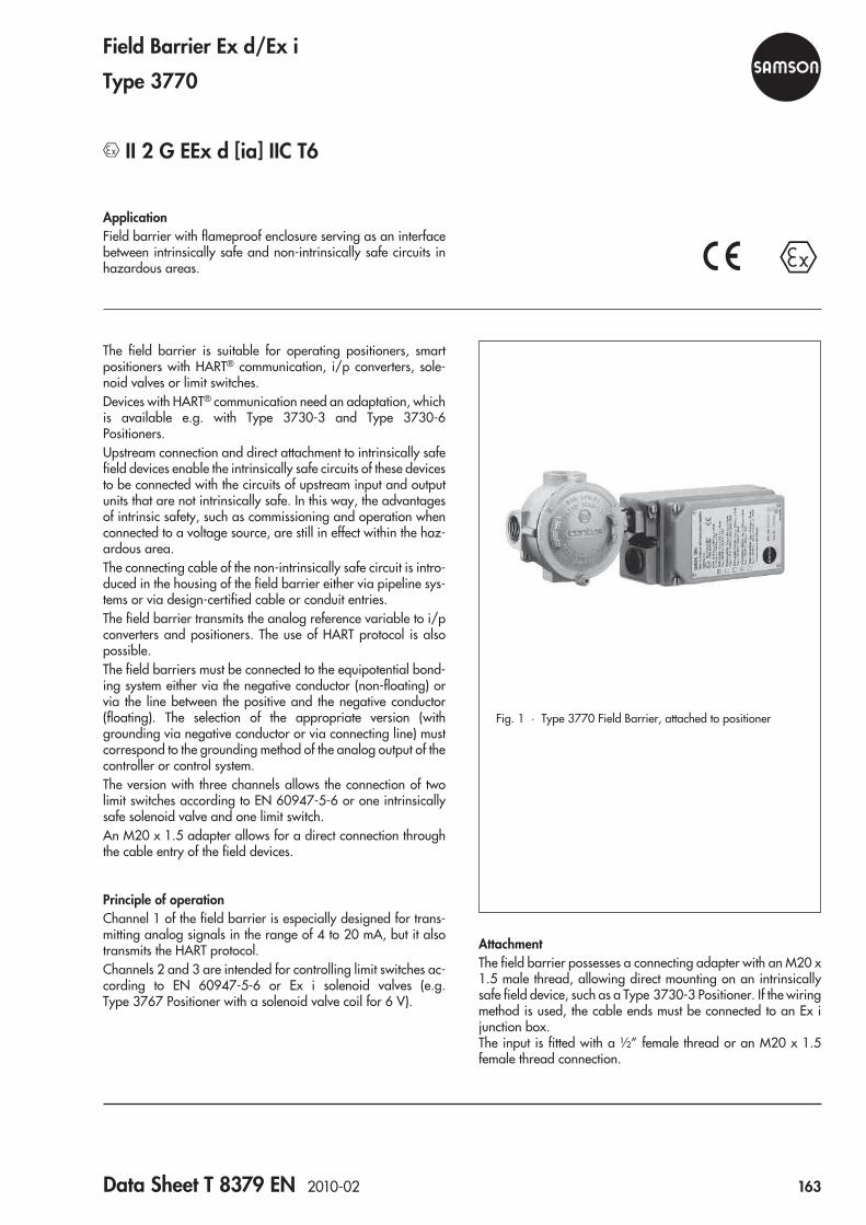
ApplicationField barrier with flameproof enclosure serving as an interfacebetween intrinsically safe and non-intrinsically safe circuits inhazardous areas.
The field barrier is suitable for operating positioners, smartpositioners with HART® communication, i/p converters, sole-noid valves or limit switches.Devices with HART® communication need an adaptation, whichis available e.g. with Type 3730-3 and Type 3730-6Positioners.Upstream connection and direct attachment to intrinsically safefield devices enable the intrinsically safe circuits of these devicesto be connected with the circuits of upstream input and outputunits that are not intrinsically safe. In this way, the advantagesof intrinsic safety, such as commissioning and operation whenconnected to a voltage source, are still in effect within the haz-ardous area.The connecting cable of the non-intrinsically safe circuit is intro-duced in the housing of the field barrier either via pipeline sys-tems or via design-certified cable or conduit entries.The field barrier transmits the analog reference variable to i/pconverters and positioners. The use of HART protocol is alsopossible.The field barriers must be connected to the equipotential bond-ing system either via the negative conductor (non-floating) orvia the line between the positive and the negative conductor(floating). The selection of the appropriate version (withgrounding via negative conductor or via connecting line) mustcorrespond to the grounding method of the analog output of thecontroller or control system.The version with three channels allows the connection of twolimit switches according to EN 60947-5-6 or one intrinsicallysafe solenoid valve and one limit switch.An M20 x 1.5 adapter allows for a direct connection throughthe cable entry of the field devices.
Principle of operationChannel 1 of the field barrier is especially designed for trans-mitting analog signals in the range of 4 to 20 mA, but it alsotransmits the HART protocol.Channels 2 and 3 are intended for controlling limit switches ac-cording to EN 60947-5-6 or Ex i solenoid valves (e.g.Type 3767 Positioner with a solenoid valve coil for 6 V).
AttachmentThe field barrier possesses a connecting adapter with an M20 x1.5 male thread, allowing direct mounting on an intrinsicallysafe field device, such as a Type 3730-3 Positioner. If the wiringmethod is used, the cable ends must be connected to an Ex ijunction box.The input is fitted with a ½” female thread or an M20 x 1.5female thread connection.
Fig. 1 · Type 3770 Field Barrier, attached to positioner
Field Barrier Ex d/Ex i
Type 3770
II 2 G EEx d [ia] IIC T6
Data Sheet T 8379 EN 2010-02 163

Electrical connectionsThe individual current circuits of the Type 3770 Ex d/Ex i FieldBarrier are electrically connected with internal and externalequipotential bonding terminals.For safety reasons, the intrinsically safe circuits must be con-nected to the equipotential bonding system. The connection be-tween the equipotential bonding terminal and the equipotentialbonding system must be as short as possible.
The selection of the grounding method of the barrier must corre-spond to the grounding method of the analog output of the con-troller or control system, i.e. either the connecting line betweenthe negative and the positive conductor of Channel 1 (Fig. 2) orthe negative conductor of Channel 1 (Fig. 3) has to be con-nected to the equipotential bonding system.
Table 1 · Technical data
Type of protection EEx d [ia] IIC T6
Connection Channel 1: Ch 1 +/– Channels 2 and 3: Ch 2 +/– and Ch 3 +/–
Operational values (0) 4 ... 20 mA or UN ... 15 V orlimit switches acc. to EN 60947-5-6
not suitable for transmitter supply
(0) 4 ... 20 mA or UN ... 10 V orlimit switches acc. to EN 60947-5-6
not suitable for transmitter supply
Input Um = 250 V
Fuse rating IN = 80 mA (slow-acting)
Output circuit EEx ia IIC
Max. valuesacc. to EC Type ExaminationCertificate
U0I0P0C0L0
≤ 17.2 V≤ 110 mA≤ 473 mW
360 nF/IIC · 2.1 μF/IIB3 mH/IIC · 12 mH/IIB
≤ 12.6 V≤ 49 mA
≤ 154 mW1.15 μF/IIC · 7.4 μF/IIB15 mH/IIC · 56 mH/IIB
Series resistance RLmax 190 Ω 285 Ω
Load impedance 3.8 V at 20 mA 5.7 V at 20 mA
Permissible ambient temperature –45 °C ≤ ta ≤ 60 °C T6
Enclosure material Die-cast aluminum, painted or stainless steel (AISI 316)
Degree of protection IP 65 according to IEC 529
CH1
CH2
+
_
+
_
+
_
2
1
4
3
6
5
CH3
Ex ia
Ex ia
Ex ia
CH1
CH2
+
_
+
_
+
_
2
1
4
3
6
5
CH3
Ex ia
Ex ia
Ex ia
Fig. 2 · Circuit diagram for Type 3770-1310Channel 1 floating
Fig. 3 · Circuit diagram for Type 3770-1410Channel 1 non-floating
Equipotentialbonding terminal
Equipotentialbonding terminal
164 Data Sheet T 8379 EN 2010-02

Dimensions in mm Electrical connections
M20 x 1.5
Explosion protection certificates for Type 3770 Field Barrier
Type of approval Certificate number Date Comments
EC Type Examination Certificate PTB 98 ATEX 1025X 1998-06-08 II 2 G EEx d [ia] IIC T6
First Addendum 2000-10-10 Channel 1 non-floating
GOST approval B 02637 2009-02-26 1 Ex d [ia] IIC T6
Circuitry
Fig. 4 · Field barrier (one channel interconnected) with
Hazardous area
Safe area Ex d installation Ex i field device
Analog control signal
Equipotentialbondingterminal
Hazardous area
Safe area Ex d installation Ex i field device
Analog control signal
Binary signal
Binary signal
Fig. 5 · Field barrier (three channels interconnected) withpositioner, solenoid valve and limit switch mounted ona pneumatic control valve
Equipotentialbonding terminal
PACh1 Ch2 Ch3
EiA/gn/ge1 2 3 4 5 6
TerminalcompartmentEx d
(0)4 to 20 mA Isolating amplifiercontrol signal acc. to EN 60947-5-6 foror isolating limit switches oramplifier acc. to solenoid valve up to 10 VEN 60947-5-6 or or (0)4 to 20 mAsolenoid valveup to 15 V
Output withmarkedcable ends Ex i
Green/yellow
Data Sheet T 8379 EN 2010-02 165

Article code
Field barrier acc. to ATEX Type 3770- 1 x x x 0 x x x
Three channels4 to 20 mA, floatingand two 2 circuits acc. to EN 60947-5-6
3
Three channels4 to 20 mA, non-floatingand two 2 circuits acc. to EN 60947-5-6
4
Electrical connection
Female thread ½ NPT 1
Female thread M20 x 1.5 3
Housing material
Die-cast aluminum 0
Stainless steel AISI 316 1
Special version
None 0 0 0
GOST approval 0 0 1
166 Data Sheet T 8379 EN 2010-02

Type 3701 Solenoid Valve
ApplicationSolenoid valve for controlling pneumatic linear actuators withNAMUR rib according to IEC 60534 or pneumatic rotaryactuators with NAMUR interface acc. to VDI/VDE 3845
Low power binary signals issued by automation equipment orfieldbus systems can be used for controlling purposes. Intrin-sically safe versions can also be implemented.
Features• High level of operational reliability owing to the flapper/
nozzle assembly and booster valve with a diaphragm actua-tor
• Standard version for nominal signals 6, 12, 24 V DC, 24,48, 115 or 230 V AC
• Type of protection ”Intrinsic safety” II 2 G EEx ia IIC T6,“non-sparking“ II 3 G EEx nA II T6 according to ATEX,CSA and FM, for nominal signals of 6, 12 or 24 V DC
• 6 to 27 mW or 0.04 to 0.46 VA power consumption, de-pending on nominal signal
• Electrical connection over M20 x 1.5 cable gland or option-ally with plug connector
• Corrosion-resistant housing in degree of protection IP 54 orIP 65
• Versions compatible with paint/free of silicone on request• Air supply 1.4 to 6 bar• Service life: More than 20 million switching cycles• Ambient temperature –45 to 80 °C, depending on type of
protection, temperature class and seals• Typetesting performed by TÜV Rheinland for safety-related
applications according to DIN 3393 Part 1, DIN EN 161,DIN 32 725 and optionally according to DIN 32 730
• Suitable for safety shut-off valves up to SIL 4 according toIEC 61508 (optional)
• Cable breakage protection available
Versions– 3/2-way or 5/2-way solenoid valve with Kvs = 0.25– Special switching functions on request– The actuator can be vented or alternatively filled with air in
the neutral position of the 3/2-way solenoid valve– Attachment to linear actuators with NAMUR rib or rod-type
yoke as well as to rotary actuators with NAMUR interface– Interfaces for special attachment available on request
Fig. 1 · Type 3701 Solenoid Valve
E
P
E
P
E
P
9 481+82-
81+82-
1.3 2.3
9 481+82-
1.3
9 4
1.3
3/2-way* 5/2-way
Type 3701-xx0 Type 3701-xx2Neutral position “Actuator vented”
Type 3701-xx1Neutral position “Actuator filled with air”
* Versions for rotary actuatorscontain an internal exhaust air feedback
Fig. 2 · Switching symbols for 3/2-way and 5/2-waysolenoid valves
Data Sheet T 3701 EN 2006-06 167

Table 1 · Technical data for Type 3701 Solenoid Valve
General data
Construction Solenoid with flapper/nozzle assembly and diaphragm switching elements
Degree of protection IP 54 with filter · IP 65 with filter check valve
Material Enclosure Al Mg, powder-coated, grayish beige RAL 1019
NAMUR adapter plate Al Mg, powder-coated, grayish beige RAL 1019
Screws 1.4571
Springs 1.4310
Seals Silicone rubber, Perbunan
Diaphragm Chloroprene rubber 57 Cr 868 (–20 ... +80 °C) · Silicone rubber (–45 ... +80 °C)
Ambient temperature See “Electrical data”
Mounting position Any position
Weight Approx. 450 g
Electrical data
Nominal signal UnUmax
6 V DC27 V
12 V DC25 V
24 V DC32 V
24 V AC36 V
48 V AC80 V
115 V AC130 V
230 V AC255 V
f − 48 ... 62 Hz
Switchingpoint
On U80 °C ≥ 4.8 V ≥ 9.6 V ≥ 18 V ≥ 19...36 V ≥ 42...80 V ≥ 82...130 V ≥ 183...255 V
I20 °C ≥ 1.41 mA ≥ 1.52 mA ≥ 1.57 mA ≥ 1.9 mA ≥ 1.9 mA ≥ 2.2 mA ≥ 2.6 mA
P20 °C ≥ 5.47 mW ≥ 13.05 mW ≥ 26.71 mW ≥ 0.04 VA ≥ 0.07 VA ≥ 0.17 VA ≥ 0.46 VA
Off–25 °C U ≤ 1.0 V ≤ 2.4 V ≤ 4.7 V ≤ 4.5 V ≤ 9 V ≤ 18 V ≤ 36 V
Input impedance R 2.6 kΩ 5.5 kΩ 10.7 kΩ Appr. 10 kΩ Appr. 24 kΩ Appr. 40 kΩ Appr. 80 kΩTemperature effect 0.4 %/°C 0.2 %/°C 0.1 %/°C 0.1 %/°C 0.1 %/°C 0.05 %/°C 0.03 %/°C
Type of protection 1) “Intrinsic safety” II 2 G EEx ia IIC T6“Non-sparking” II 3 G EEx nA II T6
Without explosion protection
Output voltage 2) Ui [V] 25 · 27 · 28 · 30 · 32 −Output current 2) Ii [mA] 150 · 125 · 115 · 100 · 85 −Power dissipation Pi 250 mW No limitation −External inductance 2) Li Negligible −External capacitance 2) Ci Negligible −Ambient temperature 7) –20 ... +60 °C (temperature class T6)
–20 ... +70 °C (temperature class T5)–20 ... +80 °C (temperature class T4)
–45 ... +80 °C
Connection See “Article code”
Pneumatic data
Type 3701 -xx0 / -xx1 -xx2
Safety function TÜV 3) · SIL 4 4)
Version 3/2-way function 5/2-way function
Kvs 4) 0.25 0.25
Air supply Medium Instrument air, free of corrosive particles and nitrogen
Pressure 1.4 ... 6 bar
Operating medium Instrument air, free of corrosive particles 5) · Air containing oil, nitrogen, non-corrosive gases 6)
Operating pressure Max. 6 bar
Output signal Operating pressure
Air consumption ≤ 80 ln/h at 1.4 bar, supply air in neutral position≤ 10 ln/h at 1.4 bar, supply air in operating position
Switching time 7) ≤ 65 ms
Service life ≥ 2 x 10⁷ switching cycles (at –20 ... +80 °C)≥ 2 x 10⁶ switching cycles (at –45 ... +80 °C)
Connection G ¼ (¼ NPT)
1) EC Type Examination Certificate PTB 01 ATEX 2178 and Statement of Conformity PTB 02 ATEX 2014 X2) Permissible maximum specifications when connected to a certified intrinisically safe circuits3) Report No. S 63/00 (mounted on control valves as per DIN 3394 Part 1, DIN EN 161, DIN 32725, DIN EN 264 and DIN 32730);
Report No. V 64/2004, part 1 (SIL 4 according to IEC 61508).4) Air flow at p1 = 2.4 bar and p2 = 1.0 bar can be calculated according to the equation: Q = Kvs x 36.22 in m3/h.5) With internal air supply (delivered status).6) With external air supply (see mounting and operating instructions).7) Permissible ambient temperature –45 °C with diaphragm and seals made of silicone rubber and metal cable gland.
168 Data Sheet T 3701 EN 2006-06

7422
9(8)
92
1.3
4
2.3
94
19
24
M20x1,5
19
2921
9(8)
14
66
11
24
4
1.3/2.3
M8
9(8)
14
194
1.3
2.329
21
M8
66
Ø5
10 11
12
5
86
Attachment and dimensions (in mm) of the Type 3701 Solenoid Valve
Attachment acc. NAMUR, e.g. to Series 240, 250 valves Attachment with clamping plate to valves with rod-type yoke(10, 11 - Support with clamping plate, order no. 1400-5742)
Attachment to valves in DN 15 to 80 with attached positioner (12 - Distance piece, order no. 1400-5905)
Dimensions for attachment according to NAMUR Dimensions for attachment to adapter plate
M20 x 1.5
Adapter plate withNAMUR interface 1400-5235
Data Sheet T 3701 EN 2006-06 169

Table 2 · Article code
Solenoid valve Type 3701- x x x x x x x x x x
Type of protection
Without explosion protection 0
II 2 G EEx ia IIC T6, Zone 1 acc. to ATEX 1
CSA/FM EEx ia 3
II 3 G EEx nA II T6, Zone 2 acc. to ATEX 8
Nominal signal
6 V DC 1
12 V DC 2
24 V DC 3
230 V AC (without explosion protection) 5
115 V AC (without explosion protection) 6
48 V AC (without explosion protection) 7
24 V AC (without explosion protection) 8
Switching function
3/2-way, NC, KVS = 0.25, (circuit 1) 0
3/2-way, NO, KVS = 0.25, (circuit 2) 1
5/2-way, KVS = 0.25 2
Attachment
NAMUR interface for rotary actuators (incl. adapter plate 1400-5235) 0
NAMUR rib for linear actuators 1
For rotary actuators additionally requiring a NAMUR adapter plate 1400-5235 2
Threaded connection
G ¼ 0
¼ NPT 1
Electrical connection
Without cable gland, fitted with blanking cap 0 0
Black cable gland M20 x 1.5 0 1
Blue cable gland M20 x 1.5 1 1
Adapter M20 x 1.5 to ½ NPT 1 2
Black CEAG cable gland, M20 x 1.5 1 3
Cable gland M20 x 1.5, brass 1 4
Harting connector, without cable socket 2 1
Connector M12 x 1, nickel-plated brass, without cable socket 2 2
Connector Form A acc. to DIN EN 175 301-803, without cable socket 2 3
Binder connector, without cable socket 2 4
Degree of protection
IP 54 0
IP 65, with filter check valve made of polyamide 1
IP 65, with filter check valve made of 1.4571 2
IP 20 3
Ambient temperature
–20 … 80 °C 0
–45 … 80 °C 2
Safety approval
None 0
SIL 4 (only for 3/2-way function) 1
TÜV (only for 3/2-way function) 2
170 Data Sheet T 3701 EN 2006-06

List of approvals
Type of approval Certificate number Date Type of connection / Comment
EC Type Examination Certificate PTB 01 ATEX 2178 2001-11-29 II 2 G EEx ia IIC T6; Type 3701-1
Statement of Conformity PTB 02 ATEX 2014 X 2002-03-07 II 3 G EEx nA II T6, Zone 2; Type 3701-8
TÜV approval St 1947 1987-04-15 Without explosion protection, DC and AC voltage;Type 3701-1
GOST approval 2002.C303 2002-12-26 Valid until 2008-01-01; Type 3701-1
FM approval J.I. 3020228 2005-02-28 Cl. I, II, III, Div. 1, Gr. A, B, C, D, E, F, GCl. I, Zone 0 AEx ia IIC T6Cl. I, Div. 2, Gr. A, B, C, DCl. II, Div. 2, Gr. F, G; Cl. III; NEMA 3R; Type 3701-3
CSA approval LR 54227-3LR 54227-33
1988-10-251998-10-15
Cl. I, Div. 1, Gr. A, B, C, D; Type 3 EnclosureCl. I, Div. 2, Gr. A, B, C, D; coil 1079-22;Type 3701-3
TÜV S63/00 2000-09-06 Mounted on control valves acc. to DIN 3394-1,DIN EN 161, DIN 32 725, DIN EN 264 andDIN 32 730
SIL 4 V 60 2004 T1 2004-07-05 Safety integrity level according to IEC 60508
AccessoriesOrder no. Description1400-5235 Adapter plate for rotary actuators with NAMUR interface as per VDI/VDE 38451400-5342 Mounting parts for valves with rod-type yokes as per NAMUR1400-5905 Mounting parts for Series 240 in DN 15 to 80, in case positioner and/or limit switch is to be mounted as well0790-6658 Cable socket according to EN 175301-803, Form A, made of polyamide, black, degree of protection IP 651400-8298 Cable socket (Harting), 7-pole, made of aluminium, silver, degree of protection IP 658831-0716 Cable socket (Binder), 7-pole, made of PBT GF, black, degree of protection IP 678831-0865 Cable socket M12 x 1, 4-pole, angled design, made of polyamide, black, degree of protection IP 678801-2810 Sensor connecting lead, two-wire, 3 m in length, blue, with angle connector M12 x 1, 4-pole8504-0066 Polyethylene filter, connection G ¼, degree of protection IP 54
Filter check valve made of polyamide or 1.4571, degree of protection IP 65 or NEMA 4. Refer to Data Sheet Z 900-7
Data Sheet T 3701 EN 2006-06 171


Solenoid Valve Type 3963
Fig. 1
5/2-way solenoid valve,single actuated with spring return mechanism,Kvs 0.16, connection G 1/4
3/2-way solenoid valve,single actuated with spring return mechanism,Kvs 4.3, connection G 1/4
5/2-way solenoid valve,double actuated with two locking positions,Kvs 1.4, connection G 1/4/NAMUR
General notes
The Type 3963 Solenoid Valves ensure a high level of operationalreliability and fast response times for controlling pneumatic actuators in hazardous areas.
Intrinsically safe, low-power binary signals issued by automationor fieldbus systems can be used for controlling purposes.
The Type 3963 Solenoid Valves offer a variety of switching functions, flow rates and connections for all desired applications(Fig. 1).
Special features of the Type 3963 Solenoid Valves include:
General
● Safety Integrity Level SIL 4 according to IEC 61508 (optional)● Safety function for use on control valves (optional)● Corrosion-resistant enclosure with degree of protection IP 54
or IP 65 for applications in humid, aggressive environments● Versions compatible with paint (on request)● Service life more than 20 millions switching cycles● Ambient temperature range �20 to �80 °C or �45 to �80 °C● Rail mounting, wall mounting or mounting with pipe fittings● Attachment to linear actuators with NAMUR rib according to
IEC 60534-6-1 or to rotary actuators with NAMUR interface according to VDI/VDE 3845
Pilot valve
● E/P binary converter with flapper/nozzle assembly● Nominal signal 6/12/24 V DC or 24/48/115/230 V AC● Type of protection II 2 G EEx ia IIC T6 or II 3 G EEx nA II T6
according to ATEX, additional certifications according to CSA, FM, GOST and NEPSI
● Power consumption 6 to 27 mW or 0.04 to 0.46 VA, depending on the nominal signal
● Manual override as pushbutton or pushbutton switch (optional)
● Air supply 1.4 to 6 bar● Electrical connection using a cable gland M 20 �1.5 to
terminals or using a plug-type connector● Cable break protection device (accessory)
Booster valve
● Diaphragm with return spring or piston, single or double actuated
● 3/2, 5/2, 5/3 or 6/2-way function● Exhaust air return (optional)● Kvs 0.16 to 4.3● Supply air/exhaust air restrictors for adjusting different
closing and opening times in a ratio of 1:15 (optional)● Threaded connection G (NPT) 1/4 or 1/2● NAMUR interface 1/4“ or 1/2“
Data Sheet T 3963 EN 2010-02 173

Versions with threaded connection
Type 3963 Solenoid Valves for continuous and on-off actuators
81�82�
EP
1.54
1.3
9 2.5
2.3
Type 3963-XXX1011XXXXXX0Solenoid Valve● 5/2-way function● Kvs 0.16● Connection G (NPT) 1/4● Rail mounting or wall mounting
1.41.5
1.39
81�82�
EP
2.42.5
2.3
Type 3963-XXX8011XXXXXX0Solenoid Valve● 6/2-way function● Kvs 0.16● Connection G (NPT) 1/4● Rail mounting or wall mounting
9
3
81�82�
EP
Type 3963-XXX0011X0XXXXXSolenoid Valve● 3/2-way function● Kvs 0.16● Connection G (NPT) 1/4● Rail mounting, wall mounting or
mounting with pipe fittings to on-off linear actuators, e. g. SAMSON’s Type 3271 or 3277
9
3
81�82�
EP
Type 3963-XXX0111X0XXXX0Solenoid Valve● 3/2-way function● Adjustable exhaust air restrictor● Kvs 0.16● Connection G (NPT) 1/4● Rail mounting, wall mounting or
mounting with pipe fittings to on-off linear actuators, e. g. SAMSON’s Types 3271 or 3277
81�82�
EP
45
3
9
Type 3963-XXX0022XXXXXXXSolenoid Valve● 3/2-way function● Kvs 0.32● Connection G (NPT) 1/4● Safety function SIL 4/TÜV● Attachment to linear actuators with
NAMUR rib, e. g. SAMSON’s Type 3271 (see Fig. 3)
81�82�
EP
Type 3963-XXX013141XXXX0Solenoid Valve● 3/2-way function● Adjustable exhaust air restrictor● Kvs 0.16● Attachment via a connection block to
SAMSON’s Type 3277 Linear Actuator with SAMSON’s Type 3730, 3766, 3767 or 378X Positioner (see Fig. 2)
81�82�
EP
Type 3963-XXX003240XXXXXSolenoid Valve● 3/2-way function● Kvs 0.32● Safety function SIL 4/TÜV● Attachment via a connection block to
SAMSON’s Type 3277 Linear Actuator with SAMSON’s Type 3730, 3766, 3767 or 378X Positioner (see Fig. 2)
81�82�
EP
45
3
9
Type 3963-XXX0012XXXXXXXSolenoid Valve● 3/2-way function● Kvs 0.32● Connection G (NPT) 1/4● Safety function SIL 4/TÜV● Rail mounting, wall mounting or
mounting with pipe fittings to linear actuators, e. g. SAMSON’s Type 3271 or 3277
Fig. 2 Fig. 3 Fig. 4 Fig. 5
174 Data Sheet T 3963 EN 2010-02

81� 81�82� 82�
EP
39 95
4
1
2
PE
Type 3963-XXX2013XXXXXXXSolenoid Valve● 5/2-way function
with two locking positions● Kvs 1.4● Connection G (NPT) 1/4● Safety function TÜV● Wall mounting or mounting with pipe
fittings
81� 81�82� 82�
EP
39 95
4
1
2
PE
Type 3963-XXX3013XXXXXX0Solenoid Valve● 5/3-way function
with spring-centered mid-position(connections 2 and 4 closed)
● Kvs 1.4● Connection G (NPT) 1/4● Wall mounting or mounting with pipe
fittings
81� 81�82� 82�
EP
39 95
4
1
2
PE
Solenoid ValveType 3963-XXX5013XXXXXXX● 5/3-way function
with spring-centered mid-position(connections 2 and 4 vented)
● Kvs 1.4● Connection G (NPT) 1/4● Safety function TÜV● Wall mounting or mounting with pipe
fittings
9 981� 81�82� 82�
EP
35
4
1
2
PE
Type 3963-XXX4013XXXXXX0Solenoid Valves● 5/3-way function
with spring-centered mid-position(connections 2 and 4 to air supply)
● Kvs 1.4● Connection G (NPT) 1/4● Wall mounting or mounting with pipe
fittings
81�82�
EP
39 5
4
1
2
Type 3963-XXX1013XXXXXX0Solenoid Valve● 5/2-way function● Kvs 1.4● Connection G (NPT) 1/4● Wall mounting or mounting with pipe
fittings to linear actuators, e. g. SAMSON’s Type 3271 or 3277
81�82�
EP
39
4
1
2
Type 3963-XXX0013XXXXXXXSolenoid Valve● 3/2-way function● Exhaust air return● Kvs 1.4● Connection G (NPT) 1/4● Safety function TÜV● Wall mounting or mounting with pipe
fittings to linear actuators, e. g. SAMSON’s Type 3271 or 3277
81�82�
EP
1.41.5
1.3
9 2.52.4
2.3
Type 3963-XXX1014XXXXXX0Solenoid Valve● 5/2-way function● Kvs 4.3● Connection G (NPT) 1/2● Wall mounting or mounting with pipe
fittings
81�82�
EP
45
3
9
Type 3963-XXX0014XXXXXXXSolenoid Valve● 3/2-way function● Kvs 4.3● Connection G (NPT) 1/2● Safety function SIL 4/TÜV● Wall mounting or mounting with pipe
fittings to linear actuators, e. g. SAMSON’s Type 3271 or 3277
81�82�
EP
1.41.5
1.3
9 2.42.5
2.3
Type 3963-XXX8014XXXXXX0Solenoid Valve● 6/2-way function● Kvs 4.3● Connection G (NPT) 1/2● Wall mounting or mounting with pipe
fittings
Fig. 6 Fig. 7 Fig. 8 Fig. 9
Versions with threaded connection
Type 3963 Solenoid Valves for continuous and on-off actuators
Data Sheet T 3963 EN 2010-02 175

Versions with NAMUR interface
Type 3963 Solenoid Valves for continuous and on-off actuators
4
1.3
81�82�
EP
2.3
2.39
Type 3963-XXX0301XXXXXX0Solenoid Valve● 3/2-way function● Adjustable supply air/exhaust air
restrictors● Kvs 0.16● Connection G (NPT) 1/4/NAMUR● Mounting to on-off rotary actuators with
NAMUR interface or with adapter plate (order no. 1400-6751) to linear actuators with NAMUR rib, e. g. SAMSON’s Type 3241-1 (see Fig. 12)
81�82�
EP
4 2.3
1.3
9
2.3
Type 3963-XXX0002XXXXXXXSolenoid Valve● 3/2-way function● Exhaust air return● Kvs 0.32● Connection G (NPT) 1/4/NAMUR● Safety function SIL 4/TÜV● Mounting to rotary actuators with
NAMUR interface, optionally with apositioner (see Fig. 10)
4
1.3
81�82�
EP
2.3
Type 3963-XXX1001XXXXXX0Solenoid Valve● 5/2-way function● Kvs 0.16● Connection G (NPT) 1/4/NAMUR● Mounting to on-off rotary actuators with
NAMUR interface (see Fig. 10)
1.41.5
1.39
81�82�
EP
2.42.5
2.3
Type 3963-XXX8001XXXXXX0Solenoid Valve● 6/2-way function● Kvs 0.16● Connection G (NPT) 1/4/NAMUR● Mounting to rotary actuators with
NAMUR interface
4
1.3
81�82�
EP
2.3
Type 3963-XXX0001X0XXXXXSolenoid Valve● 3/2-way function● Exhaust air return● Kvs 0.16● Connection G (NPT) 1/4/NAMUR● Safety function SIL 4/TÜV● Mounting to on-off rotary actuators with
NAMUR interface or with adapter plate (order no. 1400-6751) to linear actuators with NAMUR rib, e. g. SAMSON’s Type 3241-1 (see Fig. 12)
4
1.3
81�82�
EP
2.3
Type 3963-XXX0101X0XXXX0Solenoid Valve● 3/2-way function● Exhaust air return● Adjustable exhaust air restrictor● Kvs 0.16● Connection G (NPT) 1/4/NAMUR● Mounting to on-off rotary actuators with
NAMUR interface or with adapter plate (order no. 1400-6751) to linear actuators with NAMUR rib, e. g. SAMSON’s Type 3241-1 (see Fig. 12)
4
1.3
81�82�
EP
2.3
Type 3963-XXX1201X0XXXX0Solenoid Valve● 5/2-way function● Two adjustable exhaust air restrictors● Kvs 0.16● Connection G (NPT) 1/4/NAMUR● Mounting to on-off rotary actuators with
NAMUR interface (see Fig. 10)
Fig. 12Fig. 11Fig. 10
81�82�
EP
4 5
3
9
5
Type 3963-XXX0007XXXXXXXSolenoid Valve● 3/2-way function● Exhaust air return● Kvs 2.0● Connection G (NPT) 1/4, 1/2/NAMUR 1/4“● Safety function SIL 4/TÜV● Mounting to on-off rotary actuators with
NAMUR interface 1/8“ or 1/4“or with adapter plate (order no. 1400-6751) to linear actuators with NAMUR rib
Fig. 13
176 Data Sheet T 3963 EN 2010-02
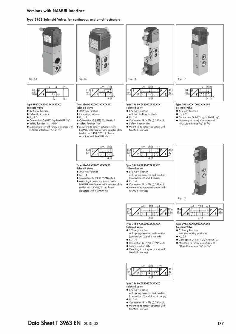
81� 81�82� 82�
EP
39 95
4
1
2
PE
Type 3963-XXX2003XXXXXXXSolenoid Valve● 5/2-way function
with two locking positions● Kvs 1.4● Connection G (NPT) 1/4/NAMUR● Safety function TÜV● Mounting to rotary actuators with
NAMUR interface
81�82�
EP
39 5
4
1
2
Type 3963-XXX1003XXXXXX0Solenoid Valve● 5/2-way function● Kvs 1.4● Connection G (NPT) 1/4/NAMUR● Mounting to rotary actuators with
NAMUR interface or with adapter plate (order no. 1400-6751) to linear actuators with NAMUR rib
81� 81�82� 82�
EP
39 95
4
1
2
PE
Type 3963-XXX3003XXXXXX0Solenoid Valve● 5/3-way function
with spring-centered mid-position(connections 2 and 4 closed)
● Kvs 1.4● Connection G (NPT) 1/4/NAMUR● Mounting to rotary actuators with
NAMUR interface
81�82�
EP
39
4
1
2
Type 3963-XXX0003XXXXXXXSolenoid Valve● 3/2-way function● Exhaust air return● Kvs 1.4● Connection G (NPT) 1/4/NAMUR● Safety function TÜV● Mounting to rotary actuators with
NAMUR interface or with adapter plate (order no. 1400-6751) to linear actuators with NAMUR rib
81� 81�82� 82�
EP
39 95
4
1
2
PE
Type 3963-XXX5003XXXXXXXSolenoid Valve● 5/3-way function
with spring-centered mid-position(connections 2 and 4 vented)
● Kvs 1.4● Connection G (NPT) 1/4/NAMUR● Safety function TÜV● Mounting to rotary actuators with
NAMUR interface
9 981� 81�82� 82�
EP
35
4
1
2
PE
Type 3963-XXX4003XXXXXX0Solenoid Valve● 5/3-way function
with spring-centered mid-position(connections 2 and 4 to air supply)
● Kvs 1.4● Connection G (NPT) 1/4/NAMUR● Mounting to rotary actuators with
NAMUR interface
Fig. 15 Fig. 16
Versions with NAMUR interface
Type 3963 Solenoid Valves for continuous and on-off actuators
81� 81�82� 82�
EP
39 95
4
1
2
PE
Type 3963-XXX2006XXXXXX0Solenoid Valve● 5/2-way function
with two locking positions● Kvs 2.9● Connection G (NPT) 1/2/NAMUR 1/2“● Mounting to rotary actuators with
NAMUR interface 3/8“ or 1/2“
Fig. 18
Fig. 17
81�82�
EP
39 5
4
1
2
Type 3963-XXX1006XXXXXX0Solenoid Valve● 5/2-way function● Kvs 2.9● Connection G (NPT) 1/2/NAMUR 1/2“● Mounting to rotary actuators with
NAMUR interface 3/8“ or 1/2“
81�82�
EP
4 5
3
9
5
Type 3963-XXX0004XXXXXXX Solenoid Valve● 3/2-way function● Exhaust air return● Kvs 4.3● Connection G (NPT) 1/2/NAMUR 1/2“● Safety function SIL 4/TÜV● Mounting to on-off rotary actuators with
NAMUR interface 3/8“ or 1/2“
Fig. 14
Data Sheet T 3963 EN 2010-02 177

�81
�82
Nominalsignal
� �
�
� ��
�
�
�
�
9Change-overto externalair supply
5
3
4
Functional diagramFunction
Solenoid valves with single actuation
The solenoid valves consist of an E/P binary converter � withmanual override � (optional) and a single actuated boostervalve � with return spring (Fig. 18).
The booster valve � supplies the E/P binary converter � inter-nally with the supply air (delivery state). Rotating a flat gasket al-lows the E/P binary converter � to be supplied with external airsupply via connection 9.
The pressure reducer � reduces the air supply pressure to 1.4 bar.
In the normal position the flapper � is lifted off the outlet nozzle� by the spring �. As a result, a pressure lower than the switch-off pressure of the booster valve � builds up in the pressure divider that consists of the restriction � and the outlet nozzle �.
When the solenoid � is energized by an electrical binary signal,the outlet nozzle � is closed by the flapper � against the forceof the spring �. As a result, the pressure in the pressure dividerrises above the switch-on pressure of the booster valve �, thusswitching it to the operating position.
After de-energizing the electrical binary signal, the booster valve� will be switched to the normal position by a return spring.
Solenoid valves with double actuation
The solenoid valves consist of two E/P binary converters � withmanual override � (optional) and a double-actuated boostervalve � with two locking positions or spring-centered mid-posi-tion.
The booster valve � supplies the E/P binary converters � inter-nally with the supply air (delivery state). Rotating two flat gasketsallows the E/P binary converters � to be supplied with externalair supply via connections 9.
The pressure reducer � reduces the air supply pressure to 1.4 bar.
In the normal position, the flapper � is lifted off the outlet nozzle� by the spring �. As a result, a pressure lower than the switch-off pressure of the booster valve � builds up in the pressure divider that consists of a restriction � and an outlet nozzle �.
When the solenoid is energized by an electrical binary signal,the outlet nozzle � is closed by the flapper � against the forceof the spring �. As a result, the pressure in the pressure dividerrises above the switch-on pressure of the booster valve �, thusswitching it to the operating position.
After de-energizing the electrical binary signal, the operatingposition of the detented booster valve � will be retained until areverse signal is received. After de-energizing the electrical binary signal the spring-centered booster valve � will beswitched to the mid-position by a return spring.
Energizing both E/P binary converters � at the same time mustbe prevented by appropriate electrical control.
Fig. 19 · Solenoid valve with diaphragm element asbooster valve (Kvs 0.16)
178 Data Sheet T 3963 EN 2010-02

1) Permissible maximum value at continuous duty. For Ex versions, the permissible maximum value Ui applies2) II 2 G EEx ia IIC T6 according to EC Type Examination Certificate PTB 01 ATEX 20853) II 3 G EEx nA II T6 according to Statement of Conformity PTB 01 ATEX 2086 X4) The Ui/Ii values apply to nominal signals 6/12/24 V DC
Technical data
General data of the solenoid valvesConstruction Solenoid with flapper/nozzle assembly and booster valveDegree of protection IP 54 with filter,
IP 65 with filter check valveMaterial Enclosure Polyamide PA 6-3-T-GF35, black
Connection plate Al Mg, powder-coated, grayish-beige RAL 1019,Stainless steel 1.4404 (special versions see “Versions and ordering data“),Polyamide PA 6-3-T-GF35, black
Screws Stainless steel 1.4571Springs Stainless steel 1.4310Gaskets Silicone rubber, PerbunanDiaphragms Chloroprene 57 Cr 868 (�20 to �80 °C),
Silicone rubber (�45 to �80 °C)Air supply Medium Instrument air, free of corrosive particles, or nitrogen
Pressure 1.4 to 6 barAir consumption � 80 l/h at 1.4 bar air supply in normal position,
� 10 l/h at 1.4 bar air supply in operating positionSwitching time � 65 msSwitching cycles 2 �107 (at �20 to �80 °C),
2 �106 (at �45 to �80 °C)Ambient temperature see „Electrical data“Mounting position As desired (see Mounting and Operating Instructions EB 3963 EN)
Electrical data of the solenoid valvesType 3963 -X1 -X2 -X3 -08 -07 -06 -05Nominal signal UN 6 V DC 12 V DC 24 V DC 24 V AC 48 V AC 115 V AC 230 V AC
Max. 27 V 1) Max. 25 V 1) Max. 32 V 1) Max. 36 V 1) Max. 80 V 1) Max. 130 V 1) Max. 255 V 1)fN 48 … 62 Hz
Switching point U�80 °C 4.8 V 9.6 V 18 V 19 … 36 V 42 … 80 V 82 … 130 V 183 … 255 V“On“ I �20 °C 1.41 mA 1.52 mA 1.57 mA 1.9 mA 1.9 mA 2.2 mA 2.6 mA
P �20 °C 5.47 mW 13.05 mW 26.71 mW 0.04 VA 0.07 VA 0.17 VA 0.46 VA“Off“ U�25 °C � 1.0 V � 2.4 V � 4.7 V � 4.5 V � 9 V � 18 V � 36 V
Impedance R �20 °C 2.6 k 5.5 k 10.7 k Approx. 10 k Approx. 24 k Approx. 40 k Approx.80k
Temperature effect 0.4 %/°C 0.2 %/°C 0.1 %/°C 0.1 %/°C 0.1 %/°C 0.05 %/°C 0.03 %/°CType of protection EEx ia IIC 2) for use in hazardous areas (zone 1)Type 3963 -11 -12 -13Permissible maximum values for connection to a certified intrinsically safe circuitOutput voltage 4) Ui 25 V 27 V 28 V 30 V 32 VOutput current 4) Ii 150 mA 125 mA 115 mA 100 mA 85 mAPower dissipation Pi 250 mW No LimitationExternal capacitance Ci � 0External inductance Li � 0Ambient temperature in temperature class
T6 �45 … �60 °CT5 �45 … �70 °CT4 �45 … �80 °C
Type of protection EEx nA II 3) for use in hazardous areas (zone 2 or 22)Type 3963 -81 -82 -83Ambient temperature in temperature class
T6 �45 … �60 °CT5 �45 … �70 °CT4 �45 … �80 °C
Data Sheet T 3963 EN 2010-02 179

Technical data
Solenoid valves with single actuation, Kvs 0.16 or 0.32Switching function 3/2-way function 3/2-way function 5/2-way function 6/2-way functionKvs
1) 0.16 0.32 0.16 0.16Safety function SIL 4 3), TÜV 4) SIL 4 3), TÜV 4) TÜV 4) –Construction Diaphragm element, soft-seated type, with return springOperating medium Instrument air, free of corrosive particles 4), oil-containing air or noncorrosive gases 5)Operating pressure max. 6 barOutput signal Operating pressureAmbient temperature 2) �45 to �80 °CConnection G (NPT) 1/4
Weight approx. 570 g (standard version)
Solenoid valves with single actuation, Kvs 4.3, threaded connectionSwitching function 3/2-way function 3/2-way function 5/2-way function 6/2-way functionKvs
1) 1.9 (4→3), 1.5 (3→4) 1.9 (4→3), 1.5 (3→4) 1.9 (4→3), 1.5 (3→4) 1.9 (4→3), 1.5 (3→4)(in direction of flow) 4.3 (3→5), 4.7 (5→3) 4.3 (3→5), 4.7 (5→3) 4.3 (3→5), 4.7 (5→3) 4.3 (3→5), 4.7 (5→3)Ambient temperature 2) �20 to �80 °C �45 to �80 °C �20 to �80 °C �20 to �80 °CSafety function SIL 4 3), TÜV 4) TÜV 4) – –Construction Seat valve, soft-seated type, with return springMaterial Enclosure GD AlSi 12, powder-coated, grayish-beige RAL 1019,
stainless steel 1.4404 (special versions see “Versions and ordering data“)Diaphragm Chloroprene Silicone rubber Chloroprene ChloropreneGaskets Chloroprene Silicone rubber Chloroprene ChloropreneScrews Stainless steel 1.4571
Actuation Single actuated by one pilot valve, Kvs 0.16Operating medium Instrument air, free of corrosive particles, or nitrogen 5),
instrument air, free of corrosive particles, oil-containing air or noncorrosive gases 6)Operating pressure max. 10 bar (4→3, 3→5) 10 bar (4→3, 3→5) 10 bar (as desired) 10 bar (as desired)(in direction of flow) 2 bar (as desired) 2 bar (as desired) 2 bar (as desired) 2 bar (as desired)Switching cycles 107 ( 6 bar) 106 ( 6 bar) 107 ( 6 bar) 107 ( 6 bar)(operating pressure) 106 (10 bar) 105 (10 bar) 106 (10 bar) 106 (10 bar)Connection G (NPT) 1/2
Weight approx. 585 g (standard version) 1 100 g (standard version)
1) Air flow at p1 = 2.4 bar and p2 = 1.0 bar can be calculated according to the following equation: Q = Kvs �36.22, expressed in m3/h2) The permissible maximum temperature of the solenoid valve depends on the permissible ambient temperature of the components, the
type of protection and the temperature class3) Safety Integrity Level SIL 4 according to IEC 61508 (Report No. V 60 2004 T1)4) Safety function for use on control valves according to DIN 3394 Part 1, DIN EN 161, DIN 32725, DIN EN 264 and DIN 32730
(Report No. S 284 2007 E1)5) With internal air supply6) With external air supply7) NAMUR interface according to VDI/VDE 3845
Solenoid valves with single actuation, Kvs 2.0 or 4.3, with NAMUR interfaceSwitching function 3/2 way function with exhaust air returnKvs
1) 1.1 (4→3) 1.1 (4→3) 1.9 (4→3) 1.9 (4→3)(in direction of flow) 2.0 (3→5) 2.0 (3→5) 4.3 (3→5) 4.3 (3→5)Ambient temperature 2) �20 to �80 °C �45 to �80 °C �20 to �80 °C �45 to �80 °CSafety function SIL 4 3), TÜV 4) TÜV 4) SIL 4 3), TÜV 4) TÜV 4)Construction Seat valve, soft-seated type, with return springMaterial Enclosure GD AlSi 12, powder-coated, grayish-beige RAL 1019,
stainless steel 1.4404 (special versions see “Versions and ordering data“)Diaphragm Chloroprene Silicone rubber Chloroprene Silicone rubberGaskets Chloroprene Silicone rubber Chloroprene Silicone rubberScrews Stainless steel 1.4571
Actuation Single actuated by one pilot valve, Kvs 0.16Operating medium Instrument air, free of corrosive particles, or nitrogen 5),
Instrument air, free of corrosive particles, oil containing air or noncorrosive gases 6)Operating pressure max. 10 bar 10 bar 10 bar 10 barSwitching cycles 107 ( 6 bar) 106 ( 6 bar) 107 ( 6 bar) 106 ( 6 bar)(operating pressure) 106 (10 bar) 105 (10 bar) 106 (10 bar) 105 (10 bar)Connection air supply G (NPT) 1/4/NAMUR interface 1/4“ 7), G 3/8 G (NPT) 1/2/NAMUR interface 1/2“ 7)
exhaust air G (NPT) 1/2/NAMUR interface 1/4“ 7), G 3/8 G (NPT) 1/2/NAMUR interface 1/2“ 7)Weight approx. 1 380 g (standard version) 1 500 g (standard version)
180 Data Sheet T 3963 EN 2010-02
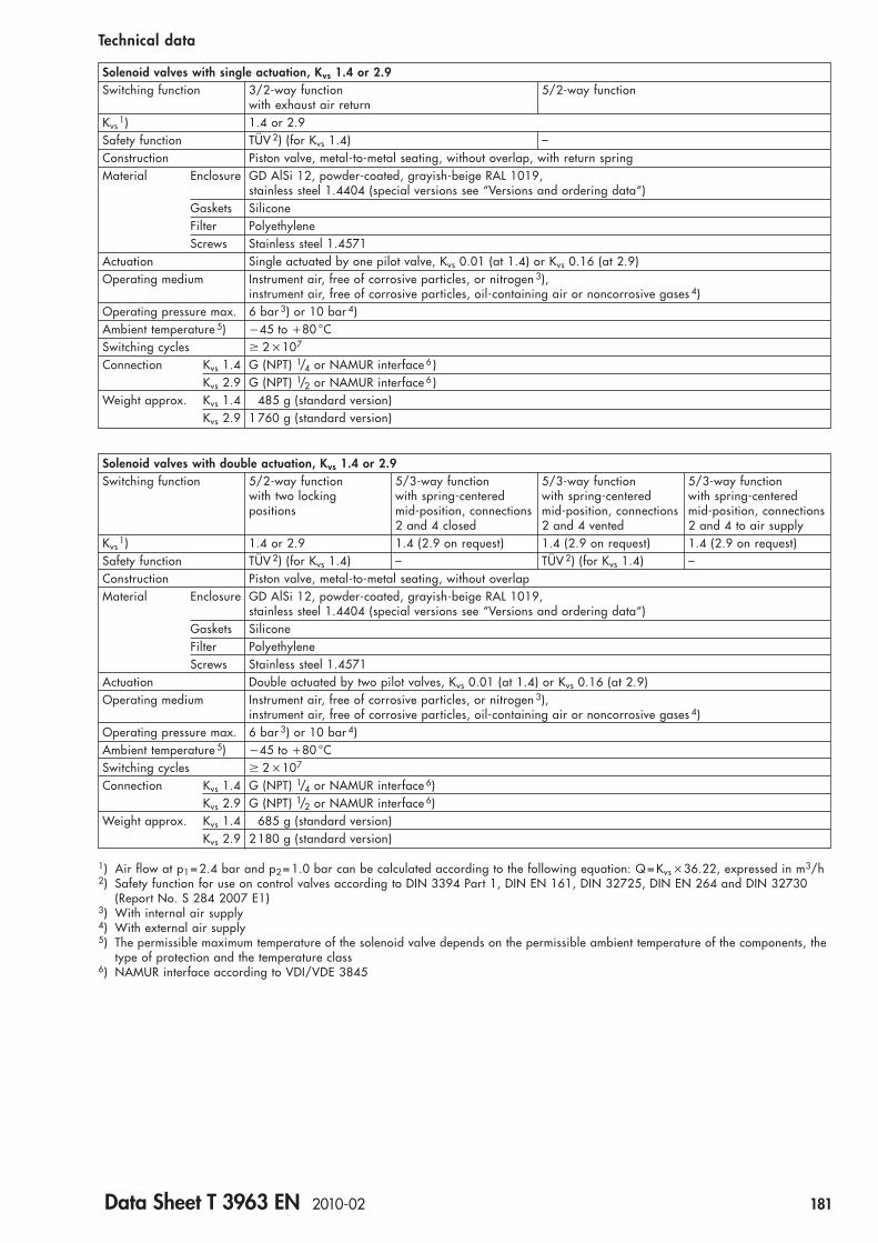
Technical data
Solenoid valves with single actuation, Kvs 1.4 or 2.9Switching function 3/2-way function 5/2-way function
with exhaust air returnKvs
1) 1.4 or 2.9Safety function TÜV 2) (for Kvs 1.4) –Construction Piston valve, metal-to-metal seating, without overlap, with return springMaterial Enclosure GD AlSi 12, powder-coated, grayish-beige RAL 1019,
stainless steel 1.4404 (special versions see “Versions and ordering data“)Gaskets SiliconeFilter PolyethyleneScrews Stainless steel 1.4571
Actuation Single actuated by one pilot valve, Kvs 0.01 (at 1.4) or Kvs 0.16 (at 2.9)Operating medium Instrument air, free of corrosive particles, or nitrogen 3),
instrument air, free of corrosive particles, oil-containing air or noncorrosive gases 4)Operating pressure max. 6 bar 3) or 10 bar 4)Ambient temperature 5) �45 to �80 °CSwitching cycles 2 �107
Connection Kvs 1.4 G (NPT) 1/4 or NAMUR interface 6 )Kvs 2.9 G (NPT) 1/2 or NAMUR interface 6 )
Weight approx. Kvs 1.4 485 g (standard version)Kvs 2.9 1 760 g (standard version)
Solenoid valves with double actuation, Kvs 1.4 or 2.9Switching function 5/2-way function 5/3-way function 5/3-way function 5/3-way function
with two locking with spring-centered with spring-centered with spring-centeredpositions mid-position, connections mid-position, connections mid-position, connections
2 and 4 closed 2 and 4 vented 2 and 4 to air supplyKvs
1) 1.4 or 2.9 1.4 (2.9 on request) 1.4 (2.9 on request) 1.4 (2.9 on request)Safety function TÜV 2) (for Kvs 1.4) – TÜV 2) (for Kvs 1.4) –Construction Piston valve, metal-to-metal seating, without overlapMaterial Enclosure GD AlSi 12, powder-coated, grayish-beige RAL 1019,
stainless steel 1.4404 (special versions see “Versions and ordering data“)Gaskets SiliconeFilter PolyethyleneScrews Stainless steel 1.4571
Actuation Double actuated by two pilot valves, Kvs 0.01 (at 1.4) or Kvs 0.16 (at 2.9)Operating medium Instrument air, free of corrosive particles, or nitrogen 3),
instrument air, free of corrosive particles, oil-containing air or noncorrosive gases 4)Operating pressure max. 6 bar 3) or 10 bar 4)Ambient temperature 5) �45 to �80 °CSwitching cycles 2 �107
Connection Kvs 1.4 G (NPT) 1/4 or NAMUR interface 6)Kvs 2.9 G (NPT) 1/2 or NAMUR interface 6)
Weight approx. Kvs 1.4 685 g (standard version)Kvs 2.9 2 180 g (standard version)
1) Air flow at p1 = 2.4 bar and p2 = 1.0 bar can be calculated according to the following equation: Q = Kvs �36.22, expressed in m3/h2) Safety function for use on control valves according to DIN 3394 Part 1, DIN EN 161, DIN 32725, DIN EN 264 and DIN 32730
(Report No. S 284 2007 E1)3) With internal air supply4) With external air supply5) The permissible maximum temperature of the solenoid valve depends on the permissible ambient temperature of the components, the
type of protection and the temperature class6) NAMUR interface according to VDI/VDE 3845
Data Sheet T 3963 EN 2010-02 181

CableglandM 20�1.5
ThreadedplugM 20�1.5
61
� 62
31 38
80
� 62
31
CableglandM 20�1.5
ThreadedplugM 20�1.5
61
63
31 38 31
� 62 � 62
Fig. 20 · Dimensions in mm
Pilot valve, Kvs 0.16
Pilot valve, Kvs 0.01
Dimensions of devices without threaded connection
Fig. 21 · Dimensions in mm
182 Data Sheet T 3963 EN 2010-02

1919
3 959(4)
Connection 9 on Type 3963-XXX0X11X0XXXXXConnection 4 on Type 3963-XXX0X12XXXXXXX
Connections 5 and 9 only on Type 3963-XXX0X12XXXXXXX
CableglandM 20�1.5
ThreadedplugM 20�1.5
31
109
61 31 38
10
29
10
� 62
40 40
� 62
28 38 48
123
321
1
2
3
M 4 / 7 mm depthM 3 / 6 mm depth 3 mm / 3.5 mm depth
Underneath view of connection plate
2.5 1.594
1.3 2.3
ThreadedplugM 20�1.5
CableglandM 20�1.5
� 62
25
10
31
124
61 31
10
2538
40 40
28 38 48
123
1
2
3
M 4 / 7 mm depthM 3 / 6 mm depth 3 mm / 3.5 mm depth
Underneath view of connection plate
Fig. 23 · Dimensions in mm
Dimensions of devices with threaded connection
5/2-way solenoid valve, single actuated, Kvs 0.16
3/2-way solenoid valve, single actuated, Kvs 0.16 or 0.32
Fig. 22 · Dimensions in mm
Data Sheet T 3963 EN 2010-02 183

CableglandM 20�1.5
1.4 2.4
1.3 2.32.5 1.5
9
ThreadedplugM 20�1.5
31
129
61 31 38
34
10
49
� 62
39
24
25
42
40
� 62
28 38 48
123
1
1
2
3
M 4 / 7 mm depthM 3 / 6 mm depth 3 mm / 3.5 mm depth
Underneath view of connection plate
6/2-way solenoid valve, single actuated, Kvs 0.16
3/2-way solenoid valve, single actuated, Kvs 0.16 or 0.32, for attachment with connection block to linear actuators
Dimensions of devices with threaded connection
Fig. 24 · Dimensions in mm
Fig. 25 · Dimensions in mm
24
22.5
22.512
* Attachment to connection block with 2 hexagon socket head screws M 5�60 DIN 912
60
61 31 38 31
108.
5
16
12
16 60
*
*
ThreadedplugM 20�1.5
CableglandM 20�1.5
184 Data Sheet T 3963 EN 2010-02

Plug G 1/4
64
53
1/2" 21 21
29
35
65
7
1/2"
1/2"
193
31
5053
34
94.5
38
62
31
9
4
5
3
99
Int
CableglandM 20�1.5
ThreadedplugM 20�1.5
3/2-way solenoid valve, single actuated, Kvs 4.3
Dimensions of devices with threaded connection
Fig. 26 · Dimensions in mm
Data Sheet T 3963 EN 2010-02 185
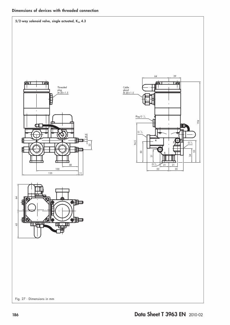
43
64
38
100
135 11
22
34
53 35
194
65
21 21
53
94.5
531
50
64 29
ThreadedplugM 20�1.5
CableglandM 20�1.5
Plug G 1/4
G 1/2
G 1/2
G 1/2
M 6
5/2-way solenoid valve, single actuated, Kvs 4.3
Dimensions of devices with threaded connection
Fig. 27 · Dimensions in mm
186 Data Sheet T 3963 EN 2010-02

ThreadedplugM 20�1.5
M 6
22
38
100
135 11
6465
Plug G 1/4
G 1/2
CableglandM 20�1.5
G 1/2
G 1/2
64 29
21 21
53 35
194
94.5
50
31 34
53
43
5
Fig. 28 · Dimensions in mm
6/2-way solenoid valve, single actuated, Kvs 4.3
Dimensions of devices with threaded connection
Data Sheet T 3963 EN 2010-02 187

61 31
4.3
32
50.8
22 2214
32
CableglandM 20�1.5
Plug G 1/4
ThreadedplugM 20�1.5
1/4"
14 13
56
44.4
47
122
Int
9
47
Connection 5 is closed on 3/2-way valve
CableglandM 20�1.5
Plug G 1/4
ThreadedplugM 20�1.5
61 31
32
50.8
4.3
14
4
2
12
3
1
5
14 56
17
1/4"
122
4747
44.4
Int
9 9
9
9 Int
122
22 22
Fig. 30 · Dimensions in mm
3/2 or 5/2-way solenoid valve, single actuated, Kvs 1.4
5/2 or 5/3-way solenoid valve, double actuated, Kvs 1.4
Dimensions of devices with threaded connection
Fig. 29 · Dimensions in mm
188 Data Sheet T 3963 EN 2010-02

67
42
12 12
10
5.3
603418
8.5
25
1.3
2.3
G 1/4
6
11
30
3016.8
60°
1.32.3
32 12
Underneath view of connection plate70 12
8.4
62
801419
40
62
3
4
G 1 / 4
CableglandM 20�1.5
ThreadedplugM 20�1.5
61 31
109
236
60°
16.8
38 31
40
10
19
9
5
3/2-way solenoid valve, single actuated, Kvs 0.32
Dimensions of devices with threaded connection for linear actuators with NAMUR rib
Adapter plate NAMUR rib/NAMUR interface (order no. 1400-6751)
Fig. 32 · Dimensions in mm
Fig. 31 · Dimensions in mm
Data Sheet T 3963 EN 2010-02 189

1.3 2.3
4
12.525
6232
61
62
88
63
31
69
25
96
24
36
38 31
CableglandM 20�1.5
ThreadedplugM 20�1.5
NAMUR fixing level
4
2.3
1.3 2.3
9
61
13
62
114
62
17
38
3424
31 31
36
69
25
32 62
96
5
22.2
18.5
ThreadedplugM 20�1.5
CableglandM 20�1.5
NAMUR fixing level
Fig. 34 · Dimensions in mm
Dimensions for devices with NAMUR interface for rotary actuators
3/2 or 5/2-way solenoid valve, single actuated, Kvs 0.16
3/2-way solenoid valve, single actuated, Kvs 0.32
Fig. 33 · Dimensions in mm
190 Data Sheet T 3963 EN 2010-02
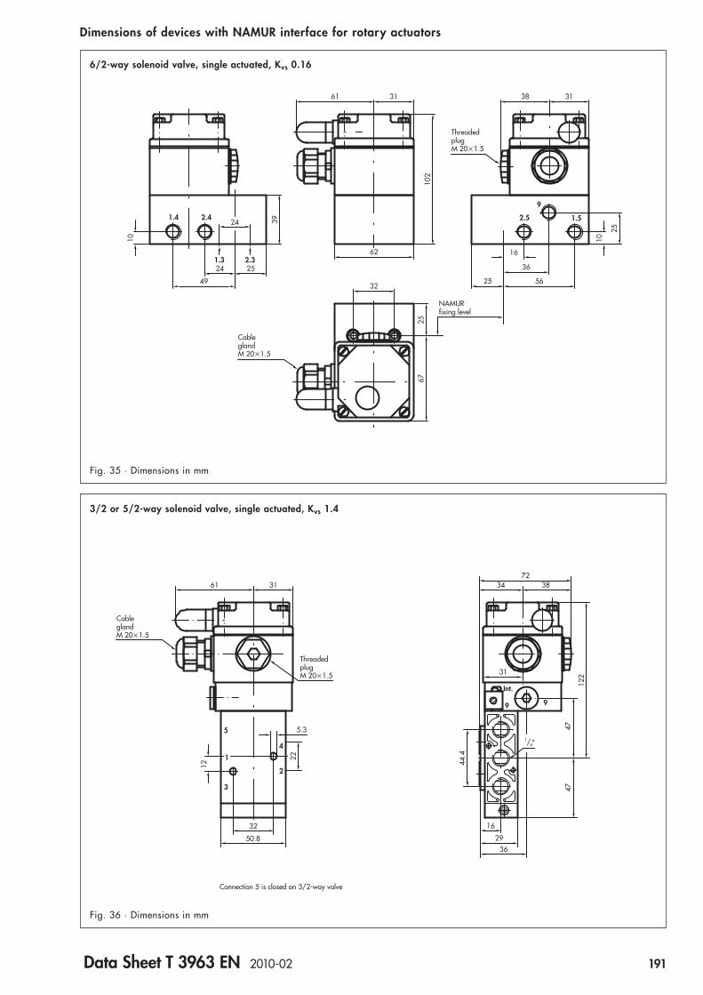
1.4 2.4
9
2.5 1.5
1.3 2.3
32
61
102
31
25
10
2524
4939
25
24
67
25
16
56
36
38 31
62
10
NAMURfixing level
CableglandM 20�1.5
ThreadedplugM 20�1.5
61 31
5.3
22
12
32
50.8
5
4
2
3
ThreadedplugM 20�1.5
CableglandM 20�1.5
Connection 5 is closed on 3/2-way valve
7234 38
31
16
2936
4747
44.4
122
99
Int.
1/4"
3/2 or 5/2-way solenoid valve, single actuated, Kvs 1.4
6/2-way solenoid valve, single actuated, Kvs 0.16
Dimensions of devices with NAMUR interface for rotary actuators
Fig. 35 · Dimensions in mm
Fig. 36 · Dimensions in mm
Data Sheet T 3963 EN 2010-02 191

3/2-way solenoid valve, single actuated, Kvs 4,3
3/2-way solenoid valve, single actuated, Kvs 2.0
Dimensions of devices with NAMUR interface for rotary actuators
Fig. 37 · Dimensions in mm
Fig. 38 · Dimensions in mm
192 Data Sheet T 3963 EN 2010-02
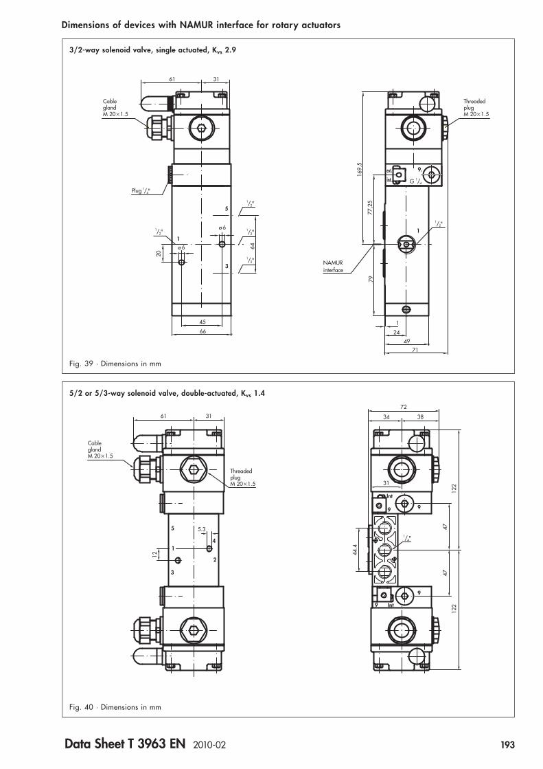
Dimensions of devices with NAMUR interface for rotary actuators
64
ø 6
ø 6
45
661
24
49
71
79
169.
5
77,2
5
G 1/4
1
5
3
ThreadedplugM 20�1.5
CableglandM 20�1.5
1/2"
1/2"1/2"
1/2"
1/2" 1
9.
int.
ext.
61 31
20
NAMURinterface
1/4"Plug
Fig. 39 · Dimensions in mm
3/2-way solenoid valve, single actuated, Kvs 2.9
5
1
3
4
2
9 9
Int
9
9 Int
5.3
122
122
72
61 31 3834
12 44.4
4747
31
ThreadedplugM 20�1.5
CableglandM 20�1.5
1/4"
Fig. 40 · Dimensions in mm
5/2 or 5/3-way solenoid valve, double-actuated, Kvs 1.4
Data Sheet T 3963 EN 2010-02 193

CableglandM 20�1.5
1/4"Plug
1/2"1/2"
1/2"
1/2"
1/4"Plug
61 31
ø 6
ø 6
66
1
5
3
64
20
5/2-way solenoid valve, double-actuated, Kvs 2.9
Fig. 41 · Dimensions in mm
Dimensions of devices with NAMUR interface for rotary actuators
170
1
32
71
ext.
int.
9.
ext.
int.
9.
1
ThreadedplugM 20�1.5
1/4G
1/2"
NAMURinterface
77.2
5
194 Data Sheet T 3963 EN 2010-02
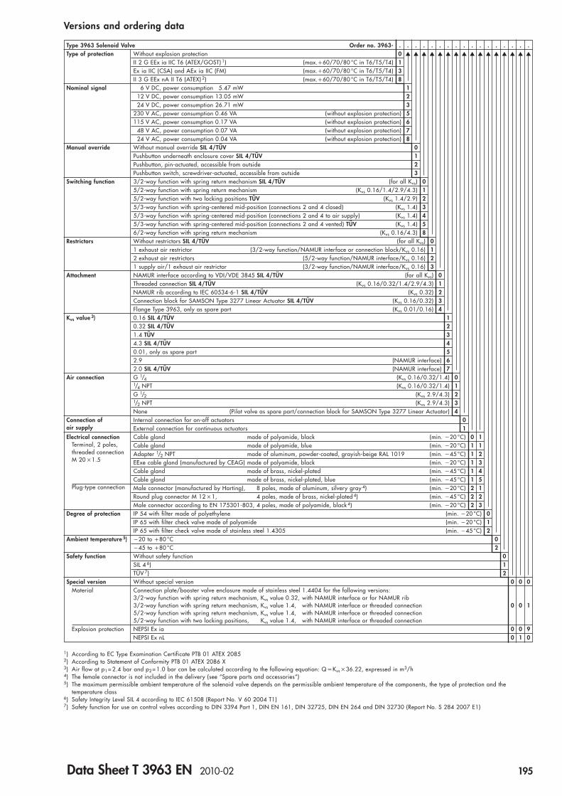
Type 3963 Solenoid Valve Order no. 3963- . . . . . . . . . . . . . . . . .Type of protection Without explosion protection 0 ▲ ▲ ▲ ▲ ▲ ▲ ▲ ▲ ▲ ▲ ▲ ▲ ▲ ▲ ▲ ▲
II 2 G EEx ia IIC T6 (ATEX/GOST) 1) (max.�60/70/80 °C in T6/T5/T4) 1Ex ia IIC (CSA) and AEx ia IIC (FM) (max.�60/70/80 °C in T6/T5/T4) 3II 3 G EEx nA II T6 (ATEX) 2) (max.�60/70/80 °C in T6/T5/T4) 8
Nominal signal 6 V DC, power consumption 5.47 mW 112 V DC, power consumption 13.05 mW 224 V DC, power consumption 26.71 mW 3
230 V AC, power consumption 0.46 VA (without explosion protection) 5115 V AC, power consumption 0.17 VA (without explosion protection) 6
48 V AC, power consumption 0.07 VA (without explosion protection) 724 V AC, power consumption 0.04 VA (without explosion protection) 8
Manual override Without manual override SIL 4/TÜV 0Pushbutton underneath enclosure cover SIL 4/TÜV 1Pushbutton, pin-actuated, accessible from outside 2Pushbutton switch, screwdriver-actuated, accessible from outside 3
Switching function 3/2-way function with spring return mechanism SIL 4/TÜV (for all Kvs) 05/2-way function with spring return mechanism (Kvs 0.16/1.4/2.9/4.3) 15/2-way function with two locking positions TÜV (Kvs 1.4/2.9) 25/3-way function with spring-centered mid-position (connections 2 and 4 closed) (Kvs 1.4) 35/3-way function with spring-centered mid-position (connections 2 and 4 to air supply) (Kvs 1.4) 45/3-way function with spring-centered mid-position (connections 2 and 4 vented) TÜV (Kvs 1.4) 56/2-way function with spring return mechanism (Kvs 0.16/4.3) 8
Restrictors Without restrictors SIL 4/TÜV (for all Kvs) 01 exhaust air restrictor (3/2-way function/NAMUR interface or connection block/Kvs 0.16) 12 exhaust air restrictors (5/2-way function/NAMUR interface/Kvs 0.16) 21 supply air/1 exhaust air restrictor (3/2-way function/NAMUR interface/Kvs 0.16) 3
Attachment NAMUR interface according to VDI/VDE 3845 SIL 4/TÜV (for all Kvs) 0Threaded connection SIL 4/TÜV (Kvs 0.16/0.32/1.4/2.9/4.3) 1NAMUR rib according to IEC 60534-6-1 SIL 4/TÜV (Kvs 0.32) 2Connection block for SAMSON Type 3277 Linear Actuator SIL 4/TÜV (Kvs 0.16/0.32) 3Flange Type 3963, only as spare part (Kvs 0.01/0.16) 4
Kvs value 3) 0.16 SIL 4/TÜV 10.32 SIL 4/TÜV 21.4 TÜV 34.3 SIL 4/TÜV 40.01, only as spare part 52.9 (NAMUR interface) 62.0 SIL 4/TÜV (NAMUR interface) 7
Air connection G 1/4 (Kvs 0.16/0.32/1.4) 01/4 NPT (Kvs 0.16/0.32/1.4) 1G 1/2 (Kvs 2.9/4.3) 21/2 NPT (Kvs 2.9/4.3) 3None (Pilot valve as spare part/connection block for SAMSON Type 3277 Linear Actuator) 4
Connection of Internal connection for on-off actuators 0air supply External connection for continuous actuators 1Electrical connection Cable gland made of polyamide, black (min. �20 °C) 0 1
Terminal, 2 poles, Cable gland made of polyamide, blue (min. �20 °C) 1 1threaded connection Adapter 1/2 NPT made of aluminum, powder-coated, grayish-beige RAL 1019 (min. �45 °C) 1 2M 20 �1.5 EExe cable gland (manufactured by CEAG) made of polyamide, black (min. �20 °C) 1 3
Cable gland made of brass, nickel-plated (min. �45 °C) 1 4Cable gland made of brass, nickel-plated, blue (min. �45 °C) 1 5
Plug-type connection Male connector (manufactured by Harting), 8 poles, made of aluminum, silvery gray 4) (min. �20 °C) 2 1Round plug connector M 12 �1, 4 poles, made of brass, nickel-plated 4) (min. �45 °C) 2 2Male connector according to EN 175301-803, 4 poles, made of polyamide, black 4) (min. �20 °C) 2 3
Degree of protection IP 54 with filter made of polyethylene (min. �20 °C) 0IP 65 with filter check valve made of polyamide (min. �20 °C) 1IP 65 with filter check valve made of stainless steel 1.4305 (min. �45 °C) 2
Ambient temperature 5) �20 to �80 °C 0�45 to �80 °C 2
Safety function Without safety function 0SIL 4 6) 1TÜV 7) 2
Special version Without special version 0 0 0Material Connection plate/booster valve enclosure made of stainless steel 1.4404 for the following versions:
3/2-way function with spring return mechanism, Kvs value 0.32, with NAMUR interface or for NAMUR rib3/2-way function with spring return mechanism, Kvs value 1.4, with NAMUR interface or threaded connection 0 0 15/2-way function with spring return mechanism, Kvs value 1.4, with NAMUR interface or threaded connection5/2-way function with two locking positions, Kvs value 1.4, with NAMUR interface or threaded connection
Explosion protection NEPSI Ex ia 0 0 9NEPSI Ex nL 0 1 0
Versions and ordering data
1) According to EC Type Examination Certificate PTB 01 ATEX 20852) According to Statement of Conformity PTB 01 ATEX 2086 X3) Air flow at p1 = 2.4 bar and p2 = 1.0 bar can be calculated according to the following equation: Q �Kvs �36.22, expressed in m3/h4) The female connector is not included in the delivery (see “Spare parts and accessories“)5) The maximum permissible ambient temperature of the solenoid valve depends on the permissible ambient temperature of the components, the type of protection and the
temperature class6) Safety Integrity Level SIL 4 according to IEC 61508 (Report No. V 60 2004 T1)7) Safety function for use on control valves according to DIN 3394 Part 1, DIN EN 161, DIN 32725, DIN EN 264 and DIN 32730 (Report No. S 284 2007 E1)
Data Sheet T 3963 EN 2010-02 195

Spare parts for Type 3963 Solenoid ValvesOrder no. Designation0430-2287 Flat gasket made of silicone rubber, �45 to �80 °C (for connection plate)8502-1091 Molded gasket (for air supply on booster valve with Kvs 1.4)
0520-0620 Diaphragm made of chloroprene, �20 to �80 °C (for booster valve with Kvs 2.0 or 4.3)0520-0622 Diaphragm made of chloroprene, �20 to �80 °C (for all booster valves, except with Kvs 2.0 or 4.3)0520-1097 Diaphragm made of silicone rubber, �45 to �80 °C (for booster valve with Kvs 2.0 or 4.3)0520-1128 Diaphragm made of silicone rubber, �45 to �80 °C (for all booster valves, except with Kvs 2.0 or 4.3)
1180-8311 Actuating element insert, �20 to �80 °C (for booster valve with Kvs 2.0 or 4.3)1180-8553 Actuating element insert, �45 to �80 °C (for booster valve with Kvs 2.0 or 4.3)
8421-0021 O-ring 2 �1 (for connection plate)8421-0308 O-ring 11 �4.5 (for booster valves with NAMUR interface)8421-9002 O-ring 16 �2 (for booster valves with NAMUR interface)8421-0085 O-ring 26 �2, �20 … �80 °C (for booster valve with Kvs 2.0 or 4.3)8421-0418 O-ring 26 �2, �45 … �80 °C (for booster valve with Kvs 2.0 or 4.3)8421-0102 O-ring 36 �2, �20 … �80 °C (for booster valve with Kvs 2.0 or 4.3)8421-0101 O-ring 36 �2, �45 … �80 °C (for booster valve with Kvs 2.0 or 4.3)
Enclosure cover without filter (for pilot valve)1099-0673 without manual override1099-0674 with pushbutton switch, screwdriver-actuated, accessible from outside1099-0675 with pushbutton, pin-actuated, accessible from outside1099-1194 with lever switch, accessible from outside
0070-0799 Plug G 1/4 made of stainless steel 1.4571 (for connection 9 on the pilot valve)8421-0070 O-ring 14 �1.5 made of NBR (for plug G 1/4)
Accessories for Type 3963 Solenoid ValvesOrder no. Designation0790-6658 Female connector according to EN 175301-803, type A, made of polyamide, black, IP 651400-8298 Female connector (manufactured by Harting), 7 poles, made of aluminum, silvery gray, IP 658801-2810 Sensor connecting cable, 2 wires, length 3 m, blue, with angle connector M 12 �1, 4 poles, IP 688831-0716 Female connector (manufactured by Binder), 7 poles, made of PBT GV, black, IP 678831-0865 Female connector M 12 �1, 4 poles, angle type, made of polyamide, black, IP 67
3994-0158 Cable break protection device with enclosure for top hat rail 35, IP 20 (for Type 3963-X1 with 6 V DC solenoid)
1400-5268 Filter made of polyethylene, connection G 1/G 1/2, IP 54 (required for actuator size � 1 400 cm2!)8504-0066 Filter made of polyethylene, connection G 1/4, IP 548504-0068 Filter made of polyethylene, connection G 1/2, IP 54
1790-7408 Filter check valve with screw-in case G 1/4, made of polyamide, IP 651790-7253 Filter check valve with screw-in case G 1/4, made of stainless steel 1.4571, IP 651790-9645 Filter check valve with screw-in case G 1/4, made of polyamide, NEMA 41790-9646 Filter check valve with screw-in case G 1/4, made of stainless steel 1.4571, NEMA 4
1400-5930 Mounting base for G profile 32 according to EN 50035 (2 pieces are required!)1400-5931 Mounting base for top hat rail 35 according to EN 50022 (2 pieces are required!)1400-6726 Mounting plate for wall mounting
Connection blocks and accessories for attaching solenoid valves to Type 3277 Linear ActuatorsOrder no. Designation
Connection block for Type 3277 Linear Actuators with integral Type 3766/3767/3780/3730 Positioner attachment1400-8813 Connection G 1/41400-8814 Connection 1/4 NPT
1400-6950 Pressure gauge build-on block, 1 �“Output“ and 1 �“Supply“, made of stainless steel/brass (for connection block)
Piping kit for “Stem retracts“1400-6444 Actuator size 240 cm2, made of steel, galvanised1400-6445 Actuator size 240 cm2, made of stainless steel1400-6446 Actuator size 350 cm2, made of steel, galvanised1400-6447 Actuator size 350 cm2, made of stainless steel1400-6448 Actuator size 700 cm2, made of steel, galvanised1400-6449 Actuator size 700 cm2, made of stainless steel
Spare parts and accessories
196 Data Sheet T 3963 EN 2010-02

Mounting kits for Type 3963 Solenoid Valves with threaded connectionOrder no. Designation1400-6759 Mounting kit for linear actuators (actuator size 80/240 cm2, connection G 1/4)
with screwed pipe connection, connection G 1/4/G 1/4, made of stainless steel
Mounting kit for linear actuators (actuator size 350/700 cm2, connection G 3/8)1400-6735 with screwed pipe connection, connection G 1/2/G 3/8, made of stainless steel1400-6761 with screwed pipe connection, connection G 1/4/G 3/8, made of stainless steel
1400-6736 Mounting kit for linear actuators (actuator size 1 400 cm2, connection G 3/4)with screwed pipe connection, connection G 1/2/G 3/4, made of stainless steel
1400-6737 Mounting kit for linear actuators (actuator size 2 800 cm2, connection G 1)with screwed pipe connection, connection G 1/2/G 1, made of stainless steel
Mounting kit for linear actuators (actuator size 80/240 cm2, connection G 1/4)with angle bracket made of stainless steel
1400-6749 and screwed joints for pipe 8 �1, connection G 1/4/G 1/4, made of steel, galvanised1400-6750 and screwed joints for pipe 8 �1, connection G 1/4/G 1/4, made of stainless steel
Mounting kit for linear actuators (actuator size 350/700 cm2, connection G 3/8)with angle bracket made of stainless steel
1400-6738 and screwed joints for pipe 8 �1, connection G 1/4/G 3/8, made of steel, galvanised1400-6739 and screwed joints for pipe 8 �1, connection G 1/4/G 3/8, made of stainless steel1400-6743 and screwed joints for pipe 12 �1, connection G 1/4/G 3/8, made of stainless steel1400-6744 and screwed joints for pipe 10 �1, connection G 1/2/G 3/8, made of polyamide1400-6745 and screwed joints for pipe 10 �1, connection G 1/4/G 3/8, made of polyamide
Mounting kit for linear actuators (actuator size 700 cm2, connection G 3/8)with angle bracket made of stainless steel
1400-6740 and screwed joints for pipe 12 �1, connection G 1/2/G 3/8, made of steel, galvanised1400-6741 and screwed joints for pipe 12 �1, connection G 1/4/G 3/8, made of steel, galvanised1400-6742 and screwed joints for pipe 12 �1, connection G 1/2/G 3/8, made of stainless steel
Spare parts and accessories
Mounting kits for Type 3963 Solenoid Valves with NAMUR interfaceOrder no. Designation
Mounting kit for linear actuators (actuator size 350/700 cm2, connection G 3/8) with NAMUR ribvia adapter plate NAMUR rib/NAMUR interface (order no. 1400-6751)
1400-6746 with screwed joints for pipe 12 �1, connection G 1/4/G 3/8, made of steel, galvanised1400-6747 with screwed joints for pipe 12 �1, connection G 1/4/G 3/8, made of stainless steel1400-6748 with screwed joints for pipe 10 �1, connection G 1/4/G 3/8, made of polyamide
Mounting kit for linear actuators (actuator size 80/240 cm2, connection G 1/4) with NAMUR ribvia adapter plate NAMUR rib/NAMUR interface (order no. 1400-6751)
1400-6752 with screwed joints for pipe 6 �1, connection G 1/4/G 1/4, made of steel, galvanised1400-6753 with screwed joints for pipe 6 �1, connection G 1/4/G 1/4, made of stainless steel1400-6756 with screwed joints for hose 10 �1, connection G 1/4/G 1/4, made of polyamide
Mounting kit for linear actuators (actuator size 350/700 cm2, connection G 3/8) with NAMUR ribvia adapter plate NAMUR rib/NAMUR interface (order no. 1400-6751)
1400-6754 with screwed joints for pipe 8 �1, connection G 1/4/G 3/8, made of steel, galvanised1400-6755 with screwed joints for pipe 8 �1, connection G 1/4/G 3/8, made of stainless steel1400-6757 with screwed joints for pipe 10 �1, connection G 1/4/G 3/8, made of polyamide
1400-6759 Mounting kit for linear actuators (actuator size 80/240 cm2, connection G 1/4)with screwed pipe connection G 1/4/G 1/4, made of stainless steel
1400-3001 Mounting kit for Type 3353 Angle Seat Valvewith adapter plate for NAMUR interface made of stainless steel 1.4301
Accessories for mounting kitsOrder no. Designation0320-1416 Bracket for NAMUR rib
(required when a positioner or a limit switch is to be mounted to linear actuators with nominal size � DN 50 at the same time)
8320-0131 Hexagon socket head screw M 8 �60 – A 4 DIN 931
1400-6751 Adapter plate NAMUR rib/NAMUR interface, connection G 1/41400-9924 Adapter plate NAMUR rib/NAMUR interface, connection 1/4 NPT
Data Sheet T 3963 EN 2010-02 197


General
The Type 3967 Solenoid Valve is used to control rotary actuatorswith NAMUR interface or linear actuators with NAMUR rib.
Intrinsically safe, low-power binary signals issued by automationor fieldbus systems can be used for controlling purposes.
Different nominal signals and connection types allow the solenoidvalve to be tailor-made to the specific task. Special features ofthe Type 3963 Solenoid Valve include:
General features
● Safety Integrity Level SIL according to IEC 61508(Report No. V 177 2009 T1)
● Service life with over 20 million switching cycles● Ambient temperature �45 to �80 °C● Corrosion-resistant enclosure with degree of protection IP 65
for humid and aggressive environments ● NAMUR interface 1/4" according to VDI/VDE 3845 for rotary
actuators or connection block with positioner for SAMSON Type 3277 Linear Actuators
● Adapter plate for linear actuators with NAMUR rib according to IEC 60534-6-1, panel, wall or rail mounting
Electric features
● E/P binary converter with flapper/nozzle assembly● Type of protection (ATEX):
II 2 G Ex ia IIC T6 (gases in zone 1), II 3 G Ex nA II T6/II 3 G Ex nL II T6 (gases in zone 2), II 2 D Ex tD A21 IP 65 T 80 °C (dusts in zone 21), II 3 D Ex tD A21 IP 65 T 80 °C (dusts in zone 22)
● Nominal signal 6/12/24 V DC● Power consumption 6 to 27 mW● Manual override● Connection to terminals with cable gland M 16 �1.5
Pneumatic features
● Plug/seat valve with return spring● 3 /2-way function● KVS value 0.32● Air supply 1.4 to 10.0 bar● Operating pressure max. 10.0 bar● Threaded connection G (NPT) 1/4● Restrictor plate (accessories)
Fig. 1 · Type 3967 Solenoid Valve
Solenoid Valve Type 3967for the control of pneumatic actuators
Version with NAMUR interface 1/4"
Version with restrictor plate
Version with adapter plate
Versions
Data Sheet T 3967 EN 2010-01 199

Function
The solenoid valve consists of an E/P binary converter � withmanual override � and a single actuated booster valve � withreturn spring (Fig. 2).
The air supply for the E/P binary converter � is connected inter-nally over connection 1 or externally over connection 9. Rotatinga flat gasket allows the connection to external air supply (seeMounting and Instruction Manual EB 3967 EN).
The pressure reducer � reduces the air supply pressure to 1.4bar.
In the normal position the flapper � is lifted off the outlet nozzle� by the spring �. As a result, a pressure lower than the switch-off pressure of the booster valve � builds up in the pressure divider that consists of the restriction � and the outlet nozzle �.
When the solenoid � is energized by an electrical binary signal,the outlet nozzle � is closed by the flapper � against the forceof the spring �. As a result, the pressure in the pressure dividerrises above the switch-on pressure of the booster valve �, thusswitching it to the operating position.
After de-energizing the electrical binary signal, the boostervalve � is switched to the normal position by a return spring.
�
�
� �
�
� ��
�
�
�
9
�
External air supply
Nominal signal
Fig. 2
Function diagram
� E/P binary converter� Outlet nozzle� Flapper� Spring� Solenoid� Pressure reducer� Restrictor
� Manual override� Booster valve
200 Data Sheet T 3967 EN 2010-01

Technical Data
General dataConstruction Solenoid with flapper/nozzle assembly and booster valveMaterial Enclosure Polyamide PA 6-3-T-GF35, black
Connection plate AlMgSiPb, powder-coated, blackBlind plate AlMgSiPb, powder-coated, blackAdapter plate AlMgSiPb, powder-coated, grayish beige RAL 1019, or stainless steel 1.4404Screws Stainless steel A2-70Springs Stainless steel 1.4310Gaskets Silicone rubber
Air connection G (NPT) 1/4/NAMUR interface 1/4"Electrical connection Screw terminal, 2-poles, with cable gland M 16 �1.5Degree of protection IP 65Ambient temperature 1) �20 … �80 °C,
�45 … �80 °CWeight approx. 450 g,
800 g with adapter plate
1) The permissible maximum ambient temperature depends on the permissible ambient temperature of the cable gland, the type of protection and the temperature class
Electrical dataType 3967 -XXX1 -XXX2 -XXX3Nominal signal UN 6 V DC 12 V DC 24 V DC
max. 27 V 1) max. 40 V 1) max. 60 V 1)Switching point “On“ U�80 °C 4.8 V 9.6 V 18 V
P �20 °C 5.47 mW 13.05 mW 26.71 mW“Off“ U�25 °C � 1.0 V � 2.3 V � 4.6 V
Impedance R �20 °C 2.6 k 5.3 k 10.5 k
Temperature effect to R 0.4 %/°C 0.2 %/°C 0.1 %/°CType of protection Ex ia IIC 2) for use in hazardous areas (zone 1 or 21)Type 3967 -1101 -1102 -1103Permissible maximum values for connection to a certified intrinsically safe circuitOutput voltage Ui The following values Ui/Ii apply for nominal signals 6/12/24 V DC:
25 V/150 mA, 27 V/125 mA, 28 V/115 mA, 30 V/100 mA, 32 V/85 mAOutput current IiPower dissipation 3) Pi 250 mW No limitationsExternal capacitance Ci � 0External inductance Li � 0Ambient temperature in temperature class
T6 �45 to �60 °CT5 �45 to �70 °CT4 �45 to �80 °C
Type of protection Ex nA II/Ex nL IIC 4) for use in hazardous areas (zone 2 or 22)Type 3967 -8101 -8102 -8103Permissible maximum values for connection to a certified energy-limited circuitOutput voltage Ui 32 VOutput current Ii 132 mAPower dissipation Pi No limitationExternal capacitance Ci � 0External inductance Li � 0Ambient temperature in temperature class
T6 �45 to �60 °CT5 �45 to �70 °CT4 �45 to �80 °C
1) Permissible maximum values during 100 % duty. For Ex versions the permissible maximum value Ui is relevant.2) II 2 G Ex ia IIC T6 (gases in zone 1),
II 2 D Ex tD A21 IP 65 T 80 °C (dusts in zone 21)according to EC Type Examination Certificate PTB 06 ATEX 2027
3) The permissible maximum power dissipation at 6 V DC and a rectangular characteristic is 250 mW. With a linear characteristicthere are no limitations.
4) II 3 G Ex nA II T6/II 3 G Ex nL IIC T6 (gases in zone 2),II 3 D Ex tD A21 IP 65 T 80 °C (dusts in zone 22)according to Certificate of Conformity PTB 06 ATEX 2028 X
Data Sheet T 3967 EN 2010-01 201

Technical data
Pneumatic dataSwitching function 3/2-way function with spring return mechanismKVS value 1) 0.32Safety function SIL 2)Construction Plug/seat valve with return springAir supply Medium Instrument air, free of corossive particles, or nitrogen
Pressure 1.4 … 10.0 bar 3),1.4 … 6.0 bar (at 0 … 6.0 bar operating pressure) 4),1.9 … 10.0 bar (at 0 … 10.0 bar operating pressure) 4)
Operating medium Instrument air, free of corrosive particles, or nitrogen 3),Instrument air, free of corrosive particles, oil containing air or noncorrosive gases 4)
Operating pressure 1.4 … 10.0 bar 3),0 … 10.0 bar 4)
Output signal Operating pressureAir consumption � 25 l/h (actuated),at 1.4 bar air supply � 80 l/h (unactuated)Switching time � 65 msSwitching cycles 2 �107
1) Air flow at p1� 2.4 bar and p2 �1.0 bar can be calculated according to the following equation: Q � KVS �36.22, expressed in m3/h2) Safety Integrity Level SIL according to IEC 61508 (Report No. V 177 2009 T1)3) With interneral air supply4) With external air supply
202 Data Sheet T 3967 EN 2010-01
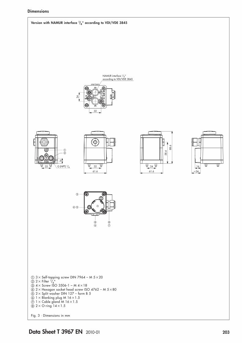
61.6
24
32
91
61.6
25
1
23
NAMUR interface 1/4" according to VDI/VDE 3845
G (NPT) 1/4
9
16
16
�24
243258
.4
88.6
��
�
� �
�
�
Version with NAMUR interface 1/4" according to VDI/VDE 3845
Fig. 3 · Dimensions in mm
Dimensions
� 3 � Self-tapping screw DIN 7964 – M 5 �20� 2 � Filter 1/4"� 4 � Screw ISO 3506-1 – M 4 �18� 2 � Hexagon socket head screw ISO 4762 – M 5 �80� 2 � Split washer DIN 127 – form B 5� 1 � Blanking plug M 16 �1.5� 1 � Cable gland M 16 �1.5 2 � O-ring 14 �1.5
Data Sheet T 3967 EN 2010-01 203

24
32
91
61.6
25
1
23
NAMUR interface 1/4" according to VDI/VDE 3845
G (NPT) 1/4
9
16
61.6
32 24
78.4
108.
6
��
�
� �
�
�
20
16
�24
Version with NAMUR interface 1/4" according to VDI/VDE 3845 and restrictor plate
Fig. 4 · Dimensions in mm
Dimensions
� 3 � Self-tapping screw DIN 7964 – M 5 �20� 2 � Filter 1/4"� 4 � Screw ISO 3506-1 – M 4 �18� 2 � Hexagon socket head screw ISO 4762 – M 5 �80� 2 � Split washer DIN 127 – form B 5� 1 � Blanking plug M 16 �1.5� 1 � Cable gland M 16 �1.5 2 � O-ring 14 �1.5
204 Data Sheet T 3967 EN 2010-01

61.6
24
32
91
61.6
1
23
NAMUR interface 1/4" according to VDI/VDE 3845
9
16
�24
243258
.4
88.6
�
�
� �
�
�
�
�
Version with NAMUR interface 1/4" according to VDI/VDE 3845 for connection block with positioner
Fig. 5 · Dimensions in mm
Dimensions
� 3 � Self-tapping screw DIN 7964 – M 5 �20� 4 � Screw ISO 3506-1 – M 4 �18� 2 � Hexagon socket head screw ISO 4762 – M 5 �80� 2 � Split washer DIN 127 – form B 5� 1 � Blanking plug M 16 �1.5� 1 � Cable gland M 16 �1.5� 2 � O-ring 14 �1.5
Data Sheet T 3967 EN 2010-01 205
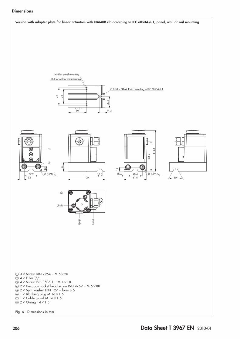
61.6
�82
.4
113.
4
100
14.2
111
G (NPT) 1/4
13
24
37.213.8
3 9
G (NPT) 1/440.410.6
2
30.8
91
M 4 for panel mounting
M 3 for wall or rail mounting
50
8.5 for NAMUR rib according to IEC 60534-6-1
48 38
�
�
��
�
�
60°16.8
Version with adapter plate for linear actuators with NAMUR rib according to IEC 60534-6-1, panel, wall or rail mounting
Fig. 6 · Dimensions in mm
Dimensions
� 3 � Screw DIN 7964 – M 5 �20� 4 � Filter 1/4"� 4 � Screw ISO 3506-1 – M 4 �18� 2 � Hexagon socket head screw ISO 4762 – M 5 �80� 2 � Split washer DIN 127 – form B 5� 1 � Blanking plug M 16 �1.5� 1 � Cable gland M 16 �1.5 2 � O-ring 14 �1.5
206 Data Sheet T 3967 EN 2010-01
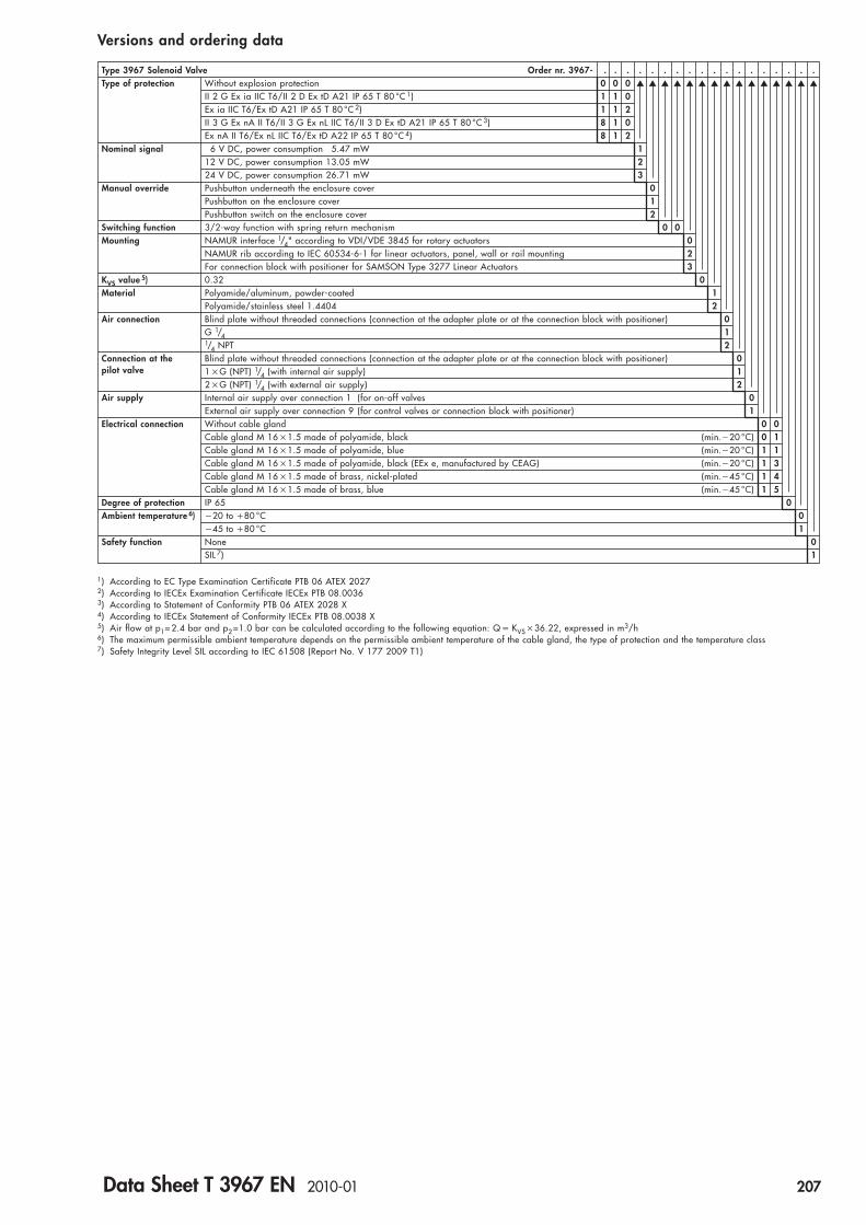
Type 3967 Solenoid Valve Order nr. 3967- . . . . . . . . . . . . . . . . . .Type of protection Without explosion protection 0 0 0 ▲ ▲ ▲ ▲ ▲ ▲ ▲ ▲ ▲ ▲ ▲ ▲ ▲ ▲ ▲
II 2 G Ex ia IIC T6/II 2 D Ex tD A21 IP 65 T 80 °C 1) 1 1 0Ex ia IIC T6/Ex tD A21 IP 65 T 80 °C 2) 1 1 2II 3 G Ex nA II T6/II 3 G Ex nL IIC T6/II 3 D Ex tD A21 IP 65 T 80 °C 3) 8 1 0Ex nA II T6/Ex nL IIC T6/Ex tD A22 IP 65 T 80 °C 4) 8 1 2
Nominal signal 6 V DC, power consumption 5.47 mW 112 V DC, power consumption 13.05 mW 224 V DC, power consumption 26.71 mW 3
Manual override Pushbutton underneath the enclosure cover 0Pushbutton on the enclosure cover 1Pushbutton switch on the enclosure cover 2
Switching function 3/2-way function with spring return mechanism 0 0Mounting NAMUR interface 1/4" according to VDI/VDE 3845 for rotary actuators 0
NAMUR rib according to IEC 60534-6-1 for linear actuators, panel, wall or rail mounting 2For connection block with positioner for SAMSON Type 3277 Linear Actuators 3
KVS value 5) 0.32 0Material Polyamide/aluminum, powder-coated 1
Polyamide/stainless steel 1.4404 2Air connection Blind plate without threaded connections (connection at the adapter plate or at the connection block with positioner) 0
G 1/4 11/4 NPT 2
Connection at the Blind plate without threaded connections (connection at the adapter plate or at the connection block with positioner) 0pilot valve 1 �G (NPT) 1/4 (with internal air supply) 1
2 �G (NPT) 1/4 (with external air supply) 2Air supply Internal air supply over connection 1 (for on-off valves 0
External air supply over connection 9 (for control valves or connection block with positioner) 1Electrical connection Without cable gland 0 0
Cable gland M 16 �1.5 made of polyamide, black (min.�20 °C) 0 1Cable gland M 16 �1.5 made of polyamide, blue (min.�20 °C) 1 1Cable gland M 16 �1.5 made of polyamide, black (EEx e, manufactured by CEAG) (min.�20 °C) 1 3Cable gland M 16 �1.5 made of brass, nickel-plated (min.�45 °C) 1 4Cable gland M 16 �1.5 made of brass, blue (min.�45 °C) 1 5
Degree of protection IP 65 0Ambient temperature 6) �20 to �80 °C 0
�45 to �80 °C 1Safety function None 0
SIL 7) 1
Versions and ordering data
1) According to EC Type Examination Certificate PTB 06 ATEX 20272) According to IECEx Examination Certificate IECEx PTB 08.00363) According to Statement of Conformity PTB 06 ATEX 2028 X4) According to IECEx Statement of Conformity IECEx PTB 08.0038 X5) Air flow at p1= 2.4 bar and p2 =1.0 bar can be calculated according to the following equation: Q � KVS �36.22, expressed in m3/h6) The maximum permissible ambient temperature depends on the permissible ambient temperature of the cable gland, the type of protection and the temperature class7) Safety Integrity Level SIL according to IEC 61508 (Report No. V 177 2009 T1)
Data Sheet T 3967 EN 2010-01 207

Spare partsOrder no. Designation1089-1527 Enclosure cover complete, with pushbutton1089-1528 Enclosure cover complete, with pushbutton switch1099-6236 Enclosure cover complete0430-1941 Gasket (for enclosure cover)8320-1163 Screw ISO 3506-1 – M 4 �18 (for enclosure cover)
0070-0808 Venting plug0520-1370 Diaphragm (for venting plug)8336-0769 Cross head srew ISO 3506 – 3 �10 (for venting plug)
0070-0799 Blanking plug G 1/4 made of stainless steel 1.4571 (for connection 9)8421-0070 O-ring 14 �1.5 made of nitrile butadiene rubber (for blanking plug G 1/4)
0550-0213 Filter 1/4" (for threaded connections)
0430-1884 Reversible gasket (for connection plate and blind plate)8336-9013 Screw DIN 7964 – M 5 �20 (for connection plate and blind plate)
0430-1883 Molded gasket (for NAMUR interface 1/4")
8333-1318 Hexagon socket head screw ISO 4762 – M 5 �80 (for mounting the device)0270-2758 Split washer DIN 127 – B 5 (for locking the hexagon socket head screw)
AccessoriesOrder no. Designation8808-1010 Cable gland M 16 �1.5 made of polyamide, black, cable 5 … 10 mm8808-2007 Cable gland M 16 �1.5 made of polyamide, black, cable 5.5 … 10 mm (EEx e, manufactured by CEAG)8808-2008 Cable gland M 16 �1.5 made of polyamide, blue, cable 4 … 8 mm8808-2009 Cable gland M 16 �1.5 made of brass, nickel-plated, cable 4 … 8 mm1991-6471 Cable gland M 16 �1.5 made of brass, blue, cable 4 … 8 mm
8808-2011 Enlargement gland M 16 �1.5 to M 20 made of polyamide, blue (�20 … �70 °C)
8808-1024 Plug M 16 �1. 5 made of polyamide, black (for cable entry)
8421-0070 O-ring 14 �1.5 made of nitrile butadiene rubber (for cable gland and blanking plug)
Adapter plate for NAMUR rib according to IEC 60534-6-1, panel, wall or rail mounting,with hexagon socket head screw ISO 4762 – M 8 �35 and split washer DIN 127 – form B 8,
1400-9598 made of AlMgSiPb, powder-coated, grayish beige RAL 1019, connection G 1/41400-9599 made of AlMgSiPb, powder-coated, grayish beige RAL 1019, connection 1/4 NPT1400-9600 made of stainless steel 1.4404, connection G 1/41400-9601 made of stainless steel 1.4404, connection 1/4 NPT
Mounting base according to EN 60715 with slotted cheese head screw ISO 1207 – M 3 �81400-5930 for G profile G 32 (2 pcs. required!)1400-5931 for top hat rail TH 35 (2 pcs. required!)
1400-6726 Mounting plate for wall mounting with 2 hexagon socket head screws ISO 4762 – M 3 �8
Restrictor plate made of AlMgSiPb, powder-coated, grayish beige RAL 1019, with two threaded bolts M 5,1400-9602 with exhaust air restrictor, KVS value 0.23 … 0.32, adjustable1400-9603 with supply air restrictor, KVS value 0.23 … 0.32, adjustable
3994-0158 Cable break protection device with enclosure for top hat rail TH 35 according to EN 60715, IP 20 (for Type 3967-XXX1)
Spare parts and accessories
208 Data Sheet T 3967 EN 2010-01

Connection blocks and accessories for SAMSON Type 3277 Linear ActuatorsOrder no. Designation
Connection block for SAMSON Type 3277 Linear Actuators,1400-8813 connection G 1/41400-8814 connection 1/4 NPT
1400-6950 Pressure gauge build-on block, 1 �“Output“ and 1 �“Supply“, made of stainless steel/brass (for connection block)
Piping kit for actuator “Stem retracts“,1400-6444 actuator size 240 cm2, made of steel, zinc-coated1400-6445 actuator size 240 cm2, made of stainless steel1400-6446 actuator size 350 cm2, made of steel, zinc-coated1400-6447 actuator size 350 cm2, made of stainless steel1400-6448 actuator size 700 cm2, made of steel, zinc-coated1400-6449 actuator size 700 cm2, made of stainless steel
Data Sheet T 3967 EN 2010-01 209

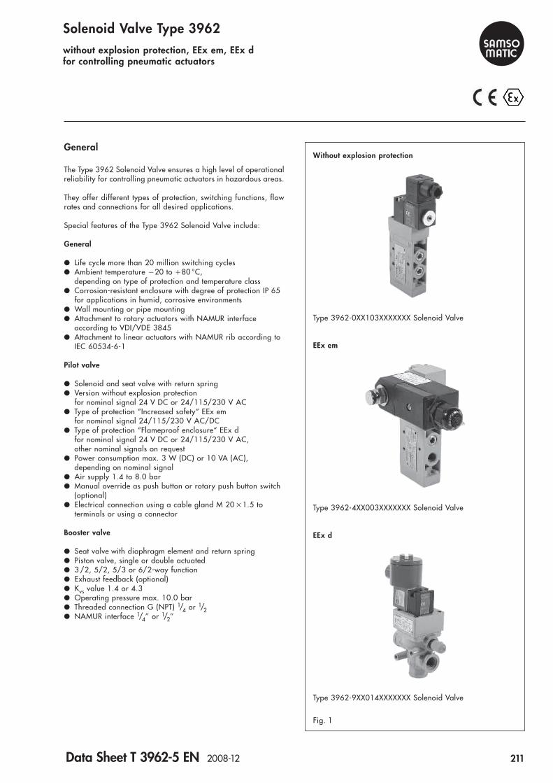
Solenoid Valve Type 3962without explosion protection, EEx em, EEx dfor controlling pneumatic actuators
General
The Type 3962 Solenoid Valve ensures a high level of operationalreliability for controlling pneumatic actuators in hazardous areas.
They offer different types of protection, switching functions, flowrates and connections for all desired applications.
Special features of the Type 3962 Solenoid Valve include:
General
● Life cycle more than 20 million switching cycles● Ambient temperature �20 to �80 °C,
depending on type of protection and temperature class● Corrosion-resistant enclosure with degree of protection IP 65
for applications in humid, corrosive environments● Wall mounting or pipe mounting● Attachment to rotary actuators with NAMUR interface
according to VDI/VDE 3845● Attachment to linear actuators with NAMUR rib according to
IEC 60534-6-1
Pilot valve
● Solenoid and seat valve with return spring● Version without explosion protection
for nominal signal 24 V DC or 24/115/230 V AC● Type of protection “Increased safety“ EEx em
for nominal signal 24/115/230 V AC/DC● Type of protection “Flameproof enclosure“ EEx d
for nominal signal 24 V DC or 24/115/230 V AC,other nominal signals on request
● Power consumption max. 3 W (DC) or 10 VA (AC), depending on nominal signal
● Air supply 1.4 to 8.0 bar● Manual override as push button or rotary push button switch
(optional)● Electrical connection using a cable gland M 20 �1.5 to
terminals or using a connector
Booster valve
● Seat valve with diaphragm element and return spring● Piston valve, single or double actuated● 3 /2, 5/2, 5/3 or 6/2-way function● Exhaust feedback (optional)● Kvs value 1.4 or 4.3● Operating pressure max. 10.0 bar● Threaded connection G (NPT) 1/4 or 1/2● NAMUR interface 1/4’’ or 1/2’’
Fig. 1
Type 3962-4XX003XXXXXXX Solenoid Valve
Type 3962-9XX014XXXXXXX Solenoid Valve
Type 3962-0XX103XXXXXXX Solenoid Valve
Without explosion protection
EEx em
EEx d
Data Sheet T 3962-5 EN 2008-12 211

Fig. 2 Fig. 3 Fig. 4
Type 3962-0XX103XXXXXXX● Without explosion protection● Nominal signal 24 V DC or 24/115/230 V AC● 5/2-way function
with spring return mechanism● Kvs value 1.4● Connection G (NPT) 1/4/NAMUR 1/4“● Mounting to on-off rotary actuators with
NAMUR interface 1/8“ or 1/4“
Type 3962-4XX003XXXXXXX● Type of protection “Increased safety“ EEx em● Nominal signal 24/115/230 V AC/DC● 3/2-way function
with spring return mechanism● Exhaust feedback● Kvs value 1.4● Connection G (NPT) 1/4/NAMUR 1/4“● Mounting to on-off rotary actuators with
NAMUR interface 1/8“ or 1/4“
Type 3962-9XX014XXXXXXX● Type of protection “Flameproof enclosure“ EEx d● Nominal signal 24 V DC or 24/115/230 V AC● 3/2-way function
with spring return mechanism● Kvs value 4.3● Connection G (NPT) 1/2● Wall mounting or pipe mounting
Versions
Examples of configuration
Without explosion protection EEx em EEx d
212 Data Sheet T 3962-5 EN 2008-12

Solenoid valves with NAMUR interface for rotary actuators
81�82�
EP
39
4
1
2
Type 3962-XXX013XXXXXXX● 3/2-way function
with spring return mechanism● Exhaust feedback● Kvs value 1.4● Connection G (NPT) 1/4
81�82�
EP
45
3
9
Type 3962-XXX014XXXXXXX● 3/2-way function
with spring return mechanism● Kvs value 4.3● Connection G (NPT) 1/2
81�82�
EP
39 5
4
1
2
Type 3962-XXX113XXXXXXX● 5/2-way function
with spring return mechanism● Kvsvalue 1.4● Connection G (NPT) 1/4
81�82�
EP
1.41.5
1.3
9 2.42.5
2.3
Type 3962-XXX614XXXXXXX● 6/2-way function
with spring return mechanism● Kvs value 4.3● Connection G (NPT) 1/2
81� 81�82� 82�
EP
39 95
4
1
2
PE
Type 3962-XXX313XXXXXXX● 5/3-way function
with spring-centered mid-position(2 and 4 closed)
● Kvs value 1.4● Connection G (NPT) 1/4
81� 81�82� 82�
EP
39.1 9.25
4
1
2
PE
Type 3962-XXX513XXXXXXX● 5/3-way function
with spring-centered mid-position(2 and 4 vented)
● Kvs value 1.4● Connection G (NPT) 1/4
81� 81�82� 82�
EP
39 95
4
1
2
PE
Type 3962-XXX413XXXXXXX● 5/3-way function
with spring-centered mid-position(2 and 4 to air supply)
● Kvs value 1.4● Connection G (NPT) 1/4
81� 81�82� 82�
EP
39 95
4
1
2
PE
Type 3962-XXX213XXXXXXX● 5/2-way function
with two locking positions● Kvs value 1.4● Connection G (NPT) 1/4
81�82�
EP
1.41.5
1.3
9 2.52.4
2.3
Type 3962-XXX114XXXXXXX● 5/2-way function
with spring return mechanism● Kvs value 4.3● Connection G (NPT) 1/2
Versions
Solenoid valves with threaded connection for wall mounting or pipe mounting
81�82�
EP
39
4
1
2
Type 3962-XXX003XXXXXXX● 3/2-way function
with spring return mechanism● Exhaust feedback● Kvs value 1.4● Connection G (NPT) 1/4/NAMUR 1/4“● Attachment to on-off rotary actuators
with NAMUR interface 1/8“ or 1/4“
81�82�
EP
4 5
3
9
5
Type 3962-XXX004XXXXXXX● 3/2-way function
with spring return mechanism● Exhaust feedback● Kvs value 4.3● Connection G (NPT) 1/2/NAMUR 1/2“● Attachment to on-off rotary actuators
with NAMUR interface 3/8“ or 1/2“
81�82�
EP
39 5
4
1
2
Type 3962-XXX103XXXXXXX● 5/2-way function
with spring return mechanism● Kvs value 1.4● Connection G (NPT) 1/4/NAMUR 1/4“● Attachment to on-off rotary actuators
with NAMUR interface 1/8“ or 1/4“
81� 81�82� 82�
EP
39 95
4
1
2
PE
Type 3962-XXX203XXXXXXX● 5/2-way function
with two locking positions● Kvs value 1.4● Connection G (NPT) 1/4/NAMUR 1/4“● Attachment to rotary actuators with
NAMUR interface 1/8“ or 1/4“
81� 81�82� 82�
EP
39 95
4
1
2
PE
Type 3962-XXX303XXXXXXX● 5/3-way function
with spring-centered mid-position(2 and 4 closed)
● Kvs value 1.4● Connection G (NPT) 1/4/NAMUR 1/4“● Attachment to rotary actuators with
NAMUR interface 1/8“ or 1/4“
81� 81�82� 82�
EP
39.1 9.25
4
1
2
PE
Type 3962-XXX503XXXXXXX● 5/3-way function
with spring-centered mid-position(2 and 4 vented)
● Kvs value 1.4● Connection G (NPT) 1/4/NAMUR 1/4“● Attachment to rotary actuators with
NAMUR interface 1/8“ or 1/4“
81� 81�82� 82�
EP
39 95
4
1
2
PE
Type 3962-XXX403XXXXXXX● 5/3-way function
with spring-centered mid-position (2 and 4 to air supply)
● Kvs value 1.4● Connection G (NPT) 1/4/NAMUR 1/4“● Attachment to rotary actuators with
NAMUR interface 1/8“ or 1/4“
Data Sheet T 3962-5 EN 2008-12 213

Electrical data for pilot valve without explosion protectionType 3962-03 3962-05 3962-06 3962-08Nominal signal Un 24 V DC (�10 %) 230 V AC (�10 %), 115 V AC (�10 %), 24 V AC �(10 %),
50 … 60 Hz 50 … 60 Hz 50 … 60 HzPower consumption Pick-up 2.7 W 6.0 VA 6.0 VA 6.0 VA
Hold 2.7 W 3.7 VA 3.7 VA 3.7 VAContinuous duty 100 %Ambient temperature �20 … �80 °CConnection Connector according to EN 175301-803, form A
1) According to EC Type Examination Certificate PTB 02 ATEX 2125 X and Certificate of Conformity NEPSI GYJ071071X
Technical data
Pneumatic data for pilot valveType 3962-0 3962-4 3962-9Air supply Medium Instrument air
Pressure 1.4 … 10 bar 1.4 … 8 bar 1.4 … 8 barOutput signal Pressure of air supplyAir consumption No air consumptionKvs value 1) 0.06 0.05 0.05Switching time 10 ms 30 ms 30 msControl connection CNOMO interface
General data for pilot valveType 3962-0 3962-4XXXXX0(1) 3962-4XXXXX2(3) 3962-9Construction Solenoid and seat valve with return springDegree of protection IP 65 IP 65 IP 65 IP 66Material Casting compound Polyamide Polyurethane Polyurethane –
Enclosure Polyamide, black Polyamide and Polyamide and Aluminum,aluminum, aluminum, anodized andpowder coated, powder coated, powder coated,grayish-beige grayish-beige red
Internal parts Stainless steel and brass Stainless steel and brass, Stainless steel and brass, Brassnickel-plated nickel-plated
Screws Steel, galvanized Stainless steelGaskets Fluoro rubber Nitrile rubber
Mounting position As desiredSwitching cycles 2 �107
Weight approx. 170 g 550 g 650 g ca. 850 g
1) Air flow at p1 �2.4 bar and p2 �1.0 bar can be calculated according to the following equation: Q �Kvs �36.22, expressed in m3/h
Electrical data for pilot valve with type of protection “Increased safety“ EEx em 1)Type 3962-44 3962-47 3962-42Nominal signal Un 230 V AC/DC (�15 … �10 %), 115 V AC/DC (�15 … �10 %), 24 V AC/DC (�15 … �10 %),
40 … 65 Hz 40 … 65 Hz 40 … 65 HzPower consumption 1.8 WContinuous duty 100 %Ambient temperature T6 �20 … �50 °Cin temperature class T5 �20 … �60 °CConnection Cable gland M 20 �1.5
Electrical data for pilot valve with type of protection “Flameproof enclosure“ EEx d 1)Type 3962-93 3962-95 3962-96 3962-98Nominal signal Un 24 V DC (�10 %) 230 V AC (�10 %), 115 V AC (�10 %), 24 V AC (�10 %),
50 … 60 Hz 50 … 60 Hz 50 … 60 HzPower consumption Pick-up 3 W 10 VA 10 VA 10 VA
Hold 3 W 9.5 VA 9.5 VA 9.5 VAContinuous duty 100 %Ambient temperature T6 �10 … �40 °C – – –in temperature class T5 �10 … �55 °C – – –(max. cable temperature) T4 �10 … �65 °C (105 °C) �10 … �40 °C (90 °C) �10 … �40 °C (90 °C) �10 … �40 °C (90 °C)
�10 … �80 °C ( 85 °C)T3 – �10 … �55 °C (105 °C) �10 … �55 °C (105 °C) �10 … �55 °C (105 °C)
Connection Female thread M 20 �1.5
1) According to EC Type Examination Certificate BAS 02 ATEX 2145, Certificate of Conformity IECEx BAS 04.0028 and Certificate ofConformity CEPEL-EX-195/04
214 Data Sheet T 3962-5 EN 2008-12
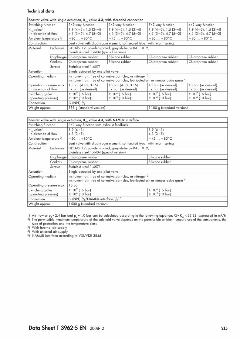
Booster valve with single actuation, Kvs value 4.3, with threaded connectionSwitching function 3/2-way function 3/2-way function 5/2-way function 6/2-way functionKvs value 1) 1.9 (4→3), 1.5 (3→4) 1.9 (4→3), 1.5 (3→4) 1.9 (4→3), 1.5 (3→4) 1.9 (4→3), 1.5 (3→4)(in direction of flow) 4.3 (3→5), 4.7 (5→3) 4.3 (3→5), 4.7 (5→3) 4.3 (3→5), 4.7 (5→3) 4.3 (3→5), 4.7 (5→3)Ambient temperature 2) �20 … �80 °C �45 … �80 °C �20 … �80 °C �20 … �80 °CConstruction Seat valve with diaphragm element, soft-seated type, with return springMaterial Enclosure GD AlSi 12, powder-coated, grayish-beige RAL 1019,
Stainless steel 1.4404 (special version)Diaphragm Chloroprene rubber Silicone rubber Chloroprene rubber Chloroprene rubberGaskets Chloroprene rubber Silicone rubber Chloroprene rubber Chloroprene rubberScrews Stainless steel 1.4571
Actuation Single actuated by one pilot valveOperating medium Instrument air, free of corrosive particles, or nitrogen 3),
Instrument air, free of corrosive particles, lubricated air or noncorrosive gases 4)Operating pressure max. 10 bar (4→3, 3→5) 10 bar (4→3, 3→5) 10 bar (as desired) 10 bar (as desired)(in direction of flow) 2 bar (as desired) 2 bar (as desired) 2 bar (as desired) 2 bar (as desired)Switching cycles 107 ( 6 bar) 106 ( 6 bar) 107 ( 6 bar) 107 ( 6 bar)(operating pressure) 106 (10 bar) 105 (10 bar) 106 (10 bar) 106 (10 bar)Connection G (NPT) 1/2Weight approx. 585 g (standard version) 1 100 g (standard version)
1) Air flow at p1 = 2.4 bar and p2 = 1.0 bar can be calculated according to the following equation: Q = Kvs �36.22, expressed in m3/h2) The permissible maximum temperature of the solenoid valve depends on the permissible ambient temperature of the components, the
type of protection and the temperature class3) With internal air supply4) With external air supply5) NAMUR interface according to VDI/VDE 3845
Booster valve with single actuation, Kvs value 4.3, with NAMUR interfaceSwitching function 3/2-way function with exhaust feedbackKvs value 1) 1.9 (4→3) 1.9 (4→3)(in direction of flow) 4.3 (3→5) 4.3 (3→5)Ambient temperature 2) �20 … �80 °C �45 … �80 °CConstruction Seat valve with diaphragm element, soft-seated type, with return springMaterial Enclosure GD AlSi 12, powder-coated, grayish-beige RAL 1019,
Stainless steel 1.4404 (special version)Diaphragm Chloroprene rubber Silicone rubberGaskets Chloroprene rubber Silicone rubberScrews Stainless steel 1.4571
Actuation Single actuated by one pilot valveOperating medium Instrument air, free of corrosive particles, or nitrogen 3),
Instrument air, free of corrosive particles, lubricated air or noncorrosive gases 4)Operating pressure max. 10 barSwitching cycles 107 ( 6 bar) 106 ( 6 bar)(operating pressure) 106 (10 bar) 105 (10 bar)Connection G (NPT) 1/2/NAMUR interface 1/2’’ 5)Weight approx. 1 500 g (standard version)
Technical data
Data Sheet T 3962-5 EN 2008-12 215
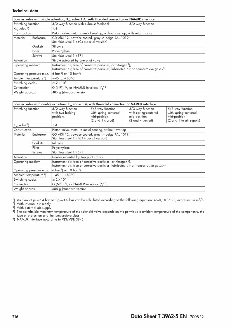
Technical data
Booster valve with single actuation, Kvs value 1.4, with threaded connection or NAMUR interfaceSwitching function 3/2-way function with exhaust feedback 5/2-way functionKvs value 1) 1.4Construction Piston valve, metal-to-metal seating, without overlap, with return springMaterial Enclosure GD AlSi 12, powder-coated, grayish-beige RAL 1019,
Stainless steel 1.4404 (special version)Gaskets SiliconeFilter PolyethyleneScrews Stainless steel 1.4571
Actuation Single actuated by one pilot valveOperating medium Instrument air, free of corrosive particles, or nitrogen 2),
Instrument air, free of corrosive particles, lubricated air or noncorrosive gases 3)Operating pressure max. 6 bar 2) or 10 bar 3)Ambient temperature 4) �45 … �80 °CSwitching cycles 2 �107
Connection G (NPT) 1/4 or NAMUR interface 1/4’’ 5)Weight approx. 485 g (standard version)
Booster valve with double actuation, Kvs value 1.4, with threaded connection or NAMUR interfaceSwitching function 5/2-way function 5/3-way function 5/3-way function 5/3-way function
with two locking with spring-centered with spring-centered with spring-centeredpositions mid-position mid-position mid-position
(2 and 4 closed) (2 and 4 vented) (2 and 4 to air supply)Kvs value 1) 1.4Construction Piston valve, metal-to-metal seating, without overlapMaterial Enclosure GD AlSi 12, powder-coated, grayish-beige RAL 1019,
Stainless steel 1.4404 (special version)Gaskets SiliconeFilter PolyethyleneScrews Stainless steel 1.4571
Actuation Double actuated by two pilot valvesOperating medium Instrument air, free of corrosive particles, or nitrogen 2),
Instrument air, free of corrosive particles, lubricated air or noncorrosive gases 3)Operating pressure max. 6 bar 2) or 10 bar 3)Ambient temperature 4) �45 … �80 °CSwitching cycles 2 �107
Connection G (NPT) 1/4 or NAMUR interface 1/4’’ 5)Weight approx. 685 g (standard version)
1) Air flow at p1 = 2.4 bar and p2 = 1.0 bar can be calculated according to the following equation: Q = Kvs �36.22, expressed in m3/h2) With internal air supply3) With external air supply4) The permissible maximum temperature of the solenoid valve depends on the permissible ambient temperature of the components, the
type of protection and the temperature class5) NAMUR interface according to VDI/VDE 3845
216 Data Sheet T 3962-5 EN 2008-12

Type 3962 Solenoid Valve Order no. 3962- . . . . . . . . . . . . .Type of protection Without explosion protection 0 ▲ ▲ ▲ ▲ ▲ ▲ ▲ ▲ ▲ ▲ ▲ ▲
II 2 G EEx em II T5/T6 1) 4II 2 G EEx d IIC T3/T4/T5/T6 2) 9
Nominal signal 24 V AC/DC (type -4) 224 V DC (types -0 and -9) 3
230 V AC/DC (type -4) 4230 V AC (types -0 and -9) 5115 V AC (types -0 and -9) 6115 V AC/DC (type -4) 7
24 V AC (types -0 and -9) 8Manual override None 0
Push button accessible from the outside (types -0 and -9) 2Rotary push button switch accessible from the outside (type -0) 3Lever-type switch accessible from the outside (type -9) 4
Switching 3/2-way function with spring return mechanism 0function 5/2-way function with spring return mechanism 1
5/2-way function with two locking positions 25/3-way function with spring-centered mid-position (2 and 4 closed) 35/3-way function with spring-centered mid-position (2 and 4 to air supply) 45/3-way function with spring centered mid position (2 and 4 vented) 56/2-way function with spring return mechanism 6
Attachment NAMUR interface according to VDI/VDE 3845 0Threaded connection for wall mounting or pipe mounting 1CNOMO interface, 30 mm (pilot valve as spare part) 2NAMUR rib according to IEC 60534-6-1 3
Kvs value 3) 1.4 34.3 40.05 (pilot valve as spare part) 5
Air connection G 1/4 01/4 NPT 1G 1/2 21/2 NPT 3Without threaded connection (pilot valve as spare part) 4
Air supply Internal connection for on-off actuators 0External connection for continuous actuators 1
Electrical Female thread M 20 �1.5 (type -9) 0 0connection Cable gland M 20 �1.5 made of polyamide, black (type -4) 0 1
Connector according to EN 175301-803, form A, made of polyamide, black 4) (type -0) 2 3Degree of IP 65 (types -0 and -4) 1protection IP 66 (type -9) 2Exhaust air filter None 0at the pilot valve Filter M 5 made of polyethylene, IP 54 (types -0 and -9) 1
Filter check valve G 1/4 made of stainless steel 1.4305, IP 65 (types -0 and -9) 2Ambient �20 … �80 °C (type -0) 0temperature 5) �20 … �60 °C (type -4) 1
�10 … �40 °C (type -9) 2�40 … �40 °C (type -9) 3
Versions and ordering data
1) According to EC Type Examination Certificate PTB 02 ATEX 2125 X and Certificate of Conformity NEPSI GYJ071071X2) According to EC Type Examination Certificate BAS 02 ATEX 2145, Certificate of Conformity IECEx BAS 04.0028 and Certificate of
Conformity CEPEL-EX-195/043) Air flow at p1 = 2.4 bar and p2 = 1.0 bar can be calculated according to the following equation: Q = Kvs �36.22, expressed in m3/h4) The female connector is not included in the delivery (see “Spare parts and accessories“)5) The permissible maximum temperature of the solenoid valve depends on the permissible ambient temperature of the components, the
type of protection and the temperature class
Data Sheet T 3962-5 EN 2008-12 217
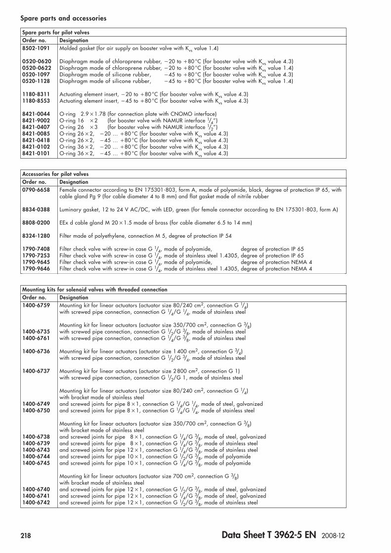
Spare parts for pilot valvesOrder no. Designation8502-1091 Molded gasket (for air supply on booster valve with Kvs value 1.4)
0520-0620 Diaphragm made of chloroprene rubber, �20 to �80 °C (for booster valve with Kvs value 4.3)0520-0622 Diaphragm made of chloroprene rubber, �20 to �80 °C (for booster valve with Kvs value 1.4)0520-1097 Diaphragm made of silicone rubber, �45 to �80 °C (for booster valve with Kvs value 4.3)0520-1128 Diaphragm made of silicone rubber, �45 to �80 °C (for booster valve with Kvs value 1.4)
1180-8311 Actuating element insert, �20 to �80 °C (for booster valve with Kvs value 4.3)1180-8553 Actuating element insert, �45 to �80 °C (for booster valve with Kvs value 4.3)
8421-0044 O-ring 2.9 �1.78 (for connection plate with CNOMO interface)8421-9002 O-ring 16 �2 (for booster valve with NAMUR interface 1/4’’)8421-0407 O-ring 26 �3 (for booster valve with NAMUR interface 1/2’’)8421-0085 O-ring 26 �2, �20 … �80 °C (for booster valve with Kvs value 4.3)8421-0418 O-ring 26 �2, �45 … �80 °C (for booster valve with Kvs value 4.3)8421-0102 O-ring 36 �2, �20 … �80 °C (for booster valve with Kvs value 4.3)8421-0101 O-ring 36 �2, �45 … �80 °C (for booster valve with Kvs value 4.3)
Accessories for pilot valvesOrder no. Designation0790-6658 Female connector according to EN 175301-803, form A, made of polyamide, black, degree of protection IP 65, with
cable gland Pg 9 (for cable diameter 4 to 8 mm) and flat gasket made of nitrile rubber
8834-0388 Luminary gasket, 12 to 24 V AC/DC, with LED, green (for female connector according to EN 175301-803, form A)
8808-0200 EEx d cable gland M 20 �1.5 made of brass (for cable diameter 6.5 to 14 mm)
8324-1280 Filter made of polyethylene, connection M 5, degree of protection IP 54
1790-7408 Filter check valve with screw-in case G 1/4, made of polyamide, degree of protection IP 651790-7253 Filter check valve with screw-in case G 1/4, made of stainless steel 1.4305, degree of protection IP 651790-9645 Filter check valve with screw-in case G 1/4, made of polyamide, degree of protection NEMA 41790-9646 Filter check valve with screw-in case G 1/4, made of stainless steel 1.4305, degree of protection NEMA 4
Spare parts and accessories
Mounting kits for solenoid valves with threaded connectionOrder no. Designation1400-6759 Mounting kit for linear actuators (actuator size 80/240 cm2, connection G 1/4)
with screwed pipe connection, connection G 1/4/G 1/4, made of stainless steel
Mounting kit for linear actuators (actuator size 350/700 cm2, connection G 3/8)1400-6735 with screwed pipe connection, connection G 1/2/G 3/8, made of stainless steel1400-6761 with screwed pipe connection, connection G 1/4/G 3/8, made of stainless steel
1400-6736 Mounting kit for linear actuators (actuator size 1 400 cm2, connection G 3/4)with screwed pipe connection, connection G 1/2/G 3/4, made of stainless steel
1400-6737 Mounting kit for linear actuators (actuator size 2 800 cm2, connection G 1)with screwed pipe connection, connection G 1/2/G 1, made of stainless steel
Mounting kit for linear actuators (actuator size 80/240 cm2, connection G 1/4)with bracket made of stainless steel
1400-6749 and screwed joints for pipe 8 �1, connection G 1/4/G 1/4, made of steel, galvanized1400-6750 and screwed joints for pipe 8 �1, connection G 1/4/G 1/4, made of stainless steel
Mounting kit for linear actuators (actuator size 350/700 cm2, connection G 3/8)with bracket made of stainless steel
1400-6738 and screwed joints for pipe 8 �1, connection G 1/4/G 3/8, made of steel, galvanized1400-6739 and screwed joints for pipe 8 �1, connection G 1/4/G 3/8, made of stainless steel1400-6743 and screwed joints for pipe 12 �1, connection G 1/4/G 3/8, made of stainless steel1400-6744 and screwed joints for pipe 10 �1, connection G 1/2/G 3/8, made of polyamide1400-6745 and screwed joints for pipe 10 �1, connection G 1/4/G 3/8, made of polyamide
Mounting kit for linear actuators (actuator size 700 cm2, connection G 3/8)with bracket made of stainless steel
1400-6740 and screwed joints for pipe 12 �1, connection G 1/2/G 3/8, made of steel, galvanized1400-6741 and screwed joints for pipe 12 �1, connection G 1/4/G 3/8, made of steel, galvanized1400-6742 and screwed joints for pipe 12 �1, connection G 1/2/G 3/8, made of stainless steel
218 Data Sheet T 3962-5 EN 2008-12

Spare parts and accessories
Mounting kits for solenoid valves with NAMUR interfaceOrder no. Designation
Mounting kit for linear actuators (actuator size 350/700 cm2, connection G 3/8) with NAMUR ribvia adapter plate NAMUR rib/NAMUR interface (order no. 1400-6751)
1400-6746 with screwed joints for pipe 12 �1, connection G 1/4/G 3/8, made of steel, galvanized1400-6747 with screwed joints for pipe 12 �1, connection G 1/4/G 3/8, made of stainless steel1400-6748 with screwed joints for pipe 10 �1, connection G 1/4/G 3/8, made of polyamide
Mounting kit for linear actuators (actuator size 80/240 cm2, connection G 1/4) with NAMUR ribvia adapter plate NAMUR rib/NAMUR interface (order no. 1400-6751)
1400-6752 with screwed joints for pipe 6 �1, connection G 1/4/G 1/4, made of steel, galvanized1400-6753 with screwed joints for pipe 6 �1, connection G 1/4/G 1/4, made of stainless steel1400-6756 with screwed joints for hose 10 �1, connection G 1/4/G 1/4, made of polyamide
Mounting kit for linear actuators (actuator size 350/700 cm2, connection G 3/8) with NAMUR ribvia adapter plate NAMUR rib/NAMUR interface (order no. 1400-6751)
1400-6754 with screwed joints for pipe 8 �1, connection G 1/4/G 3/8, made of steel, galvanized1400-6755 with screwed joints for pipe 8 �1, connection G 1/4/G 3/8, made of stainless steel1400-6757 with screwed joints for pipe 10 �1, connection G 1/4/G 3/8, made of polyamide
1400-6759 Mounting kit for linear actuators (actuator size 80/240 cm2, connection G 1/4)with screwed pipe connection G 1/4/G 1/4, made of stainless steel
1400-3001 Mounting kit for Type 3353 Angle Seat Valvewith adapter plate for NAMUR interface made of stainless steel 1.4301
Accessories for mounting kitsOrder no. Designation0320-1416 Bracket for NAMUR rib
(required when a positioner or a limit switch is to be mounted to linear actuators with nominal size � DN 50 at the same time)
8320-0131 Hexagon socket head screw M 8 �60 – A 4 DIN 931
1400-6751 Adapter plate NAMUR rib/NAMUR interface 1/4“
(Specifications subject to change without notice.)
Data Sheet T 3962-5 EN 2008-12 219

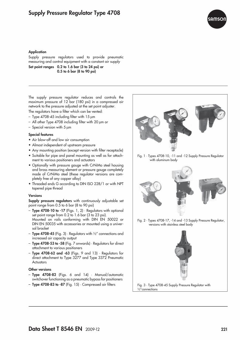
Supply Pressure Regulator Type 4708
ApplicationSupply pressure regulators used to provide pneumaticmeasuring and control equipment with a constant air supplySet point ranges 0.2 to 1.6 bar (3 to 24 psi) or
0.5 to 6 bar (8 to 90 psi)
The supply pressure regulator reduces and controls themaximum pressure of 12 bar (180 psi) in a compressed airnetwork to the pressure adjusted at the set point adjuster.The regulators have a filter which can be vented:– Type 4708-45 including filter with 15 μm– All other Type 4708 including filter with 20 μm or– Special version with 5 μm
Special features• Air blow-off and low air consumption• Almost independent of upstream pressure• Any mounting position (except version with filter receptacle)• Suitable for pipe and panel mounting as well as for attach-
ment to various positioners and actuators• Optionally with pressure gauge with CrNiMo steel housing
and brass measuring element or pressure gauge completelymade of CrNiMo steel (these regulator versions are com-pletely free of any copper alloy)
• Threaded ends G according to DIN ISO 228/1 or with NPTtapered pipe thread
VersionsSupply pressure regulators with continuously adjustable setpoint range from 0.5 to 6 bar (8 to 90 psi)– Type 4708-10 to -17 (Figs. 1, 2) · Regulators with optional
set point range from 0.2 to 1.6 bar (3 to 23 psi).Mounted on rails conforming with DIN EN 50022 orDIN EN 50035 with accessories or mounted using a univer-sal bracket
– Type 4708-45 (Fig. 3) · Regulators with ½” connections andincreased air capacity output
– Type 4708-53 to -58 (Fig. 7 onwards) · Regulators for directattachment to various positioners
– Type 4708-62 and -63 (Figs. 9 and 13) · Regulators fordirect attachment to Type 3277 and Type 3372 PneumaticActuators
Other versions– Type 4708-82 (Figs. 6 and 14) · Manual/automatic
switchover functioning as a pneumatic bypass for positioners– Type 4708-83 to -87 (Fig. 15) · Compressed air filters
Fig. 2 · Types 4708-17, -14 and -13 Supply Pressure Regulator,versions with stainless steel body
Fig. 1 · Types 4708-10, -11 and -12 Supply Pressure Regulatorwith aluminum body
Fig. 3 · Type 4708-45 Supply Pressure Regulator with½”connections
Data Sheet T 8546 EN 2009-12 221
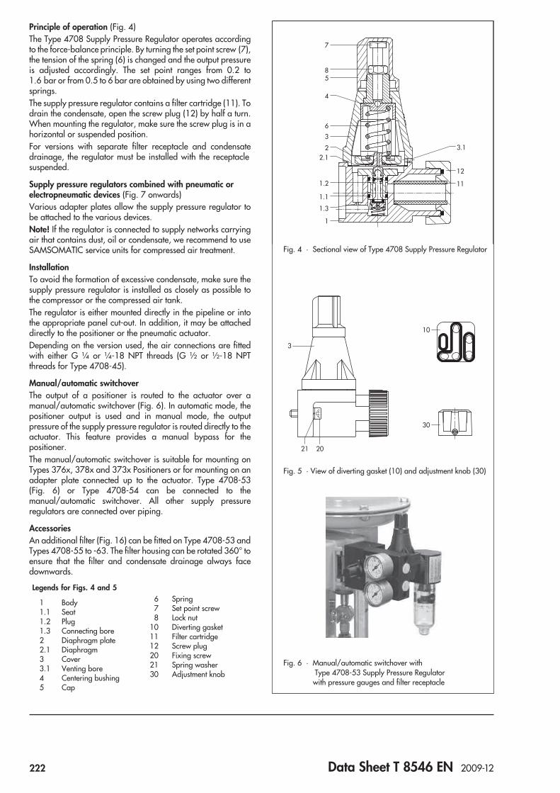
Principle of operation (Fig. 4)The Type 4708 Supply Pressure Regulator operates accordingto the force-balance principle. By turning the set point screw (7),the tension of the spring (6) is changed and the output pressureis adjusted accordingly. The set point ranges from 0.2 to1.6 bar or from 0.5 to 6 bar are obtained by using two differentsprings.The supply pressure regulator contains a filter cartridge (11). Todrain the condensate, open the screw plug (12) by half a turn.When mounting the regulator, make sure the screw plug is in ahorizontal or suspended position.For versions with separate filter receptacle and condensatedrainage, the regulator must be installed with the receptaclesuspended.
Supply pressure regulators combined with pneumatic orelectropneumatic devices (Fig. 7 onwards)Various adapter plates allow the supply pressure regulator tobe attached to the various devices.Note! If the regulator is connected to supply networks carryingair that contains dust, oil or condensate, we recommend to useSAMSOMATIC service units for compressed air treatment.
InstallationTo avoid the formation of excessive condensate, make sure thesupply pressure regulator is installed as closely as possible tothe compressor or the compressed air tank.The regulator is either mounted directly in the pipeline or intothe appropriate panel cut-out. In addition, it may be attacheddirectly to the positioner or the pneumatic actuator.Depending on the version used, the air connections are fittedwith either G ¼ or ¼-18 NPT threads (G ½ or ½-18 NPTthreads for Type 4708-45).
Manual/automatic switchoverThe output of a positioner is routed to the actuator over amanual/automatic switchover (Fig. 6). In automatic mode, thepositioner output is used and in manual mode, the outputpressure of the supply pressure regulator is routed directly to theactuator. This feature provides a manual bypass for thepositioner.The manual/automatic switchover is suitable for mounting onTypes 376x, 378x and 373x Positioners or for mounting on anadapter plate connected up to the actuator. Type 4708-53(Fig. 6) or Type 4708-54 can be connected to themanual/automatic switchover. All other supply pressureregulators are connected over piping.
AccessoriesAn additional filter (Fig. 16) can be fitted on Type 4708-53 andTypes 4708-55 to -63. The filter housing can be rotated 360° toensure that the filter and condensate drainage always facedownwards.
7
85
4
6
3
2.13.1
12
11
2
1.3
1
1.2
1.1
Fig. 4 · Sectional view of Type 4708 Supply Pressure Regulator
3
30
10
21 20
Fig. 5 · View of diverting gasket (10) and adjustment knob (30)
Legends for Figs. 4 and 5
1 Body1.1 Seat1.2 Plug1.3 Connecting bore2 Diaphragm plate2.1 Diaphragm3 Cover3.1 Venting bore4 Centering bushing5 Cap
6 Spring7 Set point screw8 Lock nut
10 Diverting gasket11 Filter cartridge12 Screw plug20 Fixing screw21 Spring washer30 Adjustment knob
Fig. 6 · Manual/automatic switchover withType 4708-53 Supply Pressure Regulatorwith pressure gauges and filter receptacle
222 Data Sheet T 8546 EN 2009-12

Summary of SAMSON positioners and actuators with associated Type 4708-xx Supply Pressure Regulator
Positioner For actuator Associated supply pressure regulator
Type 3730Type 3731Type 376xType 378x
Type 3271Type 3277
120 cm² and 240 to 700 cm²with hooked-up accessories(solenoid valve,Type 3709-2 Lock-up Valve)
also with Type 4708-82 or withType 3709-1
Rotary actuatorsalso with Type 4708-82(not with Type 3709-1)
Type 3277240 to 700 cm²without any hooked-up accessoriesand without manual/automaticswitchover (Type 4708-82)
Type 3760 Type 3277120 to 350 cm²
Type 3761 Rotary actuators
Type 4763Type 4765
Type 3271
Integral attachedversion
Type 3372for Series V2001valves
Fig. 10Type 4708-57xx
Fig. 9Type 4708-63xx
Fig. 7Type 4708-53xx
Fig. 8Type 4708-54xx
Fig. 12Type 4708-55xx
Fig. 11Type 4708-58xx
Fig. 13Type 4708-62xx
Data Sheet T 8546 EN 2009-12 223
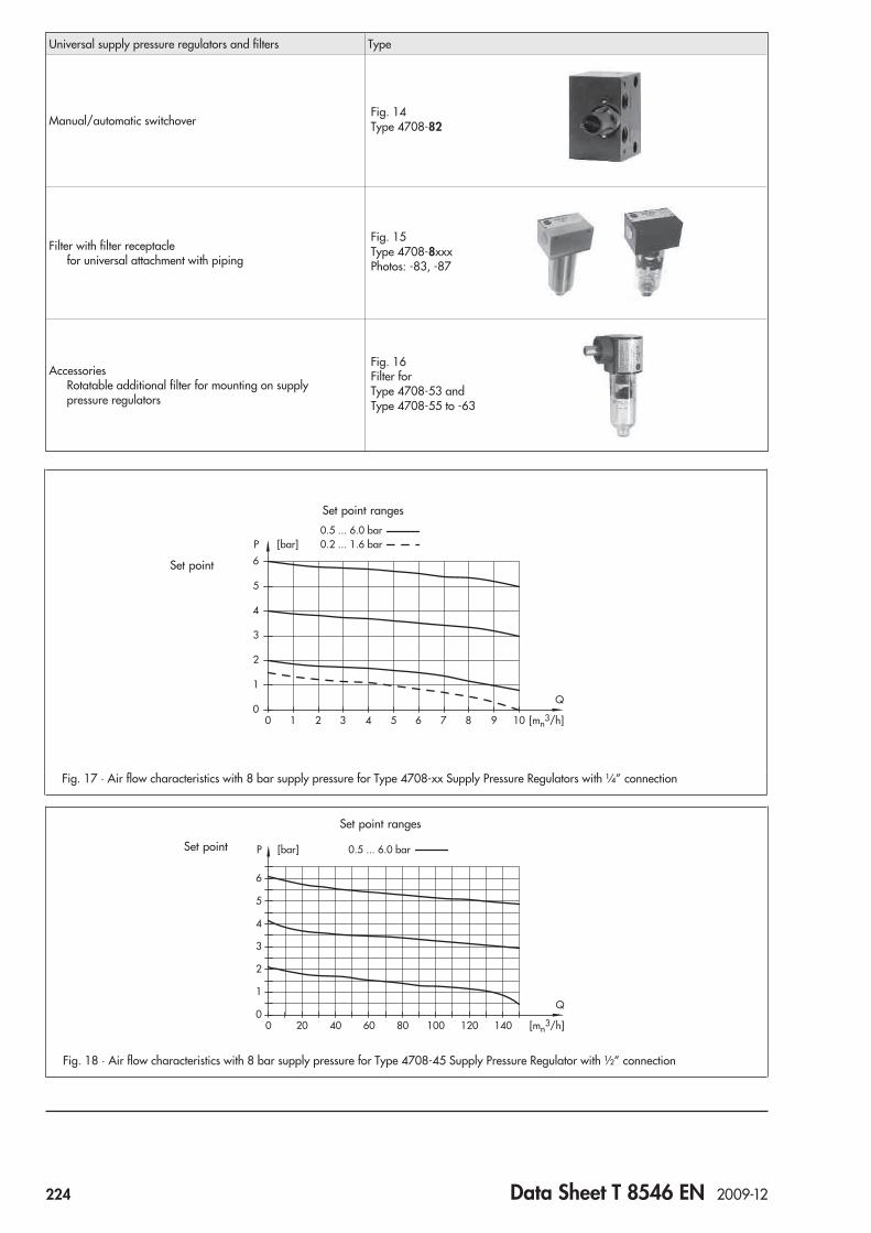
Universal supply pressure regulators and filters Type
Manual/automatic switchover
Filter with filter receptaclefor universal attachment with piping
AccessoriesRotatable additional filter for mounting on supplypressure regulators
Fig. 16Filter forType 4708-53 andType 4708-55 to -63
Fig. 15Type 4708-8xxxPhotos: -83, -87
00 1 2 3 4 5 6 7 8 9 10 [mn
3/h]
Q1
2
3
4
5
6
P [bar] 0.2 ... 1.6 bar0.5 ... 6.0 bar
Fig. 17 · Air flow characteristics with 8 bar supply pressure for Type 4708-xx Supply Pressure Regulators with ¼” connection
00 20 40 60 80 100 120 140 [mn
3/h]
Q1
2
3
4
5
6
P [bar] 0.5 ... 6.0 bar
Fig. 18 · Air flow characteristics with 8 bar supply pressure for Type 4708-45 Supply Pressure Regulator with ½” connection
Set point ranges
Set point
Set point ranges
Set point
Fig. 14Type 4708-82
224 Data Sheet T 8546 EN 2009-12

Table 1 · Technical data
Supply pressure regulators Type 4708-xx · ¼” connections Type 4708-45 · ½” connections
Supply pressure 1 bar (15 psi) above the adjusted set point,however, at least 1.6 bar (24 psi)
Minimum 1 bar (15 psi) abovethe adjusted set point
Max. supplypressure 12 bar (180 psi)
Set point range 0.2 to 1.6 bar (3 to 24 psi) or 0.5 to 6 bar (8 to 90 psi)
Air consumption at 7 barsupply pressure
≤ 0.05 mn³/h ≤ 0.1 mn³/h
Dependency on input pressure < 0.01 bar/Δp = 1 bar Negligible (< 10 mbar/4 bar)
Reversing error 0.1 to 0.4 bar(depending on set point)
50 mbar with set point range0.5 to 6 bar (8 to 90 psi)
Hysteresis < 0.1 bar 50 mbar with set point range0.5 to 6 bar (8 to 90 psi)
Filter cartridge mesh size 20 μm · Optional 5 μm 15 μm
Pressure gauge
Range of reading 0 to 1.6 bar (0 to 24 psi) or 0 to 6 bar (0 to 90 psi)
Connection G 18
Ambient temperature ranges
Supply pressureregulators Type 4708 -10 -11 -12 -13 -14 -17 -45 -53 -54 -55 -57 -58 -62 -63 -82 -83 -84 -86 -87
Standard–25...70 °C* • • • • •
–25...80 °C • • • • • • • • • • • • • •
Version for lowtemperatures
–40...80 °C •
–50...70 °C* • • • • •
–50...80 °C • • • • • • • • • • • • •
* Applies also to rotatable additional filter
Weights
Regulator with¼” connections
Type 4708 -10 -11 -12 -13 -14 -17 -53 -54 -55 -57 -58 -62 -63 -82 -83 -84 -86 -87
Approx. kg 0.48 0.58 0.66 1.65 1.2 1.0 0.68 0.95 0.37 0.47 0.4 0.4 0.87 0.4 0.24 0.32 0.59 0.95
Regulator with½” connections
Type4708-45 0.74 kg (aluminum body and polyamide filter receptacle)
Table 2 · Materials
Pressure regulators Type 4708-xx · ¼” connections Type 4708-45 · ½” connections
Body Metal parts Aluminum (3.3547) or stainless steel (1.4404)
Plastic parts Polyamide, glass fiber reinforced
Cover Polyamide, glass fiber reinforced
Cap Polyamide, glass fiber reinforced
Plug Polyamide, glass fiber reinforcedand polyoxymethylene 1.4305 and polyoxymethylene
Diaphragm NBR · FVMQ for low-temperature version
Diaphragm plate Polyamide, glass fiber reinforced or aluminum
Set point spring 1.4310
Filter receptacle UV-resistant polyamide (Trogamid T 5004)
Filter cartridge Polypropylene Polypropylene and polyethylene
Pressure gauge
Body Stainless steel
Connection and measuringelement Nickel-plated brass or stainless steel for copper-free version
Data Sheet T 8546 EN 2009-12 225
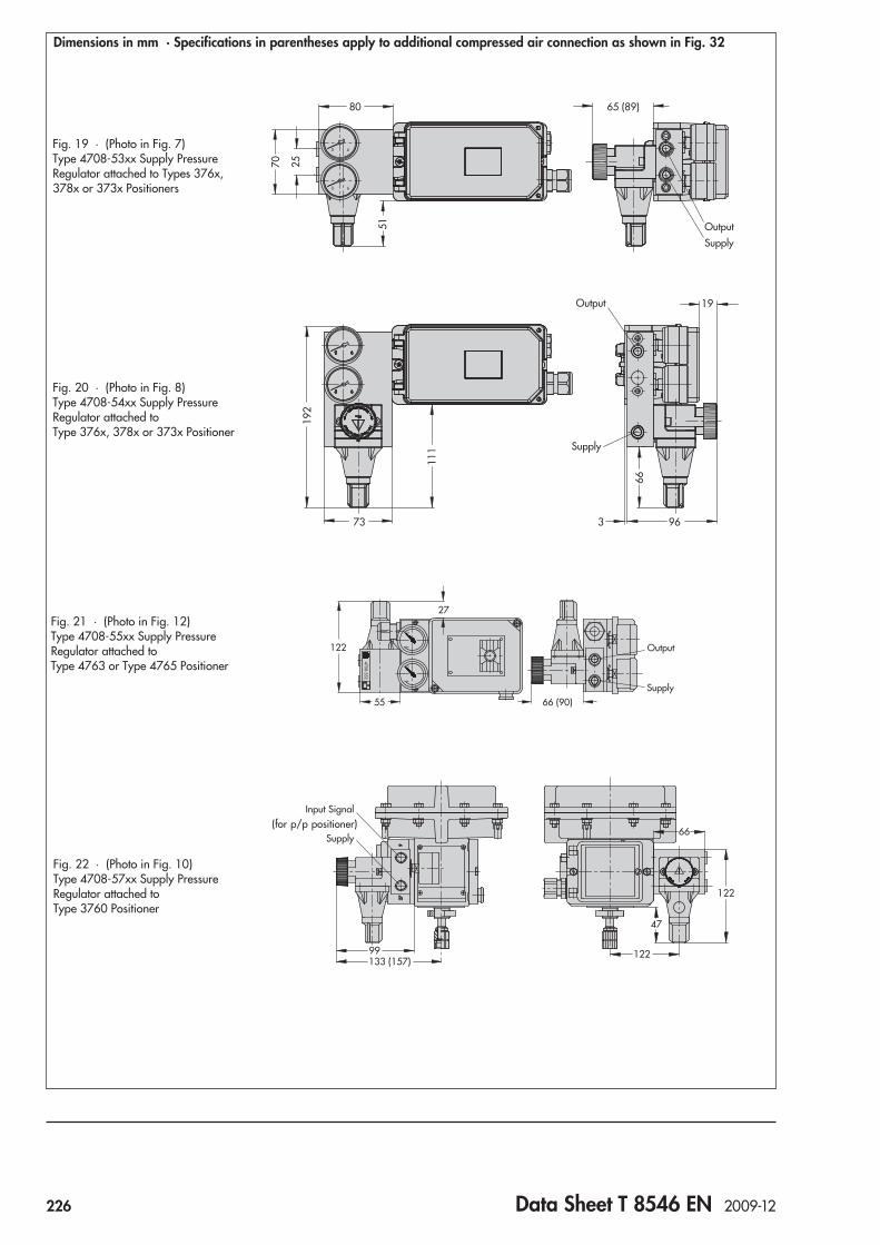
Dimensions in mm · Specifications in parentheses apply to additional compressed air connection as shown in Fig. 32
927
133 (157)99 122
66
47
122
Input Signal
Supply
Fig. 22 · (Photo in Fig. 10)Type 4708-57xx Supply PressureRegulator attached toType 3760 Positioner
80
0 6
0 6
70 25
51
65 (89)
Output
Supply
Fig. 19 · (Photo in Fig. 7)Type 4708-53xx Supply PressureRegulator attached to Types 376x,378x or 373x Positioners
60
4708-552.
60
66 (90)55
27
122
G
Output
Supply
Fig. 21 · (Photo in Fig. 12)Type 4708-55xx Supply PressureRegulator attached toType 4763 or Type 4765 Positioner
73
192
111
66
96
19
3
Output
Supply
Fig. 20 · (Photo in Fig. 8)Type 4708-54xx Supply PressureRegulator attached toType 376x, 378x or 373x Positioner
(for p/p positioner)
226 Data Sheet T 8546 EN 2009-12

Output
Supply
99
42
44
Ø41
102123
12
59
Fig. 25 · (Photos in Figs. 1 and 2) Type 4708-12xx/-13xxSupply Pressure Regulator
157
45
258
57
83
60
Ø41
65
Fig. 26 · (Photo in Fig. 3) Type 4708-45 Supply PressureRegulator with ½” connections
138238
GO
utputO
utputS
Input6
5
43
2
1
0
27
60(84)93
56
30
Supply
111
Fig. 23 · (Photo in Fig. 11)Type 4708-58xx Supply PressureRegulator attached toType 3761 Positioner
43 180
111 13
4
47
123
88
Supply
G3/8
0 6
0 6
Fig. 24 · (Photo in Fig. 9)Type 4708-63xx Supply PressureRegulator for Type 3277 PneumaticActuator and Types 376x, 378x or373x Positioners
OutputSupply
Data Sheet T 8546 EN 2009-12 227

Output
Supply
795243
19
51
60 44
182 (206)
Fig. 28 · (Photos in Figs. 1 and 2)Types 4708-11xx/-14xx Supply Pressure Regulator
0 6
G4708-622X
Supp
ly
113
113
60
1911
1 (1
35) 94
Fig. 27 · Type 4708-62xx Supply Pressure Regulatorfor Type 3372 Pneumatic Actuator
Output
Supply
795243
19
51
60 44
78 (102)
Fig. 29 · (Photos in Figs. 1 and 2)Types 4708-10xx/-17xx Supply Pressure Regulator
228 Data Sheet T 8546 EN 2009-12

Ordering textSupply pressure regulator According to article code
AccessoriesFor Types 4708-10 to -45 and -81 to -87:
Mounting parts for valve attachment orDIN rails acc. to EN 50022 orDIN rails acc. to EN 50035
For Types 4708-10, -11, -14, -17, -53, -55, -57, -58:Intermediate plate for additionalcompressed air output (G ¼ or ¼ NPT)
For Type 4708-53 and Type 4708-55 to -63:Rotatable filter receptacle
For Type 4708-82:Adapter plate for freely configurablehook-up or NAMUR attachment(G ¼ or ¼ NPT)
4459
42
15
116
Fig. 30 · (Photo in Fig. 15)Type 4708-83xx/-84xx/-86xx/-87xx Filter
45
50
147
55
18
Fig. 31 · (Photo in Fig. 16)Rotatable filter receptacle
90
24Fig. 32 · Intermediate plate for additional compressed air
connection · Type 4708-55xx
7056
56
46
24
82
28
50
13
10
Fig. 33 · (Photo in Fig. 6)Type 4708-82 Manual/automatic Switchoverwith adapter plate
Data Sheet T 8546 EN 2009-12 229

Article code
Supply pressure regulators Type 4708- x x x x 0 x x x x x 0 0 x
Aluminum/plastic body, with filter, without separate filter receptacle 1 0 25
01 0 1
Aluminum/plastic body, with transparent plastic filter receptacle 1 1 25
01 0 2
Aluminum body and filter receptacle 1 2 25
01 0 3
Stainless steel body and filter receptacle 1 3 25
01 1 4
Stainless steel/plastic body, with transparent plastic filter receptacle 1 4 25
01 1 2
Stainless steel/plastic body, with filter, without separate filter receptacle 1 7 25
01 1 1
Aluminum or stainless steel/plastic body, transparent plastic or metal filterreceptacle, increased air capacity output 4 5 6
712 1 0
1
234
0
Aluminum/plastic body, with filter, for attachment to Types 373x/376x/378xPositioners (linear actuators) 5 3 2
512 2 0 1
Aluminum/plastic body, with filter, for attachment to Types 373x/376x/378xPositioners (rotary actuators) 5 4 2
512 2 0 1
Aluminum/plastic body, with filter, for attachment to Type 476x Positioner 5 5 25 0 0 0 1
Aluminum/plastic body, with filter, for attachment to Type 3760 Positioner 5 7 25
12 1 0 1
Aluminum/plastic body, with filter, for attachment to Type 3761 Positioner 5 8 25
012
01 0 1
Aluminum/plastic body, with filter, for attachment to Type 3372 Actuator 6 2 25
12 1 0 1
Aluminum/plastic body, with filter, as connection block(direct attachment to Type 3277 Actuator, 240 to 700 cm²) 6 3 2
512 2 0 1
Manual/automatic switchover 8 2 25 8 0 0 0 0
1 0
Compressed air filter, aluminum body, transparent plastic filter receptacle 8 3 25 8 0 0 2
Compressed air filter, aluminum body and filter receptacle 8 4 25 8 0 0 3
Compressed air filter, stainless steel body, transparent plastic filter receptacle 8 6 25 8 0 1 2
Compressed air filter, stainless steel body and filter receptacle 8 7 25 8 0 1 4
Threaded connections
ISO-228/1 - G ¼ 2
¼-18 NPT 5
ISO-228/1 - G ½ 6
½-14 NPT 7
Set point ranges
0.5 to 6.0 bar, without pressure gauge 0 0
0.5 to 6.0 bar, with pressure gauge,completely of CrNiMo (free of copper) 1 0
0.5 to 6.0 bar, with pressure gauge, (nickel-plated brass connection) 2 0
0.2 to 1.6 bar, without pressure gauge 3 0
0.2 to 1.6 bar, with pressure gauge,completely of CrNiMo (free of copper) 4 0
0.2 to 1.6 bar, with pressure gauge, (nickel-plated brass connection) 5 0
None 8 0
230 Data Sheet T 8546 EN 2009-12

Specifications subject to change without notice.
Supply pressure regulators Type 4708- x x x x 0 x x x x x 0 0 x
Number of pressure gauges
None 0
1 pressure gauge 1
2 pressure gauges 2
Body material
Aluminum 0
Stainless steel 1
Filter
None 0
in black plastic regulator body 1
in transparent plastic receptacle (not moveable) 2
in aluminum receptacle (not moveable) 3
in stainless steel receptacle (not moveable) 4
Temperature range
–20 to 70 °C, standard 0
–40 to 70 °C 6 3 1
–50 to 70 °C 2
Application
Standard 0
Device free of substances that can impair paint adhesion 1
Exhaust port with thread 2
Special version
None 0 0 0
Filter cartridge, mesh width 5 μm 0 0 1
Data Sheet T 8546 EN 2009-12 231


Service Unit Type 3999-009Xfor conditioning and control of compressed air
General
The reliability and efficiency of a pneumatic instrumentation andcontrol system depends largely on the condition of the supply air.Supply air conditioning to meet the operational requirements isessential for the functional reliability of pneumatic components.
The Type 3999-009X Service Unit is used for the compressed airsupply of pneumatic transmitters, controllers and valve position-ers. The unit removes dirt, water and oil from the compressed air.At the same time, the air pressure is regulated to a constant out-put pressure.
The Type 3999-0096 Filter Regulator (see Data Sheet T 3999-8 EN)can be used for the compressed air supply of pneumatic volumeboosters for large actuators.
Versions
Service unit with bracketcomprising coarse filter, pressure reducer, pressure gauge andsubmicro filter,condensate drainage over float valves Order no. 3999-0090condensate drainage over solenoid valves Order no. 3999-0093
Service unit on mounting platecomprising manual spool valve, coarse filter, pressure reducer,pressure gauge, submicro filter and pressure switch,condensate drainage over float valves Order no. 3999-0091condensate drainage over solenoid valves Order no. 3999-0094
Service unit on mounting platecomprising manual spool valve, coarse filter, pressure reducer,pressure gauge, submicro filter, differential pressure switch andpressure switch,condensate drainage over float valves Order no. 3999-0092condensate drainage over solenoid valves Order no. 3999-0095
Principle of operation
The compressed air flows across a manual spool valve � and acoarse filter � with a maximum input pressure p1 of 16 bar. Theair is cleaned of coarse dirt particles larger than 8 μm as well aswater and oil, while the pressure is reduced to a constant outputpressure p2 of 0.5 to 10 bar by a pressure reducer �. The out-put pressure p2 is indicated on a pressure gauge � and moni-tored by a pressure switch �. The prefiltered air flows across asubmicro filter �, retaining dirt particles larger than 0.01μm.The function of the submicro filter � is monitored by a differen-tial pressure switch �.
The coarse filter � and the submicro filter � are fitted with ei-ther float valves or solenoid valves. The float valves open auto-matically when a defined liquid level is reached. In the event offailure, the condensate receptacle can be drained manually byunscrewing the drain plug. The solenoid valves must be openedby an external control signal at regular intervals, depending onthe degree of contamination of the compressed air.
Fig. 1 · Type 3999-0092 Service Unit
�PE
PE
p2p1
� �� �
�
� �
Block diagram
Fig. 2
� Manual spool valve (Types -0091/-0092/-0094/-0095)� Coarse filter� Pressure reducer� Pressure gauge� Submicro filter� Differential pressure switch (Types -0092/-0095)� Pressure switch (Types -0091/-0092/-0094/-0095)
Double-throw contact:1 � C (lilac)2 � NC (blue)4 � NO (red)
Data Sheet T 3999-6 EN 2006-07 233

General dataAttachment Pipe or wall mountingMounting position Upright, condensate drainage downwardsAmbient temperature �5 … �50 °CDegree of protection IP 54Connection Input G 3/8 female (for Types -0090/-0093),
G 3/8 male (for Types -0091/-0092/-0094/-0095)Output G 3/8 female (for Types -0090/-0093),
Compression fitting for pipe 12 mm (for Types -0091/-0092/-0094/-0095)Weight, approx. 3.6 kg (for Types -0090/-0093),
5.8 kg (for Types -0091/-0094),6.3 kg (for Types -0092/-0095)
Bracket (Types -0090/-0093)Material Steel, chromatedMounting plate (Types -0091/-0092/-0094/-0095)Material Steel, powder-coated, gray-beige RAL 1019Manual spool valve (Types -0091/-0092/-0094/-0095)Nominal size 3/8“Filter unitVersion Coarse filter, submicro filter, pressure reducer with secondary venting, pressure gaugeMaterial Coarse filter cartridge Sintered bronze
Submicro filter cartridge Borosilicate glassCondensate receptacle Makrolon, clear, with cromated steel cage
Medium Compressed air, free of corrosive particlesInput pressure p1 Max. 16 bar (max. 8 bar for solenoid valves with 24 V DC)Output pressure p2 0.5 … 10 bar, adjustableFlow rate According to characteristic (see Fig.3)Filter mesh Coarse filter cartridge 8 μm particle size
Submicro filter cartridge 0.01 μm particle sizeReceptacle volume 2 �65 cm3 condensateCondensate drainage Automatic over float valves (for Types -0090/-0091/-0092),
Automatic over solenoid valves (for Types -0093/-0094/-0095)Differential pressure switch (Types -0092/-0095)Set point 0.25 bar, set by manufacturerVersion Double-throw contact, floatingSwitching capacity Max. 250 V AC, 5 AConnection Connector according to EN 175301-801, form APressure switch (Types -0091/-0092/-0094/-0095)Set point 0.5 … 6 bar, adjustableVersion Double-throw contact, floatingSwitching capacity Max. 250 V AC, 5 AConnection Connector according to EN 175301-801, form ASolenoid valves (Types -0093/-0094/-0095)Rated signal 24 V DC (for p1� max. 8 bar), AC rated signal (for p1� max. 16 bar) on requestConnection Connector according to EN 175301-801, form A
Technical data
5
Output pressure p2 (bar)
1 2 3 4 5 6 7 8 9 10
10
15
20
25
30
00
Flow
rat
e Q
(m3 /
h)
Flow rate diagram
Fig. 3 · Flow rate Q at a differential pressure of 0.5 barbetween input pressure p1 and output pressure p2
234 Data Sheet T 3999-6 EN 2006-07

Dimensions Types 3999-0090/-0093
Fig. 4 · Dimensions in mm
Dimensions Types 3999-0091/-0092/-0094/-0095
Designation Order no.� Manual spool valve G 3/8 0790-6697� Coarse filter –� Pressure reducer –� Pressure gauge 0790-6967� Submicro filter –� Differential pressure switch 0790-6659� Pressure switch 3994-9001 Mounting plate 0790-6683
�
�
�
�
�
�
3
6
3
57
138
App
rox.
184
50
154.5
5.5
G 1/8//
App
rox.
185
App
rox.
280
43.5
47
Approx. 125
34.5
220
3/8//
SW 24
G
G 1/8//Pg 11
��
�
�
�
�
�
�
�
�
��
�
6
3
G 1/8//
Approx. 1453
App
rox.
404
App
rox.
480
Approx. 420
120
Approx. 200 Approx. 200
169
7.5
185
150
6.5
34
440
G 3/8//
SW 24G 3/
G /8// Pg 11
bar
�
�
Designation Order no. Coarse filter cartridge 8 μm 0790-6691� Submicro filter cartridge 0.01 μm 0790-6692� Condensate receptacle 0790-6693� Diaphragm 0790-6694� Cable socket 0790-6658
according to EN 175301-803, form A Float valve G 1/8 0790-6965� Solenoid valve G 1/8 0790-6966
Data Sheet T 3999-6 EN 2006-07 235

Installation instructions
Ambient conditionsThe service unit may be installed only in rooms with an ambienttemperature of �5 to �50 °C. It should be installed preferably inthe coolest location in the room so that no water can condense inthe output pressure pipe.
Mounting positionThe service unit must be installed in the output pressure pipe withthe condensate drainage in the upright position facing down-wards. It must be installed at the lowest point of the output pres-sure pipe so that condensate can flow always to the service unit.
Output pressure pipeThe output pressure piping must be adequately sized so that thepressure loss is negligible.
Operation
The maximum permissible input pressure p1 of 16 barmust not be exceeded!
Adjustment instructions
The following adjustment instructions apply to the versions withpressure switch and differential pressure switch:
Differential pressure switchThe differential pressure switch is adjusted by the manufacturerto a set point of 0.25 bar.
This adjusted set point must not be changed!
Pressure switchThe set point of the pressure switch can be adjusted between 0.5to 6 bar (see Fig. 5). The set point is adjusted using a screwdriverby turning the stem �, after unscrewing the threaded pin �. Theset point is indicated on the scale �. The stem � must securedby retightening the threaded pin �.
Maintenance instructions
The following maintenance must be performed at regular inter-vals, dependent on the degree of contamination of the com-pressed air (see Fig. 4):
Filter cartridgesCheck coarse filter cartridge and submicro filter � for conta-mination and replace when heavily contaminated. For the ver-sions with differential pressure switch �, contamination of thesubmicro filter cardridge � is monitored continuously and auto-matically registered as contamination causes the pressure todrop.
Condensate drainageCheck functioning of the automatic drainage of the flow valve or the solenoid valves �. In case of failure, the condensate re-ceptacles � with float valves can be drained manually by un-screwing the drain plugs. The condensate receptacles � must beresealed afterwards by retightening the drain plugs.
Set point adjustment at the pressure switch
Fig. 5
� Stem� Threaded pin� Scale
�
�
� � �
(Specifications subject to change without notice.)
236 Data Sheet T 3999-6 EN 2006-07

Filter Regulator Type 3999-0096for filtering and control of compressed air
General
The reliability and efficiency of a pneumatic instrumentation andcontrol system depends largely on the condition of the supply air.Supply air conditioning to meet the operational requirements isessential for the functional reliability of pneumatic components.
The Type 3999-0096 Filter Regulator is used for the compressedair supply of pneumatic volume boosters for large actuators. Itremoves dirt, water and oil from the compressed air. At the sametime, the air pressure is regulated to a constant output pressure.
The Type 3999-009X Service Unit (see Data Sheet T 3999-6 EN)can be used for the compressed air supply of pneumatic transmit-ters, controllers and positioners.
Version
Filter regulator with bracketcomprising filter, pressure regulator and pressure gauge,condensate drainage over drain valve Order no. 3999-0096
Principle of operation
The compressed air flows across a filter � with a maximum inputpressure p1 of 16 bar. The air is cleaned of coarse dirt particleslarger than 8 μm as well as water and oil, while the pressure isreduced to a constant output pressure p2 of 0.5 to 10 bar by apressure reducer �. The output pressure p2 is indicated on apressure gauge �.
The filter � is fitted with a drain valve. The condensate recepta-cle must drained at regular intervals by unscrewing the drainplug, depending on the degree of contamination of the com-pressed air.
Fig. 1 · Type 3999-0096 Filter Regulator
Block diagram
Fig. 2
� Filter� Pressure reducer� Pressure gauge� Drain valve
Data Sheet T 3999-8 EN 2006-07 237

General dataAttachment Pipe or wall mountingMounting position Upright, condensate drainage downwardsAmbient temperature �40 … �60 °CDegree of protection IP 54Connection G 1/2 femaleWeight, approx. 1.8 kgBracketMaterial Steel, chromatedFilter unitVersion Filter, pressure reducer with secondary venting, pressure gaugeMaterial Filter cartridge Sintered bronze
Condensat receptacle Aluminium, powder-coated, gray-beige RAL 1019Medium Compressed air, free of corrosive particlesInput pressure p1 Max. 16 barOutput pressure p2 0.5 … 10 bar, adjustableFlow rate According to characteristic (see Fig. 3)Filter mesh 8 μm particle sizeReceptacle volume 65 cm3 condensateCondensate drainage Manual over drain valve
Technical data
0
Flow rate Q (m3/h)
60 120 180 240 3000
2
4
6
8
Out
put p
ress
ure
p2 (b
ar)
Flow rate diagram
Fig. 3 · Flow rate Q at an input pressure p1 of 8 bar
238 Data Sheet T 3999-8 EN 2006-07

Dimensions
Fig. 4 · Dimensions in mm
Installation instructions
Mounting positionThe filter regulator must be installed in the output pressure pipewith the condensate drainage in the upright position facingdownwards. It must be installed at the lowest point of the outputpressure pipe so that condensate can flow always to the filterregulator.
Output pressure pipeThe output pressure pipe must be adequately sized so that thepressure loss is negligible.
Operation
The maximum permissible input pressure p1 of 16 barmust not be exceeded!
Maintenance instructions
The following maintenance must be performed at regular inter-vals, depending on the degree of contamination of the com-pressed air (see Fig. 4):
Filter cartridgeCheck filter cartridge � for contamination and replace whenheavily contaminated.
Condensate drainageDrain the condensate receptacle over the drain valve � byunscrewing the drain plug. The condensate receptacle must bethen resealed by retightening the drain plug.
Designation Order no.� Filter –� Pressure reducer –� Pressure gauge 0790-6967� Drain valve –
�
�
�
�
3
6
3
5713
8
54
5.5
App
rox.
230
App
rox.
300
87 Approx. 125
App
rox.
220
pp17
3
52.5
G 1/2// bar
�
�
�
Designation Order no.� Bracket –� Filter cartridge 8 μm 0790-6691� Diaphragm 0790-6694 Condensate receptacle 0790-6693
�
Data Sheet T 3999-8 EN 2006-07 239


ApplicationPressure adjustment in pneumatic systems
The remote adjuster is a precision pressure regulator which canbe manually adjusted. It is designed for use in pneumatic con-trol loops as either a set point adjuster or manual remote ad-juster and can be used as an adjustable precision pressure reg-ulator for measuring, calibration and testing equipment.
Special features• Precise adjustment• Constancy of the adjusted pressure value• Large air delivery• Small dimensions
VersionsThe Type 3759 Remote Adjuster is available for the followingpressure ranges: 0 to 0.6 bar, 0 to 1.6 bar, 0 to 4 bar and 0 to6 bar. The max. supply pressure for all versions is 7 bar.
Standard versionDesigned for panel mounting with adjustment screw which canbe turned using a screwdriver. The device can be equipped withthe following parts (see Table 2):– Rotary knob for manual adjustment– Rotary knob and mounting plate with cover bushing– Protective cover and mounting plate– Equipment for panel or wall mounting with bracket and, if re-
quired, rotary knob for manual adjustment
Principle of operationThe force of the leaf spring (2), adjustable via the adjustmentscrew (1), is balanced by a counterforce generated by the out-put pressure acting on the diaphragm (4).Increasing the spring force by turning the adjustment screw orlowering the output pressure causes the outlet nozzle (3) to beincreasingly covered. As a result, the pressure produced by thepressure divider, made up of the nozzle (5) and the outlet noz-zle (3), rises and is applied as intermediate pressure on the dou-ble diaphragm (6). The diaphragm moves the double plug (8)downwards. More supply air flows to the output and into thechamber below the diaphragm (6). This pressure increase re-sults in a new equilibrium.If the spring force is decreased or the output pressure rises, thepressure acting on the double diaphragm decreases, the doublediaphragm moves upwards, and the air can escape through theoutlet nozzle (3) until there is a new pressure balance.
Pneumatic Remote Adjuster
Type 3759
Fig. 1 · Type 3759 Pneumatic Remote Adjuster
10
9
87
6
5
1
4
3
2
Fig. 2 · Sectional drawing of Type 3759
Legend1 Adjustment screw2 Leaf spring3 Outlet nozzle4 Diaphragm5 Nozzle
6 Double diaphragm7 Return spring8 Double plug9 Output connection
10 Supply connection
Data Sheet T 8510 EN 2006-02 241

Table 1 · Technical data
Output pressure bar 0 ... 0.6 0 ... 1.6 0 ... 4 0 ... 6
Requiredsupply pressure bar 1.4 ... 7 2 ... 7 5 ... 7 7
Flow rate in ln/h 1)
max. air delivery) atupstream pressure (bar)
2 2000
5 4000
7 5300
Perm. ambient temperature –20 ... +60 °C
Air consumption in ln/h 1)
in steady state atupstream pressure (bar)
2 70
5 110
7 130
Dependence on upstreampressure
0.001 bar/0.1 bar pressure variation
Influence of temperature °C(based on upper value) 0.035 % 0.02 % 0.035 %
Reproducibility bar 0.002
1) Measured against ambient pressure with remote adjusteropen to the maximum.
All pressures are effective pressures pe in bar (gauge) unlessotherwise specified.
Ø25
.5
12
126
95.5
4048
1230
M4
Panel mounting using bracket
Panel mounting using plate
Protective cap
Mounting plate
max. 3
Rotary knob
Bushing
118
50
4.3
68
110
28
15.5
Ø6
SW 17
41
26
1/8NPT
40
Fig. 3 · Panel cut-out for standard version
Table 2 · Accessories
Mounting Version with Item no.
Panelmounting withplate
Rotary knob 8442-0380
Rotary knob and plate 1400-5632
Protective cap and plate 1400-5631
Panelmounting withbracket
Bracket 0300-0394
Rotary knob and bracket 1400-5634
MountingPanel mounting using plate · For direct mounting of the stan-dard version, a panel cut-out according to Fig. 3 needs to bemade. On using the plate included in the accessories, a holewith 22 + 1 (mm) diameter is required.Panel mounting using bracket · The associated bracket must befastened using two screws.
242 Data Sheet T 8510 EN 2006-02

ApplicationPneumatic lock-up valve for shutting off the signal pressure lineof pneumatic actuators
The pneumatic lock-up valve shuts off the signal pressure line ei-ther when the air supply falls below an adjusted value or uponcomplete air supply failure. This causes the actuator to remainin its last position.
VersionsType 3709-1 (Fig. 1) · Lock-up valve for direct attachment toTypes 4765 or 3766 Pneumatic Positioners or Types 4763,3767, 3780 or 3785 Electropneumatic Positioners when theseare integrally attached to a Type 3277 Actuator, without con-nection block (not in connection with mounting block andType 4708 Supply Pressure Regulator).Type 3709-2 (Fig. 2) · Lock-up valve for arbitrary installation inthe signal pressure line.
Principle of operation (Fig. 3)The supply air produces a force on the diaphragm (4) which isbalanced by the spring (6). When the force produced on the di-aphragm is greater than the spring force, input and output areconnected, i.e. the signal pressure supplied by the positioner istransmitted unobstructed to the actuator. When the supply airpressure falls below the adjusted value, the spring force domi-nates, and the spring (6) moves the plug (3) fully into the seat(9). As a result, the pressure in the actuator is blocked.
Pneumatic Lock-up Valve
Type 3709
Fig. 2 · Type 3709-2 Pneumatic Lock-up Valve
p z
p e
p a
Fig. 3 · Sectional drawing of Type 3709-2
Legend for Fig. 3
1 Housing2 Cover3 Plug4 Diaphragm5 Diaphragm plate6 Spring
7 Spindle8 Cap9 Seatpa Signal pressure outputpe Signal pressure inputpz Supply air
Fig. 1 · Type 3709-1 Pneumatic Lock-up Valve
Data Sheet T 8391 EN 2010-02 243

Typical applications
Ordering textPneumatic Lock-Up Valve Type 3709- ...Attached to Positioner Type ...Connections ¼ NPT or G ¼
Specifications subject to change without notice.
Dimensions in mm
3
1
2
y y
2
1
4
3
y
Pst
4
1
2
3
Closed loop control with interlocking Closed and open loop control with interlocking Closed loop control and safety interlocking
1 Pneumatic control valve2 Positioner3 Lock-up valve4 Solenoid valve
Technical data
Connections ¼ NPT or G ¼
Supply air Max. 12 bar
Signal pressure Max. 6 bar
KVS coefficient Approx. 0.2
Set point range Continuously adjustable from 0 to 6 bar
Recommended setting ≥ 0.2 bar above required signalpressure, min 1.6 bar
Permissible ambienttemperature
–25 ... 80 °CExtended range on request
Weight, approx. 0.4 kg
Materials
Housing Die-cast aluminum, plastic-coatedStainless steel on request
Cover Ultramid
Diaphragm CR (chloropene rubber with fabric)
Diaphragm plate Aluminum
130
42
Inputsignal
Output
123
70
OutputSupply
5228
28
5444
Supply
1125
23.5
1316
Type 3709-1
Type 3709-2
pa Signal pressure outputpe Signal pressure inputpz Supply pressure
244 Data Sheet T 8391 EN 2010-02

Series 3710
Reversing Amplifier Type 3710
ApplicationReversing amplifier to operate a double-acting pneumatic actu-ator using a single-acting pneumatic or electropneumaticpositioner or limit switch
The reversing amplifier is used together with single-actingelectropneumatic positioners of Series 3730 and 3731. It is alsosuitable for use with Types 3766, 3767 and 3780 Positioners aswell as Type 3768 Limit Switch in model versions 37xx-x..x.05and higher.It is attached to the positioner either• Without pressure gauge• With one pressure gauge when used with a Type 4708-54
Supply Pressure Regulator• With two pressure gauges
VersionsNormal version without pressure gauge with pressure gaugethreaded connections · Suitable for a maximum supply pres-sure of 6 bar at a permissible ambient temperature range from–25 to 80 °C, degree of protection IP 65 with polyamide checkvalve– Type 3710 (Fig. 1) · Reversing amplifier with pressure
gauge threaded connections at the front and back
Other versions– Type 3710 with two pressure gauges supplied as accessories
for Y1 and Y2 (Fig. 2)– With one pressure gauge for Y2 when used with a
Type 4708-54 Supply Pressure Regulator (Fig. 3)– Degree of protection IP 65 with stainless steel check valve
Figs. 1 and 2 · Type 3710 Reversing Amplifierwithout pressure gauge andtwo pressure gauges
Fig. 4 · Type 3710 Reversing Amplifier,Type 3730 Positioner and Type 3275 Piston Actuator
Fig. 3 · Type 3710 Reversing Amplifier andType 4708-54 Supply Pressure Regulatormounted on Type 3730 Positioner for a pneumaticpiston actuator
Data Sheet T 8392 EN 2010-01 245
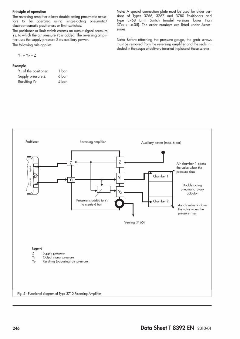
Principle of operationThe reversing amplifier allows double-acting pneumatic actua-tors to be operated using single-acting pneumatic/electropneumatic positioners or limit switches.The positioner or limit switch creates an output signal pressureY1, to which the air pressure Y2 is added. The reversing ampli-fier uses the supply pressure Z as auxiliary power.The following rule applies:
Y1 + Y2 = Z
ExampleY1 of the positioner 1 barSupply pressure Z 6 barResulting Y2 5 bar
Note: A special connection plate must be used for older ver-sions of Types 3766, 3767 and 3780 Positioners andType 3768 Limit Switch (model versions lower than37xx-x…x.05). The order numbers are listed under Acces-sories.
Note: Before attaching the pressure gauge, the grub screwsmust be removed from the reversing amplifier and the seals in-cluded in the scope of delivery inserted in place of these screws.
Z
Y2
Y1
Z
Y1
Out
put 3
8Su
pply
9
Fig. 5 · Functional diagram of Type 3710 Reversing Amplifier
Positioner Reversing amplifier
Pressure is added to Y1to create 6 bar
Auxiliary power (max. 6 bar)
Venting (IP 65)
Chamber 1
Chamber 2
Double-actingpneumatic rotary
actuator
Air chamber 1 opensthe valve when thepressure rises
Air chamber 2 closesthe valve when thepressure rises
LegendZ Supply pressureY1 Output signal pressureY2 Resulting (opposing) air pressure
246 Data Sheet T 8392 EN 2010-01

Table 2 · Materials
Type 3710 Reversing Amplifier
Housing and cover Aluminum, powder paint coated
Diaphragm plate Aluminum, yellow chromated
Seat and plug Brass
Diaphragms Silicone rubber FVMQ
Pressure gauge, optional
Housing Stainless steel, device free of copper
Measuring unit and connection Stainless steel, free of copper · Nickel-plated brass connection
Table 1 · Technical data
Type 3710 Reversing Amplifier
Permissible supply pressure 6 bar
KV coefficient Supply 0.11
Vent 0.12
Leakage Z to Y2 ≤ 20 l/h when Y2 = 0 bar and Z = 6 bar
Y2 to Vent ≤ 40 l/h when Y1 = 0 bar and Y2 = 6 bar
Connections ¼-18 NPT · ISO 228/1-G ¼
Degree of protection IP 65
Permissible ambient temperature –25 … 80 °C · –58 … 185 °F
Weight 0.5 kg
Option
Pressure gauge ∅ 40 mm
Range of reading 0 to 6 bar · 0 to 90 psi
Connection G 18
Table 3 · Article code
Reversing amplifier Type 3710- 1 0 x 1 0 0 2 0
Connecting thread
ISO 228/1-G ¼ 1
¼-18 NPT 2
Data Sheet T 8392 EN 2010-01 247

Accessories Order no.
Pressure gauge 0 to 6 bar/psi/kPa
Completely made of stainless steel 1400-9945
St. steel/nickel-plated brass connection 1400-9946
Seals 1099-4305
Filter check valve, stainless steel 1.4305 1079-7253
Connection plate for older versions ofTypes 3766, 3767 and 3780 Positioners as wellas Type 3768 Limit Switch
1400-9621
Ordering textReversing amplifier with
Pressure gauge threaded connections Type 3710Used for Types 3730-x, 3731-x Positionersor model versions 37xx-x...x.05 or higher ofType 3766 Pneumatic Positioner,Type 3767 Electropneumatic Positioner,Type 3780 Positioner with HART® communicationType 3768 Limit Switch
With 2 pressure gauges for Y1 and Y2
With 1 pressure gauge for Y2for mounting onType 4708-54Supply Pressure Regulator
5686
13080
166
3086
Ø 101
8090
164
52 Output Y1
Output Y2
Supply (9)Output Y1
Output Y2
Fig. 6 · Dimensional drawing of Type 3710 Reversing Amplifier, mounted on Type 3730 Positioner
Reversing amplifierwith pressure gauges
248 Data Sheet T 8392 EN 2010-01

Series 3755
Pneumatic Volume BoosterType 3755
ApplicationThe volume booster is used together with positioners to increasethe positioning speed of pneumatic actuators.KVS for Supply and Exhaust 2.5 m³/hSignal-to-output ratio 1:1
The pneumatic volume booster supplies an air flow output at theactuator port whose pressure corresponds exactly with the sig-nal pressure, except that it has a much higher volume output.
Special features• Compact body made of cast aluminum• Fast dynamic response due low hysteresis• Bypass restriction with linear characteristic• Bypass restriction setting lead-sealable• Sintered polyethylene filter disc to reduce noise emission• Constant reversing pressure• Version with optimized dynamics• Exhaust feedback possible• Weather protection cover for version with sintered polyethyl-
ene filter disc
VersionsStandard version for mounting between positioner and actuatorLow-noise exhaust over sintered polyethylene filter disc · Supplypressure max. 10 bar · Signal and actuator pressure max. 7 barAmbient temperature range between –40 and80 °C · G ¾ connections for supply (SUP) and actuator (OUT)as well as G ¼ connection for signal (SIG)– Type 3755-1 (Figs. 1 and 2) · Pneumatic volume booster
with low-noise sintered polyethylene filter disc
Further version– Type 3755-2 (Fig. 3) · Pneumatic volume booster,
flanged-on exhaust port (ISO 228 G 1 or 1-11½ NPT)
Options– Connections with NPT thread
Fig. 1 · Type 3755 Pneumatic Volume Booster
Fig. 2 · Type 3755-1, showing sintered polyethylene filter disc
Fig. 3 · Type 3755-2, version with flanged-on exhaust port
Data Sheet T 8393 EN 2009-09 249

Principle of operationIf the positioner signal increases to supply air to the actuator, thepressure above the diaphragm (1) increases. The differentialpressure at the diaphragm causes the supply plug (2) to open,providing supply air up to a maximum of 10 bar to the actuator.In contrast, a positioner signal to vent the actuator causes theexhaust plug (3) to open. The pressure in the actuator is relievedover the exhaust port.The fail-safe action upon signal pressure failure always causesventing!The bypass restriction screw (4) is used to adjust the response ofthe pneumatic volume booster to match the system conditions.The setting of the bypass restriction screw can be locked in posi-tion by a lock nut to prevent it from being turned and addition-ally lead-sealed.The bypass restriction screw must never be completely closed.This prevents the system from hunting and allows for a stablecontrol performance by the positioner.Note: The bypass restriction screw (4) with lock nut (4.1) mustonly be hand-tightened. The maximum permissible tighteningtorque is 3 Nm.
Mounting on control valvesMount the pneumatic volume booster so that the air betweenSuppy and Actuator flows in the direction indicated on thebody. Mount the device between the positioner and pneumaticactuator (Fig. 5).
Pneumatic connectionsThe air connections for Signal, Supply, Actuator and for the ver-sion with flanged-on exhaust port are designed with G or NPTthreads depending on the female thread selected for the pipe.Note: If higher dynamic requirements are to be met, the supplypressure, hook-up and actuator bench range must be sized ac-cordingly.
Actuator
Exhaust
Supply
SignalBypass
4
1
2
3
4.1
Fig. 4 · Type 3755, cross-sectional drawing with pneumaticconnections
Supp
ly
Out
put
Positioner
Supply air
SUP
SIG
OUT
EXHBooster
Control valve
0/4
... 2
0 m
A
E
Fig. 5 · Connection diagram of Type 3755 with electropneumatic positioner and pneumatic control valve
Legend1 Diaphragm2 Supply plug3 Exhaust plug4 Bypass restriction screw4.1 Lock nut
250 Data Sheet T 8393 EN 2009-09

Table 1 · Technical data
Type 3755 Pneumatic Volume Booster
Flow capacity
KVS Supply 2.5 m³/h
KVS Exhaust 2.5 m³/h
KVS Bypass 0.8 m³/h
Control performance
Pressure ratio Signal to output = 1:1
Reversing pressure 80 mbar
Dynamic versions Standard (options in preparation)
Pressure
Supply max. 10 bar · max. 150 psi
Actuator max. 7 bar · max. 105 psi
Signal max. 7 bar · max. 105 psi
Air quality according toISO 8573-1
Maximum particle size and density: Class 4 · Oil content: Class 3Pressure dew point: Class 3 or at least 10 K below the
lowest ambient temperature to be expected
Connecting thread
Supply (SUP) G ¾ (optionally ¾ NPT)
Output (OUT) G ¾ (optionally ¾ NPT)
Signal (SIG) G ¼ (optionally ¼ NPT)
Flanged-on exhaust port (EXH) G 1 or G ¾ (optionally 1 NPT or ¾ NPT)
Other operating parameters
Permissible ambient temperature –40 to 80 °C
Service life ≥ 1 x 10⁷ full strokes
Degree of protection IP 42 (with the exhaust port facing downwards)
Safety instrumented systems Use in SIS acc. to IEC 61508/SIL 2 (in preparation)
Weight 2.1 kg · Version with flanged-on exhaust port: 2.4 kg
Table 2 · Materials
Body Cast aluminum, gray-beige, RAL 1019 powder paint coated
Flanged-on exhaust port Aluminium, gray-beige, RAL 1019 powder paint coated
Silencer(not for version with flanged-on exhaust port) Sintered polyethylene filter disc
Diaphragm VMQ
Other external parts Stainless steel 1.4301
Data Sheet T 8393 EN 2009-09 251
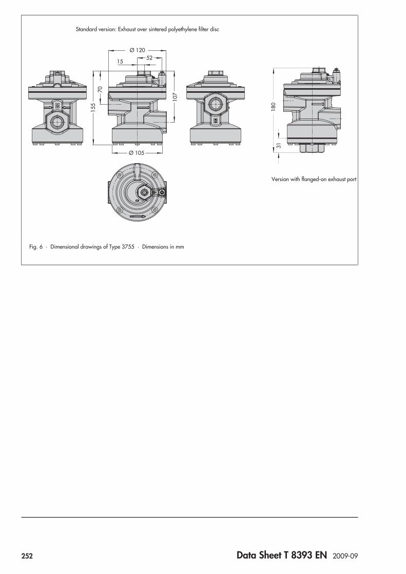
107
155
70
5215
Ø 105
Ø 120
Fig. 6 · Dimensional drawings of Type 3755 · Dimensions in mm
180
31
Version with flanged-on exhaust port
Standard version: Exhaust over sintered polyethylene filter disc
252 Data Sheet T 8393 EN 2009-09

Ordering textPneumatic Volume Booster Type 3755Version Low-noise exhaust
orFlanged-on exhaust port
Pneumatic connections G / NPTExhaust connection Silencer/
flanged-on exhaust portBody material AluminumColor Gray-beige,
structured finishRAL 1019
Article code
Pneumatic volume booster Type 3755- x x x 0 0 x x 0 0 x 0 0 0 0
Version
Standard: low-noise exhaust over sintered polyethylene filter disc 1
Flanged-on exhaust port 2
Pneumatic connections
Standard: Supply and Actuator ISO 228 - G ¾ , Signal ISO 228 - G ¼ 1
Supply and Actuator ¾-14 NPT, Signal ¼-18 NPT 2
Exhaust connection
Standard: sintered polyethylene filter disc 0
Flanged-on exhaust port ISO 228 - G 1 3
Flanged-on exhaust port 1-11 ½ NPT 5
Flow capacity
Standard: Supply KVS = 2.5 m³/h, Exhaust KVS = 2.5 m³/h 0
Dynamic response
Standard 0
Body material
Standard, aluminium 0
Color
Standard: Gray-beige, RAL 1019, structured finish 0
Temperature range
Standard: –40 … 80 °C 0
Data Sheet T 8393 EN 2009-09 253

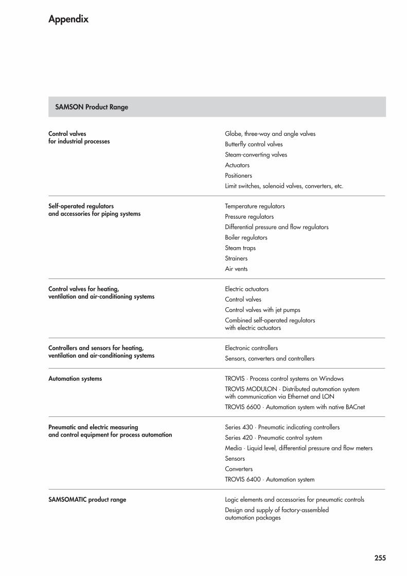
Control valvesfor industrial processes
Globe, three-way and angle valves
Butterfly control valves
Steam-converting valves
Actuators
Positioners
Limit switches, solenoid valves, converters, etc.
Self-operated regulatorsand accessories for piping systems
Temperature regulators
Pressure regulators
Differential pressure and flow regulators
Boiler regulators
Steam traps
Strainers
Air vents
Control valves for heating,ventilation and air-conditioning systems
Electric actuators
Control valves
Control valves with jet pumps
Combined self-operated regulatorswith electric actuators
Controllers and sensors for heating,ventilation and air-conditioning systems
Electronic controllers
Sensors, converters and controllers
Automation systems TROVIS · Process control systems on Windows
TROVIS MODULON · Distributed automation systemwith communication via Ethernet and LON
TROVIS 6600 · Automation system with native BACnet
Pneumatic and electric measuringand control equipment for process automation
Series 430 · Pneumatic indicating controllers
Series 420 · Pneumatic control system
Media · Liquid level, differential pressure and flow meters
Sensors
Converters
TROVIS 6400 · Automation system
SAMSOMATIC product range Logic elements and accessories for pneumatic controls
Design and supply of factory-assembledautomation packages
Appendix
SAMSON Product Range
255


SAMSON Subsidiaries, Agencies and Service FacilitiesWorldwide
Argentina VALTROL-SAMSONS.A.California 2082 ·Of. 307A, Edificio Central ParkC1289AAP Buenos AiresPhone: +54 11 4360-0421 · Fax: +54 11 4360-0421E-mail: [email protected]: www.valtrolsamson.com.ar
Australia SAMSONCONTROLS PTY LTDUnits 13A, 14A and 15A · Port Botany Industrial Park61-71 Beauchamp Road ·Matraville, NSW2036Phone: +61 2 93167800 · Fax: +61 2 96665963E-mail: [email protected]
Austria SAMSONMESS- UNDREGELGERÄTEGESELLSCHAFTM.B.H.Amalienstraße 57 · 1130WienPhone: +43 1 8772674-0 · Fax: +43 1 8772674-96E-mail: [email protected] · Internet: www.samson.at
Bangladesh COSMOSMARKETING, CONSULTANTS (PVT) LTD.Cosmos Centre · 69/1,NewCircular Road,MalibaghP.O. BoxG3066 ·Dhaka 1217Phone: +880 2 405152, +880 2 411564,
+880 2 8312024Fax: +880 2 8314602, +880 2 9345540E-mail: [email protected]: www.cosmosgroup.net
Belgium S.A. SAMSONN.V.282/284, Rue St. Denis/St. Denijsstraat1190 Bruxelles/BrusselPhone: +32 2 3474849 · Fax: +32 2 3430033E-mail: [email protected]
Bosnia-Herzegovina
FASEK ENGINEERINGAND TRADINGD.O.O.Zvonigradska 4310000 Zagreb (Croatia)Phone: +385 1 3695-525, +385 1 3695-546Fax: +385 1 3695-525, +385 1 3695-546E-mail: [email protected] · Internet: www.fasek.com
Brazil SAMSONCONTROL LTDA.RuaMatrix 159 · Centro Empresarial CapuavaBairroMoinho Velho · 06714-360 Cotia / SPPhone: +55 11 46178181, +55 11 47027867Fax: +55 11 46178187E-mail: [email protected]: www.samsoncontrol.com.br
Bulgaria BJB LTD.25Hristo Belchev · 1000 SofiaPhone: +359 2 9867289 · Fax: +359 2 9867467E-mail: [email protected] · Internet: www.bjbgroup.com
Canada SAMSONCONTROLS INC.1-105 Riviera Drive ·Markham,Ontario L3R 5J7Phone: +1 905 4740354 · Fax: +1 905 4740998E-mail: [email protected]: www.samsoncontrols.com
Chile SAMSONCONTROLS S.A.Lo Boza 107,Módulo B-8, Flex Center · Pudahuel, SantiagoPhone: +56 2 240 5100 · Fax: +56 2 949 3390E-mail: [email protected]
Colombia STEAMCONTROL S.A.Carrera 27,No. 17-80, PaloquemaoSantafé de Bogotá, D.C.Phone: +57 1 3750033 · Fax: +57 1 3710452E-mail: [email protected]: www.steamcontrol.com
Croatia FASEK ENGINEERINGAND TRADINGD.O.O.Zvonigradska 43 · 10000 ZagrebPhone: +385 1 3695-525, +385 1 3695-546Fax: +385 1 3695-525, +385 1 3695-546E-mail: [email protected] · Internet: www.fasek.com
CzechRepublic
DLOUHÝ I.T.A. CZ S.R.O.Jinonická 805/57 · 150 00 Praha 5Phone: +420 2 57216955, +420 2 57216956Fax: +420 2 57216957E-mail: [email protected] · Internet: www.samson-cz.cz
Denmark SAMSONREGULERINGSTEKNIKA/SBlokken 55 · 3460 BirkerødPhone: +45 45819301 · Fax: +45 45819530E-mail: [email protected]: www.samson-reg.dk
Ecuador ENERGYPETROL S.A.José PuertaN39-155 y Eloy Alfaro ·QuitoPhone: +593 2 2923064, +593 2 6003288,
+593 2 6003289Fax: +593 2 2923115E-mail: [email protected]: www.energypetrol.net
Egypt Middle East
SAMSONCONTROLS S.A.E.AreaNo. 128, First Industrial Zone · Badr City, Cairo 11829Phone: +20 2 28643050 · Fax: +20 2 28643051E-mail: [email protected]: www.samsoncontrols.com.eg
Finland OYSAMSONABKonalantie 9 · 00370HelsinkiP.O. Box 80 · 00371HelsinkiPhone: +358 10 4207060 · Fax: +358 9 535556E-mail: [email protected] · Internet: www.samson.fi
France SAMSONREGULATIONS.A.1-3, rue Jean Corona · BP 14069512Vaulx en Velin CédexPhone: +33 4 72047500 · Fax: +33 4 72047575E-mail: [email protected] · Internet: www.samson.fr
Germany SAMSONAKTIENGESELLSCHAFTMESS- UNDREGELTECHNIKWeismüllerstraße 3 · 60314 Frankfurt amMainPostfach 10 19 01 · 60019 Frankfurt amMainPhone: +49 69 4009-0 · Fax: +49 69 4009-1507E-mail: [email protected] · Internet: www.samson.de
SAMSOMATICGMBHWeismüllerstraße 20-22 · 60314 Frankfurt amMainPostfach 10 19 01 · 60019 Frankfurt amMainPhone: +49 69 4009-0 · Fax: +49 69 4009-1644E-mail: [email protected]: www.samsomatic.de
257
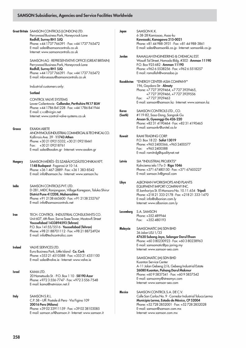
SAMSON Subsidiaries, Agencies and Service FacilitiesWorldwide
Great Britain SAMSONCONTROLS (LONDON) LTD.Perrywood Business Park, Honeycrock LaneRedhill, Surrey RH1 5JQPhone: +44 1737 766391 · Fax: +44 1737 765472E-mail: [email protected]: www.samsoncontrols.co.uk
SAMSONAG · REPRESENTATIVEOFFICE (GREAT BRITAIN)Perrywood Business Park, Honeycrock LaneRedhill, Surrey RH1 5JQPhone: +44 1737 766391 · Fax: +44 1737 765472E-mail: [email protected]
Industrial customers only:
Scotland
CONTROL VALVE SYSTEMSLower Coilentowie · Callander, Perthshire FK17 8LWPhone: +44 1786 841228 · Fax: +44 1786 841944E-mail: [email protected]: www.control-valve-systems.co.uk
Greece EXAKMABETEANONYMOUSINDUSTRIALCOMMERCIAL&TECHNICALCO.Kallirrois Ave. 39 · 11743AthenPhone: +30 21 09215332, +30 21 09218441Fax: +30 21 09218761E-mail: [email protected] · Internet: www.exakm.gr
Hungary SAMSONMÉRÉS- ÉS SZABÁLYOZÁSTECHNIKAI KFT.1148 Budapest · Fogarasi út 10-14.Phone: +36 1 467-2889 · Fax: +36 1 383-8542E-mail: [email protected] · Internet: www.samson.hu
India SAMSONCONTROLS PVT. LTD.D-281,MIDC Ranjangaon, Village Karegaon, Taluka ShirurDistrict Pune 412208,MaharashtraPhone: +91 2138 665600 · Fax: +91 2138 232767E-mail: [email protected]
Iran TECH. CONTROL · INDUSTRIAL CONSULTANTSCO.Unit 607, 6th floor, Sarve Saee Tower,Mostowfi StreetYoussefabad 1433894593 (Tehran)P.O. Box 14155/5516 · Youssefabad (Tehran)Phone: +98 21 88701112 · Fax: +98 21 88724924E-mail: [email protected]
Ireland VALVE SERVICES LTD.Euro Business Park, Little Island · Co. CorkPhone: +353 21 4510588 · Fax: +353 21 4351100E-mail: [email protected] · Internet: www.valve.ie
Israel KAMA LTD.20Hametsuda St. · P.O. Box 1 10 · 58190AzorPhone: +972 3 556-7747 · Fax: +972 3 556-7548E-mail: [email protected]
Italy SAMSONS.R.L.C.P. 58 – Uff. Postale di Pero · Via Figino 10920016 Pero (Milano)Phone: +39 02 33911159 · Fax: +39 02 38103085E-mail: [email protected] · Internet: www.samson.it
Japan SAMSONK.K.6-38-28 Kamiasao, Asao-kuKawasaki, Kanagawa 215-0021Phone: +81 44 988-3931 · Fax: +81 44 988-3861E-mail: [email protected] · Internet: samsonkk.co.jp
Jordan RAMALLAH ENGINEERING&CHEMICAL EST.Wasafi Tal Street, Hamada Bldg. #302 ·Amman 11190P.O. Box 925 682 ·Amman 11190Phone: +962 6 5538256 · Fax: +962 6 5518257E-mail: [email protected]
Kazakhstan "ENERGYCENTER-ASIACOMPANY"196,Gaydara Str ·AlmatyPhone: +7 727 3929464, +7 727 3929465,
+7 727 3929466, +7 727 3929556Fax: +7 727 3929463E-mail: [email protected] · Internet: www.samson.kz
Korea(South)
SAMSONCONTROLS LTD., CO.#119-82, Sasa-Dong, Sangrok-GuAnsan-Si, Gyeonggi-Do 426-220Phone: +82 31 4190464 · Fax: +82 31 4190465E-mail: [email protected]
Kuwait RAMI TRADINGCORP.P.O. Box 18 22 · Safat 13019Phone: +965 2400566, +965 2400577Fax: +965 2400588E-mail: [email protected]
Latvia SIA "INDUSTRIAL PROJEKTS"Kalnciema iela 17a-3 · Riga 1046Phone: +371 67480150 · Fax: +371 67605227E-mail: [email protected]
Libya ALBONIANWORKSHOPSAND PLANTSEQUIPMENT IMPORT COMPANY INC.El Jamhoriya St. El MansoraNo. 10.11.654 · TripoliPhone: +218 21 333-2178 · Fax: +218 21 333-1470E-mail: [email protected]: www.albonian.com.ly
Luxemburg S.A. SAMSONPhone: +352 489944Fax: +352 480193
Malaysia SAMSOMATIC (M) SDNBHD36 Jalan USJ 1/3347620 Subang Jaya, Selangor Darul EhsanPhone: +60 3 80230923 · Fax: +60 3 80238963E-mail: [email protected]: www.samson-sea.com
SAMSOMATIC (M) SDNBHDKuantan Service CenterA-11 JalanGebeng 2/6,Gebeng Industrial Estate26080 Kuantan, Pahang DarulMakmurPhone: +60 9 5837541 · Fax: +60 9 5837542E-mail: [email protected]: www.samson-sea.com
Mexico SAMSONCONTROL S.A. DE C.V.Calle San Carlos No. 9 · Corredor Industrial Toluca LermaMunicipio Lerma, Estado deMéxico, CP 52004Phone: +52 728 2852001 · Fax: +52 728 2852028E-mail: [email protected]: www.samson.com.mx
258

SAMSON Subsidiaries, Agencies and Service FacilitiesWorldwide
Netherlands SAMSONREGELTECHNIEK B.V.Signaalrood 10 · 2718 SH ZoetermeerPostbus 2 90 · 2700AGZoetermeerPhone: +31 79 3610501 · Fax: +31 79 3615930E-mail: [email protected]: www.samson-regeltechniek.nl
Norway MATEK – SAMSONREGULERINGA/SPorsgrunnsvn. 4 · 3730 SkienPhone: +47 35900870 · Fax: +47 35900880E-mail: [email protected] · Internet: www.matek.no
Oman MIDDLE EASTOILFIELD SERVICES L.L.C.P.O. Box 35 00 · 112 Ruwi (Muscat)Phone: +968 24487152, +968 24487153Fax: +968 24483832E-mail: [email protected]
Pakistan ENGRO INNOVATIVEAUTOMATION PVT. LTD.140 E/1Gulberg – III · Lahore – 54660Phone: +92 42 111940940 · Fax: +92 42 5711356E-mail: [email protected] · Internet: www.iael.com
People`sRepublic ofChina
SAMSONCONTROLS (CHINA) CO., LTD.No. 11, Yong ChangNan Lu, BDABeijing 100176Phone: +86 10 67803011Fax: +86 10 67803196E-mail: [email protected]: www.samsonchina.com
Philippines SAMSONMARKETINGOFFICE IN PHILIPPINESPhone: +63 44 7602129 · Fax: +63 44 7602129E-mail: [email protected]: www.samson-sea.com
Poland SAMSONSP. ZO.O.AUTOMATYKA I TECHNIKA POMIAROWAal. Krakowska 197 · 02-180WarszawaPhone: +48 22 5739-777 · Fax: +48 22 5739-776E-mail: [email protected]: www.samson.com.pl
Portugal SAMSON, S.A. ·MEDIDA E REGULAÇÃOZona Industrial Ligeira 2, Lote 112 · Apartado 3467520-309 SinesPhone: +351 269 634100 · Fax: +351 269 636104E-mail: [email protected] · Internet: www.samson.pt
Qatar QATARMODERN INSTRUMENTS&CONTROLS CO.(Q.M. CONTROLS)P.O. Box 64 29 ·DohaPhone: +974 4432326, +974 4372895Fax: +974 4432460E-mail: [email protected]
Republic ofSouth Africa
SAMSONCONTROLS (PTY) LTD.6 Engine Ave,MontagueGardensMilnerton 7441, Cape ProvinceP.O. Box 3 05 ·Milnerton 7435, Cape ProvincePhone: +27 21 5526088, +27 21 5526089,
+27 21 5526510Fax: +27 21 5512515E-mail: [email protected]: www.samson-sa.com
Romania CBCARMATURI INDUSTRIALE S.R.L.Str. Gladiolelor nr. 27, Vila E077025 Bragadiru, IlfovPhone: +40 21 4213852, +40 21 4213854Fax: +40 21 4213853E-mail: [email protected]: www.cbc-armaturi.ro
RussianFederation
OOOSAMSONCONTROLS"Business Center", 4. StockMarksistskaja Str. 16 · 109147MoskauPhone: +7 495 6474545 · Fax: +7 495 7373949E-mail: [email protected] · Internet: www.samson.ru
SAMSONAG · REPRESENTATIVEOFFICEMOSKAU"Business Center", 4. StockMarksistskaja Str. 16 · 109147MoskauPhone: +7 495 6474545 · Fax: +7 495 7373949E-mail: [email protected]
Saudi Arabia ANASIA TRADINGCO., LTD.P.O. Box 5 09 59 · Jeddah 21533Phone: +966 2 6363825 · Fax: +966 2 6380720E-mail: [email protected]: www.anasiasaudi.com
Singapore SAMSONCONTROLS PTE LTD27 Kaki Bukit View · Kaki Bukit Techpark IISingapore 415962Phone: +65 67488810 · Fax: +65 67451418E-mail: [email protected]: www.samson-sea.com
Slovakia DLOUHÝ I.T.A. S.R.O.PodHradiskom9 · 01004 ZilinaPhone: +421 41 7234370 · Fax: +421 41 7234371E-mail: [email protected] · Internet: www.samson.sk
Slovenia GIA-S INDUSTRIJSKAOPEMAD.O.O.Industrijska cesta 5 · 1290GrosupljePhone: +386 1 7865-300 · Fax: +386 1 7863-568E-mail: [email protected] · Internet: www.gia.si
Spain SAMSONS.A.TÉCNICADEMEDICIÓNY REGULACIÓNPol. Ind. Cova Solera · Avda. Can Sucarrats, 104Apartado 311 · 08191 Rubi (Barcelona)Phone: +34 93 5861070 · Fax: +34 93 6994300E-mail: [email protected] · Internet: www.samson.es
Sweden SAMSONMÄT-OCHREGLERTEKNIKABKungsporten 1A · 427 50 BilldalBox 67 · 427 22 BilldalPhone: +46 31 914015 · Fax: +46 31 914019E-mail: [email protected] · Internet: www.samson.se
Switzerland SAMSONAG ·MESS- UNDREGELTECHNIKTechnisches Büro SchweizPostfach 187 · 4125 Riehen 1 (Basel)Phone: +49 7621 95695-0 · Fax: +49 7621 95695-6E-mail: [email protected]: www.samson-ag.ch
Taiwan SAMSONCONTROLS CO., LTD.3F, 132, Hsin-Hu Third Road · Taipei 114Phone: +886 2 8792-1230 · Fax: +886 2 8792-1270E-mail: [email protected]
259

SAMSON Subsidiaries, Agencies and Service FacilitiesWorldwide
Thailand SAMSONCONTROLS LTD.267/233-4 Sukhumvit RoadMap Ta Phut, Muang · Rayong 21150Phone: +66 38 608939 · Fax: +66 38 608943E-mail: [email protected] · Internet: www.samson.co.th
SAMSONCONTROLS LTD.Bangkok Branch · 24th floor UM TowerNo. 9 Ramkamheang Road, Suanluang · Bangkok 10250Phone: +66 2 7198214-5 · Fax: +66 2 7198237E-mail: [email protected] · Internet: www.samson.co.th
Turkey SAMSONÖLÇÜVEOTOMATIK KONTROL SISTEMLERISANAYI VE TICARETA.S
´.
EvrenMahallesi, Gülbahar Caddesi No: 9434212Günes
´li-Istanbul
P.K. 3 89 · 80003 Karaköy-IstanbulPhone: +90 212 6518746 · Fax: +90 212 6518750E-mail: [email protected]: www.samson.com.tr
U.S.A. SAMSONCONTROLS INC.4111Cedar Boulevard · Baytown, Texas 77523-8588Phone: +1 281 383-3677 · Fax: +1 281 383-3690E-mail: [email protected]: www.samson-usa.com
SAMSONPROJECT ENGINEERING, INC.14811 St. Mary´s Lane, Suite 130 ·Houston, Texas 77079Phone: +1 281 7596900, +1 281 7596902Fax: +1 281 8708007E-mail: [email protected]: www.samson-pei.com
Ukraine "SAMSON-ENGINEERINGGMBH"Floor 10,Office 4 · 19Marina Raskowa St · 02002 KiewPhone: +380 44 4905305 · Fax: +380 44 4905305E-mail: [email protected]: www.samsoneng.kiev.ua
United ArabEmirates
SAMSONCONTROLS FZEP.O. Box 262793 · PBU YC01 (near R/A 08)Jebel Ali Free Zone, DubaiPhone: +971 4 8834933Fax: +971 4 8834944E-mail: [email protected]: www.samson.ae
Venezuela SAMSONCONTROLS S.A.Ur. Los Rosales, Calle Bermúdez · Edif. LaGarantíaCaracas 1040Distrito FederalPhone: +58 212 6903645 · Fax: +58 212 6935953E-mail: [email protected]: www.samson.com.ve
All addresses, including e-mail and Internet addresses, can be found athttp://www.samson.de
260

T 3701 ENType 3701 Solenoid Valve 167
T 3776 ENLimit Switch Type 3776 125
T 3962-5 ENSolenoid Valve Type 3962 211
T 3963 ENSolenoid Valve Type 3963 173
T 3967 ENSolenoid Valve Type 3967 199
T 3999-6 ENService Unit Type 3999-009X 233
T 3999-8 ENFilter Regulator Type 3999-0096 237
T 6116 ENi/p Converter Type 6116 109
T 6151 ENu/i Module Type 6151 115
T 6661 ENTROVIS-VIEW Software TROVIS 6661 79
T 8350 ENInformation SheetPositioners, Converters, Limit Switches,Position Transmitters, Solenoid Valves, Accessories 5
T 8355 ENPneumatic Positioner Type 3766Electropneumatic Positioner Type 3767 85
T 8356 ENInductive Limit Switchfor Pneumatic Control Valves Type 3768 141
T 8359 ENElectropneumatic Positioner Type 4763Pneumatic Positioner Type 4765 97
T 8363 ENAnalog Position Transmitter Type 4748 157
T 8365 ENElectric or Pneumatic Limit Switch Type 4746 119
T 8367 ENElectric Limit Switch Type 4744 145
T 8379 ENField Barrier Ex d/Ex i Type 3770 163
T 8384-0 ENElectropneumatic Positioner Type 3730-0 25
T 8384-1 ENElectropneumatic Positioner Type 3730-1 31
T 8384-2/3 ENElectropneumatic PositionerType 3730-2 and Type 3730-3with HART® communication 37
T 8384-4 ENElectropneumatic Positioner Type 3730-4with PROFIBUS-PA communication 45
T 8384-5 ENElectropneumatic Positioner Type 3730-5with FOUNDATIONTM fieldbus communication 53
T 8385 ENElectropneumatic Positioner andPneumatic Positioner Type 3760 103
T 8387-3 ENElectropneumatic Ex d Positioner Type 3731-3with HART® communication 59
T 8387-5 ENElectropneumatic Ex d Positioner Type 3731-5with FOUNDATIONTM fieldbus communication 65
T 8389 ENSeries 3730 and Series 3731EXPERTplus Valve Diagnosticswith Partial Stroke Test (PST) 71
T 8390 ENElectronic Limit Switch Type 3738-20 149
T 8391 ENPneumatic Lock-up Valve Type 3709 243
T 8392 ENReversing Amplifier Type 3710 245
T 8393 ENPneumatic Volume Booster Type 3755 249
T 8510 ENPneumatic Remote Adjuster Type 3759 241
T 8546 ENSupply Pressure Regulator Type 4708 221
Data Sheet Summary
261


3701 Solenoid Valve 167
3709 Pneumatic Lock-up Valve 243
3710 Reversing Amplifier 245
3730-0 Electropneumatic Positioner 25
3730-1 Electropneumatic Positioner 31
3730-2 Electropneumatic Positioner with HART® communication 37
3730-3 Electropneumatic Positioner with HART® communication 37
3730-4 Electropneumatic Positioner with PROFIBUS-PA communication 45
3730-5 Electropneumatic Positioner with FOUNDATIONTM fieldbus communication 53
3731-3 Electropneumatic Ex d Positioner with HART® communication 59
3731-5 Electropneumatic Ex d Positioner with FOUNDATIONTM fieldbus communication 65
3738-20 Electronic Limit Switch 149
3755 Pneumatic Volume Booster 249
3759 Pneumatic Remote Adjuster 241
3760 Electropneumatic Positioner and Pneumatic Positioner 103
3766 Pneumatic Positioner 85
3767 Electropneumatic Positioner 85
3768 Inductive Limit Switch for Pneumatic Control Valves 141
3770 Field Barrier Ex d/Ex i 163
3776 Limit Switch 125
3962 Solenoid Valve 211
3963 Solenoid Valve 173
3967 Solenoid Valve 199
3999-009X Service Unit 233
3999-0096 Filter Regulator 237
4708 Supply Pressure Regulator 221
4744 Electric Limit Switch 145
4746 Electric or Pneumatic Limit Switch 119
4748 Analog Position Transmitter 157
4763 Electropneumatic Positioner 97
4765 Pneumatic Positioner 97
6116 i/p Converter 109
6151 u/i Module 115
EXPERT* Series 3730 and Series 3731 EXPERTplus Valve Diagnostics with Partial Stroke Test (PST) 71
TROVIS 6661 TROVIS-VIEW Software 79
Type Application/Function Page Type Application/Function Page
Index
263


SAMSONSAM
SO
N
2010
-04
WS
· K 1
3 EN
SAMSON AG · MESS- UND REGELTECHNIK · Weismüllerstraße 3 · 60314 Frankfurt am Main · GermanyPhone: +49 69 4009-0 · Fax: +49 69 4009-1507 · E-mail: [email protected] · Internet: http://www.samson.de
Control Valves for Industrial ProcessesVolume 3
Cont
rol V
alve
s fo
r In
dust
rial P
roce
sses
· Vo
lum
e 3