samson catalog - hlk shop · samson ag · mess- und regeltechnik ... trovis 5610 29 programmable...
TRANSCRIPT

SAMSON AG · MESS- UND REGELTECHNIK Weismüllerstraße 3 · 60314 Frankfurt am Main · GermanyPhone: +49 69 4009-0 · Fax: +49 069 4009-1507 E-mail: [email protected] · Internet: www.samson.deSAMSON GROUP · www.samsongroup.net
Controllers and Sensorsfor Heating, Ventilation andAir-conditioning Systems
Cont
rolle
rs a
nd S
enso
rs fo
r H
eatin
g, V
entil
atio
n an
d A
ir-co
nditi
onin
g Sy
stem
s
Catalog
2012
-07
WS
· K5
EN
SAM
SON
Controllers and Sensors for Heating, Ventilation and Air-conditioning Systems
Catalog 2012 Overview
Appendix
Accessories
Sensors
Controllers with Electric Actuators
Electronic Controllers 5
59
89
117
123
1

2
Electronic Controllers
Information Sheet Controllers and Systems for HVAC Applications Heating and District Heating Controllers 5
Heating and District Heating Controller TROVIS 5573 9
Heating and District Heating Controller TROVIS 5575 13
Heating and District Heating Controller TROVIS 5576 19
Heating and District Heating Controller TROVIS 5579 23
Heating and District Heating Controller TROVIS 5610 29
Programmable Logic Controller (PLC) TROVIS 5571 31
Room Controller TROVIS 5572 35
Room Panel TROVIS 5570 37
Communication components 39
Meter Bus Gateway TROVIS 5488 51
Web Module TROVIS 5590 55
Controllers with Electric Actuators
Controller with Electric Actuator Type 5757-7 for heating and cooling applications 59
Controller with Electric Actuator Typ 5725-7, with fail-safe action for heating and cooling applications 65
Controller with Electric Actuator Type 5757-3 for domestic hot water heating 73
Controller with Electric Actuator Type 5724, without fail-safe action Type 5725, with fail-safe action for domestic hot water heating 81
Sensors
Information Sheet Temperature Sensors Thermostats 89
Temperature Sensors Types 5204 to 5256 with Pt 100 resistors 95
Temperature Sensors Types 5207 to 5277 with Pt 1000 resistors 97
Fast-response Temperature Sensors Types 5207-61/-64/-65 with Pt 1000 resistor 105
Fast-response Temperature Sensor Type 5207-0060 with Pt 1000 resistor 107
Thermostats Safety Temperature Monitor (STM) Type 5343 Temperature Regulator (TR) Type 5344 Safety Temperature Limiter (STL) Type 5345 Double Thermostats TR/STL Type 5347, TR/STM Type 5348 and STM/STL Type 5349 109
Thermostats Frost Protection Thermostat Type 5312-2 115
Accessories
TROVIS-VIEW Software TROVIS 6661 117
Appendix
SAMSON Product Range 123
SAMSON Subsidiaries, Agencies and Service Facilities Worldwide 125
Data Sheet Summary 131
Index 132
Specifications subject to change without notice. The information sheets and data sheets in this catalog may have been updated since the catalog went to print (July 2012). The latest versions are available on our website.
Contents
2 3

4
Information Sheet T 5500 EN 2012-01 5
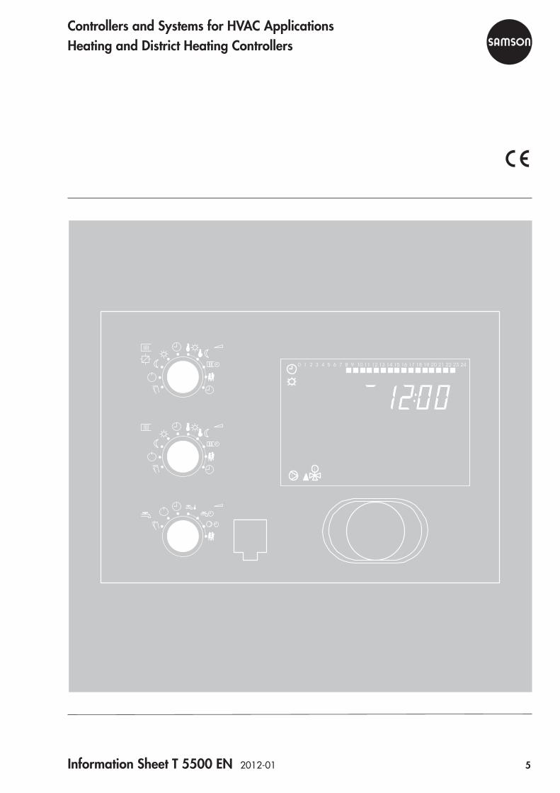
Controllers and Systems for HVAC ApplicationsHeating and District Heating Controllers
6 Information Sheet T 5500 EN 2012-01
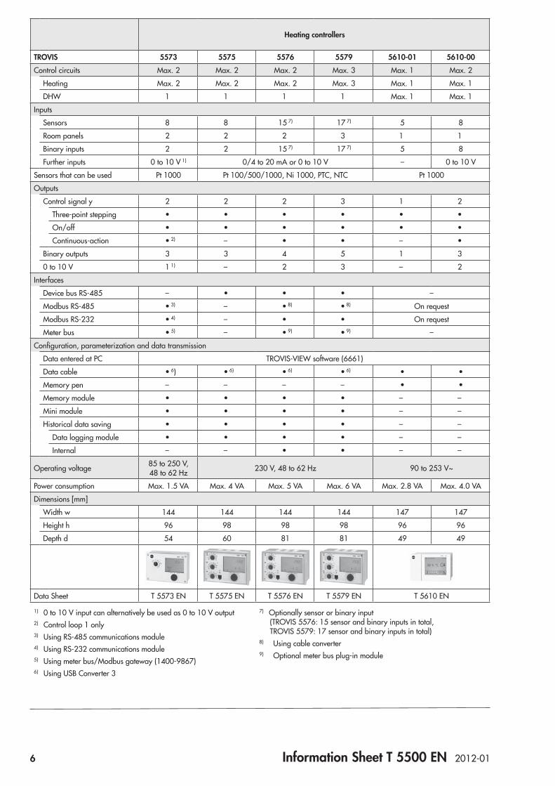
Heating controllers
TROVIS 5573 5575 5576 5579 5610-01 5610-00Control circuits Max. 2 Max. 2 Max. 2 Max. 3 Max. 1 Max. 2
Heating Max. 2 Max. 2 Max. 2 Max. 3 Max. 1 Max. 1
DHW 1 1 1 1 Max. 1 Max. 1
Inputs
Sensors 8 8 15 7) 17 7) 5 8
Room panels 2 2 2 3 1 1
Binary inputs 2 2 15 7) 17 7) 5 8
Further inputs 0 to 10 V 1) 0/4 to 20 mA or 0 to 10 V – 0 to 10 V
Sensors that can be used Pt 1000 Pt 100/500/1000, Ni 1000, PTC, NTC Pt 1000
Outputs
Control signal y 2 2 2 3 1 2
Three-point stepping • • • • • •
On/off • • • • • •
Continuous-action • 2) – • • – •
Binary outputs 3 3 4 5 1 3
0 to 10 V 1 1) – 2 3 – 2
Interfaces
Device bus RS-485 – • • • –
Modbus RS-485 • 3) – • 8) • 8) On request
Modbus RS-232 • 4) – • • On request
Meter bus • 5) – • 9) • 9) –
Configuration, parameterization and data transmission
Data entered at PC TROVIS-VIEW software (6661)
Data cable • 6) • 6) • 6) • 6) • •
Memory pen – – – – • •
Memory module • • • • – –
Mini module • • • • – –
Historical data saving • • • • – –
Data logging module • • • • – –
Internal – – • • – –
Operating voltage 85 to 250 V, 48 to 62 Hz 230 V, 48 to 62 Hz 90 to 253 V~
Power consumption Max. 1.5 VA Max. 4 VA Max. 5 VA Max. 6 VA Max. 2.8 VA Max. 4.0 VA
Dimensions [mm]
Width w 144 144 144 144 147 147
Height h 96 98 98 98 96 96
Depth d 54 60 81 81 49 49
Data Sheet T 5573 EN T 5575 EN T 5576 EN T 5579 EN T 5610 EN
1) 0 to 10 V input can alternatively be used as 0 to 10 V output2) Control loop 1 only3) Using RS-485 communications module4) Using RS-232 communications module5) Using meter bus/Modbus gateway (1400-9867)6) Using USB Converter 3
7) Optionally sensor or binary input (TROVIS 5576: 15 sensor and binary inputs in total, TROVIS 5579: 17 sensor and binary inputs in total)
8) Using cable converter9) Optional meter bus plug-in module
Information Sheet T 5500 EN 2012-01 7
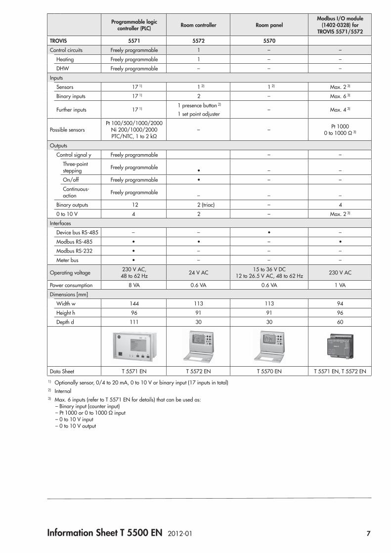
Programmable logic controller (PLC) Room controller Room panel
Modbus I/O module (1402-0328) for
TROVIS 5571/5572TROVIS 5571 5572 5570Control circuits Freely programmable 1 – –
Heating Freely programmable 1 – –
DHW Freely programmable – – –
Inputs
Sensors 17 1) 1 2) 1 2) Max. 2 3)
Binary inputs 17 1) 2 – Max. 6 3)
Further inputs 17 1) 1 presence button 2)
1 set point adjuster – Max. 4 3)
Possible sensorsPt 100/500/1000/2000
Ni 200/1000/2000 PTC/NTC, 1 to 2 kΩ
– – Pt 1000 0 to 1000 Ω 3)
Outputs
Control signal y Freely programmable – –
Three-point stepping Freely programmable • – –
On/off Freely programmable • – –
Continuous-action Freely programmable – – –
Binary outputs 12 2 (triac) – 4
0 to 10 V 4 2 – Max. 2 3)
Interfaces
Device bus RS-485 – – • –
Modbus RS-485 • • – •
Modbus RS-232 • – – –
Meter bus • – – –
Operating voltage 230 V AC, 48 to 62 Hz 24 V AC 15 to 36 V DC
12 to 26.5 V AC, 48 to 62 Hz 230 V AC
Power consumption 8 VA 0.6 VA 0.6 VA 1 VA
Dimensions [mm]
Width w 144 113 113 94
Height h 96 91 91 96
Depth d 111 30 30 60
Data Sheet T 5571 EN T 5572 EN T 5570 EN T 5571 EN, T 5572 EN
1) Optionally sensor, 0/4 to 20 mA, 0 to 10 V or binary input (17 inputs in total)2) Internal3) Max. 6 inputs (refer to T 5571 EN for details) that can be used as:
– Binary input (counter input) – Pt 1000 or 0 to 1000 Ω input – 0 to 10 V input – 0 to 10 V output


Data Sheet T 5573 EN 2012-05 9
ApplicationControl of max. two control circuits
Automation System TROVIS 5500Heating and District Heating Controller TROVIS 5573
Fig. 1: TROVIS 5573 Heating and District Heating Controller
The TROVIS 5573 Heating and District Heating Controller is used to control max. two control circuits: – Control of a primary heat exchanger or boiler with max.
one mixing and one non-mixing heating circuit (both weather-compensated) as well as control of DHW heating in the secondary circuit
– Control of one weather-compensated heating circuit and a DHW heating with two valves in the primary circuit
– Control of two weather-compensated heating circuits with two valves in the primary circuit
Versions – TROVIS 5573-000x: Controller with icon readings on the
display – TROVIS 5573-100x: Controller with plain-text readings
on the graphics display
Special features • Rotary switches for direct access to the operating modes
and essential parameters of the control circuits • Intuitive data retrieval and input by pressing and turning
the pushbutton • 365-day clock with max. four time schedules and auto-
matic summer time/winter time changeover; maximum three times-of-use per day (input in steps of 15 minutes)
• Room panels connected to individual heating circuits to override operating mode and rated room temperature
• Demand-driven control by set point demand by subse-quent controllers over a 0 to 10 V signal. The primary circuit controls the maximum flow temperature demanded plus adjustable boost.
• Applications with solar hot water system available • Heating characteristics optionally based on the gradient
or based on four points; variable return flow temperature limitation
• Adaptation: automatic adaptation of the heating charac-teristic (room temperature sensor required)
• Optimization: calculation of the best possible activation and deactivation times for the heating (room temperature sensor required)
• Drying of jointless floors function with adjustable param-eter settings
• Updatable flash memory in controller (operating system) • Configuration and parameterization using a memory module • Data logging function:
– Operating data can be saved to a data logging module – Data can be displayed in the data log viewer on a PC – TROVIS 5573-100x: Analysis of data saved in operat-
ing data memory on graphics display
®
Electronics from SAMSON
TROVIS 5573-000x with icon readings on the display
TROVIS 5573-100x with plain-text read-ings on graphics display
10 Data Sheet T 5573 EN 2012-05
Inputs and outputs • 8 inputs for Pt 1000 temperature sensors and two binary
inputs • 0 to 10 V input (can alternatively be used as 0 to 10 V
output) • Three-step or on/off control circuit outputs configurable with
PI control algorithm
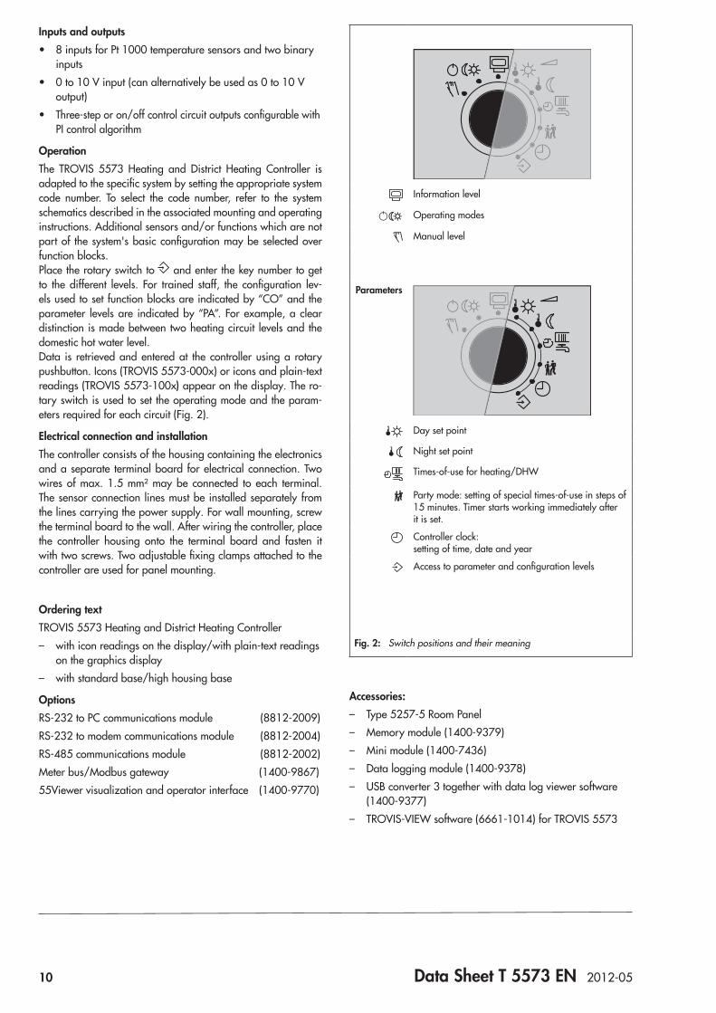
OperationThe TROVIS 5573 Heating and District Heating Controller is adapted to the specific system by setting the appropriate system code number. To select the code number, refer to the system schematics described in the associated mounting and operating instructions. Additional sensors and/or functions which are not part of the system's basic configuration may be selected over function blocks.Place the rotary switch to and enter the key number to get to the different levels. For trained staff, the configuration lev-els used to set function blocks are indicated by “CO” and the parameter levels are indicated by “PA”. For example, a clear distinction is made between two heating circuit levels and the domestic hot water level.Data is retrieved and entered at the controller using a rotary pushbutton. Icons (TROVIS 5573-000x) or icons and plain-text readings (TROVIS 5573-100x) appear on the display. The ro-tary switch is used to set the operating mode and the param-eters required for each circuit (Fig. 2).
Electrical connection and installationThe controller consists of the housing containing the electronics and a separate terminal board for electrical connection. Two wires of max. 1.5 mm² may be connected to each terminal. The sensor connection lines must be installed separately from the lines carrying the power supply. For wall mounting, screw the terminal board to the wall. After wiring the controller, place the controller housing onto the terminal board and fasten it with two screws. Two adjustable fixing clamps attached to the controller are used for panel mounting.
Ordering textTROVIS 5573 Heating and District Heating Controller – with icon readings on the display/with plain-text readings
on the graphics display – with standard base/high housing base
OptionsRS-232 to PC communications module (8812-2009)RS-232 to modem communications module (8812-2004)RS-485 communications module (8812-2002)Meter bus/Modbus gateway (1400-9867)55Viewer visualization and operator interface (1400-9770)
Information level
Operating modes
Manual level
Parameters
Day set point
Night set point
Times-of-use for heating/DHW
Party mode: setting of special times-of-use in steps of 15 minutes. Timer starts working immediately after it is set.
Controller clock: setting of time, date and year
Access to parameter and configuration levels
Fig. 2: Switch positions and their meaning
Accessories: – Type 5257-5 Room Panel – Memory module (1400-9379) – Mini module (1400-7436) – Data logging module (1400-9378) – USB converter 3 together with data log viewer software
(1400-9377) – TROVIS-VIEW software (6661-1014) for TROVIS 5573
Data Sheet T 5573 EN 2012-05 11
Technical data
Inputs 8 inputs for Pt 1000 temperature sensors and two binary inputs, Input terminal 11 alternatively for 0 to 10 V signal for external demand by subsequent controllers (0 to 10 V correspond to 20 to 120 °C flow temperature)
Outputs* 2 x three-step signal: load max. 250 V AC, 2 A Alternatively 2 x on/off signal: load max. 250 V AC, 2 A3 x pump output: load max. 250 V AC, 2 A; all outputs are relay outputs with varistor suppressionInput terminal 11 alternatively can be used as 0 to 10 V output for continuous-action control for control circuit Rk1 or signal for external demand, load > 5 kΩ
Optional interfaces – Modbus RS-232 interface for modem using RS-232 to PC communications module– Modbus RS-485 interface for two-wire bus using RS-485 communications module(Modbus RTU protocol, data format 8N1, RJ 45 connector socket at the side)
Operating voltage 85 to 250 V, 48 to 62 Hz, max. 1.5 VA
Ambient temperature 0 to 40 °C (operation), –10 °C to 60 °C (storage and transport)
Degree of protection IP 40 according to IEC 60529
Class of protection II according to VDE 0106
Degree of contamination 2 according to VDE 0110
Overvoltage category II according to VDE 0110
Humidity rating F according to VDE 40040
Noise immunity According to EN 61000-6-1
Noise emission According to EN 61000-6-3
Weight Approx. 0.5 kg
* For systems with one control circuit, a maximum of four pumps are available
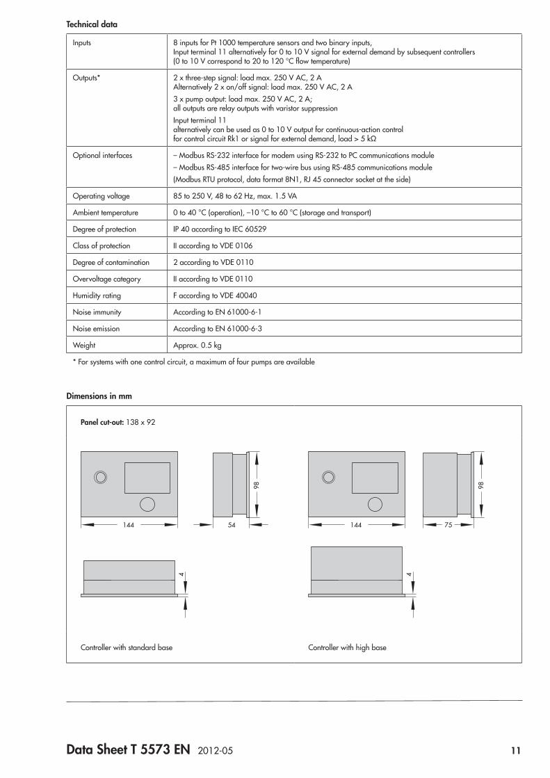
Dimensions in mm
Panel cut-out: 138 x 92
98
54144
4
98
75144
4
Controller with standard base Controller with high base
12 Data Sheet T 5573 EN 2012-05
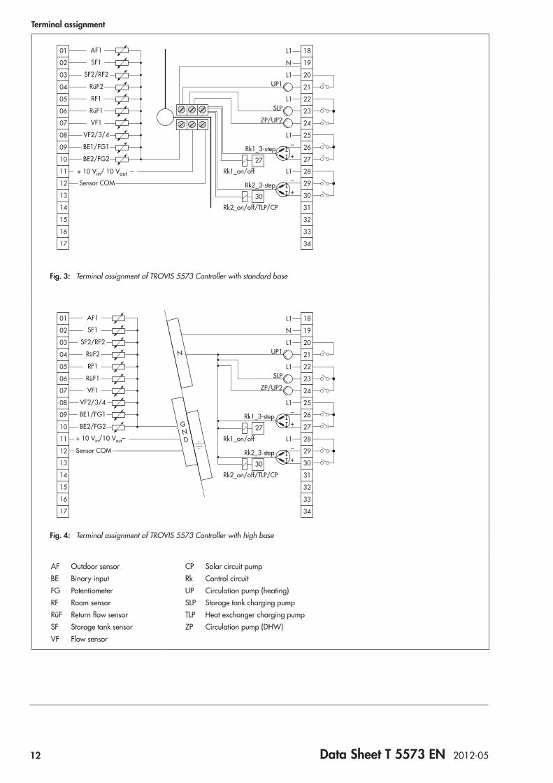
Terminal assignment
_
+
_
+
08
09
10
11
12
13
14
15
16
17
01
02
03
04
05
06
07
UP1
SLP
ZP/UP2
Rk1_3-step
Rk2_3-step
Rk1_on/off
Rk2_on/off/TLP/CP
AF1
SF1
SF2/RF2
RüF2
RF1
RüF1
VF1
VF2/3/4
BE1/FG1
BE2/FG2
+ 10 Vin/ 10 Vout _
Sensor COM
25
26
27
28
30
27
29
30
31
32
33
34
18L1
L1
L1
L1
L1
19N
20
21
22
23
24
Fig. 3: Terminal assignment of TROVIS 5573 Controller with standard base
_
+
_
+
08
09
10
11
12
13
14
15
16
17
01
02
03
04
05
06
07
UP1
SLP
ZP/UP2
Rk1_3-step
Rk2_3-step
Rk1_on/off
Rk2_on/off/TLP/CP
AF1
SF1
SF2/RF2
RüF2
RF1
RüF1
VF1
VF2/3/4
BE1/FG1
BE2/FG2
Sensor COM
+ 10 Vin/10 Vout–
25
26
27
28
30
27
29
30
31
32
33
34
18L1
L1
L1
L1
L1
19N
20
21
22
23
24
N
GND
Fig. 4: Terminal assignment of TROVIS 5573 Controller with high base
AF Outdoor sensorBE Binary inputFG PotentiometerRF Room sensorRüF Return flow sensorSF Storage tank sensorVF Flow sensor
CP Solar circuit pumpRk Control circuitUP Circulation pump (heating)SLP Storage tank charging pumpTLP Heat exchanger charging pumpZP Circulation pump (DHW)

Data Sheet T 5575 EN 2007-11 13
ApplicationControl of max. two control circuits. To control more circuits, several controllers can be linked by a device bus.
Automation System TROVIS 5500Heating and District Heating Controller TROVIS 5575
Fig. 1: TROVIS 5575 Heating and District Heating Controller
The TROVIS 5575 Heating and District Heating Controller is used to control max. two control circuits:Control of a primary heat exchanger or boiler with max. one mixing and one non-mixing heating circuit (both weather-com-pensated) as well as control of DHW heating in the secondary circuit – Control of one weather-compensated heating circuit and a
DHW heating with two valves in the primary circuit – Control of two weather-compensated heating circuits with
two valves in the primary circuit
Special features • Rotary switches for direct access to the operating modes
and essential parameters of the control circuits • Intuitive data retrieval and input by pressing and turning
the pushbutton • Illuminated display • 365-day clock with max. four time schedules and auto-
matic summer time/winter time changeover; maximum three times-of-use per day (input in steps of 15 minutes)
• Room panels may be connected for each heating circuit: – Convenient room panels for adjustment of the operat-
ing mode, the day and night set points, the times-of-use for heating, the controller clock and party mode. Additional outdoor and room temperature readings. Connection via device bus
– Room panel to override operating mode and rated room temperature
• Demand-driven control by set point demand by subsequent controllers over a device bus or 0 to 10 V signal. The primary circuit controls the maximum flow temperature de-manded plus adjustable boost.
• Applications with solar hot water system available • Instantaneous heating systems with water flow sensor con-
figurable • Heating characteristics optionally based on the gradient
or based on four points; variable return flow temperature limitation
• Adaptation: automatic adaptation of the heating charac-teristic (room temperature sensor required)
• Optimization: calculation of the best possible activation and deactivation times for the heating (room temperature sensor required)
• Drying of jointless floors function with adjustable param-eter settings
• Updatable flash memory in controller (operating system) • Configuration and parameterization either using memory
module or online using USB converter 3 and TROVIS-VIEW software
• Data logging function: – Operating data can be saved to a data logging module – Data can be displayed in the data log viewer on a PC
®
Electronics from SAMSON
14 Data Sheet T 5575 EN 2007-11
Inputs and outputs • 8 inputs for Pt 1000/Pt 100, PTC/Pt 100, NTC/Pt 100,
Ni 1000/Pt 100 or Pt 500/Pt 100 temperature sensors and two binary inputs
• Three-step or on/off control circuit outputs configurable with PI control algorithm
OperationThe TROVIS 5575 Heating and District Heating Controller is adapted to the specific system by setting the appropriate sys-tem code number. To select the code number, refer to the system schematics described in the associated mounting and operat-ing instructions. Additional sensors and/or functions which are not part of the system's basic configuration may be selected over function blocks. Press the changeover key to access the different levels. For trained staff, the configuration levels used to set function blocks are indicated by “CO” and the parameter levels are indicated by “PA”. For example, a clear distinction is made between two heating circuit levels, a domestic hot water level and a communication level.Data is retrieved and entered at the controller using a rotary pushbutton. This process is facilitated by icons displayed on the LCD. The three rotary switches are used to set the operating mode (left) and the parameters required for each circuit (right) as illustrated in Fig. 2.
Versions – TROVIS 5575-000x · Standard controller with backlight
and device bus – TROVIS 5575-001x · Controller with backlight, device bus
and an additional pump output – TROVIS 5575-002x · Controller without backlight or de-
vice busAll versions can be fitted with either a standard housing base or a high base (see Fig. 3 and Fig. 4).
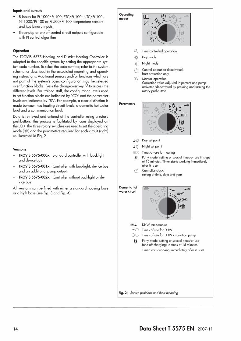
Operating modes
Time-controlled operation
Day mode
Night mode
Control operation deactivated, frost protection onlyManual operation: Correction value adjusted in percent and pump activated/deactivated by pressing and turning the rotary pushbutton
Parameters
Day set point
Night set point
Times-of-use for heatingParty mode: setting of special times-of-use in steps of 15 minutes. Timer starts working immediately after it is set.Controller clock: setting of time, date and year
Domestic hot water circuit
DHW temperatureTimes-of-use for DHWTimes-of-use for DHW circulation pumpParty mode: setting of special times-of-use (one-off charging) in steps of 15 minutes.Timer starts working immediately after it is set.
Fig. 2: Switch positions and their meaning
Data Sheet T 5575 EN 2007-11 15
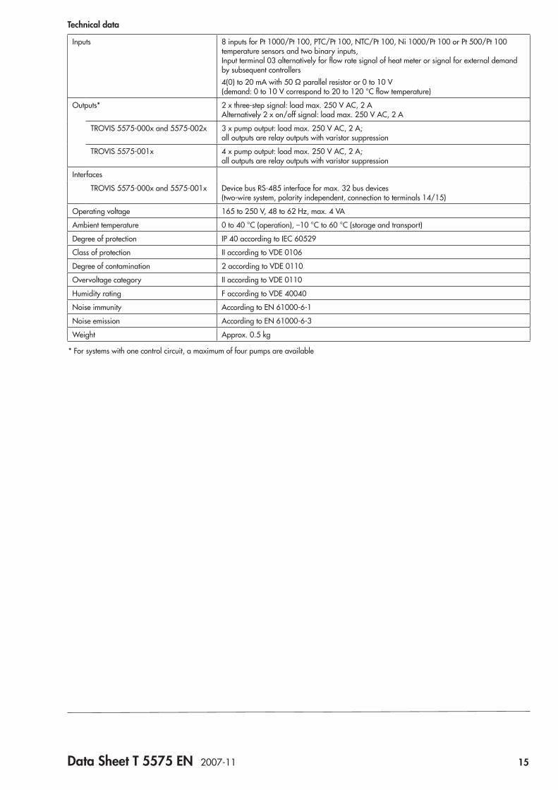
Technical data
Inputs 8 inputs for Pt 1000/Pt 100, PTC/Pt 100, NTC/Pt 100, Ni 1000/Pt 100 or Pt 500/Pt 100 temperature sensors and two binary inputs, Input terminal 03 alternatively for flow rate signal of heat meter or signal for external demand by subsequent controllers4(0) to 20 mA with 50 Ω parallel resistor or 0 to 10 V (demand: 0 to 10 V correspond to 20 to 120 °C flow temperature)
Outputs* 2 x three-step signal: load max. 250 V AC, 2 A Alternatively 2 x on/off signal: load max. 250 V AC, 2 A
TROVIS 5575-000x and 5575-002x 3 x pump output: load max. 250 V AC, 2 A; all outputs are relay outputs with varistor suppression
TROVIS 5575-001x 4 x pump output: load max. 250 V AC, 2 A; all outputs are relay outputs with varistor suppression
Interfaces
TROVIS 5575-000x and 5575-001x Device bus RS-485 interface for max. 32 bus devices (two-wire system, polarity independent, connection to terminals 14/15)
Operating voltage 165 to 250 V, 48 to 62 Hz, max. 4 VA
Ambient temperature 0 to 40 °C (operation), –10 °C to 60 °C (storage and transport)
Degree of protection IP 40 according to IEC 60529
Class of protection II according to VDE 0106
Degree of contamination 2 according to VDE 0110
Overvoltage category II according to VDE 0110
Humidity rating F according to VDE 40040
Noise immunity According to EN 61000-6-1
Noise emission According to EN 61000-6-3
Weight Approx. 0.5 kg
* For systems with one control circuit, a maximum of four pumps are available
16 Data Sheet T 5575 EN 2007-11
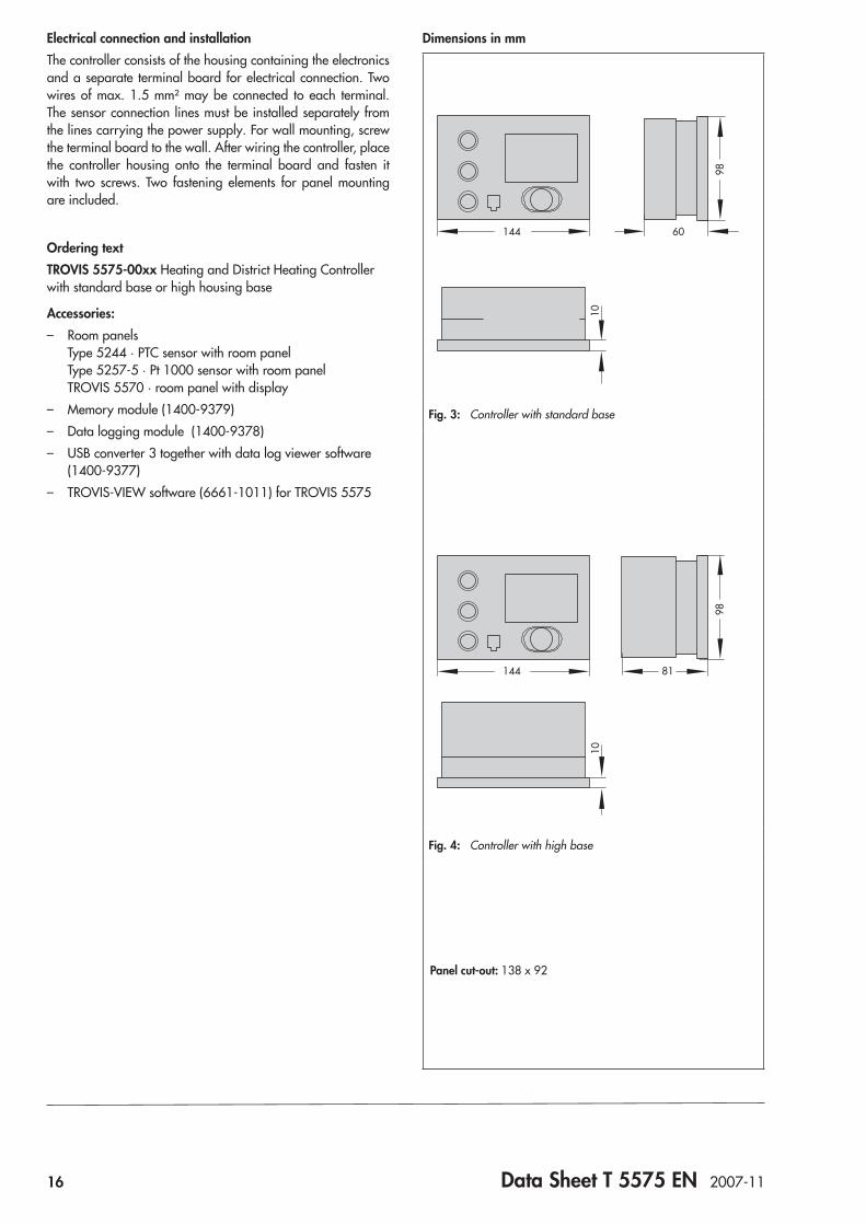
Electrical connection and installationThe controller consists of the housing containing the electronics and a separate terminal board for electrical connection. Two wires of max. 1.5 mm² may be connected to each terminal. The sensor connection lines must be installed separately from the lines carrying the power supply. For wall mounting, screw the terminal board to the wall. After wiring the controller, place the controller housing onto the terminal board and fasten it with two screws. Two fastening elements for panel mounting are included.
Ordering textTROVIS 5575-00xx Heating and District Heating Controller with standard base or high housing base
Accessories: – Room panels
Type 5244 · PTC sensor with room panel Type 5257-5 · Pt 1000 sensor with room panel TROVIS 5570 · room panel with display
– Memory module (1400-9379) – Data logging module (1400-9378) – USB converter 3 together with data log viewer software
(1400-9377) – TROVIS-VIEW software (6661-1011) for TROVIS 5575
Dimensions in mm
98
60144
10
Fig. 3: Controller with standard base
98
81144
10
Fig. 4: Controller with high base
Panel cut-out: 138 x 92
Data Sheet T 5575 EN 2007-11 17
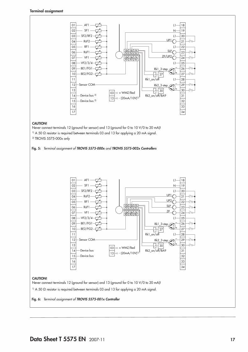
Terminal assignment
_
+
_
+
08
09
10
11
12
13
14
15
16
17
01
02
03
04
05
06
07
UP1
SLP
ZP/UP2
Rk1_3-step
Rk2_3-step
Rk1_on/off
Rk2_on/off/BA9
AF1
SF1
SF2/RF2
RüF2
RF1
RüF1
VF1
VF2/3/4
BE1/FG1
BE2/FG2
Sensor COM
Device bus 2)
Device bus 2)
03
13
+ WMZ/Bed
- (20mA/10V)1)
25
26
27
28
30
27
29
30
31
32
33
34
18L1
L1
L1
L1
L1
19N
20
21
22
23
24
CAUTION! Never connect terminals 12 (ground for sensor) and 13 (ground for 0 to 10 V/0 to 20 mA)!1) A 50 Ω resistor is required between terminals 03 and 13 for applying a 20 mA signal.2) TROVIS 5575-000x only
Fig. 5: Terminal assignment of TROVIS 5575-000x and TROVIS 5575-002x Controllers
_
+
_
+
08
09
10
11
12
13
14
15
16
17
01
02
03
04
05
06
07
UP1
SLP
ZP
Rk1_3-step
Rk2_3-step
Rk1_on/off
Rk2_on/off/BA9
AF1
SF1
SF2/RF2
RüF2
RF1
RüF1
VF1
VF2/3/4
BE1/FG1
BE2/FG2
Sensor COM
Device bus
Device bus
03
13
+ WMZ/Bed
- (20mA/10V)1)
25
26
27
28
30
27
29
30
31
32
33
34
18L1
L1
L1
L1
19N
20
21
22
23
24
UP2
CAUTION! Never connect terminals 12 (ground for sensor) and 13 (ground for 0 to 10 V/0 to 20 mA)!1) A 50 Ω resistor is required between terminals 03 and 13 for applying a 20 mA signal.
Fig. 6: Terminal assignment of TROVIS 5575-001x Controller

18 Data Sheet T 5575 EN 2007-11
Terminal assignment (continued)
_
+
_
+
08
09
10
11
12
13
14
15
16
17
01
02
03
04
05
06
07
UP1
SLP
ZP/UP2
Rk1_3-step
Rk2_3-step
Rk1_on/off
Rk2_on/off/BA9
AF1
SF1
SF2/RF2
RüF2
RF1
RüF1
VF1
VF2/3/4
BE1/FG1
BE2/FG2
Sensor COM
03
13
+ WMZ/Bed
- (20mA/10V)1)
25
26
27
28
30
27
29
30
31
32
33
34
18L1
L1
L1
L1
L1
19N
20
21
22
23
24
Device bus 2)
Device bus 2)
N
GND
CAUTION! Never connect terminals 12 (ground for sensor) and 13 (ground for 0 to 10 V/0 to 20 mA)!1) A 50 Ω resistor is required between terminals 03 and 13 for applying a 20 mA signal.2) TROVIS 5575-000x only
Fig. 7: Terminal assignment of TROVIS 5575-000x and TROVIS 5575-002x Controllers with high base
_
+
_
+
08
09
10
11
12
13
14
15
16
17
01
02
03
04
05
06
07
UP1
SLP
ZP
Rk1_3-step
Rk2_3-step
Rk1_on/off
Rk2_on/off/BA9
AF1
SF1
SF2/RF2
RüF2
RF1
RüF1
VF1
VF2/3/4
BE1/FG1
BE2/FG2
Sensor COM
03
13
+ WMZ/Bed
- (20mA/10V)1)
25
26
27
28
30
27
29
30
31
32
33
34
18L1
L1
L1
L1
19N
20
21
22
23
24
N
GND
UP2
Device bus
Device bus
CAUTION! Never connect terminals 12 (ground for sensor) and 13 (ground for 0 to 10 V/0 to 20 mA)!1) A 50 Ω resistor is required between terminals 03 and 13 for applying a 20 mA signal.
Fig. 8: Terminal assignment of TROVIS 5575-001x Controller with high base

Data Sheet T 5576 EN 2007-10 19
ApplicationControl of max. two control circuits. To control more circuits, several controllers can be linked by a device bus. The controller can communicate with up to six heat meters using the retrofit-table meter bus plug-in module.
Automation System TROVIS 5500TROVIS 5576 Heating and District Heating Controller
Fig. 1: TROVIS 5576 Heating and District Heating Controller
The TROVIS 5576 Heating and District Heating Controller is used to control max. two control circuits:Control of a primary heat exchanger or boiler with max. one mixing and one non-mixing heating circuit (both weather-com-pensated) as well as control of DHW heating in the secondary circuit – Control of one weather-compensated heating circuit and a
DHW heating with two valves in the primary circuit – Control of two weather-compensated heating circuits with
two valves in the primary circuit
Special features • Rotary switches for direct access to the operating modes
and essential parameters of the control circuits • Intuitive data retrieval and input by pressing and turning
the pushbutton • Illuminated display • 365-day clock with max. four time schedules and auto-
matic summer time/winter time changeover; maximum three times-of-use per day (input in steps of 15 minutes)
• Room panels may be connected for each heating circuit: – Convenient room panels for adjustment of the operat-
ing mode, the day and night set points, the times-of-use for heating, the controller clock and party mode. Additional outdoor and room temperature readings. Connection via device bus
– Room panel to override operating mode and rated room temperature
• Demand-driven control by set point demand by subse-quent controllers over a device bus or 0 to 10 V signal. The primary circuit controls the maximum flow tempera-ture demanded plus adjustable boost.
• Applications with solar hot water system available • Instantaneous heating systems with water flow sensor con-
figurable • Heating characteristics optionally based on the gradient
or based on four points; variable return flow temperature limitation
®
Electronics from SAMSON
• Adaptation: automatic adaptation of the heating charac-teristic (room temperature sensor required)
• Optimization: calculation of the best possible activation and deactivation times for the heating (room temperature sensor required)
• Drying of jointless floors function with adjustable param-eter settings
• Pump management function: speed changeover for a heating circulation pump available
• Data logging function: – Operating data can be saved internally and/or saved
to a data logging module – Data can be displayed in the data log viewer on a PC
20 Data Sheet T 5576 EN 2007-10
Inputs and outputs • 15 configurable inputs for Pt 1000/Pt 100, PTC/Pt 100,
NTC/Pt 100, Ni 1000/Pt 100 or Pt 500/Pt 100 tempera-ture sensors and binary inputs
• Three-step, on/off or continuous-action control circuit out-puts (0 to 10 V) configurable with PID control algorithm
Communication • RS-232 interface for modem or point-to-point connection
to a PC • Configuration and parameterization either using memory
module or online using USB converter 3 and TROVIS-VIEW software
• Alarm notification by text message (modem required) • Flash EPROM of the controller (operating system) can be
updated via the RS-232 system bus interface (also via mo-dem) and the RS-485 interface (via cable converter)
• RS-232/RS-485 cable converter for communication with the bus (optional)
• Meter bus plug-in module for communication with up to six heat meters (optional)
OperationThe TROVIS 5576 Heating and District Heating Controller is adapted to the specific system by setting the appropriate sys-tem code number. To select the code number, refer to the system schematics described in the associated mounting and operat-ing instructions. Additional sensors and/or functions which are not part of the system's basic configuration may be selected over function blocks.Press the changeover key to access the different levels. For trained staff, the configuration levels used to set function blocks are indicated by “CO” and the parameter levels are indicated by “PA”. For example, a clear distinction is made between two heating circuit levels, a domestic hot water level and a com-munication level.Data is retrieved and entered at the controller using a rotary pushbutton. This process is facilitated by icons displayed on the LCD. The three rotary switches are used to set the operating mode (left) and the parameters required for each circuit (right) as illustrated in Fig. 2.
Meter bus plug-in moduleThe meter bus plug-in module allows simple connection of heat or energy meters as well as water meters to the controller. A maximum of six meters conforming to EN 1434-3 may be con-nected for data transfer.A heat meter (provided it supplies high-resolution measuring accuracy) can be used to limit flow rate and/or heat capacity. Different flow rate and capacity limits can be set for the operat-ing states “Heating control only”, “Heating control and domes-tic hot water heating” and “Domestic hot water heating only”.
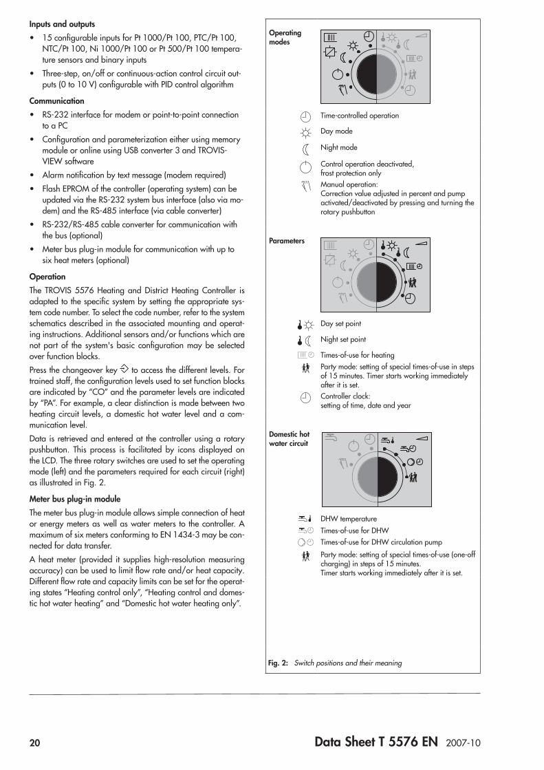
Operating modes
Time-controlled operation
Day mode
Night mode
Control operation deactivated, frost protection onlyManual operation: Correction value adjusted in percent and pump activated/deactivated by pressing and turning the rotary pushbutton
Parameters
Day set point
Night set point
Times-of-use for heatingParty mode: setting of special times-of-use in steps of 15 minutes. Timer starts working immediately after it is set.Controller clock: setting of time, date and year
Domestic hot water circuit
DHW temperatureTimes-of-use for DHWTimes-of-use for DHW circulation pumpParty mode: setting of special times-of-use (one-off charging) in steps of 15 minutes. Timer starts working immediately after it is set.
Fig. 2: Switch positions and their meaning

Data Sheet T 5576 EN 2007-10 21
Technical dataInputs 15 configurable inputs for Pt 1000/Pt 100, PTC/Pt 100, NTC/Pt 100, Ni 1000/Pt 100 or Pt
500/Pt 100 temperature sensors and binary inputs, Input 17 alternatively for flow rate signal of heat meter or signal for external demand by subse-quent controllers,4(0) to 20 mA with 50 Ω parallel resistor or 0 to 10 V (demand: 0 to 10 V correspond to 20 to 120 °C flow temperature)
Outputs* 2 x three-step signal: load max. 250 V AC, 2 A Alternatively on/off signal: load max. 250 V AC, 2 A Alternatively continuous-action output: 0 to 10 V, load > 5 kΩ4 x pump output: load max. 250 V AC, 2 A; all outputs are relay outputs with varistor suppression2 x semiconductor relay: load max. 24 V AC/DC, 50 mA
Interfaces Device bus RS-485 interface for max. 32 bus devices (2-wire system, polarity independent, connection to terminals 29/30 as required or together with the two-wire system bus via 1400-8800 cable converter)
System bus RS-232 Modbus interface for modem or point-to-point connection to a PC (Modbus RTU protocol, data format 8N1, RJ 45 connector socket at the side)Optional: – RS-485 Modbus interface for four-wire bus using a cable converter (1400-7308) – RS-485 Modbus interface for two-wire bus using a cable converter (1400-8800)
Meter bus Optional: Meter bus plug-in module, protocol according to EN 1434-3 (also suitable for retrofitting)
Operating voltage 165 to 250 V, 48 to 62 Hz, max. 5 VAAmbient temperature 0 to 40 °C (operation), –10 °C to 60 °C (storage and transport)Degree of protection IP 40 according to IEC 60529Class of protection II according to VDE 0106Degree of contamination 2 according to VDE 0110Overvoltage category II according to VDE 0110Humidity rating F according to VDE 40040Noise immunity According to EN 61000-6-1Noise emission According to EN 61000-6-3Weight Approx. 0.5 kg
* For systems with two control circuits and five pumps, the second heating circuit can only use the 0 to 10 V output.
Electrical connection and installationThe controller consists of the housing containing the electronics and a separate terminal board for electrical connection. Two wires of max. 1.5 mm² may be connected to each terminal. The sensor connection lines must be installed separately from the lines carrying the power supply. For wall mounting, screw the terminal board to the wall. After wiring the controller, place the controller housing onto the terminal board and fasten it with two screws. Two fastening elements for panel mounting are included.
Dimensions in mm
Panel cut-out:138x92
98
81144
10
22 Data Sheet T 5576 EN 2007-10
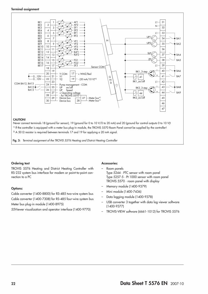
Terminal assignment
BA12BA13
UP on/offUP Speed
Pump management - COM
Device bus Device bus
COM BA12, BA13
Y COMY1Y2
0...10V0...10V
16
18
20
22
15
17
19
21
2324
26
28
30
17
19
25
27
+ WMZ/Bed
Sensor COM
2928
27
+ Operating voltage- for TROVIS 5570*1
- (20 mA/10 V)*2
Meter bus*1 Meter bus*1
2
4
6
8
1
3
5
7
910
12
14
11
13
L1
L1_
+
_
+
L1
N
N
GND
L1UP1
UP2
SLP
ZP
RK1_3-step
RK2_3-step
RK1_on/off
RK2_on/off
AF1AF2SF1SF2RF1RF2
VF1VF2VF3VF4RüF1RüF2
FG1FG2SF3
BE1BE2BE3BE4BE5BE6BE7BE8BE9BE10BE11BE12BE13BE14BE15BE16BE17
38
39
40
4141
44
42
43
44
45
46
47
31
32
33
34
35
36
37
BA1
BA2
BA4
BA5
BA6
BA7
BA8
BA9
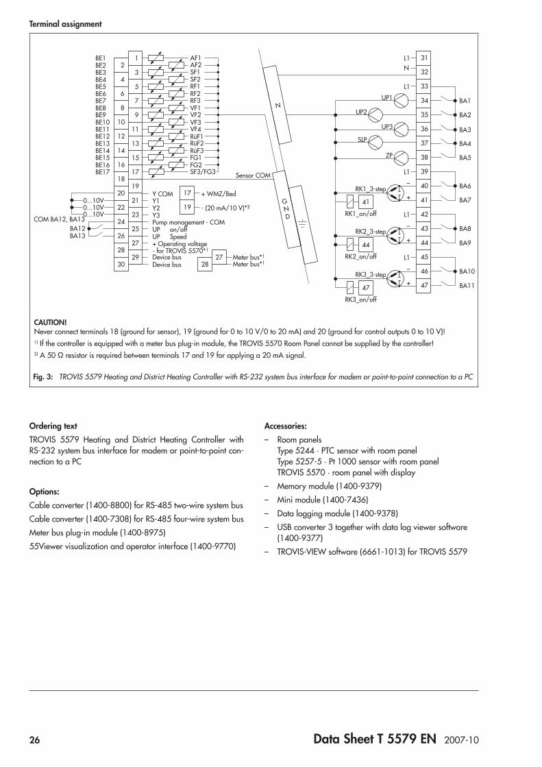
CAUTION! Never connect terminals 18 (ground for sensor), 19 (ground for 0 to 10 V/0 to 20 mA) and 20 (ground for control outputs 0 to 10 V)!1) If the controller is equipped with a meter bus plug-in module, the TROVIS 5570 Room Panel cannot be supplied by the controller!2) A 50 Ω resistor is required between terminals 17 and 19 for applying a 20 mA signal.
Fig. 3: Terminal assignment of the TROVIS 5576 Heating and District Heating Controller
Ordering textTROVIS 5576 Heating and District Heating Controller with RS-232 system bus interface for modem or point-to-point con-nection to a PC
Options:Cable converter (1400-8800) for RS-485 two-wire system busCable converter (1400-7308) for RS-485 four-wire system busMeter bus plug-in module (1400-8975)55Viewer visualization and operator interface (1400-9770)
Accessories: – Room panels
Type 5244 · PTC sensor with room panel Type 5257-5 · Pt 1000 sensor with room panel TROVIS 5570 · room panel with display
– Memory module (1400-9379) – Mini module (1400-7436) – Data logging module (1400-9378) – USB converter 3 together with data log viewer software
(1400-9377) – TROVIS-VIEW software (6661-1012) for TROVIS 5576

Data Sheet T 5579 EN 2007-10 23
ApplicationControl of max. three control circuits. To control more circuits, several controllers can be linked by a device bus. The controller can communicate with up to six heat meters using the retrofit-table meter bus plug-in module.
Automation System TROVIS 5500Heating and District Heating Controller TROVIS 5579
Fig. 1: TROVIS 5579 Heating and District Heating Controller
The TROVIS 5579 Heating and District Heating Controller is used to control max. three control circuits: – Control of a primary heat exchanger or boiler with max.
two mixing and one non-mixing heating circuit. Control of a DHW heating in the secondary or primary domestic hot water control circuit
– Control of two weather-compensated heating circuits and a DHW heating with three valves in the primary circuit
– Control of three weather-compensated heating circuits with three valves in the primary circuit
Special features • Rotary switches for direct access to the operating modes
and essential parameters of the control circuits • Intuitive data retrieval and input by pressing and turning
the pushbutton • Illuminated display • 365-day clock with max. four time schedules and auto-
matic summer time/winter time changeover; maximum three times-of-use per day (input in steps of 15 minutes)
• Room panels may be connected for each heating circuit: – Convenient room panels for adjustment of the operat-
ing mode, the day and night set points, the times-of-use for heating, the controller clock and party mode. Additional outdoor and room temperature readings. Connection via device bus
– Room panel to override operating mode and rated room temperaturet
• Demand-driven control by set point demand by subse-quent controllers over a device bus or 0 to 10 V signal. The primary circuit controls the maximum flow tempera-ture demanded plus adjustable boost.
• Applications with solar hot water system available • Instantaneous heating systems with water flow sensor con-
figurable • Heating characteristics optionally based on the gradient
or based on four points; variable return flow temperature limitation
• Adaptation: automatic adaptation of the heating charac-teristic (room temperature sensor required)
• Optimization: calculation of the best possible activation and deactivation times for the heating (room temperature sensor required)
• Drying of jointless floors function with adjustable param-eter settings
• Pump management function: speed changeover for a heat-ing circulation pump available
• Data logging function: – Operating data can be saved internally and/or saved
to a data logging module – Data can be displayed in the data log viewer on a PC
®
Electronics from SAMSON
24 Data Sheet T 5579 EN 2007-10
Inputs and outputs • 17 configurable inputs for Pt 1000/Pt 100, PTC/Pt 100,
NTC/Pt 100, Ni 1000/Pt 100 or Pt 500/Pt 100 tempera-ture sensors and binary inputs
• Three-step, on/off or continuous-action control circuit out-puts (0 to 10 V) configurable with PID control algorithm
Communication • RS-232 interface for modem or point-to-point connection
to a PC • Configuration and parameterization either using memory
module or online using USB converter 3 and TROVIS-VIEW software
• Alarm notification by text message (modem required) • Flash EPROM of the controller (operating system) can be
updated via the RS-232 system bus interface (also via mo-dem) and the RS-485 interface (via cable converter)
• RS-232/RS-485 cable converter for communication with the bus (optional)
• Meter bus plug-in module for communication with up to six heat meters (optional)
OperationThe TROVIS 5579 Heating and District Heating Controller is adapted to the specific system by setting the appropriate sys-tem code number. To select the code number, refer to the system schematics described in the associated mounting and operat-ing instructions. Additional sensors and/or functions which are not part of the system's basic configuration may be selected over function blocks.Press the changeover key to access the different levels. For trained staff, the configuration levels used to set function blocks are indicated by “CO” and the parameter levels are indicated by “PA”. For example, a clear distinction is made between three heating circuit levels, a domestic hot water level and a com-munication level.Data is retrieved and entered at the controller using a rotary pushbutton. This process is facilitated by icons displayed on the LCD. The three rotary switches are used to set the operating mode (left) and the parameters required for each circuit (right) as illustrated in Fig. 2.
Meter bus plug-in moduleThe meter bus plug-in module allows simple connection of heat or energy meters as well as water meters to the controller. A maximum of six meters conforming to EN 1434-3 may be con-nected for data transfer.A heat meter (provided it supplies high-resolution measuring accuracy) can be used to limit flow rate and/or heat capacity. Different flow rate and capacity limits can be set for the operat-ing states “Heating control only”, “Heating control and domes-tic hot water heating” and “Domestic hot water heating only”.
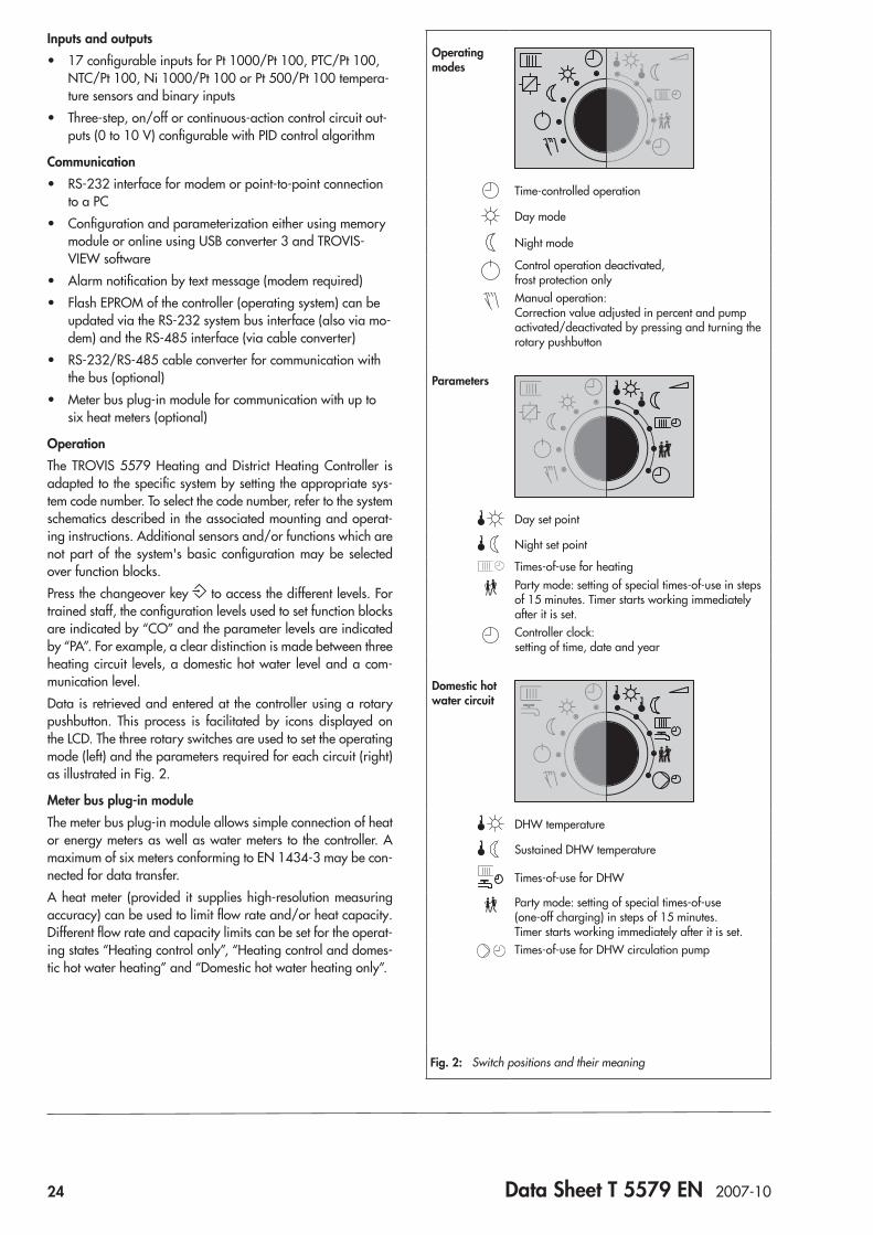
Operating modes
Time-controlled operation
Day mode
Night mode
Control operation deactivated, frost protection onlyManual operation: Correction value adjusted in percent and pump activated/deactivated by pressing and turning the rotary pushbutton
Parameters
Day set point
Night set point
Times-of-use for heatingParty mode: setting of special times-of-use in steps of 15 minutes. Timer starts working immediately after it is set.Controller clock: setting of time, date and year
Domestic hot water circuit
DHW temperature
Sustained DHW temperature
Times-of-use for DHW
Party mode: setting of special times-of-use (one-off charging) in steps of 15 minutes. Timer starts working immediately after it is set.Times-of-use for DHW circulation pump
Fig. 2: Switch positions and their meaning
Data Sheet T 5579 EN 2007-10 25
Technical dataInputs 17 configurable inputs for Pt 1000/Pt 100, PTC/Pt 100, NTC/Pt 100, Ni 1000/Pt 100 or Pt
500/Pt 100 temperature sensors and binary inputs, Input 17 alternatively for flow rate signal of heat meter or signal for external demand by subse-quent controllers,4(0) to 20 mA with 50 Ω parallel resistor or 0 to 10 V (demand: 0 to 10 V correspond to 20 to 120 °C flow temperature)
Outputs 3 x three-step signal: load max. 250 V AC, 2 A Alternatively on/off signal: load max. 250 V AC, 2 A Alternatively continuous-action output: 0 to 10 V, load > 5 kΩ5 x pump output: load max. 250 V AC, 2 A; all outputs are relay outputs with varistor suppression2 x semiconductor relay: load max. 24 V AC/DC, 50 mA
Interfaces Device bus RS-485 interface for max. 32 bus devices (2-wire system, polarity independent, connection to terminals 29/30 as required or together with the two-wire system bus via 1400-8800 cable converter)
System bus RS-232 Modbus interface for modem or point-to-point connection to a PC (Modbus RTU protocol, data format 8N1, RJ 45 connector socket at the side)Optional: – RS-485 Modbus interface for four-wire bus using a cable converter (1400-7308) – RS-485 Modbus interface for two-wire bus using a cable converter (1400-8800)
Meter bus Optional: Meter bus plug-in module, protocol according to EN 1434-3 (also suitable for retrofitting)
Operating voltage 165 to 250 V, 48 to 62 Hz, max. 6 VAAmbient temperature 0 to 40 °C (operation), –10 °C to 60 °C (storage and transport)Degree of protection IP 40 according to IEC 60529Class of protection II according to VDE 0106Degree of contamination 2 according to VDE 0110Overvoltage category II according to VDE 0110Humidity rating F according to VDE 40040Noise immunity According to EN 61000-6-1Noise emission According to EN 61000-6-3Weight Approx. 0.5 kg
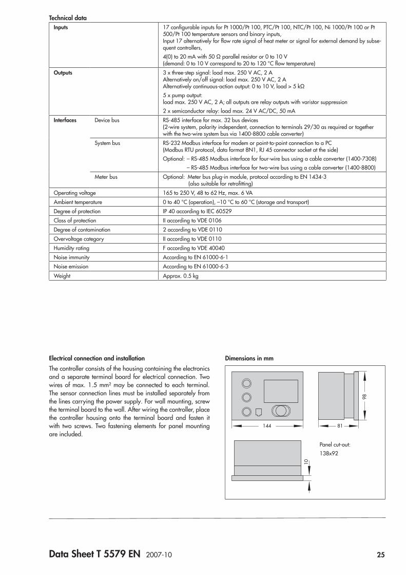
Electrical connection and installationThe controller consists of the housing containing the electronics and a separate terminal board for electrical connection. Two wires of max. 1.5 mm² may be connected to each terminal. The sensor connection lines must be installed separately from the lines carrying the power supply. For wall mounting, screw the terminal board to the wall. After wiring the controller, place the controller housing onto the terminal board and fasten it with two screws. Two fastening elements for panel mounting are included.
Dimensions in mm
Panel cut-out:138x92
98
81144
10
26 Data Sheet T 5579 EN 2007-10
Terminal assignment
BA12BA13
UP on/offUP Speed
Pump management - COM
Device bus Device bus
COM BA12, BA13
Y COMY1Y2Y3
0...10V0...10V0...10V
16
18
20
22
15
17
19
21
2324
26
28
30
17
19
25
27
+ WMZ/Bed
Sensor COM
2928
27
+ Operating voltage- for TROVIS 5570*1
- (20 mA/10 V)*2
Meter bus*1 Meter bus*1
2
4
6
8
1
3
5
7
910
12
14
11
13
L1
L1_
+
_
+
L1
N
L1
UP1
UP3
UP2
SLP
ZP
RK1_3-step
RK2_3-step
RK1_on/off
RK2_on/off
AF1AF2SF1SF2RF1RF2
VF1VF2
RF3
VF3VF4RüF1
RüF3RüF2
FG1FG2SF3/FG3
BE1BE2BE3BE4BE5BE6BE7BE8BE9BE10BE11BE12BE13BE14BE15BE16BE17
38
39
40
4141
44
_
+
L1
RK3_3-step
RK3_on/off
47
42
43
44
45
46
47
31
32
33
34
35
36
37
BA1
BA2
BA3
BA4
BA5
BA6
BA7
BA8
BA9
BA10
BA11
N
GND
CAUTION! Never connect terminals 18 (ground for sensor), 19 (ground for 0 to 10 V/0 to 20 mA) and 20 (ground for control outputs 0 to 10 V)!1) If the controller is equipped with a meter bus plug-in module, the TROVIS 5570 Room Panel cannot be supplied by the controller!2) A 50 Ω resistor is required between terminals 17 and 19 for applying a 20 mA signal.
Fig. 3: TROVIS 5579 Heating and District Heating Controller with RS-232 system bus interface for modem or point-to-point connection to a PC
Ordering textTROVIS 5579 Heating and District Heating Controller with RS-232 system bus interface for modem or point-to-point con-nection to a PC
Options:Cable converter (1400-8800) for RS-485 two-wire system busCable converter (1400-7308) for RS-485 four-wire system busMeter bus plug-in module (1400-8975)55Viewer visualization and operator interface (1400-9770)
Accessories: – Room panels
Type 5244 · PTC sensor with room panel Type 5257-5 · Pt 1000 sensor with room panel TROVIS 5570 · room panel with display
– Memory module (1400-9379) – Mini module (1400-7436) – Data logging module (1400-9378) – USB converter 3 together with data log viewer software
(1400-9377) – TROVIS-VIEW software (6661-1013) for TROVIS 5579

Data Sheet T 5610 EN 2011-11 27
ApplicationThe TROVIS 5610 Heating and District Heating Controller is available in two versions. The compact version can be used to control one control circuit (HC or DHW) and the standard version allows the control of maximum two control circuits (HC and DHW).
Special features • Large-sized touch screen for clear display of technical in-
teractions • A start-up wizard facilitates initial setup • Simple menu navigation • All menus can be selected directly on the start screen
– Information menu with information on sensors, operat-ing modes, system and controller
– Mode menu for setting the operating mode and special times-of-use (day or night mode, stand-by)
– Manual menu for setting the controller outputs – Times-of-use menu for setting the week schedules with
max. three times-of-use per day (in steps of 15 minutes) – Setup menu for changing the set points and deactiva-
tion values, brightness and contrast, language, display calibration and selection of system, configuration and parameters
• Heating characteristics optionally based on the gradient or based on four points; variable return flow temperature limitation
• Adaptation: automatic adaptation of the heating character-istic (room temperature sensor required)
• Optimization: calculation of the best possible activation and deactivation times for the heating (room temperature sensor required)
• Drying of jointless floors function with adjustable param-eter settings
• Simple error detection and diagnostics (including diagnos-tics menu)
• Updatable flash memory in controller (operating system)
Automation System TROVIS 5600Heating and District Heating Controller TROVIS 5610
Fig. 1: TROVIS 5610 Heating and District Heating Controller (start screen)
®
Electronics from SAMSON
28 Data Sheet T 5610 EN 2011-11
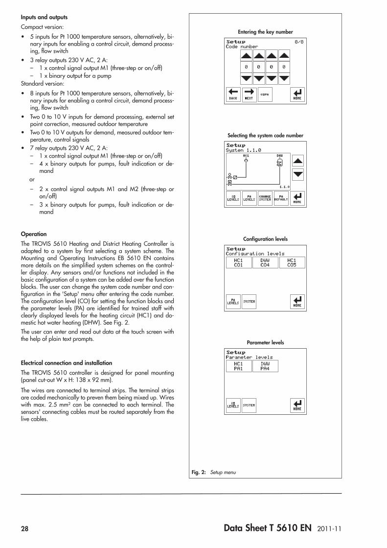
Inputs and outputsCompact version:
• 5 inputs for Pt 1000 temperature sensors, alternatively, bi-nary inputs for enabling a control circuit, demand process-ing, flow switch
• 3 relay outputs 230 V AC, 2 A: – 1 x control signal output M1 (three-step or on/off) – 1 x binary output for a pump
Standard version: • 8 inputs for Pt 1000 temperature sensors, alternatively, bi-
nary inputs for enabling a control circuit, demand process-ing, flow switch
• Two 0 to 10 V inputs for demand processing, external set point correction, measured outdoor temperature
• Two 0 to 10 V outputs for demand, measured outdoor tem-perature, control signals
• 7 relay outputs 230 V AC, 2 A: – 1 x control signal output M1 (three-step or on/off) – 4 x binary outputs for pumps, fault indication or de-
mand or
– 2 x control signal outputs M1 and M2 (three-step or on/off)
– 3 x binary outputs for pumps, fault indication or de-mand
OperationThe TROVIS 5610 Heating and District Heating Controller is adapted to a system by first selecting a system scheme. The Mounting and Operating Instructions EB 5610 EN contains more details on the simplified system schemes on the control-ler display. Any sensors and/or functions not included in the basic configuration of a system can be added over the function blocks. The user can change the system code number and con-figuration in the 'Setup' menu after entering the code number. The configuration level (CO) for setting the function blocks and the parameter levels (PA) are identified for trained staff with clearly displayed levels for the heating circuit (HC1) and do-mestic hot water heating (DHW). See Fig. 2.The user can enter and read out data at the touch screen with the help of plain text prompts.
Electrical connection and installationThe TROVIS 5610 controller is designed for panel mounting (panel cut-out W x H: 138 x 92 mm).
The wires are connected to terminal strips. The terminal strips are coded mechanically to preven them being mixed up. Wires with max. 2.5 mm² can be connected to each terminal. The sensors' connecting cables must be routed separately from the live cables.
Entering the key number
Selecting the system code number
Configuration levels
Parameter levels
Fig. 2: Setup menu
Data Sheet T 5610 EN 2011-11 29
Accessories: – Type 5257-5 Room Panel (see Data Sheet T 5220 EN) – Interface board with RJ12 port for memory pen (order no.
1402-0321) – Memory pen (order no. 1400-7697) – TROVIS-VIEW 6661 software (with database module
5610)
Ordering textHeating and District Heating Controller TROVIS 5610 – Compact version – Standard version
Technical data
Inputs Compact version:
5 inputs for Pt 1000 temperature sensors, alternatively, binary inputs for enabling a control circuit, demand processing, flow switch
Standard version:
8
2
inputs for Pt 1000 temperature sensors, alternatively, binary inputs for enabling a control circuit, demand processing, flow switch0 to 10 V inputs for demand processing, external set point correction, measured outdoor temperature
Outputs Compact version:
3 relay outputs 230 V AC, 2 A:1 x control signal output M1 (three-step or on/off)1 x binary output for a pump
Standard version:
27
0 to 10 V outputs for demand, measured outdoor temperature, control signalsrelay outputs 230 V AC, 2 A:1 x control signal output M1 (three-step or on/off)4 x binary outputs for pumps, fault indication or demandor2 x control signal outputs M1 and M2 (three-step or on/off)3 x binary outputs for pumps, fault indication or demand
Interfaces 1 slot for optional interface boards
Operating voltage 90 to 253 V AC
Power consumption Compact version: max. 2.8 VAStandard version: max. 4.0 VA
Ambient temperature 0 to 50 °C (operation), –20 °C to 70 °C (storage and transport)
Relative humidity 5 to 95 %, no dew formation
Degree of protection Without seal for panel mounting: IP 40 according to IEC 60529With seal for panel mounting: IP 41 according to IEC 60529
Class of protection I according to IEC 61140
Degree of contamination 2 according to IEC 60730
Overvoltage categories III according to IEC 60730
Noise immunity According to IEC 61000-6-1
Noise emission According to IEC 61000-6-3
Dimensions W x H x D Approx. 147 x 96 x 49 mm
Weight Approx. 0.4 kg
30 Data Sheet T 5610 EN 2011-11
Terminal assignment
Pt 1000
1 3
2Type5257-5
NL
– +
S4S2S1 S3 S5
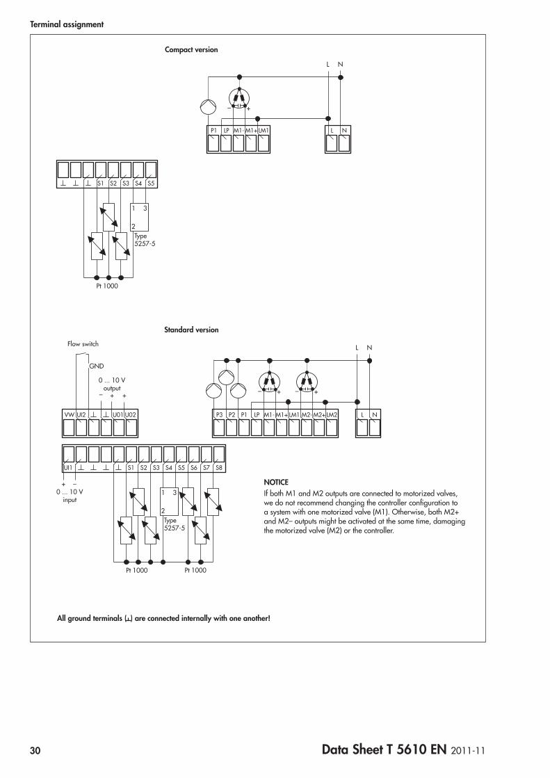
NLM1+ LM1M1-LPP1
Compact version
UI1 S4S2S1 S3 S5 S6 S7 S8
VW UI2 U01 P3 LM2M2+ NLM1+ LM1 M2-M1-LPP1P2U02
0 ... 10 Vinput
Pt 1000
–+1 3
2Type 5257-5
Pt 1000
0 ... 10 Voutput
– + +
NL
– + – +
Standard version
Flow switch
GND
NOTICEIf both M1 and M2 outputs are connected to motorized valves, we do not recommend changing the controller configuration to a system with one motorized valve (M1). Otherwise, both M2+ and M2– outputs might be activated at the same time, damaging the motorized valve (M2) or the controller.
All ground terminals ( ) are connected internally with one another!

Data Sheet T 5571 EN 2012-01 31
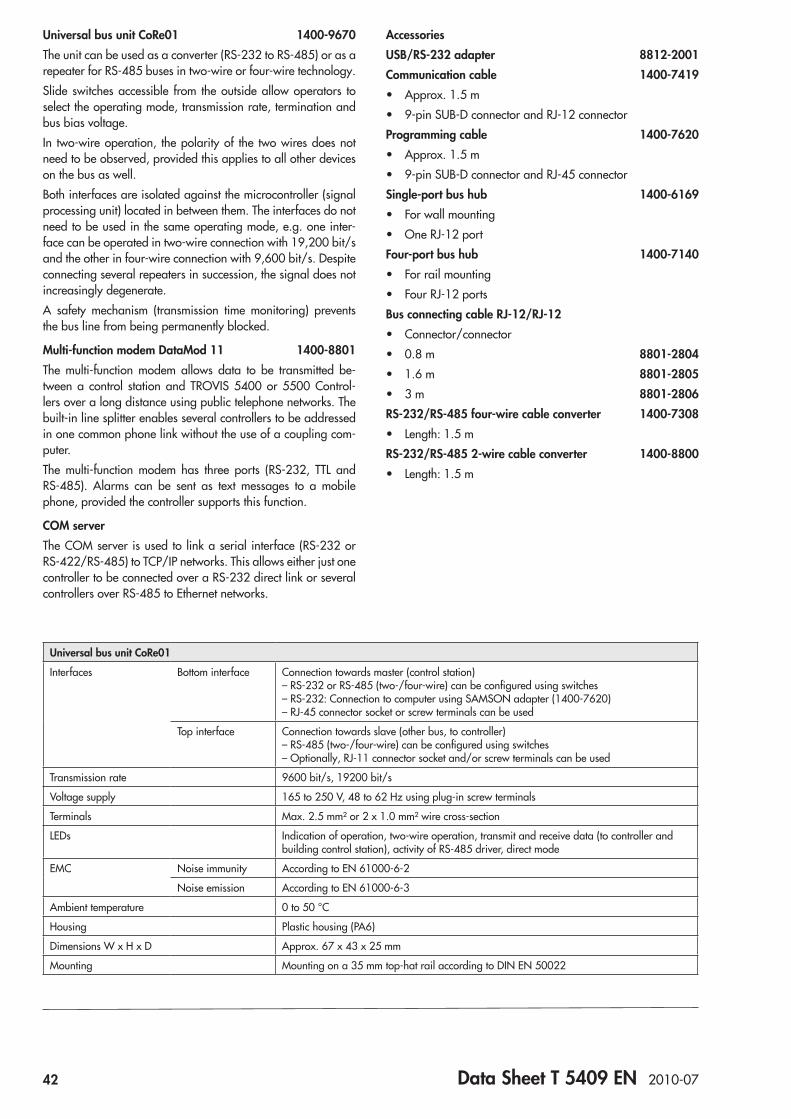
ApplicationFreely programmable plants and applications for HVAC sys-tems. Modbus master interface for communication with other Modbus devices (e.g. TROVIS 5576, 5579). Inputs and outputs extendable using Modbus I/O module (accessories)
Automation System TROVIS 5500TROVIS 5571 Programmable Logic Controller (PLC)
Fig. 1: TROVIS 5571 Programmable Logic Controller (PLC)
Functions • Freely programmable according to IEC 61131 using
ISaGRAF®
• Six programming languages – Ladder Diagram (LD) – Function Block Diagram (FBD) – Structured Text (ST) – Instruction List (IL) – Flow Chart (FC) – Sequential Function Chart (SFC)
• Fully graphic, illuminated display with user-friendly opera-tion and plain text display
• Ready-programmed standard applications: – Boiler control (Kes71) – Ventilation control (Luft71) – Heat exchanger sequence control (WT71)
• Ready-programmed default functions/function modules (see ISaGRAF® documentation)
• Over 50 special functions/function modules for extensive program generation in HVAC applications – Boiler plants – Heat exchanger sequence control – Ventilation systems – Hot water generation – Heating circuits etc.
• Simple operation in various levels – Operating level:
Application from ISaGRAF® (user configurable) – Information level:
Analog inputs, binary inputs, analog outputs, binary outputs and meter bus
– Setting level: Date/time levels, Modbus slave, Modbus master, me-ter bus and universal input type
• Individually configurable universal inputs
• Sensor calibration for each sensor input • Binary inputs can be added to the error status register • Modbus communication over Modbus master function and
Modbus slave function • Modbus slave connection, also over modem (RS-232) • Alarm notification by fax or text message • Meter bus communication with a maximum of three meters • Flash memory (operating system can be updated over
RS-232)
®
Electronics from SAMSON
32 Data Sheet T 5571 EN 2012-01
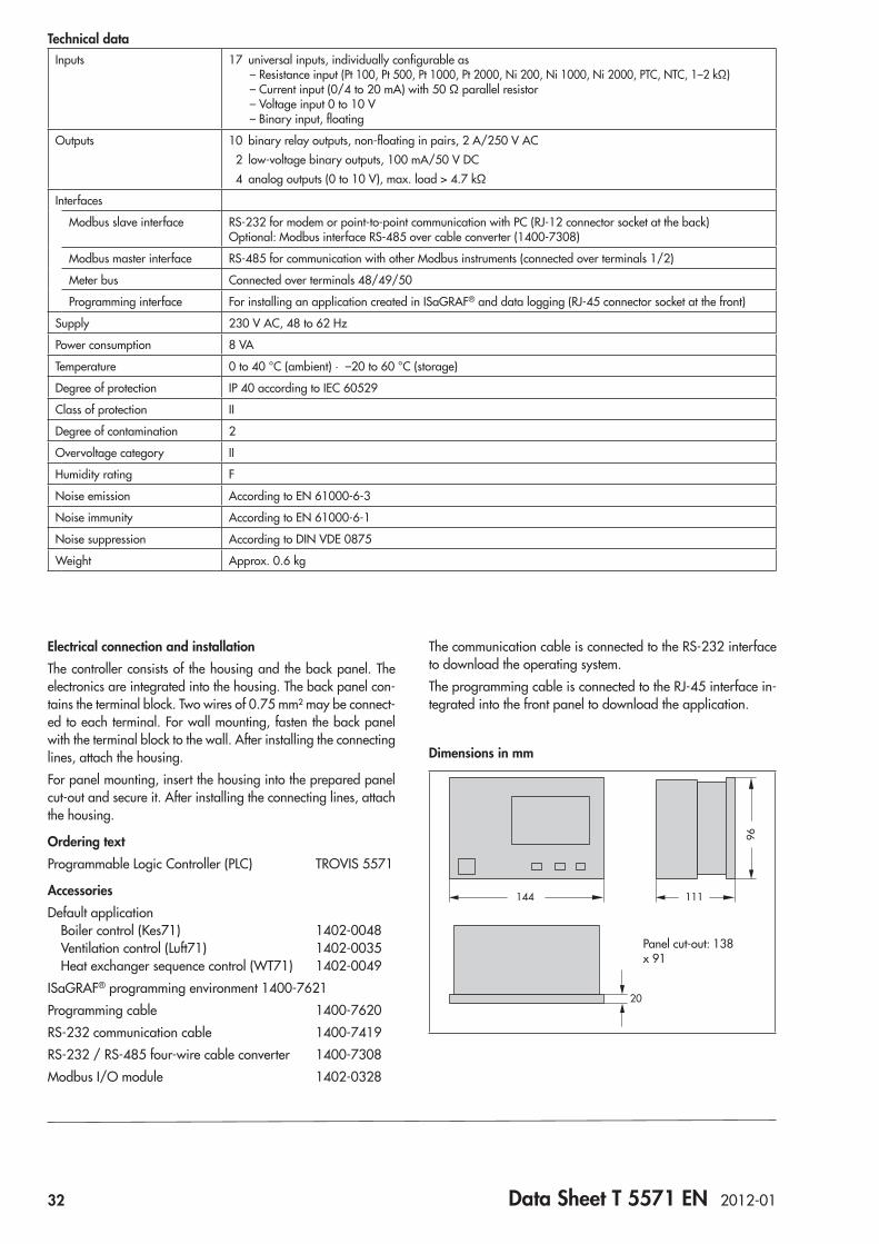
Technical dataInputs 17 universal inputs, individually configurable as
– Resistance input (Pt 100, Pt 500, Pt 1000, Pt 2000, Ni 200, Ni 1000, Ni 2000, PTC, NTC, 1–2 kΩ) – Current input (0/4 to 20 mA) with 50 Ω parallel resistor – Voltage input 0 to 10 V – Binary input, floating
Outputs 10 binary relay outputs, non-floating in pairs, 2 A/250 V AC 2 low-voltage binary outputs, 100 mA/50 V DC 4 analog outputs (0 to 10 V), max. load > 4.7 kΩ
Interfaces
Modbus slave interface RS-232 for modem or point-to-point communication with PC (RJ-12 connector socket at the back) Optional: Modbus interface RS-485 over cable converter (1400-7308)
Modbus master interface RS-485 for communication with other Modbus instruments (connected over terminals 1/2)
Meter bus Connected over terminals 48/49/50
Programming interface For installing an application created in ISaGRAF® and data logging (RJ-45 connector socket at the front)
Supply 230 V AC, 48 to 62 Hz
Power consumption 8 VA
Temperature 0 to 40 °C (ambient) · –20 to 60 °C (storage)
Degree of protection IP 40 according to IEC 60529
Class of protection II
Degree of contamination 2
Overvoltage category II
Humidity rating F
Noise emission According to EN 61000-6-3
Noise immunity According to EN 61000-6-1
Noise suppression According to DIN VDE 0875
Weight Approx. 0.6 kg
Electrical connection and installationThe controller consists of the housing and the back panel. The electronics are integrated into the housing. The back panel con-tains the terminal block. Two wires of 0.75 mm² may be connect-ed to each terminal. For wall mounting, fasten the back panel with the terminal block to the wall. After installing the connecting lines, attach the housing.For panel mounting, insert the housing into the prepared panel cut-out and secure it. After installing the connecting lines, attach the housing.
Ordering textProgrammable Logic Controller (PLC) TROVIS 5571
AccessoriesDefault application Boiler control (Kes71) 1402-0048 Ventilation control (Luft71) 1402-0035 Heat exchanger sequence control (WT71) 1402-0049ISaGRAF® programming environment 1400-7621Programming cable 1400-7620RS-232 communication cable 1400-7419RS-232 / RS-485 four-wire cable converter 1400-7308Modbus I/O module 1402-0328
The communication cable is connected to the RS-232 interface to download the operating system.The programming cable is connected to the RJ-45 interface in-tegrated into the front panel to download the application.
Dimensions in mm96
111144
20
Panel cut-out: 138 x 91
Data Sheet T 5571 EN 2012-01 33
3029
2827
2625
2423
2122
2019
1817
1615
1413
1211
109
87
65
4
23
50 49 48
1
31
32
33
34
35
36
37
38
39
40
41
42
43
44
45
BA9
BA8
BA7
L1NUE1UE2UE3UE4UE5UE6UE7UE8UE9UE10UE11UE12UE13UE14UE15UE16UE170...10V COM
Sensor COMAA_GNDAA1 (0...10 V)AA2 (0...10 V)
AA4 (0...10 V)AA3 (0...10 V)
BA2BA2
BA1
RS485-ARS485-B
BA6
BA4
BA10
BA12
BA11
BA9
BA8
BA7
BA6
BA4
BA10
BA12
BA1146
47
N
+
BA1
BA5
BA3
BA5
BA3
MODBUS
RS 232
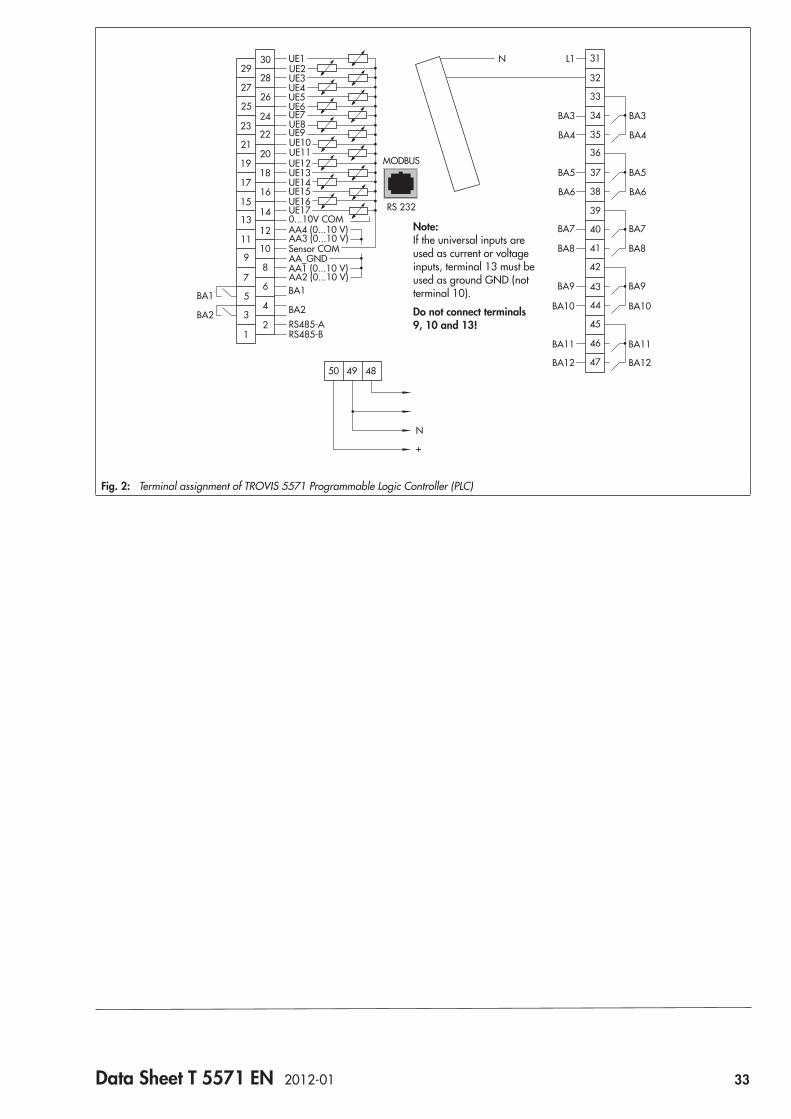
Note: If the universal inputs are used as current or voltage inputs, terminal 13 must be used as ground GND (not terminal 10).
Do not connect terminals 9, 10 and 13!
Fig. 2: Terminal assignment of TROVIS 5571 Programmable Logic Controller (PLC)
34 Data Sheet T 5571 EN 2012-01
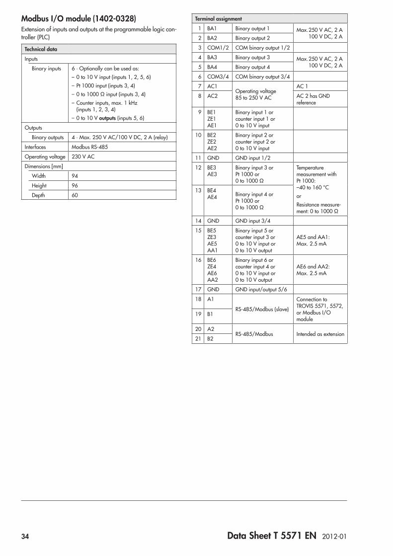
Modbus I/O module (1402-0328)Extension of inputs and outputs at the programmable logic con-troller (PLC)
Technical data
Inputs
Binary inputs 6 · Optionally can be used as:– 0 to 10 V input (inputs 1, 2, 5, 6)– Pt 1000 input (inputs 3, 4)– 0 to 1000 Ω input (inputs 3, 4)– Counter inputs, max. 1 kHz
(inputs 1, 2, 3, 4)– 0 to 10 V outputs (inputs 5, 6)
Outputs
Binary outputs 4 · Max. 250 V AC/100 V DC, 2 A (relay)
Interfaces Modbus RS-485
Operating voltage 230 V AC
Dimensions [mm]
Width 94
Height 96
Depth 60
Terminal assignment
1 BA1 Binary output 1 Max. 250 V AC, 2 A 100 V DC, 2 A 2 BA2 Binary output 2
3 COM1/2 COM binary output 1/2
4 BA3 Binary output 3 Max. 250 V AC, 2 A 100 V DC, 2 A 5 BA4 Binary output 4
6 COM3/4 COM binary output 3/4
7 AC1Operating voltage 85 to 250 V AC
AC 1
8 AC2 AC 2 has GND reference
9 BE1 ZE1 AE1
Binary input 1 or counter input 1 or 0 to 10 V input
10 BE2 ZE2 AE2
Binary input 2 or counter input 2 or 0 to 10 V input
11 GND GND input 1/2
12 BE3 AE3
Binary input 3 or Pt 1000 or 0 to 1000 Ω
Temperature measurement with Pt 1000: –40 to 160 °CorResistance measure-ment: 0 to 1000 Ω
13 BE4 AE4 Binary input 4 or
Pt 1000 or 0 to 1000 Ω
14 GND GND input 3/4
15 BE5 ZE3 AE5 AA1
Binary input 5 or counter input 3 or 0 to 10 V input or 0 to 10 V output
AE5 and AA1: Max. 2.5 mA
16 BE6 ZE4 AE6 AA2
Binary input 6 or counter input 4 or 0 to 10 V input or 0 to 10 V output
AE6 and AA2: Max. 2.5 mA
17 GND GND input/output 5/6
18 A1
RS-485/Modbus (slave)
Connection to TROVIS 5571, 5572, or Modbus I/O module
19 B1
20 A2RS-485/Modbus Intended as extension
21 B2

Data Sheet T 5572 EN 2012-01 35
ApplicationRoom temperature control in a room by heating or cooling
Automation System TROVIS 5500Room Controller TROVIS 5572
Fig. 1: TROVIS 5572 Room Controller (with front cover open)
Special features • Direct access to the operating modes:
Automatic mode – Time-of-use – Outside time-of-use • Room set point and measured room temperature readings
displayed • Three time schedules configurable separately for each day
of the week • Vacation program mode with different set point • Temporary set point correction • Parameterization and configuration directly at the control-
ler or over a station for operation and monitoring • Communication over Modbus interface for integration into
TROVIS 5500 System • Inputs and outputs extendable using Modbus I/O module
(accessories)
OperationThe current set point for times-of-use and outside times-of-use can be temporarily changed over the and keys when the controller cover is closed. The changed set point remains valid until the next time-of-use starts (automatic mode) or until the operating mode is changed, however, eight hours at the maxi-mum.When the controller cover is opened (Fig. 1) additional operat-ing keys are accessible exist for parameterization and configu-ration purposes.The changeover key allows the controller time and the time schedules to be altered.Parameters are selected and changed using the , and keys in the Set points, Control and Communication parameter levels.The operating mode can be changed by pressing the (Auto-matic mode – Time-of-use – Outside time-of-use).
®
Electronics from SAMSON
36 Data Sheet T 5572 EN 2012-01
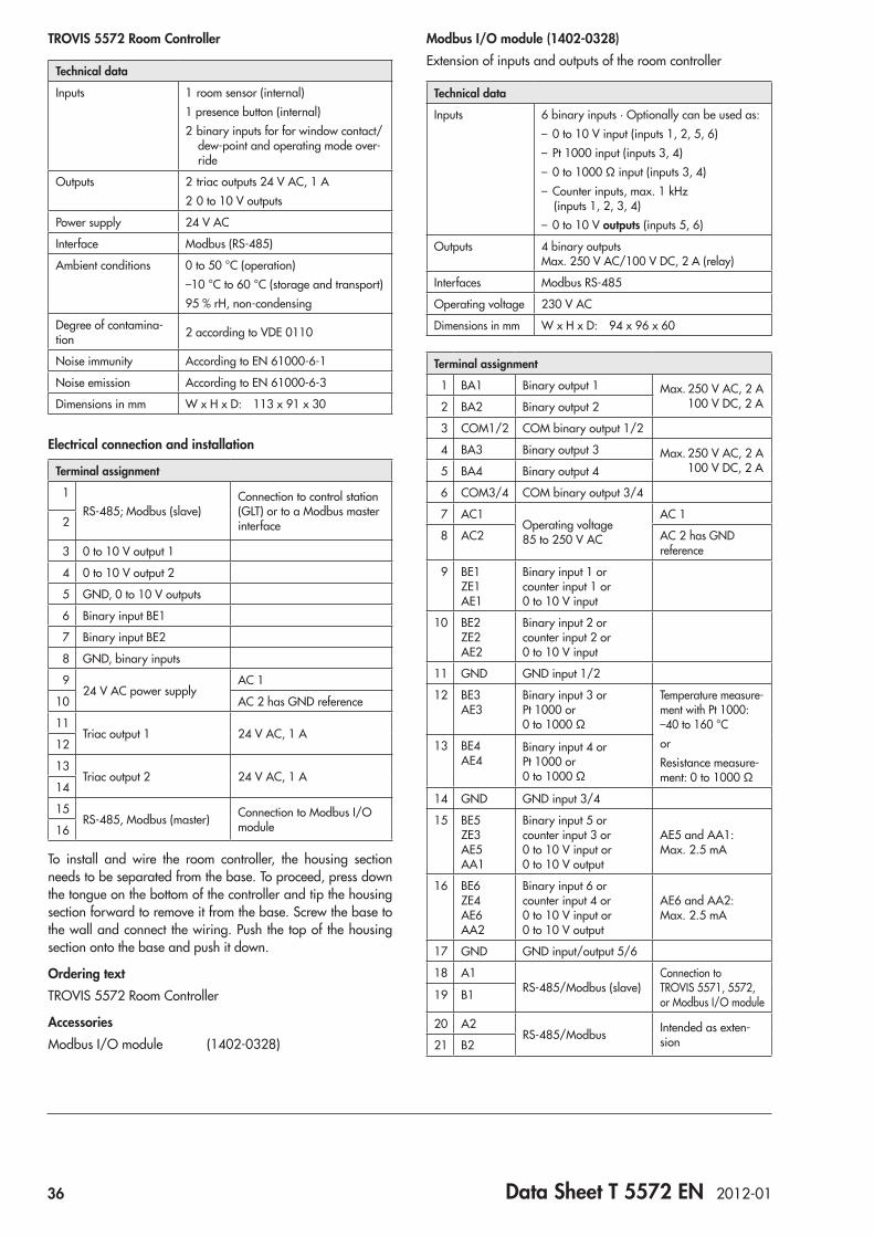
TROVIS 5572 Room Controller
Technical data
Inputs 1 room sensor (internal)1 presence button (internal)2 binary inputs for for window contact/
dew-point and operating mode over-ride
Outputs 2 triac outputs 24 V AC, 1 A2 0 to 10 V outputs
Power supply 24 V AC
Interface Modbus (RS-485)
Ambient conditions 0 to 50 °C (operation)–10 °C to 60 °C (storage and transport)95 % rH, non-condensing
Degree of contamina-tion 2 according to VDE 0110
Noise immunity According to EN 61000-6-1
Noise emission According to EN 61000-6-3
Dimensions in mm W x H x D: 113 x 91 x 30
Electrical connection and installation
Terminal assignment
1RS-485; Modbus (slave)
Connection to control station (GLT) or to a Modbus master interface 2
3 0 to 10 V output 1
4 0 to 10 V output 2
5 GND, 0 to 10 V outputs
6 Binary input BE1
7 Binary input BE2
8 GND, binary inputs
924 V AC power supply
AC 1
10 AC 2 has GND reference
11Triac output 1 24 V AC, 1 A
12
13Triac output 2 24 V AC, 1 A
14
15RS-485, Modbus (master) Connection to Modbus I/O
module16
To install and wire the room controller, the housing section needs to be separated from the base. To proceed, press down the tongue on the bottom of the controller and tip the housing section forward to remove it from the base. Screw the base to the wall and connect the wiring. Push the top of the housing section onto the base and push it down.
Ordering textTROVIS 5572 Room Controller
AccessoriesModbus I/O module (1402-0328)
Modbus I/O module (1402-0328)Extension of inputs and outputs of the room controller
Technical data
Inputs 6 binary inputs · Optionally can be used as:– 0 to 10 V input (inputs 1, 2, 5, 6)– Pt 1000 input (inputs 3, 4)– 0 to 1000 Ω input (inputs 3, 4)– Counter inputs, max. 1 kHz
(inputs 1, 2, 3, 4)– 0 to 10 V outputs (inputs 5, 6)
Outputs 4 binary outputs Max. 250 V AC/100 V DC, 2 A (relay)
Interfaces Modbus RS-485
Operating voltage 230 V AC
Dimensions in mm W x H x D: 94 x 96 x 60
Terminal assignment
1 BA1 Binary output 1 Max. 250 V AC, 2 A 100 V DC, 2 A 2 BA2 Binary output 2
3 COM1/2 COM binary output 1/2
4 BA3 Binary output 3 Max. 250 V AC, 2 A 100 V DC, 2 A 5 BA4 Binary output 4
6 COM3/4 COM binary output 3/4
7 AC1Operating voltage 85 to 250 V AC
AC 1
8 AC2 AC 2 has GND reference
9 BE1 ZE1 AE1
Binary input 1 or counter input 1 or 0 to 10 V input
10 BE2 ZE2 AE2
Binary input 2 or counter input 2 or 0 to 10 V input
11 GND GND input 1/2
12 BE3 AE3
Binary input 3 or Pt 1000 or 0 to 1000 Ω
Temperature measure-ment with Pt 1000: –40 to 160 °CorResistance measure-ment: 0 to 1000 Ω
13 BE4 AE4
Binary input 4 or Pt 1000 or 0 to 1000 Ω
14 GND GND input 3/4
15 BE5 ZE3 AE5 AA1
Binary input 5 or counter input 3 or 0 to 10 V input or 0 to 10 V output
AE5 and AA1: Max. 2.5 mA
16 BE6 ZE4 AE6 AA2
Binary input 6 or counter input 4 or 0 to 10 V input or 0 to 10 V output
AE6 and AA2: Max. 2.5 mA
17 GND GND input/output 5/6
18 A1RS-485/Modbus (slave)
Connection to TROVIS 5571, 5572, or Modbus I/O module19 B1
20 A2RS-485/Modbus Intended as exten-
sion21 B2

Data Sheet T 5570 EN 2002-03 37
ApplicationAccessories for TROVIS 5500 Series Controllers for room tem-perature measurement and remote operation of a heating cir-cuit
Automation System TROVIS 5500Room Panel TROVIS 5570
Fig. 1: TROVIS 5570 Room Panel with open front cover
Special features • Direct access to operating modes • Display of measured room temperature and outdoor tem-
perature (from controller) • Display of up to ten further measured values (max. five
temperature and five dimensionless values) from the as-sociated heating or district heating controller, provided the controller has been set up accordingly
• Main parameters of a heating circuit can be set at the room panel: – Day and night set points – Times-of-use of the heating circuit – Timer for party mode
• Connection via device bus
OperationThree keys , and are visible when the front cover is closed:Using the arrow keys ( and ) users can switch successively between controller time, room temperature in addition to the day set point and night set point, outdoor temperature and cur-rent status of the party mode timer.By pressing users can switch between the operating modes: Day, Night, Stand-by and Automatic.Additional operating keys are accessible when the front cover is opened (Fig. 1). The key is marked inside by .After pressing the changeover key, the controller time, set points for day and night as well as heating times-of-use start-ing with time schedules 1–7 (Mon–Sun) followed by individual days 1 (Mon), 2 (Tue), 3 (Wed), etc. can be changed.A timer for the party mode can be set using the special key.Diverse parameters can be activated and set using the , and keys.
®
Electronics from SAMSON
38 Data Sheet T 5570 EN 2002-03
Technical data
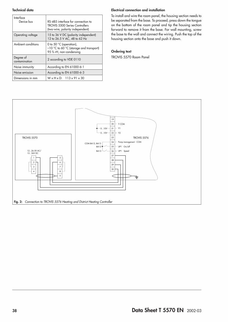
Interface Device bus
RS-485 interface for connection to TROVIS 5500 Series Controllers (two-wire, polarity independent)
Operating voltage 15 to 36 V DC (polarity independent) 12 to 26.5 V AC, 48 to 62 Hz
Ambient conditions 0 to 50 °C (operation), –10 °C to 60 °C (storage and transport) 95 % rH, non-condensing
Degree of contamination 2 according to VDE 0110
Noise immunity According to EN 61000-6-1
Noise emission According to EN 61000-6-3
Dimensions in mm W x H x D: 113 x 91 x 30
Electrical connection and installationTo install and wire the room panel, the housing section needs to be separated from the base. To proceed, press down the tongue on the bottom of the room panel and tip the housing section forward to remove it from the base. For wall mounting, screw the base to the wall and connect the wiring. Push the top of the housing section onto the base and push it down.
Ordering textTROVIS 5570 Room Panel
12...26.5V AC/15...36V DC
BA12
BA13
UP1 On/off
UP1 Speed
Pump management - COMCOM BA12, BA13
Y COM
TROVIS 5576TROVIS 5570
Y1
Y2
0...10V
0...10V
23
22
21
20
19
24
25
26
27
28
29
30
1
2
3
4
5
6
7
8
9
Fig. 2: Connection to TROVIS 5576 Heating and District Heating Controller

Data Sheet T 5409 EN 2010-07 39
Field of application:TROVIS 5400, 5500 and 6400 Automation Systems
Communication components
RS-232-C
RS-485
X1
X2A
5 4 3 2 1B
1
6
5
4
3
2
X1
X2 B5 1 2
3 4
1 2
PE
RJ12
RJ12
RJ12
RJ12
3 4
5 2 1 3 4
A
A B
200Ω
40 Data Sheet T 5409 EN 2010-07
Type/order number CoRe01 1400-9670 1400-9867 DataMod 11
1400-8801 1400-6169 1400-7140 SA 1000 1400-9898
SA 5000 1400-9868
SAC055 1400-9771
COM server1402-0056
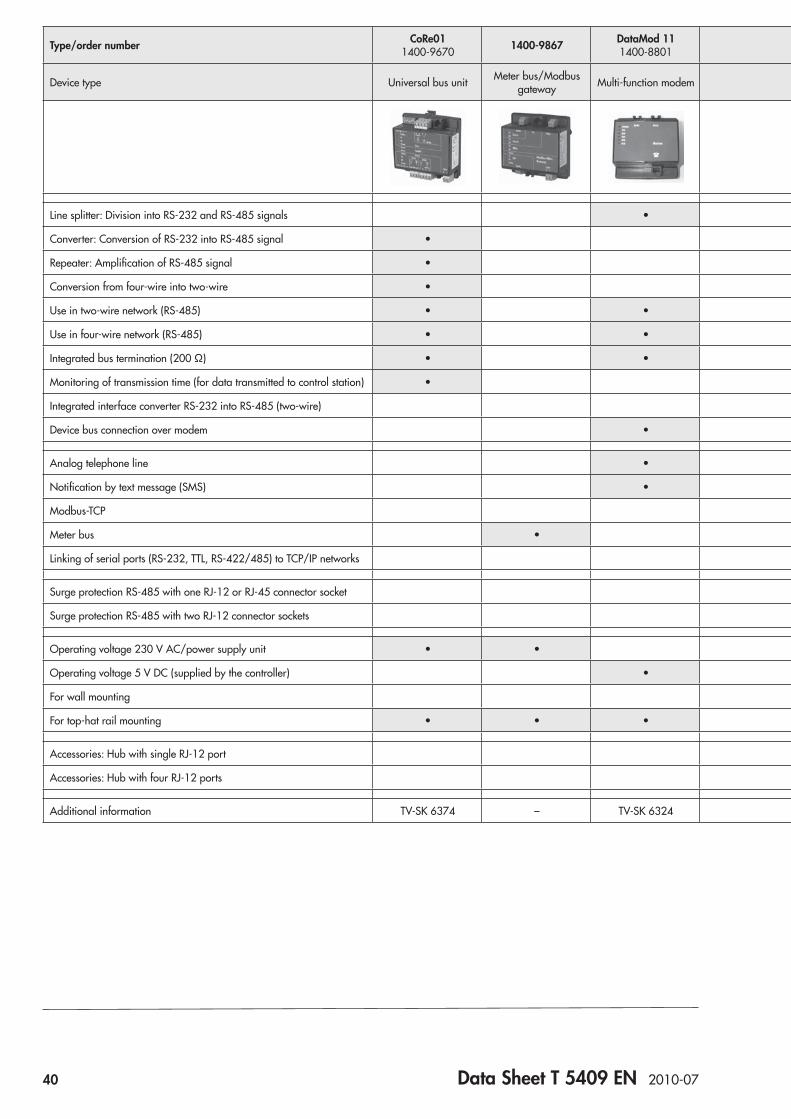
Device type Universal bus unit Meter bus/Modbus gateway Multi-function modem Single-port bus
hub Four-port bus hub Surge protection Modbus/TCP gateway
Line splitter: Division into RS-232 and RS-485 signals •
Converter: Conversion of RS-232 into RS-485 signal •
Repeater: Amplification of RS-485 signal •
Conversion from four-wire into two-wire •
Use in two-wire network (RS-485) • • • • • •
Use in four-wire network (RS-485) • • • •
Integrated bus termination (200 Ω) • • • •
Monitoring of transmission time (for data transmitted to control station) •
Integrated interface converter RS-232 into RS-485 (two-wire) •
Device bus connection over modem •
Analog telephone line •
Notification by text message (SMS) •
Modbus-TCP •
Meter bus •
Linking of serial ports (RS-232, TTL, RS-422/485) to TCP/IP networks • •
Surge protection RS-485 with one RJ-12 or RJ-45 connector socket • •
Surge protection RS-485 with two RJ-12 connector sockets •
Operating voltage 230 V AC/power supply unit • • • •
Operating voltage 5 V DC (supplied by the controller) •
For wall mounting •
For top-hat rail mounting • • • • • • • • •
Accessories: Hub with single RJ-12 port •
Accessories: Hub with four RJ-12 ports •
Additional information TV-SK 6374 – TV-SK 6324 T 5409 EN T 5409 EN T 5409 EN TV-SK 6395 TV-SK 6388 TV-SK 6375 –
Data Sheet T 5409 EN 2010-07 41
Type/order number CoRe01 1400-9670 1400-9867 DataMod 11
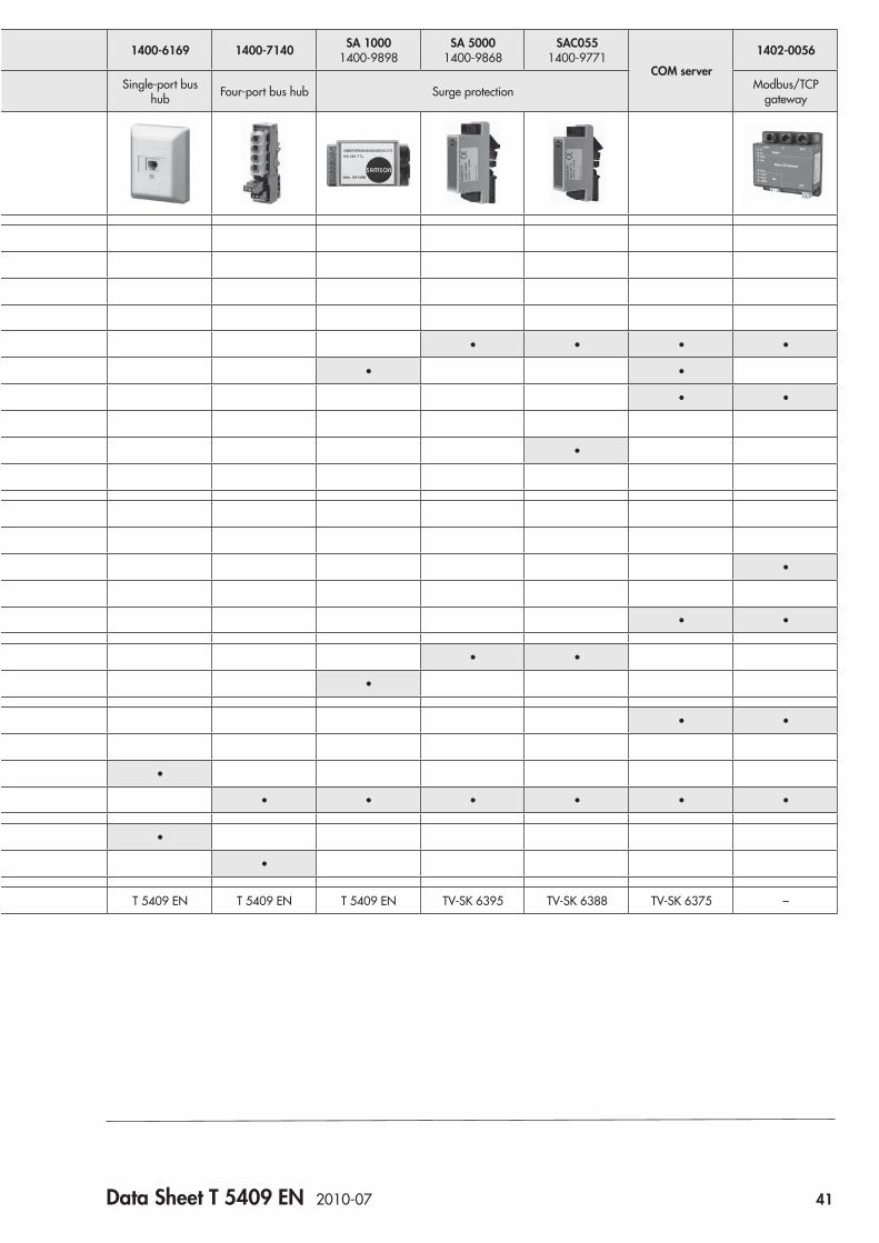
1400-8801 1400-6169 1400-7140 SA 1000 1400-9898
SA 5000 1400-9868
SAC055 1400-9771
COM server1402-0056
Device type Universal bus unit Meter bus/Modbus gateway Multi-function modem Single-port bus
hub Four-port bus hub Surge protection Modbus/TCP gateway
Line splitter: Division into RS-232 and RS-485 signals •
Converter: Conversion of RS-232 into RS-485 signal •
Repeater: Amplification of RS-485 signal •
Conversion from four-wire into two-wire •
Use in two-wire network (RS-485) • • • • • •
Use in four-wire network (RS-485) • • • •
Integrated bus termination (200 Ω) • • • •
Monitoring of transmission time (for data transmitted to control station) •
Integrated interface converter RS-232 into RS-485 (two-wire) •
Device bus connection over modem •
Analog telephone line •
Notification by text message (SMS) •
Modbus-TCP •
Meter bus •
Linking of serial ports (RS-232, TTL, RS-422/485) to TCP/IP networks • •
Surge protection RS-485 with one RJ-12 or RJ-45 connector socket • •
Surge protection RS-485 with two RJ-12 connector sockets •
Operating voltage 230 V AC/power supply unit • • • •
Operating voltage 5 V DC (supplied by the controller) •
For wall mounting •
For top-hat rail mounting • • • • • • • • •
Accessories: Hub with single RJ-12 port •
Accessories: Hub with four RJ-12 ports •
Additional information TV-SK 6374 – TV-SK 6324 T 5409 EN T 5409 EN T 5409 EN TV-SK 6395 TV-SK 6388 TV-SK 6375 –
42 Data Sheet T 5409 EN 2010-07
Universal bus unit CoRe01 1400-9670The unit can be used as a converter (RS-232 to RS-485) or as a repeater for RS-485 buses in two-wire or four-wire technology.Slide switches accessible from the outside allow operators to select the operating mode, transmission rate, termination and bus bias voltage.In two-wire operation, the polarity of the two wires does not need to be observed, provided this applies to all other devices on the bus as well.Both interfaces are isolated against the microcontroller (signal processing unit) located in between them. The interfaces do not need to be used in the same operating mode, e.g. one inter-face can be operated in two-wire connection with 19,200 bit/s and the other in four-wire connection with 9,600 bit/s. Despite connecting several repeaters in succession, the signal does not increasingly degenerate.A safety mechanism (transmission time monitoring) prevents the bus line from being permanently blocked.
Multi-function modem DataMod 11 1400-8801The multi-function modem allows data to be transmitted be-tween a control station and TROVIS 5400 or 5500 Control-lers over a long distance using public telephone networks. The built-in line splitter enables several controllers to be addressed in one common phone link without the use of a coupling com-puter.The multi-function modem has three ports (RS-232, TTL and RS-485). Alarms can be sent as text messages to a mobile phone, provided the controller supports this function.
COM serverThe COM server is used to link a serial interface (RS-232 or RS-422/RS-485) to TCP/IP networks. This allows either just one controller to be connected over a RS-232 direct link or several controllers over RS-485 to Ethernet networks.
AccessoriesUSB/RS-232 adapter 8812-2001Communication cable 1400-7419 • Approx. 1.5 m • 9-pin SUB-D connector and RJ-12 connector
Programming cable 1400-7620 • Approx. 1.5 m • 9-pin SUB-D connector and RJ-45 connector
Single-port bus hub 1400-6169 • For wall mounting • One RJ-12 port
Four-port bus hub 1400-7140 • For rail mounting • Four RJ-12 ports
Bus connecting cable RJ-12/RJ-12 • Connector/connector • 0.8 m 8801-2804 • 1.6 m 8801-2805 • 3 m 8801-2806
RS-232/RS-485 four-wire cable converter 1400-7308 • Length: 1.5 m
RS-232/RS-485 2-wire cable converter 1400-8800 • Length: 1.5 m
Universal bus unit CoRe01
Interfaces Bottom interface Connection towards master (control station) – RS-232 or RS-485 (two-/four-wire) can be configured using switches – RS-232: Connection to computer using SAMSON adapter (1400-7620) – RJ-45 connector socket or screw terminals can be used
Top interface Connection towards slave (other bus, to controller) – RS-485 (two-/four-wire) can be configured using switches – Optionally, RJ-11 connector socket and/or screw terminals can be used
Transmission rate 9600 bit/s, 19200 bit/s
Voltage supply 165 to 250 V, 48 to 62 Hz using plug-in screw terminals
Terminals Max. 2.5 mm² or 2 x 1.0 mm² wire cross-section
LEDs Indication of operation, two-wire operation, transmit and receive data (to controller and building control station), activity of RS-485 driver, direct mode
EMC Noise immunity According to EN 61000-6-2
Noise emission According to EN 61000-6-3
Ambient temperature 0 to 50 °C
Housing Plastic housing (PA6)
Dimensions W x H x D Approx. 67 x 43 x 25 mm
Mounting Mounting on a 35 mm top-hat rail according to DIN EN 50022
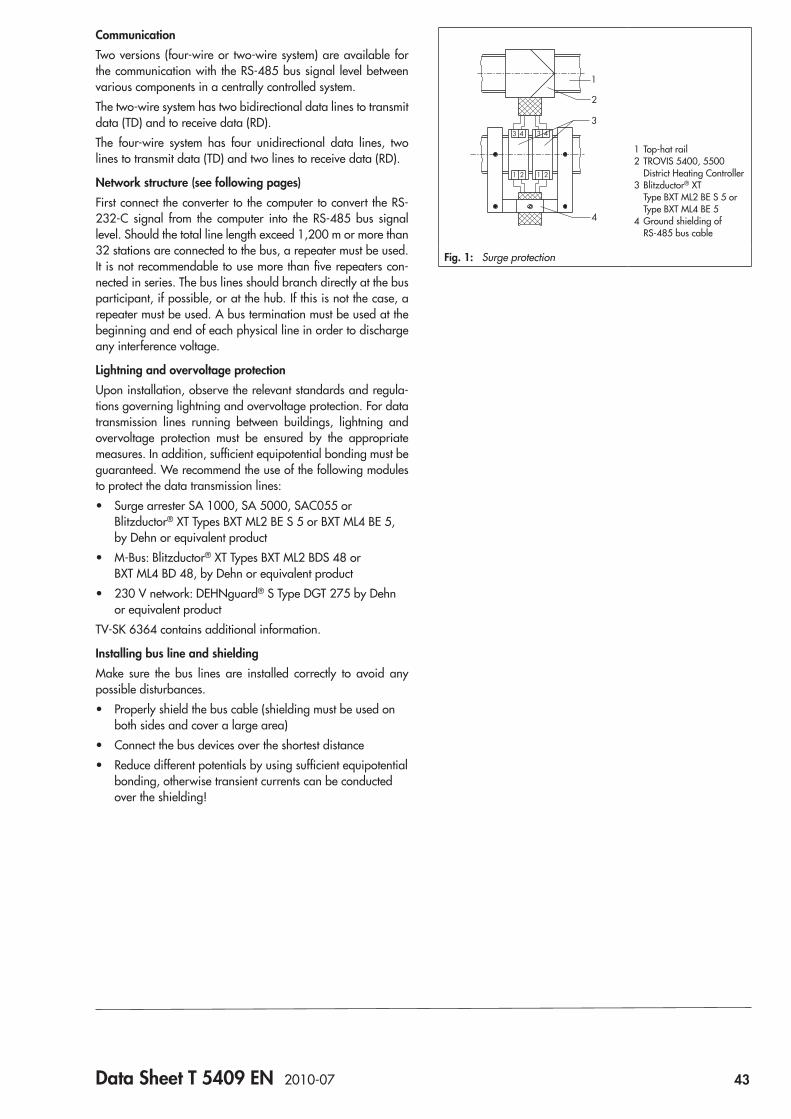
Data Sheet T 5409 EN 2010-07 43
CommunicationTwo versions (four-wire or two-wire system) are available for the communication with the RS-485 bus signal level between various components in a centrally controlled system.The two-wire system has two bidirectional data lines to transmit data (TD) and to receive data (RD).The four-wire system has four unidirectional data lines, two lines to transmit data (TD) and two lines to receive data (RD).
Network structure (see following pages)First connect the converter to the computer to convert the RS-232-C signal from the computer into the RS-485 bus signal level. Should the total line length exceed 1,200 m or more than 32 stations are connected to the bus, a repeater must be used. It is not recommendable to use more than five repeaters con-nected in series. The bus lines should branch directly at the bus participant, if possible, or at the hub. If this is not the case, a repeater must be used. A bus termination must be used at the beginning and end of each physical line in order to discharge any interference voltage.
Lightning and overvoltage protectionUpon installation, observe the relevant standards and regula-tions governing lightning and overvoltage protection. For data transmission lines running between buildings, lightning and overvoltage protection must be ensured by the appropriate measures. In addition, sufficient equipotential bonding must be guaranteed. We recommend the use of the following modules to protect the data transmission lines:
• Surge arrester SA 1000, SA 5000, SAC055 or Blitzductor® XT Types BXT ML2 BE S 5 or BXT ML4 BE 5, by Dehn or equivalent product
• M-Bus: Blitzductor® XT Types BXT ML2 BDS 48 or BXT ML4 BD 48, by Dehn or equivalent product
• 230 V network: DEHNguard® S Type DGT 275 by Dehn or equivalent product
TV-SK 6364 contains additional information.
Installing bus line and shieldingMake sure the bus lines are installed correctly to avoid any possible disturbances.
• Properly shield the bus cable (shielding must be used on both sides and cover a large area)
• Connect the bus devices over the shortest distance • Reduce different potentials by using sufficient equipotential
bonding, otherwise transient currents can be conducted over the shielding!
1
2
3
4
1 2 1 2
3 4 3 4
1 Top-hat rail2 TROVIS 5400, 5500
District Heating Controller3 Blitzductor® XT
Type BXT ML2 BE S 5 or Type BXT ML4 BE 5
4 Ground shielding of RS-485 bus cable
Fig. 1: Surge protection

44 Data Sheet T 5409 EN 2010-07
Bus protocolSAMSON devices belonging to the Series TROVIS 5400, 5500 and TROVIS 6400 communicate using the bus protocol, Modbus RTU.
Modbus protocol description
Specification GOULD MODICON
Protocol name Modbus
Protocol type 584
Protocol format RTU (remote terminal unit)
Protocol principle Master/slave
Max. word length 2 bytes
Max. block length 256 bytes
Block start identification None
Block end identification Min. 3.5 bytes transmission pause
Data integrity check CRC-16
Ranges
Address range 0 to 255
Standard addresses 1 to 247
Special addresses 0 and 248 to 255
Register range 0001 to 9999
Supported function codes for TROVIS 540x and 6400 1, 3, 5, 6, 15, 16
Supported function codes TROVIS 5400, 5500 1, 3, 5, 6
Special function codes 65, 66, 67, 68, 69
Data transmission
Standard format 1 start bit, 8 data bits, 1 stop bit, no parity (8N1)
Transfer rates 150 to 19200 Baud (Standard: 9600 Baud)
Transmission standard RS-485, RS-422, four-wire/two-wire bus
Driver load > 54 Ω
RS-485 line termination 200 Ω between receiver lines
Transmission medium Screened twisted pair (STP, AWG 24) Resistance < 100 Ω/km, capacitance < 100 nF/km
Topology
Bus topology Line, with stubs separated by repeaters
Number of bus devices Max. 32/126 (including repeater or converter) per segment with four-wire/two-wire system
Number of repeaters Max. 5 in series
Stub length (branch) Max. 3 m
Segment length Max. 1200 m
Bus range Max. 7200 m, greater distances on request
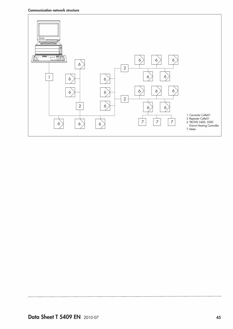
Data Sheet T 5409 EN 2010-07 45
Communication network structure
1
6
6
6
2
6 6
6
6
6
2
2
7 7 7
6 6 6
6 6
6 6 6
6 6
6
1 Converter CoRe012 Repeater CoRe016 TROVIS 5400, 5500
District Heating Controller7 Meter
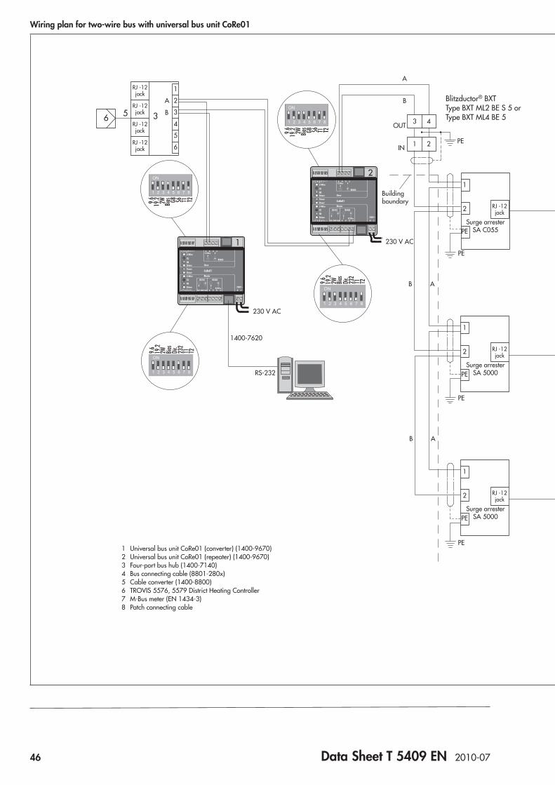
46 Data Sheet T 5409 EN 2010-07
Wiring plan for two-wire bus with universal bus unit CoRe01
T1T2T1T2
T1T2T1T2
T1T2T1T2
T1T2T1T2
T2T1Bias2W 232
Dir.
19.2
9.6
T2T1Bias2W S6GB19.29.6
T2T1Bias2W S6GB
19.29.6
T2T1Bias2W 232
Dir.
19.2
9.6
T2T1Bias2W S6GB
19.29.6
T2T1Bias2W 232
Dir.
19.2
9.6
T2T1Bias2W S6GB
19.29.6
T2T1Bias2W 232
Dir.
19.2
9.6
6 5 3
6
5
6
5
6
5
3
1
2
8
4
4
7
6
4
2
2
4
1
6
5
4
3
2
B
A
1
6
5
4
3
2
B
A
RS-232
1400-7620
Buildingboundary
230 V AC
230 V AC
B A
B A
B
A
3 4
1 2
1
PE
2
PE
PE
PE
Surge arresterSA 5000
1
PE
2
2
1
4
3
PE
Buildingboundary
Buildingboundary
230 V AC
230 V AC
Bus terminationR=200
OUT IN
PE
A B
1
PE
2
Surge arresterSA 2000
PE
OUT
IN
Surge arresterSA C055
Surge arresterSA 5000
1
PE
2
RJ -12jack
RJ -12jack
RJ -12jack
RJ -12jack
RJ -12jack
RJ -12jack
RJ -12jack
RJ -12jack
RJ -12jack
RJ -12jack
RJ -12jack
RJ -12jack
2728
Blitzductor® BXT Type BXT ML2 BE S 5 or Type BXT ML4 BE 5
With meter bus plug-in module (1400-8975) Blitzductor® XT
Type BXT ML2 BDS 48 or Type BXT ML4 BD 48
Branching off stub line outside of the building (towards M-Bus meter)
Branching off stub line outside of the building (towards controller; bus termination at the end of the bus segment)
1 Universal bus unit CoRe01 (converter) (1400-9670)2 Universal bus unit CoRe01 (repeater) (1400-9670)3 Four-port bus hub (1400-7140)4 Bus connecting cable (8801-280x)5 Cable converter (1400-8800)6 TROVIS 5576, 5579 District Heating Controller7 M-Bus meter (EN 1434-3)8 Patch connecting cable
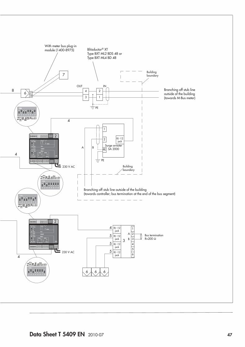
Data Sheet T 5409 EN 2010-07 47
Wiring plan for two-wire bus with universal bus unit CoRe01
T1T2T1T2
T1T2T1T2
T1T2T1T2
T1T2T1T2
T2T1Bias2W 232
Dir.
19.2
9.6
T2T1Bias2W S6GB19.29.6
T2T1Bias2W S6GB
19.29.6
T2T1Bias2W 232
Dir.
19.2
9.6
T2T1Bias2W S6GB
19.29.6
T2T1Bias2W 232
Dir.
19.2
9.6
T2T1Bias2W S6GB
19.29.6
T2T1Bias2W 232
Dir.
19.2
9.6
6 5 3
6
5
6
5
6
5
3
1
2
8
4
4
7
6
4
2
2
4
1
6
5
4
3
2
B
A
1
6
5
4
3
2
B
A
RS-232
1400-7620
Buildingboundary
230 V AC
230 V AC
B A
B A
B
A
3 4
1 2
1
PE
2
PE
PE
PE
Surge arresterSA 5000
1
PE
2
2
1
4
3
PE
Buildingboundary
Buildingboundary
230 V AC
230 V AC
Bus terminationR=200
OUT IN
PE
A B
1
PE
2
Surge arresterSA 2000
PE
OUT
IN
Surge arresterSA C055
Surge arresterSA 5000
1
PE
2
RJ -12jack
RJ -12jack
RJ -12jack
RJ -12jack
RJ -12jack
RJ -12jack
RJ -12jack
RJ -12jack
RJ -12jack
RJ -12jack
RJ -12jack
RJ -12jack
2728
Blitzductor® BXT Type BXT ML2 BE S 5 or Type BXT ML4 BE 5
With meter bus plug-in module (1400-8975) Blitzductor® XT
Type BXT ML2 BDS 48 or Type BXT ML4 BD 48
Branching off stub line outside of the building (towards M-Bus meter)
Branching off stub line outside of the building (towards controller; bus termination at the end of the bus segment)
1 Universal bus unit CoRe01 (converter) (1400-9670)2 Universal bus unit CoRe01 (repeater) (1400-9670)3 Four-port bus hub (1400-7140)4 Bus connecting cable (8801-280x)5 Cable converter (1400-8800)6 TROVIS 5576, 5579 District Heating Controller7 M-Bus meter (EN 1434-3)8 Patch connecting cable
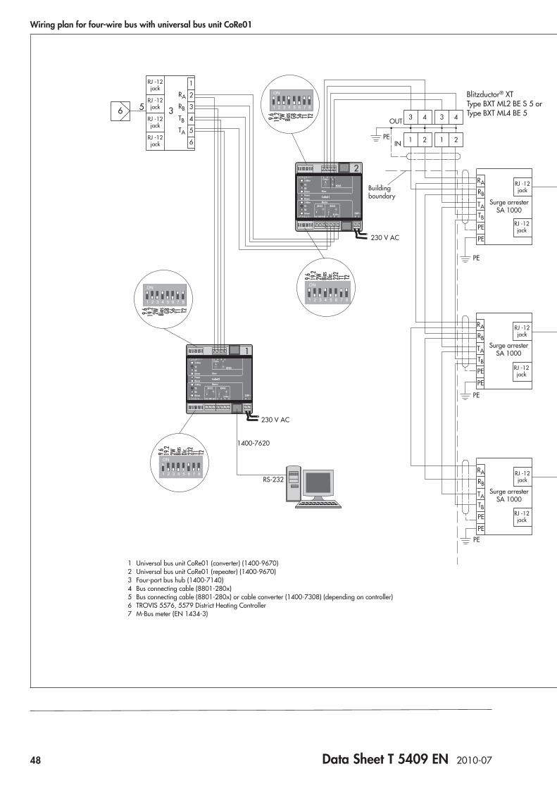
48 Data Sheet T 5409 EN 2010-07
Wiring plan for four-wire bus with universal bus unit CoRe01
T1T2T1T2
T1T2T1T2
T1T2T1T2
T1T2T1T2
2728
RJ -12jack
RJ -12jack
RJ -12jack
RJ -12jack
RJ -12jack
RJ -12jack
RJ -12jack
RJ -12jack
RJ -12jack
RJ -12jack
RJ -12jack
RJ -12jack
RJ -12jack
RJ -12jack
RJ -12jack
RJ -12jack
RB
TA
RA
TB
RA
TATB
RB
RA
TATB
RB
RA
TATB
RB
RA
TATB
RB
RB
TA
RA
TB
1
6
5
4
3
2
RS-232
1400-7620
230 V AC
Buildingboundary
Buildingboundary
Buildingboundary
Surge arresterSA 1000
230 V AC
Surge arresterSA 1000
PE
OUT
IN
Surge arresterSA 1000
PE
PE
PE
3 4
1 2
3 4
1 2
2
1
4
3
PE
230 V AC
230 V AC
OUT IN
PE
Surge arresterSA 1000
PE
PE
PE
PE
PE
PE
PE
PE
1
6
5
4
3
2
Bus terminationR=200
T2T1Bias2W S6GB19.29.6
T2T1Bias2W 232
Dir.
19.2
9.6
T2T1Bias2W S6GB19.29.6
T2T1Bias2W 232
Dir.
19.2
9.6
T2T1Bias2W 232
Dir.
19.2
9.6
T2T1Bias2W S6GB19.29.6
T2T1Bias2W 232
Dir.
19.2
9.6
T2T1Bias2W S6GB19.29.6
5
56 3
4
7
6
1
2
4
4
2
2
6
5
6
5
6
5
3
4
Blitzductor® XT Type BXT ML2 BE S 5 or Type BXT ML4 BE 5 With meter bus plug-in
module (1400-8975)
Blitzductor® XT Type BXT ML2 BDS 48 or Type BXT ML4 BD 48
Branching off stub line out-side of the building (towards M-Bus meter)
Branching off stub line outside of the building (towards controller; bus termination at the end of the bus seg-ment)
1 Universal bus unit CoRe01 (converter) (1400-9670)2 Universal bus unit CoRe01 (repeater) (1400-9670)3 Four-port bus hub (1400-7140)4 Bus connecting cable (8801-280x)5 Bus connecting cable (8801-280x) or cable converter (1400-7308) (depending on controller)6 TROVIS 5576, 5579 District Heating Controller7 M-Bus meter (EN 1434-3)
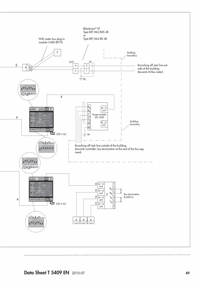
Data Sheet T 5409 EN 2010-07 49
Wiring plan for four-wire bus with universal bus unit CoRe01
T1T2T1T2
T1T2T1T2
T1T2T1T2
T1T2T1T2
2728
RJ -12jack
RJ -12jack
RJ -12jack
RJ -12jack
RJ -12jack
RJ -12jack
RJ -12jack
RJ -12jack
RJ -12jack
RJ -12jack
RJ -12jack
RJ -12jack
RJ -12jack
RJ -12jack
RJ -12jack
RJ -12jack
RB
TA
RA
TB
RA
TATB
RB
RA
TATB
RB
RA
TATB
RB
RA
TATB
RB
RB
TA
RA
TB
1
6
5
4
3
2
RS-232
1400-7620
230 V AC
Buildingboundary
Buildingboundary
Buildingboundary
Surge arresterSA 1000
230 V AC
Surge arresterSA 1000
PE
OUT
IN
Surge arresterSA 1000
PE
PE
PE
3 4
1 2
3 4
1 2
2
1
4
3
PE
230 V AC
230 V AC
OUT IN
PE
Surge arresterSA 1000
PE
PE
PE
PE
PE
PE
PE
PE
1
6
5
4
3
2
Bus terminationR=200
T2T1Bias2W S6GB19.29.6
T2T1Bias2W 232
Dir.
19.2
9.6
T2T1Bias2W S6GB19.29.6
T2T1Bias2W 232
Dir.
19.2
9.6
T2T1Bias2W 232
Dir.
19.2
9.6
T2T1Bias2W S6GB19.29.6
T2T1Bias2W 232
Dir.
19.2
9.6
T2T1Bias2W S6GB19.29.6
5
56 3
4
7
6
1
2
4
4
2
2
6
5
6
5
6
5
3
4
Blitzductor® XT Type BXT ML2 BE S 5 or Type BXT ML4 BE 5 With meter bus plug-in
module (1400-8975)
Blitzductor® XT Type BXT ML2 BDS 48 or Type BXT ML4 BD 48
Branching off stub line out-side of the building (towards M-Bus meter)
Branching off stub line outside of the building (towards controller; bus termination at the end of the bus seg-ment)
1 Universal bus unit CoRe01 (converter) (1400-9670)2 Universal bus unit CoRe01 (repeater) (1400-9670)3 Four-port bus hub (1400-7140)4 Bus connecting cable (8801-280x)5 Bus connecting cable (8801-280x) or cable converter (1400-7308) (depending on controller)6 TROVIS 5576, 5579 District Heating Controller7 M-Bus meter (EN 1434-3)


Data Sheet T 5488 EN 2007-11 51
Fig. 1: TROVIS 5488 Meter Bus Gateway
The meter bus plug-in module enables simple connection of heat or energy meters as well as water meters to the meter bus gateway. A maximum of 32 meters conforming to EN 1434-3 may be connected for data transfer. Additionally, the meter bus gateway is equipped with 16 inputs for pulse counting, e.g. from heat or water meters.The meter bus gateway converts the read or recorded data into Modbus data. This allows the meters to be integrated into a control system. Modern control systems, e.g. the TROVIS build-ing control system from SAMSON, visualize and log the meter data, e.g. for billing purposes.
VersionsTROVIS 5488 Meter Bus GatewaySee Table 1: Technical data for specifications.
Ordering textTROVIS 5488 Meter Bus Gateway
Accessories:RS-232/RS-485 four-wire cable converter, 1.5 m 1400-7308Memory module 1400-9379RS-232 communication cable (software update) 1400-7419Modem cable 1400-7139
ApplicationUsed in HVAC networks to integrate M-Bus meters and pulse counters into a control system
Automation System TROVIS 5400Meter Bus Gateway TROVIS 5488
®
Electronics from SAMSON
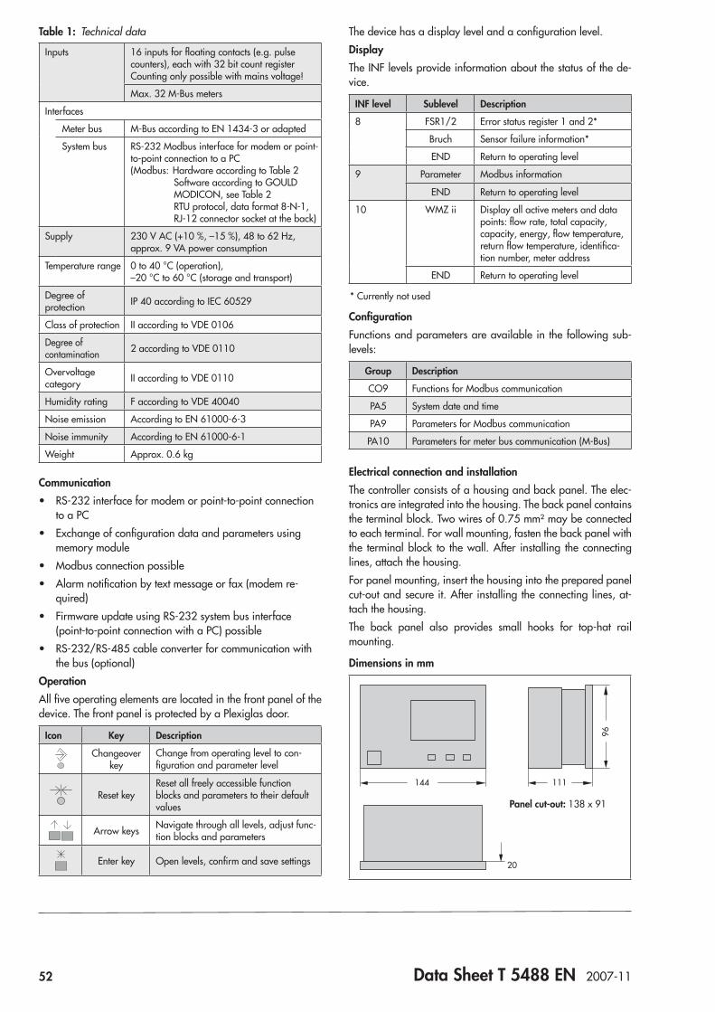
52 Data Sheet T 5488 EN 2007-11
Table 1: Technical data
Inputs 16 inputs for floating contacts (e.g. pulse counters), each with 32 bit count register Counting only possible with mains voltage!
Max. 32 M-Bus meters
Interfaces
Meter bus M-Bus according to EN 1434-3 or adapted
System bus RS-232 Modbus interface for modem or point-to-point connection to a PC(Modbus: Hardware according to Table 2
Software according to GOULD MODICON, see Table 2 RTU protocol, data format 8-N-1, RJ-12 connector socket at the back)
Supply 230 V AC (+10 %, –15 %), 48 to 62 Hz, approx. 9 VA power consumption
Temperature range 0 to 40 °C (operation), –20 °C to 60 °C (storage and transport)
Degree of protection IP 40 according to IEC 60529
Class of protection II according to VDE 0106
Degree of contamination 2 according to VDE 0110
Overvoltage category II according to VDE 0110
Humidity rating F according to VDE 40040
Noise emission According to EN 61000-6-3
Noise immunity According to EN 61000-6-1
Weight Approx. 0.6 kg
Communication • RS-232 interface for modem or point-to-point connection
to a PC • Exchange of configuration data and parameters using
memory module • Modbus connection possible • Alarm notification by text message or fax (modem re-
quired) • Firmware update using RS-232 system bus interface
(point-to-point connection with a PC) possible • RS-232/RS-485 cable converter for communication with
the bus (optional)OperationAll five operating elements are located in the front panel of the device. The front panel is protected by a Plexiglas door.
Icon Key Description
Changeover key
Change from operating level to con-figuration and parameter level
Reset keyReset all freely accessible function blocks and parameters to their default values
Arrow keys Navigate through all levels, adjust func-tion blocks and parameters
Enter key Open levels, confirm and save settings
The device has a display level and a configuration level.DisplayThe INF levels provide information about the status of the de-vice.
INF level Sublevel Description
8 FSR1/2 Error status register 1 and 2*
Bruch Sensor failure information*
END Return to operating level
9 Parameter Modbus information
END Return to operating level
10 WMZ ii Display all active meters and data points: flow rate, total capacity, capacity, energy, flow temperature, return flow temperature, identifica-tion number, meter address
END Return to operating level
* Currently not used
ConfigurationFunctions and parameters are available in the following sub-levels:
Group Description
CO9 Functions for Modbus communication
PA5 System date and time
PA9 Parameters for Modbus communication
PA10 Parameters for meter bus communication (M-Bus)
Electrical connection and installationThe controller consists of a housing and back panel. The elec-tronics are integrated into the housing. The back panel contains the terminal block. Two wires of 0.75 mm² may be connected to each terminal. For wall mounting, fasten the back panel with the terminal block to the wall. After installing the connecting lines, attach the housing.For panel mounting, insert the housing into the prepared panel cut-out and secure it. After installing the connecting lines, at-tach the housing.The back panel also provides small hooks for top-hat rail mounting.
Dimensions in mm
96
111144
20
Panel cut-out: 138 x 91
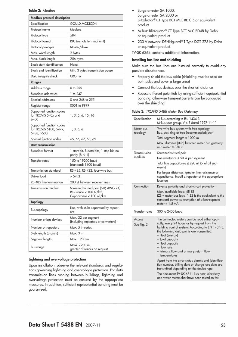
Data Sheet T 5488 EN 2007-11 53
Table 2: Modbus
Modbus protocol description
Specification GOULD MODICON
Protocol name Modbus
Protocol type 584
Protocol format RTU (remote terminal unit)
Protocol principle Master/slave
Max. word length 2 bytes
Max. block length 256 bytes
Block start identification None
Block end identification Min. 3 bytes transmission pause
Data integrity check CRC-16
Ranges
Address range 0 to 255
Standard addresses 1 to 247
Special addresses 0 and 248 to 255
Register range 0001 to 9999
Supported function codes for TROVIS 540x and 6400
1, 3, 5, 6, 15, 16
Supported function codes for TROVIS 5100, 547x, 5488, 5500
1, 3, 5, 6
Special function codes 65, 66, 67, 68, 69
Data transmission
Standard format 1 start bit, 8 data bits, 1 stop bit, no parity (8-N-1)
Transfer rates 150 to 19200 baud (standard: 9600 baud)
Transmission standard RS-485, RS-422, four-wire bus
Driver load > 54 Ω
RS-485 line termination 200 Ω between receiver lines
Transmission medium Screened twisted pair (STP, AWG 24) Resistance < 100 Ω/km, Capacitance < 100 nF/km
Topology
Bus topology Line, with stubs separated by repeat-ers
Number of bus devices Max. 32 per segment (including repeaters or converters)
Number of repeaters Max. 5 in series
Stub length (branch) Max. 3 m
Segment length Max. 1200 m
Bus range Maxi. 7200 m, greater distances on request
Lightning and overvoltage protectionUpon installation, observe the relevant standards and regula-tions governing lightning and overvoltage protection. For data transmission lines running between buildings, lightning and overvoltage protection must be ensured by the appropriate measures. In addition, sufficient equipotential bonding must be guaranteed.
• Surge arrester SA 1000, Surge arrester SA 2000 or Blitzductor® CT Type BCT MLC BE C 5 or equivalent product
• M-Bus: Blitzductor® CT Type BCT MLC BD48 by Dehn or equivalent product
• 230 V network: DEHNguard® T Type DGT 275 by Dehn or equivalent product
TV-SK 6364 contains additional information.
Installing bus line and shieldingMake sure the bus lines are installed correctly to avoid any possible disturbances. • Properly shield the bus cable (shielding must be used on
both sides and cover a large area) • Connect the bus devices over the shortest distance • Reduce different potentials by using sufficient equipotential
bonding, otherwise transient currents can be conducted over the shielding!
Table 3: TROVIS 5488 Meter Bus Gateway
Specification M-Bus according to EN 1434-3 M-Bus user group, V 4.8 dated 1997-11-11
Meter bus topology
Two-wire bus system with free topology Bus, star, ring or tree (recommended: star)Total segment length ≤ 1000 mMax. distance (stub) between meter bus gateway and meter ≤ 350 m
Transmission medium
Screened twisted pairLine resistance ≤ 50 Ω per segmentTotal line capacitance ≤ 220 nF (∑ of all seg-ments)For larger distances, greater line resistance or capacitance, install a repeater at the appropriate location
Connection Reverse polarity and short-circuit protectionMax. available load: 48 ZB (ZB = meter bus load; 1 ZB is the equivalent to the standard power consumption of a bus-capable meter = 1.5 mA)
Transfer rates 300 to 2400 baud
AccessSee Fig. 2
The connected meters can be read either cycli-cally, every 24 hours or by request from the building control system. According to EN 1434-3, the following data points are transmitted: – Heat (energy) – Total capacity – Heat capacity – Flow rate – Primary flow and primary return flow temperaturesApart from the error status alarms and identifica-tion number, billing date or charge rate data are transmitted depending on the device type.The document TV-SK 6311 lists heat, electricity and water meters that have been tested so far.
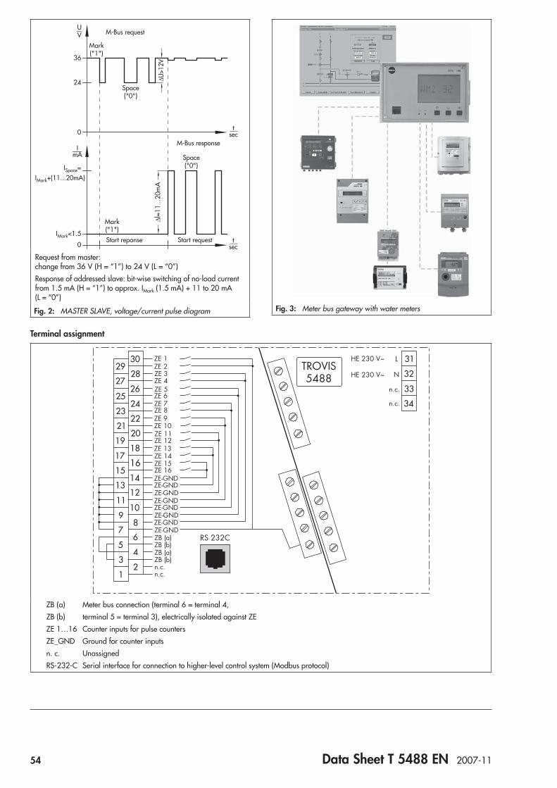
54 Data Sheet T 5488 EN 2007-11
36
UV
24
0
ISpace=IMark+(11...20mA)
0
IMark<1.5
ImA
tsec
tsec
∆l=1
1...2
0mA
∆U>1
2V
Space("0")
Mark("1")
Mark("1")
Space("0")
Start reponse Start request
M-Bus request
M-Bus response
Request from master: change from 36 V (H = “1”) to 24 V (L = “0”)Response of addressed slave: bit-wise switching of no-load current from 1.5 mA (H = “1”) to approx. IMark (1.5 mA) + 11 to 20 mA (L = “0”)
Fig. 2: MASTER SLAVE, voltage/current pulse diagram Fig. 3: Meter bus gateway with water meters
Terminal assignment
33
29
27
30
28
2625
2423
2221
2019
1817
1615
1413
1110
98
76
54
32
1
31
32
34
12
ZE 1ZE 2ZE 3
ZE 5ZE 6ZE 7ZE 8
ZE 4
ZE 9ZE 10ZE 11ZE 12ZE 13ZE 14ZE 15ZE 16ZE-GNDZE-GNDZE-GNDZE-GNDZE-GNDZE-GNDZE-GNDZE-GNDZB (a)ZB (b)ZB (a)ZB (b)n.c.n.c.
RS 232C
TROVIS5488
HE 230 V~
HE 230 V~
L
N
n.c.
n.c.
ZB (a) Meter bus connection (terminal 6 = terminal 4,ZB (b) terminal 5 = terminal 3), electrically isolated against ZEZE 1…16 Counter inputs for pulse countersZE_GND Ground for counter inputsn. c. UnassignedRS-232-C Serial interface for connection to higher-level control system (Modbus protocol)

Data Sheet T 5590 EN 2010-11 55
Fig. 1: TROVIS 5590 Web Module
The web module allows the visualization of data from smart controllers in the TROVIS 5100, 5400 and 5500 Automation Systems as well as the TROVIS 6495-2 Industrial Controller us-ing the TCP/IP protocol. The plant schematics, relevant control parameters and time schedules of a connected controller can be viewed in a web browser.Data from connected controllers are saved cyclically in the web module and can be displayed as trend graphs. An alarm management handles incoming fault alarms and sends event-triggered e-mails to max. four e-mail addresses.Communication to Modbus devices is established either over RS-232 or RS-485 (2-wire/4-wire). There are two Modbus communications interfaces to allow two controllers to communi-cate with the web module over the RS-232 interface or a group of controllers to communicate with the web module over the RS-485 interface and an additional controller to communicate with the web module over the RS-232 interface. The number of controllers that can be connected is restricted by the maximum number of plant schematics (4) and the number of maximum data points (256).
Special features • Visualization and operation using a web browser • Data logging (trend graphs and function to export data as
CSV files) • Alarm management including e-mail notification • Four configurable user levels • High password security (MD5 transmission) • Ethernet interface 10/100 MBit • RS-232 for configuration • RS-232, RS-485 (2-wire/4-wire) Modbus RTU • Processing of max. three heat meters • Dynamic DNS-supported internet connection • LEDs for Power, TxD, RxD, 10 Mbit, 100 Mbit • Mounting on a 35 mm top-hat rail according to
DIN EN 50022 • Voltage supply 230 V AC, 50/60 Hz
ApplicationCommunication over TCP/IP network (internet/intranet) with TROVIS 5100, 5400 and 5500 Automation Systems as well as the TROVIS 6495-2 Industrial Controller
Automation System TROVIS 5500Web Module TROVIS 5590
The web module editor software tool is used to create applica-tions for the web module. This tool allows users to configure all functions over intranet/internet and, for example, to alter user access rights and e-mail addresses.
®
Electronics from SAMSON
Fig. 1: TROVIS 5590 Web Module
ApplicationCommunication over TCP/IP network (internet/intranet) with TROVIS 5100, 5400 and 5500 Automation Systems as well as the TROVIS 6495-2 Industrial Controller
Automation System TROVIS 5500Web Module TROVIS 5590
®
Electronics from SAMSON
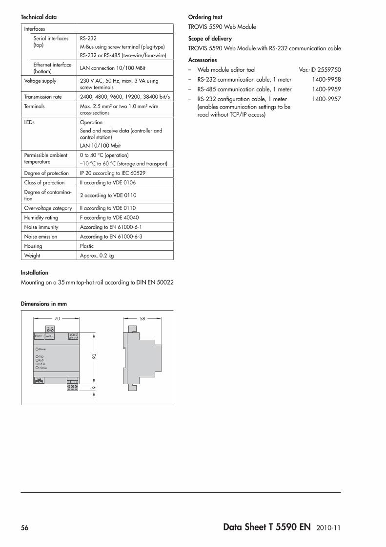
56 Data Sheet T 5590 EN 2010-11
Technical data
Interfaces
Serial interfaces (top)
RS-232M-Bus using screw terminal (plug-type)RS-232 or RS-485 (two-wire/four-wire)
Ethernet interface (bottom) LAN connection 10/100 MBit
Voltage supply 230 V AC, 50 Hz, max. 3 VA using screw terminals
Transmission rate 2400, 4800, 9600, 19200, 38400 bit/s
Terminals Max. 2.5 mm² or two 1.0 mm² wire cross-sections
LEDs OperationSend and receive data (controller and control station)LAN 10/100 Mbit
Permissible ambient temperature
0 to 40 °C (operation)–10 °C to 60 °C (storage and transport)
Degree of protection IP 20 according to IEC 60529
Class of protection II according to VDE 0106
Degree of contamina-tion 2 according to VDE 0110
Overvoltage category II according to VDE 0110
Humidity rating F according to VDE 40040
Noise immunity According to EN 61000-6-1
Noise emission According to EN 61000-6-3
Housing Plastic
Weight Approx. 0.2 kg
InstallationMounting on a 35 mm top-hat rail according to DIN EN 50022
Dimensions in mm
1 3
RS232-1 M-BusRS232-2
Power
TxDRxD10 M100 M
70 58
909
RS485
Ordering textTROVIS 5590 Web Module
Scope of deliveryTROVIS 5590 Web Module with RS-232 communication cable
Accessories – Web module editor tool Var.-ID 2559750 – RS-232 communication cable, 1 meter 1400-9958 – RS-485 communication cable, 1 meter 1400-9959 – RS-232 configuration cable, 1 meter 1400-9957
(enables communication settings to be read without TCP/IP access)
57
Controllers with Electric Actuators

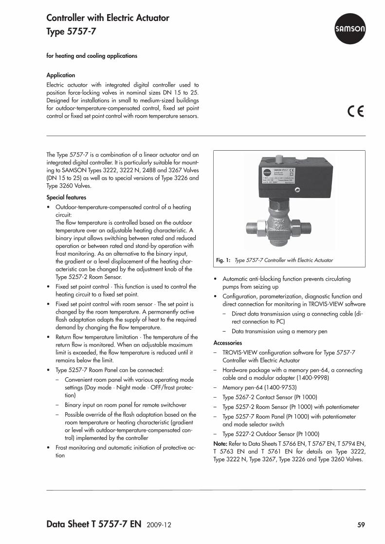
Data Sheet T 5757-7 EN 2009-12 59
Fig. 1: Type 5757-7 Controller with Electric Actuator
The Type 5757-7 is a combination of a linear actuator and an integrated digital controller. It is particularly suitable for mount-ing to SAMSON Types 3222, 3222 N, 2488 and 3267 Valves (DN 15 to 25) as well as to special versions of Type 3226 and Type 3260 Valves.
Special features • Outdoor-temperature-compensated control of a heating
circuit: The flow temperature is controlled based on the outdoor temperature over an adjustable heating characteristic. A binary input allows switching between rated and reduced operation or between rated and stand-by operation with frost monitoring. As an alternative to the binary input, the gradient or a level displacement of the heating char-acteristic can be changed by the adjustment knob of the Type 5257-2 Room Sensor.
• Fixed set point control · This function is used to control the heating circuit to a fixed set point.
• Fixed set point control with room sensor · The set point is changed by the room temperature. A permanently active flash adaptation adapts the supply of heat to the required demand by changing the flow temperature.
• Return flow temperature limitation · The temperature of the return flow is monitored. When an adjustable maximum limit is exceeded, the flow temperature is reduced until it remains below the limit.
• Type 5257-7 Room Panel can be connected: – Convenient room panel with various operating mode
settings (Day mode · Night mode · OFF/frost protec-tion)
– Binary input on room panel for remote switchover – Possible override of the flash adaptation based on the
room temperature or heating characteristic (gradient or level with outdoor-temperature-compensated con-trol) implemented by the controller
• Frost monitoring and automatic initiation of protective ac-tion
ApplicationElectric actuator with integrated digital controller used to position force-locking valves in nominal sizes DN 15 to 25. Designed for installations in small to medium-sized buildings for outdoor-temperature-compensated control, fixed set point control or fixed set point control with room temperature sensors.
Controller with Electric ActuatorType 5757-7
for heating and cooling applications
• Automatic anti-blocking function prevents circulating pumps from seizing up
• Configuration, parameterization, diagnostic function and direct connection for monitoring in TROVIS-VIEW software – Direct data transmission using a connecting cable (di-
rect connection to PC) – Data transmission using a memory pen
Accessories – TROVIS-VIEW configuration software for Type 5757-7
Controller with Electric Actuator – Hardware package with a memory pen-64, a connecting
cable and a modular adapter (1400-9998) – Memory pen-64 (1400-9753) – Type 5267-2 Contact Sensor (Pt 1000) – Type 5257-2 Room Sensor (Pt 1000) with potentiometer – Type 5257-7 Room Panel (Pt 1000) with potentiometer
and mode selector switch – Type 5227-2 Outdoor Sensor (Pt 1000)
Note: Refer to Data Sheets T 5766 EN, T 5767 EN, T 5794 EN, T 5763 EN and T 5761 EN for details on Type 3222, Type 3222 N, Type 3267, Type 3226 and Type 3260 Valves.
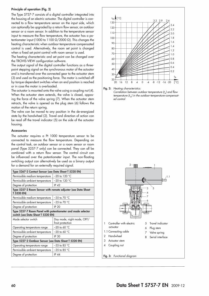
60 Data Sheet T 5757-7 EN 2009-12
Principle of operation (Fig. 2)The Type 5757-7 consists of a digital controller integrated into the housing of an electric actuator. The digital controller is con-nected to a flow temperature sensor on the input side, which can optionally be upgraded by a return flow sensor, an outdoor sensor or a room sensor. In addition to the temperature sensor input to measure the flow temperature, the actuator has a po-tentiometer input (1000 to 1100 Ω/2000 Ω). This changes the heating characteristic when outdoor-temperature-compensated control is used. Alternatively, the room set point is changed when a fixed set point control with room sensor is used.The heating characteristic and set point can be changed over the TROVIS-VIEW configuration software.The output signal of the digital controller functions as a three-point stepping signal on the synchronous motor of the actuator and is transferred over the connected gear to the actuator stem (3) and used as the positioning force. The motor is switched off by torque-dependent switches when an end position is reached or in case the motor is overloaded.The actuator is mounted onto the valve using a coupling nut (4).When the actuator stem extends, the valve is closed, oppos-ing the force of the valve spring (7). When the actuator stem retracts, the valve is opened as the plug stem (6) follows the motion of the return spring.The valve can be moved to any position in the de-energized state by the handwheel (2). Travel and direction of action can be read off the travel indicator (5) on the side of the actuator housing.
AccessoriesThe actuator requires a Pt 1000 temperature sensor to be connected to measure the flow temperature. Depending on the control task, an outdoor sensor or a room sensor or room panel (Type 5257-7 only) can be connected. They can all be combined with a return flow sensor. The control circuit can be influenced over the potentiometer input. The non-floating switching output can alternatively be used as a binary output for a demand for an externally required signal.
Type 5267-2 Contact Sensor (see Data Sheet T 5220 EN)Permissible medium temperature –20 to 120 °CPermissible ambient temperature –20 to 120 °CDegree of protection IP 42Type 5257-2 Room Sensor with remote adjuster (see Data Sheet T 5220 EN)Permissible medium temperature –35 to 70 °CPermissible ambient temperature –35 to 70 °CDegree of protection IP 20Type 5257-7 Room Panel with potentiometer and mode selector switch (see Data Sheet T 5220 EN)Mode selector switch Day mode, night mode, OFF/
frost protectionOperating temperature range –20 to 60 °CPermissible ambient temperature –20 to 60 °CDegree of protection IP 30Type 5227-2 Outdoor Sensor (see Data Sheet T 5220 EN)Operating temperature range –35 to 85 °CPermissible ambient temperature –35 to 85 °CDegree of protection IP 44
20
300.2
2.4
2.62.93.2
2.2
2.0
1.8
1.6
1.4
1.21.0
0.8
0.4
0.6
40
50
60
70
80
90
100
110
120
130
tVL [˚C]
-20 [˚C]
tA
-16-12-8-4048121620
Fig. 2: Heating characteristics: Correlation between outdoor temperature (tA) and flow temperature (tVL) in the outdoor-temperature-compensat-ed control
12
4
3
6
7
5
1.1
1 Controller with electric actuator
1.1 Connecting cable2 Handwheel3 Actuator stem4 Coupling nut
5 Travel indicator6 Plug stem7 Valve spring8 Serial interface
Fig. 3: Functional diagram
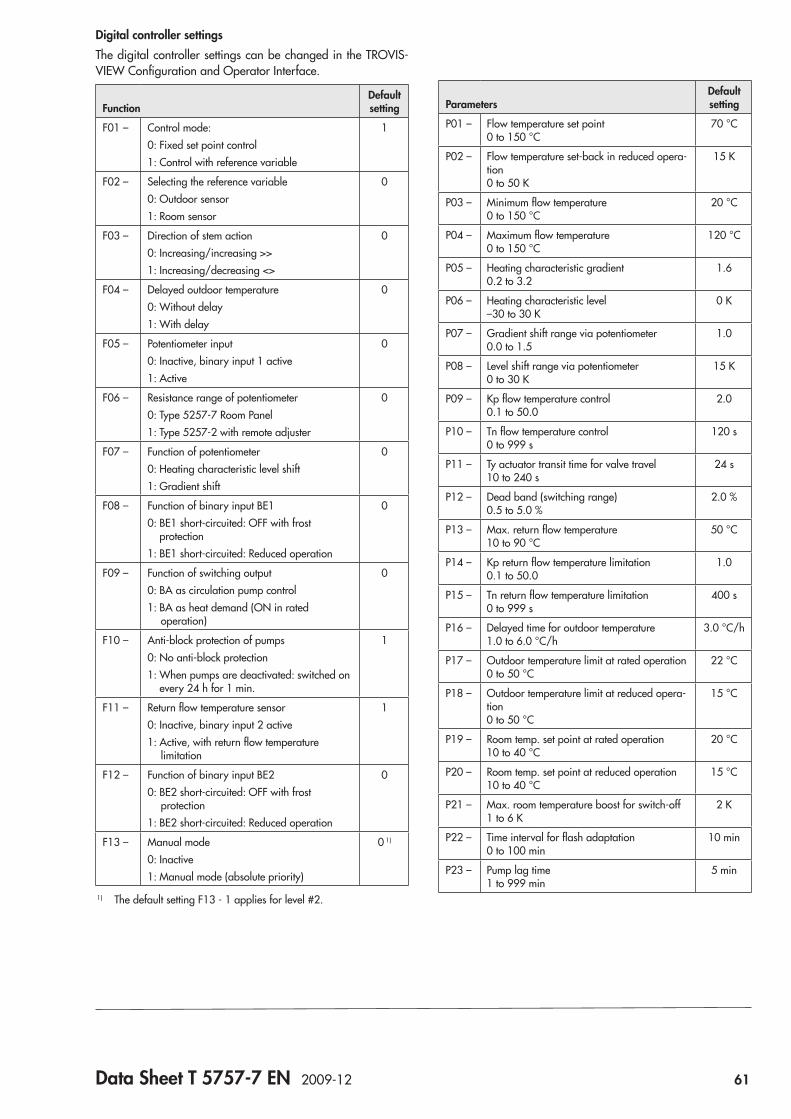
Data Sheet T 5757-7 EN 2009-12 61
Digital controller settingsThe digital controller settings can be changed in the TROVIS-VIEW Configuration and Operator Interface.
FunctionDefault setting
F01 – Control mode:0: Fixed set point control1: Control with reference variable
1
F02 – Selecting the reference variable0: Outdoor sensor1: Room sensor
0
F03 – Direction of stem action0: Increasing/increasing >>1: Increasing/decreasing <>
0
F04 – Delayed outdoor temperature0: Without delay1: With delay
0
F05 – Potentiometer input0: Inactive, binary input 1 active1: Active
0
F06 – Resistance range of potentiometer0: Type 5257-7 Room Panel1: Type 5257-2 with remote adjuster
0
F07 – Function of potentiometer0: Heating characteristic level shift1: Gradient shift
0
F08 – Function of binary input BE10: BE1 short-circuited: OFF with frost
protection1: BE1 short-circuited: Reduced operation
0
F09 – Function of switching output0: BA as circulation pump control1: BA as heat demand (ON in rated
operation)
0
F10 – Anti-block protection of pumps0: No anti-block protection1: When pumps are deactivated: switched on
every 24 h for 1 min.
1
F11 – Return flow temperature sensor0: Inactive, binary input 2 active1: Active, with return flow temperature
limitation
1
F12 – Function of binary input BE20: BE2 short-circuited: OFF with frost
protection1: BE2 short-circuited: Reduced operation
0
F13 – Manual mode0: Inactive1: Manual mode (absolute priority)
0 1)
1) The default setting F13 - 1 applies for level #2.
ParametersDefault setting
P01 – Flow temperature set point 0 to 150 °C
70 °C
P02 – Flow temperature set-back in reduced opera-tion 0 to 50 K
15 K
P03 – Minimum flow temperature 0 to 150 °C
20 °C
P04 – Maximum flow temperature 0 to 150 °C
120 °C
P05 – Heating characteristic gradient 0.2 to 3.2
1.6
P06 – Heating characteristic level –30 to 30 K
0 K
P07 – Gradient shift range via potentiometer 0.0 to 1.5
1.0
P08 – Level shift range via potentiometer 0 to 30 K
15 K
P09 – Kp flow temperature control 0.1 to 50.0
2.0
P10 – Tn flow temperature control 0 to 999 s
120 s
P11 – Ty actuator transit time for valve travel 10 to 240 s
24 s
P12 – Dead band (switching range) 0.5 to 5.0 %
2.0 %
P13 – Max. return flow temperature 10 to 90 °C
50 °C
P14 – Kp return flow temperature limitation 0.1 to 50.0
1.0
P15 – Tn return flow temperature limitation 0 to 999 s
400 s
P16 – Delayed time for outdoor temperature 1.0 to 6.0 °C/h
3.0 °C/h
P17 – Outdoor temperature limit at rated operation 0 to 50 °C
22 °C
P18 – Outdoor temperature limit at reduced opera-tion 0 to 50 °C
15 °C
P19 – Room temp. set point at rated operation 10 to 40 °C
20 °C
P20 – Room temp. set point at reduced operation 10 to 40 °C
15 °C
P21 – Max. room temperature boost for switch-off 1 to 6 K
2 K
P22 – Time interval for flash adaptation 0 to 100 min
10 min
P23 – Pump lag time 1 to 999 min
5 min
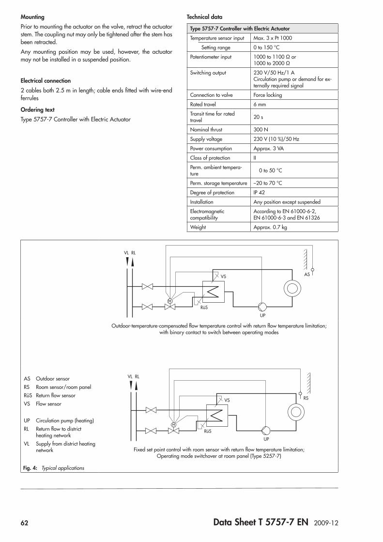
62 Data Sheet T 5757-7 EN 2009-12
Technical data
Type 5757-7 Controller with Electric Actuator
Temperature sensor input Max. 3 x Pt 1000
Setting range 0 to 150 °C
Potentiometer input 1000 to 1100 Ω or 1000 to 2000 Ω
Switching output 230 V/50 Hz/1 A Circulation pump or demand for ex-ternally required signal
Connection to valve Force locking
Rated travel 6 mm
Transit time for rated travel 20 s
Nominal thrust 300 N
Supply voltage 230 V (10 %)/50 Hz
Power consumption Approx. 3 VA
Class of protection II
Perm. ambient tempera-ture 0 to 50 °C
Perm. storage temperature –20 to 70 °C
Degree of protection IP 42
Installation Any position except suspended
Electromagnetic compatibility
According to EN 61000-6-2, EN 61000-6-3 and EN 61326
Weight Approx. 0.7 kg
MountingPrior to mounting the actuator on the valve, retract the actuator stem. The coupling nut may only be tightened after the stem has been retracted.Any mounting position may be used, however, the actuator may not be installed in a suspended position.
Electrical connection2 cables both 2.5 m in length; cable ends fitted with wire-end ferrules
Ordering textType 5757-7 Controller with Electric Actuator
AS Outdoor sensorRS Room sensor/room panelRüS Return flow sensorVS Flow sensor
UP Circulation pump (heating)RL Return flow to district heating networkVL Supply from district heating network
RüS
UP
VS
VL RL
AS
Outdoor-temperature-compensated flow temperature control with return flow temperature limitation; with binary contact to switch between operating modes
RüS
UP
VS
VL RL
RS
Fixed set point control with room sensor with return flow temperature limitation; Operating mode switchover at room panel (Type 5257-7)
Fig. 4: Typical applications
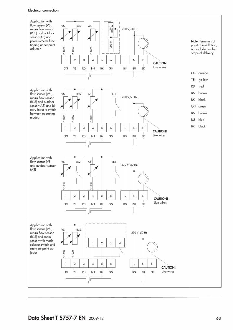
Data Sheet T 5757-7 EN 2009-12 63
Electrical connection
Application with flow sensor (VS), return flow sensor (RüS) and outdoor sensor (AS) and potentiometer func-tioning as set point adjuster
OG YE RD BN BK GN BN BU BK
3 4 6521 L L´N
230 V,VS
Pt 1
000
Pt 1
000
Pt 1
000
ASRüS50 Hz
100/
1000
W10
00 W
CAUTION! Live wires
Note: Terminals at point of installation, not included in the scope of delivery!
OG orange
YE yellow
RD red
BN brown
BK black
GN green
BN brown
BU blue
BK black
Application with flow sensor (VS), return flow sensor (RüS) and outdoor sensor (AS) and bi-nary input to switch between operating modes
OG YE RD BN BK GN BN BU BK
3 4 6521 L L´N
230 V,VS
Pt 1
000
Pt 1
000
Pt 1
000
AS BE1RüS50 Hz
CAUTION! Live wires
Application with flow sensor (VS) and outdoor sensor (AS)
OG YE RD BN BK GN BN BU BK
3 4 6521 L L´N
230 V, 50 HzVS
Pt 1
000
Pt 1
000
ASBE2 BE1
CAUTION! Live wires
Application with flow sensor (VS), return flow sensor (RüS) and room sensor with mode selector switch and room set point ad-juster
OG YE RD BN BK GN BN BU BK
3 4 65
1 432
21 L L´N
230 V, 50 HzVS
Pt 1
000
Pt 1
000
RüS
CAUTION! Live wires

64 Data Sheet T 5757-7 EN 2009-12
Dimensions in mm
Ø 1255
8011
32 70 eL Stem retracts
aL Stem extends114
2.5 m
70
Controller with electric actuator
Accessories for heating control
21
Ø4
5036
756022
28
84
+_
30
23
84
Type 5227-2 Outdoor Sensor (Pt 1000)Color: RAL 9016
Type 5257-2 Room Sensor (Pt 1000) with remote adjuster
502 32
30
82 32
20
86
Type 5267-2 Contact Sensor (Pt 1000) (flow and return flow temperature measurement)
Type 5257-7 Room Panel (Pt 1000)
Continuous day mode (rated operation) Continuous night mode (reduced operation) Off/frost protection
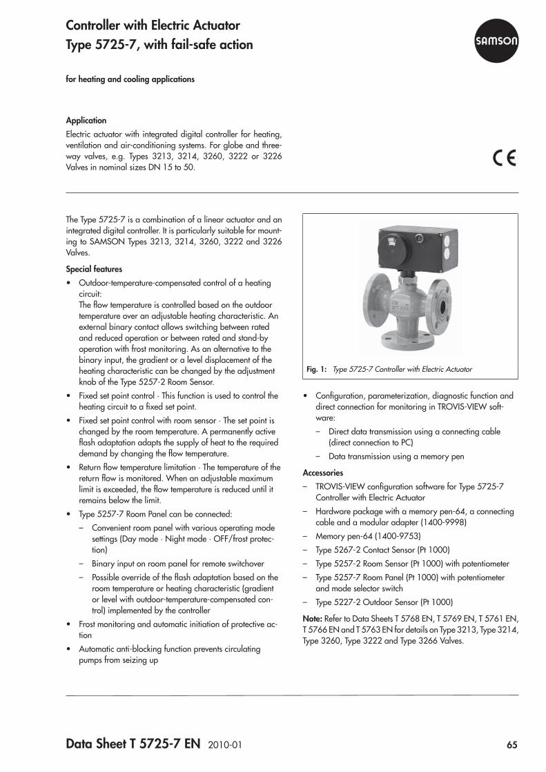
Data Sheet T 5725-7 EN 2010-01 65
Fig. 1: Type 5725-7 Controller with Electric Actuator
The Type 5725-7 is a combination of a linear actuator and an integrated digital controller. It is particularly suitable for mount-ing to SAMSON Types 3213, 3214, 3260, 3222 and 3226 Valves.
Special features • Outdoor-temperature-compensated control of a heating
circuit: The flow temperature is controlled based on the outdoor temperature over an adjustable heating characteristic. An external binary contact allows switching between rated and reduced operation or between rated and stand-by operation with frost monitoring. As an alternative to the binary input, the gradient or a level displacement of the heating characteristic can be changed by the adjustment knob of the Type 5257-2 Room Sensor.
• Fixed set point control · This function is used to control the heating circuit to a fixed set point.
• Fixed set point control with room sensor · The set point is changed by the room temperature. A permanently active flash adaptation adapts the supply of heat to the required demand by changing the flow temperature.
• Return flow temperature limitation · The temperature of the return flow is monitored. When an adjustable maximum limit is exceeded, the flow temperature is reduced until it remains below the limit.
• Type 5257-7 Room Panel can be connected: – Convenient room panel with various operating mode
settings (Day mode · Night mode · OFF/frost protec-tion)
– Binary input on room panel for remote switchover – Possible override of the flash adaptation based on the
room temperature or heating characteristic (gradient or level with outdoor-temperature-compensated con-trol) implemented by the controller
• Frost monitoring and automatic initiation of protective ac-tion
• Automatic anti-blocking function prevents circulating pumps from seizing up
ApplicationElectric actuator with integrated digital controller for heating, ventilation and air-conditioning systems. For globe and three-way valves, e.g. Types 3213, 3214, 3260, 3222 or 3226 Valves in nominal sizes DN 15 to 50.
Controller with Electric ActuatorType 5725-7, with fail-safe action
for heating and cooling applications
• Configuration, parameterization, diagnostic function and direct connection for monitoring in TROVIS-VIEW soft-ware: – Direct data transmission using a connecting cable
(direct connection to PC) – Data transmission using a memory pen
Accessories – TROVIS-VIEW configuration software for Type 5725-7
Controller with Electric Actuator – Hardware package with a memory pen-64, a connecting
cable and a modular adapter (1400-9998) – Memory pen-64 (1400-9753) – Type 5267-2 Contact Sensor (Pt 1000) – Type 5257-2 Room Sensor (Pt 1000) with potentiometer – Type 5257-7 Room Panel (Pt 1000) with potentiometer
and mode selector switch – Type 5227-2 Outdoor Sensor (Pt 1000)
Note: Refer to Data Sheets T 5768 EN, T 5769 EN, T 5761 EN, T 5766 EN and T 5763 EN for details on Type 3213, Type 3214, Type 3260, Type 3222 and Type 3266 Valves.
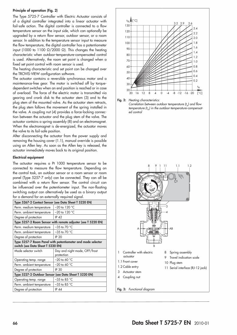
66 Data Sheet T 5725-7 EN 2010-01
Principle of operation (Fig. 2)The Type 5725-7 Controller with Electric Actuator consists of of a digital controller integrated into a linear actuator with fail-safe action. The digital controller is connected to a flow temperature sensor on the input side, which can optionally be upgraded by a return flow sensor, outdoor sensor, or a room sensor. In addition to the temperature sensor input to measure the flow temperature, the digital controller has a potentiometer input (1000 to 1100 Ω/2000 Ω). This changes the heating characteristic when outdoor-temperature-compensated control is used. Alternatively, the room set point is changed when a fixed set point control with room sensor is used.The heating characteristic and set point can be changed over the TROVIS-VIEW configuration software.The actuator contains a reversible synchronous motor and a maintenance-free gear. The motor is switched off by torque-dependent switches when an end position is reached or in case of overload. The force of the electric motor is transmitted via gearing and crank disk to the actuator stem (3) and to the plug stem of the mounted valve. As the actuator stem retracts, the plug stem follows the movement of the spring installed in the valve. A coupling nut (4) provides a force-locking connec-tion between the actuator and the plug stem of the valve. The actuator contains a spring assembly (8) and an electromagnet. When the electromagnet is de-energized, the actuator moves the valve to its fail-safe position.After disconnecting the actuator from the power supply and removing the housing cover (1.1), manual override is possible using an Allen key. As soon as the Allen key is released, the actuator immediately moves back to its original position.
Electrical equipmentThe actuator requires a Pt 1000 temperature sensor to be connected to measure the flow temperature. Depending on the control task, an outdoor sensor or a room sensor or room panel (Type 5257-7 only) can be connected. They can all be combined with a return flow sensor. The control circuit can be influenced over the potentiometer input. The non-floating switching output can alternatively be used as a binary output for a demand for an externally required signal.Type 5267-2 Contact Sensor (see Data Sheet T 5220 EN)Perm. medium temperature –20 to 120 °CPerm. ambient temperature –20 to 120 °CDegree of protection IP 42Type 5257-2 Room Sensor with remote adjuster (see T 5220 EN)Perm. medium temperature –35 to 70 °CPerm. ambient temperature –35 to 70 °CDegree of protection IP 20Type 5257-7 Room Panel with potentiometer and mode selector switch (see Data Sheet T 5220 EN)Mode selector switch Day and night mode, OFF/frost
protectionOperating temp. range –20 to 60 °CPerm. ambient temperature –20 to 60 °CDegree of protection IP 30Type 5227-2 Outdoor Sensor (see Data Sheet T 5220 EN)Operating temp. range –35 to 85 °CPerm. ambient temperature –35 to 85 °CDegree of protection IP 44
20
300.2
2.4
2.62.93.2
2.2
2.0
1.8
1.6
1.4
1.21.0
0.8
0.4
0.6
40
50
60
70
80
90
100
110
120
130
tVL [˚C]
-20 [˚C]
tA
-16-12-8-4048121620
Fig. 2: Heating characteristics: Correlation between outdoor temperature (tA) and flow temperature (tVL) in the outdoor-temperature-compensat-ed control
0612
15
15 126
0
0
6 1215
8 9 1 1.111 1.2
4
3
A AB
B
1 Controller with electric actuator
1.1 Front cover1.2 Cable entry3 Actuator stem4 Coupling nut
8 Spring assembly9 Travel indication scale10 Plug stem11 Serial interface (RJ-12 jack)
Fig. 3: Functional diagram
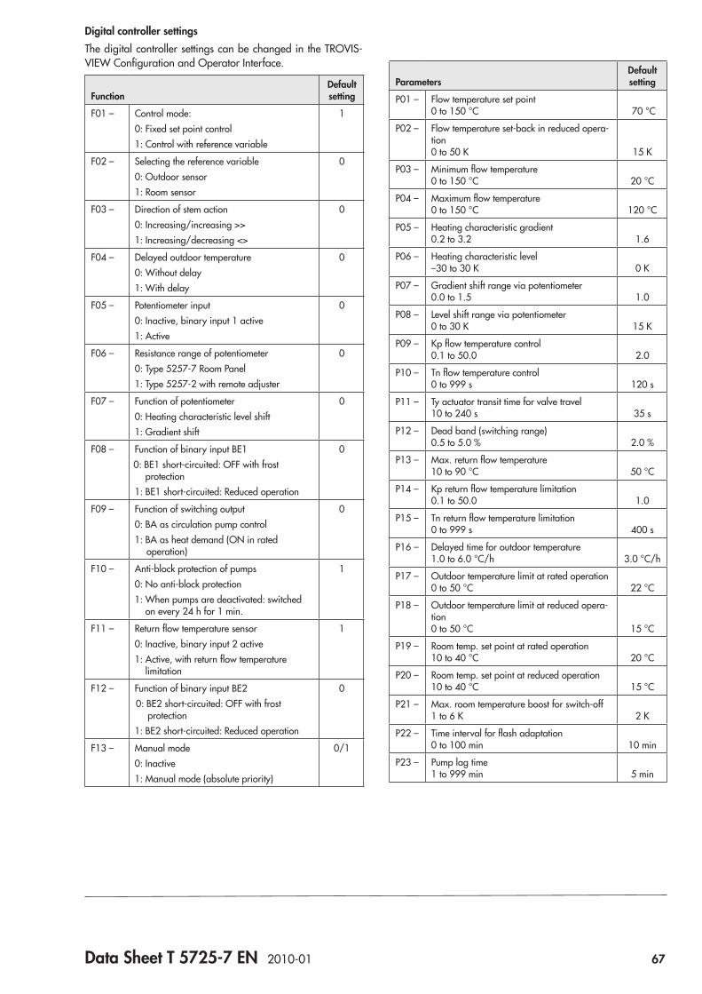
Data Sheet T 5725-7 EN 2010-01 67
Digital controller settingsThe digital controller settings can be changed in the TROVIS-VIEW Configuration and Operator Interface.
FunctionDefault setting
F01 – Control mode:0: Fixed set point control1: Control with reference variable
1
F02 – Selecting the reference variable0: Outdoor sensor1: Room sensor
0
F03 – Direction of stem action0: Increasing/increasing >>1: Increasing/decreasing <>
0
F04 – Delayed outdoor temperature0: Without delay1: With delay
0
F05 – Potentiometer input0: Inactive, binary input 1 active1: Active
0
F06 – Resistance range of potentiometer0: Type 5257-7 Room Panel1: Type 5257-2 with remote adjuster
0
F07 – Function of potentiometer0: Heating characteristic level shift1: Gradient shift
0
F08 – Function of binary input BE10: BE1 short-circuited: OFF with frost
protection1: BE1 short-circuited: Reduced operation
0
F09 – Function of switching output0: BA as circulation pump control1: BA as heat demand (ON in rated
operation)
0
F10 – Anti-block protection of pumps0: No anti-block protection1: When pumps are deactivated: switched
on every 24 h for 1 min.
1
F11 – Return flow temperature sensor0: Inactive, binary input 2 active1: Active, with return flow temperature
limitation
1
F12 – Function of binary input BE20: BE2 short-circuited: OFF with frost
protection1: BE2 short-circuited: Reduced operation
0
F13 – Manual mode0: Inactive1: Manual mode (absolute priority)
0/1
ParametersDefault setting
P01 – Flow temperature set point 0 to 150 °C 70 °C
P02 – Flow temperature set-back in reduced opera-tion 0 to 50 K 15 K
P03 – Minimum flow temperature 0 to 150 °C 20 °C
P04 – Maximum flow temperature 0 to 150 °C 120 °C
P05 – Heating characteristic gradient 0.2 to 3.2 1.6
P06 – Heating characteristic level –30 to 30 K 0 K
P07 – Gradient shift range via potentiometer 0.0 to 1.5 1.0
P08 – Level shift range via potentiometer 0 to 30 K 15 K
P09 – Kp flow temperature control 0.1 to 50.0 2.0
P10 – Tn flow temperature control 0 to 999 s 120 s
P11 – Ty actuator transit time for valve travel 10 to 240 s 35 s
P12 – Dead band (switching range) 0.5 to 5.0 % 2.0 %
P13 – Max. return flow temperature 10 to 90 °C 50 °C
P14 – Kp return flow temperature limitation 0.1 to 50.0 1.0
P15 – Tn return flow temperature limitation 0 to 999 s 400 s
P16 – Delayed time for outdoor temperature 1.0 to 6.0 °C/h 3.0 °C/h
P17 – Outdoor temperature limit at rated operation 0 to 50 °C 22 °C
P18 – Outdoor temperature limit at reduced opera-tion 0 to 50 °C 15 °C
P19 – Room temp. set point at rated operation 10 to 40 °C 20 °C
P20 – Room temp. set point at reduced operation 10 to 40 °C 15 °C
P21 – Max. room temperature boost for switch-off 1 to 6 K 2 K
P22 – Time interval for flash adaptation 0 to 100 min 10 min
P23 – Pump lag time 1 to 999 min 5 min
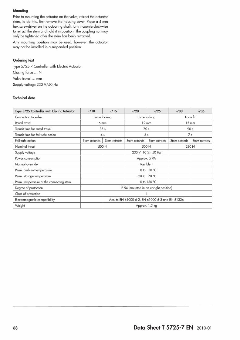
68 Data Sheet T 5725-7 EN 2010-01
Type 5725 Controller with Electric Actuator -710 -715 -720 -725 -730 -735
Connection to valve Force locking Force locking Form fit
Rated travel 6 mm 12 mm 15 mm
Transit time for rated travel 35 s 70 s 90 s
Transit time for fail-safe action 4 s 6 s 7 s
Fail-safe action Stem extends Stem retracts Stem extends Stem retracts Stem extends Stem retracts
Nominal thrust 500 N 500 N 280 N
Supply voltage 230 V (10 %), 50 Hz
Power consumption Approx. 5 VA
Manual override Possible 1)
Perm. ambient temperature 0 to 50 °C
Perm. storage temperature –20 to 70 °C
Perm. temperature at the connecting stem 0 to 130 °C
Degree of protection IP 54 (mounted in an upright position)
Class of protection II
Electromagnetic compatibility Acc. to EN 61000-6-2, EN 61000-6-3 and EN 61326
Weight Approx. 1.3 kg
MountingPrior to mounting the actuator on the valve, retract the actuator stem. To do this, first remove the housing cover. Place a 4 mm hex screwdriver on the actuating shaft, turn it counterclockwise to retract the stem and hold it in position. The coupling nut may only be tightened after the stem has been retracted.Any mounting position may be used, however, the actuator may not be installed in a suspended position.
Ordering textType 5725-7 Controller with Electric ActuatorClosing force … NValve travel … mmSupply voltage 230 V/50 Hz
Technical data
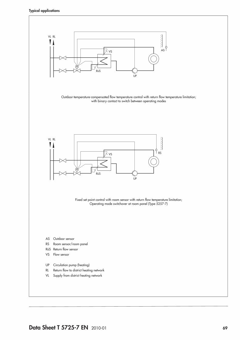
Data Sheet T 5725-7 EN 2010-01 69
Typical applications
RüS
UP
VS
VL RL
AS
Outdoor-temperature-compensated flow temperature control with return flow temperature limitation; with binary contact to switch between operating modes
RüS
UP
VS
VL RL
RS
Fixed set point control with room sensor with return flow temperature limitation; Operating mode switchover at room panel (Type 5257-7)
AS Outdoor sensorRS Room sensor/room panelRüS Return flow sensorVS Flow sensor
UP Circulation pump (heating)RL Return flow to district heating networkVL Supply from district heating network
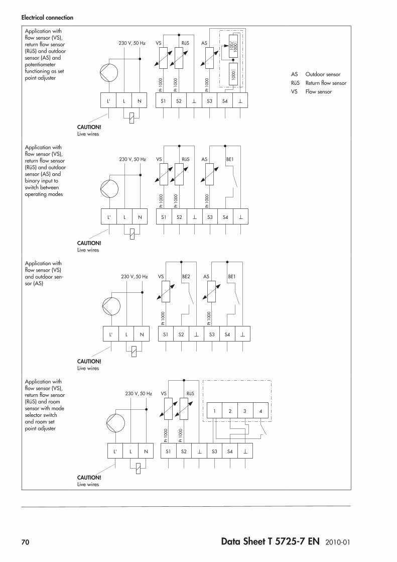
70 Data Sheet T 5725-7 EN 2010-01
Electrical connection
Application with flow sensor (VS), return flow sensor (RüS) and outdoor sensor (AS) and potentiometer functioning as set point adjuster
S3 S4S2S1L' NL
230 V, VS
Pt 1
000
Pt 1
000
Pt 1
000
ASRüS50 Hz
100/
1000
10
00
CAUTION! Live wires
AS Outdoor sensorRüS Return flow sensorVS Flow sensor
Application with flow sensor (VS), return flow sensor (RüS) and outdoor sensor (AS) and binary input to switch between operating modes
VSPt
100
0
Pt 1
000
Pt 1
000
AS BE1RüS
S3 S4S2S1L' NL
230 V, 50 Hz
CAUTION! Live wires
Application with flow sensor (VS) and outdoor sen-sor (AS)
VS
Pt 1
000
Pt 1
000
AS
S3 S4S2S1L' NL
230 V, 50 Hz BE2 BE1
CAUTION! Live wires
Application with flow sensor (VS), return flow sensor (RüS) and room sensor with mode selector switch and room set point adjuster
1 432
VS
Pt 1
000
Pt 1
000
RüS
S3 S4S2S1L' NL
230 V, 50 Hz
CAUTION! Live wires
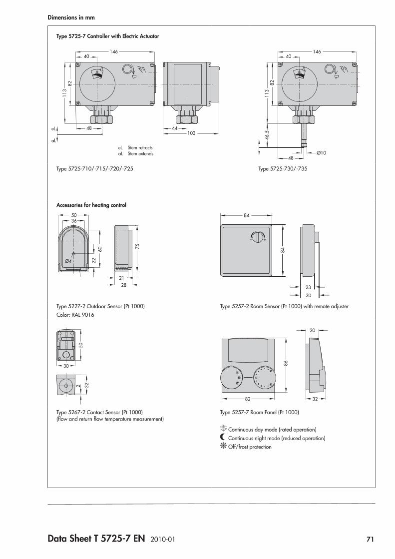
Data Sheet T 5725-7 EN 2010-01 71
Dimensions in mm
Type 5725-7 Controller with Electric Actuator
146
8211
3
48 44103
40146
8211
346
.5
48Ø10
40
Type 5725-710/-715/-720/-725 Type 5725-730/-735
Accessories for heating control
21
Ø4
5036
756022
28
84
+_
30
2384
Type 5227-2 Outdoor Sensor (Pt 1000)Color: RAL 9016
Type 5257-2 Room Sensor (Pt 1000) with remote adjuster
502 32
30
82 32
20
86
Type 5267-2 Contact Sensor (Pt 1000) (flow and return flow temperature measurement)
Type 5257-7 Room Panel (Pt 1000)
Continuous day mode (rated operation) Continuous night mode (reduced operation) Off/frost protection
eL Stem retractsaL Stem extends
eL
aL

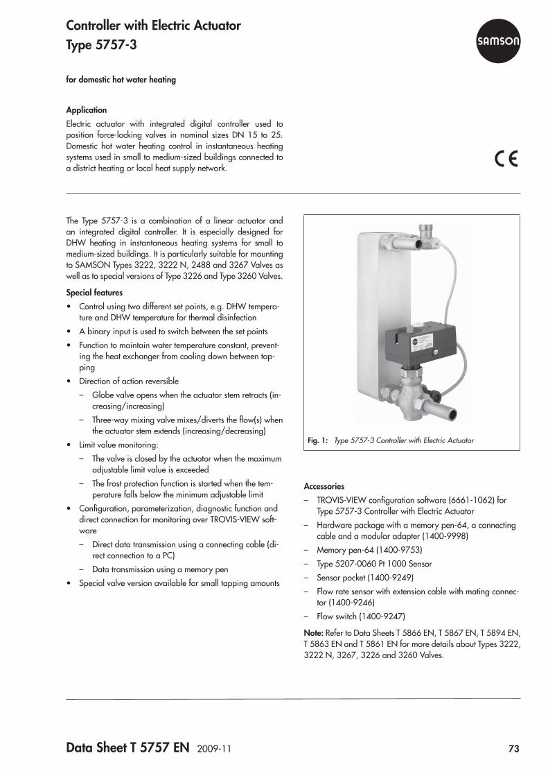
Data Sheet T 5757 EN 2009-11 73
Fig. 1: Type 5757-3 Controller with Electric Actuator
The Type 5757-3 is a combination of a linear actuator and an integrated digital controller. It is especially designed for DHW heating in instantaneous heating systems for small to medium-sized buildings. It is particularly suitable for mounting to SAMSON Types 3222, 3222 N, 2488 and 3267 Valves as well as to special versions of Type 3226 and Type 3260 Valves.
Special features • Control using two different set points, e.g. DHW tempera-
ture and DHW temperature for thermal disinfection • A binary input is used to switch between the set points • Function to maintain water temperature constant, prevent-
ing the heat exchanger from cooling down between tap-ping
• Direction of action reversible – Globe valve opens when the actuator stem retracts (in-
creasing/increasing) – Three-way mixing valve mixes/diverts the flow(s) when
the actuator stem extends (increasing/decreasing) • Limit value monitoring:
– The valve is closed by the actuator when the maximum adjustable limit value is exceeded
– The frost protection function is started when the tem-perature falls below the minimum adjustable limit
• Configuration, parameterization, diagnostic function and direct connection for monitoring over TROVIS-VIEW soft-ware – Direct data transmission using a connecting cable (di-
rect connection to a PC) – Data transmission using a memory pen
• Special valve version available for small tapping amounts
ApplicationElectric actuator with integrated digital controller used to position force-locking valves in nominal sizes DN 15 to 25. Domestic hot water heating control in instantaneous heating systems used in small to medium-sized buildings connected to a district heating or local heat supply network.
Controller with Electric ActuatorType 5757-3
for domestic hot water heating
Accessories – TROVIS-VIEW configuration software (6661-1062) for
Type 5757-3 Controller with Electric Actuator – Hardware package with a memory pen-64, a connecting
cable and a modular adapter (1400-9998) – Memory pen-64 (1400-9753) – Type 5207-0060 Pt 1000 Sensor – Sensor pocket (1400-9249) – Flow rate sensor with extension cable with mating connec-
tor (1400-9246) – Flow switch (1400-9247)
Note: Refer to Data Sheets T 5866 EN, T 5867 EN, T 5894 EN, T 5863 EN and T 5861 EN for more details about Types 3222, 3222 N, 3267, 3226 and 3260 Valves.
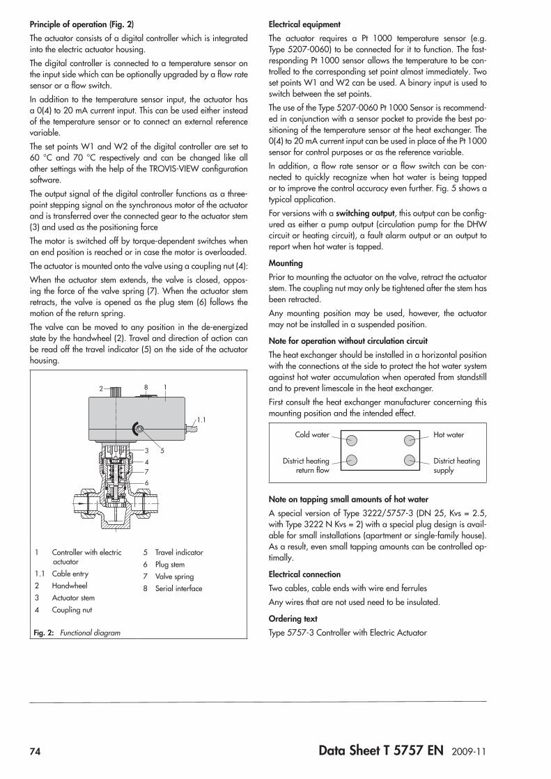
74 Data Sheet T 5757 EN 2009-11
Principle of operation (Fig. 2)The actuator consists of a digital controller which is integrated into the electric actuator housing.The digital controller is connected to a temperature sensor on the input side which can be optionally upgraded by a flow rate sensor or a flow switch.In addition to the temperature sensor input, the actuator has a 0(4) to 20 mA current input. This can be used either instead of the temperature sensor or to connect an external reference variable.The set points W1 and W2 of the digital controller are set to 60 °C and 70 °C respectively and can be changed like all other settings with the help of the TROVIS-VIEW configuration software.The output signal of the digital controller functions as a three-point stepping signal on the synchronous motor of the actuator and is transferred over the connected gear to the actuator stem (3) and used as the positioning forceThe motor is switched off by torque-dependent switches when an end position is reached or in case the motor is overloaded.The actuator is mounted onto the valve using a coupling nut (4):When the actuator stem extends, the valve is closed, oppos-ing the force of the valve spring (7). When the actuator stem retracts, the valve is opened as the plug stem (6) follows the motion of the return spring.The valve can be moved to any position in the de-energized state by the handwheel (2). Travel and direction of action can be read off the travel indicator (5) on the side of the actuator housing.
182
4
3
6
7
5
1.1
1 Controller with electric actuator
1.1 Cable entry2 Handwheel3 Actuator stem4 Coupling nut
5 Travel indicator6 Plug stem7 Valve spring8 Serial interface
Fig. 2: Functional diagram
Electrical equipmentThe actuator requires a Pt 1000 temperature sensor (e.g. Type 5207-0060) to be connected for it to function. The fast-responding Pt 1000 sensor allows the temperature to be con-trolled to the corresponding set point almost immediately. Two set points W1 and W2 can be used. A binary input is used to switch between the set points.The use of the Type 5207-0060 Pt 1000 Sensor is recommend-ed in conjunction with a sensor pocket to provide the best po-sitioning of the temperature sensor at the heat exchanger. The 0(4) to 20 mA current input can be used in place of the Pt 1000 sensor for control purposes or as the reference variable.In addition, a flow rate sensor or a flow switch can be con-nected to quickly recognize when hot water is being tapped or to improve the control accuracy even further. Fig. 5 shows a typical application.For versions with a switching output, this output can be config-ured as either a pump output (circulation pump for the DHW circuit or heating circuit), a fault alarm output or an output to report when hot water is tapped.
MountingPrior to mounting the actuator on the valve, retract the actuator stem. The coupling nut may only be tightened after the stem has been retracted.Any mounting position may be used, however, the actuator may not be installed in a suspended position.
Note for operation without circulation circuitThe heat exchanger should be installed in a horizontal position with the connections at the side to protect the hot water system against hot water accumulation when operated from standstill and to prevent limescale in the heat exchanger.First consult the heat exchanger manufacturer concerning this mounting position and the intended effect.
Hot water
District heating supply
District heating return flow
Cold water
Note on tapping small amounts of hot waterA special version of Type 3222/5757-3 (DN 25, Kvs = 2.5, with Type 3222 N Kvs = 2) with a special plug design is avail-able for small installations (apartment or single-family house). As a result, even small tapping amounts can be controlled op-timally.
Electrical connectionTwo cables, cable ends with wire end ferrulesAny wires that are not used need to be insulated.
Ordering textType 5757-3 Controller with Electric Actuator
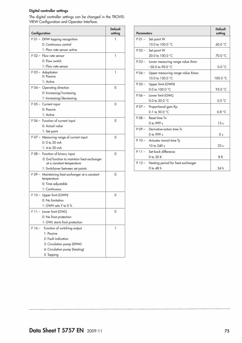
Data Sheet T 5757 EN 2009-11 75
Digital controller settingsThe digital controller settings can be changed in the TROVIS-VIEW Configuration and Operator Interface.
ConfigurationDefault setting
F 01 – DHW tapping recognition0: Continuous control1: Flow rate sensor active
1
F 02 – Flow rate sensor0: Flow switch1: Flow rate sensor
1
F 03 – Adaptiaton 0: Passive1: Active
1
F 04 – Operating direction0: Increasing/increasing1: Increasing/decreasing
0
F 05 – Current input0: Passive1: Active
0
F 06 – Function of current input0: Actual value1: Set point
0
F 07 – Measuring range of current input0: 0 to 20 mA1: 4 to 20 mA
0
F 08 – Function of binary input0: End function to maintain heat exchanger
at a constant temperature1: Switchover between set points
0
F 09 – Maintaining heat exchanger at a constant temperature0: Time adjustable1: Continuous
0
F 10 – Upper limit (GWH)0: No limitation1: GWH sets Y to 0 %
0
F 11 – Lower limit (GWL)0: No frost protection1: GWL starts frost protection
0
F 16 – Function of switching output1: Passive2: Fault indication3: Circulation pump (DHW)4: Circulation pump (heating)5: Tapping
1
ParametersDefault setting
P 01 – Set point W10.0 to 100.0 °C 60.0 °C
P 02 – Set point W20.0 to 100.0 °C 70.0 °C
P 03 – Lower measuring range value Xmin–50.0 to 90.0 °C 0.0 °C
P 04 – Upper measuring range value Xmax10.0 to 150.0 °C 100.0 °C
P 05 – Upper limit (GWH)0.0 to 100.0 °C 95.0 °C
P 06 – Lower limit (GWL)0.0 to 20.0 °C 5.0 °C
P 07 – Proportional gain Kp0.1 to 50.0 °C 0.8 °C
P 08 – Reset time Tn0 to 999 s 15 s
P 09 – Derivative-action time Tv0 to 999 s 0 s
P 10 – Actuator transit time Ty10 to 240 s 25 s
P 11 – Set-back difference0 to 30 K 8 K
P 12 – Heating period for heat exchanger0 to 48 h 24 h
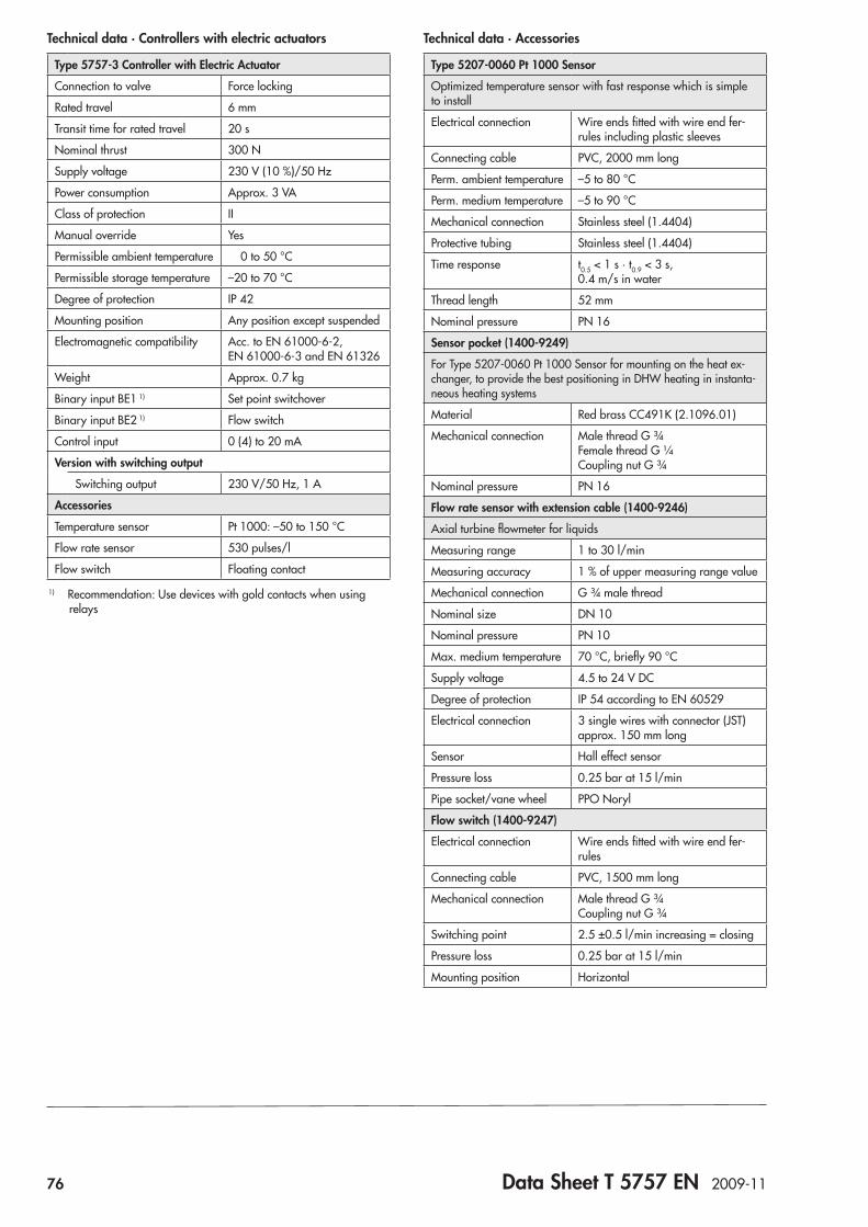
76 Data Sheet T 5757 EN 2009-11
Technical data · Accessories
Type 5207-0060 Pt 1000 Sensor
Optimized temperature sensor with fast response which is simple to install
Electrical connection Wire ends fitted with wire end fer-rules including plastic sleeves
Connecting cable PVC, 2000 mm long
Perm. ambient temperature –5 to 80 °C
Perm. medium temperature –5 to 90 °C
Mechanical connection Stainless steel (1.4404)
Protective tubing Stainless steel (1.4404)
Time response t0.5 < 1 s · t0.9 < 3 s, 0.4 m/s in water
Thread length 52 mm
Nominal pressure PN 16
Sensor pocket (1400-9249)
For Type 5207-0060 Pt 1000 Sensor for mounting on the heat ex-changer, to provide the best positioning in DHW heating in instanta-neous heating systems
Material Red brass CC491K (2.1096.01)
Mechanical connection Male thread G ¾ Female thread G ¼ Coupling nut G ¾
Nominal pressure PN 16
Flow rate sensor with extension cable (1400-9246)
Axial turbine flowmeter for liquids
Measuring range 1 to 30 l/min
Measuring accuracy 1 % of upper measuring range value
Mechanical connection G ¾ male thread
Nominal size DN 10
Nominal pressure PN 10
Max. medium temperature 70 °C, briefly 90 °C
Supply voltage 4.5 to 24 V DC
Degree of protection IP 54 according to EN 60529
Electrical connection 3 single wires with connector (JST) approx. 150 mm long
Sensor Hall effect sensor
Pressure loss 0.25 bar at 15 l/min
Pipe socket/vane wheel PPO Noryl
Flow switch (1400-9247)
Electrical connection Wire ends fitted with wire end fer-rules
Connecting cable PVC, 1500 mm long
Mechanical connection Male thread G ¾ Coupling nut G ¾
Switching point 2.5 ±0.5 l/min increasing = closing
Pressure loss 0.25 bar at 15 l/min
Mounting position Horizontal
Technical data · Controllers with electric actuators
Type 5757-3 Controller with Electric Actuator
Connection to valve Force locking
Rated travel 6 mm
Transit time for rated travel 20 s
Nominal thrust 300 N
Supply voltage 230 V (10 %)/50 Hz
Power consumption Approx. 3 VA
Class of protection II
Manual override Yes
Permissible ambient temperature 0 to 50 °C
Permissible storage temperature –20 to 70 °C
Degree of protection IP 42
Mounting position Any position except suspended
Electromagnetic compatibility Acc. to EN 61000-6-2, EN 61000-6-3 and EN 61326
Weight Approx. 0.7 kg
Binary input BE1 1) Set point switchover
Binary input BE2 1) Flow switch
Control input 0 (4) to 20 mA
Version with switching output
Switching output 230 V/50 Hz, 1 A
Accessories
Temperature sensor Pt 1000: –50 to 150 °C
Flow rate sensor 530 pulses/l
Flow switch Floating contact
1) Recommendation: Use devices with gold contacts when using relays
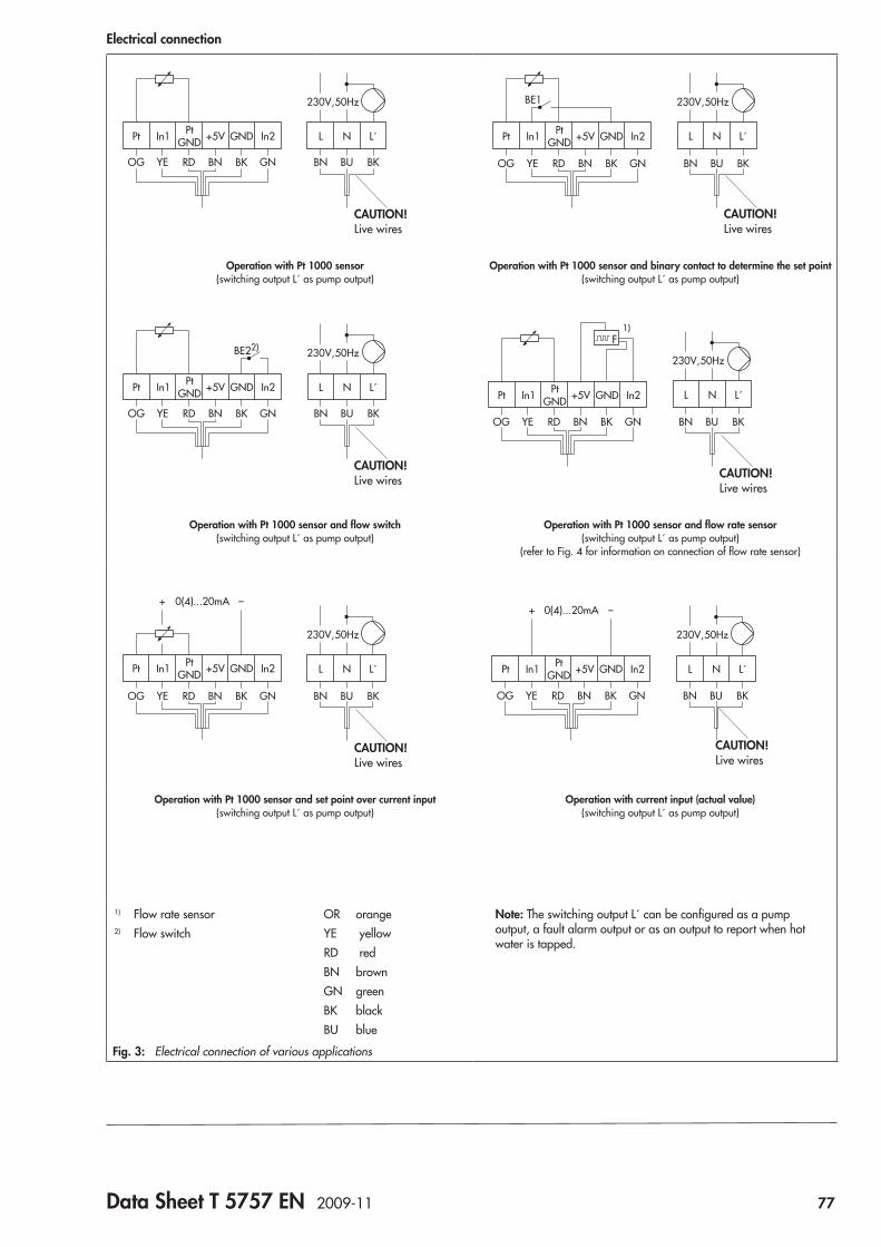
Data Sheet T 5757 EN 2009-11 77
Electrical connection
OG YE RD BN BK GN
230V,50Hz
+5V GNDPt PtGND In2In1 L N L´
BN BU BK
CAUTION! Live wires
BE1
+5V GNDPt PtGND In2In1
OG YE RD BN BK GN BN BU BK
230V,50Hz
L N L´
CAUTION! Live wires
Operation with Pt 1000 sensor(switching output L´ as pump output)
Operation with Pt 1000 sensor and binary contact to determine the set point(switching output L´ as pump output)
BE22)
+5V GNDPt PtGND In2In1
OG YE RD BN BK GN BN BU BK
230V,50Hz
L N L´
CAUTION! Live wires
1)
+5V GNDPt PtGND In2In1
OG YE RD BN BK GN BN BU BK
230V,50Hz
L N L´
CAUTION! Live wires
Operation with Pt 1000 sensor and flow switch(switching output L´ as pump output)
Operation with Pt 1000 sensor and flow rate sensor(switching output L´ as pump output)
(refer to Fig. 4 for information on connection of flow rate sensor)
CAUTION! Live wires
+ 0(4)...20mA –
+5V GNDPt PtGND In2In1
OG YE RD BN BK GN BN BU BK
230V,50Hz
L N L´
+ 0(4)...20mA –
+5V GNDPt PtGND In2In1
OG YE RD BN BK GN BN BU BK
230V,50Hz
L N L´
CAUTION! Live wires
Operation with Pt 1000 sensor and set point over current input(switching output L´ as pump output)
Operation with current input (actual value)(switching output L´ as pump output)
1) Flow rate sensor2) Flow switch
OR orangeYE yellowRD redBN brownGN greenBK blackBU blue
Note: The switching output L´ can be configured as a pump output, a fault alarm output or as an output to report when hot water is tapped.
Fig. 3: Electrical connection of various applications
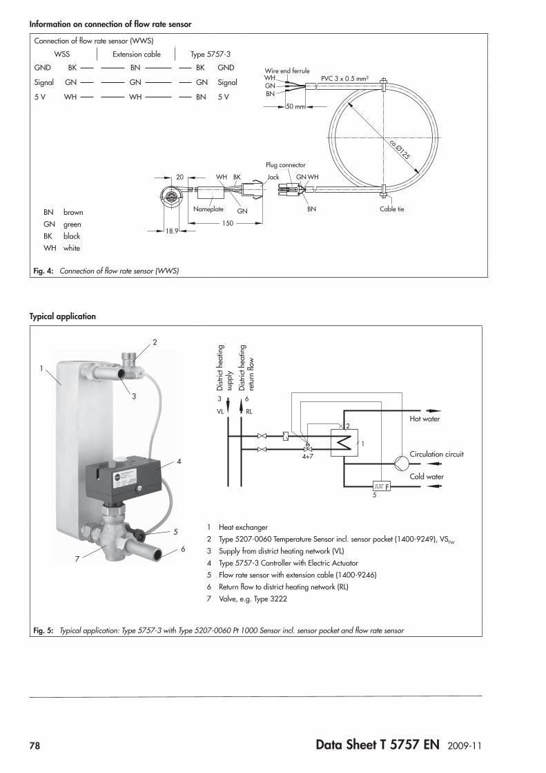
78 Data Sheet T 5757 EN 2009-11
Information on connection of flow rate sensor
Connection of flow rate sensor (WWS)
WSS Extension cable Type 5757-3
GND BK BN BK GND
Signal GN GN GN Signal
5 V WH WH BN 5 V
BN brownGN greenBK blackWH white
Fig. 4: Connection of flow rate sensor (WWS)
Typical application
2
3
1
5
67
4
VL RL
3 6
4+7
1
2
5
Hot water
Circulation circuit
Cold water
Distr
ict h
eatin
g su
pply
Distr
ict h
eatin
g re
turn
flow
1 Heat exchanger2 Type 5207-0060 Temperature Sensor incl. sensor pocket (1400-9249), VSTW
3 Supply from district heating network (VL)4 Type 5757-3 Controller with Electric Actuator5 Flow rate sensor with extension cable (1400-9246)6 Return flow to district heating network (RL)7 Valve, e.g. Type 3222
Fig. 5: Typical application: Type 5757-3 with Type 5207-0060 Pt 1000 Sensor incl. sensor pocket and flow rate sensor
18.9
20
150
BK Jack
GN
WH
Nameplate Cable tie
Plug connector
Wire end ferrule
BN
GN WH
BNGNWH
50 mm
PVC 3 x 0.5 mm²
ca.Ø125
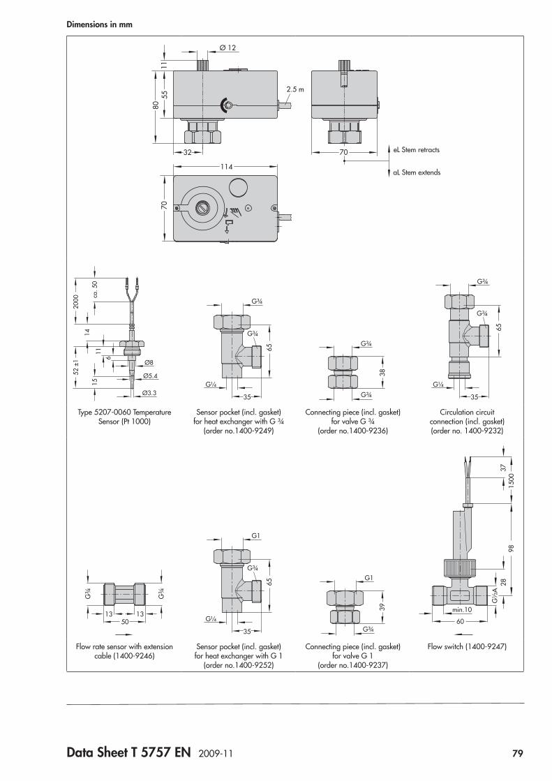
Data Sheet T 5757 EN 2009-11 79
Dimensions in mm
Ø 12
5580
1132 70 eL Stem retracts
aL Stem extends114
2.5 m
70
Ø3.3
Ø5.4
1115
14
52 ±
120
00 ca. 5
0
Ø8
6
G¼
G¾
35
G¾
65
38
G¾
G¾G¼
G¾
35
G¾
65
Type 5207-0060 Temperature Sensor (Pt 1000)
Sensor pocket (incl. gasket) for heat exchanger with G ¾
(order no.1400-9249)
Connecting piece (incl. gasket) for valve G ¾
(order no.1400-9236)
Circulation circuit connection (incl. gasket) (order no. 1400-9232)
50
G¾
G¾
13 13G¼
G1
35
G¾
65
39
G1
G¾
28G
½A
60
min.10
1500
3798
Flow rate sensor with extension cable (1400-9246)
Sensor pocket (incl. gasket) for heat exchanger with G 1
(order no.1400-9252)
Connecting piece (incl. gasket) for valve G 1
(order no.1400-9237)
Flow switch (1400-9247)


Data Sheet T 5724 EN 2010-06 81
Fig. 1: Type 5724 Controller with Electric Actuator
ApplicationElectric actuator with integrated digital controller for heating, ventilation and air-conditioning systems. For globe and three-way valves, e.g. Types 3213, 3214, 3260, 3222 or 3226 Valves in nominal sizes DN 15 to 50.
The Type 5724 and Type 5725 are a combination of a linear actuator and an integrated digital controller. They are especially designed for DHW heating in instantaneous heating systems for small to medium-sized buildings and for fixed set point control circuits in mechanical engineering applications. They are par-ticularly suitable for mounting to SAMSON Types 3213, 3214, 3260, 3222 and 3226 Valves.The Type 5724 Actuator is without fail-safe action and Type 5725 with fail-safe action. The Type 5724 has a manual override to manually move the valve in the de-energized state.
Special features • Control using two different set points, e.g. DHW tempera-
ture and DHW temperature for thermal disinfection. • Manual setting possible at the set point potentiometer or
over TROVIS-VIEW software • Function to maintain water temperature constant, prevent-
ing the heat exchanger from cooling down between tap-ping
• Pump output to control a circulation pump can alterna-tively be used as a fault alarm output
• Direction of action reversible: – Globe valve opens when the actuator stem retracts (in-
creasing/increasing) – Three-way mixing valve mixes/diverts the flow(s) when
the actuator stem extends (increasing/decreasing) • Limit value monitoring:
– The valve is closed by the actuator when the maximum adjustable limit value is exceeded
– The frost protection function is started when the tem-perature falls below the minimum adjustable limit
• Configuration, parameterization, diagnostic function and direct connection for monitoring over TROVIS-VIEW soft-ware – Direct data transmission using a connecting cable (di-
rect connection to PC) – Data transmission using a memory pen
Controllers with Electric ActuatorsType 5724, without fail-safe actionType 5725, with fail-safe action
for domestic hot water heating
Typetested versionThe Type 5725 Controller with Electric Actuator is typetested in the force-locking version together with various SAMSON valves by the German Technical Inspectorate (TÜV) according to DIN EN 14597. Register number available on request.
Note: Refer to Data Sheets T 5868 EN, T 5869 EN, T 5861 EN, T 5866 EN and T 5863 EN for details on Types 3213, 3214, 3260, 3222 and 3226 Valves.
Accessories – TROVIS-VIEW configuration software (6661-1060) for
Type 5724/5725 Controller with Electric Actuator – Hardware package with a memory pen-64, a connecting
cable and a modular adapter (1400-9998) – Memory pen-64 (1400-9753) – Type 5207-0060 Pt 1000 Sensor – Sensor pocket (1400-9249) – Flow rate sensor with extension cable with mating connec-
tor (1400-9246) – Flow switch (1400-9247)
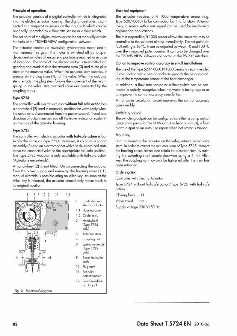
82 Data Sheet T 5724 EN 2010-06
Principle of operationThe actuator consists of a digital controller which is integrated into the electric actuator housing. The digital controller is con-nected to a temperature sensor on the input side which can be optionally upgraded by a flow rate sensor or a flow switch.The set point of the digital controller can be set manually or with the help of the TROVIS-VIEW configuration software.The actuator contains a reversible synchronous motor and a maintenance-free gear. The motor is switched off by torque-dependent switches when an end position is reached or in case of overload. The force of the electric motor is transmitted via gearing and crank disk to the actuator stem (3) and to the plug stem of the mounted valve. When the actuator stem extends, it presses on the plug stem (10) of the valve. When the actuator stem retracts, the plug stem follows the movement of the return spring in the valve. Actuator and valve are connected by the coupling nut (4).
Type 5724The controller with electric actuator without fail-safe action has a handwheel (2) used to manually position the valve (only when the actuator is disconnected from the power supply). Travel and direction of action can be read off the travel indication scale (9) on the side of the actuator housing.
Type 5725The controller with electric actuator with fail-safe action is ba-sically the same as Type 5724. However, it contains a spring assembly (8) and an electromagnet which in de-energized state move the connected valve to the appropriate fail-safe position. The Type 5725 Actuator is only available with fail-safe action “Actuator stem extends”.A handwheel (2) is not fitted. On disconnecting the actuator from the power supply and removing the housing cover (1.1), manual override is possible using an Allen key. As soon as the Allen key is released, the actuator immediately moves back to its original position.
06
1215
15 126
0
0
6 1215
0
100
50
8 9 1 1.1
11
212 1.2
4
3
A AB
B
1 Controller with electric actuator
1.1 Housing cover1.2 Cable entry2 Handwheel
(Type 5724 only)
3 Actuator stem4 Coupling nut8 Spring assembly
(Type 5725 only)
9 Travel indication scale
10 Plug stem11 Set point
potentiometer12 Serial interface
(RJ-12 jack)
Fig. 2: Functional diagram
Electrical equipmentThe actuator requires a Pt 1000 temperature sensor (e.g. Type 5207-0060) to be connected for it to function. Alterna-tively, a sensor with a mA signal can be used for mechanical engineering applications.The fast-responding Pt 1000 sensor allows the temperature to be controlled to the set point almost immediately. The set point de-fault setting is 60 °C. It can be adjusted between 10 and 100 °C over the integrated potentiometer. It can also be changed over the TROVIS-VIEW software connected at the RS-232 interface.
Option to improve control accuracy in small installationsThe use of the Type 5207-0060 Pt 1000 Sensor is recommended in conjunction with a sensor pocket to provide the best position-ing of the temperature sensor at the heat exchanger. In addition, a flow rate sensor or a flow switch can be con-nected to quickly recognize when hot water is being tapped or to improve the control accuracy even further. A hot water circulation circuit improves the control accuracy considerably.
Switching outputThe switching output can be configured as either a pump output (circulation pump for the DHW circuit or heating circuit), a fault alarm output or an output to report when hot water is tapped.
MountingPrior to mounting the actuator on the valve, retract the actuator stem. In order to retract the actuator stem of Type 5725, remove the housing cover, retract and retain the actuator stem by turn-ing the actuating shaft counterclockwise using a 4 mm Allen key. The coupling nut may only be tightened after the stem has been retracted.
Ordering textController with Electric ActuatorType 5724 without fail-safe action/Type 5725 with fail-safe actionClosing force … NValve travel … mmSupply voltage 230 V/50 Hz
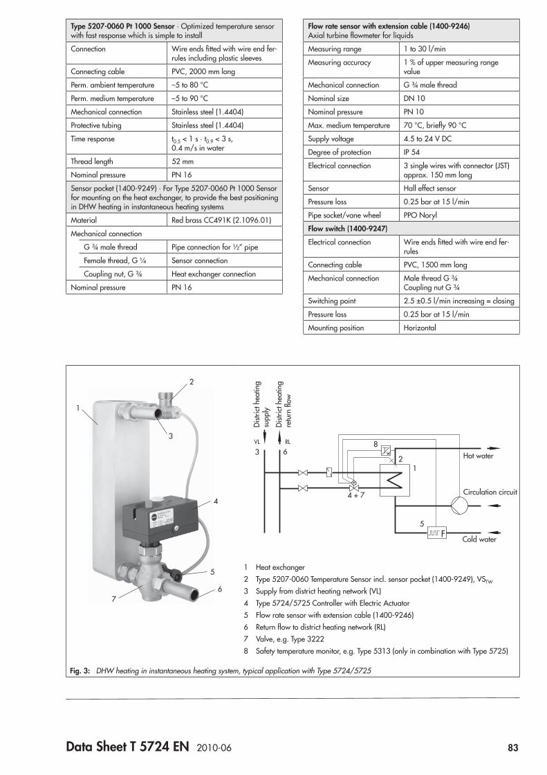
Data Sheet T 5724 EN 2010-06 83
Type 5207-0060 Pt 1000 Sensor · Optimized temperature sensor with fast response which is simple to install
Connection Wire ends fitted with wire end fer-rules including plastic sleeves
Connecting cable PVC, 2000 mm long
Perm. ambient temperature –5 to 80 °C
Perm. medium temperature –5 to 90 °C
Mechanical connection Stainless steel (1.4404)
Protective tubing Stainless steel (1.4404)
Time response t0.5 < 1 s · t0.9 < 3 s, 0.4 m/s in water
Thread length 52 mm
Nominal pressure PN 16
Sensor pocket (1400-9249) · For Type 5207-0060 Pt 1000 Sensor for mounting on the heat exchanger, to provide the best positioning in DHW heating in instantaneous heating systems
Material Red brass CC491K (2.1096.01)
Mechanical connection
G ¾ male thread Pipe connection for ½” pipe
Female thread, G ¼ Sensor connection
Coupling nut, G ¾ Heat exchanger connection
Nominal pressure PN 16
Flow rate sensor with extension cable (1400-9246) Axial turbine flowmeter for liquids
Measuring range 1 to 30 l/min
Measuring accuracy 1 % of upper measuring range value
Mechanical connection G ¾ male thread
Nominal size DN 10
Nominal pressure PN 10
Max. medium temperature 70 °C, briefly 90 °C
Supply voltage 4.5 to 24 V DC
Degree of protection IP 54
Electrical connection 3 single wires with connector (JST) approx. 150 mm long
Sensor Hall effect sensor
Pressure loss 0.25 bar at 15 l/min
Pipe socket/vane wheel PPO Noryl
Flow switch (1400-9247)
Electrical connection Wire ends fitted with wire end fer-rules
Connecting cable PVC, 1500 mm long
Mechanical connection Male thread G ¾ Coupling nut G ¾
Switching point 2.5 ±0.5 l/min increasing = closing
Pressure loss 0.25 bar at 15 l/min
Mounting position Horizontal
2
3
1
5
67
4
VL RL
Hot water
Circulation circuit
Cold water
Distr
ict h
eatin
g su
pply
Distr
ict h
eatin
g re
turn
flow
1 Heat exchanger2 Type 5207-0060 Temperature Sensor incl. sensor pocket (1400-9249), VSTW
3 Supply from district heating network (VL)4 Type 5724/5725 Controller with Electric Actuator5 Flow rate sensor with extension cable (1400-9246)6 Return flow to district heating network (RL)7 Valve, e.g. Type 32228 Safety temperature monitor, e.g. Type 5313 (only in combination with Type 5725)
Fig. 3: DHW heating in instantaneous heating system, typical application with Type 5724/5725
68
4 + 7
23
1
5
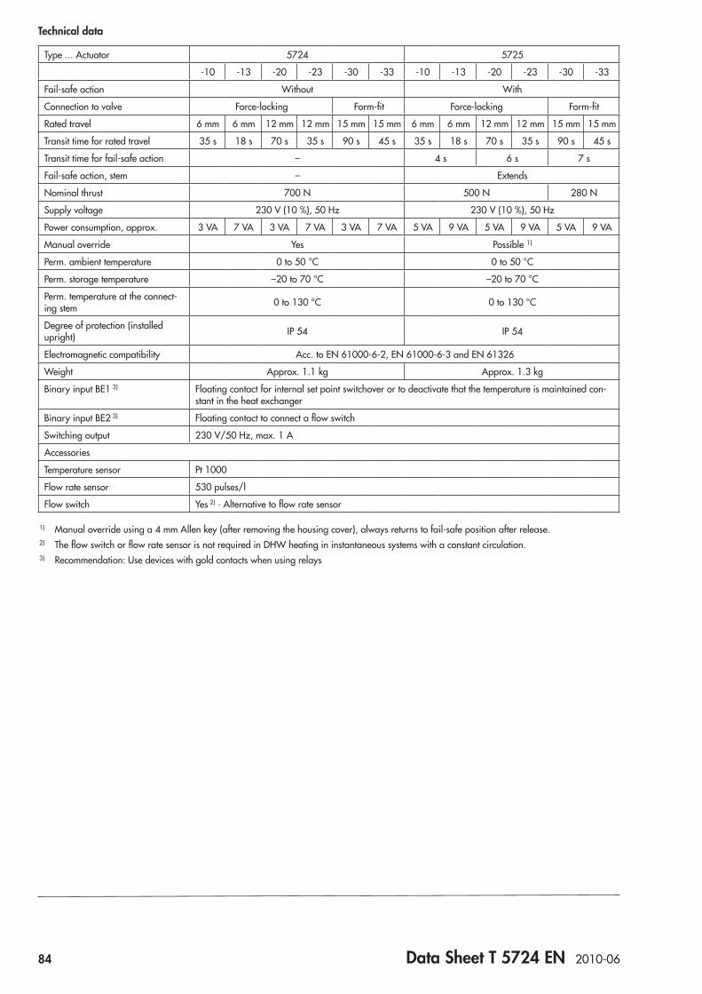
84 Data Sheet T 5724 EN 2010-06
Technical data
Type ... Actuator 5724 5725
-10 -13 -20 -23 -30 -33 -10 -13 -20 -23 -30 -33
Fail-safe action Without With
Connection to valve Force-locking Form-fit Force-locking Form-fit
Rated travel 6 mm 6 mm 12 mm 12 mm 15 mm 15 mm 6 mm 6 mm 12 mm 12 mm 15 mm 15 mm
Transit time for rated travel 35 s 18 s 70 s 35 s 90 s 45 s 35 s 18 s 70 s 35 s 90 s 45 s
Transit time for fail-safe action – 4 s 6 s 7 s
Fail-safe action, stem – Extends
Nominal thrust 700 N 500 N 280 N
Supply voltage 230 V (10 %), 50 Hz 230 V (10 %), 50 Hz
Power consumption, approx. 3 VA 7 VA 3 VA 7 VA 3 VA 7 VA 5 VA 9 VA 5 VA 9 VA 5 VA 9 VA
Manual override Yes Possible 1)
Perm. ambient temperature 0 to 50 °C 0 to 50 °C
Perm. storage temperature –20 to 70 °C –20 to 70 °C
Perm. temperature at the connect-ing stem 0 to 130 °C 0 to 130 °C
Degree of protection (installed upright) IP 54 IP 54
Electromagnetic compatibility Acc. to EN 61000-6-2, EN 61000-6-3 and EN 61326
Weight Approx. 1.1 kg Approx. 1.3 kg
Binary input BE1 3) Floating contact for internal set point switchover or to deactivate that the temperature is maintained con-stant in the heat exchanger
Binary input BE2 3) Floating contact to connect a flow switch
Switching output 230 V/50 Hz, max. 1 A
Accessories
Temperature sensor Pt 1000
Flow rate sensor 530 pulses/l
Flow switch Yes 2) · Alternative to flow rate sensor
1) Manual override using a 4 mm Allen key (after removing the housing cover), always returns to fail-safe position after release.2) The flow switch or flow rate sensor is not required in DHW heating in instantaneous systems with a constant circulation.3) Recommendation: Use devices with gold contacts when using relays
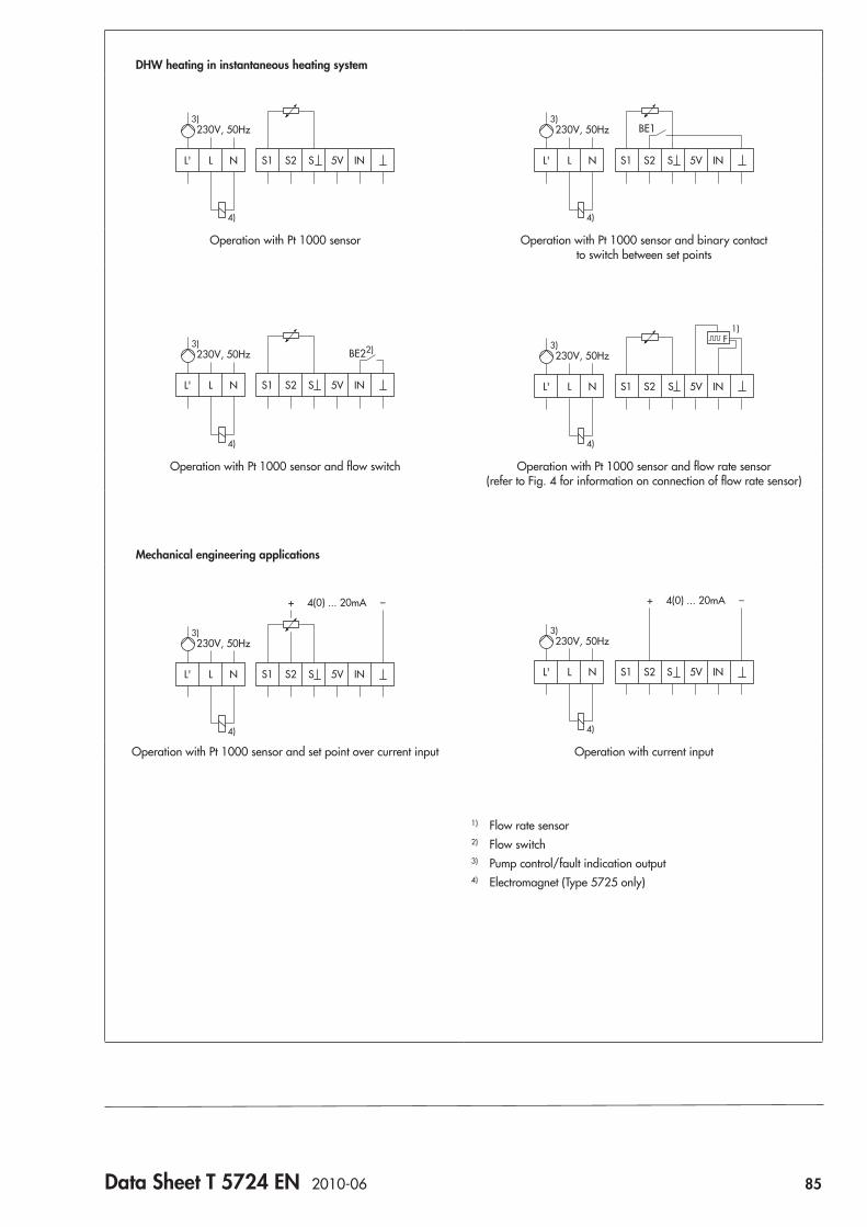
Data Sheet T 5724 EN 2010-06 85
DHW heating in instantaneous heating system
LL' N 5V INS1 SS2
230V, 50Hz3)
4)
BE1
LL' N 5V INS1 SS2
230V, 50Hz3)
4)
Operation with Pt 1000 sensor Operation with Pt 1000 sensor and binary contact to switch between set points
BE22)
4)
LL' N 5V INS1 SS2
230V, 50Hz3)
1)
LL' N 5V INS1 SS2
230V, 50Hz3)
4)
Operation with Pt 1000 sensor and flow switch Operation with Pt 1000 sensor and flow rate sensor (refer to Fig. 4 for information on connection of flow rate sensor)
Mechanical engineering applications
LL' N 5V INS1 SS2
230V, 50Hz
+ –4(0) ... 20mA
3)
4)
LL' N 5V INS1 SS2
230V, 50Hz
+ –4(0) ... 20mA
3)
4)
Operation with Pt 1000 sensor and set point over current input Operation with current input
1) Flow rate sensor2) Flow switch3) Pump control/fault indication output4) Electromagnet (Type 5725 only)
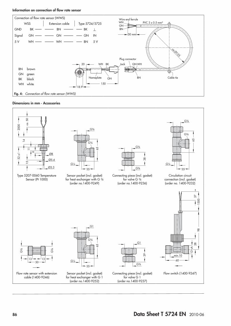
86 Data Sheet T 5724 EN 2010-06
Information on connection of flow rate sensor
Connection of flow rate sensor (WWS)
WSS Extension cable Type 5724/5725
GND BK BN BK
Signal GN GN GN IN
5 V WH WH BN 5 V
BN brownGN greenBK blackWH white
Fig. 4: Connection of flow rate sensor (WWS)
Dimensions in mm · Accessories
Ø3.3
Ø5.4
1115
14
52 ±
120
00 ca. 5
0
Ø8
6
G¼
G¾
35
G¾
65
38G¾
G¾G¼
G¾
35
G¾
65
Type 5207-0060 Temperature Sensor (Pt 1000)
Sensor pocket (incl. gasket) for heat exchanger with G ¾
(order no.1400-9249)
Connecting piece (incl. gasket) for valve G ¾
(order no.1400-9236)
Circulation circuit connection (incl. gasket) (order no. 1400-9232)
50
G¾
G¾
13 13G¼
G1
35
G¾
65
39
G1
G¾
28G
½A
60
min.10
1500
3798
Flow rate sensor with extension cable (1400-9246)
Sensor pocket (incl. gasket) for heat exchanger with G 1
(order no.1400-9252)
Connecting piece (incl. gasket) for valve G 1
(order no.1400-9237)
Flow switch (1400-9247)
18.9
20
150
BK Jack
GN
WH
Nameplate Cable tie
Plug connector
Wire end ferrule
BN
GN WH
BNGNWH
50 mm
PVC 3 x 0.5 mm²
ca.Ø125
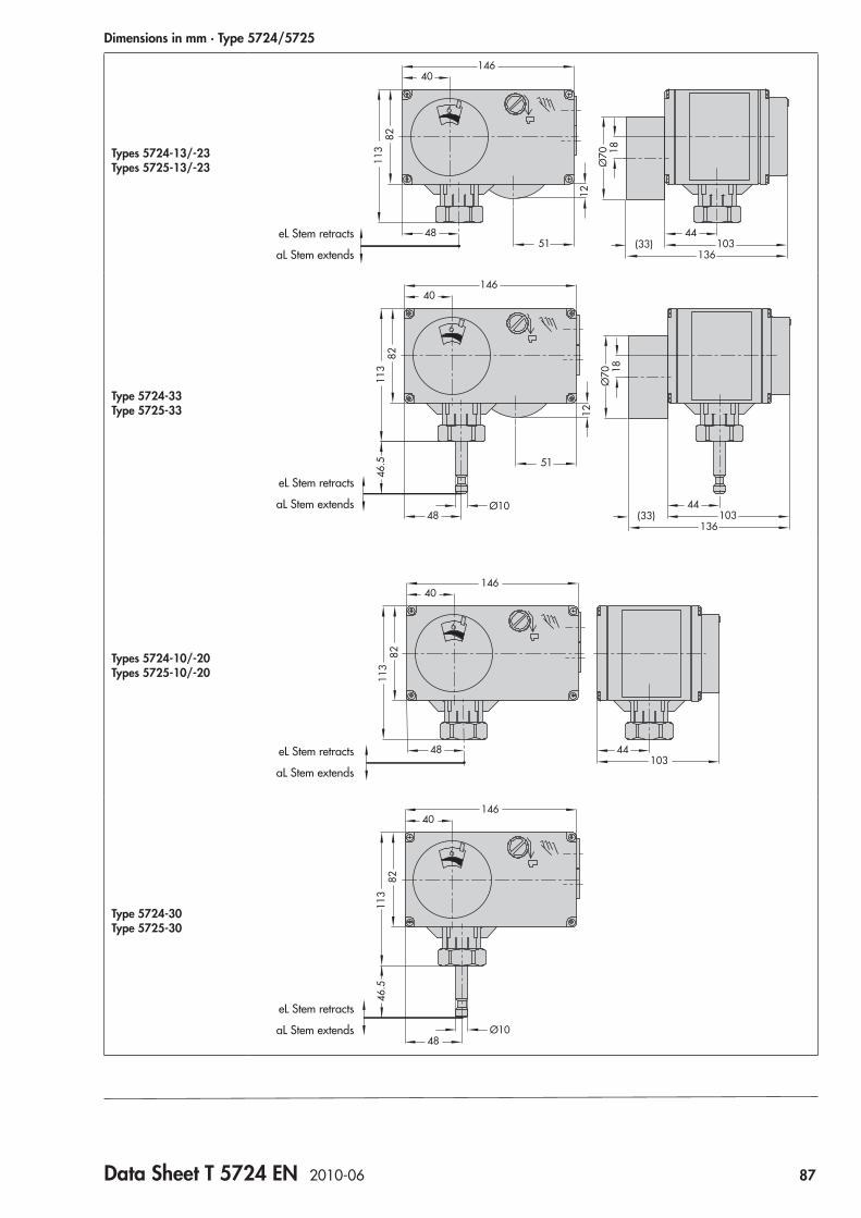
Data Sheet T 5724 EN 2010-06 87
Dimensions in mm · Type 5724/5725
Types 5724-13/-23 Types 5725-13/-23
eL Stem retracts
aL Stem extends
146
8211
3
12
18Ø
70
4851
44(33) 103
136
40
Type 5724-33 Type 5725-33
eL Stem retracts
aL Stem extends
146
8211
3
12
18Ø
70
48
51
44(33) 103
136
40
46.5
Ø10
Types 5724-10/-20 Types 5725-10/-20
146
8211
3
48 44103
40
eL Stem retracts
aL Stem extends
Type 5724-30 Type 5725-30
eL Stem retracts
aL Stem extends
146
8211
346
.5
48Ø10
40

Information Sheet T 5200 EN 2010-10 89
Field of application: Heating, ventilation and air-conditioning
Temperature SensorsThermostats

90 Information Sheet T 5200 EN 2010-10
Outdoor sensorsMeasurement of outdoor temperature mounted on the exterior walls of buildings
Type 5225 5226 5227-2
Resistor Pt 100 Pt 100 Pt 1000
Quantity 1 2 1
Permissible temperature [°C]
Medium –20 … 50 –20 … 50 –35 … 85
Ambient –35 … 85 –35 … 85 –35 … 85
Style
Data Sheet T 5203 EN T 5203 EN T 5220 EN
Duct sensorsMeasurement of supply air, mixed air, or exhaust air tempera-tures in ventilation and air-conditioning systems (non-corrosive air or gases)
Type 5215 5216 5217
Resistor Pt 100 Pt 100 Pt 1000
Quantity 1 2 1
Sensor length [mm] 60 … 300 60 … 300 60 … 280
Sensor shaft Nickel-plated brass
Nickel-plated brass
Nickel- plated brass
Permissible temperature [°C]
Medium –35 … 200 –35 … 200 –20 … 150
Ambient –20 … 70 –20 … 70 –20 … 70
Style
Data Sheet T 5203 EN T 5203 EN T 5220 EN
Fig. 1: Type 5227-2 Outdoor Sensor
Fig. 2: Type 5257-5 Room Panel
Room sensors and room panelsMeasurement of room temperature in recreation rooms and offices
Type 5255 5257-1 1) 5257-2 1) 5257-3 1) 5257-5 1) 5257-6 1) 5257-7 1)
Resistor Pt 100 Pt 1000 Pt 1000 Pt 1000 Pt 1000 Pt 1000 Pt 1000
Quantity 1 1 1 1 1 1 1
Perm. temp. [°C] –35 … 85 –35 … 70 –35 … 70 –35 … 70 –20 … 60 –35 … 70 –20 …60
Equipped with
Set point correction • • • • •
Mode selector switch • •
Step switch •
Pushbutton •
Style+_ +_ +_
0 I II
Data Sheet T 5203 EN T 5220 EN T 5220 EN T 5220 EN T 5220 EN T 5220 EN T 5220 EN
1) See associated Data Sheet T 5220 EN for possible connections to SAMSON controllers
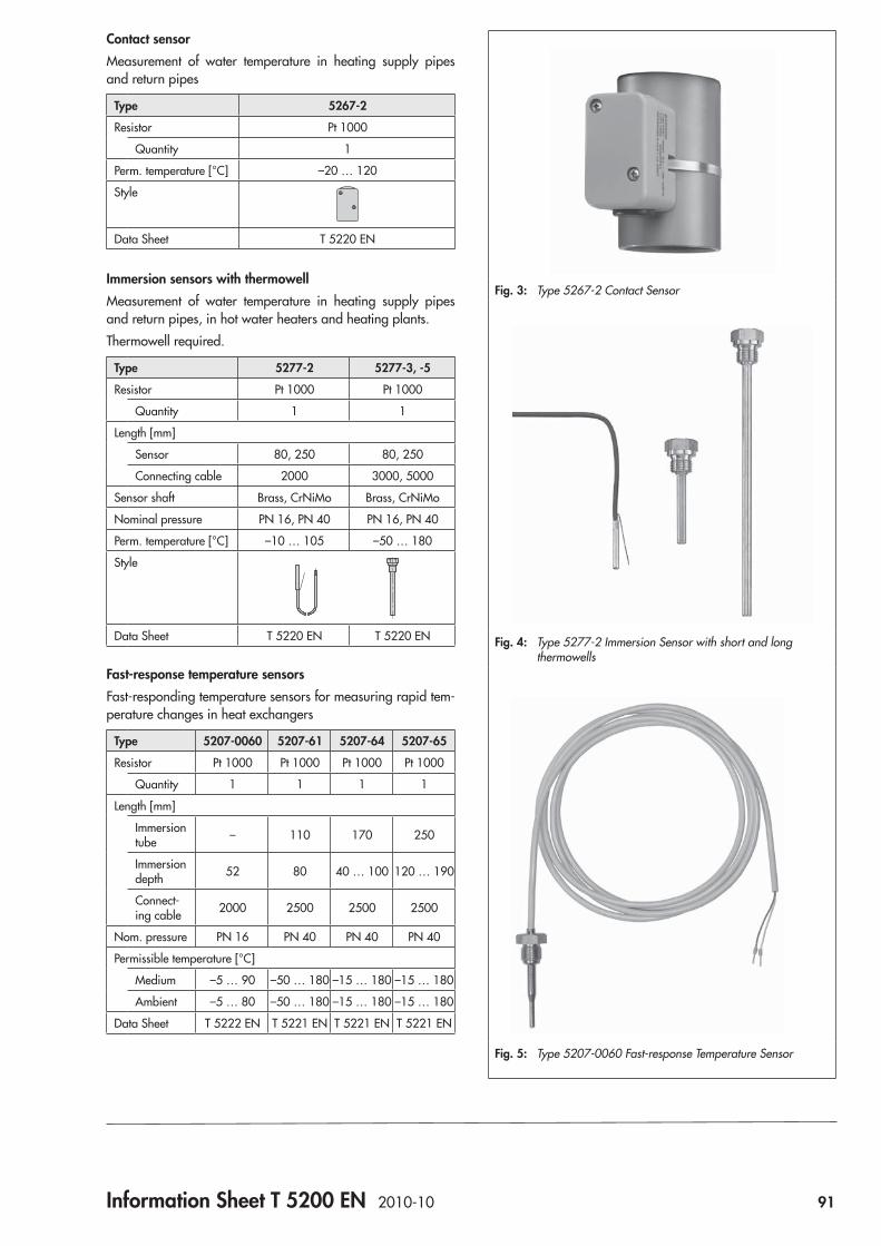
Information Sheet T 5200 EN 2010-10 91
Contact sensorMeasurement of water temperature in heating supply pipes and return pipes
Type 5267-2
Resistor Pt 1000
Quantity 1
Perm. temperature [°C] –20 … 120
Style
Data Sheet T 5220 EN
Immersion sensors with thermowellMeasurement of water temperature in heating supply pipes and return pipes, in hot water heaters and heating plants.Thermowell required.
Type 5277-2 5277-3, -5
Resistor Pt 1000 Pt 1000
Quantity 1 1
Length [mm]
Sensor 80, 250 80, 250
Connecting cable 2000 3000, 5000
Sensor shaft Brass, CrNiMo Brass, CrNiMo
Nominal pressure PN 16, PN 40 PN 16, PN 40
Perm. temperature [°C] –10 … 105 –50 … 180
Style
Data Sheet T 5220 EN T 5220 EN
Fast-response temperature sensorsFast-responding temperature sensors for measuring rapid tem-perature changes in heat exchangers
Type 5207-0060 5207-61 5207-64 5207-65
Resistor Pt 1000 Pt 1000 Pt 1000 Pt 1000
Quantity 1 1 1 1
Length [mm]
Immersion tube – 110 170 250
Immersion depth 52 80 40 … 100 120 … 190
Connect-ing cable 2000 2500 2500 2500
Nom. pressure PN 16 PN 40 PN 40 PN 40
Permissible temperature [°C]
Medium –5 … 90 –50 … 180 –15 … 180 –15 … 180
Ambient –5 … 80 –50 … 180 –15 … 180 –15 … 180
Data Sheet T 5222 EN T 5221 EN T 5221 EN T 5221 EN
Fig. 3: Type 5267-2 Contact Sensor
Fig. 4: Type 5277-2 Immersion Sensor with short and long thermowells
Fig. 5: Type 5207-0060 Fast-response Temperature Sensor
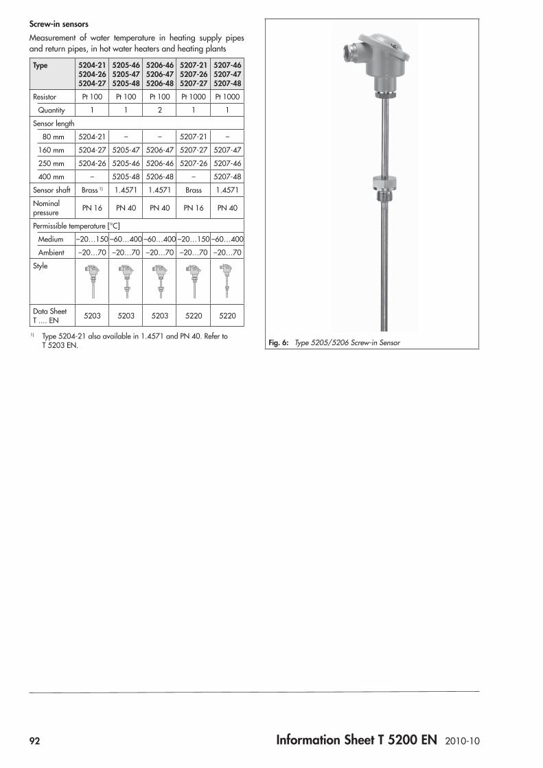
92 Information Sheet T 5200 EN 2010-10
Screw-in sensorsMeasurement of water temperature in heating supply pipes and return pipes, in hot water heaters and heating plants
Type 5204-21 5204-26 5204-27
5205-46 5205-47 5205-48
5206-46 5206-47 5206-48
5207-21 5207-26 5207-27
5207-46 5207-47 5207-48
Resistor Pt 100 Pt 100 Pt 100 Pt 1000 Pt 1000
Quantity 1 1 2 1 1
Sensor length
80 mm 5204-21 – – 5207-21 –
160 mm 5204-27 5205-47 5206-47 5207-27 5207-47
250 mm 5204-26 5205-46 5206-46 5207-26 5207-46
400 mm – 5205-48 5206-48 – 5207-48
Sensor shaft Brass 1) 1.4571 1.4571 Brass 1.4571
Nominal pressure PN 16 PN 40 PN 40 PN 16 PN 40
Permissible temperature [°C]
Medium –20…150 –60…400 –60…400 –20…150 –60…400
Ambient –20…70 –20…70 –20…70 –20…70 –20…70
Style
Data Sheet T .... EN 5203 5203 5203 5220 5220
1) Type 5204-21 also available in 1.4571 and PN 40. Refer to T 5203 EN. Fig. 6: Type 5205/5206 Screw-in Sensor
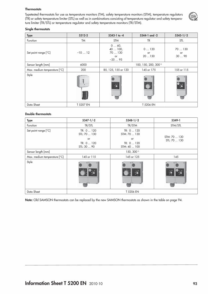
Information Sheet T 5200 EN 2010-10 93
ThermostatsTypetested thermostats for use as temperature monitors (TM), safety temperature monitors (STM), temperature regulators (TR) or safety temperature limiter (STL) as well as in combinations consisting of temperature regulator and safety tempera-ture limiter (TR/STL) or temperature regulator and safety temperature monitors (TR/STM).
Single thermostats
Type 5312-2 5343-1 to -4 5344-1 and -2 5345-1/-2
Function TM STM TR STL
Set point range [°C] –10 … 12
0 … 60, 40 … 100, 70 … 130
or –35 … 95
0 … 120 or
20 …150
70 … 130 or
30 … 90
Sensor length [mm] 6000 100, 150, 200, 300 1)
Max. medium temperature [°C] 200 85, 125, 155 or 120 145 or 175 155 or 115
Style
Data Sheet T 5207 EN T 5206 EN
Double thermostats
Type 5347-1/-2 5348-1/-2 5349-1
Function TR/STL TR/STM STM/STL
Set point range [°C] TR: 0 ... 120 STL: 70 ... 130
or TR: 0 ... 120 STL: 30 ... 90
TR: 0 ... 120 STM: 70 ... 130
or TR: 0 ... 120 STM: 40 ... 100
STM: 70 ... 130 STL: 70 ... 130
Sensor length [mm] 150, 300 1)
Max. medium temperature [°C] 145 or 115 145 or 125 145
Style
Data Sheet T 5206 EN
Note: Old SAMSON thermostats can be replaced by the new SAMSON thermostats as shown in the table on page 94.
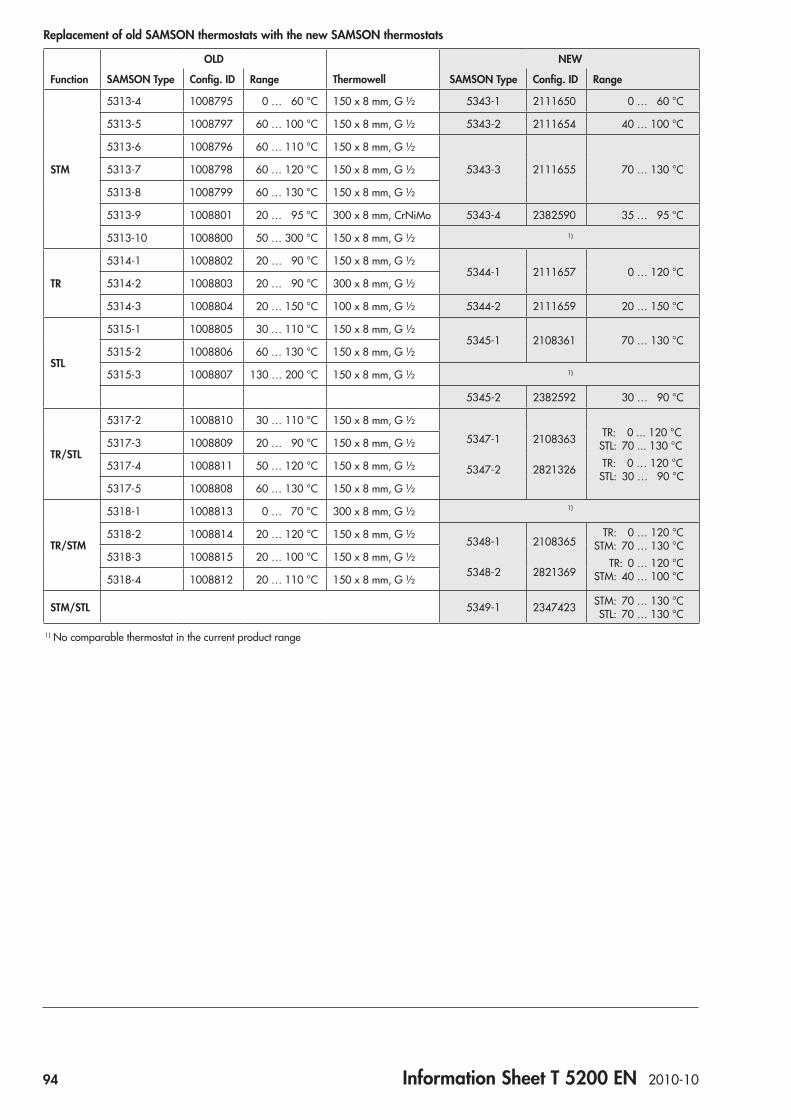
94 Information Sheet T 5200 EN 2010-10
Replacement of old SAMSON thermostats with the new SAMSON thermostats
OLD NEW
Function SAMSON Type Config. ID Range Thermowell SAMSON Type Config. ID Range
STM
5313-4 1008795 0 … 60 °C 150 x 8 mm, G ½ 5343-1 2111650 0 … 60 °C
5313-5 1008797 60 … 100 °C 150 x 8 mm, G ½ 5343-2 2111654 40 … 100 °C
5313-6 1008796 60 … 110 °C 150 x 8 mm, G ½
5343-3 2111655 70 … 130 °C5313-7 1008798 60 … 120 °C 150 x 8 mm, G ½
5313-8 1008799 60 … 130 °C 150 x 8 mm, G ½
5313-9 1008801 20 … 95 °C 300 x 8 mm, CrNiMo 5343-4 2382590 35 … 95 °C
5313-10 1008800 50 … 300 °C 150 x 8 mm, G ½ 1)
TR
5314-1 1008802 20 … 90 °C 150 x 8 mm, G ½5344-1 2111657 0 … 120 °C
5314-2 1008803 20 … 90 °C 300 x 8 mm, G ½
5314-3 1008804 20 … 150 °C 100 x 8 mm, G ½ 5344-2 2111659 20 … 150 °C
STL
5315-1 1008805 30 … 110 °C 150 x 8 mm, G ½5345-1 2108361 70 … 130 °C
5315-2 1008806 60 … 130 °C 150 x 8 mm, G ½
5315-3 1008807 130 … 200 °C 150 x 8 mm, G ½ 1)
5345-2 2382592 30 … 90 °C
TR/STL
5317-2 1008810 30 … 110 °C 150 x 8 mm, G ½
5347-1
5347-2
2108363
2821326
TR: 0 ... 120 °C STL: 70 ... 130 °C TR: 0 … 120 °C STL: 30 … 90 °C
5317-3 1008809 20 … 90 °C 150 x 8 mm, G ½
5317-4 1008811 50 … 120 °C 150 x 8 mm, G ½
5317-5 1008808 60 … 130 °C 150 x 8 mm, G ½
TR/STM
5318-1 1008813 0 … 70 °C 300 x 8 mm, G ½ 1)
5318-2 1008814 20 … 120 °C 150 x 8 mm, G ½5348-1
5348-2
2108365
2821369
TR: 0 … 120 °C STM: 70 … 130 °C TR: 0 … 120 °C STM: 40 … 100 °C
5318-3 1008815 20 … 100 °C 150 x 8 mm, G ½
5318-4 1008812 20 … 110 °C 150 x 8 mm, G ½
STM/STL 5349-1 2347423 STM: 70 … 130 °C STL: 70 … 130 °C
1) No comparable thermostat in the current product range
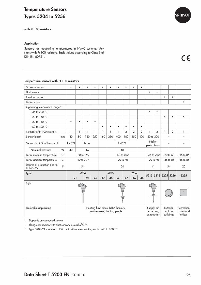
Data Sheet T 5203 EN 2010-10 95
Temperature sensors with Pt 100 resistors
Screw-in sensor • • • • • • • • • •
Duct sensor • •
Outdoor sensor • •
Room sensor •
Operating temperature range 1)
–35 to 200 °C • •
–20 to 50 °C • • •
–20 to 150 °C • • • •
–60 to 400 °C • • • • • •
Number of Pt 100 resistors 1 1 1 1 1 1 1 2 2 2 1 2 1 2 1
Sensor length mm 80 80 160 250 160 250 400 160 250 400 60 to 300 – –
Sensor shaft G ½ 2) made of 1.4571 Brass 1.4571 Nickel- plated brass – –
Nominal pressure PN 40 16 40 – – –
Perm. medium temperature °C –20 to 150 –60 to 400 –35 to 200 –20 to 50 –35 to 85
Perm. ambient temperature °C –20 to 70 3) –20 to 70 –20 to 70 –35 to 85 –35 to 85
Degree of protection acc. to EN 60529 IP 54 54 41 54 20
Type 5204 5205 52065215 5216 5225 5226 5255
-21 -27 -26 -47 -46 -48 -47 -46 -48
Style
Preferable application Heating flow pipes, DHW heaters, service water, heating plants
Supply air, mixed air, exhaust air
Exterior walls of buildings
Recreation rooms and
offices
1) Depends on connected device2) Flange connection with duct sensors instead of G ½ 3) Type 5204-21 made of 1.4571 with silicone connecting cable: –40 to 100 °C
ApplicationSensors for measuring temperatures in HVAC systems. Ver-sions with Pt 100 resistors. Basic values according to Class B of DIN EN 60751.
Temperature SensorsTypes 5204 to 5256
with Pt 100 resistors
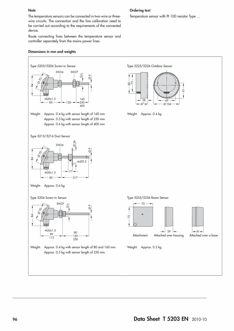
96 Data Sheet T 5203 EN 2010-10
NoteThe temperature sensors can be connected in two-wire or three-wire circuits. The connection and the line calibration need to be carried out according to the requirements of the connected device.Route connecting lines between the temperature sensor and controller separately from the mains power lines.
Dimensions in mm and weights
Ordering textTemperature sensor with Pt 100 resistor Type …
Type 5205/5206 Screw-in Sensor Type 5225/5226 Outdoor Sensor
Ø 9G½
84
85M20x1.5
SW24 SW27
120160250400
Ø 7
0
Ø4728 69
7380
61
104
Weight: Approx. 0.4 kg with sensor length of 160 mm Approx. 0.5 kg with sensor length of 250 mm Approx. 0.6 kg with sensor length of 400 mm
Weight: Approx. 0.4 kg
Type 5215/5216 Duct Sensor
Ø 9
4xØ5.2
Ø 5
6
M20x1.5
SW24
85 317
17
84
Ø 7
0
Weight: Approx. 0.6 kg
Type 5204 Screw-in Sensor Type 5255/5256 Room Sensor
Ø 9G½
M20x1.5
SW27
89112
80160250
84
Ø 7
0
29 41
72
72
Attachment Attached over housing Attached over a base
Weight: Approx. 0.4 kg with sensor length of 80 and 160 mm Approx. 0.5 kg with sensor length of 250 mm
Weight: Approx. 0.2 kg
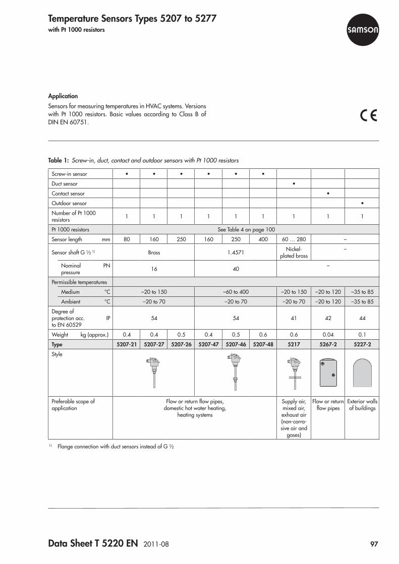
Data Sheet T 5220 EN 2011-08 97
Table 1: Screw-in, duct, contact and outdoor sensors with Pt 1000 resistors
Screw-in sensor • • • • • •
Duct sensor •
Contact sensor •
Outdoor sensor •
Number of Pt 1000 resistors 1 1 1 1 1 1 1 1 1
Pt 1000 resistors See Table 4 on page 100
Sensor length mm 80 160 250 160 250 400 60 … 280 –
Sensor shaft G ½ 1) Brass 1.4571 Nickel- plated brass
–
Nominal pressure
PN 16 40 –
Permissible temperatures
Medium °C –20 to 150 –60 to 400 –20 to 150 –20 to 120 –35 to 85
Ambient °C –20 to 70 –20 to 70 –20 to 70 –20 to 120 –35 to 85
Degree of protection acc. to EN 60529
IP 54 54 41 42 44
Weight kg (approx.) 0.4 0.4 0.5 0.4 0.5 0.6 0.6 0.04 0.1
Type 5207-21 5207-27 5207-26 5207-47 5207-46 5207-48 5217 5267-2 5227-2
Style
Preferable scope of application
Flow or return flow pipes, domestic hot water heating,
heating systems
Supply air, mixed air, exhaust air (non-corro-sive air and
gases)
Flow or return flow pipes
Exterior walls of buildings
1) Flange connection with duct sensors instead of G ½
Temperature Sensors Types 5207 to 5277with Pt 1000 resistors
ApplicationSensors for measuring temperatures in HVAC systems. Versions with Pt 1000 resistors. Basic values according to Class B of DIN EN 60751.
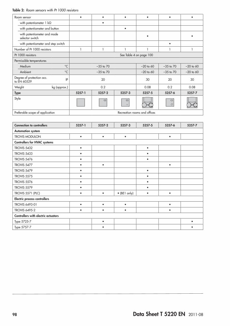
98 Data Sheet T 5220 EN 2011-08
Table 2: Room sensors with Pt 1000 resistors
Room sensor • • • • • •
with potentiometer 1 kΩ •
with potentiometer and button •
with potentiometer and mode selector switch • •
with potentiometer and step switch •
Number of Pt 1000 resistors 1 1 1 1 1 1
Pt 1000 resistors See Table 4 on page 100
Permissible temperatures
Medium °C –35 to 70 –20 to 60 –35 to 70 –20 to 60
Ambient °C –35 to 70 –20 to 60 –35 to 70 –20 to 60
Degree of protection acc. to EN 60529 IP 20 30 20 30
Weight kg (approx.) 0.2 0.08 0.2 0.08
Type 5257-1 5257-2 5257-3 5257-5 5257-6 5257-7
Style+_ +_ +_
0 I II
Preferable scope of application Recreation rooms and offices
Connection to controllers 5257-1 5257-2 5257-3 5257-5 5257-6 5257-7
Automation system
TROVIS MODULON • • • •
Controllers for HVAC systems
TROVIS 5432 • •
TROVIS 5433 • •
TROVIS 5476 • •
TROVIS 5477 • • •
TROVIS 5479 • •
TROVIS 5575 • •
TROVIS 5576 • •
TROVIS 5579 • •
TROVIS 5571 (PLC) • • • (BE1 only) • •
Electric process controllers
TROVIS 6493-01 • • • •
TROVIS 6495-2 • • • •
Controllers with electric actuators
Type 5725-7 • •
Type 5757-7 • •

Data Sheet T 5220 EN 2011-08 99
Table 3: Immersion sensors with Pt 1000 resistors (can also be used as contact sensors) 1)
Immersion sensor with thermowell/ contact sensor • • • • • • • • •
Number of Pt 1000 resistors 1 1 1 1 1 1 1 1 1
Pt 1000 resistors See Table 4 on page 100
Sensor length mm 80 250 80 250 80 250
Sensor shaft G ½ Brass CrNiMo steel Brass CrNiMo steel Brass CrNiMo steel
Nominal pressure PN 16 40 16 40 16 40
Permissible temperatures
Medium °C –10 to 105 –50 to 180
Ambient °C –10 to 105 –50 to 180
Degree of protection acc. to EN 60529 IP 52 52
Weight kg (approx.) 0.23 0.23 0.25 0.23 0.23 0.25 0.23 0.23 0.25
Length of connecting cable m 2 3 5
Type 5277-2 5277-3 5277-5
Style
Application Immersion sensor with connecting cable. Thermowell required 1) Flow or return flow pipes, domestic hot water heating, heating systems
1) AccessoriesforTypes 5277-2/-3/-5 – Brass thermowell, G ½, PN 16
Immersion length 80 mm Order no. 1099-0807 Immersion length 160 mm Order no. 8525-5005
– CrNiMo steel thermowell, G ½, PN 40 Immersion length 80 mm Order no. 1099-0805 Immersion length 250 mm Order no. 1099-0806 Immersion length 160 mm Order no. 8525-5011
– Mounting kit for contact sensor Order no. 8524-0020
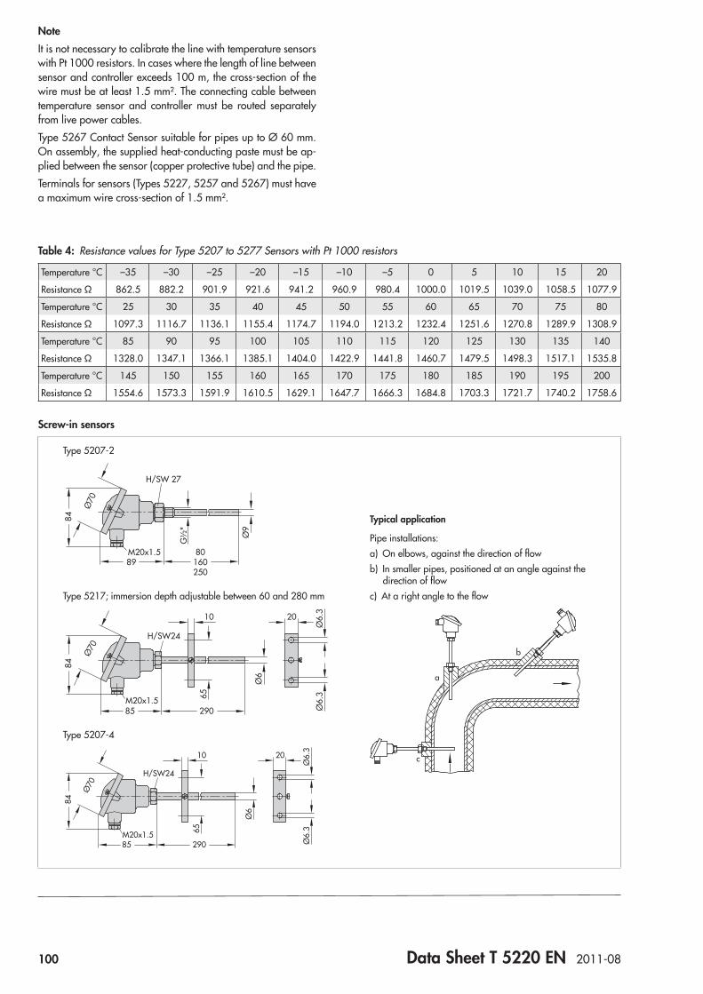
100 Data Sheet T 5220 EN 2011-08
Table 4: Resistance values for Type 5207 to 5277 Sensors with Pt 1000 resistors
Temperature °C –35 –30 –25 –20 –15 –10 –5 0 5 10 15 20
Resistance Ω 862.5 882.2 901.9 921.6 941.2 960.9 980.4 1000.0 1019.5 1039.0 1058.5 1077.9
Temperature °C 25 30 35 40 45 50 55 60 65 70 75 80
Resistance Ω 1097.3 1116.7 1136.1 1155.4 1174.7 1194.0 1213.2 1232.4 1251.6 1270.8 1289.9 1308.9
Temperature °C 85 90 95 100 105 110 115 120 125 130 135 140
Resistance Ω 1328.0 1347.1 1366.1 1385.1 1404.0 1422.9 1441.8 1460.7 1479.5 1498.3 1517.1 1535.8
Temperature °C 145 150 155 160 165 170 175 180 185 190 195 200
Resistance Ω 1554.6 1573.3 1591.9 1610.5 1629.1 1647.7 1666.3 1684.8 1703.3 1721.7 1740.2 1758.6
Screw-in sensors
Type 5207-2
Typical application
Pipe installations:a) On elbows, against the direction of flowb) In smaller pipes, positioned at an angle against the direction of flowc) At a right angle to the flow
H/SW 27
M20x1.5 80160250
89
G½
"
Ø9
84
Ø70
Type 5217; immersion depth adjustable between 60 and 280 mm
Ø70
Ø6
65
Ø6.
3Ø
6.3
84
M20x1.585 290
10 20
H/SW24
a
b
c
Type 5207-4
Ø70
Ø6
65
Ø6.
3Ø
6.3
84
M20x1.585 290
10 20
H/SW24
NoteIt is not necessary to calibrate the line with temperature sensors with Pt 1000 resistors. In cases where the length of line between sensor and controller exceeds 100 m, the cross-section of the wire must be at least 1.5 mm². The connecting cable between temperature sensor and controller must be routed separately from live power cables.Type 5267 Contact Sensor suitable for pipes up to Ø 60 mm. On assembly, the supplied heat-conducting paste must be ap-plied between the sensor (copper protective tube) and the pipe.Terminals for sensors (Types 5227, 5257 and 5267) must have a maximum wire cross-section of 1.5 mm².
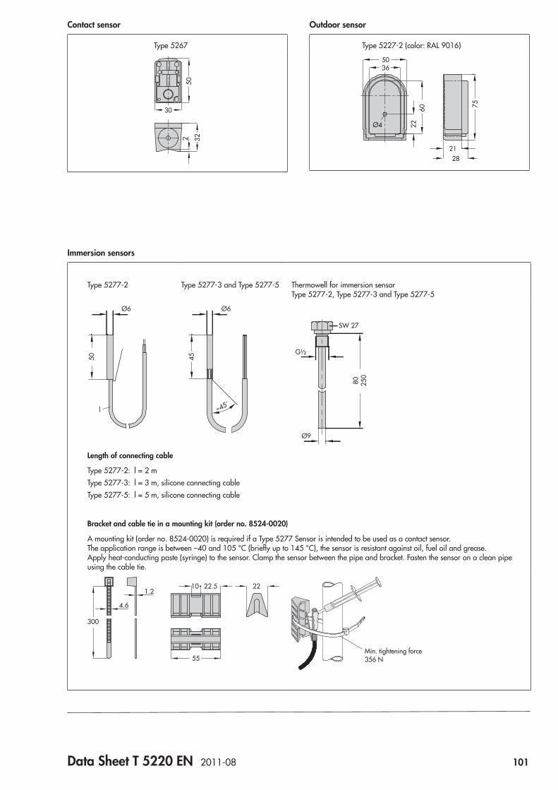
Data Sheet T 5220 EN 2011-08 101
Outdoor sensor
Type 5227-2 (color: RAL 9016)
21
Ø4
5036
756022
28
Contact sensor
Type 5267
502 32
30
Immersion sensors
Type 5277-2 Type 5277-3 and Type 5277-5 Thermowell for immersion sensor Type 5277-2, Type 5277-3 and Type 5277-5
Ø6
l
50
Ø6
45
80 250
Ø9
SW 27
G½
~45˚
Length of connecting cable
Type 5277-2: l = 2 mType 5277-3: l = 3 m, silicone connecting cableType 5277-5: l = 5 m, silicone connecting cable
Bracket and cable tie in a mounting kit (order no. 8524-0020)
A mounting kit (order no. 8524-0020) is required if a Type 5277 Sensor is intended to be used as a contact sensor. The application range is between –40 and 105 °C (briefly up to 145 °C), the sensor is resistant against oil, fuel oil and grease. Apply heat-conducting paste (syringe) to the sensor. Clamp the sensor between the pipe and bracket. Fasten the sensor on a clean pipe using the cable tie.
55
300
1.2
4.6
22.510 22
Min. tightening force 356 N
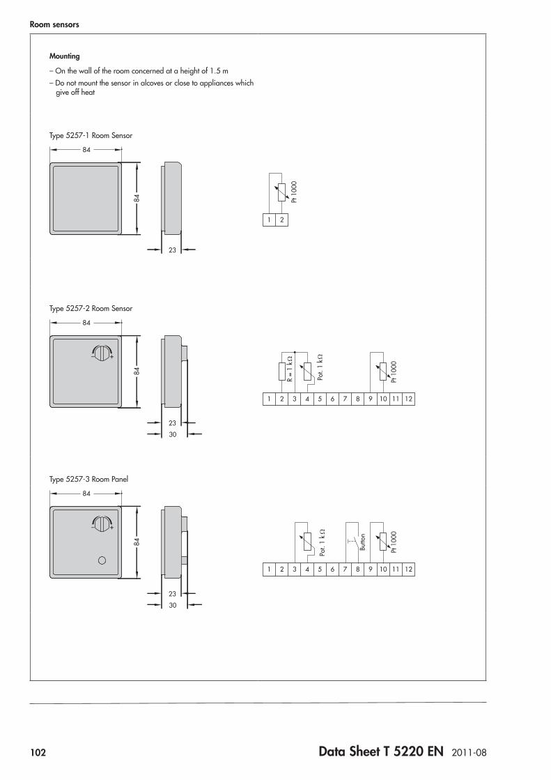
102 Data Sheet T 5220 EN 2011-08
Room sensors
Mounting
– On the wall of the room concerned at a height of 1.5 m– Do not mount the sensor in alcoves or close to appliances which give off heat
Type 5257-1 Room Sensor
84
23
84
21
Pt 1
000
Type 5257-2 Room Sensor
84
+_
30
23
84
109 121187654321Pt
100
0
Pot.
1 k
R =
1 k
Type 5257-3 Room Panel
84
+_
30
23
84
109 121187654321
Pt 1
000
Butto
n
Pot.
1 k
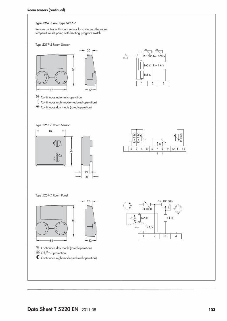
Data Sheet T 5220 EN 2011-08 103
Room sensors (continued)
Type 5257-5 and Type 5257-7
Remote control with room sensor for changing the room temperature set point, with heating program switch
Type 5257-5 Room Sensor
82 32
20
86
321
Pot. 100Pt 1000
R = 1 k165
165
Continuous automatic operation Continuous night mode (reduced operation) Continuous day mode (rated operation)
Type 5257-6 Room Sensor
84
+_
0 I II
30
23
84
Pt 1
000
109 121187
III
654321
Type 5257-7 Room Panel
82 32
20
86
+
_+_
3 421
Pot. 100 lin
Pt 1000
1 k165
165
Continuous day mode (rated operation) Off/frost protection Continuous night mode (reduced operation)


Data Sheet T 5221 EN 2012-05 105
Fig. 1: Type 5207-64 Temperature Sensor (top)/ Type 5207-61 (bottom)
Fast-responding temperature sensors are used in compact heat exchangers and domestic hot water generators which only have a fairly small mass with a low heat storage capacity. As a result, the temperature can change rapidly. Moreover, the temperature sensors are easy to install and do not need to be calibrated. The Types 5207-61/-64/-65 Temperature Sensors include the following features:
• Step response (refer to diagram on following page) featur-ing a response time t of less than one second
• Minimum thermal resistance and low heat capacity • No air space between measuring insert and immersion
tube • Without thermowell • Immersion depth fixed for Type 5207-61 • Immersion depth variable for Types 5207-64/-65
VersionsType 5207-61 · Fast-response temperature sensor; immersion sensor with Pt 1000 resistor; operating temperature range –50 to 180 °C, with immersion tube of 110 mm in length, 80 mm immersion depthType 5207-64 · Fast-response temperature sensor; immersion sensor with Pt 1000 resistor; operating temperature range –15 to 180 °C, with immersion tube of 170 mm in length, 40 to 100 mm immersion depthType 5207-65 · Fast-response temperature sensor; immersion sensor with Pt 1000 resistor; operating temperature range –15 to 180 °C, with immersion tube of 250 mm in length, 120 to 190 mm immersion depth
Ordering textTypes 5207-61/-64/-65 Fast-response Temperature Sensor
ApplicationFast-responding temperature sensors for measuring rapid tem-perature changes in heat exchangers and DHW circuits. Pt 1000 resistors. Basic values according to Class B of DIN EN 60751.
Fast-response Temperature SensorsTypes 5207-61/-64/-65
with Pt 1000 resistors
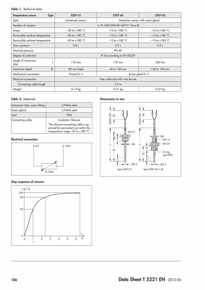
106 Data Sheet T 5221 EN 2012-05
Table 2: Materials
Immersion tube, screw fitting CrNiMo steel
Screw gland CrNiMo steel
Seal FPM
Connecting cable Insulation: SiliconeThe silicone connecting cable is ap-proved for permanent use within the temperature range –50 to +180 °C.
Electrical connection
Pt 1000
whitered
Step response of sensors
s54321τ
0 6
t
T
100
90
63
0
[˚C]
Dimensions in mm
7EL
50
2500
+150
1412
L
Ø3.3
Ø6
SW 27
SW 27
SW 1425
00+1
00L
50EL
1214
Ø6
Ø3.3
O-ring seal (FFP)
Type 5207-61 Type 5207-64 / 65
Table 1: Technical data
Temperature sensor Type 5207-61 5207-64 5207-65
Style Immersion sensor Immersion sensor with screw gland
Number of resistors 1x Pt 1000 (DIN EN 60751 Class B)
Scope –50 to +180 °C –15 to +180 °C –15 to +180 °C
Permissible medium temperature –50 to +180 °C –15 to +180 °C –15 to +180 °C
Permissible ambient temperature –50 to +180 °C –15 to +180 °C –15 to +180 °C
Time constant t 0.8 s 0.9 s 0.9 s
Nominal pressure PN 40
Degree of protection IP 65 according to EN 60529
Length of immersion tube L 110 mm 170 mm 250 mm
Immersion depth EL 80 mm fixed 40 to 120 mm 120 to 190 mm
Mechanical connection Thread G ½ Screw gland G ½
Electrical connection Free cable end with wire ferrule
Connecting cable length 2.5 m
Weight 0.15 kg 0.21 kg 0.27 kg
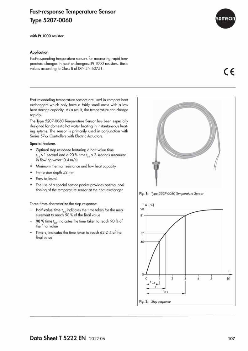
Data Sheet T 5222 EN 2012-06 107
Fig. 1: Type 5207-0060 Temperature Sensor
[s]5432
τ
1t 0.5
t 0.9
0
t
T90
81
57
45
0
[˚C]
Fig. 2: Step response
Fast-responding temperature sensors are used in compact heat exchangers which only have a fairly small mass with a low heat storage capacity. As a result, the temperature can change rapidly.The Type 5207-0060 Temperature Sensor has been especially designed for domestic hot water heating in instantaneous heat-ing sytems. The sensor is primarily used in conjunction with Series 57xx Controllers with Electric Actuators.
Special features • Optimal step response featuring a half-value time
t0.5 ≤ 1 second and a 90 % time t0.9 ≤ 3 seconds measured in flowing water (0.4 m/s)
• Minimum thermal resistance and low heat capacity • Immersion depth 52 mm • Easy to install • The use of a special sensor pocket provides optimal posi-
tioning of the temperature sensor at the heat exchanger
Three times characterize the step response: – Half-value time t0.5 indicates the time taken for the mea-
surement to reach 50 % of the final value – 90 % time t0.9 indicates the time taken to reach 90 % of
the final value – Time t, indicates the time taken to reach 63.2 % of the
final value
ApplicationFast-responding temperature sensors for measuring rapid tem-perature changes in heat exchangers. Pt 1000 resistors. Basic values according to Class B of DIN EN 60751.
Fast-response Temperature SensorType 5207-0060
with Pt 1000 resistor
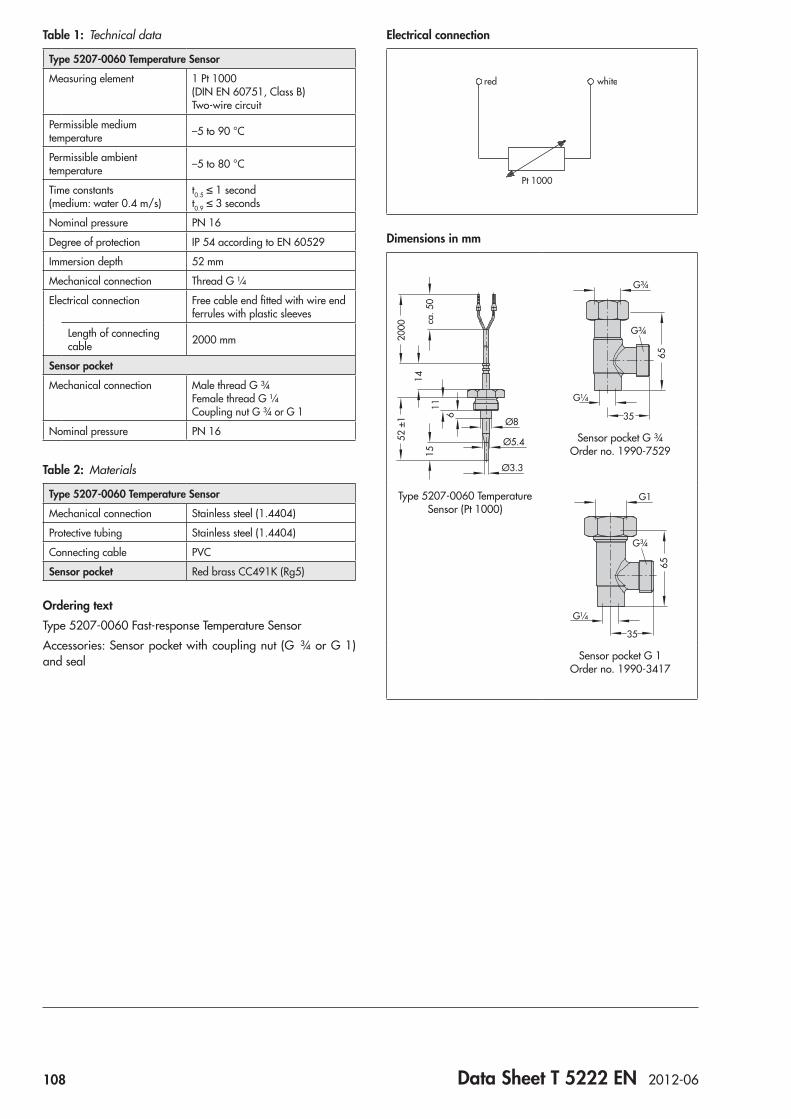
108 Data Sheet T 5222 EN 2012-06
Electrical connection
Pt 1000
whitered
Dimensions in mm
Ø3.3
Ø5.411
1514
52 ±
120
00 ca. 5
0Ø8
6
G¼
G¾
35
G¾
65
Sensor pocket G ¾ Order no. 1990-7529
Type 5207-0060 Temperature Sensor (Pt 1000)
G¼
G1
35
G¾
65Sensor pocket G 1
Order no. 1990-3417
Table 1: Technical data
Type 5207-0060 Temperature Sensor
Measuring element 1 Pt 1000 (DIN EN 60751, Class B) Two-wire circuit
Permissible medium temperature –5 to 90 °C
Permissible ambient temperature –5 to 80 °C
Time constants (medium: water 0.4 m/s)
t0.5 ≤ 1 second t0.9 ≤ 3 seconds
Nominal pressure PN 16
Degree of protection IP 54 according to EN 60529
Immersion depth 52 mm
Mechanical connection Thread G ¼
Electrical connection Free cable end fitted with wire end ferrules with plastic sleeves
Length of connecting cable 2000 mm
Sensor pocket
Mechanical connection Male thread G ¾ Female thread G ¼ Coupling nut G ¾ or G 1
Nominal pressure PN 16
Table 2: Materials
Type 5207-0060 Temperature Sensor
Mechanical connection Stainless steel (1.4404)
Protective tubing Stainless steel (1.4404)
Connecting cable PVC
Sensor pocket Red brass CC491K (Rg5)
Ordering textType 5207-0060 Fast-response Temperature SensorAccessories: Sensor pocket with coupling nut (G ¾ or G 1) and seal
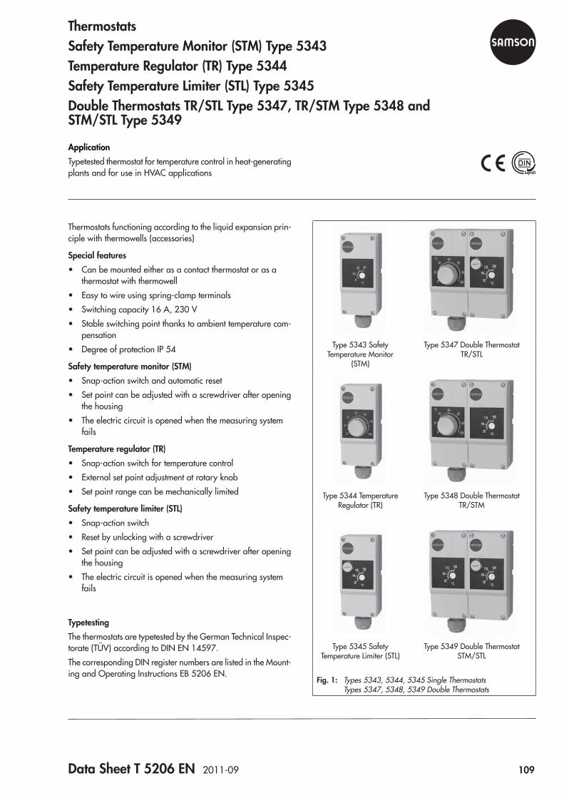
Data Sheet T 5206 EN 2011-09 109
Type 5343 Safety Temperature Monitor
(STM)
Type 5347 Double Thermostat TR/STL
Type 5344 Temperature Regulator (TR)
Type 5348 Double Thermostat TR/STM
Type 5345 Safety Temperature Limiter (STL)
Type 5349 Double Thermostat STM/STL
Fig. 1: Types 5343, 5344, 5345 Single Thermostats Types 5347, 5348, 5349 Double Thermostats
Thermostats functioning according to the liquid expansion prin-ciple with thermowells (accessories)
Special features • Can be mounted either as a contact thermostat or as a
thermostat with thermowell • Easy to wire using spring-clamp terminals • Switching capacity 16 A, 230 V • Stable switching point thanks to ambient temperature com-
pensation • Degree of protection IP 54
Safety temperature monitor (STM) • Snap-action switch and automatic reset • Set point can be adjusted with a screwdriver after opening
the housing • The electric circuit is opened when the measuring system
fails
Temperature regulator (TR) • Snap-action switch for temperature control • External set point adjustment at rotary knob • Set point range can be mechanically limited
Safety temperature limiter (STL) • Snap-action switch • Reset by unlocking with a screwdriver • Set point can be adjusted with a screwdriver after opening
the housing • The electric circuit is opened when the measuring system
fails
TypetestingThe thermostats are typetested by the German Technical Inspec-torate (TÜV) according to DIN EN 14597.The corresponding DIN register numbers are listed in the Mount-ing and Operating Instructions EB 5206 EN.
ApplicationTypetested thermostat for temperature control in heat-generating plants and for use in HVAC applications
ThermostatsSafety Temperature Monitor (STM) Type 5343Temperature Regulator (TR) Type 5344Safety Temperature Limiter (STL) Type 5345DoubleThermostatsTR/STLType5347,TR/STMType5348and STM/STLType5349
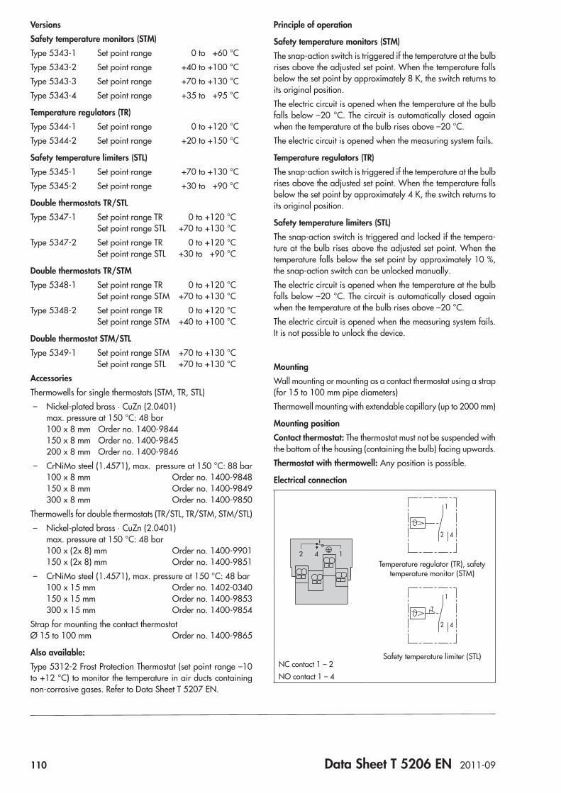
110 Data Sheet T 5206 EN 2011-09
VersionsSafety temperature monitors (STM)Type 5343-1 Set point range 0 to +60 °CType 5343-2 Set point range +40 to +100 °CType 5343-3 Set point range +70 to +130 °CType 5343-4 Set point range +35 to +95 °C
Temperature regulators (TR)Type 5344-1 Set point range 0 to +120 °CType 5344-2 Set point range +20 to +150 °C
Safety temperature limiters (STL)Type 5345-1 Set point range +70 to +130 °CType 5345-2 Set point range +30 to +90 °C
DoublethermostatsTR/STLType 5347-1 Set point range TR 0 to +120 °C Set point range STL +70 to +130 °CType 5347-2 Set point range TR 0 to +120 °C Set point range STL +30 to +90 °C
DoublethermostatsTR/STMType 5348-1 Set point range TR 0 to +120 °C Set point range STM +70 to +130 °CType 5348-2 Set point range TR 0 to +120 °C Set point range STM +40 to +100 °C
DoublethermostatSTM/STLType 5349-1 Set point range STM +70 to +130 °C Set point range STL +70 to +130 °CAccessoriesThermowells for single thermostats (STM, TR, STL)
– Nickel-plated brass · CuZn (2.0401) max. pressure at 150 °C: 48 bar 100 x 8 mm Order no. 1400-9844 150 x 8 mm Order no. 1400-9845 200 x 8 mm Order no. 1400-9846
– CrNiMo steel (1.4571), max. pressure at 150 °C: 88 bar 100 x 8 mm Order no. 1400-9848 150 x 8 mm Order no. 1400-9849 300 x 8 mm Order no. 1400-9850
Thermowells for double thermostats (TR/STL, TR/STM, STM/STL) – Nickel-plated brass · CuZn (2.0401)
max. pressure at 150 °C: 48 bar 100 x (2x 8) mm Order no. 1400-9901 150 x (2x 8) mm Order no. 1400-9851
– CrNiMo steel (1.4571), max. pressure at 150 °C: 48 bar 100 x 15 mm Order no. 1402-0340 150 x 15 mm Order no. 1400-9853 300 x 15 mm Order no. 1400-9854
Strap for mounting the contact thermostat Ø 15 to 100 mm Order no. 1400-9865
Also available:Type 5312-2 Frost Protection Thermostat (set point range –10 to +12 °C) to monitor the temperature in air ducts containing non-corrosive gases. Refer to Data Sheet T 5207 EN.
Principle of operation
Safety temperature monitors (STM)The snap-action switch is triggered if the temperature at the bulb rises above the adjusted set point. When the temperature falls below the set point by approximately 8 K, the switch returns to its original position.The electric circuit is opened when the temperature at the bulb falls below –20 °C. The circuit is automatically closed again when the temperature at the bulb rises above –20 °C. The electric circuit is opened when the measuring system fails.
Temperature regulators (TR)The snap-action switch is triggered if the temperature at the bulb rises above the adjusted set point. When the temperature falls below the set point by approximately 4 K, the switch returns to its original position.
Safety temperature limiters (STL)The snap-action switch is triggered and locked if the tempera-ture at the bulb rises above the adjusted set point. When the temperature falls below the set point by approximately 10 %, the snap-action switch can be unlocked manually.The electric circuit is opened when the temperature at the bulb falls below –20 °C. The circuit is automatically closed again when the temperature at the bulb rises above –20 °C.The electric circuit is opened when the measuring system fails. It is not possible to unlock the device.
MountingWall mounting or mounting as a contact thermostat using a strap (for 15 to 100 mm pipe diameters)Thermowell mounting with extendable capillary (up to 2000 mm)
Mounting positionContact thermostat: The thermostat must not be suspended with the bottom of the housing (containing the bulb) facing upwards.Thermostat with thermowell: Any position is possible.
Electrical connection
2 4 1
1
42
Temperature regulator (TR), safety temperature monitor (STM)
1
42
NC contact 1 – 2NO contact 1 – 4
Safety temperature limiter (STL)
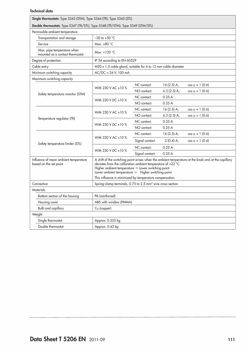
Data Sheet T 5206 EN 2011-09 111
Technical data
Single thermostats: Type 5343 (STM), Type 5344 (TR), Type 5345 (STL)
Double thermostats: Type 5347 (TR/STL), Type 5348 (TR/STM), Type 5349 (STM/STL)
Permissible ambient temperature
Transportation and storage –30 to +50 °C
Service Max. +80 °C
Max. pipe temperature when mounted as a contact thermostat Max. +120 °C
Degree of protection IP 54 according to EN 60529
Cable entry M20 x 1.5 cable gland, suitable for 6 to 12 mm cable diameter
Minimum switching capacity AC/DC = 24 V, 100 mA
Maximum switching capacity
Safety temperature monitor (STM)
With 230 V AC +10 %NC contact: 16 (2.5) A; cos j = 1 (0.6)
NO contact: 6.3 (2.5) A; cos j = 1 (0.6)
With 230 V DC +10 %NC contact: 0.25 A
NO contact: 0.25 A
Temperature regulator (TR)
With 230 V AC +10 %NC contact: 16 (2.5) A; cos j = 1 (0.6)
NO contact: 6.3 (2.5) A; cos j = 1 (0.6)
With 230 V DC +10 %NC contact: 0.25 A
NO contact: 0.25 A
Safety temperature limiter (STL)
With 230 V AC +10 %NC contact: 16 (2.5) A; cos j = 1 (0.6)
Signal contact: 2 (0.4) A; cos j = 1 (0.6)
With 230 V DC +10 %NC contact: 0.25 A
Signal contact: 0.25 A
Influence of mean ambient temperature based on the set point
A shift of the switching point arises when the ambient temperature at the knob and at the capillary deviates from the calibration ambient temperature of +22 °C: Higher ambient temperature g Lower switching point Lower ambient temperature g Higher switching pointThis influence is minimized by temperature compensation.
Connection Spring-clamp terminals, 0.75 to 2.5 mm² wire cross-section
Materials
Bottom section of the housing PA (reinforced)
Housing cover ABS with window (PMMA)
Bulb and capillary Cu (copper)
Weight
Single thermostat Approx. 0.225 kg
Double thermostat Approx. 0.45 kg
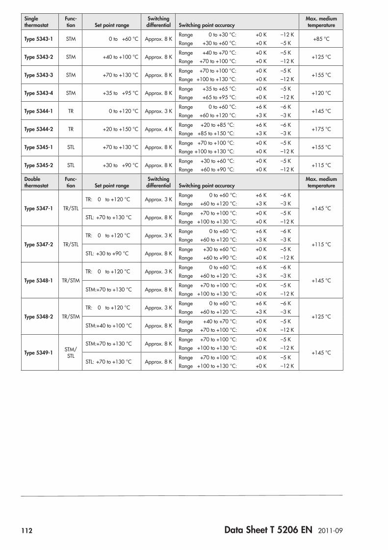
112 Data Sheet T 5206 EN 2011-09
Single thermostat
Func-tion Set point range
Switching differential Switching point accuracy
Max. medium temperature
Type 5343-1 STM 0 to +60 °C Approx. 8 KRange 0 to +30 °C: +0 K –12 KRange +30 to +60 °C: +0 K –5 K
+85 °C
Type 5343-2 STM +40 to +100 °C Approx. 8 KRange +40 to +70 °C: +0 K –5 KRange +70 to +100 °C: +0 K –12 K
+125 °C
Type 5343-3 STM +70 to +130 °C Approx. 8 KRange +70 to +100 °C: +0 K –5 KRange +100 to +130 °C: +0 K –12 K
+155 °C
Type 5343-4 STM +35 to +95 °C Approx. 8 KRange +35 to +65 °C: +0 K –5 KRange +65 to +95 °C: +0 K –12 K
+120 °C
Type 5344-1 TR 0 to +120 °C Approx. 3 KRange 0 to +60 °C: +6 K –6 KRange +60 to +120 °C: +3 K –3 K
+145 °C
Type 5344-2 TR +20 to +150 °C Approx. 4 KRange +20 to +85 °C: +6 K –6 KRange +85 to +150 °C: +3 K –3 K
+175 °C
Type 5345-1 STL +70 to +130 °C Approx. 8 KRange +70 to +100 °C: +0 K –5 KRange +100 to +130 °C: +0 K –12 K
+155 °C
Type 5345-2 STL +30 to +90 °C Approx. 8 KRange +30 to +60 °C: +0 K –5 KRange +60 to +90 °C: +0 K –12 K
+115 °C
Double thermostat
Func-tion Set point range
Switching differential Switching point accuracy
Max. medium temperature
Type 5347-1 TR/STLTR: 0 to +120 °C Approx. 3 K
Range 0 to +60 °C: +6 K –6 KRange +60 to +120 °C: +3 K –3 K
+145 °CSTL: +70 to +130 °C Approx. 8 K
Range +70 to +100 °C: +0 K –5 KRange +100 to +130 °C: +0 K –12 K
Type 5347-2 TR/STLTR: 0 to +120 °C Approx. 3 K
Range 0 to +60 °C: +6 K –6 KRange +60 to +120 °C: +3 K –3 K
+115 °CSTL: +30 to +90 °C Approx. 8 K
Range +30 to +60 °C: +0 K –5 KRange +60 to +90 °C: +0 K –12 K
Type 5348-1 TR/STMTR: 0 to +120 °C Approx. 3 K
Range 0 to +60 °C: +6 K –6 KRange +60 to +120 °C: +3 K –3 K
+145 °CSTM: +70 to +130 °C Approx. 8 K
Range +70 to +100 °C: +0 K –5 KRange +100 to +130 °C: +0 K –12 K
Type 5348-2 TR/STMTR: 0 to +120 °C Approx. 3 K
Range 0 to +60 °C: +6 K –6 KRange +60 to +120 °C: +3 K –3 K
+125 °CSTM: +40 to +100 °C Approx. 8 K
Range +40 to +70 °C: +0 K –5 KRange +70 to +100 °C: +0 K –12 K
Type 5349-1 STM/STL
STM: +70 to +130 °C Approx. 8 KRange +70 to +100 °C: +0 K –5 KRange +100 to +130 °C: +0 K –12 K
+145 °CSTL: +70 to +130 °C Approx. 8 K
Range +70 to +100 °C: +0 K –5 KRange +100 to +130 °C: +0 K –12 K
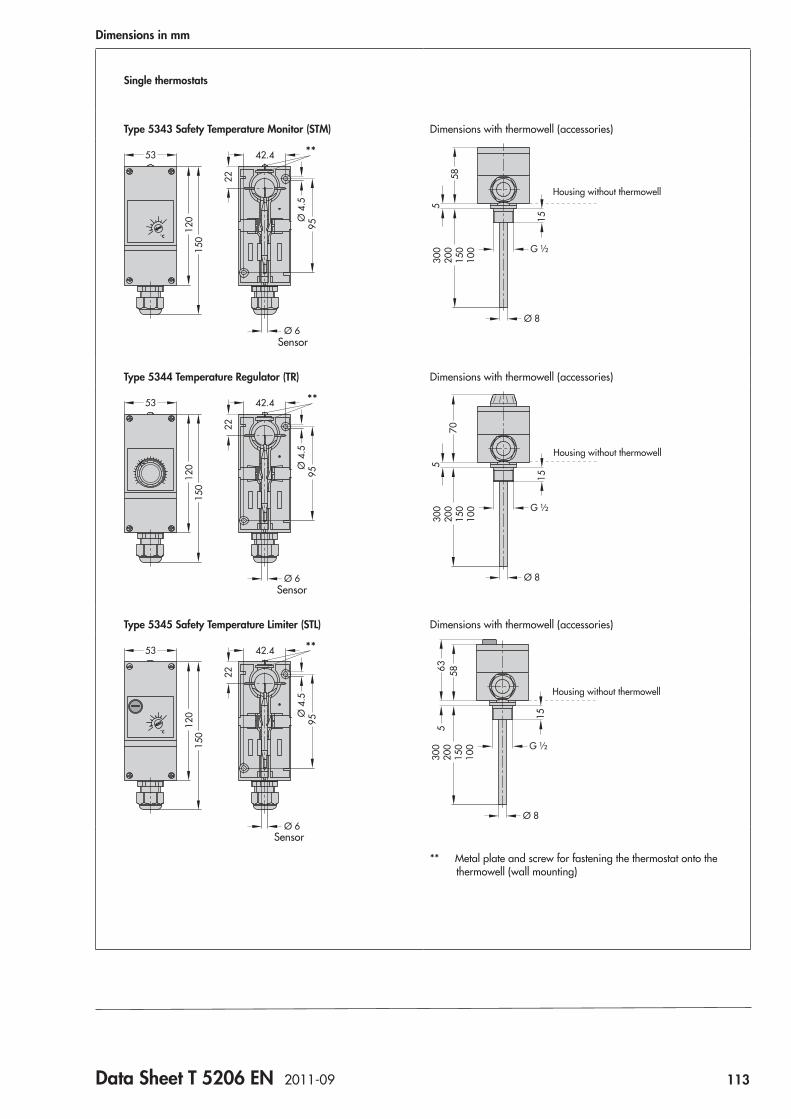
Data Sheet T 5206 EN 2011-09 113
Dimensions in mm
Single thermostats
Type 5343 Safety Temperature Monitor (STM) Dimensions with thermowell (accessories)
˚C
120
150
53 42.4
Ø 6
22
Ø 4
.595
**
Sensor
G ½
Ø 8
58
530
020
015
010
0
15
Housing without thermowell
Type 5344 Temperature Regulator (TR) Dimensions with thermowell (accessories)
120
150
53 42.4 **
22
Ø 4
.595
Ø 6Sensor
Housing without thermowell
G ½
Ø 8
70
300
200
150
100
15
5
Type 5345 Safety Temperature Limiter (STL) Dimensions with thermowell (accessories)
Housing without thermowell
G ½
Ø 8
58
300
200
150
100
15
635
** Metal plate and screw for fastening the thermostat onto the thermowell (wall mounting)
˚C
120
150
53 42.4
22
Ø 4
.595
**
Ø 6Sensor
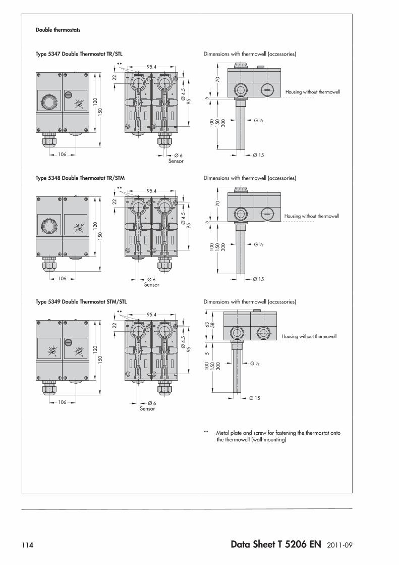
114 Data Sheet T 5206 EN 2011-09
Double thermostats
Type 5347 Double Thermostat TR/STL Dimensions with thermowell (accessories)
Sensor
˚C
120
150
106
95.4
22
Ø 4
.595
**
Ø 6
Housing without thermowell
G ½
Ø 15
7010
015
030
0
5
Type 5348 Double Thermostat TR/STM Dimensions with thermowell (accessories)
˚C
120
150
106
95.4
22
Ø 4
.595
**
Ø 6Sensor
G ½
Ø 15
7010
015
030
0
5
Housing without thermowell
Type 5349 Double Thermostat STM/STL Dimensions with thermowell (accessories)
Sensor
˚C˚C
120
150
106
95.4
22
Ø 4
.595
**
Ø 6
G ½
Ø 15
100
150
300
63 585
Housing without thermowell
** Metal plate and screw for fastening the thermostat onto the thermowell (wall mounting)

Data Sheet T 5207 EN 2008-09 115
Fig. 1: Type 5312-2 Frost Protection Thermostat
Type 5312-2 Frost Protection Thermostat • Temperature monitor (TM) with double-throw switch and
automatic reset • Set point can be adjusted at the adjustment screw when
the housing is closed • Set point range –10 to +12 °C • Capillary made of copper, filled with gas, approx. 6 m in
length, sensitive along the entire length of the capillary • A broken capillary is indicated by the temperature falling
below the set point
Principle of operationThe double-throw switch is triggered if the temperature at the sensor rises above the adjusted set point. When the temperature falls below the set point, the switch is automatically reset.
Ordering textType 5312-2 Frost Protection ThermostatOptional set of mounting brackets (6 pcs.)
Also available (see Data Sheet T 5206 EN): – Type 5343 Safety Temperature Monitor (STM) – Type 5344 Temperature Regulator (TR) – Type 5345 Safety Temperature Limiter (STL) – Type 5347 Double Thermostat TR/STL – Type 5348 Double Thermostat TR/STM – Type 5349 Double Thermostat STM/STL
ApplicationThe frost protection thermostat is used to monitor the temperature in air ducts containing non-corrosive gases.
ThermostatsFrost Protection Thermostat Type 5312-2

116 Data Sheet T 5207 EN 2008-09
Technical data
Type 5312-2
Set point range –10 to +12 °C
Function Temperature monitor (TM)
Sensor Copper capillary, approx. 6 m in length, already sensitive in partial ranges of approx. 0.3 m, filled with gas
Switching differential Approx. 1 K
Temperature
Medium Max. +200 °C
Housing –15 to +55 °C, at least as high as the adjusted set point
Switching element Microswitch, 1 changeover contact
Contact rating
At 24 to 250 V~
15 (8) A with resistive load 2 A with cos j = 0.6
At 24 V~ Min. 150 mA
Housing Sheet steel, degree of protection IP 40 acc. to EN 60529
MountingWall mountingMount the housing as close to the point of measurement as possible since the capillary is sensitive along its entire length.
Mounting positionThe thermostat may be installed in any position.
Electrical connection
2
1
4
Dimensions in mm
10546.5
39.543
77
2527
Ø5.5M20x1.5
Ø41
112
2722
55
M5
10
6
Screw for set point adjustment
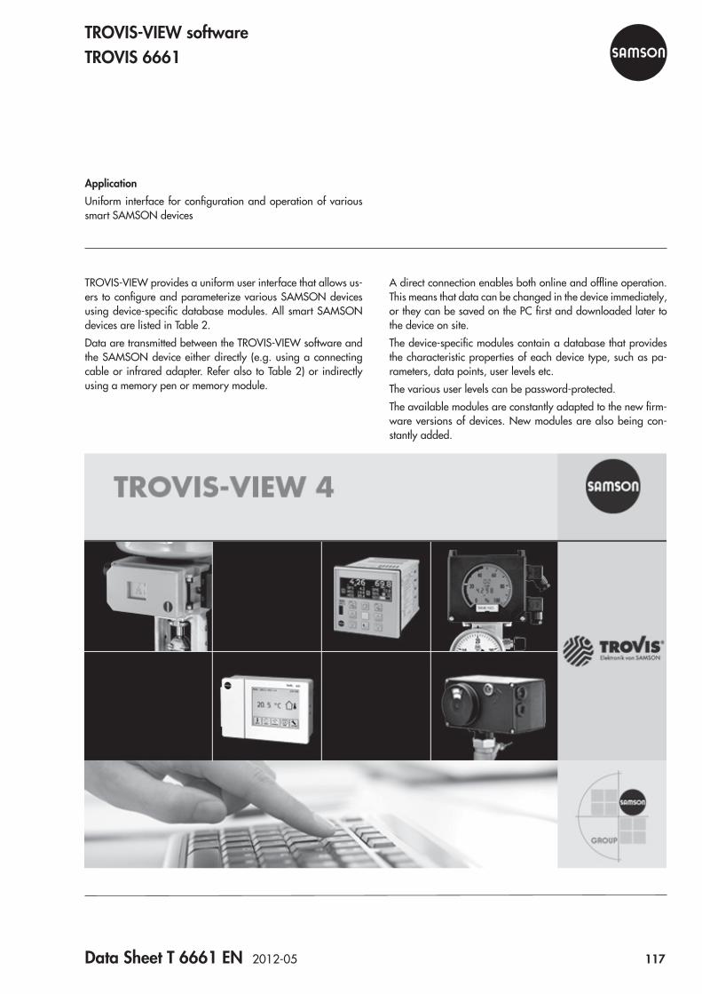
Data Sheet T 6661 EN 2012-05 117
A direct connection enables both online and offline operation. This means that data can be changed in the device immediately, or they can be saved on the PC first and downloaded later to the device on site.The device-specific modules contain a database that provides the characteristic properties of each device type, such as pa-rameters, data points, user levels etc.The various user levels can be password-protected.The available modules are constantly adapted to the new firm-ware versions of devices. New modules are also being con-stantly added.
TROVIS-VIEW provides a uniform user interface that allows us-ers to configure and parameterize various SAMSON devices using device-specific database modules. All smart SAMSON devices are listed in Table 2.Data are transmitted between the TROVIS-VIEW software and the SAMSON device either directly (e.g. using a connecting cable or infrared adapter. Refer also to Table 2) or indirectly using a memory pen or memory module.
ApplicationUniform interface for configuration and operation of various smart SAMSON devices
TROVIS-VIEW softwareTROVIS 6661
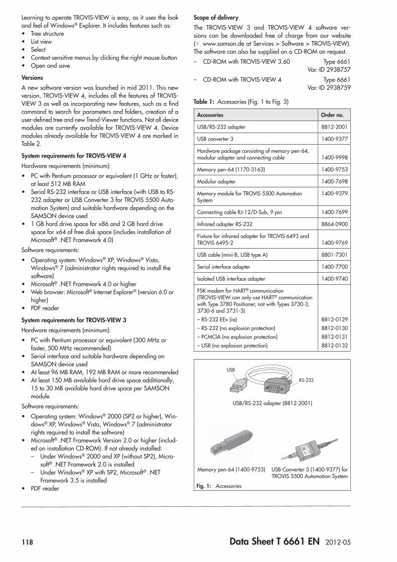
118 Data Sheet T 6661 EN 2012-05
Learning to operate TROVIS-VIEW is easy, as it uses the look and feel of Windows® Explorer. It includes features such as: • Tree structure • List view • Select • Context-sensitive menus by clicking the right mouse button • Open and save
VersionsA new software version was launched in mid 2011. This new version, TROVIS-VIEW 4, includes all the features of TROVIS-VIEW 3 as well as incorporating new features, such as a find command to search for parameters and folders, creation of a user-defined tree and new Trend-Viewer functions. Not all device modules are currently available for TROVIS-VIEW 4. Device modules already available for TROVIS-VIEW 4 are marked in Table 2.
System requirements for TROVIS-VIEW 4Hardware requirements (minimum):
• PC with Pentium processor or equivalent (1 GHz or faster), at least 512 MB RAM
• Serial RS-232 interface or USB interface (with USB to RS-232 adapter or USB Converter 3 for TROVIS 5500 Auto-mation System) and suitable hardware depending on the SAMSON device used
• 1 GB hard drive space for x86 and 2 GB hard drive space for x64 of free disk space (includes installation of Microsoft® .NET Framework 4.0)
Software requirements: • Operating system: Windows® XP, Windows® Vista,
Windows® 7 (administrator rights required to install the software)
• Microsoft® .NET Framework 4.0 or higher • Web browser: Microsoft® Internet Explorer® (version 6.0 or
higher) • PDF reader
System requirements for TROVIS-VIEW 3Hardware requirements (minimum):
• PC with Pentium processor or equivalent (300 MHz or faster, 500 MHz recommended)
• Serial interface and suitable hardware depending on SAMSON device used
• At least 96 MB RAM, 192 MB RAM or more recommended • At least 150 MB available hard drive space additionally,
15 to 30 MB available hard drive space per SAMSON module
Software requirements: • Operating system: Windows® 2000 (SP2 or higher), Win-
dows® XP, Windows® Vista, Windows® 7 (administrator rights required to install the software)
• Microsoft® .NET Framework Version 2.0 or higher (includ-ed on installation CD-ROM). If not already installed: – Under Windows® 2000 and XP (without SP2), Micro-
soft® .NET Framework 2.0 is installed – Under Windows® XP with SP2, Microsoft® .NET
Framework 3.5 is installed • PDF reader
Scope of deliveryThe TROVIS-VIEW 3 and TROVIS-VIEW 4 software ver-sions can be downloaded free of charge from our website (u www.samson.de at Services > Software > TROVIS-VIEW). The software can also be supplied on a CD-ROM on request. – CD-ROM with TROVIS-VIEW 3.60 Type 6661
Var.-ID 2938757 – CD-ROM with TROVIS-VIEW 4 Type 6661
Var.-ID 2938759
Table 1: Accessories (Fig. 1 to Fig. 3)
Accessories Order no.
USB/RS-232 adapter 8812-2001
USB converter 3 1400-9377
Hardware package consisting of memory pen-64, modular adapter and connecting cable 1400-9998
Memory pen-64 (1170-3163) 1400-9753
Modular adapter 1400-7698
Memory module for TROVIS 5500 Automation System
1400-9379
Connecting cable RJ-12/D-Sub, 9 pin 1400-7699
Infrared adapter RS-232 8864-0900
Fixture for infrared adapter for TROVIS 6493 and TROVIS 6495-2 1400-9769
USB cable (mini-B, USB type A) 8801-7301
Serial interface adapter 1400-7700
Isolated USB interface adapter 1400-9740
FSK modem for HART® communication (TROVIS-VIEW can only use HART® communication with Type 3780 Positioner, not with Types 3730-3, 3730-6 and 3731-3)– RS-232 EEx (ia)– RS-232 (no explosion protection)– PCMCIA (no explosion protection)– USB (no explosion protection)
8812-01298812-01308812-01318812-0132
USB
RS-232
USB/RS-232 adapter (8812-2001)
Memory pen-64 (1400-9753) USB Converter 3 (1400-9377) for TROVIS 5500 Automation System
Fig. 1: Accessories
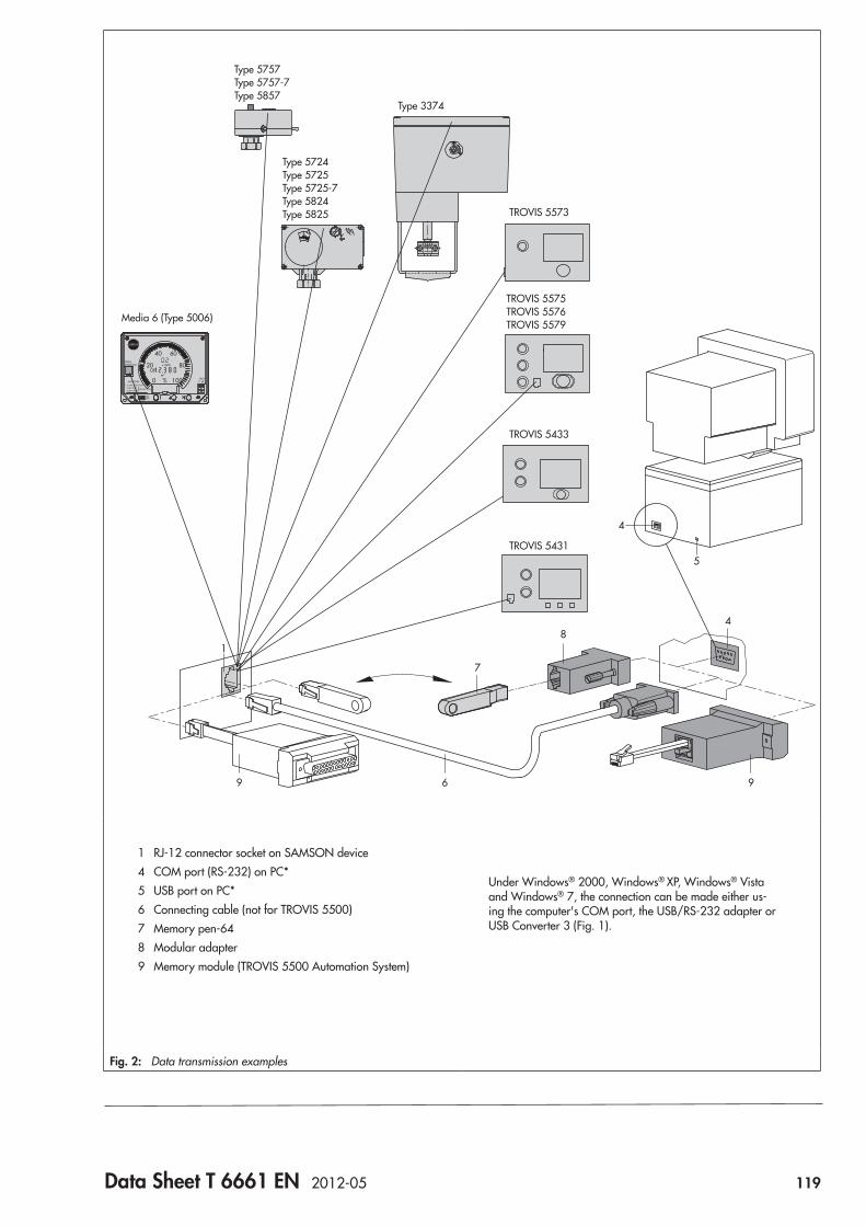
Data Sheet T 6661 EN 2012-05 119
84
6
1
4
5
6
9 9
7
Type 5757 Type 5757-7 Type 5857
Media 6 (Type 5006)
Type 5724 Type 5725 Type 5725-7 Type 5824 Type 5825
Type 3374
TROVIS 5573
TROVIS 5575 TROVIS 5576 TROVIS 5579
TROVIS 5433
TROVIS 5431
1 RJ-12 connector socket on SAMSON device 4 COM port (RS-232) on PC* 5 USB port on PC* 6 Connecting cable (not for TROVIS 5500) 7 Memory pen-64 8 Modular adapter 9 Memory module (TROVIS 5500 Automation System)
Under Windows® 2000, Windows® XP, Windows® Vista and Windows® 7, the connection can be made either us-ing the computer's COM port, the USB/RS-232 adapter or USB Converter 3 (Fig. 1).
Fig. 2: Data transmission examples
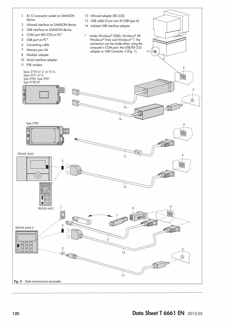
120 Data Sheet T 6661 EN 2012-05
1
2
2
3
FSK
84
7
6
5
13
5
4
4
4
4
10
11
12
12
14
5
Types 3730-2/-3/-4/-5/-6, Types 3731-3/-5, Type 3785, Type 3787, Type 3738-20
Type 3780
TROVIS 5432
TROVIS 6495-2
1 RJ-12 connector socket on SAMSON device 2 Infrared interface on SAMSON device 3 USB interface on SAMSON device 4 COM port (RS-232) on PC* 5 USB port on PC* 6 Connecting cable 7 Memory pen-64 8 Modular adapter10 Serial interface adapter11 FSK modem
12 Infrared adapter (RS-232)13 USB cable (5-pin mini-B/USB type A)14 Isolated USB interface adapter
* Under Windows® 2000, Windows® XP, Windows® Vista and Windows® 7, the connection can be made either using the computer's COM port, the USB/RS-232 adapter or USB Converter 3 (Fig. 1).
TROVIS 6493
Fig. 3: Data transmission examples
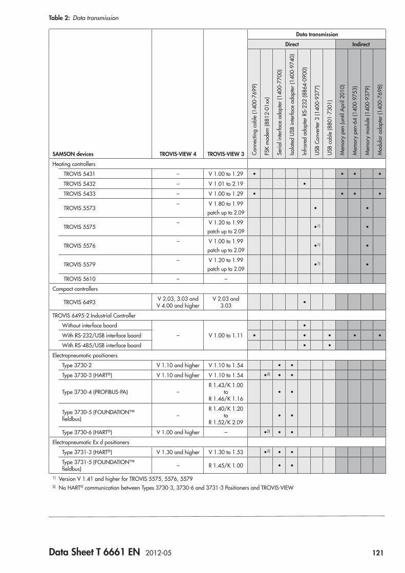
Data Sheet T 6661 EN 2012-05 121
Table 2: Data transmission
SAMSON devices TROVIS-VIEW 4 TROVIS-VIEW 3
Data transmission
Direct Indirect
Conn
ectin
g ca
ble
(140
0-76
99)
FSK
mod
em (8
812-
01xx
)
Seria
l int
erfa
ce a
dapt
er (1
400-
7700
)
Isola
ted
USB
inte
rface
ada
pter
(140
0-97
40)
Infra
red
adap
ter R
S-23
2 (8
864-
0900
)
USB
Conv
erte
r 3 (1
400-
9377
)
USB
cabl
e (8
801-
7301
)
Mem
ory
pen
(unt
il A
pril
2010
)
Mem
ory
pen-
64 (1
400-
9753
)
Mem
ory
mod
ule
(140
0-93
79)
Mod
ular
ada
pter
(140
0-76
98)
Heating controllers
TROVIS 5431 – V 1.00 to 1.29 • • • •
TROVIS 5432 – V 1.01 to 2.19 •
TROVIS 5433 – V 1.00 to 1.29 • • • •
TROVIS 5573– V 1.80 to 1.99
patch up to 2.09• •
TROVIS 5575– V 1.20 to 1.99
patch up to 2.09•1) •
TROVIS 5576– V 1.00 to 1.99
patch up to 2.09•1) •
TROVIS 5579– V 1.20 to 1.99
patch up to 2.09•1) •
TROVIS 5610 – –
Compact controllers
TROVIS 6493 V 2.03, 3.03 and V 4.00 and higher
V 2.03 and 3.03 •
TROVIS 6495-2 Industrial Controller
Without interface board
– V 1.00 to 1.11
•
With RS-232/USB interface board • • • • •
With RS-485/USB interface board • •
Electropneumatic positioners
Type 3730-2 V 1.10 and higher V 1.10 to 1.54 • •
Type 3730-3 (HART®) V 1.10 and higher V 1.10 to 1.54 •2) • •
Type 3730-4 (PROFIBUS-PA) –R 1.43/K 1.00
to R 1.46/K 1.16
• •
Type 3730-5 (FOUNDATION™ fieldbus) –
R 1.40/K 1.20 to
R 1.52/K 2.09• •
Type 3730-6 (HART®) V 1.00 and higher – •2) • •
Electropneumatic Ex d positioners
Type 3731-3 (HART®) V 1.30 and higher V 1.30 to 1.53 •2) • •
Type 3731-5 (FOUNDATION™ fieldbus) – R 1.45/K 1.00 • •
1) Version V 1.41 and higher for TROVIS 5575, 5576, 55792) No HART® communication between Types 3730-3, 3730-6 and 3731-3 Positioners and TROVIS-VIEW
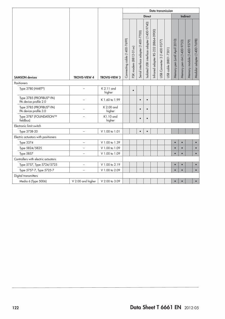
122 Data Sheet T 6661 EN 2012-05
SAMSON devices TROVIS-VIEW 4 TROVIS-VIEW 3
Data transmission
Direct Indirect
Conn
ectin
g ca
ble
(140
0-76
99)
FSK
mod
em (8
812-
01xx
)
Seria
l int
erfa
ce a
dapt
er (1
400-
7700
)
Isola
ted
USB
inte
rface
ada
pter
(140
0-97
40)
Infra
red
adap
ter R
S-23
2 (8
864-
0900
)
USB
Conv
erte
r 3 (1
400-
9377
)
USB
cabl
e (8
801-
7301
)
Mem
ory
pen
(unt
il A
pril
2010
)
Mem
ory
pen-
64 (1
400-
9753
)
Mem
ory
mod
ule
(140
0-93
79)
Mod
ular
ada
pter
(140
0-76
98)
Positioners
Type 3780 (HART®) – K 2.11 and higher •
Type 3785 (PROFIBUS®-PA) PA device profile 2.0 – K 1.60 to 1.99 • •
Type 3785 (PROFIBUS®-PA) PA device profile 3.0 – K 2.00 and
higher • •
Type 3787 (FOUNDATION™ fieldbus)
– K1.10 and higher • •
Electronic limit switch
Type 3738-20 – V 1.00 to 1.01 • •
Electric actuators with positioners
Type 3374 – V 1.00 to 1.39 • • •
Type 5824/5825 – V 1.00 to 1.09 • • •
Type 5857 – V 1.00 to 1.09 • • •
Controllers with electric actuators
Type 5757, Type 5724/5725 – V 1.00 to 2.19 • • •
Type 5757-7, Type 5725-7 – V 1.00 to 2.09 • • •
Digital transmitters
Media 6 (Type 5006) V 2.00 and higher V 2.00 to 3.09 • • •
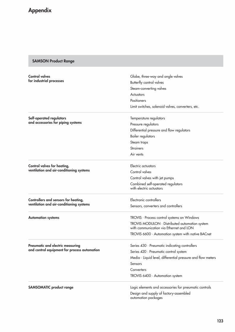
Control valves for industrial processes
Globe, three-way and angle valvesButterfly control valvesSteam-converting valvesActuatorsPositionersLimit switches, solenoid valves, converters, etc.
Self-operated regulators and accessories for piping systems
Temperature regulatorsPressure regulatorsDifferential pressure and flow regulatorsBoiler regulatorsSteam trapsStrainersAir vents
Control valves for heating, ventilation and air-conditioning systems
Electric actuatorsControl valvesControl valves with jet pumpsCombined self-operated regulators with electric actuators
Controllers and sensors for heating, ventilation and air-conditioning systems
Electronic controllersSensors, converters and controllers
Automation systems TROVIS · Process control systems on WindowsTROVIS MODULON · Distributed automation system with communication via Ethernet and LONTROVIS 6600 · Automation system with native BACnet
Pneumatic and electric measuring and control equipment for process automation
Series 430 · Pneumatic indicating controllersSeries 420 · Pneumatic control systemMedia · Liquid level, differential pressure and flow metersSensorsConvertersTROVIS 6400 · Automation system
SAMSOMATIC product range Logic elements and accessories for pneumatic controlsDesign and supply of factory-assembled automation packages
SAMSON Product Range
Appendix
123

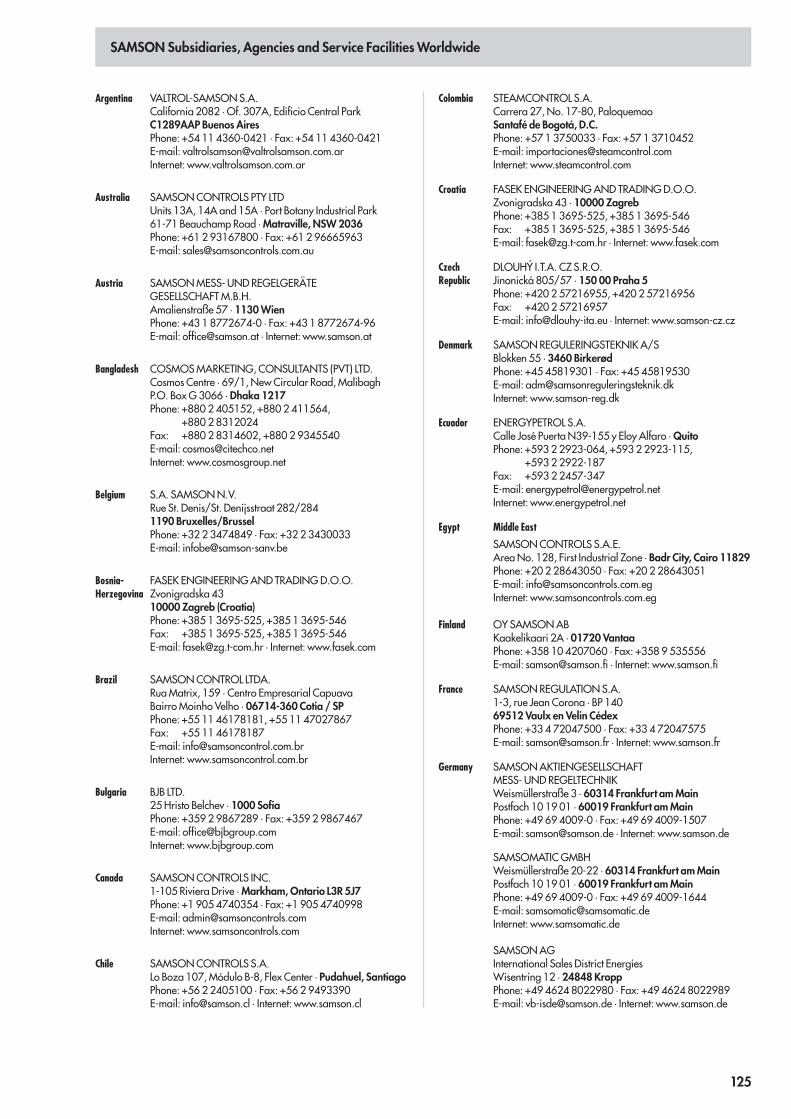
SAMSON Subsidiaries, Agencies and Service Facilities Worldwide
Argentina VALTROL-SAMSON S.A.California 2082 · Of. 307A, Edificio Central ParkC1289AAP Buenos AiresPhone: +54 11 4360-0421 · Fax: +54 11 4360-0421E-mail: [email protected]: www.valtrolsamson.com.ar
Australia SAMSON CONTROLS PTY LTDUnits 13A, 14A and 15A · Port Botany Industrial Park61-71 Beauchamp Road · Matraville, NSW 2036Phone: +61 2 93167800 · Fax: +61 2 96665963E-mail: [email protected]
Austria SAMSON MESS- UND REGELGERÄTEGESELLSCHAFT M.B.H.Amalienstraße 57 · 1130 WienPhone: +43 1 8772674-0 · Fax: +43 1 8772674-96E-mail: [email protected] · Internet: www.samson.at
Bangladesh COSMOS MARKETING, CONSULTANTS (PVT) LTD.Cosmos Centre · 69/1, New Circular Road, MalibaghP.O. Box G 3066 · Dhaka 1217Phone: +880 2 405152, +880 2 411564,
+880 2 8312024Fax: +880 2 8314602, +880 2 9345540E-mail: [email protected]: www.cosmosgroup.net
Belgium S.A. SAMSON N.V.Rue St. Denis/St. Denijsstraat 282/2841190 Bruxelles/BrusselPhone: +32 2 3474849 · Fax: +32 2 3430033E-mail: [email protected]
Bosnia-Herzegovina
FASEK ENGINEERING AND TRADING D.O.O.Zvonigradska 4310000 Zagreb (Croatia)Phone: +385 1 3695-525, +385 1 3695-546Fax: +385 1 3695-525, +385 1 3695-546E-mail: [email protected] · Internet: www.fasek.com
Brazil SAMSON CONTROL LTDA.Rua Matrix, 159 · Centro Empresarial CapuavaBairro Moinho Velho · 06714-360 Cotia / SPPhone: +55 11 46178181, +55 11 47027867Fax: +55 11 46178187E-mail: [email protected]: www.samsoncontrol.com.br
Bulgaria BJB LTD.25 Hristo Belchev · 1000 SofiaPhone: +359 2 9867289 · Fax: +359 2 9867467E-mail: [email protected]: www.bjbgroup.com
Canada SAMSON CONTROLS INC.1-105 Riviera Drive · Markham, Ontario L3R 5J7Phone: +1 905 4740354 · Fax: +1 905 4740998E-mail: [email protected]: www.samsoncontrols.com
Chile SAMSON CONTROLS S.A.Lo Boza 107, Módulo B-8, Flex Center · Pudahuel, SantiagoPhone: +56 2 2405100 · Fax: +56 2 9493390E-mail: [email protected] · Internet: www.samson.cl
Colombia STEAMCONTROL S.A.Carrera 27, No. 17-80, PaloquemaoSantafé de Bogotá, D.C.Phone: +57 1 3750033 · Fax: +57 1 3710452E-mail: [email protected]: www.steamcontrol.com
Croatia FASEK ENGINEERING AND TRADING D.O.O.Zvonigradska 43 · 10000 ZagrebPhone: +385 1 3695-525, +385 1 3695-546Fax: +385 1 3695-525, +385 1 3695-546E-mail: [email protected] · Internet: www.fasek.com
CzechRepublic
DLOUHÝ I.T.A. CZ S.R.O.Jinonická 805/57 · 150 00 Praha 5Phone: +420 2 57216955, +420 2 57216956Fax: +420 2 57216957E-mail: [email protected] · Internet: www.samson-cz.cz
Denmark SAMSON REGULERINGSTEKNIK A/SBlokken 55 · 3460 BirkerødPhone: +45 45819301 · Fax: +45 45819530E-mail: [email protected]: www.samson-reg.dk
Ecuador ENERGYPETROL S.A.Calle José Puerta N39-155 y Eloy Alfaro · QuitoPhone: +593 2 2923-064, +593 2 2923-115,
+593 2 2922-187Fax: +593 2 2457-347E-mail: [email protected]: www.energypetrol.net
Egypt Middle East
SAMSON CONTROLS S.A.E.Area No. 128, First Industrial Zone · Badr City, Cairo 11829Phone: +20 2 28643050 · Fax: +20 2 28643051E-mail: [email protected]: www.samsoncontrols.com.eg
Finland OY SAMSON ABKaakelikaari 2A · 01720 VantaaPhone: +358 10 4207060 · Fax: +358 9 535556E-mail: [email protected] · Internet: www.samson.fi
France SAMSON REGULATION S.A.1-3, rue Jean Corona · BP 14069512 Vaulx en Velin CédexPhone: +33 4 72047500 · Fax: +33 4 72047575E-mail: [email protected] · Internet: www.samson.fr
Germany SAMSON AKTIENGESELLSCHAFTMESS- UND REGELTECHNIKWeismüllerstraße 3 · 60314 Frankfurt am MainPostfach 10 19 01 · 60019 Frankfurt am MainPhone: +49 69 4009-0 · Fax: +49 69 4009-1507E-mail: [email protected] · Internet: www.samson.de
SAMSOMATIC GMBHWeismüllerstraße 20-22 · 60314 Frankfurt am MainPostfach 10 19 01 · 60019 Frankfurt am MainPhone: +49 69 4009-0 · Fax: +49 69 4009-1644E-mail: [email protected]: www.samsomatic.de
SAMSON AGInternational Sales District EnergiesWisentring 12 · 24848 KroppPhone: +49 4624 8022980 · Fax: +49 4624 8022989E-mail: [email protected] · Internet: www.samson.de
125
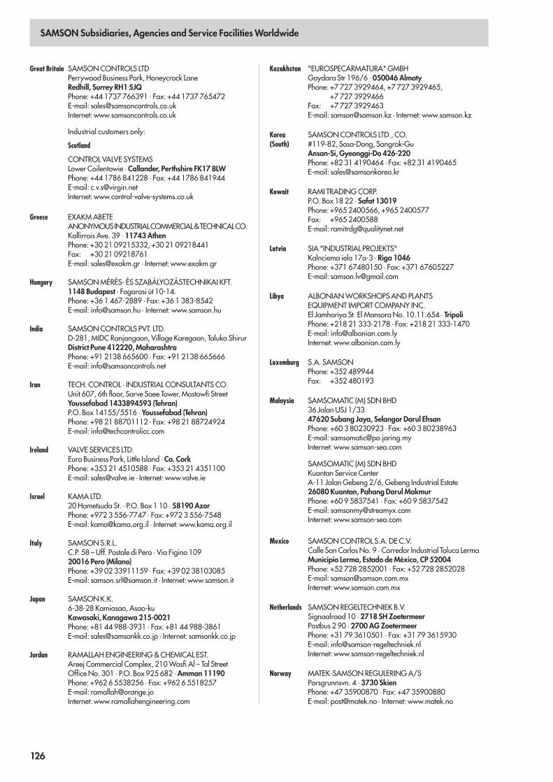
SAMSON Subsidiaries, Agencies and Service Facilities Worldwide
Great Britain SAMSON CONTROLS LTDPerrywood Business Park, Honeycrock LaneRedhill, Surrey RH1 5JQPhone: +44 1737 766391 · Fax: +44 1737 765472E-mail: [email protected]: www.samsoncontrols.co.uk
Industrial customers only:
Scotland
CONTROL VALVE SYSTEMSLower Coilentowie · Callander, Perthshire FK17 8LWPhone: +44 1786 841228 · Fax: +44 1786 841944E-mail: [email protected]: www.control-valve-systems.co.uk
Greece EXAKM ABETEANONYMOUSINDUSTRIALCOMMERCIAL&TECHNICALCO.Kallirrois Ave. 39 · 11743 AthenPhone: +30 21 09215332, +30 21 09218441Fax: +30 21 09218761E-mail: [email protected] · Internet: www.exakm.gr
Hungary SAMSON MÉRÉS- ÉS SZABÁLYOZÁSTECHNIKAI KFT.1148 Budapest · Fogarasi út 10-14.Phone: +36 1 467-2889 · Fax: +36 1 383-8542E-mail: [email protected] · Internet: www.samson.hu
India SAMSON CONTROLS PVT. LTD.D-281, MIDC Ranjangaon, Village Karegaon, Taluka ShirurDistrict Pune 412220, MaharashtraPhone: +91 2138 665600 · Fax: +91 2138 665666E-mail: [email protected]
Iran TECH. CONTROL · INDUSTRIAL CONSULTANTS CO.Unit 607, 6th floor, Sarve Saee Tower, Mostowfi StreetYoussefabad 1433894593 (Tehran)P.O. Box 14155/5516 · Youssefabad (Tehran)Phone: +98 21 88701112 · Fax: +98 21 88724924E-mail: [email protected]
Ireland VALVE SERVICES LTD.Euro Business Park, Little Island · Co. CorkPhone: +353 21 4510588 · Fax: +353 21 4351100E-mail: [email protected] · Internet: www.valve.ie
Israel KAMA LTD.20 Hametsuda St. · P.O. Box 1 10 · 58190 AzorPhone: +972 3 556-7747 · Fax: +972 3 556-7548E-mail: [email protected] · Internet: www.kama.org.il
Italy SAMSON S.R.L.C.P. 58 – Uff. Postale di Pero · Via Figino 10920016 Pero (Milano)Phone: +39 02 33911159 · Fax: +39 02 38103085E-mail: [email protected] · Internet: www.samson.it
Japan SAMSON K.K.6-38-28 Kamiasao, Asao-kuKawasaki, Kanagawa 215-0021Phone: +81 44 988-3931 · Fax: +81 44 988-3861E-mail: [email protected] · Internet: samsonkk.co.jp
Jordan RAMALLAH ENGINEERING & CHEMICAL EST.Areej Commercial Complex, 210 Wasfi Al – Tal StreetOffice No. 301 · P.O. Box 925 682 · Amman 11190Phone: +962 6 5538256 · Fax: +962 6 5518257E-mail: [email protected]: www.ramallahengineering.com
Kazakhstan "EUROSPECARMATURA" GMBHGaydara Str 196/6 · 050046 AlmatyPhone: +7 727 3929464, +7 727 3929465,
+7 727 3929466Fax: +7 727 3929463E-mail: [email protected] · Internet: www.samson.kz
Korea(South)
SAMSON CONTROLS LTD., CO.#119-82, Sasa-Dong, Sangrok-GuAnsan-Si, Gyeonggi-Do 426-220Phone: +82 31 4190464 · Fax: +82 31 4190465E-mail: [email protected]
Kuwait RAMI TRADING CORP.P.O. Box 18 22 · Safat 13019Phone: +965 2400566, +965 2400577Fax: +965 2400588E-mail: [email protected]
Latvia SIA "INDUSTRIAL PROJEKTS"Kalnciema iela 17a-3 · Riga 1046Phone: +371 67480150 · Fax: +371 67605227E-mail: [email protected]
Libya ALBONIAN WORKSHOPS AND PLANTSEQUIPMENT IMPORT COMPANY INC.El Jamhoriya St. El Mansora No. 10.11.654 · TripoliPhone: +218 21 333-2178 · Fax: +218 21 333-1470E-mail: [email protected]: www.albonian.com.ly
Luxemburg S.A. SAMSONPhone: +352 489944Fax: +352 480193
Malaysia SAMSOMATIC (M) SDN BHD36 Jalan USJ 1/3347620 Subang Jaya, Selangor Darul EhsanPhone: +60 3 80230923 · Fax: +60 3 80238963E-mail: [email protected]: www.samson-sea.com
SAMSOMATIC (M) SDN BHDKuantan Service CenterA-11 Jalan Gebeng 2/6, Gebeng Industrial Estate26080 Kuantan, Pahang Darul MakmurPhone: +60 9 5837541 · Fax: +60 9 5837542E-mail: [email protected]: www.samson-sea.com
Mexico SAMSON CONTROL S.A. DE C.V.Calle San Carlos No. 9 · Corredor Industrial Toluca LermaMunicipio Lerma, Estado de México, CP 52004Phone: +52 728 2852001 · Fax: +52 728 2852028E-mail: [email protected]: www.samson.com.mx
Netherlands SAMSON REGELTECHNIEK B.V.Signaalrood 10 · 2718 SH ZoetermeerPostbus 2 90 · 2700 AG ZoetermeerPhone: +31 79 3610501 · Fax: +31 79 3615930E-mail: [email protected]: www.samson-regeltechniek.nl
Norway MATEK-SAMSON REGULERING A/SPorsgrunnsvn. 4 · 3730 SkienPhone: +47 35900870 · Fax: +47 35900880E-mail: [email protected] · Internet: www.matek.no
126
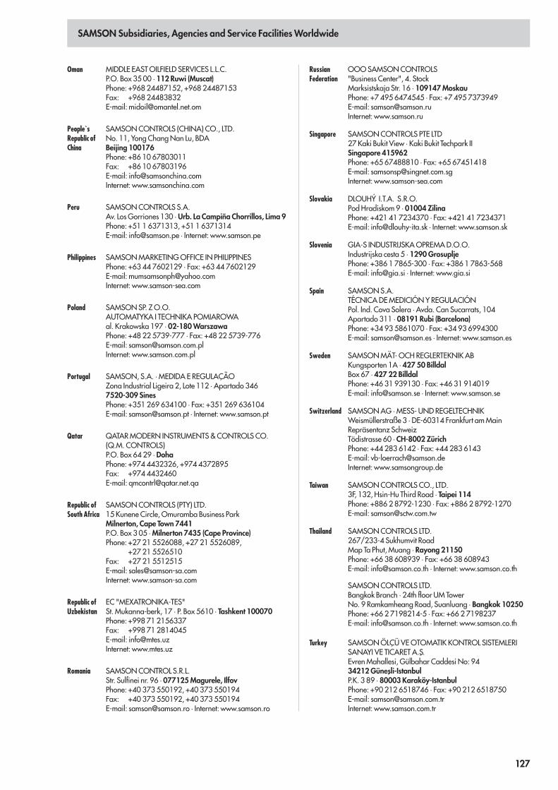
SAMSON Subsidiaries, Agencies and Service Facilities Worldwide
Oman MIDDLE EAST OILFIELD SERVICES L.L.C.P.O. Box 35 00 · 112 Ruwi (Muscat)Phone: +968 24487152, +968 24487153Fax: +968 24483832E-mail: [email protected]
People`sRepublic ofChina
SAMSON CONTROLS (CHINA) CO., LTD.No. 11, Yong Chang Nan Lu, BDABeijing 100176Phone: +86 10 67803011Fax: +86 10 67803196E-mail: [email protected]: www.samsonchina.com
Peru SAMSON CONTROLS S.A.Av. Los Gorriones 130 · Urb. La Campiña Chorrillos, Lima 9Phone: +51 1 6371313, +51 1 6371314E-mail: [email protected] · Internet: www.samson.pe
Philippines SAMSON MARKETING OFFICE IN PHILIPPINESPhone: +63 44 7602129 · Fax: +63 44 7602129E-mail: [email protected]: www.samson-sea.com
Poland SAMSON SP. Z O.O.AUTOMATYKA I TECHNIKA POMIAROWAal. Krakowska 197 · 02-180 WarszawaPhone: +48 22 5739-777 · Fax: +48 22 5739-776E-mail: [email protected]: www.samson.com.pl
Portugal SAMSON, S.A. · MEDIDA E REGULAÇÃOZona Industrial Ligeira 2, Lote 112 · Apartado 3467520-309 SinesPhone: +351 269 634100 · Fax: +351 269 636104E-mail: [email protected] · Internet: www.samson.pt
Qatar QATAR MODERN INSTRUMENTS & CONTROLS CO.(Q.M. CONTROLS)P.O. Box 64 29 · DohaPhone: +974 4432326, +974 4372895Fax: +974 4432460E-mail: [email protected]
Republic ofSouth Africa
SAMSON CONTROLS (PTY) LTD.15 Kunene Circle, Omuramba Business ParkMilnerton, Cape Town 7441P.O. Box 3 05 · Milnerton 7435 (Cape Province)Phone: +27 21 5526088, +27 21 5526089,
+27 21 5526510Fax: +27 21 5512515E-mail: [email protected]: www.samson-sa.com
Republic ofUzbekistan
EC "MEXATRONIKA-TES"St. Mukanna-berk, 17 · P. Box 5610 · Tashkent 100070Phone: +998 71 2156337Fax: +998 71 2814045E-mail: [email protected]: www.mtes.uz
Romania SAMSON CONTROL S.R.L.Str. Sulfinei nr. 96 · 077125 Magurele, IlfovPhone: +40 373 550192, +40 373 550194Fax: +40 373 550192, +40 373 550194E-mail: [email protected] · Internet: www.samson.ro
RussianFederation
OOO SAMSON CONTROLS"Business Center", 4. StockMarksistskaja Str. 16 · 109147 MoskauPhone: +7 495 6474545 · Fax: +7 495 7373949E-mail: [email protected]: www.samson.ru
Singapore SAMSON CONTROLS PTE LTD27 Kaki Bukit View · Kaki Bukit Techpark IISingapore 415962Phone: +65 67488810 · Fax: +65 67451418E-mail: [email protected]: www.samson-sea.com
Slovakia DLOUHÝ I.T.A. S.R.O.Pod Hradiskom 9 · 01004 ZilinaPhone: +421 41 7234370 · Fax: +421 41 7234371E-mail: [email protected] · Internet: www.samson.sk
Slovenia GIA-S INDUSTRIJSKA OPREMA D.O.O.Industrijska cesta 5 · 1290 GrosupljePhone: +386 1 7865-300 · Fax: +386 1 7863-568E-mail: [email protected] · Internet: www.gia.si
Spain SAMSON S.A.TÉCNICA DE MEDICIÓN Y REGULACIÓNPol. Ind. Cova Solera · Avda. Can Sucarrats, 104Apartado 311 · 08191 Rubi (Barcelona)Phone: +34 93 5861070 · Fax: +34 93 6994300E-mail: [email protected] · Internet: www.samson.es
Sweden SAMSON MÄT- OCH REGLERTEKNIK ABKungsporten 1A · 427 50 BilldalBox 67 · 427 22 BilldalPhone: +46 31 939130 · Fax: +46 31 914019E-mail: [email protected] · Internet: www.samson.se
Switzerland SAMSON AG · MESS- UND REGELTECHNIKWeismüllerstraße 3 · DE-60314 Frankfurt am MainRepräsentanz SchweizTödistrasse 60 · CH-8002 ZürichPhone: +44 283 6142 · Fax: +44 283 6143E-mail: [email protected]: www.samsongroup.de
Taiwan SAMSON CONTROLS CO., LTD.3F, 132, Hsin-Hu Third Road · Taipei 114Phone: +886 2 8792-1230 · Fax: +886 2 8792-1270E-mail: [email protected]
Thailand SAMSON CONTROLS LTD.267/233-4 Sukhumvit RoadMap Ta Phut, Muang · Rayong 21150Phone: +66 38 608939 · Fax: +66 38 608943E-mail: [email protected] · Internet: www.samson.co.th
SAMSON CONTROLS LTD.Bangkok Branch · 24th floor UM TowerNo. 9 Ramkamheang Road, Suanluang · Bangkok 10250Phone: +66 2 7198214-5 · Fax: +66 2 7198237E-mail: [email protected] · Internet: www.samson.co.th
Turkey SAMSON ÖLÇÜ VE OTOMATIK KONTROL SISTEMLERISANAYI VE TICARET A.S
´.
Evren Mahallesi, Gülbahar Caddesi No: 9434212 Günes
´li-Istanbul
P.K. 3 89 · 80003 Karaköy-IstanbulPhone: +90 212 6518746 · Fax: +90 212 6518750E-mail: [email protected]: www.samson.com.tr
126 127
SAMSON Subsidiaries, Agencies and Service Facilities Worldwide
U.S.A. SAMSON CONTROLS INC.4111 Cedar Boulevard · Baytown, Texas 77523-8588Phone: +1 281 383-3677 · Fax: +1 281 383-3690E-mail: [email protected]: www.samson-usa.com
SAMSON PROJECT ENGINEERING, INC.14811 St. Mary´s Lane, Suite 130 · Houston, Texas 77079Phone: +1 281 7596900, +1 281 7596902Fax: +1 281 8708007E-mail: [email protected]: www.samson-pei.com
Ukraine "SAMSON-ENGINEERING GMBH"Floor 10, Office 4 · 19 Marina Raskowa St · 02002 KievPhone: +380 44 4905305 · Fax: +380 44 4941517E-mail: [email protected]: www.samsoneng.kiev.ua
United ArabEmirates
SAMSON CONTROLS FZEP.O. Box 262793 · PBU YC01 (near R/A 08)Jebel Ali Free Zone, DubaiPhone: +971 4 8834933Fax: +971 4 8834944E-mail: [email protected]: www.samson.ae
Venezuela SAMSON CONTROLS S.A.Urb. Los Rosales, Calle Bermúdez · Edif. La GarantíaCaracas 1040 Distrito FederalPhone: +58 212 6903645 · Fax: +58 212 6935953E-mail: [email protected]: www.samson.com.ve
Vietnam SAMSON VIETNAM CO., LTD.8th Floor, ATIC Office Building · 4 Nguyen Thi Minh KhaiDakao Ward, District 1, Ho Chi Minh CityPhone: +84 839 106533 · Fax: +84 839 106583E-mail: [email protected]
All addresses, including e-mail and Internet addresses, can be found athttp://www.samson.de
128

______________________________________________________________________________________________________________________________
______________________________________________________________________________________________________________________________
______________________________________________________________________________________________________________________________
______________________________________________________________________________________________________________________________
______________________________________________________________________________________________________________________________
______________________________________________________________________________________________________________________________
______________________________________________________________________________________________________________________________
______________________________________________________________________________________________________________________________
______________________________________________________________________________________________________________________________
______________________________________________________________________________________________________________________________
______________________________________________________________________________________________________________________________
______________________________________________________________________________________________________________________________
______________________________________________________________________________________________________________________________
______________________________________________________________________________________________________________________________
______________________________________________________________________________________________________________________________
______________________________________________________________________________________________________________________________
______________________________________________________________________________________________________________________________
______________________________________________________________________________________________________________________________
______________________________________________________________________________________________________________________________
______________________________________________________________________________________________________________________________
______________________________________________________________________________________________________________________________
______________________________________________________________________________________________________________________________
______________________________________________________________________________________________________________________________
______________________________________________________________________________________________________________________________
______________________________________________________________________________________________________________________________
______________________________________________________________________________________________________________________________
______________________________________________________________________________________________________________________________
______________________________________________________________________________________________________________________________
______________________________________________________________________________________________________________________________
______________________________________________________________________________________________________________________________
Notes
129

______________________________________________________________________________________________________________________________
______________________________________________________________________________________________________________________________
______________________________________________________________________________________________________________________________
______________________________________________________________________________________________________________________________
______________________________________________________________________________________________________________________________
______________________________________________________________________________________________________________________________
______________________________________________________________________________________________________________________________
______________________________________________________________________________________________________________________________
______________________________________________________________________________________________________________________________
______________________________________________________________________________________________________________________________
______________________________________________________________________________________________________________________________
______________________________________________________________________________________________________________________________
______________________________________________________________________________________________________________________________
______________________________________________________________________________________________________________________________
______________________________________________________________________________________________________________________________
______________________________________________________________________________________________________________________________
______________________________________________________________________________________________________________________________
______________________________________________________________________________________________________________________________
______________________________________________________________________________________________________________________________
______________________________________________________________________________________________________________________________
______________________________________________________________________________________________________________________________
______________________________________________________________________________________________________________________________
______________________________________________________________________________________________________________________________
______________________________________________________________________________________________________________________________
______________________________________________________________________________________________________________________________
______________________________________________________________________________________________________________________________
______________________________________________________________________________________________________________________________
______________________________________________________________________________________________________________________________
______________________________________________________________________________________________________________________________
______________________________________________________________________________________________________________________________
Notes
130
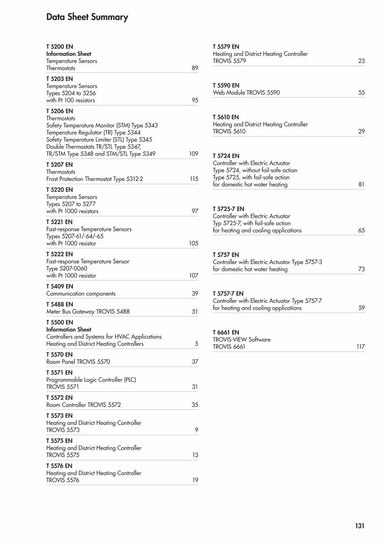
Data Sheet Summary
T 5200 EN Information Sheet Temperature Sensors Thermostats 89
T 5203 EN Temperature Sensors Types 5204 to 5256 with Pt 100 resistors 95
T 5206 EN Thermostats Safety Temperature Monitor (STM) Type 5343 Temperature Regulator (TR) Type 5344 Safety Temperature Limiter (STL) Type 5345 Double Thermostats TR/STL Type 5347, TR/STM Type 5348 and STM/STL Type 5349 109
T 5207 EN Thermostats Frost Protection Thermostat Type 5312-2 115
T 5220 EN Temperature Sensors Types 5207 to 5277 with Pt 1000 resistors 97
T 5221 EN Fast-response Temperature Sensors Types 5207-61/-64/-65 with Pt 1000 resistor 105
T 5222 EN Fast-response Temperature Sensor Type 5207-0060 with Pt 1000 resistor 107
T 5409 EN Communication components 39
T 5488 EN Meter Bus Gateway TROVIS 5488 51
T 5500 EN Information Sheet Controllers and Systems for HVAC Applications Heating and District Heating Controllers 5
T 5570 EN Room Panel TROVIS 5570 37
T 5571 EN Programmable Logic Controller (PLC) TROVIS 5571 31
T 5572 EN Room Controller TROVIS 5572 35
T 5573 EN Heating and District Heating Controller TROVIS 5573 9
T 5575 EN Heating and District Heating Controller TROVIS 5575 13
T 5576 EN Heating and District Heating Controller TROVIS 5576 19
T 5579 EN Heating and District Heating Controller TROVIS 5579 23
T 5590 EN Web Module TROVIS 5590 55
T 5610 EN Heating and District Heating Controller TROVIS 5610 29
T 5724 EN Controller with Electric Actuator Type 5724, without fail-safe action Type 5725, with fail-safe action for domestic hot water heating 81
T 5725-7 EN Controller with Electric Actuator Typ 5725-7, with fail-safe action for heating and cooling applications 65
T 5757 EN Controller with Electric Actuator Type 5757-3 for domestic hot water heating 73
T 5757-7 EN Controller with Electric Actuator Type 5757-7 for heating and cooling applications 59
T 6661 EN TROVIS-VIEW Software TROVIS 6661 117
MF 131
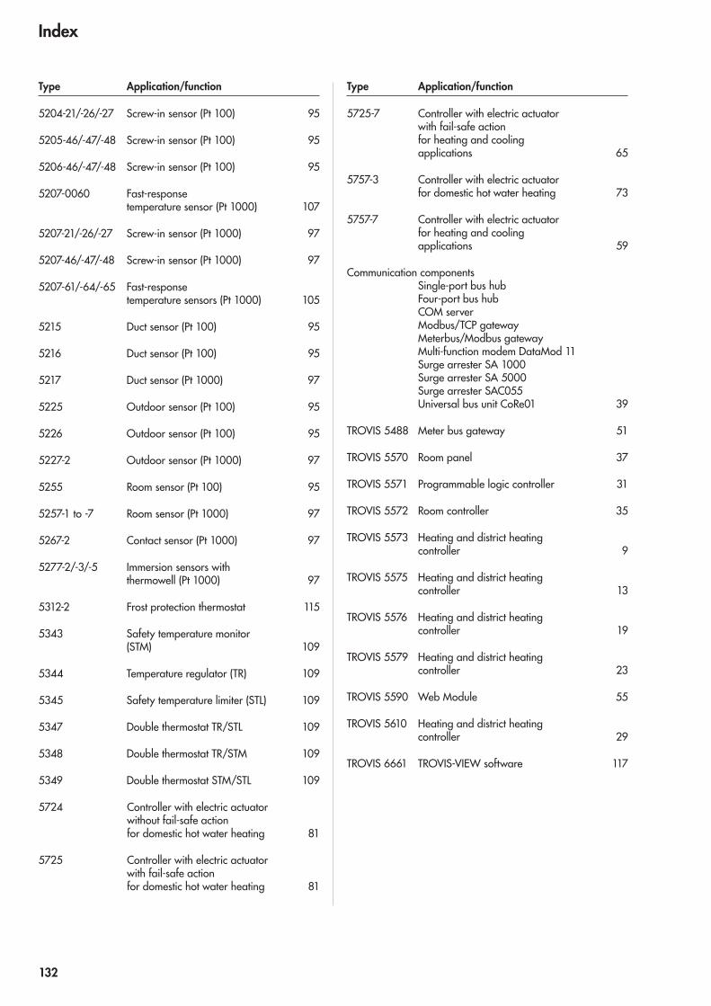
5204-21/-26/-27 Screw-in sensor (Pt 100) 95
5205-46/-47/-48 Screw-in sensor (Pt 100) 95
5206-46/-47/-48 Screw-in sensor (Pt 100) 95
5207-0060 Fast-response temperature sensor (Pt 1000) 107
5207-21/-26/-27 Screw-in sensor (Pt 1000) 97
5207-46/-47/-48 Screw-in sensor (Pt 1000) 97
5207-61/-64/-65 Fast-response temperature sensors (Pt 1000) 105
5215 Duct sensor (Pt 100) 95
5216 Duct sensor (Pt 100) 95
5217 Duct sensor (Pt 1000) 97
5225 Outdoor sensor (Pt 100) 95
5226 Outdoor sensor (Pt 100) 95
5227-2 Outdoor sensor (Pt 1000) 97
5255 Room sensor (Pt 100) 95
5257-1 to -7 Room sensor (Pt 1000) 97
5267-2 Contact sensor (Pt 1000) 97
5277-2/-3/-5 Immersion sensors with thermowell (Pt 1000) 97
5312-2 Frost protection thermostat 115
5343 Safety temperature monitor (STM) 109
5344 Temperature regulator (TR) 109
5345 Safety temperature limiter (STL) 109
5347 Double thermostat TR/STL 109
5348 Double thermostat TR/STM 109
5349 Double thermostat STM/STL 109
5724 Controller with electric actuator without fail-safe action for domestic hot water heating 81
5725 Controller with electric actuator with fail-safe action for domestic hot water heating 81
5725-7 Controller with electric actuator with fail-safe action for heating and cooling applications 65
5757-3 Controller with electric actuator for domestic hot water heating 73
5757-7 Controller with electric actuator for heating and cooling applications 59
Communication components Single-port bus hub Four-port bus hub COM server Modbus/TCP gateway Meterbus/Modbus gateway Multi-function modem DataMod 11 Surge arrester SA 1000 Surge arrester SA 5000 Surge arrester SAC055 Universal bus unit CoRe01 39
TROVIS 5488 Meter bus gateway 51
TROVIS 5570 Room panel 37
TROVIS 5571 Programmable logic controller 31
TROVIS 5572 Room controller 35
TROVIS 5573 Heating and district heating controller 9
TROVIS 5575 Heating and district heating controller 13
TROVIS 5576 Heating and district heating controller 19
TROVIS 5579 Heating and district heating controller 23
TROVIS 5590 Web Module 55
TROVIS 5610 Heating and district heating controller 29
TROVIS 6661 TROVIS-VIEW software 117
Type Application/function Type Application/function
Index
132

SAMSON AG · MESS- UND REGELTECHNIK Weismüllerstraße 3 · 60314 Frankfurt am Main · GermanyPhone: +49 69 4009-0 · Fax: +49 069 4009-1507 E-mail: [email protected] · Internet: www.samson.deSAMSON GROUP · www.samsongroup.net
Controllers and Sensorsfor Heating, Ventilation andAir-conditioning Systems
Cont
rolle
rs a
nd S
enso
rs fo
r H
eatin
g, V
entil
atio
n an
d A
ir-co
nditi
onin
g Sy
stem
s
Catalog
2012
-07
WS
· K5
EN
SAM
SON