salvage and denolition of two nvy offshore platform …
TRANSCRIPT

A D-AlES 656 SALVAGE AND DENOLITION OF TWO NVY OFFSHORE PLATFORM IA(U) *RNETT AND CASBARIAN INC NETAIRIE LA Ni N SEELIOOCT 94 CHES/'NVFC-FPO--S4(32) N62477-82-C-0393
UNCLSSIFIED F/G 13/13 N

.
-- L6-
. . . . . ... .
FPONIO
A DTI C~ELE1CT
DIV ON
SALVAGE AND DEMOLITIONOF
TWO NAVY OFFSHORE PLATFORMS
By
CDWILLIAM N. SEELIGLfl
(.0 PO-1-84(32) OCTOBER, 1984
* Co
Ocean Engineering0ILESAPEAK[ DIVISIOANNAVAL FACILITIES 1!4NI\11U1 (, COMND
;%AT!NC',rJN NAVY YXRD' 'fSIIINCTIUy, DC 203/4
Li-iAppmov.4 foi public r~iIoiji.Ctaftibufio Utdamifiqd
- H
IA.
SALVAGE AND DEMOLITIONOF
TWO NAVY OFFSHORE PLATFORMS
BY
WILLIAM N. SEELIG
FPo-l-84(32) OCTOBER, 1984
CONThCT 162477-82-C--03 93
p APPROVED BY:
A.'40. P. CASBARIAPE SUN LIMG, P.E.Executive Vice Pxeaidgnt- Director
- hrnett &Casbarian, Inc.) Engineering Analyses Division
OCEAN ENGINEERING & CONSTRUCTION PROJECT OFFICECHE9SAPEAIK DIVISION
NAVAL FAC ILITIES ENGINEERING COMMANDMASHINGTON, D.C. 20374
MMMShIUTON STATEMFNT A1
Approved tot public releaselDistribu.tion Unlhited
UnclassifiedSECURITY CLASSIFICATION OF THIS PAGE
REPORT DOCUMENTATION PAGEla. REPORT SECURITY CLASSIFICATION lb. RESTRICTIVE MARKINGSUnclassified
2a. SECURITY CLASSIFICATION AUTHORITY 3. DISTRIBUTION AVAILABILITY OF REP.
Approved for public release;distribution is unlimited
2b. DECLASSIFICATION/DOWNGRADING SCHEDULE
4. PERFORMING ORGANIZATION REPORT NUMBER 5. MONITORING ORGANIZATION REPORT *FPO-I-84(32)
6a. NAME OF PERFORM. ORG. 6b. OFFICE SYM 7a. NAME OF MONITORING ORGANIZATIONOcean Engineering& ConstructionProject OfficeCHESNAVFACENGCOM
6c. ADDRESS (City, State, and Zip Code) 7b. ADDRESS (City, State, and Zip )BLDG. 212, Washington Navy YardWashington, D.C. 20374-2121Ba. NAME OF FUNDING ORG. 8b. OFFICE SYM 9. PROCUREMENT INSTRUMENT INDENT *
8c. ADDRESS (City, State & Zip) 10. SOURCE OF FUNDING NUMBERSPROGRAM PROJECT TASK WORK UNITELEMENT 4 4 ACCESS
11. TITLE (Including Security Classification)Salvage and Demolition of Two Navy Offshore Platforms
12. PERSONAL AUTHOR(S)William N. Seelig13a. TYPE OF REPORT 13b. TIME COVERED 14. DATE OF REP. (YYMMDD) 15. PAGES
FROM TO 84-10 9216. SUPPLEMENTARY NOTATION
17. COSATI CODES 18. SUBJECT TERMS (Continue on reverse if nec.)FIELD GROUP SUB-GROUP Platforms, Salvage. Demolition, Ocean____construction & structures
.-. o
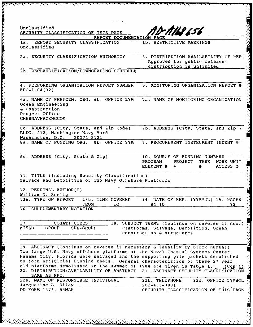
19. ABSTRACT (Continue on reverse if necessary & identify by block number)Two large U.S. Navy offshore platforms at the Naval Coastal Systems Center,
Panama City. Florida were salvaged and the supporting pile jackets demolished.- to form artificial fishing reefs. General characteristics of these 27 year
old platforms demolished in the summer of 1984 are given in Table i. -' (Con't)20. DISTRIBUTION/AVAILABILITY OF ABSTRACT 21. ABSTRACT SECURITY CLASSIFICATION
SAME AS RPT.22a. NAME OF RESPONSIBLE INDIVIDUAL 22b. TELEPHONE 22c. OFFICE SYMBOLJacqueline B. Riley 202-433-3881DD FORM 1473, 84MAR SECURITY CLASSIFICATION OF THIS PAGE
.. .. .% .* ~ * .** .~ .. . .. . . . . .

• "%.-
BLOCK 19 (Con't)
This was a joint project by the Chesapeake Division, Naval FacilitiesEngineering Command (Sanford Offshore Salvage. Morgan City, La. contractor),and the Explosive Ordinance Disposal Group Two. Detachment. Panama City,Florida (Table 2 gives project organization).
...........

TABLE OF CONTENTS
r
Page No.
EXECUTIVE SUMMARY
INTRODUCTION 1
HISTORY 3
Uses
Repairs and Inspections 5
Permits 8
PLATFORM DECK CLEANUP, SALVAGE AND REMOVAL 9aDEMOLITION OF THE JACKETS 20 FORM UNDERWATER ARTIFICIAL REEFS 12
Type of Explosives Used 13
Demolition Sequence Stage I 15
Demolition Sequence Stage I 16
" Lessons Learned 16
Observations 17
Accesion ForPROJECT COMPLETION 17
DTIC TAB
SUMMARY Unannounced El 17Just if ctL n'
" " ACKNOWLEDGMENTS By 18Dist ibtion i
Availability Codes
Dist Avai a.,d or
spt:w
:.°-'.-', _ _ --..'-, . ,' " " -' " - ", -,', "- ". . - .-- ., --- .,-,.. . . '- '-. . .. .., - " " " . .. - . .. " -"• - . - .-.° .. .-"..- - -".. .
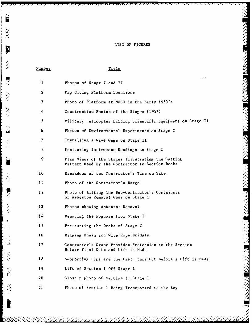
LIST OF FIGURES
Number Title
1 Photos of Stage I and II
2 Map Giving Platform Locations
3 Photo of Platform at NCSC in the Early 1950's
4 Construction Photos of the Stages (1957)
5 Military Helicopter Lifting Scientific Equipment on Stage II
6 Photos of Environmental Experiments on Stage I
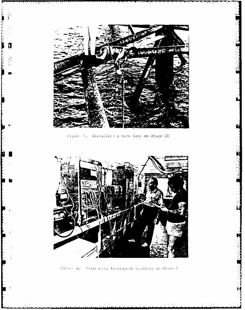
7 Installing a Wave Cage on Stage II
8 Monitoring Instrument Readings on Stage I
a9 Plan Views of the Stages Illustrating the CuttingPattern Used by the Contractor to Section Decks
10 Breakdown of the Contractor's Time on Site
11 Photo of the Contractor's Barge
P12 Photo of Lifting The Sub--Contrac tor's Containersof Asbestos Removal Gear on Stage I
13 Photos shoving Asbestos Removal
14 Removing the Foghorn from Stage I
15 Pre-cutting the Decks of Stage 1
16 Rigging Chain and Wire Rope Bridals
17 Contractor's Crane Provides Pretension to the Section
Before Final Cuts and Lift is Made
18 Supporting Legs are the Last Items Cut Before a Lift is Made
19 Lift of Section 1 Off Stage I
20 Closeup photo of Section 1, Stage I
21 Photo of Section 1 Being Transported to the Bay
77
22 Photo of Stage I with Section 1 Removed
23 Unloading Section 2 (Stage I) on the Materials Barge
24 Stage I with Six Sections Removed
25 Lifting Section 7 Off Stage I
26 Stage I Jacket with Deck Removed
27 Solar Panel Being Removed from Stage II
28 Section I (Upper Two Decks) Being Removed from Stage II
29 Section 4 Being Removed from Stage II
30 The Last Section from Stage II Being Towed to the Bay
31 Computer Plot of Stage I
32 Computer Plot of Stage II
33 Sample Placement of a Container of NM/Deta
34 A Shaped Circular Charge
35 C-4 (RDK) Plastic Charges being Readied
' 36 Flexible Linear Shaped Charges
37 Transmitter Used for Demolition
38 Demolition Signal Receivers
" 39 Stage I -Plan Location of Charges
40 Stage I - Elevation Location of ChargesI.
41 Demolition Shot of the Northern Jacket of Stage I
42 Stage II - Plan Location of Charges
43 Stage II - Elevation Location of Charges
* . 44 Demolition Shot on Stage II
45 Salvage/Demolition Schedule
46 A Barracuda Picked Up After a Shot at Stage I
47 Disposal of Asbestos Waste
--

S.]
LIST OF TABLES
* Table Number Title
1 General Characteristics of the Platforms
2 Organization of the Project
3 Problems and Approach
k 4 Project Use of the Stages 1974 - 1980
5 Status of Sensors on Stage (Oct. 1982)
6 Organization
7 Summary of Contractor's Effort
8 Reef Characteristics
9 Estimate of Fish Killed
10 Costs for Demolition of Stages I and II
U
r.°
.°
.el-
% 7"
. . .- S ** *'S... . . . . . . . . .
LIST OF APPENDICES
APPENDIX
A CHRONOLOGICAL HISTORY OF THE STAGES
B CONTRACTOR PERSONNEL AND EQUIPMENT
C DAILY SUMMARY LOG OF CONTRACTOR'S ACTIVITIES
D DAILY SUMMARY LOG OF EOD ACTIVITIES
*E ASBESTOS DATA
F REFERENCES
R-M"
I..4
SALVAGE AND DEMOLITION OF TWO NAVY OFFSHORE PLATFORMS-
STAGES I & II
NAVAL COASTAL SYSTEMS CENTERI."
PANAMA CITY, FLORIDA -s
by
William N. Seelig, P.E.
EXECUTIVE SUMMARY
Two large U.S. Navy offshore platforms (Figure 1) at the Naval Coastal Systems
Center, Panama City, Florida were salvaged and the supporting pile jackets
demolished to form artificial fishing reefs. General characteristics of these
27 year old platforms demolished in the summer of 1984 are given in Table 1.
*This was a joint project by the Chesapeake Division, Naval Facilities
Engineering Command (Sanford Offshore Salvage, Morgan City, La. contractor), and
.*- the Explosive Ordinance Disposal Group Two, Detachment, Panama City, Florida
(Table 2 gives project organization). Capt. C. C. King was the Commanding
Officer of Naval Coastal Systems Center, Capt. L. K. Donovan was the Commanding
Officer of the Chesapeake Division and Lt. J. DeSimone was the Officer-In-Charge
of the EOD team.
4
SALVAGE AND DEMOLITION OF TWO NAVY OFFSHORE PLATFORMS
STAGES I & II
NAVAL COASTAL SYSTEMS CENTER
PANAMA CITY, FLORIDA
P by
William N. Seelig, P.E.
INTRODUCTION
The purpose of this report is to document the salvage and demolition in June-
- August 1984 of two offshore U.S. Navy platforms (Figure 1 and Table 1) for the
Naval Coastal Systems Center (NCSC), Panama City, Florida. Platforms were
located in the Gulf of Mexico as shown in Figure 2. This demolition project was
-. conducted jointly by the Ocean Engineering and Construction Project Office,
* Chesapeake Division, Naval Facilities Engineering Command (CHESDIV), and
Explosive Ordinance Disposal Group Two, Detachment, Panama City, Florida.
- Barnett & Casbarian, Inc. of Metairie, LA provided technical A/E support
* throughout the project. Work breakdown structure for the project is outlined in
1, Table 2.
Stages I and II were two large offshore platforms built by Brown and Root, Inc.
in 1957 to provide unique research facilities to the Naval Coastal Systems
"- Center (formerly U.S. Navy Mine Defense Laboratory). After 27 years of service,
*.: NCSC found maintenance costs for the platforms were high and believed the
platforr !trictural integrity to be questionable. Therefore, the N$CSC utiblic
-1

VV L W
Work Division tasked the Ocean Engineering and Construction Project Office
(Code FPO-I of CHESDIV) to evaluate the platforms. Underwater inspections,
structural analyses, economic studies and an evaluation of alternative led to
the recommendation to demolish the structures in 1981. CHESDIV was tasked in
1983 to proceed with designing the demolition. CHESDIV contracted Barnett &
Casbarian to provide demolition plans and specification and support during
" demolition. The final demolition after coordination with NCSL, State of
Florida, and various environmental was accomplished in the following manner:
1) A Chesapeake Division contractor cleaned and removed the platform decks.
This approach minimized the possibility of pollution to Florida waters and
" adjacent beaches, which is a popular tourist area.
* 2) The Explosive Ordinance Disposal EOD) detachment at Panama City
demolished the platform jackets in place to form artificial fishing reefs.
This approach a) provided EOD unique prototype explosive training, b) utilized
S excellent U.S. Navy diving support facilities available at NCSC, c) used cost
effective Navy personnel and d) provided a valuable fishing reefs to the local
-. sportfishing community.
This report gives a brief history of the platforms, summarizes use of the
stages, documents the demolition work and presents lessons learned as a result
of the project. A summary of the schedule and costs is also presented, which
may be useful in planning future demolition work of a similar nature.
-2-
* HISTORY
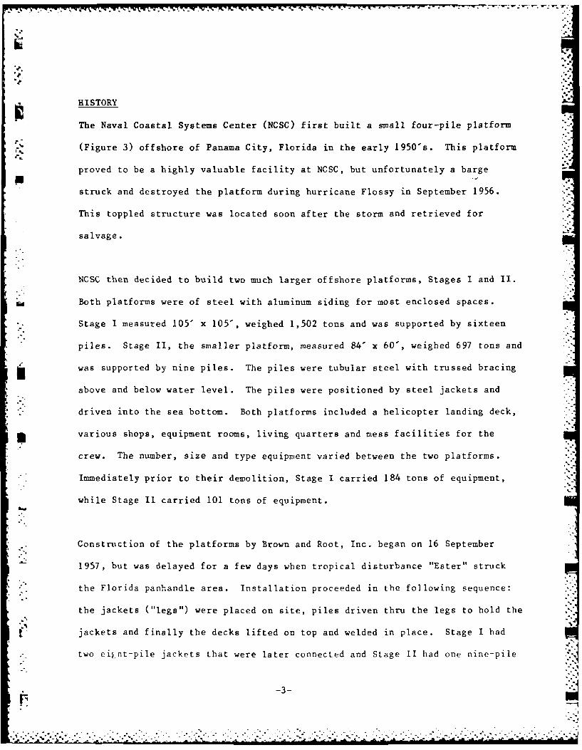
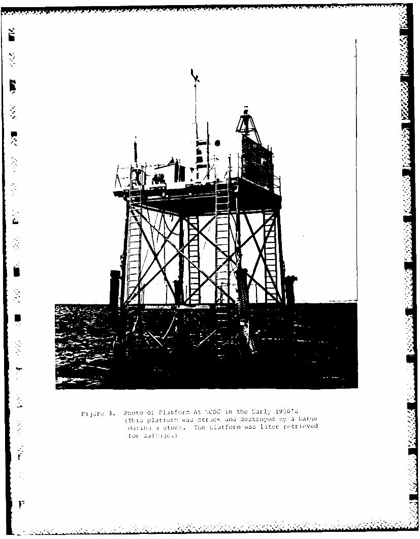
The Naval Coastal Systems Center (NCSC) first built a small four-pile platform
(Figure 3) offshore of Panama City, Florida in the early 1950's. This platform
proved to be a highly valuable facility at NCSC, but unfortunately a barge
struck and destroyed the platform during hurricane Flossy in September 1956.
This toppled structure was located soon after the storm and retrieved for
salvage.
NCSC then decided to build two much larger offshore platforms, Stages I and 1I.
Both platforms were of steel with aluminum siding for most enclosed spaces.
* Stage I measured 105' x 105', weighed 1,502 tons and was supported by sixteen
*piles. Stage II, the smaller platform, measured 84' x 60', weighed 697 tons and
j was supported by nine piles. The piles were tubular steel with trussed bracing
above and below water level. The piles were positioned by steel jackets and
* *. driven into the sea bottom. Both platforms included a helicopter landing deck,
various shops, equipment rooms, living quarters and mess facilities for the
crew. The number, size and type equipment varied between the two platforms.
* Immediately prior to their demolition, Stage I carried 184 tons of equipment,
while Stage II carried 101 tons of equipment.
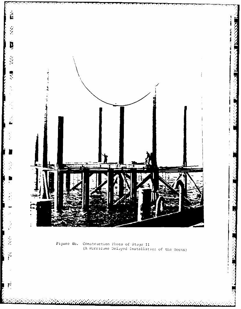
* Construction of the platforms by Brown and Root, Inc. began on 16 September
1957, but was delayed for a few days when tropical disturbance "Ester" struck
the Florida panhandle area. Installation proceeded in the following sequence:
the jackets ("legs") were placed on site, piles driven thru the legs to hold the
jackets and finally the decks lifted on top and welded in place. Stage I had
* two ei~nt-pile jackets that were later connected and Stage II had one nine-pile
-3-
.7 1

CC~~~~~K 77 K 17 07 -7 W. W: r n-rr r r rrrrr.
P.
jacket. The cost to originally build and install the platforms was $3 million
(1957 dollars). Figure 4 includes selected installation photos.
Both stages were originally designed to be manned full time and included
facilities for 30 people on Stage I and facilities for a crew of 6 on Stage II.
* However, the crews living on board were removed in 1961 when it was decided that
full time crews were too expensive.
* USES
Numerous scientific and military research projects were conducted on the
platforms. Some of the projects conducted during 1979 and 1980, for example,
* included:
* Evaluation of USCG oil containment booms.
Ground truth for comparison to remote sensor measurements.
Testing of various sea-going radars.
Evaluation of effect of oil drilling contaminants on marine life.
Signature measurements on various advanced craft.
Evaluation of diver support equipment.
Very specialized environmental measurements.
* A further sunmnary of platform use is given in Table 4 and a sample list of
sensors on the stages is given in Table 5. Sample uses of the Stages are
illustrated in photos given in Figures 5 thru 8.
- 4-

REPAIRS AND INSPECTIONS
Numerous alterations were made to the stages over the years. After the manning
crew departed in 1961, for example, the platforms were altered to operate
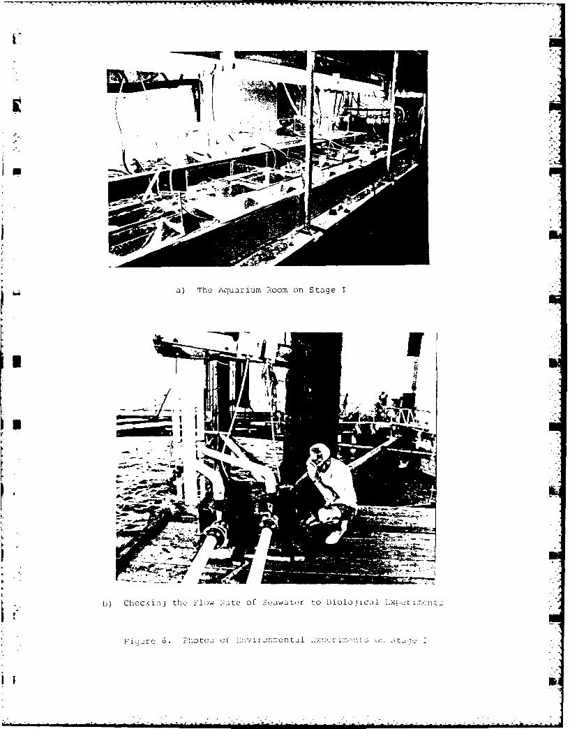
automatically. Changes were also made to accoimnodate various experiments. For
example, the aquarium room on Stage I was installed so that environmental
studies could be performed on marine life.
Major storms occasionally damaged the stairways and catwalks, so they were
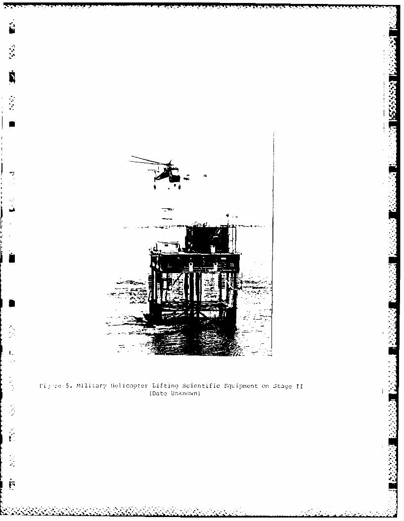
periodically repaired. Another problem was to find safe ways to get personnel
and equipment to and from the stages. Boat transport was used during mild wave
conditions and helicopter support was provided for heavier equipment (Figure 5).
The first underwater inspection was performed by military divers 23-31 July
1968. Condition Reports in July 1968 and August 1969 followed this inspection.
They found for the most part, extensive pitting in the jacket, several holes in
the bracing and welds in good condition. These reports recommended several
repairs and safety considerations. The inspections continued in mid-October
1969 on Stages I and II followed by inspection reports in November 1969. As a
result of these reports, the cathodic protection systems of the Stages were
S,"overhauled in June and August 1970.
* :Several "swim-by" visual inspections by military divers were made during the
, 1970's. No written reports on results of those inspections were available.
-5-
" "- .. ."'"'"'" "" ""' "" ' '""."" """. " "" ' ' " ' ' ./.... i. "'. . " :'" i
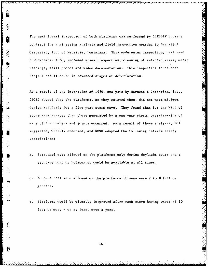
p The next formal inspection of both platforms was performed by CHESDIV under a
contract for engineering analysis and field inspection awarded to Barnett &
J, Casbarian, Inc. of Metairie, Louisiana. This underwater inspection, performed
3-9 December 1980, included visual inspection, cleaning of selected areas, meter
readings, still photos and video documentation. This inspection found both
* Stage I and II to be in advanced stages of deterioration.
As a result of the inspection of 1980, analysis by Barnett & Casbarian, Inc.,
(BCI) showed that the platforms, as they existed then, did not meet minimum
Isdesign standards for a five year storm wave. They found that for any kind of
*storm wave greater than those generated by a one year storm, overstressing of
many of the numbers and joints occurred. As a result of these analyses, BCI
suggested, CHESDIV endorsed, and NCSC adopted the following interim safety
restrictions:
m a. Personnel were allowed on the platforms only during daylight hours and a
stand-by boat or helicopter would be available at all times.
b. No personnel were allowed on the platforms if seas were 7 to 8 feet or
greater.
c. Platforms would be visually inspected after each storm having waves of 10
feet or more -or at least once a year.-
-6--

-' CM 7-7 1 .- .
After the inspection in 1980 and the strength analysis in 1981 of Stages I and
II, it was apparent that both platforms were in the advanced stages of
%pdeterioration. To rectify this situation, many different solutions were
considered.
One of the solutions considered in the BCI 1981 Platform Strength Evaluation,
involved restoring the platforms to working order. The restoration would
include:
a. Install insert piles -
b. Replace missing members
c. Install saddles
d. Grout key members
e. Remnove debris and add anodes
f. Repair deck structures
g. Additional engineering
*h. Contingencies
* The cost of restoring the platforms, $9,800,000 for Stage I and $6,500,000 for
Stage II, proved to be so prohibitive that it was not seriously considered.
Another alternative considered in the 1981 report was constructing one new
platform. The Navy indicated, if a new platform were to be built, only one
would be needed in 100 ft. of water. The estimated cost of the new platform was
$5,300,000 with equipment and quarters and $3,300,000 without them. All costs
in the BCI report were in 1981 dollars.
-7-

The last alternative suggested was to salvage both platform, which included
removing decks, pilings and jackets. The estimated salvage cost was $1,125,000.
if the structure fell before salvage, the cost of salvage, which included
recovering the debris from the bottom and cutting it up, rose to $1,730,000 in
1981 dollars.
CHESDIV was tasked by NCSC in 1983 to proceed with designing the demolition.
BCI was again contracted for this effort. In 1983, Barnett & Casbarian, Inc.
issued their final report entitled "Demolition/Salvage Analysis of Offshore
Platforms Stage I and II". In this report, they evaluated seven promising
alternatives. Based on this evaluation and additional input it was decided to
salvage the platform decks and demolish the jackets in place to form artificial
reefs.
PERMITS
* Many various interested agencies and groups were contacted in preparation of the
* final demolition planning. These included:
State of Florida, Department of Natural Resources
*State of Florida, Department of Environmental Regulation
Florida Marine Patrol
U.S. Army Corps of Engineers
U.S. Environmental Protection Agency
U.S. Coast Guard
U.S. Minerals Management Service
Tenneco Oil Company
V Bay County, Florida
Local Interested Parties
L .%)
Ir
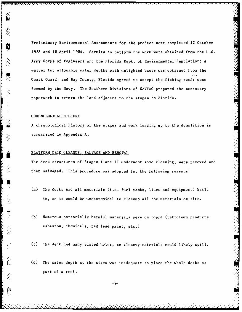
Preliminary Environmental Assessments for the project were completed 12 October
1983 and 18 April 1984. Permits to perform the work were obtained from the U.S.
Army Corps of Engineers and the Florida Dept. of Environmental Regulation; a
waiver for allowable water depths with unlighted buoys was obtained from the
• 'Coast Guard; and Bay County, Florida agreed to accept the fishing reefs once
formed by the Navy. The Southern Divisions of NAVFAC prepared the necessary
paperwork to return the land adjacent to the stages to Florida.
CHRONOLOGICAL HISTORY
A chronological history of the stages and work leading up to the demolition is
* .. : summarized in Appendix A.
l i PLATFORM DECK CLEANUP, SALVAGE AND REMOVAL
The deck structures of Stages I and II underwent some cleaning, were removed and
then salvaged. This procedure was adopted for the following reasons:
m-.(a) The decks had all materials (i.e. fuel tanks, lines and equipment) built
in, so it would be uneconomical to cleanup all the materials on site.
* (b) Numerous potentially harmful materials were on board (petroleum products,
asbestos, chemicals, red lead paint, etc.)
' (c) The deck had many rusted holes, so cleanup materials could likely spill.
(d) The water depth at the sites was inadequate to place the whole decks as
part of a reef.
-9-
.. -7
i7
,%
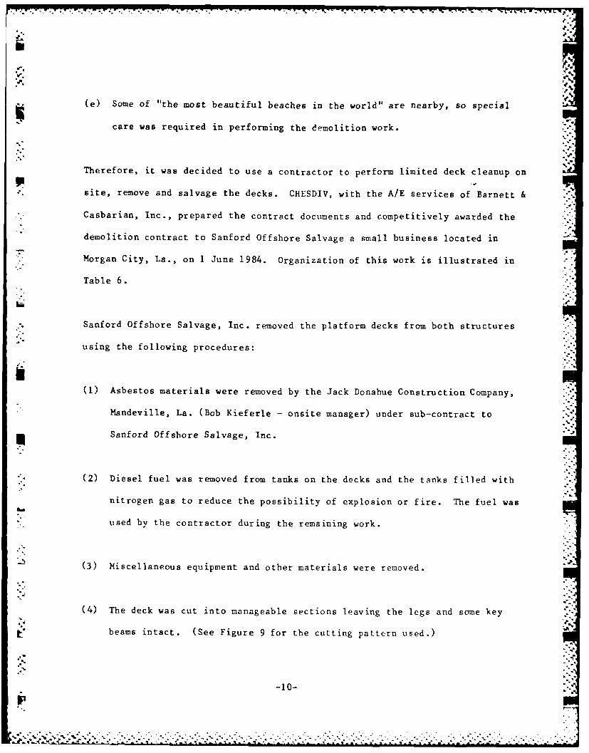
(e) Some of "the most beautiful beaches in the world" are nearby, so special
care was required in performing the demolition work.
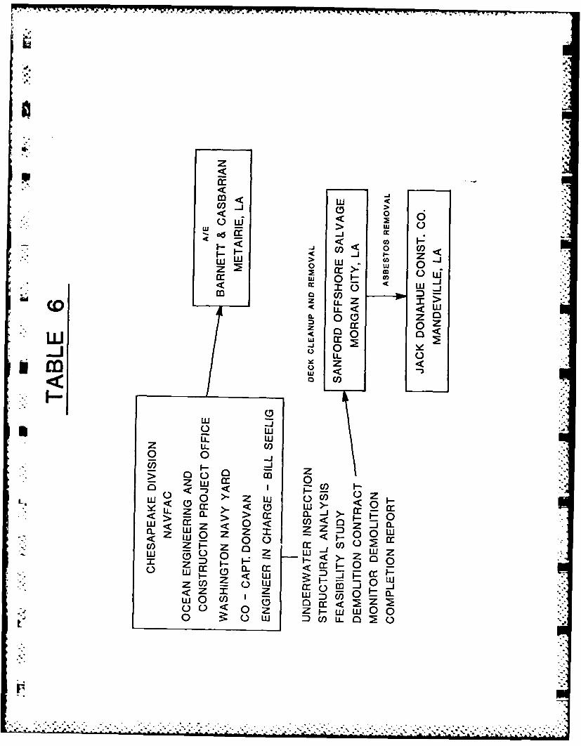
Therefore, it was decided to use a contractor to perform limited deck cleanup on
* site, remove and salvage the decks. CHESDIV, with the AlE services of Barnett &
Casbarian, Inc., prepared the contract documents and competitively awarded the
demolition contract to Sanford Offshore Salvage a small business located in
*Morgan City, La., on I June 1984. Organization of this work is illustrated in
Table 6.
* Sanford Offshore Salvage, Inc. removed the platform decks from both structures
using the following procedures:
(1) Asbestos materials were removed by the Jack Donahue Construction Company,
Mandeville, La. (Bob Kieferle -onsite manager) under sub-contract to
* Sanford Offshore Salvage, Inc.
* (2) Diesel fuel was removed from tank~s on the decks and the tanks filled with
nitrogen gas to reduce the possibility of explosion or f ire. The fuel was
used by the contractor during the remaining work.
(3) Miscellaneous equipment and other materials were removed. -
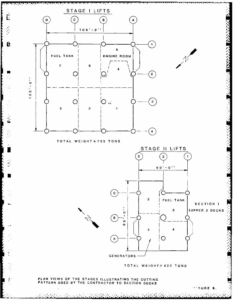
(4) The deck was cut into manageable sections leaving the legs and some key
beams intact. (See Figure 9 for the cutting pattern used.)
-10-
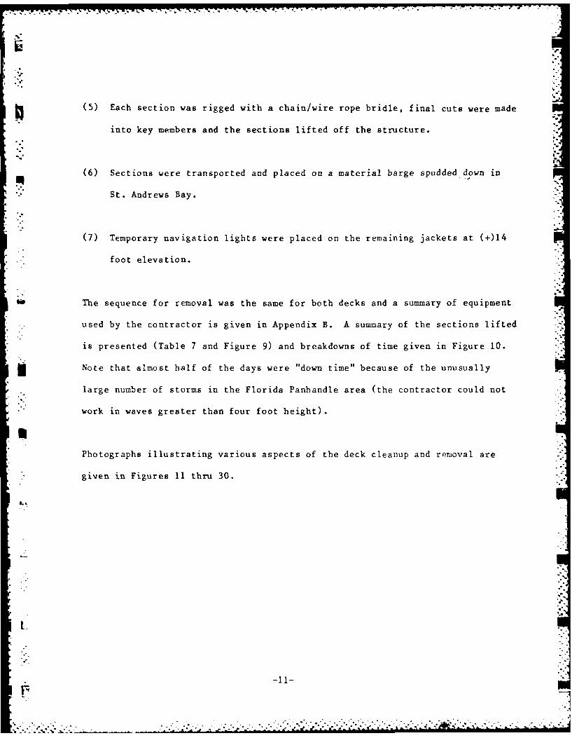
(5) Each section was rigged with a chain/wire rope bridle, final cuts were made
into key members and the sections lifted off the structure.
(6) Sections were transported and placed on a material barge spudded down in
St. Andrews Bay.
(7) Temporary navigation lights were placed on the remaining jackets at (+)14
foot elevation.
The sequence for removal was the same for both decks and a summary of equipment
used by the contractor is given in Appendix B. A summary of the sections lifted
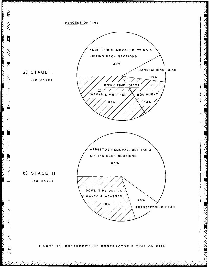
is presented (Table 7 and Figure 9) and breakdowns of time given in Figure 10.
i Note that almost half of the days were "down time" because of the unusually
large number of storms in the Florida Panhandle area (the contractor could not
work in waves greater than four foot height).
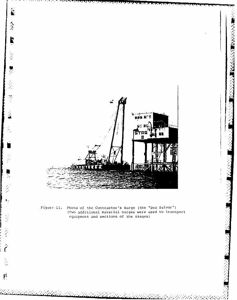
mPhotographs illustrating various aspects of the deck cleanup and removal are
given in Figures 11 thru 30.
Lx
-11-
,. .....-. ..... . .. . : ... ... ...-. ,- .-. i . .:-) 2 .-. . .'..,-3o .,, * *._.,* .. :: .

DEMOLITION OF THE JACKETS TO FORM
UNDERWATER ARTIFICLAL REEFS
p ".
The stage jackets make excellent fishing reefs because the large exposed surface
*area (Figure 31 and 32) form a habitat and attract marine life. Artif icial
*reefs are especially valuable to Florida waters because the sea bottom consists
* largely of a plain sand capable of supporting only modest amounts of sea life.
It was impractical to leave the jackets intact due to the navigational hazards,
so a decision was made to topple them in place to form underwater artificial
reefs. Necessary permits were obtained to form these reefs and Bay County,
Florida agreed to accept the reefs, once formed.
Captain King, the Commanding Officer, NCSC, tasked the Explosive Ordinance
Disposal Group Two, Detachment, Panama City to perform this demolition for the
* following reasons:
(1) It provided excellent prototype training.
(2) Outstanding support is available from Naval Diving & Salvage Training
Center at Panama City.
* (3) Use of Navy personnel gives optimum cost effectiveness.
CHESDIV provided an observer, Peter Williams, to monitor the demolition work.
L1
DEOIINOFTEJC7T OFR

TYPE OF EXPLOSIVE USED 6U
A combination of military and commercial explosives were used to accomplish thisi
demolition work. The combination of devices used was carefully selected to both I
efficiently accomplish the task and provide training with a variety of
equipment.
Commercial Explosives
(Obtained from Jet Research, Mansfield, Texas 76063)
A
t; (1) Binary liquid explosive of nitromethane and diethyenetriamine (NM/DETA).
This binary explosive was selected because it is extremely safe, effective
and easy to deploy. The NM/DETA was poured into shaped canisters holding
43 pounds of explosive (Figure 33). These charges were then lowered down
inside to pile to a predetermined depth. These explosives proved to be
especially effective because the force from detonation acted radially from
* inside the piles. Loss of marine life was also minimized by these charges,
since much of the pressure wave from the explosive was dissipated by the
time the explosive ruptured the piles.
.-l
(2) NM/DETA was initiated by use of a "MACH Wave Generator" 100 grain/ft
detonating cord.
- (3) Shaped circular charges in bracelet form (Figure 34) were used in two sizes
(10-3/4", 18", and 12-3/4" to 18" sizes) and were selected as the optimum
charge to cut piles and braces from the exterior.
-13-
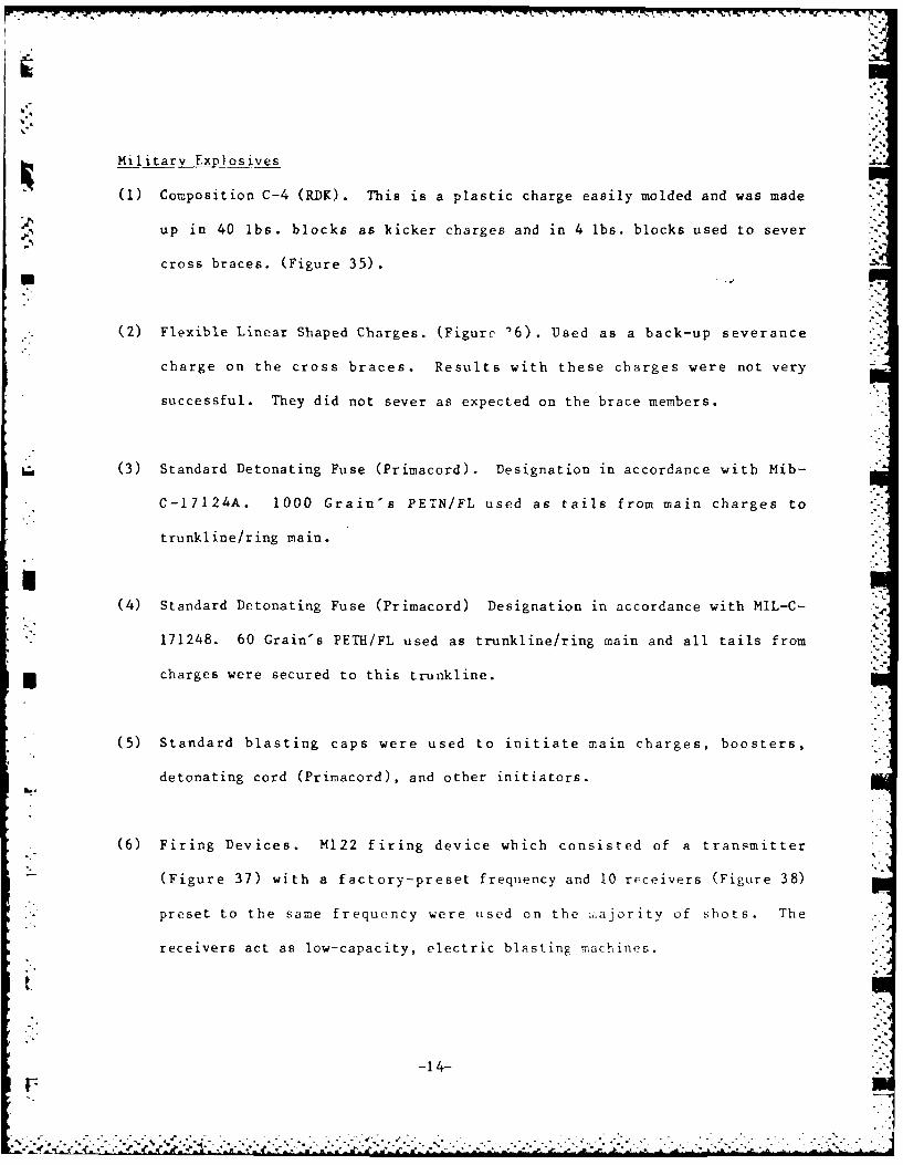
Military Explosives
(1) Composition C-4 (RDK). This is a plastic charge easily molded and was made
up in 40 lbs. blocks as kicker charges and in 4 lbs. blocks used to sever
cross braces. (Figure 35).
(2) Flexible Linear Shaped Charges. (Figure '6). Used as a back-up severance
charge on the cross braces. Results with these charges were not very
successful. They did not sever as expected on the brace members.
(3) Standard Detonating Fuse (Primacord). Designation in accordance with Mib-
C-17124A. 1000 Grain's PETN/FL used as tails from main charges to
trunkline/ring main.
(4) Standard Detonating Fuse (Primacord) Designation in accordance with MIL-C-
171248. 60 Grain's PETH/FL used as trunkline/ring main and all tails from
charges were secured to this trunkline.
(5) Standard blasting caps were used to initiate main charges, boosters,
detonating cord (Primacord), and other initiators.
(6) Firing Devices. M122 firing device which consisted of a transmitter
(Figure 37) with a factory-preset frequency and 10 receivers (Figure 38)
preset to the same frequency were used on the 1ajority of shots. The
receivers act as low-capacity, electric blasting machines.
-14-t7Z
-A .
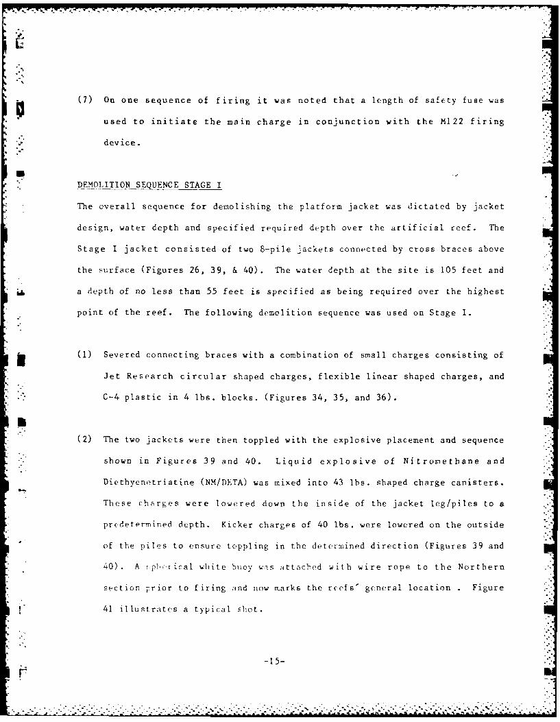
(7) On one sequence of firing it was noted that a length of safety fuse was
used to initiate the main charge in conjunction with the M122 firing
. device.
DEMOLITION SEQUENCE STAGE I
The overall sequence for demolishing the platform jacket was dictated by jacket
design, water depth and specified required depth over the artificial reef. The
Stage I jacket consisted of two 8-pile jackets connected by cross braces above
the surface (Figures 26, 39, & 40). The water depth at the site is 105 feet and
a depth of no less than 55 feet is specified as being required over the highest
point of the reef. The following demolition sequence was used on Stage I.
(1) Severed connecting braces with a combination of small charges consisting of
Jet Research circular shaped charges, flexible linear shaped charges, and
C-4 plastic in 4 lbs. blocks. (Figures 34, 35, and 36).
(2) The two jackets were then toppled with the explosive placement and sequence
shown in Figures 39 and 40. Liquid explosive of Nitromethane and
Diethyenetriatine (NM/DETA) was mixed into 43 lbs. shaped charge canisters.
These charges were lowered down the inside of the jacket leg/piles to a
predetermined depth. Kicker charges of 40 lbs. were lowered on the outside
of the piles to ensure toppling in the determined direction (Figures 39 and
40). A ,phrical white buoy was attached with wire rope to the Northern
section Trior to firing and now marks the reefs' general location . Figure
41 illustrates a typical shot.
-15-
. . ..-
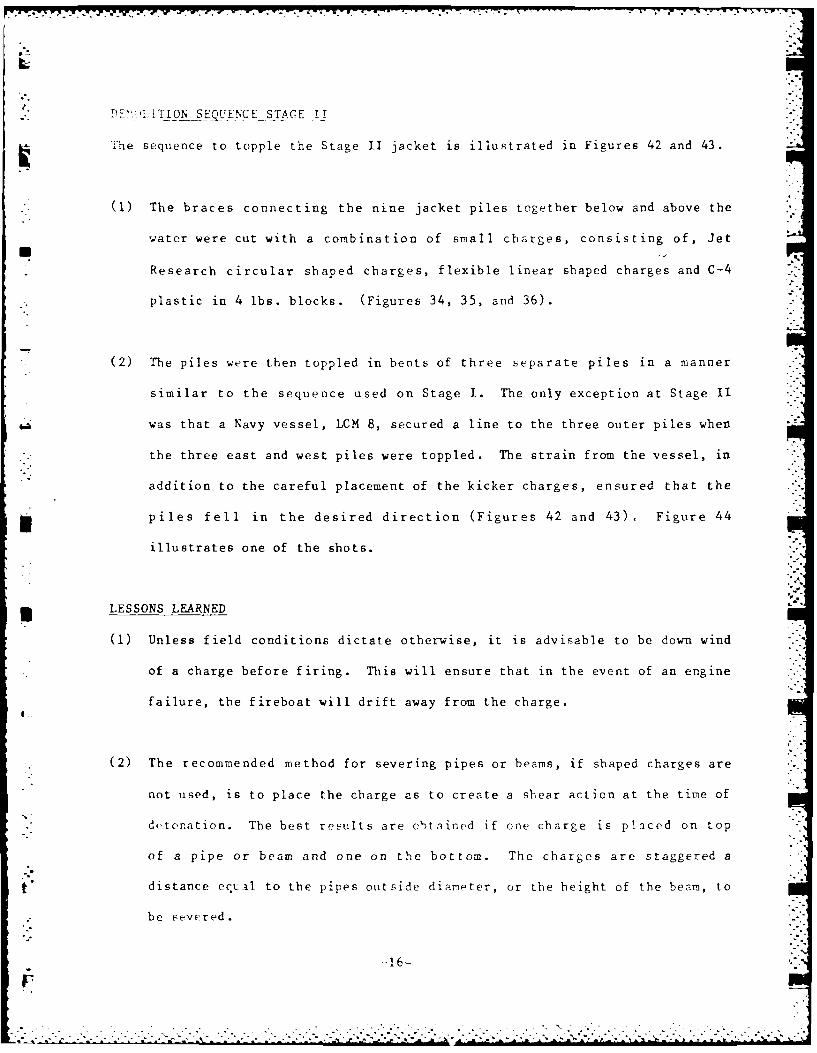
DE ' TION SEQUEN-CEST-AGE I!
The sequence to topple the Stage II jacket is illustrated in Figures 42 and 43.
(1) The braces connecting the nine jacket piles together below and above the
water were cut with a combination of small charges, consisting of, Jet
Research circular shaped charges, flexible linear shaped charges and C-4
plastic in 4 lbs. blocks. (Figures 34, 35, and 36).
*(2) The piles were then toppled in bents of three separate piles in a manner
similar to the sequence used on Stage I. The only exception at Stage II
was that a Navy vessel, LCM 8, secured a line to the three outer piles when
the three east and west piles were toppled. The strain from the vessel, in
addition to the careful placement of the kicker charges, ensured that the
piles fell in the desired direction (Figures 42 and 43). Figure 44
illustrates one of the shots.
* LESSONS LEARNED
(1) Unless field conditions dictate otherwise, it is advisable to be down wind
of a charge before firing. This will ensure that in the event of an engine
failure, the fireboat will drift away from the charge.
(2) The recommended method for severing pipes or beams, if shaped charges are
not used, is to place the charge as to create a shear action at the time of
de tonat ion. The best results are obtained if one charge is placed on top
of a pipe or beam and one on the bottom. The charges are staggered a
F distance ectal to the pipes outside diarmeter, or the height of the beznm, to
be severed.
-16-
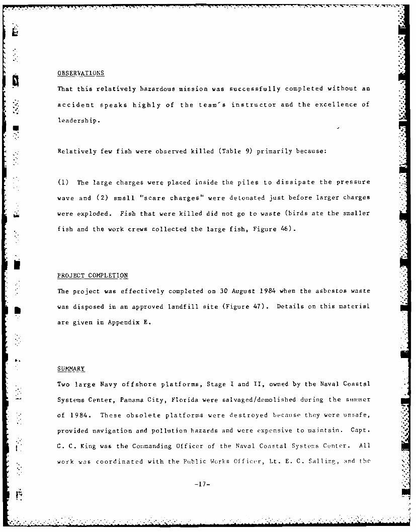
OBSERVATIONS
That this relatively hazardous mission was successfully completed without an
accident speaks highly of the team's instructor and the excellence of
leadership.
Relatively few fish were observed killed (Table 9) primarily because:
(1) The large charges were placed inside the piles to dissipate the pressure
wave and (2) small "scare charges"s were detonated just before larger charges
W were exploded. Fish that were killed did not go to waste (birds ate the smaller
fish and the work crews collected the large fish, Figure 46).
PROJECT COMIPLETION
* The project was effectively completed on 30 August 1984 when the asbestos waste
* was disposed in an approved landfill site (Figure 47). Details on this material
are given in Appendix E.
SUMMARY
Two large Navy offshore platforms, Stage I and II, owned by the Naval Coastal
Systems Center, Panama City, Florida were salvaged /demol ished during the summer
of 1984. These obsolete platforms were destroyed because they were unsafe,
provided navigation and pollution hazards and were expensive to maintain. Capt.
C. C. King was the Comimanding Officer of the Naval Coastal System~s Center. All
* work was coordinated with the Public Works Officer, Lt. E. C. Sailing, and the
-17-
. .. . . . . . . . . . . " MOM
* - - - * .,. i - . -. - - | i - ... -. - - - - -: -t - -
chief of the NCSC Engineering Branch, M. Southall. The Ocean Engineering and
construction Project Office, Chesapeake Division, Naval Facilities Engineering
-" Command, provided engineering support with the assistance of Barnett &
Casbarian, Inc., Metairie, LA. Sanford Offshore Salvage, Inc., Morgan City, LA,
*' under contract to CHESDIV, salvaged the platform decks and Bill Seelig of
CHESDIV was the Engineer-In-Charge and onsite contract monitor. Explosive
Ordinance Group Two, Detachment, Panama City, Florida demolished the jackets in
place to form artificial fishing reefs. Lt. "Rocky" DeSimone was the Officer-
In-Charge of the jacket demolition and Peter Williams was the CHESDIV observer
to the jacket demolition work.
The salvage/demolition schedule for this project is given in Figure 45 and a
sullmary of costs is presented in Table 10.
A bibliography of background information is attached as Appendix F.
ACKNOWLEDGMENTS
" Thanks to the U.S. Coast Guard detachment at Panama City, Florida for securing
the work area during critical phases of work.
-18-
°
LIST OF FIGURES _
Number Title
I Photos of Stage I and II
2 Map Giving Platform Locations
3 Photo of Platform at NCSC in the Early 1950"s
4 Construction Photos of the Stages (1957)
5 Military Helicopter Lifting Scientific Equipment on Stage II
6 Photos of Environmental Experiments on Stage I
7 Installing a Wave Gage on Stage II
8 Monitoring Instrument Readings on Stage I
9 Plan Views of the Stages Illustrating the CuttingPattern Used by the Contractor to Section Decks
10 Breakdown of the Contractor's Time on Site
11 Photo of the Contractor's Barge
i 12 Photo of Lifting The Sub-Contractor's Containers
of Asbestos Removal Gear on Stage I
13 Photos showing Asbestos Removal
14 Removing the Foghorn from Stage I
15 Pre-cutting the Decks of Stage I
16 Rigging Chain and Wire Rope Bridals
17 Contractor's Crane Provides Pretension to the SectionBefore Final Cuts and Lift is Made
18 Supporting Legs are the Last Items Cut Before a Lift is Made
19 Lift of Section I Off Stage I
20 Clescup photo of Section 1, Stage I
21 Photo of Section I Being Transported to the Bay
, .-..-. -. . .-.. .. .

22 Photo of Stage I with Section 1 RemovedIl
23 Unloading Section 2 (Stage 1) on the Materials Barge
24 Stage I with Six Sections Removed
25 Lifting Section 7 Off Stage I
26 Stage I Jacket with Deck Removed
27 Solar Panel Being Removed from Stage II
28 Section I (Upper Two Decks) Being Removed from Stage II
7-~
29 Section 4 Being Removed from Stage II
30 The Last Section from Stage II Being Towed to the Bay
31 Computer Plot of Stage I
32 Computer Plot of Stage II
33 Sample Placement of a Container of NM/Deta
j34 A Shaped Circular Charge
35 C-4 (RDK) Plastic Charges being Readied
36 Flexible Linear Shaped Charges
rn37 Transmitter Used for Demolition
38 Demolition Signal Receivers
39 Stage I - Plan Location of Charges
40 Stage I - Elevation Location of Charges
41 Demolition Shot of the Northern Jacket of Stage I
*42 Stage II -Plan Location of Charges
43 Stage II -Elevation Location of Charges
*44 Dr-i-olition Shot on Stage II
45 Salvage/Demolition Schedule
46 A Barracuda Picked Up After a Shot at Stage I
47 Disposal of Asbestos Waste
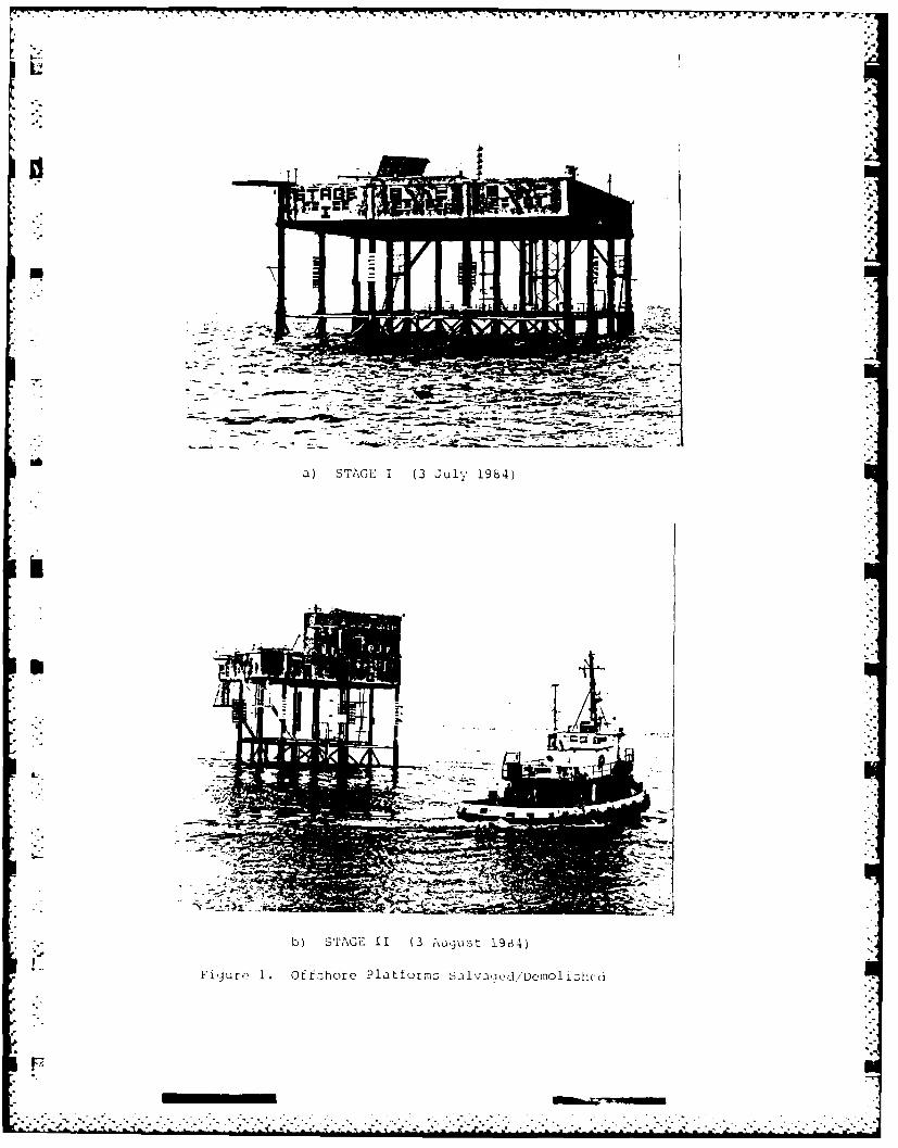
a) SAE1(-J l 94
b) STAG 11 (3 Jul 1 s- 1964)
Fiuo .Of fuhore Platfurms SilvaQed/'DomOli51c(

.- .. .. ... ..... CI
*44,4o *0 W -
INVIVIII 0 *L O4
awot 0oNo4 d% .44 46-,
-~~~~~~a To40- 'W~~-7w06 nw -. o- I9 - v t. CCS*L1Mot
MAPS.-
1-5 A 4 " 4 .tL r . .
- 40
A fl ,, .40' -A. 0
t~A 06 1. i
.2,4
'0
.64 ? ), M, *.4PF .. * - ,.
A . S 0.SA,6-
AA4 'it:-" ' ~ 0. 0 44 0
- = ,~4- \ 56 - ~ . 64 7.PAR.
46 4. .~ 5t 6x
' 4
2 -s
VA5 4 4 04 4 . 4 4

TOM1S-dASIPPI PASSES
-AL-
- It*
* 0~ le a" ca
e. n. auj-re alsa&2
W, so.,es
j., Il ...... .. 3
.~~~~ E ne.S'Etu's T,"abF4I'ged aINCpoc
-. ~ %,,-
I%
pL~ro3.ph oto ot Platformi At EWnC in thc - Early 1950'L;
(fin:.,: -i stun:-". Tie jhiatforin was later retrieved
for 1.e)

% 4b~
4a. Installation of Stage I Jacket (27 September 1957)
(A Hurricane Delayed Installation O[ the Decks)
-.... . . . .
k
J.MK
Ii I.
-J I.
KV
I I
I
U
* 1 V}.. - .
p 1
I
Fijurc 4b. Con5truction Photo of Stale II(A Hurric3ne Delcived ~nst~I1atjo~i of the Decks)
F
*%*~.**~**.**.* . . . -.. 7.'.................. ...-...-- * -*..*. ~
. . . . . * . . - . . *.
4 a . . - . - - -. ' ..
* aI.
U
- '4
* ow
I
U
S
I-
i'ij r~ 5. Miii :.ary Helicopter L iftincg Scientific Equipment on Stage II(Date Unknown)
.- ~. ...
I.T
a) The Aquarium Room on Stage I
b) Chec? in~J t.,., [,low P~tc of Scklwatkr to Biolo i ical Ex ;cr £mIt
6i~r . Photc) os t "irPsftl .J!i:e 2 S.
~ .In~ i n a rv Gage or) Staje II
Itj
.~~~~,..- Rd. TV- NO 7-1;w w w ~ '~
STAGE I LIFTS
L D CBA
I 5FUEL TANK IENGINE ROOM
7 I 6 4J
0ol
o I G
3 2 1
SETO I
101
UU
C 0
GENERATORS
TOTAL WEIGHT= 420 TONS
v PLAN VIEWS OF THE STAGES ILLUSTRATING THE CUTTINGPATTERN USED BY THE CONTRACTOR TO SECTION DECKS
-'GURE 9.
PERCENT OF TIME
ip
:'iASBESTOS REMOVAL. CUTN&"" LIFTING DECK SECTIONS
.m 42% T"""" TRANSFERRING GEAR
a) STAGE I t10%
(32 DAYS)
DOWN TIME (48%)
WAVES & WEATHER EQUIPMENT
• .- 34% 14% i,
I: ""
" ~ASBESTOS REMOVAL, CUTTING & -
*I LIFTING DECK SECTIONS i
b) STAGE II I(16 DAYS)
DOWN TIME DUE TO,; "
WAVES & WEATHER
/ / TRANSFERRING GEAR
F 1R
*" FIGURE 10. BREAKDOWN OF CONTRACTOR'S TIME ON SITE
I!I
I-:
Figure 1I. Photo of the Contractor's Barge (the "Sea Salvor")
(Two additional material barges were used to transportequipment and sections of the stages)
...-.......... ....................
F-,
17
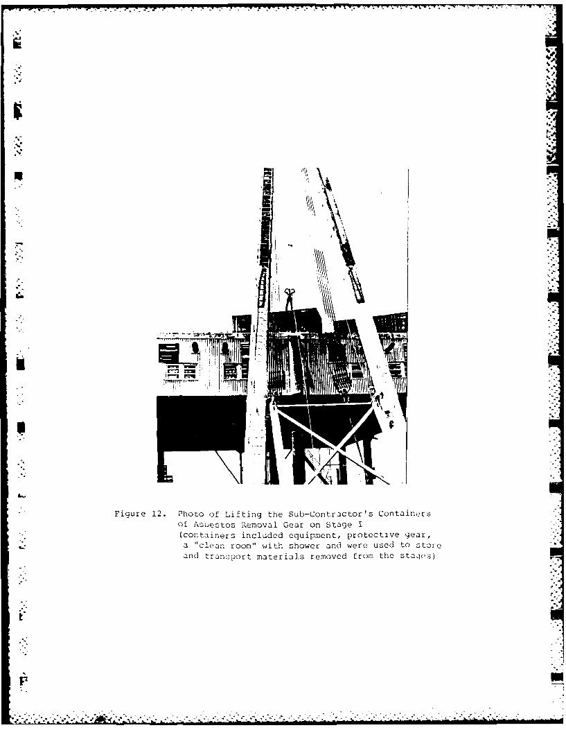
Figure 12. Photo of Lifting the Sub-Contractor's ContainersOf Asbestos Removal Gear on Stage I(containers included equipment, protective gear,a "clean room" with shower and were used to storeand transport materials removed from the sta,3es)
-C 47* .. . .

a) Removing Non-FriableCeiling Tiles
-
b) Sampling Friable AsbestosCovering Mufflers(friable material was removedjusing the glove-bag method)
Figure 13. iPiOtOs Showing AsbQLtoo eoj
-An-7-
V, R. 'r -rq K- .C L IL - . n
AJ
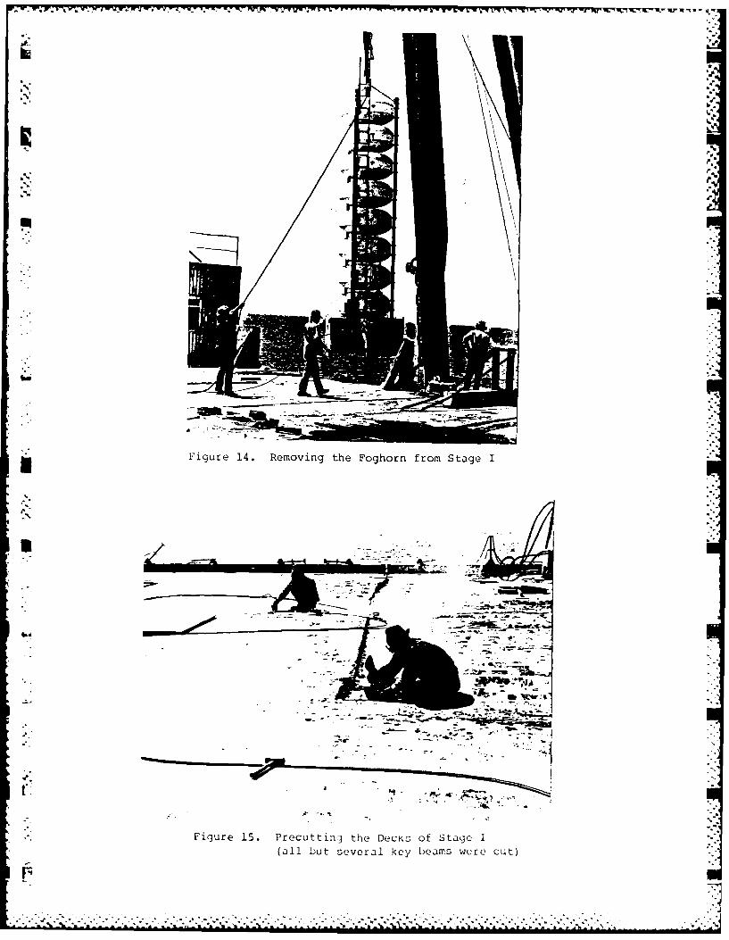
Figure 1. Reovin the Foghor fo StageI
(albtsvrlke em eect
S-
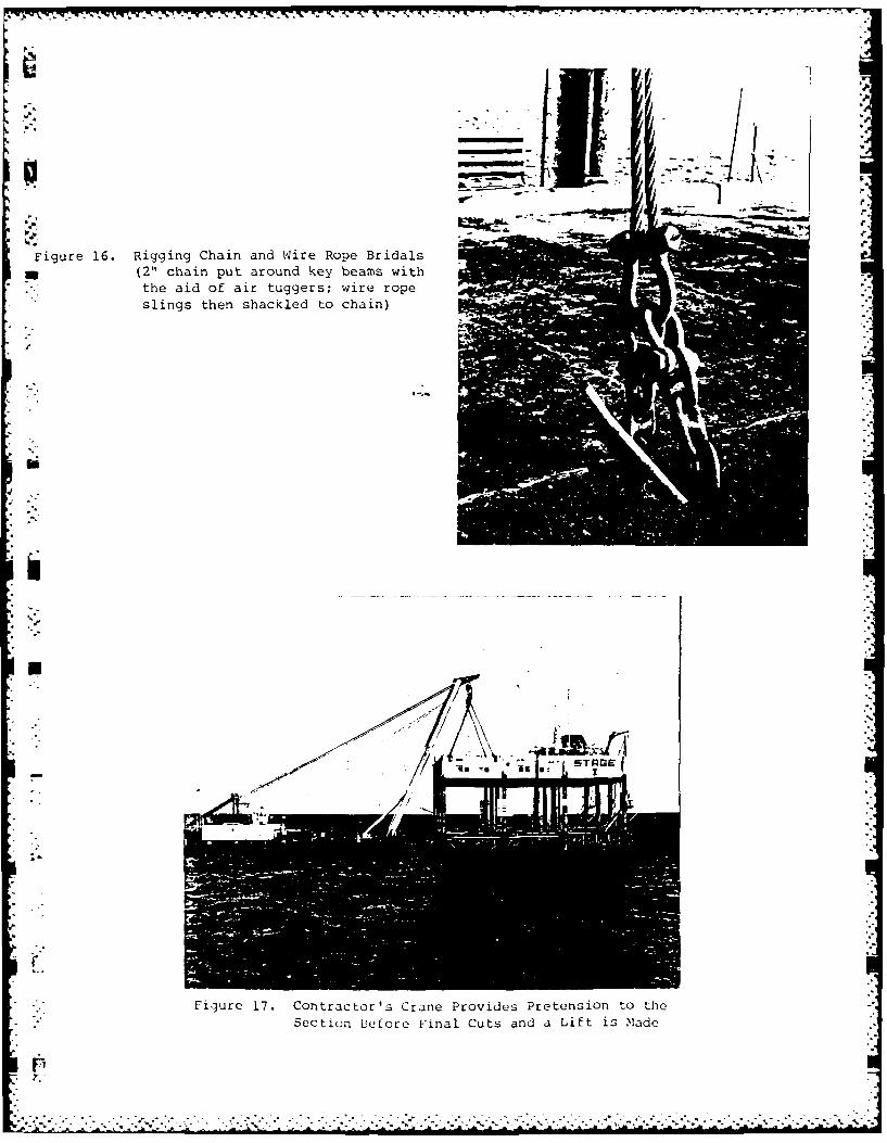
Figure 16. Rigging Chain and wire Rope Bridals
e
II (2" chain put around key beams withthe aid of air tuggers; wire rope
slings then shackled to chain)
!-' -
Figure 17. Contractor's Crane Provides Pretension to the
Section Before F'inal Cuts and a Lift is Made
p
p - -.

;:.
2"-71
Figure 18. Supporting Legs are Last Items Cut Before a Lift is Made
(A 6" long section of circumference is not cut by the welderson one pile; this hangover" is torn off during lifting)
. 1.
::.: r
t..L
. am.
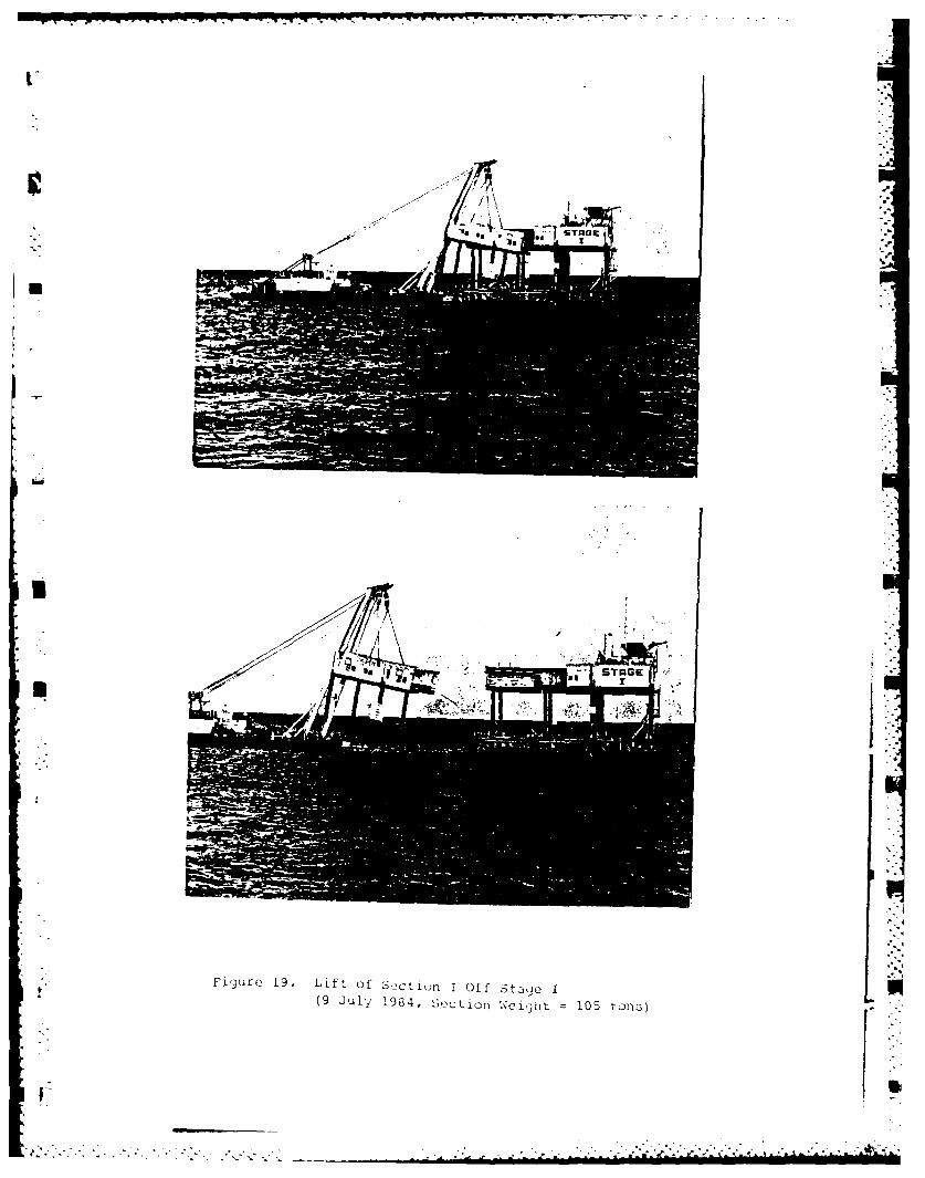
Fi'JurQ 19. Lift Of S,2Ction I Off Stagje I(9 July' 1934, ;,,cti(Djj .Woijht 105 toli)F
~~AP7
Fig-ire 20. Closeup Photo Of Section 1, Stage I
FiyurC 21. Photo ft Se ctioil 1 Beinq Trans or ted to the.(No L t>), t sections5 werc lower~ed wi th K v3 in tj( water
d ur ing to-ainig to reduce dynamic 1oadi3 in tht bijas

Figure 22. Photo of Stage I with Section 1 Removed
Figure 23. Unloading3 Section 2 (Stage I)on 'Materials Barge(Note that come sections werestacked dcjubl.e-aecker and thenwelded togj,2ther to save space)
JL r

3.b
Figure 24. Stage I with Six Sections Removed
*AL
Figure 25. Lifting- Section 7 Off StagjeI
(28 July 1984, this was thefueltan, weght 200 tons)
fuI-t n ,w.

Figure 26. Stage I Jacket with Deck Remo~ved
(A temporary navigation 1i~jht wasinstalled soon after this photowas taken. This completed the
Contractor's work on Stage I.)
r-

-7- -7-- 7-i' 7 - -, ."- . .I r. ;- - 1, .9 I V L, q -1. 97.-
ZiA
40
Figure 27. Solar Panel Being Removed from Stagell)(5 August 1984)
Figure 28. Soction I (1U per TWO Decks) 13eirln POMOVed t x. M)taI II e~ ".just 1984, %,eij3ht '0 ',n.:
11%
Fiiur -30 Te 29.t Section 4B ngmvdfrom Stagee IIIIi~ T~c, o h- -(8 u gust 1984, section weight 110 tons
.J
Fiiure 31. Computer Plot of stage I

p
I
I I
-N.
i-'iit~u .i4. '~9Hsjt~r Plot of Stage II
t.
F
. . . . . . . . . . *5* . .
WATER LINE
M122 DETONATING RECEIVERI\
* SAMPLE PLACEMENT OF A CONTAINER OF NM/DETA
Fl'
FIGURE 33
d"4
Figure 34. A Shaped Circular Charge
al
Figure 35. C-4 (B'DK) Pla~stic Charges Being 2~id
..1
opo I
-. 1
IA,
Figure 36. Flexible Linear Shaped Charges

-* - - -. - - - -
ASW
I ~
.4'
p C 5'
S I,
Figure 37. Transmitter Used for Demolition
U
m
I,
~*5
* '5
CFicjure 38. Demolition Sigi~al Receiveru
5..
Sr *1- - . . . - --..-.- . *5*5* j
* S * * S~ ~ .~...................................
DEMOLITION SEQUENCE
1) SEVERED CONNECTING BRACES
2) TOPPLED ROWS 1 & 2
3) TOPPLED ROWS 3 & 4
TYPIAL LG DEAILTYP. SEVERED BRACE
DB---
STG I LOAINO HRE
FIGURE 39
............~......................... 6 . '
KEY PLAN
35-0- 35'-On 35'-0'
I PRIMACORD RING MAIN I PRIMACORD RING MAIN
M.L.G.I
AROW INDICAT
EL.(-) 257-0 I_____________ ___________ NIIIN/T KIKE CHRG
SHPE CHARGE
(TYP) I IP
EL(- 89I
SHAPED~FIUR CHREKCKRCAG

VWVW £~ TT . - - ~' - -- - -
a
F.,
-a
a a
a
- &
S
h
Figure 41. Demolition of the Northern Jacket of Stage I
n
280 .500 PILE GROUT 22.754 .625 PILE GROUT
30+ .750 24 .500
INTERIOR LEG EXTERIOR LEGS
TYPICAL LEG DETAILS
TYP. SEVERED BRACE-
DIRECTION OF FALL
(TYP.)
TYPICAL HORIZONTAL FRAMING PLAN
STAGE 11 LOCATION OF CHARGES
DEMOLITION SEQUENCE:
1) SEVERED CONNECTING BRACES
2) TOPPLED ROW C. PULLED WITH LCM-8
3) TOPPLED ROWq A & B. PULLED WITH LCM-8
FIGURE 42
-.. " .= ,, ", * ', ,. ,, . -. ". ". ,, • . . -i . ' . 5 .. o -,
" .S . . , -,. ." .- " ," " " . ." , ,. -t " . : ." --

A B
KEY PLAN
A BC
30"-O' 30'-O"
PRIMACORD RING MAIN(TYP.)
ARROWS INDICATE
* DIRECTION OF FALL(T YP.)
I KICKER CHARGE(TV P.)
NM/DETA SHAPED CHARGE--"* (T YP.)
MUDLINE
TYPICAL ELEVATION ROWS 1, 2 & 3
STAGE 11 LOCATION OF CHARGES
FIGURE 43

- . - -.-----. -' - - .. '.
* L.-U-
U
Figure 44. DemolitiOn Shot on Stage II -
r
F
. . . .
- . ......... ..........................................

co) _ _ _ _ _ _ _ _ _
- _o_ _
co _ _ _ _ _ _ _ __ _ _ _ _ _ _ I.
'I.-
p 0
LcJ
I. coJ-LJ0
oLJ
< 0L
00
w --
_w V ) co-
-CJ >)C
0u > 0L
z 0
oJJ 0
(Io _ _ _
< -l
-i z -J0/ Cf UC1
Uw w V) 0r
Ci . C) o CL-
FIU E4
L h.
m
4.
C,
Fiyure 46. A l3arr3cuda Picked Up After a Shot at StaQje 1.
. . . .........................
.. *. . . .

A&F.
411-
Fijur'2 47. Dis;.os;al oF A&LusLtu; N Jsto

lp .0 9 W.
LIST OF TABLES
II
Table Number Title•
'.j
1 General Characteristics of the Platforms
2 Organization of the Project
3 Problems and Approach
Al 4 Project Use of the Stages 1974- 1980
5 Status of Sensors on Stage (Oct. 1982)
6 Organization
a 7 Summary of Contractor's Effort
8 Reef Characteristics
9 Estimate of Fish Killed
1 10 Costs for Demolition of Stages I and II
I.%
, ,-. --..
LLil
ccl00
cc c
00LL xz
0
XL co IL
NO I xIq.
C- Cl
(I)~ co-ccLw
I-
~ -J cc Cl-F-
wC
.. . . ..

zzZ< 0
- 0~~%tJ0 Ike.
-i M
0 IQ
>0 2 ) z-zw LL 0
.... C -aL
ww
II-
z
00cmr
Cl) cr c
W 0 o0 0wz
Cj) Z a
F- < <
* 0
z z
00 a. -J 000
w < ELL- I -w b
> c- c
< <w qc 0 Zw~ 0
z c 1 -
< -J 0 U
Co w Q , ~aw a cc c 0
z I- w wj w 0 0
0 0 U. a. 0 0

c!)
M 0
C.C)2<
C,))w 0J-
z cc, 0 -wC ) C/)
o< CL) W L
J ZLL
ClCl,
i-r0 0<)<Z
al 0 o z w-
<J 0rn ccr
o- 0 L
U- < < < CD -
- . <

'* TABLE 4. PROJECT USE OF STAGES
1974 - 1980
1. RADAR EVALUATION OVER WATER
Sea Echo NADCIGa Tech Sea returnSea Clutter NRL/Ga Tech Sea returnRadar Buoy NSWC/Ga Tech Buoy SignatureADF Equip Eval PME-107 Surface scatterSmall Target Radar NRL Floating targetsWave Ht Sensor SESTF Over water test
17 O.T.H. Radar NRL Over water test
2. SONAR EVALUATION IN WATER
PARRAY DARPA/NAVELEX/ARL Open seaParametric Sonar DARPA/NAVELEX/ARL Open seaBistatic Sonar NCSC Open sea
3. ATMOSPHERIC MEASUREMENTS/EFFECTS
Sunglitter APL/JHU Open air/seaSky-Water Light NRL Open air/sea
i Fog Study NAFI/CSI Open waterRemote Sensors NAFI/CSI/EPA, etc. Ground truthShips Lighted Tests NCSC Remote open water
Night Vision Goggles NCSC Open water targets
4. STABLE PLATFORM IN OPEN WATER
OMEGA NRL Propagation studyBRA-8 APL/JHU Buoy performance
" WIRAD APL/JHU Antenna test
TEAK OIL PME-107 Antenna/Revr testOil Barrier USCG Observation platformWave Dynamics APL/JHU Instrument platform
Plankton Effect Univ of Texas Clear, open waterInfrared Tests TRW Measurements
Oil Pollution EPA Clean sea waterXP Plastic Army/NRL Salt air effectsLIDO NCSC Instrument platform
MAST NCSC Instrument platformInternal Wave NCSC Instrument platformSonobuoy Drops NAVAIR Observation platformOrdinance Drops Navy Ammo Dump Photo platform
Fl
"tf * f * f. * t ft . . . . . f
TABLE 4. (CONTINUED) I
5. GENERAL ENVIRONMENTAL DATA SUPPORT
SES-100B Trials SESTFJEFF Craft Tests AALC-ETU
LACV-30 ArmyCoast Guard Sled USCG
n Sea/Air Rescue USCGData Buoy NORDAVoyageur Ops Army/BellHADAPS USMCWave Rider Eval AALC-ETU
6. MISCELLANEOUS
RAYDIST Site NCSC Ship positioningSEAL Team Use Navy TrainingCurrent Meter Eval NORDA Open seaMarine Fouling US/UK Navies Open seaBelo Acoustic Sig. NCSC Over waterWave Profile APL/JHU Statistical studyMagnetic Barrier NCSC Open waterLaser Eval Various Open space e
7. TEST SUPPORT TOO NUMEROUS TO IDENTIFY SEPARATELY
Diving Equipment EvaluationAcoustic MeasurementsMagnetic MeasurementsDiver TrainingDiver Requalification (100' depth)Scientists-in-the-Sea (FSU)Numerous Telephone Calls (NCSC, TAFB, Eglin, etc.)
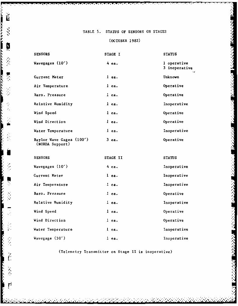
S' TABLE 5. STATUS OF SENSORS ON STAGES
(OCTOBER 1982)
SENSORS STAGE I STATUS
Wavegages (10") 4 ea. 1 operative3 inoperative
Current Meter 1 ea. Unknown
Air Temperature 1 ea. Operative
Baro. Pressure 1 ea. Operative
Relative Humidity 1 ea. Inoperative
Wind Speed 1 ea. Operative
Wind Direction I ea. Operative
Water Temperature 1 ea. Inoperative
Baylor Wave Gages (100') 3 ea. Operative(NORDA Support)
SENSORS STAGE II STATUS
Wavegages (10") 4 ea. Inoperative• .5'
Current Meter 1 ea. Inoperative
Air Temperature I ea. Inoperative
Baro. Pressure I ea. Operative
Relative Humidity 1 ea. Inoperative
* Wind Speed 1 ea. Operative
Wind Direction 1 ea. Operative.,"
- Water Temperature I ea. Inoperative
* Wavegage (30") 1 ea. Inoperative
(Telemetry Transmitter on Stage II is inoperative)
A.
-174
z
c:
_jj
< 0
<L <0<u 00
-JC CO U)
ww> w . co Iz0 WU: cr a>- C)d<w OL m) O< W _
ud 0 z LLZ :
cr LL <0
cc0W aJ 0 0ZL CL
0D 0-0Oa CO
5 ZwaH
> >a: 0zZW 00 (0<D
LL Z a _a. LL00 ZZx 0W
wOCl) 0 - Zc J0 50 0cl : _j ZH WO
0 00 WClL~t~~~ ~ __ _ _ _ _ __ _ _ _ _ _ __ _ _ _ _ _
< . .: z.. . :3 u) o a-4
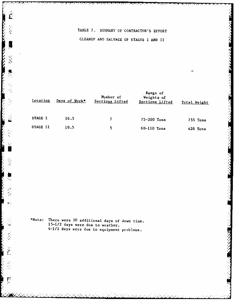
TABLE 7. SUMMARY OF CONTRACTOR'S EFFORT
CLEANUP AND SALVAGE OF STAGES I AND II
Range ofNumber of Weights ofLocation Days of Work* Sections Lifted Sections Lifted Total Weight
STAGE 1 16.5 7 75-200 Tons 755 Tons
STAGE 11 10.5 5 60-110 Tons 420 Tons
*Note: There were 20 additional days of down time.15-1/2 days were due to weather.4-1/2 days were due to equipment problems.
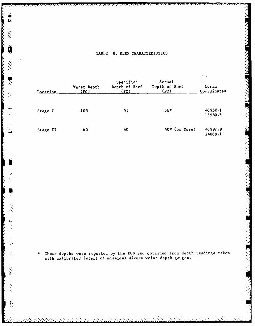
TABLE 8. REEF CHARACTERISTICS
Specified Actual
Water Depth Depth of Reef Depth of Reef Loran
Location (FC) (FC) (FC) Coordinates
Stage I 105 55 68* 46958.113980.3
Stage II 60 40 40* (or More) 46997.914069.1
I.-"
*These depths were reported by the EOD and obtained from depth readings takenwith calibrated (start of mission) divers wrist depth gauges.----- .---.....-- -. . . . . .. . .-

. Ip.
TABLE 9. ESTIMATE OF FISH KILLED*.2
Number of Number of-Number of Small** Large***
Location Main Shots (Under I' Long) (Over I' Long)
Stage I 4 215 34
Stage II 3 Several Thousand 3
.--
-
rn
*,Based on visual observations of dead fish on the surface after the shots.An undetermined number of fish may not have surfaced.
- ** Small fish were eaten by Seagulls and Pelicans. The birds were quick toflock to the site as soon as they realized food was available.
- ** Larger fish were taken and eaten by the work crews.
"-" .'- " ...-........ .'..."......-....-...-.....-."."-...".-.."" "" -.-.. . . . -'"", . " " "" "" "" ""*',"*" - * "S-,"-' ".
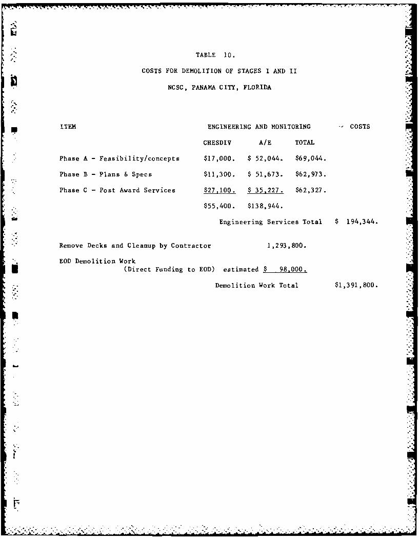
TABLE 10.
COSTS FOR DEMOLITION OF STAGES I AND II
NCSC, PANAMA CITY, FLORIDA
ITEM ENGINEERING AND MONITORING - COSTS
CHESDIV A/E TOTAL '
Phase A - Feasibility/concepts $17,000. $ 52,044. $69,044.
Phase B - Plans & Specs $11,300. $ 51,673. $62,973.
Phase C - Post Award Services $27,100. $ 35,227. $62,327.
$55,400. $138,944.
Engineering Services Total $ 194,344.
Remove Decks and Cleanup by Contractor 1,293,800.
EOD Demolition Work(Direct Funding to EOD) estimated $ 98,000.
Demolition Work Total $1,391,800.
-4
'4"
rn
.o-
- LIST OF APPENDICES
APPENDIX
r7.
A CHRONOLOGICAL HISTORY OF THE STAGES
iiB CONTRACTOR PERSONNEL AND EQUIPMENT
C DAILY SUMMARY LOG OF CONTRACTOR'S ACTIVITIES
D DAILY SUMMARY LOG OF EOD ACTIVITIES
*E ASBESTOS DATA
F REFERENCES
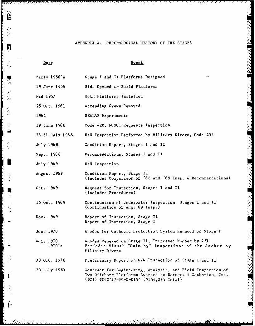
APPENDIX A. CHRONOLOGICAL HISTORY OF THE STAGES
Date Event
Early 1950's Stage I and II Platforms Designed
19 June 1956 Bids Opened to Build Platforms
Mid 1957 Both Platforms Installed
25 Oct. 1961 Attending Crews Removed
1964 SEALAB Experiments
19 June 1968 Code 420, NCSC, Requests Inspection
23-31 July 1968 U/W Inspection Performed by Military Divers, Code 455
-. July 1968 Condition Report, Stages I and II
Sept. 1968 Recommendations, Stages I and II
July 1969 U/W Inspection
* August 1969 Condition Report, Stage II(Includes Comparison of '68 and '69 Insp. & Recommendations)
Oct. 1969 Request for Inspection, Stages I and II(Includes Procedures)
15 Oct. 1969 Continuation of Underwater Inspection, Stages I and II(Continuation of Aug. 69 Insp.)
Nov, 1969 Report of Inspection, Stage IIReport of Inspection, Stage I
June 1970 Anodes for Cathodic Protection System Renewed on Ste;e I
Aug. 1970 Anodes Renewed on Stage II, Increased Number by 25%]970"s Periodic Visual "Swim-by" Inspections of the Jacket by
Miliatry Divers
" 30 Oct. 1978 Preliminary Report on U/W Inspection of Stage I and II
. 2B July 1980 Contract for Engineering, Analysis, and Field Inspection off Two Offshore Platforms Awarded to Barnett & Casbarian, Inc.
(BCI) ON62477-80-C-0194 ($144,275 Total)
r

Date Event
7 Oct. 1980 Site Visit to Platforms and Meeting between Barnett &*" Casbarian, Inc. and Assistant OICC.
Structural Analysis Requested at this Meeting
24 Nov. 1980 Phase A - Inspection Plan Review Meeting,Stages I and II, NCSC
3-9 Dec. 1980 Stage I and II Underwater Inspection (Visual Inspection,Cleaning, Meter Readings, Still Photos, Video Documentation)
* .12 Jan. 1981 Phase B - Project Meeting - Inspection Results Discussed
27 Feb. 1981 Phase C - Project Completion Review Meeting at NCSC
Safety Precautions Recommended
2 Mar 1981 Submittal of Platform Strength Evaluation, Stage I and II
23 Sept. 1982 CHESNAVFACENGCOM (FPO-l) Funded to Perform FeasibilityStudy of Stage Removal
g 1 April 1983 A/E Contract Awarded to Barnett & Casbarian, Inc.
18 April 1983 Pre-Design Meeting at NCSC
- 19 April 1983 Stage I and II Above Water Platforms Inspected by FPO-1 and
NCSC - Equipment on Platforms Recorded
May 1983 Issued Preliminary Report No. 1
- Contained Inspection Results
June 1983 Issued Preliminary Report No. 2
- Contained Alternatives, Working Cost Estimates,and Pertinent Laws and Regulations
7 July 1983 Progress Report Meeting at NCSC to Discuss Alternativesand Cost Estimates
July 1983 Larry Taylor, FL Dept of Environmental Protection InspectedTopside of Stages I and II to Check on Possibility ofMaking Reef Out of Topside
" Aug. 1983 Final Report by Barnett & Casbarian, Inc. issued -
Contained Equipment Inventory, Inspection Results,Principal Alternative for Disposal and Evaluation ofthe Most Feasible Alternatives.
12 Oct. 1983 PEA on EOD Explosive Tests
21 Nov. 1983 Coast Guard Waiver for Lighted Buoys Issued
F. .. . . .
4
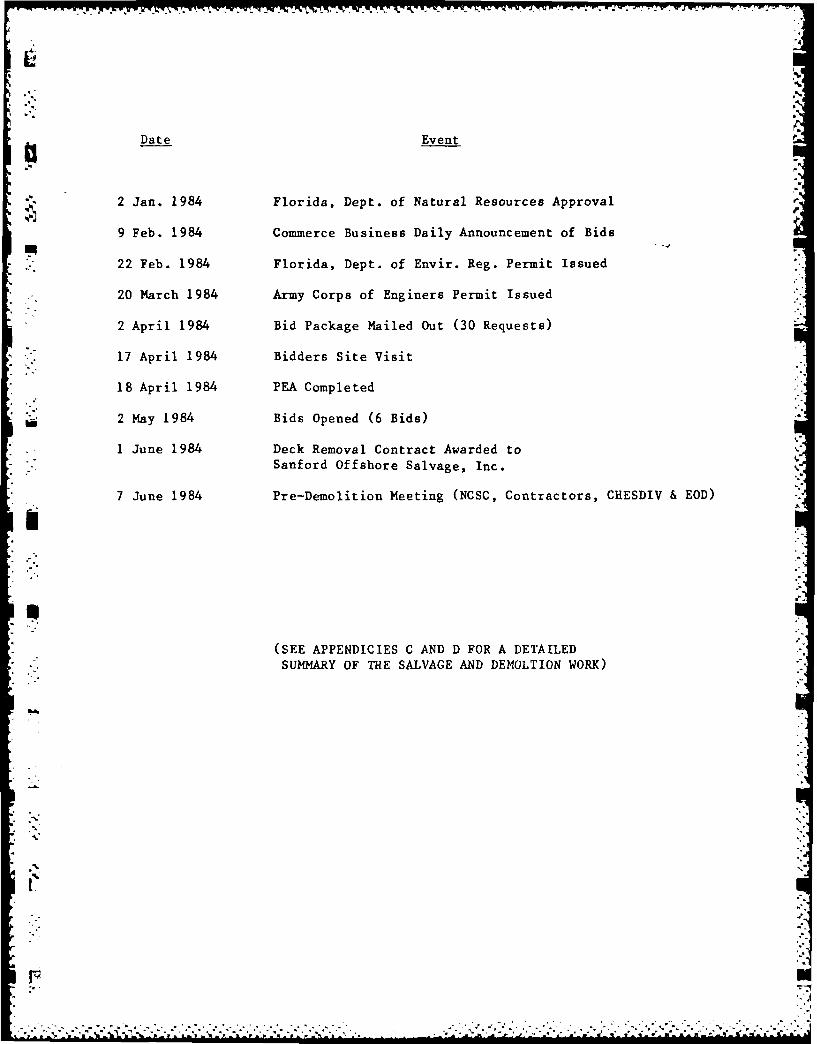
Date Event
2 Jan. 1984 Florida, Dept. of Natural Resources Approval
9 Feb. 1984 Commerce Business Daily Announcement of Bids
- 22 Feb. 1984 Florida, Dept. of Envir. Reg. Permit Issued
20 March 1984 Army Corps of Enginers Permit Issued
2 April 1984 Bid Package Mailed Out (30 Requests)
17 April 1984 Bidders Site Visit
18 April 1984 PEA Completed
2 May 1984 Bids Opened (6 Bids)
1 June 1984 Deck Removal Contract Awarded to
Sanford Offshore Salvage, Inc.
7 June 1984 Pre-Demolition Meeting (NCSC, Contractors, CHESDIV & EOD)
(SEE APPENDICIES C AND D FOR A DETAILED
SUMMARY OF THE SALVAGE AND DEMOLTION WORK)
..
t:

APPENDIX B. CONTRACTOR PERSONNEL AND EQUIPMENT
lip!
V. Number of
Personnel Phone Address* Main Contractor
Owner (1) (1) (504)-631-0836 Sanford Offshore SalvageLogistics Manager (1) P. 0. Box 2523
• .i Captain (1) Morgan City, La. 70381Foreman (1)Welder/Rigger (5)
Cook (1)
Asbestos Sub-Contractor
Supervisor (1) (504)-626-4431 Jack Donahue Con. Inc.Ind. Hygenist (1) P. 0. Box 159Air Monitor Tech. (1) Mandeville, La. 70448Crew (7) (Attn: Bob Kieferle)
Crew Boat "Dot"
Boat Operator (1)
Tug Boat "Cindy F"
. Captain (1)Crew (2)
o-.', .

APPENDIX BD ~100' .
* V--..
CREW BOAT FOR TRANSFERING PERSONNEL DOT
CINDY F
TUG BOAT FOR PROVIDING SUPPORT
-. MATERIALS BARGE WITH *CHERRY PICKER-. ' RG 40FOR PROVIDING MISCELLANEOUS SUPPORT 2 SEA MULES
110 X40'X8' FOR PROPULSION
4 - 3000 LBS. LWT ANCHORS
MAIN BARGE FOR LIFTING DECK SECTIONS
AND PROVIDING LIVING QUARTERS
='SEA SALVOR
15'X 50' X 10'AFRAME< 50x 0x1,
200 TONS LIFT CAPACITY .
ELEVATION=100 FEET OFF OF DECK
.
MATERIALS BARGE TO TRANSPORT DB-4
PLATFORM DECK SECTIONS
300' X 85' X 14'0 0
*" -SPUDS FOR HOLDING BARGE IN PLACE .'-
CONTRACTORS EQUIPMENT. .• % • %= '%_%. =', ,. % %. .• ..................... .... .. . -...- •., ......... o
.. - b...." ," " " " " * '*a"5*' " - '-" " : :- - - ' " - , - , - - • • . .' ' '

0.4.
APPENDIX C. DAILY SUMMARY LOG OF CONTRACTOR'S ACTIVITIES
DAYS DOWNTIMEW =weather
DATE SUMMARY OF ACTIVITY Due to Weather
2 Apr 84 Bid Packages Mailed Out
17 Apr 84 Site Visit
18 Apr 84 PEA Completed
2 May 84 Bids Opened
1 Jun 84 Contract Award
W7 Jun 84 Pre-demolition Conference at NCSC
27 Jun 84 Contractor Arrives at Panama City
28 Poor Weather 1 W
STAGE I
29 Jun 84 First day of Asbestos Removal (Non-friable)
1 Jul 84 Poor Weather 1 W
2 Jul 84 Poor Weather 1 W
3 Jul 84 Unload Asbestos Gear on Stage I, Continued Work
4 Jul 84 Pre-cut Main Deck, Continued Asbestos Removal
5 Jul 84 Cutting & Asbestos Work, Met EOD Team at Stage I
*6 Jul 84 Asbestos Stage I complete, Pre-Cutting 95% Complete
*7 Jul 84 Unloaded Stage I Equip. Containers
J 8 Jul 84 Loaded Equip. Containers Stage II. Asbestos RemovalStage II
9 Jul1 84 1st Lift Stage I, Asbestos Work Stage II
*.10 Jul 84 Asbestos Work Stage 11I lE
L11 Jul 84 Unloaded Section 1 on Deck, Welded doubler plates on IlE
boom, finished asbestos Stage II
*12 Jul 84 Finished Welding Doubler Plates, "DB4" arrives 1 E
OF4 t
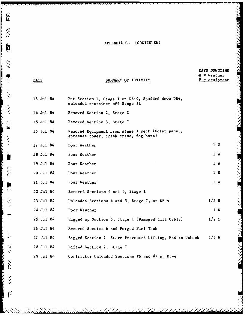
APPENDIX C. (CONTINUED)
DAYS DOWNTIME--- = weather
DATE SUMMARY OF ACTIVITY E = equipment
-13 Jul 84 Put Section 1, Stage I on DB-4, Spudded down DB4,unloaded container off Stage II
*14 Jul 84 Removed Section 2, Stage I
15 Jul 84 Removed Section 3, Stage I
16 Jul 84 Removed Equipment from stage I deck (Solar panel,antennae tower, crash crane, fog horn)
-17 Jul 84 Poor Weather I1W
18 Ju 84 oor eathr 1-
j18 Jul 84 Poor Weather I1W
19 Jul 84 Poor Weather 1 W
210Jul 84 Poor Weather 1 W
*22 Jul 84 Removed Sections 4 and 5, Stage I
* *23 Jul 84 Unloaded Sections 4 and 5, Stage I, on DB-4 1/2 W
24 Jul 84 Poor Weather 1 W
*25 Jul 84 Rigged up Section 6, Stage I (Damaged Lift Cable) 1/2 E
*26 Jul 84 Removed Section 6 and Purged Fuel Tank
27 Jul 84 Rigged Section 7, Storm Prevented Lifting, Had to Unhook 1/2 W
28 Jul 84 Lifted Section 7, Stage I
29 Jul 84 Contractor Unloaded Sections #6 and #7on DB-4

ki
APPENDIX C. (CONTINUED)
DAYS DOWNTIME
DATE SUMMARY OF ACTIVITY Due to Weather
STAGE II
8-11 Jul 84 Asbestos Removal
30 Jul 84 Contractor got more Welding Supplies; High Waves I Day
31 Jul 84 Weather, Work being done on Tug I Day
1 Aug 84 Weather poor, Unable to Work Stage 11 1Day
2 Aug 84 Weather poor, Unable to Work Stage II 1 Day
3 Aug 84 Pumped Fuel Stage II thru the Night 20,000 gals 1/2 Day
4 Aug 84 Put Nitrogen in Fuel Tank, Began Precutting
5 Aug 84 Lifted Section 1, Stage II and Equipment
6 Aug 84 Precutting
7 Aug 84 Lifted Section 2 and 3
8 Aug 84 Lifted Sections 4 and 5
9 Aug 84 Returned Equipment to Navy and Departed Panama City
,-p
.
- I
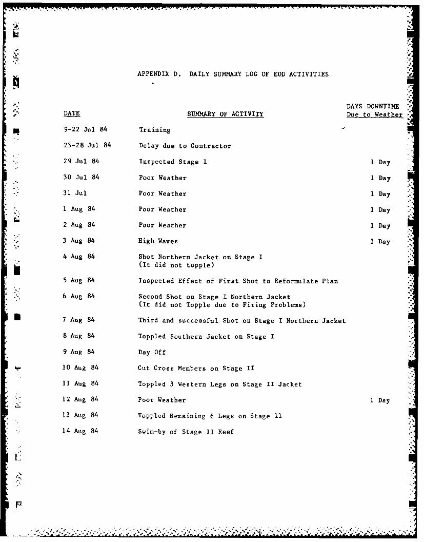
APPENDIX D. DAILY SUMMARY LOG OF EOD ACTIVITIES
DAYS DOWNTIMEDATE SUMMARY OF ACTIVITY Due to Weather
*9-22 Jul 84 Training
23-28 Jul 84 Delay due to Contractor
29 Jul 84 Inspected Stage I 1 Day
30 Jul 84 Poor Weather I Day
31 Jul Poor Weather 1iDay
1 Aug 84 Poor Weather 1 Day -
2 Aug 84 Poor Weather 1 Day
3 Aug 84 High Waves 1iDay
4 Aug 84 Shot Northern Jacket on Stage I
(It did not topple)
*5 Aug 84 Inspected Effect of First Shot to Reformulate Plan
6 6Aug 84 Second Shot on Stage I Northern Jacket(It did not Topple due to Firing Problems)
*7 Aug 84 Third and successful Shot on Stage I Northern Jacket
8 Aug 84 Toppled Southern Jacket on Stage I
9 Aug 84 Day Off
10 Aug 84 Cut Cross Members on Stage II
11 Aug 84 Toppled 3 Western Legs on Stage II Jacket
*12 Aug 84 Poor Weather I Day
13 Aug 84 Toppled Remaining 6 Legs on Stage 11
*14 Aug 84 Swim-by of Stage II Reef

APPENDIX E. ASBESTOS DATA
Contractor Performing Removal an Disposal:
Jack Donahue Contractors, Inc.P. 0. Box 159Mandeville, LA 70448(504) 626-4431
On-Site Manager: Bob Kieferle
Wetting Agent:
Aqua-Grow Asbestos Wet by Asbestos Control Technology, Inc.
Asbestos Sealer:
Foster #32-21 Blue Encapsulant
Air Monitoring:
Each crew is made up of two (2) men -- one (1) of two-man crew will wear apersonal monitor.
Testing Laboratory:
Technician -- Employee of Durio Consulting Services
122 St. John StreetLuling, LA 70070(504) 785-1484
Lab -- West Payne7979 GRSI St.Baton Rouge, LA
(504) 769-4900
Industrial Hygienist:
Durio Consulting Services122 St. John StreetLuling, LA 70070(504) 785-1484 #1549
: . . e .
I
I : ., -...., --.-.-.-, -, ...-. ... - ..-.... .-. . .. . - .....-., -..: .: .. --.; -, , -...: : -7 :
- 9
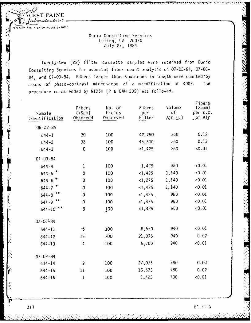
--- WEST-PAINE.12
?Y7PGVI AVE * BATO OuGE LA 7D82C
Durio Consultino ServicesLuling, LA 70070
July 27, 1984
Twenty-two (22) filter cassette samples were received from Durio
Consulting Services for asbestos fiber count analysis on 07-02-84, 07-06-
84, and 07-09-84. Fibers larger than 5 microns in length were counted-by
I means of phase-contrast microscope at a magrification of 400X. The
procedure reconended by NIOSH (P & CAM 239) was followed.
FibersFibers No. of Fibers Volume (>5pm)
Sample (>5pm) Fields per of per c.c.
Identification Observed Observed Filter Air (L) of Air
06-29-84
644-1 30 100 42,750 360 0.12
644-2 32 100 45,600 360 0.13
644-3 0 100 <1,425 360 <0.01
07-03-84
644-4 1 100 1,425 360 <0.01
644-5 * 0 100 <1,425 1,140 <0.01
644-6 * 3 100 <1,275 1,140 <0.01
644-7 * 0 100 <1,425 1,140 <0.01
644-8 ** 0 100 <1,425 960 <0.01
644-9 ** 0 100 <1,425 960 <0.01
644-10 ** 0 100 <1,425 960 <0.01
07-06-84
644-11 -6 100 8,550 940 <0.01
644-12 15 100 21,375 940 0.02
644-13 4 100 5,700 940 <0.01
07-09-84
644-14 9 100 27,075 780 0.03
64415 11 100 15,675 780 0.02
644-16 1 100 1,425 780 <0.01
d sdsl 3-?5 R

--- S. -*..*~-* -F' uI'N E
cz Z& -S . -. N .
S? ' 0 AVE • BAIO'NO, GE LAcx6 0TIDurio Consulting Services
Luling, LA 70070July 27, 1984
FibersFibers No. of Fibers Volume (>5pm)
Sample (>5pm) Fields per of per c.c.Identification -Observed Observed. F ilter Air _L) of Air 1:
07-10-84
644-17 91 100 129,675 660 0.20
1 644-18 16 100 22,800 660 0.03
7 644-19 1 100 1,425 660 <0.01
07-11-84
644-20 127 100 180,975 480 0.38
644-21 78 100 111,150 480 0.23
644-22 6 100 8,550 480 0.02
* 07-04-84
** 07-05-84
Jonpy H. VickersCh nist
dsl
,.,....., ,1......-,.. ...,,: .,,,,. ,,: ...-... . . .. - . -.... .. -- . ,- S... 1.- . .....-.. -... . . : :"-
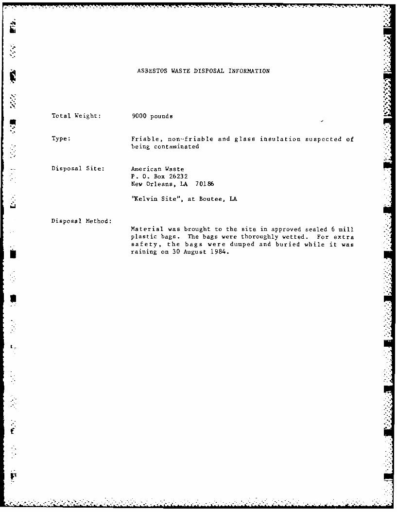
ASBESTOS WASTE DISPOSAL INFORMATION
Total Weight: 9000 pounds -
Type: Friable, non--friable and glass insulation suspected of
being contaminated
Disposal Site: American Waste
P. 0. Box 26232New Orleans, LA 70186
"Kelvin Site", at Boutee, LA
Disposal Method:Material was brought to the site in approved sealed 6 millplastic bags. The bags were thoroughly wetted. For extrasafety, the bags were dumped and buried while it was
* raining on 30 August 1984.
. . *
I:
APPENDIX F. REFERENCES
1. "Stage I and II Platform Strength Evaluation Offshore Panama City, Florida",Barnett & Casbarian, Inc., February, 1981.
2. "Demolition/Salvage Analysis of Offshore Platforms (Stage I and II) at the
Naval Coastal Systems Center, Panama City, Florida", BCI, August, 1983.
|" I
*, I
I. -
-p