u.s. navy salvage engineer’s handbook, volume 1 (salvage engineering)
DESCRIPTION
In a 1948 address to the Society of Naval Architects and Marine Engineers, Rear Admiral W.A. Sullivan, Chief of Navy Salvage and Supervisor of Salvage during World War II, called salvage "a branch of engineering." That precept has been oft quoted, and generally endorsed by salvors, naval architects, and engineers of variousdisciplines who have become involved in salvage work. Despite this general consensus, no institution offers significant instruction or grants a degree in salvage engineering. For the most part, individuals evolve into salvage engineers through years of application of a naval architecture or engineering education to the problems of ship salvage. Training by experience has its advantages, but the lack of a welldefined, structured academic base has left salvage engineers with adearth of literature specific to the field. If a profession is known by its technical writing, salvage engineering could easily be overlooked.There is a fairly extensive body of literature on marine salvage, but apart from calculation and analysis sections of reports of specificsalvage operations, very little published material addresses the engineering aspects of ship salvage.This handbook has been assembled to provide the Navy salvage engineer an authoritative and comprehensive reference work comparable to the standard reference works available for other technical disciplines. Most of the subject matter presented is notnew, but has been gleaned from many different sources. Salvage engineering is by its nature interdisciplinary, innovative, and improvisational; it is quite impossible to include in a single volume a thorough treatment of all the fields encompassed by the profession.This handbook should be taken as an outline of an extremely broad and diverse subject. Many of the component subjects are extensively treated in available literature and the aspiring salvage engineer should expect to gain a complete knowledge of the profession only by reference to works on related topics, extensive study of salvage histories, and time on the proving ground of experience. The Salvage Engineer’s Handbook is part of a family of references that includes the U.S. Navy Towing Manual, the Emergency ShipSalvage Material Catalog (ESSM), the U.S. Navy Underwater Cuttingand Welding Manual, the Technical Manual for Use of Explosives in Underwater Salvage, and the six volume U.S. Navy Salvage Manual,which was developed concurrently with the handbook. The handbook builds and expands on these works, in particular the Salvage Manual,taking it as a point of departure. While there is an intimate relationship between the salvage engineer and salvage officer (theymay, on occasion, be the same person), this handbook concerns itself with the engineering aspects of salvage. In general, information provided in the mentioned references is not repeated, except as necessary to maintain the continuity of discussion, or to preventexcessive searching between manuals. The Handbook has been published in two volumes. Volume 1 is a comprehensive treatment of salvage engineering and related calculations. Volume 2 is the user’smanual for the NAVSEA Program of Ship Salvage Engineering(POSSE), computer software designed for field work, which relieves the salvage engineer of much of the tedium of salvage calculations—but not of the assumptions and underlying mechanics that make the calculations meaningful.Salvage engineers, as engineers and as salvors, are members of a profession defined by concepts, rather than a craft defined by procedures. It has been said that there is no substitute for good judgement in the absence of hard fact. Good judgement in the absence of fact is made possible by a thorough understanding of similarsituations. Only through mastery of the underlying concepts is it possible to improvise or innovate solutions to problems where standard procedures do not apply. Familiarity with established practice combined with eager evaluation of new situations areTRANSCRIPT
U.S. NAVYSALVAGE ENGINEER’SHANDBOOK, VOLUME 1
(Salvage Engineering)
S0300-A8-HBK-0100910-LP-107-7400
PUBLISHED BY DIRECTION OF COMMANDER, NAVAL SEA SYSTEMS COMMAND
DISTRIBUTION STATEMENT A: THIS DOCUMENT HAS BEEN APPROVED FOR PUBLIC RELEASE AND SALE; ITS DISTRIBUTION IS UNLIMITED.
S0300-A8-HBK-010
LISTLIST OFOF EFFECTIVEEFFECTIVE PAGESPAGES
Date of original pages is:
Original. . . . . . . . . . . . . . . . . . O . . . . . . . . . . . . . . . 1 May1992
Total number of pages in this publication is 766, consisting of the following:
Page ChangeNo. No.
Title Page. . . . . . . . . . . . . . . . . . . . . . . . . . . . . . . . . . . . OTitle Page-2 blank. . . . . . . . . . . . . . . . . . . . . . . . . . . . . . OA (List of Effective Pages). . . . . . . . . . . . . . . . . . . . . . . . . OB blank . . . . . . . . . . . . . . . . . . . . . . . . . . . . . . . . . . . . . . ORecord of Changes. . . . . . . . . . . . . . . . . . . . . . . . . . . . . . . ORecord of Changes-2 blank. . . . . . . . . . . . . . . . . . . . . . . . . ODedication . . . . . . . . . . . . . . . . . . . . . . . . . . . . . . . . . . . . ODedication-2 blank. . . . . . . . . . . . . . . . . . . . . . . . . . . . . . . Oi (Acknowledgements). . . . . . . . . . . . . . . . . . . . . . . . . . . . Oii blank . . . . . . . . . . . . . . . . . . . . . . . . . . . . . . . . . . . . . . . Oiii (Foreword) . . . . . . . . . . . . . . . . . . . . . . . . . . . . . . . . . . Oiv blank . . . . . . . . . . . . . . . . . . . . . . . . . . . . . . . . . . . . . . Ov through xxiii . . . . . . . . . . . . . . . . . . . . . . . . . . . . . . . . . Oxxiv blank . . . . . . . . . . . . . . . . . . . . . . . . . . . . . . . . . . . . . Oxxv through xxxi . . . . . . . . . . . . . . . . . . . . . . . . . . . . . . . . Oxxxii blank . . . . . . . . . . . . . . . . . . . . . . . . . . . . . . . . . . . . Oxxxiii . . . . . . . . . . . . . . . . . . . . . . . . . . . . . . . . . . . . . . . . Oxxxiv blank . . . . . . . . . . . . . . . . . . . . . . . . . . . . . . . . . . . . O1-1 through 1-109. . . . . . . . . . . . . . . . . . . . . . . . . . . . . . . O1-110 blank. . . . . . . . . . . . . . . . . . . . . . . . . . . . . . . . . . . . O2-1 through 2-66. . . . . . . . . . . . . . . . . . . . . . . . . . . . . . . . O3-1 through 3-38. . . . . . . . . . . . . . . . . . . . . . . . . . . . . . . . O4-1 through 4-24. . . . . . . . . . . . . . . . . . . . . . . . . . . . . . . . O5-1 through 5-34. . . . . . . . . . . . . . . . . . . . . . . . . . . . . . . . O6-1 through 6-13. . . . . . . . . . . . . . . . . . . . . . . . . . . . . . . . O6-14 blank . . . . . . . . . . . . . . . . . . . . . . . . . . . . . . . . . . . . O7-1 through 7-72. . . . . . . . . . . . . . . . . . . . . . . . . . . . . . . . O8-1 through 8-44. . . . . . . . . . . . . . . . . . . . . . . . . . . . . . . . O9-1 through 9-16. . . . . . . . . . . . . . . . . . . . . . . . . . . . . . . . O
Page ChangeNo. No.
10-1 through 10-24 . . . . . . . . . . . . . . . . . . . . . . . . . . . . . . OA-1 through A-2 . . . . . . . . . . . . . . . . . . . . . . . . . . . . . . . . OB-1 through B-57 . . . . . . . . . . . . . . . . . . . . . . . . . . . . . . . OB-58 blank . . . . . . . . . . . . . . . . . . . . . . . . . . . . . . . . . . . . OC-1 through C-22 . . . . . . . . . . . . . . . . . . . . . . . . . . . . . . . OD-1 through D-25 . . . . . . . . . . . . . . . . . . . . . . . . . . . . . . . OD-26 blank . . . . . . . . . . . . . . . . . . . . . . . . . . . . . . . . . . . . OE-1 through E-21. . . . . . . . . . . . . . . . . . . . . . . . . . . . . . . . OE-22 blank . . . . . . . . . . . . . . . . . . . . . . . . . . . . . . . . . . . . OF-1 through F-35. . . . . . . . . . . . . . . . . . . . . . . . . . . . . . . . OF-36 blank . . . . . . . . . . . . . . . . . . . . . . . . . . . . . . . . . . . . OG-1 through G-36 . . . . . . . . . . . . . . . . . . . . . . . . . . . . . . . OH-1 through H-16 . . . . . . . . . . . . . . . . . . . . . . . . . . . . . . . OBibliography-1 through Bibliography-14. . . . . . . . . . . . . . . . OGlossary-1 through Glossary-20. . . . . . . . . . . . . . . . . . . . . . OIndex-1 through Index-20. . . . . . . . . . . . . . . . . . . . . . . . . . OIndex- blank . . . . . . . . . . . . . . . . . . . . . . . . . . . . . . . . . . . OFP-1 . . . . . . . . . . . . . . . . . . . . . . . . . . . . . . . . . . . . . . . . . OFP-2 blank . . . . . . . . . . . . . . . . . . . . . . . . . . . . . . . . . . . . OFP-3 . . . . . . . . . . . . . . . . . . . . . . . . . . . . . . . . . . . . . . . . . OFP-4 blank . . . . . . . . . . . . . . . . . . . . . . . . . . . . . . . . . . . . OFP-5 . . . . . . . . . . . . . . . . . . . . . . . . . . . . . . . . . . . . . . . . . OFP-6 blank . . . . . . . . . . . . . . . . . . . . . . . . . . . . . . . . . . . . OFP-7 . . . . . . . . . . . . . . . . . . . . . . . . . . . . . . . . . . . . . . . . . OFP-8 blank . . . . . . . . . . . . . . . . . . . . . . . . . . . . . . . . . . . . OFP-9 . . . . . . . . . . . . . . . . . . . . . . . . . . . . . . . . . . . . . . . . . OFP-10 blank . . . . . . . . . . . . . . . . . . . . . . . . . . . . . . . . . . . OFP-11 . . . . . . . . . . . . . . . . . . . . . . . . . . . . . . . . . . . . . . . . OFP-12 blank . . . . . . . . . . . . . . . . . . . . . . . . . . . . . . . . . . . O
A (B blank)

S0300-A8-HBK-010
RECORD OF CHANGES
CHANGENUMBER
DATE TITLE AND/ORBRIEF DESCRIPTION
ENTERED BY

to
CAPTAIN CHARLES A. BARTHOLOMEW,
whose drive and vision defined the need and created the opportunityfor the handbook, and whose experience and mentorship led the way
in its crafting.

ABOUTABOUT THETHE AUTHORSAUTHORS
Captain Charles A. (Black Bart) Bartholomew was an engineer who made the Navy—and salvage—his career. A graduate of the United StatesNavy Academy, Webb Institute of Naval Architecture, and the Navy Deep Sea Diving School at the Washington Navy Yard, he served in anumber of engineering billets before assignment in 1970 to the heavy repair ship USS HECTOR during a period of significant battle-damagerepair and combat support operations in southeast Asia. From there he was ordered to the Naval Sea Systems Command (NAVSEA) inWashington, D.C., where is served in several offices, including that of the Supervisor of Salvage.
From 1977 to 1985 he was Commanding Officer of the Naval Experimental Diving Unit, served on the Commander in Chief, U.S. Pacific Fleetstaff, and was Repair Officer and then Production Officer at the Long Beach, California Naval Shipyard. In 1985 Captain Bartholomew wastransferred back to the nation’s capital and NAVSEA to serve as Director of Ocean Engineering and Supervisor of Salvage and Diving wherehe served until his untimely death in 1991.
During his twenty-two years as a Navy diver and salvor, Captain Bartholomew participated in the salvage of sixteen ships, numerous aircraft,and the space shuttleChallenger. The "Bart" in his nickname derives in part from his surname and in part from the acronym for "Bitts AndRound Turns," a common term used in seamanship.
Commander Bert Marsh was commissioned in 1975 through the NROTC program at Oregon State University and immediately attended the NavyDeep Sea Diving School at the Washington Navy Yard. He is a plank owner in the Special Operations community as a diver and salvor, havingserved on both ARS and ASR (salvage and submarine rescue) ships. During his earlier shipboard tours, he served as diver or salvage officeron numerous aircraft salvage operations and in several ship and small craft recoveries.
As an exchange officer with the Royal Navy, Commander Marsh participated as diver, bell operator, or diving officer on the RN saturationdiving vessel, making open ocean dives to 500 FSW. He then transferred to the Navy Postgraduate School where he earned an MSME andshifted to the Engineering Duty Officer community.
During tours at Puget Sound Naval Shipyard and NAVSEA, Commander Marsh directed salvage operations from Alaska to the Persian Gulf.His salvage experience has included submarine strandings, hydrofoil PHM salvages, oil and gasoline tanker firefighting and salvage, along withcombat salvage and structural integrity evaluation of the USS PRINCETON during the Gulf War.
Commander Marsh is currently serving as the Commanding Officer of the Navy Experimental Diving Unit in Panama City, Florida.
Lieutenant Commander Richard W. Hooper, a native of Baltimore, Maryland, graduated from Loyola College, Baltimore (Bachelor of Science,Chemistry and Physics) in 1980 and was subsequently commissioned through Officer Candidate School as an Engineering Duty Officer. Hisassignments have included Boilers Officer aboard USS INDEPENDENCE (1981-1984) and Ship Overhaul Project Officer, Drydocking Officer,and Diving Officer at Norfolk Naval Shipyard (1985-1988). Lieutenant Commander Hooper received his MSME from the Naval PostgraduateSchool in 1991 and is currently assigned to the Naval Sea Systems Command, Office of the Supervisor of Salvage and Diving as the Assistantfor Salvage Operations.
TheSalvage Engineer’s Handbookwas a significant goal for Captain Bartholomew. His death in 1991 left considerable doubt as to the survivalof this engineering project, however, hisroad mapprovided Commander Marsh and Lieutenant Commander Hooper clear direction for thecompletion of this undertaking.
S0300-A8-HBK-010
FOREWORDFOREWORD
In a 1948 address to the Society of Naval Architects and MarineEngineers, Rear Admiral W.A. Sullivan, Chief of Navy Salvage andSupervisor of Salvage during World War II, called salvage "a branchof engineering." That precept has been oft quoted, and generallyendorsed by salvors, naval architects, and engineers of variousdisciplines who have become involved in salvage work. Despite thisgeneral consensus, no institution offers significant instruction orgrants a degree in salvage engineering. For the most part, individualsevolve into salvage engineers through years of application of a navalarchitecture or engineering education to the problems of ship salvage.Training by experience has its advantages, but the lack of a well-defined, structured academic base has left salvage engineers with adearth of literature specific to the field. If a profession is known byits technical writing, salvage engineering could easily be overlooked.There is a fairly extensive body of literature on marine salvage, butapart from calculation and analysis sections of reports of specificsalvage operations, very little published material addresses theengineering aspects of ship salvage.
This handbook has been assembled to provide the Navy salvageengineer an authoritative and comprehensive reference workcomparable to the standard reference works available for othertechnical disciplines. Most of the subject matter presented is notnew, but has been gleaned from many different sources. Salvageengineering is by its nature interdisciplinary, innovative, andimprovisational; it is quite impossible to include in a single volumea thorough treatment of all the fields encompassed by the profession.This handbook should be taken as an outline of an extremely broadand diverse subject. Many of the component subjects are extensivelytreated in available literature and the aspiring salvage engineer shouldexpect to gain a complete knowledge of the profession only byreference to works on related topics, extensive study of salvagehistories, and time on the proving ground of experience.
The Salvage Engineer’s Handbookis part of a family of referencesthat includes theU.S. Navy Towing Manual, the Emergency ShipSalvage Material Catalog (ESSM),theU.S. Navy Underwater Cuttingand Welding Manual, theTechnical Manual for Use of Explosives inUnderwater Salvage, and the six volumeU.S. Navy Salvage Manual,which was developed concurrently with the handbook. The handbookbuilds and expands on these works, in particular theSalvage Manual,taking it as a point of departure. While there is an intimaterelationship between the salvage engineer and salvage officer (theymay, on occasion, be the same person), this handbook concerns itselfwith the engineering aspects of salvage. In general, informationprovided in the mentioned references is not repeated, except asnecessary to maintain the continuity of discussion, or to preventexcessive searching between manuals. The Handbook has beenpublished in two volumes.Volume 1is a comprehensive treatment ofsalvage engineering and related calculations.Volume 2is the user’smanual for the NAVSEAProgram of Ship Salvage Engineering(POSSE), computer software designed for field work, which relievesthe salvage engineer of much of the tedium of salvagecalculations—but not of the assumptions and underlying mechanicsthat make the calculations meaningful.
Salvage engineers, as engineers and as salvors, are members of aprofession defined by concepts, rather than a craft defined byprocedures. It has been said that there is no substitute for good judge-ment in the absence of hard fact. Good judgement in the absence offact is made possible by a thorough understanding of similarsituations. Only through mastery of the underlying concepts is itpossible to improvise or innovate solutions to problems where standardprocedures do not apply. Familiarity with established practicecombined with eager evaluation of new situations are the under-pinnings of a progressive profession. This is doubly true in salvage,where the requirements to deal with old ships, operate in remote,undeveloped areas, and improvise in the field mandates a knowledgeof techniques and equipment considered obsolete in other fields, whilethe advances in shipbuilding technology and increases in ship sizedemand that salvors be familiar with the latest innovations.
The Salvage Engineer’s Handbookis intended to be the standardreference for the salvage engineer. However, this standard referenceis a dynamic work, refined by the continuing experiences andknowledge of the community it serves. Evaluation and discussion willpave the way for subsequent, improved editions.
R. P. FISKEDirectory of Ocean EngineeringSupervisor of Salvage and Diving, USN
iii (iv blank)
S0300-A8-HBK-010
INTRODUCTIO NINTRODUCTION
Salvage engineering is a broad-based, interdisciplinary field. Salvageengineers must have a firm grasp on the principles of navalarchitecture to be able to assess the strength and stability of adamaged vessel. A working knowledge of strength of materials,mechanics, dynamics, and structures is requisite, as are someunderstanding of soil mechanics, fluid dynamics, coastal processes,safety engineering, and the theory and practice associated withrigging systems design and operation, pumping operations,compressed air system design and operation, metals fabrication,industrial processes, and explosives use. An effective salvageengineer wil l also be familiar with ship operations, deck seamanship,machinery operation, diving, and oil spill remediation. Above allelse, however, a salvage engineer must understand salvage—what itis, and why it is. In the words of Rear Admiral W.A. Sullivan:
The salvage officer . . . must know sufficient navalarchitecture to be thoroughly conversant with thesubjects of ship stability, buoyancy, and trim. Hemust know something of the strength of ships so thathe can estimate the stress that can be placed on aship’s structure with safety. He should be anengineer conversant with the laws of mechanics, ofthe strength of materials and of gases, especiallythose pertaining to compressed air. He must knowabout the nature of soils and rocks upon which avessel may strand and he must be most thoroughlyversed in the principles of salvage. He must knowsomething of the valuation of ships and of theircargoes, for, in addition to salvaging ships, he willhave to decide whether or not a ship offers sufficientsalved value to warrant theexpenseand risk involvedin its salvage. The salvage officer must be a man ofexperience and decision. He will have no time whenhe arrives at the scene of a wreck to make longsurveys and to consider a plan of action. He willhave to decide upon this very quickly and he is notapt to hold his position long if he makes manymistakes.
Marine salvage is a service provided to ship and cargo owners withthe object of preserving asignificant portion of the value of the ship,its cargo, or both. Typical salvage services include rescue towing,debeaching stranded vessels, raising sunken vessels, firefighting,damage control assistance, and cargo recovery or removal. Salvorsuniversally apply the term casualty to a vessel requiring salvageassistance, in keeping with the definition of the word as something"harmed or destroyed as the result of some act or event." Althoughoperationally similar, wreck removal, harbor clearance, and similaroperations are not salvage in the strictest sense, as the casualty haslittl e or no salvage value.
Commercial salvors provide their services voluntarily in theexpectation of financial reward in the form of a fixed fee, a per diemrate, or a salvage award based on the value of the ships or goodssalved. Commercial salvage is viable only so long as the potentialsalvage award exceeds the cost of the salvage. The economics ofmilitary salvage operations are not as easily summarized. Salvage isa mission assigned to certain ships and units; it is not an economicventure. Although projected mission costsmay influencethedecisionto conduct aparticular operation, the returnsof asuccessful operationare not always measured in financial or even tangible terms.Political, environmental, or military considerationssometimesrequirethat the price of salvage be paid, no matter how high. Military orother government agenciesof most maritimecountriesmaintain someform of salvage capability because national interests may require theundertaking of commercially unattractive salvage operations, and toensure that salvage assets wil l be available for wartime use.
Public Law 513 (10 U.S.C. §§ 7361 et seq) authorizes the Secretaryof the Navy to provide "by contract or otherwise, necessary salvagefacilities for public and private vessels upon such terms as hedetermines to be in the best interest of the United States." Asunnecessary government competition with thesalvage industry wouldnot be in thebest long-term interest of thecountry, peacetimesalvageservices provided by the Navy and other military services are largelylimited to salvage of government owned assets. Salvage servicesmay be provided to nongovernment assets if commercial salvorscannot or wil l not provide the required services. Salvage operationsconducted by military forces and assets during peacetime generallyfall into one of the following categories:
• Salvage of publicly owned vessels and clearance ofFederally controlled harbors.
• Salvage assistance to allied navies/governments.
• Clearance of critical waterways at the request of the U.S.Coast Guard or U.S. Army Corps of Engineers.
• Salvageor removal of vesselspresenting aseverepollutionhazard, when no commercial assetsareavailable, and whenrequested by the U.S. Coast Guard.
• Salvage of vessels that present a unique trainingopportunity, as determined by the Supervisor of Salvage.
• Recovery of aircraft components to support mishap invest-igations as required by military and civil agencies.
• Recovery of valuable or sensitive objects belonging togovernment agencies.
• Support of oceanographic research.
• Assistance to state and municipal governments.
• Salvage of commercial vessels when no adequatecommercial assets are available and the government iscontracted by the vessels’ owners.
v
S0300-A8-HBK-010
Wartimesalvagemay fall into any of theabovecategories, dependingon priorities at the time. The principal reason for wartime navalsalvage, however, is to recover assets that cannot be procuredelsewhere in sufficient quantity at any cost. Examples of wartimesalvage operations include:
• Expedient repairs to damaged ships, or refloatinglightly damaged ships for immediate return to duty.
• Firefighting, damage control assistance, expedientrepair, and rescue towing of ships damaged by enemyaction.
• Salvage and delivery of more heavily damaged ships torepair facilities for eventual return to duty.
• Clearance of vital ports and waterways.
• Recovery of war critical cargo, shipboard equipment ormunitions for further use, and/or to prevent enemy use.
• Recovery of sensitive or classified items to preventenemy recovery.
• Salvage or recovery of enemy assets for intelligence orfriendly use.
Salvage engineering combines elements of both field and designengineering. In addition to assessing the condition of a ship casualtyin its awkward situation, the salvage engineer must often oversee theoperation of purpose-built salvage systems—beach gear, liftingsystems, specialized salvage craft, etc. The salvage engineer is alsocalled upon to design specialized systems, modify existing systems,and determine operating limits for systems and equipment usedoutside their designed operating conditions. As the principletechnical advisor to the salvage officer, the salvage engineer plays acritical role in selecting salvage methods and developing salvageplans. Salvage engineering can be divided into the followingcategories:
• Evaluating Ship Casualties – Estimating a casualty’sstability, reserve buoyancy, and strength based onknown and estimated conditions.
• Local Strength Analysis – Determining the capacity ofportions of casualty or assisting ship structure to carryextreme or unusual loads.
• Determining Environmental Effects – Estimatingforces and pressures resulting from currents, wind,waves, and other environmental factors.
• Systems Design – Designing systems to apply or resistforces, or to recover buoyancy:
(1) Designing pulling, lifting, or parbuckling systems.
(2) Designing and constructing cofferdams, currentdeflectors, and similar structures.
(3) Selecting and evaluating attachment pointsfor liftingor pulling systems.
(4) Designing and installing structural reinforcements.
(5) Designing and assembling dewatering systemsusingpumps, compressed air, induced buoyancy devices,or a combination of methods.
(6) Designing, constructing, and installing largepatches.
(7) Designing field-built or improvised weight- andcargo-handling systems.
(8) Evaluating anchor holding power and designingmooring systems.
(9) Designing and constructing footings and shallowfoundations.
(10) Modifying existing systems for salvage use.
• Systems Operation – Ensuring that engineered systemsareoperated safely and effectively; establishing operatinglimits for improvised or modified systems and ensuringthat operating personnel know system operatingcharacteristics and limitations.
• Planning – Estimating feasibility and the time,manpower, materials and specialized assets required toaccomplish tasks; devising, with other salvage personnel,means to improve damaged vessel conditions; estimatingcasualty stability, reserve buoyancy, and strength duringand following planned salvage actions.
• Documentation –Providing salvagecalculations, systemsdesign data, and technical analysis of operations for post-salvage reports.
Salvage engineering design differs from conventional design practicein three significant areas:
• Selection of component material and size.
• Treatment of fatigue considerations.
• Precision of calculations and measurements.
vi
S0300-A8-HBK-010
In conventional engineering design, component material and size areselected to give adequate strength for a clearly defined design load.Design loads are determined by dividing the "known" failure load bya factor of safety to provide a reserve of strength in a system orcomponent. Tabulated failure loads for various materials areaverages based on destructive testing—a particular sample of thematerial may fail at higher or lower loads. The factor of safety istherefore a factor of uncertainty. In any design, there is additionaluncertainty about a component’s actual failure mode, behavior of thematerial in the vicinity of its ultimate stress, applicability of designtheory assumptions, operating environment, quality control duringfabrication and installation, and additional stresses introduced bydeformation of components within the system. Design safety factorsrecommended or required by regulatory bodies are selected to givean acceptable degree of certainty that a structure wil l carry the designload. Standard safety factors vary depending on service and theanticipated result of failure. For example, safety factors for systemswhere failure may endanger human lif e are much higher than forsimilar systems where there is no lif e hazard.
The changeable environment of salvage work, with its requirementto work with sometimes incomplete data, increases uncertaintiesconcerning failuremodes, applicability of design theory assumptions,operating environment, and quality control. In such cases, safetyfactors should be increased over those recommended for design workwherever possible. Oilfield design, beset with similar uncertainties,is typified in the phrase "build it stout for hell!" Salvors, however,must often work with the limited materials at hand. In salvageengineering design, choice of component materials and size is oftenforced by capacity of handling systems or material availability, andthe salvage engineer must determine limiting loads based on thestrength of components to be used. In many cases, it is necessary toaccept lower factors of safety than called for by standard designpractice—salvage system components, such as chain, wire rope,sheaves, structural shapes, etc., may see loads that exceed theirnormal safe working or design load. Because a reduced safety factorgives less certainty that the structure wil l not fail under load, designand operating procedures should be modified to remove personneland critical equipment from danger areasduring system loading whencircumstances dictate the acceptance of reduced safety factors.
Safety factors for some structures are based on an assumed loss ofmaterial through corrosion or other forms of deterioration over agiven service life. Lower safety factors can be accepted safely iffailure loads are calculated from actual rather than nominal or initialcomponent dimensions.
Component service lif e is a major concern in conventional design.Structural component stress levels are selected to avoid fatiguefailure. Salvage systems are often designed for short-term or onetime use on a single operation; fatigue is not a primary consideration.Short term use must be defined in terms of load cycles, however, nottime. As an example, structural reinforcements and tensioned wirerope on a stranded casualty are subjected to load fluctuations orreversals by the passage of waves. With a 5- to 7-second waveperiod, the components may experience over 17,000 load cycles perday. The salvage engineer must ensure that system componentssubjected to excessive stresses or cyclic loading during salvageoperations are carefully inspected prior to reuse, and scrapped ifunacceptably worn or deformed.
The salvage engineer is almost always faced with impreciseinformation or totally unknown conditions that must be estimated.In some instances, sound approximations wil l provide sufficientlyaccurate results. In other situations, measurement of casualtydimensions and/or extensive numerical integration may be necessaryfor adequate precision. The precision of input data limits theprecision of calculations. For example, drafts can seldom be readmore precisely than ± 3 inches on ships outside well-protectedharbors. A calculation based on displacement from observed drafts,such as ground reaction, can therefore be no more precise than ± 3times the ships TPI. A similar awareness of the accuracy of datafrom curves or drawings must be maintained. Calculated data withunjustified significant digits can instill false confidence in operatingpersonnel. Wherever possible, thesalvageengineer should determineand provide an error range with calculated values. If for example, itis calculated that the freeing force for a particular stranding is 500short tons ± 50 tons, salvors are aware that the casualty may pull freewith as littl e as 450 tons line tension. On the other hand, they arealso aware that at least 550 tons of pulling force should be available,and that until the pulling force is well above 550 tons, there is noreason to suspect a miscalculation or the presence of unknownfactors.
There is also a fundamental difference in the way salvage engineersand ship designers approach naval architecture. Naval architects, asdesigners, deal with ships as designed, as built, or as modified, whilesalvage engineers deal with them as wrecked. The differences inapproach resulting from this distinction are subtle but significant.Naval architects examine proposed ship designs and alterations innormal operating, or intact conditions, and certain hypotheticalconditions of damage. The salvage engineer on the other hand, dealswith ships in conditions of known or identifiabledamage. This is notto say that a salvage engineer does not design, or examinehypothetical conditions; it does say that in most cases, thoseconditions have as their point of departure an initial damagedcondition.
Since most naval architects deal with new construction ormodifications to fairly new ships, they concern themselves chieflywith current design practice and rules. However, old ships don’tdisappear from the seas on the adoption of new rules or practices,but, like MacArthur’s "old soldiers," only gradually fade away.Strandings, collision, mechanical breakdown, and other marineincidents are part of the fading process, and are more, rather thanless, likely as a ship ages. The salvage engineer must therefore haveat least apassing knowledgeof ship design and construction practicesfor the last 40 years or so, as well as the most current methods.
An oft quoted, humorous anecdote states that
Ship salvage is a science of vague assumptions based ondebatablefiguresfrominconclusiveinstruments, performedwith equipment of problematical accuracy by persons ofdoubtful reliability and of questionable mentality.
vii
S0300-A8-HBK-010
This statement, attributed to an unidentified chief mate of a Europeansalvage tug, is sometimes used to justify a slaphazard approach tosalvage work. It should instead be taken as a sobering warning as tothe changeable nature of salvage work and supporting engineeringanalysis. Because salvage is conducted in an uncontrolled and oftenimperfectly defined environment, assumptions are sometimesnecessarily vague, and are always subject to change. This shouldprompt a periodic reevaluation of the data and assumptions employed,and the conclusions they have produced. The temptation toover-engineera situation must be resisted, however. The second part ofabove quoted anecdote is less well known but equally as instructiveas the first part:
The captain of a salvage vessel is said to be aman who knows a great deal about very little,and he goes on knowing more and more aboutless and less until finally he knows practicallyeverything about nothing. The chief engineer onthe other hand, is a man who knows very littleabout a great deal and keeps on knowing lessand less about more and more until he finallyknows practically nothing about everything. Thesalvage master starts out knowing practicallyeverything about everything and ends upknowing nothing about anything due to hisassociation with captains and engineers.
Because the aims of a salvage operation are usually quite limited, itis easy to focus attention too narrowly, to the exclusion of peripheral,but none the less vital issues. It is just as easy to include too manyextraneous considerations, to attempt toengineer the world.
A large part of a salvage engineer’s contribution to an operation issubjective analysis that does not involve calculation or detailedmeasurement. Even as mariners develop aseaman’s eye,engineersdevelop an analytical view of the world around them. In applyingthis view to a ship casualty, an engineer may note items overlookedby others, and obtain an intuitive feel for the casualty. By the sametoken, experienced salvors and seaman may note things overlookedby the engineer. By comparing impressions, operators and engineerscan create a synergy that can solve problems that might defeat themwhen working alone. Salvage engineering can be truthfully called ascience of boundaries and boundary conditions. The salvageengineer’s art is to recognize boundary conditions and theirsignificance to calculations and assumptions. Having establishedoperating boundaries, the salvage engineer must be mindful of howclosely the operation approaches those boundaries. Calculationsbased on a mix of hard data and assumptions are not absolute, butcan be assigned aconfidence level.The salvage engineer must beaware of the confidence level of his calculations andrecommendations and communicate this to the salvage officer orsalvage master.
The feel for the casualty can only be obtained by direct observation.While it is not possible for the salvage engineer to personally observeall aspects of a salvage operation, he should get out on deck, crawlthe bilges, and see for himself the condition of the casualty insofaras practical. The engineer should also make time to observe salvagework and preparations in progress. By so doing, the salvage engineercan get a feel for the kind of problems facing the salvors, and maybe able to suggest improvements or modifications. He can alsoensure that systems and components are fabricated to designspecifications. Innocent and seemingly minor field expediencies,such altering the orientation of timbers or structural shapes to easefabrication, can seriously compromise a structure. Time spent inMBWA (ManagementBy Walking Around) is time well spent. Theengineer who isolates himself from the salvage operation to work onhis calculations is of little practical use to the salvors, and thereforelikely to be ignored.
The amount of engineering analysis that can or should be conductedis often determined by time constraints. The planned removal of awreck that has lain on a beach for some time can proceed in athoughtful, orderly manner—there is little if anything to lose shouldthe wreck be damaged by weather or surf, so time is available forextensive data gathering, analysis, and planning. On the other hand,a casualty stranded on an exposed coast and subject to scouringcurrents may be destroyed in days or even hours if not successfullyrefloated. It has been said thatperfectis the enemy ofgood enough.The time and effort expended to perfect a good enough analysis orplan may not be justified, especially if the delay results in additionaldamage to the casualty or prevents successful salvage. Thisrecognition should be tempered with the realization that some jobsmay be impossible without careful engineering analysis, despite timeconstraints. The adage that "there is never enough time to do it right,but always time to do it over again" may not apply. There may beonly time to succeed or fail on the first attempt.
The almost explosive increase in the power and utility of personalcomputers in recent years has greatly increased the ability of thesalvage engineer to provide real-time engineering analysis. A fewcomputer programs have been developed specifically for salvagecalculations and planning; others are under development. TheNAVSEA Program of Ship Salvage Engineering (POSSE), runningon an MS/DOS©-based microcomputer, can perform hydrostatic,stability, longitudinal strength, and ground reaction calculations. TheU. S. Navy Salvage Engineer’s Handbook, Volume 2(S0300-A8-HBK-020) describes the capabilities and operation ofPOSSE. Useof POSSEor a program with similar capabilities permits the salvageengineer to provide a quick initial assessment, and to evaluate theeffects of proposed actionsbefore they are taken, even when littletime is available for planning and analysis. The increased speed ofsalvage calculations also allows the salvage engineer to spend moretime with the salvors and understanding the problems at hand.
viii
S0300-A8-HBK-010
TTABLEABLE OFOF CONTENTSCONTENTS
ACKNOWLEDGEMENTS . . . . . . . . . . . . . . . . . . . . . . . . . . . . . . . . . . . . . . I
FOREWORD . . . . . . . . . . . . . . . . . . . . . . . . . . . . . . . . . . . . . . . . . . . . . . III
INTRODUCTION . . . . . . . . . . . . . . . . . . . . . . . . . . . . . . . . . . . . . . . . . . . V
TABLE OF CONTENTS . . . . . . . . . . . . . . . . . . . . . . . . . . . . . . . . . . . . . . IX
LIST OF ILLUSTRATIONS . . . . . . . . . . . . . . . . . . . . . . . . . . . . . . XIX
LIST OF TABLES . . . . . . . . . . . . . . . . . . . . . . . . . . . . . . . . . . . XXV
LIST OF SYMBOLS AND ABBREVIATIONS . . . . . . . . . . . . . . XXIX
STANDARD NAVY SYNTAX SUMMARY . . . . . . . . . . . . . . . . . XXXIII
PAGE
CHAPTER/PARAGRAPH NUMBER
PAGE
CHAPTER/PARAGRAPH NUMBER
CHAPTER 1 - NAVAL ARCHITECTURE FOR THE SALVAGE ENGINEER
1-1 INTRODUCTION . . . . . . . . . . . . . . . . . . . . . . . . . . . . . . . . . . . . . . . . . 1-11-2 HULL FORM . . . . . . . . . . . . . . . . . . . . . . . . . . . . . . . . . . . . . . . . . . . . 1-11-2.1 LOCATION OF POINTS WITHIN A SHIP . . . . . . . . . . . . . . . . . 1-11-2.2 LOCATION OF POINTS . . . . . . . . . . . . . . . . . . . . . . . . . . . . . . . 1-21-2.3 SHIP DIMENSIONS . . . . . . . . . . . . . . . . . . . . . . . . . . . . . . . . . . 1-21-2.4 LINES . . . . . . . . . . . . . . . . . . . . . . . . . . . . . . . . . . . . . . . . . . . . 1-31-2.4.1 THE BODY PLAN . . . . . . . . . . . . . . . . . . . . . . . . . . . . . . . . . . . 1-31-2.4.2 HALFBREADTH PLAN . . . . . . . . . . . . . . . . . . . . . . . . . . . . . . . . 1-31-2.4.3 SHEER PLAN . . . . . . . . . . . . . . . . . . . . . . . . . . . . . . . . . . . . . . 1-31-2.4.4 DESCRIPTIVE TERMS . . . . . . . . . . . . . . . . . . . . . . . . . . . . . . . 1-41-2.5 COEFFICIENTS OF FORM . . . . . . . . . . . . . . . . . . . . . . . . . . . . 1-61-2.5.1 BLOCK . . . . . . . . . . . . . . . . . . . . . . . . . . . . . . . . . . . . . . . . . . . 1-61-2.5.2 MIDSHIP SECTION . . . . . . . . . . . . . . . . . . . . . . . . . . . . . . . . . . 1-61-2.5.3 WATERPLANE . . . . . . . . . . . . . . . . . . . . . . . . . . . . . . . . . . . . . . 1-61-2.5.4 PRISMATIC . . . . . . . . . . . . . . . . . . . . . . . . . . . . . . . . . . . . . . . . 1-71-2.6 SHIP PROPORTIONS . . . . . . . . . . . . . . . . . . . . . . . . . . . . . . . . 1-71-2.7 OFFSETS . . . . . . . . . . . . . . . . . . . . . . . . . . . . . . . . . . . . . . . . . 1-81-2.8 WETTED SURFACE . . . . . . . . . . . . . . . . . . . . . . . . . . . . . . . . . 1-91-3 DISPLACEMENT AND BUOYANCY . . . . . . . . . . . . . . . . . . . . . . . . . . . 1-91-3.1 SHIP’S WEIGHT, DISPLACEMENT AND CAPACITY . . . . . . . . 1-91-3.2 STANDARD LOADING CONDITIONS . . . . . . . . . . . . . . . . . . . 1-101-3.2.1 U.S. NAVY SHIPS . . . . . . . . . . . . . . . . . . . . . . . . . . . . . . . . . 1-101-3.2.2 COMMERCIAL VESSELS . . . . . . . . . . . . . . . . . . . . . . . . . . . . 1-111-3.2.3 LOADING INSTRUCTIONS . . . . . . . . . . . . . . . . . . . . . . . . . . . 1-111-3.3 DEADWEIGHT . . . . . . . . . . . . . . . . . . . . . . . . . . . . . . . . . . . . . 1-111-3.4 CHANGE IN DRAFT . . . . . . . . . . . . . . . . . . . . . . . . . . . . . . . . 1-121-3.5 TONS PER INCH IMMERSION (TPI)I . . . . . . . . . . . . . . . . . . . 1-141-3.6 RESERVE BUOYANCY . . . . . . . . . . . . . . . . . . . . . . . . . . . . . . 1-141-3.7 CENTER OF GRAVITY . . . . . . . . . . . . . . . . . . . . . . . . . . . . . . 1-141-3.8 CENTER OF BUOYANCY . . . . . . . . . . . . . . . . . . . . . . . . . . . . 1-151-3.9 METACENTER . . . . . . . . . . . . . . . . . . . . . . . . . . . . . . . . . . . . . 1-151-3.10 CENTER OF FLOTATION . . . . . . . . . . . . . . . . . . . . . . . . . . . . 1-151-3.11 BONJEAN’S CURVES . . . . . . . . . . . . . . . . . . . . . . . . . . . . . . . 1-151-4 APPROXIMATE INTEGRATION TECHNIQUES
AND APPLICATIONS . . . . . . . . . . . . . . . . . . . . . . . . . . . . . . . . . . . . . 1-161-4.1 GRAPHICAL INTEGRATION . . . . . . . . . . . . . . . . . . . . . . . . . . 1-161-4.2 NUMERICAL INTEGRATION . . . . . . . . . . . . . . . . . . . . . . . . . . 1-161-4.3 TRAPEZOIDAL RULE . . . . . . . . . . . . . . . . . . . . . . . . . . . . . . . 1-161-4.4 SIMPSON’S RULES . . . . . . . . . . . . . . . . . . . . . . . . . . . . . . . . 1-171-4.4.1 SIMPSON’S FIRST RULE . . . . . . . . . . . . . . . . . . . . . . . . . . . . 1-171-4.4.2 SIMPSON’S SECOND RULE . . . . . . . . . . . . . . . . . . . . . . . . . 1-191-4.5 APPLICATIONS . . . . . . . . . . . . . . . . . . . . . . . . . . . . . . . . . . . . 1-191-4.5.1 MOMENTS AND CENTROIDS . . . . . . . . . . . . . . . . . . . . . . . . . 1-201-4.5.2 SECOND MOMENTS OF AREA . . . . . . . . . . . . . . . . . . . . . . . 1-211-4.5.3 VOLUMES AND CENTROIDS OF VOLUME . . . . . . . . . . . . . . 1-221-4.5.4 GENERAL FORMS FOR AREA
AND MOMENT CALCULATIONS . . . . . . . . . . . . . . . . . . . . . . . 1-231-4.6 OTHER SIMPSON’S RULE FORMS . . . . . . . . . . . . . . . . . . . . 1-261-4.6.1 5, 8, MINUS ONE AND 3, 10, MINUS ONE RULES . . . . . . 1-261-4.6.2 SIMPSON’S RULES FOR ANY NUMBER
OF ORDINATES . . . . . . . . . . . . . . . . . . . . . . . . . . . . . . . . . . . 1-26
1-4.7 OTHER INTEGRATION RULES . . . . . . . . . . . . . . . . . . . . . . . . 1-261-4.8 GENERAL NOTES FOR NUMERICAL INTEGRATION . . . . . . 1-271-4.9 INTEGRATION OF DISCONTINUOUS CURVES . . . . . . . . . . . 1-271-4.10 CALCULATION OF HULL PROPERTIES . . . . . . . . . . . . . . . . . 1-281-4.10.1 FUNCTIONS OF FORM . . . . . . . . . . . . . . . . . . . . . . . . . . . . . . 1-281-4.10.2 APPENDAGE DISPLACEMENT . . . . . . . . . . . . . . . . . . . . . . . . 1-281-4.10.3 STATION SPACING . . . . . . . . . . . . . . . . . . . . . . . . . . . . . . . . . 1-281-4.10.4 FULL SECTIONS . . . . . . . . . . . . . . . . . . . . . . . . . . . . . . . . . . 1-291-4.10.5 LOWEST WATERLINES . . . . . . . . . . . . . . . . . . . . . . . . . . . . . 1-291-4.10.6 ENDS OF FULL HULL FORMS . . . . . . . . . . . . . . . . . . . . . . . 1-291-4.10.7 TANK AND COMPARTMENT VOLUMES . . . . . . . . . . . . . . . . . 1-291-5 TRANSVERSE STABILITY . . . . . . . . . . . . . . . . . . . . . . . . . . . . . . . . . 1-301-5.1 EQUILIBRIUM AND STABILITY . . . . . . . . . . . . . . . . . . . . . . . . 1-301-5.2 INTERNAL FORCES . . . . . . . . . . . . . . . . . . . . . . . . . . . . . . . . 1-301-5.3 EXTERNAL FORCES . . . . . . . . . . . . . . . . . . . . . . . . . . . . . . . 1-321-5.4 HEIGHTS OF CENTERS . . . . . . . . . . . . . . . . . . . . . . . . . . . . . 1-321-5.4.1 HEIGHT OF THE CENTER OF GRAVITY . . . . . . . . . . . . . . . . 1-321-5.4.2 HEIGHT OF THE CENTER OF BUOYANCY . . . . . . . . . . . . . . 1-331-5.4.3 METACENTRIC HEIGHT . . . . . . . . . . . . . . . . . . . . . . . . . . . . . 1-331-5.5 RIGHTING ARM . . . . . . . . . . . . . . . . . . . . . . . . . . . . . . . . . . . 1-351-5.6 RIGHTING MOMENT . . . . . . . . . . . . . . . . . . . . . . . . . . . . . . . 1-351-5.7 CHANGE OF DISPLACEMENT . . . . . . . . . . . . . . . . . . . . . . . . 1-361-5.8 LIST . . . . . . . . . . . . . . . . . . . . . . . . . . . . . . . . . . . . . . . . . . . . 1-361-5.9 THE STABILITY CURVE . . . . . . . . . . . . . . . . . . . . . . . . . . . . . 1-361-5.9.1 CROSS CURVES OF STABILITY . . . . . . . . . . . . . . . . . . . . . . 1-371-5.9.2 CORRECTION FOR ACTUAL KGI. . . . . . . . . . . . . . . . . . . . . . 1-381-5.9.3 RANGE OF STABILITY . . . . . . . . . . . . . . . . . . . . . . . . . . . . . . 1-381-5.9.4 RIGHTING ARM AND RIGHTING MOMENT . . . . . . . . . . . . . . 1-391-5.9.5 METACENTRIC HEIGHT . . . . . . . . . . . . . . . . . . . . . . . . . . . . . 1-391-5.9.6 ANGLE OF DECK EDGE IMMERSION . . . . . . . . . . . . . . . . . . 1-391-5.9.7 RIGHTING ENERGY . . . . . . . . . . . . . . . . . . . . . . . . . . . . . . . . 1-391-5.10 EFFECTS OF HULL FORM ON THE
STABILITY CURVE . . . . . . . . . . . . . . . . . . . . . . . . . . . . . . . . . 1-391-5.10.1 BEAM . . . . . . . . . . . . . . . . . . . . . . . . . . . . . . . . . . . . . . . . . . . 1-391-5.10.2 LENGTH . . . . . . . . . . . . . . . . . . . . . . . . . . . . . . . . . . . . . . . . . 1-401-5.10.3 FREEBOARD . . . . . . . . . . . . . . . . . . . . . . . . . . . . . . . . . . . . . . 1-401-5.10.4 DRAFT . . . . . . . . . . . . . . . . . . . . . . . . . . . . . . . . . . . . . . . . . . 1-401-5.10.5 DISPLACEMENT . . . . . . . . . . . . . . . . . . . . . . . . . . . . . . . . . . . 1-401-5.10.6 SIDE AND BOTTOM PROFILE . . . . . . . . . . . . . . . . . . . . . . . . 1-401-5.11 PROHASKA’S METHOD . . . . . . . . . . . . . . . . . . . . . . . . . . . . . 1-411-6 LONGITUDINAL STABILITY . . . . . . . . . . . . . . . . . . . . . . . . . . . . . . . . 1-421-6.1 TRIM . . . . . . . . . . . . . . . . . . . . . . . . . . . . . . . . . . . . . . . . . . . . 1-421-6.2 LONGITUDINAL STABILITY PARAMETERS . . . . . . . . . . . . . . 1-421-6.2.1 LONGITUDINAL POSITION OF THE
CENTER OF GRAVITY . . . . . . . . . . . . . . . . . . . . . . . . . . . . . . 1-421-6.2.2 LONGITUDINAL POSITION OF THE
CENTER OF BUOYANCY . . . . . . . . . . . . . . . . . . . . . . . . . . . . 1-421-6.2.3 LONGITUDINAL POSITION OF THE
CENTER OF FLOTATION (LCF)I . . . . . . . . . . . . . . . . . . . . . . 1-421-6.2.4 LONGITUDINAL METACENTER . . . . . . . . . . . . . . . . . . . . . . . . 1-421-6.3 TRIMMING ARMS AND MOMENTS . . . . . . . . . . . . . . . . . . . . 1-43
ix
S0300-A8-HBK-010
PAGE
CHAPTER/PARAGRAPH NUMBER
PAGE
CHAPTER/PARAGRAPH NUMBER
CHAPTER 1 - NAVAL ARCHITECTURE FOR THE SALVAGE ENGINEER (CONTINUED)
1-6.4 MOMENT TO CHANGE TRIM ONE INCH (MT1)I . . . . . . . . . 1-431-6.5 DRAFTS AFTER A CHANGE IN TRIM . . . . . . . . . . . . . . . . . . 1-441-6.6 MOVEMENT OF LCB AND LCG
WITH CHANGE OF TRIM . . . . . . . . . . . . . . . . . . . . . . . . . . . . 1-451-7 PARAMETRIC DETERMINATION OF HULL CHARACTERISTICS . . . 1-451-7.1 PARAMETRIC MODEL . . . . . . . . . . . . . . . . . . . . . . . . . . . . . . 1-451-7.1.1 REQUIRED INFORMATION . . . . . . . . . . . . . . . . . . . . . . . . . . . 1-461-7.1.2 DISPLACEMENT AND COEFFICIENTS OF FORM . . . . . . . . . 1-461-7.1.3 HEIGHTS OF CENTERS . . . . . . . . . . . . . . . . . . . . . . . . . . . . . 1-471-7.1.4 TONS PER INCH IMMERSION . . . . . . . . . . . . . . . . . . . . . . . . 1-481-7.1.5 MOMENT TO TRIM ONE INCH . . . . . . . . . . . . . . . . . . . . . . . 1-481-7.1.6 LONGITUDINAL POSITIONS OF CENTERS . . . . . . . . . . . . . . 1-491-7.2 CHANGES . . . . . . . . . . . . . . . . . . . . . . . . . . . . . . . . . . . . . . . . 1-491-7.3 CALCULATION HIERARCHY . . . . . . . . . . . . . . . . . . . . . . . . . . 1-501-7.4 CAUTIONS . . . . . . . . . . . . . . . . . . . . . . . . . . . . . . . . . . . . . . . 1-501-7.5 APPLICATIONS TO SALVAGE CALCULATIONS . . . . . . . . . . . 1-501-8 WEIGHT AND STABILITY . . . . . . . . . . . . . . . . . . . . . . . . . . . . . . . . . 1-511-8.1 WEIGHT SHIFTS . . . . . . . . . . . . . . . . . . . . . . . . . . . . . . . . . . 1-511-8.1.1 LONGITUDINAL EFFECTS OF WEIGHT SHIFTS . . . . . . . . . . 1-521-8.1.2 OFFCENTER WEIGHT . . . . . . . . . . . . . . . . . . . . . . . . . . . . . . 1-521-8.1.3 STABILITY CURVE CORRECTION FOR
OFFCENTER WEIGHT . . . . . . . . . . . . . . . . . . . . . . . . . . . . . . 1-531-8.2 WEIGHT ADDITIONS AND REMOVALS . . . . . . . . . . . . . . . . . 1-531-8.2.1 WEIGHT CHANGES AWAY FROM THE CENTER
OF GRAVITY . . . . . . . . . . . . . . . . . . . . . . . . . . . . . . . . . . . . . . 1-541-8.2.2 WEIGHT CHANGES WITHOUT CHANGE OF TRIM . . . . . . . 1-541-8.2.3 POINT OF CONSTANT DRAFT . . . . . . . . . . . . . . . . . . . . . . . 1-561-8.3 INCLINING EXPERIMENT . . . . . . . . . . . . . . . . . . . . . . . . . . . . 1-561-8.4 SALLYING SHIP . . . . . . . . . . . . . . . . . . . . . . . . . . . . . . . . . . . 1-561-8.5 BALLAST . . . . . . . . . . . . . . . . . . . . . . . . . . . . . . . . . . . . . . . . . 1-571-9 IMPAIRED STABILITY . . . . . . . . . . . . . . . . . . . . . . . . . . . . . . . . . . . . 1-571-9.1 FLOODING . . . . . . . . . . . . . . . . . . . . . . . . . . . . . . . . . . . . . . . 1-571-9.1.1 PERMEABILITY . . . . . . . . . . . . . . . . . . . . . . . . . . . . . . . . . . . . 1-581-9.1.2 DOWNFLOODING . . . . . . . . . . . . . . . . . . . . . . . . . . . . . . . . . . 1-581-9.1.3 FLOODING INTO LIQUID-FILLED SPACES . . . . . . . . . . . . . . . 1-581-9.2 LOOSE WATER . . . . . . . . . . . . . . . . . . . . . . . . . . . . . . . . . . . 1-601-9.2.1 FREE SURFACE EFFECT . . . . . . . . . . . . . . . . . . . . . . . . . . . 1-601-9.2.2 CROSS-FLOODING . . . . . . . . . . . . . . . . . . . . . . . . . . . . . . . . . 1-641-9.2.3 LIQUIDS OF DIFFERENT DENSITIES . . . . . . . . . . . . . . . . . . 1-641-9.2.4 BULK CARGOES . . . . . . . . . . . . . . . . . . . . . . . . . . . . . . . . . . 1-641-9.2.5 FREE COMMUNICATION EFFECT . . . . . . . . . . . . . . . . . . . . . 1-641-9.3 ICING . . . . . . . . . . . . . . . . . . . . . . . . . . . . . . . . . . . . . . . . . . . 1-641-9.4 ADDED WEIGHT VERSUS LOST BUOYANCY . . . . . . . . . . . 1-651-9.5 LOSS OF GMI. . . . . . . . . . . . . . . . . . . . . . . . . . . . . . . . . . . . . 1-661-9.6 DRYDOCKING . . . . . . . . . . . . . . . . . . . . . . . . . . . . . . . . . . . . . 1-661-9.6.1 BLOCK REACTION AND RESIDUAL BUOYANCY . . . . . . . . . 1-661-9.6.2 DOCKING STABILITY . . . . . . . . . . . . . . . . . . . . . . . . . . . . . . . 1-671-10 SHIP CONSTRUCTION . . . . . . . . . . . . . . . . . . . . . . . . . . . . . . . . . . . 1-691-10.1 FRAMING SYSTEMS . . . . . . . . . . . . . . . . . . . . . . . . . . . . . . . 1-691-10.1.1 LONGITUDINAL FRAMING . . . . . . . . . . . . . . . . . . . . . . . . . . . 1-701-10.1.2 TRANSVERSE FRAMING . . . . . . . . . . . . . . . . . . . . . . . . . . . . 1-701-10.1.3 COMBINATION SYSTEMS . . . . . . . . . . . . . . . . . . . . . . . . . . . . 1-701-10.1.4 CONNECTIONS . . . . . . . . . . . . . . . . . . . . . . . . . . . . . . . . . . . . 1-711-10.2 LONGITUDINAL MEMBERS . . . . . . . . . . . . . . . . . . . . . . . . . . 1-711-10.2.1 KEEL . . . . . . . . . . . . . . . . . . . . . . . . . . . . . . . . . . . . . . . . . . . . 1-711-10.2.2 OTHER LONGITUDINAL MEMBERS . . . . . . . . . . . . . . . . . . . . 1-71
1-10.3 TRANSVERSE STRUCTURAL MEMBERS . . . . . . . . . . . . . . . 1-711-10.3.1 FRAMES . . . . . . . . . . . . . . . . . . . . . . . . . . . . . . . . . . . . . . . . . 1-711-10.3.2 FLOORS . . . . . . . . . . . . . . . . . . . . . . . . . . . . . . . . . . . . . . . . . 1-711-10.3.3 BEAMS . . . . . . . . . . . . . . . . . . . . . . . . . . . . . . . . . . . . . . . . . . 1-721-10.4 SHELL PLATING . . . . . . . . . . . . . . . . . . . . . . . . . . . . . . . . . . . 1-721-10.5 DECKS . . . . . . . . . . . . . . . . . . . . . . . . . . . . . . . . . . . . . . . . . . 1-721-10.6 BULKHEADS . . . . . . . . . . . . . . . . . . . . . . . . . . . . . . . . . . . . . . 1-731-10.7 OTHER STRUCTURAL MEMBERS . . . . . . . . . . . . . . . . . . . . . 1-731-10.8 SUPERSTRUCTURES AND DECKHOUSES . . . . . . . . . . . . . . 1-741-10.9 DAMAGE-RESISTANT FEATURES OF SHIPS . . . . . . . . . . . . 1-741-10.9.1 SUBDIVISION . . . . . . . . . . . . . . . . . . . . . . . . . . . . . . . . . . . . . 1-741-10.9.2 FLOODING . . . . . . . . . . . . . . . . . . . . . . . . . . . . . . . . . . . . . . . 1-741-10.9.3 LIKELY DAMAGE . . . . . . . . . . . . . . . . . . . . . . . . . . . . . . . . . . 1-751-10.9.4 STRUCTURAL DAMAGE . . . . . . . . . . . . . . . . . . . . . . . . . . . . . 1-751-10.9.5 ADDITIONAL FEATURES OF NAVAL SHIPS . . . . . . . . . . . . . 1-751-11 SHIP STRENGTH . . . . . . . . . . . . . . . . . . . . . . . . . . . . . . . . . . . . . . . 1-761-11.1 STRESSES IN SHIPS . . . . . . . . . . . . . . . . . . . . . . . . . . . . . . . 1-761-11.1.1 STRUCTURAL STRESSES . . . . . . . . . . . . . . . . . . . . . . . . . . . 1-761-11.1.2 LOCAL STRESSES . . . . . . . . . . . . . . . . . . . . . . . . . . . . . . . . . 1-781-11.1.3 WEAPONS EFFECTS . . . . . . . . . . . . . . . . . . . . . . . . . . . . . . . 1-781-11.2 LONGITUDINAL BENDING STRESS . . . . . . . . . . . . . . . . . . . . 1-781-11.2.1 LOAD CURVE . . . . . . . . . . . . . . . . . . . . . . . . . . . . . . . . . . . . . 1-791-11.2.2 BUOYANCY CURVE . . . . . . . . . . . . . . . . . . . . . . . . . . . . . . . . 1-791-11.2.3 WEIGHT CURVE . . . . . . . . . . . . . . . . . . . . . . . . . . . . . . . . . . 1-791-11.2.4 SHEAR AND BENDING MOMENT CURVES . . . . . . . . . . . . . 1-801-11.3 VARIATIONS IN LOADING . . . . . . . . . . . . . . . . . . . . . . . . . . . 1-811-11.3.1 CHANGES IN WEIGHT DISTRIBUTION . . . . . . . . . . . . . . . . . 1-811-11.3.2 WAVE-INDUCED BUOYANCY DISTRIBUTION . . . . . . . . . . . . 1-821-11.4 CURVE SCALES . . . . . . . . . . . . . . . . . . . . . . . . . . . . . . . . . . . 1-831-11.5 SECTION MODULUS . . . . . . . . . . . . . . . . . . . . . . . . . . . . . . . 1-841-11.5.1 EFFECTIVE STRUCTURE . . . . . . . . . . . . . . . . . . . . . . . . . . . . 1-841-11.5.2 CALCULATING SECTION MODULUS . . . . . . . . . . . . . . . . . . . 1-851-11.6 SHEAR STRESS . . . . . . . . . . . . . . . . . . . . . . . . . . . . . . . . . . . 1-881-11.7 BENDING STRESS IN INCLINED SHIPS . . . . . . . . . . . . . . . . 1-941-11.8 COMBINED STRESSES . . . . . . . . . . . . . . . . . . . . . . . . . . . . . 1-951-11.9 ACCEPTABLE STRESS LEVELS . . . . . . . . . . . . . . . . . . . . . . 1-951-11.9.1 FAILURE DEFINITION . . . . . . . . . . . . . . . . . . . . . . . . . . . . . . . 1-951-11.9.2 FACTORS OF SAFETY . . . . . . . . . . . . . . . . . . . . . . . . . . . . . . 1-951-11.9.3 COMMON MATERIALS . . . . . . . . . . . . . . . . . . . . . . . . . . . . . . 1-961-11.10 HULL GIRDER DEFLECTION . . . . . . . . . . . . . . . . . . . . . . . . . 1-971-11.11 APPROXIMATE STRENGTH CALCULATIONS . . . . . . . . . . . . . 1-971-11.12 WEIGHT CURVE APPROXIMATIONS . . . . . . . . . . . . . . . . . . . 1-971-11.12.1 STATION COEFFICIENT METHOD . . . . . . . . . . . . . . . . . . . . . 1-981-11.12.2 BARE HULL ESTIMATES . . . . . . . . . . . . . . . . . . . . . . . . . . . . 1-981-11.12.3 COFFIN DIAGRAM . . . . . . . . . . . . . . . . . . . . . . . . . . . . . . . . 1-1011-11.12.4 SHIPS WITHOUT PARALLEL MIDBODY . . . . . . . . . . . . . . . 1-1021-11.13 WAVE BENDING MOMENT
WITH NONSTANDARD WAVES . . . . . . . . . . . . . . . . . . . . . . 1-1021-11.14 MURRAY’S METHOD FOR APPROXIMATING
MAXIMUM BENDING MOMENT . . . . . . . . . . . . . . . . . . . . . . 1-1041-11.14.1 STILL WATER BENDING MOMENT . . . . . . . . . . . . . . . . . . . 1-1041-11.14.2 WAVE BENDING MOMENT . . . . . . . . . . . . . . . . . . . . . . . . . 1-1081-11.15 SECTION PROPERTY DESIGN RULES . . . . . . . . . . . . . . . . 1-1081-11.16 BY RULE SECTION MODULUS . . . . . . . . . . . . . . . . . . . . . . 1-1091-11.17 STRENGTH CONSIDERATIONS
IN SALVAGE OPERATIONS . . . . . . . . . . . . . . . . . . . . . . . . . 1-109
x
S0300-A8-HBK-010
PAGE
CHAPTER/PARAGRAPH NUMBER
PAGE
CHAPTER/PARAGRAPH NUMBER
CHAPTER 2 - STRUCTURAL ENGINEERING
2-1 INTRODUCTION . . . . . . . . . . . . . . . . . . . . . . . . . . . . . . . . . . . . . . . . . 2-12-2 HULL STRENGTH IN SALVAGE . . . . . . . . . . . . . . . . . . . . . . . . . . . . . 2-22-2.1 DAMAGED STRENGTH . . . . . . . . . . . . . . . . . . . . . . . . . . . . . . . 2-22-2.2 STIFFENED PLATING . . . . . . . . . . . . . . . . . . . . . . . . . . . . . . . . 2-42-2.3 GRILLAGES . . . . . . . . . . . . . . . . . . . . . . . . . . . . . . . . . . . . . . . . 2-52-2.3.1 DESIGN CURVES . . . . . . . . . . . . . . . . . . . . . . . . . . . . . . . . . . . 2-62-2.3.2 PLATE FAILURE . . . . . . . . . . . . . . . . . . . . . . . . . . . . . . . . . . . 2-122-2.3.3 INTER-FRAME FLEXURAL BUCKLING . . . . . . . . . . . . . . . . . . 2-122-2.3.4 INTER-FRAME TRIPPING . . . . . . . . . . . . . . . . . . . . . . . . . . . . 2-122-2.3.5 GRILLAGE INSTABILITY . . . . . . . . . . . . . . . . . . . . . . . . . . . . . 2-122-2.3.6 RESIDUAL STRESSES . . . . . . . . . . . . . . . . . . . . . . . . . . . . . . 2-122-2.3.7 HERZOG FORMULA FOR STIFFENED
PANELS UNDER UNIAXIAL COMPRESSION . . . . . . . . . . . . . 2-122-2.4 PLASTIC STRESS AND RESIDUAL STRENGTH . . . . . . . . . . 2-132-2.5 ULTIMATE STRENGTH COMPUTER PROGRAMS . . . . . . . . . 2-132-3 BEAMS . . . . . . . . . . . . . . . . . . . . . . . . . . . . . . . . . . . . . . . . . . . . . . . 2-142-3.1 THEORY OF FLEXURE . . . . . . . . . . . . . . . . . . . . . . . . . . . . . . 2-152-3.2 DEFLECTION . . . . . . . . . . . . . . . . . . . . . . . . . . . . . . . . . . . . . 2-292-3.3 SUPERPOSITION . . . . . . . . . . . . . . . . . . . . . . . . . . . . . . . . . . 2-302-3.4 OBLIQUE LOADING . . . . . . . . . . . . . . . . . . . . . . . . . . . . . . . . 2-322-3.5 ASYMMETRICAL SECTIONS . . . . . . . . . . . . . . . . . . . . . . . . . . 2-322-3.6 CONTINUOUS BEAMS . . . . . . . . . . . . . . . . . . . . . . . . . . . . . . 2-322-3.7 CURVED BEAMS . . . . . . . . . . . . . . . . . . . . . . . . . . . . . . . . . . 2-332-3.7.1 CONCENTRIC BEAMS . . . . . . . . . . . . . . . . . . . . . . . . . . . . . . 2-342-3.7.2 ECCENTRIC BEAMS . . . . . . . . . . . . . . . . . . . . . . . . . . . . . . . . 2-352-4 STRUTS AND COLUMNS . . . . . . . . . . . . . . . . . . . . . . . . . . . . . . . . . 2-362-4.1 COMPRESSION BLOCKS . . . . . . . . . . . . . . . . . . . . . . . . . . . . 2-362-4.2 LONG AND SHORT COLUMNS . . . . . . . . . . . . . . . . . . . . . . . 2-372-4.3 ECCENTRIC LOADS . . . . . . . . . . . . . . . . . . . . . . . . . . . . . . . . 2-382-5 FLAT PLATES . . . . . . . . . . . . . . . . . . . . . . . . . . . . . . . . . . . . . . . . . . 2-392-6 CYLINDERS AND SPHERES . . . . . . . . . . . . . . . . . . . . . . . . . . . . . . 2-42
2-6.1 THIN-WALLED CYLINDERS AND SPHERES . . . . . . . . . . . . . 2-422-6.1.1 INTERNAL PRESSURE . . . . . . . . . . . . . . . . . . . . . . . . . . . . . . 2-422-6.1.2 EXTERNAL PRESSURE . . . . . . . . . . . . . . . . . . . . . . . . . . . . . 2-422-6.2 RING-STIFFENED CYLINDERS . . . . . . . . . . . . . . . . . . . . . . . . 2-432-6.3 THICK-WALLED CYLINDERS AND SPHERES . . . . . . . . . . . . 2-442-7 CONNECTIONS . . . . . . . . . . . . . . . . . . . . . . . . . . . . . . . . . . . . . . . . . 2-452-7.1 WELDS . . . . . . . . . . . . . . . . . . . . . . . . . . . . . . . . . . . . . . . . . . 2-452-7.2 BOLTS AND RIVETS . . . . . . . . . . . . . . . . . . . . . . . . . . . . . . . 2-462-7.3 CONNECTIONS IN WOODEN STRUCTURES . . . . . . . . . . . . 2-482-7.3.1 NAILS AND SPIKES . . . . . . . . . . . . . . . . . . . . . . . . . . . . . . . . 2-482-7.3.2 SCREWS . . . . . . . . . . . . . . . . . . . . . . . . . . . . . . . . . . . . . . . . . 2-492-7.3.3 BOLTED JOINTS IN WOOD . . . . . . . . . . . . . . . . . . . . . . . . . . 2-512-8 STRESSES . . . . . . . . . . . . . . . . . . . . . . . . . . . . . . . . . . . . . . . . . . . . 2-522-8.1 STRESSES IN COMPOSITE STRUCTURES . . . . . . . . . . . . . . 2-522-8.2 COMBINED STRESSES . . . . . . . . . . . . . . . . . . . . . . . . . . . . . 2-522-8.3 STRESS CONCENTRATION . . . . . . . . . . . . . . . . . . . . . . . . . . 2-532-9 TORSION . . . . . . . . . . . . . . . . . . . . . . . . . . . . . . . . . . . . . . . . . . . . . 2-572-10 IMPACT . . . . . . . . . . . . . . . . . . . . . . . . . . . . . . . . . . . . . . . . . . . . . . . 2-602-11 STRUCTURAL REPAIR AND REINFORCEMENT . . . . . . . . . . . . . . . 2-602-11.1 BROKEN OR MISSING STRUCTURE . . . . . . . . . . . . . . . . . . . 2-612-11.1.1 BRIDGING DISCONTINUITIES . . . . . . . . . . . . . . . . . . . . . . . . 2-612-11.1.2 CRACKS . . . . . . . . . . . . . . . . . . . . . . . . . . . . . . . . . . . . . . . . . 2-622-11.2 BUCKLED STRUCTURE . . . . . . . . . . . . . . . . . . . . . . . . . . . . . 2-622-11.3 OPENINGS . . . . . . . . . . . . . . . . . . . . . . . . . . . . . . . . . . . . . . . 2-632-11.3.1 COMPENSATION . . . . . . . . . . . . . . . . . . . . . . . . . . . . . . . . . . . 2-632-11.3.2 CUTS IN STIFFENERS . . . . . . . . . . . . . . . . . . . . . . . . . . . . . . 2-652-11.3.3 COMPENSATION FOR CUTS IN STIFFENERS . . . . . . . . . . . 2-662-11.3.4 DAMAGE OPENINGS . . . . . . . . . . . . . . . . . . . . . . . . . . . . . . . 2-662-11.3.5 EXISTING OPENINGS . . . . . . . . . . . . . . . . . . . . . . . . . . . . . . 2-662-11.4 REINFORCING UNDAMAGED STRUCTURE . . . . . . . . . . . . . . 2-662-11.5 INCREASED STRESSES CAUSED BY REINFORCEMENT . . . 2-66
CHAPTER 3 - ENVIRONMENTAL FORCES
3-1 INTRODUCTION . . . . . . . . . . . . . . . . . . . . . . . . . . . . . . . . . . . . . . . . . 3-13-2 WAVES, SURF, AND SWELLS . . . . . . . . . . . . . . . . . . . . . . . . . . . . . 3-13-2.1 DEEP WATER WAVES . . . . . . . . . . . . . . . . . . . . . . . . . . . . . . . 3-13-2.2 SHALLOW WATER WAVES . . . . . . . . . . . . . . . . . . . . . . . . . . . 3-43-2.3 WAVE FORCES . . . . . . . . . . . . . . . . . . . . . . . . . . . . . . . . . . . . 3-43-2.3.1 NONBREAKING WAVE FORCES . . . . . . . . . . . . . . . . . . . . . . . 3-53-2.3.2 BREAKING WAVE FORCES . . . . . . . . . . . . . . . . . . . . . . . . . . . 3-63-3 WATER LEVEL FLUCTUATIONS . . . . . . . . . . . . . . . . . . . . . . . . . . . . 3-73-4 CURRENT . . . . . . . . . . . . . . . . . . . . . . . . . . . . . . . . . . . . . . . . . . . . . . 3-83-4.1 TIDAL CURRENTS . . . . . . . . . . . . . . . . . . . . . . . . . . . . . . . . . . 3-83-4.1.1 CIRCULATION PATTERNS AROUND TIDAL INLETS . . . . . . . . 3-83-4.1.2 HYDRAULIC CURRENTS IN TIDAL INLETS . . . . . . . . . . . . . . 3-103-4.2 NONTIDAL CURRENTS . . . . . . . . . . . . . . . . . . . . . . . . . . . . . 3-103-4.2.1 BEACH CURRENTS . . . . . . . . . . . . . . . . . . . . . . . . . . . . . . . . 3-113-4.2.2 LITTORAL CURRENTS . . . . . . . . . . . . . . . . . . . . . . . . . . . . . . 3-113-4.2.3 WIND CURRENTS . . . . . . . . . . . . . . . . . . . . . . . . . . . . . . . . . 3-123-4.2.4 HYDRAULIC CURRENTS . . . . . . . . . . . . . . . . . . . . . . . . . . . . 3-123-4.2.5 RIVER CURRENTS . . . . . . . . . . . . . . . . . . . . . . . . . . . . . . . . . 3-123-4.3 CROSS-SECTIONAL CURRENT VARIATIONS . . . . . . . . . . . . 3-133-4.3.1 FRICTION . . . . . . . . . . . . . . . . . . . . . . . . . . . . . . . . . . . . . . . . 3-133-4.3.2 CORIOLIS FORCE . . . . . . . . . . . . . . . . . . . . . . . . . . . . . . . . . 3-133-4.3.3 WATER LAYERS . . . . . . . . . . . . . . . . . . . . . . . . . . . . . . . . . . . 3-133-4.4 CURRENT OBSERVATIONS . . . . . . . . . . . . . . . . . . . . . . . . . . 3-133-4.5 CURRENT EFFECTS . . . . . . . . . . . . . . . . . . . . . . . . . . . . . . . 3-143-4.5.1 CURRENT FORCE . . . . . . . . . . . . . . . . . . . . . . . . . . . . . . . . . 3-143-4.5.2 SCOUR . . . . . . . . . . . . . . . . . . . . . . . . . . . . . . . . . . . . . . . . . . 3-163-5 WIND FORCE . . . . . . . . . . . . . . . . . . . . . . . . . . . . . . . . . . . . . . . . . . 3-163-6 WEATHER . . . . . . . . . . . . . . . . . . . . . . . . . . . . . . . . . . . . . . . . . . . . . 3-173-7 SOIL CHARACTERISTICS . . . . . . . . . . . . . . . . . . . . . . . . . . . . . . . . . 3-183-7.1 SOIL PROPERTIES . . . . . . . . . . . . . . . . . . . . . . . . . . . . . . . . . 3-183-7.1.1 GRAIN PROPERTIES . . . . . . . . . . . . . . . . . . . . . . . . . . . . . . . 3-193-7.1.2 AGGREGATE PROPERTIES . . . . . . . . . . . . . . . . . . . . . . . . . . 3-203-7.1.3 PERMEABILITY . . . . . . . . . . . . . . . . . . . . . . . . . . . . . . . . . . . . 3-21
3-7.1.4 SHEAR STRENGTH . . . . . . . . . . . . . . . . . . . . . . . . . . . . . . . . 3-213-7.2 SOIL BEARING CAPACITY . . . . . . . . . . . . . . . . . . . . . . . . . . . 3-233-7.2.1 UNIT BEARING STRENGTH . . . . . . . . . . . . . . . . . . . . . . . . . . 3-233-7.2.2 BEARING CAPACITY . . . . . . . . . . . . . . . . . . . . . . . . . . . . . . . 3-253-7.2.3 SEAFLOOR PENETRATION . . . . . . . . . . . . . . . . . . . . . . . . . . 3-253-7.3 BOTTOM BREAKOUT FORCE . . . . . . . . . . . . . . . . . . . . . . . . 3-253-7.4 LITTORAL PROCESSES . . . . . . . . . . . . . . . . . . . . . . . . . . . . . 3-273-7.4.1 SCOURING, SEDIMENTATION, AND
LITTORAL TRANSPORT . . . . . . . . . . . . . . . . . . . . . . . . . . . . . 3-283-7.4.2 PREDICTION OF BEACH EROSION
OR ACCRETION . . . . . . . . . . . . . . . . . . . . . . . . . . . . . . . . . . . 3-303-7.5 RETAINING WALLS . . . . . . . . . . . . . . . . . . . . . . . . . . . . . . . . 3-303-7.5.1 ACTIVE EARTH FORCE . . . . . . . . . . . . . . . . . . . . . . . . . . . . . 3-313-7.5.2 PASSIVE EARTH FORCE . . . . . . . . . . . . . . . . . . . . . . . . . . . . 3-313-7.6 SOIL IDENTIFICATION . . . . . . . . . . . . . . . . . . . . . . . . . . . . . . 3-323-7.6.1 DRY STRENGTH . . . . . . . . . . . . . . . . . . . . . . . . . . . . . . . . . . 3-323-7.6.2 DILATENCY . . . . . . . . . . . . . . . . . . . . . . . . . . . . . . . . . . . . . . . 3-323-7.6.3 PLASTICITY . . . . . . . . . . . . . . . . . . . . . . . . . . . . . . . . . . . . . . 3-323-7.6.4 DISPERSION . . . . . . . . . . . . . . . . . . . . . . . . . . . . . . . . . . . . . . 3-323-7.6.5 ORGANIC SOILS . . . . . . . . . . . . . . . . . . . . . . . . . . . . . . . . . . 3-323-7.6.6 SOIL PROPERTY TESTS . . . . . . . . . . . . . . . . . . . . . . . . . . . . 3-323-8 ICE . . . . . . . . . . . . . . . . . . . . . . . . . . . . . . . . . . . . . . . . . . . . . . . . . . 3-333-8.1 ICE FORMATION AND BEHAVIOR . . . . . . . . . . . . . . . . . . . . . 3-333-8.1.1 ICE FORMATION . . . . . . . . . . . . . . . . . . . . . . . . . . . . . . . . . . . 3-333-8.1.2 SEA ICE . . . . . . . . . . . . . . . . . . . . . . . . . . . . . . . . . . . . . . . . . 3-333-8.1.3 INLAND ICE . . . . . . . . . . . . . . . . . . . . . . . . . . . . . . . . . . . . . . 3-353-8.2 ICE FORCES . . . . . . . . . . . . . . . . . . . . . . . . . . . . . . . . . . . . . 3-363-8.3 ICE PROTECTION . . . . . . . . . . . . . . . . . . . . . . . . . . . . . . . . . . 3-363-8.3.1 ARTIFICIAL ICE ISLANDS . . . . . . . . . . . . . . . . . . . . . . . . . . . . 3-363-8.3.2 CONSTRUCTION . . . . . . . . . . . . . . . . . . . . . . . . . . . . . . . . . . . 3-373-8.3.3 INTERNAL SHEAR STRENGTH . . . . . . . . . . . . . . . . . . . . . . . 3-373-8.3.4 SLIDING AT THE BOTTOM . . . . . . . . . . . . . . . . . . . . . . . . . . . 3-373-8.3.5 OVERTURNING . . . . . . . . . . . . . . . . . . . . . . . . . . . . . . . . . . . . 3-38
xi
S0300-A8-HBK-010
PAGE
CHAPTER/PARAGRAPH NUMBER
PAGE
CHAPTER/PARAGRAPH NUMBER
CHAPTER 4 - SURVEYS AND PLANNING
4-1 INTRODUCTION . . . . . . . . . . . . . . . . . . . . . . . . . . . . . . . . . . . . . . . . . 4-14-1.1 SALVAGE OPERATIONS . . . . . . . . . . . . . . . . . . . . . . . . . . . . . . 4-14-1.1.1 OFFSHORE SALVAGE . . . . . . . . . . . . . . . . . . . . . . . . . . . . . . . 4-14-1.1.2 HARBOR SALVAGE . . . . . . . . . . . . . . . . . . . . . . . . . . . . . . . . . 4-14-1.1.3 CARGO AND EQUIPMENT SALVAGE . . . . . . . . . . . . . . . . . . . 4-14-1.1.4 WRECK REMOVAL . . . . . . . . . . . . . . . . . . . . . . . . . . . . . . . . . . 4-14-1.1.5 CLEARANCE . . . . . . . . . . . . . . . . . . . . . . . . . . . . . . . . . . . . . . . 4-14-1.1.6 AFLOAT SALVAGE . . . . . . . . . . . . . . . . . . . . . . . . . . . . . . . . . . 4-24-1.2 PLANNING FACTORS . . . . . . . . . . . . . . . . . . . . . . . . . . . . . . . . 4-24-1.3 INITIAL RECOMMENDATIONS . . . . . . . . . . . . . . . . . . . . . . . . . 4-24-2 INFORMATION DEVELOPMENT . . . . . . . . . . . . . . . . . . . . . . . . . . . . . 4-24-2.1 SALVAGE SURVEYS . . . . . . . . . . . . . . . . . . . . . . . . . . . . . . . . . 4-34-2.2 SURVEY BREAKDOWN . . . . . . . . . . . . . . . . . . . . . . . . . . . . . . 4-34-2.2.1 PRELIMINARY SURVEY . . . . . . . . . . . . . . . . . . . . . . . . . . . . . . 4-34-2.2.2 DETAILED SURVEY . . . . . . . . . . . . . . . . . . . . . . . . . . . . . . . . . 4-44-2.2.3 TOPSIDE SURVEY . . . . . . . . . . . . . . . . . . . . . . . . . . . . . . . . . . 4-54-2.2.4 INTERIOR HULL SURVEY . . . . . . . . . . . . . . . . . . . . . . . . . . . . 4-54-2.2.5 MACHINERY . . . . . . . . . . . . . . . . . . . . . . . . . . . . . . . . . . . . . . . 4-54-2.2.6 DIVING AND EXTERIOR HULL SURVEY . . . . . . . . . . . . . . . . . 4-64-2.2.7 HYDROGRAPHIC SURVEY . . . . . . . . . . . . . . . . . . . . . . . . . . . . 4-64-2.2.8 SAFETY SURVEY . . . . . . . . . . . . . . . . . . . . . . . . . . . . . . . . . . . 4-64-2.3 SURVEY TEAMS . . . . . . . . . . . . . . . . . . . . . . . . . . . . . . . . . . . . 4-64-2.4 SURVEY TECHNIQUES . . . . . . . . . . . . . . . . . . . . . . . . . . . . . . 4-74-2.4.1 DRAFT READINGS . . . . . . . . . . . . . . . . . . . . . . . . . . . . . . . . . . 4-74-2.4.2 DETERMINING CASUALTY MOVEMENT . . . . . . . . . . . . . . . . . 4-74-2.4.3 HULL DEFLECTION . . . . . . . . . . . . . . . . . . . . . . . . . . . . . . . . . 4-74-2.4.4 HULL STRAIN READINGS . . . . . . . . . . . . . . . . . . . . . . . . . . . . 4-74-2.4.5 DAMAGE REPORTS . . . . . . . . . . . . . . . . . . . . . . . . . . . . . . . . . 4-74-2.4.6 VERIFYING COMPARTMENT DESIGNATION . . . . . . . . . . . . . . 4-84-2.4.7 TANK SOUNDINGS . . . . . . . . . . . . . . . . . . . . . . . . . . . . . . . . . . 4-84-2.4.8 UNDERWATER VIDEO . . . . . . . . . . . . . . . . . . . . . . . . . . . . . . . 4-84-2.4.9 TIDES . . . . . . . . . . . . . . . . . . . . . . . . . . . . . . . . . . . . . . . . . . . . 4-84-2.4.10 HYDROGRAPHIC DATA . . . . . . . . . . . . . . . . . . . . . . . . . . . . . . 4-84-2.4.11 REPEAT SURVEYS . . . . . . . . . . . . . . . . . . . . . . . . . . . . . . . . . . 4-84-2.4.12 AERIAL OBSERVATIONS . . . . . . . . . . . . . . . . . . . . . . . . . . . . . 4-84-2.5 CORRELATION OF SURVEY INFORMATION . . . . . . . . . . . . . . 4-94-2.5.1 STATUS BOARDS . . . . . . . . . . . . . . . . . . . . . . . . . . . . . . . . . . . 4-94-2.5.2 SHIP’S PLANS . . . . . . . . . . . . . . . . . . . . . . . . . . . . . . . . . . . . . 4-94-2.5.3 COMPUTERS . . . . . . . . . . . . . . . . . . . . . . . . . . . . . . . . . . . . . . 4-94-2.6 SUNKEN SHIP SURVEYS . . . . . . . . . . . . . . . . . . . . . . . . . . . 4-10
4-2.7 HARBOR CLEARANCE SURVEYS . . . . . . . . . . . . . . . . . . . . . 4-104-2.8 RETENTION OF INFORMATION . . . . . . . . . . . . . . . . . . . . . . . 4-124-3 THE SALVAGE PLAN . . . . . . . . . . . . . . . . . . . . . . . . . . . . . . . . . . . . 4-124-3.1 THE PLANNING PROCESS . . . . . . . . . . . . . . . . . . . . . . . . . . 4-124-3.2 SALVAGE PLAN DEVELOPMENT . . . . . . . . . . . . . . . . . . . . . . 4-134-3.3 SALVAGE PLAN ORGANIZATION . . . . . . . . . . . . . . . . . . . . . . 4-144-3.4 HARBOR CLEARANCE PLANNING . . . . . . . . . . . . . . . . . . . . 4-154-3.5 PLANNING FOR AFLOAT CASUALTIES . . . . . . . . . . . . . . . . . 4-154-4 LIAISON WITH REPAIR ORGANIZATION . . . . . . . . . . . . . . . . . . . . . 4-164-5 COSTS . . . . . . . . . . . . . . . . . . . . . . . . . . . . . . . . . . . . . . . . . . . . . . . 4-164-5.1 OPERATIONAL BASES . . . . . . . . . . . . . . . . . . . . . . . . . . . . . . 4-164-5.1.1 CONTRACT TYPES . . . . . . . . . . . . . . . . . . . . . . . . . . . . . . . . 4-164-5.1.2 EVALUATION FACTORS . . . . . . . . . . . . . . . . . . . . . . . . . . . . . 4-174-5.2 COST FACTORS . . . . . . . . . . . . . . . . . . . . . . . . . . . . . . . . . . . 4-174-5.3 COSTING NOTES . . . . . . . . . . . . . . . . . . . . . . . . . . . . . . . . . . 4-174-6 PERSONNEL . . . . . . . . . . . . . . . . . . . . . . . . . . . . . . . . . . . . . . . . . . . 4-174-6.1 ENGINEERS AND PRACTICAL PEOPLEI . . . . . . . . . . . . . . . . 4-174-6.2 SALVAGE CREW . . . . . . . . . . . . . . . . . . . . . . . . . . . . . . . . . . 4-184-6.3 DIVERS . . . . . . . . . . . . . . . . . . . . . . . . . . . . . . . . . . . . . . . . . . 4-184-7 ADDITIONAL PLANNING CONSIDERATIONS . . . . . . . . . . . . . . . . . . 4-194-7.1 WATER DAMAGE PROTECTION . . . . . . . . . . . . . . . . . . . . . . 4-194-7.2 POLLUTION PREVENTION AND CONTROL . . . . . . . . . . . . . . 4-194-7.3 HAZARDOUS MATERIALS . . . . . . . . . . . . . . . . . . . . . . . . . . . 4-204-7.3.1 HAZARDOUS MATERIAL DEFINITION . . . . . . . . . . . . . . . . . . 4-204-7.3.2 HAZARD AWARENESS . . . . . . . . . . . . . . . . . . . . . . . . . . . . . . 4-204-7.3.3 HAZARD EVALUATION . . . . . . . . . . . . . . . . . . . . . . . . . . . . . . 4-214-7.3.4 PROTECTIVE MEASURES . . . . . . . . . . . . . . . . . . . . . . . . . . . 4-214-7.4 HELICOPTERS IN SALVAGE . . . . . . . . . . . . . . . . . . . . . . . . . 4-224-7.4.1 PLANNING AND COORDINATION . . . . . . . . . . . . . . . . . . . . . . 4-224-7.4.2 OBSERVATION AND SURVEY . . . . . . . . . . . . . . . . . . . . . . . . 4-234-7.4.3 PERSONNEL TRANSFER . . . . . . . . . . . . . . . . . . . . . . . . . . . . 4-234-7.4.4 EQUIPMENT TRANSFER . . . . . . . . . . . . . . . . . . . . . . . . . . . . 4-234-7.4.5 LINE HANDLING . . . . . . . . . . . . . . . . . . . . . . . . . . . . . . . . . . . 4-234-7.4.6 CARGO OFFLOAD . . . . . . . . . . . . . . . . . . . . . . . . . . . . . . . . . 4-234-7.4.7 MEDICAL EVACUATION AND RESCUE . . . . . . . . . . . . . . . . . 4-234-7.5 CHANNEL AND FAIRWAY OBSTRUCTIONS . . . . . . . . . . . . . . 4-234-8 SALVAGE REPORTS . . . . . . . . . . . . . . . . . . . . . . . . . . . . . . . . . . . . 4-244-8.1 THE POST-SALVAGE OPERATIONS REPORT . . . . . . . . . . . 4-244-8.2 THE SALVAGE TECHNICAL REPORT . . . . . . . . . . . . . . . . . . 4-24
CHAPTER 5 - STRANDED SHIPS
5-1 INTRODUCTION . . . . . . . . . . . . . . . . . . . . . . . . . . . . . . . . . . . . . . . . . 5-15-2 THE STRANDING CONDITION . . . . . . . . . . . . . . . . . . . . . . . . . . . . . . 5-15-3 GROUND REACTION . . . . . . . . . . . . . . . . . . . . . . . . . . . . . . . . . . . . . 5-25-3.1 DISTRIBUTION AND CENTER OF
GROUND REACTION . . . . . . . . . . . . . . . . . . . . . . . . . . . . . . . . 5-25-3.1.1 CENTER OF GROUND REACTION . . . . . . . . . . . . . . . . . . . . . 5-25-3.1.2 GROUND REACTION DISTRIBUTION . . . . . . . . . . . . . . . . . . . 5-35-3.2 DETERMINING GROUND REACTION . . . . . . . . . . . . . . . . . . . . 5-45-3.2.1 RESIDUAL BUOYANCY DISTRIBUTION METHOD . . . . . . . . . . 5-45-3.2.2 CHANGE OF DISPLACEMENT METHOD . . . . . . . . . . . . . . . . . 5-45-3.2.3 CHANGE OF DRAFT FORWARD METHOD . . . . . . . . . . . . . . . 5-45-3.2.4 TONS PER INCH IMMERSION METHOD . . . . . . . . . . . . . . . . . 5-55-3.2.5 CHANGE OF TRIM METHOD . . . . . . . . . . . . . . . . . . . . . . . . . . 5-55-3.2.6 SUMMARY OF GROUND REACTION CALCULATIONS . . . . . . 5-85-3.2.7 STRANDING ON MULTIPLE POINTS . . . . . . . . . . . . . . . . . . . . 5-85-3.3 WEIGHT CHANGES AND GROUND REACTION . . . . . . . . . . . 5-95-3.3.1 NEUTRAL LOADING POINT . . . . . . . . . . . . . . . . . . . . . . . . . . 5-105-3.3.2 CHANGES IN GROUND REACTION FROM
WEIGHT CHANGES . . . . . . . . . . . . . . . . . . . . . . . . . . . . . . . . 5-115-3.3.3 USE OF WEIGHT AND BUOYANCY CURVES . . . . . . . . . . . . 5-135-4 ENVIRONMENTAL FORCES ON STRANDINGS . . . . . . . . . . . . . . . . 5-135-4.1 SEAFLOOR EFFECTS . . . . . . . . . . . . . . . . . . . . . . . . . . . . . . 5-135-4.1.1 FRICTION AND FREEING FORCE . . . . . . . . . . . . . . . . . . . . . 5-135-4.1.2 TURNING PULL . . . . . . . . . . . . . . . . . . . . . . . . . . . . . . . . . . . 5-145-4.1.3 MUD BOTTOMS . . . . . . . . . . . . . . . . . . . . . . . . . . . . . . . . . . . 5-165-4.1.4 DAMAGE AND IMPALEMENT . . . . . . . . . . . . . . . . . . . . . . . . . 5-165-4.2 TIDES . . . . . . . . . . . . . . . . . . . . . . . . . . . . . . . . . . . . . . . . . . . 5-165-4.2.1 TIDE AND GROUND REACTION . . . . . . . . . . . . . . . . . . . . . . 5-165-4.3 WAVE EFFECTS . . . . . . . . . . . . . . . . . . . . . . . . . . . . . . . . . . . 5-175-4.4 CURRENT . . . . . . . . . . . . . . . . . . . . . . . . . . . . . . . . . . . . . . . . 5-185-4.4.1 SCOUR . . . . . . . . . . . . . . . . . . . . . . . . . . . . . . . . . . . . . . . . . . 5-185-4.5 WIND FORCE . . . . . . . . . . . . . . . . . . . . . . . . . . . . . . . . . . . . . 5-185-5 STABILITY OF STRANDED SHIPS . . . . . . . . . . . . . . . . . . . . . . . . . . 5-19
5-5.1 EFFECT OF GROUNDING ON CENTER OF GRAVITY . . . . . 5-195-5.2 EFFECT OF GROUNDING ON THE METACENTER . . . . . . . . 5-195-5.3 GROUNDING OFF CENTERLINE . . . . . . . . . . . . . . . . . . . . . . 5-195-5.4 STABILITY DURING AND AFTER REFLOATING . . . . . . . . . . 5-205-5.5 SUMMARY OF STRANDED STABILITY . . . . . . . . . . . . . . . . . 5-205-6 STRENGTH OF STRANDED SHIPS . . . . . . . . . . . . . . . . . . . . . . . . . 5-205-7 REFLOATING STRANDED SHIPS . . . . . . . . . . . . . . . . . . . . . . . . . . 5-215-7.1 MOVING STRANDED SHIPS . . . . . . . . . . . . . . . . . . . . . . . . . 5-215-7.1.1 REDUCING GROUND REACTION . . . . . . . . . . . . . . . . . . . . . 5-215-7.1.2 REDUCING FRICTION . . . . . . . . . . . . . . . . . . . . . . . . . . . . . . 5-225-7.2 INCREASING WATER DEPTH . . . . . . . . . . . . . . . . . . . . . . . . 5-235-7.3 TEMPORARY REDUCTION . . . . . . . . . . . . . . . . . . . . . . . . . . . 5-235-7.4 EXPLOSIVES . . . . . . . . . . . . . . . . . . . . . . . . . . . . . . . . . . . . . . 5-235-8 APPLYING FORCES . . . . . . . . . . . . . . . . . . . . . . . . . . . . . . . . . . . . . 5-245-8.1 TUG BOLLARD PULL . . . . . . . . . . . . . . . . . . . . . . . . . . . . . . . 5-245-8.2 HIGH-CAPACITY WINCHES . . . . . . . . . . . . . . . . . . . . . . . . . . 5-265-8.3 GROUND TACKLE NOTES . . . . . . . . . . . . . . . . . . . . . . . . . . . 5-265-8.3.1 REQUIRED GROUND LEG SCOPE AND LENGTH . . . . . . . . 5-265-8.3.2 LINEAR PULLERS . . . . . . . . . . . . . . . . . . . . . . . . . . . . . . . . . . 5-265-8.3.3 BEACH GEAR PURCHASES . . . . . . . . . . . . . . . . . . . . . . . . . 5-265-8.3.4 HEAVING SYSTEM LOCATION . . . . . . . . . . . . . . . . . . . . . . . . 5-265-8.3.5 FOUNDATIONS . . . . . . . . . . . . . . . . . . . . . . . . . . . . . . . . . . . . 5-285-8.3.6 IMPROVISED BEACH GEAR . . . . . . . . . . . . . . . . . . . . . . . . . 5-295-8.3.7 TENSIONING PURCHASES WITH VEHICLES . . . . . . . . . . . . 5-295-9 UNDERWATER EXCAVATION . . . . . . . . . . . . . . . . . . . . . . . . . . . . . . 5-305-9.1 SCOURING . . . . . . . . . . . . . . . . . . . . . . . . . . . . . . . . . . . . . . . 5-315-9.2 AIR LIFTING . . . . . . . . . . . . . . . . . . . . . . . . . . . . . . . . . . . . . . 5-325-9.3 JETTING . . . . . . . . . . . . . . . . . . . . . . . . . . . . . . . . . . . . . . . . . 5-325-9.4 DREDGING . . . . . . . . . . . . . . . . . . . . . . . . . . . . . . . . . . . . . . . 5-325-9.4.1 MECHANICAL DREDGES . . . . . . . . . . . . . . . . . . . . . . . . . . . . 5-325-9.4.2 HYDRAULIC DREDGES . . . . . . . . . . . . . . . . . . . . . . . . . . . . . 5-335-9.4.3 IMPROVISED DREDGES . . . . . . . . . . . . . . . . . . . . . . . . . . . . . 5-335-9.4.4 SALVAGE DREDGING . . . . . . . . . . . . . . . . . . . . . . . . . . . . . . . 5-34
xii
S0300-A8-HBK-010
PAGE
CHAPTER/PARAGRAPH NUMBER
PAGE
CHAPTER/PARAGRAPH NUMBER
CHAPTER 6 - SUNKEN AND CAPSIZED SHIPS
6-1 INTRODUCTION . . . . . . . . . . . . . . . . . . . . . . . . . . . . . . . . . . . . . . . . . 6-16-2 SINKING CONDITION . . . . . . . . . . . . . . . . . . . . . . . . . . . . . . . . . . . . . 6-16-3 ENVIRONMENTAL EFFECTS . . . . . . . . . . . . . . . . . . . . . . . . . . . . . . . 6-26-3.1 SEAFLOOR EFFECTS . . . . . . . . . . . . . . . . . . . . . . . . . . . . . . . 6-26-3.2 FLUID FORCES . . . . . . . . . . . . . . . . . . . . . . . . . . . . . . . . . . . . 6-26-3.2.1 WATER DEPTH . . . . . . . . . . . . . . . . . . . . . . . . . . . . . . . . . . . . 6-26-3.2.2 TIDE . . . . . . . . . . . . . . . . . . . . . . . . . . . . . . . . . . . . . . . . . . . . . 6-46-3.2.3 WAVES AND SWELLS . . . . . . . . . . . . . . . . . . . . . . . . . . . . . . . 6-46-3.2.4 CURRENT . . . . . . . . . . . . . . . . . . . . . . . . . . . . . . . . . . . . . . . . . 6-46-4 STABILITY OF SUNKEN SHIPS . . . . . . . . . . . . . . . . . . . . . . . . . . . . . 6-56-4.1 COMPLETELY SUBMERGED VESSELS . . . . . . . . . . . . . . . . . . 6-56-4.1.1 FREE SURFACE IN SUBMERGED VESSELS . . . . . . . . . . . . . 6-66-4.1.2 TRANSITION FROM SUBMERGED TO
SURFACED STABILITY . . . . . . . . . . . . . . . . . . . . . . . . . . . . . . . 6-7
6-4.1.3 ATTITUDE WHEN FREELY FLOATING . . . . . . . . . . . . . . . . . . 6-86-4.2 PARTIALLY SUBMERGED VESSELS . . . . . . . . . . . . . . . . . . . . 6-96-4.3 SHIPS PARTIALLY SUPPORTED BY THEIR BUOYANCY . . . 6-106-4.4 SHIPS DEWATERED WITH COFFERDAMS . . . . . . . . . . . . . . 6-116-4.5 BUOYANCY AND FREE SURFACE . . . . . . . . . . . . . . . . . . . . . 6-116-4.5.1 FIXED BUOYANCY WITHOUT FREE SURFACE . . . . . . . . . . . 6-116-4.5.2 FIXED BUOYANCY WITH FREE SURFACE . . . . . . . . . . . . . . 6-116-4.5.3 VARIABLE BUOYANCY WITH FREE SURFACE . . . . . . . . . . . 6-126-4.5.4 VARIABLE BUOYANCY WITHOUT FREE SURFACE . . . . . . . 6-126-4.6 LONGITUDINAL STABILITY . . . . . . . . . . . . . . . . . . . . . . . . . . . 6-126-4.7 KEEPING THE SHIP UPRIGHT . . . . . . . . . . . . . . . . . . . . . . . 6-126-5 STRENGTH OF SUNKEN SHIPS . . . . . . . . . . . . . . . . . . . . . . . . . . . 6-136-6 RIGHTING CAPSIZED SHIPS . . . . . . . . . . . . . . . . . . . . . . . . . . . . . . 6-13
CHAPTER 7 - RIGGING SYSTEMS
7-1 INTRODUCTION . . . . . . . . . . . . . . . . . . . . . . . . . . . . . . . . . . . . . . . . . 7-17-2 WIRE ROPE . . . . . . . . . . . . . . . . . . . . . . . . . . . . . . . . . . . . . . . . . . . . 7-17-2.1 CORE . . . . . . . . . . . . . . . . . . . . . . . . . . . . . . . . . . . . . . . . . . . . 7-17-2.2 CONSTRUCTION . . . . . . . . . . . . . . . . . . . . . . . . . . . . . . . . . . . . 7-17-2.2.1 CONSTRUCTION CLASSES . . . . . . . . . . . . . . . . . . . . . . . . . . . 7-27-2.2.2 SPECIAL CONSTRUCTIONS . . . . . . . . . . . . . . . . . . . . . . . . . . . 7-27-2.3 EFFECTS OF CONSTRUCTION ON ROPE PROPERTIES . . . . 7-37-2.4 TYPE OF LAY . . . . . . . . . . . . . . . . . . . . . . . . . . . . . . . . . . . . . . 7-37-2.5 PITCH OR LENGTH OF LAY . . . . . . . . . . . . . . . . . . . . . . . . . . 7-47-2.6 PREFORMING . . . . . . . . . . . . . . . . . . . . . . . . . . . . . . . . . . . . . . 7-47-2.7 TYPE OR GRADE OF METAL . . . . . . . . . . . . . . . . . . . . . . . . . 7-47-2.8 WIRE ROPE STRENGTH . . . . . . . . . . . . . . . . . . . . . . . . . . . . . 7-47-2.9 RESERVE STRENGTH . . . . . . . . . . . . . . . . . . . . . . . . . . . . . . . 7-77-2.10 STRETCH . . . . . . . . . . . . . . . . . . . . . . . . . . . . . . . . . . . . . . . . . 7-77-2.11 WIRE ROPE TERMINAL FITTINGS . . . . . . . . . . . . . . . . . . . . . 7-87-2.12 BENDING STRESSES . . . . . . . . . . . . . . . . . . . . . . . . . . . . . . . . 7-87-2.13 DRUMS AND SHEAVES . . . . . . . . . . . . . . . . . . . . . . . . . . . . . 7-107-2.14 RADIAL PRESSURE . . . . . . . . . . . . . . . . . . . . . . . . . . . . . . . . 7-127-2.15 WIRE ROPE SELECTION . . . . . . . . . . . . . . . . . . . . . . . . . . . . 7-137-2.16 WIRE ROPE INSPECTION . . . . . . . . . . . . . . . . . . . . . . . . . . . 7-147-3 CHAIN . . . . . . . . . . . . . . . . . . . . . . . . . . . . . . . . . . . . . . . . . . . . . . . . 7-177-3.1 STRENGTH . . . . . . . . . . . . . . . . . . . . . . . . . . . . . . . . . . . . . . . 7-177-3.2 OPEN LINK CHAIN . . . . . . . . . . . . . . . . . . . . . . . . . . . . . . . . 7-177-3.3 RIGGING CHAIN END FITTINGS . . . . . . . . . . . . . . . . . . . . . . 7-177-3.4 ANCHOR/MOORING CHAIN . . . . . . . . . . . . . . . . . . . . . . . . . . 7-187-3.5 STUD-LINK CHAIN . . . . . . . . . . . . . . . . . . . . . . . . . . . . . . . . . 7-187-3.6 WELDED STUD-LINK CHAIN . . . . . . . . . . . . . . . . . . . . . . . . . 7-197-3.7 DI-LOK CHAIN . . . . . . . . . . . . . . . . . . . . . . . . . . . . . . . . . . . . 7-227-3.8 CAST STUD-LINK CHAIN . . . . . . . . . . . . . . . . . . . . . . . . . . . 7-257-3.9 SQUARE-SECTION CHAIN . . . . . . . . . . . . . . . . . . . . . . . . . . . 7-257-3.10 SPECIAL-PURPOSE CHAINS . . . . . . . . . . . . . . . . . . . . . . . . . 7-267-3.11 CHAIN BENDING . . . . . . . . . . . . . . . . . . . . . . . . . . . . . . . . . . 7-287-3.12 CHAIN LINKS AND CONNECTORS . . . . . . . . . . . . . . . . . . . . 7-307-3.12.1 DETACHABLE LINKS . . . . . . . . . . . . . . . . . . . . . . . . . . . . . . . 7-307-3.12.2 SHACKLES . . . . . . . . . . . . . . . . . . . . . . . . . . . . . . . . . . . . . . . 7-31
7-3.12.3 SWIVELS . . . . . . . . . . . . . . . . . . . . . . . . . . . . . . . . . . . . . . . . . 7-317-3.12.4 EQUALIZERS . . . . . . . . . . . . . . . . . . . . . . . . . . . . . . . . . . . . . 7-327-3.12.5 CHAIN STOPPERS . . . . . . . . . . . . . . . . . . . . . . . . . . . . . . . . . 7-327-3.13 CHAIN IDENTIFICATION AND INSPECTION . . . . . . . . . . . . . . 7-327-4 FIBER LINE . . . . . . . . . . . . . . . . . . . . . . . . . . . . . . . . . . . . . . . . . . . 7-347-4.1 FIBERS . . . . . . . . . . . . . . . . . . . . . . . . . . . . . . . . . . . . . . . . . . 7-347-4.2 TWISTED FIBER LINES (3-STRAND)I . . . . . . . . . . . . . . . . . . 7-347-4.3 BRAIDED FIBER LINES . . . . . . . . . . . . . . . . . . . . . . . . . . . . . 7-367-4.4 FIBER LINE STRENGTH . . . . . . . . . . . . . . . . . . . . . . . . . . . . 7-367-4.5 STRETCH . . . . . . . . . . . . . . . . . . . . . . . . . . . . . . . . . . . . . . . . 7-367-4.6 BENDING . . . . . . . . . . . . . . . . . . . . . . . . . . . . . . . . . . . . . . . . 7-367-4.7 TERMINATIONS AND CONNECTIONS . . . . . . . . . . . . . . . . . . 7-367-4.8 DAMAGE . . . . . . . . . . . . . . . . . . . . . . . . . . . . . . . . . . . . . . . . . 7-367-4.9 DETERIORATION . . . . . . . . . . . . . . . . . . . . . . . . . . . . . . . . . . 7-377-5 RIGGING HARDWARE . . . . . . . . . . . . . . . . . . . . . . . . . . . . . . . . . . . 7-407-6 WEIGHT-HANDLING AND LIFTING SYSTEMS . . . . . . . . . . . . . . . . . 7-507-6.1 BOOMS . . . . . . . . . . . . . . . . . . . . . . . . . . . . . . . . . . . . . . . . . . 7-507-6.2 CRANES AND DAVITS . . . . . . . . . . . . . . . . . . . . . . . . . . . . . . 7-547-6.3 FLOATING CRANES . . . . . . . . . . . . . . . . . . . . . . . . . . . . . . . . 7-567-6.4 IMPROVISED SYSTEMS . . . . . . . . . . . . . . . . . . . . . . . . . . . . . 7-597-6.4.1 GIN POLE . . . . . . . . . . . . . . . . . . . . . . . . . . . . . . . . . . . . . . . . 7-597-6.4.2 SWINGING DERRICK . . . . . . . . . . . . . . . . . . . . . . . . . . . . . . . 7-607-6.4.3 SHEER LEGS . . . . . . . . . . . . . . . . . . . . . . . . . . . . . . . . . . . . . 7-617-6.4.4 TRIPOD . . . . . . . . . . . . . . . . . . . . . . . . . . . . . . . . . . . . . . . . . . 7-627-6.4.5 OTHER IMPROVISED SYSTEMS . . . . . . . . . . . . . . . . . . . . . . 7-627-6.5 PURCHASES . . . . . . . . . . . . . . . . . . . . . . . . . . . . . . . . . . . . . . 7-647-6.6 LINE-HANDLING EQUIPMENT . . . . . . . . . . . . . . . . . . . . . . . . 7-677-7 ACCELERATION LOADS . . . . . . . . . . . . . . . . . . . . . . . . . . . . . . . . . . 7-687-8 DECK FITTINGS . . . . . . . . . . . . . . . . . . . . . . . . . . . . . . . . . . . . . . . . 7-697-8.1 BITTS AND SIMILAR FITTINGS . . . . . . . . . . . . . . . . . . . . . . . 7-697-8.2 PADEYES . . . . . . . . . . . . . . . . . . . . . . . . . . . . . . . . . . . . . . . . 7-697-8.2.1 DECK PADS . . . . . . . . . . . . . . . . . . . . . . . . . . . . . . . . . . . . . . 7-707-8.2.2 TOWING BRACKET . . . . . . . . . . . . . . . . . . . . . . . . . . . . . . . . 7-717-8.2.3 GENERAL-PURPOSE PADEYES . . . . . . . . . . . . . . . . . . . . . . 7-717-8.2.4 REPLENISHMENT AT SEA (RAS) PADEYES . . . . . . . . . . . . 7-717-8.2.5 PADEYE DESIGN . . . . . . . . . . . . . . . . . . . . . . . . . . . . . . . . . . 7-72
xiii
S0300-A8-HBK-010
PAGE
CHAPTER/PARAGRAPH NUMBER
PAGE
CHAPTER/PARAGRAPH NUMBER
CHAPTER 8 - RECOVERING BUOYANCY
8-1 INTRODUCTION . . . . . . . . . . . . . . . . . . . . . . . . . . . . . . . . . . . . . . . . . 8-18-1.1 SELECTION OF SPACES TO BE DEWATERED . . . . . . . . . . . . 8-18-1.1.1 STABILITY . . . . . . . . . . . . . . . . . . . . . . . . . . . . . . . . . . . . . . . . . 8-18-1.1.2 STRENGTH . . . . . . . . . . . . . . . . . . . . . . . . . . . . . . . . . . . . . . . . 8-18-2 PATCHING NOTES . . . . . . . . . . . . . . . . . . . . . . . . . . . . . . . . . . . . . . . 8-18-2.1 PATCH STRENGTH . . . . . . . . . . . . . . . . . . . . . . . . . . . . . . . . . 8-18-2.1.1 UNSTIFFENED PATCHES . . . . . . . . . . . . . . . . . . . . . . . . . . . . . 8-28-2.1.2 STIFFENED PATCHES . . . . . . . . . . . . . . . . . . . . . . . . . . . . . . . 8-38-2.1.3 PLANKS . . . . . . . . . . . . . . . . . . . . . . . . . . . . . . . . . . . . . . . . . . 8-48-2.2 BUILT-UP PATCHES . . . . . . . . . . . . . . . . . . . . . . . . . . . . . . . . . 8-58-2.3 LARGE PREFABRICATED STEEL PATCHES . . . . . . . . . . . . . . 8-58-2.4 CONCRETE . . . . . . . . . . . . . . . . . . . . . . . . . . . . . . . . . . . . . . . . 8-58-2.4.1 CEMENT . . . . . . . . . . . . . . . . . . . . . . . . . . . . . . . . . . . . . . . . . . 8-68-2.4.2 AGGREGATE . . . . . . . . . . . . . . . . . . . . . . . . . . . . . . . . . . . . . . . 8-68-2.4.3 WATER . . . . . . . . . . . . . . . . . . . . . . . . . . . . . . . . . . . . . . . . . . . 8-68-2.4.4 ADMIXTURES . . . . . . . . . . . . . . . . . . . . . . . . . . . . . . . . . . . . . . 8-68-2.4.5 CONCRETE DELIVERY . . . . . . . . . . . . . . . . . . . . . . . . . . . . . . . 8-78-2.4.6 CONCRETE CONSISTENCY . . . . . . . . . . . . . . . . . . . . . . . . . . . 8-78-2.4.7 CONCRETE PROPORTIONING . . . . . . . . . . . . . . . . . . . . . . . . . 8-88-2.4.8 CONCRETE STRENGTH . . . . . . . . . . . . . . . . . . . . . . . . . . . . . . 8-88-2.4.9 DIMENSIONING CONCRETE PATCHES . . . . . . . . . . . . . . . . . . 8-98-2.5 FIBER COMPOSITES . . . . . . . . . . . . . . . . . . . . . . . . . . . . . . . . 8-98-2.5.1 COMPOSITE PANELS . . . . . . . . . . . . . . . . . . . . . . . . . . . . . . . 8-108-2.5.2 GRP LAY-UP . . . . . . . . . . . . . . . . . . . . . . . . . . . . . . . . . . . . . 8-108-2.6 SALVAGE AND COLLISION MATS . . . . . . . . . . . . . . . . . . . . . 8-118-2.7 HANDLING MODERATE-TO-LARGE PATCHES . . . . . . . . . . . 8-128-2.8 STRUCTURAL PATCHES . . . . . . . . . . . . . . . . . . . . . . . . . . . . 8-128-3 PUMPS AND PUMPING . . . . . . . . . . . . . . . . . . . . . . . . . . . . . . . . . . 8-138-3.1 PUMP THEORY AND TERMINOLOGY . . . . . . . . . . . . . . . . . . 8-138-3.1.1 ATMOSPHERIC HEAD (HA)I . . . . . . . . . . . . . . . . . . . . . . . . . . 8-148-3.1.2 VAPOR PRESSURE HEAD (HVP)I . . . . . . . . . . . . . . . . . . . . . . 8-148-3.1.3 STATIC SUCTION HEAD (HS)I . . . . . . . . . . . . . . . . . . . . . . . . 8-148-3.1.4 STATIC DISCHARGE HEAD (HD)I . . . . . . . . . . . . . . . . . . . . . . 8-148-3.1.5 FRICTION HEAD (HF)I. . . . . . . . . . . . . . . . . . . . . . . . . . . . . . . 8-158-3.1.6 TOTAL DYNAMIC HEAD REQUIRED (TDHR)I . . . . . . . . . . . 8-158-3.1.7 TOTAL DYNAMIC HEAD AVAILABLE (TDHA)I . . . . . . . . . . . 8-168-3.1.8 NET POSITIVE SUCTION HEAD (NPSH)I . . . . . . . . . . . . . . 8-168-3.2 PUMP CLASSIFICATION . . . . . . . . . . . . . . . . . . . . . . . . . . . . . 8-168-3.3 PRIME MOVERS . . . . . . . . . . . . . . . . . . . . . . . . . . . . . . . . . . 8-178-3.4 POSITIVE-DISPLACEMENT PUMPS . . . . . . . . . . . . . . . . . . . . 8-178-3.5 DYNAMIC PUMPS . . . . . . . . . . . . . . . . . . . . . . . . . . . . . . . . . 8-188-3.5.1 JET PUMPS . . . . . . . . . . . . . . . . . . . . . . . . . . . . . . . . . . . . . . 8-19
8-3.5.2 AIR LIFTS . . . . . . . . . . . . . . . . . . . . . . . . . . . . . . . . . . . . . . . . 8-208-3.6 SALVAGE PUMPS . . . . . . . . . . . . . . . . . . . . . . . . . . . . . . . . . . 8-218-3.6.1 ALTERNATIVE PUMPS . . . . . . . . . . . . . . . . . . . . . . . . . . . . . . 8-228-3.6.2 INSTALLED PUMPS . . . . . . . . . . . . . . . . . . . . . . . . . . . . . . . . 8-228-3.7 PUMP SELECTION . . . . . . . . . . . . . . . . . . . . . . . . . . . . . . . . . 8-238-3.7.1 CAPACITY . . . . . . . . . . . . . . . . . . . . . . . . . . . . . . . . . . . . . . . . 8-238-3.7.2 SIZE . . . . . . . . . . . . . . . . . . . . . . . . . . . . . . . . . . . . . . . . . . . . 8-238-3.7.3 SPACE CONTENTS . . . . . . . . . . . . . . . . . . . . . . . . . . . . . . . . 8-238-3.7.4 REQUIRED HEAD . . . . . . . . . . . . . . . . . . . . . . . . . . . . . . . . . . 8-238-3.7.5 OPERATING REQUIREMENTS . . . . . . . . . . . . . . . . . . . . . . . . 8-238-3.8 SLURRIES . . . . . . . . . . . . . . . . . . . . . . . . . . . . . . . . . . . . . . . . 8-248-3.9 PUMPING OPERATIONS . . . . . . . . . . . . . . . . . . . . . . . . . . . . . 8-278-3.9.1 LIMITING TOTAL HEAD . . . . . . . . . . . . . . . . . . . . . . . . . . . . . 8-278-3.9.2 DRAINAGE . . . . . . . . . . . . . . . . . . . . . . . . . . . . . . . . . . . . . . . 8-278-3.9.3 FLAMMABLE LIQUIDS . . . . . . . . . . . . . . . . . . . . . . . . . . . . . . 8-278-3.10 PUMPING CALCULATIONS . . . . . . . . . . . . . . . . . . . . . . . . . . . 8-288-3.11 PUMPS IN UNUSUAL SERVICE . . . . . . . . . . . . . . . . . . . . . . . 8-288-3.11.1 PUMP POWER REQUIREMENTS . . . . . . . . . . . . . . . . . . . . . . 8-298-3.11.2 SPECIFIC GRAVITY . . . . . . . . . . . . . . . . . . . . . . . . . . . . . . . . 8-298-3.11.3 VISCOSITY . . . . . . . . . . . . . . . . . . . . . . . . . . . . . . . . . . . . . . . 8-308-3.11.4 VAPOR PRESSURE . . . . . . . . . . . . . . . . . . . . . . . . . . . . . . . . 8-328-3.11.5 ABRASIVENESS AND CORROSIVITY . . . . . . . . . . . . . . . . . . . 8-328-4 COMPRESSED AIR DEWATERING . . . . . . . . . . . . . . . . . . . . . . . . . 8-338-4.1 COMPRESSED AIR BASICS . . . . . . . . . . . . . . . . . . . . . . . . . 8-338-4.2 COMPRESSORS . . . . . . . . . . . . . . . . . . . . . . . . . . . . . . . . . . . 8-348-4.3 SALVAGE COMPRESSORS AND AIR SOURCES . . . . . . . . . 8-358-4.4 COMPRESSED AIR DEWATERING . . . . . . . . . . . . . . . . . . . . 8-368-4.4.1 RECOVERABLE BUOYANCY . . . . . . . . . . . . . . . . . . . . . . . . . 8-378-4.4.2 VENTS AND STANDPIPES . . . . . . . . . . . . . . . . . . . . . . . . . . . 8-378-4.4.3 EXPEDIENT BLOWING FITTINGS . . . . . . . . . . . . . . . . . . . . . 8-378-4.4.4 REMOVING LIQUIDS OTHER THAN FLOODWATER . . . . . . . 8-378-4.4.5 BLOWING AND DIFFERENTIAL PRESSURES . . . . . . . . . . . . 8-388-4.4.6 AIR FLOW REQUIREMENTS . . . . . . . . . . . . . . . . . . . . . . . . . 8-388-4.4.7 COMPRESSED AIR DISTRIBUTION . . . . . . . . . . . . . . . . . . . . 8-408-4.5 OPERATIONAL NOTES . . . . . . . . . . . . . . . . . . . . . . . . . . . . . . 8-408-5 COMBINED USE OF AIR AND PUMPING . . . . . . . . . . . . . . . . . . . . 8-408-5.1 EXCESSIVE EXTERNAL PRESSURE . . . . . . . . . . . . . . . . . . . 8-418-5.2 EXCESSIVE INTERNAL PRESSURE . . . . . . . . . . . . . . . . . . . . 8-418-6 INDUCED BUOYANCY . . . . . . . . . . . . . . . . . . . . . . . . . . . . . . . . . . . 8-428-6.1 EXPEDIENT BUOYANCY RECOVERY . . . . . . . . . . . . . . . . . . 8-428-6.2 CAST-IN-PLACE FOAM . . . . . . . . . . . . . . . . . . . . . . . . . . . . . 8-428-6.3 OTHER WATER DISPLACEMENT METHODS . . . . . . . . . . . . 8-44
CHAPTER 9 - WEIGHT
9-1 INTRODUCTION . . . . . . . . . . . . . . . . . . . . . . . . . . . . . . . . . . . . . . . . . 9-19-2 REMOVABLE WEIGHTS . . . . . . . . . . . . . . . . . . . . . . . . . . . . . . . . . . . 9-19-2.1 FLOODWATER . . . . . . . . . . . . . . . . . . . . . . . . . . . . . . . . . . . . . 9-29-2.2 BALLAST . . . . . . . . . . . . . . . . . . . . . . . . . . . . . . . . . . . . . . . . . . 9-29-2.3 CARGO . . . . . . . . . . . . . . . . . . . . . . . . . . . . . . . . . . . . . . . . . . . 9-29-2.4 FUEL AND OTHER LIQUIDS . . . . . . . . . . . . . . . . . . . . . . . . . . 9-39-2.5 STORES AND PROVISIONS . . . . . . . . . . . . . . . . . . . . . . . . . . . 9-39-2.6 AMMUNITION AND WEAPONS . . . . . . . . . . . . . . . . . . . . . . . . . 9-39-2.7 BOATS . . . . . . . . . . . . . . . . . . . . . . . . . . . . . . . . . . . . . . . . . . . 9-39-2.8 AIRCRAFT . . . . . . . . . . . . . . . . . . . . . . . . . . . . . . . . . . . . . . . . . 9-39-2.9 PORTABLE EQUIPMENT AND UTILITY VEHICLES . . . . . . . . . 9-39-2.10 STRUCTURE AND FITTINGS . . . . . . . . . . . . . . . . . . . . . . . . . . 9-39-2.11 ANCHORS AND CHAIN . . . . . . . . . . . . . . . . . . . . . . . . . . . . . . 9-39-2.12 CREW AND EFFECTS . . . . . . . . . . . . . . . . . . . . . . . . . . . . . . . 9-39-3 WEIGHT ADDITION . . . . . . . . . . . . . . . . . . . . . . . . . . . . . . . . . . . . . . 9-49-3.1 BLADDERS . . . . . . . . . . . . . . . . . . . . . . . . . . . . . . . . . . . . . . . . 9-4
9-3.2 TEMPORARY TANKS . . . . . . . . . . . . . . . . . . . . . . . . . . . . . . . . 9-49-3.3 COMPARTMENTS . . . . . . . . . . . . . . . . . . . . . . . . . . . . . . . . . . . 9-59-4 WEIGHT SELECTION . . . . . . . . . . . . . . . . . . . . . . . . . . . . . . . . . . . . . 9-59-5 DISPOSITION . . . . . . . . . . . . . . . . . . . . . . . . . . . . . . . . . . . . . . . . . . . 9-69-5.1 LIGHTERING . . . . . . . . . . . . . . . . . . . . . . . . . . . . . . . . . . . . . . . 9-69-5.2 JETTISONING . . . . . . . . . . . . . . . . . . . . . . . . . . . . . . . . . . . . . . 9-99-6 HANDLING METHODS . . . . . . . . . . . . . . . . . . . . . . . . . . . . . . . . . . . 9-109-6.1 LIQUIDS . . . . . . . . . . . . . . . . . . . . . . . . . . . . . . . . . . . . . . . . . 9-109-6.2 BULK CARGO . . . . . . . . . . . . . . . . . . . . . . . . . . . . . . . . . . . . . 9-119-6.3 BREAKBULK CARGO . . . . . . . . . . . . . . . . . . . . . . . . . . . . . . . 9-119-6.4 CONTAINERS . . . . . . . . . . . . . . . . . . . . . . . . . . . . . . . . . . . . . 9-119-6.5 VEHICLES . . . . . . . . . . . . . . . . . . . . . . . . . . . . . . . . . . . . . . . . 9-149-6.6 BOATS . . . . . . . . . . . . . . . . . . . . . . . . . . . . . . . . . . . . . . . . . . 9-149-6.7 WEIGHT-HANDLING EQUIPMENT . . . . . . . . . . . . . . . . . . . . . 9-149-6.8 HELICOPTERS . . . . . . . . . . . . . . . . . . . . . . . . . . . . . . . . . . . . 9-159-6.9 WORK FORCE . . . . . . . . . . . . . . . . . . . . . . . . . . . . . . . . . . . . 9-159-6.10 DISCHARGE RATES . . . . . . . . . . . . . . . . . . . . . . . . . . . . . . . . 9-15
xiv
S0300-A8-HBK-010
PAGE
CHAPTER/PARAGRAPH NUMBER
PAGE
CHAPTER/PARAGRAPH NUMBER
CHAPTER 10 - EXPLOSIVES
10-1 INTRODUCTION . . . . . . . . . . . . . . . . . . . . . . . . . . . . . . . . . . . . . . . . 10-110-2 EXPLOSIVES SAFETY . . . . . . . . . . . . . . . . . . . . . . . . . . . . . . . . . . . 10-210-3 EXPLOSIVES THEORY . . . . . . . . . . . . . . . . . . . . . . . . . . . . . . . . . . . 10-310-3.1 EXPLOSIONS . . . . . . . . . . . . . . . . . . . . . . . . . . . . . . . . . . . . . 10-310-3.2 PROPERTIES OF EXPLOSIVES . . . . . . . . . . . . . . . . . . . . . . . 10-410-3.2.1 BRISANCE . . . . . . . . . . . . . . . . . . . . . . . . . . . . . . . . . . . . . . . 10-410-3.2.2 RELATIVE EFFECTIVENESS . . . . . . . . . . . . . . . . . . . . . . . . . . 10-410-3.2.3 SENSITIVITY . . . . . . . . . . . . . . . . . . . . . . . . . . . . . . . . . . . . . . 10-410-3.2.4 SENSITIVENESS . . . . . . . . . . . . . . . . . . . . . . . . . . . . . . . . . . . 10-410-3.2.5 WATER RESISTANCE . . . . . . . . . . . . . . . . . . . . . . . . . . . . . . . 10-410-3.3 UNDERWATER EXPLOSIONS . . . . . . . . . . . . . . . . . . . . . . . . . 10-410-3.3.1 SHOCK WAVE . . . . . . . . . . . . . . . . . . . . . . . . . . . . . . . . . . . . 10-410-3.3.2 SCALED DISTANCE . . . . . . . . . . . . . . . . . . . . . . . . . . . . . . . . 10-510-3.3.3 BUBBLE PULSE . . . . . . . . . . . . . . . . . . . . . . . . . . . . . . . . . . . 10-510-3.4 BLAST EFFECTS OF UNDERWATER EXPLOSIONS . . . . . . . 10-710-3.4.1 STRUCTURAL EFFECTS . . . . . . . . . . . . . . . . . . . . . . . . . . . . 10-710-3.4.2 LINEAR CHARGES . . . . . . . . . . . . . . . . . . . . . . . . . . . . . . . . . 10-810-3.4.3 MULTIPLE CHARGES . . . . . . . . . . . . . . . . . . . . . . . . . . . . . . . 10-910-3.4.4 BALLASTING . . . . . . . . . . . . . . . . . . . . . . . . . . . . . . . . . . . . . . 10-910-3.5 EFFECTS ON MARINE LIFE . . . . . . . . . . . . . . . . . . . . . . . . 10-1010-3.6 SAFE DISTANCES FOR ABOVE-WATER BLASTS . . . . . . . . 10-1010-4 EXPLOSIVES WORK . . . . . . . . . . . . . . . . . . . . . . . . . . . . . . . . . . . 10-1110-4.1 CHARGE WEIGHT . . . . . . . . . . . . . . . . . . . . . . . . . . . . . . . . 10-1210-4.2 UNDERWATER BLASTING . . . . . . . . . . . . . . . . . . . . . . . . . . 10-1210-4.3 CUTTING AND FRACTURING CHARGES . . . . . . . . . . . . . . . 10-1310-4.3.1 SHAPED CHARGES . . . . . . . . . . . . . . . . . . . . . . . . . . . . . . . 10-13
10-4.3.2 FRACTURING CHARGES . . . . . . . . . . . . . . . . . . . . . . . . . . . 10-1410-4.3.3 CONTACT CHARGES . . . . . . . . . . . . . . . . . . . . . . . . . . . . . . 10-1610-4.3.4 CHARGE PLACEMENT . . . . . . . . . . . . . . . . . . . . . . . . . . . . . 10-1610-4.3.5 SHIP SECTIONING . . . . . . . . . . . . . . . . . . . . . . . . . . . . . . . . 10-1610-4.4 SEAFLOOR BLASTING . . . . . . . . . . . . . . . . . . . . . . . . . . . . . 10-1810-4.4.1 ROCK BLASTING . . . . . . . . . . . . . . . . . . . . . . . . . . . . . . . . . 10-1810-4.4.2 CORAL BLASTING . . . . . . . . . . . . . . . . . . . . . . . . . . . . . . . . 10-2010-4.4.3 BLASTING IMPALEMENTS . . . . . . . . . . . . . . . . . . . . . . . . . . 10-2010-4.4.4 SETTING ANCHORS . . . . . . . . . . . . . . . . . . . . . . . . . . . . . . . 10-2010-4.4.5 CHANNELING IN SOFT BOTTOMS . . . . . . . . . . . . . . . . . . . 10-2010-4.5 CONCRETE AND MASONRY BLASTING . . . . . . . . . . . . . . . 10-2110-4.6 TIMBER AND PILE CUTTING . . . . . . . . . . . . . . . . . . . . . . . . 10-2110-4.7 REDUCING UNDERWATER SHOCK WAVE
PRESSURE AND IMPULSE . . . . . . . . . . . . . . . . . . . . . . . . . . 10-2110-4.7.1 CHARGE PLACEMENT . . . . . . . . . . . . . . . . . . . . . . . . . . . . . 10-2210-4.7.2 BUBBLE SCREENS . . . . . . . . . . . . . . . . . . . . . . . . . . . . . . . 10-2210-4.7.3 FIRING SEQUENCE . . . . . . . . . . . . . . . . . . . . . . . . . . . . . . . 10-2210-5 PERMITS . . . . . . . . . . . . . . . . . . . . . . . . . . . . . . . . . . . . . . . . . . . . 10-2310-5.1 CORPS OF ENGINEERS . . . . . . . . . . . . . . . . . . . . . . . . . . . 10-2310-5.2 ENVIRONMENTAL IMPACT STATEMENT . . . . . . . . . . . . . . . 10-2310-5.3 STATE AND LOCAL AGENCIES . . . . . . . . . . . . . . . . . . . . . . 10-2310-6 OPERATIONAL NOTES . . . . . . . . . . . . . . . . . . . . . . . . . . . . . . . . . . 10-2310-6.1 TEST SHOTS . . . . . . . . . . . . . . . . . . . . . . . . . . . . . . . . . . . . 10-2310-6.2 EXPLOSIVES EXPERTISE . . . . . . . . . . . . . . . . . . . . . . . . . . 10-2410-6.3 U.S. MILITARY EXPLOSIVES . . . . . . . . . . . . . . . . . . . . . . . 10-2410-6.4 COMMERCIAL EXPLOSIVES . . . . . . . . . . . . . . . . . . . . . . . . 10-24
PAGE
APPENDIX/PARAGRAPH NUMBER
PAGE
APPENDIX/PARAGRAPH NUMBER
APPENDIX A - DOCUMENTATION MATRIX
A-1 PURPOSE . . . . . . . . . . . . . . . . . . . . . . . . . . . . . . . . . . . . . . . . . . . . . . A-1 A-2 REFERENCE DOCUMENTS . . . . . . . . . . . . . . . . . . . . . . . . . . . . . . . . A-1
APPENDIX B - INTACT SHIP INFORMATION
B-1 INTRODUCTION . . . . . . . . . . . . . . . . . . . . . . . . . . . . . . . . . . . . . . . . . B-1B-2 SHIP-SPECIFIC DATA . . . . . . . . . . . . . . . . . . . . . . . . . . . . . . . . . . . . . B-1B-2.1 CURVES OF FORM . . . . . . . . . . . . . . . . . . . . . . . . . . . . . . . . . B-2B-2.2 OFFSETS . . . . . . . . . . . . . . . . . . . . . . . . . . . . . . . . . . . . . . . . . B-3B-2.3 BONJEAN’S CURVES . . . . . . . . . . . . . . . . . . . . . . . . . . . . . . . . B-3B-2.4 INCLINING EXPERIMENT . . . . . . . . . . . . . . . . . . . . . . . . . . . . . B-4B-2.5 STABILITY AND LOADING DATA BOOKLET . . . . . . . . . . . . . . B-4B-2.6 DAMAGE CONTROL (DC) BOOK . . . . . . . . . . . . . . . . . . . . . . B-4B-2.6.1 TABLES AND DRAWINGS . . . . . . . . . . . . . . . . . . . . . . . . . . . . B-4B-2.6.2 DRAFT DIAGRAM AND FUNCTIONS OF FORM . . . . . . . . . . . B-5B-2.6.3 DAMAGE CONTROL PLATES . . . . . . . . . . . . . . . . . . . . . . . . . . B-5B-2.6.4 LIQUID LOAD DIAGRAM . . . . . . . . . . . . . . . . . . . . . . . . . . . . . B-5B-2.6.5 FLOODING EFFECT DIAGRAM . . . . . . . . . . . . . . . . . . . . . . . . B-6B-2.7 TANK SOUNDING TABLES OR CURVES . . . . . . . . . . . . . . . . B-6B-2.8 COMPARTMENT AREAS AND VOLUMES . . . . . . . . . . . . . . . . B-6B-2.9 BOOKLET OF GENERAL PLANS . . . . . . . . . . . . . . . . . . . . . . . B-6B-2.10 SHIP’S INFORMATION BOOK . . . . . . . . . . . . . . . . . . . . . . . . . . B-6B-2.11 STRUCTURAL PLANS . . . . . . . . . . . . . . . . . . . . . . . . . . . . . . . B-7B-2.12 DOCKING PLANS AND REPORTS . . . . . . . . . . . . . . . . . . . . . . B-7B-2.13 TRIM AND STABILITY BOOKLET . . . . . . . . . . . . . . . . . . . . . . . B-7B-2.14 DEADWEIGHT SCALE . . . . . . . . . . . . . . . . . . . . . . . . . . . . . . . B-8B-2.15 CAPACITY PLAN . . . . . . . . . . . . . . . . . . . . . . . . . . . . . . . . . . . B-8B-2.16 COMPONENT DRAWINGS . . . . . . . . . . . . . . . . . . . . . . . . . . . . B-8B-2.17 LOGS AND RECORDS . . . . . . . . . . . . . . . . . . . . . . . . . . . . . . . B-8
B-2.18 COMPUTER-GENERATED INFORMATION . . . . . . . . . . . . . . . . B-8B-2.19 SHIPPING REGISTERS . . . . . . . . . . . . . . . . . . . . . . . . . . . . . . . B-9B-3 STANDARD VESSEL DESIGNATIONS . . . . . . . . . . . . . . . . . . . . . . . . B-9B-3.1 U.S. NAVY SHIP AND SERVICE CRAFT DESIGNATORS . . B-10B-3.2 U.S. COAST GUARD VESSEL DESIGNATIONS . . . . . . . . . . B-11B-3.3 U.S. ARMY VESSEL DESIGNATIONS . . . . . . . . . . . . . . . . . . B-12B-3.4 MARITIME ADMINISTRATION (MARAD)
CLASSIFICATION SYSTEM . . . . . . . . . . . . . . . . . . . . . . . . . . . B-12B-4 NAVSEA DRAWING NUMBERING AND FORMAT . . . . . . . . . . . . . B-13B-4.1 SHIP WORK BREAKDOWN STRUCTURE (SWBS)I . . . . . . . B-13B-4.1.1 SUBGROUPS AND ELEMENTS . . . . . . . . . . . . . . . . . . . . . . . B-13B-4.2 DRAWING NUMBERING AND CATALOGING . . . . . . . . . . . . . B-13B-4.3 DRAWING FORMAT . . . . . . . . . . . . . . . . . . . . . . . . . . . . . . . . B-14B-4.3.1 TITLE BLOCK . . . . . . . . . . . . . . . . . . . . . . . . . . . . . . . . . . . . . B-14B-4.3.2 REVISION BLOCK . . . . . . . . . . . . . . . . . . . . . . . . . . . . . . . . . B-15B-4.3.3 REFERENCE BLOCK . . . . . . . . . . . . . . . . . . . . . . . . . . . . . . . B-15B-4.3.4 LIST OF MATERIALS BLOCK . . . . . . . . . . . . . . . . . . . . . . . . . B-15B-4.3.5 GENERAL NOTES . . . . . . . . . . . . . . . . . . . . . . . . . . . . . . . . . B-15B-4.3.6 ZONE IDENTIFICATION . . . . . . . . . . . . . . . . . . . . . . . . . . . . . . B-15B-4.4 OBTAINING AND USING SHIP’S DRAWINGS . . . . . . . . . . . . B-16B-4.4.1 NUMBERING SYSTEM FOR OLDER DRAWINGS . . . . . . . . . B-18B-4.4.2 TYPE DESIGNATOR/HULL NUMBER CHANGES . . . . . . . . . . B-18B-4.4.3 SCALING DIMENSIONS FROM DRAWINGS . . . . . . . . . . . . . . B-18B-5 VESSEL CHARACTERISTICS TABLES . . . . . . . . . . . . . . . . . . . . . . . B-19
xv
S0300-A8-HBK-010
PAGE
CHAPTER/PARAGRAPH NUMBER
PAGE
CHAPTER/PARAGRAPH NUMBER
APPENDIX B - INTACT SHIP INFORMATION (CONTINUED)
B-6 COMMERCIAL VESSEL DESCRIPTIONS . . . . . . . . . . . . . . . . . . . . . B-28B-6.1 GENERAL . . . . . . . . . . . . . . . . . . . . . . . . . . . . . . . . . . . . . . . . B-28B-6.1.1 CARGO . . . . . . . . . . . . . . . . . . . . . . . . . . . . . . . . . . . . . . . . . . B-29B-6.1.2 TANKS . . . . . . . . . . . . . . . . . . . . . . . . . . . . . . . . . . . . . . . . . . B-29B-6.1.3 CARGO-HANDLING SYSTEMS . . . . . . . . . . . . . . . . . . . . . . . . B-29B-6.2 GENERAL CARGO SHIP . . . . . . . . . . . . . . . . . . . . . . . . . . . . B-30B-6.3 COMBINATION CARGO-PASSENGER SHIP . . . . . . . . . . . . . B-31B-6.4 REFRIGERATED CARGO SHIPS . . . . . . . . . . . . . . . . . . . . . . B-31B-6.5 ALL HATCH SHIP . . . . . . . . . . . . . . . . . . . . . . . . . . . . . . . . . . B-32B-6.6 CONTAINER SHIPS . . . . . . . . . . . . . . . . . . . . . . . . . . . . . . . . B-33B-6.6.1 CONTAINERS . . . . . . . . . . . . . . . . . . . . . . . . . . . . . . . . . . . . . B-33B-6.6.2 VERTICAL CELL CONTAINER SHIPS . . . . . . . . . . . . . . . . . . B-34B-6.6.3 HORIZONTAL LOADING CONTAINER SHIPS . . . . . . . . . . . . . B-36B-6.7 ROLL-ON/ROLL-OFF SHIPS . . . . . . . . . . . . . . . . . . . . . . . . . B-36B-6.7.1 VEHICLE CARRIER . . . . . . . . . . . . . . . . . . . . . . . . . . . . . . . . B-38B-6.7.2 TRAIN SHIP . . . . . . . . . . . . . . . . . . . . . . . . . . . . . . . . . . . . . . B-38B-6.7.3 TRAILER SHIP . . . . . . . . . . . . . . . . . . . . . . . . . . . . . . . . . . . . B-38B-6.8 BARGE CARRIERS . . . . . . . . . . . . . . . . . . . . . . . . . . . . . . . . . B-39B-6.8.1 LASH SHIP . . . . . . . . . . . . . . . . . . . . . . . . . . . . . . . . . . . . . . B-39
B-6.8.2 SEABEE SHIP . . . . . . . . . . . . . . . . . . . . . . . . . . . . . . . . . . . B-39B-6.8.3 BARGE CONTAINER (BACO) SHIP . . . . . . . . . . . . . . . . . . . B-40B-6.9 TANKERS . . . . . . . . . . . . . . . . . . . . . . . . . . . . . . . . . . . . . . . . B-40B-6.9.1 TANKER PIPING SYSTEMS . . . . . . . . . . . . . . . . . . . . . . . . . . B-41B-6.9.2 TANK CLEANING . . . . . . . . . . . . . . . . . . . . . . . . . . . . . . . . . . B-42B-6.9.3 COASTAL (SMALL) TANKERS . . . . . . . . . . . . . . . . . . . . . . . . B-42B-6.9.4 MID-SIZE TANKERS . . . . . . . . . . . . . . . . . . . . . . . . . . . . . . . . B-42B-6.9.5 LARGE TANKERS . . . . . . . . . . . . . . . . . . . . . . . . . . . . . . . . . . B-42B-6.9.6 DOUBLE-HULL TANKERS . . . . . . . . . . . . . . . . . . . . . . . . . . . B-42B-6.10 BULK CARRIERS . . . . . . . . . . . . . . . . . . . . . . . . . . . . . . . . . . B-43B-6.10.1 ORE/OIL CARRIERS . . . . . . . . . . . . . . . . . . . . . . . . . . . . . . . B-44B-6.10.2 ORE/BULK/OIL (OBO) CARRIERS . . . . . . . . . . . . . . . . . . . B-44B-6.11 GREAT LAKES BULK CARRIERS . . . . . . . . . . . . . . . . . . . . . B-45B-6.12 LIQUIFIED GAS CARRIERS . . . . . . . . . . . . . . . . . . . . . . . . . . B-47B-6.12.1 LIQUIFIED PETROLEUM GAS (LPG) TANKERS . . . . . . . . . B-47B-6.12.2 LIQUIFIED NATURAL GAS (LNG) CARRIER . . . . . . . . . . . . B-49B-6.13 CHEMICAL CARRIERS . . . . . . . . . . . . . . . . . . . . . . . . . . . . . . B-49B-6.14 BARGES . . . . . . . . . . . . . . . . . . . . . . . . . . . . . . . . . . . . . . . . . B-50B-6.15 VESSEL CHARACTERISTICS TABLES . . . . . . . . . . . . . . . . . . B-50
APPENDIX C - STABILITY AND CONSTRUCTION STANDARDS
C-1 INTRODUCTION . . . . . . . . . . . . . . . . . . . . . . . . . . . . . . . . . . . . . . . . . C-1C-2 STABILITY STANDARDS . . . . . . . . . . . . . . . . . . . . . . . . . . . . . . . . . . . C-1C-2.1 U.S. NAVY STABILITY STANDARDS . . . . . . . . . . . . . . . . . . . . C-2C-2.1.1 WIND HEEL COMBINED WITH ROLLING . . . . . . . . . . . . . . . . C-2C-2.1.2 OFFCENTER WEIGHT CRITERIA . . . . . . . . . . . . . . . . . . . . . . C-2C-2.1.3 TOWLINE PULL FOR TUGS . . . . . . . . . . . . . . . . . . . . . . . . . . . C-3C-2.1.4 HIGH-SPEED TURNING . . . . . . . . . . . . . . . . . . . . . . . . . . . . . . C-3C-2.1.5 TOPSIDE ICING . . . . . . . . . . . . . . . . . . . . . . . . . . . . . . . . . . . . C-3C-2.1.6 RESIDUAL (DAMAGE) STABILITY . . . . . . . . . . . . . . . . . . . . . . C-4C-2.2 U.S. COAST GUARD STABILITY STANDARDS . . . . . . . . . . . C-5C-2.2.1 WEATHER CRITERIA . . . . . . . . . . . . . . . . . . . . . . . . . . . . . . . . C-5C-2.2.2 BULK CARRIERS . . . . . . . . . . . . . . . . . . . . . . . . . . . . . . . . . . . C-6C-2.2.3 TANK BARGES . . . . . . . . . . . . . . . . . . . . . . . . . . . . . . . . . . . . . C-6C-2.2.4 DECK CARGO BARGES . . . . . . . . . . . . . . . . . . . . . . . . . . . . . C-7C-2.2.5 LIFTING . . . . . . . . . . . . . . . . . . . . . . . . . . . . . . . . . . . . . . . . . . . C-7C-2.2.6 TOWING . . . . . . . . . . . . . . . . . . . . . . . . . . . . . . . . . . . . . . . . . . C-8C-2.2.7 MOBILE OFFSHORE DRILLING UNITS . . . . . . . . . . . . . . . . . . C-9C-2.3 IMO STABILITY STANDARDS . . . . . . . . . . . . . . . . . . . . . . . . . C-9C-2.3.1 IMO RESOLUTION A.167I. . . . . . . . . . . . . . . . . . . . . . . . . . . . C-9C-2.3.2 IMO RESOLUTION A.562I. . . . . . . . . . . . . . . . . . . . . . . . . . . C-10C-3 LOAD LINES AND LIMITING DRAFT MARKS . . . . . . . . . . . . . . . . . C-12C-3.1 LOAD LINES . . . . . . . . . . . . . . . . . . . . . . . . . . . . . . . . . . . . . . C-12
C-3.1.1 SEASONAL AND REGIONAL LOAD LINES . . . . . . . . . . . . . . C-13C-3.1.2 SUBDIVISION LOAD LINES . . . . . . . . . . . . . . . . . . . . . . . . . . C-13C-3.1.3 SCANTLING DRAFTS . . . . . . . . . . . . . . . . . . . . . . . . . . . . . . . C-13C-3.1.4 GREAT LAKES LOAD LINES . . . . . . . . . . . . . . . . . . . . . . . . . C-13C-3.1.5 SPECIAL SERVICE COASTWISE LOAD LINES . . . . . . . . . . . C-13C-3.1.6 COMBINATION LOAD LINES . . . . . . . . . . . . . . . . . . . . . . . . . C-13C-3.1.7 LOAD LINE REQUIREMENTS AND INSPECTIONS . . . . . . . . C-14C-3.2 NAVY LIMITING DRAFT MARKS . . . . . . . . . . . . . . . . . . . . . . C-14C-4 SECTION MODULUS STANDARDS . . . . . . . . . . . . . . . . . . . . . . . . . C-15C-4.1 SECTION MODULUS REQUIREMENTS
FOR NAVY SHIPS . . . . . . . . . . . . . . . . . . . . . . . . . . . . . . . . . C-15C-4.2 ABS SECTION MODULUS STANDARDS . . . . . . . . . . . . . . . C-16C-4.3 1990 ABS RULES . . . . . . . . . . . . . . . . . . . . . . . . . . . . . . . . C-16C-4.3.1 REQUIRED SECTION MODULUS . . . . . . . . . . . . . . . . . . . . . . C-16C-4.3.2 BENDING MOMENT . . . . . . . . . . . . . . . . . . . . . . . . . . . . . . . . C-16C-4.3.3 MINIMUM SECTION MODULUS . . . . . . . . . . . . . . . . . . . . . . . C-18C-4.3.4 REQUIRED MOMENT OF INERTIA . . . . . . . . . . . . . . . . . . . . . C-18C-4.3.5 PERMISSIBLE SHEAR STRESS . . . . . . . . . . . . . . . . . . . . . . . C-18C-4.3.6 HULL GIRDER SHEAR FORCE . . . . . . . . . . . . . . . . . . . . . . . C-19C-4.3.7 EFFECTIVE STRUCTURE . . . . . . . . . . . . . . . . . . . . . . . . . . . . C-20C-4.3.8 HIGHER STRENGTH MATERIALS . . . . . . . . . . . . . . . . . . . . . C-21C-4.4 1980 ABS RULES . . . . . . . . . . . . . . . . . . . . . . . . . . . . . . . . C-21
xvi
S0300-A8-HBK-010
PAGE
CHAPTER/PARAGRAPH NUMBER
PAGE
CHAPTER/PARAGRAPH NUMBER
APPENDIX D - BASIC ENGINEERING CALCULATIONS
D-1 INTRODUCTION . . . . . . . . . . . . . . . . . . . . . . . . . . . . . . . . . . . . . . . . . D-1D-2 MATHEMATICS . . . . . . . . . . . . . . . . . . . . . . . . . . . . . . . . . . . . . . . . . . D-1D-2.1 QUADRATIC EQUATIONS . . . . . . . . . . . . . . . . . . . . . . . . . . . . . D-1D-2.2 CUBIC EQUATIONS . . . . . . . . . . . . . . . . . . . . . . . . . . . . . . . . . D-1D-2.3 TRIGONOMETRY . . . . . . . . . . . . . . . . . . . . . . . . . . . . . . . . . . . D-2D-2.3.1 ANGULAR MEASURE . . . . . . . . . . . . . . . . . . . . . . . . . . . . . . . . D-2D-2.3.2 RIGHT TRIANGLES . . . . . . . . . . . . . . . . . . . . . . . . . . . . . . . . . D-2D-2.3.3 TRIGONOMETRIC IDENTITIES . . . . . . . . . . . . . . . . . . . . . . . . . D-3D-2.3.4 TWO-ANGLE FORMULAE . . . . . . . . . . . . . . . . . . . . . . . . . . . . . D-3D-2.3.5 GENERAL TRIANGLES . . . . . . . . . . . . . . . . . . . . . . . . . . . . . . . D-3D-2.3.6 HYPERBOLIC FUNCTIONS . . . . . . . . . . . . . . . . . . . . . . . . . . . . D-3D-2.4 STRAIGHT-LINE ANALYTIC GEOMETRY . . . . . . . . . . . . . . . . . D-4D-2.5 DIFFERENTIAL CALCULUS . . . . . . . . . . . . . . . . . . . . . . . . . . . D-4D-2.6 INTEGRAL CALCULUS . . . . . . . . . . . . . . . . . . . . . . . . . . . . . . . D-5D-2.6.1 INTEGRATION BY PARTS . . . . . . . . . . . . . . . . . . . . . . . . . . . . . D-5D-2.6.2 INDEFINITE INTEGRALS . . . . . . . . . . . . . . . . . . . . . . . . . . . . . . D-5D-2.6.3 INTEGRAL TABLES . . . . . . . . . . . . . . . . . . . . . . . . . . . . . . . . . . D-6D-2.6.4 USES OF INTEGRALS . . . . . . . . . . . . . . . . . . . . . . . . . . . . . . . D-6D-2.7 MISCELLANEOUS CONSTANTS . . . . . . . . . . . . . . . . . . . . . . . . D-7D-3 SOLID MECHANICS . . . . . . . . . . . . . . . . . . . . . . . . . . . . . . . . . . . . . . D-7D-3.1 UNITS OF MASS AND FORCE . . . . . . . . . . . . . . . . . . . . . . . . D-7D-3.2 STATICS . . . . . . . . . . . . . . . . . . . . . . . . . . . . . . . . . . . . . . . . . . D-8D-3.2.1 COPLANAR CONCURRENT FORCES . . . . . . . . . . . . . . . . . . . D-8D-3.2.2 NONCOPLANAR CONCURRENT FORCES . . . . . . . . . . . . . . . . D-9D-3.2.3 MOMENTS AND COUPLES . . . . . . . . . . . . . . . . . . . . . . . . . . . D-9D-3.2.4 COPLANAR NONCONCURRENT FORCES . . . . . . . . . . . . . . . D-10D-3.2.5 NONCOPLANAR NONCONCURRENT FORCES . . . . . . . . . . . D-10D-3.3 CONDITIONS OF EQUILIBRIUM . . . . . . . . . . . . . . . . . . . . . . . D-11D-3.4 CENTROIDS AND CENTERS OF GRAVITY . . . . . . . . . . . . . . D-12D-3.5 MOMENT OF INERTIA . . . . . . . . . . . . . . . . . . . . . . . . . . . . . . D-12D-3.5.1 PARALLEL AXIS THEOREM . . . . . . . . . . . . . . . . . . . . . . . . . . D-12D-3.5.2 POLAR MOMENT OF INERTIA . . . . . . . . . . . . . . . . . . . . . . . . D-13D-3.5.3 PRODUCT OF INERTIA . . . . . . . . . . . . . . . . . . . . . . . . . . . . . D-13D-3.5.4 MOMENTS OF INERTIA ABOUT INCLINED AXES . . . . . . . . . D-13
D-3.5.5 PRINCIPAL MOMENTS OF INERTIA . . . . . . . . . . . . . . . . . . . . D-13D-4 PHYSICAL AND MECHANICAL PROPERTIES OF MATTER . . . . . . D-14D-4.1 DENSITY . . . . . . . . . . . . . . . . . . . . . . . . . . . . . . . . . . . . . . . . . D-14D-4.1.1 SPECIFIC VOLUME . . . . . . . . . . . . . . . . . . . . . . . . . . . . . . . . D-14D-4.1.2 SPECIFIC GRAVITY . . . . . . . . . . . . . . . . . . . . . . . . . . . . . . . . D-14D-4.2 VISCOSITY . . . . . . . . . . . . . . . . . . . . . . . . . . . . . . . . . . . . . . . D-15D-4.3 VAPOR PRESSURE . . . . . . . . . . . . . . . . . . . . . . . . . . . . . . . . D-16D-4.4 SURFACE TENSION . . . . . . . . . . . . . . . . . . . . . . . . . . . . . . . . D-16D-4.5 COMPRESSIBILITY . . . . . . . . . . . . . . . . . . . . . . . . . . . . . . . . . D-16D-5 FLUID MECHANICS . . . . . . . . . . . . . . . . . . . . . . . . . . . . . . . . . . . . . D-17D-5.1 FLUID STATICS . . . . . . . . . . . . . . . . . . . . . . . . . . . . . . . . . . . D-17D-5.1.1 MANOMETERS . . . . . . . . . . . . . . . . . . . . . . . . . . . . . . . . . . . . D-17D-5.1.2 HYDROSTATIC PRESSURE FROM
INCOMPRESSIBLE FLUIDS . . . . . . . . . . . . . . . . . . . . . . . . . . . D-17D-5.1.3 HYDROSTATIC PRESSURE FROM
COMPRESSIBLE FLUIDS . . . . . . . . . . . . . . . . . . . . . . . . . . . . D-18D-5.1.4 FLUID MASSES UNDER ACCELERATION . . . . . . . . . . . . . . . D-19D-5.2 HEAD . . . . . . . . . . . . . . . . . . . . . . . . . . . . . . . . . . . . . . . . . . . D-19D-5.3 REYNOLDS NUMBER . . . . . . . . . . . . . . . . . . . . . . . . . . . . . . . D-19D-5.4 EQUIVALENT DIAMETER . . . . . . . . . . . . . . . . . . . . . . . . . . . . D-20D-5.5 HYDRAULIC RADIUS . . . . . . . . . . . . . . . . . . . . . . . . . . . . . . . D-20D-6 STRENGTH OF MATERIALS . . . . . . . . . . . . . . . . . . . . . . . . . . . . . . . D-20D-6.1 STRESS . . . . . . . . . . . . . . . . . . . . . . . . . . . . . . . . . . . . . . . . . D-20D-6.2 STRAIN . . . . . . . . . . . . . . . . . . . . . . . . . . . . . . . . . . . . . . . . . . D-20D-6.3 STRESS-STRAIN RELATIONSHIPS . . . . . . . . . . . . . . . . . . . . D-21D-6.3.1 TENSILE STRESS-STRAIN DIAGRAM . . . . . . . . . . . . . . . . . . D-21D-6.3.2 COMPRESSIVE STRESS-STRAIN DIAGRAM . . . . . . . . . . . . . D-21D-6.3.3 RELATIONSHIP BETWEEN STRENGTH AND LOADING . . . . D-21D-6.4 HARDNESS . . . . . . . . . . . . . . . . . . . . . . . . . . . . . . . . . . . . . . . D-22D-6.5 ADDITIONAL DEFINITIONS . . . . . . . . . . . . . . . . . . . . . . . . . . . D-22D-6.6 FAILURE MODES AND SAFETY FACTORS . . . . . . . . . . . . . . D-24D-6.6.1 BRITTLE MATERIALS . . . . . . . . . . . . . . . . . . . . . . . . . . . . . . . D-24D-6.6.2 DUCTILE MATERIALS IN STATIC LOADING . . . . . . . . . . . . . D-24D-6.6.3 DUCTILE MATERIALS IN CYCLIC LOADING . . . . . . . . . . . . . D-25
APPENDIX E - ENGINEER’S TABLES
APPENDIX F - COMPREHENSIVE EXAMPLES
F-1 INTRODUCTION . . . . . . . . . . . . . . . . . . . . . . . . . . . . . . . . . . . . . . . . . F-1 F-2 CASUALTY DESCRIPTION . . . . . . . . . . . . . . . . . . . . . . . . . . . . . . . . . F-1
xvii
S0300-A8-HBK-010
PAGE
CHAPTER/PARAGRAPH NUMBER
PAGE
CHAPTER/PARAGRAPH NUMBER
APPENDIX G - ANCHORING SYSTEMS
G-1 INTRODUCTION . . . . . . . . . . . . . . . . . . . . . . . . . . . . . . . . . . . . . . . . . G-1G-2 DRAG-EMBEDMENT ANCHORS . . . . . . . . . . . . . . . . . . . . . . . . . . . . . G-3G-2.1 FUNCTION . . . . . . . . . . . . . . . . . . . . . . . . . . . . . . . . . . . . . . . . G-3G-2.1.1 TRIPPING . . . . . . . . . . . . . . . . . . . . . . . . . . . . . . . . . . . . . . . . . G-3G-2.1.2 PENETRATION . . . . . . . . . . . . . . . . . . . . . . . . . . . . . . . . . . . . . G-3G-2.1.3 BURIAL . . . . . . . . . . . . . . . . . . . . . . . . . . . . . . . . . . . . . . . . . . . G-4G-2.1.4 STABILITY . . . . . . . . . . . . . . . . . . . . . . . . . . . . . . . . . . . . . . . . . G-5G-2.2 HOLDING CAPACITY . . . . . . . . . . . . . . . . . . . . . . . . . . . . . . . . G-6G-2.3 SELECTION . . . . . . . . . . . . . . . . . . . . . . . . . . . . . . . . . . . . . . . . G-8G-2.4 DRAG ANCHOR TYPES . . . . . . . . . . . . . . . . . . . . . . . . . . . . . . G-9G-2.5 DRAG ANCHOR NOTES . . . . . . . . . . . . . . . . . . . . . . . . . . . . G-10G-2.5.1 STEVSHARK . . . . . . . . . . . . . . . . . . . . . . . . . . . . . . . . . . . . . . G-10G-2.5.2 DELTA . . . . . . . . . . . . . . . . . . . . . . . . . . . . . . . . . . . . . . . . . . . G-10G-2.5.3 BRUCE . . . . . . . . . . . . . . . . . . . . . . . . . . . . . . . . . . . . . . . . . . G-10G-2.5.4 HOOK . . . . . . . . . . . . . . . . . . . . . . . . . . . . . . . . . . . . . . . . . . . G-10G-2.5.5 STEVIN . . . . . . . . . . . . . . . . . . . . . . . . . . . . . . . . . . . . . . . . . . G-10G-2.5.6 MOORFAST . . . . . . . . . . . . . . . . . . . . . . . . . . . . . . . . . . . . . . . G-10G-2.5.7 IMPROVED STOCKLESS ANCHORS . . . . . . . . . . . . . . . . . . . G-10G-2.5.8 STANDARD STOCKLESS . . . . . . . . . . . . . . . . . . . . . . . . . . . . G-11G-2.5.9 STOCK ANCHORS . . . . . . . . . . . . . . . . . . . . . . . . . . . . . . . . . G-11G-2.5.10 DORIS MUD . . . . . . . . . . . . . . . . . . . . . . . . . . . . . . . . . . . . . . G-11G-3 DEADWEIGHT ANCHORS . . . . . . . . . . . . . . . . . . . . . . . . . . . . . . . . G-11G-3.1 HOLDING CAPACITY . . . . . . . . . . . . . . . . . . . . . . . . . . . . . . . G-11G-3.1.1 STATIC SHORT-TERM AND CYCLIC LOADING
IN COHESIVE SOILS . . . . . . . . . . . . . . . . . . . . . . . . . . . . . . . G-12G-3.1.2 STATIC SHORT- AND LONG-TERM LOADING
IN COHESIONLESS SOILS . . . . . . . . . . . . . . . . . . . . . . . . . . . G-13G-3.1.3 SHEAR KEYS . . . . . . . . . . . . . . . . . . . . . . . . . . . . . . . . . . . . . G-14G-3.1.4 OVERTURNING RESISTANCE . . . . . . . . . . . . . . . . . . . . . . . . G-14G-3.2 SHALLOW FOUNDATIONS . . . . . . . . . . . . . . . . . . . . . . . . . . . G-15G-4 GRAPPLING DEVICES . . . . . . . . . . . . . . . . . . . . . . . . . . . . . . . . . . . G-16G-5 DIRECT-EMBEDMENT ANCHORS . . . . . . . . . . . . . . . . . . . . . . . . . . G-16G-5.1 PROPELLANT-EMBEDDED ANCHORS . . . . . . . . . . . . . . . . . . G-17G-5.1.1 HOLDING CAPACITY IN CORAL . . . . . . . . . . . . . . . . . . . . . . G-19G-5.1.2 HOLDING CAPACITY IN ROCK . . . . . . . . . . . . . . . . . . . . . . . G-19G-5.1.3 SEDIMENT OVERBURDEN . . . . . . . . . . . . . . . . . . . . . . . . . . . G-20G-5.1.4 TOPOGRAPHY . . . . . . . . . . . . . . . . . . . . . . . . . . . . . . . . . . . . G-20G-5.2 IMPACT-DRIVEN ANCHORS . . . . . . . . . . . . . . . . . . . . . . . . . . G-20G-5.3 JETTED-IN ANCHORS . . . . . . . . . . . . . . . . . . . . . . . . . . . . . . G-20G-5.4 VIBRO-DRIVEN ANCHORS . . . . . . . . . . . . . . . . . . . . . . . . . . . G-21
G-5.5 AUGURED-IN ANCHORS . . . . . . . . . . . . . . . . . . . . . . . . . . . . G-21G-5.6 SITE DATA . . . . . . . . . . . . . . . . . . . . . . . . . . . . . . . . . . . . . . . G-21G-5.6.1 COMPLICATING OR HAZARDOUS CONDITIONS . . . . . . . . . . G-21G-5.6.2 SPECIALIZED SURVEY TOOLS . . . . . . . . . . . . . . . . . . . . . . . G-22G-5.7 FLUKE PENETRATION AND KEYING . . . . . . . . . . . . . . . . . . . G-22G-5.8 STATIC HOLDING CAPACITY . . . . . . . . . . . . . . . . . . . . . . . . . G-22G-5.8.1 SHORT-TERM CAPACITY IN COHESIVE SOILS . . . . . . . . . . G-22G-5.8.2 LONG-TERM CAPACITY IN COHESIVE SOILS . . . . . . . . . . . G-23G-5.8.3 SHORT- AND LONG-TERM CAPACITY IN
COHESIONLESS SOILS . . . . . . . . . . . . . . . . . . . . . . . . . . . . . G-24G-5.8.4 FACTORS OF SAFETY . . . . . . . . . . . . . . . . . . . . . . . . . . . . . . G-24G-5.9 DYNAMIC HOLDING CAPACITY . . . . . . . . . . . . . . . . . . . . . . . G-24G-5.9.1 CYCLIC LOADING . . . . . . . . . . . . . . . . . . . . . . . . . . . . . . . . . G-24G-5.9.2 STRENGTH LOSS . . . . . . . . . . . . . . . . . . . . . . . . . . . . . . . . . . G-24G-5.9.3 FACTORS OF SAFETY . . . . . . . . . . . . . . . . . . . . . . . . . . . . . . G-25G-5.9.4 IMPULSE LOADING . . . . . . . . . . . . . . . . . . . . . . . . . . . . . . . . G-25G-5.9.5 COHESIVE SOIL . . . . . . . . . . . . . . . . . . . . . . . . . . . . . . . . . . . G-26G-5.9.6 COHESIONLESS SOILS . . . . . . . . . . . . . . . . . . . . . . . . . . . . . G-27G-5.10 HOLDING CAPACITY ON SLOPES . . . . . . . . . . . . . . . . . . . . . G-27G-6 PILE FOUNDATIONS AND ANCHORS . . . . . . . . . . . . . . . . . . . . . . . G-28G-6.1 HOLDING CAPACITY . . . . . . . . . . . . . . . . . . . . . . . . . . . . . . . G-28G-6.1.1 LATERAL LOAD CAPACITY . . . . . . . . . . . . . . . . . . . . . . . . . . G-29G-6.1.2 UPLIFT CAPACITY . . . . . . . . . . . . . . . . . . . . . . . . . . . . . . . . . G-30G-6.1.3 COMPRESSIVE LOAD CAPACITY . . . . . . . . . . . . . . . . . . . . . G-31G-6.1.4 STEEL STRESS ANALYSIS . . . . . . . . . . . . . . . . . . . . . . . . . . G-32G-6.2 SUBMERGED ANCHOR PILE HEAD . . . . . . . . . . . . . . . . . . . G-33G-6.3 PILE ANCHORS IN ROCK SEAFLOORS . . . . . . . . . . . . . . . . G-33G-6.3.1 LATERAL CAPACITY . . . . . . . . . . . . . . . . . . . . . . . . . . . . . . . . G-33G-6.3.2 SOIL OVERLYING ROCK . . . . . . . . . . . . . . . . . . . . . . . . . . . . G-33G-6.3.3 ROCK LAYER OVERLYING SOIL . . . . . . . . . . . . . . . . . . . . . . G-34G-6.3.4 UPLIFT CAPACITY . . . . . . . . . . . . . . . . . . . . . . . . . . . . . . . . . G-34G-6.4 INCREASING LATERAL LOAD CAPACITY . . . . . . . . . . . . . . . G-35G-6.4.1 LOAD APPLIED BELOW THE PILE HEAD . . . . . . . . . . . . . . . G-35G-6.4.2 PILES WITH VARIABLE CROSS SECTIONS . . . . . . . . . . . . . G-35G-6.5 SPECIAL SEAFLOOR CONDITIONS . . . . . . . . . . . . . . . . . . . . G-35G-6.6 PILE INSTALLATION . . . . . . . . . . . . . . . . . . . . . . . . . . . . . . . . G-35G-6.6.1 DRIVEN PILES . . . . . . . . . . . . . . . . . . . . . . . . . . . . . . . . . . . . G-36G-6.6.2 DRILLING AND GROUTING . . . . . . . . . . . . . . . . . . . . . . . . . . G-36G-6.6.3 JACK-IN PILES . . . . . . . . . . . . . . . . . . . . . . . . . . . . . . . . . . . . G-36G-6.6.4 JETTED PILES . . . . . . . . . . . . . . . . . . . . . . . . . . . . . . . . . . . . G-36
APPENDIX H - FFG-7 CLASS DATA
H-1 INTRODUCTION . . . . . . . . . . . . . . . . . . . . . . . . . . . . . . . . . . . . . . . . . H-1
BIBLIOGRAPHY /GLOSSARY/INDEX
BIBLIOGRAPHY . . . . . . . . . . . . . . . . . . . . . . . . . . . . . . . . . . . . . . . . BIBLIOGRAPHY-1GLOSSARY . . . . . . . . . . . . . . . . . . . . . . . . . . . . . . . . . . . . . . . . . . . . . . . GLOSSARY-1
INDEX . . . . . . . . . . . . . . . . . . . . . . . . . . . . . . . . . . . . . . . . . . . . . . . . . . . . . . . INDEX-1
xviii

S0300-A8-HBK-010
LISTLIST OFOF ILLUSTRAILLUSTRATIONSTIONS
FIGURE PAGE
NUMBER TITLE NUMBER
FIGURE PAGE
NUMBER TITLE NUMBER
CHAPTER 1 - NAVAL ARCHITECTURE FOR THE SALVAGE ENGINEER
1-1 PRINCIPAL DIMENSIONS . . . . . . . . . . . . . . . . . . . . . . . . . . . . . . . . . . . 1-3
1-2 HULL FORM NOMENCLATURE . . . . . . . . . . . . . . . . . . . . . . . . . . . . . . 1-4
1-3 APPROXIMATE SHIP PROPORTIONS . . . . . . . . . . . . . . . . . . . . . . . . . 1-7
1-4 RELATIVE POSITIONS OF M, B, AND G
DURING SMALL INCLINATIONS . . . . . . . . . . . . . . . . . . . . . . . . . . . 1-15
1-5 CURVILINEAR FIGURE APPROXIMATED BY
SERIES OF TRAPEZOIDS . . . . . . . . . . . . . . . . . . . . . . . . . . . . . . . . 1-16
1-6 SIMPSON’S THREE-ORDINATE RULE . . . . . . . . . . . . . . . . . . . . . . 1-17
1-7 SIMPSON’S MULTIPLIERS FOR LONG CURVE . . . . . . . . . . . . . . . 1-18
1-8 SIMPSON’S MULTIPLIERS WITH HALF-SPACED STATIONS . . . . . 1-19
1-9 VARIABLES FOR MOMENT AND SECOND-MOMENT
CALCULATIONS . . . . . . . . . . . . . . . . . . . . . . . . . . . . . . . . . . . . . . . . 1-20
1-10 DETERMINATION OF VOLUME BY NUMERICAL INTEGRATION . . . 1-22
1-11 CALCULATING SECTIONAL AREA BELOW THE
LOWEST WATERLINE . . . . . . . . . . . . . . . . . . . . . . . . . . . . . . . . . . . 1-29
1-12 INHERENT INTEGRATION ERROR IN FULL WATERLINES . . . . . . . 1-29
1-13 STABILITY OF A FLOATING OBJECT . . . . . . . . . . . . . . . . . . . . . . . 1-30
1-14 DEVELOPMENT AND LOSS OF RIGHTING ARM . . . . . . . . . . . . . . 1-30
1-15 STABILITY OF A SUBMERGED OBJECT . . . . . . . . . . . . . . . . . . . . . 1-31
1-16 RIGHTING ARM (GZ)I . . . . . . . . . . . . . . . . . . . . . . . . . . . . . . . . . . . 1-31
1-17 UPSETTING ARM . . . . . . . . . . . . . . . . . . . . . . . . . . . . . . . . . . . . . . 1-31
1-18 TYPICAL STABILITY CURVES . . . . . . . . . . . . . . . . . . . . . . . . . . . . . 1-36
1-19 FFG-7 CLASS CROSS CURVES OF STABILITY . . . . . . . . . . . . . . 1-37
1-20 STATICAL STABILITY CURVE . . . . . . . . . . . . . . . . . . . . . . . . . . . . . 1-37
1-21 ASSUMED KG FOR STABILITY CURVE . . . . . . . . . . . . . . . . . . . . . 1-38
1-22 CORRECTION TO STABILITY CURVE,
G TWO FEET HIGHER THAN ASSUMED . . . . . . . . . . . . . . . . . . . . 1-38
1-23 EFFECTS OF CHANGING HULL FORM . . . . . . . . . . . . . . . . . . . . . 1-39
1-24 INFLUENCE OF HULL FORM ON STABILITY . . . . . . . . . . . . . . . . . 1-40
1-25 RESIDUARY RIGHTING ARM . . . . . . . . . . . . . . . . . . . . . . . . . . . . . 1-40
1-26 TRIM DUE TO SHIFT IN LCGI. . . . . . . . . . . . . . . . . . . . . . . . . . . . . 1-43
1-27 TRIMMING MOMENTS AND LONGITUDINAL METACENTER . . . . . . 1-43
1-28 CALCULATION HIERARCHY . . . . . . . . . . . . . . . . . . . . . . . . . . . . . . 1-50
1-29 LIST DUE TO TRANSVERSE SHIFT OF GI . . . . . . . . . . . . . . . . . . . 1-52
1-30 REDUCED RIGHTING ARM DUE TO TRANSVERSE
SHIFT OF GI. . . . . . . . . . . . . . . . . . . . . . . . . . . . . . . . . . . . . . . . . . . 1-52
1-31 CORRECTION TO STATICAL STABILITY CURVE
FOR TRANSVERSE SHIFT OF GI . . . . . . . . . . . . . . . . . . . . . . . . . . 1-53
1-32 FREE SURFACE EFFECT . . . . . . . . . . . . . . . . . . . . . . . . . . . . . . . . 1-60
1-33 POCKETING . . . . . . . . . . . . . . . . . . . . . . . . . . . . . . . . . . . . . . . . . . . 1-61
1-34 POCKETING ANGLE . . . . . . . . . . . . . . . . . . . . . . . . . . . . . . . . . . . . 1-61
1-35 FFG-7 CLASS SHIP LIMITING WINDS
FOR ICING CONDITIONS . . . . . . . . . . . . . . . . . . . . . . . . . . . . . . . . . 1-65
1-36 STABILITY CURVE SHOWING RANGE
OF INSTABILITY (LOLLING)I . . . . . . . . . . . . . . . . . . . . . . . . . . . . . . . 1-66
1-37 DRYDOCKING FORCES . . . . . . . . . . . . . . . . . . . . . . . . . . . . . . . . . . 1-66
1-38 DRYDOCKING PLOTS . . . . . . . . . . . . . . . . . . . . . . . . . . . . . . . . . . . 1-67
1-39A LONGITUDINAL FRAMING . . . . . . . . . . . . . . . . . . . . . . . . . . . . . . . . 1-69
1-39B LONGITUDINAL FRAMING . . . . . . . . . . . . . . . . . . . . . . . . . . . . . . . . 1-69
1-40 TRANSVERSE FRAMING . . . . . . . . . . . . . . . . . . . . . . . . . . . . . . . . . 1-70
1-41 COMBINATION FRAMING SYSTEMS . . . . . . . . . . . . . . . . . . . . . . . . 1-71
1-42 STEMS . . . . . . . . . . . . . . . . . . . . . . . . . . . . . . . . . . . . . . . . . . . . . . . 1-72
1-43 STERN ASSEMBLIES . . . . . . . . . . . . . . . . . . . . . . . . . . . . . . . . . . . . 1-73
1-44 EFFECTS OF A SILL . . . . . . . . . . . . . . . . . . . . . . . . . . . . . . . . . . . . 1-75
1-45 FFG-7 TRANSVERSE SUBDIVISION . . . . . . . . . . . . . . . . . . . . . . . . 1-75
1-46 SHEER DEFEATING PROGRESSIVE FLOODING . . . . . . . . . . . . . . . 1-75
1-47 DEFLECTIONS FROM PRIMARY, SECONDARY,
AND TERTIARY STRESSES . . . . . . . . . . . . . . . . . . . . . . . . . . . . . . . 1-76
1-48 HULL GIRDER BENDING . . . . . . . . . . . . . . . . . . . . . . . . . . . . . . . . . 1-76
1-49 WATER PRESSURE . . . . . . . . . . . . . . . . . . . . . . . . . . . . . . . . . . . . . 1-77
1-50 RACKING . . . . . . . . . . . . . . . . . . . . . . . . . . . . . . . . . . . . . . . . . . . . . 1-77
1-51 LOCAL STRENGTHENING . . . . . . . . . . . . . . . . . . . . . . . . . . . . . . . . 1-78
1-52 APPROXIMATE BUOYANCY CURVE FOR FULL-BODIED SHIP . . . 1-79
1-53 LOAD, SHEAR, BENDING MOMENT
CURVE RELATIONS AND CONVENTIONS . . . . . . . . . . . . . . . . . . . . 1-80
1-54 WAVE-INDUCED BUOYANCY . . . . . . . . . . . . . . . . . . . . . . . . . . . . . . 1-82
1-55 TROCHOIDIAL WAVE FORM . . . . . . . . . . . . . . . . . . . . . . . . . . . . . . 1-82
1-56 INEFFECTIVE SHADOW ZONES AT DISCONTINUITIES . . . . . . . . . 1-84
1-57 MOMENT OF INERTIA FOR INCLINED PLATES . . . . . . . . . . . . . . . . 1-85
1-58 FRIGATE HULL SECTION AT STATION 10I . . . . . . . . . . . . . . . . . . . 1-86
1-59 SHEAR STRESS IN THE HULL GIRDER . . . . . . . . . . . . . . . . . . . . . 1-88
1-60 SHEAR STRESS . . . . . . . . . . . . . . . . . . . . . . . . . . . . . . . . . . . . . . . 1-89
1-61 BUOYANCY, WEIGHT, AND LOAD CURVES FOR FFG-7I . . . . . . . 1-93
1-62 STILL WATER LOAD, SHEAR, AND BENDING
MOMENT CURVES FOR FFG-7I . . . . . . . . . . . . . . . . . . . . . . . . . . . 1-93
1-63 STILL WATER BENDING STRESSES FOR FFG-7I . . . . . . . . . . . . . 1-94
1-64 STRESSES IN INCLINED SHIPS . . . . . . . . . . . . . . . . . . . . . . . . . . . 1-94
1-65 HULL GIRDER DEFLECTION DETERMINATION . . . . . . . . . . . . . . . 1-97
1-66 STATION COEFFICIENT WEIGHT CURVES . . . . . . . . . . . . . . . . . . . 1-98
1-67 MACHINERY WEIGHT . . . . . . . . . . . . . . . . . . . . . . . . . . . . . . . . . . . 1-99
1-68 COFFIN DIAGRAM . . . . . . . . . . . . . . . . . . . . . . . . . . . . . . . . . . . . . 1-101
1-69 ADJUSTING LCG OF THE COFFIN DIAGRAM . . . . . . . . . . . . . . . 1-101
1-70 GENERAL PARALLEL MIDBODY WEIGHT CURVE . . . . . . . . . . . . 1-102
1-71 CENTROID OF A TRAPEZOID . . . . . . . . . . . . . . . . . . . . . . . . . . . . 1-102
1-72 PARABOLIC WEIGHT CURVE . . . . . . . . . . . . . . . . . . . . . . . . . . . . 1-103
1-73 ALTERNATE WEIGHT DISTRIBUTION FOR SHIPS
WITHOUT PARALLEL MIDBODY . . . . . . . . . . . . . . . . . . . . . . . . . . 1-103
1-74 FFG-7 BENDING MOMENT WITH VARYING WAVELENGTH . . . . 1-103
1-75 RATIO OF MAXIMUM TO STANDARD WAVE BENDING MOMENT
AS A FUNCTION OF BLOCK COEFFICIENT . . . . . . . . . . . . . . . . . 1-104
1-76 NORMALIZED WAVE BENDING MOMENT AS A FUNCTION
OF BLOCK COEFFICIENT . . . . . . . . . . . . . . . . . . . . . . . . . . . . . . . 1-104
1-77 RATIO OF WAVE BENDING MOMENT TO STANDARD
BENDING MOMENT, CB =0.46I . . . . . . . . . . . . . . . . . . . . . . . . . . . 1-105
1-78 RATIO OF WAVE BENDING MOMENT TO STANDARD
BENDING MOMENT, CB =1.0I . . . . . . . . . . . . . . . . . . . . . . . . . . . . 1-105
1-79 NORMALIZED WAVE BENDING MOMENT AS A
FUNCTION OF WAVE HEIGHT . . . . . . . . . . . . . . . . . . . . . . . . . . . 1-106
1-80 DETERMINATION OF STILL WATER BENDING MOMENT
BY MURRAY’S METHOD . . . . . . . . . . . . . . . . . . . . . . . . . . . . . . . . 1-106
1-81 MAXIMUM BENDING MOMENT FOR FFG-7I . . . . . . . . . . . . . . . . 1-109
xix
S0300-A8-HBK-010
FIGURE PAGE
NUMBER TITLE NUMBER
FIGURE PAGE
NUMBER TITLE NUMBER
CHAPTER 2 - STRUCTURAL ENGINEERING
2-1 STRESS DISTRIBUTION IN STIFFENED PLATING . . . . . . . . . . . . . . . 2-42-2 GRILLAGE . . . . . . . . . . . . . . . . . . . . . . . . . . . . . . . . . . . . . . . . . . . . . . 2-52-3 TYPES OF STIFFENING, WITH APPLICABLE FORMULAS
FOR PARAMETERS . . . . . . . . . . . . . . . . . . . . . . . . . . . . . . . . . . . . . . . 2-62-4 STIFFENED PLATE NOMENCLATURE . . . . . . . . . . . . . . . . . . . . . . . . . 2-62-5 FIELD BENDING STRESS IN PLATING LONG DIRECTION . . . . . . . . 2-72-6 FIELD BENDING STRESS IN FREE FLANGES
IN LONG DIRECTION . . . . . . . . . . . . . . . . . . . . . . . . . . . . . . . . . . . . . . 2-82-7 FIELD BENDING STRESS IN PLATING IN SHORT DIRECTION . . . . . 2-82-8 FIELD BENDING STRESS IN FREE FLANGES
IN SHORT DIRECTION . . . . . . . . . . . . . . . . . . . . . . . . . . . . . . . . . . . . 2-92-9 SUPPORT BENDING STRESS IN PLATING . . . . . . . . . . . . . . . . . . . . . 2-92-10 SUPPORT BENDING STRESS IN FREE FLANGES . . . . . . . . . . . . . 2-102-11 SHEAR STRESS IN LONG WEBS . . . . . . . . . . . . . . . . . . . . . . . . . . 2-102-12 SHEAR STRESS IN SHORT WEBS . . . . . . . . . . . . . . . . . . . . . . . . . 2-112-13 DEFLECTION AT CENTER . . . . . . . . . . . . . . . . . . . . . . . . . . . . . . . . . 2-112-14 BEAM END RESTRAINTS AND LOADINGS . . . . . . . . . . . . . . . . . . . 2-142-15 FLEXURAL (BENDING) STRESS . . . . . . . . . . . . . . . . . . . . . . . . . . . 2-152-16A MOMENT DIAGRAMS BY PARTS . . . . . . . . . . . . . . . . . . . . . . . . . . 2-312-16B MOMENT DIAGRAMS BY PARTS . . . . . . . . . . . . . . . . . . . . . . . . . . 2-312-17 OBLIQUE LOADING AND ASYMMETRIC BEAM SECTIONS . . . . . . 2-322-18 CONTINUOUS BEAM SOLUTION BY SUPER POSITION . . . . . . . . 2-322-19 EQUAL-SPAN, UNIFORMLY LOADED CONTINUOUS BEAM . . . . . 2-332-20 CURVED BEAMS . . . . . . . . . . . . . . . . . . . . . . . . . . . . . . . . . . . . . . . 2-352-21 ECCENTRICALLY LOADED STRUT . . . . . . . . . . . . . . . . . . . . . . . . . 2-382-22 KERNS . . . . . . . . . . . . . . . . . . . . . . . . . . . . . . . . . . . . . . . . . . . . . . . 2-392-23 FLAT PLATE LOADING AND EDGE RESTRAINT CASE . . . . . . . . . 2-402-24 STRESSES IN THE THIN-WALLED CYLINDER
UNDER INTERNAL PRESSURE . . . . . . . . . . . . . . . . . . . . . . . . . . . . 2-42
2-25 CYLINDER BUCKLING FACTORS, KI . . . . . . . . . . . . . . . . . . . . . . . . 2-432-26 THICK-WALLED CYLINDERS . . . . . . . . . . . . . . . . . . . . . . . . . . . . . . 2-442-27 WELDED JOINTS . . . . . . . . . . . . . . . . . . . . . . . . . . . . . . . . . . . . . . . 2-452-28 FILLET WELD GEOMETRY . . . . . . . . . . . . . . . . . . . . . . . . . . . . . . . 2-462-29 BOLTED JOINTS . . . . . . . . . . . . . . . . . . . . . . . . . . . . . . . . . . . . . . . 2-462-30 MULTIPLE FASTENER JOINT . . . . . . . . . . . . . . . . . . . . . . . . . . . . . 2-472-31 ECCENTRICALLY LOADED CONNECTIONS . . . . . . . . . . . . . . . . . . . 2-482-32 BOLTED SPLICE FOR TIMBER FRAMING . . . . . . . . . . . . . . . . . . . . 2-512-33 COMBINED STRESSES . . . . . . . . . . . . . . . . . . . . . . . . . . . . . . . . . . 2-522-34 STRESS CONCENTRATION . . . . . . . . . . . . . . . . . . . . . . . . . . . . . . . 2-532-35 STRESS CONCENTRATION FOR ELLIPTICAL
OPENING IN INFINITE PLATE . . . . . . . . . . . . . . . . . . . . . . . . . . . . . 2-542-36 STRESS CONCENTRATION FOR SQUARE OPENING
IN INFINITE PLATE . . . . . . . . . . . . . . . . . . . . . . . . . . . . . . . . . . . . . . 2-542-37 STRESS CONCENTRATION FOR SQUARE OPENINGS
IN INFINITE PLATE . . . . . . . . . . . . . . . . . . . . . . . . . . . . . . . . . . . . . . 2-552-38 STRESS CONCENTRATION FOR RECTANGULAR OPENING
IN FINITE PLATE . . . . . . . . . . . . . . . . . . . . . . . . . . . . . . . . . . . . . . . 2-552-39A THEORETICAL STRESS CONCENTRATION FACTORS . . . . . . . . . . 2-562-39B THEORETICAL STRESS CONCENTRATION FACTORS . . . . . . . . . . 2-572-40 RIGID BRIDGE . . . . . . . . . . . . . . . . . . . . . . . . . . . . . . . . . . . . . . . . . 2-602-41 TYING REINFORCEMENT INTO SOUND STRUCTURE . . . . . . . . . . 2-612-42 WELDING REPAIR TO CRACK . . . . . . . . . . . . . . . . . . . . . . . . . . . . 2-622-43 REPAIRING TRIPPED AND BUCKLED STIFFENERS . . . . . . . . . . . . 2-632-44 FREE-EDGE STIFFENING . . . . . . . . . . . . . . . . . . . . . . . . . . . . . . . . 2-642-45 DOUBLERS . . . . . . . . . . . . . . . . . . . . . . . . . . . . . . . . . . . . . . . . . . . . 2-652-46 CUTS IN STIFFENERS . . . . . . . . . . . . . . . . . . . . . . . . . . . . . . . . . . . 2-652-47 COMPENSATION FOR OVERSIZE CUTS IN STIFFENERS . . . . . . . 2-66
CHAPTER 3 - ENVIRONMENTAL FORCES
3-1 DEEP WATER WAVE FORECASTING CURVES AS A FUNCTION
OF WIND SPEED, FETCH LENGTH,AND WIND DURATION . . . . . . . 3-23-2 DECAYED WAVE PREDICTION CURVES . . . . . . . . . . . . . . . . . . . . . . 3-33-3 BREAKER HEIGHT AND WATER DEPTH . . . . . . . . . . . . . . . . . . . . . . 3-43-4 PRESSURE DISTRIBUTIONS FOR NONBREAKING WAVES . . . . . . . . 3-53-5 MINIKIN WAVE PRESSURE DISTRIBUTION . . . . . . . . . . . . . . . . . . . . 3-63-6 TYPICAL TIDE AND CURRENT PLOT . . . . . . . . . . . . . . . . . . . . . . . . . 3-83-7 TYPICAL EBB-TIDAL DELTA MORPHOLOGY . . . . . . . . . . . . . . . . . . . 3-93-8 GENERAL CURRENT CIRCULATION OUTSIDE A TIDAL INLET . . . . . 3-93-9 SEA-INLET-BASIN SYSTEM . . . . . . . . . . . . . . . . . . . . . . . . . . . . . . 3-103-10 DIMENSIONLESS SOLUTIONS FOR SEA-INLET-BASIN FLOW . . . . 3-113-11 POLE FLOAT . . . . . . . . . . . . . . . . . . . . . . . . . . . . . . . . . . . . . . . . . . 3-13
3-12 CURRENT DRAG COEFFICIENT . . . . . . . . . . . . . . . . . . . . . . . . . . . 3-143-13 CURRENT FORCE DEPTH CORRECTION FACTOR . . . . . . . . . . . . 3-143-14 FFG-7 CLASS SHIP STRANDED BROADSIDE TO CURRENT . . . . 3-153-15 TYPICAL STRENGTH PROFILE FOR NEAR-SHORE
SILTY CLAY . . . . . . . . . . . . . . . . . . . . . . . . . . . . . . . . . . . . . . . . . . . 3-223-16 NORMALIZED LONG-TERM BREAKOUT FORCE AS A FUNCTION
OF BREAKOUT TIME PARAMETER . . . . . . . . . . . . . . . . . . . . . . . . . 3-263-17 STORM WAVE ATTACK ON BEACH AND DUNE . . . . . . . . . . . . . . 3-273-18 FALL VELOCITY OF AN ISOLATED PARTICLE . . . . . . . . . . . . . . . . 3-283-19 PARTICLE FALL VELOCITY CORRECTION EXPONENT . . . . . . . . . 3-293-20 EARTH FORCES ON RETAINING WALLS . . . . . . . . . . . . . . . . . . . . 3-313-21 TRILINEAL SOIL CLASSIFICATION PLOT . . . . . . . . . . . . . . . . . . . . 3-323-22 ICE FORCES ON A FIXED STRUCTURE . . . . . . . . . . . . . . . . . . . . . 3-37
CHAPTER 4 - SURVEYS AND PLANNING
4-1 HARBOR CLEARANCE SUMMARY SHEET . . . . . . . . . . . . . . . . . . . . 4-11
xx
S0300-A8-HBK-010
FIGURE PAGE
NUMBER TITLE NUMBER
FIGURE PAGE
NUMBER TITLE NUMBER
CHAPTER 5 - STRANDED SHIPS
5-1 FORCES ON A STRANDED SHIP . . . . . . . . . . . . . . . . . . . . . . . . . . . . 5-25-2 UNIFORM GROUND REACTION DISTRIBUTION . . . . . . . . . . . . . . . . . 5-35-3 ASYMMETRIC GROUND REACTION DISTRIBUTION . . . . . . . . . . . . . 5-35-4 CHANGE OF DRAFT FORWARD METHOD . . . . . . . . . . . . . . . . . . . . . 5-45-5 GROUND RESTRAINTS ON A STRANDED SHIP . . . . . . . . . . . . . . . . 5-95-6 NEUTRAL LOADING POINT . . . . . . . . . . . . . . . . . . . . . . . . . . . . . . . 5-105-7 EFFECTS OF WEIGHT CHANGES ON GROUND REACTION . . . . . . 5-115-8 EFFECTS OF WEIGHT CHANGES ON GROUND REACTION . . . . . 5-125-9 TURNING PULL . . . . . . . . . . . . . . . . . . . . . . . . . . . . . . . . . . . . . . . . 5-145-10 STRANDING CASE FOR EXAMPLE 5-2I . . . . . . . . . . . . . . . . . . . . . 5-155-11 GROUNDING OFF CENTERLINE . . . . . . . . . . . . . . . . . . . . . . . . . . . 5-19
5-12 POTENTIALLY HIGH-BENDING-MOMENT STRANDINGS . . . . . . . . 5-205-13 MEASURING HULL GIRDER DEFLECTION WITH DRAFT PLOT . . 5-215-14 TYPICAL PULLING ARRANGEMENTS . . . . . . . . . . . . . . . . . . . . . . . 5-245-15 PULLING ARRANGEMENTS FOR UNUSUAL CIRCUMSTANCES . . . 5-255-16 FLOATING BEACH GEAR . . . . . . . . . . . . . . . . . . . . . . . . . . . . . . . . 5-275-17 PULLING PADEYES . . . . . . . . . . . . . . . . . . . . . . . . . . . . . . . . . . . . . 5-285-18 IMPROVISED WIRE ROPE STOPPERS . . . . . . . . . . . . . . . . . . . . . . 5-285-19 SALVAGE TUG SCOURING AWAY SOFT MATERIAL . . . . . . . . . . . 5-305-20 TYPICAL AIR LIFTS . . . . . . . . . . . . . . . . . . . . . . . . . . . . . . . . . . . . . 5-325-21 JETTING NOZZLE . . . . . . . . . . . . . . . . . . . . . . . . . . . . . . . . . . . . . . 5-335-22 IMPROVISED DREDGE . . . . . . . . . . . . . . . . . . . . . . . . . . . . . . . . . . . 5-33
CHAPTER 6 - SUNKEN AND CAPSIZED SHIPS
6-1 STABILITY OF COMPLETELY SUNKEN SHIPS . . . . . . . . . . . . . . . . . . 6-56-2 SUBMERGED SHIP WITH LARGE FREE SURFACE . . . . . . . . . . . . . 6-66-3 REFLOATED SHIP WITH LOW FREEBOARD AND
EXTENSIVE FREE SURFACE . . . . . . . . . . . . . . . . . . . . . . . . . . . . . . . 6-76-4 DEVELOPMENT OF STABILITY IN RAISING A
COMPLETELY SUNKEN SHIP . . . . . . . . . . . . . . . . . . . . . . . . . . . . . . . 6-7
6-5 SUBMERGED EQUILIBRIUM ATTITUDE . . . . . . . . . . . . . . . . . . . . . . . . 6-86-6 SUNKEN SHIP STABILITY. MAIN DECK ABOVE WATER . . . . . . . . . 6-96-7 SUNKEN SHIP STABILITY. MAIN DECK ABOVE WATER . . . . . . . . . 6-96-8 SUNKEN SHIP PARTIALLY SUPPORTED BY BUOYANCY . . . . . . . . 6-106-9 GROUND REACTION FOR PARTIALLY BUOYANT
(SUBMERGED) SHIP . . . . . . . . . . . . . . . . . . . . . . . . . . . . . . . . . . . . 6-10
CHAPTER 7 - RIGGING SYSTEMS
7-1 WIRE ROPE CONSTRUCTION . . . . . . . . . . . . . . . . . . . . . . . . . . . . . . 7-17-2 WIRE ROPE "X" CHART . . . . . . . . . . . . . . . . . . . . . . . . . . . . . . . . . . 7-37-3 WIRE ROPE LAYS . . . . . . . . . . . . . . . . . . . . . . . . . . . . . . . . . . . . . . . 7-37-4 LAY LENGTH, SIX-STRAND ROPE . . . . . . . . . . . . . . . . . . . . . . . . . . . 7-47-5 WIRE ROPE TERMINAL FITTINGS . . . . . . . . . . . . . . . . . . . . . . . . . . . 7-87-6 CORRECT & INCORRECT APPLICATIONS OF TEMPORARY
WIRE ROPE TERMINATIONS . . . . . . . . . . . . . . . . . . . . . . . . . . . . . . . 7-87-7 WIRE ROPE BRACKETS . . . . . . . . . . . . . . . . . . . . . . . . . . . . . . . . . . . 7-97-8 EFFECT OF SHEAVE DIAMETER ON 6X19 AND
6X37 CLASS ROPES . . . . . . . . . . . . . . . . . . . . . . . . . . . . . . . . . . . . . 7-97-9 DIMENSIONS FOR DRUM CAPACITY . . . . . . . . . . . . . . . . . . . . . . . 7-107-10 FLEET ANGLE . . . . . . . . . . . . . . . . . . . . . . . . . . . . . . . . . . . . . . . . . . 7-117-11 SHEAVE GROOVE NOMENCLATURE, PROPORTIONS,
AND TOLERANCES . . . . . . . . . . . . . . . . . . . . . . . . . . . . . . . . . . . . . . 7-117-12 KNUCKLE OR FAIRLEAD SHEAVE . . . . . . . . . . . . . . . . . . . . . . . . . 7-127-13 CURVE SHEAVES . . . . . . . . . . . . . . . . . . . . . . . . . . . . . . . . . . . . . . 7-127-14 SHEAVE CATEGORIES . . . . . . . . . . . . . . . . . . . . . . . . . . . . . . . . . . 7-137-15 STRAND NICKING . . . . . . . . . . . . . . . . . . . . . . . . . . . . . . . . . . . . . . 7-157-16 TYPICAL TENSION BREAK . . . . . . . . . . . . . . . . . . . . . . . . . . . . . . . 7-157-17 WIRE BREAKAGE . . . . . . . . . . . . . . . . . . . . . . . . . . . . . . . . . . . . . . 7-157-18 FATIGUE FAILURE . . . . . . . . . . . . . . . . . . . . . . . . . . . . . . . . . . . . . . 7-157-19 OPEN AND CLOSED KINKS . . . . . . . . . . . . . . . . . . . . . . . . . . . . . . 7-167-20 BIRD CAGE . . . . . . . . . . . . . . . . . . . . . . . . . . . . . . . . . . . . . . . . . . . 7-167-21 PEENING AND ABRASION . . . . . . . . . . . . . . . . . . . . . . . . . . . . . . . 7-167-22 POPPED CORE . . . . . . . . . . . . . . . . . . . . . . . . . . . . . . . . . . . . . . . . 7-167-23 STRESSES IN A CHAIN LINK . . . . . . . . . . . . . . . . . . . . . . . . . . . . . 7-177-24 GENERAL FEATURES OF STUD-LINK CHAIN . . . . . . . . . . . . . . . . 7-197-25 STUD-LINK CHAIN . . . . . . . . . . . . . . . . . . . . . . . . . . . . . . . . . . . . . 7-197-26 DEFLECTION OF 1-INCH STUD-LINK CHAIN UNDER
LATERAL LOAD . . . . . . . . . . . . . . . . . . . . . . . . . . . . . . . . . . . . . . . . 7-227-27 ADMIRALTY PATTERN SQUARE SECTION MOORING CHAIN . . . . 7-257-28 CHAIN BENT OVER A CURVED SURFACE . . . . . . . . . . . . . . . . . . 7-297-29 RESULTS OF CHAIN BENDING TESTS . . . . . . . . . . . . . . . . . . . . . 7-29
7-30 TYPICAL LINKS . . . . . . . . . . . . . . . . . . . . . . . . . . . . . . . . . . . . . . . . 7-307-31 DETACHABLE LINKS . . . . . . . . . . . . . . . . . . . . . . . . . . . . . . . . . . . . 7-307-32 CHAIN SHACKLES . . . . . . . . . . . . . . . . . . . . . . . . . . . . . . . . . . . . . . 7-317-33 SWIVELS, GROUND RING, AND SPIDER PLATE . . . . . . . . . . . . . . 7-317-34 EQUALIZER . . . . . . . . . . . . . . . . . . . . . . . . . . . . . . . . . . . . . . . . . . . 7-327-35 CHAIN STOPPERS . . . . . . . . . . . . . . . . . . . . . . . . . . . . . . . . . . . . . . 7-337-36 RIGGING HARDWARE . . . . . . . . . . . . . . . . . . . . . . . . . . . . . . . . . . . 7-407-37 PLATE SHACKLE . . . . . . . . . . . . . . . . . . . . . . . . . . . . . . . . . . . . . . . 7-407-38 TURNBUCKLES . . . . . . . . . . . . . . . . . . . . . . . . . . . . . . . . . . . . . . . . 7-497-39 DERRICKS . . . . . . . . . . . . . . . . . . . . . . . . . . . . . . . . . . . . . . . . . . . . 7-507-40 NOMENCLATURE FOR CARGO BOOM AND KINGPOST . . . . . . . . 7-507-41 FORCES ON CARGO RIG . . . . . . . . . . . . . . . . . . . . . . . . . . . . . . . . 7-517-42 STUELKEN OR NEWPORT NEWS HEAVY LIFT BOOM . . . . . . . . . 7-547-43 ROTATING CRANES . . . . . . . . . . . . . . . . . . . . . . . . . . . . . . . . . . . . . 7-557-44 ROTATING NONTOPPING CRANES . . . . . . . . . . . . . . . . . . . . . . . . . 7-557-45 NONROTATING CRANES . . . . . . . . . . . . . . . . . . . . . . . . . . . . . . . . . 7-567-46 SALVAGE SHEER LEGS . . . . . . . . . . . . . . . . . . . . . . . . . . . . . . . . . 7-577-47 TYPICAL OFFSHORE FLOATING CRANE LIFT CURVES . . . . . . . . 7-587-48 GIN POLE FORCES . . . . . . . . . . . . . . . . . . . . . . . . . . . . . . . . . . . . . 7-597-49 MODIFIED GIN POLES . . . . . . . . . . . . . . . . . . . . . . . . . . . . . . . . . . 7-607-50 IMPROVISED SWINGING DERRICK . . . . . . . . . . . . . . . . . . . . . . . . . 7-607-51 CHICAGO BOOM . . . . . . . . . . . . . . . . . . . . . . . . . . . . . . . . . . . . . . . 7-617-52 FIELD-BUILT SEER LEGS . . . . . . . . . . . . . . . . . . . . . . . . . . . . . . . . 7-617-53 TRIPODS . . . . . . . . . . . . . . . . . . . . . . . . . . . . . . . . . . . . . . . . . . . . . 7-627-54 IMPROVISED WEIGHT-HANDLING SYSTEMS . . . . . . . . . . . . . . . . . 7-637-55 PURCHASES . . . . . . . . . . . . . . . . . . . . . . . . . . . . . . . . . . . . . . . . . . 7-657-56 HEAVY PURCHASES . . . . . . . . . . . . . . . . . . . . . . . . . . . . . . . . . . . . 7-667-57 LINE-HANDLING EQUIPMENT . . . . . . . . . . . . . . . . . . . . . . . . . . . . . 7-677-58 VERTICAL FREE-STRANDING PADEYE . . . . . . . . . . . . . . . . . . . . . 7-707-59 HORIZONTAL PADEYES . . . . . . . . . . . . . . . . . . . . . . . . . . . . . . . . . . 7-707-60 SMIT TOWING BRACKET . . . . . . . . . . . . . . . . . . . . . . . . . . . . . . . . 7-717-61 PADEYE DESIGN . . . . . . . . . . . . . . . . . . . . . . . . . . . . . . . . . . . . . . . 7-72
xxi
S0300-A8-HBK-010
FIGURE PAGE
NUMBER TITLE NUMBER
FIGURE PAGE
NUMBER TITLE NUMBER
CHAPTER 8 - RECOVERING BUOYANCY
8-1 PATCH CONNECTIONS - FIXED EDGE . . . . . . . . . . . . . . . . . . . . . . . 8-28-2 JIG FOR SHAPING CONTOURED PLATE PATCHES . . . . . . . . . . . . . 8-58-3 CONCRETE PUMP . . . . . . . . . . . . . . . . . . . . . . . . . . . . . . . . . . . . . . . 8-78-4 GRP PATCH LAY-UP . . . . . . . . . . . . . . . . . . . . . . . . . . . . . . . . . . . 8-108-5 FIBERGLASS PANELS AND REINFORCEMENT . . . . . . . . . . . . . . . . 8-118-6 COLLISION MAT . . . . . . . . . . . . . . . . . . . . . . . . . . . . . . . . . . . . . . . . 8-118-7 SALVAGE MAT . . . . . . . . . . . . . . . . . . . . . . . . . . . . . . . . . . . . . . . . . 8-128-8 PUMPING HEADS . . . . . . . . . . . . . . . . . . . . . . . . . . . . . . . . . . . . . . 8-138-9 FRICTION FACTORS FOR PIPE FLOW . . . . . . . . . . . . . . . . . . . . . . 8-158-10 EFFECT OF POSITIVE SUCTION HEAD . . . . . . . . . . . . . . . . . . . . . 8-168-11 DISCHARGE HEAD AND PUMP CAPACITY . . . . . . . . . . . . . . . . . . 8-178-12 TYPICAL CENTRIFUGAL PUMP PERFORMANCE CURVES . . . . . . 8-188-13 6-INCH PUMP, FOUR-WAY FIRE HOSE
CONNECTION MANIFOLD . . . . . . . . . . . . . . . . . . . . . . . . . . . . . . . . 8-19
8-14 DRAG COEFFICIENTS FOR SPHERES, AFTER PRANDTL . . . . . . . 8-248-15 SOLID TRANSPORT FLOW REGIMES . . . . . . . . . . . . . . . . . . . . . . . 8-258-16 PUMP RIGGING . . . . . . . . . . . . . . . . . . . . . . . . . . . . . . . . . . . . . . . . 8-268-17 PUMP PERFORMANCE CORRECTION FACTOR CHART . . . . . . . . 8-318-18 PRESSURE CAPACITY CURES FOR DIFFERENT
COMPRESSOR TYPES . . . . . . . . . . . . . . . . . . . . . . . . . . . . . . . . . . . 8-358-19 BLOWING FITTING . . . . . . . . . . . . . . . . . . . . . . . . . . . . . . . . . . . . . . 8-368-20 COMPRESSED AIR DEWATERING . . . . . . . . . . . . . . . . . . . . . . . . . 8-368-21 EMERGENCY COMPRESSED AIR FITTINGS . . . . . . . . . . . . . . . . . 8-378-22 DIFFERENTIAL PRESSURE . . . . . . . . . . . . . . . . . . . . . . . . . . . . . . . 8-388-23 DISCHARGE COEFFICIENTS . . . . . . . . . . . . . . . . . . . . . . . . . . . . . . 8-398-24 LIMITING DIFFERENTIAL PRESSURE WITH COMPRESSED AIR . . 8-418-25 PONTOONS PLACED INSIDE HOLDS . . . . . . . . . . . . . . . . . . . . . . . 8-428-26 TYPICAL CAST-IN-PLACE FOAM SYSTEM . . . . . . . . . . . . . . . . . . . 8-438-27 CAST-IN-PLACE FOAM STABILITY PROBLEMS . . . . . . . . . . . . . . . 8-44
CHAPTER 9 - WEIGHT
9-1 FLAT-TOPPED BARGE MODIFIED TO CARRY BULK CARGO . . . . . 9-89-2 STAND-OFF LIGHTERING - PACKAGED CARGO . . . . . . . . . . . . . . . . 9-89-3 STAND-OFF LIGHTERING - LIQUID CARGO . . . . . . . . . . . . . . . . . . . 9-99-4 REMOVING BULK CARGO FROM A GEARLESS CARRIER . . . . . . 9-109-5 REMOVING BULK CARGOES FROM FLOODED HOLDS . . . . . . . . . 9-11
9-6 UNLOADING POLLUTANT BULK CARGO AND RETURNING
SLURRY WATER CASUALTY . . . . . . . . . . . . . . . . . . . . . . . . . . . . . . . 9-119-7 CARGO SLINGS . . . . . . . . . . . . . . . . . . . . . . . . . . . . . . . . . . . . . . . . 9-129-8A FORKLIFT ATTACHMENTS . . . . . . . . . . . . . . . . . . . . . . . . . . . . . . . . 9-129-8B FORKLIFT ATTACHMENTS . . . . . . . . . . . . . . . . . . . . . . . . . . . . . . . . 9-139-9 OFFLOADING VEHICLES OR RO/RO CARGO . . . . . . . . . . . . . . . . 9-14
CHAPTER 10 - EXPLOSIVES
10-1 DETONATION ADVANCE . . . . . . . . . . . . . . . . . . . . . . . . . . . . . . . . . 10-310-2 EFFECTS OF CHARGE DIAMETER ON
DETONATION VELOCITY . . . . . . . . . . . . . . . . . . . . . . . . . . . . . . . . . 10-310-3 PRESSURE-TIME HISTORY VERSUS DISTANCE . . . . . . . . . . . . . . 10-410-4 GAS BUBBLE EXPANSION . . . . . . . . . . . . . . . . . . . . . . . . . . . . . . . 10-610-5 PRESSURE-TIME SIGNATURE 60 FEET FROM 300-POUND
TNT CHARGE DETONATED IN DEEP WATER . . . . . . . . . . . . . . . 10-610-6 SEAFLOOR GEOMETRY LIKELY TO FOCUS
EXPLOSIVE ENERGY . . . . . . . . . . . . . . . . . . . . . . . . . . . . . . . . . . . 10-710-7 DAMAGE FACTORS . . . . . . . . . . . . . . . . . . . . . . . . . . . . . . . . . . . . . 10-810-8 GEOMETRY FOR CALCULATING SHOCK FACTOR . . . . . . . . . . . . 10-910-9 MINIMUM DELAY BETWEEN DETONATIONS IN
CHARGE ARRAY . . . . . . . . . . . . . . . . . . . . . . . . . . . . . . . . . . . . . . . 10-910-10 CHARGE CONFIGURATIONS TO CHANNEL
EXPLOSIVE FORCES . . . . . . . . . . . . . . . . . . . . . . . . . . . . . . . . . . 10-11
10-11 SHARED CHARGE CUTTING SEQUENCE . . . . . . . . . . . . . . . . . . . 10-1210-12 TYPICAL SHAPED CHARGES FOR SALVAGE WORK . . . . . . . . . . 10-1310-13 TYPICAL MANUFACTURE’S DATA FOR LINEAR
SHAPED CHARGES . . . . . . . . . . . . . . . . . . . . . . . . . . . . . . . . . . . . 10-1410-14 IMPROVISED SHAPED CHARGES . . . . . . . . . . . . . . . . . . . . . . . . . 10-1510-15 FRACTURING CHARGES . . . . . . . . . . . . . . . . . . . . . . . . . . . . . . . . 10-1510-16 STEEL CUTTING CONTACT CHARGES . . . . . . . . . . . . . . . . . . . . 10-1610-17 OBSTRUCTION BLASTING . . . . . . . . . . . . . . . . . . . . . . . . . . . . . . . 10-1810-18 EXCAVATION ROCK BLASTING . . . . . . . . . . . . . . . . . . . . . . . . . . . 10-1910-19 CORAL BLASTING . . . . . . . . . . . . . . . . . . . . . . . . . . . . . . . . . . . . . 10-2010-20 SETTING ANCHORS WITH EXPLOSIVE CHARGES . . . . . . . . . . . 10-2110-21 TAMPING FACTOR, C, FOR CONCRETE
BREACHING CHARGES . . . . . . . . . . . . . . . . . . . . . . . . . . . . . . . . . 10-2210-22 SHOCK WAVE EFFECTS FOR VARIOUS
BLASTING CONDITIONS . . . . . . . . . . . . . . . . . . . . . . . . . . . . . . . . 10-22
APPENDIX B - INTACT SHIP INFORMATION
B-1 CORRECTION TO DISPLACEMENT FOR TRIM . . . . . . . . . . . . . . . . . B-3B-2 LIQUID LOAD DIAGRAM . . . . . . . . . . . . . . . . . . . . . . . . . . . . . . . . . . B-5B-3 FLOODING EFFECT DIAGRAM . . . . . . . . . . . . . . . . . . . . . . . . . . . . . B-6B-4 TYPICAL HYDROSTATICS TABLE . . . . . . . . . . . . . . . . . . . . . . . . . . . B-7B-5 CAPACITY PLAN - MULTI-PURPOSE DRY CARGO SHIP . . . . . . . . B-8B-6 LLOYD’S REGISTER OF SHIP’S ENTRY . . . . . . . . . . . . . . . . . . . . . . B-9B-7 STANDARD NAVSEA DRAWING TITLE BLOCK . . . . . . . . . . . . . . B-14B-8 LIBERTY SHIP (MARAD TYPE EC2)I . . . . . . . . . . . . . . . . . . . . . . B-30B-9 GENERAL CARGO SHIP . . . . . . . . . . . . . . . . . . . . . . . . . . . . . . . . . B-30B-10 THREE-HATCH SHIP . . . . . . . . . . . . . . . . . . . . . . . . . . . . . . . . . . . . B-32
B-11 INTERMODAL CONTAINER . . . . . . . . . . . . . . . . . . . . . . . . . . . . . . . . B-33B-12 VERTICAL CELL CONTAINER SHIPS . . . . . . . . . . . . . . . . . . . . . . . B-35B-13 ROLL-ON/ROLL-OFF SHIPS . . . . . . . . . . . . . . . . . . . . . . . . . . . . . . B-37B-14 BARGE CARRIERS . . . . . . . . . . . . . . . . . . . . . . . . . . . . . . . . . . . . . B-39B-15 TANKERS . . . . . . . . . . . . . . . . . . . . . . . . . . . . . . . . . . . . . . . . . . . . . B-40B-16 TANKER PIPING SYSTEMS . . . . . . . . . . . . . . . . . . . . . . . . . . . . . . . B-41B-17 BULK CARRIERS . . . . . . . . . . . . . . . . . . . . . . . . . . . . . . . . . . . . . . . B-43B-18 OBO PROFILE, DECK PLANS, AND LOADING CONDITIONS . . . . B-45B-19 GREAT LAKE BULK CARRIERS . . . . . . . . . . . . . . . . . . . . . . . . . . . B-46B-20 LIQUEFIED GAS CARRIERS . . . . . . . . . . . . . . . . . . . . . . . . . . . . . . B-48
xxii
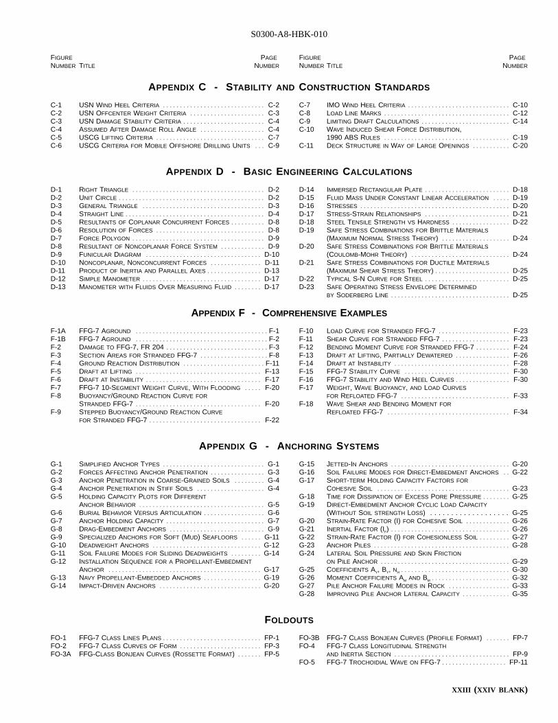
S0300-A8-HBK-010
FIGURE PAGE
NUMBER TITLE NUMBER
FIGURE PAGE
NUMBER TITLE NUMBER
APPENDIX C - STABILITY AND CONSTRUCTION STANDARDS
C-1 USN WIND HEEL CRITERIA . . . . . . . . . . . . . . . . . . . . . . . . . . . . . . C-2C-2 USN OFFCENTER WEIGHT CRITERIA . . . . . . . . . . . . . . . . . . . . . . C-3C-3 USN DAMAGE STABILITY CRITERIA . . . . . . . . . . . . . . . . . . . . . . . . C-4C-4 ASSUMED AFTER DAMAGE ROLL ANGLE . . . . . . . . . . . . . . . . . . . C-4C-5 USCG LIFTING CRITERIA . . . . . . . . . . . . . . . . . . . . . . . . . . . . . . . . C-7C-6 USCG CRITERIA FOR MOBILE OFFSHORE DRILLING UNITS . . . C-9
C-7 IMO WIND HEEL CRITERIA . . . . . . . . . . . . . . . . . . . . . . . . . . . . . . C-10C-8 LOAD LINE MARKS . . . . . . . . . . . . . . . . . . . . . . . . . . . . . . . . . . . . . C-12C-9 LIMITING DRAFT CALCULATIONS . . . . . . . . . . . . . . . . . . . . . . . . . . C-14C-10 WAVE INDUCED SHEAR FORCE DISTRIBUTION,
1990 ABS RULES . . . . . . . . . . . . . . . . . . . . . . . . . . . . . . . . . . . . . C-19C-11 DECK STRUCTURE IN WAY OF LARGE OPENINGS . . . . . . . . . . . C-20
APPENDIX D - BASIC ENGINEERING CALCULATIONS
D-1 RIGHT TRIANGLE . . . . . . . . . . . . . . . . . . . . . . . . . . . . . . . . . . . . . . . D-2D-2 UNIT CIRCLE . . . . . . . . . . . . . . . . . . . . . . . . . . . . . . . . . . . . . . . . . . . D-2D-3 GENERAL TRIANGLE . . . . . . . . . . . . . . . . . . . . . . . . . . . . . . . . . . . . D-3D-4 STRAIGHT LINE . . . . . . . . . . . . . . . . . . . . . . . . . . . . . . . . . . . . . . . . . D-4D-5 RESULTANTS OF COPLANAR CONCURRENT FORCES . . . . . . . . . . D-8D-6 RESOLUTION OF FORCES . . . . . . . . . . . . . . . . . . . . . . . . . . . . . . . . D-8D-7 FORCE POLYGON . . . . . . . . . . . . . . . . . . . . . . . . . . . . . . . . . . . . . . . D-9D-8 RESULTANT OF NONCOPLANAR FORCE SYSTEM . . . . . . . . . . . . . D-9D-9 FUNICULAR DIAGRAM . . . . . . . . . . . . . . . . . . . . . . . . . . . . . . . . . . D-10D-10 NONCOPLANAR, NONCONCURRENT FORCES . . . . . . . . . . . . . . . D-11D-11 PRODUCT OF INERTIA AND PARALLEL AXES . . . . . . . . . . . . . . . . D-13D-12 SIMPLE MANOMETER . . . . . . . . . . . . . . . . . . . . . . . . . . . . . . . . . . . D-17D-13 MANOMETER WITH FLUIDS OVER MEASURING FLUID . . . . . . . . D-17
D-14 IMMERSED RECTANGULAR PLATE . . . . . . . . . . . . . . . . . . . . . . . . . D-18D-15 FLUID MASS UNDER CONSTANT LINEAR ACCELERATION . . . . . D-19D-16 STRESSES . . . . . . . . . . . . . . . . . . . . . . . . . . . . . . . . . . . . . . . . . . . . D-20D-17 STRESS-STRAIN RELATIONSHIPS . . . . . . . . . . . . . . . . . . . . . . . . . D-21D-18 STEEL TENSILE STRENGTH VS HARDNESS . . . . . . . . . . . . . . . . . D-22D-19 SAFE STRESS COMBINATIONS FOR BRITTLE MATERIALS
(MAXIMUM NORMAL STRESS THEORY)I . . . . . . . . . . . . . . . . . . . . D-24D-20 SAFE STRESS COMBINATIONS FOR BRITTLE MATERIALS
(COULOMB-MOHR THEORY)I . . . . . . . . . . . . . . . . . . . . . . . . . . . . . D-24D-21 SAFE STRESS COMBINATIONS FOR DUCTILE MATERIALS
(MAXIMUM SHEAR STRESS THEORY)I. . . . . . . . . . . . . . . . . . . . . . D-25D-22 TYPICAL S-N CURVE FOR STEEL . . . . . . . . . . . . . . . . . . . . . . . . . D-25D-23 SAFE OPERATING STRESS ENVELOPE DETERMINED
BY SODERBERG LINE . . . . . . . . . . . . . . . . . . . . . . . . . . . . . . . . . . . D-25
APPENDIX F - COMPREHENSIVE EXAMPLES
F-1A FFG-7 AGROUND . . . . . . . . . . . . . . . . . . . . . . . . . . . . . . . . . . . . . . . F-1F-1B FFG-7 AGROUND . . . . . . . . . . . . . . . . . . . . . . . . . . . . . . . . . . . . . . . F-2F-2 DAMAGE TO FFG-7, FR 204I . . . . . . . . . . . . . . . . . . . . . . . . . . . . . . F-3F-3 SECTION AREAS FOR STRANDED FFG-7I . . . . . . . . . . . . . . . . . . . . F-8F-4 GROUND REACTION DISTRIBUTION . . . . . . . . . . . . . . . . . . . . . . . . F-11F-5 DRAFT AT LIFTING . . . . . . . . . . . . . . . . . . . . . . . . . . . . . . . . . . . . . F-13F-6 DRAFT AT INSTABILITY . . . . . . . . . . . . . . . . . . . . . . . . . . . . . . . . . . F-17F-7 FFG-7 10-SEGMENT WEIGHT CURVE, WITH FLOODING . . . . . F-20F-8 BUOYANCY/GROUND REACTION CURVE FOR
STRANDED FFG-7I . . . . . . . . . . . . . . . . . . . . . . . . . . . . . . . . . . . . . F-20F-9 STEPPED BUOYANCY/GROUND REACTION CURVE
FOR STRANDED FFG-7I . . . . . . . . . . . . . . . . . . . . . . . . . . . . . . . . . F-22
F-10 LOAD CURVE FOR STRANDED FFG-7I . . . . . . . . . . . . . . . . . . . . . F-23F-11 SHEAR CURVE FOR STRANDED FFG-7I . . . . . . . . . . . . . . . . . . . . F-23F-12 BENDING MOMENT CURVE FOR STRANDED FFG-7I . . . . . . . . . . F-24F-13 DRAFT AT LIFTING, PARTIALLY DEWATERED . . . . . . . . . . . . . . . . F-26F-14 DRAFT AT INSTABILITY . . . . . . . . . . . . . . . . . . . . . . . . . . . . . . . . . . F-28F-15 FFG-7 STABILITY CURVE . . . . . . . . . . . . . . . . . . . . . . . . . . . . . . . F-30F-16 FFG-7 STABILITY AND WIND HEEL CURVES . . . . . . . . . . . . . . . . F-30F-17 WEIGHT, WAVE BUOYANCY, AND LOAD CURVES
FOR REFLOATED FFG-7I . . . . . . . . . . . . . . . . . . . . . . . . . . . . . . . . F-33F-18 WAVE SHEAR AND BENDING MOMENT FOR
REFLOATED FFG-7I . . . . . . . . . . . . . . . . . . . . . . . . . . . . . . . . . . . . F-34
APPENDIX G - ANCHORING SYSTEMS
G-1 SIMPLIFIED ANCHOR TYPES . . . . . . . . . . . . . . . . . . . . . . . . . . . . . . G-1G-2 FORCES AFFECTING ANCHOR PENETRATION . . . . . . . . . . . . . . . . G-3G-3 ANCHOR PENETRATION IN COARSE-GRAINED SOILS . . . . . . . . . G-4G-4 ANCHOR PENETRATION IN STIFF SOILS . . . . . . . . . . . . . . . . . . . . G-4G-5 HOLDING CAPACITY PLOTS FOR DIFFERENT
ANCHOR BEHAVIOR . . . . . . . . . . . . . . . . . . . . . . . . . . . . . . . . . . . . . G-5G-6 BURIAL BEHAVIOR VERSUS ARTICULATION . . . . . . . . . . . . . . . . . . G-6G-7 ANCHOR HOLDING CAPACITY . . . . . . . . . . . . . . . . . . . . . . . . . . . . . G-7G-8 DRAG-EMBEDMENT ANCHORS . . . . . . . . . . . . . . . . . . . . . . . . . . . . G-9G-9 SPECIALIZED ANCHORS FOR SOFT (MUD) SEAFLOORS . . . . . . G-11G-10 DEADWEIGHT ANCHORS . . . . . . . . . . . . . . . . . . . . . . . . . . . . . . . . G-12G-11 SOIL FAILURE MODES FOR SLIDING DEADWEIGHTS . . . . . . . . . G-14G-12 INSTALLATION SEQUENCE FOR A PROPELLANT-EMBEDMENT
ANCHOR . . . . . . . . . . . . . . . . . . . . . . . . . . . . . . . . . . . . . . . . . . . . . G-17G-13 NAVY PROPELLANT-EMBEDDED ANCHORS . . . . . . . . . . . . . . . . . G-19G-14 IMPACT-DRIVEN ANCHORS . . . . . . . . . . . . . . . . . . . . . . . . . . . . . . G-20
G-15 JETTED-IN ANCHORS . . . . . . . . . . . . . . . . . . . . . . . . . . . . . . . . . . . G-20G-16 SOIL FAILURE MODES FOR DIRECT-EMBEDMENT ANCHORS . . G-22G-17 SHORT-TERM HOLDING CAPACITY FACTORS FOR
COHESIVE SOIL . . . . . . . . . . . . . . . . . . . . . . . . . . . . . . . . . . . . . . . G-23G-18 TIME FOR DISSIPATION OF EXCESS PORE PRESSURE . . . . . . . . G-25G-19 DIRECT-EMBEDMENT ANCHOR CYCLIC LOAD CAPACITY
(WITHOUT SOIL STRENGTH LOSS) . . . . . . . . . . . . . . . . . . . G-25G-20 STRAIN-RATE FACTOR (I) FOR COHESIVE SOIL . . . . . . . . . . . . . G-26G-21 INERTIAL FACTOR (IF)I . . . . . . . . . . . . . . . . . . . . . . . . . . . . . . . . . . . G-26G-22 STRAIN-RATE FACTOR (I) FOR COHESIONLESS SOIL . . . . . . . . . G-27G-23 ANCHOR PILES . . . . . . . . . . . . . . . . . . . . . . . . . . . . . . . . . . . . . . . . G-28G-24 LATERAL SOIL PRESSURE AND SKIN FRICTION
ON PILE ANCHOR . . . . . . . . . . . . . . . . . . . . . . . . . . . . . . . . . . . . . . G-29G-25 COEFFICIENTS AY, BY, NHI. . . . . . . . . . . . . . . . . . . . . . . . . . . . . . . . G-30G-26 MOMENT COEFFICIENTS AM AND BMI. . . . . . . . . . . . . . . . . . . . . . . G-32G-27 PILE ANCHOR FAILURE MODES IN ROCK . . . . . . . . . . . . . . . . . . G-33G-28 IMPROVING PILE ANCHOR LATERAL CAPACITY . . . . . . . . . . . . . . G-35
FOLDOUTS
FO-1 FFG-7 CLASS LINES PLANS . . . . . . . . . . . . . . . . . . . . . . . . . . . . . FP-1FO-2 FFG-7 CLASS CURVES OF FORM . . . . . . . . . . . . . . . . . . . . . . . . FP-3FO-3A FFG-CLASS BONJEAN CURVES (ROSSETTE FORMAT)I . . . . . . . FP-5
FO-3B FFG-7 CLASS BONJEAN CURVES (PROFILE FORMAT)I . . . . . . . FP-7FO-4 FFG-7 CLASS LONGITUDINAL STRENGTH
AND INERTIA SECTION . . . . . . . . . . . . . . . . . . . . . . . . . . . . . . . . . . FP-9FO-5 FFG-7 TROCHOIDIAL WAVE ON FFG-7I. . . . . . . . . . . . . . . . . . . FP-11
XXIII (XXIV BLANK )
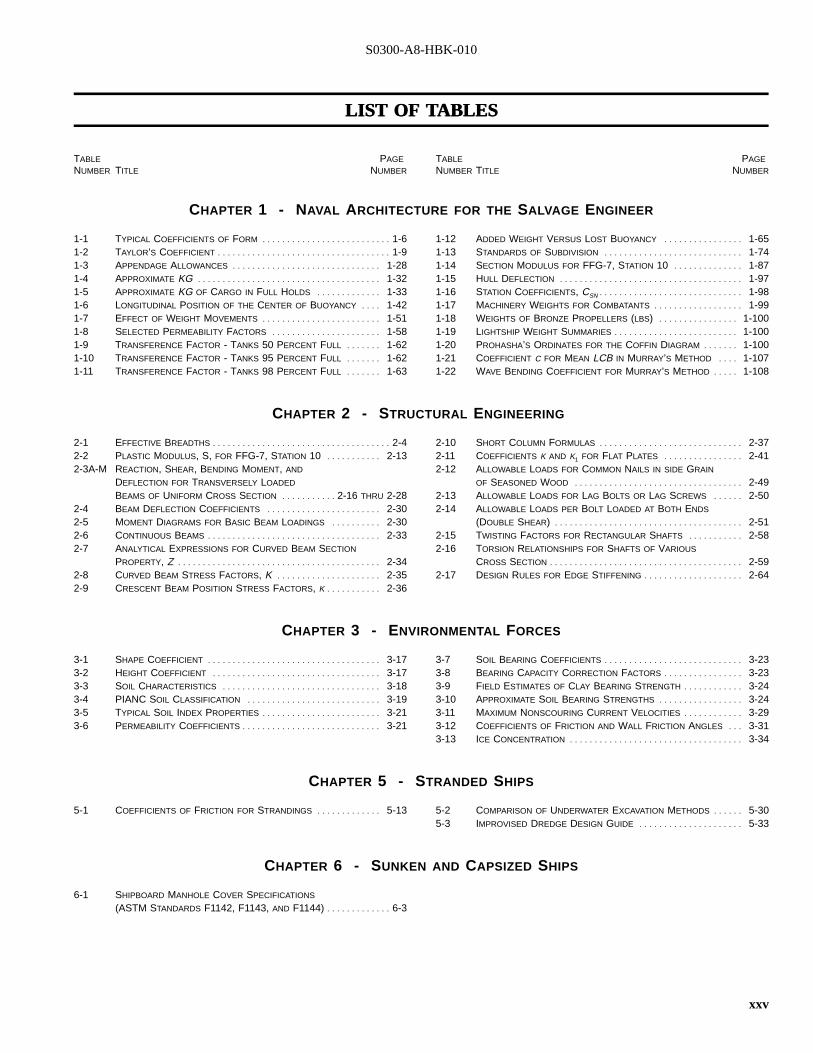
S0300-A8-HBK-010
LISTLIST OFOF TTABLESABLES
TABLE PAGE
NUMBER TITLE NUMBER
TABLE PAGE
NUMBER TITLE NUMBER
CHAPTER 1 - NAVAL ARCHITECTURE FOR THE SALVAGE ENGINEER
1-1 TYPICAL COEFFICIENTS OF FORM . . . . . . . . . . . . . . . . . . . . . . . . . . 1-61-2 TAYLOR’S COEFFICIENT . . . . . . . . . . . . . . . . . . . . . . . . . . . . . . . . . . . 1-91-3 APPENDAGE ALLOWANCES . . . . . . . . . . . . . . . . . . . . . . . . . . . . . . 1-281-4 APPROXIMATE KGI . . . . . . . . . . . . . . . . . . . . . . . . . . . . . . . . . . . . . 1-321-5 APPROXIMATE KG OF CARGO IN FULL HOLDS . . . . . . . . . . . . . 1-331-6 LONGITUDINAL POSITION OF THE CENTER OF BUOYANCY . . . . 1-421-7 EFFECT OF WEIGHT MOVEMENTS . . . . . . . . . . . . . . . . . . . . . . . . 1-511-8 SELECTED PERMEABILITY FACTORS . . . . . . . . . . . . . . . . . . . . . . 1-581-9 TRANSFERENCE FACTOR - TANKS 50 PERCENT FULL . . . . . . . 1-621-10 TRANSFERENCE FACTOR - TANKS 95 PERCENT FULL . . . . . . . 1-621-11 TRANSFERENCE FACTOR - TANKS 98 PERCENT FULL . . . . . . . 1-63
1-12 ADDED WEIGHT VERSUS LOST BUOYANCY . . . . . . . . . . . . . . . . 1-651-13 STANDARDS OF SUBDIVISION . . . . . . . . . . . . . . . . . . . . . . . . . . . . 1-741-14 SECTION MODULUS FOR FFG-7, STATION 10I . . . . . . . . . . . . . . 1-871-15 HULL DEFLECTION . . . . . . . . . . . . . . . . . . . . . . . . . . . . . . . . . . . . . 1-971-16 STATION COEFFICIENTS, CSNI. . . . . . . . . . . . . . . . . . . . . . . . . . . . . 1-981-17 MACHINERY WEIGHTS FOR COMBATANTS . . . . . . . . . . . . . . . . . . 1-991-18 WEIGHTS OF BRONZE PROPELLERS (LBS)I . . . . . . . . . . . . . . . . 1-1001-19 LIGHTSHIP WEIGHT SUMMARIES . . . . . . . . . . . . . . . . . . . . . . . . . 1-1001-20 PROHASHA’S ORDINATES FOR THE COFFIN DIAGRAM . . . . . . . 1-1001-21 COEFFICIENT C FOR MEAN LCB IN MURRAY’S METHOD . . . . 1-1071-22 WAVE BENDING COEFFICIENT FOR MURRAY’S METHOD . . . . . 1-108
CHAPTER 2 - STRUCTURAL ENGINEERING
2-1 EFFECTIVE BREADTHS . . . . . . . . . . . . . . . . . . . . . . . . . . . . . . . . . . . . 2-42-2 PLASTIC MODULUS, S, FOR FFG-7, STATION 10I . . . . . . . . . . . 2-132-3A-M REACTION, SHEAR, BENDING MOMENT, AND
DEFLECTION FOR TRANSVERSELY LOADED
BEAMS OF UNIFORM CROSS SECTION . . . . . . . . . . . 2-16 THRU 2-282-4 BEAM DEFLECTION COEFFICIENTS . . . . . . . . . . . . . . . . . . . . . . . 2-302-5 MOMENT DIAGRAMS FOR BASIC BEAM LOADINGS . . . . . . . . . . 2-302-6 CONTINUOUS BEAMS . . . . . . . . . . . . . . . . . . . . . . . . . . . . . . . . . . . 2-332-7 ANALYTICAL EXPRESSIONS FOR CURVED BEAM SECTION
PROPERTY, ZI . . . . . . . . . . . . . . . . . . . . . . . . . . . . . . . . . . . . . . . . . 2-342-8 CURVED BEAM STRESS FACTORS, KI . . . . . . . . . . . . . . . . . . . . . 2-352-9 CRESCENT BEAM POSITION STRESS FACTORS, KI. . . . . . . . . . . 2-36
2-10 SHORT COLUMN FORMULAS . . . . . . . . . . . . . . . . . . . . . . . . . . . . . 2-372-11 COEFFICIENTS K AND K1 FOR FLAT PLATES . . . . . . . . . . . . . . . . 2-412-12 ALLOWABLE LOADS FOR COMMON NAILS IN SIDE GRAIN
OF SEASONED WOOD . . . . . . . . . . . . . . . . . . . . . . . . . . . . . . . . . . 2-492-13 ALLOWABLE LOADS FOR LAG BOLTS OR LAG SCREWS . . . . . . 2-502-14 ALLOWABLE LOADS PER BOLT LOADED AT BOTH ENDS
(DOUBLE SHEAR)I . . . . . . . . . . . . . . . . . . . . . . . . . . . . . . . . . . . . . . 2-512-15 TWISTING FACTORS FOR RECTANGULAR SHAFTS . . . . . . . . . . . 2-582-16 TORSION RELATIONSHIPS FOR SHAFTS OF VARIOUS
CROSS SECTION . . . . . . . . . . . . . . . . . . . . . . . . . . . . . . . . . . . . . . . 2-592-17 DESIGN RULES FOR EDGE STIFFENING . . . . . . . . . . . . . . . . . . . . 2-64
CHAPTER 3 - ENVIRONMENTAL FORCES
3-1 SHAPE COEFFICIENT . . . . . . . . . . . . . . . . . . . . . . . . . . . . . . . . . . . 3-173-2 HEIGHT COEFFICIENT . . . . . . . . . . . . . . . . . . . . . . . . . . . . . . . . . . 3-173-3 SOIL CHARACTERISTICS . . . . . . . . . . . . . . . . . . . . . . . . . . . . . . . . 3-183-4 PIANC SOIL CLASSIFICATION . . . . . . . . . . . . . . . . . . . . . . . . . . . 3-193-5 TYPICAL SOIL INDEX PROPERTIES . . . . . . . . . . . . . . . . . . . . . . . . 3-213-6 PERMEABILITY COEFFICIENTS . . . . . . . . . . . . . . . . . . . . . . . . . . . . 3-21
3-7 SOIL BEARING COEFFICIENTS . . . . . . . . . . . . . . . . . . . . . . . . . . . . 3-233-8 BEARING CAPACITY CORRECTION FACTORS . . . . . . . . . . . . . . . . 3-233-9 FIELD ESTIMATES OF CLAY BEARING STRENGTH . . . . . . . . . . . . 3-243-10 APPROXIMATE SOIL BEARING STRENGTHS . . . . . . . . . . . . . . . . . 3-243-11 MAXIMUM NONSCOURING CURRENT VELOCITIES . . . . . . . . . . . . 3-293-12 COEFFICIENTS OF FRICTION AND WALL FRICTION ANGLES . . . 3-313-13 ICE CONCENTRATION . . . . . . . . . . . . . . . . . . . . . . . . . . . . . . . . . . . 3-34
CHAPTER 5 - STRANDED SHIPS
5-1 COEFFICIENTS OF FRICTION FOR STRANDINGS . . . . . . . . . . . . . 5-13 5-2 COMPARISON OF UNDERWATER EXCAVATION METHODS . . . . . . 5-305-3 IMPROVISED DREDGE DESIGN GUIDE . . . . . . . . . . . . . . . . . . . . . 5-33
CHAPTER 6 - SUNKEN AND CAPSIZED SHIPS
6-1 SHIPBOARD MANHOLE COVER SPECIFICATIONS
(ASTM STANDARDS F1142, F1143, AND F1144)I. . . . . . . . . . . . . 6-3
xxv
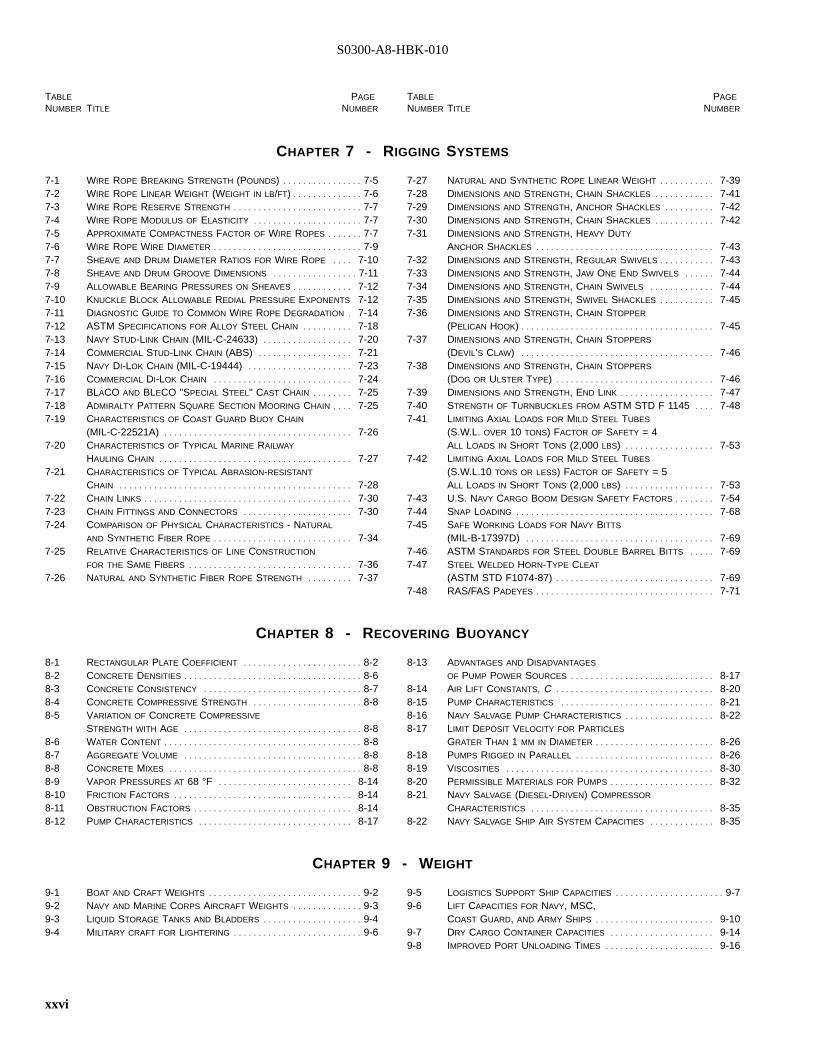
S0300-A8-HBK-010
TABLE PAGE
NUMBER TITLE NUMBER
TABLE PAGE
NUMBER TITLE NUMBER
CHAPTER 7 - RIGGING SYSTEMS
7-1 WIRE ROPE BREAKING STRENGTH (POUNDS)I . . . . . . . . . . . . . . . . 7-57-2 WIRE ROPE LINEAR WEIGHT (WEIGHT IN LB/FT)I. . . . . . . . . . . . . . 7-67-3 WIRE ROPE RESERVE STRENGTH . . . . . . . . . . . . . . . . . . . . . . . . . . 7-77-4 WIRE ROPE MODULUS OF ELASTICITY . . . . . . . . . . . . . . . . . . . . . . 7-77-5 APPROXIMATE COMPACTNESS FACTOR OF WIRE ROPES . . . . . . . 7-77-6 WIRE ROPE WIRE DIAMETER . . . . . . . . . . . . . . . . . . . . . . . . . . . . . . 7-97-7 SHEAVE AND DRUM DIAMETER RATIOS FOR WIRE ROPE . . . . 7-107-8 SHEAVE AND DRUM GROOVE DIMENSIONS . . . . . . . . . . . . . . . . . 7-117-9 ALLOWABLE BEARING PRESSURES ON SHEAVES . . . . . . . . . . . . 7-127-10 KNUCKLE BLOCK ALLOWABLE REDIAL PRESSURE EXPONENTS 7-127-11 DIAGNOSTIC GUIDE TO COMMON WIRE ROPE DEGRADATION . 7-147-12 ASTM SPECIFICATIONS FOR ALLOY STEEL CHAIN . . . . . . . . . . 7-187-13 NAVY STUD-LINK CHAIN (MIL-C-24633)I . . . . . . . . . . . . . . . . . . 7-207-14 COMMERCIAL STUD-LINK CHAIN (ABS)I . . . . . . . . . . . . . . . . . . . 7-217-15 NAVY DI-LOK CHAIN (MIL-C-19444)I . . . . . . . . . . . . . . . . . . . . . 7-237-16 COMMERCIAL DI-LOK CHAIN . . . . . . . . . . . . . . . . . . . . . . . . . . . . 7-247-17 BLACO AND BLECO "SPECIAL STEEL" CAST CHAIN . . . . . . . . 7-257-18 ADMIRALTY PATTERN SQUARE SECTION MOORING CHAIN . . . . 7-257-19 CHARACTERISTICS OF COAST GUARD BUOY CHAIN
(MIL-C-22521A)I . . . . . . . . . . . . . . . . . . . . . . . . . . . . . . . . . . . . . . 7-267-20 CHARACTERISTICS OF TYPICAL MARINE RAILWAY
HAULING CHAIN . . . . . . . . . . . . . . . . . . . . . . . . . . . . . . . . . . . . . . . 7-277-21 CHARACTERISTICS OF TYPICAL ABRASION-RESISTANT
CHAIN . . . . . . . . . . . . . . . . . . . . . . . . . . . . . . . . . . . . . . . . . . . . . . . 7-287-22 CHAIN LINKS . . . . . . . . . . . . . . . . . . . . . . . . . . . . . . . . . . . . . . . . . . 7-307-23 CHAIN FITTINGS AND CONNECTORS . . . . . . . . . . . . . . . . . . . . . . 7-307-24 COMPARISON OF PHYSICAL CHARACTERISTICS - NATURAL
AND SYNTHETIC FIBER ROPE . . . . . . . . . . . . . . . . . . . . . . . . . . . . 7-347-25 RELATIVE CHARACTERISTICS OF LINE CONSTRUCTION
FOR THE SAME FIBERS . . . . . . . . . . . . . . . . . . . . . . . . . . . . . . . . . 7-367-26 NATURAL AND SYNTHETIC FIBER ROPE STRENGTH . . . . . . . . . 7-37
7-27 NATURAL AND SYNTHETIC ROPE LINEAR WEIGHT . . . . . . . . . . . 7-397-28 DIMENSIONS AND STRENGTH, CHAIN SHACKLES . . . . . . . . . . . . 7-417-29 DIMENSIONS AND STRENGTH, ANCHOR SHACKLES . . . . . . . . . . 7-427-30 DIMENSIONS AND STRENGTH, CHAIN SHACKLES . . . . . . . . . . . . 7-427-31 DIMENSIONS AND STRENGTH, HEAVY DUTY
ANCHOR SHACKLES . . . . . . . . . . . . . . . . . . . . . . . . . . . . . . . . . . . . 7-437-32 DIMENSIONS AND STRENGTH, REGULAR SWIVELS . . . . . . . . . . . 7-437-33 DIMENSIONS AND STRENGTH, JAW ONE END SWIVELS . . . . . . 7-447-34 DIMENSIONS AND STRENGTH, CHAIN SWIVELS . . . . . . . . . . . . . 7-447-35 DIMENSIONS AND STRENGTH, SWIVEL SHACKLES . . . . . . . . . . . 7-457-36 DIMENSIONS AND STRENGTH, CHAIN STOPPER
(PELICAN HOOK)I. . . . . . . . . . . . . . . . . . . . . . . . . . . . . . . . . . . . . . . 7-457-37 DIMENSIONS AND STRENGTH, CHAIN STOPPERS
(DEVIL’S CLAW)I . . . . . . . . . . . . . . . . . . . . . . . . . . . . . . . . . . . . . . . 7-467-38 DIMENSIONS AND STRENGTH, CHAIN STOPPERS
(DOG OR ULSTER TYPE)I . . . . . . . . . . . . . . . . . . . . . . . . . . . . . . . . 7-467-39 DIMENSIONS AND STRENGTH, END LINK . . . . . . . . . . . . . . . . . . . 7-477-40 STRENGTH OF TURNBUCKLES FROM ASTM STD F 1145I . . . . 7-487-41 LIMITING AXIAL LOADS FOR MILD STEEL TUBES
(S.W.L. OVER 10 TONS) FACTOR OF SAFETY = 4ALL LOADS IN SHORT TONS (2,000 LBS)I . . . . . . . . . . . . . . . . . . 7-53
7-42 LIMITING AXIAL LOADS FOR MILD STEEL TUBES
(S.W.L.10 TONS OR LESS) FACTOR OF SAFETY = 5ALL LOADS IN SHORT TONS (2,000 LBS)I . . . . . . . . . . . . . . . . . . 7-53
7-43 U.S. NAVY CARGO BOOM DESIGN SAFETY FACTORS . . . . . . . . 7-547-44 SNAP LOADING . . . . . . . . . . . . . . . . . . . . . . . . . . . . . . . . . . . . . . . . 7-687-45 SAFE WORKING LOADS FOR NAVY BITTS
(MIL-B-17397D)I . . . . . . . . . . . . . . . . . . . . . . . . . . . . . . . . . . . . . . 7-697-46 ASTM STANDARDS FOR STEEL DOUBLE BARREL BITTS . . . . . 7-697-47 STEEL WELDED HORN-TYPE CLEAT
(ASTM STD F1074-87)I . . . . . . . . . . . . . . . . . . . . . . . . . . . . . . . . 7-697-48 RAS/FAS PADEYES . . . . . . . . . . . . . . . . . . . . . . . . . . . . . . . . . . . . 7-71
CHAPTER 8 - RECOVERING BUOYANCY
8-1 RECTANGULAR PLATE COEFFICIENT . . . . . . . . . . . . . . . . . . . . . . . . 8-28-2 CONCRETE DENSITIES . . . . . . . . . . . . . . . . . . . . . . . . . . . . . . . . . . . . 8-68-3 CONCRETE CONSISTENCY . . . . . . . . . . . . . . . . . . . . . . . . . . . . . . . . 8-78-4 CONCRETE COMPRESSIVE STRENGTH . . . . . . . . . . . . . . . . . . . . . . 8-88-5 VARIATION OF CONCRETE COMPRESSIVE
STRENGTH WITH AGE . . . . . . . . . . . . . . . . . . . . . . . . . . . . . . . . . . . . 8-88-6 WATER CONTENT . . . . . . . . . . . . . . . . . . . . . . . . . . . . . . . . . . . . . . . . 8-88-7 AGGREGATE VOLUME . . . . . . . . . . . . . . . . . . . . . . . . . . . . . . . . . . . . 8-88-8 CONCRETE MIXES . . . . . . . . . . . . . . . . . . . . . . . . . . . . . . . . . . . . . . . 8-88-9 VAPOR PRESSURES AT 68 °FI . . . . . . . . . . . . . . . . . . . . . . . . . . . 8-148-10 FRICTION FACTORS . . . . . . . . . . . . . . . . . . . . . . . . . . . . . . . . . . . . 8-148-11 OBSTRUCTION FACTORS . . . . . . . . . . . . . . . . . . . . . . . . . . . . . . . . 8-148-12 PUMP CHARACTERISTICS . . . . . . . . . . . . . . . . . . . . . . . . . . . . . . . 8-17
8-13 ADVANTAGES AND DISADVANTAGES
OF PUMP POWER SOURCES . . . . . . . . . . . . . . . . . . . . . . . . . . . . . 8-178-14 AIR LIFT CONSTANTS, CI . . . . . . . . . . . . . . . . . . . . . . . . . . . . . . . . 8-208-15 PUMP CHARACTERISTICS . . . . . . . . . . . . . . . . . . . . . . . . . . . . . . . 8-218-16 NAVY SALVAGE PUMP CHARACTERISTICS . . . . . . . . . . . . . . . . . . 8-228-17 LIMIT DEPOSIT VELOCITY FOR PARTICLES
GRATER THAN 1 MM IN DIAMETER . . . . . . . . . . . . . . . . . . . . . . . . 8-268-18 PUMPS RIGGED IN PARALLEL . . . . . . . . . . . . . . . . . . . . . . . . . . . . 8-268-19 VISCOSITIES . . . . . . . . . . . . . . . . . . . . . . . . . . . . . . . . . . . . . . . . . . 8-308-20 PERMISSIBLE MATERIALS FOR PUMPS . . . . . . . . . . . . . . . . . . . . . 8-328-21 NAVY SALVAGE (DIESEL-DRIVEN) COMPRESSOR
CHARACTERISTICS . . . . . . . . . . . . . . . . . . . . . . . . . . . . . . . . . . . . . 8-358-22 NAVY SALVAGE SHIP AIR SYSTEM CAPACITIES . . . . . . . . . . . . . 8-35
CHAPTER 9 - WEIGHT
9-1 BOAT AND CRAFT WEIGHTS . . . . . . . . . . . . . . . . . . . . . . . . . . . . . . . 9-29-2 NAVY AND MARINE CORPS AIRCRAFT WEIGHTS . . . . . . . . . . . . . . 9-39-3 LIQUID STORAGE TANKS AND BLADDERS . . . . . . . . . . . . . . . . . . . . 9-49-4 MILITARY CRAFT FOR LIGHTERING . . . . . . . . . . . . . . . . . . . . . . . . . . 9-6
9-5 LOGISTICS SUPPORT SHIP CAPACITIES . . . . . . . . . . . . . . . . . . . . . . 9-79-6 LIFT CAPACITIES FOR NAVY, MSC,
COAST GUARD, AND ARMY SHIPS . . . . . . . . . . . . . . . . . . . . . . . . 9-109-7 DRY CARGO CONTAINER CAPACITIES . . . . . . . . . . . . . . . . . . . . . 9-149-8 IMPROVED PORT UNLOADING TIMES . . . . . . . . . . . . . . . . . . . . . . 9-16
xxvi
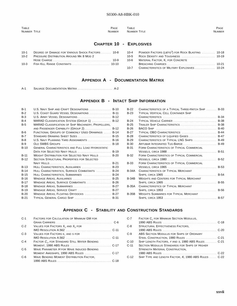
S0300-A8-HBK-010
TABLE PAGE
NUMBER TITLE NUMBER
TABLE PAGE
NUMBER TITLE NUMBER
CHAPTER 10 - EXPLOSIVES
10-1 DEGREE OF DAMAGE FOR VARIOUS SHOCK FACTORS . . . . . . . 10-810-2 PRESSURE DISTRIBUTION AROUND MK 8 MOD 2
HOSE CHARGE . . . . . . . . . . . . . . . . . . . . . . . . . . . . . . . . . . . . . . . . 10-910-3 FISH KILL RANGE CONSTANTS . . . . . . . . . . . . . . . . . . . . . . . . . . 10-10
10-4 POWDER FACTORS (LB/YD3) FOR ROCK BLASTING . . . . . . . . . 10-1810-5 ROCK DENSITY AND TOUGHNESS . . . . . . . . . . . . . . . . . . . . . . . 10-1910-6 MATERIAL FACTOR, K, FOR CONCRETE
BREACHING CHARGES . . . . . . . . . . . . . . . . . . . . . . . . . . . . . . . . . 10-2110-7 CHARACTERISTICS OF MILITARY EXPLOSIVES . . . . . . . . . . . . . . 10-24
APPENDIX A - DOCUMENTATION MATRIX
A-1 SALVAGE DOCUMENTATION MATRIX . . . . . . . . . . . . . . . . . . . . . . . . A-2
APPENDIX B - INTACT SHIP INFORMATION
B-1 U.S. NAVY SHIP AND CRAFT DESIGNATIONS . . . . . . . . . . . . . . . B-10B-2 U.S. COAST GUARD VESSEL DESIGNATIONS . . . . . . . . . . . . . . . B-11B-3 U.S. ARMY VESSEL DESIGNATIONS . . . . . . . . . . . . . . . . . . . . . . . B-12B-4 MARAD CLASSIFICATION SYSTEM (GROUP 1)I . . . . . . . . . . . . . B-12B-5 MARAD CLASSIFICATION OF SHIP MACHINERY, PROPELLERS,
AND PASSENGER CAPABILITY (GROUP 2)I . . . . . . . . . . . . . . . . . . B-12B-6 FUNCTIONAL GROUPS OF COMMONLY USED DRAWINGS . . . . . B-14B-7 STANDARD DRAWING SHEET SIZES . . . . . . . . . . . . . . . . . . . . . . . B-15B-8 U.S. NAVY PLANNING YARD ASSIGNMENTS . . . . . . . . . . . . . . . . B-16B-9 OLD SWBS GROUPS . . . . . . . . . . . . . . . . . . . . . . . . . . . . . . . . . . B-18B-10 GENERAL CHARACTERISTICS AND FULL LOAD HYDROSTATIC
DATA FOR SELECTED NAVY HULLS . . . . . . . . . . . . . . . . . . . . . . . B-19B-11 WEIGHT DISTRIBUTION FOR SELECTED NAVY HULLS . . . . . . . . B-20B-12 SECTION STRUCTURAL PROPERTIES FOR SELECTED
NAVY HULLS . . . . . . . . . . . . . . . . . . . . . . . . . . . . . . . . . . . . . . . . . . B-21B-13 HULL CHARACTERISTICS, AUXILIARIES . . . . . . . . . . . . . . . . . . . . B-23B-14 HULL CHARACTERISTICS, SURFACE COMBATANTS . . . . . . . . . . B-24B-15 HULL CHARACTERISTICS, SUBMARINES . . . . . . . . . . . . . . . . . . . B-24B-16 WINDAGE AREAS, AUXILIARIES . . . . . . . . . . . . . . . . . . . . . . . . . . B-25B-17 WINDAGE AREAS, SURFACE COMBATANTS . . . . . . . . . . . . . . . . . B-26B-18 WINDAGE AREAS, SUBMARINES . . . . . . . . . . . . . . . . . . . . . . . . . . B-27B-19 WINDAGE AREAS, SERVICE CRAFT . . . . . . . . . . . . . . . . . . . . . . . B-27B-20 WINDAGE AREAS, FLOATING DRYDOCKS . . . . . . . . . . . . . . . . . . B-27B-21 TYPICAL GENERAL CARGO SHIP . . . . . . . . . . . . . . . . . . . . . . . . . B-31
B-22 CHARACTERISTICS OF A TYPICAL THREE-HATCH SHIP . . . . . . . B-33B-23 TYPICAL VERTICAL CELL CONTAINER SHIP
CHARACTERISTICS . . . . . . . . . . . . . . . . . . . . . . . . . . . . . . . . . . . . . B-34B-24 TYPICAL VEHICLE CARRIER . . . . . . . . . . . . . . . . . . . . . . . . . . . . . . B-38B-25 TRAILER SHIP CHARACTERISTICS . . . . . . . . . . . . . . . . . . . . . . . . . B-38B-26 BACO SHIP . . . . . . . . . . . . . . . . . . . . . . . . . . . . . . . . . . . . . . . . . . B-40B-27 TYPICAL OBO CHARACTERISTICS . . . . . . . . . . . . . . . . . . . . . . . . B-44B-28 CHARACTERISTICS OF LIQUIFIED GASES . . . . . . . . . . . . . . . . . . . B-47B-29 CHARACTERISTICS OF TYPICAL LNG SHIPS . . . . . . . . . . . . . . . . B-49B-30 ARTUBAR INTEGRATED TUG-BARGE . . . . . . . . . . . . . . . . . . . . . . . B-49B-31 FORM CHARACTERISTICS OF TYPICAL COMMERCIAL
VESSELS, CIRCA 1988I . . . . . . . . . . . . . . . . . . . . . . . . . . . . . . . . . . B-51B-32 FORM CHARACTERISTICS OF TYPICAL COMMERCIAL
VESSELS, CIRCA 1980I . . . . . . . . . . . . . . . . . . . . . . . . . . . . . . . . . . B-52B-33 FORM CHARACTERISTICS OF TYPICAL COMMERCIAL
VESSELS, CIRCA 1965I . . . . . . . . . . . . . . . . . . . . . . . . . . . . . . . . . . B-53B-34A CHARACTERISTICS OF TYPICAL MERCHANT
SHIPS, CIRCA 1965I . . . . . . . . . . . . . . . . . . . . . . . . . . . . . . . . . . . . B-54B-34B WEIGHTS AND CENTERS FOR TYPICAL MERCHANT
SHIPS, CIRCA 1965I . . . . . . . . . . . . . . . . . . . . . . . . . . . . . . . . . . . . B-55B-35A CHARACTERISTICS OF TYPICAL MERCHANT
SHIPS, CIRCA 1953I . . . . . . . . . . . . . . . . . . . . . . . . . . . . . . . . . . . . B-56B-35B WEIGHTS SUMMARIES FOR TYPICAL MERCHANT
SHIPS, CIRCA 1953I . . . . . . . . . . . . . . . . . . . . . . . . . . . . . . . . . . . . B-57
APPENDIX C - STABILITY AND CONSTRUCTION STANDARDS
C-1 FACTORS FOR CALCULATION OF MINIMUM GM FOR
GRAIN CARRIERS . . . . . . . . . . . . . . . . . . . . . . . . . . . . . . . . . . . . . . . C-6C-2 VALUES FOR FACTORS X1 AND X2 FOR
IMO RESOLUTION A.562I . . . . . . . . . . . . . . . . . . . . . . . . . . . . . . . C-11C-3 VALUES FOR FACTORS K, AND S FOR
IMO RESOLUTION A.562I . . . . . . . . . . . . . . . . . . . . . . . . . . . . . . . C-11C-4 FACTOR CST FOR STANDARD STILL WATER BENDING
MOMENT, 1990 ABS RULES . . . . . . . . . . . . . . . . . . . . . . . . . . . . C-17C-5 WAVE PARAMETER H FOR WAVE INDUCED BENDING
MOMENT AMIDSHIPS, 1990 ABS RULES . . . . . . . . . . . . . . . . . . C-17C-6 WAVE BENDING MOMENT DISTRIBUTION FACTOR,
1990 ABS RULES . . . . . . . . . . . . . . . . . . . . . . . . . . . . . . . . . . . . . C-18
C-7 FACTOR C1 FOR MINIMUM SECTION MODULUS,1990 ABS RULES . . . . . . . . . . . . . . . . . . . . . . . . . . . . . . . . . . . . . C-18
C-8 STRUCTURAL EFFECTIVENESS FACTORS,1990 ABS RULES . . . . . . . . . . . . . . . . . . . . . . . . . . . . . . . . . . . . . C-20
C-9 ABS SECTION MODULUS FOR SHIPS OF ORDINARY
STEEL CONSTRUCTION, 1980 RULES . . . . . . . . . . . . . . . . . . . . . C-21C-10 SHIP LENGTH FACTORS, F AND S, 1980 ABS RULES . . . . . . . . C-21C-11 SECTION MODULUS STANDARDS FOR SHIPS OF HIGHER
STRENGTH MATERIAL CONSTRUCTION,1980 ABS RULES . . . . . . . . . . . . . . . . . . . . . . . . . . . . . . . . . . . . . C-22
C-12 SHIP TYPE AND LENGTH FACTOR, K, 1980 ABS RULES . . . . . C-22
xxvii
S0300-A8-HBK-010
TABLE PAGE
NUMBER TITLE NUMBER
TABLE PAGE
NUMBER TITLE NUMBER
APPENDIX D - BASIC ENGINEERING CALCULATIONS
D-1 FUNCTIONS OF RELATED ANGLES . . . . . . . . . . . . . . . . . . . . . . . . . D-2D-2 CONDITIONS OF EQUILIBRIUM . . . . . . . . . . . . . . . . . . . . . . . . . . . . D-11D-3 VISCOSITY UNITS . . . . . . . . . . . . . . . . . . . . . . . . . . . . . . . . . . . . . . D-15
D-4 VISCOSITY CONVERSIONS . . . . . . . . . . . . . . . . . . . . . . . . . . . . . . . D-15D-5 TYPICAL SURFACE TENSIONS (68 °F, AIR CONTACT)I . . . . . . . . D-16D-6 EQUIVALENT DIAMETERS . . . . . . . . . . . . . . . . . . . . . . . . . . . . . . . . D-20
APPENDIX E - BASIC ENGINEER’S TABLES
E-1 WATER FACTORS (AT POINT OF GREATEST
DENSITY - 39.2 °F)I . . . . . . . . . . . . . . . . . . . . . . . . . . . . . . . . . . . . . E-1E-2 TEMPERATURE AND PRESSURE EFFECTS
ON WATER DENSITY . . . . . . . . . . . . . . . . . . . . . . . . . . . . . . . . . . . . E-1E-3 MECHANICAL PROPERTIES OF STEEL AND ALUMINUM
ALLOY FOR NAVY SHIPS . . . . . . . . . . . . . . . . . . . . . . . . . . . . . . . . . E-2E-4 TYPICAL MECHANICAL CONSTANTS OF METALS . . . . . . . . . . . . . . E-2E-5 MECHANICAL PROPERTIES OF COMMERCIAL STEELS . . . . . . . . . E-3E-6 DIMENSIONS AND PROPERTIES OF W SHAPES . . . . . . . . . . . . . . E-5E-7 DIMENSIONS AND PROPERTIES OF STRUCTURAL
TEES CUT FROM W SHAPES (WT)I . . . . . . . . . . . . . . . . . . . . . . . . E-7E-8 DIMENSIONS AND PROPERTIES OF S SHAPES . . . . . . . . . . . . . . . E-8E-9 DIMENSIONS AND PROPERTIES OF STRUCTURAL
TEES CUT FROM S SHAPES (ST)I . . . . . . . . . . . . . . . . . . . . . . . . . E-9
E-10 DIMENSIONS AND PROPERTIES OF M SHAPES . . . . . . . . . . . . . . E-10E-11 DIMENSIONS AND PROPERTIES OF HP SHAPES . . . . . . . . . . . . . E-11E-12 DIMENSIONS AND PROPERTIES FOR AMERICAN
STANDARD CHANNELS (C-SHAPES)I . . . . . . . . . . . . . . . . . . . . . . . E-12E-13 DIMENSIONS AND PROPERTIES OF MISCELLANEOUS
(MC) CHANNELS . . . . . . . . . . . . . . . . . . . . . . . . . . . . . . . . . . . . . . E-13E-14 PROPERTIES OF EQUAL AND UNEQUAL LEG ANGLES
(L SHAPES)I . . . . . . . . . . . . . . . . . . . . . . . . . . . . . . . . . . . . . . . . . . . E-14E-15 WEIGHT AND GAGE OF STEEL PLATES . . . . . . . . . . . . . . . . . . . . E-15E-16 WEIGHT OF STEEL PLATES . . . . . . . . . . . . . . . . . . . . . . . . . . . . . . E-15E-17 STRUCTURAL TIMBER ALLOWABLE STRESSES . . . . . . . . . . . . . . E-16E-18 TIMBER SIZES FOR DESIGN . . . . . . . . . . . . . . . . . . . . . . . . . . . . . E-17E-19 DENSITIES . . . . . . . . . . . . . . . . . . . . . . . . . . . . . . . . . . . . . . . . . . . . E-18E-20 LIQUID DENSITIES . . . . . . . . . . . . . . . . . . . . . . . . . . . . . . . . . . . . . . E-21
APPENDIX G - ANCHORING SYSTEMS
G-1 COMPARISON OF ANCHOR TYPES . . . . . . . . . . . . . . . . . . . . . . . . . G-2G-2 ADVANTAGES AND DISADVANTAGES OF ANCHOR TYPES . . . . . . G-2G-3 POWER LAW COEFFICIENTS . . . . . . . . . . . . . . . . . . . . . . . . . . . . . . G-6G-4 ANCHOR SELECTION . . . . . . . . . . . . . . . . . . . . . . . . . . . . . . . . . . . . G-8G-5 RATING OF DRAG-EMBEDMENT ANCHOR TYPES . . . . . . . . . . . . . G-8G-6 COEFFICIENT OF FRICTION FOR DEADWEIGHT ANCHORS . . . . . G-13G-7 ADVANTAGES AND DISADVANTAGES OF DIRECT-EMBEDMENT
ANCHORS . . . . . . . . . . . . . . . . . . . . . . . . . . . . . . . . . . . . . . . . . . . . G-16G-8 PROPELLANT-EMBEDDED ANCHORS (PEA)I. . . . . . . . . . . . . . . . . G-17G-9 PEA CHARACTERISTICS AND PERFORMANCE . . . . . . . . . . . . . . G-18G-10 NCEL 20K PROPELLENT-EMBEDDED ANCHOR
TESTS IN ROCK . . . . . . . . . . . . . . . . . . . . . . . . . . . . . . . . . . . . . . . G-19
G-11 CONDITIONS COMPLICATING DIRECT-EMBEDMENT
ANCHOR USE . . . . . . . . . . . . . . . . . . . . . . . . . . . . . . . . . . . . . . . . . G-21G-12 SOIL STRENGTH REDUCTION FACTOR . . . . . . . . . . . . . . . . . . . . . G-22G-13 DIRECT-EMBEDMENT ANCHOR EFFECTS ON SUBMARINE
SLOPE STABILITY . . . . . . . . . . . . . . . . . . . . . . . . . . . . . . . . . . . . . . G-27G-14 PILE ANCHORS . . . . . . . . . . . . . . . . . . . . . . . . . . . . . . . . . . . . . . . . G-28G-15 RECOMMENDED LIMITING VALUES FOR UNIT SKIN FRICTION
AND END BEARING FOR COHESIONLESS SOILS . . . . . . . . . . . . . G-30G-16 BEARING CAPACITY FACTORS FOR CHAIN LATERAL
FORCE IN SAND . . . . . . . . . . . . . . . . . . . . . . . . . . . . . . . . . . . . . . . G-33G-17 COMPRESSIVE STRENGTH OF ROCK . . . . . . . . . . . . . . . . . . . . . . G-34
xxviii
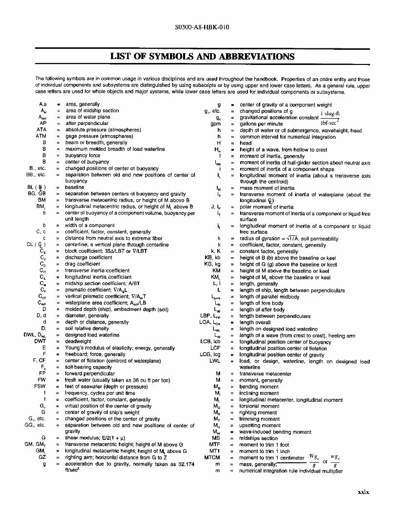
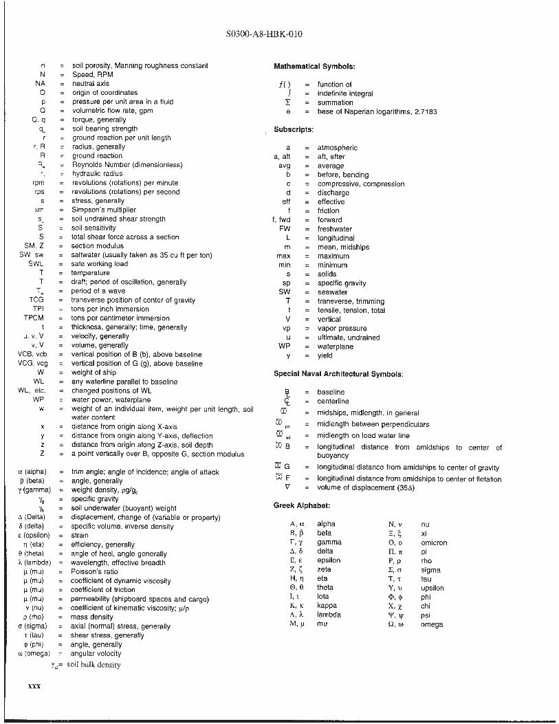

S0300-A8-HBK-010
Abbreviations for References :
ABS American Bureau of ShippingAISC American Institute of Steel ConstructionAISI American Iron and Steel InstituteAPI American Petroleum InstituteASCE American Society of Civil EngineersASME American Society of Mechanical EngineersASNE American Society of Naval EngineersASTM American Society for Testing of MaterialsBUSHIPS Bureau of Ships, now Naval Sea Systems CommandCFR U.S. Code of Federal RegulationsDM Design Manual (NAVFAC)DDS Design Data SheetFM Field ManualGENSPECs General Specifications for Ships of the United States
NavyIMCO International Maritime Consultative Organization, now
IMOIMO International Maritime Organization(R) INA (Royal) Institution of Naval ArchitectsNAVSEA Naval Sea Systems CommandNAVSHIPS Naval Ship Systems CommandNAVFAC Naval Facilities Engineering CommandNSTM Naval Ships Technical ManualOCIMF Oil Companies International Marine ForumSDS Ship Design StandardSAE Society of Automotive EngineersSNAME Society of Naval Architects and Marine EngineersTM Technical ManualUSC United States CodeUWSHM Underwater Ship Husbandry Manual
Other Abbreviations:
BHP Brake HorsepowerBS&W Bottom Sediment and WaterCB Center of BuoyancyCFM Cubic Feet per MinuteCG Center of GravityEHP Effective horsepowerEOD Explosive Ordnance DisposalESSM Emergency Ship salvage MaterialFC Fiber CoreFSW Feet of SeawaterGPM Gallons per MinuteHGPS High Grade Plow SteelIHP Indicated horsepower, installed horsepowerIPS Improved Plowed SteelIWRC Independent Wire Rope CoreLEL Lower Explosive LevelMARAD Maritime AdministrationNAVSEA 00C Naval Sea Systems Command, Director of Ocean
Engineering and Supervisor of SalvageNCEL Naval Civil Engineering LaboratoryNOAA National Oceanographic and Atmospheric
AdministrationNOS National Ocean ServiceNOSC Naval On-Scene CoordinatorNOSCDR Naval On-Scene CommanderNPSHA Net Positive Suction Head AvailableNPSHR Net Positive Suction Head RequiredPMS Preventive Maintenance SystemPOL Petroleum, Oil, and LubricantsPPM Parts per MillionPSI Pounds Per Square InchRPM Revolutions Per MinuteSCF Standard Cubic FeetSCFM Standard Cubic Feet per MinuteSHCP Ship Hull Characteristics ProgramSITREP Situational ReportSHP Shaft HorsepowerSWL Safe Working LoadTDHA Total Dynamic Head AvailableTDHR Total Dynamic Head RequiredUEL Upper Explosive LevelUSAV United States Army VesselUSCGC United States Coast Guard CutterUSNS United States Naval ShipUSS United States ShipWSC Wire Strand CoreXIPS, EIPS Extra Improved Plowed Steel
xxxi (xxxii blank)
S0300-A8-HBK-010
STANDARDSTANDARD NAVYNAVY SYNTAXSYNTAX SUMMARYSUMMARY
Since this manual will form the technical basis of many subsequent instructions or directives, it utilizes the standard Navy syntax as pertainsto permissive, advisory, and mandatory language. This is done to facilitate the use of the information provided herein as a reference for issuingFleet Directives. The concept of word usage and intended meaning which has been adhered to in preparing this manual is as follows:
"Shall" has been used only when application of a procedure is mandatory.
"Should" has been used only when application of a procedure is recommended.
"May" and "need not" have been used only when application of a procedure is discretionary.
"Will" has been used only to indicate futurity; never to indicate any degree of requirement for application of a procedure.
The usage of other words has been checked against other standard nautical and naval terminology references.
xxxiii (xxxiv blank)
S0300-A8-HBK-010
BIBLIOGRAPHYBIBLIOGRAPHY
SALVAGE AND TOWING
Baptist, C. N. T.,Salvage Operations, Stanford Maritime Ltd., 1979.
Accounts of several salvage operations highlighting unique salvage problems, techniques and skills.
Bartholomew, C. A.,Mud, Muscles, and Miracles, Naval History Center, 1990.
Comprehensive history of U.S. Navy marine salvage.
Blank, John, S., 3rd,Modern Towing,Cornell Maritime Press, 1989.
Brady, Edward M.,Marine Salvage Operations, Cornell Maritime Press, 1960.
Salvage practices pertaining to strandings and sinkings, salvage equipment and structures, and integration of naval architecture principles.
Clay, John S.Salvage of Stranded Tank Vessels with Computer Assistance, Department of Ocean Engineering, University of Rhode Island, 1983.
Describes modification of the Ship Hull Characteristics Program (SHCP), that assists modeling to determine probability of exceedinglongitudinal hull strength of stranded ships.
George, R. L., Quirk, John L.,Use of Magnets in Marine Salvage,NCEL Technical Report R583, 1968.
Explores the application of magnets to underwater work, concludes that magnets have uses in shallow water but are of little value indeep water salvage because of low payload/weight ratios.
Hancox, David,Reed’s Commercial Salvage Practice, Volumes 1 and 2, Thomas Reed Publications Ltd., 1987.
Encyclopedic treatment of practical casualty salvage and wreck removal.
NAVAIR 00-80R-19, NATOPS U.S. Navy Aircraft Crash and Salvage Operations Manual, 1989.
Salvage procedures, lift points, weights, and other pertinent details for U.S. Navy aircraft.
NAVSHIPS 250-880-5,Ship Salvage Operations, Miscellaneous Techniques, 1946.
Collection of ship salvage operations notes.
NAVSHIPS 250-631-2,Submarine Salvage – Pontoons and Related Equipment, Boston Naval Shipyard, 1964.
Description and operation of submarine salvage pontoons and other submarine salvage equipment.
Reid, George H.,Ship Handling with Tugs, Cornell Maritime Press, 1986.
Short practical guide to tug work.
Ship Salvage Notes, Parts 1 and 2, Naval Deep-Sea Diving School, Washington, D.C., 1960.
Student guide formerly used in salvage officer course of instruction.
TM 55-503,Marine Salvage and Hull Repair, Department of the Army, 1966.
Reference and training guide to salvage and repair of marine hulls and related equipment.
Bibliography-1Bibliography-1
S0300-A8-HBK-010
SALVAGE REPORTS
Boyd, J. H., Suez Canal SALVOPS in 1974, 1974.
Removal of ten large wrecks from the Suez Canal in seven months.
Commander Service Group THREE/Commander Task Force SEVENTY-THREE ltr 4740, ser 70-0172, of 16 Jun, 1966,SS EXCELLENCYSalvage Operations; report of.
Refloating of MSTS freighter stranded on Triton Island by pulling/wrenching with beach gear and tugs, and discharging 368 tons ofcargo into an LST.
"Marine Technology Society Journal," Second Quarter 1984.
Issue devoted to marine salvage, with reports of several operations.
Matich, M.A. J.,Burial of Wreck Obstructing the St. Lawrence Channel,N.Z. Engineering, 15 February 1969.
Soil Mechanics aspects of the successful disposal of a 527-foot ore carrier in the river bottom to below specified navigation clearance.
NAVSEA S0300-BJ-RPT-010,Commercial Aircraft Salvage Operations,10 February 1991.
Four aircraft recovery/salvage report overviews (KAL Flight 007, Air India Flight 182, South African Airways Flight 295, and UnitedAirlines Flight 811), illustrating the evolution of recovery/ salvage equipment and procedures.
NAVSEA SL740-AC-RPT-010/SUPSALV,USCGC MESQUITE Salvage Operation Dec. ’89-July ’90 Keweenaw Peninsula, Michigan,19 July1991.
Removal and disposal of 180-foot buoy tender from shallow water over a rock ledge. Details construction and employment of heavylift barge and preparations of wreck for lifting.
NAVSEA Supervisor of Salvage Report,USNS Chauvenet Salvage Report,1982.
Difficult refloating of AGOR stranded on steeply shelving coral reef; addresses solutions to stability problems and lack of suitable beachgear anchorages.
NAVSEA Supervisor of Salvage Report 84-06,EX-USS BLUEGILL Salvage Operations,1984.
GATO class submarine (WW II fleetboat) raised from 138 FSW on internal buoyancy with 8.4 ton salvage pontoon for added lift andcontrol.
NAVSEA SL740-AB-RPT-010/SUPSALV,Barge 45 Salvage Operations, Buffalo, N.Y. 1986,1988.
Removal and disposal of barge in heavy current in Niagara river. Calculations include hydrodynamic force prediction and ad hoc liftbarge design
NAVSEA T9597-AB-RPT-010/SUPSALV,EX-USS TORTUGA (LSD 26) Salvage Report,1989.
Removal and scuttling of large vessel from San Miguel Island. Details extensive topside weight removal and use of prototype ShipSalvage Engineering Program (SSEP).
NAVSEA T9597-AA-RPT-010/SUPSALV,Space Shuttle "Challenger" Salvage Report,1988.
Underwater search and salvage using manned and unmanned submersibles in a logistically complex operation.
NAVSEA 0994-016-7010/SUPSALV,"A. Mackenzie" Salvage Operation,1975.
Unique operation using "cut in place and lift" technique; report details solutions to difficulties encountered using explosives as a cuttingtechnique.
Bibliography-2Bibliography-2
S0300-A8-HBK-010
NAVSEA 0994-LP-017-4010/SUPSALV,SS "Sidney E. Smith, Jr." Salvage Operation,1976.
Removal of Great Lakes coal carrier from busy ship channel using cast-in-place foam.
NAVSEA 0994-LP-016-6010 through 6060, Salvops 69-70, 6 volumes, 1970-1975.
Annual summaries of significant salvage operations.
NAVSHIPS 250-880-21,Salvage of the USS LAFAYETTE (EX-SS NORMANDIE),1946.
Righting and refloating of large ocean liner in New York harbor. Details removal of superstructure, shoring, and pumping operations.
Petersen, Charles, C.,The Soviet Port Clearing Operation in Bangladesh, March 1972-April 1973,Center For Naval Analyses Memorandum,(CNA) 1406-73, 28 August 1973.
Analyses of Soviet port clearance and salvage capabilities as evidenced by operations in Bangladesh.
Whitaker, F. H., Captain, USN,The Salvage of USS "Oklahoma,"Transactions SNAME, Vol. 52, 1944.
Righting and refloating of battleship capsized and sunk by extensive torpedo damage at Pearl Harbor, HI, 7 December 1941.
DIVING AND UNDERWATER WORK
Hackman, Donald J. and Cardy, Donald W.,Underwater Tools, Battelle Press, 1981.
Guide to fabrication and design of underwater work systems.
Larn, Richard and Whistler, Rex,Commercial Diving Manual, David and Charles, 1984 basic diving procedures and underwater work techniquesfor construction, inspection, and maintenance.
NAVFAC P-990,Conventional Underwater Construction and Repair Techniques, not dated.
Guide for underwater construction team (UCT) conventional operations - based on UCT case histories and commercial practice.
NAVSEA P-991,Expedient Underwater Repair Techniques,not dated.
Guide for underwater construction team (UCT) repairs in contingencies. Companion volume to NAVFAC P-990.
NAVSEA 0994-LP-007-8010/8020,Underwater Inspection, Maintenance, and Repair of Naval Ships(Underwater Work Techniques Manual)Volumes 1 and 2, not dated.
Shallow water ship’s husbandry and equipment guide.
NAVSEA 0994-LP-001-9010,U.S. Navy Diving Manual, Vol. 1, AIR (REV 2), 1988.
Navy air diving procedures and requirements; discussions of physics, medicine, physiology operations planning, decompressionprocedures and tables, and recompression therapy. Addresses SCUBA, lightweight diving apparatus, MK 12 deep-sea diving dress.
NAVSEA 0994-LP-001-9020,U.S. Navy Diving Manual, Vol. 2, Mixed Gas Diving, Second Edition, 1977.
Continuation of Volume 1, detailing Navy mixed gas diving procedures and requirements; includes gas properties for use in diving,saturation diving theory and practice.
Bibliography-3Bibliography-3

S0300-A8-HBK-010
NAVSEA 50600-AA-PRO-010,Underwater Ship’s Husbandry Manual, 1988.
Information, techniques, and procedures for underwater inspection, maintenance, and repair of hulls and appendages of surface ships,submarines, and small craft. Completed chapters include:
1 Index and user’s guide2 General information and safety procedures3 Propellers4 Auxiliary Propulsion Units5 Master emitter belts6 Sonar systems
NOAA Diving Manual,National Oceanic and Atmospheric Administration, Manned Undersea Science And Technology Office, 1979.
Comprehensive treatment of diving and related technology as applied to scientific research.
Talkington, Howard R.,Undersea Work Systems, Naval Ocean Systems Center, San Diego, CA., 1981.
Fabrication and design of underwater work systems, including vehicles.
Tucker, Wayne C.,Diver’s Handbook of Underwater Calculations, Cornell Maritime Press, 1980.
Calculations and data commonly used in underwater work for divers and engineers.
NAVAL ARCHITECTURE
Lewis, E. V. (Editor),Principles of Naval Architecture, Society of Naval Architects and Marine Engineers (SNAME), Second Revision, 1988.
Standard reference of basic naval architecture calculations and methods.
Taggart, R. (Editor),Ship Design and Construction, Society of Naval Architects and Marine Engineers (SNAME), Second Edition, 1980.
Companion volume to PNA, addressing advanced topics.
Atwood, E. L. and Pengelly, H. S.,Theory of Naval Architecture, 1937.
Comprehensive text and reference by a recognized master of the subject. A "standard" reference.
Muckle, W., revised by Taylor, D. A.,Muckles Naval Architecture, Second Edition, Butterworths, 1987.
Fundamental principles and practices of naval architecture.
Gillmer, Thomas C. and Johnson, Bruce,Introduction to Naval Architecture, Naval Institute Press, 1987.
Fundamental text written for freshmen naval architecture students.
Rawson, K. J. and Tupper, E. C.,Basic Ship Theory, Volumes 1 and 2, Third Edition, Longman Inc., 1983.
Introductory naval architecture, including computer application and usage.
Pursey, H. J.,Merchant Ship Construction, Seventh Edition, Brown, Son, and Ferguson Ltd., 1975.
Illustrated discussion of construction and arrangement of ship structural components.
Manning, George C.,Manual of Ship Construction, D. Van Nostrand Company, Inc., 1942.
Fundamentals of naval architecture, ship construction, and shipyard practice.
Bibliography-4Bibliography-4
S0300-A8-HBK-010
White, G. W.,Elementary Beam Theory and the Ship Girder, Stanford Maritime Ltd., 1979.
Shipboard loading and discharging operations, strength of materials, ship girders, and problem solving by manual and automatedmethods.
NAVFAC DM 28, Design Manual: Weight Handling Equipment and Service Craft,1975.
Design data and operating procedures for heavy lift equipment on all types of platforms.
NAVSEA 0900-LP-097-4010,Structural Design Manual for Naval Surface Ships,15 Dec 1976.
Comprehensive steel and aluminum ship structure design manual.
PB 171471, NAVSHIPS 250-443-1,Manual of Properties of Combined Beam and Plate,Volumes 1 and 2.
Tabulated area, moment of inertia, and section modulus for various stiffener-plating combinations.
NAVSHIPS 250336,Wood: A Manual for It’s Use as a Shipbuilding Material,1957.
Wooden ship design and construction in four volumes.
NAVSHIPS ENGINEERING CENTER DESIGN DATA SHEETS
DDS 079-1, Stability and Buoyancy of U.S. Naval Surface Ships, 1975. NAVSEA design practice for stability and buoyancy.
DDS 100-1, Reinforcement of Openings in Structures of Surface Ships, Other Than In Protective Plating, 1984.
DDS 100-4, Strength of Structural Members, 1982. Uniform standards for design of structural members in compression and shear.
DDS 100-5, Strength of Glass Reinforced Plastic Structural Members.
DDS 100-6, Longitudinal Strength Calculation, 1987. Standard practice for longitudinal hull strength calculations and drawings (traditional staticbalance).
SHIP CHARACTERISTICS AND DATA
Classification society and regulatory body registers:
Lloyds Register of Shipping:
Register of Ships, annual – Ship name and former names, official number, Lloyds Register number, call sign, owners, managers, portof registry, tonnages, hull type/classification, builder and date and place of build, extreme and molded dimensions, construction details,hold and hatch dimensions and/or tank capacities, number and capacity of winches and cranes/derricks, machinery type and power,speed. Updated by monthly supplements and a "Weekly List of Alterations."
Register of Offshore Units, Submersibles and Diving Systems, annual – Data on mobile drilling rigs able to operate in at least 50 feetof water, submersibles, diving systems classed with or certified by Lloyds Register, and selected work units (ships, barges, and platformsemployed in offshore construction, pipelaying, heavy lifting, firefighting, and submersible/diving support). Sections cover units inexistence and under construction. Also included is a list of owners and managers with addresses, telex, telephone, and telefax numbers.
Maritime Guide, annual – Data on drydocks, gazetteer, maps, telegraphic addresses and telex numbers for shipbuilders, marine enginebuilders and boilermakers, shipbreakers, marine insurance companies, and marine associations.
U.S. Department of Transportation/U.S. Coast Guard:
Merchant Vessels of the United States, annual – Official U.S shipping register, including yachts, giving official number, name, call sign,hull type, tonnage, dimensions, place and year built, service, horsepower, name of owner, and home port. Updated by monthlysupplements.
Bibliography-5Bibliography-5
S0300-A8-HBK-010
Jane’s Publications (Jane’s Publishing Co. Ltd.):
Sharpe, Richard (Editor),Jane’s Fighting Ships, annual.
Descriptions of ships and major aircraft of the world’s navies with selected illustrations.
Trillo, Robert J. (Editor),Jane’s Ocean Technology, annual.
Compendium of data on manufacturers and operators of tugs, salvage vessels, submersibles, and offshore supply vessels. Includes vesselcharacteristics and operator addresses.
Other:
Polmar, Norman,Combat Fleets of the World, biennial, United States Naval Institute, 1978-79.
Similar in scope toJane’s Fighting Ships,with slightly less detail
ENGINEERING
Ocean, Coastal, and Marine Geotechnical Engineering:
Beer, Tom,Environmental Oceanography, Pergamon Press Inc., 1983
An introduction to coastal zone processes, including wave generation and decay, surf, current effects, and beach erosion/accretion.
Myers, John J., Holm, Carl H., McAllister, and Raymond F. (Editors),Handbook of Ocean and Underwater Engineering, McGraw-Hill BookCo., Inc., 1969.
Guidelines for design of systems and structures for over-water construction; written for engineers without ocean-related background
Rocker, Karl,Handbook for Marine Geotechnical Engineering, Naval Civil Engineering Lab, 1985.
Response of seafloor materials to foundation and mooring loads. Includes very comprehensive discussion of performance factors forall types of anchors.
Puech, A.,The Use of Anchors in Offshore Petroleum Operations, Gulf Publishing Company, 1984.
Excellent guide to drag anchor selection and employment. Descriptions and data for wide selection of commercial anchors.
CRC Practical Handbook of Marine Science, Chemical Rubber Company, 1990.
Reference data of physical, chemical and biological aspects of the ocean environment. Includes air-sea interactions and oceanengineering information.
Shore Protection Manual, Volumes 1 and 2, Fourth Edition, U. S. Army Coastal Engineering Research Center, 1984.
Volume 1 – analysis and solution of coastal design problems.Volume 2 – details of selected projects such as seawalls and breakwaters.
TM 5-360,Port Construction and Rehabilitation, Department of the Army, 1964.
Construction and rehabilitation of ship unloading and cargo handling facilities in theater of operations harbors; harbor clearance; portadministration
Huston, John,Hydraulic Dredging, Cornell Maritime Press, 1970.
Design, hydraulics, pipe friction and pump hydraulics related to hydraulic dredging.
Bibliography-6Bibliography-6
S0300-A8-HBK-010
Turner, Thomas M.,Fundamentals of Hydraulic Dredging, Cornell Maritime Press, 1984.
A noncalculus approach emphasizing hydraulic principles.
Herbich, John B.,Coastal and Deep Ocean Dredging, Gulf Publishing Company, 1975.
Theory of centrifugal pumps, dredge pump cavitation, head losses, and pipeline transport of solids.
Driscoll, Alan H. (Editor),Handbook of Oceanic Winch, Wire, and Cable Technology, Second Edition, 1989.
Comprehensive handbook encompassing most aspects of usage and safety of wire rope, winches, sheaves. Includes sections on Kevlar,fiber optics, coatings, testing, and calculation tables.
Vendrell, J.,The Oil Rig Moorings Handbook, Brown, Son and Ferguson, Ltd., 1985.
Anchoring and mooring systems for various rigs; details computer programs useful in catenary calculations.
API Recommended Practice 2P (RP2P),Analysis of Spread Mooring Systems for Floating Drilling Units, Second Edition, American PetroleumInstitute, 1987.
Design, and evaluation of spread mooring systems for floating drilling platforms.
Naval Facilities Engineering Command (NAVFAC) Design Manuals:
DM 25.1, Waterfront Operational Facilities,1971 – Design criteria for piers and wharves
DM 26.1, Harbors, (Change 1), 1984 – General planning criteria including functional layout and data sources.
DM 26.2,Coastal Protection,1982 – Principles of coastal structures with general planning and structural design criteria. Includes wavetheory and transformations.
DM 26.3, Dredging,1968 – Dredging project logistics for harbors, turning basins, and channels.
DM 26.4, Fixed Moorings,1986 – Guidelines for designing and loading fixed moorings.
DM 26.5,Fleet Moorings, Basic Criteria and Planning Guidelines,1985 – Criteria and planning guidelines with example calculationsfor design of fleet moorings.
DM 26.6,Mooring Design, Physical and Empirical Data,1986 – Vessel characteristics, strength and dimensions of anchors, buoy, chainand fittings.
Mechanical Engineering, Structures:
Parrish, A.,Mechanical Engineer’s Reference Book,Butterworths, 1973.
General reference mechanical engineering topics, with extensive tables and charts.
Karassik, Krutzsch, William C., Fraser, Warren H., and Messina, Joseph P. (Editors),Pump Handbook, Second Edition, McGraw-Hill BookCompany, 1985.
In-depth treatment of pump design, application, selection, and operation.
Syska, R. E. and Birk, J. R. (Editors),Pump Engineering Manual,The Duriron Company, Inc. 1983.
Compact guide to pump selection, installation and operation.
Mih, W. C., Chen, C. K. and Orsborn, J. F.,Bibliography of Solid-Liquid Transport in Pipelines,Albrook Hydraulic Laboratory College ofEngineering Research Division Washington State University, December 1971.
Bibliography with brief theoretical discussion of slurry transport.
Bibliography-7Bibliography-7

S0300-A8-HBK-010
Encyclopedia of Fluid Mechanics,Gulf Publishing Company, 1986.
Volume 1 – flow phenomena and measurementVolume 5 – slurry flow technologyVolume 6 – complex flow phenomena and modeling.
Avallone, Eugene A. and Baumeister, Theodore III (Editors),Marks’ Standard Handbook for Mechanical Engineers, Ninth Edition, McGraw-HillBook Company, 1987.
Encyclopedic reference of mechanical engineering and related disciplines.
Lindeberg, Michael R.,Mechanical Engineering Review Manual,Seventh Edition, Professional Publications, Inc., 1984.
A concise comprehensive review course for the professional engineer’s examination.
Manual of Steel Construction, Eighth Edition, American Institute of Steel Construction, Inc., 1980.
Detailed information on properties, design and specifications. Also math tables and other data on fabricated steel structures.
Levinson, Irving J.,Mechanics of Materials, Prentice-Hall Inc., 1970.
Concise, noncalculus treatment of the most common strength of materials problems.
Timoshenko, Stephen,Strength of Materials, Third Edition, Van Nostrand, 1956.
Comprehensive text by a recognized master of the subject. A "standard" reference.
Roark, R. J. and Young, W. C.,Formulas for Stress and Strain, Fifth Edition, McGraw-Hill, 1975.
Load response and stress, strain, and deflection relationships for common structural components, including beams, plates, cylinders,spheres, struts, etc.
NAVFAC DM 3, Design Manual: Mechanical Engineering,1972.
General shore-based guide covering plumbing, ventilation, vacuum, refrigeration, and air systems.
Civil Engineering, Soil and Rock Mechanics:
Krynine, Dimitri P.,Soil Mechanics,McGraw Hill Book Company, Inc., 1947.
Comprehensive and understandable text.
NAVFAC DM 5, Design Manual: Civil Engineering,1972.
Surveying, hydrology and hydraulics, pollution control systems.
NAVFAC DM 7, Design Manual: Soil Mechanics, Foundations, and Earth Structures,1971.
Soil classification and measurement, rock and soil stability, structure settlement analysis.
Lindeberg, Michael R.,Civil Engineering Reference Manual,Fourth Edition, Professional Publications, 1986.
A concise comprehensive review course for the professional engineer’s examination.
Brady, Nyle C.,The Nature and Properties of Soils, Tenth Edition, MacMillan Publishing Co, 1990.
Soil properties reference guide.
Bibliography-8Bibliography-8

S0300-A8-HBK-010
Troxell, G. E., Harmer, E. D., and Kelly, J. W.,Composition and Properties of Concrete, McGraw-Hill Book Co., 1968
Concrete proportioning and placement, structural properties
Meyers, Arnold,Current Bibliography of Offshore Technology and Offshore Literature Classifications,ASR Marketing, 1984.
Chen, Andrie T. and Leidersdorf, Craig B. (Editors),Arctic Coastal Processes and Slope Protection Design,American Society of CivilEngineers, 1988.
Papers addressing the civil engineering challenges of cold regions. The first six focus on arctic coastal processes including coastalgeomorphology, ice processes, and other environmental ice processes. The last 5 cover slope protection design.
Bowie, I. G.,An Application of Flow Net Theory to Marine Salvage Operations,University of Sydney, School of Civil and Mining EngineeringResearch Report 490, March 1985.
Theoretical examination of the feasibility of reducing ground reaction by inducing steady state water flow in the soil under a strandedship.
Marine Engineering:
Osbourne, Alan and Bayne, Niel A.,Modern Marine Engineers Manual, Volume 1, Second Edition, Cornell Maritime Press, 1973.
Design, operation and repair of general types of marine equipment.
Osbourne, Alan and Hunt, Everett,Modern Marine Engineers Manual, Volume 2, Second Edition, Cornell Maritime Press, 1991.
Design, operation and repair of general types of marine equipment.
Harrington, Roy L. (Editor),Marine Engineering, Society of Naval Architects and Marine Engineers (SNAME), 1971.
General applications of marine engineering for readers with engineering backgrounds
NAVPERS 10788-B,Principles of Naval Engineering, 1970.
Overview of shipboard engineering plants and fundamentals of machinery and equipment design and operation,
General Engineering References:
Gieck, Kurt,Engineering Formulas, McGraw-Hill Book Company, 1986.
Highly recommended pocket guide to the more important technical and mathematical formulas. Translated from the German.
Hicks, Tyler G. and Hicks, David S.,Standard Handbook of Engineering Calculations, Second Edition, McGraw Hill, 1985.
Comprehensive reference encompassing all fields of engineering, including marine and nuclear. Includes over 5,000 routine andnonroutine problems.
Hughes, William F. and Eber, W. Gaylord,Basic Equations of Engineering Science, 1964.
Over 1,400 basic equations of continuum mechanics.
Tuma, Jan J.,Handbook of Numerical Calculations in Engineering, McGraw-Hill, 1989.
Definitions, theorems, computer models, numerical examples, and tables with formulas and functions.
CRC Standard Mathematical Tables, Chemical Rubber Co, 1989, Re-issued periodically
Brief review of mathematics through integral calculus, with supporting tables.
Bibliography-9Bibliography-9
S0300-A8-HBK-010
Computer languages and software
Birnes, William J. (Editor),McGraw-Hill Personal Computer Programming - Languages and Operating Systems Encyclopedia, Second Edition,McGraw-Hill, 1989.
Single volume cross-indexed desktop reference including language applications, software, and operating systems. Thirty-seven languagesaddressed, including ADA, Basic, COBOL, Fortran, Pascal, RPG, Paradox, DBase II, Lotus, "C", MS-DOS, Apple, Macintosh,Commodore software.
Handbook and Guide for Comparing and Selecting Computer Languages, Stuff of Research and Education Association, 1985.
Intended to help programmers make the correct choice by drawing comparisons between eight languages including Basic, COBOL, "C",Fortran, and Pascal.
Kernighan, Brian W. and Ritchie, Dennis M.The "C" Programming Language, Prentice-Hall, 1978.
Designed for "C" novices desiring a programming guide.
Purdum, Jack J., Leslie, Timothy C., and Stegenoller, Alan L.,"C" Programmer’s Library, Que Corporation, 1984.
Design and writing functions plus several methods to analyze and attack problems.
Grogono, Peter,Programming in Pascal, Addison Wesley Publishing Co., 1980.
Assumes no prior knowledge of Pascal; suitable for an introductory course.
EXPLOSIVES
Gregory, C. E.,Explosives for North American Engineers,Trans Tech Publications, 1973.
General guide to civil and mining engineering applications of explosive technology.
Henrych, Josef,Dynamics of Explosion and Its Use,Elsevier Scientific Publishing Company, 1979.
Analytical examination of the effects of explosion induce waves and forces on various media and interfaces, and their engineeringapplications.
FM 5-25,Explosives and Demolitions Field Manual, Department of the Army, 1967.
Guide to explosives use in destruction of military obstacles and certain construction projects. General reference for charge weightformulas, handling, safety, types, and preparation of explosives.
Cole, Robert H.,Underwater Explosions, Princeton University Press, 1948.
Theoretical and logical exposition and compendium of the basic phenomena associated with underwater explosions.
Blasters’s Handbook, Fifteenth Edition, E.I. du Pont de Nemours and Company (Inc.), Wilmington, Delaware (1967).
Handbook for the use of commercial explosives, including many particular applications, historical sketches and safety precautions.
Holland, Norma O. (Editor),Explosives - Effects and Properties (U), Naval Ordnance Laboratory (White Oak) Report NOLTR 65-218, 21 Feb1967, CONFIDENTIAL.
Handbook of explosive properties, and the effects of explosives in air and water.
Kennard, E. H.,Underwater Explosions - A Summary of Results (U), David Taylor Model Basin Report C-334, Feb 1951, CONFIDENTIAL.
Excellent introductory summary of explosive phenomena and damage mechanisms.
Bibliography-10Bibliography-10
S0300-A8-HBK-010
Strange, J.N.,Water Shock-Wave Reflection Properties of Various Bottom Materials, Summary Progress Report, Army Engineer WaterwaysExperiment Station, Vicksburg, Mississippi, Miscellaneous Paper No. 1-826, Jun 1966.
Data on shock reflection properties of unconsolidated clayey silt, consolidated clayey silt, sand, and concrete, with graphical results andtentative conclusions.
Strange, J.N. and Miller, Louis,An Exploratory Study of the Effect of a Bubble Screen on Water Shock (U), Army Engineer WaterwaysExperiment Station, Vicksburg, Mississippi, Miscellaneous Paper No. 2-285 Oct 1958, CONFIDENTIAL.
A set of experiments that indicates the peak pressure and impulse are significantly reduced by an appropriate bubble screen: boundaryconditions for the tests do not permit detailed predictions, however.
Strange, J.N. and Miller, Louis,Shock-Wave Attenuation Properties of a Bubble Screen, Army Engineer Waterways Experiment Station,Vicksburg, Mississippi, Technical Report No. 2-564, Apr 1961.
Experimental results of shock-wave attenuation by a bubble screen 20 feet long and 0.5 to 3.0 feet thick with an airflow of 0.8 to 2.0cubic feet per second on pressure, impulse, and energy.
Thompson, W.M., Jr.,The Effect of Liquid Loading on Double Bottom Response to Underwater Explosions (U), Underwater Explosions ResearchDivision Report 1-59, Feb 1959, CONFIDENTIAL.
Tests on a 3/8-scale model section of the FORRESTAL (CVA-59) bottom structure indicating that an optimum liquid loading tominimize damage does exist.
TECHNICAL MANUALS, OPERATION AND MAINTENANCE GUIDES
Naval Sea Systems Command,Naval Ships Technical Manual (NSTM),various dates.
Administrative and technical instructions for operation and maintenance of U.S. Navy shipboard equipment. Chapter 001 is index anduser guide. Chapters pertinent to salvage include:
CHAPTER VOLUME TITLE PUBLICATION #074 1
2Welding and Allied processesNDT of metals, qualification and certification requirements for Navalpersonnel
59086-CH-STM-010/011/01259086-CH-STM-020
075 Threaded fasteners 59086-CJ-STM-000/001079 1
2Practical damage controlDamage Control - stability and buoyancy
59086-CN-STM-02059086-CN-STM-010
096 Weights and stability 59086-C6-STM-000-001100 Hull structures 59086-DA-STM-000221 Boilers 59086-GY-STM-000-015223 Diesel engines 59086-HB-STM-000-004234 Marine gas turbines 59086-HC-STM-000/001/002503 Pumps 59086-RH-STM-000/001/002541 Petroleum fuel stowage, use and testing 59086-SN-STM-000/001/002542 Gasoline and JP-5 fuel systems 59086-SP-STM-000/001550 Industrial gases; generating, handling, and storage 59086-SX-STM-006555 Firefighting - ship 59086-S3-STM-010573 Booms 59086-TM-STM-000581 Anchors and anchoring 59086-TV-STM-000583 Boats and small craft 59086-TX-STM-000/003584 Stern gates, ramps, bow doors, turntables and water barriers 59086-TY-STM-000593 Pollution control 59086-T8-STM-000594 Salvage-submarine safety escape and rescue devices 59086-T9-STM-000611 Fenders 59086-US-STM-000/001613 Wire and fiber rope and rigging 59086-VV-STM-000670 Stowage, handling and disposal of hazardous general use consumables 59086-WK-STM-000/006700 Shipboard ammunition handling and stowage 59086-XG-STM-000/001/0029180 Rigging 0901-LP-180-00019200 Winches and capstans 0901-LP-200-00019250 Towing gear 0901-LP-250-00012980 Fiber ropes; natural and synthetic 0901-LP-280-0001
Bibliography-11Bibliography-11

S0300-A8-HBK-010
Hiscox, Gardner Dexter (Editor),Henley’s 20th Century Book of Formulas, Processes, and Trade Secrets, Norman W. Henley Publishing Co.,1944.
Over 10,000 scientific formulas and chemical recipes for industrial and general use compounds.
Phillips, Arthur L. (Editor),Welding Handbook - Fundamentals of Welding, Fifth Edition, American Welding Society, 1963.
Welding processes and materials, techniques and metallurgy.
Swanson, W.E.,Modern Shipfitter’s Handbook, Cornell Maritime Press, 1941
Heavy construction, welding, and fabrication practices that can be adapted to field work
MATERIAL PROPERTIES
Moss, John B,Properties of Engineering Materials, CRC Press, 1971.
Properties and behavior of materials and their response to the environment,
Shubert, P.B., Moltrecht, K.H., and Ryffel, H.R. (Editors),Machinery’s Handbook, 21st edition, Industrial Press Inc., 1981.
Compendium of metal properties, component standards, and standard practices for design and fabrication of machine parts.
SEAMANSHIP AND NAVIGATION
General:
Hayler, William B. (Editor),Merchant Marine Officers’ Handbook,Fifth edition, Cornell Maritime Press, 1989.
Danton, Graham,The Theory and Practice of Seamanship, Ninth Edition, Routledge and Kegan Paul, 1985.
Comprehensive commercial (British) seamanship reference.
Knight, Austin M.,Knight’s Modern Seamanship, Ninth Edition, 1941, Twelfth Edition, 1953 (D. Van Nostrand Co. Inc.), Eighteenth Edition,1989 (Van Nostrand Reinhold).
Fundamentals of basic seamanship, oriented towards Naval operations. Older editions include valuable guidance for improvising lifting,pulling, and handling rigs. Editions after the first revised by various authorities.
House, D. J.,Seamanship Techniques, Volumes 1 and 2, Heinemann, 1987.
Volume 1 - shipboard practice and theory, rigging, lifting gear, cargo and anchors.Volume 2 - shiphandling, collision, tanker work and pollution, and watertight integrity.
Vanderberghe, J. P., Chaballe, L. Y.,Elseviers Nautical Dictionary, Elseviers Scientific Publishing Co., 1978.
Over 18,000 nautical terms with definitions in English/American, Dutch, French, German, Italian, and Spanish.
Chief of Naval Operations (CNO OP 03C2),U.S. Navy Cold Weather Handbook for Surface Ships,1988.
Operations manual describing cold weather effects on personnel, machinery, and ship handling.
Macdonald, Edwin A.,Polar Operations, United States Naval Institute, 1969.
Comprehensive description of operational requirements particular to polar operations.
Canadian Hydrographic Service Marine Sciences Branch,Pilot of Arctic Canada,Second Edition, 1970.
Sailing directions for Arctic Canada, with comprehensive discussion Arctic ice formation and behavior.
Bibliography-12Bibliography-12

S0300-A8-HBK-010
Navigation:
Maloney, Elbert S.,Duttons Navigation and Piloting, Thirteenth Edition, Naval Institute Press, 1978.
Comprehensive piloting and navigation information covering dead reckoning, celestial, and radio navigation.
Bowditch, Nathaniel,American Practical Navigator, Defense Mapping Agency Hydrographic Center, 1977 (periodically updated).
Recognized standard reference for celestial and terrestrial navigation.
Cargo-handling and stowage:
Leeming, Joseph,Modern Ship Stowage, U.S. Government Printing Office, 1942.
Ship stowage standards and methods of handling cargo at ocean terminals.
Ship-to-Ship Transfer Guide (Petroleum), Second Edition, International Chamber of Shipping, Oil Companies International Marine Forum, 1988.
Safe transfer of petroleum products between ocean-going vessels at sea, including standard operating procedures and safetyconsiderations.
Sauerbier, Charles L., Meurn, Robert J.,Marine Cargo Operations, Second Edition, John Wiley and Sons, 1985.
Basic principles and techniques of cargo operations and stowage implications.
International Safety Guide for Oil Tankers and Terminals, Second Edition, International Chamber of Shipping, Oil Companies InternationalMarine Forum, International Association of Ports and Harbors, 1984.
Safety precautions and guidelines for the transport of petroleum products at sea.
Code of Safe Practice for Solid Bulk Cargoes, International Maritime Organization, 1987.
Standards for safe stowage and shipment of solid bulk cargoes; includes stowage factors and hazard information for approximately 2400items.
RIGGING
Rossnagel, W. E., Higgins, J. R., and Macdonald, J. A.,Handbook of Rigging for Construction and Industrial Operations, Fourth Edition,McGraw-Hill Book Company, 1988.
Standard reference and regulation guide for rigging operations.
NAVSEA 0900-LP-008-2010,Design and Care of Wire-Rope Installations, 1946.
General guidance for design and operation of wire rope systems.
Toss, Brion,The Rigger’s Apprentice, International Marine Publishing Company, 1984.
General marlinspike seamanship guide including emergency rigging.
Wire Rope User’s Manual, Second Edition, American Iron and Steel Institute (AISI), 1985.
Information on load factors, rope grade, varieties and properties, and handling, storage, and safety considerations. Tables of standardstrengths of various wire rope constructions.
Blandford, Percy W,Knots and Splices, Arco Publishing Company, Inc., 1978.
Pocket guide to essential knots and splices
Bibliography-13Bibliography-13
S0300-A8-HBK-010
HAZARDOUS MATERIAL HANDLING AND PRECAUTIONS
CG-174,Manual for the Safe Handling of Flammable and Combustible Liquids and other Hazardous Products, U.S. Coast Guard, 1976.
Procedures for safe handling of hazardous and combustible materials.
Meyer, Eugene,Chemistry of Hazardous Materials, Prentice-Hall Inc., 1977.
General properties of classes of hazardous materials.
STANDARDS
Shipbuilding and Marine Safety:
NAVSEA 0910-LP-007-4100,General Specifications for Ships of the U.S. Navy(GENSPECs), annual.
American Bureau of Shipping:
Rules for Building and Classing:
Steel Vessels(annual) Steel Barges(1991)Mobile Offshore Drilling Units(1991) Underwater Vehicles(1990)Reinforced Plastic Vessels(1978) Aluminum Vessels(1975)
Lloyds Register of Shipping:
Rules and Regulations for the Classification of Ships(annual) Rules for Floating Docks(annual)Rules for Yachts and Small Craft(annual) Rules for Ships for Liquefied Gases(annual)Rules for Inland Waterways Ships(annual) Rules for Ships for Liquid Chemicals(annual)
General:
American Society for Testing and Materials,Annual Book of ASTM Standards
Standards on performance and characteristics of materials, products, systems and services. Volume 00.01 indexes standards by title,number, and keyword. Sections pertinent to salvage include:
1 Iron and steel Products 11 Water and Environmental Technology2 Nonferrous Metal Products 15 General Products4 Construction 15.06 Adhesives5 Petroleum Products, Lubricants, and Fossil Fuels 15.08 Fasteners
U.S. Code of Federal Regulations (CFR), revised annually.
General and permanent rules published by executive departments and agencies of the Federal Government. Divided into 50 titles thatare further subdivided into chapters and parts. Titles pertinent to salvage include:
29 Labor 46 Shipping40 Protection of the Environment 49 Transportation
International Standards Organization (ISO)
Vendor Directories
Thomas Register, Volumes 1 through 23, Thomas Publishing Co., annual
Extensive vendor listings, primarily but not exclusively firms doing business in the U.S. Divided into 3 sections:Products & Services(volumes 1 through 14) – a "yellow pages" type product-to-vendor cross reference,Company Profiles(volumes 15 and 16) – briefproduct/services descriptions, contact points,Catalog File (volumes 17 through 23) – detailed product descriptions, specifications,performance data, drawings, photos, availability. Regional buying guides are also published.
Bibliography-14Bibliography-14
S0300-A8-HBK-010
GLOSSARYGLOSSARY
The glossary consists of two parts:
• Definitions relating to or amplifying topics addressed in the text.
• Abbreviations and symbols commonly used on ship’s structural drawings.
A list of symbols and abbreviations used in the handbook is given on page xxix.
DEFINITIONS
Air port. A hinged glass window, generally circular, in the ship’s side or deckhouse, for light and ventilation; also called porthole, portlightor side scuttle.
Anchor, bower. The large anchors carried in the bow of a vessel. Weight varies with the size and service of the ship.
Anchor, kedge. A small anchor used for warping or kedging. It is usually laid from a boat and the vessel hauled up toward it. Weight varies,usually from 900 to 1,200 pounds.
Anchor, stream. An anchor weighing about one-fourth to one-third the weight of the main bowers and used when mooring in a narrow channelor harbor to prevent the vessel’s stern from swinging with the current or the tide.
Anchor hawk. Grappling device used to recover lost anchors, chains, wire rope, etc.
Ancillary equipment. Equipment that supports the operation of a system’s principal components or assemblies.
Angle collar. A collar or band made of one or more pieces of angle bar and fitted tightly around a pipe, trunk, frame, longitudinal, or stiffenerintersecting or projecting through a bulkhead or deck to make a watertight or oiltight joint.
Angle of Entrance (ae). The angle between the tangents to the load waterline at the fore end.
Auxiliary. A vessel that maintains, supplies, or supports combatants.
Auxiliary machinery, auxiliaries. Various pumps, motors, generators, etc., required on a ship, as distinguished from main propulsive machineryunits.
Bail. The part of a pelican hook or chain stopper that holds the hook closed.
Bale cubic. The cubic capacity of a cargo hold measured to the inside of the frames or cargo battens.
Ballasted condition. A condition of loading in which solid or liquid ballast is carried to obtain proper immersion, stability, and steeringqualities.
Barrel. The rotating drum of a capstan or winch.
Basin. A naturally or artificially enclosed or nearly enclosed harbor.
Batten. Long, thin strips of wood or steel used to keep tarpaulins in place over a hatch.
Glossary-1Glossary-1
S0300-A8-HBK-010
Battens, cargo. Wood planks or steel shapes fitted to the inside of the frames in a hold to keep the cargo away from the shell plating; stripsof wood or steel used to prevent shifting of cargo.
Bay. A recess in the shore or an inlet of a sea between two capes or headlands, not as large as a gulf but larger than a cove.
Beach berm. A nearly horizontal part of the beach or backshore formed by the deposit of material by wave action. Some beaches have noberms, others have one or several.
Beach gear. A generic term for ground tackle and associated tensioning gear used to exert forces on grounded ships.
Beam, cant. Beams supporting the deck plating in the overhanging portion of the stern. These beams radiate in fan-shaped formation fromthe transom beam to the cant frames.
Beam, transom. A strong deck beam situated in the after end of the vessel connected at each end to the transom frame. The cant beams whichsupport the deck plating in an overhanging stern are attached to and radiate from it.
Beam ends. A vessel hove over or listed until her deck beams approach vertical is said to be on her beam ends.
Beam knee. A bracket to stiffen the joint between a frame or stiffener and the end of a beam; also a beam arm or beam bracket.
Beam line. A line showing the points of intersection between the top edge of the beam and the molded frame line, also called molded deckline.
Bearding (bearding line). The line of intersection of the shell plating and stem or sternpost.
Bearer. Foundations, particularly those having vertical web plates as principal members. The vertical web plates of foundations are also calledbearers.
Beaufort number or scale. A numerical scale (from 0 to 12) used for rating wind strength in order of ascending velocity.
Between decks.The space between any two, not necessarily adjacent, decks. Frequently "’tween decks."
Bevel. The angle between the flanges of a frame or other member. (When greater than a right angle, open bevel; when less, closed or shutbevel); to chamfer.
Bight. A loop or bend in a rope; strictly, any part of the rope between the two ends.
Bilge. The rounded portion of a vessel’s shell which connects the bottom with side. To open a vessel’s lower body to the sea; curved sectionbetween the bottom and the side; the recess into which water drains from holds or other spaces.
Bilge and ballast system. A system of piping generally located in the holds or lower compartments of a ship and connected to pumps. Thissystem is used for pumping overboard accumulations of water in holds and compartments, and also for filling ballast tanks.
Bilge bracket. A vertical transverse flat plate welded or riveted to the tank top or margin plate and to the frame in the area of the bilge.
Bilge keels. Flat surfaces projecting normally or nearly normally from the hull at the turn of the bilge. Bilge keels usually run on or near thebilge diagonal. With full ships, bilge keels usually lie in one diagonal plane, but with finer forms it is sometimes necessary to lift the endsunless the keels are very short.
Bilge plates. The curved shell plates that fit the bilge and form the bilge strake.
Bill board. An inclined platform, fitted at the intersection of the weather deck and the shell, for stowing an anchor.
Glossary-2Glossary-2
S0300-A8-HBK-010
Bitter end. The inboard end of a vessel’s anchor chain which is made fast in the chain locker; the inboard end of any line or rope, i.e., theend that is secured to bitts.
Bitts. Short metal or wood columns extending up from a base plate secured to a deck or bulwark rail or placed on a pier for the purpose ofsecuring and belaying ropes, hawsers, cables, etc.
Bitumastic. An elastic bituminous cement used in place of paint to protect steel, especially anchor chain.
Block, snatch. A single sheave block having one side of the frame hinged so that it can be opened to allow the bight of a rope to be placedon the sheave, thus avoiding the necessity of threading the end of the rope through the swallow of the block. Often employed as a fair leadaround obstructions.
Bollard. Single posts secured to a pier or vessel deck to which heavy hawsers are secured.
Boom crutch/boom rest. A light structure built up from a deck to support the free end of a boom when it is not in use.
Boom table. A small, stout platform attached to a mast to support the hinged heel bearings of booms and to provide proper working clearanceswhen a number of booms are installed on or around one mast. Also mast table.
Boot topping. An outside area on a vessel’s hull from bow to stern between certain waterlines to which special air, water, and grease-resistingpaint is applied; also the paint applied to such areas.
Bosom piece. A short piece of angle riveted inside a butt joint of two angles to form a strap.
Bossing or boss.The convex curved portion of the ship’s shell plating that surrounds and supports the propeller shaft.
Bossing plate. Steel plate covering the bulged portion of hull where the propeller shaft passes outboard.
Bottom plating. That part of the shell plating which is below the water line. More specifically, the immersed shell plating from bilge to bilge.
Bow thruster. A propulsive device located forward in the ship and used to control lateral movement.
Bowing. Lack of flatness in sheet or strip metal in which the longitudinal or transverse section forms an arc.
Bracket. A plate (usually triangular or trapezoidal) used to connect rigidly two or more structural parts, such as deck beam to frame, orbulkhead stiffener to the deck or tank top.
Break. The end of a partial superstructure such as a poop, bridge or forecastle where it drops to the deck below.
Breakwater. A structure protecting a shore area, harbor, anchorage, or basin from waves; a plate or timber structure fitted on a forward weatherdeck to form a V-shaped shield against water that is shipped over the bow.
Breast line. A mooring line from ship to pier, or ship to ship, perpendicular to the fore and aft axis, or at right angles to the ship.
Buckler. A portable cover secured over the deck opening of the hawsepipes and the chain pipes to restrict the flow of water through theopenings.
Bulk cargo. Liquid or solid cargo made up of commodities such as oil, coal, ore, grain, etc., not shipped in bags or containers; more specificallyapplied to solid cargoes.
Bulkhead, aft peak. The first main transverse bulkhead forward of the sternpost, forming the forward boundary of the after peak tank.
Bulkhead, collision. A transverse watertight bulkhead, extending to the bulkhead deck and located 5 to 8 percent of the ships length aft of theforward perpendicular, to resist flooding caused by collision damage. The collision bulkhead often forms the aft boundary of the fore peak tank.
Glossary-3Glossary-3
S0300-A8-HBK-010
Bulkhead, screen. A light nonwatertight transverse bulkhead.
Bull rope. Colloquial term for a towline or large hawser.
Bullnose. A closed chock at the bow of a vessel.
Bulwark. Section of a ship’s side continued above the main deck or fore-and-aft vertical plating immediately above the upper edge of the sheerstrake installed as protection against heavy weather, usually about 3 feet 6 inches high.
Butt. The joint formed when two parts are placed edge to edge; the end (transverse or vertical) joint between two plates.
Butt strap. A strap that overlaps the butt between two plates in a bolted or riveted strap joint.
Butt welding. Joining two edges or ends by placing one against the other and welding.
Calk or caulk. To fill seams in a wood deck with oakum and pay them with pitch, marine glue, etc. To drive or hammer the adjoining edgesof metal together to stop or prevent leaks.
Cant. An inclination of an object from a perpendicular; to turn anything so that it does not stand perpendicularly or square to a given object.
Caprail. Rail on the stern of a towing vessel, over which the tow wire rides.
Cargo port/side port. Opening in a ship’s side for loading and unloading cargo.
Casing, engine and boiler.Bulkheads enclosing a large opening between the weather deck and the engine and boiler rooms that provides spacefor the boiler uptakes, access to these rooms, and permits installing or removing large propulsion units such as boilers or turbines.
Catenary. The downward curve or sag of a rope suspended between two points.
Ceiling, hold and tanktop. A covering, usually of wood, placed over the tank top for its protection.
Chafing plate. Bent plate laid over a sharp edge to minimizing chafing of ropes, as at hatches.
Chain locker. Compartment in forward lower portion of ship in which anchor chain is stowed.
Chain pendant. A piece of chain used as a strap; chain rigged between the tow and tow hawser; chain used to create a catenary.
Chain pipe. Pipe for passage of chain from windlass to chain locker.
Chain riveting. Two or more rows of rivets so arranged that the rivets in one row are abreast those in the adjacent row; see also zig-zagriveting.
Chamfer. To bevel, to form a smooth, round surface; to cut off the sharp edge of a 90-degree corner; to trim to an acute angle.
Chine. When the shell curvature is changed abruptly at a knuckle, the points of inflection lie on a line known as a chine.
Chock. A heavy, smooth-surfaced fitting usually located near the edge of the weather deck through which wire ropes or fiber hawsers maybe led.
Clay. Generally, fine-grained soils having particle diameters less than 0.002 millimeter and exhibiting plastic properties when wet.
Cleat. A piece of wood or metal, of various shapes according to use, usually having two projecting arms or horns upon which to belay ropes;a clip on the frames to hold the cargo battens in place.
Glossary-4Glossary-4
S0300-A8-HBK-010
Clinometer. An instrument that indicates the angle of roll or pitch of a vessel, by means of a pendulum or a bubble in a curved, fluid-filledtube.
Coaming, hatch. A frame bounding a hatch for the purpose of stiffening the edges of the opening and forming the support for the covers.In a steel ship, it generally consists of a strake of strong vertical plating completely bounding the edges of a deck opening.
Cofferdams. Empty spaces separating two or more compartments as insulation or to prevent the liquid contents of one compartment fromentering another in the event of rupture or leak in the compartment bulkheads (naval architecture). Watertight enclosures built around deckopenings or the entire deck of a sunken ship to permit water to be removed by pumping (salvage). Temporary dams enclosing a basin so thewater level within can be lowered (civil engineering).
Cordage. A comprehensive term for all ropes of whatever size or kind.
Counter. That part of a ship’s stern which overhangs the stern post, usually that part above the water line.
Cowl. A hood-shaped top or end of a natural ventilation trunk that may be rotated to cause wind to blow air into or out of the trunk.
Crabbing. Moving sideways through the water.
Cutwater. The stem of a ship, the forwardmost portion of the bow, which cuts the water as the ship moves.
Datum planes. The three reference planes from which offset measurements are taken.
Dead flat. The portion of a ship’s structure that has the same transverse shape as the midship section.
Dead light or fixed light. A portlight that does not open.
Deck, shelter. Formerly, a nonwatertight superstructure deck continuous from stem to stern and fitted with at least one tonnage opening.
Deck, tonnage. The upper boundary of the internal volume of the measurable portions of the ship, as defined by the tonnage regulations.
Deck height. The vertical distance between the molded lines of two adjacent decks.
Deck machinery. Capstans, windlasses, winches, and miscellaneous machinery located on the decks of ship.
Deck stringer. The strip of deck plating that runs along the outboard edge of a deck.
Deep tanks. Tanks extending from the bottom or inner bottom of a vessel up to or higher than the lowest deck. They are often fitted withhatches so they can also be used for solid cargo.
Derrick. A device for hoisting and lowering heavy weights, cargo, stores, etc.
Diagonals. The intersections of diagonal planes with the molded surface.Bilge diagonalsare diagonal planes intersecting the molded surfacein the vicinity of the turn of the bilge.
Dog. A pawl; a device applied to a winch drum to prevent rotation; a small metal fitting used to hold doors, hatch covers, manhole covers,etc., closed.
Dolphin. Several piles bound together, free standing or situated at the corner of a pier and used for docking and warping vessels. Also appliedto single piles and bollards on piers that are used in docking and warping.
Downdrift. The direction of predominant movement of littoral materials.
Glossary-5Glossary-5
S0300-A8-HBK-010
Dunnage. Cushioning, blocks, boards, paper, burlap, or loose material placed under or among cargo in the holds to prevent their motion orchafing.
Dutchman. A piece of steel fitted or driven into an opening to cover up open joints or crevices usually caused by poor workmanship.
Eddy. A circular movement of water formed on the side of a main current. Eddies may be created at points where the main stream passesprojecting obstructions or where two adjacent currents flow counter to each other.
Embankment. An artificial bank, such as a mound or dike, generally built to hold back water or to carry a roadway.
Equilibrium, neutral. The state of equilibrium in which a vessel inclined from its original position of rest by an external force tends to maintainthe inclined position assumed after that force has ceased to act.
Equilibrium, stable. The state of equilibrium in which a vessel inclined from its original position of rest by an external force tends to returnto its original position after that force has ceased to act.
Equilibrium, unstable. The state of equilibrium in which a vessel inclined from its original position of rest by an external force tends to departfarther from the inclined position assumed after that force has ceased to act.
Escape trunk. A vertical trunk fitted with a ladder to permit personnel to escape if trapped. Usually provided from the after end of the shafttunnel to topside spaces in commercial vessels.
Expansion trunk or tank. A trunk extending above a space which is used for the stowage of liquid cargo. The surface of the cargo liquidis kept sufficiently high in the trunk to permit expansion without risk of excessive strain on the hull or of overflowing, and to allow contractionof the liquid without increase of free surface.
Face plate, face bar. Generally a narrow stiffening plate fitted along the inner edge of web frames, stringers, etc., to form the flange of themember.
Fair. To smooth curves, such as a ship’s lines; to eliminate irregularities; to assemble the parts of a ship so that they will be fair, i.e., withoutkinks, bumps, or waves; to bring rivet or bolt holes into alignment. Fairings are plates, castings, etc., placed over or adjacent to projectionsto give a streamlined form.
Fairwater. Plating or casting fitted around the ends of a shaft tube or strut barrel, and shaped to streamline the parts, thus eliminating abruptchanges in the waterflow. Also applied to any casting or plating fitted to the hull for the purpose of preserving a smooth flow of water.
Fall. The entire length of rope used with blocks to make up a tackle. The end secured to the block is called the standing part, the oppositeend, the hauling part.
Falling off. Drifting away from a desired position or direction.
Fantail. Formerly, the overhanging stern section of ships with round or elliptical after endings to uppermost decks and which extend well abaftthe after perpendicular. Now commonly applied to the after end of the weather deck of any ship.
Fathom. A nautical unit of length used in measuring cordage, chains, depths, etc., normally equivalent to 6 feet.
Faying surface. The surface between two adjoining parts.
Fidley. The top of engine and boiler room casings on the weather deck. A partially raised deck over the engine and boiler casings, usuallyaround the smokestack.
Fines. The smaller particles of a granular material, such as silt and clay in sandy soils or sand in sandy gravel.
Fish hooks. Outer wires of wire rope that have broken so that short ends project from the rope.
Glossary-6Glossary-6
S0300-A8-HBK-010
Flange. The part of a plate or shape bent at right angles to the main part; to bend over to form an angle.
Floodable length. The length of ship that may be flooded without sinking below her safety or margin line. The floodable length of a vesselvaries from point to point throughout her length and is usually greatest amidships and least near the quarter length.
Floor. A vertical transverse plate in the bottom of a ship running from bilge to bilge usually on every frame to deepen it. In wood ships, thelowest frame timber or the one crossing the keel is called the floor.
Flounder(s) plate. A triangular steel plate to which chain bridle legs are connected, sometimes called a "fish plate."
Forefoot. The lower end of a vessel’s stem which is stepped on the keel.
Fouling. The attachment and growth of marine plants and animals on surfaces of operational importance to man.
Foundation. Structural supports for heavy machinery and equipment. Main foundations support propulsion boilers, main engines or turbines,and reduction gears; auxiliary foundations support machinery space auxiliaries.
Frame, cant. A frame not square to the centerline at the counter of the ship and connected at the upper end to the cant beams. At the sternand at wide flaring bows, the inclination of the molded surface to the middle line of the ship may become so great that it is desirable to cantor incline the frames so that the standing flanges are more normal to the surface.
Frame spacing. The fore-and-aft distances between frames, heel to heel.
Freeboard. On a ship, the distance from the waterline to main deck or gunwale; the additional height of a coastal structure above design highwater level to prevent overflow. Also, at a given time, the vertical distance between the water level and the top of the structure.
Freeboard, statutory. The vertical distance between the permissible water line and a margin line established near the freeboard deck.
Freeing port. An opening in the lower portion of a bulwark to allow deck water to drain overboard.
Freshening the nip. Paying out or hauling in a line to move the point of contact with a chock or caprail so as to distribute wear.
Fully-arisen sea. The condition when the fetch length and duration are long enough for a given wind velocity to produce the highest wavespossible. This steady wave state requires a minimum fetch and duration which can be related to the wind velocity at a specific height abovethe sea surface.
Furnaced plate. A plate that requires heating in order to shape it.
Fuse pendant. A pendant of wire rope or chain specifically designed to fail at a known tension. May be used to protect the rest of the riggingarrangement.
Gear. A comprehensive term in general use on shipboard signifying the total of all implements, apparatus, mechanism, machinery, etc.,appertaining to and employed in the performance of any given operation, as "cleaning gear," "steering gear," "anchor gear," etc.
Girth. Any expanded length, such as the length of a frame from gunwale to gunwale.
Grain cubic. The cubic capacity of a hold when carrying bulk cargo, measured to the shell plating rather than to the inside of the frames orcargo battens.
Grapnel/grappling hook. An implement having from four to six hooks or prongs, usually four, arranged in a circular manner around one endof a shank having a ring at its other end, used as an anchor for small boats, for recovering small articles dropped overboard, to hook on to lines,and for similar purposes.
Groin/groyne. A shore protection structure built (usually perpendicular to the shoreline) to trap littoral drift or retard erosion of the shore.
Glossary-7Glossary-7
S0300-A8-HBK-010
Grommet. A soft ring used under a nut or bolt head to maintain watertightness; a leather, fabric, metal, or plastic reinforcement around anopening in a sail, tarpaulin, or similar piece of fabric.
Ground tackle. A general term for all anchors, cables, wire ropes, etc., used to moor or anchoring a ship to the bottom.
Gudgeon. Bosses or lugs on sternpost drilled for the pins (pintles) on which the rudder hinges.
Gunwale. The line where a weather deck stringer intersects the shell.
Gunwale bar. See stringer bar.
Gusset plate. A bracket plate lying in a horizontal, or nearly horizontal plane.
Gypsy head. A cylinder-like fitting on the end of winch or windlass shafts. Fiber line or wire rope is hauled or slacked by winding a few turnsaround it, the free end being held taut manually as it rotates.
Hamper, top hamper. Articles of outfit, especially spars, rigging, etc., above the deck, that may become in certain emergencies a source ofdanger or inconvenience.
Harbor. Any protected water area affording a place of safety for vessels.
Hardness. Defined in terms of the method of measurement: usually the resistance to indentation, but also the stiffness or temper of wroughtproducts, or machinability characteristics.
Hatch (hatchway). An opening in a deck through which cargo and stores are loaded or unloaded.
Hatch battens. Flat bars that are wedged against hatch coamings to secure tarpaulins.
Hatch beam. Portable beam across a hatch to support hatch covers.
Hawsepipe. Heavy castings through which the anchor chain runs from the deck down and forward through the ship’s bow plating; stocklessanchors are usually stowed in the shank in the hawsepipe.
Hawser. A heavy line or wire rope used in warping, towing, and mooring; any line over 5 inches in circumference.
Headland. A high steep-faced promontory extending into the sea.
Heel. The corner of an angle, bulb angle or channel. The inclination of a ship to one side.
Holds. Large below deck spaces where cargo is stowed; the lowermost cargo compartments; the lowest deck in combatant ships.
Horsepower, brake. Engine horsepower as measured at the engine output shaft.
Horsepower, delivered. Horsepower delivered to the propeller, i.e., brake horsepower less losses in reduction gearing and line shafting.
Horsepower, indicated. Theoretical engine horsepower based on cylinder pressures and temperatures, piston stroke, and engine speed, that doesnot account for mechanical efficiency.
Horsepower, shaft. Propulsion plant power measured at the propeller shaft.
Intercostal. The term broadly applied, where two members intersect, to the one that is cut; the opposite of continuous; made in separate parts;between floors, frames or beams, etc.
Glossary-8Glossary-8

S0300-A8-HBK-010
International Great Lakes Datum (IGLD). The common datum used in the Great Lakes area based on mean water level in the St. LawrenceRiver at Father Point, Quebec, established in 1955.
Intertidal Zone. The land area that is alternately inundated and uncovered with the tides, usually considered to extend from mean low waterto extreme high tide.
Intrinsically safe. Equipment or devices that do not produce sparks, heat, or provide other ignition source. Primarily applicable to electricaland communication equipment.
Jetty. On open seacoasts, a structure extending into a body of water, and designed to prevent shoaling of a channel by littoral materials, andto direct and confine the stream or tidal flow. Jetties are built at the mouth of a river or tidal inlet to help deepen and stabilize a channel.
Joggle. To offset a plate or shape to avoid the use of liners in riveted construction.
Keckling. Chafing gear on a cable, consisting of old rope.
Keel blocks. Heavy wood or concrete blocks on which the ship rests during construction or drydocking.
Keelson, side. Fore-and-aft vertical plate member located above the bottom shell on each side of the center vertical keel and some distancetherefrom.
Kenter shackle. A type of detachable link.
Kjellam grips. A lightweight stopper useful for passing a wire rope where only low tension is exerted on the rope.
Knee, beam. Bracket between a deck beam and frame.
Knuckle. A sudden change of curvature; an abrupt change in direction of the plating, frames, keel, deck, or other structure of a vessel.
Kort nozzle. A nozzle enclosing a ship’s propeller.
Lagging. Insulating material on the outside of boilers, piping, bulkheads, etc.
Lap. The distance that one piece of material is laid over another, the amount of overlap, as in a lapped joint.
Laying off. The development of the lines of ship’s form on the mold-loft floor and making templates therefrom; also called laying down.
Lee. Shelter, or the part or side sheltered or turned away from the wind or waves.
Lightening hole. A hole cut out of a structural member, as in the web, to reduce weight. Lightening holes are located in low stress areas tominimize loss of strength. Lightening holes are commonly cut in floor plates and longitudinals in double bottoms, where they provide accessas well as reduce weight.
Lighter. A boat used in harbors for transporting merchandise; a full-bodied, heavily built craft, usually not self-propelled, used in bringingmerchandise or cargo alongside or in transferring same from a vessel.
Limber hole. A hole or slot cut into a frame or plate to prevent water from collecting. Most frequently found in floor plates just above theframe flange or shell plating and near the center line of the ship.
Line shafting. Sections of the main shafting located in the shaft tunnel between the engine room and the after peak bulkhead.
Liner. A flat or tapered strip placed under a plate or shape to bring it in line with another part that it overlaps; a filler.
Glossary-9Glossary-9
S0300-A8-HBK-010
Littoral transport. The movement of sediments (littoral drift) in the littoral zone by waves and currents. Includes movement parallel (longshoretransport) and perpendicular (on-offshore transport) to the shore.
Locking pin. Keeper or device used to hold or maintain a chain stopper, shackle, or other similar devices in a designated position.
Longitudinal direction. The direction in a wrought metal product parallel to direction of working (drawing, extruding, rolling). The fore andaft direction in a ship.
Low Water Datum (LWD). An approximation to the plane of mean low water that has been adopted as a standard reference plane.
Magazine. Spaces or compartments for the stowage of ammunition.
Manhole. A round or oval access hole cut in decks, tanks, boilers, etc.
Margin angle. Angle connecting margin plate to shell.
Margin bracket. See bilge bracket.
Margin plate. The outboard strake of the inner bottom. When the margin plate is turned down at the bilge it forms the outboard boundaryof the double bottom, connecting the inner bottom to the shell plating at the bilge.
Mast. A tall vertical or raked structure, normally located on the centerline of a ship and used to carry navigation lights, radio antennae, or cargobooms.
Mast step. The foundation on which a mast is erected.
Mast table. See boom table.
Mean Sea Level (MSL). The average height of the surface of the sea for all stages of the tide over a 19-year period, usually determined fromhourly height readings. Not necessarily equal to mean tide level.
Messenger. A light line used for hauling over a heavier rope or hawser.
Mooring ring. A round or oval casting inserted in the bulwark plating through which the mooring lines, or hawsers, are passed. A heavy ringon the top of a mooring buoy.
Mortise. The opening of a shackle or detachable link.
Mud. A fluid-to-plastic mixture of finely divided particles of solid material and water.
Nearshore (zone). In beach terminology an indefinite zone extending seaward from the shoreline well beyond the breaker zone. It defines thearea of nearshore currents.
Neutral Axis. For a beam in bending, an axis through the centroid of a beam cross section, perpendicular to the plane of the bending moment,where bending stresses are zero.
Nip. A sharp bend in a line or wire.
Norman pin. A steel rod or post that can be raised or lowered, and which usually is mounted toward the stern of a vessel to limit the sweepof a hawser across the rear deck.
Offset shackle. A plate shackle used to connect different sized ropes and chains.
Overhang. That portion of a ship’s bow or stern clear of the water which projects beyond the forward or after perpendiculars.
Glossary-10Glossary-10
S0300-A8-HBK-010
Pacific iron. Alternate term for gooseneck (cargo boom fitting, see Figure 7-40)>
Pelican hook. A hook which can be opened while under a strain by knocking away a locking ring or bale which holds it closed; used to providean instantaneous release.
Pendant. A length of wire rope, chain, or fiber line used to facilitate connecting longer lengths of the same.
Percolation. The process by which water flows through the interstices of a sediment. In wave phenomena, the process by which wave actionforces water through the interstices of the bottom sediment, tending to reduce wave heights.
Permeability. The characteristics of a material which allow a liquid or gas to pass through.
Pillar. SeeStanchion.
Pile, sheet. A pile with a generally slender flat cross section to be driven into the ground or seabed and meshed or interlocked with likemembers to form a diaphragm, wall, or bulkhead.
Pintles. The pins or bolts that hinge the rudder to the gudgeons on the sternpost or rudder post.
Plating, clinker. Plating laid up so the edges of the plates form lap joints so that one edge of a plate is inside, while the other is outside ofthe adjacent strakes.
Plating, flush. Plating laid up so the edges of the plates form butt joints resulting in a flush surface. The connections between the plates aremade by butt welds or by seam and butt straps in riveted construction.
Plating, in and out. Plating laid up with alternate strakes lying outside the adjacent strakes; the plates are connected by lap joints with bothedges of alternate strakes of plating either inside or outside of the adjacent strakes.
Plating, joggled. Plating laid up with the edges of the plates joggled, or offset, to avoid the use of liners between the plating and the framing.
Plunging breaker. A wave breaking on a shore, over a reef, etc., where the crest curls over an air pocket; breaking is usually with a crash.Smooth splash-up usually follows.
Poop. A superstructure fitted at the after end of the upper deck.
Porosity. Ratio of volume of soil voids to total volume.
Preventer. Any line, wire, or chain whose general purpose is to act as a safeguard should another tension member be carried away.
Propeller shaft/tail shaft. The short aftermost section of the main shafting to which the propeller is attached.
Prow. The part of the bow above the waterline.
Pudding. A fiber or fabric filled canvas or leather bag used as chafing gear or a fender to protect such items as a towline or spar.
Rabbet. A groove, depression, or offset in a member into which the end or edge of another member is fitted, generally so that the two surfacesare flush.
Reeving. The threading of a line or wire through a block, sheave, or other parts of a wire rope system.
Relation coefficient (e). The ratio between the prismatic and water line coefficients. It has a more constant value than the other coefficientsand is of use in the prediction of the water plane coefficient before the lines have been drawn.
Rider plate. A continuous flat plate attached to the top or bottom of a girder.
Glossary-11Glossary-11
S0300-A8-HBK-010
Riding chocks. The chock on deck through which the anchor chain or towing gear passes inboard.
Riprap. A layer, facing, or protective mound of stones randomly placed to prevent erosion, scour, or sloughing of a structure or embankment;also the stone so used.
Rockered keel. A keel curved so that it is deeper in the midships region than at the ends.
Roll. To impart curvature to a plate. Also the cyclic, reversing transverse inclination of a ship in waves.
Roundings. Condemned rope under 4 inches in diameter, used to wrap around a rope to prevent chafing.
Rudder post. See sternpost.
Rudder stock. A vertical rudder shaft that connects to the steering engine.
Salvage towing. Towing undertaken to rescue or save a discarded, wrecked, or damaged ship, or to transport a refloated ship to a safe haven.
Samson post. A strong vertical post that supports cargo booms.
Scantlings. The dimensions of a ship’s frames, girders, plating, etc.
Scarf. A connection made between two pieces by tapering their ends so that they fit together in a joint of the same breadth and depth as thepieces connected. It is used on bar keels, stem and stern frames, and other parts.
Scow. A large, open, usually flat-bottomed boat or barge for transporting sand, gravel, mud, garbage, etc.
Screen bulkhead. See bulkhead, screen.
Screw stopper. A chain stopper fitted with a turnbuckle.
Scuppers. Drains from decks to carry off accumulations of rainwater, condensation or seawater. Scuppers are located in the gutters orwaterways, on open decks, and in corners of enclosed decks, and connect to pipes usually leading overboard when fitted below decks.
Scuttle. A small circular or oval opening fitted in decks to provide access. When used as escape scuttles and fitted with dogs that permit quickopening, they are called quick-acting scuttles. Also, to intentionally open a ship’s hull to the sea to sink it.
Sea chest.A shell opening for supplying seawater to condensers, pumps, etc., and for discharging water from the ship’s water systems to thesea. It is a box-like structure located in the hull below the waterline and having means for the attachment of the associated piping. Suctionsea chests are fitted with strainers or gratings, and sometimes have a lip that forces water into the sea chest when under way.
Seas. Waves caused by wind at the place and time of observation.
Seawall. A structure separating land and water areas, primarily designed to prevent erosion and other damage due to wave action.
Seam. Fore-and-aft joint of shell plating, deck and tank top plating, or a lengthwise edge joint of any plating.
Seam strap. A strip of plate serving as a connecting strap between the butted edges of plating. Strap connections at the ends of plates arecalled butt straps.
Seaway. The motion of the sea when clear of shoal water.
Section modulus. A geometric property of a beam, indicating its resistance to bending, equal to the moment of inertia of the cross sectiondivided by the distance from the neutral axis to the outer fibers of the beam, measured in the plane of the bending moment.
Glossary-12Glossary-12
S0300-A8-HBK-010
Seiche. (1) A standing wave oscillation of an enclosed water body that continues after the cessation of the originating force, which may havebeen either seismic or atmospheric. (2) An oscillation of a fluid body in response to a disturbing force having the same frequency as the naturalfrequency of the fluid system. Tides are seiches induced primarily by the periodic forces caused by the sun and moon. (3) In the Great Lakesarea, any sudden rise in the water of a harbor or a lake whether or not it is oscillatory. Although inaccurate in a strict sense, this usage is well-established in the Great Lakes area.
Seize. To bind with small stuff, as one rope to another or a rope to a spar.
Shaft tunnel, shaft alley. A watertight enclosure for the propeller shafting large enough to walk in, extending aft from the engine room toprovide access and protection to the shafting.
Shape (structural). A bar of constant cross section such as a channel, T-bar, angle bar, etc., either rolled or extruded; a rolled bar of constantcross section such as an angle, bulb angle, channel, etc.; to impart curvature to a plate or other member.
Sheers, shear legs.Alternate terms for sheer legs (See Paragraphs 7-6.3 and 7-6.4.3).
Shell landings. Points on the frames where the edges of shell plates are located.
Shell plating. The plates forming the outerside and bottom skin of the hull, sometimes extended to include weather deck plating.
Shifting boards. Portable bulkheads, generally constructed of wood planking and fitted fore and aft in cargo holds when carrying grain or othercargo that might shift to one side when the ship is rolling in a seaway.
Shift of butts. The arrangement of the butts in structural plating members whereby the butts of adjacent members are located a specifieddistance from one another.
Shore. A brace or prop used for support.
Shroud. A fixed wire rope running from a mast to the ship’s side, to provide lateral support to the mast. See alsoStays.
Shut bevel. The closing together of the flanges of an angle to less than 90 degrees, the opposite of open bevel. Shut bevel makes rivetingdifficult and was avoided on ships of riveted construction; a "turning frame" was arranged about amidships. All frames forward of turning framehad the shell flanges of the frames on the aft side of the frame station. The aft frames had the shell flanges on the forward side so that theytoo "looked in" towards the midship section.
Side plating. Plating above the bilge in the main body of a vessel. Also plating on the sides of deck houses, and the vertical sides of enclosedplated structures.
Side port. SeeCargo port.
Sight edge. The visible edge of shell plating as seen from outside the hull.
Significant wave height. The average height of the one-third highest waves of a given wave group.
Skeg. A deep, vertical, fin-like projection on the bottom of a vessel near the stern, installed to provide directional stability, support the loweredge of the rudder, support the propeller shaft in single-screw ships, and support the vessel in dry dock.
Skylight. A framework with covers with glass panels fitted over a deck opening to admit light and air to the compartment below.
Sling. A length of chain or rope made fast to an object to be lifted, the other end connected to or laid over the hook of a crane or other liftingrig; the rods, chains, or ropes attached near the bow and stern of a small boat into which the davit or crane tackle is hooked; the chain or ropesupporting the yard at the masthead.
Slip stopper. A chain stopper hooked or shackled to the deck and fitted with a slip-hook for holding a towline.
Glossary-13Glossary-13
S0300-A8-HBK-010
Small stuff. Small-circumference fiber line (generally less than 2 inches).
Soffit. The underside of a structural part, as of a beam, arch, or deck.
Sounding tube, sounding pipe. A pipe leading to the bottom of an oil or water tank, used to guide a sounding tape or jointed rod whenmeasuring the depth of liquid in the tank.
Span. The distance between any two similar members, as the span of the frames. The length of a member between its supports, as the spanof a girder. A rope whose ends are both made fast some distance apart, the bight having attached to it a topping lift, tackle, etc. A lineconnecting two davit heads so that when one davit is turned the other follows.
Spanish windlass. A device to exert force in bringing together two parts of a rope, e.g., shortening a pair of parallel lines by twisting themwith a lever inserted between them at a right angle to their axis.
Spectacle frame. A large casting extending outboard from the main hull and furnishing support for the ends of the propeller shafts in amultiscrew ship. The shell plating (bossing) encloses the shafts and is attached at its after end to the spectacle frame. Used in place of shaftstruts.
Spring, spring line. A mooring or docking line leading at an angle less than 45 degrees with the fore-and-aft lines of the vessel. Used to turna vessel or prevent it from moving ahead or astern.
Stanchion/pillar. A vertical member or column supporting a deck.
Standing rigging. Fixed rigging, (shrouds, stays, etc.) that support masts and kingposts.
Stays. Fixed wire ropes that run either forward or aft from aloft on a mast to the deck to support the mast, as opposed to shrouds that run ina generally athwartships direction.
Stealer. A single wide plate that is butt-connected to two narrow plates, usually near the ends of a ship, to reduce the number of strakes ofplating.
Stern, cruiser. A spoon-shaped stern designed to give maximum immersed length.
Stern, transom. A square-ended stern used to provide additional hull volume and deck space aft and/or to decrease resistance in some highspeed ships.
Sternpost. A vertical part of the stern frame to which the rudder is attached in some types of construction.
Stern rollers. The horizontal and vertical rollers at the very stern of a tug used to lead, capture, and control the tow hawser.
Stern tube. The watertight tube enclosing and supporting the propeller shaft.
Still Water Level (SWL). The elevation that the surface of the water would assume if all wave action were absent.
Stopper. A short length of rope secured at one end and lashed with rolling hitches to a line under tension to stop it from running.
Strake, bilge. Course of shell plates at the bilge.
Strap. A ring of wire or line, made by splicing the ends together, used for handling weight, etc.
Stringer bar. The angle connecting the deck plating to the shell plating or to the inside of the frames. The strength deck stringer bar is usuallycalled the gunwale bar.
Stringer plate. The course of plating that runs along the outboard edge of a deck.
Glossary-14Glossary-14
S0300-A8-HBK-010
Strut. Structural member loaded in tension or compression in line with its longitudinal axis. Outboard column-like or V-arranged supportsfor the propeller shaft, used on some ships with more than one propeller instead of bossings. Rarely used on merchant vessels.
Surf zone. The area between the outermost breaker and the limit of wave uprush.
Surge, surge load. A violent or sudden increase in load on a wire, line, winch, etc.
Swell. Wind-generated waves that have traveled out of their generating area. Swells characteristically exhibit a more regular and longer period,and have flatter crests than waves within their fetch.
Tackle. An arrangement of ropes and blocks to give a mechanical advantage; a purchase; any combination of ropes and blocks that multipliespower. Also applied to a single whip which does not multiply power but simply changes direction.
Tail shaft. See propeller shaft.
Tank, settling. Relatively deep fuel oil tanks where oil is allowed to stand for a few hours until entrained water has settled to the bottom, tobe drained or pumped off.
Tank, trimming. A tank located near the ends of a ship. Seawater (or fuel oil) is carried in such tanks as necessary to change trim.
Tarpaulin. A pliable waterproof cloth cover secured over nonwatertight hatch covers.
Template. Wood or paper full-size patterns to be placed on materials to indicate the size and location of rivet holes, plate edges, etc.; also toindicate the curvature to which frames, plate or other members are to be bent.
Tidal inlet. A natural inlet maintained by tidal flow. Loosely, any inlet in which the tide ebbs and flows.
Tie plate. A fore-and-aft course of plating attached to deck beams under a wood deck to increase strength.
Tonnage deck. See Deck, tonnage
Tonnage openings. Formerly, nonwatertight openings in the shelter deck and in the ’tween deck bulkheads immediately below in order toexclude spaces from tonnage measurement and thus obtain reduced gross and net tonnage; also fitted at ends of partial superstructures. Theopenings could be closed by nonwatertight wood shifting boards or metal covers meeting the tonnage and load line regulations.
Transom frame. The aftermost transverse side frame, see also beam, transom.
Tripping bracket. Flat bars or plates fitted perpendicular to the webs of girders, stiffeners, or beams to prevent their free flanges from tripping.
Trunk. A vertical or inclined space or passage formed by bulkheads or casings, extending one or more deck heights, around openings in thedecks, through which access can be obtained and cargo, stores, etc., handled, or ventilation provided without disturbing or interfering with thecontents or arrangements of the adjoining spaces.
Turbid. Of a liquid, containing suspended matter that interferes with the passage of light so that visibility through the liquid is restricted.
Turning frame. See shut bevel.
’Tween decks. See between decks
Two-blocked. When the two blocks of a tackle have been drawn together or tightened.
Ullage. The void above a liquid surface in a tank, and the measurement of this void.
Glossary-15Glossary-15
S0300-A8-HBK-010
Uptake. A metal casing connecting the boiler smoke outlet with the inner smokestack. It conveys the smoke and hot gases from the boilerto the stack.
Waterway. A narrow gutter along the edge of the deck for drainage.
Wave crest. The highest part of a wave. That part of the wave above still water level.
Wave height. The vertical distance between a crest and the preceding trough.
Wavelength. The horizontal distance between similar points on successive waves measured perpendicularly to the crest.
Wave period. The time for a wave crest to traverse a distance equal to one wavelength, i.e., the time for two successive wave crests to passa fixed point.
Wave trough. The lowest part of a wave form between successive crests. That part of a wave below still water level.
Web. The vertical portion of a beam; the athwartship portion of a frame; the portion of a girder between the flanges.
Web frame. A built-up frame consisting of a deep web plate with flanges on its edges, placed several frame spaces apart, with the smaller,regular frames in between.
Welding. A process used to join metals by the application of heat. Fusion welding, which includes gas, arc, and resistance welding, requiresthat the parent metals be melted. In brazing, the joining (brazing) metal is melted but the parent metal(s) are not. In pressure welding joiningis accomplished by the use of heat and pressure without melting. The parts that are being welded are pressed together and heated simultaneously,so that recrystallization occurs across the interface.
Well. Space in the bottom of a ship to which bilge water drains so that it may be pumped overboard; space between partial superstructures.
Whip. A term loosely applied to any tackle used for hoisting light weights and designates the use to which a tackle is put rather than to themethod of reeving the tackle.
Wildcat. A special type of drum whose faces are so formed to fit the links of a chain of given size.
Winch. An electric, hydraulic, or steam machine aboard ship used for hauling in lines, wire, or chain; a hoisting or pulling machine fitted witha horizontal single or double drum.
Windlass. An apparatus in which horizontal or vertical drums or gypsies and wildcats are operated by means of an engine or motor for thepurpose of handling heavy anchor chains, hawsers, etc.
Yard tug. A harbor tug used in berthing operations; e.g., YTL, YTM and YTB classes of tugs.
Yellow gear. Colloquial term for portable salvage machinery.
Zig-Zag riveting. Two or more rows of rivets spaced so that the rivets of one row are offset; see also chain riveting.
Glossary-16Glossary-16

S0300-A8-HBK-010
COMMON ABBREVIATIONS ON SHIP’S STRUCTURAL DRAWINGS
A area BWG Birmingham Wire Gageab; abov. above bwk. bulwarkABS American Bureau of Shipping cal caliberabt. about calc. calculateda c; A C alternating current cap. capacityaccom accommodation carp. carpenteradj. adjustable C. B. center of buoyancy; Carnegie Beam SectionA. E. after end (rear or stern) c to c; c/c center to centeralt. alteration cfm cubic feet per minutealum aluminum chg. chargeamm; ammo ammunition chk. plt. checker plateA P after perpendicular; after peak; airport C. I. cast iron; corrugated ironapp. approved; appendix cir circular; circumference; circulatingapprox approximate; approximately C. L. centerlineard. around clk. calked; calkingarrgt. arrangement cm centimeterASTM American Society for Testing Materials coam. coamingAT airtight comp. composition (brass or bronze)avg average compt. compartmentaux auxiliary conn. connectionAWG American Wire Gage const constantb breadth (general) constr. constructionB breadth of ship; maximum breadth or beam cont. continuousb/b back to back corr. correctedBA bulb angle CRS cold rolled or corrosion resistant steelbbl barrel CS cast steelbd. board csk. countersink or countersunkB. E. beveled edge ctr. centerbel. below cu cubicbet. between cu ft cubic feetbev. bevel cu in. cubic inchbhd bulkhead CVK center vertical keelbhp; BHP brake horsepower cyl cylinder or cylindricalB. K. bilge keel; bar keel d depth (general) diameter; draft of shipbkt. bracket D depth of ship; down (ladders)BL baseline DB double bottombldg building dbl. doubleblk block; black dblr. doublerbm. beam (structural member d c; D C deck covering; direct currentB. M. bolted manhole cover plate deg degreebosn boatswain dept departmentbot; bott. bottom det. detailbdry; bound. boundary dev. developedB. P. between perpendiculars dia; diam diameterbr. brass diag. diagonalB. R. boiler room diam diameterBr. Dk. bridge deck dim. dimensionbrg. bearing disp. displacementbrz. bronze dist. distanceb. s. both sides div. division; dividedB. S. butt strap dk deckBt. Dk. boat deck dn; dwn. downbtk. buttock D.O. diesel oilB V Bureau Veritas do ditto
dr. door
Glossary-17Glossary-17

S0300-A8-HBK-010
COMMON ABBREVIATIONS ON SHIP’S STRUCTURAL DRAWINGS
drg; dwg drawing gen. generatorD. W. deadweight; drinking water genl. generalDWT deadweight G. I. galvanized irondoz dozen gird. girderea. each G. M. I. galvanized malleable ironE. H. extra heavy govt. governmentelec electric; electrical ht; h heightel; elev. elevation; elevator H draft, H-beamE. M. expanded metal H. B. half breadthemer; emerg. emergency hd. headencl. enclosed hex. hexagonaleng. engine; engineering h/h heel to heelengr. engineer hls. holeseq equal; equation H. M. S. hull medium steelequip. equipment horiz. horizontalequiv. equivalent hp; H P horsepowerE R engine room H. R. half roundE. S. extra strong H. R. S. hot rolled steelesc. escape ht. heightest. estimated HTS high tensile steel; heat treated steeletc. and so forth hvy. heavyexist. existing I I beamexp. expanded; expansion IB inner bottomext external ihp; IHP indicated horsepowerext. exterior; extend ID inside diameterfab. fabricated in inch; inchesF & A fore and aft inbd inboardF. B. flat bar incl. including; includedFBK flat bar keel insp. inspection; inspectorfbd. freeboard inst. instrumentf’c’sle forecastle int. internalF. E. forward end interl. intercostalF. H. flat head inv. inverted; invoicedfig. figure I. P. S. iron pipe sizeF. I. P. fair in place jog. joggleF. K. flat keel jr. juniorF. L. fixed light; floodable length K keelflg. flange KP kingpostflr. floor l length (general)FO fuel oil L length of shipford. forward lb poundfound. foundation LBP length between perpendicularsFP fore peak; forward perpendicular; flanged plate lg. longfr frame L. H. left handedfr sp; F S frame spacing; far side; forged steel lin. linealft feet; foot lkr. lockerF T flame or fume tight LLWL length on the load waterlineF T D flame or fume tight door LO lubricating oilF W fresh water; feed water LOA length overallfwd forward long. longitudinalga. gage; gauge L. R. Lloyd’s Registergal gallon lt. lightgar; garbd. garboard lvr. lever; louvregalv. galvanized LWL load waterline
Glossary-18Glossary-18

S0300-A8-HBK-010
COMMON ABBREVIATIONS ON SHIP’S STRUCTURAL DRAWINGS
m meter plt platemach. machine pr. pairmachy, mchry machinery prelim; prel. preliminarymag. magazine press. pressuremar. margin; marine prop. propellermatl. material psi pounds per square inchmax maximum pt. pointmn dk; M D main deck P S; P & S port and starboardmech. mechanical PW potable watermed. medium qtrs. quartersmet. metal r radiusMG machine gun; motor generator rad. radius; radiatorM. H. manhole rd. roundM. I. malleable iron ref. referencemin minimum req. requisition; requiredmisc. miscellaneous red. reductionmk. mark reqd. requiredM. L. molded line; mold loft; margin line res. reservemld. molded RFW reserve feed watermm millimeter rev. reversem. m. moment R. H. right hand; round headM. P. mid-perpendicular riv. rivetM. S. medium steel; machine steel; machine screw rm. roomMS motorship rpm; RPM revolutions per minuteM. V. mushroom ventilator; motor vessel rt. rightMV motor vessel sect. sectionN. A. naval architect; neutral axis sep. separatenav. navigating; navigation sett. settlingN. M. S. nonmagnetic steel sgl. singleno. number sh. shape; sheernorm. normal sht. sheetN. & F. near and far shp; SHP shaft horsepowerN. S. near side sk. sketchN. T. S. not to scale sol. solidN V Norske Veritas spa. space; spacedNWT nonwatertight spec. specification; specialO. A. overall sq squareO. B. outboard SS steamshipO D outside diameter st straightoff. office; officer sta. stationO. H. oval head; open hearth stan; stanch stanchionopen. opening star; stbd. starboardopp. opposite std. standardord. ordinate stiff. stiffenerO. S. outside; outstanding; other side stl. steelOT oil tight str. stringerOTH oil tight hatch struct. structuralpass. passage; passenger STS special treatment steelpatt. pattern SW salt waterpc. piece symm. symmetricalP. C. pitch circle t thicknessP. C. D. pitch circle diameter T T-bar; top; tonsperf. perforated temp template; temporary; temperatureperp. perpendicular T. F. O. tons fuel oilP. H. pilothouse T. F. W. tons fresh waterpl. plan thd. threadplat. platform
Glossary-19Glossary-19
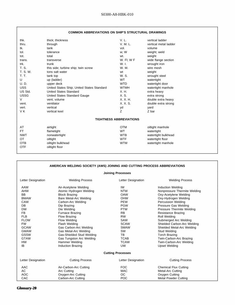
S0300-A8-HBK-010
COMMON ABBREVIATIONS ON SHIP’S STRUCTURAL DRAWINGS
thk. thick; thickness V. L. vertical ladderthru. through V. M. L. vertical metal laddertk. tank vol. volumetol. tolerance w; W weight; weldtot. total wt. weighttrans. transverse W. Fl; W F wide flange sectiontrk. trunk W. I. wrought ironT. S. this side; turbine ship; twin screw W. M. wire meshT. S. W. tons salt water wt weightT. T. tank top W. S. wrought steelU up (ladder) WT watertightU. D. upper deck WTD watertight doorUSS United States Ship; United States Standard WTMH watertight manholeUS Std. United States Standard X. H. extra heavyUSSG United States Standard Gauge X. S. extra strongV vent; volume X. X. H. double extra heavyvent. ventilator X. X. S. double extra strongvert. vertical yd yardV K vertical keel Z Z bar
TIGHTNESS ABBREVIATIONS
AT airtight OTM oiltight manholeFT flametight WT watertightNWT nonwatertight WTB watertight bulkheadOT oiltight WTF watertight floorOTB oiltight bulkhead WTM watertight manholeOTF oiltight floor
AMERICAN WELDING SOCIETY (AWS) JOINING AND CUTTING PROCESS ABBREVIATIONS
Joining Processes
Letter Designation Welding Process Letter Designation Welding Process
AAW Air-Acetylene Welding IW Induction WeldingAHW Atomic Hydrogen Welding NTW Nonpressure Thermite WeldingBB Block Brazing OAW Oxy-Acetylene WeldingBMAW Bare Metal-Arc Welding OHW Oxy-Hydrogen WeldingCAW Carbon-Arc Welding PEW Percussion WeldingDB Dip Brazing PGW Pressure Gas WeldingDW Die Welding PTW Pressure Thermite WeldingFB Furnace Brazing RB Resistance BrazingFLB Flow Brazing RW Roll WeldingFLOW Flow Welding SAW Submerged Arc WeldingFW Flash Welding SCAW Shielded Carbon-Arc WeldingGCAW Gas Carbon-Arc Welding SMAW Shielded Metal-Arc WeldingGMAW Gas Metal-Arc Welding SW Stud WeldingGSSW Gas-Shielded Stud Welding TB Torch BrazingGTAW Gas Tungston Arc Welding TCAB Twin-Carbon-Arc BrazingHW Hammer Welding TCAW Twin-Carbon-Arc WeldingIB Induction Brazing UW Upset Welding
Cutting Processes
Letter Designation Cutting Process Letter Designation Cutting Process
AAC Air-Carbon-Arc Cutting FOC Chemical Flux CuttingAC Arc Cutting MAC Metal-Arc CuttingAOC Oxygen-Arc Cutting OC Oxygen CuttingCAC Carbon-Arc Cutting POC Metal Powder Cutting
Glossary-20Glossary-20
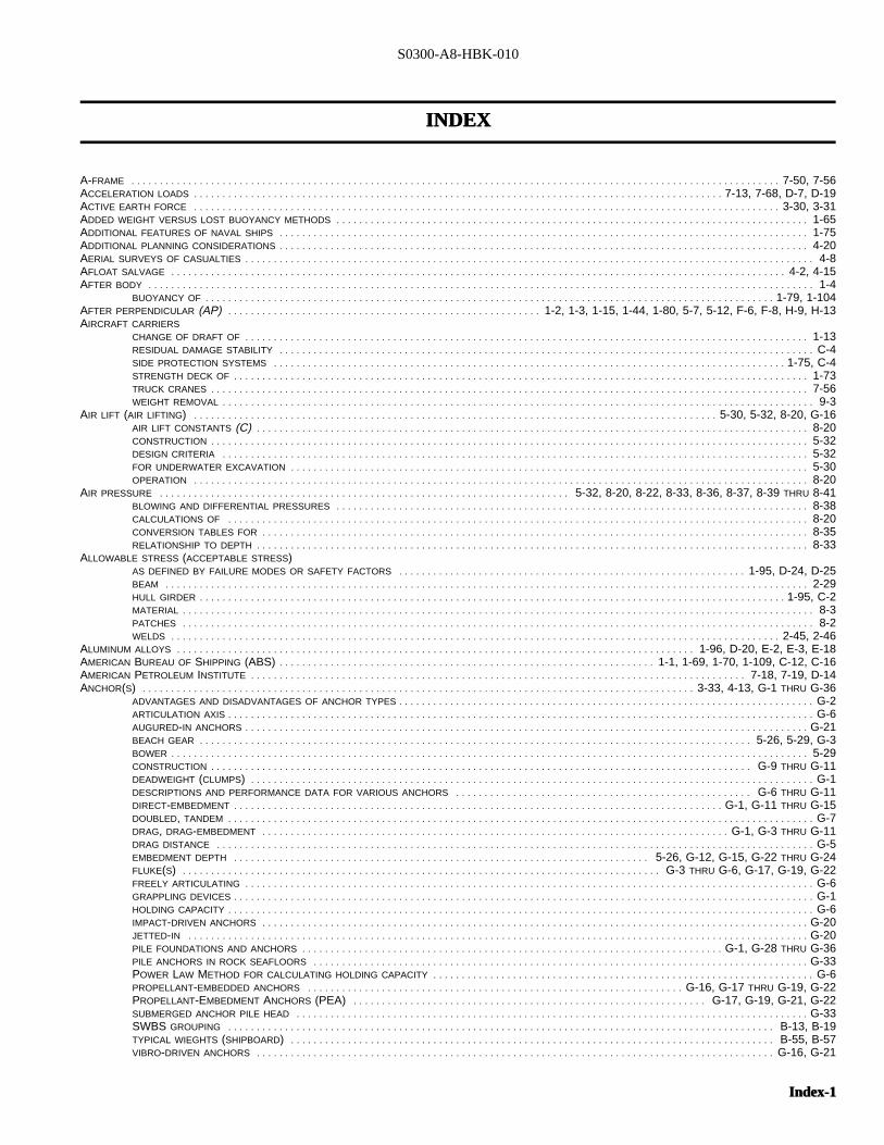
S0300-A8-HBK-010
INDEXINDEX
A-FRAME . . . . . . . . . . . . . . . . . . . . . . . . . . . . . . . . . . . . . . . . . . . . . . . . . . . . . . . . . . . . . . . . . . . . . . . . . . . . . . . . . . . . . . . . . . . . . . . . . . . . . . . . . . . . . . . . . . 7-50, 7-56ACCELERATION LOADS . . . . . . . . . . . . . . . . . . . . . . . . . . . . . . . . . . . . . . . . . . . . . . . . . . . . . . . . . . . . . . . . . . . . . . . . . . . . . . . . . . . . . . . . . . . . . 7-13, 7-68, D-7, D-19ACTIVE EARTH FORCE . . . . . . . . . . . . . . . . . . . . . . . . . . . . . . . . . . . . . . . . . . . . . . . . . . . . . . . . . . . . . . . . . . . . . . . . . . . . . . . . . . . . . . . . . . . . . . . . . . . . . . . 3-30, 3-31ADDED WEIGHT VERSUS LOST BUOYANCY METHODS . . . . . . . . . . . . . . . . . . . . . . . . . . . . . . . . . . . . . . . . . . . . . . . . . . . . . . . . . . . . . . . . . . . . . . . . . . . . . . . . . . . 1-65ADDITIONAL FEATURES OF NAVAL SHIPS . . . . . . . . . . . . . . . . . . . . . . . . . . . . . . . . . . . . . . . . . . . . . . . . . . . . . . . . . . . . . . . . . . . . . . . . . . . . . . . . . . . . . . . . . . . . . 1-75ADDITIONAL PLANNING CONSIDERATIONS . . . . . . . . . . . . . . . . . . . . . . . . . . . . . . . . . . . . . . . . . . . . . . . . . . . . . . . . . . . . . . . . . . . . . . . . . . . . . . . . . . . . . . . . . . . . . 4-20AERIAL SURVEYS OF CASUALTIES . . . . . . . . . . . . . . . . . . . . . . . . . . . . . . . . . . . . . . . . . . . . . . . . . . . . . . . . . . . . . . . . . . . . . . . . . . . . . . . . . . . . . . . . . . . . . . . . . . . . 4-8AFLOAT SALVAGE . . . . . . . . . . . . . . . . . . . . . . . . . . . . . . . . . . . . . . . . . . . . . . . . . . . . . . . . . . . . . . . . . . . . . . . . . . . . . . . . . . . . . . . . . . . . . . . . . . . . . . . . . . . . 4-2, 4-15AFTER BODY . . . . . . . . . . . . . . . . . . . . . . . . . . . . . . . . . . . . . . . . . . . . . . . . . . . . . . . . . . . . . . . . . . . . . . . . . . . . . . . . . . . . . . . . . . . . . . . . . . . . . . . . . . . . . . . . . . . . . 1-4
BUOYANCY OF . . . . . . . . . . . . . . . . . . . . . . . . . . . . . . . . . . . . . . . . . . . . . . . . . . . . . . . . . . . . . . . . . . . . . . . . . . . . . . . . . . . . . . . . . . . . . . . . . . . . 1-79, 1-104AFTER PERPENDICULAR (AP)I . . . . . . . . . . . . . . . . . . . . . . . . . . . . . . . . . . . . . . . . . . . . . . . . . . . . . . . 1-2, 1-3, 1-15, 1-44, 1-80, 5-7, 5-12, F-6, F-8, H-9, H-13AIRCRAFT CARRIERS
CHANGE OF DRAFT OF . . . . . . . . . . . . . . . . . . . . . . . . . . . . . . . . . . . . . . . . . . . . . . . . . . . . . . . . . . . . . . . . . . . . . . . . . . . . . . . . . . . . . . . . . . . . . . . . . . . 1-13RESIDUAL DAMAGE STABILITY . . . . . . . . . . . . . . . . . . . . . . . . . . . . . . . . . . . . . . . . . . . . . . . . . . . . . . . . . . . . . . . . . . . . . . . . . . . . . . . . . . . . . . . . . . . . . . C-4SIDE PROTECTION SYSTEMS . . . . . . . . . . . . . . . . . . . . . . . . . . . . . . . . . . . . . . . . . . . . . . . . . . . . . . . . . . . . . . . . . . . . . . . . . . . . . . . . . . . . . . . . . . 1-75, C-4STRENGTH DECK OF . . . . . . . . . . . . . . . . . . . . . . . . . . . . . . . . . . . . . . . . . . . . . . . . . . . . . . . . . . . . . . . . . . . . . . . . . . . . . . . . . . . . . . . . . . . . . . . . . . . . . 1-73TRUCK CRANES . . . . . . . . . . . . . . . . . . . . . . . . . . . . . . . . . . . . . . . . . . . . . . . . . . . . . . . . . . . . . . . . . . . . . . . . . . . . . . . . . . . . . . . . . . . . . . . . . . . . . . . . . 7-56WEIGHT REMOVAL . . . . . . . . . . . . . . . . . . . . . . . . . . . . . . . . . . . . . . . . . . . . . . . . . . . . . . . . . . . . . . . . . . . . . . . . . . . . . . . . . . . . . . . . . . . . . . . . . . . . . . . . 9-3
AIR LIFT (AIR LIFTING)I . . . . . . . . . . . . . . . . . . . . . . . . . . . . . . . . . . . . . . . . . . . . . . . . . . . . . . . . . . . . . . . . . . . . . . . . . . . . . . . . . . . . . . . . . . . . 5-30, 5-32, 8-20, G-16AIR LIFT CONSTANTS (C)I . . . . . . . . . . . . . . . . . . . . . . . . . . . . . . . . . . . . . . . . . . . . . . . . . . . . . . . . . . . . . . . . . . . . . . . . . . . . . . . . . . . . . . . . . . . . . . . . . 8-20CONSTRUCTION . . . . . . . . . . . . . . . . . . . . . . . . . . . . . . . . . . . . . . . . . . . . . . . . . . . . . . . . . . . . . . . . . . . . . . . . . . . . . . . . . . . . . . . . . . . . . . . . . . . . . . . . . 5-32DESIGN CRITERIA . . . . . . . . . . . . . . . . . . . . . . . . . . . . . . . . . . . . . . . . . . . . . . . . . . . . . . . . . . . . . . . . . . . . . . . . . . . . . . . . . . . . . . . . . . . . . . . . . . . . . . . 5-32FOR UNDERWATER EXCAVATION . . . . . . . . . . . . . . . . . . . . . . . . . . . . . . . . . . . . . . . . . . . . . . . . . . . . . . . . . . . . . . . . . . . . . . . . . . . . . . . . . . . . . . . . . . . 5-30OPERATION . . . . . . . . . . . . . . . . . . . . . . . . . . . . . . . . . . . . . . . . . . . . . . . . . . . . . . . . . . . . . . . . . . . . . . . . . . . . . . . . . . . . . . . . . . . . . . . . . . . . . . . . . . . . 8-20
AIR PRESSURE . . . . . . . . . . . . . . . . . . . . . . . . . . . . . . . . . . . . . . . . . . . . . . . . . . . . . . . . . . . . . . . . . . . . . . . . 5-32, 8-20, 8-22, 8-33, 8-36, 8-37, 8-39 THRU 8-41BLOWING AND DIFFERENTIAL PRESSURES . . . . . . . . . . . . . . . . . . . . . . . . . . . . . . . . . . . . . . . . . . . . . . . . . . . . . . . . . . . . . . . . . . . . . . . . . . . . . . . . . . . 8-38CALCULATIONS OF . . . . . . . . . . . . . . . . . . . . . . . . . . . . . . . . . . . . . . . . . . . . . . . . . . . . . . . . . . . . . . . . . . . . . . . . . . . . . . . . . . . . . . . . . . . . . . . . . . . . . . 8-20CONVERSION TABLES FOR . . . . . . . . . . . . . . . . . . . . . . . . . . . . . . . . . . . . . . . . . . . . . . . . . . . . . . . . . . . . . . . . . . . . . . . . . . . . . . . . . . . . . . . . . . . . . . . . 8-35RELATIONSHIP TO DEPTH . . . . . . . . . . . . . . . . . . . . . . . . . . . . . . . . . . . . . . . . . . . . . . . . . . . . . . . . . . . . . . . . . . . . . . . . . . . . . . . . . . . . . . . . . . . . . . . . . 8-33
ALLOWABLE STRESS (ACCEPTABLE STRESS)AS DEFINED BY FAILURE MODES OR SAFETY FACTORS . . . . . . . . . . . . . . . . . . . . . . . . . . . . . . . . . . . . . . . . . . . . . . . . . . . . . . . . . . . . . 1-95, D-24, D-25BEAM . . . . . . . . . . . . . . . . . . . . . . . . . . . . . . . . . . . . . . . . . . . . . . . . . . . . . . . . . . . . . . . . . . . . . . . . . . . . . . . . . . . . . . . . . . . . . . . . . . . . . . . . . . . . . . . . . 2-29HULL GIRDER . . . . . . . . . . . . . . . . . . . . . . . . . . . . . . . . . . . . . . . . . . . . . . . . . . . . . . . . . . . . . . . . . . . . . . . . . . . . . . . . . . . . . . . . . . . . . . . . . . . . . . . 1-95, C-2MATERIAL . . . . . . . . . . . . . . . . . . . . . . . . . . . . . . . . . . . . . . . . . . . . . . . . . . . . . . . . . . . . . . . . . . . . . . . . . . . . . . . . . . . . . . . . . . . . . . . . . . . . . . . . . . . . . . . 8-3PATCHES . . . . . . . . . . . . . . . . . . . . . . . . . . . . . . . . . . . . . . . . . . . . . . . . . . . . . . . . . . . . . . . . . . . . . . . . . . . . . . . . . . . . . . . . . . . . . . . . . . . . . . . . . . . . . . . 8-2WELDS . . . . . . . . . . . . . . . . . . . . . . . . . . . . . . . . . . . . . . . . . . . . . . . . . . . . . . . . . . . . . . . . . . . . . . . . . . . . . . . . . . . . . . . . . . . . . . . . . . . . . . . . . . . 2-45, 2-46
ALUMINUM ALLOYS . . . . . . . . . . . . . . . . . . . . . . . . . . . . . . . . . . . . . . . . . . . . . . . . . . . . . . . . . . . . . . . . . . . . . . . . . . . . . . . . . . . . . . . . . . . 1-96, D-20, E-2, E-3, E-18AMERICAN BUREAU OF SHIPPING (ABS)I . . . . . . . . . . . . . . . . . . . . . . . . . . . . . . . . . . . . . . . . . . . . . . . . . . . . . . . . . . . . . . . . . . 1-1, 1-69, 1-70, 1-109, C-12, C-16AMERICAN PETROLEUM INSTITUTE . . . . . . . . . . . . . . . . . . . . . . . . . . . . . . . . . . . . . . . . . . . . . . . . . . . . . . . . . . . . . . . . . . . . . . . . . . . . . . . . . . . . . . . 7-18, 7-19, D-14ANCHOR(S)I . . . . . . . . . . . . . . . . . . . . . . . . . . . . . . . . . . . . . . . . . . . . . . . . . . . . . . . . . . . . . . . . . . . . . . . . . . . . . . . . . . . . . . . . . . . . . . . . . 3-33, 4-13, G-1 THRU G-36
ADVANTAGES AND DISADVANTAGES OF ANCHOR TYPES . . . . . . . . . . . . . . . . . . . . . . . . . . . . . . . . . . . . . . . . . . . . . . . . . . . . . . . . . . . . . . . . . . . . . . . . . G-2ARTICULATION AXIS . . . . . . . . . . . . . . . . . . . . . . . . . . . . . . . . . . . . . . . . . . . . . . . . . . . . . . . . . . . . . . . . . . . . . . . . . . . . . . . . . . . . . . . . . . . . . . . . . . . . . . . G-6AUGURED-IN ANCHORS . . . . . . . . . . . . . . . . . . . . . . . . . . . . . . . . . . . . . . . . . . . . . . . . . . . . . . . . . . . . . . . . . . . . . . . . . . . . . . . . . . . . . . . . . . . . . . . . . . . G-21BEACH GEAR . . . . . . . . . . . . . . . . . . . . . . . . . . . . . . . . . . . . . . . . . . . . . . . . . . . . . . . . . . . . . . . . . . . . . . . . . . . . . . . . . . . . . . . . . . . . . . . . . 5-26, 5-29, G-3BOWER . . . . . . . . . . . . . . . . . . . . . . . . . . . . . . . . . . . . . . . . . . . . . . . . . . . . . . . . . . . . . . . . . . . . . . . . . . . . . . . . . . . . . . . . . . . . . . . . . . . . . . . . . . . . . . . . 5-29CONSTRUCTION . . . . . . . . . . . . . . . . . . . . . . . . . . . . . . . . . . . . . . . . . . . . . . . . . . . . . . . . . . . . . . . . . . . . . . . . . . . . . . . . . . . . . . . . . . . . . . . G-9 THRU G-11DEADWEIGHT (CLUMPS)I . . . . . . . . . . . . . . . . . . . . . . . . . . . . . . . . . . . . . . . . . . . . . . . . . . . . . . . . . . . . . . . . . . . . . . . . . . . . . . . . . . . . . . . . . . . . . . . . . . . G-1DESCRIPTIONS AND PERFORMANCE DATA FOR VARIOUS ANCHORS . . . . . . . . . . . . . . . . . . . . . . . . . . . . . . . . . . . . . . . . . . . . . . . . . . . . G-6 THRU G-11DIRECT-EMBEDMENT . . . . . . . . . . . . . . . . . . . . . . . . . . . . . . . . . . . . . . . . . . . . . . . . . . . . . . . . . . . . . . . . . . . . . . . . . . . . . . . . . . . . . . G-1, G-11 THRU G-15DOUBLED, TANDEM . . . . . . . . . . . . . . . . . . . . . . . . . . . . . . . . . . . . . . . . . . . . . . . . . . . . . . . . . . . . . . . . . . . . . . . . . . . . . . . . . . . . . . . . . . . . . . . . . . . . . . . G-7DRAG, DRAG-EMBEDMENT . . . . . . . . . . . . . . . . . . . . . . . . . . . . . . . . . . . . . . . . . . . . . . . . . . . . . . . . . . . . . . . . . . . . . . . . . . . . . . . . . . G-1, G-3 THRU G-11DRAG DISTANCE . . . . . . . . . . . . . . . . . . . . . . . . . . . . . . . . . . . . . . . . . . . . . . . . . . . . . . . . . . . . . . . . . . . . . . . . . . . . . . . . . . . . . . . . . . . . . . . . . . . . . . . . . G-5EMBEDMENT DEPTH . . . . . . . . . . . . . . . . . . . . . . . . . . . . . . . . . . . . . . . . . . . . . . . . . . . . . . . . . . . . . . . . . . . . . . . . . 5-26, G-12, G-15, G-22 THRU G-24FLUKE(S)I . . . . . . . . . . . . . . . . . . . . . . . . . . . . . . . . . . . . . . . . . . . . . . . . . . . . . . . . . . . . . . . . . . . . . . . . . . . . . . . . . . . . G-3 THRU G-6, G-17, G-19, G-22FREELY ARTICULATING . . . . . . . . . . . . . . . . . . . . . . . . . . . . . . . . . . . . . . . . . . . . . . . . . . . . . . . . . . . . . . . . . . . . . . . . . . . . . . . . . . . . . . . . . . . . . . . . . . . . G-6GRAPPLING DEVICES . . . . . . . . . . . . . . . . . . . . . . . . . . . . . . . . . . . . . . . . . . . . . . . . . . . . . . . . . . . . . . . . . . . . . . . . . . . . . . . . . . . . . . . . . . . . . . . . . . . . . . G-1HOLDING CAPACITY . . . . . . . . . . . . . . . . . . . . . . . . . . . . . . . . . . . . . . . . . . . . . . . . . . . . . . . . . . . . . . . . . . . . . . . . . . . . . . . . . . . . . . . . . . . . . . . . . . . . . . . G-6IMPACT-DRIVEN ANCHORS . . . . . . . . . . . . . . . . . . . . . . . . . . . . . . . . . . . . . . . . . . . . . . . . . . . . . . . . . . . . . . . . . . . . . . . . . . . . . . . . . . . . . . . . . . . . . . . . G-20JETTED-IN . . . . . . . . . . . . . . . . . . . . . . . . . . . . . . . . . . . . . . . . . . . . . . . . . . . . . . . . . . . . . . . . . . . . . . . . . . . . . . . . . . . . . . . . . . . . . . . . . . . . . . . . . . . . . G-20PILE FOUNDATIONS AND ANCHORS . . . . . . . . . . . . . . . . . . . . . . . . . . . . . . . . . . . . . . . . . . . . . . . . . . . . . . . . . . . . . . . . . . . . . . . . . . G-1, G-28 THRU G-36PILE ANCHORS IN ROCK SEAFLOORS . . . . . . . . . . . . . . . . . . . . . . . . . . . . . . . . . . . . . . . . . . . . . . . . . . . . . . . . . . . . . . . . . . . . . . . . . . . . . . . . . . . . . . . G-33POWER LAW METHOD FOR CALCULATING HOLDING CAPACITY . . . . . . . . . . . . . . . . . . . . . . . . . . . . . . . . . . . . . . . . . . . . . . . . . . . . . . . . . . . . . . . . . . . G-6PROPELLANT-EMBEDDED ANCHORS . . . . . . . . . . . . . . . . . . . . . . . . . . . . . . . . . . . . . . . . . . . . . . . . . . . . . . . . . . . . . . . . . . G-16, G-17 THRU G-19, G-22PROPELLANT-EMBEDMENT ANCHORS (PEA)I . . . . . . . . . . . . . . . . . . . . . . . . . . . . . . . . . . . . . . . . . . . . . . . . . . . . . . . . . . . . . . G-17, G-19, G-21, G-22SUBMERGED ANCHOR PILE HEAD . . . . . . . . . . . . . . . . . . . . . . . . . . . . . . . . . . . . . . . . . . . . . . . . . . . . . . . . . . . . . . . . . . . . . . . . . . . . . . . . . . . . . . . . . . G-33SWBS GROUPING . . . . . . . . . . . . . . . . . . . . . . . . . . . . . . . . . . . . . . . . . . . . . . . . . . . . . . . . . . . . . . . . . . . . . . . . . . . . . . . . . . . . . . . . . . . . . . . . B-13, B-19TYPICAL WIEGHTS (SHIPBOARD)I . . . . . . . . . . . . . . . . . . . . . . . . . . . . . . . . . . . . . . . . . . . . . . . . . . . . . . . . . . . . . . . . . . . . . . . . . . . . . . . . . . . . . B-55, B-57VIBRO-DRIVEN ANCHORS . . . . . . . . . . . . . . . . . . . . . . . . . . . . . . . . . . . . . . . . . . . . . . . . . . . . . . . . . . . . . . . . . . . . . . . . . . . . . . . . . . . . . . . . . . . G-16, G-21
Index-1Index-1
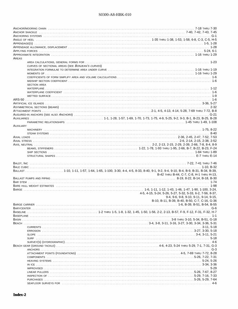
S0300-A8-HBK-010
ANCHOR/MOORING CHAIN . . . . . . . . . . . . . . . . . . . . . . . . . . . . . . . . . . . . . . . . . . . . . . . . . . . . . . . . . . . . . . . . . . . . . . . . . . . . . . . . . . . . . . . . . . . . . . . 7-18 THRU 7-30ANCHOR SHACKLE . . . . . . . . . . . . . . . . . . . . . . . . . . . . . . . . . . . . . . . . . . . . . . . . . . . . . . . . . . . . . . . . . . . . . . . . . . . . . . . . . . . . . . . . . . . . . . . 7-40, 7-42, 7-43, 7-45ANCHORING SYSTEMS . . . . . . . . . . . . . . . . . . . . . . . . . . . . . . . . . . . . . . . . . . . . . . . . . . . . . . . . . . . . . . . . . . . . . . . . . . . . . . . . . . . . . . . . . . . . . . . . . . . . . . . . . . . . . G-1ANGLE OF HEEL . . . . . . . . . . . . . . . . . . . . . . . . . . . . . . . . . . . . . . . . . . . . . . . . . . . . . . . . . . . . . . . . . . . . . . . . . . . 1-35 THRU 1-38, 1-53, 1-58, 6-8, C-3, C-5, H-5APPENDAGE(S)I . . . . . . . . . . . . . . . . . . . . . . . . . . . . . . . . . . . . . . . . . . . . . . . . . . . . . . . . . . . . . . . . . . . . . . . . . . . . . . . . . . . . . . . . . . . . . . . . . . . . . . . . . . . . . . 1-5, 1-28APPENDAGE ALLOWANCE, DISPLACEMENT . . . . . . . . . . . . . . . . . . . . . . . . . . . . . . . . . . . . . . . . . . . . . . . . . . . . . . . . . . . . . . . . . . . . . . . . . . . . . . . . . . . . . . . . . . . . 1-28APPLYING FORCES . . . . . . . . . . . . . . . . . . . . . . . . . . . . . . . . . . . . . . . . . . . . . . . . . . . . . . . . . . . . . . . . . . . . . . . . . . . . . . . . . . . . . . . . . . . . . . . . . . . . . . . . . . . 5-24, 6-1APPROXIMATE INTEGRATION . . . . . . . . . . . . . . . . . . . . . . . . . . . . . . . . . . . . . . . . . . . . . . . . . . . . . . . . . . . . . . . . . . . . . . . . . . . . . . . . . . . . . . . . . . . . . 1-16 THRU 1-29AREAS
AREA CALCULATIONS, GENERAL FORMS FOR . . . . . . . . . . . . . . . . . . . . . . . . . . . . . . . . . . . . . . . . . . . . . . . . . . . . . . . . . . . . . . . . . . . . . . . . . . . . . . . . . 1-23CURVES OF SECTIONAL AREAS (SEE BONJEAN’S CURVES)INTEGRATION FORMULAE TO DETERMINE AREA UNDER CURVE . . . . . . . . . . . . . . . . . . . . . . . . . . . . . . . . . . . . . . . . . . . . . . . . . . . . . . . . 1-16 THRU 1-19MOMENTS OF . . . . . . . . . . . . . . . . . . . . . . . . . . . . . . . . . . . . . . . . . . . . . . . . . . . . . . . . . . . . . . . . . . . . . . . . . . . . . . . . . . . . . . . . . . . . . . . . . 1-16 THRU 1-29COEFFICIENTS OF FORM SIMPLIFY AREA AND VOLUME CALCULATIONS . . . . . . . . . . . . . . . . . . . . . . . . . . . . . . . . . . . . . . . . . . . . . . . . . . . . . . . . . . . . . 1-6MIDSHIP SECTION COEFFICIENT . . . . . . . . . . . . . . . . . . . . . . . . . . . . . . . . . . . . . . . . . . . . . . . . . . . . . . . . . . . . . . . . . . . . . . . . . . . . . . . . . . . . . . . . . . . . . 1-6SECTION AREA
WATERPLANE . . . . . . . . . . . . . . . . . . . . . . . . . . . . . . . . . . . . . . . . . . . . . . . . . . . . . . . . . . . . . . . . . . . . . . . . . . . . . . . . . . . . . . . . . . . . . . . . . . . . . . . . . . . 1-12WATERPLANE COEFFICIENT . . . . . . . . . . . . . . . . . . . . . . . . . . . . . . . . . . . . . . . . . . . . . . . . . . . . . . . . . . . . . . . . . . . . . . . . . . . . . . . . . . . . . . . . . . . . . . . . 1-6WETTED SURFACE . . . . . . . . . . . . . . . . . . . . . . . . . . . . . . . . . . . . . . . . . . . . . . . . . . . . . . . . . . . . . . . . . . . . . . . . . . . . . . . . . . . . . . . . . . . . . . . . . . . . . . . . 1-9
ARS-50I . . . . . . . . . . . . . . . . . . . . . . . . . . . . . . . . . . . . . . . . . . . . . . . . . . . . . . . . . . . . . . . . . . . . . . . . . . . . . . . . . . . . . . . . . . . . . . . . . . . . . . . . . . . . . . . . . . . . . . . . . 1-6ARTIFICIAL ICE ISLANDS . . . . . . . . . . . . . . . . . . . . . . . . . . . . . . . . . . . . . . . . . . . . . . . . . . . . . . . . . . . . . . . . . . . . . . . . . . . . . . . . . . . . . . . . . . . . . . . . . . . . . . 3-36, 5-27ASYMMETRICAL SECTIONS (BEAMS)I . . . . . . . . . . . . . . . . . . . . . . . . . . . . . . . . . . . . . . . . . . . . . . . . . . . . . . . . . . . . . . . . . . . . . . . . . . . . . . . . . . . . . . . . . . . . . . . . . 2-32ATTACHMENT POINTS . . . . . . . . . . . . . . . . . . . . . . . . . . . . . . . . . . . . . . . . . . . . . . . . . . . . . . . . . . . . . . . . . . . . . . . 2-1, 4-5, 4-13, 4-14, 5-28, 7-69 THRU 7-72, B-8AUGURED-IN ANCHORS (SEE ALSO ANCHORS)I . . . . . . . . . . . . . . . . . . . . . . . . . . . . . . . . . . . . . . . . . . . . . . . . . . . . . . . . . . . . . . . . . . . . . . . . . . . . . . . . . . . . . . . . G-21AUXILIARIES . . . . . . . . . . . . . . . . . . . . . . . . . . . . . . . . . . . . . . . . . . . . . . . . 1-1, 1-28, 1-57, 1-69, 1-70, 1-73, 1-75, 4-9, 5-25, 9-2, 9-3, B-1, B-23, B-25, B-28
PARAMETRIC RELATIONSHIPS . . . . . . . . . . . . . . . . . . . . . . . . . . . . . . . . . . . . . . . . . . . . . . . . . . . . . . . . . . . . . . . . . . . . . . . . . . . . . 1-45 THRU 1-49, 1-108AUXILIARY
MACHINERY . . . . . . . . . . . . . . . . . . . . . . . . . . . . . . . . . . . . . . . . . . . . . . . . . . . . . . . . . . . . . . . . . . . . . . . . . . . . . . . . . . . . . . . . . . . . . . . . . . . . . . . 1-75, 8-22STEAM SYSTEMS . . . . . . . . . . . . . . . . . . . . . . . . . . . . . . . . . . . . . . . . . . . . . . . . . . . . . . . . . . . . . . . . . . . . . . . . . . . . . . . . . . . . . . . . . . . . . . . . . . . . . . . . 8-40
AXIAL LOADS . . . . . . . . . . . . . . . . . . . . . . . . . . . . . . . . . . . . . . . . . . . . . . . . . . . . . . . . . . . . . . . . . . . . . . . . . . . . . . . . . . . . . . . . . . . . . . . 2-36, 2-45, 2-47, 7-52, 7-53AXIAL STRESS . . . . . . . . . . . . . . . . . . . . . . . . . . . . . . . . . . . . . . . . . . . . . . . . . . . . . . . . . . . . . . . . . . . . . . . . . . . . . . . . . . . . . . . . . . . . . . . 2-6, 2-14, 2-15, 2-38, 2-52AXIS, NEUTRAL . . . . . . . . . . . . . . . . . . . . . . . . . . . . . . . . . . . . . . . . . . . . . . . . . . . . . . . . . . . . . . . . . . . . . . . . . . . . 2-2, 2-13, 2-15, 2-29, 2-39, 2-66, 7-8, 8-4, 8-9
BEAMS, STIFFENERS . . . . . . . . . . . . . . . . . . . . . . . . . . . . . . . . . . . . . . . . . . . . . . . . . . . . . . 1-22, 1-78, 1-93 THRU 1-95, 2-66, B-7, B-22, B-23, F-24SHIP SECTIONS . . . . . . . . . . . . . . . . . . . . . . . . . . . . . . . . . . . . . . . . . . . . . . . . . . . . . . . . . . . . . . . . . . . . . . . . . . . . . . . . . . . . . . . . . . . . . . . 1-84 THRU 1-89STRUCTURAL SHAPES . . . . . . . . . . . . . . . . . . . . . . . . . . . . . . . . . . . . . . . . . . . . . . . . . . . . . . . . . . . . . . . . . . . . . . . . . . . . . . . . . . . . . . . . . . . E-7 THRU E-14
BALDT, INC . . . . . . . . . . . . . . . . . . . . . . . . . . . . . . . . . . . . . . . . . . . . . . . . . . . . . . . . . . . . . . . . . . . . . . . . . . . . . . . . . . . . . . . . . . . . . . . . . . . . . . 7-22, 7-41 THRU 7-46BALE CUBIC . . . . . . . . . . . . . . . . . . . . . . . . . . . . . . . . . . . . . . . . . . . . . . . . . . . . . . . . . . . . . . . . . . . . . . . . . . . . . . . . . . . . . . . . . . . . . . . . . . . . . . . . . . . . . . . . 1-10, B-32BALLAST . . . . . . . . . . . . . . . . . . . . . . . . . 1-10, 1-11, 1-57, 1-64, 1-65, 1-100, 3-30, 4-4, 4-5, 8-33, 8-40, 9-1, 9-2, 9-4, 9-10, B-4, B-9, B-31, B-34, B-39,
B-42 THRU B-44, C-7, C-8, H-1 THRU H-13,BALLAST PUMPS AND PIPING . . . . . . . . . . . . . . . . . . . . . . . . . . . . . . . . . . . . . . . . . . . . . . . . . . . . . . . . . . . . . . . . . . . . . . . . . . . . . . . . . 8-19, 8-22, B-14, B-18, B-30BAR STEM . . . . . . . . . . . . . . . . . . . . . . . . . . . . . . . . . . . . . . . . . . . . . . . . . . . . . . . . . . . . . . . . . . . . . . . . . . . . . . . . . . . . . . . . . . . . . . . . . . . . . . . . . . . . . . . . . . . . . . 1-74BARE HULL WEIGHT ESTIMATES . . . . . . . . . . . . . . . . . . . . . . . . . . . . . . . . . . . . . . . . . . . . . . . . . . . . . . . . . . . . . . . . . . . . . . . . . . . . . . . . . . . . . . . . . . . . . . . . . . . . 1-98BARGE . . . . . . . . . . . . . . . . . . . . . . . . . . . . . . . . . . . . . . . . . . . . . . . . . . . . . . . . . . . . . . . . . . . . . . . . . . . . . . 1-6, 1-11, 1-12, 1-43, 1-46, 1-47, 1-90, 1-100, 3-24,
4-5, 4-15, 5-24, 5-26, 5-27, 5-32, 5-33, 6-2, 7-56, 8-37,9-4, 9-6, 9-8, 9-10, 9-11, 9-14, 9-15,
B-10, B-11, B-39, B-40, B-50, C-7, C-16, G-36BARGE CARRIER . . . . . . . . . . . . . . . . . . . . . . . . . . . . . . . . . . . . . . . . . . . . . . . . . . . . . . . . . . . . . . . . . . . . . . . . . . . . . . . . . . . . . . . . . . . . 1-6, B-39, B-51, B-54, B-55BARYCENTER . . . . . . . . . . . . . . . . . . . . . . . . . . . . . . . . . . . . . . . . . . . . . . . . . . . . . . . . . . . . . . . . . . . . . . . . . . . . . . . . . . . . . . . . . . . . . . . . . . . . . . . . . . . . . . . . . . . . . G-6BASELINE . . . . . . . . . . . . . . . . . . . . . . . . . . . . . . . . . . . . . . . . . . . . . . 1-2 THRU 1-5, 1-8, 1-32, 1-45, 1-50, 1-56, 2-2, 2-13, B-57, F-9, F-12, F-31, F-32, H-7BASEPLANE . . . . . . . . . . . . . . . . . . . . . . . . . . . . . . . . . . . . . . . . . . . . . . . . . . . . . . . . . . . . . . . . . . . . . . . . . . . . . . . . . . . . . . . . . . . . . . . . . . . . . . . . . . . . . . . . . . . . . . 1-1BASIN . . . . . . . . . . . . . . . . . . . . . . . . . . . . . . . . . . . . . . . . . . . . . . . . . . . . . . . . . . . . . . . . . . . . . . . . . . . . . . . . . . . . . . . . . . . . . . . . . 3-8 THRU 3-10, 5-34, B-51, G-18BEACH . . . . . . . . . . . . . . . . . . . . . . . . . . . . . . . . . . . . . . . . . . . . . . . . . . . . . . . . . . . . . . . . . . . . . . . . . . . . . . . . . 3-4, 3-8, 3-11, 3-16, 3-27, 3-30, 3-34, 3-36, 5-31
CURRENTS . . . . . . . . . . . . . . . . . . . . . . . . . . . . . . . . . . . . . . . . . . . . . . . . . . . . . . . . . . . . . . . . . . . . . . . . . . . . . . . . . . . . . . . . . . . . . . . . . . . . . . . . 3-11, 5-18ERROSION . . . . . . . . . . . . . . . . . . . . . . . . . . . . . . . . . . . . . . . . . . . . . . . . . . . . . . . . . . . . . . . . . . . . . . . . . . . . . . . . . . . . . . . . . . . . . . . . . . . 3-27, 3-30, 5-18SLOPE . . . . . . . . . . . . . . . . . . . . . . . . . . . . . . . . . . . . . . . . . . . . . . . . . . . . . . . . . . . . . . . . . . . . . . . . . . . . . . . . . . . . . . . . . . . . . . . . . . . . . . . 3-4, 3-11, 5-21SURF . . . . . . . . . . . . . . . . . . . . . . . . . . . . . . . . . . . . . . . . . . . . . . . . . . . . . . . . . . . . . . . . . . . . . . . . . . . . . . . . . . . . . . . . . . . . . . . . . . . . . . . . . . . . . . . . . 5-18SURVEY(S) (HYDROGRAPHIC)I. . . . . . . . . . . . . . . . . . . . . . . . . . . . . . . . . . . . . . . . . . . . . . . . . . . . . . . . . . . . . . . . . . . . . . . . . . . . . . . . . . . . . . . . . . . . . . . 4-6
BEACH GEAR (GROUND TACKLE)I . . . . . . . . . . . . . . . . . . . . . . . . . . . . . . . . . . . . . . . . . . . . . . . . . . . . . . . . . . . . . . . . . . . 4-6, 4-23, 5-24 THRU 5-29, 7-1, 7-31, G-3ANCHORS . . . . . . . . . . . . . . . . . . . . . . . . . . . . . . . . . . . . . . . . . . . . . . . . . . . . . . . . . . . . . . . . . . . . . . . . . . . . . . . . . . . . . . . . . . . . . . . . . . . . . . . . . . . . . . . G-3ATTACHMENT POINTS (FOUNDATIONS)I . . . . . . . . . . . . . . . . . . . . . . . . . . . . . . . . . . . . . . . . . . . . . . . . . . . . . . . . . . . . . . . . . . . 4-5, 7-69 THRU 7-72, 8-28COMPONENTS . . . . . . . . . . . . . . . . . . . . . . . . . . . . . . . . . . . . . . . . . . . . . . . . . . . . . . . . . . . . . . . . . . . . . . . . . . . . . . . . . . . . . . . . . . . . . . . . 5-26, 7-22, 7-31HEAVING SYSTEMS . . . . . . . . . . . . . . . . . . . . . . . . . . . . . . . . . . . . . . . . . . . . . . . . . . . . . . . . . . . . . . . . . . . . . . . . . . . . . . . . . . . . . . . . . . . . . . . . . 5-24, 5-26IN ICE . . . . . . . . . . . . . . . . . . . . . . . . . . . . . . . . . . . . . . . . . . . . . . . . . . . . . . . . . . . . . . . . . . . . . . . . . . . . . . . . . . . . . . . . . . . . . . . . . . . . . . . . . . . . 3-34, 3-36IMPROVISED . . . . . . . . . . . . . . . . . . . . . . . . . . . . . . . . . . . . . . . . . . . . . . . . . . . . . . . . . . . . . . . . . . . . . . . . . . . . . . . . . . . . . . . . . . . . . . . . . . . . . . . . . . . . 5-29LINEAR PULLERS . . . . . . . . . . . . . . . . . . . . . . . . . . . . . . . . . . . . . . . . . . . . . . . . . . . . . . . . . . . . . . . . . . . . . . . . . . . . . . . . . . . . . . . . . . . . . . 5-26, 7-67, 8-27INSPECTION OF . . . . . . . . . . . . . . . . . . . . . . . . . . . . . . . . . . . . . . . . . . . . . . . . . . . . . . . . . . . . . . . . . . . . . . . . . . . . . . . . . . . . . . . . . . . . . . . 5-29, 7-16, 7-33PURCHASES . . . . . . . . . . . . . . . . . . . . . . . . . . . . . . . . . . . . . . . . . . . . . . . . . . . . . . . . . . . . . . . . . . . . . . . . . . . . . . . . . . . . . . . . . . . . . . . . . . 5-26, 5-29, 7-64SEAFLOOR SURVEYS FOR . . . . . . . . . . . . . . . . . . . . . . . . . . . . . . . . . . . . . . . . . . . . . . . . . . . . . . . . . . . . . . . . . . . . . . . . . . . . . . . . . . . . . . . . . . . . . . . . . 4-6
Index-2Index-2
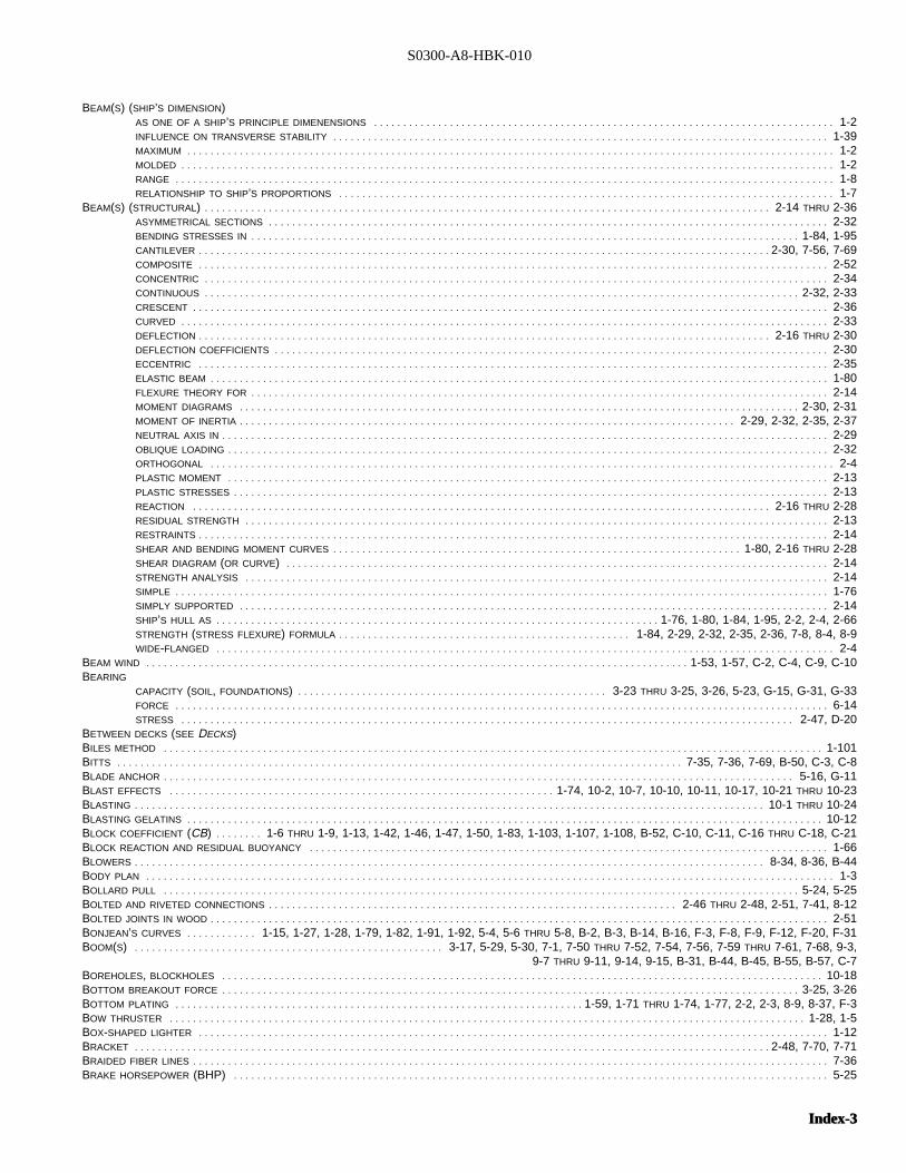
S0300-A8-HBK-010
BEAM(S) (SHIP’S DIMENSION)AS ONE OF A SHIP’S PRINCIPLE DIMENENSIONS . . . . . . . . . . . . . . . . . . . . . . . . . . . . . . . . . . . . . . . . . . . . . . . . . . . . . . . . . . . . . . . . . . . . . . . . . . . . . . . 1-2INFLUENCE ON TRANSVERSE STABILITY . . . . . . . . . . . . . . . . . . . . . . . . . . . . . . . . . . . . . . . . . . . . . . . . . . . . . . . . . . . . . . . . . . . . . . . . . . . . . . . . . . . . . 1-39MAXIMUM . . . . . . . . . . . . . . . . . . . . . . . . . . . . . . . . . . . . . . . . . . . . . . . . . . . . . . . . . . . . . . . . . . . . . . . . . . . . . . . . . . . . . . . . . . . . . . . . . . . . . . . . . . . . . . . 1-2MOLDED . . . . . . . . . . . . . . . . . . . . . . . . . . . . . . . . . . . . . . . . . . . . . . . . . . . . . . . . . . . . . . . . . . . . . . . . . . . . . . . . . . . . . . . . . . . . . . . . . . . . . . . . . . . . . . . . 1-2RANGE . . . . . . . . . . . . . . . . . . . . . . . . . . . . . . . . . . . . . . . . . . . . . . . . . . . . . . . . . . . . . . . . . . . . . . . . . . . . . . . . . . . . . . . . . . . . . . . . . . . . . . . . . . . . . . . . . 1-8RELATIONSHIP TO SHIP’S PROPORTIONS . . . . . . . . . . . . . . . . . . . . . . . . . . . . . . . . . . . . . . . . . . . . . . . . . . . . . . . . . . . . . . . . . . . . . . . . . . . . . . . . . . . . . 1-7
BEAM(S) (STRUCTURAL)I . . . . . . . . . . . . . . . . . . . . . . . . . . . . . . . . . . . . . . . . . . . . . . . . . . . . . . . . . . . . . . . . . . . . . . . . . . . . . . . . . . . . . . . . . . . . . . . . . 2-14 THRU 2-36ASYMMETRICAL SECTIONS . . . . . . . . . . . . . . . . . . . . . . . . . . . . . . . . . . . . . . . . . . . . . . . . . . . . . . . . . . . . . . . . . . . . . . . . . . . . . . . . . . . . . . . . . . . . . . . . 2-32BENDING STRESSES IN . . . . . . . . . . . . . . . . . . . . . . . . . . . . . . . . . . . . . . . . . . . . . . . . . . . . . . . . . . . . . . . . . . . . . . . . . . . . . . . . . . . . . . . . . . . . . . 1-84, 1-95CANTILEVER . . . . . . . . . . . . . . . . . . . . . . . . . . . . . . . . . . . . . . . . . . . . . . . . . . . . . . . . . . . . . . . . . . . . . . . . . . . . . . . . . . . . . . . . . . . . . . . . . . 2-30, 7-56, 7-69COMPOSITE . . . . . . . . . . . . . . . . . . . . . . . . . . . . . . . . . . . . . . . . . . . . . . . . . . . . . . . . . . . . . . . . . . . . . . . . . . . . . . . . . . . . . . . . . . . . . . . . . . . . . . . . . . . . 2-52CONCENTRIC . . . . . . . . . . . . . . . . . . . . . . . . . . . . . . . . . . . . . . . . . . . . . . . . . . . . . . . . . . . . . . . . . . . . . . . . . . . . . . . . . . . . . . . . . . . . . . . . . . . . . . . . . . . 2-34CONTINUOUS . . . . . . . . . . . . . . . . . . . . . . . . . . . . . . . . . . . . . . . . . . . . . . . . . . . . . . . . . . . . . . . . . . . . . . . . . . . . . . . . . . . . . . . . . . . . . . . . . . . . . . 2-32, 2-33CRESCENT . . . . . . . . . . . . . . . . . . . . . . . . . . . . . . . . . . . . . . . . . . . . . . . . . . . . . . . . . . . . . . . . . . . . . . . . . . . . . . . . . . . . . . . . . . . . . . . . . . . . . . . . . . . . . 2-36CURVED . . . . . . . . . . . . . . . . . . . . . . . . . . . . . . . . . . . . . . . . . . . . . . . . . . . . . . . . . . . . . . . . . . . . . . . . . . . . . . . . . . . . . . . . . . . . . . . . . . . . . . . . . . . . . . . 2-33DEFLECTION . . . . . . . . . . . . . . . . . . . . . . . . . . . . . . . . . . . . . . . . . . . . . . . . . . . . . . . . . . . . . . . . . . . . . . . . . . . . . . . . . . . . . . . . . . . . . . . . . . 2-16 THRU 2-30DEFLECTION COEFFICIENTS . . . . . . . . . . . . . . . . . . . . . . . . . . . . . . . . . . . . . . . . . . . . . . . . . . . . . . . . . . . . . . . . . . . . . . . . . . . . . . . . . . . . . . . . . . . . . . . 2-30ECCENTRIC . . . . . . . . . . . . . . . . . . . . . . . . . . . . . . . . . . . . . . . . . . . . . . . . . . . . . . . . . . . . . . . . . . . . . . . . . . . . . . . . . . . . . . . . . . . . . . . . . . . . . . . . . . . . 2-35ELASTIC BEAM . . . . . . . . . . . . . . . . . . . . . . . . . . . . . . . . . . . . . . . . . . . . . . . . . . . . . . . . . . . . . . . . . . . . . . . . . . . . . . . . . . . . . . . . . . . . . . . . . . . . . . . . . . 1-80FLEXURE THEORY FOR . . . . . . . . . . . . . . . . . . . . . . . . . . . . . . . . . . . . . . . . . . . . . . . . . . . . . . . . . . . . . . . . . . . . . . . . . . . . . . . . . . . . . . . . . . . . . . . . . . . 2-14MOMENT DIAGRAMS . . . . . . . . . . . . . . . . . . . . . . . . . . . . . . . . . . . . . . . . . . . . . . . . . . . . . . . . . . . . . . . . . . . . . . . . . . . . . . . . . . . . . . . . . . . . . . . . 2-30, 2-31MOMENT OF INERTIA . . . . . . . . . . . . . . . . . . . . . . . . . . . . . . . . . . . . . . . . . . . . . . . . . . . . . . . . . . . . . . . . . . . . . . . . . . . . . . . . . . . . . 2-29, 2-32, 2-35, 2-37NEUTRAL AXIS IN . . . . . . . . . . . . . . . . . . . . . . . . . . . . . . . . . . . . . . . . . . . . . . . . . . . . . . . . . . . . . . . . . . . . . . . . . . . . . . . . . . . . . . . . . . . . . . . . . . . . . . . . 2-29OBLIQUE LOADING . . . . . . . . . . . . . . . . . . . . . . . . . . . . . . . . . . . . . . . . . . . . . . . . . . . . . . . . . . . . . . . . . . . . . . . . . . . . . . . . . . . . . . . . . . . . . . . . . . . . . . . 2-32ORTHOGONAL . . . . . . . . . . . . . . . . . . . . . . . . . . . . . . . . . . . . . . . . . . . . . . . . . . . . . . . . . . . . . . . . . . . . . . . . . . . . . . . . . . . . . . . . . . . . . . . . . . . . . . . . . . . 2-4PLASTIC MOMENT . . . . . . . . . . . . . . . . . . . . . . . . . . . . . . . . . . . . . . . . . . . . . . . . . . . . . . . . . . . . . . . . . . . . . . . . . . . . . . . . . . . . . . . . . . . . . . . . . . . . . . . 2-13PLASTIC STRESSES . . . . . . . . . . . . . . . . . . . . . . . . . . . . . . . . . . . . . . . . . . . . . . . . . . . . . . . . . . . . . . . . . . . . . . . . . . . . . . . . . . . . . . . . . . . . . . . . . . . . . . 2-13REACTION . . . . . . . . . . . . . . . . . . . . . . . . . . . . . . . . . . . . . . . . . . . . . . . . . . . . . . . . . . . . . . . . . . . . . . . . . . . . . . . . . . . . . . . . . . . . . . . . . . . 2-16 THRU 2-28RESIDUAL STRENGTH . . . . . . . . . . . . . . . . . . . . . . . . . . . . . . . . . . . . . . . . . . . . . . . . . . . . . . . . . . . . . . . . . . . . . . . . . . . . . . . . . . . . . . . . . . . . . . . . . . . . 2-13RESTRAINTS . . . . . . . . . . . . . . . . . . . . . . . . . . . . . . . . . . . . . . . . . . . . . . . . . . . . . . . . . . . . . . . . . . . . . . . . . . . . . . . . . . . . . . . . . . . . . . . . . . . . . . . . . . . . 2-14SHEAR AND BENDING MOMENT CURVES . . . . . . . . . . . . . . . . . . . . . . . . . . . . . . . . . . . . . . . . . . . . . . . . . . . . . . . . . . . . . . . . . . . . . . 1-80, 2-16 THRU 2-28SHEAR DIAGRAM (OR CURVE)I . . . . . . . . . . . . . . . . . . . . . . . . . . . . . . . . . . . . . . . . . . . . . . . . . . . . . . . . . . . . . . . . . . . . . . . . . . . . . . . . . . . . . . . . . . . . . 2-14STRENGTH ANALYSIS . . . . . . . . . . . . . . . . . . . . . . . . . . . . . . . . . . . . . . . . . . . . . . . . . . . . . . . . . . . . . . . . . . . . . . . . . . . . . . . . . . . . . . . . . . . . . . . . . . . . 2-14SIMPLE . . . . . . . . . . . . . . . . . . . . . . . . . . . . . . . . . . . . . . . . . . . . . . . . . . . . . . . . . . . . . . . . . . . . . . . . . . . . . . . . . . . . . . . . . . . . . . . . . . . . . . . . . . . . . . . . 1-76SIMPLY SUPPORTED . . . . . . . . . . . . . . . . . . . . . . . . . . . . . . . . . . . . . . . . . . . . . . . . . . . . . . . . . . . . . . . . . . . . . . . . . . . . . . . . . . . . . . . . . . . . . . . . . . . . . 2-14SHIP’S HULL AS . . . . . . . . . . . . . . . . . . . . . . . . . . . . . . . . . . . . . . . . . . . . . . . . . . . . . . . . . . . . . . . . . . . . . . . . . . . . 1-76, 1-80, 1-84, 1-95, 2-2, 2-4, 2-66STRENGTH (STRESS FLEXURE) FORMULA . . . . . . . . . . . . . . . . . . . . . . . . . . . . . . . . . . . . . . . . . . . . . . . . . . 1-84, 2-29, 2-32, 2-35, 2-36, 7-8, 8-4, 8-9WIDE-FLANGED . . . . . . . . . . . . . . . . . . . . . . . . . . . . . . . . . . . . . . . . . . . . . . . . . . . . . . . . . . . . . . . . . . . . . . . . . . . . . . . . . . . . . . . . . . . . . . . . . . . . . . . . . . 2-4
BEAM WIND . . . . . . . . . . . . . . . . . . . . . . . . . . . . . . . . . . . . . . . . . . . . . . . . . . . . . . . . . . . . . . . . . . . . . . . . . . . . . . . . . . . . . . . . . . . . . 1-53, 1-57, C-2, C-4, C-9, C-10BEARING
CAPACITY (SOIL, FOUNDATIONS)I . . . . . . . . . . . . . . . . . . . . . . . . . . . . . . . . . . . . . . . . . . . . . . . . . . . . . 3-23 THRU 3-25, 3-26, 5-23, G-15, G-31, G-33FORCE . . . . . . . . . . . . . . . . . . . . . . . . . . . . . . . . . . . . . . . . . . . . . . . . . . . . . . . . . . . . . . . . . . . . . . . . . . . . . . . . . . . . . . . . . . . . . . . . . . . . . . . . . . . . . . . . 6-14STRESS . . . . . . . . . . . . . . . . . . . . . . . . . . . . . . . . . . . . . . . . . . . . . . . . . . . . . . . . . . . . . . . . . . . . . . . . . . . . . . . . . . . . . . . . . . . . . . . . . . . . . . . . . 2-47, D-20
BETWEEN DECKS (SEE DECKS)BILES METHOD . . . . . . . . . . . . . . . . . . . . . . . . . . . . . . . . . . . . . . . . . . . . . . . . . . . . . . . . . . . . . . . . . . . . . . . . . . . . . . . . . . . . . . . . . . . . . . . . . . . . . . . . . . . . . . . . . 1-101BITTS . . . . . . . . . . . . . . . . . . . . . . . . . . . . . . . . . . . . . . . . . . . . . . . . . . . . . . . . . . . . . . . . . . . . . . . . . . . . . . . . . . . . . . . . . . . . . . . . . 7-35, 7-36, 7-69, B-50, C-3, C-8BLADE ANCHOR . . . . . . . . . . . . . . . . . . . . . . . . . . . . . . . . . . . . . . . . . . . . . . . . . . . . . . . . . . . . . . . . . . . . . . . . . . . . . . . . . . . . . . . . . . . . . . . . . . . . . . . . . . . . 5-16, G-11BLAST EFFECTS . . . . . . . . . . . . . . . . . . . . . . . . . . . . . . . . . . . . . . . . . . . . . . . . . . . . . . . . . . . . . . . . . . 1-74, 10-2, 10-7, 10-10, 10-11, 10-17, 10-21 THRU 10-23BLASTING . . . . . . . . . . . . . . . . . . . . . . . . . . . . . . . . . . . . . . . . . . . . . . . . . . . . . . . . . . . . . . . . . . . . . . . . . . . . . . . . . . . . . . . . . . . . . . . . . . . . . . . . . . . . 10-1 THRU 10-24BLASTING GELATINS . . . . . . . . . . . . . . . . . . . . . . . . . . . . . . . . . . . . . . . . . . . . . . . . . . . . . . . . . . . . . . . . . . . . . . . . . . . . . . . . . . . . . . . . . . . . . . . . . . . . . . . . . . . . . 10-12BLOCK COEFFICIENT (CB)I . . . . . . . . 1-6 THRU 1-9, 1-13, 1-42, 1-46, 1-47, 1-50, 1-83, 1-103, 1-107, 1-108, B-52, C-10, C-11, C-16 THRU C-18, C-21BLOCK REACTION AND RESIDUAL BUOYANCY . . . . . . . . . . . . . . . . . . . . . . . . . . . . . . . . . . . . . . . . . . . . . . . . . . . . . . . . . . . . . . . . . . . . . . . . . . . . . . . . . . . . . . . . . 1-66BLOWERS . . . . . . . . . . . . . . . . . . . . . . . . . . . . . . . . . . . . . . . . . . . . . . . . . . . . . . . . . . . . . . . . . . . . . . . . . . . . . . . . . . . . . . . . . . . . . . . . . . . . . . . . . . . . 8-34, 8-36, B-44BODY PLAN . . . . . . . . . . . . . . . . . . . . . . . . . . . . . . . . . . . . . . . . . . . . . . . . . . . . . . . . . . . . . . . . . . . . . . . . . . . . . . . . . . . . . . . . . . . . . . . . . . . . . . . . . . . . . . . . . . . . . . 1-3BOLLARD PULL . . . . . . . . . . . . . . . . . . . . . . . . . . . . . . . . . . . . . . . . . . . . . . . . . . . . . . . . . . . . . . . . . . . . . . . . . . . . . . . . . . . . . . . . . . . . . . . . . . . . . . . . . . . . . 5-24, 5-25BOLTED AND RIVETED CONNECTIONS . . . . . . . . . . . . . . . . . . . . . . . . . . . . . . . . . . . . . . . . . . . . . . . . . . . . . . . . . . . . . . . . . . . . . . 2-46 THRU 2-48, 2-51, 7-41, 8-12BOLTED JOINTS IN WOOD . . . . . . . . . . . . . . . . . . . . . . . . . . . . . . . . . . . . . . . . . . . . . . . . . . . . . . . . . . . . . . . . . . . . . . . . . . . . . . . . . . . . . . . . . . . . . . . . . . . . . . . . . . 2-51BONJEAN’S CURVES . . . . . . . . . . . . 1-15, 1-27, 1-28, 1-79, 1-82, 1-91, 1-92, 5-4, 5-6 THRU 5-8, B-2, B-3, B-14, B-16, F-3, F-8, F-9, F-12, F-20, F-31BOOM(S)I . . . . . . . . . . . . . . . . . . . . . . . . . . . . . . . . . . . . . . . . . . . . . . . . . . . . . 3-17, 5-29, 5-30, 7-1, 7-50 THRU 7-52, 7-54, 7-56, 7-59 THRU 7-61, 7-68, 9-3,
9-7 THRU 9-11, 9-14, 9-15, B-31, B-44, B-45, B-55, B-57, C-7BOREHOLES, BLOCKHOLES . . . . . . . . . . . . . . . . . . . . . . . . . . . . . . . . . . . . . . . . . . . . . . . . . . . . . . . . . . . . . . . . . . . . . . . . . . . . . . . . . . . . . . . . . . . . . . . . . . . . . . . 10-18BOTTOM BREAKOUT FORCE . . . . . . . . . . . . . . . . . . . . . . . . . . . . . . . . . . . . . . . . . . . . . . . . . . . . . . . . . . . . . . . . . . . . . . . . . . . . . . . . . . . . . . . . . . . . . . . . . . . 3-25, 3-26BOTTOM PLATING . . . . . . . . . . . . . . . . . . . . . . . . . . . . . . . . . . . . . . . . . . . . . . . . . . . . . . . . . . . . . . . . . . . . . . 1-59, 1-71 THRU 1-74, 1-77, 2-2, 2-3, 8-9, 8-37, F-3BOW THRUSTER . . . . . . . . . . . . . . . . . . . . . . . . . . . . . . . . . . . . . . . . . . . . . . . . . . . . . . . . . . . . . . . . . . . . . . . . . . . . . . . . . . . . . . . . . . . . . . . . . . . . . . . . . . . . . 1-28, 1-5BOX-SHAPED LIGHTER . . . . . . . . . . . . . . . . . . . . . . . . . . . . . . . . . . . . . . . . . . . . . . . . . . . . . . . . . . . . . . . . . . . . . . . . . . . . . . . . . . . . . . . . . . . . . . . . . . . . . . . . . . . . 1-12BRACKET . . . . . . . . . . . . . . . . . . . . . . . . . . . . . . . . . . . . . . . . . . . . . . . . . . . . . . . . . . . . . . . . . . . . . . . . . . . . . . . . . . . . . . . . . . . . . . . . . . . . . . . . . . . . . 2-48, 7-70, 7-71BRAIDED FIBER LINES . . . . . . . . . . . . . . . . . . . . . . . . . . . . . . . . . . . . . . . . . . . . . . . . . . . . . . . . . . . . . . . . . . . . . . . . . . . . . . . . . . . . . . . . . . . . . . . . . . . . . . . . . . . . . 7-36BRAKE HORSEPOWER (BHP)I . . . . . . . . . . . . . . . . . . . . . . . . . . . . . . . . . . . . . . . . . . . . . . . . . . . . . . . . . . . . . . . . . . . . . . . . . . . . . . . . . . . . . . . . . . . . . . . . . . . . . . 5-25
Index-3Index-3
S0300-A8-HBK-010
BREAKERS (WAVES)I . . . . . . . . . . . . . . . . . . . . . . . . . . . . . . . . . . . . . . . . . . . . . . . . . . . . . . . . . . . . . . . . . . . . . . . . . . . . . . . . . . . . . . . . 3-1, 3-3, 3-6, 3-11, 4-8, 5-18BREAKING STRENGTH (FIBER AND WIRE ROPE, CHAIN)I . . . . . . . . . . . . . . . . . . . . . . . . . . . . . . . . . . . . . . . . . . . . . . . 7-4, 7-5, 7-18, 7-20, 7-21, 7-23 THRU 7-28BREAKOUT FORCE (SUCTION)I . . . . . . . . . . . . . . . . . . . . . . . . . . . . . . . . . . . . . . . . . . . . . . . . . . . . . . . . . . . . . . . . . . . . . . . . . . . . . . . . . . . . . . . . . . . . . 7-5, 7-37, 7-38BREAKWATER . . . . . . . . . . . . . . . . . . . . . . . . . . . . . . . . . . . . . . . . . . . . . . . . . . . . . . . . . . . . . . . . . . . . . . . . . . . . . . . . . . . . . . . . . . . . . . . . . . . . . . . . . . . . . . . . . . . . 5-1BREASTHOOKS . . . . . . . . . . . . . . . . . . . . . . . . . . . . . . . . . . . . . . . . . . . . . . . . . . . . . . . . . . . . . . . . . . . . . . . . . . . . . . . . . . . . . . . . . . . . . . . . . . . . . . . . . . . . . . . . . . 1-74BRITTLE MATERIALS . . . . . . . . . . . . . . . . . . . . . . . . . . . . . . . . . . . . . . . . . . . . . . . . . . . . . . . . . . . . . . . . . . . . . . . . . . . . . . . . . . . . . . . . 2-36, 2-53, D-21, D-24, D-25BROACH (BROACHING)I . . . . . . . . . . . . . . . . . . . . . . . . . . . . . . . . . . . . . . . . . . . . . . . . . . . . . . . . . . . . . . . . . . . . . . . . . . . . . . . . . . . . . . . . . . . . . . . . . . 5-14, 5-18, 5-29BROKEN OR MISSING STRUCTURE . . . . . . . . . . . . . . . . . . . . . . . . . . . . . . . . . . . . . . . . . . . . . . . . . . . . . . . . . . . . . . . . . . . . . . . . . . . . . . . . . . . . . . . . . . . . . . . . . . 2-61BRUCE (SEE ALSO ANCHORS)I . . . . . . . . . . . . . . . . . . . . . . . . . . . . . . . . . . . . . . . . . . . . . . . . . . . . . . . . . . . . . . . . . . . . . . . . . . . . . . . . . . . G-5, G-6, G-8 THRU G-10BUBBLE PULSE . . . . . . . . . . . . . . . . . . . . . . . . . . . . . . . . . . . . . . . . . . . . . . . . . . . . . . . . . . . . . . . . . . . . . . . . . . . . . . . . . . . . . . . . . . . . . . . . . . . . . . . . . . . . . . . . . . 10-5BUCKLED STRUCTURE . . . . . . . . . . . . . . . . . . . . . . . . . . . . . . . . . . . . . . . . . . . . . . . . . . . . . . . . . . . . . . . . . . . . . . . . . . . . . . . . . . . . . . . . . . . . . . . . . . . . . . . . . . . . 2-62BULBOUS BOWS . . . . . . . . . . . . . . . . . . . . . . . . . . . . . . . . . . . . . . . . . . . . . . . . . . . . . . . . . . . . . . . . . . . . . . . . . . . . . . . . . . . . . . . . . . . . . . . . . . . . . . . 1-2, 1-73, B-51BULK CARGO(ES)I . . . . . . . . . . . . . . . . . . . . . . . . . . . . . . . . . . 1-10, 1-58, 1-64, 1-98, 4-9, 8-20, 9-8, 9-11, 9-16, B-30, B-32, B-34, B-35, B-45, B-51, C-5BULK CARRIER . . . . . . . . . . . . . . . . . . . . . . . . . . . . . . . . . . . . . . . . . . . . . . . . . . . . . . . . . . . . . . . 1-6, 1-12, B-12, B-29, B-43, B-44, B-51 THRU B-56, C-5, C-6BULKHEAD(S)I. . . . . . . . . . . . . . . . . . . . . . . . . . . . . . . . . . . . . . . . . . . . . . . . . . . . . . . . . . . . . . . . . . . . . . . . . . . . . . . . . . . . . . . . . . . . . . . . . . . . . . . . . . . 1-73, 6-3, 8-41BULKHEAD DECK . . . . . . . . . . . . . . . . . . . . . . . . . . . . . . . . . . . . . . . . . . . . . . . . . . . . . . . . . . . . . . . . . . . . . . . . . . . . . . . . . 1-73 THRU 1-75, B-35, B-37, B-39, C-14BULWARK . . . . . . . . . . . . . . . . . . . . . . . . . . . . . . . . . . . . . . . . . . . . . . . . . . . . . . . . . . . . . . . . . . . . . . . . . . . . . . . . . . . . . . . . . . . . . . . . . . . . . . . . . . . . . . . . . 1-70, C-12BUNKERS (FUEL)I . . . . . . . . . . . . . . . . . . . . . . . . . . . . . . . . . . . . . . . . . . . . . . . . . . . . . . . . . . . . . . . . . . . . . . . . . . . . . . . . . . . . . . . . . . . . . . . . . . . . . . . . . . . . . . . . . . B-9BUOYANCY . . . . . . . . . . . . . . . . . . . . . 1-9 THRU 1-15, 1-30, 1-31, 1-65, 1-79, 1-82, 1-104, 5-4, 5-6 THRU 5-8, 5-19, 6-4, 6-6, 6-7, 6-9 THRU 6-12, 8-37BURIAL (ANCHOR)I . . . . . . . . . . . . . . . . . . . . . . . . . . . . . . . . . . . . . . . . . . . . . . . . . . . . . . . . . . . . . . . . . . . . . . . . . . . . . . . . . G-4 THRU G-6, G-10, G-11, G-16, G-21BUTTOCK . . . . . . . . . . . . . . . . . . . . . . . . . . . . . . . . . . . . . . . . . . . . . . . . . . . . . . . . . . . . . . . . . . . . . . . . . . . . . . . . . . . . . . . . . . . . . . . . . . . . . . . . . . . . . . . . . . . . . . . . 1-3BY RULE SECTION MODULUS . . . . . . . . . . . . . . . . . . . . . . . . . . . . . . . . . . . . . . . . . . . . . . . . . . . . . . . . . . . . . . . . . . . . . . . . . . . . . . . . . . . . . . 1-109, G-15 THRU G-22
CALCULATING SECTION MODULUS . . . . . . . . . . . . . . . . . . . . . . . . . . . . . . . . . . . . . . . . . . . . . . . . . . . . . . . . . . . . . . . . . . . . . . . . . . . . . . . . . . . . . . . . . . . . . 1-85, 1-109CALCULATIONS OF HULL VOLUMES AND PROPERTIES . . . . . . . . . . . . . . . . . . . . . . . . . . . . . . . . . . . . . . . . . . . . . . . . . . . . . . . . . . . . . . . . . . . . . . . . . 1-16 THRU 1-29CAMBER . . . . . . . . . . . . . . . . . . . . . . . . . . . . . . . . . . . . . . . . . . . . . . . . . . . . . . . . . . . . . . . . . . . . . . . . . . . . . . . . . . . . . . . . . . . . . . . . . . . . . . . . . . . . . . . . . . . . . . . . . 1-5CANTILEVER FRAMING . . . . . . . . . . . . . . . . . . . . . . . . . . . . . . . . . . . . . . . . . . . . . . . . . . . . . . . . . . . . . . . . . . . . . . . . . . . . . . . . . . . . . . . . . . . . 1-70, 1-71, 1-74, B-32CANTILEVER BEAMS . . . . . . . . . . . . . . . . . . . . . . . . . . . . . . . . . . . . . . . . . . . . . . . . . . . . . . . . . . . . . . . . . . . . . . . . . . . . . . . . . . . . . . . . . . . . . . . . . . . . . . . . . . . . . . 2-30CAPSIZING, CAPSIZED SHIP . . . . . . . . . . . . . . . . . . . . . . . . . . . . . . . . . . . . . . . 1-53, 1-74, 5-19, 5-20, 6-5 THRU 6-7, 6-13, 6-14, 7-56, B-43, F-16, F-17, H-6CAPSTANS . . . . . . . . . . . . . . . . . . . . . . . . . . . . . . . . . . . . . . . . . . . . . . . . . . . . . . . . . . . . . . . . . . . . . . . . . . . . . . . . . . . . . . . . . . . . . . . . . . . . . . 5-26, 7-67, 8-11, B-57CARPENTER STOPPER . . . . . . . . . . . . . . . . . . . . . . . . . . . . . . . . . . . . . . . . . . . . . . . . . . . . . . . . . . . . . . . . . . . . . . . . . . . . . . . . . . . . . . . . . . . . . . . . . . . . . . . . . . . . 5-26CAST-IN-PLACE FOAM . . . . . . . . . . . . . . . . . . . . . . . . . . . . . . . . . . . . . . . . . . . . . . . . . . . . . . . . . . . . . . . . . . . . . . . . . . . . . . . . . . . . . . . . . . 4-1, 6-11, 8-42 THRU 8-44CAST IRON . . . . . . . . . . . . . . . . . . . . . . . . . . . . . . . . . . . . . . . . . . . . . . . . . . . . . . . . . . . . . . . . . . . . . . . . . . . . . . . . . . . . . . . . . . . . . . . . . . . . . . . . . . . . . . . . . . . . . . 1-96CAST STUD-LINK CHAIN . . . . . . . . . . . . . . . . . . . . . . . . . . . . . . . . . . . . . . . . . . . . . . . . . . . . . . . . . . . . . . . . . . . . . . . . . . . . . . . . . . . . . . . . . . . . . . . . . . . . . . . . . . . 7-25CASUALTIES . . . . . . . . . . . . . . . . . . . . . . . . . . . . . . . . . . . . . . . . . . . . . . . . . . . . . . . . . 1-59, 2-2, 3-14, 3-27, 3-36, 4-1 THRU 4-3, 4-15, 4-19, 4-20, 4-22, 4-23,
5-16, 5-19, 5-20, 5-28, 5-34, 7-10, 7-56, 8-23, 8-37, 9-3, B-48, B-51, C-1CENTER OF BUOYANCY . . . . . . . . . . . . . . . . . . . . . . . . . . . . . . . . . . . . . . . . . . . . . . . . . . . . . . . . . . . . . . . . . . . . . . . 1-14, 1-15, 1-31 THRU 1-33, 1-42, 1-54, 8-43CENTER OF FLOTATION . . . . . . . . . . . . . . . . . . . . . . . . . . . . . . . . . . . . . . . . . . . . . . . . . . . . . . . . . . . . . . . . . . . . . . . . . . . . . . . . . . . . . . . . . . . . . . . . . . . . . . . . . . . 1-15CENTER OF GRAVITY . . . . . . . . . . . . . . . . . . . . . . . . . . . . . . . . . . . . . . . . . . . . . 1-14, 1-32 THRU 1-35, 1-42, 1-52 THRU 1-57, 1-64, 1-65, 1-67, 1-101, D-21CENTER OF GROUND REACTION . . . . . . . . . . . . . . . . . . . . . . . . . . . . . . . . . . . . . 3-15, 5-2 THRU 5-4, 5-8, 5-10 THRU 5-12, 5-14, 5-16, 5-19, 5-22, F-6, F-10CENTER OF VOLUME (BUOYANCY)I . . . . . . . . . . . . . . . . . . . . . . . . . . . . . . . . . . . . . . . . . . . . . . . . . . . . . . . . . . . . . . . . . . . . . . . . . . . . . . . . . . . . . . . . . . . . . 1-14, 1-31CENTER VERTICAL KEEL . . . . . . . . . . . . . . . . . . . . . . . . . . . . . . . . . . . . . . . . . . . . . . . . . . . . . . . . . . . . . . . . . . . . . . . . . . . . . . . . . . . . . . . . . . . . . . . . . . . . . . . . . . . 1-71CENTERLINE . . . . . . . . . . . . . . . . . . . . . . . . . . . . . . . . . . . . . . . . . . . . . . . . . . . . . . . . . . . . . . . . . . . . . . . . . . . . . . . . . . . . . . . . . . . . . . . . . . . . . . . . . . . . . . . . . . . . . 1-2CENTERPLANE . . . . . . . . . . . . . . . . . . . . . . . . . . . . . . . . . . . . . . . . . . . . . . . . . . . . . . . . . . . . . . . . . . . . . . . . . . . . . . . . . . . . . . . . . . . . . . . . . . . . . . . . . . . . . . . . 1-1, 1-2CENTRIFUGAL PUMPS . . . . . . . . . . . . . . . . . . . . . . . . . . . . . . . . . . . . . . . . . . . . . . . . . . . . . . . . . . . . . . . . . . . . . . . . . 8-14, 8-16 THRU 8-18, 8-21, 8-22, 8-26, 8-32CENTROID . . . . . . . . . . . . . . . . 1-14 THRU 1-16, 1-20 THRU 1-23, 1-27, 1-28, 1-43, 1-54, 1-85, 1-91, 1-92, 1-101, 1-102, 2-15, 2-30, 2-47, 2-48, D-21CHAIN STOPPERS . . . . . . . . . . . . . . . . . . . . . . . . . . . . . . . . . . . . . . . . . . . . . . . . . . . . . . . . . . . . . . . . . . . . . . . . . . . . . . . . . . . . . . . . . . . . . . . . . . . . . . 7-32, 7-45, 7-46CHANGE IN TRIM . . . . . . . . . . . . . . . . . . . . . . . . . . . . . . . . . . . . . . . . . . . . . . . . . . . . . . . . . . . . . . . . . . . . . . . . . . . . 1-36, 1-43, THRU 1-45, 1-48, 1-52, 1-54, 1-55CHANGE IN DRAFT . . . . . . . . . . . . . . . . . . . . . . . . . . . . . . . . . . . . . . . . . . . . . . . . . . . . . . . . . . . . . . . . . . . . . . . . . . . . . . . . . . . . . . . . . . . . . . . . . . . . . 1-12 THRU 1-14CHANGE OF DISPLACEMENT . . . . . . . . . . . . . . . . . . . . . . . . . . . . . . . . . . . . . . . . . . . . . . . . . . . . . . . . . . . . . . . . . . . . . . . . . . . . . . . . . . . . . . . . . . . . . . . . . . 1-14, 1-36CHANNEL AND FAIRWAY OBSTRUCTIONS . . . . . . . . . . . . . . . . . . . . . . . . . . . . . . . . . . . . . . . . . . . . . . . . . . . . . . . . . . . . . . . . . . . . . . . . . . . . . . . . . . . . . . . . . . . . . 4-23CHANNELING, DREDGING . . . . . . . . . . . . . . . . . . . . . . . . . . . . . . . . . . . . . . . . . . . . . . . . . . . . . . . . . . . . . . . . . . . . . . . . . 5-23, 5-30 THRU 5-34, 10-18 THRU 10-20CHEMICAL CARRIERS, TANKERS . . . . . . . . . . . . . . . . . . . . . . . . . . . . . . . . . . . . . . . . . . . . . . . . . . . . . . . . . . . . . . . . . . . . . . . . . . . . . . . . . . . . . . . . . . . . . . . 1-46, B-50CHEZY FORMULA . . . . . . . . . . . . . . . . . . . . . . . . . . . . . . . . . . . . . . . . . . . . . . . . . . . . . . . . . . . . . . . . . . . . . . . . . . . . . . . . . . . . . . . . . . . . . . . . . . . . . . . . . . . . . . . . . 3-12CHINE . . . . . . . . . . . . . . . . . . . . . . . . . . . . . . . . . . . . . . . . . . . . . . . . . . . . . . . . . . . . . . . . . . . . . . . . . . . . . . . . . . . . . . . . . . . . . . . . . . . . . . . . . . . . . . . . . . . . . . . . . . . 1-4CHOCK . . . . . . . . . . . . . . . . . . . . . . . . . . . . . . . . . . . . . . . . . . . . . . . . . . . . . . . . . . . . . . . . . . . . . . . . . . . . . . . . . . . . . . . . . . . . . . . . . . . . . . . . . . . . . . . . . . . . . 7-8, 7-69CLAPOTIS . . . . . . . . . . . . . . . . . . . . . . . . . . . . . . . . . . . . . . . . . . . . . . . . . . . . . . . . . . . . . . . . . . . . . . . . . . . . . . . . . . . . . . . . . . . . . . . . . . . . . . . . . . . . . . . . . . . . . . . . 3-5CLAY (SEE COHESIVE SOIL)CLEAT . . . . . . . . . . . . . . . . . . . . . . . . . . . . . . . . . . . . . . . . . . . . . . . . . . . . . . . . . . . . . . . . . . . . . . . . . . . . . . . . . . . . . . . . . . . . . . . . . . . . . . . . . . . . . . . . . . . . . . . . . 7-69CLINOMETER . . . . . . . . . . . . . . . . . . . . . . . . . . . . . . . . . . . . . . . . . . . . . . . . . . . . . . . . . . . . . . . . . . . . . . . . . . . . . . . . . . . . . . . . . . . . . . . . . . . . . . . . . . . . . . . . . . . . . 4-7COAMING (HATCH)I . . . . . . . . . . . . . . . . . . . . . . . . . . . . . . . . . . . . . . . . . . . . . . . . . . . . . . . . . . . . . . . . . . . . . . . . . . . . . . . . . . . . . . . . . . . . . . . . . . . . B-31, B-32, C-20COASTWISE SALVAGE . . . . . . . . . . . . . . . . . . . . . . . . . . . . . . . . . . . . . . . . . . . . . . . . . . . . . . . . . . . . . . . . . . . . . . . . . . . . . . . . . . . . . . . . . . . . . . . . . . . . . . . . . . . . . . 4-1COFFIN DIAGRAM . . . . . . . . . . . . . . . . . . . . . . . . . . . . . . . . . . . . . . . . . . . . . . . . . . . . . . . . . . . . . . . . . . . . . . . . . . . . . . . . . . . . . . . . . . . . . . . . . . . . 1-100 THRU 1-102COHESIONLESS SOIL (SAND, SILT)I . . . . . . . . . . . . . . . . . . . . . . . . . . . . . . . . . . . . . . . . . . . . 3-18, 3-22 THRU 3-25, 3-27, 3-28, 5-13, 5-14, 5-22, G-22, G-27COHESIVE SOIL (CLAY)I . . . . . . . . . . . . . . . . . . . . . . . . . . . . . . . . . . . . . . . . . . . . . . 3-18 THRU 3-28, 3-30, 3-32, 5-13, 5-14, 5-16, 5-22, 5-30, 5-33, 8-6, 8-20
G-2, G-3, G-10, G-11, G-16, G-18, G-20 THRU G-22, G-26 THRU G-28COLLISION BULKHEAD . . . . . . . . . . . . . . . . . . . . . . . . . . . . . . . . . . . . . . . . . . . . . . . . . . . . . . . . . . . . . . . . . . . . . . . . . . . . . . . . . . . . . . . . . . . . . . . . . . . . . . . . . . . . . 1-75COLUMNS (STRUCTURAL)I . . . . . . . . . . . . . . . . . . . . . . . . . . . . . . . . . . . . . . . . . . . . . . . . . . . . . . . . . . . . . . . . . . . . . . . . . . . . . . . . . . . . . . . . 2-36 THRU 2-39, 6-3, E-4COMBINATION FRAMING SYSTEMS . . . . . . . . . . . . . . . . . . . . . . . . . . . . . . . . . . . . . . . . . . . . . . . . . . . . . . . . . . . . . . . . . . . . . . . 1-70, B-32, B-34, B-37, B-41, B-47
Index-4Index-4
S0300-A8-HBK-010
COMBINED STRESSES . . . . . . . . . . . . . . . . . . . . . . . . . . . . . . . . . . . . . . . . . . . . . . . . . . . . . . . . . . . . . . . . . . . . . . . . . . . . . . . . . . . . . . . . . 1-95, 2-1, 2-46, 2-52, 7-17COMMON SHIPBUILDING MATERIALS . . . . . . . . . . . . . . . . . . . . . . . . . . . . . . . . . . . . . . . . . . . . . . . . . . . . . . . . . . . . . . . . . . . . . . . . . . . . . . . . . . . . . . . . . . . . . . . . . 1-96COMPARTMENTATION, SUBDIVISION . . . . . . . . . . . . . . . . . . . . . . . . . . . . . . . . . . . . . . . . . . . . . . . . . . . . . . . . . . . . . . . . . . . . . . . . . . . . . . . . . . . . . . . . . . . . . . . . . 1-74COMPRESSED AIR . . . . . . . . . . 3-37, 4-5, 6-6, 6-11, 6-12, 8-1, 8-17, 8-19, 8-20, 8-33 THRU 8-37, 8-39, 8-40, 8-42 THRU 8-44, 9-10, B-14, B-19, G-36COMPRESSION BLOCKS . . . . . . . . . . . . . . . . . . . . . . . . . . . . . . . . . . . . . . . . . . . . . . . . . . . . . . . . . . . . . . . . . . . . . . . . . . . . . . . . . . . . . . . . . . . . . . . . . . . . . . . . . . . 2-36COMPRESSIVE FAILURE . . . . . . . . . . . . . . . . . . . . . . . . . . . . . . . . . . . . . . . . . . . . . . . . . . . . . . . . . . . . . . . . . . . . . . . . . . . . . . . . . . . . . . . . . . . . . . . . . . 2-2, 2-12, 2-36COMPRESSIVE STRENGTH . . . . . . . . . . . . . . . . . . . . . . . . . . . . . . . . . . . . . . . . . . . . . . . . . . . . . . . . . . . . . . . . . . . . . . . . . 2-12, 2-36, 8-8, 8-43, D-21, G-19, G-34
OF BRITTLE MATERIALS . . . . . . . . . . . . . . . . . . . . . . . . . . . . . . . . . . . . . . . . . . . . . . . . . . . . . . . . . . . . . . . . . . . . . . . . . . . . . . . . . . . . . . . . . . . . D-21, D-24OF CAST-IN-PLACE FOAM . . . . . . . . . . . . . . . . . . . . . . . . . . . . . . . . . . . . . . . . . . . . . . . . . . . . . . . . . . . . . . . . . . . . . . . . . . . . . . . . . . . . . . . . . . . . . . . . . 8-43OF COLUMNS . . . . . . . . . . . . . . . . . . . . . . . . . . . . . . . . . . . . . . . . . . . . . . . . . . . . . . . . . . . . . . . . . . . . . . . . . . . . . . . . . . . . . . . . . . . . . . . . . 2-36 THRU 2-39OF CONCRETE . . . . . . . . . . . . . . . . . . . . . . . . . . . . . . . . . . . . . . . . . . . . . . . . . . . . . . . . . . . . . . . . . . . . . . . . . . . . . . . . . . . . . . . . . . . . . . . . . . . . . . . . . . . 8-8OF CORAL . . . . . . . . . . . . . . . . . . . . . . . . . . . . . . . . . . . . . . . . . . . . . . . . . . . . . . . . . . . . . . . . . . . . . . . . . . . . . . . . . . . . . . . . . . . . . . . . . . . . . . . . . . . . . G-19OF DUCTILE MATERIALS . . . . . . . . . . . . . . . . . . . . . . . . . . . . . . . . . . . . . . . . . . . . . . . . . . . . . . . . . . . . . . . . . . . . . . . . . . . . . . . . . . . . . . . . . . . . D-21, D-25OF ICE . . . . . . . . . . . . . . . . . . . . . . . . . . . . . . . . . . . . . . . . . . . . . . . . . . . . . . . . . . . . . . . . . . . . . . . . . . . . . . . . . . . . . . . . . . . . . . . . . . . . . . . . . . . . . . . . 3-36OF MILD STEEL TUBES . . . . . . . . . . . . . . . . . . . . . . . . . . . . . . . . . . . . . . . . . . . . . . . . . . . . . . . . . . . . . . . . . . . . . . . . . . . . . . . . . . . . . . . . . . . . . . . . . . . 7-53OF ROCK . . . . . . . . . . . . . . . . . . . . . . . . . . . . . . . . . . . . . . . . . . . . . . . . . . . . . . . . . . . . . . . . . . . . . . . . . . . . . . . . . . . . . . . . . . . . . . . . . . . . . . . . G-19, G-34OF TIMBER, WOOD . . . . . . . . . . . . . . . . . . . . . . . . . . . . . . . . . . . . . . . . . . . . . . . . . . . . . . . . . . . . . . . . . . . . . . . . . . . . . . . . . . . . . . . . . . . . . . . . . . . . . . E-16
COMPRESSIVE LOADS, COMPRESSION, STRESS . . . . . . . . . . . . . . . 2-2, 2-3, 2-12, 2-15, 2-38, 2-45, 2-51, 2-52, 2-54, 7-50 THRU 7-52, D-20, D-21, E-16COMPUTERS . . . . . . . . . . . . . . . . . . . . . . . . . . . . . . . . . . . . . . . . . . . . . . . . . . . . . . . . . . . . . . . . . . . . . . . . . . . . . . . . . . . . . 1-11, 1-27, 4-9, 5-4, 5-8, 9-2, B-9, D-2CONCENTRIC BEAMS . . . . . . . . . . . . . . . . . . . . . . . . . . . . . . . . . . . . . . . . . . . . . . . . . . . . . . . . . . . . . . . . . . . . . . . . . . . . . . . . . . . . . . . . . . . . . . . . . . . . . . . . . . . . . 2-34CONNECTIONS (STRUCTURAL)I . . . . . . . . . . . . . . . . . . . . . . . . . . . . . . . . . . . . 1-70 THRU 1-72, 2-3, 2-45, 2-46, 2-48, 4-5, 5-28, 7-13, 7-32, 7-36, 7-41, 8-12CONSTRUCTION CLASSES (WIRE ROPE)I . . . . . . . . . . . . . . . . . . . . . . . . . . . . . . . . . . . . . . . . . . . . . . . . . . . . . . . . . . . . . . . . . . . . . . . . . . . . . . . . . . . . . . . . . . . . . . . 7-2CONSTRUCTION SPECIFICATIONS (SHIP)I. . . . . . . . . . . . . . . . . . . . . . . . . . . . . . . . . . . . . . . . . . . . . . . . . . . . . . . . . . . . . . . . . . . . . . . . . . . . . . . . . . . . . . . . . . . . . . . 1-1CONTACT BLASTING . . . . . . . . . . . . . . . . . . . . . . . . . . . . . . . . . . . . . . . . . . . . . . . . . . . . . . . . . . . . . . . . . . . . . . . . . . . . . . . . . . . . . . . . . . . . . . . . . . . . . . . . . . . . . 10-18CONTAINER SHIP . . . . . . . . . . . . . . . . . . . . . . . . . . . . . . . . . . . . . . . . . . . . . . . . . . . . . . . . . . . 1-6, 1-97, 1-98, 1-100, B-30, B-34, B-35, B-52, B-53, B-55, B-56CONTAINERS . . . . . . . . . . . . . . . . . . . . . . . . . . . . 1-10, 1-58, 4-9, 4-23, 9-4, 9-5, 9-11, 9-16, B-9, B-30, B-32, B-34, B-35, B-37, B-39, B-40, B-51, B-53CONTINUOUS BEAMS . . . . . . . . . . . . . . . . . . . . . . . . . . . . . . . . . . . . . . . . . . . . . . . . . . . . . . . . . . . . . . . . . . . . . . . . . . . . . . . . . . . . . . . . . . . . . . . . . . . . 2-32, 2-33, 5-8CONTRACT TYPES (SALVAGE)I . . . . . . . . . . . . . . . . . . . . . . . . . . . . . . . . . . . . . . . . . . . . . . . . . . . . . . . . . . . . . . . . . . . . . . . . . . . . . . . . . . . . . . . . . . . . . . . . . . . . . . 4-17CONTROLLABLE-PITCH PROPELLERS . . . . . . . . . . . . . . . . . . . . . . . . . . . . . . . . . . . . . . . . . . . . . . . . . . . . . . . . . . . . . . . . . . . . . . . . . . . . . . . . . . . . . . . . . . . . 5-24, 5-31CORAL BLASTING . . . . . . . . . . . . . . . . . . . . . . . . . . . . . . . . . . . . . . . . . . . . . . . . . . . . . . . . . . . . . . . . . . . . . . . . . . . . . . . . . . . . . . . . . . . . . . . . . . . . . . . . . . . . . . . 10-20CORDAGE . . . . . . . . . . . . . . . . . . . . . . . . . . . . . . . . . . . . . . . . . . . . . . . . . . . . . . . . . . . . . . . . . . . . . . . . . . . . . . . . . . . . . . . . . . . . . . . . . . . . . . . . . . . . . . . . . . . . . . 7-35CORIOLIS FORCE . . . . . . . . . . . . . . . . . . . . . . . . . . . . . . . . . . . . . . . . . . . . . . . . . . . . . . . . . . . . . . . . . . . . . . . . . . . . . . . . . . . . . . . . . . . . . . . . . . . . . . . . . . . . . . . . . 3-13CORRELATION OF SURVEY INFORMATION . . . . . . . . . . . . . . . . . . . . . . . . . . . . . . . . . . . . . . . . . . . . . . . . . . . . . . . . . . . . . . . . . . . . . . . . . . . . . . . . . . . . . . . . . . . . . . 4-9CORROSION . . . . . . . . . . . . . . . . . . . . . . . . . . . . . . . . . . . . . 1-96, 2-3, 4-20, 7-3, 7-4, 7-13 THRU 7-15, 7-19, 7-22, 7-25, 7-32, 7-33, 8-6, B-46, C-15, D-23CORROSION-RESISTANT STEELS (STAINLESS STEELS)I . . . . . . . . . . . . . . . . . . . . . . . . . . . . . . . . . . . . . . . . . . . . . . . . . . . . . . . . . . . . . . . . . . . . . . . . 1-96, E-3, E-18COSINE CORRECTION (STABILITY CURVE)I . . . . . . . . . . . . . . . . . . . . . . . . . . . . . . . . . . . . . . . . . . . . . . . . . . . . . . . . . . . . . . . . . . . . . . . . . . . . . . . . . . . . . . . . . . . . 1-53COST ESTIMATING . . . . . . . . . . . . . . . . . . . . . . . . . . . . . . . . . . . . . . . . . . . . . . . . . . . . . . . . . . . . . . . . . . . . . . . . . . . . . . . . . . . . . . . . . . . . . . . . . . . . . . 4-16 THRU 4-18COSTS . . . . . . . . . . . . . . . . . . . . . . . . . . . . . . . . . . . . . . . . . . . . . . . . . . . . . . . . . . . . . . . . . . . . . . . . . . . . . . . 4-12, 4-16 THRU 4-18, 4-23, 9-16, G-2, G-21, G-28COUPLE(S)
DEFINITION . . . . . . . . . . . . . . . . . . . . . . . . . . . . . . . . . . . . . . . . . . . . . . . . . . . . . . . . . . . . . . . . . . . . . . . . . . . . . . . . . . . . . . . . . . . . . . . . . . . . . . . . . . . . . . D-9IN GENERAL FORCE SYSTEMS . . . . . . . . . . . . . . . . . . . . . . . . . . . . . . . . . . . . . . . . . . . . . . . . . . . . . . . . . . . . . . . . . . . . . . . . . . . . . . . . . . . . D-8 THRU D-11IN SHIPS (RIGHTING, UPSETTING, TRIMMING)I . . . . . . . . . . . . . . . . . . . . . . . . . . . . . . . . . . . . . . . . . . . . . . . . . . . . . . . . . . . . . 1-30, 1-31, 1-35, 1-52, 6-6
CROSS CURVES OF STABILITY . . . . . . . . . . . . . . . . . . . . . . . . . . . . . . . . . . . . . . . . . . . . . . . . . . . . . . . . . . . . . . . . . . . . . . . . . . . . . . . . . . . . . . . . . . . . . . . . . . . . . . 1-37CROSS-FLOODING . . . . . . . . . . . . . . . . . . . . . . . . . . . . . . . . . . . . . . . . . . . . . . . . . . . . . . . . . . . . . . . . . . . . . . . . . . . . . . . . . . . . . . . . . . . . . . . . . . . . . . . . . . . . . . . . 1-64CROSS-SECTIONAL CURRENT VARIATIONS . . . . . . . . . . . . . . . . . . . . . . . . . . . . . . . . . . . . . . . . . . . . . . . . . . . . . . . . . . . . . . . . . . . . . . . . . . . . . . . . . . . . . . . 3-12, 3-13CROSS-STIFFENED GRILLAGE . . . . . . . . . . . . . . . . . . . . . . . . . . . . . . . . . . . . . . . . . . . . . . . . . . . . . . . . . . . . . . . . . . . . . . . . . . . . . . . . . . . . . . . . . . . . . . . . . . . . . . . 2-6CRUISER STERN . . . . . . . . . . . . . . . . . . . . . . . . . . . . . . . . . . . . . . . . . . . . . . . . . . . . . . . . . . . . . . . . . . . . . . . . . . . . . . . . . . . . . . . . . . . . . . . . . . . . . . . . . . . . . . . . . 1-73CURVE SCALES . . . . . . . . . . . . . . . . . . . . . . . . . . . . . . . . . . . . . . . . . . . . . . . . . . . . . . . . . . . . . . . . . . . . . . . . . . . . . . . . . . . . . . . . . . . . . . . . . . . . . . . . . . . . . . . . . . 1-83CURVED BEAMS . . . . . . . . . . . . . . . . . . . . . . . . . . . . . . . . . . . . . . . . . . . . . . . . . . . . . . . . . . . . . . . . . . . . . . . . . . . . . . . . . . . . . . . . . . . . . . . . . . . . . . . 2-33 THRU 2-36CUT-UP . . . . . . . . . . . . . . . . . . . . . . . . . . . . . . . . . . . . . . . . . . . . . . . . . . . . . . . . . . . . . . . . . . . . . . . . . . . . . . . . . . . . . . . . . . . . . . . . . . . . . . . . . . . . . . . . . . . . . . . . . 1-5CUTS IN STIFFENERS . . . . . . . . . . . . . . . . . . . . . . . . . . . . . . . . . . . . . . . . . . . . . . . . . . . . . . . . . . . . . . . . . . . . . . . . . . . . . . . . . . . . . . . . . . . . . . . . . . . . . . . . 2-65, 2-66CYCLIC LOADING, STRESS . . . . . . . . . . . . . . . . . . . . . . . . INTRODUCTION-1 THRU INTRODUCTION-4, 2-2, 2-53, 3-5, 6-4, D-23, D-25, G-12, G-24 THRU G-27CYCLO-BALL INDUCED BUOYANCY SYSTEM . . . . . . . . . . . . . . . . . . . . . . . . . . . . . . . . . . . . . . . . . . . . . . . . . . . . . . . . . . . . . . . . . . . . . . . . . . . . . . . . . . . . . . . . . . 8-44CYLINDERS (STRENGTH ANALYSIS)I . . . . . . . . . . . . . . . . . . . . . . . . . . . . . . . . . . . . . . . . . . . . . . . . . . . . . . . . . . . . . . . . . . . . . . . . . . . . . . . . . . . . . . . . 2-42 THRU 2-44CYLINDERS AND SPHERES . . . . . . . . . . . . . . . . . . . . . . . . . . . . . . . . . . . . . . . . . . . . . . . . . . . . . . . . . . . . . . . . . . . . . . . . . . . . . . . . . . . . . . . . . . . . . . . . . . . . 2-42, 2-44
DAMAGE
STABILITY . . . . . . . . . . . . . . . . . . . . . . . . . . . . . . . . . . . . . . . . . . . . . . . . . . . . . . . . . . . . . . . . . . . . . . . . . . . . . . . . . . . . . . . . . . . . . . . . . . . . . . . . . . . . . . . C-4TO BEACH GEAR . . . . . . . . . . . . . . . . . . . . . . . . . . . . . . . . . . . . . . . . . . . . . . . . . . . . . . . . . . . . . . . . . . . . . . . . . . . . . . . . . . . . . . . . . . . . . . . . . . . . . . . . 5-29TO CARGO . . . . . . . . . . . . . . . . . . . . . . . . . . . . . . . . . . . . . . . . . . . . . . . . . . . . . . . . . . . . . . . . . . . . . . . . . . . . . . . . . . . . . . . . . . . . . . . . . 9-5, 9-6, 9-8, 9-16TO CHAIN . . . . . . . . . . . . . . . . . . . . . . . . . . . . . . . . . . . . . . . . . . . . . . . . . . . . . . . . . . . . . . . . . . . . . . . . . . . . . . . . . . . . . . . . . . . . . . . . . . . . . . . . . 7-32, 7-33TO COMPRESSED AIR SYSTEMS . . . . . . . . . . . . . . . . . . . . . . . . . . . . . . . . . . . . . . . . . . . . . . . . . . . . . . . . . . . . . . . . . . . . . . . . . . . . . . . . . . . . . . . 8-35, 8-39TO CRP PROPELLERS . . . . . . . . . . . . . . . . . . . . . . . . . . . . . . . . . . . . . . . . . . . . . . . . . . . . . . . . . . . . . . . . . . . . . . . . . . . . . . . . . . . . . . . . . . . . . . . . . . . 5-31TO FIBER ROPE . . . . . . . . . . . . . . . . . . . . . . . . . . . . . . . . . . . . . . . . . . . . . . . . . . . . . . . . . . . . . . . . . . . . . . . . . . . . . . . . . . . . . . . . . . . . . . . 7-34, 7-36, 7-37TO PUMPS . . . . . . . . . . . . . . . . . . . . . . . . . . . . . . . . . . . . . . . . . . . . . . . . . . . . . . . . . . . . . . . . . . . . . . . . . . . . . . . . . . . . . . . . 8-16, 8-17, 8-19, 8-30, 8-32TO WIRE ROPE . . . . . . . . . . . . . . . . . . . . . . . . . . . . . . . . . . . . . . . . . . . . . . . . . . . . . . . . . . . . . . . . . . . . . . . . . . . . . . . . . . . . . . . . . . . 7-8, 7-13 THRU 7-16
Index-5Index-5
S0300-A8-HBK-010
DAMAGE (SHIPS)ENVIRONMENTAL . . . . . . . . . . . . . . . . . . . . . . . . . . . . . . . . . . . . . . . . . . . . . . . . . . . . . . . . . . . . . . . . . . . . . . . . . . . . . . . . . . . . . . . . . . 3-4, 3-6, 3-14, 3-18EXPLOSIVE . . . . . . . . . . . . . . . . . . . . . . . . . . . . . . . . . . . . . . . . . . . . . . . . . . . . . . . . . . . . . . . . . . . . . . . . . . . . . . . . . . . . . . . . . . . . . . . . . . . 10-6 THRU 10-9FROM ICE . . . . . . . . . . . . . . . . . . . . . . . . . . . . . . . . . . . . . . . . . . . . . . . . . . . . . . . . . . . . . . . . . . . . . . . . . . . . . . . . . . . . . . . . . . . . . . . . . . . . . . . . . 3-33, 3-36LOCAL . . . . . . . . . . . . . . . . . . . . . . . . . . . . . . . . . . . . . . . . . . . . . . . . . . . . . . . . . . . . . . . . . . . . . . . . . . . . . . . . . . . . . . . . . . . . . . . . . . . . . . . . . . . 3-14, 7-63RESISTANCE TO . . . . . . . . . . . . . . . . . . . . . . . . . . . . 1-1, 1-34, 1-59, 1-70, 1-72, 1-74, 1-75, B-47, B-49, B-50, C-1 THRU C-7, C-12 THRU C-15STRUCTURAL, HULL GIRDER . . . . . . . . . . . . . . . . . . . . . . . . . . . . . . . . . . . . . . . . . . . . . . . . . . . . . . . 1-84, 1-109, 2-2, 2-3, 2-12, 2-60 THRU 2-66, 8-44TO CASUALTIES . . . . . . . . . . . . . . . . . . . . . . . . . . . . . . . . . . . . . . . . . . . . . . . . . . . . . . 4-4, 4-5, 4-7 THRU 4-10, 4-15, 4-16, 4-19, 5-1, 5-18, 6-1, 6-2,
6-4, 6-10, 6-12, 6-13, 8-33, 8-37, 8-40, 8-44, 9-2, B-28DAMAGE CONTROL (DC) BOOK . . . . . . . . . . . . . . . . . . . . . . . . . . . . . . . . . . . . . . . . . . . . . . . . . . . . . . . . . . . . . . . . . . . . . . . . . . . . . . . . . . . . . 1-11, 1-57, 1-90, B-4DAMAGE OPENINGS . . . . . . . . . . . . . . . . . . . . . . . . . . . . . . . . . . . . . . . . . . . . . . . . . . . . . . . . . . . . . . . . . . . . . . . . . . . . . . . . . . . . . . . . . . . . . . . . . . . . . . . . . 2-63, 2-66DAMAGED STABILITY . . . . . . . . . . . . . . . . . . . . . . . . . . . . . . . . . . . . . . . . . . . . . . . . . . . . . . . . . . . . . . . . . . . . . . . . . . . . . . . . . . . . . . . . . . . . 1-1, B-9, C-14, H-1, H-4DAMAGED STRENGTH . . . . . . . . . . . . . . . . . . . . . . . . . . . . . . . . . . . . . . . . . . . . . . . . . . . . . . . . . . . . . . . . . . . . . . . . . . . . . . . . . . . . . . . . . . . . . . . . . . . . . . . . . . . . . . 2-2DATUM . . . . . . . . . . . . . . . . . . . . . . . . . . . . . . . . . . . . . . . . . . . . . . . . . . . . . . . . . . . . . . . . . . . . . . . . . . . . . . . . . . . 3-7, 4-4, 4-7, 4-8, 5-10, 8-13, D-17, F-28, F-31DEADRISE . . . . . . . . . . . . . . . . . . . . . . . . . . . . . . . . . . . . . . . . . . . . . . . . . . . . . . . . . . . . . . . . . . . . . . . . . . . . . . . . . . . . . . . . . . . . . . . . . . . . . . . 1-4, 1-40, 5-20, 5-22DEADWEIGHT (ANCHOR)I . . . . . . . . . . . . . . . . . . . . . . . . . . . . . . . . . . . . . . . . . . . . . . . . . . . . . . . . . . . . . . . . . . . . . . . . . . . . G-1, G-2, G-11 THRU G-15, G-21, G-28DEADWEIGHT SCALE . . . . . . . . . . . . . . . . . . . . . . . . . . . . . . . . . . . . . . . . . . . . . . . . . . . . . . . . . . . . . . . . . . . . . . . . . . . . . . . . . . . . . . . . . . . . . . . . . . . . . . . . . . . . . . . B-8DEADWEIGHT (DWT)I . . 1-8, 1-12, B-28, B-30, B-31, B-33, B-34, B-36 THRU B-40, B-42, B-44 THRU B-46, B-48, B-49, B-52, B-54 THRU B-57, C-12DEADWEIGHT COEFFICIENT . . . . . . . . . . . . . . . . . . . . . . . . . . . . . . . . . . . . . . . . . . . . . . . . . . . . . . . . . . . . . . . . . . . . . . . . . . . . . . . . . . . . . . . . . . . . . . . . . . . . . . . . 1-12DEADWOOD . . . . . . . . . . . . . . . . . . . . . . . . . . . . . . . . . . . . . . . . . . . . . . . . . . . . . . . . . . . . . . . . . . . . . . . . . . . . . . . . . . . . . . . . . . . . . . . . . . . . . . . . . . . . . . . . . . . . . . 1-5DECK(S)I . . . . . . . . . . . . . . . . . . . . . . 1-71 THRU 1-75, 2-1 THRU 2-4, 3-5, 4-5, 4-7, 5-28, 6-3, 8-43, B-6, B-14, B-32, B-33, B-35, B-37 THRU B-45, B-51,
B-53 THRU B-57, C-12 THRU C-16, C-20 THRU C-22, F-8, H-1’TWEEN DECKS . . . . . . . . . . . . . . . . . . . . . . . . . . . . . . . . . . . . . . . . . . . . . . . . . . . 1-33, 1-57, 1-73, 1-74, 1-100, 9-15, B-8, B-31, B-32, B-39, B-44CARGO . . . . . . . . . . . . . . . . . . . . . . . . . . . . . . . . . . . . . . . . . . . . . . . . . . . . . . . . . . . . . . . . . . . . . . . . . . . . . . . . . . . . . . . . . . . . . . . B-36, B-37, B-39, B-44FITTINGS . . . . . . . . . . . . . . . . . . . . . . . . . . . . . . . . . . . . . . . . . . . . . . . . . . . . . . . . . . . . . . . . . . . . . . . . . . . . . . . . 4-5, 5-26, 5-28, 7-36, 7-69 THRU 7-72STRENGTH DECK . . . . . . . . . . . . . . . . . . . . . . . . . . . . . . . . . . . . . . . . . . . . . . . . . . . . . . . . 2-2, B-21, B-22, B-31, B-53, B-54, B-56, C-20, F-18, F-25UPPER DECK . . . . . . . . . . . . . . . . . . . . . . . . . . . . . . . . . . . . . . . . . . . . . . . . . . . . . . . . . . . . . . . . . . . . . . . . . . . . . . . . . . . . . . . . . . . B-37, C-20 THRU C-22
DEEP TANKS . . . . . . . . . . . . . . . . . . . . . . . . . . . . . . . . . . . . . . . . . . . . . . . . . . . . . . . . . . . . . . . . . . . . . . . . . . . . . . . . . . . . . . . . . 1-64, 8-33, B-32, B-56, B-57, F-14DEEP WATER WAVES . . . . . . . . . . . . . . . . . . . . . . . . . . . . . . . . . . . . . . . . . . . . . . . . . . . . . . . . . . . . . . . . . . . . . . . . . . . . . . . . . . . . . . . . . . . . . . . . . . . . . . . . . . 3-1, 3-3DEFLECTION . . . . . . . . . . . . . . 1-15, 1-76, 1-95, 1-97, 2-1, 2-3 THRU 2-6, 2-15 THRU 2-33, 2-39, 2-40, 3-13, 4-7, 5-4, 5-7, 5-8, 5-11, 5-13, 5-21, 7-22,
8-2 THRU 8-4, 8-11, B-3, B-41, C-15, F-2, F-7, G-29, G-35DERRICK . . . . . . . . . . . . . . . . . . . . . . . . . . . . . . . . . . . . . . . . . . . . . . . . . . . . . . . . . . . . . . . . . . . . . . . . . . . . . . . . . . . . . . . 5-33, 7-59 THRU 7-62, B-11, B-29, B-44DESIGN CURVES FOR STIFFENED PLATING . . . . . . . . . . . . . . . . . . . . . . . . . . . . . . . . . . . . . . . . . . . . . . . . . . . . . . . . . . . . . . . . . . . . . . . . . . . . . . . . . . . 2-5 THRU 2-12DESIGN STRESS (SEE ALLOWABLE STRESS)DESIGN WATERPLANE . . . . . . . . . . . . . . . . . . . . . . . . . . . . . . . . . . . . . . . . . . . . . . . . . . . . . . . . . . . . . . . . . . . . . . . . . . . . . . . . . . . . . . . . . . . . . . . . . . . . . . . . . . . . . . 1-1DETACHABLE LINKS . . . . . . . . . . . . . . . . . . . . . . . . . . . . . . . . . . . . . . . . . . . . . . . . . . . . . . . . . . . . . . . . . . . . . . . . . . . . . . . . . . . . . . . . . . . . . . . . . . . . . . . . . 7-30, 7-33DETAILED SURVEY . . . . . . . . . . . . . . . . . . . . . . . . . . . . . . . . . . . . . . . . . . . . . . . . . . . . . . . . . . . . . . . . . . . . . . . . . . . . . . . . . . . . . . . . . . . . . . . . . . . . 4-1, 4-3, 4-4, 4-8DETERIORATION . . . . . . . . . . . . . . . . . . . . . . . . . . . . . . . . . . . . . . . . . . . . . . . . . . . . . . . . . . . . . . . . . . . . . . . . . . . . . . . 4-1, 7-14, 7-35, 7-37, 8-1, 9-5, C-15, D-23DETERMINING CASUALTY MOVEMENT . . . . . . . . . . . . . . . . . . . . . . . . . . . . . . . . . . . . . . . . . . . . . . . . . . . . . . . . . . . . . . . . . . . . . . . . . . . . . . . . . . . . . . . . . . . . . . . . . 4-7DETONATION VELOCITY . . . . . . . . . . . . . . . . . . . . . . . . . . . . . . . . . . . . . . . . . . . . . . . . . . . . . . . . . . . . . . . . . . . . . . . . . . . . . . . . . . . . . . . . . . . . . . . . . . . . . . . . . . . 10-3DEWATERING . . . . . . . . . . . 1-66, 2-1, 5-21, 6-3, 6-11, 6-13, 8-1, 8-3, 8-13, 8-19 THRU 8-23, 8-28, 8-30, 8-33, 8-35 THRU 8-37, 8-39, 8-42, 9-10, F-26DI-LOK CHAIN . . . . . . . . . . . . . . . . . . . . . . . . . . . . . . . . . . . . . . . . . . . . . . . . . . . . . . . . . . . . . . . . . . . . . . . . . . . . . . . . . . . . . . . . . . . . . . . 7-18, 7-22 THRU 7-25, 7-32DIAMETER, EQUIVALENT . . . . . . . . . . . . . . . . . . . . . . . . . . . . . . . . . . . . . . . . . . . . . . . . . . . . . . . . . . . . . . . . . . . . . . . . . . . . . . . . . . . . . . . . . . . . . . . . . . . . . . . . . . . D-20DIAPHRAGM PUMPS . . . . . . . . . . . . . . . . . . . . . . . . . . . . . . . . . . . . . . . . . . . . . . . . . . . . . . . . . . . . . . . . . . . . . . . . . . . . . . . . . . . . . . . . . . . . . . . . . . . . 8-22, 8-23, 8-27DIESEL ENGINES . . . . . . . . . . . . . . . . . . . . . . . . . . . . . . . . . . . . . . . . . . . . . . . . . . . . . . . . . . . . . . . . . . . . . . . . . . . . . . . . . . . . . . . . . . . . . . . . . . . . . . . 4-20, 5-25, 8-17DILATENCY . . . . . . . . . . . . . . . . . . . . . . . . . . . . . . . . . . . . . . . . . . . . . . . . . . . . . . . . . . . . . . . . . . . . . . . . . . . . . . . . . . . . . . . . . . . . . . . . . . . . . . . . . . . . . . . . . 3-19, 3-32DIMENSIONS, SHIP . . . . . . . . . . . . . . . . . . . . . . . . . . . . . . . 1-2, B-19, B-23, B-24, B-31, B-33 THRU B-35, B-38, B-40, B-44, B-46, B-49, B-51 THRU B-56DIRECT-EMBEDMENT ANCHORS (SEE ANCHORS)DISPERSION . . . . . . . . . . . . . . . . . . . . . . . . . . . . . . . . . . . . . . . . . . . . . . . . . . . . . . . . . . . . . . . . . . . . . . . . . . . . . . . . . . . . . . . . . . . . . . . . . . . . . . . . . . . . . . . . 3-19, 3-32DISPLACEMENT . . . . . . . . . . . . . . . . . . . . . . . . . . . . . . . . . . . . . . 1-5, 1-9 THRU 1-15, 1-28, 1-29, 1-36, 1-40, 1-46, 1-50, 1-57, 1-65, 1-106, 5-4, 5-8, 5-29,
6-7, 6-10, 8-43, 8-44, B-2, B-8, B-19, B-23, B-24, B-31, B-33, B-34, B-38,B-44, B-49, B-52, B-54 THRU B-56, C-2 THRU C-8, C-10, H-3, H-5 THRU H-7, H-9, H-13
DISPLACEMENT AND BUOYANCY . . . . . . . . . . . . . . . . . . . . . . . . . . . . . . . . . . . . . . . . . . . . . . . . . . . . . . . . . . . . . . . . . . . . . . . . . . . . . . . . . . . . . . . . . . . 1-9 THRU 1-15DISPLACEMENT AND COEFFICIENTS OF FORM . . . . . . . . . . . . . . . . . . . . . . . . . . . . . . . . . . . . . . . . . . . . . . . . . . . . . . . . . . . . . . . . . . . . . . . . . . . . . . . . . . . . . . . . . 1-46DISPLACEMENT, CHANGE OF . . . . . . . . . . . . . . . . . . . . . . . . . . . . . . . . . . . . . . . . . . . . . . . . . . . . . . . . . . . . . . . . . . . . . . . . . . . . . . . . . . . . . . . . . . . . . . . . . . . . . . . 1-36DISPLACEMENT VOLUME (∇)I . . . . . . . . . . . . . . . . . . . . . . . . . . . . . . . . . 1-9, 1-12, 1-15, 1-19, 1-28, 1-29, 1-47, 1-60, 1-63 THRU 1-65, 6-6, 6-7, 6-9, 6-11DISTRIBUTED LOADS . . . . . . . . . . . . . . . . . . . . . . . . . . . . . . . . . . . . . . . . . . . . . . . . . . . . . . . . . . . . . . . . . . . . . . . . . . . 2-14, 2-15, 2-30, 2-65, 6-3, 8-1, C-15, F-19DIVERS, DIVING . . . . . . . . . . . . . . . . . . . . . . . . . . . . . . . . . . . . . . . . . . . . 3-11, 4-6 THRU 4-8, 4-10, 4-18, 4-19, 5-32, 5-34, 6-4, 6-13, 7-13, 8-12, 8-40, 8-42DOCKING STABILITY . . . . . . . . . . . . . . . . . . . . . . . . . . . . . . . . . . . . . . . . . . . . . . . . . . . . . . . . . . . . . . . . . . . . . . . . . . . . . . . . . . . . . . . . . . . . . . . . . . . . . . . . . 1-66, 1-67DORIS (SEE ANCHORS)DOUBLE BOTTOM(S)I . . . . . . . . . . . . . . . . . . . . . . . . . . . . . . . . . . . . . . . . . . . . . . . . . . . . . . . . . . . . . . . . . . . . . . . . . . . . . . 1-70, 1-74, 1-75, B-31, B-42 THRU B-44DOUBLER PLATES . . . . . . . . . . . . . . . . . . . . . . . . . . . . . . . . . . . . . . . . . . . . . . . . . . . . . . . . . . . . . . . . . . . . . . . . . . . . . . . . . . . . . . . . . . . 2-62, 2-65, 2-66, 5-28, 7-72DOWNFLOODING, DOWNFLOODING ANGLE . . . . . . . . . . . . . . . . . . . . . . . . . . . . . . . . . . . . . . . . . . . . . . . . . . . . . . . . . . . . . . . . . . . . . . . . . . . . . . . 1-58, 6-4, C-5, C-9DRAFT (CARGO LIFT)I . . . . . . . . . . . . . . . . . . . . . . . . . . . . . . . . . . . . . . . . . . . . . . . . . . . . . . . . . . . . . . . . . . . . . . . . . . . . . . . . . . . . . . . . . . . . . . . . . . . . . . . . 9-15, 9-16DRAFT (SHIP)I. . . . . 1-2, 1-7, 1-12 THRU 1-14, 1-40, 1-44, 1-51, 1-54 THRU 1-56, 1-65, 1-82, 3-14, 4-15, 5-4 THRU 5-10, 5-12, 5-13, 5-16, 5-17, 6-2,
9-6, 9-7, B-2, B-3, B-5, B-7, B-19, B-23 THRU B-25, B-30, B-31, B-33, B-34, B-38,B-40, B-44, B-46, B-49, B-51 THRU B-57, C-13, C-14, H-6, H-9, H-13
DRAFTS, DRAFT READINGS . . . . . . . . . . . . . . . . . . . . . . . . . . . . . . . . . . . . . . . . . . . . . . . . . . . . . . . . . . . . . . . . . . . . . . . . . . . . . . . . . . . . . . . . . . . 4-7, 5-8, 5-21, F-2DRAFTS AFTER A CHANGE IN TRIM . . . . . . . . . . . . . . . . . . . . . . . . . . . . . . . . . . . . . . . . . . . . . . . . . . . . . . . . . . . . . . . . . . . . . . . . . . . . . . . . . . . . . . . . . . . . . . . . . . 1-44
Index-6Index-6
S0300-A8-HBK-010
DRAG, DRAGGING . . . . . . . . . . . . . . . . . . . . . . . . . . . . . . . . . . . . . . . . . . . . . . . . . . . . . . . . . . . . . . . . . . . . . . . . . . . . . . . . . . . . . . . . . . . 3-36, 5-14, 5-18, 7-25, B-50DRAG (HYDRODYNAMIC)I . . . . . . . . . . . . . . . . . . . . . . . . . . . . . . . . . . . . . . . . . . . . . . . . . . . . . . . . . . . . . . . . 3-3, 3-14, 4-19, 5-18, 6-4, 6-13, 7-68, 8-5, 8-24, C-1DRAG (KEEL)I . . . . . . . . . . . . . . . . . . . . . . . . . . . . . . . . . . . . . . . . . . . . . . . . . . . . . . . . . . . . . . . . . . . . . . . . . . . . . . . . . . . . . . . . . . . . . . . . . . . . . . . . . . . . . . . . 1-5, 1-42DRAG (WIRE)I . . . . . . . . . . . . . . . . . . . . . . . . . . . . . . . . . . . . . . . . . . . . . . . . . . . . . . . . . . . . . . . . . . . . . . . . . . . . . . . . . . . . . . . . . . . . . . . . . . . . . . . . . . . . . . . . . . . . . 4-8DRAG, DRAG DISTANCE (ANCHORS)I . . . . . . . . . . . . . . . . . . . . . . . . . . . . . . . . . . . . . . . . . . . . . . . . . . . 7-25, G-1 THRU G-6, G-8 THRU G-11, G-16, G-21, G-28DRAG-EMBEDMENT ANCHORS (SEE ANCHORS)DREDGING . . . . . . . . . . . . . . . . . . . . . . . . . . . . . . . . . . . . . . . . . . . . . . . . . . . . . . . . . . . . . . . . . . . . . . . . . . . . . . . . . . . . . . . . . . . . 4-15, 5-23, 5-30 THRU 5-34, 8-24DRILLING AND GROUTING . . . . . . . . . . . . . . . . . . . . . . . . . . . . . . . . . . . . . . . . . . . . . . . . . . . . . . . . . . . . . . . . . . . . . . . . . . . . . . . . . . . . . . . . . . . . . . G-28, G-35, G-36DRIVEN PILES . . . . . . . . . . . . . . . . . . . . . . . . . . . . . . . . . . . . . . . . . . . . . . . . . . . . . . . . . . . . . . . . . . . . . . . . . . . . . . . . . . . . . . . . . . . . . . . . . . . . . . . . G-2, G-35, G-36DRUMS AND SHEAVES . . . . . . . . . . . . . . . . . . . . . . . . . . . . . . . . . . . . . . . . . . . . . . . . . . . . . . . . . . . . . . . . . . . . . . . . . . . . . . . . . . . . . . . . . . . . . . . . . . . . . . . 7-10, 7-14DRY STRENGTH (SOIL)I . . . . . . . . . . . . . . . . . . . . . . . . . . . . . . . . . . . . . . . . . . . . . . . . . . . . . . . . . . . . . . . . . . . . . . . . . . . . . . . . . . . . . . . . . . . . . . . . . . . . . . . 3-19, 3-32DRY STRENGTH (FIBER ROPE)I. . . . . . . . . . . . . . . . . . . . . . . . . . . . . . . . . . . . . . . . . . . . . . . . . . . . . . . . . . . . . . . . . . . . . . . . . . . . . . . . . . . . . . . . . . . . . . . . . 7-34, 7-37DRYDOCKING . . . . . . . . . . . . . . . . . . . . . . . . . . . . . . . . . . . . . . . . . . . . . . . . . . . . . . . . . . . . . . . . . . . . . . . . . . . . . . . . . . . . . . 1-66 THRU 1-68, 1-71, 1-77, 1-81, B-7DUCTILE MATERIALS . . . . . . . . . . . . . . . . . . . . . . . . . . . . . . . . . . . . . . . . . . . . . . . . . . . . . . . . . . . . . . . . . . . . . . . . . . . . . 2-36, 2-40, 2-47, 2-53, D-21, D-24, D-25DUNNAGE . . . . . . . . . . . . . . . . . . . . . . . . . . . . . . . . . . . . . . . . . . . . . . . . . . . . . . . . . . . . . . . . . . . . . . . . . . . . . . . . . . . . . . . . . . . . . . . . . . . . . . . . . . . . . . . . . . . . . . . B-32
EARTH PRESSURE, EARTH FORCE . . . . . . . . . . . . . . . . . . . . . . . . . . . . . . . . . . . . . . . . . . . . . . . . . . . . . . . . . . . . . . . . . . . . . . . . . . . . . . . . . 3-30, 3-31, G-14, G-28EBB-TIDAL DELTA . . . . . . . . . . . . . . . . . . . . . . . . . . . . . . . . . . . . . . . . . . . . . . . . . . . . . . . . . . . . . . . . . . . . . . . . . . . . . . . . . . . . . . . . . . . . . . . . . . . . . . . . . . . . . . . . . 3-9ECCENTRIC LOADS, LOADING . . . . . . . . . . . . . . . . . . . . . . . . . . . . . . . . . . . . . . . . . . . . . . . . . . . . . . . . . . . . . . . . . . . . . . . . . . . . . . . . . . . . . . . . . . . 2-38, 2-48, G-15EDUCTOR . . . . . . . . . . . . . . . . . . . . . . . . . . . . . . . . . . . . . . . . . . . . . . . . . . . . . . . . . . . . . . . . . . . . . . . . . . . . . . . . . . . . . . . . . . . . . . . . . . . . . . . . . . . . . 5-34, 8-19, 8-22EELLS (SEE ALSO ANCHORS)I . . . . . . . . . . . . . . . . . . . . . . . . . . . . . . . . . . . . . . . . . . . . . . . . . . . . . . . . . . . . . . . . . . . . . . . . . . . . . . . . . . . . . . . . . . . . G-3, G-5, G-10EFFECTIVE (EQUIVALENT) BREADTH . . . . . . . . . . . . . . . . . . . . . . . . . . . . . . . . . . . . . . . . . . . . . . . . . . . . . . . . . . . . . . . . . . . . . . . . . . . . . . . . . . . 2-4, 2-6, 3-25, G-15EFFECTIVE LENGTH . . . . . . . . . . . . . . . . . . . . . . . . . . . . . . . . . . . . . . . . . . . . . . . . . . . . . . . . . . . . . . . . . . . . . . . . . . . . . . . . . . . . . . . . . . . . . 2-39, 3-25, G-15, G-34EFFECTIVE STRUCTURE . . . . . . . . . . . . . . . . . . . . . . . . . . . . . . . . . . . . . . . . . . . . . . . . . . . . . . . . . . . . . . . . . . . . . . . . . . . . . . . . . . . . . . . . . . . . . . . . 1-84, 1-88, C-20ELASTIC, STRESS, DEFORMATION; ELASTICITY . . 1-80, 2-3, 2-15, 2-29, 2-39, 2-42, 2-52, 4-7, 5-9, 7-7, 7-22, 7-34, 7-36, 8-9, D-20, D-21, G-15, G-28ELECTRIC SUBMERSIBLE PUMPS . . . . . . . . . . . . . . . . . . . . . . . . . . . . . . . . . . . . . . . . . . . . . . . . . . . . . . . . . . . . . . . . . . . . . . . . . . . . . . . . . . . . . . . . . . . . . . . 8-22, 8-27ELLIPTICAL STERNS . . . . . . . . . . . . . . . . . . . . . . . . . . . . . . . . . . . . . . . . . . . . . . . . . . . . . . . . . . . . . . . . . . . . . . . . . . . . . . . . . . . . . . . . . . . . . . . . . . . . . . . . . . . . . . 1-73EMBEDMENT DEPTH (IN SEAFLOOR)I . . . . . . . . . . . . . . . . . . . . . . . . . . . . . . . . . . . . . . . . . . . . . . . . . 3-25, 3-26, 5-26, G-4, G-12, G-13, G-15, G-22 THRU G-24ENDURANCE LIMIT . . . . . . . . . . . . . . . . . . . . . . . . . . . . . . . . . . . . . . . . . . . . . . . . . . . . . . . . . . . . . . . . . . . . . . . . . . . . . . . . . . . . . . . . . . . . . . . . . . . . . . 2-2, D-23, D-25ENGINEERS AND PRACTICAL PEOPLE . . . . . . . . . . . . . . . . . . . . . . . . . . . . . . . . . . . . . . . . . . . . . . . . . . . . . . . . . . . . . . . . . . . . . . . . . . . . . . . . . . . . . . . . . . . . . . . . 4-18ENTRANCE . . . . . . . . . . . . . . . . . . . . . . . . . . . . . . . . . . . . . . . . . . . . . . . . . . . . . . . . . . . . . . . . . . . . . . . . . . . . . . . . . . . . . . . . . . . . . . . . . . . . . . . . 1-4, 3-8, 3-10, 4-15ENVIRONMENT
EFFECTS OF . . . . . . 1-64, 1-65, 1-82, 2-2, 2-46, 3-1 THRU 3-18, 3-23 THRU 3-31, 3-36, 4-19, 5-1, 5-13, 6-1, 6-2, 8-5, C-2, C-9, C-7, F-35OPERATING . . . . . . . . . . . . . . . . . . . . . . . . . . . . . . . . . . . . . . . . . . . . . . . . . . . . . . . . . . . . . . . . . . . . . . . . . . 2-2, 4-1, 4-19, 7-13, 8-17, 8-23, D-24, H-1PROTECTION OF . . . . . . . . . . . . . . . . . . . . . . . . . . . . . . . . . . . . . . . . . . . . . . . 4-2, 4-12, 4-20, 4-21, 9-1 THRU 9-3, 9-9, 10-10, 10-21, 10-22, B-49
ENVIRONMENTAL IMPACT STATEMENT . . . . . . . . . . . . . . . . . . . . . . . . . . . . . . . . . . . . . . . . . . . . . . . . . . . . . . . . . . . . . . . . . . . . . . . . . . . . . . . . . . . . . . . . . . . . . . 10-23EPOXY RESIN . . . . . . . . . . . . . . . . . . . . . . . . . . . . . . . . . . . . . . . . . . . . . . . . . . . . . . . . . . . . . . . . . . . . . . . . . . . . . . . . . . . . . . . . . . . . . . . . . . . . . . . . . . . . . . . . . . . 8-10EQUALIZERS . . . . . . . . . . . . . . . . . . . . . . . . . . . . . . . . . . . . . . . . . . . . . . . . . . . . . . . . . . . . . . . . . . . . . . . . . . . . . . . . . . . . . . . . . . . . . . . . . . . . . . . . . . . . . . . . . . . . 7-32EQUILIBRIUM . . . . . . . . . . . . . . . . . . . . . . . . . . . . . . . . . . . . . . . . . . . . . . . . . . . . . . . . . . . . 1-9, 1-30, 1-32, 1-52, 1-59, 1-80, 3-23, 3-25, 5-4, D-11, D-12, G-6EQUIVALENT DIAMETER . . . . . . . . . . . . . . . . . . . . . . . . . . . . . . . . . . . . . . . . . . . . . . . . . . . . . . . . . . . . . . . . . . . . . . . . . . . . . . . . . . . . . . . . . . . . . . . . . . . . . . . . . . . D-20EQUIVALENT DIMENSIONS . . . . . . . . . . . . . . . . . . . . . . . . . . . . . . . . . . . . . . . . . . . . . . . . . . . . . . . . . . . . . . . . . . . . . . . . . . . . . . . . . . . . . . . . . . . . . . . . . . . . . . . . . 3-25ESSM SYSTEM . . . . . . . . . . . . . . . . . . . . . . . . . . . . . . . . . . . . . . . . . . . . . . . . . . . . . . . . . . . . . . . . . . . . . . . . . . . . . . . . . . . . . . . . . 7-19, 7-22, 8-22, 8-35, 9-4, 9-14EXCAVATION . . . . . . . . . . . . . . . . . . . . . . . . . . . . . . . . . . . . . . . . . . . . . . . . . . . . . . . . . . . . . . . . . . . . . . . . . . . . . . . . . . . . . . . . . . . 5-23, 5-30 THRU 5-32, 6-2, 8-20EXISTING OPENINGS . . . . . . . . . . . . . . . . . . . . . . . . . . . . . . . . . . . . . . . . . . . . . . . . . . . . . . . . . . . . . . . . . . . . . . . . . . . . . . . . . . . . . . . . . . . . . . . . . . . . . . . . . . . . . . 2-66EXPANSION TRUNK . . . . . . . . . . . . . . . . . . . . . . . . . . . . . . . . . . . . . . . . . . . . . . . . . . . . . . . . . . . . . . . . . . . . . . . . . . . . . . . . . . . . . . . . . . . . . . . . . . . . . . . . . . . . . . . . 4-8EXPLOSIVE(S)I . . . . . . . . . . . . . . . . . . . . . . . . . . . . . . . . . . . . . . . . . . . . . . . . . . . . . . . . . . . . . . . . . . . . . . . . . . . . . . . . . . . . . . . . . . . . . 5-23, 10-4 THRU 10-24, G-16
APPLICATIONS . . . . . . . . . . . . . . . . . . . . . . . . . . . . . . . . . . . . . . . . . . . . . . . . . . . . . . . . . . . . . . . . . . . . . . . . . . . . . . . . . . . . . . . . . . . . 10-12, 10-13, 10-20BARRICADES . . . . . . . . . . . . . . . . . . . . . . . . . . . . . . . . . . . . . . . . . . . . . . . . . . . . . . . . . . . . . . . . . . . . . . . . . . . . . . . . . . . . . . . . . . . . . . . . . . . . . . . . . . 10-11BLAST EFFECTS . . . . . . . . . . . . . . . . . . . . . . . . . . . . . . . . . . . . . . . . . . . . . . . . . . . . . . . . . . . . . . . . . . . . . . . . . . . . 10-3, 10-4 THRU 10-10, 10-21, 10-22BUBBLE PULSE . . . . . . . . . . . . . . . . . . . . . . . . . . . . . . . . . . . . . . . . . . . . . . . . . . . . . . . . . . . . . . . . . . . . . . . . . . . . . . . . . . . . . . . . . . . . . . . 10-5 THRU 10-7BUBBLE SCREENS . . . . . . . . . . . . . . . . . . . . . . . . . . . . . . . . . . . . . . . . . . . . . . . . . . . . . . . . . . . . . . . . . . . . . . . . . . . . . . . . . . . . . . . . . . . . . . . . . . . . . . 10-22CHAPMAN-JOUQUET (C-J) PLANE . . . . . . . . . . . . . . . . . . . . . . . . . . . . . . . . . . . . . . . . . . . . . . . . . . . . . . . . . . . . . . . . . . . . . . . . . . . . . . . . . . . . . . . . . . 10-3CHARGE GEOMETRY . . . . . . . . . . . . . . . . . . . . . . . . . . . . . . . . . . . . . . . . . . . . . . . . . . . . . . . . . . . . . . . . . . . . . . . . . . . . . . . . . . . . . . . . 10-3, 10-11, 10-13CHARGE PLACEMENT . . . . . . . . . . . . . . . . . . . . . . . . . . . . . . . . . . . . . . . . . . . . . . . . . . . . 10-7 THRU 10-9, 10-11, 10-12, 10-16, 10-18, 10-21, 10-22COMMERCIAL . . . . . . . . . . . . . . . . . . . . . . . . . . . . . . . . . . . . . . . . . . . . . . . . . . . . . . . . . . . . . . . . . . . . . . . . . . . . . . . . . . . . . . . . . . . . . . 10-3, 10-14, 10-24CONCRETE AND MASONRY BLASTING . . . . . . . . . . . . . . . . . . . . . . . . . . . . . . . . . . . . . . . . . . . . . . . . . . . . . . . . . . . . . . . . . . . . . . . . . . . . . . . . . . . . . . 10-21CONTACT CHARGES . . . . . . . . . . . . . . . . . . . . . . . . . . . . . . . . . . . . . . . . . . . . . . . . . . . . . . . . . . . . . . . . . . . . . . . . . . . . . . . . . . . . . . . . . . . . . . 10-16, 10-18CORAL BLASTING . . . . . . . . . . . . . . . . . . . . . . . . . . . . . . . . . . . . . . . . . . . . . . . . . . . . . . . . . . . . . . . . . . . . . . . . . . . . . . . . . . . . . . . . . . . . . . . . . . . . . . . 10-20COUPLING . . . . . . . . . . . . . . . . . . . . . . . . . . . . . . . . . . . . . . . . . . . . . . . . . . . . . . . . . . . . . . . . . . . . . . . . . . . . . . . . . . . . . . . . . . . . . . . . . . . . . . . . . . . . . 10-3CUTTING AND FRACTURING . . . . . . . . . . . . . . . . . . . . . . . . . . . . . . . . . . . . . . . . . . . . . . . . . . . . . . . . . . . . . . . . . . . . . . . . . . . . . 10-13 THRU 10-19, 10-21DAMAGE FACTORS . . . . . . . . . . . . . . . . . . . . . . . . . . . . . . . . . . . . . . . . . . . . . . . . . . . . . . . . . . . . . . . . . . . . . . . . . . . . . . . . . . . . . . . . . . . . . . . . . . . . . . 10-8DANGERS TO DIVERS . . . . . . . . . . . . . . . . . . . . . . . . . . . . . . . . . . . . . . . . . . . . . . . . . . . . . . . . . . . . . . . . . . . . . . . . . . . . . . . . . . . . . . . . . . . . . . . . . . . 10-24DETONATION VELOCITY . . . . . . . . . . . . . . . . . . . . . . . . . . . . . . . . . . . . . . . . . . . . . . . . . . . . . . . . . . . . . . . . . . . . . . . . . . . . . . . . . . . . . . . . . . . . . . . . . . 10-3EFFECTS ON MARINE LIFE . . . . . . . . . . . . . . . . . . . . . . . . . . . . . . . . . . . . . . . . . . . . . . . . . . . . . . . . . . . . . . . . . . . . . . . . . . . . . . . . . . . . . . . . . . . . . . . 10-10FRACTURING CHARGES . . . . . . . . . . . . . . . . . . . . . . . . . . . . . . . . . . . . . . . . . . . . . . . . . . . . . . . . . . . . . . . . . . . . . . . . . . . . . . . . . . . . . . . . . . . 10-13, 10-14HAZARDS . . . . . . . . . . . . . . . . . . . . . . . . . . . . . . . . . . . . . . . . . . . . . . . . . . . . . . . . . . . . . . . . . . . . . . . . . . . . . . . . . . . . . . . . . . 8-17, 8-27, 8-37, 9-2, B-29INTERNAL CHARGES . . . . . . . . . . . . . . . . . . . . . . . . . . . . . . . . . . . . . . . . . . . . . . . . . . . . . . . . . . . . . . . . . . . . . . . . . . . . . . . . . 10-11, 10-18, 10-20, 10-21LINEAR CHARGES . . . . . . . . . . . . . . . . . . . . . . . . . . . . . . . . . . . . . . . . . . . . . . . . . . . . . . . . . . . . . . . . . . . . . . . . . . . . . . . . . . . . . . . . . . . . . . . . . . . . . . . 10-8MILITARY . . . . . . . . . . . . . . . . . . . . . . . . . . . . . . . . . . . . . . . . . . . . . . . . . . . . . . . . . . . . . . . . . . . . . . . . . . . . . . . . . . . . . . . . . . . . . . . . . . . . . . . . . . . . . 10-24
Index-7Index-7
S0300-A8-HBK-010
EXPLOSIVE(S) (CONTINUED)MULTIPLE CHARGES . . . . . . . . . . . . . . . . . . . . . . . . . . . . . . . . . . . . . . . . . . . . . . . . . . . . . . . . . . . . . . . . . . . . . . . . . . . . . . . . . . . . . . . . . . . . . . . 10-9, 10-22OPERATIONAL NOTES . . . . . . . . . . . . . . . . . . . . . . . . . . . . . . . . . . . . . . . . . . . . . . . . . . . . . . . . . . . . . . . . . . . . . . . . . . . . . . . . . . . . . . . . . . . . . . . . . . . 10-23REDUCING SHOCK WAVE PRESSURE AND IMPULSE . . . . . . . . . . . . . . . . . . . . . . . . . . . . . . . . . . . . . . . . . . . . . . . . . . . . . . . . 10-11, 10-17, 10-21, 10-22SETTING ANCHORS . . . . . . . . . . . . . . . . . . . . . . . . . . . . . . . . . . . . . . . . . . . . . . . . . . . . . . . . . . . . . . . . . . . . . . . . . . . . . . . . . . . . . . . . . . . . . . . . . . . . . 10-21SHAPED CHARGES . . . . . . . . . . . . . . . . . . . . . . . . . . . . . . . . . . . . . . . . . . . . . . . . . . . . . . . . . . . . . . . . . . . . . . . . . . . . . . . . . . . . . . . . . . . . . . . . . . . . . 10-13SHIP SECTIONING . . . . . . . . . . . . . . . . . . . . . . . . . . . . . . . . . . . . . . . . . . . . . . . . . . . . . . . . . . . . . . . . . . . . . . . . . . . . . . . . . . . . . . . . . . . . . . . . . . . . . . 10-16SHOCK FACTORS . . . . . . . . . . . . . . . . . . . . . . . . . . . . . . . . . . . . . . . . . . . . . . . . . . . . . . . . . . . . . . . . . . . . . . . . . . . . . . . . . . . . . . . . . . . . . . . . . . . . . . . . 10-8SHOCK WAVE EFFECTS . . . . . . . . . . . . . . . . . . . . . . . . . . . . . . . . . . . . . . . . . . . . . . . . . . . . . . . . . . . . . . . . . . . . . . . 10-4, 10-5, 10-7 THRU 10-10, 10-22TAMPING, STEMMING . . . . . . . . . . . . . . . . . . . . . . . . . . . . . . . . . . . . . . . . . . . . . . . . . . . . . . . . . . . . . . . . . . . . . . . . . . . . . . . . . . . . . . 10-11, 10-21, 10-22TENSION PULSE . . . . . . . . . . . . . . . . . . . . . . . . . . . . . . . . . . . . . . . . . . . . . . . . . . . . . . . . . . . . . . . . . . . . . . . . . . . . . . . . . . . . . . . . . . . . 10-3, 10-14, 10-19TEST SHOTS . . . . . . . . . . . . . . . . . . . . . . . . . . . . . . . . . . . . . . . . . . . . . . . . . . . . . . . . . . . . . . . . . . . . . . . . . . . . . . . . . . . . . . . . . . . . . . . . . . . . . . . . . . 10-23TIMBER AND PILE CUTTING . . . . . . . . . . . . . . . . . . . . . . . . . . . . . . . . . . . . . . . . . . . . . . . . . . . . . . . . . . . . . . . . . . . . . . . . . . . . . . . . . . . . . . . . . . . . . . 10-21
EXTERNAL FORCES . . . . . . . . . . . . . . . . . . . . . . . . . . . . . . . . . . . . . . . . . . . . . . . . . . . . . . . . . . . . . . . . . . . . . . . . . . . . . . . . . . . . . . . . . . . . . . . . . . . . . . . . . . . . . . . 1-32EXTERNAL PRESSURE . . . . . . . . . . . . . . . . . . . . . . . . . . . . . . . . . . . . . . . . . . . . . . . . . . . . . . . . . . . . . . . . . . . . . . . . . . . . . . . . . . . . . . . . . . . . . 2-42, 2-44, 2-45, 8-41
FACE BAR . . . . . . . . . . . . . . . . . . . . . . . . . . . . . . . . . . . . . . . . . . . . . . . . . . . . . . . . . . . . . . . . . . . . . . . . . . . . . . . . . . . . . . . . . . . . . . . . . . . . . . . . . . . . . . . . . 2-64, 2-66FACTOR OF SAFETY . . . . . . . . . . . . . . . . . . . . . . . . . . . . . . . . . . . 1-95, 2-46, 7-35, 7-53, 7-69, 7-70, 7-72, 8-3, 8-43, D-24, D-25, G-13, G-24, G-25, G-27FAILURE DEFINITION, FAILURE MODES . . . . . . . . . . . . . . . . . . . . . . . . . . . . . . . . . . . . . . . . . . . . . . . . . . . . . . . . . . . . . . . . . . . . . . . . . . . . . . . . . . . . . . . . . 1-95, D-24FAIRLEADS . . . . . . . . . . . . . . . . . . . . . . . . . . . . . . . . . . . . . . . . . . . . . . . . . . . . . . . . . . . . . . . . . . . . . . . . . . . . . . . . . . . . . . . . . . . . . . . . . . . . . . . . . . . . . . . . . 7-27, 7-36FATIGUE . . . . . . . . . . . . . . . . . . . . . . . . . . . . . . . . . . . . 2-2, 2-46, 2-53, 3-5, 4-19, 5-18, 7-3, 7-10, 7-13 THRU 7-16, 7-32, 7-33, D-23 THRU D-25, E-3, G-2FATIGUE FAILURE . . . . . . . . . . . . . . . . . . . . . . . . . . . . . . . . . . . . . . . . . . . . . . . . . . . . . . . . . . . . . . . . . . . . . . . . . . . . . . . . . . . . . . . . . . . . . . . . . . . . . . . . . . 7-15, D-23FETCH . . . . . . . . . . . . . . . . . . . . . . . . . . . . . . . . . . . . . . . . . . . . . . . . . . . . . . . . . . . . . . . . . . . . . . . . . . . . . . . . . . . . . . . . . . . . . . . . . . . . . . . . . . . . . . . . . . . . . . 3-2, 3-3FIBER LINE, FIBER ROPE . . . . . . . . . . . . . . . . . . . . . . . . . . . . . . . . . . . . . . . . . . . . . . . . . . . . . . . . . . . . . . . . . . . . . . . . . . . . . . . . 7-32, 7-34 THRU 7-39, 7-64, 7-69FIBERGLASS (GRP)I . . . . . . . . . . . . . . . . . . . . . . . . . . . . . . . . . . . . . . . . . . . . . . . . . . . . . . . . . . . . . . . . . . . . . . . . . . . . . . . . . . . . . . . . . . . . . . . . . . . . . . . . . . 8-9, B-34FIRE, FIREFIGHTING . . . . . . . . . . . . . . . . . . . . . . . . . . . . . . . . . . . . . . . . . . . . . . . . . . . . . . . . . . . . . . . . . . . . . . . . . . . . . . . . . . . . . . . . . . 1-57, 1-74, 1-75, 2-3, 8-19FIXED PRICE CONTRACTS . . . . . . . . . . . . . . . . . . . . . . . . . . . . . . . . . . . . . . . . . . . . . . . . . . . . . . . . . . . . . . . . . . . . . . . . . . . . . . . . . . . . . . . . . . . . . . . . . . . . . . . . . 4-17FLARE . . . . . . . . . . . . . . . . . . . . . . . . . . . . . . . . . . . . . . . . . . . . . . . . . . . . . . . . . . . . . . . . . . . . . . . . . . . . . . . . . . . . . . . . . . . . . . . . . . . . . . . . . . . . . . . . . . . . . 1-5, 1-40FLAT PLATES . . . . . . . . . . . . . . . . . . . . . . . . . . . . . . . . . . . . . . . . . . . . . . . . . . . . . . . . . . . . . . . . . . . . . . . . . . . . . . . . . . . . . . . . . . . . . . . . . . . . . . 2-39, 2-41, 8-1, 8-2FLEXURE (THEORY)I. . . . . . . . . . . . . . . . . . . . . . . . . . . . . . . . . . . . . . . . . . . . . . . . . . . . . . . . . . . . . . . . . . . . . . . . . . . . . . . . 1-78, 2-12, 2-14 THRU 2-33, 2-35, 2-52FLOATING CRANES . . . . . . . . . . . . . . . . . . . . . . . . . . . . . . . . . . . . . . . . . . . . . . . . . . . . . . . . . . . . . . . . . . . . . . . . . . . . . . . . . . . . . . . . . . . . 4-1, 7-56, 7-58, 9-14, C-7FLOODING . . . . . . . . . . . . . . . . . . . . . . . . . . . . . . . . . 1-57 THRU 1-59, 1-63 THRU 1-65, 1-72 THRU 1-75, 1-81, 1-109, 2-1, 2-2, 3-35, 3-37, 4-5, 5-23, 6-1,
6-2, 6-10, 8-1, 8-23, 9-1, B-5, B-6, C-14, H-1, H-6FLOORS . . . . . . . . . . . . . . . . . . . . . . . . . . . . . . . . . . . . . . . . . . . . . . . . . . . . . . . . . . . . . . . . . . . . . . . . . . . . . . . . . . . . . . . . . . . . . . . . . . . . . . . . . . . . . . 1-70, 1-71, 1-73FLUID FORCES . . . . . . . . . . . . . . . . . . . . . . . . . . . . . . . . . . . . . . . . . . . . . . . . . . . . . . . . . . . . . . . . . . . . . . . . . . . . 3-1, 3-4, 3-14, 3-16, 5-13, 6-2, D-17 THRU D-19FLUID MECHANICS . . . . . . . . . . . . . . . . . . . . . . . . . . . . . . . . . . . . . . . . . . . . . . . . . . . . . . . . . . . . . . . . . . . . . . . . . . . . . . . . . . . . . . . . . . . . . . . . . . . . . . D-17 THRU D-19FLUID PROPERTIES . . . . . . . . . . . . . . . . . . . . . . . . . . . . . . . . . . . . . . . . . . . . . . . . . . . . . . . . . . . . . . . . . . . . . . . . . . . . . . . . . . . . . 8-28, 8-30, D-15, D-16, E-1, E-21FLUKE(S) (SEE ALSO ANCHORS)I . . . . . . . . . . . . . . . . . . . . . . . . . . . . . . . . . . . . . . . . . . . . . . . . . . . . . . . G-3 THRU G-6, G-8 THRU G-11, G-17 THRU G-23, G-25FOAM . . . . . . . . . . . . . . . . . . . . . . . . . . . . . . . . . . . . . . . . . . . . . . . . . . . . . . . . . . . . . . . . . . . . . . . . . . . . . . . . . . . . . 6-11, 8-10, 8-12, 8-42 THRU 8-44, B-43, E-19FOREBODY . . . . . . . . . . . . . . . . . . . . . . . . . . . . . . . . . . . . . . . . . . . . . . . . . . . . . . . . . . . . . . . . . . . . . . . . . . . . . . . . . . . . . . . . . . . . . . . . . . . . . . . . . . . . . . . . . . . . . . . 1-4FOREFOOT . . . . . . . . . . . . . . . . . . . . . . . . . . . . . . . . . . . . . . . . . . . . . . . . . . . . . . . . . . . . . . . . . . . . . . . . . . . . . . . . . . . . . . . . . . . . . . . . . . . . . . . . . . . . . . . . . 1-73, 5-22FORM STABILITY . . . . . . . . . . . . . . . . . . . . . . . . . . . . . . . . . . . . . . . . . . . . . . . . . . . . . . . . . . . . . . . . . . . . . . . . . . . . . . . . . . . . . . . . . . . . . . . . . . . . . . . . . . . . . 1-30, 6-7FORWARD PERPENDICULAR (FP)I . . . . . . . . . . . . . . . . . . . . . . . . . . . . . . . . . . . . . . . . . . . . . . . . . . . . . . . . . . . . . . . . . . . . . . . . . . . . . . . . . . . . . . . . . . . . . . . . . . . . 1-2FOUNDATION . . . . . . . . . . . . . . . . . . . . . . . . . . . . . . . . . . . . . . . . . . . . . . . . . . . . . . 1-78, 2-1, 2-3, 3-23, 3-36, 3-30, 5-23, 5-28, 7-69, G-15, G-28 THRU G-36FRAME(S)I . . . . . . . . . . . . . . . . . . . . . . . . . . . . . . . . . . . . . . . . . . . . . . . . . . . . . . . . . . . . . . . . . . . . . . . . . . . . . . . . . . . . . . . . . . 1-69 THRU 1-73, 2-7, 2-12, 2-61, 4-7FRAMING . . . . . . . . . . . . . . . . . . . . . . . . . . . . . . . . . . . . . . . . . . . . . . . 1-2, 1-29, 1-69, 1-70, 1-73, 5-28, 8-5, 8-12, B-7, B-14, B-19, B-37, B-38, B-42, B-48FRAMING SYSTEM(S)I. . . . . . . . . . . . . . . . . . . . . . . . . . . . . . . . . . . . . . . . . . . . . . . . . . . . . . . . . . . . . . . . . . . . . . . . . . . . . . . . . . . . . . . . . . . . . . . . . . . . . . . . . 1-69, 1-70
COMBINATION . . . . . . . . . . . . . . . . . . . . . . . . . . . . . . . . . . . . . . . . . . . . . . . . . . . . . . . . . . . . . . . . . . . . . . . . . . . . . . 1-70, B-32, B-34, B-37, B-41, B-47LONGITUDINAL . . . . . . . . . . . . . . . . . . . . . . . . . . . . . . . . . . . . . . . . . . . . . . . . . . . . . . . . . . . . . . . . . . . . . . . . . . . . . . . . . . . . . . . . . . 1-70, B-37, B-41, B-47TRANSVERSE . . . . . . . . . . . . . . . . . . . . . . . . . . . . . . . . . . . . . . . . . . . . . . . . . . . . . . . . . . . . . . . . . . . . . . . . . . . . . . . . . . . . . . . . . . . . . . . . 1-70, B-37, B-47
FREE COMMUNICATION . . . . . . . . . . . . . . . . . . . . . . . . . . . . . . . . . . . . . . . . . . . . . . . . . . . . . . . . . . . . . . . . . . . . . . . . . . . . . . . 1-57, 1-64, 1-65, 3-4, 6-6, 8-37, B-6FREE SURFACE . . . . . . . . . . . . . . . . . . . . . . . . . . . . . . . . . . . . . . . . . . . . . 1-1, 1-47, 1-48, 1-57, 1-58, 1-60 THRU 1-66, 1-74, 6-6, 6-9, 6-11, 6-12, B-6, B-29FREE-BODY DIAGRAMS . . . . . . . . . . . . . . . . . . . . . . . . . . . . . . . . . . . . . . . . . . . . . . . . . . . . . . . . . . . . . . . . . . . . . . . . . . . . . . . . . . . . . . . 2-42, 7-41, 7-56, 7-72, D-21FREEBOARD . . . . . . . . . . . . . . . . . . . . . . . . 1-2, 1-14, 1-40, 1-75, 4-7, 6-5, 6-7, B-29, B-35, B-49, B-55, C-1, C-4, C-5, C-7, C-8, C-10, C-12 THRU C-14FREEING FORCE . . . . . . . . . . . . . . . . . . . . . . . . . . . . . . . . . . . . . . . . . . . . . . . . . . . . . . . . . . . . . . . . . . . . . . . . . . . . . . . . . . . 4-14, 5-13, 5-21 THRU 5-23, F-1, F-26FRICTION . . . . . . . . . . . . . . . . . . . . . . . . . . . . . . . . . . . . . 3-3, 3-4, 3-10, 3-12, 3-13, 3-16, 3-18, 3-21 THRU 3-25, 3-27, 3-31, 3-32, 3-37, 5-13 THRU 5-18,
5-20 THRU 5-24, 5-30, 7-13, 7-36, 7-64, 7-66, 8-14 THRU 8-16, 8-19, 8-24, 8-27, 8-28, 8-38,9-16, F-26, G-4, G-11, G-13, G-14, G-23, G-24, G-27, G-28, G-30, G-33, G-36
FUNCTIONS OF FORM . . . . . . . . . . . . . . . . . . . . . . . . . . . . . . . . . . . . . . . . . . . . . . . . . . . . . . . . . . . . . . . . . . . . . . . . . . . . . . . . . . . . . . . . . . . . . . . . . . . . . . . . . 1-28, B-2
GAGE . . . . . . . . . . . . . . . . . . . . . . . . . . . . . . . . . . . . . . . . . . . . . . . . . . . . . . . . . . . . . . . . . . . . . . . . . . . . . . . . . . . . . . . . . . . . . . . . . . . . . . . . . . . . . . . . . . . . 8-36, D-22GAGE (SHEET)I. . . . . . . . . . . . . . . . . . . . . . . . . . . . . . . . . . . . . . . . . . . . . . . . . . . . . . . . . . . . . . . . . . . . . . . . . . . . . . . . . . . . . . . . . . . . . . . . . . . . . . . . . . . . . . . . . . . E-15GAGE PRESSURE . . . . . . . . . . . . . . . . . . . . . . . . . . . . . . . . . . . . . . . . . . . . . . . . . . . . . . . . . . . . . . . . . . . . . . . . . . . . . . . . . . . . . . . . . . . . . . . . . . . . . . . . . . . . . . . . D-17GELIGNITES . . . . . . . . . . . . . . . . . . . . . . . . . . . . . . . . . . . . . . . . . . . . . . . . . . . . . . . . . . . . . . . . . . . . . . . . . . . . . . . . . . . . . . . . . . . . . . . . . . . . . . . . . . . . . . . . . . . . 10-12GENERAL CARGO . . . . . . . . . . . . . . . . . . . . . . . . . . . . . . . . . . . . . . . 1-33, 1-58, 1-100, 9-8, 9-15, 9-16, B-8, B-33, B-34, B-50 THRU B-52, B-54 THRU B-57GENERAL CARGO SHIPS . . . . . . . . . . . . . . . . . . . 1-6 THRU 1-8, 1-12, 1-32, 1-57, 1-100, 8-33, 9-15, 9-16, B-8, B-12, B-30, B-31, C-5, C-16, C-21, C-22GENERAL PARALLEL MIDBODY METHOD . . . . . . . . . . . . . . . . . . . . . . . . . . . . . . . . . . . . . . . . . . . . . . . . . . . . . . . . . . . . . . . . . . . . . . . . . . . . . . . . . . . . . . . 1-101, 1-102GENERAL-PURPOSE PADEYES . . . . . . . . . . . . . . . . . . . . . . . . . . . . . . . . . . . . . . . . . . . . . . . . . . . . . . . . . . . . . . . . . . . . . . . . . . . . . . . . . . . . . . . . . . . . . . . . . . . . . . 7-71GENERAL SPECIFICATIONS FOR SHIPS (GENSPECS)I. . . . . . . . . . . . . . . . . . . . . . . . . . . . . . . . . . . . . . . . . . . . . . . . . . . . . . . . . . . . . . . . . . . . . . . . . . . . . . . . . . 1-70
Index-8Index-8
S0300-A8-HBK-010
GIN POLE . . . . . . . . . . . . . . . . . . . . . . . . . . . . . . . . . . . . . . . . . . . . . . . . . . . . . . . . . . . . . . . . . . . . . . . . . . . . . . . . . . . . . . . . . . . . . . . . . . . . . . . . . . . . . 7-50, 7-59, 7-61GIRDER (SEE ALSO BEAM)I. . . . . . . . . . . . . . . . . . . . . . . 1-70, 1-71, 1-76 THRU 1-79, 1-84, 1-86, 1-95, 1-97, 2-1 THRU 2-4, 2-13, 2-29, 2-61, B-35, C-20GIRDER, HULL . . . . . . . 1-11, 1-72, 1-74, 1-76 THRU 1-95, 1-97 THRU 1-102, 2-1 THRU 2-3, 2-13, 2-29, 2-60 THRU 2-66, 3-5, 4-7, 4-14, 5-1, 5-2, 5-9,
5-20, 6-2, 6-13, 8-1, 8-12, 8-43, 9-1, 9-5, B-34, C-15 THRU C-22, F-18 THRU F-25, F-30 THRU F-35BENDING STRESS DISTRIBUTION DURING STRANDING . . . . . . . . . . . . . . . . . . . . . . . . . . . . . . . . . . . . . . . . . . . . . . . . . . . . . . . . . . . . . . . . . . . . . . . . . . 1-77CASUALTY STRENGTH ANALYSIS . . . . . . . . . . . . . . . . . . . . . . . . . . . . . . . . . . . . . . . . . . . . . . . . . . . . . . . . . . . . . . . . . . . . . . . . . . . . . . . . . . . . . . . . . . . . 2-1DEFLECTION . . . . . . . . . . . . . . . . . . . . . . . . . . . . . . . . . . . . . . . . . . . . . . . . . . . . . . . . . . . . . . . . . . . . . . . . . . . . . . . . . . . . . . . . . . . . . . . . . . . . . . . . . . . . 1-97FAILURE . . . . . . . . . . . . . . . . . . . . . . . . . . . . . . . . . . . . . . . . . . . . . . . . . . . . . . . . . . . . . . . . . . . . . . . . . . . . . . . . . . . . . . . . . . . . . . . . . . . . . . . . . . . . . . . . 2-2LOAD CURVE . . . . . . . . . . . . . . . . . . . . . . . . . . . . . . . . . . . . . . . . . . . . . . . . . . . . . . . . . . . . . . . . . . . . . . . . . . . . . . . . . . . . . . . . . . . . . . . . . . . . . . . . . . . 1-79LONGITUDINAL STRESS . . . . . . . . . . . . . . . . . . . . . . . . . . . . . . . . . . . . . . . . . . . . . . . . . . . . . . . . . . . . . . . . . . . . . . . . . . . . . . . . . . . . . . . . . . . . . . . . . . . 1-78SHEAR . . . . . . . . . . . . . . . . . . . . . . . . . . . . . . . . . . . . . . . . . . . . . . . . . . . . . . . . . . . . . . . . . . . . . . . . . . . . . . . . . . . . . . . . . . . . . . . . . . . . . . . . . . . . . . . . 1-95STRENGTH (SEE LONGITUDINAL STRENGTH)STRENGTH, IN RELATIONSHIP TO DECKHOUSE . . . . . . . . . . . . . . . . . . . . . . . . . . . . . . . . . . . . . . . . . . . . . . . . . . . . . . . . . . . . . . . . . . . . . . . . . . . . . . . . 1-74STRESSES AFFECTING . . . . . . . . . . . . . . . . . . . . . . . . . . . . . . . . . . . . . . . . . . . . . . . . . . . . . . . . . . . . . . . . . . . . . . . . . . . . . . . . . . . . . . . . . . . . . . . . . . . 1-76ULTIMATE STRENGTH COMPUTER PROGRAMS . . . . . . . . . . . . . . . . . . . . . . . . . . . . . . . . . . . . . . . . . . . . . . . . . . . . . . . . . . . . . . . . . . . . . . . . . . . . . . . . 2-13WEIGHT CURVE . . . . . . . . . . . . . . . . . . . . . . . . . . . . . . . . . . . . . . . . . . . . . . . . . . . . . . . . . . . . . . . . . . . . . . . . . . . . . . . . . . . . . . . . . . . . . . . . . . . . . . . . . 1-79
GLASS REINFORCED PLASTIC (GRP)I . . . . . . . . . . . . . . . . . . . . . . . . . . . . . . . . . . . . . . . . . . . . . . . . . . . . . . . . . . . . . . . . . . . . . . . . 1-96, 8-3, 8-9 THRU 8-11, E-20GM (SEE ALSO METACENTER)I . . . . 1-33 THRU 1-36, 1-39, 1-41, 1-45, 1-48, 1-50, 1-51, 1-56, 1-57, 1-66, 1-67, 6-9, 6-11, 8-1, B-4, B-7, B-55, B-57,
C-1, C-5 THRU C-9, C-11, F-14, F-16, F-17, F-28, F-29, H-9, H-13GRAPHICAL INTEGRATION . . . . . . . . . . . . . . . . . . . . . . . . . . . . . . . . . . . . . . . . . . . . . . . . . . . . . . . . . . . . . . . . . . . . . . . . . . . . . . . . . . . . . . . . . . . . . . . . . . . . . . . . . 1-16GRAPPLING DEVICES . . . . . . . . . . . . . . . . . . . . . . . . . . . . . . . . . . . . . . . . . . . . . . . . . . . . . . . . . . . . . . . . . . . . . . . . . . . . . . . . . . . . . . . . . . . . . . . . . . . . . . . . G-1, G-16GRAVITY . . . . . . . . . . . . . . . . . . . . . . . . . . . . . . . . . 1-9, 1-14, 1-15, 1-21, 1-30 THRU 1-38, 1-40, 1-42 THRU 1-45, 1-49, 1-51 THRU 1-57, 1-59 THRU 1-61,
1-63 THRU 1-68, 1-82, 1-90 THRU 1-92, 1-101 THRU 1-103, 1-106, 1-107GREAT LAKES . . . . . . . . . . . . . . . . . . . . . . . . . . . . . . . . . . . . . . . . . . . . . . . . . . . . . . . . . . . . . . . . . . . . . . . . . . . . . . . . . . . . . . . . . . . 3-33, 3-35, C-5 THRU C-7, C-13GREAT LAKES BULK CARRIER . . . . . . . . . . . . . . . . . . . . . . . . . . . . . . . . . . . . . . . . . . . . . . . . . . . . . . . 1-6, 1-74, 9-11, B-12, B-29, B-44 THRU B-47, B-51, B-53GRILLAGE(S)I . . . . . . . . . . . . . . . . . . . . . . . . . . . . . . . . . . . . . . . . . . . . . . . . . . . . . . . . . . . . . . . . . . . . . . . . . . . . . . . . . . . . . . . . . . . . 1-69, 1-70, 2-5 THRU 2-12, B-3GROSS TONNAGE . . . . . . . . . . . . . . . . . . . . . . . . . . . . . . . . . . . . . . . . . . . . . . . . . . . . . . . . . . . . . . . . . . . . . . . . . . . . . . . . . . . . . . . . . . . . . . . . . . . . . . . . . . . . . . . . 1-10GROUND LEG . . . . . . . . . . . . . . . . . . . . . . . . . . . . . . . . . . . . . . . . . . . . . . . . . . . . . . . . . . . . . . . . . . . . . . . . . . . . . . . . . . . . . 5-24, 5-26, 5-27, 5-29, G-1, G-3, G-5GROUND REACTION . . . . . . . . . . . . . . . . . . . . . . 1-50, 1-78, 3-5, 3-15, 3-16, 4-4, 4-7, 4-9, 4-14, 5-1 THRU 5-23, 5-26, 5-30, 5-34, 6-1, 6-10, 6-14, 7-56,
9-1, 9-2, 9-4, B-30, F-1, F-4, F-6 THRU F-13, F-15, F-16, F-18, F-20 THRU F-22, F-26GROUND REMOVAL . . . . . . . . . . . . . . . . . . . . . . . . . . . . . . . . . . . . . . . . . . . . . . . . . . . . . . . . . . . . . . . . . . . . . . . . . . . . . . . . . . . . . . . . . . . . . . . . . . . . . . . . . . . . . . . 5-23GROUND TACKLE (SEE ALSO BEACH GEAR)I . . . . . . . . . . . . . . . . . . . . . . . . . . . . . . . . . . . . . . . . . . . . . . . . . . . . . . . . . . . . . . . . 4-22, 5-24, 5-26 THRU 5-29, 5-31GROUNDING OFF CENTERLINE . . . . . . . . . . . . . . . . . . . . . . . . . . . . . . . . . . . . . . . . . . . . . . . . . . . . . . . . . . . . . . . . . . . . . . . . . . . . . . . . . . . . . . . . . . . . . . . . . . . . . . 5-19GUNWALE . . . . . . . . . . . . . . . . . . . . . . . . . . . . . . . . . . . . . . . . . . . . . . . . . . . . . . . . . . . . . . . . . . . . . . . . . . . . . . . . . . . . . . . . . . . . . . . . . . . . . . . . . . . . . . . . . 1-72, 3-13GZ (SEE RIGHTING ARM)
HALFBREADTH PLAN . . . . . . . . . . . . . . . . . . . . . . . . . . . . . . . . . . . . . . . . . . . . . . . . . . . . . . . . . . . . . . . . . . . . . . . . . . . . . . . . . . . . . . . . . . . . . . . . . . . . . . . . . . . . . . . 1-3HARBOR CLEARANCE . . . . . . . . . . . . . . . . . . . . . . . . . . . . . . . . . . . . . . . . . . . . . . . . . . . . . . . . . . . . . . . . . . . . . . . . . . . . . . . . 4-1, 4-10, 4-11, 4-15, 5-30, 6-1, 8-23HARBOR SALVAGE . . . . . . . . . . . . . . . . . . . . . . . . . . . . . . . . . . . . . . . . . . . . . . . . . . . . . . . . . . . . . . . . . . . . . . . . . . . . . . . . . . . . . . . . . . . . . . . . . . . . . . . . . . . . . . . . 4-1HARDNESS . . . . . . . . . . . . . . . . . . . . . . . . . . . . . . . . . . . . . . . . . . . . . . . . . . . . . . . . . . . . . . . . . . . . . . . . . . . . . . . . 1-96, 3-24, 3-35, 7-12, 7-17, 7-28, D-22, D-23HATCH . . . . . . . . . . . . . . . . . . . . . . . . . 1-70, 2-55, 6-6, 7-36, 7-60, 9-10, 9-11, 9-15, B-33 THRU B-35, B-39, B-40, B-45, B-51, B-56, B-57, C-12, C-20HAWSER . . . . . . . . . . . . . . . . . . . . . . . . . . . . . . . . . . . . . . . . . . . . . . . . . . . . . . . . . . . . . . . . . . . . . . . . . . . . . . . . . . . . . . . . . . . . . . . . . . . . . . . . . . . . . . . 5-25, 7-3, 7-70HAZARDOUS CARGOES . . . . . . . . . . . . . . . . . . . . . . . . . . . . . . . . . . . . . . . . . . . . . . . . . . . . . . . . . . . . . . . . . . . . . . . . . . . . . . . . . . . . . . . . . . . . . . . . . . 4-5, 4-20, B-50HAZARDOUS MATERIALS . . . . . . . . . . . . . . . . . . . . . . . . . . . . . . . . . . . . . . . . . . . . . . . . . . . . . . . . . . . . . . . . . . . . . . . . . . . . . . . . . . . . . . . . . . . . . . . . . . . . . . . . . . . 4-20HEAD (HYDRAULIC)I . . . . . . . . . . . . . . . . . 3-8, 3-12, 3-14, 5-32 THRU 5-34, 6-3, 8-1, 8-13 THRU 8-23, 8-25 THRU 8-30, 8-32, 8-39, 8-41, 9-5, 9-10, D-19HEEL . . . . . . . . . . . . . . . . . . . . . . . . . . 1-32, 1-33, 1-35 THRU 1-42, 1-53, 1-56, 1-58, 1-59, 1-61, 1-63 THRU 1-65, 3-17, 6-8, C-1 THRU C-10, C-14, H-5HEIGHTS OF CENTERS (BUOYANCY, GRAVITY, METACENTER)I . . . . . . . . . . . . . . . . . . . . . . . . . . . . . . . . . . . . . . . . . . . . . . . . . . . . . . . . . . . . . . . . . . 1-32 THRU 1-34HELICOPTER(S)I . . . . . . . . . . . . . . . . . . . . . . . . . . . . . . . . . . . . . . . . . . . . . . . . . . . . . . . . . . . . . . . 4-1, 4-2, 4-8, 4-15, 4-21 THRU 4-23, 9-3, 9-8, 9-15, B-10, H-6HERZOG FORMULA . . . . . . . . . . . . . . . . . . . . . . . . . . . . . . . . . . . . . . . . . . . . . . . . . . . . . . . . . . . . . . . . . . . . . . . . . . . . . . . . . . . . . . . . . . . . . . . . . . . . . . . . . . . . . . . 2-12HIGH-CAPACITY WINCHES . . . . . . . . . . . . . . . . . . . . . . . . . . . . . . . . . . . . . . . . . . . . . . . . . . . . . . . . . . . . . . . . . . . . . . . . . . . . . . . . . . . . . . . . . . . . . . . . . . . . . . . . . 5-26HIGHLINE . . . . . . . . . . . . . . . . . . . . . . . . . . . . . . . . . . . . . . . . . . . . . . . . . . . . . . . . . . . . . . . . . . . . . . . . . . . . . . . . . . . . . . . . . . . . . . . . . . . . . . . . . . . . . . 7-71, 9-8, 9-15HOG (HOGGING)I . . . . . . . . . . . . . . . . . . . . . . . . . . . . . . . . . . . . . . . . . . . . . . . . . . . . . . . . . . . . . . . . . . . . . . . . . . . . . . 1-76, 1-77, 1-91, 2-3, 5-21, B-3, B-42, 1-81HOLD (CARGO)I . . . . . . . . . . . . . . . . . . . . . . . . . . . . . . . . . . . . . . . . . 1-29, 1-33, 1-64, 1-76, 1-107, 8-27, 8-33, 9-6, 9-15, B-7, B-8, B-29 THRU B-31, B-34,
B-38 THRU B-41, B-43, B-52, C-6, C-20HOLDING CAPACITY (ANCHOR)I. . . . . . . . . . . . . . . . . . . . . . . . . . . . . . . . . . . . . . . . . . . . . . . . . . . . . . . . . . . . G-1 THRU G-8, G-10, G-11, G-16 THRU G-29, G-33HOOKE’S LAW . . . . . . . . . . . . . . . . . . . . . . . . . . . . . . . . . . . . . . . . . . . . . . . . . . . . . . . . . . . . . . . . . . . . . . . . . . . . . . . . . . . . . . . . . . . . . . . . . . . . . . . . 2-15, 2-42, D-21HORSEPOWER . . . . . . . . . . . . . . . . . . . . . . . . . . . . . . . . . . . . . . . . . . . . . . . 1-99, 1-100, 5-25, 8-29, B-32 THRU B-34, B-38, B-44, B-49 THRU B-53, C-3, C-8HOSE (PIPELINE)I . . . . . . . . . . . . . . . . . . . . . . . . . . . . . . . . . . . . . . . . . . . . . . . . . . . . 5-31, 5-32, 5-34, 7-71, 8-7, 8-14, 8-15, 8-26, 8-36, 8-37, 8-40, 9-8, 9-10HULL CHARACTERISTICS, PARAMETRIC DETERMINATION OF . . . . . . . . . . . . . . . . . . . . . . . . . . . . . . . . . . . . . . . . . . . . . . . . . . . . . . . . . . . . . . . . . . . . 1-45 THRU 1-50HULL GIRDER (SEE GIRDER, HULL)HULL GIRDER FAILURE . . . . . . . . . . . . . . . . . . . . . . . . . . . . . . . . . . . . . . . . . . . . . . . . . . . . . . . . . . . . . . . . . . . . . . . . . . . . . . . . . . . . . . . . . . . . . . . . . . . . . . . . . . . . . 2-2HULL DEFLECTION . . . . . . . . . . . . . . . . . . . . . . . . . . . . . . . . . . . . . . . . . . . . . . . . . . . . . . . . . . . . . . . . . . . 4-7, 5-4, 5-6 THRU 5-8, 5-11, 5-12, 5-21, B-3, F-2, F-7HULL FORM(S)I . . . . . . . . . . . . . . . . . . . . . . . . . . . . . . . . . . . . . . . . . . . . . . . . . . . . . . . . . . . . . . . . . . . . . . . . . . . 1-1, 1-8, 1-16, 1-29, 1-39, 1-103, B-2, B-9, B-43HULL STRAIN READINGS . . . . . . . . . . . . . . . . . . . . . . . . . . . . . . . . . . . . . . . . . . . . . . . . . . . . . . . . . . . . . . . . . . . . . . . . . . . . . . . . . . . . . . . . . . . . . . . . . . . . . . . . . . . . 4-7HULL STRENGTH IN SALVAGE . . . . . . . . . . . . . . . . . . . . . . . . . . . . . . . . . . . . . . . . . . . . . . . . . . . . . . . . . . . . . . . . . . . . . . . . . . . . . . . . . . . . . . . . 2-2, 2-3, 5-20, 6-13HULL STRUCTURE . . . . . . . . . . . . . . . . . . . . . . . . . . . . . 1-69 THRU 1-75, 1-96, 2-4, 8-5, 8-12, B-7, B-31, B-32, B-36, B-37, B-41, B-46, B-47, B-49, B-50HULL SURFACES . . . . . . . . . . . . . . . . . . . . . . . . . . . . . . . . . . . . . . . . . . . . . . . . . . . . . . . . . . . . . . . . . . . . . . . . . . . . . . . . . . . . . . . . . . . . . . . . . . . . . . . . . . . . . . . . . . 1-5HYDRAULIC BLOCK . . . . . . . . . . . . . . . . . . . . . . . . . . . . . . . . . . . . . . . . . . . . . . . . . . . . . . . . . . . . . . . . . . . . . . . . . . . . . . . . . . . . . . . . . . . . . . . . . . . . . . . . . . . . . . . 8-39HYDRAULIC CURRENTS . . . . . . . . . . . . . . . . . . . . . . . . . . . . . . . . . . . . . . . . . . . . . . . . . . . . . . . . . . . . . . . . . . . . . . . . . . . . . . . . . . . . . . . . . . . . . . . . . . . . . . . 3-10, 3-12
Index-9Index-9
S0300-A8-HBK-010
HYDRAULIC DREDGES . . . . . . . . . . . . . . . . . . . . . . . . . . . . . . . . . . . . . . . . . . . . . . . . . . . . . . . . . . . . . . . . . . . . . . . . . . . . . . . . . . . . . . . . . . . . . . . . . . . . . . . . 5-33, 5-34HYDRAULICS . . . . . . . . . . . . . . . . . . . . . . . . . . . . . . . . . . . . . . . . . . . . . . . . . . . . . . . . . . . . . . . . . . . . . . . . . . . . . . . . . . . . . . . . . . . . . . . . . . . . . . . . . . . . . . . . . . . . . 3-9HYDROGRAPHIC DATA . . . . . . . . . . . . . . . . . . . . . . . . . . . . . . . . . . . . . . . . . . . . . . . . . . . . . . . . . . . . . . . . . . . . . . . . . . . . . . . . . . . . . . . . . . . . . . . . . . . . . . . . 4-8, 4-14HYDROSTATICS, HULL (FUNCTIONS FOR FORM)I. . . . . . . . . . . . . . . . . . . . . . . . . . . . . . . . . . . . . . . . . . . . . . . . . . . 1-6, 1-9 THRU 1-15, 1-28, 1-45, B-2, B-5, B-7
I-BEAMS . . . . . . . . . . . . . . . . . . . . . . . . . . . . . . . . . . . . . . . . . . . . . . . . . . . . . . . . . . . . . . . . . . . . . . . . . . . . . . . . . . . . . . . . . . . . . . . . . . . . . . . . . . . . . . . . . . . . 2-35, E-4ICE . . . . . . . . . . . . . . . . . . . . . . . . . . . . . . . . . . . . . . . . . . . . . . . . . . . . . . . . . . . . . . . . . . . . . . . . . . . . . . . . . . . . . . . . . . . . . . . . . . . . . . . . 3-18, 3-33 THRU 3-38, 7-36
FORCES . . . . . . . . . . . . . . . . . . . . . . . . . . . . . . . . . . . . . . . . . . . . . . . . . . . . . . . . . . . . . . . . . . . . . . . . . . . . . . . . . . . . . . . . . . . . . . . . . . . . . . . . . . . . . . . 3-36FORMATION . . . . . . . . . . . . . . . . . . . . . . . . . . . . . . . . . . . . . . . . . . . . . . . . . . . . . . . . . . . . . . . . . . . . . . . . . . . . . . . . . . . . . . . . . . . . . . . . . . 3-33 THRU 3-35FORMS . . . . . . . . . . . . . . . . . . . . . . . . . . . . . . . . . . . . . . . . . . . . . . . . . . . . . . . . . . . . . . . . . . . . . . . . . . . . . . . . . . . . . . . . . . . . . . . . . . . . . . . . . . . 3-33, 3-34ICING . . . . . . . . . . . . . . . . . . . . . . . . . . . . . . . . . . . . . . . . . . . . . . . . . . . . . . . . . . . . . . . . . . . . . . . . . . . . . . . . . . . . . . . . . . . . . . . . . . 1-64, 1-65, 3-18, C-3ISLANDS . . . . . . . . . . . . . . . . . . . . . . . . . . . . . . . . . . . . . . . . . . . . . . . . . . . . . . . . . . . . . . . . . . . . . . . . . . . . . . . . . . . . . . . . . . . 3-34, 3-36 THRU 3-38, 5-27PROPERTIES . . . . . . . . . . . . . . . . . . . . . . . . . . . . . . . . . . . . . . . . . . . . . . . . . . . . . . . . . . . . . . . . . . . . . . . . . . . . . . . . . . . . . . . . . . . . . . . . . 3-18, 3-35, 3-37PROTECTION . . . . . . . . . . . . . . . . . . . . . . . . . . . . . . . . . . . . . . . . . . . . . . . . . . . . . . . . . . . . . . . . . . . . . . . . . . . . . . . . . . . . . . . . . . . . . . . . . . . . . . 3-18, 3-36
ICEBREAKER . . . . . . . . . . . . . . . . . . . . . . . . . . . . . . . . . . . . . . . . . . . . . . . . . . . . . . . . . . . . . . . . . . . . . . . . . . . . . . . . . . . . . . . . . . . . . . . . . . . . . . . . . . . . . . . . . . . . B-51IMPACT . . . . . . . . . . . . . . . . . . . . . . . . . . . . . . . . . . . . . . . . . . . . . . . . . . . . . . . . . . . . . . . . . . . . . . . . . . . 2-46, 2-60, 3-4, 3-6, 5-18, 6-12, 7-68, D-22, D-23, G-36IMPACT-DRIVEN ANCHORS (SEE ALSO ANCHORS)I . . . . . . . . . . . . . . . . . . . . . . . . . . . . . . . . . . . . . . . . . . . . . . . . . . . . . . . . . . . . . . . . . . . . . . . . . . . . . . . . G-16, G-20IMPAIRED STABILITY . . . . . . . . . . . . . . . . . . . . . . . . . . . . . . . . . . . . . . . . . . . . . . . . . . . . . . . . . . . . . . . . . . . . . . . . . . . . . . . . . . . . . 1-58 THRU 1-65, 1-67 THRU 1-69IMPROVED STOCKLESS ANCHORS (SEE ALSO ANCHORS)I . . . . . . . . . . . . . . . . . . . . . . . . . . . . . . . . . . . . . . . . . . . . . . . . . . . . . . . . . . . . . . . . . . . . . . . . . . . G-9, G-10IMPROVISED SYSTEMS
BEACH GEAR . . . . . . . . . . . . . . . . . . . . . . . . . . . . . . . . . . . . . . . . . . . . . . . . . . . . . . . . . . . . . . . . . . . . . . . . . . . . . . . . . . . . . . . . . . . . . . . . . . . . . . 5-28, 5-29DREDGES . . . . . . . . . . . . . . . . . . . . . . . . . . . . . . . . . . . . . . . . . . . . . . . . . . . . . . . . . . . . . . . . . . . . . . . . . . . . . . . . . . . . . . . . . . . . . . . . . . . . 5-31, 5-32, 5-34WEIGHT HANDLING . . . . . . . . . . . . . . . . . . . . . . . . . . . . . . . . . . . . . . . . . . . . . . . . . . . . . . . . . . . . . . . . . . . . . . . . . . . . . . . . . . . . . . . . . . . . 7-59 THRU 7-63
IMPULSE LOADING (ANCHORS)I . . . . . . . . . . . . . . . . . . . . . . . . . . . . . . . . . . . . . . . . . . . . . . . . . . . . . . . . . . . . . . . . . . . . . . . . . . . . . . . . . . . . . . G-24, G-25 THRU G-27INCLINATION (HEEL, LIST, ROLL)I . . . . . . . . . . . . . . . . . . . . . . . . . . . . . . . . . . . . . . . . . . . . . . . . . . . . . . . . . . . . . . . . . . . . . . . . . . . . . . . . . . . . . . . . . . . . . . . 1-32, 1-36INCLINING EXPERIMENT . . . . . . . . . . . . . . . . . . . . . . . . . . . . . . . . . . . . . . . . . . . . . . . . . . . . . . . . . . . . . . . . . . . . . . . . . . . . . . . . . . . . . . . . . . . . . . . . . 1-56, B-4, B-14INDUCED BUOYANCY . . . . . . . . . . . . . . . . . . . . . . . . . . . . . . . . . . . . . . . . . . . . . . . . . . . . . . . . . . . . . . . . . . . . . . . . . . . . . . . . . . . . . . . . . . . . . . . . 8-1, 8-42 THRU 8-44INERT GAS . . . . . . . . . . . . . . . . . . . . . . . . . . . . . . . . . . . . . . . . . . . . . . . . . . . . . . . . . . . . . . . . . . . . . . . . . . . . . . . . . . . . . . . . . . . . . . . . . 8-33, 8-36, 8-37, 8-40, B-29INITIAL RECOMMENDATIONS . . . . . . . . . . . . . . . . . . . . . . . . . . . . . . . . . . . . . . . . . . . . . . . . . . . . . . . . . . . . . . . . . . . . . . . . . . . . . . . . . . . . . . . . . . . . . . . . . . . . . . . . . 4-2INITIAL STABILITY . . . . . . . . . . . . . . . . . . . . . . . . . . . . . . . . . . . . . . . . . . . . . . . . . . . . . . . . . . . . . . . . . . 1-15, 1-33, 1-34, 1-39, 1-40, 1-57, 1-63, C-1, F-14, F-28INLAND ICE . . . . . . . . . . . . . . . . . . . . . . . . . . . . . . . . . . . . . . . . . . . . . . . . . . . . . . . . . . . . . . . . . . . . . . . . . . . . . . . . . . . . . . . . . . . . . . . . . . . . . . . . . . . . . . . . . . . . . . 3-35INTACT STABILITY . . . . . . . . . . . . . . . . . . . . . . . . . . . . . . . . . . . . . . . . . . . . . . . . . . . . . . . . . . . . . . . . . . . . . . . 1-1, C-1 THRU C-3, C-5 THRU C-10, H-3 THRU H-6INTEGRATION . . . . . . . . . . . . . . . . . . . . . . . . . . . . . . . . . . . . . . . . . . . . . . . . . . . . . . . . . . . . . . . . . . . . . . . . . . . . . . . . . . . . . . . . . . . . . . . . . 1-16 THRU 1-29, D-5, D-6
CALCULATIONS FOR FUNCTIONS OF FORM . . . . . . . . . . . . . . . . . . . . . . . . . . . . . . . . . . . . . . . . . . . . . . . . . . . . . . . . . . . . . . . . . . . . . . . . . . . . . . . . . . . 1-28DISCONTINUOUS CURVES . . . . . . . . . . . . . . . . . . . . . . . . . . . . . . . . . . . . . . . . . . . . . . . . . . . . . . . . . . . . . . . . . . . . . . . . . . . . . . . . . . . . . . . . . . . . . . . . . 1-27GENERAL FORMS FOR AREA AND MOMENT CALCULATIONS . . . . . . . . . . . . . . . . . . . . . . . . . . . . . . . . . . . . . . . . . . . . . . . . . . . . . . . . . . . . . . . . . . . . . 1-23GRAPHICAL . . . . . . . . . . . . . . . . . . . . . . . . . . . . . . . . . . . . . . . . . . . . . . . . . . . . . . . . . . . . . . . . . . . . . . . . . . . . . . . . . . . . . . . . . . . . . . . . . . . . . . . . . . . . 1-16INTEGRAL CALCULUS . . . . . . . . . . . . . . . . . . . . . . . . . . . . . . . . . . . . . . . . . . . . . . . . . . . . . . . . . . . . . . . . . . . . . . . . . . . . . . . . . . . . . . . . . . . . . . . . D-5, D-6MOMENTS AND CENTROIDS . . . . . . . . . . . . . . . . . . . . . . . . . . . . . . . . . . . . . . . . . . . . . . . . . . . . . . . . . . . . . . . . . . . . . . . . . . . . . . . . . . . . . . . . . . . . . . . 1-20NUMERICAL . . . . . . . . . . . . . . . . . . . . . . . . . . . . . . . . . . . . . . . . . . . . . . . . . . . . . . . . . . . . . . . . . . . . . . . . . . . . . . . . . . . . . . . . . . . . . . . . . . 1-16 THRU 1-27OTHER INTEGRATION RULES . . . . . . . . . . . . . . . . . . . . . . . . . . . . . . . . . . . . . . . . . . . . . . . . . . . . . . . . . . . . . . . . . . . . . . . . . . . . . . . . . . . . . . . . . . . . . . 1-26SECOND MOMENTS OF AREA . . . . . . . . . . . . . . . . . . . . . . . . . . . . . . . . . . . . . . . . . . . . . . . . . . . . . . . . . . . . . . . . . . . . . . . . . . . . . . . . . . . . . . . . . . . . . . 1-21SIMPSON’S RULES . . . . . . . . . . . . . . . . . . . . . . . . . . . . . . . . . . . . . . . . . . . . . . . . . . . . . . . . . . . . . . . . . . . . . . . . . . . . . . . . . . 1-17 THRU 1-19, 1-26, 1-29TRAPEZOIDAL RULE . . . . . . . . . . . . . . . . . . . . . . . . . . . . . . . . . . . . . . . . . . . . . . . . . . . . . . . . . . . . . . . . . . . . . . . . . . . . . . . . . . . . . . . . . . . . 1-16, 1-24, 1-29VOLUMES . . . . . . . . . . . . . . . . . . . . . . . . . . . . . . . . . . . . . . . . . . . . . . . . . . . . . . . . . . . . . . . . . . . . . . . . . . . . . . . . . . . . . . . . . . . . . . . . . . . . . . . . . . . . . . 1-22
INTER-FRAME FLEXURAL BUCKLING . . . . . . . . . . . . . . . . . . . . . . . . . . . . . . . . . . . . . . . . . . . . . . . . . . . . . . . . . . . . . . . . . . . . . . . . . . . . . . . . . . . . . . . . . . . . . . 2-7, 2-12INTER-FRAME TRIPPING . . . . . . . . . . . . . . . . . . . . . . . . . . . . . . . . . . . . . . . . . . . . . . . . . . . . . . . . . . . . . . . . . . . . . . . . . . . . . . . . . . . . . . . . . . . . . . . . . . . . . . . 2-7, 2-12INTERCOSTAL . . . . . . . . . . . . . . . . . . . . . . . . . . . . . . . . . . . . . . . . . . . . . . . . . . . . . . . . . . . . . . . . . . . . . . . . . . . . . . . . . . . . . . . . . . . . . . . . . . . . . . . . . . . . . . 1-69, 1-70INTERIOR HULL SURVEY . . . . . . . . . . . . . . . . . . . . . . . . . . . . . . . . . . . . . . . . . . . . . . . . . . . . . . . . . . . . . . . . . . . . . . . . . . . . . . . . . . . . . . . . . . . . . . . . . . . . . . . . . . . . 4-5INTERNAL PRESSURE . . . . . . . . . . . . . . . . . . . . . . . . . . . . . . . . . . . . . . . . . . . . . . . . . . . . . . . . . . . . . . . . . . . 2-42 THRU 2-45, 8-17, 8-35, 8-38, 8-40, 8-41, 8-44INTERNAL SHEAR STRENGTH (ICE)I . . . . . . . . . . . . . . . . . . . . . . . . . . . . . . . . . . . . . . . . . . . . . . . . . . . . . . . . . . . . . . . . . . . . . . . . . . . . . . . . . . . . . . . . . . . . . . . . . . 3-37INTERNAL WATER DISPLACEMENT (INDUCED BUOYANCY)I . . . . . . . . . . . . . . . . . . . . . . . . . . . . . . . . . . . . . . . . . . . . . . . . . . . . . . . . . . . . . . . . . . . . . . 8-42 THRU 8-44
JACK-IN PILES . . . . . . . . . . . . . . . . . . . . . . . . . . . . . . . . . . . . . . . . . . . . . . . . . . . . . . . . . . . . . . . . . . . . . . . . . . . . . . . . . . . . . . . . . . . . . . . . . . . . . . . . . . . . . . . . . . . G-36JACKS . . . . . . . . . . . . . . . . . . . . . . . . . . . . . . . . . . . . . . . . . . . . . . . . . . . . . . . . . . . . . . . . . . . . . . . . . . . . . . . . . . . . . . . . . . . . . . . . . . . . . . . . . . . . . . . . . . . . . 3-23, 5-23JET PUMPS . . . . . . . . . . . . . . . . . . . . . . . . . . . . . . . . . . . . . . . . . . . . . . . . . . . . . . . . . . . . . . . . . . . . . . . . . . . . . . . . . . . . . . 5-33, 5-34, 8-17 THRU 8-19, 8-21, 8-22JETTED-IN ANCHORS . . . . . . . . . . . . . . . . . . . . . . . . . . . . . . . . . . . . . . . . . . . . . . . . . . . . . . . . . . . . . . . . . . . . . . . . . . . . . . . . . . . . . . . . . . . . . . . . . . . . . . . . G-16, G-20JETTED PILES . . . . . . . . . . . . . . . . . . . . . . . . . . . . . . . . . . . . . . . . . . . . . . . . . . . . . . . . . . . . . . . . . . . . . . . . . . . . . . . . . . . . . . . . . . . . . . . . . . . . . . . . . . . . . G-35, G-36JETTING . . . . . . . . . . . . . . . . . . . . . . . . . . . . . . . . . . . . . . . . . . . . . . . . . . . . . . . . . . . . . . . . . . . . . . . . . . . . . . . . . . . . . . . . . . . . . . . . . . . . . . . . 5-30, 5-32, 8-19, 8-22JETTISONING . . . . . . . . . . . . . . . . . . . . . . . . . . . . . . . . . . . . . . . . . . . . . . . . . . . . . . . . . . . . . . . . . . . . . . . . . . . . . . . . . . . . . . . . . . . . . . . . . . . . . . . . . . . . . . . . . 9-6, 9-9JIG . . . . . . . . . . . . . . . . . . . . . . . . . . . . . . . . . . . . . . . . . . . . . . . . . . . . . . . . . . . . . . . . . . . . . . . . . . . . . . . . . . . . . . . . . . . . . . . . . . . . . . . . . . . . . . . . . . . . . . . . 8-5, 8-10
KARL KROYER (INDUCED BUOYANCY SYSTEM)I. . . . . . . . . . . . . . . . . . . . . . . . . . . . . . . . . . . . . . . . . . . . . . . . . . . . . . . . . . . . . . . . . . . . . . . . . . . . . . . . . . . . . . . . 8-44KEEL . . . . . . . . . . . . . . . . . . . . . . . . . . . . . . 1-2 THRU 1-5, 1-32, 1-66 THRU 1-68, 1-71, 1-72, 1-76, 1-77, 1-85 THRU 1-87, 1-89, 2-2, 3-34, 5-1, 5-19, H-7KEELSON . . . . . . . . . . . . . . . . . . . . . . . . . . . . . . . . . . . . . . . . . . . . . . . . . . . . . . . . . . . . . . . . . . . . . . . . . . . . . . . . . . . . . . . . . . . . . . . . . . . . . . . . . . . . . . . . . . . . . . . 1-71KERN . . . . . . . . . . . . . . . . . . . . . . . . . . . . . . . . . . . . . . . . . . . . . . . . . . . . . . . . . . . . . . . . . . . . . . . . . . . . . . . . . . . . . . . . . . . . . . . . . . . . . . . . . . . . . . . . . . . . . . . . . . 2-39KINEMATIC VISCOSITY . . . . . . . . . . . . . . . . . . . . . . . . . . . . . . . . . . . . . . . . . . . . . . . . . . . . . . . . . . . . . . . . . . . . . . . . . . . . . . . . . . . 3-28, 3-29, 8-15, D-6, D-10, D-19KNEE . . . . . . . . . . . . . . . . . . . . . . . . . . . . . . . . . . . . . . . . . . . . . . . . . . . . . . . . . . . . . . . . . . . . . . . . . . . . . . . . . . . . . . . . . . . . . . . . . . . . . . . . . . . . . . . 1-72, 9-16, B-50KNUCKLE . . . . . . . . . . . . . . . . . . . . . . . . . . . . . . . . . . . . . . . . . . . . . . . . . . . . . . . . . . . . . . . . . . . . . . . . . . . . . . . . . . . . . . . . . . . . . . . . . . . . . . . . . . . . . . . . 1-4, 1-5, F-6
Index-10Index-10
S0300-A8-HBK-010
KNUCKLE BLOCK . . . . . . . . . . . . . . . . . . . . . . . . . . . . . . . . . . . . . . . . . . . . . . . . . . . . . . . . . . . . . . . . . . . . . . . . . . . . . . . . . . . . . . . . . . . . . . . . . . . . . . . . . . . . . . . . . 1-66KNUCKLE SHEAVE . . . . . . . . . . . . . . . . . . . . . . . . . . . . . . . . . . . . . . . . . . . . . . . . . . . . . . . . . . . . . . . . . . . . . . . . . . . . . . . . . . . . . . . . . . . . . . . . . . . . . . . . . . . . . . . . 7-12KROYER . . . . . . . . . . . . . . . . . . . . . . . . . . . . . . . . . . . . . . . . . . . . . . . . . . . . . . . . . . . . . . . . . . . . . . . . . . . . . . . . . . . . . . . . . . . . . . . . . . . . . . . . . . . . . . . . . . . . . . . . 8-44
LAMINAR FLOW . . . . . . . . . . . . . . . . . . . . . . . . . . . . . . . . . . . . . . . . . . . . . . . . . . . . . . . . . . . . . . . . . . . . . . . . . . . . . . . . . . . . . . . . . . . . . . . . . . . . . . . . . . . . 8-15, D-20LANDING CRAFT . . . . . . . . . . . . . . . . . . . . . . . . . . . . . . . . . . . . . . . . . . . . . . . . . . . . . . . . . . . . . . . . . . . . . . 5-29, 7-56, 9-2, 9-3, 9-6, 9-8, 9-14, B-10 THRU B-12LATERAL LOAD CAPACITY (ANCHOR)I. . . . . . . . . . . . . . . . . . . . . . . . . . . . G-2, G-6, G-8, G-11 THRU G-14, G-16, G-17, G-19, G-22 THRU G-27, G-29, G-35LATERAL LOADING
BEAMS . . . . . . . . . . . . . . . . . . . . . . . . . . . . . . . . . . . . . . . . . . . . . . . . . . . . . . . . . . . . . . . . . . . . . . . . . . . . . . . . . . . . . . . . . . . . . . . . . . . . . . 2-39 THRU 2-41PLATES . . . . . . . . . . . . . . . . . . . . . . . . . . . . . . . . . . . . . . . . . . . . . . . . . . . . . . . . . . . . . . . . . . . . . . . . . . . . . . . . . . . . . . . . . . . . . . . . . . . . . . 2-39 THRU 2-41
LAY (ROPE)I . . . . . . . . . . . . . . . . . . . . . . . . . . . . . . . . . . . . . . . . . . . . . . . . . . . . . . . . . . . . . . . . . . . . . . . . . . . . . . . . . . . . . . . . . . . . . . . . . . . . . . . . . . . . . 7-1, 7-3, 7-34LIAISON WITH REPAIR ORGANIZATION . . . . . . . . . . . . . . . . . . . . . . . . . . . . . . . . . . . . . . . . . . . . . . . . . . . . . . . . . . . . . . . . . . . . . . . . . . . . . . . . . . . . . . . . . . . . . . . . 4-16LIBERTY SHIPS . . . . . . . . . . . . . . . . . . . . . . . . . . . . . . . . . . . . . . . . . . . . . . . . . . . . . . . . . . . . . . . . . . . . . . . . . . . . . . . . . . . . . . . . . . . . . . . . . . . . . . . . . . . . . . . . . . B-31LIFTING . . . . . . . . . . . . . . . . . . . . . . . . . . . . . . . . . . . 2-1, 3-3, 4-23, 5-21, 5-32, 6-1, 6-2, 6-4, 6-8, 6-11 THRU 6-13, 7-1, 7-2, 7-17, 7-50 THRU 7-63, 7-68,
9-1 THRU 9-3, 9-10, 9-12, 9-14, C-2, C-3, C-7LIGHTER(S), LIGHTERAGE . . . . . . . . . . . . . . . . . . . . . . . . . . . . . . . . . . . . 4-8, 4-13, 5-16, 5-18, 9-5 THRU 9-9, 9-15, 9-16, B-10 THRU B-12, B-29, B-38, B-49LIKELY DAMAGE . . . . . . . . . . . . . . . . . . . . . . . . . . . . . . . . . . . . . . . . . . . . . . . . . . . . . . . . . . . . . . . . . . . . . . . . . . . . . . . . . . . . . . . . . . . . . . . . . . . . . . . . . . . . . . . . . . 1-75LIMITING DRAFTS . . . . . . . . . . . . . . . . . . . . . . . . . . . . . . . . . . . . . . . . . . . . . . . . . . . . . . . . . . . . . . . . . . . . . . . . . . . . . . . . . . . . . . . . . . . . . . . . . . . B-4, C-4, C-14, H-6LINE HANDLING . . . . . . . . . . . . . . . . . . . . . . . . . . . . . . . . . . . . . . . . . . . . . . . . . . . . . . . . . . . . . . . . . . . . . . . . . . . . . . . . . . . . . . . . . . . . . . . . . . . . . . . . . . . . . . . . . . 4-22LINE-HANDLING EQUIPMENT . . . . . . . . . . . . . . . . . . . . . . . . . . . . . . . . . . . . . . . . . . . . . . . . . . . . . . . . . . . . . . . . . . . . . . . . . . . . . . . . . . . . . . . . . . . . . . . . . . . 5-26, 7-67LINEAR CHARGES (EXPLOSIVE)I . . . . . . . . . . . . . . . . . . . . . . . . . . . . . . . . . . . . . . . . . . . . . . . . . . . . . . . . . . . . . . . . . . . . . . . . . . . . . . . . . . . . . . . . . . . . . . . . . . . . . 10-8LINEAR DIMENSION RATIO (EXPLOSIVE)I . . . . . . . . . . . . . . . . . . . . . . . . . . . . . . . . . . . . . . . . . . . . . . . . . . . . . . . . . . . . . . . . . . . . . . . . . . . . . . . . . . . . . . . . . . . . . . 10-5LINEAR PULLERS . . . . . . . . . . . . . . . . . . . . . . . . . . . . . . . . . . . . . . . . . . . . . . . . . . . . . . . . . . . . . . . . . . . . . . . . . . . . . . . . . . . . . . . . . . . . . . . . . . . . . . . . . . . . 5-26, 7-67LINES PLAN . . . . . . . . . . . . . . . . . . . . . . . . . . . . . . . . . . . . . . . . . . . . . . . . . . . . . . . . . . . . . . . . . . . . . . . . . . . . . . . . . . . . . . . . . . . . . . . . . . . . . . . . . . . . . . . . . . 1-3, B-3LIQUID LOADING . . . . . . . . . . . . . . . . . . . . . . . . . . . . . . . . . . . . . . . . . . . . . . . . . . . . . . . . . . . . . . . . . . . . . . . . . . . . . . . . . . . . . . . . . . 1-10, 4-4, 4-5, B-5, B-8, B-41LIST . . . . . . . . . . . . . . . . . . . . . . . . . . . . . . . . . . . . . . . . . . . . . . . . . 1-30, 1-32, 1-36, 1-39, 1-52, 1-53, 1-58, 1-64, 4-4, 5-1, 5-19, 5-21, 6-1, 6-5, 6-9, 6-10,
8-40, 9-1, B-5, B-7, B-34, C-4, H-1, H-3LITTORAL PROCESSES . . . . . . . . . . . . . . . . . . . . . . . . . . . . . . . . . . . . . . . . . . . . . . . . . . . . . . . . . . . . . . . . . . . . . . . . . . . . . . . . . . . . . . . . . . . . 3-11, 3-27, 3-28, 5-18LNGI . . . . . . . . . . . . . . . . . . . . . . . . . . . . . . . . . . . . . . . . . . . . . . . . . . . . . . . . . . . . . . . . . . . . . . . . . . . . . . . . . . . . . . . . . . . . . . . . . . . . . . . . . . . . . . . . . . . . . . . . . . . B-46LNG CARRIER, TANKER . . . . . . . . . . . . . . . . . . . . . . . . . . . . . . . . . . . . . . . . . . . . . . . . . . . . . . . . . . . . . . . . . . . . . . . . . . . . . . . . . . . . . . 1-45, B-46 THRU B-48, B-50LOAD CURVE, DISTRIBUTION (SHIP)I. . . . . . . . . . . . . . . . . . . . . . . . . . . . . . . . . . . . . . . . . . . . . 1-78, 1-79, 1-81 THRU 1-83, 1-90, 1-92, 1-93, F-23, F-33, F-34LOAD LINE(S)I . . . . . . . . . . . . . . . . . . . . . . . . . . . . . . . . . . . . . . . . . . . . . . . . . . . . . . . . . . . . . . . . . . . . . . . . . . . . . . . . . . . . . 1-11, 1-75, B-43, C-1, C-12 THRU C-14LOADING INSTRUCTIONS . . . . . . . . . . . . . . . . . . . . . . . . . . . . . . . . . . . . . . . . . . . . . . . . . . . . . . . . . . . . . . . . . . . . . . . . . . . . . . . . . . . . . . . . . . . . . . . . . . . . . 1-11, C-16LOCAL LOADS, STRESSES . . . . . . . . . . . . . . . . . . . . . . . . . . . . . . . . . . . . . . . . . . . . . . . . . . . . . . . . . . . . . . . . . . . . . . . . . . . . . . . . . . 1-78, 2-1, 2-2, 2-14 THRU 2-66LOCATION OF POINTS . . . . . . . . . . . . . . . . . . . . . . . . . . . . . . . . . . . . . . . . . . . . . . . . . . . . . . . . . . . . . . . . . . . . . . . . . . . . . . . . . . . . . . . . . . . . . . . . 1-1, 1-2, 1-32, H-7LOLLING . . . . . . . . . . . . . . . . . . . . . . . . . . . . . . . . . . . . . . . . . . . . . . . . . . . . . . . . . . . . . . . . . . . . . . . . . . . . . . . . . . . . . . . . . . . . . . . . . . . . . . . . . . . . . . . . . . . . . . . . 1-33LONG-TERM CAPACITY (ANCHORS)I . . . . . . . . . . . . . . . . . . . . . . . . . . . . . . . . . . . . . . . . . . . . . . . . . . . . . . G-6, G-13, G-17, G-19, G-23, G-24, G-29 THRU G-35LONGITUDINAL FRAMING, STRENGTH MEMBERS . . . . . . . . . . . . . . . . . . . . . . . . . . . . . . . . . . . 1-69 THRU 1-71, 1-84, 4-7, B-31, B-32, B-37, B-41, B-47, C-20LONGITUDINAL METACENTER . . . . . . . . . . . . . . . . . . . . . . . . . . . . . . . . . . . . . . . . . . . . . . . . . . . . . . . . . . . . . . . . . . . . . . . . . . . . . . . . . . . . . . . . . . . . . . . . . . . . . . . 1-42LONGITUDINAL METACENTRIC HEIGHT (GML)I. . . . . . . . . . . . . . . . . . . . . . . . . . . . . . . . . . . . . . . . . . . . . . . . . . . . . . . . . . . . . . . . . . . . . . . . . . . . . . . . 1-43, 1-44, 1-48LONGITUDINAL METACENTRIC RADIUS (BML)I . . . . . . . . . . . . . . . . . . . . . . . . . . . . . . . . . . . . . . . . . . . . . . . . . . . . . . . . . . . . . . . . . . . . . . . . . . . . . . . . . . . . . 1-42, 1-48LONGITUDINAL POSITION OF THE CENTER OF BUOYANCY . . . . . . . . . . . . . . . . . . . . . . . . . . . . . . . . . . . . . . . . . . . . . . . . . . . . . . . . . . . . . . . . . . . . . . . . . . . . . . . 1-42LONGITUDINAL POSITION OF THE CENTER OF FLOTATION . . . . . . . . . . . . . . . . . . . . . . . . . . . . . . . . . . . . . . . . . . . . . . . . . . . . . . . . . . . . . . . . . . . . . . . . . . . . . . . 1-42LONGITUDINAL POSITION OF THE CENTER OF GRAVITY . . . . . . . . . . . . . . . . . . . . . . . . . . . . . . . . . . . . . . . . . . . . . . . . . . . . . . . . . . . . . . . . . . . . . . . . . . . . . . . . . 1-42LONGITUDINAL PRISMATIC COEFFICIENT (CP)I. . . . . . . . . . . . . . . . . . . . . . . . . . . . . . . . . . . . . . . . . . . . . . . . . . . . . . . . . . . . . . . . . . . . . . . . . . . . . . . . . . . . . . 1-7, 1-46LONGITUDINAL STABILITY . . . . . . . . . . . . . . . . . . . . . . . . . . . . . . . . . . . . . . . . . . . . . . . . . . . . . . . . . . . . . . . . . . . . . . . . . . . . . . . . . . . 1-42 THRU 1-45, 6-5, 6-8, 6-12LONGITUDINAL STRENGTH . . . . . . . . . . . . . . . . . . . . . . . . . . . . . . . . . . . . . 1-70 THRU 1-72, 1-76 THRU 1-109, 2-2, 2-13, 8-12, 9-2, B-31, B-37, C-15, C-16,
F-18 THRU F-25, F-30 THRU F-35, H-7LONGITUDINAL STRENGTH DRAWING . . . . . . . . . . . . . . . . . . . . . . . . . . . . . . . . . . . . . . . . . . . . . . . . . . . . . . . . . . . . . . . . . . . . . . . . . . . . . . . . . . . . . . 1-79, B-7, FP-9LONGITUDINALS . . . . . . . . . . . . . . . . . . . . . . . . . . . . . . . . . . . . . . . . . . . . . . . . . . . . . . 1-69 THRU 1-71, 1-73, 1-77, 1-87, 2-2, 2-4, 2-62, 4-7, B-34, B-38, 8-12LOOSE WATER (FREE SURFACE)I . . . . . . . . . . . . . . . . . . . . . . . . . . . . . . . . . . . . . . . . . . . . . . . . . . . . . . . . . . . . . . . . . . . . . . . . . . . . . . . . . . . . . 1-57, 1-60 THRU 1-63LOSS OF GMI. . . . . . . . . . . . . . . . . . . . . . . . . . . . . . . . . . . . . . . . . . . . . . . . . . . . . . . . . . . . . . . . . . . . . . . . . . . . . . . . . . . . . . . . . . . . . . . . . . . . . . . . . . . . . . . . . . . . 1-66LOST BUOYANCY METHOD . . . . . . . . . . . . . . . . . . . . . . . . . . . . . . . . . . . . . . . . . . . . . . . . . . . . . . . . . . . . . . . . . . . . . . . . . . . . . . . . . . . . . . . . . . . . . . . . . . . . . . . . . 1-65LPGI . . . . . . . . . . . . . . . . . . . . . . . . . . . . . . . . . . . . . . . . . . . . . . . . . . . . . . . . . . . . . . . . . . . . . . . . . . . . . . . . . . . . . . . . . . . . . . . . . . . . . . . . . . . . . . . . . . . . . . . . . . . 1-46LPG CARRIER, TANKER . . . . . . . . . . . . . . . . . . . . . . . . . . . . . . . . . . . . . . . . . . . . . . . . . . . . . . . . . . . . . . . . . . . . . . . . . . . . . . . . . . . . . . . . . . . . . . . . 1-46, B-47, B-48LWT (WARPING TUG)I . . . . . . . . . . . . . . . . . . . . . . . . . . . . . . . . . . . . . . . . . . . . . . . . . . . . . . . . . . . . . . . . . . . . . . . . . . . . . . . . . . . . . . . . . . . . . . . . . . . . . . . . . . . . . B-11
MACHINERY, MACHINERY SPACES . . . . . . . . . . . . . 1-58, 1-71, 1-73 THRU 1-75, 1-78, 1-98 THRU 1-100, 2-3, 3-33, 4-1, 4-4, 4-5, 4-20, 5-22, 5-30, 5-31,7-71, 8-1, 8-22, 8-33, 8-44, B-1, B-9, B-12 THRU B-14, B-18, B-33,
B-37 THRU B-41, B-43 THRU B-46, B-49, B-52, B-54 THRU B-57, C-4MAGAZINE . . . . . . . . . . . . . . . . . . . . . . . . . . . . . . . . . . . . . . . . . . . . . . . . . . . . . . . . . . . . . . . . . . . . . . . . . . . . . . . . . . . . . . . . . . . . . . . . . . . . . . . . . . . . . . . . . . 4-5, 7-56MAIN DECK . . . . . . . . . . . . . . . . . . . . . . . . . . . . . . . . . . . . . . . . . . . . . . . . . . . . . . . . . . . 1-70, 1-72, 1-74, 1-96, 6-3, 9-10, B-14, B-18, B-31, B-35, B-38, B-41MANHOLE . . . . . . . . . . . . . . . . . . . . . . . . . . . . . . . . . . . . . . . . . . . . . . . . . . . . . . . . . . . . . . . . . . . . . . . . . . . . . . . . . . . . . . . . . . . . . . . . . . . . . . . . . . . . . . 6-3, 8-36, 9-10MANIFOLD . . . . . . . . . . . . . . . . . . . . . . . . . . . . . . . . . . . . . . . . . . . . . . . . . . . . . . . . . . . . . . . . . . . . . . . . . . . . . . . . . . . . . . . . . . . . . . . . . . . . . . 8-19, 8-22, 8-27, 9-16MARGIN PLATE . . . . . . . . . . . . . . . . . . . . . . . . . . . . . . . . . . . . . . . . . . . . . . . . . . . . . . . . . . . . . . . . . . . . . . . . . . . . . . . . . . . . . . . . . . . . . . . . . . . . . . . . . . . . . 1-70, 1-73MAST . . . . . . . . . . . . . . . . . . . . . . . . . . . . . . . . . . . . . . . . . . . . . . . . . . . . . . . . . . . . . . . . . . . . . . . . . . . . . . . . . . . . . . . . . . . . 5-28, 6-2, 6-13, 7-50 THRU 7-52, 7-60MEASUREMENT TON . . . . . . . . . . . . . . . . . . . . . . . . . . . . . . . . . . . . . . . . . . . . . . . . . . . . . . . . . . . . . . . . . . . . . . . . . . . . . . . . . . . . . . . . . . . . . . . . . . . . . . . . . . . . . . 1-10MECHANICAL ADVANTAGE . . . . . . . . . . . . . . . . . . . . . . . . . . . . . . . . . . . . . . . . . . . . . . . . . . . . . . . . . . . . . . . . . . . . . . . . . . . . . . . . . . . . . . . . . . . . . . . 5-26, 5-29, 7-64MECHANICAL DREDGES . . . . . . . . . . . . . . . . . . . . . . . . . . . . . . . . . . . . . . . . . . . . . . . . . . . . . . . . . . . . . . . . . . . . . . . . . . . . . . . . . . . . . . . . . . . . . . . . . . . . . . . . . . . 5-33
Index-11Index-11
S0300-A8-HBK-010
METACENTER (M)I . . . . . . . . . . . . . . . . . . . . . . . . . . . . 1-15, 1-28, 1-32, 1-38, 1-41, 1-51 THRU 1-55, 1-65, 1-67, 5-19, 6-6, 6-7, 6-9, 6-11, 8-1, 8-19, B-7METACENTRIC HEIGHT (GM)I . . . . . . . . . . . . . . . . . . . . . . . . . . 1-33 THRU 1-39, 1-47, 1-48, 1-51, 1-56, 1-57, 1-66, 1-67, 5-16, 5-19, 5-20, 6-7, 6-9, 6-11,
8-1, B-4, B-7, B-19, B-43, C-1, C-5 THRU C-9, C-11, F-29, H-9, H-13METACENTRIC RADIUS (BM)I . . . . . . . . . . . . . . . . . . . . . . . . . . . . . . . . . . . . . . . 1-33, 1-34, 1-36, 1-39, 1-41, 1-47, 1-51, 6-5 THRU 6-7, 6-9, 6-11, 6-12, B-2MIDSHIP PLANE . . . . . . . . . . . . . . . . . . . . . . . . . . . . . . . . . . . . . . . . . . . . . . . . . . . . . . . . . . . . . . . . . . . . . . . . . . . . . . . . . . . . . . . . . . . . . . . . . . . . . . . . . . . . . . . . . . . 1-1MIDSHIP SECTION . . . . . . . . . . . . . . . . . . . . . . . . . . . . . . . . . . . . . . . . . . . . . . . . . . . . . . . . . . . . . . . . . . . . . . . . . . . . . . . . . . . . . . 1-2, 1-4, 1-6, 1-7, 1-42, 1-47, B-2MIDSHIP SECTION COEFFICIENT (CM)I . . . . . . . . . . . . . . . . . . . . . . . . . . . . . . . . . . . . . . . . . . . . . . . . . . . . . . . . . . . . . . . . . . . . . . 1-6, 1-47, B-51, B-53, B-54, B-56MIDSHIPS BENDING MOMENTS . . . . . . . . . . . . . . . . . . . . . . . . . . . . . . . . . . . . . . . . . . . . . . . . . . . . . . . . . . . . . . . . . . . . . . . . . . . . . . . . . . . . . . . . . . . . . . . . 1-82, C-16MINIKIN FORMULA . . . . . . . . . . . . . . . . . . . . . . . . . . . . . . . . . . . . . . . . . . . . . . . . . . . . . . . . . . . . . . . . . . . . . . . . . . . . . . . . . . . . . . . . . . . . . . . . . . . . . . . . . . . . . . . . . 3-6MINIMUM ACCEPTANCE STRENGTH (WIRE ROPE)I . . . . . . . . . . . . . . . . . . . . . . . . . . . . . . . . . . . . . . . . . . . . . . . . . . . . . . . . . . . . . . . . . . . . . . . . . . . . . . . . . . . . . . . 7-4MINIMUM FREEBOARD . . . . . . . . . . . . . . . . . . . . . . . . . . . . . . . . . . . . . . . . . . . . . . . . . . . . . . . . . . . . . . . . . . . . . . . . . . . . . . . 1-2, 1-75, B-36, C-1, C-12 THRU C-14MINIMUM SECTION MODULUS . . . . . . . . . . . . . . . . . . . . . . . . . . . . . . . . . . . . . . . . . . . . . . . . . . . . . . . . . . . . . . . . . . . . . . . . . . . . . . . . . . . . . . . . . . . 1-109, C-16, C-18MODULUS
BULK . . . . . . . . . . . . . . . . . . . . . . . . . . . . . . . . . . . . . . . . . . . . . . . . . . . . . . . . . . . . . . . . . . . . . . . . . . . . . . . . . . . . . . . . . . . . . . . . . . . . . . . . . . . . . D-16, E-3OF ELASTICITY (YOUNG’S MODULUS)I . . . . . . . . . . . . . . . 2-5, 2-7, 2-12, 2-29 THRU 2-31, 2-37, 2-52, 7-7, 7-8, 7-52, 8-4, 8-9, D-21, E-3, E-16OF RIGIDITY (SHEAR MODULUS)I. . . . . . . . . . . . . . . . . . . . . . . . . . . . . . . . . . . . . . . . . . . . . . . . . . . . . . . . . . . . . . . . . . . . . . . . . . . . . 2-57, 2-58, D-23, E-3OF RUPTURE (SEE ALSO ULTIMATE STRENGTH)I . . . . . . . . . . . . . . . . . . . . . . . . . . . . . . . . . . . . . . . . . . . . . . . . . . . . . . . . . . . . . . . . . . . . . . . . . . . . . . D-23PLASTIC . . . . . . . . . . . . . . . . . . . . . . . . . . . . . . . . . . . . . . . . . . . . . . . . . . . . . . . . . . . . . . . . . . . . . . . . . . . . . . . . . . . . . . . . . . . . . . . . . . . . . . . . . . . . . . . 2-13SECTION (SEE SECTION MODULUS)TANGENT . . . . . . . . . . . . . . . . . . . . . . . . . . . . . . . . . . . . . . . . . . . . . . . . . . . . . . . . . . . . . . . . . . . . . . . . . . . . . . . . . . . . . . . . . . . . . . . . . . . . . . . . . . . . . . D-23
MOLDED DIMENSIONS . . . . . . . . . . . . . . . . . . . . . . . . . . . . . . . . . . . . . . . . . . . . . . . . . . . . . . . . . . . . . . . . . . . . . . . . . . . . . . . . . . . . . . . . . . . . . . . . . . . . . . . . . . . . . . 1-2MOMENT OF TRANSFERENCE (FREE SURFACE)I . . . . . . . . . . . . . . . . . . . . . . . . . . . . . . . . . . . . . . . . . . . . . . . . . . . . . . . . . . . . . . . . . . . . . . . . . . . . . . 1-61, 1-62, 1-64MOMENT ARM . . . . . . . . . . . . . . . . . . . . . . . . . . . . . . . . . . . . . . . . . . . . . . . . . . . . . . . . . . . . . . . . . . . . . . . . . . . . . . . . . . . . . . . . . . . . . . . . . . . . . . . . . . . . . . . 1-32, D-9MOMENT CALCULATIONS (NUMERICAL INTEGRATION)I . . . . . . . . . . . . . . . . . . . . . . . . . . . . . . . . . . . . . . . . . . . . . . . . . . . . . . . . . . . . . . . . . . . . . . . . . . . . . . 1-20, 1-23MOMENT OF INERTIA (I)(SECOND MOMENT OF AREA)I . . . 1-21, 1-22, 1-24, 1-25, 1-28, 1-34, 1-43, 1-47, 1-48, 1-60, 1-78, 1-84, 1-85, 1-94, 1-95, 1-97,
1-108, 2-4, 2-48, 2-52, 6-6, 6-7, 6-9, 6-11, C-15, C-18, C-19, C-22, D-12, D-13, E-5 THRU E-17, H-7MOMENT TO CHANGE TRIM ONE INCH (MT1)I . . . . . . . . . . . . . . . . . . . . . . . . . . . . . . . . . . . . . . . . . . . . . . . . . . . . . . . . . . . . . . . . . . . . . . . . . . . . . . 1-43, 1-44, 1-48MOMENTS AND CENTROIDS . . . . . . . . . . . . . . . . . . . . . . . . . . . . . . . . . . . . . . . . . . . . . . . . . . . . . . . . . . . . . . . . . . . . . . . . . . . . . . . . . . . . . . . . . . . . . . . . . . . . . . . . 1-20MOORFAST (SEE ALSO ANCHORS)I . . . . . . . . . . . . . . . . . . . . . . . . . . . . . . . . . . . . . . . . . . . . . . . . . . . . . . . . . . . . . . . . . . . . . . . . . . . . . . . 7-45, G-6, G-8 THRU G-10MOVEMENT OF LCB AND LCG WITH CHANGE OF TRIM . . . . . . . . . . . . . . . . . . . . . . . . . . . . . . . . . . . . . . . . . . . . . . . . . . . . . . . . . . . . . . . . . . . . . . . . . . . . . . . . . 1-45MOVING STRANDED SHIPS . . . . . . . . . . . . . . . . . . . . . . . . . . . . . . . . . . . . . . . . . . . . . . . . . . . . . . . . . . . . . . . . . . . . . . . . . . . . . . . . . . . . . . . . . . . . . . . . . . . . . . . . . 5-21MUD . . . . . . . . . . . . . . . . . . . . . . . . . . . . . . . . . . . . 1-57, 5-13, 5-16, 5-22, 5-31 THRU 5-33, 6-2, 8-20, 8-21, 9-2, G-2, G-3, G-8, G-10, G-11, G-24, G-28MUDCAPPING . . . . . . . . . . . . . . . . . . . . . . . . . . . . . . . . . . . . . . . . . . . . . . . . . . . . . . . . . . . . . . . . . . . . . . . . . . . . . . . . . . . . . . . . . . . . . . . . . . . . . . . . . . . . . . . . . . . 10-18
NAILS AND SPIKES . . . . . . . . . . . . . . . . . . . . . . . . . . . . . . . . . . . . . . . . . . . . . . . . . . . . . . . . . . . . . . . . . . . . . . . . . . . . . . . . . . . . . . . . . . . . . . . . . . . . . . . . . . . . . . . 2-48NATURAL ROLLING PERIOD . . . . . . . . . . . . . . . . . . . . . . . . . . . . . . . . . . . . . . . . . . . . . . . . . . . . . . . . . . . . . . . . . . . . . . . . . . . . . . . . . . . . . . . . 1-32, 1-34, 1-35, 1-56NAVAL SEA SYSTEMS COMMAND (NAVSEA)I . . . . . . . . . . . . . . . . . . . . . . . . . . . . . . . . . . . . . . . . . . . . . . . . . . . . . . . . . 1-1, 1-6, 4-4, 4-12, 4-23, 4-24, B-9, C-1NAVMOOR (SEE ALSO ANCHORS)I . . . . . . . . . . . . . . . . . . . . . . . . . . . . . . . . . . . . . . . . . . . . . . . . . . . . . . . . . . . . . . . . . . . . . . . . . . . . . . 5-26, G-3, G-6, G-9, G-10NAVY STOCKLESS (SEE ALSO ANCHORS)I . . . . . . . . . . . . . . . . . . . . . . . . . . . . . . . . . . . . . . . . . . . . . . . . . . . . . . . . . . . . . . . . . . . . . . . . . . . . . . . . . . G-9 THRU G-11NEARSHORE . . . . . . . . . . . . . . . . . . . . . . . . . . . . . . . . . . . . . . . . . . . . . . . . . . . . . . . . . . . . . . . . . . . . . . . . . . 3-11 THRU 3-13, 3-18, 3-22, 3-23, 3-27, 3-28, 3-30NEGATIVE APPENDAGES . . . . . . . . . . . . . . . . . . . . . . . . . . . . . . . . . . . . . . . . . . . . . . . . . . . . . . . . . . . . . . . . . . . . . . . . . . . . . . . . . . . . . . . . . . . . . . . . . . . . . . . . . . . . 1-5NET TONNAGE . . . . . . . . . . . . . . . . . . . . . . . . . . . . . . . . . . . . . . . . . . . . . . . . . . . . . . . . . . . . . . . . . . . . . . . . . . . . . . . . . . . . . . . . . . . . . . . . . . . . . . . . . . . . . . . . . . . 1-10NEUTRAL AXIS . . . . . . . . . . . . . . . . . . . . . . . . . . . . . . . . . . . . . . . . . . . . . . . . . . . . . . . . . . 1-22, 1-78, 1-89, 2-2, 2-13, 2-15, 2-29, 2-39, 2-66, B-7, B-21, B-22NEUTRAL BUOYANCY . . . . . . . . . . . . . . . . . . . . . . . . . . . . . . . . . . . . . . . . . . . . . . . . . . . . . . . . . . . . . . . . . . . . . . . . . . . . . . . . . . . . . . . . . . . . . . . . . . . . . . . . . . . . . . 1-9NEUTRAL LOADING POINT . . . . . . . . . . . . . . . . . . . . . . . . . . . . . . . . . . . . . . . . . . . . . . . . . . . . . . . . . . . . . . . . . . . . . . . . . . . . . . . . . . . . . . . . . . 4-14, 5-10 THRU 5-13NEWTON’S SECOND LAW . . . . . . . . . . . . . . . . . . . . . . . . . . . . . . . . . . . . . . . . . . . . . . . . . . . . . . . . . . . . . . . . . . . . . . . . . . . . . . . . . . . . . . . . . . . . . . . . . . . . . . 7-68, D-7NOMINAL STRENGTH (WIRE ROPE)I . . . . . . . . . . . . . . . . . . . . . . . . . . . . . . . . . . . . . . . . . . . . . . . . . . . . . . . . . . . . . . . . . . . . . . . . . . . . . . . . . . . . . . . . . . . . . . . 7-4, 7-5NONBREAKING WAVE FORCES . . . . . . . . . . . . . . . . . . . . . . . . . . . . . . . . . . . . . . . . . . . . . . . . . . . . . . . . . . . . . . . . . . . . . . . . . . . . . . . . . . . . . . . . . . . . . . . . . . . . . . . 3-5NONTIDAL CURRENTS . . . . . . . . . . . . . . . . . . . . . . . . . . . . . . . . . . . . . . . . . . . . . . . . . . . . . . . . . . . . . . . . . . . . . . . . . . . . . . . . . . . . . . . . . . . . . . . . . . . . . . . . . 3-8, 3-10NUMBERING SYSTEMS FOR DRAWINGS . . . . . . . . . . . . . . . . . . . . . . . . . . . . . . . . . . . . . . . . . . . . . . . . . . . . . . . . . . . . . . . . . . . . . . . . . . . . . . . . . . . . . . . . . B-13, B-18NUMERICAL INTEGRATION . . . . . . . . . . . . . . . . . . . . . . . . . . . . . . . . . . . . . . . . . . . . . . . . . . . . . . . . . . . . . . . . . . . . . . . . . . . . . . . . . . . . . . . . . . . . . . . 1-16 THRU 1-29NYLON (FIBER ROPE)I . . . . . . . . . . . . . . . . . . . . . . . . . . . . . . . . . . . . . . . . . . . . . . . . . . . . . . . . . . . . . . . . . . . . . . . . . . . . . . . . . . . . . . . . . . . . . . . . . . . 7-34 THRU 7-39
OBLIQUE LOADING . . . . . . . . . . . . . . . . . . . . . . . . . . . . . . . . . . . . . . . . . . . . . . . . . . . . . . . . . . . . . . . . . . . . . . . . . . . . . . . . . . . . . . . . . . . . . . . . . . . . . . . . . . . . . . . 2-32OBOI. . . . . . . . . . . . . . . . . . . . . . . . . . . . . . . . . . . . . . . . . . . . . . . . . . . . . . . . . . . . . . . . . . . . . . . . . . . . . . . . . . . . . . . . . . . . . . . . . . . . . . . . . . . 1-46, 1-47, B-44, B-51OFFCENTER WEIGHT (SEE ALSO TRANSVERSE STABILITY)I. . . . . . . . . . . . . . . . . . . . . . . . . . . . . . . . . . . . . . . . . . . . . . . . . . . . . . . . . . . . . . . . . . . . . . . . . . 1-52, 1-53OFFSETS . . . . . . . . . . . . . . . . . . . . . . . . . . . . . . . . . . . . . . . . . . . . . . . . . . . . . . . . . . . . . . . . . . . . . . . . . . . . 1-8, 1-28, 1-29, 1-33, 1-79, 5-4, 5-8, B-3, B-9, FP-1OFFSHORE SALVAGE . . . . . . . . . . . . . . . . . . . . . . . . . . . . . . . . . . . . . . . . . . . . . . . . . . . . . . . . . . . . . . . . . . . . . . . . . . . . . . . . . . . . . . . . . . . . . . . . . . . . . . . . . . . . . . 4-1OIL . . . . . . . . . . . . . . . . . . . . . . . . . . . . . . . . . . . . . . . . . . . . . . . . . . . . 3-36, 3-37, 4-8, 4-13, 4-20, 7-19, 7-21, 8-6, 8-11, 8-14, 8-17, 8-21 THRU 8-23, 8-27,
8-30, 8-32, 8-42, 9-3, 9-4, 9-6, 9-7, 9-11, 9-14, B-9, B-11, B-12, B-19,B-30, B-32, B-41 THRU B-43, B-45, B-50, B-54, B-56 THRU B-58
OPEN FORM CONTRACTS . . . . . . . . . . . . . . . . . . . . . . . . . . . . . . . . . . . . . . . . . . . . . . . . . . . . . . . . . . . . . . . . . . . . . . . . . . . . . . . . . . . . . . . . . . . . . . . . . . . . . . . . . 4-17OPEN LINK CHAIN (CLOSE-LINKED CHAIN)I . . . . . . . . . . . . . . . . . . . . . . . . . . . . . . . . . . . . . . . . . . . . . . . . . . . . . . . . . . . . . . . . . . . . . . . . . . . . . . . . . . . . . . . 7-17, 7-18OPERATIONAL BASES (COST)I. . . . . . . . . . . . . . . . . . . . . . . . . . . . . . . . . . . . . . . . . . . . . . . . . . . . . . . . . . . . . . . . . . . . . . . . . . . . . . . . . . . . . . . . . . . . . . . . . . . . . . . 4-16ORDNANCE . . . . . . . . . . . . . . . . . . . . . . . . . . . . . . . . . . . . . . . . . . . . . . . . . . . . . . . . . . . . . . . . . . . . . . . . . . . . . . . . . . . . . . . . . . . . . . 4-1, 4-12, 4-15, 9-3, B-4, G-2ORE CARRIERS . . . . . . . . . . . . . . . . . . . . . . . . . . . . . . . . . . . . . . . . . . . . . . . . . . . . . . . . . . . . . . . . . . . . . . . . . . . . . . . 1-6, 1-11, 1-12, 1-33, 1-57, 1-75, C-6, C-21ORGANIC MATERIAL . . . . . . . . . . . . . . . . . . . . . . . . . . . . . . . . . . . . . . . . . . . . . . . . . . . . . . . . . . . . . . . . . . . . . . . . . . . . . . . . . . . . . . . . . . . . . . . . . . . . . 1-57, 3-19, 8-6ORGANIC SOILS . . . . . . . . . . . . . . . . . . . . . . . . . . . . . . . . . . . . . . . . . . . . . . . . . . . . . . . . . . . . . . . . . . . . . . . . . . . . . . . . . . . . . . . . . . . . . . . . . . . . . . . . . . . . . 3-19, 3-32OVERTURNING FORCES . . . . . . . . . . . . . . . . . . . . . . . . . . . . . . . . . . . . . . . . . . . . . . . . . . . . . . . . . . . . . . . . . . . . . . . . . . . . . . . . . . . . . . . . . . . . . . . . . . 3-6, 3-17, 3-36OVERTURNING RESISTANCE . . . . . . . . . . . . . . . . . . . . . . . . . . . . . . . . . . . . . . . . . . . . . . . . . . . . . . . . . . . . . . . . . . . . . . . . . . . . . . . . . . . . . . . . . . . . . 3-38, G-14, G-15
Index-12Index-12
S0300-A8-HBK-010
PADEYE(S)I . . . . . . . . . . . . . . . . . . . . . . . . . . . . . . . . . . . . . . . . . . . . . . . . . . . . . . . . . . . . . . . . . . . . . . . . . . . . . . . . . . . . . . . . . . . . . . . . . . . . . . . 5-28, 7-69 THRU 7-72PALLETS . . . . . . . . . . . . . . . . . . . . . . . . . . . . . . . . . . . . . . . . . . . . . . . . . . . . . . . . . . . . . . . . . . . . . . . . . . . . . . . . . . . . . . . . . . . . . . . . . . . . . . . . . . . . . . . . . . . 1-10, 9-11PANAMAX . . . . . . . . . . . . . . . . . . . . . . . . . . . . . . . . . . . . . . . . . . . . . . . . . . . . . . . . . . . . . . . . . . . . . . . . . . . . . . . . . . . . . . . . . . . . . . . . . . . . . . . . . . . . . . . . . . . . . . . B-29PANTING . . . . . . . . . . . . . . . . . . . . . . . . . . . . . . . . . . . . . . . . . . . . . . . . . . . . . . . . . . . . . . . . . . . . . . . . . . . . . . . . . . . . . . . . . . . . . . . . . . . . . . . . . . . . . . 1-78, 2-12, 4-5PARALLEL MIDBODY . . . . . . . . . . . . . . . . . . . . . . . . . . . . . . . . . . . . . . . . . . . . . . . . . . . . . . . . . . . . . . . . . . . . . . . . . . . . . . . . . . . . . . . . . . . . . . . . . . . . . . . . . 1-4, 1-101PARALLEL SINKAGE . . . . . . . . . . . . . . . . . . . . . . . . . . . . . . . . . . . . . . . . . . . . . . . . . . . . . . . . . . . . . . . . . . . . . . . . . . . . . . . . . . . . . . . . . . . . . . . . . . . . . . 1-56, 5-9, 5-10PARAMETRIC DETERMINATION OF HULL CHARACTERISTICS . . . . . . . . . . . . . . . . . . . . . . . . . . . . . . . . . . . . . . . . . . . . . . . . . . . . . . . . . . 1-45 THRU 1-50, 1-79, 1-98PARBUCKLING . . . . . . . . . . . . . . . . . . . . . . . . . . . . . . . . . . . . . . . . . . . . . . . . . . . . . . . . . . . . . . . . . . . . . . . . . . . . . . . . . . . . . . . . . . . . . . . . . 2-1, 3-23, 6-1, 6-14, G-3PARTIALLY SUBMERGED VESSELS . . . . . . . . . . . . . . . . . . . . . . . . . . . . . . . . . . . . . . . . . . . . . . . . . . . . . . . . . . . . . . . . . . . . . . . . . . . . . . . . . . . . . . . . . . . . . . . 6-9, 6-10PASSIVE EARTH FORCE . . . . . . . . . . . . . . . . . . . . . . . . . . . . . . . . . . . . . . . . . . . . . . . . . . . . . . . . . . . . . . . . . . . . . . . . . . . . . . . . . . . . . . . . . . . . . . . . . . . . . . . . . . . 3-31PATCH(ES)I . . . . . . . . . . . . . . . . . . . . . . . . . . . . . . . . . . . . . . . . . . . . . . . . . . . . . . . . . . . . . . . . . . . . . . . . . . . . . . . . . . . . . . . . . . . . . . . . . . . . 1-5, 2-61, 8-1 THRU 8-12PAYLOAD . . . . . . . . . . . . . . . . . . . . . . . . . . . . . . . . . . . . . . . . . . . . . . . . . . . . . . . . . . . . . . . . . . . . . . . . . . . . . . . . . . . . . . . . . . . . . . . . . . . . . . . . . . . . . . . . . . 1-11, B-44PELICAN HOOK . . . . . . . . . . . . . . . . . . . . . . . . . . . . . . . . . . . . . . . . . . . . . . . . . . . . . . . . . . . . . . . . . . . . . . . . . . . . . . . . . . . . . . . . . . . . . . . . . . . . . . . . . . . . . 7-32, 7-45PENDANT . . . . . . . . . . . . . . . . . . . . . . . . . . . . . . . . . . . . . . . . . . . . . . . . . . . . . . . . . . . . . . . . . . . . . . . . . . . . . . . . . . . . . . . . . . . . . . . . . . . . . . . . . . . . . 5-26, 5-27, 7-71PENETRATION, SEAFLOOR . . . . . . . . . . . . . . . . . . . . . . . . . . . . . . . . . . . . . . . 3-25, 5-16, 6-2, G-3 THRU G-5, G-9 THRU G-11, G-14, G-16 THRU G-20, G-36PERMEABILITY, FLOODING . . . . . . . . . . . . . . . . . . . . . . . . . . . . . . . . . . . . . . . . . . . . . . . . . . . . . . . . . . . . . . . . . . . . . . . . . . . . . . . . . . . . . 1-29, 1-58, 1-63, 8-42, B-5PERMEABILITY, SOLIDS AND SOIL . . . . . . . . . . . . . . . . . . . . . . . . . . . . . . . . . . . . . . . . . . . . . . . . . . . . . . . . . . . . . . . . . . . . . . . . . . . . . 3-18, 3-21, 3-26, 8-27, G-25PERMITS FOR EXPLOSIVES . . . . . . . . . . . . . . . . . . . . . . . . . . . . . . . . . . . . . . . . . . . . . . . . . . . . . . . . . . . . . . . . . . . . . . . . . . . . . . . . . . . . . . . . . . . . . . . . . . . . . . . 10-23PERPENDICULARS . . . . . . . . . . . . . . . . . . . . . . . . . . . . . . . . . . . . . . . . . . . . . . . . . 1-34, 1-42, 1-44 THRU 1-46, 1-56, 1-74, 1-79, 1-80, 1-83, 1-97 THRU 1-99,
1-103, 1-106 THRU 1-108, 5-2, 5-7, 5-10, 5-16, 5-20, B-34, B-35, B-39, B-45, B-50, C-5, C-16, F-6, F-35, H-1PERSONNEL . . . . . . . . . . . . . . . . . . . . . . . . . . . . . . . . . . . . . . . . . . . . . . . . . . . . . . . . . 1-11, 1-34, 1-56, 1-65, 1-74, 3-13, 3-18, 3-32, 4-3, 4-6, 4-8 THRU 4-10,
4-12, 4-14 THRU 4-23, 5-29, 6-4, 7-8, 8-23, 8-44, 9-2, 9-3PERSONNEL TRANSFER . . . . . . . . . . . . . . . . . . . . . . . . . . . . . . . . . . . . . . . . . . . . . . . . . . . . . . . . . . . . . . . . . . . . . . . . . . . . . . . . . . . . . . . . . . . . . . . . . . . . . . 4-21, 4-22PILE FOUNDATIONS AND ANCHORS . . . . . . . . . . . . . . . . . . . . . . . . . . . . . . . . . . . . . . . . . . . . . . . . . . . . . . . . . . . . . . . . . . . 3-30, G-1, G-2, G-20, G-28 THRU G-36
IN ROCK SEAFLOORS . . . . . . . . . . . . . . . . . . . . . . . . . . . . . . . . . . . . . . . . . . . . . . . . . . . . . . . . . . . . . . . . . . . . . . . . . . . . . . . . . . . . . . . . . . . . . . . . . . . . G-33INSTALLATION . . . . . . . . . . . . . . . . . . . . . . . . . . . . . . . . . . . . . . . . . . . . . . . . . . . . . . . . . . . . . . . . . . . . . . . . . . . . . . . . . . . . . . . . . . . . . . . . . . . . G-28, G-35VARIABLE CROSS SECTIONS . . . . . . . . . . . . . . . . . . . . . . . . . . . . . . . . . . . . . . . . . . . . . . . . . . . . . . . . . . . . . . . . . . . . . . . . . . . . . . . . . . . . . . . . . . . . . . G-35
PINNACLES . . . . . . . . . . . . . . . . . . . . . . . . . . . . . . . . . . . . . . . . . . . . . . . . . . . . . . . . . . . . . . . . . . . . . . . . . . . . . . . . . . . . . . . . . . . . . 1-97, 5-4, 5-8, 5-10, 5-19, 5-20PITCH OR LENGTH OF LAY (ROPE)I . . . . . . . . . . . . . . . . . . . . . . . . . . . . . . . . . . . . . . . . . . . . . . . . . . . . . . . . . . . . . . . . . . . . . . . . . . . . . . . . . . . . . . . . . . . . . . . . . . . 7-4PLANKS (IN PATCHES)I . . . . . . . . . . . . . . . . . . . . . . . . . . . . . . . . . . . . . . . . . . . . . . . . . . . . . . . . . . . . . . . . . . . . . . . . . . . . . . . . . . . . . . . . . . . . . . . . . . . . . . . . . 8-3, 8-4PLANNING . . . . . . . . . . . . . . . . . . . . . . . . . . . . . . . . . . . . . . . . . . . . . . . . . . . . . . . . . . . . . . . . . . . . . . . . . . . . . . . 4-1, 4-2, 4-12 THRU 4-15, 4-17 THRU 4-23, 5-34PLASTIC (PERMANENT) DEFORMATION . . . . . . . . . . . . . . . . . . . . . . . . . . . . . . . . . . . . . . . . . . . . . . . . . . . . . . . . . . . . . . . . . . . 1-95, 2-3, 2-13, 2-53, 4-7, 5-9, 7-34PLASTIC STRESS AND RESIDUAL STRENGTH . . . . . . . . . . . . . . . . . . . . . . . . . . . . . . . . . . . . . . . . . . . . . . . . . . . . . . . . . . . . . . . . . . . . . . . . . . . . . . . . . . . . . . 2-3, 2-13PLASTICITY . . . . . . . . . . . . . . . . . . . . . . . . . . . . . . . . . . . . . . . . . . . . . . . . . . . . . . . . . . . . . . . . . . . . . . . . . . . . . . . . . . . . . . . . . . . . . . . . . . . . . 3-19, 3-21, 3-32, D-23PLATE(S)I . . . . . . . . . . . . . . . . . . . . . . . . . . . . . . . . . . . . . . . . . . . . . . . 2-3, 2-4, 2-6 THRU 2-39, 2-41, 2-46, 2-47, 2-54 THRU 2-56, 2-61 THRU 2-66, 8-2, 8-3,
8-5, 8-12, 8-36, B-6, E-2, E-4, E-15, G-10, G-16, G-19 THRU G-22, G-28PLATE FAILURE . . . . . . . . . . . . . . . . . . . . . . . . . . . . . . . . . . . . . . . . . . . . . . . . . . . . . . . . . . . . . . . . . . . . . . . . . . . . . . . . . . . . . . . . . . . . . . . . . . . . . . . . . . . . . . 2-7, 2-12PLATE SHACKLES . . . . . . . . . . . . . . . . . . . . . . . . . . . . . . . . . . . . . . . . . . . . . . . . . . . . . . . . . . . . . . . . . . . . . . . . . . . . . . . . . . . . . . . . . . . . . . . . 7-31, 7-32, 7-40, 7-41PLATE STEM . . . . . . . . . . . . . . . . . . . . . . . . . . . . . . . . . . . . . . . . . . . . . . . . . . . . . . . . . . . . . . . . . . . . . . . . . . . . . . . . . . . . . . . . . . . . . . . . . . . . . . . . . . . . . . . . . . . . 1-74PLATING . . . . . . . . . . . . . . . 1-2, 1-3, 1-28, 1-59, 1-69, 1-70, 1-78, 1-84, 1-87, 1-88, 1-94, 1-96, 1-109, 2-2 THRU 2-13, 5-18, 5-23, 8-2, 8-3, 8-5, 8-12PLYWOOD . . . . . . . . . . . . . . . . . . . . . . . . . . . . . . . . . . . . . . . . . . . . . . . . . . . . . . . . . . . . . . . . . . . . . . . . . . . . . . . . . . . . . . . . . . . . . . . . . . . . . . . . . . . . 8-2, 8-10, B-34POCKETING . . . . . . . . . . . . . . . . . . . . . . . . . . . . . . . . . . . . . . . . . . . . . . . . . . . . . . . . . . . . . . . . . . . . . . . . . . . . . . . . . . . . . . . . . . . . . . . . . . . . . . . . . . . 1-61 THRU 1-63POINT OF CONSTANT DRAFT . . . . . . . . . . . . . . . . . . . . . . . . . . . . . . . . . . . . . . . . . . . . . . . . . . . . . . . . . . . . . . . . . . . . . . . . . . . . . . . . . . . . . . . . . . . . . . . . . . . . . . . 1-57POISSON’S RATIO . . . . . . . . . . . . . . . . . . . . . . . . . . . . . . . . . . . . . . . . . . . . . . . . . . . . . . . . . . . . . . . . . . . . . . . . . . . . . . . . . . . . . . . . . . . . . . . . . . 2-6, 2-40, 2-42, E-3POLLUTION . . . . . . . . . . . . . . . . . . . . . . . . . . . . . . . . . . . . . . . . . . . . . . . . . . . . . . . . . . . . . . . . . . . . . . . . . . . . . . . . . . . . . . . . . . . . . . . . . 1-59, 4-12, 4-14, 4-20, 9-2POLLUTION PREVENTION AND CONTROL . . . . . . . . . . . . . . . . . . . . . . . . . . . . . . . . . . . . . . . . . . . . . . . . . . . . . . . . . . . . . . . . . . . . . . . . . . . . . . . . . . . . . . . . . . . . . . 4-20POLYARAMID (KEVLAR)I . . . . . . . . . . . . . . . . . . . . . . . . . . . . . . . . . . . . . . . . . . . . . . . . . . . . . . . . . . . . . . . . . . . . . . . . . . . . . . . . . . . . . . . . . . . . . . . . . . . . . . . 7-34, 8-9POLYURETHANE FOAM . . . . . . . . . . . . . . . . . . . . . . . . . . . . . . . . . . . . . . . . . . . . . . . . . . . . . . . . . . . . . . . . . . . . . . . . . . . . . . . . . . . . . . . . . . . . . . . . . . . . . . . 8-42, E-19PONTOONS . . . . . . . . . . . . . . . . . . . . . . . . . . . . . . . . . . . . . . . . . . . . . . . . . . . . . . . . . . . . . . . . . . . . . . . . . . . . . . . . . . . . . . . . . . . 5-21, 6-10 THRU 6-13, 7-56, 8-42POROSITY . . . . . . . . . . . . . . . . . . . . . . . . . . . . . . . . . . . . . . . . . . . . . . . . . . . . . . . . . . . . . . . . . . . . . . . . . . . . . . . . . . . . . . . . . . . . . . . . . . . . . . . . . . . . . 3-20, 3-21, 6-2POSITIVE APPENDAGES . . . . . . . . . . . . . . . . . . . . . . . . . . . . . . . . . . . . . . . . . . . . . . . . . . . . . . . . . . . . . . . . . . . . . . . . . . . . . . . . . . . . . . . . . . . . . . . . . . . . . . . . . . . . 1-5POUNDING . . . . . . . . . . . . . . . . . . . . . . . . . . . . . . . . . . . . . . . . . . . . . . . . . . . . . . . . . . . . . . . . . . . . . . . . . . . . . . . . . . . . . . . . . . . . . . . . . . . . . . . . . . . . . . . . . . . . . . 1-78PORICELLI-BOYD-SCHLEIFFER REGRESSION ANALYSIS . . . . . . . . . . . . . . . . . . . . . . . . . . . . . . . . . . . . . . . . . . . . . . . . . . . . . . . . . . . . . . . . . . . . . . . 1-45, 1-79, 1-98PREDICTION OF BEACH EROSION . . . . . . . . . . . . . . . . . . . . . . . . . . . . . . . . . . . . . . . . . . . . . . . . . . . . . . . . . . . . . . . . . . . . . . . . . . . . . . . . . . . . . . . . . . . . . . . . . . . 3-30PREFORMING (WIRE ROPE)I . . . . . . . . . . . . . . . . . . . . . . . . . . . . . . . . . . . . . . . . . . . . . . . . . . . . . . . . . . . . . . . . . . . . . . . . . . . . . . . . . . . . . . . . . . . . . . . . . . . . . . . . . 7-4PRELIMINARY SURVEY . . . . . . . . . . . . . . . . . . . . . . . . . . . . . . . . . . . . . . . . . . . . . . . . . . . . . . . . . . . . . . . . . . . . . . . . . . . . . . . . . . . . . . . . . . . . . . . . . . . . . . . . . 4-3, 4-4PRESSURE
AIR LIFT . . . . . . . . . . . . . . . . . . . . . . . . . . . . . . . . . . . . . . . . . . . . . . . . . . . . . . . . . . . . . . . . . . . . . . . . . . . . . . . . . . . . . . . . . . . . . . . . . . . . . . . . . . . . . . . 8-20BLOWING . . . . . . . . . . . . . . . . . . . . . . . . . . . . . . . . . . . . . . . . . . . . . . . . . . . . . . . . . . . . . . . . . . . . . . . . . . . . . . . . . . . . . . . . . . . . . . . . . . . . . . . . . . . . . . 8-38COMPRESSOR . . . . . . . . . . . . . . . . . . . . . . . . . . . . . . . . . . . . . . . . . . . . . . . . . . . . . . . . . . . . . . . . . . . . . . . . . . . . . . . . . . . . . . . . . . . . . . . . . . . . . . . . . . 8-34DIFFERENTIAL . . . . . . . . . . . . . . . . . . . . . . . . . . . . . . . . . . . . . . . . . . . . . . . . . . . . . . . . . . . . . . . . . . . . . . . . . . . . . . . . . . . . . . . . . . . . . . . . . . . . . . . . . . 8-38EXTERNAL . . . . . . . . . . . . . . . . . . . . . . . . . . . . . . . . . . . . . . . . . . . . . . . . . . . . . . . . . . . . . . . . . . . . . . . . . . . . . . . . . . . . . . . . . . . . . . . . . . . 2-42, 2-44, 8-41HYDROSTATIC . . . . . . . . . . . . . . . . . . . . . . . . . . . . . . . . . . . . . . . . . . . . . . . . . . . . . . . . . . . . . . . . . . . . . . . . . . . . . . . . . . . . 1-58, 1-59, 8-38, D-17, D-18INTERNAL . . . . . . . . . . . . . . . . . . . . . . . . . . . . . . . . . . . . . . . . . . . . . . . . . . . . . . . . . . . . . . . . . . . . . . . . . . . . . . . . . . . . . . . . . . . . . . . . . . . . 2-42, 2-44, 8-41PUMP (HEAD)I . . . . . . . . . . . . . . . . . . . . . . . . . . . . . . . . . . . . . . . . . . . . . . . . . . . . . . . . . . . . . . . . . . . . . . . . . . . . . . . . . . . . . . . 8-13 THRU 8-16, 8-22, 8-23VAPOR . . . . . . . . . . . . . . . . . . . . . . . . . . . . . . . . . . . . . . . . . . . . . . . . . . . . . . . . . . . . . . . . . . . . . . . . . . . . . . . . . . . . . . . . . . . . . . . . . . . . . . . . . . 8-32, D-16
PRESSURE-TIME PLOT (EXPLOSIVE)I . . . . . . . . . . . . . . . . . . . . . . . . . . . . . . . . . . . . . . . . . . . . . . . . . . . . . . . . . . . . . . . . . . . . . . . . . . . . . . . . . . . . . . . . . . . . . . . . . 10-5PRINCIPAL STRESS . . . . . . . . . . . . . . . . . . . . . . . . . . . . . . . . . . . . . . . . . . . . . . . . . . . . . . . . . . . . . . . . . . . . . . . . . . . . . . . . . . . . . . . . . . . . . . . . . . . . 1-95, 2-52, D-24PRINCIPLE OF SIMILARITY (EXPLOSIONS)I . . . . . . . . . . . . . . . . . . . . . . . . . . . . . . . . . . . . . . . . . . . . . . . . . . . . . . . . . . . . . . . . . . . . . . . . . . . . . . . . . . . . . . . . . . . . . 10-5
Index-13Index-13
S0300-A8-HBK-010
PROGRAM OF SHIP SALVAGE ENGINEERING (POSSE)I . . . . . . . . . . . . . . . . . . . . . . . . . . . . . . . . . . . . . . . . . . . . . . . . . . . . . . . . . . . . . . 1-45, 2-15, 4-9, B-8, C-15PROHASKA’S METHOD . . . . . . . . . . . . . . . . . . . . . . . . . . . . . . . . . . . . . . . . . . . . . . . . . . . . . . . . . . . . . . . . . . . . . . . . . . . . . . . . . . . . . . . . . . . . . . . . . . . . . . . . . . . . 1-41PROOF STRESS, STRENGTH, TEST, LOAD . . . . . . . . . . . . . . . . . . . . . . . . . . . . . . . . . . . . . . . . . . . . . . . . . . . . . . . . 7-18, 7-20, 7-21, 7-23 THRU 7-28, 7-33, D-23PROPELLANT-EMBEDDED ANCHORS (SEE ALSO ANCHORS)I . . . . . . . . . . . . . . . . . . . . . . . . . . . . . . . . . . . . . . . . . . . . . . . . . . . . . . . . . . . . G-17, G-19, G-21, G-22PROPELLER(S)I. . . . . . . . . . . . . . . . . . . . . . . . . . . . . . . . . . . . . . . . . . . . . . . . . . . . . . . . . . . . . . 1-5, 1-73, 1-100, B-12, B-14, B-30, B-52, B-55, B-57, C-3, C-8PROPERTIES
MECHANICAL . . . . . . . . . . . . . . . . . . . . . . . . . . . . . . . . . . . . . . . . . . . . . . . . . . . . . . . . . . . . . . . . . . . . . . . . . . . . . . . . . . . . . . . . . . . . . . . . . D-20 THRU D-23OF EXPLOSIVES . . . . . . . . . . . . . . . . . . . . . . . . . . . . . . . . . . . . . . . . . . . . . . . . . . . . . . . . . . . . . . . . . . . . . . . . . . . . . . . . . . . . . . . . . . . . . . . . . . . 10-4, 10-24OF ICE . . . . . . . . . . . . . . . . . . . . . . . . . . . . . . . . . . . . . . . . . . . . . . . . . . . . . . . . . . . . . . . . . . . . . . . . . . . . . . . . . . . . . . . . . . . . . . . . . . . . . . 3-33 THRU 3-35OF LINES . . . . . . . . . . . . . . . . . . . . . . . . . . . . . . . . . . . . . . . . . . . . . . . . . . . . . . . . . . . . . . . . . . . . . . . . . . . . . . . . . . . . . . . . . . . . . . . . . . . . . . . . . . . . . . . D-3OF LIQUIDS . . . . . . . . . . . . . . . . . . . . . . . . . . . . . . . . . . . . . . . . . . . . . . . . . . . . . . . . . . . . . . . . . . . . . . . . . . . . . . . . . . . . . . . . . . . . . . . . . . . . . . . . . . . . E-20OF MATERIALS . . . . . . . . . . . . . . . . . . . . . . . . . . . . . . . . . . . . . . . . . . . . . . . . . . . . . . . . . . . . . . . . . . . . . . . . . . . . . E-1 THRU E-3, E-16, E-18 THRU E-20OF ROCK . . . . . . . . . . . . . . . . . . . . . . . . . . . . . . . . . . . . . . . . . . . . . . . . . . . . . . . . . . . . . . . . . . . . . . . . . . . . . . . . . . . . . . . . . . . . . . . . . . . . . . . 10-19, G-34OF SOIL . . . . . . . . . . . . . . . . . . . . . . . . . . . . . . . . . . . . . . . . . . . . . . . . . . . . . . . . . . . . . . . . . . . . . . . . . . . . . . . . . . . . . . . . . . . . . . . . . . . . . 3-18 THRU 3-24OF STRUCTURAL SHAPES . . . . . . . . . . . . . . . . . . . . . . . . . . . . . . . . . . . . . . . . . . . . . . . . . . . . . . . . . . . . . . . . . . . . . . . . . . . . . . . . . . E-4 THRU E-15, E-17OF TRIANGLES . . . . . . . . . . . . . . . . . . . . . . . . . . . . . . . . . . . . . . . . . . . . . . . . . . . . . . . . . . . . . . . . . . . . . . . . . . . . . . . . . . . . . . . . . . . . . . . . . . . . . . D-2, D-3OF WATER . . . . . . . . . . . . . . . . . . . . . . . . . . . . . . . . . . . . . . . . . . . . . . . . . . . . . . . . . . . . . . . . . . . . . . . . . . . . . . . . . . . . . . . . . . . . . . . . . . . . . . . . . . . . . . E-1PHYSICAL . . . . . . . . . . . . . . . . . . . . . . . . . . . . . . . . . . . . . . . . . . . . . . . . . . . . . . . . . . . . . . . . . . . . . . . . . . . . . . . . . . . . . . . . . . . . . . B-47, D-14 THRU D-16
PROPORTIONAL LIMIT, ELASTIC LIMIT . . . . . . . . . . . . . . . . . . . . . . . . . . . . . . . . . . . . . . . . . . . . . . . . . . . . . . . . . . . . . . . . . . . . . . . . . . . . . . . . . . . . . . . . . . 7-22, D-21PULLING SYSTEMS . . . . . . . . . . . . . . . . . . . . . . . . . . . . . . . . . . . . . . . . . . . . . . . . . . . . . . . . . . . . . . . . . . . . . . . . . . . . . . . . . . . . . . . . . . . 5-24 THRU 5-27, 5-29, G-1PUMP(S)I. . . . . . . . . . . . . . . . . . . . . . . . . . . . . . . . . . . . . . . . . . . . . . . . . . . . . . . . . . . . . . . . . . . . . . . . . . . . . . . . . . . . . . . . . . . . . . . . . . . . . . . . . . . . . . . . . . . . . . . . B-13
AIR LIFT . . . . . . . . . . . . . . . . . . . . . . . . . . . . . . . . . . . . . . . . . . . . . . . . . . . . . . . . . . . . . . . . . . . . . . . . . . . . . . . . . . . . . . . . . . . . . . . . . . . . . . . . . . . . . . . 8-20AXIAL FLOW . . . . . . . . . . . . . . . . . . . . . . . . . . . . . . . . . . . . . . . . . . . . . . . . . . . . . . . . . . . . . . . . . . . . . . . . . . . . . . . . . . . . . . . . . . . . . . . . . . . . . . . 8-17, 8-21BALLAST . . . . . . . . . . . . . . . . . . . . . . . . . . . . . . . . . . . . . . . . . . . . . . . . . . . . . . . . . . . . . . . . . . . . . . . . . . . . . . . . . . . . . . . . . . . . . . . . . . . . . . . . . . . . . . . 8-19CAPACITY . . . . . . . . . . . . . . . . . . . . . . . . . . . . . . . . . . . . . . . . . . . . . . . . . . . . . . . . . . . . . . . . . . . . . . . . . . . . . . . . . . . . 8-16, 8-18, 8-23, 8-28 THRU 8-31CARGO . . . . . . . . . . . . . . . . . . . . . . . . . . . . . . . . . . . . . . . . . . . . . . . . . . . . . . . . . . . . . . . . . . . . . . . . . . . . . . . . . . . . . . . . . . . . . . . . . . . . . 1-59, 8-19, B-29CENTRIFUGAL . . . . . . . . . . . . . . . . . . . . . . . . . . . . . . . . . . . . . . . . . . . . . . . . . . . . . . . . . . . . . . . . . . . . . . 8-14, 8-16 THRU 8-19, 8-21, 8-22, 8-26, 8-32CHARACTERISTICS . . . . . . . . . . . . . . . . . . . . . . . . . . . . . . . . . . . . . . . . . . . . . . . . . . . . . . . . . . . . . . . . . . . . . . . . . . . . . . . . . . . . . . . . . . . . 8-17, 8-21, 8-22EDUCTORS (JET PUMPS)I . . . . . . . . . . . . . . . . . . . . . . . . . . . . . . . . . . . . . . . . . . . . . . . . . . . . . . . . . . . . . . . . . . . . . . . . . . . . . . . . . . . . . . . . . . . . . . . . . 8-19INSTALLED . . . . . . . . . . . . . . . . . . . . . . . . . . . . . . . . . . . . . . . . . . . . . . . . . . . . . . . . . . . . . . . . . . . . . . . . . . . . . . . . . . . . . . . . . . . . . . . . . . . . . . . . . . . . . 8-22POSITIVE DISPLACEMENT . . . . . . . . . . . . . . . . . . . . . . . . . . . . . . . . . . . . . . . . . . . . . . . . . . . . . . . . . . . . . . . . . . . . . . . . . . . . . . . . . . . . . . . . . . . . 8-17, 8-21POWER, PRIME MOVERS . . . . . . . . . . . . . . . . . . . . . . . . . . . . . . . . . . . . . . . . . . . . . . . . . . . . . . . . . . . . . . . . . . . . . . . . . . . . . . . . . . . . . . . . . . . . . 8-17, 8-28RECIPROCATING . . . . . . . . . . . . . . . . . . . . . . . . . . . . . . . . . . . . . . . . . . . . . . . . . . . . . . . . . . . . . . . . . . . . . . . . . . . . . . . . . . . . . . . . . . . . . . . . . . . 8-17, 8-21ROTARY . . . . . . . . . . . . . . . . . . . . . . . . . . . . . . . . . . . . . . . . . . . . . . . . . . . . . . . . . . . . . . . . . . . . . . . . . . . . . . . . . . . . . . . . . . . . . . . . . . . . . . . . . . . . . . . 8-21SALVAGE . . . . . . . . . . . . . . . . . . . . . . . . . . . . . . . . . . . . . . . . . . . . . . . . . . . . . . . . . . . . . . . . . . . . . . . . . . . . . . . . . . . . . . . . . . . . . . . . . . . . . . . . . 8-21, 8-22SLURRY . . . . . . . . . . . . . . . . . . . . . . . . . . . . . . . . . . . . . . . . . . . . . . . . . . . . . . . . . . . . . . . . . . . . . . . . . . . . . . . . . . . . . . . . . . . . . . . . . . . . . . . . . . . . . . . 8-26SUBMERSIBLE . . . . . . . . . . . . . . . . . . . . . . . . . . . . . . . . . . . . . . . . . . . . . . . . . . . . . . . . . . . . . . . . . . . . . . . . . . . . . . . . . . . . . . . . . . . . . . . . . . . . . 8-22, 8-26SUCTION . . . . . . . . . . . . . . . . . . . . . . . . . . . . . . . . . . . . . . . . . . . . . . . . . . . . . . . . . . . . . . . . . . . . . . . . . . . . . . . . . . . . . 8-14, 8-16, 8-21 THRU 8-23, 8-28TYPES . . . . . . . . . . . . . . . . . . . . . . . . . . . . . . . . . . . . . . . . . . . . . . . . . . . . . . . . . . . . . . . . . . . . . . . . . . . . . . . . . . . . . . . . . . . . . . . . . . . . . . 8-16 THRU 8-22
PUMPING . . . . . . . . . . . . . . . . . . . . . . . . . . . . . . . . . . . . . . . . . . . . . . . . . . . . . . . . . . . . . . . . . . . . . . . . . . . . . . . . . . . . . . . . . 1-66, 3-38, 8-1, 8-13 THRU 8-32, 9-10CARGO . . . . . . . . . . . . . . . . . . . . . . . . . . . . . . . . . . . . . . . . . . . . . . . . . . . . . . . . . . . . . . . . . . . . . . . . . . . . . . . . 8-27, 9-10, 9-11, 9-16, B-41, B-42, B-49CAVITATION . . . . . . . . . . . . . . . . . . . . . . . . . . . . . . . . . . . . . . . . . . . . . . . . . . . . . . . . . . . . . . . . . . . . . . . . . . . . . . . . . . . . . . . . . . . . . . . . . . . . . . . 8-16, 8-19COMBINED WITH COMPRESSED AIR . . . . . . . . . . . . . . . . . . . . . . . . . . . . . . . . . . . . . . . . . . . . . . . . . . . . . . . . . . . . . . . . . . . . . . . . . . . . . . . . . . . . . . . . . 8-40FLAMMABLES . . . . . . . . . . . . . . . . . . . . . . . . . . . . . . . . . . . . . . . . . . . . . . . . . . . . . . . . . . . . . . . . . . . . . . . . . . . . . . . . . . . . . . . . . . . . . . . . . . . . . . . . . . . 8-27FRICTION, HEAD LOSS . . . . . . . . . . . . . . . . . . . . . . . . . . . . . . . . . . . . . . . . . . . . . . . . . . . . . . . . . . . . . . . . . . . . . . . . . . . . . . . . . . . . . . . . . . . . . . . . . . . 8-15HEAD . . . . . . . . . . . . . . . . . . . . . . . . . . . . . . . . . . . . . . . . . . . . . . . . . . . . . . . . . . . . . . . . . . . . . . . . . . . . . . . . . . . 1-66, 3-38, 8-1, 8-13 THRU 8-32, 9-10SLURRY . . . . . . . . . . . . . . . . . . . . . . . . . . . . . . . . . . . . . . . . . . . . . . . . . . . . . . . . . . . . . . . . . . . . . . . . . . . . . . . . . . . . . . . . . . . . . . . . 8-24 THRU 8-26, 8-32SYSTEMS . . . . . . . . . . . . . . . . . . . . . . . . . . . . . . . . . . . . . . . . . . . . . . . . . . . . . . . . . . . . . . . . . . . . . . . . . . . . . . . . . . . . . . . . B-13, B-14, B-18, B-41, B-49VISCOSITY . . . . . . . . . . . . . . . . . . . . . . . . . . . . . . . . . . . . . . . . . . . . . . . . . . . . . . . . . . . . . . . . . . . . . . . . . . . . . . . . . . . . . . . . . . . . . . . . . . . . . . . . 8-23, 8-30
PURCHASE(S)I . . . . . . . . . . . . . . . . . . . . . . . . . . . . . . . . . . . . . . . . . . . . . . . . . . . . . . . . . . . . . . . . . . . . . . . . . . . . . . . . . . . 5-24, 5-26, 5-27, 5-29, 7-64, 7-66, 7-67
RACKING STRESSES . . . . . . . . . . . . . . . . . . . . . . . . . . . . . . . . . . . . . . . . . . . . . . . . . . . . . . . . . . . . . . . . . . . . . . . . . . . . . . . . . . . . . . . . . . . . . . 1-70, 1-77, 5-18, 7-70RADIAL PRESSURE (WIRE ROPE)I . . . . . . . . . . . . . . . . . . . . . . . . . . . . . . . . . . . . . . . . . . . . . . . . . . . . . . . . . . . . . . . . . . . . . . . . . . . . . . . . . . . . . . . . . . . . . . . . . . . . 7-12RADIUS, HYDRAULIC . . . . . . . . . . . . . . . . . . . . . . . . . . . . . . . . . . . . . . . . . . . . . . . . . . . . . . . . . . . . . . . . . . . . . . . . . . . . . . . . . . . . . . . . . . . . . . . . . . . . . . . . . . . . . . D-20RADIUS OF GYRATION . . . . . . . . . . . . . . . . . . . . . . . . . . . . . . . . . . . . . . . . . . . . . . . . . . . . . . . . . . . . . . . . . . . . . . . . . . . . . . . . . . . . . . . 1-34, 1-85, 2-36, 7-52, D-13RAKE . . . . . . . . . . . . . . . . . . . . . . . . . . . . . . . . . . . . . . . . . . . . . . . . . . . . . . . . . . . . . . . . . . . . . . . . . . . . . . . . . . . . . . . . . . . . . . . . . . . . . . . . . . . 1-46, 1-47, 1-49, 1-5RANGE OF STABILITY . . . . . . . . . . . . . . . . . . . . . . . . . . . . . . . . . . . . . . . . . . . . . . . . . . . . . . . . . . . . . . . . . . . . . . . . . . 1-37 THRU 1-40, 1-52, 5-20, C-1, C-8, C-12RECIPROCATING PUMPS . . . . . . . . . . . . . . . . . . . . . . . . . . . . . . . . . . . . . . . . . . . . . . . . . . . . . . . . . . . . . . . . . . . . . . . . . . . . . . . . . . . . . . . . . . . . . . . . . . . . . . . . . . . 8-17REDUCING FRICTION . . . . . . . . . . . . . . . . . . . . . . . . . . . . . . . . . . . . . . . . . . . . . . . . . . . . . . . . . . . . . . . . . . . . . . . . . . . . . . . . . . . . . . . . . . . . . . . . . . . . . . . . . . . . . . 5-22REDUCING GROUND REACTION . . . . . . . . . . . . . . . . . . . . . . . . . . . . . . . . . . . . . . . . . . . . . . . . . . . . . . . . . . . . . . . . . . . . . . . . . . . . . . . . . . . . . . . . . . 5-21, 5-22, F-16REFERENCE POINTS . . . . . . . . . . . . . . . . . . . . . . . . . . . . . . . . . . . . . . . . . . . . . . . . . . . . . . . . . . . . . . . . . . . . . . . . . . . . . . . . . . . . . . . . . . . . . . . . . . 1-1, 1-2, B-7, H-7REFLOATING . . . . . . . . . . . . . . . . . . . . . . . . . . . . . . . . . . . . . . . . . . . . . . . . . . . . . . . . . . . . . . . . . . . . . . . . 1-68, 5-21 THRU 5-23, 6-5 THRU 6-13, 8-27, 9-2, B-42REINFORCING UNDAMAGED STRUCTURE . . . . . . . . . . . . . . . . . . . . . . . . . . . . . . . . . . . . . . . . . . . . . . . . . . . . . . . . . . . . . . . . . . . . . . . . . . . . . . . . . . . . . . . . . . . . . 2-66RELATIVE EFFECTIVENESS (EXPLOSIVES)I. . . . . . . . . . . . . . . . . . . . . . . . . . . . . . . . . . . . . . . . . . . . . . . . . . . . . . . . . . . . . . . . . . . . . . . . . . . . . . . . . . . . . . . . . . . . . 10-4REPAIRS . . . . . . . . . . . . . . . . . . . . . . . . . . . . . . . . . . . . . . . . . . . 1-96, 2-1 THRU 2-3, 2-45 THRU 2-48, 2-60 THRU 2-66, 4-9, 4-15, 4-16, 8-1 THRU 8-12, B-7REPLENISHMENT AT SEA (RAS) PADEYES . . . . . . . . . . . . . . . . . . . . . . . . . . . . . . . . . . . . . . . . . . . . . . . . . . . . . . . . . . . . . . . . . . . . . . . . . . . . . . . . . . . . . . . 7-69, 7-71REPORTS . . . . . . . . . . . . . . . . . . . . . . . . . . . . . . . . . . . . . . . . . . . . . . . . . . . . . . . . . . . . . . . . . . . . . . . . . . . . . . . . . . . . . . . . . . . . . . 1-56, 4-7, 4-23, 4-24, B-7, B-13RESERVE BUOYANCY . . . . . . . . . . . . . . . . . . . . . . . . . . . . . . . . . . . . . . . . . . . . . . . . . . . . . . 1-14, 1-57, 1-74, 1-75, C-1, C-4, C-12 THRU C-14, F-26, H-1, H-6RESERVE STRENGTH . . . . . . . . . . . . . . . . . . . . . . . . . . . . . . . . . . . . . . . . . . . . . . . . . . . . . . . . . . . . . . . . . . . . . . . . . . . . . . . . . . . . . . . . . . . . . . 1-75, 7-7, C-15, C-16
Index-14Index-14
S0300-A8-HBK-010
RESIDUAL STRESS(ES)I . . . . . . . . . . . . . . . . . . . . . . . . . . . . . . . . . . . . . . . . . . . . . . . . . . . . . . . . . . . . . . . . . . . . . . . . . . . . . . . . . . . . . . . . . . . . . 2-12, 7-4, 7-32, D-23RETAINING WALLS . . . . . . . . . . . . . . . . . . . . . . . . . . . . . . . . . . . . . . . . . . . . . . . . . . . . . . . . . . . . . . . . . . . . . . . . . . . . . . . . . . . . . . . . . . . . . . . . . . . . . . . . . . . . . . . . 3-30REYNOLDS NUMBER . . . . . . . . . . . . . . . . . . . . . . . . . . . . . . . . . . . . . . . . . . . . . . . . . . . . . . . . . . . . . . . . . . . . . . . . . . . . . . . . . . . . . . . . 3-28, 8-15, 8-24, D-19, D-20RIGGING . . . . . . . . . . . . . . . . . . . . . . . . . . . . . . . . . . . . . . . . . . . . . . . . . . . . . . . . . . . . . . . . . . . . . . . . . . . . . . . . . . . . . . . . . . 5-26, 6-12, 6-13, 7-1 THRU 7-72, 8-26RIGGING CHAIN END FITTINGS . . . . . . . . . . . . . . . . . . . . . . . . . . . . . . . . . . . . . . . . . . . . . . . . . . . . . . . . . . . . . . . . . . . . . . . . . . . . . . . . . . . . . . . . . . . . . . . . . . . . . . 7-17RIGGING HARDWARE . . . . . . . . . . . . . . . . . . . . . . . . . . . . . . . . . . . . . . . . . . . . . . . . . . . . . . . . . . . . . . . . . . . . . . . . . . . . . . . . . . . . . . . . . . . . . . . . . . . 7-40 THRU 7-49RIGHTING ARM . . . . . . . . . . . . . . . . . . . . . . . . 1-31, 1-35 THRU 1-39, 1-41, 1-43, 1-53, 1-60 THRU 1-64, 5-19, 6-6, 6-8, C-1 THRU C-10, C-12, F-30, H-5RIGHTING CAPSIZED SHIPS . . . . . . . . . . . . . . . . . . . . . . . . . . . . . . . . . . . . . . . . . . . . . . . . . . . . . . . . . . . . . . . . . . . . . . . . . . . . . . . . . . . . . . . . . . . . . . . . . . . . . . . . 6-14RIGHTING ENERGY . . . . . . . . . . . . . . . . . . . . . . . . . . . . . . . . . . . . . . . . . . . . . . . . . . . . . . . . . . . . . . . . . . . . . . . . . . . . . . . . . . . . . . . . . . . 1-39, C-1 THRU C-11, F-30RIGHTING MOMENT . . . . . . . . . . . . . . . . . . . . . . . . . . . . . . . . . . . . . . . . . . . . . . . . . . . . . . . . . . . . . . . . . . . . . . . . . . . . . . . . 1-30, 1-31, 1-35, 1-39, 6-12, C-2, F-29RIGID BODY ANALYSIS . . . . . . . . . . . . . . . . . . . . . . . . . . . . . . . . . . . . . . . . . . . . . . . . . . . . . . . . . . . . . . . . . . . . . . . . . . . . . . . . . . . . . . . . . . . . . . . . . . 5-12 THRU 5-14RING-STIFFENED CYLINDERS . . . . . . . . . . . . . . . . . . . . . . . . . . . . . . . . . . . . . . . . . . . . . . . . . . . . . . . . . . . . . . . . . . . . . . . . . . . . . . . . . . . . . . . . . . . . . . . . . . . . . . . 2-43RIPRAP . . . . . . . . . . . . . . . . . . . . . . . . . . . . . . . . . . . . . . . . . . . . . . . . . . . . . . . . . . . . . . . . . . . . . . . . . . . . . . . . . . . . . . . . . . . . . . . . . . . . . . . . . . . . . . . . . . . . 4-11, E-19RIVER CURRENTS . . . . . . . . . . . . . . . . . . . . . . . . . . . . . . . . . . . . . . . . . . . . . . . . . . . . . . . . . . . . . . . . . . . . . . . . . . . . . . . . . . . . . . . . . . . . . . . . . . . . . . . . . . . 3-12, 3-13RIVETED (BOLTED) CONNECTIONS . . . . . . . . . . . . . . . . . . . . . . . . . . . . . . . . . . . . . . . . . . . . . . . . . . . . . . . . . . . . . . . . . . . . . . . . . . . . . . . . . . . . . . . . . 2-3, 2-46, 8-12ROCK BLASTING . . . . . . . . . . . . . . . . . . . . . . . . . . . . . . . . . . . . . . . . . . . . . . . . . . . . . . . . . . . . . . . . . . . . . . . . . . . . . . . . . . . . . . . . . . . . . . . . . . . . . . . . . . . . . . . . 10-18ROCK DENSITY AND TOUGHNESS . . . . . . . . . . . . . . . . . . . . . . . . . . . . . . . . . . . . . . . . . . . . . . . . . . . . . . . . . . . . . . . . . . . . . . . . . . . . . . . . . . . . . . . . . . . . . . . . . . 10-19ROCK STRENGTH . . . . . . . . . . . . . . . . . . . . . . . . . . . . . . . . . . . . . . . . . . . . . . . . . . . . . . . . . . . . . . . . . . . . . . . . . . . . . . . . . . . . . . . . . . . . . . . . . . . . . . . . . . . . . . . . G-34ROLL . . . . . . . . . . . . . . . . . . . . . . . . . . . . . . . . . . . . . . . . . . . . . . . . . . . . . . . . . . . . . . . . . . . . . . . . . . . . . . . . . . . . . . 1-32, 5-18, 5-22, 7-68, C-2, C-4, C-10, C-14ROLL-ON/ROLL-OFF (RO/RO)I . . . . . . . . . . . . . . . . . . . . . . . . . . . . . . . . . . . . . . . . . . . . . . . . . . . . . . . . . . . . . . . . . . . . . . . . . . . . . . . . . . . . . . 1-10, B-29, B-36, B-51ROLLERS . . . . . . . . . . . . . . . . . . . . . . . . . . . . . . . . . . . . . . . . . . . . . . . . . . . . . . . . . . . . . . . . . . . . . . . . . . . . . . . . . . . . . . . . . . . . . . . . . . . 7-10, 7-11, 7-13 THRU 7-16ROPE
FIBER . . . . . . . . . . . . . . . . . . . . . . . . . . . . . . . . . . . . . . . . . . . . . . . . . . . . . . . . . . . . . . . . . . . . . . . . . . . . . . . . . . . . . . . . . . . . . . . . . . . . . . . 7-34 THRU 7-39WIRE . . . . . . . . . . . . . . . . . . . . . . . . . . . . . . . . . . . . . . . . . . . . . . . . . . . . . . . . . . . . . . . . . . . . . . . . . . . . . . . . . . . . . . . . . . . . . . . 2-61, 5-29, 7-1 THRU 7-16
RUDDER . . . . . . . . . . . . . . . . . . . . . . . . . . . . . . . . . . . . . . . . . . . . . . . . . . . . . . . . . . . . . . . . . . . . . . . . . . . . . . . . . . . . . . . . . . . . . . . . . . . . . . . . 1-73, 5-16, 5-25, B-47RUN . . . . . . . . . . . . . . . . . . . . . . . . . . . . . . . . . . . . . . . . . . . . . . . . . . . . . . . . . . . . . . . . . . . . . . . . . . . . . . . . . . . . . . . . . . . . . . . . . . . . . . . . . . . . . . . . . . . . . . . . . . . . 1-4RUPTURE STRESS . . . . . . . . . . . . . . . . . . . . . . . . . . . . . . . . . . . . . . . . . . . . . . . . . . . . . . . . . . . . . . . . . . . . . . . . . . . . . . . . . . . . . . . . . . . . . . . . . . . . . . . . . . . . . . . . D-21
SAFETY FACTORS . . . . . . . . . . . . . . . . . . . . . . . . . . . . . . . . . . . . . . . . . . . . . . . . . . . . . . . . . . . . . . . . . . . . . . 1-95, 4-6, 4-14, 5-29, 7-13, 7-35, 7-54, D-24, G-25SAG (SAGGING)I . . . . . . . . . . . . . . . . . . . . . . . . . . . . . . . . . . . . . . . . . . . . . . . . . . . . . . . . . . . . . . . . . . . . . . . . . . . . . . . . . . . . 1-76, 1-77, 1-81, 1-91, 2-3, 5-21, B-3SALLYING SHIP . . . . . . . . . . . . . . . . . . . . . . . . . . . . . . . . . . . . . . . . . . . . . . . . . . . . . . . . . . . . . . . . . . . . . . . . . . . . . . . . . . . . . . . . . . . . . . . . . . . . . . . . . . . . . . . . . . 1-57SALVAGE CREW . . . . . . . . . . . . . . . . . . . . . . . . . . . . . . . . . . . . . . . . . . . . . . . . . . . . . . . . . . . . . . . . . . . . . . . . . . . . . . . . . . . . . . . . . . . . . 4-7, 4-13, 4-18, 4-19, 4-22SALVAGE DREDGING . . . . . . . . . . . . . . . . . . . . . . . . . . . . . . . . . . . . . . . . . . . . . . . . . . . . . . . . . . . . . . . . . . . . . . . . . . . . . . . . . . . . . . . . . . . . . . . . . . . . . . . . . . . . . . 5-34SALVAGE MACHINERY . . . . . . . . . . . . . . . . . . . . . . . . . . . . . . . . . . . . . . . . . . . . . . . . . . . . . . . . . . . . . . . . . . . . . . . . . . . . . . . . . . . . . . . . . . . . . . . . . . . . . . . . . 4-22, 9-1SALVAGE OPERATIONS . . . . . . . . . . . . . . . . . . . . . . . . . . . . . . . . . . . . . . . . . . . . . . . . . . . . . . . . . . . . . . . . . . . . . . . . . . . . . . . . . . . . . . . . . . . . . . . . . . . . . . . . . 4-1, 4-2SALVAGE PLAN . . . . . . . . . . . . . . . . . . . . . . . . . . . . . . . . . . . . . . . . . . . . . . . . . . . . . . . . . . . . . . . . . . . . . . . . . . . . . . . . . . . . . . 4-1, 4-3, 4-6, 4-12 THRU 4-14, 9-15
DEVELOPMENT . . . . . . . . . . . . . . . . . . . . . . . . . . . . . . . . . . . . . . . . . . . . . . . . . . . . . . . . . . . . . . . . . . . . . . . . . . . . . . . . . . . . . . . . . . . . . . . . . . . . . . . . . . 4-13ORGANIZATION . . . . . . . . . . . . . . . . . . . . . . . . . . . . . . . . . . . . . . . . . . . . . . . . . . . . . . . . . . . . . . . . . . . . . . . . . . . . . . . . . . . . . . . . . . . . . . . . . . . . . . . . . 4-14
SALVAGE REPORT(S)I . . . . . . . . . . . . . . . . . . . . . . . . . . . . . . . . . . . . . . . . . . . . . . . . . . . . . . . . . . . . . . . . . . . . . . . . . . . . . . . . . . . . . . . . . . . . . . . . . . . 4-12, 4-23, 4-24SALVAGE SURVEY(S)I . . . . . . . . . . . . . . . . . . . . . . . . . . . . . . . . . . . . . . . . . . . . . . . . . . . . . . . . . . . . . . . . . . . . . . . . . . . . . . . . . . . . . . . . . . . . . . . . . . . . 4-3 THRU 4-12SALVORS . . . . . . . . . . . . . . . . . . . . . . . . . . . . . . . . . . . . . . . . . . . . . . . . . . . . . . . . . . . . . . . . . . . . . . . . . . . . . . . . . . . . . . . . . . . . . . . . . . . . . . . . . . . . . . . . . . . F-4, F-13SCANTLINGS . . . . . . . . . . . . . . . . . . . . . . . . . . . . . . . . . . . . . . . . . . . . . . . . . . . . . 1-75, 1-86, 1-96, 9-4, B-6, B-7, B-41, B-43, B-50, C-15, C-16, C-18, C-20SCOUR (AND SEDIMENTATION)I . . . . . . . . . . . . . . . . . . . . . . . . . . . . . . . . . . . . . . . . . . . . . . . . . . . . . . . . 3-9, 3-11, 3-16, 4-6, 4-15, 5-18, 5-30, 5-31, 6-2, G-13SCOUR CURRENT . . . . . . . . . . . . . . . . . . . . . . . . . . . . . . . . . . . . . . . . . . . . . . . . . . . . . . . . . . . . . . . . . . . . . . . . . . . . . . . . . . . . . . . . . . . . . . . . . . . . . . . . . . . . . . . . 3-11SCREWS (SEE PROPELLERS)SEA ICE . . . . . . . . . . . . . . . . . . . . . . . . . . . . . . . . . . . . . . . . . . . . . . . . . . . . . . . . . . . . . . . . . . . . . . . . . . . . . . . . . . . . . . . . . . . . . . . . . . . . . . . . . 3-18, 3-33 THRU 3-38SEAFLOOR BLASTING . . . . . . . . . . . . . . . . . . . . . . . . . . . . . . . . . . . . . . . . . . . . . . . . . . . . . . . . . . . . . . . . . . . . . . . . . . . . . . . . . . . . . . . . . . . . . . . . . 10-18 THRU 10-20SEAFLOOR EFFECTS . . . . . . . . . . . . . . . . . . . . . . . . . . . . . . . . . . . . . . . . . . . . . . . . . . . . . . . . . . . . . . . . . . . . . . . . . . . . . . . . . . . . . . . . . . . . . . . . . . . . . . . . . . 5-13, 6-2SEAFLOOR PENETRATION . . . . . . . . . . . . . . . . . . . . . . . . . . . . . . . . . . . . . . . . . . . . . . . . . . . . . . . . . . . . . . . . . . . . . . . . . . . . . . . . . . . . . . . . . . . . . . . . . . . . . . . . . . 3-25SEAKEEPING . . . . . . . . . . . . . . . . . . . . . . . . . . . . . . . . . . . . . . . . . . . . . . . . . . . . . . . . . . . . . . . . . . . . . . . . . . . . . . . . . . . . . . . . . . . . . . . . . . . . . . . . . . . . . . . . . . . . 1-71SEAKINDLINESS . . . . . . . . . . . . . . . . . . . . . . . . . . . . . . . . . . . . . . . . . . . . . . . . . . . . . . . . . . . . . . . . . . . . . . . . . . . . . . . . . . . . . . . . . . . . . . . . . . . . . . . . . . . . . 1-34, 1-57SEAWORTHINESS . . . . . . . . . . . . . . . . . . . . . . . . . . . . . . . . . . . . . . . . . . . . . . . . . . . . . . . . . . . . . . . . . . . . . . . . . . . . . . . . . . . . . . . . . . . . . . . . . . . . . . . . . . . F-29, F-30SECOND MOMENTS OF AREA (SEE MOMENT OF I)SECTION MODULUS
CHAIN . . . . . . . . . . . . . . . . . . . . . . . . . . . . . . . . . . . . . . . . . . . . . . . . . . . . . . . . . . . . . . . . . . . . . . . . . . . . . . . . . . . . . . . . . . . . . . . . . . . . . . . . . . . . . . . . . 7-22HULL GIRDER . . . . . . . . . . . . . . . . . . . . . . . . . . . . . . . . . . . . . . 1-78, 1-84 THRU 1-88, 1-108, 1-109, 2-3, 4-9, C-15, C-16, C-18, C-20 THRU C-22STIFFENER . . . . . . . . . . . . . . . . . . . . . . . . . . . . . . . . . . . . . . . . . . . . . . . . . . . . . . . . . . . . . . . . . . . . . . . . . . . . . . . . . . . . . . . . . . . . . . . . . . . . . . . . . . . . . . 8-4STRUCTURAL SHAPES . . . . . . . . . . . . . . . . . . . . . . . . . . . . . . . . . . . . . . . . . . . . . . . . . . . . . . . . . . . . . . . . . . . . . . . . . . . . . . . . . . . . . . . . . . . E-5 THRU E-14TIMBER . . . . . . . . . . . . . . . . . . . . . . . . . . . . . . . . . . . . . . . . . . . . . . . . . . . . . . . . . . . . . . . . . . . . . . . . . . . . . . . . . . . . . . . . . . . . . . . . . . . . . . . . . . . . . . . . E-17TORSIONAL . . . . . . . . . . . . . . . . . . . . . . . . . . . . . . . . . . . . . . . . . . . . . . . . . . . . . . . . . . . . . . . . . . . . . . . . . . . . . . . . . . . . . . . . . . . . . . . . . . . . . . . . . . . . 7-52
SECTION PROPERTY DESIGN RULES . . . . . . . . . . . . . . . . . . . . . . . . . . . . . . . . . . . . . . . . . . . . . . . . . . . . . . . . . . . . . . . . . . . . . . . . . . . . . . . . . . . . . . . . . . . . . . . . 1-108SECTIONAL AREAS . . . . . . . . . . . . . . . . . . . . . . . . . . . . . . . . . . . . . . . . . . . . . . . . . 1-15, 1-19, 1-22, 1-26, 1-28, 1-29, 1-79, 1-82, 3-12, B-2, B-3, C-16, C-20SEDIMENT OVERBURDEN . . . . . . . . . . . . . . . . . . . . . . . . . . . . . . . . . . . . . . . . . . . . . . . . . . . . . . . . . . . . . . . . . . . . . . . . . . . . . . . . . . . . . . . . . . . . . . . . . . . . . . . . . . G-20SENSITIVITY (EXPLOSIVES)I. . . . . . . . . . . . . . . . . . . . . . . . . . . . . . . . . . . . . . . . . . . . . . . . . . . . . . . . . . . . . . . . . . . . . . . . . . . . . . . . . . . . . . . . . . . . . . . . . . . . . . . . . 10-4SENSITIVITY (SOIL)I . . . . . . . . . . . . . . . . . . . . . . . . . . . . . . . . . . . . . . . . . . . . . . . . . . . . . . . . . . . . . . . . . . . . . . . . . . . . . . . . . . . . . . . . . . . . . . . . . . . . . . . . . . . . . . . 3-23SHACKLES . . . . . . . . . . . . . . . . . . . . . . . . . . . . . . . . . . . . . . . . . . . . . . . . . . . . . . . . 5-29, 7-18, 7-30, 7-31, 7-33, 7-36, 7-40 THRU 7-43, 7-45, 7-70, 7-72, G-7SHAFT ALLEY . . . . . . . . . . . . . . . . . . . . . . . . . . . . . . . . . . . . . . . . . . . . . . . . . . . . . . . . . . . . . . . . . . . . . . . . . . . . . . . . . . . . . . . . . . . . . . . . . . . . . . . . . . . . . . . . . . . . 8-27SHALLOW FOUNDATIONS . . . . . . . . . . . . . . . . . . . . . . . . . . . . . . . . . . . . . . . . . . . . . . . . . . . . . . . . . . . . . . . . . . . . . . . . . . . . . . . . . . . . . . . . . . . . . . . . . . . . G-14, G-15SHALLOW WATER WAVES . . . . . . . . . . . . . . . . . . . . . . . . . . . . . . . . . . . . . . . . . . . . . . . . . . . . . . . . . . . . . . . . . . . . . . . . . . . . . . . . . . . . 3-4 THRU 3-6, 3-29, 5-18, 6-4
Index-15Index-15
S0300-A8-HBK-010
SHAPED CHARGES . . . . . . . . . . . . . . . . . . . . . . . . . . . . . . . . . . . . . . . . . . . . . . . . . . . . . . . . . . . . . . . . . . . . . . . . . . . . . . . . . . . . . . . . . . . . . . 10-3, 10-12 THRU 10-14SHEAR (FORCE)I . . . . . . . . . . . . . . . . . . . . . . . . . . . . . . . . . . . . . . . . . . . . . . . . . . . . . . . . . . . . . . . . . . . . . . . . . . . . . . . . . . . . . . . . . . . 1-78, 1-88, 1-89, 1-93, 1-108SHEAR FAILURE . . . . . . . . . . . . . . . . . . . . . . . . . . . . . . . . . . . . . . . . . . . . . . . . . . . . . . . . . . . . . . . . . . . . . . . . . . . . . . . . . . . . . . . . . . . . . . 2-2, 2-46, 7-15, 7-17, 7-72SHEAR STRESS . . . . . . . . . . . . . . . . . . . . . . . . . . . . . . . . . . 1-88 THRU 1-90, 1-93, 1-95, 1-96, 2-2, 2-6, 2-7, 2-46 THRU 2-48, 2-52, 2-53, 2-57, 2-58, 2-60,
2-65, 3-13, 3-37, 3-38, 5-23, 7-17, 7-52, 8-9, C-18, C-19, D-15, D-17, D-20, D-23 THRU D-25SHEAR AND BENDING MOMENT CURVES . . . . . . . . . . . . . . . . . . . . . . . . . . . . . . . . . . . . . . . . . . . . . . . . . . . . . . . . . . . . . . . . . . . . . . . . . . . . . . . . . . . . . . . . . 1-80, 1-92SHEAR KEYS . . . . . . . . . . . . . . . . . . . . . . . . . . . . . . . . . . . . . . . . . . . . . . . . . . . . . . . . . . . . . . . . . . . . . . . . . . . . . . . . . . . . . . . . . . . . . . . . . . . . . . . . . . . . . . G-13, G-14SHEAR MODULUS (MODULUS OF RIGIDITY)I. . . . . . . . . . . . . . . . . . . . . . . . . . . . . . . . . . . . . . . . . . . . . . . . . . . . . . . . . . . . . . . . . . . . . . . . . . . . . 2-57, 2-58, D-23, E-3SHEAR STRENGTH . . . . . . . . . . . . . . . . . . . . . . . . . . . . . . . . . . . . . . . . . . . . 2-66, 3-18, 3-19, 3-21 THRU 3-25, 3-32, 3-37, 5-14, 5-22, 6-13, 8-8, 8-43, 8-44SHEAVE . . . . . . . . . . . . . . . . . . . . . . . . . . . . . . . . . . . . . . . . . . . . . . . . . . . . . . . . . . . . . . . . . . . . . . . . . . . . . . . . . . . . . 5-29, 7-52, 7-64, 7-8, 7-10 THRU 7-14, 7-16SHEER . . . . . . . . . . . . . . . . . . . . . . . . . . . . . . . . . . . . . . . . . . . . . . . . . . . . . . . . . . . . . . . . . . . . . . . . . . . . . . . . . . . . . . . . . . . . . . . . . . . . . . . . . . . . . . . . . . . . . 1-5, 1-75SHEER LEGS . . . . . . . . . . . . . . . . . . . . . . . . . . . . . . . . . . . . . . . . . . . . . . . . . . . . . . . . . . . . . . . . . . . . . . . . . . . . . . . 4-18, 5-21, 6-10, 6-13, 7-50, 7-56, 7-59, 7-61SHEER PLAN . . . . . . . . . . . . . . . . . . . . . . . . . . . . . . . . . . . . . . . . . . . . . . . . . . . . . . . . . . . . . . . . . . . . . . . . . . . . . . . . . . . . . . . . . . . . . . . . . . . . . . . . . . . . . . . . . . . . . 1-3SHEER STRAKE . . . . . . . . . . . . . . . . . . . . . . . . . . . . . . . . . . . . . . . . . . . . . . . . . . . . . . . . . . . . . . . . . . . . . . . . . . . . . . . . . . . . . . . . . . . . . . . . . . . 1-72, 1-76, 2-2, B-34SHELL PLATING . . . . . . . . . . . . . . . . . . . . . . . . . . . . . . . . 1-2, 1-3, 1-5, 1-8, 1-15, 1-28, 1-58, 1-69 THRU 1-72, 1-78, 2-3, 2-4, 2-55, 5-6, 6-12, 7-69, 7-71,
8-5, 8-12, 8-40, B-3, B-7, B-13, B-14, B-18, B-36, C-19, C-20, F-8, F-24SHIFTING BOARDS . . . . . . . . . . . . . . . . . . . . . . . . . . . . . . . . . . . . . . . . . . . . . . . . . . . . . . . . . . . . . . . . . . . . . . . . . . . . . . . . . . . . . . . . . . . . . . . . . . . . . . . . . . . 1-29, 1-64SHIP CONSTRUCTION . . . . . . . . . . . . . . . . . . . . . . . . . . . . . . . . . . . . . . . . . . . . . . . . . . . . . . . . . . . . . . . . . . . . . . . . . . . . . . . . . . . . . . . . . . . . . . . . . . . 1-69 THRU 1-75SHIP DATA . . . . . . . . . . . . . . . . . . . . . . . . . . . . . . . . . . . . . . . . . . . . . . . . . . . . . . . . . . . . . . . . . . . . . . . . . . . . . . . . . . . . . . . . . . . . . . . . . . . . . . . . . . . . . B-1 THRU B-28SHIP DIMENSIONS . . . . . . . . . . . . . . . . . . . . . . . . . . . . . . . . . . . . . . . . . . . . . . . . . . . . . . . . . . . . . . . . . . . . . . . . . . . . . . . . . . . . . . . . . . . . . . . . . . . . . . . . . . . . . . . . . 1-2SHIP PROPORTIONS . . . . . . . . . . . . . . . . . . . . . . . . . . . . . . . . . . . . . . . . . . . . . . . . . . . . . . . . . . . . . . . . . . . . . . . . . . . . . . . . . . . . . . . . . . . . . . . . . . . . . . . . . . . . . . . 1-7SHIP’S FORM . . . . . . . . . . . . . . . . . . . . . . . . . . . . . . . . . . . . . . . . . . . . . . . . . . . . . . . . . . . . . . . . . . . . . . . . . . . . . . . . . . . . . . . . . . . . . . . . . . . . . . . . . . . . . . . . . 1-4, 1-5SHIP’S PLANS . . . . . . . . . . . . . . . . . . . . . . . . . . . . . . . . . . . . . . . . . . . . . . . . . . . . . . . . . . . . . . . . . . . . . . . . . . . . . . . . . . . . . . . . . . . . . . . . . . . 4-8, 4-9, B-1 THRU B-9SHIPS DEWATERED WITH COFFERDAMS . . . . . . . . . . . . . . . . . . . . . . . . . . . . . . . . . . . . . . . . . . . . . . . . . . . . . . . . . . . . . . . . . . . . . . . . . . . . . . . . . . . . . . . . . . . . . . 6-11SHIPS PARTIALLY SUPPORTED BY THEIR BUOYANCY . . . . . . . . . . . . . . . . . . . . . . . . . . . . . . . . . . . . . . . . . . . . . . . . . . . . . . . . . . . . . . . . . . . . . . . . . . . . . . 4-10, 6-10SHIPS WITHOUT PARALLEL MIDBODY (WEIGHT CURVE FOR)I. . . . . . . . . . . . . . . . . . . . . . . . . . . . . . . . . . . . . . . . . . . . . . . . . . . . . . . . . . . . . . . . . . . . . . . . . . . . . 1-102SHOCK EFFECTS . . . . . . . . . . . . . . . . . . . . . . . . . . . . . . . . . . . . . . . . . . . . . . . . . . . . . . . . . . . . . . . . 1-78, 2-3, 2-60, 10-4, 10-5, 10-7 THRU 10-10, 10-21, 10-22SHOCK FACTOR (IN EXPLOSIONS)I . . . . . . . . . . . . . . . . . . . . . . . . . . . . . . . . . . . . . . . . . . . . . . . . . . . . . . . . . . . . . . . . . . . . . . . . . . . . . . . . . . . . . . . . . . . . . . . . . . . 10-8SHOCK WAVE (EXPLOSIVE)I . . . . . . . . . . . . . . . . . . . . . . . . . . . . . . . . . . . . . . . . . . . . . . . . . . . . . . . . . . . . . . . . . . . . . . . . . . . . . . . . . . . . . . . . . . . . . . . . . . . 10-4, 10-5SHORING . . . . . . . . . . . . . . . . . . . . . . . . . . . . . . . . . . . . . . . . . . . . . . . . . . . . . . . . . . . . . . . . . . . . . . . . . . . . . . . . . . . . . . . . . . . . . . . . . . . . . . . . . . . . . . . . 2-1, 6-3, 9-5SIDE PLATING . . . . . . . . . . . . . . . . . . . . . . . . . . . . . . . . . . . . . . . . . . . . . . . . . . . . . . . . . . . . . . . . . 1-4, 1-70 THRU 1-73, 1-77, 2-2, 5-18, 5-23, 8-27, 8-33, C-12SIGNIFICANT WAVE HEIGHT . . . . . . . . . . . . . . . . . . . . . . . . . . . . . . . . . . . . . . . . . . . . . . . . . . . . . . . . . . . . . . . . . . . . . . . . . . . . . . . . . . . . . . . . . . . 3-1 THRU 3-3, 3-30SIGNIFICANT WAVE METHOD (WAVE FORECASTING)I . . . . . . . . . . . . . . . . . . . . . . . . . . . . . . . . . . . . . . . . . . . . . . . . . . . . . . . . . . . . . . . . . . . . . . . . . . . . . . . . . . . . . 3-3SILT . . . . . . . . . . . . . . . . . . . . . . . . . . . . . . 3-16, 3-18, 3-19, 3-21, 3-24, 3-28, 3-32, 5-13, 5-16, 5-18, 5-31, 5-32, 6-2, 8-6, G-2, G-3, G-13, G-22, G-30SIMPSON’S RULES . . . . . . . . . . . . . . . . . . . . . . . . . . . . . . . . . . . . . . . . . . . . . . . . . . . . . . . . . . . . . . . . . . . . . . . . . . . . . . . . . 1-17 THRU 1-19, 1-26, 1-27, 3-25, F-30SINE CORRECTION (STABILITY CURVE)I . . . . . . . . . . . . . . . . . . . . . . . . . . . . . . . . . . . . . . . . . . . . . . . . . . . . . . . . . . . . . . . . . . . . . . . . . . . . . . . . . . . . . . . . . . 1-38, F-29SINKING CONDITION . . . . . . . . . . . . . . . . . . . . . . . . . . . . . . . . . . . . . . . . . . . . . . . . . . . . . . . . . . . . . . . . . . . . . . . . . . . . . . . . . . . . . . . . . . . . . . . . . . . . . . . . . . . . . . . 6-1SINUSOIDAL (WAVE)I . . . . . . . . . . . . . . . . . . . . . . . . . . . . . . . . . . . . . . . . . . . . . . . . . . . . . . . . . . . . . . . . . . . . . . . . . . . . . . . . . . . . . . . . . . . . . . . . . . . . . . . . . 1-82, 1-83SKEG . . . . . . . . . . . . . . . . . . . . . . . . . . . . . . . . . . . . . . . . . . . . . . . . . . . . . . . . . . . . . . . . . . . . . . . . . . . . . . . . . . . . . . . . . . . . . . . . . . . . . . . . . . . . . . . . . . . . . . . . . . . 1-5SLAMMING . . . . . . . . . . . . . . . . . . . . . . . . . . . . . . . . . . . . . . . . . . . . . . . . . . . . . . . . . . . . . . . . . . . . . . . . . . . . . . . . . . . . . . . . . . . . . . . . . . . . . . . . . . . 1-57, 1-78, B-50SLENDERNESS RATIO . . . . . . . . . . . . . . . . . . . . . . . . . . . . . . . . . . . . . . . . . . . . . . . . . . . . . . . . . . . . . . . . . . . . . . . . . . . . . . . . . . . . . . . . . . . . . 2-36, 2-37, 7-52, C-20SLING . . . . . . . . . . . . . . . . . . . . . . . . . . . . . . . . . . . . . . . . . . . . . . . . . . . . . . . . . . . . . . . . . . . . . . . . . . . . . . . . . . . . . . . . . . . . . . . . . . . . . . . . . . . . . . . . . . . . . 7-17, 7-30SLURRY (SLURRIES)I . . . . . . . . . . . . . . . . . . . . . . . . . . . . . . . . . . . . . . . . . . . . . . . . . . . . . . . . . . . . . . . . . . . . 1-64, 8-21, 8-23 THRU 8-26, 8-32, 8-42, 8-44, 9-11SNAKEHOLING . . . . . . . . . . . . . . . . . . . . . . . . . . . . . . . . . . . . . . . . . . . . . . . . . . . . . . . . . . . . . . . . . . . . . . . . . . . . . . . . . . . . . . . . . . . . . . . . . . . . . . . . . . . . . . . . . . 10-18SNAP LOADING . . . . . . . . . . . . . . . . . . . . . . . . . . . . . . . . . . . . . . . . . . . . . . . . . . . . . . . . . . . . . . . . . . . . . . . . . . . . . . . . . . . . . . . . . . . . . . . . . . . . . . . . . . . . . 7-13, 7-68SOIL . . . . . . . . . . . . . . . . . . . . . . . . . . . . . . . . . . . . . . . . . . . . . . . . . . . . . . . . . . . . . . . . . . . . . . . . . . . . . . . . . . . . . . . . . . . . . . . . . . . . . . . . . . . . . . . . . 3-18 THRU 3-32
BEARING CAPACITY . . . . . . . . . . . . . . . . . . . . . . . . . . . . . . . . . . . . . . . . . . . . . . . . . . . . . . . . . . . . . . . . . . . . . . . . . . . . . . . . . . . . . . 3-23, 3-25, 3-26, G-31CHARACTERISTICS . . . . . . . . . . . . . . . . . . . . . . . . . . . . . . . . . . . . . . . . . . . . . . . . . . . . . . . . . . . . . . . . . . . . . . . . . . . . . . . . . . . . . . . . . . . . . . . . . . . . . . 3-18FRICTION . . . . . . . . . . . . . . . . . . . . . . . . . . . . . . . . . . . . . . . . . . . . . . . . . . . . . . . . . . . . . . . . . . . . . . . . . . . . . . . . . . . . . . . . . . . . . . . . . . . . . . . . . 5-13, 5-14IDENTIFICATION . . . . . . . . . . . . . . . . . . . . . . . . . . . . . . . . . . . . . . . . . . . . . . . . . . . . . . . . . . . . . . . . . . . . . . . . . . . . . . . . . . . . . . . . . . . . . . . . . . . . 3-18, 3-32MECHANICS . . . . . . . . . . . . . . . . . . . . . . . . . . . . . . . . . . . . . . . . . . . . . . . . . . . . . . . . . . . . . . . . . . . . . . . . . . . . . . . . . . . . . . . . . . . . . . . . . . . . . . . . . . . . . G-2OVERLYING ROCK . . . . . . . . . . . . . . . . . . . . . . . . . . . . . . . . . . . . . . . . . . . . . . . . . . . . . . . . . . . . . . . . . . . . . . . . . . . . . . . . . . . . . . . . . . . . . . . . . . . . . . . G-33PROPERTY TESTS . . . . . . . . . . . . . . . . . . . . . . . . . . . . . . . . . . . . . . . . . . . . . . . . . . . . . . . . . . . . . . . . . . . . . . . . . . . . . . . . . . . . . . . . . . . . . . . . . . . . . . . 3-32
SONAR . . . . . . . . . . . . . . . . . . . . . . . . . . . . . . . . . . . . . . . . . . . . . . . . . . . . . . . . . . . . . . . . . . . . . . . . . . . . . . . . . . . . . . . . . 1-2, 1-5, 1-28, 4-6, 4-8, 5-6, B-14, B-18SOUNDING TUBE . . . . . . . . . . . . . . . . . . . . . . . . . . . . . . . . . . . . . . . . . . . . . . . . . . . . . . . . . . . . . . . . . . . . . . . . . . . . . . . . . . . . . . . . . . . . . . . . . . . . . . . . . . . . 8-36, B-30SOUNDINGS . . . . . . . . . . . . . . . . . . . . . . . . . . . . . . . . . . . . . . . . . . . . . . . . . . . . . . . . . . . . . . . . . . . . . . . . . . . . . . . . . . . . . . . . . . . . . . . . . 4-4 THRU 4-6, 4-8, 4-9, B-6SPECIAL CONSTRUCTIONS (WIRE ROPE)I. . . . . . . . . . . . . . . . . . . . . . . . . . . . . . . . . . . . . . . . . . . . . . . . . . . . . . . . . . . . . . . . . . . . . . . . . . . . . . . . . . . . . . . . . . . . . . . 7-2SPECIAL-PURPOSE CHAIN . . . . . . . . . . . . . . . . . . . . . . . . . . . . . . . . . . . . . . . . . . . . . . . . . . . . . . . . . . . . . . . . . . . . . . . . . . . . . . . . . . . . . . . . . . . . . . . . . . . . . . . . . 7-26SPECIFIC GRAVITY . . . . . . . . . . . . . . . . . . . . . . . . . . . . . . . . . . . . . . 1-59, 2-49, 2-50, 3-28, 3-35, 7-34, 8-20, 8-24, 8-28, B-47, D-14, E-1, E-18 THRU E-20SPECIFIC VOLUME . . . . . . . . . . . . . . . . . . . . . . . . . . . . . . . . . . . . . . . . . . . . . . . . . . . . . . . . . . . . . . . . . . . . . . 1-10, 1-12 THRU 1-15, 1-47, 1-58, 3-14, 8-17, D-23SPECIFIC WEIGHT . . . . . . . . . . . . . . . . . . . . . . . . . . . . . . . . . . . . . . . . . . . . . . . . . . . . . . . . . . . . . . . . . . . . . . . . . . . . . . . . . . . . . . . . . . . . . . . . . . . . . . . . . . . . . . . . D-14SPHERES . . . . . . . . . . . . . . . . . . . . . . . . . . . . . . . . . . . . . . . . . . . . . . . . . . . . . . . . . . . . . . . . . . . . . . . . . . . . . . . . . . . . . . . . . . . . . . . . . . 2-42, 2-44, 2-45, 8-42, 8-44SPRING LAY . . . . . . . . . . . . . . . . . . . . . . . . . . . . . . . . . . . . . . . . . . . . . . . . . . . . . . . . . . . . . . . . . . . . . . . . . . . . . . . . . . . . . . . . . . . . . . . . . . . . . . . . . . . . . . . . . . 7-2, 7-6SQUARE-SECTION CHAIN . . . . . . . . . . . . . . . . . . . . . . . . . . . . . . . . . . . . . . . . . . . . . . . . . . . . . . . . . . . . . . . . . . . . . . . . . . . . . . . . . . . . . . . . . . . . . . . . . . . . . . . . . . 7-25STABILITY CURVE (SEE ALSO TRANSVERSE STABILITY)I . . . . . . . . . . . . . . . . . . . . 1-36 THRU 1-40, 1-53, 1-61 THRU 1-63, 1-66, 5-19, C-1, C-3, F-29, F-30
ANGLE OF DECK EDGE IMMERSION . . . . . . . . . . . . . . . . . . . . . . . . . . . . . . . . . . . . . . . . . . . . . . . . . . . . . . . . . . . . . . . . . . . . . . . . . . . . . . . . . . . . . . . . . 1-39CORRECTION FOR ACTUAL KGI . . . . . . . . . . . . . . . . . . . . . . . . . . . . . . . . . . . . . . . . . . . . . . . . . . . . . . . . . . . . . . . . . . . . . . . . . . . . . . . . . . . . . . . . . . . . 1-38CORRECTION FOR OFFCENTER WEIGHT . . . . . . . . . . . . . . . . . . . . . . . . . . . . . . . . . . . . . . . . . . . . . . . . . . . . . . . . . . . . . . . . . . . . . . . . . . . . . . . . . . . . . 1-53CROSS CURVES OF STABILITY . . . . . . . . . . . . . . . . . . . . . . . . . . . . . . . . . . . . . . . . . . . . . . . . . . . . . . . . . . . . . . . . . . . . . . . . . . . . . . . . . . . . . . . . . . . . . 1-37
Index-16Index-16
S0300-A8-HBK-010
STABILITY CURVE (CONTINUED)EFFECTS OF HULL FORM ON . . . . . . . . . . . . . . . . . . . . . . . . . . . . . . . . . . . . . . . . . . . . . . . . . . . . . . . . . . . . . . . . . . . . . . . . . . . . . . . . . . . . . . . . . 1-39, 1-40METACENTRIC HEIGHT . . . . . . . . . . . . . . . . . . . . . . . . . . . . . . . . . . . . . . . . . . . . . . . . . . . . . . . . . . . . . . . . . . . . . . . . . . . . . . . . . . . . . . . . . . . . . . . . . . . 1-39RANGE OF STABILITY . . . . . . . . . . . . . . . . . . . . . . . . . . . . . . . . . . . . . . . . . . . . . . . . . . . . . . . . . . . . . . . . . . . . . . . . . . . . . . . . . . . . . . . . . . . . . . . . . . . . 1-38RIGHTING ARM . . . . . . . . . . . . . . . . . . . . . . . . . . . . . . . . . . . . . . . . . . . . . . . . . . . . . . . . . . . . . . . . . . . . . . . . . . . . . . . . . . . . . . . . . . . . . . . . . . . . . . . . . . 1-39RIGHTING ENERGY . . . . . . . . . . . . . . . . . . . . . . . . . . . . . . . . . . . . . . . . . . . . . . . . . . . . . . . . . . . . . . . . . . . . . . . . . . . . . . . . . . . . . . . . . . . . . . . . . . . . . . 1-39RIGHTING MOMENT . . . . . . . . . . . . . . . . . . . . . . . . . . . . . . . . . . . . . . . . . . . . . . . . . . . . . . . . . . . . . . . . . . . . . . . . . . . . . . . . . . . . . . . . . . . . . . . . . . . . . . 1-39
STABILITY DURING AND AFTER REFLOATING . . . . . . . . . . . . . . . . . . . . . . . . . . . . . . . . . . . . . . . . . . . . . . . . . . . . . . . . . . . . . . . . . . . . . . . . . . . . . . . . . . . . . . . . . . 5-20STABILITY OF STRANDED SHIPS . . . . . . . . . . . . . . . . . . . . . . . . . . . . . . . . . . . . . . . . . . . . . . . . . . . . . . . . . . . . . . . . . . . . . . . . . . . . . . . . . . . . . . . . . . . . . . . 5-19, 5-20STABILITY OF SUNKEN SHIPS . . . . . . . . . . . . . . . . . . . . . . . . . . . . . . . . . . . . . . . . . . . . . . . . . . . . . . . . . . . . . . . . . . . . . . . . . . . . . . . . . . . . . . . . . . . . . . . . . . . . . . . . 6-5STANDARD LOADING CONDITIONS . . . . . . . . . . . . . . . . . . . . . . . . . . . . . . . . . . . . . . . . . . . . . . . . . . . . . . . . . . . . . . . . . . . . . . . . . . . . . . . . . . . . . . . . . . . . . . . . . . . 1-10STANDARD STOCKLESS (ANCHORS)I . . . . . . . . . . . . . . . . . . . . . . . . . . . . . . . . . . . . . . . . . . . . . . . . . . . . . . . . . . . . . . . . . . . . . . . . . . . . . . . . . . . . . . . . . . . . G-9, G-11STANDING RIGGING . . . . . . . . . . . . . . . . . . . . . . . . . . . . . . . . . . . . . . . . . . . . . . . . . . . . . . . . . . . . . . . . . . . . . . . . . . . . . . . . . . . . . . . . . . . . . . . . . . . . . . . . . . . 7-2, 7-13STATIC HOLDING CAPACITY (ANCHOR)I . . . . . . . . . . . . . . . . . . . . . . . . . . . . . . . . . . . . . . . . . . . . . . . . . . . . . . . . . . . . . . . . . . . . . . . . . . . . . . . G-22 THRU G-24, G-27STATICALLY DETERMINATE BEAMS . . . . . . . . . . . . . . . . . . . . . . . . . . . . . . . . . . . . . . . . . . . . . . . . . . . . . . . . . . . . . . . . . . . . . . . . . . . . . . . . . . . . . . . . . . . . . . . . . . 2-14STATICALLY INDETERMINATE BEAMS . . . . . . . . . . . . . . . . . . . . . . . . . . . . . . . . . . . . . . . . . . . . . . . . . . . . . . . . . . . . . . . . . . . . . . . . . . . . . . . . . . . . . . . . . . . . . . . . . 2-32STATICS . . . . . . . . . . . . . . . . . . . . . . . . . . . . . . . . . . . . . . . . . . . . . . . . . . . . . . . . . . . . . . . . . . . . . . . . . . . . . . . . . . . . . . . . . . . . . . . . . . . . . 2-1, D-7 THRU D-11, D-17STATION COEFFICIENT METHOD . . . . . . . . . . . . . . . . . . . . . . . . . . . . . . . . . . . . . . . . . . . . . . . . . . . . . . . . . . . . . . . . . . . . . . . . . . . . . . . . . . . . . . . . . . . . . . . 1-97, 1-98STATION SPACING . . . . . . . . . . . . . . . . . . . . . . . . . . . . . . . . . . . . . . . . . . . . . . . . . . . . . . . . . . . . . . . . . . . . . . . . . . . . . . . . . . . . . . . . . . . . . . . . . . . . . . . . . . . . 1-3, 1-28STATO (SEE ALSO ANCHORS)I . . . . . . . . . . . . . . . . . . . . . . . . . . . . . . . . . . . . . . . . . . . . . . . . . . . . . . . . . . . . . . . . . . . . . . . . . . . . . . . . . . G-3, G-6, G-8 THRU G-10STATUS BOARDS . . . . . . . . . . . . . . . . . . . . . . . . . . . . . . . . . . . . . . . . . . . . . . . . . . . . . . . . . . . . . . . . . . . . . . . . . . . . . . . . . . . . . . . . . . . . . . . . . . . . . . . . . . . . . . . . . . 4-9STEEL . . . . . . . . . . . . . . . . . . . . . . . . . . . . . . . . . . . . . . . . . . . . . . . . . . . . . . . . . . . . . . . . . . . . . . . . . . . . . . . . . . . . . . 1-96, D-22, D-25, E-1 THRU E-4, E-15, E-18STEM ASSEMBLY . . . . . . . . . . . . . . . . . . . . . . . . . . . . . . . . . . . . . . . . . . . . . . . . . . . . . . . . . . . . . . . . . . . . . . . . . . . . . . . . . . . . . . . . . . . . . . . . . . . . . . . . . . . . . . . . . 1-74STERN . . . . . . . . . . . . . . . . . . . . . . . . . . . . . . . . . . . . . . . . . . . . . . . . . . . . . . . . . . . . . . . . . . . . . . . . . . . . . . . . . . . . . . . . . . . . . . . . . . . . . . . . . . 1-2, 1-46, 1-73, 1-75STERN POST . . . . . . . . . . . . . . . . . . . . . . . . . . . . . . . . . . . . . . . . . . . . . . . . . . . . . . . . . . . . . . . . . . . . . . . . . . . . . . . . . . . . . . . . . . . . . . . . . . . . . . . . . . . . . . . . . . . . 1-73STEVIN (SEE ALSO ANCHORS)I. . . . . . . . . . . . . . . . . . . . . . . . . . . . . . . . . . . . . . . . . . . . . . . . . . . . . . . . . . . . . . . . . . . . . . . . . . . . . . . . . . . . . . . . G-6, G-8 THRU G-10STEVSHARK (SEE ALSO ANCHORS)I. . . . . . . . . . . . . . . . . . . . . . . . . . . . . . . . . . . . . . . . . . . . . . . . . . . . . . . . . . . . . . . . . . . . . . . . . . . . . . . . . . . . . . . . G-8 THRU G-10STIFFENED PLATING . . . . . . . . . . . . . . . . . . . . . . . . . . . . . . . . . . . . . . . . . . . . . . . . . . . . . . . . . . . . . . . . . . . . . . . . . . . . . . . . . . . . . . . . . . . . . 2-4, 2-6, 2-13, 8-1, 8-3STIFFENERS . . . . . . . . . . . . . . . . . . . . . . . . . . . . . . . 2-3, 2-5 THRU 2-7, 2-12, 2-32, 2-61 THRU 2-63, 2-65, 2-66, 6-3, 7-72, 8-2, 8-3, 8-9 THRU 8-12, C-20STILL WATER BENDING MOMENT . . . . . . . . . . . . . . . . . . . . . . . . . . . . . . . . . . . . . . . . . . . . . . . . . . . . . . . . . . . . . . . . . . . . . . 1-81, 1-82, 1-90, 1-104, 1-106, 1-107STOCK ANCHORS (SEE ALSO ANCHORS)I . . . . . . . . . . . . . . . . . . . . . . . . . . . . . . . . . . . . . . . . . . . . . . . . . . . . . . . . . . . . . . . . . . . . . . . . . . . . . . . . . . . . . . . . . . . . . G-11STRAIN . . . . . . . . . . . . . . . . . . . . . . . . . . . . . . . . . . . . . . . . . . . . . . . . . . . . . . . . . . . . . . . . . . . . . . . . . . . . . . . . . . . 2-13, 2-44, 2-57, 2-60, 7-14, D-20, D-21, D-23STRAIN HARDENING . . . . . . . . . . . . . . . . . . . . . . . . . . . . . . . . . . . . . . . . . . . . . . . . . . . . . . . . . . . . . . . . . . . . . . . . . . . . . . . . . . . . . . . . . . . . . . . . . . . . . . . . . . . . . . D-23STRAKE . . . . . . . . . . . . . . . . . . . . . . . . . . . . . . . . . . . . . . . . . . . . . . . . . . . . . . . . . . . . . . . . . . . . . . . . . . . . . . . . . . . . . 1-2, 1-72, 1-73, 1-76, 1-87, 1-94, 2-2, 2-13STRANDING . . . . . . . . . . . . . . . . . . . . . . . . . . . . . . . . . . . . . . . . . . . . . . . . 1-50, 1-65, 1-77, 3-15, 3-36, 4-3 THRU 4-10, 4-14, 5-1 THRU 5-29, F-1 THRU F-28STRANDINGS ON MULTIPLE POINTS . . . . . . . . . . . . . . . . . . . . . . . . . . . . . . . . . . . . . . . . . . . . . . . . . . . . . . . . . . . . . . . . . . . . . . . . . . . . . . . . . . . . . . . . . . . . . . 1-97, 5-8STRENGTH
ALUMINUM . . . . . . . . . . . . . . . . . . . . . . . . . . . . . . . . . . . . . . . . . . . . . . . . . . . . . . . . . . . . . . . . . . . . . . . . . . . . . . . . . . . . . . . . . . . . . . . . . . . . . 8-3, E-2, E-3BEAMS . . . . . . . . . . . . . . . . . . . . . . . . . . . . . . . . . . . . . . . . . . . . . . . . . . . . . . . . . . . . . . . . . . . . . . . . . . . . . . . . . . . . . . . . . . . . . . . . . . . . . . 2-14 THRU 2-36BOLTED, RIVETED CONNECTIONS . . . . . . . . . . . . . . . . . . . . . . . . . . . . . . . . . . . . . . . . . . . . . . . . . . . . . . . . . . . . . . . . . . . . . . . . . . . . . . . . 2-47, 2-48, 2-51BULKHEADS . . . . . . . . . . . . . . . . . . . . . . . . . . . . . . . . . . . . . . . . . . . . . . . . . . . . . . . . . . . . . . . . . . . . . . . . . . . . . . . . . . . . . . . . . . . . . . . . . . . . . . . . . . . . . 6-3CHAIN . . . . . . . . . . . . . . . . . . . . . . . . . . . . . . . . . . . . . . . . . . . . . . . . . . . . . . . . . . . . . . . . . . . . . . . . . . . . . . . . . . . . . . . . . . . . . . . . . . . . . . . 7-17 THRU 7-28COLUMNS . . . . . . . . . . . . . . . . . . . . . . . . . . . . . . . . . . . . . . . . . . . . . . . . . . . . . . . . . . . . . . . . . . . . . . . . . . . . . . . . . . . . . . . . . . . . . . . . . . . . 2-36 THRU 2-39CONCRETE . . . . . . . . . . . . . . . . . . . . . . . . . . . . . . . . . . . . . . . . . . . . . . . . . . . . . . . . . . . . . . . . . . . . . . . . . . . . . . . . . . . . . . . . . . . . . . . . . . . . . . . . . . . . . . 8-8CYLINDERS AND SPHERES . . . . . . . . . . . . . . . . . . . . . . . . . . . . . . . . . . . . . . . . . . . . . . . . . . . . . . . . . . . . . . . . . . . . . . . . . . . . . . . . . . . . . . 2-42 THRU 2-45DECK . . . . . . . . . . . . . . . . . . . . . . . . . . . . . . . . . . . . . . . . . . . . . . . . . . . . . . . . . . . 1-70, 1-72, 1-76, 1-86, 1-88, 1-108, 6-3, B-31, B-32, B-36, B-37FIBER ROPE . . . . . . . . . . . . . . . . . . . . . . . . . . . . . . . . . . . . . . . . . . . . . . . . . . . . . . . . . . . . . . . . . . . . . . . . . . . . . . . . . . . . . . . . . . . . . . . . . . 7-34 THRU 7-38FLAT PLATES . . . . . . . . . . . . . . . . . . . . . . . . . . . . . . . . . . . . . . . . . . . . . . . . . . . . . . . . . . . . . . . . . . . . . . . . . . . . . . . . . . . . . . . . . . . . . . . . . 2-39 THRU 2-41FORMULA . . . . . . . . . . . . . . . . . . . . . . . . . . . . . . . . . . . . . . 1-76 THRU 1-109, 2-29, 2-32, 2-35, 2-36, 8-4, 8-9, B-7, B-21, B-37, C-15 THRU C-22GRPI. . . . . . . . . . . . . . . . . . . . . . . . . . . . . . . . . . . . . . . . . . . . . . . . . . . . . . . . . . . . . . . . . . . . . . . . . . . . . . . . . . . . . . . . . . . . . . . . . . . . . . . . . . . . . . . . . . . 8-3HULL GIRDER(S)I . . . . . . . . . . . . . . . . . . . . . . . . . . . . . . . . . . . . . . . . . . . . . . . . . . . . . . . . . . . . . . . . . . . . . . . . . . . . . . . . . 2-1 THRU 2-4, 2-13, 5-20, 6-13ICE . . . . . . . . . . . . . . . . . . . . . . . . . . . . . . . . . . . . . . . . . . . . . . . . . . . . . . . . . . . . . . . . . . . . . . . . . . . . . . . . . . . . . . . . . . . . . . . . . . . . . . . . . . . . . . 3-36, 3-37MANHOLE COVERS . . . . . . . . . . . . . . . . . . . . . . . . . . . . . . . . . . . . . . . . . . . . . . . . . . . . . . . . . . . . . . . . . . . . . . . . . . . . . . . . . . . . . . . . . . . . . . . . . . . . . . . 6-3MATERIALS . . . . . . . . . . . . . . . . . . . . . . . . . . . . . . . . . . . . . . . . . . . . . . . . . . . . . . . . . . . . . . . . . . . . . . . . . . . . . . . . . . . . . . . . . . . . . . . . . . . D-20 THRU D-25MILD STEEL (MS) TUBES . . . . . . . . . . . . . . . . . . . . . . . . . . . . . . . . . . . . . . . . . . . . . . . . . . . . . . . . . . . . . . . . . . . . . . . . . . . . . . . . . . . . . . . . . . . . 7-52, 7-53PATCHES . . . . . . . . . . . . . . . . . . . . . . . . . . . . . . . . . . . . . . . . . . . . . . . . . . . . . . . . . . . . . . . . . . . . . . . . . . . . . . . . . . . . . . . . . . . . . . . . . . . . . . 8-1 THRU 8-4RIGGING HARDWARE . . . . . . . . . . . . . . . . . . . . . . . . . . . . . . . . . . . . . . . . . . . . . . . . . . . . . . . . . . . . . . . . . . . . . . . . . . . . . . . . . . . . . . . . . . . 7-41 THRU 7-48SOIL . . . . . . . . . . . . . . . . . . . . . . . . . . . . . . . . . . . . . . . . . . . . . . . . . . . . . . . . . . . . . . . . . . . . . . . . . . . . . . . . . . . . . . . . . . . . . . . . . . . . . . . . . . . . . 3-36, 3-37STEEL . . . . . . . . . . . . . . . . . . . . . . . . . . . . . . . . . . . . . . . . . . . . . . . . . . . . . . . . . . . . . . . . . . . . . . . . . . . . . . . . . . . . . . . . . . . . . . . . . . . . . . . . . 8-3, E-2, E-3STIFFENED PLATING . . . . . . . . . . . . . . . . . . . . . . . . . . . . . . . . . . . . . . . . . . . . . . . . . . . . . . . . . . . . . . . . . . . . . . . . . . . . . . . . . . . . . . . . . . . . 2-7 THRU 2-12WELDS . . . . . . . . . . . . . . . . . . . . . . . . . . . . . . . . . . . . . . . . . . . . . . . . . . . . . . . . . . . . . . . . . . . . . . . . . . . . . . . . . . . . . . . . . . . . . . . . . . . . . . . . . . . 2-45, 2-46WIRE ROPE . . . . . . . . . . . . . . . . . . . . . . . . . . . . . . . . . . . . . . . . . . . . . . . . . . . . . . . . . . . . . . . . . . . . . . . . . . . . . . . . . . . . . . . . . . . . . . . . . . . . 7-4 THRU 7-6WOOD . . . . . . . . . . . . . . . . . . . . . . . . . . . . . . . . . . . . . . . . . . . . . . . . . . . . . . . . . . . . . . . . . . . . . . . . . . . . . . . . . . . . . . . . . . . . . . 2-49 THRU 2-51, 8-3, E-16
STRENGTH OF STRANDED SHIPS . . . . . . . . . . . . . . . . . . . . . . . . . . . . . . . . . . . . . . . . . . . . . . . . . . . . . . . . . . . . . . . . . . . . . . . . . . . . . . . . . . . . . . . . . . . . . . . . . . . . 5-20STRENGTH OF SUNKEN SHIPS . . . . . . . . . . . . . . . . . . . . . . . . . . . . . . . . . . . . . . . . . . . . . . . . . . . . . . . . . . . . . . . . . . . . . . . . . . . . . . . . . . . . . . . . . . . . . . . . . . . . . . 6-13STRESS CONCENTRATION . . . . . . . . . . . . . . . . . . . . . . . . . . . . . . . . . . . . . . . . . . . . . . . . . . . . . . . . . . . 2-3, 2-47, 2-53 THRU 2-57, 2-61, 2-63, 2-66, 7-33, 8-12STRESS-STRAIN DIAGRAM . . . . . . . . . . . . . . . . . . . . . . . . . . . . . . . . . . . . . . . . . . . . . . . . . . . . . . . . . . . . . . . . . . . . . . . . . . . . . . . . . . . . . . . . . . . . . . . . . . . . . . . . . D-21STRESSES IN COMPOSITE STRUCTURES . . . . . . . . . . . . . . . . . . . . . . . . . . . . . . . . . . . . . . . . . . . . . . . . . . . . . . . . . . . . . . . . . . . . . . . . . . . . . . . . . . . . . . . . . . . . . . 2-52STRESSES IN SHIPS . . . . . . . . . . . . . . . . . . . . . . . . . . . . . . . . . . . . . . . . . . . . . . . . . . . . . . . . . . . . . . . . . . . . . . . . . . . . . . . . . . . . . . . . . . . . . . . . . . . . . . . . . 1-76, 1-82
Index-17Index-17
S0300-A8-HBK-010
STRETCH . . . . . . . . . . . . . . . . . . . . . . . . . . . . . . . . . . . . . . . . . . . . . . . . . . . . . . . . . . . . . . . . . . . . . . . . . . . . . . . . . . . . . . . . . . . . . . . . . . . 7-7, 7-14, 7-34, 7-36, 7-60STRINGER . . . . . . . . . . . . . . . . . . . . . . . . . . . . . . . . . . . . . . . . . . . . . . . . . . . . . . . . . . . . . . . . . . . . . . . . . . . . . . . . . . . . . . . . . . . . . . . . . . . . . . . . . . . . . . . . . 1-70, 1-72STRUCTURAL DAMAGE . . . . . . . . . . . . . . . . . . . . . . . . . . . . . . . . . . . . . . . . . . . . . . . . . . . . . . . . . . . . . . . . . . . . . . . . . . . . . . . . . . . . . . . . . . . . . . . . 1-75, 2-2, 2-3, 4-5STRUCTURAL REPAIR AND REINFORCEMENT . . . . . . . . . . . . . . . . . . . . . . . . . . . . . . . . . . . . . . . . . . . . . . . . . . . . . . . . . . . . . . . . . . . . . . . . . . . . . . . . 2-60 THRU 2-66STRUTS AND COLUMNS . . . . . . . . . . . . . . . . . . . . . . . . . . . . . . . . . . . . . . . . . . . . . . . . . . . . . . . . . . . . . . . . . . . . . . . . . . . . . . . . . . . . . . . . . . . . . . . . . 2-36 THRU 2-39STUD-LINK CHAIN . . . . . . . . . . . . . . . . . . . . . . . . . . . . . . . . . . . . . . . . . . . . . . . . . . . . . . . . . . . . . . . . . . . . . . . . . . . . . . . . . . . . . . 7-18 THRU 7-25, 7-28, 7-32, 7-33SUBDIVISION . . . . . . . . . . . . . . . . . . . . . . . . . . . . . . . . . . . . . . . . . . . . . . . . . . . . . . . . . . . . . . . . . . . . 1-73 THRU 1-75, 6-6, B-5, B-6, C-4, C-6, C-13, C-14, H-1SUBMERGED ANCHOR PILE HEAD . . . . . . . . . . . . . . . . . . . . . . . . . . . . . . . . . . . . . . . . . . . . . . . . . . . . . . . . . . . . . . . . . . . . . . . . . . . . . . . . . . . . . . . . . . . . . . . . . . . G-33SUCTION, MUD . . . . . . . . . . . . . . . . . . . . . . . . . . . . . . . . . . . . . 3-4, 3-16, 3-23, 3-25 THRU 3-27, 5-13, 5-16 THRU 5-18, 5-21, 5-22, 5-24, 5-30, 5-31, 5-33
5-34, 6-2, 8-26 THRU 8-28, 8-30, 8-32, 8-33, 8-40, 8-41, 9-11, B-45, F-26, G-11, G-23, H-3SUNKEN SHIP SURVEYS . . . . . . . . . . . . . . . . . . . . . . . . . . . . . . . . . . . . . . . . . . . . . . . . . . . . . . . . . . . . . . . . . . . . . . . . . . . . . . . . . . . . . . . . . . . . . . . . . . . . . . . . . . . 4-10SUPERPOSITION . . . . . . . . . . . . . . . . . . . . . . . . . . . . . . . . . . . . . . . . . . . . . . . . . . . . . . . . . . . . . . . . . . . . . . . . . . . . . . . . . . . . . . . . . . . . . . . . . . 2-30, 2-32, 2-40, 5-8SUPERSTRUCTURES AND DECKHOUSES . . . . . . . . . . . . . . . . . . . . . . . . . . . . . . . . . . . . . . . . . . . . . . . . . . . . . . . . . . . . . . . . . . . . . . . . . . . . . . . . . . . . . . . . . . . . . . 1-74SURF . . . . . . . . . . . . . . . . . . . . . . . . . . . . . . . . . . . . . . . . . . . . . . . . . . . . . . . . . . . . . . . . . . . . . 3-1, 3-4, 3-6, 3-11, 3-17, 3-18, 4-1, 4-8, 4-21, 5-17, 5-18, 5-26SURFACE AREA . . . . . . . . . . . . . . . . . . . . . . . . . . . . . . . . . . . . . . . . . . . . . . . . . . . . . . . . . . . . . . . . . . . . . . . . . . . . . . . . . . . . . . . . . . . . . . 1-9, 3-10, 3-23, 3-36, 3-37SURFACE PERMEABILITY . . . . . . . . . . . . . . . . . . . . . . . . . . . . . . . . . . . . . . . . . . . . . . . . . . . . . . . . . . . . . . . . . . . . . . . . . . . . . . . . . . . . . . . . . . . . . . . . . . . . . . . . . . 1-63SURFACE ROUGHNESS . . . . . . . . . . . . . . . . . . . . . . . . . . . . . . . . . . . . . . . . . . . . . . . . . . . . . . . . . . . . . . . . . . . . . . . . . . . . . . . . . . . . . . . . . . . . . . . . . . . . . . . . 3-5, 8-15SURGE . . . . . . . . . . . . . . . . . . . . . . . . . . . . . . . . . . . . . . . . . . . . . . . . . . . . . . . . . . . . . . . . . . . . . . . . . . . . . . . . . . . . . . . . . . . . 3-7, 3-17, 3-27, 5-18, 5-31, 6-4, 8-35SURVEY . . . . . . . . . . . . . . . . . . . . . . . . . . . . . . . . . . . . . . . . . . . . . . . . . . . . . . . . . . . . . . . . . . . . . . . . . . . . . . . . . . . . . . . . . . . . . . . 4-1 THRU 4-11, 4-14, 4-22, 6-13SURVEY TEAMS . . . . . . . . . . . . . . . . . . . . . . . . . . . . . . . . . . . . . . . . . . . . . . . . . . . . . . . . . . . . . . . . . . . . . . . . . . . . . . . . . . . . . . . . . . . . . . . . . . . . . . . . . 4-6, 4-10, 4-11SURVEY TECHNIQUES . . . . . . . . . . . . . . . . . . . . . . . . . . . . . . . . . . . . . . . . . . . . . . . . . . . . . . . . . . . . . . . . . . . . . . . . . . . . . . . . . . . . . . . . . . . . . . . . . . . . . . . . . . . . . . 4-7SWELL . . . . . . . . . . . . . . . . . . . . . . . . . . . . . . . . . . . . . . . . . . . . . . . . . . . . . . . . . . . . . . . . . . . . 3-1, 3-17, 3-27, 4-4, 4-6, 4-8, 5-17, 5-18, 5-20, 5-23, 5-26, 6-4SWINGING DERRICK . . . . . . . . . . . . . . . . . . . . . . . . . . . . . . . . . . . . . . . . . . . . . . . . . . . . . . . . . . . . . . . . . . . . . . . . . . . . . . . . . . . . . . . . . . . . . . . . . . . . . . . . . 7-60, 7-61SWIVELS . . . . . . . . . . . . . . . . . . . . . . . . . . . . . . . . . . . . . . . . . . . . . . . . . . . . . . . . . . . . . . . . . . . . . . . . . . . . . . . . . . . . . . . . . . . . . . . . . . . . . . . . . . . . . 7-31, 7-43, 7-44
TANK SOUNDINGS . . . . . . . . . . . . . . . . . . . . . . . . . . . . . . . . . . . . . . . . . . . . . . . . . . . . . . . . . . . . . . . . . . . . . . . . . . . . . . . . . . . . . . . . . . . . . . . . . . . . . . . . . 4-8, 4-9, B-6TANK VOLUMES . . . . . . . . . . . . . . . . . . . . . . . . . . . . . . . . . . . . . . . . . . . . . . . . . . . . . . . . . . . . . . . . . . . . . . . . . . . . . . . . . . . . . . . . . . . . . . . . . . . . . . . . . . . . . . . . . . 1-29TANK VESSELS (TANKERS, OILERS, TANK BARGES)I. . . . . . . . . . . . . . . . . . . . . . . 1-7, 1-8, 1-11, 1-28, 1-29, 1-32, 1-46, 1-59, 1-70, 1-74, 1-75, 1-80, 1-97,
1-100, 1-108, 4-8, 4-9, 4-22, 8-17, 8-19, 8-27, 8-33, 8-40, 9-2, 9-6, 9-10, B-10,B-12, B-19, B-23, B-25, B-29, B-40 THRU B-42, B-49, B-50 THRU B-57, C-6, C-21, C-27
TANK(S)I . . . . . . . . . . . . . . . . . . . . . 1-29, 1-57, 1-59, 1-73, 2-42, 4-5, 4-8, 4-10, 6-8, 6-13, 8-22, 8-23, 8-27, 8-33, 8-37, 8-40, 9-2, 9-4 THRU 9-6, 9-10,B-1, B-4, B-5, B-7 THRU B-9, B-14, B-28 THRU B-30, B-33, B-35, B-39, B-44, B-47 THRU B-49, C-15, C-19
TEMPERATURE . . . . . . . . . . . . . . . . . . . . 1-10, 1-65, 3-33, 3-35, 3-37, 5-25, 7-35, 8-7, 8-10, 8-13, 8-30, 8-34, 8-38, 8-39, B-48, D-12, D-14, D-23, E-1TEMPORARY REDUCTION (GROUND REACTION)I . . . . . . . . . . . . . . . . . . . . . . . . . . . . . . . . . . . . . . . . . . . . . . . . . . . . . . . . . . . . . . . . . . . . . . . . . . . . . . . . . . . . . . . . 5-23TENSILE FAILURE . . . . . . . . . . . . . . . . . . . . . . . . . . . . . . . . . . . . . . . . . . . . . . . . . . . . . . . . . . . . . . . . . . . . . . . . . . . . . . . . . . . . . . . . . . . . . . . . . 2-2, 2-46, 7-15, 7-72TENSILE STRESS, LOADS, TENSION . . . . . . . 1-95, 2-1 THRU 2-3, 2-15, 2-38, 2-42, 2-44, 2-45, 2-51, 2-52, 2-54, 2-61, 2-62, 7-7 THRU 7-72, D-20, D-21TENSILE STRENGTH . . . . . . . . . . . . . . . . . . . . . . . . . . . . . . . . . . . . . . . . . . . . . . . . . . . . . . . . . . . . . . . . 2-47, 7-34, 7-69, 8-8, C-21, C-22, D-21, D-22, E-2, E-3TENSION PULSE (EXPLOSIVE)I . . . . . . . . . . . . . . . . . . . . . . . . . . . . . . . . . . . . . . . . . . . . . . . . . . . . . . . . . . . . . . . . . . . . . . . . . . . . . . . . . . . . . . . . . . . . . . . . . . . . . . 10-3TENSIONING PURCHASES WITH VEHICLES . . . . . . . . . . . . . . . . . . . . . . . . . . . . . . . . . . . . . . . . . . . . . . . . . . . . . . . . . . . . . . . . . . . . . . . . . . . . . . . . . . . . . . . . . . . . 5-29TERMINATIONS AND CONNECTIONS . . . . . . . . . . . . . . . . . . . . . . . . . . . . . . . . . . . . . . . . . . . . . . . . . . . . . . . . . . . . . . . . . . . . . . . . . 7-8, 7-30, 7-36, 7-40 THRU 7-49THEORY OF FLEXURE . . . . . . . . . . . . . . . . . . . . . . . . . . . . . . . . . . . . . . . . . . . . . . . . . . . . . . . . . . . . . . . . . . . . . . . . . . . . . . . . . . . . . . . . . . . . . . . . . . . . . . . . 2-14, 2-15TIDAL INLETS . . . . . . . . . . . . . . . . . . . . . . . . . . . . . . . . . . . . . . . . . . . . . . . . . . . . . . . . . . . . . . . . . . . . . . . . . . . . . . . . . . . . . . . . . . . . . . . . . . . . . . . . . . . 3-8 THRU 3-10TIDAL CURRENTS . . . . . . . . . . . . . . . . . . . . . . . . . . . . . . . . . . . . . . . . . . . . . . . . . . . . . . . . . . . . . . . . . . . . . . . . . . . . . . . . . . . . . . . . 3-8, 3-12, 3-13, 4-6, 5-16, 5-31TIDAL ZONE . . . . . . . . . . . . . . . . . . . . . . . . . . . . . . . . . . . . . . . . . . . . . . . . . . . . . . . . . . . . . . . . . . . . . . . . . . . . . . . . . . . . . . . . . . . . . . . . . . . . . . . . . . . . . . . . 3-27, 7-22TIDE(S)I . . . . . . . . . . . . . . . . . . . . . . . . . . . . . . . . . . . . . . . . . . . . . . . . . . . . . . . . . . . . . . . . . 3-7, 3-12, 3-34, 4-4, 4-6, 4-8, 5-9, 5-16, 5-17, 5-19, 5-20, 6-4, 9-8TIMBER . . . . . . . . . . . . . . . . . . . . . . . . . . . . . . . . . . . . . . . . . . . . . . . . . . . . . . . . . . . . . . . . . . . . . . . . . . . . . . . . . . . . . . . . . . . . . . . . . . . . . . . . . 1-71, E-16 THRU E-18TONNAGE . . . . . . . . . . . . . . . . . . . . . . . . . . . . . . . . . . . . . . . . . . . . . . . . . . . . . . . . . . . . . . . . . . . . . . . . . . . . . . . . . . . . . . . . . . . . . . . . . . . . . . . . . . . . . 1-10, 1-11, B-9TONS PER INCH IMMERSION (TPI)I . . . . . . . . . . . . . . . . . . . . . . . . . . . . . . . . . . . . . . . . . . . . . . . . . . . . . . . . . . . . . . . . . . . . . . . . . . . . . . . 1-14, 1-53, 1-48, 5-5, B-2TOPSIDE SURVEY . . . . . . . . . . . . . . . . . . . . . . . . . . . . . . . . . . . . . . . . . . . . . . . . . . . . . . . . . . . . . . . . . . . . . . . . . . . . . . . . . . . . . . . . . . . . . . . . . . . . . . . . . . . . . 4-5, 4-6TORSION . . . . . . . . . . . . . . . . . . . . . . . . . . . . . . . . . . . . . . . . . . . . . . . . . . . . . . . . . . . . . . . . . . . . . . . . . . . . . . 1-71, 2-7, 2-48, 2-57 THRU 2-59, 5-18, 7-14, D-23TOUGHNESS . . . . . . . . . . . . . . . . . . . . . . . . . . . . . . . . . . . . . . . . . . . . . . . . . . . . . . . . . . . . . . . . . . . . . . . . . . . . . . . . . . . . . . . . . . . . . . . . . . . . . . . . . . . . . . 7-35, D-22TOWING BRACKET . . . . . . . . . . . . . . . . . . . . . . . . . . . . . . . . . . . . . . . . . . . . . . . . . . . . . . . . . . . . . . . . . . . . . . . . . . . . . . . . . . . . . . . . . . . . . . . . . . . . . . . . . . . 7-70, 7-71TRAIN SHIP . . . . . . . . . . . . . . . . . . . . . . . . . . . . . . . . . . . . . . . . . . . . . . . . . . . . . . . . . . . . . . . . . . . . . . . . . . . . . . . . . . . . . . . . . . . . . . . . . . . . . . . . . . . . . . . . . . . . . B-39TRANSFERENCE . . . . . . . . . . . . . . . . . . . . . . . . . . . . . . . . . . . . . . . . . . . . . . . . . . . . . . . . . . . . . . . . . . . . . . . . . . . . . . . . . . . . . . . . . . . . . . . . . . . . . . . . . . . . . . . . . B-39TRANSOM FRAME . . . . . . . . . . . . . . . . . . . . . . . . . . . . . . . . . . . . . . . . . . . . . . . . . . . . . . . . . . . . . . . . . . . . . . . . . . . . . . . . . . . . . . . . . . . . . . . . . . . . . . . . . . . . . . . . 1-73TRANSOM STERNS . . . . . . . . . . . . . . . . . . . . . . . . . . . . . . . . . . . . . . . . . . . . . . . . . . . . . . . . . . . . . . . . . . . . . . . . . . . . . . . . . . . . . . . . . . . . . . . . . . . . . . . . . . . . . . . 1-74TRANSVERSE BULKHEADS . . . . . . . . . . . . . . . . . . . . . . . . . . . . . . . . . . . . . . . . . . . . . . . . . . . . . . . . . . . . . . . . . . . . . . . . 1-74, 1-75, 1-77, B-36, B-41, C-18, C-19TRANSVERSE FRAMING . . . . . . . . . . . . . . . . . . . . . . . . . . . . . . . . . . . . . . . . . . . . . . . . . . . . . . . . . . . . . . . . . . . . . . . . . . . . . . . . . . . . . . . . . . . . . . . . . . . . . . . 1-70, B-48TRANSVERSE INERTIA COEFFICIENT . . . . . . . . . . . . . . . . . . . . . . . . . . . . . . . . . . . . . . . . . . . . . . . . . . . . . . . . . . . . . . . . . . . . . . . . . . . . . . . . . . . . . . . . . . . . . . . . . 1-47TRANSVERSE STABILITY . . . . . . . . . . . . . . . . . . . . . . . . . . . . . . . . . . . . . . . . . . . . . . . . . . . . . . . . . . . . . . . . . . . . . . . . . . . . . . . . . . 1-30 THRU 1-41, C-1 THRU C-12
CENTER OF BUOYANCY . . . . . . . . . . . . . . . . . . . . . . . . . . . . . . . . . . . . . . . . . . . . . . . . . . . . . . . . . . . . . . . . . . . . . . . . . . . . . . . . . . . . . . . . . . . . . . . . . . 1-31CHANGE OF DISPLACEMENT . . . . . . . . . . . . . . . . . . . . . . . . . . . . . . . . . . . . . . . . . . . . . . . . . . . . . . . . . . . . . . . . . . . . . . . . . . . . . . . . . . . . . . . . . . . . . . . 1-36CROSS CURVES OF STABILITY . . . . . . . . . . . . . . . . . . . . . . . . . . . . . . . . . . . . . . . . . . . . . . . . . . . . . . . . . . . . . . . . . . . . . . . . . . . . . . . . . . . . . . . . . . . . . 1-37DEVELOPMENT AND LOSS OF RIGHTING ARM . . . . . . . . . . . . . . . . . . . . . . . . . . . . . . . . . . . . . . . . . . . . . . . . . . . . . . . . . . . . . . . . . . . . . . . . . . . . . . . . . 1-30EQUILIBRIUM AND STABILITY . . . . . . . . . . . . . . . . . . . . . . . . . . . . . . . . . . . . . . . . . . . . . . . . . . . . . . . . . . . . . . . . . . . . . . . . . . . . . . . . . . . . . . . . . . . . . . 1-30EXTERNAL FORCES . . . . . . . . . . . . . . . . . . . . . . . . . . . . . . . . . . . . . . . . . . . . . . . . . . . . . . . . . . . . . . . . . . . . . . . . . . . . . . . . . . . . . . . . . . . . . . . . . . . . . . 1-32FORM STABILITY . . . . . . . . . . . . . . . . . . . . . . . . . . . . . . . . . . . . . . . . . . . . . . . . . . . . . . . . . . . . . . . . . . . . . . . . . . . . . . . . . . . . . . . . . . . . . . . . . . . . . . . . 1-30HEIGHT OF THE METACENTER . . . . . . . . . . . . . . . . . . . . . . . . . . . . . . . . . . . . . . . . . . . . . . . . . . . . . . . . . . . . . . . . . . . . . . . . . . . . . . . . . . . . . . . . . . . . . 1-34HEIGHTS OF CENTERS . . . . . . . . . . . . . . . . . . . . . . . . . . . . . . . . . . . . . . . . . . . . . . . . . . . . . . . . . . . . . . . . . . . . . . . . . . . . . . . . . . . . . . . . . . . . . . . . . . . 1-32
Index-18Index-18
S0300-A8-HBK-010
TRANSVERSE STABILITY (CONTINUED)INTERNAL FORCES . . . . . . . . . . . . . . . . . . . . . . . . . . . . . . . . . . . . . . . . . . . . . . . . . . . . . . . . . . . . . . . . . . . . . . . . . . . . . . . . . . . . . . . . . . . . . . . . . . . . . . 1-30LIST . . . . . . . . . . . . . . . . . . . . . . . . . . . . . . . . . . . . . . . . . . . . . . . . . . . . . . . . . . . . . . . . . . . . . . . . . . . . . . . . . . . . . . . . . . . . . . . . . . . . . . . . . . . . . . . . . . 1-36METACENTRIC HEIGHT . . . . . . . . . . . . . . . . . . . . . . . . . . . . . . . . . . . . . . . . . . . . . . . . . . . . . . . . . . . . . . . . . . . . . . . . . . . . . . . . . . . . . . . . . . . . . . . . . . . 1-39METACENTRIC RADIUS . . . . . . . . . . . . . . . . . . . . . . . . . . . . . . . . . . . . . . . . . . . . . . . . . . . . . . . . . . . . . . . . . . . . . . . . . . . . . . . . . . . . . . . . . . . . . . . . . . . 1-33PROHASKA’S METHOD . . . . . . . . . . . . . . . . . . . . . . . . . . . . . . . . . . . . . . . . . . . . . . . . . . . . . . . . . . . . . . . . . . . . . . . . . . . . . . . . . . . . . . . . . . . . . . . . . . . 1-41RIGHTING ARM . . . . . . . . . . . . . . . . . . . . . . . . . . . . . . . . . . . . . . . . . . . . . . . . . . . . . . . . . . . . . . . . . . . . . . . . . . . . . . . . . . . . . . . . . . . . . . . . 1-31, 1-35, 1-39RIGHTING ENERGY . . . . . . . . . . . . . . . . . . . . . . . . . . . . . . . . . . . . . . . . . . . . . . . . . . . . . . . . . . . . . . . . . . . . . . . . . . 1-39, C-2 THRU C-4, C-7, C-9, C-10RIGHTING MOMENT . . . . . . . . . . . . . . . . . . . . . . . . . . . . . . . . . . . . . . . . . . . . . . . . . . . . . . . . . . . . . . . . . . . . . . . . . . . . . . . . . . . . . . . . . . . . . . . . . 1-35, 1-39STABILITY CURVE . . . . . . . . . . . . . . . . . . . . . . . . . . . . . . . . . . . . . . . . . . . . . . . . . . . . . . . . . . . . . . . . . . . . . . . . . . . . . . . . . . . . . . . . . . . . . 1-36 THRU 1-40STABILITY OF A FLOATING OBJECT . . . . . . . . . . . . . . . . . . . . . . . . . . . . . . . . . . . . . . . . . . . . . . . . . . . . . . . . . . . . . . . . . . . . . . . . . . . . . . . . . . . . . . . . . 1-30STABILITY OF A SUBMERGED OBJECT . . . . . . . . . . . . . . . . . . . . . . . . . . . . . . . . . . . . . . . . . . . . . . . . . . . . . . . . . . . . . . . . . . . . . . . . . . . . . . . . . . . . . . . 1-31UPSETTING ARM . . . . . . . . . . . . . . . . . . . . . . . . . . . . . . . . . . . . . . . . . . . . . . . . . . . . . . . . . . . . . . . . . . . . . . . . . . . . . . . . . . . . . . . . . . . . . . . . . . . . . . . . 1-31
TRANSVERSE STRUCTURAL MEMBERS . . . . . . . . . . . . . . . . . . . . . . . . . . . . . . . . . . . . . . . . . . . . . . . . . . . . . . . . . . . . . . . . . . . . . . . . . . . . . . . . . . . . . . . . . . 1-69, 1-71TRAPEZOIDAL RULE . . . . . . . . . . . . . . . . . . . . . . . . . . . . . . . . . . . . . . . . . . . . . . . . . . . . . . . . . . . . . . . . . . . . . . . . . . . . . . . . . . . . . . . . . . . . . . . . . . . . 1-16, 1-24, 1-29TRIM . . . . . . . . . . . . . . . . . . . . . . . . . . . . . . . . . . . . 1-42, 1-44, 1-49, 5-1, 5-2, 5-4 THRU 5-8, 5-10, 5-11, 5-16, 5-17, 5-20 THRU 5-22, 6-1, 6-5, 6-8, 6-12,
8-1, 8-27, 8-37, 8-43, 9-1, 9-2, B-2, B-3, B-5, B-18, C-14, H-1, H-6, H-9, H-13TRIM AND STABILITY BOOKLET . . . . . . . . . . . . . . . . . . . . . . . . . . . . . . . . . . . . . . . . . . . . . . . . . . . . . . . . . . . . . . . . . . . . . . . . . . . . . . . . . . . . . . . . . . . 1-11, 1-57, B-7TRIM ANGLE . . . . . . . . . . . . . . . . . . . . . . . . . . . . . . . . . . . . . . . . . . . . . . . . . . . . . . . . . . . . . . . . . . . . . . . . . . . . . . . . . . . . . . . . . . . . . . . . . . . . . . . . . . . . . . . . 1-43, 1-45TRIM ARMS, MOMENTS . . . . . . . . . . . . . . . . . . . . . . . . . . . . . . . . . . . . . . . . . . . . . . . . . . . . . . . . . . . . . . . . . . . . . . . . . . . . 1-43, 1-44, 1-49, 1-52, 1-54, 1-55, 1-66TRIPOD . . . . . . . . . . . . . . . . . . . . . . . . . . . . . . . . . . . . . . . . . . . . . . . . . . . . . . . . . . . . . . . . . . . . . . . . . . . . . . . . . . . . . . . . . . . . . . . . . . . . . . . . . . . . . . . . . . . . . . . . . 7-62TRIPPING (ANCHOR)I . . . . . . . . . . . . . . . . . . . . . . . . . . . . . . . . . . . . . . . . . . . . . . . . . . . . . . . . . . . . . . . . . . . . . . . . . . . . 1-109, 2-3, G-3 THRU G-5, G-9 THRU G-11TRIPPING (STRUCTURAL)I . . . . . . . . . . . . . . . . . . . . . . . . . . . . . . . . . . . . . . . . . . . . . . . . . . . . . . . . . . . . . . . . . . . . . . . . . . . 1-78, 1-109, 2-3, 2-7, 2-12, 2-62, 2-63TROCHOID (WAVE)I . . . . . . . . . . . . . . . . . . . . . . . . . . . . . . . . . . . . . . . . . . . . . . . . . . . . . . . . . . . . . . . . . . . . . . . . . . . . . 1-82, 1-83, 1-103, F-30 THRU F-32, FP-11TROUGH . . . . . . . . . . . . . . . . . . . . . . . . . . . . . . . . . . . . . . . . . . . . . . . . . . . . . . . . . . . . . . . . . . . . . . . . . . . . . . . . . . . . . . . . . . . . . . . . . . . . . . . . . . . . . . 1-82, 1-108, 3-5TUG BOLLARD PULL . . . . . . . . . . . . . . . . . . . . . . . . . . . . . . . . . . . . . . . . . . . . . . . . . . . . . . . . . . . . . . . . . . . . . . . . . . . . . . . . . . . . . . . . . . . . . . . . . . . . . . . . . . . . . . 5-24TUGS . . . . . . . . . . . . . . . . . . . . . . . . . . . . . . . . . . . . . . . . . . . . . . . . 1-4 THRU 1-6, 3-36, 4-1, 4-13, 4-18, 5-24 THRU 5-26, 5-31, 7-70, B-50, C-3, C-8, G-10TUMBLEHOME . . . . . . . . . . . . . . . . . . . . . . . . . . . . . . . . . . . . . . . . . . . . . . . . . . . . . . . . . . . . . . . . . . . . . . . . . . . . . . . . . . . . . . . . . . . . . . . . . . . . . . . . . . . 1-4, 1-5, 1-40TUNNELING . . . . . . . . . . . . . . . . . . . . . . . . . . . . . . . . . . . . . . . . . . . . . . . . . . . . . . . . . . . . . . . . . . . . . . . . . . . . . . . . . . . . . . . . . . . . . . . . . . . . . . . . . . . . . . . . 5-30, 5-32TURBULENT FLOW . . . . . . . . . . . . . . . . . . . . . . . . . . . . . . . . . . . . . . . . . . . . . . . . . . . . . . . . . . . . . . . . . . . . . . . . . . . . . . . . . . . . . . . . . . . . . . . . . . . . . 3-29, 8-15, D-20TURNING . . . . . . . . . . . . . . . . . . . . . . . . . . . . . . . . . . . . . . . . . . . . . . . . . . . . . . . . . . . . . . . . . . . . . . . . . . . . . . . . . . . 3-15, 5-14 THRU 5-16, B-36, B-37, B-45, C-3
U.S. MARITIME ADMINISTRATION (MARAD)I . . . . . . . . . . . . . . . . . . . . . . . . . . . . . . . . . . . . . . . . . . . . . . . . . . . . . . . . . . . . . . . . . . . . . . . . . . . . . . . . . . . . . . 1-1, B-12ULCC . . . . . . . . . . . . . . . . . . . . . . . . . . . . . . . . . . . . . . . . . . . . . . . . . . . . . . . . . . . . . . . . . . . . . . . . . . . . . . . . . . . . 1-28, 1-29, B-40, B-42ULLAGE . . . . . . . . . . . . . . . . . . . . . . . . . . . . . . . . . . . . . . . . . . . . . . . . . . . . . . . . . . . . . . . . . . . . . . . . . . . . . . . . . . . . . . . . . . . . . . . . . . . . . . . . . . . . . . . . . . . . 4-8, B-30ULTIMATE STRENGTH (SEE ALSO TENSILE STRENGTH)I. . . . . . . . . . . . . . . . . . . . . . . . . . . . . . . . . . . . . . . . . . . . . 2-12, 2-13, 7-54, 7-69, 7-70, D-21 THRU D-25ULTIMATE STRENGTH COMPUTER PROGRAMS . . . . . . . . . . . . . . . . . . . . . . . . . . . . . . . . . . . . . . . . . . . . . . . . . . . . . . . . . . . . . . . . . . . . . . . . . . . . . . . . . . . . . . . . . 2-13UNDERWATER EXCAVATION . . . . . . . . . . . . . . . . . . . . . . . . . . . . . . . . . . . . . . . . . . . . . . . . . . . . . . . . . . . . . . . . . . . . . . . . . . . . . . . . . . . . 5-23, 5-30 THRU 5-32, 8-20UNDERWATER EXPLOSIONS (SEE ALSO EXPLOSIVES)
BLAST EFFECTS . . . . . . . . . . . . . . . . . . . . . . . . . . . . . . . . . . . . . . . . . . . . . . . . . . . . . . . . . . . . . . . . . . . . . . . . . . . . . . . . . 10-4 THRU 10-10, 10-21, 10-22BOREHOLES . . . . . . . . . . . . . . . . . . . . . . . . . . . . . . . . . . . . . . . . . . . . . . . . . . . . . . . . . . . . . . . . . . . . . . . . . . . . . . . . . . . . . . . . . . . . . . . . . . . . . 10-18, 10-22BUBBLE PULSE . . . . . . . . . . . . . . . . . . . . . . . . . . . . . . . . . . . . . . . . . . . . . . . . . . . . . . . . . . . . . . . . . . . . . . . . . . . . . . . . . . . . . . . . . . . . . . . . . . . . . . . . . 10-5SEAFLOOR BLASTING . . . . . . . . . . . . . . . . . . . . . . . . . . . . . . . . . . . . . . . . . . . . . . . . . . . . . . . . . . . . . . . . . . . . . . . . . . . . . . . . . . . . . . . . 10-18 THRU 10-20SHIP SECTIONING . . . . . . . . . . . . . . . . . . . . . . . . . . . . . . . . . . . . . . . . . . . . . . . . . . . . . . . . . . . . . . . . . . . . . . . . . . . . . . . . . . . . . . . . . . . . . . . . 10-16, 10-17SHOCK WAVE . . . . . . . . . . . . . . . . . . . . . . . . . . . . . . . . . . . . . . . . . . . . . . . . . . . . . . . . . . . . . . . . . . . . . . . . . 10-4, 10-5, 10-7 THRU 10-10, 10-21, 10-22
UNDERWATER VIDEO . . . . . . . . . . . . . . . . . . . . . . . . . . . . . . . . . . . . . . . . . . . . . . . . . . . . . . . . . . . . . . . . . . . . . . . . . . . . . . . . . . . . . . . . . . . . . . . . . . . . . . . . . . . . . . 4-8UNDERWATER WORK . . . . . . . . . . . . . . . . . . . . . . . . . . . . . . . . . . . . . . . . . . . . . . . . . . . . . . . . . . . . . . . . . . . . . . . . . . . . . . . . . . . . . . . . . . . . . . . . . . . . . . . . . . . . . 4-19UNIT BEARING STRENGTH (SOIL)I. . . . . . . . . . . . . . . . . . . . . . . . . . . . . . . . . . . . . . . . . . . . . . . . . . . . . . . . . . . . . . . . . . . . . . . . . . . . . . . . . . . . . . . . . . . . . . . 3-23, 3-24UPLIFT CAPACITY (ANCHOR)I . . . . . . . . . . . . . . . . . . . . . . . . . . . . . . . . . . . . . . . . . . . . . . . . . . . . . G-2, G-11, G-17, G-19, G-22 THRU G-28, G-30, G-33, G-34UPSETTING ARM, MOMENT . . . . . . . . . . . . . . . . . . . . . . . . . . . . . . . . . . . . . . . . . . . . . . . . . . . . . . . . . . . . . . . . . . . . . . . . . . . . . . . . . . . . . . . . . . 1-31, 1-39, 1-52, 6-6
VARIABLE BUOYANCY . . . . . . . . . . . . . . . . . . . . . . . . . . . . . . . . . . . . . . . . . . . . . . . . . . . . . . . . . . . . . . . . . . . . . . . . . . . . . . . . . . . . . . . . . . . . . . . . . . . . . . . . 6-11, 6-12VECTORS . . . . . . . . . . . . . . . . . . . . . . . . . . . . . . . . . . . . . . . . . . . . . . . . . . . . . . . . . . . . . . . . . . . . . . . . . . . . . . . . . . . . . . . . . . . . . . . . . . . . . . . . . 6-4, 7-59, D-8, D-10VEHICLES . . . . . . . . . . . . . . . . . . . . . . . . . . . . . . . . . . . . . . . . . . . . . . . . . . . . . . . . . . . . . . . . . . . . . . . . . . . . . . . . . . . . . . . . . . 5-29, 9-1, 9-3, 9-8, 9-14, B-35, B-37VEHICLE CARRIER . . . . . . . . . . . . . . . . . . . . . . . . . . . . . . . . . . . . . . . . . . . . . . . . . . . . . . . . . . . . . . . . . . . . . . . . . . . . . . . . . . . . . . . . . . . . . . . . . . . . . . . . . . . . . . . . B-37VENTILATION . . . . . . . . . . . . . . . . . . . . . . . . . . . . . . . . . . . . . . . . . . . . . . . . . . . . . . . . . . . . . . . . . . . . . . 2-63, 4-5, 4-19, 8-23, 8-36, 9-16, B-4, B-32, B-35, B-49VERIFYING COMPARTMENT DESIGNATION . . . . . . . . . . . . . . . . . . . . . . . . . . . . . . . . . . . . . . . . . . . . . . . . . . . . . . . . . . . . . . . . . . . . . . . . . . . . . . . . . . . . . . . . . . . . . . 4-8VERTICAL PRISMATIC COEFFICIENT . . . . . . . . . . . . . . . . . . . . . . . . . . . . . . . . . . . . . . . . . . . . . . . . . . . . . . . . . . . . . . . . . . . . . . . . . . . . . . . . . . . . . . . . . . . . . . . 1-7, 8-5VERTICAL SHEAR . . . . . . . . . . . . . . . . . . . . . . . . . . . . . . . . . . . . . . . . . . . . . . . . . . . . . . . . . . . . . . . . . . . . . . . . . . . . . . . . . . . . . . . . . . . . . . . . . . . . . . . . . . . 1-80, 1-88VIBRATION . . . . . . . . . . . . . . . . . . . . . . . . . . . . . . . . . . . . . . . . . . . . . . . . . . . . . . . . . . . . . . . . . . . . . . . . . . . . . . . . . . . . . . . . . . . . . . . . . . . . . . . . . . . . . . . . . . . . . . 1-78VIBRO-DRIVEN ANCHORS . . . . . . . . . . . . . . . . . . . . . . . . . . . . . . . . . . . . . . . . . . . . . . . . . . . . . . . . . . . . . . . . . . . . . . . . . . . . . . . . . . . . . . . . . . . . . . . . . . . . G-16, G-21VIDEO . . . . . . . . . . . . . . . . . . . . . . . . . . . . . . . . . . . . . . . . . . . . . . . . . . . . . . . . . . . . . . . . . . . . . . . . . . . . . . . . . . . . . . . . . . . . . . . . . . . . . . . . . . . . . . . . . . . . . . . . . . . 4-8VIRTUAL RISE OF GI . . . . . . . . . . . . . . . . . . . . . . . . . . . . . . . . . . . . . . . . . . . . . . . . . . . . . . . . . . . . . . . . . . . . . . . . . . . . . . . . . . . . . . . . . . . . . . 1-57, 1-63, 1-64, 5-19VISCOSITY . . . . . . . . . . . . . . . . . . . . . . . . . . . . . . . . . . . . . . . . . . . . . . . . . . . . . . . . . . . . 3-28, 3-29, 8-15, 8-21, 8-23, 8-24, 8-29, 8-30, D-15 THRU D-17, D-19VITAL SPACES . . . . . . . . . . . . . . . . . . . . . . . . . . . . . . . . . . . . . . . . . . . . . . . . . . . . . . . . . . . . . . . . . . . . . . . . . . . . . . . . . . . . . . . . . . . . . . . . . . . . . . . . . . . . . . 1-74, 1-75VLCCI. . . . . . . . . . . . . . . . . . . . . . . . . . . . . . . . . . . . . . . . . . . . . . . . . . . . . . . . 1-6 THRU 1-8, 1-12, 1-28, 1-29, 1-36, 1-97, 5-21, B-40 THRU B-42, B-51, B-52VOIDS . . . . . . . . . . . . . . . . . . . . . . . . . . . . . . . . . . . . . . . . . . . . . . . . . . . . . . . . . . . . . . . . . . . . . . . . . . . . . . . . . . . . . . . . . 3-20 THRU 3-22, 6-2, 7-1, 8-6, B-19, B-20VOLUMES AND CENTROIDS . . . . . . . . . . . . . . . . . . . . . . . . . . . . . . . . . . . . . . . . . . . . . . . . . . . . . . . . . . . . . . . . . . . . . . . . . . . . . . . . . . . . . . . . . . . . . . . . . . . . . . . . 1-22
Index-19Index-19
S0300-A8-HBK-010
WALL-SIDED SHIPS . . . . . . . . . . . . . . . . . . . . . . . . . . . . . . . . . . . . . . . . . . . . . . . . . . . . . . . . . . . . . . . . . . . . . . . . . . . . . . . . . . . . . . . . . . . . . . . . . . . . . . . . . . . . . . . 1-35WATER RESISTANCE (EXPLOSIVES)I. . . . . . . . . . . . . . . . . . . . . . . . . . . . . . . . . . . . . . . . . . . . . . . . . . . . . . . . . . . . . . . . . . . . . . . . . . . . . . . . . . . . . . . . . . . . 10-4, 10-24WATER BOTTOM . . . . . . . . . . . . . . . . . . . . . . . . . . . . . . . . . . . . . . . . . . . . . . . . . . . . . . . . . . . . . . . . . . . . . . . . . . . . . . . . . . . . . . . . . . . . . . . . . . . . . . . . . . . . . . . . . 1-59WATER DAMAGE PROTECTION . . . . . . . . . . . . . . . . . . . . . . . . . . . . . . . . . . . . . . . . . . . . . . . . . . . . . . . . . . . . . . . . . . . . . . . . . . . . . . . . . . . . . . . . . . . . . . . . . . 4-5, 4-20WATER DEPTH . . . . . . . . . . . . . . . . . . . 3-4 THRU 3-6, 3-14, 3-15, 3-34, 4-3, 4-8, 5-12, 5-14, 5-18, 5-23, 5-30, 5-31, 5-33, 6-2 THRU 6-4, 6-8, 8-3, 8-20,
8-38, 8-40, 8-42, 9-4, 9-6, 9-8, 9-10, 9-14, F-9, F-12, F-14, F-16, F-28, G-2, G-11, G-16 THRU G-18, G-20, G-21, G-36WATER LAYERS . . . . . . . . . . . . . . . . . . . . . . . . . . . . . . . . . . . . . . . . . . . . . . . . . . . . . . . . . . . . . . . . . . . . . . . . . . . . . . . . . . . . . . . . . . . . . . . . . . . . . . . . . . . . . 3-13, 3-33WATER LEVEL FLUCTUATIONS . . . . . . . . . . . . . . . . . . . . . . . . . . . . . . . . . . . . . . . . . . . . . . . . . . . . . . . . . . . . . . . . . . . . . . . . . . . . . . . . . . . . . . . 3-7, 3-12, 3-17, G-15WATERPLANE COEFFICIENT (WWP)I . . . . . . . . . . . . . . . . . . . . . . . . . . . . . . . . . . . . . . . . . . . . . . . . . . . . . . . . . . . . . . . . . . . . 1-6, 1-12, 1-24, 1-25, 1-46 THRU 1-48WATERPLANE . . . . . . . . . . . . . . . . . . . 1-1, 1-3, 1-6, 1-7, 1-12, 1-14, 1-15, 1-24, 1-25, 1-28, 1-35, 1-39, 1-40, 1-42 THRU 1-44, 1-48, 1-51, 1-54, 3-25,
6-5 THRU 6-9, 6-11 THRU 6-13, H-9, H-13WATERTIGHT SUBDIVISION . . . . . . . . . . . . . . . . . . . . . . . . . . . . . . . . . . . . . . . . . . . . . . . . . . . . . . . . . . . . . . . . . . . . . . . . . . . . . . . . . . . . . . . . . . . . . . 1-74, 1-75, B-34WATERWAY . . . . . . . . . . . . . . . . . . . . . . . . . . . . . . . . . . . . . . . . . . . . . . . . . . . . . . . . . . . . . . . . . . . . . . . . . . . . . . . . . . . . . . . . . . . . . . . . . . . . . . . . . . . . . . . . . 4-1, 4-15WAVE(S)I . . . . . . . . . . . . . . . . . . . . . . . . . . . . . . . . . . . . . . . . . . . . . . . . . . . . . . . . . . . . . . . . . . . . . . . . . . . . . . . . . . . . . . . . . . . . . . . . . . . . . . 3-1 THRU 3-7, 4-8, B-47
CURRENTS . . . . . . . . . . . . . . . . . . . . . . . . . . . . . . . . . . . . . . . . . . . . . . . . . . . . . . . . . . . . . . . . . . . . . . . . . . . . . . . . . . . . . . . . . . . . . . . . . . . . 3-9, 3-11, 5-18FORCES . . . . . . . . . . . . . . . . . . . . . . . . . . . . . . . . . . . . . . . . . . . . . . . . . . . . . . . . . . . . . . . . . . . . . . . . . . . . . . . . . . . 3-4 THRU 3-6, 6-4, 5-17, 5-18, C-15HEIGHT . . . . . . . . . . . . . . . . . . . . . . . . . . . . . . . . . . . . . . . . . . . . . . . . . . . . . . . . . . . . . . . . . . . . . . . . . . . . . . . . . . . . . . . . . . . . . . . . . . . . . . . . . . . . . . . . . 3-2PERIOD . . . . . . . . . . . . . . . . . . . . . . . . . . . . . . . . . . . . . . . . . . . . . . . . . . . . . . . . . . . . . . . . . . . . . . . . . . . . . . . . . . . . . . . . . . . . . . . . . . . . . . . . 3-1 THRU 3-3SEDIMENT TRANSPORT BY . . . . . . . . . . . . . . . . . . . . . . . . . . . . . . . . . . . . . . . . . . . . . . . . . . . . . . . . . . . . . . . . . . . . . . . . . . . . . . . . . . . . . . 3-29, 3-30, 5-18STANDARD . . . . . . . . . . . . . . . . . . . . . . . . . . . . . . . . . . . . . . . . . . . . . . . . . . . . . . . . . . . . . . . . . . . . . . . . . . . . . . . . . . . . . . . . . . . . . . . . . . 1-82, C-15, F-30VELOCITY . . . . . . . . . . . . . . . . . . . . . . . . . . . . . . . . . . . . . . . . . . . . . . . . . . . . . . . . . . . . . . . . . . . . . . . . . . . . . . . . . . . . . . . . . . . . . . . . . . . . . . . . . . . 3-2, 3-4
WAVE BENDING MOMENT . . . . . . . . . . . . . . . . . . . . . . . . . . . . . . . . . . . 1-82, 1-83, 1-97, 1-102 THRU 1-105, 1-108, C-15 THRU C-19, F-25, F-30 THRU F-35WAVE-INDUCED BUOYANCY DISTRIBUTION . . . . . . . . . . . . . . . . . . . . . . . . . . . . . . . . . . . . . . . . . . . . . . . . . . . . . . . . . . . . . . . . . . . . . . . . . . . . . . . . . . . . . . . 1-82, F-30WEAPONS EFFECTS . . . . . . . . . . . . . . . . . . . . . . . . . . . . . . . . . . . . . . . . . . . . . . . . . . . . . . . . . . . . . . . . . . . . . . . . . . . . . . . . . . . . . . . . . . . . . . . . . . . . . 1-78, 2-3, 2-60WEATHER . . . . . . . . . . . . . . . . . . . . . . 3-1, 3-7, 3-12, 3-17, 3-18, 3-27, 3-36, 3-37, 4-1, 4-2, 4-4, 4-5, 4-13, 4-15, 4-19, 4-21, 5-13, 5-26, 6-1, 6-2, 8-7WEATHER DECK . . . . . . . . . . . . . . . . . . . . . . . . . . . . . . . . . . . . . . . . . . . . . . . . . . . . . . . . . . . . . . . 1-74, 4-6, 6-3, 9-15, B-19, B-37, B-39, C-6, C-7, C-12, C-15WEB FRAMES . . . . . . . . . . . . . . . . . . . . . . . . . . . . . . . . . . . . . . . . . . . . . . . . . . . . . . . . . . . . . . . . . . . . . . . . . . . . . . . . . . . . . . . . 1-70, 1-71, 2-61, 9-16, B-35, B-38WEIGHT
ADDITION, REMOVAL SHIFTS . . . . . . . . . . . . . . . . . . . . . . . . . . . . . . . . . . . . . . . . 1-32, 1-51 THRU 1-53, 1-60, 5-11 THRU 5-13, 9-1 THRU 9-5, F-28AND STABILITY . . . . . . . . . . . . . . . . . . . . . . . . . . . . . . . . . . . . . . . . . . . . . . . . . . . . . . . . . . . . . . . . . . . . . . . . . . . . . . . . . . . . . . . . . . . . 1-51 THRU 1-57, 8-1AND TRIM . . . . . . . . . . . . . . . . . . . . . . . . . . . . . . . . . . . . . . . . . . . . . . . . . . . . . . . . . . . . . . . . . . . . . . . . . . . . . . . . . . . . . . . . . . . . . . 1-51, 1-52, 1-54, 1-55BALLAST . . . . . . . . . . . . . . . . . . . . . . . . . . . . . . . . . . . . . . . . . . . . . . . . . . . . . . . . . . . . . . . . . . . . . . . . . . . . . . . . . . . . . . . . . . . . . . . . . . . . . . . . . . . . . . . 1-58CHANGE OF DISPLACEMENT . . . . . . . . . . . . . . . . . . . . . . . . . . . . . . . . . . . . . . . . . . . . . . . . . . . . . . . . . . . . . . . . . . . . . . . . . . . . . . . . . . . . . . . . . . . . . . . 1-51INCLINING EXPERIMENT, SALLYING SHIP . . . . . . . . . . . . . . . . . . . . . . . . . . . . . . . . . . . . . . . . . . . . . . . . . . . . . . . . . . . . . . . . . . . . . . . . . . . . . . . . . . . . . 1-57MOVEMENT OF CENTER OF GRAVITY . . . . . . . . . . . . . . . . . . . . . . . . . . . . . . . . . . . . . . . . . . . . . . . . . . . . . . . . . . . . . . . . . . . . . . . . . . . . . . . . . . . . . . . 1-51OFFCENTER WEIGHT . . . . . . . . . . . . . . . . . . . . . . . . . . . . . . . . . . . . . . . . . . . . . . . . . . . . . . . . . . . . . . . . . . . . . . . . . . . . . . . . . . . . . . . . . . . . . . . . 1-52, 1-53POINT OF CONSTANT DRAFT . . . . . . . . . . . . . . . . . . . . . . . . . . . . . . . . . . . . . . . . . . . . . . . . . . . . . . . . . . . . . . . . . . . . . . . . . . . . . . . . . . . . . . . . . . . . . . 1-57WEIGHT CHANGES WITHOUT CHANGE OF TRIM . . . . . . . . . . . . . . . . . . . . . . . . . . . . . . . . . . . . . . . . . . . . . . . . . . . . . . . . . . . . . . . . . . . . . . . . . . . . . . . 1-54
WEIGHT CURVE APPROXIMATIONS . . . . . . . . . . . . . . . . . . . . . . . . . . . . . . . . . . . . . . . . . . . . . . . . . . . . . . . . . . . . . . . . . . . . . . . . . . . . . . . . . . . . . . . 1-97 THRU 1-103WEIGHT DISTRIBUTION, CURVE . . . . . . . . . . . . . . . . . . . . . . . . . . . . . . . . . . . . . . . 1-79 THRU 1-81, 1-90 THRU 1-92, 1-98 THRU 1-103, F-18 THRU F-20, FP-9WEIGHT STABILITY . . . . . . . . . . . . . . . . . . . . . . . . . . . . . . . . . . . . . . . . . . . . . . . . . . . . . . . . . . . . . . . . . . . . . . . . . . . . . . . . . . . . . . . . . . . . . . . . . . . . . . . . . . . . . . . 1-30WELDED-CONSTRUCTION (SHIPS)I . . . . . . . . . . . . . . . . . . . . . . . . . . . . . . . . . . . . . . . . . . . . . . . . . . . . . . . . . . . . . . . . . . . . . . . . . . . . . . . . . . . . . . . . . . . . . . . . . . . 1-71WELDED STUD-LINK CHAIN . . . . . . . . . . . . . . . . . . . . . . . . . . . . . . . . . . . . . . . . . . . . . . . . . . . . . . . . . . . . . . . . . . . . . . . . . . . . . . . . . . . . . . . . . . 7-18 THRU 7-21, 7-32WELD, WELDING . . . . . . . . . . . . . . . . . . . . . . . . . . . . . . . . . . . . . . . . . . . . . . . . . . . . . . . . . . . . . . 1-70, 1-71, 2-3, 2-45, 2-46, 2-62, 2-63, 5-28, 7-32, 7-72, 8-5WETTED SURFACE . . . . . . . . . . . . . . . . . . . . . . . . . . . . . . . . . . . . . . . . . . . . . . . . . . . . . . . . . . . . . . . . . . . . . . . . . . . . . . . . . . . . . . . . . . . . . . . . . . . . . . . . . . . . . . . . 1-9WILDCAT . . . . . . . . . . . . . . . . . . . . . . . . . . . . . . . . . . . . . . . . . . . . . . . . . . . . . . . . . . . . . . . . . . . . . . . . . . . . . . . . . . . . . . . . . . . . . . . . . . . . . . . . . . . . . 7-27, 7-30, 7-67WINCHES . . . . . . . . . . . . . . . . . . . . . . . . . . . . . . . . . . . . . . . . . . . . . . . . . . . . . . . . . . . . . . . . . . . . . . . . 5-24, 5-26 THRU 5-29, 7-10, B-9, B-32, B-48, B-51, B-58WIND CURRENTS . . . . . . . . . . . . . . . . . . . . . . . . . . . . . . . . . . . . . . . . . . . . . . . . . . . . . . . . . . . . . . . . . . . . . . . . . . . . . . . . . . . . . . . . . . . . . . . . . . . . . . . . . . . . . . . . . 3-12WIND FORCE . . . . . . . . . . . . . . . . . . . . . . . . . . . . . . . . . . . . . . . . . . . . . . . . . . . . . . . . . . . . . . . . . . . . . . . . . . . . . . . . . . . . . . . . . . . . . . . . . . . . . . . . . . 3-16, 3-17, 5-18WIND HEEL . . . . . . . . . . . . . . . . . . . . . . . . . . . . . . . . . . . . . . . . . . . . . . . . . . . . . . . . . . . . . . . . . . . . . . . . . . . . . . . . . . . . . . . . . 3-17, C-1, C-2, C-4, C-9, C-10, H-5WIND PRESSURE . . . . . . . . . . . . . . . . . . . . . . . . . . . . . . . . . . . . . . . . . . . . . . . . . . . . . . . . . . . . . . . . . . . . . . . . . . . . . . . . . . . . . . . . . . 1-32, 3-1, 3-16, C-1, C-9, H-5WINDLASS . . . . . . . . . . . . . . . . . . . . . . . . . . . . . . . . . . . . . . . . . . . . . . . . . . . . . . . . . . . . . . . . . . . . . . . . . . . . . . . . . . . . . . . . . . . . . . . . . . . . . . . . . . . . . . . . . 7-67, B-58WING TANKS . . . . . . . . . . . . . . . . . . . . . . . . . . . . . . . . . . . . . . . . . . . . . . . . . . . . . . . . . . . . . . . . . . . . . . . . . . . . . . . . . . . . . . . . . . . . . . 1-74, 1-75, B-42, B-44, B-45WIRE ROPE . . . . . . . . . . . . . . . . . . . . . . . . . . . . . . . . . . . . . . . . . . . . . . . . . . . . . . . . . . . . . . . . . . . . . . . . . . . . . 2-61, 5-29, 7-1 THRU 7-16, 7-64, 7-69, G-5, G-33
INSPECTION . . . . . . . . . . . . . . . . . . . . . . . . . . . . . . . . . . . . . . . . . . . . . . . . . . . . . . . . . . . . . . . . . . . . . . . . . . . . . . . . . . . . . . . . . . . . . . . . . . . . . . . . . . . . 7-14SELECTION . . . . . . . . . . . . . . . . . . . . . . . . . . . . . . . . . . . . . . . . . . . . . . . . . . . . . . . . . . . . . . . . . . . . . . . . . . . . . . . . . . . . . . . . . . . . . . . . . . . . . . . . . . . . . 7-13STRENGTH . . . . . . . . . . . . . . . . . . . . . . . . . . . . . . . . . . . . . . . . . . . . . . . . . . . . . . . . . . . . . . . . . . . . . . . . . . . . . . . . . . . . . . . . . . . . . . . . . . . . . . . . . . . . . . 7-4TERMINAL FITTINGS . . . . . . . . . . . . . . . . . . . . . . . . . . . . . . . . . . . . . . . . . . . . . . . . . . . . . . . . . . . . . . . . . . . . . . . . . . . . . . . . . . . . . . . . . . . . . . . . . . . . . . . 7-8
WOODEN SHIPS . . . . . . . . . . . . . . . . . . . . . . . . . . . . . . . . . . . . . . . . . . . . . . . . . . . . . . . . . . . . . . . . . . . . . . . . . . . . . . . . . . . . . . . . . . . . . . . . . . . . . . . . . . . . . . . . . . 1-71WORKING STRESS (SEE ALSO ALLOWABLE STRESS)I . . . . . . . . . . . . . . . . . . . . . . . . . . . . . . . . . . . . . . . . . . . . . . . . . . . . . . . . . . . . . . . . . . . . . . . . 2-37, 2-47, D-24WRAPPER PLATES . . . . . . . . . . . . . . . . . . . . . . . . . . . . . . . . . . . . . . . . . . . . . . . . . . . . . . . . . . . . . . . . . . . . . . . . . . . . . . . . . . . . . . . . . . . . . . . . . . . . . . . . . . . . . . . 1-74WRECK REMOVAL . . . . . . . . . . . . . . . . . . . . . . . . . . . . . . . . . . . . . . . . . . . . . . . . . . . . . . . . . . . . . . . . . . . . . . . . . . . . . . . . . . . . . . . . . . . . . . . . . . . . . . . . 4-1, 4-17, 6-1WRENCHING . . . . . . . . . . . . . . . . . . . . . . . . . . . . . . . . . . . . . . . . . . . . . . . . . . . . . . . . . . . . . . . . . . . . . . . . . . . . . . . . . . . . . . . . . . . . . . . . . . . . . . . . . . 5-14, 5-22, 5-24
YIELD . . . . . . . . . . . . . . . . . . . . . . . . . . . . . . . . . . . . . . . . . . . . . . . . . . . . . . . . . . . . . . . . . . . . . . . . . . . . . . . . . . . . . . . . . . . . . . . . . . . . . . . . . . . . . . . . . . . . . . 2-3, 2-13YIELD POINT . . . . . . . . . . . . . . . . . . . . . . . . . . . . . . . . . . . . . . . . . . . . . . . . . . . . . . . . . . . . . . . . . . . . . . . . . . . . . . . . . . . . . . . . . . . . . . . . . . . . . . . . . . . . . . . . . . . . D-21YIELD STRENGTH . . . . . . . . . . . . . . . . . . . . . . . . . . . . . . . . . . . . . . . . . . . . . . . . . . 1-96, 2-7, 2-12, 2-13, 7-17, C-21, C-22, D-21, D-23 THRU D-25, E-2, E-3YIELD STRESS . . . . . . . . . . . . . . . . . . . . . . . . . . . . . . . . . . . . . . . . . . . . . . . . . . . . . . . . . . . . . . . . . . . . . . . . . . . . . . . . . . . . . . . . . . . . . . . . . . . . . . . . 2-45, 2-47, C-15YOUNG’S MODULUS . . . . . . . . . . . . . . . . . . . . . . . . . . . . . . . . . . . . . . . . . . . . . . . . . . . . . . . . . . . . . . . . . . . . . . . . . . . . . . . . . . . . . . . . . . . . . . . . . . . . . . . . D-21, D-23
Index-20Index-20